Modeling and Testing of a Digital Distance Relay Using MATLAB/SIMULINK Li-Cheng Wu, Chih-Wen Liu,Senior Member,jEEE, Ching-Shan Chen,Member,IEEE Department of Electrical Engineering, National Taiwan University, Taipei, Taiwan Abstract This paper describes modelling and testing of a digital distance relay for transmission line protection using MATLAB/SIMULINK. SIMULINK's Power System Blockset (PSB) is used for detailed modelling of a power system network and fault simulation. MATLAB is used to implement programs of digital distance relaying algorithms and to serve as main software environment. The technique is an interactive simulation environment for relaying algorithm design and evaluation. The basic principles of a digital distance relay and some related filtering techniques are also described in this paper. A 345 kV, 100 km transmission line and a MHO type distance relay are selected as examples for fault simulation and relay testing. Some simulation results are given. Index Terms-Digital relay - Digital distance relay - Electromagnetic Transient Program (EMTP) Automatic test analysis tool [4]. This tool was modelled by using a graphically Object-Oriented environment approach integrated with the digital calculate technology that gives more flexibility to create simulation system; therefore, we can quickly develop a program of protective relay algorithms, and a model of protection relays. Because they commonly exist in the same environment that involves communication ability, it is very easy to develop a convenient graphical tool for building interactive relay test system. The above-mentioned excellent advantages that MATLAB/SIMULINK has make MATLAB/SIMULINK a convenient and interactive tool for both numerous analysis and direct communications with relay's test program. This paper describes how to use MATLAB/SIMULINK for automatic, interactive, and high performance testing relay system. Some examples and simulation results are also provided in the paper. I. INTRODUCTION For transmission lines protection, choosing a suitable relay type or relay's setting is essential. Generally speaking, we may make the fault analysis and the test by the simulation software, and according to the actual system requirement, choose the suitable protective relay, but for reliability and security considerations, the massive simulations tests are usually undertaken. This is a quite numerous and diverse job; therefore, having a superior simulated environment is important. The EMTP [1](Electromagnetic Transient Program) is the simulation tool that is used to simulate the electromagnetic transient phenomenon, and power system faults analysis, and it is one of the most widely used programs in the electric utility since 1970. Generally speaking, Protective relay performance has been tested with the waveform signals generated by the non real-time simulator like EMTP. This approach has the disadvantage that it's difficult to provide real-time test for the relay algorithm dynamically. In addition, we can't finished most test tasks at the same time with the tool. In school and industry, simulation tools based on MATLAB/SIMULINK [2] are becoming popular for engineering applications. The MATLAB involves many high instructions and tools for some systems designing applications and developing algorithms and the SIMULINK provides excellent GUI (Graphical User Interface) interface and block module that will allow the users to rapidly and easily build and simulate system models and executive massive simulation tests at the same time. Furthermore, since the MATLAB/SIMULINK contain Power System Block Set Toolbox [3], the software tum into a powerful power systems simulation and II. ALGORITHM OF DIGITAL DISTANCE RELAY Digital distance protection is a universal short-circuit protection. It's mode of operation is based on the measurement and evaluation of the short-circuit impedance, which is named by the algorithm of digital distance relay. This algorithm is used to input signals to DSP by discrete voltage and discrete current to judge whether faults occur or not. However, this method is just a program. MATLAB has the advantage of conducting massive calculation functions and its program can be easily developed. Therefore, it is a very suitable tool of protective relay designs and applications for protection engineers. It can't be denied that graphics reach out to people better than texts do. In addition, we focus not only on the correction of relay operations, but also on the dynamic characteristics of relay. Therefore, if we can use graphics to show the variance of impedances trace, then the software of interface will become more user-friendly and convenient. MATLAB includes excellent graphics capacity and multi-dimension of graphic function, and can change graphics parameters at the same time. Therefore, many graphs can be shown on the same window to make comparison with one another. This paper focuses on the model and test of digital distance relay. Therefore, the principles and relating techniques of the distance relay will be discussed first, followed by the description of the distance relay practice by MATLAB. Distance relays are also named impedance relays. They are used to calculate line impedance by measurement of voltages and currents on one single end. For example, for MHO type distance relays, the relays compare the 0-7803-9255-8/05/$20.00 2005 IEEE 253 Authorized licensed use limited to: Kansas State University. Downloaded on April 24,2010 at 09:35:09 UTC from IEEE Xplore. Restrictions apply.

Welcome message from author
This document is posted to help you gain knowledge. Please leave a comment to let me know what you think about it! Share it to your friends and learn new things together.
Transcript
Modeling and Testing ofa Digital Distance Relay UsingMATLAB/SIMULINK
Li-Cheng Wu, Chih-Wen Liu,Senior Member,jEEE, Ching-Shan Chen,Member,IEEEDepartment of Electrical Engineering, National Taiwan University, Taipei, Taiwan
Abstract This paper describes modelling and testing of adigital distance relay for transmission line protection usingMATLAB/SIMULINK. SIMULINK's Power System Blockset(PSB) is used for detailed modelling of a power systemnetwork and fault simulation. MATLAB is used to implementprograms of digital distance relaying algorithms and to serveas main software environment. The technique is aninteractive simulation environment for relaying algorithmdesign and evaluation. The basic principles of a digitaldistance relay and some related filtering techniques are alsodescribed in this paper. A 345 kV, 100 km transmission lineand a MHO type distance relay are selected as examples forfault simulation and relay testing. Some simulation resultsare given.
Index Terms-Digital relay - Digital distance relay -
Electromagnetic Transient Program (EMTP) Automatictest
analysis tool [4]. This tool was modelled by using agraphically Object-Oriented environment approachintegrated with the digital calculate technology that givesmore flexibility to create simulation system; therefore, wecan quickly develop a program of protective relayalgorithms, and a model of protection relays. Because theycommonly exist in the same environment that involvescommunication ability, it is very easy to develop aconvenient graphical tool for building interactive relay testsystem.
The above-mentioned excellent advantages thatMATLAB/SIMULINK has make MATLAB/SIMULINK aconvenient and interactive tool for both numerous analysisand direct communications with relay's test program. Thispaper describes how to use MATLAB/SIMULINK forautomatic, interactive, and high performance testing relaysystem. Some examples and simulation results are alsoprovided in the paper.
I. INTRODUCTION
For transmission lines protection, choosing a suitablerelay type or relay's setting is essential. Generallyspeaking, we may make the fault analysis and the test bythe simulation software, and according to the actualsystem requirement, choose the suitable protective relay,but for reliability and security considerations, themassive simulations tests are usually undertaken. This is aquite numerous and diverse job; therefore, having asuperior simulated environment is important.
The EMTP [1](Electromagnetic Transient Program)is the simulation tool that is used to simulate theelectromagnetic transient phenomenon, and power systemfaults analysis, and it is one of the most widely usedprograms in the electric utility since 1970. Generallyspeaking, Protective relay performance has been testedwith the waveform signals generated by the non real-timesimulator like EMTP. This approach has the disadvantagethat it's difficult to provide real-time test for the relayalgorithm dynamically. In addition, we can't finished mosttest tasks at the same time with the tool.
In school and industry, simulation tools based onMATLAB/SIMULINK [2] are becoming popular forengineering applications. The MATLAB involves manyhigh instructions and tools for some systems designingapplications and developing algorithms and theSIMULINK provides excellent GUI (Graphical UserInterface) interface and block module that will allow theusers to rapidly and easily build and simulate systemmodels and executive massive simulation tests at the sametime. Furthermore, since the MATLAB/SIMULINKcontain Power System Block Set Toolbox [3], the softwaretum into a powerful power systems simulation and
II. ALGORITHM OF DIGITAL DISTANCE RELAY
Digital distance protection is a universal short-circuitprotection. It's mode of operation is based on themeasurement and evaluation of the short-circuitimpedance, which is named by the algorithm of digitaldistance relay. This algorithm is used to input signals toDSP by discrete voltage and discrete current to judgewhether faults occur or not. However, this method is just aprogram. MATLAB has the advantage of conductingmassive calculation functions and its program can beeasily developed. Therefore, it is a very suitable tool ofprotective relay designs and applications for protectionengineers.
It can't be denied that graphics reach out to peoplebetter than texts do. In addition, we focus not only on thecorrection of relay operations, but also on the dynamiccharacteristics of relay. Therefore, if we can use graphicsto show the variance of impedances trace, then thesoftware of interface will become more user-friendly andconvenient. MATLAB includes excellent graphicscapacity and multi-dimension of graphic function, and canchange graphics parameters at the same time. Therefore,many graphs can be shown on the same window to makecomparison with one another. This paper focuses on themodel and test of digital distance relay. Therefore, theprinciples and relating techniques of the distance relay willbe discussed first, followed by the description of thedistance relay practice by MATLAB.
Distance relays are also named impedance relays.They are used to calculate line impedance by measurementof voltages and currents on one single end. For example,for MHO type distance relays, the relays compare the
0-7803-9255-8/05/$20.00 2005 IEEE
253
Authorized licensed use limited to: Kansas State University. Downloaded on April 24,2010 at 09:35:09 UTC from IEEE Xplore. Restrictions apply.
setting impedance with the measurement impedance todetermine if the fault is inside or outside the protectedzone. They immediately release a trip signal when theimpedance value is inside the zone 1 impedance circle ofdistance relay. For security protection consideration, theconfirmation of a fault occurrence will not be made untilsuccessive trip signals are released in one season.
Different formulas should be adopted whencalculating the fault impedance due to different fault types.Table 1 indicates calculation formula for all of the faulttypes [5]. Any three-phase faults can be detected fromevery formula in Table 1. In order to reduce calculationburden, we design a fault detector and fault type selector.The fault detector can judge which fault type it is and thencalculate fault impedance by selecting a suitable formulafrom Table 1. If we don't use fault type judgment first,then the distance relay of programs must be calculated byall the six formulas in table 1 at the same time, whichcauses much calculation burden.
'Iable I fault impedance calculation formula oni diffieren1ce faults
Fault Type FormulaAG VA/(1A+3k]o)BG VB/(IB+3kIo)CG Vc/(Ic+3kIo)AB or ABG (VA-VB)/ (IA-IB)BC or BCG (VB-Vc)/ (IB-IC)CA or CAG (Vc-VA)/ (IC-IA)Where A - B and C indicates number of phase, G is groundfault ,V and I are phasor of voltage and current, k=(Zo-Z1)/Z1 ' Zoand Z1 are line of impedance zero-sequence, positive- sequencerespectively. lo is zero-sequence current.
When the distance relays receive discrete voltage andcurrent signal, it has to convert them to phasor. TheDiscrete Fourier Transform (DFT) is the most popularmethod to estimate fundamental phasors for digitalrelaying. The full-cycle DFT is described as followingequation (1):
N-1X--
2
Xke ij2(1)NkN(
Where X is complex phasor, Xk is the sample discretedata of the signal, and N is the number of samples percycle.
Equation (1) is the formula of full-cycle DFT. When asignal is sampled with 32 samples per cycle, as anexample, then MATLAB DFT program can be written asfollows:
In addition, when a fault occurs on transmission lines,the voltage and current signals are severely distorted.These signals may contain decaying dc components,subsystem frequency transients, high frequency oscillationquantities, and etc. The higher frequency components can
be eliminated using low pass anti-aliasing filters withappropriate cut-off frequency, but the anti-aliasing filterscannot remove decaying dc components and reject lowfrequency components. This makes the phasors verydifficult to be quickly estimated and affects theperformance of digital relaying. Therefore, we usually usethe mimic filter to removed the dc-offset components [6].The mimic filter can be developed by digital method. Here,we want to pass the fundamental frequency signal (60Hz)by the filter. Then, assuming the gain K equals I and thesamples frequency is f5 (f5 = I IT ), finally, we obtain aformula (2)
|K(1 JTf5) - KlTf cos T, + jKtfs sin T=1 (2)Where o = 2* n *60 , T is time constant for userdefinition.
To solve equation (2) can get the gain K
K = sqrt(I
Where
M =1 + Tf5 -tfscos( )fs
2 *n*60N=cf sin( ).fs
(3)
(4-1)
(4-2)
When we use mimic filter to remove the dc-offsetcomponents, MATLAB program is described as follows:
t=2*1/60; % assumed time constant = 2cyclesfs = 32 * 60; % samplingfrequencyM=1 +t*fs-t*fs*cos(2*pi *60/fs);N=t*fs *sin(2*pi *60/fs);K=sqrt(l/(M^2+N^2));b=[K*(l+t*fs) -K*t*fs];a=[]];ia mf=filter(b,a, ia);
As shown in the above equation, the current ia isthrough the mimic filter in order to remove the dc-offsetcomponents. Finally, we get a fundamental frequencywave ia mf.
From the above discussion, we know that MATLABcan easily finish all of algorithms for protective relays.With the advantage that SIMULINK can easily simulatepower system faults, the design and the test of protectiverelays can be achieved with ease. Its major characteristicof integrating system fault simulation and protection relayalgorithms in a software system can enhance the efficiencyof protection relay test.
III. POWER SYSTEM ESTABLISHMENT ANDSIMULATION
In order to get exact simulation results, we mustestablish accurate network model. SIMULINK/PowerSystem Blockset (PSB) is used to create power systemmodel for simulation. With the updated versions ofMATLAB/SIMULINK, the model development of powersystem components is onward to perfection. Due to the
254
N = 32;X= 0;for k I:NX = X + x(k)*exp(j*2*pi/32*(k-1));
endX = X*2/N;
Authorized licensed use limited to: Kansas State University. Downloaded on April 24,2010 at 09:35:09 UTC from IEEE Xplore. Restrictions apply.
fast development of new technologies, which improve thepower transfer efficiency and the optimum utilization ofsystem capability, power electronic equipment likeTCSC - UPFC - STATCOM...and so on may be widelyused in power systems In the future. Thus, the selectionand the setting of protective relay should be evaluated andtested thoroughly [7]. Here, SIMULINK includes variantbasic power components, which can be used alone or incombinative use to finish all kinds of power systemnetwork simulations.
It is very easy to create power system in SIMULINKenvironment, which allows users to build a model bysimple "click and drag" procedures. Because all of theelectrical parts of the simulation interact with theSIMLLINK'S extensive modelling library, it is not just
possible to easily draw the power system network, but alsoto include its interactions with every electrical component.In addition, the simulation system of block component canset relation electrical parameters from MATLABcommands.
One thing should be noted is that SIMULINK is moresuitable for a small system for simulated tests. Executionspeed of the simulation system will become slow whensimulating system is large. Luckily, the protective relaysare for protection of one article of electrical equipment, sowe just focus on protected equipment. Other componentscan be made in equivalent value. Therefore, by reducingthe complexity of the simulation system, the simulationsystem result will be in high performance.
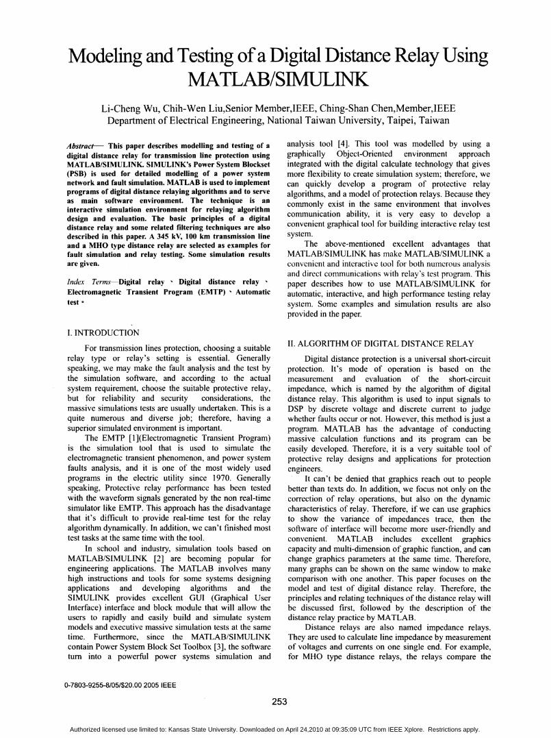
Zs ZR '
LsrelayFig. 1. One-line diagram of simulation system
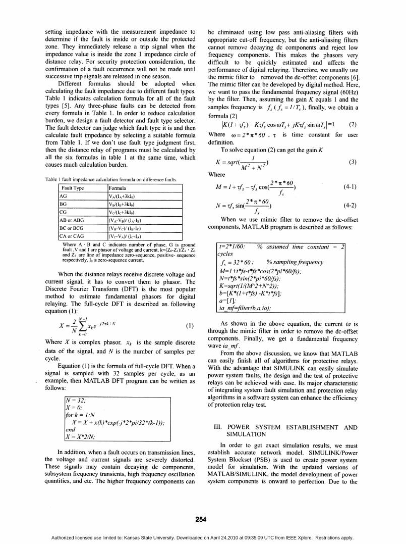
Fig. 2. SIMULINK/Power System Block constructs the simulation systems diagram
255
vs_
Authorized licensed use limited to: Kansas State University. Downloaded on April 24,2010 at 09:35:09 UTC from IEEE Xplore. Restrictions apply.
Subsybm Imesk)
Pa *:disle
130fa-t_lt_m13160-lII-_m
fig i6o;--- ----
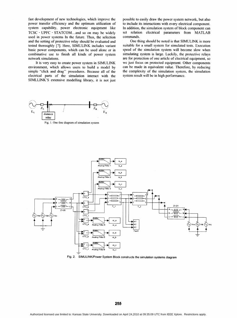
Fig. 3. Main window and parameter interface for simulation systems
This section describes the performance test andverification of transmission line protection of distancerelays using MATLAB/SIMULINK. How to use
SIMULINK of the PSB to build transmission linessystems model will be discussed as follows. Withreference to Fig. I One-line diagram of simulation system,we can establish the simulation system diagram in Fig. 2.The simulation system of each end source can be replacedby the The'venin equivalent circuits. However, we can
completely finish all of the test circuits with the use of thesource and the model of coupling component. Eachelement value of the test system can be set by power flowdata and short-circuit capacity data. Generally speaking,we need to get voltages and current signal data by currenttransformer (CT) and voltage transformer (VT) as shownin Fig.2 CTS and VTS respectively because distancerelays need three-phase voltages and three-phase currentsfor the impedance calculation. The design of digitaldistance relays of algorithm is based on the component offundamental frequency (60Hz). When power systems faultoccurs, the signals may contain high frequencycomponents. These higher frequency components must beeliminated, so we adopt analogue low pass filters of blockin the simulation systems in SIMULINK. This block can
be defined as filter of types (Low pass, Band pass, andHigh pass), order, and cut-off frequency etc. by user.
These are excellent characteristics. In addition,SIMULINK provides some options like real-time display,storing data in WORKSPACE and hard disk after thesignals data is released by filter. As shown in Fig.2, we
capture signals and store them in WORKSPACE from thesimulation systems, which is provided for using input ofdistance relay algorithm. About transmission lines model,SIMULINK provides Pi and distribution model, which can
sets parameters as numbers ofphase, frequency, resistance,
inductance, capacitor, and line length etc. This paper usesdistribution model for transmission line model of thepower systems simulation. In Fig. 2, the block for faulttype selection and fault resistances setting are locatedbelow two distribution model blocks.
Here, we have finished the power system simulationmodel as shown in Fig.2, but the graphic shown inwindow is a bit messy. Thus the SUBSYSTEM block isused by covering all of blocks to produce a single block,as shown in Fig. 3. Fault simulation block. If we doubleclick the block, the interactive interface window on rightside of Fig. 3. will be shown again, in which the interfacewindow can renew some parameters for next timesimulation when the simulation is finished. In addition, wecan simulate many cases at the same time. As discussedabove, the protective relay simulation system has becomea system of easy use and with efficiency.
437
MATLABWORKSPACE I
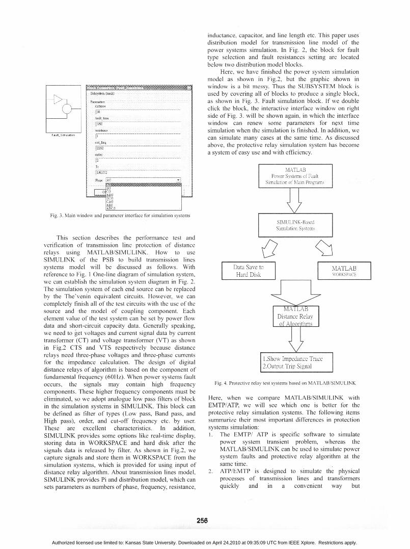
Fig. 4. Protective relay test systems based on MATLAB/SIMULINK
Here, when we compare MATLAB/SIMULINK withEMTP/ATP, we will see which one is better for theprotective relay simulation systems. The following itemssummarize their most important differences in protectionsystems simulation:1. The EMTP/ ATP is specific software to simulate
power system transient problem, whereas theMATLAB/SIMULINK can be used to simulate power
system faults and protective relay algorithm at thesame time.
2. ATP/EMTP is designed to simulate the physicalprocesses of transmission lines and transformersquickly and in a convenient way but
256
MATLABPower Systems of Fault
Simulation of Main Programs
SIMUJLINK-BasedSimulation Systems
.'n=-
Authorized licensed use limited to: Kansas State University. Downloaded on April 24,2010 at 09:35:09 UTC from IEEE Xplore. Restrictions apply.
MATLAB/SIMULINK offers more possibilities inpower electronics, signal processing and control.
3. Users can easily create new relay model withMATLAB/SIMULINK, whereas EMTP/ ATP doesn'thave such capacity.
4. MATLAB/SIMULINK encompasses better graphicfunction tools than EMTP/ATP of PCPLOT, PLOTXYand so on.
Therefore, this paper selects MATLAB/SIMULINK forinteractive automatic relay test systems.
IV. INTERACTIVE RELAY TEST SYSTEMS
Based on the discussion made in the previous twosections, we can establish interactive relay test systemsbased on MATLAB/SIMULINK as shown in Fig. 4. Wecan use MATLAB to write main program for protectiverelay test. The main program can not only start faultsimulation systems with SIMULINK but also givecommands and parameters to renew simulation systems atthe same time. As indicated in Fig. 3, we can changeparameters of simulation systems including fault locations,fault resistances, fault time, and fault types etc., and thenthe main program will execute setting and change value.Finally the main program controls SIMULINK executiondynamic of simulation as shown on Fig. 2. After thesimulation is finished, the simulation result data will bestored in WORKSPACE or hard disk, and its waveformcan be shown directly on screen through user's command.So far we have finished fault simulation task, and then gotrelated input data for protective relay algorithm. As far asthe distance relays in this paper are concemed, we need toget three-phase voltages and three-phase currents from Sterminal (Fig. 1.).
In the next step, input the simulation result data toprotective relay algorithm by MATLAB to distinguishwhether the circuit breaker (C.B.) action occurs or notfrom plan logic. When the fault impedance is calculatedand it is satisfied in the protection zone 1, the protectiverelay operation then releases trip signal to C.B. withoutadditional delay. Here, MATLAB can easily showimpedance trace on screen for user's verification, and storethe test records. So far we have only finished one faultcase for verification relay action. After this test is finished,the main program can automatically change parametersagain to execute simulations, tests, and records continually.With the inclusion of the loop function and themodification of system parameters, the main program canfinish hundreds and thousands of case tests at the sametime to meet the purpose of having automatic tests forprotective relays. The reason why this function is sopowerful is that we integrate MATLAB/SIMULINK intoone single environment and make use of its easycommunication function.
In addition to the above-mentioned advantage ofautomatic protective relay tests, MATLAB can empowerus to modify and adjust the problems that the initial relaydesign may have. With the powerful graphic function byMATLAB we can use the program to obtain easily outputsignal values and waveforms for relay algorithmsvenrfication. If the relay algorithm is bad, then modify it
immediately. It is very convenient for designing protectiverelay as well as for checking whether the setting of theinteractive relay test environment is appropriate.
V. EXAMPLE
Now that the theory and the structure of theinteractive relay test system are prescribed, the followingbegins with an example of a power transmission line offault simulation to test relay operation. Fig. 1 depicts the345 kV, 60 Hz simulated system one-line diagram. Fig. 2is the simulated system model by SIMULINK. The otherrelated parameters of the simulated system are shown inTable 2. Zone 1 is setting 80% of the total line length. Thisexample uses MHO type to explain the relay operationperformance. The mimic filters with time constant 2 cycles,the phase difference between ES and ER is 15 degrees,and the sampling frequency is 1920 Hz. The transmissionline length is 100 km. The phasor is estimated byfull-cycle DFT.
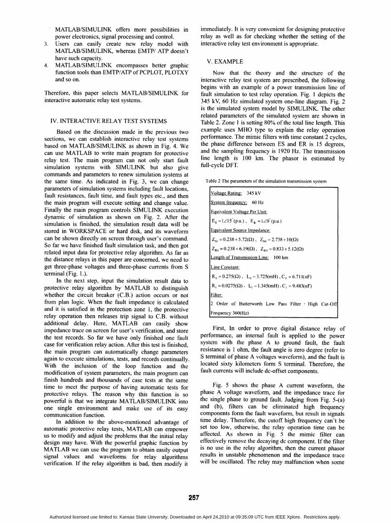
Table 2 The parameters of the simulation transmission system
First, In order to prove digital distance relay ofperformance, an intemal fault is applied to the powersystem with the phase A to ground fault, the faultresistance is 1 ohm, the fault angle is zero degree (refer toS terminal of phase A voltages waveform), and the fault islocated sixty kilometers form S terminal. Therefore, thefault currents will include dc-offset components.
Fig. 5 shows the phase A current waveform, thephase A voltage waveform, and the impedance trace forthe single phase to ground fault. Judging from Fig. 5-(a)and (b), filters can be eliminated high frequencycomponents form the fault waveform, but result in signalstime delay. Therefore, the cutoff high frequency can't beset too low, otherwise, the relay operation time can beaffected. As shown in Fig. 5 the mimic filter caneffectively remove the decaying dc component. If the filteris no use in the relay algorithm, then the current phasorresults in unstable phenomenon and the impedance tracewill be oscillated. The relay may malfunction when some
257
Voltage Rating: 345 kV
System frequency: 60 Hz
Equivalent Voltage Per Unit:
ES =1/Z5(p.u.), ER =1Z0(p.u.)Equivalent Source Impedance:
zsi = 0.238 + 5.72(Q), Zso = 2.738 + 10(Q)
ZRI =0.238+6.19(Q), ZR0 =0.833+5.12(Q)Length of Transmission Line: 100 km
Line Constant:
Ro = 0.275(Q), Lo = 3.725(mH), C0 = 6.71 l(nF)
RI = 0.0275(Q), LI = 1.345(mH), Cl = 9.483(nF)
Filter:
2 Order of Butterworth Low Pass Filter High Cut-Off
Frequency 360(Hz)
Authorized licensed use limited to: Kansas State University. Downloaded on April 24,2010 at 09:35:09 UTC from IEEE Xplore. Restrictions apply.
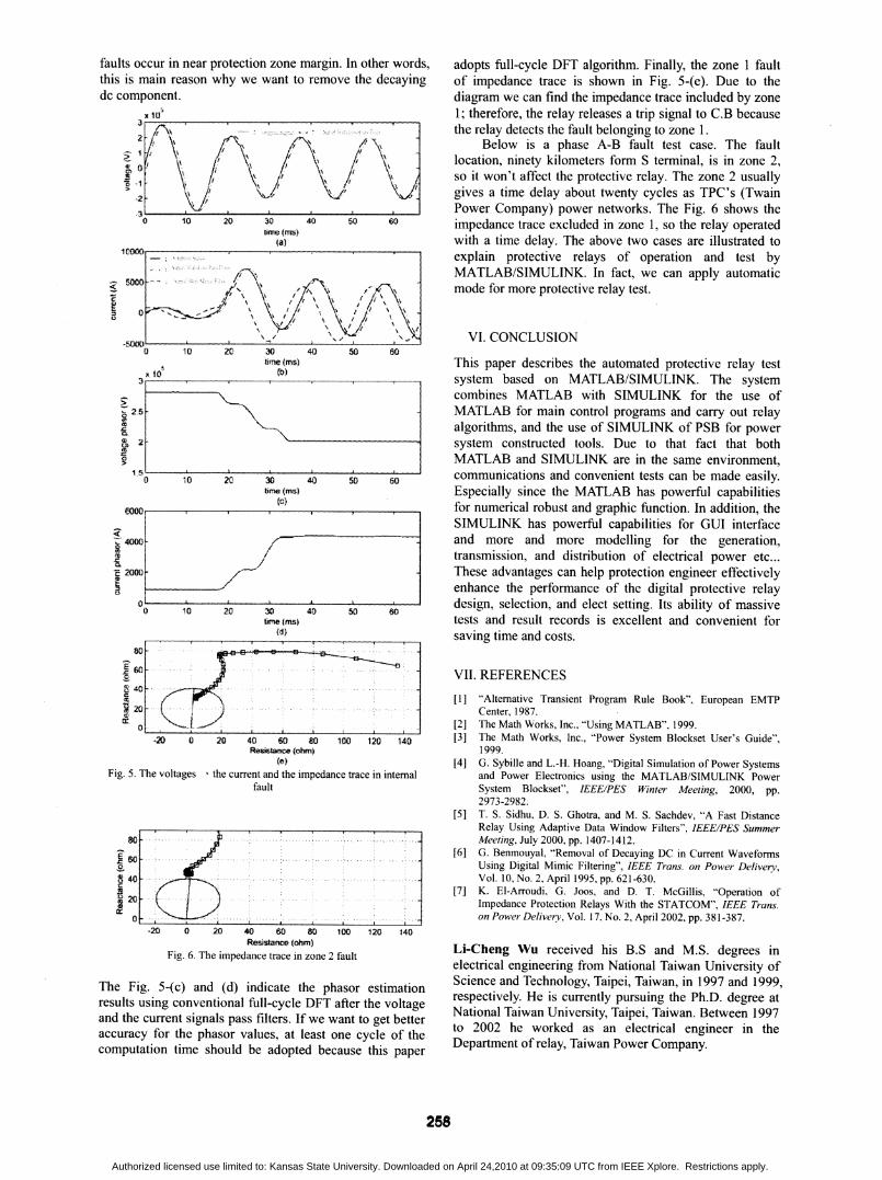
faults occur in near protection zone margin. In other words,this is main reason why we want to remove the decayingdc component.
X 1.,
0 10 20 30 40 50 60lime (ms)
.^ 44}~~~~~~~~a
0 10 20 30tife
5 10 (3
2.25 X
51 2(a
0 10 2C 30time60001
I~~~~_z. 4O.-
--a.F 2000 -.
0
0 10 20 30tir
t42
X ,
-20 0 20
40 50 60
adopts full-cycle DFT algorithm. Finally, the zone 1 faultof impedance trace is shown in Fig. 5-(e). Due to thediagram we can find the impedance trace included by zone1; therefore, the relay releases a trip signal to C.B becausethe relay detects the fault belonging to zone 1.
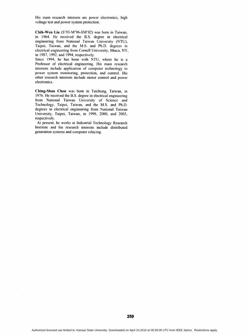
Below is a phase A-B fault test case. The faultlocation, ninety kilometers form S terminal, is in zone 2,so it won't affect the protective relay. The zone 2 usuallygives a time delay about twenty cycles as TPC's (TwainPower Company) power networks. The Fig. 6 shows theimpedance trace excluded in zone 1, so the relay operatedwith a time delay. The above two cases are illustrated toexplain protective relays of operation and test byMATLAB/SIMULINK. In fact, we can apply automaticmode for more protective relay test.
VI. CONCLUSION
(ms) This paper describes the automated protective relay testsystem based on MATLAB/SIMULINK. The systemcombines MATLAB with SIMULINK for the use ofMATLAB for main control programs and carry out relayalgorithms, and the use of SIMULINK of PSB for power
------ 1-1 system constructed tools. Due to that fact that bothMATLAB and SIMULINK are in the same environment,
Z 50 60 communications and convenient tests can be made easily.(Ms) Especially since the MATLAB has powerful capabilitiesit) for numerical robust and graphic function. In addition, the
SIMULINK has powerful capabilities for GUI interfaceand more and more modelling for the generation,transmission, and distribution of electrical power etc...These advantages can help protection engineer effectivelyenhance the performance of the digital protective relay
v > w design, selection, and elect setting. Its ability of massive40 50 60(me) tests and result records is excellent and convenient for
--- ------------- saving time and costs.
40 60 80 100 120 140Resistance (ohm)
(e)Fig. 5. The voltages - the current and the impedance trace in internal
fault
-20 0 20 40 60 80 00 120 140Resistance (ohm)
Fi1,. 6. The impedance trace in zone 2 fault
The Fig. 5-(c) and (d) indicate the phasor estimationresults using conventional full-cycle DFT after the voltageand the current signals pass filters. If we want to get betteraccuracy for the phasor values, at least one cycle of thecomputation time should be adopted because this paper
VII. REFERENCES[1] "Altemative Transient Program Rule Book", European EMTP
Center, 1987.[2] The Math Works, Inc., "Using MATLAB". 1999.[3] The Math Works, Inc., "Power System Blockset User's Guide",
1999.[4] G. Sybille and L.-H. Hoang, "Digital Simulation of Power Systems
and Power Electronics using the MATLAB/SIMULINK PowerSystem Blockset", IEEE/PES Winter Meeting, 2000, pp.2973-2982.
[5] T. S. Sidhu, D. S. Ghotra, and M. S. Sachdev, "A Fast DistanceRelay Using Adaptive Data Window Filters", IEEE/PES SummerMeeting, July 2000, pp. 1407-1412.
[6] G. Benmouyal, "Removal of Decaying DC in Current WaveformsUsing Digital Mimic Filtering", IEEE Trans. on Power Delivery,Vol. 10, No. 2, April 1995, pp. 621-630.
[7] K. El-Arroudi. G. Joos, and D. T. McGillis, "'Operation ofImpedance Protection Relays With the STATCOM", IEEE Trans.on Power Delivery, Vol. 17, No. 2, April 2002, pp. 381-387.
Li-Cheng Wu received his B.S and M.S. degrees inelectrical engineering from National Taiwan University ofScience and Technology, Taipei, Taiwan, in 1997 and 1999,respectively. He is currently pursuing the Ph.D. degree atNational Taiwan University, Taipei, Taiwan. Between 1997to 2002 he worked as an electrical engineer in theDepartment of relay, Taiwan Power Company.
258
V.
~00
0 .1/ \ . 1' /. .. . a
'1 1.." \
to
80
E608 40
:t.1200
Authorized licensed use limited to: Kansas State University. Downloaded on April 24,2010 at 09:35:09 UTC from IEEE Xplore. Restrictions apply.
His main research interests are power electronics, highvoltage test and power system protection.
Chih-Wen Liu (S'93-M'96-SM'02) was bom in Taiwan,in 1964. He received the B.S. degree in electricalengineering from National Taiwan University (NTU),Taipei, Taiwan, and the M.S. and Ph.D. degrees inelectrical engineering from Comell University, Ithaca, NY,in 1987, 1992, and 1994, respectively.Since 1994, he has been with NTU, where he is aProfessor of electrical engineering. His main researchinterests include application of computer technology topower system monitoring, protection, and control. Hisother research interests include motor control and powerelectronics.
Ching-Shan Chen was bom in Taichung, Taiwan, in1976. He received the B.S. degree in electrical engineeringfrom National Taiwan University of Science andTechnology, Taipei, Taiwan, and the M.S. and Ph.D.degrees in electrical engineering from National TaiwanUniversity, Taipei, Taiwan, in 1998, 2000, and 2003,respectively.At present, he works at Industrial Technology Research
Institute and his research interests include distributedgeneration systems and computer relaying.
259
Authorized licensed use limited to: Kansas State University. Downloaded on April 24,2010 at 09:35:09 UTC from IEEE Xplore. Restrictions apply.
Related Documents


