IJISET - International Journal of Innovative Science, Engineering & Technology, Vol. 6 Issue 5, May 2019 ISSN (Online) 2348 – 7968 www.ijiset.com 175 Modeling and Simulation of Rail End Bolt Hole and Bolted Rail Joint by FEM Amberbir Wondimu 1 , Negash Alemu2 , Yohanes Regassa1 1 Department of Mechanical Engineering, Addis Ababa Science & Technology University (AASTU), Addis Ababa, Ethiopia 2 Department of Metallurgical & Materials Engineering, Defense University (DU), Bishoftu, Ethiopia . Abstract: The rail joint is typically considered to be one of the weakest part of the rail way track superstructure. There are a number of defects and failures around rail end joint including bolt hole cracks, head–web cracking or separation, broken or missing bolts, and joint bar defects have been found to start at rail joints and the area surrounding these joints. The initiation and propagation of these defects are primarily due to the discontinuities of both geometric and mechanical properties in the rail joint area. This research work studies on the effects of support condition, speed of wheel, and loading position on the rail end vertical displacement, stress distribution at the bolt hole and the upper fillet area under static and dynamic loading condition by using finite element method. Preliminary results of static load showed that when loading position varies, the response of rail end joint varies, the rail vertical displacement and stresses on the rail upper fillet and stress on the bolt hole were also varies. Preliminary results from dynamic loading indicated the contact force at the wheel-rail interface would not change monotonically with the changing train speed and the stresses calculated around the bolt-hole area were significantly smaller than the stresses around the upper fillet area. Therefore to conclude the center supported joint is strongly recommended because of its high stiffness causing smaller deflection and smaller bolt-hole stress around the rail end joint can reduce defects around the joint. Key words: Rail end joint, static and dynamic loading, finite element method 1. INTRODUCTION Ethiopia has invested a great deal in creating the road network that will support economic development and ensuring that Ethiopia has good connections to each of the neighboring states [1]. Among the various railway truck components, rail joint typically is one of the weakest elements of a track superstructure, this is primarily because of discontinuities in its geometric, mechanical properties and the high-impact loads induced by these discontinuities. The development of continuously welded rail has significantly reduced the number of rail joints, but many bolted joints remain installed in rail transit systems especially in Ethiopia [2]. Because of the unique loading environment of a rail transit system (especially high-frequency, high- repetition loads), defects related to bolted rail joints (e.g., joint bar failures, bolt hole cracks, and cracks in the upper fillet) continue to cause service failures and can pose derailment risks [3].

Welcome message from author
This document is posted to help you gain knowledge. Please leave a comment to let me know what you think about it! Share it to your friends and learn new things together.
Transcript

IJISET - International Journal of Innovative Science, Engineering & Technology, Vol. 6 Issue 5, May 2019
ISSN (Online) 2348 – 7968
www.ijiset.com
175
Modeling and Simulation of Rail End Bolt Hole and Bolted Rail Joint by FEM
Amberbir Wondimu P
1P, Negash Alemu P
2P, Yohanes Regassa P
1
P
1 PDepartment of Mechanical Engineering, Addis Ababa Science & Technology University (AASTU),
Addis Ababa, Ethiopia
P
2PDepartment of Metallurgical & Materials Engineering, Defense University (DU), Bishoftu, Ethiopia
. Abstract: The rail joint is typically considered to be one of the weakest part of the rail way track
superstructure. There are a number of defects and failures around rail end joint including bolt hole cracks,
head–web cracking or separation, broken or missing bolts, and joint bar defects have been found to start
at rail joints and the area surrounding these joints. The initiation and propagation of these defects are
primarily due to the discontinuities of both geometric and mechanical properties in the rail joint area. This
research work studies on the effects of support condition, speed of wheel, and loading position on the
rail end vertical displacement, stress distribution at the bolt hole and the upper fillet area under static and
dynamic loading condition by using finite element method. Preliminary results of static load showed that
when loading position varies, the response of rail end joint varies, the rail vertical displacement and
stresses on the rail upper fillet and stress on the bolt hole were also varies. Preliminary results from
dynamic loading indicated the contact force at the wheel-rail interface would not change monotonically
with the changing train speed and the stresses calculated around the bolt-hole area were significantly
smaller than the stresses around the upper fillet area. Therefore to conclude the center supported joint is
strongly recommended because of its high stiffness causing smaller deflection and smaller bolt-hole stress
around the rail end joint can reduce defects around the joint.
Key words: Rail end joint, static and dynamic loading, finite element method
1. INTRODUCTION Ethiopia has invested a great deal in creating the road network that will support economic development and ensuring that Ethiopia has good connections to each of the neighboring states [1]. Among the various railway truck components, rail joint typically is one of the weakest elements of a track superstructure, this is primarily because of discontinuities in its geometric, mechanical properties and the high-impact loads induced by these discontinuities. The development of continuously welded rail has significantly reduced the number of rail joints, but many bolted joints remain installed in rail transit systems especially in Ethiopia [2]. Because of the unique loading environment of a rail transit system (especially high-frequency, high-repetition loads), defects related to bolted rail joints (e.g., joint bar failures, bolt hole cracks, and cracks in the upper fillet) continue to cause service failures and can pose derailment risks [3].

IJISET - International Journal of Innovative Science, Engineering & Technology, Vol. 6 Issue 5, May 2019
ISSN (Online) 2348 – 7968
www.ijiset.com
176
2. RELEVANT LITERATURES Rail joints are the weakest part of the track, where their life ranges between a third and a half of the life of the rails, [4]. Due to the above facts different researchers are done great jobs to solve problems around rail end joints by using FEM as their basic tool and method of computation. This paper work is same in many aspects with the relevant literatures discussed below and only three things makes this paper different, these are study area, considers only effect of vertical static and dynamic wheel load on rail end joint, would fill knowledge voids relating to how support conditions, bolt conditions and speed of rail wheel affect the stresses around the rail-end bolt hole.
Authors Modeling Techniques
Discussion Limitations
Kaijun Zhu, et al, 2017
3D FEA Stress distribution was investigated at the rail-end bolt hole and upper fillet areas
Comprehensive parametric analysis performed with finite element modeling.
Considers static analysis only
R.Kasanna. etal.,2017
3-D FEA Elastic Modal analysis is done to calculate the Modal shapes, natural frequencies.
Focused only the interaction between left and right wheels.
Frictional Element Model
Shows super-elevation have significantly effects on contact stress, life, damage, safety factor.
Grossoni I. et al., 2014
2D FEA vehicle track coupling model,
2D model includes 3 parameters of IRJs (joint max deflection, joint angle and joint length) by using a mathematical idealization of dipped beam in 2D.
The model does not allow looking in neither the interfaces of RJ components, nor the structural investigation of the RJ.
Sunil Patel1,et al., 2013
3D FEM, Model for RJ
The static and dynamic loads are being applied to estimate fatigue life and endurance strength at the section. The material properties of the rail and wheel are assumed to be same.
The combined effect of vertical and lateral bending; which is not included in the beam theory approximations.
Patel Q., Kumar V. and
Nareliya R., 2013
Wheel-rail dynamic 3D FEA, standard RJ.
Model included a mechanical non-insulated RJ on a two sleeper configuration on elastic support.
Lack of symmetry and short length of model may affect the result, mesh is not presented.
Zong N. et al.,2013
Wheel rail contact impact model, 3D FEA
Account for wheel-rail frictional contact, 200 KN bolt preload, elastic support per rail end. Model examines the contact and impact force, contact pressure, validated against vertical strain in rail web with field test.
It doesn’t present structural performance of the joint in terms of deflection, stresses on fishplate, and does not comment on how the rail-fishplate interfaces were modelled.
Table1. Relevant literature summery
3. THEORY OF ANALYSIS The knowledge of contact mechanics as the Hertz’s theory provides a closed-form solution to the normal contact problem. Therefore, during rail wheel and rail end joint contact analysis the following assumptions are taken from the Hertz theory are:

IJISET - International Journal of Innovative Science, Engineering & Technology, Vol. 6 Issue 5, May 2019
ISSN (Online) 2348 – 7968
www.ijiset.com
177
Displacements and strains are small.
The bodies in contact are homogeneous, isotropic and linearly elastic.
Smooth surfaces where the surface roughness is neglected (frictionless contact)
The dimensions of the contact patch are significantly smaller than the dimensions of the
bodies in contact.
The curvature of the bodies in contact is constant.
The materials of the bodies are quasi-identical, [4].
Figure 1. Cylinder in rolling-sliding contact with an elastic half-space, [4].
Figure 2. Rolling –sliding of train wheel on rail
4. MODELING OF RAIL WHEEL CONTACT The wheel profile consists of a flange to guide the trains along the rails and a conical tread that contacts rail head, and rail has many curvatures to guide wheel properly. The contact positions of the wheel / rail are different in the Different situation. However, this paper uses the contact between the wheels tread and rail head. The contact area between wheel and rail are very small compared to their dimension, [6].

IJISET - International Journal of Innovative Science, Engineering & Technology, Vol. 6 Issue 5, May 2019
ISSN (Online) 2348 – 7968
www.ijiset.com
178
Figure 3. Setting wheel and rail contact as per UIC 60 standard, model used in research
5. SIMULATION WITH ANSYS WORK BENCH VERSION 19.2 Generally, there are two kinds of analysis one is experimental and other is simulation analysis. The biggest problem with experimental analysis is the cost and time. Therefore, commercial simulation software’s have been used in different engineering fields, because it just needs a computer and the suitable software. Moreover, simulation software can offer the results in much shorter time period. The ANSYS workbench software is carried out in three basic principles. They are:-Preprocessor>> Processor >>Postprocessor. Geometric Model specification: - The model was done as per UIC 60 rail standard.
Track Gauge 1435mm
Type of Rail 60 Kg/m
Wheel Diameter U< U660mm
Fish Plate length and thickness 820mm×19mm
Sleeper Gap 625mm
End Joint Gap 5mm
Standard Joint Bolt and Nut M28
Operation Parameters Speed
Maximum operating speed 70km/hr(20𝑚 𝑠)⁄
Travelling speed on minimum curve radius ≥ 12km ℎ𝑟⁄ (4𝑚 𝑠)⁄
Operating speed during car wash 3~4km/hr
Table 2. UIC 60 Design Rail Specification [2, 5, 7]
Mechanical forces considered in the analysis: Vertical Force: The vertical force (FRVR) acting on the wheel is due to the passenger and payload. These forces are transferred to the wheel through the axle. A static and dynamic load of 55600N on each wheel is considered in this study.
Material Selection: For each supper structures around rail end joint the following tabular materials are used.
IJISET - International Journal of Innovative Science, Engineering & Technology, Vol. 6 Issue 5, May 2019
ISSN (Online) 2348 – 7968
www.ijiset.com
179
Table 3. Material used for rail supper structure, these elements generally include carbon, manganese, silicon, chromium, phosphorus, Sulphur [5, 7].
Finite Element Modeling: Finite element method is used to analyze the response of the rail joint to the static and dynamic load. The Finite Element analysis is performed using structural analysis of the ANSYS R19.2 workbench software after imported 3D assemblies form SOLIDWORKS 18 software.
Figure 4. Model and mesh generation specific to the joint (main study area).
Part Part Type Element Type Number of
Element
Moment of Inertia
Rail 3D-
Deformable
Solids
Linear tetrahedron 49076 4.77e6 kg.mmP
2
Joint bar Linear tetrahedron 21567 1.05e5 kg.mmP
2
S bolt and nut Linear tetrahedron 7379 1992.9 kg.mmP
2
Wheel Linear tetrahedron 73669 5.89 e6 kg.mmP
2
Table 4. Mesh results when relevance center and span angle is set to fine. ANSYS work bench procedure for analysis: - File of the wheel and track is saved in IGS format on solid work 18. >>3D model of assembly is inserted in ANSYS work bench. >> Simulation is selected for analysis of wheel and track. >> Connection is made between wheel and rail as per contact set. >>Frictional and Rough Contact between rail joints is selected. >> Tetrahedral element is selected mesh is generated. >>Track is fixed in all 3 DOF by fixture option. >> Design load is applied on wheel. >> Result is obtained by showing the final result option.
Part Name
Mechanical Properties of the Selected Material
Poison’s
Ratio
Young’s
Modulus (GPa)
Ultimate tensile
strength (MPa)
Yield strength
(MPa)
Density
(kg/mP
3P)
Maximum
Deformation
Rail 0.3 207 780 640 7800 12%
Fish Plate 0.3 207 780 640 7800 12%
Bolt and Nut 0.3 207 780 640 7800 12%
IJISET - International Journal of Innovative Science, Engineering & Technology, Vol. 6 Issue 5, May 2019
ISSN (Online) 2348 – 7968
www.ijiset.com
180
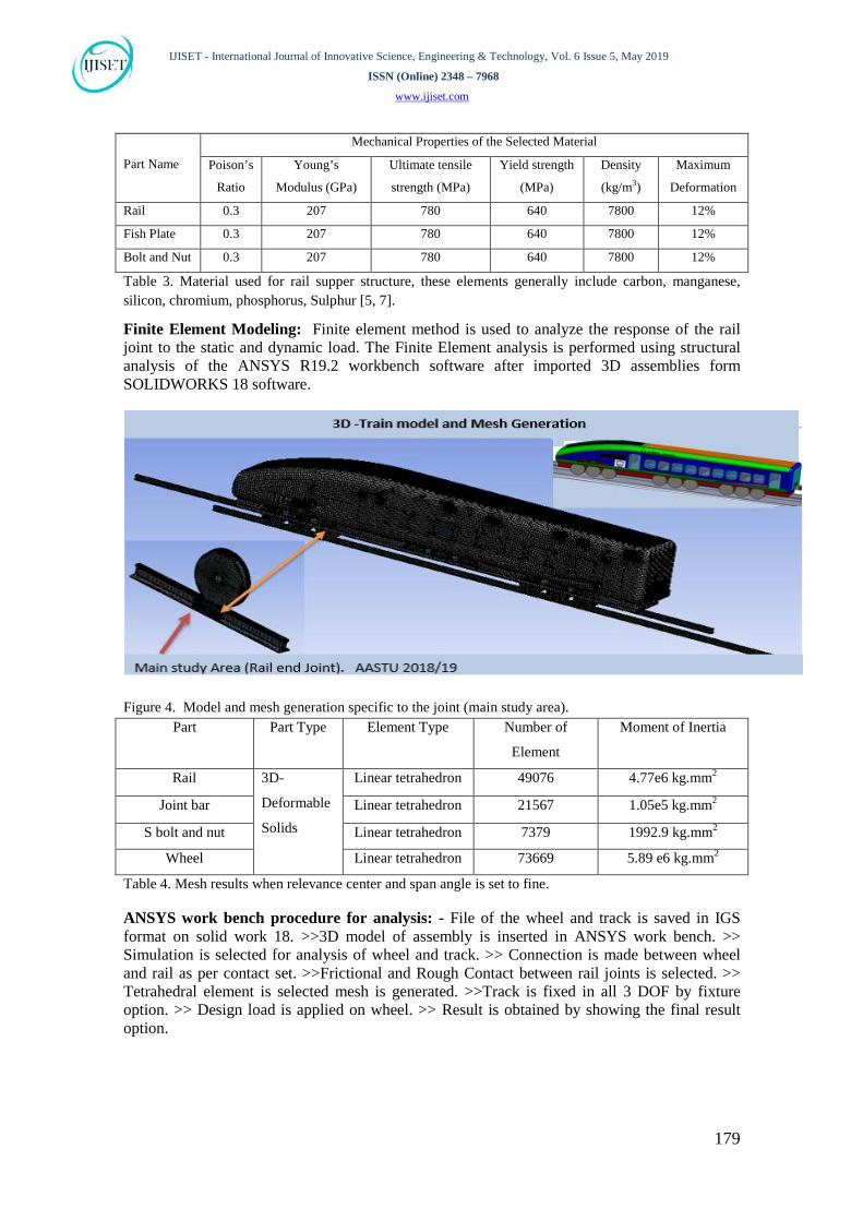
6. RESULTS AND DISCUSSION I. When Load acting at center of joint response of the rail end joint as follows
• Center Supported Joint.
Figure 5. a) Vertical displacement along rail with a bolted joint (mm). b) von Mises stress at rail end upper fillet (MPa). c). Principal stress around first bolt hole (MPa)
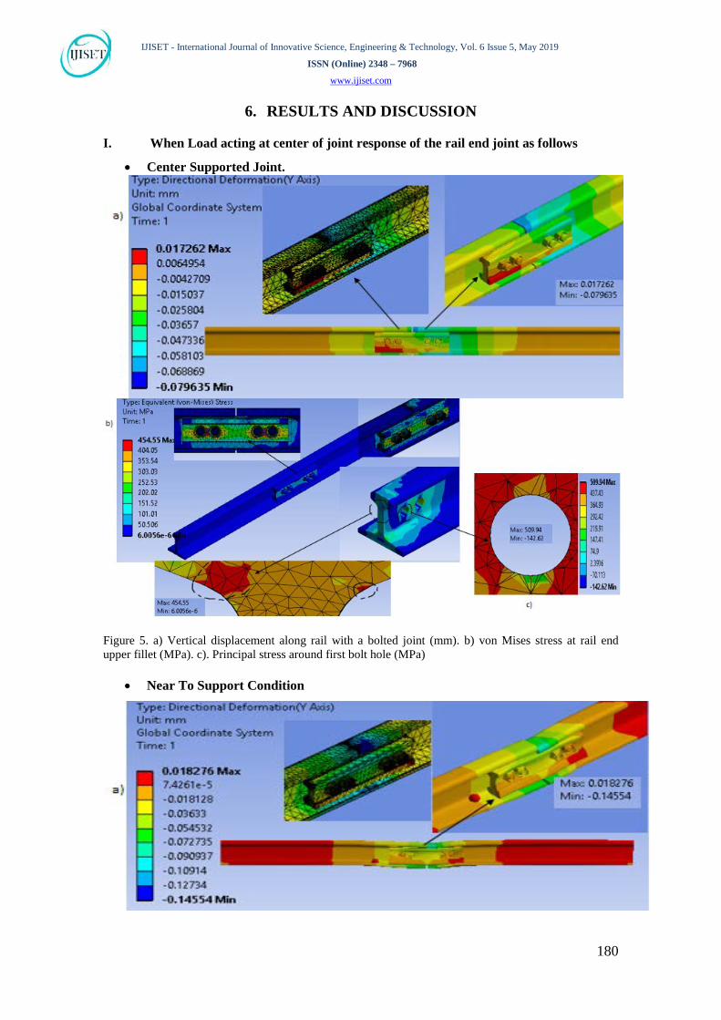
• Near To Support Condition

IJISET - International Journal of Innovative Science, Engineering & Technology, Vol. 6 Issue 5, May 2019
ISSN (Online) 2348 – 7968
www.ijiset.com
181
Figure 6. a) Vertical displacement along rail with a bolted joint (mm). b) von Mises stress at rail end upper fillet (MPa). c). Principal stress around first bolt hole (MPa).
• Suspended Joint
Figure 7. a) Vertical displacement along rail with a bolted joint (mm). b) von Mises stress at rail end upper fillet (MPa). c). Principal stress around first bolt hole (MPa)
IJISET - International Journal of Innovative Science, Engineering & Technology, Vol. 6 Issue 5, May 2019
ISSN (Online) 2348 – 7968
www.ijiset.com
182
Summer on results and discussion obtained when static wheel load is acting at center of the rail end joint for three different support conditions as follows
Rail End Joint Support Configuration Studied parameters
Results
Rail end vertical Displacement 0.017mm Center Supported Rail end bolt hole Tensile Stresses 509.94MPa Rail end upper fillet von Mises Stresses 454.55MPa Rail end vertical Displacement 0.0183mm Near to Support Rail end bolt hole Tensile Stresses 476.38MPa Rail end upper fillet von Mises Stresses 450.38MPa Rail end vertical Displacement 0.123mm Suspended Joint Rail end bolt hole Tensile Stresses 421.76 Rail end upper fillet von Mises Stresses 464.68 Table 5 Summery of response of different support configuration for load acting at center of rail end joint. The increase in the vertical displacement was relatively high when suspended joint is
used; this result may be attributable to consider closer spacing of the two centre
crossties bolted joint. The reduction of the bolt hole tensile stress is attributable to the
release of the bolt load. The magnitude of the upper fillet stress was relatively high,
which might have been caused by the limited contact area and the excessive relative
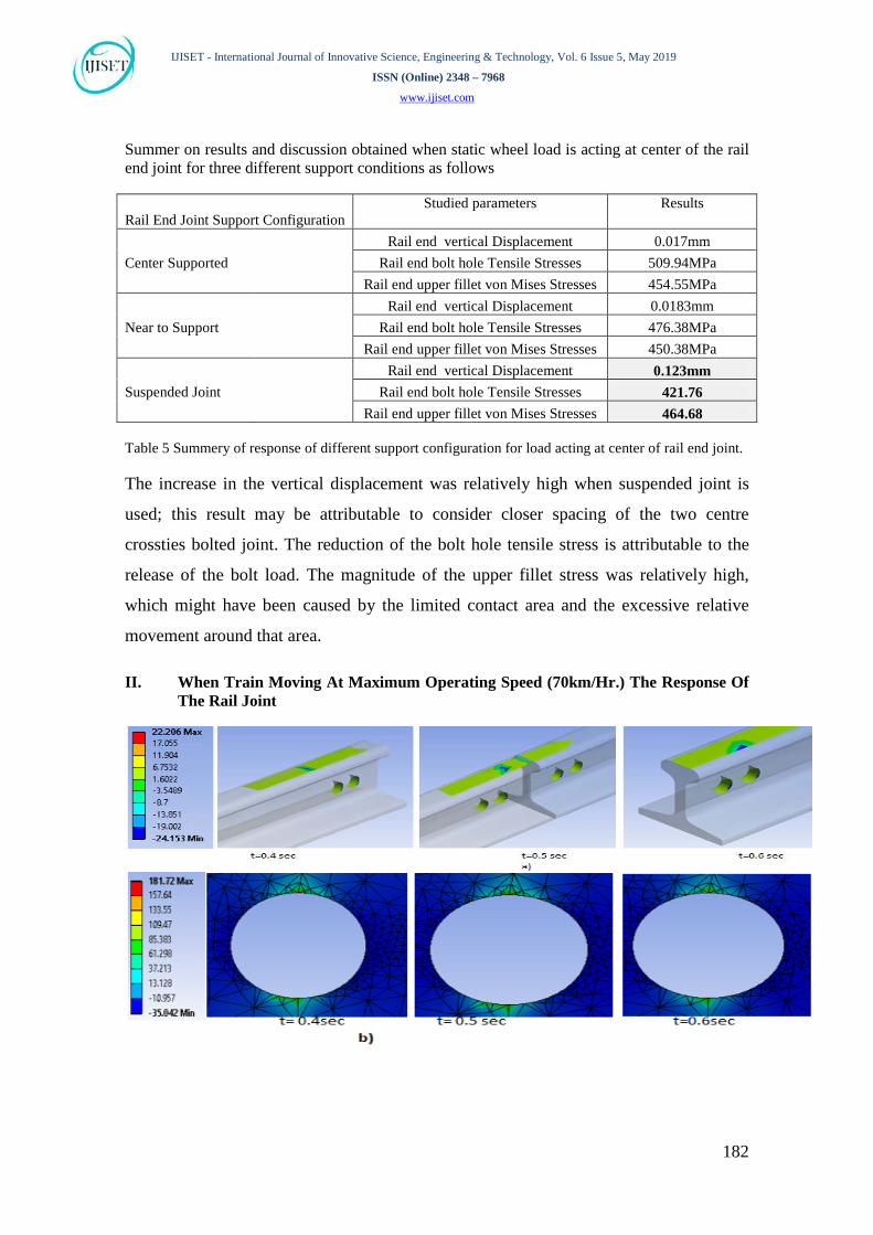
movement around that area. II. When Train Moving At Maximum Operating Speed (70km/Hr.) The Response Of
The Rail Joint
IJISET - International Journal of Innovative Science, Engineering & Technology, Vol. 6 Issue 5, May 2019
ISSN (Online) 2348 – 7968
www.ijiset.com
183
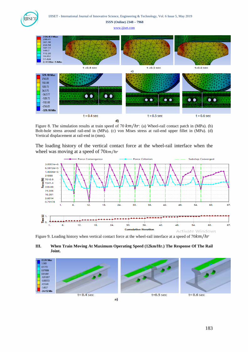
Figure 8. The simulation results at train speed of 70 𝑘𝑚 ℎ𝑟⁄ : (a) Wheel-rail contact patch in (MPa). (b) Bolt-hole stress around rail-end in (MPa). (c) von Mises stress at rail-end upper fillet in (MPa). (d) Vertical displacement at rail-end in (mm). The loading history of the vertical contact force at the wheel-rail interface when the wheel was moving at a speed of 70𝑘𝑚 ℎ𝑟 ⁄
Figure 9. Loading history when vertical contact force at the wheel-rail interface at a speed of 70𝑘𝑚 ℎ𝑟⁄ III. When Train Moving At Maximum Operating Speed (12km/Hr.) The Response Of The Rail
Joint.

IJISET - International Journal of Innovative Science, Engineering & Technology, Vol. 6 Issue 5, May 2019
ISSN (Online) 2348 – 7968
www.ijiset.com
184
Figure 10. The simulation results at train speed of 12 𝑘𝑚 ℎ𝑟⁄ : (a) Wheel-rail contact patch in (MPa). (b) Bolt-hole stress around rail-end in (MPa). (c) von Mises stress at rail-end upper fillet in (MPa). (d) Vertical displacement at rail-end in (mm). The loading history of the vertical contact force at the wheel-rail interface when the wheel was moving at a speed of 12𝑘𝑚 ℎ𝑟 ⁄
Figure 11. Loading history when vertical contact force at the wheel-rail interface at a speed of 12𝑘𝑚 ℎ𝑟⁄

IJISET - International Journal of Innovative Science, Engineering & Technology, Vol. 6 Issue 5, May 2019
ISSN (Online) 2348 – 7968
www.ijiset.com
185
Summary of result and discussion of moving load Operating Speed Studied Parameter Values 70𝑘𝑚 ℎ𝑟 ⁄ maximum
operating speed wheel-rail contact patch (MPa) 22.207
stress around rail-end bolt-hole (MPa) 181.72 von Mises stress at rail-end upper fillet (MPa) 336.83
vertical displacement at rail-end (mm) 329.18 12𝑘𝑚 ℎ𝑟 ⁄ minimum operating speed
wheel-rail contact patch (MPa) 22.207 stress around rail-end bolt-hole (MPa) 181.65
von Mises stress at rail-end upper fillet (MPa) 336.78 vertical displacement at rail-end (mm) 57.44
Table 6. Effect of speed on rail joint
As shown on the above summery Table 6 on the effect of bolt loading and speed on rail end joint, variation of speed will not affect the wheel rail contact patch which is strongly agreed with the formulation of contact mechanics, but bolt loading were strongly affect the wheel rail contact patch. As general the results shows for same bolt loading cases variation of speed strongly affect the rail end vertical displacement only which is agree with the formulation of contact mechanics formulation for the relation between varying speed and vertical displacement which was done by[9,10].
7. CONCLUSION In this study, the responses of a bolted rail joint component are determined under static and dynamic loads, the results are assumed to be significant. The analysis can include rail end vertical displacement, rail end bolt hole tensile stress, and upper fillet von Mises stress responses of bolted rail joint caused by vertical wheel load. The analysis is taking into account by using various position of bolted rail joint on the support and effect of maximum and minimum operating speed. When load was acting at the centre of rail end, the joint gets its maximum upper fillet stress which is more risk for life of the rail supper structure when the joint support is suspended. This part of rail track needed more attention than other parts, to reduce the problem related to the rail joint. This paper recommends using the sleeper support at the rail joint position and bolt around the end gap need to have more strength than part of the joint due to the exposure of the vertical load and it should be center supported, then it will have less deflection and high stiffness. Generally, the rail end joint needs a special treatment to reduce the rail super structure failure.
ACKNOWLEDGEMENTS
This research was supported by FDRE, ministry of education. We thank our colleagues from AASTU who provided scientific insight and expertise advice that greatly assisted the research.

IJISET - International Journal of Innovative Science, Engineering & Technology, Vol. 6 Issue 5, May 2019
ISSN (Online) 2348 – 7968
www.ijiset.com
186
REFERENCE [1] U. N. D. Program, National logistics strategies of Ethiopia, Ethiopia: Policy
Advisory Unit of UNDP Ethiopia, 2017. [2] Google/https/en.wikipedia.org, “List of Rail Acidents 2013 to present,” Adiss
Ababa, Acesses date 28/3/2019. [3] Zhu K, “Finite Element Analysis of the Effects of Bolt Condition on Bolted Rail
Joint Stresses,” 2016. [4] Joseph.T, Condition Monitoring of Bolted Joint, Sheffeild: University of Sheffield,
2015. [5] Amol. Y, Analysis And Experimental Investigation Of Rail Joint To Improve
Fatigue Life Using Cold Expansion Process., India: Losr Journal Of Mechanical And Civil Engineering (Iosr-Jmce),, 2014.
[6] Zhu K, Fatigue Analysis Of Rail-Head-To-Web Fillet At Bolted Rail Joint Under Various Impact Wheel Load Factors And Support Configurations., Columbia, USA, April 12-15, 2016.
[7] Maximov J, A new approach for pre-stressing of rail-end-bolt holes, Gabrovo, Bulgaria: Journal of mechanical engineering science, 2016.
[8] Li.N, fatigue strength of the rail bolt are studied by Finite Element Contact Analysis method, china, 2013.
[9] Nia.H, “Heavy-Haul Wheel Damages using Vehicle Dynamics Simulation,,” 2018. [10] Yin.H, “Investigation of Relationship between Train Speed and Bolted Rail Joint
Fatigue Life,” 2017.
Related Documents