Modeling and optimization of multi-tubular metal hydride beds for efficient hydrogen storage Constantinos A. Krokos a,b , Dragan Nikolic a , Eustathios S. Kikkinides a, *, Michael C. Georgiadis c , Athanasios K. Stubos b a Department of Mechanical Engineering, University of Western Macedonia, Bakola & Salvera Str., 50100 Kozani, Greece b National Center of Scientific Research DEMOKRITOS, Institute of Nuclear Technology and Radiation Protection, 15310 Ag. Paraskevi Attikis, Athens, Greece c Department of Engineering Informatics and Telecommunications, University of Western Macedonia, Karamanli & Ligeris Str., 50100 Kozani, Greece article info Article history: Received 24 July 2009 Received in revised form 9 September 2009 Accepted 9 September 2009 Available online 2 October 2009 Keywords: Metal hydrides Hydrogen storage Multi-tubular reactors Numerical simulations abstract This work presents a novel systematic approach for the optimal design of a multi-tubular metal hydride tank, containing up to nine tubular metal hydride reactors, used for hydrogen storage. The tank is designed to store enough amount of hydrogen for 25 km range 1 , for a fuel cell vehicle. A detailed 3D Cartesian, mathematical model is developed and validated against a 2D cylindrical developed by Kikkinides et al. [1]. The objective is to find the optimal process design so as to increase the overall thermal efficiency, and thus minimize the storage time. Optimization results indicate that almost 90% improvement of the storage time can be achieved, over the case where the tank is not optimized and for a minimum storage capacity of 99% of the maximum value. ª 2009 Professor T. Nejat Veziroglu. Published by Elsevier Ltd. All rights reserved. 1. Introduction Hydrogen is shown to be the future fuel from the point of view of human fuel evolution. The fuel evolution experienced the history from coal through petroleum to natural gas following the direction of increasing the content of hydrogen, therefore, it must finally reach the destination of pure hydrogen [1–3]. Automotive industry is slowly moving towards this direction by developing fuel cell vehicles, which have the benefit of zero emissions. However, before introducing the fuel cell vehicle in the market, several issues including the hydrogen storage need to be addressed. Currently, high pressure tanks and liquid hydrogen tanks are used for road tests, but both technologies do not meet all the requirements of future fuel cell vehicles [3]. Storage of hydrogen in a pressurized cylinder is not likely to be applied in the future due to low density, high pressurization costs and safety considerations [2]. Liquid hydrogen could be applied if the unit cost becomes compa- rable with gasoline, yet inevitable boiling-off liquid might be in concern [2]. Metal hydride materials seem to exhibit good storage capabilities and constitute a promising direction towards the hydrogen economy [4–6]. This can be attributed to the reduced operating pressure compared to compressed gas technology, thus ensuring less weight and increased safety [1]. The current work is motivated by the desire to design a metal hydride tank, with small charge–discharge duration germane * Corresponding author. E-mail address: [email protected] (E.S. Kikkinides). 1 Based on data from Honda FCX Clarity. Available at www.sciencedirect.com journal homepage: www.elsevier.com/locate/he 0360-3199/$ – see front matter ª 2009 Professor T. Nejat Veziroglu. Published by Elsevier Ltd. All rights reserved. doi:10.1016/j.ijhydene.2009.09.021 international journal of hydrogen energy 34 (2009) 9128–9140

Welcome message from author
This document is posted to help you gain knowledge. Please leave a comment to let me know what you think about it! Share it to your friends and learn new things together.
Transcript
i n t e r n a t i o n a l j o u r n a l o f h y d r o g e n e n e r g y 3 4 ( 2 0 0 9 ) 9 1 2 8 – 9 1 4 0
Avai lab le at www.sc iencedi rect .com
journa l homepage : www.e lsev ie r . com/ loca te /he
Modeling and optimization of multi-tubular metal hydridebeds for efficient hydrogen storage
Constantinos A. Krokos a,b, Dragan Nikolic a, Eustathios S. Kikkinides a,*,Michael C. Georgiadis c, Athanasios K. Stubos b
a Department of Mechanical Engineering, University of Western Macedonia, Bakola & Salvera Str., 50100 Kozani, Greeceb National Center of Scientific Research DEMOKRITOS, Institute of Nuclear Technology and Radiation Protection,
15310 Ag. Paraskevi Attikis, Athens, Greecec Department of Engineering Informatics and Telecommunications, University of Western Macedonia, Karamanli & Ligeris Str.,
50100 Kozani, Greece
a r t i c l e i n f o
Article history:
Received 24 July 2009
Received in revised form
9 September 2009
Accepted 9 September 2009
Available online 2 October 2009
Keywords:
Metal hydrides
Hydrogen storage
Multi-tubular reactors
Numerical simulations
* Corresponding author.E-mail address: [email protected] (E.S. Kikk
1 Based on data from Honda FCX Clarity.0360-3199/$ – see front matter ª 2009 Profesdoi:10.1016/j.ijhydene.2009.09.021
a b s t r a c t
This work presents a novel systematic approach for the optimal design of a multi-tubular
metal hydride tank, containing up to nine tubular metal hydride reactors, used for
hydrogen storage. The tank is designed to store enough amount of hydrogen for 25 km
range1, for a fuel cell vehicle. A detailed 3D Cartesian, mathematical model is developed
and validated against a 2D cylindrical developed by Kikkinides et al. [1]. The objective is to
find the optimal process design so as to increase the overall thermal efficiency, and thus
minimize the storage time. Optimization results indicate that almost 90% improvement of
the storage time can be achieved, over the case where the tank is not optimized and for
a minimum storage capacity of 99% of the maximum value.
ª 2009 Professor T. Nejat Veziroglu. Published by Elsevier Ltd. All rights reserved.
1. Introduction technologies do not meet all the requirements of future fuel
Hydrogen is shown to be the future fuel from the point of view
of human fuel evolution. The fuel evolution experienced the
history from coal through petroleum to natural gas following
the direction of increasing the content of hydrogen, therefore,
it must finally reach the destination of pure hydrogen [1–3].
Automotive industry is slowly moving towards this direction
by developing fuel cell vehicles, which have the benefit of zero
emissions. However, before introducing the fuel cell vehicle in
the market, several issues including the hydrogen storage
need to be addressed. Currently, high pressure tanks and
liquid hydrogen tanks are used for road tests, but both
inides).
sor T. Nejat Veziroglu. Pu
cell vehicles [3]. Storage of hydrogen in a pressurized cylinder
is not likely to be applied in the future due to low density, high
pressurization costs and safety considerations [2]. Liquid
hydrogen could be applied if the unit cost becomes compa-
rable with gasoline, yet inevitable boiling-off liquid might be
in concern [2]. Metal hydride materials seem to exhibit good
storage capabilities and constitute a promising direction
towards the hydrogen economy [4–6]. This can be attributed to
the reduced operating pressure compared to compressed gas
technology, thus ensuring less weight and increased safety [1].
The current work is motivated by the desire to design a metal
hydride tank, with small charge–discharge duration germane
blished by Elsevier Ltd. All rights reserved.

Fig. 1 – Circle drawn with the 8-way symmetry on pixelized
surface.
i n t e r n a t i o n a l j o u r n a l o f h y d r o g e n e n e r g y 3 4 ( 2 0 0 9 ) 9 1 2 8 – 9 1 4 0 9129
to automotive use. The tank is designed to store enough
amount of hydrogen for 25 km range for a fuel cell vehicle
similar to Honda’s FCX Clarity. It is possible to increase the
range by increasing the number of reactor modules.
The performance of hydrogen absorption to and desorp-
tion from metal hydride depends on the heat transfer, mass
transfer and kinetic-reactions of the metal hydride bed [7].
Hence, there have been numerous experimental and theo-
retical investigations on several aspects of metal hydride
storage systems. Muthukumar et al. [8] analyzed the effect of
various operating conditions in metal hydride based on
hydrogen storage device. MacDonald and Rowe [9] analyzed
dynamic metal hydride storage systems by a combination of
experimental tests and simulations. Several parameters that
play a significant role on precise modeling results were
investigated. Jemni and Narsallah [10] presented a theoretical
Fig. 2 – The five regions for the case of the reactor with 4
metal hydride beds.
study of the mass and heat transfer dynamics in a metal
hydride reactor. Some of the assumptions used in their work
were validated in a subsequent contribution [11]. Jemni et al.
[12] presented an experimental approach to determine the
reaction kinetics equilibrium conditions and transport prop-
erties in LaNi5–H2 system. Nakagawa et al [13] presented a 2D
model for the transient heat and mass transfer within a metal
hydride bed. Mat and Kaplan [14] developed a mathematical
model to describe hydrogen absorption in a porous
lanthanum metal bed. The model takes into account the
complex mass and heat transfer and reaction kinetics. Model
prediction results were found to be in a good agreement with
experimental data. Demircan et al. [15] examined experi-
mentally the hydrogen absorption in two LaNi5H2 reactors.
Kaplan Y. [16] studied experimentally the effect of heat
transfer mechanisms in three different geometric design
configurations of MH reactors under various charging pres-
sures. It was concluded that the charging of the MH reactors is
primarily heat transfer depended and the reactor with better
cooling exhibits the fastest charging characteristics.
Aldas et al. [17] and Mat et al. [18], presented an integrated
model of heat and mass transfer, reaction kinetics and fluid
dynamics in a hydride bed. An important conclusion of this
work is that the flow conditions do not significantly affect the
amount of hydrogen absorbed. Askri et al. [19] extended the
previous studies [10–12], by investigating the effect of radiate
heat transfer in LaNi5H2 and MgH2 hydride beds. Simulation
results showed that radiation effects are negligible on the
sorption process in the LaNi5H2 bed but they play an important
role in the case of MgH2 hydride bed. The effects of heat transfer
on the sorption kinetics of complex hydride reacting systems
werestudiedbyLozanoetal. [20]. Itwasfoundthat thesizeofthe
hydride bed as well as the container has a significant effect on
the hydrogenation kinetics of NaAlH4 system. Recently Chung
and Ho [21] studied the effect of the expansion volume on top of
a metal hydride reactor using detailed simulation models. It was
found that the expansion volume has a retardation effect on the
reaction rates due to an increase in the thermal resistance to the
heat transfer from the heat exchanger. Moreover, heat convec-
tion is no longer negligible as in similar studies with hydride
reactors without expansion volume.
The systematic optimization of hydrogen storage in
a metal hydride bed was investigated by Kikkinides et al. [1],
where two novel cooling options were investigated by intro-
ducing additional heat exchangers at a concentric inner tube
and an annular ring inside the tank. Askri et al. [22] investi-
gated numerically the impact of the tank wall thermal mass
on the hydride process and it was found that there is no
significant effect on the hydrogen storage time. In the same
work the dynamic behaviour inside four metal hydride tank
designs was studied. The design that includes a concentric
heat exchanger tube equipped with fins and filled with flowing
cooling fluid presents the shortest storage duration.
A lumped-parameter numerical model of a metal hydride
hydrogen-storage tank was developed and validated against
experimental results by Gambini et al. [23]. The model was
used as a tool to predict the performance of metal hydride
hydrogen storage devices operating in Fuel Cell based energy
systems. Brown et al. [24] following the original work of Mayer
et al. [25] developed a simplified dynamic model to be applied
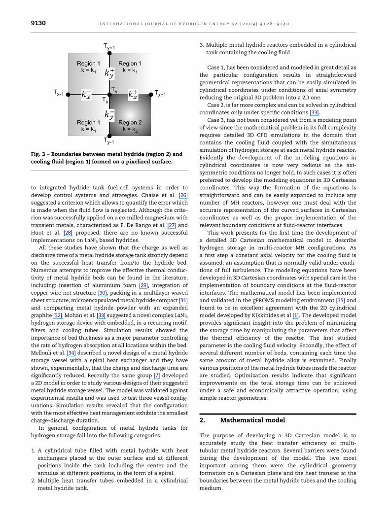
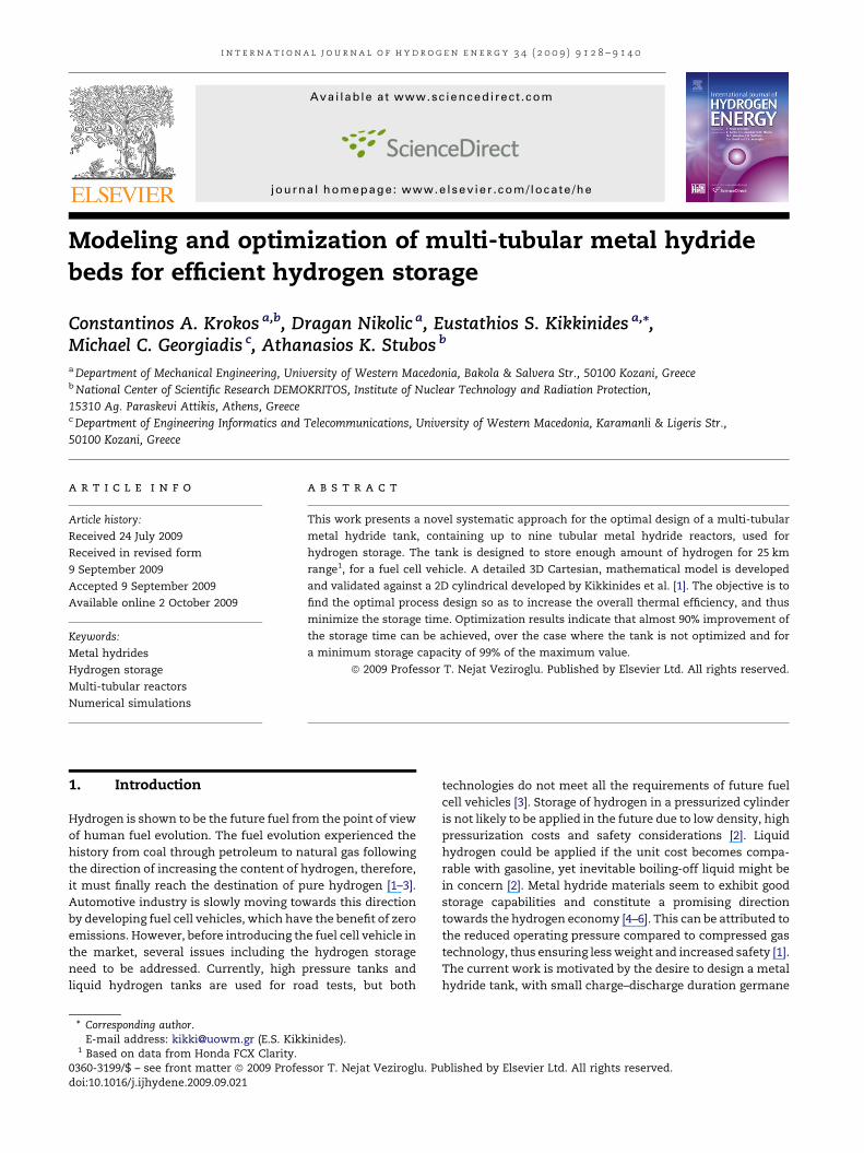
Fig. 3 – Boundaries between metal hydride (region 2) and
cooling fluid (region 1) formed on a pixelized surface.
i n t e r n a t i o n a l j o u r n a l o f h y d r o g e n e n e r g y 3 4 ( 2 0 0 9 ) 9 1 2 8 – 9 1 4 09130
to integrated hydride tank fuel-cell systems in order to
develop control systems and strategies. Chaise et al. [26]
suggested a criterion which allows to quantify the error which
is made when the fluid flow is neglected. Although the crite-
rion was successfully applied on a co-milled magnesium with
transient metals, characterized as P. De Rango et al. [27] and
Huot et al. [28] proposed, there are no known successful
implementations on LaNi5 based hydrides.
All these studies have shown that the charge as well as
discharge time of a metal hydride storage tank strongly depend
on the successful heat transfer from/to the hydride bed.
Numerous attempts to improve the effective thermal conduc-
tivity of metal hydride beds can be found in the literature,
including: insertion of aluminium foam [29], integration of
copper wire net structure [30], packing in a multilayer waved
sheet structure, microencapsulated metal hydride compact [31]
and compacting metal hydride powder with an expanded
graphite [32]. Mohan et al. [33] suggested a novel complex LaNi5hydrogen storage device with embedded, in a recurring motif,
filters and cooling tubes. Simulation results showed the
importance of bed thickness as a major parameter controlling
the rate of hydrogen absorption at all locations within the bed.
Mellouli et al. [34] described a novel design of a metal hydride
storage vessel with a spiral heat exchanger and they have
shown, experimentally, that the charge and discharge time are
significantly reduced. Recently the same group [7] developed
a 2D model in order to study various designs of their suggested
metal hydride storage vessel. The model was validated against
experimental results and was used to test three vessel config-
urations. Simulation results revealed that the configuration
with the most effective heat management exhibits the smallest
charge–discharge duration.
In general, configuration of metal hydride tanks for
hydrogen storage fall into the following categories:
1. A cylindrical tube filled with metal hydride with heat
exchangers placed at the outer surface and at different
positions inside the tank including the center and the
annulus at different positions, in the form of a spiral.
2. Multiple heat transfer tubes embedded in a cylindrical
metal hydride tank.
3. Multiple metal hydride reactors embedded in a cylindrical
tank containing the cooling fluid.
Case 1, has been considered and modeled in great detail as
the particular configuration results in straightforward
geometrical representations that can be easily simulated in
cylindrical coordinates under conditions of axial symmetry
reducing the original 3D problem into a 2D one.
Case 2, is far more complex and can be solved in cylindrical
coordinates only under specific conditions [33].
Case 3, has not been considered yet from a modeling point
of view since the mathematical problem in its full complexity
requires detailed 3D CFD simulations in the domain that
contains the cooling fluid coupled with the simultaneous
simulation of hydrogen storage at each metal hydride reactor.
Evidently the development of the modeling equations in
cylindrical coordinates is now very tedious as the axi-
symmetric conditions no longer hold. In such cases it is often
preferred to develop the modeling equations in 3D Cartesian
coordinates. This way the formation of the equations is
straightforward and can be easily expanded to include any
number of MH reactors, however one must deal with the
accurate representation of the curved surfaces in Cartesian
coordinates as well as the proper implementation of the
relevant boundary conditions at fluid-reactor interfaces.
This work presents for the first time the development of
a detailed 3D Cartesian mathematical model to describe
hydrogen storage in multi-reactor MH configurations. As
a first step a constant axial velocity for the cooling fluid is
assumed, an assumption that is normally valid under condi-
tions of full turbulence. The modeling equations have been
developed in 3D Cartesian coordinates with special care in the
implementation of boundary conditions at the fluid-reactor
interfaces. The mathematical model has been implemented
and validated in the gPROMS modeling environment [35] and
found to be in excellent agreement with the 2D cylindrical
model developed by Kikkinides et al [1]. The developed model
provides significant insight into the problem of minimizing
the storage time by manipulating the parameters that affect
the thermal efficiency of the reactor. The first studied
parameter is the cooling fluid velocity. Secondly, the effect of
several different number of beds, containing each time the
same amount of metal hydride alloy is examined. Finally
various positions of the metal hydride tubes inside the reactor
are studied. Optimization results indicate that significant
improvements on the total storage time can be achieved
under a safe and economically attractive operation, using
simple reactor geometries.
2. Mathematical model
The purpose of developing a 3D Cartesian model is to
accurately study the heat transfer efficiency of multi-
tubular metal hydride reactors. Several barriers were found
during the development of the model. The two most
important among them were the cylindrical geometry
formation on a Cartesian plane and the heat transfer at the
boundaries between the metal hydride tubes and the cooling
medium.
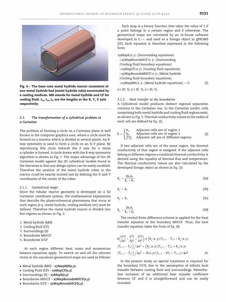
Fig. 4 – The base-case metal hydride reactor consistent of
one metal hydride bed (metal hydride tube) surrounded by
a cooling medium. MH stands for metal hydride and CF for
cooling fluid. Lx, Ly, Lz are the lengths at the X, Y, Z axis
respectively.
i n t e r n a t i o n a l j o u r n a l o f h y d r o g e n e n e r g y 3 4 ( 2 0 0 9 ) 9 1 2 8 – 9 1 4 0 9131
2.1. The transformation of a cylindrical problem toa Cartesian
The problem of forming a circle on a Cartesian plane is well
known in the computer graphics area, where a circle must be
formed on a monitor which is divided in several pixels. An 8-
way symmetry is used to form a circle on an X–Y plane. By
reproducing this circle towards the Z axis for n times
a cylinder is formed. A circle drawn with the 8-way symmetry
algorithm is shown in Fig. 1. The major advantage of the 3D
Cartesian model against the 2D cylindrical models found in
the literature is that any design option can be easily modeled.
Therefore the position of the metal hydride tubes in the
reactor could be exactly located just by defining the X and Y
coordinates of the center of the tubes.
2.1.1. Geometrical mapsSince the tubular reactor geometry is developed on a 3D
Cartesian coordinate system, the mathematical expressions
that describe the physicochemical phenomena that occur at
each region (e.q. metal hydride, cooling medium etc) must be
defined. Therefore the metal hydride reactor is divided into
five regions as shown in Fig. 2:
1. Metal hydride (MH)
2. Cooling fluid (CF)
3. Surroundings (S)
4. Boundaries MH/CF
5. Boundaries S/CF
At each region different heat, mass and momentum
balance equations apply. To switch on and off the relevant
terms in the equations geometrical maps are used as follows:
� Metal hydride (MH) – xyMapMH(x,y)
� Cooling Fluid (CF) – xyMapCF(x,y)
� Surroundings (S) – xyMapS(x,y)
� Boundaries MH/CF – xyMapBoundsMHCF(x,y)
� Boundaries S/CF – xyMapBoundsSCF(x,y).
Each map is a binary function that takes the value of 1 if
a point belongs in a certain region and 0 otherwise. The
geometrical maps are calculated by an in-house software
developed in Cþþ and used as a foreign object in gPROMS
[35]. Each equation is therefore expressed in the following
form:
xyMapSðx; yÞ fSurrounding equationsgþxyMapBoundsSCFðx; yÞ fSurrounding
=Cooling fluid boundary equationsgþxyMapCFðx; yÞ fCooling fluid equationsgþxyMapBoundsMHCFðx; yÞ fMetal hydride
=Cooling fluid boundary equationsgþxyMapMHðx; yÞ fMetal hydride equationsg ¼ 0 (1)
x ˛ (0, 1), y ˛ (0, 1), z ˛ (0, 1).
2.1.2. Heat transfer at the boundariesA Cylindrical model produces distinct regional separation
contrary to the Cartesian one. In the Cartesian model, cells
comprising both metal hydride and cooling fluid regions exist,
as shown in Fig. 3. Thermal conductivity values at the nodes of
each cell are defined by Eq. (2).
k ¼
8<:
k1; Adjacent cells are of region 1k2; Adjacent cells are of region 22k1k2k1þk2
; Adjacent cell are of different regions(2)
If two adjacent cells are of the same region, the thermal
conductivity of that region is assigned. If the adjacent cells
belong to different regions a combined thermal conductivity is
derived using the equality of thermal flux and temperature.
The thermal conductivity values are also calculated by the
developed foreign object as shown in Eq. (3)
kþx ¼2k1k2
k1 þ k2(3a)
k�x ¼ k1 (3b)
kþy ¼ k1 (3c)
k�y ¼2k1k2
k1 þ k2(3d)
The central finite difference scheme is applied for the heat
transfer equation at the boundary MH/CF. Thus, the heat
transfer equation takes the form of Eq. (4)
k
�v2Tvx2þ v2T
vy2þ v2T
vz2
�z�
kþx ðx; yÞðTxþ1 � TxÞ þ k�x ðx; yÞ
ðTx�1 � TxÞ�.
Dx2 þ�
kþy ðx; yÞ�Tyþ1 � Ty
�þ k�y ðx; yÞ�
Ty�1 � Ty
��.Dy2 þ ðkðx; yÞðTzþ1 � 2Tz þ Tz�1ÞÞ=Dz2 ð4Þ
In the present study no special treatment is required for
the boundary CF/S, due to the assumption of infinite heat
transfer between cooling fluid and surroundings. Neverthe-
less inclusion of an additional heat transfer coefficient
between CF and S is straightforward and can be easily
included.

Table 1 – List of basic model input parameters.
Parameter Units Value
Lz m 0.2
e dim/less 0.5
u0 m s�1 0.2
DH J mol�1 �29879
Cps J kg�1 K�1 429.1
Cpg J kg�1 K�1 14.3� 103
Cpf J kg�1 K�1 4184
K0 m2 1� 10�8
P0 Pa 1� 106
T0 K 290
m Pa s 8� 10�6
lg W m�1 K�1 0.12
ls W m�1 K�1 1.20
lf W m�1 K�1 0.60
h W m�2 K�1 1650
rs,0 kg m�3 4140
rf kg m�3 1000
a
b
i n t e r n a t i o n a l j o u r n a l o f h y d r o g e n e n e r g y 3 4 ( 2 0 0 9 ) 9 1 2 8 – 9 1 4 09132
2.2. Mathematical modeling of heat and mass transfer
The base case of a metal hydride reactor with one metal
hydride tube (bed), as shown in Fig. 4, is used for the presen-
tation of the mathematical model. The bed is considered to be
filled with a metal hydride alloy (namely LaNi5), surrounded by
cooling medium that flows with constant velocity towards the
a
b
Fig. 5 – Time evolution of the total hydrogen mass
absorbed for two cooling fluid velocities (a) 0 m/s, (b) 1 m/s,
for both Cartesian and Cylindrical models.
Fig. 6 – Time evolution of the average temperature in the
metal hydride beds for two cooling fluid velocities (a) 0 m/s,
(b) 1 m/s, for both Cartesian and Cylindrical models.
Z axis. The developed mathematical model is based in the
following assumptions:
� The ideal gas law holds in the gas phase.
� The solid and fluid temperatures are essentially equal.
� The axial pressure drop in the bed depends linearly on the
superficial velocity through Darcy’s Law.
� Infinite heat transfer between cooling fluid and
surroundings.
� Radial flow is neglected.
The latter assumption is justified from previous studies on
LaNi5 MHT, where the effect of convection is found to be
negligible compared to that of conduction of the Energy
balance [7,11]. Since in the present work hydrogen is assumed
to be introduced axially in the MHT, the axial velocity term is
taken into account (and the respective convection term). This
is also justified from previous studies which revealed that at
very short times and for special types of pressure charging,
the axial convection term may not be completely negligible.
On the other hand, the radial velocity term has been always
negligible in magnitude for the LaNi5 system and thus it was
not included in the model equation. This leads to significant
reduction in computational requirements, an important issue
as the number of MHT increases.
i n t e r n a t i o n a l j o u r n a l o f h y d r o g e n e n e r g y 3 4 ( 2 0 0 9 ) 9 1 2 8 – 9 1 4 0 9133
2.2.1. Mass balance of hydrogen in the gas phase
vbrvsþ 1
e
vðbrbuzÞvbz þW0
vbrs
vs¼ 0; (5)
where s, is the dimensionless time, s¼ t$Lz/u0, (Lz is the
modular reactor length, u0 is the reference velocity), bz stands
for the dimensionless axial distance, normalized by the total
bed length Lz ðbz ¼ z=LzÞ, buz is the axial superficial velocity,br ¼ r=r0 is the density of hydrogen in the gas phase, r0 being the
density at the bed inlet ðbz ¼ 0Þ, and brs is the solid (metal)
density of the alloy. W0 is a dimensionless parameter defined in
Section 2.2.7, and e is the void fraction of the bed.
2.2.2. Pressure drop equationThe steady state momentum balance of laminar gas flow
through a packed bed can be expressed by Darcy’s law.
buz ¼ �KzvbPvbz: (6)
where Kz is the dimensionless permeability value of the bed, bPis the dimensionless pressure ðbP ¼ P=P0Þ and P0 is the inlet
pressure. For the derivation of Eq. (6), it is assumed that the
transient and inertial velocity terms are negligible, according
a
b
Fig. 7 – Cooling fluid velocity effect on storage (a) and
cooling (b) duration, T0 [ 290 K.
to previous related studies on adsorption dynamics in fixed
beds [36].
2.2.3. Energy balance for the metal hydride bed
vðbrqÞvsþ Le
vðbrsqÞvs
� g
g� 1vbPvsþ 1
e
vðbrbuzqÞvbz �
�1
Pet
�V2q
�W0bvbrs
vs¼ 0; (7)
where q¼ T/T0 is the dimensionless gas temperature, T0 being
the temperature at the bed inlet. Le is the dimensionless Lewis
number expressing the ratio of the metal hydride heat
capacity over the gas heat capacity. Pet is the dimensionless
thermal Peclet number for the metal hydride bed.
2.2.4. Mass balance for the metal hydrideWe use the following kinetic scheme that has been successfully
employed for the case of LaNi5–H2 system [5,10–12,14,17–19]:
ð1� eÞvrs
vs¼ Catresexpð�ea=qÞln
� bPbPeq
��brsat � brs
�; (8)
where bPeq is the dimensionless equilibrium pressure, brsat is
the ‘‘saturated’’ bed density after complete reaction of the
alloy with H2 and ea is the dimensionless activation energy of
the reaction kinetics process.
2.2.5. Definition of equilibrium pressureFor the case of LaNi5–H2 system the equilibrium pressure is
defined as follows:
bPeq ¼ fðH=MÞ � exp
�DHR
�1
T0q� 1
Tref
�; (9)
where the function fðH=MÞ is the equilibrium pressure at the
reference temperature Tref. This is normally determined by
fitting the experimental data to a polynomial of nth degree. For
the case of LaNi5 available polynomial fits of 5th and 9th
degree are given in [10,12], respectively.
2.2.6. Energy balance for the cooling fluidThe cooling medium is assumed to flow at a constant axial
velocity (z-direction). The energy balance for the cooling fluid
is defined as follows:
vbTf
vs� 1
PetfV2 bTf þ
uf
u0
vbTf
vbz ¼ 0; (10)
where bTf is the dimensionless cooling fluid temperature and
uf being the cooling medium velocity. Petf is the dimensionless
thermal Peclet number for the cooling fluid.
2.2.7. Other auxiliary expressionsThe dimensionless form of the model introduces several
dimensionless parameters, which are defined below.
W0 ¼�
1� e
e
�$rs;0
r0
; (11)
Le ¼W0$Cps
Cpg(12)
b ¼ �DHT0$Cpg
; (13)

i n t e r n a t i o n a l j o u r n a l o f h y d r o g e n e n e r g y 3 4 ( 2 0 0 9 ) 9 1 2 8 – 9 1 4 09134
Lam ¼ e$lg þ ð1� eÞ$ls; (14)
Kz ¼K0$P0
m$u0$Lz; (15)
ea ¼Ea
Rg$T0; (16)
tres ¼Lz
u0; (17)
Pet;x ¼e$Cpg$r0$T0$u0$Lx
Lam; Pet;y ¼
e$Cpg$r0$T0$u0$Ly
Lam;
Pet;z ¼e$Cpg$r0$T0$u0$Lz
Lam; (18)
Petf;x ¼rf$Cpf$u0$Lx
lf; Petf;y ¼
rf$Cpf$u0$Ly
lf; Petf;z ¼
rf$Cpf$u0$Lz
lf:
(19)
Note that the operator V2, become, in the dimensionless
form:
V2C ¼ Lz
Lx
v2C
vbx2 þLz
Ly
v2C
vby2 þv2C
vbz2 : (20)
where bx and by are the dimensionless distances at the X and Y
direction respectively, normalized by the total bed length Lz,
ðbx ¼ x=Lz; by ¼ y=LzÞ. It should be noted that the aspect ratio
Lz/Lx and Lz/Ly does not appear in the 2nd power in Eq. (20)
because of the way the dimensionless time, s and the Peclet
numbers, Pet, Petf have been defined.
2.2.8. Boundary and initial conditionsThe boundary conditions between the metal hydride bed and
cooling fluid, and between cooling fluid and surroundings are
included in the model as described previously. The remaining
necessary boundary and initial conditions to complement the
model equations are given bellow.
At the modular reactor inlet ðbz ¼ 0Þ:Dirichlet boundary conditions:
br ¼ 1 (21a)
q ¼ 0 (21b)
bP ¼ 1 (21c)
bTf ¼ 0 (21d)
At the modular reactor outlet ðbz ¼ 1Þ:
vbrvbz ¼ 0 (22a)
vq
vbz ¼ 0 (22b)
vbP ¼ 0 (22c)
vbzbuz ¼ 0 (22d)vbTf
vbz ¼ 0 (22e)
Initial conditions ðs ¼ 0Þ
The metal hydride bed is initially assumed to contain no
hydrogen and to be at a temperature equal to the inlet
temperature. The cooling medium is initially assumed to flow
with constant velocity uf towards the z-direction and to be at
a temperature equal to ambient temperature.
3. Simulation results and discussion
The model of a hydrogen modular reactor comprises a set of
integral, partial differential and algebraic equations (IPDAEs).
It is solved numerically using gPROMS [35], a software package
for the modeling and simulation of processes combining
discrete and continuous characteristics. gPROMS allows the
direct modeling of systems described by a combination of
partial and/or ordinary differential equations combined if
necessary with algebraic ones. The solution method is based
on a two-phase method-of-lines approach. In the first phase
the spatial dimensions are discretized in terms of finite
dimensional representations and this reduces the IPDAEs into
sets of differential algebraic equations (DAEs). In the second
phase the DAEs are integrated over the time horizon of
interest using advanced techniques with stiff integrators. The
external software that develops the reactor geometry is
properly linked to the gPROMS model as a foreign object.
In this case spatial discretization is done manually using
central finite differences. The X and Y domains are discretized
using from 12 up to 40 cells/MHT diameter to describe the radial
geometry of the reactor(s) as accurately as possible. The Z
domain was discretized using only 10 points without sacrificing
the accuracy of the model due to the homogeneity of regions
through the Z-direction. All model equations have been imple-
mented in the gPROMS environment. Simulation runs in
gPROMS for the problem under question require about 20 min.
3.1. Model validation
The goal of this task is to validate the Cartesian model by
reproducing the results of the cylindrical model developed by
Kikkinides et al [1]. The base case of an external cooled reactor
with one metal hydride tube, as shown in Fig. 4, was simulated
using both models. All the data used in the simulations are
summarized in Table 1.
The first examined parameter was the temporal evolution of
the total hydrogen mass adsorbed. The results between the two
models and for two cooling fluid velocities, 0 m/s and 1 m/s, are
in excellent agreement, as shown in Fig. 5. Thus, it is concluded
that the present Cartesian model represents adequately the
cylindrical geometry of a metal hydride reactor and for this

a
b
Fig. 8 – Time-space evolution of temperature in the reactor
in the reactor. (a) Reactor with one metal hydride bed, (b)
reactor with five metal hydride beds. Axial z [ 0.5, t [ 50 s.
a
b
Fig. 9 – Number of metal hydride tubes effect on (a) storage
time and (b) cooling time, T0 [ 290 K.
i n t e r n a t i o n a l j o u r n a l o f h y d r o g e n e n e r g y 3 4 ( 2 0 0 9 ) 9 1 2 8 – 9 1 4 0 9135
reason it can be used in more complex geometries. A second
step was to study the temporal evolution of the average
temperature in the metal hydride bed, for two cooling fluid
velocities, 0 m/s and 1 m/s. The simulation results produced by
the two models, as shown in Fig. 6, are almost identical. Indeed
the error of the results produced by the 3D Cartesian model
against the results produced by the 2D cylindrical is less than 1%
thus indicating the accuracy of the 3D Cartesian model.
From the above results it is evident that the developed
Cartesian model can represent accurately the cylindrical
geometry of the MH storage tanks provided that we use a fine
enough resolution to describe the reactor’s cross-sectional area.
If the mesh resolution is not fine enough we may expect some
error in the treatment of the boundary layer at the powder bed/
wall interface. Nevertheless, this error is much smaller when
comparing volume averaged quantities including the average
amount of hydrogen stored in the MHT as a function of time. For
this reason extensive simulations have been performed using
a single MHT reactor to study the effect of resolution on the
average amount of hydrogen stored in the MHT. Our studies
have shown that for 15 cells/diameter, the relative error is
approximately 4.6% at small to medium storage times (70% of
maximumcapacity) dropping to 1.7% at large storage times (99%
of maximum storage). The error is still tolerable even for
12/cells/diameter becoming 7% and 2.9%, at small and large
times, respectively. The above trend remains when using more
than 1 MHT, so the impact on the reduction of storage time due
to thepresence ofmulti-tubularconfigurations isnot affectedby
errors in resolution. Obviously improvement of the resolution
can be easily achieved provided that the necessary resources of
computer memory are available.
3.2. Optimization of the thermal efficiency of the metalhydride reactor
There are two main factors affecting the storage efficiency of
a metal hydride reactor. The first factor is the type of the metal
hydride alloy used in the reactor, which defines the maximum
capacity of the tank. The second is the thermal efficiency,
which defines the time required for complete hydrogen
storage. In this case the metal hydride used in the simulations
is LaNi5 with a maximum theoretical capacity of 0.0138 kg
hydrogen/kg alloy. So, this work focused on the optimal heat
management of the reactor in order to minimize the storage
time. More specifically, first the cooling fluid velocity is
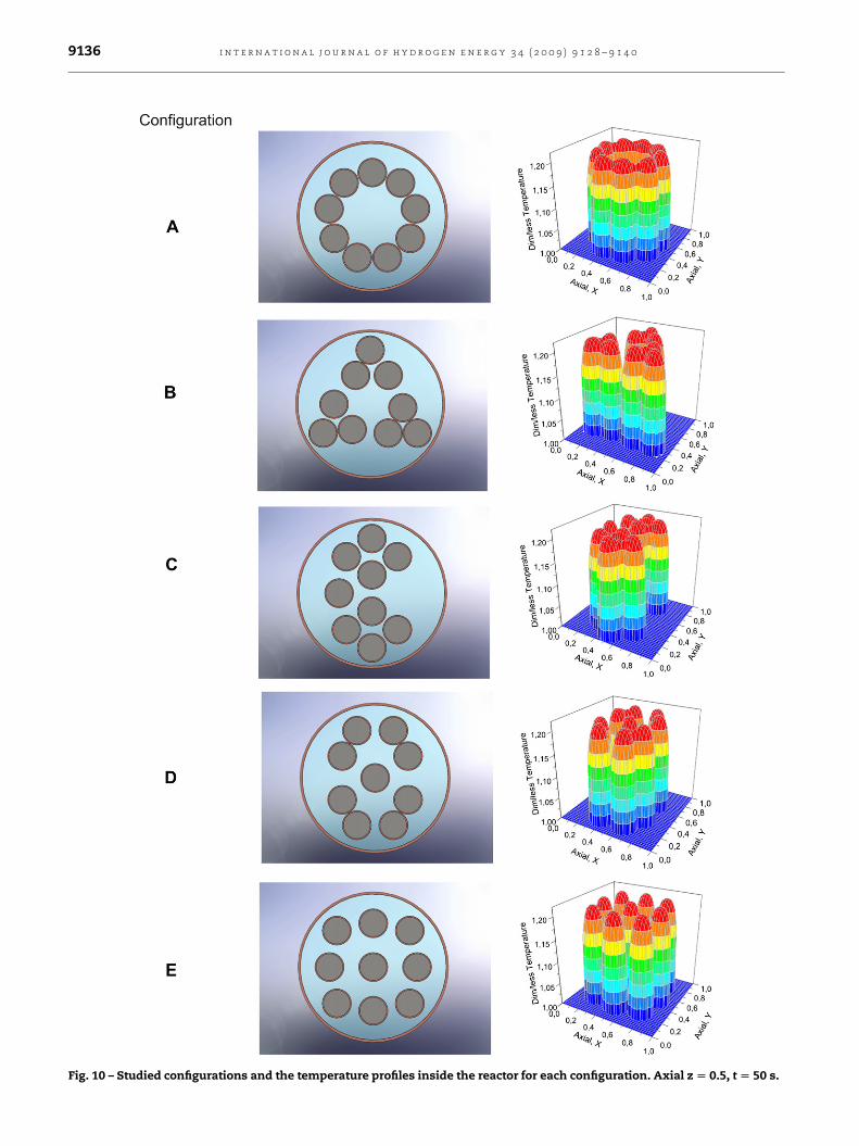
Fig. 10 – Studied configurations and the temperature profiles inside the reactor for each configuration. Axial z [ 0.5, t [ 50 s.
i n t e r n a t i o n a l j o u r n a l o f h y d r o g e n e n e r g y 3 4 ( 2 0 0 9 ) 9 1 2 8 – 9 1 4 09136

a
b
Fig. 11 – Configuration effect on (a) storage time and (b)
cooling time, T0 [ 290 K.
Fig. 12 – Metal hydride tanks. (a) The base-case tank, (b) the
optimized tank.
i n t e r n a t i o n a l j o u r n a l o f h y d r o g e n e n e r g y 3 4 ( 2 0 0 9 ) 9 1 2 8 – 9 1 4 0 9137
optimized followed by the number and positions of the metal
hydride tubes inside the reactor.
3.2.1. Effect of cooling fluid velocitySeveral cooling fluid velocities were studied for the base case
of the modular reactor shown in Fig. 4. The effect of cooling
fluid velocity on the storage time is shown in Fig. 7(a) while
Fig. 7(b) shows the effect of cooling fluid velocity on cooling
time, which is the time required for the temperature to drop to
a certain value. It is clear that the storage time depends
strongly on the amount of hydrogen adsorbed which in this
case is measured as the percentage of the maximum theo-
retical amount. It is clear that a limit cooling fluid velocity
exists, in this case 1 m/s, beyond which neither the storage
time nor the cooling time are affected.
The exothermic absorption process increases the temper-
ature in the metal hydride bed analogous to the formation
enthalpy of the hydride (DH¼�29879 J mol�1 for LaNi5 case).
The heat generated is then transported to the bed’s boundary
by conduction. The heat transfer rate from the metal hydride
alloy to the boundary is defined by the thermal conductivity of
the alloy (lMH¼ 0.66 W m�1 K�1 for LaNi5 case). The cooling
fluid rejects the available amount of heat from the boundary
to the environment. Increasing the cooling fluid velocity
increases the heat transfer rate from the metal hydride
boundary to the environment. The problem is that if the
cooling fluid velocity is increased above 1 m/s there is no
improvement on heat transfer rate because there is no avail-
able heat to be transferred. Conduction thus becomes the
limiting factor.
Despite the existence of a limiting cooling fluid velocity the
time required for 99% hydrogen storage changes from 6910 s
when the cooling fluid velocity is 0 m/s to 4780 s when the
cooling fluid velocity is 1 m/s, indicating an improvement of
30%. Similarly the time required for the temperature inside the
metal hydride tube, to drop to T/T0¼ 1.01 changes from 8200 s
to 5590 s indicating an improvement of 31%. Note that the tank
was designed to store enough amount of hydrogen for 25 km
using the 99% of its theoretical maximum storage capacity.
It should be noted that the assumption of constant cooling
velocity is only justified at high cooling fluid velocities. For
low cooling fluid velocities on the other hand it is better to
include an appropriate heat transfer coefficient to account for
the convective boundary layer effect. This is easy to imple-
ment but for the purposes of the present work, which is to
provide the methodology and tools to perform simulations
and optimizations of hydrogen storage using multi-tube
metal hydride reactor configurations, it will not change any
of the conclusions in a substantial manner. The developed
in-house software is relatively straightforward to build, easy
to implement and maintain and gives accurate results
compared to cylindrical geometries provided that the mesh is
fine enough. Furthermore an even more accurate treatment
would be to employ a commercial software that allows for

i n t e r n a t i o n a l j o u r n a l o f h y d r o g e n e n e r g y 3 4 ( 2 0 0 9 ) 9 1 2 8 – 9 1 4 09138
more suitable meshes and modeling of more complex flows
for the coolant, however, there are currently some compu-
tational difficulties and limitations in interfacing gPROMS
with such a software. Nevertheless this will be systematically
considered in a future work.
3.2.2. Effect of the number of metal hydride tubesIncreasing the cooling fluid velocity is not the panacea for the
reduction of storage time. More complicated, non-concentric
metal hydride reactor geometries should be studied to achieve
a further decrease of the storage time. The same amount of
metal hydride as the concentric reactor shown in Fig. 4, was
divided to 2, 3, 4, 5 and 9 tubes to test multi-tubular metal
hydride reactor geometries. It is essential to keep the amount
of metal hydride the same in order to ensure a constant
overall storage capacity of the tanks under consideration. The
cooling fluid velocity was also kept constant and equal to 1 m/
s for all the cases studied.
Fig. 8 shows that the division of the metal hydride alloy in
several tubes reduces the zones of the temperature gradients
that occur inside the reactor and thus improve the perfor-
mance of the storage time by reducing the time needed for
complete storage and release of hydrogen. Fig. 9 shows the
effect of the number of the metal hydride tubes on the
storage and cooling time. As the number of metal hydride
tubes increases, the time for complete storage decays expo-
nentially. More specifically the time required for 99%
hydrogen storage reduces from 4789 s, when one metal
hydride tube was used, to 2010 s when metal hydride was
divided to three metal hydride tubes, indicating an
improvement of 58%. If the number of tubes is increased to
nine then the time required for 99% storage becomes 1030 s
which represents a total improvement of 78%. Analogously
the time required for the temperature, inside the metal
hydride tubes, to drop to T/T0¼ 1.01 decreased from 5590 s,
when a single metal hydride tube was used, to 2350 s when
three metal hydride tubes were used, indicating an
improvement of 58%. When the number of tubes is increased
to nine then a further improvement of 48.9% on the cooling
time was achieved.
The improvement of cooling and storage time, when the
metal hydride is divided in several tubes is attributed to the
increment of the Surface/Volume ratio as the number of metal
hydride tubes increases. More specifically:
AV¼ 2$p$r$L
p$r2$L¼ 2
r; (23)
Note that the Surface/Volume ratio increases as the metal
hydride tube radius decreases.
3.2.3. Effect of metal hydride tubes position in the reactorIt is important to investigate if there is an ‘‘optimal’’ config-
uration (metal hydride tubes position in the reactor). Hence
we studied five different configurations for the case of the nine
metal hydride tubes reactor, to explore the effect of the posi-
tion of the tubes on the storage and cooling time. The five
studied configurations are shown in Fig. 10.
The effect of process configuration on cooling and
storage time is shown in Fig. 11. It is evident that the posi-
tion of the metal hydride tubes plays an important role
regarding the temperature profile inside the reactor.
Therefore the configuration with the best storage time is
configuration E, where the metal hydride tubes are placed in
such a manner so as the available space of the reactor
(where cooling fluid resides) is more efficiently utilized. So,
if they the tubes are not evenly distributed with respect to
each other and the storage container then the available
cooling fluid is not effectively utilized. For example in
configuration C the right part of the cross-sectional area is
not-well utilized as the cooling fluid in that region flows
without removing enough heat from the reactors. On the
other hand, the upper and lower regions are over-crowded
with MH reactors and as result there is not enough cooling
fluid per unit time to remove the produced heat due to
absorption of hydrogen in the neighboring MH reactors. If
the reactors touch each other we loose interfacial area of
reactor to fluid. More specifically the time required for 99%
hydrogen storage changes from 1030 s, for the configuration
A to 780 s when the configuration E was used, indicating an
improvement of 25%. Similarly the time required for the
temperature to drop to T/T0¼ 1.01 changed from 1200 s to
900 s implying an improvement of 25%.
In summary, it should be emphasized that the aim of the
present work is to provide a systematic methodology and
modeling tools to perform simulations and optimizations of
hydrogen storage using multi-tube metal hydride reactor
configurations. This has been illustrated by several cases. The
main modeling assumptions of this study relate to the use of
a constant cooling fluid velocity, the rather simple represen-
tation of the wall structure and the negligence of the radial
flow within the hydride bed. The latter has indeed been found
negligible in all cases studied. As for the remaining assump-
tions, they do not affect in any significant manner the
conclusions and principal goals of the work. While the quali-
tative tendencies found and the proposed methodology, do
not bear any dependence on these assumptions, it is true that
the actual calculated tank filling times carry an estimated
uncertainty of about 10–15% as a result of the simplifying
assumptions. On the other hand, a worth mentioning limita-
tion of the computational approach has to do with the mesh
resolution employed. As shown by extensive simulations that
were performed specifically to study the effect of resolution,
the errors induced are less than 10% in all cases, i.e. smaller
than the uncertainty imposed by the assumptions.
4. Conclusions
A 3D Cartesian mathematical model has been developed to
study complex metal hydride reactor geometries. The
Cartesian model has been validated and then used to study
the effect of three basic parameters on the storage and
cooling time of the tank. The first parameter is the cooling
fluid velocity whose optimal value found to 1 m/s. A further
step along this study was to explore the effect of the number
of the metal hydride tubes (for the same amount of metal
hydride alloy) on the storage and cooling time. Then the
effect of the number of metal hydride tubes and their posi-
tion was systematically studied. It was shown that the
configuration with nine tubes resulted in the highest

i n t e r n a t i o n a l j o u r n a l o f h y d r o g e n e n e r g y 3 4 ( 2 0 0 9 ) 9 1 2 8 – 9 1 4 0 9139
improvement on the storage and cooling time. The justifica-
tion of this trend is due to the fact that as the number of
metal hydride tubes increases the radius of the tubes
decreases and thus the Surface/Volume ratio increases.
Finally, the optimal position of the metal hydride tubes was
also studied. It was illustrated that the tubes should be
placed in a uniform manner to utilize more effectively the
available space in which the cooling medium resides that
leading to a more effective heat management.
The base-case tank and the optimized tank, both capable
for storing enough amount of hydrogen for 25 km range, are
shown in Fig. 12. The time required for 99% hydrogen storage
changed from 6910 s, for the base-case tank with cooling fluid
velocity 0 m/s, to 780 s, when the cooling fluid velocity, the
number of metal hydride tubes and the configuration of the
tubes in the reactor were optimized, indicating a total
improvement of 88.7%. Evidently the above figures could be
further improved if more efficient metal hydrides are applied
and this is the subject for a future work.
Acknowledgements
Financial support from the European Commission under the
DIAMANTE Marie Curie ToK project of FP6 (contract No: MTKI-
CT-2005-029544) is gratefully acknowledged. A. K. Stubos and
C.A. Krokos wish to acknowledge the EU/NESSHY Integrated
Project (SES6-518271) for partial financial support.
r e f e r e n c e s
[1] Kikkinides E, Georiadis M, Stubos A. On the optimization ofhydrogen storage in metal hydride beds. Int J HydrogenEnergy 2006;31(6):737–51.
[2] Zhou Li. Progress and problems in hydrogen storage methods.J Renewable Sustainable Energy Rev. 2005;9(4):395–408.
[3] Kikkinides ES. Hydrogen-based energy systems: the storagechallenge. In: Georgiadis MC, Kikkinides ES,Pistikopoulos EN, editors. Chapter 3. Weinheim: Wiley-VCHVerlag, ISBN 978-3-527-31694-6; 2008. p. 85–123.
[4] Mohanty KK. The near-term energy challenge. AIChE J 2003;49(10):2454–60.
[5] Kaplan Y, Veziroglou TN. Mathematical modelling ofhydrogen storage in LaNi5 hydride bed. Int J Energy Res 2003;27(11):1027–38.
[6] Sakintuna B, Lamari-Darkrim F, Hirscher M. Metal hydridematerials for solid hydrogen storage: a review. Int J HydrogenEnergy 2007;32(9):1121–40.
[7] Mellouli S, Askri F, Dhaou H, Jemni A, Nasrallah SB. Numericalstudy of heat exchanger effects on charge/discharge times ofmetal-hydrogen storage vessel. Int J Hydrogen Energy 2009;34(7):3005–17.
[8] Muthukumar P, Prakash Maiya M, Srinivasa Murthy S.Experiment on a metal hydride-based hydrogen storagedevice. Int J Hydrogen Energy 2005;30(15):1569–81.
[9] MacDonald B, Rowe A. Experimental and numerical analysisof dynamic metal hydride hydrogen storage systems. J PowerSources 2007;174(1):282–93.
[10] Jemni A, Nasrallah SB. Study of two-dimensional heat andmass transfer during absorption in a metal-hydrogenreactor. Int J Hydrogen Energy 1995;20(1):43–52.
[11] Nasrallah SB, Jemni A. Study of two-dimensional heat andmass transfer during desorption in a metal-hydrogenreactor. Int J Hydrogen Energy 1997;22(1):67–76.
[12] Jemni A, Nasrallah B, Lamloumi J. Experimental andtheoretical study of a metal-hydrogen reactor. Int J HydrogenEnergy 1999;24(7):631–44.
[13] Nakagawa T, Inomata A, Aoki H, Miura T. Numerical analysisof heat and mass transfer characteristics in the metalhydride bed. Int J Hydrogen Energy 2000;25(4):339–50.
[14] Mat MD, Kaplan Y. Numerical study of hydrogen absorptionin an LM–Ni5 hydride reactor. Int J Hydrogen Energy 2001;26(9):957–63.
[15] Demircan A, Demiralp M, Kaplan Y, Mat MD, Veziroglu TN.Experimental and theoretical analysis of hydrogenabsorption in LaNi5H2 reactors. Int J Hydrogen Energy 2005;30(13):1437–46.
[16] Kaplan Y. Effect of design parameters on enhancement ofhydrogen charging in metal hydride reactors. Int J HydrogenEnergy 2009;34(5):2288–94.
[17] Aldas K, Mat MD, Kaplan Y. A three-dimensional model forabsorption in a metal hydride bed. Int J Hydrogen Energy2002;27(10):1049–56.
[18] Mat MD, Kaplan Y, Aldas K. Investigation of three-dimensional heat and mass transfer in a metal hydridereactor. Int J Energy Research 2002;26(11):973–86.
[19] Askri F, Jemni A, Nasrallah SB. Study of two-dimensionaland dynamic heat and mass transfer in a metal-hydrogenreactor. Int J Hydrogen Energy 2003;28(5):537–57.
[20] Lozano AG, Eigen N, Keller C, Dornheim M, Bormann R.Effects of heat transfer on the sorption kinetics of complexhydride reacting systems. Int J Hydrogen Energy 2009;34(4):1896–903.
[21] Chung CA, Ci-Jyun Ho. Thermal-fluid behavior of the hydridingand dehydriding processes ina metal hydride hydrogenstoragecanister. Int J Hydrogen Energy 2009;34(10):4351–64.
[22] Askri F, Salah BM, Jemni A, Nasrallah BS. Optimization ofhydrogen storage in metal-hydride tanks. Int J HydrogenEnergy 2009;34(2):897–905.
[23] Gambini M, Manno M, Vellini M. Numerical analysis andperformance assessment of metal hydride-basedhydrogen storage systems. Int J Hydrogen Energy 2008;33(21):6178–87.
[24] Brown TM, Brouwer J, Samuelsen GS, Holcomb FH, King J.Accurate simplified dynamic model a metal hydride tank.Int J Hydrogen Energy 2008;33(20):5596–605.
[25] Mayer U, Groll M, Super W. Heat and mass transfer in metalhydride reaction beds: experimental and theoretical results.J Less Common Metals 1987;131(1–2):235–44.
[26] Chaise A, Marty P, De Rango P, Fruchart D. A simple criterionfor estimating the effect of pressure gradients duringhydrogen absorption in a hydride reactor. Int J Heat MassTransfer 2009;52(19–20):4564–72.
[27] de Rango P, Chaise A, Charbonnier J, Fruchart D, Jehan M,Marty P, et al. Nanostructured magnesium hydride for pilottank development. J Alloys Compounds 2007;446–447:52–7.
[28] Huot J, Liang G, Boily S, Van Neste A, Schultz R. Structural studyand hydrogen sorption kinetics of ball-milled magnesiumhydride. J Alloys Compounds 1999;293–295:495–500.
[29] Levesque S, Ciureanu M, Roberge R, Motyka T. Hydrogenstorage for fuel cell systems with stationary applications I.Transient measurement technique for packed bedevaluation. Int J Hydrogen Energy 2000;25(11):1095–105.
[30] Nagel M, Komazaki Y, Suda S. Effective thermal conductivityof a metal hydride bed augmented with a copper wire-netmatrix. J Less Common Metals 1987;131(1–2):426.
[31] Kim KJ, Lloyd G, Razani Jr A, Feldman KT. Thermal analysisof the Ca0.4Mm0.6Ni5 metal-hydride reactor. Applied ThermalEngineering 1998;18(12):1325–36.

i n t e r n a t i o n a l j o u r n a l o f h y d r o g e n e n e r g y 3 4 ( 2 0 0 9 ) 9 1 2 8 – 9 1 4 09140
[32] Kim KJ, Feldman Jr KT, Lloyd G, Razani A, Shanahan KL.Performance of high power metal hydride reactors.Int J Hydrogen Energy 1998;23(5):355–62.
[33] Mohan G, Maiya PM, Murthy SS. Performance simulation ofmetal hydride hydrogen storage device with embeddedfilters and heat exchanger tubes. Int J Hydrogen Energy 2007;32(18):4978–87.
[34] Mellouli S, Askri F, Dhaou H, Jemni A, Ben Nasrallah S.A novel design of a heat exchanger for a metal-hydrogenreactor. Int J Hydrogen Energy 2007;32(15):3501–7.
[35] gPROMS advanced users guide. London, UK: Process SystemsEnterprise Ltd.; 2004.
[36] Kikkinides ES, Yang RT. Effects of bed pressure drop onisothermal and adiabatic adsorber dynamics. Chem Eng Sci1993;48(9):1545–55.
Nomenclature
HM: dim/less hydrogen to metal atomic ratioK: permeabilityL: lengthLe: dim/less Lewis numberP: pressurePet: dim/less thermal Peclet numberPeq: equilibrium pressure
T: temperaturetres: residence timeu: velocityW0: dim/less parameter
Greek lettersb: dim/less parametere: void fractionea: dim/less activation energyr: densityq: dim/less temperature
s: dim/less time
Subscripts0: reference or inletf: cooling fluidg: gass: solidx: axial – Xy: axial – Y
z: axial – Z
Superscripts^: dim/less
Related Documents