137 Volume: 6, Issue: 2, Year : 2019 e-ISSN: 2148-6840 www.cjoscience.com Modeling and Optimal Trajectory Tracking Control of Wheeled a Mobile Robot Tayfun ABUT 1,* , Mesut HÜSEYİNOĞLU 2 1 Muş Alparslan University, Engineering and Architecture Faculty, Department of Mechanical Engineering, 49100, Muş, Turkey 2 Dicle University, Engineering Faculty, Department of Mechanical Engineering, 21280, Diyarbakır, Turkey Araştırma Makalesi Research Article Makine Mühendisliği Mechanical Engineering Geliş Tarihi/Received 22.05.2019 Kabul Tarihi/Accepted 25.11.2019 Abstract: Mobile robots have an unlimited workspace, unlike conventional fixed to the robot. Therefore, they are frequently studied from past to present. In this study, it is aimed to model wheeled a mobile robot(WMR) and realize optimal trajectory tracking control. Mathematical model of the robot was obtained. The Linear Quadratic Regulator (LQR) method, one of the optimum control methods for controlling the robot has been proposed. The Q and R parameters affecting the performance of the proposed control method were obtained by using the Firefly optimization algorithm. Both process noise and measurement noise have been added to control the robot in conditions close to the actual ambient conditions. As a result, in order to demonstrate the validity of the obtained model and the proposed control method, the robot was performed control in the simulation environment. The obtained results were given graphically and the results were examined. Keywords: Wheeled Mobile Robot(WMR), Mathematic Model, Optimal Trajectory Tracking, Lineer Quadratic Regulator(LQR), Firefly Algorithm. 1. INTRODUCTION Mobile robots have a wide range of application thanks to having an unlimited work area. Mobile robots can be used in many fields such as industry, space, military and social needs (vacuum cleaners and lawnmowers, etc.), which make people's lives easier, for entertainment and other purposes. In the control of mobile robots, the focus is generally on two main targets. These are a stable posture stabilization and trajectory tracking controller. The purpose of posture stabilization is to immobilize the robot to a reference point, the purpose of trajectory tracking is to allow the robot to follow a reference trajectory. In the study conducted in 1983, Brockett stated an opinion regarding whether nonholonomic mobile robot systems could be controlled through a smooth state feedback control (Brockett, 1983). Tayfun ABUT : ORCID:https://orcid.org/ 0000-0003-4646-3345 Mesut HÜSEYİNOĞLU : ORCID:https://orcid.org/ 0000-0002-6130-6658 Sorumlu Yazar/Corresponding Author E-mail: [email protected]

Welcome message from author
This document is posted to help you gain knowledge. Please leave a comment to let me know what you think about it! Share it to your friends and learn new things together.
Transcript
137
Volume: 6, Issue: 2, Year : 2019 e-ISSN: 2148-6840 www.cjoscience.com
Modeling and Optimal Trajectory Tracking Control of Wheeled a Mobile
Robot
Tayfun ABUT1,*, Mesut HÜSEYİNOĞLU2
1Muş Alparslan University, Engineering and Architecture Faculty, Department of Mechanical Engineering, 49100,
Muş, Turkey
2Dicle University, Engineering Faculty, Department of Mechanical Engineering, 21280, Diyarbakır, Turkey
Araştırma Makalesi
Research Article
Makine Mühendisliği
Mechanical Engineering
Geliş Tarihi/Received
22.05.2019
Kabul Tarihi/Accepted
25.11.2019
Abstract: Mobile robots have an unlimited workspace, unlike conventional fixed to the robot. Therefore, they are
frequently studied from past to present. In this study, it is aimed to model wheeled a mobile robot(WMR) and
realize optimal trajectory tracking control. Mathematical model of the robot was obtained. The Linear Quadratic
Regulator (LQR) method, one of the optimum control methods for controlling the robot has been proposed. The Q
and R parameters affecting the performance of the proposed control method were obtained by using the Firefly
optimization algorithm. Both process noise and measurement noise have been added to control the robot in
conditions close to the actual ambient conditions. As a result, in order to demonstrate the validity of the obtained
model and the proposed control method, the robot was performed control in the simulation environment. The
obtained results were given graphically and the results were examined.
Keywords: Wheeled Mobile Robot(WMR), Mathematic Model, Optimal Trajectory Tracking, Lineer Quadratic
Regulator(LQR), Firefly Algorithm.
1. INTRODUCTION
Mobile robots have a wide range of application thanks to having an unlimited work
area. Mobile robots can be used in many fields such as industry, space, military and social
needs (vacuum cleaners and lawnmowers, etc.), which make people's lives easier, for
entertainment and other purposes. In the control of mobile robots, the focus is generally on
two main targets. These are a stable posture stabilization and trajectory tracking controller.
The purpose of posture stabilization is to immobilize the robot to a reference point, the
purpose of trajectory tracking is to allow the robot to follow a reference trajectory. In the
study conducted in 1983, Brockett stated an opinion regarding whether nonholonomic mobile
robot systems could be controlled through a smooth state feedback control (Brockett, 1983).
Tayfun ABUT : ORCID:https://orcid.org/ 0000-0003-4646-3345
Mesut HÜSEYİNOĞLU : ORCID:https://orcid.org/ 0000-0002-6130-6658
Sorumlu Yazar/Corresponding Author E-mail: [email protected]
Modeling and Optimal Trajectory Tracking Control of Wheeled a Mobile Robot
138
Hamel et al. proposed a control method resistant to localization errors of mobile robots
(Hamel and Dominique, 1996). In another method proposed in the literature, a technical
tracking controller with recoil recursion was used (Jiang and Nijmeijer, 1999; Fu et al., 2013).
Xin et al. designed a disturbance observer and an adaptive stabilizer in order to cope with the
uncertainties of wheeled mobile robots (Xin et al., 2016). Canale et al. handled the problem of
the rapid implementation of a nonlinear predictive control model with function approach
techniques (Canale et al., 2010). Bessas et al. proposed the integral sliding mode control
method in order to solve the problem of accessing the sliding surface used in the sliding mode
control method, and to enable an effective trajectory tracking control (Bessas et al., 2016).
Wu and Karkoub proposed the method of hierarchical fuzzy sliding mode adaptive control for
trajectory tracking of differentially driven mobile robots (Wu and Karkoub, 2019). In the
literature, various studies on mobile robots have been conducted and continue to be conducted
by researchers (Yang and Kim, 1999; Kara et al., 1999; Wu et al., 2019, Tian and Sarkar,
2014; Li et al., 2015, Atan, 2019). In this study, it was aimed to model a wheeled mobile
robot (WMR) and to perform optimum tracking control. The mathematical model of the robot
was obtained. The Linear Quadratic Regulator (LQR) method, which is one of the optimum
control methods, was proposed to control the robot. Both process noise and measurement
noise were added to control the robot under the conditions close to real environment
conditions. As a result, to demonstrate the validity of the obtained model and the proposed
control method, the control of the robot was performed in the simulation environment. The
results obtained were graphically given and examined. A second-order low-pass filter was
designed to improve control performance of the robot under the conditions close to real
environment conditions. The control methods applied according to the results of the obtained
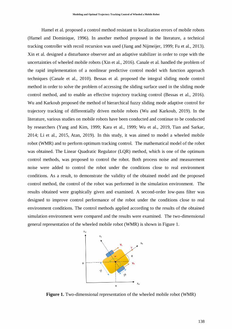
simulation environment were compared and the results were examined. The two-dimensional
general representation of the wheeled mobile robot (WMR) is shown in Figure 1.
Figure 1. Two-dimensional representation of the wheeled mobile robot (WMR)
Abut & Hüseyinoğlu / Caucasian Journal of Science 6 (2), (2019), 137-146
139
2. SYSTEM PREVIEW AND MODELING
In the literature, mobile robots are studied depending on different wheel designs and
types. The robot used in this study consists of two independent wheels on the right and left.
Generally, the motion of the system is performed by controlling the angular velocities of the
dc motors connected to these wheels. Changing the orientations by moving on a curved
trajectory or turning around by adjusting the angular velocities of two driving wheels is only
one of the abilities of WMRs. To apply high-performance controllers in the control of a robot,
the robot must be modeled. On a mobile robot with a differential drive, it is possible to apply
the kinematic control approach provided that suitable conditions without sliding are selected.
The kinematic model used for a two-wheeled mobile robot in Figure 1 is based on the
assumption that the wheels move without sliding. Accordingly, the velocity references given
to the actuators on the wheels enable the robot to move at linear and angular velocities
corresponding to these references. In Figure 1, the robot coordinate framework was accepted
as the center of mass of WMR located on the point C and used as the origin of XR and YR. The
robot used in this study has two control variables; these are the angular velocities of the right
and left wheels. In Figure 1, the linear velocity of the left wheel is shown with VL and linear
velocity of the right wheel is shown with VR. Similarly, the angular velocities of the left and
right wheels are ωL and ωR, respectively. R is the radius of the wheel, 2L is the distance
between the wheels and 2L is the distance between the endpoint of the robot and point C
which is the geometric center of the robot. The orientation angle of the mobile robot
according to the XW-YW coordinate axis is θ. The following equations were obtained for
linear and angular velocities
𝑉 =𝑉𝑅+𝑉𝐿
2 (1)
𝑉 = 𝜔 ∗ 𝑅 (2)
𝑉𝑅 = 𝜔𝑅 ∗ 𝑅, 𝑉𝐿 = 𝜔𝐿 ∗ 𝑅 (3)
𝜔𝑅 =𝑉𝑅
𝑅−𝐿 (4)
𝜔𝐿 =𝑉𝐿
𝑅+𝐿 (5)
State equations of the mobile robot according to the XW-YW coordinate axis were expressed
as follows.
Modeling and Optimal Trajectory Tracking Control of Wheeled a Mobile Robot
140
[�̇��̇�
�̇�
] = [𝑐𝑜𝑠𝜃 0sin 𝜃 0
0 1] [
𝑣𝜔
] (6)
In this study, the method of Lagrange multipliers was used to obtain the mathematical model
of WMR (Bertsekas,1999).
𝑀(𝑞𝑚)�̈�𝑚 + C(𝑞𝑚 , �̇�𝑚)�̇�𝑚 + 𝐺𝑚(𝑞𝑚) + 𝜏𝑑 = 𝐵𝑚(𝑞𝑚)𝜏 − 𝐴𝑇(𝑞𝑚)Λ (7)
𝑞𝑚(𝑥, 𝑦, 𝜃) indicates the position and orientation angle in X and Y directions,
respectively. 𝑀(𝑞𝑚) ∈ 𝑅3∗3 is a positive definite symmetric matrix and shows inertia matrix ;
𝐶(𝑞𝑚) ∈ 𝑅3∗3 shows Coriolis and centrifugal forces matrix; 𝐺(𝑞𝑚) ∈ 𝑅3∗3 indicates the
forces of gravity. In addition, 𝐵(𝑞𝑚), 𝐴(𝑞𝑚), 𝜏 𝑣𝑒 Λ shows the input matrix, kinematic
constraint matrix, input vector and Lagrange multiplier. Table I is shown physical parameter
of WMR.
3. CONTROLLER DESIGN
The main objective for designing the control system of the mobile robot is stability
and low tracking error. In the control of WMR, Linear Quadratic Regulator (LQR) control
method was used. The aim of the control methods used is to ensure that the output value of
the system tracks the targeted (reference) value. Error is tried to be minimized with the
controller applied to the system.
Table 1. Physical Parameter of WMR
Description and symbol Units and value
Mass of car (m) 1 (kg)
Wheels Distance (L) 0.28 m
Radius of Wheels (R) 0.143 m
Inertia (I) 0.15 g-m2
3.1. LQR (Linear Quadratic Regulator) Control Method
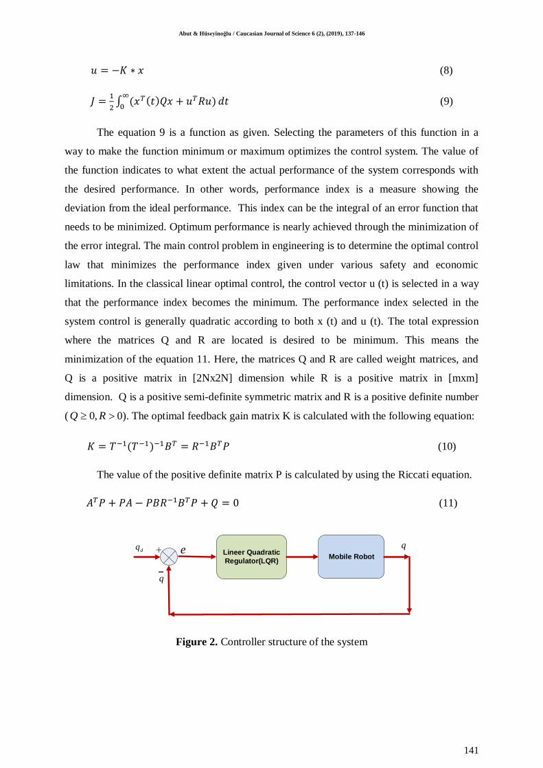
LQR control method is a modern control method that is used to control a system. This
control method is widely used in the literature in optimal control problems (Anderson 2007;
Abut,2016). The purpose of the control here is to minimize the integral of the quadratic
performance index. In Figure 2, a block diagram of the linear quadratic regulator (LQR)
control method is shown.
Abut & Hüseyinoğlu / Caucasian Journal of Science 6 (2), (2019), 137-146
141
𝑢 = −𝐾 ∗ 𝑥 (8)
𝐽 =1
2∫ (𝑥𝑇(𝑡)𝑄𝑥 + 𝑢𝑇𝑅𝑢)
∞
0𝑑𝑡 (9)
The equation 9 is a function as given. Selecting the parameters of this function in a
way to make the function minimum or maximum optimizes the control system. The value of
the function indicates to what extent the actual performance of the system corresponds with
the desired performance. In other words, performance index is a measure showing the
deviation from the ideal performance. This index can be the integral of an error function that
needs to be minimized. Optimum performance is nearly achieved through the minimization of
the error integral. The main control problem in engineering is to determine the optimal control
law that minimizes the performance index given under various safety and economic
limitations. In the classical linear optimal control, the control vector u (t) is selected in a way
that the performance index becomes the minimum. The performance index selected in the
system control is generally quadratic according to both x (t) and u (t). The total expression
where the matrices Q and R are located is desired to be minimum. This means the
minimization of the equation 11. Here, the matrices Q and R are called weight matrices, and
Q is a positive matrix in [2Nx2N] dimension while R is a positive matrix in [mxm]
dimension. Q is a positive semi-definite symmetric matrix and R is a positive definite number
( 0,Q R 0). The optimal feedback gain matrix K is calculated with the following equation:
𝐾 = 𝑇−1(𝑇−1)−1𝐵𝑇 = 𝑅−1𝐵𝑇𝑃 (10)
The value of the positive definite matrix P is calculated by using the Riccati equation.
𝐴𝑇𝑃 + 𝑃𝐴 − 𝑃𝐵𝑅−1𝐵𝑇𝑃 + 𝑄 = 0 (11)
Lineer Quadratic
Regulator(LQR)Mobile Robot
dq e
q
q
Figure 2. Controller structure of the system
Modeling and Optimal Trajectory Tracking Control of Wheeled a Mobile Robot
142
3.2. Firefly Optimization Algorithm
Various methods are applied to design and control the systems at optimal values. In this
context, Firefly Optimization Algorithm, which is one of the metaheuristic optimization
algorithm types and is actively researched in recent years, is an algorithm type developed by
Yang (Yang ,2010; Yang, et al.,2013). This algorithm is used for the optimization of various
problems (Olivares, et al.,2014; Patle, et al.,2017; Patle, et al.,2018; Lagunes, et al.,2019).
The Firefly Algorithm inspired by the flashing patterns of fireflies in nature is based on the
principle of moving to a random direction. According to the level of brightness, fireflies can
affect the opposite sex or may scare the predators depending on the speed of flashing. They
also use these biological flashing activities to attract their preys. Certain assumptions have
been made in this optimization algorithm.
1) All fireflies are accepted as unisexual, so they are attracted to each other
independently.
2) Attractiveness is determined by brightness; a less bright firefly moves toward a more
bright one.
3) The brightness (objective) function of a firefly is proportional to the fitness function
that produces the brightest value.
In this method, there are two important parameters. One of them is the change in the light
intensity and the other is the attractiveness of the firefly. In a simple form, according to the
inverse-square law, the change of the light intensity obtained at a distance of r from a light
source is given in the equation 12.
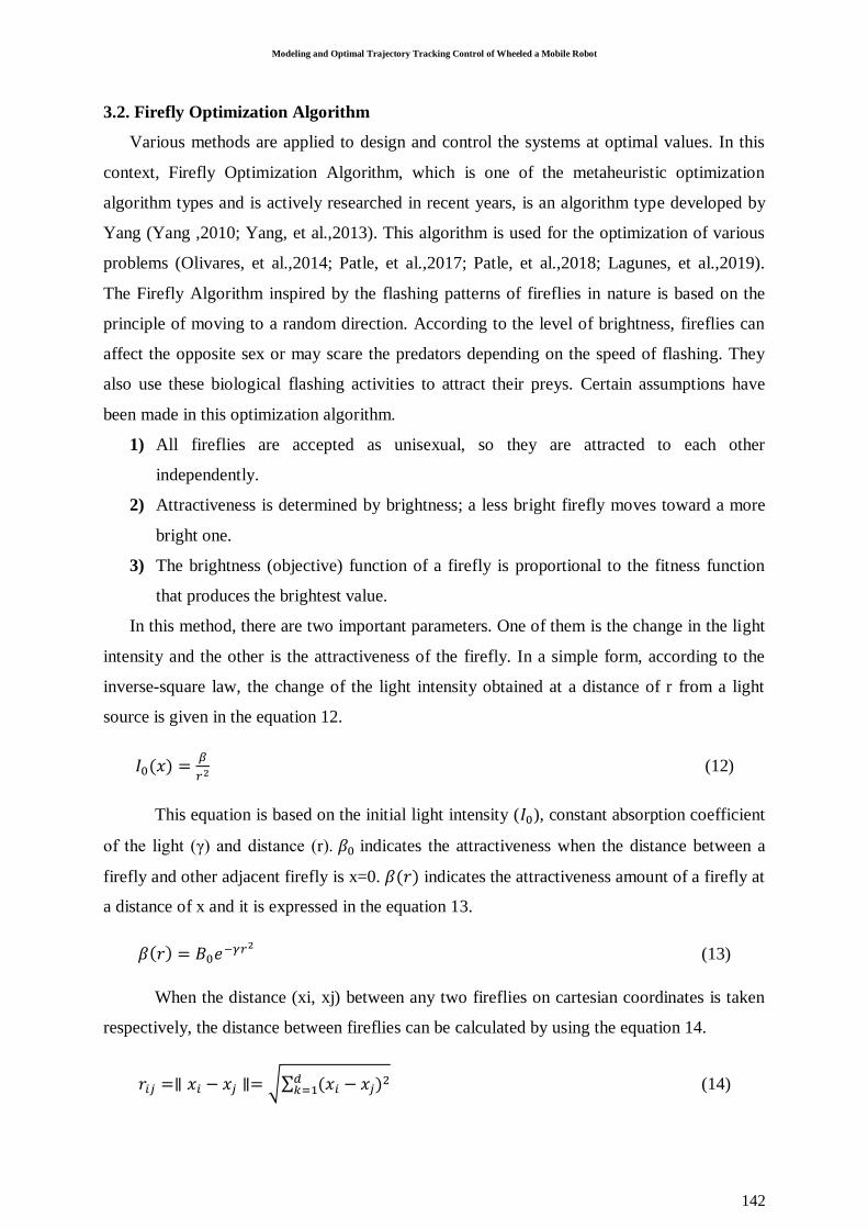
𝐼0(𝑥) =𝛽
𝑟2 (12)
This equation is based on the initial light intensity (𝐼0), constant absorption coefficient
of the light (γ) and distance (r). 𝛽0 indicates the attractiveness when the distance between a
firefly and other adjacent firefly is x=0. 𝛽(𝑟) indicates the attractiveness amount of a firefly at
a distance of x and it is expressed in the equation 13.
𝛽(𝑟) = 𝐵0𝑒−𝛾𝑟2 (13)
When the distance (xi, xj) between any two fireflies on cartesian coordinates is taken
respectively, the distance between fireflies can be calculated by using the equation 14.
𝑟𝑖𝑗 =∥ 𝑥𝑖 − 𝑥𝑗 ∥= √∑ (𝑥𝑖 − 𝑥𝑗)2𝑑𝑘=1 (14)
Abut & Hüseyinoğlu / Caucasian Journal of Science 6 (2), (2019), 137-146
143
The distance between fireflies, for example, the distance between the ith firefly and jth
firefly, can be determined by using the equation 15. Distance is important since it affects light
intensity and attractiveness and determines the direction of fireflies.
𝑥𝑖 = 𝑥𝑖 + 𝐵0𝑒−𝛾𝑟2(𝑥𝑖 − 𝑥𝑗) + 𝛼𝜀𝑖 (15)
The first term in the right of the equation 15 indicates the current position of the firefly,
the second term establishes a relation between the light intensity seen by the adjacent fireflies
and attractiveness of the current firefly and the last term represents a random movement to be
made when there is not a more attractive firefly around the current firefly. 𝛼 indicates the
coefficient taking a constant value in the range of random parameter [0,1] and 𝜀𝑖 shows a
Gauss distribution vector drawn with random numbers in the range of [0,1].
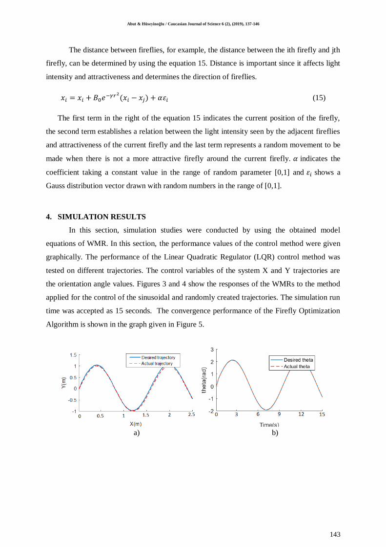
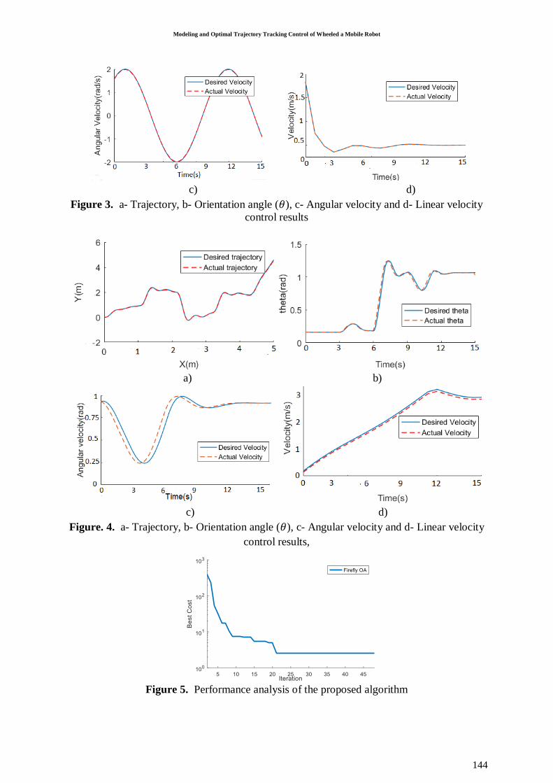
4. SIMULATION RESULTS
In this section, simulation studies were conducted by using the obtained model
equations of WMR. In this section, the performance values of the control method were given
graphically. The performance of the Linear Quadratic Regulator (LQR) control method was
tested on different trajectories. The control variables of the system X and Y trajectories are
the orientation angle values. Figures 3 and 4 show the responses of the WMRs to the method
applied for the control of the sinusoidal and randomly created trajectories. The simulation run
time was accepted as 15 seconds. The convergence performance of the Firefly Optimization
Algorithm is shown in the graph given in Figure 5.
a) b)
Modeling and Optimal Trajectory Tracking Control of Wheeled a Mobile Robot
144
c) d)
Figure 3. a- Trajectory, b- Orientation angle (𝜃), c- Angular velocity and d- Linear velocity
control results
a) b)
c) d)
Figure. 4. a- Trajectory, b- Orientation angle (𝜃), c- Angular velocity and d- Linear velocity
control results,
Figure 5. Performance analysis of the proposed algorithm
Abut & Hüseyinoğlu / Caucasian Journal of Science 6 (2), (2019), 137-146
145
Figures 3-a, b, c, and d show trajectory, orientation angle, angular velocity, and linear
velocity responses, respectively. Figures 4-a, b, c, and d show trajectory, orientation angle,
angular velocity, and linear velocity responses, respectively. For the trajectory tracking
control of WMR, both kinematic and dynamic models were considered. In the section of
kinematic control, the position deviations in the target trajectory were eliminated and
accordingly, the desired velocity was generated as output in the dynamic controller. The
tracking error of LQR was observed to be low on both trajectories. System iteration number
was taken as 50. However, it was observed that the algorithm proposed in the graph given in
Figure 5 reached the best solution in the 21st iteration. Another important parameter is that
the algorithm used in this study is fast. In the simulations, it was seen that the control
performance showing fastness, smoothness and robustness was obtained in the LQR control
method.
5. DISCUSSION AND CONCLUSION
In this study, the mathematical model of a wheeled mobile robot (WMR) was obtained
and control studies were conducted in the simulation environment. For the control of WMR,
the design and simulation of LQR control method were performed. Determining the matrices
Q and R when designing an LQR control method is one of the main problems that decrease
performance. By using the Firefly Optimization Algorithm, optimum matrices Q and R were
obtained and applied successfully. The second-order low-pass filter design was made and
applied to enable an effective control under the effect of process and measurement noises
added to perform the control of WMR under the conditions close to real environment
conditions. The results of the control method showed that the controller gave satisfactory
results. In future studies, it is aimed to apply the proposed method on a real robot
REFERENCES
Abut T. (2016). Modeling and Optimal Control of a DC Motor. International Journal of Engineering Trends and
Technology, 32(3), 146-150.
Anderson B.D., Moore J.B. (2007). Optimal control: linear quadratic methods. Courier Corporation.
Atan O. (2019). Fuzzy Variable Order Extremum-Seeking Controller Design for Mobile Robots. Balkan Journal
of Electrical and Computer Engineering, 7(1), 81-87.
Bertsekas D. P. (2014). Constrained optimization and Lagrange multiplier methods. Academic press.
Bessas A., Benalia A., Boudjema F. (2016). Integral sliding mode control for trajectory tracking of wheeled
mobile robot in presence of uncertainties. Journal of Control Science and Engineering, 2016.
Modeling and Optimal Trajectory Tracking Control of Wheeled a Mobile Robot
146
Brockett, R. W. (1983). Asymptotic stability and feedback stabilization. Differential geometric control
theory, 27(1), 181-191.
Canale, M., Fagiano, L.,Milanese, M. (2010). Efficient model predictive control for nonlinear systems via
function approximation techniques. IEEE Transactions on Automatic Control, 55(8), 1911-1916.
Fu, J., Chai, T., Su, C. Y., Jin, Y. (2013). Motion/force tracking control of nonholonomic mechanical systems
via combining cascaded design and backstepping. Automatica, 49(12), 3682-3686.
Hamel, T., Meizel, D. (1996). Robust control laws for wheeled mobile robots. International journal of systems
science, 27(8), 695-704.
Jiang, Z. P., Nijmeijer, H. (1999). A recursive technique for tracking control of nonholonomic systems in
chained form. IEEE Transactions on Automatic control, 44(2), 265-279.
Kara, S. E., Arıkan, K. B. (2019). İki tekerlekli ve tek kollu robotik platformun kayan kipli denetimi ve
parametre optimizasyonu. DÜMF Mühendislik Dergisi, 10(2), 591-601.
Lagunes, M. L., Castillo, O., Soria, J., Garcia, M., Valdez, F. (2019). Optimization of granulation for fuzzy
controllers of autonomous mobile robots using the Firefly Algorithm. Granular Computing, 4(2), 185-
195.
Li, C., Qu, Z., Weitnauer, M. A. (2015). Distributed extremum seeking and formation control for nonholonomic
mobile network. Systems & Control Letters, 75, 27-34.
Olivares-Suarez, M., Palma, W., Paredes, F., Olguín, E., Norero, E. (2014). A binary coded firefly algorithm that
solves the set covering problem. Science and Technology, 17(3), 252-264.
Patle, B. K., Parhi, D. R., Jagadeesh, A., Kashyap, S. K. (2017). On firefly algorithm: optimization and
application in mobile robot navigation. World Journal of Engineering, 14(1), 65-76.
Patle, B. K., Pandey, A., Jagadeesh, A., Parhi, D. R. (2018). Path planning in uncertain environment by using
firefly algorithm. Defence technology, 14(6), 691-701.
Tian, Y., Sarkar, N. (2014). Control of a mobile robot subject to wheel slip. Journal of Intelligent & Robotic
Systems, 74(3-4), 915-929.
Wu, H. M., Karkoub, M. (2019). Hierarchical Fuzzy Sliding-Mode Adaptive Control for the Trajectory Tracking
of Differential-Driven Mobile Robots. International Journal of Fuzzy Systems, 21(1), 33-49.
Wu, X., Jin, P., Zou, T., Qi, Z., Xiao, H., Lou, P. (2019). Backstepping Trajectory Tracking Based on Fuzzy
Sliding Mode Control for Differential Mobile Robots. Journal of Intelligent & Robotic Systems, 1-13.
Xin, L., Wang, Q., She, J., Li, Y. (2016). Robust adaptive tracking control of wheeled mobile robot. Robotics
and Autonomous Systems, 78, 36-48.
Yang, J. M., Kim, J. H. (1999). Sliding mode control for trajectory tracking of nonholonomic wheeled mobile
robots. IEEE Transactions on robotics and automation, 15(3), 578-587.
Yang, X. S. (2010). Nature-inspired metaheuristic algorithms. Luniver press.
Yang, X. S., He, X. (2013). Firefly algorithm: recent advances and applications. arXiv preprint arXiv:1308.3898.
Related Documents


![[EN-A-073] Robust Optimal Trajectory Planning under ...](https://static.cupdf.com/doc/110x72/6211df51e743c86aea630c41/en-a-073-robust-optimal-trajectory-planning-under-.jpg)

