Modeling and Fatigue Analysis of Automotive Wheel Rim CHAPTER 1 INTRODUCTION 1.1 History of Wheel/Rim Several thousand years ago was the start of the history of wheel when the human race began to use the log to transport heavy objects. The original of the wheel were the round slices of a log and it was gradually re-inforced and used in this form for centuries on both carts and wagons. This solid disc changed to a design having several spokes radially arranged to support the outer part of the wheel keeping it equidistant from the wheel centre. A wooden wheel which used hard wood stakes as spokes was very popular as a wheel for many vehicles up to about 1920. Afterwards the disc wheel, in which the spokes were replaced with a disc made of steel plate, was introduced and is still being used to this day. Furthermore, a light alloy has come to be used currently as a wheel material for many types of vehicle. Trucks have been basic backbone of the world's workforce for decades. They're big, powerful, and can really get you through the roughest of terrains. But a truck can't do its job without properly functioning wheels. Truck rims need to be replaced if they're bent or cracked for the sake of your truck's life - and sometimes just for an upgrade. Knowing your truck rim options will greatly assist you in this process. 1

Modeling and Fatigue Analysis of Automotive Wheel Rim
Feb 08, 2016
Modeling and Fatigue Analysis of Automotive Wheel Rim
Welcome message from author
This document is posted to help you gain knowledge. Please leave a comment to let me know what you think about it! Share it to your friends and learn new things together.
Transcript

Modeling and Fatigue Analysis of Automotive Wheel Rim
CHAPTER 1
INTRODUCTION1.1 History of Wheel/Rim
Several thousand years ago was the start of the history of wheel when the human race
began to use the log to transport heavy objects. The original of the wheel were the round
slices of a log and it was gradually re-inforced and used in this form for centuries on both
carts and wagons.
This solid disc changed to a design having several spokes radially arranged to support the
outer part of the wheel keeping it equidistant from the wheel centre.
A wooden wheel which used hard wood stakes as spokes was very popular as a wheel for
many vehicles up to about 1920.
Afterwards the disc wheel, in which the spokes were replaced with a disc made of steel
plate, was introduced and is still being used to this day.
Furthermore, a light alloy has come to be used currently as a wheel material for many
types of vehicle.
Trucks have been basic backbone of the world's workforce for decades. They're big,
powerful, and can really get you through the roughest of terrains. But a truck can't do its
job without properly functioning wheels. Truck rims need to be replaced if they're bent or
cracked for the sake of your truck's life - and sometimes just for an upgrade. Knowing
your truck rim options will greatly assist you in this process.
Most steel truck rims are created in the same way. It starts with a hard cast hub, with 4, 5
or even 6 holes for the bolts. A spun steel rim is then secured around this with a series of
welds. The rim is properly balanced and then given a smooth finish. Although some steel
rims are available in silver and chrome, most of those finishes are saved for alloy wheels.
Truck wheels need to be durable and able to carry around weight. You won't find many
spoke designs with these rims. They're usually as solid as possible. But that doesn't mean
your options aren't varied when looking for replacements. The most important thing to
remember is to purchase the same size rims you're replacing unless you're also planning
on vehicle modifications.
1

Modeling and Fatigue Analysis of Automotive Wheel Rim
Lighter wheels can improve handling by reducing unsprung mass , allowing suspension to
follow the terrain more closely and thus improve grip, however not all alloy wheels are
lighter than their steel equivalents. Reduction in overall vehicle mass can also help to
reduce fuel consumption .
Better heat conduction can help dissipate heat from the brakes , which improves braking
performance in more demanding driving conditions and reduces the chance of brake
failure due to overheating.
1.2 wheel rim description
The rim of a wheel is the outer circular design of the metal on which the inside
edge of the tyre is mounted on vehicles such as automobiles. For example, in a four
wheeler the rim is a hoop attached to the outer ends of the spokes-arm of the wheel that
holds the tyre and tube.
A standard automotive steel wheel rim is made from a rectangular sheet metal.
The metal plate is bent to produce a cylindrical sleeve with the two free edges of the
sleeve welded together. At least one cylindrical flow spinning operation is carried out to
obtain a given thickness profile of the sleeve — in particular comprising in the zone
intended to constitute the outer seat an angle of inclination relative to the axial direction.
The sleeve is then shaped to obtain the rims on each side with a radially inner cylindrical
wall in the zone of the outer seat and with a radially outer frusto-conical wall inclined at
an angle corresponding to the standard inclination of the rim seats. The rim is then
calibrated.
To support the cylindrical rim structure, a disc is made by stamping a metal plate. It has
to have appropriate holes for the center hub and lug nuts. The radial outer surface of the
wheel disk has a cylindrical geometry to fit inside the rim. The rim and wheel disk are
assembled by fitting together under the outer seat of the rim and the assembly welded
together.
Wheel rim is the part of automotive where it heavily undergoes both static loads as
well as fatigue loads as wheel rim travels different road profile. It develops heavy stresses
in rim so we have to find the critical stress point and we have to find for how many
2

Modeling and Fatigue Analysis of Automotive Wheel Rim
number cycle that the wheel rim is going to fail.
1.3 Type of Wheel/Rim (Material)
Steel and light alloy are the main materials used in a wheel however some composite
materials including glass-fiber are being used for special wheels.
(1) Wire Spoke Wheel
Wire spoke wheel is a structural where the outside edge part of the wheel (rim) and the
axle mounting part are connected by numerous wires called spokes. Today's vehicles with
their high horsepower have made this type of wheel construction obsolete. This type of
wheel is still used on classic vehicles. Light alloy wheels have developed in recent years,
a design to emphasize this spoke effect to satisfy users fashion requirements.
(2) Steel Disc Wheel
This is a rim which processes the steel-made
rim and the wheel into one by welding, and
it is used mainly for passenger vehicle
especially original equipment tires.
(3) Light Alloy Wheel
These wheels based on the use of light metals such as aluminium and magnesium have
become popular in the market. These wheels rapidly become popular for the original
equipment vehicle in Europe in 1960's and for the replacement tire in United States in
1970's. The features of each light alloy wheel are explained as below;
3

Modeling and Fatigue Analysis of Automotive Wheel Rim
A) Aluminium Alloy Wheel
Aluminium is a metal with features of excellent lightness,
thermal conductivity, corrosion resistance, characteristics
of casting, low temperature, machine processing and
recycling, etc.
This metals main advantage is reduced weight, high
accuracy and design choices of the wheel.
This metal is useful for energy conservation because it is
possible to re-cycle aluminum easily.
B) Magnesium Alloy Wheel
Magnesium is about 30% lighter than aluminium, and also, excellent as for size stability
and impact resistance. However, its use is mainly restricted to racing, which needs the
features of lightness and high strength at the expense of corrosion resistance and design
choice, etc. compared with aluminium.
Recently, the technology for casting and forging is improved, and the corrosion resistance
of magnesium is also improving. This material is receiving special attention due to the
renewed interest in energy conservation.
C) Titanium Alloy Wheel
Titanium is an excellent metal for corrosion resistance and strength (about 2.5 times)
compared with aluminum, but it is inferior due to machine processing, designing and high
cost. It is still in the development stage although there is some use in the field of racing.
D) Composite Material Wheel
The composite materials wheel, is different from the light alloy wheel, and it (Generally,
it is thermoplastic resin which contains the glass fiber reinforcement material) is
developed mainly for low weight. However, this wheel has insufficient reliability against
heat and for strength. Development is continuing.
4

Modeling and Fatigue Analysis of Automotive Wheel Rim
1.4 Manufacturing Method of Wheel/Rim
The steel disk wheel and the light alloy wheel are the most typical installation. The
method of manufacturing the light alloy wheel, which has become popular in recent
years, is explained here. The manufacturing method for the light alloy wheel is classified
into two. They are cast metal or the forged manufacturing methods.
The aluminum alloy wheel is manufactured both ways, and the casting manufacturing
method is used as for the magnesium alloy wheel. There are the following three methods
of manufacturing the aluminum alloy wheel.
(a) One Piece Rim
This is a method of the casting or the forge at the same time by one as for the rim and
disc.
(b) Two Pieces Rim
This is the methods which separately manufacture the rim and disc similar to the
manufacture of the steel wheel and these components are welded afterwards.
(c) Three Pieces Rim
This is a method to manufacture each flange separately, and combining later to the disc
by welding.
Each method is shown below.
5

Modeling and Fatigue Analysis of Automotive Wheel Rim
(d) Forging Method (for One Piece Rim)
(e) Forging Method (for Two Pieces Rim)
6
Modeling and Fatigue Analysis of Automotive Wheel Rim
(f) Forging Method (for Three Pieces Rim)
(g) Casting Method
7

Modeling and Fatigue Analysis of Automotive Wheel Rim
1.5 Test of Wheel
Wheels are part of a vehicle and as such subjected to a high load. The durability of the
wheel is important for the safe operation of the vehicle. Therefore, it is necessary to
examine a wheel for both strength and fatigue resistance.
(a) Endurance Test in Direction of Radius of Rim
The tire on the test rim is rotated under high pressure condition on steel drum and the
durability of the rim is examined. Sometimes, test is done giving camber angle and
adding a side force.
(b) Test of Disc
The rim flange is tested by applying a load from an arm mounted to the hub. A bending
moment is applied while the rim rotates.
(c) Impact Test
The case where the wheel collides with curb of the road or a large obstacle is assumed
and the fall impact examination is done.
(d) Others
The test for welding between rim and disc and the nut seat tightening etc. are provided in
the vehicle test standard. Moreover, nondestructive testing such as X ray and color check,
etc. are adopted to the light alloy wheel to detect the defects in the casting process. Bead
Unseating Test, provided in the tire safety standards, for a mounted tire and the rim is also
applied.
In addition tests are carried out in the field with the assembly mounted on a vehicle under
various road surfaces.
1.6 Use Limit of the Wheel
Though we think it is possible to permanently use a wheel until it rusts away there is a
limit to a wheels useful life. If a rim is used in severe operations such as racing or rallying
hidden damage is caused. This may result in an accident or sudden rim failure whilst
8

Modeling and Fatigue Analysis of Automotive Wheel Rim
damage is caused. This may result in an accident or sudden rim failure whilst the vehicle
is in service. The life of a rim is varied according to using conditions. A rim normally
lasts longer than a tire so at time of a tire change a rim should be checked for damage or
sign of failure. If any are found the rim should be scrapped.
In the case of steel wheel, cracks and corrosions by rust at the joint parts of rim and disc,
nut seats, between decoration holes of the rim or the flange is bent, you should scrap the
rim.
1.7 Maintaining rims
Very necessary but often overlooked, it is vitally important to inspect your motorcycle
rims and clean them on a regular basis to help prevent spoke failure or corrosion weak
points. You can definitely suffer flat tires if a few spokes fail on your motorcycle rims.
This can happen under ordinary everyday conditions. The broken spoke pushes into the
wheel and punctures the tube. So always keep your wheels clean and check them for signs
of corrosion or other damage. It may only take one bad spoke to ruin your ride. The
aluminum motorcycle rims are usually coated. Some chemicals used for bike maintenance
of other systems (like brake fluid) can damage that coating. Once the bare aluminum on
the motorcycle rim is exposed to air it can begin to corrode. Wheels can come under a lot
of stress and even small areas of corrosion can become a point of failure.
Rim locks are used on wheels to prevent your tire from slipping around your motorcycle
rims. This can occur if you are running your tires at very low pressures. They are quite
common when bikers take to riding off road. If your tire turns on the rim it can pull the
valve stem through the wheel or tear it off completely leaving you with a flat. They are
fairly simple to install but it requires removal of the tires and tubes and this can be more
work than the rim lock installation. The rear is the more critical of the motorcycle rims to
lock as it is subjected to the forces of driving the bike forward. Install them opposite the
valve stem to minimize the affect they will have on wheel balance.
9

Modeling and Fatigue Analysis of Automotive Wheel Rim
1.8 Failure of a Wheel rim
a. Motorcycle Rims Problems
If you have been in an accident or purchased a bike with unknown history it is possible
that your motorcycle wheel could be out of true. The wheel might seem to oscillate
laterally (side to side) or appear to move up and down (out of round). Motorcycle rims
can be casually inspected by supporting the bike on the centre stand or other stand and
spinning them while viewing side on or edgewise. A really bad wobble will be obvious
even to someone like me!. You can secure a sharp pencil to the fork or swing arm to help
measure smaller variations. If the wheel is badly out of true, especially if the cause is
from an accident, you may want to let a professional motorcycle rims shop or dealer do
the repair. Sometimes the cause is just from lazy spoke maintenance (shame on you)! The
wheel can slowly drift out of true over time. This kind of thing can be repaired yourself if
you are up to it.
b. New Tire, new wobble?
If you have just had new tires installed and you feel or see a wobble it is more likely that
the tire is the cause not bent rims. What can happen when mounting a new tire is the
installer fails to get the new tire fully seated on the motorcycle rims. It may be close and
because the tire has a tube in it there will be no leak to give it away. What you need to do
is this.
Examine the sidewall of the tire where it meets the rim to see if there is any
indication that the tire is not fully seated. This might show up as a slight variation in
the measurement between a mould line on the tire and the rims. This is best done on a
centre stand if you have one.
Have the installer correct any problem you find. Sometimes stock rims can be
difficult to seat properly (or unseat for that matter).
Sometimes what the tire installer will do to correct the problem is overinflate the
tire to force the tire to seat. TAKE CARE! I am not suggesting you try this yourself, it
can be very dangerous.
Also make sure the tire is installed correctly, arrow pointing in the direction of
travel.
10
Modeling and Fatigue Analysis of Automotive Wheel Rim
CHAPTER 2
LITERATURE SURVEYA wheel rim is a highly stressed component in an automobile that is subjected to bending
and torsional loads. Because of the long life and high stresses, as well as the need for
weight reduction, material and manufacturing process selection is important in rim
design. There are competitions among materials and manufacturing processes, due to cost
performance, and weight. This is a direct result of industry demand for components that
are lighter, to increase efficiency, and cheaper to produce, while at the same time
maintaining fatigue strength and other functional requirements.
A paper published in the year 2009,which is about the fatigue analysis of aluminium
wheel rim by Liangmo Wang* - Yufa Chen - Chenzhi Wang - Qingzheng Wang School
of Mechanical Engineering, Nanjing University of Science & Technology, China.
To improve the quality of aluminum wheels, a new method for evaluating the fatigue life
of aluminum wheels is proposed in that paper. The ABAQUS software was used to build
the static load finite element model of aluminum wheels for rotary fatigue test. Using the
method proposed in this paper, the wheel life cycle was improved to over 1.0×10⁵ and
satisfied the design requirement. The results indicated that the proposed method of
integrating finite element analysis and nominal stress method was a good and efficient
method to predict the fatigue life of aluminum wheels.
In this paper, for predicting the wheel fatigue life, the nominal stress method was
integrated into the CAD / CAE technology to simulate the rotary fatigue test. In addition,
an actual prototype of the test was done to verify the analysis.
In the rotary fatigue test, a wheel was spun to bear a moment to simulate the process of
turning corner continued the wheel’s ability bearing the moment, a wheel was mounted
on a rotating table. A shaft was attached to the center of the wheel where a constant
normal force was applied
as shown in Fig.2.1.
11
Modeling and Fatigue Analysis of Automotive Wheel Rim
Fig 2.1. Layout of wheel rotary fatigue test
M = (μR + d)F_ ,
Where, M is the moment (Nm), it is the strengthening moment the real vehicle bears;
μ is the friction coefficient between tires and the road and set as 0.7;
R is the tire static load radius (m);
D is the offset of wheel (m);
F is the maximum rated load (N), which can be obtained by standards;
λ is the strength coefficient and set as 1.5.
It is necessary to bear such a cycle load 1.0×10⁵ times with no visible crack.
Static analysis
The wheel was constrained around flange edge of the rim and loaded with a constant
force at the end of the shaft, see Fig2.2. The load shaft and wheel were connected by
bolts. Due to the main concern being wheel deformation, the load shaft in the FEA
analysis was defined as a rigid body, using tie connection with wheel. J area under the
wheel rim was under full constraints.
Fig2.2 Finite element model
. In aluminum alloy wheel fatigue test, failure occurs at 1×10⁵ cycles
12

Modeling and Fatigue Analysis of Automotive Wheel Rim
In the above static analysis constraints are applied on the circumference of the rim, and
got fatigue strength of 1*105 cycles in wheel rotary fatigue test. To improve the results we
are applying constraints on the wheel bolt holes of the rim. Fatigue analysis is done in
MSC fatigue software, as it has following benefits,
MSC.Fatigue Basic is a module of the MSC.Fatigue product line which uses stress or
strain results from finite element (FE) models, variations in loading and cyclic material
properties to estimate life to failure. Both the traditional S-N and the more state-of-the-art
local strain or crack initiation methods are available. Usage of MSC.Fatigue brings
fatigue analysis up front in the design-to-manufacturing process and creates an MCAE
environment for integrated durability management.
We are also doing analysis on other materials like steel alloy, forged steel, and
magnesium alloy for fatigue strength and comparing the results.
According to the FEA results of the baseline design, the aluminum alloy wheel design
could be improved by reinforcing the weaker area.
13

Modeling and Fatigue Analysis of Automotive Wheel Rim
CHAPTER 3
MODELING OF WHEEL RIM
3.1 Wheel rim nomenclature
3.2 2D model of the wheel rim
Initially the 2D drawing of wheel rim is done by using CATIA according to dimensions
specified in the Table 3.2.1
Table No.3.2.1
Outer diameter 450 mm
Hub hole diameter 150 mm
Bolt hole diameter 20 mm
Rim width 254 mm
14

Modeling and Fatigue Analysis of Automotive Wheel Rim
Fig 3.2.1: 2D drawing of wheel rim
15
Modeling and Fatigue Analysis of Automotive Wheel Rim
3.3 3D Model of the wheel rim
Isometric view
Fig 3.3.1: 3D Model of the wheel rim
16

Modeling and Fatigue Analysis of Automotive Wheel Rim
3.4 Generating the mesh using HYPERMESH Software
Brief introduction of Hyper Mesh Software
Altair Hyper Mesh is a high-performance finite element pre- and postprocessor for
popular finite element solvers - allowing engineers to analyze product design
performance in a highly interactive and visual environment.
Hyper Mesh user-interface is easy to learn and supports many CAD geometry and
finite element model files - increasing interoperability and efficiency. Advanced
functionality within Hyper Mesh allows users to efficiently mesh high fidelity models.
This functionality includes user defined quality criteria and controls, morphing
technology to update existing meshes to new design proposals, and automatic mid-surface
generation for complex designs with of varying wall thicknesses. Automated tetra-
meshing and hexa-meshing minimizes meshing time while batch meshing enables large
scale meshing of parts with no model clean up and minimal user input.
Benefits
Reduce time and engineering analysis cost through high-performance finite
element modeling and post-processing.
The industry's broadest and most comprehensive CAD and CAE solver direct
interface support.
Reduce overhead costs of maintaining multiple pre- and post-processing tools,
minimize "new user" learning curves, and increase staff efficiency with a
powerful, intuitive, consistent finite element analysis environment.
Reduce redundancy and model development costs through the direct use of
CAD geometry and legacy finite element models.
Simplify the modeling process for complex geometry through high-speed,
high-quality auto meshing, hexa-meshing and tetra meshing.
Dramatically increase end-user modeling efficiency by eliminating the need to
perform manual geometry clean up and meshing with Batch Meshed
technology.
The process of generating a mesh of nodes and elements consists of three general steps.
1. Set the element attributes.
2. Set mesh controls (optional).
3. Meshing model.
17

Modeling and Fatigue Analysis of Automotive Wheel Rim
The wheel rim solid model (.iges file format) is imported to HYPERMESH and the model
is meshed with solid tetra element and saved in .hm file format thus finite element model
is created
Fig 3.4.1 : 2D meshing in Hyper mesh Fig 3.4.2: 3D meshing in Hyper mesh
Fig3.4.3: Meshing finished model
18

Modeling and Fatigue Analysis of Automotive Wheel Rim
CHAPTER 4
FINITE ELEMENT ANALYSIS
4.1 Introduction to finite element method
The finite element method is a powerful tool for the numerical procedure to obtain
solutions to many of the problems encountered in engineering analysis. Structural,
thermal and heat transfer, fluid dynamics, fatigue related problems, electric and magnetic
fields, the concepts of finite element methods can be utilized to solve these engineering
problems. In this method of analysis, a complex region defining a continuum is
discretized into simple geometric shapes called finite elements the domain over which the
analysis is studied is divided into a number of finite elements. The material properties and
the governing relationship are considered over these elements and expressed in terms of
unknown values at element corner .An assembly process, duly considering the loading
and constraint, results in set of equation. Solution of these equations gives the
approximate behavior of the continuum.
4.2 Steps involved in FEM
The different steps involved in the Finite element method are as follows:
Step1: Discretization of continuum
The first step in any FEM is to divide the given continuum in to smaller region
called element. The type of elements has to be taken depending on type of analysis
carried out like one dimensional, two dimensional, and three dimensional.
Step 2: Selection of displacement model
For the continuum discretized in to number of element, displacement variation
over each of these element is unknown .Hence a displacement function is assumed for
each of the element ,this function is called displacement model.
Step 3: Derivation of elemental stiffness matrix
The equilibrium equation for an element is determined by using the principal of
minimum potential energy.
Step 4: Assembly of the element stiffness matrix
19
Modeling and Fatigue Analysis of Automotive Wheel Rim
This step involves determining of global stiffness matrix. This is done by using
the compatibility conditions at the nodes. The displacement of a particular node must be
the same for every element connected to it. The externally applied loads must also be
balanced by the forces on the elements at these nodes.
Step 5: Apply the boundary conditions
To obtain a unique solution of the problem, some displacement constraints (i.e.
boundary conditions) and loading conditions must be prescribed at some of the nodes.
This may be of the following forms
1) Elimination method
2) Penalty method
3) Multi constraint method
These boundary conditions are incorporated into the system of linear algebraic
equations, which can then be solved to obtain a unique solution for the displacements at
each node.
Step 6: To find unknown displacement, strain and stress
After solving the global equations, displacements at all the nodal points are
determined. From the displacement values, the element strains can be obtained from the
stress-strains relations. In FE formulation only the displacements are the independent
variables, that is, forces, strains and stresses are obtained from the displacements
4.3 Convergence study
Convergence is a process of refining mesh, as the mesh is refined, the finite
element solution approach the analytical solution of the mathematical model. This
attribute is obviously necessary to increase the confidence in FEM results from the
standpoint of mathematics.
The fundamental premise of FEM is that as number of elements (mesh density) is
increased, the solution gets closer and closure, however solution time and compute
resources required also increases dramatically as we increases the number of elements to
the true solution. The objective of analysis decides how to mesh the given geometry, if
we are interested in getting accurate stress; a fine mesh is needed, omitting geometric
details at the location we needed. If we are interested in deflection results, relatively
course mesh is sufficient.
20

Modeling and Fatigue Analysis of Automotive Wheel Rim
There are two convergence studies, h-convergence study and p-convergence study
h- Convergence study is done by increasing number of elements which can be done by
making mesh size finer, and it is important to maintain continuity in meshing and element
check should be done for aspect ratio, warping angle, skew ratio and others The elements
must have enough approximation power to capture the analytical solution in the limit of a
mesh refinement process. p- Convergence study is done by increasing number of nodes.
Meshing of a given model will be done depending on geometry of the model, it is
better to have more degrees of freedom hence more number of elements so that results
obtained will be closure to analytical results. In two bay panel analyses, crack region is
meshed with more number of elements when compared with other parts of fuselage, for
obtaining a converged solution which in turn a better solution.
4.4 Structural analysis
Structural analysis is probably the most common application of the finite element
method. The term structural implies not only civil engineering structures such as bridges
and buildings, but also naval, aeronautical, and mechanical structures such as ship hulls,
aircraft bodies, and machine housings, as well as mechanical components such as pistons,
machine parts, and tools.
4.4.1 Static Analysis:
Static analysis calculates the effects of steady loading conditions on a structure,
while ignoring inertia and damping effects, such as those caused by time-varying loads. A
static analysis can, however, include steady inertia loads (such as gravity and rotational
velocity), and time-varying loads that can be approximated as static equivalent loads
(such as the static equivalent wind and seismic loads commonly defined in many building
codes). Static analysis involves both linear and nonlinear analyses. Nonlinearities can
include plasticity, stress stiffening, large deflection, large strain, hyper elasticity, contact
surfaces, and creep.
The FE analysis used for the major part of this work is static analysis which involves both
linear and nonlinear structural analysis. Hence more prominence is imparted on Linear
and nonlinear analysis in further sections.
21

Modeling and Fatigue Analysis of Automotive Wheel Rim
Linear Static Analysis
In linear analysis, the behavior of the structure is assumed to be completely
reversible; that is, the body returns to its original undeformed state upon the removal of
applied loads and solutions for various load cases can be superimposed.
The assumptions in linear analysis are:
1) Displacements are assumed to be linearly dependent on the applied load.
2) A linear relationship is assumed between stress and strain.
3) Changes in geometry due to displacement are assumed to be small and hence
ignored.
4) Loading sequence is not important and the final state is not affected by the load
history. The load is applied in one go with no iterations.
Non Linear static analysis
In many engineering problems, the behavior of the structure may depend on the load
history or may result in large deformations beyond the elastic limit. The assumptions/
features in nonlinear analysis are:
1) The load-displacement relationships are usually nonlinear.
2) In problems involving material non-linearity, the stress-strain relationship is a
nonlinear function of stress, strain, and/or time.
3) Displacements may not be small, hence an updated reference state may be needed.
4) The behavior of the structure may depend on the load history, hence the load may
have to be applied in small increments with iterations performed to ensure that
equilibrium is satisfied at every load increment.
From the above assumptions, the finite element equilibrium equation for static analysis is:
[K] {U} = [F]
Where [K] is the linear elastic stiffness. When the above assumptions are not valid, one
performs nonlinear analysis.
Geometric nonlinearity
Geometric nonlinearity occurs when the changes in the geometry of a structure
due to its displacement under load are taken into account in analyzing its behavior. In
geometric nonlinearity, the equilibrium equations take into account the deformed shape.
As a consequence of this, the strain-displacement relations may have to be redefined to
22

Modeling and Fatigue Analysis of Automotive Wheel Rim
take into account the current (updated) deformed shape. That is, the stiffness [K] is a
function of the displacements {u}.
Some common geometric nonlinearities are:
1) Large strain assumes that the strains are no longer infinitesimal (they are finite).
Shape changes (e.g. area, thickness, etc.) are also accounted for. Deflections and
rotations may be arbitrarily large.
2) Large rotation assumes that the rotations are large but the mechanical strains
(those that cause stresses) are evaluated using linearized expressions. The
structure is assumed not to change shape except for rigid body motions.
3) Stress stiffening Stress stiffening also called geometric stiffening or incremental
stiffening is the stiffening of a structure due to its stress state. This stiffening
effect normally needs to be considered for thin structures with bending stiffness
very small compared to axial stiffness, such as cables, thin beams, and shells and
couples the in-plane and transverse displacements.
4) Spin softening: The vibration of a spinning body will cause relative
circumferential motions, which will change the direction of the centrifugal load
which, in turn, will tend to destabilize the structure. As a small deflection analysis
cannot directly account for changes in geometry, the effect can be accounted for
by an adjustment of the stiffness matrix, called spin softening.
4.5 Description of element used in static analysis in ansys
4.5.1 SOLID45 Element Description
SOLID45 is used for the 3-D modeling of solid structures. The element is defined
by eight nodes having three degrees of freedom at each node: translations in the nodal x,
y, and z directions.
The element has plasticity, creep, swelling, stress stiffening, large deflection, and
large strain capabilities. A reduced integration option with hourglass control is available.
Fig( 4) SOLID45 Geometry
23
Modeling and Fatigue Analysis of Automotive Wheel Rim
Fig4.5.1 SOLID45 Geometry
4.5.2 SOLID45 Assumptions and Restrictions
Zero volume elements are not allowed.
Elements may be numbered either as shown in Figure 45.1: “SOLID45 Geometry”
or may have the planes IJKL and MNOP interchanged.
The element may not be twisted such that the element has two separate volumes.
This occurs most frequently when the elements are not numbered properly.
All elements must have eight nodes.
A prism-shaped element may be formed by defining duplicate K and L and
duplicate O and P node numbers (see Triangle, Prism and Tetrahedral
Elements).
A tetrahedron shape is also available. The extra shapes are automatically
deleted for tetrahedron elements.
4.5.3 The procedure for a model analysis consists of four main steps:
1. Build the model.
2. Apply loads and obtain the solution.
3. Expand the modes.
4. Review the results.
Importing the Model:
24

Modeling and Fatigue Analysis of Automotive Wheel Rim
The finite element meshed model (.hm file format) of wheel rim is imported from
Hyper Mesh Software to ANSYS Software.
• Centrifugal force, F=mrω2 N
• ω =2*(22/7)*N/60 rad/s
• M=24 kg
• For N=600 rpm
• ω =62.8 rps
By substituting, we get centrifugal force=21.3kN which acts at each node of the
circumference of the rim
Boundary conditions and Loading:
To get compressive and tensile stress, a load of 21.3kN is applied on the bolt holes of the
wheel rim.
• Displacements
a. Translation in x, y, z directions is zero.
b. Rotation in x, y, z direction is zero.
• Angular velocity in X direction is zero,
Y direction is 62.8 rps,
Z direction is zero.
• These conditions are applied on the six holes provided on the rim.
In the same way, Centrifugal force is also applied in the loading condition on the holes.
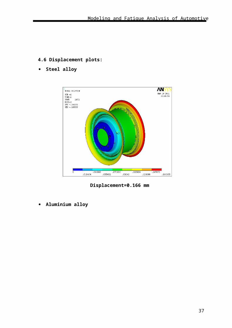
4.6 Displacement plots:
25

Modeling and Fatigue Analysis of Automotive Wheel Rim
Steel alloy
Displacement=0.166 mm
Aluminium alloy
Displacement=0.204mm
26

Modeling and Fatigue Analysis of Automotive Wheel Rim
Magnesium (mg) alloy.
Displacement=0.2136mm
Forged steel
Displacement=0.1923mm
Steel alloy
27
Modeling and Fatigue Analysis of Automotive Wheel Rim
Max vonmises stress=140.056 Mpa
Min vonmises stress=3.202 Mpa
Aluminium alloy
Max vonmises stress=48.326 Mpa
Min vonmises stress=0.92 Mpa
Magnesium(mg) alloy
28

Modeling and Fatigue Analysis of Automotive Wheel Rim
Maximum vonmises stress=32.294 Mpa.
Minimum vonmises stress=0.6954 Mpa.
Forged steel
Maximum stress distribution=135.931 Mpa
Minimum stress distribution=2.452 Mpa
CHAPTER 5
FATIGUE ANALYSIS
29

Modeling and Fatigue Analysis of Automotive Wheel Rim
5.1 Fatigue Mechanisms
The basic feature that underlies all the specific fatigue failure mechanisms is the
existence of repeated or cyclic stresses at some point of the component. This could be
considered the basic definition of fatigue. The cyclic stresses or strains give origin to
damage accumulation until it develops into a crack that finally leads to failure of the
component. Keeping in mind the basic assumption for a fatigue failure, different
definitions will be provided for the specific fatigue failure mechanisms. The different
fatigue failure mechanisms are essentially related to the way those cyclic stresses arise in
a specific point of the component, or to the cause of the stresses. Sometimes they are also
related to the existence of other concurrent or synergistic damaging mechanisms such as
wear or corrosion.
The fatigue failure mechanisms are divided into two classes: the primary mechanisms and
the secondary mechanisms, according to the following definition:
Primary mechanisms: mechanisms that are able by themselves to initiate and
propagate fatigue cracks;
Secondary mechanisms: mechanisms that are not able by themselves to promote
fatigue fracture but may either initiate cracks or help on crack propagation of pre-
existing cracks.
A definition for the different fatigue mechanisms, either primary or secondary
mechanisms, will be subsequently given. Some schemes of the mechanisms are shown on
the damaged components section.
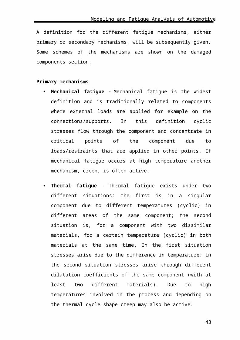
Primary mechanisms
Mechanical fatigue - Mechanical fatigue is the widest definition and is
traditionally related to components where external loads are applied for example
on the connections/supports. In this definition cyclic stresses flow through the
component and concentrate in critical points of the component due to
loads/restraints that are applied in other points. If mechanical fatigue occurs at
high temperature another mechanism, creep, is often active.
Thermal fatigue - Thermal fatigue exists under two different situations: the first
is in a singular component due to different temperatures (cyclic) in different areas
of the same component; the second situation is, for a component with two
30

Modeling and Fatigue Analysis of Automotive Wheel Rim
dissimilar materials, for a certain temperature (cyclic) in both materials at the
same time. In the first situation stresses arise due to the difference in temperature;
in the second situation stresses arise through different dilatation coefficients of the
same component (with at least two different materials). Due to high temperatures
involved in the process and depending on the thermal cycle shape creep may also
be active.
Thermal/mechanical fatigue -
Thermal/mechanical fatigue exists when both mechanical and thermal fatigue act
at the same time. It is common to have superposed thermal and fatigue cycles. Due to
high temperature involved creep is sometimes active in thermal/fatigue situations.
Contact fatigue - Contact fatigue exists when two free bodies are in contact but
they are not attached one to another. It occurs mainly when there is a rolling
contact. The contact forces are the responsible for the Hertzian stresses and strains
in the components. On the contact surface between the free bodies and due to the
contact deformation there may exist a very small relative displacement between
the bodies. Thus sometimes, another mechanism, fretting, may be considered as
associated with rolling contact fatigue..
Impact fatigue - Impact fatigue is characterized by the existence of an impact
contact. Thus there is a load between the two bodies plus the impact energy due to
the prior movement of at least one of the bodies.
Cavitation fatigue - Cavitation fatigue exists when bubbles are created inside a
liquid in an under-pressure region and, when those bubbles reach higher pressure
zones they implode and the wave pressure that born from the implosion impacts a
solid surface. These waves are the responsible for the stresses and strains at the
solid bodies.
Creep fatigues - Creep fatigue is a superposition of mechanical fatigue and creep
(deformation at high temperature at a constant load). According to the high
temperature level and load fatigue cycle waveform creep may be more or less
active but is almost always present.
Secondary mechanisms
31

Modeling and Fatigue Analysis of Automotive Wheel Rim
Wear-fatigue - Wear fatigue exists when two bodies are not attached one to
another but there is contact and a relative displacement between both components.
There are the normal contact forces plus the tangential forces due to the sliding
movement between both bodies.
Fretting fatigue - Fretting fatigue is similar to wear fatigue because there is wear
between the two bodies due to a relative displacement. The main difference is that
the two bodies are commonly connected or attached one to the other for example
with screws, and the relative displacement between both components is very small
(traditionally between 1 to 100 ì m)
Abrasion fatigue - Abrasion fatigue exists when two solid bodies are not in direct
contact one to the other but a third body (for example dust) promotes the contact
and load transmission between the initial two bodies. The third body (for example
dust) may be involved in oil or water. Initially they cause pitting or spalling like
on contact fatigue but in cases where a pre-existing crack exists they may promote
crack propagation.
Corrosion fatigue - corrosion fatigue exists when structural metals operate in
deleterious environments. This detrimental environment accelerates fatigue crack
growth. Even materials immune to SCC – Stress Corrosion Cracking are
susceptible to CC – Corrosion Cracking (or corrosion fatigue cracking).
Hydrodynamic fatigue – (trapped water/oil fatigue) - There are at least two
different ways in which hydrodynamic fatigue is present. One is when there is
load transmission between two rigid bodies by means of a liquid (for example oil)
and there is a pre-existing crack. The liquid enters the crack and promote crack
propagation by exerting opening loads on the crack surfaces. The other situation is
when two solid bodies are in direct contact, for example under rolling contact, and
there is a pre-existing crack with liquid inside. When one body contacts the other
body on the crack position, the crack closes and the liquid is trapped inside the
crack. The pressure on the trapped liquid promotes crack propagation.
5.2 MSC.fatigue software:
MSC Fatigue is a FE-based durability and damage tolerance solver that enables
users with minimal knowledge of fatigue to perform comprehensive durability analysis.
32

Modeling and Fatigue Analysis of Automotive Wheel Rim
Some estimates put annual costs in the United States due to premature fatigue
fractures in structural components at as much as 4% of the gross domestic product. Yet
testing against repeated loading cycles, sometimes millions of times over, is often too
expensive and time consuming to be practical. Finite element analysis programs can tell
you where stress “hot spots” exist, but on their own can’t tell you whether those hot spots
are critical areas for fatigue failure, or when fatigue might become a problem. To avoid
contributing further to this statistic, many manufacturers simply accept long prototype-
development cycles, overweight components, unpredictable warranty claims, and loss of
customer confidence.
MSC Fatigue enables durability engineers to quickly and accurately predict how long
products will last under any combination of time-dependent or frequency-dependent
loading conditions. Benefits include reduced prototype testing, fewer product recalls,
lower warranty costs, and increased confidence that your product designs will pass
required test schedules
Welcome to MSC.Fatigue. MSC.Fatigue is an advanced fatigue life estimation program
for use with finite Element analysis. When used early in a development design cycle it is
possible to greatly enhance product life as well as reduce testing and prototype costs, thus
Ensuring greater speed to market. It is jointly developed in close cooperation between
MSC. Software Corporation and its fatigue technology partner, nCode International, Ltd.
of Sheffield, England.
Although many definitions can be applied to the word, for the purposes of this
manual, fatigue is failure under a repeated or otherwise varying load which never reaches
a level sufficient to cause failure in a single application. It can also be thought of as the
initiation and growth of a crack, or growth from a preexisting defect, until it reaches a
critical size, such as separation into two or more parts.
Fatigue analysis itself usually refers to one of two methodologies: either the stress
life or S-N method, commonly referred to as total life since it makes no distinction
between initiating or growing a crack, or the local strain or strain-life (ε-N) method,
commonly referred to as the crack initiation method which concerns itself only with the
initiation of a crack. Fracture specifically concerns itself with the growth or propagation
33

Modeling and Fatigue Analysis of Automotive Wheel Rim
of a crack once it has initiated. Durability is then the conglomeration of all aspects that
affect the life of a product and usually involves much more than just fatigue and fracture,
but also loading conditions, environmental concerns, material characterizations, and
testing simulations to name a few. A true product durability program in an organization
takes all of these aspects (and more) into consideration.
5.3 The Fatigue “Five-Box Trick”
Almost without exception, each exercise is constructed around the concept of the fatigue
“Five-box trick.” The Illustration to the right Depicts this well. For any life analysis
whether it be Fatigue or fracture there are always three inputs.
The first three boxes are these inputs:
Cyclic Material Information: Materials behave differently when they are Subject to
cyclic as opposed to monotonic loading. Monotonic material Properties are the result
of material tests where the load is steadily increased until the test coupon breaks.
Cyclic material parameters are obtained from Material tests where the loading is
reversed and cycled until failure at various load levels. These parameters differ
depending on the fatigue analysis type involved.
Service Loading Information: The proper specification of the variation of the
loading is extremely important to achieve an accurate fatigue life prediction. The
loading can be defined in various manners. Whether it be time based, frequency
based, or in the form of some sort of spectra depends on the fatigue analysis type to be
used. When working with finite element models the loading can be force, pressure,
temperature, displacement, or a number of other types. Loading in the test world
34

Modeling and Fatigue Analysis of Automotive Wheel Rim
usually refers to the acquisition of a response measurement, usually from a strain
gauge.
Geometry Information: Geometry has different meanings depending on whether you
are working from a finite element model or from a test specimen. In the testing world,
the geometry input is the Kt (stress concentration factor) since the point of failure is
usually away from the actual point of measurement. Therefore a geometry
compensation factor (Kt) is defined to relate the measured response to that at the
failure location. You can think of this as a fudge factor. With a finite element model
the local stresses and strains are known at all locations (Kt=1 at all locations). The FE
geometry gives us the entire stress distribution needed for fatigue life calculations.
For crack growth analysis the geometry definition takes on yet another form as a
compliance function. The correctness and accuracy of each of these inputs is
important in that any error in any of these will be magnified through the fatigue
analysis procedure, the fourth box, since this process is logarithmic. A ten percent
error in loading magnitude could result in a 100% error in the predicted fatigue life.
The fifth box is the post processing or results evaluation. This can take on the form of
color contours on a finite element model or a tabular listing but also quite often leads
back into the three inputs to see what effect variations of these inputs will have on the life
prediction. This is referred to as a sensitivity or a “what if” study. This is extremely useful
at times when you are not quite sure about the accuracy of one of the inputs. The software
denotes this as “optimization” in places.
BENEFITS:
Analysis using MSC.Fatigue significantly reduces costs associated with
prototyping and testing by simulating fatigue life early in the design phase. Early
simulation shortens time-to-market, improves product reliability, customer confidence
and reduces costly recalls or other undesirable consequences of premature product failure.
Usage of MSC.Fatigue brings fatigue analysis up front in the design-to-manufacturing
process and creates an MCAE environment for integrated durability management.
5.4 Life Estimation Process
The life estimation process really centers around two major relationships.
1. The first relation is that of the loading environment to the stresses and strains in the
component or model. This load-strain or load-stress relation is determined using finite
35

Modeling and Fatigue Analysis of Automotive Wheel Rim
element modeling and running linear elastic FE analysis. It is dependent on the
characterization of the material properties and in some instances requires that a notch
correction procedure take place. For the purposes of this discussion a notch correction
is simply a way to compensate for plasticity from a linear FE analysis.
2. The second relation is that of the stresses or stains to the life of the component or
model. This is accomplished by using damage modeling. Each fatigue life method has
its own techniques to determine and sum damage which shall be explained as you
progress through the example problems.
The fatigue analysis is carried out in MSC fatigue tool .The von-misses stresses
from ANSYS(.rst file format) is imported to the MSCfatigue and find the number of
cycles to failures of crankshaft for forged steel and sintered aluminium.
Fig 5.4.1: Type of Fatigue load inputting
5.5 Fatigue plots and S-N curves
Steel alloy :
36
Modeling and Fatigue Analysis of Automotive Wheel Rim
Fatigue strength=2.17*105 cycles
Aluminium alloy
Fatigue strength=1.32*105 cycles
Magnesium alloy
37

Modeling and Fatigue Analysis of Automotive Wheel Rim
Fatigue strength=1.2*105 cycles
Forged steel
Fatigue strength=1.97*105 cycles
38

Modeling and Fatigue Analysis of Automotive Wheel Rim
Steel alloy
Aluminium alloy
39

Modeling and Fatigue Analysis of Automotive Wheel Rim
Magnesium alloy
Forged steelCHAPTER 6
40

Modeling and Fatigue Analysis of Automotive Wheel Rim
RESULTS AND DISCUSSIONS
6.1 Material properties
Steel alloy:
Young’s modulus (E) =2.34*105 N/mm2
Yield stress=240 N/mm2
Density =7800kg/m3
Aluminum alloy:
Young’s modulus (E) =72000 N/mm2
Yield stress=160 N/mm2
Density =2800kg/m3
Magnesium alloy:
Young’s modulus (E) =45000N/mm2
Yield stress=130 N/mm2
Density =1800kg/m3
Forged steel:
Young’s modulus (E) =210000N/mm2
Yield stress=220 N/mm2
Density =7600kg/m3
41

Modeling and Fatigue Analysis of Automotive Wheel Rim
6.2 Results obtained from softwares:
Steel alloy:-
Von misses stress (σv ) =140.056 N/mm2
Number of cycles to failure (Nf)=2.17*105Cycles
Aluminum alloy:-
Von misses stress (σv ) =48.326 N/mm2
Number of cycles to failure (Nf) =1.32*105Cycles
Magnesium alloy:-
Von misses stress (σv ) =32.204 N/mm2
Number of cycles to failure (Nf) =1.2*105Cycles
Forged steel:-
Von misses stress (σv ) =135.931 N/mm2
Number of cycles to failure (Nf) =1.97*105Cycles
Table 6.2.1
MATERIAL Displacement
(mm)
Vonmisses stress
(Mpa)
Fatigue strength
(cycles)
Steel alloy 0.1663 140.056 2.17*105
Aluminium alloy 0.204 48.326 1.32*105
Magnesium alloy 0.2136 32.29 1.2*105
Forged steel 0.1923 135.931 1.97*105
42
Modeling and Fatigue Analysis of Automotive Wheel Rim
CHAPTER7
CONCLUSION1) The von misses stresses developed in steel alloy during static analysis is 140.056
N/mm2 at load 21.3KN the stress is below yield stress of material for these stress
range we have to find at what number of cycles the component is yielding or crack
is going to initiates
2) During fatigue analysis of steel alloy the crack is initiating at Nf =2.17*105Cycles.
3) The von misses stresses developed in aluminum alloy during static analysis is
48.326 N/mm2 at load 21.3KN the stress is below yield stress of material for these
stress range we have to find at what number of cycles the component is yielding or
crack is going to initiates
4) During fatigue analysis of aluminum alloy the crack is initiating at
Nf=1.32*105Cycles.
5) The von misses stresses developed in Magnesium alloy during static analysis is
32.294 N/mm2 at load 21.3KN the stress is below yield stress of material for these
stress range we have to find at what number of cycles the component is yielding or
crack is going to initiates.
6) During fatigue analysis of Magnesium alloy the crack is initiating at
Nf =1.2*105Cycles.
7) The von misses stresses developed in Forged steel during static analysis is 135.931
N/mm2 at load 21.3KN the stress is below yield stress of material for these stress
range we have to find at what number of cycles the component is yielding or crack
is going to initiates
8) During fatigue analysis of Forged steel the crack is initiating at
Nf =1.97*105Cycles.
9) From results we can make out, in steel alloy the Number of cycles to failure (N f)=
2.17*105Cycles is greater than Aluminium, Magnesium, Forged steel. Hence Steel
alloy is more feasible to use than aluminum.
10) Hence steel alloy have more life and durability compared to aluminum.
43

Modeling and Fatigue Analysis of Automotive Wheel Rim
SCOPE FOR FUTURE WORK:-
1) Further we can do optimization of material thickness to reduce the material
consumption.
2) Further we can improve life of component by using advanced fatigue strain life
approach.
8.REFERENCES
44

Modeling and Fatigue Analysis of Automotive Wheel Rim
[1] K. Mahadevan and Balaveera Reddy, “Design Data Hand Book”.
[2] “Finite Element Analysis”, Chandra Pautla.
[3] “Strength Of Materials”, Ramambrutham.
[4] “Ansys User Manual”,
[5] “Metal Fatigue” , Ralfh Stefunson, Ali Fatemi & A.O. Cuph.
[6] “MSC Fatigue User Manual”,
[7] Metal_fatigue_in_engineering by Stefan.
[8] Fatigue Life Analysis of Aluminum Wheels by Simulation of Rotary Fatigue Test
Liangmo Wang* - Yufa Chen - Chenzhi Wang - Qingzheng Wang School of
Mechanical Engineering, Nanjing University of Science & Technology, China
[9] Fatigue properties of a cast aluminium alloy for rims of car wheels.
C.Bosi,G.L.Garagnani .
45
Related Documents