Modeling analysis of the electromagnetic braking action on rotating solid cylinders Oriano Bottauscio a, * , Mario Chiampi b , Alessandra Manzin a a Istituto Nazionale di Ricerca Metrologica (I.N.RI.M.), Strada delle Cacce 91, 10135 Torino, Italy b Politecnico di Torino, Dipartimento di Ingegneria Elettrica, Corso Duca degli Abruzzi 24, I-10129 Torino, Italy Received 1 January 2006; received in revised form 1 October 2006; accepted 24 October 2006 Available online 18 December 2006 Abstract The electromagnetic diffusion and the electromechanical phenomena arising in a solid cylinder rotating inside a mag- netic field are here analyzed. The study is developed through a time stepping Finite Element voltage-driven formulation, employing the sliding mesh technique for handling the cylinder motion. The influence on the dynamic behavior and energy dissipation of the material electric and magnetic properties, the geometrical parameters and the supply conditions is inves- tigated considering a model problem. Ó 2006 Elsevier Inc. All rights reserved. Keywords: Moving systems; Eddy currents; Non-linear media; Magneto-mechanical coupled problems; Finite element sliding mesh 1. Introduction One of the most important areas of interest in the power engineering involves the computation of the induced electric field and the associated eddy currents in rotating structures. In fact, when an electrical con- ductor rotates in a magnetic field, currents are induced within the material [1]. These eddy currents, which tend to cancel the magnetic field inside the conductor, give rise to electromagnetic forces and to energy transfor- mation into the form of heat. The first phenomenon determines the device mechanical behavior; the second one produces an undesirable increment of the rotor temperature. The prediction of these coupled phenomena is essential in the analysis of the magnetic bearing and brake actuators, as well as more generally in the study of the electrical machines [2–8]. The aim of the present paper, focused on the braking action, is the modeling analysis of the electromagnetic phenomena arising when a solid structure rotates inside a magnetic field. The attention is intentionally addressed to a two-dimensional problem, where a solid cylinder is rotating between the poles of an electro- magnet supplied by a known voltage generator. In this model problem, the cylinder is initially supposed to 0307-904X/$ - see front matter Ó 2006 Elsevier Inc. All rights reserved. doi:10.1016/j.apm.2006.10.021 * Corresponding author. Tel.: +39 (0) 11 3919828; fax: +39 (0) 11 3919849. E-mail addresses: [email protected] (O. Bottauscio), [email protected] (M. Chiampi), [email protected] (A. Manzin). Applied Mathematical Modelling 32 (2008) 12–27 www.elsevier.com/locate/apm brought to you by CORE View metadata, citation and similar papers at core.ac.uk provided by Elsevier - Publisher Connector

Welcome message from author
This document is posted to help you gain knowledge. Please leave a comment to let me know what you think about it! Share it to your friends and learn new things together.
Transcript

brought to you by COREView metadata, citation and similar papers at core.ac.uk
provided by Elsevier - Publisher Connector
Applied Mathematical Modelling 32 (2008) 12–27
www.elsevier.com/locate/apm
Modeling analysis of the electromagnetic braking actionon rotating solid cylinders
Oriano Bottauscio a,*, Mario Chiampi b, Alessandra Manzin a
a Istituto Nazionale di Ricerca Metrologica (I.N.RI.M.), Strada delle Cacce 91, 10135 Torino, Italyb Politecnico di Torino, Dipartimento di Ingegneria Elettrica, Corso Duca degli Abruzzi 24, I-10129 Torino, Italy
Received 1 January 2006; received in revised form 1 October 2006; accepted 24 October 2006Available online 18 December 2006
Abstract
The electromagnetic diffusion and the electromechanical phenomena arising in a solid cylinder rotating inside a mag-netic field are here analyzed. The study is developed through a time stepping Finite Element voltage-driven formulation,employing the sliding mesh technique for handling the cylinder motion. The influence on the dynamic behavior and energydissipation of the material electric and magnetic properties, the geometrical parameters and the supply conditions is inves-tigated considering a model problem.� 2006 Elsevier Inc. All rights reserved.
Keywords: Moving systems; Eddy currents; Non-linear media; Magneto-mechanical coupled problems; Finite element sliding mesh
1. Introduction
One of the most important areas of interest in the power engineering involves the computation of theinduced electric field and the associated eddy currents in rotating structures. In fact, when an electrical con-ductor rotates in a magnetic field, currents are induced within the material [1]. These eddy currents, which tendto cancel the magnetic field inside the conductor, give rise to electromagnetic forces and to energy transfor-mation into the form of heat. The first phenomenon determines the device mechanical behavior; the secondone produces an undesirable increment of the rotor temperature. The prediction of these coupled phenomenais essential in the analysis of the magnetic bearing and brake actuators, as well as more generally in the studyof the electrical machines [2–8].
The aim of the present paper, focused on the braking action, is the modeling analysis of the electromagneticphenomena arising when a solid structure rotates inside a magnetic field. The attention is intentionallyaddressed to a two-dimensional problem, where a solid cylinder is rotating between the poles of an electro-magnet supplied by a known voltage generator. In this model problem, the cylinder is initially supposed to
0307-904X/$ - see front matter � 2006 Elsevier Inc. All rights reserved.
doi:10.1016/j.apm.2006.10.021
* Corresponding author. Tel.: +39 (0) 11 3919828; fax: +39 (0) 11 3919849.E-mail addresses: [email protected] (O. Bottauscio), [email protected] (M. Chiampi), [email protected] (A. Manzin).

O. Bottauscio et al. / Applied Mathematical Modelling 32 (2008) 12–27 13
rotate at a given angular speed, friction-less and without a driving torque; after the current making in the sup-ply circuit, the induced phenomena in the conductive solid cylinder give rise to a braking action, which causesa gradual reduction of the rotor angular speed. The electromagnetic diffusion phenomena inside the cylinderare strongly dependent on the material properties and their evolution during the transient state affects, in avery complex way, the electromechanical behavior and the energy dissipation mechanism. Despite the simplegeometry and the two-dimensional approximation, which are not representative of an actual device, all theelectromagnetic and electromechanical phenomena arising in the considered structure are taken into account,allowing us to deeply investigate the influence on the braking action of the material properties, the geometricalparameters and the supply conditions.
The modeling analysis of the considered problem requires the coupling of several physical phenomena,which can be so synthesized: (i) arising of eddy currents in solid conductive materials, directly responsiblefor the braking torque, (ii) non-linear and hysteretic behavior of magnetic materials, producing local satura-tions and time delays, (iii) interaction between electromagnetic field and electric supply circuits, (iv) mechan-ical effect on the rotating parts, and finally (v) energy dissipation mechanisms. The simulation of all thesephenomena is not usual in the commercial tools, so that a specific mathematical engine has been developed.The approach is based on a two-dimensional Finite element (FE) solution of the Maxwell’s equations, han-dling the magnetic non-linearities and the hysteresis by the Fixed Point iterative technique and modelingthe cylinder rotation through the sliding mesh technique [9–11]. The transient time evolution is treated by astep-by-step procedure.
A detailed description of the modeling approach is presented in Section 2. In Section 3 the numerical pro-cedure is applied to the analysis of pure conductive and ferromagnetic rotating cylinders, investigating thephysical phenomena arising in the rotor and discussing the influence of different parameters on the brakingaction.
2. Electromagneto-mechanical model
The behaviour of the considered device results from the combination of different physical phenomena:
• the eddy currents arising in non-linear and hysteretic materials;• the electromagnetic interaction with the electric network;• the mechanical torques acting on rotating components.
Therefore the modelling approach is based on three systems of equations, respectively describing the elec-tromagnetic problem, including eddy current and hysteresis effects, the supply circuit behaviour and themechanical laws. In particular, the analysis of the transient evolution is performed by a step-by-step time pro-cedure: at each time instant, after the solution of the combined field-circuit problem, driven by a voltagesource, and the consequent estimation of the electromagnetic torque, the rotor angular displacement is calcu-lated by means of the mechanical equations. Then, the computed motion is imposed on the moving object, inorder to update the domain configuration for the next instant.
2.1. Electromagnetic field problem
In this paper the FE formulation is developed for a two-dimensional problem, assuming geometric andphysical properties invariant along one of the coordinate axis. Considering a Cartesian coordinate system,the magnetic flux density vector b is supposed to lay in the (x,y) plane and to be independent from coordinatez, while the currents flow along z-axis. Then, omitting the time dependency, vector quantities b and currentdensity j result defined as
b ¼ ðbxðx; yÞ; byðx; yÞ; 0Þ;j ¼ ð0; 0; jzðx; yÞÞ:
14 O. Bottauscio et al. / Applied Mathematical Modelling 32 (2008) 12–27
Expressing field vector b as the curl of a vector potential a = (0,0,a(x,y)), so that diva = 0, and consideringthe magnetic constitutive relationship h = f(b) between magnetic field h and magnetic flux density b, the fol-lowing electromagnetic field equation is obtained:
curl½fðcurlaÞ� ¼ j: ð1Þ
In Eq. (1), which represents the starting point for the electromagnetic field analysis, the unknown quantityis the z-component of the magnetic vector potential. Vector j includes the presence of exciting windings andeddy currents in conductive materials (non-magnetic or ferromagnetic). Thus, two types of conductors are dis-tinguished: the conductive regions having an electrical conductivity different from zero, indicated as electro-
magnetic conductors, and the circuit conductors, including the device components electrically connected tothe supply circuit (e.g. the windings traces). In the first conductors the eddy current phenomena are taken intoaccount, and then the solid cylinder is assumed as an electromagnetic conductor. The second category includesboth bulk conductors (generally conductive rings or traces of coils having a few turns) and windings composedof numerous filaments. In the last case the current density distribution results uniform, because the conductorcross-sectional area is supposed to be too small to allow a local influence of eddy currents. In the studied prob-lem, the supply windings are constituted of filamentary conductors, so that vector j results expressed as
j ¼ �X
k
rk _a� rk
Sk
ZXk
_ads� �� �
Ckuz þX
p
N pip
SpCpuz; ð2Þ
where uz is the unit vector along z-direction. Index p indicates a winding composed of Np filaments and car-rying a current ip (Fig. 1). In the present problem, where the source voltages are assigned (voltage driven prob-lem), this current is unknown and depends both on the field distribution and on the supply circuit features.Index k indicates a generic electromagnetic conductor, having electrical conductivity rk and occupying a regionof trace Xk and area Sk. The characteristic function Ck is defined as
Ckðx; yÞ ¼1 if ðx; yÞ 2 Xk
0 if ðx; yÞ 62 Xk:
�
The constitutive relationship h = f(b) appearing in Eq. (1) takes into account the magnetic non-linearity,due to the presence of ferromagnetic materials, which exhibit saturation effects. The method here employedfor treating non-linear problems is the Fixed point (FP) technique, which is based on a decomposition ofthe magnetization characteristic into a linear part (coefficient mFP) and a residual term (r) to be iteratively eval-uated. Despite the FP technique requires a higher number of iterations with respect to the most popular New-ton–Raphson scheme, it is found to be more efficient, since it does not require the upgrade of the stiffness
Fig. 1. Scheme of the domain under analysis with the terms of current density appearing in Eq. (2).
O. Bottauscio et al. / Applied Mathematical Modelling 32 (2008) 12–27 15
matrix at each step. In our application, this feature is even more exploited by adopting a LU factorisation ofthe system matrix, following the Tinney algorithm [12]; this means that each iteration requires just the solutionof two triangular systems. Finally, FP is generally found more accurate in regions with high magnetic satura-tion levels [13].
The residual term accounts for the non-linearity and it is updated at the generic iteration m, as
rðmÞ ¼ fðbðmÞÞ � mFPbðmÞ; ð3Þ
where r = (rx(x,y), ry(x,y), 0).In order to guarantee a convergent scheme, function f has to satisfy particular conditions: strong monotony
and uniform Lipschitz continuity [14]. Moreover the constant coefficient mFP has to belong to an intervalaround the average between the major and the minor rates of curve f. Under these hypotheses, the methodconverges to the solution, whatever the initial value assigned to the residual term.
If ferromagnetic materials show a non-negligible hysteretic behaviour the b–h relationship is not a singlevalued function and a given (b,h) state depends on the previous magnetic history. In this case the FP iterativescheme requires the use of a hysteresis model able to provide the magnetic field strength evolution startingfrom the knowledge of the magnetic flux density waveform (inverse hysteresis model). To do this, a modelbased on the so-called stop hysterons [15,16], specifically tailored for a magnetic vector potential formulation,can be used. As an alternative, Preisach-like models can be adopted employing a modified FP scheme (H-ver-sion) [17]. Following this last procedure, at each iteration step, an estimation of the magnetic field strength isobtained as:
~hðmÞ ¼ mFPbðmÞ þ rðm�1Þ;
then ~h is used as input for the direct hysteresis model and the new residual value is computed as
rðmÞ ¼ ~hðmÞ � mFPf�1 ~hðmÞ� �
:
Applying the FP technique and considering expression (2), the resultant field equation, written in the weakform, becomes
ZXFmcurlaðmÞ � curlwds ¼ �
ZXF
rðm�1Þ � curl wdsþX
k
rk
ZXk
MXk ð _aðmÞÞwds� rk
ZXk
_aðmÞwds� �
þX
p
ZXp
N pip
Spwds
" #; ð4Þ
where m is the local value of the magnetic reductivity (m = mFP for non-linear media), w is the test function, XF isthe entire finite element domain and MXk ð _aÞ is the mean of _a over Xk. Homogenous Dirichlet boundary con-ditions complete the electromagnetic field problem. Eq. (4) is discretized using the standard nodal FE tech-nique, with triangular elements and first-order shape functions. In presence of material discontinuities withcorners, errors can arise in the solution derivatives, as stated in [18]. Anyway, this problem can be satisfacto-rily overcome by adopting a suitable fine mesh in the corner regions, which allows the achievement of therequested precision [19].
In voltage driven problems, all or some supply currents ip appearing in (4) are unknowns and they have tobe determined by the interaction with the circuit equations. In this case, it is necessary to add the electric net-work equations and to introduce relationships linking the circuit and the field quantities. The present paperproposes an approach which combines the integro-differential FE formulation of the transient electromagneticproblem with the conventional Loop current method of the circuit theory.
The external circuit is described in terms of branches. Each of them can be constituted of different electricalcomponents (voltage generators, induced electromotive forces, resistors, inductors) series connected. Thus thebranch voltage drop is given by
ubranch ¼ Riþ Ldidtþ ep � u0: ð5Þ

16 O. Bottauscio et al. / Applied Mathematical Modelling 32 (2008) 12–27
The voltage of the generator u0 represents the known electric source. The induced electromotive force ep
(relative to the generic winding p) introduces the field unknowns in the circuit equations, being expressedas a function of the magnetic vector potential, by the relationship
epðtÞ ¼ DNþpSþp
ZXþp
_ads�N�pS�p
ZX�p
_ads
" #; ð6Þ
where D is the domain depth along the z-direction and the integration is performed on the positive (Xþp Þ andthe negative (X�p Þ traces of the winding, having respectively cross-sectional area Sþp and S�p and turn numberNþp and N�p .
2.2. Mechanical equations and rotation handling
Since the studied electromechanical problem involves moving components, a complete time-domain mod-elling requires the coupling between the field-circuit equations and the mechanical ones. As the motion lawinvolves the electromagnetic torque acting on the rotor, it is necessary to know its value in order to obtainthe solution of the mechanical system. This quantity can be evaluated by the virtual work principle or bythe Maxwell Stress Tensor method, that provide the global torques exerted on rigid movable parts.
In this paper, the electromagnetic torque acting on the rotor is computed by the Maxwell stress tensormethod. Following this approach, in a 2-D problem, the overall torque is estimated by the numerical integra-tion of the local stress along a closed contour surrounding the rotor and contained in the airgap. In particular,the electromagnetic torque Tem can easily be calculated through the relationship
Tem ¼ DZ
Crl �
1
l0
bnbtt þ1
2l0
b2n � b2
t
� �n
� �dl; ð7Þ
where C is any closed line (with tangential unit vector t) surrounding the rotor in a region free of sources andmagnetic materials, n is the unit outward vector normal to C, bn and bt are the normal and tangential com-ponents of the magnetic flux density, and l0 is the magnetic permeability of air. Vector rl corresponds tothe lever arm (the vector which connects the rotation centre to the midpoint of segment dl). Then, the calcu-lated electromagnetic torque Tem is inserted into the mechanical equation
Jd2adt2¼ T em � T r; ð8Þ
where a is the angular position of the moving object, J is the inertial moment and Tr is an applied opposingtorque, assumed equal to zero in the following analysis. The time integration of Eq. (8) allows the computa-tion of the rotor angular displacement during a given time interval.
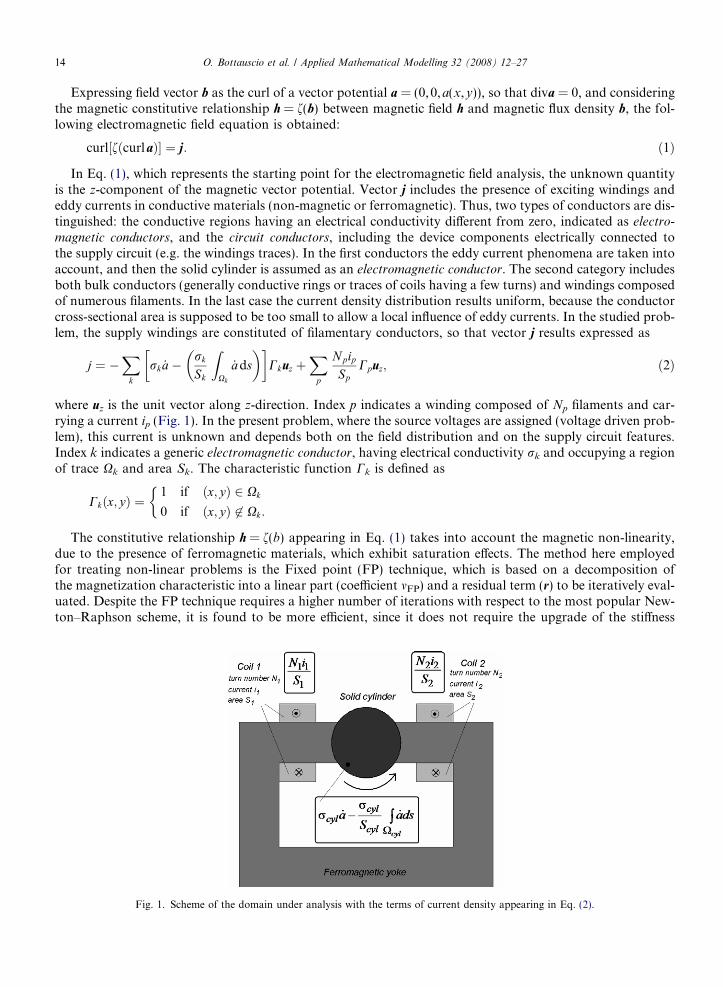
The presence of rotating parts is handled dividing the domain under study into two FE separate meshes: amoving one including the rotor and a portion of air-gap (master mesh), and a stationary one containing theremaining fixed domain (slave mesh). The two grids are connected through an interface circumference, wherethe imposition of the magnetic vector potential continuity guarantees the coupling of the two derived sets ofequations. For each configuration, a specific algorithm couples the master nodes, sliding on the interface, withthe slave ones, locally adapting the slave grid. In particular, the slave elements facing the circumference can besubdivided into more triangles, in order to link interface master nodes to stationary ones (see Fig. 2). Whenslave nodes on the interface have an intermediate position between two moving ones, they are treated asnon-conformal nodes. In other words, the associated magnetic vector potential is expressed interpolatingthe values of the two nearest conformal nodes belonging to the master grid boundary. The weights employedin the linear combination depend on the relative distances from the considered moving nodes.
2.3. Step-by-step procedure
By assembling the FE electromagnetic field problem, described by Eq. (4), and the external circuit behav-iour, the following system of ordinary differential equations has to be solved:
Fig. 2. Moving and stationary meshes and handling of non-conformal nodes. Symbol a represents the nodal value of magnetic vectorpotential in points 1, 2, A and B.
O. Bottauscio et al. / Applied Mathematical Modelling 32 (2008) 12–27 17
BNN ð _xÞ ¼ �½ANN �ðxÞ � ½ANM1�ðy1Þ � ½ANM2
�ðy2Þ þ ðcNÞ0 ¼ �½AMN �ðxÞ � ½AMM1
�ðy1Þ � ½AMM2�ðy2Þ þ ðcMÞ:
�ð9Þ
In Eq. (9) matrix A includes the FE stiffness matrix and the circuit terms which do not involve time deriv-atives; matrix B takes into account the electromagnetic induction phenomena in the field-circuit equations.The right-hand side (c) can be separated into two time dependent vectors (s) and (f) expressing respectivelythe known sources and the FP residuals.
The problem unknowns are divided into N state variables x (with time derivatives _xÞ and M algebraic vari-ables y; the algebraic variables are separated into M1 variables on the interface strips and M2 ones elsewhere,so that matrix A results to be decomposed into six sub-matrices. This separation is advantageous, because thediscretization imposed by the sliding mesh technique causes, at each time step, a variation in the contributionsto the system matrix only for the M1 nodes belonging to the interface strips.
In conclusion, vector (x) state variables of the field-circuit equations, which are:
• the nodal values of the magnetic vector potential in correspondence of materials having an electrical con-ductivity different from zero (eddy current effect);
• the nodal values of the magnetic vector potential in correspondence of materials electrically connected tothe external supply circuit (phenomena of electromagnetic induction);
• the inductive loop currents.
Vector (y) includes the other variables, i.e.:
• the nodal values of the magnetic vector potential in correspondence of materials having an electrical con-ductivity equal to zero or not connected to the external network;
• the loop currents that involve only resistive components.
The transient analysis is performed by the application of a step-by-step time procedure. In this work weemploy the h-method, that approximates the time derivative of the unknown x in the interval from t to(t + h) by the derivative at a generic instant (t + hh), defined by the dimensionless parameter h (0 < h < 1).The recurrence relation, which links the unknown values at two successive time instants (one-step method),is obtained taking into account the following relationships:
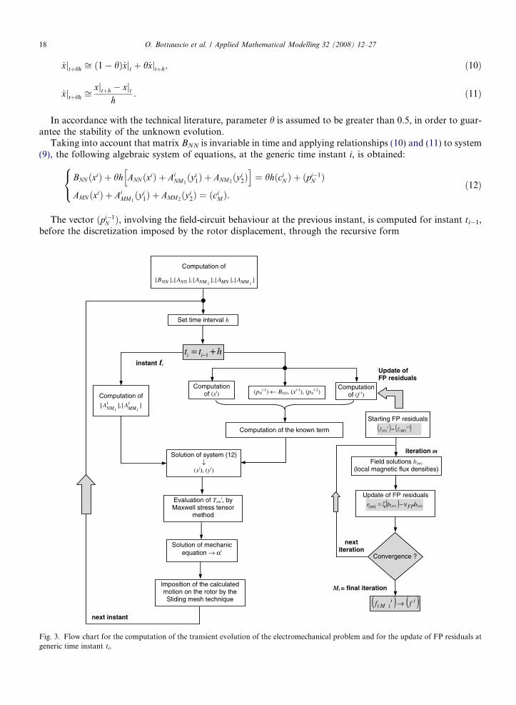
Fig. 3.generic
18 O. Bottauscio et al. / Applied Mathematical Modelling 32 (2008) 12–27
_xjtþhh ffi ð1� hÞ _xjt þ h _xjtþh; ð10Þ
_xjtþhh ffixjtþh � xjt
h: ð11Þ
In accordance with the technical literature, parameter h is assumed to be greater than 0.5, in order to guar-antee the stability of the unknown evolution.
Taking into account that matrix BNN is invariable in time and applying relationships (10) and (11) to system(9), the following algebraic system of equations, at the generic time instant i, is obtained:
BNN ðxiÞ þ hh ANN ðxiÞ þ AiNM1ðyi
1Þ þ ANM2ðyi
2Þh i
¼ hhðciN Þ þ ðpi�1
N Þ
AMN ðxiÞ þ AiMM1ðyi
1Þ þ AMM2ðyi
2Þ ¼ ðciMÞ:
8<: ð12Þ
The vector ðpi�1N Þ, involving the field-circuit behaviour at the previous instant, is computed for instant ti�1,
before the discretization imposed by the rotor displacement, through the recursive form
Flow chart for the computation of the transient evolution of the electromechanical problem and for the update of FP residuals attime instant ti.
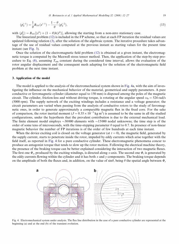
Fig. 4.beginn
O. Bottauscio et al. / Applied Mathematical Modelling 32 (2008) 12–27 19
ðpi�1N Þ ¼
1
hBNN ðxi�1Þ � 1� h
hðpi�2
N Þ; ð13Þ
with ðp0N Þ ¼ BNN ½ðx0Þ þ ð1� hÞhð _x0Þ�, allowing the starting from a non-zero stationary case.
The linearized problem (12) is included in the FP scheme, so that at each FP iteration the residual values areupdated following relation (3), after the solution of the algebraic system. The iterative procedure takes advan-tage of the use of residual values computed at the previous instant as starting values for the present timeinstant (see Fig. 3).
Once the solution of the electromagnetic field problem (12) is obtained at a given instant, the electromag-netic torque is computed by the Maxwell stress tensor method. Then, the application of the step-by-step pro-cedure to Eq. (8), assuming Tem constant during the considered time interval, allows the evaluation of therotor angular displacement and the consequent mesh adapting for the solution of the electromagnetic fieldproblem at the next time instant.
3. Application of the model
The model is applied to the analysis of the electromechanical system shown in Fig. 4a, with the aim of inves-tigating the influence on the mechanical behavior of the material, geometrical and supply parameters. A pureconductive or ferromagnetic cylinder (diameter equal to 150 mm) is disposed among the poles of the magneticcircuit. The cylinder, friction-less and without driving torque, is rotating at the angular speed x0 = 524 rad/s(5000 rpm). The supply network of the exciting windings includes a resistance and a voltage generator; thecircuit parameters are varied when passing from the analysis of conductive rotors to the study of ferromag-netic ones, in order to generate approximately a comparable magnetic flux in the fixed core. For the sakeof comparison, the rotor inertial moment (J = 0.35 · 10�3 kg m2) is assumed to be the same in all the studiedconfigurations, under the hypothesis that the prevalent contribution is due to the external mechanical load.The finite element model employs �30000 elements with �15000 nodal unknowns; the time step is of theorder of some tens of microseconds, with the time-stepping parameter h equal to 0.7. In presence of non-linearmagnetic behavior the number of FP iterations is of the order of few hundreds at each time instant.
When the device exciting coil is closed on the voltage generator (at t = 0), the magnetic field, generated bythe supply current, starts to penetrate inside the rotor, impeded by eddy currents which arise together with thefield itself, as reported in Fig. 4 for a pure conductive cylinder. These electromagnetic phenomena concur toproduce an antagonist torque that tends to slow up the rotor motion. Following the electrical machine theory,the presence of the braking torque can be better explained considering the interaction of two magnetic fluxes.The first one Us, produced by the exciting windings, is directed along x-axis. The second one Ur is generated bythe eddy currents flowing within the cylinder and it has both x and y components. The braking torque dependson the amplitude of both the fluxes and, in addition, on the value of sinh, being h the spatial angle between Us
Electromechanical system under analysis. The flux line distribution in the case of a pure conductive cylinder are represented at theing (a) and at the end (b) of the transient evolution.
20 O. Bottauscio et al. / Applied Mathematical Modelling 32 (2008) 12–27
and Ur; thus practically the resulting torque is determined by the y-component of Ur. The study of the involvedphenomena is further complicated by the fact that, differently from electrical machines, the rotor currents arenot localized in the conductors, but distributed over the entire cylinder. All these aspects contribute to makevery difficult a a-priori estimation of the influence of the constitutive and geometrical parameters.
3.1. Pure conductive cylinder
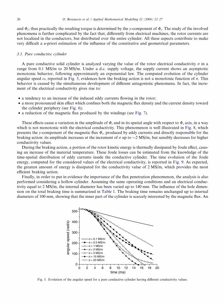
A pure conductive solid cylinder is analyzed varying the value of the rotor electrical conductivity r in arange from 0.1 MS/m to 20 MS/m. Under a d.c. supply voltage, the supply current shows an asymptoticmonotonic behavior, following approximately an exponential law. The computed evolution of the cylinderangular speed x, reported in Fig. 5, evidences how the braking action is not a monotonic function of r. Thisbehavior is caused by the simultaneous development of different antagonistic phenomena. In fact, the incre-ment of the electrical conductivity gives rise to:
• a tendency to an increase of the induced eddy currents flowing in the rotor;• a more pronounced skin effect which confines both the magnetic flux density and the current density toward
the cylinder periphery (see Fig. 6);• a reduction of the magnetic flux produced by the windings (see Fig. 7).
These effects cause a variation in the amplitude of Ur and in its spatial angle with respect to Us axis, in a waywhich is not monotonic with the electrical conductivity. This phenomenon is well illustrated in Fig. 8, whichpresents the y-component of the magnetic flux Ur, produced by eddy currents and directly responsible for thebraking action: its amplitude increases at the increment of r up to �2 MS/m, but sensibly decreases for higherconductivity values.
During the braking action, a portion of the rotor kinetic energy is thermally dissipated by Joule effect, caus-ing an increase of the material temperature. These Joule losses can be estimated from the knowledge of thetime-spatial distribution of eddy currents inside the conductive cylinder. The time evolution of the Jouleenergy, computed for the considered values of the electrical conductivity, is reported in Fig. 9. As expected,the greatest amount of energy is dissipated for the conductivity value of 2 MS/m, which provides the mostefficient braking action.
Finally, in order to put in evidence the importance of the flux penetration phenomenon, the analysis is alsoperformed considering a hollow cylinder. Assuming the same operating conditions and an electrical conduc-tivity equal to 2 MS/m, the internal diameter has been varied up to 140 mm. The influence of the hole dimen-sion on the total braking time is summarized in Table 1. The braking time remains unchanged up to internaldiameters of 100 mm, showing that the inner part of the cylinder is scarcely interested by the magnetic flux. An
0 2 4 6 8 10 12 14 16 18 200
100
200
300
400
500
angu
lar
spee
d (r
ad/s
)
time (ms)
σ = 0.1 MS/mσ = 0.5 MS/mσ = 1 MS/mσ = 2 MS/mσ = 5 MS/mσ = 10 MS/mσ = 20 MS/m
Fig. 5. Evolution of the angular speed for a pure conductive cylinder having different conductivity values.

0 2 4 6 8 10 12 140.0
0.1
0.2
0.3
0.4
Link
ed m
agne
tic fl
ux (
Wb)
time (ms)
σ = 0.1 MS/mσ = 0.5 MS/mσ = 1 MS/mσ = 2 MS/mσ = 5 MS/mσ = 10 MS/mσ = 20 MS/m
Fig. 7. Evolution of the magnetic flux linked with the supply windings for a pure conductive cylinder having different conductivity values.
0 2 4 6 8 10 12 14 16 18 200.0
0.1
0.2
0.3
0.4
0.5
0.6 σ = 0.1 MS/mσ = 1 MS/mσ = 2 MS/mσ = 5 MS/mσ = 10 MS/mσ = 20 MS/m
Mag
netic
flux
(m
Wb)
time (ms)
Fig. 8. Time evolution of the y-component of the magnetic flux Ur for a pure conductive cylinder having different conductivity values.
0 10 20 30 40 50 60 70
0.00
0.05
0.10
0.15
0.20
0.25
0.30
0.35
σ = 0.1 MS/mσ = 2 MS/mσ = 5 MS/mσ = 10 MS/mσ = 20 MS/m
Mag
netic
flux
den
sity
(T
)
radius (mm)
Fig. 6. Distribution of magnetic flux density (peak value) along the cylinder radius for a pure conductive cylinder having differentconductivity values.
O. Bottauscio et al. / Applied Mathematical Modelling 32 (2008) 12–27 21

Table 1Braking time for hollow pure conductive cylinders
Internal diameter (mm) Braking time (ms)
6100 15120 18140 60
0 2 4 6 8 10 12 14 16 18 200
5
10
15
20
25
30σ = 0.1 MS/mσ = 0.5 MS/mσ = 1 MS/mσ = 2 MS/mσ = 5 MS/mσ = 10 MS/mσ = 20 MS/m
Joul
e E
nerg
y (J
)
time (ms)
Fig. 9. Evolution of the Joule energy for a pure conductive cylinder having different conductivity values.
22 O. Bottauscio et al. / Applied Mathematical Modelling 32 (2008) 12–27
increase of the braking time occurs only when a portion of material close to the rotor periphery (where themagnetic flux and the current density are concentrated) is removed.
3.2. Ferromagnetic cylinder
The simulation of a ferromagnetic cylinder is performed keeping approximately the same magnetic flux inthe fixed core. For such a purpose, the required steady state magnetomotive force has been reduced withrespect to the case of a pure conductive cylinder, modifying the supply circuit characteristics. The analysisis initially performed neglecting hysteresis and considering a ferromagnetic material, whose first magnetizationcurve is reported in Fig. 10.
0 2000 4000 6000 8000 10000 120000.0
0.2
0.4
0.6
0.8
1.0
1.2
1.4
1.6
first magnetization Hc = 225 A/m
Hc = 1000 A/m
Mag
netic
flux
den
sity
(T
)
Magnetic field (A/m)
Fig. 10. First magnetization curve and hysteresis loops of the considered ferromagnetic material.
O. Bottauscio et al. / Applied Mathematical Modelling 32 (2008) 12–27 23
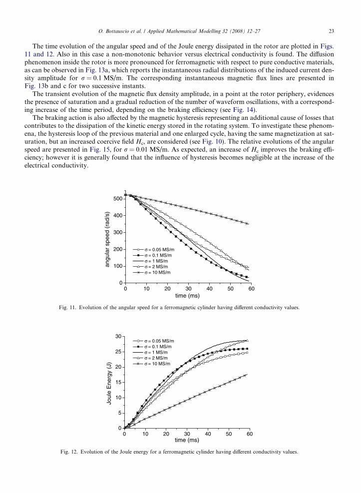
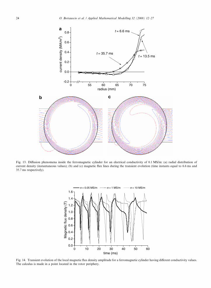
The time evolution of the angular speed and of the Joule energy dissipated in the rotor are plotted in Figs.11 and 12. Also in this case a non-monotonic behavior versus electrical conductivity is found. The diffusionphenomenon inside the rotor is more pronounced for ferromagnetic with respect to pure conductive materials,as can be observed in Fig. 13a, which reports the instantaneous radial distributions of the induced current den-sity amplitude for r = 0.1 MS/m. The corresponding instantaneous magnetic flux lines are presented inFig. 13b and c for two successive instants.
The transient evolution of the magnetic flux density amplitude, in a point at the rotor periphery, evidencesthe presence of saturation and a gradual reduction of the number of waveform oscillations, with a correspond-ing increase of the time period, depending on the braking efficiency (see Fig. 14).
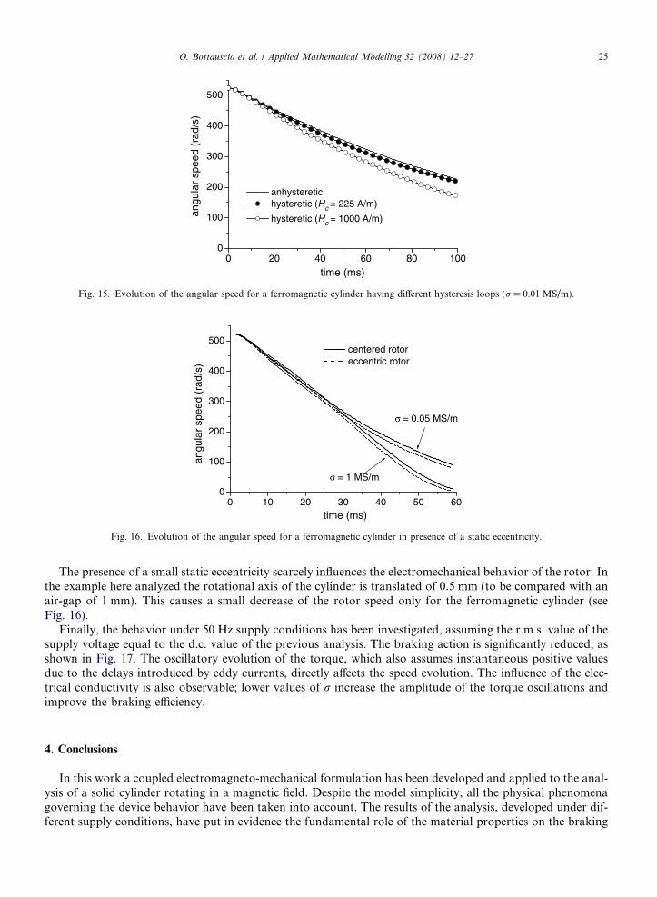
The braking action is also affected by the magnetic hysteresis representing an additional cause of losses thatcontributes to the dissipation of the kinetic energy stored in the rotating system. To investigate these phenom-ena, the hysteresis loop of the previous material and one enlarged cycle, having the same magnetization at sat-uration, but an increased coercive field Hc, are considered (see Fig. 10). The relative evolutions of the angularspeed are presented in Fig. 15, for r = 0.01 MS/m. As expected, an increase of Hc improves the braking effi-ciency; however it is generally found that the influence of hysteresis becomes negligible at the increase of theelectrical conductivity.
0 10 20 30 40 50 600
100
200
300
400
500
angu
lar
spee
d (r
ad/s
)
time (ms)
σ = 0.05 MS/mσ = 0.1 MS/mσ = 1 MS/mσ = 2 MS/mσ = 10 MS/m
Fig. 11. Evolution of the angular speed for a ferromagnetic cylinder having different conductivity values.
0 10 20 30 40 50 600
5
10
15
20
25
30σ = 0.05 MS/mσ = 0.1 MS/mσ = 1 MS/mσ = 2 MS/mσ = 10 MS/m
Joul
e E
nerg
y (J
)
time (ms)
Fig. 12. Evolution of the Joule energy for a ferromagnetic cylinder having different conductivity values.
0 55 60 65 70 75-0.2
0.0
0.2
0.4
0.6
0.8
t = 35.7 mst = 13.5 ms
curr
ent d
ensi
ty (
MA
/m2 )
radius (mm)
t = 6.6 msa
b c
Fig. 13. Diffusion phenomena inside the ferromagnetic cylinder for an electrical conductivity of 0.1 MS/m: (a) radial distribution ofcurrent density (instantaneous values); (b) and (c) magnetic flux lines during the transient evolution (time instants equal to 6.6 ms and35.7 ms respectively).
0 10 20 30 40 50 600.0
0.2
0.4
0.6
0.8
1.0
1.2
1.4
1.6
Mag
netic
flux
den
sity
(T
)
time (ms)
σ = 0.05 MS/m σ = 1 MS/m σ = 10 MS/m
Fig. 14. Transient evolution of the local magnetic flux density amplitude for a ferromagnetic cylinder having different conductivity values.The calculus is made in a point located in the rotor periphery.
24 O. Bottauscio et al. / Applied Mathematical Modelling 32 (2008) 12–27
0 20 40 60 80 1000
100
200
300
400
500
angu
lar
spee
d (r
ad/s
)
time (ms)
anhysteretic hysteretic (Hc = 225 A/m)
hysteretic (Hc = 1000 A/m)
Fig. 15. Evolution of the angular speed for a ferromagnetic cylinder having different hysteresis loops (r = 0.01 MS/m).
0 10 20 30 40 50 600
100
200
300
400
500
σ = 1 MS/m
angu
lar
spee
d (r
ad/s
)
time (ms)
centered rotor eccentric rotor
σ = 0.05 MS/m
Fig. 16. Evolution of the angular speed for a ferromagnetic cylinder in presence of a static eccentricity.
O. Bottauscio et al. / Applied Mathematical Modelling 32 (2008) 12–27 25
The presence of a small static eccentricity scarcely influences the electromechanical behavior of the rotor. Inthe example here analyzed the rotational axis of the cylinder is translated of 0.5 mm (to be compared with anair-gap of 1 mm). This causes a small decrease of the rotor speed only for the ferromagnetic cylinder (seeFig. 16).
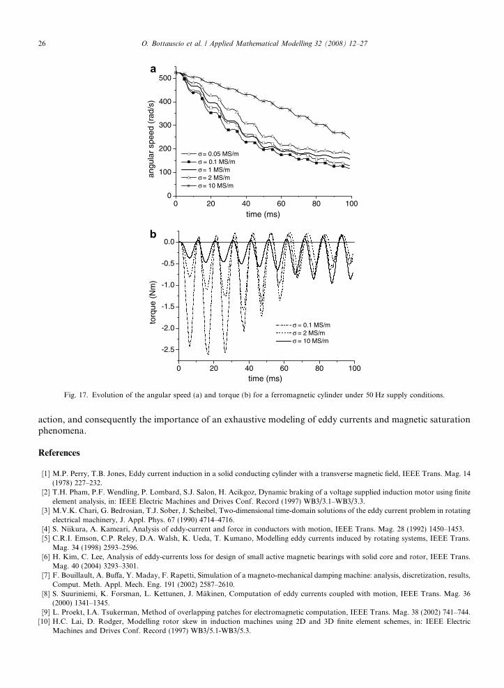
Finally, the behavior under 50 Hz supply conditions has been investigated, assuming the r.m.s. value of thesupply voltage equal to the d.c. value of the previous analysis. The braking action is significantly reduced, asshown in Fig. 17. The oscillatory evolution of the torque, which also assumes instantaneous positive valuesdue to the delays introduced by eddy currents, directly affects the speed evolution. The influence of the elec-trical conductivity is also observable; lower values of r increase the amplitude of the torque oscillations andimprove the braking efficiency.
4. Conclusions
In this work a coupled electromagneto-mechanical formulation has been developed and applied to the anal-ysis of a solid cylinder rotating in a magnetic field. Despite the model simplicity, all the physical phenomenagoverning the device behavior have been taken into account. The results of the analysis, developed under dif-ferent supply conditions, have put in evidence the fundamental role of the material properties on the braking
0 20 40 60 80 1000
100
200
300
400
500
angu
lar
spee
d (r
ad/s
)
time (ms)
σ = 0.05 MS/mσ = 0.1 MS/mσ = 1 MS/mσ = 2 MS/mσ = 10 MS/m
0 20 40 60 80 100
-2.5
-2.0
-1.5
-1.0
-0.5
0.0
torq
ue (
Nm
)
time (ms)
σ = 0.1 MS/mσ = 2 MS/mσ = 10 MS/m
b
a
Fig. 17. Evolution of the angular speed (a) and torque (b) for a ferromagnetic cylinder under 50 Hz supply conditions.
26 O. Bottauscio et al. / Applied Mathematical Modelling 32 (2008) 12–27
action, and consequently the importance of an exhaustive modeling of eddy currents and magnetic saturationphenomena.
References
[1] M.P. Perry, T.B. Jones, Eddy current induction in a solid conducting cylinder with a transverse magnetic field, IEEE Trans. Mag. 14(1978) 227–232.
[2] T.H. Pham, P.F. Wendling, P. Lombard, S.J. Salon, H. Acikgoz, Dynamic braking of a voltage supplied induction motor using finiteelement analysis, in: IEEE Electric Machines and Drives Conf. Record (1997) WB3/3.1–WB3/3.3.
[3] M.V.K. Chari, G. Bedrosian, T.J. Sober, J. Scheibel, Two-dimensional time-domain solutions of the eddy current problem in rotatingelectrical machinery, J. Appl. Phys. 67 (1990) 4714–4716.
[4] S. Niikura, A. Kameari, Analysis of eddy-current and force in conductors with motion, IEEE Trans. Mag. 28 (1992) 1450–1453.[5] C.R.I. Emson, C.P. Reley, D.A. Walsh, K. Ueda, T. Kumano, Modelling eddy currents induced by rotating systems, IEEE Trans.
Mag. 34 (1998) 2593–2596.[6] H. Kim, C. Lee, Analysis of eddy-currents loss for design of small active magnetic bearings with solid core and rotor, IEEE Trans.
Mag. 40 (2004) 3293–3301.[7] F. Bouillault, A. Buffa, Y. Maday, F. Rapetti, Simulation of a magneto-mechanical damping machine: analysis, discretization, results,
Comput. Meth. Appl. Mech. Eng. 191 (2002) 2587–2610.[8] S. Suuriniemi, K. Forsman, L. Kettunen, J. Makinen, Computation of eddy currents coupled with motion, IEEE Trans. Mag. 36
(2000) 1341–1345.[9] L. Proekt, I.A. Tsukerman, Method of overlapping patches for electromagnetic computation, IEEE Trans. Mag. 38 (2002) 741–744.
[10] H.C. Lai, D. Rodger, Modelling rotor skew in induction machines using 2D and 3D finite element schemes, in: IEEE ElectricMachines and Drives Conf. Record (1997) WB3/5.1-WB3/5.3.
O. Bottauscio et al. / Applied Mathematical Modelling 32 (2008) 12–27 27
[11] A. Buffa, Y. Maday, F. Rapetti, Calculation of eddy currents in moving structures by a sliding mesh – finite element method, IEEETrans. Mag. 36 (2000) 1356–1359.
[12] E.C. Ogbuobiri, W.F. Tinney, J.W. Walker, Sparsity-directed decomposition for Gaussian elimination on matrices, IEEE Trans.Power App. Syst. 89 (1970) 141–150.
[13] M. Chiampi, D. Chiarabaglio, M. Repetto, An accurate investigation on numerical methods for nonlinear magnetic field problems, J.Magn. Magn. Mat. 133 (1994) 591–595.
[14] M. Chiampi, A. Negro, M. Tartaglia, A finite element method to compute 3-dimensional magnetic field distribution in transformercores, IEEE Trans. Mag. 16 (1980) 1413–1419.
[15] A.J. Bergqvist, S.A. Lundgren, S.G. Engdahl, Computationally efficient vector hysteresis model using flux density as known variable,in: V. Kose, J. Sievert (Eds.), Non-Linear Electromagnetic Systems, IOS Press, Amsterdam, 1998, pp. 463–466.
[16] O. Bottauscio, M. Chiampi, A. Manzin, Advanced model for dynamic analysis of electromechanical devices, IEEE Trans. Mag. 41(2005) 36–46.
[17] I.F. Hantila, A method for solving stationary magnetic field in non-linear media, Rev. Roum. Sci. Techn. – Electrotechn. et Energ. 20(1975) 397.
[18] I. Babuska, Error-bounds for finite element method, Numer. Math. 16 (1971) 322–333.[19] S. Biddlecombe, J. Simkin, C.W. Trowbridge, Error analysis in finite element models of electromagnetic fields, IEEE Trans. Mag. 22
(1986) 811–813.
Related Documents