Modeling ADS-B Position and Velocity Errors for Airborne Merging and Spacing in Interval Management Application Satish C. Mohleji Ganghuai Wang Center for Advanced Aviation System Development (CAASD) The MITRE Corporation 7515 Colshire Drive McLean VA 22102 [email protected] Abstract As a part of the Next Generation Air Transportation System (NextGen), the Federal Aviation Administration (FAA) is developing an advanced airborne Merging and Spacing (M&S) concept utilizing satellite-based surveillance information provided by Automatic Dependent Surveillance- Broadcast (ADS-B). The M&S concept is defined as Airborne Spacing- Flight deck Interval Management (ASPA-FIM), which includes both a ground component and an airborne component including a speed control algorithm as a part of the Interval Management (IM) capability. The ground based function establishes a sequence for an IM aircraft conducting ASPA-FIM procedure to merge behind another designated target aircraft at a waypoint with a desired spacing interval, and then maintain the desired spacing interval. The aircraft achieve the spacing requirement through speed commands generated by Interval Management (IM) equipment in the aircraft. The IM speed control algorithm relies upon ADS-B position and velocity measurements broadcasted by the target aircraft, where the position accuracy depends upon the Global Positioning System (GPS) measurement errors including a bias and an instantaneous jitter. Since most mathematical models for GPS position errors do not take into consideration the correlation between the successive position measurement errors, this paper presents a model for time correlation between position measurement errors using a Gauss- Markov process. In order to determine the minimum position and velocity accuracy required for successful implementation of ASPA-FIM procedure so that the number of speed commands to achieve the desired spacing is acceptable to flight crew and the errors in the achieved spacing is satisfactory, the paper presents results from a Monte Carlo simulation capability which includes ADS-B position/velocity error models, flight dynamics models, a wind model and an IM speed control algorithm. The paper also describes the determination of a desired spacing interval based on established aircraft separation minima during different phases of flight and estimation of the safety tolerance for operational uncertainties. The simulation results provide a preliminary assessment of minimum position and velocity accuracies required to support this ADS-B application. There is a tradeoff between the number of speed adjustments and the accuracy of achieved spacing interval. Using operational scenarios for en route and descent flight paths into Louisville International airport, example results are presented showing the number of IM-equipment-derived speed commands needed and corresponding spacing interval achieved during merge and maintain phases of flight. A

Welcome message from author
This document is posted to help you gain knowledge. Please leave a comment to let me know what you think about it! Share it to your friends and learn new things together.
Transcript

Modeling ADS-B Position and Velocity Errors for Airborne Merging and
Spacing in Interval Management Application
Satish C. Mohleji
Ganghuai Wang
Center for Advanced Aviation System Development (CAASD)
The MITRE Corporation
7515 Colshire Drive
McLean VA 22102
Abstract
As a part of the Next Generation Air Transportation System (NextGen), the Federal Aviation
Administration (FAA) is developing an advanced airborne Merging and Spacing (M&S) concept
utilizing satellite-based surveillance information provided by Automatic Dependent
Surveillance- Broadcast (ADS-B). The M&S concept is defined as Airborne Spacing- Flight
deck Interval Management (ASPA-FIM), which includes both a ground component and an
airborne component including a speed control algorithm as a part of the Interval Management
(IM) capability. The ground based function establishes a sequence for an IM aircraft conducting
ASPA-FIM procedure to merge behind another designated target aircraft at a waypoint with a
desired spacing interval, and then maintain the desired spacing interval. The aircraft achieve the
spacing requirement through speed commands generated by Interval Management (IM)
equipment in the aircraft. The IM speed control algorithm relies upon ADS-B position and
velocity measurements broadcasted by the target aircraft, where the position accuracy depends
upon the Global Positioning System (GPS) measurement errors including a bias and an
instantaneous jitter. Since most mathematical models for GPS position errors do not take into
consideration the correlation between the successive position measurement errors, this paper
presents a model for time correlation between position measurement errors using a Gauss-
Markov process. In order to determine the minimum position and velocity accuracy required for
successful implementation of ASPA-FIM procedure so that the number of speed commands to
achieve the desired spacing is acceptable to flight crew and the errors in the achieved spacing is
satisfactory, the paper presents results from a Monte Carlo simulation capability which includes
ADS-B position/velocity error models, flight dynamics models, a wind model and an IM speed
control algorithm. The paper also describes the determination of a desired spacing interval based
on established aircraft separation minima during different phases of flight and estimation of the
safety tolerance for operational uncertainties.
The simulation results provide a preliminary assessment of minimum position and velocity
accuracies required to support this ADS-B application. There is a tradeoff between the number of
speed adjustments and the accuracy of achieved spacing interval. Using operational scenarios for
en route and descent flight paths into Louisville International airport, example results are
presented showing the number of IM-equipment-derived speed commands needed and
corresponding spacing interval achieved during merge and maintain phases of flight. A
mastro
Text Box
Approved for Public Release; Distribution Unlimited Case # 10-3026

qualitative discussion of expected benefits from the ASPA-FIM application is also included in
the paper.
Introduction
The Next Generation Air Transportation System will transform current ground based
Communication, Navigation and Surveillance (CNS) capabilities to satellite based systems, and
ground centric Air Traffic Management (ATM) to an aircraft centric system [1]. The new CNS
technologies include data link for air/ground information sharing, Area Navigation (RNAV) and
Required Navigation Performance (RNP) for precise navigation using GPS, and ADS-B for
aircraft surveillance providing highly accurate aircraft position and velocity information [2]. The
integrated time based flow management forming the basis for future ATM automation will
provide strategic flight planning for Four Dimensional (4D) Trajectory Based Operations (TBO)
by accurately predicting flight times along the desired routes of flight. For transformation to
NextGen, the FAA and the aviation community are developing concepts to permit sharing of
tactical flight management and conformance monitoring responsibilities between the aircraft and
ground control systems. One of such concepts is associated with an ADS-B application called
Flight Deck Based Interval Management-Spacing [3] or ASPA-FIM [4]. In this concept an
appropriately equipped aircraft is permitted to accurately achieve and maintain a desired spacing
(time or distance) interval from a designated aircraft, while the controller remains responsible for
assuring separation. The controller essentially needs information on aircraft capabilities so as to
decide which aircraft could participate in self spacing [5].
During the past few years, the ASPA-FIM concept has been undergoing research, development,
simulation evaluations and field trials by the FAA, the National Aeronautics and Space
Administration (NASA), the MITRE Center for Advanced Aviation System Development
(CAASD) and United Parcel Service (UPS). The FAA and MITRE/CAASD described an earlier
concept of Flight Deck Based Merging and Spacing (FDMS) application for aircraft to maintain
a desired spacing interval [6]. This work was followed by human in the loop simulations to
validate the concept, and the development of an Airline Based En route Sequencing and Spacing
(ABESS) capability, which allows the Airlines Operations Center (AOC) to sequence and space
traffic arrival flows from en route airspace into the terminal area. The FAA, NASA, MITRE and
UPS evaluated the concept at Louisville International Standiford (SDF) Airport [7, 8]. The AOC,
after coordinating with ATC system, sends the desired spacing requirement to appropriate
aircraft over the Aircraft Communications Addressing and Reporting System (ACARS), and the
aircraft achieve and maintain the required spacing from the designated aircraft using airborne
derived speed commands. The field trials showed promise and the work is continuing to develop
specifications for this application. NASA also conducted human in the loop simulations to
evaluate the use of the concept to support Continuous Descent Arrivals (CDA) [9]. The results
show pilot acceptance of the application. The research and simulation studies at
EUROCONTROL assessed the airborne merging and spacing concept in an extended terminal
area environment using Time to Fly (TTF) calculations. The simulation results showed improved
runway throughput with time based spacing targets and reduced air/ground communications [10].
The successful use of ASPA-FIM application depends on the position and velocity measurement
accuracies offered by ADS-B, which is a satellite based surveillance system using input from

various navigation sources such as Global Navigation Satellite Systems (GNSS) (e.g., GPS) and
Inertial Navigation Systems (INS). The ADS-B state vector report from a broadcasting aircraft
includes horizontal position, horizontal velocity, altitude and altitude rate. The broadcast ADS-B
state vector reports can be received by the ground stations as well as by other aircraft equipped
with ADS-B capability. The ground stations direct the ADS-B broadcast state vector reports to
Air Traffic control (ATC) automation systems. A receiving aircraft with ADS-B equipment can
use the received ADS-B report for situational awareness or, in the future, for more advanced
airborne applications. The ASPA-FIM application uses ADS-B state vector reports broadcast
from a designated target aircraft to enable the crew of an IM capable aircraft to perform self-
spacing operations. The IM speed control algorithm in the cockpit uses position and velocity
information from the target aircraft and own aircraft to calculate speed adjustments needed to
meet the spacing objective, and provides the speed change instruction to the crew to enable them
to appropriately space their aircraft from the target aircraft [11].
According to RTCA Minimum Aviation System Performance Standards (MASPS) for Aircraft
Surveillance Applications (ASA), the Navigation Accuracy Category for position (NACp) and
velocity (NACv) are established so that each ASA needs to determine what level of these
accuracy parameters can support the application [12]. In order for the ASPA-FIM application to
operate properly, the accuracy of the position and velocity data from both the target and own
aircraft should meet minimum standards. The objective of the work presented in this paper is to
provide a preliminary assessment of such minimum airborne surveillance requirements using
satellite navigation based position measurement error models in Monte Carlo simulations of
ASPA-FIM application for its effective use during different phases of flight and acceptable to the
flight crew.
Airborne Spacing- Flight deck Interval Management Concept
The ASPA-FIM concept is one of the applications enabled by ADS-B and includes a suite of
functional capabilities which permit an IM equipped aircraft to achieve and maintain a desired
spacing interval from a designated target aircraft [3, 4]. The objective of the ASPA-FIM
capability is to attain precise and consistent inter-aircraft spacing intervals from other aircraft.
This concept has two components: 1) a ground based component; and 2) a flight deck based
component [5]. The ground based component relies on ATC automation to provide information
on the IM capable aircraft, the desired spacing interval (time or distance) between the selected
aircraft to perform IM functions and the designated target aircraft. The integrated time-based
flow management function as a part of the ground automation determines aircraft arrival
sequence at en route merge points and at the runway threshold. The flight deck-based component
needs ADS-B information on current state vector data and some form of intent data (including
arrival and approach information at trajectory change points and runway threshold) for target
aircraft.
Two types of speed control algorithms for the ASPA-FIM application described in the literature
have been used in operational performance requirement assessment simulations. The first type is
based on time history of the target aircraft by projecting target aircraft’s historical position onto
the IM aircraft’s intended flight path. The speed control algorithm adjusts the speed of the IM
aircraft so that it arrives at any horizontal position on its path at a time that is desired spacing

interval later than the target aircraft. The second type of speed control approach is based on
Estimated Time of Arrival (ETA) of both target and IM aircraft at a merge or an achieve-by
point (for example, the final approach fix - FAF). The ETAs of both the IM aircraft and the
target aircraft are used as input to the speed control algorithm to calculate the speed command
for the IM aircraft [4]. The ETA of the IM aircraft can be calculated either by its Flight
Management System (FMS) or by its ETA-based speed control algorithm. The ETA of the target
aircraft could either be estimated by the speed control algorithm of the IM aircraft, or
broadcasted by the target aircraft as its intent to the IM aircraft as a part of ADS-B report.
Modeling of Time Correlated Position Measurement Errors
The onboard navigation equipment supporting the airborne surveillance function requires
conversion of navigation sensor measurement data into standard ADS-B data format. The
following parameters specify navigation data quality requirement for determining position
accuracy and velocity accuracy for ADS-B transmitting subsystem. The position accuracy
parameters are usually called horizontal Estimated Position Uncertainty (EPU), NACp and
Geometric Vertical Accuracy (GVA). The EPU is defined as the radius of a circle centered at the
true horizontal position within which the measured horizontal position lies with 95% probability.
A NACp is a 4-bit representation of a corresponding EPU in an ADS-B broadcast state vector
report. For example a NACp with a decimal value 11 corresponds to an EPU of less than 3
meters. EPU is usually called Horizontal Figure of Merit (HFOM) if it is reported by GPS or
other GNSS. A GVA is a 2-bit representation of geometric altitude accuracy. For example, a
GVA with decimal value 2 corresponds to geometric vertical accuracy (95% accuracy bound) of
45 meters or less. The 95% accuracy bound is also called Vertical Figure of Merit (VFOM) if it
is reported by a GNSS [12, 13, 14]. Similarly, the NACv parameter describes the accuracy
region about the relative velocity vector within which the true velocity is assured to be with a 95
percent probability at the reported time of applicability [12].
Tables 1, 2 and 3 show the values of the NACp, NACv and GVA [14]. As shown, horizontal
position accuracy is characterized with NACp and the corresponding horizontal EPU; horizontal
velocity accuracy is characterized with the NACv; and GNSS vertical accuracy is characterized
with the GVA.
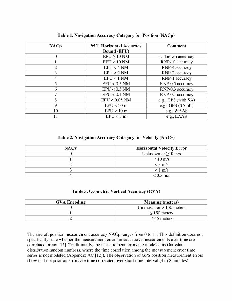
Table 1. Navigation Accuracy Category for Position (NACp)
NACp 95% Horizontal Accuracy
Bound (EPU)
Comment
0 EPU ≥ 10 NM Unknown accuracy
1 EPU < 10 NM RNP-10 accuracy
2 EPU < 4 NM RNP-4 accuracy
3 EPU < 2 NM RNP-2 accuracy
4 EPU < 1 NM RNP-1 accuracy
5 EPU < 0.5 NM RNP-0.5 accuracy
6 EPU < 0.3 NM RNP-0.3 accuracy
7 EPU < 0.1 NM RNP-0.1 accuracy
8 EPU < 0.05 NM e.g., GPS (with SA)
9 EPU < 30 m e.g., GPS (SA off)
10 EPU < 10 m e.g., WAAS
11 EPU < 3 m e.g., LAAS
Table 2. Navigation Accuracy Category for Velocity (NACv)
NACv Horizontal Velocity Error
0 Unknown or ≥10 m/s
1 < 10 m/s
2 < 3 m/s
3 < 1 m/s
4 < 0.3 m/s
Table 3. Geometric Vertical Accuracy (GVA)
GVA Encoding Meaning (meters)
0 Unknown or > 150 meters
1 ≤ 150 meters
2 ≤ 45 meters
The aircraft position measurement accuracy NACp ranges from 0 to 11. This definition does not
specifically state whether the measurement errors in successive measurements over time are
correlated or not [15]. Traditionally, the measurement errors are modeled as Gaussian
distribution random numbers, where the time correlation among the measurement error time
series is not modeled (Appendix AC [12]). The observation of GPS position measurement errors
show that the position errors are time correlated over short time interval (4 to 8 minutes).

A first-order Gauss-Markov process is developed as follows to realistically model the time
correlated GNSS position measurement errors for use in a Monte Carlo simulation described
later in this paper to assess the position and velocity accuracy requirements for ASPA-FIM
application.
Gauss-Markov Process
A first-order Gauss-Markov process is a random process that describes the behavior of a random
variable as a function of time. Because the Monte Carlo simulation used in this work is a discrete
time simulation, a discrete first-order Gauss-Markov process is used in which the time is
modeled as discrete instead of continuous. The discrete first-order Gauss-Markov process is
defined with the following equation:
���� � ���� � 1� ���� (1)
where n is the discrete time that takes values 1, 2, 3, …; u(n) is a random variable that follows
Gaussian distribution ��0, ����; ��0� is a random variable that follows a Gaussian distribution
��0, ���� �; a is a coefficient greater than 0 and less than 1; and y(n) is the output of the random
process.
We make ��0� � 0 here.
The mean, variance, and autocorrelation of ���� are as follows:
������� � 0
�������������� � ����1 � ����/�1 � ��� (2)
�� ����������!�, ����� � ����"#��1 � ����/�1 � ��� when ! $ n
%�&������'�&������!�, ����� � �"#� when ! $ n
Or
%�&������'�&��������, ��� (�� � �) for any ( � 1, 2, 3, … (3)
In order to calculate the value of coefficient � from a given correlation time – the lag time -
corresponding to the autocorrelation value being equal to 1/� [16], from Equation (3), we have
�. � 1/�. If we know the correlation time T, we can calculate the value of � as
� � �#//. (4)
!
That is, if the correlation time of ���� is T, then it can be shown that � � �#//..
When n is large, from Equation (2), the variance of y(n) is:

�������������� � ���/�1 � ��� (5)
If the variance of y(n) is known, the variance of u can be calculated from Equation (5).
For ADS-B, the GPS horizontal radial position measurement error is generally modeled as a
Rayleigh distribution random variable (Appendix AC in [12]), where the measurement errors in
x and y components of the aircraft position (x, y) are modeled as Gaussian distributed random
errors. The 95% accuracy bound of the horizontal radial position error can be used to map into
the standard deviations of the measurement errors in the x and y components.
In the Monte Carlo simulation used to analyze the performance of ASPA-FIM application,
instead of using Gaussian distributed random numbers to model the measurement errors in the x
and y components, the above first-order Gauss-Markov process is used to model these errors.
The coefficient a is determined by the correlation time of the position measurement errors using
Equation (4); and the variance of u(n) is determined using Equation (5), given that the 95%
accuracy bound of the x and y component position measurement error y(n) is known. In turn, the
95% accuracy bound of the x and y component position measurement errors y(n) is calculated
from the 95% accuracy bound of the horizontal radial position measurement as shown below.
Assuming the radial horizontal error0 � √2� 3�, where X and Y are random variables from a
Gaussian distribution ��0, ���, then R is a random variable following a Rayleigh distribution,
and the cumulative distribution function (CDF) for Rayleigh distribution is:
4��� � 1 � �56����/�2���� (6)
From Equation (6), we have σ � �/7��2'��1 � 4�����
If 4��� � 0.95, then r is the 95 percentile of the Rayleigh distribution, and we have
� � �/72'��20�� � �/2.448 (7)
Therefore, given the horizontal radial position 95 percent accuracy bound r, the standard
deviation of the x component and y component of the horizontal position error can be calculated
by using Equation (7).
Although not included in the paper, results indicate that position accuracy corresponding to
NACp 6 or lower may not be adequate to support the ASPA-FIM application. Therefore NACp
values of 7 and above were chosen for the performance assessment of the application. Figure 1
and Figure 2 show a comparison between the uncorrelated errors that were modeled with a
Gaussian distribution and the correlated position measurement errors that were modeled with a
Gauss-Markov process with the same position error accuracy – NACp 7 (0.1 NM 95 percentile).
As shown, the time correlation of the position measurement errors are significantly reduced with
the Gauss-Markov process compared with the Gauss probability distribution.

Figure 1. Comparison of Simulated Correlated Errors and Uncorrelated Horizontal
Position Errors – X Axis (NACp 7)
Figure 2. Comparison of Simulated Correlated Errors and Uncorrelated Horizontal
Position Errors – Y Axis (NACp 7)
Figure 3 shows the impact of velocity measurement accuracy on aircraft true air speed during en
route cruise phase of flight for an aircraft flying at a nominal true airspeed of 458 knots (kts). As
shown in the figure, the velocity measurement accuracy defined as NACv 1 is not adequate to
support the ASPA-FIM application.
-0.2
-0.15
-0.1
-0.05
0
0.05
0.1
0.15
0.2
0 50 100 150 200 250 300
X p
osi
tio
n e
rro
r (N
M)
Time (sec)
-0.2
-0.15
-0.1
-0.05
0
0.05
0.1
0.15
0 50 100 150 200 250 300
Y p
osi
tio
n e
rro
r (N
M)
Time (sec)
Correlated
Uncorrelated
Uncorrelate
d
Correlated

Figure 3. Target aircraft Velocity Measurement Errors during En Route Cruise (0.8 Mach,
37,000 feet)
Desired Aircraft Spacing Interval Determination for ASPA-FIM Application
The FAA Order 7110. 65R establishes the horizontal separation requirements (Standards)
between a pair of aircraft flying at the same altitude as 3.0 NM if the aircraft are within 40 NM
of a radar site typically in the TRACON airspace, and 5 NM when the aircraft are more than 40
NM from the radar location in the en route and transition airspace. The horizontal separation
requirement is uniformly enforced, regardless of whether the aircraft are on the same route when
the above separations are applied longitudinally, or when the aircraft are on different routes these
separations are applied laterally. On final approach for arrivals, the Order defines the separation
standards as 2.5, 4.0, 5.0 and 6.0 NM depending upon the weight classes of the lead and
following aircraft to avoid wake vortices in Instrument Meteorological Conditions (IMC). Air
traffic controllers are responsible for maintaining these separation standards for safety. In order
to ascertain that the aircraft achieve the desired minimum separations, the ATC system applies
additional spacing (a spacing buffer) beyond the minimum desired separation to account for
aircraft position variations. The spacing buffer varies with the phase of flight and the traffic
conditions.
The operational data for flights using jet routes and RNAV Q-routes in Miami (ZMA) and
Jacksonville (ZJX) Air Route Traffic Control Centers (ARTCC) were analyzed to determine
achieved separations between aircraft in en route airspace. The analysis of operational data for
flights operating in and out of Atlanta (ATL) and Denver (DEN) TRACONs provided
separations achieved during arrival and final approach phases of flight. Table 4 shows the results
of the operational data analysis for the observed inter-aircraft longitudinal spacing during various
phases of flight and on the final approach between different classes of aircraft in the U.S. The
Table highlights the mean achieved separations in distance and time, as well as provides the
values of one Standard Deviation (S.D.). The difference between the observed and desired

minimum separation indicates the magnitude of the spacing buffer estimated in current
operations [17].
Table 4. Longitudinal Aircraft Separations
Phase of Flight
Minimum
Required
Separation
(NM)
Observed Distance
Separation (NM)
Observed Time Separation
(Seconds)
Mean S. D. Mean S. D.
En Route
Arrivals 5.0 10.6 2.54 101 32
TRACON 3.0 8.1 2.1 99 27
Final
Approach
Large/Large
Aircraft 2.5 3.4 0.78 85 17
Heavy/Heavy
Aircraft 4.0 5.5 1.13 118 24
Large/Heavy
Aircraft 5.0 6.2 1.16 133 25
En Route
Departures 5.0 12.3 3.57 122 41
In order to account for aircraft performance variations, the desired separations between
consecutive aircraft should be determined considering the required minimum separation plus a
tolerance to account for aircraft performance variations in order to prevent violation of minimum
separation standards. Operational data from current National Airspace System (NAS) was
analyzed for en route, terminal and final approach phases of flight to determine the distribution
(mean, standard deviation) of achieved separations between aircraft pairs in high density traffic
conditions. Assuming that the aircraft performance variations are normally distributed, the
desired separation tolerance between a pair of aircraft is 1.65 times the S.D. The desired spacing
interval is determined by adding this tolerance to the minimum required separation for the
desired phase of flight to assure realization of the required separation interval 95 percent of the
time. The corresponding time separation intervals can be determined from the above distance
based separations and the expected average ground speed over the desired segments of the flight.
If the objective of the IM application is to assure minimum required separation between aircraft
99 percent of the time, then the desired minimum separation tolerance is 2.33 times S.D.
Monte Carlo Simulation Performance Assessment of Merging and Spacing
Functions for IM Application
The Monte Carlo simulation layout used in this work is as shown in Figure 4. A flight dynamics
model calculates the true position and true velocity of the aircraft in the simulation. Rapid update

(RUC) wind data and the corresponding analysis files
and direction data at different flight levels
The flight dynamics model also use
control algorithm. The true position and
were input to the position and velocity measurement model which use
accuracy values (e.g., NACp and NACv) to calculate the measurement errors and add those
errors to the true position and velocity
Then the position and velocity measurement
model which models the ADS-B quantization, trans
takes the ADS-B state vector report broad
probability of receiving it. The received ADS
aircraft’s navigation measurement
speed command. This simulation use
speed adjustments to the IM aircraft so that it arrives at any horizontal position at a time that is
“t” seconds later than the target aircraft, where
spacing interval.
Figure 4
To analyze performance for merging and spacing functions,
model simulated the operational scenarios shown in
target aircraft operations during en route cruise, Continuous Descent Arrival (CDA) and final
approach phases of flight. The figure also shows the simulation capability to model two types of
situations where: 1) each scenario representing a segm
independently of other phases of flight; and 2) the entire flight path is considered as one with
performance for each scenario representing a phase i
aircraft performance during phases are interdependent.
(RUC) wind data and the corresponding analysis files were used to model the wind
data at different flight levels were part of the input to the flight dynamics model.
used as input the speed commands generated by
control algorithm. The true position and true velocity calculated in the flight dynamics model
input to the position and velocity measurement model which used position and velocity
accuracy values (e.g., NACp and NACv) to calculate the measurement errors and add those
errors to the true position and velocity to represent ADS-B position and velocity measurements.
he position and velocity measurements were used as an input to the ADS-B transmitter
B quantization, transmit latency, etc. The ADS-B receiver model
B state vector report broadcasted from the target aircraft considering
The received ADS-B state vector of the target aircraft and
aircraft’s navigation measurements were used by the IM speed control algorithm to
simulation used the time-history-based speed control approach
IM aircraft so that it arrives at any horizontal position at a time that is
seconds later than the target aircraft, where “t” is the time corresponding to the desired
Figure 4. Monte Carlo Simulation Layout
performance for merging and spacing functions, the above Monte Carlo simulation
operational scenarios shown in Figure 5. The scenarios represent
target aircraft operations during en route cruise, Continuous Descent Arrival (CDA) and final
approach phases of flight. The figure also shows the simulation capability to model two types of
situations where: 1) each scenario representing a segment of flight is assessed separately and
of other phases of flight; and 2) the entire flight path is considered as one with
each scenario representing a phase is linked to the previous phase and the IM
ing phases are interdependent.
used to model the winds. Wind speed
part of the input to the flight dynamics model.
the IM speed
ynamics model
position and velocity
accuracy values (e.g., NACp and NACv) to calculate the measurement errors and add those
ition and velocity measurements.
B transmitter
B receiver model
considering the
B state vector of the target aircraft and the own
speed control algorithm to derive the
approach to provide
IM aircraft so that it arrives at any horizontal position at a time that is
to the desired
Monte Carlo simulation
The scenarios represent the IM and
target aircraft operations during en route cruise, Continuous Descent Arrival (CDA) and final
approach phases of flight. The figure also shows the simulation capability to model two types of
ent of flight is assessed separately and
of other phases of flight; and 2) the entire flight path is considered as one with
s linked to the previous phase and the IM
Sixteen flights were simulated: Merging in the en route phase of flight before the top of descent
(TOD) point, during continuous descent arrival (CDA) and in the final phase of flight.
Performance was measured in terms of the achieved separation intervals compared to the desired
intervals discussed above at various waypoints to determine the achieved spacing tolerance
variance, and the frequency of speed commands needed to achieve or maintain the desired
interval as a function of position and velocity accuracies. These performance parameters were
determined where the flights merged at a point, as well as during the in-trail mode when the IM
aircraft was required to maintain the above desired interval from the target aircraft. The
performance was measured independently for each phase of flight as well as in a linked mode
where the performance is determined as composite over the entire flight path shown in Figure 6
for arrival to Louisville International Airport. The spacing between each aircraft pair in the
sequence was achieved or maintained with the speed changes provided by the speed control
algorithm. Other parameters considered in the simulation included the initial spacing error when
the IM aircraft starts using the ASPA-FIM application and the wind forecast uncertainty.
Figure 5. Phases of Simulated Flight

Figure 6. Nominal Horizontal Trajectory of Each Aircraft
Simulation Results
For the operational scenarios discussed above, the Monte Carlo simulation was run for ADS-B
position accuracy varying from NACp 7 to NACp 10, and velocity accuracy of NACv 2 and
NACv 3. The IM aircraft performance was assessed in terms of the achieved spacing variance at
the merge point and the final approach fix and the corresponding speed commands needed to
achieve or maintain spacing over the entire flight path from the start up to the performance
measurement point. Figure 7 shows an example of the error in achieved spacing at FAF based on
a horizontal position measurement accuracy of 30 meters (95% bound) which corresponds to
NACp 9, a horizontal velocity measurement accuracy of 1 meter/second which corresponds to
NACv 3, and an initial spacing error with standard deviation of 15 seconds. Figure 8 shows the
corresponding total number of speed commands from the starting point in en route cruise to the
FAF.

Figure 7. Example Achieved Spacing Errors at the FAF
Figure 8. Example Frequency of Speed Commands by FAF

Table 5 and Table 6 show some example of overall performance assessment results. The results
show that the IM aircraft performance is less sensitive to the improvement in position
measurement accuracy over the minimum value of NACp 7 (185.2 m to 10 m), however the
number of speed commands are reduced as the velocity measurement accuracy improves from
NACv 2 (3 m/sec) to NACv 3 (1 m/sec). The IM performance is either sustained or has small
differences when the performance of first aircraft pair is compared to the performance of 15th
aircraft pair in the chain.
Table 5. Spacing Error and Number of Speed Commands for Desired Spacing = 120 sec,
Initial Spacing Mean = 120 sec, Initial Spacing Error Standard deviation (SD) = 15 sec,
Aircraft Pair 1 at the merge point and at the Final Approach Fix (FAF)
Spacing Error (second) Number of Speed Commands
At Merge Point At FAF Before Merge Point Before FAF
NACp NACv Mean SD Mean SD Mean SD Mean SD
7 3 3.2 10.9 -2.6 3.0 0 1 7 1
8 3 2.4 11.0 -2.5 3.0 0 1 7 1
9 3 3.0 10.9 -2.6 3.1 0 1 7 1
10 3 1.5 10.7 -2.7 2.9 0 1 7 1
7 2 2.5 10.7 -1.3 3.5 0 1 8 2
8 2 2.5 10.3 -1.2 3.6 0 1 8 1
9 2 2.3 10.9 -1.2 3.5 0 1 8 1
10 2 1.4 10.2 -1.1 3.5 0 1 7 1
Table 6. Spacing Error and Number of Speed Commands for Desired Spacing = 120 sec,
Initial Spacing Mean = 120 sec, Initial Spacing Error SD = 15 sec, Aircraft Pair 15 at the
merge point and at the Final Approach Fix (FAF)
Spacing Error (second) Number of Speed Commands
At Merge Point At FAF Before Merge Point Before FAF
NACp NACv Mean SD Mean SD Mean SD Mean SD
7 3 0.1 9.8 1.5 5.8 1 1 7 2
8 3 -0.2 9.2 1.4 5.9 1 1 7 2
9 3 -0.1 9.8 1.2 5.9 1 1 7 2
10 3 0.8 9.9 1.3 5.7 1 1 7 2
7 2 -0.5 9.0 1.7 5.9 1 1 10 2
8 2 0.2 9.6 2.0 6.0 1 1 9 2
9 2 0.2 9.6 1.8 5.8 1 1 9 2
10 2 -0.1 9.1 1.8 5.8 1 1 9 2

ASPA-FIM Application Benefits
General
The IM equipment onboard the aircraft will permit flight crew (or FMS) take over the task of
achieving and maintaining desired spacing in all phases of flight, viz, departure climbs, en route,
descents and during final approaches. The ASPA-FIM application is expected to help achieve
spacing intervals between aircraft pairs accurately with tighter tolerances. The reduction in
spacing tolerances will improve aircraft times of arrival at waypoints along the flight paths, and
potentially increase airport throughput. By redistributing some of the tasks from the ATC to the
cockpit for achieving/maintaining spacing, air/ground communications will be reduced
significantly depending upon the number of aircraft pairs using ASPA-FIM application in
various phases of flight operations. Moreover, the pair-wise use of the ASPA-FIM application
would minimize the need for mile-in-trail restrictions across the board, thereby reducing delays
and improving flight efficiency. Lastly, by precisely merging and spacing of aircraft at selected
waypoints, the ASPA-FIM application could provide metering of traffic at airports, which do not
have a metering or traffic flow management capability e.g., Traffic Management Advisor
(TMA).
Assessment of ASPA-FIM Application Benefits
The type and amount of ASPA-FIM application benefits depend upon the specific situations
which warrant the use of the application, and the number of aircraft pairs simultaneously using
the IM equipment. As discussed above, the overall benefits of using IM applications are to: 1)
reduce airborne delays and improve flight efficiency thereby saving flight time and fuel yielding
reduction in Direct Operating Costs (DOC); and 2) reduce air/ground communications by using
air derived speed commands and sometimes turn to merge guidance thereby potentially reducing
workload. Although a quantitative assessment of benefits requires radar data and voice
communication analysis that is beyond the scope of this report, a qualitative assessment of the
type, and size of benefits as well as the number of operations impacted during various
operational situations is presented as follows. Six scenarios are defined where the use of ASPA-
FIM application for IM aircraft could provide benefits in departure, en route, transition, terminal
and approach phases of flight.
1. ASPA-FIM Application Benefits for IM Aircraft to Remain Behind in a Chain
Although the situation highlighted in this scenario could apply in any phase of flight (level en
route or descent) this IM application will be most beneficial to the stream of aircraft converging
onto their final approach path. The tighter tolerances for the final approach spacing achievable
by the IM aircraft could increase runway throughput thereby reducing airborne delays during
medium to heavy traffic periods. During en route phase of flight, these situations would enhance
flight efficiency making the aircraft to stay close to their optimal trajectories. In both situations,
the resulting benefits would be reduction in flight time and fuel consumption yielding Direct
Operating Costs (DOC) savings. As a result of air derived commands requiring no ATC

instructions for achieving/maintaining required spacing, there will also be a reduction in
air/ground communications and as such workload. Minimizing reliance on vectoring in the
terminal maneuvering areas could yield on the average about three minutes reduction in flying
time per aircraft, 362 lbs of fuel savings and 30 percent less air/ground communications [18].
Since these situations occur most of the time during busy traffic periods at medium to high
density airports, a large number of operations could benefit from the ASPA-FIM application.
The overall benefits however will depend upon the number of aircraft equipped with the IM
equipment.
2. ASPA-FIM Application Benefits during a Turn Maneuver to Merge
In situations when the IM equipment derived speed commands are not adequate to meet the
spacing interval requirement at a merge point, the IM equipment is also capable of determining
when to efficiently turn the aircraft to accurately achieve the desired spacing. Since the ASPA-
FIM application may be used infrequently, the only benefit for a limited number of aircraft will
come from one less vectoring instruction from the ground system. However, Aircraft selecting
the precise time to turn could provide small savings in flight time and fuel consumption.
3. ASPA-FIM Application Benefits during Optimized Profile Descents
Most of the time/fuel/cost saving benefits for aircraft conducting Optimized Profile Descents
(OPD) will come from the aircraft descending from the top of descent point to the final approach
efficiently and economically when compared to routine step down descents. The added benefits
of aircraft using IM equipment will only come from maintaining tighter spacing tolerances for
achieving/maintaining spacing intervals. Consequently there will be insignificant benefits during
light traffic conditions. However the majority of benefits will accrue for a large number of
aircraft pairs conducting OPDs during medium to heavy traffic conditions that could otherwise
be reduced due to operational inefficiencies. Based on information from the pilots conducting
OPDs, the composite benefits of using ASPA-FIM application during OPDs will be about 500
lbs savings in fuel per aircraft, two minutes of flying time and about an 80 percent reduction in
air/ground communications when compared to step down descents. Moreover the use of OPDs
will cut down on noise and emissions. Since the IM aircraft will be able to stay on the desired
flight paths with few deviations, the use of ASPA-FIM application will help sustain the
noise/emission reduction benefits for a large number of operations.
4. Benefits of using ASPA-FIM Application in Turn Maneuver for Crossing Runways
Arrival Operations
With the use of ASPA-FIM application, the IM aircraft would achieve tighter arrival spacing
tolerance and predictable turn to conduct final approaches to the desired runways. This will
maximize airport arrival/departure capacity resulting in reduced delays and DOC savings. The
IM aircraft will also require fewer air/ground communications for arrivals. There are 23 airports
in the U.S. with intersecting runways, about half of them are medium traffic density airports and
the other half airports are high density. A large number of operations at the medium density
airports could benefit from this application in terms of fuel savings on the average of 300 lbs and
reduction in air/ground communications of about 10 percent. Since the intersecting runways are

used less frequently at major airports, as other primary runways are mostly used, the benefits at
such airports for IM aircraft using this application will be small.
5. ASPA-FIM Application Benefits from Accurately Maintaining Departure Spacing
By efficiently adhering to the most efficient climb profiles and accurately achieving and
maintaining the desired spacing at the merge points, the IM aircraft could alleviate the need for
ATC miles-in-trail restrictions. The resulting benefits will likely be reduction in time/fuel and
DOC savings. Because there is less variability in climb profiles, such benefits are expected to be
small, although a significantly large number of aircraft could realize the benefits. Most benefits
will come from reduction in air/ground communications expected to be about 5 to 10 percent.
6. ASPA-FIM Benefits for Two Target Aircraft Arrival Operations
The IM aircraft will benefit from the ASPA-FIM application at airports with dependent parallel
runway operations through an increase in airport throughput and reduction in delays. There are
19 airports in the U.S. with dependent parallel runway configurations. 12 of these airports have
exclusively dependent parallel runway operations, while the other seven airports also have
independent parallel runways. IM operations at these 12 airports will provide benefits through
increased throughput during the medium to high density traffic conditions. Although the
operations at other seven airports are conducted mostly on independent parallel runways, where
an IM aircraft will follow an individual target aircraft arriving at a designated runway with
reduced spacing thereby enhancing throughput at that runway, the above ASPA-FIM application
will improve throughput during situations when operations at dependent runways are conducted.
Summary
The FAA and the aviation community are developing concepts to permit sharing of tactical flight
management and conformance monitoring responsibilities between the aircraft and the ground
control system. One of such concepts is associated with an ADS-B application called ASPA-
FIM. In this concept an appropriately equipped aircraft with an IM capability is permitted to
accurately achieve and maintain a ground-desired spacing (time or distance) interval from a
designated target aircraft, while the controller remains responsible for assuring separation.
A model for time correlation between position measurement errors using a Gauss-Markov
process was presented. In order to determine the minimum position and velocity accuracy
required for successful implementation of ASPA-FIM procedure so that the number of speed
commands to achieve the desired spacing is acceptable to flight crews, a Monte Carlo simulation
capability was developed including the Gauss-Markov ADS-B position error model, flight
dynamics models, and a wind model. Based on operational data analysis, the ground system
desired spacing interval determination approach is presented based on established aircraft
separation minima during different phases of flight and estimation of safety tolerances to
compensate for operational uncertainties. The simulation assessment of IM aircraft performance
under various operational scenarios showed at a preliminary first level that a minimum ADS-B
position accuracy of NACp 7 (185.2 m) and velocity accuracy of NACv 2 (3 m/sec) will be
needed to support the use of ASPA-FIM application. There is a tradeoff between achieving

smaller spacing tolerances and the number of speed adjustments needed to achieve them that are
acceptable to the flight crew. The preliminary results presented here show some sensitivity to
the velocity accuracy. However, additional rigorous analysis is needed to establish minimum
ADS-B data requirements for successful implementation of the application.
The ASPA-FIM application is expected to help accurately achieve spacing intervals between
aircraft pairs with tighter spacing tolerances. The reduction in spacing variances will improve
aircraft times of arrival at waypoints along the flight paths, and potentially increase airport
throughput. By redistributing some of the tasks from the ground to the cockpit for
achieving/maintaining spacing intervals, air/ground communications will be reduced
significantly depending upon the number of aircraft pairs using the IM application in various
phases of flight operations. Moreover, the pair-wise use of IM applications would minimize the
need for miles-in-trail restrictions across the board, thereby reducing delays and improving flight
efficiency. Lastly, by precisely merging and spacing aircraft at selected waypoints, the IM
application could provide metering of traffic at airports, which do not have a metering or traffic
flow management capability (e.g., Traffic Management Advisor).
References
[1] Concept of Operations for the Next Generation Air Transportation System, V 2.0, Joint
Planning and Development Office, 13 June, 2007.
[2] FAA’s NextGen Implementation Plan, Federal Aviation Administration, March 2010.
[3] Application Integrated Work Plan, V 2.0, Federal Aviation Administration, June 2010.
[4] Safety, Performance and Interoperability Requirements Document for Airborne Spacing-
Flight Deck Interval Management (ASPA-FIM), Interim Draft V 0.6, RTCA Inc, 16 July, 2010.
[5] Advanced Merging and Spacing Concepts of Operation for NextGen Mid-Term, V 1.4,
Federal Aviation Administration, 18 September, 2009.
[6] Flight Deck- Based Merging and Spacing (FDMS) Application Description, R.S. Bone, J.
Marksteiner, V 2.1, MITRE /Federal Aviation Administration, 19 February, 2008.
[7] Evaluation of Flight Deck-Based Merging and Spacing Concept on en route Air Traffic
Control Operations, W.J. Penhallegon, R.S. bone, Seventh USA/Europe Air Traffic Management
R&D Seminar, July, 2007.
[8] Field Test Results of an Airline Based En route Sequencing and Spacing Tool, P.M. Moertl,
W.C. Arthur, M.E. Pollack, J.L. Stein, Laura Zheng, 28th
Digital Avionics Systems Conference,
October, 2009.
[9] Evaluation of an Airborne Spacing Concept to Support Continuous Descent Arrival
Operations, J.L. Murdoch, B.E. Barmore, B.T. Baxley, T.S. Abbott, Eighth USA/Europe Air
Traffic Management R&D Seminar, June, 2009.

[10] Delegating Upstream: Mapping Where It Happens, I. Grimaud, E. Hoffman, E.R. Rognin,
K. Zeghal, Fourth USA/Europe Air Traffic Management R&D Seminar, December, 2001.
[11] Airborne Spacing-Interval Management (ASPA-IM) OSED Description, Package 1, Edition
1.4.0, 4 December, 2009.
[12] Minimum Aviation System Performance Standards for Aircraft Surveillance Applications
(ASA), RTCA DO-289, Change1, Special Committee 186, RTCA Inc, December, 2003.
[13] Minimum Operational Performance Standards for 1090 MHz Extended Squitter Automatic
Dependent Surveillance – Broadcast (ADS-B) and Traffic Information Service – Broadcast (TIS-
B), RTCA DO-260B, 2 December, 2009
[14] Minimum Operational Performance Standards for Universal Access Transceiver (UAT)
Automatic Dependent Surveillance – Broadcast (ADS-B), RTCA DO-282B, 2 December, 2009
[15] Global Positioning System: Theory and Applications, Vol I, B.W. Parkinson, J.J. Spilker Jr.,
Volume 163 Progress in Astronautics and Aeronautics, American Institute of Aeronautics and
Astronautics, Inc.
[16] Applied Optimal Control, Arthur Gelb, The MIT Press, 15 May, 1974.
[17] Analysis of Observed Aircraft-to-Aircraft Separation, S. Szurgyi, S. Shresta, D. Neskovic,
J. DeArmon, S. Williams, 2008 ICNS Conference, May, 2008.
[18] A Route-Oriented Planning and Control concept for Efficient Flight Operations at Busy
Airports, S. C. Mohleji, Control Engineering Practice Journal, Vol. 4, No. 8, pp 1143-1151,
August, 1996.
Related Documents