User’s Manual Model VJ77 PC-based Parameters Setting Tool (with Model L4506HA Dedicated Adapter) IM 77J01J77-01E IM 77J01J77-01E 11th Edition

Welcome message from author
This document is posted to help you gain knowledge. Please leave a comment to let me know what you think about it! Share it to your friends and learn new things together.
Transcript
User’sManual Model VJ77
PC-based Parameters Setting Tool(with Model L4506HA Dedicated Adapter)
IM 77J01J77-01E
IM 77J01J77-01E
11th Edition


User Registration Request
Thank you for purchasing YOKOGAWA products.Please register to the following Customer Portal Member Site.You can use various services such as confirmation of purchased product information, and download of related materials.
https://myportal.yokogawa.com/


i
IM 77J01J77-01E IM 77J01J77-01EAll Rights Reserved Copyright © 1999, Yokogawa Electric Corporation
IntroductionThis instruction manual describes the functions and operation of the Model VJ77 PC-based Parameters Setting Tool (R3.01 or later).
ConfiguationofThisManualThis manual consists of 11 chapters.
Chapter 1 VJ77 PC-based Parameters Setting ToolGives an overview of VJ77 and describes its functions and the operating environment.
Chapter 2 SetupDescribes how to setup the hardware and software required to use VJ77.
Chapter 3 Basic OperationDescribes the basic operation and main windows of VJ77.
Chapter 4 Setting ParametersDescribes how to set parameters of JUXTA or YS80 instruments.
Chapter 5 Setting a ProgramDescribes how to set a program for JUXTA computing units.
Chapter 6 Uploading and DownloadingDescribes how to upload parameter or program data inside JUXTA instruments from VJ77 and how to download the data to JUXTA or YS80 instruments.
Chapter 7 Saving DataDescribes how to save parameter or program data on a disk.
Chapter 8 Printing DataDescribes how to print parameter or program data.
Chapter 9 Monitoring Input/Output ValuesDescribes how to monitor the I/O values of JUXTA or YS80 instruments and how to view the result of self-diagnosis.
Chapter 10 Input and output adjustmentDescribes how to adjust JUXTA or YS80 instruments’ input/output, how to correct the wiring resistance, and others.
Chapter 11 Trouble shootingDescribes how to solve problems when any trouble has occurred while using VJ77.

ii
IM 77J01J77-01E
Intended ReadersThis manual is intended for people familiar with the functions of JUXTA signal conditioners or YS80 series rack insturuments and capable of working with Windows, such as instrumentation and control engineers and personnel in charge of maintaining instruments and control equipment.
Related Documents Instruction manuals for individual JUXTA signal conditioners
These manuals provide information about the procedure of installation and wiring of signal conditioners and parameter lists.
Instruction manuals for individual YS80 series rack instrumentsThese manuals provide information about the procedure of installation and wiring of signal conditioners and parameter lists.
QR codeThe product has a QR Code pasted for efficient plant maintenance work and asset information management. It enables confirming the specifications of purchased products and user’s manuals. For more details, please refer to the following URL.https://www.yokogawa.com/qr-code* QR Code is a registered trademark of DENSO WAVE INCORPORATED.
TrademarkAll the brands or names of Yokogawa Electric’s products used in this manual are either trademarks or registered trademarks of Yokogawa Electric Corporation.Microsoft and Windows are either registered trademarks or trademarks of Microsoft Corporation in the United States and/or other countries.Other company names and product names appearing in this document are registered trademarks or trademarks of their respective holders.The company and product names used in this manual are not accompanied by the registered trademark or trademark symbols (® and ™).
Authorised Representative in the EEAYokogawa Europe BV. (Address: Euroweg 2 , 3825 HD Amersfoort, The Netherlands) is the Authorised Representative of Yokogawa Electric Corporation for this Product in the EEA.You can download the latest manuals from the following website:To view the User’s Manuals, use Adobe Acrobat Reader of Adobe Systems Incorporated.
http://www.yokogawa.com/ns/juxta/vj77/download/
• Manuals
Model VJ77 PC-based Parameters Setting Tool (IM 77J01J77-01E)
Model VJ77 PC-based Parameter Setting Tool Downloading the Software and Manual (IM 77J01J77-11Z1)
• General Specifications
Model VJ77 PC-based Parameters Setting Tool (GS 77J01J77-01E)
iii
IM 77J01J77-01E
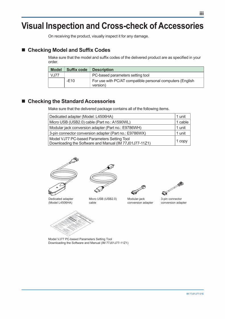
Visual Inspection and Cross-check of AccessoriesOn receiving the product, visually inspect it for any damage.
CheckingModelandSuffixCodesMake sure that the model and suffix codes of the delivered product are as specified in your order.
Model Suffixcode DescriptionVJ77 PC-based parameters setting tool
-E10 For use with PC/AT compatible personal computers (English version)
Checking the Standard AccessoriesMake sure that the delivered package contains all of the following items.
Dedicated adapter (Model: L4506HA) 1 unitMicro USB (USB2.0) cable (Part no.: A1590WL) 1 cableModular jack conversion adapter (Part no.: E9786WH) 1 unit3-pin connector conversion adapter (Part no.: E9786WX) 1 unitModel VJ77 PC-based Parameters Setting Tool Downloading the Software and Manual (IM 77J01J77-11Z1) 1 copy
Micro USB (USB2.0)cable
Dedicated adapter(Model L4506HA)
3-pin connectorconversion adapter
Modular-jackconversion adapter
Model VJ77 PC-based Parameters Setting ToolDownloading the Software and Manual (IM 77J01J77-11Z1)

iv
IM 77J01J77-01E
Documentation Conventions
Documentation ConventionsThe following conventions are used throughout this manual:
The names of named dialog boxes, windows, and views are written in title cap and refer to the exact titles.
Parameter Setting Menu dialog box
Gantt view
The names of unnamed windows, dialog boxes, and views are written in all lowercase letters.
document window
print preview
Commands (including buttons) in a dialog box or window and menu commands are written in boldface.
Click OK.Click Options.From the File menu, choose Exit.
Characters to be typed by the user via keyboard are written in monotype font.
Type JUXTA in the Model box.
Item Usage
IMPORTANTIndicates that operating the hardware or software in a particular manner may damage it or result in a system failure.
NOTE Draws attention to information that is essential for understanding the operation and/or features of the product.
TIPGives additional information to complement the present topic.
See AlsoGives reference locations for further information on the topic.
Illustrations in This Document (1) Illustrations and figures presenting this product or its functions in this manual may not
be exactly the same as the actual product or functions so as to simplify understanding.(2) Figures and illustrations representing the displays may differ from the actual displays in
regard to the position and/or display characters (uppercase or lowercase, for example), but not to an extent that impairs a correct understanding of the functions and the proper setting operation.
v
IM 77J01J77-01E
Notice
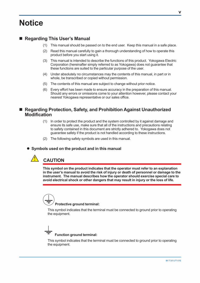
Regarding This User’s Manual(1) This manual should be passed on to the end user. Keep this manual in a safe place.(2) Read this manual carefully to gain a thorough understanding of how to operate this
product before you start using it.(3) This manual is intended to describe the functions of this product. Yokogawa Electric
Corporation (hereinafter simply referred to as Yokogawa) does not guarantee that these functions are suited to the particular purpose of the user.
(4) Under absolutely no circumstances may the contents of this manual, in part or in whole, be transcribed or copied without permission.
(5) The contents of this manual are subject to change without prior notice.(6) Every effort has been made to ensure accuracy in the preparation of this manual.
Should any errors or omissions come to your attention however, please contact your nearest Yokogawa representative or our sales office.
Regarding Protection, Safety, and Prohibition Against Unauthorized Modification
(1) In order to protect the product and the system controlled by it against damage and ensure its safe use, make sure that all of the instructions and precautions relating to safety contained in this document are strictly adhered to. Yokogawa does not guarantee safety if the product is not handled according to these instructions.
(2) The following safety symbols are used in this manual.
Symbols used on the product and in this manual
CAUTIONThissymbolontheproductindicatesthattheoperatormustrefertoanexplanationin the user’s manual to avoid the risk of injury or death of personnel or damage to the instrument.Themanualdescribeshowtheoperatorshouldexercisespecialcaretoavoid electrical shock or other dangers that may result in injury or the loss of life.
Protective ground terminal: This symbol indicates that the terminal must be connected to ground prior to operating
the equipment.
Function ground terminal: This symbol indicates that the terminal must be connected to ground prior to operating
the equipment.
vi
IM 77J01J77-01E
ExemptionfromResponsibility(1) Yokogawa does not make any warranties regarding the product except those
mentioned in the WARRANTY that is provided separately. (2) Yokogawa assumes no liability to any party for any loss or damage, direct or indirect,
caused by the use or any unpredictable defect of the product. (3) Be sure to use the spare parts approved by Yokogawa when replacing parts or
consumables.(4) Modification of the product is strictly prohibited.(5) This software may be used with one specified computer only. You must purchase
another copy of the software for use on each additional computer.(6) Copying the software for purposes other than backup is strictly prohibited.(7) Reverse engineering such as the disassembly or recompilation of software is strictly
prohibited.(8) No portion of the software supplied by Yokogawa may be transferred, exchanged,
leased, or sublet for use by any third party without the prior permission of Yokogawa.

vii
IM 77J01J77-01E
LICENSE AGREEMENT FOR PACKAGE SOFTWARE PRODUCTATTENTION! -
Please read this LICENSE AGREEMENT (hereinafter referred to as the “Agreement”) carefully before installing this package software product of Yokogawa Electric Corporation (hereinafter referred to as “Yokogawa”) on the computer.Installing this package software product indicates your acceptance of the terms and conditions of this Agreement. If you are not the end user, transferring this package software product indicates your acceptance of the terms and conditions of this Agreement. If you don’t accept the terms and conditions of this Agreement, please kindly return this package software product, without installing it, to the seller or Yokogawa immediately.
1. Grant of License(1) The terms and conditions of this Agreement shall apply to the following package software of Yokogawa (herein after referred to as “Package Software Product”.
Product: VJ77, Parameters Setting Tool and materials related thereto that Yokogawa designates Number of license: One (1)(2) The Package Software Product herein shall include; without limitation, a software program, font, data base, data put into fill-in-the-form, instruction manual,
functional specifications, materials related thereto image, photograph, animation, video image, sound, music, text all of which are incorporated into software component (program) and applet. (“applet” means software component (program) incorporated into text or icon.)
2. Terms and Conditions of License(1) Yokogawa grants you, for the purpose of your own use, non-exclusive and non-transferable license of the Package Software Product on designated computer
agreed by both parties in consideration of the license fee agreed separately by the both parties.(2) You are, unless otherwise agreed in writing by Yokogawa, not entitled to sell, lend, distribute, transfer or sublicense, or if any, pledge the Package Software Product.
You shall not use Package Software Product on other computer than the designated one through Wide area network, either, including but not limited to intranet, internet, local area network and wide area network.
(3) The Package Software Product shall not be copied in whole or in part except keeping one copy for back-up purpose unless otherwise agreed in writing by Yokogawa in advance. You shall store and manage the copy or duplicate of the Package Software Product in strict confidence and with utmost care.
(4) You shall not and shall not have any third party, including the end user, alter, decompile, disassemble, decrypt, extract or otherwise reverse-engineer the Package Software Product or create any derivative works thereof. Unless otherwise separately agreed by Yokogawa, Yokogawa has no obligation to provide you with the source code for the Package Software Product.
(5) The Package Software Product including all proprietary technology, algorithm, and know-how such as a factor, invariant or process contained therein shall be the proprietary property or trade secret of Yokogawa or a third party which grants Yokogawa the rights.
(6) The proprietary property and/or trade secret as defined in the preceding Article 2.(5) shall not be published or disclosed to any third parties except for your limited employees or equivalents thereto who need to have access thereto. You are also required to impose no less stringent confidentiality obligation than herein the on them.
(7) Yokogawa may use or add copy protection in or to the Package Software Product. In no event shall you remove or attempt to remove such copy protection.(8) The Package Software Product and the all copy and duplicates thereof shall be returned to Yokogawa or the party designated by Yokogawa immediately after the
expiration or termination of this Agreement. Alternatively, if Yokogawa requires in writing to you that all the Package Software Product is destroyed or disposed, all the information therein shall be deleted completely.
(9) You shall not remove any copyright notice, trademark notice, logo or other proprietary notices or identification shown in the Package Software Product.3. LimitationforSpecificUses
(1) Unless otherwise agreed by both parties in writing, the Package Software Product shall not be intended to be specifically designed, manufactured or distributed for the purpose of operation of any aviation, vessel, support of those operations from the ground, or for any design, construction, maintenance, operation and/or use of nuclear products and/or facilities.
(2) Even if you use the Package Software Product for the purpose of preceding Article 3.(1), Yokogawa disclaims any responsibilities, warranties, liabilities, claims or damages whatsoever similar thereto arising out of the use or operations of the Package Software Product for such purpose and you shall indemnify and hold harmless Yokogawa including without limitation its officers, employees, sales representatives, and their officers and employees, from any claim, suit, demand, damage, and similar thereto (including reasonable attorneys’ fees).
4. Warranty(1) During the warranty period defined in this Article 4.(4) below (hereinafter called “Warranty Period”), Yokogawa warrants that the Package Software Product shall
properly function in accordance with the Instruction Manual or Functional Specifications of Yokogawa, on the hardware under the environmental or other conditions designated by the vendor of such hardware or by Yokogawa. However, in no event shall Yokogawa warrant the following under any operating environment and circumstance.
The Package Software Product;a) will never be interruptedb) will never be free from defectc) will be completely correctedd) will be free from any cross interference such as cross conflict with other software programe) will satisfy your or your customer’s any particular and/or prospective purposef) will be accurate, correct, reliable or most up-datedg) will be free of vulnerability (including but not limited to vulnerability to intrusion or attack cause by computer virus or unauthorized access or the like).
(2) During the Warranty Period, if the Package Software Product fails to operate in accordance with the steps of the instruction manual or functional specifications attributable to Yokogawa, or if defect(s) such as damage of a media of the Package Software Product attributable to Yokogawa is found, Yokogawa agrees to either repair or replace, free of charge, any Package Software Product which shall be returned to Yokogawa’s nearest authorized service facility immediately at your expense; where in consideration of the license fee of the Package Software Product is outside of Japan, re-import tax and other charges shall be also borne by you.
Further, in the case that repair or replacement of the Package Software Product requires additional works such as loading of the same at the site by Yokogawa or any person designated by Yokogawa is needed, such cost and expense for the works shall be borne by you and you shall initialize or shut down the system and other related system, products or equipment, if deemed necessary at Yokogawa’s sole judgment.
(3) Notwithstanding the preceding Article 4.(2), Yokogawa’s warranty shall not apply if the defect of the Package Software Product is caused by any of the followings;a) where hardware on which the Package Software Product operates becomes out of warranty of the vendor and proper maintenance contract for the hardware is
not in place;b) where, if Yokogawa designates hardware on which the Package Software Product operates, you changed such hardware to other hardware without
Yokogawa’s consent;c) where any third party other than entrusted by Yokogawa conducted renovation, or improvement of the Package Software Product;d) where hardware on which the Package Software Product operates was moved by you or any third party without Yokogawa’s consent;e) where you or a party you designate (including your customer) misused, renovated, up-graded, or used the Package Software Product for any other purpose
than set forth in the Instruction Manuals etc.;f) where the Package Software Product was used or operated under the different operating environment and/or other conditions than the terms designated by
Yokogawa or provider of hardware;g) where you or your customer does not execute the proper trouble or non-conformity avoiding measures (including repair or replacement) Yokogawa proposed;
or other cause of defect not attributable to Yokogawa;(4) The Warranty Period shall be the twelve (12) month period from the date when Yokogawa complete the delivery at the place designated by you (including your
customer) or you or your customer use part or whole of the Package Software Product for the operation, whichever comes first, unless otherwise agreed in writing by Yokogawa.
viii
IM 77J01J77-01E
(5) Under separate maintenance contract, Yokogawa may conduct maintenance service for the Package Software Product, at the expense of you even after the Warranty period. The maintenance service for the Package Software Product shall be classified into those of standard software, customized software.a) Standard Software Standard Software herein means the standard package software covered by Yokogawa’s Catalogue and/or General Specifications. The maintenance service
for Standard Software may be available for the latest two versions unless otherwise covered by Yokogawa’s Catalogue and/or General Specifications. However, the maintenance service for the Package Software Product which is the earlier version among the latest two versions may be available only for
five (5) years after the last up-dated. The maintenance service for the version of the Package Software Product declared by Yokogawa to discontinue order acceptance may be available for five (5) years after such declaration.
b) Customized Software Customized Software herein means the software customized by Yokogawa pursuant to the Quotation or Functional Specifications agreed by both parties. The maintenance service for the Customized Software shall not be available to you including your customer after the Warranty Period unless otherwise
separately agreed by both parties. However, such maintenance service may be conducted at your expense as remodeling contract agreed by the both parties.(6) Notwithstanding the preceding Article 4.(1), 4.(2), 4.(3), 4.(4) and 4.(5), on the third party’s software, warranty, including warranty period, of such third party provider
shall apply.5. Revision-Up Package Software
When you receive the Revision-Up of the Package Software Product which is substituted for or is added to the Package Software Product (“Revision-Up”), you can install such Revision-Up in the computer(s) on which you use the Package Software Product. Furthermore, the Revision-Up shall be considered as the Package Software Product and you shall agree to comply with the terms and conditions of this Agreement in order to use the Revision-Up.
6. If You are not the End UserIf you are not the end user of the Package Software Product, you shall present the terms and conditions of this Agreement to your end user and cause your end user to observe such terms and conditions. If Yokogawa incurs damage due to your end user’s breach of such terms and conditions as set forth herein, you shall indemnify and hold Yokogawa harmless as set forth herein above. In this case, it is the end user that is granted the license of the Package Software Product by Yokogawa and if you are not the end user, you shall transfer the possession of media and related materials of the Package Software Product to your end user.
7. Intellectual Property Infringement(1) If and when any third party should demand injunction, initiate a law suit, or demand damages against you under patent right, utility model right, design patent right,
trademark right, copyright and/or any other right relating to any of the Package Software Product including but not limited to its related materials, you shall notify Yokogawa of that effect in writing without delay.
(2) In case of preceding Article 7.(1), you shall assign to Yokogawa all of the rights to defend you, to negotiate and to settle with the claiming party. Furthermore, you shall provide Yokogawa with necessary information or any other assistance for Yokogawa’s defense and negotiation. If and when such a claim should be attributable to Yokogawa, Yokogawa shall defend you and negotiate with the claiming party at Yokogawa’s cost and expense and be responsible for the final settlement or judgment granted to the claiming party in the preceding Article 7.(1).
Provided, however, that Yokogawa shall have no liability for any claim of infringement in the preceding Article 7.(1) if based on;a) use of other than the latest version of Package Software Product made available to you, if the infringement would have been avoided by use of such version; b) addition to Package Software Product of any other software or program not advised or recommended by Yokogawa, if the infringement would have been
avoided without such addition; c) the combination or use of Package Software Product with software or program not furnished by Yokogawa if such infringement would have been avoided by
use of Package Software Product with Yokogawa software or program alone; or any other cause not within the control of Yokogawa.(3) When any assertion of the infringement of third party's right defined in Article 7. (1) is made or when, at Yokogawa’s judgment, there is possibility of such assertion,
Yokogawa will, at its discretion and not obligation, take any of the following countermeasures at Yokogawa’s cost and expense.a) To acquire the necessary right from a third party which has lawful ownership of the right so that you will be able to continue to use the Package Software
Product;b) To replace the Package Software Product with the one, which avoids the infringement;c) To remodel the Package Software Product so that the Package Software Products can avoid the infringement of such third party's right; ord) If and when Yokogawa fails to take either of the countermeasures set forth in a. through c. above, Yokogawa shall indemnify you only by paying back the price
amount of the Package Software Product, which Yokogawa has already received.8. Limitation of Liability
If and when you should incur any damage relating to the Package Software Product Yokogawa provided to you under any damage due to the reason attributable to Yokogawa”, Yokogawa shall take actions in accordance with this Agreement. However, in no event shall Yokogawa be responsible for any indirect damage, consequential damage, punitive damage and/or special damage, including without limitation, loss of operational profit, loss of interruption of your business, and loss of business information and that Yokogawa’s liability to your damage shall not exceed the price amount of the Package Software Product Yokogawa received. It is specifically agreed by both parties that Yokogawa shall be released and discharged from part or any and all of the liability and responsibility under this Agreement if you (including the case you have any third party cause to ) modify, remodel, combine with other software or products, or cause any deviation from the basic specifications or functional specifications, without Yokogawa’s prior written consent.
9. Term(1) This Agreement shall become effective from the date when you receive the Package Software Product and continues in effect until the earlier of early termination as
provided in Article 12, Yokogawa gives thirty (30) days prior written notice to you, or your license term terminates.(2) Articles 2.(4), 2.(6), 2.(8), 7, 8,11 and 12 shall survive even after the termination.
10. Injunction for UseDuring the term of this Agreement, Yokogawa may, at its own discretion, demand an injunction against you and your customer in case Yokogawa deems the Package Software Product is used improperly or under severer environments than those Yokogawa first granted or any other condition which Yokogawa may not permit.
11. ConfidentialityObligation(1) You agree that the structure, organization and code of the Package Software Product are the valuable trade secrets of Yokogawa or third party which grants
Yokogawa the rights and the Package Software Product contains other proprietary information and know-how of Yokogawa and its third party, which may be disclosed for the purpose of license granted hereunder. You shall not divulge any of such trade secrets, information and know-how to any third party without Yokogawa’s consent and shall not use for any purpose other than license use.
(2) You shall maintain the Package Software Product, its media, any printing material and any copy thereof in strict confidence and with utmost care to comply with the said secrecy obligation and protect the right of Yokogawa and third party which grants Yokogawa the rights.
12. Termination by CauseYokogawa may terminate this Agreement without any notice or demand to you immediately terminate. if you breach any of the terms and conditions of this Agreement.
13. Governing Law and Arbitration(1) This Agreement shall be governed by and construed in accordance with the laws of Japan.(2) All disputes, controversies or differences which may arise between the parties hereto, out of or in relation to or in connection with this Agreement shall be finally
settled by arbitration in Tokyo, Japan in accordance with the Commercial Arbitration Rules of the Japan Commercial Arbitration Association. The arbitration is conducted in English language. The award rendered by the arbitrator(s) shall be final and binding upon the parties hereto.
14. Miscellaneous(1) This Agreement supersedes all prior oral and written understandings, representations and discussions between the parties concerning the subject matter hereof to
the extent such understandings, representations and discussions should be discrepant or inconsistent with this Agreement.(2) If any part of this Agreement is found void or unenforceable, it shall not affect the validity of the balance of the Agreement, which shall remain valid and enforceable
according to its terms and conditions. The parties hereby agree to attempt to substitute for such invalid or unenforceable provision a valid or enforceable provision that achieves to the greatest extent possible the economic, legal and commercial objectives of the invalid or unenforceable provision.
(3) Failure by either party to insist on performance of this Agreement or to exercise a right does not prevent such party from doing so at a later time, either in relation to that default or any subsequent default.

ix
IM 77J01J77-01E
IM 77J01J77-01E
Model VJ77PC-based Parameters Setting Tool
CONTENTSIntroduction ...............................................................................................................................iVisual Inspection and Cross-check of Accessories ...........................................................iiiDocumentation Conventions .................................................................................................ivNotice ....................................................................................................................................v
LICENSE AGREEMENT FOR PACKAGE SOFTWARE PRODUCT ...................... vii1. VJ77 PC-based Parameters Setting Tool ...................................................1-1
1.1 An Overview of VJ77 and Its Functions ............................................................. 1-11.1.1 What is VJ77? ........................................................................................ 1-11.1.2 Functions................................................................................................ 1-1
1.2 Conceptual View of VJ77 ..................................................................................... 1-21.3 OperatingEnvironmentandWiringSpecifications .......................................... 1-3
1.3.1 System Requirements ........................................................................... 1-31.3.2 Dedicated Adapter ................................................................................. 1-3
1.4 ExternalViewofDedicatedAdapter ................................................................... 1-41.5 Precautions When Communicating with Device ............................................... 1-5
2. Setup ..............................................................................................................2-12.1 Downloading the Software and Driver ..................................................................2-12.2 Installing the USB Driver .........................................................................................2-12.3 Installing VJ77 ....................................................................................................... 2-72.4 Uninstalling VJ77 .................................................................................................. 2-72.5 Connecting Instrument to Personal Computer ................................................. 2-8
2.5.1 Items Required for Connection .............................................................. 2-82.5.2 How to Connect ..................................................................................... 2-8
2.6 Setting the Communication Port ....................................................................... 2-10
3. Basic Operation ............................................................................................3-13.1 Starting VJ77 ......................................................................................................... 3-13.2 Quitting VJ77 ........................................................................................................ 3-13.3 Window Elements and Functions ....................................................................... 3-23.4 Basic Operation .................................................................................................... 3-3
3.4.1 Operation Using a Mouse ...................................................................... 3-33.4.2 Operation Using Keyboard .................................................................... 3-4
3.5 Main Windows and Their Functions ................................................................... 3-53.5.1 DISPLAY Menu Window ........................................................................ 3-53.5.2 SET Menu Window ................................................................................ 3-53.5.3 ADJUST Menu Window ......................................................................... 3-63.5.4 Program Setting Window ....................................................................... 3-6
IM 77J01J77-01E
x
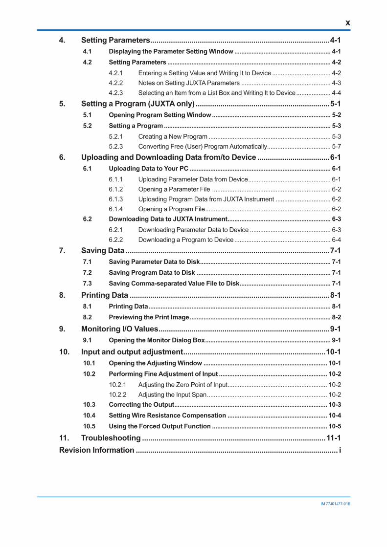
4. Setting Parameters .......................................................................................4-14.1 Displaying the Parameter Setting Window ........................................................ 4-14.2 Setting Parameters ............................................................................................... 4-2
4.2.1 Entering a Setting Value and Writing It to Device .................................. 4-24.2.2 Notes on Setting JUXTA Parameters .................................................... 4-34.2.3 Selecting an Item from a List Box and Writing It to Device .................... 4-4
5. Setting a Program (JUXTA only) .................................................................5-15.1 Opening Program Setting Window ..................................................................... 5-25.2 Setting a Program ................................................................................................. 5-3
5.2.1 Creating a New Program ....................................................................... 5-35.2.3 Converting Free (User) Program Automatically..................................... 5-7
6. Uploading and Downloading Data from/to Device ...................................6-16.1 Uploading Data to Your PC .................................................................................. 6-1
6.1.1 Uploading Parameter Data from Device ................................................ 6-16.1.2 Opening a Parameter File ..................................................................... 6-26.1.3 Uploading Program Data from JUXTA Instrument ................................ 6-26.1.4 Opening a Program File ......................................................................... 6-2
6.2 Downloading Data to JUXTA Instrument ............................................................ 6-36.2.1 Downloading Parameter Data to Device ............................................... 6-36.2.2 Downloading a Program to Device ........................................................ 6-4
7. Saving Data ...................................................................................................7-17.1 Saving Parameter Data to Disk ............................................................................ 7-17.2 Saving Program Data to Disk .............................................................................. 7-17.3 Saving Comma-separated Value File to Disk ..................................................... 7-1
8. Printing Data .................................................................................................8-18.1 Printing Data .......................................................................................................... 8-18.2 Previewing the Print Image .................................................................................. 8-2
9. Monitoring I/O Values ...................................................................................9-19.1 OpeningtheMonitorDialogBox ......................................................................... 9-1
10. Input and output adjustment .....................................................................10-110.1 Opening the Adjusting Window ........................................................................ 10-110.2 Performing Fine Adjustment of Input ............................................................... 10-2
10.2.1 Adjusting the Zero Point of Input .......................................................... 10-210.2.2 Adjusting the Input Span ...................................................................... 10-2
10.3 Correcting the Output ......................................................................................... 10-310.4 Setting Wire Resistance Compensation .......................................................... 10-410.5 Using the Forced Output Function ................................................................... 10-5
11. Troubleshooting .........................................................................................11-1Revision Information .................................................................................................. i
1-1
IM 77J01J77-01E
1. VJ77 PC-based Parameters Setting Tool
This chapter gives an overview of the VJ77 tool and describes its operating environment.
1.1 An Overview of VJ77 and Its Functions1.1.1 What is VJ77?
The VJ77 Parameter Setting Tool is a PC software package for setting various parameters and computing unit programs of the microcomputer-based JUXTA, and various parameters of YS80 series rack instruments with the BRAIN communication function (hereafter, the YS80).
1.1.2 Functions
Parameter settingSets parameters that configure the functions of microprocessor-based JUXTA or YS80 instruments.
Program settingSets programs of microprocessor-based JUXTA computing units.Programs can be edited from a PC even when offline.** A state in which the PC (VJ77) and the JUXTA instrument are not connected
Download to/upload from the JUXTA instrumentUploads parameters or program from a microprocessor-based JUXTA instrument to a personal computer, and downloads the parameters and program once loaded or a program you created, to a JUXTA instrument. It also enables you to read and write parameters to and from the YS80. You can also write to a YS80 even it is of a different style.
Data saving to diskSaves parameters or program in a JUXTA instrument to the hard disk of a personal computer, etc. Also, you can save loaded YS80 parameters to the PC’s hard disk.
Data printingPrints parameters or program uploaded from a JUXTA instrument. Also, you can print loaded YS80 parameters to a printer connected to the PC.
Input/output value monitorViews the I/O values and the result of self-diagnosis of a microprocessor-controlled JUXTA or YS80 instrument.
Input and output adjustmentAdjusts inputs and outputs of a microprocessor-controlled JUXTA or YS80 instrument.
1-2
IM 77J01J77-01E
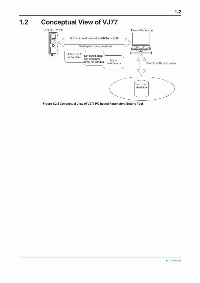
1.2 Conceptual View of VJ77
ALM1
ALM2
Hard disk
Upload from/download to JUXTA or YS80
JUXTA or YS80 Personal computer
Read from/Save to a disk
(Pier-to-pier communication)
Reference to parameters Set parameters/
Set programs(only for JUXTA) Adjust
Instrumens
Figure 1.2.1 Conceptual View of VJ77 PC-based Parameters Setting Tool

1-3
IM 77J01J77-01E
1.3 Operating Environment and Wiring Specifications
1.3.1 System RequirementsItem Windows11 (1)
Japanese / EnglishWindows10 (1)
Japanese / EnglishWindows8.1 (1)
Japanese / English
Edition Pro 64bit Pro 64bit Pro 32bit/64bit
Version (1) 21H2 or later 20H2 or later Update
CPU Intel processor that supports 64 bit and 1 GHz or faster with 2 or more cores
Intel processor that supports 64 bit and 2 GHz or faster speed (recommended)
Intel processor that supports 2 GHz or faster speed (recommended)
Recommended main memory capacity
8 GB or more 8 GB or more 2 GB or more
Recommended storage free capacity
32 GB or more 32 GB or more 16 GB or more
Display resolution Display compatible with OS
Communication port USB port
Printer Support for letter or A4 size (Required for printing)
1: YOKOGAWA also has ended support for OS’s that Microsoft Corporation no longer supports.
1.3.2 Dedicated AdapterPower supply: Supplied from the USB bus power.Insulation resistance: Minimum of 100 M/500 V DC between USB communication port
and the JUXTA connection sides.Dielectric strength: 500 V AC/minute between USB communication port and the JUXTA
connection sides.Ambient temperature: 0 to 50°CAmbient humidity: 5 to 90%RH (no condensation)Transport and storage conditions: −40 to 70°C, 5 to 95%RH (no condensation)Waterproof & dustproof construction: Not applicable

1-4
IM 77J01J77-01E
1.4 ExternalViewofDedicatedAdapterUnit: mm
14.5
18.5
74.6
70.2
Micro USB cable
985±35 (70.2)
(74.6)
30
1190±351150±25
Modular-jack conversion adapter
1090±20
5-pin connector
3-pin connector conversion adapter
Figure 1.4.1 Dedicated Adapter
EMC StandardsModel: L4506HACE: EN 61326-1 Class A Table 2 compliance EN 55011 Class A Group 1 complianceRCM: EN 55011 Class A, Group 1 complianceKC: Electromagnetic wave interference prevention standard, electromagnetic wave
protection standard compliance.

1-5
IM 77J01J77-01E
1.5 Precautions When Communicating with Device NOTE
Do not remove the communication cable while communicating with a JUXTA or YS80 instrument.Communication may be in progress in the following windows.• Communication execution window
• Parameter setting window
• Parameter view window
• Program setting window
• Parameter Setting dialog box
• Program Editor dialog box
• Constant Setting dialog box
• Check Downloading to Device dialog box
• Command Check Error list dialog box
• SLOT No. Setting dialog box

Blank Page
2-1
IM 77J01J77-01E
2. SetupThis chapter describes how to set up the hardware and software required to run VJ77.First, download the necessary software and driver from the website.Next, install the USB driver to allow the use of a USB cable. Finally, install the VJ77 PC-based Parameters Setting Tool.
2.1 Downloading the Software and DriverDownload VJ77 PC-based Parameters Setting Tool and USB Converter Driver Software from the following URL. Download files are in zip format.
http://www.yokogawa.com/ns/juxta/vj77/download/
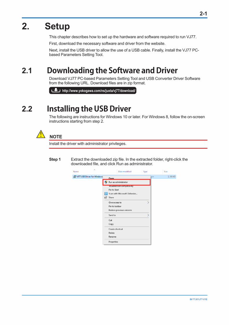
2.2 Installing the USB DriverThe following are instructions for Windows 10 or later. For Windows 8, follow the on-screen instructions starting from step 2.
NOTEInstall the driver with administrator privileges.
Step 1 Extract the downloaded zip file. In the extracted folder, right-click the downloaded file, and click Run as administrator.

2-2
IM 77J01J77-01E
Step 2 In the User Account Control screen, click Yes. Step 3 In the VJ77 USB Driver for Windows 10 Setup screen, click Install.
Step 4 In the Finished screen, click Close.
This completes the installation of the driver.Connect the dedicated cable to the PC’s USB port to automatically start using the cable.
2-3
IM 77J01J77-01E
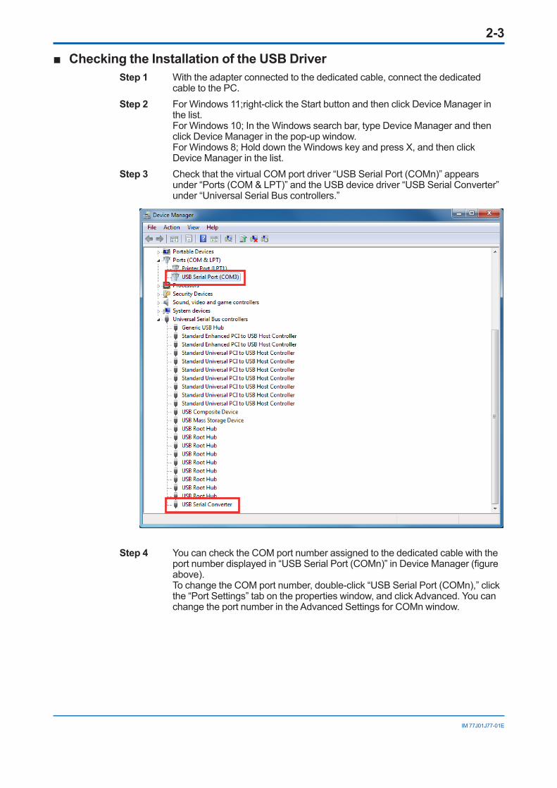
■ Checking the Installation of the USB DriverStep 1 With the adapter connected to the dedicated cable, connect the dedicated
cable to the PC.Step 2 For Windows 11;right-click the Start button and then click Device Manager in
the list. For Windows 10; In the Windows search bar, type Device Manager and then click Device Manager in the pop-up window. For Windows 8; Hold down the Windows key and press X, and then click Device Manager in the list.
Step 3 Check that the virtual COM port driver “USB Serial Port (COMn)” appears under “Ports (COM & LPT)” and the USB device driver “USB Serial Converter” under “Universal Serial Bus controllers.”
Step 4 You can check the COM port number assigned to the dedicated cable with the port number displayed in “USB Serial Port (COMn)” in Device Manager (figure above). To change the COM port number, double-click “USB Serial Port (COMn),” click the “Port Settings” tab on the properties window, and click Advanced. You can change the port number in the Advanced Settings for COMn window.

2-4
IM 77J01J77-01E
■ Uninstalling the USB DriverFor Windows 10 / Windows 11Step 1 If a dedicated cable is connected to the PC, disconnect it. Step 2 On the Windows Start menu, click Settings > Apps > Apps & Features. Step 3 Click VJ77 USB Driver for Windows 10, and then click Uninstall. Step 4 If the User Account Control screen appears, click Yes. Step 5 In the VJ77 USB Driver for Windows 10 Setup screen, click Uninstall.
Step 6 In the Uninstall Finished screen, click Close.
This completes the uninstallation.

2-5
IM 77J01J77-01E
For Windows 8Step 1 Connect the dedicated cable to the PC.Step 2 Hold down the Windows key and press X, and then click Device Manager in the
list.Step 3 Right-click “USB Serial Port (COMn)” under “Ports (COM & LPT),” and click
Uninstall.
Step 4 A device uninstallation confirmation window appears. Select the “Delete the driver software for this device” check box, and click OK.
2-6
IM 77J01J77-01E
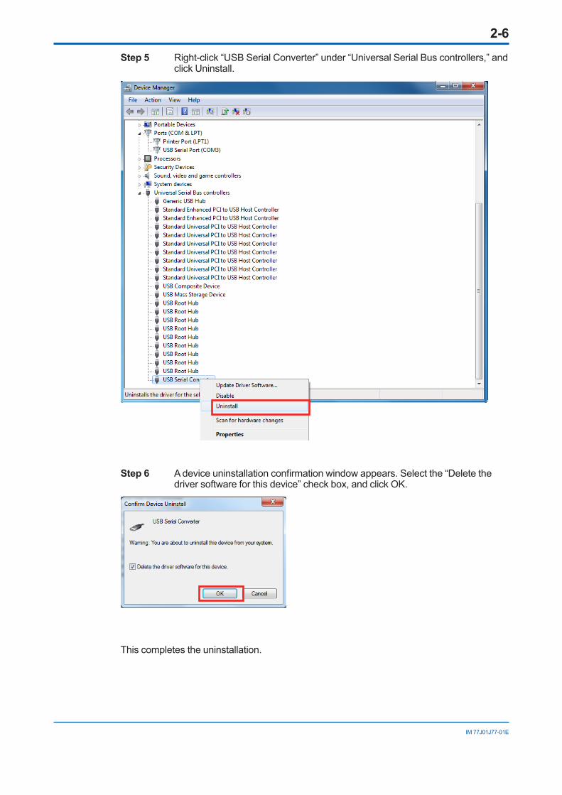
Step 5 Right-click “USB Serial Converter” under “Universal Serial Bus controllers,” and click Uninstall.
Step 6 A device uninstallation confirmation window appears. Select the “Delete the driver software for this device” check box, and click OK.
This completes the uninstallation.

2-7
IM 77J01J77-01E
2.3 Installing VJ77
NOTE• Install the software as an administrator.
• Do not save VJ77 user file in Program Files folder. The VJ77 will not work properly.
• Before installing VJ77 Setting Software, quit all running applications.
• Avoid entering just the drive as the installation location, such as C:\. Enter the full directory path.
• If .NET Framework 4.0 is not installed in your PC, it will be installed. (This is necessary to run VJ77.)
• When reinstalling VJ77, uninstall the installed VJ77 first, and then reinstall VJ77.
• To run VJ77, Microsoft’s .NET Framework 4.0 runtime is required.
• If .NET Framework 4.0 needs to be installed and the PC is connected to a network, .NET Framework 4.0 will automatically be downloaded and installed before the installation of VJ77.
Step 1 Double-click the downloaded zip file to extract the files.Step 2 Double-click setup.exe in the unzipped folder to start a setup wizard. Follow the
instructions in the dialog boxes.
For Windows8.1 When installation is complete, VJ77 will be registered under All Programs in the
Windows Start menu.For Windows10 When installation is complete, VJ77 will be registered under Apps in the
Windows Start menu.For Windows11 When installation is complete, VJ77 Setting Tool will be registered under All
apps in the Windows Start menu.
2.4 Uninstalling VJ77Step 1 For Windows 10 / Windows11; In the Windows Start menu, click Start >
Settings > Apps > Apps & Features. Under Apps & Features, click VJ77, and then click Uninstall.
For Windows 8; Hold down the Windows key and press X, and then click Uninstall a Program in the list. In Programs and Features, click VJ77 to uninstall it.
Step 2 A User Account Control window appears. Click Yes. VJ77 will be uninstalled.*1: If the Control Panel display mode is Control Panel Home, use Uninstall a program.

2-8
IM 77J01J77-01E
2.5 Connecting Instrument to Personal ComputerThis section describes how to connect a JUXTA or YS80 instrument to a personal computer.
2.5.1 Items Required for ConnectionTo connect a JUXTA instrument to a personal computer, the following are required: (1) Personal computer with VJ77 installed(2) Micro USB(USB2.0) cable(3) Dedicated adapter(4) Modular-jack conversion adapter;
Used when communicating with JUXTA VJ, M and YS80 series.(5) 3-pin connector conversion adapter;
Used when communicating with JUXTA F and W series.
2.5.2 How to ConnectStep 1 Connect the micro USB cable to the PC and the dedicated adapter.Step 2 • When communicating with the JUXTA D series (DSC2), connect the cable (5-
pin connector) of the dedicated adapter to JUXTA. • When communicating with JUXTA F and W series, connect the 3-pin
connector conversion adapter to the cable of the dedicated adapter, and then connect to JUXTA.
• When communicating with the JUXTA VJ, M, YS80 series, connect the modular jack conversion adapter to the cable of the dedicated adapter, and then connect to JUXTA or YS80.
PC Example of connecting to the VJ series
JUXTAVJ series
Modular-jackconversion adapter
Dedicated adapter for VJ77 (L4506HA)
Micro USB (USB2.0)cable

2-9
IM 77J01J77-01E
YS80 SeriesRack instrument
Micro USB (USB2.0)cable
Modular-jackconversion adapter
Dedicated adapter (L4506HA)
Example of connecting to the YS80 series PC

2-10
IM 77J01J77-01E
2.6 Setting the Communication PortThis section describes how to set the communication port to connect a JUXTA or YS80 instrument to the personal computer (VJ77). The communication port (serial port) indicates the valid serial port that the PC is using when a communication execution window is open.
Serial Port
Parametersettingscreenexample
The communication execution window is displayed by the following five operations.• Parameter Setting
• Upload Parameter Data from Device
• Download Parameter Data to Device
• Upload Program Data from Device
• Download Program Data to Device

3-1
IM 77J01J77-01E
3. Basic OperationThis chapter describes basic operation and identifies the main dialog boxes of VJ77.
3.1 Starting VJ77From the Windows Start menu, choose the commands in the following sequence.For Windows10 Start > Apps > VJ77 > VJ77 Setting Tool Or, double-click the shortcut (VJ77 Setting Tool).For Windows11 Start > All apps > VJ77 Setting Tool Or, double-click the shortcut (VJ77 Setting Tool).
VJ77 starts up, and the main window appears.
3.2 Quitting VJ77 From the File menu, choose Exit. Or, click × in the upper right of the window.

3-2
IM 77J01J77-01E
3.3 Window Elements and FunctionsThis section identifies the element and their functions of a window and dialog box of VJ77 with reference to the parameter setting window.
Command area Parameter data display area
Window areaStatus bar area
Title barMenu bar Parameter menu button
Submenu button
Title bar “Setting Tool” is displayed. If file data is displayed in the window, the file name is also
displayed in the title bar.
Menu bar As is usual for Windows applications, the menu bar is displayed below the title bar of a
window. Each menu name contains the related commands.
Parameter menu button Shows the menu items read from the JUXTA or YS80 instrument.
Submenu button Shows the submenu items of the selected parameter menu.
Command area Shows the commands that can be used on VJ77. The commands are arranged by
parameter or program type.
3-3
IM 77J01J77-01E
Status Window area TShows command execution windows (communication execution window, parameter
setting window, program setting window, etc.).
bar area Shows communication status and other temporary information.
Parameter data display area Shows the parameters retrieved from the JUXTA or YS80 instrument.
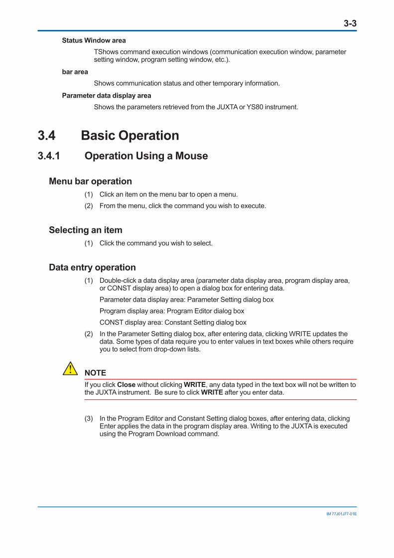
3.4 Basic Operation3.4.1 Operation Using a Mouse
Menu bar operation(1) Click an item on the menu bar to open a menu.(2) From the menu, click the command you wish to execute.
Selecting an item(1) Click the command you wish to select.
Data entry operation(1) Double-click a data display area (parameter data display area, program display area,
or CONST display area) to open a dialog box for entering data. Parameter data display area: Parameter Setting dialog box Program display area: Program Editor dialog box CONST display area: Constant Setting dialog box(2) In the Parameter Setting dialog box, after entering data, clicking WRITE updates the
data. Some types of data require you to enter values in text boxes while others require you to select from drop-down lists.
NOTEIf you click Close without clicking WRITE, any data typed in the text box will not be written to the JUXTA instrument. Be sure to click WRITE after you enter data.
(3) In the Program Editor and Constant Setting dialog boxes, after entering data, clicking Enter applies the data in the program display area. Writing to the JUXTA is executed using the Program Download command.

3-4
IM 77J01J77-01E
3.4.2 Operation Using Keyboard
Menu bar operation(1) Press the F10 or ALT key on the keyboard. File in the menu bar is displayed as a
button, indicating that it is selected. Move to the menu item you wish to execute using the RIGHT ARROW and LEFT ARROW keys, then press the ENTER, UP ARROW, or DOWN ARROW key. The menu of the selected item is then displayed. (Pressing the ALT key+F key opens the pull-down menu of File)
(2) In the pull-down menu, move to the command you wish to execute using the UP ARROW and DOWN ARROW keys, then press ENTER.
(3) To cancel the operation, press the ESC key.
Selecting an item In a window, each press of the TAB key switches the selected command in turn.
Data entry operation(1) In the data display area, after selecting an item (line), pressing Ctrl+Enter displays a
dialog box for entering data.(2) Enter the value from the keyboard.(3) After entering data, press Tab to move the cursor to WRITE or Enter, and press Enter.
Command buttons (WRITE, Close, Cancel, etc.)(1) Select a command button using the TAB key.(2) Press ENTER to execute the corresponding command.

3-5
IM 77J01J77-01E
3.5 Main Windows and Their Functions3.5.1 DISPLAY Menu Window
This window shows the input/output values of the JUXTA or YS80 instrument and the results of self-diagnosis.
See Also
For more information about the DISPLAY dialog box, see Chapter 9, “Monitoring I/O Values.”
3.5.2 SET Menu WindowThis window is used to set various parameters of the JUXTA or YS80 instrument.
See Also
For more information about the SET dialog box, see Chapter 4, “Setting Parameters.”
3-6
IM 77J01J77-01E
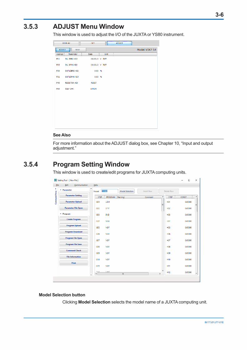
3.5.3 ADJUST Menu WindowThis window is used to adjust the I/O of the JUXTA or YS80 instrument.
See Also
For more information about the ADJUST dialog box, see Chapter 10, “Input and output adjustment.”
3.5.4 Program Setting WindowThis window is used to create/edit programs for JUXTA computing units.
Model Selection button Clicking Model Selection selects the model name of a JUXTA computing unit.
3-7
IM 77J01J77-01E
Program display area*Shows programs and comment data.
STEP Shows the program step.PROGRAM Shows the program command.Warning Shows an icon when a command error occurs.Comment A cell for entering comments for the specified program (up to 25
characters).
CONST (constant) display area*Shows constants for the specified program.
*: When Program Upload is executed and the Program Editor dialog box is displayed, these cells show the program and constants uploaded from the JUXTA instrument.
Insert Row buttonWhen a line is selected in the program display area, clicking this button inserts a line above the selected line.
Delete Row buttonWhen a line is selected in the program display area, clicking this button deletes the line.
See Also
For more information about the Program Editor dialog box, see Chapter 5, “Setting a Program.”

Blank Page
4-1
IM 77J01J77-01E
4. Setting ParametersThis chapter describes the operation to set parameters of JUXTA or YS80 instruments using VJ77. Parameters are set in the parameter setting window.
See Also
When you set parameters, refer to the parameter lists given in the respective user’s manuals of JUXTA signal conditioners, computing units and YS80 series rack instruments.
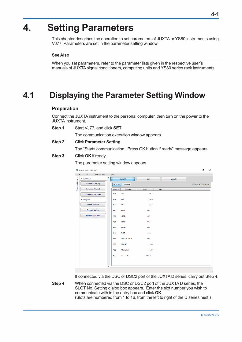
4.1 Displaying the Parameter Setting WindowPreparation
Connect the JUXTA instrument to the personal computer, then turn on the power to the JUXTA instrument.Step 1 Start VJ77, and click SET. The communication execution window appears.Step 2 Click Parameter Setting. The “Starts communication. Press OK button if ready” message appears.Step 3 Click OK if ready. The parameter setting window appears.
If connected via the DSC or DSC2 port of the JUXTA D series, carry out Step 4.Step 4 When connected via the DSC or DSC2 port of the JUXTA D series, the
SLOT No. Setting dialog box appears. Enter the slot number you wish to communicate with in the entry box and click OK. (Slots are numbered from 1 to 16, from the left to right of the D series nest.)

4-2
IM 77J01J77-01E
4.2 Setting ParametersThis section describes how to input individual parameter data and write the data to the device from the parameter setting display (the SET dialog box).
4.2.1 Entering a Setting Value and Writing It to DeviceThe following describes how to change the input range of JUXTA VJX7 (S4) (computing unit) with reference to the example of changing the input range from 1 to 5 V DC, to –10 to 10 V DC.Step 1 In the Parameter Setting window, click SET and then SET(I/O). The SET(I/O) submenu window appears.Step 2 Double-click the parameter D24: INPUT1 L_RNG. A Parameter Setting dialog box appears.
Step 3 In the text box, type -10 and click WRITE. The new data is written to the JUXTA instrument, and the display data in the
cell is updated from 1 to –10.
NOTEAfter you click WRITE, the data value shown in the data cell may be different from the value you entered in the text box. This is because the JUXTA instrument has limits for some of its parameters, and if the entered value is outside the limits, the instrument automatically sets the parameter to the nearest limit value.
Step 4 In the same way as Step 1 to Step 3, set the 100% value of the input range by double-clicking the data cell of D25: INPUT1 H_RNG.
The input range of the connected JUXTA instrument has now been changed from 1 to 5 V DC, to –10 to +10 V DC.
4-3
IM 77J01J77-01E
4.2.2 Notes on Setting JUXTA ParametersThe input range/output range of a JUXTA instrument can be set in two ways, depending on the model of the instrument.(1) Models for which 0% and 100% values of the range are set: The high range limit and low range limit are represented as L_RNG and H_RNG, as in INPUT L_RNG and INPUT H_RNG.
(2) Models for which the span value and span of the range are set: The 0% value and span are represented as ZERO and SPAN, respectively, as in INP
ZERO and INP SPAN.
For example, to set an input range of –10 to 10 V DC: • In case (1), set –10 for INPUT L_RNG and 10 for INPUT H_RNG.
• In case (2), set –10 for INP ZERO and 20 for INP SPAN.
IMPORTANTWhen you set the range of a JUXTA instrument, confirm the respective parameter codes to determine whether they are L_RNG and H_RNG, or ZERO and SPAN, to make sure that you set 0% and 100% values of the range or set the 0% value and span.
NOTEFor a numeral parameter, the number of significant digits is 4. For example, if you enter 123.45, the data value will be written as 123.4 and if you enter 0.12345, the data value will be written as 0.1234.
4-4
IM 77J01J77-01E
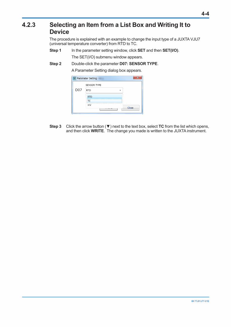
4.2.3 SelectinganItemfromaListBoxandWritingIttoDeviceThe procedure is explained with an example to change the input type of a JUXTA VJU7 (universal temperature converter) from RTD to TC.Step 1 In the parameter setting window, click SET and then SET(I/O). The SET(I/O) submenu window appears.Step 2 Double-click the parameter D07: SENSOR TYPE. A Parameter Setting dialog box appears.
Step 3 Click the arrow button (▼) next to the text box, select TC from the list which opens, and then click WRITE. The change you made is written to the JUXTA instrument.

5-1
IM 77J01J77-01E
5. Setting a Program (JUXTA only)This chapter describes the procedure to set a program for a JUXTA instrument via the program setting window.
See Also
When setting programs, refer to the parameter lists given in the documentation for the respective JUXTA computing units. For details about creating a program, see the Technical Information documents for the respective programmable computing units (document No. TI 231-01E).You can download the latest manuals from the following website:
http://www.yokogawa.com/ns/juxta/im/
To set a program, do one of the following:• Create a new program.
• Upload program data from a JUXTA instrument and modify it.
• Read program data from a file and modify it.
Whichever method is chosen, there are no major differences in operations in the program setting window. This chapter is an example of the procedure to create a new program.

5-2
IM 77J01J77-01E
5.1 Opening Program Setting WindowStep 1 Start VJ77.Step 2 Click Create Program. The program setting window appears.
See Also
For operations after selecting Upload Program Data from Device or Read Program Data from a File, see Chapter 6, “Uploading and Downloading.”
Model Selection button
Constant data display areaProgram data display area
5-3
IM 77J01J77-01E
5.2 Setting a Program5.2.1 Creating a New Program
The following is an example of the procedure to set a moving average computation (of the last 100 seconds) for a VJX7 free program.
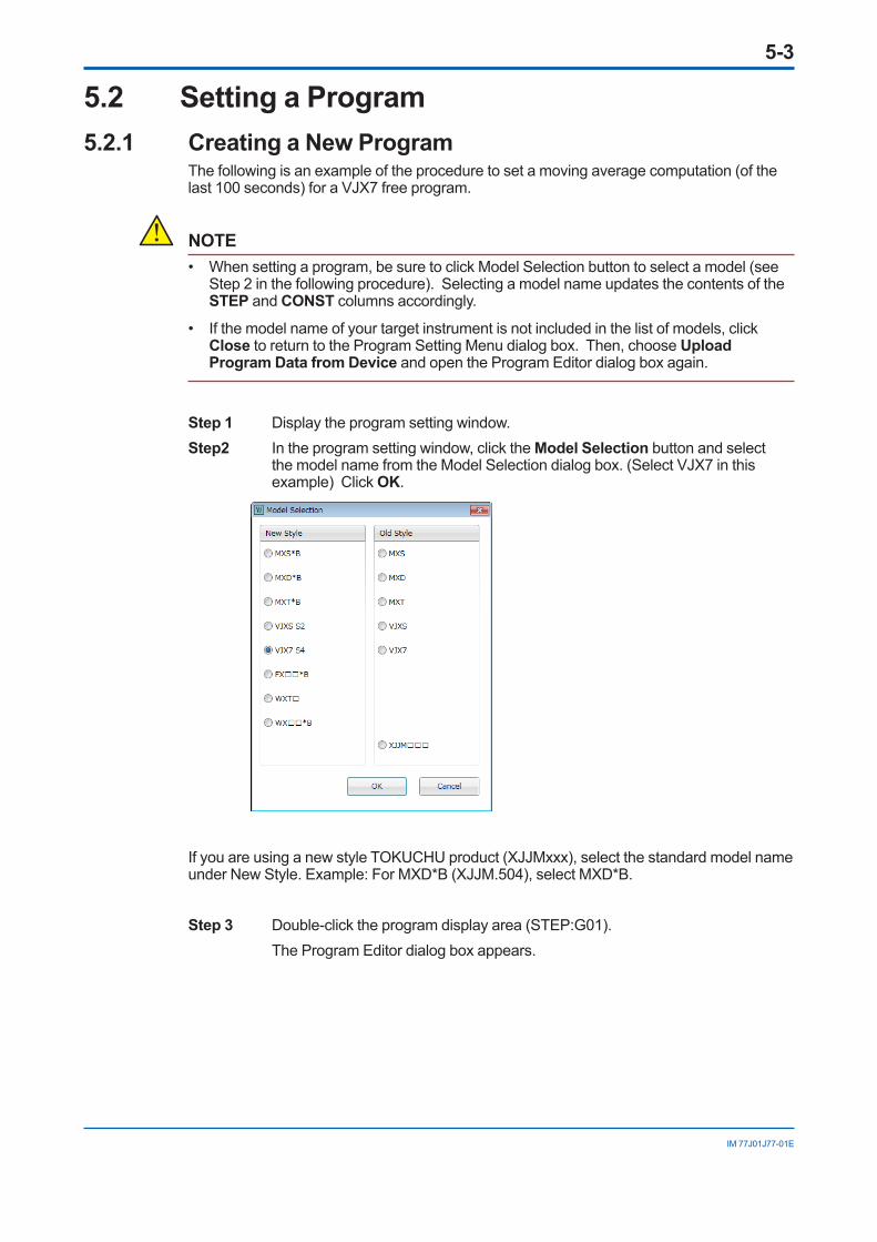
NOTE• When setting a program, be sure to click Model Selection button to select a model (see
Step 2 in the following procedure). Selecting a model name updates the contents of the STEP and CONST columns accordingly.
• If the model name of your target instrument is not included in the list of models, click Close to return to the Program Setting Menu dialog box. Then, choose Upload Program Data from Device and open the Program Editor dialog box again.
Step 1 Display the program setting window.Step2 In the program setting window, click the Model Selection button and select
the model name from the Model Selection dialog box. (Select VJX7 in this example) Click OK.
If you are using a new style TOKUCHU product (XJJMxxx), select the standard model name under New Style. Example: For MXD*B (XJJM.504), select MXD*B.
Step 3 Double-click the program display area (STEP:G01). The Program Editor dialog box appears.

5-4
IM 77J01J77-01E
Step scroll bar
Program text box
STEP
Comment text box
Command group buttonShows/hides the command help
When the command help is shown
Command list display area
Step 4 Click the program text box under STEP:G01, type LDX1, and then click Enter.Step 5 Like step 4, enter LDH1 for G02, MAV for G03, STY1 for G04, and END for G05.
Then, click Enter.Step 6 To enter comments for each program step, type them in the comment text box. You can enter up to 25 characters in a comment text box.Step 7 Double-click the constant display area (STEP:H01). A Constant Setting dialog box appears.

5-5
IM 77J01J77-01E
Step 8 Type “10” in the H01 text box, and then click Enter. Set the moving average time span to 100 seconds (enter a percentage where
0.0 to 100.0% corresponds to 0 to 1000 seconds).Now the program setting is complete.
NOTEIn the Program Editor dialog box, the step numbers of program cells and the constant numbers of constant cells differ depending on the JUXTA model selected. Refer to the parameter lists given in the documentation for the respective JUXTA computing units.
IMPORTANTDO NOT change a program for a computing unit of the JUXTA F series and JUXTA W series other than programmable computing units. In case the unit is operated on the computing function with program changed after factory-ship, the operation will not be guaranteed.
5.2.2 Functions to Facilitate Program Coding
To insert a step:Click the cell immediately below the position where you want to insert a step, then click Insert Row.
To delete a step:Click the cell of the step you want to delete, then click Delete Row.

5-6
IM 77J01J77-01E
Tocheckthesyntaxoftheprogramyoucreatedormodified:Click Command Check.
NOTE• The Command Check function is disabled when setting up the program of any model
whose name is not listed in the Model Selection dialog box.
• The Command Check button is used to check the spelling of operation codes and whether the number of steps exceeds the limit.
Adialogboxappearswhenanerrorisfound:
To copy program code, comment, or constant to another cell: Select a cell or characters and press the + keys. Then click the position to which you want to copy the contents of the selected cell or the selected characters, and press the
+ keys.

5-7
IM 77J01J77-01E
5.2.3 Converting Free (User) Program AutomaticallyThis section explains how to convert old style MXS free (user) programs to those for the new style MXS.Step 1 Upload free (user) program data from the JUXTA (see Section 6.1.3 for details on
the uploading procedure).Step 2 In the Program Editor dialog box, click the Model Selection button.Step 3 In the Model Selection dialog box, select a new style MXS and click the OK button.
Check the command after conversion because some program codes are not available depending on the model.
Step 4 Download the free (user) program to the JUXTA (see Section 6.2.2 for details on the downloading procedure).
Step 5 Save the free (user) program to the disk as necessary (see Section 7.2 for details on the saving procedure).
Automatic conversion of free programsFree programs can be converted from older style models to new style models or vice versa, or between different models. Converting a free program automatically causes the start address name, start address number and operation code to be converted as well. Automatic conversion of free programs may not be possible, however, depending on the number of steps in the user program or on the number of fixed constants (CONST).Example: Assume that a new style MXS user program (59 steps and 59 fixed constants)
is converted to an old style MXS user program. In this case, conversion is not possible since the old style MXS can only have up to 40 steps and 44 fixed constants; therefore the number of user program steps exceeds the limit.
Old style models: MXS, MXD, MXT, VJXS, XJJMxxx, VJX7New style models: MXS*B, MXD*B, MXT*B, VJXS(S2), VJX7 (S4), FXnn*B, WXTx, WXxx*B
Convertingthestartaddressofuserprogramsandfixedconstants(CONST)
Target model to which the user program is converted
Program start address after conversion
CONST start address after conversion
FXxx*B, WXx*B B20 C11WXTx, MXS, MXD, MXT, VJXS, XJJMxxx
B20 C20
VJX7 G01 H01MXS*B, MXD*B, MXT*B, VJXS(S2), VJX7(S4)
G01 H01
Converting operation code (operation code LDC before conversion and operation code LDH)If the new style target model to which the program is converted is either the VJX7, MXS*B, MXD*B, MXT*B or VJXS(S2), the operation code LDC is converted to LDH.If the source model whose program is converted is new style VJX7, MXS*B, MXD*B, MXT*B and VJXS(S2) and the target model is either the FXxx*B, WXTx or WXxx*B; or either the old style MXS, MXD, MXT, VJXS, VJX7 or XJJMxxx, the operation code LDH is converted to LDC.

Blank Page
6-1
IM 77J01J77-01E
6. Uploading and Downloading Data from/to Device
This chapter describes how to upload/download parameter or program data.
6.1 Uploading Data to Your PCThis section describes how to upload parameter or program data* inside a JUXTA or YS80 instrument or open a parameter file.*: Program data is for JUXTA instrument.
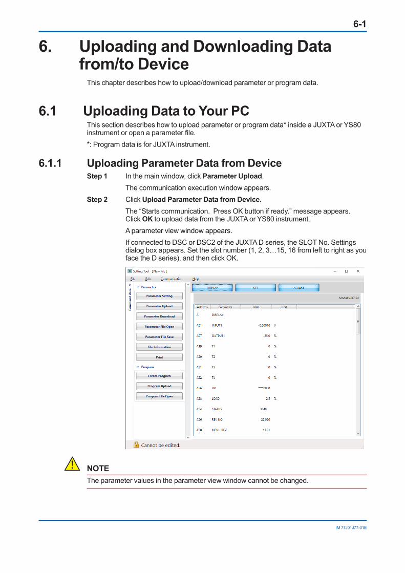
6.1.1 Uploading Parameter Data from DeviceStep 1 In the main window, click Parameter Upload. The communication execution window appears.Step 2 Click Upload Parameter Data from Device. The “Starts communication. Press OK button if ready.” message appears.
Click OK to upload data from the JUXTA or YS80 instrument. A parameter view window appears. If connected to DSC or DSC2 of the JUXTA D series, the SLOT No. Settings
dialog box appears. Set the slot number (1, 2, 3…15, 16 from left to right as you face the D series), and then click OK.
NOTEThe parameter values in the parameter view window cannot be changed.
6-2
IM 77J01J77-01E
6.1.2 Opening a Parameter File Step 1 In the main window, click Parameter File Open. An Open dialog box appears. Files created on the old version (R1.08.01 or earlier) of VJ77 (.7pa extension)
can also be loaded.Step 2 Click the name of the file to load, and click Open. A parameter view window appears.
See Aiso
For how to save the parameter data to disk, see Chapter 7, “Saving Data.”
6.1.3 Uploading Program Data from JUXTA InstrumentStep 1 In the main window, click Program Upload. The communication execution window appears.Step 2 Click Upload Program Data from Device.
The “Starts communication. Press OK button if ready.” message appears. Click OK to upload data from the JUXTA instrument.
A program setting window appears.
NOTEOnly constants (CONST) are displayed for a computing unit other than programmable computing units of the JUXTA VJ series, JUXTA M series, and WXT.
See Aiso
For the how to create and modify a program in the Program Editor dialog box, see Chapter 5, “Setting a Program.”
6.1.4 Opening a Program FileStep 1 In the main window, click Program File Open. An Open dialog box appears. Files created on the old version (R1.08.01 or earlier) of VJ77 (.7pr extension)
can also be loaded.Step 2 Click the name of the file to load, and click Open. A program setting window appears.
See Aiso
For how to save the program data to disk, see Chapter 7, “Saving Data.”

6-3
IM 77J01J77-01E
6.2 Downloading Data to JUXTA InstrumentThis section describes the operation to download the parameter or program data from VJ77 to the JUXTA instrument. You can copy parameter settings or a program to multiple JUXTA instruments. In the same manner, you can copy the same parameters to the YS80.
NOTEBefore you download parameter data, make sure that the model name of the JUXTA instrument selected in MODEL box matches with that of the product’s nameplate. For some models, VJ77 cannot determine whether it is a standard product or a customized product, and a communication error may result.For YS80 series rack instruments, confirm that the model, suffix codes and jumper setting are the same before writing parameters. However, the style code can be different when writing parameters.
ExamplesofYS80modelsthatcanmutuallywriteparameters(STED)Copy source Copy destination Descriptions Copy Y/N
STED-710-UN*Rxxx STED-710-UN*Rxxx Style R --> Style R YSTED-710-UN*Sxxx STED-710-UN*Sxxx Style S --> Style S YSTED-710-UN*Rxxx STED-710-UN*Sxxx Style R --> Style S YSTED-710-UN*Sxxx STED-710-UN*Rxxx Style S --> Style R YSTED-210-TK*Sxxx STED-210-TT*Sxxx Different suffix codes NSKYD-100*Sxxxxx SIND-100*Sxxxxx Different models N
6.2.1 Downloading Parameter Data to DeviceStep 1 In the parameter view window, click Parameter Download.Step 2 Click Download Parameter Data to Device. The “Starts communication. Press OK button if ready.” message appears.
Click OK to download data from the JUXTA or YS80 instrument. The Now Communicating dialog box appears and shows the progress of
downloading. When the download is complete, the “Download completed.” message appears.
If connected to DSC or DSC2 of the JUXTA D series, the SLOT No. Settings dialog box appears. Set the slot number (1, 2, 3…15, 16 from left to right as you face the D series), and then click OK.
NOTEVJ77 only downloads the data shown in the SET menu window. Data shown in the DISPLAY or ADJUST menu window is not downloaded.

6-4
IM 77J01J77-01E
6.2.2 Downloading a Program to DeviceStep 1 In the program setting window, click Program Download.Step 2 Click Download Program Data to Device. The “Starts communication. Press OK button if ready.” appears. Click OK to
start downloading. The Now Communicating dialog box appears and shows the progress of
downloading. When the download is complete, the “Download completed.” message appears.
NOTE• Data in the Comment cells are not downloaded.
• A created program downloaded to the JUXTA computing unit other than programmable computing units is not downloaded and only constants are downloaded.
TIP
The “Error found during command check. Do you want to see the error content?” appears if the program contains any syntax error or other kind of error. Clicking Yes opens the Command Check Error list dialog box shown in Section 5.2.2. Or, clicking No downloads the data containing the program with syntax errors. In this case, each illegal program code will overwrite the corresponding current code or be written as “NOP” and the Check Downloading to JUXTA dialog box appears.

7-1
IM 77J01J77-01E
7. Saving DataThis chapter describes how to save to disk the parameter/program data that was uploaded or you created.Parameter data and program data will be saved with the following filename extensions: • Parameter data files: ********.7pm
• Program data files: ********.7pg
• Filename extension of CSV files: *.csv
7.1 Saving Parameter Data to DiskStep 1 Follow the instructions in Section 6.1, “Uploading Data to Your PC” to upload
parameter data. Step 2 In the parameter view window, click Program File Save. A Save As dialog box appears.Step 3 Type the file name in the File name text box, and click Save.
Click File Information to display an Information dialog box. You can specify the file title, author, date, instrument serial number, and comment (up to 40 characters for the title, author, date, and instrument serial number and up 400 characters for the comment).
7.2 Saving Program Data to DiskStep 1 In the Program Editor dialog box, click Savetofile. The Save As dialog box
opens.Step 2 In the File name box of the Save As dialog box, type the file name within 16
characters and click Save. The Information dialog box appears. In the same way as in Section 7.1, set the file information and click OK. The file is saved to disk.
7.3 Saving Comma-separated Value File to DiskParameters and programs can be saved to CSV files.Step 1 In the Save As dialog box, set Files of type to CSV files. Step 2 In the Save As dialog box, type the file name in the File name text box, and
click Save.

Blank Page
8-1
IM 77J01J77-01E
8. Printing DataThis chapter describes how to print the parameter or program data.
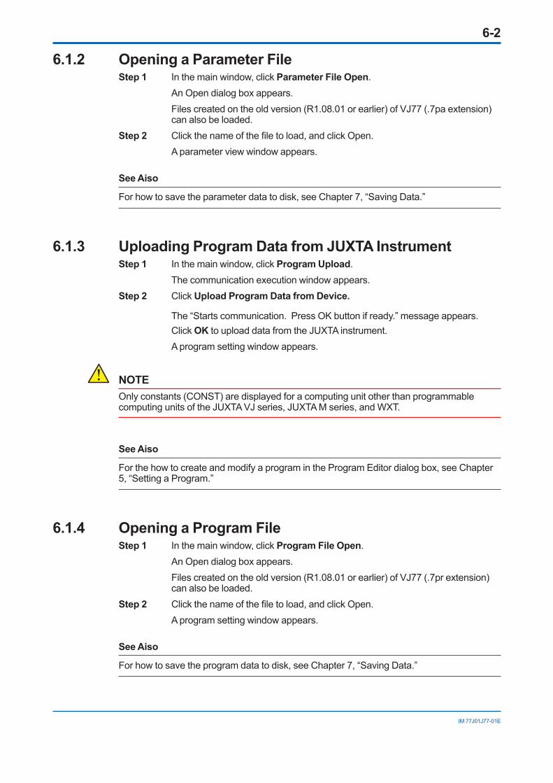
8.1 Printing DataStep 1 To print parameters, click Print in the parameter view window. To print the
program, click Print in the Program Setting window. A Print Range dialog box appears.
Printing parameters
Printing a program
Step 2 The Print dialog box appears. You can select the ranges of items to be printed by selecting and clearing the check boxes. Then, click Print to start printing.

8-2
IM 77J01J77-01E
8.2 Previewing the Print ImageThis section describes how to view the print image. Step In the Print Range dialog box, click Print Preview. A Print Preview dialog box appears. If there are multiple pages, you can use the
scroll bar to turn the displayed page. Close the Print Preview dialog box to return to the parameter view window or
Program Setting window.
9-1
IM 77J01J77-01E
9. Monitoring I/O ValuesThis chapter describes how to monitor input/output values of a JUXTA or YS80 instrument and the self-diagnosis result. You can monitor this information via the DISPLAY menu window.
9.1 OpeningtheMonitorDialogBoxThe following is an example using JUXTA.
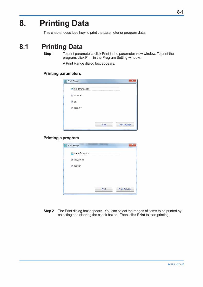
PreparationConnect the JUXTA instrument to the personal computer, then turn on the power to the instrument.Step 1 Start VJ77, and click SET in the main window. The communication execution window appearsStep 2 Click Parameter Setting. The “Starts communication. Press OK button if ready” message appears. Click OK if ready. If connected to DSC or DSC2 of the JUXTA D series, the SLOT No. Settings
dialog box appears. Set the slot number (1, 2, 3…15, 16 from left to right as you face the D series), and then click OK.
A Parameter Setting window (DISPLAY menu window) appears. Depending on the type of JUXTA instrument, two submenus, DISPLAY1 and
DISPLAY2, will be displayed.
9-2
IM 77J01J77-01E
TIP
The DISPLAY1 page or the DISPLAY dialog box without a tabbed page shows the conditions at the time of communication. However, the DISPLAY2 page updates its display contents in approximately 5-second intervals (periodic upload for updating).
When DISPLAY or DISPLAY1 appears, to update the data, click another parameter menu selection button or submenu selection button, and then click the DISPLAY button. To stop the periodic upload for updating of the DISPLAY2 page, click READ STOP. The button label changes from READ STOP to READ START. To resume the periodic upload for updating, click READ START.
10-1
IM 77J01J77-01E
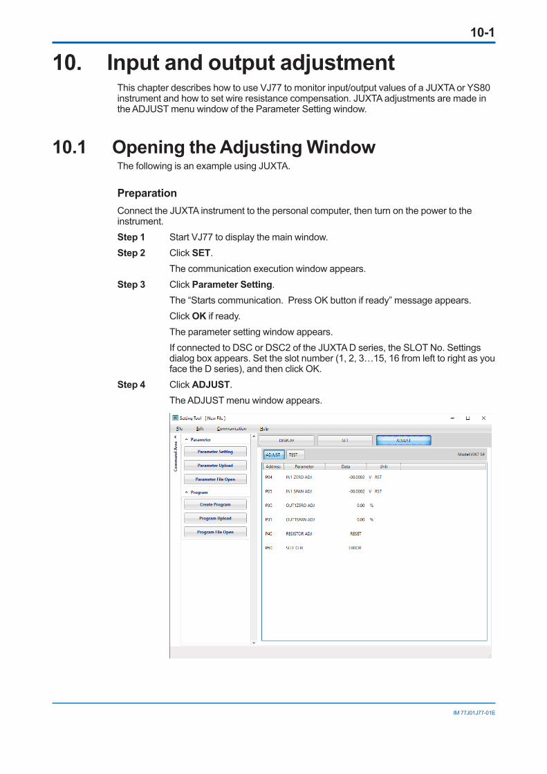
10. Input and output adjustmentThis chapter describes how to use VJ77 to monitor input/output values of a JUXTA or YS80 instrument and how to set wire resistance compensation. JUXTA adjustments are made in the ADJUST menu window of the Parameter Setting window.
10.1 Opening the Adjusting WindowThe following is an example using JUXTA.
PreparationConnect the JUXTA instrument to the personal computer, then turn on the power to the instrument.Step 1 Start VJ77 to display the main window.Step 2 Click SET. The communication execution window appears.Step 3 Click Parameter Setting. The “Starts communication. Press OK button if ready” message appears. Click OK if ready. The parameter setting window appears. If connected to DSC or DSC2 of the JUXTA D series, the SLOT No. Settings
dialog box appears. Set the slot number (1, 2, 3…15, 16 from left to right as you face the D series), and then click OK.
Step 4 Click ADJUST. The ADJUST menu window appears.

10-2
IM 77J01J77-01E
10.2 Performing Fine Adjustment of InputThis section describes how to perform fine adjustments of inputs. The following shows an example when doing so for a JUXTA VJX7 (S4). For wiring with a calibrator or other apparatuses, see the user’s manuals for respective JUXTA or YS80 instruments.
10.2.1 Adjusting the Zero Point of InputStep 1 Apply the 0% level of the input to the JUXTA instrument. If the signal level after
A/D conversion in the JUXTA instrument (the value displayed in the P04: IN1 ZERO ADJ data cell) and the value actually input do not match, perform the following steps to offset the zero-point shift.
Step 2 Double-click the P04: IN1ZERO ADJ data cell. The text box at the bottom of the ADJUST dialog box becomes available.
Step 3 Click the down arrow next to the text box to open a list, which contains the following:
+*.* V INC: Adds the specified voltage after A/D conversion.+*.* V DEC: Subtracting specified voltage after A/D conversion.+*.* V RST: Resets the value that has been adjusted by INC or DEC to 0.HINC or HDEC: Adjusts the value by about 10 times that specified by the +*.*
INC or +*.* DEC command.” Step 4 Since the value shown in the P04: IN1 ZERO ADJ cell is larger than the actual
input level in the example above, select +*.* V DEC and click WRITE. Repeat this procedure to complete the adjustment.
10.2.2 Adjusting the Input SpanApply the 100% level of the input to the JUXTA instrument. If the signal level after A/D conversion in the JUXTA instrument (the value displayed in the P05: IN1 SPAN ADJ data cell) and the actual input signal level do not match, you must correct the input span. The procedure is the same as above.
NOTEFor some models, +*.* HINC and +*.* HDEC are not included in the list. The unit of signal differs depending on the model.
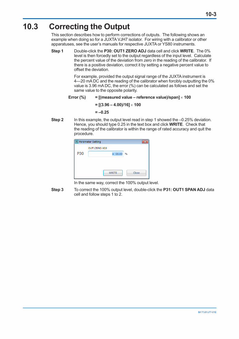
10-3
IM 77J01J77-01E
10.3 Correcting the OutputThis section describes how to perform corrections of outputs. The following shows an example when doing so for a JUXTA VJH7 isolator. For wiring with a calibrator or other apparatuses, see the user’s manuals for respective JUXTA or YS80 instruments.Step 1 Double-click the P30: OUT1 ZERO ADJ data cell and click WRITE. The 0%
level is then forcedly set to the output regardless of the input level. Calculate the percent value of the deviation from zero in the reading of the calibrator. If there is a positive deviation, correct it by setting a negative percent value to offset the deviation.
For example, provided the output signal range of the JUXTA instrument is 4—20 mA DC and the reading of the calibrator when forcibly outputting the 0% value is 3.96 mA DC, the error (%) can be calculated as follows and set the same value to the opposite polarity.
Error (%) = [(measured value – reference value)/span] × 100 = [(3.96 – 4.00)/16] × 100 = –0.25Step 2 In this example, the output level read in step 1 showed the –0.25% deviation.
Hence, you should type 0.25 in the text box and click WRITE. Check that the reading of the calibrator is within the range of rated accuracy and quit the procedure.
In the same way, correct the 100% output level.Step 3 To correct the 100% output level, double-click the P31: OUT1 SPAN ADJ data
cell and follow steps 1 to 2.

10-4
IM 77J01J77-01E
10.4 Setting Wire Resistance CompensationThis section explains how to perform wiring resistance correction using JUXTA VJU7 (S4) as an example. For wiring details, see the relevant JUXTA or YS80 user’s manual.If the input wiring resistance is causing a significant error after the wiring to the field device has been completed, you can compensate for the wiring resistance with the following procedure. Change the wiring connections in the field as shown at the bottom of this page.Step 1 When the input is stable, double-click the P01: WIRING R data cell.
Step 2 Click the arrow next to the text box. Choose EXECUTE from the list and click WRITE. The wiring resistance is then compensated.
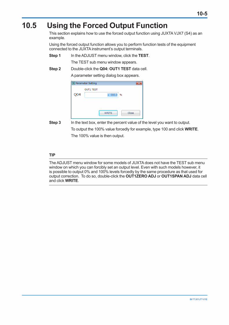
10-5
IM 77J01J77-01E
10.5 Using the Forced Output FunctionThis section explains how to use the forced output function using JUXTA VJX7 (S4) as an example.Using the forced output function allows you to perform function tests of the equipment connected to the JUXTA instrument’s output terminals. Step 1 In the ADJUST menu window, click the TEST. The TEST sub menu window appears.Step 2 Double-click the Q04: OUT1 TEST data cell. A parameter setting dialog box appears.
Step 3 In the text box, enter the percent value of the level you want to output. To output the 100% value forcedly for example, type 100 and click WRITE. The 100% value is then output.
TIP
The ADJUST menu window for some models of JUXTA does not have the TEST sub menu window on which you can forcibly set an output level. Even with such models however, it is possible to output 0% and 100% levels forcedly by the same procedure as that used for output correction. To do so, double-click the OUT1ZERO ADJ or OUT1SPAN ADJ data cell and click WRITE.

Blank Page
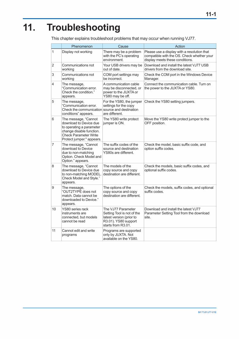
11-1
IM 77J01J77-01E
11. TroubleshootingThis chapter explains troubleshoot problems that may occur when running VJ77.
Phenomenon Cause Action1 Display not working There may be a problem
with the PC’s operating environment.
Please use a display with a resolution that compatible with the OS. Check whether your display meets these conditions.
2 Communications not working
Your USB drivers may be out of date.
Download and install the latest VJ77 USB drivers from the download site.
3 Communications not working
COM port settings may be incorrect.
Check the COM port in the Windows Device Manager.
4 The message, “Communication error. Check the condition.” appears.
A communication cable may be disconnected, or power to the JUXTA or YS80 may be off.
Connect the communication cable. Turn on the power to the JUXTA or YS80.
5 The message, “Communication error. Check the communication conditions” appears.
For the YS80, the jumper settings for the copy source and destination are different.
Check the YS80 setting jumpers.
6 The message, “Cannot download to Device due to operating a parameter change disable function. Check Parameter Write Protect jumper." appears.
The YS80 write protect jumper is ON.
Move the YS80 write protect jumper to the OFF position.
7 The message, “Cannot download to Device due to non-matching Option. Check Model and Option.” appears.
The suffix codes of the source and destination YS80s are different.
Check the model, basic suffix code, and option suffix codes.
8 The message, “Cannot download to Device due to non-matching MODEL. Check Model and Style.” appears.
The models of the copy source and copy destination are different.
Check the models, basic suffix codes, and optional suffix codes.
9 The message, “OUT2TYPE does not match. Data cannot be downloaded to Device.” appears.
The options of the copy source and copy destination are different.
Check the models, suffix codes, and optional suffix codes.
10 YS80 series rack instruments are connected, but models cannot be read
The VJ77 Parameter Setting Tool is not of the latest version (prior to R3.01). YS80 support starts from R3.01.
Download and install the latest VJ77 Parameter Setting Tool from the download site.
11 Cannot edit and write programs
Programs are supported only by JUXTA. Not available on the YS80.

Blank Page
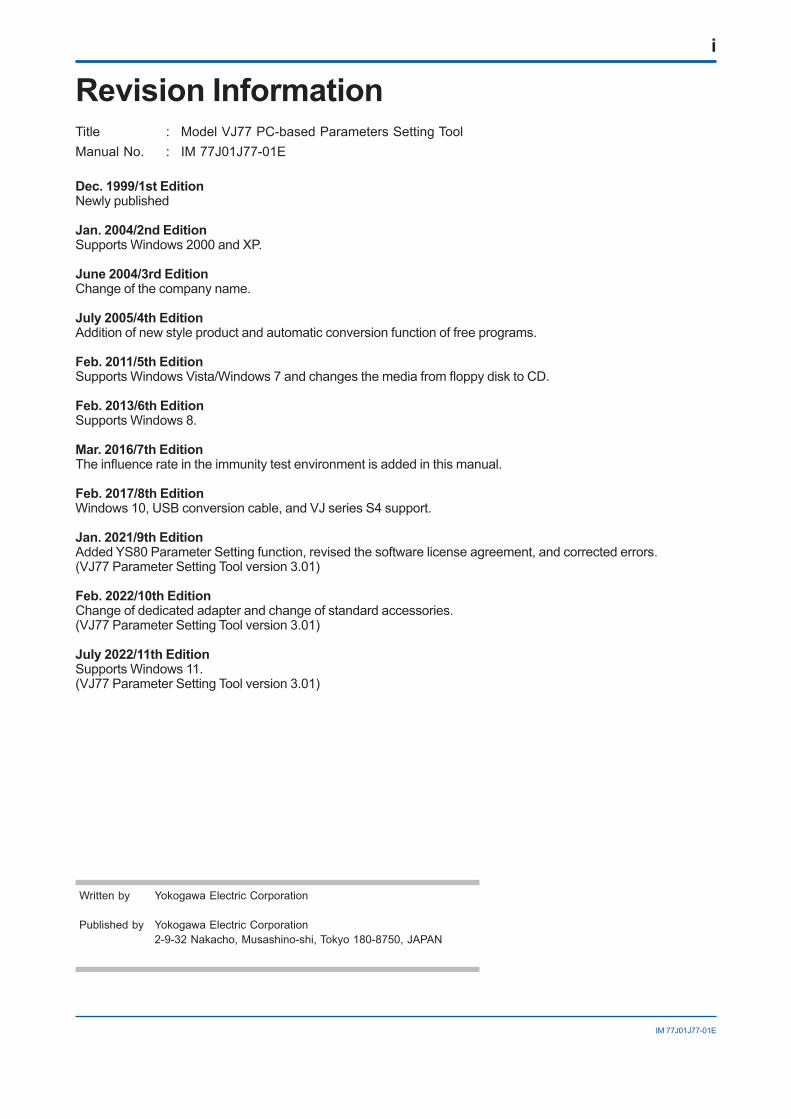
i
IM 77J01J77-01E
Revision InformationTitle : Model VJ77 PC-based Parameters Setting ToolManual No. : IM 77J01J77-01E
Dec. 1999/1st EditionNewly published
Jan. 2004/2nd EditionSupports Windows 2000 and XP.
June 2004/3rd EditionChange of the company name.
July 2005/4th EditionAddition of new style product and automatic conversion function of free programs.
Feb. 2011/5th EditionSupports Windows Vista/Windows 7 and changes the media from floppy disk to CD.
Feb. 2013/6th EditionSupports Windows 8.
Mar. 2016/7th EditionThe influence rate in the immunity test environment is added in this manual.
Feb. 2017/8th EditionWindows 10, USB conversion cable, and VJ series S4 support.
Jan. 2021/9th EditionAdded YS80 Parameter Setting function, revised the software license agreement, and corrected errors. (VJ77 Parameter Setting Tool version 3.01)
Feb. 2022/10th EditionChange of dedicated adapter and change of standard accessories.(VJ77 Parameter Setting Tool version 3.01)
July 2022/11th EditionSupports Windows 11.(VJ77 Parameter Setting Tool version 3.01)
Written by Yokogawa Electric Corporation
Published by Yokogawa Electric Corporation 2-9-32 Nakacho, Musashino-shi, Tokyo 180-8750, JAPAN

Related Documents