Model 6020 Advanced Dewpoint Hygrometer User Manual English

Welcome message from author
This document is posted to help you gain knowledge. Please leave a comment to let me know what you think about it! Share it to your friends and learn new things together.
Transcript
Model 6020
Advanced Dewpoint Hygrometer
User Manual
English

Document Reference: 1931 - Issue 2 - 27 MARCH 2014
© Alpha Moisture Systems Ltd.
This manual should be kept with the Model 6020
Please read this manual carefully
from the beginning.
You must observe the safety information
on page 3 before installation.

Section1 General Information 22 Safety Information 33 User Interface and Controls 44 Quick Start Guide 55 Outline Specification 6
5.1 Limits 65.2 Enclosure DIN Style 6
6 Installation 76.1 Mechanical installation into a panel 76.2 Electrical installation 7-8
7 Installing the air/gas sampling system 97.1 Piping installation schematic 107.2 Piping schematic component index 10-11
8 Installing and commissioning the sensor 129 AutoCal Calibration (Sensor Ranges up to 0
0
C dewpoint) 1310 AutoCal Calibration (Sensor Ranges up to +20
0
C dewpoint) 1311 Entering numerical data 14-1512 Hot keys 16
12.1 Lock Hot keys using Panel Function 1612.2 Units Hot key 1612.3 Alarms Hot keys 17
13 Using the Model 6020 Setup Menu 1813.1 Configuration Parameters 19
13.1.1 Choosing Moisture Units 1913.1.2 Choosing Pressure Units 1913.1.3 Choice of Temperature Units 1913.1.4 Entry of Pressure at Sensor 1913.1.5 Entry of Pressure at Display 2013.1.6 Entry of Standard Pressure 2013.1.7 Entry of Standard Temperature 2013.1.8 Entry of Gas Type 2013.1.9 Enabling and disabling the model for Natural Gas measurements 2013.1.10 Enabling and disabling selection of sensor linearisation 20
13.2 Sensor range 2113.2.1 Choosing the Sensor Range 2113.2.2 Viewing Range End Points (Hi Lo) 2213.2.3 Viewing linearisation data points 2213.2.4 Viewing linearisation data points 22-2313.2.5 Viewing the ADC values in measurement mode 23
13.3 Analogue output 23-2613.4 Alarms 2713.5 Security Features 27
13.5.1 Panel submenu 2713.5.2 Password to control access to Setup menus 2713.5.3 Password to control access to the linearised data points 2713.5.4 Password to control access to Reset Command 2713.5.5 Changing passwords 28
13.6 Reset 2913.7 Digital Communications 29
14 Monitoring the System 3015 Error Messages 30
Appendices 31A Default instrument configuration 32B0 Setup Menu diagram 33B1 Configuration Submenu diagram 34B2 Sensor Range diagram 35B3 Setup Menu [Output, Alarms, Communications and Security] diagram 36C Communications Protocol 37-38
Contact Information 39
Model 6020
1931 - Iss 2 - 03/14 1
Contents

1. General information
Model 6020
The Model 6020 is the next level in online dewpoint hygrometry for multi-species gasesand natural gas. With powerful functions and features available that allow the user toset detailed configurations and parameters for more continuous measurement control.This makes the Model 6020 the advanced choice with the following features and benefits:
• Large easy to read 5-digit LED display• Four-button membrane keypad• Six selectable engineering units
• Three hot keys to enable rapid access
• Two visual alarms LEDS
• AutoCal (Automatic Calibration) function to perform periodic auto-calibration of
the sensor
• Fully-controllable linear selectable 0-20mA or 4-20mA output for process
retransmission
• RS485 port for digital output
• Option for external alarms
• User-controllable password system
• AC or DC powered models available
Model 6020
1931 - Iss 2 - 03/142
Component list of Model 6020 Advanced Dewpoint Hygrometer System
• Model 6020 panel mounted instrument
• Three connectors for wiring
• Ferrite Bead for power cable
• Mounting Gasket
• 2 panel retaining screws
• Screwdriver
• User Manual
• Certificate of Calibration
• Declaration of Conformity
• Sensor Cable
• Sensor
Optional extras
• Sensor Holder

2. Safety Information and Warnings
These safety instructions and guidelines must be followed.
The Model 6020 is designed to be connected to hazardous electric voltages (240V).
The power supply must be protected by a 1 amp fuse. The Model 6020 must be earthed.
Check to establish that all wiring and connections are not damaged. If damage is
observed to any electrical wiring or damage to the apparatus they must not be
connected to the power supply but returned to the supplier for rectification.
Before powering up the unit, check that the connecting plugs at the back of the unit
have been wired correctly. Observe the wiring diagrams in section 6.2, Figure 1.
Do not connect the Model 6020 to the power supply until it is in a permanent
position.
Risk of electric shock - Do not open any part of the Model 6020 whilst connected to the
power supply.
Remove the power supply and isolate before any maintenance is carried out.
The power supply terminals and associated internal circuitry are isolated from all other
parts of the equipment in accordance with EN61010-1 for connection to a category II
supply (pollution degree2).
Any terminals or wiring connected to the input or output, which are accessible in
normal operation, must only be connected to signals complying with the requirements
for Safety Extra Low Voltage (SELV) circuits.
Hazardous voltages may be present on instrument terminals. The equipment must be
installed by suitably qualified personnel and the instrument must be mounted in a
position that provides protection behind the panel to at least IP20.
Note: The instrument contains no user serviceable parts.
Ignoring this safety information can result in severe personal injury and/or damage to
the unit. The product specifications must not be exceeded at anytime as this may
cause damage to the apparatus or cause risk of damage or fire.
Ensure that the Model 6020 does not come into direct contact with water or any other
liquids.
Cleaning
Disconnect the power supply first. To maintain the instrument, never use harsh abrasive
cleaners or solvents. Wipe the instrument only with a soft cloth slightly dampened with
warm soapy water.
Maintenance:
Risk of damage to the Sensor – Always ensure that the Model 6020 is “switched off”
before removing or replacing a Sensor. By not doing so can result in short circuit damage
to the Sensor.
Model 6020
1931 - Iss 2 - 03/14 3

3. User Interface and Controls
MODEL 6020 DEWPOINT HYGROMETER
A U T O C A L
AL 1
MENU
ESC
UNITS AL 1 AL 2
AL 2
AutoCalpotentiometer
Alarm Indicators
Secondary Display
PrimaryDisplay
User Input and Hot Keys
6020 C.
Consists of a membrane keyboard with four user input keys and also four visual indication
elements or windows: the primary five character LED, a single character secondary LED
for units indication, two alarm LEDs and the access cover to the AutoCal potentiometer.
In normal operation, the Model 6020 will display the current moisture value of the
connected sensor in the Primary Display.
The engineering units are indicated in the Secondary Display.
The Alarm LED’s (AL 1 & AL 2) will light RED whenever an alarm condition occurs and only
turn off when the alarm condition clears, unless the alarms are latched.
Remote signalling of an alarm condition is provided by separate internal changeover re-
lays that trigger at the same time as the LED’s.
Model 6020
1931 - Iss 2 - 03/144

4. Quick Start Guide
Note: Your instrument has been calibrated by Alpha Moisture Systems to your
specification.
To get started quickly there is no need to go through all the menus on the Model 6020
at this stage.
Follow these step by step instructions below for a fast set up and quick start to
measuring.
1. Unpack the Control Unit and Sensor only when they are ready to install.
2. Read the safety instructions in section 2.
3. Make a location for the Model 6020 - For dimensions see section 6.1.
4. Make ready and seal all pipework for sampling.
5. Unpack and wire up the Model 6020 display unit, see section 6.2.
DO NOT power up at this stage.
6. Unpack and very carefully insert the sensor into the sensor holder and connect
to the Model 6020 display unit.
7. Purge the gas to be sampled through the pipework and sensor holder
see sections 7.1 and 7.2 for full details.
8. Re-check all connections and wiring - NOW power up the Model 6020.
8. The screen will now look like this for example:
9. If the display is still changing, allow this to settle before taking final reading.
Note: Time to settle can vary between a few minutes and several hours
dependant on the condition of the sample tubing on start up. Time
can be affected by for example, temperature, pressure, sample
moisture content and other factors.
Take a final reading when the display is static.
10. If alarms are to be set at this stage see section 12.3 or 13.4.
11. To set up passwords see section 13.5.
-56.3 C.
Model 6020
1931 - Iss 2 - 03/14 5
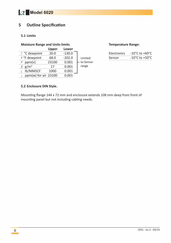
5.1 Limits
Moisture Range and Units limits
Upper Lower
C °C dewpoint 20.0 -130.0
°F dewpoint 68.0 -202.0
ppm(v) 23100 0.001
g g/m3 17 0.001
L lb/MMSCF 1000 0.001
ppm(w) for air 23100 0.001
5.2 Enclosure DIN Style.
Mounting flange 144 x 72 mm and enclosure extends 108 mm deep from front of
mounting panel but not including cabling needs.
-
5 Outline Specification
Temperature Range:
Electronics -10°C to +60°C
Sensor -10°C to +50°CLimited
to Sensor
range
Model 6020
1931 - Iss 2 - 03/146

6 Installation
6.1 Mechanical installation into a panel
Make a cut-out in the donor panel 138.0 x 68.0 mm (DIN 43700).
The maximum panel thickness is 8mm. If an effective IP65 weatherproof seal is
required, the minimum recommended panel thickness is 2.5 mm.
Pass the instrument case through the cut-out in the donor panel and attach the two
retaining screws to the studs on either side of the case making use of the supplied
gasket.
Tighten the retaining screws onto the back of the donor panel until the instrument is
clamped securely in position. The screws must be tightened sufficiently to affect a seal
between the front of the donor panel and the back of the instrument bezel, but never
over tightened.
Model 6020
1931 - Iss 2 - 03/14 7
6.2 Electrical installation
Viewed from the rear and on the left is the moisture sensor input connector
which is a panel mounted BNC. Just below it is a cable compensation adjustment
potentiometer labelled ZERO.
The ZERO adjustment is used where long cable lengths are fitted to the instrument
and, only used at the commissioning stage of the installation.
Normally, when the cable is attached and laid in the operating position, but the sensor
disconnected, the instrument display should read the lowest value of the selected
range. If it does not, the ZERO can be adjusted to compensate for any raised value
induced by the cable.
Care should be taken to ensure accurate adjustment, or the accuracy of the system may
be impaired. Only very small adjustments should be necessary and the procedure is as
follows:
Insert the small screwdriver to engage with the ZERO potentiometer and, slowly,
adjust the potentiometer until the display reads the lowest value of the selected range.
It is important to note that the display value will not indicate below the lowest value
therefore care must be taken to ensure that adjustment drops as soon as the lowest
value is reached.
Also see illustration Figure 1 on the next page for wiring details.

There are three banks of wiring connections points organised into groups named
here as C1, C2 and C3.
Connector C1
Analogue Output and Digital Communications Port
• On first two pins on left is the 4-20 mA Analogue Output.
• On the last three pins is the RS485 Digital Communications port.
Connector C2
Alarms: Two independent SPCO volt free contacts rated 10A/240 VAC.
Connector C3
Power Supply: Universal 90 – 250 VAC 50/60 Hz, or, 24 VDC version dependant on
factory set option.
Important Notes for both AC and DC powered units.
• The power supply to the instrument must be protected by a 1A fuse
• A local isolation switch is advisable for ease of isolation during maintenance to
reduce the possibility of electric shock or damage to the instrument.
• The power supply ground GND terminal must be wired to a suitable permanent
ground point.
• The supplied ferrite bead must be installed on the power supply cable
approximately 50 mm from the connector using the supplied tool on the rear of
the instrument.
• The power supply wires are retained by screws and care should be taken to
ensure that the exposed section of the wire is fully inserted and that no loose
strands are exposed.
• Cables should to be properly supported and segregated.
Figure 1
+ - A B Com NO C NC NO C NC L N GND
GND
N
L = Fused1A
GND
-+ = Fused
1A
4-20mA
Output
Connector C1
Alarm 1
Cable
Compensation Potentiometer
Alarm 2
ZERO
Coaxial
Sensor Connection
AC Wiring DC Wiring
Model 6020
1931 - Iss 2 - 03/148
Connector C2
Connector C3
+ - GND
24VDCPowerSupply
4VA
AC Power90-250V50/60Hz
10VA
Model 6020
1931 - Iss 2 - 03/14 9
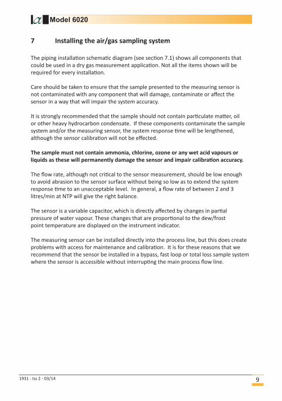
7 Installing the air/gas sampling system
The piping installation schematic diagram (see section 7.1) shows all components that
could be used in a dry gas measurement application. Not all the items shown will be
required for every installation.
Care should be taken to ensure that the sample presented to the measuring sensor is
not contaminated with any component that will damage, contaminate or affect the
sensor in a way that will impair the system accuracy.
It is strongly recommended that the sample should not contain particulate matter, oil
or other heavy hydrocarbon condensate. If these components contaminate the sample
system and/or the measuring sensor, the system response time will be lengthened,
although the sensor calibration will not be effected.
The sample must not contain ammonia, chlorine, ozone or any wet acid vapours or
liquids as these will permanently damage the sensor and impair calibration accuracy.
The flow rate, although not critical to the sensor measurement, should be low enough
to avoid abrasion to the sensor surface without being so low as to extend the system
response time to an unacceptable level. In general, a flow rate of between 2 and 3
litres/min at NTP will give the right balance.
The sensor is a variable capacitor, which is directly affected by changes in partial
pressure of water vapour. These changes that are proportional to the dew/frost
point temperature are displayed on the instrument indicator.
The measuring sensor can be installed directly into the process line, but this does create
problems with access for maintenance and calibration. It is for these reasons that we
recommend that the sensor be installed in a bypass, fast loop or total loss sample system
where the sensor is accessible without interrupting the main process flow line.
Model 6020
1931 - Iss 2 - 03/1410
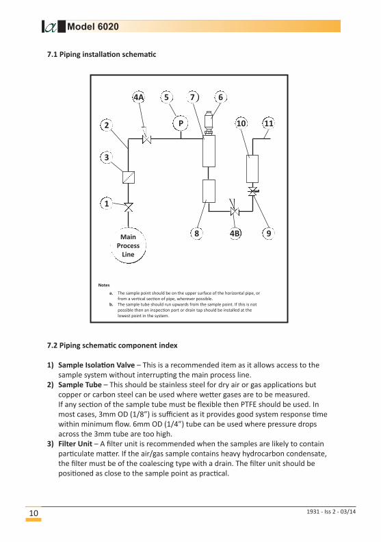
7.2 Piping schematic component index
1) Sample Isolation Valve – This is a recommended item as it allows access to the
sample system without interrupting the main process line.
2) Sample Tube – This should be stainless steel for dry air or gas applications but
copper or carbon steel can be used where wetter gases are to be measured.
If any section of the sample tube must be flexible then PTFE should be used. In
most cases, 3mm OD (1/8”) is sufficient as it provides good system response time
within minimum flow. 6mm OD (1/4”) tube can be used where pressure drops
across the 3mm tube are too high.
3) Filter Unit – A filter unit is recommended when the samples are likely to contain
particulate matter. If the air/gas sample contains heavy hydrocarbon condensate,
the filter must be of the coalescing type with a drain. The filter unit should be
positioned as close to the sample point as practical.
7.1 Piping installation schematic
Main
Process
Line
4B 9
11102
3
1
4A 5
P
7 6
8
a. The sample point should be on the upper surface of the horizontal pipe, or
from a vertical section of pipe, wherever possible.
b. The sample tube should run upwards from the sample point. If this is not
possible then an inspection port or drain tap should be installed at the
lowest point in the system.
Notes

Model 6020
1931 - Iss 2 - 03/14 11
4) Pressure Reduction Valve or Pressure Regulator – If the sample is to be measured
at atmospheric pressure then the valve 4A should be fitted and 4B omitted from the
system. If the sample is to be measured at full line pressure and the exhaust vented
to atmosphere, then valve 4B should be fitted and 4A omitted from the system.
If measurements are to be taken at full line pressure and the sample is to be
returned to a part of the main line or a vent, which is at a pressure higher than
atmospheric, and the input to that line needs a controlled pressure, then both 4A
and 4B will be required.
5) Sample Pressure Gauge – This is not a critical part of the moisture measurement
but may be required if Dew/Frost point measurements are to be made at higher
than atmospheric pressure.
6) Measuring Sensor.
7) Sensor Holder.
8) Desiccant Chamber – This item is required when the sampling is to be intermittent.
When installed, it prevents the ingress of wet air to the sample system while the
sample is not flowing, improving the response time.
9) Flow Control Valve – This can be a separate item or combined with the flow
indicator.
10)Flow Indicator – The recommended sample flow is 2 to 3 litres/min at NTP.
11)Sample Exhaust – The exhaust can be vented to atmosphere or returned to the
process line as discussed above.

Model 6020
1931 - Iss 2 - 03/1412
8 Installing and commissioning the sensor
It is advisable to carry out an initial purge routine of the sample loop before installing
the sensor. This is to remove the possibility of sensor damage on start-up.
Note: Before any AutoCal procedures are carried out after installation
you must first set the Zero on the Cable Potentiometer sited on the
rear of the Model 6020 - see section 6.2.
Refer to the sample system schematic in section 7.1. Open the inlet isolation valve
slowly until a small flow of air/gas (at atmospheric pressure) flows through the inlet pipe
work to the sensor holder, exhausting through the sensor entry port of the sensor holder.
Allow this purge to continue for about 15 to 20 minutes to remove any residual
moisture from the sample pipe work and components.
Close the inlet isolation valve and install the sensor into the sensor holder. Locate and
coaxial cable in positioned on the sensor.
Open the inlet valve slowly, by opening all valves after the sensor holder, allow a
low-pressure purge through the whole sample system.
Note: If a closed by-pass loop is installed, this section of the procedure
is not possible.
Set the required flows within the sample loop.
This completes the installation and commissioning, but on initial start-up, it could
take several hours for the system to reach equilibrium. The Model 6020 will now
indicate the dewpoint of the air/gas surrounding the sensor, and the analogue output
will be giving mA signals proportional to the indicated dewpoint.

9 AutoCal Calibration (Sensor Ranges up to 0°C dewpoint)
The system relies on the fact that each sensor is designed to give no further increase in
reading when it reaches its maximum moisture level. This means that, for instance, the
Silver Spot or Red Spot sensor will read –20°C Dewpoint when it is exposed to gas
at –20°C Dewpoint, but will continue to read -20°C Dewpoint when it is exposed to
wetter gas. The system can therefore be calibrated very simply by exposing the sensor
to anything wetter than –20°C Dewpoint and adjusting the reading to that point on the
display. For the Grey Spot Sensor the maximum level is 0°C dewpoint and the same
principle applies but the gas must be above 0°C.
In practice, an AutoCal is performed as follows:-
1. Ensure the Model 6020 is powered up and displaying the moisture content in
°C Dewpoint.
2. Remove the sensor from the sensor holder and expose it to ambient conditions
for at least 1 minute.
3. Check the Model 6020 reading. It should display the maximum level of Dew
point for the instrument (i.e. –20°C for Red and 0°C for Grey).
4. If the unit is reading incorrectly then use a small screwdriver to turn the
Autocal potentiometer (found on the front panel of the instrument under the
knurled cap) clockwise to increase the reading (wetter) or anticlockwise to
decrease it (dryer).
10 AutoCal Calibration (Sensor Ranges up to +20°C dewpoint)
In order to calibrate a +20°C Sensors, it is necessary to measure the ambient air
Dewpoint by some other method. Careful use of a sling or whirling hygrometer can
achieve accurate results or a cooled mirror device can be used.
The following procedure should be used:-
1. Ensure the Model 6020 is powered up and displaying the moisture content in
°C Dewpoint.
2. Remove the sensor from the sensor holder and expose it to ambient conditions
for at least 1 minute.
3. Compare the reading of the Model 6020 in the ambient air, against the actual
moisture level obtained by another method. Turn the Autocal potentiometer
(found on the front panel of the instrument under the knurled cap) using a
small screwdriver clockwise to increase the reading (wetter) or anticlockwise
to decrease it (dryer).
Model 6020
1931 - Iss 2 - 03/14 13

11 Entering numerical data
When a numerical value has to be entered into the Model 6020 the following procedure
should be used.
The right most character of the main display flashes to indicate it is active for
editing. If required press the key repeatedly to select the number or sign which
needs to change.
MODEL 6020 DEWPOINT HYGROMETER
A U T O C A L
AL 1
MENU
ESC
UNITS AL 1 AL 2
AL 26020 C.
The key allows the user to leave a part of the menu without changing any settings.
Use the key to change the required number between 0 and 9.
Pressing the key at any point sets the numerical value.
Continue this process until all characters are entered.
Keys Function
Returns the user to the previous screen, without changing any variables.
Used to confirm a numerical variable or the selection of a chosen option.
Used to select the next digit when setting a numerical variable or to scroll
through the options available.
Used to decrease the selected digit when setting a numerical variable.
-800 -800 -800
-800 -700 -600 -600
Model 6020
1931 - Iss 2 - 03/1414
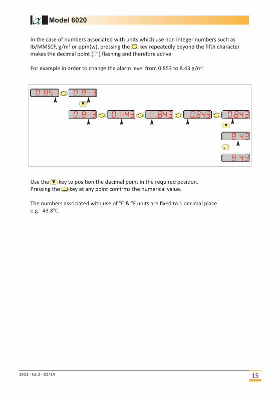
In the case of numbers associated with units which use non integer numbers such as
lb/MMSCF, g/m3 or ppm(w), pressing the key repeatedly beyond the fifth character
makes the decimal point (“.”) flashing and therefore active.
For example in order to change the alarm level from 0.853 to 8.43 g/m3
Use the key to position the decimal point in the required position.
Pressing the key at any point confirms the numerical value.
The numbers associated with use of °C & °F units are fixed to 1 decimal place
e.g. -43.8°C.
0.853
0.843
0.853
0.843 0.843 .0.843 0.843
8.43
Model 6020
1931 - Iss 2 - 03/14 15
8.43

12 Hot keys
The ‘Units’ Hot key allows the user to view and alter the displayed units.
To review the moisture in alternative units, press the (Units) key for longer than 3
seconds. The main display will then show the message Units. Press the key to
select a different moisture unit in the flashing secondary display by repeatedly pressing
the key to scroll through the current moisture level in each of the moisture units.
Press the key to select the chosen moisture units and it will stop flashing.
For example:
To change from a ‘dewpoint C’ to a ‘dewpoint F’
While Units is displayed press the key to enter the subroutine.
C.
units -9.0
f.
-22.0
f.
-22.0
To return
The secondary display now shows the unit type
flashing.
Use the key to scroll through to the next unit
type is displayed e.g. F
Press the key to select the new unit.
12.2 Units Hot key
Model 6020
1931 - Iss 2 - 03/1416
12.1 Lock Hot keys using Panel Function
There is an option to restrict the Hot keys so that Units or Alarms may only be inspected
rather than adjusted using the Hot keys. If this is the case when an attempt is made to
change the parameter then the user is presented with the message On4 to indicate
that the parameter is “Read Only”
The Panel option allows the user to restrict the functions of the front panel Hot keys. If
the ‘OFF’ option is selected, the Hot keys are RESTRICTED to “Read Only”.
For example:
While nL is displayed, press the key to enter the subroutine. The main display
will now display On or O. Use the key to select Onor O.
Press the key to confirm selection.
paneL On Off paneL
Note: Pressing the key at any time escapes to the hot key function and returns to
the measurement display without saving any changes.

Model 6020
1931 - Iss 2 - 03/14 17
12.3 Alarms Hot keys
The two alarm Hot keys ‘AL 1’ and ‘AL 2’ allow the user to review and set the
Alarm trigger points.
To review the alarm trip point press the (AL1) or (AL2) key momentarily. The
primary display will show the set trip point for 1 second before reverting back to
the moisture reading.
To change the trip point press and hold the (AL1) or (AL2) keys for longer than
3 seconds. The main display will then show the message L or L 2. Press the
key to select Alarm in the flashing main display by repeatedly pressing the and
keys to scroll through and adjust the alarm setting.
Press the key to select the chosen alarm setting.

13 Using the Model 6020 Setup Menu
To enter the Setup Menu press and hold the key for 3 seconds.
This displays the tv message on the main display.
Press the key takes the user to the top of the first item in the Setup menu structure
that being either Co or depending on how the instrument is configured.
Note 1: If the user has set a setup password, then the user is prompted to enter the
correct password before continuing on to the top level.
Note 2: Most of the screens within the menu have an active 10-second timeout.
Therefore, if no keys are pressed within this period the unit reverts
automatically to normal operation. In most cases where the 10-second
timeout occurs, changes will not have been saved.
setvp
ange
Confg
To return
Press
and hold
for 3
seconds
OR
Model 6020
1931 - Iss 2 - 03/1418
Configuration Contains submenus for choosing engineering units, choice
of gas types and whether sensor linearisation is employed.
Sensor Range Contains submenus to choose the Range of sensor and
linearisation data points.
Analog output Contains submenus to allow the user to fully configure the
Analog output.
Alarms Contains submenus to fully control behaviour of two
independent alarms.
Communications Contains submenus for changing baud rate and address of
the instrument’s RS485 communication port.
Security Contains submenus to set up passwords to control or limit
access certain features from unauthorised changes.
Table 1 Setup Menu contents

13.1 Configuration Parameters
13.1.1 Choosing Moisture Units
The Units submenu allows the user to alter the displayed units.
While units is displayed press the key to enter the submenu.
The currently selected unit is displayed.
Select a different moisture unit by repeatedly pressing the key to scroll through
each of the moisture units.
Press the key to set the chosen moisture units.
For example.
To change from a ‘dewpoint C’ to a ‘dewpoint F’
Note: Pressing the key at any time reverts to the Hot key function back to
the measurement display without saving any changes.
13.1.2 Choosing Pressure Units
The Unit submenu within etvp allows the user to alter the units for the
pressure parameters
The choices are:
Pascal x 103 e3
psi gauge sig
bar gauge a g
13.1.3 Choice of Temperature Units
The tUnit submenu allows the user to alter the units for the temperature
parameters.
The choices are:
°F
°C C
13.1.4 Entry of Pressure at Sensor
The submenu allows entry of pressure at sensor
C
f
units
units
Model 6020
1931 - Iss 2 - 03/14 19
.
.

13.1.5 Entry of Pressure at Display
isp allows entry of pressure at which to display the dewpoint.
13.1.6 Entry of Standard Pressure
pst allows entry of standard pressure (Default 101.3 x 10³ Pa, 0 psig, 0 barg)
13.1.7 Entry of Standard Temperature
tst allows entry of standard temperature. (Default 60°F, 15.56°C)
13.1.8 Entry of Gas Type
gas allows entry of type of gas at sensor for ppm(w) calculations.
Air i
Argon, Ar
Methane, CH4 C4
Carbon Dioxide, CO2 CO2
Hydrogen, H2 2
Nitrogen, N2 2
Sulphur hexafluoride, SF6 sf6
Custom molar mass uaLue
13.1.9 Enabling and disabling the model for Natural Gas measurements
ntgas requires a Yes or No response to turn on or off the Natural Gas correlation.
If Yes, then the sensor linearisation follows a modified curve defined in the
Natural Gas correlation.
If No, the sensor follows the ideal gas linearisation.
13.1.10 Enabling and disabling selection of sensor linearisation
Lin requires a Yes or No response.
If Yes, then the instrument linearisation follows a curve defined in the
Linearisation Correction Table.
If No, then the instrument follows the natural response of the sensor.
Model 6020
1931 - Iss 2 - 03/1420
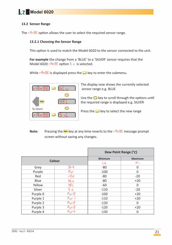
13.2 Sensor Range
The ng option allows the user to select the required sensor range.
13.2.1 Choosing the Sensor Range
This option is used to match the Model 6020 to the sensor connected to the unit.
For example the change from a ‘BLUE’ to a ‘SILVER’ sensor requires that the
Model 6020 ng option siL is selected.
While ng is displayed press the key to enter the submenu.
bLv
yeL
ange
ange siL
To return
The display now shows the currently selected
sensor range e.g. BLUE
Use the key to scroll through the options until
the required range is displayed e.g. SILVER
Press the key to select the new range
Note: Pressing the key at any time reverts to the ng message prompt
screen without saving any changes.
Dew Point Range (°C)
ColourMinimum Maximum
Lo i
Grey 4 -80 0
Purple v -100 0
Red -80 -20
Blue Lv -80 +20
Yellow L -60 0
Silver iL -110 -20
Purple 0 v0 -100 +20
Purple 1 v -110 +20
Purple 2 v2 -120 0
Purple 3 v3 -120 +20
Purple 4 v4 -130 0
Model 6020
1931 - Iss 2 - 03/14 21
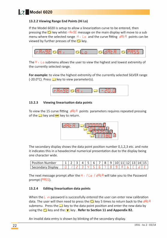
If the Model 6020 is setup to allow a linearization curve to be entered, then
pressing the key whilst ng message on the main display will move to a sub
menu where the selected range i Lo and the curve fitting points can be
viewed by further presses of the key.
ange i Lo ata pass
ange i -20.0
The i Lo submenu allows the user to view the highest and lowest extremity of
the currently selected range.
13.2.3 Viewing linearisation data points
To view the 15 curve fitting points parameters requires repeated pressing
of the key and key to return.
The secondary display shows the data point position number 0,1,2,3 etc. and note
it indicates this in a hexadecimal numerical presentation due to the display being
one character wide.
The next message prompt after the i / Lo / will take you to the Password
prompt ().
13.2.4 Editing linearisation data points
When the Lin password is successfully entered the user can enter new calibration
data. The user will then need to press the key 5 times to return back to the
submenu. Press the key to the data point position and enter the new data by
using the key and the key . Refer to Section 11 and Appendix B2.
An invalid data entry is shown by blinking of the secondary display.
Position Number 1 2 3 4 5 6 7 8 9 10 11 12 13 14 15
Secondary Display 0 2 3 4 5 6 7 8 9 C
0ata 0000003002032543780
Model 6020
1931 - Iss 2 - 03/1422
13.2.2 Viewing Range End Points (Hi Lo)
For example: to view the highest extremity of the currently selected SILVER range
(-20.0°C). Press key to view parameter(s).

13.3 Analogue output
The Model 6020 features an analogue output port which the user may use to retransmitthe moisture reading to another system. The wiring connected to this output must onlybe connected to signals complying with the requirements for Safety Extra Low Voltage(SELV) circuits. The output however benefits from galvanic isolation and segregation byisolated electrical circuits.
The analogue output is a current output. It is always enabled and care should be exercised therefore to ensure that during installation the two terminals are not shorted and have a load attached more than 200 Ω for optimum performance.
By factory default, the output is linear to match the selected units.
+ -
Zero
Remote
Equipment
Model 6020
1931 - Iss 2 - 03/14 23
Warning: We strongly recommend that you record the current value before you enter a new value in the event that you have to re-enter the original data.To save a new value, press the return key repeatedly until 00000 are displayed for 1 second and the word is shown. At this point the new data will be saved automatically. Pressing the escape key, or if the Model 6020 “Times Out”your new data values will not be saved.
13.2.5 Viewing the ADC values in measurement mode
Additionally an option is also enabled by this Lin password which for the extentof the powered on state will display in measurement mode the instrument’s current analogue to digital converter count ‘ADC’ value via a no choice afterthe main display message prompt . This feature may be useful for calibrationlaboratory work.
-20
-50
-80
Also linear in °F
°C ppm(v)
Low Med
Moisture Content Moisture Content
High
1000
40
0.5
OUTPUT - Linear in °C
-20
-25
-80
°Cppm(v)
Low Med High
1000
500
0.5
OUTPUT - Linear in ppm(v)
Also linear in
g/m3 or Ib/MMSCF

Therefore using the above example the port will be providing 4 mA when the
instrument display is at -80°C dewpoint
ESC
-80.0 C.
+4.00 mA
And the output provides 20 mA when the display is at +20°C dewpoint.
ESC
20.0 C.
+20.00 mA
If a sensor is detected as short circuit then the current output will rise to +20.25 mA.
ESC
----- C.
+20.25 mA
Model 6020
1931 - Iss 2 - 03/1424
For example: For a blue sensor scaled from -80°C to + 20°C dewpoint then the
analogue output will be at its minimum when the reading is at -80°C dewpoint and
at its maximum when the reading is at +20°C dewpoint.
Furthermore the factory default configuration is that the output current ranges from
4 to 20 mA.
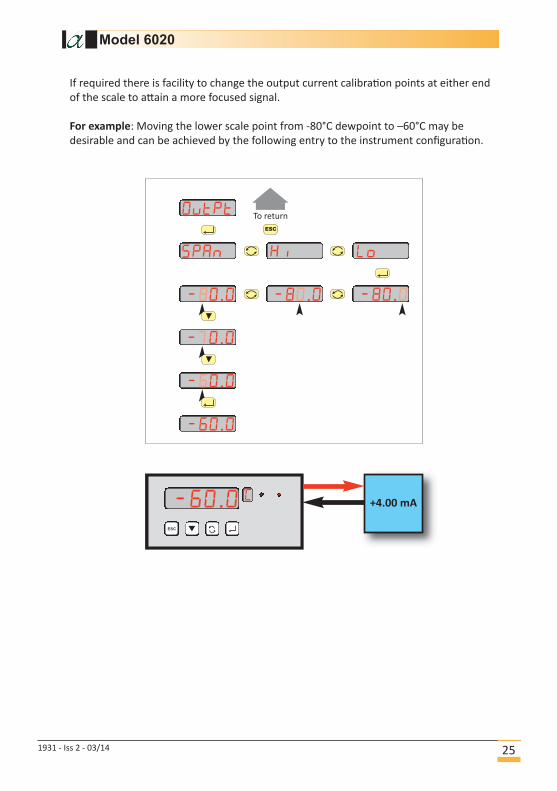
If required there is facility to change the output current calibration points at either end
of the scale to attain a more focused signal.
For example: Moving the lower scale point from -80°C dewpoint to –60°C may be
desirable and can be achieved by the following entry to the instrument configuration.
Ovtpt
span i Lo
-80.0-80.0 -80.0
-70.0
-60.0
-60.0
To return
ESC
-60.0 C.
+4.00 mA
Model 6020
1931 - Iss 2 - 03/14 25

It is also possible to select a 0-20mA output range instead of the standard 4–20mA.
Selecting this range is useful to provide a convenient method of providing a 0-5 Vdc
voltage output to the remote equipment when used in conjuction with a suitable
250 Ω resistor.
Ovtpt
span
4-20
span
0-20
To return
ESC
-60.0 C.
00.00 mA
Model 6020
1931 - Iss 2 - 03/1426
+
_
0 - 5 Vdcanalog input
0 - 20 mAoutput range 250 Ω+ -
Zero

13.4 Alarms
The two independent alarms options (1 and 2) allow the user to setup configurable
alarm events by configuring the trip points, direction of trigger, relay enable energised-
on-event command, latching on-event command and hysteresis.
While L or L2 are displayed press the key to enter the submenu. The main
display indicates the trip point tt. Use the key to select the required function
and then press the key.
Note: Pressing the key reverts back to the display L or L 2message screen.
The following functions can be performed:-
tt Enter the alarm set point.
t4 Select if the alarm is to activate on a rising signal i,
falling signal Lo or O.
L4 Select if the relays are Energised n or de-energised -n
Lt Set if the alarm is Latch or not latching no.
4t Enter the hysteresis value.
Note: Pressing the key sets any of the alarm parameter, will not revert to the
previous value even if the 10 second timeout occurs or the key.
13.5 Security Features
There are options to secure features and settings .
13.5.1 Panel Submenu.
The ane option allows the user to restrict the functions of the front panel Hot keys.If the on option is selected, the Hot keys are unrestricted.
While ane is displayed, press the key to enter the submenu. The main display now displays on or off. Use the key to select on or off. Press the key to confirm selection.
13.5.2 Password to control access to Setup menus.
The user may set a password to secure access to the etup menus.The default password for this 0000
13.5.3 Password to control access to the linearised data points.
There is additionally a password which controls access to being able to edit the 15
data points parameters contained in Li submenu.The default password for this 9000
13.5.4 Password to control access to Reset Command.
The password on the eset allows the user to alter the security password used to
protect the eset command and is entered on entry to reset submenu.The default password for this 9000
Model 6020
1931 - Iss 2 - 03/14 27
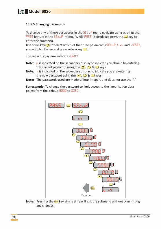
13.5.5 Changing passwords
To change any of these passwords in the etvp menu navigate using scroll to the
feature in the setvp menu. While is displayed press the key to
enter the submenu.
Use scroll key to select which of the three passwords (setvp, Lin and eset)
you wish to change and press return key .
The main display now indicates 0000
Note: 0 is indicated on the secondary display to indicate you should be entering
the current password using the , & keys.
Note: is indicated on the secondary display to indicate you are entering
the new password using the , & keys.
Note: The passwords used are made of four integers and does not use the “.”
For example: To change the password to limit access to the linearisation data
points from the default 9000 to 0090.
00000
LinTo return
Lin
setvppass
Note: Pressing the key at any time will exit the submenu without committing
any changes.
00000
00000
00000
09000
0000
0000
0090
Model 6020
1931 - Iss 2 - 03/1428

13.6 Reset
The eset submenu allows the user to reset the instrument back to the default
settings.
13.7 Digital Communication
The s485 submenu allows the user to set the address and baud rate used in
communicating with a PC using RS485 communications.
A RS485 interface and cable are required.
All transmission is binary and is NOT ASCII characters.
A single instrument may be connected using the universal address of 0.
Up to 32 separate instruments may be connected using addresses 1 to 32
(NOT including the universal address of 0)
The instrument is the slave and must be requested for data.
There is only one command that returns the process value in the units set in the
secondary display.
Alarm state and a sensor short are returned in a 2-byte status word.
Baud rate and address are set from the front panel under s485 submenu.
While s485 is displayed press the key to enter the submenu.
The main display now displays . Use the key to select either , or bU
then press the key.
If the option is selected the screen will display the current address value.
Use the & keys to enter the new value. Press the key to set the new address.
Legal addresses are 1 to 32.
Note: Once the key is pressed to set the address or baud rate, that value is
committed and will not revert to the previous value even if the 10 second timeout
occurs or the key is pressed.
If the bU option is selected, use the key to select the required baud rate.
Select between: 9600
4800
2400
1200
Press the key to confirm selection.
Note: Pressing the key reverts the instrument back to the s485 screen.
Refer to Appendix C for communications protocol.
Model 6020
1931 - Iss 2 - 03/14 29
14 Monitoring the System
The system is designed to operate continuously with a minimum amount of operatorinput.
It is, however, advisable to inspect the sample loop periodically to ensure that the required flows are being maintained.
The number and type of items employed in the sample loop will determine what, if any,routine checks should be made. If, for instance, a filter is used, the filter element shouldbe inspected periodically and changed when necessary.
The instrument should not require any routine maintenance, but if any malfunction is suspected, it is advisable to contact your local dealer.
Should it be necessary at any time or for whatever reason, to change either the instrument or sensor, it should be noted that the instrument and sensor are completely interchangeable.
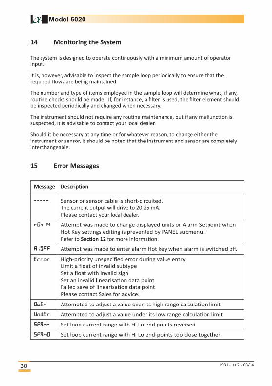
15 Error Messages
Model 6020
1931 - Iss 2 - 03/1430
Message Description
----- Sensor or sensor cable is short-circuited.
The current output will drive to 20.25 mA.
Please contact your local dealer.
On4 Attempt was made to change displayed units or Alarm Setpoint when
Hot Key settings editing is prevented by PANEL submenu.
Refer to Section 12 for more information.
Off Attempt was made to enter alarm Hot key when alarm is switched off.
o High-priority unspecified error during value entry
Limit a float of invalid subtype
Set a float with invalid sign
Set an invalid linearisation data point
Failed save of linearisation data point
Please contact Sales for advice.
Ove Attempted to adjust a value over its high range calculation limit
Une Attempted to adjust a value under its low range calculation limit
pan- Set loop current range with Hi Lo end points reversed
pan0 Set loop current range with Hi Lo end-points too close together

Model 6020
1931 - Iss 2 - 03/14 31
Appendices

Model 6020
Appendix A. Default instrument configuration
Configuration Contains submenus for choosing engineering units, choice of gas types and whether sensor linearisation is employed.Defaults are:
• the moisture content in °C dewpoint• the ppm(w) calculations use the gas type as Air• the model for natural gas is disabled• the pressure units are bar g• the temperature units are °C• sensor linearisation data points are enabled• the standard temperature and pressures are reset to
15.56°C (60°F) and 0 barg
Sensor Range Contains submenus to choose the range of sensor and entry of linearisation data points.Defaults are:
• The sensor range is GREY• The viewing of the instrument’s internal ACU readings are
not enabled.
Analog output Contains submenus to allow the user to fully configure the analog output.Defaults are:
• Output range is set to 4-20mA• Output range is set to the full span of the selected moisture
range e.g. 4 mA = -80°C and 20 mA = 0°C for GREY sensor range.
Alarms Contains submenus to fully control behaviour of two independent alarms.Defaults are:
• Both alarms setpoints are set to 0°C• Both alarms are set to trigger when rising above the upper
limit.• The relays are de-energised in a non event state• The alarms events are not latching• The alarm hysteresis is set to 0.1°C or the equivalent in
other units
Communications Contains submenus for changing baud rate and address of the instrument’s RS485 communication port.Defaults are:
• The instrument will communicate with a baud rate of 9600.• The address will be 00.
Security Contains submenus to set up passwords to control or limit access certain features from unauthorised changes.Defaults are:
• The setup password is reset to 0000 and as such is not requested unless changed.
• Other security password codes are defaulted (and on a reset set) to 9000.
• Panel submenu is enabled allowing changes via hot keys
1931 - Iss 2 - 03/1432

RS485 REPLY Protocol (as seen by Model 6020)
Byte Description
0, first 255
1 255
2 Preamble 255
3 255
4 255
5 Slave-to-Master 6
6 Return Address (128 for Address 0)
8-bit arithmetic OR of address with 128
7 Command 24
8 Data Len 6
9Status
bits 15 - 8
10 bits 7 - 0
11 Process Value,
12Data
Single Precision (4-Byte Float),
13 IEEE 754 Format,
14 Big-endian (first byte = msb)
15, last Checksum 8-bit arithmetic XOR of
byte 5 onwards
Appendix C. Communications Protocol
RS485 REQUEST Protocol (as seen by Model 6020)
Byte Description
0, first 255
1 255
2 Preamble 255
3 255
4 255
5 Master-to-Slave 2
6 Address 0 to 32
7 Command 24
8 Data Length 1
9 Data Bytes 0
10, last Checksum 27
8-bit arithmetic XOR of
byte 5 onwards
Model 6020
1931 - Iss 2 - 03/14 37

REPLY Status
Byte Description
15, first (ms)
14
13Not defined
12
11 Alarm 2: user to clear
10 Alarm 1: user to clear
9 Alarm 2
8 Alarm 1
7 Not defined
6 Sensor short
5
4
3Not defined
2
1
0, last (ls)
Example of communication using universal of 0
255255255255255
20
2410
27
255255255255255
612824600
<4 bytes of single float><1 byte of checksum>
Request message sent
to Model 6020
Reply message from
Model 6020
Model 6020
1931 - Iss 2 - 03/1438

Contact Information
Head Office:
Alpha Moisture Systems
96 City Road
Bradford
West Yorkshire
BD8 8ES
United Kingdom
Tel: +44 (0) 1274 733100
Fax: +44 (0) 1274 733200
Email: [email protected]
Web: www.dew-point.com
Office Opening Hours:
Monday - Thursday
8.30am - 5.30pm GMT
Friday
8.30am - 5.00pm GMT
Notes:
Model 6020
Location
1931 - Iss 2 - 03/14 39
Related Documents


![SHAW AUTOMATIC DEWPOINT METER MANUAL - … · SHAW AUTOMATIC DEWPOINT METER MANUAL ... drier than about -65 c. dewpoint). Then ... and slowly raise the head by hand]. 6.](https://static.cupdf.com/doc/110x72/5b4ff89e7f8b9a2a6e8d5734/shaw-automatic-dewpoint-meter-manual-shaw-automatic-dewpoint-meter-manual.jpg)


