Model description and experiments on carbon diffusion through protective layers Heijnen, L.M. DOI: 10.6100/IR276659 Published: 01/01/1987 Document Version Publisher’s PDF, also known as Version of Record (includes final page, issue and volume numbers) Please check the document version of this publication: • A submitted manuscript is the author's version of the article upon submission and before peer-review. There can be important differences between the submitted version and the official published version of record. People interested in the research are advised to contact the author for the final version of the publication, or visit the DOI to the publisher's website. • The final author version and the galley proof are versions of the publication after peer review. • The final published version features the final layout of the paper including the volume, issue and page numbers. Link to publication Citation for published version (APA): Heijnen, L. M. (1987). Model description and experiments on carbon diffusion through protective layers Eindhoven: Technische Universiteit Eindhoven DOI: 10.6100/IR276659 General rights Copyright and moral rights for the publications made accessible in the public portal are retained by the authors and/or other copyright owners and it is a condition of accessing publications that users recognise and abide by the legal requirements associated with these rights. • Users may download and print one copy of any publication from the public portal for the purpose of private study or research. • You may not further distribute the material or use it for any profit-making activity or commercial gain • You may freely distribute the URL identifying the publication in the public portal ? Take down policy If you believe that this document breaches copyright please contact us providing details, and we will remove access to the work immediately and investigate your claim. Download date: 17. May. 2018

Welcome message from author
This document is posted to help you gain knowledge. Please leave a comment to let me know what you think about it! Share it to your friends and learn new things together.
Transcript

Model description and experiments on carbon diffusionthrough protective layersHeijnen, L.M.
DOI:10.6100/IR276659
Published: 01/01/1987
Document VersionPublisher’s PDF, also known as Version of Record (includes final page, issue and volume numbers)
Please check the document version of this publication:
• A submitted manuscript is the author's version of the article upon submission and before peer-review. There can be important differencesbetween the submitted version and the official published version of record. People interested in the research are advised to contact theauthor for the final version of the publication, or visit the DOI to the publisher's website.• The final author version and the galley proof are versions of the publication after peer review.• The final published version features the final layout of the paper including the volume, issue and page numbers.
Link to publication
Citation for published version (APA):Heijnen, L. M. (1987). Model description and experiments on carbon diffusion through protective layersEindhoven: Technische Universiteit Eindhoven DOI: 10.6100/IR276659
General rightsCopyright and moral rights for the publications made accessible in the public portal are retained by the authors and/or other copyright ownersand it is a condition of accessing publications that users recognise and abide by the legal requirements associated with these rights.
• Users may download and print one copy of any publication from the public portal for the purpose of private study or research. • You may not further distribute the material or use it for any profit-making activity or commercial gain • You may freely distribute the URL identifying the publication in the public portal ?
Take down policyIf you believe that this document breaches copyright please contact us providing details, and we will remove access to the work immediatelyand investigate your claim.
Download date: 17. May. 2018

MODEL DESCRIPTION AND EXPERIMENTS
ON CARBON DIFFUSION
THROUGH PROTECTIVE LAYERS
MODEL DESCRIPTION AND EXPERIMENTSON CARBON DIFFUSION
THROUGH PROTECTIVE LAYERS
PROEFSCHRIFf
ter verkrijging van de graad van doctor aan deTechnische Universiteit Eindhoven, op gezagvan de rector magnificus, Prof. dr. F.N. Hooge,voor een commissie aangewezen door het Collegevan Decanen in het openbaar te verdedigen op
dinsdag 22 december 1987 te 16.00 uur
door
LEONARDUS MARIE HEIJNEN
geboren te Swalmen
Druk: Dissertatiedrukkerij Wibro. Helmond

Dit proefschrift is goedgekeurddoor de promotoren:
le promotor: Prof. dr. ir. J.A. Klostermann2e promotor: Prof. dr. R. Metselaarco-promotor: Dr F.J.J. van Loo

Contents
Chapter 1. General introductionPage:
1 . 11.21.3
CarburizationAvailable diffusion data and model descriptionsContents of this thesisReferences chapter 1
1457
Chapter 2. Mathematical model
2.12.2
2.32.3.12.3.22.3.32.42.4.1
2.4.22.5
IntroductionDiffusion of an element through a finitecomposite systemSolutions for special casesDiffusion in a one phase finite solidDiffusion in a one phase semi-finite solidDiffusion in a semi-infinite composite solidDiffusion through a diffusion barrierDiffusion through a diffusion barrier ona finite substrateDiffusion through a thin film diffusion barrierDiscussionReferences chapter 2
910
222224262729
313638
Chapter 3 Application of the mathematical model
3.13.23.33.43.5
IntroductionCalculationsAnalysis of the nomogramsDiscussionConclusionsReferences chapter 3
393943465053
Chapter 4 Deposition and characterization of layers
4.14.24.2.14.2.24.2.2.14.2.2.2
. 4.34.3.14.3.24.3.34.3.4
IntroductionLayer deposition by P.V.D.Classification of P.V.D. processesSome properties of P.V.D. layersThe structure of P.V.D. layersAdhesion of P.V.D layersThe characterization of the deposited layersOptical- and electron-microscopyX-ray photo-electron spectroscopyX-ray diffractionVacuum annealing
5456566363656768697272
4.44.4.14.4.24.4.2.14.4.2.24.4.2.3
4.4.2.44.4.2.54.4.2.6
4.4.2.74.4.2.84.4.3.14.4.3.24.54.6
Chapter 5
5. 15.2.15.2.25.2.35.35.45.5
5.65.7
ExperimentalApparatus and procedureDeposition of copper layersCopper deposition by ion platingCharacterization of ion plated copper layersCopper deposition by evaporation at highsubstrate temperaturesCharacterization of evaporated copper layersCopper deposition by D.C. bias sputteringCharacterization of D.C. bias sputteredcopper layersCopper deposition by D.C. sputteringCharacterization of D.C. sputtered copper layersSilver deposition by D.C. sputteringCharacterization of D.C. sputtered silver layersDiscussionConclusionsReferences chapter 4
Solid state carburization experiments on copper andsilver
IntroductionSolid state carburization methodPreparation of the carbon sourcePreparation of the samplesAnalytical techniquesExperiments and resultsCalculations of the transport coefficientof carbon in copper and silverDiscussionConclusionsReferences chapter 5
737376767981
828586
9293959698
101103
106107108109110111116
121122123
Chapter 6 Gas carburization
6.16.26.2.16.2.26.2.36.36.4
6.56.6
IntroductionExperimentalApparatusProcedurePreparation of the samplesExperiments and resultsCalculations of the transport coefficientsof carbon incopper and silverDiscussionConclusionsReferences chapter 6
124125125126128129135
141144146

Chapter 7
7.17.2
7.3
7.4
7.5
The instability of copper diffusion barriers
Introduction 147The breakdown of a copper layer during a gas 148carburization experimentThe breakdown of a copper layer during solid state 150carburizationThe stability of silver diffusion barriers during 155gas carburization and solid state carburizationConclusions 156References chapter 7 157
Appendix 158
List of symbols 166
Summary 168
Acknowledgement 171
Samenvatting 172
Curriculum vitae 175
Dankwoord 176
Chapter 1 GeDeral introduction
1 . 1 <:arburization
Carburization is one of the corrosion processes that can occur
at high temperatures in gas atmospheres with high carbon potentials.
The uptake of carbon from process environments by materials
(carburizationl is often a problem in ethylene pyrolysis furnaces,
methane conversion reactors, process equipment for coal gasification
and coal combustion and in heat exchangers for gas cooled nuclear
reactors [1-7]. It is reported in literature that carburization has
detrimental effects on the rupture strength and creep properties,
and produces changes in volume, expansion coefficient and thermal
conductivity of high temperature alloys (5].
To reduce the problem of carburization a number of proposals have
been made to change e.g. the process conditions or to use pre
operation surface treatments of the high temperature alloys.
The effect of the surface oxidation of high temperature alloys has
been extensively studied by a number of investigators [8-12]. A pre
oxidation of the high temperature alloy surface has two major
advantages. The first advantage is a coverage of the catalytic
active sites (e.g. nickell, which are present at the surface and
promote· the decomposition. of qaseous carbon containing species[13].
The second advantage is the 'often low solubility in, and the low
diffusion coefficient of carbon through,oxide lattices. The
- 1 -

solubility of carbon for example in wustite (FeO) and some other
oxides is reported to be indetectably small [14].
The structure and composition of oxide scales, grown on high
temperature alloys depend on the type of alloy used. The grown oxide
scales are mostly silicon oxide, aluminium oxide, chromium oxide or
mixed oxides and a large number of results report that pre-oxidation
has been very successful in reducing the carburization of high
temperature alloys.
Still a problem is present, because the grown oxide scales are often
damaged by thermal or mechanical cycling, thus leading to a failure
in the bond between the oxide scale and the bulk material
(spalling). But also the process of mechanical creep of alloys at
elevated temperatures can cause cracking of the oxide scales,
leading to a less effective protection of the underlaying bulk
material. The use of most oxide scales in process environments where
partial oxide pressures are extremely low, is strongly limited,
because the surface oxide scales are thermodynamically unstable and
they tend to be reduced. For this reason it is impossible to use
grown oxide scales on high temperature alloys in heat exchangers for
high temperature gas cooled nuclear reactors [16].
The fast and numerous developments in the .field of coating
techniques during the last 20 years, opened new possibilities to
solve problems concerning material corrosion in general. Because of
the successful usage of cQatings in aircraft gas turbines in
reducing the deleterious effects of hot corrrosion, the coating
- 2 -

techniques were also ad.opted to solve problems with (hot) corrosion
in the field of industrial processes.
Until now only a small number of reports mentioned the results of
investigations on the carburization resistance of coated high
temperature alloys [17-24].
The use of deposition techniques also introduces the possibility to
improve the adhesion between the oxide layer and the high
temperature alloy, e.g. by using intermediate layers, thus
increasing the thermal and mechanical cycling resistance. Another
advantage of coating techniques is of course the possibility of
depositing non-oxide layers on high temperature alloys, for those
applications in which oxide layers are thermodynamically unstable.
Before coatings can be considered for high temperature applications,
a large number of properties have to be carefully considered. For
example the interdiffusion of layer- and bulk-material has to be
low, to·ensure that the layer material does not vanish during
operation. So, the combinations of layer- and bulk-material
(substrate) have to be carefully considered. Of course also layer
properties as the carbon solubility and the carbon diffusion
coefficient h~ve to be known, in order to predict whether a layer
materid is suitable to use as a carbon (diffusion.> barrier. Because
of the need to predict the effectiveness of diffusion barriers there
is also an increas~ng need for valid model descriptions. Experiments
on carb?n diffusion ~hrough layer/substrate systems together with
- 3. -
good model descriptions would greatly enlarge the knowledge about
the behaviour of (carbon) diffusion barriers.
1. 2 Available diffusion data and ~el descriptions
Until now remarkably few data, necessary to predict the
behaviour of (carbon) diffusion barriers, can be found in
literature. The lack of information about carbon solubilities and
carbon diffusion coefficients in materials (especially for
compounds) is a large problem as the effectiveness of a coating has
to be predicted.
The absence of a good generally valid description of diffusion of an
element through a layer/substrate (composite) system, together with
the lack of diffusion data, make reliable predictions about the
behaviour of diffusion barriers impossible. The model descriptions
which are presented in literature have the problem that they all
assume the substrate/bulk material to be semi-infinite, which is of
course in contradiction with the usual practice.
The model description of carburization is complicated by the
complexity of the carburization process in which three successive
processes are involved. The first process is determined by flow
characteristics, near the surface of the object of study. A second
process is the chemical decomposition of the carbon 'containing'
gaseous compounds at the surface, where the kinetics can be rate
limiting. The third process is of course the solid state diffusion
of the (elemental) carbon from the surface into tbe bulk aaterial.
- 4 -

1 . 3 COIlteDts of t:Jais thesis
A new general model is proposed, which describes the diffusion
of an element in a finite composite (layer/substrate) system. The
new model is proven to be generally applicable to composite systems
by focussing on a number of special cases, which are incorporated in
it (chapter 2).
In chapter 3, the general model is used to study the diffusion
process of an element through a layer/substrate system, by
monitoring two characteristic features, as a function of time. The
first one, represents the thermodynamic activity of the diffusing
element at the interface layer/substrate, the second one represents
the the amount of the diffusing element in the substrate. The fact,
that the "monitored" factors are normalized and dimensionless, the
calculated nomogramli can generally be applied to. predict the
behaviour of any possible layer/substrate combination. With help of
the nomograms it is also possible to calculate the transport
coefficient of carbon in a layer material, if only the layer
thickness and the substrate-properties and -length are known.
In chapter 4 the experiments are described by which a suitable
Physical Vapour Deposition (P.V.D.) process is chosen to deposit
copper and silver layers which show good high temperature
performances.
Chapter 5 and 6 reveal the results of carburization experiments on
P.V.D. coated copper and silver samples. Also copper and silver
layers are chosen as model systems, the remarkably good performance
- 5-

of e.g. silver indicates that metallic diffusion" barriers can be
very interesting for applications, because they can be more reliable
than ceramic layers.
The two carburization methods and the achieved results are
described. The first method comprises only solid state diffusion of
carbon through deposited copper- resp. silver-layers and also solid
state diffusion experiments on barriers existing of copper and
silver foils are reported.
The second type is the more complex gravimetrical gas carburization
method (CH4/H2). From the results of the carburization experiments
and with help of the proposed general model the unknown (carbon)
transport coefficient of carbon in silver and copper are calculated.
With help of the solubility values of carbon in copper and silver,
from literature, the carbon diffusion coefficients are calculated.
Chapter 7 gives a possible explanation of the observed breakdown of
the copper layers during solid state and qas carburization
experiments.
- 6 -

References cba,ur 1
[1] D.M. Ward, ·Corrosion and mechanical stress at high
temperatures·, Ed. V. Guttmann, M. Merz, Applied Science
Publishers Ltd., London, (1981), 31
[2] R.H. Kane, ·Proc. NACE Corrosion 83" National
Association of Corrosion Engineers, Houston, (1983), 89/1
[3] M.W. Mueek, "Proe. NACE Corrosion 83", National
Association of Corrosion Engineers, Houston, (1983),269/2
[4] J. Ebberink, K. Krompholz, E. te Heesen, "Corrosion and
mechanical stress at high temperatures", Ed. V. Guttmann,
M. Merz, Applied Science Publishers Ltd., London, (1981), 87
[5] P. Ennis, H. Schuster, "Corrosion and mechanical stress
at high temperatures", Ed. V. Guttmann,
M. Merz, Applied Science Publishers Ltd., London, (1981), 103
[6] J. Norton, "Carburization in high temperature process plant
materials·, Colloquium Proceedings EUR 7773, (1981), 43
[7] S. Muraoka, H. Itami, S. Nomura, J. Nuel. Mat.,
59, (1975), 18
[8] J. Perkins, A. Goldberg, oxidation of metals, 11, (1977), 23
[9] K. Ledjeff, A. Ramhel, M. Schorr, Werkstoffe u. Korrosion,
30, (1979), 767
[10] X. Ledjeff, A. Ramhel, M. Schorr, Werkstoffe u. Xorrosion,
31, (1980), 31
[11] J. Peters, H.J. Grabke, Werkstoffe u. Xorrosion
35, (1984), 385
[12] T.N. Rhys-Jones, H.J. Grabke, H. Xudielka, Werkstoffe u.
Korrosion, 38, (1987),65
[13] D.W. McKee, G. Romeo, Metall. Trans., 4, (1973), 1877
[14] H. Meurer, H. Smalzried, Arch. Eisenhuttenwes.,
42, (1971), 87
[15] W.J. Quadakkers, H. Schuster, Werkstoffe u. Korrosion,
36, (1985), 141
[16] R. Swaroop, J. Vac. Sci. Technol., 13, (1976),531
- 7 -

[17] R. Swaroop, J. Vac. Sci. Technol., 13, (1976), 680
[18] G. Wahl, F. Schmaderer, Thin solid films, 84, (1981), 127
[19] G. Wahl, Thin solid films, 107, (1983),417
[20] T.A. Taylor, M.P. Overs, J.M. Quets, R.C. Tucker,
Thin solid films I 107, (1983), 427
[21] T. Shikama, Y. Sakai, M. Okada, Thin solid films,
145, (1986), 145
[22] D.E. Brown, J.T.K. Clark, A.I. Foster, J.J. McCaroll,
M.S. Richards, M.L. Sims, M.A.M. swidzinski, "Proceedinqs
8th International conference on Chemical vapour deposition",
Paris, (1980), 699
[23] D.E. Brown, J.T.K. Clark A.I. Foster, J.J. McCaroll,
M.L. Sims, "Proceedinqs International symposium on Coke
formation on catalysts and pyrolysis units', New York, (1982)
[24] J.T.K Clark, A.I. Foster, M.L. Sims, M.A.M. Swidzinski,
D. Young, "Proceedings of 4th European conference on C.V.D.,
Eindhoven, (1983), 385
- 8 -

Chapter 2 Ilat:l14sltical .adel
2 . 1 Introduction
Because of the tremendous developments in thin film deposition
techniques it has been possible to extend the applications of
materials to higher temperatures and more aggressive environments.
In connection with this a lot of work has been done on the
description of surface layers on substrate materials as a barrier
against heat conduction and .interdiffusion.
In this chapter a new mathematical model will be proposed which
describes the diffusion of a chemical element through a finite
composite solid (layer/substrate). The model is achieved in an
analytical way which makes it possible to get more information about
how material-properties and -dimension affect the diffusion of the
element. This description is practically confined to linear
problems, but it often is possible to reduce a practical problem to
a simple linear problem. Effects like e.g. a concentration
dependence of the interdiffusion coefficient are not taken. into
account. These extentions are more complex and a finite difference'
techniquets needed to solve these problems.
The proposed model is not restricted to a certain kind of chemical
process., If a ~hemical process meets with the assumptions on which
the model is based, it is applicable (e.g. to carburization,
nitriding, hydrogen permeation etc.).
- 9 -
In the third part of the chapter the model is applied to special
cases which have been solved by other investigators. The equality of
the results points out the validity of our general model and shows
its broad field of application.
In the last part of this chapter the model will be used to describe
the effect of a diffusion barrier, on the diffusion of an element,in
a finite substrate.
Results which have been obtained in the field of thermal conduction
can be translated into comparable problems in the field of
diffusion. This analogy has been used by Crank [1] to find solutions
for diffusion problems, using solutions of heat conduction problems
found by Carslaw and Jaeger [2]. The model presented in this
chapter, can therefore be "translated" easily to an analogous heat
conduction problem.
2 . 2 oiffusiOD of an eleaent throu9h a finite ca.posite solid
In this chapter we will mathematically describe the one
dimensional diffusion of an element in a finite composite solid, at
one side exposed to the diffusing element (Fig. 2.1). A series of
solutions to problems concerning thermal conduction or diffusion in
such composite syste.s has been reported in literature [1-4]. Most
of these solutions, however are concerned with systeas in which the
bulk or substrate material is an infinite or seai-infinite solid.
Only a few descriptions deal with finite coaposite systeas, but then
- 10 -
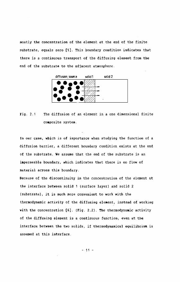
mostly the concentration of the element at the end of the finite
substrate, equals zero [5]. This boundary condition indicates that
there is a continuous transport of the diffusing element from the
end of the substrate to the adjacent atmosphere.
diffusion. source solid 1 solid 2
Fig. 2.1
•••••• • • • -+/j-:--7j0-'-;-';~~-';-t---.... ////..... /:
The diffusion of an element in a one dimensional finite
composite system.
In our case, which is of importance when studying the function of a
diffusion barrier, a different boundary condition exists at the end
of the substrate. We assume that the end of the substrate is an
impermeable boundary, which indicates that there is no flow of
material across this boundary.
Because of the discontinuity in the concentration of the element at
the interface between solid 1 (surface layer) and solid 2
(substrate), it is much more convenient to work with the
thermodynamic activity of the diffusing element, instead of working
with the concentration (6]. (Fig. 2.2). The thermodynamic activity
of the diffusing element is a continuous fu~ction, even at the
interface between the two solids, if thermodynamical equilibrium is
assumed at this interface.
- 11 -

i I IT: I-l 0 d
-x
Fig. 2.2a The concentration of the diffusing element in a
composite system.
N
f
~~-l o
-x d
Fig. 2.2b The thermodynamic activity of the diffusing element in a
composite system.
The activity is given by:
(2. 1)
Where: a = thermodynamic activity of the diffusing element
1 activity coefficient of the diffusing element
N =molar fraction of the diffusing element
- 12 -

The concentration (C) in moles per unit volume and the molar
fraction are related via the molar volume (Vm), which is supposed to
be independent of the concentration of the diffusing element.
CN
Vm
(2.2)
If the activity coefficient is constant, it is equal to the recipro-
cal value of the maximum solubility (L) of the element in a material
at the temperature involved (Fig. 2.3). This is true if only a small
amount of the element is soluble in the layer, and if this solid
solution exists in chemical equilibrium with the pure element:
1 =L
(L in mol fraction) (2.3)
T
1
o L o L
Fig.2.3a The maximum solubility of
element x in a phase ~ at
a temperature T.
Fig.2.3b The activity of x as
a function of the
mol fraction of x, at
a temperature T.
We now suppose that the interdiffusion takes place by migration of
the "diffusing element" only, i.e. other elements present in solid
- 13 -

or solid 2 do not take part in the diffusion process. Using the
equations (2.1) and (2.2) and assuming the diffusion coefficient (D)
to be independent of the thermodynamic activity (a), Fick's first
and second law turn into:
D aaJ = ---
y Vm ax
oa a2aD-
ot ax2
(2.4)
(2.5)
Where t = diffusion time
D = diffusion coefficient of the diffusing element
J = flux of the diffusing element
x = direction of one-dimensional diffusion
We will try to find a concentration penetration curve for the
diffusing element as a function of time, thickness of solid 1 (1)
and thickness of solid 2 (d). The problem will be treated on the
basis of the following assumptions:
(i) We regard the system as one-dimensional.
(ii) Only one element diffuses.
(iii) The activity coefficient (y), the diffusion
coefficient (D) and the molar volume (Vm) are
constant and independent of the concentration of
the diffusing element.
(iv) The amount of the indiffusing element is small,
therefore the total volume and the thicknesses of
the solid 1 (1) and solid 2 (d) are supposed to be
- 14 -

constant. (Theoretically, a constant total volume
is contradictory to the demand of a constant molar
volume; for small amounts of the diffusing
. elements the error is negligible).
(v) No interdiffusion nor a reaction occurs between
solid 1 (surface layer) and solid 2 (substrate)
(vi) No reactions occur between the diffusing element
and the matrix.
The differential equations and the boundary conditions under the
assumptions (i)-(vi) in this are:
3a1 a2a 1
D1 -1 < x o / t > 0 (2.6)
at 3x 2
3a2 a2a 2D2 0 x < d I t > 0 (2.7)
3t 3x 2
a1 a2 a -1 < x < d , t 0 (Z.8)b
a1 aO x '" -1 / t > 0 (2.9)
a1 a2 x '" o , t > 0 (2.10)
D1 3a, D2 aaZ--- ---- x '" o , t > 0 (2. 11 )Vm1 .... 1 ax VmZ ....2 ax
D2 aaz--- 0 x '" d / t > 0 (Z.1Z)Vm2 '1'z ax
- 15 -

In words this means, that the activity of the diffusing element at
the beginning of the experiment is equal and constant (a b) in solid
1 and solid 2, while the activity at the surface of the layer is
equal to a constant v~lue aO from the beginning Df the experiment
(Fig. 2.4). The activity at the interface between solid 1 and solid
2 as well as the flux of the diffusing element are equal in solid
and solid 2 and the activity gradient of the diffusing element is
zero at the end of solid 2.
solid 1 solid 2aoa(x,t)
ft=oab l----+---~---____l
-L o-x
d
Fig. 2.4 The thermodynamic activity of the diffusing element in a
finite composite solid at t = 0 and t > O.
Problems on diffusion and heat conduction in solids are usually best
solved by the Laplace Transformation Method.
- 16 -

Taking the Laplace transforms of the equations (2.6)-(2.12), we
obtain a new set of equations:
2-a a1
°1 - P a1 ab -1 ( x 0 (2.13 )
ax2
2-a a2
°2 - P a2ab o < x < d (2.14 )
ai
aoa1 x = -1 (2.15 )
p
- -0 (2.16)a1
a2 x =
°1 aa1 1 °2 aii2
--- --- x = 0 (2.17)V
m1 'Y 1 ax Vm2 'Y2 ax
02 aa 2--- 0 x = d (2.18)Vm2 'Y2 ax
Where ai(x) denotes the Laplace transform of the activity ai(x,t):
(2.19)
- 17 -

The Laplace transformed differential equations turn out to be
inhomogeneous and so a particular solution will be determined. The
term ab in the equations (2.13) and (2.14) is constant and thus the
particular solutions (a l' a 2 are easily written down.p, p,
-1 < x < 0
o < x < dp
The general solutions for the problem will be of the form:
a + (2.20)
with help of the particular solutions the inhomogeneous Laplace
transformed differen~ial equations and boundary conditions are
turned into the following homogeneous Laplace transformed
differential equations and boundary conditions:
2-3 ah ,1
D1 p~,1
3x2
2-o ah,2D2
ox2p ah,2
aO - abah ,1 p
-1 < x < 0
o < x < d
x = -1
- 18 -
(2.21)
(2.22)
(2.23)

ah,1 ah,2 x = 0 (2.24)
°1 a~,1 °2 oah,2---- ---- x = 0 (2.25)Vm1 "1 1 ax Vm2 "12 ax
°2 oah,2---- 0 x = d (2.26)Vm2 "12 ax
12
pAssuming q1 = ( ) and q2
D1
p
12
) and solving the Laplace trans-
formed differential equations (2.21) and (2.22) under the given
boundary conditions, we obtain the following solutions for the
homogeneous Laplace transformed differential equations. (see also
appendix A):
aO - ab coshq2d coshq1X - o sinhQ2d sinhQ1x
a h,1 (2.27)p coshQ1l coshQ2d + o sinhQ1l sinhQ2d
- 1 < x 0
aO - a b coshQ2(d - x)
ah ,2 (2.28)p coshQ1l coshQ2d + o sinhQ1l sinhQ2d
0 < x < d
- 19 -

where: 0=.--
Vm2 '1 2 °1
12
(2.29)
So, the general Laplace transformed solutions according to equation
(2.20) are:
ab
a - ab coshq2d coshQ1x - o sinhQ2d sinhq1x0a 1
-+ (2.30)P P coshq11 coshQ2d + 0 sinhQ11 sinhQ2d
- 1 < x < 0
abaO - ab coshQ2(d - x)
a 2-+ (2.31 )
PP coshQ1l coshQ2d + 0 sinhQ1l sinhQ2d
0 < x < d
The inverse Laplace transformation of the equations (2.30) and
(2.31) can be determined by carrying out "the method of partial
fractions" [7]. (see also appendix A). Thus we obtain:
- 1 < x < 0 , t > 0
- 20 -
(2.32)

o < x < d , t > 0
In these equations P is the infinite series of roots of then
·characteristic equation·:
1 - 0 tanPnl tanPnkd 0
1
°12
where: k
°2
(2.33)
(2.34)
(2.35)
with use of the equations (2.1) and (2.2) the equations (2.32) and
(2.33) can be transformed to concentration distribution equations
given by:
ab
(aO
- ab
)
C1--t'Y 1 Vm1 'Y 1 Vm1
(ao - ab
)
2---'Y 1 Vm1
- 21 -
- 1 < x < 0 , t > 0 (2.36)

ab
c=---+2 12 Vm2
(ao - ab
) ..
2 I:12 Vm2 n=1
o < x < d , t > 0
2.3 Solutions for special cases
2.3.1 Diffusion in a one pbase, finite solid
(2.37)
In the former section a mathematical description was presented
for the diffusion of an element through a finite, composite solid.
It is a general description in which no restrictions have been made
to dimensions or material properties of the solids involved.
If we assume that D1= D2= D, 11= 12= 1 and Vm1 Vm2 , it is clear
from equation (2.29) and (2.35) that 0 = 1 and k 1. In words this
means that, the material properties of solid 1 and solid 2 are
identical. If we further assume that the activity of the diffusing
element at the beginning of the diffusion proces is zero throughout
the solid (ab = 0) and use Laplace transformed solutions (2.30) and
(2.31) this will yield:
12p
)
D
- 22 -
ao coshqd coshqx - sinhqd sinhqx
a 1 coshq1 coshqd + sinhq1 sinhqdp
-1 < x < 0
aO coshq(d-x)
a 2 coshq1 coshqd + sinhq1 sinhqdp
(2.38)
(2.39)
It can easily be seen that a1
a1 and a2 can be replaced by a :
o < x < d
a2 over the interval -1 < x < d, 50
aO coshq(d-x)
a =p coshq (l+d)
-1 < x < d (2.40)
By using "the method of partial fractions" the inverse Laplace
transformed solution is found. (see appendix B):
4 aO " ( _1)n (2n+1)wa = aO - -W---
n;1(2n+1) cos[2(d+1) (d - x)] e
(2n+1)2w2 D t
4(1+d)2
-1 < x < d , t > 0 (2.41)
This solution for a finite one phase solid as a special case of the
more general solution is equal to the solutions given by Crank [1],
Cars1aw and Jaeger [2] and Cheung [8].
- 23 -
2.3.2 Diffusion iD a ODe pbase seti-iDfiDite solid aterial
This very special case of the general solution concerns one of
the most frequently occurring problems in diffusion and heat
conduction. Again we return to the Laplace transformed general
solutions. By describing a finite system in which d ~ ~, we indicate
that the system is becoming semi-infinite. Assuming that a b= 0 and
rewriting the Laplace transformed solutions, (2.30) and (2.31)
results in:
coshq2dcoshq1X - a sinhq1xaO sinhq2d
a 1 coshq2dpcoshQ11 + a sinhQ1lsinhQ1d
-1 ( x < 0
coshQ2dcoshQ2x - sinhQ2xaO sinhQ2d
a 2 coshQ2dpcoshQ11 + a sinhQ1lsinhQ2d
0 ( x < d
According to the assumption d .... :
Q2d -Q2d -2Q dcoshQ2d + e + e 2e
limsinhQ2d
limq2d -q2d
lim- 2q2d
d~~ d.... d....e - e - e
(2.42)
(2.43)
- 24 -

Now equations (2.42) and (2.43) turn into:
aO COshq1X - a sinhq1x
a 1 coshq11 + 0 sinhq11p
-1 < x < 0
aO coshQ2X - sinhQ2xa 2
coshq11 + o sinhQ11p
o < x < 00
(2.44)
(2.45)
since we have a one phase solid, D1= D2= D, 11= 12= 1 and Vm1 = Vm2
which means: 0 = 1, k = 1, q1 = q2 = q, the equations (2.44) and
(2.45) turn into:
aO coshqx - sinhqx
p coshql + sinhql
aO coshqx - sinhqx
p coshql + sinhql
aO -q(x+1)-e
p
-1 < x < 0
a O -q(x+l)-e
p
o < x < ..
(2.46)
(2.47)
The equations above are identical and can be expressed by one
equation:
aa -q(x+l)e
- 25 -
-1 < x < 00 (2.48)

Using the table of Laplace transforms [9,10], the well known
solution for the activity as a function of distance and time in a
semi-infinite one phase system results:
x + 1-1 < x < - , t >0
2.3.3 Diffusion in a seai-infinite ca.posite solid
(2.49)
In section 2.3.2 we discussed the situation in which solid 2
is becoming infinite (d ~ -). Together with the assumption that the
activity in the whole system is zero at the beqinning (ab = 0), the
Laplace transformed solutions for this case were qiven by equations
(2.44) and (2.45), These equations are the Laplace transformed
solutions to the problem of diffusion of an element throuqh a semi-
infinite composite solid. The equations can be arranged, giving:
2 aO d -Q1(x+l) Q1(x-1)e - a e
a 1 (1 + 0) P - 2q11- a e
2 aO d -q1[(2n+1)1+x] -q1 [(2n+1 )1-x][
n(1 + 0)
a (e - a e )pn=O
- 26 -
-1 < x < 0 (2.50)

2 aO
d
(1 + 0) P
-q1 (kx+l)e 2 a
Od
(1 + 0) p[ an
n=O
-Q1[(2n+1)l+kx]e
where:0-1
a = 0 + 1
o < x ( .. (2.51)
Using the table of Laplace transforms [9,10], the solution becomes:
aO
[ an erfc( (2n~ + x ) _ an+1erfc( (2n+1)l - xn=O 2 D1t 2JD 1t
2 aO
(1 + 0)
-1 < x ( 0 , t > 0
(2n+111 + kx[ an erfc( ~
n=O 2 D1t
o ( x ( .. ,t> 0
(2.52)
(2.53)
This solution, to the problem of diffusion or heat conduction in a
semi-infinite composite system, is identical to the solution given
by other investigators [1,2].
2.4 Diffusion through a diffusion barrier
The scope of this thesis is to study the effects of layers or
thin films which act as diffusion barriers. By focussing on this
feature it is possible to turn the "complex" general solution into a
more handy solution which can be. used if an element is diffusing
through a finite barrier/substrate system. Before rearranging the
- 27 -

(2.54)
solution to a form in which solid 1 is a diffusion barrier, we will
first discuss the properties of solid 1 needed for this purpose.
Fick's first law has been given by:
- D aaJ
1 Vm ax
This indicates that the transport (flux) of an element diffusing
through a solid depends on the diffusion coefficient (D) and the
activity coefficient (y).
If one is looking for a good barrier material against diffusion of
some element the most important properties are the diffusion
coefficient and the solubility of that element in the barrier
material. A good bar·rier is a material through which the transport
or diffusion is slow, which indicates according to (2.54) that
preferably both the diffusion coefficient and the solubility are
low. If solid 1 has to act like a barrier material on solid 2 for
the diffusion of an element this means that:
and also
(because L1 < L2 )
- 28 -

2.4. 1 Diffusion tbrouC)b a diffusioD barrier OD a finite substrate
If the diffusing element in solid 1 has a lower diffusion
coefficient and a lower solubility compared to solid 2, solid 1 acts
as a diffusion barrier on solid 2. In this case it is possible to
simplify the general solution to a more handy form. Under the
assumption 01 « 02 and "11 » "12 ' a will be large:
1vm1 "1 1 °2
2
a =--°1Vm2 "1 2
Rewriting (2.34) gives the following expression:
a sinp kd sinp 1n n
(2.55)
With this expression the general equations (2.32) and (2.33) can be
rewritten:
sinp (x + 1)n
- 29 -
-1 < x < 0 , t > 0 (2.56)

_/32 D tn 1
(0 sin/3 1 cos/3 kx + cos/3 1 sin/3 kx) en n n n
o ~ x < d , t > 0 (2.57)
We assume that in case of a good diffusion barrier 0 » 1, which
turns the equations (2.56) and (2.57) into:
_/32 D tsin/3 (x + 1) n 1en
/3 n1 + /3nokd . 2 1Sln /3n
-1 < x < 0 , t > 0
[
n=1
o < x < d , t > 0
(2.58)
(2.59)
In these equations /3n is the infinite series given by (2.34). The
expressions above are solutions given for the situation in a finite
composite system in which solid 1 acts as a good diffusion barrier.
- 30 -

2.4.2 Diffusion thEougb a thin fila diffusion barrier
If in a practical case a diffusion barrier is used, the
thickness of such a phase (solid 1) is very small compared to the
thickness of the substrate phase (solid 2). Comparing the thickness
of the thin layer and substrate one would normally say that I « d,
but in this case it is more convenient to compare a characteristic
dimensionless layer- and substrate-length with each other. This
means that we assume:
I d«
J0 1t J0 2twhich means: I « kd
(2.60)
Combining the assumptions 0 » 1 and I « kd, we have a new special
case of the general solution of the finite composite solid.
-pn2
01 tThe value of the factor e in the general equatiolls (2.32)
and (2.33) rapidly decreases as Pn increases. If therefore we
exclude from considerations small values of time (t), we may
restrict ourselves to the first terms of the infinite series of pn.
This, together with the assumptions that 0 ~ ~ and 1 « kd, provides
a possibility to approximate the infinite series of Pn expressed by
equation (2.34). Because 0 » 1 and 1 « kd the tanpnl in the
characteristic equation can be approximated by pnl. This leads to:
1- ,. P I tanp kdo n n
- 31 -

The first root is determined by expanding the tanP 1kd and retaining
the term in P~k3d3, so we obtain:
1 1- = P 1 (P kd - - P 3k3d3)a 1 1 3 1
Solving this equation, we find:
P 21
-3 + J9 + 12(~)
2 k2
d2
The other roots of the characteristic equation are found by solving
equation (2.60) under the assumption that 0 » 1 and thus ! ~ o.o
n1lThis means tanpnkd = 0, which leads to Pn kd for n ) O. So, the
series of approximated roots used will be:
(2.61 )(n - 1) 11
Pn = kd n = 2,3,4,5, ....
If we introduce these approximated p. 's in the equations expressing1
the solution for the diffusion barrier/substrate system, (2.58) and
(2.59) become:
- 32 -
sina1 (x + 1) 2-11 1 01 t
--------e
nil
sin[(kd)(x + 1)]
nil nil ,2 nil(kd)l + (kd)a Sin (kd)l
nil 2- (kd) 01 t
e
-1 < x < 0 , t > 0 (2.62)
1~ cOSll 11 sinll1kx + sinll11 cOSll 1kx
1 nil 1 nil x nil 1 nil x nil 2~ cos~ sin-a- + sin~ cos-a- -(kd) 01 t
- enil nil . 2 nil
(kd)1 + (kd)akd Sin (kd)l
o ( x < d , t > 0 (2.63)
Because of the assumption 1 « kd, we may say that for n is not too
large:
nil 1 nil 1sin kd ,. kd
sin 1l 1(x + 1) ,. 11 1 (x + 1)
- 33 -

nw nwsin ~(x + 1) ~ kd (x + 1)
-1 < x < 0
This together with equation (2.61) turns equation (2.62) and (2.63)
into:
x + 1
1e
x + 1 00
2(aO
.- ab) -- r1 n=1
-1 < x < 0 It) 0
(2.64 )
01 2 21 + (kd)n w
kd 1 nwx nwx(--)--- sin--- + cos---
00 01 nw d d
x xsin(d~) + cos(d~)
e
nw 2- (d) D2 t
------------e
o < x < d , t ) 0
In which:
: + ~ V9 + 12 /d)2 2 01
- 34 -
(2.65)
Reviewing the equations which describe the system of a thin film
diffusion barrier on a finite substrate we may write:
x + 1[ e
1 n=O 011 + (kd)fln
[
n=O 011 + (kd) fin
In which: fin is
-1 < x < 0 , t > 0
e
o ~ x < d , t > 0
(2.66)
(2.67)
3 1 J9 + 12 (kd)2 + 2 01
2 2n 11 n= 1,2,3, .
- 35 -
(2.68)

substrate
2.5 Discussion
The general model describing the diffusion of an element
through a finite composite system contains a number of special
cases. This of course is not surprising at all, because the
diffusion process can be divided into successively 3 stages.
(Fig. 2.5). The first stage (0 < t < T1), is the stage in which the
penetration depth of the diffusing element is smaller than the layer
thickness (I), The process in this stage can be mathematically
described by the formula given for the diffusion of an element in a
semi-infinite one-phase system.
layeraO r====f===::::::r=====t
a(x,fl
1
-l o--x d
Fig. 2,5 The three different stages in the diffusion of an
element in a finite composite system.
In the second stage (T 1 < t < T2 ), the penetration depth of the
diffusing element is bigger than the layer thickness, but has not
reached the end of the substrate. This stage can be mathematically
described with the formulae given for the diffusion of an element in
- 36 -

a semi-infinite composite system. The last stage (T 2 < t < T 3), is
the stage in which the penetration has progressed through the entire
substrate length (d), so the system can not be regarded anymore as a
semi-infinite system. It is clear that the above mentioned special
cases must be contained in a model which deals with the problem of
the diffusion of an element through a finite composite system.
The activity curve of the diffusing element can be calculated in any
system, at any given time, using the general model. Because of the
complexity of the general solution, it is difficult to see the
relations between material-properties, -dimensions and time. It
follows from the equations (2.66) to (2.6B), that by approximating
the general equations in case of a thin film diffusion barrier on a
finite substrate, the activity is a function of two dimensionless
parameters. The first parameter contains the material-properties,
-dimensions (ol/kd).
01 D2 1 1 Vm1 I
kd = n;- 12 Vm2 d
The second parameter, the dimensionless characteristic time (T),
which holds the diffusion coefficient of the diffusing element in
the substrate, the substrate dimension and the time.
T =
- 37 -

References chapter 2
[1] J. Crank, "The mathematics of diffusion", Clarendon Press,
Oxford, (1956)
[2] H.S. Carslaw, J.C. Jaeger, "Conduction of heat in solids",
Clarendon Press, Oxford, (1959)
[3] A.V. Luikov, "Analytical heat diffusion theory",
ed. J.P. Hartnett, Academic Press, New York, (1968)
[4] R.B. Bird, W.E. Stewart, E.N. Lightfoot, "Transport
phenomena", John Wiley & Sonc. Inc. New York, (1978)
[5J N. Kishimoto, T. Tanabe, H. Josihida, Thin solid films, 106,
(1983),225
[6J B. Million, Z. Metallkde., 74, (1983), 105
[7J B.J. Starkey, " Laplace transforms for electrical engineers",
Iliffe & Sons Ltd., New York, (1954)
[BJ C.T. Cheung, G. Simkovich, Reactivity of solids,
3, (1987), 161
[9J H. Bateman, "Tables of integral transforms", Ed. A.Erdelyi,
Mc.Graw-Hill Book Company Inc., New York, (1954)
[10] M. Abramowitz, I.A. Stegun, "Handbook of mathematical
functions", Dover Publications Inc., New York, (1964)
- 38 -

Chapter 3 Application of the _the.atical ~el
3 . 1 Introduction
The general solution to the problem of the diffusion of an
element through a finite composite solid, made it possible to
predict the influences of a change in material-properties and
dimensions on the activity profile of the diffusing element. In the
last part of the former chapter, an approximation was given for a
thin film (1 < kd) diffusion barrier (0 » 1) and it turned out that
the important parameters influencing the activity profile in the
composite solid were the factors ol/kd and D2t/d2. This knowledge is
very helpful, but not satisfying, e.g. when the entire range of very
thin diffusion barriers up to very thick ones (1 ) kd) has to be
covered. For this reason some results from computer calculations
using the general model are presented and analysed in this chapter.
The calculations were focussed on two major important variables
which monitor the diffusion barrier behaviour. The first variable is
the activity of the diffusing element at the interface between layer
and substrate (a1 (O/t». The second variable is the amount of the
diffusing element in the substrate at any given time (M (t».s
3 . 2 calculations
All computer calculations were performed with the formulae
which express the general solution to the problem of an element
- 39 -
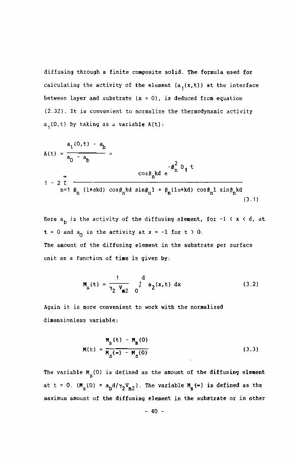
diffusing through a finite composite solid. The formula used for
calculating the activity of the element (a 1(x,t» at the interface
between layer and substrate (x = 0), is deduced from equation
(2.32). It is convenient to normalize the thermodynamic activity
a1(0,t) by taking as a variable A(t):
A(t)
1 - 2 rn=1 ~n (l+okd) cos~nkd sin~lll + ~n(1o+kd) cOSllnl sinllnkd
(3.1)
Here a b is the activity of the diffusing element, for -1 ( x ( d, at
t = 0 and aO is the activity at x = -1 for t ) O.
The amount of the diffusing element in the substrate per surface
unit as a function of time is given by:
d--- J
"12 Vm2 0(3.2)
Again it is more convenient to work with the normalized
dimensionless variable:
M(t)
MS(t) - Ms (0)
Ms(oo) - Ms(O)(3.3)
The variable M (0) is defined as the amount of the diffusing elements
at t = O. (Ms(O) = abd/"12Vm2). The variable Ms(oo) is defined as the
maximum amount of the diffusing element in the substrate or in other
- 40 -

words the total amount of the diffusing element in the substrate at
t = ~, (Ms(~) = aOd/12Vm2)' The equation used to calculate this
characteristic dimensionless variable M(t) can be found with help of
the.equations (2.33) and (3.1) resulting in:
M(t) 1 - 2 rn=1 f3~(l+(Jkd) cosf3nkd sin f3nl + f3~(1o+kd) cosf3nl sinf3nkd
(3.4)
In the equations (3,1) and (3.4), an is the infinite series of roots
of the characteristic equation:
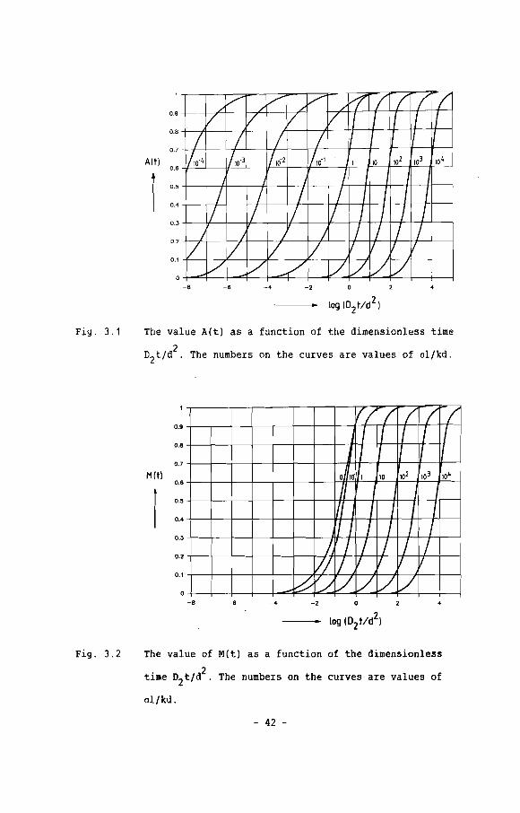
The calculated values of A(t) and M(t) are plotted against a
characteristic dimensionless time (D 2t/d 2) for various values of
ol/kd. The calculated nomograms of A(t) and M(t) are given in fig.
3.1 and 3.2.
- 41 -
/v // /V /~ -/ / / -('/ V '/ VI II I J J
I I I I II ,/ J II ,I
/10'4 /10'3 '110-2 /10-1 1 10 102 103 10 4
/ I I
/ / / / I I I I/ / 1/ / I I / /
/ / / / / / / /V V / V / / /
--/ V ....V / ~~ /
0.9
0.8
0.7
A(t)0.6
0.5
0.4
0.3
0.2
0.1
a-8 -6 -4 -2
Fig. 3.1 The value A(t) as a function of the dimensionless time
ZDzt/d . The numbers on the curves are values of ol/kd.
Iff -/ / / /J I I I I IJ I I II II
o 101 1 10 102 103 104
, I I, I I I II / I / /
~ / / / / /1/ I I I II
-? /./ '/ / / /
0.9
0.8
0.7
M(t)0.8
0.5
0.4
0.3
0.2
0.1
a-8 -8 -4 -2 a 4
Fig. 3.2 The value of M(t) as a function of the dimensionless
time D2t/d2 . The numbers on the curves are values of
ol/kd.
- 42 -
3 . 3 Analysis of the nomgrilllS
The nomogram of A(t) against 02t/d2 shows that the A(t)
increases as time increases, which is not surprising at all, since
the process starts at t = 0 with a1 (O,t) = ab (A(t) = 0) and
progresses until a steady state situation is reached at t = ~ with
1). The nomogram also shows that an increase of
the parameter ol/kd, shifts the A(t)-line in the nomogram to the
right. A higher value of ol/kd indicates that the diffusion barrier
is more effective and therefore it takes a longer time to reach the
same value for A(t). The nomogram for A(t) can be divided into three
regions. The first region for ol/kd S 0.1, a second one for 0.1 <
ol/kd < 10 and a third one for ol/kd ! 10. In the first region the
"distance" between two successive lines in the nomogram is exactly a
2factor hundred on the 02t/d -scale, whereas the ol/kd-values of two
successive lines differ only by a factor ten. This indicates that
the parameter ol/kd and the characteristic dimensionless time 02t/d2
can be combined to a new process-governing parameter Q1:
1
02 t 1 201 02 'Y 1 Vm1 1
Q1 kd )/(d2 /
~ 'Y2 Vm2 Jt
01
kd S 0.1 (3.5)
The "distance" between two successive lines, in the third region of
2the nomogram, is exactly a factor ten on the 02t/d -scale which is
- 43 -

equal to the difference between the ol/kd-factors of two successive
lines. This indicates that the parameter ol/kd and the dimensionless
time in the region can be combined to the a process-governing
parameter Q3:
111Vm1ld
= D1
12
Vm2
t
01kd l 10 (3.6)
The region between region 1 and region 3 is a transition region,
where the displacement of the curve parallel to the time axis is not
the only effect of a change in the factor ol/kd, but also a slight
change in the shape of the curves occurs. The slight change in the
shape of the curves as ol/kd increases, indicates that the
determining factor changes continuously, from Q1 valid in region 1,
equation (3.5), to Q3 valid in region 3, equation (3.6).
In other words, A(t) is a function of a parameter Q, in which
material-properties, -dimension and time are related in a fairly
simple way. This parameter makes it possible to predict the effect
of a change ill material-properties and/or -dimensions on the value
of A(t) for ol/kd 5 0.1 and ol/kd l 10. For example, in a diffusion
barrier/substrate system with 0 1 /k d the value of A(t) is knowna a a a
at a time t . The value of °ala/kada is less than 0.1 and so thea
determining factor must be described by equation (3.5). The question
can be asked: how long does it take to reach the same value for
A(ta ) if we change the material-properties and/or dimension to
- 44 -
We know that A(ta ) and A(t2 ) are a function of Q1' this leads to
equations (3.7) given below from which ~ can be calculated.
a 1 1 1~ ) 2 2k d (D2 )b (da ) .Jt a 1 ~ (D2 )ba a a a a
----- .- (3.7)ablb 1 1
kbd b) (D ) 2 (db) ~ ab lb ka (D2):2 a
The same holds for A(t) as aala/kada ~ 10, except for the fact that
A(t) is described by equation (3.6). This leads to:
aala 2 tk d (D2) b (da ) a a 1 da kb (D2 )ba a a a----- - (3.8)
ablb(d )2
a lb db ka (D2 )a) (D2 )a ~
akbd b b
The nomogram for M(t) (Fig. 3.2), is slightly different from the one
for A(t), only two regions being present. One region between
al/kd = 0 up to al/kd = 10 and a second one for al/kd ~ 10. The
first region starts with the situation of a substrate without any
layer (al/kd = 0). For al/kd ) 10 the "distance" between two
successive lines in the nomogram is again exactly a factor ten on
2the D2t/d -scale as al/kd also increases with a factor ten, which
indicates that M(t) is a function of the same parameter Q3 as the
one valid for region 3 in the A(t)-nomogram. So, the M(t)
determining parameter for ol/kd ~ 10, is given by equation (3.6).
With the help of the nomograms it is possible to predict A(t) and
M(t) for every layer/substrate combination at any given time(t).
This means that with help of the nomograms A(t) and M(t) it is
- 45 -

possible to predict respectively the activity of the diffusing
element at the interface of layer and substrate and the total
content of the diffusing element in the substrate for any finite
composite system at any given time.
3.4 Discussioa
We have seen from the nomogram for A(t), that the value of
ol/kd discriminates, whether a layer substrate combination belongs
to region 1, 2 or 3. We already stated in section (2.4) that:
o 1k )( d
D2 11 Vm1 1--- )(D, 12 Vm2 d
The factor ol/kd is determined as shown above by two distinct groups
of variables. One group contains only material-properties (D
"
D2
etc), the other group holds the material-dimensions. Interesting to
know is, which cases respectively are incorporated in region 1 and
region 3. The value of ol/kd S 0.1 can be achieved in two different
ways. First, it is possible that the substrate length (d) is
extremely large compared with the layer thickness (1), or in the
most extreme cases, the substrate length becomes semi-infinite (d••)
which inevitably makes ol/kd SO.,. A second situation which belongs
to region , occurs if the factor of the material-properties of the
layer (D,/l,Vm') is almost equal or even larger than the one for the
substrate (D2/12Vm2 ) and thus giving rise to a small value of o/k.
- 46 -

Region 3 holds cases in which we have relatively thick layers which
in combination with the substrate- and layer-properties provide a
ol/kd ~ 10. Also incorporated in region 3 are those cases in which
the layer has excellent diffusion barrier properties (D1/11Vm1«
D2/12Vm2). Even if the layer thickness is small compared with the
substrate thickness (e.g. 1 « kd), the system can still give rise
to a ol/kd-value larger than 10. The last situation of course is the
case if I « kd and a » 1, the situation we already described
before in section 2.4.2.
Returning to the situation in which the substrate is semi-infinite
(ol/kd 5 0.1) we demonstrated A(t) to be a function of the parameter
Q1 described by equation (3.5).
The diffusion of an element through a layer in a semi-infinite
system was also studied by Marijnissen and Klostermann (1] and
Agren (2]. Marijnissen et.al.indicate that the A(t)-value is a
function of material properties, -dimensions and time in following
way:
A(t)
1 +
Agren's model gives the relation between material-properties,
dimensions and time in almost the same way:
- 47 -

1 +
A(t)
1/21 D2 "1 VII1 I
-------- = f( -- --- -- )1/2 D1 "2 Vm2 ..fit
D2 "1 Vm1 I
-D-1- "2 V
m2.J2t
A plot of the calculations for A(t) using the model of Marijnissen
and Klostermann, Agren's model and our own model is given in fig.
3.3. We see that there is only a small discrepancy between the
plots, due to differences in the A(t)-determining parameter, which
arises from the fact that all three models have different
mathematical bases.
..»~ ..... JiJ~rv JiJ~rv
QIY QW' C1W'/ / /
1J<0'3 '1.0'2 ~O'I
</ </ </
/ / /nl~ DI~ DI~ " =Marijnissen
) ) ) ~=Agren
V eV "r -=General model
l--J-~ I... .JiI-V
0.8
0.8
0.7
AU)0.8
I 0.5
0.4
0.3
0.2
0.1
o-8 -6 -4 -2 o 2
Fig. 3.3 The value of the M(t) as a function of the dimensionless
time D2t/i, calculated by the model of Marijnissen/
Xlostermann, Agren and the general model. The numbers
on the curves are values of ol/kd.
- 48 -
The situation of semi-infinite substrates is not incorporated in the
nomogram of M(t). The reason for this is the impossibility of
defining the total amount of the diffusing element in the semi-
infinite substrate at t = ~ (Ms(~»'
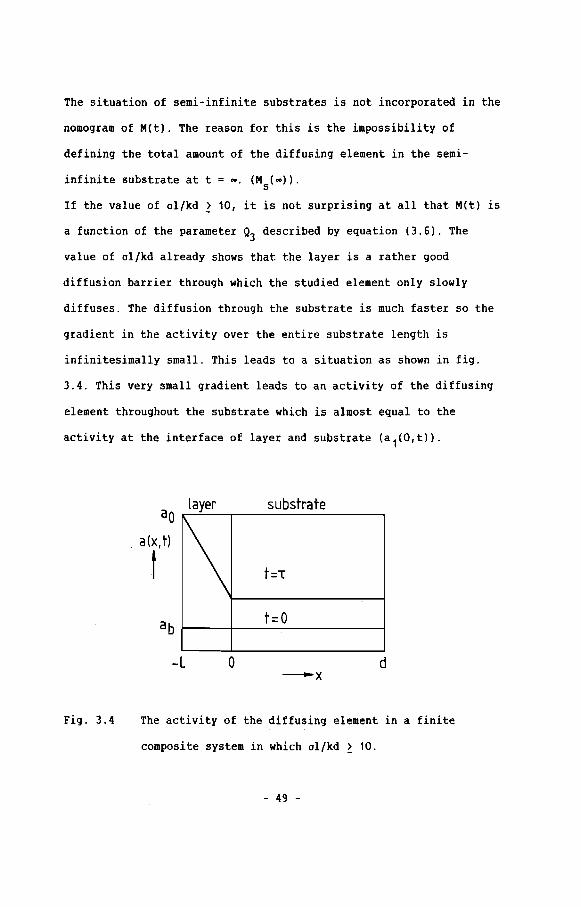
If the value of ol/kd > 10, it is not surprising at all that M(t) is
a function of the parameter Q3 described by equation (3.6). The
value of ol/kd already shows that the layer is a rather good
diffusion barrier through which the studied element only slowly
diffuses. The diffusion through the substrate is much faster so the
gradient in the activity over the entire substrate length is
infinitesimally small. This leads to a situation as shown in fig.
3.4. This very small gradient leads to an activity of the diffusing
element throughout the substrate which is almost equal to the
activity at the interface of layer and substrate (a 1(0,t».
substrateao
layer
\a(x,t)
t
ab
-l 0-x
d
Fig. 3.4 The activity of the diffusing element in a finite
composite system in which ol/kd > 10.
- 49 -

In that case it is possible to approximate the value of "set) by:
which indicates that "set) ~ a1(0,t) and therefore M(t) = A(t).
Knowing that A(t) = M(t) explains, why for good diffusion barrier
(ol/kd > 10) the value of A(t) and M(t) are determined by the same
parameter.
3.5 Coaclusiou
Until now, literature concentrated on diffusion problems with
layers on semi-infinite substrates as already mentioned in chapter
2. With the help of the model proposed in chapter 2 it is possible
to predict, how films or layers with all kinds of dimensions and
properties, affect the indiffusion of an element in a substrate.
It is possible to monitor the effect of a diffusion barrier by
monitoring the value of the activity of the diffusing element at the
interface of layer and substrate (A(t». The normalized a 1(0,t)
value (A(t», is a function of a parameter in which material-
properties, -dimensions and time are incorporated in a fairly simple
way. This function is:
A(t)
- 50 -
01kd ~ 0.1
A(t)
A(t}
"11 1 Vml
"2D2 1 df( ---- -}
Dl 12 Vm2"3
t
1 1 Vml 1 d
f( ------D1 12 Vm2 t
010.1 < kd < 10
01kd ~ 10
where: A(t}
a1
(O,t) - ab
aO - ab
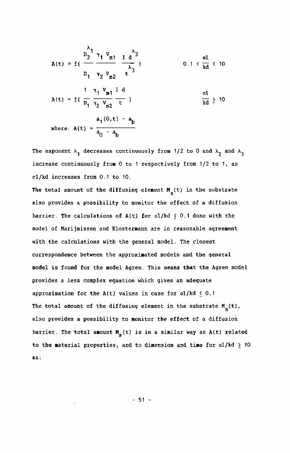
The exponent "1 decreases continuously from 1/2 to 0 and "2 and "3
increase continuously from 0 to 1 respectively from 1/2 to 1, as
al/kd increases from 0.1 to 10.
The total amount of the diffusing element M (t) in the substrates
also provides a possibility to monitor the effect of a diffusion
barrier. The calculations of A(t) for al/kd < 0.1 done with the
model of Marijnissen and Klostermann are in reasonable agreement
with the calculations with the general model. The closest
correspondence between the approximated models and the general
model is found for the model Agren. This means that the Agren model
provides a less complex equation which gives an adequate
approximation for the A(t) values in case for al/kd ~ 0.1
The total amount of the diffusing element in the substrate Ms(t},
also provides a possibility to monitor the effect ofa diffusion
barrier. The total amount Ms(t} is in a similar way as A(t) related
to the material properties, and to dimension and time for al/kd > 10
as:
- 51 -
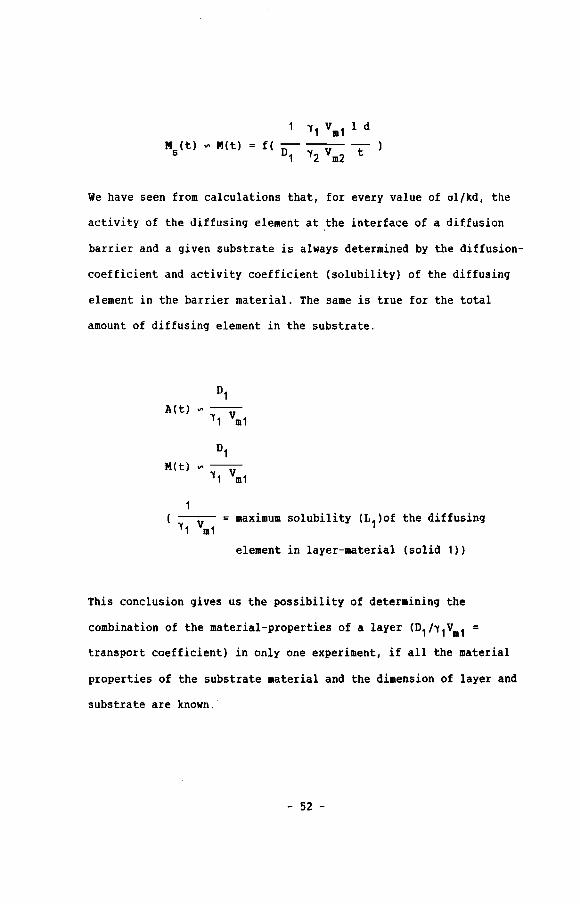
'Y,Vm,ldf(---
D, 'Y2 Vm2 t
We have seen from calculations that, for every value of al!kd, the
activity of the diffusinq element at the interface of a diffusion
barrier and a given substrate is always determined by the diffusion-
coefficient and activity coefficient (solubility) of the diffusinq
element in the barrier material. The same is true for the total
amount of diffusinq element in the substrate.
maximum solubility (L1)of the diffusing
element in layer-material (solid 1»
This conclusion qives us the possibility of determining the
combination of the material-properties of a layer (D1!'Y1Vm1
transport coefficient) in only one experiment, if all the material
properties of the substrate material and the dimension of layer and
substrate are known.
- 52 -
References cbapter 3
[1] G.H. Marijnissen, J.A. Klostermann, "Behaviour of high
temperature alloys in aggressive environments·, Ed. E. Lang,
Applied Science Publishers Ltd., London, (1980), 720
[2] J.J. Agren, Metall. trans. A, 17A, (1986), 2083
- 53 -
Chapter 4 Depositioa aad cbaracteriAtioa of layers
4 . 1 IDtroductiOD
During the last 20 years there has been an increasing
tendency to apply coatings on a lot of different materials using a
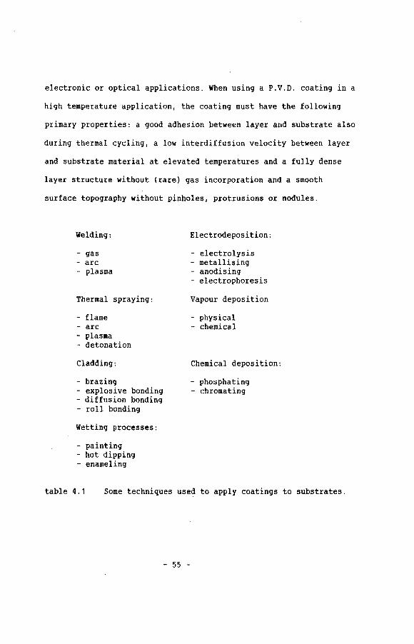
wide range of coating techniques. Table 4.1 illustrates some of the
techniques which are frequently used. In this work we have mainly
concentrated on Physical Vapour Deposition (P.V.D.) techniques. The
reason to do so is the high flexibility of a P.V.D. system in
coating laboratory sized samples with many different kinds of
layers.
The P.V.D. techniques have already been used in e.g. electronic
industry (conductors, integrated circuits [1-4]) and car industry
(head light reflectors [5]) for a long time. In the past 10 years
P.V.D. layers have found their way into the field of friction and
wear [6-13], prevention of environmental corrosion [14,15] and
optical applications [16-19]. Only the last few years P.V.D.
techniques are used in the field of high temperature corrosion and
erosion prevention [20-22]. This of course supported by the good
results in other fields, and the steadyly growing knowledge of the
P.V.D. processes.
The properties required for P.V.D. layers which have to perform
their duty at high temperatures and often in aggressive
environments, are much more rigorous as compared with e.g.
- 54 -
electronic or optical applications. When using a P.V.D. coating in a
high temperature application, the coating must have the following
primary properties: a good adhesion between layer and substrate also
during thermal cycling, a low interdiffusion velocity between layex
and substrate material at elevated temperatures and a fully dense
layer structure without (rare) gas incorporation and a smooth
surface topography without pinholes, protrusions or nodules.
Welding:
- gas- arc- plasma
Thermal spraying:
- flame- arc- plasma- detonation
Cladding:
- brazing- explosive bonding- diffusion bonding- roll bonding
Wetting processes:
- painting- hot dipping- enameling
Electrodeposition:
- electrolysis- metallising- anodising- electrophoresis
Vapour deposition
- physical- chemical
Chemical deposition:
- phosphating- chromating
table 4.1 Some techniques used to apply coatings to substrates.
- 55 -
4.2 Layexo deposition by P.9.0.
4.2.1 Classification of P.9.0. processes
Physical Vapour Deposition techniques can be divided in two
main groups, evaporation and sputtering.
If the transfer of the coating material to the vapour phase is done
by heating the coating material to a temperature above the melting
point, the technique is called evaporation (Fig. 4.1). The melting
of the base layer material can be done in different ways e.g. by
resistance-, electron beam-, induction- or arc-heating.
The vapour atoms produced travel in straight lines through the
vacuum chamber until they collide with the chamber walls or
substrates, where they condense and form a film. Evaporation might
be considered as an atomic phenomenon.
In case of sputtering (Fig. 4.2), coating material is transferred to
the vapour phase by inert gas ions, which bombard the surface of a
source target which consists of the elements to be deposited. This
bombardment of the source target is realized by putting a negative
voltage on the target, by connecting it to a power supply (D.C. or
R.F.). The inert gas introduced in the vacuum chamber provides a
medium in which a glow discharge can be initiated and maintained,
and in which inert gas ions are produced. The inert gas ions which
bombard the target surface, release atoms and clusters from the
target by momentum transfer. The ejected "particles" condense at
chamber walls or substrates, thus forming a film. Both electrical
conductors and insulators can be sputtered. For sputtering
- 56 -
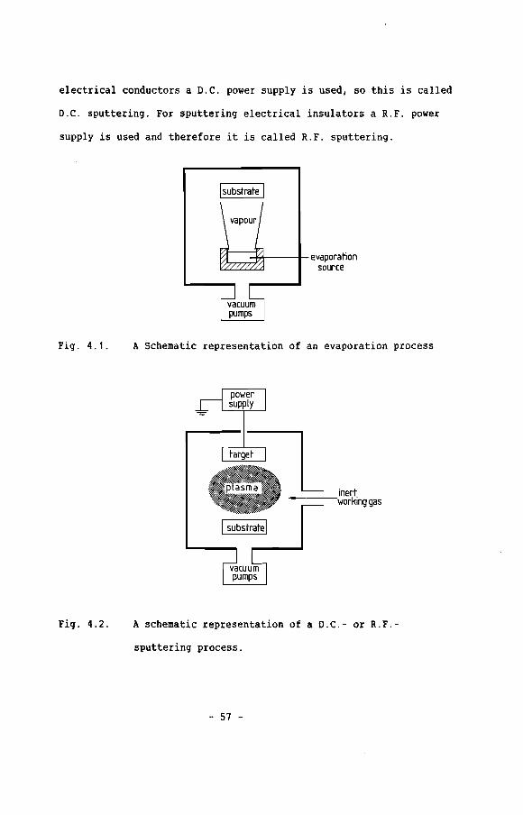
electrical conductors a D.C. power supply is used, so this is called
D.C. sputtering. For sputtering electrical insulators a R.F. power
supply is used and therefore it is called R.F. sputtering.
Isubstrate I
~~POlL1/;I~01~;~I-i-eVdPoratjon12 source
rJcuu~I ~m~m I
Fig. 4.1.
Fig. 4.2.
A Schematic representation of an evaporation process
inert-----·working gas
A schematic representation of a D.C.- or R.F.-
sputtering process.
- 57 -

A large number of specialized P.V.D. techniques have been developed
in the past years, and some of these techniques are mentioned in
table 4.2.
Evaporation:
- thermal- arc- electron beam- induction- ion plating- reactive- activated reactive- reactive ion plating
Sputtering:
- D.C.- R.F.- D.C. magnetron- R.F. magnetron- D.C. bias- R.F. bias- triode assisted D.C.- reactive D.C. bias magnetron- ion beam
table 4.2 Several P.V.D. techniques mentioned in literature.
The most important specialized P.V.D. techniques which are commonly
used will be briefly discussed [23,24].
The first group of specialized P.V.D. processes is that of the
reactive deposition processes. These processes are performed in an
evacuated chamber to which a reactive gas is admitted at low
pressure. The presence of the reactive gas makes it possible to
deposit compounds, because vapour particles and reactive gas
particles will give rise to chemical reactions by which compounds
are formed. The method of compound formation by evaporation in
reactive gases is called reactive evaporation. If the vapour
particles are generated by sputtering, the process is called
reactive sputtering. Nowadays the reactive P.V.D. processes are
frequently used to deposit e.g. TiN, A1 203, siC, TiC etc.
- 58 -

Another group of P.V.D. processes is usually marked as ion plating
processes. During the layer deposition the growing film is bombarded
by energetic inert gas ions and particles which enhances the
adhesion between layer and substrate, densifies the layer structure
and minimizes the grain size of the deposit. This particle
bombardment of the growing layer is achieved by applying a negative
(bias) voltage on the substrate. The bias voltage and the substrate
in combination with the evaporation process (Fig. 4.3a) is called
ion plating, in combination with the sputtering process (Fig. 4.3b)
it is called sputter ion plating or bias sputtering.
~~---:-------'--
evaporationi--i~;~source
_inertworking gas
Fig. 4.3a A schematic representation of an ion plating process
using resistance heating.
- 59 -

inert-----workirg gas
~ I I~r-----T--- substrate
,....-_.....
Fig. 4.3b A schematic representation of an sputter ion plating or
bias sputtering process.
The main advantage of evaporation is the high deposition rate, which
can be achieved. Deposition rates up to 10 - 100 ~m/min are not
uncommon. Comparison of the deposition rates of evaporation with
those of sputtering shows a tremendous difference, since the
deposition rate of D.C. sputtering is usually only a few microns per
hour.
Some methods have been developed to increase the deposition rates
in case of sputtering. One of the methods frequently used on
laboratory scale, is a thermionic support of the glow discharge
(Fig. 4.4). In this technique a thermionic filament or hot cathode
is used to generate electrons, which are "pumped" into the glow
discharge thus increasing the ionization efficiency (triode
- 60 -
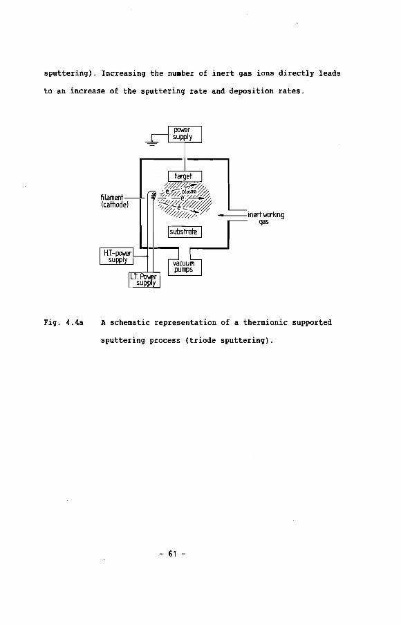
sputtering). Increasing the number of inert gas ions directly leads
to an increase of the sputtering rate and deposition rates.
filament(cathode)
Isubstrate I---- inert wai<ing
gas
Fig. 4.4a A schematic representation of a thermionic supported
sputtering process (triode sputtering).
- 61 -
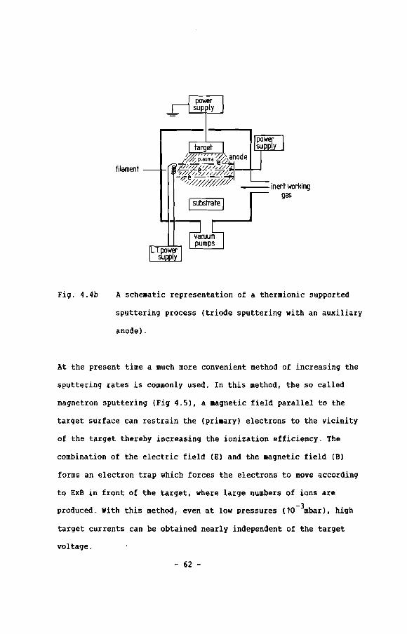
filament
Isubstrate I
Fig. 4.4b A schematic representation of a thermionic supported
sputtering process (triode sputtering with an auxiliary
anode) .
At the present time a much more convenient method of increasing the
sputtering rates is commonly used. In this method, the so called
magnetron sputtering (Fig 4.5), a magnetic field parallel to the
target surface can restrain the (primary) electrons to the vicinity
of the target thereby increasing the ionization efficiency. The
combination of the electric field (E) and the magnetic field (B)
forms an electron trap which forces the electrons to move according
to ExB in front of the target, where large numbers of ions are
produced. With this method, even at low pressures (1o-3mbar), high
target currents can be obtained nearly independent of the target
voltage.
- 62 -
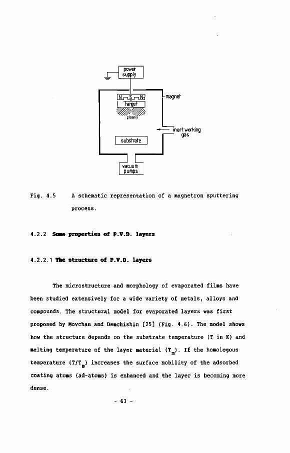
Fig. 4.5
I substrate I
A schematic representation of a magnetron sputtering
process.
4.2.2 sa.e properties of P.V.D. layers
4 . 2 . 2 . 1 '!be st:ructure of P.V•D. layers
The microstructure and morphology of evaporated films have
been studied extensively for a wide variety of metals, alloys and
compounds. The structural model for evaporated layers was first
proposed by Movchan and Demchishin (25] (Fig. 4.6). The model shows
how the structure depends on the substrate temperature (T in K) and
melting temperature of the layer material (Tm). If the homologous
temperature (T/Tm) increases the surface mobility of the adsorbed
coating atoms (ad-atoms) is enhanced and the layer is becoming more
dense.
- 63 -

Zone I Zone 2 Zone 3
Metals
Oxides
Zone I
<0.3 T~
<0.26 T~
Zone 2
03-0.45 T~
0.26-0 45 T~
Zone 3
>0.45T;">045T'm
Fig. 4.6 The microstructure zone model for evaporated materials.
(Movchan and Demchishin). The microstructure is given
as a function of the homologous substrate temperature
TITm [25].
Thornton [26] also proposed a structure zone model for D.C.
magnetron sputtered layers (Fig. 4.7). In this model the structure
is again depending on the homologous temperature (T/Tm) but also
depends on the gas pressure. From the model it can be seen that
decreasing the gas pressure will promote more dense structures if
the homologous temperature is kept the same.
Other investigators [27-33] studied the influences of the bias
voltage on the substrate during deposition by evaporation and
sputtering. They state that an increase of the bias voltage at a
given pressure shifts the zone boundaries in the zone structure
model of Movchan and Thornton to lower temperatures. This should
indicate that the bias voltage is an external factor which
influences the density of the coating. It is believed that the
- 64 -

mobility of the deposited atoms is thermal and bombardment induced
(34-37].
POROJS STRUCTURE
COWIN-I"R GR"INS
Fiq. 4.7 The microstructure zone model for maqnetron sputtered
materials (Thornton). The microstructure is qivenas a
function of the homoloqous substrate temperature TITm
and the arqon pressure (26].
4.2.2.2 ldbesiOD of P.V.D. layers
One of the most important properties of a film is the
adhesion between the fila and the substrate. In order to grow a well
adherinq film the surface of the substrate on which the film will be
deposited should be free of contaminants like e.g. grease, dust,
adsorbed water etc. The initial surface rouqhness influences the
adhesion of layer and substrate in a negative way, mainly at low
substrate temperatures so, most specimen are carefully qround and
- 65 -

polished on diamond paste. To prepare a clean surface before
deposition the surfaces are usually degreased and ultrasonically
cleaned before placing them in the vacuum chamber. After pumping
down the chamber to low pressures ion bombardment of the substrate
(and target) is performed (sputter cleaning). This ion bombardment
removes adsorbed water vapour and thin oxide scales from the surface
and makes the surface "atomically clean". During this sputter
cleaning the temperature of non-water-cooled substrates rises, which
promotes the degassing of the samples. If the above described
procedure is used, the basic requirements for good adhesion are
fulfilled [38-41]. Also during the deposition there are still
process-conditions which can strongly influence the layer/substrate
adhesion. The most important process parameters are: the substrate
temperature and the bias voltage on the substrate. Deposition of a
layer on a cold substrate e.g. by evaporation will only provide a
layer/substrate interface of the order of one monolayer. Elevated
substrate temperatures promote the surface diffusion of ad-atoms but
also increase the interdiffusion of layer- and substrate material,
thus providing a diffusion zone or even an alloyed or compound
interface between the layer and substrate.
On the contrary high temperature applications of coatings require
layer-substrate combinations which show no, or very low inter
diffusion. In that case one would expect an interface of only one
monolayer. The use of a substrate bias voltage during deposition
offers the possibility to grow well adherent films on the substrates
even-when layer-and substrate-material show no interdiffusion or
solubility. The reason for this is an ion bombardment induced
- 66 -
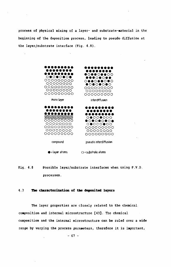
process of physical mixing of a layer- and substrate-material in the
beginning. of the deposition process, leading to pseudo diffusion at
the layer/substrate interface (Fig. 4.6) .
••••••••••••••••••••••••••0.0.0.0.00000000000000000
00000000000000000
000000000
mono layer
••••••••••••••••••••••••••~00000000
00000000000000000
000000000
compound
• =layer atoms
•••••••••••••••••.0•• 0 ••00• ••0.0••
0 ••0 ••0.0.0.0.0.000000000000000000000000000
inll!rdiffusion
••••••••••••••••••••••••••0.00.000.0.0.0.0.0.000.0000000000000000000000000000
pseudo interdiffusion
o =substrall! atoms
Fig. 4.8 possible layer/substrate interfaces when using P.V.D.
processes.
4 . 3 The cbaracterization of the deposited layers
The layer properties are closely related to the chemical
composition and internal microstructure [43]. The chemical
composition and the internal microstructure can be ruled over a wide
range by varying the process parameters, therefore it is important,
- 67 -

in the evaluation of the coating properties, to take the structural
and chemical features into consideration in an effort to optimize
the results of a deposition process. In section 4.1 we already
mentioned that the required properties of the layers used for high
temperature applications are rather rigorous. For this reason, those
layer characterization technique~' were selected which give
information about the most important layer properties. The most
important properties are the density and surface topography, the
chemical composition and the high temperature behaviour of the
layer. The wide variety and the complex relations between deposition
parameters forced us to use relatively simple deposition processes
without too many special conditions.
Excellent reviews have been written on the principles of the
characterization techniques used in this work and for that reason
we will only briefly review these techniques [44-47].
4 . 3 . 1 Optical- aDlI electron ucrosco"
The information gained from microscopical examinations can be
divided in two parts. First of all, examination of the layer surface
gives information about the surface topography, the presence of
cracks, pinholes or protrusions. Microscopical investigation of a
fracture edge tells something about the density and the
microstructure of the deposited layer. Before the microstructure of
a layer can be studied,it has to be made visible. This can be
achieved by making a notch at the backside of the substrate before
deposition. Afterwards the notched coated substrate can be broken,
- 68 -

thus giving rise to a fracture edge which can be studied by scanning
electron microscopy (S.£.M.). It is also possible to get some
qualitative information about the adhesion between layer and
substrate. The breaking of the notched samples introduces mechanical
stresses between layer and substrate, by which less adherent layers
are separated from the substrates.
Information about layer thickness and layer thickness distribution
can also be gained by microscopical investigations. For these
examinations cross sectioned coated substrates are embedded, ground
and polished and afterwards studied with a microscope equipped with
a calibrated filar micrometer eyepiece. The optical microscope can
only be used to determine the layer thickness in case of layer
thicknesses larger than 1 ~m. Layer thicknesses of less than 1 ~m
can be examined by scanning electron microscopy.
The optical microscopes used in our investigations, were a Leitz
Durimet Ie and a Leitz Metallophan FSA-GW661. The used scanning
electron microscope was a Jeol JSM-T20.
4 . 3 .2 X-ray photo electroD spectroscopy
Surface analyses of the layer surface can be performed with
the x-ray photo electron spectroscopy (XPS) technique [44,45]. The
technique is based on excitation of the sample surface resulting in
an emission of electrons, under U.H.V. conditions (P < 5e10-8mbar).
The excitation can be carried out by photons, geqerating electrons
by a photo-electric effect.
- 69 -

A flux of x-rays striking a solid will cause ejection of electrons
from electron levels with binding energies less than the energy of
the incoming photons. Because of limited mean free path of the
ejected electron inside the solid material a high surface
sensitivity results. The kinetic energy of the photo electrons
escaping from the solid material are determined by electrostatic
deflection of the electrons to a biased electron mUltiplier. The
kinetic energy of the photo electrons e.g. ejected from the K-shell
is given by the energy of the x-rays (hv) minus a work function (+)
and the binding energy of the ejected electron (Ek). (Fig. 4.9).
Photoelectron orIonizing Electron
Auger Electron(KL,Lz.3)
E
1
o
--r---\------f----- Vacuum
---';7/;7li~i/7,f7/,~~7!l--- Fermi Surface1--- Valence Band
CoreLevels
Fig. 4.9
Photoelectron: EPE = hVI - EK - <t>
X·Ray Fluorescence: hVF = EK - EL,
Electron emission processes and electron levels
depicting photo electrons (XPS) and Auger electrons
(AES) (23).
- 70 -
So, XPS is used to determine the elemental composition, but is also
used to chemically identify the surface composition, by comparing
the measured spectra and peak positions with the catalogued spectra
and peak positions of a great number of elements and compounds.
Since the set of binding energies are specific for a given element,
the photo electron energy (peaks) can be used for elemental
examinations. The binding energy of an electron is of course
influenced by the binding state or chemical state of the element. A
change in the binding state of an element causes a slight change in
the binding energy and thus causing a shift in the photo electron
energy peaks. Thus, the shift of a photo electron peak of an element
gives direct information about the binding state of that element.
Sometimes, so called Auger electrons, can also be detected in an
XPS-spectrum. Normally Auger electrons refer to electrons excited by
a primary electron beam with a specific electron energy.
Auger electron spectroscopy (AES) is also a surface analysis
technique which uses electrons to analyse the surface elemental
composition by measuring the energies of these electrons. There are
four possible Auger lines which can appear in XPS spectra, viz. the
KLL-, LLM-, MNN- and the NOO-Auger lines.
All XPS-measurements were performed on a Physical Electronics (PHI)
550 XPS/SAM system. The system is also equipped with an ion beam
source with which argon ions can be generated by which the surface
can be sputtered. This sputtering with argon ion~ can be used to
remove surface contaminations which are present because of handling
the specimen, but is can also be used for "depth profiling".
- 71 -
4.3.3 X-ra~ diffractiOD
X-ray diffraction is used to determine the crystallographic
structure of the deposited layers. With results of x-ray
diffractograms the lattice parameter can be calculated [47]. It is
sometimes possible to draw qualitative conclusions about particle
size and the presence of stresses in the lattice. X-ray diffraction
with help of a cylindrical camera is carried out to determine a
possible texture in the deposited layer.
In our case for all the x-ray diffraction experiments a Philips PW
1120 x-ray generator was used, equipped with a copper x-ray tube and
a nickel absorption filter to generate copper Ka radiation. The
diffractometer was equipped with a rotative specimen holder.
4.3.4 Vacua. annealing
The deposited layers have to perform at temperatures of 800
9000 e and for that reason the high temperature behaviour of the
deposited layers has to be studied. From literature [48-53] it is
known that during a post deposition treatment a number of changes
may occur e.g. recrystallization, outgassing, stress relaxation etc.
The removal of gases incorporated during deposition e.g. can damage
the layer when it is used at high temperature, but also the stress
relaxation process can deteriorate the layer completely.
The vacuum annealing of coated samples was performed in a furnace in
which a quartz tube was placed, which was pumped by an oil
- 72 -
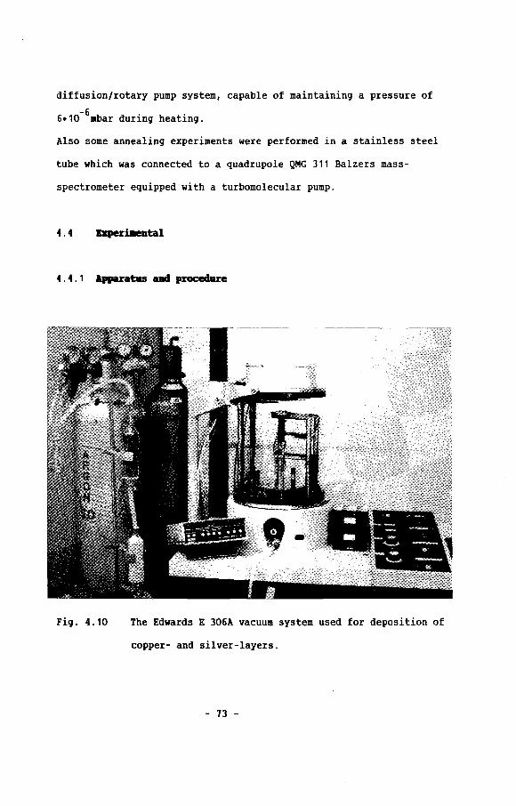
diffusion/rotary pump system, capable of maintaining a pressure of
-66.10 mbar during heating.
Also some annealing experiments were performed in a stainless steel
tube which was connected to a quadrupole QMG 311 Balzers mass-
spectrometer equipped with a turbomolecular pump.
4.4 !qIerDeDtal
4 . 4 . 1 Apparatus lIIId procedure
Fig. 4.10 The Edwards E 306A vacuum system used for deposition of
copper- and silver-layers.
- 73 -

The system in which the P.V.D. coatings were deposited, is
based on a commercially available Edwards E 306A vacuum system
(Fig. 4. 10). The vacuum system is an oil diffusion pumped system
with an integral liquid nitrogen trap, with which an ultimate
-7pressure of 8-10 mbar can be reached. The vacuum chamber has a
volume of 25 litres and the chamber is a borosilicate cylinder. The
top plate of the system holds a circular watercooled target holder
with a diameter of 100 mm, suitable for D.C. and D.C. magnetron
sputtering. Two H.T. power supplies (max. 3 kV/ 75mA) are connected
to the system for D.C. sputtering and ion plating purposes. For
thermal evaporation a L.T. power supply of 5 V/200 A is present. The
pressure in the vacuum chamber is measured with Pirani- and Penning
gauges, and the gas flows are controlled by mass flow meters. The
argon gas used in all experiments, is a high purity gas (99.999\).
The deposition rates can be monitored during the process by an
oscillating quartz crystal. A manual shutter is used to separate the
region of the source (target or evaporant) and substrate before and
after deposition.
A simple substrate holder capable of maintaining a constant
substrate temperature up to 1000 K was built. A schematic drawing of
the holder is shown in fig. 4.11. The holder is a stainless steel
cylinder with a thermocoax wire (core NiCr mantle, stainless steel)
wound around. The substrate holder was placed in a electrically
grounded box, which minimizes heat losses and acts as a radiation.
shield preventing the rest of the vacuum chamber from heating. The
substrate temperature was measured with a chromel-alumel thermo-
couple placed against a substrate.
- 74 -
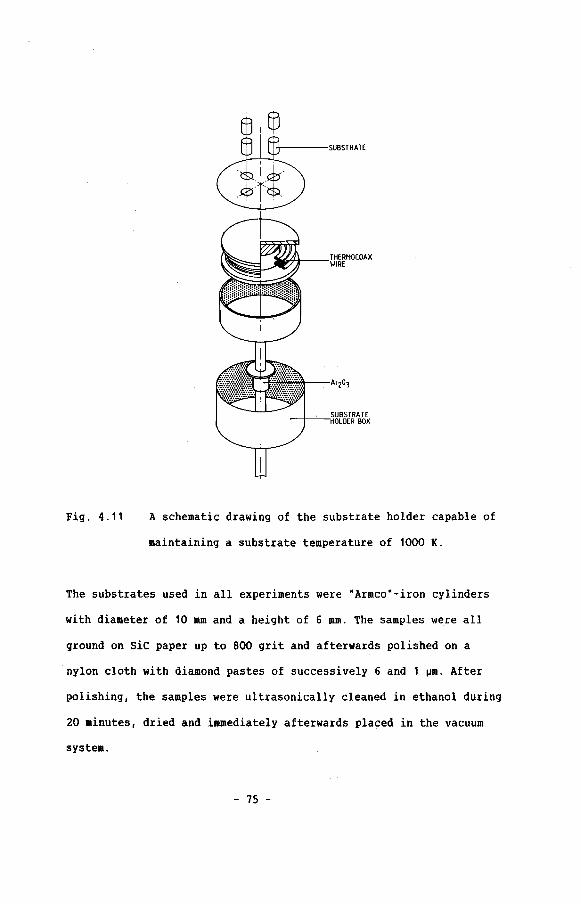
Fig. 4.11 A schematic drawing of the substrate holder capable of
maintaining a substrate temperature of 1000 K.
The substrates used in all experiments were "Armco"-iron cylinders
with diameter of 10 mm and a height of 6 mm. The samples were all
ground on siC paper up to 800 grit and afterwards polished on a
nylon cloth with diamond pastes of successively 6 and 1 ~m. After
polishing, the samples were ultrasonically cleaned in ethanol during
20 minutes, dried and immediately afterwards placed in the vacuum
system.
- 75 -

4.4.2 Deposition of copper layers
Four P.V.D. processes were studied to find out the most
convenient process with the best layer properties. The sa.ples from
every experiment were examined by optical- and electron microscopy
before using any other technique to characterize the layer
properties. After studying the results of a deposition
microscopically, we tried to optimize the process in such a way,
that layer properties would meet the earlier stated requirements
(dense layers with a low surface roughness). After selecting those
processes and process conditions, by which dense layers were
obtained, the layers were characterized by surface analysis, x-ray
diffraction and vacuum annealing at elevated temperatures.
In the following sections we will subsequently describe the four
P.V.D. processes and discuss the results obtained.
4 . 4 . 2 . 1 Copper deposition by ion plati.acJ
After placing the samples on the substrate holder and
-6evacuating the system to a pressure below 2.10 mbar, the chamber
was backfilled with argon to a pressure of S.10-2mbar. The next step
in the deposition procedure was sputter cleaning of the substrates
by a glow discharge on the substrate. The glow discharge was ignited
and maintained by a negative voltage on the substrate (-1.8 kV). The
substrate current density at the beginning of the sputter cleaning
process was 1 mA/cm2 but slowly decreased to 0.8 - 0.9 mA/cm2 in
about 20 minutes. According to literature, this decrease in the
- 76 -

discharge current at a constant voltage and pressure is due to the
removal of species with high secondary electron emission ratio's
e.g. oxides or gaseous contaminations [48]. The decrease of the
discharge was used to determine the endpoint of the sputter cleaning
process. The bombardment of inert gas ions on the substrate not only
removed oxides and water vapour but also raised the substrate
temperature up to 200 - 250 0 C, which again reinforced the outgassing
of e.g. water vapour. During the last minutes of the sputter
cleaning a pre-melting of the copper material in a tungsten filament
was done, to remove surface contaminations from the copper wire and
the filament. During the pre-melting of the copper, the substrate
current density and the gas pressure were adjusted to the desired
values by changing the substrate voltage and the argon gas flow.
After 20 seconds of pre-melting the current through the filament was
increased from 140 A up 160 A and the shutter, which was placed
between the filament and the substrates, was removed thus starting
the deposition. The substrate filament distance in all experiments
was 12 cm. The deposition rates were about 5 - 7 ~m/min depending on
gas pressure and filament current. The deposition rates, when using
the resistance heating were hardly controllable and not reproducible
and was also complicated by the bad wettability of the tungsten
filament by molten copper. The deposition was continued until a
layer thickness of 10 - 30 ~m was reached. At the end of the
deposition process the shutter was closed, the gas flow into the
system was stopped and the power supplies were turned off. The
substrates were allowed to cool down to room temperature in about 4
- 77 -
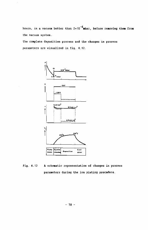
O.9mA/cm2II
II,:
-6hours, in a vacuum better than 2.10 mbar, before removing them from
the vacuum system.
The complete deposition process and the changes in process
parameters are visualized in fig. 4.12.
p
v-3kV
,,~':'!;!..kJl" I" ,I '- ...
1mA/cm2
~: ....._-,, II ,, II ,I ,, II I
: L l!.2~~~~
T.
t
I
Fig. 4.12 A schematic representation of changes in process
parameters during the ion plating procedure.
- 78 -

4.4.2.2. Cllancteriutica of iea platel C'OIIPH layers
The ion plated copper layers had a dull appearance and the
reflectance varied with the direction of viewing. Microscopical
examinations of the ion plated layers showed out that the layers had
a high surface roughness due to the presence of dendrites
(Fig. 4.13) and nodules (Fig. 4.14), thus giving the surface a
diffuse reflecting character. The nodules are clusters of layer
material which are not incorporated in the layer but form almost
separated particles.
Fig. 4.13 A cross section of a copper ion plated layer (-1.8 kV,
2 -20.9 mA/cm, PAr = 8.10 mbar) , showing a dendritic
structure.
- 79 -
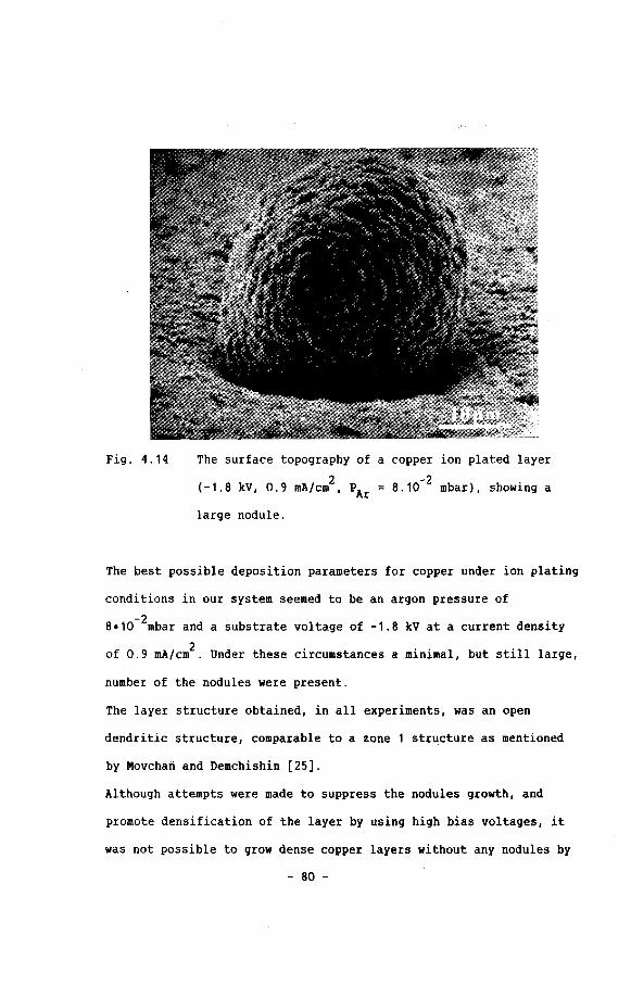
Fig. 4.14 The surface topography of a copper ion plated layer
(-1.8 kV, 0.9 mA/cm2, PAr 8.10-2 mbar) , showing a
large nodule.
The best possible deposition parameters for copper under ion plating
conditions in our system seemed to be an argon pressure of
8.10-2mbar and a substrate voltage of -1.8 kV at a current density
of 0.9 mA/cm2 . Under these circumstances a minimal, but still large,
number of the nodules were present.
The layer structure obtained, in all experiments, was an open
dendriti~ structure, comparable to a zone 1 str~cture as mentioned
by Movchan and Demchishin [25].
Although attempts were made to suppress the, nodules growth, and
promote densification of the layer by using high bias voltages, it
was not possible to grow dense copper layers without any nodules by
- 80 -

ion plating. For this reason the resistance heating/ion plating (as
possible in our systea), was rejected as a suitable technique for
depositing high teaperature diffusion barriers.
4 . 4 .2 . 3 COpper deposition by evaporation at n9h substrate
tellperatures
The substrates used for evaporation experiments were heated
up to a temperature of 7000 C in the vacuum chamber under a pressure
-6better than 4.10 mbar, prior to deposition. No sputter cleaning of
the substrates was carried out because of constructional limitations
of the substrate holder used. The SUbstrate/filament distance was
12 cm during all experiments. Before opening the shutter the copper
material inside the tungsten filament was pre-heated for 20 seconds
(pre-melting) and after increasing the current through the filament
the shutter was opened and the deposition was started and continued
until the desired layer thickness was reached (10 - 30 ~m). Again
high, but hardly controllable deposition rates of 3 - 5 ~m/min were
obtained. (The process steps are schematically shown in fig. 4.15).
- 81 -
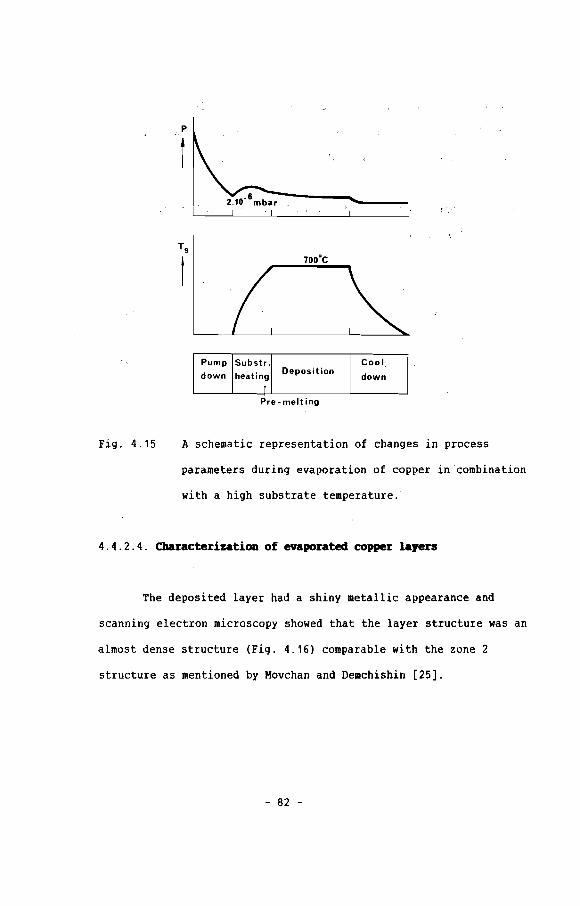
P
- LI---'-------l__-"--- -----l _
700·C
Fig. 4.15
Pump Substr. Cool
down he,atingDeposition
down1
Pre· melt ing
A schematic representation of changes in process
parameters during evaporation of copper in 'combination
with a high substrate temperature.
4 . 4 . 2 . 4. CbaracterizatioD of evaporated copper layers
The deposited layer had a shiny metallic appearance and
scanning electron microscopy showed that the layer structure was an
almost dense structure (Fig. 4.16) comparable with the zone 2
structure as mentioned by Movchan and Demchishin [25].
- 82 -

Fig. 4.16 A cross section of a, by evaporation, deposited copper
layer using a substrate temperature of 700°C.
Although the surface roughness was fairly low, still a large number
of nodules could be observed (Fig. 4.17) and it was also
demonstrated that the bond between the nodules and the substrate or
layer was very weak (Fig. 4.18). An increase of the substrate
temperature to 7500C and 8000C did not have a significant effect on
the appearance of the nodules.
- 83 -
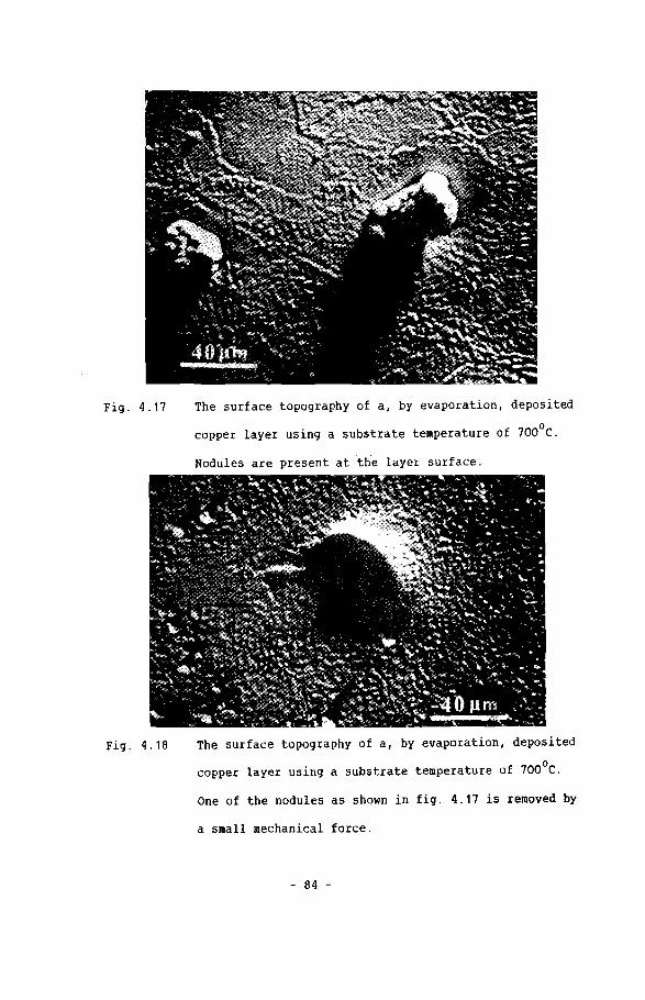
Fig. 4.17 The surface topography of a, by evaporation, deposited
copper layer using a substrate temperature of 700°C.
Nodules are present at the layer surface.
Fig. 4.18 The surface topography of a, by evaporation, deposited
copper layer using a substrate temperature of 700°C.
One of the nodules as shown in fig. 4.17 is removed by
a small mechanical force.
- 84 -

Vacuum annealing for more than 8 hours at 900 0C had no effect on the
nodules, although the rest of laY~F seemed to densify a little bit.
Because of the impossibility of suppressing the growth of the
nodules no further work was done on layer deposition by using
resistance evaporation at high substrate temperature.
4.4.2.5 Copper deposition by D.C. bias sputtering
Before starting the sputter deposition process the chamber
-6was pumped down to a pressure below 2.10 mbar and afterwards
-2sputter cleaned at an argon pressure of 8.10 mbar. The substrate
voltage was -1.8 kV at a substrate current density of 1 mA/cm2 .
During the sputter cleaning the substrate temperature increased to
100 - 250oC. The copper target was also sputter cleaned during this
period, with a voltage -3 kV at a current density of 1 mA/cm2 . The
distance between target and substrates, in all experiments was 5 cm.
After finishing the sputter cleaning process, the voltage on the
substrate was lowered to a value between 0 and -300 V and therefore
the substrate current density is reduced to 0.1 - 0.2 mA/cm2. After
opening the shutter the deposition was performed at a sputter rate
of 8 ~m/h. After reaching the desired layer thickness (10 - 30 ~m),
the shutter was closed and the voltages were removed from the target
and substrates. The gas flow was turned off and the substrates were
allowed to cool down to room temperature in a vacuum better than
4.10-6mbar (Fig. 4.19).
- 85 -

Sputter cleaning target
I,tmA/cm2
~IIIII,IIII
O.9mA/cm2
:IIIIIIIII
Fig. 4.19 A schematic representation of changes in process
parameters during the copper deposition by D.C. bias
sputtering.
4.4.2.6 Characterization of D.C. bias spui:tered copper layers
We examined D.C. bias sputtered copper layers which were
sputtered under the following (negative) bias voltage 0, 50, 100
and 150 V. All the layers had a dull appearance, which indicates a
fairly rough layer surface. The layer structure of D.C. bias
sputtered copper layers is given in figs. 4.20-4.23.
- 86 -
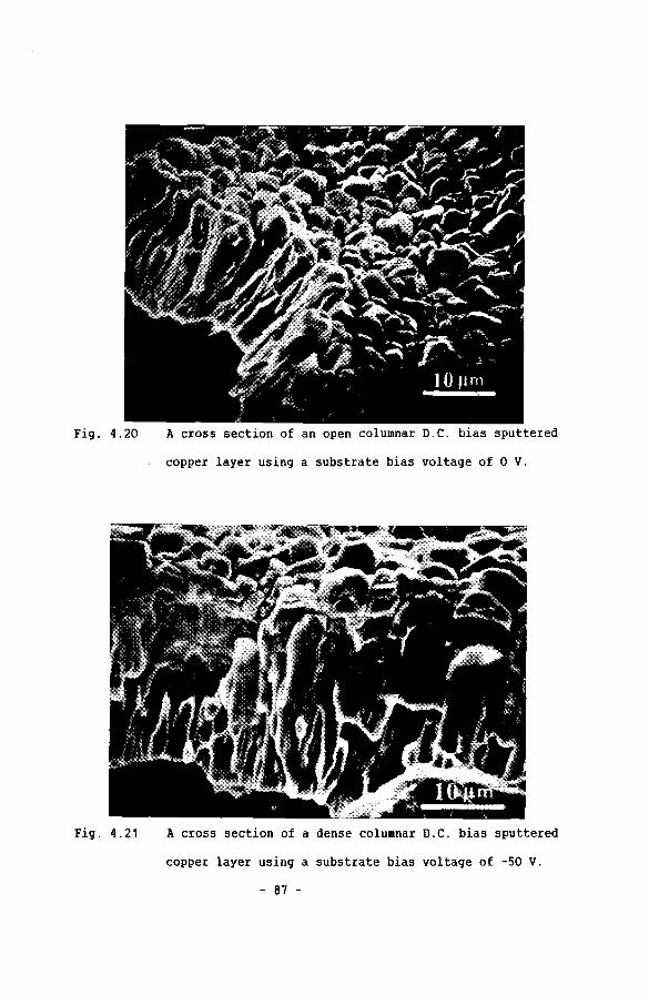
Fig. 4.20 A cross section of an open columnar D.C. bias sputtered
copper layer using a substrate bias voltage of 0 v.
Fig. 4.21 A cross section of a dense columnar D.C. bias sputtered
copper layer using a substrate bias voltage of -50 V.
- 87 -

Fig. 4.22 A cross section of a open columnar D.C. bias sputtered
copper layer using a substrate bias voltage of -100 V.
Fig. 4.23 A cross section of a dense columnar D.C. bias sputtered
copper layer using a substrate bias voltage of -150 V.
- 88 -

It appeared clear that by an increase of the substrate bias voltage,
the structure qfthe layer changed from an open zone 1 structure as
given by Thornton [261 to a columnar but Qense zone T structure. The
surface roughness was only determined by the domed tops of the
columns by which the layer is built up. The number of nodules
present was very low at a zero substrate bias voltage and they all
disappeared as the bias voltage was increased.
X-ray diffraction measurements on 10 ~m bias sputtered copper
(Vbias = ~ 100 V) showed that the layer had cubic crystallographic
structure with a lattice parameter of 0.3612 nm, which is only
different from the value given by the powder diffraction file of the
JCPDS system (0.3615 nm). X-ray diffraction measurements with the
cylindrical camera did not show any preferred orientation (texture)
in the bias sputtered copper layers.
Before starting the XPS surface analysis measurements of the bias
sputtered copper layers, an area of 8 x 8 mm 2 of the layer was
sputtered with an argon ion beam (5 kV, 250 nA) for 5, minutes, this
to remove all possible contaminations present because of. e.g. sample
handling or adsorption of gas molecules. The XPS-measurements showed
spectra with only copper lines (Fig·. 4.24) indicating. that the
deposited copper layers we~e free of contaminations of e.g. carbon.
- 89 -

7 ESCA SURVEY Sf: 176.582 44.125 4.688 DAT: 5.76 88/24/84 CU Sf
.............,..............•..............~...... . .
~~ MG ......... .. .....cU7. ..LA.Y£R···:Ku·'···CU 2P
5 ~ ....I
III 4 : , : :
\
Ii%3-' , .
ClllUill
: CU 3l'
... L__..~~..~~". '~-N[J Jr·~······_l~·\8L............J..................~ ~ ~.......~.....~....1.I......L...........~ ..j""cd1~ ~ ~ ~ ~ ~ ~ ~ ~ ~
BINDI", ElIEl!n, EY
Fig. 4.24 XPS spectrum of copper deposited by D.C. bias
sputtering.
Vacuum annealing of the bias sputtered copper layers was performed
at 9250 C for periods of to 4 hours at a pressure better than
a.10- 6mbar. Microscopical analyses of the annealed sample showed
that during a heat treatment the layer started to densify but also a
severe blistering (Fig. 4.25) and the occurrence of holes could be
detected.
- 90 -

Fig. 4.25 Blistering of D.C. bias sputtered copper layers, using
a bias voltage of -150 V, after a vacuum heat treatment
of 2 hours at 925°C.
The effect of blistering and the number of holes after annealing
increased as the bias voltage, used during deposition, increased.
The effect of blistering and the occurrence of holes was detected
already after a short period of annealing (less than 1 hour), and
only when the temperature during the heat treatment, was raised
above 5000 C. To determine the gaseous species, which deteriorated
the layer during a high temperature heat treatment, coated samples
(Vbias = -150 V) were heated in a stainless steel tube, analysing
the outgassing components by a mass-spectrometer. Indeed, in all
experiments at a temperature of 450 - 5000 C a very small signal of a
component was detected with a mass/valence (m/e) ratio of 40
(argon), but also the signals of components like
- 91 -

nitrogen/carbonmonoxide (m/e = 28) and water (m/e = 17, 18)
increased. It was shown in comparative experiments that the
outgassing products of the stainless steel tube at 5000C were indeed
nitrogen, carbonmonoxide and water, while no outgassing of argon was
detected.
The incorporation of inert gas in layers during D.C. bias sputtering
strongly limits the application of these layers at high
temperatures. For that reason no further work was done on D.C. bias
sputtering of diffusion barriers for high temperature applications.
4.4.2.7 Copper deposition by D.C. sputtering
Before depositing the copper layers, the substrates were
-6heated up under a pressure lower than 4.10 mbar. After reaching the
o -2temperature of 700 C, argon was admitted to a pressure of 8.10 mbar
and the target was sputter cleaned with a target voltage of -3 kV
and a current density of 1 mA/cm 2. Afterwards the shutter was opened
and the deposition took place until the ultimate layer thickness was
reached. The substrate/target distance during all experiments was
5 em, and the deposition rate was 6 ~m/h at 7000 C substrate
temperature. The samples were allowed to cool down to room
temperature before removing them from the vacuum system
(P < 40 10-6mbar). (see also Fig. 4.26).
- 92 -

Fig. 4.26
p
I
·1.SkY
~" II, I
" II I I
1mA/cm2 2r---;.:lmA/Cm
II 'I 'I 'I 'I '
A schematic representation of changes in process
parameters during the copper deposition by D.C.
sputtering using a substrate temperature of 100°C.
4.4.2.8 Cbarac:terizatiOll of D.C. sputtered copper layers
The microstructure of the D.C. sputtered copper layers, at a
substrate temperature of 1000 C showed a polycrystalline dense type
zone 3 structure (Fig. 4.21, 4.28). On the layer surface no nodules
were detected which was in accordance with the shiny metallic
appearance of the layers. The creation of suitable fraction edges by
bending the notched sample appeared to be extremely difficult which
- 93 -

indicated that the adhesion between layer and substrate was very
good.
Fig. 4.27 A cross section of a dense, D.C. sputtered copper layer
using a substrate temperature of 700°C.
Fig. 4.28 The surface topography of a dense, D.C. sputtered
copper layer using a substrate temperature of 700°C.
- 94 -

The x-ray investigations of 10 ~m thick copper layers deposited by
D.C. sputtering at high temperatures showed a cubic crystallographic
structure with a lattice parameter of 0.3610 nm, almost equal to
the lattice parameter for bulk copper. The x-ray analysis with the
cylindrical camera showed no texture inside the deposited layers.
Surface analysis of the copper layer by XPS showed the same spectra
as measured on bias sputtered copper layers, no contaminations were
present, thus indicating that the layer existed of pure copper.
Vacuum annealing at 9250 C of the D.C. sputtered layers showed no
appearance of blistering nor holes. The only effect of vacuum
annealing was a slight grain growth when annealing for periods
longer than two hours.
4.4.3.1 Silver depositiOD br D.C. sputteriDg
Because of the good results of the deposition of copper
layers by D.C. sputtering in combination with high substrate
temperatures, the same process was used to deposit silver layers.
The system was pumped down to a pressure lower than 4.10-6mbar,
before heating the substrates to 700°C. After the substrate
temperature was raised to 700°C (T/Tm = 0.8), argon gas was bled
into the chamber up to a pressure of 8.10-2mbar and sputter cleaning
of the target was performed (-2.8 kV, 1 mA/cm2) during 20 minutes.
After sputter cleaning the target the shutter wa~ opened and the
deposition was continued until the desired layer thickness was
reached. During the experiments the target/substrate distance was 5
- 95 -

cm and the deposition rate was 8 ~m/h. After the deposition process
was completed the coated substrates were allowed to cool down to
room temperature before removing them from the vacuum system.
4.4.3.2 Cbuecterizatioa of the D.C. sput;b!red silver layers
The microstructure of the D.C. sputtered silver layers was a
polycrystalline dense structure (Fig. 4.29, 4.30). The layer surface
was smooth and free of nodules.
Fig. 4.29 A cross section of a dense, D.C. sputtered silver layer
using a substrate temperature of 700°C.
- 96 -

Fig. 4.30 The surface topography of a dense, D.C. sputtered
silver layer using ,a substrate temperature of 700oC.
X-ray investigations on 10 ~m thick silver layers deposited at a
substrate temperature of 700°C, showed a cubic lattice with. a
lattice parameter of 0.4086 nm which agreed well with the value
given by the JCPDS system (0.40862 nm). X-ray diffraction
measurements with the cylindrical camera did not show any texture
inside the silver layers.
Surface analysis by XPS showed no contaminations in the deposited
layers (Fig. 4.31).
Vacuum annealing of the silver layers at 82SoC, during two hours,
did not influence the layer properties except from the fact that a
slight grain growth was observed.
- 97 -

61 .j..
,f ,I ~G- L~YER'.....j
f} i a"U ..•.. j
':.'. er, ... \ L, llG3I' ·.·.·.·.·.·.·.·.·.·.·.·.·.1.l
ir
J) ""1 -
t~~hH8L...............~.......~........L~u.u..L~.....~...........~..............:............~........~..J
-1888 -988 -888 -788 -688 -S88 -488 -388 -288 -188
BINDING ENERGY I EV
Fig. 4.31 XPS spectrum of silver deposited by D.C. bias
sputtering.
4.5 DiscossioD
Although in literature a lot of successful depositions were
reported using ion plating, we did not succeed in growing dense and
nodule-free copper layers by using a basic ion plating process.
Literature also reports that improvements of the results obtained by
ion plating were achieved by using higher power densities (up to 15
2 -3W/cm ) and lower pressures «5.10 mbar). Higher power densities are
normally achieved by using auxiliary means (thermionic support glow
discharge). In our experiments it was only possible to increase the
power density by increasing the gas pressure. The high gas pressure
- 98 -
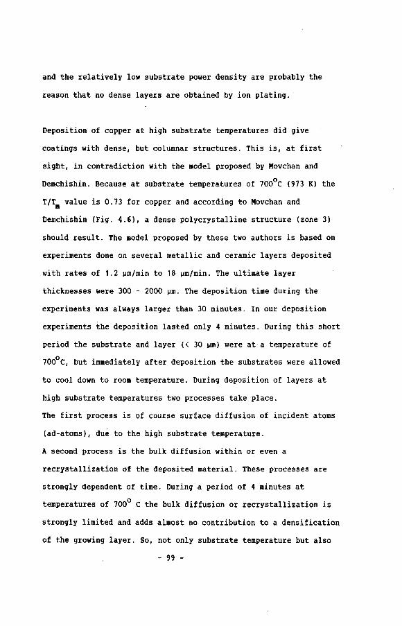
and the relatively low substrate power density are probably the
reason that no dense layers are obtained by ion plating.
Deposition of copper at high substrate temperatures did give
coatings with dense, but columnar structures. This is, at first
sight, in contradiction with the model proposed by Movchan and
Demchishin. Because at substrate temperatures of 7000 C (973 K) the
T/Tm value is 0.73 for copper and according to Movchan and
Demchishin (Fig. 4.6), a dense polycrystalline structure (zone 3)
should result. The model proposed by these two authors is based on
experiments done on several metallic and ceramic layers deposited
with rates of 1.2 ~m/min to 18 ~m/min. The ultimate layer
thicknesses were 300 - 2000 ~m. The deposition time during the
experiments was always larger than 30 minutes. In our deposition
experiments the deposition lasted only 4 minutes. During this short
period the substrate and layer « 30 ~m) were ata temperature of
7000 C, but immediately after deposition the substrates were allowed
to cool down to room temperature: During deposition of layers at
high substrate temperatures two processes take place.
The first process is of course surface diffusion of incident atoms
(ad-atoms), due to the high substrate temperature.
A second process is the bulk diffusion within or even a
recrystallization of the deposited material. These processes are
strongly dependent of time. During a period of 4 minutes at
temperatures of 7000 C the bulk diffusion or rec~ystallization is
strongly limited and adds almost no contribution to a densification
of the growing layer. So, not only substrate temperature but also
- 99 -
deposition time are important variables with respect to the ultimate
layer structure. The parameter time is not incorporated as a
structure determining factor in the Movchan, Demchishin model. The
problem of suppressing the growth of the nodules which have weak
bonds with the layer or substrate, limits the application of the
layers as corrosion resistant layers.
The bias sputtering of copper at ae10- 2mbar and bias voltages of
- 50 V to - 150 V gave dense columnar coating without nodules.
The coating showed a zone T structure from the Thornton model
(Fig. 4.7). It was also shown by vacuum annealing (9250 C) that the
layer densified already after a short time (one hour), but also
showed blistering and the appearance of holes probably dued to the
release of incorporated inert gases. The incorporation of inert
gases during sputtering is also known from literature [49], in which
inert gas concentrations up to 30 at.\ were reported at bias voltage
of -150 V. The incorporation of inert gases during bias sputtering
and the release of inert gases during vacuum annealing, makes the
application of bias sputtered layers for high temperatures
impossible. An adaptation of the bias sputtered processes which
makes the process suitable for depositing layers for high
temperature applications is probably bias sputtering at elevated
substrate temperatures (> 500oC). As already mentioned the
combination of high substrate temperature and bias substrate voltage
was not possible in our experiments, because of constructional
limitations of the substrate holder.
- 100 -
Deposition of copper- and silver-layers by D.C. sputtering at
substrate temperatures of 7000 C has been successful to deposit dense
polycrystalline layers with very low concentrations of inert gases.
Although the gas pressure during the sputtering of the copper and
silver was high (S.10- 2mbarl, the deposited layers were dense and
polycrystalline. The high substrate temperature was one of the most
important factors promoting the growth of the dense layer structure,
but also the "long" deposition times were favourable for bulk
diffusion in and recrystallization of the deposited layer material.
4 . 6 conclusions
Dense copper- and silver-layers were deposited by D.C.
sputtering at S.10-2mbar using substrate temperature of 7000 C.
The deposited copper- and silver-layers had dense, polycrystalline
structures, without any prefered crystallographic orientation.
Examinations by XPS showed that the layers were free of detectable
amounts of impurities, while also the high temperature behaviour
during vacuum annealing was good.
Ion plating and evaporation of copper at a high substrate
temperature did result in an open layer structures and nodular
growth. The open structure and the presence of weakly bonded nodules
made the ion plated and evaporated layers not applicable for high
temperature applications.
- 101 -
D.C. bias sputtering of copper resulted in a dense coating at
bias substrate voltage of -50 to -150 V, but a deterioration of the
coatings occurred during vacuum annealing at temperatures above
5000 C due to the release of incorporated inert gas, which limits the
high temperature applications of the D.C. bias sputtered layers.
P.V.D. processes in general have a large number of parameters
which influence the ultimate structure of the deposits. From the
results of our experiments in which high substrate temperatures were
used, it appeared that to this large number of structure determining
parameters two extra parameters have to be added. The first is the
in literature seldomly mentioned influence of the deposition rate,
and a second parameter is the deposition time. Both parameters
together strongly determine whether bulk diffusion and/or
recrystallization play a pronounced role in the growing of dense
layer structures.
- 102 -
RefereJlces chapter 4
[1] L.r. Maissel "Handbook of thin film technology",
Ed. L.I. Maissel, R. GIang, Mc.Graw-Hill Book Company Inc.,
(1983)
[2] D. Gerstenberg "Handbook of thin film technology",
Ed. L.I. Maissel, R. GIang, Mc.Graw-Hill Book Company Inc.,
(1983), 19-1
[3] r. Raffael, "Handbook of thin film technology·,
Ed. L.I. Maissel, R. GIang, Mc.Graw-Hill Book Company Inc.,
(1983), 29-1
[4] P.B. Glate, "Deposition techniques for films and coatings"
Ed.R.F. Bunshah, Noyes Publications Park Ridge,
(1982), 514
[5] L. Holland, ·Vacuum deposition of thin films",
Chapmann & Hall. Ltd, London, (1961)
[6] R.J. Hill, G. Scheuermann, R. Lucariello,
Thin solid films, 40, (1977), 217
[7] D.G. Teer, F.B. Salem, Thin solid films 45, (1977) 583
[8] W. Fleischer, D. Schulze, R: Wilberg, Thin solid films, 43,
(1979),347
[9] A.X. Suri, Thin solid films, 72, (1980), 529
[10] R. Buhl, H.K. Pulker, E. Moll, Thin solid films, 80,
(1981),265
[11] R.R. Nimmagadda, H.J. Doerr; R.F. Bunshah, Thin solid
films, 84, (1981), 303
[12] W.D. Miinz, D. Hofmann, K. Hartig, Thin solid films, 96,
(1982),79
[13] A. Matthews, Thin solid films, 126, (1985), 283
[14] D.M. Mattox, R.D. Bland, J. Nucl. Mats., 21,
(1967), 349
[15] K.E. Steube, L.E. McCrary, J. Vac. Sci. Technol., 11,
(1974), 362
[16] A.R. Janus, G.A. Shirn, J. Vac. Sci. Technol., 4,
(1966), 37
[17] P. Nath, R.F. Bunshah, Thin solid films, 69,
- 103 -

(1980),63
[18] B.R. Natarajan, A.H. Eltoukhy, J.E. Greene,
Thin solid films, ", (1980), 201
[19] M.J. Brett, R.W. McMahon, J. Affinito, R.R. Parsons,
J. Vac. Sci. Technol., A1, (1982), 352
[20] R. Swaroop, J. Vac. Sci. Technol., 13, (1976), 531
[21] R. Swaroop, J. Vac. Sci. Technol., 13, (1976), 680
[22] T. Shikama, Y. Sakai, M. Okada, Thin solid films, 145,
(1986), 89
[23] R.C. Bunshah, "Deposition techniques for films and coatings",
Ed. R.F. Bunshah Noyes Publications, Park Ridge, (1982), 514
[24] J.L. Vossen, J.J. Cuomo, "Thin film processes",
Ed. J.L. Vossen, W. Kerm, Academic Press, New York, (1978)
[25] B.A. Movchan, A.V. Demchishin, Fiz. Metal. metalloved, 28,
(1969),83
[26] J.A. Thornton, J. Vac. Sci. Technol., 12, (1975), 830
[27] B. Swaroop, I. Adler, J. Vac. Sci. Technol., 10, (1973), 503
[28] C.T. Wan, D.L. Chambers, D.C. Carmichael, J. Vac. Sci.
Technol., 11, (1974),379
[29] D.C. Carmichael, J. Vac. Sci. Technol., 11, (1974), 839
[30] E. Tsunasawa, K. Inagaki, K. Yamanaka, J. Vac. Sci.
Technol., 14, (1977), 651
[31] J.A. Thornton, Thin solid films, 40, (1977), 344
[32] P.A. Higham, D.G.Teer, Thin solid films, 58, (1979), 121
[33] J.E. Sundgren, B.O. Johansson, S.E. Karlsson,
Thin solid films, 80, (1981), 77
[34] D.M. Mattox, G.J. Kominiak, J. Vac. Sci. Technol., "
(1972), 528
[35] R.D. Bland, G,J. Kominiak, D.M. Mattox, J. Vac. Sci. technol.
11, (1074), 671
[36] M. Lardon, R. Buhl, H. Signer, H.K. Pulker, E. Moll,
Thin Solid Films, 54, (1978), 317
[37] R. Messier, A.P. Giri, R.A. Roy, J. Vac. Sci. Technol. A,
2, (1984), 500
[38] R.P. Govier, G.M. McCracken, J. Vac. Sci. Technol., 7,
(1970), 552
- 104 -

[39] G.J. Kominiak, J.E. Uhl, J. Vac. Sci. Technol., 13, (1976),
170
[40] D.M. Mattox, Thin solid films, 124, (1985), 3
[41] D.M. Mattox, J. Vac. Sci. Technol., 20, (1982), 1345
[42] H.E. Hintermann, "Verschleiss Schutzschichten unter
Anwendung der CVD!PVD-Verfahren", Ed. H.K. Pulker,
Technische Akademie Esslingen, (1985)
[43] B.E. Jacobson, "Coatings for high temperature
applications", Applied Science publishers,
Ed. E. Lang, Londen, (1983)
[44] G.E. McGuire, "Depositions techniques for films and
coatings", Ed. R.F. Bunshah, Noyes Publications,
Park Ridge, (1982)
[45] "Methods of surface analysis", Ed. A.W. Czanderna,
Elsevier Scientific publishing company, Amsterdam, (1975)
[46] S. Mader, "Handbook of thin film technology",
Ed. L.I. Maissel, R. GIang, Me Graw Hill Book Company,
(1983)
[47] B.D. Cullity, "Elements of x-ray diffraction" ,
Addison-Wesley Publ. Compo Inc., (1967)
[48] J.E. Houston, R.D. Bland, J. Appl. Phys., 44, (1973), 2504
[49] H.F. Winters, E. Kay, J. Appl. Phys., 38, (1967),3928
[50] F.B. Koch, R.t. Meek, D.V. McCaughan, J. Electrochem. Soc.,
(1974), 558
[51] J.J. Cuomo, R.J. Gambino, J. Vac. Sci. Technol., 14,
(1977), 152
[52] M.A. Bayne, R.W. Moss, E.D. McClanahan, Thin solid films, 63,
(1979), 137
[53] T. Motohiro, Y. Taga, Thin solid films, 120, (1984), 313
- 105 -
Cbapter 5 Solid state carburizatioa ezper.meau oa copper aDd
silver
5 . 1 Introduction
Remarkably few data, necessary to predict the behaviour of
carbon diffusion barriers, can be found in literature. Solubilities
and diffusion coefficients for carbon are unknown for most materials
and reliable transport constants for carbon through pure metallic
and compound layers have never been measured.
To determine the diffusion rate of carbon through a layer material
it is of utmost importance to have a good and reliable carburization
technique in combination with a powerful technique capable of
detecting low carbon concentrations.
The carburization methods which are mentioned in literature are
generally gas-[1], pack-[2] or plasma-carburization [3]. The large
problem of gas- and pack-carburization techniques is the badly
defined carbon activity of the carburizing atmosphere. The plasma
carburization method does not have this disadvantages but this
technique has the problem of continuously sputtering off the top
surface of a sample. The other mentioned requirement which has to be
fulfilled if reliable transport- or diffusion data for carbon have
to be obtained is the need for a good analytical technique. The
first question which arises when selecting such a technique is of
course: what is the lowest amount of carbon which has to be
measured? Normally, one has to measure the carbon concentration
- 106 -

profile inside the layer material, in order to obtain diffusion data
for carbon. Knowing that the solubility of carbon in a possible
diffusion barrier material is very low, the chosen technique must be
capable of measuring carbon in the ppm-range or even in the ppb
range. Possibilities are e.g. 14c tracer techniques [4] or nucleare
probe methods [5], often in combination with micro-sectioning
technique. Those techniques are rather complicated and all have
their own specific difficulties.
In this chapter a simple solid state carburization process will be
presented. Simple metallographic examinations (optical and electron-
microscopy) are used to study the effect and the behaviour of
copper- and silver-diffusion barriers. Using the proposed model in
chapter 2 and 3 of this thesis together with information from
metallographic examinations make it possible to determine the
transport- or diffusion-coefficients for carbon in copper and
silver.
5 . 2 . 1 fte solid state carburbatic. MtiIod
The carburization technique described in this section is
comparable with the technique used by Demel an Degischer [6]. Their
carburization technique was based on depositing radioactive carbon
14( C) on the surface of the sample using a colloidal carbon
solution. The carbon deposited at the sample surface ensured that
the thermodynamic activity of carbon has a value of one, during
diffusion annealing at high temperatures.
- 107 -

In our experiments the carbon activity at the sample surface (a )o
has also a value of one during diffusion annealing, but this is
achieved in a different way. We use an iron/carbon alloy in which
graphite nodules are present. The presence of free carbon in the
alloy defines the carbon activity as equal to one (a = 1). Byo
pressing the carbon source (iron/carbon alloy) onto the sample a
so-called diffusion couple is formed. When annealing this
couple at high temperature in an inert atmosphere or vacuum, carbon
starts to diffuse from the carbon source, where the carbon activity
is high (ao = 1), to the sample where the carbon activity is
lower. The advantage of this method of carburization using a solid
state carbon source is the well defined carbon activity at the
desired temperature. Also the fact that the diffusion of carbon
occurs in only one direction makes the mathematics of the process
comparable with the in chapter 2 described general model.
5 . 2 . 2 Preparation of the carbon source
The solid carbon source was prepared by arc melting an
addition of 4.5 wt.\ carbon together with "Armco" iron (pure iron).
After annealing the arc-molten samples for 100 hours at 11000 C in
vacuum graphite nodules in a pearlite matrix were present in the
samples. To prepare the carbon sources for carburization experiments
the samples were ground upto 800 grit on sic paper, polished with 6
and 1 ~m diamond pastes on a soft cloth and afterwards
ultrasonically cleaned in ethanol.
- 108 -

5 .2. 3 PreperatioD of the ....Ies
The samples in all experiments were made of "Armco"-iron which
has the following composition:
Manganese: 0.08 wt.\
Sulfur 0.015 wt.\
Carbon 0.02 wt.\ Silicon
Phosporus
Iron
< 0.01 wt.\
0.02 wt.\
rest
The samples used had a diameter of 10 mm and a height of 6 mm.
Uncoated samples were ground, upto 800 grit on Sic paper, polished
on 6 and 1 ~m diamond pastes and ultrasonically cleaned in ethanol
before they were used in the experiments.
The copper- and silver-coated samples were prepared by D.C.
sputtering using a substrate temperature of 700°C. The sputtering
procedure is described in section 4.4.2.7 and 4.4.2.9. The
structure of the deposited layers was dense and polycrystalline.
(See section 4.4.2.8 and 4.4.2.1). The in the experiments used
copper and silver foils had purities of 99.99\ and a thickness of
respectively 30 and 25 ~m.
The prepared carbon source and the foil/substrate or coated
substrate were joint together during a heat treatment in flowing
argon (purity 99.999\) at the chosen diffusion temperature during
four hours. To ensure a good contact between the carbon source and
the sample the two parts were pressed together, during the annealing
in flowing argon. This was done by means of a load controllable from
the outside of the furnace (Fig. 5.1). The external load used was
- 109 -

always 100 N/cm2. After "contact"-annealing the diffusion couple
(carbon source/sample) was removed from the furnace and transferred
to a vacuum furnace in which the diffusion annealing was continued.
fOlLe
carbon saturated- ironlayer
iron-substrate
---1---1- - I
- - - - I- - I-I - I I- I
t t t I
III
--- --~
IIIII
Ar-atmospherer(furnace) I
I
L
force
Fig. 5.1 The configuration of the carbon source and the iron
sample during contact annealing.
5 . 3 Allalytical teclmi.ques
The annealed diffusion couples were cross sectioned and
metallographically prepared. After grinding and polishing, the cross
sections were etched, using a 2 vol.% nitric acid/ethanol mixture.
Optical- and electron-microscopy was used to study the carbon uptake
of the substrate material. The carburization of the substrate
material could be detected by the appearance of pearlite
(ferrite/cementite) and cementite in the "ArmcoO-iron substrate.
This technique is rather sensitive because already a small increase
in the amount of carbon in the "Armco"-iron (0.01 wt.%) give rise to
pearlite formation. Compositional investigations of the layers were
- 110 -

performed by electron micro probe analysis (EPMA) using a Jeol
superprobe 733.
5 . 4 bperi.-..ts aDd results
The experiments and results of solid state carburization
through copper- and silver-layers performed by the solid state
carburization techniques are given in table 5.1.
temperature time carburizationlayer
material
layer
thickness (h) of the substrate
Cu foil 30 11m 950°C
Cu foil 30 11m 950°C
Cu foil 30 11m 950°C
Cu dep. 15 11m 950°C
Cu dep. 15 11m 950°C
Cu dep. 5 11m 950°C
Ag foil 25 11m 850°C
Ag dep. 25 11m 850°C
142
172
307
40
76
172
350
700
no fig. 5.2
no fig. 5.3
slight fig. 5.4
no fig. 7.3
slight fig. 7.4
strong fig. 5.5
no fig. 5.6
no fig. 5.7
(dep. = D.C. sputtered)
Table 5.1. The performed carburization experiments on "Armco"-iron
samples coated with copper and silver diffusion
barriers.
- 111 -

Fig. 5.2 A cross section of a diffusion couple with a 30 ~m thick
copper foil after annealing for 142 hours at 950°C.
Fig. 5.3 A cross section of a diffusion couple with a 30 ~m thick
copper foil after annealing for 172 hours at 950°C.
- 112 -
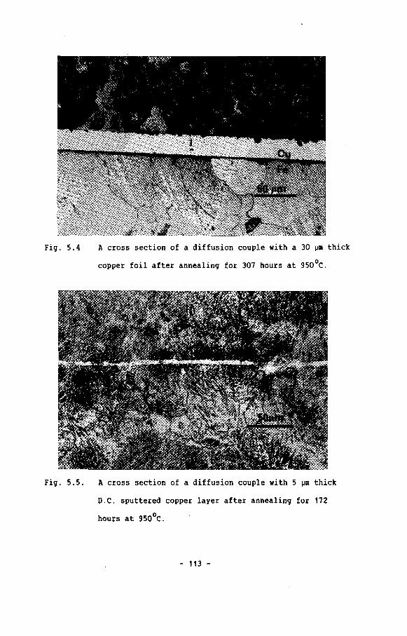
Fig. 5.4 A cross section of a diffusion couple with a 30 ~m thick
copper foil after annealing for 307 hours at 950°C.
Fig. 5.5. A cross section of a diffusion couple with 5 ~m thick
D.C. sputtered copper layer after annealing for 172
hours at 950°C.
- 113 -

Fig. 5.6. A cross section of a diffusion couple with a 25 ~m thick
silver foil after annealing for 350 hours at 850°C.
Fig. 5.7. A cross section of a diffusion couple with a 25 ~m thick
D.C. sputtered silver layer after annealing for 700
hours at 850°C.
- 114 -

From table 5.1. we can conclude that 30 ~m thick copper foils were
the most effective carbon diffusion barriers at 950°C. After
diffusion annealing for 300 hours the first pearlite was detected
inside the iron substrate. At this time, also precipitates were
visible inside the copper layer of the annealed sample (Fig. 5.8).
EPHA analysis pointed out that the precipitates consisted of iron
containing 2.5 wt.\ copper. These precipitates were also detected in
15 ~m thick copper D.C. sputtered copper layers after diffusion
annealing for 76 hours at 950°C. In these samples again pearlite was
present in the iron substrate indicating that a slight carburization
of the iron substrate did occur. The results of the experiments on
15 ~m thick D.C. sputtered copper layers are presented in chapter 7,
where a possible explanation of the observed growth of precipitates
is given.
Fig. 5.8 A cross section of a diffusion couple with a 30 ~m thick
copper foil after 307 hours (see also Fig. 5.7).
- 115 -
Annealing of a diffusion couple, in which a 5 ~m thick D.C.
sputtered copper layer was present, during 172 hours at 950°C showed
a complete breakdown of the barrier and a severe carburization of
the iron substrate (Fig. 5.5).
In all the experiments on silver foil and D.C. sputtered silver
layers, the silver barrier was still dense after diffusion annealing
at 850°C for 700 hours (Fig. 5.7). After this annealing treatment,
in none of the performed experiments pearlite was detected inside
the "Armco"-iron substrate. This indicates that a 25 ~m thick
silver-foil or -layer is sufficient to retard the carburization of
the iron substrate at 850°C for more than 700 hours.
Comparing the results obtained by using copper foils and deposited
copper layers and silver foils and deposited silver layers, it can
be concluded that there was no difference in the effect and
behaviour of layer- or foil-materials.
5 . 5 . calculations of the traasport coefficieat: of carbon
in silver and copper
In the substrates of copper coated samples the first pearlite
was detected after a period of 307 hours. This means that after that
period the concentration of the carbon in the iron substrate
(M(t» exceeded 0.03 wt.%, thus starting the formation of pearlite.
At the start of the experiment (t = 0), the carbon content in
"Armco"-iron was Ms(o) '" 0.02 wt.%.
- 116 -
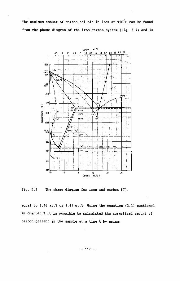
The maximum amount of carbon soluble in iron at 950°C can be found
from the phase diagram of the iron-carbon system (Fig. 5.9) and is
Carban I wt.'Io I0.5 10 1.5 2.0 2.5 3.0 3.5 4.0 4.5 5.0 55 60 65 1.0
25
11,00' '. ..
"91" \ \ '{"K ..• I:" / !Locl\ I " i i .
i" ..•• :!' "j ' ...., . I. iT I I .,. ..1 .:[! .•
1600. : • '
I . . ili
.'.... ....••...• ···•. ll,""lii
.,'.....Ii 1.L,15J6"~b-F. ". •...1526°C i
1500 1.43 "T Ll ! ,.i\ ..., .L...
\! 149~" ~.I .... ..... I.! 1.
Fig. 5.9 The phase diagram for iron and carbon [7].
equal to 6.16 at.\ or 1.41 wt.\. Using the equation (3.3) mentioned
in chapter 3 it is possible to calculated the normalized amount of
carbon present in the sample at a time t by using:
- 117 -

where:
M(t)
fraction of carbon in the substrate at the
beginning of the experiment = 0.02 wt.%
fraction of carbon at t = ~, in other words the
maximum possible fraction = 1.41 wt.\
Ms(t) = fraction of carbon at time t = 0.03 wt.\
After 307 hour diffusion annealing the M(t) value is 0.007. The
diffusion time t also has to be normalized if we wanted use the
nomogram of M(t) to determine the ol/kd-value of the layer/substrate
system. The time is normalized by the expression:
where:
T =d
2
02 diffusion coefficient of carbon in
iron = 1.3.10-7cm2/sec
d substrate length = 0.6 em.
Using log (02t/d2) value of -0.40 (307 hours) together with the M(t)
value of 0.007, a ol/kd value of 100 is found using fig. 5.10.
Using the carbon solubility in iron ('/~2)' the carbon diffusion
coefficient in iron (02) [8], the molar volume Vm2 of iron and width
of layer (1) and substrate (d) we can calculate the transport
coefficient for carbon in copper as follows:
01 °2~'Vmll-----
kd 01 ~2 Vm2 d
- 118 -
100

1 -33.10 cm -7 21.3.10 cm /sec
d = 0.6 em Y2 = 16.23
0.9
0.8
0.7
MIt)0.6
0.5
0.4
0.3
0.2
0.1
I /( ( ( ( -(
GA 30)Jm Cu(9S0·C,307hl J ( I I I II---- ,
I I I I0:B:2S)JmAglBSO·C,700hl i!
o 10'1 1 10 102 103 104
I I I II I / / /
~ / / / / /VI / 1/ / / 1/
l.?v./LLV / / Io
-8 -6 -4 -2 4
Fig. 5.10 The calculated M(t) nomogram with the "measured"
M(t)-value for copper and silver layers.
This results in a transport coefficient for carbon through copper
13(Y1Vm1/D1) of 1.8.10 cm sec/mol.
° -3The solubility of carbon in copper (1/y,) at 950 C is 4.3.10 wt.\
or 2.27.10-2at.\ [9] and together with the molar volume of copper
3(Vm1 = 7.1 em /mol), it is possible to calculate the diffusion
coefficient of carbon in copper (D,) at 950°C to be 1.8.10-9cm 2/sec.
- 119 -

At 850°C the diffusion coefficient of carbon in iron (D2 ) is
3.5.10-8cm2/sec while the solubility of carbon in iron is (1/12 )
1.12 wt.% or 4.67 at.%. Using 25 ~m thick silver layer as a
diffusion barrier between "Armco"-iron and the carbon source even
after a diffusion annealing for 700 hours (109(D 2t/d2
)= -0.61) no
pearlite was detected in the substrate, this means that the carbon
content is less than 0.03 wt.%. Thus the M(t) value for such a
system is zero. From fig. 5.10 a al/kd value larger than fifty is
2found by using the values of M(t) and the normalized time (D 2t/d ).
Using the solUbility (1/12), the diffusion coefficient of carbon in
iron (D2), the molar volume of iron (Vm2 ) and the width of layer (1)
and substrate (d) we can calculate the transport coefficient for
carbon in silver as follows:
01
kd
D2 "1 1 Vm1 1
-----D1 "1 2 Vm2 d
> 50
1 -3 D2-8 22.5.10 cm 3.5.10 cm /sec
d 0.6 cm 12 21.41
Vm2 7.1 3cm /mol
This results in a transport coefficient ("I1Vm1/D1) of
5.2.1013 cm sec/mol. The solubility of carbon in silver (1/"1 1) at
850°C is 2.2.10- 3wt.% or 1.98.10-2wt% [7], together with the molar
volume of silver (Vm1 = 10.25 cm3/mol) makes it possible to
- 120 -

calculate the diffusion coefficient of carbon in silver (01), This
results in a carbon diffusion coefficient less 1.10-9cm2/sec.
5.6 DiscussiCHl
In the solid state carburization experiments on copper at
950°C the main problem is the breakdown of the diffusion barrier.
The time at which the iron precipitates directly connect carbon
source and iron-substrate depends on the initial layer thickness.
The breakdown process impedes the measurements of carburization
rates on copper coated samples. During the measurements two process
occur at one time: carbon diffusion and carbon induced breakdown of
the diffusion barrier. This means that the "measured" transport-
coefficient (01/11Vm1) and the diffusion coefficient (01) for carbon
in copper are only upper limits.
This is also proven by the inhomogeneous carburization of the iron
substrate. The carbon inside the iron substrate is found only near
the interface layer/substrate. (Fig. 5.4), which indicates that the
transport through the perforated layer is equal or faster than the
diffusion rate of carbon in the iron substrate. According to the
model we predicted the carburization to be homogeneously if only
solid state carbon diffusion through the diffusion barrier is rate
controlling and the a1/kd-va1ue is equal or larger than ten (see
section 3.5.)
Solid state carburization experiments on silver diffusion barriers
are only controlled by solid state diffusion of carbon. The
calculated transport- (01111 Vm1 ) and diffusion-coefficient (01) are
- 121 -

again upper limits. To determine accurate values for transport- and
diffusion-coefficients, the layer thicknesses has to be reduced
and/or the diffusion times has to be increase in order to see the
first signs of carburization.
5.7 Conclusions
The solid state carburization is a convenient technique to
study the effect and behaviour of carbon diffusion through
protective layers.
Breakdown processes in layers strongly influence or even
dominate the values of transport- (D1/11Vm1) and diffusion
coefficients (D 1) of carbon in these layer materials.
If the diffusion barrier is stable, and no breakdown occurs,
it is possible to determine transport- and diffusion-coefficients
for carbon in layer materials accurately, by using the proposed
general model.
- 122 -
References cbapter 5
[1] J.M. Harrison, J. Norton, "Behaviour of high temperature
alloys in aggressive environments", Ed. E. Lang,
Applied science publishers London, (1980), 661
[2] W. Steinkusch, W. Werkstoffe u. Korrosion, 30, (1979),837
[3] M.Booth, "Coating and surface treatments for corrosion and
wear resistance", Ed. K.D. Strafford, Horwood Ltd.,
Birmingham, (1984), 150
[4] H.J. Grabke, K. Ohla, J. Peters I. Wolf,
Werkstoffe u. Korrosion, 34, (1983), 495
[5] T.B. Pierce, J.W. McMillan, Nucl. Instr. Meth.,
118, (1974), 115
[6] O. Demel, H.P. Degischer, "Behaviour of high temperature
alloys in aggressive environments", Ed. E. Lang,
Applied science publishers, London, (1980), 649
[7] O. Kubaschewski, "Iron binary phase diagrams", Springer-Verlag
Berlin, (1982), 24
[8] Y. Adda, J. Philbert, "La diffusion dans les solids", Tome I
Press Universitaire de France, Paris, (1966), 1166
[9] R.B. McLellan, Scripta Metallurgica, 3, (1969), 389
- 123 -

Chapter fi Gas carburization ezperiJlents
6 . 1 Introduction
The most widely used experimental technique to study
carburization of high temperature alloys is the gas carburization
technique [1-3]. In the gas carburization experiments a carbonaceous
gas provides the carbon that can be transferred from the gas phase
to a solid material, assuming the thermodynamic carbon activity (a )c
of the gas atmosphere to be higher than the initial carbon activity
of the solid material.
The gas carburization method is widely used, probably for two
different reasons. The first reason is, the gas carburization
experiments are comparable with the carburization processes which
occur in process industry. Secondly, the thermodynamic carbon
activity is controllable over a wide range, by careful controlling
the gas composition.
Compared to the method of solid state carburization as described in
chapter 5, the gas carburization method has the advantage that no
mechanical deformation of the sample surface occurs, which can be of
great importance when testing brittle ceramic layers.
Although the gas carburization has proven to be a convenient
experimental technique it has one big disadvantage, namely its
complexity. Three separated features are insolved in the carbon
transfer from the gas phase to a solid state material. These are:
the flow characteristics of the gases involved, the decomposition
- 124 -

rates of the carbonaceous compounds at the solid state surface and
the diffusion of elemental carbon in the solid state material.
Grabke and Schnaas reported, that apart from an initial period, the
carburization of high temperature alloys in methane/hydrogen mixture
at 800 - 10000 C is controlled by the solid state diffusion of carbon
(4]. The flow characteristics of gases strongly depend on the
experimental apparatus and conditions used. It should also be stated
that gas phase boundary reactions (decomposition) are strongly
influenced by the composition and conditions of the sample surface
and also by the type of carbonaceous compound used.
6 . 2 !xperDeatal
6 . 2 . 1 Appuabls
The gas carburization experiments were performed in a Setaram
MTB 10-8 microbalance, capable of measuring weight changes of 1 ~g.
This microbalance has two experimental chambers, in which an active
sample and a reference sample were heated separately, but in
identical environments. The sample and reference sample (alumina,
purity 99.999\) were suspended from the beam of the balance in two
separated alumina tubes inside the symmetrical furnace. The test
gases were introduced separately from the bottom of the tubes
controlling the gas flow by a mass flow meter (Fig. 6.1). The use of
an inert reference sample which resembles the sample in all respects
and which is placed in an identical environment eliminates a number
of perturbance factors such as buoyance and convectional flow.
- 125 -
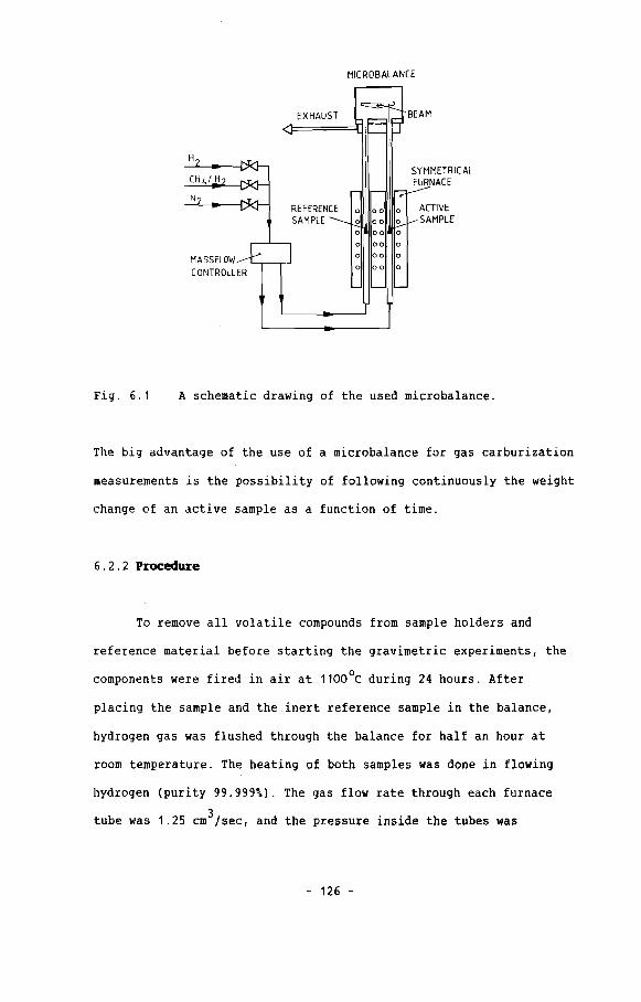
MICROBALANCE
<l=~EX~H~A~U~S';'T=~ir=~I~J BEAM
HSYMMETRICALFURNACE
r.111r-.IIIr-::::1--"'--CH / H
N
MASSFLOWCONTROLLER
REFERENCESAMPLE
o 00 0
o 00 0
o 00 0
o 00 0
o 00 0
o 00 0
ACTIVESAMPLE
Fig. 6.1 A schematic drawing of the used microbalance.
The big advantage of the use of a microbalance for gas carburization
measurements is the possibility of following continuously the weight
change of an active sample as a function of time.
6 . 2 . 2 Procedure
To remove all volatile compounds from sample holders and
reference material before starting the gravimetric experiments, the
components were fired in air at 1100 0C during 24 hours. After
placing the sample and the inert reference sample in the balance,
hydrogen gas was flushed through the balance for half an hour at
room temperature. The heating of both samples was done in flowing
hydrogen (purity 99.999\). The gas flow rate through each furnace
3tube was 1.25 cm /sec, and the pressure inside the tubes was
- 126 -
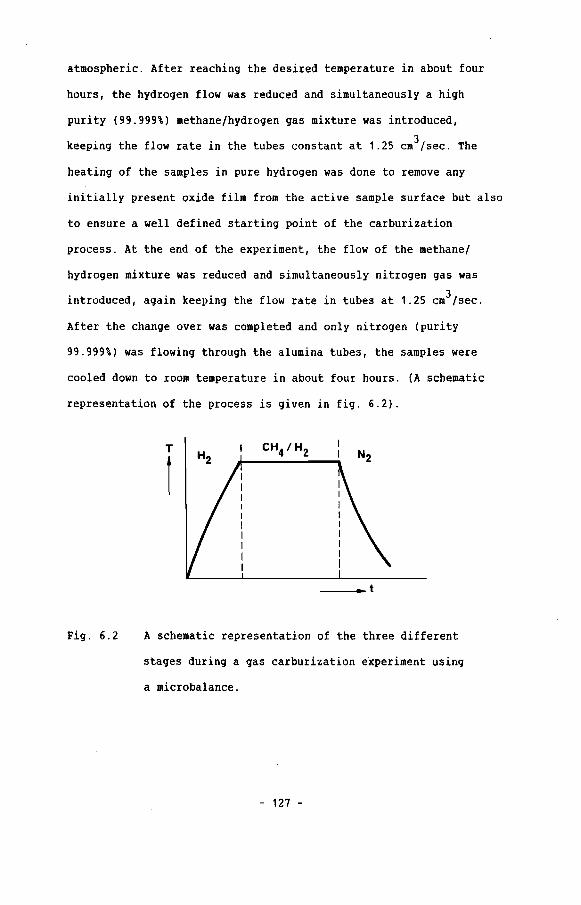
atmospheric. After reaching the desired temperature in about four
hours, the hydrogen flow was reduced and simultaneously a high
purity (99.999%) methane/hydrogen gas mixture was introduced,
3keeping the flow rate in the tubes constant at 1.25 cm /sec. The
heating of the samples in pure hydrogen was done to remove any
initially present oxide film from the active sample surface but also
to ensure a well defined starting point of the carburization
process. At the end of the experiment, the flow of the methane/
hydrogen mixture was reduced and simultaneously nitrogen gas was
introduced, again keeping the flow rate in tubes at 1.25 cm3/sec.
After the change over was completed and only nitrogen (purity
99.999%) was flowing through the alumina tubes, the samples were
cooled down to room temperature in about four hours. (A schematic
representation of the process is given in fig. 6.2).
T
1
Fig. 6.2 A schematic representation of the three different
stages during a gas carburization experiment using
a microbalance.
- 127 -
The thermodynamic carbon activity of the methane/hydrogen gas
mixtures at a temperature T (K) can be calculated by the following
relationship:
6Gexp ( RT ) . 2
~2 Pt
where: f..G free energy of formation of methane
R gas constant
T temperature (K)
Pt total pressure
xCH the mol fraction of methane4
xH the mol fraction of hydrogen2
6.2.3 Preparation of the saaples
(6. 1 )
Uncoated, copper-coated and silver-coated substrates were used
in the gravimetric experiments. All samples had a diameter of 4.5 mm
and a height of 2 mm and they were all made of "Armco"-iron.
The uncoated samples were carefully ground upto 800 grit on siC
paper, polished with 6 and 1 ~m diamond pastes on a 50ft cloth and
afterwards ultrasonically cleaned in ethanol before starting the
experiments. The other "Armco"-iron samples were coated with 10 ~m
copper resp. 10 ~m silver by D.C. sputtering using a substrate
temperature of 7000C (see section 4.4.2.7 and 4.4.3.1). The samples
had to be completely covered with the desired layer, therefore the
D.C. sputtering process was done twice to cover top- and bottom-
surface of the samples. The layer thickness was almost homogeneous
- 128 -
over the entire sample surface, and the deposited copper-, resp.
silver-layers were dense polycrystalline layers as described in
section 4.4.2.8 and 4.4.3.2.
6.3 bperi.aeDt:s and results
The experiments performed on uncoated, resp. copper- and
silver- coated samples are given in table 6.1.
calculated
carbon activity
of the gas (a c)
0.94
0.94
0.47
test temperature gas composition
1. 53 vol. % CH498.47 vol. % H2
1. 53 vol.% CH498.47 vol.% H2
1. 53 vol.% CH498.47 vol.% H2
"Armco"-
iron sample
uncoated
copper
coated
silver-
coated
tabel 6.1. Gravimetric gas carburization experiments and their
conditions
The experiments on uncoated "Armco"-iron showed an immediate strong
increase of the sample weight as the methane/hydrogen mixture was
introduced (Fig. 6.3.).
- 129 -
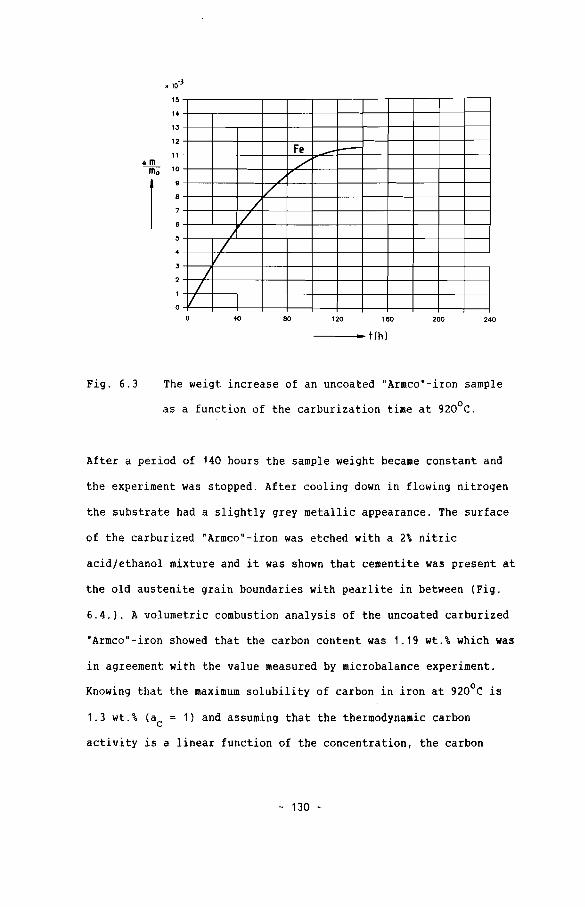
15
14
13
12
11.om---m;;- 10
8
7
5
o
Fe I----./
/'1/
//
J/
V/
/1/
40 80 120 160 200 240
Fig. 6.3
------4.a- t (h )
The weigt increase of an uncoated "Armco"-iron sample
as a function of the carburization time at 920°C.
After a period of 140 hours the sample weight became constant and
the experiment was stopped. After cooling down in flowing nitrogen
the substrate had a slightly grey metallic appearance. The surface
of the carburized "Armco"-iron was etched with a 2\ nitric
acid/ethanol mixture and it was shown that cementite was present at
the old austenite grain boundaries with pearlite in between (Fig.
6.4.). A volumetric combustion analysis of the uncoated carburized
"Armco" - iron showed that the carbon content was 1. 19 wt. \ which was
in agreement with the value measured by microbalance experiment.
Knowing that the maximum solubility of carbon in iron at 920°C is
1.3 wt.\ (ac = 1) and assuming that the thermodynamic carbon
activity is a linear function of the concentration, the carbon
- 130 -
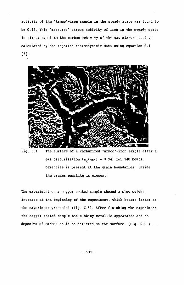
activity of the "Armco"-iron sample in the steady state was found to
be 0.92. This "measured" carbon activity of iron in the steady state
is almost equal to the carbon activity of the gas mixture used as
calculated by the reported thermodynamic data using equation 6.1
[5].
Fig. 6.4 The surface of a carburized "Armco"-iron sample after a
gas carburization (ac(gas) = 0.94} for 140 hours.
cementite is present at the grain boundaries, inside
the grains pearlite is present.
The experiment on a copper coated sample showed a slow weight
increase at the beginning of the experiment, which became faster as
the experiment proceeded (Fig. 6.5). After finishing the experiment
the copper coated sample had a shiny metallic appearance and no
deposits of carbon could be detected on the surface. (Fig. 6.6.).
- 131 -

x 10.3
0.9
0.8
"'m 0.7
~
0.6
0.5
0.4
0.3
0.2
0.1
/
Aq V/
l-(U /
/ /V /
/ /
/ V/' ./
,/"
.-/V ---f---
40 80 120 160 200 240
Fig. 6.5
---0_ t(h)
The weight increase of 10 ~m thick copper coated and
silver coated samples during a gas carburization
experiment at respectiveliy 920°C and 836°C.
Fig. 6.6 The surface of the copper layer after 143 hours of
gas carburization at 920°C.
- 132 -

Cross sections of the carburized sample showed that inside the
copper layer precipitates were formed (Fig. 6.7). By EPMA analysis
it was proven that the precipitates inside the copper layer
contained 2.5 wt.\ copper and 97.5 wt.\ iron. In chapter 7 we will
examine the mechanism by which these precipitates are formed.
Fig. 6.7 A cross section of the copper coated "Armco"-iron sample
after a gas carburization of 143 hours at 920°C.
The experiment on a silver coated sample showed a weight increase
during the experiment as given in fig. 6.5. The sample surface of
the carburized sample had a shiny metallic character and
microscopical examinations showed that large silver grains were
present at the surface (Fig. 6.8.). At a few places, the silver
grain boundaries were surrounded by holes as shown in fig. 6.9.
Metallographic prepared cross sections showed that the layer is
still dense after 220 hours of carburization at 836°C. (Fig. 6.10).
- 133 -

Fig. 6.8 The surface of a silver layer after 220 hours of gas
carburization at 836°C.
Fig. 6.9 The surface of a silver layer after 220 hours of gas
carburization showing holes at grain boundaries.
- 134 -

Fig. 6.10 A cross section of the silver coated "Armco"-iron sample
after a gas carburization experiment of 220 hours at
6 . 4 Calculations of transport coefficient of carbon in copper
and silver'
A translation of the measured weight increase (6m/mo ) into the
normalized concentration M(t) is done in following way. The weight
percentage carbon inside the substrate at a time t is given by:
6m(t)
m + 6m(t)o
(6.2)
- 135 -
M (t) - M (0)s s
where: 6m(t)
mo
weight increase of the sample as a function of
time
weight of the sample at the beginning of the
experiment (t 0)
increase in the weight fraction of carbon in the
sample at time t
Because 6m(t) « mo' we assume:
m + 6m(t) '" mo 0
thus:6m(t)
mo
(6.3)
We have seen in chapter 3 that the normalized amount of carbon in
the substrate is defined as:
M(t)
Ms(t) - Ms(O)
Ms(oo) - Ms(O)(6.4)
where: fraction of carbon at the beginning of the
experiment (t ~ 0)
fraction of the carbon at t = 00, or in
other words the maximum possible carbon
concentration under the given conditions (a ). c
In our experiments the concentration of carbon in the sample at the
beginning of the experiment. is (Ms(O) ~) 0.02 wt.\. The maximum
possible amount of carbon in the substrate (M (00») is given by thes
condition of chemical equilibrium between gas phase and solid phase:
ac(gas) " ac(substrate). If the maximum solubility of carbon in the
substrate material (L) at a given temperature is known the amount of
- 136 -

carbon in the substrate, which is in thermodynamic equilibrium with
the gas atmosphere (ac(gas», can be calculated by:
ac (gas) • L
This together with the equations (6.3) and (6.4) leads to:
l1m(t)
(6.5)
M(t)
m° (6.6)
The maximum solubility (L) of carbon in iron at any given
temperature can be found by using the phase diagram of carbon and
iron [6]. (Fig. 5.9).
The measured weight gain of the sample (l1m/mo ) of course originates
from the carbon uptake in the layer- and substrate-material.
l1m(t)
m°
l1m(t)(substrate) + l1m(t) (layer)
m
°(6.7)
The variable M(t) was defined as the normalized carbon content of
only the substrate. If the above described calculation has to be
valid the carbon content of the layer material has to be negligibly
small compared to the carbon content in the substrate during an
experiment.
The solubility of carbon in copper at 920°C is 3.7.10-3 wt.\ or
1.95.10-2 at.\ and for silver at 836°C it is 2.10-3 wt.\ or
1.79.10-2 at.\ [7], which is much lower than the solubility of
carbon in iron at those temperatures (resp. 1.3 wt.\ or 5.66 at.\
- 137 -

and 1.0 wt.% or 4.5 at.%). Therefore the amount of carbon in a 10 ~m
thick copper or silver layer is negligibly compared to the amount of
carbon in the substrate, after an initial period:
~m(substrate)
m
°(6.8)
This justifies the use of the equation (6.4) to calculate the
normalized M(t)-values for 10 ~m thick copper- and silver- coated
samples from the data gained by the gravimetrical experiments.
Not only the weight increase but also the time t has to be
2normalized in order to use the M(t) - 10g(D2tfd ) curves to
calculate the olfkd value for the uncoated, copper coated and silver
coated samples. For this reason also the diffusion coefficient of
carbon in the substrate material has to be known. For the performed
calculations we use the carbon diffusion coefficient in iron of
-8 2 ° -8 2 °9.10 cm /sec at 920 C and 5.10 cm /sec at 836 C [8].
In fig. 6.11 the "measured" M(t) - curves for uncoated, copper
coated and silver coated samples are given, together with the
calculated M(t) curves.
Assuming the gas carburization process on copper- and silver-coated
samples to be a one dimensional processes which is controlled by
solid state carbon diffusion only, we can calculate the transport
constant of carbon in copper and silver at resp. 920°C and 836°C.
- 138 -
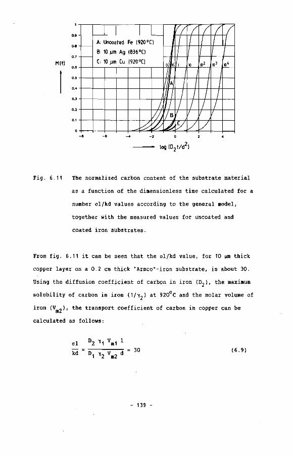
VI / / / (A: Uncoated Fe (920 oC\ I I / / 1/- I I I I IB: 10.um Ag (836°0
-
o ·\11[: 10.um (u (920°(110 102 10' 10 4
III A I I I I~I
I I I I/1 / / / /
Ili/ B il / 1/
~0LtlY / /
0.8
0.8
0.7
Hltl0.8
0.5
0.4
0.3
0.2
0.1
o-8 -8 -4 -2 o 4
Fig. 6.11 The normalized carbon content of the substrate material
as a function of the dimensionless time calculated for a
number ol/kd values according to the general model,
together with the measured values for uncoated and
coated iron substrates.
From fig. 6.11 it can be seen that the ol/kd value, for 10 ~m thick
copper layer on a 0.2 cm thick "Armco"-iron substrate, is about 30.
Using the diffusion coefficient of carbon in iron (D2 ), the maximum
solubility of carbon in iron (1/12) at 920°C and the molar volume of
iron (Vm2 ), the transport coefficient of carbon in copper can be
calculated as follows:
01 D2 11 Vm1 1
kd D1 12 Vm2 d 30
- 139 -
(6.9)

where: I -3 -8 210 cm °2 9.10 cm /sec
d 0.2 cm 'Y 2 17.67
Vm237.1 cm /mol
This results in a transport coefficient ('Y1Vm1/01)' for carbon in
copper at 920°C of 8.3.1012cm sec/mol. By using the molar volume of
copper (Vm1 ) and the solubility of carbon in copper (1h1
) [7], the
diffusion coefficient of carbon in copper at 920°C can be
-9 2calculated. This results in a value for 01 of 4.35.10 em /sec.
A similar calculation can be made for the 10 ~m thick silver coated
"Armco"-iron substrate at 836°C which according to fig. 6.11 has a
al/kd value of about ten.
al °2 'Y 1 Vm1 I
kd °1 Vm2 d 10 (6. 10)'Y 2
where: 1 -3 -8 210 cm D2 5.10 cm /sec
d 0.2 cm 22.2
This results in a transport coefficient ('Y1Vm1/01) for carbon in
silver at 836°C, of 6.3.1012cm/sec mol. Using the molar volume of
silver (10.25 cm3/mol) and the solubility of carbon in silver
(1/'Y2 ) [7] at 836°C the diffusion coefficient of carbon in silver is
-9 29 . 10 10 cm / s ec .
- 140 -

6.5 Discussion
From fig. 6.11 it can be seen that the ol/kd value for
uncoated iron is not equal to unity as we expected. Compared to the
calculation of the M(t) curves using the general model, the ol/kd
value for uncoated iron was about 8.10- 1 at the beginning of the
experiment, shifted to ol/kd = 0 and even passed the ol/kd = 0 line
at the end of the experiment. This means that the carburization rate
of uncoated samples is initially lower that we expected from theory
(ol/kd = 0, because I = 0) and at the final stage is higher than
expected. The deviation from the expected value and the change in
the carburization rate during the experiment is surprising and an
explanation of the observed changes is complicated.
A slower carburization of pure iron can occur if a thin oxide film
is present at the sample surface. The carburization is retarded by
the thin oxide film, but because of the fact that almost pure
hydrogen is used during the carburization, the oxide film is
thermodynamically unstable and is removed as the experiment
proceeds. Also the transport of methane to the sample surface can
control or slow down the carburization. If for example the solid
state carbon diffusion is fast while the methane transport is
relatively small, the carbon activity at the surface of the specimen
will become lower than in the bulk of the gas flow. So, the
carburization rate will become lower than expected, because the
general model assumes the carbon activity at the specimen surface to
be equal to the carbon activity of the bulk gas flow. (Only solid
state diffusion of carbon is rate limiting).
- 141 -

The decomposition rate of the carbonaceous compound at the specimen
surface is also a factor which can strongly influence the carbon
activity at the sample surface. If the decomposition reaction is
slow, compared with the solid state diffusion of carbon, again the
carbon activity at the sample surface will become lower than the
carbon activity in the gas leading to a lower carburization rate as
expected. Although reports on gravimetrical experiments on Incoloy
800, mentioned in literature, using methane/hydrogen mixture at 800
- 11000 C mention only an initial period of transport or gas phase
boundary reaction controlled carburization [4]. This will not
directly indicate that the substrates with other surface
compositions and surface-conditions have the same rate controlling
mechanism.
It is difficult to prove whether oxide film, methane transport to
the surface or a rate limiting decomposition reaction at the surface
is responsable for the low carburization rate of the uncoated iron
sample at the beginning of the experiment. But according to the fast
increase in the weight gain of the uncoated substrate after
introducing methane in the gas, seems to indicate that probably the
methane transport and/or the decomposition of the carbonaceous
compound methane is rate limiting in the beginning of the
experiment.
The assumption that gas carburization experiments as performed, give
rise to a one dimensional diffusion process is also doubtful. The
diffusion takes place not only through the top-surface of the
sample, but also through the cylindrical surface (Fig. 6.121.
- 142 -
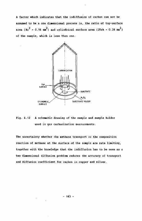
A factor which indicates that the indiffusion of carbon can not be
assumed to be a one dimensional process is, the ratio of top-surface
area (wr2 = 0.16 mm2) and cylindrical surface area (2Wrh =0.28 mm2)
of the sample, which is less than one.
I
CARBURIZAliON
I
TOPSURFAC;;:E--tIi#=~-hC
CYLINDRICALSURFACE
~---h~-SUB~RATE
Al Z03
SUBSTRATE HOLDER
Fig. 6.12 A schematic drawing of the sample and sample holder
used in gas carburization measurements.
The uncertainty whether the methane transport or the composition
reaction of methane at the surface of the sample are rate limiting,
together with the knowledge that the indiffusion has to be seen as a
two dimensional diffusion problem reduces the accuracy of transport
and diffusion coefficient for carbon in copper and silver.
- 143 -

6.6 ConclusioDS
The gas carburization of iron in a mixture of 1.53 vol.%
methane and 98.47 vol.% hydrogen using a microbalance showed that
the carburization is not only controlled by solid state diffusion of
carbon, but also by the transport of methane to the sample surface
and/or by gas phase boundary reactions at the surface of the sample.
Gas carburization experiments on copper coated "Armco·-iron
sample, showed that copper layers are effective in reducing the
carburization of "Armco"-iron at 9200 e. Assuming that only solid
state diffusion of carbon is rate limiting we found that the
diffusion coefficient of carbon in copper at 920 0e is
4.35010- 9cm2/sec. The value for the diffusion coefficient of carbon
in copper using the gas carburization method is higher than the
value found from the solid state carburization experiments
(1.8 010-9cm2/secl. This is probably dued to the fact that the
surface area through which diffusion occurs during gas carburization
is not only area of the top surface as we assumed, but also the
cylindrical surface area of the sample.
Inside the copper layer iron precipitates are formed during
the gas carburization experiments, by which the carbon diffusion is
reinforced. The formation of these iron precipitates is probably a
stage in the breakdown of the copper diffusion barrier.
Silver coatings were also effective in reducing the
carburization rate of "Armco· substrate at 836oe. Using the
- 144 -
assumption that only solid state diffusion of carbon is rate
limiting in the experiments, we found that the diffusion coefficient
of carbon in silver at 836 0C is lower than of 9.1.10-9cm 2/sec.
Again the value found for the carbon diffusion through silver
layer using gas carburization experiments is higher the the value
found in solid state carburization experiments (1.10- 9cm2/sec). In
this case we can not explain the difference between the two values
by stating the gas carburization is a two dimensional carburization
process, which means that the real surface area through which carbon
diffuses is larger than the value we assume. The appearence of the
small holes in the silver layer after carburization could be an
explanation of the observed difference. If the carburization is
faster through these imperfections than through the rest of the
layer the diffusion coefficient would be generally higher.
- 145 -

References chapter ,
[1] J.F. Norton, L. Blidegn, S. Cametoli, P.B. Framton,
Werkstoffe u. Korrosion, 32, (1981), 467
[2] W. Christl, H.J. Christ, H.G. Sockel, Werkstoffe u. Korrosion,
37, (1986), 437
[3] A. Schnaas, H.J. Grabke, Werkstoffe u. Korrosion,
29, (1978), 635
[4] A. Schnaas, H.J. Grabke, Oxidation of metals, 12, (1978), 387
[5] I. Barin, O. Knacke, "The thermodynamic properties of
inorganic materials", Springer-Verlag, Berlin, (1973)
[6] O. Kubaschewski, "Iron binary phase diagrams", Springer
Verlag, Berlin, (1982),24
[7] R.B. McLellan, Scripta Metallurgica, 3, (1969), 389
[8] Y. Adda, J. Philbert, "La diffusion dans les solids", Tome I
Press Universitaire de France, Paris, (1966), 1166
- 146 -

Chapter 7 The instability of a copper diffusion barrier
7 . 1. Introduction
In this chapter we propose an explanation of the observed
growth of iron precipitates in the copper layers. In both
carburization techniques (gas- resp. solid state carburization), the
formation of iron precipitates are responsible for the fact that the
diffusion barrier becomes less efficient.
At first it should be mentioned that iron is soluble in copper and
copper is soluble in iron (Fig. 7.1).
10 10 30
Copper (wt.%)
40 50 60 70 80 90
90 CuIII7040 50 60
Copper (at."Io)
3010
,
~ 1411"Ci
7~---- ic ,...
Ki
/ • i... 1\
0
I \,.. . . ...
\'/'1094"C
/ "'K'... ... !---, ., 1084.~ o~
Ii
I···· .~ 9S0·C ,,.. , i
'fc 159°(..... - -'- ._._.......""""""--C'- '-' '-i'-
, .. i
i .
!i
Fe-Cu
600Fe 10
700
1100
800
911·(900
1300
1500
14001391"
1535°(
~
~ 1000
_ 110
Fig. 7.1 The binary phase diagram of copper and iron [1].
- 147 -

We also know that iron and copper can interdiffuse at high
temperatures [2,3]. This means that during a carburization
experiment iron atoms diffuse into the copper layer and copper atoms
diffuse into the iron substrate. During the solid state
carburization the copper diffuses also into the carbon source.
To our opinion, the most important step in the breakdown of a copper
layer is, the diffusion of iron into the copper layer. This results
in an increasing amount of iron in the copper layer during an
experiment. The maximum possible iron concentration in the copper
layer is of course given by the maximum solubility of iron in copper
(Fig. 7.1).
7 . 2 The breaItdcND of a copper layer duri.acJ a 9U carburizatioD
experi.llent
We first focus on the gas carburization experiment and assume
that we have the following situation. Iron starts to diffuse through
the layer towards the layer/gas interface, while carbon diffuses
into the layer (Fig. 7.2a). Assuming that iron diffusion is faster
than the carbon diffusion through the layer material, the iron and
carbon would "meet" each other somewhere near the layer/gas
interface. If we assume the diffusion coefficient of iron in copper
is larger than the diffusion coefficient of carbon in copper this
directly indicates that the diffusion coefficient of carbon in
-10 2copper is less than 6.10 cm /sec [4]. This again showes that the
values for the diffusion coefficient of carbon in copper as
- 148 -

calculated in chapter 5 and 6 are only upper limits, which are
controlled by the breakdown process.
Normally the maximum solubility of iron in copper is given by the
binary phase diagram of iron and copper, but because of the presence
of a third element (carbon), the system is no longer a binary
system, but becomes a ternary one.
Cu
C-H-4-----1c~-!LC--
(gas)
® ®
Fig. 7.2
CH4 C(gas)
A schematic representation of the breakdown process of a
copper layer during gas carburization.
The third element can influence the solubility of iron in the copper
in three possible ways. First of all, the carbon does not have any
- 149 -
influence on the solubility of iron inside the copper layer. A
second possibility is that carbon increases the solubility of iron
in the copper or third, the maximum solubility of iron in copper is
decreased by the presence of carbon. If the carbon does not change
the maximum solubility one may still see the copper, iron, carbon
system as a binary system. An increase in the solubility of iron in
copper as carbon is present does not lead to the formation of iron
precipitates inside the copper layer. During gas carburization
indeed iron precipitates were seen in the copper layer, and they
almost all were found near the layer/gas interface (Fig. 6.7).
This strongly indicates that indeed the carbon diffusion in copper
is slower than the diffusion of iron in copper, but also proves that
carbon decreases the maximum solubility of iron in copper (Fig.7.2).
If the gas carburization experiment had been continued the
precipitates of iron had probably grown until in a final stage the
iron precipitates had reached the surface of the copper layer
(Fig.7.2d,e).
7 . 3 The breakdOllD of copper layers during solid state
carburizatioD
The breakdown of the copper layers during solid state
carburization seems to have three different stages. The first stage,
is the stage in which the carbon source/layer interface starts
rimpling (Fig. 7.3). In a second stage, protrusions grow, from the
carbon source/layer interface into the copper layer (Fig. 7.4).
- 150 -

Fig. 7.3 A cross section of a sputtered copper layer after a
diffusion annealing for 40 hours at 920°C.
Fig. 7.4 A cross section of a sputtered copper layer after a
diffusion annealing for 76 hours at 920°C.
- 151 -
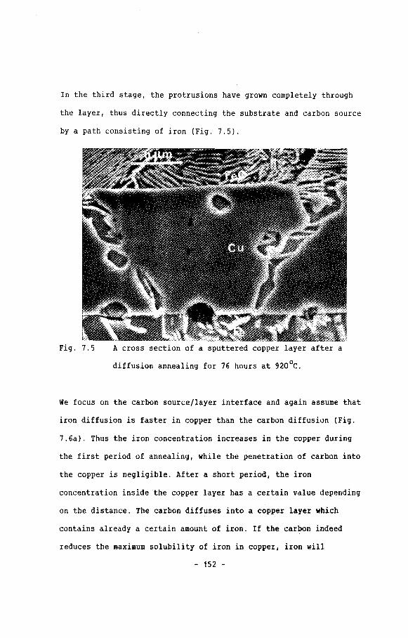
In the third stage, the protrusions have grown completely through
the layer, thus directly connecting the substrate and carbon source
by a path consisting of iron (Fig. 7.5).
Fig. 7.5 A cross section of a sputtered copper layer after a
diffusion annealing for 76 hours at 920°C.
We focus on the carbon source/layer interface and again assume that
iron diffusion is faster in copper than the carbon diffusion (Fig.
7.6a). Thus the iron concentration increases in the copper during
the first period of annealing, while the penetration of carbon into
the copper is negligible. After a short period, the iron
concentration inside the copper layer has a certain value depending
on the distance. The carbon diffuses into a copper layer which
contains already a certain amount of iron. If the carbon indeed
reduces the maximum solubility of iron in copper, iron will
- 152 -
precipitate. According to Meijering [5] the solubility of an element
A in B is influenced by the presence of a third element (Cl, if the
chemical affinity between A and C differs from the chemical affinity
between B andC. This is indeed true for copper and iron, because
the solubility of carbon in iron differs from the solubility of
carbon in copper. So, there is reason to believe that indeed carbon
decreases the solubility of iron in copper.
Because of the fact that the carbon has diffused into the copper
layer for only a very small distance, the precipitates formed are
present near the carbon source/layer interface. For that
reason the precipitates are not detected as islands or protrusions
inside the copper layer but they produce a wavy carbon source/layer
interface (Fig. 7.6bl. This process proceeds until the wavy
character of the interface turns into real protrusions (second
staqe, Fig. 7.6c). The carbon diffusion, inside the iron
protrusions, is much faster than the diffusion inside the copper
layer and therefore the protrusions grow. Because of the fact that
iron diffusion also occcurs at the iron substrate/layer interface,
(which kept planar during the first and second stages), the iron
concentration also increases at that side uf the system (Fig. 7.6dl.
If at a given time the iron diffusion coming from the
layer/substrate interface, meets a growing protrusion, there is a
sudden rapid growth of the protrusion, in the direction of the
layer/substrate interface.
- 153 -

Fe
~ l-_-_-_-[u
®
Fe
FeFe l____ 1-_-_-_-_-[u
Fig. 7.6 A schematic representation of the breakdown process of a
copper layer during a solid state carburization process.
In the final stage, the protrusion reaches the iron substrate/layer
interface, thus creating a path between the carbon source and
substrate, by which fast diffusion can occur (Fig. 7.6el.
- 154 -

7.4 The stabili1:y of silver layers durin, 9U carburizatioD and
solid state carburizatioD
During gas carburization and solid state carburization of
silver layers on iron substrates, we did not detect any precipitates
of iron inside a silver layer. Using the phase diagram of silver and
iron (Fig. 7.7), we see that iron is not soluble in silver and
silver is not soluble in iron at 850°C. Therefore, the iron
concentration inside the silver layer is almost zero. For that
reason carbon can not significantly influence the solubility of iron
in silver, at least it has no detrimental effect on the stability of
the silver layer.
WEIGHT °/.. Fe0.1. 0,4 0.' -0.& 1.0 ,4.1. 9,.{, Fe
1 " l I' , ! , , Ii I
1600l..lQ, ... LIQ.1. LIG.' 2
l.1Q.·1 :,-l
153'!o -- 15'38
-' o..~\..IQ., .. (~·Fe.)
'9~14 "·'8 \
140099.99...:
1~9~
~ '. 1398 .,/ 0·5 9'.978
12.00LlQ.., + (t....\
1000 :,.o.~!9.lnS
fJE,1.9O{" .
0."" ("'1\ + it...a) '9.""91t.S •99.9998
Boo(Aq\ + tll(.-;:e~
.oo-'--~~_~--rl >-r-~~~.--'
.tv:\ 0.5 '.0 1.1Z> Z.O '9·" ".f> FeATOM 1>'0 Fe
Fig. 7.7 The binary phase diagram of silver and iron [6].
- 155 -
7.5 Conclusions
Generally only binary systems are studied to predict whether a
diffusion barrier will be effective, viz. the diffusing element/
layer, the diffusing element/substrate and the layer/substrate
system. The last system is often used to predict the stability of
the layer, particularly whether the layer disappears by inter
diffusion into the substrate or becomes less effective because the
substrate material diffuses into the layer.
As we 'have seen also knowledge of the ternary system i. of major
importance in order to be sure, that the layer stays effective
during long term application, since the interaction of the three
elements rules the stability of a diffusion barrier.
- 156 -
References cbapter 7
[1] O. Kubaschewski, "Iron binary phase diagrams·, Springer-Verlag
Berlin, (1982), 24
[2] L. Rotherham, S. Pearson, J. Metals, (1956), 881
[3] Y.V. Piquzov, W.D. Werder, I.Y. Rzehevskaya Phys. Metalloqr.,
24, (1967), 179
[4] D.B. Butrymowicz, J.R. Manning, M.E. Read,
J. Phys. Chem. Ref. Data, 5, (1976), 103
[5] J.L. Meijering, Philips Technisch Tijdschrift, 27,
(1965/66), 228
[6] L.G. Swartzendruber, Bull. alloy phase diagrams,
5, (1984),560
- 157 -

Appendix A
The Laplace transformed homogeneous differential equations of the
finite composite system are:
2-o ah ,1D1 p ah ,1
0/
2-a a h ,2
D2 p ah ,2ax2
-1 < x 0
o x < d
(2.21)
(2.22)
with the following boundary conditions:
a - a0 b
ah ,1 x = -1 (2.23)p
- 0 (2.24)ah ,1 ah ,2 x =
D1 aah ,1 D2 aah ,2---- ---- x = 0 (2.25)Vm1 '1 1 ax Vm2 '12 ax
D2 aah ,2---- 0 x = d (2.26)Vm2 '12 ax
A solution of equation (2.21) which satisfies equation (2.23) is:
pcoshq1 (l+x) + A sinhq1 (l+x)
-1 < x < 0
- 158 -
(A.1)

A solution of equation (2.22) which satisfies equation (2.26) is:
o < x < d (A.2)
The unknown A and B are found by using equation (2.24) and (2.25):
sinhq2d + sinhq11\.
aa-~ a coshq11 coshq2d
A= - (A.3)P a sinhq11 sinhq2d + coshQ11 coshQ2d
ao -~ coshq,l o coshq,l sinhq21 + sinhq,l coshQ2d sinhq,l
B= ( )p coshq2 d a sinhq,l sinhq2d + coshq,l coshq2d coshQ2d
(A.4)
°1,
Va' 'Y, D2- -k = )2 0 ---- ( )2
°2 Vm2 'Y2 0,
The Laplace transformed solutions of the homogeneous differential
equations are:
- aa-~ coshq2d coshQ1X - a sinhQ2d sinhQ1x
ah,1 =p coshQ11 coshQ2d + ~ sinhQ1d sinhQ2d
-1 < x < 0
aO - ab cosbQ2(d-x)
ah,2 =p coshq11 coshQ2d + a sinhq11 sinhQ2d
(2.27)
(2.28)
- 159 -

o < x < d
The general solutions for the problem will be of the form:
a + (2.20)
./
We have to find the solutions for the general Laplace transformed
solution a with help of the particular and the homogeneous Laplace
tran~formed solutions.
abwhere: ap , 1 P
a bap,2 p
-1 < x < 0
o x < d
(A.5)
(A. 6)
The general solution can be determined by an inverse Laplace
transformation of the partial and homogeneous Laplace transformed
solutions separatly. The inverse Laplace transformation of the
partial solutions (A.5) and (A.6) are determined by using the table
of Laplace transforms. Thus obtaining:
a p,1 ab
a·· ab.p,2
-1 < x 0
o x <d
The inverse Laplace transformation of the homogeneous Laplace
transformed solutions can be determined by carrying qut "the method
of partial fractions" as follows:
- 160 -

ah,1and ah,2 can be written as:
resp.g{p) ~,2 g{p)
f 1(p), f 2{p) and g{p) are polynomials and the characteristic
equation g{p) = 0 has no multiple roots (Pn). The solution a1{t) and
a 2{t) can be found by:
f,{Pn)Pn t
[ ---en=1 g' (Pn )
.. f 2{Pn)Pn t
[ ---en=1 g'{Pn )
Solving the equation g{p) 0, we find:
Po 0 ,p - P
+ 0 tanh{ )2 1 tanh { )2 d
°1 °2
o n=1,2,3, ....
In case P 's are reals no solutions are found.n
1 1Pn
)2 1Pn
)2 do tanh{ tanh ( > 0
°1 °2
If we assume that p 's are complex and also knowing that:n
tanh(ix) :: i tan(x)
- 161 -

we get:
where:
Using equations (A.7), (A.B) and the Pn's we obtain:
P t(coshq1X coshQ2d - 0 sinhQ1x sinhQ2d) e n
- 1 < x < 0
P tcoshQ2(d-x) e n
o < x < d
Knowing that:
- 162 -

coshix = cosx
sinhix = i sinx
we finally get the solutions:
-11 20 t(cosllnx cosll kd + a sinll x sinll kd) e n 1n n n
- 1 < x < 0 , t > 0 (2.32)
-11 2 0 tn 1e
2(ao - ab
) [n=1 II (l+akd) (cosll kd sinll 1) + II (la+kd) (sinll kd coslln1)n n n n n
o < x < d , t >0
In these equations II is the infinite series of roots of then
"characteristic equation":
- 163 -
(2.33)
(2.34)
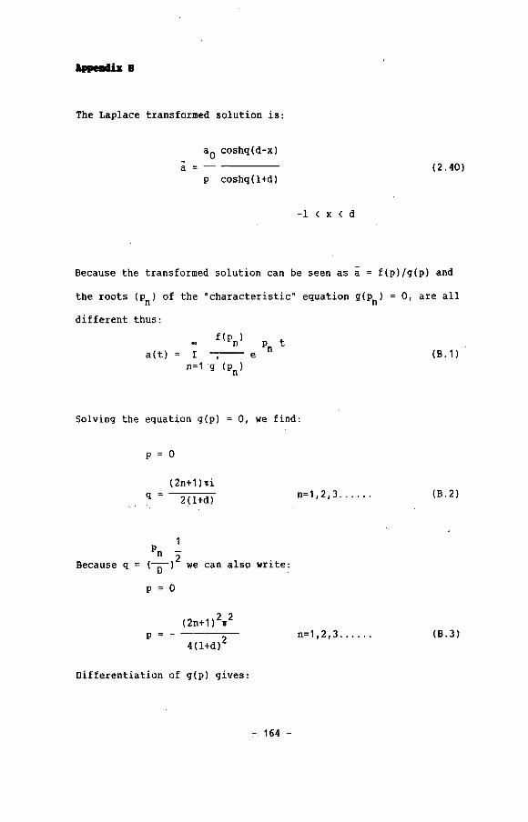
lBeallil: 8
The Laplace transformed solution is:
ao coshq(d-x)a=-----
p coshq(1+d)
-1 < x < d
(2.40)
Because the transformed solution can be seen as a = f(p)!g(p) and
the roots (Pn) of the ·characteristic" equation g(Pn) = 0, are all
different thus:
a(t)f(Pn) t
Pnr -,-- en=1 g (P
n)
(B. 1)
Solving the equation g(p) = 0, we find:
P 0
q =(2n+1l'11i
2(1+d) n=l, 2,3 . (B.2)
1Pn -
Because q = ( )2 we can also write:D
P = 0
P =-(2n+1)2lf2
4(l+d)2n=l, 2, 3 . (B.3)
Differentiation of g(p) gives:
:-. 164 -

g'(p) = p coshq(l+dl = coshq(l+d) + 1/2 q(l+d) sinhq(l+dl (8.4)
For:
p =0 g'(O) 1
1'1=1,2,3 ... '...
p = -(2n+1 )2/
4(l+dl 2 g'(p) =(2n+1 h
(_1)n4
(B.5)
(2ri+1) 211 20 t
4(d+1) 2
With equation we finally obtain:
4 aO _ ( _1)n (2n+1lll
a = aO - -1I---n:
1(2n+1) cos[2(d+l) (d - xl] e
-1 < x < d , t > 0
- 165 -
(B.6)
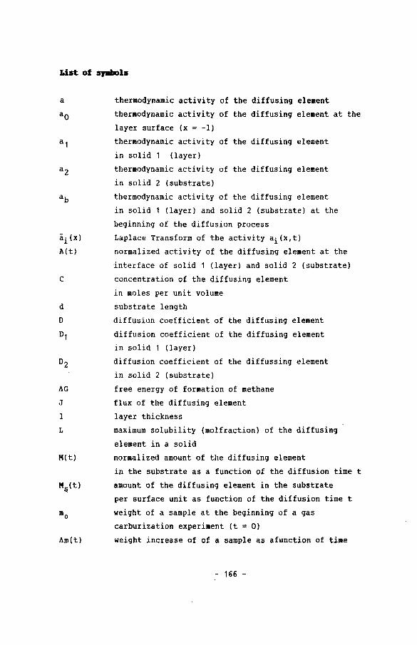
Lin of QIIIIols
a
ai(x)A(t)
c
d
o01
hG
J
1
L
M(t)
hm(t)
thermodynamic activity of the diffusing element
thermodynamic activity of the diffusing element at the
layer surface (x = -1)
thermodynamic activity of the diffusing element
in solid 1 (layer)
thermodynamic activity of the diffusing element
in solid 2 (substrate)
thermodynamic activity of the diffusing element
in solid 1 (layer) and solid 2 (substrate) at the
beginning of the diffusion process
Laplace Transform of the activity ai(x,t)
normalized activity of the diffusing element at the
interface of solid 1 (layer) and solid 2 (substrate)
concentration of the diffusing element
in moles per unit volume
substrate length
diffusion coefficient of the diffusing element
diffusion coefficient of the diffusing element
in solid 1 (layer)
diffusion coefficient of the diffussing element
in solid 2 (substrate)
free energy of formation of methane
flux of the diffusing element
layer thickness
maximum solubility (mol fraction) of the diffusing
element in a solid
normalized amount of the diffusing element
in the substrate as a function of the diffusion time t
amount of the diffusing element in the substrate
per surface unit as function of the diffusion time t
weight of a sample at the beginning of a gas
carburization experiment (t = 0)
weight increase of of a sample as afunction of time
- 166 -

T
molar fraction of the diffusing element
gas constant
diffusion time
absolute temperature (K)
molar volume of solid 1 (layer)
molar volume of solid 2 (substrate)
distance parameter
activity coefficient of the diffusing element
activity coefficient of the diffusing element
in solid 1 (layer)
activity coefficient of the diffusing element
in solid 2 (substrate)
dimensionless characteristic time parameter (D2t/d2)
- 167 -

S..-ry
This thesis describes the theoretical and experimental results
of a study on carbon diffusion through protective layers.
The result of the theoretical part of the study is a new,
general mathematical model which deals with the diffusion of an
element in finite systems. The model comprises a larger number of
diffusion problems which have already been solved by other
investigators. The model also holds the solution for the problem
concerning the diffusion of an element in a layer/substrate system.
The general model deals with the whole range of possibilities
varying from thin to thick diffusion barriers with minor or
excellent qualities.
The results of calculations with the general model are
summarized in two nomograms in which degrees of carburization under
specific material conditions are given as a function of a
characteristic time parameter. With these nomograms it is possible
to predict the influence of a diffusion barrier, with known
properties and dimensions, on the diffusion of an element in a
layer/substrate system (composite system).
With several Physical Vapour Deposition processes it was tried'to
deposit dense metallic layers, which have a good high temperature
performance. It was found that only by D.C. sputtering using a high
substrate temperature copper- and silver-layers with the required
properties could be deposited.
The copper- and silver-layers and also copper- and silver
foils were examined on their diffusion barrier behaviour using a
- 168 -

solid state carburization technique. This technique uses an
iron/carbon alloy to provide the carbon for diffusion.
It was found that at 950°C, 30 ~m copper was effective in
retarding the carburization of the iron substrate during 300 hours.
After a long period at high temperature the copper layer gets
perforated and carburization of the underlying substrate occurs. The
silver layers of 25 ~m showed an excellent behaviour at 850°C during
700 hours, after which still no carburization of the substrate had
occurred. With help of the results from the solid state
carburization experiments and with the use of the general model
upper limit values for transport coefficients and diffusion
coefficients for carbon in copper and silver are calculated.
Copper- and silver-layers were also examined by gas
carburization experiments using a microbalance. In the experiments
copper showed the same behaviour as during solid state carburization
experiments. After a period, in which the 10 ~m copper layer
protected the substrate from carburization, the layer was perforated
and the underlying substrate carburized.
A 10 ~m silver layer again showed excellent properties, for it
reduced the carburization at B360C during 243 hours. No diffusion
barrier breakdown processes were detected when using silver layers,
although small pores were found after long annealing times.
Applying the results from the gas carburization measurements upper
limit values for transport coefficients and diffusion coefficients
of carbon in copper and silver are calculated using the general
aodel.
- 169-

The breakdown process which appeared in the copper layers is
discussed and a mechanism is proposed, which explains the occurrence
of the breakdown process.
- 170 -

This work has been preformed under contract of the "Bureau Energie
Onderzoek Projecten" of the "Stichting Energie Onderzoek Centrum
Nederland" as part of the national research program "Kolen",
financed by the "Ministerie van Economische Zaken." resp. D.S.H.
andK.M.5. "de Schelde".
- 171 -

SaJleDvatti.Dv
Dit proefschrift beschrijft de theoretische en experimentele
resultaten van een studie naar koolstofdiffusie door koolstof
diffusiebarrieres.
Het resultaat van het theoretisch gedeelte van de studie is
een nieuw algemeen mathematisch model, dat de diffusie van een
element in een eindig systeem beschrijft. Het model omvat een groot
aantal diffusieproblemen die reeds door andere onderzoekers zijn
opgelost. Verder bevat het model een oplossing voor het probleem
van de diffusie van een element in een laag{substraat systeem. Het
algemene model behandelt een reeks gevallen waarin sprake kan zijn
van dunne of dikke diffusiebarrieres met een geringe tot hoge
kwaliteit. De resultaten van de berekeningen met het algemene model
zijn opgenomen in twee nomogrammen waarin een maat voor opkoling bij
specifieke materiaalcondities als functie van een karakteristieke
tijd-parameter zijn uitgezet. Met behulp van de nomogrammen is het
mogelijk de invloed te voorspellen van een diffusiebarriere op de
diffusie Vdn een element in een laag{substraat systeem. Hiervoor
dienen materiaaleigenschappen en geometrie bekend te zijn.
Er is geprobeerd om met behulp van een aantal Physical Vapour
Deposition processen dichte, metallische lagen te groeien met goede
hoge-temperatuureigenschappen. Het bleek dat aIleen D.C. sputteren
in combinatie met hoge substraattemperaturen geschikt is om dichte
koper- en zilverlagen te groeien.
- 172 -

De gegroeide koper- en zilverlagen en ook koper- en zilver
folies werden onderzocht op hun gedrag als koolstofdiffusie
barriere, waarbij gebruik werd gemaakt van vastestofopkoling. Bij
deze techniek wordt een koolstof-ijzer legering aangewend als
koolstofleverancier voor de diffusie.
Het bleek dat een 30 ~m dikke koperlaag bij een temperatuur van
950°C gedurende 300 uur het ijzersubstraat tegen opkoling
beschermde. De koperlaag blijkt onder de gegeven omstandigheden
instabiel te worden zodat de levensduur van een dergelijke coating
beperkt is. Na lange tijd op hoge temperatuur wordt de koperlaag
doorbroken en opkoling van het onderliggende substraat vindt plaats.
Zilverlagen van 25 ~m blijken het ijzersubstraat gedurende 700
uur op 850°C uitstekend te beschermen tegen opkoling. Met de
resultaten van de vaste-stof-opkolingsexperimenten en door gebruik
te maken van het algemene model is het mogelijk om transport
coefficienten en diffusiecoefficienten van koolstof in koper en
zilver te berekenen, C.q. een maximale grenswaarde hiervoor te
bepalen.
Koper- en zilverlagen werden eveneens bestudeerd met behulp van
gasfase opkolingsexperimenten waarbij gebruik werd gemaakt van een
micro-balans. In de experimenten bleken de koperlagen het zelfde
gedrag te vertonen als waargenomen tijdens vaste-stofopkoling. Na
een periode waarin een 10 ~m dikke koperlaag het onderliggende
substraat tegen opkoling beschermt, wordt de laag doorbroken en
vindt opkoling van het substraat plaats.
- 173 -
Een 10 ~m dikke zilverlaag bleek uitstekende eigenschappen te
vertonen tijdens de gasfase-opkolingsexperimenten op 836°C.
Met behulp van de resultaten verkregen uit gasfase
opkolingsexperimenten en onder gebruikmaking van het algemene
mathematische model werden transportcoefficienten en diffusie
coefficienten van koolstof in koper en zilver berekend, c.q.
maximale grenswaarden bepaald.
Het afbraakproces dat plaats vindt in koperlagen tijdens
opkoolexperimenten wordt besproken en er wordt een mechanisme
voorgesteld dat het optreden van een dergelijk proces verklaart.
- 174 -

CDrricub. Vitae
De schrijver van dit proefschrift werd op 30 september 1959
geboren te Swalmen. Na het behalen van het diploma Atheneum-B aan
het Bisschoppelijk College Broekhin in 1977, werd in dat jaar
begonnen met de studie aan de afdeling der Scheikundige Technologie
van de Technische Hogeschool Eindhoven.
Het afstudeerwerk werd verricht binnen de TNO-TPD groep
"Fijnkeramiek" onder leiding van dr. ir. C.A.M. Siskens, met als
afstudeerhoogleraar prof. dr. R. Metselaar van de vakgroep Physische
Chemie. Het afstudeer onderwerp luidde: Bereiding en karakterisering
van p-sialon. In augustus 1983 werd het ingenieursexamen afgelegd.
Vanaf 1 september 1983 tot 1 november 1987 was hij werkzaam
als wetenschappelijk assistent in dienst van de Technische
Universiteit Eindhoven. Het in dit proefschrift beschreven werk werd
uitgevoerd binnen de afdeling der Werktuigbouwkunde onder leiding
van prof. dr. ir. J.A. Klostermann.
Sinds 1 november is hij in dienst getreden als
wetenschappelijk medewerker bij het Philips Natuurkundig
Laboratorium te Eindhoven.
- 175 -
Allereerst wil ik Prof.dr.ir. Anton Klostermann en
Prof.dr. R. Metselaar bedanken voor de moeite die zij zich hebben
getroost om gedurende de afgelopen vier jaar enige wetenschappelijke
lijn in mijn onderzoek te brengen. In dit verband moet ook dr. Frans
van Loo genoemd worden, met wie ik vele uren gediscussieerd heb, en
die me steeds weer wist te motiveren door te gaan op de ingeslagen
weg.
Het zou te ver voeren om iedereen op te noemen die aan de
totstandkoming van dit proefschrift hebben bijgedragen. Toch wil ik
nog de namen van een aantal mensen noemen zonder wie dit onderzoek
niet tot een goed einde gebracht had kunnen worden.
Prof.dr. J.B. Aiblas voor Z1Jn adviezen op momenten dat we met de
wiskunde geen raad wisten. Medewerkers van de vakgroep Physische
Chemie van Prof.dr. R. Metselaar, bleken tijdens dit onderzoek
onontbeerlijk. Met name voor de uitgevoerde elektron-micro-probe
metingen verricht door ir. Hans Heiligers, de assistentie van Fred
Kruger bij het doen van rontgendiffractie en het leren omgaan met de
thermo-balans door Jo van Ham. Willem van de Vleuten, van de
afdeling Natuurkunde die ons vaak wist te redden uit benarde
situaties, waarin wij tijdens en aantal oppervlakte analyse metingen
verstrikt raakten. Collega's van de vakgroep W.O.C. (sektie
materiaalkundel, in het bijzonder wijlen Jan van Bakel, 109. Jan
Faessen en ing. Kees Meesters die de "gast" uit de andere groep
altijd netjes assisteerden in "hun" laboratorium. Dhr. van Dijk voor
adviezen op fotogebied, Medewerkers CTD, met name Toon Gevers voor
het bouwen van de vloeibare stikstof regeling, en het koppel Dhr.
Huisman-Paul Peters voor het bouwen van de
hoogspanningsgelijkrichters voor het PVD-apparaat. Joepie
Bognetteau-Janssen en Caroia Tak voor het geduldig wachten op de
meestal veel te laat teruggebrachte boeken.
- 176 -

Dr.ir. Ruud Beerkens (TPD-TNO-qlas) voor het lenen van zijn massa
spectro meter en ook voor zijn nooit aflatende interesse in dit
onderzoek.De afstudeerders, Geert Smits (thermo-balans), Theo
Hermans, Remco Hutten (De tekeninqen), ir. Arthur van Broekhoeven
(R.F.-sputteren), en Willy van den Hooqen. Staqaires Paul van
Avoirt voor de technische tekeninqen en ontwerpen, als ook de
bijdraqe aan enkele illustratieve tekeninqen in dit proefschrift,
Rene de Hamer (triode sputteren). Toon Manders, voor het beschikbaar
stellen van zijn tekenkwaliteiten. "Van Buitenshuis', Dhr. van
Sluis, Kon. Maatsch. "De Schelde" te Vlissinqen voor het
vervaardiqen van Al203 P.V.D.laqen.
Van de eiqen sektie:
Wiel Enqels voor het vervaardiqen van allerlei kleine ditjes en
datjes. Drs. Theo Kuijpers voor het in het onderzoek qestelde
,interesse, het inwijden in de mystiek en de problematiek in de
wiskunde, en het aanleren van Fortran 77. Marjan Verschuren en Mies
Brink voor het typen van kwartaalverslaqen en delen van dit
proefschrift. Ir. Jos Houben, voor het altijd aanweziqe qewilliqe
oor voor technische en orqanisatorische problemen. Het hechte koppel
Gijs van Liempd en Piet de Waal voor de technische assistentie,
tekenwerk, het aanhoren van aIle frustaties, en het laten merken dat
er meer is dan promoveren. "Toontje" Hoeben voor het uitstekende
fotoqrafische werk in dit proefschrift, waar hij zelfs s'nachts niet
meer van kon slapen, de niet weq te cijferen bijdrage aan al het
praktisch werk en het afremmen van een al te haastiqe promovendus.
Ir. Hennie Both, kamerqenoot, colleqa en vriend waarmee ik samen in
de afqelopen 4 jaar zeven ververvelende verhuizinqen heb onderqaan
en die het weI en wee van mijn promotiewerk heeft qedeeld.
Mijn vrouw Tonny, voor haar nimmer aflatende steun, een qedeelte van
het typewerk en correctiewerk in dit proefschrift, en de stimulans
08 oak in het laatste zware half jaar door te gaan, en het geheel
tot een goed einde te brengen.
- 177 -

Mijn ouders, die in de periode voorafgaande aan dit promotiewerk m~J
de mogelijkheden hebben geboden voor het leggen van de basis in dit
proefschrift.
En al diegenen die ik vergeten heb,
Van harte bedankt.
- 178 -

STELLINGEN
1. De ontwerper van werktuigbouwkundige constructiesconcentreert zich vaak te eenzijdig op hetmechanisch sterkte-aspect, terwijl chemischeaspecten, zoals corrosie, minstens even belangrijke factoren in zijn aandacht dienen te zijn.
2. Het verschil tussen metaal en keramiek wordtaardig toegelicht in de uitspraak"buigen of barsten".
3. Het verdient aanbeveling een promotie-onderzoekte laten verrichten door twee samenwerkendepromovendt, zodat er sprake is van gelijkwaardigegesprekspartners, hetgeen dan leiden kan tot eendoeltreffender en diepgaander resultaat.
4. Verdere bevordering van het girale geldverkeerz&l leiden tot een reductie van het "zwarte"geldcircuit.
S. van Seek, H. Jacobi, M. Scharloo, K. Jansen,"Geld door de eeuwen heen"P~mpus Associates Amsterdam (1984), 145.
5. Ondanks het feit dat ultra dunne metaaloxidelagen al sinds 1960 commercieel worden toegepastter versteviging van glaswerk, is de grondslagvan dat verstevigingsmechanisme onbekend.
C.H. Careless, Glass Technology,28, (1987), 175
6. De door Mattox geintroduceerde term "ionplating"is een onjuiste benaming voor het hiermee bedoelde,door een plasma ondersteund, P.V.D. proces.
J. Halling, Design Engineering,4, (1977), 43
7. De schatting van de Nederlandse corrosieschade,die jaarlijks 10 tot 15 miljard bedraagt, is aande lage kant, omdat veel bedrijven productieverliesten gevolge van corrosie niet onderbrengen onderde post corresieschade.
J. van Kasteren, De Ingenieur,10, (1983), 19
8. Met de invoering van deeltijdbanen in het basisonderwijs heeft men het principe van een leerkrachtper greep verlaten, hetgeen positieve gevolgenkan hebben veor de oudere leerling, maar zeerzeker negatieve veer het jongere schoelkind.
L.M. Heijnen
Eindhoven, 5 november 1987
Related Documents