Model CB 15-100 HP Boilers Section A6-1 Rev. 07-10 MODEL CB 15 - 100 HP Steam and Hot Water Dryback Integral Burner CONTENTS FEATURES AND BENEFITS ............................................................................................................................... A6-3 PRODUCT OFFERING ........................................................................................................................................ A6-4 Boiler Options ................................................................................................................................................... A6-4 Burner/Control Options ..................................................................................................................................... A6-4 Fuel Options ..................................................................................................................................................... A6-5 DIMENSIONS AND RATINGS ............................................................................................................................. A6-5 PERFORMANCE DATA ..................................................................................................................................... A6-14 Efficiency......................................................................................................................................................... A6-14 Emissions........................................................................................................................................................ A6-15 ENGINEERING DATA ........................................................................................................................................ A6-17 Blowdown Water Requirements ..................................................................................................................... A6-17 Sound Level .................................................................................................................................................... A6-18 Units ................................................................................................................................................................ A6-18 Test Method .................................................................................................................................................... A6-21 Sound Level Meter.......................................................................................................................................... A6-21 Sound Pressure .............................................................................................................................................. A6-21 Typical Values ................................................................................................................................................ A6-21 Octave Band ................................................................................................................................................... A6-21 Gas-Fired Burners .......................................................................................................................................... A6-21 Oil-Fired Burners ............................................................................................................................................ A6-21 No. 6 Oil Piping, Storage Tank Heating.......................................................................................................... A6-22 Boiler Room Information ................................................................................................................................. A6-30 Stack Support Capabilities.............................................................................................................................. A6-30 Stack/Breeching Size Criteria ......................................................................................................................... A6-30 Boiler Room Combustion Air .......................................................................................................................... A6-30 SAMPLE SPECIFICATIONS - STEAM .............................................................................................................. A6-35 SAMPLE SPECIFICATIONS - HOT WATER ..................................................................................................... A6-47

Welcome message from author
This document is posted to help you gain knowledge. Please leave a comment to let me know what you think about it! Share it to your friends and learn new things together.
Transcript
Model CB 15-100 HP Boilers
Section A6-1 Rev. 07-10
MODEL CB
15 - 100 HP Steam and Hot Water
Dryback Integral Burner
CONTENTS
FEATURES AND BENEFITS ............................................................................................................................... A6-3 PRODUCT OFFERING ........................................................................................................................................ A6-4
Boiler Options ................................................................................................................................................... A6-4 Burner/Control Options ..................................................................................................................................... A6-4 Fuel Options ..................................................................................................................................................... A6-5
DIMENSIONS AND RATINGS ............................................................................................................................. A6-5 PERFORMANCE DATA ..................................................................................................................................... A6-14
Efficiency ......................................................................................................................................................... A6-14 Emissions ........................................................................................................................................................ A6-15
ENGINEERING DATA ........................................................................................................................................ A6-17 Blowdown Water Requirements ..................................................................................................................... A6-17 Sound Level .................................................................................................................................................... A6-18 Units ................................................................................................................................................................ A6-18 Test Method .................................................................................................................................................... A6-21 Sound Level Meter .......................................................................................................................................... A6-21 Sound Pressure .............................................................................................................................................. A6-21 Typical Values ................................................................................................................................................ A6-21 Octave Band ................................................................................................................................................... A6-21 Gas-Fired Burners .......................................................................................................................................... A6-21 Oil-Fired Burners ............................................................................................................................................ A6-21 No. 6 Oil Piping, Storage Tank Heating .......................................................................................................... A6-22 Boiler Room Information ................................................................................................................................. A6-30 Stack Support Capabilities .............................................................................................................................. A6-30 Stack/Breeching Size Criteria ......................................................................................................................... A6-30 Boiler Room Combustion Air .......................................................................................................................... A6-30
SAMPLE SPECIFICATIONS - STEAM .............................................................................................................. A6-35 SAMPLE SPECIFICATIONS - HOT WATER ..................................................................................................... A6-47
Model CB 15-100 HP Boilers
Section A6-2 Rev. 07-10
ILLUSTRATIONS
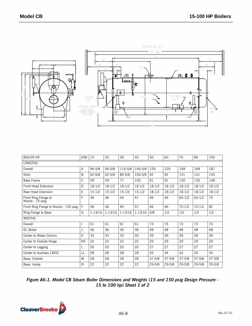
Figure A6-1. Model CB Steam Boiler Dimensions and Weights (15 and 150 psig Design Pressure - 15 to 100 hp) Sheet 1 of 2 ....................................................................................................................... A6-8
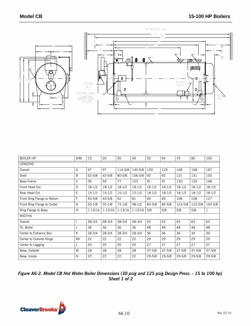
Figure A6-2. Model CB Hot Water Boiler Dimensions (30 psig and 125 psig Design Press. - 15 to 100 hp) Sheet 1 of 2 ..................................................................................................................... A6-10
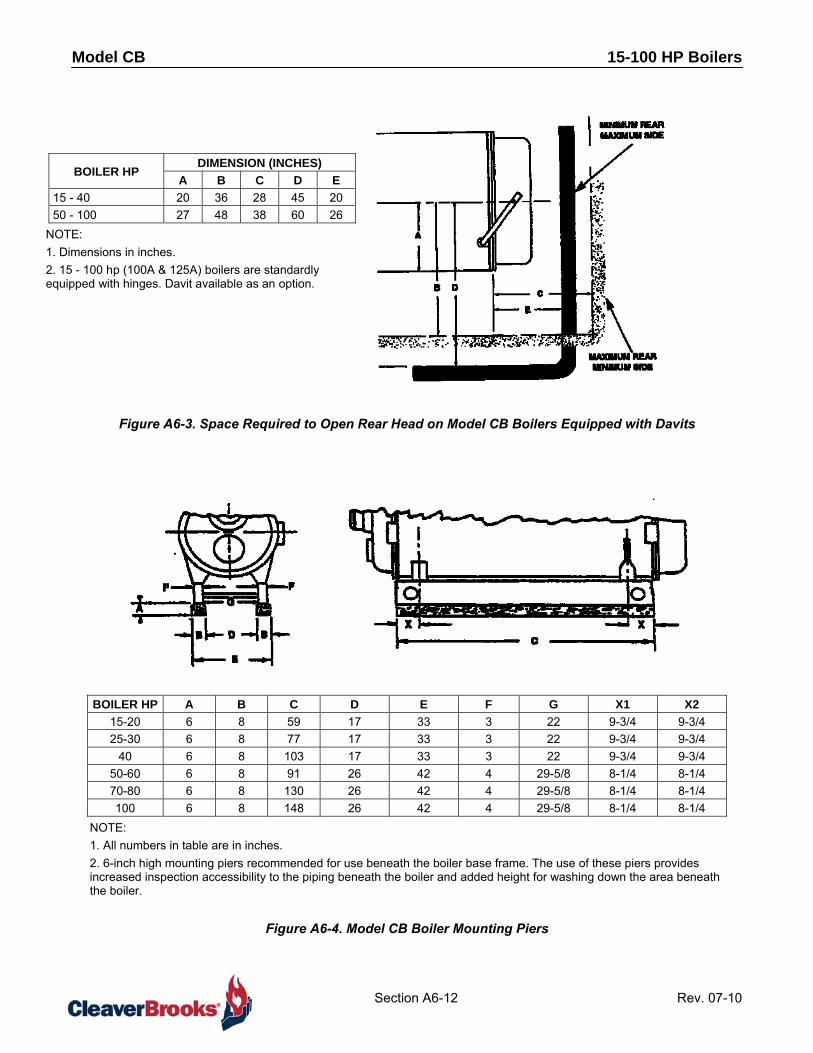
Figure A6-3. Space Required to Open Rear Head on Model CB Boilers Equipped with Davits ........................ A6-12 Figure A6-4. Model CB Boiler Mounting Piers .................................................................................................... A6-12 Figure A6-5. Lifting Lug Locations, Model CB Boilers ........................................................................................ A6-13 Figure A6-6. Predicted Stack Temperature Increase for Pressure Greater Than 125 psig ............................... A6-16 Figure A6-7. Standard Gas Train Connection Size and Location ...................................................................... A6-23 Figure A6-8. Typical Gas Piping Layout ............................................................................................................. A6-24 Figure A6-9. Model CB Gas Train Components ................................................................................................. A6-25 Figure A6-10. No. 2 Oil Connection Size, Location and Recommended Line Sizes ......................................... A6-26 Figure A6-11. No. 6 Oil Connection Size, Location and Recommended Line Sizes, Model CB Boiler ............. A6-26 Figure A6-12. No. 2 Oil Piping, Single Boiler Installation, Remote Oil Pump..................................................... A6-27 Figure A6-13. No. 2 Oil Piping, Multiple Boiler Installation, Remote Oil Pumps ................................................ A6-27 Figure A6-14. No. 2 Oil Piping, Multiple Boiler Installation ................................................................................. A6-28 Figure A6-15. Typical Fuel Storage Tank Arrangement ..................................................................................... A6-29 Figure A6-16. Boiler Room Length (Typical Layout) .......................................................................................... A6-32 Figure A6-17. Boiler Room Width (Typical Layout) ............................................................................................ A6-32 Figure A6-18. Breeching Arrangement ............................................................................................................... A6-33
TABLES
Table A6-1. Model CB Steam Boiler Ratings (15 - 100 hp) ................................................................................. A6-6 Table A6-2. Model CB Hot Water Boiler Ratings (15 - 100 hp) ............................................................................ A6-6 Table A6-3. Steam Boiler Safety Valve Openings ................................................................................................ A6-7 Table A6-4. Hot Water Boiler Relief Valve Openings ........................................................................................... A6-7 Table A6-5. Predicted Fuel-to-Steam Efficiencies (%), Model CB Boilers - 10 psig, Natural Gas ..................... A6-15 Table A6-6. Predicted Fuel-to-Steam Efficiencies (%), Model CB Boilers - 125 psig, Natural Gas ................... A6-15 Table A6-7. Predicted Fuel-to-Steam Efficiencies (%), Model CB Boilers - 10 psig, No. 6 Oil .......................... A6-16 Table A6-8. Predicted Fuel-to-Steam Efficiencies (%), Model CB Boilers - 125 psig, No 6 Oil ......................... A6-16 Table A6-9. Predicted Fuel-to-Steam Efficiencies (%), Model CB Boilers - 10 psig, No. 2 Oil .......................... A6-16 Table A6-10. Predicted Fuel-to-Steam Efficiencies (%), Model CB Boilers - 125 psig, No 2 Oil ......................... A6-16 Table A6-11. Model CB Boiler Emission Data .................................................................................................... A6-17 Table A6-12. Heating Surface, Model CB Boilers .............................................................................................. A6-17 Table A6-13. Steam Volume and Disengaging Area .......................................................................................... A6-18 Table A6-14. Water Circulation Rate and Temperature Drop for Hot Water Boiler ........................................... A6-18 Table A6-15. Recommended Steam Nozzle Size (To Maintain 4000 to 5000 fpm Nozzle Velocity) ................. A6-19 Table A6-16. Model CB Blowdown Tank Sizing Information .............................................................................. A6-19 Table A6-17. Sound Pressure Level Summary (50-100 hp) .............................................................................. A6-19 Table A6-18. Model CB Boiler Sound Pressure Level Details (40 hp) ............................................................... A6-20 Table A6-19. Model CB Boiler Sound Pressure Level Details (50 - 100 hp)...................................................... A6-20 Table A6-20. Minimum Required Gas Pressure at Entrance To Gas Train ....................................................... A6-22 Table A6-21. Minimum Required Gas Pressure Altitude Conversion ................................................................ A6-22 Table A6-22. Maximum Gas Consumption (CFH) for Natural Gas and Propane Vapor .................................... A6-23 Table A6-23. Gas Pilot Data ............................................................................................................................... A6-23

Model CB 15-100 HP Boilers
Section A6-3 Rev. 07-10
FEATURES AND BENEFITS
In addition to the features provided on all Cleaver-Brooks Firetube Boilers, the following features apply specifically to Model CB Firetube Boilers. The CB four-pass dryback boiler is the premium firetube boiler design available.
Four-Pass Dryback Design:
• Four-pass design provides high flue gas velocities and low stack temperature for guaranteed maximum efficiency.
• Dryback design provides full access to boiler tubes, tube sheet, and furnace for ease of maintenance.
• Dryback design includes single rear tube sheet construction, providing reduced tube sheet stresses.
Five Square Feet of Heating Surface per Boiler hp:
• Maximum heat transfer with minimum thermal stresses provide guaranteed efficiency and long boiler life.
• Highest guaranteed fuel-to-steam efficiencies.
Low Furnace Location
• Furnace located well below water level with generous clearance from bottom of boiler, allowing proper circulation.
• Low furnace provides additional safety margin between furnace and water level. • Reduces water carryover, producing drier steam.
Hinged or Davited Front and Rear Doors:
• Provides full access to front and rear tube sheet and furnace. • Reduces maintenance costs.
High Turndown Burner:
• 4:1 turndown (gas and oil) is standard. • Advanced burner design provides maximum combustion efficiencies and high
turndown. • Reduced boiler cycling and maintenance. • Boiler stays on line during low load conditions for optimum efficiency and
performance.
Gas, No. 2 Oil, No. 6 Oil, and Combination Gas and Oil Burners Available:
• High radiant multi-port gas burner designed for high gas velocities and complete fuel/air mixing, providing maximum combustion efficiencies.
• Air atomizing oil burner available for proper oil atomization, maximum combustion efficiency, and low maintenance requirements.
• Air atomizing compressor provided with the boiler package for clean oil burning and ease of maintenance.
• Combination gas/oil burners provide quick fuel changeover without re- adjustment of the burner.
• Fuel oil controller eliminates the need for over 40 connections, combining gauges, valves, and regulators into a single casting.
• Retractable oil nozzle provides easy access and cleaning and eliminates coking of oil and nozzle tip when firing gas.
Model CB 15-100 HP Boilers
Section A6-4 Rev. 07-10
PRODUCT OFFERING
Model CB Firetube Boilers are available in low pressure steam, high pressure steam, and hot water designs. Burners are available to fire natural gas, light oil, heavy oil, or a combination of oil and gas. Optional alternate fuel burners are also available.
Model CB Boilers include:
• Four-pass dryback design.
• 15 hp through 100 hp.
• 150 psig - 350 psig high pressure steam.
• 15 psig low pressure steam.
• 30 psig or 125 psig hot water.
• Natural gas, light oil, or heavy oil firing.
The Model CB Boiler is the premium firetube product offering providing maximum boiler efficiency, the widest range of size and pressures, and premium control packages.
Available options: For option details, contact your Cleaver-Brooks authorized representative. Options include the following:
Boiler Options
• Auxiliary low water cut-off (standard on steam boilers). • Drain valves. • Additional screwed or flanged tappings. • Special design pressures. • Surge load baffles. • Seismic design. • Internal hot water coils. • Blowdown valves. • Non-return valves. • Feedwater valves and regulators. • Special doors, davited, hinged, left swing. • Special base rails. • Surface blowdown systems. • Combustion relief door. • Weather-proofing. • Blend pump.
Burner/Control Options
• Special modulation controls. • Optional flame safeguard controller. • Lead/lag system. • High altitude design, up to 12,000 ft. • Special insurance and code requirements (e.g. FM, ASME CSD-1). • Alarm bell/silence switch.

Model CB 15-100 HP Boilers
Section A6-5 Rev. 07-10
• Special motor requirements (TEFC, high efficiency). • Remote contacts. • Special purpose indicator lights. • Main disconnect. • Elapsed time meter. • Voltmeter/micro-ammeter. • NEMA enclosures. • Low fire hold controls. • Remote emergency shut-off (115V). • Circuit breaker. • Day/night controls. • Special power requirements.
Fuel Options
• Automatic fuel changeover. • Special gas pressure regulator. • Oversized/undersized gas trains. • Gas strainer. • Special fuel shut-off valves. • Special pilot. • Alternate fuel firing (propane, digester gas, etc.). • Special oil pumps.
DIMENSIONS AND RATINGS
• Dimensions and ratings for the Model CB boilers are shown in the following tables and illustrations:
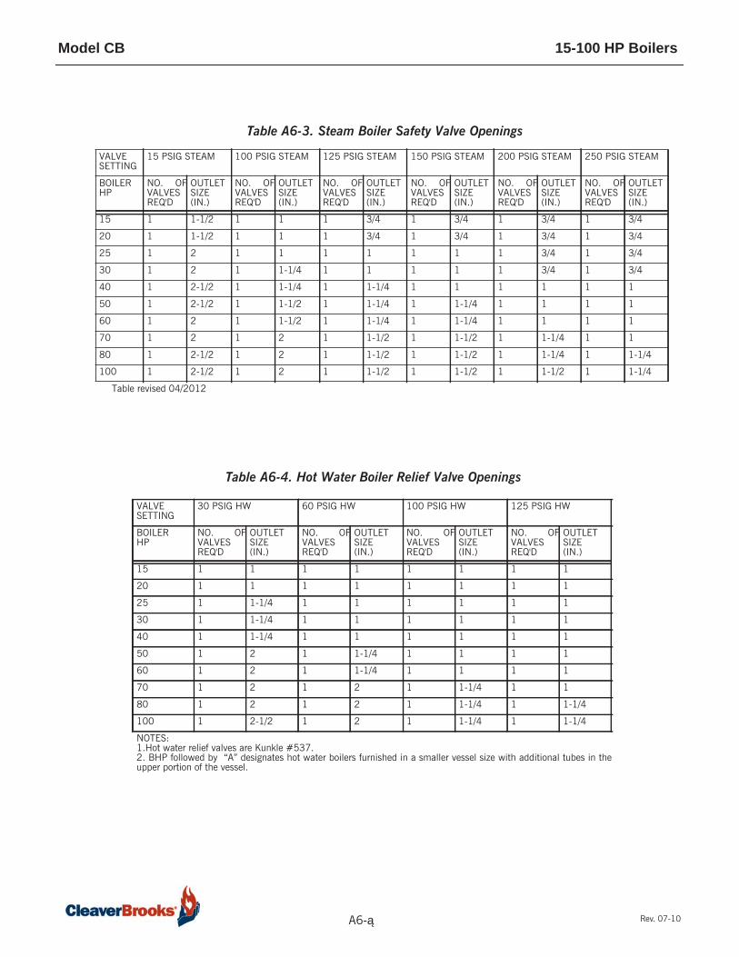
• Table A6-1. Model CB Steam Boiler Ratings (15 thru 100 hp) • Table A6-2. Model CB Hot Water Boiler Ratings (15 thru 100 hp) • Table A6-3. Safety Valve Openings • Table A6-4. Relief Valve Openings • Figure A6-1. Model CB Steam Boiler Dimensions (15 and 150 lb design pressure) (15
thru 100 hp) • Figure A6-2 Model CB Hot Water Boiler Dimensions (15 and 150 lb design pressure)
(15 thru 100 hp) • Figure A6-3. Space Required to Open Rear Head on Model CB Boilers Equipped
with Davits • Figure A6-4. Model CB Boiler Mounting Piers • Figure A6-5. Lifting Lug Locations, Model CB Boilers
Model CB 15-100 HP Boilers
A6-6 Rev. 07-10
BOILER HP 15C 20C 30C 40C 50 60 70 80 100
RATINGS - SEA LEVEL TO 3000 FT
Rated Cap. (lbs steam/hr @212°F)Btu Output (1000 Btu/hr)
518502
690670
10351004
13801339
17251674
20702009
24152343
27602678
34503348
APPROXIMATE FUEL CONSUMPTION AT RATED CAPACITY
Light Oil (gph)A 4.5 6.0 9.0 12.0 14.9 17.9 20.9 23.9 29.9
Heavy Oil (gph)B - - - - 13.9 16.7 19.5 22.3 27.9
Gas (cfh) 1000 Btu-NatGas (Therm/hr)
6286.3
8378.4
125512.6
167416.7
209220.9
251125.1
292929.3
334833.5
418441.8
POWER REQUIREMENTS - SEA LEVEL TO 3000 FT, 60 HZ
Blower Motor hp (except gas) 1 1 1-1/2 2 2 2 2 2D 3
Gas Models (only) 1 1 1-1/2 2 2 2 2 2D 3
Oil Pump Motor, hp No. 2 Oil Belt-Driven From Blower 1/3 1/3 1/3 1/3 1/3
Oil Pump Motor, hp No. 6 Oil - - - - 1/3 1/3 1/3 1/3 1/3
Oil Heater kW No. 6 Oil - - - - 5 5 5 5 5
Air Compressor Motor hp (Oil firing Only)
Air Compressor Belt-Driven from Blower Motor
2 2 2 2 2
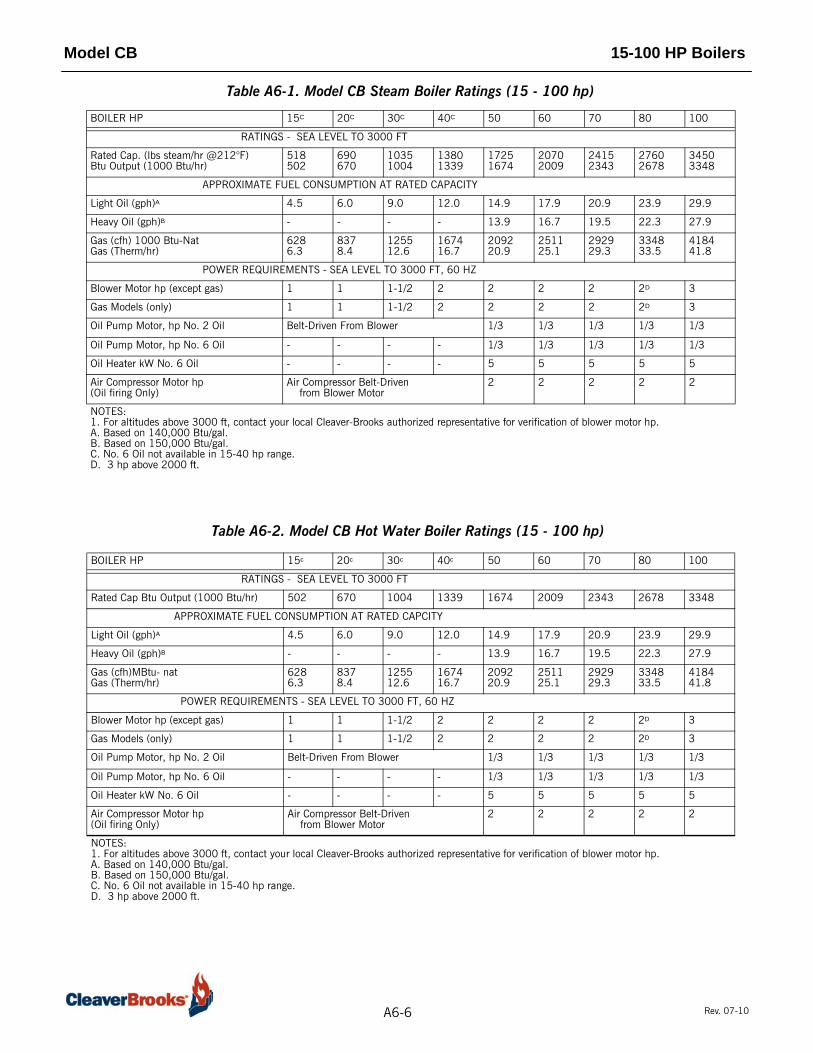
NOTES:1. For altitudes above 3000 ft, contact your local Cleaver-Brooks authorized representative for verification of blower motor hp.A. Based on 140,000 Btu/gal.B. Based on 150,000 Btu/gal.C. No. 6 Oil not available in 15-40 hp range.D. 3 hp above 2000 ft.
Table A6-1. Model CB Steam Boiler Ratings (15 - 100 hp)
BOILER HP 15c 20c 30c 40c 50 60 70 80 100
RATINGS - SEA LEVEL TO 3000 FT
Rated Cap Btu Output (1000 Btu/hr) 502 670 1004 1339 1674 2009 2343 2678 3348
APPROXIMATE FUEL CONSUMPTION AT RATED CAPCITY
Light Oil (gph)A 4.5 6.0 9.0 12.0 14.9 17.9 20.9 23.9 29.9
Heavy Oil (gph)B - - - - 13.9 16.7 19.5 22.3 27.9
Gas (cfh)MBtu- natGas (Therm/hr)
6286.3
8378.4
125512.6
167416.7
209220.9
251125.1
292929.3
334833.5
418441.8
POWER REQUIREMENTS - SEA LEVEL TO 3000 FT, 60 HZ
Blower Motor hp (except gas) 1 1 1-1/2 2 2 2 2 2D 3
Gas Models (only) 1 1 1-1/2 2 2 2 2 2D 3
Oil Pump Motor, hp No. 2 Oil Belt-Driven From Blower 1/3 1/3 1/3 1/3 1/3
Oil Pump Motor, hp No. 6 Oil - - - - 1/3 1/3 1/3 1/3 1/3
Oil Heater kW No. 6 Oil - - - - 5 5 5 5 5
Air Compressor Motor hp (Oil firing Only)
Air Compressor Belt-Driven from Blower Motor
2 2 2 2 2
NOTES:1. For altitudes above 3000 ft, contact your local Cleaver-Brooks authorized representative for verification of blower motor hp.A. Based on 140,000 Btu/gal.B. Based on 150,000 Btu/gal.C. No. 6 Oil not available in 15-40 hp range.D. 3 hp above 2000 ft.
Table A6-2. Model CB Hot Water Boiler Ratings (15 - 100 hp)
Model CB 15-100 HP Boilers
A6- Rev. 07-10
VALVESETTING
15 PSIG STEAM 100 PSIG STEAM 125 PSIG STEAM 150 PSIG STEAM 200 PSIG STEAM 250 PSIG STEAM
BOILERHP
NO. OFVALVESREQ'D
OUTLETSIZE(IN.)
NO. OFVALVESREQ'D
OUTLETSIZE(IN.)
NO. OFVALVESREQ'D
OUTLETSIZE(IN.)
NO. OFVALVESREQ'D
OUTLETSIZE(IN.)
NO. OFVALVESREQ'D
OUTLETSIZE(IN.)
NO. OFVALVESREQ'D
OUTLETSIZE(IN.)
15 1 1-1/2 1 1 1 3/4 1 3/4 1 3/4 1 3/4
20 1 1-1/2 1 1 1 3/4 1 3/4 1 3/4 1 3/4
25 1 2 1 1 1 1 1 1 1 3/4 1 3/4
30 1 2 1 1-1/4 1 1 1 1 1 3/4 1 3/4
40 1 2-1/2 1 1-1/4 1 1-1/4 1 1 1 1 1 1
50 1 2-1/2 1 1-1/2 1 1-1/4 1 1-1/4 1 1 1 1
60 1 2 1 1-1/2 1 1-1/4 1 1-1/4 1 1 1 1
70 1 2 1 2 1 1-1/2 1 1-1/2 1 1-1/4 1 1
80 1 2-1/2 1 2 1 1-1/2 1 1-1/2 1 1-1/4 1 1-1/4
100 1 2-1/2 1 2 1 1-1/2 1 1-1/2 1 1-1/2 1 1-1/4
Table A6-3. Steam Boiler Safety Valve Openings
VALVE SETTING
30 PSIG HW 60 PSIG HW 100 PSIG HW 125 PSIG HW
BOILERHP
NO. OFVALVESREQ'D
OUTLETSIZE (IN.)
NO. OFVALVESREQ'D
OUTLET SIZE(IN.)
NO. OFVALVESREQ'D
OUTLETSIZE(IN.)
NO. OFVALVESREQ'D
OUTLETSIZE(IN.)
15 1 1 1 1 1 1 1 1
20 1 1 1 1 1 1 1 1
25 1 1-1/4 1 1 1 1 1 1
30 1 1-1/4 1 1 1 1 1 1
40 1 1-1/4 1 1 1 1 1 1
50 1 2 1 1-1/4 1 1 1 1
60 1 2 1 1-1/4 1 1 1 1
70 1 2 1 2 1 1-1/4 1 1
80 1 2 1 2 1 1-1/4 1 1-1/4
100 1 2-1/2 1 2 1 1-1/4 1 1-1/4
NOTES: 1.Hot water relief valves are Kunkle #537.2. BHP followed by “A” designates hot water boilers furnished in a smaller vessel size with additional tubes in theupper portion of the vessel.
Table A6-4. Hot Water Boiler Relief Valve Openings
Table revised 04/2012
Model CB 15-100 HP Boilers
A6-8 Rev. 07-10
BOILER HP DIM 15 20 30 40 50 60 70 80 100
LENGTHS
Overall A 96-5/8 96-5/8 114-5/8 140-5/8 129 129 168 168 187
Shell B 62-5/8 62-5/8 80-5/8 106-5/8 92 92 131 131 150
Base Frame C 59 59 77 103 91 91 130 130 148
Front Head Extension D 18-1/2 18-1/2 18-1/2 18-1/2 18-1/2 18-1/2 18-1/2 18-1/2 18-1/2
Rear Head Extension E 15-1/2 15-1/2 15-1/2 15-1/2 18-1/2 18-1/2 18-1/2 18-1/2 18-1/2
Front Ring Flange to Nozzle - 15 psig
F 36 36 45 57 46 46 65-1/2 65-1/2 75
Front Ring Flange to Nozzle - 150 psig F 36 36 45 57 46 46 72-1/2 72-1/2 82
Ring Flange to Base G 1-13/16 1-13/16 1-13/16 1-13/16 5/8 1/2 1/2 1/2 1/2
WIDTHS
Overall I 61 61 61 61 73 73 73 73 73
ID, Boiler J 36 36 36 36 48 48 48 48 48
Center to Water Column K 33 33 33 33 39 39 39 39 39
Center to Outside Hinge KK 22 22 22 22 29 29 29 29 29
Center to Lagging L 20 20 20 20 27 27 27 27 27
Center to Auxiliary LWCO LL 28 28 28 28 34 34 34 34 34
Base, Outside M 28 28 28 28 37-5/8 37-5/8 37-5/8 37-5/8 37-5/8
Base, Inside N 22 22 22 22 29-5/8 29-5/8 29-5/8 29-5/8 29-5/8
Figure A6-1. Model CB Steam Boiler Dimensions and Weights (15 and 150 psig Design Pressure -15 to 100 hp) Sheet 1 of 2

Model CB 15-100 HP Boilers
A6-9 Rev. 07-10
BOILER HP DIM 15 20 30 40 50 60 70 80 100
HEIGHTS
Base to Steam Outlet (15 psig only) PL 50-1/4 50-1/4 50-1/4 50-1/4 70-1/2 70-1/2 70-1/2 70-1/2 70-1/2
Overall OO 66 66 66 66 78-3/4 78-3/4 78-3/4 78-3/4 78-3/4
Base to Vent Outlet O 53-1/2 53-1/2 53-1/2 53-1/2 70 70 70 70 70
Base to Steam Outlet (150 psig only) PH 50-1/4 50-1/4 50-1/4 50-1/4 66-1/2 66-1/2 66-1/2 66-1/2 70-5/16
Height of Base Q 8 8 8 8 12 12 12 12 12
Base to Bottom of Boiler R 12 12 12 12 16 16 16 16 16
BOILER CONNECTIONS
Chemical Feed H 1 1 1 1 1 1 1 1 1
Feedwater, Right and Left S 1 1 1 1 1-1/4 1-1/4 1-1/4 1-1/4 1-1/4
Low Pressure (15 psig only)Steam NozzleDrain, Front and Rear
UW
41
41
41
6A
1-1/46A
1-1/46A
1-1/46A
1-1/26A
1-1/28A
1-1/2
High Pressure (150 psig only)Surface Blowoff, Top CLSteam Nozzle Blowdown, Front and Rear
TYW
11-1/21
11-1/21
121
121
131-1/4
131-1/4
131-1/4
131-1/4
14B
1-1/4
VENT STACK
Diameter (flgd connection) BB 6 6 8 8 10 10 12 12 12
Front Ring Flange to Vent CL CC 4 4 5 5 6 6 7 7 7
MINIMUM CLEARANCES
Rear Door SwingC DD 44 44 44 44 55 55 55 55 55
Front Door SwingC EE 44 44 44 44 55 55 55 55 55
Tube Removal, Rear FF 56 56 74 100 84 84 123 123 142
Tube Removal, Front GG 46 46 64 90 74 74 113 113 132
MINIMUM BOILER ROOM LENGTH ALLOWING FOR DOOR SWING AND TUBE REMOVAL FROM:
Rear of Boiler RR 163 163 199 251 231 231 309 309 347
Front of Boiler RF 153 153 189 241 221 221 299 299 337
Thru Window or Doorway RD 151 151 169 195 202 202 241 241 260
WEIGHT IN LBS
Normal Water Capacity 1340 1300 1710 2290 3130 2920 4620 4460 5088
Approx. Ship Wgt - 15 psig 3000 3100 3650 4350 6900 7000 8100 8200 9000
Approx. Ship Wgt - 150 psig 3100 3200 3800 4500 7000 7200 8800 9000 9500
Approx. Ship Wgt - 200 psig 3300 3400 4100 4700 7400 7600 9300 9500 10000
NOTES:1. Air compressor belt driven from blower motor on sizes 15 thru 402. Air compressor module on sizes 50 thru 100 hp.3. Accompanying dimensions, while sufficiently accurate for layout purposes, must be confirmed for construction by certified dimension prints.A. ANSI 150 psig flange.B. ANSI 300 psig flange. C. 15 thru 100 hp standard hinged door.
Figure A6-1. Model CB Steam Boiler Dimensions and Weights (15 and 150 psig Design Pressure - 15 to 100 hp) Sheet 2 of 2
Model CB 15-100 HP Boilers
A6-10 Rev. 07-10
Figure A6-2. Model CB Hot Water Boiler Dimensions (30 psig and 125 psig Design Press. - 15 to 100 hp) Sheet 1 of 2
BOILER HP DIM 15 20 30 40 50 60 70 80 100
LENGTHS
Overall A 97 97 114-5/8 140-5/8 129 129 168 168 187
Shell B 62-5/8 62-5/8 80-5/8 106-5/8 92 92 131 131 150
Base Frame C 59 59 77 103 91 91 130 130 148
Front Head Ext. D 18-1/2 18-1/2 18-1/2 18-1/2 18-1/2 18-1/2 18-1/2 18-1/2 18-1/2
Rear Head Ext. E 15-1/2 15-1/2 15-1/2 15-1/2 18-1/2 18-1/2 18-1/2 18-1/2 18-1/2
Front Ring Flange to Return F 43-5/8 43-5/8 62 81 69 69 108 108 127
Front Ring Flange to Outlet G 55-1/8 55-1/8 73-1/8 98-1/2 84-5/8 84-5/8 123-5/8 123-5/8 142-5/8
Ring Flange to Base H 1-13/16 1-13/16 1-13/16 1-13/16 5/8 5/8 5/8 5/8 1
WIDTHS
Overall I 48-3/4 48-3/4 48-3/4 48-3/4 63 63 63 63 63
ID, Boiler J 36 36 36 36 48 48 48 48 48
Center to Entrance Box K 28-3/4 28-3/4 28-3/4 28-3/4 36 36 36 36 36
Center to Outside Hinge KK 22 22 22 22 29 29 29 29 29
Center to Lagging L 20 20 20 20 27 27 27 27 27
Base, Outside M 28 28 28 28 37-5/8 37-5/8 37-5/8 37-5/8 37-5/8
Base, Inside N 22 22 22 22 29-5/8 29-5/8 29-5/8 29-5/8 29-5/8

Model CB 15-100 HP Boilers
A6-11 Rev. 07-10
BOILER HP DIM 15 20 30 40 50 60 70 80 100
HEIGHTS
Overall OO 66 66 66 66 72-5/8 72-5/8 72-5/8 72-5/8 72-5/8
Base to Vent Outlet O 53-1/2 53-1/2 53-1/2 53-1/2 70 70 70 70 70
Base to Return and outlet P 50 50 50 50 70-1/2 70-1/2 70-1/2 70-1/2 70-1/2
Davit (Front) DF - - - - - - - - -
Davit (Rear) DR - - - - - - - - -
Height of Base Q 8 8 8 8 12 12 12 12 12
Base to bottom of boiler R 12 12 12 12 16 16 16 16 16
BOILER CONNECTION
Water ReturnA T 2-1/2 2-1/2 3 3 4 4 4 4 4
Water OutletA -dip tube included U 2-1/2 2-1/2 3 3 4 4 4 4 4
Air Vent v 1 1 1 1 1-1/4 1-1/4 1-1/4 1-1/4 1-1/4
Drain, Front and Rear W 1 1 1 1-1/4 1-1/4 1-1/4 1-1/2 1-1/2 1-1/2
Auxiliary Connection X 1 1 1 1 1 1 1 1 1
VENT STACK
Diameter (flgd. connection) BB 6 6 8 8 10 10 12 12 12
Front Ring Flange to vent CL CC 4 4 5 5 6 6 7 7 7
MINIMUM CLEARANCES
Rear Door Swing DD 44 44 44 44 55 55 55 55 55
Front Door Swing EE 44 44 44 44 55 55 55 55 55
Tube Removal, Rear FF 56 56 74 100 84 84 123 123 142
Tube, Removal, Front GG 46 46 64 90 74 74 113 113 132
MINIMUM BOLER ROOM LENGTH ALLOWING FOR DOOR SWING AND TUBE REMOVAL FROM:
Rear of Boiler RR 163 163 199 251 231 231 309 309 347
Front of Boiler RF 153 153 189 241 221 221 299 299 337
Thru Window or Doorway RD 151 151 169 195 202 202 241 241 260
WEIGHT IN LBS
Water Capacity Flooded 1500 1460 1915 2585 3665 3500 5420 5250 5960
Approx. Ship. Wgt. – 30 psigApprox. Ship. Wgt. – 125 psig
30003300
31003400
36503880
43504580
68007100
70007300
80008350
81008450
88009150
NOTES:1. Accompanying dimensions and ratings while sufficiently accurate for layout purposes, must be confirmed for construction by certified
dimension prints.2. Air compressor belt driven from blower motor on sizes 15 thru 40 hp. 3. Air compressor module on sizes 50 thru 100 hp.4. 15 - 100 hp, hinged door standard.5. Add 370 lbs to the 80 hp ship weight for 100A and 485 lbs to the 100 hp ship weight for the 125A.
A. 15-40 HP are threaded connection; 50-100 HP are 150# flange.
Figure A6-2. Model CB Hot Water Boiler Dimensions (30 psig Design Pressure - 15 to 100 hp) - Sheet 2 of 2
Model CB 15-100 HP Boilers
Section A6-12 Rev. 07-10
Figure A6-3. Space Required to Open Rear Head on Model CB Boilers Equipped with Davits
BOILER HP A B C D E F G X1 X2
15-20 6 8 59 17 33 3 22 9-3/4 9-3/4 25-30 6 8 77 17 33 3 22 9-3/4 9-3/4
40 6 8 103 17 33 3 22 9-3/4 9-3/4 50-60 6 8 91 26 42 4 29-5/8 8-1/4 8-1/4 70-80 6 8 130 26 42 4 29-5/8 8-1/4 8-1/4 100 6 8 148 26 42 4 29-5/8 8-1/4 8-1/4
NOTE: 1. All numbers in table are in inches. 2. 6-inch high mounting piers recommended for use beneath the boiler base frame. The use of these piers provides increased inspection accessibility to the piping beneath the boiler and added height for washing down the area beneath the boiler.
Figure A6-4. Model CB Boiler Mounting Piers
BOILER HP DIMENSION (INCHES)
A B C D E
15 - 40 20 36 28 45 20 50 - 100 27 48 38 60 26
NOTE: 1. Dimensions in inches. 2. 15 - 100 hp (100A & 125A) boilers are standardly equipped with hinges. Davit available as an option.

Model CB 15-100 HP Boilers
Section A6-13 Rev. 07-10
BOILER HP
VIEW ALL DIMENSIONS IN INCHES
A B C D E
15 Steam A 51-3/4 12 38-3/4 - 2-1/2 Hot Water B 50-1/2 12 38-3/4 6 2-1/2
20 Steam A 51-3/4 12 38-3/4 - 2-1/2 Hot Water B 50-1/2 12 38-3/4 6 2-1/2
25 Steam A 51-3/4 12 56-3/4 - 2-1/2 Hot Water B 50-1/2 12 56-3/4 6 2-1/2
30 Steam A 51-3/4 12 56-3/4 - 2-1/2 Hot Water B 50-1/2 12 56-3/4 6 2-1/2
40 Steam A 51-3/4 12 82-3/4 - 2-1/2 Hot Water B 50-1/2 12 82-3/4 6 2-1/2
50 All B 68 18 57 10 2-1/2 60 All B 68 18 57 10 2-1/2 70 All B 68 27 67 10 2-1/2 80 All B 68 27 67 10 2-1/2 100 All B 68 27 86 10 2-1/2
NOTE: 1. A, B and C Dimensions may vary by 1/2 inch. 2. BHP followed by “A” designates hot water boilers furnished in a smaller vessel size with additional tubes in upper portion of vessel.
Figure A6-5. Lifting Lug Locations, Model CB Boilers

Model CB 15-100 HP Boilers
Section A6-14 Rev. 07-10
PERFORMANCE DATA
Efficiency
Tables A6-5 through A6-10 show predicted fuel-to-steam efficiencies (including radiation and convection losses) for Cleaver-Brooks Model CB Firetube boilers. For specific efficiencies on firetube boiler offerings not listed here, contact your local Cleaver-Brooks authorized representative.
Cleaver-Brooks offers an industry leading fuel-to-steam boiler efficiency guarantee for Model CB Firetube Boilers. The guarantee is based on the fuel-to-steam efficiencies shown in the efficiency tables and the following conditions. The efficiency percent number is only meaningful if the specific conditions of the efficiency calculations are clearly stated in the specification (see Cleaver-Brooks publication CB-7768 for a detailed description of efficiency calculations).
The boiler manufacturer shall guarantee that, at the time of startup, the boiler will achieve fuel-to-steam efficiency (as shown in the tables listed above) at 100% firing rate (add efficiency guarantees at 25%, 50%, and 75% of rating, if required). If the boiler(s) fail to achieve the corresponding guaranteed efficiency as published, the boiler manufacturer will rebate, to the ultimate boiler owner, five thousand dollars ($5,000) for every full efficiency point (1.0%) that the actual efficiency is below the guaranteed level. The specified boiler efficiency is based on the following conditions.
1. Fuel specification used to determine boiler efficiency:
• Natural Gas
Carbon, % (wt) = 69.98
Hydrogen, % (wt) = 22.31
Sulfur, % (wt) = 0.0
Heating value, Btu/lb = 21,830
• No. 2 Oil
Carbon, % (wt) = 85.8
Hydrogen, % (wt) = 12.7
Sulfur, % (wt) = 0.2
Heating value, Btu/lb = 19,420
• No. 6 Oil
Carbon, % (wt) = 86.6
Hydrogen, % (wt) = 10.9
Sulfur, % (wt) = 2.09
Heating value, Btu/lb = 18,830
2. Efficiencies are based on ambient air temperature of 80 °F, relative humidity of 30%, and 15% excess air in the exhaust flue gas.
3. Efficiencies are based on manufacturer’s published radiation and convection losses. (For Cleaver-Brooks radiation and convection losses, see Boiler Efficiency Facts Guide, publication number CB-7767).
4. Any efficiency verification testing will be based on the stack loss method.

Model CB 15-100 HP Boilers
Section A6-15 Rev. 07-10
When specifying the efficiencies in the tables, be sure to include the specific guarantee conditions to maximize the effectiveness of your efficiency specification. If you have any questions regarding the efficiency specifications, please contact your local Cleaver-Brooks authorized representative. For efficiencies and stack temperatures at operating pressures not listed, follow these procedures:
When the operating steam pressure is between 10 psig and 125 psig, interpolate the values from the efficiency tables.
When the operating steam pressure is above 125 psig, estimated efficiency can be calculated as follows:
Example:
Boiler: 100 hp.
Fuel: natural gas.
Operating steam pressure: 200 psig.
Find the fuel-to-steam efficiency at 100% firing rate. From Figure A6-6 for a 100 hp boiler operating at 100% firing rate and an operating steam pressure of 125 psig, the efficiency is 88.0%.
Using Figure A6-6, note that the stack temperature increases 36 °F at the higher operating pressure. To estimate boiler efficiency, use this rule of thumb: For every 40 °F increase in stack temperature, efficiency decreases by 1%. Since the stack temperature rise is 36 °F, the decrease in the boiler efficiency at 200 psig operating pressure is calculated as follows: 36/40 = .9%. Therefore, the boiler efficiency at 200 psig operating pressure is 82.5 - .9 = 81.6%.
Emissions
The emission data included in this section consists of typical uncontrolled emission levels for Cleaver-Brooks Model CB Firetube Boilers.
Notice The data in Table A6-11 represents typical emission levels only. Guaranteed emission levels are available from your local Cleaver-Brooks authorized representative.
Table A6-5. Predicted Fuel-to-Steam Efficiencies (%), Model CB Boilers - 10 psig, Natural Gas
BOILER HP
FIRING RATE (%) 25 50 75 100
50 83.0 83.2 82.9 82.4 60 82.9 83.1 82.7 82.3 70 84.5 84.7 84.3 83.9 80 84.6 84.8 84.5 84.0
100 84.4 85.0 84.8 84.4
Table A6-6. Predicted Fuel-to-Steam Efficiencies (%), Model CB Boilers - 125 psig, Natural Gas
BOILER HP
FIRING RATE (%)25 50 75 100
50 80.2 81.9 80.4 80.1 60 80.1 80.4 80.3 80.1 70 81.7 82.0 81.9 81.7 80 81.8 82.1 82.0 81.8 100 81.5 82.4 82.3 82.2

Model CB 15-100 HP Boilers
Section A6-16 Rev. 07-10
Table A6-7. Predicted Fuel-to-Steam Efficiencies (%), Model CB Boilers - 10 psig, No. 6 Oil
BOILER HP
FIRING RATE (%) 25 50 75 100
50 86.8 87.0 86.6 86.1 60 86.7 86.9 86.5 86.0 70 88.4 88.6 88.2 87.7 80 88.5 88.7 88.3 87.8
100 88.2 88.5 88.3 88.0
Table A6-8. Predicted Fuel-to-Steam Efficiencies (%), Model CB Boilers - 125 psig, No 6 Oil
BOILER HP
FIRING RATE (%)25 50 75 100
50 83.9 84.2 84.0 83.8 60 83.8 84.1 83.9 83.8 70 85.5 85.8 85.6 85.4 80 85.6 85.9 85.7 85.6
100 84.6 85.8 85.9 85.8
Table A6-9. Predicted Fuel-to-Steam Efficiencies (%), Model CB Boilers - 10 psig, No. 2 Oil
BOILER HP
FIRING RATE (%) 25 50 75 100
50 86.5 86.7 86.3 85.8 60 86.3 86.6 86.2 85.7 70 87.9 88.2 87.8 87.3 80 88.1 88.3 87.9 87.4
100 87.8 88.4 88.1 87.7
Table A6-10. Predicted Fuel-to-Steam Efficiencies (%), Model CB Boilers - 125 psig, No 2 Oil
BOILER HP
FIRING RATE (%)25 50 75 100
50 83.6 84.0 83.8 83.5 60 83.5 83.8 83.7 83.5 70 85.1 85.4 85.3 85.1 80 85.2 85.6 85.4 85.3 100 84.8 85.7 85.6 85.5
Figure A6-6. Predicted Stack Temperature Increase for Pressure Greater Than 125 psig

Model CB 15-100 HP Boilers
Section A6-17 Rev. 07-10
Table A6-11. Model CB Boiler Emission Data
POLLUTANT ESTIMATED LEVELS - UNCONTROLLED
NATURAL GAS NO. 2 OILB NO. 6 OILC
CO ppmA 200 90 95
Lb/MMBtu 0.15 0.07 0.075
NOx ppmA 100 185 502
Lb/MMBtu 0.12 0.25 0.67
SOx ppmA 1 278 278
Lb/MMbtu 0.001 0.52 0.52
HC/VOCs ppmA 40 50 70
Lb/MMBtu 0.016 0.025 0.035
PM ppmA - - -
Lb/MMBtu 0.01 0.025 0.160 NOTES: Refer to Section E for detailed emission information. A. ppm levels corrected to 3% O2, dry basis. B. Based on fuel constituent levels of: Fuel-bound nitrogen content = 0.015% by weight Sulfur content = 0.5% by weight Ash content = 0.01% by weight
C. Based on fuel constituent levels of: Fuel-bound nitrogen content = 0.7% by weight Sulfur content = 0.5% by weight Ash content = 0.1% by weight Conradson carbon residue = 16% by weight
Table A6-12. Heating Surface, Model CB Boilers
BOILER HP HEATING SURFACE (SQ-FT)
FIRESIDE WATERSIDE
15 75 85 20 100 109 25 125 144 30 150 162 40 200 219 50 250 266 60 300 323 70 350 388 80 400 441 100 500 544
ENGINEERING DATA
The following engineering information is provided for Model CB Firetube Boilers. Additional detail is available from your local Cleaver-Brooks authorized representative.
Blowdown Water Requirements
Some local codes require blowdown tanks to be constructed in accordance with recommendations of the National Board of Boiler and Pressure Vessel Inspectors.
The National Board’s recommendations base the size of the blowdown tank on the removal of at least 4 inches of water from the boiler.

Model CB 15-100 HP Boilers
Section A6-18 Rev. 07-10
Sound Level
Table A6-17 summarizes predicted sound pressure levels for Model CB Boilers.
Table A6-18 and A6-19 give detailed octave band sound pressure levels for each boiler. These values are based on standard motors. Optional motor types and altitude conditions can increase sound levels.
Units
The units for the sound level tables are dBA (decibels, measured on the A-weighted scale) in reference to 0.0002 microbars (20 micro-Newtons per square meter). They are standardly referenced in specifying and reporting sound pressure levels on industrial equipment.
Table A6-13. Steam Volume and Disengaging Area
BOILER HP STEAM VOLUME CU-FT STEAM RELIEVING AREA, SQ-IN
HIGH PRESSUREA LOW PRESSUREB HIGH PRESSUREA LOW PRESSUREB
15 2.9 5.9 1356 1637 20 2.9 5.9 1356 1637
25 & 30 3.9 7.9 1817 2195 40 5.3 10.8 2485 2999 50 9.7 16.0 2959 3372 60 9.7 16.0 2959 3372 70 14.3 23.7 4367 4975 80 14.3 23.7 4367 4975 100 16.6 27.4 5053 5757
NOTE: Based on normal water level. A. Based on 150 psig design pressure. B. Based on 15 psig design pressure.
Table A6-14. Water Circulation Rate and Temperature Drop for Hot Water Boiler
BOILER HP
BOILER OUTPUT
(1000) BTU/HR
SYSTEM TEMPERATURE DROP - DEGREES F
10 20 30 40 50 60 70 80 90 100
MAXIMUM CIRCULATING RATE - GPM
15 500 100 50 33 25 20 17 14 12 11 10 20 670 134 67 45 33 27 22 19 17 15 13 30 1005 200 100 67 50 40 33 29 25 22 20 40 1340 268 134 89 67 54 45 38 33 30 27 50 1675 335 168 112 84 67 56 48 42 37 33 60 2010 402 201 134 101 80 67 58 50 45 40 70 2345 470 235 157 118 94 78 67 59 52 47 80 2680 536 268 179 134 107 90 77 67 60 54 100 3350 670 335 223 168 134 112 96 84 75 67
NOTES: 1. Minimum recommended return water temperature is 150 °F. Minimum recommended outlet temperature for Model CB Hot Water Boilers is 170 °F. Contact your local Cleaver-Brooks authorized representative for special hot water application information. 2. See Section H2 for over-pressure requirements.
Model CB 15-100 HP Boilers
Section A6-19 Rev. 07-10
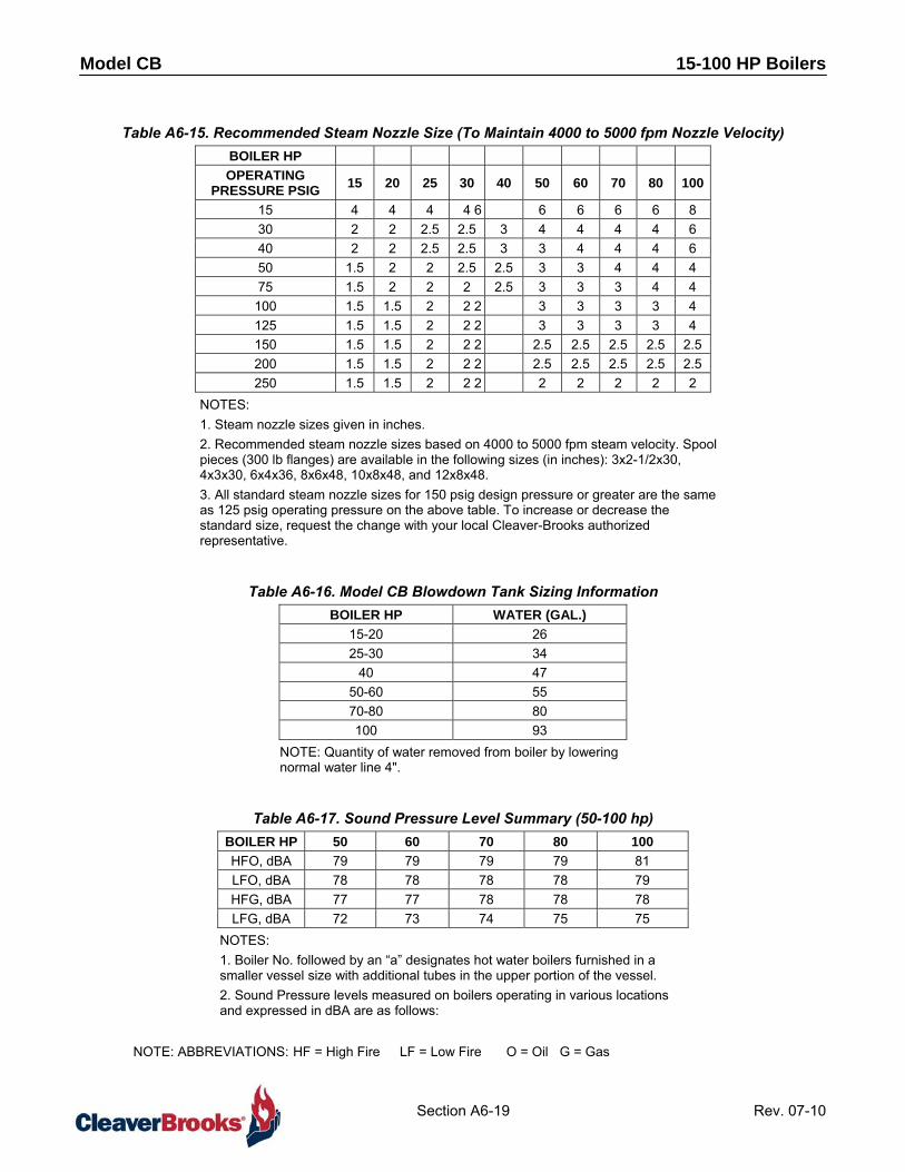
Table A6-15. Recommended Steam Nozzle Size (To Maintain 4000 to 5000 fpm Nozzle Velocity) BOILER HP
OPERATING PRESSURE PSIG
15 20 25 30 40 50 60 70 80 100
15 4 4 4 4 6 6 6 6 6 8 30 2 2 2.5 2.5 3 4 4 4 4 6 40 2 2 2.5 2.5 3 3 4 4 4 6 50 1.5 2 2 2.5 2.5 3 3 4 4 4 75 1.5 2 2 2 2.5 3 3 3 4 4 100 1.5 1.5 2 2 2 3 3 3 3 4 125 1.5 1.5 2 2 2 3 3 3 3 4 150 1.5 1.5 2 2 2 2.5 2.5 2.5 2.5 2.5 200 1.5 1.5 2 2 2 2.5 2.5 2.5 2.5 2.5 250 1.5 1.5 2 2 2 2 2 2 2 2
NOTES: 1. Steam nozzle sizes given in inches. 2. Recommended steam nozzle sizes based on 4000 to 5000 fpm steam velocity. Spool pieces (300 lb flanges) are available in the following sizes (in inches): 3x2-1/2x30, 4x3x30, 6x4x36, 8x6x48, 10x8x48, and 12x8x48. 3. All standard steam nozzle sizes for 150 psig design pressure or greater are the same as 125 psig operating pressure on the above table. To increase or decrease the standard size, request the change with your local Cleaver-Brooks authorized representative.
Table A6-16. Model CB Blowdown Tank Sizing Information BOILER HP WATER (GAL.)
15-20 26 25-30 34
40 47 50-60 55 70-80 80 100 93
NOTE: Quantity of water removed from boiler by lowering normal water line 4".
Table A6-17. Sound Pressure Level Summary (50-100 hp) BOILER HP 50 60 70 80 100
HFO, dBA 79 79 79 79 81 LFO, dBA 78 78 78 78 79 HFG, dBA 77 77 78 78 78 LFG, dBA 72 73 74 75 75
NOTES: 1. Boiler No. followed by an “a” designates hot water boilers furnished in a smaller vessel size with additional tubes in the upper portion of the vessel. 2. Sound Pressure levels measured on boilers operating in various locations and expressed in dBA are as follows:
NOTE: ABBREVIATIONS: HF = High Fire LF = Low Fire O = Oil G = Gas

Model CB 15-100 HP Boilers
Section A6-20 Rev. 07-10
Table A6-18. Model CB Boiler Sound Pressure Level Details (40 hp) FIRING RATE FUEL
SOUND LEVEL
dBA
OCTAVE BAND SOUND PRESSURE LEVELS IN dB RE .0002 MICROBAR
31Hz 63Hz 125Hz 250Hz 500Hz 1kHz 2kHz 4kHz 8kHz 16kHz
40HPA LFG 76 73 75 72 74 76 70 67 68 64 57 LFO 77 73 75 75 76 75 72 67 66 66 58 HFG 79 81 78 74 80 78 71 69 68 64 58 HFO 79 72 77 77 81 78 73 69 66 66 58
A. The data shown above was taken on the 40 hp. Since the highest Sound Level is below 80 dBA, no additional 36" diameter Firetubes were tested. If Sound Level predictions are required for the 15 thru 30 hp, use the values shown for the 40 hp. NOTE: ABBREVIATIONS: HF = High Fire LF = Low Fire O = Oil G = Gas
Table A6-19. Model CB Boiler Sound Pressure Level Details (50 - 100 hp)
FIRING RATE FUEL
SOUND LEVEL
dBA
OCTAVE BAND SOUND PRESSURE LEVELS IN dB RE .0002 MICROBAR
31Hz 63Hz 125Hz 250Hz 500Hz 1kHz 2kHz 4kHz 8kHz 16kHz
50 HP LFG 72 71 65 71 71 70 68 63 60 53 46 LFO 78 71 76 78 73 72 72 76 61 56 54 HFG 77 72 68 75 76 74 74 66 61 54 47 HFO 79 72 70 75 75 77 77 70 63 56 54
60 HP LFG 73 70 75 72 72 73 68 61 56 50 45 LFO 78 68 77 74 74 75 74 71 58 53 48 HFG 77 73 75 72 72 75 76 63 55 50 44 HFO 79 75 75 75 75 77 77 72 59 52 45
70 HP LFG 74 70 70 75 74 73 71 62 56 51 46 LFO 78 70 73 77 74 75 74 70 59 53 57 HFG 78 72 72 77 78 75 76 68 58 52 57 HFO 79 73 73 80 77 77 76 70 60 54 48
80 HP LFG 75 70 75 75 73 75 76 66 62 62 53 LFO 78 69 77 76 74 76 74 73 63 62 57 HFG 78 72 74 78 75 75 76 57 61 59 52 HFO 79 75 75 75 74 76 75 69 62 59 54
100 HP LFG 75 69 69 75 76 73 71 65 63 59 50 LFO 79 68 73 78 78 75 79 76 63 59 54 HFG 78 69 70 77 77 74 74 69 63 59 50 HFO 81 68 70 77 78 78 77 71 64 59 57
NOTES: ABBREVIATIONS: HF = High Fire LF = Low Fire O = Oil G = Gas Boiler HP followed by an “A” designates hot water boilers furnished in a smaller vessel size with additional tubes in the upper portion of the vessel.

Model CB 15-100 HP Boilers
Section A6-21 Rev. 07-10
Test Method
The sound pressure levels in the above tables were obtained from tests in accordance with the "ABMA Test Code for the Measurement of Sound from Packages Boilers." In accordance with this code, the sound pressure levels reported were measured on the boiler centerline 4-1/2 feet vertically above the bottom of the base rails and 3 feet horizontally in front of the end of the blower motor or front surface of the electrical cabinet.
Sound Level Meter
The sound level meter used complies with ANSI S1.4, Type 1 (Precision). The readings are taken with the meter set for slow response.
Sound Pressure
On large size boilers, the need for auxiliary equipment, and the necessary interconnecting piping, make it impractical (and sometimes impossible) to provide a boiler testing environment that is suitable for obtaining the data needed to develop Sound Pressure Power levels.
Typical Values
Sound pressure levels (dBA) for identical boilers will vary between boiler rooms. In addition, variations will occur between different people using different sound meters on the same boiler. And finally, no two boilers can be expected to give precisely the same sound levels. For these reasons, we can only predict, but not guarantee, sound levels (dBA).
Octave Band
When predicting sound pressures in octave bands (e.g., dB at 125 Hz), even greater variations between boilers, between sound meters, and between operators can be expected. These larger variations in the low and high frequencies make octave band levels a less reliable method of reporting than A-scale sound levels. (Since A-scale sound levels are dominated by mid-frequency sounds, the A-scale sound levels between two boilers can be in reasonable agreement even though the low and high frequencies of octave band measurement do not closely correspond).
Gas-Fired Burners
Table A6-20 shows minimum gas pressure requirements for Model CB Boilers. Table A6-21 shows minimum required gas pressure altitude conversion. Table A6-22 shows maximum gas consumption for natural gas and propane vapor. Figure A6-7 shows standard gas train sizes and locations for Model CB Firetube Boilers. Figure A6-8 shows typical gas train piping layouts for multiple boiler applications. Figure A6-9 shows gas train components.
Oil-Fired Burners
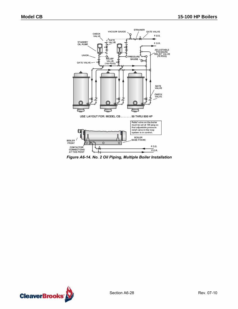
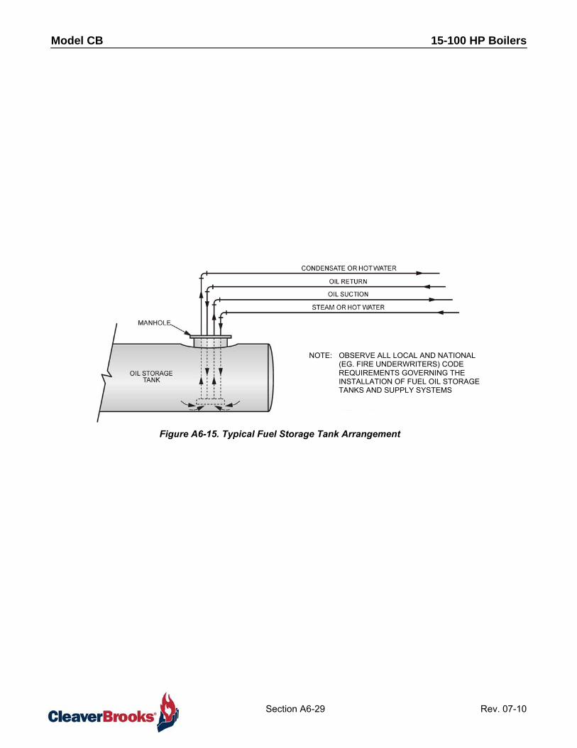
Fuel oil consumption information is shown on the boiler rating sheets in the Dimensions and Rating Section. Figure A6-10 shows the oil connection sizes and locations for Model CB Boilers firing No. 2 oil. Figure A6-11 shows the oil connection sizes and locations for Model CB Boilers firing No. 5 and No. 6 oil. Figure A6-12 through Figure A6-14 show typical oil systems and layouts. Figure A6-15 shows the detail of an oil transfer tank (day tank) typically utilized to provide a storage reservoir between the oil system supply pump and the boiler oil pump.

Model CB 15-100 HP Boilers
A6-22 Rev. 07-10
No. 6 Oil Piping, Storage Tank Heating
If the oil viscosity exceeds 4,000 SSU at the pumping temperature, tank preheatingis required.
Based on the climate conditions for the job location, the minimum pumpingtemperature can be predicted, and the viscosity for the particular oil at this pumpingtemperature can be determined.
It is recommended to provide for tank and/or line heating on all No. 6 oilinstallations to ensure against high viscosities at decreased pumping temperatures.The following are two common methods:
1. Provide a tank suction heater and bundling the steam or water lines to the heater with the oil lines.
2. Provide electric heating equipment on the oil lines and/or in the storage tank.
NoticeThe temperature in the oil suction line should not exceed 130 °F as higher temper-atures could cause vapor binding of the oil pump and decreased oil flow.
See Figure A6-16 for an example of tank heating method.
Table A6-20. Minimum required gas pressure at entrance to gas train
Boiler Hp
Train Size
Gas Supply Pressure Less Then 27" W.C. Gas Supply Pressure Up To 10 Psi
Regulator Model* Min. Supply Press "W.C. Regulator Model* Min. Supply Press "W.C.
15 1-1/4 Maxitrol 1-1/4", RV-61 4 Maxitrol 1-1/4", 210-D 4
20 1-1/4 Maxitrol 1-1/4", RV-61 7 Maxitrol 1-1/4", 210-D 7
30 1-1/2 Maxitrol 1-1/2", RV-81 6 Maxitrol 1-1/2", 210-D 7
40 1-1/2 Maxitrol 1-1/2", RV-81 9 Maxitrol 1-1/2", 210-D 10
50 2 Maxitrol 2", RV-91 6 Maxitrol 2", 210-E 7
60 2 Maxitrol 2", RV-91 7 Maxitrol 2", 210-E 8
70 2 Maxitrol 2", RV-91 10 Maxitrol 2", 210-E 11
80 2 Maxitrol 2", RV-91 12 Maxitrol 2", 210-E 14
100 2 Maxitrol 2", RV-91 12 Maxitrol 2", 210-E 15
*Maxitrol RV series is standard; 210 series is optional
ALTITUDE (FT)
CORRECTIONFACTOR
ALTITUDE (FT)
CORRECTIONFACTOR
1000 1.04 6000 1.252000 1.07 7000 1.303000 1.11 8000 1.354000 1.16 9000 1.405000 1.21 - -To obtain minimum required gas pressure at altitudes above700 feet, multiply the pressure by the listed factors: Inches WC x 0.577 = oz/sq-in. Oz/sq-in x 1.732 = Inches WC.Inches WC x 0.0361= psig. Oz/sq-in x 0.0625 = psig.Psig x 27.71 = Inches WC. Psig x 16.0 = Oz/sq-in.
Table A6-21. Minimum required gas pressure altitude conversion
Model CB 15-100 HP Boilers
Section A6-23 Rev. 07-10
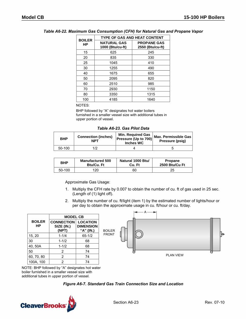
Table A6-22. Maximum Gas Consumption (CFH) for Natural Gas and Propane Vapor
BOILER HP
TYPE OF GAS AND HEAT CONTENT
NATURAL GAS1000 (Btu/cu-ft)
PROPANE GAS2550 (Btu/cu-ft)
15 625 245 20 835 330 25 1045 410 30 1255 490 40 1675 655 50 2095 820 60 2510 985 70 2930 1150 80 3350 1315
100 4185 1640 NOTES: BHP followed by “A” designates hot water boilers furnished in a smaller vessel size with additional tubes in upper portion of vessel.
Table A6-23. Gas Pilot Data
BHP Connection (inches)
NPT
Min. Required GasPressure (Up to 700)
Inches WC
Max. Permissible Gas Pressure (psig)
50-100 1/2 4 5
BHP Manufactured 500
Btu/Cu. Ft Natural 1000 Btu/
Cu. Ft Propane
2500 Btu/Cu Ft
50-100 120 60 25
Approximate Gas Usage:
1. Multiply the CFH rate by 0.007 to obtain the number of cu. ft of gas used in 25 sec. (Length of (1) light off).
2. Multiply the number of cu. ft/light (item 1) by the estimated number of lights/hour or per day to obtain the approximate usage in cu. ft/hour or cu. ft/day.
Figure A6-7. Standard Gas Train Connection Size and Location
BOILER HP
MODEL CB
CONNECTION SIZE (IN.)
(NPT)
LOCATION DIMENSION
“A” (IN.)
15, 20 1-1/4 65-1/2 30 1-1/2 68 40, 50A 1-1/2 68 50 2 74 60, 70, 80 2 74 100A, 100 2 74
NOTE: BHP followed by “A” designates hot water boiler furnished in a smaller vessel size with additional tubes in upper portion of vessel.
BOILER FRONT
PLAN VIEW
A

Model CB 15-100 HP Boilers
Section A6-24 Rev. 07-10
This figure illustrates the basic gas valve arrangement on Cleaver-Brooks Model CB Boiler and shows the contractor’s connection point. The valves and controls between the contractor connection point and the gas main in the street are representative of a typical installation. Actual requirements may vary depending on local codes or local gas company requirements which should be investigated prior to preparation of specifications and prior to construction.
A. Utilities service valve.
B. Utilities service regulator.
C. Gas meter.
D. Piping from meter to boiler.
The size of the gas line from the meter to the gas pressure regulator at the boiler can be very important if gas pressures are marginal. The gas line sizing is dependent on:
1. Gas pressure at outlet of gas meter (C)
2. Rate of gas flow required, CFH
3. Length of pipe run (D)
4. Pressure required at contractor connection point.
The local gas utility will advise the pressure that is available at the outlet of their meter.
Figure A6-8. Typical Gas Piping Layout
Model CB 15-100 HP Boilers
Section A6-25 Rev. 07-10
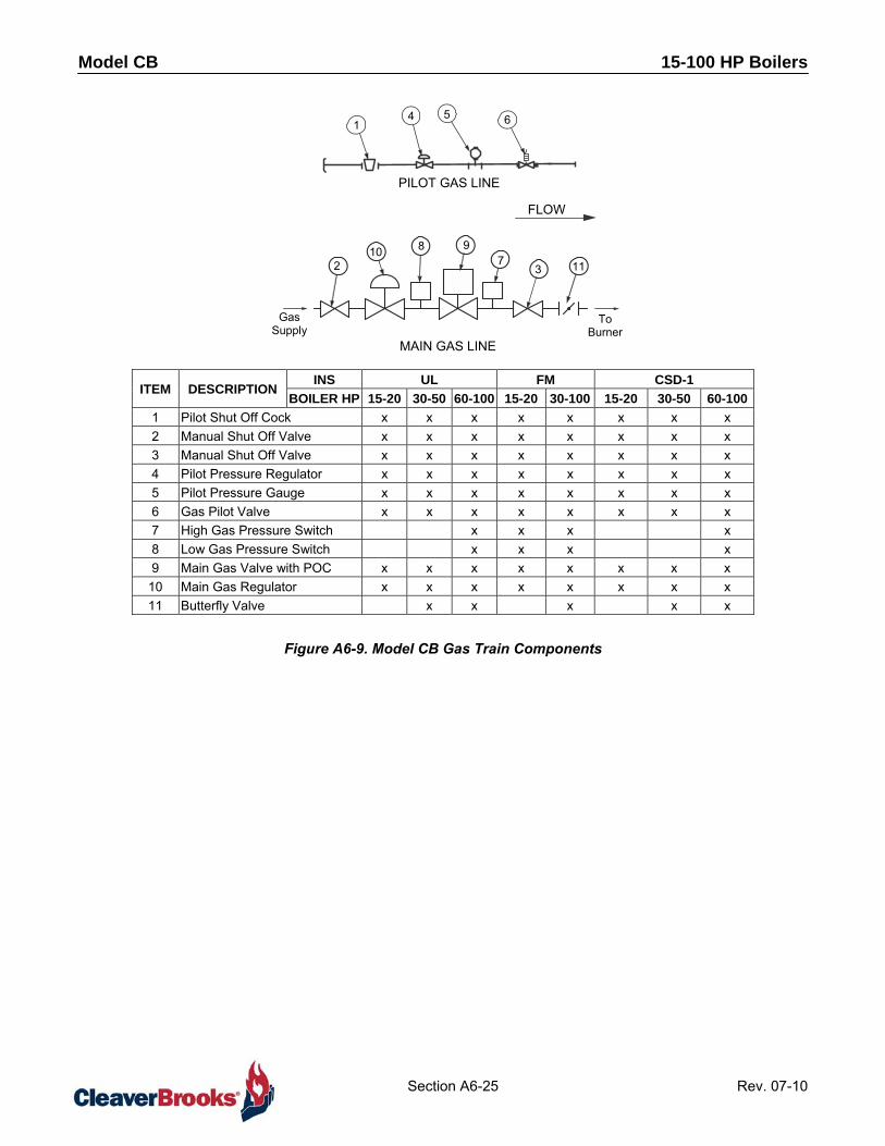
ITEM DESCRIPTION INS UL FM CSD-1
BOILER HP 15-20 30-50 60-100 15-20 30-100 15-20 30-50 60-100
1 Pilot Shut Off Cock x x x x x x x x 2 Manual Shut Off Valve x x x x x x x x 3 Manual Shut Off Valve x x x x x x x x 4 Pilot Pressure Regulator x x x x x x x x 5 Pilot Pressure Gauge x x x x x x x x 6 Gas Pilot Valve x x x x x x x x 7 High Gas Pressure Switch x x x x 8 Low Gas Pressure Switch x x x x 9 Main Gas Valve with POC x x x x x x x x
10 Main Gas Regulator x x x x x x x x 11 Butterfly Valve x x x x x
Figure A6-9. Model CB Gas Train Components
PILOT GAS LINE
MAIN GAS LINE
Gas Supply
FLOW
To Burner
4
3 2
5 6
7 8 9 10
11
1

Model CB 15-100 HP Boilers
Section A6-26 Rev. 07-10
BOILER HP
MODEL CB
SUPPLY AND RETURN CONN
SIZES (IN.) (NPT)
DIM. A (IN.)
RECOMMENDED OIL LINEA SIZES (STANDARD PIPE)
(IN.)
STORAGE TANK TO BOILER OR PUMP CONNECT
PUMP TO BOILER
RETURN LINE TO TANK
15, 20 3/4 8-1/4 3/4 NONE 3/4 30, 40 3/4 8-1/4 3/4 NONE 3/4 50, 60 3/4 11-1/2 3/4 1 3/4 70, 80 3/4 11-1/2 3/4 1 3/4
100 3/4 11-1/2 1 1 1 NOTE: See No. 2 Oil Line Sizing Instruction for systems with other conditions. A. For suction line condition with a maximum of 10 Feet of lift and a total of 100 equivalent feet of suction line. B. This table is based on a single boiler installation.
Figure A6-10. No. 2 Oil Connection Size, Location and Recommended Line Sizes
BOILER HP
SUPPLY CONNECTION
RETURN CONNECTION
RECOMMENDED OIL LINE SIZES(STANDARD PIPE)
(IN.)
SIZE (IN.) (NPT)
A (IN.)SIZE (IN.)
(NPT) B (IN.)
STORAGE TANK TO
PUMP
PUMP TO BOILER
RETURN LINE TO TANK
50, 60, 70, 80, 100 1-1/4 27-3/4 3/4 19-3/4 2 1-1/4 1-1/4 NOTES: 1. All dimensions in inches. 2. For suction lines with a maximum of 10 feet of lift and a total of 100 equivalent feet of suction line. 3. This table is based on a single boiler installation.
Figure A6-11. No. 6 Oil Connection Size, Location and Recommended Line Sizes, Model CB Boiler
BOILER FRONT
CONTRACTOR CONNECTIONS
BOILER BASE FRAME
RIGHT HAND SIDE VIEW A
PLAN VIEW B
A
C
BOILER FRONT
Model CB 15-100 HP Boilers
Section A6-27 Rev. 07-10
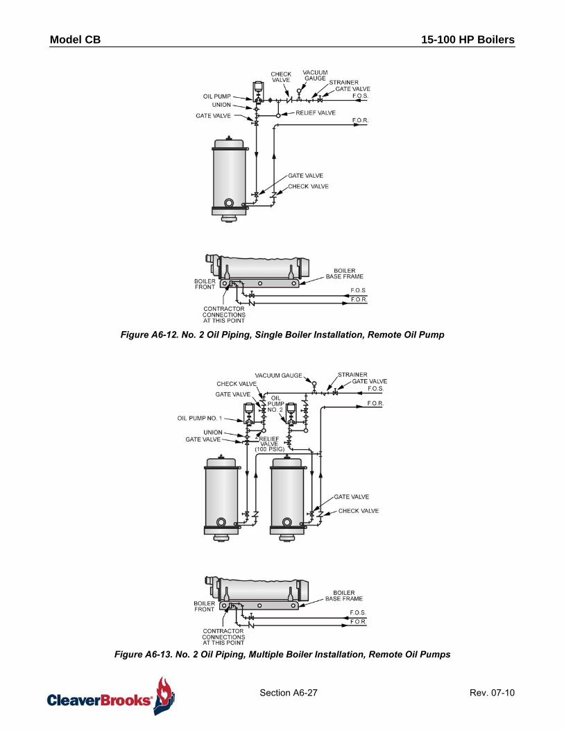
Figure A6-12. No. 2 Oil Piping, Single Boiler Installation, Remote Oil Pump
Figure A6-13. No. 2 Oil Piping, Multiple Boiler Installation, Remote Oil Pumps
Model CB 15-100 HP Boilers
Section A6-28 Rev. 07-10
Figure A6-14. No. 2 Oil Piping, Multiple Boiler Installation
Model CB 15-100 HP Boilers
Section A6-29 Rev. 07-10
Figure A6-15. Typical Fuel Storage Tank Arrangement
NOTE: OBSERVE ALL LOCAL AND NATIONAL (EG. FIRE UNDERWRITERS) CODE REQUIREMENTS GOVERNING THE INSTALLATION OF FUEL OIL STORAGE TANKS AND SUPPLY SYSTEMS

Model CB 15-100 HP Boilers
Section A6-30 Rev. 07-10
Boiler Room Information
Figure A6-17 shows typical boiler room length requirements.
Figure A6-18 shows typical boiler room width requirements.
Figure A6-19 shows typical breeching arrangements.
Stack Support Capabilities
Cleaver-Brooks Firetube Boilers 15 hp through 100 hp can support up to 1,000 lbs without additional support. Firetube boilers 125 hp through 800 hp can support up to 2,000 lbs without additional support.
Firetube sizes 250 hp through 800 hp can be reinforced to support 3,000 lbs.
Stack/Breeching Size Criteria
The design of the stack and breeching must provide the required draft at each boiler flue gas outlet. Proper draft is critical to burner performance.
Although constant pressure at the flue gas outlet of the Model CB is not required, it is necessary to size the stack/breeching to limit flue gas pressure variation. For boiler sizes 50 – 800 horsepower, the allowable pressure range is –0.5" W.C. to
+0.5" W.C. The maximum pressure variation at any firing rate for the boiler is 0.5" W.C. For boiler sizes 15 – 40 horsepower, the allowable pressure range is –0.25" W.C. to +0.25" W.C.
For additional information, please review Section I4, General Engineering Data (Stacks) and Section F, Stacks. Stack and breeching sizes should always be provided by a reputable stack supplier who will design the stack and breeching system based on the above criteria. Your local Cleaver-Brooks authorized representative is capable of assisting in your evaluation of the stack/breeching design.
Boiler Room Combustion Air
When determining boiler room air requirements, the size of the room, air flow, and velocity of air must be reviewed as follows:
1. Size (area) and location of air supply openings in boiler room.
A. Two (2) permanent air supply openings in the outer walls of the boiler room are recommended. Locate one at each end of the boiler room, preferably below a height of 7 feet. This allows air to sweep the length of the boiler.
B. Air supply openings can be louvered for weather protection, but they should not be covered with fine mesh wire, as this type of covering has poor air flow qualities and is subject to clogging by dust or dirt.
C. A vent fan in the boiler room is not recommended, as it could create a slight vacuum under certain conditions and cause variations in the quantity of combustion air. This can result in unsatisfactory burner performance.
D. Under no condition should the total area of the air supply openings be less than (1) square foot.
E. Size the openings by using the formula:
Area (sq-ft) = cfm/fpm
2. Amount of air required (cfm).
A. Combustion Air = Rated bhp x 8 cfm/bhp.
B. Ventilation Air = Maximum bhp x 2 cfm/bhp

Model CB 15-100 HP Boilers
Section A6-31 Rev. 07-10
C. Total recommended air, 10 cfm/bhp - up to 1000 feet elevation. Add 3 percent more per 1000 feet of added elevation.
3. Acceptable air velocity in boiler room (fpm).
A. From floor to (7) foot height - 250 fpm.
B. Above (7) foot height - 500 fpm.
Example: Determine the area of the boiler room air supply openings for (1) 300 hp boiler at 800 feet altitude. The air openings are to be 5 feet above floor level.
• Air required: 300 x 10 = 3000 cfm (from 2B above).
• Air velocity: Up to 7 feet = 250 fpm (from 3 above).
• Area Required: Area = cfm = 3000/250 = 12 Sq-ft total.
• Area/Opening: 12/2 = 6 sq-ft/opening (2 required).
Notice Consult local codes, which may supersede these requirements.

Model CB 15-100 HP Boilers
Section A6-32 Rev. 07-10
1. Shortest boiler room length (Dwg A) is obtained by allowing for possible future tube replacement (from front or rear of boiler) through a window or doorway. Allowance is only made for minimum door swing at each end of the boiler. This arrangement provides sufficient aisle space at the front of the boiler but a "tight" space condition at the rear. If space permits, approximately 1.5 additional feet should be allowed at the rear for additional aisle and working space. 2. Next shortest boiler room length (Dwg B) is obtained by allowing for possible future tube replacement from the front of the boiler. Allowance is only made for minimum door swing at the rear. If space permits, approximately 1.5 additional feet should be allowed at the rear for additional aisle and working space. 3. A slightly longer boiler room (Dwg C) is obtained by allowing for possible future tube replacement from the rear of the boiler. Allowance for door swing at the front provides sufficient aisle and working space at the front.
Figure A6-16. Boiler Room Length (Typical Layout)
Figure A6-17. Boiler Room Width (Typical Layout)
FRONT FEEDWATER
TANK
BOILER FEEDWATER
PUMP
DRAIN
TRENCH
DWG A
DWG B
DWG C
BOILER HP 15-40 50-100
Dimension A 75" 81" Dimension B 103" 115"
NOTES: 1. Recommended Minimum Distance Between Boiler and Wall.
Dimension "A" allows for a "clear" 42" aisle between the water column on the boiler and the wall. If space permits, this aisle should be widened.
2. Recommended Minimum Distance Between Boilers. Dimension "B" between boilers allows for a "clear" aisle of: 42" - 15-100 hp If space permits, this aisle should be widened.
A FEEDWATER TANK
BOILER FEEDWATER
PUMP
DRAIN
TRENCH
B

Model CB 15-100 HP Boilers
Section A6-33 Rev. 07-10
Figure A6-18. Breeching Arrangement
NOTE: These stack breeching arrangements for multiple boilers are typical and not intended for your specific design requirements. For additional information, review Section F, Stacks. Stack and breeching sizes should always be provided by a reputable stack supplier who will design the stack and breeching system based on your specific criteria. Your local Cleaver-Brooks authorized representative is capable of assisting in your evaluation of stack and breeching design.

Model CB 15-100 HP Boilers
Section A6-34 Rev. 07-10
Notes

Model CB 15-100 HP Boilers
Section A6-35 Rev. 07-10
SECTION A6 MODEL CB 15-100 HP
SAMPLE SPECIFICATIONS - STEAM
1.01 Boiler Characteristics (Steam) ................................................................................................................ A6-36 1.02 General Boiler Design ............................................................................................................................. A6-36 1.03 Steam Boiler Trim ................................................................................................................................... A6-37 1.04 Burner and Controls ................................................................................................................................ A6-38 1.05 Efficiency Guarantee .............................................................................................................................. A6-44 1.06 Warranty ................................................................................................................................................. A6-45 1.07 Shop Tests .............................................................................................................................................. A6-45 1.08 Start-up Service ...................................................................................................................................... A6-45

Model CB 15-100 HP Boilers
Section A6-36 Rev. 07-10
MODEL CB 15-100 HP MODEL CB STEAM BOILER (15-100 HP, STEAM 15-350 PSIG)
The following sample specification is provided by Cleaver-Brooks to assist you in meeting your customer’s specific needs and application.
A separate specification for steam boilers and hot water boilers is provided. Burner specifications and detailed control specifications for CB 780 Flame Safeguard control and the CB-HAWK Flame Safeguard control are included. See Section D, Controls, for additional information on control options.
The Sample Specifications are typically utilized as the base template for the complete boiler specification. Contact your local Cleaver-Brooks authorized representative for information on special insurance requirements, special code requirements, optional equipment, or general assistance in completing the specification.
1.01 Boiler Characteristics (Steam)
A. The Steam Boiler shall be Cleaver-Brooks Model CB, Fuel Series _____ (100, 200, 400, 600, 700), _____ hp designed for _____ psig (15, 150, 200, or other psig steam). The maximum operating pressure shall be _____ psig.
B. The boiler shall have a maximum output of _____ Btu/hr, or _____ horsepower when fired with CS 12-48 _____ oil and/or natural gas, _____ Btu/cu-ft. Electrical power available will be _____ Volt _____ Phase _____ Cycle.
1.02 General Boiler Design
A. The boiler shall be a four pass horizontal firetube updraft boiler with five (5) square feet of heating surface per rated boiler horsepower. It shall be mounted on a heavy steel frame with integral forced draft burner and burner controls.
The complete package boiler shall be approved as a unit by Underwriters Laboratories and shall bear the UL/ULC label, except in the case where 50 Hz has been selected.
1. The boiler shall be completely preassembled and fire tested at the factory.
The unit shall be ready for immediate mounting on floor or simple foundation and ready for attachment of water, steam, fuel, electrical, vent and blowdown connections.
2. The boiler shall be built to comply with the following insurance and codes _______________ (Factory Mutual, ASME CSD-1).
B. Boiler Shell (Steam)
1. The boiler shell must be constructed in accordance with ASME Boiler Code and must receive authorized boiler inspection prior to shipment. A copy of the inspection report shall be furnished to the purchaser.
2. Two lifting eyes shall be located on top of the boiler.
3. Front and rear doors on the boiler shall be hinged or davited. Doors are to be sealed with fiberglass tadpole gaskets and fastened tightly using heavy capscrews that thread into replaceable brass nuts.

Model CB 15-100 HP Boilers
Section A6-37 Rev. 07-10
4. Rear refractory and insulation shall be contained in the formed door, which must swing open for inspection of brick work.
5. The boiler tubes shall not include turbulators, swirlers or other add-on appurtenances.
6. Front and rear tube sheets and all flues must be fully accessible for inspection and cleaning when the doors are swung open. The boiler shall be furnished with adequate handholes to facilitate boiler inspection and cleaning.
7. The exhaust gas vent shall be located near the front of the boiler on the top center line and shall be capable of supporting:
• 15-100 hp. 1000 lbs and shall contain a stack thermometer
8. The boiler shell shall contain a chemical feed connection.
C. Observation ports for the inspection of flame conditions shall be provided at each end of the boiler.
D. The boiler insulation shall consist of a 2 inch blanket under a sectional preformed sheet metal lagging. This insulation must be readily removable and capable of being reinstalled, if required.
E. The entire boiler base frame and other components shall be factory painted before shipment using a hard finish enamel coating.
1.03 Steam Boiler Trim
A. Water Column A water column shall be located on the right hand side of the boiler complete with gauge glass set and water column blowdown valves.
1. Feedwater Pump Control The boiler feedwater pump control shall be included as an integral part of the water column to automatically actuate a motor driven feed water pump maintaining the boiler water level within normal limits.
2. Low Water Cutoff
The low water cutoff shall be included as an integral part of the boiler feedwater control wired into the burner control circuit to prevent burner operation if the boiler water level falls below a safe level.
B. Auxiliary Low Water Cutoff Auxiliary low water cutoff manual reset shall be included, piped to the vessel, and wired to the burner control circuit. A manual reset device shall be used on this control.
C. Steam Pressure Gauge The steam pressure gauge shall be located at the front of the boiler and include cock and test connection.
D. Safety Valves Safety valves of a type and size to comply with ASME Code requirements shall be shipped loose.
E. Steam Pressure Controls The steam pressure controls to regulate burner operation shall be mounted near the water column. Controls shall be a high limit (manual reset), operating limit (auto reset), and firing rate control (30-100 hp).

Model CB 15-100 HP Boilers
Section A6-38 Rev. 07-10
1.04 Burner and Controls
A. Mode of Operation Select one of the following:
• 15 and 20 hp. Burner operation shall be on-off principle.
• 30 and 40 hp. Burner operation shall be high-low-off principle. The burner shall always return to low fire position for ignition.
• 50 - 100 hp. Burner operation shall be full modulation principle. The burner shall always return to low fire position for ignition.
B. Blower
1. Air for combustion shall be supplied by a forced draft blower mounted in the front boiler door, above the burner, to eliminate vibration and reduce noise level.
2. Maximum sound level of the boiler/burner package shall not exceed _____ dbA (when measured in accordance with ABMA Sound Test Standards).
3. The impeller shall be cast aluminum, radial blade, carefully balanced, and directly connected to the blower motor shaft.
C. Combustion Air Control Select one of the following:
• 15 and 20 hp. Combustion air damper shall be manually set for proper air-fuel ratios.
• 30 and 40 hp. Combustion air damper shall be linked to damper motor. Auxiliary switch on the damper motor shall control high or low firing rate.
• 50 - 100 hp. Combustion air damper and cam operated fuel metering valves shall be operated by a single damper control motor that regulates the fire according to load demand. Potentiometer type position controls shall be provided to regulate operation of the damper control motor.
D. Fuel Specification and Piping Select one of the following fuel types:
• Fuel series 700 - Gas fired (4.4.1).
• Fuel series 100 - Light oil (No. 2) fired (4.4.2).
• Fuel series 200 - Light oil or gas fired (4.4.3).
• Fuel series 600 - No. 6 oil fired (4.4.4).
• Fuel series 400 - No. oil or gas fired (4.4.5).
1. Fuel Series 700 - Gas Fired
a. Burner Type - The burner shall be integral with the front head of the boiler and of high radiant multi-port type for gas. The burner shall be approved for operation on natural gas fuel.
b. Gas Pilot - The gas pilot shall be a premix type with automatic electric ignition. An electronic detector shall monitor the pilot so that the primary gas valve cannot open until pilot flame has been established. The pilot train shall include two manual shut-off valves, solenoid valve, pressure regulator and pressure gauge.
c. Gas Burner Piping - Gas burner piping on all units shall include pressure regulator, primary gas shutoff valve, motor operated with proof of closure switch and plugged leakage test connection. The main gas valve(s) shall be wired to close automatically in the event of power failure, flame failure, low

Model CB 15-100 HP Boilers
Section A6-39 Rev. 07-10
water or any safety shutdown condition. A lubricating plug cock or butterfly shutoff valve shall be provided as a means for a tightness check of the primary shut off valve. An additional plug cock on butterfly valve shall be furnished at entrance to gas train. Select one of the following:
1) 15-50 hp. Burners equipped as shown above.
2) 60-100 hp. High and low gas pressure switches shall be provided.
d. Burner Turndown - Select one of the following:
1) 15 and 20 hp. Burner shall operate on the on/off principle.
2) 30 and 40 hp. Burner shall operate on the high-low-off principle with a turndown of 3:1 when firing natural gas.
3) 50-100 hp. Turndown range of burner shall be 4:1 when firing natural gas.
2. Fuel Series 100 - Light Oil Fired
a. Burner Type - The burner shall be integral with the front head of the boiler, and shall be a low pressure air atomizing type approved for operation with CS12-48, Commercial No. 2 oil.
3. Oil Pilot - The oil pilot shall be air atomizing type with automatic electric ignition and include oil solenoid valve. An electronic detector shall monitor the pilot so that the primary oil valve cannot open until flame has been established.
4. Oil Pump - An oil pump with a capacity of approximately twice the maximum burning rate shall be included. Select one of the following:
• 15 hp through 40 hp. The oil pump shall be integral with the burner and belt driven from the blower motor.
• 50 hp through 100 hp. Separate motor driven pump set, shipped loose to be installed in a location favorable to the oil storage tank, shall be provided.
5. Oil Burner Piping - Fuel oil piping on the unit shall include oil pressure regulating devices, oil metering controls, solenoid shutoff valves, pressure gauges and fuel strainer, all integrally mounted on the unit. Select one of the following:
• 50 hp through 100 hp. A fuel oil controller shall be provided to combine all of the fuel oil controls into a single casting which is mounted on the front door of the unit. A single tip retractable nozzle shall be used for the low pressure air atomizing burner.
• 70 hp through 100 hp. A low oil pressure switch shall be included in the oil piping.
6. Low Pressure Air Atomizing - Select one of the following:
• 15 hp through 40 hp. Belt driven air compressor, lubricating oil tank, oil level indicator, inlet air filter, air pressure gauge, and low atomizing air pressure switch.
• 50 hp through 100 hp. Separate air compressor module mounted on boiler base rail with low atomizing air pressure switch.
7. Burner Turndown - Select one of the following:
• 15 and 20 hp. Burner shall operate on the on/off principle.
• 30 and 40 hp. Burner shall operate on the high-low-off principle with a turndown of 3:1 when firing No. 2 oil.

Model CB 15-100 HP Boilers
Section A6-40 Rev. 07-10
• 50 hp through 100 hp. Turndown range shall be 4:1 when firing No. 2 oil.
E. Fuel Series 200 - Light Oil or Gas Fired
1. Burner Type - The burner, integral with the front head of the boiler, shall be a combination of the low pressure air atomizing type for oil and high radiant multi-port type for gas. The burner shall be approved for operation with either CS12-48 Commercial No. 2 Oil or natural gas.
2. Gas Pilot - The gas pilot shall be premix type with automatic electric ignition. An electronic detector shall monitor the pilot so that the primary fuel valve cannot open until flame has been established. The pilot train shall include two manual shut-off valves, solenoid valve, pressure regulator and pressure gauge.
3. Oil Burner
a. Oil Pump - An oil pump with a capacity of approximately twice the maximum burning rate shall be included. Select one of the following:
1) 15 hp through 40 hp. The oil pump shall be integral with the burner and belt driven from the blower motor.
2) 50 hp through 100 hp. Separate motor driven pump set, shipped loose, to be installed in a location favorable to the oil storage tank, shall be provided.
4. Oil Burner Piping - Fuel oil piping on the unit shall include oil pressure regulating devices, oil metering controls, solenoid shutoff valves, pressure gauges and fuel strainer, all integrally mounted on the unit. Select one of the following:
a. 50 hp through 100 hp. A fuel oil controller shall be provided to combine all of the fuel oil controls into a single casting which is mounted on the front door of the unit. A single tip retractable nozzle shall be used for the low pressure air atomizing burner.
b. 70 hp through 100 hp. A low oil pressure switch shall be included in the oil piping.
5. Low pressure air atomizing. Select one of the following:
a. 15 hp through 40 hp. Belt driven air compressor, lubricating oil tank, oil level indicator, inlet air filter, air pressure gauge and low atomizing air pressure switch.
b. 50 hp through 100 hp. Separate air compressor module mounted on boiler base rail with low atomizing air pressure switch.
6. Gas Burner
a. Gas Burner Piping - gas burner piping on all units shall include pressure regulator, primary gas shutoff valve, motor operated with proof of closure switch and plugged leakage test connection. The main gas valve(s) shall be wired to close automatically in the event of power failure, flame failure, low water or any safety shutdown condition. A lubricating plug cock or butterfly shutoff valve shall be provided as a means for a tightness check of the primary shut off valve. An additional plug cock or butterfly valve shall be furnished at entrance to gas train. Select one of the following:
1) 15-50 hp. Burners equipped as shown above.
2) 60-100 hp. High and low gas pressure switches shall be provided.
7. Burner Turndown Select one of the following:

Model CB 15-100 HP Boilers
Section A6-41 Rev. 07-10
• 15 and 20 hp. Burner shall operate on the on/off principle.
• 30 and 40 hp. Burner shall operate on the high-low-off principle with a turndown of 3:1
• 50-100 hp. Turndown range of the burner shall be 4:1.
F. Fuel Series 600 - No. 6 Oil Fired
1. Burner Type - The burner shall be integral with the front head of the boiler and low pressure air atomizing type approved for operation with CS12-48, Commercial No. 6 Oil.
2. Gas Pilot - The gas pilot shall be a premix type with automatic electric ignition. An electronic detector shall monitor the pilot so that the primary oil valve cannot open until pilot flame has been established. The pilot train shall include two manual shut-off valves, solenoid valve, pressure regulator and pressure gauge.
3. Oil Pump - An oil pump set with a capacity of approximately twice the maximum burning rate shall be included.
A separate motor driven pump set shall be included shipped loose for location favorable to the oil storage tank.
4. Oil Burner Piping - A fuel oil controller combining all of the fuel oil controls into a single casing shall be provided. Oil pressure regulating devices, oil metering controls, solenoid shutoff valves, high and low oil temperature switches and necessary pressure and temperature gauges shall be included in this packaged assembly mounted on the front door of the boiler. A fuel strainer shall also be provided, mounted to the boiler. A single tip retractable nozzle shall be used for the low pressure air atomizing burner. Flexible hoses shall be provided to allow easy removal of the nozzle for inspection when it is placed in the vice jaws located on the front door of the boiler.
The metering valve shall permit circulation of hot oil to the burner at all times. The burner drawer oil piping and nozzle shall be purged of oil on each shutdown.
For 70 through 100 hp, a low oil pressure switch shall be included in the oil piping.
5. Low Pressure Air Atomizing - Select one of the following:
a. 50 through 100 hp. Separate air compressor module mounted on boiler base rail with low atomizing air pressure switch.
6. Oil Preheat The oil shall be preheated by a steam heater and electric heater, each with thermostatic control. Both heaters shall be installed in a single compact shell mounted, piped, and wired on the boiler. The thermostatic controls shall be set to cut-out the electric heater when steam is available. Select one of the following:
a. 50 through 100 hp. Electric preheater size shall be 5 kW.
G. Fuel Series 400 - No. 6 Oil or Gas Fired
1. Burner Type - The burner shall be integral with the front head of the boiler and shall be a combination of the low pressure atomizing type for oil and high radiant multi-port type for gas. The burner shall be approved for operation with either CS12-48 Commercial No. 6 oil or natural gas.
2. Gas Pilot - The gas pilot shall be a premix type with automatic electric ignition. An electronic detector shall monitor the pilot so that the primary oil valve cannot open until pilot flame has been established. The pilot train shall include two manual shut-off valves, solenoid valve, pressure regulator and pressure gauge.

Model CB 15-100 HP Boilers
Section A6-42 Rev. 07-10
3. Oil Burner
a. Oil Pump - An oil pump set with a capacity of approximately twice the maximum burning rate shall be included.
b. Oil Burner Piping - A fuel oil controller combining all of the fuel oil controls into a single casing shall be provided. Oil pressure regulating devices, oil metering controls, solenoid shutoff valves, high and low oil temperature switches, and the necessary pressure and temperature gauges shall be included in this packaged assembly mounted on the front door of the boiler. A fuel strainer shall also be provided, mounted to the boiler. A single tip retractable nozzle shall be used for the low pressure air atomizing burner. Flexible hoses shall be provided to allow easy removal of the nozzle for inspection when it is placed in the vice jaws located on the front door of the boiler. The metering valve shall permit circulation of hot oil to the burner at all times. The burner drawer oil piping and nozzle shall be purged of oil at each shutdown.
For 70 through 100 hp, a low oil pressure switch shall be included in the oil piping.
1. Low Pressure Air Atomizing - Select one of the following:
a. 50 through 100 hp. Separate air compressor module mounted on boiler base rail with low atomizing air pressure switch.
2. Oil Preheat The oil shall be preheated by a steam heater and electric heater, each with thermostatic control. Both heaters shall be installed in a single compact shell mounted, piped, and wired on the boiler. The thermostatic controls shall be set to cut-out the electric heater when steam is available.
a. 50 through 100 hp. Electric preheater size shall be 5 kW.
3. Gas Burner
a. Gas Burner Piping - Gas burner piping on all units shall include pressure regulator, primary gas shutoff valve, motor operated with proof of closure switch and plugged leakage test connection. The main gas valve(s) shall be wired to close automatically in the event of power failure, flame failure, low water or any safety shutdown condition. A lubricating plug cock or butterfly shutoff valve shall be provided as means for a tightness check of the primary shutoff valve. An additional plug cock or butterfly valve shall be furnished at entrance to gas train. Select one of the following:
1) 50 hp. Burner equipped as shown above.
2) 60 through 100 hp. High and low gas pressure switches shall be provided.
b. Burner Turndown - Turndown shall be 4:1.
H. Boiler Flame Safeguard Controller and Control Panel
1. CB780E Flame Safeguard
a. Boilers with CB780E Control - Each boiler shall be factory equipped with flame safeguard controller providing technology and functions equal to the Cleaver-Brooks Model CB780E.
Controller shall be computerized solid state having sequence and flame-on lights and alpha- numeric “first out” fault indications of flame safeguard trip functions. It shall include dynamic self-check logic. The controller shall have a fixed operating sequence incapable of being manually altered. The

Model CB 15-100 HP Boilers
Section A6-43 Rev. 07-10
sequence shall include start, pre-purge, pilot and main fuel ignition run and post-purge cycles.
Controller shall be the non-recycle type for maximum safety that shall shutdown the burner and indicate as a minimum the following trip functions: pilot and main flame failure, high and low fire proving switch faults, locking interlocks open, false flame signal and fuel valve open (when proof of closure switch is furnished).
The controller shall have a run/test switch. It shall allow interruptions to sequence just after pre-purge, during pilot ignition trial and run cycles for adjustments to firing rate motor, damper linkages and pilot flame for minimum turndown tests.
b. Control Panel - The control panel shall be mounted on the front door of the boiler in a location convenient to the operator. The hinged metal cabinet will have NEMA 1A rating that includes a neoprene dust seal and a Yale cabinet key type lock.
The panel shall contain the boiler flame safeguard controller, blower motor starter, indicating lights and selector switches.
The panel shall have a removable sub-base for mounting the flame safeguard controller, blower motor starter, and terminal blocks. For combination gas-oil and heavy oil fired boilers the panel will contain the fuel selector and/or oil heater selector switch.
The panel shall contain the following lights and switches:
Lights
• White - load demanded.
• White - fuel valve open.
• Red - low water.
• Red - flame failure.
Control Switches
• Burner On-Off.
• Manual-Automatic.
• Manual Firing Rate Control.
2. Oil, heat and moisture resistant wire shall be used and identified with circuit numbers corresponding to the electrical wiring diagram.
3. All electrical equipment and wiring shall be in conformance with Underwriters Laboratories requirements.
4. Boiler to be supplied with a control circuit transformer and fuse protection for the control circuit.
5. Control Panel: The control panel shall be mounted on the front door of the boiler in a location convenient to the operator. The hinged metal cabinet will have NEMA 1A rating that includes a neoprene dust seal and a Yale cabinet key type lock.
The panel shall contain the boiler flame safeguard controller, indicating lights and selector switches.

Model CB 15-100 HP Boilers
Section A6-44 Rev. 07-10
Panel shall have a removable sub-base for mounting the flame safeguard controller, and terminal blocks. For combination gas-oil and heavy oil fired boilers the panel will contain the fuel selector and/or oil heater selector switch.
6. Oil, heat, and moisture resistant wire shall be used and identified with circuit numbers corresponding to the electrical wiring diagram.
7. All electrical equipment and wiring shall be in conformance with Underwriters Laboratories requirements.
8. Boiler to be supplied with a control circuit transformer and fuse protection for the control circuit.
1.05 Efficiency Guarantee
The boiler manufacturer shall guarantee that, at the time of startup, the boiler will achieve _____ fuel-to-steam efficiency at 100% firing rate when burning natural gas and _____ fuel-to-steam efficiency at 100% firing rate when burning oil (add efficiency guarantees at 25%, 50%, and 75% of rating, if required). If the boiler(s) fail to achieve the corresponding guaranteed efficiency as published, the boiler manufacturer will rebate, to the ultimate boiler owner, five thousand dollars ($5,000) for every full efficiency point (1.0%) that the actual efficiency is below the guaranteed level.
The specified boiler efficiency is based on the following conditions.
A. Fuel specification used to determine boiler efficiency:
1. Natural Gas
Carbon, % (wt) = 69.98
Hydrogen, % (wt) = 22.31
Sulfur, % (wt) = 0.0
Heating value, Btu/lb = 21,830
2. No. 2 Oil
Carbon, % (wt) = 85.8
Hydrogen, % (wt) = 12.7
Sulfur, % (wt) = 0.2
Heating value, Btu/lb = 19,420
3. No. 6 Oil
Carbon, % (wt) = 86.6
Hydrogen, % (wt) = 10.9
Sulfur, % (wt) = 2.09
Heating value, Btu/lb = 18,830
B. Efficiencies are based on ambient air temperature of 80 °F, relative humidity of 30%, and 15% excess air in the exhaust flue gas.
C. Efficiencies are based on manufacturer’s published radiation and convection losses. (For Cleaver-Brooks radiation and convection losses, see Boiler Efficiency Facts Guide, publication number CB-7767).
D. Any efficiency verification testing will be based on the stack loss method.
Model CB 15-100 HP Boilers
Section A6-45 Rev. 07-10
EXECUTION
1.06 Warranty
A. All equipment is to be guaranteed against defects in materials and/or workmanship for a period of 12 months from date of start-up or 18 months from date of shipment, whichever comes first.
1.07 Shop Tests
A. The packaged boiler must receive factory tests to check the construction, controls, and operation of the unit. All tests may be witnessed by the purchaser, if desired.
1.08 Start-up Service
After boiler installation is completed, the manufacturer shall provide the services of a field representative for starting the unit and training the operator at no additional costs.
A. A factory approved and authorized start-up report shall be submitted to the customer/user at the time of start-up.

Model CB 15-100 HP Boilers
Section A6-46 Rev. 07-10
Notes
Model CB 15-100 HP Boilers
Section A6-47 Rev. 07-10
SECTION A6 MODEL CB 15-100 HP
SAMPLE SPECIFICATIONS - HOT WATER
1.01 Boiler Characteristics (Hot Water) .......................................................................................................... A6-48 1.02 General Boiler Design ............................................................................................................................. A6-48 1.03 Hot Water Boiler Trim ............................................................................................................................. A6-49 1.04 Burner and Controls ................................................................................................................................ A6-49 1.05 Blower ..................................................................................................................................................... A6-49 1.06 Combustion Air Control ........................................................................................................................... A6-50 1.07 Fuel Specification and Piping ................................................................................................................. A6-50 1.08 Efficiency Guarantee .............................................................................................................................. A6-56 1.09 Warranty ................................................................................................................................................. A6-56 2.01 Shop Tests .............................................................................................................................................. A6-57

Model CB 15-100 HP Boilers
Section A6-48 Rev. 07-10
MODEL CB HOT WATER BOILER (15-100 HP, 30 PSIG, 125 PSIG)
1.01 Boiler Characteristics (Hot Water)
A. The Hot Water Boiler shall be Cleaver-Brooks Model CB, Fuel Series _____ (100, 200, 400, 600, 700), _____ hp designed for _____ psig (30, 125, or other psig hot water). The maximum water temperature will be _____ degree F, and the maximum system temperature drop will be _____ degree F.
B. The boiler shall have a maximum output of _____ Btu/hr, or _____ horsepower when fired with CS 12-48 _____ oil and/or natural gas, _____ Btu/cu-ft. Electrical power available will be _____ Volt _____ Phase _____ Cycle.
1.02 General Boiler Design
A. The boiler shall be a four pass horizontal firetube updraft boiler with five (5) square feet of heating surface per rated boiler horsepower. It shall be mounted on a heavy steel frame with integral forced draft burner and burner controls. The complete package boiler shall be approved as a unit by Underwriters Laboratories and shall bear the UL/ULC label.
1. The boiler shall be completely preassembled and fire tested at the factory.
The unit shall be ready for immediate mounting on floor or simple foundation and ready for attachment of water, steam, fuel, electrical, vent and blowdown connections.
2. The boiler shall be built to comply with the following insurance and codes _______________ (Factory Mutual, ASME CSD-1).
B. Boiler Shell (Hot Water)
1. The boiler shell must be constructed in accordance with ASME Boiler Code and must receive authorized boiler inspection prior to shipment. A copy of the inspection report shall be furnished to the purchaser.
2. The hot water return and outlet connections shall be located on the top center line of the boiler. The boiler shall be designated to rapidly mix the return water with the boiler water. Forced internal circulation shall be used.
3. A dip tube shall be included as an integral part of the water outlet.
4. Two lifting eyes shall be located on top of the boiler.
5. Front and rear doors on the boiler shall be hinged or davited. Doors are to be sealed with fiberglass tadpole gaskets and fastened tightly using heavy capscrews that thread into replaceable brass nuts.
6. Rear refractory and insulation shall be contained in the formed door, which must swing open for inspection of brick work.
7. The boiler tubes shall not include turbulators, swirlers or other add-on appurtenances.
8. Front and rear tube sheets and all flues must be fully accessible for inspection and cleaning when the doors are swung open. The shell must be furnished with adequate handholes to facilitate boiler inspection and cleaning.

Model CB 15-100 HP Boilers
Section A6-49 Rev. 07-10
9. The exhaust gas vent shall be located near the front of the boiler on the top center line and shall be capable of supporting 1000 lbs and shall contain a stack thermometer
C. Observation ports for the inspection of flame conditions shall be provided at each end of the boiler.
D. The boiler insulation shall consist of a 2 inch blanket under a sectional preformed sheet metal lagging. This insulation must be readily removable and capable of being reinstalled, if required.
E. The entire boiler based frame and other components shall be factory painted before shipment using a hard finish enamel coating.
1.03 Hot Water Boiler Trim
A. Low Water Cutoff A low water cutoff control (manual reset) shall be mounted on the top centerline of the boiler wired into the burner control circuit to prevent burner operation if boiler water falls below a safe level.
B. Pressure and Temperature Gauges Pressure and temperature gauges shall be mounted on the boiler with temperature sensing element located adjacent to the hot water outlet.
C. Relief Valves Water relief valves of a type and size to comply with ASME Code requirements shall be shipped loose.
D. Temperature Controls Temperature controls to regulate burner operation shall be mounted on the unit with temperature sensing elements located adjacent to the hot water outlet. Controls shall be high limit (manual reset), operating limit (auto reset), and firing rate control (30-100 hp).
1.04 Burner and Controls
A. Mode of Operation Select one of the following:
• 15 and 20 hp. Burner operation shall be on-off principle.
• 30 and 40 hp. Burner operation shall be high-low-off principle. The burner shall always return to low fire position for ignition.
• 50 - 100 hp. Burner operation shall be full modulation principle. The burner shall always return to low fire position for ignition.
1.05 Blower
A. Air for combustion shall be supplied by a forced draft blower mounted in the front boiler door, above the burner, to eliminate vibration and reduce noise level.
B. Maximum sound level of the boiler/burner package shall not exceed _____ dbA (when measured in accordance with ABMA Sound Test Standards).
C. The impeller shall be cast aluminum, radial blade, carefully balanced, and directly connected to the blower motor shaft.
Model CB 15-100 HP Boilers
Section A6-50 Rev. 07-10
1.06 Combustion Air Control
Select one of the following:
• 15 and 20 hp. Combustion air damper shall be manually set for proper air-fuel ratios.
• 30 and 40 hp. Combustion air damper shall be linked to damper motor. Auxiliary switch on the damper motor shall control high or low firing rate.
• 50 - 100 hp. Combustion air damper and cam operated fuel metering valves shall be operated by a single damper control motor that regulates the fire according to load demand. Potentiometer type position controls shall be provided to regulate operation of the damper control motor (remove this sentence when a CB-HAWK Flame Safeguard is used).
1.07 Fuel Specification and Piping
Select one of the following fuel types:
• Fuel series 700 - Gas fired (4.4.1).
• Fuel series 100 - Light oil (No. 2) fired (4.4.2).
• Fuel series 200 - Light oil or gas fired (4.4.3).
• Fuel series 600 - No. 6 oil fired (4.4.4).
• Fuel series 400 - No. oil or gas fired (4.4.5).
A. Fuel Series 700 - Gas Fired
1. Burner Type - The burner shall be integral with the front head of the boiler and of high radiant multi-port type for gas. The burner shall be approved for operation on natural gas fuel.
2. Gas Pilot - The gas pilot shall be a premix type with automatic electric ignition. An electronic detector shall monitor the pilot so that the primary gas valve cannot open until pilot flame has been established. The pilot train shall include two manual shut-off valves, solenoid valve, pressure regulator and pressure gauge.
3. Gas Burner Piping - Gas burner piping on all units shall include pressure regulator, primary gas shutoff valve, motor operated with proof of closure switch and plugged leakage test connection. The main gas valve(s) shall be wired to close automatically in the event of power failure, flame failure, low water or any safety shutdown condition. A lubricating plug cock or butterfly shutoff valve shall be provided as a means for a tightness check of the primary shut off valve. An additional plug cock on butterfly valve shall be furnished at entrance to gas train. Select one of the following:
a. 15-50 hp. Burners equipped as shown above.
b. 60-100 hp. High and low gas pressure switches shall be provided.
4. Burner Turndown - Select one of the following:
a. 15 and 20 hp. Burner shall operate on the on/off principle.
b. 30 and 40 hp. Burner shall operate on the high-low-off principle with a turndown of 3:1 when firing natural gas.
c. 50-100 hp. Turndown range of burner shall be 4:1 when firing natural gas.
B. Fuel Series 100 - Light Oil Fired

Model CB 15-100 HP Boilers
Section A6-51 Rev. 07-10
1. Burner Type - The burner shall be integral with the front head of the boiler, and shall be a low pressure air atomizing type approved for operation with CS12-48, Commercial No. 2 oil.
2. Oil Pilot - The oil pilot shall be air atomizing type with automatic electric ignition and include oil solenoid valve. An electronic detector shall monitor the pilot so that the primary oil valve cannot open until flame has been established.
3. Oil Pump - An oil pump with a capacity of approximately twice the maximum burning rate shall be included. Select one of the following:
a. 15 hp through 40 hp. The oil pump shall be integral with the burner and belt driven from the blower motor.
b. 50 hp through 100 hp. Separate motor driven pump set, shipped loose to be installed in a location favorable to the oil storage tank, shall be provided.
4. Oil Burner Piping - Fuel oil piping on the unit shall include oil pressure regulating devices, oil metering controls, solenoid shutoff valves, pressure gauges and fuel strainer, all integrally mounted on the unit. Select one of the following:
a. 50 hp through 100 hp. A fuel oil controller shall be provided to combine all of the fuel oil controls into a single casting which is mounted on the front door of the unit. A single tip retractable nozzle shall be used for the low pressure air atomizing burner.
b. 70 hp through 100 hp. A low oil pressure switch shall be included in the oil piping.
5. Low Pressure Air Atomizing - Select one of the following:
• 15 hp through 40 hp. Belt driven air compressor, lubricating oil tank, oil level indicator, inlet air filter, air pressure gauge, and low atomizing air pressure switch.
• 50 hp through 100 hp. Separate air compressor module mounted on boiler base rail with low atomizing air pressure switch.
6. Burner Turndown - Turndown range of the burner shall be 4:1 when firing No. 2 oil. Select one of the following:
• 15 and 20 hp. Burner shall operate on the on/off principle.
• 30 and 40 hp. Burner shall operate on the high-low-off principle with a turndown of 3:1 when firing No. 2 oil.
• 50 hp through 100 hp. Turndown range shall be 4:1 when firing No. 2 oil.
C. Fuel Series 200 - Light Oil or Gas Fired
1. Burner Type - The burner, integral with the front head of the boiler, shall be a combination of the low pressure air atomizing type for oil and high radiant multi-port type for gas. The burner shall be approved for operation with either CS12-48 Commercial No. 2 Oil or natural gas.
2. Gas Pilot - The gas pilot shall be premix type with automatic electric ignition. An electronic detector shall monitor the pilot so that the primary fuel valve cannot open until flame has been established. The pilot train shall include two manual shut-off valves, solenoid valve, pressure regulator and pressure gauge.
3. Oil Burner
a. Oil Pump - An oil pump with a capacity of approximately twice the maximum burning rate shall be included. Select one of the following:

Model CB 15-100 HP Boilers
Section A6-52 Rev. 07-10
1) 15 hp through 40 hp. The oil pump shall be integral with the burner and belt driven from the blower motor.
2) 50 hp through 100 hp. Separate motor driven pump set, shipped loose, to be installed in a location favorable to the oil storage tank, shall be provided.
b. Oil Burner Piping - Fuel oil piping on the unit shall include oil pressure regulating devices, oil metering controls, solenoid shutoff valves, pressure gauges and fuel strainer, all integrally mounted on the unit. Select one of the following:
1) 50 hp through 100 hp. A fuel oil controller shall be provided to combine all of the fuel oil controls into a single casting which is mounted on the front door of the unit. A single tip retractable nozzle shall be used for the low pressure air atomizing burner.
2) 70 hp through 100 hp. A low oil pressure switch shall be included in the oil piping.
3) Low pressure air atomizing - Select one of the following:
• 15 hp through 40 hp. Belt driven air compressor, lubricating oil tank, oil level indicator, inlet air filter, air pressure gauge and low atomizing air pressure switch.
• 50 hp through 100 hp. Separate air compressor module mounted on boiler base rail with low atomizing air pressure switch.
4. Gas Burner
a. Gas Burner Piping - gas burner piping on all units shall include pressure regulator, primary gas shutoff valve, motor operated with proof of closure switch and plugged leakage test connection. The main gas valve(s) shall be wired to close automatically in the event of power failure, flame failure, low water or any safety shutdown condition. A lubricating plug cock or butterfly shutoff valve shall be provided as a means for a tightness check of the primary shut off valve. An additional plug cock or butterfly valve shall be furnished at entrance to gas train.
Select one of the following:
• 15-50 hp. Burners equipped as shown above.
• 60-100 hp. High and low gas pressure switches shall be provided.
5. Burner Turndown - Select one of the following:
• 15 and 20 hp. Burner shall operate on the on/off principle.
• 30 and 40 hp. Burner shall operate on the high-low-off principle with a turndown of 3:1
• 50-100 hp. Turndown range of the burner shall be 4:1.
6. Fuel Series 600 - No. 6 Oil Fired
a. Burner Type - The burner shall be integral with the front head of the boiler and low pressure air atomizing type approved for operation with CS12-48, Commercial No. 6 Oil.
b. Gas Pilot - The gas pilot shall be a premix type with automatic electric ignition. An electronic detector shall monitor the pilot so that the primary oil valve cannot open until pilot flame has been established. The pilot train shall

Model CB 15-100 HP Boilers
Section A6-53 Rev. 07-10
include two manual shut-off valves, solenoid valve, pressure regulator and pressure gauge.
c. Oil Pump - An oil pump set with a capacity of approximately twice the maximum burning rate shall be included.
A separate motor driven pump set shall be included shipped loose for location favorable to the oil storage tank.
d. Oil Burner Piping - A fuel oil controller combining all of the fuel oil controls into a single casing shall be provided. Oil pressure regulating devices, oil metering controls, solenoid shutoff valves, high and low oil temperature switches and necessary pressure and temperature gauges shall be included in this packaged assembly mounted on the front door of the boiler. A fuel strainer shall also be provided, mounted to the boiler. A single tip retractable nozzle shall be used for the low pressure air atomizing burner. Flexible hoses shall be provided to allow easy removal of the nozzle for inspection when it is placed in the vice jaws located on the front door of the boiler.
The metering valve shall permit circulation of hot oil to the burner at all times. The burner drawer oil piping and nozzle shall be purged of oil on each shutdown.
For 70 through 100 hp, a low oil pressure switch shall be included in the oil piping.
e. Low Pressure Air Atomizing
1) 50 through 100 hp. Separate air compressor module mounted on boiler base rail with low atomizing air pressure switch.
f. Oil Preheat The oil shall be preheated by a safety type water-to-water-to-oil preheating system in conjunction with an electric preheater, each with thermostatic control. Both heaters shall be mounted, piped, and wired on the boiler.
1) 50 through 100 hp. Electric preheater size shall be 5 kW.
7. Fuel Series 400 - No. 6 Oil or Gas Fired
a. Burner Type - The burner shall be integral with the front head of the boiler and shall be a combination of the low pressure atomizing type for oil and high radiant multi-port type for gas. The burner shall be approved for operation with either CS12-48 Commercial No. 6 oil or natural gas.
b. Gas Pilot - The gas pilot shall be a premix type with automatic electric ignition. An electronic detector shall monitor the pilot so that the primary oil valve cannot open until pilot flame has been established. The pilot train shall include two manual shut-off valves, solenoid valve, pressure regulator and pressure gauge.
8. Oil Burner
a. Oil Pump - An oil pump set with a capacity of approximately twice the maximum burning rate shall be included.
b. Oil Burner Piping - A fuel oil controller combining all of the fuel oil controls into a single casing shall be provided. Oil pressure regulating devices, oil metering controls, solenoid shutoff valves, high and low oil temperature switches, and the necessary pressure and temperature gauges shall be included in this packaged assembly mounted on the front door of the boiler. A fuel strainer shall also be provided, mounted to the boiler. A single tip retractable nozzle shall be used for the low pressure air atomizing burner.

Model CB 15-100 HP Boilers
Section A6-54 Rev. 07-10
Flexible hoses shall be provided to allow easy removal of the nozzle for inspection when it is placed in the vice jaws located on the front door of the boiler. The metering valve shall permit circulation of hot oil to the burner at all times. The burner drawer oil piping and nozzle shall be purged of oil at each shutdown.
For 70 through 100 hp, a low oil pressure switch shall be included in the oil piping.
9. Low Pressure Air Atomizing
a. 50 through 100 hp. Separate air compressor module mounted on boiler base rail with low atomizing air pressure switch.
10. Oil Preheat The oil shall be preheated by a safety type water-to-water-to-oil preheating system in conjunction with an electric preheater, each with thermostatic control. Both heaters shall be mounted, piped, and wired on the boiler. Select one of the following:
a. 50 through 100 hp. Electric preheater size shall be 5 kW.
11. Gas Burner
a. Gas Burner Piping - Gas burner piping on all units shall include pressure regulator, primary gas shutoff valve, motor operated with proof of closure switch and plugged leakage test connection. The main gas valve(s) shall be wired to close automatically in the event of power failure, flame failure, low water or any safety shutdown condition. A lubricating plug cock or butterfly shutoff valve shall be provided as means for a tightness check of the primary shutoff valve. An additional plug cock or butterfly valve shall be furnished at entrance to gas train. Select one of the following:
1) 50 hp. Burner equipped as shown above.
2) 60 through 100 hp. High and low gas pressure switches shall be provided.
3) Burner Turndown - Turndown shall be 4:1.
D. Boiler Flame Safeguard Controller and Control Panel
1. CB780E Flame Safeguard
2. 4.5.1.1 Boilers with CB780E Control - Each boiler shall be factory equipped with flame safeguard controller providing technology and functions equal to the Cleaver-Brooks Model CB780E.
Controller shall be computerized solid state having sequence and flame-on lights and digital “first out” fault code indications of flame safeguard trip functions. It shall include dynamic self-check logic. The controller shall have a fixed operating sequence incapable of being manually altered. The sequence shall include start, pre-purge, pilot and main fuel ignition run and post-purge cycles.
Controller shall be the non-recycle type for maximum safety that shall shutdown the burner and indicate as a minimum the following trip functions: pilot and main flame failure, high and low fire proving switch faults, running interlocks open, false flame signal and fuel valve open (when proof of closure switch is furnished).
The controller shall have a run/test switch. It shall allow interruptions to sequence just after pre- purge, during pilot ignition trial and run cycles for adjustments to firing rate motor, damper linkages and pilot flame for minimum turndown tests.

Model CB 15-100 HP Boilers
Section A6-55 Rev. 07-10
3. Control Panel: The control panel shall be mounted on the front door of the boiler in a location convenient to the operator. The hinged metal cabinet will have NEMA 1A rating that includes a neoprene dust seal and a Yale cabinet key type lock.
The panel shall contain the boiler flame safeguard controller, blower motor starter, indicating lights and selector switches.
The panel shall have a removable sub-base for mounting the flame safeguard controller, blower motor starter, and terminal blocks. For combination gas-oil and heavy oil fired boilers the panel will contain the fuel selector and/or oil heater selector switch.
The panel shall contain the following lights and switches:
a. Lights
• White - load demanded.
• White - fuel valve open.
• Red - low water.
• Red - flame failure.
b. Control Switches
• Burner On-Off.
• Manual-Automatic.
• Manual Firing Rate Control.
4. Oil, heat and moisture resistant wire shall be used and identified with circuit numbers corresponding to the electrical wiring diagram.
5. All electrical equipment and wiring shall be in conformance with Underwriters Laboratories requirements.
6. Boiler to be supplied with a control circuit transformer and fuse protection for the control circuit.
7. Control Panel: The control panel shall be mounted on the front door of the boiler in a location convenient to the operator. The hinged metal cabinet will have NEMA 1A rating that includes a neoprene dust seal and a Yale cabinet key type lock.
The panel shall contain the boiler flame safeguard controller, indicating lights and selector switches.
Panel shall have a removable sub-base for mounting the flame safeguard controller, and terminal blocks. For combination gas-oil and heavy oil fired boilers the panel will contain the fuel selector and/or oil heater selector switch.
8. Oil, heat, and moisture resistant wire shall be used and identified with circuit numbers corresponding to the electrical wiring diagram.
9. All electrical equipment and wiring shall be in conformance with Underwriters Laboratories requirements.
10. Boiler to be supplied with a control circuit transformer and fuse protection for the control circuit.

Model CB 15-100 HP Boilers
Section A6-56 Rev. 07-10
1.08 Efficiency Guarantee
The boiler manufacturer shall guarantee that, at the time of startup, the boiler will achieve _____ fuel-to-steam efficiency at 100% firing rate when burning natural gas and _____ fuel-to-steam efficiency at 100% firing rate when burning oil (add efficiency guarantees at 25%,
50%, and 75% of rating, if required). If the boiler(s) fail to achieve the corresponding guaranteed efficiency as published, the boiler manufacturer will rebate, to the ultimate boiler owner, five thousand dollars ($5,000) for every full efficiency point (1.0%) that the actual efficiency is below the guaranteed level.
The specified boiler efficiency is based on the following conditions.
A. Fuel specification used to determine boiler efficiency:
1. Natural Gas
Carbon, % (wt) = 69.98
Hydrogen, % (wt) = 22.31
Sulfur, % (wt) = 0.0
Heating value, Btu/lb = 21,830
2. No. 2 Oil
Carbon, % (wt) = 85.8
Hydrogen, % (wt) = 12.7
Sulfur, % (wt) = 0.2
Heating value, Btu/lb = 19,420
3. No. 6 Oil
Carbon, % (wt) = 86.6
Hydrogen, % (wt) = 10.9
Sulfur, % (wt) = 2.09
Heating value, Btu/lb = 18,830
B. Efficiencies are based on ambient air temperature of 80 °F, relative humidity of 30%, and 15% excess air in the exhaust flue gas.
C. Efficiencies are based on manufacturer’s published radiation and convection losses. (For Cleaver-Brooks radiation and convection losses, see Boiler Efficiency Facts Guide, publication number CB-7767).
D. Any efficiency verification testing will be based on the stack loss method.
1.09 Warranty
A. All equipment is to be guaranteed against defects in materials and/or workmanship for a period of 12 months from date of start-up or 18 months from date of shipment, whichever comes first.

Model CB 15-100 HP Boilers
Section A6-57 Rev. 07-10
EXECUTION
2.01 Shop Tests
A. The packaged boiler must receive factory tests to check the construction, controls, and operation of the unit. All tests may be witnessed by the purchaser, if desired.
B. Start-up Service
1. After boiler installation is completed, the manufacturer shall provide the services of a field representative for starting the unit and training the operator at no additional costs.
a. A factory approved and authorized start-up report shall be submitted to the customer/user at the time of start-up.

Model CB 15-100 HP Boilers
Section A6-58 Rev. 07-10
Notes
Related Documents


![KW - Utica Boilers · push nipples, the boiler maintains a water tight seal. ... Mbh = 1,000 BTU per hour [BTU = British Thermal Unit] (2) Heating Capacity based on 13% CO2 with a](https://static.cupdf.com/doc/110x72/5c8d2d5109d3f24c448d1df0/kw-utica-boilers-push-nipples-the-boiler-maintains-a-water-tight-seal-.jpg)