HEWLETT ® PACKARD Model C100/110 Owner’s Guide HP Part No. A4200-90014 Edition E0995 Printed in U.S.A.

Welcome message from author
This document is posted to help you gain knowledge. Please leave a comment to let me know what you think about it! Share it to your friends and learn new things together.
Transcript

HEWLETT®
PACKARD
Model C100/110 Owner’s Guide
HP Part No. A4200-90014Edition E0995
Printed in U.S.A.

Hewlett-Packard Co. 1995
Printing History
First Printing: September 1995
UNIX is a registered trademark in the United States and other countries,licensed exclusively through X/Open Company Limited.
NOTICE
The information contained in this document is subject to change withoutnotice.
HEWLETT-PACKARD MAKES NO WARRANTY OF ANY KIND WITHREGARD TO THIS MATERIAL INCLUDING BUT NOT LIMITED TOTHE IMPLIED WARRANTIES OF MERCHANTABILITY AND FIT-NESS FOR A PARTICULAR PURPOSE. Hewlett-Packard shall not be lia-ble for errors contained herein or for incidental or consequential damages inconnection with the furnishing, performance or use of this material.
Hewlett-Packard assumes no responsibility for the use or reliability of itssoftware on equipment that is not furnished by Hewlett-Packard.
This document contains proprietary information that is protected by copy-right. All rights reserved. No part of this document may be photocopied,reproduced or translated to another language without the prior written con-sent of Hewlett-Packard Company.
RESTRICTED RIGHTS LEGEND. Use, duplication, or disclosure by gov-ernment is subject to restrictions as set forth in subdivision (c) (1) (ii) of theRights in Technical Data and Computer Software Clause at DFARS252.227.7013. Hewlett-Packard Co., 3000 Hanover St., Palo Alto, CA94304.
10 9 8 7 6 5 4 3 2 1

Contents
iii
Contents
Preface xvii
1 System Overview
Product Description 3
System Unit Front Panel Controls and LEDs5
System Power Switch 6
Power LED 6
System LEDs 6
Audio Controls 7
Removable Storage Devices 7

iv
Contents
System Unit Rear Panel Connectors 8
Security Loop 9
Audio Connectors 10
Keyboard Connectors 12
HP Parallel I/O Connector 12
802.3 Network Connectors 12
Serial I/O Connectors 12
SCSI Connectors 13
TOC Button 14
Power Cord Connector 14
Monitors 15
Keyboards 16
Keyboard Differences 16
Pointing Devices 19
Operating System Overview 20
Important Information You Need to Note 21
LANIC ID 21
SCSI ID and Device File Information for HP-UX 9.05 23
SCSI ID and Device File Information for HP-UX 10.0 23
Networking Overview 25
Mail 25
telnet 25
rlogin 26
ftp 26
rcp 26
NFS 26
Contents
v
2 Setting Up Your Printer
Gathering Printer Information 29
Setting Up a Local Printer Using SAM 30
Setting Up Your Printer for Network Printing 35
Printing a File 37
Solving Printer Problems 38
3 Using Your CD-ROM Drive
CD-ROM Drive and CD-ROM Media Descriptions 41
CD-ROM Drive 41
CD-ROM Media 44
Operating the CD-ROM Drive 45
Loading and Unloading a CD-ROM in the Disc Tray 45
Verifying the CD-ROM Drive Operation 51
Using Device Files 53
Mounting and Unmounting a CD-ROM Disc 54
Mounting a CD-ROM Disc Using SAM 54
Unmounting a CD-ROM Disc Using SAM 57
Reading the Busy Light 59
Troubleshooting 61
vi
Contents
4 Using Your Digital Data Storage (DDS) Tape Drive
DDS Tape Drive and Data Cassette Descriptions 65
DDS Drive 65
Data Cassettes 68
Setting the Write-Protect Tab on a Data Cassette 69
Operating the DDS Tape Drive 71
Loading and Unloading a Data Cassette 71
Verifying the DDS Tape Drive Operation 72
Using Device Files 73
Archiving Data in Compressed and Noncompressed Mode 74
Writing to a Data Cassette 74
Restoring Files from a Data Cassette to Your System 75
Listing the Files on a Data Cassette 75
Further Command Information 76
Media Interchangeability Restrictions 76
Troubleshooting 77
Ordering Information 78

Contents
vii
5 Using Your 3.5-Inch Floppy Disk Drive
Using the Floppy Diskette 81
Setting the Write-Protect Tab on a Diskette 81
Inserting and Removing a Diskette 82
Operating the Floppy Drive 83
Verifying the Floppy Drive Configuration 83
Using Device Files 84
Formatting a New Diskette 85
Transferring Data To and From a Floppy Diskette 86
Saving Files to a Floppy Diskette 86
Restoring Files from a Floppy Diskette to Your System 87
Listing the Files on a Floppy Diskette 88
For More Information 89
Configuring the Floppy Driver 90
Troubleshooting 91
Ordering Information 91
viii
Contents
6 Solving Problems
Common Problems and Solutions 95
Problems with Powering Up the System 95
Problems Loading and Booting the Operating System 96
Problems with the 802.3 Network 96
Problems Using a Hard Disk Drive 97
Problems Using the CD-ROM Drive 98
Problems Using the DDS Tape Drive 99
Problems Using the Floppy Disk Drive 100
Dealing with a Boot Failure 101
Running System Verification Tests 102
A Safety and Regulatory Statements
Emissions Regulations 107
Federal Communications Commission (FCC) 107
VCCI Class 2 ITE 108
108
Emissions Regulations Compliance 108
Acoustics 108
Regulation On Noise Declaration For Machines -3. GSGV 108
Electrostatic Discharge (ESD) Precautions 109
Safety Statement 110
Laser Safety Statement (U.S.A. Only) 111
Warnings and Cautions 112

Contents
ix
B Changing Your Workstation’s Hardware Configuration
Checking the SCSI IDs 115
Preparing Your Workstation 117
Installing Storage Devices 119
Preparing to Install Your Storage Device 120
Installing a CD-ROM or a DDS-Format Tape Drive 125
Installing a Floppy Drive 127
Installing a Hard Disk Drive in Position 1 129
Installing a Hard Disk Drive in Position 3 or Position 4 131
Replacing the Storage Tray 134
Configuring a Hard Disk Drive 136
Removing the Main Tray Assembly 139
Replacing the Main Tray Assembly 141
Installing Additional memory 143
Installing an EISA or GSC Option Board 147
Graphics Paths 148
Installing the Option Board 149
Replacing the Battery 154
Changing Your Monitor Type 155
Setting the Monitor Type from the Boot Console Interface 155
Setting the Monitor Type at Power On 155
x
Contents
C SCSI Connections
SCSI Bus Differences 159
SCSI Restrictions 161
Cables 161
Connectors and Terminators 162
SCSI Configuration Constraints 162
Determining SCSI Bus Length 165
Single-Ended SCSI-2 Bus Length 165
Fast, Wide Differential SCSI Bus Length 167
Assigning SCSI Device IDs 168
Single-Ended Standard System SCSI Device IDs 170
Fast, Wide Differential SCSI IDs 172
Connecting to the SCSI Ports 173
System SCSI Port Connection 173
D The Boot Console Interface
Boot Console Interface Features 177
Accessing the Boot Console Interface 180
Booting Your Workstation 181
Searching for Bootable Media 183
Resetting Your Workstation 184
Displaying and Setting Paths 185
Displaying and Setting the Monitor Type 187

Contents
xi
The Monitor Command 187
Displaying the Current Monitor Configuration 188
Setting the Monitor Type 189
Setting the Monitor Type at Power On 193
Displaying the Current Memory Configuration 194
Sample Output 1 195
Sample Output 2 196
Displaying the Status of the EISA Slots 197
Setting the Auto Boot and Auto Search Flags 198
Displaying and Setting the Fastboot Mode 200
Displaying the LAN Station Address 201
Displaying System Information 202
Displaying PIM Information 203

xii
Contents
Figures
System Unit Front Panel Controls 5
System Unit Rear Panel Connectors 9
Opening the Toolbox Subpanel 30
Opening the General Toolbox 30
Opening the System_Admin Toolbox 31
Executing the SAM Icon 31
CD-ROM Drive Controls and Features 42
CD-ROM Disc Tray 45
Placing a CD-ROM Disc in a Horizontally Mounted Drive 46
Removing a CD-ROM Disc From a Horizontally Mounted Drive 47
Releasing the Disc Holder Retainers 48
Placing a CD-ROM Disc in a Vertically Mounted Drive 49
Removing a CD-ROM Disc From a Vertically Mounted Drive 50
DDS Drive Controls and Indicators 65
DDS Tape Drive LED Display Codes 67
Setting the Write-Protect Tab on a DDS Tape 70
Loading and Unloading a Data Cassette 71
Setting the Write-Protect Tab on a Floppy Diskette 81

Contents
xiii
Figures
Inserting and Removing a Floppy Diskette 82
Removing the Floor Stand 118
Disk Tray Positions 121
Mounting the Storage Device Slides 122
Mounting the Disk Shield 123
Removing the Storage Tray 124
Removing a Disk Filler Panel 125
Installing a CD-ROM or DDS Tape 126
Removing a Disk Filler Panel 127
Installing a Floppy Drive 128
Removing a Disk Filler Panel 129
Installing a Hard Disk Drive in Position 1 130
Removing the Disk Interconnect Board 131
Installing a Hard Disk Drive 132
Installing the Disk Interconnect Board 133
Installing the Storage Tray Assembly 134
Removing Main Tray Assembly 139
Replacing the Main Tray Assembly 141

xiv
Contents
Memory Module Location 145
Installing Memory Cards 146
EISA/GSC Slots from Outside the System Unit 147
Rotating the Fan 149
Removing the EISA Retainer 149
Removing the EISA Slider and Blank Plate 150
Installing an Option Board 151
Installing the EISA Retainer and EISA Slider 152
Securing the Fan 153
Removing the Battery 154
Rear Panel SCSI Connectors without Terminators 173
Contents
xv
Tables
Audio Electrical Specifications 11
Serial I/O Pins 13
PS2 Keyboard and ITF Keyboard Equivalent Keys 17
Sample LANSCAN COMMAND TABLE 22
CD-ROM Drive Operating Controls and Features 43
Power Up Problems 95
Problems Loading and Booting the Operating System 96
Problems with the 802.3 Network 96
Problems Using a Hard Disk Drive 97
Problems Using the CD-ROM Drive 98
Problems Using the DDS Tape Drive 99
Problems Using the Floppy Disk Drive 100
Default SCSI IDs 120
Storage Configurations 121
C100/C110 Memory Configurations 144
SCSI Bus Differences 159
SCSI Bus Addresses, ID Numbers, and Arbitration Priorities 160
Single-Ended SCSI-2 Bus Configuration Constraints 163
xvi
Contents
Tables
Fast, Wide Differential SCSI Bus Configuration Constraints 164
Bus Length Worksheet for Single-Ended SCSI Bus 166
Fats, Wide SCSI Bus Length Worksheet for Fast, Wide Differential SCSI Bus 167
Single-Ended SCSI Device IDs 171
Fast, Wide Differential SCSI Device Drives and Device ID 172
System Paths 185
Mnemonic Style Notation 185
Graphics Configurations 192
1
1
System Overview

2
System Overview
This chapter introduces the HP 9000 C100/C110 workstation. Its purpose isto familiarize you with your workstation and its controls and indicators. Theinformation is presented in the following sections:
• Product Description
• System unit front panel controls and LEDs
• System unit rear panel connectors
• Monitors
• Keyboards
• Pointing devices
• Operating system overview
• Important information you need to note
• Networking overview
NOTICE: The instructions in this chapter assume you are using HP-UXversion 9.05 or greater operating system with HP VUE version 3.0interface.
3
System OverviewProduct Description
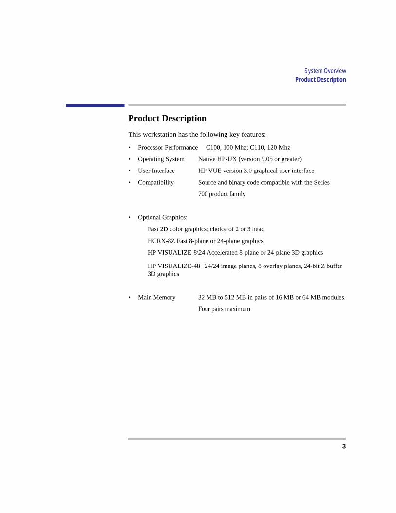
Product Description
This workstation has the following key features:
• Processor Performance C100, 100 Mhz; C110, 120 Mhz
• Operating System Native HP-UX (version 9.05 or greater)
• User Interface HP VUE version 3.0 graphical user interface
• Compatibility Source and binary code compatible with the Series
700 product family
• Optional Graphics:
Fast 2D color graphics; choice of 2 or 3 head
HCRX-8Z Fast 8-plane or 24-plane graphics
HP VISUALIZE-8\24 Accelerated 8-plane or 24-plane 3D graphics
HP VISUALIZE-48 24/24 image planes, 8 overlay planes, 24-bit Z buffer3D graphics
• Main Memory 32 MB to 512 MB in pairs of 16 MB or 64 MB modules.
Four pairs maximum
4
System OverviewProduct Description
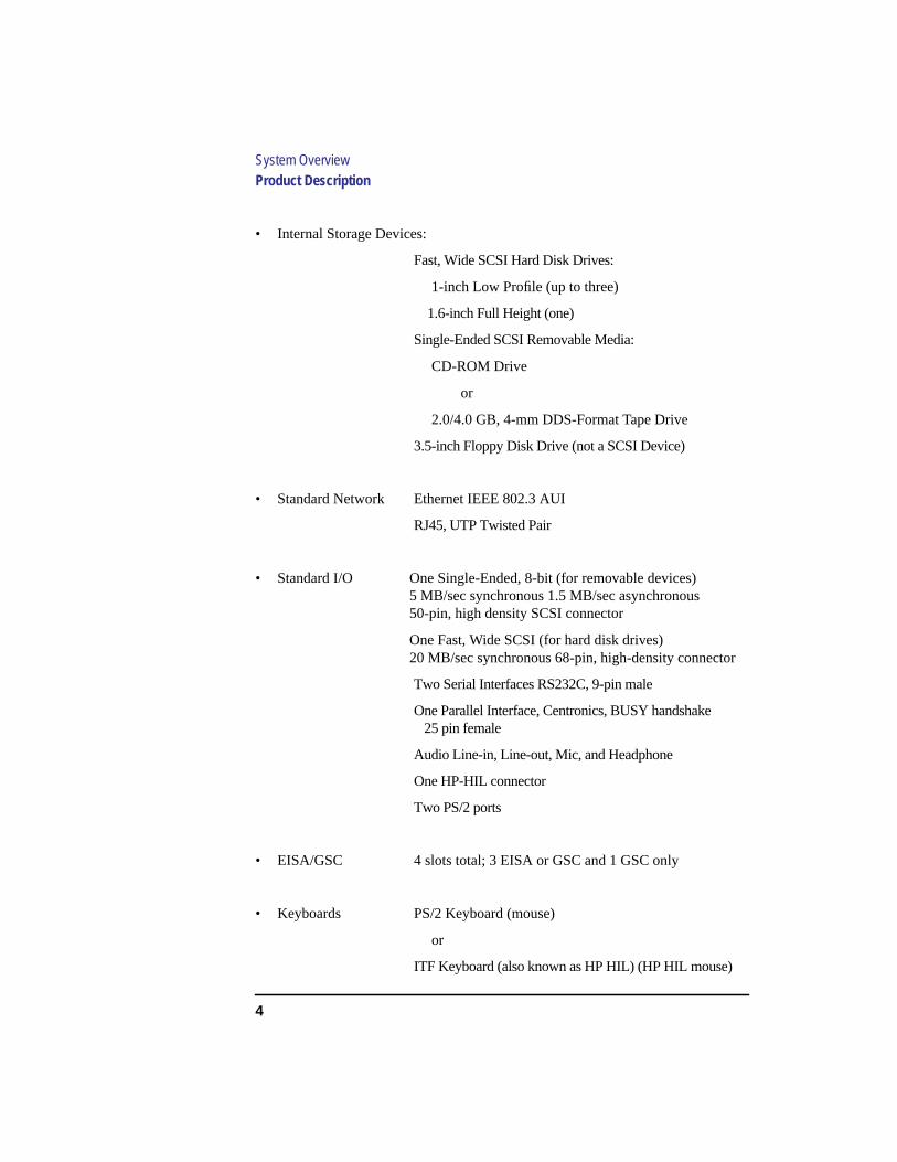
• Internal Storage Devices:
Fast, Wide SCSI Hard Disk Drives:
1-inch Low Profile (up to three)
1.6-inch Full Height (one)
Single-Ended SCSI Removable Media:
CD-ROM Drive
or
2.0/4.0 GB, 4-mm DDS-Format Tape Drive
3.5-inch Floppy Disk Drive (not a SCSI Device)
• Standard Network Ethernet IEEE 802.3 AUI
RJ45, UTP Twisted Pair
• Standard I/O One Single-Ended, 8-bit (for removable devices)5 MB/sec synchronous 1.5 MB/sec asynchronous50-pin, high density SCSI connector
One Fast, Wide SCSI (for hard disk drives)20 MB/sec synchronous 68-pin, high-density connector
Two Serial Interfaces RS232C, 9-pin male
One Parallel Interface, Centronics, BUSY handshake25 pin female
Audio Line-in, Line-out, Mic, and Headphone
One HP-HIL connector
Two PS/2 ports
• EISA/GSC 4 slots total; 3 EISA or GSC and 1 GSC only
• Keyboards PS/2 Keyboard (mouse)
or
ITF Keyboard (also known as HP HIL) (HP HIL mouse)

5
System OverviewSystem Unit Front Panel Controls and LEDs
System Unit Front Panel Controls and LEDs
Before powering on your system, you should become familiar with thesystem unit controls.
Figure 1 shows the system unit front panel controls.
Figure 1 System Unit Front Panel Controls
Storage Devices
Power Switch
Power LED
System LEDs
Removable
Volume
Mute
Headset
Mic

6
System OverviewSystem Unit Front Panel Controls and LEDs
System Power Switch
Use the Power switch to power the system unit on and off.
NOTICE: There is no need to manually shut down the HP-UX operating system onyour workstation before powering it off. When you turn off the powerswitch, your workstation automatically shuts down the operating systembefore terminating the power.
Power LED
The Power LED lights when the system unit power is on.
System LEDs
The system LEDs indicate the status of your workstation. In the event of asystem problem, the LEDs are lighted in different patterns to indicate errorcodes. See Chapter 6 for a complete list of the system LED error codes.
LED 4 - System Heartbeat
LED 3 - SCSI Bus Activity
LED 2 - Network Transmit
LED 1 - Network Receive
7
System OverviewSystem Unit Front Panel Controls and LEDs
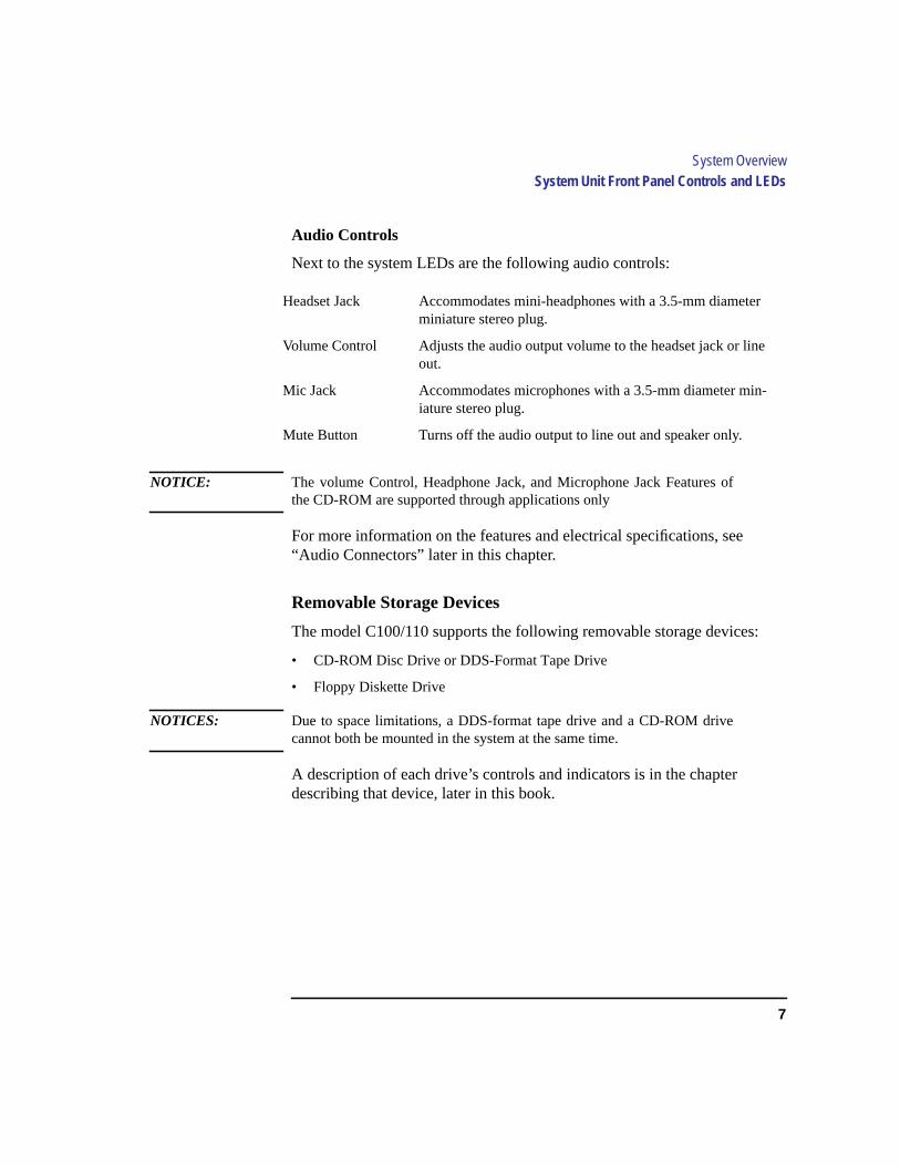
Audio Controls
Next to the system LEDs are the following audio controls:
NOTICE: The volume Control, Headphone Jack, and Microphone Jack Features ofthe CD-ROM are supported through applications only
For more information on the features and electrical specifications, see“Audio Connectors” later in this chapter.
Removable Storage Devices
The model C100/110 supports the following removable storage devices:
• CD-ROM Disc Drive or DDS-Format Tape Drive
• Floppy Diskette Drive
NOTICES: Due to space limitations, a DDS-format tape drive and a CD-ROM drivecannot both be mounted in the system at the same time.
A description of each drive’s controls and indicators is in the chapterdescribing that device, later in this book.
Headset Jack Accommodates mini-headphones with a 3.5-mm diameterminiature stereo plug.
Volume Control Adjusts the audio output volume to the headset jack or lineout.
Mic Jack Accommodates microphones with a 3.5-mm diameter min-iature stereo plug.
Mute Button Turns off the audio output to line out and speaker only.
8
System OverviewSystem Unit Rear Panel Connectors
System Unit Rear Panel Connectors
This section describes the following connectors on the system unit’s rearpanel:
• Security Loop
• Audio Line IN and Line OUT connectors
• PS/2 keyboard and mouse connectors
• HP parallel Centronics I/O connector
• 802.3 AUI LAN connector
• 802.3 TP (Twisted Pair) LAN connector
• Serial I/O connectors
• HP HIL connectors (keyboard, mouse, optional HIL devices)
• Monitor connector
• SCSI connectors (including fast, wide SCSI and single-ended SCSI)
• TOC button (Transfer of Control)
• Power cord connector
NOTICE: To maintain electro-magnetic and radio frequency emissions compliance,verify that all cables are fully seated and properly fastened.
Figure 2 shows the locations of the connectors on the system unit’s rearpanel.

9
System OverviewSystem Unit Rear Panel Connectors
Figure 2 System Unit Rear Panel Connectors
Security Loop
The security loop provides a means of locking the storage tray, with a pad-lock or other locking device, to prevent unauthorized removal from the sys-tem.
Audio Line In
PS/2 Mouse
PS/2 Keyboard
HP HILHP Parallel
LAN-AUILAN-TP
Serial 1
Serial 2
Single-ended SCSIFast, Wide SCSI
Audio Line Out
Power
Security Loop
TOC
Monitor

10
System OverviewSystem Unit Rear Panel Connectors
Audio Connectors
Your workstation has audio input and output capability through externalinput and output connectors on the rear panel and through an internalspeaker. The rear panel contains the Audio IN (stereo line-in) and AudioOUT (stereo line-out) connectors.
The audio connectors are standard stereo audio mini-jacks. Hewlett-Packardrecommends using gold-plated plugs available through audio retailers forbest quality recording and playback through the external connectors. Thefollowing is a summary of the workstation audio features:
• Audio Features Programmable sample rates:
8kHz, 16kHz, 32kHz, 48kHz, 11.025kHz,
22.05kHz, and 44.1kHz.
Programmable output attenuation:
0 to -96dB in -1.5dB steps
Programmable input gain:
0 to 22.5dB in 1.5dB steps
Input monitoring:
16-bit linear, 8-bit u-law, or A-law coding
• Audio Inputs Line-in
Mono microphone (on the front panel) compatible with 1.5Vphantom supply (bias voltage supplied by the system).
CD-ROM audio (if internal CD-ROM is installed.
• Audio Outputs Line-out
Headphone (on the front panel)
Built-in mono speaker
• Audio CODEC Crystal CS4215

11
System OverviewSystem Unit Rear Panel Connectors
The audio electrical specification for this workstation are summarized inTable 1.
*To convert from dB to number of significant bits, use the formula:
For example, for 61dB S/N then n=61/6 or approx. 10 significant bits, or in otherwords, about 6 bits of noise.
Table 1 Audio Electrical Specifications
Frequency Response 25-20,000 Hz
Input Sensitivity/Impedance
Line In 2.0Vpk/47k ohm
Microphone 22mVpk/1k ohm
Max Output Level/Impedance
Line Out 2.8Vpp/47k ohm
Headphone 2.75Vpp/50 ohm
Speaker (internal) 5.88Vpp/48 ohm
Output Impedance
Line Out 619 ohm
Headphone 118 ohm
Signal to Noise*
Line Out 65 dB
Headphone 61 dB
Speaker 63 dB
Line In 61 dB
Microphone 57 dB
THD (w nominal load)
Line Out -73 dB
Headphone -70 dB
Speaker -68 dB
Line In -75 dB
Microphone -73 dB
'ndB
20 10log[ ]--------------------------- dB
6-------≈
=
12
System OverviewSystem Unit Rear Panel Connectors
Keyboard Connectors
PS/2 Keyboard and Mouse Connectors
The PS/2 connectors provide an interface for a keyboard and a mouse to thesystem. Consult the documentation that accompanies each input device forspecific information concerning its use.
HP-HIL Keyboard Connector
The HP HIL connector provides an interface for the ITF Keyboard and itsmouse to the system. Consult the documentation that accompanies eachinput device for specific information concerning its use.
HP Parallel I/O Connector
The 25-pin HP Parallel I/O interface uses Centronics interface protocols tosupport peripheral devices such as printers and plotters. Consult the docu-mentation that accompanies each peripheral device for specific informationconcerning its use.
802.3 Network Connectors
Your workstation has built-in ThickNet LAN-AUI and LAN-TP (TwistedPair) connectors for the 802.3 (ETHERNET) network. Connections to Thin-LAN networks require an external transceiver. Your workstation will autose-lect the correct network setting.
Serial I/O Connectors
You can attach a variety of pointing devices (such as a mouse or trackball),or peripheral devices to the Serial Input/Output (SIO) ports on the C100/C110 workstation. Peripheral devices include printers, plotters, modems,and scanners. Consult the documentation that accompanies each pointing orperipheral device for specific information concerning its use.
The SIO ports are programmable. You can set functions such as bit rate,character length, parity, and stop bits. The SIO Ports are used as an interfacefor serial asynchronous devices to the CPU. The ports operate at up to a460.8K baud rate.

13
System OverviewSystem Unit Rear Panel Connectors
Table 2 shows the SIO connector pin listings. The serial connectors are 9-pinD-sub connectors. Signal names are those specified in the EIA RS-232 stan-dard.
SCSI Connectors
Use the single-ended and fast, wide connectors to connect external SCSIdevices such as DDS-format tape drives and CD-ROM drives. Consult thedocumentation that accompanies each SCSI device for specific informationconcerning its use. Refer to Appendix C for information about connectingSCSI devices to your workstation.
NOTICE: When attaching external SCSI devices, be sure to terminate the last deviceon the external SCSI bus.
Table 2 Serial I/O Pins
Pin No. Signal Description
1 DCD Data Carrier Detect
2 RXD Receive Data
3 TXD Transmit Data
4 DTR Data Terminal Ready
5 GND Ground
6 DSR Data Set Ready
7 RTS Request To Send
8 CTS Clear To Send
9 RI Ring Indicator
14
System OverviewSystem Unit Rear Panel Connectors
TOC Button
The TOC button resets the system and transfers control from the defaultdevice to an auxiliary device.
Power Cord Connector
Plug the workstation’s power cord into the power cord connector to provideac power to the system.
15
System OverviewMonitors
Monitors
You can use one of two HP monitors with your workstation:
• 17-inch, 1280x1024 color monitor (A4032A)
• 20-inch, 1280x1024 color monitor (A4033A)
Before using your monitor you should become familiar with its controls,connectors, and indicators. For this information, consult the documentationthat was packaged with your monitor, or see theHP A4032/A4033 ColorMonitor CE Handbook (A4033-90099).
16
System OverviewKeyboards
Keyboards
There are two types of Hewlett-Packard keyboards available for use withyour workstation.
• PS/2 Keyboard (P/S2 interface)
• ITF Keyboard (HP-HIL interface)
CAUTION: Only connect devices that conform to the HP-HIL specification withHewlett-Packard HIL ports. Devices that are not HP-HIL compatible buthave similar connectors may appear to be compatible, but will damageyour system.
Keyboard Differences
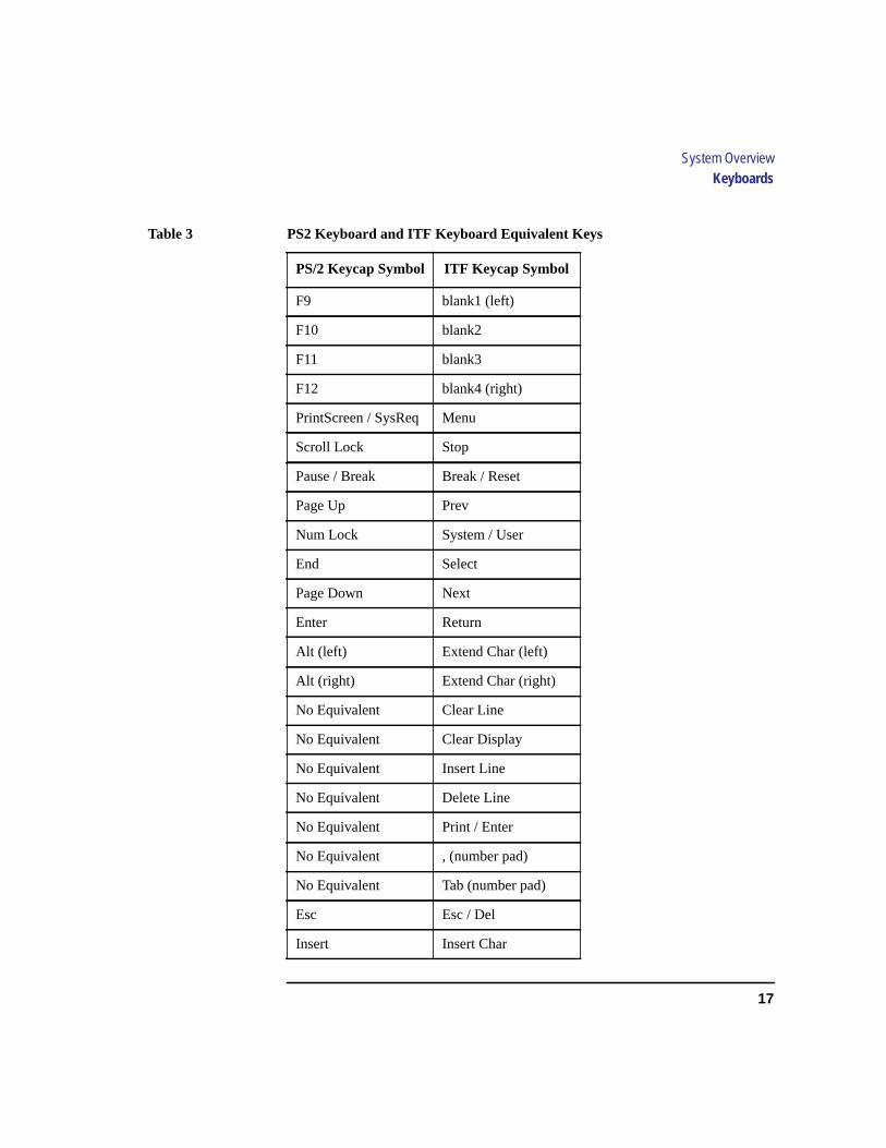
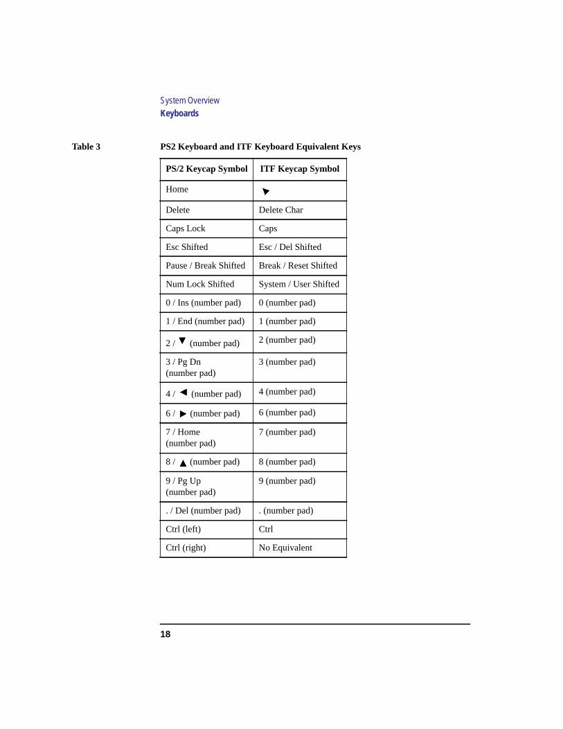
Aside from the obvious difference in the appearance of the PS/2 and ITFkeyboards due to the arrangement of the keys, there is also a difference inthe keys and their output codes. For example, some keys on one keyboardmay not exist on the other keyboard. These keys generate codes that may notexist as output from the other keyboard (or may be generated by a differentkey). Codes that are generated when a key is pressed are called keycodes.
Some applications expect to use keycodes generated by keys existing on oneof the keyboards (the ITF keyboard for example). Since the keys do not existon the other keyboard (the PS/2 keyboard for example), an accommodationmust be made if the PS/2 keyboard is to be used. In most cases, it is still pos-sible to use some other key that is equivalent (generates the same keycodefrom a different keycap). To do this, it is necessary to know which keys areequivalent on the two keyboards. Table 3 compares the equivalent keys ofthe ITF and PS/2 keyboards.
NOTICE: Keyboard keys not mentioned inTable 3 are the same on both keyboards.
17
System OverviewKeyboards
Table 3 PS2 Keyboard and ITF Keyboard Equivalent Keys
PS/2 Keycap Symbol ITF Keycap Symbol
F9 blank1 (left)
F10 blank2
F11 blank3
F12 blank4 (right)
PrintScreen / SysReq Menu
Scroll Lock Stop
Pause / Break Break / Reset
Page Up Prev
Num Lock System / User
End Select
Page Down Next
Enter Return
Alt (left) Extend Char (left)
Alt (right) Extend Char (right)
No Equivalent Clear Line
No Equivalent Clear Display
No Equivalent Insert Line
No Equivalent Delete Line
No Equivalent Print / Enter
No Equivalent , (number pad)
No Equivalent Tab (number pad)
Esc Esc / Del
Insert Insert Char
18
System OverviewKeyboards
Home
Delete Delete Char
Caps Lock Caps
Esc Shifted Esc / Del Shifted
Pause / Break Shifted Break / Reset Shifted
Num Lock Shifted System / User Shifted
0 / Ins (number pad) 0 (number pad)
1 / End (number pad) 1 (number pad)
2 / (number pad) 2 (number pad)
3 / Pg Dn(number pad)
3 (number pad)
4 / (number pad) 4 (number pad)
6 / (number pad) 6 (number pad)
7 / Home(number pad)
7 (number pad)
8 / (number pad) 8 (number pad)
9 / Pg Up(number pad)
9 (number pad)
. / Del (number pad) . (number pad)
Ctrl (left) Ctrl
Ctrl (right) No Equivalent
Table 3 PS2 Keyboard and ITF Keyboard Equivalent Keys
PS/2 Keycap Symbol ITF Keycap Symbol

19
System OverviewPointing Devices
Pointing Devices
You can use an HP three-button mouse, a trackball, or other options as point-ing devices using the PS/2 connector, the HIL port, or the Serial ports. Forinstructions on using your particular pointing device, see the manual thatcame with it.
For general information on using three-button mice and on the various cur-sor shapes associated with different areas of HP VUE while using a mouse,seeUsing Your HP Workstation.

20
System OverviewOperating System Overview
Operating System Overview
Your workstation uses the HP-UX operating system, version 9.05 or greater.Instant Ignition systems, (systems with preloaded software), have X-win-dows and Hewlett-Packard’s graphical user interface, HP VUE version 3.0,installed and configured.
Please refer to the “Instant Ignition System Configuration Information”sheet that shipped with your system for details on configuration.
If you have any questions about Instant Ignition, refer toUsing Your HPWorkstation for more information.
NOTICE: When you power on your workstation, a selftest program runs before thesystem boots.
21
System OverviewImportant Information You Need to Note
Important Information You Need to Note
Before you begin using your workstation, take a moment to gather the fol-lowing important information and note it in the appropriate subsection forfuture use:
• LANIC ID
• SCSI device ID
• Device file used for each SCSI device
• Internet Protocol (IP) address
• Subnetwork mask
NOTICE: For help with these, refer toUsing your HP Workstation.
LANIC ID
Locate the contents label that comes with the workstation shipping carton.Find the LANIC ID listed there and write it down in the space provided:
LANIC ID ____________________________________________
You can also get your LANIC ID by using the lanscan command in a termi-nal window. To do this, follow these steps:
1 Turn your workstation and monitor on, if you have not already done so. Figure 1of this chapter shows the location of the power switch on the workstation. See thedocumentation that came with your monitor for the location of the monitor powerswitch.
2 Move the mouse cursor to the Terminal Control on the Front Panel of your Work-space and click the left mouse button.

22
System OverviewImportant Information You Need to Note
A terminal window opens.
3 Move the mouse cursor into the terminal window and single-click the left mousebutton.
4 If you are using HP-UX 9.05, enter the following at the prompt:
/etc/lanscan
If you are using HP-UX 10.0, enter the following at the prompt:
/usr/sbin/lanscan
You will see a table similar to Table 4.
The LANIC ID in this example is 0800091595EE.
Table 4 Sample LANSCAN COMMAND TABLE
Hardware Station Dev Hardware
Net-Interface NetMgt Encapsulation
Path Address lu State NameUnit State ID Methods
2.0.2 0x0800091595EE 0 UP lan0 UP 4 ETHER IEEE8023
Terminal Control
23
System OverviewImportant Information You Need to Note
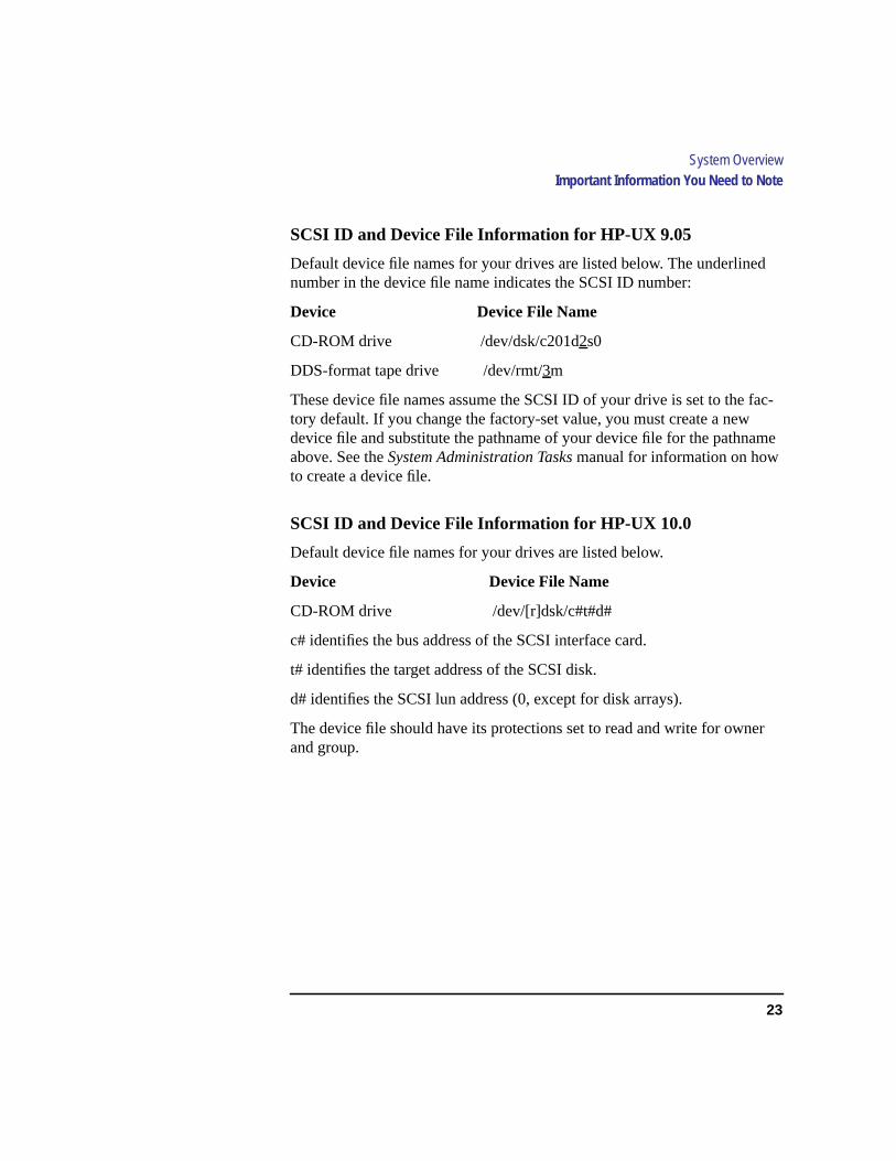
SCSI ID and Device File Information for HP-UX 9.05
Default device file names for your drives are listed below. The underlinednumber in the device file name indicates the SCSI ID number:
Device Device File Name
CD-ROM drive /dev/dsk/c201d2s0
DDS-format tape drive /dev/rmt/3m
These device file names assume the SCSI ID of your drive is set to the fac-tory default. If you change the factory-set value, you must create a newdevice file and substitute the pathname of your device file for the pathnameabove. See theSystem Administration Tasks manual for information on howto create a device file.
SCSI ID and Device File Information for HP-UX 10.0
Default device file names for your drives are listed below.
Device Device File Name
CD-ROM drive /dev/[r]dsk/c#t#d#
c# identifies the bus address of the SCSI interface card.
t# identifies the target address of the SCSI disk.
d# identifies the SCSI lun address (0, except for disk arrays).
The device file should have its protections set to read and write for ownerand group.

24
System OverviewImportant Information You Need to Note
Device file names for DDS drives at HP-UX 10.0 depend on the namingconventions of the system on which you are installing them.
For installation on a system permitting long file names:
/dev/rmt/c#t#d#BEST AT&T style, best available density,character entry.
/dev/rmt/c#t#d#BESTb Berkeley style, best available densitycharacter entry.
/dev/rmt/c#t#d#BESTn AT&T style, no rewind, best availabledensity, character entry.
/dev/rmt/c#t#d#BESTnb Berkeley style, no rewind, best availabledensity, character entry.
For installation on a system requiring short file names:
/dev/rmt/c#t#d#f0 AT&T style, best available density,character entry.
/dev/rmt/c#t#d#f0b Berkeley style, best available densitycharacter entry.
/dev/rmt/c#t#d#f0n AT&T style, no rewind, best available densitycharacter entry.
/dev/rmt/c#t#d##f0nb Berkeley style, no rewind, best availabledensity, character entry.
IP Address and Subnetwork Mask Information
Get the IP address and the subnet mask information for your workstationfrom either your System Administrator or your Network Administrator andnote them here:
IP address ____________________________________________________
subnet mask __________________________________________________
25
System OverviewNetworking Overview
Networking Overview
Your workstation is capable of many more tasks than are described in thisowner’s guide. This section gives an overview of some of the networkingcapabilities of your system and directs you to the appropriate source formore information.
Electronic mail allows you to send and receive mail messages on your work-station. For information on setting up and using electronic mail on yourworkstation, contact your system administrator and also see theUsing YourHP Workstation manual that came with your workstation.
telnet
The telnet application uses the TELNET protocol to communicate withanother computer system on the network. The telnet application allows youto log on to the remote system from your workstation. If your system hasmanpages installed, you may read the onlinetelnet man page by entering thefollowing at a command-line prompt:
man telnet
26
System OverviewNetworking Overview
rlogin
The rlogin application also allows you to log on to another computer systemon the network from your workstation. For more information on rlogin, seetheUsing Your HP Workstationmanual that came with your workstation andread the online man page by entering the following at a command-lineprompt:
man rlogin
ftp
The ftp application is a user interface to the File Transfer Protocol. Use ftp tocopy files between your workstation and another computer system on thenetwork. For more information, see theUsing Your HP Workstationmanualthat came with your workstation and read the online man page by enteringthe following at a command-line prompt:
man ftp
rcp
The rcp application allows you to remotely copy files from another computersystem on a network to your workstation. For more information, see theUsing Your HP Workstation manual that came with your workstation andread the online man page by entering the following at a command-lineprompt:
man rcp
NFS
The Network File System (NFS) allows your workstation to access files onremote computer systems as if they were on your local system. The file sys-tem on the remote computer system does not have to be compatible withyour workstation’s file system. For more information, see Installing andAdministering NFS ServersandHP-UX System Administration Tasks manu-als.

27
2
Setting Up Your Printer

28
Setting Up Your Printer
This chapter describes how to configure your workstation to use a printerthat you have physically attached to either the parallel connector or the serial(RS-232C) connector on the rear of your workstation.
This chapter is divided into the following sections:
• Gathering printer information
• Setting up a local printer using SAM
• Setting up your printer for network printing
• Printing a file
• Solving printing problems
The instructions in this chapter assume you are using HP-UX version 9.05 or10.0 operating system with HP VUE version 3.0 or later interface.
NOTICES: Make sure you have installed the printer as described in the manufacturer’s instruc-tions before following the instructions in this chapter. Also ensure that the printer ispowered on, connected to your workstation, has paper loaded, and is online.
Some procedures in this chapter require you to log in as root. If you cannotlog in asroot, contact your system administrator.

29
Setting Up Your PrinterGathering Printer Information
Gathering Printer Information
Before you start, fill in the following list with the requested information andrefer to it during the printer setup procedure:
• Printer Interface (check one):
❒ Parallel
❒ Serial (RS232C) Port 1
❒ Serial (RS232C) Port 2
• Printer Name ____________________________________________________
(The printer name is a name the system uses to identify the printer. The printername can be any name that you wish.)
• Printer Model Number_____________________________________________
(On Hewlett-Packard printers the model number is located on a label on the backof the printer.)

30
Setting Up Your PrinterSetting Up a Local Printer Using SAM
Setting Up a Local Printer Using SAM
Follow the instructions in this section to set up a printer that is physicallyattached to your workstation.
The procedures in this section require you to log in as root. If you cannot login as root, contact your system administrator.
If your workstation is running HP VUE, follow these instructions to set upyour printer using SAM.
1 Log in as root. If you need information on logging in or setting up a user account,seeUsing Your HP Workstation.
2 Move the mouse pointer to the up arrow above the Toolbox control and click theleft mouse button. (This is called a single click, or simply a click.)
Figure 3 Opening the Toolbox Subpanel
3 The Toolbox subpanel opens. Click on the General toolbox icon, shown below.
Figure 4 Opening the General Toolbox

31
Setting Up Your PrinterSetting Up a Local Printer Using SAM
4 A file manager window appears with a number of icons in it. Double-click on theSystem_Admin toolbox icon.
Figure 5 Opening the System_Admin Toolbox
5 Move the mouse cursor to the SAM icon shown below (your icon can look likeeither of these) and double-click the left mouse button.
Figure 6 Executing the SAM Icon
6 The System Administration Manager window opens. Double-click onPrintersand Plotters ->.
7 The Printers and Plotters window opens. Double-click onPrinters/Plotters.
If your workstation doesn’t have any printers set up, a message window opens.Click onOK to remove it.
8 From the Actions menu, click onAdd Local Printer/Plotter.
9 Another menu opens. If your printer is connected to the parallel port on yourworkstation, click onAdd a Parallel Printer/Plotter.
If your printer is connected to one of the serial connectors on your workstation,click onAdd Serial (RS-232C) Printer/Plotter.
A window opens displaying the available parallel or serial interfaces.
10 If you choseAdd Parallel Printer/Plotter in the previous step, only one parallelinterface will be listed. Place the mouse cursor on the listed parallel interface andclick the left mouse button.
32
Setting Up Your PrinterSetting Up a Local Printer Using SAM
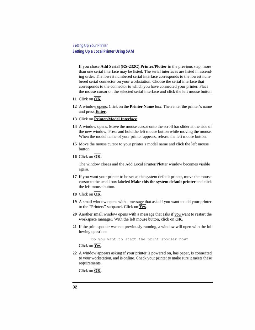
If you choseAdd Serial (RS-232C) Printer/Plotter in the previous step, morethan one serial interface may be listed. The serial interfaces are listed in ascend-ing order. The lowest numbered serial interface corresponds to the lowest num-bered serial connector on your workstation. Choose the serial interface thatcorresponds to the connector to which you have connected your printer. Placethe mouse cursor on the selected serial interface and click the left mouse button.
11 Click onOK .
12 A window opens. Click on thePrinter Name box. Then enter the printer’s nameand pressEnter.
13 Click onPrinter/Model Interface .
14 A window opens. Move the mouse cursor onto the scroll bar slider at the side ofthe new window. Press and hold the left mouse button while moving the mouse.When the model name of your printer appears, release the left mouse button.
15 Move the mouse cursor to your printer’s model name and click the left mousebutton.
16 Click onOK .
The window closes and the Add Local Printer/Plotter window becomes visibleagain.
17 If you want your printer to be set as the system default printer, move the mousecursor to the small box labeled Make this the system default printer and clickthe left mouse button.
18 Click onOK .
19 A small window opens with a message that asks if you want to add your printerto the “Printers” subpanel. Click onYes.
20 Another small window opens with a message that asks if you want to restart theworkspace manager. With the left mouse button, click onOK .
21 If the print spooler was not previously running, a window will open with the fol-lowing question:
Do you want to start the print spooler now?
Click onYes.
22 A window appears asking if your printer is powered on, has paper, is connectedto your workstation, and is online. Check your printer to make sure it meets theserequirements.
Click onOK .
33
Setting Up Your PrinterSetting Up a Local Printer Using SAM
23 Click onOK at the bottom of theMessages window.
ThePrinter/Plotter Manager window now lists your printer.
24 Move the cursor to the wordList at the top of thePrinter/Plotter Manager win-dow and click the left mouse button.
25 A menu opens below the wordList . Click onExit .
The mainSAM window becomes visible again.
26 In the mainSAM window, click onExit SAM .
TheSAM window closes.
27 Double-click on the window menu button in the upper-left corner of theToolboxwindow. The window closes.
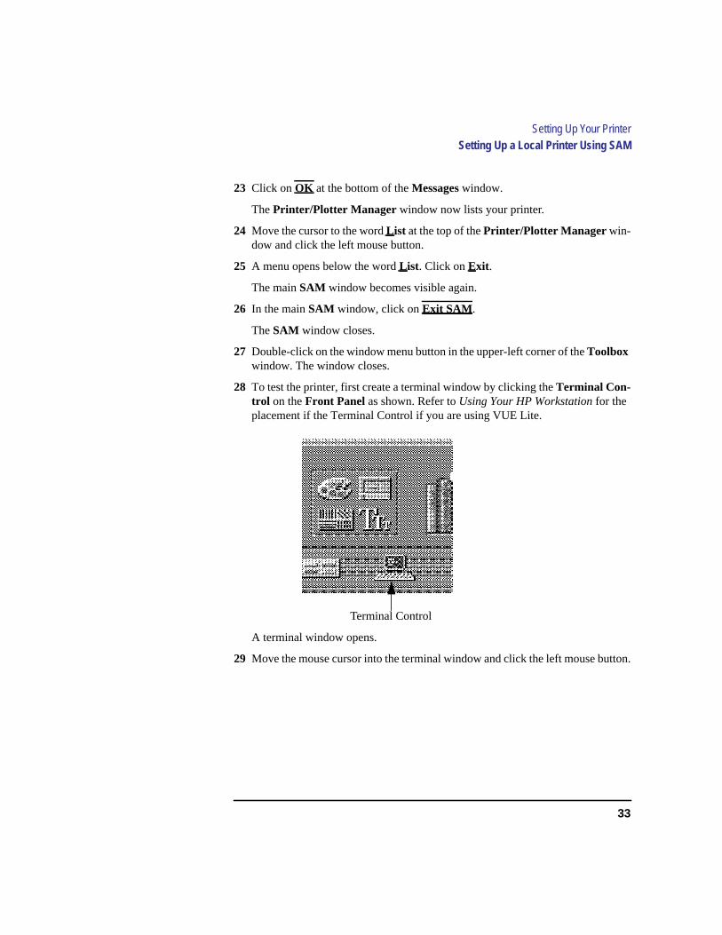
28 To test the printer, first create a terminal window by clicking theTerminal Con-trol on theFront Panel as shown. Refer toUsing Your HP Workstation for theplacement if the Terminal Control if you are using VUE Lite.
A terminal window opens.
29 Move the mouse cursor into the terminal window and click the left mouse button.
Terminal Control
34
Setting Up Your PrinterSetting Up a Local Printer Using SAM
30 If you made your printer the default system printer, enter the following commandto test your printer:
lp .vueprofile
If your printer isn’t the default system printer, enter the following command totest your printer:
lp -dprintername .vueprofile
whereprintername is the name you chose when setting up your printer.
The lp command sends files to a printer.
The file named .vueprofile prints out on the printer.
If the file doesn’t print, see the section titled “Printing Problems,” later in thischapter.
35
Setting Up Your PrinterSetting Up Your Printer for Network Printing
Setting Up Your Printer for Network Printing
If you have a printer physically attached to your workstation, you can set itup to receive print requests from other computers on your network. To dothis, you must start up the remote line printer daemon.
Follow the instructions in this section to set up your workstation to acceptprint requests from other computers on your network.
1 Log in asroot. If you need information on logging in or setting up a user account,seeUsing Your HP Workstation.
2 If you are using HP-UX 9.05, using a text editor such as vi or Text Editor, editthe following file:
/etc/inetd.conf
If you are using HP-UX 10.0, using a text editor such as vi or Text Editor, editthe following file:
/usr/sbin/inetd.conf
3 Find the following section in the file:
##
#
# Other HP-UX network services
#
##
4 The following line should be directly below Other HP-UX network services:
# printer stream tcp nowait root /usr/lib/rlpdaemon rlpdaemon -i
If the line is present, delete the pound sign (#) from the beginning. If the line isnot there, add it without the pound sign (#) at the beginning.
36
Setting Up Your PrinterSetting Up Your Printer for Network Printing
The line should look like the following:
printer stream tcp nowait root /usr/lib/rlpdaemon rlpdaemon -i
5 Save the file and close it.
6 Click on theTerminal Control on theFront Panel of your Workspace.
A terminal window opens.
7 Move the mouse cursor into the terminal window and click the left mouse button.
8 If you are using HP-UX 9.05, enter the following command line to reboot yourworkstation:
/etc/reboot
If you are using HP-UX 10.0, enter the following command line to reboot yourworkstation:
/usr/sbin/reboot
Your workstation shuts itself down and then reboots automatically. This maytake a few minutes. When the login prompt returns, your system is ready toaccept printer requests from other computers on your network.
37
Setting Up Your PrinterPrinting a File
Printing a File
To print a file, use one of the following command lines in a terminal window
lp filename
or
lp -dprintername filename
wherefilename is the name of the file that you want to print, andprintername is the name of the printer on which you wish to print the file.
The lp command sends files to a printer.
1 Click on theTerminal Control on theFront Panel of your Workspace.
A terminal window opens.
2 Move the mouse cursor into the terminal window and click the left mouse button.
3 Enter thelp command as described above.
For more information on thelp command, enter the following:
man lp
Also see the manualUsing Your HP Workstation for information on printingfiles by dragging and dropping the file icon onto the printer tool.
38
Setting Up Your PrinterSolving Printer Problems
Solving Printer Problems
If you have problems printing, check the following:
• Printer’s power cord is plugged in.
• Printer is powered on.
• Printer is online.
• Printer has paper loaded.
• Printer is set up for the correct interface type.
• Printer cable is connected to the correct interface port on your printer.
• Printer cable is connected to the correct interface port on your workstation.
39
3
Using Your CD-ROM Drive

40
Using Your CD-ROM Drive
This chapter describes how to use your CD-ROM drive. It is divided into thefollowing sections:
• CD-ROM drive and CD-ROM media descriptions
• Operating the CD-ROM Drive
• Mounting and unmounting a CD-ROM disc
• Troubleshooting
NOTICE Be sure you read and understand the information on mounting andunmounting CD-ROM discs before you begin using your CD-ROM discdrive.
This chapter provides an overview of the optional CD-ROM drive andmedia, and describes how to use the CD-ROM drive. We assume the CD-ROM drive is set to the factory default address of SCSI ID 2.
The instructions in this chapter assume you are using HP-UX version 9.05 orlater operating system with HP VUE version 3.0 or later interface.
NOTICE Some procedures in this chapter require you to log in asroot. If you cannotlog in asroot, contact your system administrator.
41
Using Your CD-ROM DriveCD-ROM Drive and CD-ROM Media Descriptions
CD-ROM Drive and CD-ROM Media Descriptions
This section describes basic information needed for using the CD-ROMdrive and CD-ROM discs.
CD-ROM Drive
The CD-ROM drive is a random access read-only mass storage device thatuses removable CD-ROM discs. The drive supports the ISO 9660 and HighSierra format standards. You can access information from the drive like anyother disk drive, except that you cannot write to the drive. The drive containsa semiconductor laser for reading data optically, and includes an embeddedcontroller with a SCSI interface.
42
Using Your CD-ROM DriveCD-ROM Drive and CD-ROM Media Descriptions
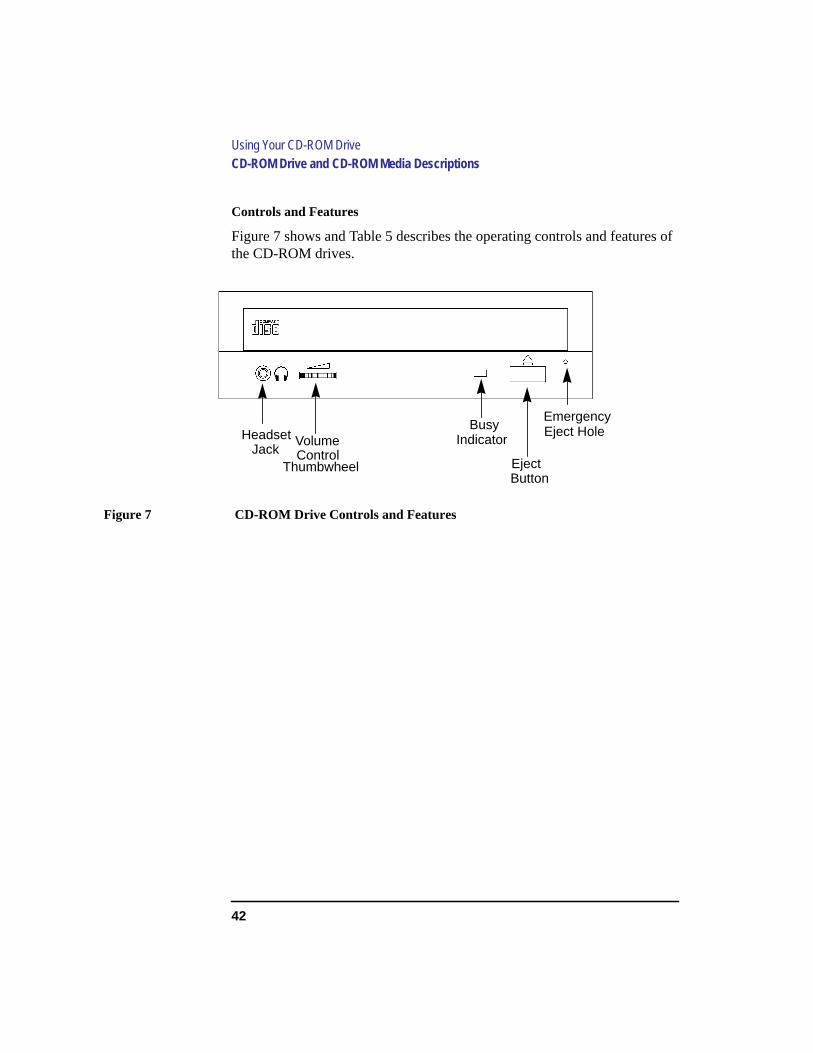
Controls and Features
Figure 7 shows and Table 5 describes the operating controls and features ofthe CD-ROM drives.
Figure 7 CD-ROM Drive Controls and Features
JackHeadset Volume
ControlThumbwheel
BusyIndicator
EjectButton
EmergencyEject Hole
43
Using Your CD-ROM DriveCD-ROM Drive and CD-ROM Media Descriptions
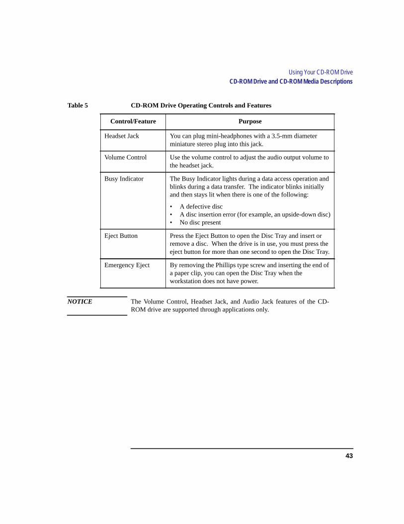
NOTICE The Volume Control, Headset Jack, and Audio Jack features of the CD-ROM drive are supported through applications only.
Table 5 CD-ROM Drive Operating Controls and Features
Control/Feature Purpose
Headset Jack You can plug mini-headphones with a 3.5-mm diameterminiature stereo plug into this jack.
Volume Control Use the volume control to adjust the audio output volume tothe headset jack.
Busy Indicator The Busy Indicator lights during a data access operation andblinks during a data transfer. The indicator blinks initiallyand then stays lit when there is one of the following:
• A defective disc• A disc insertion error (for example, an upside-down disc)• No disc present
Eject Button Press the Eject Button to open the Disc Tray and insert orremove a disc. When the drive is in use, you must press theeject button for more than one second to open the Disc Tray.
Emergency Eject By removing the Phillips type screw and inserting the end ofa paper clip, you can open the Disc Tray when theworkstation does not have power.
44
Using Your CD-ROM DriveCD-ROM Drive and CD-ROM Media Descriptions
CD-ROM Media
CD-ROM discs are 120 mm (4.7 in.) in diameter, and use one data surfacewith a capacity of approximately 600 megabytes. The data surface containspits and flat spots arranged in a continuous spiral track, which is read at aconstant speed. You may access files and data stored on a CD-ROM disc, butyou may not write files or data to a CD-ROM disc.
CD-ROM data discs are identical to audio compact discs (CDs) except thatthey store computer data and information.
CAUTION: Handle CD-ROM discs by the edges only. Always be sure a CD-ROM disc is eitherin the CD-ROM drive or its protective case when not in use. This will lessen thechance of exposing the disc surface to dust. Over time, dust reduces the reliability ofthe read head in the CD-ROM drive.
Caring for CD-ROM Discs
Observe the following guidelines to help prevent data loss and prolong thelife of your CD-ROM discs and drive:
• Use CD-ROM discs in a clean environment to prevent dust particles fromscratching disc surfaces.
• Store CD-ROM discs in a cool, dry place to prevent moisture and heatdamage.
• Don’t try to clean the surface of a CD-ROM disc with cleaning solvents,as some cleaning solvents may damage the disc.
NOTICE: You must mount the disc after loading it into the drive. Refer to the section“Mounting and Unmounting a CD-ROM Disc,” later in this chapter, forinstructions about mounting a disc.

45
Using Your CD-ROM DriveOperating the CD-ROM Drive
Operating the CD-ROM Drive
This section describes how to perform tasks with your CD-ROM drive.
Loading and Unloading a CD-ROM in the Disc Tray
This subsection describes how to load or unload a CD-ROM disc in the CD-ROM drive.
Disc Tray Description
This CD-ROM is designed to be used in either the horizontal or verticalposition, depending on whether your system unit is horizontal or vertical (inthe floor stand). The disc tray has three spring-loaded disc holders that holdthe disc in place when the CD-ROM drive is in the vertical position. Whenthe drive is in the horizontal position, the disc holders are not used and areheld out of the way by three disc holder retainers. Figure 8 shows the CD-ROM disc tray, and disc holders.
Figure 8 CD-ROM Disc Tray
DiscHolder
DiscHolder
DiscHolder
46
Using Your CD-ROM DriveOperating the CD-ROM Drive
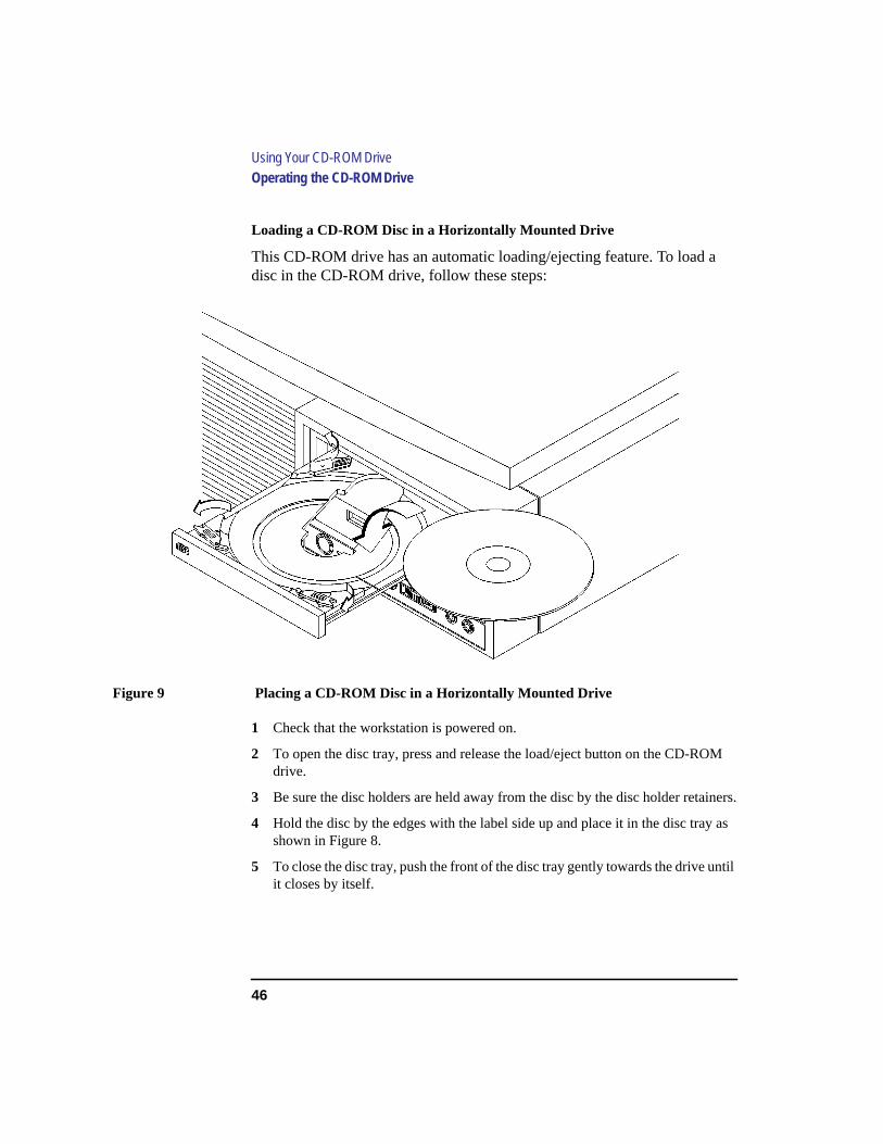
Loading a CD-ROM Disc in a Horizontally Mounted Drive
This CD-ROM drive has an automatic loading/ejecting feature. To load adisc in the CD-ROM drive, follow these steps:
Figure 9 Placing a CD-ROM Disc in a Horizontally Mounted Drive
1 Check that the workstation is powered on.
2 To open the disc tray, press and release the load/eject button on the CD-ROMdrive.
3 Be sure the disc holders are held away from the disc by the disc holder retainers.
4 Hold the disc by the edges with the label side up and place it in the disc tray asshown in Figure 8.
5 To close the disc tray, push the front of the disc tray gently towards the drive untilit closes by itself.
47
Using Your CD-ROM DriveOperating the CD-ROM Drive
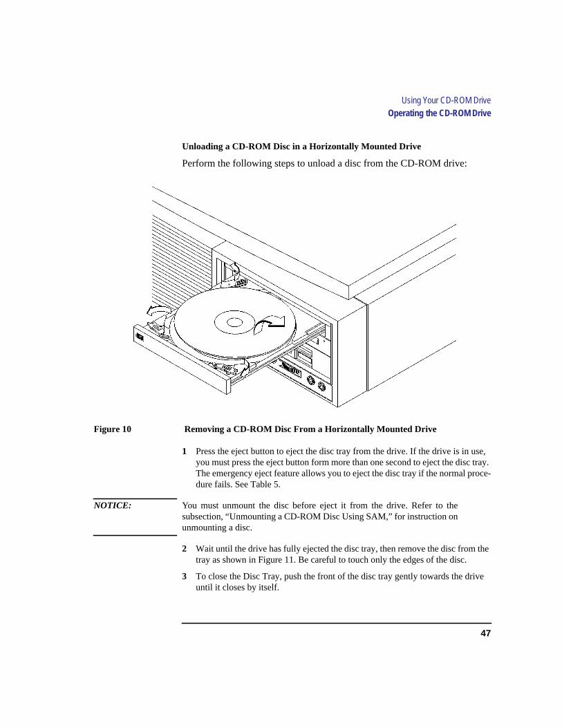
Unloading a CD-ROM Disc in a Horizontally Mounted Drive
Perform the following steps to unload a disc from the CD-ROM drive:
Figure 10 Removing a CD-ROM Disc From a Horizontally Mounted Drive
1 Press the eject button to eject the disc tray from the drive. If the drive is in use,you must press the eject button form more than one second to eject the disc tray.The emergency eject feature allows you to eject the disc tray if the normal proce-dure fails. See Table 5.
NOTICE: You must unmount the disc before eject it from the drive. Refer to thesubsection, “Unmounting a CD-ROM Disc Using SAM,” for instruction onunmounting a disc.
2 Wait until the drive has fully ejected the disc tray, then remove the disc from thetray as shown in Figure 11. Be careful to touch only the edges of the disc.
3 To close the Disc Tray, push the front of the disc tray gently towards the driveuntil it closes by itself.

48
Using Your CD-ROM DriveOperating the CD-ROM Drive
Loading a CD-ROM Disc in a Vertically Mounted Drive
To load a disc in the CD-ROM drive, follow these steps:
Figure 11 Releasing the Disc Holder Retainers
1 Make sure the three disc holders are disengaged from the disc holder retainers, asshown in Figure 11.
DiscHolder A
DiscHolder C
DiscHolder B

49
Using Your CD-ROM DriveOperating the CD-ROM Drive
2 Hold the disc with the label side to the left and place the edge of the disc onto discholders A and B as shown in
Figure 12 Placing a CD-ROM Disc in a Vertically Mounted Drive
3 Press down gently against the spring tension of disc holders A and B, and swingthe top of the disc in until it is held by disc holder C.
4 To close the disc tray, push the front of the disc tray gently towards the drive untilit closes by itself.
50
Using Your CD-ROM DriveOperating the CD-ROM Drive
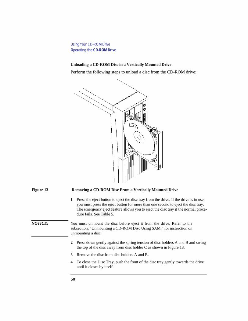
Unloading a CD-ROM Disc in a Vertically Mounted Drive
Perform the following steps to unload a disc from the CD-ROM drive:
Figure 13 Removing a CD-ROM Disc From a Vertically Mounted Drive
1 Press the eject button to eject the disc tray from the drive. If the drive is in use,you must press the eject button for more than one second to eject the disc tray.The emergency eject feature allows you to eject the disc tray if the normal proce-dure fails. See Table 5.
NOTICE: You must unmount the disc before eject it from the drive. Refer to thesubsection, “Unmounting a CD-ROM Disc Using SAM,” for instruction onunmounting a disc.
2 Press down gently against the spring tension of disc holders A and B and swingthe top of the disc away from disc holder C as shown in Figure 13.
3 Remove the disc from disc holders A and B.
4 To close the Disc Tray, push the front of the disc tray gently towards the driveuntil it closes by itself.
51
Using Your CD-ROM DriveOperating the CD-ROM Drive
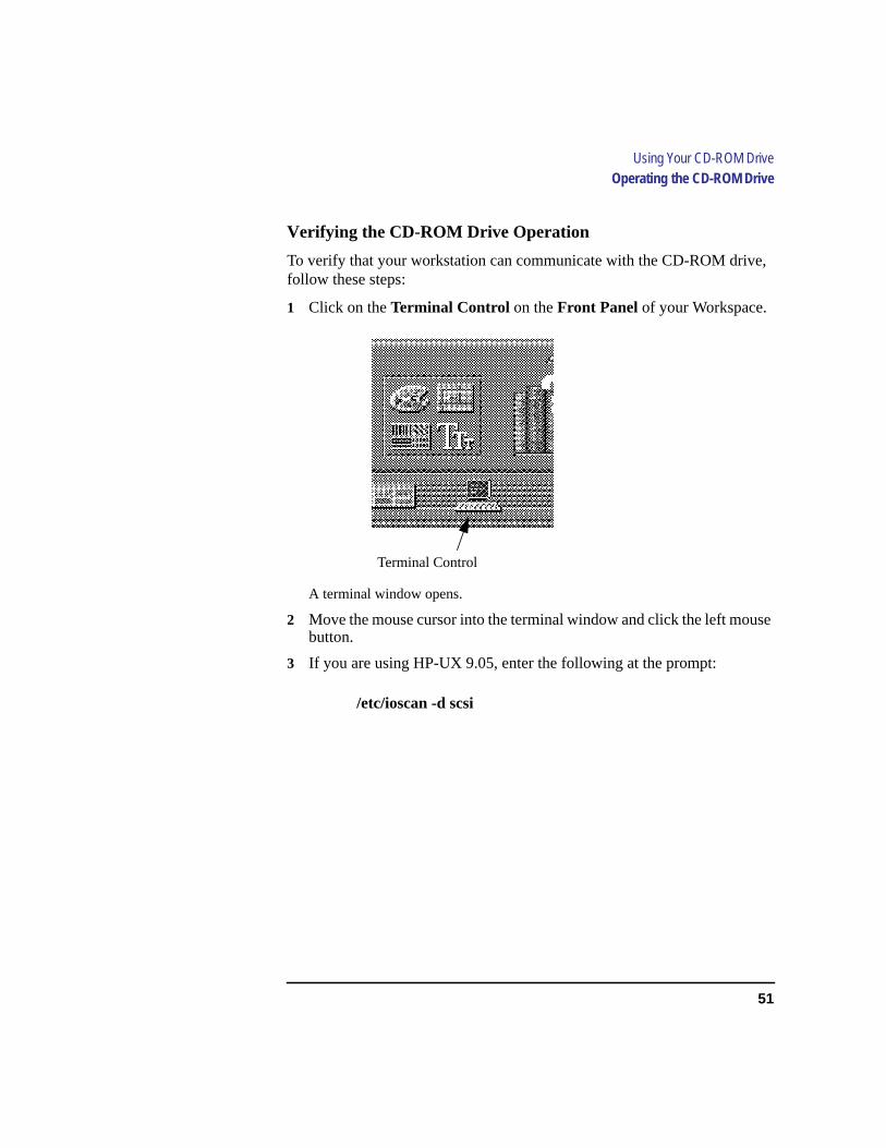
Verifying the CD-ROM Drive Operation
To verify that your workstation can communicate with the CD-ROM drive,follow these steps:
1 Click on theTerminal Control on theFront Panel of your Workspace.
A terminal window opens.
2 Move the mouse cursor into the terminal window and click the left mousebutton.
3 If you are using HP-UX 9.05, enter the following at the prompt:
/etc/ioscan -d scsi
Terminal Control
52
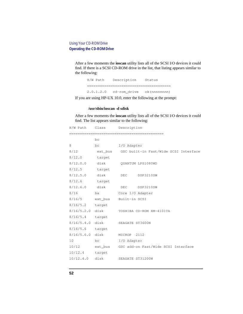
Using Your CD-ROM DriveOperating the CD-ROM Drive
After a few moments theioscan utility lists all of the SCSI I/O devices it couldfind. If there is a SCSI CD-ROM drive in the list, that listing appears similar tothe following:
H/W Path Description Status
=======================================
2.0.1.2.0 cd-rom_drive ok(nnnnnnnn)
If you are using HP-UX 10.0, enter the following at the prompt:
/usr/sbin/ioscan -d sdisk
After a few moments theioscan utility lists all of the SCSI I/O devices it couldfind. The list appears similar to the following:
H/W Path Class Description
============================================
bc
8 bc I/O Adapter
8/12 ext_bus GSC built-in Fast/Wide SCSI Interface
8/12.0 target
8/12.0.0 disk QUANTUM LPS1080WD
8/12.5 target
8/12.5.0 disk DEC DSP3210SW
8/12.6 target
8/12.6.0 disk DEC DSP3210SW
8/16 ba Core I/O Adapter
8/16/5 ext_bus Built-in SCSI
8/16/5.2 target
8/16/5.2.0 disk TOSHIBA CD-ROM XM-4101TA
8/16/5.4 target
8/16/5.4.0 disk SEAGATE ST3600N
8/16/5.6 target
8/16/5.6.0 disk MICROP 2112
10 bc I/O Adapter
10/12 ext_bus GSC add-on Fast/Wide SCSI Interface
10/12.4 target
10/12.4.0 disk SEAGATE ST31200W

53
Using Your CD-ROM DriveOperating the CD-ROM Drive
If ioscan does not see your CD-ROM drive it returns the following message:
ioscan: No hardware found
If you receive this message, go to Chapter 6, “Solving Problems.”
Using Device Files
Device files are special files that tell your system which pathway to usethrough the system hardware when communicating with a specific device,and tell what kind of device it is.
The examples in this section assume that the SCSI ID of your CD-ROMdrive is set to the factory default of SCSI ID 2, using the device file/dev/dsk/c201d2s0. (The underlined 2 indicates the SCSI ID number.)
NOTICE: The device file name used in these examples is appropriate only forsystems running HP-UX 9.05. If you are using HP-UX 10.0, the device filenames will depend on the naming conventions of your particular system.See “SCSI ID and Device File Information for HP-UX 10.0” in Chapter 1of this book.
If you set the SCSI address of your CD-ROM drive to a value other than 2,you must create a device file for it, then substitute the pathname of yourdevice file in the examples that follow. Refer to theSystem AdministrationTasks manual for information on how to create a device file.

54
Using Your CD-ROM DriveMounting and Unmounting a CD-ROM Disc
Mounting and Unmounting a CD-ROM Disc
To access information on a CD-ROM disc, you must first mount the disc.This applies to file system information only. If you wish to load a music CD,for example, you would not need to mount the disc. Mounting a disc withfile system information on it gives the disc a pathname that allows yourworkstation to communicate electronically with it. You must unmount theCD-ROM disc before removing it from the drive.
CAUTION: To use a CD-ROM disc as a mounted file system, you must mount the CD-ROM discevery time you load it into the drive. You must also unmount the CD-ROM discevery time you unload it from the drive. Failure to mount or unmount a disc can causea system error condition that can require rebooting the system.
If your workstation is running HP VUE, follow these instructions to mountand unmount a CD-ROM disc as a file system. If you’re using somethingother than HP VUE, use the instructions for mounting and unmounting aCD-ROM disc that come with that product. For more information on config-uring your CD-ROM drive, see theSystem Administration Tasks manual oronline help.
The procedures in this chapter require you to log in asroot. If you cannotlog in asroot, contact your system administrator.
Mounting a CD-ROM Disc Using SAM
Use the following procedure to mount a CD-ROM disc:
1 Log in asroot. If you need information on logging in or setting up a useraccount, seeUsing Your HP Workstation.
2 Load the CD-ROM disc into the disc tray and gently push the tray into thedrive.
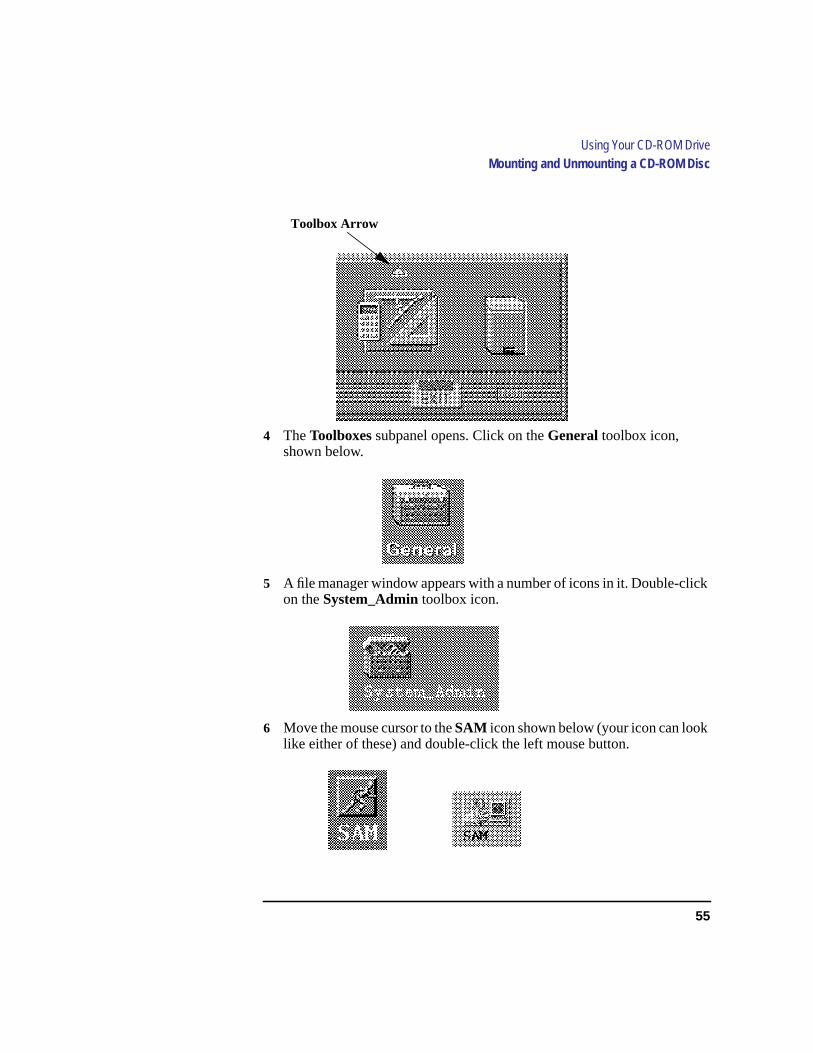
3 Move the mouse pointer to thearrow above theToolboxcontrol and clickthe left mouse button once.
55
Using Your CD-ROM DriveMounting and Unmounting a CD-ROM Disc
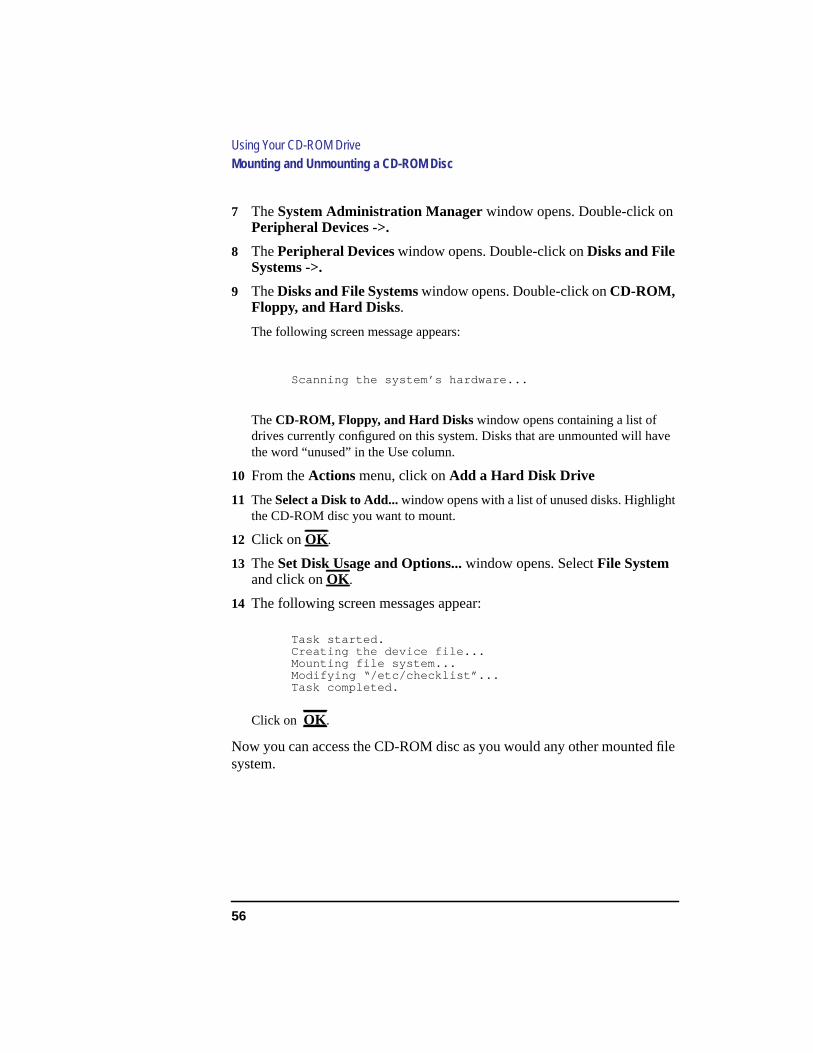
4 TheToolboxes subpanel opens. Click on theGeneral toolbox icon,shown below.
5 A file manager window appears with a number of icons in it. Double-clickon theSystem_Admin toolbox icon.
6 Move the mouse cursor to theSAM icon shown below (your icon can looklike either of these) and double-click the left mouse button.
Toolbox Arrow
56
Using Your CD-ROM DriveMounting and Unmounting a CD-ROM Disc
7 TheSystem Administration Manager window opens. Double-click onPeripheral Devices ->.
8 ThePeripheral Deviceswindow opens. Double-click onDisks and FileSystems ->.
9 TheDisks and File Systemswindow opens. Double-click onCD-ROM,Floppy, and Hard Disks.
The following screen message appears:
Scanning the system’s hardware...
TheCD-ROM, Floppy, and Hard Diskswindow opens containing a list ofdrives currently configured on this system. Disks that are unmounted will havethe word “unused” in the Use column.
10 From theActions menu, click onAdd a Hard Disk Drive
11 TheSelect a Disk to Add... window opens with a list of unused disks. Highlightthe CD-ROM disc you want to mount.
12 Click onOK .
13 TheSet Disk Usage and Options... window opens. SelectFile Systemand click onOK .
14 The following screen messages appear:
Task started.Creating the device file...Mounting file system...Modifying “/etc/checklist”...Task completed.
Click on OK .
Now you can access the CD-ROM disc as you would any other mounted filesystem.
57
Using Your CD-ROM DriveMounting and Unmounting a CD-ROM Disc
Unmounting a CD-ROM Disc Using SAM
Use the following procedure to unmount a CD-ROM disc:
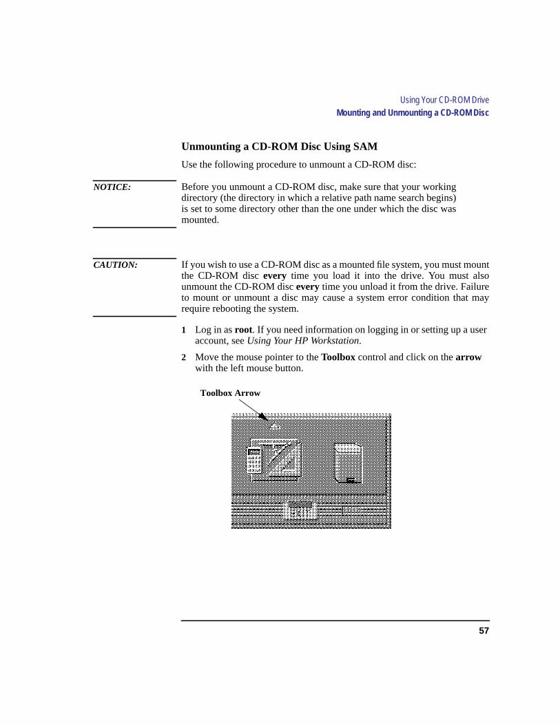
NOTICE: Before you unmount a CD-ROM disc, make sure that your workingdirectory (the directory in which a relative path name search begins)is set to some directory other than the one under which the disc wasmounted.
CAUTION: If you wish to use a CD-ROM disc as a mounted file system, you must mountthe CD-ROM discevery time you load it into the drive. You must alsounmount the CD-ROM discevery time you unload it from the drive. Failureto mount or unmount a disc may cause a system error condition that mayrequire rebooting the system.
1 Log in asroot. If you need information on logging in or setting up a useraccount, seeUsing Your HP Workstation.
2 Move the mouse pointer to theToolbox control and click on thearrowwith the left mouse button.
Toolbox Arrow

58
Using Your CD-ROM DriveMounting and Unmounting a CD-ROM Disc
3 TheToolbox subpanel opens. Place the mouse cursor on theGeneraltoolbox icon, shown below, and click the left mouse button.
4 A file manager window appears with a number of icons in it. Double-clickon theSystem_Admin toolbox icon.
5 Move the mouse cursor to theSAM icon shown below (your icon can looklike either of these) and double-click the left mouse button.
6 TheSystem Administration Managerwindow opens. Double-click onPeripheral Devices ->.
7 ThePeripheral Devices window opens. Double-click onDisks and FileSystems ->.
8 TheDisks and File Systemswindow opens. Double-click onCD-ROM,Floppy, and Hard Disks.
The following screen message appears:
Scanning the system’s hardware...
TheCD-ROM, Floppy, and Hard Disks window opens containing a list ofdrives currently configured on this system.

59
Using Your CD-ROM DriveMounting and Unmounting a CD-ROM Disc
9 Highlight the disc you want to unmount and click onRemove a HardDisk Drive from the Actions menu.
10 A window with the following message opens:
Do you want to remove the disk?
Click onYes.
11 Press the eject button on the CD-ROM drive and remove the CD-ROMdisc from the disc tray.
Reading the Busy Light
The CD-ROM busy light shows the status of the drive during the self testand during activity with the host system.
The CD-ROM drive performs the self test when one of the following hap-pens:
• You load a disc and close the Disc Tray.
• You turn on the workstation with a disc already loaded in the CD-ROMdrive.
For the self test, the busy light operates in the following sequence:
1 Light On - The busy light goes on when the disc loads into thedrive.
2 Light Flashing - The light flashes six times while a read test is per-formed on the disc.
3 Light Off - The light goes off when the self test is complete.
60
Using Your CD-ROM DriveMounting and Unmounting a CD-ROM Disc
The busy light stays on after the self test when one of the following condi-tions exist:
• A defective disc
• A disc insertion error (for example, an upside-down disc)
• No disc present
The busy light goes off when one of the following conditions exist:
• A CD-ROM drive power failure exists.
• The drive is idle on the SCSI bus.
The busy light flashes during normal activity with the system.

61
Using Your CD-ROM DriveTroubleshooting
Troubleshooting
If you have trouble with any of these procedures for using your CD-ROMdrive, see Chapter 6 of this book, “Solving Problems.”

62
Using Your CD-ROM DriveTroubleshooting
63
4
Using Your Digital Data Storage (DDS)Tape Drive
64
Using Your Digital Data Storage (DDS) Tape Drive
This chapter describes how to perform tasks that archive to and transfer datafrom the optional Digital Data Storage (DDS) tape drive. It also describeshow to maintain and care for the drive. We assume the DDS tape drive is setto the factory default address of SCSI ID 3.
The instructions in this chapter assume you are using HP-UX version 9.05 orlater operating system with HP VUE version 3.0 or later interface.
This chapter provides information on the following:
• DDS tape drive and data cassette descriptions
• Operating the DDS Tape Drive
• Troubleshooting
• Ordering information
CAUTION: Use only data cassettes labeled DDS cassettes. Never use audio cassettes labeledDAT (Digital Audio Tape) in your DDS-format drive.

65
Using Your Digital Data Storage (DDS) Tape DriveDDS Tape Drive and Data Cassette Descriptions
DDS Tape Drive and Data Cassette Descriptions
This section describes basic information needed for using your DDS tapedrive and data cassettes. Note that this drive is also referred to as a DDS-DCdrive, the DC standing for Data Compression.
DDS Drive
Your DDS tape drive is a 3.5-inch form factor DDS tape drive with datacompression and a SCSI interface. It conforms to the DDS format standardfor storing computer data, and incorporates a data compression capability.It’s a high-capacity, high transfer-rate device for data storage on tape.
Controls and Indicators
Figure 14 shows the LEDs, power on/off button, and eject button of the DDSdrive.
Figure 14 DDS Drive Controls and Indicators
Cassette LED Drive LED Eject Button

66
Using Your Digital Data Storage (DDS) Tape DriveDDS Tape Drive and Data Cassette Descriptions
LEDs
This section describes the LED codes that are displayed.
LEDs (light emitting diodes) indicate different activities or problems thatoccur with your workstation DDS drive.
The front panel has two colored LEDs: Cassette and Drive. A green lightindicates normal operation, and anamber light indicates a warning condi-tion. Pulsing shows activity between the drive and the SCSI bus.
If the Cassette Light (left LED) shows steady amber, it means that the cas-sette is write-protected. If the Drive Light (right LED) shows steady amber,this indicates a fault condition. Figure 15 lists the LED codes and theirmeanings.

67
Using Your Digital Data Storage (DDS) Tape DriveDDS Tape Drive and Data Cassette Descriptions
Figure 15 DDS Tape Drive LED Display Codes
LED Warning Conditions
The following sections describe actions to take if the LEDs indicate a warn-ing condition.
High Humidity If the LEDs display the high humidity signal, the humidity istoo high. The drive does not perform any operations until the humiditydrops.
Self-Test (Failure) If the LEDs display the self-test (failure) signal, a faultwas diagnosed during the self tests. Note the pattern of the pulses and con-tact your local service representative.
OFF
Green
Amber
Pulsing Green
Pulsing Amber
Pulsing Greenand Amber
KeyCassette Drive Meaning
Read/Write States
Write-Protect States
Error States
Cassette (un)loading
Cassette loaded/online
Cassette loaded/activity
Cassette loaded/offline
Cassette (un)loading
Cassette loaded/online
Cassette loaded/activity
Cassette loaded/offline
Media wear (caution)
High humidity
Self-test (normal)
Self-test (failure)

68
Using Your Digital Data Storage (DDS) Tape DriveDDS Tape Drive and Data Cassette Descriptions
Media Wear (Caution) Hewlett-Packard DDS drives continually monitor thenumber of errors they have to correct when reading and writing to a tape todetermine tape wear and tape head cleanliness. If excessive tape wear ordirty tape heads are suspected, the drive warns you by displaying the MediaWear (Caution) signal on the LED indicators.
If the LED indicators on your DDS-format drive display the Media Wear(Caution) condition, follow this procedure:
1 Check the system console for any tape error messages. A hard error during a reador write operation may have occurred.
2 Clean the heads with a cleaning cassette (HP92283K) as described in the “Clean-ing the Tape Heads” section, later in this chapter.
3 Repeat the operation you performed when the Media Wear (Caution) signal dis-played. If the Media Wear (Caution) signal still displays, then the data cassetteshould be replaced.
4 If you are performing a backup from disk to tape, discard the data cassette andback up your files using a new data cassette.
5 If you are performing a restore from tape to disk, complete the restore, back upthe files to a new data cassette, then discard the data cassette
Data Cassettes
Media Life
HP DDS data cassettes are currently specified to 2000 passes over any partof the tape under optimal environmental conditions (50% relative humidity,22 degrees C). During a tape operation, any one area of the tape may havemultiple passes over the heads. This translates into approximately 200 to300 backups or restores.
Under certain conditions, the life of your data cassette is less. Replace yourdata cassettes after 100 backups or restores if your operating conditions meetany of the following criteria:
• The relative humidity in your operating environment is consistently less than50%.
• You know that the backup software you are using makes multiple passes over sec-
69
Using Your Digital Data Storage (DDS) Tape DriveDDS Tape Drive and Data Cassette Descriptions
tions of the tape during backups or restores.
• You notice that when you do backups and restores the tape stops and starts fre-quently.
Cleaning the Tape Heads
Clean the heads of your tape drive after every 25 hours of tape drive use or ifthe Media Wear (Caution) signal is displayed on the LED.
NOTICE: Only use HP Cleaning Cassettes (HP92283K) to clean the tape heads. Donot use swabs or other means of cleaning the tape heads.
Follow this procedure to clean the tape heads:
1 Insert the cleaning cassette into the drive. The tape automatically loads the cas-sette and cleans the heads. At the end of the cleaning cycle, the drive ejects thecassette.
2 Write the current date on the label on the cleaning cassette so that you know howmany times you have used it. Discard the cleaning cassette after you have used it25 times.
Media Restrictions
If you interchange media between other HP workstation DDS tape drives,note that data cassettes with compressed data can only be read by tape drivesthat have data compression capabilities. This includes data cassettes thatcontain both compressed and noncompressed data.
Setting the Write-Protect Tab on a Data Cassette
You can only store or change information on a data cassette when the write-protect tab is in thewrite position. So, before trying to write to the data cas-sette, make sure that the write-protect tab is in thewrite position, as shownin Figure 16.

70
Using Your Digital Data Storage (DDS) Tape DriveDDS Tape Drive and Data Cassette Descriptions
Figure 16 Setting the Write-Protect Tab on a DDS Tape
To protect information on a data cassette from being overwritten, set thewrite-protect tab to thewrite-protect position, as shown in Figure 16.
NOTICE: The write-protect tab should always be in thewrite position for transferringdata to a cassette.
Push tab rightfor write.
Push tableft forwrite-protect.

71
Using Your Digital Data Storage (DDS) Tape DriveOperating the DDS Tape Drive
Operating the DDS Tape Drive
This section describes how to perform tasks with your DDS tape drive.
Loading and Unloading a Data Cassette
Follow these steps to load and unload a data cassette from the DDS tapedrive:
1 Turn on power to the tape drive.
2 Insert the data cassette into the drive, as shown in Figure 17.
Figure 17 Loading and Unloading a Data Cassette
3 Push the data cassette about three quarters of the way into the drive. The driveautomatically pulls the data cassette the rest of the way in. When the LEDs on thefront of the drive stop flashing, the drive has loaded the data cassette.
4 To remove the data cassette, press and release the eject button on the front of thedrive, as shown in Figure 17. The LEDs on the drive flash on and off. Ten to twen-ty seconds later, the data cassette slides partway out of the drive. Remove the cas-sette from the drive.
Eject Button

72
Using Your Digital Data Storage (DDS) Tape DriveOperating the DDS Tape Drive
Verifying the DDS Tape Drive Operation
To verify that your workstation can communicate with the DDS-format tapedrive, if you are using HP-UX 9.05, enter the following:
/etc/ioscan -d scsi
After a few moments theioscan utility returns a message similar to the fol-lowing:
H/W Path Description Status
======================================
2.0.1.3.0 tape_drive ok(nnnnnnnnn)
If you are using HP-UX 10.0, enter the following:
/usr/sbin/ioscan -d stape
After a few moments theioscan utility returns a message similar to the fol-lowing:
H/W Path Class Description
============================================
bc
8 bc I/O Adapter
8/16 ba Core I/O Adapter
8/16/5 ext_bus Built-in SCSI
8/16/5.3 target
8/16/5.3.0 tape HP HP35480A
If ioscan does not see your tape drive it will return the following message:
ioscan: No hardware found
If you receive this message, go to Chapter 6, “Solving Problems.”
73
Using Your Digital Data Storage (DDS) Tape DriveOperating the DDS Tape Drive
Using Device Files
Your system has four default device files for use with your tape drive: twodevice files for noncompressed mode and two device files for compressedmode. If you use these device files, you do not need to create any devicefiles.
Device files are special files that tell your system which system hardwarepathway to use when communicating with a specific device and what kind ofdevice it is.
If the SCSI address of your tape drive is not set to the factory default ofSCSI ID 3, you must create a device file, then substitute the pathname ofyour device file in the examples that follow. Refer to theSystem Administra-tion Tasks manual for information on how to create a device file.
NOTICE: The device file names used in these examples are appropriate only forsystems running HP-UX 9.05. If you are using HP-UX 10.0, the device filenames will depend on the naming conventions of your particular system.See “SCSI ID and Device File Information for HP-UX 10.0” in Chapter 1of this book.
Device Files — No Data Compression
Your system has two device files for using your tape drive with data com-pression turned off. The device files are named/dev/rmt/3m and/dev/rmt/3mn, and are set for SCSI ID 3.
If you use the/dev/rmt/3m device file, the tape drive rewinds the data cas-sette every time the system releases the drive from its control.
If you use the/dev/rmt/3mn device file, the drive does not rewind the datacassette. The tape stays where it was after the last operation.
If you use these device files, you do not need to create any device files.
Device Files — Data Compression
If you wish to use the data compression feature, use the device files /dev/rmt/3hc and/dev/rmt/3hcn, which are set for SCSI ID 3.
If you use the/dev/rmt/3hc device file, the tape drive compresses the dataand rewinds the data cassette every time the system releases the drive fromits control.

74
Using Your Digital Data Storage (DDS) Tape DriveOperating the DDS Tape Drive
If you use the/dev/rmt/3hcn device file, the drive compresses the data, butdoes not rewind the data cassette. The tape stays where it was left after thelast operation.
If you use these device files, you do not need to create any device files.
Archiving Data in Compressed and Noncompressed Mode
This section describes how to transfer data to and from a DDS- format datacassette (saving and restoring) using the HP-UXtar command and your tapedrive’s device file.
NOTICE: Before using your DDS-format tape drive to back up your file system,make sure you read the “Media Interchangeability Restrictions” sectionlater in this chapter.
Thetar (tape file archiver) command allows you to save files to a data cas-sette, restore files from a data cassette to your system, or list the files on yourdata cassette.
The examples in this chapter use the device file/dev/rmt/3m, whicharchives the data in noncompressed mode and causes the drive to rewind thedata cassette. To use data compression, substitute/dev/rmt/3hc for /dev/rmt/3m. If you named your device files differently,substitute the correct file name where appropriate.
NOTICE: A DDS-format tape drive with data compression capability is labeledDCLZ on its front panel.
Writing to a Data Cassette
Use the following instructions to save files to a data cassette:
1 Check that the write-protect tab on the data cassette is in thewrite position.
2 Load the data cassette into the tape drive.
3 Click on theTerminal Control on theFront Panel of your Workspace.
A terminal window opens.

75
Using Your Digital Data Storage (DDS) Tape DriveOperating the DDS Tape Drive
4 Move the mouse cursor into the terminal window and click the left mouse button.
5 Enter the following command line to write to the tape:
tar -cvf /dev/rmt/3m pathname
wherepathname is the pathname of the file or directory containing files that youwant to write to the tape. To use the data compression mode, substitute /dev/rmt/3hc for /dev/rmt/3m.
Restoring Files from a Data Cassette to Your System
Use the following instructions to restore files from a data cassette to yoursystem:
1 Load the data cassette into the tape drive.
2 Click on theTerminal Control on theFront Panel of your Workspace.
A terminal window opens.
3 Move the mouse cursor into the terminal window and click the left mouse button.
4 Usecd to change to the directory you want the files to reside in.
5 Enter the following command line to restore data:
tar -xvf /dev/rmt/3m pathname
wherepathname is the pathname of the file or directory containing files that youwant to restore from the tape. Ifpathname is not specified, everything on thedata cassette is restored. To use the data compression mode, substitute /dev/rmt/3hc for /dev/rmt/3m.
Listing the Files on a Data Cassette
Use the following instructions to list the files on a data cassette:
1 Load the data cassette into the tape drive.
2 Click on theTerminal Control on theFront Panel of your Workspace.
A terminal window opens.
3 Move the mouse cursor into the terminal window and click the left mouse button.

76
Using Your Digital Data Storage (DDS) Tape DriveOperating the DDS Tape Drive
4 Enter the following command line to receive a file listing of the data cassette:
tar -tvf /dev/rmt/3m
To use the data compression mode, substitute/dev/rmt/3hc for /dev/rmt/3m.
Further Command Information
For additional information on usingtar and a complete list of the commandarguments, refer to thetar man page by typing the following:
man tar
Theman utility looks up man pages on the system.
You may also communicate with the tape drive with thecpio, ftio, mt , andfbackup commands. For more information on these commands, enter thefollowing in a terminal window:
man command
Media Interchangeability Restrictions
If you interchange media between DDS-format tape drives, the followingtwo restrictions apply to the media:
• Data cassettes with compressed data can only be read by tape drives which havedata compression capabilities, such as the tape drive (part number C1504-67201)found in Kit A2275A #AHS. This includes data cassettes that contain both com-pressed and noncompressed data.
• Use 90-meter data cassettes only in the 3.5-inch form factor DDS-format tapedrives found in Kit A2274A #AHS (part number C1503-67201) and Kit A2275A#AHS (part number C1504-67201). The full height (5 1/4-in) DDS-format tapedrives cannot read or write to 90-meter data cassettes.
77
Using Your Digital Data Storage (DDS) Tape DriveTroubleshooting
Troubleshooting
If you have trouble with any of these procedures for using your DDS tapedrive, see Chapter 7 of this book, “Solving Problems.”

78
Using Your Digital Data Storage (DDS) Tape DriveOrdering Information
Ordering Information
To order Hewlett-Packard data cassettes and cleaning cassettes for use inyour DDS tape drive, use the following order numbers:
• HP92283A Box of five 60-meter DDS data cassettes
• HP92283B Box of five 90-meter DDS data cassettes
• HP92283K Package of two cleaning cassettes
CAUTION: Use only data cassettes labeled as DDS cassettes. Never use audio cassettes labeledDAT (Digital Audio Tape) in your DDS-format drive.

79
5
Using Your 3.5-Inch Floppy Disk Drive

80
Using Your 3.5-Inch Floppy Disk Drive
This chapter describes how to perform tasks that allow you to archive to ortransfer data from the optional 3.5-inch floppy disk drive. The information isorganized into the following sections:
• Using the floppy diskette
• Operating the floppy drive
• Troubleshooting
• Ordering information
The instructions in this chapter assume you are using HP-UX version 9.05 orlater operating system with HP VUE version 3.0 or later interface.
NOTICES: When examples of user input are given in this chapter, enter them at thecommand-line prompt in an HP VUE terminal window or HP-UX shell.
Some procedures in this chapter require you to log in asroot. If you cannotlog in asroot, contact your system administrator.
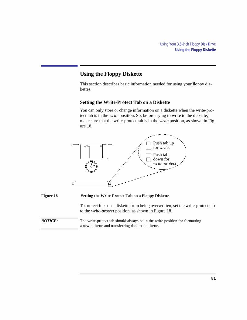
81
Using Your 3.5-Inch Floppy Disk DriveUsing the Floppy Diskette
Using the Floppy Diskette
This section describes basic information needed for using your floppy dis-kettes.
Setting the Write-Protect Tab on a Diskette
You can only store or change information on a diskette when the write-pro-tect tab is in thewrite position. So, before trying to write to the diskette,make sure that the write-protect tab is in thewrite position, as shown in Fig-ure 18.
Figure 18 Setting the Write-Protect Tab on a Floppy Diskette
To protect files on a diskette from being overwritten, set the write-protect tabto thewrite-protect position, as shown in Figure 18.
NOTICE: The write-protect tab should always be in the write position for formattinga new diskette and transferring data to a diskette.
Push tab upfor write.
Push tabdown forwrite-protect

82
Using Your 3.5-Inch Floppy Disk DriveUsing the Floppy Diskette
Inserting and Removing a Diskette
Follow these steps to insert and remove a diskette from the floppy disk drive:
1 Insert the diskette into the drive, as shown in Figure 19.
Figure 19 Inserting and Removing a Floppy Diskette
2 Push the diskette into the floppy drive until it clicks into place.
3 To remove the diskette, push the eject button (Figure 19), then take out the dis-kette.
Eject Button

83
Using Your 3.5-Inch Floppy Disk DriveOperating the Floppy Drive
Operating the Floppy Drive
This section describes how to perform tasks with your 3.5-inch floppy diskdrive.
Verifying the Floppy Drive Configuration
To verify that your workstation can communicate with the floppy drive, usethe ioscan command in a terminal window to see which devices are cur-rently in use on your system. The following are examples of usingioscanforversion 9.05 and version 10.0:
1 Click on theTerminal Control on theFront Panel of your Workspace.
A terminal window opens.
2 Move the mouse cursor into the terminal window and click the left mouse button.
3 Enter the following at the prompt:
/etc/ioscan(for 9.05)
ioscan(for 10.0)
Terminal Control
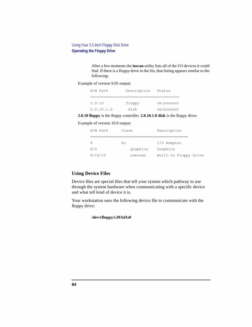
84
Using Your 3.5-Inch Floppy Disk DriveOperating the Floppy Drive
After a few moments the ioscan utility lists all of the I/O devices it couldfind. If there is a floppy drive in the list, that listing appears similar to thefollowing:
Example of version 9.05 output:
H/W Path Description Status
========================================
2.0.10 floppy ok(nnnnnn)
2.0.10.1.0 disk ok(nnnnnn)
2.0.10 floppy is the floppy controller.2.0.10.1.0 disk is the floppy drive.
Example of version 10.0 output:
H/W Path Class Description
============================================
8 bc I/O Adapter
8/0 graphics Graphics
8/16/10 unknown Built-in Floppy Drive
Using Device Files
Device files are special files that tell your system which pathway to usethrough the system hardware when communicating with a specific deviceand what tell kind of device it is.
Your workstation uses the following device file to communicate with thefloppy drive:
/dev/rfloppy/c20Ad1s0

85
Using Your 3.5-Inch Floppy Disk DriveOperating the Floppy Drive
Formatting a New Diskette
You must always format a new floppy diskette with themediainit utilitybefore using it. To format a new floppy diskette follow these steps:
1 Log in asroot.
2 Make sure that the write-protect tab on the floppy diskette is in thewrite position,as shown in Figure 18.
3 Insert the diskette into the floppy disk drive.
4 Click on theTerminal Control on theFront Panel of your Workspace.
A terminal window opens.
5 Move the mouse cursor into the terminal window and click the left mouse button.
6 Executemediainit with an interleave of 2 by entering the following:
mediainit -i 2 /dev/rfloppy/c20Ad1s0
Terminal Control
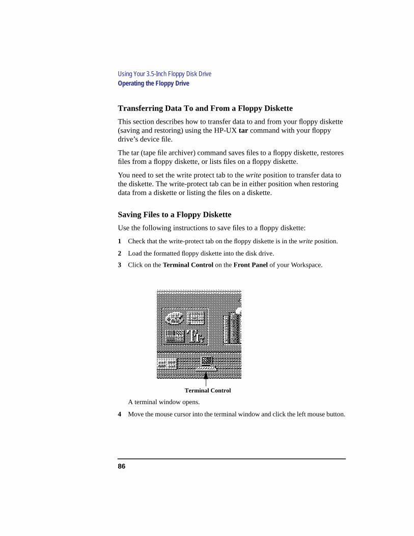
86
Using Your 3.5-Inch Floppy Disk DriveOperating the Floppy Drive
Transferring Data To and From a Floppy Diskette
This section describes how to transfer data to and from your floppy diskette(saving and restoring) using the HP-UXtar command with your floppydrive’s device file.
The tar (tape file archiver) command saves files to a floppy diskette, restoresfiles from a floppy diskette, or lists files on a floppy diskette.
You need to set the write protect tab to thewrite position to transfer data tothe diskette. The write-protect tab can be in either position when restoringdata from a diskette or listing the files on a diskette.
Saving Files to a Floppy Diskette
Use the following instructions to save files to a floppy diskette:
1 Check that the write-protect tab on the floppy diskette is in thewrite position.
2 Load the formatted floppy diskette into the disk drive.
3 Click on theTerminal Control on theFront Panel of your Workspace.
A terminal window opens.
4 Move the mouse cursor into the terminal window and click the left mouse button.
Terminal Control
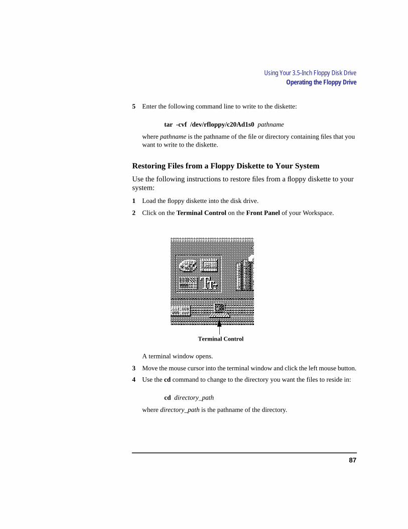
87
Using Your 3.5-Inch Floppy Disk DriveOperating the Floppy Drive
5 Enter the following command line to write to the diskette:
tar -cvf /dev/rfloppy/c20Ad1s0 pathname
wherepathname is the pathname of the file or directory containing files that youwant to write to the diskette.
Restoring Files from a Floppy Diskette to Your System
Use the following instructions to restore files from a floppy diskette to yoursystem:
1 Load the floppy diskette into the disk drive.
2 Click on theTerminal Control on theFront Panel of your Workspace.
A terminal window opens.
3 Move the mouse cursor into the terminal window and click the left mouse button.
4 Use thecd command to change to the directory you want the files to reside in:
cd directory_path
wheredirectory_path is the pathname of the directory.
Terminal Control
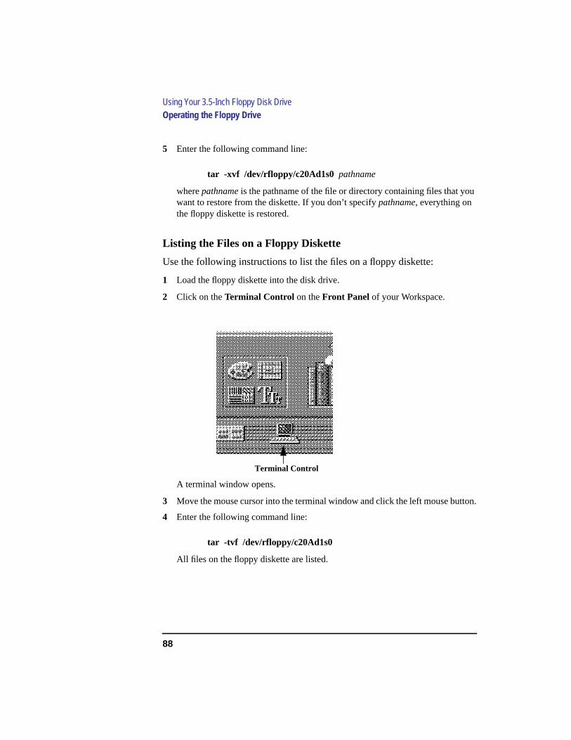
88
Using Your 3.5-Inch Floppy Disk DriveOperating the Floppy Drive
5 Enter the following command line:
tar -xvf /dev/rfloppy/c20Ad1s0 pathname
wherepathname is the pathname of the file or directory containing files that youwant to restore from the diskette. If you don’t specifypathname, everything onthe floppy diskette is restored.
Listing the Files on a Floppy Diskette
Use the following instructions to list the files on a floppy diskette:
1 Load the floppy diskette into the disk drive.
2 Click on theTerminal Control on theFront Panel of your Workspace.
A terminal window opens.
3 Move the mouse cursor into the terminal window and click the left mouse button.
4 Enter the following command line:
tar -tvf /dev/rfloppy/c20Ad1s0
All files on the floppy diskette are listed.
Terminal Control
89
Using Your 3.5-Inch Floppy Disk DriveOperating the Floppy Drive
For More Information
For more information on usingtar and a complete list of the command argu-ments, refer to the tar man page by typing the following in a terminal win-dow:
man tar
The man utility looks up man pages on the system.
You can mount the floppy drive as a file system using the SAM utility. Besure to unmount the drive before removing it as a file system. For moreinformation about how to mount and unmount the floppy drive, see the man-ualUsing HP-UX (B2910-90001).
For more information on copying data to or from your system to othermedia, including your floppy diskette, refer to thecpio man page by typingthe following in a terminal window:
man cpio
For more information on copying to or from DOS files, refer to thedoscpman page by typing the following in a terminal window:
man doscp
For more information on listing the contents of DOS directories, refer to thedosls man page by typing the following in a terminal window:
man dosls
For more information on using your floppy disk drive and floppy diskettes,refer to thefloppy man page by typing the following in a terminal window:
man floppy
For more information on using themediainit command, refer to themedi-ainit man page by typing the following in a terminal window:
man mediainit

90
Using Your 3.5-Inch Floppy Disk DriveOperating the Floppy Drive
Configuring the Floppy Driver
If you reload software or rebuild the Instant Ignition system on your work-station, you need to reconfigure the HP-UX Kernel to add the floppy driver.Use the SAM utility to add theflexible disk driver and build a new HP-UXkernel.
For more information about how to reconfigure the kernel using SAM, seethe following manuals:
• System Administration Tasks HP 9000 Series 700 Computers(B2355-90040)
• Using HP-UX (B2910-90001)

91
Using Your 3.5-Inch Floppy Disk DriveTroubleshooting
Troubleshooting
If you have trouble with any of these procedures for using your floppy diskdrive, see Chapter 6 of this book, “Solving Problems.”
Ordering Information
To order Hewlett-Packard micro flexible diskettes for use in your 3.5-inchfloppy disk drive, use the following order number:
HP-92192X High-Density Micro Flexible Disks (1.44MB Formatted Capacity) - box of ten diskettes

92
Using Your 3.5-Inch Floppy Disk DriveOrdering Information

93
6
Solving Problems

94
Solving Problems
This chapter contains information to help you determine what’s wrong withyour system when you have problems. If you have a problem that isn’t listedin this chapter, or if your problem persists, contact your designated servicerepresentative. When calling for service, always have your system’s modelnumber and serial number ready.
This chapter is divided into the following sections
• Common problems and solutions
• Dealing with a boot failure
• Running system verification tests
The instructions in this chapter assume you are using HP-UX version 9.05 orlater operating system with HP VUE version 3.0 or later interface.

95
Solving ProblemsCommon Problems and Solutions
Common Problems and Solutions
The tables in this section list common problems you may encounter withyour workstation. The tables also tell you what to do to help solve the prob-lems.
Problems with Powering Up the System
Table 6 describes possible problems you may encounter when powering upthe system and offers solutions.
Table 6 Power Up Problems
Problem Solution
The power LED does notlight.
Make sure all AC power cables are connected securely tothe system.
Make sure the power cord is plugged into a working ACoutlet.
Make sure the power switch is set to the ON position.
The power LED lights,but the screen is blank orflickers.
Press the brightness control on the monitor to adjust it. Ifthe screen is still blank, turn off the system and monitorpower switches. When the system is completely poweredoff, check the video cable connections.
Go to the section "Changing Your Monitor Type" in Appen-dix B for information about displaying and setting yourworkstation’s monitor configuration.
If the problem persists, contact your system administrator or call your designated servicerepresentative.

96
Solving ProblemsCommon Problems and Solutions
Problems Loading and Booting the Operating System
Table 7 describes possible problems you may encounter when loading andbooting the operating system and offers solutions.
Problems with the 802.3 Network
Table 8 describes possible problems you may encounter with the 802.3 net-work and offers solutions.
Table 7 Problems Loading and Booting the Operating System
Problem Solution
The power LED is lit,and text appears on thescreen, but more than twominutes have passed withno sign of system activ-ity.
Make sure that all SCSI devices are set to the proper SCSIID. (See Appendix C for default SCSI ID settings.)
Check that all SCSI devices are correctly cabled. Check thatthe SCSI bus is correctly terminated. (See Appendix C forinformation on SCSI cabling and termination).
The system stops orhangs while booting.
Follow the instructions in "Dealing With a Boot Failure" inthis chapter.
If problem persists, contact your system administrator or call your designated servicerepresentative.
Table 8 Problems with the 802.3 Network
Problem Solution
Cannot reach other sys-tems on the network.Applications that rely onthe network will not run.
Check the network connector on the back of the system unit.Make sure that the network cable or transceiver is fastenedsecurely to the connector.
If problem persists, contact your system administrator or call your designated servicerepresentative.
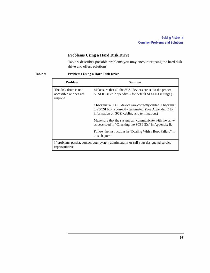
97
Solving ProblemsCommon Problems and Solutions
Problems Using a Hard Disk Drive
Table 9 describes possible problems you may encounter using the hard diskdrive and offers solutions.
Table 9 Problems Using a Hard Disk Drive
Problem Solution
The disk drive is notaccessible or does notrespond.
Make sure that all the SCSI devices are set to the properSCSI ID. (See Appendix C for default SCSI ID settings.)
Check that all SCSI devices are correctly cabled. Check thatthe SCSI bus is correctly terminated. (See Appendix C forinformation on SCSI cabling and termination.)
Make sure that the system can communicate with the driveas described in "Checking the SCSI IDs" in Appendix B.
Follow the instructions in "Dealing With a Boot Failure" inthis chapter.
If problems persist, contact your system administrator or call your designated servicerepresentative.

98
Solving ProblemsCommon Problems and Solutions
Problems Using the CD-ROM Drive
Table 10 describes a possible problem you may encounter when you use theCD-ROM drive and offers a solution.
Table 10 Problems Using the CD-ROM Drive
Problem Solution
The CD-ROM drivedoes not respond to com-mands.
Re-enter the commands and make sure that you have typedthem correctly.
Make sure that the system can communicate with the driveas described in "Checking the SCSI IDs" in Appendix B.
Follow the instructions in the section "Running the SystemVerificatin Tests" in this chapter to verify that the CD-ROMdrive is functioning properly.
If problems persist, contact your system administrator or call your designated servicerepresentative

99
Solving ProblemsCommon Problems and Solutions
Problems Using the DDS Tape Drive
Table 11 describes a possible problem you may encounter using the DDStape drive and offers solutions.
Table 11 Problems Using the DDS Tape Drive
Problem Solution
The DDS tape drive doesnot respond to com-mands.
Re-enter the commands and make sure that you have typedthem correctly.
Make sure that you specified the correct device file name forcommands that require a device file name.
Make sure the write-protect tab is set towrite if you are try-ing to copy data to a data cassette.
Make sure that the system can communicate with the driveas described in "Checking the SCSI IDs" in Appendix B.
Follow the instructions in the section "Running the SystemVerification Tests" in this chapter to verify that the tapedrive is functioning properly.
If the problem persists, contact your system administrator or call your designated servicerepresentative.
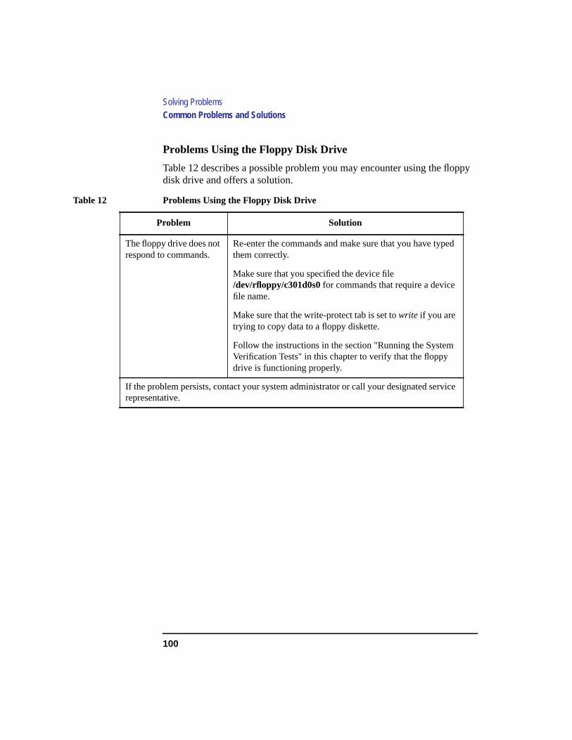
100
Solving ProblemsCommon Problems and Solutions
Problems Using the Floppy Disk Drive
Table 12 describes a possible problem you may encounter using the floppydisk drive and offers a solution.
Table 12 Problems Using the Floppy Disk Drive
Problem Solution
The floppy drive does notrespond to commands.
Re-enter the commands and make sure that you have typedthem correctly.
Make sure that you specified the device file/dev/rfloppy/c301d0s0for commands that require a devicefile name.
Make sure that the write-protect tab is set towrite if you aretrying to copy data to a floppy diskette.
Follow the instructions in the section "Running the SystemVerification Tests" in this chapter to verify that the floppydrive is functioning properly.
If the problem persists, contact your system administrator or call your designated servicerepresentative.
101
Solving ProblemsDealing with a Boot Failure
Dealing with a Boot Failure
If your usual boot device (typically a disk) is not responding as it should,you must try to boot from the disk (or another boot device) by selecting itmanually.
To boot a device manually, follow these steps:
1 Follow the directions in “Accessing the Boot Console Interface,” in Appendix Dof this book.
NOTICE: Your workstation automatically shuts down the operating systembefore it terminates the power.
2 At the Main Menu prompt, type the following:
Main Menu: Enter a command or a menu > search ipl
This causes your workstation to searchexhaustively for bootable media.
The search command looks for bootable media on your workstation.
3 Boot from one of the listed devices by typing the following at the prompt:
Main Menu: Enter a command or a menu > boot device
wheredevice is thehardware path to the device, specified in mnemonic stylenotation, such asscsi.5.0
4 If your workstation still fails to boot, there is either something wrong with the filesystem or with the hardware. If you suspect a file system failure, see the manualUsing HP-UX for help on dealing with file system failures. If you think that some-thing is wrong with the hardware, continue reading this chapter for more trouble-shooting information.
102
Solving ProblemsRunning System Verification Tests
Running System Verification Tests
HP-UX uses a diagnostics product called SupportWave. SupportWave con-tains the Support Tools Manager so that you can verify your system opera-tion.
You can access the Support Tools Manager in a terminal window. If you areusing HP VUE as your interface, you can also access the Support ToolsManager through thesys_admin directory.
Three interfaces are available with the Support Tools Manager: a commandline interface (accessed through thecstm command), a menu-driven inter-face (accessed through themstm command), and the graphical user interface(accessed through thexstm command).
For more information on SupportWave user interfaces, see the on-line manpages by entering the following at a command line prompt:
man cstm
man mstm
man xstm
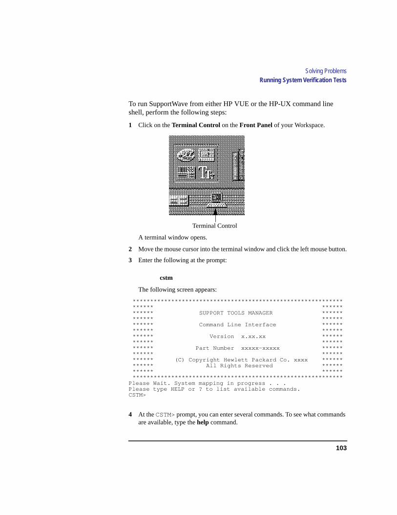
103
Solving ProblemsRunning System Verification Tests
To run SupportWave from either HP VUE or the HP-UX command lineshell, perform the following steps:
1 Click on theTerminal Control on theFront Panel of your Workspace.
A terminal window opens.
2 Move the mouse cursor into the terminal window and click the left mouse button.
3 Enter the following at the prompt:
cstm
The following screen appears:
****************************************************************** ************ SUPPORT TOOLS MANAGER ************ ************ Command Line Interface ************ ************ Version x.xx.xx ************ ************ Part Number xxxxx-xxxxx ************ ************ (C) Copyright Hewlett Packard Co. xxxx ************ All Rights Reserved ************ ******************************************************************
Please Wait. System mapping in progress . . .Please type HELP or ? to list available commands.CSTM>
4 At theCSTM> prompt, you can enter several commands. To see what commandsare available, type thehelp command.
Terminal Control

104
Solving ProblemsRunning System Verification Tests
5 To verify the system operation, type the following at theCSTM> prompt:
CSTM> verify all
The following messages appear:
Verification has started on device (CPU).Verification has started on device (FPU).Verification has started on device (0/0/0).Verification has started on device (2/0/1.0.0).Verification has started on device (2/0/1.5.0).Verification has started on device (2/0/1.6.0).Verification has started on device (2/0/2).
CSTM>Message from (0/0/0):This graphics test displays a number of graphics images on thescreen of the graphics device being tested. If an X server isnot currently running on that display, X Windows will be startedand run for the duration of the test. The Starbase shared li-brary (/usr/lib/libsbisl) should be present to run this test.
CAUTION: This test will fail if any portion of the test windowis modified or overlaid in any way.
NOTE: If a VUE login screen is currently displayed on the mon-itor, the test will wait until someone logs in the HP VUE on thegraphics monitor to release the lock. The test stops if theScreen Saver times out, it runs again once the Screen is acti-vated.
WARNING: Do not run this exercise with any other option.(Type ’R’ for Ready, Type ’S’ for Skip) [R] >>
6 When you see the>> prompt shown above, enterr
The following messages and a graphics test window appear:
Verification of (2/0/1.0.0) has completed. Result status - (Success)Verification of (2/0/1.5.0) has completed. Result status - (Success)Verification of (2/0/1.6.0) has completed. Result status - (Success)Verification of (CPU) has completed. Result status - (Success)Verification of (FPU) has completed. Result status - (Success)Verification of (2/0/2) has completed. Result status - (Success)Verification of (0/0/0) has completed. Result status - (Success).
7 PressEnter to return to theCSTM> prompt after all test results are reported.
8 To exit the Support Tools Manager, enter the following:
CSTM> exit
If any tests failed, further diagnosis is necessary by qualified service personnel.Contact your designated service representative.

105
A
Safety and Regulatory Statements
106
Safety and Regulatory Statements
This appendix contains safety and regulatory statements pertaining to yourC100/C110 workstation. It provides information on the following topics:
• Emissions regulations
• Emissions regulations compliance
• Datacom users statement
• Acoustics
• Electrostatic discharge (ESD) precautions
• Safety statements
• Laser safety statements
• Warnings and cautions
107
Safety and Regulatory StatementsEmissions Regulations
Emissions Regulations
Federal Communications Commission (FCC)
This equipment has been tested and found to comply with the limits for aClass B digital device, pursuant to part 15 of the FCC Rules and the Cana-dian Department of Communications. These limits are designed to providereasonable protection against harmful interference in a residential installa-tion. This equipment generates, uses, and can radiate radio frequency energyand, if not installed and used in accordance with the instructions, may causeharmful interference to radio communications. However, there is no guaran-tee that interference will not occur in a particular installation. If this equip-ment does cause harmful interference to radio or television reception(determined by turning the equipment off and on), you can correct the inter-ference by one or more of the following measures:
• Reorient or relocate the receiving antenna.
• Increase the separation between the equipment and the receiver.
• Connect the equipment into an outlet on a circuit different from that to which thereceiver is connected.
• Ask the dealer or an experienced radio/television technician for help.
Hewlett-Packard’s system certification tests were conducted with HP-sup-ported peripheral devices and HP shielded cables, such as those you receivewith your computer. Changes or modifications not expressly approved byHewlett-Packard could void the user’s authority to operate the equipment.
Operation of this device is subject to the following conditions:
• This device may not cause harmful interference.
• This device must accept interference received, including interference that maycause undesired operation.
• Cables used with this device must be properly shielded to comply with the re-quirements of the FCC.
108
Safety and Regulatory StatementsEmissions Regulations Compliance
VCCI Class 2 ITE
Emissions Regulations Compliance
Any third-party I/O device installed in HP system(s) must be in accordancewith the requirements set forth in the preceding Emissions Regulations state-ments. In the event that a third-party noncompliant I/O device is installed,the customer assumes all responsibility and liability arising therefrom.
Acoustics
Regulation On Noise Declaration For Machines -3. GSGV
Lpa <70dB Lpa<70dB
operator position am Arbeitsplatz
normal operation normaler Betrieb
per ISO 7779 nach DIN 45635 T.19
109
Safety and Regulatory StatementsElectrostatic Discharge (ESD) Precautions
Electrostatic Discharge (ESD) Precautions
Electrostatic charges can damage the integrated circuits on printed circuitboards. To prevent such damage from occurring, observe the following pre-cautions during board unpacking and installation:
• Stand on a static-free mat.
• Wear a static strap to ensure that any accumulated electrostatic charge is dis-charged from your body to ground.
• Connect all equipment together, including the static-free mat, static strap, routingnodes, and peripheral units.
• Keep uninstalled printed circuit boards in their protective antistatic bags.
• Handle printed circuit boards by their edges, once you have removed them fromtheir protective antistatic bags.

110
Safety and Regulatory StatementsSafety Statement
Safety Statement
This equipment conforms to the following safety standards:
• UL 1950
• CSA 950
• IEC 950
• EN 60950

111
Safety and Regulatory StatementsLaser Safety Statement (U.S.A. Only)
Laser Safety Statement (U.S.A. Only)
The CD ROM mass-storage system is certified as a Class-1 laser productunder the U.S. Department of Health and Human Services (DHHS) Radia-tion Performance Standard according to the Radiation Control for Healthand Safety Act of 1968.
This means that the mass-storage system does not produce hazardous laserradiation. Because laser light emitted inside the mass-storage system is com-pletely confined within protective housings and external covers, the laserbeam cannot escape from the machine during any phase of user operation.
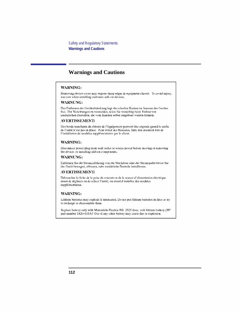
112
Safety and Regulatory StatementsWarnings and Cautions
Warnings and Cautions

113
B
Changing Your Workstation’sHardware Configuration

114
Changing Your Workstation’s Hardware Configuration
This appendix describes the procedures to change your workstation’s hard-ware configuration. It presents the information in the following sections:
• Checking the SCSI IDs
• Preparing your workstation
• Installing storage devices
• Removing the main tray assembly
• Replacing the main tray assembly
• Installing additional memory
• Installing an EISA or GSC option board
• Changing your monitor type
The instructions in this chapter assume you are using HP-UX version 9.05 orlater operating system with HP VUE version 3.0 or later interface.
NOTICE: Your workstation shipped with a package of extra disk slides. Keep theslides in a safe place, you will need them when you add new devices to thestorage tray.
CAUTION: Always wear a properly grounded wrist strap when reconfiguring yourworkstation.
Use the following tools to remove or replace hardware parts when changingyour configuration:
• Light-duty flat blade screwdriver with 150 mm (6 in.) blade
• Needlenose pliers
Also, read the ESD Precautions in Appendix A of this guide.

115
Changing Your Workstation’s Hardware ConfigurationChecking the SCSI IDs
Checking the SCSI IDs
To determine which SCSI IDs are currently in use on your system, use theioscan command in a terminal window:
1 Click on theTerminal Control on theFront Panel of your Workspace.
A terminal window opens.
2 Move the mouse cursor into the terminal window and single-click the left mousebutton.
3 If you are using HP-UX 9.05 or greater, enter the following at the prompt:
/etc/ioscan -d scsi
After a few moments theioscan utility lists all of the SCSI I/O devices it couldfind. The list should appear similar to the following:
H/W Path Description Status
=============================================
2.0.1.2.0 cd-rom_drive ok(nnnnnnnn)
If you are using HP-UX 10.0, enter the following at the prompt:
/usr/sbin/ioscan -f

116
Changing Your Workstation’s Hardware ConfigurationChecking the SCSI IDs
After a few moments theioscan utility lists all of the SCSI I/O devices it couldfind. The list appears similar to the following:
Class I H/W Path Driver S/W State H/W Type Description=============================================================================================bc 0 root CLAIMED BUS_NEXUSbc 1 8 ccio CLAIMED BUS_NEXUS I/O Adapterext_bus 0 8/0 c720 CLAIMED INTERFACE GSC built-in Fast/Wide SCSIInterfacetarget 0 8/0.0 tgt CLAIMED DEVICEdisk 3 8/0.0.0 sdisk CLAIMED DEVICE QUANTUM LPS1080WDtarget 1 8/0.5 tgt CLAIMED DEVICEdisk 2 8/0.5.0 sdisk CLAIMED DEVICE DEC DSP3210SWtarget 2 8/0.6 tgt CLAIMED DEVICEdisk 0 8/0.6.0 sdisk CLAIMED DEVICE DEC DSP3210SWba 0 8/16 bus_adapterCLAIMED BUS_NEXUS Core I/O Adapterext_bus 2 8/16/0 CentIf CLAIMED INTERFACE Built-in Parallel Interfaceaudio 0 8/16/1 audio CLAIMED INTERFACE Built-in Audiotty 0 8/16/4 asio0 CLAIMED INTERFACE Built-in RS-232Cext_bus 1 8/16/5 c700 CLAIMED INTERFACE Built-in SCSItarget 3 8/16/5.2 tgt CLAIMED DEVICEdisk 1 8/16/5.2.0 sdisk CLAIMED DEVICE TOSHIBA CD-ROM XM-4101TAtarget 4 8/16/5.3 tgt CLAIMED DEVICEtape 0 8/16/5.3.0 stape CLAIMED DEVICE HP HP35480Atarget 5 8/16/5.4 tgt CLAIMED DEVICEdisk 10 8/16/5.4.0 sdisk CLAIMED DEVICE SEAGATE ST3600Ntarget 6 8/16/5.6 tgt CLAIMED DEVICEdisk 5 8/16/5.6.0 sdisk CLAIMED DEVICE MICROP 2112lan 0 8/16/6 lan2 CLAIMED INTERFACE Built-in LANps2 0 8/16/7 ps2 CLAIMED INTERFACE Built-in Keyboard/Mousebc 2 10 ccio CLAIMED BUS_NEXUS I/O Adapterext_bus 3 10/12 c720 CLAIMED INTERFACE GSC Fast/WideSCSI Interfacetarget 7 10/12.4 tgt CLAIMED DEVICEdisk 6 10/12.4.0 sdisk CLAIMED DEVICE SEAGATE ST31200Wgraphics 2 10/16 graph3 CLAIMED INTERFACE Graphicsba 1 8/20 bus_adapterCLAIMED BUS_NEXUS Core I/O Adapterhil 0 8/20/1 hil CLAIMED INTERFACE Built-in HILtty 1 8/20/2 asio0 CLAIMED INTERFACE Built-in RS-232Cba 2 8/20/5 eisa CLAIMED BUS_NEXUS EISA Bus Adapterext_bus 4 8/20/5/3 hshpib CLAIMED INTERFACE EISA card HWP0C70target 8 8/20/5/3.0 tgt CLAIMED DEVICEtarget 9 8/20/5/3.1 tgt CLAIMED DEVICEtarget 10 8/20/5/3.2 tgt CLAIMED DEVICEprocessor 0 32 processor CLAIMED PROCESSOR Processormemory 0 49 memory CLAIMED MEMORY Memory
4 If you are using HP-UX 9.05 or greater, you can find out the SCSI IDs currentlyin use by looking under theH/W Path heading. The listing2.0.1 scsi is the built-in SCSI bus controller. For devices connected to the built-in SCSI bus, such asdisks, the fourth number is the SCSI ID for that device. For example, the listing2.0.1.6.0 in the sample device list tells you that there is a SCSI device (a disk)currently using ID 6 on the SCSI bus.
Although the information is presented in a different format if you are using HP-UX 10.0, you also look under the H/W Path heading.
NOTICE: Never use SCSI address 7 for any device. Address 7 is reserved for theSCSI controller.

117
Changing Your Workstation’s Hardware ConfigurationPreparing Your Workstation
Preparing Your Workstation
This section describes how to prepare your workstation for changing its con-figuration. Use the following procedure to prepare your workstation:
1 Power off your workstation by pressing the power button on the front panel.
When you press the power button, the workstation automatically shuts down theoperating system before it powers off the system.
2 When the workstation has completed shutting down and powering off, power offthe monitor, and any peripheral devices connected to the workstation.
3 Unplug the power cord of the system unit, the monitor, and any peripheral devic-es from ac wall outlets.
4 Unplug the power cord from the back of the system unit.
5 Remove the floor stand from the system unit, as shown in Figure 20.

118
Changing Your Workstation’s Hardware ConfigurationPreparing Your Workstation
Figure 20 Removing the Floor Stand
6 Lay the system unit on a flat surface, such as a table top.
7 Attach a static-grounding wrist strap to bare metal on the back of the system unit.
119
Changing Your Workstation’s Hardware ConfigurationInstalling Storage Devices
Installing Storage Devices
This section describes how to install storage devices in your workstation.Before installing a new storage device, perform the following procedures asdescribed earlier in this chapter:
• Checking the SCSI IDs
• Preparing Your Workstation
CAUTION: All storage devices are susceptible to mechanical and electrostatic shock. Whenhandling the devices, always wear the static-grounding wrist strap that came in thestorage device kit. Always handle the drive carefully.
NOTICE: Do not use SCSI ID 7 for any of your storage devices’ SCSI addresses. Thehost SCSI controllers use SCSI ID 7.
120
Changing Your Workstation’s Hardware ConfigurationInstalling Storage Devices
Preparing to Install Your Storage Device
This section describes information that you need to consider and proceduresthat you need to perform before installing any storage device.
Configuring your Storage Device
Table 13 lists the recommended SCSI IDs for internal storage devices. If anexisting device already uses one of the suggested IDs, select an alternate ID.
Set the jumpers and SCSI IDs according to the installation instructions thatcame with your device.
Determining Your Storage Devices Position
Each storage device is restricted as to where in the storage tray it may beinstalled. Before installing a storage device, use Figure 21 and Table 14 todetermine which disk tray position is correct for your device.
Figure 21 shows the storage device positions in the disk tray. Table 14 listswhat devices are supported in the different disk tray positions. The numbersin the table’s left column refer to the position numbers in Figure 21.
Table 13 Default SCSI IDs
Fast/Wide Differential SCSI Devices SCSI ID
1st Hard Disk Drive 6
2nd Hard Disk Drive 5
3rd Hard Disk Drive 4
Single-Ended SCSI-2 Devices SCSI ID
CD-ROM Drive 2
DDS-Format Tape Drive 3
NOTE: The floppy drive is not a SCSI device.

121
Changing Your Workstation’s Hardware ConfigurationInstalling Storage Devices
Figure 21 Disk Tray Positions
Table 14 Storage Configurations
DiskTray
PositionSupported Devices Conditions
1 Floppy Drive
1-inch Low ProfileDisk Drive
2 CD-ROM
DDS-Tape
3 1-inch Low ProfileDisk Drive
1.6-inch Full HeightDisk Drive
If a CD-ROM drive is installed, installa 1.6-inch full height disk drive in thisposition.
4 1-inch Low ProfileDisk Drive
1.6-inch Full HeightDisk Drive
This is the preferred position for a1.6-inch full height disk drive.
If a CD-ROM drive is installed, a 1.6-inch full height disk drive cannot beinstalled in this position.
All hard disk drives are fast, wide SCSI devices. The CD-ROM drive and theDDS tape drive are single-ended SCSI devices. The floppy drive is not a SCSIdevice.

122
Changing Your Workstation’s Hardware ConfigurationInstalling Storage Devices
Mounting the Storage Device Slides
From the accessory hardware kit which came with your workstation, locatetwo plastic storage device slides. Using the screws that came with the stor-age device, mount the slides on the new storage device so that the lockingtabs are at the connector end of the drive, as shown in Figure 22.
Figure 22 Mounting the Storage Device Slides
CAUTION: When mounting the storage device slides, only use the screws that shippedwith the storage device. Use of other screws can cause physical damage tothe device.
Locking Tab
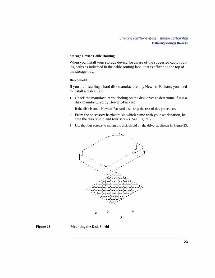
123
Changing Your Workstation’s Hardware ConfigurationInstalling Storage Devices
Storage Device Cable Routing
When you install your storage device, be aware of the suggested cable rout-ing paths as indicated in the cable routing label that is affixed to the top ofthe storage tray.
Disk Shield
If you are installing a hard disk manufactured by Hewlett-Packard, you needto install a disk shield.
1 Check the manufacturer’s labeling on the disk drive to determine if it is adisk manufactured by Hewlett-Packard.
If the disk is not a Hewlett-Packard disk, skip the rest of this procedure.
2 From the accessory hardware kit which came with your workstation, lo-cate the disk shield and four screws. See Figure 23.
3 Use the four screws to mount the disk shield on the drive, as shown in Figure 23.
Figure 23 Mounting the Disk Shield

124
Changing Your Workstation’s Hardware ConfigurationInstalling Storage Devices
Removing the Disk Tray
Perform the following procedure to remove the Storage Tray from the sys-tem unit:
1 Remove the storage tray retaining screw, as shown in Figure 24.
2 If installed, remove any locking device from the storage tray security loop on therear of the system unit.
3 Place your fingertips in the groove on the bottom of the storage tray bezel. SeeFigure 24.
Figure 24 Removing the Storage Tray
4 Slide the storage tray completely out of the system unit.
CAUTION: Be sure to support the storage tray from underneath while sliding it out ofthe system unit.
Proceed to one of the following sections in this chapter to install your stor-age device in the disk tray:
• Installing a CD-ROM or a DDS-Format Tape Drive
• Installing a Floppy Drive
• Installing a Hard Disk Drive in Position 3 or Position 4
Retaining Screw
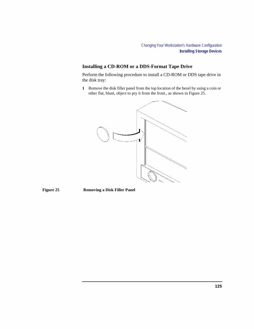
125
Changing Your Workstation’s Hardware ConfigurationInstalling Storage Devices
Installing a CD-ROM or a DDS-Format Tape Drive
Perform the following procedure to install a CD-ROM or DDS tape drive inthe disk tray:
1 Remove the disk filler panel from the top location of the bezel by using a coin orother flat, blunt, object to pry it from the front., as shown in Figure 25.
Figure 25 Removing a Disk Filler Panel

126
Changing Your Workstation’s Hardware ConfigurationInstalling Storage Devices
2 From the rear of the storage tray, line up the disk slides on the CD-ROM or DDStape drive with the position 1slots in the storage tray chassis, and slide it intoplace, as shown in Figure 26.
Figure 26 Installing a CD-ROM or DDS Tape
3 Push the storage device in until the locking tabs snap into place.
4 Connect the single-ended SCSI-2 data cable and the power cable to the drive.Refer to the cable routing label on the storage tray.
5 Proceed to the section entitled Replacing the Storage Tray.
CD-ROM or DDS Tape Drive
Cable Routing Label
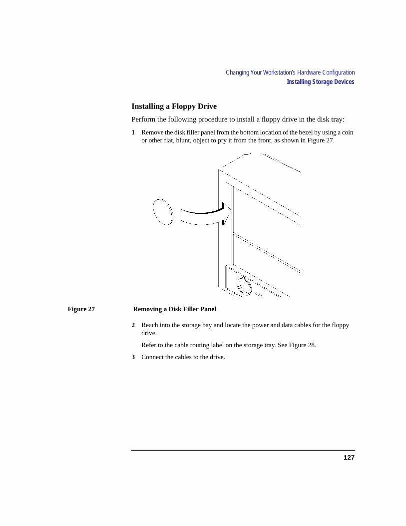
127
Changing Your Workstation’s Hardware ConfigurationInstalling Storage Devices
Installing a Floppy Drive
Perform the following procedure to install a floppy drive in the disk tray:
1 Remove the disk filler panel from the bottom location of the bezel by using a coinor other flat, blunt, object to pry it from the front, as shown in Figure 27.
Figure 27 Removing a Disk Filler Panel
2 Reach into the storage bay and locate the power and data cables for the floppydrive.
Refer to the cable routing label on the storage tray. See Figure 28.
3 Connect the cables to the drive.

128
Changing Your Workstation’s Hardware ConfigurationInstalling Storage Devices
4 From the front of the storage tray, line up the disk slides on the floppy drive withthe position 2 slots in the storage tray chassis and slide it into place, as shown inFigure 28.
Figure 28 Installing a Floppy Drive
5 Push the floppy drive in until the locking tabs snap into place.
6 Proceed to the section entitled Replacing the Storage Tray.
Cable Routing Label
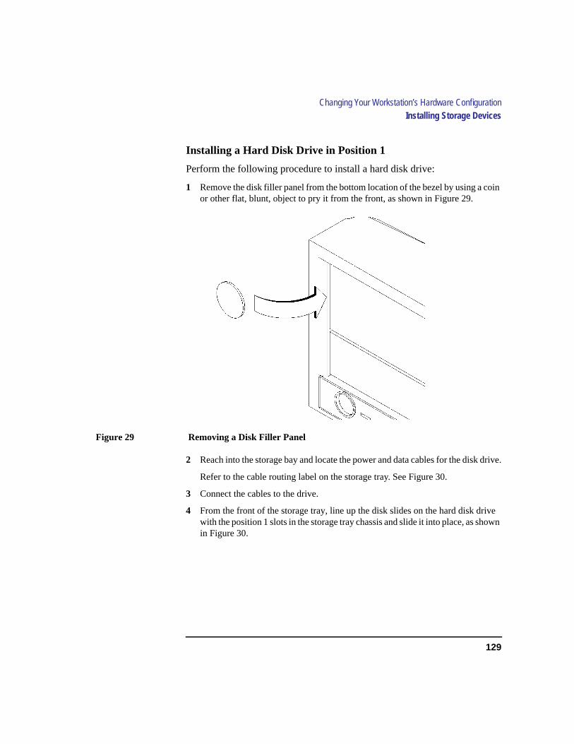
129
Changing Your Workstation’s Hardware ConfigurationInstalling Storage Devices
Installing a Hard Disk Drive in Position 1
Perform the following procedure to install a hard disk drive:
1 Remove the disk filler panel from the bottom location of the bezel by using a coinor other flat, blunt, object to pry it from the front, as shown in Figure 29.
Figure 29 Removing a Disk Filler Panel
2 Reach into the storage bay and locate the power and data cables for the disk drive.
Refer to the cable routing label on the storage tray. See Figure 30.
3 Connect the cables to the drive.
4 From the front of the storage tray, line up the disk slides on the hard disk drivewith the position 1 slots in the storage tray chassis and slide it into place, as shownin Figure 30.

130
Changing Your Workstation’s Hardware ConfigurationInstalling Storage Devices
Figure 30 Installing a Hard Disk Drive in Position 1
5 Push the drive in until the locking tabs snap into place.
6 Snap the disk filler panel into the lower bezel position.
7 Proceed to the section entitled Replacing the Storage Tray.
Cable Routing Label

131
Changing Your Workstation’s Hardware ConfigurationInstalling Storage Devices
Installing a Hard Disk Drive in Position 3 or Position 4
Perform the following procedure to install a hard disk drive in positions 3 or4 of the disk tray:
1 Remove the two retaining screws from the disk interconnect board, as shown inFigure 31.
Figure 31 Removing the Disk Interconnect Board
2 Disconnect any cables from the disk interconnect board.
3 Hold the disk interconnect board on the edges and lift it straight up to remove it,as shown in Figure 31.
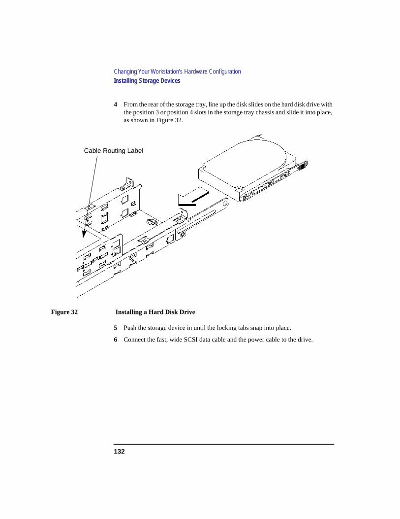
132
Changing Your Workstation’s Hardware ConfigurationInstalling Storage Devices
4 From the rear of the storage tray, line up the disk slides on the hard disk drive withthe position 3 or position 4 slots in the storage tray chassis and slide it into place,as shown in Figure 32.
Figure 32 Installing a Hard Disk Drive
5 Push the storage device in until the locking tabs snap into place.
6 Connect the fast, wide SCSI data cable and the power cable to the drive.
Cable Routing Label
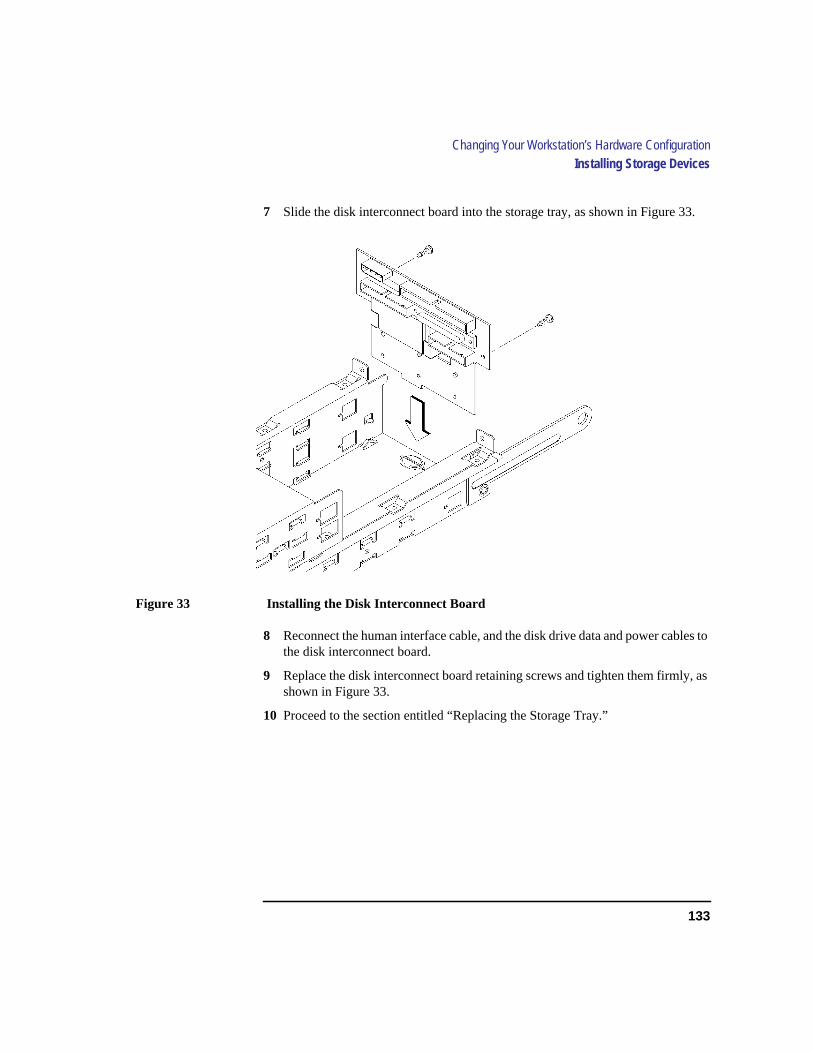
133
Changing Your Workstation’s Hardware ConfigurationInstalling Storage Devices
7 Slide the disk interconnect board into the storage tray, as shown in Figure 33.
Figure 33 Installing the Disk Interconnect Board
8 Reconnect the human interface cable, and the disk drive data and power cables tothe disk interconnect board.
9 Replace the disk interconnect board retaining screws and tighten them firmly, asshown in Figure 33.
10 Proceed to the section entitled “Replacing the Storage Tray.”
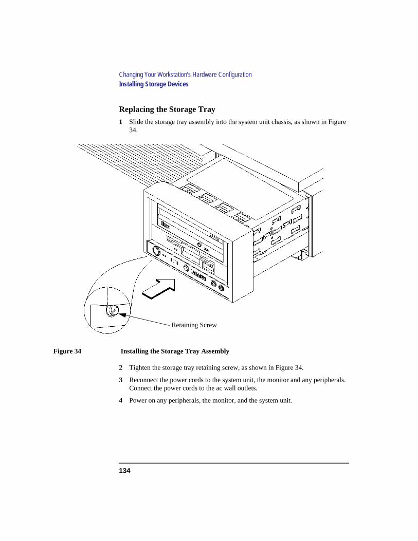
134
Changing Your Workstation’s Hardware ConfigurationInstalling Storage Devices
Replacing the Storage Tray
1 Slide the storage tray assembly into the system unit chassis, as shown in Figure34.
Figure 34 Installing the Storage Tray Assembly
2 Tighten the storage tray retaining screw, as shown in Figure 34.
3 Reconnect the power cords to the system unit, the monitor and any peripherals.Connect the power cords to the ac wall outlets.
4 Power on any peripherals, the monitor, and the system unit.
Retaining Screw
135
Changing Your Workstation’s Hardware ConfigurationInstalling Storage Devices
If you installed a new hard disk drive, proceed to the section entitled “Con-figuring a Hard Disk Drive.”
If you installed a new removable media device, refer to the following chap-ters for information on using the device:
• Chapter 3 - Using Your CD-ROM Drive
• Chapter 4 - Using Your Digital Data Storage (DDS) Tape Drive
• Chapter 5 - Using Your 3.5-inch Floppy Drive

136
Changing Your Workstation’s Hardware ConfigurationInstalling Storage Devices
Configuring a Hard Disk Drive
This section describes how to add a hard disk drive to your system as a filesystem using SAM. If you installed a new hard disk drive, follow theseinstructions to make your new disk usable as a file system. For more infor-mation about configuring a hard disk drive, refer to theSystem Administra-tion Tasks manual.
This procedure requires you to log in asroot. If you cannot log in asroot,contact your system administrator.
1 Log in asroot.
2 Move the mouse pointer to thearrow above theToolboxcontrol and clickthe left mouse button.
3 TheToolbox subpanel opens. Click on theGeneral toolbox icon, shownbelow.
Toolbox Control Arrow

137
Changing Your Workstation’s Hardware ConfigurationInstalling Storage Devices
4 A file manager window appears with a number of icons in it. Double-clickon theSystem_Admin toolbox icon.
5 Move the mouse cursor to theSAM icon shown below (your icon can looklike either of these) and double-click the left mouse button.
SAM (System Administration Manager) is a utility that performs system adminis-tration tasks using a windows graphical user interface.
6 TheSystem Administration Manager window opens. Double-click onPeripheral Devices ->.
7 ThePeripheral Devices window opens. Double-click onDisks and FileSystems ->.
8 TheDisks and File Systems window opens. Double-click onCD-ROM,Floppy, and Hard Disks.
The following screen message appears:
Scanning the system’s hardware...
TheCD-ROM, Floppy, and Hard Disks window opens, containing a list ofdrives currently configured on this system.
9 From the Actions menu, click onAdd a Hard Disk Drive.
10 The Select a Disk to Add... window opens with a list of unused disks. Highlightthe hard disk drive you want to add to your system.
11 Click onOK.
138
Changing Your Workstation’s Hardware ConfigurationInstalling Storage Devices
12 The Set Disk Usage and Options... window opens. Select File System and clickonOK.
13 The following screen messages appear:
Task started.
Creating the device file...
Modifying “/etc/checklist”...
Task completed.
Click onOK.
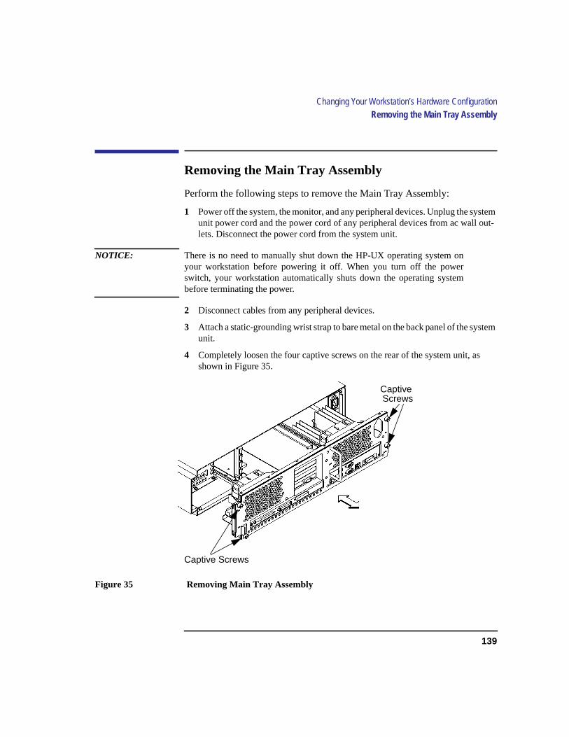
139
Changing Your Workstation’s Hardware ConfigurationRemoving the Main Tray Assembly
Removing the Main Tray Assembly
Perform the following steps to remove the Main Tray Assembly:
1 Power off the system, the monitor, and any peripheral devices. Unplug the systemunit power cord and the power cord of any peripheral devices from ac wall out-lets. Disconnect the power cord from the system unit.
NOTICE: There is no need to manually shut down the HP-UX operating system onyour workstation before powering it off. When you turn off the powerswitch, your workstation automatically shuts down the operating systembefore terminating the power.
2 Disconnect cables from any peripheral devices.
3 Attach a static-grounding wrist strap to bare metal on the back panel of the systemunit.
4 Completely loosen the four captive screws on the rear of the system unit, asshown in Figure 35.
Figure 35 Removing Main Tray Assembly
Captive Screws
CaptiveScrews

140
Changing Your Workstation’s Hardware ConfigurationRemoving the Main Tray Assembly
5 Place one hand on the top of the system unit and push, while pulling the handleon the rear panel with your other hand. See Figure 35.
6 Slide the main tray assembly out of the chassis.

141
Changing Your Workstation’s Hardware ConfigurationReplacing the Main Tray Assembly
Replacing the Main Tray Assembly
Perform the following steps to replace the main tray assembly:
1 Align the main tray assembly with the chassis and slide it into place, as shown inFigure 36.
Figure 36 Replacing the Main Tray Assembly
2 Slide the main tray in until you feel it make contact with the internal connectors.
3 Push firmly and evenly on the main tray assembly to make sure that all connec-tors are fully seated.
4 Tighten the four captive screws, as shown in Figure 36.
NOTICE: To maintain FCC/EMI compliance, verify that the main tray is fully seatedand all four captive screws are completely tightened.
Captive Screws
CaptiveScrews

142
Changing Your Workstation’s Hardware ConfigurationReplacing the Main Tray Assembly
5 Reconnect the power cables and any other cables that you disconnectedwhen opening the workstation.
6 Power on the monitor, any peripheral devices, and the system unit.

143
Changing Your Workstation’s Hardware ConfigurationInstalling Additional memory
Installing Additional memory
Take a moment to read over the following important notes about installingmemory.
• Before you attempt to install additional memory modules in your C100/C110workstation, use the procedure described in Appendix D, “Boot Console Inter-face,” to determine the current memory configuration for this workstation.
• Read over the steps involved in installing memory modules before you begin.
• You must insert memory modules in pairs of equal size.
• Modules must be inserted in the lowest numbered memory pair first then in nu-merical order. For example, install memory in 0A and 0B first, then 1A and 1B,2A and 2B, and 3A and 3B. Refer to Figure 37 for memory pair numbering andlocation.
• When you have finished installing additional memory modules, use the BootConsole Interface to verify that they are seen by the workstation.
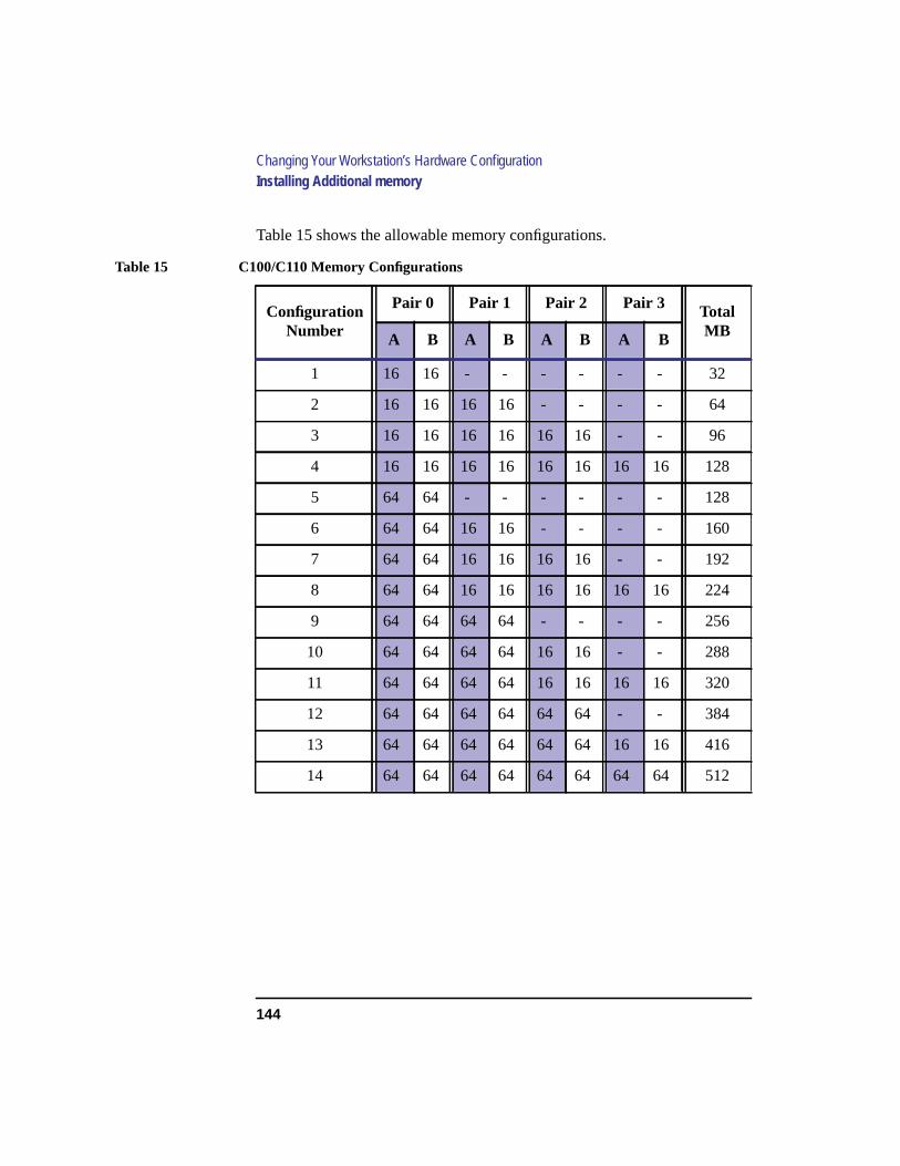
144
Changing Your Workstation’s Hardware ConfigurationInstalling Additional memory
Table 15 shows the allowable memory configurations.
Table 15 C100/C110 Memory Configurations
ConfigurationNumber
Pair 0 Pair 1 Pair 2 Pair 3 TotalMBA B A B A B A B
1 16 16 - - - - - - 32
2 16 16 16 16 - - - - 64
3 16 16 16 16 16 16 - - 96
4 16 16 16 16 16 16 16 16 128
5 64 64 - - - - - - 128
6 64 64 16 16 - - - - 160
7 64 64 16 16 16 16 - - 192
8 64 64 16 16 16 16 16 16 224
9 64 64 64 64 - - - - 256
10 64 64 64 64 16 16 - - 288
11 64 64 64 64 16 16 16 16 320
12 64 64 64 64 64 64 - - 384
13 64 64 64 64 64 64 16 16 416
14 64 64 64 64 64 64 64 64 512

145
Changing Your Workstation’s Hardware ConfigurationInstalling Additional memory
Perform the following steps to add memory modules to your workstation.
1 Remove the main tray assembly according to the directions in “Removing theMain Tray Assembly” earlier in this appendix.
2 Use Figure 37 to locate the memory modules on the CPU Assembly.
Figure 37 Memory Module Location
This workstation has 8 memory slots, labeled 0A, 0B through 3A, 3B. The mem-ory configuration is 32 MB to 512 MB installed in pairs of 16 MB or 32 MBmemory modules.
Memory modules must be installed in pairs of equal capacity.
Always install the largest capacity memory modules in the lowest numberedmemory slots.
For example, if you have a pair of 16 MB memory modules and a pair of 64 MBmemory modules, first install the pair of 64 MB memory modules in slots 0Aand 0B, then install the 16 MB modules in slots 1A and 1B.
NOTICE: Memory slots must be filled in order from 0A and 0B through 3A and 3B.
Rear of Main Tray
0A2A0B2B
1A3A1B3B
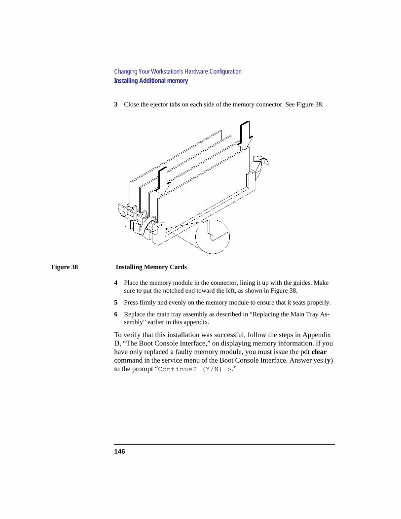
146
Changing Your Workstation’s Hardware ConfigurationInstalling Additional memory
3 Close the ejector tabs on each side of the memory connector. See Figure 38.
Figure 38 Installing Memory Cards
4 Place the memory module in the connector, lining it up with the guides. Makesure to put the notched end toward the left, as shown in Figure 38.
5 Press firmly and evenly on the memory module to ensure that it seats properly.
6 Replace the main tray assembly as described in “Replacing the Main Tray As-sembly” earlier in this appendix.
To verify that this installation was successful, follow the steps in AppendixD, “The Boot Console Interface,” on displaying memory information. If youhave only replaced a faulty memory module, you must issue the pdtclearcommand in the service menu of the Boot Console Interface. Answer yes (y)to the prompt “Continue? (Y/N) > .”
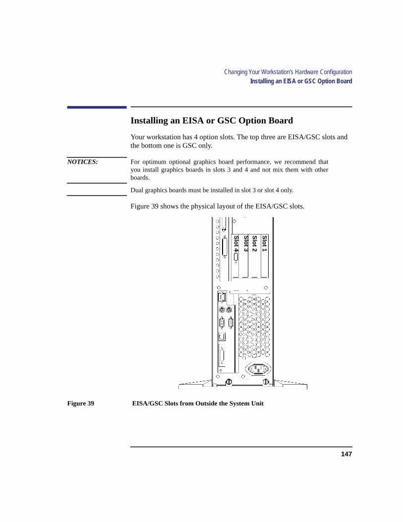
147
Changing Your Workstation’s Hardware ConfigurationInstalling an EISA or GSC Option Board
Installing an EISA or GSC Option Board
Your workstation has 4 option slots. The top three are EISA/GSC slots andthe bottom one is GSC only.
NOTICES: For optimum optional graphics board performance, we recommend thatyou install graphics boards in slots 3 and 4 and not mix them with otherboards.
Dual graphics boards must be installed in slot 3 or slot 4 only.
Figure 39 shows the physical layout of the EISA/GSC slots.
Figure 39 EISA/GSC Slots from Outside the System Unit
Slot 1
Slot 2
Slot 3
Slot 4
148
Changing Your Workstation’s Hardware ConfigurationInstalling an EISA or GSC Option Board
Graphics Paths
If you are installing a graphics option, read the information in this sectionfirst.
graphics0through graphics2are not supported. If the configuration value isset to“ default” (graphics 0), the system console will be graphics 3, Slot 3.
graphics3Graphics device in slot3. If there is a Dual Graphics Card in slot4,this is the port to the right on the card when facing the back of the worksta-tion.
graphics4 Graphics device in slot4. If there is a Dual Graphics Card in slot3 or 4, this is the port to the left on the card when facing the back of theworkstation.
NOTICE: If you install a VISUALIZE-48 graphics card (geometry accelerator boardinstalled in slot 3 or slot 4) the system path isgraphics 3.
If your model C100/110 is running HPUX 9.05, the system consolegraphics device must be installed in Slot 3.
If your model C100/110 is running HPUX 9.07 or later, the system willfind a console graphics device installed in Slot 3 by default. You mayinstall the console graphics device in Slot 4 if you modify your system filesas described inHP Visual User Environment Users Guideor HPUX X UserEnvironment User’s Guide.

149
Changing Your Workstation’s Hardware ConfigurationInstalling an EISA or GSC Option Board
Installing the Option Board
Follow these steps to install an EISA or GSC board into your workstation:
NOTICE: You may not install any graphics cards in Slots 1 or 2.
1 Remove the main tray assembly as described in “Removing the Main Tray As-sembly” earlier in this appendix.
2 Press the fan release clip and rotate the fan, as shown in Figure 41.
Figure 40 Rotating the Fan
3 Remove the screw from the EISA retainer, and remove the EISA retainer, asshown in Figure 41.
Figure 41 Removing the EISA Retainer
EISA Retainer

150
Changing Your Workstation’s Hardware ConfigurationInstalling an EISA or GSC Option Board
4 Remove the EISA Slider, as shown in Figure 42.
5 In the desired EISA slot, turn the blank plate’s locking knob counter-clockwiseto unlock the plate, as shown in Figure 42.
Figure 42 Removing the EISA Slider and Blank Plate
6 Remove the blank plate from the slot, as shown in Figure 42.
Blank Plate
Locking Knob
EISA Slider

151
Changing Your Workstation’s Hardware ConfigurationInstalling an EISA or GSC Option Board
7 Slide the board into the slot. Make sure that the hole in the board’s handle alignswith the pin on the back panel, as shown in Figure 43.
Figure 43 Installing an Option Board
8 Press in firmly on both ends of the option board at the same time to make surethat it is firmly seated in the backplane connector.

152
Changing Your Workstation’s Hardware ConfigurationInstalling an EISA or GSC Option Board
9 Replace the EISA retainer and its screw, as shown in Figure 44.
Figure 44 Installing the EISA Retainer and EISA Slider
10 Replace the EISA slider, as shown in Figure 44.
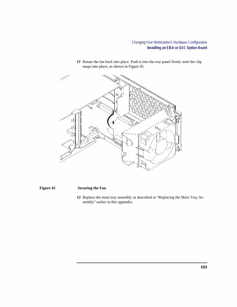
153
Changing Your Workstation’s Hardware ConfigurationInstalling an EISA or GSC Option Board
11 Rotate the fan back into place. Push it into the rear panel firmly until the clipsnaps into place, as shown in Figure 45.
Figure 45 Securing the Fan
12 Replace the main tray assembly as described in “Replacing the Main Tray As-sembly” earlier in this appendix.
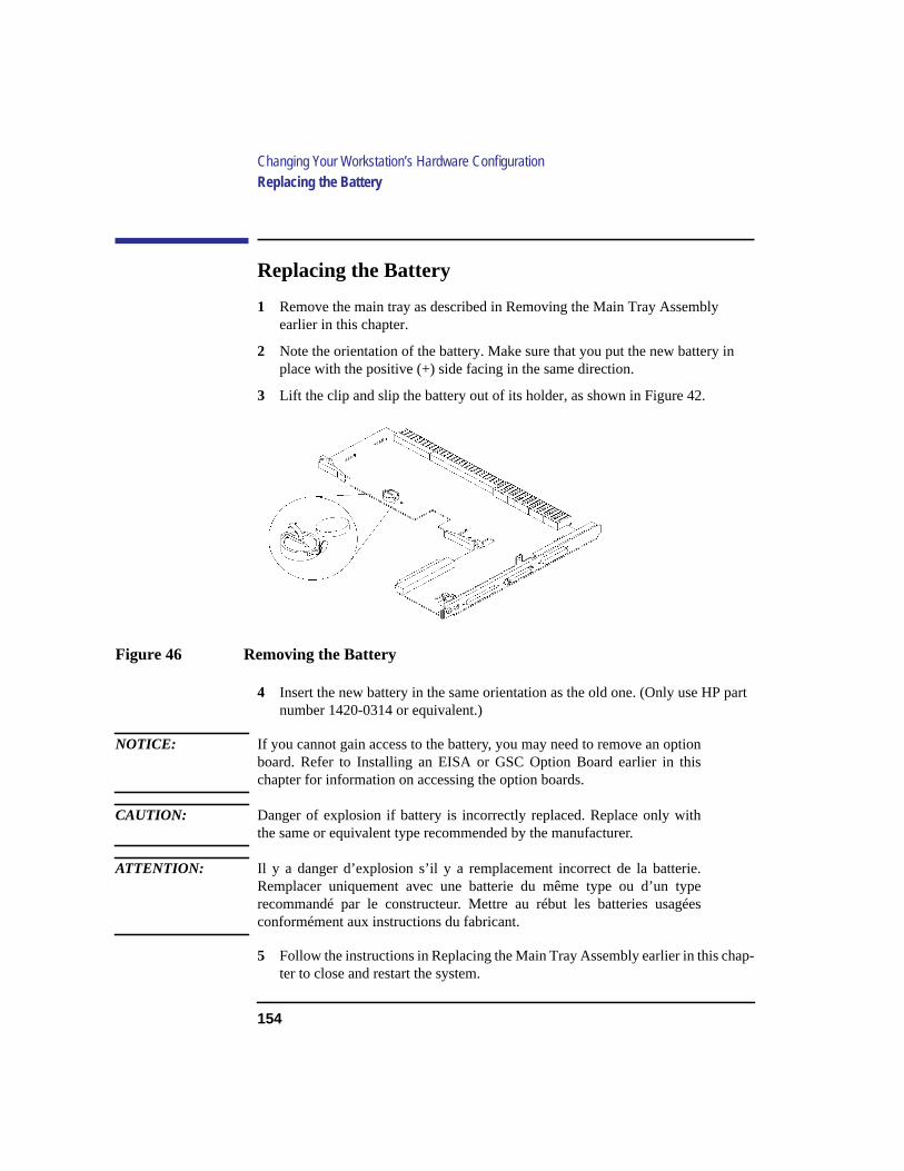
154
Changing Your Workstation’s Hardware ConfigurationReplacing the Battery
Replacing the Battery
1 Remove the main tray as described in Removing the Main Tray Assemblyearlier in this chapter.
2 Note the orientation of the battery. Make sure that you put the new battery inplace with the positive (+) side facing in the same direction.
3 Lift the clip and slip the battery out of its holder, as shown in Figure 42.
Figure 46 Removing the Battery
4 Insert the new battery in the same orientation as the old one. (Only use HP partnumber 1420-0314 or equivalent.)
NOTICE: If you cannot gain access to the battery, you may need to remove an optionboard. Refer to Installing an EISA or GSC Option Board earlier in thischapter for information on accessing the option boards.
CAUTION: Danger of explosion if battery is incorrectly replaced. Replace only withthe same or equivalent type recommended by the manufacturer.
ATTENTION: Il y a danger d’explosion s’il y a remplacement incorrect de la batterie.Remplacer uniquement avec une batterie du même type ou d’un typerecommandé par le constructeur. Mettre au rébut les batteries usagéesconformément aux instructions du fabricant.
5 Follow the instructions in Replacing the Main Tray Assembly earlier in this chap-ter to close and restart the system.
155
Changing Your Workstation’s Hardware ConfigurationChanging Your Monitor Type
Changing Your Monitor Type
Your system ships from the factory preset to use a monitor with a specificresolution and frequency. If you replace your monitor with a different type,you must reconfigure your workstation to support it.
There are two ways to reconfigure your workstation to support a differentmonitor type:
Setting the Monitor Type from the Boot Console Interface
To change your workstation’s graphics parametersbefore you replace yourmonitor, go to “Displaying and Setting the Monitor Type” in Appendix D.
Setting the Monitor Type at Power On
If you replace your workstation’s monitor with a different monitor type, anddo not set the workstation’s graphics parameters by using the monitor com-mand before doing so, you need to perform the following:
If your keyboard connects to the PS/2 connector on your system, wait 2 sec-onds after the Num Lock light flashes near the end of the boot sequence,then pressTab to initiate the automatic monitor selection process.
If you have a keyboard that connects to the HIL connector on your system,pressTab every three seconds during the boot sequence to initiate the auto-matic monitor selection process.
Your system queries you for the new monitor type. Select the new type bypressingEnter. The system queries you to confirm your selection. Pressy tosave this monitor type.
If you don’t press y, the system stops cycling. You can use themonitorgraphics command in the configuration menu to change monitor type.

156
Changing Your Workstation’s Hardware ConfigurationChanging Your Monitor Type

157
C
SCSI Connections

158
SCSI Connections
This appendix provides information about connecting Small Computer Sys-tem Interface (SCSI) devices to an HP 9000 C100/C110 workstation. It pre-sents the information in the following sections:
• SCSI bus differences
• SCSI restrictions
• Determining SCSI bus length
• Assigning SCSI device IDs
• Connecting to the SCSI ports
The instructions in this chapter assume you are using HP-UX version 9.05 orlater operating system with HP VUE version 3.0 or later interface.
NOTICE When attaching external SCSI devices, be sure to terminate the last deviceon the external SCSI bus.
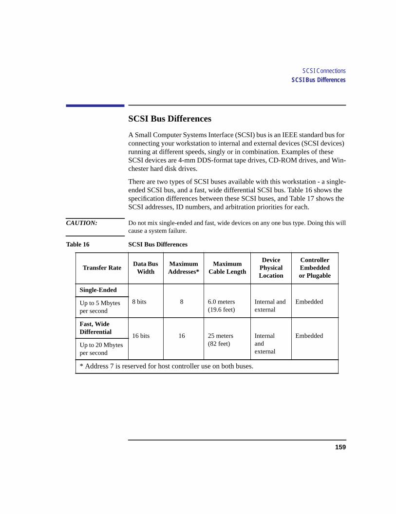
159
SCSI ConnectionsSCSI Bus Differences
SCSI Bus Differences
A Small Computer Systems Interface (SCSI) bus is an IEEE standard bus forconnecting your workstation to internal and external devices (SCSI devices)running at different speeds, singly or in combination. Examples of theseSCSI devices are 4-mm DDS-format tape drives, CD-ROM drives, and Win-chester hard disk drives.
There are two types of SCSI buses available with this workstation - a single-ended SCSI bus, and a fast, wide differential SCSI bus. Table 16 shows thespecification differences between these SCSI buses, and Table 17 shows theSCSI addresses, ID numbers, and arbitration priorities for each.
CAUTION: Do not mix single-ended and fast, wide devices on any one bus type. Doing this willcause a system failure.
Table 16 SCSI Bus Differences
Transfer RateData Bus
WidthMaximumAddresses*
MaximumCable Length
DevicePhysicalLocation
ControllerEmbeddedor Plugable
Single-Ended
8 bits 8 6.0 meters(19.6 feet)
Internal andexternal
EmbeddedUp to 5 Mbytesper second
Fast, WideDifferential
16 bits 16 25 meters(82 feet)
Internalandexternal
Embedded
Up to 20 Mbytesper second
* Address 7 is reserved for host controller use on both buses.
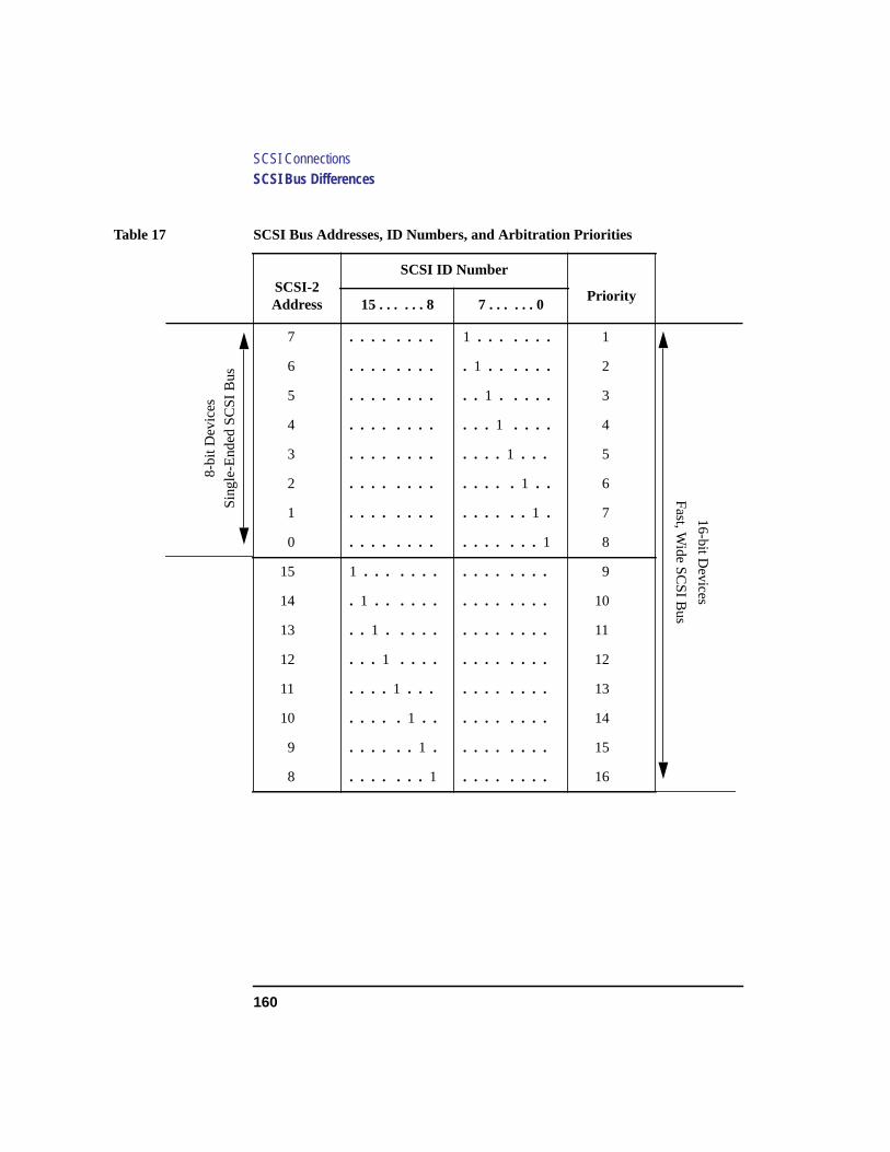
160
SCSI ConnectionsSCSI Bus Differences
Table 17 SCSI Bus Addresses, ID Numbers, and Arbitration Priorities
SCSI-2Address
SCSI ID Number
Priority15 . . . . . . 8 7 . . . . . . 0
7 . . . . . . . . 1 . . . . . . . 1
6 . . . . . . . . . 1 . . . . . . 2
5 . . . . . . . . . . 1 . . . . . 3
4 . . . . . . . . . . .1 . . . . 4
3 . . . . . . . . . . . .1 . . . 5
2 . . . . . . . . . . . . .1 . . 6
1 . . . . . . . . . . . . . .1 . 7
0 . . . . . . . . . . . . . . . 1 8
15 1 . . . . . . . . . . . . . . . 9
14 . 1 . . . . . . . . . . . . . . 10
13 . . 1 . . . . . . . . . . . . . 11
12 . . . 1 . . . . . . . . . . . . 12
11 . . . . 1 . . . . . . . . . . . 13
10 . . . . .1 . . . . . . . . . . 14
9 . . . . . .1 . . . . . . . . . 15
8 . . . . . . .1 . . . . . . . . 16
8-bi
t Dev
ices
Sin
gle-
End
ed S
CS
I Bus
16-bit Devices
Fast, W
ide SC
SI B
us
161
SCSI ConnectionsSCSI Restrictions
SCSI Restrictions
This section describes the SCSI restrictions that apply to your workstation inthe following areas:
• Cables
• Connectors and Terminator
• SCSI configuration constraints
Cables
All SCSI devices ship without cables. Only SCSI cables approved by HPcan be used to connect your workstation and any SCSI devices. HP offersthe following SCSI cables for single-ended standard SCSI devices:
• K2296 cable with 0.9 meter (3 feet) length
• K2297 cable with 1.5 meter (5 feet) length
HP offers the following SCSI cables for connecting externally connecteddevices to the system fast, wide port:
• C2911A cable with 0.9 meter (3 feet) length
• C2924A cable with 2.5 meter (8.2 feet) length
• C2925A cable with 10.0 meter (32.8 feet) length
• C2926A cable with 20.0 meter (65.6 feet) length
CAUTION: SCSI cables approved by HP are designed to function within the SCSI tolerances forHP devices. Use of other cables can result in significant problems with systemoperation.
Singled-ended SCSI-2 definition limits the total cable length of SCSI-2cables to 6 meters (19.6 feet).
Fast, wide differential SCSI definition limits the total cable length of Fast,Wide SCSI cables to 25 meters (82 feet).
Always use the shortest possible cable(s) for your configuration.
162
SCSI ConnectionsSCSI Restrictions
If you are daisy-chaining single-ended standard SCSI-2 devices together,use the following cables:
• 92222A cable with 0.5 meter (1.6 feet) length
• 92222B cable with 1.0 meter (3.2 feet) length
• 92222C cable with 2.0 meter (6.6 feet) length
If you are daisy-chaining fast, wide differential SCSI devices together, usethe following cables:
• C2911A cable with 0.9 meter (3 feet) length
• C2924A cable with 2.5 meter (8.2 feet) length
• C2925A cable with 10.0 meter (32.8 feet) length
• C2926A cable with 20.0 meter (65.6 feet) length
NOTICE See “Determining SCSI Bus Length” later in this Appendix to determinethe total length of your cables.
Connectors and Terminators
Any standard single-ended SCSI device connecting to the system boardmust use a 50-pin high-density thumb screw connector on the end connect-ing to the system board.
Any fast, wide differential SCSI device connecting to the system board mustuse a 68-pin high-density thumb screw connector on both ends.
It is not necessary to put a terminator on empty SCSI connectors on the backpanel. However, a SCSI device attached to the SCSI bus or the last deviceconnected to the SCSI bus must be terminated with a SCSI terminator. All ofthe devices listed ship without terminators. If you do not already have aSCSI terminator, you must order terminator C2904A (for 50-pin connectors)or C2905A (for 68-pin connectors) from Hewlett-Packard.
SCSI Configuration Constraints
You are limited to the number of same-type SCSI devices per system. Beforeadding another SCSI device, determine if the system can support the addi-tional device.
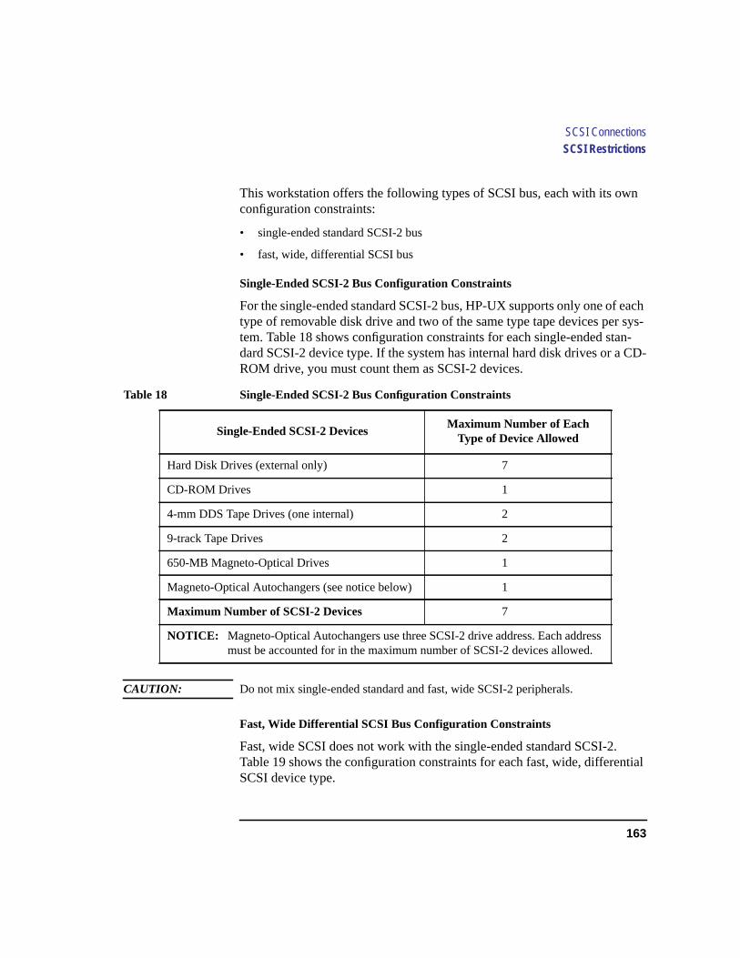
163
SCSI ConnectionsSCSI Restrictions
This workstation offers the following types of SCSI bus, each with its ownconfiguration constraints:
• single-ended standard SCSI-2 bus
• fast, wide, differential SCSI bus
Single-Ended SCSI-2 Bus Configuration Constraints
For the single-ended standard SCSI-2 bus, HP-UX supports only one of eachtype of removable disk drive and two of the same type tape devices per sys-tem. Table 18 shows configuration constraints for each single-ended stan-dard SCSI-2 device type. If the system has internal hard disk drives or a CD-ROM drive, you must count them as SCSI-2 devices.
CAUTION: Do not mix single-ended standard and fast, wide SCSI-2 peripherals.
Fast, Wide Differential SCSI Bus Configuration Constraints
Fast, wide SCSI does not work with the single-ended standard SCSI-2.Table 19 shows the configuration constraints for each fast, wide, differentialSCSI device type.
Table 18 Single-Ended SCSI-2 Bus Configuration Constraints
Single-Ended SCSI-2 DevicesMaximum Number of Each
Type of Device Allowed
Hard Disk Drives (external only) 7
CD-ROM Drives 1
4-mm DDS Tape Drives (one internal) 2
9-track Tape Drives 2
650-MB Magneto-Optical Drives 1
Magneto-Optical Autochangers (see notice below) 1
Maximum Number of SCSI-2 Devices 7
NOTICE: Magneto-Optical Autochangers use three SCSI-2 drive address. Each addressmust be accounted for in the maximum number of SCSI-2 devices allowed.
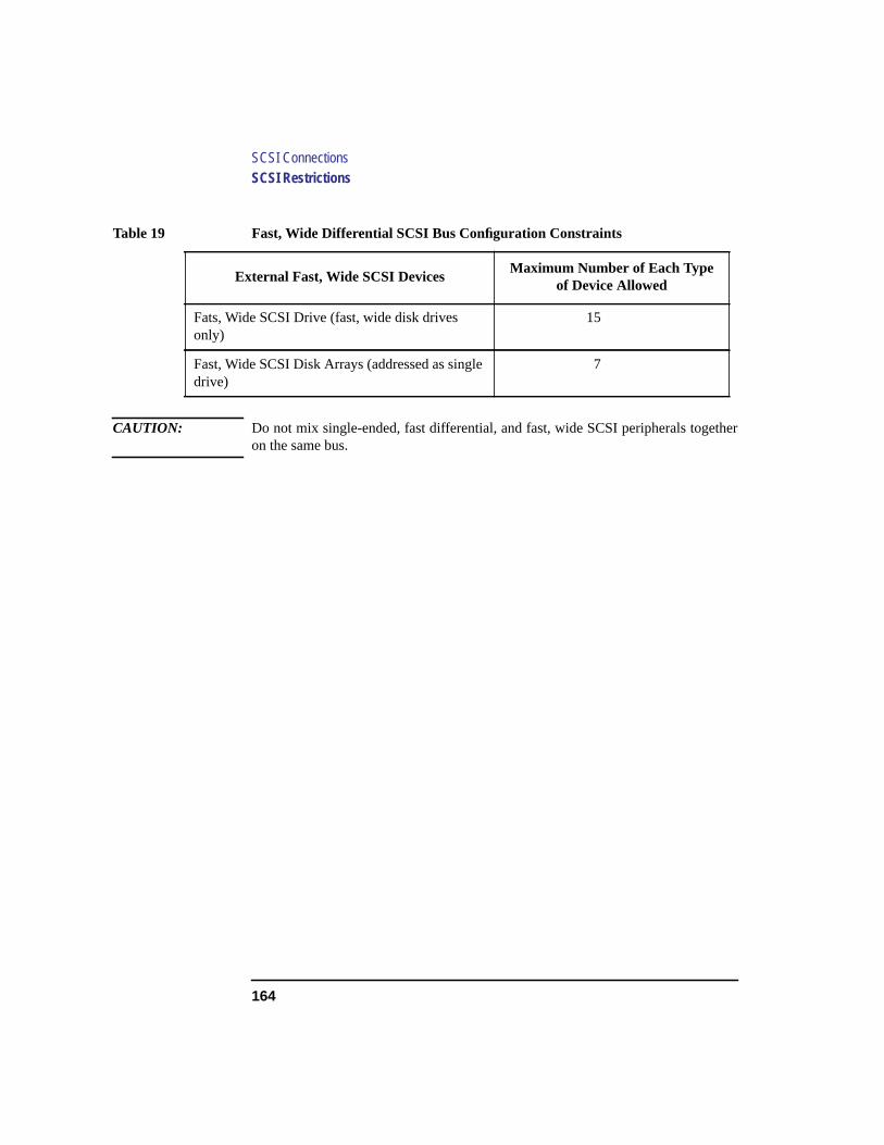
164
SCSI ConnectionsSCSI Restrictions
CAUTION: Do not mix single-ended, fast differential, and fast, wide SCSI peripherals togetheron the same bus.
Table 19 Fast, Wide Differential SCSI Bus Configuration Constraints
External Fast, Wide SCSI DevicesMaximum Number of Each Type
of Device Allowed
Fats, Wide SCSI Drive (fast, wide disk drivesonly)
15
Fast, Wide SCSI Disk Arrays (addressed as singledrive)
7
165
SCSI ConnectionsDetermining SCSI Bus Length
Determining SCSI Bus Length
This section helps you to determine the total length of the single-ended stan-dard SCSI-2 bus and the fast, wide SCSI bus.
Single-Ended SCSI-2 Bus Length
Follow these instructions to calculate your total single-ended standard SCSI-2 bus length (including the system unit, external SCSI-2 devices, and SCSI-2 interconnect cables) using Table 20:
1 Find all of your external SCSI-2 devices in the first column. In the third column,write the SCSI-2 bus lengths (from the second column) that correspond to yourdevices.
NOTICE In the third column, the length for the System Unit is already listed. Thisnumber must always be used for the system unit.
2 In the fourth column, write down the lengths of the SCSI-2 interconnect cablesyou are using for your installation. (Cable lengths are listed in subsection“Cables” in the section on “SCSI Restrictions.”
3 Add all of the numbers in the third column and write that number on the subtotalline at the bottom of the column. Do the same for the fourth column.
4 Add the subtotals together and write the total in the Total SCSI-2 Bus Length box.
NOTICE The total length of the single-ended standard SCSI-2 bus must not exceed 6meters (19.6 feet). If the number you write for Total SCSI-2 Bus Length isgreater than 6 meters (19.6 feet), try configuring your installation withshorter cables.
If you have problems, call your designated service representative.

166
SCSI ConnectionsDetermining SCSI Bus Length
Subtotals: __________ + __________
Total SCSI-2 Bus Length = __________
(Total single-ended SCSI bus length not to exceed 6 meters [19.6 feet])
Table 20 Bus Length Worksheet for Single-Ended SCSI Bus
SCSI-2 DeviceInternal SCSI-2 Bus Length
meters (feet)Device Internal Length
meters (feet)
ExternalCable Lengthmeters (feet)
System Unit 1.5 (4.9) 1.5 (4.9) N/A
A2655A 0.3 (1.0)
C1520B 0.2 (0.7)
C1521B 0.2 (0.7)
C1700C 1.1 (3.6)
C1701C 0.3 (1.0)
C1704C 0.0 (0.0)
C1705C 0.0 (0.0)
C2213A 1.5 (4.9)
C2217T 1.3 (4.3)

167
SCSI ConnectionsDetermining SCSI Bus Length
Fast, Wide Differential SCSI Bus Length
Follow these instructions to calculate your total bus length for the fast, wideSCSI bus on your system, using Table 21.
1 List all of your internal Fast, Wide SCSI devices in the first column.
2 In the third column, write the lengths of the internal Fast, Wide SCSI bus that cor-respond to your devices.
3 In the fourth column, write down the lengths of the Fast, Wide SCSI interconnectcables you are using for your installation. (Cable lengths are listed in subsection“Cables” in the section on “SCSI Restrictions.”)
4 Add all of the numbers in the third column and write the sum on the subtotal lineat the bottom of the column. Do the same for the fourth column.
5 Add the subtotals together and write the total on the Total Fast, Wide SCSI BusLength line.
NOTICE: The total length of the Fast, Wide SCSI bus must not exceed 25 meters (82feet). If the number you write for Total Fast, Wide SCSI Bus Length isgreater than 25 meters, try configuring your installation with shorter cables.
If you have problems, call your designated service representative.
Subtotals: ______________ + ________
Total Fast, Wide SCSI Bus Length = ______________
(Total fast, wide SCSI bus length not to exceed total of 25 meters [82 feet])
Table 21 Fats, Wide SCSI Bus Length Worksheet for Fast, Wide Differential SCSI Bus
Fats, WideDevice
Internal Fats, Wide SCSI BusLength meters(feet)
Device Internal Lengthmeters(feet)
ExternalCable
Lengthmeters(feet)
System Unit 1.5 (4.9) N/A
C3034T 1.0 (3.3)
C3035T 1.0 (3.3)
C3036T 1.0 (3.3)

168
SCSI ConnectionsAssigning SCSI Device IDs
Assigning SCSI Device IDs
Before assigning a SCSI device ID to your drive, you need to check yourexisting SCSI device IDs. To determine which SCSI device IDs are availablefor your device, use the ioscan command in a terminal window:
1 Click on the Terminal Control on the Front Panel of your Workspace.
A terminal window opens.
2 Move the mouse cursor into the terminal window and single-click the left mousebutton.
3 If you are using HP-UX 9.05 or greater, enter the following at the prompt
/etc/ioscan -d scsi
After a few moments the ioscan utility lists all of the SCSI I/O devices it couldfind. The list should appear similar to the following:
H/W Path Description Status
=====================================
2.0.1.2.0 cd-rom_drive ok(nnnnnnnn)
Terminal Control

169
SCSI ConnectionsAssigning SCSI Device IDs
If you are using HP-UX 10.0, enter the following at the prompt:
/usr/sbin/ioscan -f
After a few moments, the ioscan utility lists all of the SCSI I/O devices it couldfind. The list appears similar to the following:
Class I H/W Path Driver S/W State H/W Type Description
================================================================================
bc 0 root CLAIMED BUS_ NEXUS
bc 1 8 ccio CLAIMED BUS_NEXUS I/O Adapter
ext_bus 0 8/12 c720 CLAIMED INTERFACE GSC built-in Fast/Wide SCSI
target 0 8/12.0 tgt CLAIMED DEVICE
disk 3 8/12.0.0 sdisk CLAIMED DEVICE QUANTUM LPS1080WD
target 1 8/12.5 tgt CLAIMED DEVICE
disk 2 8/12.5.0 sdisk CLAIMED DEVICE DEC DSP3210SW
target 2 8/12.6 tgt CLAIMED DEVICE
disk 0 8/12.6.0 sdisk CLAIMED DEVICE DEC DSP3210SW
ba 0 8/16 bus_adapter CLAIMED BUS_NEXUS Core I/O Adapter
ext_bus 2 8/16/0 CentIf CLAIMED INTERFACE Built-in Parallel Interface
audio 0 8/16/1 audio CLAIMED INTERFACE Built-in Audio
tty 0 8/16/4 asio0 CLAIMED INTERFACE Built-in RS-232C
ext_bus 1 8/16/5 c700 CLAIMED INTERFACE Built-in SCSI
target 3 8/16/5.2 tgt CLAIMED DEVICE
disk 1 8/16/5.2.0 sdisk CLAIMED DEVICE TOSHIBA CD-ROM XM-4101TA
target 4 8/16/5.3 tgt CLAIMED DEVICE
tape 0 8/16/5.3.0 stape CLAIMED DEVICE HP HP35480A
target 5 8/16/5.4 tgt CLAIMED DEVICE
disk 10 8/16/5.4.0 sdisk CLAIMED DEVICE SEAGATE ST3600N
target 6 8/16/5.6 tgt CLAIMED DEVICE
disk 5 8/16/5.6.0 sdisk CLAIMED DEVICE MICROP 2112
lan 0 8/16/6 lan2 CLAIMED INTERFACE Built-in LAN
ps2 0 8/16/7 ps2 CLAIMED INTERFACE Built-in Keyboard/Mouse
bc 2 10 ccio CLAIMED BUS_NEXUS I/O Adapter
ext_bus 3 10/12 c720 CLAIMED INTERFACE GSC add on Fast/Wide SCSI
target 7 10/12.4 tgt CLAIMED DEVICE
disk 6 10/12.4.0 sdisk CLAIMED DEVICE SEAGATE ST31200W
graphics 2 10/16 graph3 CLAIMED INTERFACE Graphics
ba 1 10/20 bus_adapter CLAIMED BUS_NEXUS Core I/O Adapter
hil 0 10/20/1 hil CLAIMED INTERFACE Built-in HIL
tty 1 10/20/2 asio0 CLAIMED INTERFACE Built-in RS-232C
ba 2 10/20/5 eisa CLAIMED BUS_NEXUS EISA Bus Adapter
ext_bus 4 10/20/5/3 hshpib CLAIMED INTERFACE EISA card HWP0C70
target 8 10/20/5/3.0 tgt CLAIMED DEVICE
target 9 10/20/5/3.1 tgt CLAIMED DEVICE
target 10 10/20/5/3.2 tgt CLAIMED DEVICE
processor 0 32 processor CLAIMED PROCESSOR Processor
memory 0 49 memory CLAIMED MEMORY Memory

170
SCSI ConnectionsAssigning SCSI Device IDs
4 If you are using HP-UX 9.05 or greater, you can which SCSI IDs are currently inuse by looking under the H/W Path heading. The listing 2.0.1 scsi is the built-inSCSI bus controller. For devices connected to the built-in SCSI bus, such asdisks, the fourth number is the SCSI ID for that device. For example, the listing2.0.1.6.0 in the sample device list tells you that there is a SCSI device (a disk)currently using ID 6 on the SCSI bus.
Although the information is presented in a different format if you are using HP-UX 10.0, you look under the H/W Path heading also.
Single-Ended Standard System SCSI Device IDs
Before assigning a SCSI device ID to your drive, you need to check yourSCSI device IDs. To check what SCSI device IDs are available and assign anID to your device, follow these instructions which use Table 22:
1 Write in the SCSI device ID of any internal drives in Table 22
2 Write in the type of external drives (single-ended standard, EISA, or fast, widedevices) currently connected to your system under the heading “External DeviceDrives” and each drive’s SCSI device ID under the heading “Device ID.”
3 Add your new drive to the table if it is an external device. If it is an internal drive,continue to Step 4.
NOTICE: The C1700A Magneto-Optical Autochanger uses three SCSI addresses,and accounts for three of the seven devices allowed on the SCSI bus.
4 Check to see which SCSI device IDs are not used. You can use ID numbers 0through 6 if they are not already in use. If the default ID on your drive does notconflict with any existing drive IDs, use that ID. If your default address conflictswith an existing drive ID, you need to assign a new SCSI device ID to your drive.See the drive installation documentation for information on changing the deviceID.
CAUTION: Do not use SCSI device ID 7 for any device. It is reserved for the built-in SCSI buscontroller
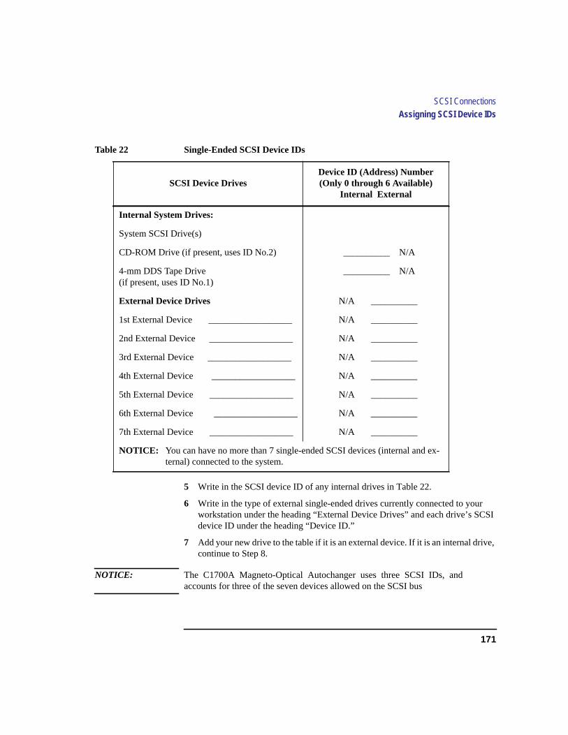
171
SCSI ConnectionsAssigning SCSI Device IDs
5 Write in the SCSI device ID of any internal drives in Table 22.
6 Write in the type of external single-ended drives currently connected to yourworkstation under the heading “External Device Drives” and each drive’s SCSIdevice ID under the heading “Device ID.”
7 Add your new drive to the table if it is an external device. If it is an internal drive,continue to Step 8.
NOTICE: The C1700A Magneto-Optical Autochanger uses three SCSI IDs, andaccounts for three of the seven devices allowed on the SCSI bus
Table 22 Single-Ended SCSI Device IDs
SCSI Device DrivesDevice ID (Address) Number(Only 0 through 6 Available)
Internal External
Internal System Drives:
System SCSI Drive(s)
CD-ROM Drive (if present, uses ID No.2) __________ N/A
4-mm DDS Tape Drive(if present, uses ID No.1)
__________ N/A
External Device Drives N/A __________
1st External Device __________________ N/A __________
2nd External Device __________________ N/A __________
3rd External Device __________________ N/A __________
4th External Device __________________ N/A __________
5th External Device __________________ N/A __________
6th External Device __________________ N/A __________
7th External Device __________________ N/A __________
NOTICE: You can have no more than 7 single-ended SCSI devices (internal and ex-ternal) connected to the system.
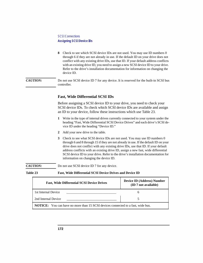
172
SCSI ConnectionsAssigning SCSI Device IDs
8 Check to see which SCSI device IDs are not used. You may use ID numbers 0through 6 if they are not already in use. If the default ID on your drive does notconflict with any existing drive IDs, use that ID. If your default address conflictswith an existing drive ID, you need to assign a new SCSI device ID to your drive.Refer to the drive’s installation documentation for information on changing thedevice ID.
CAUTION: Do not use SCSI device ID 7 for any device. It is reserved for the built-in SCSI buscontroller.
Fast, Wide Differential SCSI IDs
Before assigning a SCSI device ID to your drive, you need to check yourSCSI device IDs. To check which SCSI device IDs are available and assignan ID to your device, follow these instructions which use Table 23.
1 Write in the type of internal drives currently connected to your system under theheading “Fast, Wide Differential SCSI Device Drives” and each drive’s SCSI de-vice ID under the heading “Device ID.”
2 Add your new drive to the table.
3 Check to see what SCSI device IDs are not used. You may use ID numbers 0through 6 and 8 through 15 if they are not already in use. If the default ID on yourdrive does not conflict with any existing drive IDs, use that ID. If your defaultaddress conflicts with an existing drive ID, assign a new fast, wide differentialSCSI device ID to your drive. Refer to the drive’s installation documentation forinformation on changing the device ID.
CAUTION: Do not use SCSI device ID 7 for any device.
Table 23 Fast, Wide Differential SCSI Device Drives and Device ID
Fast, Wide Differential SCSI Device DrivesDevice ID (Address) Number
(ID 7 not available)
1st Internal Device ______________________________ 6
2nd Internal Device ______________________________ 5
NOTICE: You can have no more than 15 SCSI devices connected to a fast, wide bus.
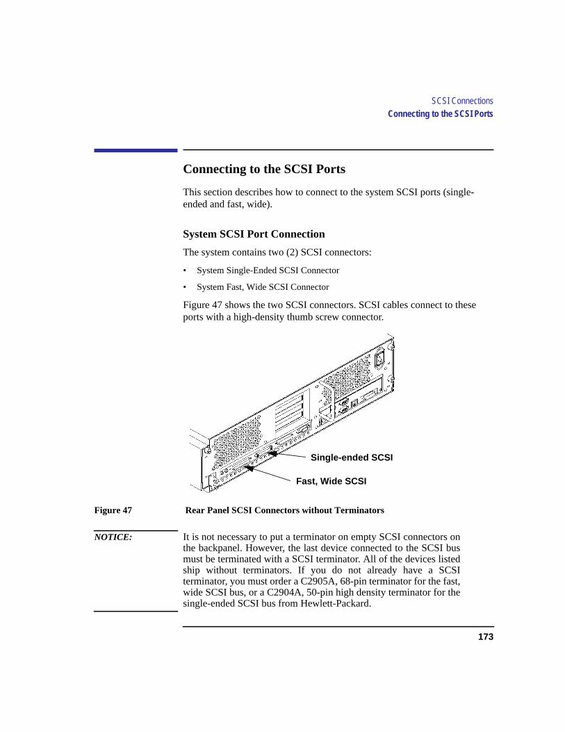
173
SCSI ConnectionsConnecting to the SCSI Ports
Connecting to the SCSI Ports
This section describes how to connect to the system SCSI ports (single-ended and fast, wide).
System SCSI Port Connection
The system contains two (2) SCSI connectors:
• System Single-Ended SCSI Connector
• System Fast, Wide SCSI Connector
Figure 47 shows the two SCSI connectors. SCSI cables connect to theseports with a high-density thumb screw connector.
Figure 47 Rear Panel SCSI Connectors without Terminators
NOTICE: It is not necessary to put a terminator on empty SCSI connectors onthe backpanel. However, the last device connected to the SCSI busmust be terminated with a SCSI terminator. All of the devices listedship without terminators. If you do not already have a SCSIterminator, you must order a C2905A, 68-pin terminator for the fast,wide SCSI bus, or a C2904A, 50-pin high density terminator for thesingle-ended SCSI bus from Hewlett-Packard.
Fast, Wide SCSI
Single-ended SCSI

174
SCSI ConnectionsConnecting to the SCSI Ports
175
D
The Boot Console Interface
176
The Boot Console Interface
This appendix describes the different features of the boot console interfaceand how to use them. It presents the information in the following sections:
• Boot console interface features
• Accessing the boot console interface
• Booting your workstation
• Searching for bootable media
• Resetting your workstation
• Displaying and setting paths
• Displaying and setting the monitor type
• Displaying the current memory configuration
• Displaying the status of the EISA slots
• Setting the Auto Boot and Auto Search flags
• Displaying and setting the Fastboot mode
• Displaying the LAN station address
• Displaying system information
• Displaying PIM information
The instructions in this chapter assume you are using HP-UX version 9.05 orlater operating system.
177
The Boot Console InterfaceBoot Console Interface Features
Boot Console Interface Features
There are times when you want to interact directly with the hardware of yourworkstationbefore it boots the operating system. Your workstation providesa menu-drivenboot console interface that allows you to perform specialtasks, display information, and set certain system parameters, even if theoperating system is unavailable.
Here are some of the things you can do:
• Boot your workstation
• Search for bootable media
• Reset your workstation
• Display and set boot paths
• Display and set your monitor type
• Display memory configuration information
• Display the status of the EISA slots
• Set Auto Boot and Auto Search
• Set Fastboot
• Display LAN information
• Display system information
• Display PIM information
NOTICE: All of the tasks in the boot console interface should be performed by asystem administrator.
Theboot console menus follow, showing the various tasks you can performand the information available.
The shortened version of all commands is indicated by the uppercase letters.
Help is available for all the menus and commands by using eitherhelp, he,or ? and the menu or command you want help on.

178
The Boot Console InterfaceBoot Console Interface Features
------ Main Menu -----------------------------------------------------
Command Description
------- -----------
BOot [PRI|ALT|<path>] Boot from specified path
PAth [PRI|ALT|CON|KEY][<path>] Display or modify a path
SEArch [DIsplay|IPL] [<path>] Search for boot devices
COnfiguration menu Displays or sets boot values
INformation menu Displays hardware information
SERvice menu Displays service commands
DIsplay Redisplay the current menu
HElp [<menu>|<command>] Display help for menu or command
RESET Restart the system
------
Main Menu: Enter a command or a menu >
------ Configuration Menu --------------------------------------------
Command Description
------- -----------
AUto [BOot|SEArch] [ON|OFF] Display or set specified flag
BootInfo Display boot-related info
DEfault Set system to predefined values
FastBoot [ON|OFF] Display or set boot tests execution
LanAddress [<option>] Display Core LAN station address
MOnitor [<option>] Display or set monitor type in EEPROM
PAth [PRI|ALT|CON|KEY] [<path>] Display or modify a path
PRocessor [<proc>] [ON|OFF] Config/Deconfig processor
SEArch [DIsplay|IPL] [<path>] Search for boot devices
TIme [c:y:m:d:h:m:[s] Read or set real time clock in GMT
BOot [PRI|ALT|<path>] Boot from specified path
DIsplay Redisplay the current menu
HElp [<command>] Display help for menu or command
RESET Restart the system
MAin Return to Main Menu
------
Configuration Menu: Enter a command or a menu >

179
The Boot Console InterfaceBoot Console Interface Features
------ Information Menu ----------------------------------------------
Command Description
----------- -----------
ALL Display all system information
BootInfo Display boot-related information
CAche Display cache information
COprocessor Display coprocessor information
EIsa Display EISA slot information
FWrVersion Display firmware version
MEmory Display memory information
MOnitor Display monitor type in EEPROM
PRocessor Display processor information
BOot [PRI|ALT|<path>] Boot from specified path
DIsplay Redisplay the current menu
HElp [<command>] Display help for menu or command
RESET Restart the system
MAin Return to Main Menu
------
Information Menu: Enter a command or a menu >
------ Service Menu --------------------------------------------------
Command Description
------- -----------
MemRead <address> [<len>] Read memory and I/O locations
PIM [<proc>][HPMC|LPMC|TOC] Display PIM information
PDT [CLEAR] Display or clear the Page Deallocation
Table
ChassisCodes [<proc>] Display chassis codes
BOot [PRI|ALT|<path>] Boot from specified path
DIsplay Redisplay the current menu
HElp [<command>] Display help for menu or command
RESET Restart the system
MAin Return to Main Menu
------
Service Menu: Enter a command or a menu >

180
The Boot Console InterfaceAccessing the Boot Console Interface
Accessing the Boot Console Interface
To access the boot console interface, follow these steps:
NOTICE: This procedure should be done by a system administrator.
1 Close any files and applications on your workstation.
2 Press the power switch on the front panel of the system unit.
NOTICES: There is no need to manually shut down the HP-UX operating system onyour workstation before powering it off. When you turn off the powerswitch, your workstation automatically shuts down the operating systembefore terminating the power.
Make sure that you do not unplug the system’s power cord or otherwiseinterrupt power to the system unit at this time.
3 Power on your workstation.
If Autoboot is turned off, the boot sequence automatically stops at the bootconsole Main Menu.
If Autoboot is turned on, you will see the following messages:
Processor is starting Autoboot process. To discontinue,press any key within 10 seconds.
NOTICE: If you are using a power-saving monitor, you will have less than 10seconds from the time this message appears to press a key.
4 Press a key. You will then see the message:
Boot terminated
The Main Menu of the boot console appears.
181
The Boot Console InterfaceBooting Your Workstation
Booting Your Workstation
Usually, you start your workstation by turning it on and waiting for HP-UXto boot automatically. However, you may not always want the usualsequence to occur.
For example, you may want to start your workstation from an operating sys-tem that is stored on a device that is different from your usual boot device. Ifyour normal operating system kernel or the disk on which it resides becomesdamaged or unusable, you may wish to boot from a different disk or perhapsanother type of device, such as a DDS-format tape drive.
Here are some situations and examples:
• If you know which device you want to boot from, and you know that it containsa bootable operating system, follow the directions in “Accessing the Boot Con-sole Interface” earlier in this appendix, and then type the following at the prompt:
Main Menu: Enter a command or a menu > boot device
wheredevice is thehardware path to the device, specified in Mnemonic StyleNotation.
For example, if you wish to boot an operating system that is stored on a DDS-format tape in a drive that is located at ‘‘scsi.1.0’’, follow the directions in“Accessing the Boot Console Interface” earlier in this appendix, and then typethe following command at the prompt:
Main Menu: Enter a command or a menu > boot scsi.1.0
The operating system on the specified device is used to start your workstation.
• If you wish to interact with the Initial System Loader (ISL) before booting yourworkstation, follow the directions in “Accessing the Boot Console Interface” ear-lier in this appendix, and then type the following at the prompt
Main Menu: Enter a command or a menu > boot device
You are prompted:
Interact with ISL (Y or N) >
182
The Boot Console InterfaceBooting Your Workstation
Answering yes (y) causes the ISL to be loaded from the specified device. After ashort time, the following prompt appears on your screen:
ISL>
ISL is the program that actually controls the loading of the operating system. Byinteracting with ISL, you can choose to load an alternate version of the HP-UXoperating system. If you do not want ISL to be loaded, you must enter NO.
For example, if the usual kernel (/hp-ux for 9.05, and/stand/vmunix for 10.0)on your root disk (fwscsi.6.0) has become corrupted, and you wish to boot yourworkstation from the backup kernel (/SYSBCKUP for 9.05, and/stand/vmu-nix.prev for 10.0), type the following at theISL> prompt:
ISL> hpux /SYSBCKUP (for 9.05)
ISL> hpux /stand/vmunix.prev (for 10.0)
• If you do not know which media in your file systems have bootable oper-ating systems, you can find them with thesearch IPL command.

183
The Boot Console InterfaceSearching for Bootable Media
Searching for Bootable Media
To list devices that contain bootable media, follow the directions in “Access-ing the Boot Console Interface” earlier in this appendix, and then type thefollowing at the prompt:
Main Menu: Enter a command or a menu > search ipl
The search command searches all buses. The search may turn up moredevices than there are lines on your display. If you are using a text terminal,you may control the progress of the search from your terminal’s keyboard byperforming the following steps:
• To hold the display temporarily, pressCtrl S
• To continue the display, pressCtrl Q
• To halt the search, press any other key
These flow-control commands do not work with a bitmapped display, butsuch a display can show more than forty lines of text, so you are unlikely toneed them.
To search for devices ofjust one type that actually contain bootable media,follow the directions in “Accessing the Boot Console Interface” earlier inthis appendix, and then type the following at the prompt:
Main Menu: Enter a command or a menu > search ipl device_type
Wheredevice_type is one of the following:
fwscsi is the built-in fast, wide SCSI bus
scsi is the built-in single-ended SCSI bus
lan is all connections to the built-in LAN
slotn.fwscsi is an optional fast, wide SCSI interface in slot numbern
184
The Boot Console InterfaceResetting Your Workstation
Resetting Your Workstation
To reset your workstation, follow the directions in “Accessing the Boot Con-sole Interface” earlier in this appendix, and then type the following at theprompt:
Main Menu: Enter a command or a menu > reset
To reset your workstation to its predefined values, follow the directions in"Accessing the Boot Console Interface" earlier in this appendix, and thentype the following at the prompt to access the Configuration Menu:
Main Menu: Enter a command or a menu > co
When the Configuration Menu appears, type the following at the prompt:
Configuration Menu: Enter a command or a menu > default

185
The Boot Console InterfaceDisplaying and Setting Paths
Displaying and Setting Paths
A path is the hardware address of a device that is attached to the I/O systemof your workstation. Thepath command sets the system paths shown inTable 24.
Thepath command sets and displays the hardware address of a specifieddevice attached to the I/O bus of your workstation.
To display the current settings for the system paths, type the following at theprompt:
Main Menu: Enter a command or a menu > path
The paths are displayed inMnemonic Style Notation, as shown in Table 25.
Table 24 System Paths
Path Type Device
primary or pri Your workstation’s default boot device (usually the rootdisk)
alternate or alt Your workstation’s alternate boot device (usually a DDS-format tape device)
consoleor con Your workstation’s primary display device
keyboard orkey
Your workstation’s primary ASCII input device
Table 25 Mnemonic Style Notation
I/O Type Specification Format
Built-in FWSCSI core.fwsci.scsi_address.logical_unit_number
Built-in SCSI core.scsi.scsi_address.logical_unit_number
Built-in LAN core.lan.server_address.init_timeout.io_timeout
186
The Boot Console InterfaceDisplaying and Setting Paths
To display the current setting for a particular system path, follow the direc-tions in “Accessing the Boot Console Interface” earlier in this appendix, andthen type the following at the prompt:
Main Menu: Enter a command or a menu > path path_type
wherepath_type is one of the path types listed in Table 24.
For example, to get the path to the primary boot device, follow the directionsin “Accessing the Boot Console Interface” earlier in this chapter, and thentype the following at the prompt:
Main Menu: Enter a command or a menu > path primary
To set a system path to a new value, follow the directions in “Accessing theBoot Console Interface” earlier in this chapter, and then type the followingat the prompt:
Main Menu: Enter a command or a menu > path path_type path
wherepath_type is one of the path types listed in Table 24 andpath is thespecification of the path in Mnemonic Style Notation (as described in Table25). For example, to set the primary boot path to a scsi disk with an ID of6.0, follow the directions in “Accessing the Boot Console Interface” earlierin this appendix, and then type the following at the prompt:
Main Menu: Enter a command or a menu > path pri scsi.6.0
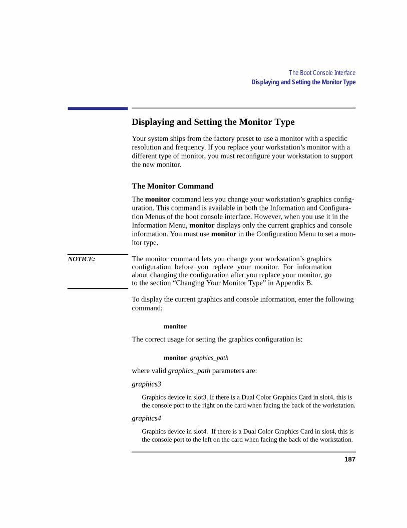
187
The Boot Console InterfaceDisplaying and Setting the Monitor Type
Displaying and Setting the Monitor Type
Your system ships from the factory preset to use a monitor with a specificresolution and frequency. If you replace your workstation’s monitor with adifferent type of monitor, you must reconfigure your workstation to supportthe new monitor.
The Monitor Command
Themonitor command lets you change your workstation’s graphics config-uration. This command is available in both the Information and Configura-tion Menus of the boot console interface. However, when you use it in theInformation Menu,monitor displays only the current graphics and consoleinformation. You must usemonitor in the Configuration Menu to set a mon-itor type.
NOTICE: The monitor command lets you change your workstation’s graphicsconfiguration before you replace your monitor. For informationabout changing the configuration after you replace your monitor, goto the section “Changing Your Monitor Type” in Appendix B.
To display the current graphics and console information, enter the followingcommand;
monitor
The correct usage for setting the graphics configuration is:
monitor graphics_path
where validgraphics_path parameters are:
graphics3
Graphics device in slot3. If there is a Dual Color Graphics Card in slot4, this isthe console port to the right on the card when facing the back of the workstation.
graphics4
Graphics device in slot4. If there is a Dual Color Graphics Card in slot4, this isthe console port to the left on the card when facing the back of the workstation.

188
The Boot Console InterfaceDisplaying and Setting the Monitor Type
Displaying the Current Monitor Configuration
To display the current monitor configuration for your system from the Con-figuration Menu of the boot console interface, follow the directions in“Accessing the Boot Console Interface” earlier in this appendix. Once youare in the Boot Console Interface Main Menu, type:
Main Menu: Enter a command or a menu > configuration
This places you in the Configuration Menu. From here type:
Configuration Menu: Enter command > monitor
The screen displays a list of the current monitors configured for your work-station.
MONITOR INFORMATION
Slot # HPA State Resolution Frequency Class
--------- ------- ---- ---------- --------- -------
graphics3 f4000000 Present Fixed
graphics4 f6000000 Empty
Current Console Path: core.RS232_.9600.8.none
Stable Store Console Path:GRAPHICS3
In this example, the graphics cards are configured as follows:
• Graphics slot3 - CRX48Z
• Graphics slot4 - Empty

189
The Boot Console InterfaceDisplaying and Setting the Monitor Type
Setting the Monitor Type
Using the list in the example above, you can set the monitor type for graph-ics slot3 by typing the following:
Configuration Menu: Enter command > monitor graphics3
NOTICE: You can exit at this point by enteringx, and the monitor type will not bechanged.
The screen displays the choice of supported monitors, similar to the follow-ing. Follow the directions in the screen prompts and enter the monitor typeyou want to configure (in this example, number 2).
MONITOR INFORMATIONType Resolution Frequency---- ---------- ---------1 1280x1024 72Hz2 1024x768 75Hz3 1024x768 70Hz4 1024x768 75Hz Flat Panel5 1280x1024 60Hz6 1024X768 60Hz7 640X480 60Hz8 1280X1024 75Hz VESA9 1024X768 75Hz VESA10 800X600 75Hz VESA11 640X480 75Hz VESA12 1280X1024 72HZ GrayScale13 1280X1024 50HZ
Enter monitor type selection from list above (or ’x’ to exit): 22 1024x768 75Hz
Press <y> to save monitor type <x> to exit monitor selection: y
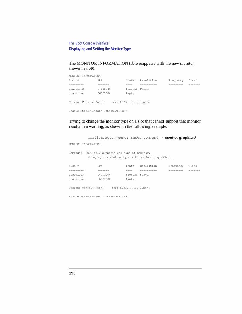
190
The Boot Console InterfaceDisplaying and Setting the Monitor Type
The MONITOR INFORMATION table reappears with the new monitorshown in slot0.
MONITOR INFORMATION
Slot # HPA State Resolution Frequency Class
--------- ------- ---- ---------- --------- -------
graphics3 f4000000 Present Fixed
graphics4 f6000000 Empty
Current Console Path: core.RS232_.9600.8.none
Stable Store Console Path:GRAPHICS3
Trying to change the monitor type on a slot that cannot support that monitorresults in a warning, as shown in the following example:
Configuration Menu: Enter command > monitor graphics3
MONITOR INFORMATION
Reminder: SGIC only supports one type of monitor.
Changing its monitor type will not have any effect.
Slot # HPA State Resolution Frequency Class
--------- ------- ---- ---------- --------- -------
graphics3 f4000000 Present Fixed
graphics4 f6000000 Empty
Current Console Path: core.RS232_.9600.8.none
Stable Store Console Path:GRAPHICS3
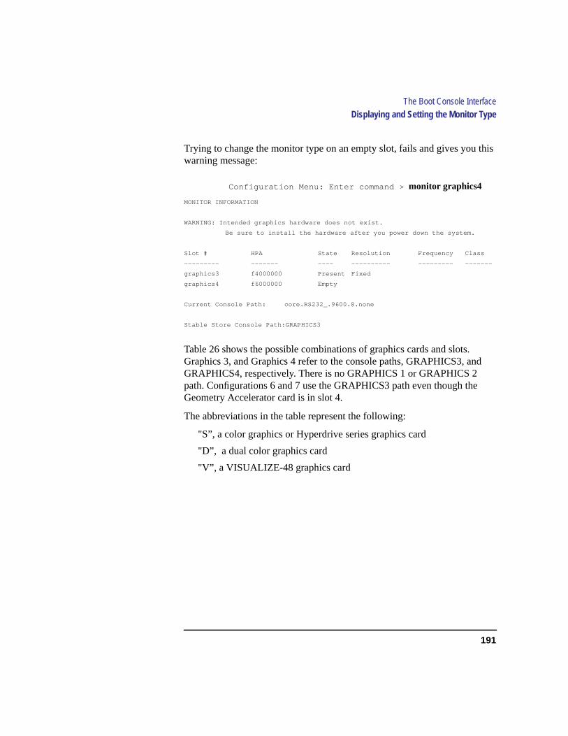
191
The Boot Console InterfaceDisplaying and Setting the Monitor Type
Trying to change the monitor type on an empty slot, fails and gives you thiswarning message:
Configuration Menu: Enter command > monitor graphics4
MONITOR INFORMATION
WARNING: Intended graphics hardware does not exist.
Be sure to install the hardware after you power down the system.
Slot # HPA State Resolution Frequency Class
--------- ------- ---- ---------- --------- -------
graphics3 f4000000 Present Fixed
graphics4 f6000000 Empty
Current Console Path: core.RS232_.9600.8.none
Stable Store Console Path:GRAPHICS3
Table 26 shows the possible combinations of graphics cards and slots.Graphics 3, and Graphics 4 refer to the console paths, GRAPHICS3, andGRAPHICS4, respectively. There is no GRAPHICS 1 or GRAPHICS 2path. Configurations 6 and 7 use the GRAPHICS3 path even though theGeometry Accelerator card is in slot 4.
The abbreviations in the table represent the following:
"S”, a color graphics or Hyperdrive series graphics card
"D”, a dual color graphics card
"V”, a VISUALIZE-48 graphics card

192
The Boot Console InterfaceDisplaying and Setting the Monitor Type
NOTICE: HPUX 9.05 requirespath console graphics3.
Do not put a graphics card into slot 1 or slot 2.
In Table 26, usepath console graphics3 for configuration numbers 6,and 7.
Table 26 Graphics Configurations
Confiig.Number
Numberof Heads
Graphics 310/16
Graphics 410/20
Slot1
Slot2
Slot 3 Slot 4
1 1 Y S
2 1 Y S
3 2 Y Y S S
4 2 Y Y D
5 2 Y Y D
6 1 Y V
7 1 Y V

193
The Boot Console InterfaceDisplaying and Setting the Monitor Type
Setting the Monitor Type at Power On
If you replace your workstation’s monitor with a different monitor type, anddo not set the workstation’s graphics parameters by using the monitor com-mand before doing so, you need to perform the following:
If your keyboard connects to the PS/2 connector on your system, wait 2 sec-onds after the Num Lock light flashes near the end of the boot sequence,then pressTab to initiate the automatic monitor selection process.
If you have a keyboard that connects to the HIL connector on your system,pressTab every three seconds during the boot sequence to initiate the auto-matic monitor selection process.
Your system queries you for the new monitor type. Select the new type bypressingEnter. The system queries you to confirm your selection. Pressy tosave this monitor type.
If you don’t press y, the system stops cycling. You can use themonitorgraphics command in the configuration menu to change monitor type.
194
The Boot Console InterfaceDisplaying the Current Memory Configuration
Displaying the Current Memory Configuration
The following sample screen output using thememory command shows:first, a memory configuration table with properly-installed and configuredmemory (Sample Output 1); and second, output when a SIMM has beenimproperly installed (Sample Output 2).
To display the current memory configuration for your system, from theInformation Menu of the boot console interface, follow the directions in“Accessing the Boot Console Interface” earlier in this appendix. Once youare in the Boot Console Interface Main Menu, type:
Main Menu: Enter a command or a menu > information
This places you in the Information Menu. From here type:
Information Menu: Enter command > memory
The screen displays a list of the current memory SIMMs configured for yourworkstation.
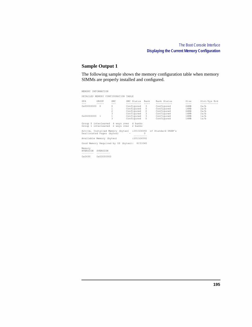
195
The Boot Console InterfaceDisplaying the Current Memory Configuration
Sample Output 1
The following sample shows the memory configuration table when memorySIMMs are properly installed and configured.
MEMORY INFORMATION
DETAILED MEMORY CONFIGURATION TABLE
SPA GROUP SMC SMC Status Bank Bank Status Size Slot/Sys Brd--- ----- --- ---------- ---- ----------- ---- ------------0x00000000 0 0 Configured 3 Configured 64MB 0a/b
1 Configured 0 Configured 16MB 2a/b2 Configured 0 Configured 64MB 0a/b3 Configured 3 Configured 16MB 2a/b
0x04000000 1 1 Configured 3 Configured 16MB 1a/b3 Configured 0 Configured 16MB 1a/b
Group 0 interleaved 4 ways over 4 banksGroup 1 interleaved 2 ways over 2 banks
Active, Installed Memory (bytes) :201326592 of Standard DRAM’sDeallocated Pages (bytes) - 0
---------Available Memory (bytes) :201326592
Good Memory Required by OS (bytes): 8151040
MemoryHVERSION SVERSION-------- ---------
0x0490 0x00000900

196
The Boot Console InterfaceDisplaying the Current Memory Configuration
Sample Output 2
The following sample shows the memory configuration table when amemory SIMM has been improperly installed, or not installed in pairs. Inthis example, there is only one SIMM installed in slot 4a. Note that now theBAD MEMORY TABLE is displayed.
MEMORY INFORMATION
WARNING: Memory banks deallocated due to a SIMM size mismatch or a SIMM failure.
Refer to the ME command in the INFORMATION menu for error information.
DETAILED MEMORY CONFIGURATION TABLE
SPA GROUP SMC SMC Status Bank Bank Status Size Slot/Sys Brd--- ----- --- ---------- ---- ----------- ---- ------------0x00000000 0 0 Configured 3 Configured 16MB 0a/b
1 Configured 0 Configured 16MB 2a/b2 Configured 0 Configured 16MB 0a/b3 Configured 3 Configured 16MB 2a/b
0x04000000 1 1 Configured 3 Configured 64MB 1a/b3 Configured 0 Configured 64MB 1a/b
Group 0 interleaved 4 ways over 4 banksGroup 1 interleaved 2 ways over 2 banks
BAD MEMORY TABLESMC SMC Status Bank Bank Status SIMM Size Slot/Sys Brd--- ---------- ---- ------------ --------- ------------ 1 Present 1 Sizing Error 0MB 4a/b 3 Present 2 Sizing Error 0MB 4a/b
Active, Installed Memory (bytes) :201326592 of Standard DRAM’sDeallocated Pages (bytes) - 0
---------Available Memory (bytes) :201326592
Good Memory Required by OS (bytes): 8151040
MemoryHVERSION SVERSION-------- ---------
0x0490 0x00000900

197
The Boot Console InterfaceDisplaying the Status of the EISA Slots
Displaying the Status of the EISA Slots
Theeisa command lets you identify all EISA cards currently installed onyour workstation by showing you the current status of your workstation’sfour EISA slots. It is available only in the Information Menu.
To use theeisa command from the Information Menu of the boot consoleinterface, type:
Information Menu: Enter command > eisa
The following table appears:
Slot # Slot State Device Information
------- ------------ --------------------
1 Empty Empty
2 Unconfigured HWP1850
3 Empty Empty
In the table above, “Slot #” is the slot number as seen on the back of yourworkstation; “Slot State” is the current state of any card in each slot; and“Device Information” is the compressed EISA ID, read from the EISA carditself.
198
The Boot Console InterfaceSetting the Auto Boot and Auto Search Flags
Setting the Auto Boot and Auto Search Flags
auto bootand auto searchare variables stored in your workstation’s non-volatile memory. (Nonvolatile memory retains its contents even after poweris turned off.) If you reset these flags to new value, the change takes effectthe next time you reboot the workstation.
auto boot boots the operating system whenever your workstation is turnedon.
To examine the state of theauto bootand auto search flags, type the fol-lowing at the prompt:
Configuration Menu: Enter command > auto
If auto boot is set toon, your workstation automatically attempts to boot theoperating system when turned on. Ifauto boot is set tooff, your workstationenters the boot administration mode of the boot console user interface.
The state of theauto search flag determines how your workstation seeks aboot device during autoboot. Ifauto searchis set toon, your workstationwill search for other boot devices if the primary boot device is not available.If auto search isoff, your workstation will default to the boot administrationmode if it can’t see the primary boot device.
To change the state of theauto boot orauto searchflags, type the followingat the prompt:
Configuration Menu: Enter command > auto boot state
or
Configuration Menu: Enter command > auto search state
wherestate is on or off.
199
The Boot Console InterfaceSetting the Auto Boot and Auto Search Flags
Autosearch searches for devices in the following order:
Primary Boot Path
Alternate Boot Path
Built-in Fast, Wide SCSI Devices
Built-in Single-Ended SCSI Devices
Built-in LAN bootp servers
NOTICE: Fast Wide SCSI adapter option cards installed in the option slots are notsearched unless they are referenced by the primary or alternate boot paths.
EISA cards are not searched.
200
The Boot Console InterfaceDisplaying and Setting the Fastboot Mode
Displaying and Setting the Fastboot Mode
Whenfastboot is enabled (set toon), your workstation does a quick checkof the memory and skips I/O interface testing during its power-on self tests.This enables your workstation to complete its boot process quicker. Thedefault factory setting is forfastboot to be enabled (on).
Thefastboot mode allows your workstation to boot quickly by performing aless extensive check of the system’s memory.
Whenfastboot is disabled (set tooff), more extensive memory testing andI/O interface testing is performed during the self tests, causing the boot pro-cess to take longer.
If you are experiencing difficulty in booting your workstation, setfastbootto off and reboot the system. The more extensive testing may reveal the errorcondition.
To display the status offastboot, type the following at the prompt:
Configuration Menu: Enter command > fastboot
To disablefastboot, type the following at the prompt:
Configuration Menu: Enter command > fastboot off
To enablefastboot, type the following at the prompt:
Configuration Menu: Enter command > fastboot on

201
The Boot Console InterfaceDisplaying the LAN Station Address
Displaying the LAN Station Address
It is sometimes necessary to supply a LAN station address of your worksta-tion to other users. For example, if your workstation is to become a memberof a cluster, the cluster administrator needs to know your LAN stationaddress in order to add your workstation to the cluster.
A LAN station address of your workstation is the label that uniquely identi-fies the LAN connection for your workstation at thelink level (the hardwarelevel).
To display your workstation’s LAN station addresses, type the following atthe prompt:
Configuration Menu: Enter command > lanaddress
The LAN station address is displayed as a twelve-digit number in hexadeci-mal notation, similar to the following:
LAN Station Addresses: 080009-789abc
The address is for the system’s built-in LAN.
202
The Boot Console InterfaceDisplaying System Information
Displaying System Information
Theall command allows you to display the system’s processor revision andspeed, cache size, memory size, flag settings, and the boot and consolepaths. To display system information from the Information Menu, type thefollowing at the prompt:
Information Menu: Enter command > all
This information is paged to allow you to view it as necessary.
203
The Boot Console InterfaceDisplaying PIM Information
Displaying PIM Information
Thepim command allows you to display the most recent PIM informationfor the specified fault type. To display PIM information for a specific fault,from the Service Menu, type the following at the prompt:
Service Menu: Enter command > pim processor_number
You can usepim in the following ways:
pim - gives all fault types
pim 0 - HPMC information on processor
pim 0 fault_type - fault type information on processor

204
The Boot Console InterfaceDisplaying PIM Information
205
Glossary
absolute pathnameThe full pathnameof a file, including all the directoriesleading to it, starting with the root direc-tory (“/”) and ending with the filenameitself. See alsofile, filename, path-name.
access permissionsSettings that allowa user or group of users to read, write, orexecute files.See alsofile access per-missions.
active window The window that is re-ceiving input from the keyboard at thepresent time. If there is no active win-dow, anything you type is lost. Only onewindow can be active at a time. The ac-tive window is said to have the “key-board focus.”
ANSI The American National Stan-dards Institute, a non-profit organization,made up of various expert committees,that publishes standards for use by na-tional industries. ANSI has adopted theIEEE standards for local area networks.
argument The part of a command linethat identifies the file or directory to beacted on.
attachment unit interface (AUI) Atransceiver cable that conforms to IEEE802.3 specifications.
back up v. To make a copy of the filesystem on a tape or disk that can bestored separately from the original files.Also called “backing up the system” orsimply “system backup.”
bitmap Generally speaking, an array ofdata bits used for graphic images. Strict-
ly speaking, a pixmap of depth one, ca-pable of representing 2-color images.
boot Short for bootstrap service. A ser-vice provided by a short program, storedin the read-only memory of your work-station, that loads the operating system(or any complex program) into mainmemory. Partner workstations providebootstrap service to diskless worksta-tions.See alsoboot ROM.
boot console interfaceThe interactivefirmware that enables you to interactwith the hardware of your workstationbefore the workstation boots the operat-ing system. The boot console interfaceallows you to perform special tasks, dis-play information, and set certain systemparameters.
boot ROM A read-only memory that isincorporated into a workstation for thepurpose of starting the operating system,testing the terminal, and producing astandard display.
bootstrap service Seeboot.
byte A fundamental character-codeunit, usually consisting of 8 bits.
CD-ROM Compact Disc Read-OnlyMemory.See alsoCD-ROM disc, CD-ROM drive .
CD-ROM disc CD-ROM discs areidentical to the audio compact discs(CDs) used to record stereo music, ex-cept that they store data. CD-ROM discsare 120 mm (4.7 inches) in diameter, anduse one data surface with a capacity of600 MB. The data surface contains pits

206
Glossary
and flat spots arranged in a continuousspiral track, which is read at a constantspeed.
CD-ROM drive A random-access,read-only, mass-storage device that usesremovable CD-ROM discs. The drivecontains a semiconductor laser for read-ing data optically and an embedded con-troller with a SCSI interface.
Central Processing Unit (CPU)Thepart of a workstation that interprets andexecutes instructions.
child directory Seesubdirectory.
click To pressand release a mouse but-ton. The term comes from the fact thatpressing and releasing most mouse but-tons makes a clicking sound.
cluster A group of workstations con-nected via a Local Area Network (LAN).One workstation, the cluster server, per-forms as a file-system server for the clus-ter clients.See alsocluster client,cluster node, cluster server.
cluster client A cluster node that doesnot have a local HP-UX file system. Itsfile system resides on the cluster server.See alsocluster, cluster node, clusterserver.
cluster node A member of a group ofworkstations connected via a Local AreaNetwork (LAN). One workstation, thecluster server, performs as a server to thecluster.See alsocluster, cluster client,cluster server.
cluster server A workstation that pro-vides file access, login access, file trans-fer, printing, and other services across anetwork to a defined cluster of systems(cluster nodes) connected via a LAN.See alsocluster, cluster client, clusternode, host.
command An instruction that you enterinto the system at a prompt, to execute aprogram or perform a task.See alsoshellcommand.
command argument Information youprovide on a command line to describethe object (usually a file or directory) tobe operated on by the command.
command interpreter A program thatreads lines of text from standard input(typed at the keyboard or read from afile) and interprets them as requests toexecute other programs. An HP-UXcommand interpreter is called a shell.See alsoshell.
command option Information you pro-vide on a command line to indicate anyspecial action you want the command totake.See alsodefault.
configuration The arrangement of aworkstation or network as defined by thenature, number, and chief characteristicsof its functional units. More specifically,the term configuration may refer to ahardware configuration or a softwareconfiguration.
control key sequenceA keystrokecombination used as a shorthand way ofspecifying commands. To enter a controlkey sequence, you hold down the control
Glossary
207
key while pressing another key.
cpu SeeCentral Processing Unit.
CRX color graphics Expanded graph-ics capability offering 24-plane color,24-plane Z-buffered color, or 48-planeZ-buffered color capability.
current directory Seecurrent work-ing directory.
current sessionThe work and process-es that have been created since youlogged into the system (and before youlog out again).See alsosession.
current working directory The direc-tory in which a relative path name searchbegins, as well as the directory in whichyou are currently working. It is alsocalled the working directory or currentdirectory.
cursor The small blinking box dis-played in whatever screen is active at aparticular time. The cursor marks yourcurrent typing position on the screen andindicates which program (HP VUE ter-minal window or shell) will receive yourcommands.
daisy-chaining A method of connect-ing devices where the signal passes fromone device to the next in serial fashionalong a bus.
DDS tape drive A device that storesdata on Digital Data Storage (DDS) cas-settes.
default Most commands give you a
choice of one or more options. If youdon’t specify an option, the commandautomatically assigns one. This automat-ic option is called the default.See alsocommand option.
dialog box A special type of HP VUEscreen that is called by the user from awindow. Dialog boxes contain controlsand settings. To display an example of adialog box, click the Style Manager but-ton on the Workspace, then click on Col-or.
directory A special type of object thatcontains information about the objectsbeneath it in the HP-UX organizationalstructure. Basically, it is a file that storesnames and links to files and other direc-tories.See alsofile.
disk A thin, round plate with a magneticsurface coating on which data is storedby magnetic recording.See alsofloppydiskette, hard disk, CD-ROM disc.
disked workstation A workstation thathas its own hard disk drive.See alsodiskless workstation, node, partnernode, workstation.
diskette Seefloppy diskette.
diskless bootingLoading the operatingsystem into local memory from the diskof a partner workstation.
diskless workstation A workstationthat has no disk. A diskless workstationcan use the disk of its partner worksta-tion or other workstations. If necessary,it can also use the computational servicesof the partner workstation or other work-

208
Glossary
stations. A diskless workstation bootsfrom its partner workstation.See alsodisked workstation, node, partnernode, workstation.
double click To press and release amouse button twice in rapid succession.
drag To press and hold down a mousebutton while moving the mouse (and thepointer on the screen).See alsodrop.
drive SeeCD-ROM drive , DDS tapedrive, floppy drive, hard disk drive.
drop To release an icon that has been“dragged” to a new position.See alsodrag.
EISA (Extended Industry StandardArchitecture) An industry standard busarchitecture based on and compatiblewith that used by IBM in their AT seriescomputers.
environment The conditions underwhich your commands are executed.These conditions include your worksta-tion characteristics, home directory, anddefault search paths.See alsoenviron-ment variables.
environment variables The set of de-fined shell variables (some of which arePATH, TERM, SHELL, EXINIT,HOME) that define the conditions underwhich your commands are executed.These conditions include your worksta-tion characteristics, home directory, anddefault search paths.See alsoenviron-ment.
ETHERNET The LAN developedjointly by Digital Equipment Corpora-tion, Intel, and Xerox Corporation, uponwhich the IEEE 802.3 network is based.
fast, differential SCSI An 8-bit widebus with high-power receivers and driv-ers, which allows a cable length of up to25 meters and a speed of up to 10 MB persecond.See alsofast-wide SCSI, single-ended standard SCSI, Small Comput-er System Interface.
fast-wide SCSI A 16-bit wide bus withhigh-power receivers and drivers, whichallows a cable length of up to 25 metersand a speed of up to 20 MB per second.See alsofast, differential SCSI, single-ended standard SCSI, Small Comput-er System Interface.
file The basic named unit of data storedon disk.See alsodirectory , filename.
file access permissionsThe accessrights given to a particular file or directo-ry. Every file and directory has a set ofaccess permissions, a code that deter-mines whether a process can perform arequested operation on the file (such asopening the file or writing to it).See alsoaccess permissions.
File Manager The HP VUE applicationthat allows you to manage your files anddirectories, and to set viewing preferenc-es.
filename The name given to a particularfile. See alsoabsolute pathname, file,pathname.
file server A workstation whose prima-
Glossary
209
ry task is to control the storage and re-trieval of data from hard disks. Anynumber of other workstations can belinked to the file server in order to use itto access data.
file system The organized set of filesand directories on a hard disk.
firmware The control software that isembedded in ROM and is always resi-dent despite the status of the operatingsystem. It handles the booting of the sys-tem, initialization of I/O, and starts theloading of the operating system.
floppy diskette A thin, record-shapedplate that stores data on its magnetic sur-faces. The system uses heads (similar toheads in tape recorders) to read and writedata on concentric disk tracks.
floppy drive A device that stores dataon a flexible diskette.
hard disk A type of disk that is rigid asopposed to a floppy diskette, which isflexible.
hard disk drive A device that storesdata on a hard disk. The hard disk is apermanent part of the drive and cannotbe removed.
HCRX color graphics Accelerated 8-plane or 24-plane graphics.See alsoCRX color graphics.
Help Manager The HP VUE applica-tion that provides online help.
$HOME The environment variable rep-
resenting the home directory. This is thedirectory in which you are placed afteryou log in. Typically, this is /users/login, where login is your username.Seealsohome directory.
home directory A shorthand way of re-ferring to a frequently used directory, al-most always the login directory.
host Seecluster server.
host name Seeinternet protocol ad-dress.
HP-UX cluster Seecluster node, clus-ter server.
HP Visual User Environment A userinterface that draws a graphical layerover the complexities of the other layersof the system (the hardware, operatingsystem, and X Window system), en-abling you to control your workstationby directly manipulating graphical ob-jects instead of by typing commands at acommand-line prompt.
HP VUE SeeHP Visual User Envi-ronment.
icon A small, graphic representation ofan object. Objects can be “iconized”(turned into icons) to clear a clutteredworkspace. Icons can be restored to theiroriginal appearance when needed. What-ever processes are executing in an objectcontinue to execute when the object isiconized.
iconify Seeiconize.
210
Glossary
iconize To turn a window or shell intoan icon. See also icon.
Initial System Loader The programthat actually controls the loading of theoperating system.
input device Any of several pieces ofhardware equipment used to give infor-mation to a system. Examples are thekeyboard and the mouse.See alsoout-put device.
input window The window that dis-plays a program’s prompt and any com-mands typed but not yet executed.
internet protocol address (IP ad-dress) A string of characters thatuniquely identifies a workstation in anetwork. Also referred to as the IP ad-dress, the system name, and the hostname.
invisible filename A filename in whichthe first character is a dot (.). Invisiblefilenames are not displayed by the listingcommands such as ls andll without addoptions, such as-a.
IP address Seeinternet protocol ad-dress.
ISL SeeInitial System Loader.
kernel The part of the operating systemthat is an executable piece of code re-sponsible for managing the computer’sresources. The kernel controls the rest ofthe operating system.
LAN Seelocal area network.
LAN station address Seelocal areanetwork station address.
link n. A special object that contains thename of another object. When you spec-ify a link as a pathname or part of a path-name, the system substitutes thepathname that the link contains.
v. To join together two or more objects.
local area network (LAN) A datacommunications system that allows anumber of independent devices to com-municate with each other. The systemsand clusters that share data, hardware,and software resources via NetworkingServices software.
local area network system addressThe label that uniquely identifies the lo-cal area network (LAN) connection foryour workstation at the hardware level.
log in To initially sign on to the systemso that you may begin to use it. This cre-ates your first user process.See alsousername.
login directory The directory in whichyou are placed when you log in, usuallyyour home directory.See alsohome di-rectory.
Login Manager The program that con-trols the initial startup of HP VUE andaccepts the user’s username and pass-word.
login script The shell program that runsat each login, and sets the login environ-ment for your system.
Glossary
211
menu bar An area at the top or bottomof a window that contain the titles of thepull-down or pop-up menus for that ap-plication.
minimize button In HP VUE, a pushbutton on the window frame that turns ascreen into an icon. See alsoicon,iconize.
mouse pointer See pointer.
name A character string associated witha file, directory, or link. A name can in-clude various alphanumeric characters,but never a slash (/) or null character.Seealsopathname.
network Two or more workstationssharing information.See alsocluster,workstation.
network controller A printed circuitboard that passes bit streams between thenetwork and the main memory of theworkstation. Coupled with the networktransceiver, the controller also handlessignal processing, encoding, and net-work media access.
node A network computer (worksta-tion). Each node in the network can usethe data, programs, and devices of othernetwork nodes. Each node contains mainmemory and has its own disk or sharesone with another node.See alsodiskedworkstation, diskless workstation,workstation.
node nameA unique identifying namegiven to a workstation in a cluster.Seealsocluster, node.
nonvolatile memory System memorythat retains its contents even after work-station power is turned off.
object Any file, directory, or link in thenetwork.See alsodirectory , file, link ,pathname.
operating systemThe program that su-pervises the execution of other programson your workstation. For example, theentire HP-UX system, including the ker-nel and all HP-UX commands.See alsokernel.
option Seecommand option.
output device Any of several pieces ofhardware used for receiving messagesfrom the workstation. Display screensand printers are examples of output de-vices.See alsoinput device.
output window The window that dis-plays a process response to your com-mand.
parent directory A directory that con-tains other directories, each of which isthen called a subdirectory.See alsosub-directory .
partner node A workstation that sharesits disk with a diskless node.See alsodiskless workstation.
password The word you enter next tothe password prompt at login time. Keepyour password secret and change it occa-sionally in order to protect your accountfrom unauthorized use.See alsouser ac-count.
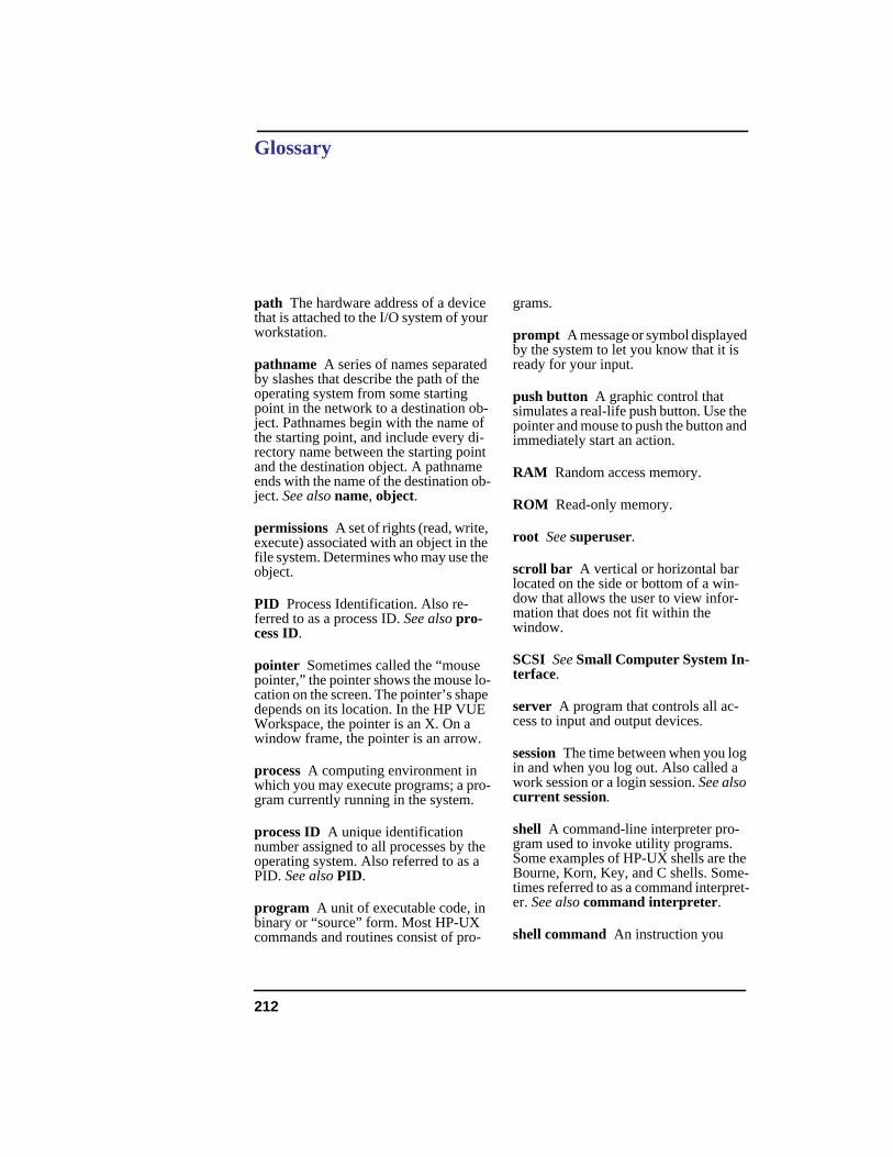
212
Glossary
path The hardware address of a devicethat is attached to the I/O system of yourworkstation.
pathname A series of names separatedby slashes that describe the path of theoperating system from some startingpoint in the network to a destination ob-ject. Pathnames begin with the name ofthe starting point, and include every di-rectory name between the starting pointand the destination object. A pathnameends with the name of the destination ob-ject.See alsoname, object.
permissions A set of rights (read, write,execute) associated with an object in thefile system. Determines who may use theobject.
PID Process Identification. Also re-ferred to as a process ID. See alsopro-cess ID.
pointer Sometimes called the “mousepointer,” the pointer shows the mouse lo-cation on the screen. The pointer’s shapedepends on its location. In the HP VUEWorkspace, the pointer is an X. On awindow frame, the pointer is an arrow.
process A computing environment inwhich you may execute programs; a pro-gram currently running in the system.
process ID A unique identificationnumber assigned to all processes by theoperating system. Also referred to as aPID. See alsoPID.
program A unit of executable code, inbinary or “source” form. Most HP-UXcommands and routines consist of pro-
grams.
prompt A message or symbol displayedby the system to let you know that it isready for your input.
push button A graphic control thatsimulates a real-life push button. Use thepointer and mouse to push the button andimmediately start an action.
RAM Random access memory.
ROM Read-only memory.
root Seesuperuser.
scroll bar A vertical or horizontal barlocated on the side or bottom of a win-dow that allows the user to view infor-mation that does not fit within thewindow.
SCSI SeeSmall Computer System In-terface.
server A program that controls all ac-cess to input and output devices.
sessionThe time between when you login and when you log out. Also called awork session or a login session.See alsocurrent session.
shell A command-line interpreter pro-gram used to invoke utility programs.Some examples of HP-UX shells are theBourne, Korn, Key, and C shells. Some-times referred to as a command interpret-er.See alsocommand interpreter.
shell command An instruction you

Glossary
213
give the system to execute a utility pro-gram or shell script.See alsoshellscript, utility program .
shell script A file that contains com-mands that the system can interpret andrun in a shell.
shutdown The process of taking thesystem from multi-user state to systemadministration state.
SIMM SeeSingle In-line MemoryModule.
single-ended standard SCSIAn 8-bitwide SCSI bus with standard receiversand drivers, which limits total cablelength to 6 meters.See alsofast, differ-ential SCSI, fast-wide SCSI, SmallComputer System Interface.
Single In-line Memory Module Amemory board.
slider One of the components of a scrollbar. The slider is the object that isdragged along the scroll area to cause achange.
Small Computer System Interface(SCSI) An IEEE standard for interfac-ing a computer to multiple, disparatehigh-speed peripherals such as a floppydisk or a CD-ROM, singly or in combi-nation.See alsofast, differential SCSI,fast-wide SCSI, single-ended standardSCSI.
standalone A workstation that is notpart of a cluster.See alsocluster.
Style Manager The HP VUE applica-tion that provides the ability to custom-ize various aspects of your system,including colors, fonts, the keyboard, themouse, session startup and terminationbehavior, and access to other worksta-tions.
subdirectory A directory that is locatedin, or anywhere on a path below, anotherdirectory. The directory above the subdi-rectory is called the parent directory. Thesubdirectory is also referred to as thechild directory.See alsoparent directo-ry .
superuser A user with permission toenter the top-level directory and makechanges to files and programs that usersare not allowed to change. To “becomesuperuser” or “becomeroot” means tolet the system know that you are now as-suming the role of system administrator.You can do this either by logging into thesystem asroot, or by typingsu at a com-mand-line prompt. You must know theroot password to becomeroot.
system administrator The person re-sponsible for system and network instal-lation, updating, maintenance, andsecurity at your site.
system call Invocation of a kernel pro-cess by a user program.
system nameSeeinternet protocoladdress.
terminal window A terminal windowis a type of HP VUE window that emu-lates a complete display terminal. Termi-nal windows are typically used to fool

214
Glossary
non-client programs into believing theyare running in their favorite terminal.When not running programs or execut-ing operating system commands, termi-nal windows display the command-lineprompt.See alsoHP Visual User Envi-ronment.
title bar The rectangular area betweenthe top of the window and the windowframe, that contains the title of the win-dow object.
transceiver A device that transmits andreceives signals.
user account The system administratordefines a user account for every personauthorized to use the system. Each useraccount contains the name the computeruses to identify the person (user ID), andthe person’s password. User accountsalso contain project and organizationnames, to help the system determine whocan use the system and what resourceseach person or organization can use.Seealsouser ID, password.
user ID The name the computer uses toidentify you. Your system administratorassigns you a user ID. Enter your user IDduring the login procedure when the sys-tem displays the login prompt.See alsouser account.
username The name that the systemrecognizes as uniquely yours. Alsoknown as your login name. The user-name is also the name that identifies youto the mail system and other software re-quiring secure entry.
utility Seeutility program .
utility program A program providedwith the operating system to perform afrequently required task, such as printinga file or displaying the contents of a di-rectory.See alsocommand, shell com-mand.
window A rectangular area of thescreen for viewing information. HP VUEallows you to create several types of win-dows on the screen. Each window is aseparate computing environment inwhich you may execute programs, edittext, or read text.See alsoWorkspaceManager.
Window Manager The HP VUE pro-gram that controls the size, placement,and operation of windows.
working directory Seecurrent work-ing directory.
Workspace What the screen becomeswhen you start HP VUE. Although youcan hide the workspace under terminalwindows or other graphic objects, youcan never position anything behind theworkspace. All windows and graphic ob-jects appear stacked on the workspace.See alsoHP Visual User Environment,terminal window.
Workspace Manager The programthat controls the size, placement, and op-eration of windows on the HP VUEWorkspace. The Workspace Manager isa special Window Manager.See alsoWindow Manager.
workstation A compact, graphics-ori-ented computer having high speed andhigh memory capacity. A workstation
Glossary
215
usually includes a keyboard, a monitor,and a system unit.See alsonode, diskedworkstation, diskless workstation.

216
Glossary

Glossary
217

218
Glossary

Glossary
219

220
Glossary

Glossary
221

222
Glossary

Glossary
223

224
Glossary

Glossary
225

226
Glossary

Glossary
227

228
Glossary

Glossary
229

230
Glossary

Glossary
231

232
Glossary

Index
217
Symbols$HOME,, 209
Aabsolute pathname,, 205access permissions,, 205active window,, 205ANSI,, 205applications
ftp,, 26rcp,, 26rlogin,, 26telnet,, 25
archiving datalisting files,, 75restoring files,, 75saving to a cassette,, 74
archiving data,, 74argument,, 205attachment unit interface (AUI),, 205audio
CODEC,, 10converting dB to number significant
bits,, 11electrical specifications,, 11features,, 10headphone jack, 7input,, 10microphone jack, 7mute button, 7output,, 10volume control, 7
auto boot,, 198auto boot, changing state,, 198auto search,, 198auto search, changing state,, 198
Bback up,, 205bitmap,, 205boot console
accessing,, 180features,, 177menus,, 177
boot console interface,, 205boot ROM,, 205boot,, 205bootable media
searching for,, 183bootstrap service,, 205byte,, 205
CCD-ROM disc
busy light during self test,, 59mounting and unmounting,, 54mounting using SAM,, 54unmounting using SAM,, 57
CD-ROM disc,, 205CD-ROM discs
caring for,, 44CD-ROM drive
controls and features,, 41description,, 41troubleshooting,, 61using device files,, 53verifying operation,, 51
CD-ROM drive,, 206CD-ROM media,, 44CD-ROM,, 205Central Processing Unit (CPU),, 206child directory,, 206click,, 206cluster client,, 206cluster node,, 206cluster server,, 206cluster,, 206command argument,, 206command interpreter,, 206command option,, 206command,, 206commands
/dev, 84/etc/lanscan,, 22/rfloppy, 84/use/sbin/lanscan,, 22all,, 202auto,, 198boot,, 181cd,, 87eisa,, 197etc,, 36fastboot,, 200lanaddress,, 201lp .vueprofile,, 34man,, 25
mediainit,, 85memory,, 194path,, 185pim,, 203reboot,, 36reset,, 184rlogin,, 26search,, 183tar,, 74
configuration,, 206connectors, system unit
audio,, 10keyboard,, 12power cord,, 14SCSI,, 13
connectors, system unit,, 8connectors,keyboard
802.3 network,, 12HP parallel I/O,, 12ITF,, 12PS/2 and mouse,, 12serial I/O,, 12
control key sequence,, 206controls, system unit
audio, 7power LED,, 6power switch,, 6system LEDs,, 6
cpu,, 207CRX color graphics,, 207current directory,, 207current working directory,, 207cursor,, 207
Ddaisy-chaining,, 207data cassettes
cleaning heads,, 69media life,, 68media restrictions,, 69ordering information,, 78setting write-protect tab,, 69
data compression,, 65data compression,using,, 74DDS tape drive
controls and indicators,, 65LED code warning conditions
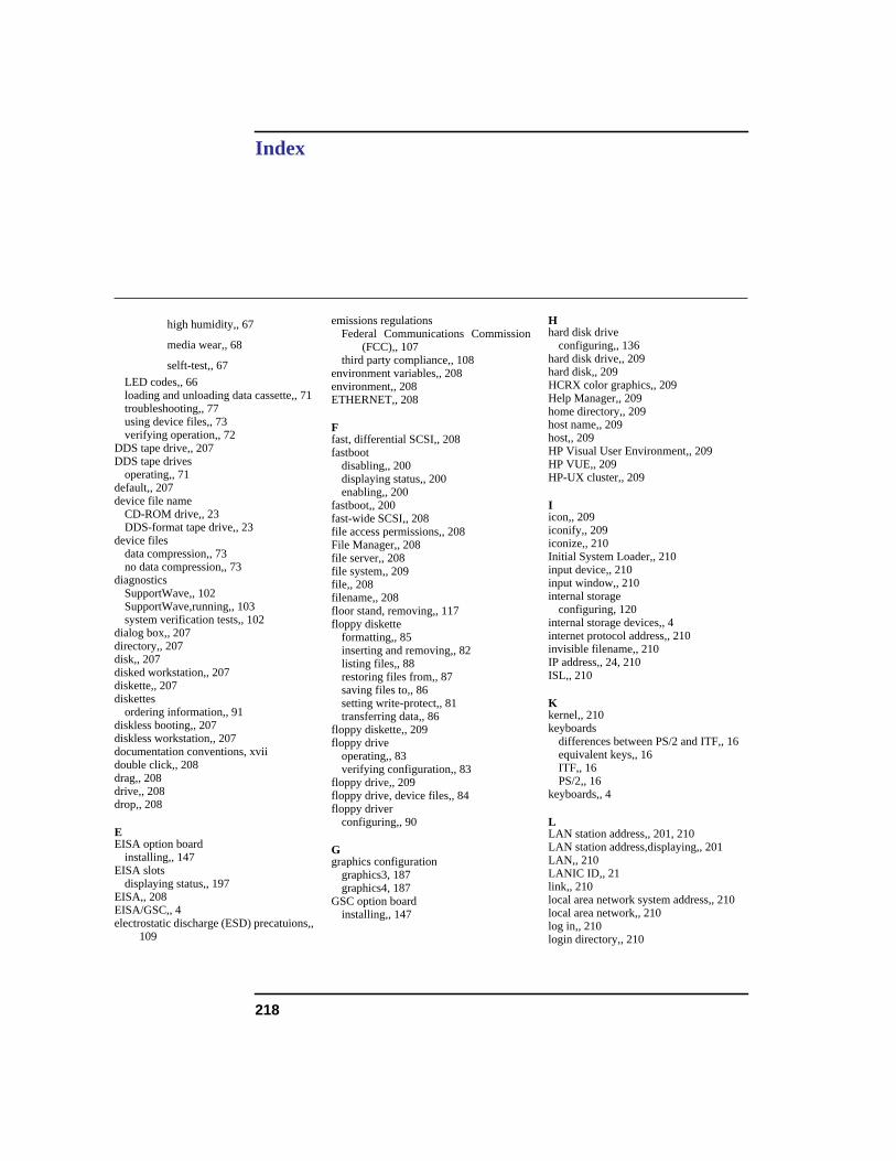
218
Index
high humidity,, 67
media wear,, 68
selft-test,, 67
LED codes,, 66loading and unloading data cassette,, 71troubleshooting,, 77using device files,, 73verifying operation,, 72
DDS tape drive,, 207DDS tape drives
operating,, 71default,, 207device file name
CD-ROM drive,, 23DDS-format tape drive,, 23
device filesdata compression,, 73no data compression,, 73
diagnosticsSupportWave,, 102SupportWave,running,, 103system verification tests,, 102
dialog box,, 207directory,, 207disk,, 207disked workstation,, 207diskette,, 207diskettes
ordering information,, 91diskless booting,, 207diskless workstation,, 207documentation conventions, xviidouble click,, 208drag,, 208drive,, 208drop,, 208
EEISA option board
installing,, 147EISA slots
displaying status,, 197EISA,, 208EISA/GSC,, 4electrostatic discharge (ESD) precatuions,,
109
emissions regulationsFederal Communications Commission
(FCC),, 107third party compliance,, 108
environment variables,, 208environment,, 208ETHERNET,, 208
Ffast, differential SCSI,, 208fastboot
disabling,, 200displaying status,, 200enabling,, 200
fastboot,, 200fast-wide SCSI,, 208file access permissions,, 208File Manager,, 208file server,, 208file system,, 209file,, 208filename,, 208floor stand, removing,, 117floppy diskette
formatting,, 85inserting and removing,, 82listing files,, 88restoring files from,, 87saving files to,, 86setting write-protect,, 81transferring data,, 86
floppy diskette,, 209floppy drive
operating,, 83verifying configuration,, 83
floppy drive,, 209floppy drive, device files,, 84floppy driver
configuring,, 90
Ggraphics configuration
graphics3, 187graphics4, 187
GSC option boardinstalling,, 147
Hhard disk drive
configuring,, 136hard disk drive,, 209hard disk,, 209HCRX color graphics,, 209Help Manager,, 209home directory,, 209host name,, 209host,, 209HP Visual User Environment,, 209HP VUE,, 209HP-UX cluster,, 209
Iicon,, 209iconify,, 209iconize,, 210Initial System Loader,, 210input device,, 210input window,, 210internal storage
configuring, 120internal storage devices,, 4internet protocol address,, 210invisible filename,, 210IP address,, 24, 210ISL,, 210
Kkernel,, 210keyboards
differences between PS/2 and ITF,, 16equivalent keys,, 16ITF,, 16PS/2,, 16
keyboards,, 4
LLAN station address,, 201, 210LAN station address,displaying,, 201LAN,, 210LANIC ID,, 21link,, 210local area network system address,, 210local area network,, 210log in,, 210login directory,, 210
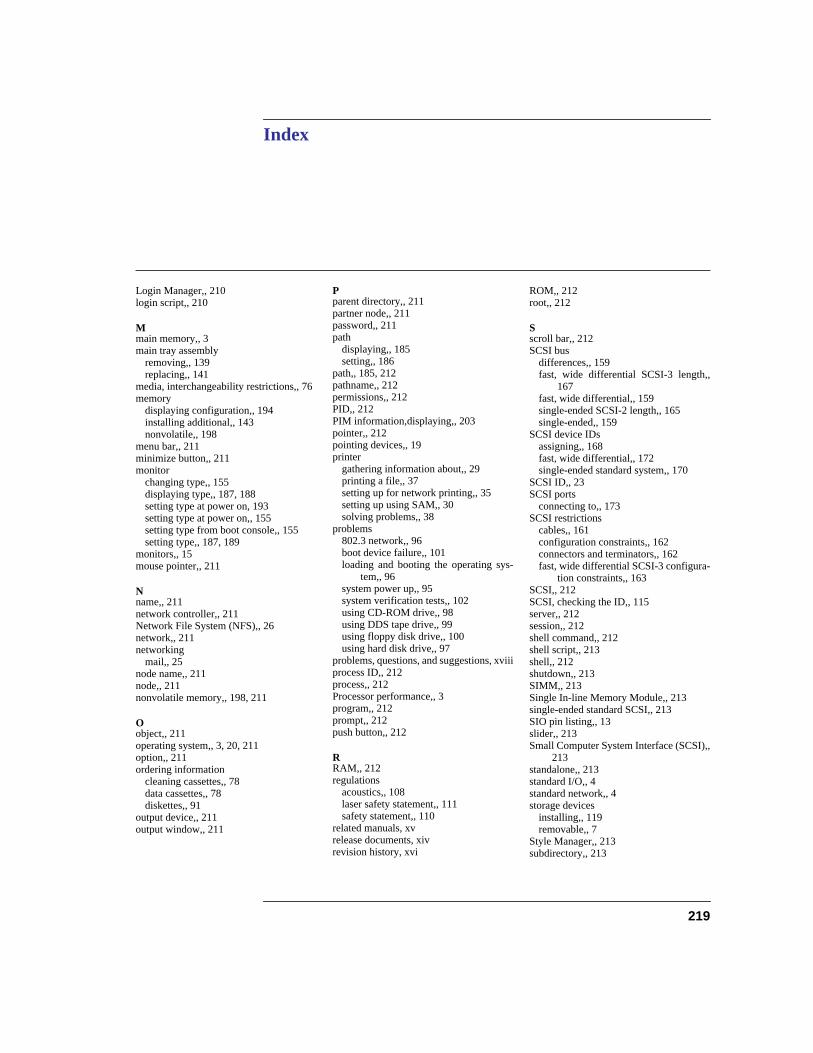
Index
219
Login Manager,, 210login script,, 210
Mmain memory,, 3main tray assembly
removing,, 139replacing,, 141
media, interchangeability restrictions,, 76memory
displaying configuration,, 194installing additional,, 143nonvolatile,, 198
menu bar,, 211minimize button,, 211monitor
changing type,, 155displaying type,, 187, 188setting type at power on, 193setting type at power on,, 155setting type from boot console,, 155setting type,, 187, 189
monitors,, 15mouse pointer,, 211
Nname,, 211network controller,, 211Network File System (NFS),, 26network,, 211networking
mail,, 25node name,, 211node,, 211nonvolatile memory,, 198, 211
Oobject,, 211operating system,, 3, 20, 211option,, 211ordering information
cleaning cassettes,, 78data cassettes,, 78diskettes,, 91
output device,, 211output window,, 211
Pparent directory,, 211partner node,, 211password,, 211path
displaying,, 185setting,, 186
path,, 185, 212pathname,, 212permissions,, 212PID,, 212PIM information,displaying,, 203pointer,, 212pointing devices,, 19printer
gathering information about,, 29printing a file,, 37setting up for network printing,, 35setting up using SAM,, 30solving problems,, 38
problems802.3 network,, 96boot device failure,, 101loading and booting the operating sys-
tem,, 96system power up,, 95system verification tests,, 102using CD-ROM drive,, 98using DDS tape drive,, 99using floppy disk drive,, 100using hard disk drive,, 97
problems, questions, and suggestions, xviiiprocess ID,, 212process,, 212Processor performance,, 3program,, 212prompt,, 212push button,, 212
RRAM,, 212regulations
acoustics,, 108laser safety statement,, 111safety statement,, 110
related manuals, xvrelease documents, xivrevision history, xvi
ROM,, 212root,, 212
Sscroll bar,, 212SCSI bus
differences,, 159fast, wide differential SCSI-3 length,,
167fast, wide differential,, 159single-ended SCSI-2 length,, 165single-ended,, 159
SCSI device IDsassigning,, 168fast, wide differential,, 172single-ended standard system,, 170
SCSI ID,, 23SCSI ports
connecting to,, 173SCSI restrictions
cables,, 161configuration constraints,, 162connectors and terminators,, 162fast, wide differential SCSI-3 configura-
tion constraints,, 163SCSI,, 212SCSI, checking the ID,, 115server,, 212session,, 212shell command,, 212shell script,, 213shell,, 212shutdown,, 213SIMM,, 213Single In-line Memory Module,, 213single-ended standard SCSI,, 213SIO pin listing,, 13slider,, 213Small Computer System Interface (SCSI),,
213standalone,, 213standard I/O,, 4standard network,, 4storage devices
installing,, 119removable,, 7
Style Manager,, 213subdirectory,, 213
220
Index
subnetwork mask,, 24superuser,, 213system administrator,, 213system call,, 213system information,displaying,, 202system name,, 213
Ttar command, additional information,, 76terminal window,, 213title bar,, 214transceiver,, 214
Uuser account,, 214user ID,, 214user interface,, 3username,, 214utility program,, 214utility,, 214
Wwarnings and cautions,, 112Window Manager,, 214window,, 214working directory,, 214Workspace Manager,, 214Workspace,, 214workstation
booting,, 181features,, 3preparing to change configuration,, 117resetting to predefined parameters, 184resetting,, 184
Workstation,, 214
Related Documents