290 IEEE/ASME TRANSACTIONS ON MECHATRONICS, VOL. 11, NO. 3, JUNE 2006 Model-Based Fault Diagnosis in Electric Drives Using Machine Learning Yi Lu Murphey, Senior Member, IEEE, M. Abul Masrur, Senior Member, IEEE, ZhiHang Chen, and Baifang Zhang Abstract—Electric motor and power electronics-based inverter are the major components in industrial and automotive electric drives. In this paper, we present a model-based fault diagnostics system developed using a machine learning technology for detect- ing and locating multiple classes of faults in an electric drive. Power electronics inverter can be considered to be the weakest link in such a system from hardware failure point of view; hence, this work is fo- cused on detecting faults and finding which switches in the inverter cause the faults. A simulation model has been developed based on the theoretical foundations of electric drives to simulate the normal condition, all single-switch and post-short-circuit faults. A machine learning algorithm has been developed to automatically select a set of representative operating points in the (torque, speed) domain, which in turn is sent to the simulated electric drive model to gen- erate signals for the training of a diagnostic neural network, fault diagnostic neural network (FDNN). We validated the capability of the FDNN on data generated by an experimental bench setup. Our research demonstrates that with a robust machine learning approach, a diagnostic system can be trained based on a simulated electric drive model, which can lead to a correct classification of faults over a wide operating domain. Index Terms—Electric drives, electric vehicle, field-oriented con- trol (FOC), fuzzy techniques, hybrid vehicle, inverter, machine learning, model-based diagnostics, motor, neural network, power electronics. I. INTRODUCTION T HREE-PHASE induction motors using techniques such as the field-oriented control (FOC) [1]–[7] to provide precise torque are widely used in various industrial applications, includ- ing the automotive power train for electric and hybrid vehicles. The control in these drives is realized by solid-state electronic switches (e.g., IGBT, MOSFET, etc.) being turned on or off [8]. In response to a control algorithm, a reference voltage is gen- erated, and the inverter synthesizes this voltage reference com- mand using techniques such as pulse-width modulation (PWM) or space-vector modulation (SVM) [4]. If a switch fails to func- tion in the way it was intended to, the voltage synthesis process will be impaired, leading to failure in getting proper voltage at the motor terminals, and hence, failure in obtaining the requisite torque at the motor shaft. Failure of the switches can take place Manuscript received January 18, 2005; revised August 19, 2005. Recom- mended by Technical Editor M.-C. Tsia. This work was supported in part by the U.S. Army RDECOM-TARDEC ILIR (In-house Laboratory Independent Research) program. Y. Murphey, Z. Chen, and B. Zhang are with the University of Michigan- Dearborn, Dearborn, MI 48128-1491 USA (e-mail: [email protected]). M. Abul Masrur is with the U.S. Army Tank-Automotive Research Devel- opment and Engineering Center, Warren, MI 48397-5000 USA (e-mail: mas- [email protected]). Digital Object Identifier 10.1109/TMECH.2006.875568 in the form of “open” and “short” circuits, as well as failure of reverse diodes in the switches. Although a motor is relatively a more robust device compared to an inverter, motor windings can deteriorate with time, which can result in either open or shorted windings, fully or partially. When this happens, the motor will fail to generate proper shaft torque or any torque at all, in spite of the fact that the inverter is applying proper voltage input to the motor. Hence, the electric drive can malfunction due to the fault of either the inverter or the motor. However, the inverter is considered to be the weakest link in the system. Our objective is to develop a robust diagnostic system that has the capability of accurately detecting the state of the drive and correctly locating faults as soon as they occur. We present a machine learning approach to train a diagnostic system, fault diagnostic neural network (FDNN), that detects and locates faulty switch or switches in the inverter. When a fault occurs, the FDNN can point out which switch or switches failed, and so the system can be shut down properly or it may lead to the reconfiguration of the system based on the nature of the fault. In other words, the diagnostic results provided by the FDNN can be used to make a gracefully degradable [9], [10] operation of a faulty drive possible. Fault diagnostics for internal combustion (IC) engine vehicles has been well investigated [11]–[15], but not to the same extent for electric or hybrid vehicles. However, there are active re- searches in electrical system diagnostics [16]–[25]. Rule-based expert systems and decision trees are two traditional diagnos- tic techniques, but they have serious limitations. A rule-based system often has difficulties in dealing with novel faults and acquiring complete knowledge to build a reliable rule base, and is system dependent. A decision tree can be very large for a complex system, and it is also system dependent such that even small engineering changes can mean significant updates [18]. More recently, model-based approaches, fuzzy logic, artificial neural networks (ANNs), and case-based reasoning (CBR) are popular techniques used in various fault diagnostic problems in electrical systems. Moseler and Isermann [16] described a model of black box type using a polynomial differential al- gebraic equation with application to a brushless dc machine. In their work, the estimated system parameters under normal and faulted conditions are compared with the current system parameter values, and if any discrepancy with normal condi- tion is seen, then a faulty condition is declared. However, the parameter-estimated model of this kind can easily lose the intu- itive focus of the system, and in general, does not point toward the specific problem and its location. In addition, sometimes the model can encounter a topological change after a fault, and hence, the premises based on which the model was originally 1083-4435/$20.00 © 2006 IEEE

Welcome message from author
This document is posted to help you gain knowledge. Please leave a comment to let me know what you think about it! Share it to your friends and learn new things together.
Transcript
290 IEEE/ASME TRANSACTIONS ON MECHATRONICS, VOL. 11, NO. 3, JUNE 2006
Model-Based Fault Diagnosis in Electric DrivesUsing Machine Learning
Yi Lu Murphey, Senior Member, IEEE, M. Abul Masrur, Senior Member, IEEE, ZhiHang Chen, and Baifang Zhang
Abstract—Electric motor and power electronics-based inverterare the major components in industrial and automotive electricdrives. In this paper, we present a model-based fault diagnosticssystem developed using a machine learning technology for detect-ing and locating multiple classes of faults in an electric drive. Powerelectronics inverter can be considered to be the weakest link in sucha system from hardware failure point of view; hence, this work is fo-cused on detecting faults and finding which switches in the invertercause the faults. A simulation model has been developed based onthe theoretical foundations of electric drives to simulate the normalcondition, all single-switch and post-short-circuit faults. A machinelearning algorithm has been developed to automatically select a setof representative operating points in the (torque, speed) domain,which in turn is sent to the simulated electric drive model to gen-erate signals for the training of a diagnostic neural network, faultdiagnostic neural network (FDNN). We validated the capabilityof the FDNN on data generated by an experimental bench setup.Our research demonstrates that with a robust machine learningapproach, a diagnostic system can be trained based on a simulatedelectric drive model, which can lead to a correct classification offaults over a wide operating domain.
Index Terms—Electric drives, electric vehicle, field-oriented con-trol (FOC), fuzzy techniques, hybrid vehicle, inverter, machinelearning, model-based diagnostics, motor, neural network, powerelectronics.
I. INTRODUCTION
THREE-PHASE induction motors using techniques such asthe field-oriented control (FOC) [1]–[7] to provide precise
torque are widely used in various industrial applications, includ-ing the automotive power train for electric and hybrid vehicles.The control in these drives is realized by solid-state electronicswitches (e.g., IGBT, MOSFET, etc.) being turned on or off [8].In response to a control algorithm, a reference voltage is gen-erated, and the inverter synthesizes this voltage reference com-mand using techniques such as pulse-width modulation (PWM)or space-vector modulation (SVM) [4]. If a switch fails to func-tion in the way it was intended to, the voltage synthesis processwill be impaired, leading to failure in getting proper voltage atthe motor terminals, and hence, failure in obtaining the requisitetorque at the motor shaft. Failure of the switches can take place
Manuscript received January 18, 2005; revised August 19, 2005. Recom-mended by Technical Editor M.-C. Tsia. This work was supported in part bythe U.S. Army RDECOM-TARDEC ILIR (In-house Laboratory IndependentResearch) program.
Y. Murphey, Z. Chen, and B. Zhang are with the University of Michigan-Dearborn, Dearborn, MI 48128-1491 USA (e-mail: [email protected]).
M. Abul Masrur is with the U.S. Army Tank-Automotive Research Devel-opment and Engineering Center, Warren, MI 48397-5000 USA (e-mail: [email protected]).
Digital Object Identifier 10.1109/TMECH.2006.875568
in the form of “open” and “short” circuits, as well as failure ofreverse diodes in the switches.
Although a motor is relatively a more robust device comparedto an inverter, motor windings can deteriorate with time, whichcan result in either open or shorted windings, fully or partially.When this happens, the motor will fail to generate proper shafttorque or any torque at all, in spite of the fact that the inverter isapplying proper voltage input to the motor. Hence, the electricdrive can malfunction due to the fault of either the inverter or themotor. However, the inverter is considered to be the weakest linkin the system. Our objective is to develop a robust diagnosticsystem that has the capability of accurately detecting the stateof the drive and correctly locating faults as soon as they occur.We present a machine learning approach to train a diagnosticsystem, fault diagnostic neural network (FDNN), that detectsand locates faulty switch or switches in the inverter. When afault occurs, the FDNN can point out which switch or switchesfailed, and so the system can be shut down properly or it maylead to the reconfiguration of the system based on the nature ofthe fault. In other words, the diagnostic results provided by theFDNN can be used to make a gracefully degradable [9], [10]operation of a faulty drive possible.
Fault diagnostics for internal combustion (IC) engine vehicleshas been well investigated [11]–[15], but not to the same extentfor electric or hybrid vehicles. However, there are active re-searches in electrical system diagnostics [16]–[25]. Rule-basedexpert systems and decision trees are two traditional diagnos-tic techniques, but they have serious limitations. A rule-basedsystem often has difficulties in dealing with novel faults andacquiring complete knowledge to build a reliable rule base, andis system dependent. A decision tree can be very large for acomplex system, and it is also system dependent such that evensmall engineering changes can mean significant updates [18].More recently, model-based approaches, fuzzy logic, artificialneural networks (ANNs), and case-based reasoning (CBR) arepopular techniques used in various fault diagnostic problemsin electrical systems. Moseler and Isermann [16] described amodel of black box type using a polynomial differential al-gebraic equation with application to a brushless dc machine.In their work, the estimated system parameters under normaland faulted conditions are compared with the current systemparameter values, and if any discrepancy with normal condi-tion is seen, then a faulty condition is declared. However, theparameter-estimated model of this kind can easily lose the intu-itive focus of the system, and in general, does not point towardthe specific problem and its location. In addition, sometimesthe model can encounter a topological change after a fault, andhence, the premises based on which the model was originally
1083-4435/$20.00 © 2006 IEEE
MURPHEY et al.: MODEL-BASED FAULT DIAGNOSIS IN ELECTRIC DRIVES USING MACHINE LEARNING 291
developed and the parameters estimated may not hold anymore.Ribeiro et al. [17] investigated four different techniques for faultdetection in voltage-fed asynchronous machine drive systems,all based on direct comparisons of the measured voltages to theirreference voltages obtained from the PWM reference signals.Fenton et al. [18] gave an overview on the fault diagnostics ofelectronic systems and emphasized on the need for automateddiagnostic tools such as ANN, fuzzy logic, etc. In particular, theyrecommended hybrid solutions such as model-based approachescombined with CBR, or fuzzy logic or ANN. Kim and Parlospresented a model-based fault detection and diagnosis systemfor electric motors [19]. Their system used a transient empir-ical predictor modeled by dynamic recurrent neural networksand wavelet packet decomposition. Their diagnosis system wastested on a 373-kW and a 597-kW induction motor, and itsdiagnostics accuracy reached about 93%. Filippetti et al. [20]investigated the applications of various artificial intelligence(AI) techniques to induction motor drive fault diagnostics. Theypresented an ANN architecture to quantify a stator short-circuitcondition and a fuzzy logic system for the detection of brokenrotor bars’ fault severity, with an adaptive fuzzy neural net-work applied to stator short-circuit detection. Zidani et al. [21]presented a fuzzy logic system for induction motor stator faultdiagnosis based on the stator current Concordia patterns. Onefuzzy output is used to assess the fault severity in four conditionsin fuzzy terms: zero, light, medium, and high. A comprehen-sive list of books, workshops, conferences, and journal papersrelated to induction motor fault detection and diagnosis can befound in [22] and a good discussion on ANN and fuzzy logicmethodologies for studying faults in the motor and mechanicalfaults can be found in [23].
Two quite different approaches used in fault diagnostics inelectric motors and drives have also influenced our research.In [24], Kastha and Bose systematically described the effectof different types of fault in a voltage-fed PWM inverter in-duction motor drive that uses the open-loop volts/hertz speedcontrol method. The important fault types, including single lineto ground, rectifier diode short circuit, and earth fault on dc bus,were identified in the beginning and followed by preliminaryanalysis of the selected fault types. A systematic simulationstudy was then conducted to substantiate the analytical study.Kastha and Bose pointed out that the study of fault performanceof the drive system is extremely complex. The complexity is fur-ther aggravated due to a modeling problem of the machine undersaturation and unsymmetrical condition. Smith et al. presented atime-domain response-based method for the online detection ofthe intermittent misfiring of the switching devices in a voltage-fed PWM inverter [25]. They pointed out that the frequencydomain methodologies are not suitable for the purpose and thattime-domain techniques are considered more appropriate.
Our research is one step ahead of those published works.Whereas most of the existing diagnostic systems are built todetect a faulty condition against the normal condition, very fewaddressed small classes of faulty conditions. We are investigat-ing an advanced machine learning technology combined witha model-based approach for the development of a robust diag-nostic system that has the capability of detecting and locating
multiple classes of faults in an electric drive operating at anyvalid (torque, speed) conditions.
Faults in electric drives can be classified into two basicgroups: 1) motor related and 2) power electronics related.Among the motor-related faults are included mechanical andelectrical faults. Mechanical faults are related to motor bear-ings and other mechanical unbalances leading to vibrations.Electrical faults within the motor such as partial/full winding(including inter-turn) short circuit, open circuit, etc., and anunbalanced inverter output applied to the motor can all resultin unbalanced current and magnetic field in the motor. Powerelectronics faults are related to inverter failure, e.g., open- orshort-circuited switches, or reverse diodes. Such faults can beof either permanent nature or intermittent type. As mentionedearlier, this research is focused on the problem of power elec-tronics inverter fault diagnostics. A power electronics invertercan have a single-switch failure (open or short), a reverse diodefailure (open or short), or a multiple of these faults. However,the probability of multiple failures is much lower than singlefailure event. Other inverter failures can be caused by breakdown of leads, shorting, or connector problems. In this paper,we focus on the classification of inverter open-circuit faults inswitches using a machine learning technology. The techniquespresented in the paper are general and can be easily extended todetect other types of faults, either electrical and/or mechanical.We want to point out that in the cases of simple discrete openfaults (or short-circuit faults), the signatures can be significantlydifferent from normal conditions and such faults can sometimesbe detected by simple methods such as rule-based algorithms.However, our methodology is general enough to detect differentclasses of faults occurring at different locations, which can beintermittent, and whose signatures may be subtle involving amultiple signal analysis. As we will see later in this paper, suchfaults are difficult to detect and locate with 100% accuracy. Fur-thermore, our approach shows that a fault diagnostic system canbe developed using machine learning techniques on simulateddata, and it performs fault diagnostics robustly under any validoperation conditions.
With the above perspective, the research presented in thispaper has the following distinct features compared to the existingtechniques.
1) It combines a model-based diagnostics approach with amachine learning technique to train a robust fault diag-nostic system.
2) The resulting fault diagnostic system has the capabilitiesof detecting and locating up to ten different classes offaults in a six-switch inverter. Signal signatures of a faultycondition against the normal condition are relatively easyto identify, whereas the signal signatures of one faultagainst another fault are often subtle, and not easy todetect.
3) During the development phase of a fault diagnostic system,there is no need to take direct measurements of data fromelectric drives, which is time consuming and costly.
4) The resulting system has been validated using the datagenerated by an experimental inverter-motor system andproven to be effective.
292 IEEE/ASME TRANSACTIONS ON MECHATRONICS, VOL. 11, NO. 3, JUNE 2006
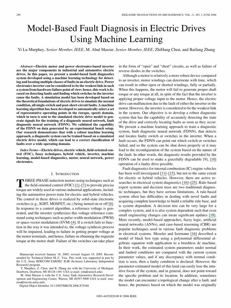
Fig. 1. Model-based fault diagnostic system driven by machine learning.
Fig. 1 illustrates our approach to fault diagnostics of electricdrive. “SIM drive,” a simulation model of a field-orientedcontrol (which can be closed or open loop) electric drivewith a power-electronics-based inverter and a three-phaseinduction motor is developed and implemented using theMatlab–Simulink software. SIM drive has the capability ofsimulating the normal operation condition of an electric drive aswell as the faulty conditions of the open- and post-short-circuitfaults in an inverter switch. A post-short-circuit fault impliesthat if a particular switch of the inverter is short circuited,very shortly thereafter the other inverter switch located on thesame limb will be gated to turn on, leading to a complete shortcircuit of the limb. Eventually, the complete limb where theshort circuit occurred will burn out to become permanentlyopen. In our on-going work, we extended the problem scope toinclude a short-circuit fault where it is assumed that the inverterwill be shutdown by a proper protective mechanism when thecurrent exceeds a certain threshold. We have found that ourmethodology works successfully on these faults as well, andwe plan to report this in a subsequent paper.
In the SIM drive model, we assume a minimal amount ofcurrent and voltage sensors available in a drive system: currentsensors in series with any two of the inverter output lines andtwo voltage sensors across any two of the output terminalsof the inverter. The SIM drive model operates at any selected(torque, speed) operating point under normal and various faultyconditions. Since in real world, an electric drive can operate atdifferent (torque, speed) points, a diagnostic system should betrained to be robust throughout the (torque, speed) domain. Amachine learning algorithm is developed to select representa-tive operating points from the (torque, speed) domain for useby the SIM drive model to generate training data. The objectiveof the machine learning approach is to train a diagnostic systemon the representative data so that it has the capability of perform-ing accurate fault diagnostics in an electric drive that operatesat any valid operating point. The intelligent system used in thisresearch is a multiclass neural network system. We will describetwo possible neural network architectures and discuss their prosand cons. It should be noted that once a model-based ANN hasbeen trained, its implementation in a real-time environment israther simple, since it amounts to having just the weights of theneurons in the ANN burnt in an inexpensive microprocessor.
Experiments were conducted on both the simulated data andthe data generated by an experimental bench setup. The resultsshow that the proposed diagnostic system is very effective indetecting multiple classes of faulty conditions of an inverter inan electric drive operating at any valid (torque, speed) point.
II. THREE-PHASE ELECTRIC DRIVE MODEL
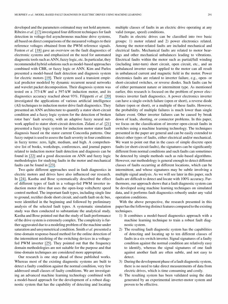
In this section, we briefly describe the basics in the devel-opment of a simulation model of an electric drive. The struc-ture of the electric drive system using an induction motor withan optional closed loop is shown in Fig. 2(a). The inputs tothe system are the dc voltage, reference torque, reference airgap magnetic flux in the induction motor, and the mechanicalsource/sink input in the form of shaft speed or load torque in theshaft. The controller is an FOC [3]–[7] that generates a referencethree-phase voltage. This reference voltage is then synthesizedthrough a PWM process. In the open-loop configuration, thefeedback torque loop shown in Fig. 2(a) does not exist, andthe controller simply generates a voltage and a frequency ref-erence using any scheme, which can include, among others,constant volts per hertz (V/Hz). The motor is represented by thefollowing standard set of equations with d–q axis fixed in thestator [3], [5]–[7]:
Vds = (Rs + pLs)Ids + pMIdr (1)
Vqs = (Rs + pLs)Iqs + pMIqr (2)
0 = pMIds + ωrMIqs + (Rr + pLr)Idr + ωrLrIqr (3)
0 = −ωrMIds + pMIqs − ωrLrIdr + (Rr + pLr)Iqr (4)
where Rs and Rr are stator and rotor resistances, Ls and Lr arestator and rotor self-inductance, M is the stator/rotor mutual in-ductance, ωr is the electrical rotor angular velocity, Vds and Vqs
are d- and q-axis stator voltages, Ids and Iqs are d- and q-axis sta-tor currents, Idr and Iqr are d- and q-axis rotor currents, and p isthe differential operator d/dt. The rotor is assumed to be shortedand hence the voltages are 0 in (3) and (4). The electromag-netic torque is defined as Te = (3/2)(P/2)M(IqsIdr − IdsIqr),where P is the number of poles. In an FOC scheme, this torqueequation can be simplified further by dropping the second termwithin the parenthesis leading to a simple control [3]. The me-chanical equation of motion for the motor shaft is given byTe − TL = P/2[J(dωm/dt) + Bωm], where ωm is the mechan-ical shaft speed, the excitation frequency ω = (P/2)ωm, TL isthe load torque, J is the moment of inertia, and B is the frictioncoefficient. These equations are numerically solved for currentsduring the implementation of a simulation model using Matlab–Simulink. Specifically, we intend to simulate various faults forthe six-switch scheme shown in Fig. 2(b).
One possible approach for fault diagnosis in an inverter isto have sensors installed at all possible locations to flag anyabnormalities, assuming that the sensors do not fail as well.For example, to detect open-circuit fault conditions within aninverter, we would need to place current sensors at every singleswitch and a reverse diode to detect whether a particular switchor diode is faulty. This is not cost-/weight-effective, and real-life inverters do not contain that many sensors. Our approachassumes that only a minimal amount of current and voltagesensors exist in an electric drive system: The current sensors inseries with any two of the inverter output lines, and two voltagesensors across any two of the output terminals of the inverter.We also assume a Y -connected three-phase induction motorstator, without any return connection from the neutral point of Y .
MURPHEY et al.: MODEL-BASED FAULT DIAGNOSIS IN ELECTRIC DRIVES USING MACHINE LEARNING 293
Fig. 2. (a) Three-phase electric drive model and (b) six-switch inverter in a three-phase electric drive.
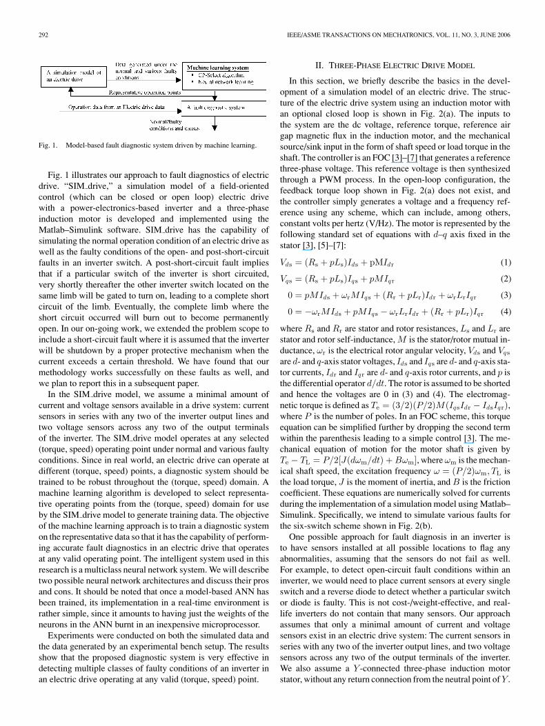
TABLE ISWITCHING TABLE FOR NORMAL OPERATION OF THE SWITCHES
The problem statement can thus be summarized as follows:For a six-switch inverter driven three-phase induction motorembedded with two current sensors in the output inverter linesand two voltage sensors across the lines, a robust diagnosticsystem is to be developed to accurately identify any single faultyinverter switch among the six switches, or one failed verticalswitch pair.
The above-mentioned theoretical model was implemented ina simulation model, SIM drive, using the Matlab–Simulink soft-ware. SIM drive has the capability of simulating the normal andfaulty operations within the three-phase induction motor driveat any given (torque, speed) point. Table I shows the normaloperation of the scheme shown in Fig. 2(b). The numbers inthe voltage columns are to be multiplied with the dc voltage V ,to obtain the true voltage applied to the motor phase windings.In the implementation, we assume that a gating signal 1 im-plies that the switch is turned on and 0 implies that the switchis turned off. We also assume that if the upper switch A is on,then the lower switch A′ will be off, and vice versa, to preventany possibility of direct short circuit of the dc voltage source.Table II shows the states of the six-switch inverter when theswitch A is open faulted. In this case, although switch A (upperlimb) is supposedly turned on, in reality, it remains off due toan open-circuit fault. In addition to the six states shown in
TABLE IISWITCHING TABLE FOR THE FAULTED OPERATION IN WHICH
SWITCH A IS PERMANENTLY OPEN
Table I, we also have two null states corresponding to allswitches being on or off simultaneously. These null statesamount to short circuiting of the motor terminals. The model isalso used to simulate three post-short-circuit cases correspond-ing to the three vertical switch pairs open, one pair at a time,namely, the pairs A and A′, B and B′, and C and C′, respectively.The operating conditions used in the simulation are specified inTable III.
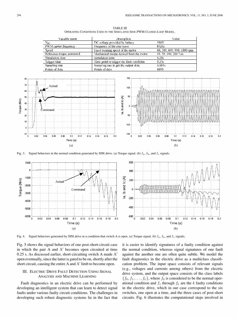
Fig. 3 shows examples of the simulated signals generatedunder the normal operation condition by SIM drive. In Fig. 3(a),the step function is the command torque and the actual torque isseen to ultimately follow the command with a delay dependingon the controller settings. Fig. 3(b) shows the current signalsIa, Ib, and Ic. Fig. 4 shows the signal behaviors with switch Aopen circuited at time 0.1 s. Fig. 4(a) shows the torque command(step function) and the actual torque signal (oscillatory withchanging amplitude). Fig. 4(b) shows the currents Ia, Ib, and Ic
(three currents in different shadings, with 120◦ phase shift fromeach other in a steady state) acquired after the fault. Note that weused a short trigger time for the purpose of clarity in viewing thefaulty signal features. It should also be noted that in simulations,no restriction was imposed on the current magnitude, whereasin an experimental system, there is a limit to the allowablecurrent to prevent any damage to the system or the components.
294 IEEE/ASME TRANSACTIONS ON MECHATRONICS, VOL. 11, NO. 3, JUNE 2006
TABLE IIIOPERATING CONDITIONS USED IN THE SIMULATED SINE-PWM-CLOSED-LOOP MODEL.
Fig. 3. Signal behaviors in the normal condition generated by SIM drive. (a) Torque signal. (b) Ia, Ib, and Ic signals.
Fig. 4. Signal behaviors generated by SIM drive in a condition that switch A is open. (a) Torque signal. (b) Ia, Ib, and Ic signals.
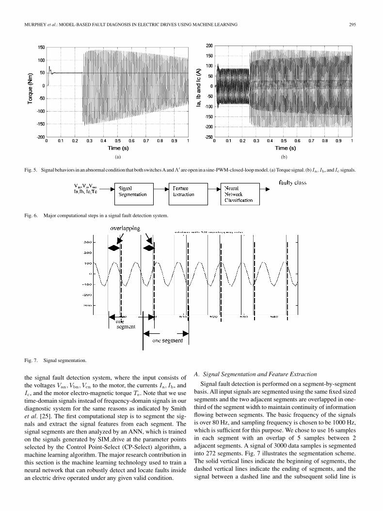
Fig. 5 shows the signal behaviors of one post-short-circuit casein which the pair A and A′ becomes open circuited at time0.25 s. As discussed earlier, short-circuiting switch A made A′
open eventually, since the latter is gated to be on, shortly after theshort circuit, causing the entire A and A′ limb to become open.
III. ELECTRIC DRIVE FAULT DETECTION USING SIGNAL
ANALYSIS AND MACHINE LEARNING
Fault diagnostics in an electric drive can be performed bydeveloping an intelligent system that can learn to detect signalfaults under various faulty circuit conditions. The challenges indeveloping such robust diagnostic systems lie in the fact that
it is easier to identify signatures of a faulty condition againstthe normal condition, whereas signal signatures of one faultagainst the another one are often quite subtle. We model thefault diagnostics in the electric drive as a multiclass classifi-cation problem. The input space consists of relevant signals(e.g., voltages and currents among others) from the electricdrive system, and the output space consists of the class labels{f0, f1, . . . , fk}, where f0 is considered to be the normal oper-ational condition and f1 through fk are the k faulty conditionsin the electric drive, which in our case correspond to the sixswitches, one open at a time, and the three cases of post-shortcircuits. Fig. 6 illustrates the computational steps involved in
MURPHEY et al.: MODEL-BASED FAULT DIAGNOSIS IN ELECTRIC DRIVES USING MACHINE LEARNING 295
Fig. 5. Signal behaviors in an abnormal condition that both switches A andA′ are open in a sine-PWM-closed-loop model. (a) Torque signal. (b)Ia, Ib, andIc signals.
Fig. 6. Major computational steps in a signal fault detection system.
Fig. 7. Signal segmentation.
the signal fault detection system, where the input consists ofthe voltages Van, Vbn, Vcn to the motor, the currents Ia, Ib, andIc, and the motor electro-magnetic torque Te. Note that we usetime-domain signals instead of frequency-domain signals in ourdiagnostic system for the same reasons as indicated by Smithet al. [25]. The first computational step is to segment the sig-nals and extract the signal features from each segment. Thesignal segments are then analyzed by an ANN, which is trainedon the signals generated by SIM drive at the parameter pointsselected by the Control Point-Select (CP-Select) algorithm, amachine learning algorithm. The major research contribution inthis section is the machine learning technology used to train aneural network that can robustly detect and locate faults insidean electric drive operated under any given valid condition.
A. Signal Segmentation and Feature Extraction
Signal fault detection is performed on a segment-by-segmentbasis. All input signals are segmented using the same fixed sizedsegments and the two adjacent segments are overlapped in one-third of the segment width to maintain continuity of informationflowing between segments. The basic frequency of the signalsis over 80 Hz, and sampling frequency is chosen to be 1000 Hz,which is sufficient for this purpose. We chose to use 16 samplesin each segment with an overlap of 5 samples between 2adjacent segments. A signal of 3000 data samples is segmentedinto 272 segments. Fig. 7 illustrates the segmentation scheme.The solid vertical lines indicate the beginning of segments, thedashed vertical lines indicate the ending of segments, and thesignal between a dashed line and the subsequent solid line is
296 IEEE/ASME TRANSACTIONS ON MECHATRONICS, VOL. 11, NO. 3, JUNE 2006
Fig. 8. CP-Select algorithm for an electric drive diagnostic system.
the overlapping portion of the two adjacent segments. Eachsignal segment is represented by the following features.
� Max: maximum magnitude of the signal within thesegment.
� Min: minimum magnitude of the signal within the segment.� Median: median of the signal within the segment.� Mean: mean of the signal within the segment.� Standard deviation: standard deviation of the signal
segment.� Zero-frequency component of the power spectrum.The detection of signal faults within a time period requires
one segment from each input signal and each segment is rep-resented by the six features listed above. Since we have seveninput signals (three voltage signals, three current signals, andone torque signal), the combined feature vector to represent aparticular state in the electric drive at a particular time is a vectorof 42 dimensions. The feature vector is the input to a neural net-work classifier that determines whether the seven signals withinthis time period manifest any fault.
B. Smart Selections of Operation Parameters
In a drive system, the current and voltage signals behave dif-ferently under different operating conditions specified by torqueand speed. The issue of smart selection of “control parameters”(also referred to as operating point) in the (torque, speed) do-main is important for all electric drive diagnostic systems thatare trained on simulated data.
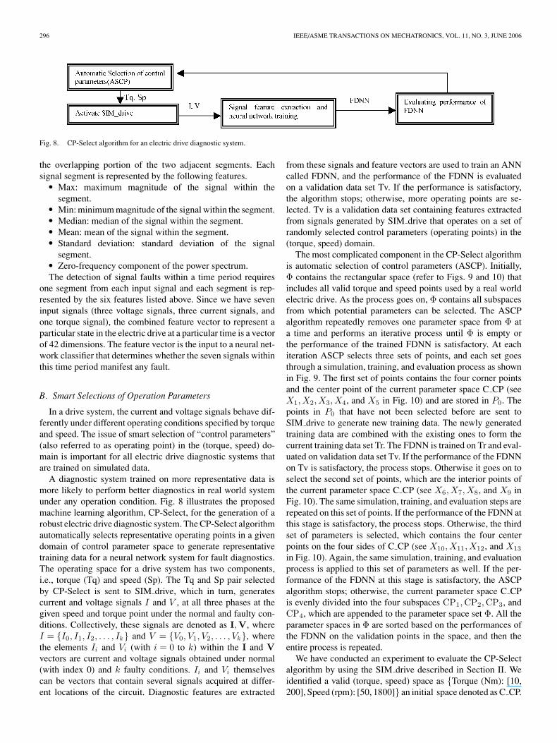
A diagnostic system trained on more representative data ismore likely to perform better diagnostics in real world systemunder any operation condition. Fig. 8 illustrates the proposedmachine learning algorithm, CP-Select, for the generation of arobust electric drive diagnostic system. The CP-Select algorithmautomatically selects representative operating points in a givendomain of control parameter space to generate representativetraining data for a neural network system for fault diagnostics.The operating space for a drive system has two components,i.e., torque (Tq) and speed (Sp). The Tq and Sp pair selectedby CP-Select is sent to SIM drive, which in turn, generatescurrent and voltage signals I and V , at all three phases at thegiven speed and torque point under the normal and faulty con-ditions. Collectively, these signals are denoted as I,V, whereI = {I0, I1, I2, . . . , Ik} and V = {V0, V1, V2, . . . , Vk}, wherethe elements Ii and Vi (with i = 0 to k) within the I and Vvectors are current and voltage signals obtained under normal(with index 0) and k faulty conditions. Ii and Vi themselvescan be vectors that contain several signals acquired at differ-ent locations of the circuit. Diagnostic features are extracted
from these signals and feature vectors are used to train an ANNcalled FDNN, and the performance of the FDNN is evaluatedon a validation data set Tv. If the performance is satisfactory,the algorithm stops; otherwise, more operating points are se-lected. Tv is a validation data set containing features extractedfrom signals generated by SIM drive that operates on a set ofrandomly selected control parameters (operating points) in the(torque, speed) domain.
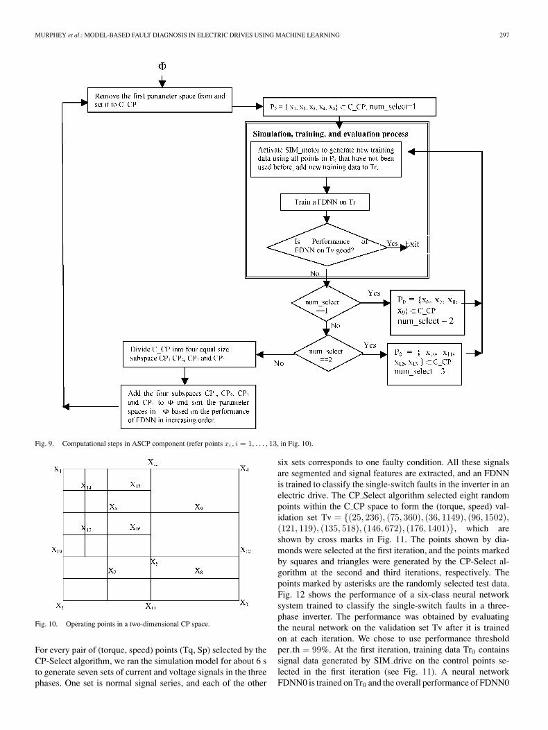
The most complicated component in the CP-Select algorithmis automatic selection of control parameters (ASCP). Initially,Φ contains the rectangular space (refer to Figs. 9 and 10) thatincludes all valid torque and speed points used by a real worldelectric drive. As the process goes on, Φ contains all subspacesfrom which potential parameters can be selected. The ASCPalgorithm repeatedly removes one parameter space from Φ ata time and performs an iterative process until Φ is empty orthe performance of the trained FDNN is satisfactory. At eachiteration ASCP selects three sets of points, and each set goesthrough a simulation, training, and evaluation process as shownin Fig. 9. The first set of points contains the four corner pointsand the center point of the current parameter space C CP (seeX1,X2,X3,X4, and X5 in Fig. 10) and are stored in P0. Thepoints in P0 that have not been selected before are sent toSIM drive to generate new training data. The newly generatedtraining data are combined with the existing ones to form thecurrent training data set Tr. The FDNN is trained on Tr and eval-uated on validation data set Tv. If the performance of the FDNNon Tv is satisfactory, the process stops. Otherwise it goes on toselect the second set of points, which are the interior points ofthe current parameter space C CP (see X6,X7,X8, and X9 inFig. 10). The same simulation, training, and evaluation steps arerepeated on this set of points. If the performance of the FDNN atthis stage is satisfactory, the process stops. Otherwise, the thirdset of parameters is selected, which contains the four centerpoints on the four sides of C CP (see X10,X11,X12, and X13
in Fig. 10). Again, the same simulation, training, and evaluationprocess is applied to this set of parameters as well. If the per-formance of the FDNN at this stage is satisfactory, the ASCPalgorithm stops; otherwise, the current parameter space C CPis evenly divided into the four subspaces CP1,CP2,CP3, andCP4, which are appended to the parameter space set Φ. All theparameter spaces in Φ are sorted based on the performances ofthe FDNN on the validation points in the space, and then theentire process is repeated.
We have conducted an experiment to evaluate the CP-Selectalgorithm by using the SIM drive described in Section II. Weidentified a valid (torque, speed) space as {Torque (Nm): [10,200], Speed (rpm): [50, 1800]} an initial space denoted as C CP.
MURPHEY et al.: MODEL-BASED FAULT DIAGNOSIS IN ELECTRIC DRIVES USING MACHINE LEARNING 297
Fig. 9. Computational steps in ASCP component (refer points xi , i = 1, . . . , 13, in Fig. 10).
Fig. 10. Operating points in a two-dimensional CP space.
For every pair of (torque, speed) points (Tq, Sp) selected by theCP-Select algorithm, we ran the simulation model for about 6 sto generate seven sets of current and voltage signals in the threephases. One set is normal signal series, and each of the other
six sets corresponds to one faulty condition. All these signalsare segmented and signal features are extracted, and an FDNNis trained to classify the single-switch faults in the inverter in anelectric drive. The CP Select algorithm selected eight randompoints within the C CP space to form the (torque, speed) val-idation set Tv = {(25, 236), (75, 360), (36, 1149), (96, 1502),(121, 119), (135, 518), (146, 672), (176, 1401)}, which areshown by cross marks in Fig. 11. The points shown by dia-monds were selected at the first iteration, and the points markedby squares and triangles were generated by the CP-Select al-gorithm at the second and third iterations, respectively. Thepoints marked by asterisks are the randomly selected test data.Fig. 12 shows the performance of a six-class neural networksystem trained to classify the single-switch faults in a three-phase inverter. The performance was obtained by evaluatingthe neural network on the validation set Tv after it is trainedon at each iteration. We chose to use performance thresholdper th = 99%. At the first iteration, training data Tr0 containssignal data generated by SIM drive on the control points se-lected in the first iteration (see Fig. 11). A neural networkFDNN0 is trained on Tr0 and the overall performance of FDNN0

298 IEEE/ASME TRANSACTIONS ON MECHATRONICS, VOL. 11, NO. 3, JUNE 2006
Fig. 11. Randomly selected test and validation set, and the train data selectedby CP-Select algorithm.
Fig. 12. Performance of the FDNN trained on data generated by SIM driveusing the control points generated by the CP-Select during three iterations. (a) Asystem of two neural networks for classifying the single-switch and short-circuitfaults in a three-phase electric drive. (b) A ten-class single neural network forclassifying all ten classes of faults in a three-phase electric drive.
evaluated on the validation set is 94.62% < Perf th = 99%. Itsperformance on individual classes is shown in the curve con-necting the diamond-shaped points in Fig. 12. At the seconditeration, the FDNN is trained on Tr0 ∪ Tr1, where Tr1 is thesignal data generated by SIM drive on the points selected bythe CP Select at the second iteration, and its performance on Tvis shown in the curve connecting the square points in Fig. 12.The overall performance is 96.06% < Perf th = 99%. At thethird iteration, the FDNN is trained on Tr0 ∪ Tr1 ∪ Tr2, whereTr2 is the signal data generated by the SIM drive on the pointsselected by the CP Select at the third iteration, and its per-formance on Tv is shown in the curve connecting the trian-gular points in Fig. 12. The overall performance at the thirditeration is 100% > Perf th = 99%; therefore, the algorithmstops.
C. Multiclass Fault Classification Using ANNs
ANNs are capable of capturing underlying numerical or log-ical relationships among training examples. Neural networkshave successfully been applied to a broad range of prob-lems, including engineering diagnosis, pattern classification,intelligent manufacturing, control problems, and computer vi-sion [25]–[34]. A neural network architecture using feedforwardbackpropagation consists of specification of the number of lay-ers, number of units in each layer, type of activation functionof each unit, and the connection weights between the units of
different layers, which are determined by a machine learning al-gorithm. According to Huang et al. [30], two-layer or sometimescalled one-hidden-layer perceptrons can implement any convexopen or closed decision regions. Therefore, we chose to use aone-hidden-layer architecture for signal fault detection. Most ofthe research in neural networks has been in the development oflearning and training algorithms for two-class classifiers, i.e.,classifiers with one output node that represent classes 0 and1. However, fault diagnostics in electric drive has six classesof single-switch faults and three classes of post-short-circuitclasses. The most common architectures, which have been pro-posed for multiclass neural networks [35], involve a single neu-ral network with K output nodes, where K is the number offaulty classes, and a system of binary neural networks combinedwith a posterior decision rule to integrate the results of neuralnetworks. A system of binary neural networks requires separatetraining of each neural network, and each trained neural networkgenerates a decision boundary between one class and all others.The most notable limitation in this approach is that the decisionboundaries generated by the different two-class neural networkclassifiers can have overlapped or uncovered regions in the fea-ture space [35]. For the feature vectors that fall on an overlappedregion in the feature space, more than one two-class classifierscan claim the input as its classes, resulting in ambiguity. Thefeature vectors falling on the regions that are not claimed byany neural networks will be rejected by all neural networks. Asa result, the resulting system may not generalize well. Anothertype of multiclass neural network system uses a single neuralnetwork with k output, where k > 1. This type of the neuralnetwork architecture has the advantage of simple training pro-cedure, and only one neural network is trained for all m classes,where m > 2. If trained properly, a neural network systemimplemented in this architecture should reduce the ambiguityproblem [35].
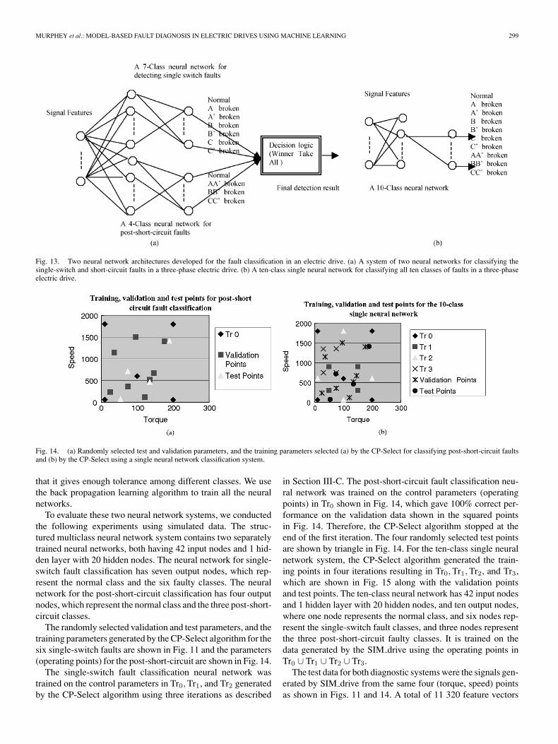
Based on the single neural network architecture, we imple-mented two different systems of neural networks as illustratedin Fig. 13 for the diagnosis of ten classes of faults in an electricdrive: one class represents the normal condition, six classes rep-resent six single switch faults, and the last three classes representthe three post-short-circuit faults.
Fig. 13(a) shows a structured diagnostic system consisting oftwo neural networks, one trained to classify single-switch faults,and the other classifies the post-short-circuit faults, and a winnertake all (WTA) [35] approach is used to integrate the resultsfrom the two neural networks. Fig. 13(b) shows a single neuralnetwork trained to classify all ten classes: Normal, six single-switch faults, and three post-short-circuit faults. One importantissue in a multiclass neural network is how to encode the classesin the output nodes of the neural network. In both neural networkarchitectures, we chose to use a “one-hot spot” method describedas follows: For a k-class classification problem, we need anoutput layer of k bits, each class is assigned a unique binarystring (codeword) of length k with only one bit set to “1” and allother bits are “0.” For example, if it is a six-class classificationproblem, class 0 is assigned a codeword of 000001, class 1is assigned a codeword of 000010, class 2 is assigned of acodeword of 000100, etc. The advantage of this encoding is
MURPHEY et al.: MODEL-BASED FAULT DIAGNOSIS IN ELECTRIC DRIVES USING MACHINE LEARNING 299
Fig. 13. Two neural network architectures developed for the fault classification in an electric drive. (a) A system of two neural networks for classifying thesingle-switch and short-circuit faults in a three-phase electric drive. (b) A ten-class single neural network for classifying all ten classes of faults in a three-phaseelectric drive.
Fig. 14. (a) Randomly selected test and validation parameters, and the training parameters selected (a) by the CP-Select for classifying post-short-circuit faultsand (b) by the CP-Select using a single neural network classification system.
that it gives enough tolerance among different classes. We usethe back propagation learning algorithm to train all the neuralnetworks.
To evaluate these two neural network systems, we conductedthe following experiments using simulated data. The struc-tured multiclass neural network system contains two separatelytrained neural networks, both having 42 input nodes and 1 hid-den layer with 20 hidden nodes. The neural network for single-switch fault classification has seven output nodes, which rep-resent the normal class and the six faulty classes. The neuralnetwork for the post-short-circuit classification has four outputnodes, which represent the normal class and the three post-short-circuit classes.
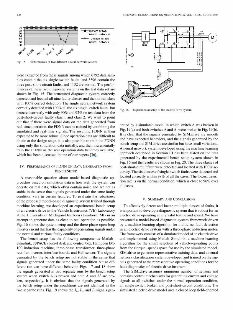
The randomly selected validation and test parameters, and thetraining parameters generated by the CP-Select algorithm for thesix single-switch faults are shown in Fig. 11 and the parameters(operating points) for the post-short-circuit are shown in Fig. 14.
The single-switch fault classification neural network wastrained on the control parameters in Tr0, Tr1, and Tr2 generatedby the CP-Select algorithm using three iterations as described
in Section III-C. The post-short-circuit fault classification neu-ral network was trained on the control parameters (operatingpoints) in Tr0 shown in Fig. 14, which gave 100% correct per-formance on the validation data shown in the squared pointsin Fig. 14. Therefore, the CP-Select algorithm stopped at theend of the first iteration. The four randomly selected test pointsare shown by triangle in Fig. 14. For the ten-class single neuralnetwork system, the CP-Select algorithm generated the train-ing points in four iterations resulting in Tr0, Tr1, Tr2, and Tr3,which are shown in Fig. 15 along with the validation pointsand test points. The ten-class neural network has 42 input nodesand 1 hidden layer with 20 hidden nodes, and ten output nodes,where one node represents the normal class, and six nodes rep-resent the single-switch fault classes, and three nodes representthe three post-short-circuit faulty classes. It is trained on thedata generated by the SIM drive using the operating points inTr0 ∪ Tr1 ∪ Tr2 ∪ Tr3.
The test data for both diagnostic systems were the signals gen-erated by SIM drive from the same four (torque, speed) pointsas shown in Figs. 11 and 14. A total of 11 320 feature vectors
300 IEEE/ASME TRANSACTIONS ON MECHATRONICS, VOL. 11, NO. 3, JUNE 2006
Fig. 15. Performances of two different neural network systems.
were extracted from these signals among which 6792 data sam-ples contain the six single-switch faults, and 3396 contain thethree post-short-circuit faults, and 1132 are normal. The perfor-mances of these two diagnostic systems on the test data set areshown in Fig. 15. The structured diagnostic system correctlydetected and located all nine faulty classes and the normal classwith 100% correct detection. The single neural network systemcorrectly detected with 100% all the six single-switch faults, butdetected correctly with only 90% and 92% on test data from thepost-short-circuit faulty class 1 and class 2. We want to pointout that if there were signal data on the data generated fromreal-time operation, the FDNN can be trained by combining thesimulated and real-time signals. The resulting FDNN is thenexpected to be more robust. Since operation data are difficult toobtain at the design stage, it is also possible to train the FDNNusing only the simulation data initially, and then incrementallytrain the FDNN as the real operation data becomes available,which has been discussed in one of our papers [36].
IV. PERFORMANCE OF FDNN ON DATA GENERATED FROM
BENCH SETUP
A reasonable question about model-based diagnostic ap-proaches based on simulation data is how well the system canoperate on real data, which often contain noise and are not asstable in the sense that signals generated under the same faultycondition vary in certain features. To evaluate the robustnessof the proposed model-based diagnostic system trained throughmachine learning, we developed an experimental bench setupof an electric drive in the Vehicle Electronics (VE) Laboratoryat the University of Michigan-Dearborn (Dearborn, MI) in anattempt to generate data as close to real operation as possible.Fig. 16 shows the system setup and the three-phase open-loopinverter circuit that has the capability of generating signals underthe normal and various faulty conditions.
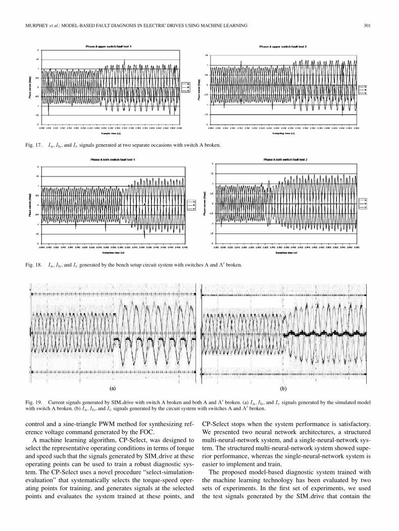
The bench setup has the following components: Matlab–Simulink, dSPACE control desk and control box, Hampden IM-100 induction machine, three-phase transformer, three-phaserectifier, inverter, interface boards, and Hall sensor. The signalsgenerated by the bench setup are not stable in the sense thatsignals generated under the same faulty condition but at dif-ferent run can have different behavior. Figs. 17 and 18 showthe signals generated in two separate runs by the bench setupsystem when switch A is broken and both A and A′ are bro-ken, respectively. It is obvious that the signals generated bythe bench setup under the conditions are not identical in thetwo separate runs. Fig. 19 shows the Ia, Ib, and Ic signals gen-
Fig. 16. Experimental setup of the electric drive system.
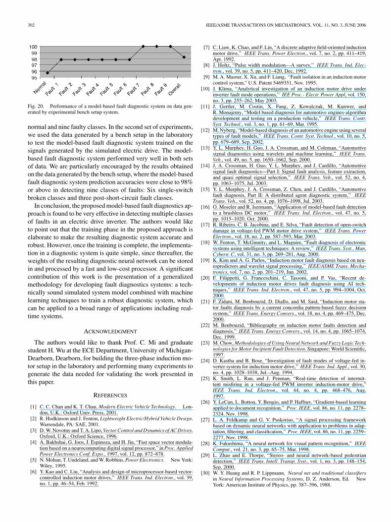
erated by a simulated model in which switch A was broken inFig. 19(a) and both switches A and A′ were broken in Fig. 19(b).It is clear that the signals generated by SIM drive are smoothand have expected behaviors, and the signals generated by thebench setup and SIM drive are similar but have small variations.A neural network system developed using the machine learningapproach described in Section III has been tested on the datagenerated by the experimental bench setup system shown inFig. 16 and the results are shown in Fig. 20. The three classes ofpost-short-circuit fault were detected and located with 100% ac-curacy. The six classes of single-switch faults were detected andlocated correctly within 98% of all the cases. The lowest detec-tion rate is on the normal condition, which is close to 96% overall cases.
V. SUMMARY AND CONCLUSIONS
To effectively detect and locate multiple classes of faults, itis important to develop a diagnostic system that is robust for anelectric drive operating at any valid torque and speed. We havepresented a model-based diagnostic system framework drivenby a machine learning algorithm for multiclass fault detectionin an electric drive system with a three-phase induction motor.The framework consists of a simulated model of an electric driveand implemented using Matlab–Simulink, a machine learningalgorithm for the smart selection of vehicle-operating pointsfrom the (torque, speed) space for use by the simulated model,SIM drive to generate representative training data, and a neuralnetwork classification system developed and trained on the sig-nals generated at the representative operating conditions for thefault diagnostics of electric drive inverters.
The SIM drive assumes minimum number of sensors andcontains control mechanisms for generating current and voltagesignals at all switches under the normal operation condition,all single switch broken and post-short-circuit conditions. Thesimulated electric drive model uses a closed loop field-oriented
MURPHEY et al.: MODEL-BASED FAULT DIAGNOSIS IN ELECTRIC DRIVES USING MACHINE LEARNING 301
Fig. 17. Ia, Ib, and Ic signals generated at two separate occasions with switch A broken.
Fig. 18. Ia, Ib, and Ic generated by the bench setup circuit system with switches A and A′ broken.
Fig. 19. Current signals generated by SIM drive with switch A broken and both A and A′ broken. (a) Ia, Ib, and Ic signals generated by the simulated modelwith switch A broken. (b) Ia, Ib, and Ic signals generated by the circuit system with switches A and A′ broken.
control and a sine-triangle PWM method for synthesizing ref-erence voltage command generated by the FOC.
A machine learning algorithm, CP-Select, was designed toselect the representative operating conditions in terms of torqueand speed such that the signals generated by SIM drive at theseoperating points can be used to train a robust diagnostic sys-tem. The CP-Select uses a novel procedure “select-simulation-evaluation” that systematically selects the torque-speed oper-ating points for training, and generates signals at the selectedpoints and evaluates the system trained at these points, and
CP-Select stops when the system performance is satisfactory.We presented two neural network architectures, a structuredmulti-neural-network system, and a single-neural-network sys-tem. The structured multi-neural-network system showed supe-rior performance, whereas the single-neural-network system iseasier to implement and train.
The proposed model-based diagnostic system trained withthe machine learning technology has been evaluated by twosets of experiments. In the first set of experiments, we usedthe test signals generated by the SIM drive that contain the
302 IEEE/ASME TRANSACTIONS ON MECHATRONICS, VOL. 11, NO. 3, JUNE 2006
Fig. 20. Performance of a model-based fault diagnostic system on data gen-erated by experimental bench setup system.
normal and nine faulty classes. In the second set of experiments,we used the data generated by a bench setup in the laboratoryto test the model-based fault diagnostic system trained on thesignals generated by the simulated electric drive. The model-based fault diagnostic system performed very well in both setsof data. We are particularly encouraged by the results obtainedon the data generated by the bench setup, where the model-basedfault diagnostic system prediction accuracies were close to 98%or above in detecting nine classes of faults: Six single-switchbroken classes and three post-short-circuit fault classes.
In conclusion, the proposed model-based fault diagnostics ap-proach is found to be very effective in detecting multiple classesof faults in an electric drive inverter. The authors would liketo point out that the training phase in the proposed approach iselaborate to make the resulting diagnostic system accurate androbust. However, once the training is complete, the implementa-tion in a diagnostic system is quite simple, since thereafter, theweights of the resulting diagnostic neural network can be storedin and processed by a fast and low-cost processor. A significantcontribution of this work is the presentation of a generalizedmethodology for developing fault diagnostics systems: a tech-nically sound simulated system model combined with machinelearning techniques to train a robust diagnostic system, whichcan be applied to a broad range of applications including real-time systems.
ACKNOWLEDGMENT
The authors would like to thank Prof. C. Mi and graduatestudent H. Wu at the ECE Department, University of Michigan-Dearborn, Dearborn, for building the three-phase induction mo-tor setup in the laboratory and performing many experiments togenerate the data needed for validating the work presented inthis paper.
REFERENCES
[1] C. C. Chan and K. T. Chau, Modern Electric Vehicle Technology. Lon-don, U.K.: Oxford Univ. Press, 2001.
[2] R. Hodkinson and J. Fenton, Lightweight Electric/Hybrid Vehicle Design.Warrendale, PA: SAE, 2001.
[3] D. W. Novotny and T. A. Lipo, Vector Control and Dynamics of AC Drives.Oxford, U.K.: Oxford Science, 1996.
[4] A. Bakhshai, G. Joos, J. Espinoza, and H. Jin, “Fast space vector modula-tion based on a neurocomputing digital signal processor,” in Proc. AppliedPower Electronics Conf. Expo., 1997, vol. 12, pp. 872–878.
[5] N. Mohan, T. Undeland, and W. Robbins, Power Electronics. New York:Wiley, 1995.
[6] Y. Kao and C. Liu, “Analysis and design of microprocessor-based vector-controlled induction motor drives,” IEEE Trans. Ind. Electron., vol. 39,no. 1, pp. 46–54, Feb. 1992.
[7] C. Liaw, K. Chao, and F. Lin, “A discrete adaptive field-oriented inductionmotor drive,” IEEE Trans. Power Electron., vol. 7, no. 2, pp. 411–419,Apr. 1992.
[8] J. Holtz, “Pulse width modulation—A survey,” IEEE Trans. Ind. Elec-tron., vol. 39, no. 5, pp. 411–420, Dec. 1992.
[9] M. A. Masrur, X. Xu, and F. Liang, “Fault isolation in an induction motorcontrol system,” U.S. Patent 5469351, Nov. 1995.
[10] J. Klima, “Analytical investigation of an induction motor drive underinverter fault mode operations,” IEE Proc.- Electr. Power Appl, vol. 150,no. 3, pp. 255–262, May 2003.
[11] J. Gertler, M. Costin, X. Fang, Z. Kowalczuk, M. Kunwer, andR. Monajemy, “Model based diagnosis for automotive engines-algorithmdevelopment and testing on a production vehicle,” IEEE Trans. Contr.Syst. Technol., vol. 3, no. 1, pp. 61–69, Mar. 1995.
[12] M. Nyberg, “Model-based diagnosis of an automotive engine using severaltypes of fault models,” IEEE Trans. Contr. Syst. Technol., vol. 10, no. 5,pp. 679–689, Sep. 2002.
[13] Y. L. Murphey, H. Guo, J. A. Crossman, and M. Coleman, “Automotivesignal diagnostics using wavelets and machine learning,” IEEE Trans.Veh., vol. 49, no. 5, pp. 1650–1662, Sep. 2000.
[14] J. A. Crossman, H. Guo, Y. L. Murphey, and J. Cardillo, “Automotivesignal fault diagnostics—Part I: Signal fault analysis, feature extraction,and quasi optimal signal selection,” IEEE Trans. Veh., vol. 52, no. 4,pp. 1063–1075, Jul. 2003.
[15] Y. L. Murphey, J. A. Crossman, Z. Chen, and J. Cardillo, “Automotivefault diagnosis, Part II: A distributed agent diagnostic system,” IEEETrans. Veh., vol. 52, no. 4, pp. 1076–1098, Jul. 2003.
[16] O. Moseler and R. Isermann, “Application of model-based fault detectionto a brushless DC motor,” IEEE Trans. Ind. Electron., vol. 47, no. 5,pp. 1015–1020, Oct. 2000.
[17] R. Ribeiro, C. B. Jacobina, and E. Silva, “Fault detection of open-switchdamage in voltage-fed PWM motor drive system,” IEEE Trans. PowerElectron., vol. 18, no. 2, pp. 587–593, Mar. 2003.
[18] W. Fenton, T. McGinnity, and L. Maguire, “Fault diagnosis of electronicsystems using intelligent techniques: A review,” IEEE Trans. Syst., Man,Cybern. C, vol. 31, no. 3, pp. 269–281, Aug. 2000.
[19] K. Kim and A. G. Parlos, “Induction motor fault diagnosis based on neu-ropredictors and wavelet signal processing,” IEEE/ASME Trans. Mecha-tronics, vol. 7, no. 2, pp. 201–219, Jun. 2002.
[20] F. Filippetti, G. Franceschini, C. Tassoni, and P. Vas, “Recent de-velopments of induction motor drives fault diagnosis using AI tech-niques,” IEEE Trans. Ind. Electron., vol. 47, no. 5, pp. 994–1004, Oct.2000.
[21] F. Zidani, M. Benbouzid, D. Diallo, and M. Said, “Induction motor sta-tor faults diagnosis by a current concordia pattern-based fuzzy decisionsystem,” IEEE Trans. Energy Convers., vol. 18, no. 4, pp. 469–475, Dec.2000.
[22] M. Benbouzid, “Bibliography on induction motor faults detection anddiagnosis,” IEEE Trans. Energy Convers., vol. 14, no. 4, pp. 1065–1074,Dec. 1999.
[23] M. Chow, Methodologies of Using Neural Network and Fuzzy Logic Tech-nologies for Motor Incipient Fault Detection. Singapore: World Scientific,1997.
[24] D. Kastha and B. Bose, “Investigation of fault modes of voltage-fed in-verter system for induction motor drive,” IEEE Trans. Ind. Appl., vol. 30,no. 4, pp. 1028–1038, Jul.–Aug. 1994.
[25] K. Smith, L. Ran, and J. Penman, “Real-time detection of intermit-tent misfiring in a voltage-fed PWM inverter induction-motor drive,”IEEE Trans. Ind. Electron., vol. 44, no. 4, pp. 468–476, Aug.1997.
[26] Y. LeCun, L. Bottou, Y. Bengio, and P. Haffner, “Gradient-based learningapplied to document recognition,” Proc. IEEE, vol. 86, no. 11, pp. 2278–2324, Nov. 1998.
[27] L. A. Feldkamp and G. V. Puskorius, “A signal processing frameworkbased on dynamic neural networks with application to problems in adap-tation, filtering, and classification,” Proc. IEEE, vol. 86, no. 11, pp. 2259–2277, Nov. 1998.
[28] K. Fukushima, “A neural network for visual pattern recognition,” IEEEComput., vol. 21, no. 3, pp. 65–75, Mar. 1998.
[29] L. Zhao and E. Thorpe, “Stereo- and neural network-based pedestriandetection,” IEEE Trans. Intell. Transp. Syst., vol. 1, no. 3, pp. 148–154,Sep. 2000.
[30] W. Y. Huang and R. P. Lippmann, Neural net and traditional classifiersin Neural Information Processing Systems, D. Z. Anderson, Ed. NewYork: American Institute of Physics, pp. 387–396, 1988.
MURPHEY et al.: MODEL-BASED FAULT DIAGNOSIS IN ELECTRIC DRIVES USING MACHINE LEARNING 303
[31] E. L. Allwein and R. E. Schapire, “Reducing multiclass to binary: Aunifying approach for margin classifiers,” J. Mach. Learning Res., vol. 1,pp. 113–141, 2000.
[32] D. Price, S. Knerr, L. Personnaz, and G. Dreyfus, “Pairwise neural networkclassifiers with probabilistic outputs,” in Advances in Neural InformationProcessing Systems 7 (NIPS-94), G. Tesauro, D. Touretzky, and T. Leen,Eds. Cambridge, MA: MIT Press, 1995, vol. 7, pp. 1109–1116.
[33] S. Har-Peled, D. Roth, and D. Zimak, “Constraint classification: A newapproach to multiclass classification,” in Proc. 13th Int. Conf. AlgorithmicLearning Theory, 2002, pp. 365–397.
[34] X. Li, X.-C. Yao, Y. L. Murphey, R. Karlsen, and G. Gerhart, “A real-timevehicle detection and tracking ststem in outdoor traffic scenes,” in Proc.Int. Conf. Pattern Recognit., Cambridge, U.K., 2004, vol. 2, pp. 761–764.
[35] G. Ou, Y. L. Murphey, and L. Feldkamp, “Multiclass pattern classificationusing neural networks,” presented at the Int. Conf. Pattern Recognition,Cambridge, UK, 2004.
[36] Y. L. Murphey, Z.-H. Chen, and L. Feldkamp, “Incremental neural learningusing AdaBoost,” in Proc. IEEE Int. Joint Conf. Neural Netw., 2002, vol. 3,pp. 2304–2308.
Yi Lu Murphey (S’85–M’88–SM’97) received theM.S. degree in computer science from Wayne StateUniversity, Detroit, MI, in 1983 and the Ph.D. de-gree in computer, information, and control engineer-ing from the University of Michigan, Ann Arbor, in1989.
She was a Research Scientist at the Environ-mental Research Institute of Michigan, Ann Arbor.Since 1992, she has been a Professor of electrical andcomputer engineering at the University of Michigan-Dearborn, Dearborn. Her recent research projects in-
clude fault diagnostics, distributed agent systems, computer vision systems forrobotic vehicles, incremental learning in neural networks, support vector ma-chine learning from large data sets, hybrid learning system with neural networksand genetic algorithms, data mining from text documents, and data mining fromtime-series data. Her research interests include machine learning, computer vi-sion, and intelligent systems.
M. Abul Masrur (M’84–SM’93) received the Ph.D.degree in electrical engineering from Texas A&MUniversity, College Station, in 1984.
From 1984 to 2001, he was with the ScientificResearch Laboratories, Ford Motor Company, andwas involved in research and development related tosimulation and control for electric drives for electricand hybrid electric vehicles and power electronics,advanced automotive electric energy managementand vehicular power system architecture, automotivemultiplexing systems, and related works. In 2001, he
joined the Vetronics Technology Department, U.S. Army RDECOM-TARDEC,Warren, MI, where he is involved in various vehicular electric power systemarchitecture concept design and development for military applications. He hasover 50 publications and holds 8 U.S. patents.
Dr. Masrur has been an Associate Editor of the IEEE TRANSACTIONS ON
VEHICULAR TECHNOLOGY since 1999. He received the Best Automotive Elec-tronics Paper Award from the IEEE Vehicular Technology Society, USA, in1998.
ZhiHang Chen received the Ph.D. degree in appliedmathematics from Peking University, Beijing, China,in 2000.
Currently, he is a Research Associate at the Univer-sity of Michigan-Dearborn, Dearborn. His researchinterests include machine learning, intelligence sys-tem, neural networks, genetic algorithms, and fuzzylogic.
Baifang Zhang received the B.S. degree in com-puter science from East Normal University, Shang-hai, China, in 1998. He is currently pursuing a Masterof Engineering program in computer engineering atthe University of Michigan-Dearborn, Dearborn.
From 1998 to 2002, he was with PanaelectronicsInc. His research interests include signal/time seriesanalysis using artificial intelligent methods, vehiclefault diagnosis, and vehicle control systems.
Related Documents


![Inverter Switch Fault Diagnosis System for BLDC Motor Drives · the model based fault detection systems [7]. In the knowledge based fault diagnosis methods, expert systems are developed](https://static.cupdf.com/doc/110x72/604dcbed2a4bc70553330155/inverter-switch-fault-diagnosis-system-for-bldc-motor-the-model-based-fault-detection.jpg)