SAFETY INSTRUCTIONS WARNING 1. 120 Volts may cause serious injury from electric shock. Disconnect electrical power before starting installation or servicing. Leave power disconnected until installation/service is completed. 2. Dropping may cause personal injury or equipment damage. Handle with care and follow installation instructions. CAUTION 1. Read all instructions before beginning installation. 2. Improper installation may cause property damage or injury. Read instructions before installation, service or maintenance. 3. Do not use in pool applications. Pool chemicals can damage the dehumidifier. 4. Do not use solvents or cleaners on or near the circuit board. Chemicals can damage circuit board components. 5. Wait 24 hours before running the unit if it was not shipped or stored in the upright position 6. Do not use dehumidification to prevent window condensation in the winter. To address window condensation, use ventilation to lower indoor humidity in the winter. READ AND SAVE THESE INSTRUCTIONS DEHUMIDIFIER CONTROL ON/OFF BUTTON USED TO TURN DEHUMIDIFIER ON AND OFF UP/DOWN BUTTONS USED TO CHANGE HUMIDITY SETTING MODE BUTTON USED FOR OPTIONAL VENTILATION FEATURE INLET FILTER ACCESS DOOR DRAIN POWER SWITCH OUTLET Model A130F Dehumidifier Installation and Operating Instructions 1

Welcome message from author
This document is posted to help you gain knowledge. Please leave a comment to let me know what you think about it! Share it to your friends and learn new things together.
Transcript
SAFETY INSTRUCTIONS
WARNING
1. 120 Volts may cause serious injury from electric shock. Disconnect electrical power before starting installation or servicing. Leave power disconnected until installation/service is completed.
2. Dropping may cause personal injury or equipment damage. Handle with care and follow installation instructions.
CAUTION
1. Read all instructions before beginning installation.
2. Improper installation may cause property damage or injury. Read instructions before installation, service or maintenance.
3. Do not use in pool applications. Pool chemicals can damage the dehumidifier.
4. Do not use solvents or cleaners on or near the circuit board. Chemicals can damage circuit board components.
5. Wait 24 hours before running the unit if it was not shipped or stored in the upright position
6. Do not use dehumidification to prevent window condensation in the winter. To address window condensation, use ventilation to lower indoor humidity in the winter.
READ AND SAVE THESE INSTRUCTIONS
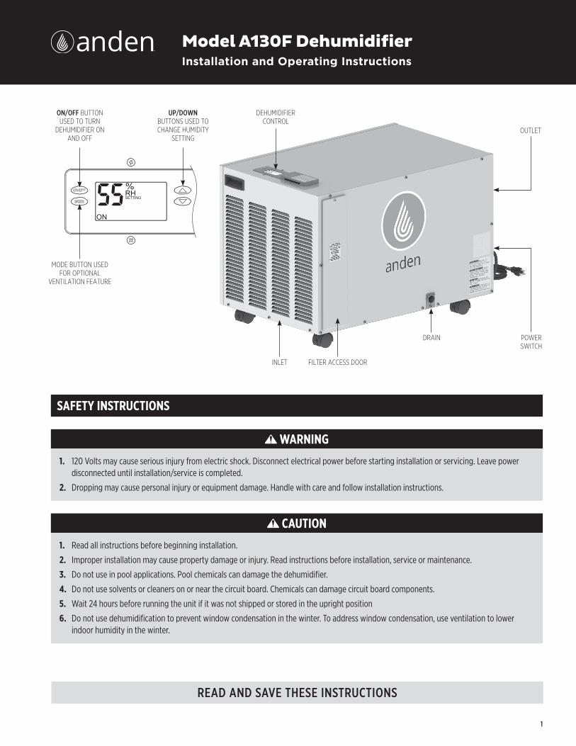
DEHUMIDIFIER CONTROL
ON/OFF BUTTON USED TO TURN
DEHUMIDIFIER ON AND OFF
UP/DOWN BUTTONS USED TO CHANGE HUMIDITY
SETTING
MODE BUTTON USED FOR OPTIONAL
VENTILATION FEATURE
INLET FILTER ACCESS DOOR
DRAIN POWER SWITCH
OUTLET
Model A130F DehumidifierInstallation and Operating Instructions
1
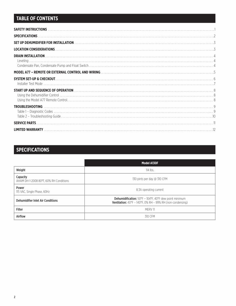
TABLE OF CONTENTS
SAFETY INSTRUCTIONS � � � � � � � � � � � � � � � � � � � � � � � � � � � � � � � � � � � � � � � � � � � � � � � � � � � � � � � � � � � � � � � � � � � � � � � � � � � � � � � � � � � � � � � � � � � � � � � � � � � � � � � � � � � � � � � � � � 1
SPECIFICATIONS � � � � � � � � � � � � � � � � � � � � � � � � � � � � � � � � � � � � � � � � � � � � � � � � � � � � � � � � � � � � � � � � � � � � � � � � � � � � � � � � � � � � � � � � � � � � � � � � � � � � � � � � � � � � � � � � � � � � � � � � �2
SET UP DEHUMIDIFIER FOR INSTALLATION � � � � � � � � � � � � � � � � � � � � � � � � � � � � � � � � � � � � � � � � � � � � � � � � � � � � � � � � � � � � � � � � � � � � � � � � � � � � � � � � � � � � � � � � � � � � � � � �3
LOCATION CONSIDERATIONS � � � � � � � � � � � � � � � � � � � � � � � � � � � � � � � � � � � � � � � � � � � � � � � � � � � � � � � � � � � � � � � � � � � � � � � � � � � � � � � � � � � � � � � � � � � � � � � � � � � � � � � � � � � � �3
DRAIN INSTALLATION � � � � � � � � � � � � � � � � � � � � � � � � � � � � � � � � � � � � � � � � � � � � � � � � � � � � � � � � � � � � � � � � � � � � � � � � � � � � � � � � � � � � � � � � � � � � � � � � � � � � � � � � � � � � � � � � � � � 4 Leveling � � � � � � � � � � � � � � � � � � � � � � � � � � � � � � � � � � � � � � � � � � � � � � � � � � � � � � � � � � � � � � � � � � � � � � � � � � � � � � � � � � � � � � � � � � � � � � � � � � � � � � � � � � � � � � � � � � � � � � � � � � � � � � 4 Condensate Pan, Condensate Pump and Float Switch � � � � � � � � � � � � � � � � � � � � � � � � � � � � � � � � � � � � � � � � � � � � � � � � � � � � � � � � � � � � � � � � � � � � � � � � � � � � � � � � � � � � � 4
MODEL A77 – REMOTE OR EXTERNAL CONTROL AND WIRING � � � � � � � � � � � � � � � � � � � � � � � � � � � � � � � � � � � � � � � � � � � � � � � � � � � � � � � � � � � � � � � � � � � � � � � � � � � � � �5
SYSTEM SET-UP & CHECKOUT � � � � � � � � � � � � � � � � � � � � � � � � � � � � � � � � � � � � � � � � � � � � � � � � � � � � � � � � � � � � � � � � � � � � � � � � � � � � � � � � � � � � � � � � � � � � � � � � � � � � � � � � � � � � 6 Installer Test Mode � � � � � � � � � � � � � � � � � � � � � � � � � � � � � � � � � � � � � � � � � � � � � � � � � � � � � � � � � � � � � � � � � � � � � � � � � � � � � � � � � � � � � � � � � � � � � � � � � � � � � � � � � � � � � � � � � � � � �7
START UP AND SEQUENCE OF OPERATION � � � � � � � � � � � � � � � � � � � � � � � � � � � � � � � � � � � � � � � � � � � � � � � � � � � � � � � � � � � � � � � � � � � � � � � � � � � � � � � � � � � � � � � � � � � � � � � 8 Using the Dehumidifier Control � � � � � � � � � � � � � � � � � � � � � � � � � � � � � � � � � � � � � � � � � � � � � � � � � � � � � � � � � � � � � � � � � � � � � � � � � � � � � � � � � � � � � � � � � � � � � � � � � � � � � � � � � 8 Using the Model A77 Remote Control� � � � � � � � � � � � � � � � � � � � � � � � � � � � � � � � � � � � � � � � � � � � � � � � � � � � � � � � � � � � � � � � � � � � � � � � � � � � � � � � � � � � � � � � � � � � � � � � � � � � 8
TROUBLESHOOTING � � � � � � � � � � � � � � � � � � � � � � � � � � � � � � � � � � � � � � � � � � � � � � � � � � � � � � � � � � � � � � � � � � � � � � � � � � � � � � � � � � � � � � � � � � � � � � � � � � � � � � � � � � � � � � � � � � � � 9 Table 1 – Diagnostic Codes � � � � � � � � � � � � � � � � � � � � � � � � � � � � � � � � � � � � � � � � � � � � � � � � � � � � � � � � � � � � � � � � � � � � � � � � � � � � � � � � � � � � � � � � � � � � � � � � � � � � � � � � � � � � � 9 Table 2 – Troubleshooting Guide � � � � � � � � � � � � � � � � � � � � � � � � � � � � � � � � � � � � � � � � � � � � � � � � � � � � � � � � � � � � � � � � � � � � � � � � � � � � � � � � � � � � � � � � � � � � � � � � � � � � � � � �10
SERVICE PARTS � � � � � � � � � � � � � � � � � � � � � � � � � � � � � � � � � � � � � � � � � � � � � � � � � � � � � � � � � � � � � � � � � � � � � � � � � � � � � � � � � � � � � � � � � � � � � � � � � � � � � � � � � � � � � � � � � � � � � � � � � 11
LIMITED WARRANTY � � � � � � � � � � � � � � � � � � � � � � � � � � � � � � � � � � � � � � � � � � � � � � � � � � � � � � � � � � � � � � � � � � � � � � � � � � � � � � � � � � � � � � � � � � � � � � � � � � � � � � � � � � � � � � � � � � � � 12
SPECIFICATIONS
Model A130F
Weight 114 lbs�
Capacity AHAM DH-1-2008 80°F, 60% RH Conditions 130 pints per day @ 310 CFM
Power 115 VAC, Single Phase, 60Hz 8�3A operating current
Dehumidifier Inlet Air Conditions Dehumidification: 50°F – 104°F, 40°F dew point minimum Ventilation: 40°F – 140°F, 0% RH – 99% RH (non-condensing)
Filter MERV 11
Airflow 310 CFM
2
SET UP DEHUMIDIFIER FOR INSTALLATION
IMPORTANT: Cut the strap securing the compressor shipping support bracket and remove the strap, shipping bracket screws, and bracket� See FIGURE 1�
LOCATION CONSIDERATIONS
• Allow sufficient clearance for filter removal and to prevent airflow obstruction
• Electrical service access will require the removal of the side panel shown� Allow sufficient space for service on this side of the unit�
• Always install the dehumidifier in a condensate pan when locating in or over a finished space�
CUT OFFPLASTIC STRAP
REMOVE SHIPPING BRACKET
TOP VIEW
FILTERMINIMUMCLEARANCE FOR FILTER(EITHER SIDE)
20"
6" MINIMUM CLEARANCEFOR PROPER AIR FLOW
ELECTRICAL SERVICEACCESS THIS SIDE
6 FT. POWER CORD
90-2040
90-2042
FIGURE 1 – REMOVE SHIPPING BRACKET
FIGURE 2 – FILTER ACCESS CLEARANCE
3
DRAIN INSTALLATION
The drain outlet on the dehumidifier can be hard piped using a 3/4" PVC Slip x 3/4" MNPT fitting and 3/4" nominal drain tubing or the provided 3/4" MNPT x 3/4" hose barb fitting and 3/4" clear PVC tubing can be used to drain the dehumidifier� Always maintain a constant downward slope from the dehumidifier to the drain and do not allow soft tubing to curl up which may result in air lock� NOTE: PTFE thread seal tape is recommended for the threaded connection and hand tighten only� If hard pipe is used, PVC primer and cement is recommended for the slip fit connection�
LEVELING
A level surface is required to ensure proper drainage from the dehumidifier�
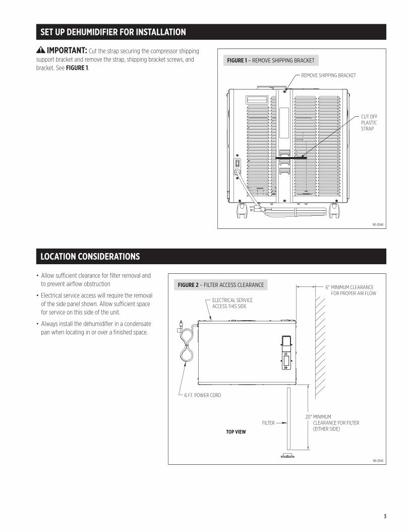
CONDENSATE PAN, CONDENSATE PUMP AND FLOAT SWITCH
A condensate pan is recommended when locating in or above a finished space or suspending over the canopy� Adhere to local codes regarding draining of the condensate pan� If a condensate pump is needed, install it in the condensate pan as well�
Install a condensate overflow safety switch (i�e� float switch) in the condensate pan, remove the factory installed jumper wire between the Float Switch terminals on the control and wire the float switch to the dehumidifier as shown in FIGURE 3� Overflow safety switches on condensate pumps can be wired to the Float Switch terminals in a similar fashion�
FLOA
TSw
itch
DHDH
NORMALLY CLOSEDFLOAT SWITCH
90-1857
FIGURE 3 – FLOAT SWITCH WIRING
4
MODEL A77 – REMOTE OR EXTERNAL CONTROL AND WIRING
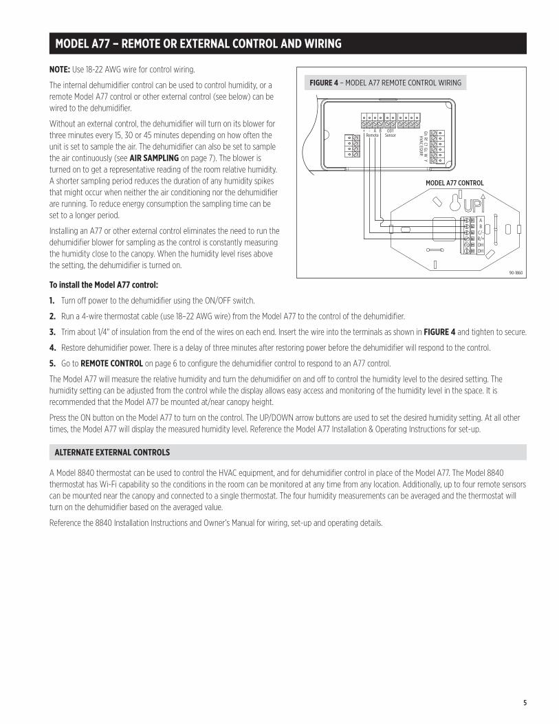
NOTE: Use 18-22 AWG wire for control wiring�
The internal dehumidifier control can be used to control humidity, or a remote Model A77 control or other external control (see below) can be wired to the dehumidifier�
Without an external control, the dehumidifier will turn on its blower for three minutes every 15, 30 or 45 minutes depending on how often the unit is set to sample the air� The dehumidifier can also be set to sample the air continuously (see AIR SAMPLING on page 7)� The blower is turned on to get a representative reading of the room relative humidity� A shorter sampling period reduces the duration of any humidity spikes that might occur when neither the air conditioning nor the dehumidifier are running� To reduce energy consumption the sampling time can be set to a longer period�
Installing an A77 or other external control eliminates the need to run the dehumidifier blower for sampling as the control is constantly measuring the humidity close to the canopy� When the humidity level rises above the setting, the dehumidifier is turned on�
To install the Model A77 control:
1. Turn off power to the dehumidifier using the ON/OFF switch�
2. Run a 4-wire thermostat cable (use 18–22 AWG wire) from the Model A77 to the control of the dehumidifier�
3. Trim about 1/4" of insulation from the end of the wires on each end� Insert the wire into the terminals as shown in FIGURE 4 and tighten to secure�
4. Restore dehumidifier power� There is a delay of three minutes after restoring power before the dehumidifier will respond to the control�
5. Go to REMOTE CONTROL on page 6 to configure the dehumidifier control to respond to an A77 control�
The Model A77 will measure the relative humidity and turn the dehumidifier on and off to control the humidity level to the desired setting� The humidity setting can be adjusted from the control while the display allows easy access and monitoring of the humidity level in the space� It is recommended that the Model A77 be mounted at/near canopy height�
Press the ON button on the Model A77 to turn on the control� The UP/DOWN arrow buttons are used to set the desired humidity setting� At all other times, the Model A77 will display the measured humidity level� Reference the Model A77 Installation & Operating Instructions for set-up�
ALTERNATE EXTERNAL CONTROLS
A Model 8840 thermostat can be used to control the HVAC equipment, and for dehumidifier control in place of the Model A77� The Model 8840 thermostat has Wi-Fi capability so the conditions in the room can be monitored at any time from any location� Additionally, up to four remote sensors can be mounted near the canopy and connected to a single thermostat� The four humidity measurements can be averaged and the thermostat will turn on the dehumidifier based on the averaged value�
Reference the 8840 Installation Instructions and Owner’s Manual for wiring, set-up and operating details�
+ - A B ODTSensorRemote
GhRf
CfGs
YW
HVAC EQUIP.
DHDHR/+C/-BA
MODEL A77 CONTROL
90-1860
FIGURE 4 – MODEL A77 REMOTE CONTROL WIRING
5
SYSTEM SET-UP & CHECKOUT
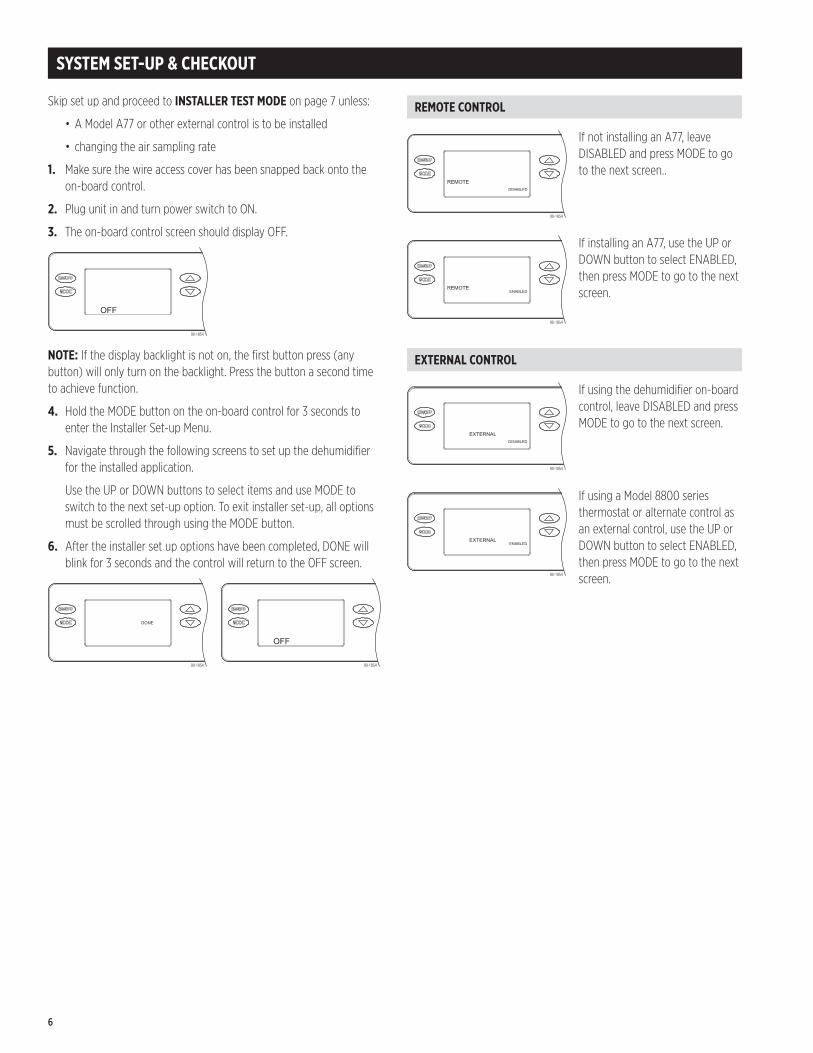
Skip set up and proceed to INSTALLER TEST MODE on page 7 unless:
• A Model A77 or other external control is to be installed
• changing the air sampling rate
1. Make sure the wire access cover has been snapped back onto the on-board control�
2. Plug unit in and turn power switch to ON�
3. The on-board control screen should display OFF�
90-1854
NOTE: If the display backlight is not on, the first button press (any button) will only turn on the backlight� Press the button a second time to achieve function�
4. Hold the MODE button on the on-board control for 3 seconds to enter the Installer Set-up Menu�
5. Navigate through the following screens to set up the dehumidifier for the installed application�
Use the UP or DOWN buttons to select items and use MODE to switch to the next set-up option� To exit installer set-up, all options must be scrolled through using the MODE button�
6. After the installer set up options have been completed, DONE will blink for 3 seconds and the control will return to the OFF screen�
90-1854 90-1854
REMOTE CONTROL
90-1854
If not installing an A77, leave DISABLED and press MODE to go to the next screen��
90-1854
If installing an A77, use the UP or DOWN button to select ENABLED, then press MODE to go to the next screen�
EXTERNAL CONTROL
90-1854
If using the dehumidifier on-board control, leave DISABLED and press MODE to go to the next screen�
90-1854
If using a Model 8800 series thermostat or alternate control as an external control, use the UP or DOWN button to select ENABLED, then press MODE to go to the next screen�
6
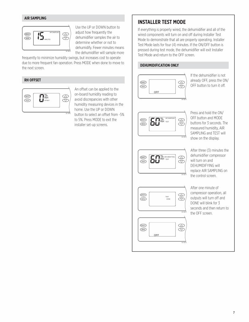
AIR SAMPLING
90-1854
Use the UP or DOWN button to adjust how frequently the dehumidifier samples the air to determine whether or not to dehumidify� Fewer minutes means the dehumidifier will sample more
frequently to minimize humidity swings, but increases cost to operate due to more frequent fan operation� Press MODE when done to move to the next screen�
RH OFFSET
90-1854
An offset can be applied to the on-board humidity reading to avoid discrepancies with other humidity measuring devices in the home� Use the UP or DOWN button to select an offset from -5% to 5%� Press MODE to exit the installer set-up screens�
INSTALLER TEST MODEIf everything is properly wired, the dehumidifier and all of the wired components will turn on and off during Installer Test Mode to demonstrate that all are properly operating� Installer Test Mode lasts for four (4) minutes� If the ON/OFF button is pressed during test mode, the dehumidifier will exit Installer Test Mode and return to the OFF screen�
DEHUMIDIFICATION ONLY
90-1854
If the dehumidifier is not already OFF, press the ON/OFF button to turn it off�
90-1854
Press and hold the ON/OFF button and MODE buttons for 3 seconds� The measured humidity, AIR SAMPLING and TEST will show on the display�
90-1854
After three (3) minutes the dehumidifier compressor will turn on and DEHUMIDIFYING will replace AIR SAMPLING on the control screen�
90-1854
After one minute of compressor operation, all outputs will turn off and DONE will blink for 3 seconds and then return to the OFF screen�
90-1854
7
START UP AND SEQUENCE OF OPERATION
USING THE DEHUMIDIFIER CONTROL
1. Press the ON/OFF button to turn the dehumidifier control ON� The display will show the current setting, and the dehumidifier blower will turn on to start sampling the air�
The setting will be replaced by the measured humidity and “AIR SAMPLING” will show on the display�
2. Use the UP or DOWN button to adjust the humidity setting as desired�
3. After three (3) minutes of sampling, the measured humidity will be compared to the setting:
a. If the humidity is above the setting, the dehumidifier compressor turns on and “AIR SAMPLING” will be replaced by “DEHUMIDIFYING”� The compressor remains on until the measured humidity falls 3% RH below the setting�
b. If the measured humidity is below the setting, the blowers turn off and the display returns to showing the RH setting�
4. The dehumidifier will sample again after the number of minutes selected during the Air Sampling portion of the System Set Up (see page 7), or any time the humidity setting is lowered�
USING THE MODEL A77 REMOTE CONTROL
1. Press the ON/OFF button to turn the dehumidifier control ON� “REMOTE” will show on the display to indicate that an external control is wired to the dehumidifier�
2. At the Model A77, press the ON button; the Model A77 will display the measured RH�
3. Use the UP or DOWN button on the Model A77 to adjust the humidity setting as desired�
4. If the RH measured by the Model A77 rises above the setting, the dehumidifier will turn on� “DEHUMIDIFYING” will appear on the dehumidifier control display to show that the Model A77 is calling for dehumidification� The dehumidifier will turn off when the RH measured by the Model A77 drops 3% RH below the setting�
8
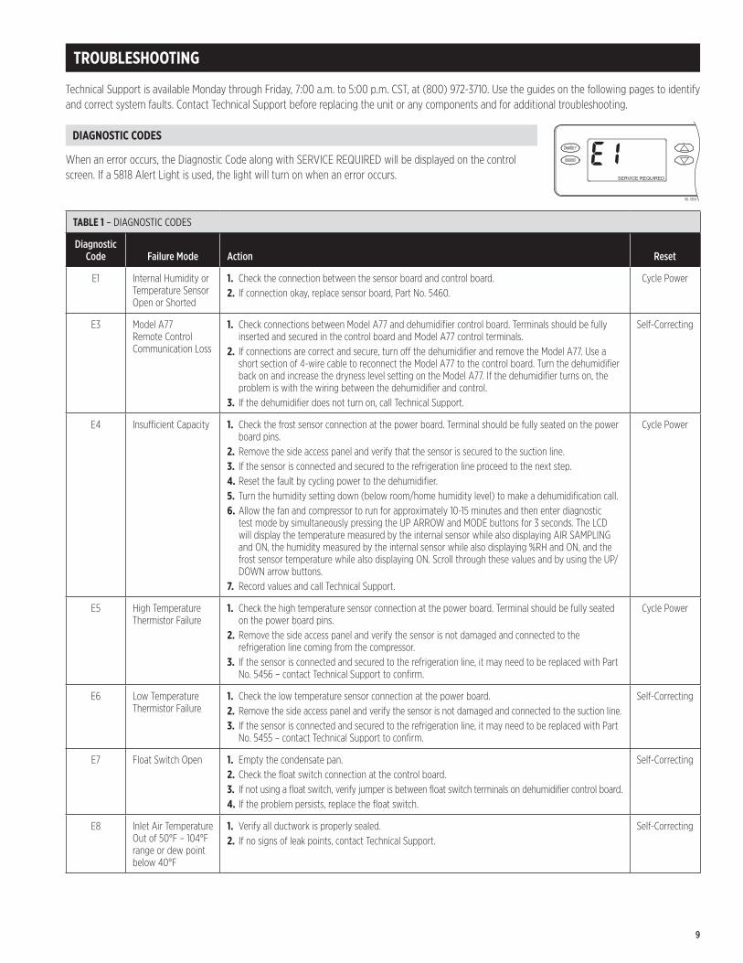
TABLE 1 – DIAGNOSTIC CODES
Diagnostic Code Failure Mode Action Reset
E1 Internal Humidity or Temperature Sensor Open or Shorted
1. Check the connection between the sensor board and control board�2. If connection okay, replace sensor board, Part No� 5460�
Cycle Power
E3 Model A77 Remote Control Communication Loss
1. Check connections between Model A77 and dehumidifier control board� Terminals should be fully inserted and secured in the control board and Model A77 control terminals�
2. If connections are correct and secure, turn off the dehumidifier and remove the Model A77� Use a short section of 4-wire cable to reconnect the Model A77 to the control board� Turn the dehumidifier back on and increase the dryness level setting on the Model A77� If the dehumidifier turns on, the problem is with the wiring between the dehumidifier and control�
3. If the dehumidifier does not turn on, call Technical Support�
Self-Correcting
E4 Insufficient Capacity 1. Check the frost sensor connection at the power board� Terminal should be fully seated on the power board pins�
2. Remove the side access panel and verify that the sensor is secured to the suction line�3. If the sensor is connected and secured to the refrigeration line proceed to the next step� 4. Reset the fault by cycling power to the dehumidifier�5. Turn the humidity setting down (below room/home humidity level) to make a dehumidification call� 6. Allow the fan and compressor to run for approximately 10-15 minutes and then enter diagnostic
test mode by simultaneously pressing the UP ARROW and MODE buttons for 3 seconds� The LCD will display the temperature measured by the internal sensor while also displaying AIR SAMPLING and ON, the humidity measured by the internal sensor while also displaying %RH and ON, and the frost sensor temperature while also displaying ON� Scroll through these values and by using the UP/DOWN arrow buttons�
7. Record values and call Technical Support�
Cycle Power
E5 High Temperature Thermistor Failure
1. Check the high temperature sensor connection at the power board� Terminal should be fully seated on the power board pins�
2. Remove the side access panel and verify the sensor is not damaged and connected to the refrigeration line coming from the compressor�
3. If the sensor is connected and secured to the refrigeration line, it may need to be replaced with Part No� 5456 – contact Technical Support to confirm�
Cycle Power
E6 Low Temperature Thermistor Failure
1. Check the low temperature sensor connection at the power board�2. Remove the side access panel and verify the sensor is not damaged and connected to the suction line�3. If the sensor is connected and secured to the refrigeration line, it may need to be replaced with Part
No� 5455 – contact Technical Support to confirm�
Self-Correcting
E7 Float Switch Open 1. Empty the condensate pan�2. Check the float switch connection at the control board�3. If not using a float switch, verify jumper is between float switch terminals on dehumidifier control board�4. If the problem persists, replace the float switch�
Self-Correcting
E8 Inlet Air Temperature Out of 50°F – 104°F range or dew point below 40°F
1. Verify all ductwork is properly sealed�2. If no signs of leak points, contact Technical Support�
Self-Correcting
TROUBLESHOOTING
Technical Support is available Monday through Friday, 7:00 a�m� to 5:00 p�m� CST, at (800) 972-3710� Use the guides on the following pages to identify and correct system faults� Contact Technical Support before replacing the unit or any components and for additional troubleshooting�
DIAGNOSTIC CODES
When an error occurs, the Diagnostic Code along with SERVICE REQUIRED will be displayed on the control screen� If a 5818 Alert Light is used, the light will turn on when an error occurs�
90-1854
9
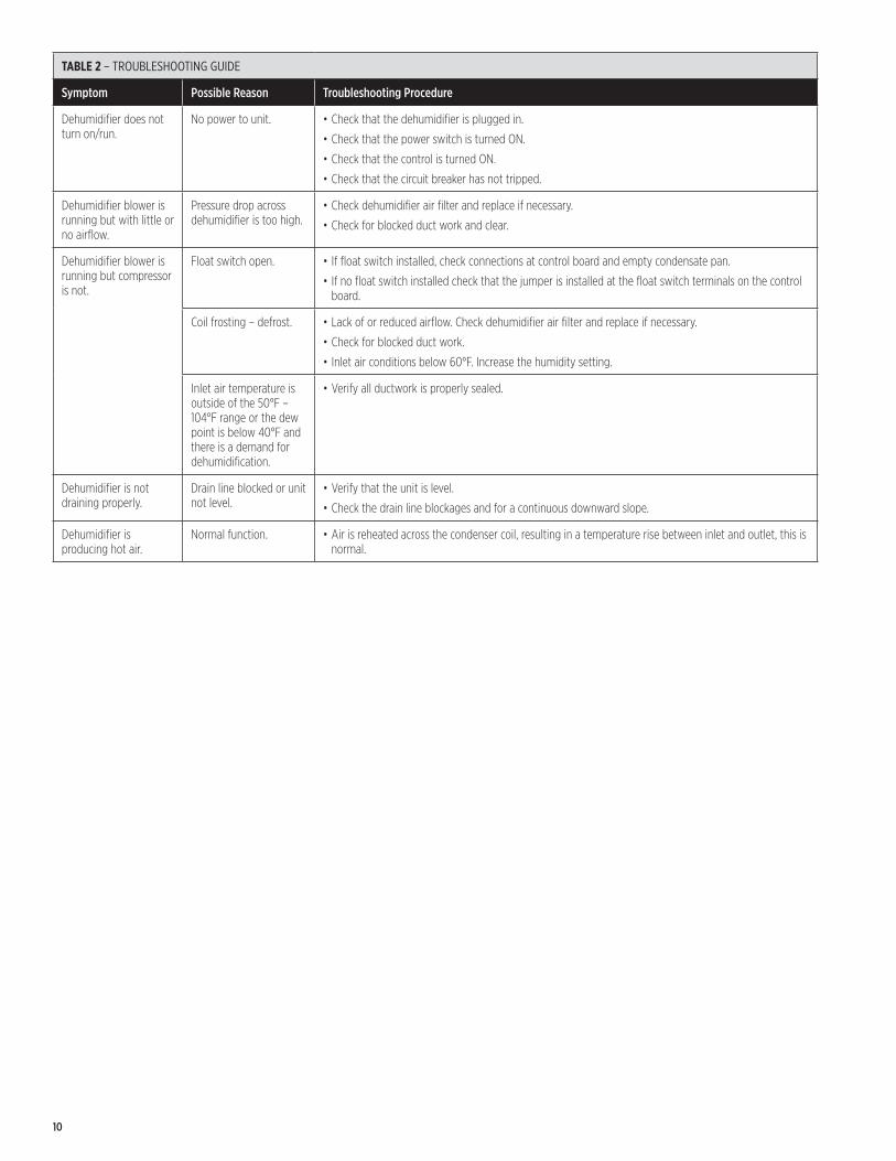
TABLE 2 – TROUBLESHOOTING GUIDE
Symptom Possible Reason Troubleshooting Procedure
Dehumidifier does not turn on/run�
No power to unit� • Check that the dehumidifier is plugged in�
• Check that the power switch is turned ON�
• Check that the control is turned ON�
• Check that the circuit breaker has not tripped�
Dehumidifier blower is running but with little or no airflow�
Pressure drop across dehumidifier is too high�
• Check dehumidifier air filter and replace if necessary�
• Check for blocked duct work and clear�
Dehumidifier blower is running but compressor is not�
Float switch open� • If float switch installed, check connections at control board and empty condensate pan�
• If no float switch installed check that the jumper is installed at the float switch terminals on the control board�
Coil frosting – defrost� • Lack of or reduced airflow� Check dehumidifier air filter and replace if necessary�
• Check for blocked duct work�
• Inlet air conditions below 60°F� Increase the humidity setting�
Inlet air temperature is outside of the 50°F – 104°F range or the dew point is below 40°F and there is a demand for dehumidification�
• Verify all ductwork is properly sealed�
Dehumidifier is not draining properly�
Drain line blocked or unit not level�
• Verify that the unit is level�
• Check the drain line blockages and for a continuous downward slope�
Dehumidifier is producing hot air�
Normal function� • Air is reheated across the condenser coil, resulting in a temperature rise between inlet and outlet, this is normal�
10
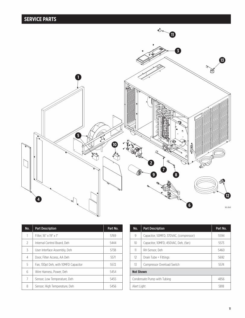
SERVICE PARTS
No. Part Description Part No.
9 Capacitor, 50MFD, 370VAC, (compressor) 5594
10 Capacitor, 10MFD, 450VAC, Deh, (fan) 5573
11 RH Sensor, Deh 5460
12 Drain Tube + Fittings 5692
13 Compressor Overload Switch 5574
Not Shown
Condensate Pump with Tubing 4856
Alert Light 5818
No. Part Description Part No.
1 Filter, 16" x 19" x 1" 5769
2 Internal Control Board, Deh 5444
3 User Interface Assembly, Deh 5738
4 Door, Filter Access, AA Deh 5571
5 Fan, 130pt Deh, with 10MFD Capacitor 5572
6 Wire Harness, Power, Deh 5454
7 Sensor, Low Temperature, Deh 5455
8 Sensor, High Temperature, Deh 5456
1
11
3
13
12
6
87
2
9
10
5
4
90-2041
11
anden.com P.O. Box 1467 Madison, WI 53701-1467 800.972.3710 F: 608.257.4357 Printed in USA©2019 Anden – A Quality brand from Research Products Corporation10013581 B2208341D 9.19
LIMITED WARRANTY
Your Research Products Corporation Anden™ Dehumidifier is expressly warranted for five (5) years from date of installation to be free from defects in materials or workmanship�
Research Products Corporation’s exclusive obligation under this warranty shall be to supply, without charge, a replacement for any component which is found to be defective within such five (5) year period and which is returned not later than thirty (30) days after said five (5) year period by you to either your original supplier or to Research Products Corporation, Madison, Wisconsin 53701, together with the model number and installation date of the dehumidifier�
THIS WARRANTY SHALL NOT OBLIGATE RESEARCH PRODUCTS CORPORATION FOR ANY LABOR COSTS AND SHALL NOT APPLY TO DEFECTS IN WORKMANSHIP OR MATERIALS FURNISHED BY YOUR INSTALLER AS CONTRASTED TO DEFECTS IN THE DEHUMIDIFIER ITSELF�
IMPLIED WARRANTIES OF MERCHANTABILITY OR FITNESS FOR A PARTICULAR PURPOSE SHALL BE LIMITED IN DURATION TO THE AFORESAID FIVE YEAR PERIOD� RESEARCH PRODUCTS CORPORATION’S LIABILITY FOR INCIDENTAL OR CONSEQUENTIAL DAMAGES, OTHER THAN DAMAGES FOR PERSONAL INJURIES, RESULTING FROM ANY BREACH OF THE AFORESAID IMPLIED WARRANTIES OR THE ABOVE LIMITED WARRANTY IS EXPRESSLY EXCLUDED� THIS LIMITED WARRANTY IS VOID IF DEFECT(S) RESULT FROM FAILURE TO HAVE THIS UNIT INSTALLED BY A QUALIFIED HEATING AND AIR CONDITIONING CONTRACTOR� IF THE LIMITED WARRANTY IS VOID DUE TO FAILURE TO USE A QUALIFIED CONTRACTOR, ALL DISCLAIMERS OF IMPLIED WARRANTIES SHALL BE EFFECTIVE UPON INSTALLATION�
Some states do not allow limitations on how long an implied warranty lasts or the exclusion or limitation of incidental or consequential damages so the above exclusion or limitations may not apply to you�
This warranty gives you specific legal rights and you may also have other rights which vary from state to state�
WARRANTY REGISTRATION
Visit us online at anden.com to register your Anden product� If you do not have online access, please mail a postcard with your name, address, phone number, email address, product purchased, model number, date of purchase, and dealer name and address to: Research Products Corporation, P�O� Box 1467, Madison, WI 53701�
Your warranty registration information will not be sold or shared outside of this company.
12
Related Documents