OPERATIONAL MANUAL MODEL: 4”Z1 CORE DRILL MACHINE USED BY HAND OR WITH OPTIONAL DRILLING RIG by BLUEROCK ® Tools Volume 1.3

Welcome message from author
This document is posted to help you gain knowledge. Please leave a comment to let me know what you think about it! Share it to your friends and learn new things together.
Transcript

OPERATIONAL MANUAL
MODEL: 4”Z1 CORE DRILL MACHINE USED BY HAND OR WITH OPTIONAL DRILLING RIG
by BLUEROCK ® Tools
Volume
1.3

M W S - 4 ” Z 1 C O R E D R I L L
UNPACKING THE ITEM CAUTION: This machine is packed together with items that may be sharp, oily and overly heavy objects. Remove the machine from the packaging in a safe manner. Check to ensure all accessories are included with the item while unpacking. If any parts are found to be missing, contact the retailer as soon as possible. Do not throw away the packaging until the item is out of the guarantee period. Dispose of the packaging in an environmentally responsible manner. Recycle if possible. Keep all plastic bags away from children due to risk of suffocation.
WEEE - Waste Electrical & Electronic Equipment. Note this machine should be disposed of as electrical & electronic waste.
SLURRY DISPOSAL
NOTE: It is recommended to dispose of the drilling slurry (the muddy/dusty water material) in an environmentally responsible manner. The disposal of slurry directly into sewage systems, sewers, lakes, rivers, or direct earth without treatment can be environmentally harmful and possibly illegal. Ask your local public authorities about current regulations in your area.
ã THE NEWMAN TRADING COMPANY LLC DBA BLUEROCK® TOOLS 2020 1033 Andover Park East, Tukwila WA 98188 USA
Phone 206.604.8363 • Fax 425.572.5167 www.bluerocktools.com
4 ” Z 1 C O R E D R I L L
Table of Contents
SAFETY 1PRE-OPERATIONAL SAFETY CHECKS 1OPERATIONAL SAFETY CHECKS 1HEALTH WARNINGS 3
SPECIFICATIONS 4
INCLUDEDACCESSORIES 4
ADDITIONALAVAILABLEACCESSORIES 5ADDITIONAL ACCESSORIES FOR THIS MACHINE CAN BE FOUND IN BLUEROCK ® TOOLS ONLINE SHOP AT WWW.BLUEROCKTOOLS.COM OR FROM YOUR LOCAL RETAILER. 5
OPERATIONS 6PURPOSE 6OPERATIONAL PRINCIPLES 6MACHINE COMPONENTS 7TRANSPORTING THE MACHINE 8RUNNING THE MACHINE USING THE HANDHELD DRILLING METHOD 8RUNNING THE MACHINE USING THE OPTIONAL DRILLING RIG 10INSTALLING CORING BITS 12
TROUBLESHOOTING 13
GENERALMAINTENANCE 14
OCCASIONALMAINTENANCE 14
PARTSLIST 16
BREAKDOWNVIEW-OVERVIEW 18
BREAKDOWNVIEW–GEARBOX/MOTORCLOSE-UP 19
BREAKDOWNVIEW–OPTIONALDRILLINGRIGCLOSE-UP 21
4 ” Z 1 C O R E D R I L L
1
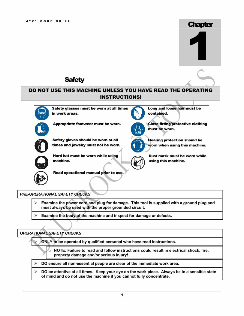
Safety DO NOT USE THIS MACHINE UNLESS YOU HAVE READ THE OPERATING
INSTRUCTIONS!
Safety glasses must be worn at all times in work areas.
Long and loose hair must be contained.
Appropriate footwear must be worn. Close fitting/protective clothing must be worn.
Safety gloves should be worn at all times and jewelry must not be worn.
Hearing protection should be worn when using this machine.
Hard-hat must be worn while using machine.
Dust mask must be worn while using this machine.
Read operational manual prior to use.
PRE-OPERATIONAL SAFETY CHECKS
Ø Examine the power cord and plug for damage. This tool is supplied with a ground plug and must always be used with the proper grounded circuit.
Ø Examine the body of the machine and inspect for damage or defects.
OPERATIONAL SAFETY CHECKS
Ø ONLY to be operated by qualified personal who have read instructions.
o NOTE: Failure to read and follow instructions could result in electrical shock, fire, property damage and/or serious injury!
Ø DO ensure all non-essential people are clear of the immediate work area.
Ø DO be attentive at all times. Keep your eye on the work piece. Always be in a sensible state of mind and do not use the machine if you cannot fully concentrate.
Chapter
1

4 ” Z 1 C O R E D R I L L
2
Ø DO keep body parts, clothing & power cords clear of turning/cutting pieces. Stay alert and use common since when using this tool.
Ø DO allow machine to reach operating speed before starting a hole.
Ø DO unplug machine while changing or adjusting cutting bits so as not to accidentally turn machine on.
Ø DO remove adjusting wrenches prior to turning the machine on.
Ø DO guard against electric shock by only operating this tool on a properly functioning GFCI (Ground Fault Circuit Interrupt) circuit.
Ø DO be mindful that power tools can expose an operator to vibrations transmitted trough contact with the machine. Prolonged exposure can lead to medical issues which should be discussed with a medical professional.
Ø DO tie in a drip loop in the power cord to prevent water from running into the power receptacle.
Ø DO use a dust extraction system for cutting materials that create dust. The operator should also wear a protective respiratory device.
Ø DO NOT make adjustments to machine while the machine is running.
Ø DO NOT switch off the machine when it is under load, except in an emergency.
Ø DO NOT remove or modify grounding plug. Only to be used on a properly grounded GFCI circuit.
Ø DO NOT leave the machine running when not in use.
Ø DO NOT hold the work piece by hand or using body. Always mechanically clamp or secure work piece.
Ø DO NOT allow operator to make contact with grounded surfaces such as metal objects.
Ø DO NOT allow liquids to enter the machine’s ventilation system.
Ø DO NOT operate machine outside of machine specifications.
Ø DO NOT touch moving parts while the machine is running as death or dismemberment could occur.
Ø DO NOT operate machine overhead (Inverted) when drilling “wet” type cores.
Ø DO NOT remove machines electrical components while connected to a power source. Only to be removed for service by qualified personal and put back on the machine after service is complete.
Ø DO NOT allow children or untrained personal to operate machine.
Ø DO NOT use this machine in the rain or a wet environment.
Ø DO NOT operate in the presence of explosive materials as power tools create sparks which may ignite dust or fumes.
Ø DO NOT drill into an area that may contain a live electrical wire/circuit.

4 ” Z 1 C O R E D R I L L
3
Ø DO NOT use this machine without safely securing to the work piece being drilled.
Ø DO NOT use full water pressure when drilling with “wet” type bits! You need minimal water to drill with these machines. Extreme water pressure can cause water to enter the gearbox!
Ø DO NOT operate this machine on a lower voltage as it may result in reduced power level and the machine could become unstable while cutting. This could also limit the motor life.
o NOTE: Use of long small gauge power extension cords can result in decreased voltage. As local voltages can vary, it may be a good idea to test the voltage at the end of the extension cord to ensure proper voltage requirements are met. You might also consult an electrician to make sure the length of cord matches up with the proper wire gauge for this size motor. Make sure to use outdoor cords when operating outdoors.
HEALTH WARNINGS
Ø Certain dust created by drilling contains chemicals known to cause cancer, birth defects or other reproductive harm. The examples of these chemicals are below:
o Lead from lead based paint.
o Crystalline silica from bricks, cement and assorted masonry products.
§ TO REDUCE RISK OF EXPOSURE TO THESE CHEMICALS, WORK IN A WELL VENTILATED AREA WITH VACUUM SYSTEMS, RESPIRATORS AND WITH ALL SUITABLE SAFETY EQUIPMENT.

4 ” Z 1 C O R E D R I L L
4
Specifications ELECTRICAL DATA Voltage 110V, 50-60Hz, Single Phase Current 13 Amps (20A Circuit Use Recommended) Motor Size 1500W Power Connection US Standard 3 Prong Type B Plug
MECHANICAL DATA Cutter Range 1” to 4” Max Diameter Cutting Speed 950/2100 RPM Two Speed Gearbox
1) Gear 2 (2100 rpm) for 1”-2” Holes 2) Gear 1 (950 rpm) for 2”-4” Holes
Tool Holder Direct Arbor 1-1/4” 7 UNC Spindle Safety Clutch Yes Water hose and Valve Yes Hand held capable Yes Drilling rig capable Yes (Drill Rig Sold Separately)
SHIPPING DATA Shipping Weight 22 Lbs Shipping Carton 19” x 6” x 15”
Included Accessories DESCRIPTION QTY Instruction Manual 1 Water Hose and Valve 1 Spare Brushes (set) 1
Chapter
2
4 ” Z 1 C O R E D R I L L
5
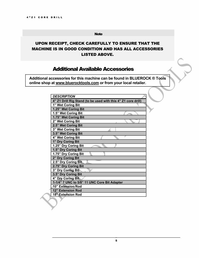
Note
UPON RECEIPT, CHECK CAREFULLY TO ENSURE THAT THE MACHINE IS IN GOOD CONDITION AND HAS ALL ACCESSORIES
LISTED ABOVE.
Additional Available Accessories Additional accessories for this machine can be found in BLUEROCK ® Tools online shop at www.bluerocktools.com or from your local retailer.
DESCRIPTION 4” Z1 Drill Rig Stand (to be used with this 4” Z1 core drill) 1” Wet Coring Bit 1.25” Wet Coring Bit 1.5” Wet Coring Bit 1.75” Wet Coring Bit 2” Wet Coring Bit 2.5” Wet Coring Bit 3” Wet Coring Bit 3.5” Wet Coring Bit 4” Wet Coring Bit 1” Dry Coring Bit 1.25” Dry Coring Bit 1.5” Dry Coring Bit 1.75” Dry Coring Bit 2” Dry Coring Bit 2.5” Dry Coring Bit 2.75” Dry Coring Bit 3” Dry Coring Bit 3.5” Dry Coring Bit 4” Dry Coring Bit 1-1/4” 7 UNC to 5/8” 11 UNC Core Bit Adapter 10” Extension Rod 12” Extension Rod 18” Extension Rod

4 ” Z 1 C O R E D R I L L
6
Operations
Note
THOROUGHLY READ THROUGH THE ENTIRE MANUAL BEFORE OPERATING THIS MACHINE!
PURPOSE
Ø The purpose of the 4”Z1 core drill is to drill through masonry, concrete or other mineral rock types using annular coring bits.
Ø These drills are designed to be used by hand or bolted to the drilling surface using an optional drilling rig.
o NOTE: If using the optional drilling rig, make sure the base fits completely on the surface and the base is securely fastened using wedge anchors to bolt to the surface.
Ø These machines can be used vertically, horizontally or overhead (inverted) provided an acceptable work environment. NOTE: For safety, when drilling horizontally or overhead with the optional drilling rig, a safety chain/strap should always be used.
o CAUTION: If drilling overhead you are only permitted to use dry type core bits with a vacuum system. “Wet” type holes overhead would allow water into the motor and create an extremely dangerous situation.
OPERATIONAL PRINCIPLES
Ø The main drilling shaft rotates in a forward clockwise direction. The main drilling motor connects to the tool spindle to make contact with a surface and slowly bore a hole. If using the optional drilling rig, the drill fits inside the C clamp assembly and using the feed handles on the side of the rig, the user can raise or lower the drilling motor.
Ø These drills are ONLY to be used with diamond impregnated coring bits.
o When drilling with “wet” type bits, the bit ends pulverizes the material and the water brings the material out of the cut.
o When drilling with “dry” type bits, the bit end pulverizes the material and dust brings the material out of the cut.
Chapter
3
4 ” Z 1 C O R E D R I L L
7
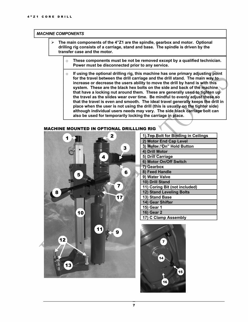
MACHINE COMPONENTS
Ø The main components of the 4”Z1 are the spindle, gearbox and motor. Optional drilling rig consists of a carriage, stand and base. The spindle is driven by the transfer case and the motor.
o These components must be not be removed except by a qualified technician. Power must be disconnected prior to any service.
o If using the optional drilling rig, this machine has one primary adjusting point for the travel between the drill carriage and the drill stand. The main way to increase or decrease the users ability to move the drill by hand is with this system. These are the black hex bolts on the side and back of the machine that have a locking nut around them. These are generally used to tighten up the travel as the slides wear over time. Be mindful to evenly adjust these so that the travel is even and smooth. The ideal travel generally keeps the drill in place when the user is not using the drill (this is usually on the tighter side) although individual users needs may vary. The side black carriage bolt can also be used for temporarily locking the carriage in place.
MACHINE MOUNTED IN OPTIONAL DRILLLING RIG
1) Top Bolt for Binding in Ceilings 2) Motor End Cap Level 3) Motor “On” Hold Button 4) Drill Motor 5) Drill Carriage 6) Motor On/Off Switch 7) Gearbox 8) Feed Handle 9) Water Valve 10) Drill Stand 11) Coring Bit (not included) 12) Stand Leveling Bolts 13) Stand Base 14) Gear Shifter 15) Gear 1 16) Gear 2 17) C Clamp Assembly
4 ” Z 1 C O R E D R I L L
8
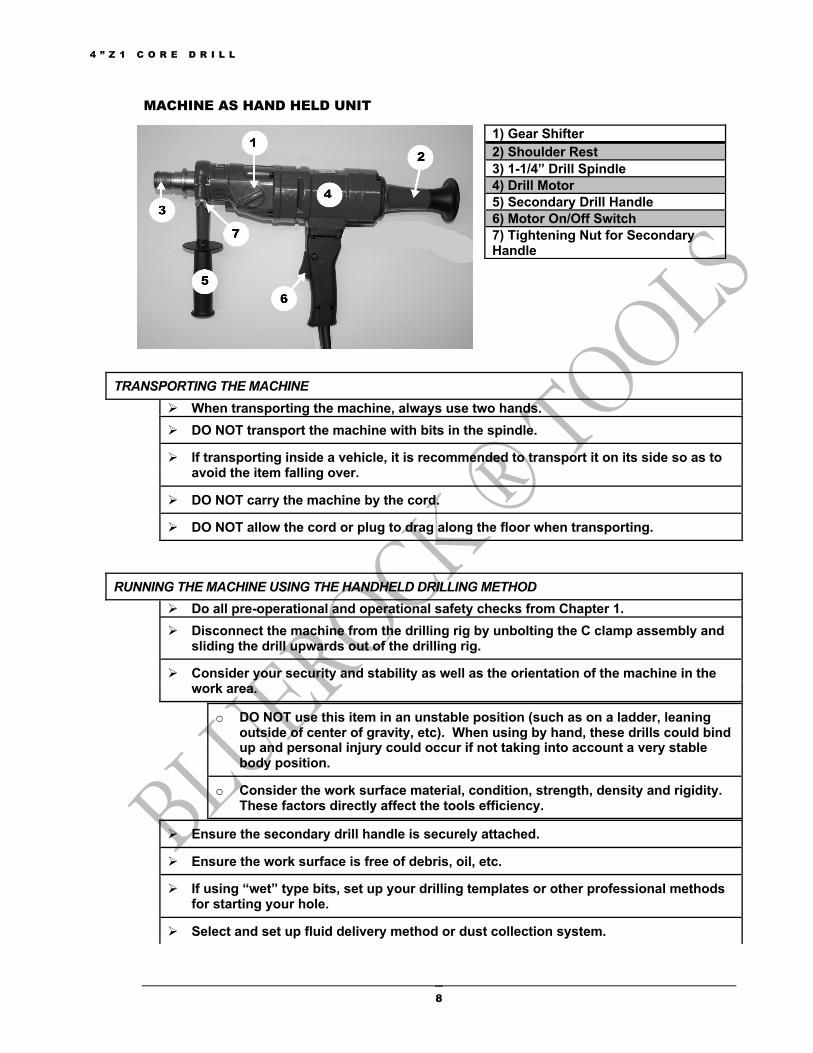
MACHINE AS HAND HELD UNIT
TRANSPORTING THE MACHINE Ø When transporting the machine, always use two hands. Ø DO NOT transport the machine with bits in the spindle.
Ø If transporting inside a vehicle, it is recommended to transport it on its side so as to avoid the item falling over.
Ø DO NOT carry the machine by the cord.
Ø DO NOT allow the cord or plug to drag along the floor when transporting.
RUNNING THE MACHINE USING THE HANDHELD DRILLING METHOD Ø Do all pre-operational and operational safety checks from Chapter 1. Ø Disconnect the machine from the drilling rig by unbolting the C clamp assembly and
sliding the drill upwards out of the drilling rig.
Ø Consider your security and stability as well as the orientation of the machine in the work area.
o DO NOT use this item in an unstable position (such as on a ladder, leaning outside of center of gravity, etc). When using by hand, these drills could bind up and personal injury could occur if not taking into account a very stable body position.
o Consider the work surface material, condition, strength, density and rigidity. These factors directly affect the tools efficiency.
Ø Ensure the secondary drill handle is securely attached.
Ø Ensure the work surface is free of debris, oil, etc.
Ø If using “wet” type bits, set up your drilling templates or other professional methods for starting your hole.
Ø Select and set up fluid delivery method or dust collection system.
1) Gear Shifter 2) Shoulder Rest 3) 1-1/4” Drill Spindle 4) Drill Motor 5) Secondary Drill Handle 6) Motor On/Off Switch 7) Tightening Nut for Secondary Handle
4 ” Z 1 C O R E D R I L L
9
Ø If using the machine with the water system, connect hose to the side of the machine using the connector.
o This connector takes standard ¾” US garden hose hookup.
o Make sure the water valve is in the off position.
§ This is generally at a 90 degree angle from the valve hose.
o Partially turn the water spigot on (usually half a turn).
§ CAUTION: DO NOT turn the hose on fully! You need sufficient water when using wet type bits. Using too much water pressure can cause the bits to not cut properly as well as water entering the gearbox.
Ø Select appropriate size cutting bit and install by screwing the bit onto the spindle. See section below for details on securing bit.
Ø Plug the machine into power source.
o Form a loose knot in the power cord close to the plug connection to prevent fluid from running down the cord and into the power receptacle.
Ø Select the gear you will be using.
o Do not force the gear shifter when changing between gears. There is a neutral position between gear 1 and gear 2.
o Change gears when the machine is stopped or almost stopped.
Ø Open the water valve to allow water to come out to the work surface.
Ø Turn the machine on by engaging the motor into the “on” position.
o CAUTION: When using the machine by hand, it is not recommended to use the machine with the motor switch “hold” position engaged. It is recommended to only use the finger trigger switch.
Ø ATTENTION: BE AWARE THESE MACHINES ARE EXTREMELY POWERFUL. THEY HAVE A TREMENDOUS AMOUNT OF TORQUE WHICH MIGHT NOT BE SUITABLE FOR ALL POTENTIAL USERS. ESPECIALLY IN LOW GEAR AND WITH LARGER BITS. DESPITE THE SAFETY CLUTCH, THESE DRILLS CAN STILL INJURE THE USER. IF IN DOUBT, CONTACT A PROFESSIONAL FOR ADVICE.
Ø Very slowly engage the cutting bit with the material surface by lightly engaging the bit with the material.
o NOTE: During the initial stages of contact the bit may wander.
o NOTE: If wet drilling and not using a guide, a common way to start the hole uses a 30 degree angle to slightly cut into the material. Once the bit has bored slightly into the material, the user will slowly level the machine out straightly. If unsure, it is recommended to contact a coring professional.
Ø After about 1/8” of cutting has been achieved in the work surface, slightly more force can be applied. This will be the normal amount of force the rest of the hole.
o NOTE: Do not force the hole. Let the machine do most of the work. Excessive physical effort should be avoided as it can cause damage to the machine or cause injury to the user.
4 ” Z 1 C O R E D R I L L
10
o If the unit jams in a hole, stop the drill immediately by quickly disengaging the “on” switch to prevent injury. Disconnect the drill from the power supply and loosen the cutter by turning drill spindle counterclockwise. Never attempt to free bit by starting motor!
§ After an interruption in drilling, make sure the drill bit is free and turns before restarting the hole. Be very careful at this point to make certain the drill does not bind when restarting.
o CAUTION: CAUTION: It can take a 1-2 seconds for the safety clutch to engage otherwise excessive wear and heat will develop.
Ø Make sure to keep the cutting material lubricated when “wet” drilling.
Ø Ease up on pressure as the cutter starts breaking through the backside of the material.
o Be certain all is clear on the output side of this core to prevent injury to persons or property.
Ø Finish drilling the hole.
Ø Turn the motor off and disconnect power once the drill is safely back to the non-drilling position.
Ø Turn water valve off.
RUNNING THE MACHINE USING THE OPTIONAL DRILLING RIG Ø Do all pre-operational and operational safety checks from Chapter 1. Ø Consider your security and stability as well as the orientation of the machine in the
work area.
o Consider the work surface material, condition, strength, density and rigidity. These factors directly affect the tools efficiency.
Ø Ensure the drill is secure in the drilling assembly by inspecting the C clamp assembly and checking the tension on the C clamp bolts.
o Ensure the machine’s axis are parallel with the drill stand.
Ø Secure the machine base to the work surface by using a wedge anchor or other method to ensure the base does not move.
Ø Use the four leveling bolts on the corners of the base to level the machine.
Ø After placing the machine in work area, connect a safety chain or strap if necessary.
o The safety chain should attach to the machine (preferably through the carrying handle or O bolt) as well as attached to the work area in such a manner that prevents the machine from detaching or falling from the work area.
Ø Ensure the feed handles are securely attached to the feed spindle.
Ø Ensure the work surface is free of debris, oil, etc.
Ø Select the gear you will be using.
4 ” Z 1 C O R E D R I L L
11
o Do not force the gear shifter when changing between gears. There is a neutral position between gear 1 and gear 2.
o Change gears when the machine is stopped or almost stopped.
Ø Select and set up fluid delivery method or dust system.
Ø If using the machine horizontally with the water system, connect hose to the side of the machine using the connector.
o This connector takes standard ¾” US garden hose hookup.
o Make sure the water valve is in the off position.
§ This is generally at a 90 degree angle from the valve hose.
o Partially turn the water spigot on (usually half a turn).
§ CAUTION: DO NOT turn the hose on fully! You need sufficient water when using wet type bits. Using too much water pressure can cause the bits to not cut properly as well as water entering the gearbox.
Ø Select appropriate size cutting bit and install. See section below for details on securing bit.
Ø Check that the machine is firmly attached to the work area.
Ø Plug the machine into power source.
o Form a loose knot in the power cord close to the plug connection to prevent fluid from running down the cord and into the power receptacle.
Ø Turn feed handle raising the cutter until the bit is above the work surface.
Ø Open the water valve to allow water to come out to the work surface.
Ø ATTENTION: BE AWARE THESE MACHINES ARE EXTREMELY POWERFUL. THEY HAVE A TREMENDOUS AMOUNT OF TORQUE WHICH MIGHT NOT BE SUITABLE FOR ALL POTENTIAL USERS. ESPECIALLY IN LOW GEAR AND WITH LARGER BITS. DESPITE THE SAFETY CLUTCH, THESE DRILLS CAN STILL INJURE THE USER. IF IN DOUBT, CONTACT A PROFESSIONAL FOR ADVICE.
Ø Turn the machine on by engaging the motor into the “on” position.
o If wanting the machine to continue in the “on” position, engage the hold button on the side of the handle above the finger “on” switch. To disengage the motor when in the hold function, quickly depress the finger “on” switch to turn the motor off. You may want to cycle through this sequence a couple times before using the machine for the first time to familiarize the user with this process.
Ø Very slowly engage the cutting bit with the material surface by lightly engaging the hand crank down towards the material.
o NOTE: During the initial stages of contact the bit may wander.
Ø After about 1/8” of cutting has been achieved in the work surface, slightly more force can be applied. This will be the normal amount of force the rest of the hole.
4 ” Z 1 C O R E D R I L L
12
o NOTE: Do not force the hole. Let the machine do most of the work. Excessive physical effort should be avoided as it can cause damage to the machine or the user.
o If the unit jams in a hole, stop the drill immediately by quickly depressing the “on” switch to prevent injury. Disconnect the drill from the power supply and loosen the cutter by turning drill spindle counterclockwise. Never attempt to free bit by starting motor!
§ After an interruption in drilling, make sure the drill bit is free and turns before restarting the hole. Be very careful at this point to make certain the drill does not bind when restarting.
o CAUTION: It can take a 1-2 seconds for the safety clutch to engage otherwise excessive wear and heat will develop.
Ø Make sure to keep the cutting material lubricated.
Ø Ease up on feed pressure as the cutter starts breaking through the backside of the material.
o Be certain all is clear on the output side of this core to prevent injury to persons or property.
Ø Finish drilling the hole.
Ø Turn the motor off and disconnect power once the drill is safely back up in the non-drilling position.
Ø Turn water valve off.
Ø Unbolt the wedge anchor.
Ø Disconnect safety chain/strap and move the drill to a new drilling location.
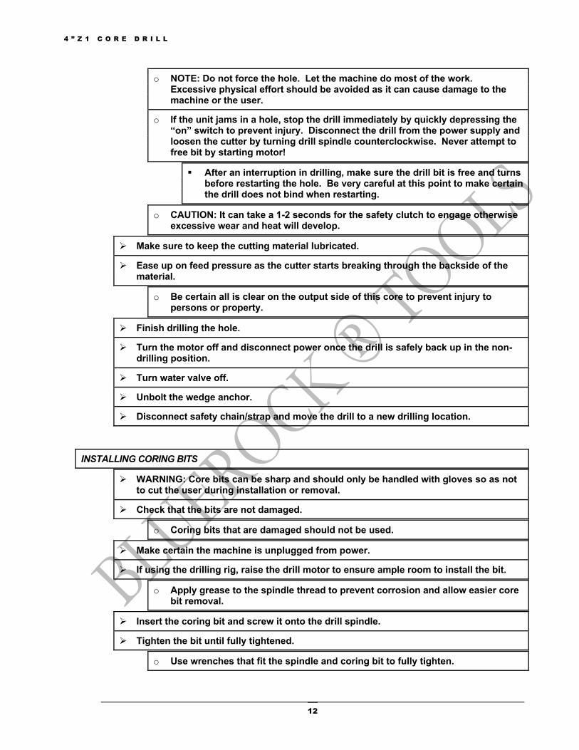
INSTALLING CORING BITS
Ø WARNING: Core bits can be sharp and should only be handled with gloves so as not to cut the user during installation or removal.
Ø Check that the bits are not damaged.
o Coring bits that are damaged should not be used.
Ø Make certain the machine is unplugged from power.
Ø If using the drilling rig, raise the drill motor to ensure ample room to install the bit.
o Apply grease to the spindle thread to prevent corrosion and allow easier core bit removal.
Ø Insert the coring bit and screw it onto the drill spindle.
Ø Tighten the bit until fully tightened.
o Use wrenches that fit the spindle and coring bit to fully tighten.
4 ” Z 1 C O R E D R I L L
13
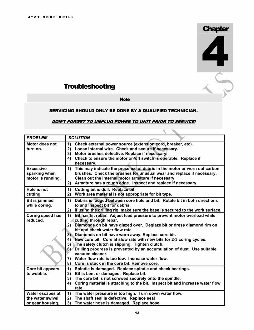
Troubleshooting
Note
SERVICING SHOULD ONLY BE DONE BY A QUALIFIED TECHNICIAN.
DON’T FORGET TO UNPLUG POWER TO UNIT PRIOR TO SERVICE!
PROBLEM SOLUTION Motor does not turn on.
1) Check external power source (extension cord, breaker, etc). 2) Loose internal wire. Check and secure if necessary. 3) Motor brushes defective. Replace if necessary. 4) Check to ensure the motor on/off switch is operable. Replace if
necessary. Excessive sparking when motor is running.
1) This may indicate the presence of debris in the motor or worn out carbon brushes. Check the brushes for unusual wear and replace if necessary. Clean out the internal motor armature if necessary.
2) Armature has a rough edge. Inspect and replace if necessary. Hole is not cutting.
1) Cutting bit is dull. Replace bit. 2) Work area material is not appropriate for bit type.
Bit is jammed while coring.
1) Debris is lodged between core hole and bit. Rotate bit in both directions to and inspect bit for debris.
2) If using the drilling rig, make sure the base is secured to the work surface. Coring speed has reduced.
1) Bit has hit rebar. Adjust feed pressure to prevent motor overload while cutting through rebar.
2) Diamonds on bit have glazed over. Deglaze bit or dress diamond rim on bit and check water flow rate.
3) Diamonds on bit have worn away. Replace core bit. 4) New core bit. Core at slow rate with new bits for 2-3 coring cycles. 5) The safety clutch is slipping. Tighten clutch. 6) Drilling progress is prevented by an accumulation of dust. Use suitable
vacuum cleaner. 7) Water flow rate is too low. Increase water flow. 8) Core is stuck in the core bit. Remove core.
Core bit appears to wobble.
1) Spindle is damaged. Replace spindle and check bearings. 2) Bit is bent or damaged. Replace bit. 3) The core bit is not screwed securely onto the spindle. 4) Coring material is attaching to the bit. Inspect bit and increase water flow
rate. Water escapes at the water swivel or gear housing.
1) The water pressure is too high. Turn down water flow. 2) The shaft seal is defective. Replace seal 3) The water hose is damaged. Replace hose.
Chapter
4
4 ” Z 1 C O R E D R I L L
14
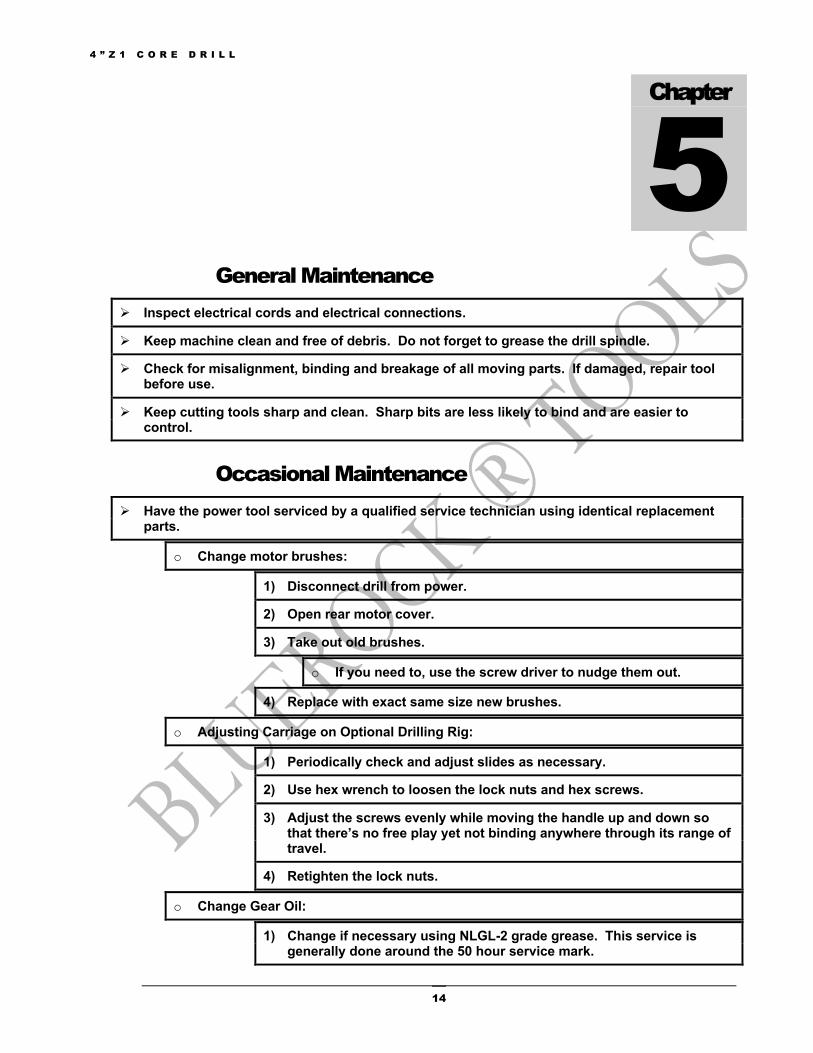
General Maintenance Ø Inspect electrical cords and electrical connections.
Ø Keep machine clean and free of debris. Do not forget to grease the drill spindle.
Ø Check for misalignment, binding and breakage of all moving parts. If damaged, repair tool before use.
Ø Keep cutting tools sharp and clean. Sharp bits are less likely to bind and are easier to control.
Occasional Maintenance Ø Have the power tool serviced by a qualified service technician using identical replacement
parts.
o Change motor brushes:
1) Disconnect drill from power.
2) Open rear motor cover.
3) Take out old brushes.
o If you need to, use the screw driver to nudge them out.
4) Replace with exact same size new brushes.
o Adjusting Carriage on Optional Drilling Rig:
1) Periodically check and adjust slides as necessary.
2) Use hex wrench to loosen the lock nuts and hex screws.
3) Adjust the screws evenly while moving the handle up and down so that there’s no free play yet not binding anywhere through its range of travel.
4) Retighten the lock nuts.
o Change Gear Oil:
1) Change if necessary using NLGL-2 grade grease. This service is generally done around the 50 hour service mark.
Chapter
5
4 ” Z 1 C O R E D R I L L
15
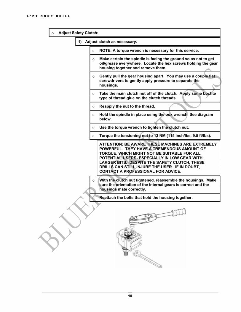
o Adjust Safety Clutch:
1) Adjust clutch as necessary.
o NOTE: A torque wrench is necessary for this service.
o Make certain the spindle is facing the ground so as not to get oil/grease everywhere. Locate the hex screws holding the gear housing together and remove them.
o Gently pull the gear housing apart. You may use a couple flat screwdrivers to gently apply pressure to separate the housings.
o Take the main clutch nut off of the clutch. Apply some Loctite type of thread glue on the clutch threads.
o Reapply the nut to the thread.
o Hold the spindle in place using the box wrench. See diagram below.
o Use the torque wrench to tighten the clutch nut.
o Torque the tensioning nut to 13 NM (115 inch/lbs, 9.5 ft/lbs).
ATTENTION: BE AWARE THESE MACHINES ARE EXTREMELY POWERFUL. THEY HAVE A TREMENDOUS AMOUNT OF TORQUE, WHICH MIGHT NOT BE SUITABLE FOR ALL POTENTIAL USERS- ESPECIALLY IN LOW GEAR WITH LARGER BITS. DESPITE THE SAFETY CLUTCH, THESE DRILLS CAN STILL INJURE THE USER. IF IN DOUBT, CONTACT A PROFESSIONAL FOR ADVICE.
o With the clutch nut tightened, reassemble the housings. Make sure the orientation of the internal gears is correct and the housings mate correctly.
o Reattach the bolts that hold the housing together.

4 ” Z 1 C O R E D R I L L
16
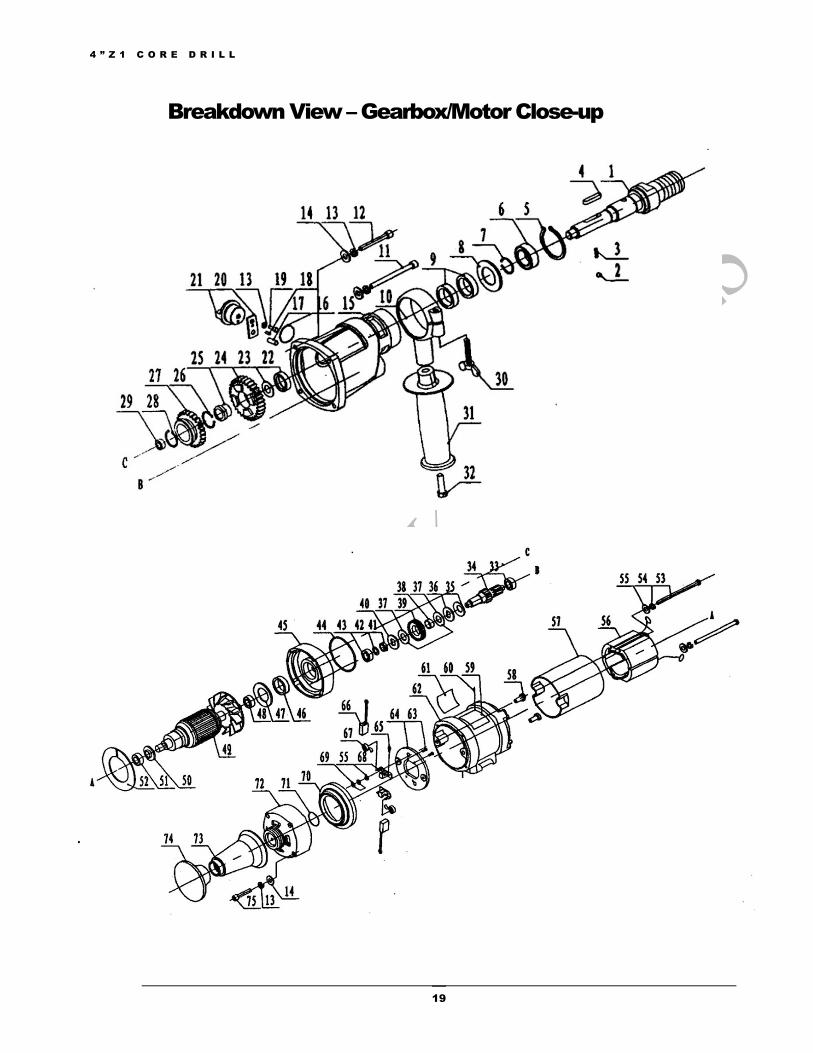
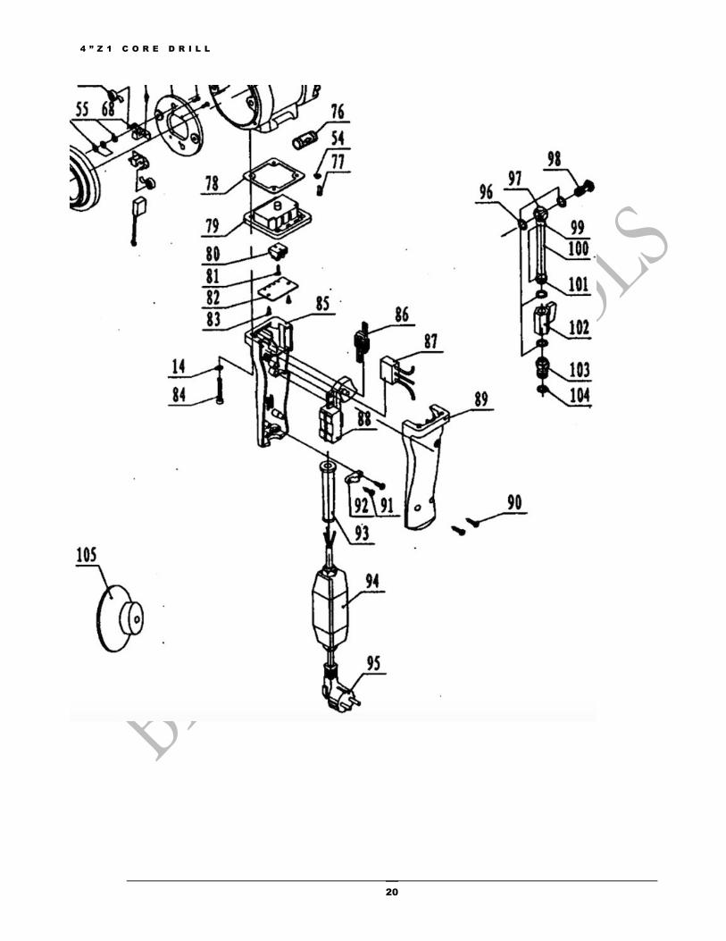
Parts List 4"Z1 Core Drill (Not Including Optional Stand)
# Spec Name # Spec Name # Spec Name # Spec Name 1 02-
80/001 Output shaft 28 φ17 Unmark
uncork shielding for shaft
55 φ4 Flat washer 82 02-80/068
Handle bracket cover board
2 φ4 Stell ball 29 HK1210
Quill bearing
56 02-80/201
Stator assembly
83 ST2.9×16 Crossed slot tapping bolt
3 02-80/050
Small spring 3.6×14.5×12
30 M16×35
Butterfly nut
57 02-80/022
Stator insulating cover
84 M5×35 Inner hexagonal roud head bolt
4 A5×32 Flat key 31 02-80/045
Assistant handle
58 02-80/023
Insulating shim
85 06-80/020
Left handle
5 φ47×1.5 Spring shield ring for holes 47
32 M14×45
Hexagonal bolt
59 02-80/033
Name plate 86 02-80/067
Inductance
6 KS-NS K60052Z
Deep groove of ball bearing
33 KS-NSK629
Deep groove ball bearing
60 2×4 Scutcheon rivet
87 Capacitance0.33uF+3300PF
7 φ25×1.2 Shield ring for shaft
34 02-80/004
3#gear shaft
61 02-80/034
Scutcheon 88 Switch
8 02-80/041
Shim cover 35 02-80/009
Butterfly spring
62 02-80/015
Shell of drill 89 06-80/019
Right handle
9 FB25×40×7
Bracket rubber sealing ring
36 02-80/049
Preforming 63 3×6 Mushroom head rivets
90 ST4.2×19 Crossed slot tapping bolt
10 02-80/044
Assistant handle cover
37 02-80/008
Friction plate
64 02-80/025
Brush-holder base plate
91 ST4.2×16 Crossed slot tapping bolt
11 M5×75 Inner hexagonal round head bolt
38 02-80/007
Copper cover
65 M3×6 Crossed slot bolt
92 02-80/029
Cable press board
12 M5×55 Inner hexagonal round head bolt
39 02-80/003
2#gear 66 02-80/047
Brush assembly
93 02-80/031
Jacket
13 φ5 Spring washer
40 02-80/010
Press ring 67 02-80/028
Coil spring 94 PRCD (optional)
14 φ5 Flat washer 41 M12×1.25
Hexagonal nut
68 Brush frame assembly
95 Cable & Plug
15 02-80/002
Reducer casing
42 02-80/040
Spacer 69 M14 Hexagonal nut
96 02-80/060
Washer for water faucet
16 φ3×20 O-shape sealing ring
43 HK1010
Quill bearing
70 02-80/024
Rear cover jacket
97 02-80/062
Connector of water faucet
17 φ5×16 Round pin 44 φ78×2 O-shape sealing ring
71 φ30×2.5×35
O-shape sealing ring
98 02-80/061
Tightening screw
18 φ3×12 Column pin 45 02-80/014
Middle cover
72 02-80/016
Rear cover 99 02-80/065
Tightening ring
19 M5×12 Inner hexagonal
46 02-80/037
Sealing oil ring
73 02-80/017
Rear handle base
100 Inner φ8×350 mesh tube
Chapter
6

4 ” Z 1 C O R E D R I L L
17
round head bolt
20 02-80/012
Adjustable speed block
47 02/80/053
Oil sealing base shim
74 02-80/018
Rear handle 101 02-80/063
Connector of water faucet
21 02-80/013
Adjustable speed knob
48 NSK6201
Deep groove ball bearing
75 M15×40
Inner hexagonal round head bolt
102 02-80/043
Mini ball valve
22 FB20×35×7
Bracket rubber sealing ring
49 02-80/101
Armature assembly
76 02-80/051
Level pole 103 02-80/064
Connector of water switch
23 02-80/058
Oil sealing (φ24×φ18×0.8)
50 02-80/052
Armature insulating rear cover
77 M4×6 Crossed slot bolt
104 11.2×2.65×16.5
O-shape sealing ring
24 02-80/006
6#gear 51 NSK6200
Deep groove ball bearing
78 02-80/039
Handle lining
105 02-80/038
Rear cover
25 02-80/006-1
Copper cover
52 02-80/035
Shield board
79 02-80/021R
Handle bracket
26 φ18×1 Shield ring for shaft
53 M14×105
Cross slot bolt
80 Post bead DG8H-0
27 02-80/005
4# gear 54 φ4 Spring washer
81 ST2.9×9.5
Crossed slot Apping bolt
4"Z1 Optional Drilling Rig # Spec Name # Spec Name 1 M8×30 Inner hexagonal round head bolt 27 Stand pole groupware 2 φ8 Spring ring 28 Z3Z-CF-180-27 Rod 3 02-80/036 Rear handle base 29 M8×10 Flying rings bolt 4 10×8×100 Flat Key 30 M5×8 Lock bolt catch 5 CF-180-07 Lift 31 CF-180-07/1 Lift body cover 6 M14 Acorn nut 32 CF-180-34 Rotate wheel 7 φ4 Spring washer 33 CF-180-33 Shaft pin 8 φ4 Flat washer 34 φ10 Cir clips for shaft 9 CF-180-39 Stop knob 35 Cable press board assembly 10 M4×16 Crossed countersunk head bolt 36 CF-180-32 Base 11 CF-180-07/2 Screw 37 M16 Hexagonal nut 12 M8 Thin hexagonal nut 38 M16×75 Hexagonal bolt 13 M8×16 Inner hexagonal round head bolt 39 M8×20 Screw 14 CF-180-07/6 Orbit strip 40 M6×30 Inner hexagonal round head bolt 15 CF-255/3-14 Ellipse handle cover 41 CF-180-07/3 Handle of lift body 16 CF-180-28 Operating stick for machine 42 M6×20 Inner hexagonal round head bolt 17 CF-180-29 Sleeve operating stick 43 φ10 Spring washer 18 Sleeve fasten assembly 19 M4×6 Crossed countersunk head bolt 20 CF-180-07/4 Orbit strip 21 CF-180-07/5 Orbit strip 22 φ8 Flat washer 23 M12×65 Inner hexagonal head bolt 24 φ17×1 Cir clips for shaft 25 6003Z Deep groove ball bearing 26 Z3Z-CF-180-16 Operating gear wheel axle

4 ” Z 1 C O R E D R I L L
18
Breakdown View - Overview
4 ” Z 1 C O R E D R I L L
19
Breakdown View – Gearbox/Motor Close-up
4 ” Z 1 C O R E D R I L L
20

4 ” Z 1 C O R E D R I L L
21
Breakdown View – Optional Drilling Rig Close-up
Related Documents