Model 3124 ADSL2+ IpDSLAM Administrator’s Reference Guide Sales Office: +1 (301) 975-1000 Technical Support: +1 (301) 975-1007 E-mail: [email protected] WWW: www.patton.com Part Number: 07M3124-ARG, Rev. A Revised: March 16, 2012

Welcome message from author
This document is posted to help you gain knowledge. Please leave a comment to let me know what you think about it! Share it to your friends and learn new things together.
Transcript

Model 3124 ADSL2+ IpDSLAMAdministrator’s Reference Guide
Sales Office: +1 (301) 975-1000Technical Support: +1 (301) 975-1007
E-mail: [email protected]: www.patton.com
Part Number: 07M3124-ARG, Rev. ARevised: March 16, 2012

Patton Electronics Company, Inc.7622 Rickenbacker Drive
Gaithersburg, MD 20879 USAtel: +1 (301) 975-1000fax: +1 (301) 869-9293
support: +1 (301) 975-1007web: www.patton.com
e-mail: [email protected]
CopyrightCopyright © 2012, Patton Electronics Company. All rights reserved.
NoticeThe information in this document is subject to change without notice. Patton Electronics assumes no liability for errors that may appear in this document.
The software described in this document is furnished under a license and may be used or copied only in accordance with the terms of such license.

1
Summary Table of Contents
1 Getting Started ................................................................................................................................................ 4
2 System Configuration.................................................................................................................................... 12
3 Bridge Configuration .................................................................................................................................... 27
4 ADSL Configuration ..................................................................................................................................... 77
5 Traffic Configuration .................................................................................................................................... 94
6 SNMP Configuration .................................................................................................................................... 98
7 Maintenance ................................................................................................................................................ 102
8 Contacting Patton for assistance ................................................................................................................. 131
A Abbreviations ............................................................................................................................................. 134

Table of Contents
Audience................................................................................................................................................................. 3
Structure................................................................................................................................................................. 3
1 Getting Started ................................................................................................................................................ 4Overview .................................................................................................................................................................5
Getting Started with the WMI ................................................................................................................................5
Accessing the WMI ...........................................................................................................................................5Logging in to the WMI .....................................................................................................................................5
WMI Overview .................................................................................................................................................6
Operating Examples ..........................................................................................................................................9
2 System Configuration.................................................................................................................................... 12System Information ...............................................................................................................................................13
Board IP Setup ......................................................................................................................................................14
Ethernet Port Service.............................................................................................................................................15ADSL Port Service.................................................................................................................................................16
CLI Setup..............................................................................................................................................................17
Cluster Setup.........................................................................................................................................................18System Inventory...................................................................................................................................................21
System Contact Info..............................................................................................................................................21
SNTP....................................................................................................................................................................22IP Routes...............................................................................................................................................................23
User Administration ..............................................................................................................................................24
Duplicator .............................................................................................................................................................26
3 Bridge Configuration .................................................................................................................................... 27Interface Setup ......................................................................................................................................................29
GIGA Bridge ..................................................................................................................................................29
ADSL PVC .....................................................................................................................................................30ADSL Bridge ..................................................................................................................................................31
ADSL Port Security ........................................................................................................................................33
802.1x Security Setup............................................................................................................................................34System Protocol ..............................................................................................................................................34
Main Setting .............................................................................................................................................34
Timer Setting ............................................................................................................................................36RADIUS & Local Profile ................................................................................................................................37
VLAN Configuration ............................................................................................................................................38
Static VLAN ...................................................................................................................................................38CONFIG VLAN ......................................................................................................................................38
SHOW VLAN ..........................................................................................................................................38
Protocol Base VLAN .......................................................................................................................................39Translation VLAN ..........................................................................................................................................39
1
Model 3124 Admin Reference Guide Table of Contents
1:1 VLAN (including 1:1 User Mode and C_VLAN Stacking Replaced Mode) ........................................40
N:1 VLAN (N:1 User Mode) ....................................................................................................................41
Static Allowed IP ............................................................................................................................................41MAC Spoofing ...............................................................................................................................................42
Access Control.......................................................................................................................................................43
Filtering ..........................................................................................................................................................43Protocol Filtering ......................................................................................................................................43
Source MAC Filtering ...............................................................................................................................44
IP Address Filtering ...................................................................................................................................45Layer 4 Destination Port Filtering .............................................................................................................45
Destination IP Filtering ............................................................................................................................46
Destination MAC Filtering .......................................................................................................................47
Ether Type Filtering ..................................................................................................................................48VLAN Priority Remark ...................................................................................................................................49
TOS ..........................................................................................................................................................49
IP Source ...................................................................................................................................................50IP Destination ...........................................................................................................................................51
MAC Source .............................................................................................................................................52
MAC Destination .....................................................................................................................................53VLAN ID ..................................................................................................................................................54
VLAN Priority Regeneration .....................................................................................................................55
Differentiated Services ...............................................................................................................................56Protocol ....................................................................................................................................................57
Ether Type ................................................................................................................................................58
Rate Limit .......................................................................................................................................................59Rate Limit Broadcast .................................................................................................................................59
Rate Limit Flooding ..................................................................................................................................60
Rate Limit Policer .....................................................................................................................................60Rate Limit Policer Binding Table ..............................................................................................................62
Three Color Marking Policer ....................................................................................................................62
Priority Queue Mapping .................................................................................................................................64Forwarding............................................................................................................................................................65
TP Forwarding DB .........................................................................................................................................65
Forwarding Static ............................................................................................................................................66Relay .....................................................................................................................................................................67
DSL Line Identify ...........................................................................................................................................67
IGMP....................................................................................................................................................................69IGMP Protocol & Router Port .......................................................................................................................69
IGMP Profile ..................................................................................................................................................71
IGMP Multicast .............................................................................................................................................73List by Number .........................................................................................................................................73
List by VID & Group IP ...........................................................................................................................74
IGMP Source ............................................................................................................................................74IPOA.....................................................................................................................................................................75
2

Model 3124 Admin Reference Guide Table of Contents
BRAS MAC ....................................................................................................................................................75
Interface Setup ................................................................................................................................................76
4 ADSL Configuration ..................................................................................................................................... 77Profile....................................................................................................................................................................78
Line Service Profile .........................................................................................................................................78
Service Channel Profile ...................................................................................................................................79
Spectrum Main Profile ....................................................................................................................................80Spectrum ADSLx Profile .................................................................................................................................83
ADSL TCA Profile .........................................................................................................................................84
Data & Inventory..................................................................................................................................................85
Inventory ........................................................................................................................................................85Loop Test .......................................................................................................................................................86
Test in progress .........................................................................................................................................86
Test completed ..........................................................................................................................................86Carrier Data ....................................................................................................................................................90
OP Data .........................................................................................................................................................91
Line Operational Data ..............................................................................................................................91Channel Operational Data ........................................................................................................................91
Line Config & Info ...............................................................................................................................................92
Line Configuration .........................................................................................................................................92Line Information ............................................................................................................................................93
5 Traffic Configuration .................................................................................................................................... 94ATM Traffic Descriptor ........................................................................................................................................95
6 SNMP Configuration .................................................................................................................................... 98SNMP Community...............................................................................................................................................99SNMP Target......................................................................................................................................................100
SNMP Notify......................................................................................................................................................101
7 Maintenance ................................................................................................................................................ 102SYS Log Server ....................................................................................................................................................103Database..............................................................................................................................................................104
(A) Import File (Write Download Config To Flash) .....................................................................................105
(B) Import File (Load Remote Config to Running Config) ...........................................................................106(C) Export File (Put Running Config to Remote TFTP Server) ....................................................................107
(D) Save Running Config to Flash (System Config) ......................................................................................108
(E) Reload Flash to Running Config .............................................................................................................109(F) Restore Factory Default ...........................................................................................................................110
(G) Flash Boot Point Configuration Select ....................................................................................................111
Firmware Update.................................................................................................................................................112ATM Loopbacks..................................................................................................................................................114
Fault Management ..............................................................................................................................................115
Alarm/Event .................................................................................................................................................115Current Alarm .........................................................................................................................................115
3

Model 3124 Admin Reference Guide Table of Contents
History Alarm .........................................................................................................................................115
Event Log ................................................................................................................................................116
Alarm Profile ................................................................................................................................................117Hardware Temperature .................................................................................................................................118
Performance Monitoring .....................................................................................................................................119
System Utilization .........................................................................................................................................119Ethernet Statistics .........................................................................................................................................119
GBE Interface .........................................................................................................................................119
ADSL Line PVC .....................................................................................................................................120ATM Statistics ..............................................................................................................................................120
RMON .........................................................................................................................................................121
ETH Statistics .........................................................................................................................................121
History Control ......................................................................................................................................123ETH History ...........................................................................................................................................124
Alarm ......................................................................................................................................................126
Event .......................................................................................................................................................128LOG .......................................................................................................................................................128
ADSL Day/Interval .......................................................................................................................................129
8 Contacting Patton for assistance ................................................................................................................. 131Introduction........................................................................................................................................................132Contact information............................................................................................................................................132
Warranty Service and Returned Merchandise Authorizations (RMAs).................................................................132
Warranty coverage ........................................................................................................................................132Out-of-warranty service ...........................................................................................................................132
Returns for credit ....................................................................................................................................132
Return for credit policy ...........................................................................................................................133RMA numbers ..............................................................................................................................................133
Shipping instructions ..............................................................................................................................133
A Abbreviations ............................................................................................................................................. 134Abbreviations ......................................................................................................................................................135
4

List of Figures
1 WMI login screen . . . . . . . . . . . . . . . . . . . . . . . . . . . . . . . . . . . . . . . . . . . . . . . . . . . . . . . . . . . . . . . . . . . . . . . . 62 WMI screen description . . . . . . . . . . . . . . . . . . . . . . . . . . . . . . . . . . . . . . . . . . . . . . . . . . . . . . . . . . . . . . . . . . . 63 Navigating the ADSL PVC Setup page . . . . . . . . . . . . . . . . . . . . . . . . . . . . . . . . . . . . . . . . . . . . . . . . . . . . . . . . 94 Navigating the IP Routes page . . . . . . . . . . . . . . . . . . . . . . . . . . . . . . . . . . . . . . . . . . . . . . . . . . . . . . . . . . . . . 105 WMI Entry Fields . . . . . . . . . . . . . . . . . . . . . . . . . . . . . . . . . . . . . . . . . . . . . . . . . . . . . . . . . . . . . . . . . . . . . . 116 System Information page . . . . . . . . . . . . . . . . . . . . . . . . . . . . . . . . . . . . . . . . . . . . . . . . . . . . . . . . . . . . . . . . . 137 Board IP Setup page . . . . . . . . . . . . . . . . . . . . . . . . . . . . . . . . . . . . . . . . . . . . . . . . . . . . . . . . . . . . . . . . . . . . . 148 Ethernet Port Service page . . . . . . . . . . . . . . . . . . . . . . . . . . . . . . . . . . . . . . . . . . . . . . . . . . . . . . . . . . . . . . . . 159 ADSL Port Service page . . . . . . . . . . . . . . . . . . . . . . . . . . . . . . . . . . . . . . . . . . . . . . . . . . . . . . . . . . . . . . . . . . 1610 CLI Setup page . . . . . . . . . . . . . . . . . . . . . . . . . . . . . . . . . . . . . . . . . . . . . . . . . . . . . . . . . . . . . . . . . . . . . . . . . 1711 Cluster network topology - Star . . . . . . . . . . . . . . . . . . . . . . . . . . . . . . . . . . . . . . . . . . . . . . . . . . . . . . . . . . . . 1812 Cluster Setup page . . . . . . . . . . . . . . . . . . . . . . . . . . . . . . . . . . . . . . . . . . . . . . . . . . . . . . . . . . . . . . . . . . . . . . 1813 Cluster Configuration - Discovering State . . . . . . . . . . . . . . . . . . . . . . . . . . . . . . . . . . . . . . . . . . . . . . . . . . . . 1914 Cluster Configuration - Master State . . . . . . . . . . . . . . . . . . . . . . . . . . . . . . . . . . . . . . . . . . . . . . . . . . . . . . . . 1915 Cluster Configuration - Slave State . . . . . . . . . . . . . . . . . . . . . . . . . . . . . . . . . . . . . . . . . . . . . . . . . . . . . . . . . . 2016 System Inventory page . . . . . . . . . . . . . . . . . . . . . . . . . . . . . . . . . . . . . . . . . . . . . . . . . . . . . . . . . . . . . . . . . . . 2117 System Contact Info page . . . . . . . . . . . . . . . . . . . . . . . . . . . . . . . . . . . . . . . . . . . . . . . . . . . . . . . . . . . . . . . . . 2118 SNTP page . . . . . . . . . . . . . . . . . . . . . . . . . . . . . . . . . . . . . . . . . . . . . . . . . . . . . . . . . . . . . . . . . . . . . . . . . . . . 2219 IP Routes page . . . . . . . . . . . . . . . . . . . . . . . . . . . . . . . . . . . . . . . . . . . . . . . . . . . . . . . . . . . . . . . . . . . . . . . . . 2320 User Administration page . . . . . . . . . . . . . . . . . . . . . . . . . . . . . . . . . . . . . . . . . . . . . . . . . . . . . . . . . . . . . . . . . 2421 Add New User Account . . . . . . . . . . . . . . . . . . . . . . . . . . . . . . . . . . . . . . . . . . . . . . . . . . . . . . . . . . . . . . . . . . 2522 Change User Password . . . . . . . . . . . . . . . . . . . . . . . . . . . . . . . . . . . . . . . . . . . . . . . . . . . . . . . . . . . . . . . . . . . 2523 System Duplicator page . . . . . . . . . . . . . . . . . . . . . . . . . . . . . . . . . . . . . . . . . . . . . . . . . . . . . . . . . . . . . . . . . . 2624 GIGA Bridge page . . . . . . . . . . . . . . . . . . . . . . . . . . . . . . . . . . . . . . . . . . . . . . . . . . . . . . . . . . . . . . . . . . . . . . 2925 ADSL PVC page . . . . . . . . . . . . . . . . . . . . . . . . . . . . . . . . . . . . . . . . . . . . . . . . . . . . . . . . . . . . . . . . . . . . . . . . 3026 ADSL Bridge page . . . . . . . . . . . . . . . . . . . . . . . . . . . . . . . . . . . . . . . . . . . . . . . . . . . . . . . . . . . . . . . . . . . . . . 3127 ADSL Port Security page . . . . . . . . . . . . . . . . . . . . . . . . . . . . . . . . . . . . . . . . . . . . . . . . . . . . . . . . . . . . . . . . . 3328 802.1x Diagram . . . . . . . . . . . . . . . . . . . . . . . . . . . . . . . . . . . . . . . . . . . . . . . . . . . . . . . . . . . . . . . . . . . . . . . . 3429 802.1x System Protcol - Main Setting page . . . . . . . . . . . . . . . . . . . . . . . . . . . . . . . . . . . . . . . . . . . . . . . . . . . . 3430 802.1x System Protcol - Timer Setting page . . . . . . . . . . . . . . . . . . . . . . . . . . . . . . . . . . . . . . . . . . . . . . . . . . . 3631 RADIUS & Local Setup page . . . . . . . . . . . . . . . . . . . . . . . . . . . . . . . . . . . . . . . . . . . . . . . . . . . . . . . . . . . . . . 3732 Static VLAN - CONFIG VLAN . . . . . . . . . . . . . . . . . . . . . . . . . . . . . . . . . . . . . . . . . . . . . . . . . . . . . . . . . . . 3833 Static VLAN - SHOW VLAN . . . . . . . . . . . . . . . . . . . . . . . . . . . . . . . . . . . . . . . . . . . . . . . . . . . . . . . . . . . . . 3834 Protocol Base VLAN . . . . . . . . . . . . . . . . . . . . . . . . . . . . . . . . . . . . . . . . . . . . . . . . . . . . . . . . . . . . . . . . . . . . 3935 Translation VLAN . . . . . . . . . . . . . . . . . . . . . . . . . . . . . . . . . . . . . . . . . . . . . . . . . . . . . . . . . . . . . . . . . . . . . . 3936 Translation VLAN - C-Tag . . . . . . . . . . . . . . . . . . . . . . . . . . . . . . . . . . . . . . . . . . . . . . . . . . . . . . . . . . . . . . . 4037 Translation VLAN - Replaced N:1 . . . . . . . . . . . . . . . . . . . . . . . . . . . . . . . . . . . . . . . . . . . . . . . . . . . . . . . . . . 4138 Static Allowed IP table . . . . . . . . . . . . . . . . . . . . . . . . . . . . . . . . . . . . . . . . . . . . . . . . . . . . . . . . . . . . . . . . . . . 4139 MAC Spoofing page . . . . . . . . . . . . . . . . . . . . . . . . . . . . . . . . . . . . . . . . . . . . . . . . . . . . . . . . . . . . . . . . . . . . . 4240 Filtering Table . . . . . . . . . . . . . . . . . . . . . . . . . . . . . . . . . . . . . . . . . . . . . . . . . . . . . . . . . . . . . . . . . . . . . . . . . 4341 Protocol Filtering page . . . . . . . . . . . . . . . . . . . . . . . . . . . . . . . . . . . . . . . . . . . . . . . . . . . . . . . . . . . . . . . . . . . 4342 Source MAC Filtering page . . . . . . . . . . . . . . . . . . . . . . . . . . . . . . . . . . . . . . . . . . . . . . . . . . . . . . . . . . . . . . . 4443 Source IP Address Filtering page . . . . . . . . . . . . . . . . . . . . . . . . . . . . . . . . . . . . . . . . . . . . . . . . . . . . . . . . . . . . 4544 Layer 4 Destination Port Filtering page . . . . . . . . . . . . . . . . . . . . . . . . . . . . . . . . . . . . . . . . . . . . . . . . . . . . . . 4545 Destination IP Filtering page . . . . . . . . . . . . . . . . . . . . . . . . . . . . . . . . . . . . . . . . . . . . . . . . . . . . . . . . . . . . . . 4646 Destination MAC Filtering page . . . . . . . . . . . . . . . . . . . . . . . . . . . . . . . . . . . . . . . . . . . . . . . . . . . . . . . . . . . . 4747 Ether Type Filtering pages . . . . . . . . . . . . . . . . . . . . . . . . . . . . . . . . . . . . . . . . . . . . . . . . . . . . . . . . . . . . . . . . 48
1

Model 3124 Admin Reference Guide
48 VLAN Priority Remark page . . . . . . . . . . . . . . . . . . . . . . . . . . . . . . . . . . . . . . . . . . . . . . . . . . . . . . . . . . . . . . . 4949 VLAN TOS Priority Remark page . . . . . . . . . . . . . . . . . . . . . . . . . . . . . . . . . . . . . . . . . . . . . . . . . . . . . . . . . . 4950 VLAN IP Source Priority Remark page . . . . . . . . . . . . . . . . . . . . . . . . . . . . . . . . . . . . . . . . . . . . . . . . . . . . . . . 5051 VLAN IP Destination Priority Remark page . . . . . . . . . . . . . . . . . . . . . . . . . . . . . . . . . . . . . . . . . . . . . . . . . . . 5152 VLAN MAC Source Priority Remark page . . . . . . . . . . . . . . . . . . . . . . . . . . . . . . . . . . . . . . . . . . . . . . . . . . . . 5253 VLAN MAC Destination Priority Remark page . . . . . . . . . . . . . . . . . . . . . . . . . . . . . . . . . . . . . . . . . . . . . . . . 5354 VLAN ID Priority Remark page . . . . . . . . . . . . . . . . . . . . . . . . . . . . . . . . . . . . . . . . . . . . . . . . . . . . . . . . . . . . 5455 VLAN Priority Regeneration page . . . . . . . . . . . . . . . . . . . . . . . . . . . . . . . . . . . . . . . . . . . . . . . . . . . . . . . . . . 5556 VLAN DSCP Priority Remark page . . . . . . . . . . . . . . . . . . . . . . . . . . . . . . . . . . . . . . . . . . . . . . . . . . . . . . . . . 5657 VLAN Protocol Priority Remark page . . . . . . . . . . . . . . . . . . . . . . . . . . . . . . . . . . . . . . . . . . . . . . . . . . . . . . . 5758 VLAN Ether Type Priority Remark page . . . . . . . . . . . . . . . . . . . . . . . . . . . . . . . . . . . . . . . . . . . . . . . . . . . . . 5859 Rate Limit page . . . . . . . . . . . . . . . . . . . . . . . . . . . . . . . . . . . . . . . . . . . . . . . . . . . . . . . . . . . . . . . . . . . . . . . . 5960 Rate Limit - Broadcast page . . . . . . . . . . . . . . . . . . . . . . . . . . . . . . . . . . . . . . . . . . . . . . . . . . . . . . . . . . . . . . . 5961 Rate Limit - Flooding page . . . . . . . . . . . . . . . . . . . . . . . . . . . . . . . . . . . . . . . . . . . . . . . . . . . . . . . . . . . . . . . . 6062 Rate Limit - Policer page . . . . . . . . . . . . . . . . . . . . . . . . . . . . . . . . . . . . . . . . . . . . . . . . . . . . . . . . . . . . . . . . . 6163 Rate Limit - Policer Binding Table . . . . . . . . . . . . . . . . . . . . . . . . . . . . . . . . . . . . . . . . . . . . . . . . . . . . . . . . . . 6264 Three Color Marking page . . . . . . . . . . . . . . . . . . . . . . . . . . . . . . . . . . . . . . . . . . . . . . . . . . . . . . . . . . . . . . . . 6365 Priority Queue Mapping page . . . . . . . . . . . . . . . . . . . . . . . . . . . . . . . . . . . . . . . . . . . . . . . . . . . . . . . . . . . . . . 6466 Transparent Forwarding Databse page . . . . . . . . . . . . . . . . . . . . . . . . . . . . . . . . . . . . . . . . . . . . . . . . . . . . . . . 6567 Forwarding Static page . . . . . . . . . . . . . . . . . . . . . . . . . . . . . . . . . . . . . . . . . . . . . . . . . . . . . . . . . . . . . . . . . . . 6668 DSL Line Identify . . . . . . . . . . . . . . . . . . . . . . . . . . . . . . . . . . . . . . . . . . . . . . . . . . . . . . . . . . . . . . . . . . . . . . . 6769 IGMP Protocol & Router Port page . . . . . . . . . . . . . . . . . . . . . . . . . . . . . . . . . . . . . . . . . . . . . . . . . . . . . . . . . 6970 IGMP ACL Profile . . . . . . . . . . . . . . . . . . . . . . . . . . . . . . . . . . . . . . . . . . . . . . . . . . . . . . . . . . . . . . . . . . . . . . 7171 IGMP Group - List by Number page . . . . . . . . . . . . . . . . . . . . . . . . . . . . . . . . . . . . . . . . . . . . . . . . . . . . . . . . 7372 IGMP Group - List by VID & Group IP page . . . . . . . . . . . . . . . . . . . . . . . . . . . . . . . . . . . . . . . . . . . . . . . . . 7473 IGMP Source page . . . . . . . . . . . . . . . . . . . . . . . . . . . . . . . . . . . . . . . . . . . . . . . . . . . . . . . . . . . . . . . . . . . . . . 7474 IPOA BRAS MAC . . . . . . . . . . . . . . . . . . . . . . . . . . . . . . . . . . . . . . . . . . . . . . . . . . . . . . . . . . . . . . . . . . . . . . 7575 IPOA Interface Setup page . . . . . . . . . . . . . . . . . . . . . . . . . . . . . . . . . . . . . . . . . . . . . . . . . . . . . . . . . . . . . . . . 7676 ADSL Line Service Profile page . . . . . . . . . . . . . . . . . . . . . . . . . . . . . . . . . . . . . . . . . . . . . . . . . . . . . . . . . . . . 7877 ADSL Service Channel Profile page . . . . . . . . . . . . . . . . . . . . . . . . . . . . . . . . . . . . . . . . . . . . . . . . . . . . . . . . . 7978 ADSL Spectrum Profile page . . . . . . . . . . . . . . . . . . . . . . . . . . . . . . . . . . . . . . . . . . . . . . . . . . . . . . . . . . . . . . 8079 ADSL Spectrum ADSLx Profile page . . . . . . . . . . . . . . . . . . . . . . . . . . . . . . . . . . . . . . . . . . . . . . . . . . . . . . . . 8380 ADSL TCA Profile page . . . . . . . . . . . . . . . . . . . . . . . . . . . . . . . . . . . . . . . . . . . . . . . . . . . . . . . . . . . . . . . . . . 8481 ADSL Inventory page . . . . . . . . . . . . . . . . . . . . . . . . . . . . . . . . . . . . . . . . . . . . . . . . . . . . . . . . . . . . . . . . . . . . 8582 ADSL Loop Test page . . . . . . . . . . . . . . . . . . . . . . . . . . . . . . . . . . . . . . . . . . . . . . . . . . . . . . . . . . . . . . . . . . . 8683 ADSL Loop Test in progress . . . . . . . . . . . . . . . . . . . . . . . . . . . . . . . . . . . . . . . . . . . . . . . . . . . . . . . . . . . . . . . 8684 ADSL Loop Test Results . . . . . . . . . . . . . . . . . . . . . . . . . . . . . . . . . . . . . . . . . . . . . . . . . . . . . . . . . . . . . . . . . 8785 ADSL Loop Test Results(2) . . . . . . . . . . . . . . . . . . . . . . . . . . . . . . . . . . . . . . . . . . . . . . . . . . . . . . . . . . . . . . . 8886 ADSL Loop Test Results(3) . . . . . . . . . . . . . . . . . . . . . . . . . . . . . . . . . . . . . . . . . . . . . . . . . . . . . . . . . . . . . . . 8987 Carrier Data table . . . . . . . . . . . . . . . . . . . . . . . . . . . . . . . . . . . . . . . . . . . . . . . . . . . . . . . . . . . . . . . . . . . . . . . 9088 ADSL Line Operational Data page . . . . . . . . . . . . . . . . . . . . . . . . . . . . . . . . . . . . . . . . . . . . . . . . . . . . . . . . . . 9189 ADSL Channel Operational Data page . . . . . . . . . . . . . . . . . . . . . . . . . . . . . . . . . . . . . . . . . . . . . . . . . . . . . . . 9190 ADSL Line Configuration page . . . . . . . . . . . . . . . . . . . . . . . . . . . . . . . . . . . . . . . . . . . . . . . . . . . . . . . . . . . . 9291 ADSL Line Information page . . . . . . . . . . . . . . . . . . . . . . . . . . . . . . . . . . . . . . . . . . . . . . . . . . . . . . . . . . . . . . 9392 ATM Traffic Descriptor page . . . . . . . . . . . . . . . . . . . . . . . . . . . . . . . . . . . . . . . . . . . . . . . . . . . . . . . . . . . . . . 9593 SNMP Community page . . . . . . . . . . . . . . . . . . . . . . . . . . . . . . . . . . . . . . . . . . . . . . . . . . . . . . . . . . . . . . . . . 9994 SNMP Target page . . . . . . . . . . . . . . . . . . . . . . . . . . . . . . . . . . . . . . . . . . . . . . . . . . . . . . . . . . . . . . . . . . . . . 10095 SNMP Notify page . . . . . . . . . . . . . . . . . . . . . . . . . . . . . . . . . . . . . . . . . . . . . . . . . . . . . . . . . . . . . . . . . . . . . 10196 System Log Server page . . . . . . . . . . . . . . . . . . . . . . . . . . . . . . . . . . . . . . . . . . . . . . . . . . . . . . . . . . . . . . . . . . 10397 Database Configuration menu . . . . . . . . . . . . . . . . . . . . . . . . . . . . . . . . . . . . . . . . . . . . . . . . . . . . . . . . . . . . 10498 Database Configuration concept . . . . . . . . . . . . . . . . . . . . . . . . . . . . . . . . . . . . . . . . . . . . . . . . . . . . . . . . . . . 104
2

Model 3124 Admin Reference Guide
99 Database Configuration - Import File - Get File . . . . . . . . . . . . . . . . . . . . . . . . . . . . . . . . . . . . . . . . . . . . . . . 105100 Database Configuration - Import File - Write to Flash . . . . . . . . . . . . . . . . . . . . . . . . . . . . . . . . . . . . . . . . . . 105101 Database Configuration - Import File - Write Successful . . . . . . . . . . . . . . . . . . . . . . . . . . . . . . . . . . . . . . . . 105102 Database Configuration - Import File - Fail to Get File . . . . . . . . . . . . . . . . . . . . . . . . . . . . . . . . . . . . . . . . . 106103 Database Configuration - Import File (Remote Config) - Get File . . . . . . . . . . . . . . . . . . . . . . . . . . . . . . . . . 106104 Database Configuration - Import File (Remote Config) - Write Successful . . . . . . . . . . . . . . . . . . . . . . . . . . . 106105 Database Configuration - Import File (Remote Config) - Write Failed . . . . . . . . . . . . . . . . . . . . . . . . . . . . . . 107106 Database Configuration - Export File - Put File . . . . . . . . . . . . . . . . . . . . . . . . . . . . . . . . . . . . . . . . . . . . . . . 107107 Database Configuration - Export File - Put File Successful . . . . . . . . . . . . . . . . . . . . . . . . . . . . . . . . . . . . . . . 107108 Database Configuration - Export File - Put File Failed . . . . . . . . . . . . . . . . . . . . . . . . . . . . . . . . . . . . . . . . . . 107109 Database Configuration - Save Running Config to Flash . . . . . . . . . . . . . . . . . . . . . . . . . . . . . . . . . . . . . . . . 108110 Database Configuration - Save Running Config to Flash Successful . . . . . . . . . . . . . . . . . . . . . . . . . . . . . . . . 108111 Database Configuration - Reload Flash . . . . . . . . . . . . . . . . . . . . . . . . . . . . . . . . . . . . . . . . . . . . . . . . . . . . . . 109112 Database Configuration - Reload Flash Successful . . . . . . . . . . . . . . . . . . . . . . . . . . . . . . . . . . . . . . . . . . . . . 109113 Database Configuration - Restore Factory Default . . . . . . . . . . . . . . . . . . . . . . . . . . . . . . . . . . . . . . . . . . . . . 110114 Database Configuration - Restore Factory Default Successful . . . . . . . . . . . . . . . . . . . . . . . . . . . . . . . . . . . . . 110115 Database Configuration - Boot Configuration . . . . . . . . . . . . . . . . . . . . . . . . . . . . . . . . . . . . . . . . . . . . . . . . 111116 Firmware Update page . . . . . . . . . . . . . . . . . . . . . . . . . . . . . . . . . . . . . . . . . . . . . . . . . . . . . . . . . . . . . . . . . . 112117 Firmware Update - Flash Write In Progress . . . . . . . . . . . . . . . . . . . . . . . . . . . . . . . . . . . . . . . . . . . . . . . . . . 113118 Firmware Update - Flash Write Successful . . . . . . . . . . . . . . . . . . . . . . . . . . . . . . . . . . . . . . . . . . . . . . . . . . . 113119 ATM Loopback page . . . . . . . . . . . . . . . . . . . . . . . . . . . . . . . . . . . . . . . . . . . . . . . . . . . . . . . . . . . . . . . . . . . 114120 Current Alarm page . . . . . . . . . . . . . . . . . . . . . . . . . . . . . . . . . . . . . . . . . . . . . . . . . . . . . . . . . . . . . . . . . . . . 115121 History Alarm page . . . . . . . . . . . . . . . . . . . . . . . . . . . . . . . . . . . . . . . . . . . . . . . . . . . . . . . . . . . . . . . . . . . . . 115122 Event Log page . . . . . . . . . . . . . . . . . . . . . . . . . . . . . . . . . . . . . . . . . . . . . . . . . . . . . . . . . . . . . . . . . . . . . . . . 116123 Alarm Profile page . . . . . . . . . . . . . . . . . . . . . . . . . . . . . . . . . . . . . . . . . . . . . . . . . . . . . . . . . . . . . . . . . . . . . 117124 Hardware Temperature page . . . . . . . . . . . . . . . . . . . . . . . . . . . . . . . . . . . . . . . . . . . . . . . . . . . . . . . . . . . . . . 118125 System Utilization . . . . . . . . . . . . . . . . . . . . . . . . . . . . . . . . . . . . . . . . . . . . . . . . . . . . . . . . . . . . . . . . . . . . . 119126 Ethernet Statistics - GBE Interface . . . . . . . . . . . . . . . . . . . . . . . . . . . . . . . . . . . . . . . . . . . . . . . . . . . . . . . . . 119127 Ethernet Statistics - ADSL Line PVC . . . . . . . . . . . . . . . . . . . . . . . . . . . . . . . . . . . . . . . . . . . . . . . . . . . . . . . 120128 ATM Statistics page . . . . . . . . . . . . . . . . . . . . . . . . . . . . . . . . . . . . . . . . . . . . . . . . . . . . . . . . . . . . . . . . . . . . 120129 Remote Monitoring (RMON) page . . . . . . . . . . . . . . . . . . . . . . . . . . . . . . . . . . . . . . . . . . . . . . . . . . . . . . . . 121130 Remote Monitoring - ETH Statistics . . . . . . . . . . . . . . . . . . . . . . . . . . . . . . . . . . . . . . . . . . . . . . . . . . . . . . . 122131 Remote Monitoring - History Control . . . . . . . . . . . . . . . . . . . . . . . . . . . . . . . . . . . . . . . . . . . . . . . . . . . . . . 123132 Remote Monitoring - ETH History . . . . . . . . . . . . . . . . . . . . . . . . . . . . . . . . . . . . . . . . . . . . . . . . . . . . . . . . 124133 Remote Monitoring - Alarm . . . . . . . . . . . . . . . . . . . . . . . . . . . . . . . . . . . . . . . . . . . . . . . . . . . . . . . . . . . . . . 126134 Example: RMON Alarm for ABSOLUTE Sample Type . . . . . . . . . . . . . . . . . . . . . . . . . . . . . . . . . . . . . . . . . 127135 Example: RMON Alarm for DELTA Sample Type . . . . . . . . . . . . . . . . . . . . . . . . . . . . . . . . . . . . . . . . . . . . 127136 Remote Monitoring - Event . . . . . . . . . . . . . . . . . . . . . . . . . . . . . . . . . . . . . . . . . . . . . . . . . . . . . . . . . . . . . . 128137 Remote Monitoring - LOG . . . . . . . . . . . . . . . . . . . . . . . . . . . . . . . . . . . . . . . . . . . . . . . . . . . . . . . . . . . . . . 128138 ADSL Line Performance Statistics . . . . . . . . . . . . . . . . . . . . . . . . . . . . . . . . . . . . . . . . . . . . . . . . . . . . . . . . . 129
3
List of Tables
1 WMI Page Map . . . . . . . . . . . . . . . . . . . . . . . . . . . . . . . . . . . . . . . . . . . . . . . . . . . . . . . . . . . . . . . . . . . . . . . . . 72 Board IP Setup Options . . . . . . . . . . . . . . . . . . . . . . . . . . . . . . . . . . . . . . . . . . . . . . . . . . . . . . . . . . . . . . . . . . 143 Ethernet Port Options . . . . . . . . . . . . . . . . . . . . . . . . . . . . . . . . . . . . . . . . . . . . . . . . . . . . . . . . . . . . . . . . . . . 154 ADSL Port Options . . . . . . . . . . . . . . . . . . . . . . . . . . . . . . . . . . . . . . . . . . . . . . . . . . . . . . . . . . . . . . . . . . . . . 165 CLI Setup Options . . . . . . . . . . . . . . . . . . . . . . . . . . . . . . . . . . . . . . . . . . . . . . . . . . . . . . . . . . . . . . . . . . . . . . 176 Cluster Setup Options . . . . . . . . . . . . . . . . . . . . . . . . . . . . . . . . . . . . . . . . . . . . . . . . . . . . . . . . . . . . . . . . . . . 197 SNTP Options . . . . . . . . . . . . . . . . . . . . . . . . . . . . . . . . . . . . . . . . . . . . . . . . . . . . . . . . . . . . . . . . . . . . . . . . . 228 IP Route Setup Options . . . . . . . . . . . . . . . . . . . . . . . . . . . . . . . . . . . . . . . . . . . . . . . . . . . . . . . . . . . . . . . . . . 239 User Administration Options . . . . . . . . . . . . . . . . . . . . . . . . . . . . . . . . . . . . . . . . . . . . . . . . . . . . . . . . . . . . . . 2410 GIGA Bridge Options . . . . . . . . . . . . . . . . . . . . . . . . . . . . . . . . . . . . . . . . . . . . . . . . . . . . . . . . . . . . . . . . . . . 2911 ADSL PVC Options . . . . . . . . . . . . . . . . . . . . . . . . . . . . . . . . . . . . . . . . . . . . . . . . . . . . . . . . . . . . . . . . . . . . . 3012 ADSL Bridge Options . . . . . . . . . . . . . . . . . . . . . . . . . . . . . . . . . . . . . . . . . . . . . . . . . . . . . . . . . . . . . . . . . . . 3213 ADSL Bridge Options . . . . . . . . . . . . . . . . . . . . . . . . . . . . . . . . . . . . . . . . . . . . . . . . . . . . . . . . . . . . . . . . . . . 3314 8021.x System Protocol - Main Setting Options . . . . . . . . . . . . . . . . . . . . . . . . . . . . . . . . . . . . . . . . . . . . . . . . 3415 8021.x System Protocol - Timer Setting Options . . . . . . . . . . . . . . . . . . . . . . . . . . . . . . . . . . . . . . . . . . . . . . . 3616 RADIUS & Local Setup Options . . . . . . . . . . . . . . . . . . . . . . . . . . . . . . . . . . . . . . . . . . . . . . . . . . . . . . . . . . . 3717 MAC Spoofing Options . . . . . . . . . . . . . . . . . . . . . . . . . . . . . . . . . . . . . . . . . . . . . . . . . . . . . . . . . . . . . . . . . . 4218 Protocol Filtering Settings . . . . . . . . . . . . . . . . . . . . . . . . . . . . . . . . . . . . . . . . . . . . . . . . . . . . . . . . . . . . . . . . 4319 Source MAC Filtering Settings . . . . . . . . . . . . . . . . . . . . . . . . . . . . . . . . . . . . . . . . . . . . . . . . . . . . . . . . . . . . . 4420 Source IP Address Filtering Settings . . . . . . . . . . . . . . . . . . . . . . . . . . . . . . . . . . . . . . . . . . . . . . . . . . . . . . . . . 4521 Layer 4 Destination Port Filtering Settings . . . . . . . . . . . . . . . . . . . . . . . . . . . . . . . . . . . . . . . . . . . . . . . . . . . . 4622 Destination IP Filtering Settings . . . . . . . . . . . . . . . . . . . . . . . . . . . . . . . . . . . . . . . . . . . . . . . . . . . . . . . . . . . . 4623 Destination MAC Filtering Settings . . . . . . . . . . . . . . . . . . . . . . . . . . . . . . . . . . . . . . . . . . . . . . . . . . . . . . . . . 4724 Ether Type Filtering Settings . . . . . . . . . . . . . . . . . . . . . . . . . . . . . . . . . . . . . . . . . . . . . . . . . . . . . . . . . . . . . . 4825 VLAN Priority Remark Settings - TOS . . . . . . . . . . . . . . . . . . . . . . . . . . . . . . . . . . . . . . . . . . . . . . . . . . . . . . 4926 VLAN Priority Remark Settings - IP Source . . . . . . . . . . . . . . . . . . . . . . . . . . . . . . . . . . . . . . . . . . . . . . . . . . . 5027 VLAN Priority Remark Settings - IP Destination . . . . . . . . . . . . . . . . . . . . . . . . . . . . . . . . . . . . . . . . . . . . . . . 5128 VLAN Priority Remark Settings - MAC Source . . . . . . . . . . . . . . . . . . . . . . . . . . . . . . . . . . . . . . . . . . . . . . . . 5229 VLAN Priority Remark Settings - MAC Destination . . . . . . . . . . . . . . . . . . . . . . . . . . . . . . . . . . . . . . . . . . . . 5330 VLAN Priority Remark Settings - VLAN ID . . . . . . . . . . . . . . . . . . . . . . . . . . . . . . . . . . . . . . . . . . . . . . . . . . 5431 VLAN Priority Remark Settings - VLAN Priority Regeneration . . . . . . . . . . . . . . . . . . . . . . . . . . . . . . . . . . . . 5532 VLAN Priority Remark Settings - Differentiated Services . . . . . . . . . . . . . . . . . . . . . . . . . . . . . . . . . . . . . . . . . 5633 VLAN Priority Remark Settings - Protocol . . . . . . . . . . . . . . . . . . . . . . . . . . . . . . . . . . . . . . . . . . . . . . . . . . . . 5734 VLAN Priority Remark Settings - Ether Type . . . . . . . . . . . . . . . . . . . . . . . . . . . . . . . . . . . . . . . . . . . . . . . . . 5835 Rate Limit - Broadcast Settings . . . . . . . . . . . . . . . . . . . . . . . . . . . . . . . . . . . . . . . . . . . . . . . . . . . . . . . . . . . . . 5936 Rate Limit - Flooding Settings . . . . . . . . . . . . . . . . . . . . . . . . . . . . . . . . . . . . . . . . . . . . . . . . . . . . . . . . . . . . . 6037 Rate Limit Policer Settings . . . . . . . . . . . . . . . . . . . . . . . . . . . . . . . . . . . . . . . . . . . . . . . . . . . . . . . . . . . . . . . . 6138 Rate Limit Policer Binding Table Settings . . . . . . . . . . . . . . . . . . . . . . . . . . . . . . . . . . . . . . . . . . . . . . . . . . . . 6239 Three Color Marking Settings . . . . . . . . . . . . . . . . . . . . . . . . . . . . . . . . . . . . . . . . . . . . . . . . . . . . . . . . . . . . . 6340 Transparent Forwarding Database Settings . . . . . . . . . . . . . . . . . . . . . . . . . . . . . . . . . . . . . . . . . . . . . . . . . . . . 6541 Forwarding Static Settings . . . . . . . . . . . . . . . . . . . . . . . . . . . . . . . . . . . . . . . . . . . . . . . . . . . . . . . . . . . . . . . . 6642 DSL Line Identify Settings . . . . . . . . . . . . . . . . . . . . . . . . . . . . . . . . . . . . . . . . . . . . . . . . . . . . . . . . . . . . . . . . 6743 IGMP Router Port Settings . . . . . . . . . . . . . . . . . . . . . . . . . . . . . . . . . . . . . . . . . . . . . . . . . . . . . . . . . . . . . . . 69
1
Model 3124 Admin Reference Guide
44 IGMP ACL Profile - Profile Binding Settings . . . . . . . . . . . . . . . . . . . . . . . . . . . . . . . . . . . . . . . . . . . . . . . . . . 7245 IGMP ACL Profile - Profile Configuration . . . . . . . . . . . . . . . . . . . . . . . . . . . . . . . . . . . . . . . . . . . . . . . . . . . . 7246 IGMP Group - List by Number Settings . . . . . . . . . . . . . . . . . . . . . . . . . . . . . . . . . . . . . . . . . . . . . . . . . . . . . 7347 IGMP Group - List by VID & Group IP Settings . . . . . . . . . . . . . . . . . . . . . . . . . . . . . . . . . . . . . . . . . . . . . . 7448 IGMP Source Settings . . . . . . . . . . . . . . . . . . . . . . . . . . . . . . . . . . . . . . . . . . . . . . . . . . . . . . . . . . . . . . . . . . . 7449 IGMP Source Settings . . . . . . . . . . . . . . . . . . . . . . . . . . . . . . . . . . . . . . . . . . . . . . . . . . . . . . . . . . . . . . . . . . . 7650 ADSL Line Service Profile Settings . . . . . . . . . . . . . . . . . . . . . . . . . . . . . . . . . . . . . . . . . . . . . . . . . . . . . . . . . . 7851 ADSL Service Channel Profile Settings . . . . . . . . . . . . . . . . . . . . . . . . . . . . . . . . . . . . . . . . . . . . . . . . . . . . . . . 7952 ADSL Spectrum Profile Settings . . . . . . . . . . . . . . . . . . . . . . . . . . . . . . . . . . . . . . . . . . . . . . . . . . . . . . . . . . . . 8053 ADSL2 Spectrum Profile Settings . . . . . . . . . . . . . . . . . . . . . . . . . . . . . . . . . . . . . . . . . . . . . . . . . . . . . . . . . . . 8354 ADSL TCA Profile Settings . . . . . . . . . . . . . . . . . . . . . . . . . . . . . . . . . . . . . . . . . . . . . . . . . . . . . . . . . . . . . . . 8455 ADSL Inventory Settings . . . . . . . . . . . . . . . . . . . . . . . . . . . . . . . . . . . . . . . . . . . . . . . . . . . . . . . . . . . . . . . . . 8556 ADSL Line Configuration Settings . . . . . . . . . . . . . . . . . . . . . . . . . . . . . . . . . . . . . . . . . . . . . . . . . . . . . . . . . . 9257 ADSL Line Information Settings . . . . . . . . . . . . . . . . . . . . . . . . . . . . . . . . . . . . . . . . . . . . . . . . . . . . . . . . . . . 9358 ATM Traffic Settings . . . . . . . . . . . . . . . . . . . . . . . . . . . . . . . . . . . . . . . . . . . . . . . . . . . . . . . . . . . . . . . . . . . . 9559 SNMP Community Options . . . . . . . . . . . . . . . . . . . . . . . . . . . . . . . . . . . . . . . . . . . . . . . . . . . . . . . . . . . . . . 9960 SNMP Target Options . . . . . . . . . . . . . . . . . . . . . . . . . . . . . . . . . . . . . . . . . . . . . . . . . . . . . . . . . . . . . . . . . . 10061 SNMP Notify Options . . . . . . . . . . . . . . . . . . . . . . . . . . . . . . . . . . . . . . . . . . . . . . . . . . . . . . . . . . . . . . . . . . 10162 SYS Log Server Settings . . . . . . . . . . . . . . . . . . . . . . . . . . . . . . . . . . . . . . . . . . . . . . . . . . . . . . . . . . . . . . . . . 10363 Firmware Update Options . . . . . . . . . . . . . . . . . . . . . . . . . . . . . . . . . . . . . . . . . . . . . . . . . . . . . . . . . . . . . . . 11264 ATM Loopback Settings . . . . . . . . . . . . . . . . . . . . . . . . . . . . . . . . . . . . . . . . . . . . . . . . . . . . . . . . . . . . . . . . . 11465 Current Alarm Table Description . . . . . . . . . . . . . . . . . . . . . . . . . . . . . . . . . . . . . . . . . . . . . . . . . . . . . . . . . . 11566 History Alarm Table Description . . . . . . . . . . . . . . . . . . . . . . . . . . . . . . . . . . . . . . . . . . . . . . . . . . . . . . . . . . 11667 Event Log Table Description . . . . . . . . . . . . . . . . . . . . . . . . . . . . . . . . . . . . . . . . . . . . . . . . . . . . . . . . . . . . . 11668 Hardware Temperature Settings . . . . . . . . . . . . . . . . . . . . . . . . . . . . . . . . . . . . . . . . . . . . . . . . . . . . . . . . . . . 11869 ATM Statistics . . . . . . . . . . . . . . . . . . . . . . . . . . . . . . . . . . . . . . . . . . . . . . . . . . . . . . . . . . . . . . . . . . . . . . . . 12070 RMON ETH Statistics . . . . . . . . . . . . . . . . . . . . . . . . . . . . . . . . . . . . . . . . . . . . . . . . . . . . . . . . . . . . . . . . . . 12171 RMON History Control . . . . . . . . . . . . . . . . . . . . . . . . . . . . . . . . . . . . . . . . . . . . . . . . . . . . . . . . . . . . . . . . 12372 RMON Eth History . . . . . . . . . . . . . . . . . . . . . . . . . . . . . . . . . . . . . . . . . . . . . . . . . . . . . . . . . . . . . . . . . . . . 12473 RMON ETH History Variables . . . . . . . . . . . . . . . . . . . . . . . . . . . . . . . . . . . . . . . . . . . . . . . . . . . . . . . . . . . 12574 RMON Alarm Options . . . . . . . . . . . . . . . . . . . . . . . . . . . . . . . . . . . . . . . . . . . . . . . . . . . . . . . . . . . . . . . . . 12675 RMON Event Options . . . . . . . . . . . . . . . . . . . . . . . . . . . . . . . . . . . . . . . . . . . . . . . . . . . . . . . . . . . . . . . . . . 12876 ADSL Line Performance Statistics . . . . . . . . . . . . . . . . . . . . . . . . . . . . . . . . . . . . . . . . . . . . . . . . . . . . . . . . . 12977 Abbreviations . . . . . . . . . . . . . . . . . . . . . . . . . . . . . . . . . . . . . . . . . . . . . . . . . . . . . . . . . . . . . . . . . . . . . . . . . 135
2

3
About this guideThis user guide describes how to configure the Model 3124 system through the Web Management Interface (WMI). For detailed hardware or set-up information, refer to the product’s User Manual.
AudienceThis guide is intended for the following users:
• Operators
• Installers
• Maintenance technicians
StructureThis guide contains the following chapters and appendices:
• Chapter 1 on page 4 provides an overview about the Web Management Interface (WMI)
• Chapter 2 on page 12 provides information on setting up system features
• Chapter 3 on page 27 provides information on configuring bridge features
• Chapter 4 on page 77 provides information on configuring ADSL options
• Chapter 5 on page 94 provides information on configuring traffic options
• Chapter 6 on page 98 provides information on configuring SNMP features
• Chapter 7 on page 102 provides information on configuring maintenance features
• Chapter 8 on page 131 provides information on contacting Patton for service and support

Chapter 1 Getting Started
Chapter contentsOverview .................................................................................................................................................................5
Getting Started with the WMI ................................................................................................................................5
Accessing the WMI ...........................................................................................................................................5Logging in to the WMI .....................................................................................................................................5
WMI Overview .................................................................................................................................................6
Operating Examples ..........................................................................................................................................9
4

Model 3124 Admin Reference Guide 1 • Getting Started
OverviewThis Model 3124 Administrator’s Reference Guide provides information about configuring the software for the 3124 ADSL2+ IPDSLAM Module through the Web Management Interface (WMI). For information about setting up the unit, refer to the Model 3124 User Manual available online at www.patton.com/manu-als/3124.pdf. For information about configuring the 3124 through the Command Line Interface (CLI), refer to the Model 3124 CLI Reference Guide available online at www.patton.com/manuals/3124-cli.pdf.
Getting Started with the WMI
Accessing the WMITo access the Web Management Interface (WMI) for the Model 3124:
1. Connect a PC to the console port of the DSLAM. At the console, type the following CLI command:
The default LAN IP address is retrieved via DHCP.
2. Start your web browser and enter the URL you retrieve by using the above command.
If you need to change the accessing port number (default is 80) of the WMI, use the following CLI com-mand (with the correct values added):
Logging in to the WMIOnce you connect to the DSLAM, a login page displays. You must enter your username and password to access the pages. The default login username and password are as follows:
User Name: admin
Password: admin
Click on the Sign in button.
You are now ready to configure your DSLAM using the WMI.
WDS:>enable Enter the enable command mode from initial mode.
WDS:%show management all Display all in-band and out-band management IP settings.
WDS:%configure Enter the configuration command mode from enable mode.
WDS:(conf)#http port <number> Set http port number.
Overview 5

Model 3124 Admin Reference Guide 1 • Getting Started
Figure 1. WMI login screen
Figure 2. WMI screen description
WMI OverviewThe Web Configuration Tool provides a series of web pages for users to setup and configure the Model 3124 system. These pages are organized into six main topics. You can select each of the following topics from the menu on the left-hand side of the main window:
• System: Information about the system, system status, basic setup of the system, CLI setup, SNTP setup, query system inventory, IP routes setup, and user administration.
• Bridge: Information about the bridge port setup, VLAN configuration, Access Control setup, Forwarding setup, DHCP relay and PPPoE relay setup, and IGMP setup.
• ADSL: Information about the configuration of the ADSL line and profiles, loop test, etc.
Getting Started with the WMI 6

Model 3124 Admin Reference Guide 1 • Getting Started
• Traffic: Information about the configuration of ATM traffic descriptor.
• SNMP: Information about SNMP Community, SNMP Target, and SNMP Notify setup.
• Maintenance: Information about SysLog server setup, Configuration import/export, Firmware update, ATM loopback setup, Fault management and Performance monitoring.
The exact information displayed on each web page depends on the specific configuration that an operator is using. The following chapters provide a general description of the setup and configuration details.
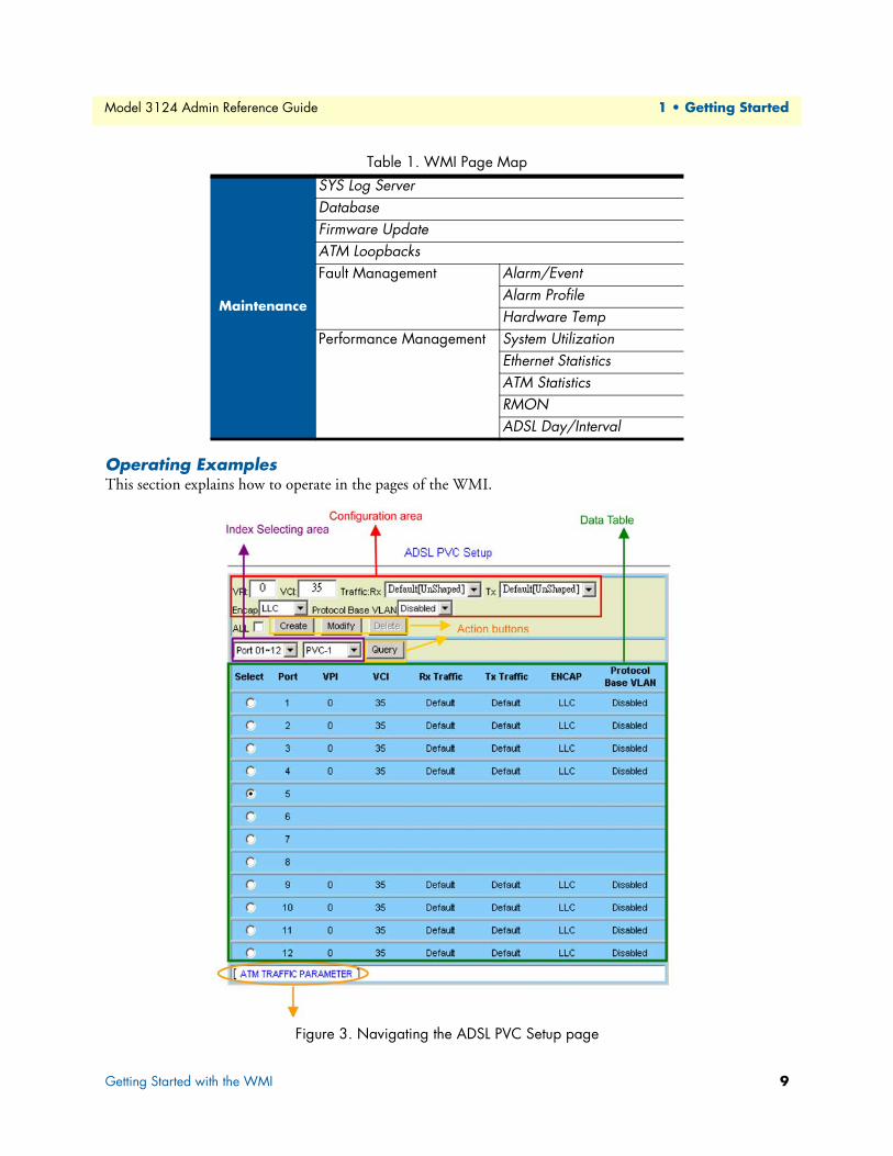
Table 1 lists the various pages of the web configuration tool.
Table 1. WMI Page Map
System
System InformationBoard IP SetupEthernet Port ServiceADSL Port ServiceCLI SetupCluster SetupSystem InventorySNTPIP RoutesUser AdministrationDuplicator
802.1x Security
System ProtocolRADIUS & Local Profile
Getting Started with the WMI 7

Model 3124 Admin Reference Guide 1 • Getting Started
Bridge
Interface Setup GIGA BridgeADSL PVCADSL BridgeADSL Port Security
VLAN Configuration Static VLANProtocol Based VLANTranslation VLANStatic Allowed IPMAC Spoofing
Access Control FilteringVLAN Priority RemarkRate LimitPriority Queue Mapping
Forwarding TP Forwarding DBForwarding Static
Relay DSL Line IdentityIGMP Protocol & Route Port
IGMP ProfileIGMP Multicast
IPOA BRAS MACInterface Setup
ADSL
Profile Service ProfileService Profile (Channel)Spectrum Profile (Main)Spectrum Profile (ADSLx)TCA Profile
Data & Inventory InventoryLoop TestCarrier DataOP Data
Line Config & Info Line ConfigurationLine Information
Traffic ATM Traffic Descriptor
SNMP
SNMP CommunitySNMP TargetSNMP Notify
Table 1. WMI Page Map
Getting Started with the WMI 8
Model 3124 Admin Reference Guide 1 • Getting Started
Operating ExamplesThis section explains how to operate in the pages of the WMI.
Figure 3. Navigating the ADSL PVC Setup page
Maintenance
SYS Log ServerDatabaseFirmware UpdateATM LoopbacksFault Management Alarm/Event
Alarm ProfileHardware Temp
Performance Management System UtilizationEthernet StatisticsATM StatisticsRMONADSL Day/Interval
Table 1. WMI Page Map
Getting Started with the WMI 9

Model 3124 Admin Reference Guide 1 • Getting Started
Click on the hyperlinks below on each configuration page will lead you to the related page(s) directly without the need to search in the menu tree.
The Index Selecting area is usually for selecting the range of interface(s) to be configured. In this case, the filters (such as link type, circuit number, PVC number, or bridge port index) will enable the operator to easily locate the target interface(s) that he would like to provision. The Configuration area is for setting the parameter value of the entries in the table. This area shows the data of selected entry in Data Table to allow operator to modify the parameter values. The Data Table is for listing the setting of each interface (bridge port). Often, there is a radio button for each port. By clicking on the radio button, you can specify which entry to be created, modi-fied, or deleted.
For the above example, first you must select the link type, circuit number range and PVC to identify the range of interfaces, and then the corresponding data of those interfaces will be listed in Data Table. Click on the radio button to select a circuit and modify the parameter values in the Configuration area. Then click on Cre-ate to create a new entry or Modify to change the setting of an existing entry. You can click on Delete to remove an entry. Click on Query to get current data whenever you want to make sure actual status of the sys-tem.
In some pages, there is the Global setup area (often with a Set button) on top of a page. After fill up the fields in this area, you have to click on Set to save the modification. Also the Configuration area is often located at the top inside the Data Table.
Figure 4. Navigating the IP Routes page
In some pages, you modify the data directly in the entry fields (remember to click on the check box or radio button to select the entry before you click on Modify button; thus the new values can really be saved into the system).
Getting Started with the WMI 10

Model 3124 Admin Reference Guide 1 • Getting Started
Figure 5. WMI Entry Fields
Getting Started with the WMI 11
Chapter 2 System Configuration
Chapter contentsSystem Information ...............................................................................................................................................13
Board IP Setup ......................................................................................................................................................14
Ethernet Port Service.............................................................................................................................................15ADSL Port Service.................................................................................................................................................16
CLI Setup..............................................................................................................................................................17
Cluster Setup.........................................................................................................................................................18System Inventory...................................................................................................................................................21
System Contact Info..............................................................................................................................................21
SNTP....................................................................................................................................................................22IP Routes...............................................................................................................................................................23
User Administration ..............................................................................................................................................24
Duplicator .............................................................................................................................................................26
12
Model 3124 Admin Reference Guide 2 • System Configuration
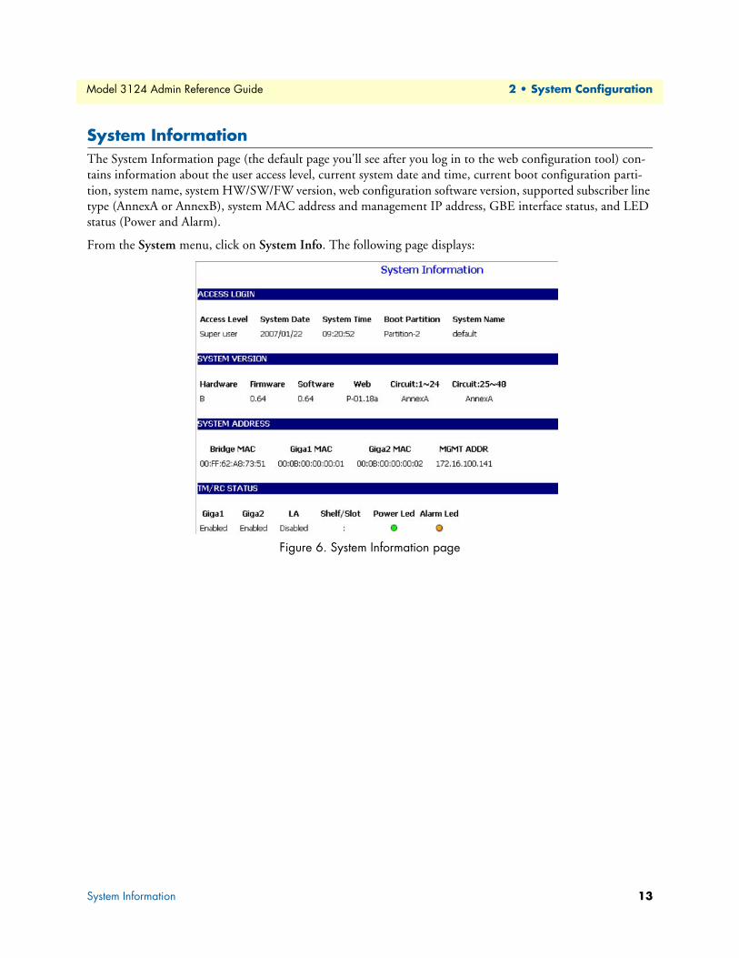
System InformationThe System Information page (the default page you'll see after you log in to the web configuration tool) con-tains information about the user access level, current system date and time, current boot configuration parti-tion, system name, system HW/SW/FW version, web configuration software version, supported subscriber line type (AnnexA or AnnexB), system MAC address and management IP address, GBE interface status, and LED status (Power and Alarm).
From the System menu, click on System Info. The following page displays:
Figure 6. System Information page
System Information 13

Model 3124 Admin Reference Guide 2 • System Configuration
Board IP SetupThis option allows you to configure the in band IP address setting, VID management setting, HTTP port set-ting, etc..
From the System menu, click on Board Setup. The following page displays:
Figure 7. Board IP Setup page
Table 2. Board IP Setup Options
Label Description
In Band Address IP Address Type in the IP address of the DSLAM for in-band management.Subnet Mask Type in the in-band subnet mask of the DSLAM
Inband VID Man-agement
No Limit VID Select this checkbox if no specific in-band management VLAN is required, and the setting in "Limit VID" parameter will be ignored.
Limit VID The VLAN ID for individual in-band management VLAN.Priority Select the VLAN priority level (0~7) of the in-band management
traffic sent out from GBE port. HTTP Port Shows current HTTP port setting. You can modify http port setting
in this field.Remote IP Shows the IP address of the management PC currently connected
to this DLSAM.System Name Type in the name of the DLSAM (must not be all digital numbers,
maximum 32 characters).Modify Click on this button to submit the modification.RESTART Click on this button to restart the system.
Board IP Setup 14
Model 3124 Admin Reference Guide 2 • System Configuration
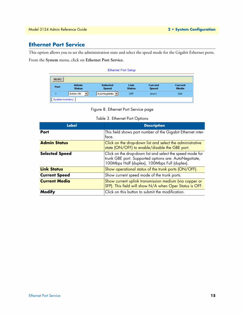
Ethernet Port ServiceThis option allows you to set the administration state and select the speed mode for the Gigabit Ethernet ports.
From the System menu, click on Ethernet Port Service.
Figure 8. Ethernet Port Service page
Table 3. Ethernet Port Options
Label Description
Port This field shows port number of the Gigabit Ethernet inter-face.
Admin Status Click on the drop-down list and select the administrative state (ON/OFF) to enable/disable the GBE port.
Selected Speed Click on the drop-down list and select the speed mode for trunk GBE port. Supported options are: AutoNegotiate, 100Mbps Half (duplex), 100Mbps Full (duplex).
Link Status Show operational status of the trunk ports (ON/OFF). Current Speed Show current speed mode of the trunk ports. Current Media Show current uplink transmission medium (via copper or
SFP). This field will show N/A when Oper Status is OFF.Modify Click on this button to submit the modification.
Ethernet Port Service 15
Model 3124 Admin Reference Guide 2 • System Configuration
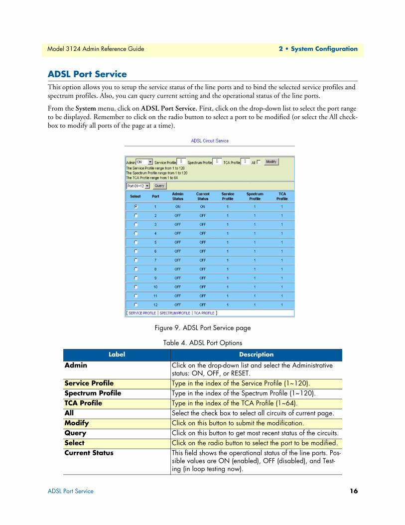
ADSL Port ServiceThis option allows you to setup the service status of the line ports and to bind the selected service profiles and spectrum profiles. Also, you can query current setting and the operational status of the line ports.
From the System menu, click on ADSL Port Service. First, click on the drop-down list to select the port range to be displayed. Remember to click on the radio button to select a port to be modified (or select the All check-box to modify all ports of the page at a time).
Figure 9. ADSL Port Service page
Table 4. ADSL Port Options
Label Description
Admin Click on the drop-down list and select the Administrative status: ON, OFF, or RESET.
Service Profile Type in the index of the Service Profile (1~120). Spectrum Profile Type in the index of the Spectrum Profile (1~120). TCA Profile Type in the index of the TCA Profile (1~64). All Select the check box to select all circuits of current page. Modify Click on this button to submit the modification.Query Click on this button to get most recent status of the circuits. Select Click on the radio button to select the port to be modified. Current Status This field shows the operational status of the line ports. Pos-
sible values are ON (enabled), OFF (disabled), and Test-ing (in loop testing now).
ADSL Port Service 16
Model 3124 Admin Reference Guide 2 • System Configuration
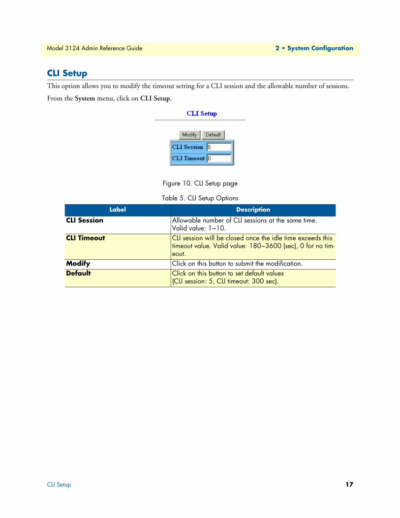
CLI SetupThis option allows you to modify the timeout setting for a CLI session and the allowable number of sessions.
From the System menu, click on CLI Setup.
Figure 10. CLI Setup page
Table 5. CLI Setup Options
Label Description
CLI Session Allowable number of CLI sessions at the same time. Valid value: 1~10.
CLI Timeout CLI session will be closed once the idle time exceeds this timeout value. Valid value: 180~3600 (sec), 0 for no tim-eout.
Modify Click on this button to submit the modification.Default Click on this button to set default values
(CLI session: 5, CLI timeout: 300 sec).
CLI Setup 17
Model 3124 Admin Reference Guide 2 • System Configuration
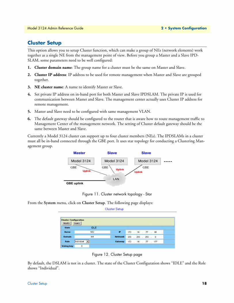
Cluster SetupThis option allows you to setup Cluster function, which can make a group of NEs (network elements) work together as a single NE from the management point of view. Before you group a Master and a Slave IPD-SLAM, some parameters need to be well configured:
1. Cluster domain name: The group name for a cluster must be the same on Master and Slave.
2. Cluster IP address: IP address to be used for remote management when Master and Slave are grouped together.
3. NE cluster name: A name to identify Master or Slave.
4. Set private IP address on in-band port for both Master and Slave IPDSLAM. The private IP is used for communication between Master and Slave. The management center actually uses Cluster IP address for remote management.
5. Master and Slave need to be configured with same management VLAN.
6. The default gateway should be configured to the router that is aware how to route management traffic to Management Center of the management network. The setting of Cluster default gateway should be the same between Master and Slave.
Currently a Model 3124 cluster can support up to four cluster members (NEs). The IPDSLAMs in a cluster must all be in-band connected through the GBE port. It uses star topology for conducting a Clustering Man-agement group.
Figure 11. Cluster network topology - Star
From the System menu, click on Cluster Setup. The following page displays:
Figure 12. Cluster Setup page
By default, the DSLAM is not in a cluster. The state of the Cluster Configuration shows “IDLE” and the Role shows “Individual”.
Cluster Setup 18

Model 3124 Admin Reference Guide 2 • System Configuration
To make the DSLAM join a cluster, select the Role as “Cluster” or “Slave only” according to your plan and then click on Modify. The state of the Cluster Configuration will show from DISCOVERING to VOTING to MASTER or SLAVE at last.
Figure 13. Cluster Configuration - Discovering State
The following figure shows the Cluster Setup page of a cluster containing two cluster members. You will see the following page if you’re connecting directly to the Master via its in-band IP address or connecting to the Cluster IP “172.16.77.88”. You can control all the IP DSLAMs in a cluster by connecting to the Cluster IP address, or by directly connecting to the Master IPDSLAM via its in-band IP address that is configured in the “Board IP Setup” on page 14.
Figure 14. Cluster Configuration - Master State
Table 6. Cluster Setup Options
Label Description
Name Type in the NE name in the cluster. Domain Type in the name of the cluster domain. Role Valid options are: Cluster (Master or Slave is decided by the
system), Slave only (role of the DLSAM is always Slave), and Individual (not in a cluster).
Voting Key Type in 0 or a positive integer as the priority to be Master. 0 means to let system decides Master and Slaves. If positive integer is typed in, the smaller the number is, the higher pri-ority for the DSLAM to be a master in a cluster. But if there’s already a Master in a cluster, a new added DSLAM cannot try to be the Master by entering a smaller voting key number; the Master cannot be changed in this way.
IP Type in the cluster IP address. Users can connect to and man-age the cluster via the cluster IP address through in-band con-nection.
Cluster Setup 19

Model 3124 Admin Reference Guide 2 • System Configuration
To control a member in the cluster:
Select a Cluster member from the drop down list above the menu tree. Then you are controlling that NE now.
Figure 15. Cluster Configuration - Slave State
Every time you modify the setting (for example, changing the Role) of any cluster member, the cluster will be reconstructed (cluster state Discovering > Voting > Master or Slave). If you modify the Role to “Individual”, Cluster State will show ‘IDLE’. The DSLAM is not in a cluster now.
If you are directly connecting to a Slave in the cluster (connecting via its in-band IP address) you cannot switch to any other member in the cluster.
Netmask Type in the cluster’s subnet mask. Gateway Type in the cluster’s gateway IP address. ID This field shows Cluster ID, which indicates cluster ordering. Modify Click on this button to submit the modification.Query Click on this button to query current status.
Table 6. Cluster Setup Options
Cluster Setup 20

Model 3124 Admin Reference Guide 2 • System Configuration
System InventoryThis option allows you to retrieve the system inventory including Description of the System, HW/FW/SW Version, Model Information, Part Number, Hardware Revision, and Serial Number.
From the System menu, click on System Inventory. Click on the Query button. The following page displays:
Figure 16. System Inventory page
System Contact InfoThis option allows you to specify the system name, system contact, and system location.
From the System menu, click on System Contact Info. The following page displays:
Figure 17. System Contact Info page
Type in the value you desire, and then click on Modify to apply the setting. Click on Query to verify if the value is changed.
System Inventory 21

Model 3124 Admin Reference Guide 2 • System Configuration
SNTPThis option allows you to setup the Simple Network Time Protocol (SNTP).
From the System menu, click on SNTP. The following page displays:
Figure 18. SNTP page
Table 7. SNTP Options
Label Description
Time Zone Sets the local time zone by selecting in the Time Zone drop-down list. Sixty-five of the world's time zones are presented (including those using standard time and sum-mer/daylight savings time).
System Date Sets system date (yyyy/mm/dd).System Time Sets system time (hh:mm:ss).Polling Interval Sets the polling interval (in seconds) that SNTP client will
sync with a designated SNTP server.SNTP Server address Sets the dedicated unicast server IP address for which the
SNTP client can synchronize its time.Modify Click on this button to submit the modification.
SNTP 22

Model 3124 Admin Reference Guide 2 • System Configuration
IP RoutesThis option allows you to configure the IP route table for the in-band management traffic.
From the System menu, click on IP Routes.
Figure 19. IP Routes page
Table 8. IP Route Setup Options
Label Description
System Gateway This field shows current system default gateway. You can modify the gateway address by typing in new value and then click on Set.If the DSLAM is a Slave in a cluster, this field shows the in-band IP address of the Master; if the DSLAM is a Master in afield shows the IP address of the Cluster gateway.
ADD Next Click on this button to add a new IP route.Destination Type in the destination IP address for the new IP route.Net Mask Type in the subnet mask for the new IP route.Gateway Type in the IP address of the gateway for the new IP route.Delete Click on the radio button to select a route and then click on
this button to delete this route from the table.
IP Routes 23
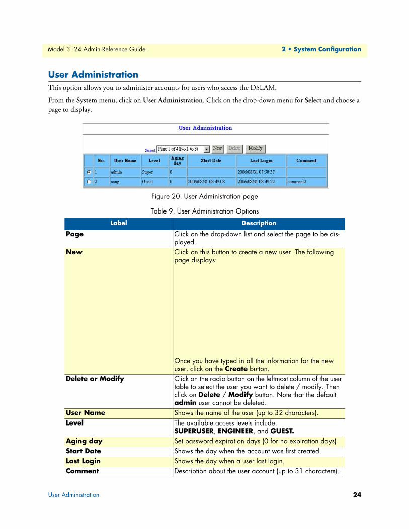
Model 3124 Admin Reference Guide 2 • System Configuration
User AdministrationThis option allows you to administer accounts for users who access the DSLAM.
From the System menu, click on User Administration. Click on the drop-down menu for Select and choose a page to display.
Figure 20. User Administration page
Table 9. User Administration Options
Label Description
Page Click on the drop-down list and select the page to be dis-played.
New Click on this button to create a new user. The following page displays:
Once you have typed in all the information for the new user, click on the Create button.
Delete or Modify Click on the radio button on the leftmost column of the user table to select the user you want to delete / modify. Then click on Delete / Modify button. Note that the default admin user cannot be deleted.
User Name Shows the name of the user (up to 32 characters).Level The available access levels include:
SUPERUSER, ENGINEER, and GUEST.Aging day Set password expiration days (0 for no expiration days)Start Date Shows the day when the account was first created.Last Login Shows the day when a user last login.Comment Description about the user account (up to 31 characters).
User Administration 24

Model 3124 Admin Reference Guide 2 • System Configuration
If a new account is added: (for example, Test1 is added)
Figure 21. Add New User Account
When user Test1 intends to login for the first time, he will be asked to change his password (see the figure below) and then login with the new password.
Figure 22. Change User Password
User Administration 25

Model 3124 Admin Reference Guide 2 • System Configuration
DuplicatorThis option allows you to duplicate all/partial the configurations of one selected line port (as a template) to other ports (as many as you want).
From the System menu, click on Duplicator.
Figure 23. System Duplicator page
Select the content of configurations (ADSL line configuration, ADSL profiles, or…) you want to duplicate first. Then specify the port number as the template (the source port to be copied), and sAt last click on Paste to apply.
Duplicator 26

Chapter 3 Bridge Configuration
Chapter contentsInterface Setup ......................................................................................................................................................29
GIGA Bridge ..................................................................................................................................................29
ADSL PVC .....................................................................................................................................................30ADSL Bridge ..................................................................................................................................................31
ADSL Port Security ........................................................................................................................................33
802.1x Security Setup............................................................................................................................................34System Protocol ..............................................................................................................................................34
Main Setting .............................................................................................................................................34
Timer Setting ............................................................................................................................................36RADIUS & Local Profile ................................................................................................................................37
VLAN Configuration ............................................................................................................................................38
Static VLAN ...................................................................................................................................................38CONFIG VLAN ......................................................................................................................................38
SHOW VLAN ..........................................................................................................................................38
Protocol Base VLAN .......................................................................................................................................39Translation VLAN ..........................................................................................................................................39
1:1 VLAN (including 1:1 User Mode and C_VLAN Stacking Replaced Mode) ........................................40
N:1 VLAN (N:1 User Mode) ....................................................................................................................41Static Allowed IP ............................................................................................................................................41
MAC Spoofing ...............................................................................................................................................42
Access Control.......................................................................................................................................................43Filtering ..........................................................................................................................................................43
Protocol Filtering ......................................................................................................................................43
Source MAC Filtering ...............................................................................................................................44IP Address Filtering ...................................................................................................................................45
Layer 4 Destination Port Filtering .............................................................................................................45
Destination IP Filtering ............................................................................................................................46Destination MAC Filtering .......................................................................................................................47
Ether Type Filtering ..................................................................................................................................48
VLAN Priority Remark ...................................................................................................................................49TOS ..........................................................................................................................................................49
IP Source ...................................................................................................................................................50
IP Destination ...........................................................................................................................................51MAC Source .............................................................................................................................................52
MAC Destination .....................................................................................................................................53
VLAN ID ..................................................................................................................................................54VLAN Priority Regeneration .....................................................................................................................55
Differentiated Services ...............................................................................................................................56
Protocol ....................................................................................................................................................57
27
Model 3124 Admin Reference Guide 3 • Bridge Configuration
Ether Type ................................................................................................................................................58
Rate Limit .......................................................................................................................................................59
Rate Limit Broadcast .................................................................................................................................59Rate Limit Flooding ..................................................................................................................................60
Rate Limit Policer .....................................................................................................................................60
Rate Limit Policer Binding Table ..............................................................................................................62Three Color Marking Policer ....................................................................................................................62
Priority Queue Mapping .................................................................................................................................64
Forwarding............................................................................................................................................................65TP Forwarding DB .........................................................................................................................................65
Forwarding Static ............................................................................................................................................66
Relay .....................................................................................................................................................................67
DSL Line Identify ...........................................................................................................................................67IGMP....................................................................................................................................................................69
IGMP Protocol & Router Port .......................................................................................................................69
IGMP Profile ..................................................................................................................................................71IGMP Multicast .............................................................................................................................................73
List by Number .........................................................................................................................................73
List by VID & Group IP ...........................................................................................................................74IGMP Source ............................................................................................................................................74
IPOA.....................................................................................................................................................................75
BRAS MAC ....................................................................................................................................................75Interface Setup ................................................................................................................................................76
28

Model 3124 Admin Reference Guide 3 • Bridge Configuration
Interface SetupThis option allows you to setup the trunk and line interfaces.
GIGA BridgeThis option allows you to setup the GBE (trunk) bridge interface. From the Bridge menu, click on Interface Setup, then GIGA Bridge. The following page displays:
Figure 24. GIGA Bridge page
Table 10. GIGA Bridge Options
Label Description
Mode Click on the drop-down list and specify the trunk port to be an Uplink or User (especially for system stacking).
VID Type in the VLAN ID (1 ~ 4094).Max MAC Type in the maximum number of MAC addresses that can be learned by
the bridge port (for GBE interface: 1 ~ 4096, for DSL interface: 1 ~ 128).VLAN VLAN setting for the egress traffic. Includes three drop-down lists:
• PRI-0 ~ 7: Set the VLAN priority Level.
• UnTagged/Tagged: Select to untag / tag the outgoing (upstream direc-tion for trunk bridge ports) packets. If UnTagged is selected, a double-tagged packet will leave single-tagged (the outer most VLAN tag is removed) and a single-tagged packet will leave untagged.
• no Stack/Stack: Disable/Enable N:1 VLAN stacking (our system adds the default VLAN tag to all the incoming frames through this port).
Note: When an untagged frame enters the Model 3124, it is assigned the default PVID of the ingress (incoming) bridge port and become a single-tagged frame no matter VLAN stacking is enabled or not.
Ingress Set Ingress ON: check if the VID of the incoming frame is in the member set. If not in the member set, block the frame.Set Ingress OFF: Ingress filter disabled.
AccFrm Click on the drop-down list and select to accept ALL Frame, only VLAN tagged frame, or only Untagged frame.
Isol ON/OFF to enable/disable isolation. When port isolation is enabled, packets received from a trunk port (when both the trunk interfaces are con-figured as up-link) cannot be forwarded to the other trunk port even for broadcasting.
Interface Setup 29

Model 3124 Admin Reference Guide 3 • Bridge Configuration
ADSL PVCThis option allows you to setup the ADSL PVC. From the Bridge menu, click on Interface Setup and then ADSL PVC. Click on the drop-down lists to select port range and PVC first. Then the data of these PVCs (bridge ports) you selected will be displayed. Click on the radio button to select the PVC you want to create, modify, or delete.
Figure 25. ADSL PVC page
Modify To modify the configuration of a GIGA port: 1. Click on the radio button to select trunk port 1 2. Change the parameter values 3. Click on Modify button to apply new values
Query Click on this button to query current status.
Table 11. ADSL PVC Options
Label Description
VPI Type in the VPI value: 0 ~ 255. Default value is 0. VCI Type in the VCI value: 21, 32 ~ 65535. Default value is 35. Traffic Click on the drop-down list and select a traffic type for transmit and
receive direction respectively. Available options are created in the ATM Traffic Descriptor page.
Encap Select AAL5 Encapsulation Type: VCMUX, LLC, or AUTO (for PVC#1 ~ PVC#4 only).a
Protocol Based VLAN
Select in the drop-down list to enable or disable protocol based VLAN function. When protocol based VLAN is enabled, the bridge port will work according to the protocol based VLAN table.
Table 10. GIGA Bridge Options
Interface Setup 30

Model 3124 Admin Reference Guide 3 • Bridge Configuration
ADSL BridgeThis option allows you to setup the ADSL bridge interface. From the Bridge menu, click on Interface Setup, then ADSL Bridge. The following page displays. Click on the drop-down lists to select port range and PVC first. Then the data of these PVCs (bridge ports) you selected will be displayed. Click on the radio button to select the bridge port you want to modify.
Figure 26. ADSL Bridge page
All Select the check box to copy specified circuit to all remainder circuits in current page.
Create Click on the radio button to select a PVC (bridge port) that has not been created. Set the parameter values and then click on Create to create a PVC.
Modify Click on the radio button to select the PVC (bridge port) you want to mod-ify. Change the parameter values and then click on Modify.
Delete Click on the radio button to select the PVC (bridge port) you want to delete. Then click on Delete to remove the PVC.
Query Click on this button to get the most recent data.
a.The Model 3124 supports auto-detection of the ATM AAL5 encapsulation method, LLC or C-Mux. Meanwhile, the Model 3124 is also able to automatically sense the following protocol encapsulations: PPPoE over ATM (per RFC 2684), IPoE over ATM bridge mode, and PPP over ATM. IPoA works on individual PVC. However, there are limitations on auto-detection of encapsulations:
1. LLC/VC-Mux automatically detection is only applicable to PVC#1 ~ PVC#4 of each ADSL port. PVC#5 ~ PVC#8 must be assigned the ATM AAL5 encapsulation method manually.
2. PPPoA works only for PVC#1 ~ PVC#4 and the LLC/VC-Mux automatically detection must be enabled. Refer to section IPoA configuration.
Table 11. ADSL PVC Options
Interface Setup 31
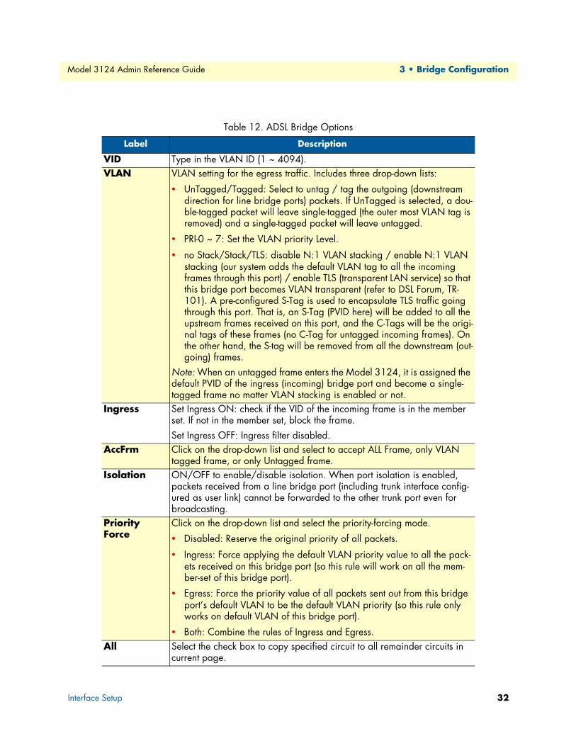
Model 3124 Admin Reference Guide 3 • Bridge Configuration
Table 12. ADSL Bridge Options
Label Description
VID Type in the VLAN ID (1 ~ 4094).VLAN VLAN setting for the egress traffic. Includes three drop-down lists:
• UnTagged/Tagged: Select to untag / tag the outgoing (downstream direction for line bridge ports) packets. If UnTagged is selected, a dou-ble-tagged packet will leave single-tagged (the outer most VLAN tag is removed) and a single-tagged packet will leave untagged.
• PRI-0 ~ 7: Set the VLAN priority Level.
• no Stack/Stack/TLS: disable N:1 VLAN stacking / enable N:1 VLAN stacking (our system adds the default VLAN tag to all the incoming frames through this port) / enable TLS (transparent LAN service) so that this bridge port becomes VLAN transparent (refer to DSL Forum, TR-101). A pre-configured S-Tag is used to encapsulate TLS traffic going through this port. That is, an S-Tag (PVID here) will be added to all the upstream frames received on this port, and the C-Tags will be the origi-nal tags of these frames (no C-Tag for untagged incoming frames). On the other hand, the S-tag will be removed from all the downstream (out-going) frames.
Note: When an untagged frame enters the Model 3124, it is assigned the default PVID of the ingress (incoming) bridge port and become a single-tagged frame no matter VLAN stacking is enabled or not.
Ingress Set Ingress ON: check if the VID of the incoming frame is in the member set. If not in the member set, block the frame.Set Ingress OFF: Ingress filter disabled.
AccFrm Click on the drop-down list and select to accept ALL Frame, only VLAN tagged frame, or only Untagged frame.
Isolation ON/OFF to enable/disable isolation. When port isolation is enabled, packets received from a line bridge port (including trunk interface config-ured as user link) cannot be forwarded to the other trunk port even for broadcasting.
Priority Force
Click on the drop-down list and select the priority-forcing mode.
• Disabled: Reserve the original priority of all packets.
• Ingress: Force applying the default VLAN priority value to all the pack-ets received on this bridge port (so this rule will work on all the mem-ber-set of this bridge port).
• Egress: Force the priority value of all packets sent out from this bridge port’s default VLAN to be the default VLAN priority (so this rule only works on default VLAN of this bridge port).
• Both: Combine the rules of Ingress and Egress. All Select the check box to copy specified circuit to all remainder circuits in
current page.
Interface Setup 32

Model 3124 Admin Reference Guide 3 • Bridge Configuration
ADSL Port Security This option allows you to setup the ADSL port security. From the Bridge menu, click on Interface Setup, then ADSL Port Security. The following page displays. Click on the drop-down lists to select port range and PVC first. Then the data of these PVCs (bridge ports) you selected will be displayed. Click on the radio button to select the bridge port you want to modify.
Figure 27. ADSL Port Security page
Modify Click on the radio button to select the bridge port you want to modify. Change the parameter values and then click on Modify.
Query Click on this button to get the most recent data.
Table 13. ADSL Bridge Options
Label Description
Max MAC Type in the maximum number of MAC addresses that can be learned by the ADSL bridge port (1 ~ 128).
MAC Learning Select to enable/disable MAC learning ability. Sometimes you can dis-able MAC learning on specified bridge port. This function is for 1:1 VLAN translation scenario.
IP Allowed Select to enable/disable IP Allowed function. When you enable IP Allowed function on a bridge port, this bridge port will work according to the Static Allowed IP table (refer to section 4.3.4). So you need to define the source IP addresses that bind to this bridge port. Then the IP packets that contain these source IP addresses can pass through this bridge port;otherwise the packets will be blocked.
All Select the check box to copy specified circuit to all remainder circuits in current page.
Modify Click on the radio button to select the bridge port you want to modify. Change the parameter values and then click on Modify.
Query Click on this button to get the most recent data.
Table 12. ADSL Bridge Options
Interface Setup 33

Model 3124 Admin Reference Guide 3 • Bridge Configuration
802.1x Security Setup
System ProtocolThis option allows you to enable/disable 802.1x authentication function of the system, and setup the 802.1x authentication mechanism for each line bridge port. Before you setup 802.1x for a line bridge port, you must create the ADSL PVC (bridge port) first.
Figure 28. 802.1x Diagram
From the 802.1x Security menu, click on System Protocol.
Main Setting
Figure 29. 802.1x System Protcol - Main Setting page
Table 14. 8021.x System Protocol - Main Setting Options
Label Description
System Authentication section
Click on the drop-down list to enable or disable the 802.1x authentication function of the system. If you select “Disabled”, any setting in the Port Authentication section will not take effect.
802.1x Security Setup 34
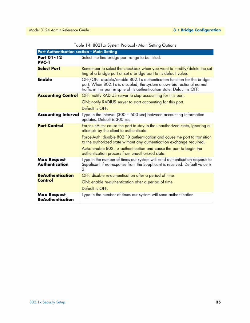
Model 3124 Admin Reference Guide 3 • Bridge Configuration
Port Authentication section - Main SettingPort 01~12 PVC-1
Select the line bridge port range to be listed.
Select Port Remember to select the checkbox when you want to modify/delete the set-ting of a bridge port or set a bridge port to its default value.
Enable OFF/ON: disable/enable 802.1x authentication function for the bridge port. When 802.1x is disabled, the system allows bidirectional normal traffic in this port in spite of its authentication state. Default is OFF.
Accounting Control OFF: notify RADIUS server to stop accounting for this port. ON: notify RADIUS server to start accounting for this port. Default is OFF.
Accounting Interval Type in the interval (300 ~ 600 sec) between accounting information updates. Default is 300 sec.
Port Control Force-unAuth: cause the port to stay in the unauthorized state, ignoring all attempts by the client to authenticate. Force-Auth: disable 802.1X authentication and cause the port to transition to the authorized state without any authentication exchange required. Auto: enable 802.1x authentication and cause the port to begin the authentication process from unauthorized state.
Max Request Authentication
Type in the number of times our system will send authentication requests to Supplicant if no response from the Supplicant is received. Default value is 2.
ReAuthentication Control
OFF: disable re-authentication after a period of time ON: enable re-authentication after a period of time Default is OFF.
Max Request ReAuthentication
Type in the number of times our system will send authentication
Table 14. 8021.x System Protocol - Main Setting Options
802.1x Security Setup 35
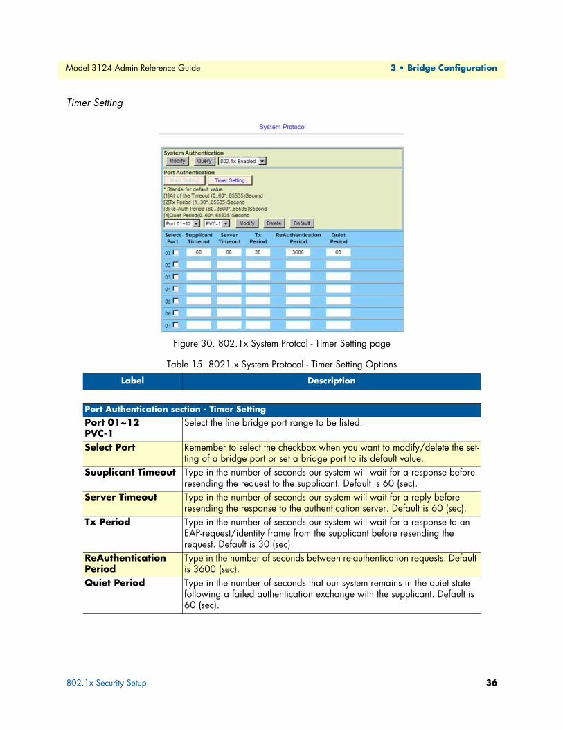
Model 3124 Admin Reference Guide 3 • Bridge Configuration
Timer Setting
Figure 30. 802.1x System Protcol - Timer Setting page
Table 15. 8021.x System Protocol - Timer Setting Options
Label Description
Port Authentication section - Timer SettingPort 01~12 PVC-1
Select the line bridge port range to be listed.
Select Port Remember to select the checkbox when you want to modify/delete the set-ting of a bridge port or set a bridge port to its default value.
Suuplicant Timeout Type in the number of seconds our system will wait for a response before resending the request to the supplicant. Default is 60 (sec).
Server Timeout Type in the number of seconds our system will wait for a reply before resending the response to the authentication server. Default is 60 (sec).
Tx Period Type in the number of seconds our system will wait for a response to an EAP-request/identity frame from the supplicant before resending the request. Default is 30 (sec).
ReAuthentication Period
Type in the number of seconds between re-authentication requests. Default is 3600 (sec).
Quiet Period Type in the number of seconds that our system remains in the quiet state following a failed authentication exchange with the supplicant. Default is 60 (sec).
802.1x Security Setup 36

Model 3124 Admin Reference Guide 3 • Bridge Configuration
RADIUS & Local ProfileThe Model 3124 system supports RADIUS client function for authenticating line ports with local authentica-tion database or remote RADIUS server. From the 802.1x Security menu, click on RADIUS & Local Pro-file. The following page displays:
Figure 31. RADIUS & Local Setup page
Table 16. RADIUS & Local Setup Options
Label Description
Authentication Method section
In this section, operators set up four AAA methods for the system to use, and the priority order is Method1 > Method2 > Method3 > Method4. If a user cannot be authenticated when the system uses Method1, the system will then try to use Method2, and so on. Click on the AAA method drop-down list and select a RADIUS server index or the local profile, which has been already configured in the RADIUS Server section or Local Profile section. Lastly, click on the Modify button.
RADIUS Server section
Select (Index#n) Remember to select the checkbox when you want to modify or delete a RADIUS server entry.
RADIUS Server IP Type in the IP address of the remote RADIUS server. Authentication Port Type in the port number for RADIUS Authentication in the Layer-4 header.
Default is 1812. Accounting Port Type in the port number for RADIUS Accounting in the Layer-4 header.
Default is 1813. Max Fail Type in the maximum allowable times of continuously failed authentication
attempts. VLAN ID Type in the VID of the VLAN which the RADIUS server belongs to. Secret ID Type in the authentication key in text format.
Local Profile section
Select Click on the drop-down list and select the profile range to be listed. There are total 8 pages and 8 profiles per page (up to 64 local profiles can be set in our system).
Username Type in the username for authentication. Password Type in the password for authentication.
802.1x Security Setup 37

Model 3124 Admin Reference Guide 3 • Bridge Configuration
VLAN Configuration
Static VLANThis option allows you to configure the static VLAN. From the Bridge menu, click on VLAN Configuration and then Static VLAN. The Static VLAN page displays. Click on the radio button to select CONFIG VLAN or SHOW VLAN.
CONFIG VLANClick on the drop-down list to select ADSL or GIGA port. Then, select a port and PVC if ADSL is selected. Once you have selected the bridge interface, its current static VLAN setting displays. To add a new VLAN member, type in VID for the New VID field and then select Tagged/UnTagged for VLAN Tag, ON/OFF for Isolation, and VLAN Priority Level (specify a number or reserve the original value) for Priority. Lastly, click on Create==>. To modify or delete a VLAN, select the checkboxes of the entries you want to modify or delete and then click on Modify or Delete.
Figure 32. Static VLAN - CONFIG VLAN
SHOW VLANIn SHOW VLAN, type in the VID and then click on Query. All the bridge ports belonging to the VLAN and the configuration data of these ports will display in the table.
Figure 33. Static VLAN - SHOW VLAN
VLAN Configuration 38
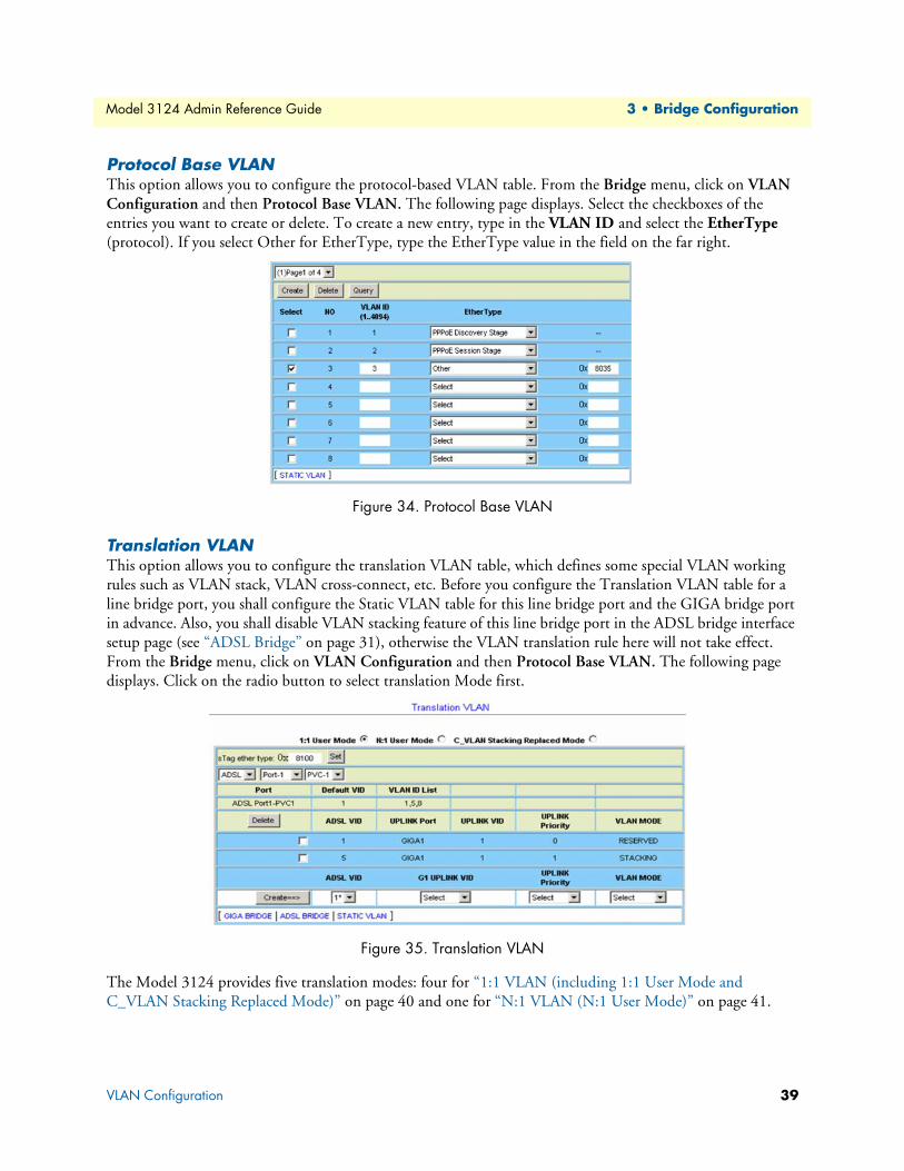
Model 3124 Admin Reference Guide 3 • Bridge Configuration
Protocol Base VLANThis option allows you to configure the protocol-based VLAN table. From the Bridge menu, click on VLAN Configuration and then Protocol Base VLAN. The following page displays. Select the checkboxes of the entries you want to create or delete. To create a new entry, type in the VLAN ID and select the EtherType (protocol). If you select Other for EtherType, type the EtherType value in the field on the far right.
Figure 34. Protocol Base VLAN
Translation VLANThis option allows you to configure the translation VLAN table, which defines some special VLAN working rules such as VLAN stack, VLAN cross-connect, etc. Before you configure the Translation VLAN table for a line bridge port, you shall configure the Static VLAN table for this line bridge port and the GIGA bridge port in advance. Also, you shall disable VLAN stacking feature of this line bridge port in the ADSL bridge interface setup page (see “ADSL Bridge” on page 31), otherwise the VLAN translation rule here will not take effect. From the Bridge menu, click on VLAN Configuration and then Protocol Base VLAN. The following page displays. Click on the radio button to select translation Mode first.
Figure 35. Translation VLAN
The Model 3124 provides five translation modes: four for “1:1 VLAN (including 1:1 User Mode and C_VLAN Stacking Replaced Mode)” on page 40 and one for “N:1 VLAN (N:1 User Mode)” on page 41.
VLAN Configuration 39
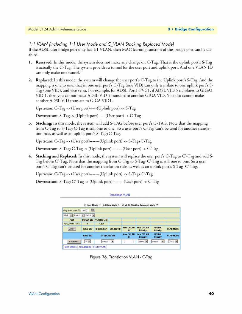
Model 3124 Admin Reference Guide 3 • Bridge Configuration
1:1 VLAN (including 1:1 User Mode and C_VLAN Stacking Replaced Mode)If the ADSL user bridge port only has 1:1 VLAN, then MAC learning function of this bridge port can be dis-abled.
1. Reserved: In this mode, the system does not make any change on C-Tag. That is the uplink port’s S-Tag is actually the C-Tag. The system provides a tunnel for the user port and uplink port. And one VLAN ID can only make one tunnel.
2. Replaced: In this mode, the system will change the user port’s C-Tag to the Uplink port’s S-Tag. And the mapping is one to one, that is, one user port’s C-Tag (one VID) can only translate to one uplink port’s S-Tag (one VID), and vice versa. For example, for ADSL Port1-PVC1, if ADSL VID 5 translates to GIGA1 VID 1, then you cannot make ADSL VID 5 translate to another GIGA VID. You also cannot make another ADSL VID translate to GIGA VID1.
Upstream: C-Tag -> (User port)-----(Uplink port) -> S-Tag
Downstream: S-Tag -> (Uplink port)-----(User port) -> C-Tag
3. Stacking: In this mode, the system will add S-TAG before user port’s C-TAG. Note that the mapping from C-Tag to S-Tag+C-Tag is still one to one. So a user port’s C-Tag can’t be used for another transla-tion rule, as well as an uplink port’s S-Tag+C-Tag.
Upstream: C-Tag -> (User port)-------(Uplink port) -> S-Tag+C-Tag
Downstream: S-Tag+C-Tag -> (Uplink port)--------(User port) -> C-Tag
4. Stacking and Replaced: In this mode, the system will replace the user port’s C-Tag to C’-Tag and add S-Tag before C’-Tag. Note that the mapping from C-Tag to S-Tag+C’-Tag is still one to one. So a user port’s C-Tag can’t be used for another translation rule, as well as an uplink port’s S-Tag+C’-Tag.
Upstream: C-Tag -> (User port)-------(Uplink port) -> S-Tag+C’-Tag
Downstream: S-Tag+C’-Tag -> (Uplink port)--------(User port) -> C-Tag
Figure 36. Translation VLAN - C-Tag
VLAN Configuration 40

Model 3124 Admin Reference Guide 3 • Bridge Configuration
N:1 VLAN (N:1 User Mode)N:1 can also be called shared VLAN, so in this mode MAC learning function of the bridge ports must not be disabled.
1. Replaced N:1: In this mode, the system will change the user port’s C-Tag to the Uplink port’s S-Tag. And the mapping is N to 1, so a user port’s C-Tag can’t be used for another VLAN translation rule. But an uplink port’s S-Tag can be used for another N:1 VLAN translation rule. So in this mode several bridge ports can have the same VLAN cross-connect rule.
Figure 37. Translation VLAN - Replaced N:1
Static Allowed IPThis option allows you to configure the Static Allowed IP table. From the Bridge menu, click on VLAN Con-figuration and then Static Allowed IP. The following page displays. To make bridge port work according to this Static Allowed IP table, the IP allowed function must be enabled (see “ADSL Port Security” on page 33).
Figure 38. Static Allowed IP table
Click on the drop-down lists to select ADSL port and PVC number, then type in VID and allowed source IP that can pass through the VLAN.
VLAN Configuration 41

Model 3124 Admin Reference Guide 3 • Bridge Configuration
MAC SpoofingThis option allows you to enable/disable anti-MAC Spoofing function and MAC-Spoofing detection log func-tion. From the Bridge menu, click on VLAN Configuration and then MAC Spoofing. The following page displays.
Figure 39. MAC Spoofing page
Table 17. MAC Spoofing Options
Label Description
Spoofing Click on the drop-down list to select: OFF: The system is able to provide service to users with duplicate MAC addresses. ON: The system is able to deny service to users with duplicate MAC addresses.
Set Click on the drop-down list to select: OFF: No log of MAC spoofing data when detected. ON: The system provides log when duplicated MAC addresses detected.
Log Click on this button to apply the setting. Query Click on this button to get the MAC spoofing information (the Log function must be
enabled).
VLAN Configuration 42
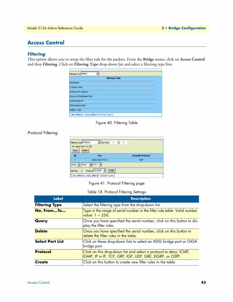
Model 3124 Admin Reference Guide 3 • Bridge Configuration
Access Control
FilteringThis option allows you to setup the filter rule for the packets. From the Bridge menu, click on Access Control and then Filtering. Click on Filtering Type drop-down list and select a filtering type first.
Figure 40. Filtering Table
Protocol Filtering
Figure 41. Protocol Filtering page
Table 18. Protocol Filtering Settings
Label Description
Filtering Type Select the filtering type from the drop-down list.No. From...To... Type in the range of serial number in the filter rule table. Valid number
value: 1 ~ 256.Query Once you have specified the serial number, click on this button to dis-
play the filter rules.Delete Once you have specified the serial number, click on this button to
delete the filter rules in the table.Select Port List Click on these drop-down lists to select an ADSL bridge port or GIGA
bridge port. Protocol Click on this drop-down list and select a protocol to deny: ICMP,
IGMP, IP in IP, TCP, GRP, IGP, UDP, GRE, EIGRP, or OSPF.Create Click on this button to create new filter rules in the table.
Access Control 43

Model 3124 Admin Reference Guide 3 • Bridge Configuration
Source MAC Filtering
Figure 42. Source MAC Filtering page
Table 19. Source MAC Filtering Settings
Label Description
Filtering Type Select the filtering type from the drop-down list.No. From...To... Type in the range of serial number in the filter rule table. Valid number
value: 1 ~ 256.Query Once you have specified the serial number, click on this button to dis-
play the filter rules.Delete Once you have specified the serial number, click on this button to
delete the filter rules in the table.Select Port List Click on these drop-down lists to select an ADSL bridge port or GIGA
bridge port. Source MAC Address Type in the MAC Address of the source.Create Click on this button to create new filter rules in the table.
Access Control 44

Model 3124 Admin Reference Guide 3 • Bridge Configuration
IP Address Filtering
Figure 43. Source IP Address Filtering page
Layer 4 Destination Port Filtering
Figure 44. Layer 4 Destination Port Filtering page
Table 20. Source IP Address Filtering Settings
Label Description
Filtering Type Select the filtering type from the drop-down list.No. From...To... Type in the range of serial number in the filter rule table. Valid number
value: 1 ~ 256.Query Once you have specified the serial number, click on this button to dis-
play the filter rules.Delete Once you have specified the serial number, click on this button to
delete the filter rules in the table.Select Port List Click on these drop-down lists to select an ADSL bridge port or GIGA
bridge port. Source IP Address Type in the IP Address of the source.MASK Type in the subnet mask.Create Click on this button to create new filter rules in the table.
Access Control 45
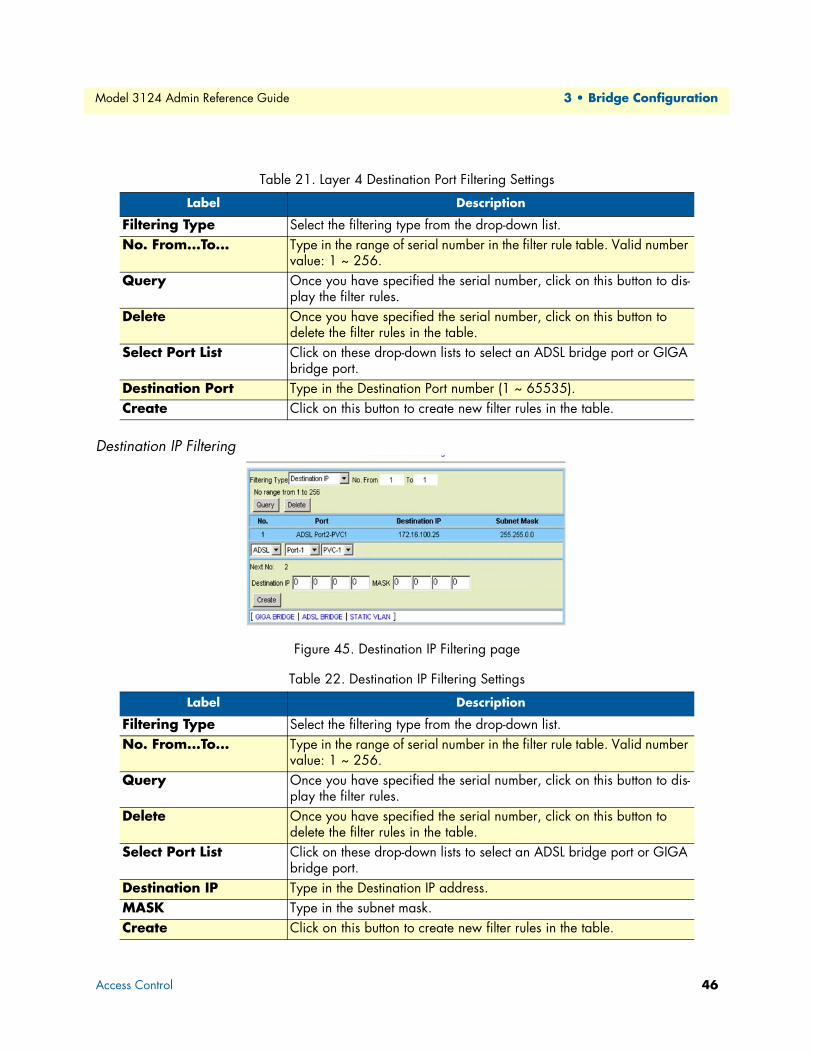
Model 3124 Admin Reference Guide 3 • Bridge Configuration
Destination IP Filtering
Figure 45. Destination IP Filtering page
Table 21. Layer 4 Destination Port Filtering Settings
Label Description
Filtering Type Select the filtering type from the drop-down list.No. From...To... Type in the range of serial number in the filter rule table. Valid number
value: 1 ~ 256.Query Once you have specified the serial number, click on this button to dis-
play the filter rules.Delete Once you have specified the serial number, click on this button to
delete the filter rules in the table.Select Port List Click on these drop-down lists to select an ADSL bridge port or GIGA
bridge port. Destination Port Type in the Destination Port number (1 ~ 65535). Create Click on this button to create new filter rules in the table.
Table 22. Destination IP Filtering Settings
Label Description
Filtering Type Select the filtering type from the drop-down list.No. From...To... Type in the range of serial number in the filter rule table. Valid number
value: 1 ~ 256.Query Once you have specified the serial number, click on this button to dis-
play the filter rules.Delete Once you have specified the serial number, click on this button to
delete the filter rules in the table.Select Port List Click on these drop-down lists to select an ADSL bridge port or GIGA
bridge port. Destination IP Type in the Destination IP address. MASK Type in the subnet mask.Create Click on this button to create new filter rules in the table.
Access Control 46

Model 3124 Admin Reference Guide 3 • Bridge Configuration
Destination MAC Filtering
Figure 46. Destination MAC Filtering page
Table 23. Destination MAC Filtering Settings
Label Description
Filtering Type Select the filtering type from the drop-down list.No. From...To... Type in the range of serial number in the filter rule table. Valid number
value: 1 ~ 256.Query Once you have specified the serial number, click on this button to dis-
play the filter rules.Delete Once you have specified the serial number, click on this button to
delete the filter rules in the table.Select Port List Click on these drop-down lists to select an ADSL bridge port or GIGA
bridge port. Destination MAC Type in the Destination MAC address. Create Click on this button to create new filter rules in the table.
Access Control 47

Model 3124 Admin Reference Guide 3 • Bridge Configuration
Ether Type Filtering
Figure 47. Ether Type Filtering pages
Table 24. Ether Type Filtering Settings
Label Description
Filtering Type Select the filtering type from the drop-down list.No. From...To... Type in the range of serial number in the filter rule table. Valid number
value: 1 ~ 256.Query Once you have specified the serial number, click on this button to dis-
play the filter rules.Delete Once you have specified the serial number, click on this button to
delete the filter rules in the table.Select Port List Click on these drop-down lists to select an ADSL bridge port or GIGA
bridge port. Incoming Ether Type Type in the EtherType value (hexadecimal). Create Click on this button to create new filter rules in the table.
Access Control 48

Model 3124 Admin Reference Guide 3 • Bridge Configuration
VLAN Priority RemarkThis option allows you to configure the VLAN priority. From the Bridge menu, click on Access Control and then VLAN Priority Remark. The following page displays:
Figure 48. VLAN Priority Remark page
Click on the VPRI Remark drop-down list and select a type of VLAN Priority Remark, including TOS, IP Source, IP Destination, MAC Source, MAC Destination, VLAN ID, VLAN Priority Regeneration, Differenti-ated Services, Protocol, and Ether Type.
TOS
Figure 49. VLAN TOS Priority Remark page
Table 25. VLAN Priority Remark Settings - TOS
Label Description
VPRI Remark Select the priority remark type from the drop-down list.No. From...To... Type in the range of entry number in the table. Valid number value: 1 ~
256.Query To query entries, type in the entry number range and then click on this but-
ton to retrieve. Delete To delete entries, type in the entry number range and then click on this but-
ton to delete. Select Port List Click on these drop-down lists to select an ADSL bridge port or GIGA
bridge port.
Access Control 49

Model 3124 Admin Reference Guide 3 • Bridge Configuration
IP Source
Figure 50. VLAN IP Source Priority Remark page
TOS In order to provide basic support for classes of service to the Internet Proto-col. The IP protocol header contains what is known as the ToS (Type of Service) bits. Click on the drop-down list and select incoming TOS (value range 0 ~ 7), then you can create the mapping between TOS and VLAN priority.
Priority (Out) Click on the drop-down list and select the outgoing VLAN priority (0 ~ 7). Create Click on this button to create new filter rules in the table.
Table 26. VLAN Priority Remark Settings - IP Source
Label Description
VPRI Remark Select the priority remark type from the drop-down list.No. From...To... Type in the range of entry number in the table. Valid number value: 1 ~
256.Query To query entries, type in the entry number range and then click on this but-
ton to retrieve. Delete To delete entries, type in the entry number range and then click on this but-
ton to delete. Select Port List Click on these drop-down lists to select an ADSL bridge port or GIGA
bridge port. Source IP Enter the IP address of the incoming source.MASK Type in the subnet mask.Priority (Out) Click on the drop-down list and select the outgoing VLAN priority (0 ~ 7). Create Click on this button to create new filter rules in the table.
Table 25. VLAN Priority Remark Settings - TOS
Access Control 50

Model 3124 Admin Reference Guide 3 • Bridge Configuration
IP Destination
Figure 51. VLAN IP Destination Priority Remark page
Table 27. VLAN Priority Remark Settings - IP Destination
Label Description
VPRI Remark Select the priority remark type from the drop-down list.No. From...To... Type in the range of entry number in the table. Valid number value: 1 ~
256.Query To query entries, type in the entry number range and then click on this but-
ton to retrieve. Delete To delete entries, type in the entry number range and then click on this but-
ton to delete. Select Port List Click on these drop-down lists to select an ADSL bridge port or GIGA
bridge port. Source IP Enter the IP address of the incoming source.MASK Type in the subnet mask.Priority (Out) Click on the drop-down list and select the outgoing VLAN priority (0 ~ 7). Create Click on this button to create new filter rules in the table.
Access Control 51
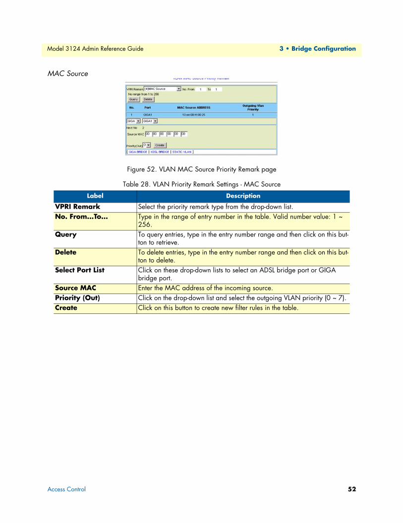
Model 3124 Admin Reference Guide 3 • Bridge Configuration
MAC Source
Figure 52. VLAN MAC Source Priority Remark page
Table 28. VLAN Priority Remark Settings - MAC Source
Label Description
VPRI Remark Select the priority remark type from the drop-down list.No. From...To... Type in the range of entry number in the table. Valid number value: 1 ~
256.Query To query entries, type in the entry number range and then click on this but-
ton to retrieve. Delete To delete entries, type in the entry number range and then click on this but-
ton to delete. Select Port List Click on these drop-down lists to select an ADSL bridge port or GIGA
bridge port. Source MAC Enter the MAC address of the incoming source.Priority (Out) Click on the drop-down list and select the outgoing VLAN priority (0 ~ 7). Create Click on this button to create new filter rules in the table.
Access Control 52
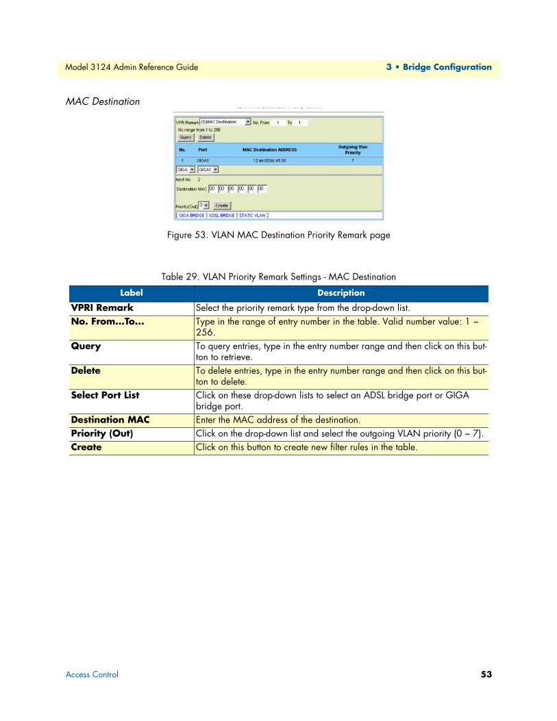
Model 3124 Admin Reference Guide 3 • Bridge Configuration
MAC Destination
Figure 53. VLAN MAC Destination Priority Remark page
Table 29. VLAN Priority Remark Settings - MAC Destination
Label Description
VPRI Remark Select the priority remark type from the drop-down list.No. From...To... Type in the range of entry number in the table. Valid number value: 1 ~
256.Query To query entries, type in the entry number range and then click on this but-
ton to retrieve. Delete To delete entries, type in the entry number range and then click on this but-
ton to delete. Select Port List Click on these drop-down lists to select an ADSL bridge port or GIGA
bridge port. Destination MAC Enter the MAC address of the destination.Priority (Out) Click on the drop-down list and select the outgoing VLAN priority (0 ~ 7). Create Click on this button to create new filter rules in the table.
Access Control 53
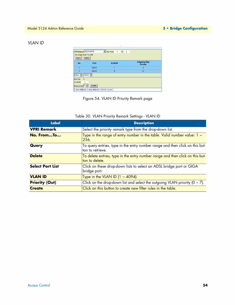
Model 3124 Admin Reference Guide 3 • Bridge Configuration
VLAN ID
Figure 54. VLAN ID Priority Remark page
Table 30. VLAN Priority Remark Settings - VLAN ID
Label Description
VPRI Remark Select the priority remark type from the drop-down list.No. From...To... Type in the range of entry number in the table. Valid number value: 1 ~
256.Query To query entries, type in the entry number range and then click on this but-
ton to retrieve. Delete To delete entries, type in the entry number range and then click on this but-
ton to delete. Select Port List Click on these drop-down lists to select an ADSL bridge port or GIGA
bridge port. VLAN ID Type in the VLAN ID (1 ~ 4094). Priority (Out) Click on the drop-down list and select the outgoing VLAN priority (0 ~ 7). Create Click on this button to create new filter rules in the table.
Access Control 54

Model 3124 Admin Reference Guide 3 • Bridge Configuration
VLAN Priority Regeneration
Figure 55. VLAN Priority Regeneration page
Table 31. VLAN Priority Remark Settings - VLAN Priority Regeneration
Label Description
VPRI Remark Select the priority remark type from the drop-down list.No. From...To... Type in the range of entry number in the table. Valid number value: 1 ~
256.Query To query entries, type in the entry number range and then click on this but-
ton to retrieve. Delete To delete entries, type in the entry number range and then click on this but-
ton to delete. Select Port List Click on these drop-down lists to select an ADSL bridge port or GIGA
bridge port. Priority (In) Click on the drop-down list and select the incoming VLAN priority (0 ~ 7).Priority (Out) Click on the drop-down list and select the outgoing VLAN priority (0 ~ 7). Create Click on this button to create new filter rules in the table.
Access Control 55

Model 3124 Admin Reference Guide 3 • Bridge Configuration
Differentiated Services
Figure 56. VLAN DSCP Priority Remark page
Table 32. VLAN Priority Remark Settings - Differentiated Services
Label Description
VPRI Remark Select the priority remark type from the drop-down list.No. From...To... Type in the range of entry number in the table. Valid number value: 1 ~
256.Query To query entries, type in the entry number range and then click on this but-
ton to retrieve. Delete To delete entries, type in the entry number range and then click on this but-
ton to delete. Select Port List Click on these drop-down lists to select an ADSL bridge port or GIGA
bridge port. Incoming DS Click on the drop-down list and select the incoming DSCP (Diffserv Code
Points, which is a 6-bit number).The standardized combinations are listed below:default Default value (bits:000000)af11 Assured Forwarding Class 1:Low Drop (bits:001010)af12 Assured Forwarding Class 1:Medium Drop (bits:001100)af13 Assured Forwarding Class 1:High Drop (bits:001110)af21 Assured Forwarding Class 2:Low Drop (bits:010010)af22 Assured Forwarding Class 2:Medium Drop (bits:010100)af23 Assured Forwarding Class 2:High Drop (bits:010110)af31 Assured Forwarding Class 3:Low Drop (bits:011010)af32 Assured Forwarding Class 3:Medium Drop af33 Assured Forwarding Class 3:High Drop (bits:011110)af41 Assured Forwarding Class 4:Low Drop (bits:100010)af42 Assured Forwarding Class 4:Medium Drop (bits:100100)af43 Assured Forwarding Class 4:High Drop (bits:100110)ef Expedited Forwarding (bits:101110)
Priority (Out) Click on the drop-down list and select the outgoing VLAN priority (0 ~ 7).Create Click on this button to create a new entry in the table.
Access Control 56
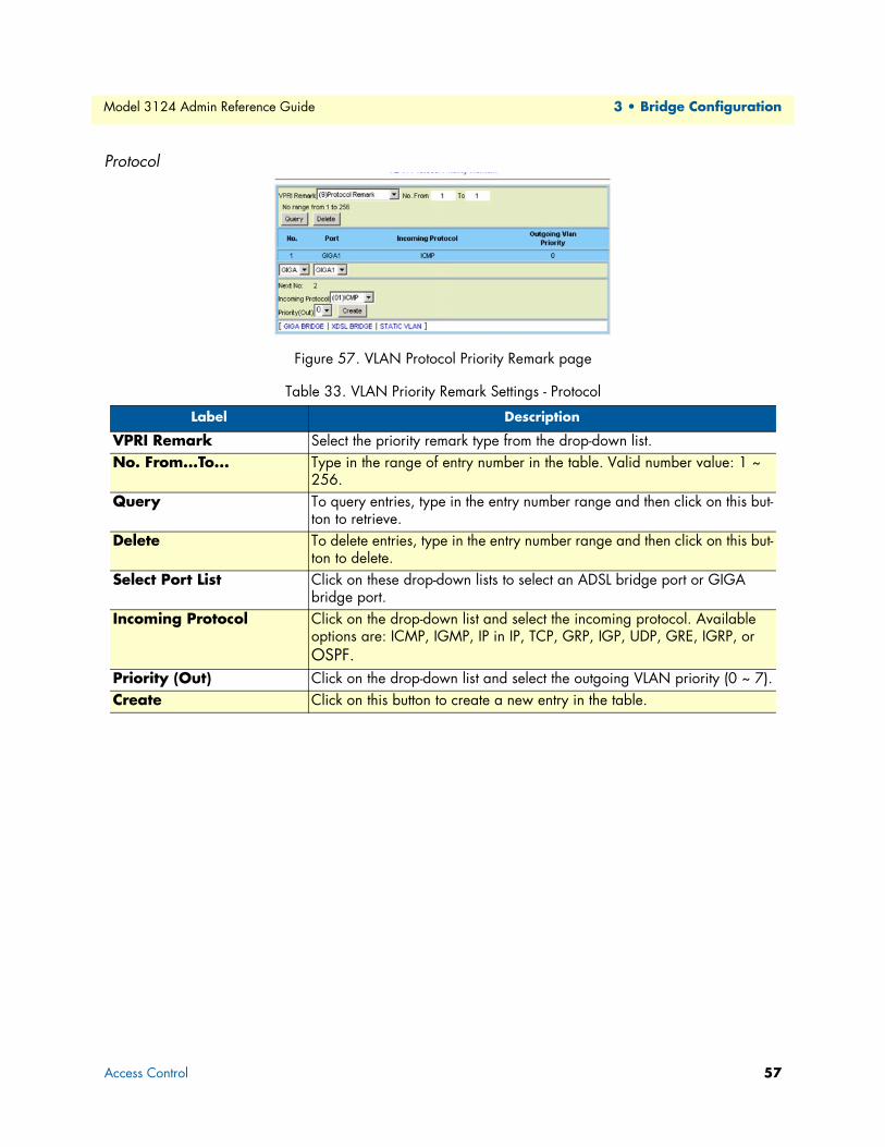
Model 3124 Admin Reference Guide 3 • Bridge Configuration
Protocol
Figure 57. VLAN Protocol Priority Remark page
Table 33. VLAN Priority Remark Settings - Protocol
Label Description
VPRI Remark Select the priority remark type from the drop-down list.No. From...To... Type in the range of entry number in the table. Valid number value: 1 ~
256.Query To query entries, type in the entry number range and then click on this but-
ton to retrieve. Delete To delete entries, type in the entry number range and then click on this but-
ton to delete. Select Port List Click on these drop-down lists to select an ADSL bridge port or GIGA
bridge port. Incoming Protocol Click on the drop-down list and select the incoming protocol. Available
options are: ICMP, IGMP, IP in IP, TCP, GRP, IGP, UDP, GRE, IGRP, or OSPF.
Priority (Out) Click on the drop-down list and select the outgoing VLAN priority (0 ~ 7).Create Click on this button to create a new entry in the table.
Access Control 57
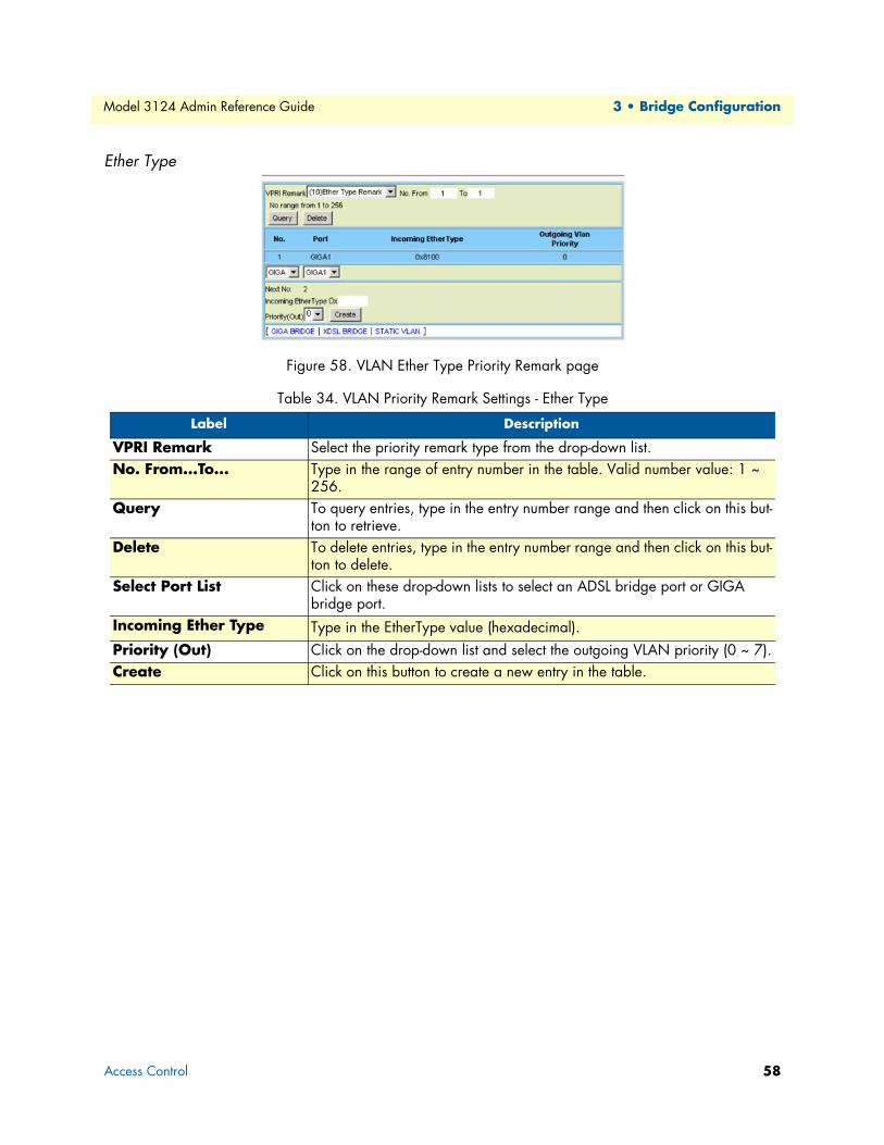
Model 3124 Admin Reference Guide 3 • Bridge Configuration
Ether Type
Figure 58. VLAN Ether Type Priority Remark page
Table 34. VLAN Priority Remark Settings - Ether Type
Label Description
VPRI Remark Select the priority remark type from the drop-down list.No. From...To... Type in the range of entry number in the table. Valid number value: 1 ~
256.Query To query entries, type in the entry number range and then click on this but-
ton to retrieve. Delete To delete entries, type in the entry number range and then click on this but-
ton to delete. Select Port List Click on these drop-down lists to select an ADSL bridge port or GIGA
bridge port. Incoming Ether Type Type in the EtherType value (hexadecimal).Priority (Out) Click on the drop-down list and select the outgoing VLAN priority (0 ~ 7).Create Click on this button to create a new entry in the table.
Access Control 58
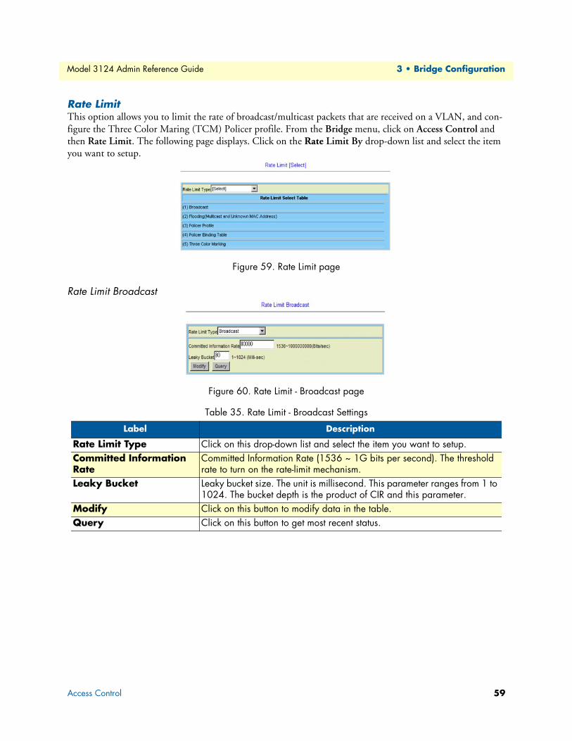
Model 3124 Admin Reference Guide 3 • Bridge Configuration
Rate LimitThis option allows you to limit the rate of broadcast/multicast packets that are received on a VLAN, and con-figure the Three Color Maring (TCM) Policer profile. From the Bridge menu, click on Access Control and then Rate Limit. The following page displays. Click on the Rate Limit By drop-down list and select the item you want to setup.
Figure 59. Rate Limit page
Rate Limit Broadcast
Figure 60. Rate Limit - Broadcast page
Table 35. Rate Limit - Broadcast Settings
Label Description
Rate Limit Type Click on this drop-down list and select the item you want to setup. Committed Information Rate
Committed Information Rate (1536 ~ 1G bits per second). The threshold rate to turn on the rate-limit mechanism.
Leaky Bucket Leaky bucket size. The unit is millisecond. This parameter ranges from 1 to 1024. The bucket depth is the product of CIR and this parameter.
Modify Click on this button to modify data in the table.Query Click on this button to get most recent status.
Access Control 59

Model 3124 Admin Reference Guide 3 • Bridge Configuration
Rate Limit Flooding
Figure 61. Rate Limit - Flooding page
Rate Limit PolicerThe Model 3124 supports two kinds of TCM Policer: two-rate TCM (with dual leaky buckets) and single-rate TCM (with single leaky bucket).
The single-rate TCM meters a traffic stream and marks its packets according to Committed Information Rate (CIR) and Committed Burst Size (CBS) to be either green, or red. The single-rate TCM operates with a single leaky bucket that is updated according to only one rate, the committed information rate - CIR. A packet is marked green if the leaky bucket is not full and red otherwise.
The two-rate TCM meters a traffic stream and marks its packets based on two rates, Committed Information Rate (CIR) and Excess Information Rate (EIR), and their associated burst sizes, Committed Burst Size (CBS) and Excess Burst Size (EBS), to be either green, yellow, or red. The two-rate TCM operates with dual leaky bucket, where each bucket is updated according to a different rate. The first bucket is updated according to the CIR, the second bucket is updated according to the EIR. A packet is marked red if it exceeds the PIR. Other-wise it is marked either yellow or green depending on whether it exceeds or doesn’t exceed the EIR.
Table 36. Rate Limit - Flooding Settings
Label Description
Rate Limit Type Click on this drop-down list and select the item you want to setup. Flooding VID Type in VLAN ID. (VID value: 1 ~ 4094) The VLAN must have been cre-
ated in the static VLAN table.Committed Information Rate
Committed Information Rate (1536 ~ 1G bits per second). The threshold rate to turn on the rate-limit mechanism.
Leaky Bucket Leaky bucket size. The unit is millisecond. This parameter ranges from 1 to 1024. The bucket depth is the product of CIR and this parameter.
Modify Click on this button to modify data in the table.Query Click on this button to get most recent status. Delete Click on this button to delete the entries in the table.
Access Control 60
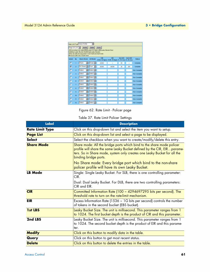
Model 3124 Admin Reference Guide 3 • Bridge Configuration
Figure 62. Rate Limit - Policer page
Table 37. Rate Limit Policer Settings
Label Description
Rate Limit Type Click on this drop-down list and select the item you want to setup. Page List Click on this drop-down list and select a page to be displayed. Select Select the checkbox when you want to create/modify/delete this entry. Share Mode Share mode: All the bridge ports which bind to the share mode policer
profile will share the same Leaky Bucket defined by the CIR, EIR…parame-ters. So in Share mode, system only creates one Leaky Bucket for all the binding bridge ports.
No Share mode: Every bridge port which bind to the non-share policer profile will have its own Leaky Bucket.
LB Mode Single: Single Leaky Bucket. For SLB, there is one controlling parameter: CIR. Dual: Dual Leaky Bucket. For DLB, there are two controlling parameters: CIR and EIR.
CIR Committed Information Rate (100 ~ 4294697295 bits per second). The threshold rate to turn on the rate-limit mechanism.
EIR Excess Information Rate (1536 ~ 1G bits per second) controls the number of tokens in the second bucket (EBS bucket).
1st LBS Leaky Bucket Size. The unit is millisecond. This parameter ranges from 1 to 1024. The first bucket depth is the product of CIR and this parameter.
2nd LBS Leaky Bucket Size. The unit is millisecond. This parameter ranges from 1 to 1024. The second bucket depth is the product of EIR and this parame-ter.
Modify Click on this button to modify data in the table.Query Click on this button to get most recent status. Delete Click on this button to delete the entries in the table.
Access Control 61
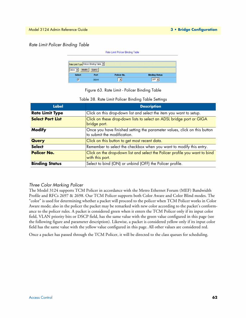
Model 3124 Admin Reference Guide 3 • Bridge Configuration
Rate Limit Policer Binding Table
Figure 63. Rate Limit - Policer Binding Table
Three Color Marking PolicerThe Model 3124 supports TCM Policer in accordance with the Metro Ethernet Forum (MEF) Bandwidth Profile and RFCs 2697 & 2698. Our TCM Policer supports both Color Aware and Color Blind modes. The “color” is used for determining whether a packet will proceed to the policer when TCM Policer works in Color Aware mode; also in the policer the packet may be remarked with new color according to the packet’s conform-ance to the policer rules. A packet is considered green when it enters the TCM Policer only if its input color field, VLAN priority bits or DSCP field, has the same value with the green value configured in this page (see the following figure and parameter description). Likewise, a packet is considered yellow only if its input color field has the same value with the yellow value configured in this page. All other values are considered red.
Once a packet has passed through the TCM Policer, it will be directed to the class queues for scheduling.
Table 38. Rate Limit Policer Binding Table Settings
Label Description
Rate Limit Type Click on this drop-down list and select the item you want to setup. Select Port List Click on these drop-down lists to select an ADSL bridge port or GIGA
bridge port. Modify Once you have finished setting the parameter values, click on this button
to submit the modification. Query Click on this button to get most recent data.Select Remember to select the checkbox when you want to modify this entry. Policer No. Click on the drop-down list and select the Policer profile you want to bind
with this port. Binding Status Select to bind (ON) or unbind (OFF) the Policer profile.
Access Control 62
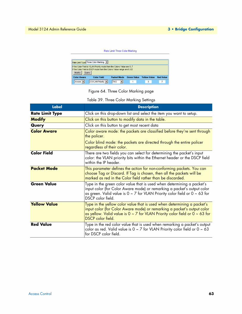
Model 3124 Admin Reference Guide 3 • Bridge Configuration
Figure 64. Three Color Marking page
Table 39. Three Color Marking Settings
Label Description
Rate Limit Type Click on this drop-down list and select the item you want to setup. Modify Click on this button to modify data in the table.Query Click on this button to get most recent data Color Aware Color aware mode: the packets are classified before they’re sent through
the policer. Color blind mode: the packets are directed through the entire policer regardless of their color.
Color Field There are two fields you can select for determining the packet’s input color: the VLAN priority bits within the Ethernet header or the DSCP field within the IP header.
Packet Mode This parameter defines the action for non-conforming packets. You can choose Tag or Discard. If Tag is chosen, then all the packets will be marked as red in the Color field rather than be discarded.
Green Value Type in the green color value that is used when determining a packet’s input color (for Color Aware mode) or remarking a packet’s output color as green. Valid value is 0 ~ 7 for VLAN Priority color field or 0 ~ 63 for DSCP color field.
Yellow Value Type in the yellow color value that is used when determining a packet’s input color (for Color Aware mode) or remarking a packet’s output color as yellow. Valid value is 0 ~ 7 for VLAN Priority color field or 0 ~ 63 for DSCP color field.
Red Value Type in the red color value that is used when remarking a packet’s output color as red. Valid value is 0 ~ 7 for VLAN Priority color field or 0 ~ 63 for DSCP color field.
Access Control 63

Model 3124 Admin Reference Guide 3 • Bridge Configuration
Priority Queue MappingThis web page is used to select SPQ/WFQ/WRR queuing mechanism and to setup the mapping between VLAN priority levels and system internal queues. From the Bridge menu, click on Access Control and then Priority Queue Mapping. The following page displays:
Figure 65. Priority Queue Mapping page
The queues for Giga and ATM interfaces are different.
• Giga: The Giga interface has 4 Queues and these queues can only work on Strict Priority Queuing (SPQ) scheduling. The priorities of these queues are: Q3 > Q2 > Q1 > Q0.
• ATM: Each ATM PVC bridge interface on each ADSL port has 8 Queues and can work in SPQ or SPQ/WFQ mix mode.
For SPQ, the priorities of these queues are: Q7 > Q6 > Q5 > Q4 > Q3 > Q2 > Q1 > Q0.
For SPQ/WFQ mixed, the priority of SPQ queues (Q7~Q4) is higher than WFQ queues (Q3~Q0).
And:
Q7 ~ Q4 are for SPQ and the priorities are Q7 > Q6 > Q5 > Q4.
Q3 ~ Q0 are for WFQ (Weighted Fair Queuing) and you can define the weight value for Q3 ~ Q0.
Note that if each queue has different weight value, the system will work as WFQ mode. If all queues have the same weight value, the system will work as Weighted Round Robin (WRR) mode.
The system allows 8 priority levels fully work aQ0 only in the Priority Queue Mapping table.
Access Control 64

Model 3124 Admin Reference Guide 3 • Bridge Configuration
Forwarding
TP Forwarding DBThis option allows you to configure the transparent forwarding database. The forwarding table will reveal the information of MAC addresses that are learned or statically configured on a specific bridge port. From the Bridge menu, click on Forwarding and then TP Forwarding DB. The following page displays:
Figure 66. Transparent Forwarding Databse page
Table 40. Transparent Forwarding Database Settings
Label Description
Aging Time Type in the aging time in seconds. An entry will be removed from the FDB (aged-out) if the device does not transmit for a specified period of time (the aging time).
Modify Click on this button to submit the modification.No. From...To... Select the range of entry number in the forwarding database.Query Once you have selected the entry number, click on this button to get the
most recent status of MAC addresses forwarding.
Forwarding 65

Model 3124 Admin Reference Guide 3 • Bridge Configuration
Forwarding StaticThis option allows you to configure the static MAC address forwarding entries on a specific bridge port. The setting of static MAC address takes effect on egress direction of bridge port. From the Bridge menu, click on Forwarding and then Forwarding Static. The following page displays:
Figure 67. Forwarding Static page
Table 41. Forwarding Static Settings
Label Description
No. From...To... Select the range of entry number in the FDB. Valid number value: 1 ~ 513.Query Click on this button to display the FDB entries.Delete Delete the entries according to the entry number range you type in.Select Port List Click on these drop-down list to select a bridge port (ADSL bridge port or
GIGA bridge port) where the static forwarding entries to be configured.Source MAC Type in the MAC address for the static entry.VID Type in the VID for the static entry (1 ~ 4094).Process Click on the drop-down list and select “Deny” the packets with the destination
MAC address or “Pass” the packets with the destination MAC address.Create Click on this button to create a new entry.
Forwarding 66

Model 3124 Admin Reference Guide 3 • Bridge Configuration
Relay
DSL Line IdentifyThis option allows you to configure the DHCP option and PPPoE relay function. From the Bridge menu, click on Relay and then DSL Line Identify. The following page displays:
Figure 68. DSL Line Identify
Table 42. DSL Line Identify Settings
Label Description
DSL Global Configuration
PPP Service Name Type in the PPPoE service name to add. PPP Service Name Check Mode
Enable: the system will check whether the PPPoE service names from the PPPoE server and client are the same. If not the same, the PPP connection between server and client will not be established. Disable: the system will not check the PPPoE service name.
DSLAM Name Type in name of the DSLAM when DSLAM Name mode is set to ‘Customer’. DSLAM Name Mode Select the DSLAM name to be customer-defined or cluster name (Domain name:NE
name). DHCP Mode Click on this drop-down list and select OFF/ON to disable/enable DHCP relay
function.ID Select Click on this drop-down list and select the Relay Agent Information that is inserted
to the forwarding packets. Options are: Circuit ID, Remote ID, or Both.Circuit ID Type Click on this drop-down list and select the type of Circuit ID. Options are:
DEFAULT, CUSTOMER. DEFAULT means our system-defined default type (DSLAM name:circuit number); CUSTOMER means the customer-defined type.
Relay 67
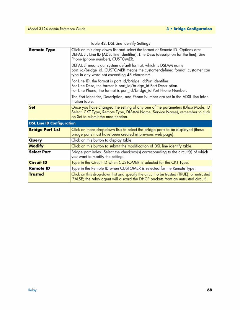
Model 3124 Admin Reference Guide 3 • Bridge Configuration
Remote Type Click on this drop-down list and select the format of Remote ID. Options are: DEFAULT, Line ID (ADSL line identifier), Line Desc (description for the line), Line Phone (phone number), CUSTOMER. DEFAULT means our system default format, which is DSLAM name: port_id/bridge_id. CUSTOMER means the customer-defined format; customer can type in any word not exceeding 48 characters. For Line ID, the format is port_id/bridge_id:Port Identifier. For Line Desc, the format is port_id/bridge_id:Port Description. For Line Phone, the format is port_id/bridge_id:Port Phone Number. The Port Identifier, Description, and Phone Number are set in the ADSL line infor-mation table.
Set Once you have changed the setting of any one of the parameters (Dhcp Mode, ID Select, CKT Type, Remote Type, DLSAM Name, Service Name), remember to click on Set to submit the modification.
DSL Line ID Configuration
Bridge Port List Click on these drop-down lists to select the bridge ports to be displayed (these bridge ports must have been created in previous web page).
Query Click on this button to display table.Modify Click on this button to submit the modification of DSL line identify table.Select Port Bridge port index. Select the checkbox(s) corresponding to the circuit(s) of which
you want to modify the setting.Circuit ID Type in the Circuit ID when CUSTOMER is selected for the CKT Type.Remote ID Type in the Remote ID when CUSTOMER is selected for the Remote Type.Trusted Click on this drop-down list and specify the circuit to be trusted (TRUE), or untrusted
(FALSE; the relay agent will discard the DHCP packets from an untrusted circuit).
Table 42. DSL Line Identify Settings
Relay 68
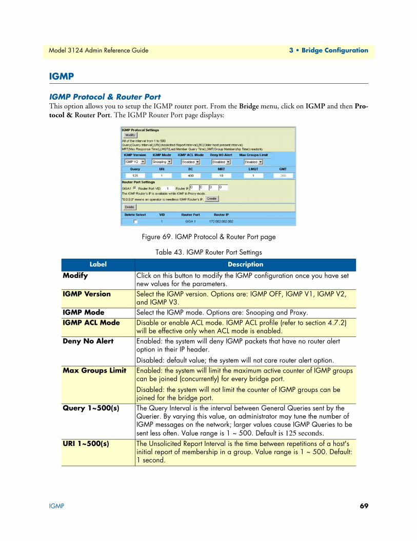
Model 3124 Admin Reference Guide 3 • Bridge Configuration
IGMP
IGMP Protocol & Router PortThis option allows you to setup the IGMP router port. From the Bridge menu, click on IGMP and then Pro-tocol & Router Port. The IGMP Router Port page displays:
Figure 69. IGMP Protocol & Router Port page
Table 43. IGMP Router Port Settings
Label Description
Modify Click on this button to modify the IGMP configuration once you have set new values for the parameters.
IGMP Version Select the IGMP version. Options are: IGMP OFF, IGMP V1, IGMP V2, and IGMP V3.
IGMP Mode Select the IGMP mode. Options are: Snooping and Proxy. IGMP ACL Mode Disable or enable ACL mode. IGMP ACL profile (refer to section 4.7.2)
will be effective only when ACL mode is enabled. Deny No Alert Enabled: the system will deny IGMP packets that have no router alert
option in their IP header. Disabled: default value; the system will not care router alert option.
Max Groups Limit Enabled: the system will limit the maximum active counter of IGMP groups can be joined (concurrently) for every bridge port. Disabled: the system will not limit the counter of IGMP groups can be joined for the bridge port.
Query 1~500(s) The Query Interval is the interval between General Queries sent by the Querier. By varying this value, an administrator may tune the number of IGMP messages on the network; larger values cause IGMP Queries to be sent less often. Value range is 1 ~ 500. Default is 125 seconds.
URI 1~500(s) The Unsolicited Report Interval is the time between repetitions of a host's initial report of membership in a group. Value range is 1 ~ 500. Default: 1 second.
IGMP 69

Model 3124 Admin Reference Guide 3 • Bridge Configuration
BC 1~500(s) The Older Host Present Interval. It represents how long a host must wait after hearing a Version 1 Query before it may send any IGMPv2 mes-sages. Default is 400 (sec).
MRT 1~500(s) The burstiness of IGMP traffic is inversely proportional to the Max Response Time. A longer Max Response Time will spread Report mes-sages over a longer interval. However, a longer Max Response Time in Group-Specific and Source-and-Group- Specific Queries extends the leave latency. (The leave latency is the time between when the last member stops listening to a source or group and when the traffic stops flowing.). Value range is 1 ~ 500. Default is 10.
LMQT 1~500(s) The Last Member Query Interval is the Max Response Time used to calculate the Max Resp Code inserted into Group- Specific Queries sent in response to Leave Group messages. It is also the Max Response Time used in calculating the Max Resp Code for Group-and-Source-Specific Query messages. Value range is 1 ~ 500. Default is 1.
GMT 1~500(s) Read-only value. The Group Membership Interval is the amount of time that must pass before a multicast router decides there are no more mem-bers of a group or a particular source on a network. This value MUST be ((the Robustness Variable) times (the Query Interval)) plus (one Query Response Interval).
GIGA1 Click on this radio button to select GBE as the IGMP router port.Route Port VID Route Port VID Type in the VID you want to setup/delete the router port for.
Valid VID value is 1 ~ 4094. Router IP Type in IGMP router IP address. When working in IGMP proxy mode,
DSLAM will send IGMP general query whose source IP address is 0.0.0.0. But PCs with Windows OS do not receive this kind of packets. So user can assign an IP address here for proxy mode IGMP general query packet ref-erence.
Create Click on this button to create a new entry.Delete Click on this button to delete an entry.
Table 43. IGMP Router Port Settings
IGMP 70

Model 3124 Admin Reference Guide 3 • Bridge Configuration
IGMP ProfileThis option allows you to configure the IGMP ACL (Access Control List) profile. This profile defines the IGMP multicast channels, which are allowed to join for each ADSL port. That is, a multicast stream will be copied to an ADSL port only if that multicast stream is registered in the ACL profile that is bound to this ADSL port. The maximum number of IGMP multicast channels in an ACL profile is 256. Note that the same multicast channel can be existed concurrently in two or more ACL profiles.
The ACL profile will be referred to only when ACL mode is enabled in the IGMP Configuration page. From the Bridge menu, click on IGMP and then ACL Profile. The following page displays:
Figure 70. IGMP ACL Profile
IGMP 71
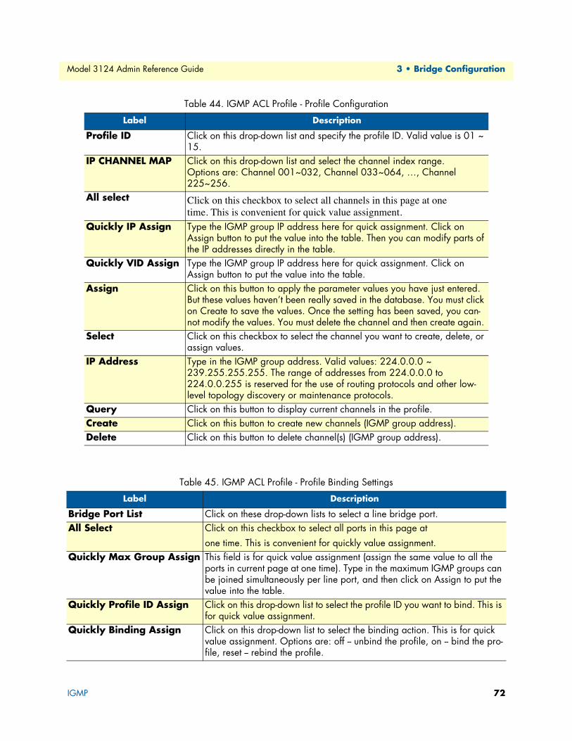
Model 3124 Admin Reference Guide 3 • Bridge Configuration
Table 44. IGMP ACL Profile - Profile Configuration
Label Description
Profile ID Click on this drop-down list and specify the profile ID. Valid value is 01 ~ 15.
IP CHANNEL MAP Click on this drop-down list and select the channel index range. Options are: Channel 001~032, Channel 033~064, …, Channel 225~256.
All select Click on this checkbox to select all channels in this page at one time. This is convenient for quick value assignment.
Quickly IP Assign Type the IGMP group IP address here for quick assignment. Click on Assign button to put the value into the table. Then you can modify parts of the IP addresses directly in the table.
Quickly VID Assign Type the IGMP group IP address here for quick assignment. Click on Assign button to put the value into the table.
Assign Click on this button to apply the parameter values you have just entered. But these values haven’t been really saved in the database. You must click on Create to save the values. Once the setting has been saved, you can-not modify the values. You must delete the channel and then create again.
Select Click on this checkbox to select the channel you want to create, delete, or assign values.
IP Address Type in the IGMP group address. Valid values: 224.0.0.0 ~ 239.255.255.255. The range of addresses from 224.0.0.0 to 224.0.0.255 is reserved for the use of routing protocols and other low-level topology discovery or maintenance protocols.
Query Click on this button to display current channels in the profile.Create Click on this button to create new channels (IGMP group address).Delete Click on this button to delete channel(s) (IGMP group address).
Table 45. IGMP ACL Profile - Profile Binding Settings
Label Description
Bridge Port List Click on these drop-down lists to select a line bridge port.All Select Click on this checkbox to select all ports in this page at
one time. This is convenient for quickly value assignment.Quickly Max Group Assign This field is for quick value assignment (assign the same value to all the
ports in current page at one time). Type in the maximum IGMP groups can be joined simultaneously per line port, and then click on Assign to put the value into the table.
Quickly Profile ID Assign Click on this drop-down list to select the profile ID you want to bind. This is for quick value assignment.
Quickly Binding Assign Click on this drop-down list to select the binding action. This is for quick value assignment. Options are: off -- unbind the profile, on -- bind the pro-file, reset -- rebind the profile.
IGMP 72
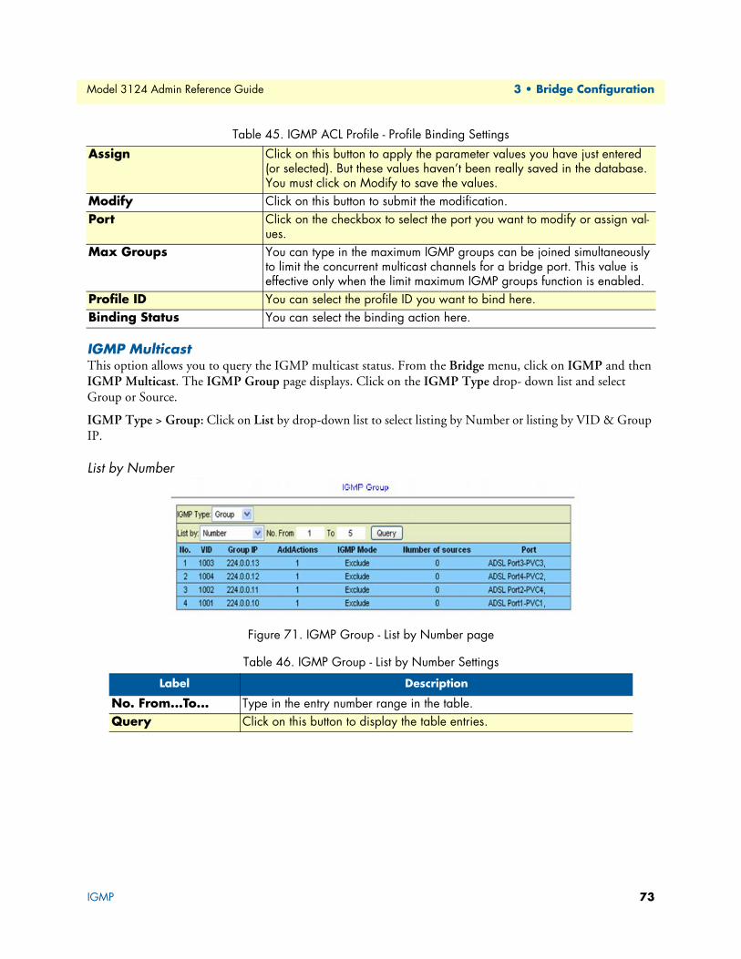
Model 3124 Admin Reference Guide 3 • Bridge Configuration
IGMP MulticastThis option allows you to query the IGMP multicast status. From the Bridge menu, click on IGMP and then IGMP Multicast. The IGMP Group page displays. Click on the IGMP Type drop- down list and select Group or Source.
IGMP Type > Group: Click on List by drop-down list to select listing by Number or listing by VID & Group IP.
List by Number
Figure 71. IGMP Group - List by Number page
Assign Click on this button to apply the parameter values you have just entered (or selected). But these values haven’t been really saved in the database. You must click on Modify to save the values.
Modify Click on this button to submit the modification. Port Click on the checkbox to select the port you want to modify or assign val-
ues. Max Groups You can type in the maximum IGMP groups can be joined simultaneously
to limit the concurrent multicast channels for a bridge port. This value is effective only when the limit maximum IGMP groups function is enabled.
Profile ID You can select the profile ID you want to bind here. Binding Status You can select the binding action here.
Table 46. IGMP Group - List by Number Settings
Label Description
No. From...To... Type in the entry number range in the table.Query Click on this button to display the table entries.
Table 45. IGMP ACL Profile - Profile Binding Settings
IGMP 73
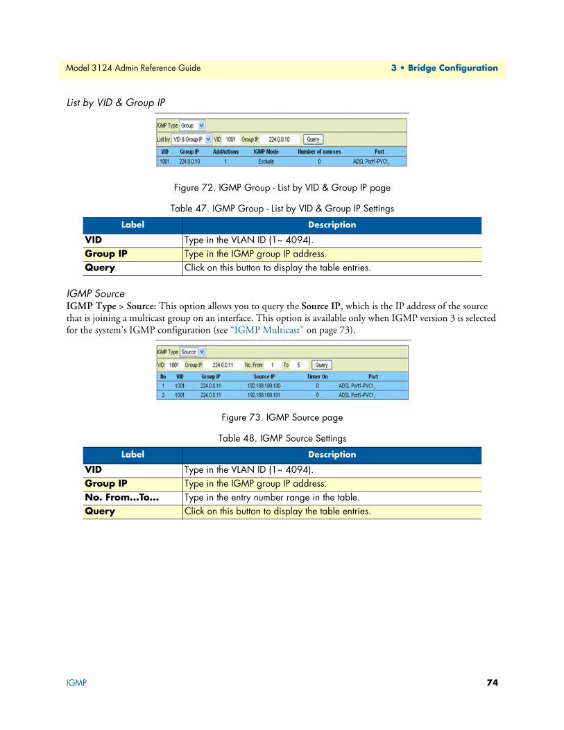
Model 3124 Admin Reference Guide 3 • Bridge Configuration
List by VID & Group IP
Figure 72. IGMP Group - List by VID & Group IP page
IGMP SourceIGMP Type > Source: This option allows you to query the Source IP, which is the IP address of the source that is joining a multicast group on an interface. This option is available only when IGMP version 3 is selected for the system's IGMP configuration (see “IGMP Multicast” on page 73).
Figure 73. IGMP Source page
Table 47. IGMP Group - List by VID & Group IP Settings
Label Description
VID Type in the VLAN ID (1~ 4094).Group IP Type in the IGMP group IP address.Query Click on this button to display the table entries.
Table 48. IGMP Source Settings
Label Description
VID Type in the VLAN ID (1~ 4094).Group IP Type in the IGMP group IP address.No. From...To... Type in the entry number range in the table.Query Click on this button to display the table entries.
IGMP 74
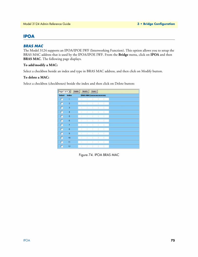
Model 3124 Admin Reference Guide 3 • Bridge Configuration
IPOA
BRAS MACThe Model 3124 supports an IPOA/IPOE IWF (Interworking Function). This option allows you to setup the BRAS MAC address that is used by the IPOA/IPOE IWF. From the Bridge menu, click on IPOA and then BRAS MAC. The following page displays.
To add/modify a MAC:
Select a checkbox beside an index and type in BRAS MAC address, and then click on Modify button.
To delete a MAC:
Select a checkbox (checkboxes) beside the index and then click on Delete button:
Figure 74. IPOA BRAS MAC
IPOA 75

Model 3124 Admin Reference Guide 3 • Bridge Configuration
Interface SetupThis option allows you to setup the interface for IPoA/IPoE IWF. From the Bridge menu, click on IPOA and then Interface Setup. The following page displays. Click on the radio button to select a circuit, set values for the parameters, and then click on Modify button.
Figure 75. IPOA Interface Setup page
Table 49. IGMP Source Settings
Label Description
Line Port List Click on the drop-down list and select the line ports to be listed.VPI Type in the VPI. Value range is 0 ~ 255. VCI Type in the VCI. Value range is 21, 32 ~ 65535. MaxMAC Type in the maximum number of MAC addresses that can be learned by
the bridge port (for GBE interface: 1 ~ 4096, for DSL interface: 1 ~ 128). CVID Type in the VID value of C-Tag (the innermost VLAN tag as defined in IEEE
802.1ad and having an EtherType value of 0x8100). The C-VID indicates the access loop.
CVPRI Click on the drop-down list and select the VLAN priority level of C-Tag (Pri-0 ~ 7).
Traffic (Rx/Tx) Click on the drop-down lists and select a traffic type for transmit and receive direction respectively. Available options are created in the ATM Traffic Descriptor page.
BRAS Click on the drop-down list and select a BRAS MAC. Available options are created through “BRAS MAC” on page 75.
Uplink Click on the drop-down list and select the uplink interface. Encap Select AAL5 Encapsulation Type: VCMUX/LLCStatus Enable/Disable IPoA IWF. Modify Click on this button to submit the modification. Query Click on this button to query most recent data.
IPOA 76

Chapter 4 ADSL Configuration
Chapter contentsProfile....................................................................................................................................................................78
Line Service Profile .........................................................................................................................................78
Service Channel Profile ...................................................................................................................................79Spectrum Main Profile ....................................................................................................................................80
Spectrum ADSLx Profile .................................................................................................................................83
ADSL TCA Profile .........................................................................................................................................84Data & Inventory..................................................................................................................................................85
Inventory ........................................................................................................................................................85
Loop Test .......................................................................................................................................................86Test in progress .........................................................................................................................................86
Test completed ..........................................................................................................................................86
Carrier Data ....................................................................................................................................................90OP Data .........................................................................................................................................................91
Line Operational Data ..............................................................................................................................91
Channel Operational Data ........................................................................................................................91Line Config & Info ...............................................................................................................................................92
Line Configuration .........................................................................................................................................92
Line Information ............................................................................................................................................93
77
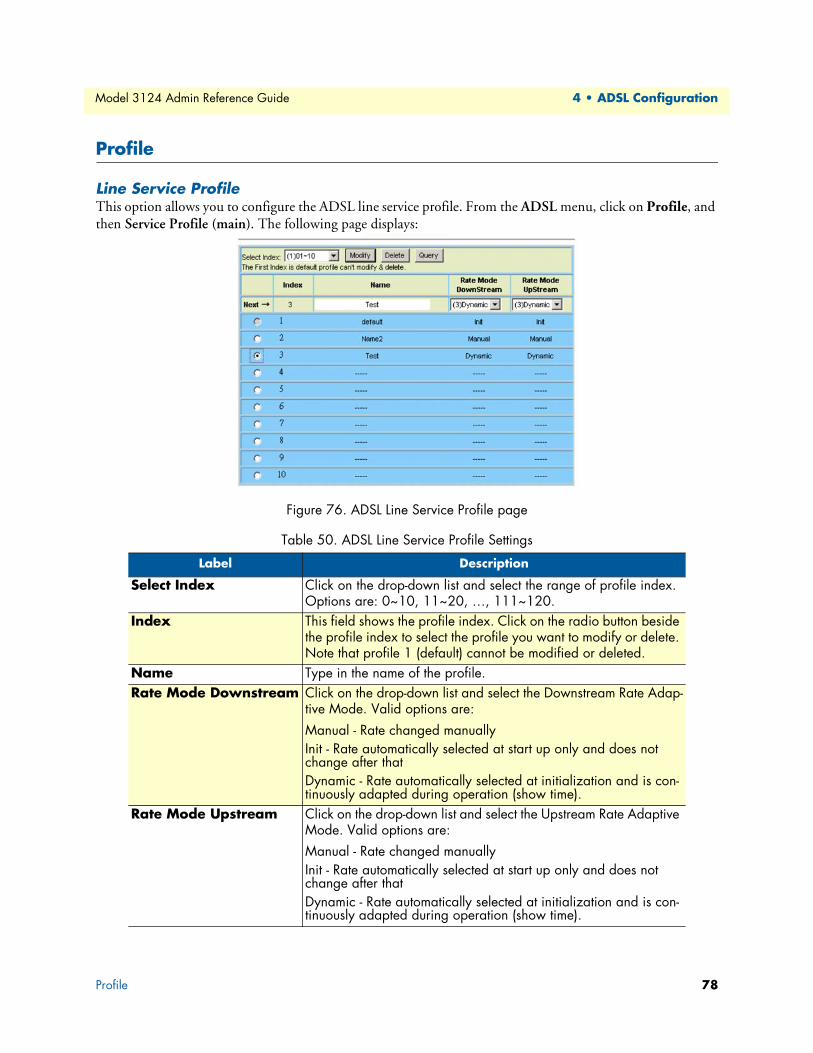
Model 3124 Admin Reference Guide 4 • ADSL Configuration
Profile
Line Service ProfileThis option allows you to configure the ADSL line service profile. From the ADSL menu, click on Profile, and then Service Profile (main). The following page displays:
Figure 76. ADSL Line Service Profile page
Table 50. ADSL Line Service Profile Settings
Label Description
Select Index Click on the drop-down list and select the range of profile index. Options are: 0~10, 11~20, …, 111~120.
Index This field shows the profile index. Click on the radio button beside the profile index to select the profile you want to modify or delete. Note that profile 1 (default) cannot be modified or deleted.
Name Type in the name of the profile.Rate Mode Downstream Click on the drop-down list and select the Downstream Rate Adap-
tive Mode. Valid options are:Manual - Rate changed manuallyInit - Rate automatically selected at start up only and does not change after that Dynamic - Rate automatically selected at initialization and is con-tinuously adapted during operation (show time).
Rate Mode Upstream Click on the drop-down list and select the Upstream Rate Adaptive Mode. Valid options are:Manual - Rate changed manuallyInit - Rate automatically selected at start up only and does not change after thatDynamic - Rate automatically selected at initialization and is con-tinuously adapted during operation (show time).
Profile 78
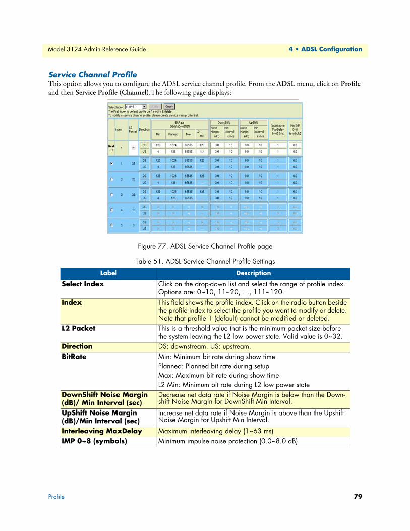
Model 3124 Admin Reference Guide 4 • ADSL Configuration
Service Channel ProfileThis option allows you to configure the ADSL service channel profile. From the ADSL menu, click on Profile and then Service Profile (Channel).The following page displays:
Figure 77. ADSL Service Channel Profile page
Table 51. ADSL Service Channel Profile Settings
Label Description
Select Index Click on the drop-down list and select the range of profile index. Options are: 0~10, 11~20, …, 111~120.
Index This field shows the profile index. Click on the radio button beside the profile index to select the profile you want to modify or delete. Note that profile 1 (default) cannot be modified or deleted.
L2 Packet This is a threshold value that is the minimum packet size before the system leaving the L2 low power state. Valid value is 0~32.
Direction DS: downstream. US: upstream.BitRate Min: Minimum bit rate during show time
Planned: Planned bit rate during setupMax: Maximum bit rate during show timeL2 Min: Minimum bit rate during L2 low power state
DownShift Noise Margin (dB)/ Min Interval (sec)
Decrease net data rate if Noise Margin is below than the Down-shift Noise Margin for DownShift Min Interval.
UpShift Noise Margin (dB)/Min Interval (sec)
Increase net data rate if Noise Margin is above than the Upshift Noise Margin for Upshift Min Interval.
Interleaving MaxDelay Maximum interleaving delay (1~63 ms)IMP 0~8 (symbols) Minimum impulse noise protection (0.0~8.0 dB)
Profile 79

Model 3124 Admin Reference Guide 4 • ADSL Configuration
Spectrum Main ProfileThis option allows you to configure the ADSL spectrum profile. From the ADSL menu, click on Profile and then Spectrum Profile (main). The following page displays:
Figure 78. ADSL Spectrum Profile page
Table 52. ADSL Spectrum Profile Settings
Label Description
Select Index Click on the drop-down list and select the range of profile index. Options are: 0~10, 11~20, …, 111~120.
Index This field shows the profile index. Click on the radio button beside the profile index to select the profile you want to modify or delete. Note that profile 1 (default) cannot be modified or deleted.
Name Type in the name of the profile.Power Mode Click on the radio button to select allowed power management
mode. Options are Disable (only L0 state allowed), L2 (L0 and L2 states allowed), L2L3 (L0, L2, and L3 states allowed).
L0 Time Type in the minimum time (in seconds) between Exit from L2 low power state and the next Entry into the L2 low power state. Value range is 0 ~ 255.
L2 Time Type in the minimum time (in seconds) between an Entry into L2 low power state and the first L2 low power trim request, and between two consecutive L2 power trim requests. Value range is 0 ~ 255.
L2 ATPR Type in the maximum aggregate transmit power reduction (in dB) that is allowed at transition of L0 to L2 state or an L2 low power trim request. Value range is 0 ~ the value of L2 ATPRT (dB).
L2 ATPRT Type in the total maximum aggregate transmit power reduction (in dB) that is allowed in the L2 state; the total reduction is the sum of all reductions of L2 Request (i.e., at transition of L0 to L2 state) and L2 power trims. Value range is 0 ~ 15 (dB).
Direction DS: downstream. US: upstream.
Profile 80
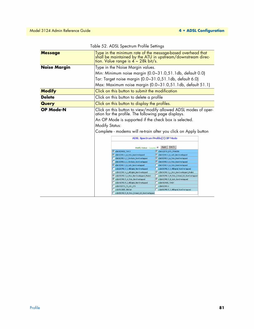
Model 3124 Admin Reference Guide 4 • ADSL Configuration
Message Type in the minimum rate of the message-based overhead that shall be maintained by the ATU in upstream/downstream direc-tion. Value range is 4 ~ 28k bit/s.
Noise Margin Type in the Noise Margin values.Min: Minimum noise margin (0.0~31.0,51.1db, default 0.0)Tar: Target noise margin (0.0~31.0,51.1db, default 6.0)Max: Maximum noise margin (0.0~31.0,51.1db, default 51.1)
Modify Click on this button to submit the modificationDelete Click on this button to delete a profileQuery Click on this button to display the profiles.OP Mode-N Click on this button to view/modify allowed ADSL modes of oper-
ation for the profile. The following page displays.An OP Mode is supported if the check box is selected.Modify Status:Complete - modems will re-train after you click on Apply button
Table 52. ADSL Spectrum Profile Settings
Profile 81

Model 3124 Admin Reference Guide 4 • ADSL Configuration
Carrier Mask-N Click on this button to view/modify the current down-stream/upstream Carrier Mask parameters. Input Carrier bit value and then click Apply.Modify Status:Complete - modems will re-train after you click on Apply button
RFI-N Click on this button to view/modify Radio Frequency Interference (RFI) Bands data. Input the Start/Stop frequency, select the Ingress Level, Egress Control, Signal Type, and then click on the Apply button.Modify Status:Complete - modems will re-train after you click on Apply button
Table 52. ADSL Spectrum Profile Settings
Profile 82

Model 3124 Admin Reference Guide 4 • ADSL Configuration
Spectrum ADSLx ProfileThis option allows you to configure the ADSL2/2+/READSL spectrum profile. From the ADSL menu, click on Profile and then Spectrum Profile (ADSLx). The following page displays:
Figure 79. ADSL Spectrum ADSLx Profile page
Table 53. ADSL2 Spectrum Profile Settings
Label Description
Select Index Click on the drop-down list to select the range of profile index. Options are: 1~4, 5~8, …, 117~120.
Index This field shows the profile index.Modem Features Select ADSL2/ReADSL2/ADSL2+ and Enable/Disable special
modem functions for better performance.Direction DS: downstream. US: upstreamAggregate Power Maximum nominal aggregate transmit power (0~25.5dB)PSD Level Maximum PSD level. Valid values are:
ADSL2: -60 ~ -40 dB/Hz DS, -60 ~ -38 dB/Hz USReADSL2: -60 ~ -37 dB/Hz DS, -60 ~ -32.9 dB/Hz USADSL2+: -60 ~ -40 dB/Hz DS, -60 ~ -38 dB/Hz US
PSD Shape Only for ADSL2+. Valid options are:Standard/CA100/CA110/CA120/CA130/CA140/CA150/CA160CA170/CA180/CA190/CA200/CA210/CA220/CA230/CA240/CA250/CA260/CA270/CA280
PBO Power backoff operation mode (OFF/ON).Max Rx Aggr. Allowed PWR Maximum aggregate receive power over a set of subcarriers. It
ranges from -25.5 to +25.5 dBm, with 0.1 dB steps.
Profile 83

Model 3124 Admin Reference Guide 4 • ADSL Configuration
ADSL TCA ProfileThis option allows you to setup the PM counter threshold for TCA (threshold crossing alert). From the ADSL menu, click on Profile and then TCA Profile. The following page displays:
Figure 80. ADSL TCA Profile page
Table 54. ADSL TCA Profile Settings
Label Description
Page List Click on this drop-down list to select the page to be displayed. Modify Once you have typed in new threshold values, click on this button
to submit the modification. Delete Click on this button to delete a selected profile (or profiles). Select Click on the checkbox to select the profile you want to modify or
delete.Enable To issue TCA when the PM statistics exceed thresholds, this profile
must be enabled. int/day ESs-NE/FE Interval/Day Errored Seconds – near end/far end int/day SESs-NE/FE Interval/Day Severely Errored Seconds – near end/far endint/day UASs-NE/FE Interval/Day Unavailable Seconds – near end/far end int LOS-NE/FE Interval Loss of Signal – near end/far end int LOF-NE/FE Interval Loss of Frame – near end/far end int LOPWR-FE Interval Loss of Power – far end int LOL-NE Interval Loss of Link – near end int ErrFrm-NE/FE Interval Error Frame – near end/far end
Profile 84
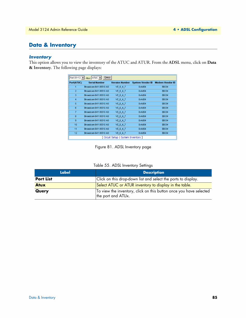
Model 3124 Admin Reference Guide 4 • ADSL Configuration
Data & Inventory
InventoryThis option allows you to view the inventory of the ATUC and ATUR. From the ADSL menu, click on Data & Inventory. The following page displays:
Figure 81. ADSL Inventory page
Table 55. ADSL Inventory Settings
Label Description
Port List Click on this drop-down list and select the ports to display.Atux Select ATUC or ATUR inventory to display in the table.Query To view the inventory, click on this button once you have selected
the port and ATUx.
Data & Inventory 85
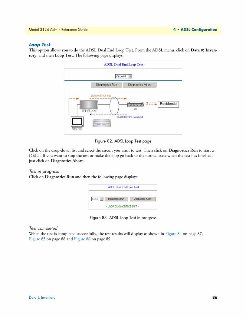
Model 3124 Admin Reference Guide 4 • ADSL Configuration
Loop TestThis option allows you to do the ADSL Dual End Loop Test. From the ADSL menu, click on Data & Inven-tory, and then Loop Test. The following page displays:
Figure 82. ADSL Loop Test page
Click on the drop-down list and select the circuit you want to test. Then click on Diagnostics Run to start a DELT. If you want to stop the test or make the loop go back to the normal state when the test has finished, just click on Diagnostics Abort.
Test in progress Click on Diagnostics Run and then the following page displays:
Figure 83. ADSL Loop Test in progress
Test completedWhen the test is completed successfully, the test results will display as shown in Figure 84 on page 87, Figure 85 on page 88 and Figure 86 on page 89.
Data & Inventory 86

Model 3124 Admin Reference Guide 4 • ADSL Configuration
Figure 84. ADSL Loop Test Results
Data & Inventory 87
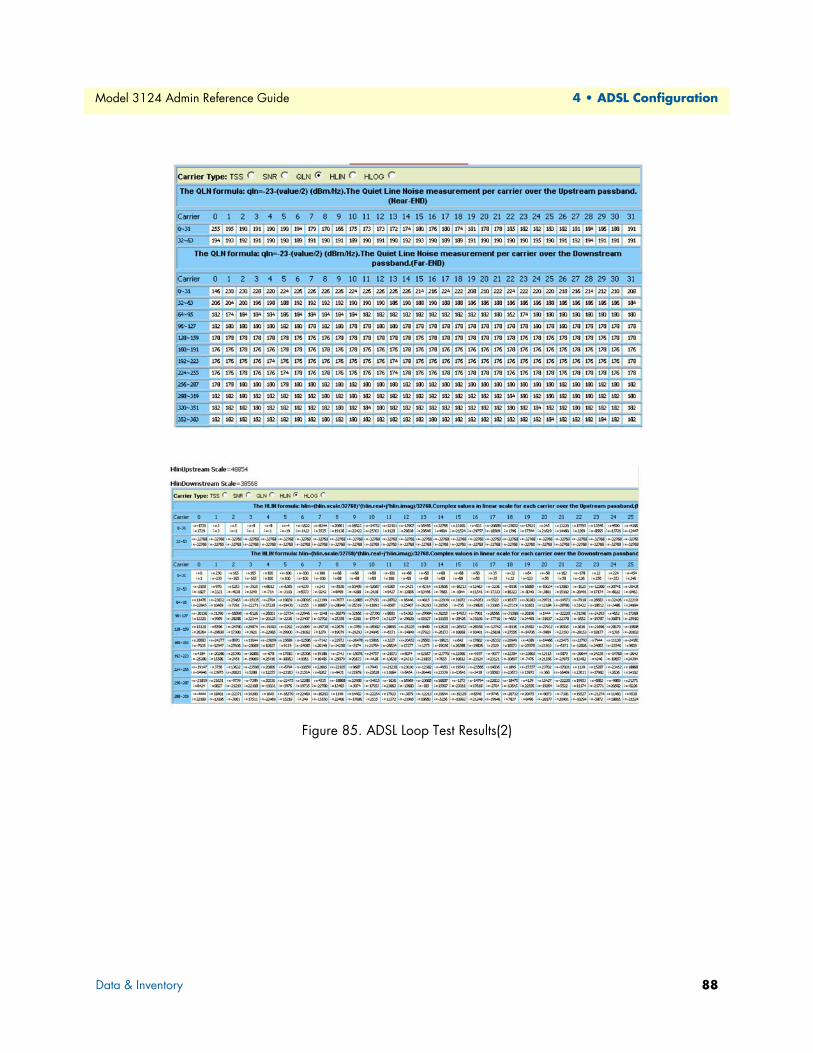
Model 3124 Admin Reference Guide 4 • ADSL Configuration
Figure 85. ADSL Loop Test Results(2)
Data & Inventory 88

Model 3124 Admin Reference Guide 4 • ADSL Configuration
Figure 86. ADSL Loop Test Results(3)
Data & Inventory 89
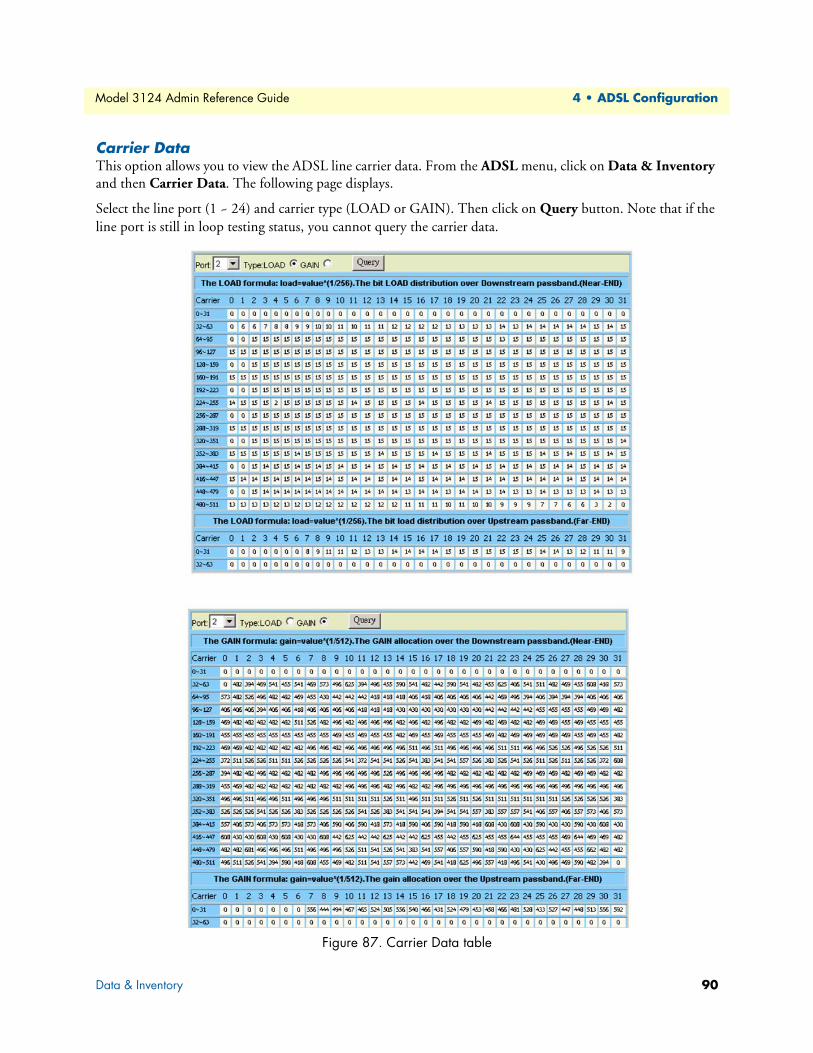
Model 3124 Admin Reference Guide 4 • ADSL Configuration
Carrier DataThis option allows you to view the ADSL line carrier data. From the ADSL menu, click on Data & Inventory and then Carrier Data. The following page displays.
Select the line port (1 ~ 24) and carrier type (LOAD or GAIN). Then click on Query button. Note that if the line port is still in loop testing status, you cannot query the carrier data.
Figure 87. Carrier Data table
Data & Inventory 90

Model 3124 Admin Reference Guide 4 • ADSL Configuration
OP DataThis option allows you to view the ADSL line/channel operational data and carrier data. From the ADSL menu, click on Data & Inventory, and then OP Data.
Line Operational DataClick on ADSL OP Data drop-down list and select the item Line (OP). Then select the line port (1~24). Click on Query button. The following page displays:
Figure 88. ADSL Line Operational Data page
Channel Operational DataClick on ADSL OP Data drop-down list and select the item Channel (OP). Then select the port (1~24). Click on Query button. The following page displays:
Figure 89. ADSL Channel Operational Data page
Data & Inventory 91
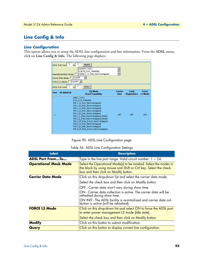
Model 3124 Admin Reference Guide 4 • ADSL Configuration
Line Config & Info
Line ConfigurationThis option allows you to setup the ADSL line configuration and line information. From the ADSL menu, click on Line Config & Info. The following page displays:
Figure 90. ADSL Line Configuration page
Table 56. ADSL Line Configuration Settings
Label Description
ADSL Port From...To... Type in the line port range. Valid circuit number: 1 ~ 24.Operational Mask Mode Select the Operational Mode(s) to be masked. Select the modes in
the block by using mouse and Shift or Ctrl key. Select the check box and then click on Modify button.
Carrier Data Mode Click on this drop-down list and select the carrier data mode.Select the check box and then click on Modify button.OFF - Carrier data won't vary during show time.ON - Carrier data collection is active. The carrier data will be refreshed during show time.ON INIT - The ADSL facility is re-initialized and carrier data col-lection is active (will be refreshed).
FORCE L3 Mode Click on this drop-down list and select ON to force the ADSL port to enter power management L3 mode (Idle state).Select the check box and then click on Modify button.
Modify Click on this button to submit modification.Query Click on this button to display current line configuration.
Line Config & Info 92

Model 3124 Admin Reference Guide 4 • ADSL Configuration
Line InformationThis option allows you to setup the ADSL line information. From the ADSL menu, click on Line Config & Info and then Line Information. The following page displays:
Figure 91. ADSL Line Information page
Table 57. ADSL Line Information Settings
Label Description
ADSL Port From...To... Type in the line port range. Valid circuit number: 1 ~ 24.Modify Click on this button to submit the modification once you have
entered new value for the ADSL line information. Note that to modify an entry, you must select the check box on the leftmost col-umn before you click on Modify.
Query Once you have typed in the port number range, click on this but-ton to display the ADSL line information of these ports.
Identifier Type in the ADSL line identifier. Up to 63 characters is allowed.Phone No Type in the phone number. Up to 63 characters is allowed.Description Type in any comment of this line. Up to 63 characters is allowed
Line Config & Info 93

Chapter 5 Traffic Configuration
Chapter contentsATM Traffic Descriptor ........................................................................................................................................95
94

Model 3124 Admin Reference Guide 5 • Traffic Configuration
ATM Traffic DescriptorThis option allows you to modify the traffic table. From the Traffic menu, click on ATM Traffic Descriptor. The following page displays:
Figure 92. ATM Traffic Descriptor page
Table 58. ATM Traffic Settings
Label Description
PCR PCR stands for Peak Cell Rate (cells/second).CDVT CDVT stands for Cell Delay Variation Tolerance (microseconds).SCR SCR stands for Sustained Cell Rate (cells/second).MBS MBS stands for Maximum Burst Size (cells).TYPE This field will show Shaped or Policed depending on the descriptor type you
select.*See the following page for more table information.*
ATM Traffic Descriptor 95

Model 3124 Admin Reference Guide 5 • Traffic Configuration
Descriptor Click on this drop-down list and select a descriptor type. After you select a descriptor type, the supported parameters will be displayed in the following columns. Valid descriptor types are:[Unshaped] atmNoTrafficDescriptor:This identifies no ATM traffic descriptor type. This traffic descriptor type can be used for best effort traffic.[Policed CBR] atmCLPTransparentNoScr /[Shaped CBR] atmCLPTransparentNoScr:This traffic descriptor type is for the CLP- transparent model and no Sustained Cell Rate. This traffic descriptor type is applicable to connections following the CBR.1 conformance definition. Connections specifying this traffic descrip-tor type will be rejected at UNI 3.0 or UNI 3.1 interfaces. For a similar traffic descriptor type that can be accepted at UNI 3.0 and UNI 3.1 interfaces, see "atmNoClpNoScr".[Policed VBR1] atmNoCLPScrCdvt:This traffic descriptor type is for no CLP with Sustained Cell Rate and CDVT. This traffic descriptor type is applicable to VBR connections following the UNI 3.0/3.1 conformance definition for PCR CLP=0+1 and SCR CLP=0+1. These VBR connections differ from VBR.1 connections in that the CLR objective applies only to the CLP=0 cell flow.[Policed VBR2] atmCLPNoTaggingScrCdvt /[Shaped UBRNRT] atmCLPNoTaggingScrCdvt:This traffic descriptor type is for CLP with Sustained Cell Rate and CDVT and no tagging. This traffic descriptor type is applicable to connections following the VBR.2 conformance definition.[Policed VBR3] atmCLPTaggingScrCdvt:This traffic descriptor type is for CLP with tagging and Sustained Cell Rate and CDVT. This traffic descriptor type is applicable to connections following the VBR.3 conformance definition.[Policed UBR1] atmNoCLPNoScrCdvt:This traffic descriptor type is for no CLP with CDVT and no Sustained Cell Rate. This traffic descriptor type is applicable toCBR connections following the UNI 3.0/3.1 conformance definition for PCR CLP=0+1. These CBR connections differ from CBR.1 connections in that the CLR objective applies only to the CLP=0 cell flow. This traffic descriptor type is also applicable to connections following the UBR.1 conformance definition.[Policed UBR2] atmNoCLPTaggingNoScr:This traffic descriptor type is for no CLP with tagging and no Sustained Cell Rate. This traffic descriptor type is applicable to connections following the UBR.2 conformance definition.[Shaped UBR] atmNoCLPNoScr:This traffic descriptor type is for no CLP and no Sustained Cell Rate[Shaped VBR] atmCLPTransparent:
Table 58. ATM Traffic Settings
ATM Traffic Descriptor 96This traffic descriptor type is for the CLP- transparent model with Sustained Cell Rate. This traffic descriptor type is applicable to connections following the VBR.1 conformance definition. Connections specifying this traffic descriptor type will be rejected at UNI 3.0 or UNI 3.1 interfaces. For a similar traffic descriptor type that can be accepted at UNI 3.0 and UNI 3.1 interfaces, see "atmNoClpScr".

Model 3124 Admin Reference Guide 5 • Traffic Configuration
Create Click on this button to create a new traffic descriptor.Delete When you want to delete a traffic descriptor, click on the radio button beside
the row number to select the traffic descriptor and then click on the Delete but-ton.
Table 58. ATM Traffic Settings
ATM Traffic Descriptor 97

Chapter 6 SNMP Configuration
Chapter contentsSNMP Community...............................................................................................................................................99
SNMP Target......................................................................................................................................................100
SNMP Notify......................................................................................................................................................101
98

Model 3124 Admin Reference Guide 6 • SNMP Configuration
SNMP CommunityThis option allows you to configure the SNMP community that is the group that Model 3124s and manage-ment stations running SNMP belong to. It helps define where information is sent. The community name is used to identify the group and serve as form of authentication. From the SNMP menu, click on SNMP Com-munity. The following page displays:
Figure 93. SNMP Community page
Table 59. SNMP Community Options
Label Description
New Click on this button to create a new SNMP community. After you click on New, the following page displays. Type in the name of the SNMP community (up to 63 characters; note that community names beginning with a digital num-ber are not allowed) and select the access mode (Read only or Read/Write). Then, click on Apply button.
Access Mode Select the SNMP community access mode: Read only or Read/Write. Modify Click on this button to modify the community name.Delete Select an index and then click on this button to delete a community.
SNMP Community 99
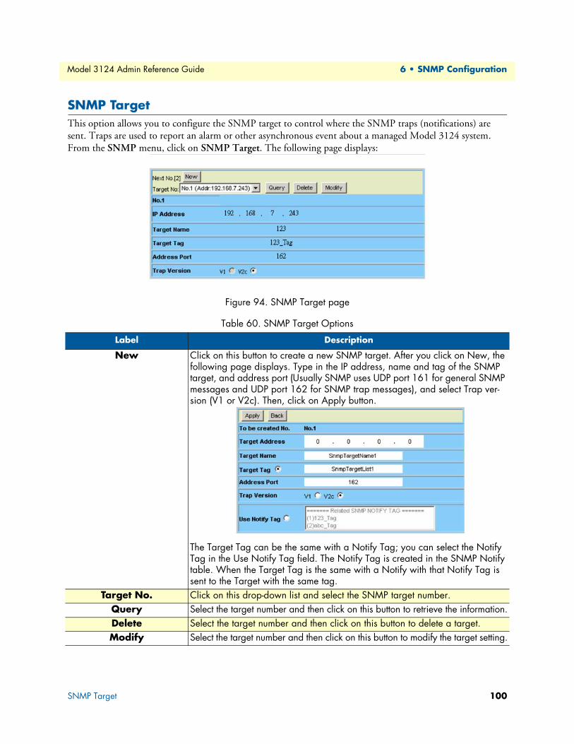
Model 3124 Admin Reference Guide 6 • SNMP Configuration
SNMP TargetThis option allows you to configure the SNMP target to control where the SNMP traps (notifications) are sent. Traps are used to report an alarm or other asynchronous event about a managed Model 3124 system. From the SNMP menu, click on SNMP Target. The following page displays:
Figure 94. SNMP Target page
Table 60. SNMP Target Options
Label Description
New Click on this button to create a new SNMP target. After you click on New, the following page displays. Type in the IP address, name and tag of the SNMP target, and address port (Usually SNMP uses UDP port 161 for general SNMP messages and UDP port 162 for SNMP trap messages), and select Trap ver-sion (V1 or V2c). Then, click on Apply button.
The Target Tag can be the same with a Notify Tag; you can select the Notify Tag in the Use Notify Tag field. The Notify Tag is created in the SNMP Notify table. When the Target Tag is the same with a Notify with that Notify Tag is sent to the Target with the same tag.
Target No. Click on this drop-down list and select the SNMP target number.Query Select the target number and then click on this button to retrieve the information.Delete Select the target number and then click on this button to delete a target.Modify Select the target number and then click on this button to modify the target setting.
SNMP Target 100

Model 3124 Admin Reference Guide 6 • SNMP Configuration
SNMP NotifyThis option allows you to setup the SNMP Notification (In SNMPv1, asynchronous event reports are called traps while they are called notifications in later versions of SNMP). From the SNMP menu, click on SNMP Notify. The following page displays:
Figure 95. SNMP Notify page
Table 61. SNMP Notify Options
Label Description
Notify No. This field shows the Notify number you select.New Click on this button to create a new SNMP Notify. After you click on New, the
following page displays. Type in the name and tag of the SNMP Notify and click on Apply button.By specifying the Notify tag, you can bind the Notify name to the SNMP target address table. When the Notify tag is the same with the Target Tag in a target table, the Notify is sent to the corresponding Target address.
Delete Select a row and then click on this button to delete a Notify.Modify Select the row and type in new notify tag and then click on this button to sub-
mit the modification.
SNMP Notify 101

Chapter 7 Maintenance
Chapter contentsSYS Log Server ....................................................................................................................................................103
Database..............................................................................................................................................................104
(A) Import File (Write Download Config To Flash) .....................................................................................105(B) Import File (Load Remote Config to Running Config) ...........................................................................106
(C) Export File (Put Running Config to Remote TFTP Server) ....................................................................107
(D) Save Running Config to Flash (System Config) ......................................................................................108(E) Reload Flash to Running Config .............................................................................................................109
(F) Restore Factory Default ...........................................................................................................................110
(G) Flash Boot Point Configuration Select ....................................................................................................111Firmware Update.................................................................................................................................................112
ATM Loopbacks..................................................................................................................................................114
Fault Management ..............................................................................................................................................115Alarm/Event .................................................................................................................................................115
Current Alarm .........................................................................................................................................115
History Alarm .........................................................................................................................................115Event Log ................................................................................................................................................116
Alarm Profile ................................................................................................................................................117
Hardware Temperature .................................................................................................................................118Performance Monitoring .....................................................................................................................................119
System Utilization .........................................................................................................................................119
Ethernet Statistics .........................................................................................................................................119GBE Interface .........................................................................................................................................119
ADSL Line PVC .....................................................................................................................................120
ATM Statistics ..............................................................................................................................................120RMON .........................................................................................................................................................121
ETH Statistics .........................................................................................................................................121
History Control ......................................................................................................................................123ETH History ...........................................................................................................................................124
Alarm ......................................................................................................................................................126
Event .......................................................................................................................................................128LOG .......................................................................................................................................................128
ADSL Day/Interval .......................................................................................................................................129
102
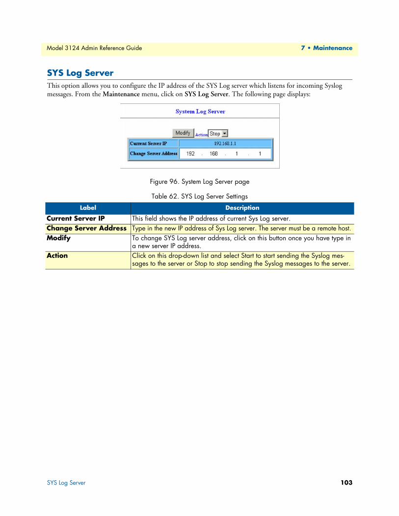
Model 3124 Admin Reference Guide 7 • Maintenance
SYS Log ServerThis option allows you to configure the IP address of the SYS Log server which listens for incoming Syslog messages. From the Maintenance menu, click on SYS Log Server. The following page displays:
Figure 96. System Log Server page
Table 62. SYS Log Server Settings
Label Description
Current Server IP This field shows the IP address of current Sys Log server.Change Server Address Type in the new IP address of Sys Log server. The server must be a remote host.Modify To change SYS Log server address, click on this button once you have type in
a new server IP address.Action Click on this drop-down list and select Start to start sending the Syslog mes-
sages to the server or Stop to stop sending the Syslog messages to the server.
SYS Log Server 103

Model 3124 Admin Reference Guide 7 • Maintenance
DatabaseThis option allows you to import/export the configuration data. From the Maintenance menu, click on Data-base. The following page displays. Select the database configuration action you want to perform.
Figure 97. Database Configuration menu
Database Configuration Concept.
Figure 98. Database Configuration concept
Database 104

Model 3124 Admin Reference Guide 7 • Maintenance
(A) Import File (Write Download Config To Flash)Type in the TFTP Server IP address and the name of the file you want to download. Then click on Get File button.
Figure 99. Database Configuration - Import File - Get File
Write downloaded Config to Flash in progress:
Figure 100. Database Configuration - Import File - Write to Flash
Write to memory successfully:
Figure 101. Database Configuration - Import File - Write Successful
Database 105

Model 3124 Admin Reference Guide 7 • Maintenance
Fail to Get File:
Figure 102. Database Configuration - Import File - Fail to Get File
(B) Import File (Load Remote Config to Running Config)Type in the TFTP Server IP address and the name of the file you want to download. Then click on Get File button.
Figure 103. Database Configuration - Import File (Remote Config) - Get File
Write to Running Config successfully:
Figure 104. Database Configuration - Import File (Remote Config) - Write Successful
Database 106
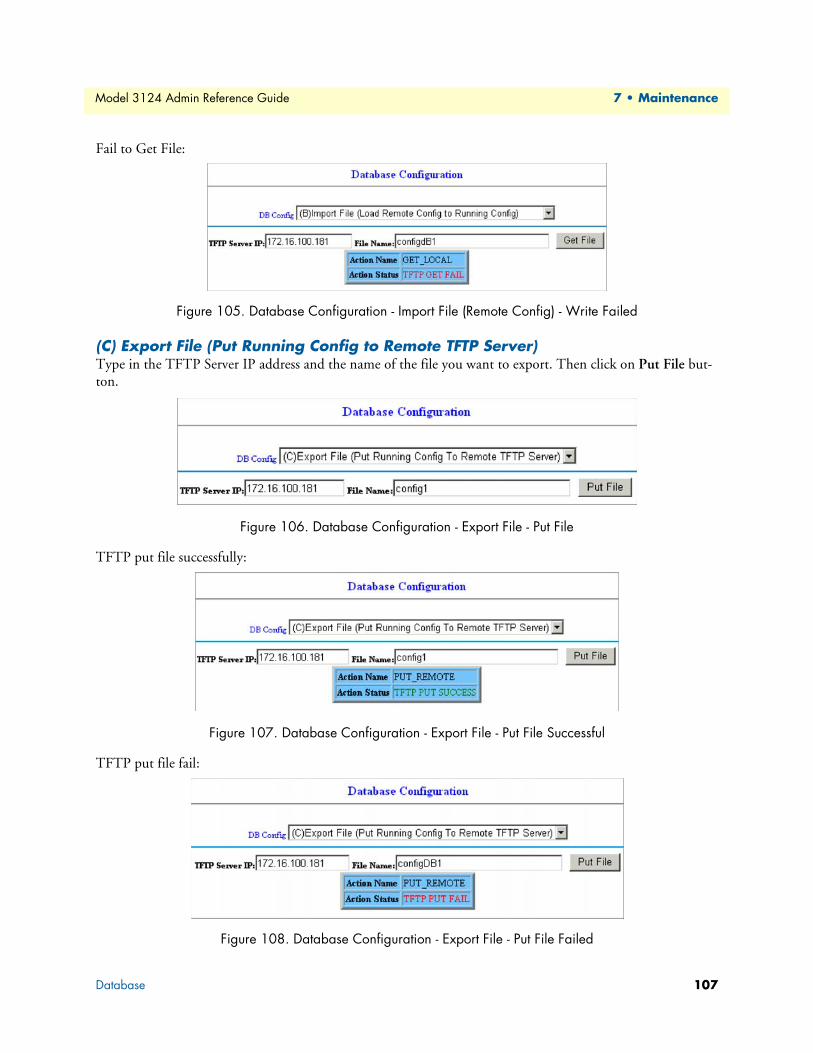
Model 3124 Admin Reference Guide 7 • Maintenance
Fail to Get File:
Figure 105. Database Configuration - Import File (Remote Config) - Write Failed
(C) Export File (Put Running Config to Remote TFTP Server)Type in the TFTP Server IP address and the name of the file you want to export. Then click on Put File but-ton.
Figure 106. Database Configuration - Export File - Put File
TFTP put file successfully:
Figure 107. Database Configuration - Export File - Put File Successful
TFTP put file fail:
Figure 108. Database Configuration - Export File - Put File Failed
Database 107
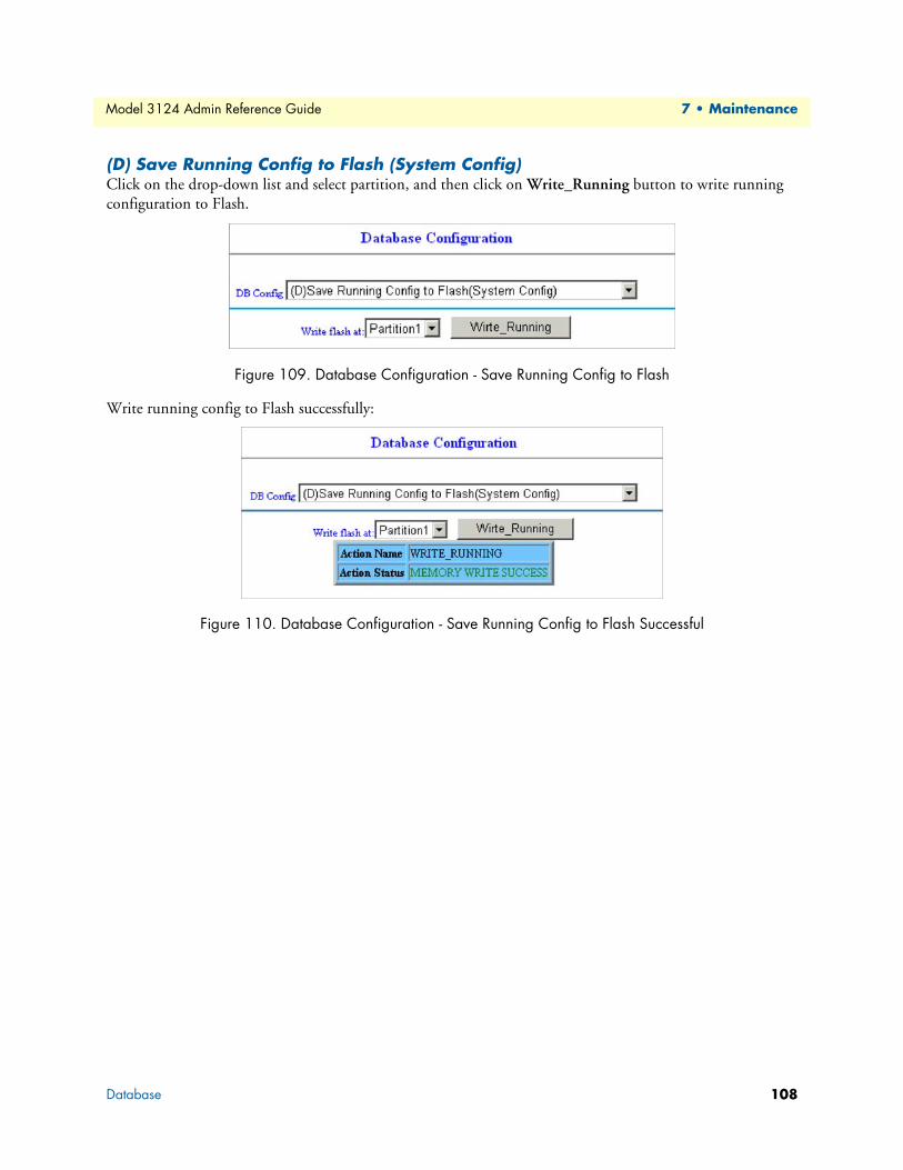
Model 3124 Admin Reference Guide 7 • Maintenance
(D) Save Running Config to Flash (System Config)Click on the drop-down list and select partition, and then click on Write_Running button to write running configuration to Flash.
Figure 109. Database Configuration - Save Running Config to Flash
Write running config to Flash successfully:
Figure 110. Database Configuration - Save Running Config to Flash Successful
Database 108

Model 3124 Admin Reference Guide 7 • Maintenance
(E) Reload Flash to Running ConfigClick on the drop-down list and select partition, and then click on LOAD_FLASH button to load configura-tion from Flash to Running Config.
Figure 111. Database Configuration - Reload Flash
Load configuration from Flash to Running Config successfully:
Figure 112. Database Configuration - Reload Flash Successful
Database 109

Model 3124 Admin Reference Guide 7 • Maintenance
(F) Restore Factory DefaultExcept out-band IP address and user account, all other configuration will be restored to factory default.
Click on Factory_Default button to restore factory default configuration.
Figure 113. Database Configuration - Restore Factory Default
After loading default configuration to Flash successfully, you must click on RESTART button to restart the system so that the configuration can take effect:
Figure 114. Database Configuration - Restore Factory Default Successful
Database 110
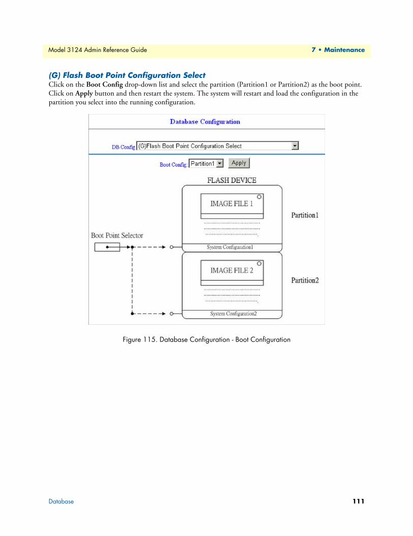
Model 3124 Admin Reference Guide 7 • Maintenance
(G) Flash Boot Point Configuration SelectClick on the Boot Config drop-down list and select the partition (Partition1 or Partition2) as the boot point. Click on Apply button and then restart the system. The system will restart and load the configuration in the partition you select into the running configuration.
Figure 115. Database Configuration - Boot Configuration
Database 111
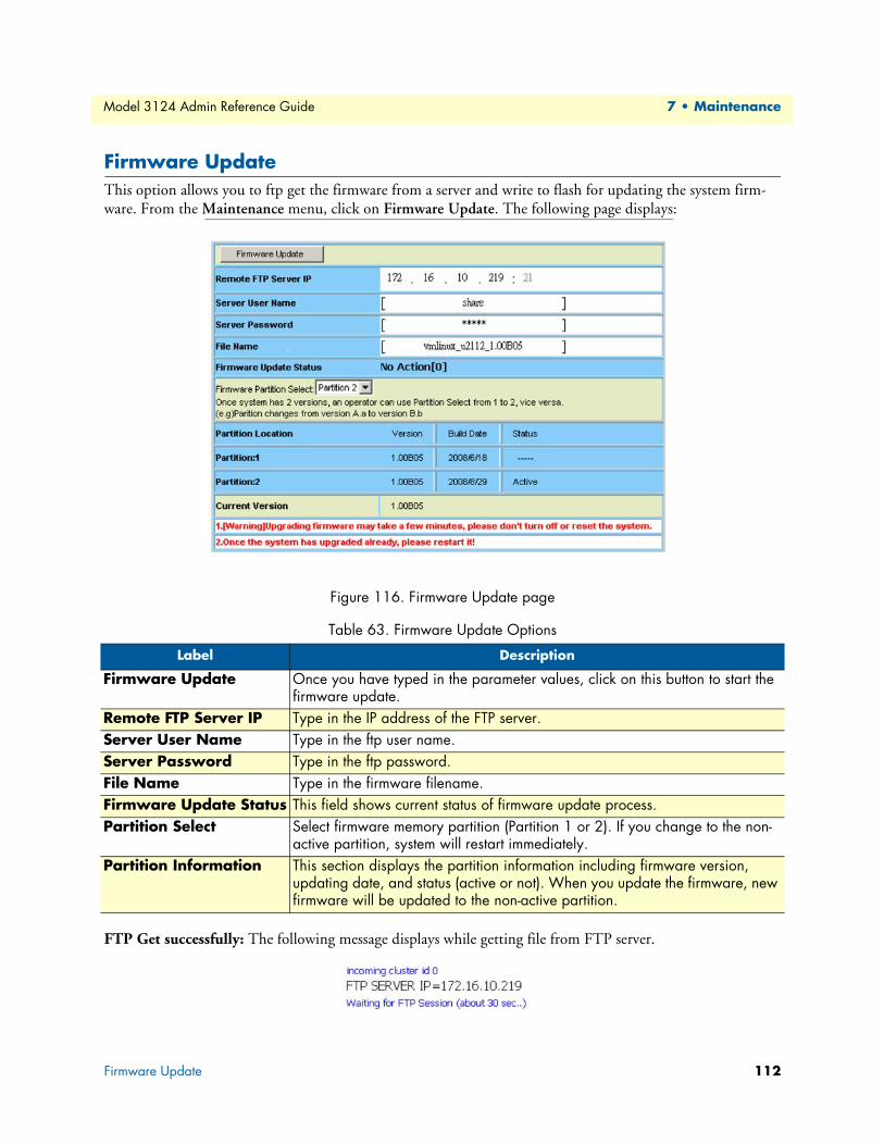
Model 3124 Admin Reference Guide 7 • Maintenance
Firmware UpdateThis option allows you to ftp get the firmware from a server and write to flash for updating the system firm-ware. From the Maintenance menu, click on Firmware Update. The following page displays:
Figure 116. Firmware Update page
FTP Get successfully: The following message displays while getting file from FTP server.
Table 63. Firmware Update Options
Label Description
Firmware Update Once you have typed in the parameter values, click on this button to start the firmware update.
Remote FTP Server IP Type in the IP address of the FTP server.Server User Name Type in the ftp user name.Server Password Type in the ftp password.File Name Type in the firmware filename.Firmware Update Status This field shows current status of firmware update process.Partition Select Select firmware memory partition (Partition 1 or 2). If you change to the non-
active partition, system will restart immediately.Partition Information This section displays the partition information including firmware version,
updating date, and status (active or not). When you update the firmware, new firmware will be updated to the non-active partition.
Firmware Update 112

Model 3124 Admin Reference Guide 7 • Maintenance
Firmware Write in progress: The Flash Write process may take a few minutes; you must not turn off or reset the system during the process.
Figure 117. Firmware Update - Flash Write In Progress
Write image to FLASH successfully: When the Flash Write process has completed successfully, the Firmware Update Status shows “Firmware has upgraded already”. You can now restart the system.
Figure 118. Firmware Update - Flash Write Successful
Firmware Update 113

Model 3124 Admin Reference Guide 7 • Maintenance
ATM LoopbacksThis option allows you to modify the ATM F4/F5 entries or send the diagnostic entry. From the Maintenance menu, click on ATM Loopbacks. The following page displays:
Figure 119. ATM Loopback page
Table 64. ATM Loopback Settings
Label Description
OAM Cell Generation Click on the radio button to Disable/Enable OAM Cell Generation. Then click on Apply button to submit the setting.
Port List Click on the drop-down lists to select port range (1 ~ 24) and PVC (1 ~ 8).Create Click on this button to create a loopback setting.
Note: Make sure the interface has been setup and the service state of the cir-cuit is turned on.
Query Click on this button to query the loopback status.Delete Click on this button to delete a loopback entry.Select Click on the check box to select the PVC you want to create or delete the loop-
back setting for.Port This field shows the port and PVC number.LoopBack ID Type in a loopback ID (32 digit).Test Type Select the loopback type: F5 E2E or F5 Segment.Status This field shows current loopback testing status. Possible values are:
Fail, Success, In Progress, or ----.
ATM Loopbacks 114

Model 3124 Admin Reference Guide 7 • Maintenance
Fault Management
Alarm/EventThis option allows you to query current alarm, history alarm, and event log. From the Maintenance menu, click on Fault Management and then Alarm/Event. The Current Alarm page displays. Click on the Alarm/Event Select drop-down list and select Current Alarm, History Alarm, or Event Log to view.
Current AlarmType in the range of rows (1 ~ 1024) and then click on the Query button.
Figure 120. Current Alarm page
History Alarm
Figure 121. History Alarm page
Table 65. Current Alarm Table Description
Label Description
Query Click on this button to get the most recent data.Row This field shows the row number (1~256).ID This field shows the alarm ID.Description This field shows the description for the alarm.Level This field shows the alarm level. Valid values are:
MJ: major alarm. MN: minor alarm.State This field shows the alarm state: Set or Clear.Sequential Sequential number.Time Alarm occurring date and time.
Fault Management 115
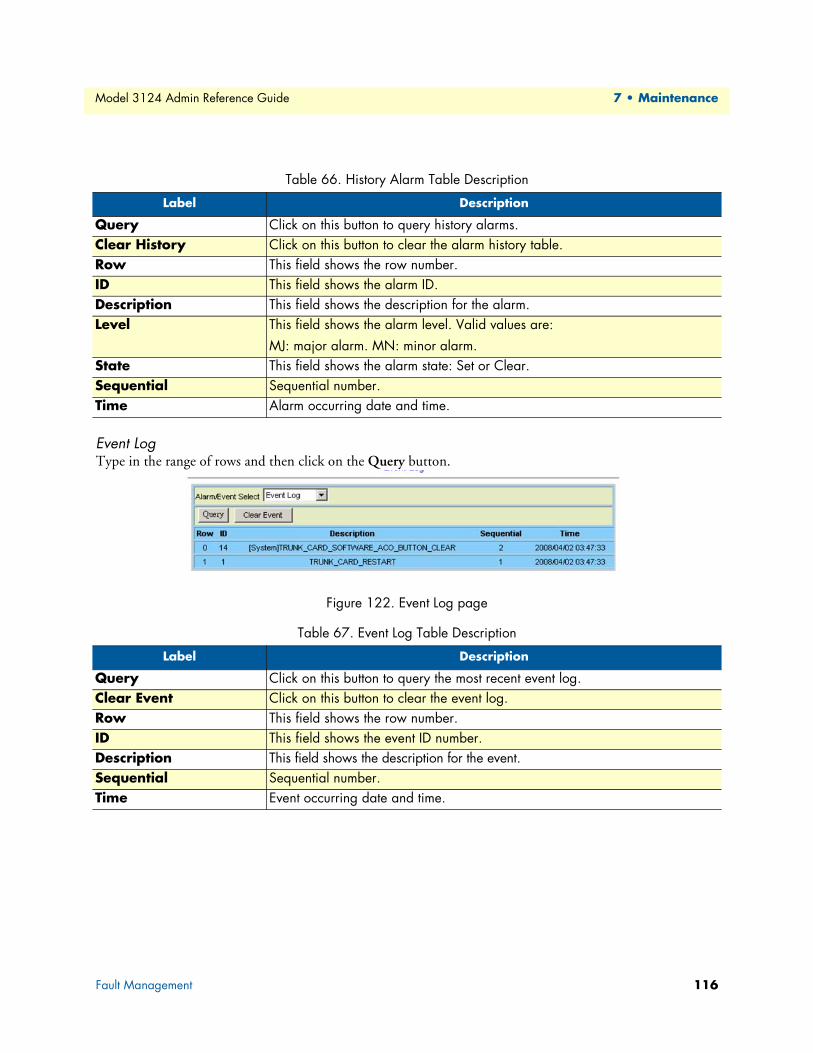
Model 3124 Admin Reference Guide 7 • Maintenance
Event LogType in the range of rows and then click on the Query button.
Figure 122. Event Log page
Table 66. History Alarm Table Description
Label Description
Query Click on this button to query history alarms.Clear History Click on this button to clear the alarm history table.Row This field shows the row number.ID This field shows the alarm ID.Description This field shows the description for the alarm.Level This field shows the alarm level. Valid values are:
MJ: major alarm. MN: minor alarm.State This field shows the alarm state: Set or Clear.Sequential Sequential number.Time Alarm occurring date and time.
Table 67. Event Log Table Description
Label Description
Query Click on this button to query the most recent event log.Clear Event Click on this button to clear the event log.Row This field shows the row number.ID This field shows the event ID number.Description This field shows the description for the event.Sequential Sequential number.Time Event occurring date and time.
Fault Management 116

Model 3124 Admin Reference Guide 7 • Maintenance
Alarm ProfileThis option allows you to view and update the alarm profiles. From the Maintenance menu, click on Fault Management and then Alarm profile. The Alarm Profile page displays. Click on the Select Page drop-down list and select a page to display.
To modify an alarm profile, click on the radio button beside the alarm ID, select the Level (Major/Minor), Mask/Unmask, and then click on the Modify button. You can also select the ALL ID checkbox to modify all alarm types at a time.
Figure 123. Alarm Profile page
Fault Management 117
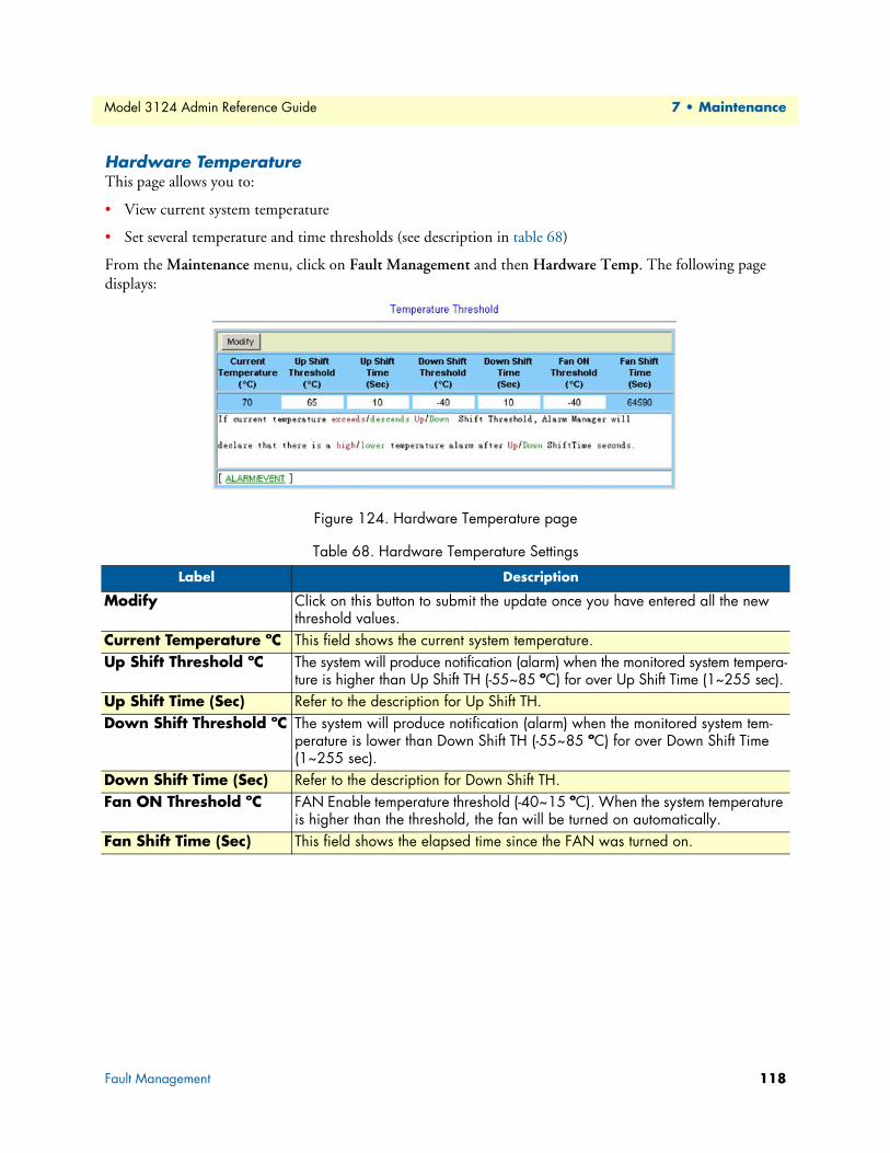
Model 3124 Admin Reference Guide 7 • Maintenance
Hardware TemperatureThis page allows you to:
• View current system temperature
• Set several temperature and time thresholds (see description in table 68)
From the Maintenance menu, click on Fault Management and then Hardware Temp. The following page displays:
Figure 124. Hardware Temperature page
Table 68. Hardware Temperature Settings
Label Description
Modify Click on this button to submit the update once you have entered all the new threshold values.
Current Temperature ºC This field shows the current system temperature.Up Shift Threshold ºC The system will produce notification (alarm) when the monitored system tempera-
ture is higher than Up Shift TH (-55~85 ºC) for over Up Shift Time (1~255 sec).Up Shift Time (Sec) Refer to the description for Up Shift TH.Down Shift Threshold ºC The system will produce notification (alarm) when the monitored system tem-
perature is lower than Down Shift TH (-55~85 ºC) for over Down Shift Time (1~255 sec).
Down Shift Time (Sec) Refer to the description for Down Shift TH.Fan ON Threshold ºC FAN Enable temperature threshold (-40~15 ºC). When the system temperature
is higher than the threshold, the fan will be turned on automatically.Fan Shift Time (Sec) This field shows the elapsed time since the FAN was turned on.
Fault Management 118

Model 3124 Admin Reference Guide 7 • Maintenance
Performance Monitoring
System UtilizationThis option allows you to monitor the memory utilization and network processor utilization. From the Main-tenance menu, click on Performance Monitoring and then System Utilization. The following page displays.
Figure 125. System Utilization
Ethernet StatisticsThis option allows you to view the Gigabit Ethernet counter values for the trunk or line interface. From the Maintenance menu, click on Performance Monitoring and then Ethernet Statistics. Click on the leftmost drop-down list to select interface (giga port or DSL line port); if line interface is selected, you must further click on the middle and rightmost drop-down list to select the line port number and PVC number. At last, click on Query to get data of that interface.
GBE Interface
Figure 126. Ethernet Statistics - GBE Interface
Performance Monitoring 119

Model 3124 Admin Reference Guide 7 • Maintenance
ADSL Line PVC
Figure 127. Ethernet Statistics - ADSL Line PVC
ATM StatisticsThis option allows you to query the ATM Statistics. From the Performance Monitoring menu, click on ATM Statistics. The following page displays:
Figure 128. ATM Statistics page
Table 69. ATM Statistics
Label Description
ADSL Port Click on this button to select the line port.Auto Update Select this check box to auto update the displayed statistics.Show Click on this drop-down list to select Tx, Rx, or All (Tx & Rx) data.Query Click on this button to query current statistics.
Performance Monitoring 120

Model 3124 Admin Reference Guide 7 • Maintenance
RMONThis option allows you to configure and query the RMON Statistics. The Model 3124 supports performance statistics defined in RMON MIB groups 1 (Ethernet statistics), 2 (history control), 3 (alarm), and 9 (event) per RFC 2819 for all network uplink ports. From the Performance Monitoring menu, click on RMON.The fol-lowing page displays:. Select statistics type in the drop-down list.
Figure 129. Remote Monitoring (RMON) page
ETH StatisticsThis option is for displaying the Ethernet interface RMON data. Click on the Data Source drop-down list and select GBE1 or GBE2. Type in an owner name and then click on New button to create a new ETH statistics entry. To modify an entry, click on the index to select the entry, type in new value, and then click on Modify. To delete an entry, click on the index to select the entry and then click on Delete. The following parameters are monitored in this table:
Table 70. RMON ETH Statistics
Variable Description
DropEvents Monitoring rx dropped packetsOctets Monitoring rx bytes packetsPkts Monitoring rx packetsBroadcastPkts Monitoring rx broadcast packetsMulticastPkts Monitoring rx multicast packetsCRCAlignErrors Monitoring rx error aligment packetsUndersizePkts Monitoring rx undersize packetsOversizePkts Monitoring rx oversize packetsFragments Monitoring rx fragments packetsJabbers Monitoring rx jabber packetsCollisions Monitoring tx single collision packetsPkts64Octets Monitoring tx 64 octetsPkts65to127Octets Monitoring tx 65 to 127 octetsPkts128to255Octets Monitoring tx 128 to 255 octetsPkts256to511Octets Monitoring tx 256 to 511 octetsPkts512to1023Octets Monitoring tx 512 to 1023 octetsPkts1024to1518Octets Monitoring tx 1024 to 1518 octets
Performance Monitoring 121

Model 3124 Admin Reference Guide 7 • Maintenance
Figure 130. Remote Monitoring - ETH Statistics
Performance Monitoring 122

Model 3124 Admin Reference Guide 7 • Maintenance
History ControlThis table is for controlling the ETH History table (see next section). History Control 1 is for controlling ETH History table 1; History Control 2 is for controlling ETH History table 2; etc. Type in the Requested value and Interval (sec) and then click on New to create a History Control entry. Up to 10 History Control entries can be created. To modify an entry, click on the index to select the entry, type in new value, and then click on Modify. To delete an entry, click on the index to select the entry and then click on Delete.
Figure 131. Remote Monitoring - History Control
Table 71. RMON History Control
Label Description
Data Source Data source identifies the source of the data for which historical data was col-lected and placed in a table on behalf of this HistoryControl entry. Here the source is GBE1 interface.
Owner An owner is the entity that configured this entry and is therefore using the resources assigned to it.
Requested Requested value is the requested number of intervals over which data is to be saved in the part of the media-specific table associated with this HistoryControl entry.
Granted The number of sampling intervals over which data shall be saved in the part of the media-specific table associated with this HistoryControl entry.
Interval The interval in seconds over which the data is sampled for each bucket in the part of the media-specific table associated with this HistoryControl entry. The value range is 1 to 3600 (sec).
Performance Monitoring 123

Model 3124 Admin Reference Guide 7 • Maintenance
ETH HistoryThis option is for displaying Ethernet interface RMON history data. Before a history table is available, you have to create a History Control entry in advance (see previous section). To query the History table, click on the History Index drop-down list and select a history table and then click on Query.
Figure 132. Remote Monitoring - ETH History
Table 72. RMON Eth History
Label Description
HistIndex This field shows the History Table index. The history identified by this index is the same history as identified by the same value of History Control index.
SampleIndex The Sample index uniquely identifies the particular Sample among all samples associated with the same History Control entry.
IntervalStart The value of System Up Timea at the start of the interval over which this sample was measured.
a. System Up Time is the time since the network management portion of the system was last re-initialized.
Performance Monitoring 124
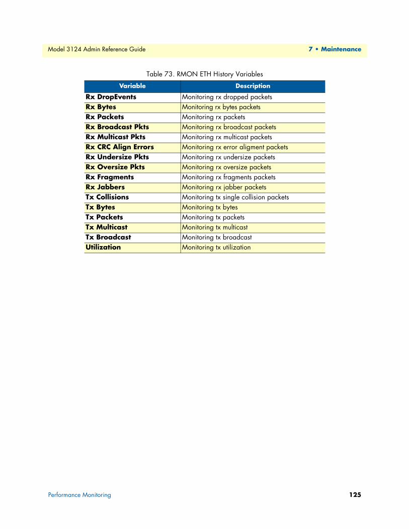
Model 3124 Admin Reference Guide 7 • Maintenance
Table 73. RMON ETH History Variables
Variable Description
Rx DropEvents Monitoring rx dropped packetsRx Bytes Monitoring rx bytes packetsRx Packets Monitoring rx packetsRx Broadcast Pkts Monitoring rx broadcast packetsRx Multicast Pkts Monitoring rx multicast packetsRx CRC Align Errors Monitoring rx error aligment packetsRx Undersize Pkts Monitoring rx undersize packetsRx Oversize Pkts Monitoring rx oversize packetsRx Fragments Monitoring rx fragments packetsRx Jabbers Monitoring rx jabber packetsTx Collisions Monitoring tx single collision packetsTx Bytes Monitoring tx bytesTx Packets Monitoring tx packetsTx Multicast Monitoring tx multicastTx Broadcast Monitoring tx broadcastUtilization Monitoring tx utilization
Performance Monitoring 125
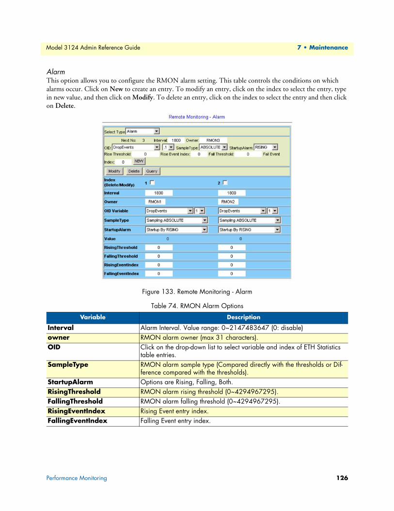
Model 3124 Admin Reference Guide 7 • Maintenance
AlarmThis option allows you to configure the RMON alarm setting. This table controls the conditions on which alarms occur. Click on New to create an entry. To modify an entry, click on the index to select the entry, type in new value, and then click on Modify. To delete an entry, click on the index to select the entry and then click on Delete.
Figure 133. Remote Monitoring - Alarm
Table 74. RMON Alarm Options
Variable Description
Interval Alarm Interval. Value range: 0~2147483647 (0: disable)owner RMON alarm owner (max 31 characters).OID Click on the drop-down list to select variable and index of ETH Statistics
table entries.SampleType RMON alarm sample type (Compared directly with the thresholds or Dif-
ference compared with the thresholds).StartupAlarm Options are Rising, Falling, Both.RisingThreshold RMON alarm rising threshold (0~4294967295).FallingThreshold RMON alarm falling threshold (0~4294967295).RisingEventIndex Rising Event entry index.FallingEventIndex Falling Event entry index.
Performance Monitoring 126

Model 3124 Admin Reference Guide 7 • Maintenance
The following figure shows an example of RMON alarm for ABSOLUTE sample type. As shown in the figure, the counting value keeps increasing. But when the value overflows, the system will count from zero again. The sample in T2 is the first one crossing the Rising Threshold, so an alarm occurs. No alarms will be generated afterwards unless the counting value overflows and count from zero again (the sample in T10 causes an alarm again).
Figure 134. Example: RMON Alarm for ABSOLUTE Sample Type
Another figure shows the example of RMON alarm for DELTA sample type. As shown in the following figure, the delta value varies high and low. The sample in T1 is the first one crossing the Rising Threshold, so an alarm occurs. No alarms will be generated afterwards until T5 sample which is crossing the Falling Threshold (note that the value of the previous sample, T4 sample, is greater than the Falling Threshold and the value of T5 sample). Alarm is not generated for T7 sample since an alarm is already generated for T5 sample and the curve is not in a downward trend around T7. A Rising Threshold crossing alarm is generated again for T10 sample, because a Falling Threshold croprevious Rising Threshold crossing alarm (T1).
Figure 135. Example: RMON Alarm for DELTA Sample Type
Performance Monitoring 127

Model 3124 Admin Reference Guide 7 • Maintenance
EventThis option allows you to configure the RMON event setting. Click on New to create an entry. To modify an entry, click on the index to select the entry, type in new value, and then click on Modify. To delete an entry, click on the index to select the entry and then click on Delete.
Figure 136. Remote Monitoring - Event
LOGThis option allows you to query the RMON LOG. Click on Query button to display the log. Only the event indices with LOG or LOGANDTRAP event type (see previous section) are possible to appear in the log.
Figure 137. Remote Monitoring - LOG
Table 75. RMON Event Options
Variable Description
Description Type in a comment describing the event.Community If an SNMP trap is to be sent, it will be sent to the SNMP community spec-
ified in this column.Owner Type in the RMON event owner.Event Type Click on the drop-down list and select event type. Options are NONE,
LOG (an entry is made in the log table for each event), SNMPTRAP (an SNMP trap is sent to one or more management stations), LOGANDTRAP (log and send trap).
LastTimeSent The value of System Up Time at the time this event entry last generated an event.
Performance Monitoring 128

Model 3124 Admin Reference Guide 7 • Maintenance
ADSL Day/IntervalThis option allows you to query the ADSL PM 15-Min and Day Statistics. The Model 3124 provides Today and Previous 1 day for Day PM, and also provides Current and Previous 1 ~ 96 interval for 15-Min PM. From the Maintenance menu, click on Performance Monitoring and then ADSL Day/Interval. The following page is displayed. You can select to display one interval or all intervals data of a single port; you can also select to dis-play one interval data for twelve ports (1~12, 13~24) at the same time.
Figure 138. ADSL Line Performance Statistics
Table 76. ADSL Line Performance Statistics
Variable Description
More Port Click on the drop-down list and select the port range. Options are: 01~12, 13~24. This drop-down list is available only when All is selected in the Port drop-down list.
Port Click on the drop-down list and select a line port number (1 ~ 24). You can also select All and then click on More Port to select a port range to view the data of twelve ports at the same time.
All Interval When you select to view a single port PM data, you can click on this checkbox to display the data of all intervals.
Query Click on this button to get the most recent data.Clear PM Click on this button to clear current PM data of the port you select.LOS Loss of SignalLOF Loss of Frame
Performance Monitoring 129

Model 3124 Admin Reference Guide 7 • Maintenance
LOM Loss of MarginLPR Loss of Power (only for Far End)LOL Loss of Link (only for Near End)ES Errored SecondsSES Severely Errored SecondsUAS Unavailable SecondsRe-Initialize Modem Re-Initialization events (only for Near End)Initialize fail (s) Modem Failed Initialization events (only for Near End)User Cell (CU) User Total Cell Count (only for Near End)Delineate Cell (CD) Delineated Total Cell Count (only for Near End)HEC ATM Header Error Count IBE Idle Cell Bit Error Count
Channel-CVs Channel PM - Code ViolationsChannel-FECCs Channel PM- Forward Error Corrections
Table 76. ADSL Line Performance Statistics
Performance Monitoring 130

Chapter 8 Contacting Patton for assistance
Chapter contentsIntroduction........................................................................................................................................................132
Contact information............................................................................................................................................132
Warranty Service and Returned Merchandise Authorizations (RMAs).................................................................132Warranty coverage ........................................................................................................................................132
Out-of-warranty service ...........................................................................................................................132
Returns for credit ....................................................................................................................................132Return for credit policy ...........................................................................................................................133
RMA numbers ..............................................................................................................................................133
Shipping instructions ..............................................................................................................................133
131

Model 3124 Admin Reference Guide 8 • Contacting Patton for assistance
IntroductionThis chapter contains the following information:
• “Contact information”—describes how to contact PATTON technical support for assistance.
• “Warranty Service and Returned Merchandise Authorizations (RMAs)”—contains information about the RAS warranty and obtaining a return merchandise authorization (RMA).
Contact informationPatton Electronics offers a wide array of free technical services. If you have questions about any of our other products we recommend you begin your search for answers by using our technical knowledge base. Here, we have gathered together many of the more commonly asked questions and compiled them into a searchable database to help you quickly solve your problems.
• Online support—available at www.patton.com.
• E-mail support—e-mail sent to [email protected] will be answered within 1 business day
• Telephone support—standard telephone support is available Monday through Friday, from 8:00 A.M. to 5:00 P.M. EST (8:00 to 17:00 UTC-5), Monday through Friday by calling +1 (301) 975-1007
Warranty Service and Returned Merchandise Authorizations (RMAs)Patton Electronics is an ISO-9001 certified manufacturer and our products are carefully tested before ship-ment. All of our products are backed by a comprehensive warranty program.
Note If you purchased your equipment from a Patton Electronics reseller, ask your reseller how you should proceed with warranty service. It is often more convenient for you to work with your local reseller to obtain a replacement. Patton services our products no matter how you acquired them.
Warranty coverageOur products are under warranty to be free from defects, and we will, at our option, repair or replace the prod-uct should it fail within one year from the first date of shipment. Our warranty is limited to defects in work-manship or materials, and does not cover customer damage, lightning or power surge damage, abuse, or unauthorized modification.
Out-of-warranty servicePatton services what we sell, no matter how you acquired it, including malfunctioning products that are no longer under warranty. Our products have a flat fee for repairs. Units damaged by lightning or other catastro-phes may require replacement.
Returns for creditCustomer satisfaction is important to us, therefore any product may be returned with authorization within 30 days from the shipment date for a full credit of the purchase price. If you have ordered the wrong equipment or you are dissatisfied in any way, please contact us to request an RMA number to accept your return. Patton is not responsible for equipment returned without a Return Authorization.
Introduction 132

Model 3124 Admin Reference Guide 8 • Contacting Patton for assistance
Return for credit policy • Less than 30 days: No Charge. Your credit will be issued upon receipt and inspection of the equipment.
• 30 to 60 days: We will add a 20% restocking charge (crediting your account with 80% of the purchase price).
• Over 60 days: Products will be accepted for repairs only.
RMA numbersRMA numbers are required for all product returns. You can obtain an RMA by doing one of the following:
• Completing a request on the RMA Request page in the Support section at www.patton.com
• By calling +1 (301) 975-1000 and speaking to a Technical Support Engineer
• By sending an e-mail to [email protected]
All returned units must have the RMA number clearly visible on the outside of the shipping container. Please use the original packing material that the device came in or pack the unit securely to avoid damage during ship-ping.
Shipping instructionsThe RMA number should be clearly visible on the address label. Our shipping address is as follows:
Patton Electronics Company RMA#: xxxx 7622 Rickenbacker Dr. Gaithersburg, MD 20879-4773 USA
Patton will ship the equipment back to you in the same manner you ship it to us. Patton will pay the return shipping costs.
Warranty Service and Returned Merchandise Authorizations (RMAs) 133

Appendix A Abbreviations
Chapter contentsAbbreviations ......................................................................................................................................................135
134

Model 3124 Admin Reference Guide A • Abbreviations
Abbreviations
Table 77. Abbreviations
Abbreviation Description
ACL Access Control ListADSL Asymmetric Digital Subscriber Line
ADSLx ADSL or ADSL2 or ADSL2+ATM Asynchronous Transfer ModeCBR Constant Bit Rate
CDVT Cell Delay Variation ToleranceCLI Command Line Interface
DHCP Dynamic Host Configuration ProtocolIGMP Internet Group Management Protocol
IP Internet ProtocolLACP Link Aggregation Control ProtocolNE Network ElementPCR Peak Cell Rate
PPPoE Point-to-Point Protocol over EthernetRMON Remote MonitoringSNMP Simple Network Management ProtocolSNTP Simple Network Time ProtocolSTP Spanning Tree ProtocolUBR Unspecified Bit RateVBR Variable Bit RateVCI Virtual Channel Identifier
VLAN Virtual Local Area NetworkVPI Virtual Path Identifier
Abbreviations 135
Related Documents