contents Specifications 3 Outline Dimensions 6 Boom Combinations 14 Boom Asset Management 16 Crane Assembly 18 Range Diagrams/Load Charts 22 Manitowoc Crane Care 24 features • 2 300 mton (2,535 t) main boom • 1 400 mton (1,540 t) vessel jib • 1 000 mton (1,100 t) luffing jib • 32 000 mton-m (241,456 ft-kips) Maximum Load Moment • 105 m (344.5 ft) Heavy-Lift Boom • 102 m (339 ft) Luffing Jib on Heavy-Lift Boom • 24 m (79.8 ft) Vessel Jib on Heavy-Lift Boom • 894 kW (1,200 HP) twin engine • Variable Position Counterweight (VPC) - Patent Pending • EPIC® controls with CAN-Bus technology • 139 m/min (456 fpm) line speed standard • 490 kN (110,000 lb) line pull standard • Designed to meet US weight and European width requirements • Fast, efficient self-assembly and disassembly model 31000 PROVISIONAL 23 May 2008 CONFIDENTIAL www.manitowoc.com product guide

Welcome message from author
This document is posted to help you gain knowledge. Please leave a comment to let me know what you think about it! Share it to your friends and learn new things together.
Transcript

contentsSpecifications 3Outline Dimensions 6Boom Combinations 14Boom Asset Management 16Crane Assembly 18Range Diagrams/Load Charts 22
Manitowoc Crane Care 24
features • 2 300 mton (2,535 t) main boom
• 1 400 mton (1,540 t) vessel jib
• 1 000 mton (1,100 t) luffing jib • 32 000 mton-m (241,456 ft-kips) Maximum Load Moment
• 105 m (344.5 ft) Heavy-Lift Boom
• 102 m (339 ft) Luffing Jib on Heavy-Lift Boom
• 24 m (79.8 ft) Vessel Jib on Heavy-Lift Boom
• 894 kW (1,200 HP) twin engine
• Variable Position Counterweight (VPC) - Patent Pending
• EPIC® controls with CAN-Bus technology
• 139 m/min (456 fpm) line speed standard
• 490 kN (110,000 lb) line pull standard
• Designed to meet US weight and European width requirements
• Fast, efficient self-assembly and disassembly
model 31000PROVISIONAL
23 May 2008
CONFIDENTIAL
www.manitowoc.com
productguide

�
mod
el 3
1000
The quick red fox jumps over the lazy brown dog. The quick red fox jumps over the lazy brown dog. The quick red fox jumps over the lazy brown dog. The quick red fox jumps over the lazy brown dog.
PROVISIONAL PROVISIONAL
CONFIDENTIALCONFIDENTIAL
specifications
3
mod
el 3
1000
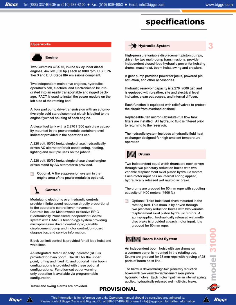
Hydraulic System
High-pressure variable displacement piston pumps, driven by two multi-pump transmissions, provide independent closed-loop hydraulic power for hoisting drums, mast hoist, boom hoist, swing and crawlers.
A gear pump provides power for jacks, powered pin actuation, and other accessories.
Hydraulic reservoir capacity is 2,270 l (600 gal) and is equipped with breather, site and electrical level indicator, clean out access, and internal diffuser.
Each function is equipped with relief valves to protect the circuit from overload or shock.
Replaceable, ten micron (absolute) full flow tank filters are installed. All hydraulic fluid is filtered prior to returning to the reservoir.
The hydraulic system includes a hydraulic fluid heat exchanger designed for high ambient temperature operation
Drums
Two independent equal width drums are each driven through two planetary reduction boxes with two variable displacement axial piston hydraulic motors. Each motor input has an internal spring applied, hydraulically released wet multi-disc brake.
The drums are grooved for 50 mm rope with spooling capacity of 1400 meters (4600 ft.)
Optional: Third hoist load drum mounted in the rotating bed. This drum is by driven through two planetary reduction boxes with two variable displacement axial piston hydraulic motors. A spring-applied, hydraulically released wet multi-disc brake is provided at each motor input. It is grooved for 50 mm rope.
Boom Hoist System
An independent boom hoist with two drums on a common barrel is mounted in the rotating bed. Drums are grooved for 36 mm rope with reeving of 28 parts of boom hoist line.
The barrel is driven through two planetary reduction boxes with two variable displacement axial piston hydraulic motors. Each motor input has an internal spring applied, hydraulically released wet multi-disc brake.
Upperworks
Engine
Two Cummins QSX 15, in-line six cylinder diesel engines, 447 kw (600 hp.) each at 1800 rpm, U.S. EPA Tier 3 and E.U. Stage IIIA emissions compliant.
Two independent main drive engines, hydraulics, operator’s cab, electrical and electronics to be inte-grated into an easily transportable and rigged pack-age. FACT is used to install the power module on the left side of the rotating bed.
A four pad pump drive transmission with an automo-tive style cold start disconnect clutch is bolted to the engine flywheel housing of each engine.
A diesel fuel tank with a 2,270 l (600 gal) draw capac-ity mounted in the power module container; level indicator provided in the operator’s cab.
A 220 volt, 50/60 hertz, single phase, hydraulically driven AC alternator for air conditioning, heating, lighting and multiple uses on the jobsite.
A 220 volt, 50/60 hertz, single phase diesel engine driven stand by AC alternator is provided.
Optional: A fire suppression system in the engine area of the power module is optional.
Controls
Modulating electronic over hydraulic controls provide infinite speed response directly proportional to the operator’s control lever movement. Controls include Manitowoc’s exclusive EPIC® Electronically Processeed Independent Control system with CANBus technology system providing microprocessor driven control logic, variable displacement pump and motor control, on-board diagnostics, and service information.
Block up limit control is provided for all load hoist and whip lines.
An integrated Rated Capacity Indicator (RCI) is provided for main boom. The RCI for the upper point, luffing and fixed jib, and optional main boom configurations is provided with these optional configurations. Function-cut out or warning only operation is available via programmable configuration.
Travel and swing alarms are provided.PROVISIONAL PROVISIONAL
CONFIDENTIALCONFIDENTIAL

specifications
�
mod
el 3
1000
Swing System
Each independent swing drive is powered by fixed displacement axial piston hydraulic motors coupled to a planetary gearbox with an internal spring-applied wet multi-disc brake. The front and rear roller carriers have four swing drives each.
Swing system maximum speed: 0.50 rpm.
Variable Position Counterweight
Variable Position Counterweight (VPC) - Patent Pending: Load moment balancing counterweight infinitely variable between a retracted position of 8.38 m (27' 6") and an extended position of 28.93 m (94' 11"). Counterweight automatically positioned based on the boom angle and applied load.
949 m-ton (2,092,700 lb) of variable position counterweight consisting of a tray and “A” frames plus 44 twenty m-ton (44,000 lb) counterweight pieces.
No carbody counterweights.
Operator’s Cab
The operator’s seat and related crane controls tilt up to 20°.
Closed circuit cameras, one to monitor each rope drum, and camera to monitor the variable position counterweight. Three monitors with divisible screens provided.
Insulated for noise and weather.
Lowerworks
Carbody
The carbody consists of front and rear cross beams plus two side beams. A cross beam at the center provides support for the king pin and hydraulic swivel.
Carbody beams are FACT™ connected, all pins are hydraulically inserted.
Four hydraulic jacking cylinders assist assembly.
All beams are bending and torsion resistant welded structure fabricated from high strength, fine grained steel.
Roller Path and Ring GearThe roller path is 12.19 m (40') outside diameter, integral with the carbody beams. The roller path is precision machined after welding.
Precision cut ring gear segments are bolted to the inside diameter of the roller path.
Crawlers
Individual trunion mounted crawler assemblies pivotally attach to each end of the front and rear cross beams. This design assures uniform load distribution over the length of each assembly.
The four crawler assemblies are hydraulically powered, the two right-side assemblies operating in unison and the two left-side assemblies operating in unison. Dual drives are installed on each crawler assembly.
The overall length of each crawler assembly is 8.62 m (28' 3"). The track pads are 2.03 m (80") wide.
Crawler drives enable travel and counter-rotation with full rated load. Maximum travel speed is 0.55 km/h (0.34 mph)
Attachments
No. 90 Heavy-Lift Boom
The liftcrane is equipped with 55 m (179' 5") No. 90 basic boom consisting of 7 m (22' 10") butt, (4) 10 m (32' 9") inserts, 6.5 m (21' 4") transition insert and 1.5 m (4' 11") top. Includes rope guides, boom hoist wire rope and boom angle indicators. The boom connectors utilize Manitowoc’s exclusive FACT™ connection system boom connector. Spring cushioned boom stop. Automatic boom stop. Powered boom pins system including cylinder, piping, operating controls, and locking device standard.
Fixed Jib (Vessel Lifting)
Optional: Fixed Jib (vessel lifting) 24 m (78' 8") 7 m (22' 11") butt, 9 m (29' 6") insert, 6.5 m (21'
4") transition insert and 1.5 m (4' 11") top.
PROVISIONAL PROVISIONAL
CONFIDENTIALCONFIDENTIAL

specifications
�
mod
el 3
1000
Steel Jib suspension straps and FACT™ connection system.
No. 91 Luffing Jib
Optional: 36 m (118') basic No. 91 luffing jib 7 m (22' 11") boom butt; 9 m (29' 6") insert; 12 m (39' 3" insert; 6.5 m (21' 4") transition insert and 1.5 m (4' 11") top; basic pendants, fixed strut, jib strut, backstay suspension straps, luffing jib hoist with ratchet and pawl and boom dolly; quick disconnect for jib hoist piping, and 38 mm luffing jib hoist line (luffing jib preparation is standard).
Optional: 6 m (19' 8") and 12 m (39' 5") No. 91 luffing jib inserts with steel boom suspension straps and FACT™ connection system.
Optional Equipment
Optional: Segmented Hook Block: The segmented, mechanically equalized,
divisible hook block consists of two 1,000 m-ton capacity duplex hooks with configurations as follows:
2000 m-ton, two hooks, two load hoist drums 1000 m-ton, one hook, two load hoist drums 500 m-ton, one hook, one load hoist drum
Miscellaneous
Bearing Loads Under Track ShoesBearing with boom straight over the end: No hook load: 9,200 MPa (63 psi, 9,060 lbs/ft2®).
At maximum load moment: 15,800 MPa (109 psi, 15,700 lbs/ft®2)
Bearing with boom swing 45° from crawler longitudinal center at maximum load moment: 17,500 MPa (121 psi, 17,300 lbs/ft2)
PROVISIONAL PROVISIONAL
CONFIDENTIALCONFIDENTIAL

outline dimensions
�
mod
el 3
1000
PROVISIONAL PROVISIONAL
CONFIDENTIALCONFIDENTIAL

outline dimensions
�
mod
el 3
1000
PROVISIONAL PROVISIONAL
CONFIDENTIALCONFIDENTIAL

outline dimensions
�
mod
el 3
1000
Power Plant and Cab Assembly x 1Length 15,90 m 52' 2"Width 3,40 m 11' 2"Height 3,00 m 9' 10"Weight 34 610 kg 76,300 lb
Power Plant Support x �Length 4,60 m 15' 1"Width 1,90 m 6' 3"Height 0,50 m 1' 8"Weight 3 600 kg 7,920 lb
Front Roller Carrier & Hook Roller Assembly x 1
Length 9,70 m 31' 10"Width 3,10 m 10' 2"Height 3,40 m 11' 2"Weight 44 500 kg 97,900 lb
Rear Roller Carrier & Hook Roller Assembly x 1
Length 8,80 m 28' 10"Width 3,00 m 9' 10"Height 3,10 m 10' 2"Weight 39 600 kg 87,120 lb
Rotating Bed x 1Length 9,80 m 32' 2"Width 3,10 m 10' 2"Height 3,00 m 9' 10"Weight 36 500 kg 80,300 lb
Crawlers x �Length 8,70 m 28' 6"Width 2,60 m 8' 6"Height 2,30 m 7' 7"Weight* 49 900 kg 109,780 lb*Weight without track pad: 28 800 kg (63,360 lb)
OptionPROVISIONAL PROVISIONAL
CONFIDENTIALCONFIDENTIAL

outline dimensions
9
mod
el 3
1000
Counterweight x ��Length 3,50 m 11' 6"Width 2,50 m 8' 2"Height 0,60 m 2' 0"Weight 20 000 kg 44,000 lb
Carbody Center Beam x 1Length 8,00 m 26' 3"Width 1,90 m 6' 3"Height 2,00 m 6' 7"Weight 8 500 kg 18,700 lb
Carbody Beam x �Length 11,50 m 37' 9"Width 2,60 m 8' 6"Height 2,60 m 8' 6"Weight 36 600 kg 80,520 lb
Swing Drive Assembly x �Length 2,60 m 8' 6"Width 1,20 m 3' 11"Height 1,50 m 4' 11"Weight 5 200 kg 11,440 lb
Trunion x �Length 3,00 m 9' 10"Width 1,00 m 3' 3"Height 1,00 m 3' 3"Weight 5 350 kg 11,770 lb
Carbody Side Beam with Struts x �Length 9,10 m 29' 10"Width 2,70 m 8' 10"Height 2,90 m 9' 6"Weight 33 100 kg 72,820 lb
Counterweight Tray Center x 1Length 5,40 m 17' 9"Width 3,50 m 11' 6"Height 2,50 m 8' 2"Weight 25 300 kg 55,660 lb
OptionPROVISIONAL PROVISIONAL
CONFIDENTIALCONFIDENTIAL

outline dimensions
10
mod
el 3
1000
Counterweight Ends with Supports x �Length 8,20 m 26' 11"Width 2,60 m 8' 6"Height 2,70 m 8' 10"Weight 37 100 kg 81,620 lb
Counterweight Positioning Frame x 1Length 14,70 m 48' 3"Width 3,40 m 11' 2"Height 2,50 m 8' 2"Weight 38 400 kg 84,480 lb
Counterweight Positioning Actuator x 1Length 10,70 m 35' 1"Width 2,70 m 8' 10"Height 1,80 m 5' 11"Weight 27 200 kg 59,840 lb
No. 90 Boom Butt �m x 1Length 7,90 m 25' 11"Width 4,00 m 13' 1"Height 3,20 m 10' 6"Weight 21 400 kg 47,080 lb
No. 90 10m Boom Insert with Straps x �Length 10,30 m 33' 9"Width 4,00 m 13' 1"Height 3,2 m 10' 6"Weight 23 300 kg 51,200 lb
No. 90 Boom Insert with 10m Wire Rope Guide x 1Length 10,30 m 33' 9"Width 4,00 m 13' 1"Height 3,2 m 10' 6"Weight 24 700 kg 54,340 lb
OptionPROVISIONAL PROVISIONAL
CONFIDENTIALCONFIDENTIAL

outline dimensions
11
mod
el 3
1000
No. 90 10m Boom Insert without Straps x 1Length 10,30 m 17' 5"Width 4,00 m 13' 1"Height 3,20 m 10' 6"Weight 20 400 kg 44,974 lb
No. 90 Boom Insert Equilizer 10,0m x 1Length 10,30 m 33' 9"Width 4,00 m 13' 1"Height 3,20 m 10' 6"Weight 26 900 kg 59,525 lb
No. 90 �m Boom Insert with Straps x 1Length 5,30 m 17' 5"Width 4,00 m 13' 1"Height 3,20 m 10' 6"Weight 14 100 kg 31,085 lb
No. 90 Boom Top �m x 1Length 9,80 m 32' 2"Width 4,00 m 13' 1"Height 3,20 m 10' 6"Weight 35 100 kg 77,220 lb
Upper Boom Point Assembly x 1 Length 9,10 m 29' 10"Width 2,20 m 7' 3"Height 3,00 m 9' 10"Weight 7 150 kg 15,730 lb
Lower Boom Point Assembly x �Length 2,60 m 8' 6"Width 1,90 m 6' 3"Height 1,90 m 6' 3"Weight 10 600 kg 23,369 lb
Mast Butt �.0�m x 1Length 7,60 m 24' 11"Width 3,10 m 10' 2"Height 2,80 m 9' 2"Weight 25 740 kg 25,740 lb
Option
PROVISIONAL PROVISIONAL
CONFIDENTIALCONFIDENTIAL
outline dimensions
1�
mod
el 3
1000
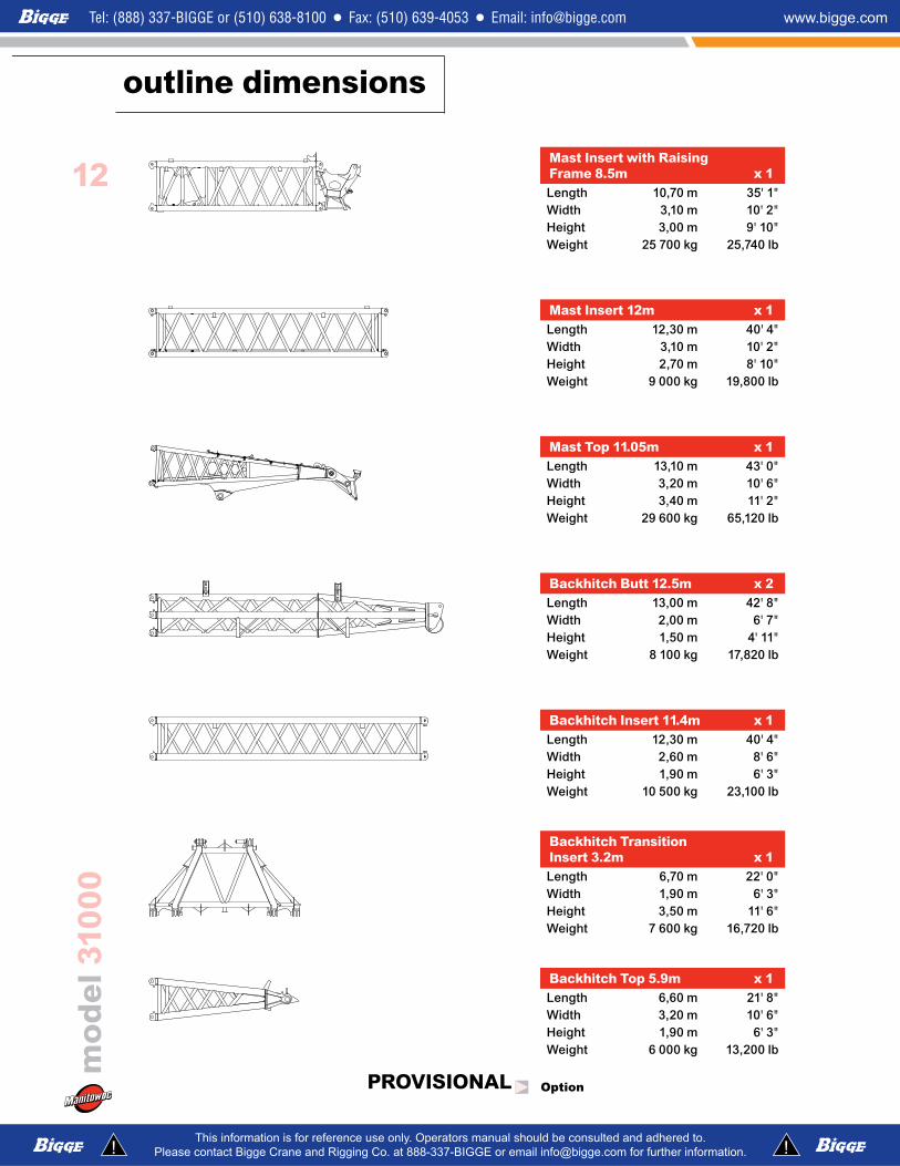
Mast Insert with Raising Frame �.�m x 1Length 10,70 m 35' 1"Width 3,10 m 10' 2"Height 3,00 m 9' 10"Weight 25 700 kg 25,740 lb
Mast Insert 1�m x 1Length 12,30 m 40' 4"Width 3,10 m 10' 2"Height 2,70 m 8' 10"Weight 9 000 kg 19,800 lb
Mast Top 11.0�m x 1Length 13,10 m 43' 0"Width 3,20 m 10' 6"Height 3,40 m 11' 2"Weight 29 600 kg 65,120 lb
Backhitch Butt 1�.�m x �Length 13,00 m 42' 8"Width 2,00 m 6' 7"Height 1,50 m 4' 11"Weight 8 100 kg 17,820 lb
Backhitch Insert 11.�m x 1Length 12,30 m 40' 4"Width 2,60 m 8' 6"Height 1,90 m 6' 3"Weight 10 500 kg 23,100 lb
Backhitch Transition Insert 3.�m x 1Length 6,70 m 22' 0"Width 1,90 m 6' 3"Height 3,50 m 11' 6"Weight 7 600 kg 16,720 lb
Backhitch Top �.9m x 1Length 6,60 m 21' 8"Width 3,20 m 10' 6"Height 1,90 m 6' 3"Weight 6 000 kg 13,200 lb
Option
CONFIDENTIALCONFIDENTIAL
PROVISIONAL PROVISIONAL
outline dimensions
13
mod
el 3
1000
CONFIDENTIALCONFIDENTIAL
PROVISIONAL PROVISIONAL
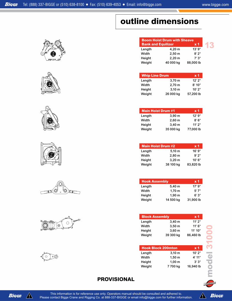
Boom Hoist Drum with Sheave Bank and Equilizer x 1Length 4,20 m 13' 9"Width 2,50 m 8' 2"Height 2,20 m 7' 3"Weight 40 000 kg 88,000 lb
Whip Line Drum x 1Length 3,70 m 12' 2"Width 2,70 m 8' 10"Height 3,10 m 10' 2"Weight 26 000 kg 57,200 lb
Main Hoist Drum #1 x 1Length 3,90 m 12' 9"Width 2,60 m 8' 6"Height 3,40 m 11' 2"Weight 35 000 kg 77,000 lb
Main Hoist Drum #� x 1Length 5,10 m 16' 9"Width 2,80 m 9' 2"Height 3,20 m 10' 6"Weight 38 100 kg 83,820 lb
Hook Assembly x 1Length 5,40 m 17' 9"Width 1,70 m 5' 7"Height 1,90 m 6' 3"Weight 14 500 kg 31,900 lb
Block Assembly x 1Length 3,40 m 11' 2"Width 3,50 m 11' 6"Height 3,60 m 11' 10"Weight 39 300 kg 86,460 lb
Hook Block �00mton x 1Length 3,10 m 10' 2"Width 1,50 m 4' 11"Height 1,00 m 3' 3"Weight 7 700 kg 16,940 lb

boom combinations
1�
mod
el 3
1000
Model 31000No. 90 Heavy-Lift Main Boom
10� m (3��.� ft)
Model 31000Fixed Jib on
No. 90 Heavy-Lift Main Boom�� m (���.� ft)
PROVISIONAL PROVISIONAL

boom combinations
1�
mod
el 3
1000
Model 31000No. 90 Luffing Jib on
No. 91 Heavy-Lift Main Boom9� m + 10� m (���.3 ft)
PROVISIONAL PROVISIONAL
1�
mod
el 3
1000
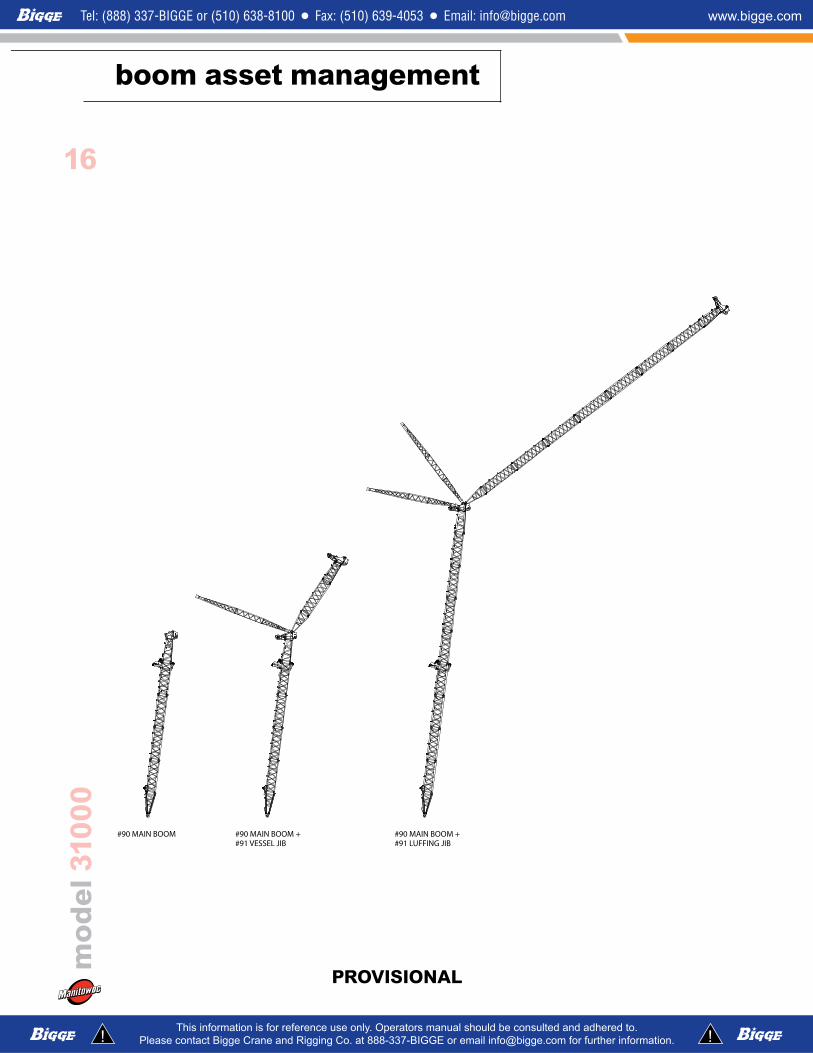
boom asset management
PROVISIONAL PROVISIONAL
CONFIDENTIALCONFIDENTIAL
#90 MAIN BOOM +#91 VESSEL JIB
#90 MAIN BOOM +#91 LUFFING JIB
#91 LIGHT BOOM+ VESSEL JIB
#90/91 MAIN BOOM#90 MAIN BOOM #91 LIGHT BOOM

1�
boom asset management
mod
el 3
1000
PROVISIONAL PROVISIONAL
CONFIDENTIALCONFIDENTIAL
#90 MAIN BOOM +#91 VESSEL JIB
#90 MAIN BOOM +#91 LUFFING JIB
#91 LIGHT BOOM+ VESSEL JIB
#90/91 MAIN BOOM#90 MAIN BOOM #91 LIGHT BOOM

1�
mod
el 3
1000
crane assembly
PROVISIONAL PROVISIONAL
CONFIDENTIALCONFIDENTIAL

19
mod
el 3
1000
crane assembly
PROVISIONAL PROVISIONAL
CONFIDENTIALCONFIDENTIAL

�0
mod
el 3
1000
crane assembly
PROVISIONAL
CONFIDENTIALCONFIDENTIAL

�1
mod
el 3
1000
crane assembly
PROVISIONAL
CONFIDENTIALCONFIDENTIAL
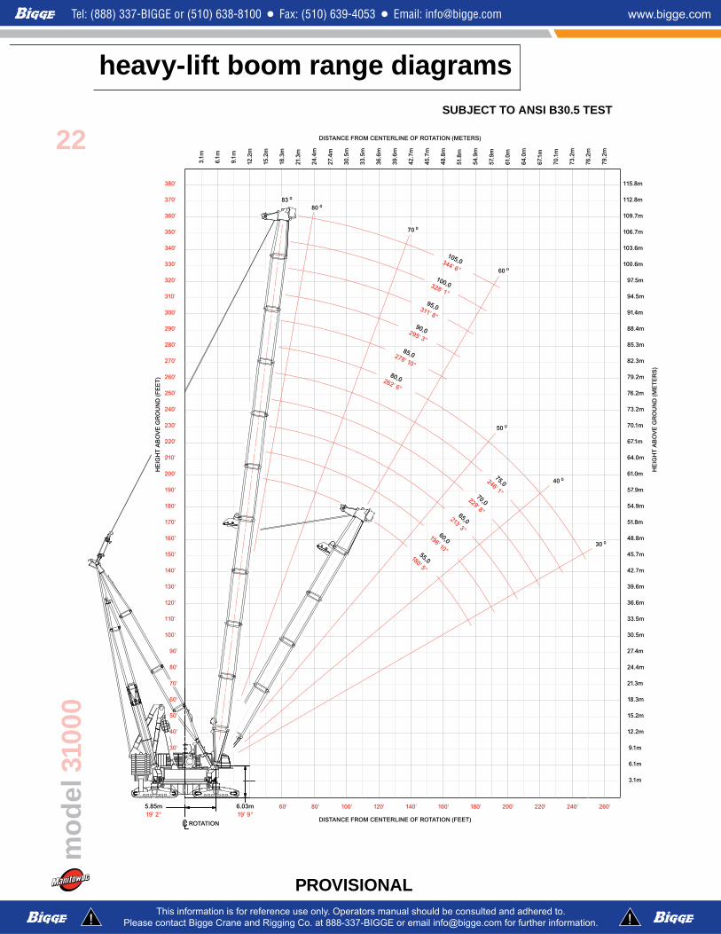
heavy-lift boom range diagrams
22
mod
el 3
1000
PROVISIONAL
SUBJECT TO ANSI B30.5 TEST

heavy-lift boom load charts
�3
mod
el 3
1000
PROVISIONAL
CONFIDENTIALCONFIDENTIAL
SUBJECT TO ANSI B30.� TEST
Model 31000 No. 90 Heavy Lift Main Boom
949 230 kg (2,092,700 lb) Variable Position Counterweight (VPC)
360° Rating kg (lb) x 1 000
Boomm (ft)
55(180)
60(197)
65(213)
70(230)
75(246)
80(262)
85(279)
90(295)
95(312)
100(328)
105(344)
Radius
14,6 (48)
2000 (4409)
15 (50)
2000 (4409)
16 (55)
1967 (4263)
1883 (4122)
20 (65)
1675 (3723)
1669 (3707)
1628 (3611)
1575 (3493)
1517 (3361)
1398 (3082)
1284 (2830)
1185 (2613)
1095(2415)
1003(2211)
24 (80)
1432(3113)
1425 (3097)
1422 (3089)
1402 (3059)
1362 (2972)
1318 (2873)
1267 (2782)
1185 (2613)
1095 (2415)
1003 (2211)
897(1978)
28 (90)
1243(2802)
1237(2787)
1234 (2779)
1227 (2763)
1223 (2745)
1190 (2660)
1157 (2582)
1212 (2506)
1085 (2415)
1003 (2211)
897 (1978)
32 (105)
1043(2300)
1039(2290)
1037(2287)
1033 (2276)
1031 (2273)
1026 (2261)
1024 (2258)
1019 (2247)
999 (2202)
969 (2137)
897 (1978)
36 (120)
892(1925)
887(1915)
886(1911)
881(1901)
879(1897)
873(1885)
872 (1881)
867 (1870)
865 (1866)
861 (1854)
862 (1849)
40 (130)
775 (1731)
771(1721)
769(1717)
764(1706)
762(1702)
757(1690)
755(1687)
750(1675)
748(1671)
743(1659)
741 (1654)
44 (145)
683(1498)
679 (1487)
677(1484)
672(1473)
670(1469)
664(1456)
663(1453)
658(1441)
656(1437)
650(1424)
648(1420)
48 (160)
608(1310)
604(1303)
602 (1300)
597(1288)
595(1284)
590(1272)
588(1268)
583(1256)
581(1252)
575(1240)
573(1235)
52 (170)
514(1144)
542(1201)
540(1197)
535 (1186)
533 (1182)
528 (1169)
526(1166)
521(1154)
519(1149)
513(1137)
511(1132)
56 (185)
476(1030)
488(1066)
483(1055)
481(1051)
475(1038)
474 (1035)
468 (1023)
466 (1018)
461 (1006)
459(1001)
60 (195)
441(991)
439(980)
437(976)
431(963)
429(960)
424(948)
422(943)
416(931)
414 (926)
64 (210)
400(882)
398(878)
392(865)
391(862)
385(850)
383(845)
378(833)
376(828)
68 (225)
365(794)
359(781)
357(778)
352(766)
350(761)
344(749)
342(744)
72 (235)
329(732)
328(728)
322(716)
320(712)
315(699)
312(695)
76 (250)
302(662)
296(650)
294(645)
288(633)
286(628)
80 (260)
273(610)
271(606)
365(593)
263(589)
84 (275)
249(552)
244(539)
242(535)
88 (290)
230(504)
225(491)
223(487)
92 (300)
207(462)
205(458)
94 (310)
197(430)
96 (320)
189(398)

Manitowoc Crane Care
��
mod
el 3
1000
PROVISIONAL PROVISIONAL
Crane Care is Manitowoc’s comprehensive service and support program. It includes classroom and on-site training, prompt parts availability, expert field service, technical support and documentation — for every one of the more than 7,000 Manitowoc cranes currently in use throughout the world.
That’s commitment you won’t find anywhere else.
That’s Crane Care.
Service TrainingManitowoc specialists work with you in our training center and in the field to make sure you know how to get maximum performance, reliability and life from your cranes.
Manitowoc Cranes Technical Training Center provides valuable multi-level training, which is available for all models and attachments, in the following format: • Basic – Provides technicians with the basic skills required in our Level I and II classes covering hydraulic and electrical theory and schematics, pump, motor, control, and LMI operation and the use of meters and gauges. • Level 1 – This model-specific class covers theory and offers hands-on training and trouble shooting or all crane systems. • Level � – This model-specific class provides in-depth coverage of all crane systems and components, and advanced troubleshooting of simulated faults.(Requires Level 1.) • Level 3 / Master – Covering all EPIC models and the 4100W, this class stresses high level system knowledge and trouble shooting of simulated faults.(Requires Level 2.)
Parts AvailabilityGenuine Manitowoc replacement parts are accessible through your distributor 24 hours a day, 7 days a week, 365 days a year.
Service Interval Kits
Provides all the parts required by Manitowoc’s Preventative Maintenance Checklist.
Hydraulic Filter Kit
Consists of the following: • Filter Element - Hydraulic in Tank (4)
Cummins Model QSZ1�-C�00 Diesel
– Service Interval Kits
�00 Hour Kit Consists of the following:
Engine • Filter Oil (2) • Filter Water (2) • Filter Fuel (2)
1,000 Hour Kit Consists of the following:
Engine • Filter Air Cleaner - Primary (2) • Filter Oil (2) • Filter Water (2) • Filter Fuel (2)
Hydraulic • Filter Element - Hydraulic in Tank (4) • Element - Hydraulic Tank Breather (1) �,000 Hour Kit Consists of the following:
Engine • Filter, Air Cleaner - Primary (2) • Filter, Air Cleaner - Safety (2) • Filter, Oil (2) • Filter, Water (2) • Filter, Fuel (2) • Ether, (Bottle) (2) • Sensor, Coolant Level (2) • Belt, Fan (2) • Belt, Alternator (set of two) (2) • Filter, Element (2)
Hydraulic • Filter Element - No substitutions allowed • Filter - Hydraulic In-Tank Suction (4) Kit, Engine Coolant Additive (SCA) Test (�)Kit, Seal (for hydraulic in tank filter) (1)Seal, Radial (for air cleaner) (�)
Hydraulic Test KitProtect your investment by demanding Genuine Manitowoc Parts Service Kits. The Hydraulic Service Kit consist of the following: • All hydraulic fittings to access all pressures and flows • Hydraulic flow meters and pressure gauges to record hydraulic data. • Electrical “Break out” harnesses to access voltages on all electrical circuits on all machines. • Fluke® Digital volt ohm meter, as used in all Manitowoc service literature.
CONFIDENTIALCONFIDENTIAL

Manitowoc Crane Care
��
mod
el 3
1000
U.S. Standard Tools KitAll standard tools needed to properly maintain and service your crane. (Does not include torque wrench.)
Field ServiceFactory-trained service experts are always ready to help maintain your crane’s peak performance.
For a worldwide listing of dealer locations, please consult our website at:www.manitowoc.com
Technical SupportManitowoc’s dealer network and factory personnel are available 24 hours a day, 7 days a week, 365 days a year to answer your technical questions and more, with the help of computerized programs that simplify crane selection, lift planning and ground-bearing calculations.
For a worldwide listing of dealer locations, please consult our website at:www.manitowoc.com
Technical DocumentationManitowoc has the industry’s most extensive documentation, and the easiest to understand, available in major languages and formats that include print, disk and videotape.
Additional copies available through your Authorized Manitowoc Distributor. • Crane Operator’s Manual • Crane Parts Manual • Crane Capacity Manual • Crane Vendor Manual • Service Manual (EPIC) • Luffing Jib Operator’s/Parts Manual • Capacity Chart Manual - Attachments
CD rom versions of the Operator’s and Parts Manuals are shipped with each crane. Also available are the following CDs: • Crane Care Owner CD – • Ground Bearing Pressure Estimator CD • Crane Selection and Planning Software (CompuCRANE©) • EPIC Crane Library CD consisting of capacity charts, range diagrams, wire rope specifications, travel specifications, crane weights, counterweight arrangements, luffing jib raising procedures, operating range diagrams, drum and lagging charts, boom rigging drawings, jib rigging drawings, outline dimensions and wind condition charts.
Available from your Authorized Manitowoc Cranes Distributor, these videos are available in NTSC, PAL and SECAM formats. • Your Capacity Chart Video • Respect the Limits Video • Crane Safety Video • Boom Inspection/Repair Video
Crane Care PackageManitowoc has assembled all of the available literature, CD’s and videos listed above plus several Manitowoc premiums into one complete Crane Care Package.
PROVISIONAL PROVISIONAL
CONFIDENTIALCONFIDENTIAL

Constant improvement and engineering progress make it necessary that we reserve the right to make specification, equipment and price changes without notice. Illustrations shown may include optional equipment and accessories, and may not include all standard equipment.
AmericasManitowoc, Wisconsin, USATel: +1 920 684 6621Fax: +1 920 683 6278
Shady Grove, Pennsylvania, USATel: +1 717 597 8121Fax: +1 717 597 4062
Europe, Middle East, AfricaEcully, FranceTel: +33 472 18 2020Fax: +33 472 18 2000
Asia – PacificShanghai, ChinaTel: +86 21 51113579Fax: +86 21 51113578
SingaporeTel: +65 6264 1188Fax: +65 6862 4142
Regional Headquarters
Regional OfficesAmericasBrazilAlphavilleTel: +55 11 3103 0200Fax: +55 11 4191 1471
MexicoMonterreyTel: +52 81 8124 0128Fax: +52 81 8124 0129
Europe, Middle East, AfricaAlgeriaHydraTel: +21 3 21 48 1173Fax: +21 3 21 48 1454
Czeck RepublicNetvoriceTel: +420 317 78 9313Fax: +420 317 78 9314
FranceBaudemontTel: +33 385 28 2589Fax: +33 385 28 0430
CergyTel: +33 130 31 3150Fax: +33 130 38 6085
DecinesTel: +33 472 81 5000Fax: +33 472 81 5010
GermanyLangenfeldTel: +49 21 73 8909-0Fax: +49 21 73 8909 30
HungaryBudapestTel: +36 13 39 8622Fax: +36 13 39 8622
ItalyParabiagoTel: +390 331 49 3311Fax: +390 331 49 3330
NetherlandsBredaTel: +31 76 578 3999 Fax: +31 76 578 3978
PolandWarsawTel: +48 22 843 3824Fax: +48 22 843 3471
PortugalAlfenaTel: +351 229 69 8840Fax: +351 229 69 8848
LisbonTel: +351 212 109 340Fax: +351 212 109 349
RussiaMoscowTel: +7 495 641 2359Fax: +7 495 641 2358
U.A.E.DubaiTel: +971 4 3381 861Fax: +971 4 3382 343
U. K.MiddlesexTel: +44 1 895 43 0053Fax: +44 1 895 45 9500
SunderlandTel: +44 191 522 2000Fax: +44 191 522 2052
Asia – PacificAustraliaMelbourneTel: +61 3 9 336 1300Fax: +61 3 9 336 1322
SydneyTel: +61 2 9 896 4433Fax: +61 2 9 896 3122
ChinaBeijingTel: +86 10 58674761Fax: +86 10 58674760
Xi’anTel: +86 29 87891465Fax: +86 29 87884504
KoreaSeoulTel: +82 2 3439 0400Fax: +82 2 3439 0405
PhilippinesMakati CityTel: +63 2 844 9437Fax: +63 2 844 4712
FactoriesBrazilAlphaville
ChinaZhangjiagang
FranceCharlieuLa ClayetteMoulins
GermanyWilhelmshaven
IndiaCalcuttaPune
ItalyNiella Tanaro
PortugalBaltarFânzeres
SlovakiaSaris
U.S.A.ManitowocPort WashingtonShady Grove
©2008 MANITOWOC 0508 - 31000 PG-US-Ewww.manitowoc.com
Related Documents


![index [] electronic-over-hydraulic controls ... jib point wheel, 26 mm or (1") luffing jib hoist line, and 54 cm (21-1 ... 0,96 m 3' 2'' 26,31 m 20' 8' OPTIONAL ...](https://static.cupdf.com/doc/110x72/5b42ba427f8b9ab15f8b5140/index-electronic-over-hydraulic-controls-jib-point-wheel-26-mm-or-1.jpg)