Model 1216 FB TECHNICAL DATA SHEET TOSACA Description Requirements Type Safety and Relief valve Calculation EN-4126-1 / 7 Connections PN 16, PN 40, 150#, 300# Design EN-12516-1, EN-4126-1 / 7 Threaded BSP / NPT DIN 259, ANSI B2.1 and ANSI B16.5 Rating PN-40 Materials EN Material Stainless steel 316 L SS Inspection EN-4126-1 / 7 Temperature range -28 to +350ºC Construction and materials Item Description Material 1 Nozzle 316 L 2 Body SA 351 CF-3M 4 Cap SA 351 CF-8 5 Disc 316 L SS 6 Guide SA 351 CF-3M 7 Push Road 316 L SS 8 Spring Button 303 SS 9 Ajusting Screw 303 SS 10 Look nut 303 SS 11 Spring 302 SS 12 Lever SA 351 CF-8 17 Release nut 316 L SS 18 Lever axis 303 SS 19 Packing lever axis 303 SS 20 Gasket PTFE 21 Gasket PTFE 22 Gasket Viton 28 Soft seat Viton / PTFE Recommended spare parts Technical information Dimensions Outlet Outlet Applications Steam, gases, vapours BSP flanges and liquids Inlet Outlet Orif. Area A A B C Weight 150# RF 150# BSP Min. Set pressure 0,2 barg 300# RF RF NPT (mm) (mm 2 ) (mm) (mm) (mm) (mm) (kg) Overpressure 10% 1/2" 3/4" 13 133 45 90 80 155 3 Blowdown Gases 10%, liquids 20% 1/2" 1" 1" 13 133 45 90 80 155 3 Tolerance Set pressure ± 3% 3/4" 1" 1" 14 154 45 90 80 155 3,2 Discharge coefficients k= 0,55 for gases 3/4" 1" 1" 14 154 45 90 80 155 3,2 k= 0,48 for liquids 1" 1" 1" 16 201 45 90 80 155 3,5 PN-16 PN16 BSP PN-40 NPT 15 3/4" 13 133 45 90 80 155 3 15 25 1" 13 133 45 90 80 155 3 20 25 1" 14 154 45 90 80 155 3,2 20 25 1" 14 154 45 90 80 155 3,2 25 25 1" 16 201 45 90 80 155 3,5 TOSACA, S.A. Edition 01/10 Pag. 6 A N S I E N T. Prueba Test gag Palanca estanca Sealed packing lever Obturador o-ring Disc o-ring Palanca manual Lifting device 1035 0163 ISO 9001 PED 97/23/EC

Welcome message from author
This document is posted to help you gain knowledge. Please leave a comment to let me know what you think about it! Share it to your friends and learn new things together.
Transcript
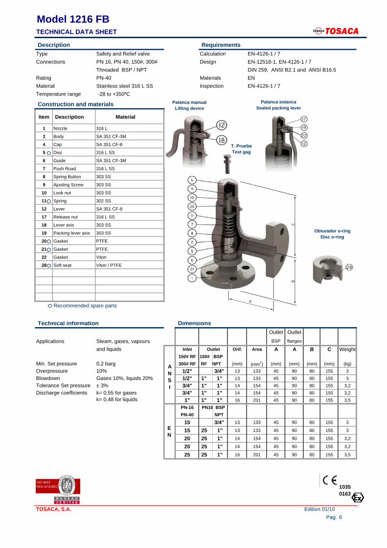
Model 1216 FBTECHNICAL DATA SHEET TOSACA Description RequirementsType Safety and Relief valve Calculation EN-4126-1 / 7 Connections PN 16, PN 40, 150#, 300# Design EN-12516-1, EN-4126-1 / 7
Threaded BSP / NPT DIN 259, ANSI B2.1 and ANSI B16.5Rating PN-40 Materials EN Material Stainless steel 316 L SS Inspection EN-4126-1 / 7 Temperature range -28 to +350ºC
Construction and materials
Item Description Material
1 Nozzle 316 L
2 Body SA 351 CF-3M
4 Cap SA 351 CF-8
5 Disc 316 L SS
6 Guide SA 351 CF-3M
7 Push Road 316 L SS
8 Spring Button 303 SS
9 Ajusting Screw 303 SS
10 Look nut 303 SS
11 Spring 302 SS
12 Lever SA 351 CF-8
17 Release nut 316 L SS
18 Lever axis 303 SS
19 Packing lever axis 303 SS
20 Gasket PTFE
21 Gasket PTFE
22 Gasket Viton
28 Soft seat Viton / PTFE
Recommended spare parts
Technical information DimensionsOutlet Outlet
Applications Steam, gases, vapours BSP flanges
and liquids Inlet Outlet Orif. Area A A B C Weight150# RF 150# BSP
Min. Set pressure 0,2 barg 300# RF RF NPT (mm) (mm2) (mm) (mm) (mm) (mm) (kg)Overpressure 10% 1/2" 3/4" 13 133 45 90 80 155 3Blowdown Gases 10%, liquids 20% 1/2" 1" 1" 13 133 45 90 80 155 3Tolerance Set pressure ± 3% 3/4" 1" 1" 14 154 45 90 80 155 3,2Discharge coefficients k= 0,55 for gases 3/4" 1" 1" 14 154 45 90 80 155 3,2
k= 0,48 for liquids 1" 1" 1" 16 201 45 90 80 155 3,5PN-16 PN16 BSPPN-40 NPT
15 3/4" 13 133 45 90 80 155 3
15 25 1" 13 133 45 90 80 155 3
20 25 1" 14 154 45 90 80 155 3,2
20 25 1" 14 154 45 90 80 155 3,2
25 25 1" 16 201 45 90 80 155 3,5
TOSACA, S.A. Edition 01/10Pag. 6
ANSI
EN
T. PruebaTest gag
Palanca estancaSealed packing lever
Obturador o-ringDisc o-ring
Palanca manualLifting device
10350163
ISO 9001PED 97/23/EC
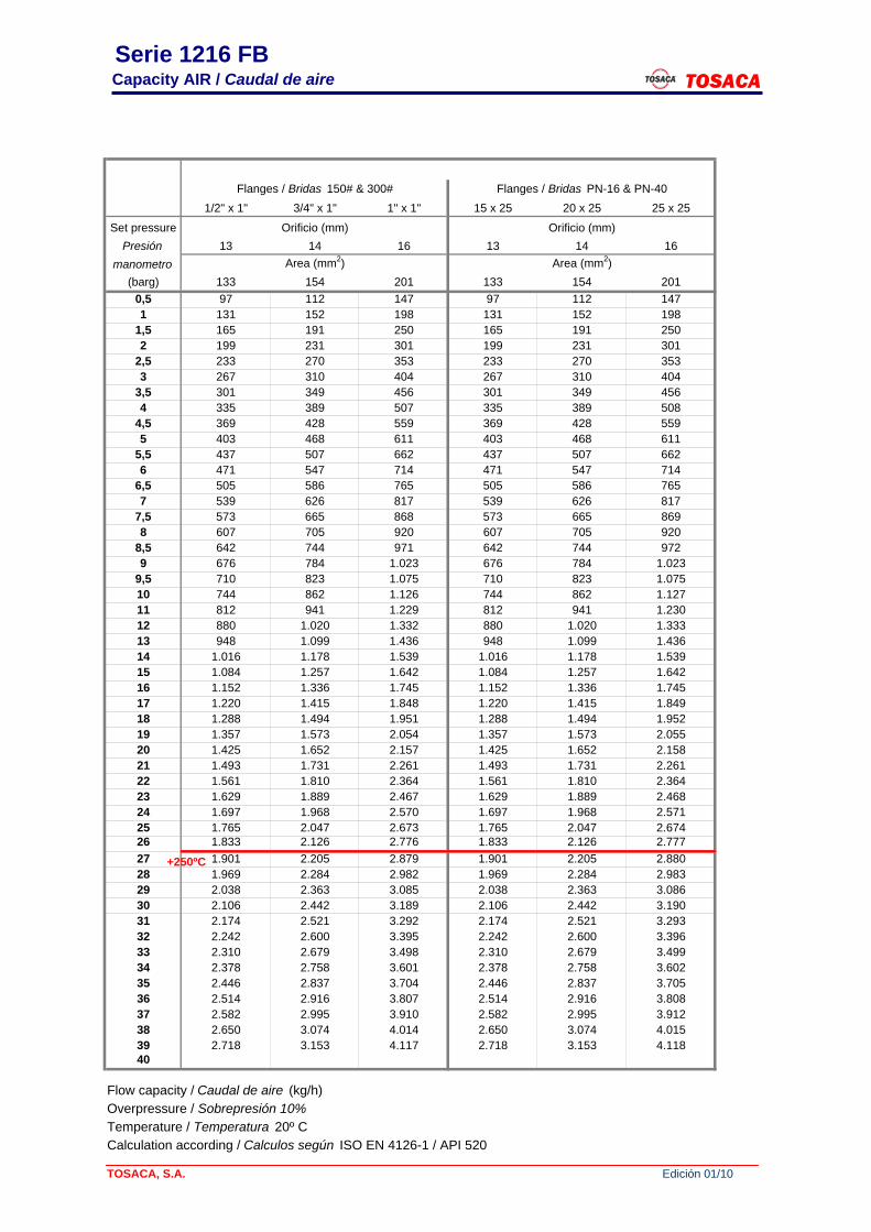
Serie 1216 FB Capacity AIR / Caudal de aire TOSACA
Flanges / Bridas 150# & 300# Flanges / Bridas PN-16 & PN-401/2" x 1" 3/4" x 1" 1" x 1" 15 x 25 20 x 25 25 x 25
Set pressure Orificio (mm) Orificio (mm)Presión 13 14 16 13 14 16
manometro Area (mm2) Area (mm2)(barg) 133 154 201 133 154 201
0,5 97 112 147 97 112 1471 131 152 198 131 152 198
1,5 165 191 250 165 191 2502 199 231 301 199 231 301
2,5 233 270 353 233 270 3533 267 310 404 267 310 404
3,5 301 349 456 301 349 4564 335 389 507 335 389 508
4,5 369 428 559 369 428 5595 403 468 611 403 468 611
5,5 437 507 662 437 507 6626 471 547 714 471 547 714
6,5 505 586 765 505 586 7657 539 626 817 539 626 817
7,5 573 665 868 573 665 8698 607 705 920 607 705 920
8,5 642 744 971 642 744 9729 676 784 1.023 676 784 1.023
9,5 710 823 1.075 710 823 1.07510 744 862 1.126 744 862 1.12711 812 941 1.229 812 941 1.23012 880 1.020 1.332 880 1.020 1.33313 948 1.099 1.436 948 1.099 1.43614 1.016 1.178 1.539 1.016 1.178 1.53915 1.084 1.257 1.642 1.084 1.257 1.64216 1.152 1.336 1.745 1.152 1.336 1.74517 1.220 1.415 1.848 1.220 1.415 1.84918 1.288 1.494 1.951 1.288 1.494 1.95219 1.357 1.573 2.054 1.357 1.573 2.05520 1.425 1.652 2.157 1.425 1.652 2.15821 1.493 1.731 2.261 1.493 1.731 2.26122 1.561 1.810 2.364 1.561 1.810 2.36423 1.629 1.889 2.467 1.629 1.889 2.46824 1.697 1.968 2.570 1.697 1.968 2.57125 1.765 2.047 2.673 1.765 2.047 2.67426 1.833 2.126 2.776 1.833 2.126 2.77727 1.901 2.205 2.879 1.901 2.205 2.88028 1.969 2.284 2.982 1.969 2.284 2.98329 2.038 2.363 3.085 2.038 2.363 3.08630 2.106 2.442 3.189 2.106 2.442 3.19031 2.174 2.521 3.292 2.174 2.521 3.29332 2.242 2.600 3.395 2.242 2.600 3.39633 2.310 2.679 3.498 2.310 2.679 3.49934 2.378 2.758 3.601 2.378 2.758 3.60235 2.446 2.837 3.704 2.446 2.837 3.70536 2.514 2.916 3.807 2.514 2.916 3.80837 2.582 2.995 3.910 2.582 2.995 3.91238 2.650 3.074 4.014 2.650 3.074 4.01539 2.718 3.153 4.117 2.718 3.153 4.11840
Flow capacity / Caudal de aire (kg/h)Overpressure / Sobrepresión 10%Temperature / Temperatura 20º CCalculation according / Calculos según ISO EN 4126-1 / API 520
TOSACA, S.A. Edición 01/10
+250ºC
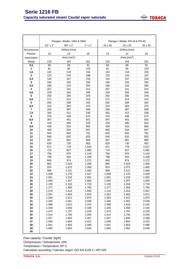
Serie 1216 FBCapacity saturated steam/ Caudal vapor saturado TOSACA
Flanges / Bridas 150# & 300# Flanges / Bridas PN-16 & PN-401/2" x 1" 3/4" x 1" 1" x 1" 15 x 25 20 x 25 25 x 25
Set pressure Orificio (mm) Orificio (mm)Presión 13 14 16 13 14 16
manometro Area (mm2) Area (mm2)(barg) 133 154 201 133 154 201
0,5 60 69 91 60 69 911 81 94 123 81 94 123
1,5 102 118 155 102 118 1552 123 143 186 123 143 187
2,5 144 167 218 144 167 2183 165 192 250 165 192 250
3,5 186 216 282 186 216 2824 207 241 314 207 241 314
4,5 229 265 346 229 265 3465 250 290 378 250 290 378
5,5 271 314 410 271 314 4106 292 338 442 292 338 442
6,5 313 363 474 313 363 4747 334 387 506 334 387 506
7,5 355 412 538 355 412 5388 376 436 570 376 436 570
8,5 397 461 601 397 461 6029 418 485 633 418 485 634
9,5 439 510 665 439 510 66610 460 534 697 460 534 69711 503 583 761 503 583 76112 545 632 825 545 632 82513 587 681 889 587 681 88914 629 730 953 629 730 95315 671 778 1.016 671 778 1.01716 713 827 1.080 713 827 1.08117 756 876 1.144 756 876 1.14418 798 925 1.208 798 925 1.20819 840 974 1.272 840 974 1.27220 882 1.023 1.336 882 1.023 1.33621 924 1.072 1.399 924 1.072 1.40022 966 1.121 1.463 966 1.121 1.46423 1.008 1.170 1.527 1.008 1.170 1.52824 1.051 1.218 1.591 1.051 1.218 1.59225 1.093 1.267 1.655 1.093 1.267 1.65526 1.135 1.316 1.719 1.135 1.316 1.71927 1.177 1.365 1.783 1.177 1.365 1.78328 1.219 1.414 1.846 1.219 1.414 1.84729 1.261 1.463 1.910 1.261 1.463 1.91130 1.304 1.512 1.974 1.304 1.512 1.97531 1.346 1.561 2.038 1.346 1.561 2.03932 1.388 1.610 2.102 1.388 1.610 2.10233 1.430 1.659 2.166 1.430 1.659 2.16634 1.472 1.707 2.229 1.472 1.707 2.23035 1.514 1.756 2.293 1.514 1.756 2.29436 1.557 1.805 2.357 1.557 1.805 2.35837 1.599 1.854 2.421 1.599 1.854 2.42238 1.641 1.903 2.485 1.641 1.903 2.48639 1.683 1.952 2.549 1.683 1.952 2.54940
Flow capacity / Caudal (kg/h)Overpressure / Sobrepresión 10%Temperature / Temperatura 20º CCalculation according / Calculos según ISO EN 4126-1 / API 520
TOSACA, S.A. Edición 01/10
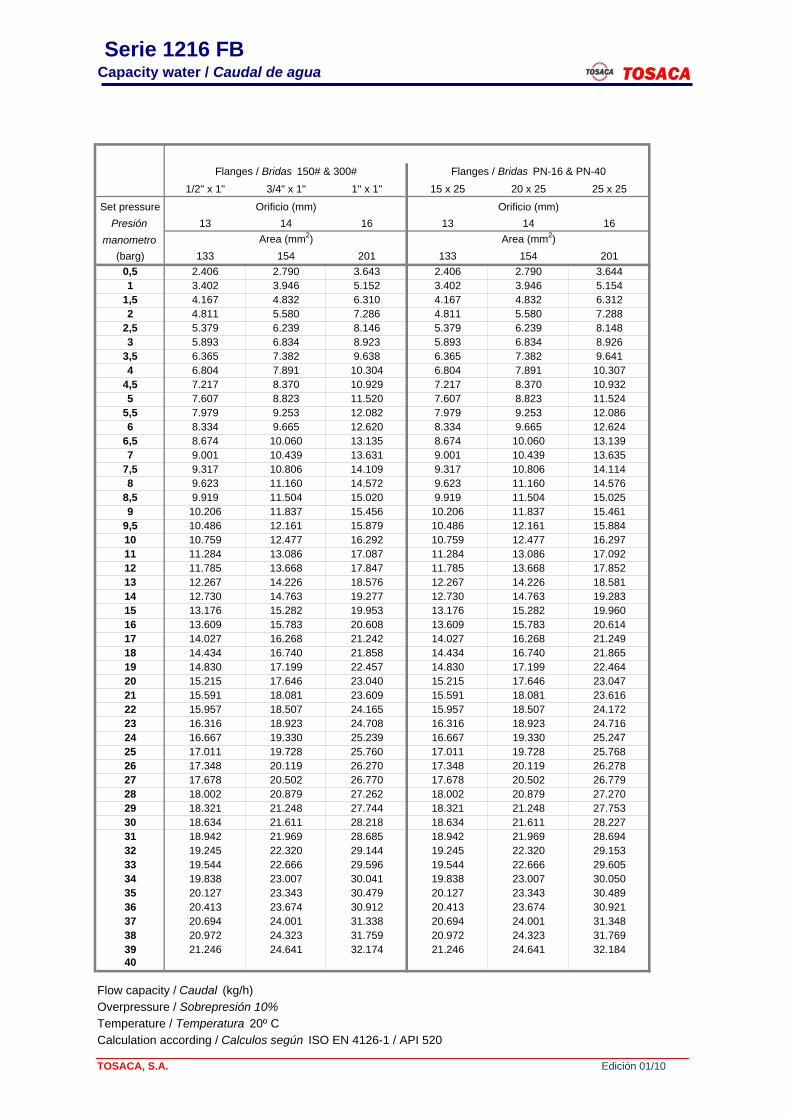
Serie 1216 FBCapacity water / Caudal de agua TOSACA
Flanges / Bridas 150# & 300# Flanges / Bridas PN-16 & PN-401/2" x 1" 3/4" x 1" 1" x 1" 15 x 25 20 x 25 25 x 25
Set pressure Orificio (mm) Orificio (mm)Presión 13 14 16 13 14 16
manometro Area (mm2) Area (mm2)(barg) 133 154 201 133 154 201
0,5 2.406 2.790 3.643 2.406 2.790 3.6441 3.402 3.946 5.152 3.402 3.946 5.154
1,5 4.167 4.832 6.310 4.167 4.832 6.3122 4.811 5.580 7.286 4.811 5.580 7.288
2,5 5.379 6.239 8.146 5.379 6.239 8.1483 5.893 6.834 8.923 5.893 6.834 8.926
3,5 6.365 7.382 9.638 6.365 7.382 9.6414 6.804 7.891 10.304 6.804 7.891 10.307
4,5 7.217 8.370 10.929 7.217 8.370 10.9325 7.607 8.823 11.520 7.607 8.823 11.524
5,5 7.979 9.253 12.082 7.979 9.253 12.0866 8.334 9.665 12.620 8.334 9.665 12.624
6,5 8.674 10.060 13.135 8.674 10.060 13.1397 9.001 10.439 13.631 9.001 10.439 13.635
7,5 9.317 10.806 14.109 9.317 10.806 14.1148 9.623 11.160 14.572 9.623 11.160 14.576
8,5 9.919 11.504 15.020 9.919 11.504 15.0259 10.206 11.837 15.456 10.206 11.837 15.461
9,5 10.486 12.161 15.879 10.486 12.161 15.88410 10.759 12.477 16.292 10.759 12.477 16.29711 11.284 13.086 17.087 11.284 13.086 17.09212 11.785 13.668 17.847 11.785 13.668 17.85213 12.267 14.226 18.576 12.267 14.226 18.58114 12.730 14.763 19.277 12.730 14.763 19.28315 13.176 15.282 19.953 13.176 15.282 19.96016 13.609 15.783 20.608 13.609 15.783 20.61417 14.027 16.268 21.242 14.027 16.268 21.24918 14.434 16.740 21.858 14.434 16.740 21.86519 14.830 17.199 22.457 14.830 17.199 22.46420 15.215 17.646 23.040 15.215 17.646 23.04721 15.591 18.081 23.609 15.591 18.081 23.61622 15.957 18.507 24.165 15.957 18.507 24.17223 16.316 18.923 24.708 16.316 18.923 24.71624 16.667 19.330 25.239 16.667 19.330 25.24725 17.011 19.728 25.760 17.011 19.728 25.76826 17.348 20.119 26.270 17.348 20.119 26.27827 17.678 20.502 26.770 17.678 20.502 26.77928 18.002 20.879 27.262 18.002 20.879 27.27029 18.321 21.248 27.744 18.321 21.248 27.75330 18.634 21.611 28.218 18.634 21.611 28.22731 18.942 21.969 28.685 18.942 21.969 28.69432 19.245 22.320 29.144 19.245 22.320 29.15333 19.544 22.666 29.596 19.544 22.666 29.60534 19.838 23.007 30.041 19.838 23.007 30.05035 20.127 23.343 30.479 20.127 23.343 30.48936 20.413 23.674 30.912 20.413 23.674 30.92137 20.694 24.001 31.338 20.694 24.001 31.34838 20.972 24.323 31.759 20.972 24.323 31.76939 21.246 24.641 32.174 21.246 24.641 32.18440
Flow capacity / Caudal (kg/h)Overpressure / Sobrepresión 10%Temperature / Temperatura 20º CCalculation according / Calculos según ISO EN 4126-1 / API 520
TOSACA, S.A. Edición 01/10
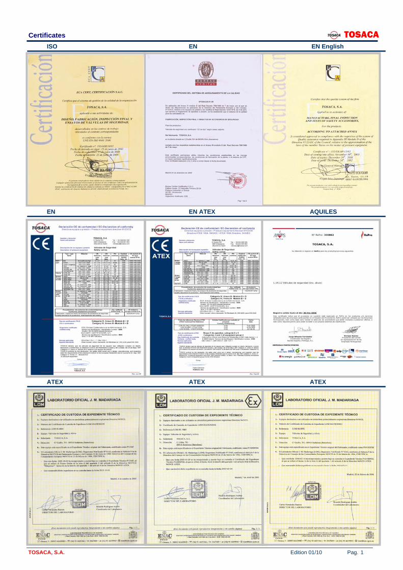
Certificates TOSACA ISO EN EN English
EN EN ATEX AQUILES
ATEX ATEX ATEX
TOSACA, S.A. Edition 01/10 Pag. 1
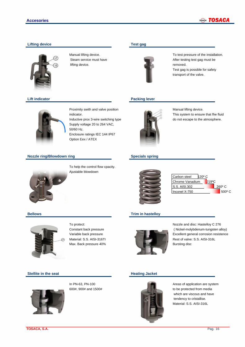
Accesories TOSACA
Lifting device Test gag
Manual lifting device. To test pressure of the installation. Steam service must have After testing test gag must be lifting device. removed.
Test gag is possible for safetytransport of the valve.
Lift indicator Packing lever
Proximity swith and valve position Manual lifting device.indicator. This system to ensure that fhe fluid Inductive prox 3-wire switching type do not escape to the atmosphere.Supply voltage 20 to 264 VAC, 50/60 Hz.Enclosure ratings IEC 144 IP67 Option Eex / ATEX
Nozzle ring/Blowdown ring Specials spring
To help the control flow cpacity.Ajustable blowdown
Carbon steel 120º CChrome Vanadium 219ºCS.S. AISI.302 260º CInconel X-750 500º C
Bellows Trim in hastelloy
To protect: Nozzle and disc: Hastelloy C 276 Constant back pressure ( Nickel-molybdenum-tungsten alloy)Variable back pressure Excellent general corrosion resistenceMaterial: S.S. AISI-316TI Rest of valve: S.S. AISI-316L Max. Back pressure 40% Bursting disc
Stellite in the seat Heating Jacket
In PN-63, PN-100 Areas of application are system 600#, 900# and 1500# to be protected from media
which are viscous and have BELLOW tendency to cristallise.
Material: S.S. AISI-316L
TOSACA, S.A. Pag. 16
Related Documents