OM-2069 050192 Model 120C24 Generator Sets Specifications 7131 Operation and Maintenance Manual Hobart Brothers Company Airport Systems Group Ground Power Equipment Troy, OH 45373 U.S.A.

Welcome message from author
This document is posted to help you gain knowledge. Please leave a comment to let me know what you think about it! Share it to your friends and learn new things together.
Transcript

OM-2069050192
Model 120C24 Generator SetsSpecifications 7131
Operation and Maintenance Manual
Hobart Brothers CompanyAirport Systems Group
Ground Power EquipmentTroy, OH 45373
U.S.A.

This page intentionally left blank
HoRMr GROUND POWER
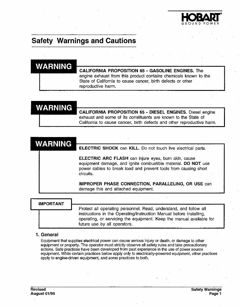
Safety Warnings and Cautions
CALIFORNIA PROPOSITION 65 - GASOLINE ENGINES. The engine exhaust from this product contains chemicals known to the State of California to cause cancer, birth defects or other reproductive harm.
CALIFORNIA PROPOSITION 65 - DIESEL ENGINES. Diesel engine I exhaust and some of its constituents are known to the State of California to cause cancer, birth defects and other reproductive harm.
I
ELECTRIC SHOCK can KILL. Do not touch live electrical pans.
ELECTRIC ARC FLASH can injure eyes, burn skin, cause equipment damage, and ignite combustible material. DO NOT use power cables to break load and prevent tools from causing short circuits.
IMPROPER PHASE CONNECTION, PARALLELING, OR USE can damage this and attached equipment. I
IMPORTANT Protect all operating personnel. Read, understand, and follow all instructions in the Operating/Instruction Manual before installing, operating, or servicing the equipment. Keep the manual available for future use by all operators.
1. General Equipment that supplies electrical power can cause serious injury or death, or damage to other equipment or property. The operator must strictly observe all safety rules and take precautionary actions. Safe practices have been developed from past experience in the use of power source equipment. While certain practices below apply only to electrically-powered equipment, other practices apply to engine-driven equipment, and some practices to both.
Revised Safety Warnings August 01/95 Page 1

2. Shock Prevention Bare conductors, or terminals in the output circuit, or ungrounded, electrically-live equipment can fatally shock a person. Have a certified electrician verify that the equipment is adequately grounded and learn what terminals and parts are electrically HOT. Avoid hot spots on machine. Use proper safety clothing, procedures, and test equipment.
HoRAm GROUND POWER
The electrical resistance of the body is decreased when wet, permitting dangerous currents to flow through it. When inspecting or servicing equipment, do not work in damp areas. Stand on a dry rubber mat or dty wood, use insulating gloves when dampness or sweat cannot be avoided. Keep clothing dry, and never work alone
a Installation and Grounding of Electrically Powered Equipment
Equipment driven by electric motors (rather than by diesel or gasoline engines) must be installed and maintained in accordance with the National Electrical Code, ANSVNFPA 70, or other applicable’ codes. A power disconnect switch or circuit breaker must be located at the equipment. Check the nameplate for voltage, frequency, and phase requirements. If only 3-phase power is available, connect any single-phase rated equipment to only two wires of the 3-phase line. DO NOT CONNECT the equipment grounding conductor (lead) to the third live wire of the 3-phase line, as this makes the equipment frame electrically HOT, which can cause a fatal shock.
Always connect the groundtng lead, if supplied in a power line cable, to the grounded switch box or building ground. If not provided, use a separate grounding lead. Ensure that the current (amperage) capacity of the grounding lead will be adequate for the worst fault current situation. Refer to the National Electrical Code ANSVNFPA 70 for details. Do not remove plug ground prongs. Use correctly mating receptacles.
b. Output Cables and Terminals
Inspect cables frequently for damage to the insulation and the connectors. Replace or repair cracked or worn cables immediately. Do not overload cables. Do not touch output terminal while equipment is energized.
3. Service and Maintenance This equipment must be maintained in good electrical and mechanical condition to avoid hazards stemming from disrepair. Report any equipment defect or safety hazard to the supervisor and discontinue use of the equipment until its safety has been assured. Repairs should be made by qualified personnel only.
Before inspecting or servicing electrically-powered equipment, take the following precautions:
a. Shut OFF all power at the disconnecting switch or line breaker before inspecting or servicing the equipment.
b. Lock switch OPEN (or remove line fuses) so that power cannot be turned on accidentally.
c. Disconnect power to equipment if it is out of service.
d. If troubleshooting must be done with the unit energized, have another person present who is trained in turning off the equipment and providing or calling for first aid.
~4. Fire And Explosion Prevention
Fire and explosion are caused by electrical short circuits, combustible material near engine exhaust piping, misuse of batteries and fuel, or unsafe operating or fueling conditions.
a. Electrical Short Circuits and Overloads
Overloaded or shorted equipment can become hot enough to cause fires by self destruction or by causing nearby combustibles to ignite. For electrically-powered equipment, provide primary input protection to remove short circuited or heavily overloaded equipment from the line.
Safety Warnings Page 2
Revised August 01/95

GROUND POWER
b. Batteries
Batteries may explode and/or give off flammable hydrogen gas. Acid and arcing from a ruptured battery can cause fires and additional failures. When servicing, do not smoke, cause sparking, or use open flame near the battery.
c. Engine Fuel
Use only approved fuel container or fueling system. Fires and explosions can occur if the fuel tank is not grounded prior to or during fuel transfer. Shut unit DOWN before removing fuel tank cap. DO NOT completely fill tank,.because heat from the equipment may cause fuel expansion overflow. Remove all spilled fuel IMMEDIATELY, including any that penetrates the unit. After clean-up, open equipment doors and blow fumes away with compressed air.
5. Toxic Fume Prevention Carbon monoxide - Engine exhaust fumes can kill and cause health problems. Pipe or vent the exhaust fumes to a suitable exhaust duct or outdoors. Never locate engine exhausts near intake ducts of air conditioners.
6. Bodily injury Prevention Serious injury can result from contact with fans inside some equipment. Shut DOWN such equipment for inspection and routine maintenance. When equipment is in operation, use extreme care in doing necessary trouble-shooting and adjustment. Do nob remove guards while equipment is operating.
7. Medical and First Aid Treatment First aid facilities and a qualified first aid person should be available for each shift for immediate treatment of all injury victims. Electric shock victims should be checked by a physician and taken to a hospital immediately if any abnormal signs are observed.,
until medical help arrives.
IF BREATHING IS DIFFICULT, give oxygen, if available, and have victim lie down. FOR ELECTRICAL SHOCK, turn off power. Remove victim; if not breathing, begin artificial respiration, preferably mouth-to-mouth. If no detectable pulse, begin external heart massage. CALL EMERGENCY RESCUE SQUAD IMMEDIATELY.
8. Equipment Precautionary Labels
Call physician immediately. Seek additional assistance. Use First Aid techniques recommended by American Red Cross
Inspect all precautionary labels on the equipment monthly. Order and inspect all labels that cannot be easily read.
Revised Safety Warnings August OV9.5 Page 3

GROUND POWER
This page intentionally left blank
Safety Warnings Revised Page 4 August OV9.5
Table of Contents
Chapter-Section Page
Chapter 1. Description / Operation
Section 1. Description 1-1 1General 1-1 1Orientation 1-1 1Special Features 1-1 1
Protective Monitor 1-1 1Voltage Regulator 1-1 1Electric Governor 1-1 1Transformer-Rectifier 1-1 1Cold Weather Starting Kit 1-1 1Low Fuel Indicating Light 1-1 2
Canopy 1-1 2Engine, Generator, and Control Box 1-1 4
Basic Engine 1-1 4Engine Manufacturer’s Equipment 1-1 4Hobart Installed Engine Equipment 1-1 5Generator 1-1 8
Control Box Assembly 1-1 8Power Module Panel Assembly 1-1 17
Description of Some Special Featuresof the Generator Set 1-1 20
Transformer-Rectifier 1-1 20Cold Weather Starting Kit 1-1 29
Section 2. Preparation for Use, Storage or Shipping 1-2 1Preparation for Use 1-2 1
Inspection/Check 1-2 1Installing Three-phase AC Output Cables 1-2 2Transformer-Rectifier (DC) Output Cable
Installation (optional equipment). 1-2 3
Preparation for Storage 1-2 3General 1-2 3Temporary Storage 1-2 4
Long Time Storage (Over 30 Days) 1-2 4Preparation for Shipment 1-2 4
OM-2069 / Operation and Maintenance Manual120C24 / Spec. 7131 / Generator Set
May 01/92 Table of ContentsPage 1

Section 3. Operation 1-3 1General 1-3 1Operating the Unit 1-3 1
Pre-start inspection 1-3 1Normal Engine Starting Procedures 1-3 1Cold Weather Engine Starting Procedures 1-3 4Preparation for Power delivery 1-3 6Power Delivery 1-3 6Discontinue Power Delivery 1-3 6Stopping the Engine 1-3 7
Transformer-Rectifier Operation 1-3 7Preparation for DC Power Delivery 1-3 7DC Power Delivery 1-3 7Discontinue Power Delivery 1-3 7Simultaneous 28.5-Volt DC and 400-Hz AC Power Delivery 1-3 8
Trailer Operation 1-3 10Towing 1-3 10Parking 1-3 10
Chapter 2. Servicing
Section 1. Maintenance Inspection/Check 2-1 1General 2-1 1Maintenance Schedule 2-1 1
General 2-1 1Maintenance Schedule Check Sheet 2-1 1Time Intervals 2-1 1Identification of Interval Periods 2-1 1
Inspection/Check 2-1 4General 2-1 4“AR” Checks and Operations (As Required) 2-1 4“A” Checks and Operations (10 Hours or Daily) 2-1 4“B” Check and Operations (200 Hours or 3 Months) 2-1 6“C” Checks and Operations (400 Hours or 6 Months) 2-1 7“D” Checks and Operations (800 Hours or 1 Year) 2-1 8“E” Checks and Operations (1200 Hours or 1 Year) 2-1 8“F” Checks and Operations (6000 Hours or 5 Years) 2-1 10Seasonal Maintenance Checks (Engine) 2-1 10
Section 2. Maintenance Procedures 2-2 1General 2-2 1Lubrication 2-2 1
General 2-2 1AC Generator 2-2 1Generator Controls 2-2 1
OM-2069 / Operation and Maintenance Manual120C24 / Spe. 7131 / Generator Set
Table of Contents May 01/92Page 2
Engine 2-2 1Engine Accessories Lubrication 2-2 5
Servicing the Air Cleaner 2-2 6Inspecting the Air Cleaner 2-2 6Cleaning Instructions 2-2 6Disposal 2-2 7
Engine Fuel 2-2 7Quality 2-2 7Fuel Filter 2-2 7Cold Weather Starting Aid 2-2 9
Engine Cooling System 2-2 9General 2-2 9Radiator Cap 2-2 9Coolant 2-2 9Warm Weather Operation (No Antifreeze) 2-2 9Cold Weather Operation (Using Antifreeze) 2-2 10Draining the Cooling System 2-2 10Cleaning the Cooling SystemCleaning the Radiator Core 2-2 10Filling the Cooling System 2-2 11Thermostat 2-2 11
Drive Belts 2-2 12General 2-2 12Preparation for Belt Check and Adjustment 2-2 12Check Fan Belt 2-2 12
Generator Maintenance 2-2 13Cleaning 2-2 13Adjustment 2-2 13
Voltage Regulator Maintenance/Repair 2-2 13Transformer-Rectifier Maintenance 2-2 13
General 2-2 13Lubrication 2-2 13Inspection 2-2 14Cleaning 2-2 14
Servicing and Troubleshooting the ColdWeather Starting Aid 2-2 14Check Fluid Cylinder Contents And Valve Gasket. 2-2 14Check of electrical system. 2-2 14
Section 3. Adjustment/Test 2-3 1General 2-3 1Testing the Generator Set 2-3 1
Pre-operational Test Procedures 2-3 1Operational Test Procedures 2-3 4Testing the No. 1 output circuit 2-3 5
OM-2069 / Operation and Maintenance Manual120C24 / Spec. 7131 / Generator Set
May 01/92 Table of ContentsPage 3

Testing the No. 2 output circuit 2-3 6Testing the main generator overload circuit 2-3 7Testing and checking meters, switches,
relays, and indicating lights 2-3 7Re-checking the entire unit after testing 2-3 9
Generator Set Adjustment 2-3 10Generator Adjustment 2-3 10Adjust 400 Hz voltage regulator. 2-3 10Basic Engine Adjustments 2-3 11Engine Accessories Adjustment 2-3 11Electric Governor System Adjustment 2-3 12
Generator and Exciter Test 2-3 17Diode Test 2-3 17Transformer-Rectifier Test and Adjustment 2-3 18
General 2-3 18Test 2-3 18Adjustment 2-3 21
Section 4. Troubleshooting Procedures 2-4 1General 2-4 1Equipment for Troubleshooting 2-4 1Parts Replacement 2-4 1Test Values 2-4 2Check Connections and Leads 2-4 2Electric Governor Troubleshooting 2-4 2Engine Troubleshooting 2-4 3Illustrations 2-4 3Connection and Schematic Diagrams 2-4 3
Chapter 3. Overhaul/Major Repair
Section 1. Table of Contents 3-1 1
Section 2. Exciter Rotors 3-2 1General 3-2 1Exciter Rotor Types 3-2 2Exciter Rotor Replacement 3-2 2
General 3-2 2Special Tools for Exciter Rotor
Removal and Installation 3-2 3Conditions for Exciter Removal 3-2 4Preparation for Exciter Rotor Removal 3-2 5Exciter Rotor Removal 3-2 5
OM-2069 / Operation and Maintenance Manual120C24 / Spe. 7131 / Generator Set
Table of Contents May 01/92Page 4
Installing the Exciter Rotor 3-2 7Preparation for Exciter Rotor Installation 3-2 7Exciter Rotor Installation 3-2 7
Section 3. Flexible CouplingsGeneral 3-3 1
Coupling Bolts 3-3 1
Disassembly 3-3 2Separate Engine and Generator 3-3 2Remove Coupling Assembly 3-3 3
Coupling Service 3-3 4Coupling Kit 3-3 4Bushing Kits 3-3 4Bushing Replacement 3-3 4
Coupling Installation 3-3 4Cleaning 3-3 4Assembly 3-3 5
Reassemble Engine and Generator 3-3 9General 3-3 9Reassembly Procedure 3-3 9Run-in and Periodic Check 3-3 10
Section 4. Generator Assembly 3-4 1General 3-4 1Procedure for Generator Assembly Removal 3-4 1
Procedure for Gaining Access to the Generator 3-4 1Removing the generator Assembly 3-4 3
Installing a Generator Assembly 3-4 4Remounting the Generator Assembly 3-4 4Remounting the Previously Removed Assemblies 3-4 4
Section 5. Transformer-Rectifier Repair 3-5 1General 3-5 1Removal and Installation 3-5 1
Removal Procedures 3-5 1Installation Procedures 3-5 1
Parts Replacement 3-5 2Access 3-5 2Parts Removal 3-5 2Parts Installation 3-5 2Fan Installation 3-5 2
Workmanship 3-5 2Connection Diagrams 3-5 2
OM-2069 / Operation and Maintenance Manual120C24 / Spec. 7131 / Generator Set
May 01/92 Table of ContentsPage 5
Chapter 4. Illustrated Parts List 4-1 1
Section 1. Introduction 4-1 1General 4-1 1Purpose 4-1 1Arrangement 4-1 1Explanation of Parts List 4-1 1
Contents 4-1 1Parts List Form 4-1 1
Section 2. Manufacturer’s Codes 4-2 1Explanation of Manufacturer’s (Vendor) Code List 4-2 1
Section 3. Illustrated Parts List 4-3 1Explanation of Parts List Arrangement 4-3 1Symbols and Abbreviations 4-3 1
Section 4. Numerical Index 4-4 1Explanation of Numerical Index 4-4 1Numerical Index 4-4 1
Chapter 5. Manufacturer’s Literature 5-1 1
OM-2069 / Operation and Maintenance Manual120C24 / Spe. 7131 / Generator Set
Table of Contents May 01/92Page 6

Introduction
This manual contains operation and maintenance information for a 400-Hertz generator set manufactured byHobart Brothers Company, Hobart Airport Systems Group, Troy, Ohio 45373.
The basic generator sets covered by the manual are rated at 120 KVA. This machine is described andidentified in Chapter 1, Description/Operation.
When applicable, manuals for sub-vendor equipment are included in Chapter 5.
The primary purpose of the manual is to provide information and instructions to experienced operators,electricians, and mechanics who are not familiar with this equipment. The intent of the manual is to guide andassist operators and maintenance personnel in the proper use and care of the equipment.
Read the instructions before starting the unit. Learn to use the manual and to locate information contained in it.
The Table of Contents, which follows this introduction, lists all Chapters, Sections, and the paragraph titleswithin each Section. The location of each listing is identified by Chapter, Section and page number. Acomplete list of illustrations, with their locations, follows the Table of Contents.
Each chapter is divided into as many Sections as necessary. Sections are always referred to by acombination Chapter/Section number, for example: 2-3 refers to Chapter 2, Section 3.
The material within each Section is divided into main subjects with applicable paragraph headings andsubheadings as required. For example, a portion of the Description Section might logically follow thisarrangement and paragraphing:
1. Control
a. Interior Panel
(1) Protective devices
a. Overload relay
(2) Contactors
Page numbers do not run consecutively throughout the manual. Each page is identified by theChapter/Section number in which it appears, and by a page number within the Chapter/Section. Therefore,the first page in each Section is page 1. These identifying numbers appear in the lower, outside corner ofeach page. Each page also bears a date located in the corner opposite the page number. This date is eitherthat of original issue, or of the latest revision. Any revision to the original text is identified by a heavy black linein the left-hand margin. Illustrations follow a numbering system similar to page numbering. The first Figure ineach Section is Figure 1.
All tables, charts and diagrams, as well as illustrations, are identified by Figure numbers to avoid confusion.
The general location of any particular information can be found quickly by running through the Table ofContents. For example: to locate any adjustment information, a quick look at the Table of Contents shows that“Adjustment/Test” is located in Chapter 2, Section 3 (shown as 2-3).
Portions of the text are referred to by identifying the paragraph in which the referenced material may be found.When referenced material is located in the same Chapter/Section as the reference, only the paragraphidentification is given, for example: (Ref. Para 1, A) means that the material is to be found in paragraph 1, A,of the same Section.
OM-2069 / Operation and Maintenance Manual120C24 / Spec. 7131 / Generator Set
May 01/92 IntroductionPage 1

When referenced material is located in another Chapter/Section, both the Chapter and Section numbers andthe paragraph identification are given, for example: (Ref. 1-2, Para 1, A) means that the referenced materialis located in Chapter/Section 1-2, and paragraph 1, A within that Chapter/Section.
Components shown in illustrations, and the illustrations themselves, are referenced in a similar manner.When this type of reference is made, the item number of the part and the Figure number in which it appearsare given, for example: (2, Fig. 3) refers to item number 2 in illustration Figure 3 of the same Chapter/Section.
When a referenced figure appears in another Chapter/Section, the reference will include the Chapter/Sectionnumber, for example: (2-3; 1, Fig. 4) tells the user that the information is in Chapter/Section 2-3, and to referto item 1 in Figure 4.
Once a Figure number reference has been established, the Figure number is not repeated and only the itemnumbers of the parts involved are referenced, for example: “Loosen screw (2, Fig. 6), slide out connector (4),and remove brush (6).”
When an item number is referenced without a Figure number, it always applies to the last preceding Figurenumber mentioned in the text.
A collection of manufacturer’s literature is supplied as part of the information package in Chapter 6.
If you have any questions concerning your Hobart Airport Systems Group equipment, you are invited tocontact our Service Department by mail, telephone or FAX.
Write: Hobart Brothers CompanyAirport Systems GroupService Department1177 Trade Square EastTroy, Ohio 45373U.S.A
In U.S.A. Call: (800) 422-4166 (Parts)(800) 422-4177 (Service)
From Foreign Countries, Call: (513) 332-5050 (Parts)(513) 332-5060 (Service)
Fax: (513) 332-5121
OM-2069 / Operation and Maintenance Manual120C24 / Spec. 7131 / Generator Set
Introduction May 01/92Page 2
Chapter 1. Description / Operation
Section 1. Description
1. GeneralThe generator set covered in this manual are manufactured by Hobart Brothers Company, GroundPower Division, Troy, Ohio 45373, USA. The generator set, is rated at 120 KVA, and identified bySpecification Number 7131. It is designed to produce and deliver 115/200-volt, 400 Hz, 3-phase ACpower to a parked aircraft or other load.
2. OrientationFor purpose of orientation, the radiator is considered to be at the REAR of the unit. The generator andcontrols are at the FRONT. RIGHT and LEFT are determined by standing at the REAR end facing themachine. Thus, the control box is mounted on the LEFT side at the FRONT of the unit.
3. Special FeaturesThe generator set has many special features which are described more fully under the assemblies inwhich they appear. Some of these features are mentioned here and described briefly.
a. Protective Monitor
A single, solid-state device (14, Fig. 7) receives signals from all of the fault sensing units in thegenerator output circuit and functions to cause the load to be disconnected from the generator if anabnormal condition of voltage, frequency, or load develops.
b. Voltage Regulator
A microprocessor-type, adjustable voltage regulator provides automatic voltage regulation at theaircraft. The regulator is also adjustable for a variety of output cable sizes and lengths.
c. Electric Governor
The engine is equipped with an electric governor kit and other special equipment more fullydescribed under the engine description.
d. Transformer-Rectifier
The transformer-rectifier (7, Fig. 1) is a compact, enclosed power supply unit employing atransformer and semiconductor diode components to convert 200-V AC, 400-Hz, 3-phase inputpower to 28.5-V DC output power. This feature on the generator set makes it possible for thegenerator set to be used in servicing aircraft and other loads requiring 28.5-V DC power. Thetransformer-rectifier is explained in greater detail at the end of this section.
e. Cold Weather Starting Kit
The purpose of this kit is to aid in starting the engine when the generator set is used in very coldtemperatures. This cold weather starting aid is a fully automatic engine starting fluid systemdesigned to spray a controlled amount of starting fluid into the engine’s air intake system during andimmediately after cranking. This feature is explained in greater detail at the end of this section.
OM-2069 / Operation and Maintenance Manual120C24 / Spec. 7131 / Generator Set
May 01/92 Chapter 1-1Page 1

f. Low Fuel Indicating Light
The purpose of this light, located on top of the canopy, is to warn the technician who is operatingthe generator set that its fuel level is low, and that its fuel tank should be filled. When the tank’s fuellevel is low, this blue light comes on and flashes continuously to warn the technician so that thegenerator set will not run out of fuel while it is delivering power to an aircraft. This assembly consistsonly of the light, a low fuel level switch installed in the fuel tank, and the necessary wiring to make itoperational.
4. CanopyA sheet metal enclosure, identified as a canopy provides protection for the engine, generator andelectrical controls. The canopy is designed to reduce the operational noise level in the immediatearea of the machine. A centrally-located lifting eye attached to a lifting yoke extends through thecanopy top to provide an attaching point for chains, cables, or hook used to lift and move thegenerator set.
1. Canopy 5. Output cable clamps
2. Lifting eye 6. Trailer (Optional)
3. Radiator access cover 7. Transformer-Rectifier, 28.5-V DC
4. Exhaust out Rear
Generator Set
Figure 1
OM-2069 / Operation and Maintenance Manual120C24 / Spec. 7131 / Generator Set
Chapter 1-1 May 01/92Page 2

Physical
Basic Unit
Length 91 in. (2311 mm)
Width 45 in. (1143 mm)
Height 44 in. (1118 mm)
Weight without trailer 4340 lbs. (1969 kg)
Trailer-Mounted Unit with Transformer-Rectifier(s)
Length 132.5 in. (3365.5 mm)
Width 77 in. (1956 mm)
Height (overall) 63 in. (1600 mm)
Weight - one TR (full fuel tank) 4880 lbs. (2213 kg)
Weight - two TR’s (full fuel tank) 5180 lbs. (2349 kg)
Generator
Output power rating (KVA) 120
Output voltage (AC) 115/200
Rated load capacity (Amps) 347
Frequency (Hz) 400
Output kilowatts 96
Power factor 0.8
Duty cycle 100%
Operating speed (RPM) 2400
Overload capacity, first or second output:125% rated load (Amps) 325
Overload capacity, both outputs:125% rated load (Amps) 434
Output cable size 2/0
Generator Protective System
Overvoltage relay Trips at 126 volts after a 1-second time delay.Trips at 140 volts in 160 milliseconds.Trips at 180 volts in 50 milliseconds.
Undervoltage relay Trips at any voltage below 100 volts after 7 seconds.
Overfrequency relay Trips at any value between 426-Hz and 480-Hz after a5-second time delay. Trips immediately at any frequencyexceeding 480-Hz.
Underfrequency relay Trips at 375 Hz or less after a 5-second time delay.
Overload time delay Trips in approximately 5 minutes at 125% load on eitheroutput or on both outputs.
Specifications and CapabilitiesFigure 2 (Sheet 1 of 2)
OM-2069 / Operation and Maintenance Manual120C24 / Spec. 7131 / Generator Set
May 01/92 Chapter 1-1Page 3

Engine
Manufacturer Cummins Engine Company, Inc.Columbus, Indiana 47201
Cummins Specification No. 88-0444-6BTAModel No. 6BTA5.9Type In-line 6 cylinderDieselBore and stroke 4.02 x 4.72 inchesDisplacement 359 cubic inchesBrake horsepower 177Idle speed 850 +/- 25 RPMHigh speed limiting approx. 2640 RPMNormal governed speed 2400 RPMElectrical system 12-V DCGround NegativeFiring order (RH rotation) 1-5-3-6-2-4Lubricating oil capacity (w/filter) 24 quartsCoolant capacity 38 quarts
Specifications and CapabilitiesFigure 2 (Sheet 2 of 2)
5. Engine, Generator, and Control BoxThe engine, generator, and control box comprise the principal components of the generator set. Theyare mounted on the welded steel frame of the chassis. The engine coolant radiator is also mounted onthe frame just forward of the engine-generator combination. Figure 3 is an illustration showing thelocation of all major components and sub-assemblies.
a. Basic Engine
The basic engine is an in-line 6-cylinder diesel rated at 177 horsepower. See Fig. 2 for generalspecifications.
b. Engine Manufacturer’s Equipment
As received from the engine manufacturer, the engine includes the following equipment which ismore fully described in the Cummins “Operation and Maintenance Manual”.
(1) Electrical System
The 12-V DC electrical generating and starting system includes an alternator, voltage regulator,and starter with solenoid switch.
(2) Fuel Filter
The fuel filter is a vacuum type connected between the fuel supply and the pump. It has twothrowaway type elements located side by side on a single head.
(3) Oil Filter
The engine oil filter is a full-flow type with replaceable cartridge. It is mounted on the right side ofthe engine.
OM-2069 / Operation and Maintenance Manual120C24 / Spec. 7131 / Generator Set
Chapter 1-1 May 01/92Page 4

(4) Automatic shutdown system. This system includes the following:
a. Fuel shutoff valve
The solenoid-operated fuel shutoff valve is mounted on the fuel pump. The pump can supplyfuel to the engine only when the solenoid is energized to hold the valve OPEN. The operationof any one of the safety switches will open the solenoid holding circuit and allow the valve toCLOSE and shut down the engine by shutting off the fuel supply. A flyback diode (CR 13 onschematic diagram) is connected across the fuel valve to protect other com- ponents in the12-V DC circuit against accidental high inductive voltage discharge from the solenoid coil.
b. Oil pressure switch
The oil pressure switch is mounted in the engine lubricating oil system at the oil filter. It isdiaphragm operated and held in closed position by any normal oil pressure above 12 PSI (83KPA). It is connected in series with the fuel shutoff valve and will open the holding circuit if oilpressure drops to 12 PSI or below.
(5) Engine overspeed protection
The engine is protected against overspeed by a speed-limiting mechanism in the fuel pump.
(6) Engine-cooling fan
The engine fan is designed to blow air outward through the radiator, rather than draw it in as aconventional fan does.
Refer to the engine Operation and Maintenance Manual in Chapter 6 for more engine details.
c. Hobart Installed Engine Equipment
The engine is modified at Hobart Brothers by the addition of the following equipment:
(1) Electric governor system
An electric governor kit is installed on the engine to replace a conventional mechanical type.The electric governor was selected for control of engine speed (and generator output frequency)because it provides faster engine response to changes in load conditions. This fast responseresults in very close frequency control. A brief description is given below:
The governor system consists of the following main components:
a. Magnetic pickup
The magnetic pickup is a device for detecting the speed of the engine. It is mounted in theflywheel housing directly over the ring gear. It produces an AC signal to the control unit whenthe ferrous flywheel teeth pass through the magnetic field at the end of the pickup.
b. Control unit
The control unit is a box containing a compact assembly of solid state components. Itreceives an AC signal from the magnetic pickup and senses speed changes in the engine. Itprovides a voltage signal to the actuator which causes the actuator to move the fuel controllever as required to maintain a predetermined engine speed. Its power is received from thecustomer furnished 12-V DC battery system.
c. Actuator
The actuator supplies the force needed to move and position the fuel lever as required tomaintain a constant engine speed. The actuator is operated by a DC signal from the controlunit.
(2) Engine safety devices
In addition to safety devices provided by the engine manufacturer, another engine shutdownfeature is added by Hobart Brothers.
OM-2069 / Operation and Maintenance Manual120C24 / Spec. 7131 / Generator Set
May 01/92 Chapter 1-1Page 5

1. Radiator 7. Trailer (Optional)
2. Engine 8. Power module panel
3. Lifting yoke 9. Engine-generator control panel
4. Air cleaner 10. Mounting frame
5. Control box 11. Muffler
6. Transformer-rectifier, 12. Exhaust out rear
28.5-V DC (Optional)
Generator Set Components
OM-2069 / Operation and Maintenance Manual120C24 / Spec. 7131 / Generator Set
Chapter 1-1 May 01/92Page 6

a. Coolant temperature switch
This is a highly sensitive temperature switch mounted at the front of the engine in the coolantcrossover system. It is electrically connected in series with the fuel shutoff valve solenoid andis normally closed. The switch will open to stop engine when internal coolant systemtemperature reaches 205 deg. F (96 deg C).
(3) Air cleaner
The diesel-engine air cleaner (Fig. 4) is so constructed that air enters it through the perforatedcylindrical body of the air cleaner itself, and is filtered in the process before being passed on tothe engine turbo-charge assembly.
An air cleaner service indicator device is mounted on the air cleaner assembly to monitor air flowin the air cleaner. When the air cleaner becomes filled with dust, dirt, and carbon, intake systemair flow becomes increasingly restricted. This restriction causes a diaphram inside the indicatorto move toward an electrical contact. When the maximum allowable restriction level is reached,the circuit closes and the air cleaner indicator light (18, Fig. 6) on the engine-generator controlpanel is illuminated to warn the operator that the air cleaner must be changed. The electricalindicator automatically resets after a new air cleaner is installed.
(4) Muffler
The muffler is a special design, combining the exhaust muffler and tail pipe into a welded,one-piece, replaceable unit.
(5) Radiator
The radiator is a one-piece type designed for long periods of operation without servicing. Referto Section 2-1 for servicing procedure.
Air Cleaner and ServiceIndicator
Figure 4
OM-2069 / Operation and Maintenance Manual120C24 / Spec. 7131 / Generator Set
May 01/92 Chapter 1-1Page 7

d. Generator
The 400 Hz generator is a brushless, revolving field, three-phase, alternating current type. For thegenerator set covered by this manual, the generator is a dual-bearing type. The front end of therotor shaft extends forward betond the front bearing and is attached to the engine flywheel by a huband flexible disc coupling assembly. The rear end of the rotor shaft extends rearward beyond therear bearing and into the exciter stator housing. The exciter rotor is mounted on this shaft extensionwith a key and is secured by a washer and 1/2"-13 thread cap screw. A rectifier with three diodes ismounted on the exciter rotor and converts exciter AC output to DC for excitation of the generatorrevolving fields. The exciter DC output to the generator fields, and consequently the generatoroutput, is controlled by the amount of DC voltage supplied to exciter fields by the voltage regulator.A centrifugal, radial-blade fan which is part of the hub and coupling assembly, draws cooling airover all internal windings. Air enters at the exciter end and is discharged at the drive end. Thecomplete generator is bolted to the engine flywheel housing.
6. Control Box AssemblyThe control box (Fig. 5) is a sheet metal enclosure which houses and provides mounting facilities forengine and generator controls and monitoring equipment.
Control Box
Figure 5
OM-2069 / Operation and Maintenance Manual120C24 / Spec. 7131 / Generator Set
Chapter 1-1 May 01/92Page 8

(1) Control Panel (Fig. 6)On the door of this control box is the control panel. The control panel is divided into threesections. On the left side of the control panel, as one faces it, are engine control switches,meters, and indicating lights (items 1 through 11). In the center of the control panel areprotective monitor fuses and indicating lights for the generator, along with test and reset buttons(items 12 through 18). Also located on the center section of the control panel is an air cleanerrestriction indicating light. On the right side of the control panel are generator control switches,meters, and indicating lights (items 19 through 28). The functions of these components are asfollow.
a. Panel lights and panel light switch
Two shielded, instrument panel lights (2) are mounted on the control panel to illuminatecontrols, instruments, and indicator lights. They are controlled by a toggle switch (4) on theleft side of the control panel.
b. Engine hourmeter
The hourmeter (3) is electrically driven from the 12-V DC battery system. The hourmetermeasures and records engine running time and will record up to 9999.9 hours on fiverevolving drums. It is functional only when the engine is running and the oil pressure safetyshutdown switch mounted on the engine block is closed.
c. Engine oil pressure gage
The oil pressure gage (5) is an electrical type which is connected by a wire to an oil pressuresensor installed in the engine lubricating system.
d. Engine ON indicating light
A green indicating light (6) glows when the engine control switch (25) is in RUN position.
e. Engine coolant temperature gage
The temperature gage (7) is an electrical type which is connected by a wire to a watertemperature sensor installed in the engine cooling system. The gage indicates enginecoolant temperature in the range of 100 to 220 deg. F (38 to 104 deg. C).
f. Engine starter switch
This pushbutton switch (8) connects 12-V DC power to the starter solenoid coil whichactuates the solenoid switch to connect power to the engine starting motor.
g. Engine control switch
The engine control switch (9), sometimes referred to as the permissive-start switch, is athree-position, toggle type. The three positions are identified as START, RUN, and STOP.The switch is spring loaded in START position and must be manually held in this position.When released from START it automatically returns to RUN position. When held in STARTposition, 12-V DC power is supplied directly to the fuel shutoff valve solenoid and engineshutdown safety switches are bypassed. This direct current is necessary for engine startingbecause the low oil pressure switch is OPEN until the engine is running normally. Whenreleased, the switch will automatically reposition to RUN and supply power to the fuel shutoffvalve through the engine shutdown safety switch circuit. A green light (28) glows to indicatethat the engine control switch is in RUN (or START) position. In STOP position the switchcontacts are open and holding power is disconnected from the fuel valve, allowing the valveto close and shut off fuel to the engine.
h. Engine ammeter
The ammeter (10) indicates the direction and value of current flow in the 12-V DC electricalsystem. Its graduated range is from -60 A through O A, to + 60 A.
OM-2069 / Operation and Maintenance Manual120C24 / Spec. 7131 / Generator Set
May 01/92 Chapter 1-1Page 9

i. Engine fuel gage
An electric fuel gauge (11) receives its controlling signal from a sending unit in the fuel tank.Twelve volt DC operating power is supplied to the fuel gauge when the engine control switch(9) is in RUN position.
j. Circuit breakers
A 10-ampere circuit breaker (14) protects the 12-V DC engine control circuit, hourmeter,illuminating light circuit, and 12-V DC system. A 2-ampere circuit breaker (13) protects thegenerator protective system, and another 2 ampere circuit breaker (12) protects the circuitsof the load contactors.
k. Protective system Indicating lights, test and reset switches
The function of this set of five lights (15) is to indicate, to the operator, the abnormalcondition of overvoltage, underfrequency, etc., which caused the protective monitor system tofunction. Each of the five lights is connected to an actuating circuit within the memory andtime delay module. When one of the circuits is activated, it turns on the applicable indicatinglight. The light will remain on until the reset switch (17) is pushed. All lamps in indicatinglights may be tested by pressing test switch (16).
l. Air cleaner indicator
The air cleaner indicator light (18) is mounted on the engine control panel, and glows whenair flow to the air cleaner is restricted.
m. Generator output monitors (meters)
The generator output is monitored by three instruments; a frequency meter (19), a voltmeter(21) , and an ammeter (27) The frequency meter is an analog type, and indicates thefrequency of the generator output alternating current in the range of 360 to 440 Hz (cyclesper second). The voltmeter indicates the generator output voltage in each phase-to-neutral(A-N, B-N and C-N) or phase-to-phase (A-B, B-C and C-A) as selected by the meter selectorswitch (20). The voltmeter has a 3-1/2-inch face and the scale is graduated 0 to 300 V. Theammeter is also 3-1/2-inch size and is graduated 0 to 500 A. The amperage value in each ofthe three phases may be read on the ammeter by selecting the desired phase with meterselector switch (20). Three ammeter current transformers, located beneath the generatorcontrol box support panel, lower the output load current to a lesser value, of definite ratio,which will operate the ammeter movement without damage. The ammeter dial scale isgraduated and numbered so that the pointer will indicate the true load current value ratherthan the meter movement current.
n. Voltmeter-ammeter selector switch
This switch provides a means of selecting and determining which phase of voltage andcurrent is indicated on the voltmeter and ammeter and whether the voltage is line-to-neutralor line-to-line. The meter switch (20) is a six-position, rotary type. A nameplate, locatedunder the switch knob, is marked and lettered to indicate the six functional positions of themeter switch.
o. Load contactor control switches
Two contactor control toggle switches are mounted at the lower right corner of the controlpanel, one switch for each of the two independent outputs of the generator set. These arethree-position, toggle switches (23 and 25) identical to the engine-generator control switch.When one of these switches is placed in the spring loaded ON position, it provides 115-V ACpower directly to a rectifier which supplies DC power for closing the load contactor of thecircuit it serves. When released it returns to normal ON position and continues to providepower to the rectifier, but in this switch position, AC power must pass through theplug-interlock and fuse-interlock relays. In OFF position the switch opens the AC circuit tothe rectifier, thereby cutting off the source of DC power to the contactor coil which allows thecontactor to open.
OM-2069 / Operation and Maintenance Manual120C24 / Spec. 7131 / Generator Set
Chapter 1-1 May 01/92Page 10

p. Load contactor power accepted indicating lights
Wired in the holding coil circuit of each of the two output load contactors is an indicating light(24 and 26) which glows green when the circuit is energized, is holding the contactor closed,and power is being accepted by the aircraft. When the load contactor opens for any reason,the light is turned OFF.
q. Engine-generator control switch
The engine-generator control switch (28) (also identified as the build-up-voltage, generate,idle switch) is a three-position toggle type. It is spring-loaded in one position, BUILD-UP-VOLTAGE, and will automatically reposition to GENERATE position when released. InBUILD-UP-VOLTS position it performs a dual function. First, it switches the governor controlfrom idle speed to generate speed, which allows the engine to be governed at 2400 RPM for400-Hz generator output; second, it momentarily supplies current for closing the contacts ofthe excitation- deenergization relay (2, Fig. 7), to make excitation voltage available to thegenerator exciter. In GENERATE position, power is maintained to the governor control boxand to the excitation deenergization relay When the switch is placed in IDLE position, poweris disconnected so that the engine returns to idle speed and the exciter field is deenergized.
r. Air cleaner indicator
The air cleaner indicator (18) is mounted on the engine control panel for easy viewing. Itsfunction is explained in Para. 5, C, (3).
(2) Control Box Internal Components (Fig. 7)
a. Excitation Deenergization relay
The purpose of this relay (2) is to allow automatic excitation to be connected to the exciterfield only when engine speed is being controlled by the electric governor.
b. Protective system interlock relay
The function of the protective system interlock relay (2) is to interrupt the load contactorholding coil circuit and remove the load in case the protective relay circuit breaker (13, Fig. 6)opens.
c. Auxiliary underfrequency relay
The function of the auxiliary underfrequency relay (4) is to automatically open theexcitation-deenergization relay and disconnect the voltage regulator anytime generatorfrequency drops to 375 Hz or below. This protects the voltage regulator (Fig. 8) againstoverload which could be caused by very high voltage regulator output in its attempt tomaintain voltage when the generator is operating at a speed which cannot produce normalvoltage output.
NOTE: If the auxiliary underfrequency relay is tripped, it will be necessary to momentarily placeengine-generator control switch (28, Fig. 6) in BUILD-UP-VOLTAGE position to restoregenerator voltage.
d. Plug interlock relays
The function of the plug-interlock relays (5 and 6) is to cause the respective output loadcontactors to open in the event the cable plug connector becomes accidentally disconnectedfrom the aircraft during power delivery, or if an attempt is made to deliver power when theoutput cable is not connected to the aircraft. Twenty-eight volt direct current for operation ofthe relay is supplied from the aircraft either through an on-board transformer-rectifier, or froma twenty-eight volt electrical system. Connection from aircraft to the interlock relay is madethrough terminals E and F on the output cable plug connector.
e. Test bank- aircraft switches
For each load contactor circuit a single pole, single throw toggle switch (7 or 8) provides ameans of bypassing the interlock relay (5 or 6) for that contactor circuit when supplyingpower to a load bank or to an aircraft not equipped with a plug interlock system.
OM-2069 / Operation and Maintenance Manual120C24 / Spec. 7131 / Generator Set
May 01/92 Chapter 1-1Page 11

1. Front panel 15. Protective system indicating lights
2. Panel light 16. Test switch, protective system
3. Engine hour meter 17. Reset switch, protective system
4. Panel light switch 18. Indicating light, air cleaner restriction
5. Oil pressure gage 19. Frequency meter
6. Engine ON indicating light 20. Selector switch, voltmeter-ammeter
7. Engine coolant temperature meter 21. Voltmeter
8. Engine start switch 22. Adjustable grip latch
9. Engine control switch 23. No. 1 contactor switch
10. Engine ammeter 24. Power accepted light, No. 1 contactor
11. Fuel gage 25. No. 2 contactor switch
12. Load contactor circuit breaker 26. Power accepted light, No. 2 contactor
13. Protective system circuit breaker 27. Generator ammeter
14. Engine system circuit breaker 28. Engine-generator control switch
Engine-Generator Control Panel
Figure 6
OM-2069 / Operation and Maintenance Manual120C24 / Spec. 7131 / Generator Set
Chapter 1-1 May 01/92Page 12
f. Regulated-diagnostic switch
When the regulated-diagnostic switch (9) is in the REGULATED (up) position, generatoroutput voltage is regulated by the solid state voltage regulator (12) for 115/200 V-AC outputto an aircraft. When this switch is placed in the DIAGNOSTIC (down) position, battery voltage(12-V DC) is applied to the generator exciter with the engine running at rated RPM, in orderto check the operation of the generator. By applying this 12 V-DC battery voltage to theexciter and observing generator output voltage, it can be determined if a particular poweroutput malfunction is caused by a defective generator or by a defective voltage regulator.
g. Voltage regulator PC board
• This voltage regulator (11, Fig. 7, and Fig. 8) is designed to provide 1% voltage regulationfor all loads up to 100% of rated load on a three-phase, four-wire, 115/200-volt, 400-Hzbrushless alternator. This regulator provides field excitation power as required to meetvarying alternator load conditions to hold the alternator voltage constant. In addition, thevoltage regulator PC board circuitry provides line drop compensation. Any deviation of thealternator voltage from its set, regulated level is sensed at the voltage regulator PC board.The sensing signal is compared to a reference signal, and, with associated circuitry, variesthe field power supplied to the rotary exciter.
• When the machine is started, and the voltage build-up switch is pushed, the rotary exciteris excited from alternator residual magnetism through the half-wave rectifier bridge, locatedon the voltage regulator PC board assembly. As the rotary exciter voltage increases,alternator excitation increases and the alternator voltage builds up. The sensing circuit ofthe voltage regulator PC board then compares the input voltage to a reference voltage andadjusts the field power of the rotary exciter to bring the voltage into regulation limits.
• When the alternator is loaded, its terminal voltage decreases, lowering the rectifiedthree-phase voltage of the voltage sensing circuit. The sensing voltage is low in respect toits reference voltage, causing the voltage regulator PC circuitry to increase the power tothe field of the rotary exciter. The alternator voltage increases until the voltage returns to itsregulated value.
• When a load is removed from the alternator, the alternator voltage rises. The rectifiedthree-phase voltage sensing signal increases, causing this signal to be higher than thereference signal. The associated voltage regulator circuitry causes the field power of therotary exciter to decrease, lowering the alternator voltage until the voltage returns toregulated value.
• The line drop voltage compensation circuit consists of: (1) A current transformer on eachphase of the load circuit, and (2) A fixed resistance in parallel with each currenttransformer. The current transformers detect the magnitude of current flowing through thepower cables from the alternator to its load and feed a signal into the voltage regulator PCboard. The PC board processes this signal to change the output voltage proportional to thecurrent draw. The regulator output increases slightly so that the alternator output voltage isequal to the regulated voltage plus the voltage drop in the lines. The line dropcompensation potentiometer may be adjusted to match exactly the voltage drop of thepower cables carrying the load current.
• A receptacle connector at the bottom of the voltage regulator PC board provides a quickconnect-disconnect facility for interconnecting wire leads.
OM-2069 / Operation and Maintenance Manual120C24 / Spec. 7131 / Generator Set
May 01/92 Chapter 1-1Page 13

h. Memory-time delay module
The memory and time delay module (12) is sometimes called the protective monitor module.It is a solid-state device with a hermetically-sealed, reed-type relay. The printed circuit boardor card includes five memory circuits and a time delay circuit. Each circuit is connected to acorresponding sensing circuit in the sensing modules (16 and 17). All memory circuits areconnected to the module relay coil, and any one of the circuits can energize the coil to openthe relay contacts. Thus, when a sensing device energizes any one of the module circuits,the module relay is also energized to break the load contactor holding circuit and allow theload contactor to open. All circuits, except the undervoltage circuit, function immediately toopen the load contactor. A time delay system is designed into the undervoltage circuit toprevent nuisance opening of the contactor under conditions of momentary undervoltage inthe generator output. An undervoltage condition which continues uninterrupted for a periodof 4 to 12 seconds (adjustable) will cause the time delay circuit to open the load contactor.Each of the five circuits is connected to a corresponding indicating light (15, Fig. 6) which isturned on when a fault occurs. The module relay will remain energized (OPEN) and the lightwill remain ON until the reset switch (17, Fig. 6) is pushed to break the module 12-V circuit,and allow the relay to return to normal, CLOSED position.
i. Sensing modules
The voltage sensing module (17) and frequency sensing module (16) are connected togenerator output leads between the generator and load contactor. These solid-state modulessense any abnormal condition of voltage or frequency and signal the solid-state circuitry ofthe memory and time delay module (14) to open the load contactor and disconnect output tothe aircraft. Trip values are adjustable; however, adjustments should be made ONLY underlaboratory conditions.
On the power module, two solid-state overload signaling devices ( 11 and 12, Fig. 9), one foreach of the two outputs, are also connected to the protective monitor module and perform afunction similar to the voltage and frequency sensing modules.
Trip values for protective circuits are as follows:
• Overvoltage relay Trips at 126 volts after a 1-second time delay.Trips at 140 volts in 160 milliseconds.Trips at 180 volts in 50 milliseconds.
• Undervoltage relay Trips at 100 volts after 7 seconds.
• Overfrequency relay Trips at any value between 426-Hz and 480-Hz after a5-second time delay. Trips immediately at any frequencyexceeding 480-Hz.
• Underfrequency relay Trips at 375 Hz or less after a 5-second time delay.
• Overload time delay Trips in approximately 5 minutes at 125% load on eitheroutput or on both outputs.
See Para. 6, h, (3) for more specific and detailed information regarding overload device.
j. Electric governor controller
As explained earlier in this section, the control unit (14, Fig. 7) is a box containing a compactassembly of solid state components. It receives an AC signal from the magnetic pickup andsenses speed changes in the engine. It provides a voltage signal to the actuator whichcauses the actuator to move the fuel control lever as required to maintain a predeterminedengine speed. Its power is received from the 12-V DC battery system. A more detailedillustration of the controller is shown Figure 5 of Section 2-3.
k. Idle speed adjustment potentiometer
Refer to Fig. 5, Section 2-3. The idle speed potentiometer is on the controller. It is con-nected into the engine’s electric circuitry such that, by turning it with a screwdriver, engineidle speed can be set at rated idle speed (850 RPM +/- 25 RPM). Idle speed is INCREASEDby turning this potentiometer CLOCKWISE and DECREASED by turning itCOUNTER-CLOCKWISE.
OM-2069 / Operation and Maintenance Manual120C24 / Spec. 7131 / Generator Set
Chapter 1-1 May 01/92Page 14
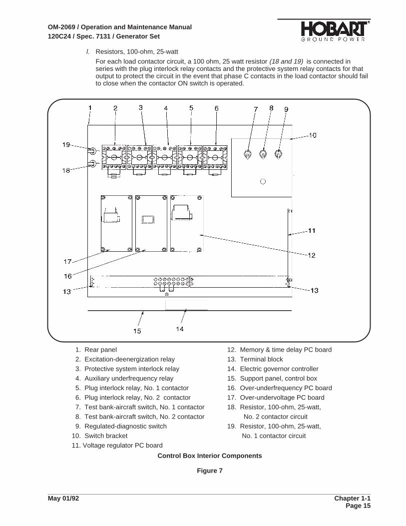
l. Resistors, 100-ohm, 25-watt
For each load contactor circuit, a 100 ohm, 25 watt resistor (18 and 19) is connected inseries with the plug interlock relay contacts and the protective system relay contacts for thatoutput to protect the circuit in the event that phase C contacts in the load contactor should failto close when the contactor ON switch is operated.
1. Rear panel 12. Memory & time delay PC board
2. Excitation-deenergization relay 13. Terminal block
3. Protective system interlock relay 14. Electric governor controller
4. Auxiliary underfrequency relay 15. Support panel, control box
5. Plug interlock relay, No. 1 contactor 16. Over-underfrequency PC board
6. Plug interlock relay, No. 2 contactor 17. Over-undervoltage PC board
7. Test bank-aircraft switch, No. 1 contactor 18. Resistor, 100-ohm, 25-watt,
8. Test bank-aircraft switch, No. 2 contactor No. 2 contactor circuit
9. Regulated-diagnostic switch 19. Resistor, 100-ohm, 25-watt,
10. Switch bracket No. 1 contactor circuit
11. Voltage regulator PC board
Control Box Interior Components
Figure 7
OM-2069 / Operation and Maintenance Manual120C24 / Spec. 7131 / Generator Set
May 01/92 Chapter 1-1Page 15
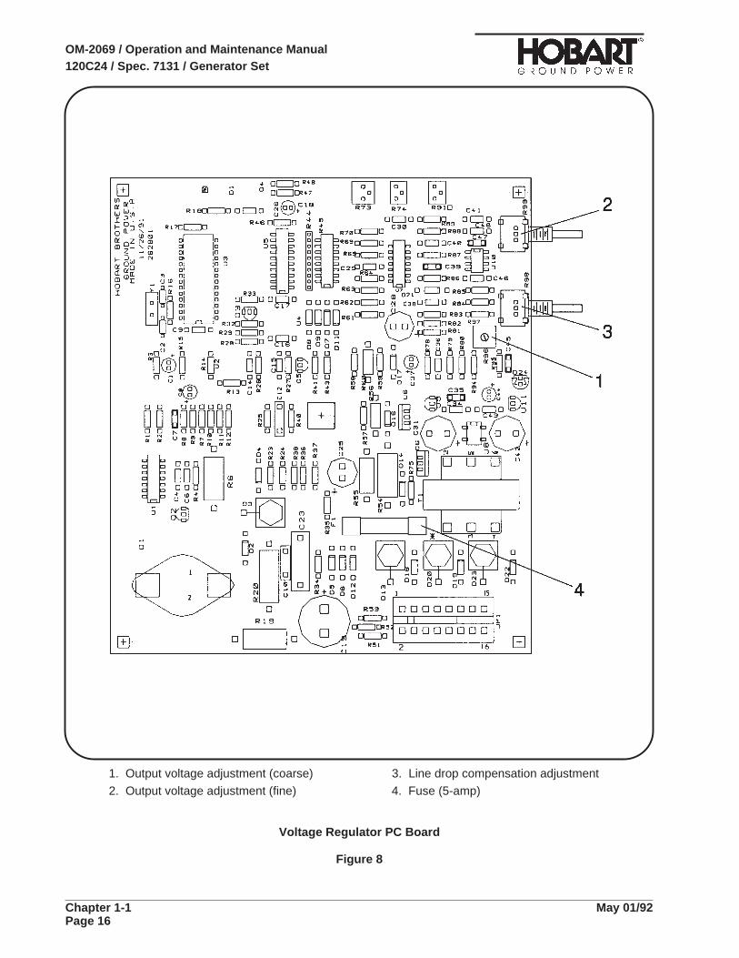
1. Output voltage adjustment (coarse) 3. Line drop compensation adjustment
2. Output voltage adjustment (fine) 4. Fuse (5-amp)
Voltage Regulator PC Board
Figure 8
OM-2069 / Operation and Maintenance Manual120C24 / Spec. 7131 / Generator Set
Chapter 1-1 May 01/92Page 16
a. Power Module Panel Assembly
The power module panel assembly (Fig. 9), sometimes referred to as the contactor panel, islocated at the left front of the machine under the control box. It is accessible by opening the leftfront door. The panel assembly provides sensing and overload protection for the output circuit andprovides a means of connecting and disconnecting generator output to and from the load (aircraft).
(1) Load contactors
The load contactors (15 and 16, Fig. 9) on this dual output machine each contain a magneticoperating coil and four sets of contacts. The three larger contacts conduct three-phase ACgenerator output. A small contact set is connected in the protective monitor circuit and supplies12-V DC power used by sensing relays to signal the protective monitor when a fault occurs.Three-phase, 400-Hz generator output power is conducted to the load contactors by 2/0 cableswhich pass through three sets of current transformers ( 1,2,6 and 9).
(2) Current transformers
a. Line-drop current transformers
The three line-drop current transformers (1, Fig. 9), in conjunction with burden resistors (4),detect the magnitude and power factor of current flowing from generator to load. They feed asignal to the voltage regulator which interprets the signal and alters the exciter field current asrequired to maintain a constant predetermined voltage at the load.
b. Main generator ammeter and overload current transformers
A set of three main current transformers, (2, Fig. 9), in conjunction with a set of burdenresistors (3), convert a current signal to a voltage signal which is sent to the ammeter and tothe main overload sensing board. The ammeter is really a voltmeter graduated andnumbered in amperes to show current proportional to the voltage signal received. Thisammeter is so graduated and numbered that, when cables running through the currenttransformers carry a current of 347 amperes (rated load), 6.67 volts is sent to the ammeter,which shows it as 347 amperes.
When there is load on both outputs and an overload condition develops, wherein loadexceeds 434 amperes (125% of rated load) the main overload sensing board sends a signalto the memory and time delay PC board (14, Fig. 6), which interrupts the load contactorcircuit to open both load contactors.
c. Main generator overload module
When there is load on both outputs of the generator set, and an overload condition existswhich exceeds 125% of the generator’s rated load (150-KVA, or 434 amperes), thissolid-state over- load module (5) interprets a signal from the main generator overload currenttransformers (2) and sends a signal to the memory and time delay PC board (14, Fig. 6).
To do this, the overload module is equipped with a hermetically-sealed, reed-type relay.Relay contacts are normally open. The solid-state circuitry is designed to close relaycontacts when output current reaches 125% of normal rated output capacity. The closedrelay sends a signal to the protective monitor. This signal gates the overload SCR(silicone-controlled rectifier) in the protective monitor and opens both contactors (15 and 16) .
d. Ammeter and overload current transformers, No 1 and No. 2 output
On each individual output, a set of three current transformers, (6 or 9, Fig. 9), in conjunctionwith a set of burden resistors (7 or 8), convert a current signal to a voltage signal which issent to the ammeter and to the overload sensing board (11 or 12) for that output. Whencables running through the current transformers for either output carry a current of 260amperes (rated load for either output), 5 volts is sent to the ammeter, which shows it as 260amperes.
When an overload condition develops on either output, wherein load exceeds 325 amperes(125% of rated load) the overload sensing board for that circuit sends a signal to the memoryand time delay board, which interrupts the load contactor circuit to open the load contactor.
OM-2069 / Operation and Maintenance Manual120C24 / Spec. 7131 / Generator Set
May 01/92 Chapter 1-1Page 17

e. Overload modules, No 1 and No. 2 output
When there is load on either of the two outputs of the generator set, and an overloadcondition exists which exceeds 125% of the rated load capacity of that output circuit,(112-KVA, or 325 amperes), the solid-state overload module for that output circuit (11 or 12)interprets a signal from the main generator overload current transformers (2) and sends asignal to the protective monitor module (14, Fig. 6) . The protective monitor module thenfunctions to open the holding circuit of the contactor in the overloaded output circuit.
The following is a list of overload module characteristics:
• At 125% load the module will function in 5 minutes.
• At 150% load the module will function in 16 seconds.
• AT 200% load the module will function in 4 seconds.
NOTE: The overload protective system will function when any phase carries 123% to 127% of ratedload. All times are plus or minus 25% and are nonadjustable.
(3) Rectifier
For each output, a diode-bridge rectifier (13 or 14) receives 400-Hz AC from phase C of thegenerator output and converts it to a pulsating, direct current for energization of the load con-tactor holding coil only. This DC coil-holding circuit is controlled indirectly by controlling the400-Hz AC to the rectifier. The ground circuit for the rectifier’s AC supply must pass through therelay contacts in the protective monitor module to ground cable N. Therefore, any time a pro-tective device functions to open the protective monitor relay, the rectifier’s AC circuit is opened.No DC is then available for the load contactor holding coil, hence, the load contactor opens.
OM-2069 / Operation and Maintenance Manual120C24 / Spec. 7131 / Generator Set
Chapter 1-1 May 01/92Page 18

1. Line drop current transformers 9. Overload current transformers,
2. Main generator overload current transformers No. 2 output
3. Main generator overload resistors, 10. Terminal block
12.5-ohm, 20-watt 11. Overload PC board, No. 1 output
4. Line drop resistors, 50-ohm, 20 watt 12. Overload PC board, No. 2 output
5. Main generator overload PC board 13. Rectifier, No. 1 output
6. Overload current transformers, No. 1 output 14. Rectifier, No. 2 output
7. Overload resistors, 16.6 ohm, 20-watt 15. Load contactor, No. 1 output
No. 1 output 16. Load contactor, No. 2 output
8. Overload resistors, 16.6 ohm, 20-watt
No. 2 output
Power Module Panel
Figure 9
OM-2069 / Operation and Maintenance Manual120C24 / Spec. 7131 / Generator Set
May 01/92 Chapter 1-1Page 19

7. Description of Some Special Features of the Generator Set
a. Transformer-Rectifier
(1) General
The Transformer-Rectifier, hereafter referred to as a T-R, is a compact, enclosed, power-supplyunit employing a transformer and semiconductor diode components to convert 200-Volt, 400-Hzinput to 28.5-Volt DC output power (see Figure 10). It has many uses including aircraft servicing,which may require high current output for short periods of time, and constant duty power supplyapplications which require a regulated voltage output at a lesser current rate.
(2) Transformer-Rectifier Assembly
The T-R consists of six main assemblies plus side panels and top, which make up theweatherproof enclosure. Terminal boards, cables, and other miscellaneous items complete theassembly. Main assemblies are identified as follows:
Transformer Top Heat SinkPanel Front Cover TerminalBase
For purposes of orientation, the control panel is considered to be at the FRONT of the T-R. Theload contactor is at the front and the fans are at the REAR. RIGHT and LEFT are determined byobserving the unit from a position at the REAR. Thus the output terminals are on the LEFT side.
The T-R is designed to convert the output of a 115/200-Volt AC, 400-Hz, 3-phase generator toregulated 28.5-Volt DC, primarily for operation and/or testing of aircraft on-board electricalequipment. AC input voltage is reduced by a transformer assembly and changed to DC by a24-diode rectifier identified as a heat sink assembly. The unit rating is 1500 Amperes at 50%duty during a complete 10-minute cycle (5 minutes ON, & 5 minutes OFF). At 100% duty(STEADY OPERATION), the unit is rated at 1050 Amperes. Refer to Figure 2 for specificationsand capabilities.
Transformer-Rectifier (28.5-V DC)
Figure 10
OM-2069 / Operation and Maintenance Manual120C24 / Spec. 7131 / Generator Set
Chapter 1-1 May 01/92Page 20

Output voltage is adjustable and controlled by a solid-state, line-drop and current-limitingmodule. Output current is also adjustable, and is controlled by the same module, however thesecapabilities are possible only when the T-R is connected to a Hobart generator set. The lattercapability allows the operator to adjust output current to as little as 700 Amperes when requiredfor soft-starting an aircraft, or other limited current applications.
Solid state current and voltage sensing modules serve to protect the T-R and aircraft bydisconnecting the load under conditions of overload and/or undervoltage. Thermostatic switchesprovide protection against overheating. Two 200-Volt AC, motor-driven fans provide cooling forinternal components. Air is drawn in over the heat sinks and discharged at the rear.
a. Control Panel Assembly
Refer to Figure 3. The control panel (14) serves a dual function. It provides a mounting panelfor instruments and controls, and when hinged downward, serves as a door for access tointernal components. Four screws (1) secure the panel in closed position. Louvers (2) oneach side of the panel admit air to the fans. An instrument light (4), controlled by a toggleswitch (12), provides illumination for controls and instruments. DC power for operation of thelight is supplied by the generator set engine circuit through a 2-Ampere fuse (10). Athree-position toggle switch (8) controls operation of a load contactor in the input circuit. Theswitch is spring loaded in the top ON, or start position.
An indicating light (7) glows green when the load contactor is closed to indicate that 28.5Volts DC is available at the output terminals. A fuse (11) protects the 115-Volt AC loadcontactor operating circuit.
Maximum output current may be adjusted from 700 Amperes to 1500 Amperes by a rheostat(5). A toggle switch (9) controls operation of the rheostat, which is functional only when theswitch is in ON position. Voltage and current in the output circuit is indicated by a DCvoltmeter (3) and a DC ammeter (6).
Other items are mounted on the inner surface of the control panel and are not visible unlessthe panel is opened. A resistor (15) is connected in the load contactor holding circuit to limitcurrent flow to approximately 0.5 Ampere. Another resistor (16) provides a means ofadjusting the current limiting range of the rheostat (5). A diode-bridge rectifier (17) providesDC power for operation of the load contactor. The line-drop compensation and current limitingmodule (18) contains solid state circuitry which interprets signals from current transformers inthe AC input circuit and sends a signal to the Hobart generator-set voltage regulator whichcauses it to regulate generator output voltage to a value which will result in a T-R output of28.5 Volts DC. Under normal operating conditions the signal from the current limitingtransformer does not enter the module circuitry. When soft-start (limited output current) isrequired, the current limiting signal is allowed to enter the module by placing the controlswitch (9) in the ON position. The signal to the voltage regulator is then controlled by thecurrent limiting rheostat (5) so that the regulator limits generator output to a value which willproduce no more current in the T-R output than that selected by the current limiting rheostat.
OM-2069 / Operation and Maintenance Manual120C24 / Spec. 7131 / Generator Set
May 01/92 Chapter 1-1Page 21

PHYSICAL
Overall dimensionsLength 34 inches (864 mm)
Width 20 3/8 inches (518 mm)
Height 13 1/8 inches (333 mm)
Mounting dimensions 24-1/8 X 16 inches (613 X 406 mm) center
to center. Four 3/8-16 inch tapped
mounting holes
Weight approximately 300 pounds (136 kg)
ELECTRICAL
InputLine volts 200 Volts AC
Cycles per second 400 Hz
Amperes 136 Amperes
Kilowatts 50 kw
OutputVolts 28.5 Volts DC
Load Rating 1500 Amperes at 50% duty cycle, 10 min.
cycle (5 min. ON, 5 min. OFF)
Maximum output rating 1050 Amperes at 100% duty cycle, 2000
Amperes for 5 minutes, 2500 Amperes for
30 seconds
Current limiting (Soft-Start Capability) 1500 Amperes to 700 Amperes minimum
Kilowatts (steady state load) 42 kW
Recommended output cable size for normal aircraft servicing 4/0
Specifications and CapabilitiesFigure 11
OM-2069 / Operation and Maintenance Manual120C24 / Spec. 7131 / Generator Set
Chapter 1-1 May 01/92Page 22

b. Electrical Components
Electrical components of the T-R, other than the control panel which was described above,are illustrated in Figures 13 through 16. A brief description of the function of each componentis given here. Theory of operation will be covered in the description where necessary.
(aa) Load Contactor
• The load contactor (5, Fig. 13) is a sealed unit similar to the one used on a Hobartgenerator set. It contains four sets of contacts and an operating coil. The three larger setsof contacts conduct the input power to the transformer. A small, auxiliary set is connectedin the 115-Volt input holding circuit to the rectifier (17, Fig. 12), which supplies directcurrent for energization of the load contactor operating coil. In operation, the load contactoris closed by holding the contactor control switch (8, Fig. 12) in spring-loaded ON (up)position momentarily. In this position the switch connects 115-Volt AC power directly to therectifier (17, Fig. 12), which in turn supplies DC power to the contactor operating coil andcloses all contacts in the load contactor. When the control switch (8, Fig. 12) is released, itautomatically returns to center ON position and 115-Volt current is maintained to therectifier, indirectly, through a resistor (15, Fig. 12) and the auxiliary contacts in the loadcontatcor. This circuit is arranged in such a manner that in case an overloaded conditiondeveloips, the 115-Volt input to the rectifier is lead directly to ground through a relay in theoverload module. The load contactor is thus opened because the holding circuit hasactually been short circuited. The resistor (15, Fig. 12) limits current flow in the holdingcircuit to 0.5 Ampere and thus prevents damage to any components.
(bb) Transformer
• The primary coils of the transformer (6, Fig. 13) consist of three sets of double windings.There are 12 secondary windings, 6 connected in wye, and 6 connected in delta. Normalinput voltage is 200 Volts AC and normal output before being rectified is approximately 21Volts DC. Output voltage of the transformer (and the T-R) is dtermined and controlled byadjusting input voltage to the transformer.
(cc) Heat Sink Assembly
• The heat sink assembly consists of two heat sink subassemblies (2 and 7, Fig. 13)mounted on two cross member supports and attached by brackets and Hx Hd SF-Tapscrews. Observed from the rear of the T-R, the positive heat sink is on the RIGHT and thenegative on the LEFT.
• Each heat sink subassembly consists of a fan, a thermostatic switch, 12 diodes, and theheat sink which is a section of multi-finned, aluminum extrusion, 25 inches (635 mm) long.The fan assembly (10, Fig. 13) is mounted on the rear of the heat sink. A five-blade,4-1/4-inch (108 mm) dia. fan draws cooling air over the diodes at a rate of 190 cubic feetper minute at 5300 RPM. The fan motor is rated at 200 Volts AC, 400 Hz. Input power is 33Watts, 0.3 Ampere. The thermostatic switch (1, Fig. 13) mounted on the front end of theheat sink, performs a function similar to an overload relay. The switch causes the loadcontactor to OPEN by interrupting the contactor holding circuit when an overload ( or otherfault) condition causes ambient temperature to rise to approximately 230 Deg. F (110 Deg.C). The switch closes at approximately 210 Deg. F (99 Deg. C).
• Two hexagon bars threaded at each end, serve as bus bars to conduct current from thepositive (right) heat sink (13, Fig. 15), to the positive terminal on the left side of the T-R.The bars pass through holes in the negative heat sink and are protected from shorting byscrew-mounted, insulating plates. Bars are threaded into the positive heat sink body andfurther secured by aluminum nuts. Two aluminum nuts on the left end of the forward barare used to attach one of the leads to the DC ammeter. The other ammeter lead isattached to the same bar on the other side of the negative heat sink by a screw. Theportion of the bar between the lead attaching points serves as a shunt for the ammeter.The shunt is adjustable by changing the location of the two aluminum nuts.
OM-2069 / Operation and Maintenance Manual120C24 / Spec. 7131 / Generator Set
May 01/92 Chapter 1-1Page 23

• Two hexagon bars (3, Fig. 15) similar to the positive bars, but shorter, are attached to thenegative heat sink in the same manner as the positive bars. They conduct current to thenegative output terminal. Each diode is attached to the heat sink by an assembled washernut.
(dd) Overload module
• The overload module (20, Fig. 12) contains solid state circuitry which interprets signalsfrom three current transformers (11, Fig. 13) and functions to close a relay when anoverload condition is detected in the T-R main circuit. The normally open relay contacts areconnected to the load contactor 115-Volt AC holding circuit so that when relay contacts areclosed by an overload condition, the load contactor holding circuit is short circuited and theload contactor opens for lack of holding power. T-R output power is thus automaticallydisconnected. Relay contacts return to normally open position when the overload isremoved by load contactor holding circuit when it is short circuited. DC power from thegenerator’s engine circuit provides operating power for the overload relay: 12 Volts DC isrequired for part number 487750-1. This circuit is protected by a 2-Ampere fuse (10). Theload contactor 115-Volt operating circuit is protected by another 2-Ampere fuse (11).
(ee) Overvoltage module
• The overvoltage module (19, Fig. 12) is another protective device with solid state circuitrywhich causes a normally CLOSED relay to OPEN under a condition of overvoltage in theT-R output circuit. The relay is connected in the ground circuit of the 115-Volt AC loadcontactor holding circuit. When an overvoltage condition causes the relay to OPEN, theload contactor holding circuit is broken and the contactor opens automatically to shut offthe T-R.
(ff) Base
• The T-R base consists of a metal plate mounted on (4) spacers. Four 3/8-16 tappedmounting holes in the base (spacers) are located 16 inches by 24-1/8 inches (406 mm by613 mm), center to center.
OM-2069 / Operation and Maintenance Manual120C24 / Spec. 7131 / Generator Set
Chapter 1-1 May 01/92Page 24
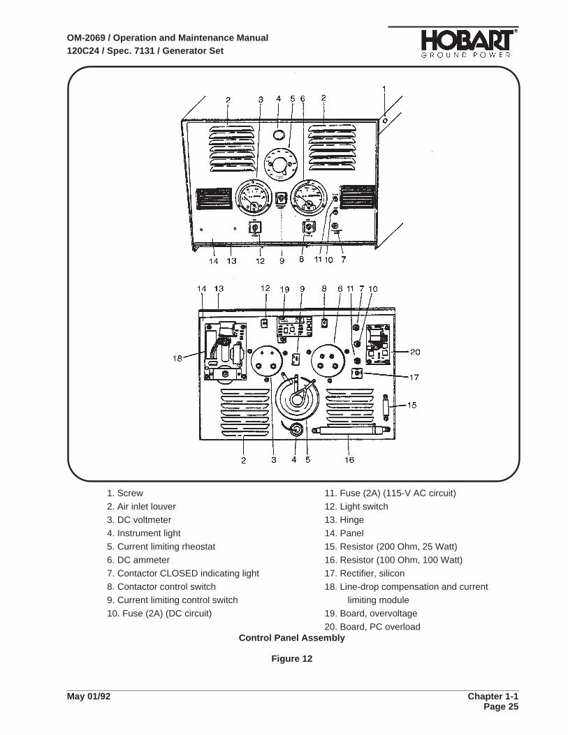
1. Screw 11. Fuse (2A) (115-V AC circuit)
2. Air inlet louver 12. Light switch
3. DC voltmeter 13. Hinge
4. Instrument light 14. Panel
5. Current limiting rheostat 15. Resistor (200 Ohm, 25 Watt)
6. DC ammeter 16. Resistor (100 Ohm, 100 Watt)
7. Contactor CLOSED indicating light 17. Rectifier, silicon
8. Contactor control switch 18. Line-drop compensation and current
9. Current limiting control switch limiting module
10. Fuse (2A) (DC circuit) 19. Board, overvoltage
20. Board, PC overloadControl Panel Assembly
Figure 12
OM-2069 / Operation and Maintenance Manual120C24 / Spec. 7131 / Generator Set
May 01/92 Chapter 1-1Page 25

1. Thermal overload relay 7. Positive heat sink
2. Negative heat sink 8. Diode leads
3. Output terminals 9. Bus bars
4. Transformer current limiting 10. Fan
5. Load contactor 11. Overload current transformer (3)
6. Transformer 12. Line drop CT
T-R Components (Front and Rear Views)
Figure 13
OM-2069 / Operation and Maintenance Manual120C24 / Spec. 7131 / Generator Set
Chapter 1-1 May 01/92Page 26

1. Thermal overload relay 7. Current limiting transformer
2. Negative heat sink 8. Overload current transformer
3. Positive output terminals 9. Load contactor
4. Negative output terminals 10. Positive heat sink
5. Negative diode 11. Positive diode
6. Fan
T-R Components (Side Views)
Figure 14
OM-2069 / Operation and Maintenance Manual120C24 / Spec. 7131 / Generator Set
May 01/92 Chapter 1-1Page 27

1. Fan 8. Control panel
2.Negative heat sink 9. Overvoltage module
3. Negative output bus 10. Current transformer
4. Positive output bus 11. Bracket resistors
5. Ammeter shunt 12. Current transformer
6. Thermal overload relay 13. Positive heat sink
7. Load Contactor
T-R Components (Top View from Front)
Figure 15
OM-2069 / Operation and Maintenance Manual120C24 / Spec. 7131 / Generator Set
Chapter 1-1 May 01/92Page 28

b. Cold Weather Starting Kit
This cold weather starting-aid kit (Figure 16) is an option available for starting the engine at verycold temperatures. This cold weather starting system is a fully automatic Engine Starting FluidSystem designed to spray a controlled amount of starting fluid into the air intake system of anengine during and immediately after cranking.
The System’s engine temperature sensor (ETS) Switch determines when the System shouldfunction. When needed, the solenoid valve is activated automatically during engine cranking; then,starting fluid is released from the pressurized cylinder, flows through the valve, through a flowmetering orifice fitting at the bottom of the valve through the nylon tubing, and out of an injectornozzle located in the engine’s air intake system. A reservoir in the valve maintains a flow of startingfluid after cranking to prevent the just started engine from faltering or dying.
1. Mounting bracket
2. Starting fluid cylinder
3. Cylinder clamp
4. Dieselmatic valve
5. Solenoid
6. Blocker fitting and filter
Cold Weather Starting Aid
Figure 16
OM-2069 / Operation and Maintenance Manual120C24 / Spec. 7131 / Generator Set
May 01/92 Chapter 1-1Page 29

This page intentionally left blank.
OM-2069 / Operation and Maintenance Manual120C24 / Spec. 7131 / Generator Set
Chapter 1-1 May 01/92Page 30
LIST OF FEATURES AVAILABLE FORSPECIFICATION 7131 GENERATOR SETS
The following is a list of the special features that may be ordered and installed at the factory as com-ponents of Specification 7131 generator sets. Those special features that are checked (X) on this list arethose which are installed on the generator set which this manual accompanies.
FEATURE PART NUMBER
Trailer Package Assembly (7131-1) 283673Transformer-Rectifier Assembly, 112-V DC 482085A-2Transformer-Rectifier Assembly, 28.5-V DC 487750-1Cold Weather Start Assembly 282192Block Heater Assembly, 115-V AC, 60-Hz 283014Low Fuel Shutdown Assembly 282995Low Fuel Flashing Light Assembly, Amber 283005-1Low Fuel Flashing Light Assembly, Blue 283005-2Low Fuel Flashing Light Assembly, Red 283005-3Low Fuel Light Assembly, Amber 283006-1Low Fuel Light Assembly, Blue 283006-2Low Fuel Light Assembly, Red 283006-3Fuel/Water Separator Assembly 283125Block Heater Assembly, 240-V AC, 50-Hz 283472Snow Shield Assembly 283023Emergency Stop Assembly 283007Emergency Stop Assembly (for field installation) 283008Unit Operating Light Kit, Amber 283004-1Unit Operating Light Kit, Blue 283004-2Unit Operating Light Kit, Red 283004-3Clearance Lights, Red 282732-2Fire Extinguisher 283012Pin-Type Hitch 381441Pintle-Type Hitch 76A-1361Fixed Mounting Kit 283661Noise Reduction Package 283474Variable Height Tow Bar Assembly 283133Cable Covers Kit 283675Spotlight Kit 282210Truck Body Package 283039Truck, Ford 283114Truck, Chevrolet 283115Low Fuel Warning Kit 283692Transformer-Rectifier Mounting Assembly, Single, on Trailer 282907-1Transformer-Rectifier Mounting Assembly, Double, on Trailer 282907-2Transformer-Rectifier Mounting Assembly, Single, on Truck 282907-3Transformer-Rectifier Mounting Assembly, Double, on Truck 282907-4
OM-2069 / Operation and Maintenance Manual120C24 / Spec. 7131 / Generator Set
May 01/92 Chapter 1-1Page 31

This page intentionally left blank
OM-2069 / Operation and Maintenance Manual120C24 / Spec. 7131 / Generator Set
Chapter 1-1 May 01/92Page 32

Section 2. Preparation for Use, Storage or Shipping
1. Preparation for Use
a. Inspection/Check
Inspect the unit thoroughly prior to operation.
(1) Remove blocking, banding, ties, and other securing material.
(2) Inspect exterior for shipping damage such as broken lights, damaged sheet metal, etc.
(3) Open all canopy doors and inspect interior for foreign material such as rags, tools, shippingpapers, etc.
(4) Check fuel, coolant, and oil hoses and connections for visible leaks. Visually inspect thecompartment floor and ground surface under the unit for signs of leakage. If leaks are found,correct by tightening hose clamps, tube fitting, etc., as required.
(5) Check security of generator set retaining components.
(6) Check the following for sufficient quantity:
a. Fuel
Turn ON engine control switch to energize fuel gage when engine is stopped. (Fuel issupplied from a customer-furnished source).
NOTE: For recommended fuel specifications refer to the Cummins engine manual in Chapter 5.
b. Engine coolant
Remove radiator cap to check coolant level. Coolant level should be approximately one inchbelow the filler neck. Allow a capacity for coolant expansion.
BE SURE the cooling system antifreeze solution is adequate to protect belowlowest temperature expected.
NOTE: For antifreeze protection, use a solution of 50% permanent antifreeze (Ethylene glycol) and50% clean water.
c. Engine lubricating oil level
The oil gage rod (1, Fig 1) has H (high) and L (low) level marks to indicate lubricating oilsupply. Oil level should be kept as near the H mark as possible.
NEVER operate the engine with oil level below the LOW-LEVEL mark or abovethe HIGH-LEVEL mark.
See 2-2, Fig. 4, or the Cummins Operation and Maintenance Manual in Chpater 5 for oilrecommendations.
d. Check Batteries
12-V DC power is supplied by customer-furnished batteries.
CAUTION
CAUTION
OM-2069 / Operation and Maintenance Manual120C24 / Spec. 7131 / Generator Set
May 01/92 Chapter 1-2Page 1

b. Installing Three-phase AC Output Cables
Units are generally shipped without generator set-to-aircraft cables. The load contactors, at whichcables must be connected are located on the right side of the unit beneath the engine control panel.
The conductor size recommended for AC output cables is 2/0 AWG. Use No. 12 size for control (Eand F terminals). Large cables (A, B, C, N) should be equipped with terminals having at least a3/8-inch diameter mounting hole. Mounting hole in small leads (E and F) should be at least 1/4-inchdiameter.
To install AC output cables proceed as follows.
(1) Open right front canopy door of the generator set.
(2) Loosen screws on cable clamps located on the side panel beneath the right rear canopy door.
(3) Route cables through cable clamp, and up to the load sides (bottoms) of the load contactors.
(4) Connect the phase cable terminal lugs to the appropriate terminal studs on the contactors: cablelug “A” to terminal stud “A”, “B” to “B”, and “C” to “C”.
(5) Connect the cable’s neutral terminal lug securely to the neutral (ground) stud on the side of theload contactor mounting bracket.
1. Oil Level Gage Rod
2. Oil Filler Cap
Oil Fill and Check LocationsFigure 1
OM-2069 / Operation and Maintenance Manual120C24 / Spec. 7131 / Generator Set
Chapter 1-2 May 01/92Page 2

(6) Tighten terminal nuts securely and replace the terminal cover on the load contactor. Connectsmall plug interlock leads “E” and “F” to terminal “E-F” on the side of the load contactor mountingbracket.
(7) Tighten clamp screws securely on the side panel, but avoid damage to cable insulation.
c. Transformer-Rectifier (DC) Output Cable Installation (optional equipment).
An output terminal panel (Figure 2) for transformer-rectifier cable connections is located inside theright front section of the generator mounting frame. Attach T-R output cable terminals to the outputterminal panel as illustrated in Figure 2. Use 4/0 size cables.
2. Preparation for StorageWhen a generator set is to be stored or removed from operation, special precautions should be takento protect the internal and external parts from rust, corrosion, and gumming in the engine fuel system.
a. General
(1) The unit should be prepared for storage as soon as possible after being removed from service.
(2) The unit should be stored in a building which is dry and which may be heated during wintermonths.
(3) Moisture absorbing chemicals are available for use where excessive dampness is a problem;however, the unit must be completely packaged and sealed if moisture absorbing chemicals areto be effective.
Transformer-Rectifier Cable InstallationFigure 2
OM-2069 / Operation and Maintenance Manual120C24 / Spec. 7131 / Generator Set
May 01/92 Chapter 1-2Page 3

b. Temporary Storage
When storing the unit for 30 days or less, prepare as follows:
(1) Lubricate the unit completely in accordance with instructions in Section 2-2. This will includechanging engine oil, and all filter elements.
(2) Start the engine and operate for about two minutes so that all internal engine components will becoated with new oil.
NOTE: Do not drain the fuel system or crankcase after this run.
(3) Make certain the cooling system antifreeze solution is adequate to protect below the lowesttemperatures expected during the storage period. See 2-2; Para 5, E. Be sure the solution isthoroughly mixed.
(4) Clean the exterior of the engine with fuel oil. Dry with clean rags and compressed air.
(5) Seal all engine openings. Use a waterproof, vaporproof material which is strong enough to resistpuncture damage from air pressures.
c. Long Time Storage (Over 30 Days)
(1) The unit may be stored for long periods with no special preparation if it is possible to operate theengine once each week.
(2) Make certain the cooling system is adequately protected.
(3) Start the engine and operate at a fast idle (800 to 1000 RPM) until coolant temperature hasreached at least 140 deg. F.
ENSURE adequate ventilation before starting the engine.
(4) Operate normal operating controls.
(5) If weekly operation is not possible, contact the nearest Cummins Engine Company distributor forinstructions.
(6) To protect the generator and other electrical components, the complete unit should bepackaged, using moisture proof packaging and sealing material. Place containers of moistureabsorbing chemicals, such as silica gel, in the unit before packaging.
d. Preparation for Shipment
During long shipments, the generator set retaining hardware may become loosened by vibration,jolting, etc.
When shipping the unit, provide sufficient retaining materials to ensure thegenerator set cannot roll out of the vehicle in which it is being transported.
NOTE: It is suggested that strong banding may be used to secure the generator set, or a strong steelbar may be welded or bolted across the front of the generator set frame.
CAUTION
WARNING
OM-2069 / Operation and Maintenance Manual120C24 / Spec. 7131 / Generator Set
Chapter 1-2 May 01/92Page 4

Section 3. Operation
1. GeneralThis section contains information and instructions for the safe and efficient operation of the equipment.Operating instructions are presented in step-by-step sequence of procedures to be followed insupplying 400-Hz power.
NOTE: Read ALL of the Operating Instructions before attempting to operate the equipment.
Ear protection equipment may be necessary when working close to thisequipment.
2. Operating the Unit
a. Pre-start inspection
(1) Be sure the fuel shutoff valve (if used) on the vehicle is open.
(2) Ensure 12-V DC power is available to the engine starting system.
(3) Check the engine and generator compartments to make certain they are free of rags or otherforeign materials.
(4) Make certain there is sufficient lubricating oil and coolant in the engine.
b. Normal Engine Starting Procedures
Engine starting procedures are outlined below. Engine operating controls and monitoringinstruments are illustrated in Fig. 1.
Refer to Operating Instructions in the Cummins Operation and MaintenanceManual, when starting engine for the first time.
NOTE: The Cummins Engine Manual is located in Chapter 5.
(1) If illumination is required, place light switch (4) in ON position.
(2) Place engine-generator control switch (28) in IDLE position.
(3) Place contactor control switch (23 and 25) in OFF position.
(4) Place and hold engine control switch (9) in START position. The green light (6) should glow toindicate power is available to the engine protective circuit and fuel shut-off valve.
(5) Press start switch button (8) to crank the engine. Release the start switch as soon as the enginestarts. Continue to hold the engine control switch in START position until oil pressure is normal.
CAUTION
CAUTION
OM-2069 / Operation and Maintenance Manual120C24 / Spec. 7131 / Generator Set
May 01/92 Chapter 1-3Page 1

1. Front panel 15. Protective system indicating lights
2. Panel light 16. Test switch, protective system
3. Engine hour meter 17. Reset switch, protective system
4. Panel light switch 18. Indicating light, air cleaner restriction
5. Oil pressure gage 19. Frequency meter
6. Engine ON indicating light 20. Selector switch, voltmeter-ammeter
7. Engine coolant temperature meter 21. Voltmeter
8. Engine start switch 22. Adjustable grip latch
9. Engine control switch 23. No. 1 contactor switch
10. Engine ammeter 24. Power accepted light, No. 1 contactor
11. Fuel gage 25. No. 2 contactor switch
12. Load contactor circuit breaker 26. Power accepted light, No. 2 contactor
13. Protective system circuit breaker 27. Generator ammeter
14. Engine system circuit breaker 28. Engine-generator control switch
Operating Controls and Instruments
Figure 1 (Sheet 1 of 2)
OM-2069 / Operation and Maintenance Manual120C24 / Spec. 7131 / Generator Set
Chapter 1-3 May 01/92Page 2

29. Test bank-aircraft switch, No. 1 output 33. Output voltage adjustment (fine)
30. Test bank-aircraft switch, No. 2 output 34. Line drop compensation adjustment
31. Regulated-diagnostic switch 35. Fuse (5-amp)
32. Output voltage adjustment (coarse)
Operating Control and Instruments
Figure 1 (Sheet 2 of 2)
OM-2069 / Operation and Maintenance Manual120C24 / Spec. 7131 / Generator Set
May 01/92 Chapter 1-3Page 3

If the engine fails to start within 30 seconds, release the start switch and allowthe starting motor to cool for a few minutes. If the engine fails to start after fourattempts, an inspection should be made to determine the cause.
If the engine fires sufficiently to disengage the starter gear, but does not start,release the start button and allow the starting motor to come to a complete stopbefore attempting to engage the starter again.
(6) When oil pressure is normal, release the permissive start switch and allow it to return to RUNposition. Green indicating light should continue to glow.
(7) Observe all engine instruments for normal operation.
(8) Allow engine to idle and warm before applying load.
DO NOT allow the engine to idle for long periods of time.
c. Cold Weather Engine Starting Procedures
A cold weather starting-aid kit (Fig. 2) is provided to assist in starting the engine at temperaturesbelow 50 degree F. To start the engine, using the starting aid, proceed as follows:
(1) Position switches and controls as instructed in steps (1) through (4), paragraph B, NormalEngine Starting Procedures, above.
(2) Prepare starting aid for use. The starting aid is shipped in a safe condition and is not operableuntil assembled. Assemble as follows:
Fires, fumes, and flying parts can kill or injure! starting fluid is extremelyflammable. it is under pressure. Use caution when handling. avoid contact withskin and avoid breathing vapor.
a. Loosen clamp screws (1, Fig. 2) and slide the cylinder (2) upward sufficiently to removeprotective cap and plug (3).
b. Use bottle opener to remove cylinder cap (3). Unscrew and remove plug inside it.
c. Slide the cylinder (2) downward and thread into the valve (4). Tighten securely. The startingaid is now ready to use.
Cold weather starting procedures are exactly the same as for normal starting.
Use starting aid only for starting. do not operate while engine is running.
Do not “flood” the engine with starting fluid. a serious explosion could result.
Note: Whenever the engine does not start within a normal period of cranking, the starting fluid cylindermay be empty. Refer to starting aid servicing and troubleshooting information in Section 2-2.
CAUTION
CAUTION
WARNING
CAUTION
WARNING
OM-2069 / Operation and Maintenance Manual120C24 / Spec. 7131 / Generator Set
Chapter 1-3 May 01/92Page 4

(3) Tips On Cold Weather Starting
a. Battery and CablesTo start in cold weather, a diesel engine must crank at a fairly high speed. Worn outbatteries, partially discharged batteries, and poor or loose cable connections will reducecranking speed. Batteries, cables, and connections should be cleaned and tightenedregularly.
b. Fuel
For an engine to start and keep running, fuel must flow through the injection system. Un-blended #2 diesel fuel, “clouds”, forming filter-clogging wax at temperatures around +150F(-100C). This makes starting and running impossible. Most engine manufacturersrecommend that fuel have a cloud point at least 100F (50C) below the coldest anticipatedtemperature.
c. Lube OilEngine lubricating oil get thicker at lower temperatures. Many oils that flow freely at 700F(210C) are extremely thick at 00F (-180C). Follow your engine manufacturer’srecommendations regarding oil viscosity for the coldest temperatures you expect your engineto encounter.
1. Clamp screw
2. Cylinder
3. Protective cap
4. Valve
5. Solenoid
6. Blockor fitting and
Cold Weather Starting Aid
Figure 2
OM-2069 / Operation and Maintenance Manual120C24 / Spec. 7131 / Generator Set
May 01/92 Chapter 1-3Page 5

d. Preparation for Power delivery
The following are preparation procedures to be followed after the engine is started.
(1) Check and position switches and controls.
a. Open the right rear door of the generator canopy and open the door on the control box (whichis the engine-generator control panel). This allows access to components inside the controlbox.
b. Place regulated-diagnostic switch (31) in REGULATED position.
c. Place test-bank switches (29 and 30) in AIRCRAFT position if the aircraft being serviced isequipped with 28.5-V DC interlock relay system. (If not, place in TEST BANK position).
d. Close the control panel (door) and fasten it shut. Close also the right rear door of the canopyassembly.
(2) Connect output cable plug connector to aircraft receptacle. Be sure connectors are mated fullyand securely.
e. Power Delivery
(1) Place engine-generator control switch (28) in BUILD-UP-VOLTAGE position momentarily, thenallow it to position itself in GEN position. The electric governor will immediately increase enginespeed to 2400 RPM and maintain it.
(2) Observe generator instruments. Frequency meter (19) should indicate exactly 400 Hz. Withvoltmeter-ammeter selector switch (20) in any line-to-neutral position, (A-N, B-N, or C-N), thevoltmeter (21) should read 115 volts. With voltmeter-ammeter selector switch switch in anyline-to-line position, (A-B, B-C, or C-A), the voltmeter should read 200 volts.
(3) The final step in delivering power is closing one or both of the load contactors. Whensatisfactory frequency and voltage values are indicated by the instruments, close either loadcontactor (or both load contactors) by momentarily placing the load contactor control switch (23or 25) in the top (spring loaded), ON position. The green indicating light (24 or 26) for thatcontactor should glow at once to indicate that the load contactor is closed and power is availableat the aircraft. As soon as the light glows, release the switch. It will automatically return to thecenter ON position.
NOTE: If the indicating light (24 or 26) should go out as soon as the switch is released, and no faultlights are ON, it indicates that 28.5-V DC holding current is not being supplied from the aircraftto the plug-interlock relay. Correct the condition and again operate load contactor control switch(23 or 25) as above.
(4) It is recommended that the operator check output voltage and current in each of the threephases early in the power delivery run. Use the meter switch (20) to select the phase andline-to-line or line-to-neutral voltage. If the load is changing, it is good operating practice toobserve the instruments until load conditions stabilize.
(5) A condition of overvoltage, undervoltage, underfrequency, overfrequency, or overload in theoutput circuit will automatically open the load contactor and turn on the applicable indicating lightto signal the operator which of the above faults caused the protective monitor system to operate.After the fault has been corrected, press the reset switch (17) to turn off the indicating light andreset the protective relay system. Proceed with power delivery by operating the load contactorswitch.
NEVER disconnect the output cable while power is being delivered..
f. Discontinue Power Delivery
(1) Place the load contactor switch (23 and/or 25) in OFF position. Green light (24 and/or 26)should go OFF immediately to indicate that the load contactor has opened and power is nolonger being delivered to the aircraft.
WARNING
OM-2069 / Operation and Maintenance Manual120C24 / Spec. 7131 / Generator Set
Chapter 1-3 May 01/92Page 6
(2) Place engine-generator control switch (28) in IDLE position.
(3) Disconnect output cable from aircraft.
g. Stopping the Engine
(1) Allow the engine to idle a few minutes before stopping, to permit cooling.
(2) To stop the engine, place engine control switch (9) in STOP position.
3. Transformer-Rectifier Operation
a. Preparation for DC Power Delivery
Start, and prepare the generator set for power delivery the same as for 400-Hz use. If it isnecessary to supply both 28.5-Volt DC and 400-Hz power at the same time, refer to Para. 4 below.
b. DC Power Delivery
(1) Connect DC output cable plug connector to aircraft receptacle connector. Be sure goodconnection is made.
(2) Operate generator-set controls, as instructed by the applicable manual, to produce 115-Volt AC,400-Hz output.
(3) If illumination is required at the T-R control panel, turn instrument light (4, Fig. 1) ON with switch(12).
(4) If current-limiting is required for soft-starting an aircraft, position controls as follows:
a. Place current limiting control switch (9, Fig.1) in the ON position.
b. Adjust rheostat (5) to the starting amperage recommended by the engine manufacturer.
(5) If power delivery is to be a load bank, or to an application where full load capacity is desired,place the current limiting control switch (9) in the OFF position. The T-R will then have a loadcapacity of 2000 Amperes for five minutes, or 2500 Amperes for 30 seconds.
(6) Close the T-R load contactor to deliver power to the output cables by momentarily holding thecontactor control switch (8) in the top, ON position until the indicating light (7) glows. Release theswitch and allow it ti return to center, ON position.
(7) Apply a load of 1000 Amperes and observe voltmeter (3). If voltage is not 28.5 Volts DC, openthe control panel and use rheostat (1, Fig.2) located on the line-drop and current limiting module(4) to adjust. Loosen locknut (2) and turn adjusting screw CLOCKWISE to increase voltage. TurnCOUNTERCLOCKWISE to decrease voltage. Adjust output to 28.5 Volts DC. Tighten locknutand close control panel.
(8) Remember that an overload, overvoltage, or overheating will cause the load contactor todisconnect the load and turn OFF the indicating light (7, Fig. 1). If shut-down occurs, check forthe condition that caused it and remedy it before restarting the T-R.
c. Discontinue Power Delivery
(1) Place contactor control switch (8, Fig. 1) in the OFF position.
(2) Disconnect output cable at aircraft.
WARNING: Do not disconnect cable while power is on. Lethal electricalshock hazard exists. Also, opening the connector under load causesarcing and pitting of connector parts.
(3) Operate generator-set controls according to instructions at the beginning of this section.
WARNING
OM-2069 / Operation and Maintenance Manual120C24 / Spec. 7131 / Generator Set
May 01/92 Chapter 1-3Page 7
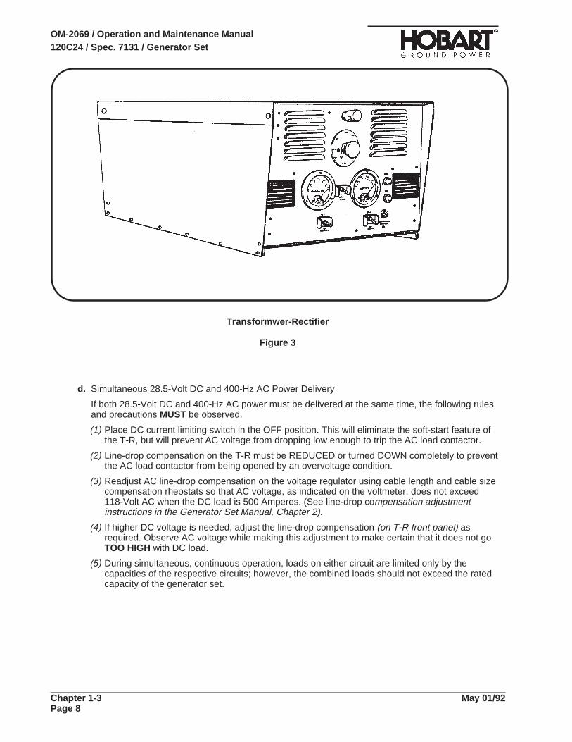
d. Simultaneous 28.5-Volt DC and 400-Hz AC Power Delivery
If both 28.5-Volt DC and 400-Hz AC power must be delivered at the same time, the following rulesand precautions MUST be observed.
(1) Place DC current limiting switch in the OFF position. This will eliminate the soft-start feature ofthe T-R, but will prevent AC voltage from dropping low enough to trip the AC load contactor.
(2) Line-drop compensation on the T-R must be REDUCED or turned DOWN completely to preventthe AC load contactor from being opened by an overvoltage condition.
(3) Readjust AC line-drop compensation on the voltage regulator using cable length and cable sizecompensation rheostats so that AC voltage, as indicated on the voltmeter, does not exceed118-Volt AC when the DC load is 500 Amperes. (See line-drop compensation adjustmentinstructions in the Generator Set Manual, Chapter 2).
(4) If higher DC voltage is needed, adjust the line-drop compensation (on T-R front panel) asrequired. Observe AC voltage while making this adjustment to make certain that it does not goTOO HIGH with DC load.
(5) During simultaneous, continuous operation, loads on either circuit are limited only by thecapacities of the respective circuits; however, the combined loads should not exceed the ratedcapacity of the generator set.
Transformwer-Rectifier
Figure 3
OM-2069 / Operation and Maintenance Manual120C24 / Spec. 7131 / Generator Set
Chapter 1-3 May 01/92Page 8

1. Screw 11. Fuse (2A) (115-V AC circuit)
2. Air inlet louver 12. Light switch
3. DC voltmeter 13. Hinge
4. Instrument light 14. Panel
5. Current limiting rheostat 15. Resistor (200 Ohm, 25 Watt)
6. DC ammeter 16. Resistor (100 Ohm, 100 Watt)
7. Contactor ON indicating light 17. Rectifier, silicon
8. Contactor control switch 18. Line-drop compensation and
9. Current limiting control switch current limiting module
10. Fuse (2A) (DC circuit) 19. Board, overvoltage
T-R Control Panel Assembly
Figure 4
OM-2069 / Operation and Maintenance Manual120C24 / Spec. 7131 / Generator Set
May 01/92 Chapter 1-3Page 9

4. Trailer Operation
a. Towing
Observe the following rules when towing the trailer.
(1) Be sure all output cables are disconnected and properly stowed.
(2) Be sure parking brake is released.
(3) Avoid turns which are shorter than the steering linkage will freely allow.
(4) Avoid dangerous speed and sudden turns.
b. Parking
This trailer is equipped with towbar activated brakes. When parking the trailer:
(1) Tow the generator set to the location where it is to be parked.
(2) Disconnect the trailer from the tow vehicle.
(3) Place drawbar in an upright, vertical position to apply the brakes.
1. Rheostat
2. Nut
3. Screw
T-R Output Voltage Adjustment
Figure 5
OM-2069 / Operation and Maintenance Manual120C24 / Spec. 7131 / Generator Set
Chapter 1-3 May 01/92Page 10
Chapter 2. Servicing
Section 1. Maintenance Inspection/Check
1. GeneralTo make certain the generator set is always ready for operation, it must be inspected and maintainedregularly and systematically so that defects may be discovered and corrected before they result inserious damage to components, or failure of the equipment.
STOP operations at once if a serious or possibly dangerous fault is discovered.
2. Maintenance Schedule
a. General
A periodic maintenance schedule should be established and maintained. A suggested schedule isprovided in Fig. 1 on the following pages. It may be modified, as required to meet varying operatingand environmental conditions. It is suggested that generator set and vehicle inspections becoordinated as much as possible.
b. Maintenance Schedule Check Sheet
It is strongly recommended that the customer use a maintenance schedule check sheet such as theone in Cummins Operation and Maintenance Manual. The check sheet will provide a record andserve as a guide for establishment of a schedule to meet the customer’s maintenance requirementsfor his specific operation.
c. Time Intervals
The schedule is based on both hours of operation and calendar intervals. These two intervals arenot necessarily the same. For example, in normal operation the oil change period, based on hoursof operation, will be reached long before the three months calendar period. The calendar period isincluded to make certain services are performed regularly when the equipment is stored, or beingoperated infrequently. Lubricating oil standing in engines that are stored, or used very little, maytend to oxidize and may require changing although it is not dirty. Perform all services onwhichever-comes-first basis.
d. Identification of Interval Periods
Each interval period is identified by a letter A, B, C, etc., (See Sect. 2-2). For example, servicesunder B schedule should be performed at the end of each 200 hours of operation, or every threemonths period. AR service are performed on an AS REQUIRED basis.
WARNING
OM-2069 / Operation and Maintenance Manual120C24 / Spec. 7131 / Generator Set
May 01/92 Chapter 2-1Page 1

HOURLY INTERVAL 10 200 400 800 1200 6000As or or or or or or
CALENDAR INTERVAL Req’rd. Daily 3 Mo. 6 Mo. 1 Yr. 1Yr. 5Yrs.
SYMBOL AR A B C D E F
ENGINEChange Air Cleaner Cartridge X
Check Engine Blow-by X
Check Crankcase Oil Level X
Drain Fuel Filter Elements X
Check Coolant Level X
Check for Leaks and Correct X
Check Air Cleaner Indicator X
Check Exhaust System X
Change Crankcase Oil X
Change Oil Filter Element X
Check and Record Oil Pressure X
Check Crankcase Breather X
Change Fuel Filter Elements X
Clean Radiator Core (external) X
Check Governor Linkage X
Change Water Filter X
Check/Adjust Serpentine Belt Tension X
Tighten Manifold Hardware X
Check Fan Hub and Drive Pulley X
Steam Clean Engine X
Clean Fuel Pump Screen and Magnet X
Check Vibration Damper X
Adjust Injector and Valves X
Check Fuel Manifold Pressure X
Check Water Pump X
Check Fan Hub X
Check Alternator X
Check Cranking Motor X
Clean/Calibrate/Replace Injectors X
Check Fuel Pump Calibration X
Clean Oil Cooler X
Overhaul Cylinder Heads X
Maintenance Schedule
Figure 1 (Sheet 1 of 2)
OM-2069 / Operation and Maintenance Manual120C24 / Spec. 7131 / Generator Set
Chapter 2-1 May 01/92Page 2

HOURLY INTERVAL 10 200 400 800 1200 6000As or or or or or or
CALENDAR INTERVAL Req’rd. Daily 3 Mo. 6 Mo. 1 Yr. 1Yr. 5Yrs.
SYMBOL AR A B C D E F
ENGINE (continued)
Replace Piston Rings X
Inspect Pistons and Cylinder Liners X
Replace Cylinder Liner Seals X
Inspect Bearings and Journals X
Check Fan Mounting
Clean Cooling System
Check Hoses
Clean Electrical Connections
Check Thermostats and Seals
Check Starting Aid
ELECTRICAL(12-V DC System)
Check Battery and Fluid Level X
Clean Battery Terminals X X
Check all Lights X
Check Charging Rate X
Check Wiring and Connections X
ELECTRICAL(400-Hz System)
Check Output Cable and Connectors X
Check Volt, Amp & Frequency Meters X
Check Protective Relays X
Inspect Wiring and Connections X
Clean and Inspect Generally X
Spring and Fall
Spring and Fall
Spring and Fall
Spring and Fall
Fall
Fall
Maintenance Schedule
OM-2069 / Operation and Maintenance Manual120C24 / Spec. 7131 / Generator Set
May 01/92 Chapter 2-1Page 3

3. Inspection/Check
a. General
Inspections, checks, and maintenance are described in general here. More specific and detailedinformation contained in 2-2 and 2-3, will be referenced when applicable. See 2-2, Para. 2 forinstructions on how to roll the generator set out for service.
b. “AR” Checks and Operations (As Required)
(1) Engine
a. Change air cleaner.
A definite time schedule for changing the air cleaner cannot be established. This air cleaneris a disposable type which, when dirty, may be washed as many as six times beforediscarding. See 2-2, para 3.
b. Check engine blow-by are required if the engine lacks power or uses oil excessively. Referto the Cummins Operation and Maintenance Manual.
c. Tighten manifold, muffler, and exhaust pipe attaching hardware (nuts and capscrews) asrequired.
d. Tighten all attaching hardware as required.
(2) Electrical System (12-V DC)
a. Check battery terminals
Anytime the battery compartment doors are opened for any reason, visually check batterycable connectors and battery posts. If corrosion is observed, disconnect cables and cleanbattery posts and connectors with a wire brush or special battery post-and-connectorcleaning tool. Coat posts and connectors with a light film of petroleum lubricant beforereconnecting cables.
c. “A” Checks and Operations (10 Hours or Daily)
(1) Engine
(2) Check crankcase oil level
DO NOT overfill. DO NOT operate the engine with oil level below L (low) markor above H (high) mark.
a. Check oil level daily with oil gage dipstick (See 1-2, Fig. 1.)
b. Oil level should not be checked until 3 to 5 minutes after engine shutdown. Keep oil level asnear H mark as possible.
NOTE: If there is any question regarding oil gage dipstick accuracy, check oil level by removing 1/8inch pipe plug in side of oil pan. Refer to Cummins Operation and Maintenance Manual.
CAUTION
OM-2069 / Operation and Maintenance Manual120C24 / Spec. 7131 / Generator Set
Chapter 2-1 May 01/92Page 4

BE SURE to prime and bleed the fuel system after draining the filters, replacingany element in the system, or if the fuel tank has run empty. Failure to do socan cause engine starting problems.
(3) Drain fuel filters
The life of the fuel pump and injectors can be extended if the operator drains about a cup of fuelfrom each of the fuel filter elements to remove water and sediment before starting the engineeach day.
a. Provide a container for catching drained fuel
b. Open the drain valve on the fuel/water filter by turning it counterclockwise.
c. Drain the filter until clear fuel is visible. Tighten the drain valve.
d. The fuel filter must be removed to drain.
e. Safely dispose of drained fuel.
f. Loosen the bleed screw
g. Operate the plunger on the lift pump until the fuel flowing fromthe fitting is free of air.
h. Tighten the bleed screw.
CAUTION
Fuel Filters
Figure 2
OM-2069 / Operation and Maintenance Manual120C24 / Spec. 7131 / Generator Set
May 01/92 Chapter 2-1Page 5

i. Check coolant level
Check coolant level daily or at each fuel fill interval. Investigate for cause of any coolant loss.
j. Check for leaks
At each daily start-up, check for coolant, fuel, and oil leaks. Coolant leaks may be morenoticeable when components are cold. Observe pumps, hoses, fittings, gasketedconnections, etc., for signs of leakage. Correct as required.
k. Check air cleaner indicator light
At each daily start-up, observe the air cleaner indicator light (1-3; 18, Fig. 1). If this lightcomes ON, it indicates that the air cleaner should be changed.
l. Check exhaust system
Visually inspect muffler and exhaust pipes for rust and signs of approaching failure. Listenfor any gasket or joint leaks.
A leaking and defective exhaust system could be a fire hazard.
(4) Electrical (Engine)
a. Check all lights
Check all indicating lights to be sure they will operate when they should. If any light fails tooperate, check both the lamp and its protective fuse. Figure 4 lists all lamps with theirlocation and part number. Figure 5 lists all fuses.
b. Check alternator charging rate
Observe the 12-V DC ammeter each time the engine is started. A zero amperage reading orextremely high reading for any length of time indicates trouble in the alternator, regulator,battery, or interconnecting wiring.
(5) Electrical (Generator)
a. Monitoring instruments
Check operation of voltmeter, ammeter and frequency meter each time the unit is started.
b. Indicating lights
Check lamps (bulbs) in all of the indicating lights at each start up. Fault indicating lights onthe control panel may be tested by pressing test switch (1-3; 16, Fig. 1). Check fuses if lightsfail to operate.
c. Output cable plug connector
Check the output cable plug connection for damaged contacts each time the connector isattached to an aircraft.
d. “B” Check and Operations (200 Hours or 3 Months)
(1) Engine
a. Change crankcase oil. See 2-2, Para. 3, D, (4) for details.
b. Change oil filter element
Change oil filter element each time crankcase oil is changed. See 2-2, Para. 3, D, (5) fordetails.
WARNING
OM-2069 / Operation and Maintenance Manual120C24 / Spec. 7131 / Generator Set
Chapter 2-1 May 01/92Page 6

c. Check and record oil pressure
After each oil change, check and record oil pressure at idle speed after oil has warmed toapproximately 140 deg. F. Record oil pressure under identical conditions at each oil changeinterval. A comparison of pressure at idle speed with previous readings will give an indicationof progressive wear of oil pump, bearings, shafts, etc. Investigate any abnormal change inpressure readings.
d. Alternator and starter lubrication
Most alternators contain sealed bearings and require no periodic lubrication. The startingmotor is lubricated at assembly and should be re-lubricated only when the starter is removedand disassembled. Check both of these accessories to determine if they have lubricationfittings.
e. Change fuel filters. Refer to 2-2; Para. 5, B for instructions.
f. Clean radiator core. See 2-2; Para. 6, H for instructions.
g. Check governor linkage
Check all attaching hardware. Check ball joints for wear and looseness. Check linkage forfree movement throughout its complete travel range.
h. Change water filter
Change water filter every 200 to 250 hours and at each coolant change. See 2-2; Para. 6, Kfor service instructions. See Cummins Manual for instructions on how to test coolantchemically.
i. Check and adjust V belts
See 2-2; Para. 7, C for tension check and adjustment instructions.
j. Check and service crankcase breather. Refer to 2-2; Para. 3, F, for service instructions.
(2) Electrical (12-V DC system)
a. Battery electrolyte level
Batter electrolyte level must be maintained above top of plates. Add distilled water asrequired.
DO NOT overfill.
b. Check battery
If battery requires water frequently, or is low in charge, the reason for the condition must befound and corrected.
c. Battery terminals
Check battery terminals and clean if necessary in accordance with Para. 3, B, (2) (a) above.
e. “C” Checks and Operations (400 Hours or 6 Months)
(1) Electrical (12-V DC system)
a. Wiring
Inspect all cables and leads for worn or damaged insulation.
b. Connectors
Inspect connectors for security and damaged or corroded condition.
CAUTION
OM-2069 / Operation and Maintenance Manual120C24 / Spec. 7131 / Generator Set
May 01/92 Chapter 2-1Page 7
(2) Electrical Generator
a. Protective relays
Check operation of all protective relays to make certain they will function if a fault shouldoccur in the output circuit. Procedures for testing these relays are contained in theAdjustment/Test section of this manual.
b. Wiring and connections
• Check all cables, leads, and wiring for broken, worn and damaged insulation.
• Check all connections for tightness.
f. “D” Checks and Operations (800 Hours or 1 Year)
(1) Engine
a. Check fan hub and drive pulley (see Cummins Maintenance Manual).
g. “E” Checks and Operations (1200 Hours or 1 Year)
(1) Engine
a. Steam clean engine
There are several reasons why the engine exterior should be kept clean. Dirt on the outsidewill enter fuel and oil filter cases and rocker housings when covers are removed unless dirt isremoved first. A clean engine will run cooler and develop fewer hot-spots.
Steam cleaning is one of the most satisfactory methods of cleaning and engine; however,there are some CAUTIONS to be observed.
1. If a cleaning compound is used, select one which is free from acid and whichwill not remove paint.
2. Protect (or remove) all electrical accessories, such as voltage regulator,alternator, and electrical wiring.
3. Seal all openings.
1. DO NOT use a flammable solvent.
2. Exercise care to avoid injury and damage to eyes and skin.
3. DO NOT use mineral spirits or solvents on a hot engine.
b. Check vibration damper.
The damper hub and inertia member are stamped with index marks to permit detection ofmovement between the two parts (see Fig. 3). There should be no indication of movementbetween the hub and the inertia member. If index marks are not aligned, replace vibrationdamper.
c. Adjust injectors and valves
Injectors and valves must be in correct adjustment at all times for best engine performance.Refer to Cummins Operation and Maintenance Manual for injector and valve adjustinginstructions.
CAUTION
WARNING
OM-2069 / Operation and Maintenance Manual120C24 / Spec. 7131 / Generator Set
Chapter 2-1 May 01/92Page 8

d. Check fuel manifold pressure
This check is necessary only if there is an apparent or suspected loss of power. Refer toCummins Operation and Maintenance Manual for tools required and test instructions.
e. Check water pump
Check water pump for signs of leaking and lubricant loss. Replace with new prelubricatedpump if lubricant is being lost.
f. Check fan hub
Check fan hub for signs of lubricant loss. Replace with new prepacked hub if lubricant isleaking.
g. Check alternator and cranking motor.
The alternator and cranking motor on this particular engine require no periodic lubrication.See 2-2, Para. 3, E, (1) and (2) for details.
Engine Check Points
Figure 3
OM-2069 / Operation and Maintenance Manual120C24 / Spec. 7131 / Generator Set
May 01/92 Chapter 2-1Page 9

h. “F” Checks and Operations (6000 Hours or 5 Years)
(1) Engine
These checks should determine whether the engine requires a complete overhaul or whether itmay be operated for another service period. High oil consumption, low oil pressure at idlespeed, oil dilution and other signs of wear must be considered.
Disassemble the engine sufficiently to perform the following inspections and services. Completeoverhaul facilities should be available. If the user performs this operation in his own shop, ashop manual should be procured from Cummins Engine Company.
a. Clean and calibrate injectors
Injectors must be cleaned and calibrated regularly to insure proper fuel delivery tocombustion chambers. Special tools are required. It is suggested that the CumminsDistributor be consulted for this operation.
b. Check fuel pump calibration
This operation may be performed on an as required basis. Pump calibration also requiresspecial tools and testing equipment. Consult the Cummins Distributor for information.
c. Inspect bearings
d. Inspect cylinder liners
e. Inspect pistons
f. Inspect crankshaft journals
g. Rebuild cylinder heads
h. Replace piston rings
i. Replace cylinder liner seals
j. Replace front and rear crankshaft seals
k. Replace vibration damper
l. Clean oil cooler
i. Seasonal Maintenance Checks (Engine)
(1) Inspect engine cooling fan each spring and fall.
a. Check fan to be sure it is securely mounted.
b. Check for fan wobble and/or bent blades.
c. Check fan hub and crankshaft pulley for secure mounting.
(2) Check cooling system each spring and fall. Clean if necessary. See 2-2, Para. 6, G and H, forcooling system maintenance.
(3) Check all hoses.
In addition to daily checks of hoses for leaks, inspect hoses thoroughly each time the coolingsystem is cleaned and serviced.
a. Inspect for signs of deterioration and collapse.
b. Inspect for cracks and cuts.
c. Inspect for cutting and deformation caused by hose clamps.
d. Replace hoses as required.
(4) Check and adjust V belts each time the cooling system is cleaned, or on an as required basis.See 2-2, Para. 8, check and adjustment procedures.
OM-2069 / Operation and Maintenance Manual120C24 / Spec. 7131 / Generator Set
Chapter 2-1 May 01/92Page 10
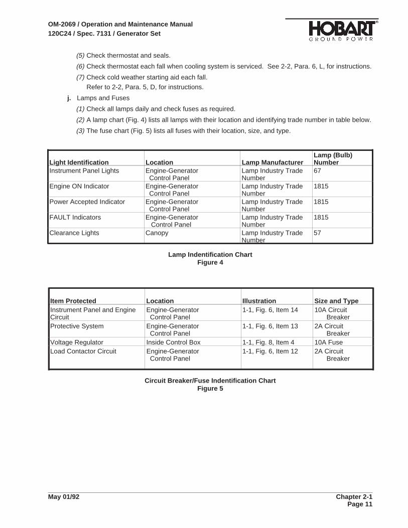
(5) Check thermostat and seals.
(6) Check thermostat each fall when cooling system is serviced. See 2-2, Para. 6, L, for instructions.
(7) Check cold weather starting aid each fall.
Refer to 2-2, Para. 5, D, for instructions.
j. Lamps and Fuses
(1) Check all lamps daily and check fuses as required.
(2) A lamp chart (Fig. 4) lists all lamps with their location and identifying trade number in table below.
(3) The fuse chart (Fig. 5) lists all fuses with their location, size, and type.
Light Identification Location Lamp ManufacturerLamp (Bulb)Number
Instrument Panel Lights Engine-GeneratorControl Panel
Lamp Industry TradeNumber
67
Engine ON Indicator Engine-GeneratorControl Panel
Lamp Industry TradeNumber
1815
Power Accepted Indicator Engine-GeneratorControl Panel
Lamp Industry TradeNumber
1815
FAULT Indicators Engine-GeneratorControl Panel
Lamp Industry TradeNumber
1815
Clearance Lights Canopy Lamp Industry TradeNumber
57
Lamp Indentification ChartFigure 4
Item Protected Location Illustration Size and TypeInstrument Panel and EngineCircuit
Engine-GeneratorControl Panel
1-1, Fig. 6, Item 14 10A CircuitBreaker
Protective System Engine-GeneratorControl Panel
1-1, Fig. 6, Item 13 2A CircuitBreaker
Voltage Regulator Inside Control Box 1-1, Fig. 8, Item 4 10A FuseLoad Contactor Circuit Engine-Generator
Control Panel1-1, Fig. 6, Item 12 2A Circuit
Breaker
Circuit Breaker/Fuse Indentification ChartFigure 5
OM-2069 / Operation and Maintenance Manual120C24 / Spec. 7131 / Generator Set
May 01/92 Chapter 2-1Page 11

This page intentionally left blank
OM-2069 / Operation and Maintenance Manual120C24 / Spec. 7131 / Generator Set
Chapter 2-1 May 01/92Page 12
Section 2. Maintenance Procedures
1. GeneralA suggested Maintenance Schedule was provided in Section 1, of this Servicing Chapter. Each step ofthe schedule was also covered in general in Section 1. This Section covers maintenance in moredetails where necessary.
Stop operation immediately if a serious or possibly dangerous fault is discovered.
2. Lubrication
a. General
Proper lubrication is one of the most important steps in good maintenance procedure. Properlubrication means the use of correct lubricants and adherence to a proper time schedule.Lubrication points, frequency of lubrication, and recommended lubricants are indicated in Figure 3.
b. AC Generator
The 400 Hz generator requires NO lubrication.
c. Generator Controls
Generator controls and instruments require no periodic lubrication. A few drops of oil may berequired on door hinges occasionally to insure free and quiet operation.
d. Engine
Although the engine and its accessories require no more attention than any other similar installation,they still inherently require a major portion of the generator set lubrication and maintenance.Recommendations regarding engine lubrication have been taken from the engine manufacturer’s“Operation and Maintenance Manual” and incorporated here to make them more readily available tooperators and maintenance personnel.
(1) Lubrication schedule
Time schedules indicated on the Lubrication Chart, Fig. 3, are approximate. They are based onaverage operating conditions. It may be necessary to lubricate more frequently under severeoperating conditions such as: low engine temperatures, high oil temperatures, or intermittentoperation. However, time intervals should not exceed those indicated in the chart without carefulevaluation.
(2) Oil specification
Engine lubricating oil, recommended by the engine manufacturer, is identified by an API(American Petroleum Institute) classification designation. The manufacturer does notrecommend any specific brand of lubricating oil.
The use of quality lubricating oil, combined with appropriate lubricating oil drain and filter changeintervals are important factors in extending engine life.
Oil recommended for the diesel engines in this application is API Class CC with a maximum ashcontent of 1.85%. An oil with NO ash content is NOT recommended.
Lubricating oil is discussed in detail in the Cummins Operation and Maintenance Manual.
WARNING
OM-2069 / Operation and Maintenance Manual120C24 / Spec. 7131 / Generator Set
May 01/92 Chapter 2-2Page 1

Lubrication and Maintenance Chart
Figure 1
OM-2069 / Operation and Maintenance Manual120C24 / Spec. 7131 / Generator Set
Chapter 2-2 May 01/92Page 2
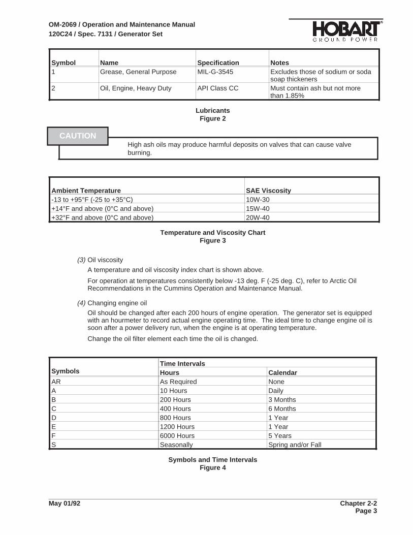
Symbol Name Specification Notes1 Grease, General Purpose MIL-G-3545 Excludes those of sodium or soda
soap thickeners2 Oil, Engine, Heavy Duty API Class CC Must contain ash but not more
than 1.85%
LubricantsFigure 2
High ash oils may produce harmful deposits on valves that can cause valveburning.
Ambient Temperature SAE Viscosity-13 to +95°F (-25 to +35°C) 10W-30+14°F and above (0°C and above) 15W-40+32°F and above (0°C and above) 20W-40
Temperature and Viscosity ChartFigure 3
(3) Oil viscosity
A temperature and oil viscosity index chart is shown above.
For operation at temperatures consistently below -13 deg. F (-25 deg. C), refer to Arctic OilRecommendations in the Cummins Operation and Maintenance Manual.
(4) Changing engine oil
Oil should be changed after each 200 hours of engine operation. The generator set is equippedwith an hourmeter to record actual engine operating time. The ideal time to change engine oil issoon after a power delivery run, when the engine is at operating temperature.
Change the oil filter element each time the oil is changed.
SymbolsTime IntervalsHours Calendar
AR As Required NoneA 10 Hours DailyB 200 Hours 3 MonthsC 400 Hours 6 MonthsD 800 Hours 1 YearE 1200 Hours 1 YearF 6000 Hours 5 YearsS Seasonally Spring and/or Fall
Symbols and Time IntervalsFigure 4
CAUTION
OM-2069 / Operation and Maintenance Manual120C24 / Spec. 7131 / Generator Set
May 01/92 Chapter 2-2Page 3
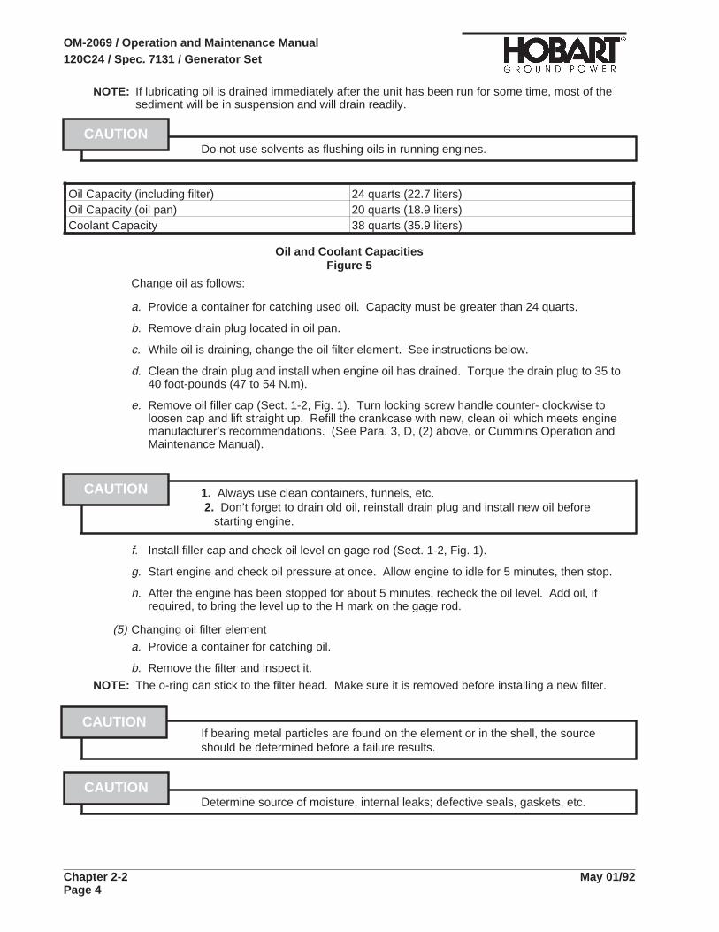
NOTE: If lubricating oil is drained immediately after the unit has been run for some time, most of thesediment will be in suspension and will drain readily.
Do not use solvents as flushing oils in running engines.
Oil Capacity (including filter) 24 quarts (22.7 liters)Oil Capacity (oil pan) 20 quarts (18.9 liters)Coolant Capacity 38 quarts (35.9 liters)
Oil and Coolant CapacitiesFigure 5
Change oil as follows:
a. Provide a container for catching used oil. Capacity must be greater than 24 quarts.
b. Remove drain plug located in oil pan.
c. While oil is draining, change the oil filter element. See instructions below.
d. Clean the drain plug and install when engine oil has drained. Torque the drain plug to 35 to40 foot-pounds (47 to 54 N.m).
e. Remove oil filler cap (Sect. 1-2, Fig. 1). Turn locking screw handle counter- clockwise toloosen cap and lift straight up. Refill the crankcase with new, clean oil which meets enginemanufacturer’s recommendations. (See Para. 3, D, (2) above, or Cummins Operation andMaintenance Manual).
1. Always use clean containers, funnels, etc.2. Don’t forget to drain old oil, reinstall drain plug and install new oil before
starting engine.
f. Install filler cap and check oil level on gage rod (Sect. 1-2, Fig. 1).
g. Start engine and check oil pressure at once. Allow engine to idle for 5 minutes, then stop.
h. After the engine has been stopped for about 5 minutes, recheck the oil level. Add oil, ifrequired, to bring the level up to the H mark on the gage rod.
(5) Changing oil filter element
a. Provide a container for catching oil.
b. Remove the filter and inspect it.
NOTE: The o-ring can stick to the filter head. Make sure it is removed before installing a new filter.
If bearing metal particles are found on the element or in the shell, the sourceshould be determined before a failure results.
Determine source of moisture, internal leaks; defective seals, gaskets, etc.
CAUTION
CAUTION
CAUTION
CAUTION
OM-2069 / Operation and Maintenance Manual120C24 / Spec. 7131 / Generator Set
Chapter 2-2 May 01/92Page 4

c. Fill the new filter with cleanlubricating oil beforeinstallation.
d. Apply a light coating oflubricating oil to the gasketsealing surface and installthe fillter. DO NOT overtighten the filter.
e. Check crankcase oil level.
f. Start engine and check oilfilter for leaks.
g. Stop engine, and afterallowing sufficient time foroil to drain to crankcase,recheck oil level. Add oil asrequired.
e. Engine Accessories Lubrication(1) Alternator
Most alternators contain sealed bearings and require no periodic lubrication, however, CHECKto make certain there are no lubrication points on your particular alternator.
(2) Starter
Most starting motors are lubricated at assembly and should be relubricated only when the starteris removed and disassembled, however, INSPECT the starter to make certain it has nolubrication points.
(3) Water Pump
The water pump is packed at assembly and requires no periodic lubrication. Replace pump ifsigns of lubricant leakage are found.
(4) Fan Hub
The fan hub is also lubricated at assembly and requires no periodic lubrication. Replace hub iflubricant is leaking.
Changing the Oil Filter
Figure 6
OM-2069 / Operation and Maintenance Manual120C24 / Spec. 7131 / Generator Set
May 01/92 Chapter 2-2Page 5
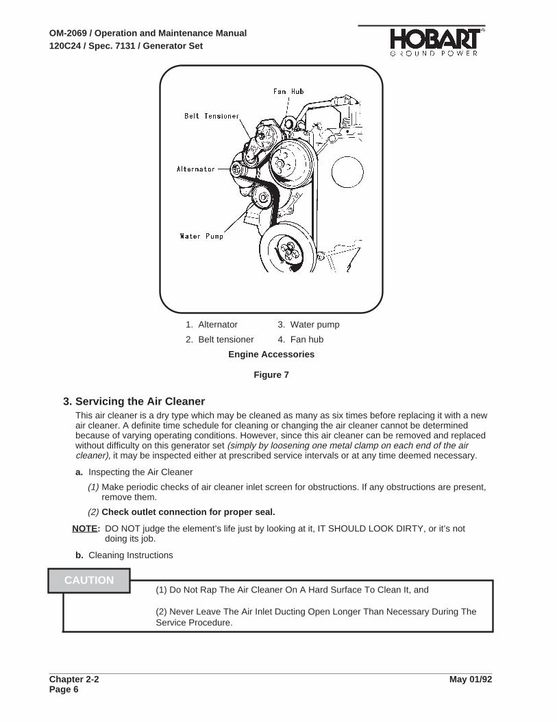
3. Servicing the Air CleanerThis air cleaner is a dry type which may be cleaned as many as six times before replacing it with a newair cleaner. A definite time schedule for cleaning or changing the air cleaner cannot be determinedbecause of varying operating conditions. However, since this air cleaner can be removed and replacedwithout difficulty on this generator set (simply by loosening one metal clamp on each end of the aircleaner), it may be inspected either at prescribed service intervals or at any time deemed necessary.
a. Inspecting the Air Cleaner
(1) Make periodic checks of air cleaner inlet screen for obstructions. If any obstructions are present,remove them.
(2) Check outlet connection for proper seal.
NOTE: DO NOT judge the element’s life just by looking at it, IT SHOULD LOOK DIRTY, or it’s notdoing its job.
b. Cleaning Instructions
(1) Do Not Rap The Air Cleaner On A Hard Surface To Clean It, and
(2) Never Leave The Air Inlet Ducting Open Longer Than Necessary During TheService Procedure.
CAUTION
1. Alternator 3. Water pump
2. Belt tensioner 4. Fan hub
Engine Accessories
Figure 7
OM-2069 / Operation and Maintenance Manual120C24 / Spec. 7131 / Generator Set
Chapter 2-2 May 01/92Page 6

(1) Pressurized air cleaning
After removing the air cleaner from the generator set, blow air into the outlet neck, causing dustto flow off the air cleaner filter media.
(1) Do not use compressed air higher in pressure than 100 psi, and
(2) Do not use compressed air cleaning when the filter media is wet.
(2) Low pressure water flusha. Flow low pressure water, warm or cold, into the air cleaner outlet neck, causing dirt to flow off
the filter media. Always be sure not to let any contaminated water back into the outlet neck.
b. A mild detergent may also be used. However, the filter must then be flushed thoroughly withclean water. This cleaning method is recommended by the manufacturer.
c. Always allow filter media to dry before use.
c. Disposal
Normal trash pick-up is acceptable. NEVER burn the air filter for disposal.
4. Engine Fuel
a. Quality
The quality of fuel oil used in the diesel engine is a major factor in engine performance and life.Fuel oil must be clean, completely distilled, stable and non-corrosive.
The Cummins engine has been developed to take advantage of the high energy content andgenerally lower cost of No. 2 Diesel Fuel. The engine will also operate satisfactorily on No. 1 fuel.If other fuels are being considered, refer to the Cummins Operation and Maintenance Manual forfuel specifications and recommended fuel oil properties.
b. Fuel Filter
A double element fuel filter is located between the fuel source and the pump. Its function is toremove foreign material from the fuel before it enters the fuel pump. The filter operates undervacuum. Elements are the throwaway type, in which the case and element are made as onedisposable part.
(1) Check fuel filter restriction
The most accurate method of determining filter change requirement and determining changeperiod is by measuring the fuel restriction. As foreign material accumulates in filter elements,fuel flow becomes more and more restricted, and vacuum pressure in the fuel inlet line betweenthe filter and pump rises. Check the degree of filter restriction as follows:
a. Connect a vacuum gage in the inlet fuel line at the pump. An adapter will be required.
NOTE: A vacuum gage No. ST-434, with special adapter, is available from Cummins Engine Company.
b. Operate the engine at governed speed and under full load. If the gage indicates 8 to 8.5 InHg (27 to 28 kPa), elements require changing (or there are other sources of restriction).When filter restriction becomes great enough to increase vacuum reading to 10 or 11 In Hg(33 to 37 kPa), the engine will lose power.
CAUTION
OM-2069 / Operation and Maintenance Manual120C24 / Spec. 7131 / Generator Set
May 01/92 Chapter 2-2Page 7

(2) Changing fuel filter elements
Change elements after each 200 hours of operation unless a restriction test indicates the timeperiod should be extended. Replacement fuel filter elements are Cummins No. FF-105D.
a. Unscrew element and discard.
NOTE: The elements should be removable by hand. If not, there are several types of filter elementremoval tools.
b. Fill NEW element with CLEAN fuel.
c. Install new element and tighten by hand until seal touches filter head. Tighten an additionalone-half to three-fourths turn.
Do not overtighten. Tightening with mechanical tools may distort or crack filterhead.
CAUTION
1. Head 3. Fuel filter
2. Center bolt 4. Fuel/water filter
Fuel Filter
Figure 8
OM-2069 / Operation and Maintenance Manual120C24 / Spec. 7131 / Generator Set
Chapter 2-2 May 01/92Page 8
c. Cold Weather Starting Aid
The cold weather starting aid (Ref. 1-3, Fig. 2) should be checked each fall to make certain it willoperate when needed.
5. Engine Cooling System
a. General
Cooling system service requires more than maintaining the proper coolant level in the radiator andprotecting the system against freezing. Water should by clean and free of any corrosive chemicalssuch as chloride, suplphate, and acids. It should be kept slightly alkaline with a pH value in therange of 8.0 to 9.5. Any water which is suitable for drinking can be used in the engine whenproperly treated as described in Cummins Operation and Maintenance Manual. The CumminsDistributor should be consulted regarding the selection of satisfactory brand, permanent-typeantifreeze for use in the cooling system.
b. Radiator Cap
(1) General
A pressure relief valve is built into the radiator cap. It is designed to open at a pressure ofapproximately seven pounds per square inch.
(2) Removal
To remove, turn the cap to the left (counterclockwise) to the safety stop. When all pressure isreleased, press down on the cap and continue to turn until the cap is free to be removed.
When removing cap from a very hot radiator, do not turn cap past safety stopuntil all pressure or steam has escaped.
Allow engine to cool before adding coolant.
NOTE: Do not attempt to repair the valve in a radiator cap. Replace with a new cap.
(3) Installation
When installing the cap, be sure it is turned clockwise as far as it will go so that the pressureretaining valve will be functional.
c. Coolant
The preparation and maintenance of the coolant solution is so important to engine life and is socompletely covered in the engine manufacturer’s manual, “Operation and Maintenance Manual”,that we will not attempt to condense or explain it here. For information regarding coolantspecifications, testing equipment, antifreeze, etc., refer to Cummins Operation and MaintenanceManual located in Chapter 6, Manufacturer’s Literature, or consult the local Cummins Distributor.
d. Warm Weather Operation (No Antifreeze)
When the unit is operated with plain water coolant during warm seasons, or in climates where anti-freeze protection is not required, the engine must have chromate protection at all times. Changewater filter regularly after each 200 to 250 hours of operation.
Never use soluble oil in the cooling system.
CAUTION
WARNING
CAUTION
OM-2069 / Operation and Maintenance Manual120C24 / Spec. 7131 / Generator Set
May 01/92 Chapter 2-2Page 9

e. Cold Weather Operation (Using Antifreeze)
(1) General
A permanent type antifreeze is recommended for use in the cooling system.
1. Do not use methanol or alcohol as an antifreeze.
2. Do no mix brands or type of antifreeze. A solution containing two or moretypes of antifreeze is impossible to test accurately.
(2) Selecting antifreeze
a. Select a permanent type antifreeze know to be satisfactory for use with chromate corrosionresistor.
b. When it is not known if the antifreeze is satisfactory for use with chromate resistor, check withlocal Cummins Distributor for a list of compatible antifreezes.
Do not use soluble oil in the cooling system
(3) Checking antifreeze solution
Check the solution with a reliable tester when in doubt about antifreeze protection.
NOTE: When testing, be sure coolant is at operating temperature. Follow manufacturer’s instructionson tester.
f. Draining the Cooling System
To drain the cooling system, proceed as follows:
(1) Remove radiator cap.
(2) Open the radiator drain valve.
(3) Allow the system to drain completely.
NOTE: Be sure the drain valve does not clog during draining.
(4) When the system is completely drained, close the drain valve.
g. Cleaning the Cooling System
If the water filter has been changed regularly, there should be little need for cooling system internalcleaning. If chemical cleaning becomes necessary, refer to instructions in the Cummins Operationand Maintenance Manual.
h. Cleaning the Radiator Core
Blow out accumulated dirt from the radiator core air passages, using compressed air. Engineoverheating is often caused by bent or clogged radiator fins. When straightening bent fins, becareful not to injure the tubes or to break the bond between fins and tubes.
NOTE: Direct the air in a reverse direction to normal air flow. Normal flow on this installation is from theengine compartment outward.
CAUTION
WARNING
OM-2069 / Operation and Maintenance Manual120C24 / Spec. 7131 / Generator Set
Chapter 2-2 May 01/92Page 10

i. Filling the Cooling System
(1) General
a. The water filter element should be changed each time coolant is changed. Before installingcoolant, check and inspect the system.
(2) Inspection/Check
a. Check system for evidence of leaks.
b. Inspect all hoses. Install new hoses as necessary. Tighten hose clamps as required.
c. Check the condition of fan and water pump belts. Replace belts if necessary.
(3) Install coolant
a. Remove radiator cap. Be sure the drain valve is closed. Make sure the vent in the watermanifold is open to allow air to escape when filling.
b. Pour coolant into radiator very slowly until it reaches level of top drain valve. Close valve andcontinue filling until coolant reaches a level approximately 1 inch below top of tank. Allow fora 5% expansion when coolant reaches operating temperature.
NOTE: A safety feature built into the tank consists of a pipe attached to the filler neck which extendsinto the tank approximately 1 inch. If coolant is added after the liquid reaches the bottom of thesafety tube, it will immediately overflow.
c. Start the engine and allow it to idle. Add coolant as trapped air escapes from the system andthe coolant level falls.
d. Continue to check coolant level until all trapped air escapes. Add coolant, if needed, to fill tothe required level, 1 inch below top of tank. Install radiator cap and close the vent valve.
NOTE: It is good practice to attach a card, indicating the cooling system contents and date serviced, tothe radiator filler neck.
j. Thermostat
The thermostat should be checked each fall, or as required. Refer to Cummins Operation andMaintenance Manual for recommended test instructions.
OM-2069 / Operation and Maintenance Manual120C24 / Spec. 7131 / Generator Set
May 01/92 Chapter 2-2Page 11

6. Drive Belts
a. General
The engine cooling fan, alternator and waterpump are driven by a timing belt which must bereplaced if it becomes worn or damaged.
b. Preparation for Belt Check and Adjustment
All driven assemblies must be securely mountedin operating position before checking belt tension.
c. Checking Belt Tension
Check belt tension every 1000 hours, or once ayear, whichever comes first. A belt which is tootight is destructive to bearings of the driven part.A loose belt will slip and cause inefficientoperation of the part being driven as well as wearto the belt.
Belt tension may be checked either with a gageor manually. Use Cummins Belt Tension Gageno. ST-1293, or equivalent. Gage should indicate90 to 110 pounds. If a gage is not available,tension may be checked manually by depressingthe belt with the index finger to determine theamount of belt deflection obtained when force ofapproximately at a point halfway between pulleys onthe longest span of the belt.
d. Check Fan Belt
(1) Check belt tension (see Para. 7, C, above).
(2) Remove the drive belt by lifting on the belttensioner with a 1/2 square drive. The beltcan then be slid off the water pump pulley andworked off the other pulleys and around thefan.
(3) Inspect the belt for damage.
a. Traverse (across the belt width) cracks areacceptable.
b. Longitudinal (direction of belt length)cracks that intersect with transverse cracksare unacceptable.
(4) Replace the belt if it has unacceptable cracks,is frayed or has pieces of material missing.
(5) Check the belt tensioner while the belt isremoved. It should spin freely without anywobble or excessive (0.006") end play.
(6) Install the drive belt.
Checking Belt Tension
Figure 9
Removing & Inspecting the Drive Belt
Figure 10
OM-2069 / Operation and Maintenance Manual120C24 / Spec. 7131 / Generator Set
Chapter 2-2 May 01/92Page 12

7. Generator MaintenanceThe 400 Hz generator required no maintenance or service other than periodic cleaning. The unit isbrushless, and bearings are permanently lubricated and sealed.
a. Cleaning
The generator may be cleaned by careful use of compressed air and/or a good, SAFE commercialcleaner. Steam cleaning of the generator is not recommended because the use of steam and harshchemical compounds may result in damage to insulation an other generator components.
Do not use a flammable solvent. Be sure the unit is completely dry beforeoperating
b. Adjustment
The generator itself requires no adjustment. Adjustment procedures for generator controls arecovered in 2-3.
8. Voltage Regulator Maintenance/RepairWhen the voltage regulator is working properly, no maintenance is necessary. However, if thegenerator set is used in a dusty environment, the regulator should be periodically cleaned withcompressed air.
The voltage regulator, which is in fact a PC board, does not lend itself to field repair. For theconvenience of maintenance personnel, this voltage regulator is designed to be trouble-free and simpleto put back into service once it has malfunctioned or if it is not functioning properly. Most malfunctionsof the voltage regulator will be corrected by (1) removing and replacing the PC board, and (2) makingvoltage and line-drop adjustments after installing the new board. To remove and replace voltageregulator PC board, proceed as follows:
a. Disconnect the 16-pin connector.
b. Remove the nuts and washers which attach the voltage regulator to the four shock mounts whichare attached to the inside right panel of the control box. Exercise care to avoid breaking or droppingthe PC board.
c. Place the new voltage regulator PC board on the four shock mounts from which the defective PCboard was removed, and fasten the new PC board securely in place with the nuts and washerswhich were previously used.
d. Re-connect the 16-pin connector, and make certain that this connection is securely made.
9. Transformer-Rectifier Maintenance
a. General
To make certain the transformer-rectifier is ready for operation at all times, it must be inspected andmaintained systematically and regularly so that any defects will be discovered and corrected beforethay result in serious damage or complete failure of the equipment.
Stop operation immediately if a serious or possible dangerous fault isdiscovered.
b. Lubrication
The T-R requires no lubrication.
WARNING
WARNING
OM-2069 / Operation and Maintenance Manual120C24 / Spec. 7131 / Generator Set
May 01/92 Chapter 2-2Page 13
c. Inspection
A periodic inspection schedule should be established and maintained. If the T-R is part of agenerator set, inspections should be scheduled to coincide with similar inspections for the parentmachine. Inspect as follows:
(1) Open the front control panel. Remove the top cover. (Rear panel and side may be removedafter the top is removed).
Be sure no input power can reach the t-r. lethal electrical shock hazard exists.
(2) Inspect leads and cables for deteriorated or damaged insulation and visually inspect allcomponents, terminals, etc., for discoloration and evidence of overheating caused byloose connections, etc.
(3) Check all accessible terminals and connectors for security.
(4) Check both fuses located on the control panel of the T-R.
d. Cleaning
Use dry, compressed air to clean the interior of the T-R each time it is inspected.
10. Servicing and Troubleshooting the Cold Weather Starting Aid
When servicing or troubleshooting the cold weather starting kit, make certainthat this work is done in a well ventilated area. Goggles should be worn toprotect eyes when servicing this kit.
Many vehicle components can affect cold weather starting. The following instructions are limited totroubleshooting of the dieselmatic System. The most common problems are (1) an empty fluidcylinder, and (2) a clogging metering orifice.
a. Check Fluid Cylinder Contents And Valve Gasket.
(1) Clean all dirt from neck of cylinder and top of valve before removing the fluid cylinder. Protecttop of valve from dirt when cylinder is removed.
(2) An empty net weight 21 oz. fluid cylinder weighs 16 oz. (454 gr.), and a full fluid cylinder weighs37 oz. (1049 gr.).
(3) Check that fluid cylinder has pressure.
(4) Check valve gasket. If gasket inside valve is damaged or worn, replace with a new gasket, KBIPart Number 300012. Make sure only one gasket is used, as two gaskets would prevent valvefrom operating.
(5) Cylinder, or its replacement, should be reinstalled hand tight. Coupling Dirt Eliminator may betransferred from old cylinder to new cylinder or replaced with a new one, KBI Part Number300830.
b. Check of electrical system.
Electrical shock can kill. Do not touch live electrical parts.
(1) Check to see if fuse is blown. Check all wiring for loose connections, shorts, and broken wires.
(2) Check that the Dieselmatic System is wired correctly.
WARNING
CAUTION
WARNING
OM-2069 / Operation and Maintenance Manual120C24 / Spec. 7131 / Generator Set
Chapter 2-2 May 01/92Page 14
NOTE: To check system for proper operation, the Engine Temperature Sensor (ETS) must be below400F (40C) or be bypassed by connecting the valve’s black lead directly to a good ground. Afterchecking be sure to reconnect the black lead in accordance with Connection Diagram 281329.
(3) Test valve by removing fluid cylinder and momentarily engaging cranking motor. Valve plungershould move up and remain up while cranking motor is engaged. If valve operates, proceed tostep (5).
(4) If valve plunger did not function, check valve by disconnecting leads from cranking motor andground. Momentarily touch leads directly across battery terminals. The valve plunger shouldmove up and remain up until the leads are disconnected. If the valve does not activate whenconnected across the battery it is faulty and should be replaced.
(5) Check Engine Temperature Sensors (ETS) Switch by chilling to sub-freezing temperatures. Atcold temperatures, the ETS Switch should close (i.e. show continuity). Check with a DCpowered test light or ohmmeter. At warm temperatures, the ETS Switch should open (i.e. notshow continuity). The closing and opening temperature should be about 400F (40C). If eithercontinuity test fails, ETS Switch should be replaced.
c. Check for clogging of flow Metering Orifice Fitting
When servicing or troubleshooting the cold weather starting kit, make certainthat this work is done in a well ventilated area. Goggles should be worn toprotect eyes when servicing this kit.
The Dieselmatic’s fluid flow rate is controlled by serviceable filtered metering orifice inside the fittingat the bottom of the valve assembly. See Figure 2. The following procedure is recommended whenchecking for clogging:
(1) Remove system’s nozzle from engine.
(2) If starting fluid does not spray from nozzle when the system is activated, disconnect tubing fromvalve fitting. If starting fluid sprays from the fitting when the system is activated, check tubing forkinks, burns, cuts, clogs, or for a clogged nozzle. When performing these two operations, besure to spray fluid into an appropriate container.
(3) If starting fluid does not spray from valve fitting, it should be removed from valve and cleaned.
NOTE: Fitting end installed in valve has left hand threads.
The filter may be removed from the fitting. It can be washed in clean solvent and blown withcompressed air. For best results, replace filter with a new one, KBI Part Number 300813.Reassemble filter with “O” ring into fitting.
(4) It is suggested before clean filtered assembly is reinserted into valve, that valve be flushed byactivating the system. When performing this operation, be sure to spray fluid into an appropriatecontainer.
(5) Reinsert clean filtered fitting assembly into valve. Remember: left hand threads. Reinstallsystem’s nozzle into engine. Reconnect tubing to valve fitting and nozzle.
(6) Check all fitting and tubing connections for leaks.
CAUTION
OM-2069 / Operation and Maintenance Manual120C24 / Spec. 7131 / Generator Set
May 01/92 Chapter 2-2Page 15

This page intentionally left blank.
OM-2069 / Operation and Maintenance Manual120C24 / Spec. 7131 / Generator Set
Chapter 2-2 May 01/92Page 16

Section 3. Adjustment/Test
1. GeneralThese adjustment and test procedures are applicable to testing and adjusting the generator set aftermajor repair, major parts replacements, or overhaul.
2. Testing the Generator Set
a. Pre-operational Test Procedures
(1) Connect cables from the generator output terminals to a load bank. Use cables of the same sizeand length as those to be used in service. Be sure the generator output N cable is grounded.
(2) Check engine oil level. Oil should be at H mark on gage rod.
(3) Check radiator coolant level (Ref. 2-2, Para. 5).
(4) Check tension of fan and generator V-belts. (See 2-2, Para. 6.)
(5) If governor throttle linkage was disturbed, check all linkage to make certain engine speed maybe controlled when the engine is started. Refer to Paragraph 3, e, (1) and see Figures 4 and 4A
(6) Inspect for oil, fuel and coolant leaks.
(7) If the setting of the output voltage coarse adjustment potentiometer (32, Fig.1) on the voltageregulator has been disturbed, set it at CENTER position (halfway between full clockwise positionand full counterclockwise position).
(8) Check engine circuit fuse (14, Fig. 1) by placing panel light switch (4) in ON position. If panellights (2) operate, the circuit breaker, switch, and lamps are good.
(9) Check fault indicating lights (15) by pressing light test switch (16). If lights glow, the protectivesystem circuit breaker (13) and indicating lamps are good.
(10) Make a general inspection of all wiring, and terminals. Inspect the equipment to be certain nodamage will result from starting the engine.
Engine must not be running when flashing exciter field if voltage regulatordamage is to be prevented. Do not leave regulated/diagnostic switch indiagnostic position after flashing field.
(11) At initial start-up after generator overhaul or repair, “flash” the exciter field bymomentarily applying 12-V DC to the field windings. To flash the exciter field, place theRegulated/Diagnostic switch (31, Fig. 1) in the DIAGNOSTIC position for 3 to 5 seconds. Thenreturn it to the REGULATED position.
(12) Check position of load contactor switches (23 and 25, Fig. 1), and engine-generator switch (28).
a. Load contactor switches must be in OFF position.
b. Engine-generator control switch must be in IDLE position.
CAUTION
OM-2069 / Operation and Maintenance Manual120C24 / Spec. 7131 / Generator Set
May 01/92 Chapter 2-3Page 1

1. Front panel 15. Protective system indicating lights
2. Panel light 16. Test switch, protective system
3. Engine hour meter 17. Reset switch, protective system
4. Panel light switch 18. Indicating light, air cleaner restriction
5. Oil pressure gage 19. Frequency meter
6. Engine ON indicating light 20. Selector switch, voltmeter-ammeter
7. Engine coolant temperature meter 21. Voltmeter
8. Engine start switch 22. Adjustable grip latch
9. Engine control switch 23. No. 1 contactor switch
10. Engine ammeter 24. No. 1 contactor power On light
11. Fuel gage 25. No. 2 contactor switch
12. Load contactor circuit breaker 26. No. 2 contactor power On light
13. Protective system circuit breaker 27. Generator ammeter
Operating Controls and Instruments
Figure 1 (Sheet 1 of 2)
OM-2069 / Operation and Maintenance Manual120C24 / Spec. 7131 / Generator Set
Chapter 2-3 May 01/92Page 2

29. Test bank-aircraft switch, No. 1 output 33. Output voltage adjustment (fine)
30. Test bank-aircraft switch, No. 2 output 34. Line drop compensation adjustment
31. Regulated-diagnostic switch 35. Fuse (5-amp)
32. Output voltage adjustment (coarse)
Operating Controls and Instruments
Figure 1 (Sheet 2 of 2)
OM-2069 / Operation and Maintenance Manual120C24 / Spec. 7131 / Generator Set
May 01/92 Chapter 2-3Page 3
b. Operational Test Procedures
(1) Start the engine in accordance with instructions in 1-3, Para. 2, A thru C.
(2) Check operation of engine instruments; DC ammeter (10, Fig. 1), coolant temperature indicator(7), oil pressure gage (5) and hourmeter (3).
(3) Check engine idle speed. Should be 850 +/- 25 RPM. If adjustment is necessary, adjust the idlespeed potentiometer on the governor control box.
NOTE: A stroboscope is required for this check.
(4) Again check for oil, fuel, and coolant leaks and correct any leaking condition.
(5) Position switches and controls for automatic voltage regulation and power delivery as follows:
a. Place regulated-diagnostic switch (31, Fig. 1) in REGULATED position.
b. Place test-bank switches (29 and 30) in AIRCRAFT position.
c. If the of the output voltage coarse adjustment potentiometer (32) on the voltage regulatorregulator has been disturbed, place the knob at mid-range position.
(6) Bring the engine up to governed speed and also energize the generator by holding theengine-generator control switch (28) in BUILD-UP-VOLTS position momentarily. Release switchand allow it to position in center RUN position.
If the engine comes up to governed speed and a voltage value appears on the voltmeter (), theelectric governor and excitation-deenergization relay circuits are functioning.
(7) Observe frequency meter (19). If engine speed is properly adjusted, frequency will be exactly400 Hz. If not, adjust engine governed speed in accordance with Para. 3, E, (3). See Fig. 6.
(8) Observe voltmeter (21). Use output voltage coarse adjustment potentiometer (32) to adjustvoltage to 115 or 240 V AC as required.
(9) Measure governor actuator input signal. See Para. 3, E, (4), (a).
(10) Measure governor magnetic pickup signal. Para 3, E, (4), (b).
(11) Check high-speed limiting governor.
Engine limiting speed governor should limit engine speed to approximately 2640 RPM.
(12) Check adjustable voltage range.
a. Observe voltmeter (21) and turn output voltage coarse adjustment potentiometer (32) to fullCLOCKWISE position. Maximum voltage should be 134 volts or higher.
NOTE: If voltage should decrease when regulator potentiometer is turned clockwise, it indicates thatinternal wiring in the voltage regulator is incorrect. Replace complete voltage regulatorassembly.
b. Observe voltmeter and turn regulator potentiometer knob to full COUNTERCLOCKWISEposition. The minimum voltage should be 95 volts or lower.
(13) Position load bank switches, etc., to apply a light load to the generator.
OM-2069 / Operation and Maintenance Manual120C24 / Spec. 7131 / Generator Set
Chapter 2-3 May 01/92Page 4

c. Testing the No. 1 output circuit
(1) Make certain that the No. 2 contactor on-off switch (25, Fig. 1) is in the OFF position. Thenplace the No. 1 load contactor on-off switch (23, Fig. 1) in the top, spring-loaded, ON position.Hold in this position momentarily. The No. 1 contactor power ON indicating light (24) shouldglow GREEN and an amperage value should appear on the AC ammeter (27).
(2) Release the No. 1 load contactor switch and allow it to return to the center ON position. The No.1 load contactor should open immediately, and the No. 1 ON indicating light should go OFF.This is because the plug interlock relay (Ref. 1-1; 5, Fig. 7) is not receiving power from anoutside source of 28 V DC. It indicates that the No. 1 plug interlock relay’s contacts are OPENas they should be when the interlock coil is not receiving 28 V DC power.
(3) Open the control panel door and place the No. 1 test bank switch (29) in TEST BANK position.
(4) Place the No. 1 load contactor switch (23) in the top, ON position. The No. 1 contactor powerON indicating light (24) should glow GREEN and remain ON when the switch is released andallowed to return to the center ON position. This indicates that the No. 1 test bank switch (29) isfunctioning to bypass the plug interlock relay.
(5) Return the No. 1 test bank switch to AIRCRAFT position. The load contactor should open atonce and the green indicating light (24) should go off.
(6) Connect a source of 24 V-DC power (two twelve-volt batteries connected in series) to terminalsN and F (or E) at the output terminal panel. Connection polarity is important. Connect plus (+)to terminals E or F, and minus (-) to terminal N.
(7) With test-bank switch in AIRCRAFT position, hold the No. 1 contactor operating switch (23) intop, ON position momentarily. The No. 1 contactor power ON indicating light (24) should glowGREEN and remain on when the switch is released and allowed to return to the center ONposition. This indicates that the load contactor is closed and the plug interlock relay isfunctioning properly.
(8) Apply 1/3 to 1/2 load (30 to 45-KVA) at the load bank and allow the unit to run for 15 to 30minutes. Observe operation of all monitoring instruments.
(9) Increase load at the load bank to 90-KVA.
(10) Check operation of the governor by observing the frequency meter (19, Fig. 1) when generator isswitched from no load to full load. and vice versa. Use the No. 1 contactor control switch (23) toapply and remove load several times. Frequency droop should be no more than 1 Hz. Adjustgovernor if necessary (see Para. 3, E, (3)).
(11) Follow instructions in Para. 3, B, (2) (b) to set voltage regulator line drop compensation for thelength and size of cable being used.
(12) Check voltage regulator, at intervals, from no load to full load and on up to 125% load. Observeand note voltage at various loads. Voltages should vary no more than +/- 1% from normal outputvoltage.
(13) Operate the No. 1 output circuit of the unit not less than 10 minutes under full 90-KVA load. Theoverload device (Ref. 1-1; 11, Fig. 9) MUST NOT trip.
(14) Operate the No. 1 output circuit of the unit at 125% load (325 amperes) for 5 minutesimmediately following the full load run. The overload device MUST trip within 5 minutes, and theoverload indicating light on the engine generator control panel must come ON to indicate anoverload condition.
(15) Reduce load to normal. Turn off overload indicating light by pressing reset switch (17, Fig. 1).
OM-2069 / Operation and Maintenance Manual120C24 / Spec. 7131 / Generator Set
May 01/92 Chapter 2-3Page 5
d. Testing the No. 2 output circuit
(1) Make certain that the No. 2 contactor on-off switch (23 Fig. 1) is in the OFF position. Then placethe No. 1 load contactor on-off switch (25, Fig. 1) in the top, spring-loaded, ON position. Hold inthis position momentarily. The No. 2 contactor power ON indicating light (26) should glowGREEN and an amperage value should appear on the AC ammeter (27).
(2) Release the No. 1 load contactor switch and allow it to return to the center ON position. The No.2 load contactor should open immediately, and the No. 1 ON indicating light should go OFF.This is because the plug interlock relay (Ref. 1-1; 5, Fig. 7) is not receiving power from anoutside source of 28 V DC. It indicates that the plug interlock contacts are OPEN as they shouldbe when the interlock coil is not receiving 28 V DC power.
(3) Open the control panel door and place the No. 2 test bank switch (30) in TEST BANK position.
(4) Place the No. 1 load contactor switch (25) in the top, ON position. The No. 2 contactor powerON indicating light (26) should glow GREEN and remain ON when the switch is released andallowed to return to the center ON position. This indicates that the No. 2 test bank switch (30) isfunctioning to bypass the plug interlock relay.
(5) Return the No. 2 test bank switch to AIRCRAFT position. The load contactor should open atonce and the green indicating light (26) should go off.
(6) Connect a source of 24 V-DC power (two twelve-volt batteries connected in series) to terminalsN and F (or E) at the output terminal panel. Connection polarity is important. Connect plus (+)to terminals E or F, and minus (-) to terminal N.
(7) With test-bank switch in AIRCRAFT position, hold the No. 2 contactor operating switch (23) intop, ON position momentarily. The No. 2 contactor power ON indicating light (26) should glowGREEN and remain on when the switch is released and allowed to return to the center ONposition. This indicates that the load contactor is closed and the plug interlock relay isfunctioning properly.
(8) Apply 1/3 to 1/2 load (30 to 45-KVA) at the load bank and allow the unit to run for 15 to 30minutes. Observe operation of all monitoring instruments.
(9) Increase load at the load bank to 90-KVA.
(10) Check operation of the governor by observing the frequency meter (19, Fig. 1) when generator isswitched from no load to full load. and vice versa. Use the No. 1 contactor control switch (25) toapply and remove load several times. Frequency droop should be no more than 1 Hz. Adjustgovernor if necessary (see Para. 3, E, (3)).
(11) Follow instructions in Para. 3, B, (2) (b) to set voltage regulator line drop compensation for thelength and size of cable being used.
(12) Check voltage regulator, at intervals, from no load to full load and on up to 125% load. Observeand note voltage at various loads. Voltages should vary no more than +/- 1% from normal outputvoltage.
(13) Operate the No.2 output circuit of the unit not less than 10 minutes under full 90-KVA load. Theoverload device (Ref. 1-1; 12, Fig. 9) MUST NOT trip.
(14) Operate the No. 2 output circuit of the unit at 125% load (325 amperes) for 5 minutesimmediately following the full load run. The overload device MUST trip within 5 minutes, and theoverload indicating light on the engine generator control panel must come ON to indicate anoverload condition.
(15) Reduce load to normal. Turn off overload indicating light by pressing reset switch (17, Fig. 1).
OM-2069 / Operation and Maintenance Manual120C24 / Spec. 7131 / Generator Set
Chapter 2-3 May 01/92Page 6

e. Testing the main generator overload circuit
(1) Place the No. 1 load contactor on-off switch (23, Fig. 1) in the top, spring-loaded, ON position.Hold in this position momentarily. The No. 1 output indicating light (24) should glow GREEN,indicating that the No. 1 load contactor circuit is operational.
(2) Place the No. 2 load contactor on-off switch (25, Fig. 1) in the top, spring-loaded, ON position.Hold in this position momentarily. The No. 2 output indicating light (26) should glow GREEN,indicating that the No. 2 load contactor circuit is also operational.
(3) Operate the unit not less than 10 minutes under 120-KVA load. The main generator overloaddevice (Ref. 1-1; 5, Fig. 9) MUST NOT trip.
(4) Operate the unit at 125% load (434 amperes) for 5 minutes immediately following the full loadrun. The main generator overload device (Ref. 1-1; 5, Fig. 9) MUST trip within 5 minutes, andoverload indicating light on engine-generator control panel must come ON to indicate anoverload condition.
(5) Turn off the load at the load bank. Turn off overload indicating light by pressing reset switch (17,Fig. 1).
f. Testing and checking meters, switches, relays, and indicating lights
(1) Check accuracy of voltmeter
a. Open door of control box and connect a master voltmeter of known accuracy to terminals ofthe voltmeter (21).
b. Compare the unit’s voltmeter reading with master meter. Error must not exceed 2% of fullscale.
(2) Check accuracy of AC ammeter
a. Connect a master ammeter of known accuracy to the AC ammeter.
b. Compare the unit’s ammeter reading with master meter under various loads. Error must notexceed 4% of full scale.
(3) Check operation of meter selector switch (20). A voltage value should be shown in each switchposition.
a. In any LINE-TO-NEUTRAL position, voltmeter reading should be 115 volts.
b. In any LINE-TO-LINE position, voltmeter reading should be 200 volts.
(4) Check accuracy of frequency meter
a. Connect a master frequency meter of known accuracy to the terminals of the frequency meter(19).
b. Compare meter readings. Error must not exceed 1% of full scale.
(5) Check operation of protective system interlock (Ref. 1-1; 3, Fig. 7). With unit operating normallyunder load, open the protective relay circuit breaker (Ref. 13, Fig. 1). The load contactor shouldopen immediately. This indicates that the protective system interlock relay is functioningproperly. Close protective relay circuit breaker and apply load.
NOTE: Make all protective system tests with the unit operating under load.
OM-2069 / Operation and Maintenance Manual120C24 / Spec. 7131 / Generator Set
May 01/92 Chapter 2-3Page 7
(6) Check operation of overvoltage relay and indicating light.
a. With the unit running at normal load, adjust the coarse adjustment potentiometer (32, Fig.1)of the voltage regulator CLOCKWISE to increase voltage until the overvoltage sensing relayactuates the protective monitor to open the load contactor and turn on the overvoltageindicating light. At 126 volts, the relay will trip after a 1-second time delay. At higher valuesof voltage, time delays for overvoltage trips are as follow:
• At 140 volts, the relay will trip within 160 milliseconds.
• At 180 volts, the relay will trip within 50 milliseconds.
b. If the load contactor does not open under the conditions described in step (a), refer to theTroubleshooting Chart in Section 2-4.
c. Return unit to normal operating conditions by adjusting coarse adjustment potentiometer(turning it counterclockwise) and pressing reset switch (17).
(7) This step checks operation of the undervoltage sensing relay, indicating light, and time delaycircuit.
When the voltage is reduced to a predetermined value, the undervoltage sensing relay (1-1; 16,Fig. 7) activates the undervoltage time delay circuit. If the undervoltage condition continues forapproximately 7 seconds, the time delay circuitry will open the protective monitor relay, which inturn opens the load contactor to stop power delivery and turns on the undervoltage indicatinglight (15, Fig. 1).
A stopwatch is required for this check.
a. With the unit running at normal load, use the output voltage coarse adjustment potentiometer(32, Fig. 1) on the voltage regulator to reduce the voltage to 104 volts. The load contactorshould NOT open.
b. Reduce voltage in steps of 1 volt, with a time delay of 7 seconds between steps. At a settingof 100 volts, the load contactor will open and the undervoltage light will glow after a 7-secondtime delay.
c. If the load contactor does not open under the conditions described in step (b), refer to theTroubleshooting Chart in Section 3-1.
d. If the undervoltage circuit performs satisfactorily, return unit to normal operation by adjustingoutput voltage coarse adjustment potentiometer for normal output voltage, pressing the resetswitch, and closing the load contactor.
(8) Check underfrequency sensing relay, protective monitor, and indicating light. At some frequencyvalue from 375 Hz or less, after 5 seconds, the underfrequency sensing relay should signal theunderfrequency circuit in the protective monitor module to OPEN the load contactor holdingcircuit, thus OPENING the load contactor. To check the underfrequency protective components,proceed as follows:
a. While the unit is operating normally under load, reduce generator output frequency byreducing engine speed. Use the governed speed setting potentiometer (Ref. Fig. 6). Turnadjusting screw COUNTERCLOCKWISE gradually to reduce engine speed until frequencymeter indicates 380 Hz. Underfrequency protective relay should not open the load contactorat this frequency.
b. Reduce frequency in steps of 1 Hz, , with a time delay of 5 seconds between steps.
c. If the protective system opens the load contactor and turns on the underfrequency light after5 seconds at 375 Hz, all components of the system are functioning properly.
OM-2069 / Operation and Maintenance Manual120C24 / Spec. 7131 / Generator Set
Chapter 2-3 May 01/92Page 8
d. If the load contactor is not opened at 375 Hz after 5 seconds, refer to Troubleshooting Chartto determine which component is defective.
e. Return unit to normal operating condition.
(9) Check overfrequency sensing relay, protective monitor, and indicating light.At some frequency value from 426 Hz to 480 Hz, after 5 seconds, the overfrequency sensingrelay should signal the overfrequency circuit in the protective monitor module to OPEN the loadcontactor holding circuit, thus OPENING the load contactor.
At any frequency value exceeding 480-Hz, the overfrequency sensing relay should immediatelysignal the overfrequency circuit in the protective monitor module to OPEN the load contactorholding circuit, thus OPENING the load contactor.
To check the overfrequency protective components, proceed as follows:
a. While the unit is operating normally under load, reduce generator output frequency byreducing engine speed. Use the governed speed setting potentiometer (Ref. Fig. 6). Turnadjusting screw CLOCKWISE gradually to increase engine speed until frequency meterindicates 420 Hz. Underfrequency protective relay should not open the load contactor at thisfrequency.
b. Increase frequency in steps of 1 Hz, with a time delay of 5 seconds between steps.
c. If the protective system opens the load contactor and turns on the overfrequency light after 5seconds at 426 Hz, all components of the system are functioning properly.
d. If the load contactor is not opened at 426 Hz after 5 seconds, refer to Troubleshooting Chartto determine which component is defective.
e. Return unit to normal operating condition.
(10) If the generator is operating under load at this point, place the contactor control switch(es) (23and 25, Fig. 1) in OFF position to open load contactors and disconnect load. There will be nofurther need for the load bank in the following check.
g. Re-checking the entire unit after testing
(1) With the engine running at normal governed speed, check the entire unit for vibration and for anyparts which may have become loosened during the above checks. Tighten any loose attachinghardware as required.
(2) Check engine oil pressure at rated speed (2400 RPM). Gage should indicate at least 45 PSIwhen engine is hot. Check engine coolant temperature. Gage should indicate in the range of180o F to 190o F, depending upon ambient temperature.
If a metal sounding rod is used to detect bearing noises, exercise extreme careto avoid injury.
(3) Check 400 Hz generator bearings. Use a stethoscope or metal sounding rod to listen forunusual noises. If using a metal rod, place on end on the generator housing and hold the otherend near the ear. Hold the rod with three fingers and use the index finger and thumb to form asounding chamber between the rod and the ear. Do NOT allow the rod to touch the ear. Listenfor grinding or pounding sounds which would indicate a defective bearing. An engine noise maybe telegraphed to the generator and misinterpreted as a generator noise. Send the unit tooverhaul if in doubt of bearing serviceability.
WARNING
OM-2069 / Operation and Maintenance Manual120C24 / Spec. 7131 / Generator Set
May 01/92 Chapter 2-3Page 9
3. Generator Set Adjustment
a. Generator Adjustment
The 400 Hz generator is a brushless type requiring no adjustments of any kind.
b. Adjust 400 Hz voltage regulator.
When a voltage regulator is first put into service, or when output (generator-to-aircraft) cables arechanged, the regulator may require adjustments of output voltage value and line-drop compen-sation. For making these adjustments, the voltage regulator has three potentiometers: (1) a coarseoutput voltage potentiometer, (2) a fine output voltage potentiometer, and (3) a line-drop compen-sation potentiometer. See Figure 1, Sheet 2 for identification of components used for regulatoradjustment. For this adjustment, the generator set must be running at rated RPM, under no-loadconditions. Adjust the regulator as follows:
(1) Adjustment
a. Adjust Voltage Control
The output voltage at which the generator is regulated is adjustable by the PC board fineoutput voltage adjustment potentiometer (33, Fig. 1). Turn the potentiometer adjustmentclockwise (CW) to increase generator output voltage, and counterclockwise (CCW) todecrease voltage.
Observe the output voltage as indicated by the voltmeter which is located on the controlpanel of the generator set. Set output voltage at 115-V AC line-to-neutral (200-V ACline-to-line).
b. Adjust Line Drop Compensation
Adjustment of line drop compensation is made with the line drop compensation potentiometer(34, Fig. 1). Turning the potentiometer knob clockwise increases the magnitude of thecompensation, and turning the potentiometer knob counterclockwise decreases themagnitude. To adjust the line drop compensation, proceed as follows:
• Connect the generator set output cables to a load. Load the generator set with the largestavailable three-phase load of rated power factor not exceeding the maximum rating of thegenerator set.
• Measure output voltage at the load end of the cables. If the load voltage rises or dropsmore than 1% at the load end of the cables, decrease or increase the line dropcompensation until the regulation is flat (115-V AC line-to-neutral and 200-V ACline-to-line).
• If the line drop compensation adjustments have affected the no-load voltage output, adjustthe fine output voltage control potentiometer (34, Fig. 1) to the desired value.
(2) Test the Voltage Regulator
After necesssary adjustments have been completed, re-test the voltage regulator as follows:
a. Connect a voltmeter at the load end of the generator output cables.
b. Operate the generator set at no-load and observe voltage reading.
c. Operate the generator set under load and observe voltage reading.
d. Voltage under load should vary no more than 1% at the load end of the cables from voltageunder no-load.
OM-2069 / Operation and Maintenance Manual120C24 / Spec. 7131 / Generator Set
Chapter 2-3 May 01/92Page 10

c. Basic Engine Adjustments
Adjustment procedures applicable to the diesel engine are included in the Cummins Operation andMaintenance Manual, which is located in Chapter 5. Specific information for these engines is listedin Figure 3. Refer to the Cummins Operation and Maintenance Manual for detailed information onthe follwing engine adjustments.
(1) Exhaust valve adjustment
(2) Exhaust valve crosshead adjustment
(3) Fuel injector timing adjustment
(4) Engine idle speed adjustment
Engine idle speed is set at the factory. The adjustment is then sealed to discourage tampering.Idle speed should not be changed by the user. If adjustment is required, contact the localCummins Distributor. The recommended idle speed is 650 RPM, +/- 25 RPM.
NOTE: A stroboscope is required for engine idle speed checks.
(5) Engine speed limiting adjustment
The speed limiting adjustment is also set and sealed at the factory. Speed should be limited toapproximately 2640 RPM. If adjustment is required, contact your local Cummins Distributor.
d. Engine Accessories Adjustment
(1) Generator and fan belt adjustment
Refer to 2-2, Para. 7, D, and E, for belt adjustment instruction.
NOTE: Replace fan belts with a matched set if replacement is necessary.
Type engine In-line 6 cylinder dieselModel Modified 6BTA5.9Cummins specification no. 88-044-6BTAEngine governed speed 2400 RPMIdle speed 850 RPM 25 RPMSpeed limiting governor approximately 2640 RPMFiring order 1-5-3-6-2-4Fuel pump speed limitimg governor automotive typeLubricating oil pressure at 2400 RPM 50 to 90 PSIEngine coolant temperature 160 to 200 deg F.
(71 to 93 deg C.)
Engine SpecificationsFigure 2
OM-2069 / Operation and Maintenance Manual120C24 / Spec. 7131 / Generator Set
May 01/92 Chapter 2-3Page 11

e. Electric Governor System Adjustment
Two of the electric governor system main components, namely the magnetic pickup and electriccontrol box, have critical adjustments which can affect engine performance and, therefore,generator output. Actuator-to-engine stop lever adjustment can also affect engine performance.When the complete system is to be checked, and/or adjusted, a definite sequence of proceduresshould be followed:
First - Check or adjust actuator linkage
Second - Check or adjust magnetic pickup
Third - Check or adjust electric control box.
NOTE: When making governor system adjustments, an important factor in such adjustments is thetype of fuel used in the generator set. For the engine of this generator set, it is recommended thatD-2 diesel fuel be used. However, Jet A-1 fuel may be used IF (and ONLY if) lube oil is added to theJet A-1 fuel. Whenever there is a change in the type of fuel used - from D-2 diesel fuel to Jet A-1fuel, or vice versa - it will be necessary to readjust the governor system for optimum performance.
(1) Acutator linkage adjustment
The proper adjustment of the mechanical linkage between the electric actuator and engine stoplever is important to the satisfactory operation of the complete system. Two definite rules mustbe followed in making the adjustment:
• Adjust linkage to use the full travel of actuator output shaft (1).
• Linkage must move engine fuel control lever from NO FUEL to MAXIMUM SPEED (2750RPM) position to allow engine to pull 125% load.
Refer to Figure 3 while making linkage adjustments. With engine stopped, check and adjustlinkage as folllows:
a. Before making adjustment, observe and note which hole in actuator lever (3) is used tomount ball joint (4). It does not necessarily have to be the same holes as previously used.Loosen the jam nut (5) that fastens the ball joint (4) to the threaded rod (6), and remove theball joint (4) from the actuator lever (3).
b. Be sure neither lever (the actuator lever (3), or the engine stop lever) has slipped on shafts. Ifa lever has slipped, position it correctly and tighten securely.
c. Place both levers (3 and 7) in NO FUEL position and attempt to place ball joint (4) in the holein actuator lever (3) from which it was removed in step (a). If placement cannot be made,loosen nut (5) and rotate the ball joint - inward or outward on the threaded rod - as necessaryfor making the placement.
d. While holding the removed ball joint in its mounting hole in the actuator lever, manuallyoperate actuator lever back and forth between NO FUEL and FULL SPEED to compare theTRAVEL OF THE ACTUATOR LEVER (3) with the TRAVEL OF THE ENGINE STOPLEVER (8). If adjustment is unsatisfactory, try another hole in the actuator lever and readjustthe rod length.
e. When proper adjustment has been completed, tighten the jam nut on the threaded rod firmlyagainst the ball joint.
OM-2069 / Operation and Maintenance Manual120C24 / Spec. 7131 / Generator Set
Chapter 2-3 May 01/92Page 12

f. Check governor linkage for freedom of travel. Move the rod assembly manually to see thatthere isn’t any binding or lost motion in the linkage. Make corrections if and as required. AtNO FUEL position, the actuator shaft shouls be pulled ALL THE WAY FORWARD. ForMAXIMUM RPM, the actuator shaft should move far enough to force the engine stop lever touse ALL OF ITS TRAVEL as it moves BACKWARD.
NOTE: It may be necessary to comprimise on the adjustment if the amount of movement of bothlevers is not the same. If such compromise is necessary, the NO FUEL position should becompromised, and NOT MAXIMUM RPM.
g. Start the engine, and set idle speed to 850 +/- 25 RPM, (Refer to Para. 3 (e) (3) (i) forprocedure for setting idle speed). Operate engine at idle speed until it is warmed to operatingtemerature.
1. Actuator 5. Nuts (2)
2. Signal input connector 6. Rod
3. Actuator lever 7. Ball joint, engine stop lever
4. Ball joint, acruator 8. Engine stop lever
Governor Actuator Linkage
Figure 3
OM-2069 / Operation and Maintenance Manual120C24 / Spec. 7131 / Generator Set
May 01/92 Chapter 2-3Page 13
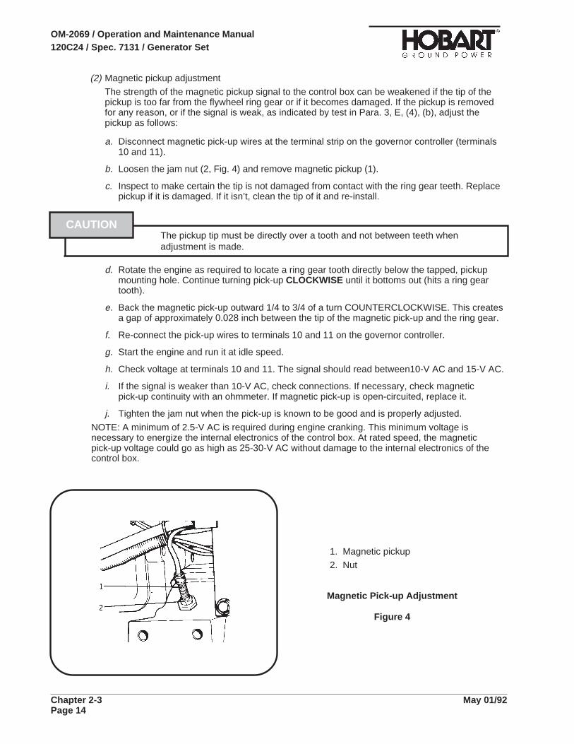
(2) Magnetic pickup adjustment
The strength of the magnetic pickup signal to the control box can be weakened if the tip of thepickup is too far from the flywheel ring gear or if it becomes damaged. If the pickup is removedfor any reason, or if the signal is weak, as indicated by test in Para. 3, E, (4), (b), adjust thepickup as follows:
a. Disconnect magnetic pick-up wires at the terminal strip on the governor controller (terminals10 and 11).
b. Loosen the jam nut (2, Fig. 4) and remove magnetic pickup (1).
c. Inspect to make certain the tip is not damaged from contact with the ring gear teeth. Replacepickup if it is damaged. If it isn’t, clean the tip of it and re-install.
The pickup tip must be directly over a tooth and not between teeth whenadjustment is made.
d. Rotate the engine as required to locate a ring gear tooth directly below the tapped, pickupmounting hole. Continue turning pick-up CLOCKWISE until it bottoms out (hits a ring geartooth).
e. Back the magnetic pick-up outward 1/4 to 3/4 of a turn COUNTERCLOCKWISE. This createsa gap of approximately 0.028 inch between the tip of the magnetic pick-up and the ring gear.
f. Re-connect the pick-up wires to terminals 10 and 11 on the governor controller.
g. Start the engine and run it at idle speed.
h. Check voltage at terminals 10 and 11. The signal should read between10-V AC and 15-V AC.
i. If the signal is weaker than 10-V AC, check connections. If necessary, check magneticpick-up continuity with an ohmmeter. If magnetic pick-up is open-circuited, replace it.
j. Tighten the jam nut when the pick-up is known to be good and is properly adjusted.
NOTE: A minimum of 2.5-V AC is required during engine cranking. This minimum voltage isnecessary to energize the internal electronics of the control box. At rated speed, the magneticpick-up voltage could go as high as 25-30-V AC without damage to the internal electronics of thecontrol box.
CAUTION
1. Magnetic pickup
2. Nut
Magnetic Pick-up Adjustment
Figure 4
OM-2069 / Operation and Maintenance Manual120C24 / Spec. 7131 / Generator Set
Chapter 2-3 May 01/92Page 14

(3) Governor control unit adjustment
Refer to Fig. 5. The controller has three control potentiometers used to control the IDLE speed:the GAIN potentiometer, the DROOP potentiometer, and the potentiometer marked “I”. Inaddition, a SPEED control potentiometer is located just next to the GAIN potentiometer. The newspeed control board is used to adjust RPM’s at the RATED speed setting. Make controllersettings as follows:
a. Preliminary Controller Settings
• With the engine OFF, set the “I” adjustment at the FOURTH increment mark from zero.
• Set the GAIN adjustment at the THIRD increment mark from zero.
• Set DROOP adjustment COUNTERCLOCKWISE to minimum (zero) position.
• Turn the adjustment pot on the speed control board, all the way COUNTERCLOCKWISE.Then, turn the pot twelve (12) full turns CLOCKWISE.
• Start the engine, leave at IDLE and adjust the controller’s SPEED potentiometer until theengine is operating at 850 RPM. Turning the adjustment CLOCKWISE increases engineRPM and turning it COUNTERCLOCKWISE decreases engine RPM.
b. Checking No-Load Operation of Controller
• Turn the GAIN potentiometer control slowly CLOCKWISE until the governor becomesunstable and the actuator lever oscillates. (If the actuator lever DOES NOT oscillate at thissetting, upset the lever manually to cause it to oscillate).
• Next, turn the same GAIN potentiometer control slowly COUNTERCLOCKWISE until thegovernor becomes stable and the oscillations cease.
• Turn “I” potentiometer control slowly CLOCKWISE until the governor again becomesunstable and the actuator lever oscillates.
• If the governor DOES NOT become unstable and the lever DOES NOT oscillate, place “I”potentiometer control setting at approximately EIGHT increment marks from zero (or TWOincrement marks from maximum setting).
• If the governor DOES become unstable, and the actuator lever DOES oscillate, turn the “I”potentiometer control slowly COUNTERCLOCKWISE until the governor becomes stableand the oscillations cease.
• Flip the engine MODE switch to the BUILD-UP VOLTAGE position. Let the enginestabilize, then flip the switch back to IDLE. Engine speed should stabilize within 3 to 5diminishing oscillations. If it doesn’t, repeat the first three steps above.
NOTE: For more accurate and dependable settings, when making GAIN and “I” adjustments,ALWAYS adjust GAIN before adjusting “I” and upset the throttle lever in between adjustments. Ifengine speed STILL doesn’t stabilize, recheck governor linkage. If linkage is set properly, thegovernor controller is probably defective.
c. Adjusting for RATED Speed Operation
The function of the new soeed control board, is to govern the engine at RATED speed. To checkfor proper adjustment, proceed with the following steps:
• With the engine running and properly adjusted for IDLE speed, flip the engine MODEswitch to the BUILD-UP VOLTAGE setting. The engine should be running at 2400 RPMand output frequency should be 400Hz.
• If the reading is high or low, operate the generator set at RATED speed, turn theadjustment pot on the speed control board in the CLOCKWISE direction to increaseRPM’s or COUNTERCLOCKWISE direction to decrease RPM’s.
• After making any adjustments, switch to IDLE speed, allow the engine to stabilize, thenswitch back to RATED speed.
OM-2069 / Operation and Maintenance Manual120C24 / Spec. 7131 / Generator Set
May 01/92 Chapter 2-3Page 15

d. Checking the Actuator
The actuator does not require any adjustments. An actuator malfunction, when it occurs, willresult in the actuator being totally inoperative, either due to the actuator coil being open orshorted to the actuator case. Resistance measurements will reveal either of these conditions.
e. Checking Operation of Controller Under Load
Apply a load to the generator set, then remove the load and observe the length of time requiredfor engine speed to stabilize. Engine speed should stabilize within 3 to 5 diminishing oscillations.If this does not happen, proceed as follows:
• With the generator set operating at no load, turn the GAIN setting slightly in theCOUNTERCLOCKWISE direction.
• Apply a load again to the generator set. Then remove the load again and observe thelength of time required for engine speed to stabilize. It should now stabilize in 3 to 5diminishing oscillations.
NOTE: If engine speed STILL doesn’t stabilize, recheck governor linkage. If the linkage is setproperly, the governor controller is probably defective.
Electric GovernorControl Box
Figure 5
OM-2069 / Operation and Maintenance Manual120C24 / Spec. 7131 / Generator Set
Chapter 2-3 May 01/92Page 16

f. Checking Magnetic Pick-up Signal
Connect a high inpedance voltmeter to magnetic pick-up input terminals (10 and 11, Fig. 6) oncontroller terminal board. The voltage value at no load, governed speed should be 4-V ACMINIMUM.
NOTE: A signal as low as 2.5-V is sufficient to operate the control unit satisfactorily. If ano-voltage condition is indicated, the magnetic pick-up is too far away from flywheel teeth, or it isdefective.
4. Generator and Exciter TestThe generator fields and exciter stators may be tested with a Kelvin bridge. This is a double-bridge typeinstrument required for the very low resistances encountered in this test. It is understood that 0resistance indicates a SHORT CIRCUITED condition. An infinite resistance reading indicates an OPENCIRCUITED condition. See Fig. 6 for resistance values.
a. Disconnect generator stator leads at the power module panel.
b. Disconnect the two black exciter field leads from terminal block mounted on power modulepanel.
c. Check resistance and compare to values given in Figure 6.
Test Connection Resistance (Ohms)Generator Stator Phase A to N (G1)* 0.00235Generator Stator Phase B to N (G1)* 0.00235Generator Stator Phase C to N (G1)* 0.00235Exciter Stator Field (RED to YELLOW-BLACK) (L2) 26.5A - B, B - C, C - A Exciter Armature (G2) 0.1Generator Revolving Field (L1) 2.1
*NOTE: The two leads of a phase must be connected when test is made. Take readings when unit iscold and in an ambient temperature of 70 deg. F. (21 deg. C.)
Generator and Exciter Stator TestsFigure 6
5. Diode TestTest values for diodes are not given here because they could be misleading. Test values may varyeven between diodes of the same part number, rating, and manufacturer. General instructions fortesting diodes follow:
a. Disconnect diode lead(s).
b. Use a good quality ohmmeter. An instrument which indicates 50 ohms at the center of thescale is preferable.
NOTE: Make certain the battery is in good condition and the pointer is adjusted to zero when the testlead points are shorted together. Set the scale selector to RX1.
c. Hold one ohmmeter lead point on the threaded end of the diode. Hold the other lead point onthe wire terminal end. Observe and note the indicated resistance. Now reverse the leadconnection on the diode. Again observe and note the ohmmeter indicated resistance.Generally speaking, if an infinite or very high resistance was indicated with the leadsconnected one way and a low, readable resistance was indicated with the leads connectedthe opposite way, the diode may be considered good.
OM-2069 / Operation and Maintenance Manual120C24 / Spec. 7131 / Generator Set
May 01/92 Chapter 2-3Page 17

6. Transformer-Rectifier Test and Adjustment
a. General
This Section contains information for testing and adjusting the T-R after major parts replacement, orrepair.
b. Test
The following test procedures may be used for testing the T-R following repair, or for checkingperformance.
(1) Preparation for Test
a. Connect the T-R to a load bank using two each, size 4/0 cables from each output terminal tothe load bank rather than single 4/0 cables ordinarily used for aircraft service.
NOTE: It is recommended that this higher capacity output cable arrangement be used for applicationswhere very large loads are connected to the T-R.
b. Check diode leads. Make certain they are not touching bus bars.
c. Make certain that each transformer bus has clearance between windings and other busing.
(2) Operational Test Procedure
a. Start generator set and adjust voltage to 115/200 Volts AC.
b. Operate the T-R by placing switch (1-3; 8, Fig. 4) in top ON position momentarily, thenrelease. The green indicating light should glow to indicate power is available at outputterminals.
c. Observe the voltmeter (1-3; 3, Fig. 4). It should indicate approx. 28.5-Volts DC. Attach amaster voltmeter and compare meter reading. Voltmeter should be accurate to within plus orminus 2%.
d. Observe operation of fans and check direction of rotation. Air intake is at control panel end(front). Exhaust is at (fan) end (rear). If fan rotation is incorrect, reverse the connection of anytwo fan input leads.
e. Check adjustment of ammeter shunt.
Adjust the load bank to apply a load of EXACTLY 500 Amperes. Use a reliable masterammeter.
Observe the T-R ammeter (1-3; 6, Fig. 4). At 70 deg F (21 deg C) ambient temperature, theshunt should be adjusted to produce an indicated 450 Amperes on the ammeter. This rule foradjusting the shunt was selected to provide a more accurate reading through the entireammeter scale range of 0 to 2500 Amperes and to provide a minimal error at rated 1050Amperes continuous load.
If adjustment is required, refer to Ammeter Shunt Adjustment, Para. 6, C, (2).
NOTE: The aluminum bus bar, a portion of which serves as a shunt, is sensitive to both ambienttemperature, and current-induced thermal changes. This means that under sustained heavyloads the ammeter reading could change considerably from the reading indicated at thebeginning of a power delivery period. The ambient temperature selected for a true ammeterreading is 70 deg F (21 deg C). It has been determined that a temperature change of 9 deg F(approx. 3 deg C) will change the ammeter reading 2%. An increase in temperature results in anincrease in indicated amperage, and a decrease in temperarue decreases the amperagereading. As a rule-of-thumb for approx. conversions, each degree of temperature change resultsin a change of 1 ampere in the indicated amperage, when the load is in the 500-Ampere range.
OM-2069 / Operation and Maintenance Manual120C24 / Spec. 7131 / Generator Set
Chapter 2-3 May 01/92Page 18

f. Place current limiting control switch (1-3; 9, Fig. 4) in the OFF position. Adjust line dropcompensation to minimum (See 1-3; Fig. 5). Loosen nut (2) and turn screw (3) fully CCW.Tighten nut.
g. With 500-Ampere load, observe the generator set ammeter. Input current to the T-R shouldbe approx. 44 Amperes. Observe DC output voltage on T-R voltmeter. Indicated voltageshould be approx. 26.5-Volts DC with line-drop compensation set to minimum.
h. Increase load to 1000 Amperes, and adjust the line-drop compensation (See 1-3; Fig. 5).Loosen nut (2) and turn adjusting screw (3) CW until 28.5-Volts DC is indicated on thevoltmeter. Tighten nut (2).
i. Check current limiting rheostat and resistor adjustment.
With current-limiting switch (1-3; 9, Fig. 4) in the OFF position, apply a load of 1500 Amperesto the T-R.
Place current-limiting switch (9) in the ON position.
Observe ammeter (6) while operating the rheostat (5). If output amperage can be controlledthrough a range of 700 to 1500 Amperes, the resistor (16) is properly adjusted. The pointerwhich is attached to the rheostat knob is properly adjusted if it points to the same amperagevalue on the dial as that indicated on the ammeter.
If output current cannot be controlled through a range of 700 to 1500 Amperes, or if thepointer indicates a value other than that shown on the ammeter, adjustment is required. Referto Para. 6, C, (3) for procedures.
j. Test overvoltage module
Place current limiting switch (1-3; 9, Fig. 4) in the OFF position. Operate switch (8) to closethe load contactor. No load is required.
Observe T-R output voltmeter and gradually increase AC input voltage by adjusting thegenerator set voltage control rheostat.
Overvoltage module should function to open the T-R load contactor when output voltagereaches 32 to 34 Volts DC. Module should function in 2 to 10 seconds after trip voltage isreached.
k. Test themal overload thermostatic switches (6, Fig. 15).Remove DC circuit fuse (1-3; 10, Fig. 4 ).
NOTE: Removing the fuse prevents operation of overload module
Apply a 2500-Ampere load.
Thermostatic switches should function to open the load contactor in less than 20 seconds.
AMMETER T-R
SHUNT AMBIENT INDICATED TRUE
TEMPERATURE AMPERES AMPERES
DEG. F DEG. C
60 16 440 500
70 21 450 500
80 27 460 500
90 32 470 500
100 38 480 500
110 43 490 500
Ammeter Shunt
Temperature Chart
Figure 7
OM-2069 / Operation and Maintenance Manual120C24 / Spec. 7131 / Generator Set
May 01/92 Chapter 2-3Page 19

Do not maintain 2500-ampere load for more than 2 minutes. damage toequipment may result.
l. Replace the DC circuit fuse and allow T-R to cool 15 to 20 minutes, or until exhaust air is thesame temperature as ambient intake air.
m. Test overload module.
Use a jumper lead to short-out the thermostat switches.
Apply a sustained minimum load of 2250 Amperes to the T-R. The overload module shouldfunction to open the load contactor within 5 minutes.
NOTE: An output load of 2500 Amperes DC will cause the overload module to function in approx. 30seconds.
A line current (input) of 182 Amperes is required to produce 8.25-Volts AC across the burdenresistors for this test.
Do not run this test for more than 7 minutes.
Remove the jumper lead across the thermostat switches.
(3) Test Silicon Diodes
Do not apply a megger or any high potential test equipment in any manner thatsubjects the silicon diodes and other components to abnormal voltages. Silicondiodes must be isolated or shorted with extremely short leads. Such tests mustbe made under the supervision of a factory representative.
a. Disconnect diode leads
b. Use a good quality ohmmeter (preferably one having a mid-scale value of approx. 50 ohms)to measure resistance values.
c. Zero the instrument on the RX 1 scale.
d. Take and note a reading by placing either ohmmeter lead on the threaded end of the diodeand the other lead on the diode lead.
e. Reverse the ohmmeter leads on the diode, take and note another reading.
f. The diode may generally be considered good if:
• One reading is infinite or very high.
• The other reading is extremely low.
NOTE: An acceptable low ohmic value or range cannot be given because ohmmeter readings may varybetween meters, or even between diodes with the same rating.
CAUTION
CAUTION
CAUTION
OM-2069 / Operation and Maintenance Manual120C24 / Spec. 7131 / Generator Set
Chapter 2-3 May 01/92Page 20

c. Adjustment
(1) Line-Drop Compensation
Adjustment procedures, which were outlined in a previous Section, are repeated here.
a. Apply a 1000-Ampere DC load to the T-R.
b. Open control panel.
c. Refer to 1-3; Fig. 5 and loosen nut (2). Adjust screw (3) to produce a voltmeter reading of28.5-Volts DC. Turn screw CW to increase voltage; CCW to decrease voltage.
d. Tighten nut (2) when adjustment is completed.
(2) Ammeter Shunt
No adjustment of the shunt should be required unless it has been disassembled.
a. Apply a load of exactly 500 Amperes. Use a reliable ammeter to make certain the load is 500Amperes.
b. Indicated amperage as observed on the T-R ammeter should be 450 Amperes. Use chartFigure 7, and Para. 6, B, 2, (e) (f) to compensate for ambient temperature.
c. Stop all operations; T-R and generator set. Remove T-R top, and reposition adjusting nuts (4,Fig. 2) to adjust shunt. Lengthen the shunt to increase the ammeter reading. Shorten theshunt to decrease the reading. Tighten the adjusting nuts.
d. Start the generator set and reapply load to check ammeter reading.
e. Turn both generator set and T-R OFF and repeat step (3) if further adjustment is required.
Do not adjust while the generator is running. lethal electrical shock hazard exists.
f. Install T-R top after adjustment is satisfactorily completed.
(3) Range of Current Limiting Rheostat
This adjustment should be required only if the resistor is replaced or if the adjustment istampered with.
a. Turn all power OFF.
b. Open the control panel and use a reliable ohmmeter to check resistance acrosscurrent-limiting, range-adjusting resistor (Fig. 9). Resistance should be 40 Ohms. If not,loosen the adjusting band (2) and slide it toward the end of the resistor where the band leadis connected, to increase resistance. Slide the opposite direction to decrease resistance.When a resistance of 40 Ohms is indicated, tighten the band clamping screw. Close thecontrol panel.
c. With current-limiting switch OFF, apply a load of 1500 Amperes to the T-R.
d. Turn current-limiting switch ON. Observe ammeter (1-3; 6, Fig. 4) and operate thecurrent-limiting rheostat (5) throughout its complete range. Output current should becontrollable from 700 to 1500 Amperes.
e. Rotate rheostat to obtain an ammeter reading of 1000 Amperes. Observe amperageindicated by the rheostat knob pointer. If the pointer does not indicate 1000 Amperes, on thedial, loosen the pointer attaching setscrew and position the pointer to indicate exactly 1000Amperes. Tighten setscrew.
WARNING
OM-2069 / Operation and Maintenance Manual120C24 / Spec. 7131 / Generator Set
May 01/92 Chapter 2-3Page 21

1. Lead attaching screw
2. Ammeter shunt [(the portion of
aluminum rod between
screw (1) and nuts (3)]
3. Adjusting nuts
4. Ammeter leads
Ammeter Shunt Adjustment
Figure 8
Current-Limiting Range
Adjustment
Figure 9
OM-2069 / Operation and Maintenance Manual120C24 / Spec. 7131 / Generator Set
Chapter 2-3 May 01/92Page 22
Section 4. Troubleshooting Procedures
1. GeneralThe Troubleshooting Chart, beginning on Page 6, covers the common malfunctions which you may findduring operation or maintenance of this equipment. It cannot list all malfunctions that may occur. If amalfunction is not listed in the chart, start looking for the cause at the source of power in the affectedcircuit. Refer to the schematic and connection diagrams in Chapter 5 and test the circuit, step by step,until the source of the malfunction is isolated.
The Troubleshooting Chart is arranged under 3 headings: Malfunction, Test or Inspection, andCorrective Action. Malfunctions are described and numbered. Tests and Inspections are indented tothe right and listed in numbered steps below Malfunctions. Corrective Action provides instructions forcorrecting the malfunction, and is listed below each Test or Inspection procedure. Tests andinspections called for in the Troubleshooting Chart are to be performed as described in section 2-3 ofthis manual.
2. Equipment for Troubleshooting
Exercise extreme care to avoid contact with high voltage leads and components.High voltage can kill!
Maintenance personnel must be very careful when performing terminal-to-terminal checks to be certain the proper terminals are being used, especiallywhen using jumper leads. Damage to electrical components may result from theapplication of improper voltage and current.
A good quality multi-scale volt ohmmeter is the only instrument required for troubleshooting. At leasttwo jumper leads with alligator, or similar clips, will be required. The engine electrical system may beused as a 12-V DC power source.
3. Parts ReplacementTo lessen end item down time and to get a faulty machine back on line as quickly as possible, theblack-box concept of parts replacement is reflected in the Troubleshooting Chart. For example, if acomponent is the protective relay tray is defective, the quickest way to remedy the situation is toreplace the complete tray assembly and send the old tray to stock. Assemblies which lend themselvesto this concept are:
Electric governor control box Protective monitor PC board
Electric governor actuator Over-Underfrequency PC board
Voltage regulator Overload PC boards
Over-Undervoltage PC board
WARNING
CAUTION
OM-2069 / Operation and Maintenance Manual120C24 / Spec. 7131 / Generator Set
May 01/92 Chapter 2-4Page 1
4. Test ValuesAlthough test values are provided throughout the troubleshooting chart , additional information andvalues are given here.
Generator output voltage at maximum voltage regulator potentiometer setting: 134 volts or higher.
Generator output voltage at minimum voltage regulator potentiometer setting: 108 volts or lower.
Overvoltage relay Trips at 126 volts after a 1-second time delay.Trips at 140 volts in 160 milliseconds.Trips at 180 volts in 50 milliseconds.
Undervoltage relay Trips at 100 volts after 7 seconds.
Overfrequency relay Trips at any value between 426-Hz and 480-Hz after a5-second time delay. Trips immediately at any frequencyexceeding 480-Hz.
Underfrequency relay Trips at 375 Hz or less after a 5-second time delay.
Overload time delay Trips in approximately 5 minutes at 125% load on eitheroutput or on both outputs.
Frequency at rated speed of 2400 RPM is 400 +/- 2 Hz at no load and rated load.
Engine oil pressure (warm and at rated speed 2400 RPM) 50 to 90 PSI (445 to 621 kPa).
Engine coolant temperature (normal operation) 160 to 200 deg. F. (71 to 93 deg. C.).
5. Check Connections and LeadsALWAYS make a check of connections and leads to a component suspected of being faulty. With theexception of a few instances, we will assume that connections and wiring have always been checkedfirst and that power has not been lost as a result of defective wiring or connections.
6. Electric Governor TroubleshootingThe following facts concerning the operation of the electric governor may be helpful in understandingthe system and in determining which unit in the system is faulty in case of troubles.
(1) The system requires two sources of power to operate normally.
a. 12 V DC input power (from engine electrical system)
b. 4 V AC input power (from magnetic pickup)
(2) Assuming other conditions are normal, the actuator will go to, or remain in IDLE position underthe following conditions:
a. No 12 V DC power
b. No voltage from control box to actuator
OM-2069 / Operation and Maintenance Manual120C24 / Spec. 7131 / Generator Set
Chapter 2-4 May 01/92Page 2
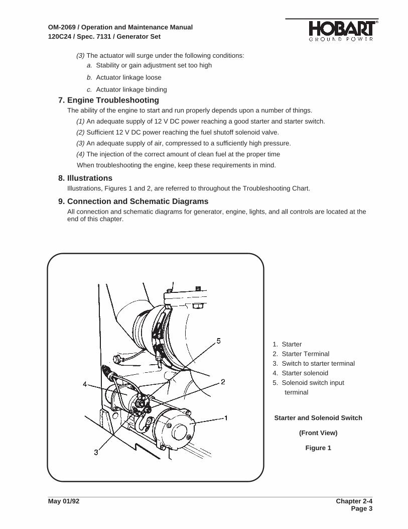
(3) The actuator will surge under the following conditions:
a. Stability or gain adjustment set too high
b. Actuator linkage loose
c. Actuator linkage binding
7. Engine TroubleshootingThe ability of the engine to start and run properly depends upon a number of things.
(1) An adequate supply of 12 V DC power reaching a good starter and starter switch.
(2) Sufficient 12 V DC power reaching the fuel shutoff solenoid valve.
(3) An adequate supply of air, compressed to a sufficiently high pressure.
(4) The injection of the correct amount of clean fuel at the proper time
When troubleshooting the engine, keep these requirements in mind.
8. IllustrationsIllustrations, Figures 1 and 2, are referred to throughout the Troubleshooting Chart.
9. Connection and Schematic DiagramsAll connection and schematic diagrams for generator, engine, lights, and all controls are located at theend of this chapter.
1. Starter
2. Starter Terminal
3. Switch to starter terminal
4. Starter solenoid
5. Solenoid switch input
terminal
Starter and Solenoid Switch
(Front View)
Figure 1
OM-2069 / Operation and Maintenance Manual120C24 / Spec. 7131 / Generator Set
May 01/92 Chapter 2-4Page 3

1. Front panel 15. Protective system indicating lights
2. Panel light 16. Test switch, protective system
3. Engine hour meter 17. Reset switch, protective system
4. Panel light switch 18. Indicating light, air cleaner restriction
5. Oil pressure gage 19. Frequency meter
6. Engine ON indicating light 20. Selector switch, voltmeter-ammeter
7. Engine coolant temperature meter 21. Voltmeter
8. Engine start switch 22. Adjustable grip latch
9. Engine control switch 23. No. 1 contactor switch
10. Engine ammeter 24. Power accepted light, No. 1 contactor
11. Fuel gage 25. No. 2 contactor switch
Operating Controls and Instruments
Figure 2 (Sheet 1 of 2)
OM-2069 / Operation and Maintenance Manual120C24 / Spec. 7131 / Generator Set
Chapter 2-4 May 01/92Page 4

29. Test bank-aircraft switch, No. 1 output 33. Output voltage adjustment (fine)
30. Test bank-aircraft switch, No. 2 output 34. Line drop compensation adjustment
31. Regulated-diagnostic switch 35. Fuse (5-amp)
32. Output voltage adjustment (coarse)
Operating Controls and Instruments
Figure 2 (Sheet 2 of 2)
OM-2069 / Operation and Maintenance Manual120C24 / Spec. 7131 / Generator Set
May 01/92 Chapter 2-4Page 5

1. Screw 11. Fuse (2A) (115-V AC circuit)
2. Air inlet louver 12. Light switch
3. DC voltmeter 13. Hinge
4. Instrument light 14. Panel
5. Current limiting rheostat 15. Resistor (200 Ohm, 25 Watt)
6. DC ammeter 16. Resistor (100 Ohm, 100 Watt)
7. Contactor CLOSED indicating light 17. Rectifier, silicon
8. Contactor control switch 18. Line-drop compensation and current
9. Current limiting control switch limiting module
10. Fuse (2A) (DC circuit) 19. Board, overvoltage
28.5-V DC TRansformer-Rectifier Control Panel Assembly
Figure 3
OM-2069 / Operation and Maintenance Manual120C24 / Spec. 7131 / Generator Set
Chapter 2-4 May 01/92Page 6
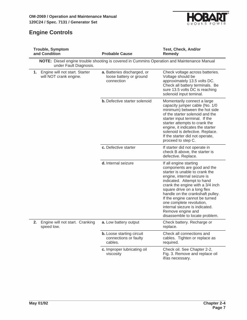
Engine Controls
Trouble, Symptom Test, Check, And/orand Condition Probable Cause Remedy
NOTE: Diesel engine trouble shooting is covered in Cummins Operation and Maintenance Manualunder Fault Diagnosis.
1. Engine will not start. Starterwill NOT crank engine.
a. Batteries discharged, orloose battery or groundconnection
Check voltage across batteries.Voltage should beapproximately 13.5 volts DC.Check all battery terminals. Besure 13.5 volts DC is reachingsolenoid input teminal.
b. Defective starter solenoid Momentarily connect a largecapacity jumper cable (No. 1/0minimum) between the hot sideof the starter solenoid and thestarter input terminal. If thestarter attempts to crank theengine, it indicates the startersolenoid is defective. Replace.If the starter did not operate,proceed to step C.
c. Defective starter If starter did not operate incheck B above, the starter isdefective. Replace.
d. Internal seizure If all engine startingcomponents are good and thestarter is unable to crank theengine, internal seizure isindicated. Attempt to handcrank the engine with a 3/4 inchsquare drive on a long flexhandle on the crankshaft pulley.If the engine cannot be turnedone complete revolution,internal siezure is indicated.Remove engine anddisassemble to locate problem.
2. Engine will not start. Crankingspeed low.
a. Low battery output Check battery. Recharge orreplace.
b. Loose starting circuitconnections or faultycables.
Check all connections andcables. Tighten or replace asrequired.
c. Improper lubricating oilviscosity
Check oil. See Chapter 2-2,Fig. 3. Remove and replace oilif/as necessary.
OM-2069 / Operation and Maintenance Manual120C24 / Spec. 7131 / Generator Set
May 01/92 Chapter 2-4Page 7
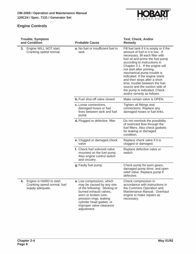
Engine Controls
Trouble, Symptom Test, Check, And/orand Condition Probable Cause Remedy
3. Engine WILL NOT start.Cranking speed normal.
a. No fuel or insufficient fuel intank
Fill fuel tank if it is empty or if theamount of fuel in it is low. Ifnecessary, fill each filter withfuel oil and prime the fuel pumpaccording to instructions inChapter 2-1. If the engine willnot start after priming,mechanical pump trouble isindicated. If the engine startsand then stops after a shorttime, trouble between the fuelsource and the suction side ofthe pump is indicated. Checkand/or remedy as follows.
b. Fuel shut-off valve closed Make certain valve is OPEN.
c. Loose connections,damaged hoses or fuellines between tank and fuelpump
Tighten all fittings andconnections. Replace anydamaged hoses or fuel links.
d. Plugged or defective filter Do not overlook the possibilityof restricted flow through thefuel filters. Also check gasketsfor leaking or damagedcondition.
e. Clogged or damaged checkvalve
Replace check valve if it isclogged or damaged.
f. Check fuel solenoid valvemounted on the fuel pump.Also engine control switchand circuitry.
Replace defective valve orswitch.
g. Faulty fuel pump Check pump for worn gears,damaged pump drive, and openrelief valve. Replace pump ifdefective.
4. Engine is HARD to start.Cranking speed normal, fuelsupply adequate.
a. Low compression, whichmay be caused by any oneof the following: Sticking orburned exhaust valves,worn or broken com-pression rings, leakingcylinder head gasket, orimproper valve clearanceadjustment.
Check compression inaccordance with instructions inthe Cummins Operation andMaintenance Manual. Overhaulengine to make repairs asnecessary.
OM-2069 / Operation and Maintenance Manual120C24 / Spec. 7131 / Generator Set
Chapter 2-4 May 01/92Page 8

Engine Controls
Trouble, Symptom Test, Check, And/orand Condition Probable Cause Remedy
5. Engine starts. Stops after afew seconds by automaticshutdown.
a. The shut-down circuit mayhave functioned normally tostop the engine because oflow lubricating oil pressureor due to a defective oilpressure switch (S46,located on the engine blockon the right side).
Restart the engine, holdpermissive start switch inSTART position, and observe oilpressure gage. If oil pressure is12 psi or more, and the engineshuts down when the permissivestart switch is released to therun position, put a jumper wireacross oil pressure switchterminals “C” and “NO”. Restartengine. If the engine continuesto run when the permissive startswitch is released to the RUNposition, the oil pressure switchis defective. Replace oilpressure switch. If the enginestops, check for the followingmalfunctions:
b. Defective or incorrectlywired high temperatureswitch (S 49, located on theengine block on the rightside).
Check wiring to high tem-perature switch according toconnection diagram in Chapter6, and see that wiring is correct.If wiring is correct, remove thewires and check resistancebetween terminals C and N.C.A resistance reading of zeroindicates a good temperatureswitch. A readable resistance,indicates a defective switch.Replace switch if defective. Ifthe engine stops, check fordefective engine control switch.
c. Defective engine controlswitch (S7) (9, Fig. 2).
Check the engine control switchby removing its wires andchecking resistance betweenterminals. Replace switch ifdefective.
OM-2069 / Operation and Maintenance Manual120C24 / Spec. 7131 / Generator Set
May 01/92 Chapter 2-4Page 9

Engine Controls
Trouble, Symptom Test, Check, And/orand Condition Probable Cause Remedy
6. Engine will not come “up” togoverned speed in GEN mode.
a. 12-V DC power notreaching governor controlbox due to defectiveoperating mode switch (28,Fig. 2)
Apply 12-V DC directly toterminal 6 on governor controlbox. If engine comes-up tospeed, check following:
b. Governor linkage binding orgovernor throttle sticking
Check governor linkage andthrottle shaft for binding andsticking. Repair as required.
c. Defective or misadjustedmagnetic pickup (Chapter2-3, Fig.5).
The control unit may not bereceiving a signal from themagnetic pickup and the“fail-safe” feature of the unitmay be functioning to preventany signal from reaching theactuator. To check themagnetic pickup, refer todiagram 283122 and dis-connect pickup input leads atterminals 10 and 11 on thecontroller.
Connect a high impedance ACvoltmeter to the pickup outputleads. Crank engine but don’tstart. Voltage reading should bea minimum of one (1) volt. If noor low voltage is indicated,check pickup adjustment [see2-3,Para. 3, e,(2)]. If pickup isproperly adjusted and voltage isstill zero, replace pickup.
d. Defective actuator Apply 12-V DC to the twoactuator input leads (terminals4 and 5 on the terminal strip).Actuator lever should moveimmediately to full speedposition. If lever does notmove, replace actuator.
.
OM-2069 / Operation and Maintenance Manual120C24 / Spec. 7131 / Generator Set
Chapter 2-4 May 01/92Page 10

Engine Controls
Trouble, Symptom Test, Check, And/orand Condition Probable Cause Remedy
Engine will not come “up” togoverned speed in GEN mode.(Continued)
e. Defective controller At terminals 4 and 5 on theterminal strip next to thecontroller, connect a DCvoltmeter. Start the engine andmanually control speed. Atspeeds below governed speedthe voltmeter should indicatewithin two (2) volts of the systemvoltage. If voltage is at nearzero, turn speed adjusting screwseveral turns clockwise to besure speed setting is not too lowbecause of tampering. If voltageremains low or at zero, replacecontroller.
7. Engine goes to overspeedwhen control switch (28, Fig. 2)is in GEN mode.
a. Governed speed controladjustment set too high(see 2-3, Fig. 5)
Turn speed control adjustingscrew fully counterclockwise.Start engine. Place controlswitch (28, Fig. 2) in GENposition. If engine speed isnow well below governedspeed, turn adjusting screwclockwise until correct speed(2000 RPM, 400-Hz) isattained. If engine still goes tooverspeed, proceed to Step B.
b. Defective linkage oractuator
Check governor linkage andactuator for sticking or bindingin full-speed position. Repairas required.
c. Defective controller Replace controller. Check it inaccordance with governorinstruction book.
8. Engine is unsteady, (surges)under load
a. Fault in engine Before condemning thegovernor system for surging,make certain the fault is not inthe engine. Make certain allcylinders are firing properly.
b. Governor system faulty ormisadjusted
Check and adjust as follows:
c. Loose or binding governorlinkage
Check linkage ball joints and allconnections for looseness orbinding. Be sure linkage willmove from idle speed to fullspeed without lost motion orbinding.
OM-2069 / Operation and Maintenance Manual120C24 / Spec. 7131 / Generator Set
May 01/92 Chapter 2-4Page 11

Engine Controls
Trouble, Symptom Test, Check, And/orand Condition Probable Cause Remedy
Engine is unsteady, (surges)under load (continued)
d. GAIN and “I” controlimproperly adjusted
Adjust GAIN and “I” control oncontroller in accordance with2-3, Para. 3, e,(3)
e. Magnetic pickup signalweak
Check and adjust pickup. See2-3, Para. 4, E, (2)
9. Engine has slow response time a. Governor controllerimproperly adjusted
Adjust. See 2-3; Para. 3, E, (3).
b. Actuator linkage binding Inspect and repair as required.
c. Engine needs tune-up Tune-up as required. Refer toCummins Operation andMaintenance Manual.
10. Engine “misses”. Runsunevenly.
a. Insufficient fuel Check fuel flow in accordancewith Cummins Operation andMaintenance Manual. Repair orreplace parts as required. Alsosee Engine, Trouble 3.
b. Faulty injector Check injectors in accordancewith Cummins Operation andMaintenance Manual. Seecauses of low compressionlisted under ENGINECONTROLS.
c. Low compression pressure Check compression inaccordance with CumminsOperation and MaintenanceManual. See causes of lowcompression listed underENGINE CONTROLS.
11. Engine lacks power a. Improper engineadjustments and gear traintiming
“Tune-up” the engine inaccordance with CumminsOperation and MaintenanceManual.
b. Insufficient fuel See ENGINE CONTROLS
c. Insufficient inlet air due todamaged air cleaner.
Check air cleaner for “plugging”and/or damage.
d. Restricted exhaust system Check exhaust pipes forrestrictions. Check muffler forclogged condition. Replace asrequired.
OM-2069 / Operation and Maintenance Manual120C24 / Spec. 7131 / Generator Set
Chapter 2-4 May 01/92Page 12

Generator Excitation Circuits
Trouble, Symptom Test, Check, And/orand Condition Probable Cause Remedy
1. No (or low) generator outputvoltage in all phases.Generator operating at 400 Hz.
a. Defective generator orexcitation circuit.
Place the REGULATED/DIAGNOSTIC switch (31,Fig. 2)in DIAGNOSTIC position. Thisapplies 12-V DC from the batteryto the exciter field, which shouldproduce an indicated outputvoltage of 59 V-AC +/- 5 V-ACline-to-neutral (102-V AC +/- 8-VAC line to line). If the voltageproduced is within this range,the generator is good, and thetrouble is in the voltage regulatorcircuit. Proceed to step B.
b. Blown regulator fuse (35,Fig. 2)
Check fuse with an ohmmeter.If it is open, replace it.
c. Defective voltage regulator Disconnect the rectangular plugconnector of the regulatorwiring assembly from thesuspect PC board, and connecta properly working PC board tothe regulator wiring assembly,while avoiding short circuitingthe bottom of the properlyworking PC board to theinstalled PC board. Then startthe generator set and performthe tests and adjustmentsaccording to instructions inSection 2-3.
If the generator set worksproperly with the properlyworking PC board temporarilyconnected, shut off thegenerator set and replace thedefective PC board with one thatis properly working (preferably,the same PC board used for thistroubleshooting check).
d. Defective REGULATED/DIAGNOSTIC switch (31,Fig. 2)
Check the switch thoroughly. Adefective switch may preventcurrent reaching and/or leavingthe voltage regulator. Replaceswitch if defective.
e. Defective excitation-deenergization relay (K16)(1-1; 2, Fig. 7)
Check EDR contacts. A faultyEDR can prevent power fromreaching the voltage regulator.Replace relay if defective.
OM-2069 / Operation and Maintenance Manual120C24 / Spec. 7131 / Generator Set
May 01/92 Chapter 2-4Page 13

Generator Excitation Circuits
Trouble, Symptom Test, Check, And/orand Condition Probable Cause Remedy
No (or low) generator outputvoltage in all phases.Generator operating at 400 Hz.
f. Defective connector atvoltage regulator, ordefective wiring fromregulator to exciter field
Disconnect plug from voltageregulator PC board. Usingjumper leads with clip and prodterminals, connect 12-V DC toterminals 1 and 4 in loose plug.Connect NEGATIVE to terminal4 Connect POSITIVE lead toterminal 1 (see Schematic/Connection Diagram in Chapter5). If the generator will NOTproduce at least 50 V-AC,replace or repair connector andwiring between voltage regulatorand exciter field as required.
OM-2069 / Operation and Maintenance Manual120C24 / Spec. 7131 / Generator Set
Chapter 2-4 May 01/92Page 14
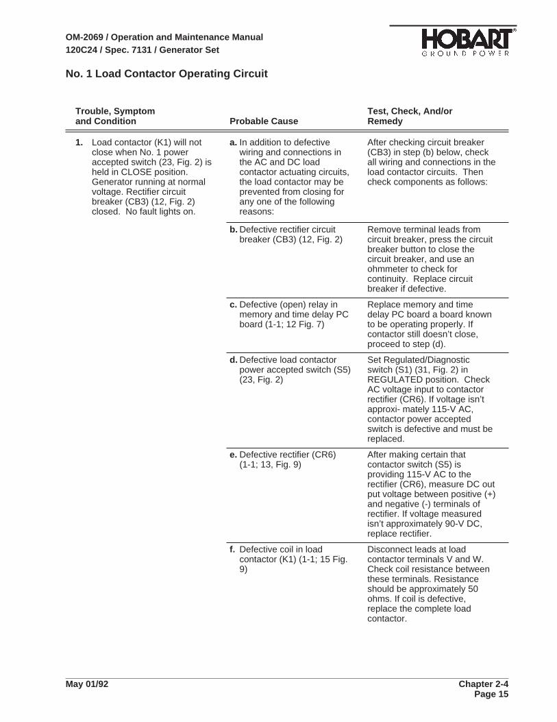
No. 1 Load Contactor Operating Circuit
Trouble, Symptom Test, Check, And/orand Condition Probable Cause Remedy
1. Load contactor (K1) will notclose when No. 1 poweraccepted switch (23, Fig. 2) isheld in CLOSE position.Generator running at normalvoltage. Rectifier circuitbreaker (CB3) (12, Fig. 2)closed. No fault lights on.
a. In addition to defectivewiring and connections inthe AC and DC loadcontactor actuating circuits,the load contactor may beprevented from closing forany one of the followingreasons:
After checking circuit breaker(CB3) in step (b) below, checkall wiring and connections in theload contactor circuits. Thencheck components as follows:
b. Defective rectifier circuitbreaker (CB3) (12, Fig. 2)
Remove terminal leads fromcircuit breaker, press the circuitbreaker button to close thecircuit breaker, and use anohmmeter to check forcontinuity. Replace circuitbreaker if defective.
c. Defective (open) relay inmemory and time delay PCboard (1-1; 12 Fig. 7)
Replace memory and timedelay PC board a board knownto be operating properly. Ifcontactor still doesn’t close,proceed to step (d).
d. Defective load contactorpower accepted switch (S5)(23, Fig. 2)
Set Regulated/Diagnosticswitch (S1) (31, Fig. 2) inREGULATED position. CheckAC voltage input to contactorrectifier (CR6). If voltage isn’tapproxi- mately 115-V AC,contactor power acceptedswitch is defective and must bereplaced.
e. Defective rectifier (CR6)(1-1; 13, Fig. 9)
After making certain thatcontactor switch (S5) isproviding 115-V AC to therectifier (CR6), measure DC output voltage between positive (+)and negative (-) terminals ofrectifier. If voltage measuredisn’t approximately 90-V DC,replace rectifier.
f. Defective coil in loadcontactor (K1) (1-1; 15 Fig.9)
Disconnect leads at loadcontactor terminals V and W.Check coil resistance betweenthese terminals. Resistanceshould be approximately 50ohms. If coil is defective,replace the complete loadcontactor.
OM-2069 / Operation and Maintenance Manual120C24 / Spec. 7131 / Generator Set
May 01/92 Chapter 2-4Page 15

No. 1 Load Contactor Operating Circuit
Trouble, Symptom Test, Check, And/orand Condition Probable Cause Remedy
2. Load contactor (K1) will closewhen No. 1 power acceptedswitch (23, Fig. 2) is held inCLOSE position. Opensimmediately when switch isreleased to center ON position.
a. 28.5-V DC is not reachingNo. 1 plug interlock relay(K2) from aircraft for thefollowing reasons:
Proceed as follows to find thecause of this malfunction.
b. Generator to aircraft cableconnector defective or notplugged into aircraftreceptacle connector.
Inspect cable connector plugthoroughly for damaged E andF terminals. Be sure the plug isfully mated with the aircraftreceptacle connector andmaking good contact.
c. Aircraft rejecting power. Check aircraft on-boardelectrical equipment andcontrols.
d. Defective protective systemcircuit breaker (CB2) (13,Fig. 2)
Remove terminal leads fromcircuit breaker, press its buttonto close it, and use an ohm-meter to check for continuity.Replace circuit breaker ifdefective.
e. Defective plug interlockrelay, No. 2 output (K2) ,(1-1; 5, Fig. 7)
Place test bank/aircraft switch,No. 1 output (S2) (29, Fig. 2) inTEST BANK position. If loadcontactor will now remainclosed, replace the pluginterlock relay.
f. Defective contacts in thesmall interlock devicemounted on the right side ofthe contactor (the devicehaving blue-yellow andblack-yellow wires).
Connect a jumper lead betweenthe terminals of the smallinterlock device. If loadcontactor will now remainclosed, replace the completeload contactor.
g. Defective protective systeminterlock relay (K17) or holdcircuit resistor (R46) for theNo. 1 output
Connect a jumper acrossresistor R46 (1-1; 19, Fig. 7). Ifthe contactor will now remainclosed, replace No. 1 outputhold circuit resistor (R46). If thecontactor does NOT remainclosed, replace protectivesystem interlock relay (K17).
OM-2069 / Operation and Maintenance Manual120C24 / Spec. 7131 / Generator Set
Chapter 2-4 May 01/92Page 16

No. 1 Load Contactor Operating Circuit
Trouble, Symptom Test, Check, And/orand Condition Probable Cause Remedy
3. Load contactor opens duringpower delivery. NO faultindicating lights on.
a. Protective system circuitbreaker (13, Fig 2) or loadcontactor circuit breaker(12, Fig. 2) defective
To test each circuit breaker,remove terminal leads fromcircuit breaker, press its buttonto close it, and use an ohmmeterto check for continuity. Replaceeither circuit breaker found to bedefective.
b. A fault has developed in theload contactor holdingcircuit.
If load contactor cannot beclosed by operation of poweraccepted switch (S5) (23, Fig.2), check circuit in accordancewith instructions in Trouble 1,above under LOADCONTACTOR OPERATINGCIRCUIT. If load contactor canbe closed, but opens as soonas power accepted switch (S5)is released, check for troubleunder Trouble 2, above.
c. Cable accidentallydisconnected from aircraft.
Reconnect cable.
OM-2069 / Operation and Maintenance Manual120C24 / Spec. 7131 / Generator Set
May 01/92 Chapter 2-4Page 17
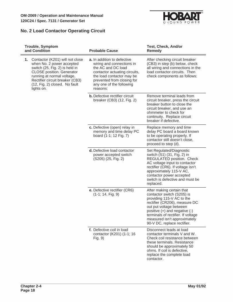
No. 2 Load Contactor Operating Circuit
Trouble, Symptom Test, Check, And/orand Condition Probable Cause Remedy
1. Contactor (K201) will not closewhen No. 2 power acceptedswitch (25, Fig. 2) is held inCLOSE position. Generatorrunning at normal voltage.Rectifier circuit breaker (CB3)(12, Fig. 2) closed. No faultlights on.
a. In addition to defectivewiring and connections inthe AC and DC loadcontactor actuating circuits,the load contactor may beprevented from closing forany one of the followingreasons:
After checking circuit breaker(CB3) in step (b) below, checkall wiring and connections in theload contactor circuits. Thencheck components as follows:
b. Defective rectifier circuitbreaker (CB3) (12, Fig. 2)
Remove terminal leads fromcircuit breaker, press the circuitbreaker button to close thecircuit breaker, and use anohmmeter to check forcontinuity. Replace circuitbreaker if defective.
c. Defective (open) relay inmemory and time delay PCboard (1-1; 12 Fig. 7)
Replace memory and timedelay PC board a board knownto be operating properly. Ifcontactor still doesn’t close,proceed to step (d).
d. Defective load contactorpower accepted switch(S205) (25, Fig. 2)
Set Regulated/Diagnosticswitch (S1) (31, Fig. 2) inREGULATED position. CheckAC voltage input to contactorrectifier (CR6). If voltage isn’tapproximately 115-V AC,contactor power acceptedswitch is defective and must bereplaced.
e. Defective rectifier (CR6)(1-1; 14, Fig. 9)
After making certain thatcontactor switch (S205) isproviding 115-V AC to therectifier (CR206), measure DCout put voltage betweenpositive (+) and negative (-)terminals of rectifier. If voltagemeasured isn’t approximately90-V DC, replace rectifier.
f. Defective coil in loadcontactor (K201) (1-1; 16Fig. 9)
Disconnect leads at loadcontactor terminals V and W.Check coil resistance betweenthese terminals. Resistanceshould be approximately 50ohms. If coil is defective,replace the complete loadcontactor.
OM-2069 / Operation and Maintenance Manual120C24 / Spec. 7131 / Generator Set
Chapter 2-4 May 01/92Page 18

No. 2 Load Contactor Operating Circuit
Trouble, Symptom Test, Check, And/orand Condition Probable Cause Remedy
2. Contactor (K201) will closewhen No. 2 power acceptedswitch (25, Fig. 2) is held inCLOSE position. Opensimmediately when switch isreleased to center ON position.
a. 28.5-V DC is not reachingNo. 2 plug interlock relay(K202) from aircraft for thefollowing reasons:
Proceed as follows to find thecause of this malfunction.
b. Generator to aircraft cableconnector defective or notplugged into aircraftreceptacle connector.
Inspect cable connector plugthoroughly for damaged E andF terminals. Be sure the plug isfully mated with the aircraftreceptacle connector andmaking good contact.
c. Aircraft rejecting power. Check aircraft on-boardelectrical equipment andcontrols.
d. Defective protective systemcircuit breaker (CB2) (13,Fig. 2)
Remove terminal leads fromcircuit breaker, press its buttonto close it, and use an ohm-meter to check for continuity.Replace circuit breaker ifdefective.
e. Defective plug interlockrelay, No. 2 output (K202) ,(1-1; 6, Fig. 7)
Place test bank/aircraft switch,No. 2 output (S202) (30, Fig. 2)in TEST BANK position. If loadcontactor will now remainclosed, replace the pluginterlock relay.
f. Defective contacts in thesmall interlock devicemounted on the right side ofthe contactor (the devicehaving orange-yellow andblack-yellow wires).
Connect a jumper lead betweenthe terminals of the smallinterlock device. If loadcontactor will now remainclosed, replace the completeload contactor.
g. Defective protective systeminterlock relay (K17) or holdcircuit resistor (R246) forthe No. 2 output
Connect a jumper acrossresistor R246 (1-1; 18, Fig. 7).If the contactor will now remainclosed, replace No. 2 outputhold circuit resistor (R46). If thecontactor does NOT remainclosed, replace protectivesystem interlock relay (K17).
OM-2069 / Operation and Maintenance Manual120C24 / Spec. 7131 / Generator Set
May 01/92 Chapter 2-4Page 19

No. 2 Load Contactor Operating Circuit
Trouble, Symptom Test, Check, And/orand Condition Probable Cause Remedy
3. Contactor opens during powerdelivery. NO fault indicatinglights on.
a. Protective system circuitbreaker (13, Fig 2) or loadcontactor circuit breaker(12, Fig. 2) defective
To test each circuit breaker,remove terminal leads fromcircuit breaker, press its buttonto close it, and use an ohmmeterto check for continuity. Replaceeither circuit breaker found to bedefective.
b. A fault has developed in theload contactor holdingcircuit.
If load contactor cannot beclosed by operation of poweraccepted switch (S205) (25,Fig. 2), check circuit inaccordance with in- structionsin Trouble 1, above underLOAD CONTACTOROPERATING CIRCUIT. If loadcontactor can be closed, butopens as soon as poweraccepted switch (S205) isreleased, check for troubleunder Trouble 2, above.
c. Cable accidentallydisconnected from aircraft.
Reconnect cable.
OM-2069 / Operation and Maintenance Manual120C24 / Spec. 7131 / Generator Set
Chapter 2-4 May 01/92Page 20

Protective Circuit
Trouble, Symptom Test, Check, And/orand Condition Probable Cause Remedy
NOTE: The protective relays and protective monitor are not completely functional until the loadcontactoris CLOSED. Since it is not advisable to vary voltages for test purposes while delivering power to anaircraft, the generator should be connected to a load bank for trouble shooting the protective circuits.
To avoid repetition, it will be assumed that the reset switch [17), Fig. 2] has been pushed and the loadcontactor has been closed before commencing each test.
1. Load contactor opens duringpowerdelivery. Overvoltageindicating light ON.
a. The overvoltage conditionmay have been the result ofa sudden drop in the load,or possible tampering withvoltage regulator potentio-meter (32, Fig. 2), and mayhave been a normal action.
Press reset switch (17, Fig. 2)and resume power delivery.Observe voltmeter (21, Fig. 2)to be certain voltage is normal115 V-AC. Adjust to normal ifnecessary. If the load contactoris opened again and anovervoltage condition isindicated by OV indicating light,proceed to step b.
b. Defective over-under-voltage PC board (K26)(1-1; 17, Fig. 7)
Use voltage adjustingpotentiometer (32, Fig. 2) toreduce voltage to 110 V AC.Observe voltmeter andgradually increase voltage withpotentiometer. If the sensingcircuit in the overundervoltagePC board (K26) functions toopen the load contactor at anyvalue less than 134 VAC, it isdefective. Replace over-undervoltage PC board.
2. Load contactor opens duringpower delivery. Undervoltageindicating light ON.
a. An undervoltage conditioncaused the If the sensingcircuit in the over-under-voltage PC board (K26) tofunction normally.
Observe generator voltage onvoltmeter and adjust to normal115 V AC with voltage regulatorpotentiometer (32, Fig. 2).Resume normal operation. Ifthe load contactor opens againand an undervoltage conditionis indicated by UV indicatinglight, proceed to step B.
b. Defective over-under-voltage PC board (K26).
Use potentiometer (27, Fig. 1)to reduce voltage to 104 V. Theundervoltage indicating lightshould NOT come on during atime delay of 4 to 12 seconds. Ifthe light comes on before adelay of 4 to 12 seconds, theundervoltage relay is defective.Replace the over-undervoltagePC board (K26).
OM-2069 / Operation and Maintenance Manual120C24 / Spec. 7131 / Generator Set
May 01/92 Chapter 2-4Page 21
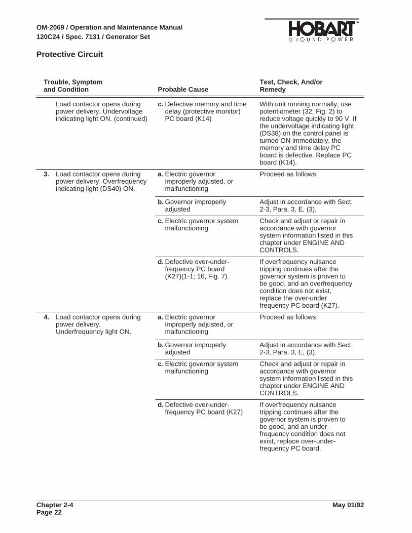
Protective Circuit
Trouble, Symptom Test, Check, And/orand Condition Probable Cause Remedy
Load contactor opens duringpower delivery. Undervoltageindicating light ON. (continued)
c. Defective memory and timedelay (protective monitor)PC board (K14)
With unit running normally, usepotentiometer (32, Fig. 2) toreduce voltage quickly to 90 V. Ifthe undervoltage indicating light(DS38) on the control panel isturned ON immediately, thememory and time delay PCboard is defective. Replace PCboard (K14).
3. Load contactor opens duringpower delivery. Overfrequencyindicating light (DS40) ON.
a. Electric governorimproperly adjusted, ormalfunctioning
Proceed as follows:
b. Governor improperlyadjusted
Adjust in accordance with Sect.2-3, Para. 3, E, (3).
c. Electric governor systemmalfunctioning
Check and adjust or repair inaccordance with governorsystem information listed in thischapter under ENGINE ANDCONTROLS.
d. Defective over-under-frequency PC board(K27)(1-1; 16, Fig. 7).
If overfrequency nuisancetripping continues after thegovernor system is proven tobe good, and an overfrequencycondition does not exist,replace the over-underfrequency PC board (K27).
4. Load contactor opens duringpower delivery.Underfrequency light ON.
a. Electric governorimproperly adjusted, ormalfunctioning
Proceed as follows:
b. Governor improperlyadjusted
Adjust in accordance with Sect.2-3, Para. 3, E, (3).
c. Electric governor systemmalfunctioning
Check and adjust or repair inaccordance with governorsystem information listed in thischapter under ENGINE ANDCONTROLS.
d. Defective over-under-frequency PC board (K27)
If overfrequency nuisancetripping continues after thegovernor system is proven tobe good, and an under-frequency condition does notexist, replace over-under-frequency PC board.
OM-2069 / Operation and Maintenance Manual120C24 / Spec. 7131 / Generator Set
Chapter 2-4 May 01/92Page 22
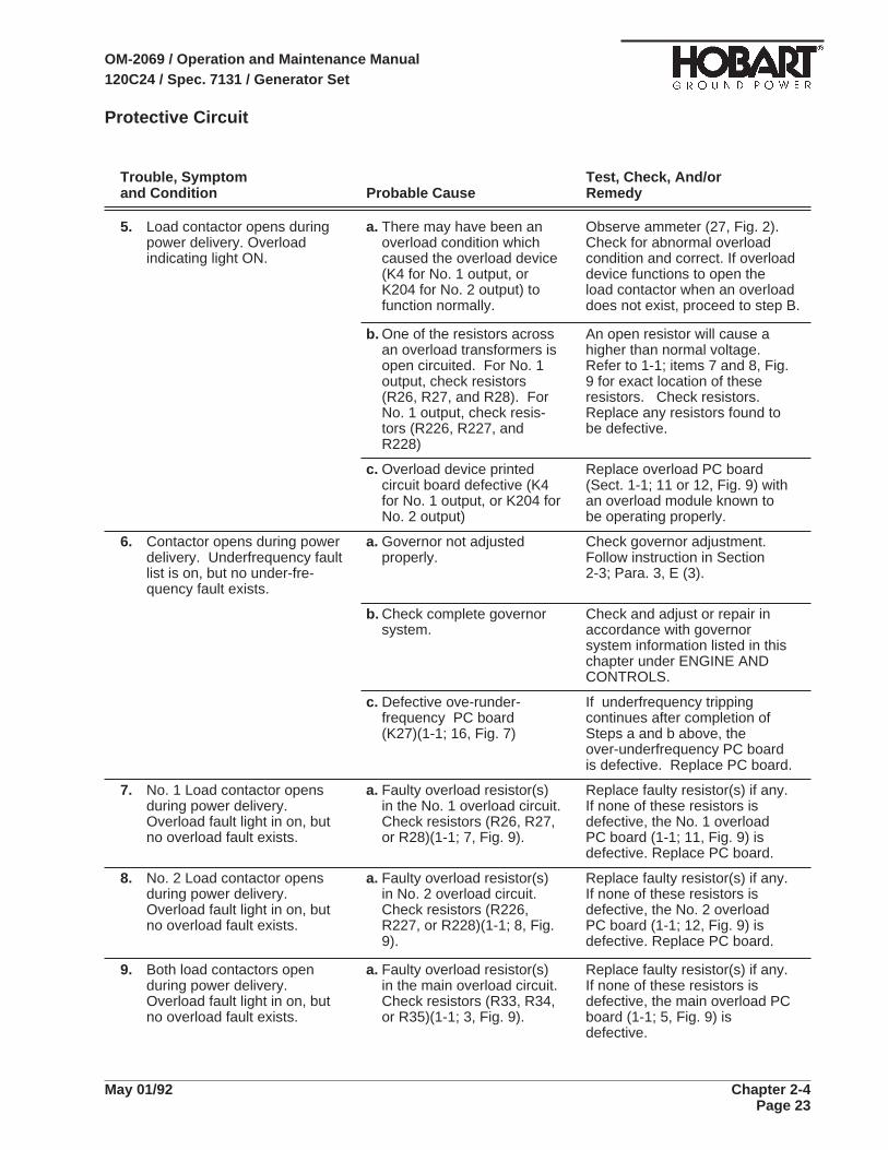
Protective Circuit
Trouble, Symptom Test, Check, And/orand Condition Probable Cause Remedy
5. Load contactor opens duringpower delivery. Overloadindicating light ON.
a. There may have been anoverload condition whichcaused the overload device(K4 for No. 1 output, orK204 for No. 2 output) tofunction normally.
Observe ammeter (27, Fig. 2).Check for abnormal overloadcondition and correct. If overloaddevice functions to open theload contactor when an overloaddoes not exist, proceed to step B.
b. One of the resistors acrossan overload transformers isopen circuited. For No. 1output, check resistors(R26, R27, and R28). ForNo. 1 output, check resis-tors (R226, R227, andR228)
An open resistor will cause ahigher than normal voltage.Refer to 1-1; items 7 and 8, Fig.9 for exact location of theseresistors. Check resistors.Replace any resistors found tobe defective.
c. Overload device printedcircuit board defective (K4for No. 1 output, or K204 forNo. 2 output)
Replace overload PC board(Sect. 1-1; 11 or 12, Fig. 9) withan overload module known tobe operating properly.
6. Contactor opens during powerdelivery. Underfrequency faultlist is on, but no under-fre-quency fault exists.
a. Governor not adjustedproperly.
Check governor adjustment.Follow instruction in Section2-3; Para. 3, E (3).
b. Check complete governorsystem.
Check and adjust or repair inaccordance with governorsystem information listed in thischapter under ENGINE ANDCONTROLS.
c. Defective ove-runder-frequency PC board(K27)(1-1; 16, Fig. 7)
If underfrequency trippingcontinues after completion ofSteps a and b above, theover-underfrequency PC boardis defective. Replace PC board.
7. No. 1 Load contactor opensduring power delivery.Overload fault light in on, butno overload fault exists.
a. Faulty overload resistor(s)in the No. 1 overload circuit.Check resistors (R26, R27,or R28)(1-1; 7, Fig. 9).
Replace faulty resistor(s) if any.If none of these resistors isdefective, the No. 1 overloadPC board (1-1; 11, Fig. 9) isdefective. Replace PC board.
8. No. 2 Load contactor opensduring power delivery.Overload fault light in on, butno overload fault exists.
a. Faulty overload resistor(s)in No. 2 overload circuit.Check resistors (R226,R227, or R228)(1-1; 8, Fig.9).
Replace faulty resistor(s) if any.If none of these resistors isdefective, the No. 2 overloadPC board (1-1; 12, Fig. 9) isdefective. Replace PC board.
9. Both load contactors openduring power delivery.Overload fault light in on, butno overload fault exists.
a. Faulty overload resistor(s)in the main overload circuit.Check resistors (R33, R34,or R35)(1-1; 3, Fig. 9).
Replace faulty resistor(s) if any.If none of these resistors isdefective, the main overload PCboard (1-1; 5, Fig. 9) isdefective.
OM-2069 / Operation and Maintenance Manual120C24 / Spec. 7131 / Generator Set
May 01/92 Chapter 2-4Page 23
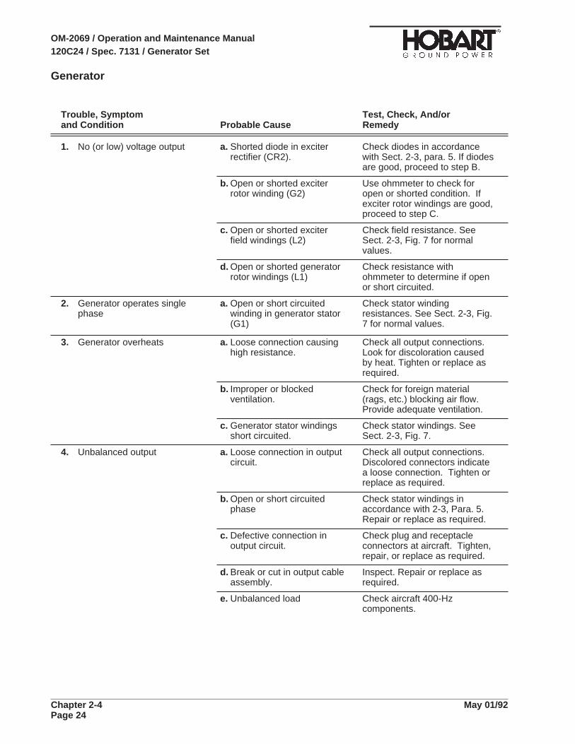
Generator
Trouble, Symptom Test, Check, And/orand Condition Probable Cause Remedy
1. No (or low) voltage output a. Shorted diode in exciterrectifier (CR2).
Check diodes in accordancewith Sect. 2-3, para. 5. If diodesare good, proceed to step B.
b. Open or shorted exciterrotor winding (G2)
Use ohmmeter to check foropen or shorted condition. Ifexciter rotor windings are good,proceed to step C.
c. Open or shorted exciterfield windings (L2)
Check field resistance. SeeSect. 2-3, Fig. 7 for normalvalues.
d. Open or shorted generatorrotor windings (L1)
Check resistance withohmmeter to determine if openor short circuited.
2. Generator operates singlephase
a. Open or short circuitedwinding in generator stator(G1)
Check stator windingresistances. See Sect. 2-3, Fig.7 for normal values.
3. Generator overheats a. Loose connection causinghigh resistance.
Check all output connections.Look for discoloration causedby heat. Tighten or replace asrequired.
b. Improper or blockedventilation.
Check for foreign material(rags, etc.) blocking air flow.Provide adequate ventilation.
c. Generator stator windingsshort circuited.
Check stator windings. SeeSect. 2-3, Fig. 7.
4. Unbalanced output a. Loose connection in outputcircuit.
Check all output connections.Discolored connectors indicatea loose connection. Tighten orreplace as required.
b. Open or short circuitedphase
Check stator windings inaccordance with 2-3, Para. 5.Repair or replace as required.
c. Defective connection inoutput circuit.
Check plug and receptacleconnectors at aircraft. Tighten,repair, or replace as required.
d. Break or cut in output cableassembly.
Inspect. Repair or replace asrequired.
e. Unbalanced load Check aircraft 400-Hzcomponents.
OM-2069 / Operation and Maintenance Manual120C24 / Spec. 7131 / Generator Set
Chapter 2-4 May 01/92Page 24
28.5-V DC Transformer-Rectifier
Trouble, Symptom Test, Check, And/orand Condition Probable Cause Remedy
1. Transformer-rectifierinoperative. Load contactor willNOT close.
a. No input power from ACpower source(generator-set)
Check voltage at contactor (See1-1, Fig.15, item 7). Inputshould be 200-V AC line-to-line.Check voltage from line C toground terminal stud on base. Ifnot approx. 115-V AC, correctfault in T-R ground circuit.
b. Fuse (11, Fig. 3) defective Remove and inspect fuse.Replace if defective.
c. Defective load contactorcontrol switch (8, Fig. 3)
Check voltage at control switchterminal (brown-red wire) whileholding switch in top ONposition. If voltage is notapprox. 115-V AC, replaceswitch.
d. Defective diode-bridgerectifier (17, Fig.3)
Check rectifier DC outputvoltage at output terminals(blue-red wires). Hold contactorcontrol switch in top ONposition while testing. If voltageis not approx. 100-V DC,replace the rectifier.
e. Relay in overvoltagemodule (19, Fig.3) defective
With switch held in ON position,check voltage at terminal T(brown-white wire) on over-voltage module. If voltage isnot approx. 115-V AC, replaceovervoltage module.
f. Defective (open-circuited)thermostatic switch (1-1,Fig.15, item 6)
Check thermostatic switches forcontinuity. If either switch isopen circuited, replace.
g. Coil in load contactor (1-1,Fig.15, item 7) defective
Check load contactor coilresistance between terminalsX1 and X2. (See connectiondiagram at rear of manual).Zero resistance indicates ashort circuit. Very high (infinite)resistance indicates an opencircuit. Replace complete loadcontactor if coil is defective.
OM-2069 / Operation and Maintenance Manual120C24 / Spec. 7131 / Generator Set
May 01/92 Chapter 2-4Page 25
28.5-V DC Transformer-Rectifier
Trouble, Symptom Test, Check, And/orand Condition Probable Cause Remedy
2. Load contactor closesnormally. Opens as soon ascontrol switch is released.
a. Defective control switch (8,Fig. 3)
Place switch in center ONposition. Check voltage at switch(S403) (See connection dia-gram). If there is no voltage,replace switch.
b. Defective resistor (15, Fig.3)
Place control switch (8,Fig. 3) incenter ON position and checkvoltage at resistor (15, Fig. 3)output end (orange-black wire).If resistor is open or shortcircuited, replace.
c. Small contacts in loadcontactor defective
With control switch (8, Fig. 3)held in top ON position to keepload contactor closed, checkvoltage at terminal No.2 (red-white wire) on load contactor. Ifno voltage is indicated, replacecomplete load contactor.
3. Fuse (11, Fig. 3) blows whenload contactor switch isoperated to ON position.
a. Short circuited condition inload contactor holdingcircuit.
Check all leads in this circuit fordamaged insulation andshorting. Check all terminalsand connections for shorting.Repair as required.
b. Defective relay (contactsclosed) in overload module
Disconnect plug connector onoverload module. If contactorwill now close and remainclosed without blowing fuse,replace overload module.
4. Output voltage unsteady.Green indicating light blinks.
a. Voltage regulator on 200-VAC power source requiresadjustment.
Refer to the generator-setinstruction manual. Adjust vol-tage regulator to stabilize out-put voltage. Voltage is steadywhen indicating light ceases toblink.
OM-2069 / Operation and Maintenance Manual120C24 / Spec. 7131 / Generator Set
Chapter 2-4 May 01/92Page 26
28.5-V DC Transformer-Rectifier
Trouble, Symptom Test, Check, And/orand Condition Probable Cause Remedy
5. Normal output voltage (28.5VDC) decreases as loadincreases. Current-limitingswitch in OFF position.
a. Line-drop and current-limiting module (18, Fig. 3),or linedrop currenttransformer defective
Apply a load of 1000A to theT-R. Check input voltage at thecontactor. At a load of 1000A,the input voltage, line-to-line,should be approx. 220-V AC. Ifinput voltage IS that, the line-drop module and current trans-former are OK and the trouble isin the main transformer and heatsink (rectifier) circuit. Proceed tostep B below. If input voltage isonly 200-V AC, the trouble is inthe line-drop module and currenttransformer circuit. Check asfollows:
b. Line-drop currenttransformer defective
Use an ohmmeter to check thetransformer. Replace if open orshort circuited.
c. Line-drop and current-limiting module (18, Fig. 3)defective
If line-drop current transformerchecked good in test b above,replace line-drop andcurrent-limiting module.
d. Defect in transformer andrectifier circuit
If line-drop circuitry was provento be good in check a above,check as follows:
e. Defective transformer Check all input and outputconnections to the transformer.Use an ohmmeter to checktransformer windings. Repair orreplace as required.
f. Defective diodes or diodeconnections
Check all diodes for open orshort circuited condition. Checkall connections. Check instal-lation of diodes (torque values).
NOTE: Torque Westinghousediodes to 25 foot-lbs. TorqueInternational diodes to 13-1/2foot-lbs. (threads lubricated withPenetrox). Check factory forother manufacturer’s diodes.Replace diodes and/or correctinstallation and connections asrequired.
OM-2069 / Operation and Maintenance Manual120C24 / Spec. 7131 / Generator Set
May 01/92 Chapter 2-4Page 27

28.5-V DC Transformer-Rectifier
Trouble, Symptom Test, Check, And/orand Condition Probable Cause Remedy
6. Overload module does notoperate
a. Module not receiving DCpower.
Check and correct as follows:
b. Fuse (10, Fig. 3) defective Place instrument light switch(12) in ON position. Ifinstrument light does notoperate, check fuse. Replace ifdefective.
c. Defect in DC circuit Check wiring and connectionsfrom DC power source tooverload module. Repair asrequired.
7. Overload module operates toopen load contactor when nooverload exists.
a. An open resistor is allowinghigher than normal voltageto enter the overloadmodule.
Check each resistor. Replaceas required.
OM-2069 / Operation and Maintenance Manual120C24 / Spec. 7131 / Generator Set
Chapter 2-4 May 01/92Page 28

Chapter 3. Overhaul/Major Repair
Section 1. Table of Contents
Section 2 Exciter Rotor
Section 3 Flexible Coupling
Section 4 Generator
Section 5 Transformer-Rectifier
OM-2069 / Operation and Maintenance Manual120C24 / Spec. 7131 / Generator Set
May 01/92 Chapter 3-1Page 1

This page intentionally left blank.
OM-2069 / Operation and Maintenance Manual120C24 / Spec. 7131 / Generator Set
Chapter 3-1 May 01/92Page 2

Section 2. Exciter Armature
1. GeneralThis section provides information and instructions for removal and installation of the exciter armatureused on this generator set. Through design improvements, the exciter and rear main bearing can nowbe removed without removing the generator from the generator set. The name exciter armature refersto the shaft-mounted, revolving three-phase windings of the exciter.
The exciter armature covered by the manual is mounted on the rear portion of the main generatorarmature shaft which extends rearward, beyond the rear generator bearing, into the exciter housing(See Fig. 1). Because of its location on the shaft, the exciter armature must be removed for rear mainbearing replacement. The exciter armature has two 3/8-16 tapped holes in its diode mounting plate toaccommodate pulling it off the shaft.
1. Coupling Key 8. Exciter Armature Assembly
2. Flex Coupling Assembly (Dual ONLY) 9. Exciter Key
3. Generator Housing & Stator Assembly 10. Flex Coupling Assembly (Single ONLY)
4. Armature Assembly 11. Mounting Bracket (Dual ONLY)
5. Exciter Housing & Coils Assembly 12. Front Bearing Retainer (Dual ONLY)
6. Exciter Cover 13. Front Bearing (Dual ONLY)
7. Rear Bearing Retainer
Generator (Top Half Section)
Figure 1
OM-2069 / Operation and Maintenance Manual120C24 / Spec. 7131 / Generator Set
May 01/92 Chapter 3-2Page 1
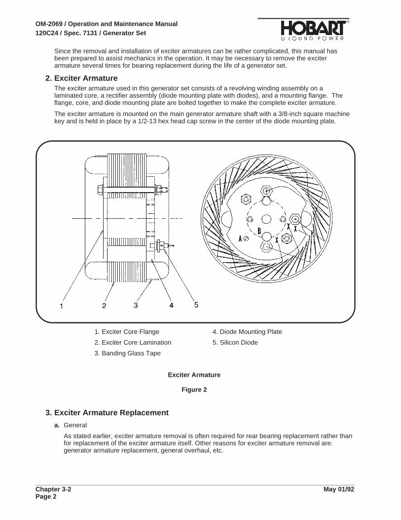
Since the removal and installation of exciter armatures can be rather complicated, this manual hasbeen prepared to assist mechanics in the operation. It may be necessary to remove the exciterarmature several times for bearing replacement during the life of a generator set.
2. Exciter ArmatureThe exciter armature used in this generator set consists of a revolving winding assembly on alaminated core, a rectifier assembly (diode mounting plate with diodes), and a mounting flange. Theflange, core, and diode mounting plate are bolted together to make the complete exciter armature.
The exciter armature is mounted on the main generator armature shaft with a 3/8-inch square machinekey and is held in place by a 1/2-13 hex head cap screw in the center of the diode mounting plate.
3. Exciter Armature Replacement
a. General
As stated earlier, exciter armature removal is often required for rear bearing replacement rather thanfor replacement of the exciter armature itself. Other reasons for exciter armature removal are:generator armature replacement, general overhaul, etc.
1. Exciter Core Flange 4. Diode Mounting Plate
2. Exciter Core Lamination 5. Silicon Diode
3. Banding Glass Tape
Exciter Armature
Figure 2
OM-2069 / Operation and Maintenance Manual120C24 / Spec. 7131 / Generator Set
Chapter 3-2 May 01/92Page 2

b. Tools for Exciter Armature Removal and Installation
In addition to the standard mechanic’s hand tools such as wrenches, etc., you will need only thefollowing items for removing the exciter armature:
A small, lightweight, sling-hammer puller
Two 3/8 - 16 X 5-inch fully-threaded hex-head bolts
A small, lightweight, sling-hammer puller is shown in Figure 3. This tool is necessary for removingthe threaded machine key which tightens the exciter armature on the generator armature shaft. Youmay have such a puller in your equipment. If not, Figure 3 also illustrates components anddimensions for fabricating such a tool. Sling-hammer pullers are also commercially available.Instructions for using tool are provided in Paragraph e, (1)
Once the threaded machine key is removed, No other special tools are required for removing theexciter from the generator shaft. This can be done using two 3/8 - 16 X 5-inch fully-threadedhex-head bolts. Instructions for doing this are provided in Paragraph e, (2).
c. Conditions for Exciter Removal
The mechanics performing the work must decide upon the best and most convenient method ofremoving the exciter armature. If the exciter armature is being replaced, then the work may beperformed without removing the generator from the machine. In a great majority of cases, exciterremoval will be for the replacement of the rear bearing. This operation can also be accomplishedwithout removing the generator. Replacement of the front bearing requires removal of the generatorfrom the unit.
1. Stud, 1/4-28 UNF 2A, Grade 5 or 8 ONLY 4. Rod, 1/2" Round, CR Steel
2. Adapter, 3/4" Round CR Steel 5. Hammer, 2" Round, CR Steel
3. Nut, 1/2-13 Hex, Steel (3 required) 6. Washer, Flat, 1/2" Steel
Sling-Hammer Puller
Figure 3
OM-2069 / Operation and Maintenance Manual120C24 / Spec. 7131 / Generator Set
May 01/92 Chapter 3-2Page 3

d. Preparation for Exciter Armature Removal
(1) Remove louvered exciter cover from end canopy.
(2) Remove exciter housing cover as required. Remove the 1/2-13 cap screw which holds theexciter armature on the generator shaft.
(3) Refer to Figures 1 and 2. Disconnect the two rectifier-to-generator field leads. One lead with aring type terminal is attached to the rectifier mounting plate with a screw (“A”, Fig. 2) and theother lead goes into a splice type connector with three other leads (“X”, Fig. 2) coming from theexciter armature windings. Cut the leads at the connector for removal of the one field lead. Cutas close as possible to the connection as to preserve lead length for reconnection later duringexciter armature installation.
(4) EXERCISE CARE to prevent damage to leads. Remove kinks in the two generator leads asmuch as possible before starting removal operation.
e. Exciter Armature Removal
(1) Removing the Threaded Key with Sling-Hammer Puller
Refer to Figure 4 for location of threaded machine key. Attachment of the assembled puller tothe key in one operation is not recommended because the weight and bulk of the assemblymake threading the 1/4 inch stud into the key rather clumsy. This could result in cross-threadingand damage to key and stud. It is safer and easier to attach as follows:
a. Thread stud (1, Fig. 4) into adapter (2) until it bottoms, then thread this assembly (1) and (2)into key until stud bottoms in key threads. Tighten securely.
b. If hammer (5) and rod (4) are not already assembled, thread one nut (3) onto adapter end ofrod (4). Thread rod into adapter until it bottoms, then tighten nut securely against adapter.Slide hammer (5) onto rod and install washer (6) and two nuts (3). Thread nuts onto rod untilboth nuts are full threaded, then lock together.
Be very careful during removal process (slide-hammering) to avoid injury tohands.
Exercise care to prevent breaking or damaging stud.
c. Position hammer at adapter end of rod.
d. Quickly move hammer to outer end of rod with a rapid, slinging motion. HOLD the hammerthrough the entire motion. If hammer is allowed to slide free on the rod, the stud could beDAMAGED or BROKEN.
e. Repeat steps (c) and (d) as required to loosen key, then remove key and slide-hammer puller.
f. After key is removed, apply penetrating oil in the armature and shaft keyways.
WARNING
CAUTION
OM-2069 / Operation and Maintenance Manual120C24 / Spec. 7131 / Generator Set
Chapter 3-2 May 01/92Page 4

(2) Removing the Exciter Armature
Leads may be damaged if armature is turned too far in either direction.
Attempt to loosen exciter armature on shaft by rotating it slightly back and forth. If armaturecannot be loosened by hand, use two 3/8 - 16 X 5-inch hex-head bolts as shown in Figure 5 toforce the exciter armature off the shaft. Turn each of the two screws a few turns at a time intothe threaded holes of the diode mounting plate until the exciter armature is sufficiently loosenedfrom the shaft to be removed from it by hand. Remove it slowly from the shaft and at the sametime observe the following CAUTION.
Pay close attention to field leads while pulling exciter armature from shaft. MakeCERTAIN that the leads stay in the 1/2" keyway. One mechanic should watchthem constantly while another operates the puller. Make certain that leads donot catch and be sure that they slide smoothly through hole (“B”, Fig. 2)Straighten leads and remove kinks as required to avoid damage to insulation.
CAUTION
CAUTION
Location of Exciter Armature Machine Key
Figure 4
OM-2069 / Operation and Maintenance Manual120C24 / Spec. 7131 / Generator Set
May 01/92 Chapter 3-2Page 5

4. Installing the Exciter Armature
a. Preparation for Exciter Armature Installation
(1) Clean generator shaft and exciter armature bore. Remove all rust, corrosion, etc.
(2) Make CERTAIN that the leads are tucked into the 1/2" keyway, which is opposite from the 3/8"keyway in the generator armature shaft.
(3) Route the revolving field leads (step 2 above) through exciter armature hole (“B”, Fig. 2), whichis opposite the keyway.
(4) Align armature keyway with key in shaft and start armature on shaft.
b. Exciter Armature Installation
(1) If the exciter armature-to-generator shaft fit is such that the exciter armature may be pushed onby hand, push it on very slowly while another mechanic carefully watches and pulls field leadsthrough hole in the exciter armature diode mounting plate. Continue installation until the diodemounting plate contacts the end of the generator shaft. If the exciter armature cannot be pushedon by hand, use a 1/2 - 13 X 5-inch hex-head bolt and 1/2 - 13 nut as shown in Figure 6 to pullthe exciter armature onto the generator shaft. Put the exciter armature on slowly and at thesame time pull field leads through hole (“B”, Fig. 2) in the diode mounting plate. Screw the nutonto the bolt until it is near the head of the bolt. Insert the bolt through the hole in the center ofthe diode mounting plate as far as it will go, and screw it into the 1/2 - 13 threaded hole in theend of the armature shaft. Screw the 1/2 - 13 nut up against the diode mounting plate. Continueturning the nut until the diode mounting plate contacts the end of the generator shaft, just as isshown in the lower portion of Figure 6. After installation, remove the 1/2 - 13 bolt and nut.
Removing Exciter Armature from Generator Armature Shaft
Figure 5
OM-2069 / Operation and Maintenance Manual120C24 / Spec. 7131 / Generator Set
Chapter 3-2 May 01/92Page 6
(2) Connect the two generator field leads to the exciter armature as follows:
a. Connect lead with ring type terminal with screw provided to the rear mounting plate (“A”, Fig.2).
b. Connect the other field lead to the three leads coming off of the exciter armature windings(“X”, Fig. 2). Use parallel splice connector, crimp and solder for a good connection.
c. Insulate with sleeving material or wrap with electrical tape.
(3) Install the Machine Key
a. Clean the machine key thoroughly. All mounting surfaces must be free of rust, corrosion, oil,grease, etc.
b. Apply LOCQUIC primer, No. 47-56 grade T to SIDES of machine key. Do not overprime. Athin film is best. Allow to dry three to four minutes.
c. Apply a thin coating of LOCTITE, No. 242 adhesive to SIDES of keyways in shaft andarmature. Be certain to remove any excess from mounting surfaces on shaft and bore ofarmature.
NOTE: Application of “Loctite” is to compensate for any looseness in machine key and keyway (up to0.005 inch). Manufacturers of LOCTITE and other recommended products are listed below.
When exciter armature removal is for the replacement of bearings and no kit is involved, be surethat LOCTITE No. 242 is recommended, which is a milder adhesive than that recommended inthe manual.
When kits are involved, the correct grade of LOCTITE is included in the Kit.
The application of NEVER-SEEZ to the shaft and armature bore is NOT recommended becausethere is a danger that it may mix with and contaminate the LOCTITE. Application ofNEVER-SEEZ will be at the customer’s risk. LOCTITE can lose its adhesive and tighteningproperties if contaminated by rust preventatives, oil, or other lubricants and antirust products.
d. d. Apply LOCTITE, No. 242 to SIDES of new type threaded machine key. A thin film 0.005 to0.010 inch thick is adequate and desirable.
e. e. Ensure keyways in the generator armature shaft and exciter armature are aligned.
f. f. Insert UNTHREADED end of key in keyways, then tap lightly until threaded end is flushwith end of shaft.
(4) Secure the exciter armature on generator shaft with the 1/2-13 cap screw.
Allow at least 6 hours for complete cure and set up of Loctite before operatingmachine.
Recommended Products Manufacturers
• “LOCQUIC” No. 47-56, Primer Grade T
• “LOCTITE” No. 40-31, Retaining Compound, Manufactured by Loctite Corporation,Newington, Connecticut 06111
• “NEVER-SEEZ” No. NSBT-8 (8 oz. can), Manufactured by Never-Seez CompoundCorporation, Broadview, Illinois 60153
• “NOCO10" Varnish No. T-211 (clear, air dry), Manufactured by Sterling Division ofReichhold Chemical Incorporated, Marysville, Pennsylvania 17053
CAUTION
OM-2069 / Operation and Maintenance Manual120C24 / Spec. 7131 / Generator Set
May 01/92 Chapter 3-2Page 7

Installating the Exciter Armature
Figure 6
OM-2069 / Operation and Maintenance Manual120C24 / Spec. 7131 / Generator Set
Chapter 3-2 May 01/92Page 8

OM-2069 I Operation and Maintenance Manual 12OC24 I Spec. 7131 I Generator Set
GROUND POWER
Section 3A. Single Bearing Flexible Coupling
1. General This manual provides basic instructions for removal, s&vice and installation of a single bearing generator flexible coupling assembly, with fan attached, manufactured by Hobart Brothers Company as Part Number 281702. This assembly is illustrated in Figure 1, The primary function of this assembly is to couple a Hobart generatoiset to a diesel engine. The flexible coupling assembly compensates for slight misaligment between the engine and the generator, due to manufacturing tolerances. A split taper bushing secures the coupling to the generator’s armature shaft. (See Fig. 5).
REAR VIEW SIDE VIEW
Coupling Assembly Single
Bearing Generator
Part No. 281702
Figure 1
2. Coupling Screws (Routine Coupling Maintenance)
Failure to verify proper coupling screw installation may result in coupling failure and damage to the equipment.
If the generator set is functioning properly, servicing the coupling assembly will be essentially limited to checking the screws which attach the flexible coupling to the engine flywheel of the generator set. These screws should be checked periodically to make certain that: (1) screws of proper type, length, and hardness are installed, (2) that the threads of the screws are not stripped, and (3) that they are torqued properly. Proceed as follows to check coupling screws.
May 01/92 Chapter 3-3A Page 1

OM-2069 I Operation and Maintenance Manual 12OC24 I Spec. 7131 I Generator Set
GROUND POWER
a. Refer to Figure 2. HoWa short iron bar through the generator housing against the fan blades of the fan and coupling assembly to block the armature against clockwise rotation. Do this carefully to avoid damaging the fan blades.
b. Use a long-handled, reversible ratchet drive fitted with a 5/16-inch Allen wrench to remove one coupling screw. Examine the screw and washers. Screws specified for this coupling are Hobart Part No. 283130, which are socket-head, self-locking 3/8 - 16 X 3/4 inch long. The vibration-proof washers are Hobart Part No. 283459, which must be installed in pairs with their cam faces together.
NOTE: Use of the proper coupling screws and washers for replacement is very important. Replacement screws and washers MUST be those specified above, torqued to 45 foot-pounds (61 Nm). There is NO ACCEPTABLE SUBSTITUTE for these screws or washers.
c. Check the threads of the screw for stripping and replace it if the threads are stripped. If the screw is not stripped, reinstall it and torque it to 45 foot-pounds (61 Nm).
d. Repeat the steps a, b, and c above for the remaining seven screws.
Access to Coupling Screws (for removal and installation)
Figure 2
3. Disassembly Removal of the flexible coupling is required for servicing the generator armature, generator bearings, or the coupling itself. To remove the coupling, for any reason, it is necessary to separate the engine and generator. Many mechanics preferto remove the engine and generator as an assembly,‘and then separate them. Others may prefer to remove the engine or the generator separately to reach the coupling. However, seperating the engine and generator while they are installed in the ground power unit is VERY DIFFICULT because of the limited working space.
During removal DO NOT cut any cables or wires. Disconnect cables or wires if/as necessary and tag them for reassembly.
a. Separate Engine and Generator
(7) Remove the sheet metal cover from around the generator housing.
(2) Install a lifting eye with l/2-13 threads in the rear-most tapped hole on top of the generator housing, and attach a hoist to it. Lifting eyes are available from Hobart as Part Number CTWll6A.
Chapter 3-3A Page 2
May 01192

OM-2069 I Operation and Maintenance Manual 12OC24 I Spec. 7131 I Generator Set
(3) Use a long-handled, reversible ratchet drive fitted with a 5/16-inch Allen wrench to remove the screws which attach the flexible coupling disk to the engine flywheel.
(4) Support the rear of the engine with a jack.
(5) Remove the bolts and shock mounts attaching the generator housing to the frame.
(6) Remove the bolts attaching the generator housing to the engine flywheel housing.
(7) Separate the generator from the engine with a hoist and move it to a clear working area.
b. Remove Coupling Assembly
(7) Refer to Figure 3. Usinga socket wrench, remove all three of the 3/8-l 6 screws (3) that secure the bushing (1) to the hub of the fan and coupling assembly.
(2) To separate the bushing from the hub, lubricate two of the 3/8-16 screws and insert them’into the threaded holes (4) in the bushing. With socket wrench, screw these screws into the bushing such that the bushing pops loose from the hub.
(3) Using a 3/16-inch Allen wrench, loosen the set screw (6) in the bushing to release pressure on the key (5).
(4) When the bushing (1) is loose in the hub, use a mallet to GENTLY tap the,~bushing out of the hub.
(5) Slide the coupling assembly off the shaft and remove the key (5).
(6) Using a 5/16-inch Allen wrench, remove the screws and washers which attach the flexible disks to the hub.
(7) Inspect the coupling assembly components carefully as follows:
a. Check for deformed fan blades and damage to the disk.
b. Check hub and split bushing for cracks, evidence of galling, and rust pits, Light rust is permissible on the split bushing and the tapered bore of the hub.
c. Check the flexible coupling disks for warping, cracks, or worn mounting holes.
d. Check the screws and washers which attach the flexible disks to the hub. The screws are Hobart Part No. 283130, which are socket-head, self-locking 3/8 - 16 X 3/4 inch long. If they are cracked, stretched, or have stripped threads, replace them. The vibration-proof washers are Hobart Part No. 283459, which must be installed in pairs with their cam faces together.
SIDE VIEW
FRONT VIEW
1. Bushing
2. Split.
3. Mounting holes (3)
4. Tapped holes (2)
5. Key
6. Setscrew
7. Tapped setscrew hole
Split Taper Bushing
Figure 3
May 01/92 Chapter 3-3A Page 3

OM-2069 I Operation and Maintenance Manual 12OC24 I Spec. 7131 I Generator Set HORAW
GROUND POWER
NOTE: Use of the proper coupling screws and washers for replacement is very important. Replacement screws and washers MUST be those specified above, torqued to 45 foot-pounds (61 Nm). There is NO ACCEPTABLE SUBSTITUTE for these screws or washers.
e. Check the shaft for any damage or deformation where the coupling was mounted on it.
4. Coupling Service When ordering coupling kits or other parts from your Hobart Brothers Company Distributor, be sure to include all pertinent information from the unit’s identification plate: Specification No., Model No., and unit rating.
If you have any questions concerning your Hobart Power Systems Group equipment, you are invited to contact our Service Department by mail, telephone or FAX.
Write: Hobart Brothers Company Airport Systems Group Service Department 1177 Trade Square East Troy, Ohio 45373 U.S.A
In U.S.A. Call: (800) 422-4166 (800) 422-4177
From Foreign Countries, Call: (513) 332-5050 (Parts) (513) 332-5060 (Service)
Fax: (513) 332-5121
A replacement coupling kit is available from your Hobart Brothers Company Distributor. This kit provides a replacement coupling assembly with attaching hardware and installation instructions. The Part Number for this kit is 283554. This kit is illustrated in Figure 4.
Coupling Asssnbly\
/ Hardwrre Package Bolts Yachlne Key
Replacement Coupling Kit
Part No. 283554
Figure 4
Chapter 33A Page 4
May 01/92

OM-2069 I Operation and Maintenance Manual 12OC24 I Spec. 7131 I Generator Set
5. Coupling Installation
GROUND POWER
Improper installation of the coupling assembly can result in serious damage to the equipment. Follow these installation instructions exactly. I
a. Cleaning
Refer to Figure 5. It is VERY IMPORTANT that the shaft, the bore and the outside of the split bushing, and the tapered inside of the hub be thoroughly CLEANED FREE OF DIRT AND GRIT.
Do not lubricate any of the surfaces listed above. Lubrication of these surfaces can cause the coupling to fail and damage the generator set. Slight traces of rust are permissible only on the bushing, but nothing else. I
b. Assembly
(1) Using a 5/16-inch Allen wrench, attach the four flexible disks to the coupling hub with the socket-head, self-locking 3/8 - 16 X 3/4 inch screws (Hobart Part No. 283130) and the 3/8-inch vibration-proof washers (Hobart Part No. 283459). The washers must be installed in pairs with their cam faces together, and the screws must be torqued to 45 foot-pounds (61 Nm).
(2) Position armature shaft in generator housing so that the generator fields and stator core are aligned, and the exciter fields and exciter armature core are aligned. The engine end of the armature shaft should be 2 inches from the face (not the seat flange) of the generator housing.
(3) Install the key in the keyway of the armature shaft
(4) Place the bushing in the hub of the fan and coupling assembly such that the keyway of the bushing lines up with the keyway in the hub.
(5) Install the coupling assembly on the armature shaft over the installed key, pushing it on until the engine side of the flexible disks are approximately l-5/8 inch from the face (not the seat flange) of the generator housing.
Make certain that only the screws are lubricated, and that no lubricant is
y bushino. permitted to get inside the bushing where the armature shaft will enter the
I
(6) Lubricate the three 3/8-16 X 314 screws SPARINGLY and start them into the three (unthreaded) holes finger-tight.
(7) Tighten the 3/8-16 X 314 screws alternately and evenly as follows:
a. Set a torque wrench to 30 foot-pounds (47 N-m) and tighten all three 3/8-l 6 screws to that value. As illustrated in Figure 2, insert and hold a short iron bar through the fan housing against the fan blades of the fan and coupling assembly to block the coupling against clockwise rotation. Do this carefully to avoid damaging the fan blades. Note that as these screws are tightened, the coupliing hub, along with the fan and flexible disks, will move toward the rear of the generator.
b. Repeat step (a)above until 3/8-16 screws can no longer be tightened.
(8) Measure the distance from the engine side of the flexible disks to the face (not the seat flange) of the generator housing. THIS DISTANCE MUST BE I-I/2-INCH!
(9) If the I-l/2-inch distance is not achieved, loosen the three screws in step (7), relocate the coupling on the armature shaft, and repeat steps (7) and (8) until the distance is achieved.
May 01/92 Chapter 33A Page 5
OM-2069 I Operation and Maintenance Manual 12OC24 I Spec. 7131 I Generator Set HonAm
GROUND POWER
(10) tJ;F a 3/16-inch Allen wrench, tighten the set screw in the bushing to apply pressure on the
6. Reassemble Engine and Generator
screws and washers is very important. Failure to use as outlined below, can result in coupling failure
Screws specified for this coupling are Hobart Part No. 283130, which are socket-head, self-locking 318 - 16 X 3/4 inch long. The vibration-proof washers are Hobart Part No. 283459, and must be installed in pairs with their cam faces together. These screws and washers are included in the coupling kit.
I a. Using a hoist, align the generator housing flange with the flange on the engine flywheel housing and
insert two of the attaching screws, one on each side of the flange. Start the screws into the tapped holes in the flywheel housing just enough to ensure thread engagement. DO NOT TIGHTEN.
b. Insert the proper coupling screws and washers through the flexible disc at the front of the coupling and into the flywheel.
c. Turn all of the coupling screws into the tapped holes in the flywheel, finger tight. DO NOT tighten with a wrench.
d. Insert all remaining attaching screws (two installed in Step a, above) through the generator flange, engaging the tapped holes in the flywheel housing, and tighten them all securely.
e. Refer to Figure 2. Insert and hold a shoti iron bar through the housing against the fan blades of the fan and coupling assembly to block the armature against clockwise rotation, Do this carefully to avoid damaging the fan blades. Torque all of the coupling screws to 45 foot-pounds (61 N-m). Be sure the flexible disks are all seated evenly into the seat of the flywheel.
7. Run-in and Periodic Check a. Mount the engine-generator assembly in a suitable test area and operate it for a 2-hour run-in.
b. Shut down the engine after 2 hours and re-torque all coupling screws to 45 foot-pounds (61 N-m) to compensate for normal torque relaxation.
c. Return the unit to normal service.
d. After 200 hours of operation, check all coupling screws with a torque wrench set at 45 foot-pounds (61 N-m).
e. Return the unit to normal service.
f. After each additional 2,000 hours of operation (or every year) recheck all coupling screws to maintain the same torque value.
Chapter 3-3A Page 6
May 01/92

OM-2099/ Operation and Maintenance Manual 12OC24 I Spec. 7131 I Generator Set
i+oBAm GROUND POWER
3Ai-1s~x 3/4” (8 requIredI
Split Bushing Yountlng Bolt/ 3/n-16 x 3/4’ (3 requlre’dl
Armature Shaft
Assembly Procedure Illustration
Figure 5
May OlI92 Chapter 33A
Page 7

OM-2069 I Operation and Maintenance Manual 12OC24 I Spec. 7131 I Generator Set HORAW
GROUND POWER
Chapter 3-3A Page 6
May Oil92

Section 3B. Dual Bearing Flexible Coupling
1. GeneralThis manual provides basic instructions for removal, service and installation of a flexible couplingassembly, with fan attached, manufactured by Hobart Brothers Company as Part Number 281701.This assembly is illustarted in Figure 1. The primary function of this assembly is to couple a HobartGenerator Set to a Diesel engine. The flexible coupling assembly compensates for slight misaligmentbetween the engine and the generator, due to manufacturing tolerances. A tapered bushing and hubsecures the coupling to the generator shaft.
a. Coupling Bolts
FAILURE TO VERIFY PROPER COUPLING BOLT INSTALLATION MAYRESULT IN COUPLING FAILURE AND DAMAGE EQUIPMENT.
NOTE: It is not necessary to separate the engine and generator if all that is being done is checking andreplacing the coupling bolts. Removal of the perforated cover over the fan housing provides access to thecoupling bolts for removal and installation.
(1) Refer to Figure 2. Use a long-handled, reversible ratchet drive with a 15/16-inch hex socketwrench to remove one coupling bolt. Measure its length. If it is 3-1/2 inches (89 mm) long,reinstall it and torque ALL three of the coupling bolts to 85 foot-pounds (115 N-m).
(2) Use of the proper coupling bolts for replacement is VERY IMPORTANT. Replacement boltsMUST be 5/8-11, SAE Grade 5, hex-head bolts, 2-3/4 inches (70 mm) long, reinstall it andtorque ALL of the coupling bolts to 85 foot-pounds (115 N-m). Only three bolts must be usedand they must be equally spaced. There is NO ACCEPTABLE SUBSTITUTE for these bolts.Hobart Brothers stocks these bolts as Part Number W-11102-18.
2. DisassemblyRemoval of the flexible coupling is required for servicing the generator armature, generator bearings, orthe coupling itself. To remove the coupling, for any reason, it is necessary to separate the engine andgenerator. On self-propelled units, many mechanics prefer to remove the engine and generator as anassembly, and then separate them. Others may prefer to remove the engine or the generatorseparately to reach the coupling. However, separating the engine and generator while they areinstalled in the Ground Power Unit is VERY DIFFICULT because of the limited working space.
During removal DO NOT cut any cables or wires. Disconnect and tag them for reassembly.
a. Separate Engine and Generator
(1) Install a lifting eye with 1/2-13 threads in the tapped hole on top of the generator frame, andattach a hoist to it. Lifting eyes are available from Hobart as Part Number CTW-116A.
(2) Remove the fan housing cover from the generator fan housing.
(3) Refer to Figure 2. Use a 15/16-inch socket ona long-handled ratchet and remove the threehex-head bolts which attach the coupling to the spacer ring.
NOTE: These bolts were torqued to 85-foot pounds (115 N-m) at installation. Therefore it may benecessary to block the armature against counterclockwise rotation to remove them.
(4) Remove bolts attaching the generator fan housing to the engine flywheel housing.
(5) Separate the generator from the engine with a hoist and move it to a clear working area.
CAUTION
OM-2069 / Operation and Maintenance Manual120C24 / Spec. 7131 / Generator Set
May 01/92 Chapter 3-3BPage 1
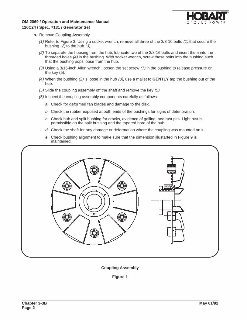
b. Remove Coupling Assembly
(1) Refer to Figure 3. Using a socket wrench, remove all three of the 3/8-16 bolts (1) that secure thebushing (2) to the hub (3).
(2) To separate the housing from the hub, lubricate two of the 3/8-16 bolts and insert them into thethreaded holes (4) in the bushing. With socket wrench, screw these bolts into the bushing suchthat the bushing pops loose from the hub.
(3) Using a 3/16-inch Allen wrench, loosen the set screw (7) in the bushing to release pressure onthe key (5).
(4) When the bushing (2) is loose in the hub (3), use a mallet to GENTLY tap the bushing out of thehub.
(5) Slide the coupling assembly off the shaft and remove the key (5).
(6) Inspect the coupling assembly components carefully as follows:
a. Check for deformed fan blades and damage to the disk.
b. Check the rubber exposed at both ends of the bushings for signs of deterioration.
c. Check hub and split bushing for cracks, evidence of galling, and rust pits. Light rust ispermissible on the split bushing and the tapered bore of the hub.
d. Check the shaft for any damage or deformation where the coupling was mounted on it.
e. Check bushing alignment to make sure that the dimension illustarted in Figure 9 ismaintained.
Coupling Assembly
Figure 1
OM-2069 / Operation and Maintenance Manual120C24 / Spec. 7131 / Generator Set
Chapter 3-3B May 01/92Page 2

3. Coupling ServiceWhen ordering coupling kits or other parts from your Hobart Brothers Company Distributor, be sure toinclude all pertinent information from the unit’s identification plate: Specification No., Model No., andunit rating.
If you have any questions concerning your Hobart Power Systems Group equipment, you are invitedto contact our Service Department by mail, telephone or FAX.
Write: Hobart Brother CompanyAirport Systems GroupService Department1177 Trade Square EastTroy, Ohio 45373U.S.A.
In U.S.A. Call: (800) 422-4166 (Parts)(800) 422-4177 (Service)
From Foreign Countries Call: (513) 332-5050 (Parts)(513) 332-5060 (Service)
FAX: (513) 332-5121
Access to Coupling Bolts
(for removal and installation)
Figure 2
OM-2069 / Operation and Maintenance Manual120C24 / Spec. 7131 / Generator Set
May 01/92 Chapter 3-3BPage 3

a. Coupling Kits
A replacement coupling kit is available from your Hobart Brothers Company Distributor. This kitprovides a replacement coupling assembly with attaching hardware and installation instructions.The Part Number for this kit is 283555. This kit is illustarted in Figure 4.
Hub andBushing
Figure 3
b. Bushing Kit
A bushing kit is available from Hobart Brothers Company for replacing the rubber bushing only inthe coupling assembly. However, it should be noted that the finished coupling assembly must bebalanced to 1/2 inch-ounce (360 mg-m) minimum, which may be a problem in the field. If bushingreplacement only is required, the kit part number is 480290. Each kit contains the required numberof bushings, a container of lubrication, and installation instaructions.
Bushing Replacement
To replace bushings only, proceed as follows:
(1) Press out ALL old bushings.
(2) Refer to Figure 5. Clean each bushing socket thoroughly, removing all traces of old rubber. DONOT scratch or deform the bore of the bushing socket.
(3) Shake the container of lubricant vigorously and poor it into a small shallow dish.
(4) Roll a bushing in the lubricant to coat it thoroughly, and press it into a socket (from thechamfered end) to the dimension shown in Figure 5: 3/32 +/- 1/64th-inch (2.381 +/- 0.397 mm)from the face of the bushing socket to the face of the bushing, on the side opposite the fanblades.
(5) Repeat step 4 until all three new bushings are installed. The three bushings must be equallyspaced.
(6) Balance the complete coupling assembly to 1/2 inch-ounce (360 mg-m) minimum.
OM-2069 / Operation and Maintenance Manual120C24 / Spec. 7131 / Generator Set
Chapter 3-3B May 01/92Page 4
4. Coupling Installation
CAUTION: IMPROPER INSTALLATION OF THE COUPLING ASSEMBLY CANRESULT IN SERIOUS DAMAGE TO THE EQUIPMENT. FOLLOW THESEINSTALLATION INSTRUCTIONS EXACTLY.
a. Cleaning
Refer to Figure 6. It is VERY IMPORTANT that the shaft, the bore and the outside of the splitbushing, and the tapered inside of the hub be thoroughly CLEANED FREE OF DIRT AND GRIT.
CAUTION: DO NOT LUBRICATE ANY OF THE SURFACES LISTED ABOVE.LUBRICATION OF THESE SURFACES CAN CAUSE THE COUPLING TOFAIL AND DAMAGE THE GENERATOR SET. SLIGHT TRACES OF RUSTARE PERMISSIBLE ON THE SURFACES MARKED “X”, BUT NOTHING ELSE.
b. Assembly
(1) If an adaptor ring must be replaced, remove the 8 bolts which secure it to the flywheel. Discardthe old adaptor ring and bolts. Install the new adaptor ring Part No. 386612 using the new boltsPart No. 402789-3 (3/8-16 X 2-1/2 Socket Head Cap Screws).
Torque all 8 bolts to 45 foot-pounds (61 N-m).
The new adaptor ring and bolts are included in the kit.
(2) Refer to Figure 3. Assemble the split bushing (2) into the hub (3).
CAUTION: MAKE CERTAIN THAT ONLY THE BOLTS ARE LUBRICATED,AND THAT NO LUBRICANT IS PERMITTED TO GET INSIDE THE BUSHINGWHERE THE ARMATURE SHAFT WILL ENTER THE BUSHING.
(3) Lubricate the three 3/8-16 bolts SPARINGLY and start them into the three (unthreaded) holesfinger-tight.
(4) Slide the generator armature as far as it will go toward the fan housing. Block the armature tomaintain this forward position throughout the installation procedure. Block the armature with awooden block or wedge, being careful not to damage any components of the armature or exciter.
CAUTION: DO NOT ROTATE THE ARMATURE WHILE THIS BLOCK ISINSTALLED.
(5) Install the key in the shaft keyway.
(6) Place the bushing in the hub over the installed key (5), and install the coupling assembly on theshaft, with the split bushing approximately flush with the end of the shaft.
(7) Using a 3/16-inch Allen wrench, tighten the set screw (6) in the bushing (2) to apply pressure onthe key (5).
CAUTION
CAUTION
CAUTION
CAUTION
OM-2069 / Operation and Maintenance Manual120C24 / Spec. 7131 / Generator Set
May 01/92 Chapter 3-3BPage 5
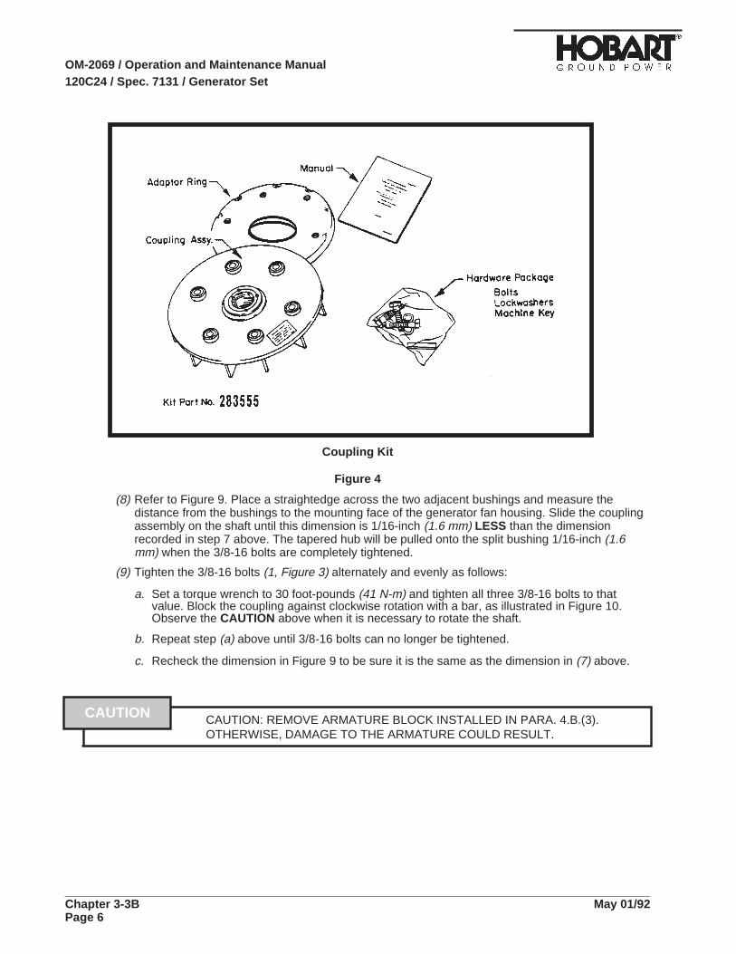
Coupling Kit
Figure 4
(8) Refer to Figure 9. Place a straightedge across the two adjacent bushings and measure thedistance from the bushings to the mounting face of the generator fan housing. Slide the couplingassembly on the shaft until this dimension is 1/16-inch (1.6 mm) LESS than the dimensionrecorded in step 7 above. The tapered hub will be pulled onto the split bushing 1/16-inch (1.6mm) when the 3/8-16 bolts are completely tightened.
(9) Tighten the 3/8-16 bolts (1, Figure 3) alternately and evenly as follows:
a. Set a torque wrench to 30 foot-pounds (41 N-m) and tighten all three 3/8-16 bolts to thatvalue. Block the coupling against clockwise rotation with a bar, as illustrated in Figure 10.Observe the CAUTION above when it is necessary to rotate the shaft.
b. Repeat step (a) above until 3/8-16 bolts can no longer be tightened.
c. Recheck the dimension in Figure 9 to be sure it is the same as the dimension in (7) above.
CAUTION: REMOVE ARMATURE BLOCK INSTALLED IN PARA. 4.B.(3).OTHERWISE, DAMAGE TO THE ARMATURE COULD RESULT.
CAUTION
OM-2069 / Operation and Maintenance Manual120C24 / Spec. 7131 / Generator Set
Chapter 3-3B May 01/92Page 6

Bushing Installation
Figure 5
OM-2069 / Operation and Maintenance Manual120C24 / Spec. 7131 / Generator Set
May 01/92 Chapter 3-3BPage 7
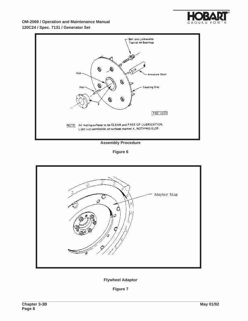
Assembly Procedure
Figure 6
Flywheel Adaptor
Figure 7
OM-2069 / Operation and Maintenance Manual120C24 / Spec. 7131 / Generator Set
Chapter 3-3B May 01/92Page 8

Engine Measurement
Figure 8
Measuring from Mounting Face to Bushing
Figure 9
OM-2069 / Operation and Maintenance Manual120C24 / Spec. 7131 / Generator Set
May 01/92 Chapter 3-3BPage 9

5. Reassemble Engine and Generator
CAUTION: USE OF THE PROPER COUPLING BOLTS IS VERY IMPORTANT.FAILURE TO USE THE PROPER BOLTS, AS OUTLINED BELOW, CANRESULT IN COUPLING FAILURE AND DAMAGE TO THE GENERATOR SET.
Use 5/8-11 SAE GRADE 5 hex-head bolts, 2-3/4 inches (70 mm) long. These bolts are included in thecoupling kit, and are available from Hobart Brothers as Part No. W-11102-18.
a. Insert the proper coupling bolts with lockwashers through the bushings from the FAN side of thecoupling.
b. Using a hoist, align the generator fan housing flange with the flange on the engine flywheel housingand insert two of the attaching bolts, one on each side of the flange. Start the bolts into the tappedholes in the flywheel housing just enough to ensure thread engagement. DO NOT TIGHTEN.
c. Turn all of the coupling bolts into the tapped holes in the flywheel, finger tight. DO NOT tighten witha wrench.
d. Insert all remaining attaching bolts (two installed in Step B, above) through the generator flange,engaging the tapped holes in the flywheel housing, and tighten them all securely.
e. Refer to Figure 2. Insert a long piece of wood through the fan housing to block the armature againstclockwise rotation. Torque all of the coupling bolts to 85 foot-pounds (115 N-m).
6. Run-in and Periodic Check
a. Mount the engine-generator assembly in a suitable test area and operate it for a 2-hour run-in.
b. Shut down the engine after 2 hours and re-torque all coupling bolts to 85 foot-pounds (115 N-m) tocompensate for normal torque relaxation.
c. Return the unit to normal service.
d. After 200 hours of operation, check all coupling bolts with a torque wrench set at 85 foot-pounds(115 N-m).
e. Return the unit to normal service.
f. After each additional 2,000 hours of operation (or every year) recheck all coupling bolts to maintainthe same torque value.
CAUTION
OM-2069 / Operation and Maintenance Manual120C24 / Spec. 7131 / Generator Set
Chapter 3-3B May 01/92Page 10

Section 4. Generator Assembly
1. GeneralThis section provides information and instructions for removal and installation of the generatorassembly used on Specification 7130 generator sets.
2. Procedure for Generator Assembly Removal
a. Procedure for Gaining Access to the Generator
Before starting removal of the generator assembly, position the front section ofthe generator set under a hoist which is capable of lifting at least 940 pounds(426 kg), which is the weight of the generator assembly.
To gain access to the generator assembly, refer to Figure 1 and Connection Diagram 283122 inChapter 5 and proceed as follows:
(1) Disconnect battery leads from the generator set.
(2) If a transformer-rectifier (T-R) assembly is mounted on the generator set, remove T-R assembly.Remove both T-R assemblies if two are mounted on the generator set.
(3) Disconnect clearance light wires from the top canopy (1).
(4) Remove top canopy panel (1). Do this by removing the 1/4 - 20 x 1/2 tap-tite screws which areused to mount it to the frame of the generator set.
(5) Disconnect plug connectors (P11 and P12) from receptacles (3) on the side of control box.
(6) Disconnect harness wires from the terminal block (TB-1) inside the control box.
(7) Remove the control box (2). Do this by removing the 1/4 - 20 keps nuts which are used to mountit to the frame of the generator set.
(8) Remove wires from terminal block TB-4.
(9) Remove the control box support panel (4) by removing the 1/4 - 20 x 3/4" self-tap screws whichare used to mount it to the frame of the generator set
(10) Remove left side panel (5) from the generator set. Do this by removing the 1/4 - 20 x 1/2 tap-titescrews which are used to mount it to the frame of the generator set.
(11) Disconnect output cables from load contactors (8), loosen cable clamps (9), and remove thecables from the generator set.
(12) Remove the right front door (6) from the generator set. Do this by removing the 1/4 - 20 x 1/2tap-tite screws which are used to mount it to the frame of the generator set.
(13) Disconnect stator leads and control cable from the power module (7).
(14) Remove power module assembly (7). Do this by removing the 1/4 - 20 keps nuts which areused to mount it to the frame of the generator set.
(15) Remove front canopy panel (10). Do this by removing the 1/4 - 20 x 1/2 tap-tite screws whichare used to mount it to the frame of the generator set.
(16) Remove generator wrapper (11). Do this by removing the 1/4 - 20 x 1-1/4 tap-tite screws whichare used to mount it to the frame of the generator set.
WARNING
OM-2069 / Operation and Maintenance Manual120C24 / Spec. 7131 / Generator Set
May 01/92 Chapter 3-4Page 1
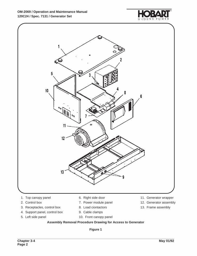
1. Top canopy panel 6. Right side door 11. Generator wrapper
2. Control box 7. Power module panel 12. Generator assembly
3. Receptacles, control box 8. Load ciontactors 13. Frame assembly
4. Support panel, control box 9. Cable clamps
5. Left side panel 10. Front canopy panel
Assembly Removal Procedure Drawing for Access to Generator
Figure 1
OM-2069 / Operation and Maintenance Manual120C24 / Spec. 7131 / Generator Set
Chapter 3-4 May 01/92Page 2

b. Removing the generator Assembly
(1) Remove the four 5/8 - 11 x 4-1/2 bolts which mount the generator assembly (12) to the frame(13) of the generator set.
(2) Support the engine at the flywheel housing with wooden blocks.
(3) Using the hoist, support the generator assembly as shown in Figure 2. For lifting con- venience,a 1/2 - 13 threaded hole is drilled in the top of the generator housing. Insert a 1/2 - 13 eye-bolt inthe hole and attach the hoist chain to the eye-bolt as shown in Figure 2.
(4) Remove the 5/8 - 11 x 4-1/2 bolts generator-to-flywheel coupling bolts.
(5) Detach the generator housing from the engine. Do this by removing the six M10 - 1.5 x 35 metricbolts.
(6) Carefully lift and separate the generator from the engine.
3. Installing a Generator AssemblyInstallation of a generator assembly is essentially a reversal of the procedure for removal of thegenerator assembly: the re-mounting of the generator assembly to the frame of the generator set, andthe re-mounting of the assemblies that were removed to gain access to the generator assembly. Toinstall the generator assembly, refer to Connection Diagram 283122, and proceed as follows:
Generator Lifting Arrangement
Figure 2
OM-2069 / Operation and Maintenance Manual120C24 / Spec. 7131 / Generator Set
May 01/92 Chapter 3-4Page 3
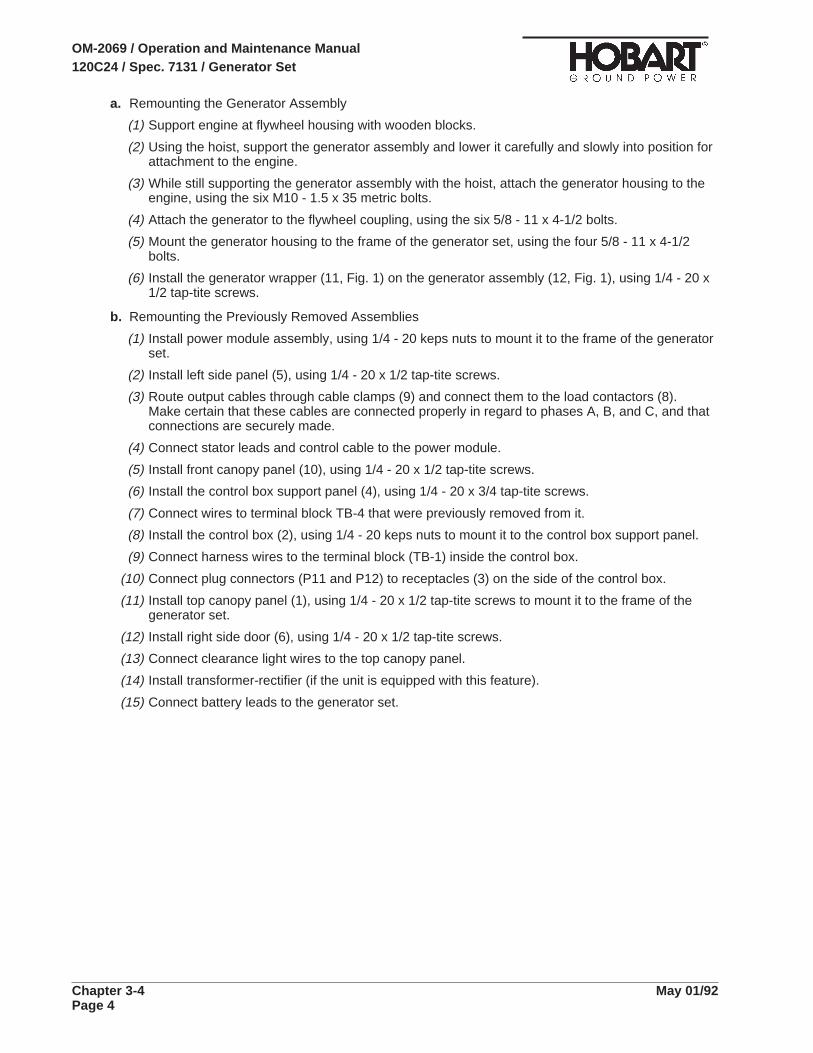
a. Remounting the Generator Assembly
(1) Support engine at flywheel housing with wooden blocks.
(2) Using the hoist, support the generator assembly and lower it carefully and slowly into position forattachment to the engine.
(3) While still supporting the generator assembly with the hoist, attach the generator housing to theengine, using the six M10 - 1.5 x 35 metric bolts.
(4) Attach the generator to the flywheel coupling, using the six 5/8 - 11 x 4-1/2 bolts.
(5) Mount the generator housing to the frame of the generator set, using the four 5/8 - 11 x 4-1/2bolts.
(6) Install the generator wrapper (11, Fig. 1) on the generator assembly (12, Fig. 1), using 1/4 - 20 x1/2 tap-tite screws.
b. Remounting the Previously Removed Assemblies
(1) Install power module assembly, using 1/4 - 20 keps nuts to mount it to the frame of the generatorset.
(2) Install left side panel (5), using 1/4 - 20 x 1/2 tap-tite screws.
(3) Route output cables through cable clamps (9) and connect them to the load contactors (8).Make certain that these cables are connected properly in regard to phases A, B, and C, and thatconnections are securely made.
(4) Connect stator leads and control cable to the power module.
(5) Install front canopy panel (10), using 1/4 - 20 x 1/2 tap-tite screws.
(6) Install the control box support panel (4), using 1/4 - 20 x 3/4 tap-tite screws.
(7) Connect wires to terminal block TB-4 that were previously removed from it.
(8) Install the control box (2), using 1/4 - 20 keps nuts to mount it to the control box support panel.
(9) Connect harness wires to the terminal block (TB-1) inside the control box.
(10) Connect plug connectors (P11 and P12) to receptacles (3) on the side of the control box.
(11) Install top canopy panel (1), using 1/4 - 20 x 1/2 tap-tite screws to mount it to the frame of thegenerator set.
(12) Install right side door (6), using 1/4 - 20 x 1/2 tap-tite screws.
(13) Connect clearance light wires to the top canopy panel.
(14) Install transformer-rectifier (if the unit is equipped with this feature).
(15) Connect battery leads to the generator set.
OM-2069 / Operation and Maintenance Manual120C24 / Spec. 7131 / Generator Set
Chapter 3-4 May 01/92Page 4

Section 5. Transformer-Rectifier Repair
1. GeneralRepair of the transformer-rectifier (T-R) will consist primarily of parts replacement. The only rotatingparts in the unit are the two cooling fans and the only other moving parts are switches, relays,rheostats, and meters.
2. Removal and InstallationIt is suggested that if extensive repairs are to be made to a T-R which is mounted on a mobile machinesuch as a self-propelled generator-set, etc., the unit be removed and placed on a workbench or othersupporting structure.
a. Removal Procedures
Make certain input power cannot reach the T-R. lethal electrical shock hazardexists.
(1) Disconnect DC cables at output terminals.
(2) Open the control panel and disconnect three AC input leads at the contactor (1-1; 7, Fig. 15).
If the mobile generator set is to be operated while t-r is removed, disconnectalso the T-R supply leads at the generator set terminal board.
(3) Disconnect plug connector P403. See connection diagrams at the rear of this manual.
(4) Remove the mounting screws which attach the T-R to the mobile unit.
(5) Attach a lifting hoist and carefully lift the T-R. Lifting holes are accessible when plug buttons areremoved in sides of the top. Be sure all leads are free and do not become entangled. Move theunit to a workbench or clear working area.
b. Installation Procedures
(1) Attach a lifting hoist to the T-R and carefully lower it to its mounting position on the generator set.Again, be sure all leads are free and do not become entangled.
(2) Remount the T-R to its mounting position on the generator set, using the same mounting screwswhich were removed preciously.
(3) Reconnect plug connector P403.
(4) Reconnect three AC input leads at the contactor
(5) Reconnect DC cables at output terminals.
WARNING
WARNING
OM-2069 / Operation and Maintenance Manual120C24 / Spec. 7131 / Generator Set
May 01/92 Chapter 3-5Page 1

3. Parts Replacement
a. Access
All parts which might normally require replacement are easily accessible by opening the front andrear hinged access panels. Output diodes are accessible by removing the housing top.
b. Parts Removal
(1) Modules
The overload, and line-drop and current-limiting modules are equipped with quick-disconnectlead connectors so that input and output lead identification for these units is not a problem.Identify and mark leads to the overvoltage module before removal.
(2) Miscellaneous parts
a. When removing a defective part, carefully disconnect any wire leads that are connected tothe defective part, after marking the leads so that they can be properly reconnected when thepart is replaced.
b. Carefully remove the defective part, after removing any other part(s) as necessary for gainingaccess to the defective part.
c. Parts Installation
Check new parts physically and electrically, if possible, before installation.
(1) Position part carefully in mounting location and attach securely.
(2) Be certain all leads are connected properly. If any doubt exists, refer to the applicableconnection diagram located at the rear of this manual.
(3) If it is necessary to replace any of the diodes mounted on the heat sinks (1-1; 3 and 13, Fig. 15)torque the Westinghouse diodes to 25 foot-lbs., or the International Rectifier diodes to 13-1/2foot-lbs.. For other manufacturer’s diodes, contact the factory at the address given in theIntroduction of this manual for installation torque requirements.
NOTE: The torque value for these diodes is a critical requirement. The torque requirements vary widelyamong the various suppliers of these diodes and, in addition, the suppliers change. Therefore, itis impracticable to provide torque values for all diodes in this manual.
(4) If the bus bars (1-1; 2 and 13, Fig. 15) and aluminum nuts which secure them are removed forany reason, they must be torqued in place at installation to 20 to 25 lb.-feet (27 to 34 N-m). Themounting face of each aluminum nut and the threads on the bus bars must be coated withPenetrox or an equivalent heat sink compound at installation.
d. Fan Installation
If fan blades rotate in the wrong direction, reverse connection of any TWO fan input leads.
4. WorkmanshipPerform all repairsin accordance with good electrical repair practices. All interconnecting leadconnections to components must be made with proper wire terminations. Route all leads neatly andsecure with ties, clamps, etc.
5. Connection DiagramsA complete set of connection diagrams are included in the rear of this manual. When reconnectingwires to a component, use the connection diagrams to make certain connections are made correctlly.
OM-2069 / Operation and Maintenance Manual120C24 / Spec. 7131 / Generator Set
Chapter 3-5 May 01/92Page 2
Chapter 4. Illustrated Parts List
Section 1. Introduction
1. GeneralThe illustrated Parts List identifies, describes, and illustrates main assemblies, subassemblies, anddetail parts of a Diesel Engine-Generator Set manufactured by Hobart Brothers Company, PowerSystems Division, Troy, Ohio.
2. PurposeThe purpose of this list is to provide parts identification and descriptive information to maintenance andprovisioning personnel for use in provisioning, requisitioning, purchasing, storing, and issuing of spareparts.
3. ArrangementChapter 4 is arranged as follows:
Section 1 - Introduction
Section 2 - Manufacturer’s Codes
Section 3 - Parts List
Section 4 - Numerical index
4. Explanation of Parts List
a. Contents
The parts list contains a breakdown of the equipment into assemblies, subassemblies, and detailparts. All parts of the equipment are listed except:
(1) Standard hardware items (attaching parts) such as nuts, screws, washers, etc., which areavailable commercially.
(2) Bulk items such as wire, cable, sleeving, tubing, etc., which are also commercially available.
(3) Permanently attached parts which lose their identity by being welded, soldered, riveted, etc., toother parts, weldments, or assemblies.
b. Parts List Form
This form is divided into six columns. Beginning at the left side of the form and proceeding to theright, columns are identified as follows:
(1) FIGURE-ITEM NO. Column
This column lists the figure number of the illustration applicable to a particular parts list and alsoidentifies each part in the list by an item number. These item numbers also appear on theillustration. Each item number on an illustration is connected to the part to which it pertains by aleader line. Thus the figure and item numbering system ties the parts lists to the illustrations andvice versa. The figure and index numbers are also used in the numerical index to assist the userin finding the illustration of a part when the part number is known.
OM-2069 / Operation and Maintenance Manual120C24 / Spec. 7131 / Generator Set
May 01/92 Chapter 4-1Page 1

(2) HOBART PART NUMBER Column
All part numbers appearing in this column are Hobart numbers. In all instances where the part isa purchased item, the vendor’s identifying five-digit code and his part number will appear in the“NOMENCLATURE” column. Vendor parts which are modified by Hobart will be identified assuch in the “NOMENCLATURE” column. In case Hobart does not have an identifying partnumber for a purchased part, the “HOBART PART NUMBER” column will reflect “No Number”and the vendor’s number will be shown in the “NOMENCLATURE” column. Parts manufacturedby Hobart will reflect no vendor or part number in the “NOMENCLATURE” column.
(3) AIRLINE PART NUMBER Column
This column will appear blank. Eleven character spaces have been reserved for filling in partnumbers that may have been assigned by indvidual airlines.
(4) NOMENCLATURE Column
The item identifying name appears in this column. The indenture method is used to indicate itemrelationship. Thus, components of an assembly are listed directly below the assembly andindented one space. Vendor codes and part numbers for purchased parts are also listed in thiscolumn when applicable. Hobart modification to vendor items is also noted in this column.
(5) EFF (Effective) Column
This column is used to indicate the applicability of parts to different models of equipment. Whenmore than one model of equipment is covered by a parts list, there are some parts which areused on only one model. This column is used for insertion of a code letter A, B, etc., to indicatethese parts and to identify the particular model they are used on. Since this manual covers onlyone generator set specification, this column is not used in this manual.
(6) UNITS PER ASSEMBLY Column
This column indicates the quantity of parts required for an assembly or subassembly in which thepart appears. This column does not necessarily reflect the total used in the complete end item.
OM-2069 / Operation and Maintenance Manual120C24 / Spec. 7131 / Generator Set
Chapter 4-1 May 01/92Page 2 Revised

Section 2. Manufacturer’s Codes
1. Explanation of Manufacturer’s (Vendor) Code ListThe following list is a compilation of vendor codes with names and addresses for suppliers ofpurchased parts listed in this publication. The codes are in accordance with the Federal Supply Codesfor Manufacturer’s Cataloging Handbook H4-1, and are arranged in numerical order. Vendor codes areinserted in the nomenclature column of the parts list directly following the item name and description. Incase a manufacturer does not have a code, the full name of the manufacturer will be listed in thenomenclature column.
Code Vendor’s Name & Address
00779 AMP Inc.P.O. Box 3608Harrisburg, PA 17105
01428 Superior Ball Joint Corporation1202 S. Quality DriveP.O. Box 227New Haven, IN 46774
01843 American Bosch MarketingDiv. of Ambac Industries Inc.3664 Main StreetSpringfield, Mass 01107
02231 Anchor Rubber Company840 S. Patterson BoulevardDayton, OH 45402
03924 STRATOFLEX, Inc.Fort Wayne, IN
04009 Arrow-Hart & Hegeman Electric Co.103 Hawthorne StreetHartford, CT 06106
04713 Motorola Inc.Semiconductor Products DivisionPhoenix, AZ
05277 Westinghouse Electric Corp.Semi & Conductor DepartmentYoungwood, PA 15697
08108 Lamp Industry for use withIndustry Designations andAbbreviations for Lamps
09393 Rochester Gauges, Inc.P.O. Box 20180Dallas, TX 75220
Code Vendor’s Name & Address
14101 Sprague Electric Company300 W. National RoadVandalia, OH 45377
15434 Cummins Engine Company1000 Fifth StreetColumbus, IN 47201
15605 Cutler-Hammer1391 W. St. Paul AvenueMilwaukee, WI 53233
16238 Lord Mfg. Co. Inc.Sterling RoadSouth Lancaster, Mass 01561
19220 Eberhard Manufacturing Company2734 Tennyson RoadCleveland, OH 44104
20038 ESB Inc. Philadelphia Pa. 2Penn Center PlazaP.O. Box 8109Philadelphia, PA 19101
21335 Fafnir Bearing CompanyDiv. of Textron37 Booth StreetNew Britain, CT 06050
21585 Farr Company2301 E. RosecransEl Segundo, CA 90245
24248 South Chester CorporationSouth Company Division3d Street & Governor Printz Blvd.Lester, PA 19113
OM-2069 / Operation and Maintenance Manual120C24 / Spec. 7131 / Generator Set
May 01/92 Chapter 4-2Page 1
Code Vendor’s Name & Address
26992 Hamilton Watch CompanyColumbia & West End AvenuesLancaster, Pennsylvania 17604
27191 Cutler-Hammer Inc.Power Distribution & Control Division4201 N. 27th StreetMilwaukee, Wisconsin 53216
28520 Heymarr Mfg. Co.1000 Michigan AvenueKenilworth, New Jersey 07033
30327 Imperial Eastman Corporation6300 W. Howard StreetChicago, IL 60648
31356 J-B-T Instruments, Inc.424 Chapel StreetP.O. Box 1818New Haven, CT 06508
35738 Charles Lentz & Sons3330 N. BroadPhiladelphia, PA 19140
41197 Madine Manufacturing Company1500 Dekoven AvenueRacine, Wisconsin 53401
44655 Ohmite Manufacturing Company3601 W. Howard StreetSkokie, Illinois 60076
49234 Protectoseal Company1920 S. WesternChicago, Illinois 60608
57448 Stephens & Adamson Mfg. Company275 Ridgeway AvenueAurora, Illinois 60507
57733 Stewart-Warner Corporation1826 Diversey ParkwayChicago, Illinois 60614
58849 Syntron Company1938 Block StreetHomer City, Pennsylvania 15748
5970 The Thomas & Betts Company36 Butler StreetElizabeth, New Jersey 07207
Code Vendor’s Name & Address
60741 Triplett Electrical Instrument Co.Harmon RoadBluffton, Ohio 45817
61112 Turner Corporation821 Park AvenueSycamore, Illinois 60178
66295 Wittek Manufacturing Company4309 W. 24thChicago, Illinois 60623
70485 Atlantic India Rubber Works Inc.571 W. Polk StreetChicago, Illinois 60607
71400 Bussmann Mfg. Divisionof McGraw & Edison Company2536 W. University StreetSt. Louis, Missouri 63017
71744 Chicago Miniature Lamp Works4433 Ravenswood AvenueChicago, Illinois 60640
74559 Carling Electric, Inc.505 New Park AvenueHartford, Connecticut 06110
74063 Hartman Electrical Manf. Co.P.O. Box 8Mansfield, Ohio 44901
74400 John W. Hobbs CorporationAsh Street & Yale BoulevardSpringfield, Illinois 62703
75358 Knape & Vogt Mfg. Company2700 Oak Industrial DriveGrand Rapids, Michigan 49505
75418 Kysor Industrial Corporation1100 W. Wright StreetCadillac, Michigan 49601
77342 American Machine & Foundry Co.Potter & Brumfield Division1200 E. BroadwayP.O. Box 522Princeton, Indiana 47570
78225 Stant Manufacturing Company Inc.1620 ColumbiaConnersville, Indiana 47331
OM-2069 / Operation and Maintenance Manual120C24 / Spec. 7131 / Generator Set
Chapter 4-2 May 01/92Page 2

Code Vendor’s Name & Address
78553 Tinnerman Products Inc.8700 Brookpark RoadCleveland, Ohio 44129
79470 The Weatherhead Company300 East 131st StreetCleveland, Ohio 44108
81074 Holub Industries, Inc.413 DeKalb AvenueSycamore, Illinois 60178
81082 Electric Auto Lite CompanyLebanon RoadCincinnati, Ohio 45241
81860 Barry ControlsDivision of Barry Wright Corp.700 Pleasant StreetWatertown, Massachusetts 02172
81861 Burton Electrical Engineering Co.Maryland & El Segundo Blvd.El Segundo, California 90246
84970 Sharkes Tarzian Inc.Broadcast Equipment DivisionE. Hillside DriveBloomington, Indiana 47401
85925 Electro Mechanical Instrument Co., Inc.8th and Chestnut StreetPerkasie, Pennsylvania 18944
89110 AMP Incorporated155 Parks StreetElizabethtown, Pennsylvania 17022
89373 United States Rubber CompanyDetroit, Michigan
89616 United States Rubber CompanyConsumer Industrial andPlastics Products Div.Mishawaka, Indiana 46544
90201 Mallary Capacitor Company3029 East Washington StreetP.O. Box 372Indianapolis, Indiana 46206
90763 United-Carr Inc.4258 N. CiceroChicago, Illinois 60640
Code Vendor’s Name & Address
91637 Dale Electronics, Inc.P.O. Box 609Columbus, Nebraska 68601
91929 Honeywell, Inc.Buildings Controls andComponents GroupMicro Switch DivisionFreeport, Illinois 61032
92242 Willard Mfg. CompanyMiamisburg, Ohio 45342
92563 McGill Manufacturing Company, Inc.Bearing Division907 LafayetteValparaiso, Indiana 46383
95879 Alemite Instrument Division ofStewart-Warner Corporation1826 Diversey ParkwayChicago, Illinois 60614
97576 The Lenz Co.3301 Klepinger RoadP.O. Box 1044Dayton, Ohio 45401
98410 E.T.C. Inc.990 E. 67th StreetCleveland, Ohio 44103
98738 Stewart-Warner ElectronicsDivision of Stewart-Warner Corp.1300 N. Kostnr.Chicago, Illinois 60651
98991 Worcester Valve Company, Inc.16 Parker StreetWorcester, Massachusetts 01610
OM-2069 / Operation and Maintenance Manual120C24 / Spec. 7131 / Generator Set
May 01/92 Chapter 4-2Page 3

This page intentionally left blank
OM-2069 / Operation and Maintenance Manual120C24 / Spec. 7131 / Generator Set
Chapter 4-2 May 01/92Page 4

Section 3. Illustrated Parts List
1. Explanation of Parts List ArrangementThe parts list is arranged so that the illustration will appear on a left-hand page and the applicable partslist will appear on the opposite right-hand page. Unless the list is unusually long, the user will be able tolook at the illustration and read the parts list without turning a page.
2. Symbols and AbbreviationsThe following is a list of symbols and abbreviations used in the parts list:
* - Item not illustrated
A, or AMP - Ampere
AC - Alternating current
AR - As required
DC - Direct current
Fig. - Figure
hd. - Head
hex - Hexagon
Hz - Hertz (cycles-per-second)
I.D. - Inside diameter
IN - Inch
KVA - Kilovolt-ampere
uF - Microfarad
No. - Number
NHA - Next higher assembly
PRV - Peak reverse voltage
PSI - Pounds per square inch
Ref - Reference (the item has been listed previously)
TM - Technical Manual
T-R - Transformer-rectifier
V - Volt (when used as a prefix to a five-digit number, indicates vendor code)
NOTE: An item which does not reflect an index number is a assembly which is not illustrated in itsassembled state, or it is similar (right-hand, left-hand, top, etc.) to an item which is illustrated.
OM-2069 / Operation and Maintenance Manual120C24 / Spec. 7131 / Generator Set
November 23/92 Chapter 4-3Revised Page 1

Generator Set
Figure 1
OM-2069 / Operation and Maintenance Manual120C24 / Spec. 7131 / Generator Set
Chapter 4-3 November 23/92Page 2 Revised

NOMENCLATURE UNITSFIGURE & HOBART AIRLINE PERITEM NO. PART NO. PART NO. 1 2 3 4 5 6 ASSY
1 - 7131-1 GENERATOR SET FOR TRAILER OR REFTRUCK MOUNTING(Optional Trailer Mounting Shown)
1 - 1 No Number . FRAME AND CANOPY ASSEMBLY (See Fig. 2) 11 - 2 No Number . GENERATOR SET without Canopy (See Fig. 3) 11 - 3 283673 . TRAILER PACKAGE (OPTIONAL) 11 - 4 402987 . NAMEPLATE, HOBART 3
* 1 - 5 408665-1 . REFLECTOR, RED 6
* 1 - 6 408665-2 . REFLECTOR, AMBER 8
* NOT ILLUSTRATED
OM-2069 / Operation and Maintenance Manual120C24 / Spec. 7131 / Generator Set
November 23/92 Chapter 4-3Revised Page 3
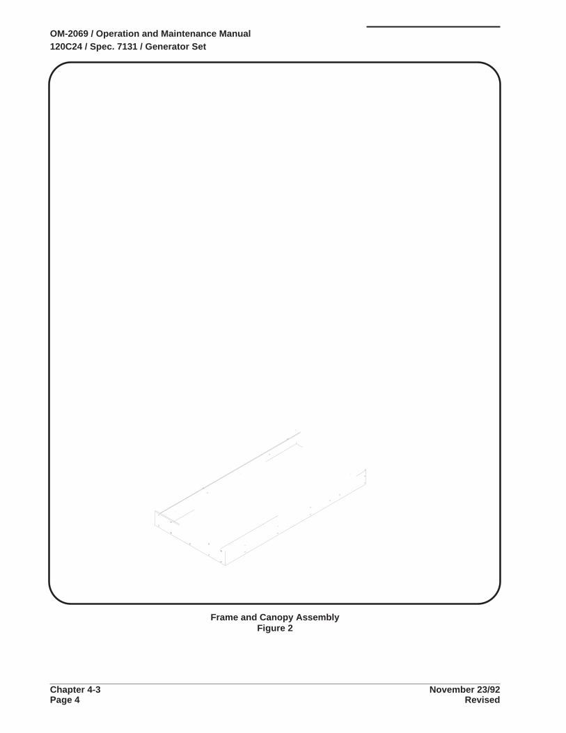
Frame and Canopy AssemblyFigure 2
OM-2069 / Operation and Maintenance Manual120C24 / Spec. 7131 / Generator Set
Chapter 4-3 November 23/92Page 4 Revised

NOMENCLATURE UNITSFIGURE & HOBART AIRLINE PERITEM NO. PART NO. PART NO. 1 2 3 4 5 6 ASSY
2 - NO NUMBER FRAME & CANOPY ASSEMBLY REFSPECIFICATION 7131(For NHA See Fig. 1)
2 - 1 283584 . TANK, FUEL ASSEMBLY 1* 2 - 2 282939 . CAP, FUEL, TANK 1
2 - 3 282747 . PLATE, FRONT, MTG., FRAME ASSY. 12 - 4 282834 . YOKE, LIFTING ASSY. 12 - 5 DDW-155 . EYEBOLT, LIFTING 1
2 - 6 282689 . FRAME MOUNTING ASSEMBLY 1283613 . CANOPY ASSEMBLY 1
2 - 7 283612 . . CANOPY, REAR ASSEMBLY 12 - 8 283645 . . TOP, CANOPY ASSEMBLY 12 - 9 282732-1 . . LIGHTS, CLEARANCE, AMBER 4
2 - 10 283591 . . DOOR, REAR, RIGHT ASSEMBLY 12 - 11 283633 . . PANEL, SUPPORT, DOORS 22 - 12 283588 . . DOOR, RIGHT FRONT, LEFT REAR 22 - 13 283634 . . CANOPY, FRONT ASSEMBLY 12 - 14 283642 . . PANEL, SIDE, LEFT FRONT, UPPER 1
2 - 15 283638 . . PANEL, SIDE, RIGHT, CANOPY ASSEMBLY 12 - 16 282876 . . PANEL, BULKHEAD 12 - 17 282915 . . SUPPORT, CONTROL BOX 12 - 18 283637 . . PANEL, SIDE, RIGHT REAR 12 - 19 283622 . . SUPPORT, REAR CANOPY ASSEMBLY 1
2 - 20 283640 . . PANEL, SIDE, LEFT, REAR 12 - 21 283641 . . PANEL, SIDE, LEFT FRONT, LOWER 1
* 2 - 22 100GH-118 . . HORN, CABLE CLAMP 2* 2 - 23 100GH-121 . . BRACKET, CABLE CLAMP 2* 2 - 24 7J-422-0 . . CLAMP, CABLE 4
* 2 - 25 387859 . . ROD, DOOR HOOK 4* 2 - 26 HJ-129A . . JOINT, BALL 4* 2 - 27 HF-530 . . KNOB, DOOR 1
2 - 28 283647 . . DOOR, ACCESS, RADIATOR ASSEMBLY 12 - 29 401911-20 . . BLOCK, TERMINAL 1
2 - 30 283425 . . LABEL, TERMINAL BLOCK 1* 2 - 31 401923-3 . . CONNECTOR 2* 2 - 32 402037-24 . . GROMMET, RUBBER 2* 2 - 33 402037-14 . . GROMMET, RUBBER 1* 2 - 34 283593 . . DOOR, FRONT, LEFT ASSEMBLY 1
2 - 35 283594 . . . DOOR, LEFT FRONT 12 - 36 283595 . . . DOOR, ACCESS 12 - 37 283598 . . . SEAL, ACCESS DOOR 12 - 38 283599 . . . WINDOW, PLEXIGLASS 12 - 39 283597 . . . HINGE, ACCESS DOOR 1
* NOT ILLUSTRATED
OM-2069 / Operation and Maintenance Manual120C24 / Spec. 7131 / Generator Set
November 23/92 Chapter 4-3Revised Page 5

This page intentionally left blank
OM-2069 / Operation and Maintenance Manual120C24 / Spec. 7131 / Generator Set
Chapter 4-3 November 23/92Page 6 Revised

NOMENCLATURE UNITSFIGURE & HOBART AIRLINE PERITEM NO. PART NO. PART NO. 1 2 3 4 5 6 ASSY
2 - CONTINUED FRAME & CANOPY ASSEMBLY REFSPECIFICATION 7131(For NHA See Fig. 1)
2 - 40 283824 . . . HINGE, ACCESS DOOR 12 - 41 80A-1134 . . . LATCH, ADJUSTABLE, GRIP 22 - 42 283604 . . . HANDLE, ACCESS DOOR 12 - 43 81B-1019 . . . LATCH, T-HANDLE 12 - 44 488307 . . . PLATE, ROD HOLDER 1
2 - 45 488306 . . . BRACKET, DOOR ROD 12 - 46 283647 . . DOOR, ACCESS, RADIATOR 1
OM-2069 / Operation and Maintenance Manual120C24 / Spec. 7131 / Generator Set
November 23/92 Chapter 4-3Revised Page 7

Generator Set Without CanopyFigure 3
OM-2069 / Operation and Maintenance Manual120C24 / Spec. 7131 / Generator Set
Chapter 4-3 November 23/92Page 8 Revised

NOMENCLATURE UNITSFIGURE & HOBART AIRLINE PERITEM NO. PART NO. PART NO. 1 2 3 4 5 6 ASSY
3 - No Number GENERATOR SET WITHOUT CANOPY REF(For NHA See Fig. 1)
3 - 1 No Number . RADIATOR & COOLING SYSTEM GROUP (See Fig. 4) 13 - 2 408773 . ENGINE, DIESEL, CUMMINS MODEL
NO. 88-044-6BTA (See Cummins Parts Catalog) 13 - 3 282866B . PANEL, POWER MODULE (See Fig. 8) 13 - 4 282763 . CONTROL BOX GROUP (See Fig. 9) 1
3 - 5 282883 . AIR CLEANER GROUP (See Fig. 12) 13 - 6 No Number . FRAME AND CANOPY ASSEMBLY (See Fig. 2) 13 - 7 283673 . TRAILER PACKAGE (OPTIONAL) 13 - 8 283613 . CANOPY ASSEMBLY (See Fig. 2)3 - 9 No Number . MUFFLER AND EXHAUST ASSEMBLY (See Fig. 14) 1
* 3 - 10 282852 . MOUNT, ENGINE, LEFT 1* 3 - 11 282853 . MOUNT, ENGINE, RIGHT 1* 3 - 12 480603-3 . MOUNT, SHOCK, GENERATOR 4* 3 - 13 480603-2 . MOUNT, SHOCK, ENGINE 2* 3 - 14 480628 . WASHER, SHOCK MOUNT 6
* 3 - 15 282895 . BATTERY CABLE MTG. ASSEMBLY 1* 3 - 16 282896 . . TRAY, BATTERY 1* 3 - 17 481209-4 . . CABLE, BATTERY, POS. 1* 3 - 18 281871-1 . . BATTERY, 12V., DEKA 1* 3 - 19 181831 . . KIT, HOLD DOWN, BATTERY FRAME 1
* 3 - 20 5CW-2048 . . ROD, BATTERY, SUPPORT 2* 3 - 21 383067-5 . . CABLE, BATTERY, NEG. 1* 3 - 22 W-9407-23 . CABLE, ENGINE TO GROUND 1* 3 - 23 489658-9 . DIODE, SOLENOID ASSEMBLY 1* 3 - 24 181204 . STRAINER, FUEL 1
* 3 - 25 283358 . KIT, GOVERNOR ASSEMBLY (See Fig. 5) 1* 3 - 26 180895 . LINES ASSEMBLY, OIL (See Fig. 6) 1* 3 - 27 283099 . LINES ASSEMBLY, FUEL (See Fig. 7) 1* 3 - 28 281689-6 . GENERATOR GROUP (See Fig. 13) 1* 3 - 29 403782-2 . SWITCH, SHUTDOWN 1
* 3 - 30 W-7814-4 . BUSHING, PIPE 1* 3 - 31 78A-1000 . LABEL, I.D. 1* 3 - 32 79A-1110 . LABEL, OPTION 1* 3 - 33 76B-1148 . LABEL, DIESEL FUEL 1* 3 - 34 430077-2 . LABEL, HANDLING 1
* 3 - 35 486270-26 . LABEL, WARNING, COMP. 1* 3 - 36 HF-2752 . MOUNT, RUBBER 6* 3 - 37 78B-1119-1 . SENDER, WATER TEMP. 1* 3 - 38 282966 . BRACKET, CLAMP, CABLE 2* 3 - 39 283301 . HARNESS, C. BOX TO POWER MODULE 1
* NOT ILLUSTRATED
OM-2069 / Operation and Maintenance Manual120C24 / Spec. 7131 / Generator Set
November 23/92 Chapter 4-3Revised Page 9
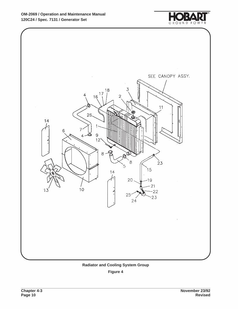
Radiator and Cooling System Group
Figure 4
OM-2069 / Operation and Maintenance Manual120C24 / Spec. 7131 / Generator Set
Chapter 4-3 November 23/92Page 10 Revised

NOMENCLATURE UNITSFIGURE & HOBART AIRLINE PERITEM NO. PART NO. PART NO. 1 2 3 4 5 6 ASSY
4 - No Number RADIATOR & COOLING SYSTEM GROUP REF(For NHA See Fig. 3)
4 - 1 283246 . RADIATOR ASSEMBLY 14 - 2 405743 . CAP, RADIATOR, V78225, NO. AAX-4018 14 - 3 282888 . SUPPORT, RADIATOR ASSEMBLY 14 - 4 W-10869-3 . CLAMP, HOSE, RADIATOR, 2-1/2" 24 - 5 56531 . HOSE, OUTLET, RADIATOR, 2-1/4" 16"
4 - 6 282891 . SHROUD, FAN, TOP 14 - 7 56533 . HOSE, INLET, RADIATOR, 1-3/4" 27"4 - 8 W-10869-5 . CLAMP, HOSE, RADIATOR, 3-1/4" 24 - 9 386751 . CLAMP, HOSE, DRAIN 14 - 10 282892 . SHROUD, FAN, BOTTOM 1
4 - 11 56534 . HOSE, OVERFLOW, 60"4 - 12 56535 . HOSE, DRAIN, 26"4 - 13 283497 . FAN, COOLING, 23" 14 - 14 283832 . GUARD, FAN 24 - 15 56501 . HOSE, LOW PRESSURE 35"
4 - 16 56535 . HOSE 20"4 - 17 W-10893-0 . FITTING, HOSE, SWIVEL, FEMALE 14 - 18 W-10886-3 . CONNECTOR, MALE 14 - 19 W-10869-2 . CLAMP, HOSE 24 - 20 385275 . PIPE, CONNECTING, WATER RETURN 1
4 - 21 402077-4 . ELBOW, 45 DEG., 3/4" 14 - 22 W-10761-1 . NIPPLE, CLOSE, 1" X 3/4" 14 - 23 W-10890-6 . ELBOW, 90 DEG., 3/4" 14 - 24 W-7814-5 . BUSHING, 1/2" X 3/4" 14 - 25 W-10760-1 . NIPPLE, CLOSE, 1" X 1/2" 1
4 - 26 W-10869-14 . CLAMP, HOSE 1* 4 - 27 W-7814-4 . BUSHING, PIPE 2* 4 - 28 283873 . VALVE, RADIATOR DRAIN 1* 4 - 29 400902 . ANTI-FREEZE 5 QT.
* NOT ILLUSTRATED
OM-2069 / Operation and Maintenance Manual120C24 / Spec. 7131 / Generator Set
November 23/92 Chapter 4-3Revised Page 11
Governor Kit Assembly
Figure 5
OM-2069 / Operation and Maintenance Manual120C24 / Spec. 7131 / Generator Set
Chapter 4-3 November 23/92Page 12 Revised
NOMENCLATURE UNITSFIGURE & HOBART AIRLINE PERITEM NO. PART NO. PART NO. 1 2 3 4 5 6 ASSY
5 - 283358 GOVERNOR KIT ASSEMBLY (For NHA See Fig. 4) REF
5 - 1 281881-3 . SENSOR, MAGNETIC PICK-UP 15 - 2 280448 . CONTROLLER, GOVERNOR, ELECTRIC,
MODEL ESD 2120 15 - 3 280447 . GOVERNOR, ACTUATOR, ELECTRIC 15 - 4 84A-1091 . ARM, THROTTLE, GOVERNOR 1
5 - 5 402908 . JOINT, BALL, GOVERNOR LINKAGE,V57448, NO. TF-4Y 2
5 - 6 283462 . ROD, THREADED, 1/4-28 15 - 7 W-11280-3 . NUT, HEX, 1/4-28 45 - 8 181891-1 . BOARD, PC, SPEED CONTROL 1
* 5 - 9 84A-1075 . MOUNT, SHOCK, RUBBER, TECH. PRODUCTSCORP., NO. 50-DURO 4
* 5 - 10 280449 . BRACKET, GOVERNOR, MTG. 15 - 11 283463 . LEVER, THROTTLE 1
* 5 - 12 281751-1 . ADAPTER 1
* 5 - 13 482496-2 . CLAMP 2* 5 - 14 400829-5 . TERMINAL, SPADE 3* 5 - 15 283464 . BRACKET, THROTTLE 1
* NOT ILLUSTRATED
OM-2069 / Operation and Maintenance Manual120C24 / Spec. 7131 / Generator Set
November 23/92 Chapter 4-3Revised Page 13

Pressure Sensing System
Figure 6
OM-2069 / Operation and Maintenance Manual120C24 / Spec. 7131 / Generator Set
Chapter 4-3 November 23/92Page 14 Revised

NOMENCLATURE UNITSFIGURE & HOBART AIRLINE PERITEM NO. PART NO. PART NO. 1 2 3 4 5 6 ASSY
6 - NO NUMBER PRESSURE SENSING SYSTEM REF
6 - 1 78B-1118-1 . SENDER, OIL PRESSURE 16 - 2 W-10750-1 . NIPPLE, CLOSE, 1/8 X 3/4 26 - 3 403809-1 . SWITCH, LOW OIL PRESSURE 16 - 4 W-10119-1 . COUPLING, 1/8" 2
OM-2069 / Operation and Maintenance Manual120C24 / Spec. 7131 / Generator Set
November 23/92 Chapter 4-3Revised Page 15

Fuel Line Assembly
Figure 7
OM-2069 / Operation and Maintenance Manual120C24 / Spec. 7131 / Generator Set
Chapter 4-3 November 23/92Page 16 Revised

NOMENCLATURE UNITSFIGURE & HOBART AIRLINE PERITEM NO. PART NO. PART NO. 1 2 3 4 5 6 ASSY
7 - 283099 FUEL LINE ASSEMBLY REF
7 - 1 W-10886-3 . CONNECTOR, MALE 17 - 2 W-10893-0 . FITTING, HOSE, SWIVEL, FEMALE 27 - 3 W-10869-14 . CLAMP, HOSE 27 - 4 56535 . HOSE, LOW PRESSURE, 3/8 I.D. 30"7 - 5 280990 . TUBE, FUEL LINE 2
7 - 6 181204 . STRAINER, FUEL 17 - 7 W-10886-8 . CONNECTOR, MALE 17 - 8 W-7814 . BUSHING, PIPE 17 - 9 400819-2 . VALVE, SHUTOFF 17 - 10 400818-1 . NIPPLE, HEX, PIPE 1
7 - 12 W-10905-2 . SLEEVE, COMPRESSION 17 - 13 W-10901-2 . NUT, FITTING 17 - 14 78B-1019-3 . FITTING, HOSE, MALE 17 - 15 56534 . HOSE, LOW PRESSURE, 1/4 I.D. 63"7 - 16 W-10893-2 . FITTING, SWIVEL, FEMALE 2
7 - 17 W-10909-1 . FITTING, TEE 17 - 18 W-7814-3 . REDUCER, PIPE 17 - 19 W-10886-1 . CONNECTOR, MALE 2
* 7 - 20 80A-1117 . CLAMP, FILTER 1
OM-2069 / Operation and Maintenance Manual120C24 / Spec. 7131 / Generator Set
November 23/92 Chapter 4-3Revised Page 17

Power Module Panel Assembly
Figure 8
OM-2069 / Operation and Maintenance Manual120C24 / Spec. 7131 / Generator Set
Chapter 4-3 November 23/92Page 18 Revised

NOMENCLATURE UNITSFIGURE & HOBART AIRLINE PERITEM NO. PART NO. PART NO. 1 2 3 4 5 6 ASSY
8 - 282866B POWER MODULE PANEL ASSEMBLY REF(For NHA See Fig. 3)
8 - 1 283127 . PANEL, POWER MODULE 18 - 2 404402-8 . RESISTOR, 50 OHM, 20 WATT 38 - 3 1CZ-148 . TRANSFORMER, CURRENT LINE DROP &
OVERLOAD V14831, NO. E-6170 128 - 4 404402-9 . RESISTOR,12.5 OHM, 20 WATT 3
8 - 5 HF-2752 . MOUNT, SHOCK, RUBBER 28 - 6 404402-1 . RESISTOR, 16.6 OHM, 20 WATT 68 - 7 283195 . BRACKET, MTG., CURRENT TRANSFORMER 128 - 8 282130-1 . CONTACTOR, LINE, 3-POLE 28 - 9 A-25 . WASHER, INSULATING 14
8 - 10 AW-626 . BUSHING, INSULATING, NEUTRAL 28 - 11 DW-1704 . BUSHING, INSULATING, E-F 28 - 12 84A-1075 . MOUNT, SHOCK, RUBBER 128 - 13 404065-2 . RECTIFIER, SIICON 28 - 14 387738A . BOARD, PC, OVERLOAD, ASSEMBLY 3
8 - 15 401564-3 . HOUSING, SOCKET 38 - 16 180593-2 . CAPACITOR, 0.1 MFD, 500 VAC, ASSEMBLY 38 - 17 283128 . HARNESS, RECEPTACLE, ASSEMBLY 18 - 18 401911-20 . BLOCK, TERMINAL 18 - 19 282089-2 . DIODE, FLYBACK 1
* 8 - 20 403069 . TERMINAL, QUICK CONNECT 2* 8 - 21 400828-2 . TIE, WIRE, PLASTIC 2
8 - 22 AW-626 . BUSHING, INSULATING, A-B-C 38 - 23 283193 . BRACKET, MTG., BOTTOM, C.T. 18 - 24 76A-1131 . TUBING, Z-FLEX, 1/2 DIA (Six 4.5" pieces) 2.25’8 - 25 283192 . BRACKET, MTG., TOP, C.T 1
* 8 - 26 283197 . CABLE, ASSEMBLY, POWERW-9350-302 (No. 101) “A” Stator Terminal to “T1" No. 1 Contactor 1W-9350-301 (No. 102) ”B" Stator Terminal to “T2" No. 1 Contactor 1W-9350-201 (No. 103) ”C" Stator Terminal to “T3" No. 1 Contactor 1W-9350-224 (No. 104) “A” Stator Terminal to “T1" No. 2 Contactor 1
W-9350-205 (No. 105) “B” Stator Terminal to “T2" No. 2 Contactor 1W-9350-305 (No. 106) “C” Stator Terminal to “T3" No. 2 Contactor 1W-9350-301 (No. 110) “N” Stator Terminal to “N” Terminal to ground 1
* NOT ILLUSTRATED
OM-2069 / Operation and Maintenance Manual120C24 / Spec. 7131 / Generator Set
November 23/92 Chapter 4-3Revised Page 19
Control Box Group
Figure 9
OM-2069 / Operation and Maintenance Manual120C24 / Spec. 7131 / Generator Set
Chapter 4-3 November 23/92Page 20 Revised

NOMENCLATURE UNITSFIGURE & HOBART AIRLINE PERITEM NO. PART NO. PART NO. 1 2 3 4 5 6 ASSY
9 - 282763 CONTROL BOX GROUP REF(For NHA See Fig. 3)
9 - 1 282791 . WRAPPER ASSEMBLY, CONTROL BOX 19 - 2 282794 . PANEL, REAR ASSEMBLY
(For Details See Fig. 11) 19 - 3 282762 . DOOR ASSEMBLY
(For Details See Fig. 10) 1
9 - 4 W-9746-3 . RESISTOR, 100 OHM, 25 WATT 29 - 5 283337 . HARNESS, RECEPTACLE 19 - 6 283339 . HARNESS, RECEPTACLE 1
* 9 - 7 401564-5 . HOUSING, SOCKET 19 - 8 282799 . BRACKET, SWITCH ASSEMBLY 1
9 - 9 280184 . BRACKET, SWITCH 19 - 10 402662 . SWITCH, TOGGLE 29 - 11 402826 . SWITCH, TOGGLE 19 - 12 402665-1 . HOUSING, RECEPTACLE 69 - 13 282089-2 . DIO1DE, FLYBACK 1
9 - 14 282800 . REGULATOR ASSEMBLY 19 - 15 84A-1075 . MOUNT, SHOCK, RUBBER 5
* 9 - 16 482989 . STRAP, GROUND (Install on top) 2
* NOT ILLUSTRATED
OM-2069 / Operation and Maintenance Manual120C24 / Spec. 7131 / Generator Set
November 23/92 Chapter 4-3Revised Page 21

Control Box Door Assembly
Figure 10
OM-2069 / Operation and Maintenance Manual120C24 / Spec. 7131 / Generator Set
Chapter 4-3 November 23/92Page 22 Revised

NOMENCLATURE UNITSFIGURE & HOBART AIRLINE PERITEM NO. PART NO. PART NO. 1 2 3 4 5 6 ASSY
10 - 282762 DOOR ASSEMBLY REF(For NHA See Fig. 9)
10 - 1 282767 . PANEL, CONTROL ASSEMBLY 110 - 2 82B-1047 . LIGHT, PANEL, 12V 210 - 3 W-11263-5 . WASHER, LOCK, IET, 5/16 210 - 4 78A-1120-1 . METER, RUNNING TIME 110 - 5 409527-5 . CIRCUIT BREAKER, 2 AMP 2
10 - 6 W-8105A-4 . METER, AC VOLTS 110 - 7 283167 . METER, FREQUENCY 110 - 8 79C-1158 . SWITCH, METER SELECTOR 110 - 9 409527-6 . CIRCUIT BREAKER, 10 AMP 110 - 10 76A-1115 . LATCH, ADJUSTABLE GRIP 1
10 - 11 403189 . SWITCH, TOGGLE 410 - 12 HF-2518-8 . LIGHT, PILOT ASSEMBLY, GREEN 310 - 13 283165 . METER, AC AMPS 110 - 14 HF-2518-2 . LIGHT, PILOT ASSEMBLY, RED 610 - 15 76A-1118 . SWITCH, SNAP, PUSHBUTTON 2
10 - 16 283494-5 . PLATE, ADAPTER 210 - 17 494134-1 . GAUGE, FUEL, ELECTRIC 110 - 18 404100 . SWITCH, PUSHBUTTON, STARTER 110 - 19 78A-1115-1 . METER, AMPS 110 - 20 78A-1116-1 . GAUGE, WATER TEMPERATURE 1
10 - 21 405365-1 . SWITCH, TOGGLE 110 - 22 78A-1117-1 . GAUGE, OIL PRESSURE 1
*10 - 23 403091-11 . PLUG, HOLE, PLASTIC 1
OM-2069 / Operation and Maintenance Manual120C24 / Spec. 7131 / Generator Set
November 23/92 Chapter 4-3Revised Page 23

Control Box Rear Panel Assembly
Figure 11
OM-2069 / Operation and Maintenance Manual120C24 / Spec. 7131 / Generator Set
Chapter 4-3 November 23/92Page 24 Revised

NOMENCLATURE UNITSFIGURE & HOBART AIRLINE PERITEM NO. PART NO. PART NO. 1 2 3 4 5 6 ASSY
11 - 282794 CONTROL BOX REAR PANEL ASSEMBLY REF
11 - 1 282795 . PANEL, REAR 111 - 2 16DA-4004A-10 . RELAY, ENCLOSED, PLUG-IN, 12VDC 311 - 3 16DA-4004A-3 . RELAY, ENCLOSED, PLUG-IN, 24VDC 211 - 4 79B-1138 . SOCKET, RELAY, 11 PIN 511 - 5 16DA-4253-1 . RETAINER, SPRING, RELAY 5
11 - 8 387736C . BOARD, MEMORY & TIME DELAY ASSEMBLY 111 - 9 401564-5 . HOUSING, SOCKET 111 - 10 482039B . BOARD, OVER/UNDER FREQUENCY ASSEMBLY 111 - 11 401564-4 . HOUSING, SOCKET 211 - 12 482038A . BOARD, OVER-UNDER VOLTAGE ASSEMBLY 1
11 - 13 282869 . BLOCK, TERMINAL 211 - 14 84A-1075 . MOUNT, SHOCK, RUBBER 1211 - 15 180329-1 . CAPACITOR & DIODE ASSEMBLY 111 - 16 489658-2 . DIODE ASSEMBLY 6
*11 - 17 406006 . CLAMP, WIRE 2
* NOT ILLUSTRATED
OM-2069 / Operation and Maintenance Manual120C24 / Spec. 7131 / Generator Set
November 23/92 Chapter 4-3Revised Page 25

Air Cleaner Group
Figure 12
OM-2069 / Operation and Maintenance Manual120C24 / Spec. 7131 / Generator Set
Chapter 4-3 November 23/92Page 26 Revised
NOMENCLATURE UNITSFIGURE & HOBART AIRLINE PERITEM NO. PART NO. PART NO. 1 2 3 4 5 6 ASSY
12 - 282883 AIR CLEANER GROUP (For NHA See Fig. 3) REF
12 - 1 282884 . BRACKET, MTG., AIR CLEANER 112 - 2 181128 . CLEANER, AIR 112 - 3 181129 . CLAMP, HOSE 212 - 4 280732-6 . CLAMP, HOSE 212 - 5 282918 . INDICATOR, REST. ELECTRIC 1
12 - 6 282877 . PIPE, AIR CLEANER ASSEMBLY 112 - 7 85A-1045 . REDUCER, RUBBER 112 - 8 280732-4 . CLAMP, HOSE 112 - 9 282919 . ADAPTER, INDICATOR 1
OM-2069 / Operation and Maintenance Manual120C24 / Spec. 7131 / Generator Set
November 23/92 Chapter 4-3Revised Page 27

Generator Group
Figure 13
OM-2069 / Operation and Maintenance Manual120C24 / Spec. 7131 / Generator Set
Chapter 4-3 November 23/92Page 28 Revised

NOMENCLATURE UNITSFIGURE & HOBART AIRLINE PERITEM NO. PART NO. PART NO. 1 2 3 4 5 6 ASSY
13 - 281689-6 GENERATOR, 2400 RPM, 120kVA, DUAL BEARING 1
13 - 1 W-11236-2 . SCREW, 1/4-20 x 5/8, HWH, SF-TAP, TYPE F 213 - 2 281698 . COVER, EXCITER 113 - 3 W-11100-3 . SCREW, 1/2-13 x 1-1/4, HHC, ST. 113 - 4 W-11254-8 . WASHER, LOCK, STD., 1/2 113 - 5 W-11242-12 . WASHER, FLAT, 1/2 1
13 - 6 282132 . ARMATURE, EXCITER, ASSEMBLY 113 - 7 180696-2 . KEY, EXCITER 113 - 8 W-11112-14 . SCREW, #10-24 x 3/8, RD HD, MH, ST. 313 - 9 W-11254-3 . WASHER, LOCK, STD., #10 313 - 10 282128 . RETAINER, BEARING, REAR 1
13 - 11 W-11097-5 . SCREW, 3/8-16 x 1-1/2, HHC, ST. 613 - 12 W-11254-6 . WASHER, LOCK, STD., 3/8 613 - 13 281697 . HOUSING & COILS, EXCITER, ASSY. 113 - 14 281690A-6 . ARMATURE, ASSY. ,DUAL. BEAR. 113 - 15 W-10072-68 . . BEARING 2
13 - 16 405061-5 . SCREW, M10-1.5 x 35 613 - 17 84B-1034 . WASHER, LOCK 613 - 18 281691-3 . HOUSING & STATOR, ASSY., 120kVA, S.B. 113 - 19 W-11236-7 . SCREW, 1/4-20 x 3/4, HWH, SF-TAP, TYPE F 313 - 20 281699 . COVER, GENERATOR 1
13 - 21 281701 . KIT, FLEX COUPLING, ASSY. 113 - 22 W-11097-33 . . SCREW, 3/8-16 x 1-3/4, HHC, ST., GRADE 5 313 - 23 85B-1039 . KEY, COUPLING 113 - 24 W-11102-18 . SCREW, 5/8-11 x 2-3/4, HD. 6
*13 - 25 283546 . SHROUD, FAN 1
*13 - 26 283560 . BRACKET, MTG., SHROUD, FAN 3*13 - 27 42517 . SLEEVING, NEG. EXC. LEAD #0 3"*13 - 28 41507 . SLEEVING, NEG. EXC. LEADS #7 13"*13 - 29 283620 . DEFLECTOR, AIR, GENERATOR EXHAUST 613 - 30 281705-1 . RETAINER, BEARING, FRONT 1
13 - 31 281700 . BRACKET, MOUNTING, ANGLE 3
* NOT ILLUSTRATED
NOTE: Items 16, 17, and 24 vary by engine to account for English/Metric or course/fine thread.
OM-2069 / Operation and Maintenance Manual120C24 / Spec. 7131 / Generator Set
November 23/92 Chapter 4-3Revised Page 29
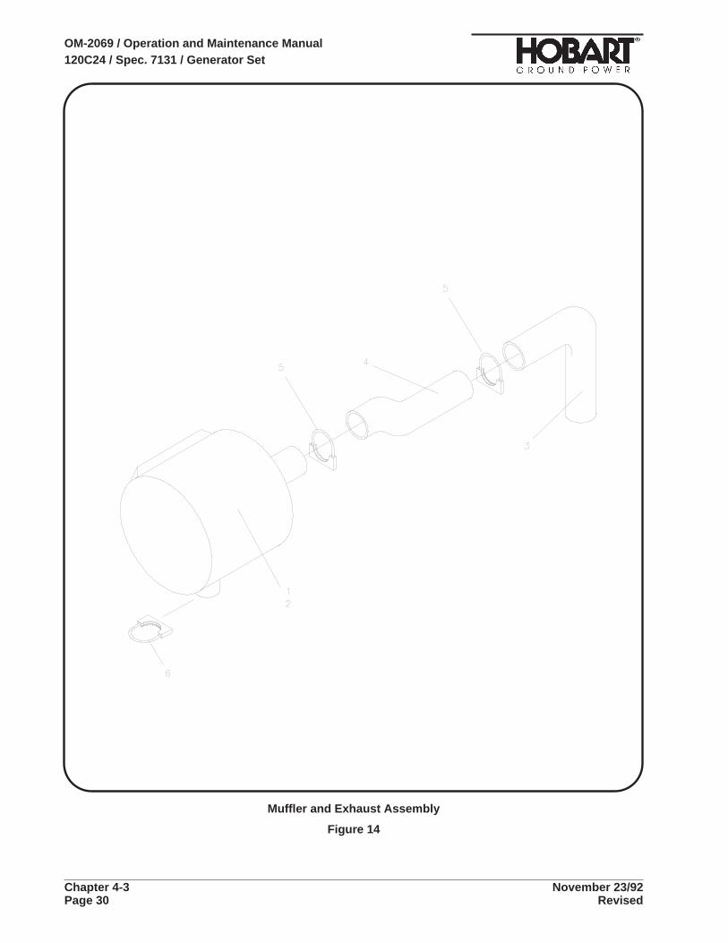
Muffler and Exhaust Assembly
Figure 14
OM-2069 / Operation and Maintenance Manual120C24 / Spec. 7131 / Generator Set
Chapter 4-3 November 23/92Page 30 Revised

NOMENCLATURE UNITSFIGURE & HOBART AIRLINE PERITEM NO. PART NO. PART NO. 1 2 3 4 5 6 ASSY
14 - NO NUMBER MUFFLER & EXHAUST ASSEMBLY REF
14 - 1 282873 . MUFFLER & INSULATION WRAP ASSEMBLY 114 - 2 282874 . . MUFFLER ASSEMBLY 114 - 3 283836 . PIPE, EXHAUST ASSEMBLY 115 - 4 283837 . PIPE, MUFFLER ASSEMBLY 114 - 5 404154-15 . CLAMP, MUFFLER, 3-1/2" 2
14 - 6 404154-13 . CLAMP, MUFFLER, 3" 1
* NOT ILLUSTRATED
OM-2069 / Operation and Maintenance Manual120C24 / Spec. 7131 / Generator Set
November 23/92 Chapter 4-3Revised Page 31

This page intentionally left blank
OM-2069 / Operation and Maintenance Manual120C24 / Spec. 7131 / Generator Set
Chapter 4-3 November 23/92Page 32 Revised

Section 4. Numerical Index
1. Explanation of Numerical IndexThe purpose of this index is to assist the user in finding the illustration and description of a part whenthe part number is known. Part numbers are arranged in numeric-alpha sequence. Thus, any numberbeginning with the letter “A” would be located toward the end of the index list. On the other hand, a partnumber starting with a “1” would be listed near the beginning of the list. The figure number and itemnumber location of the part is directly opposite the part. If the part is used more than one place, eachlocation beginning with the first is listed.
100GH-118 2 - 22
100GH-121 2 - 23
16DA-4004A-10 11 - 2
16DA-4004A-3 11 - 3
16DA-4253-1 11 - 5
180329-1 11 - 15
180593-2 8 - 16
180696-2 13 - 7
180895 3 - 25
181128 12 - 2
181129 12 - 3
181204 7 - 6
181204 3 - 23
181831 3 - 18
181891-1 5 - 8
1CZ-148 8 - 3
280184 9 - 9
280447 5 - 3
280448 5 - 2
280449 5 - 10
280732-4 12 - 8
280732-6 12 - 4
280990 7 - 5
281689-6 13 -
281689-6 3 - 27
281690A-6 13 - 14
281691-3 13 - 18
281697 13 - 13
281698 13 - 2
281699 13 - 20
281700 13 - 31
281701 13 - 21
281705-1 13 - 30
281751-1 5 - 12
281871-1 3 - 17
281881-3 5 - 1
282089-2 9 - 13
282089-2 8 - 19
282128 13 - 10
282130-1 8 - 8
282132 13 - 6
282689 2 - 6
282732-1 2 - 9
282747 2 - 3
282762 10 -
282762 9 - 3
282763 9 -
282763 3 - 4
282767 10 - 1
282791 9 - 1
282794 11 -
282794 9 - 2
282795 11 - 1
282799 9 - 8
282800 9 - 14
282834 2 - 4
282852 3 - 10
282853 3 - 11
Figure &Part Number Item Number
Figure &Part Number Item Number
OM-2069 / Operation and Maintenance Manual120C24 / Spec. 7131 / Generator Set
November 23/92 Chapter 4-4Revised Page 1

282863 3 - 37
282866B 8 -
282866B 3 - 3
282869 11 - 13
282873 14 - 1
282874 14 - 2
282876 2 - 16
282877 12 - 6
282883 12 -
282883 3 - 5
282884 12 - 1
282888 4 - 3
282891 4 - 6
282892 4 - 10
282895 3 - 14
282896 3 - 15
282915 2 - 17
282918 12 - 5
282919 12 - 9
282939 2 - 2
282966 3 - 38
283099 7 -
283099 3 - 26
283127 8 - 1
283128 8 - 17
283165 10 - 13
283167 10 - 7
283192 8 - 25
283193 8 - 23
283195 8 - 7
283197 8 - 26
283246 4 - 1
283301 3 - 39
283337 9 - 5
283339 9 - 6
283358 5 -
283358 3 - 24
283425 2 - 30
283462 5 - 6
283463 5 - 11
283464 5 - 15
283494-5 10 - 16
283497 4 - 13
283546 13 - 25
283560 13 - 26
283584 2 - 1
283588 2 - 12
283591 2 - 10
283593 2 - 34
283594 2 - 35
283595 2 - 36
283597 2 - 39
283598 2 - 37
283599 2 - 38
283604 2 - 42
283612 2 - 7
283613 3 - 8
283620 13 - 29
283622 2 - 19
283633 2 - 11
283634 2 - 13
283637 2 - 18
283638 2 - 15
283640 2 - 20
283641 2 - 21
283642 2 - 14
283645 2 - 8
283647 2 - 46
283647 2 - 28
283673 1 - 3
283673 3 - 7
283824 2 - 40
283832 4 - 14
283836 14 - 3
283837 14 - 4
283873 4 - 28
383067-5 3 - 20
385275 4 - 20
386751 4 - 9
387736C 11 - 8
Figure &Part Number Item Number
Figure &Part Number Item Number
OM-2069 / Operation and Maintenance Manual120C24 / Spec. 7131 / Generator Set
Chapter 4-4 November 23/92Page 2 Revised

387738A 8 - 14
387859 2 - 25
400818-1 7 - 10
400819-2 7 - 9
400828-2 8 - 21
400829-5 5 - 14
400902 4 - 29
401564-3 8 - 15
401564-4 11 - 11
401564-5 9 - 7
401564-5 11 - 9
401911-20 8 - 18
401911-20 2 - 29
401923-3 2 - 31
402037-14 2 - 33
402037-24 2 - 32
402077-4 4 - 21
402662 9 - 10
402665-1 9 - 12
402826 9 - 11
402908 5 - 5
402987 1 - 4
403069 8 - 20
403091-11 10 - 23
403189 10 - 11
403782-2 3 - 28
403809-1 6 - 3
404065-2 8 - 13
404100 10 - 18
404154-13 14 - 6
404154-15 14 - 5
404402-1 8 - 6
404402-8 8 - 2
404402-9 8 - 4
405061-5 13 - 16
405365-1 10 - 21
405743 4 - 2
406006 11 - 17
408773 3 - 2
409527-5 10 - 5
409527-6 10 - 9
41507 13 - 28
42517 13 - 27
430077-2 3 - 33
480603-1 3 - 12
480628 3 - 13
481209-4 3 - 16
482038A 11 - 12
482039B 11 - 10
482496-2 5 - 13
482989 9 - 16
486270-26 3 - 34
488306 2 - 45
488307 2 - 44
489658-2 11 - 16
489658-9 3 - 22
494134-1 10 - 17
56501 4 - 15
56531 4 - 5
56533 4 - 7
56534 7 - 15
56534 4 - 11
56535 7 - 4
56535 4 - 12
56535 4 - 16
5CW-2048 3 - 19
76A-1115 10 - 10
76A-1118 10 - 15
76A-1131 8 - 24
76B-1148 3 - 32
78A-1000 3 - 30
78A-1115-1 10 - 19
78A-1116-1 10 - 20
78A-1117-1 10 - 22
78A-1120-1 10 - 4
78B-1019-3 7 - 14
78B-1118-1 6 - 1
78B-1119-1 3 - 36
79A-1110 3 - 31
79B-1138 11 - 4
Figure &Part Number Item Number
Figure &Part Number Item Number
OM-2069 / Operation and Maintenance Manual120C24 / Spec. 7131 / Generator Set
November 23/92 Chapter 4-4Revised Page 3

79C-1158 10 - 8
7J-422-0 2 - 24
80A-1117 7 - 20
80A-1134 2 - 41
81B-1019 2 - 43
82B-1047 10 - 2
84A-1075 5 - 9
84A-1075 11 - 14
84A-1075 8 - 12
84A-1075 9 - 15
84A-1091 5 - 4
84B-1034 13 - 17
85A-1045 12 - 7
85B-1039 13 - 23
A-25 8 - 9
AW-626 8 - 22
AW-626 8 - 10
DDW-155 2 - 5
DW-1704 8 - 11
HF-2518-2 10 - 14
HF-2518-8 10 - 12
HF-2752 3 - 35
HF-2752 8 - 5
HF-530 2 - 27
HJ-129A 2 - 26
No Number 3 - 6
No Number 1 - 2
W-10072-68 13 - 15
W-10119-1 6 - 4
W-10750-1 6 - 2
W-10760-1 4 - 25
W-10761-1 4 - 22
W-10869-14 4 - 26
W-10869-14 7 - 3
W-10869-2 4 - 19
W-10869-3 4 - 4
W-10869-5 4 - 8
W-10886-1 7 - 19
W-10886-3 4 - 18
W-10886-3 7 - 1
W-10886-8 7 - 7
W-10890-6 4 - 23
W-10893-0 7 - 2
W-10893-0 4 - 17
W-10893-2 7 - 16
W-10901-2 7 - 13
W-10905-2 7 - 12
W-10909-1 7 - 17
W-11097-33 13 - 22
W-11097-5 13 - 11
W-11100-3 13 - 3
W-11102-18 13 - 24
W-11112-14 13 - 8
W-11236-2 13 - 1
W-11236-7 13 - 19
W-11242-12 13 - 5
W-11254-3 13 - 9
W-11254-6 13 - 12
W-11254-8 13 - 4
W-11263-5 10 - 3
W-11280-3 5 - 7
W-7814 7 - 8
W-7814-3 7 - 18
W-7814-4 3 - 29
W-7814-4 4 - 27
W-7814-5 4 - 24
W-8105A-4 10 - 6
W-9407-23 3 - 21
W-9746-3 9 - 4
Figure &Part Number Item Number
Figure &Part Number Item Number
OM-2069 / Operation and Maintenance Manual120C24 / Spec. 7131 / Generator Set
Chapter 4-4 November 23/92Page 4 Revised
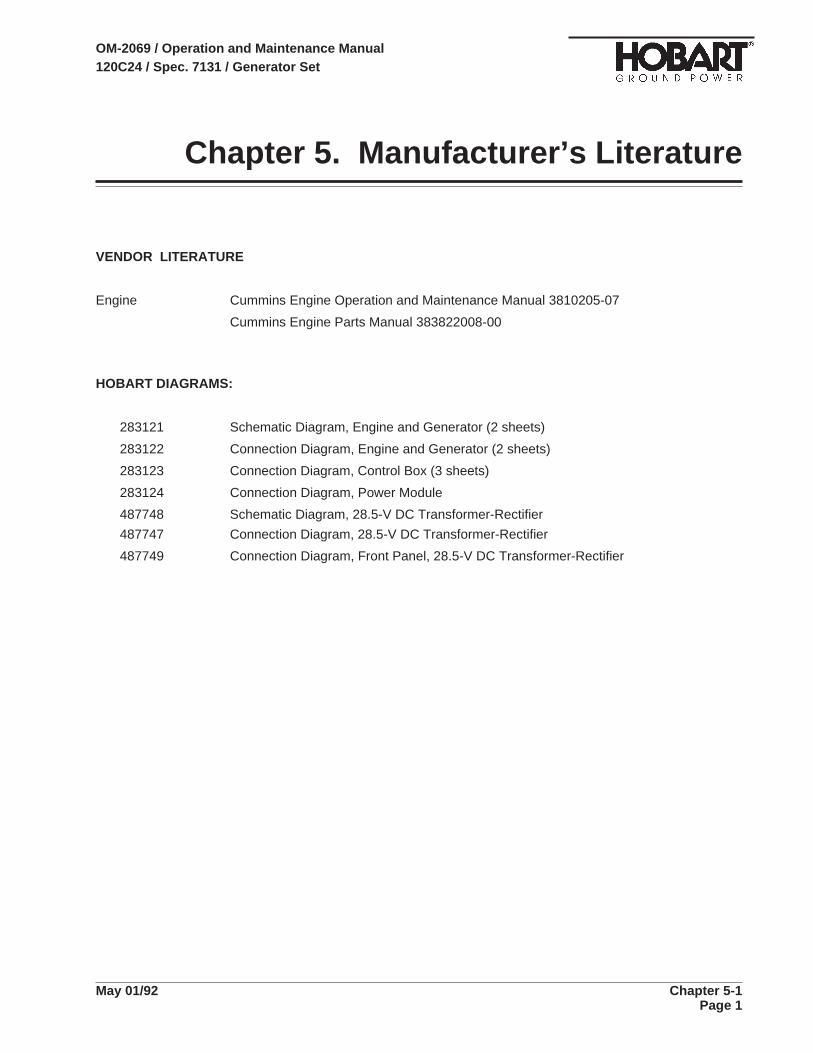
Chapter 5. Manufacturer’s Literature
VENDOR LITERATURE
Engine Cummins Engine Operation and Maintenance Manual 3810205-07
Cummins Engine Parts Manual 383822008-00
HOBART DIAGRAMS:
283121 Schematic Diagram, Engine and Generator (2 sheets)
283122 Connection Diagram, Engine and Generator (2 sheets)
283123 Connection Diagram, Control Box (3 sheets)
283124 Connection Diagram, Power Module
487748 Schematic Diagram, 28.5-V DC Transformer-Rectifier
487747 Connection Diagram, 28.5-V DC Transformer-Rectifier
487749 Connection Diagram, Front Panel, 28.5-V DC Transformer-Rectifier
OM-2069 / Operation and Maintenance Manual120C24 / Spec. 7131 / Generator Set
May 01/92 Chapter 5-1Page 1

This papge intentionally left blank
OM-2069 / Operation and Maintenance Manual120C24 / Spec. 7131 / Generator Set
Chapter 5-1 May 01/92Page 2


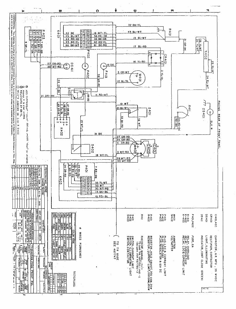


Unusual Service Conditions This information is a general guideline and cannot cover all possible conditions of equipment use. The specific local environments may be dependent upon conditions beyond the manufacturers control. The manufacturer should be consulted if any unusual conditions of use exist which may affect the physical condiiion or operation of the equipment.
Among such conditions are :
1. Exposure to:
A. Combustible, explosive, abrasive or conducting dusts
B. Environments where the accumulation of lint or excessive dirt will interfere with normal ventilation.
C. Chemical fumes, flammable or explosive gases.
D. Nuclear radiation.
E. Steam, sak-laden air, or oil vapor.
F. Damp or very dry locations, radiant heat, vermin infestation, or atmospheres conducive to fungus growth.
G. Abnormal shock, vibration or mechanical loading from external sources during equipment opera- tion.
H. Abnormal axial or side thrust imposed on rotating equipment shafts.
I. Low and/or high ambient temperatures.
2. Operation at:
A. Voltages above or below rated vokage.
B. Speeds other than rated speed.
C. Frequency other than rated frequency.
D. Standstill with rotating equipment windings energized.
E. Unbalanced voitages.
F. Operation at loads greater than rated.
3. Operation where low acoustical noise levels are required.
4. Operation with:
A. Improper fuel, lubricants or coolant.
B. Parts or elements unauthorized by the manufacturer.
C. Unauthorized modBcati0n.s.

This page intentionally let? blank

Wet-Stacking in Generator Set Diesel Engines
All diesel engines operated for extended periods under light load may develop a condition commonly referred to as wet-stacking. This condition results from the accumulation of unburned fuel in the exhaust system. It is recognizable by fuel oil wetness around the exhaust manifold, pipes, and muffler. Liquid fuel, in the form of droplets, may be spewed from the exhaust outlet.
Wet-stacking is common, and may be expected in diesel engines operated under light load. Light loads do not allow the engine to reach most efficient operating temperature for complete combustion of fuel. The unburned fuel collects in the exhaust system to create the wet condition known as wet-stacking.
To alleviate wet-stacking in lightly loaded engines, it is recommended that the machine be connected to a load bank after each 200 hours of use and operated under full rated load for one hour. This will burn away and evaporate the accumulation of fuel in the exhaust system. This clean-out procedure should be considered as a regular maintenance operation for machines operated under light load. The time schedule of 200 hours may be changed as required to suit each user’s particular needs and operating conditions.

This page intentional& left blank
Related Documents