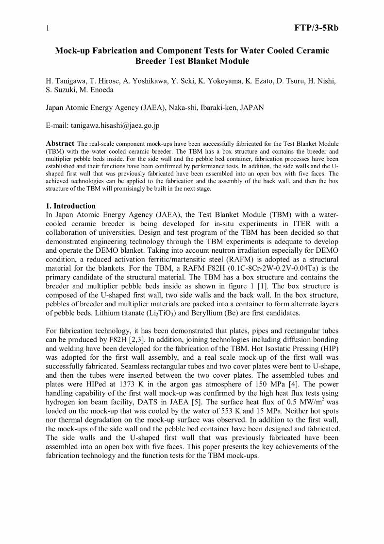
1 FTP/3-5Rb Mock-up Fabrication and Component Tests for Water Cooled Ceramic Breeder Test Blanket Module H. Tanigawa, T. Hirose, A. Yoshikawa, Y. Seki, K. Yokoyama, K. Ezato, D. Tsuru, H. Nishi, S. Suzuki, M. Enoeda Japan Atomic Energy Agency (JAEA), Naka-shi, Ibaraki-ken, JAPAN E-mail: [email protected] Abstract The real-scale component mock-ups have been successfully fabricated for the Test Blanket Module (TBM) with the water cooled ceramic breeder. The TBM has a box structure and contains the breeder and multiplier pebble beds inside. For the side wall and the pebble bed container, fabrication processes have been established and their functions have been confirmed by performance tests. In addition, the side walls and the U- shaped first wall that was previously fabricated have been assembled into an open box with five faces. The achieved technologies can be applied to the fabrication and the assembly of the back wall, and then the box structure of the TBM will promisingly be built in the next stage. 1. Introduction In Japan Atomic Energy Agency (JAEA), the Test Blanket Module (TBM) with a water- cooled ceramic breeder is being developed for in-situ experiments in ITER with a collaboration of universities. Design and test program of the TBM has been decided so that demonstrated engineering technology through the TBM experiments is adequate to develop and operate the DEMO blanket. Taking into account neutron irradiation especially for DEMO condition, a reduced activation ferritic/martensitic steel (RAFM) is adopted as a structural material for the blankets. For the TBM, a RAFM F82H (0.1C-8Cr-2W-0.2V-0.04Ta) is the primary candidate of the structural material. The TBM has a box structure and contains the breeder and multiplier pebble beds inside as shown in figure 1 [1]. The box structure is composed of the U-shaped first wall, two side walls and the back wall. In the box structure, pebbles of breeder and multiplier materials are packed into a container to form alternate layers of pebble beds. Lithium titanate (Li 2 TiO 3 ) and Beryllium (Be) are first candidates. For fabrication technology, it has been demonstrated that plates, pipes and rectangular tubes can be produced by F82H [2,3]. In addition, joining technologies including diffusion bonding and welding have been developed for the fabrication of the TBM. Hot Isostatic Pressing (HIP) was adopted for the first wall assembly, and a real scale mock-up of the first wall was successfully fabricated. Seamless rectangular tubes and two cover plates were bent to U-shape, and then the tubes were inserted between the two cover plates. The assembled tubes and plates were HIPed at 1373 K in the argon gas atmosphere of 150 MPa [4]. The power handling capability of the first wall mock-up was confirmed by the high heat flux tests using hydrogen ion beam facility, DATS in JAEA [5]. The surface heat flux of 0.5 MW/m 2 was loaded on the mock-up that was cooled by the water of 553 K and 15 MPa. Neither hot spots nor thermal degradation on the mock-up surface was observed. In addition to the first wall, the mock-ups of the side wall and the pebble bed container have been designed and fabricated. The side walls and the U-shaped first wall that was previously fabricated have been assembled into an open box with five faces. This paper presents the key achievements of the fabrication technology and the function tests for the TBM mock-ups.

Welcome message from author
This document is posted to help you gain knowledge. Please leave a comment to let me know what you think about it! Share it to your friends and learn new things together.
Transcript
1 FTP/3-5Rb
Mock-up Fabrication and Component Tests for Water Cooled Ceramic Breeder Test Blanket Module
H. Tanigawa, T. Hirose, A. Yoshikawa, Y. Seki, K. Yokoyama, K. Ezato, D. Tsuru, H. Nishi, S. Suzuki, M. Enoeda Japan Atomic Energy Agency (JAEA), Naka-shi, Ibaraki-ken, JAPAN E-mail: [email protected] Abstract The real-scale component mock-ups have been successfully fabricated for the Test Blanket Module (TBM) with the water cooled ceramic breeder. The TBM has a box structure and contains the breeder and multiplier pebble beds inside. For the side wall and the pebble bed container, fabrication processes have been established and their functions have been confirmed by performance tests. In addition, the side walls and the U-shaped first wall that was previously fabricated have been assembled into an open box with five faces. The achieved technologies can be applied to the fabrication and the assembly of the back wall, and then the box structure of the TBM will promisingly be built in the next stage. 1. Introduction In Japan Atomic Energy Agency (JAEA), the Test Blanket Module (TBM) with a water-cooled ceramic breeder is being developed for in-situ experiments in ITER with a collaboration of universities. Design and test program of the TBM has been decided so that demonstrated engineering technology through the TBM experiments is adequate to develop and operate the DEMO blanket. Taking into account neutron irradiation especially for DEMO condition, a reduced activation ferritic/martensitic steel (RAFM) is adopted as a structural material for the blankets. For the TBM, a RAFM F82H (0.1C-8Cr-2W-0.2V-0.04Ta) is the primary candidate of the structural material. The TBM has a box structure and contains the breeder and multiplier pebble beds inside as shown in figure 1 [1]. The box structure is composed of the U-shaped first wall, two side walls and the back wall. In the box structure, pebbles of breeder and multiplier materials are packed into a container to form alternate layers of pebble beds. Lithium titanate (Li2TiO3) and Beryllium (Be) are first candidates. For fabrication technology, it has been demonstrated that plates, pipes and rectangular tubes can be produced by F82H [2,3]. In addition, joining technologies including diffusion bonding and welding have been developed for the fabrication of the TBM. Hot Isostatic Pressing (HIP) was adopted for the first wall assembly, and a real scale mock-up of the first wall was successfully fabricated. Seamless rectangular tubes and two cover plates were bent to U-shape, and then the tubes were inserted between the two cover plates. The assembled tubes and plates were HIPed at 1373 K in the argon gas atmosphere of 150 MPa [4]. The power handling capability of the first wall mock-up was confirmed by the high heat flux tests using hydrogen ion beam facility, DATS in JAEA [5]. The surface heat flux of 0.5 MW/m2 was loaded on the mock-up that was cooled by the water of 553 K and 15 MPa. Neither hot spots nor thermal degradation on the mock-up surface was observed. In addition to the first wall, the mock-ups of the side wall and the pebble bed container have been designed and fabricated. The side walls and the U-shaped first wall that was previously fabricated have been assembled into an open box with five faces. This paper presents the key achievements of the fabrication technology and the function tests for the TBM mock-ups.
2 FTP/3-5Rb
1700
mm
600 mm500 mm
Structure of RAFM (F82H)
Armor (Be)
Neutron multiplierpebble bed (Be)
Tritium breederpebble bed (Li2TiO3)
Plasma side
FIG. 1 Schematic drawing and cross section of water-cooled ceramic breeder test blanket module.
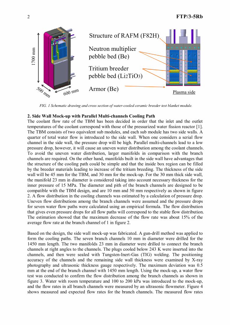
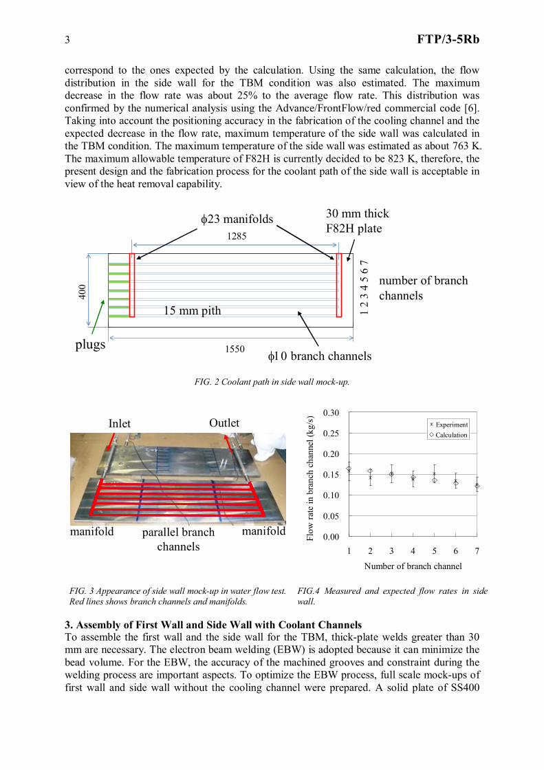
2. Side Wall Mock-up with Parallel Multi-channels Cooling Path The coolant flow rate of the TBM has been decided in order that the inlet and the outlet temperatures of the coolant correspond with those of the pressurized water fission reactor [1]. The TBM consists of two equivalent sub modules, and each sub module has two side walls. A quarter of total water flow is introduced to the side wall. When one considers a serial flow channel in the side wall, the pressure drop will be high. Parallel multi-channels lead to a low pressure drop, however, it will cause an uneven water distribution among the coolant channels. To avoid the uneven water distribution, larger manifolds in comparison with the branch channels are required. On the other hand, manifolds built in the side wall have advantages that the structure of the cooling path could be simple and that the inside box region can be filled by the breeder materials leading to increase of the tritium breeding. The thickness of the side wall will be 45 mm for the TBM, and 30 mm for the mock-up. For the 30 mm thick side wall, the manifold 23 mm in diameter is considered taking into account necessary thickness for the inner pressure of 15 MPa. The diameter and pith of the branch channels are designed to be compatible with the TBM design, and are 10 mm and 50 mm respectively as shown in figure 2. A flow distribution in the cooling channels was estimated by a calculation of pressure drop. Uneven flow distributions among the branch channels were assumed and the pressure drops for seven water flow paths were calculated using an empirical formula. The flow distribution that gives even pressure drops for all flow paths will correspond to the stable flow distribution. The estimation showed that the maximum decrease of the flow rate was about 15% of the average flow rate at the branch channel of 1 in figure 2. Based on the design, the side wall mock-up was fabricated. A gun-drill method was applied to form the cooling paths. The seven branch channels 10 mm in diameter were drilled for the 1450 mm length. The two manifolds 23 mm in diameter were drilled to connect the branch channels at right angles to the channels. The plugs cooled below 243 K were inserted into the channels, and then were sealed with Tungsten-Inert-Gas (TIG) welding. The positioning accuracy of the channels and the remaining side wall thickness were examined by X-ray photography and ultrasonic thickness gauge respectively. The maximum deviation was 0.5 mm at the end of the branch channel with 1450 mm length. Using the mock-up, a water flow test was conducted to confirm the flow distribution among the branch channels as shown in figure 3. Water with room temperature and 100 to 200 kPa was introduced to the mock-up, and the flow rates in all branch channels were measured by an ultrasonic flowmeter. Figure 4 shows measured and expected flow rates for the branch channels. The measured flow rates
3 FTP/3-5Rb
correspond to the ones expected by the calculation. Using the same calculation, the flow distribution in the side wall for the TBM condition was also estimated. The maximum decrease in the flow rate was about 25% to the average flow rate. This distribution was confirmed by the numerical analysis using the Advance/FrontFlow/red commercial code [6]. Taking into account the positioning accuracy in the fabrication of the cooling channel and the expected decrease in the flow rate, maximum temperature of the side wall was calculated in the TBM condition. The maximum temperature of the side wall was estimated as about 763 K. The maximum allowable temperature of F82H is currently decided to be 823 K, therefore, the present design and the fabrication process for the coolant path of the side wall is acceptable in view of the heat removal capability.
1550
400
1285
plugs
23 manifolds
branch channels
15 mm pith
30 mm thick F82H plate
1 2
3 4
5 6
7
number of branchchannels
FIG. 2 Coolant path in side wall mock-up.
Inlet Outlet
manifold manifoldparallel branch channels
0.00
0.05
0.10
0.15
0.20
0.25
0.30
1 2 3 4 5 6 7
Number of branch channel
Flow
rate
in b
ranc
h ch
anne
l (kg
/s)
ExperimentCalculation
FIG. 3 Appearance of side wall mock-up in water flow test. Red lines shows branch channels and manifolds.
FIG.4 Measured and expected flow rates in side wall.
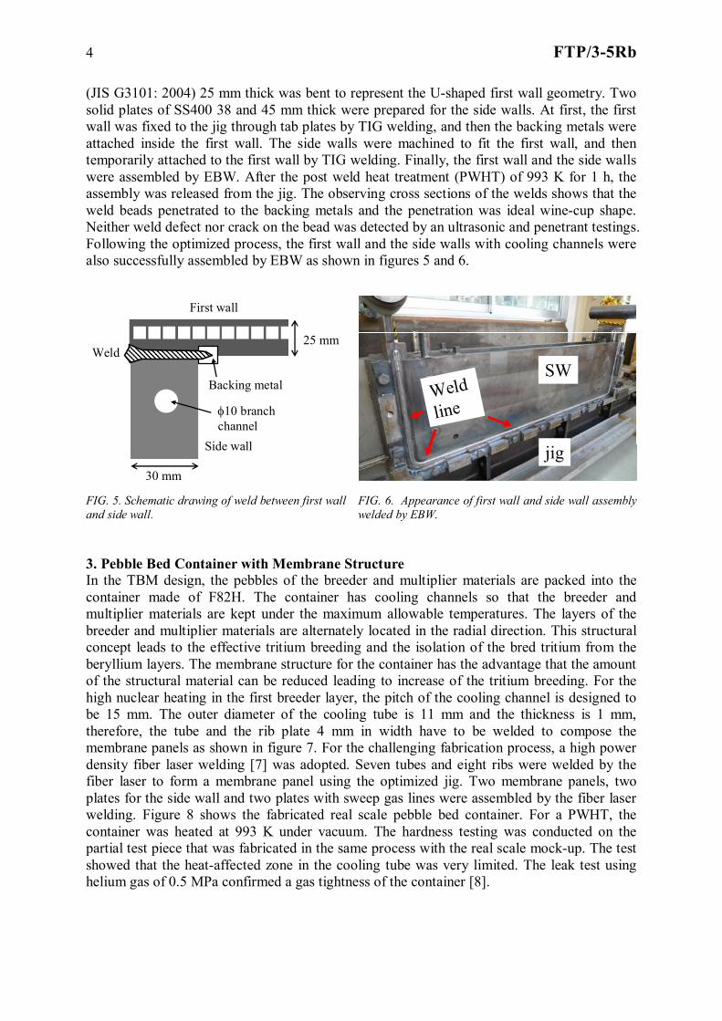
3. Assembly of First Wall and Side Wall with Coolant Channels To assemble the first wall and the side wall for the TBM, thick-plate welds greater than 30 mm are necessary. The electron beam welding (EBW) is adopted because it can minimize the bead volume. For the EBW, the accuracy of the machined grooves and constraint during the welding process are important aspects. To optimize the EBW process, full scale mock-ups of first wall and side wall without the cooling channel were prepared. A solid plate of SS400
4 FTP/3-5Rb
(JIS G3101: 2004) 25 mm thick was bent to represent the U-shaped first wall geometry. Two solid plates of SS400 38 and 45 mm thick were prepared for the side walls. At first, the first wall was fixed to the jig through tab plates by TIG welding, and then the backing metals were attached inside the first wall. The side walls were machined to fit the first wall, and then temporarily attached to the first wall by TIG welding. Finally, the first wall and the side walls were assembled by EBW. After the post weld heat treatment (PWHT) of 993 K for 1 h, the assembly was released from the jig. The observing cross sections of the welds shows that the weld beads penetrated to the backing metals and the penetration was ideal wine-cup shape. Neither weld defect nor crack on the bead was detected by an ultrasonic and penetrant testings. Following the optimized process, the first wall and the side walls with cooling channels were also successfully assembled by EBW as shown in figures 5 and 6.
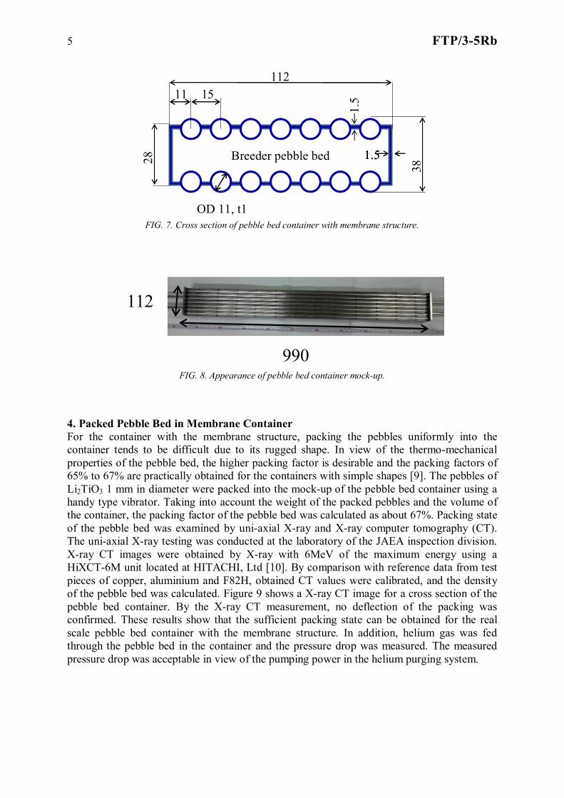
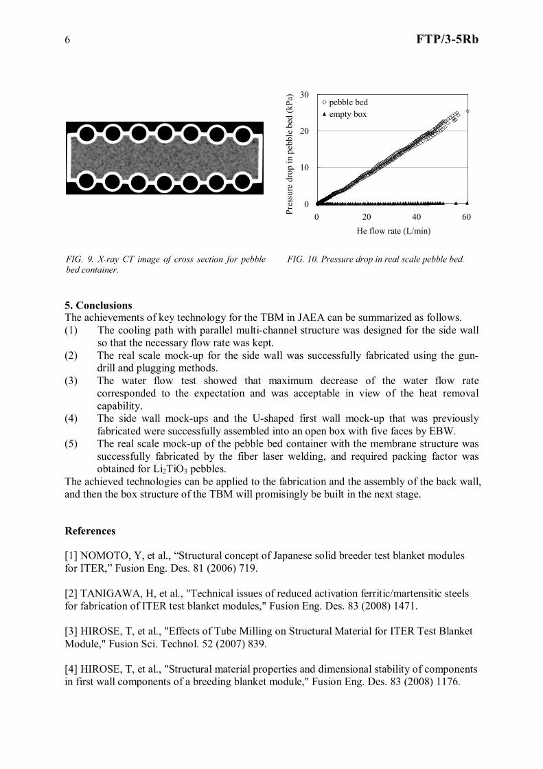
3. Pebble Bed Container with Membrane Structure In the TBM design, the pebbles of the breeder and multiplier materials are packed into the container made of F82H. The container has cooling channels so that the breeder and multiplier materials are kept under the maximum allowable temperatures. The layers of the breeder and multiplier materials are alternately located in the radial direction. This structural concept leads to the effective tritium breeding and the isolation of the bred tritium from the beryllium layers. The membrane structure for the container has the advantage that the amount of the structural material can be reduced leading to increase of the tritium breeding. For the high nuclear heating in the first breeder layer, the pitch of the cooling channel is designed to be 15 mm. The outer diameter of the cooling tube is 11 mm and the thickness is 1 mm, therefore, the tube and the rib plate 4 mm in width have to be welded to compose the membrane panels as shown in figure 7. For the challenging fabrication process, a high power density fiber laser welding [7] was adopted. Seven tubes and eight ribs were welded by the fiber laser to form a membrane panel using the optimized jig. Two membrane panels, two plates for the side wall and two plates with sweep gas lines were assembled by the fiber laser welding. Figure 8 shows the fabricated real scale pebble bed container. For a PWHT, the container was heated at 993 K under vacuum. The hardness testing was conducted on the partial test piece that was fabricated in the same process with the real scale mock-up. The test showed that the heat-affected zone in the cooling tube was very limited. The leak test using helium gas of 0.5 MPa confirmed a gas tightness of the container [8].
30 mm
First wall
Side wall
10 branch channel
Backing metal
Weld25 mm
jig
SWWeld line
FIG. 5. Schematic drawing of weld between first wall and side wall.
FIG. 6. Appearance of first wall and side wall assembly welded by EBW.
5 FTP/3-5Rb
Breeder pebble bed
11211 15
28
1.5
1.51.5
38
OD 11, t1 FIG. 7. Cross section of pebble bed container with membrane structure.
112
990
FIG. 8. Appearance of pebble bed container mock-up.
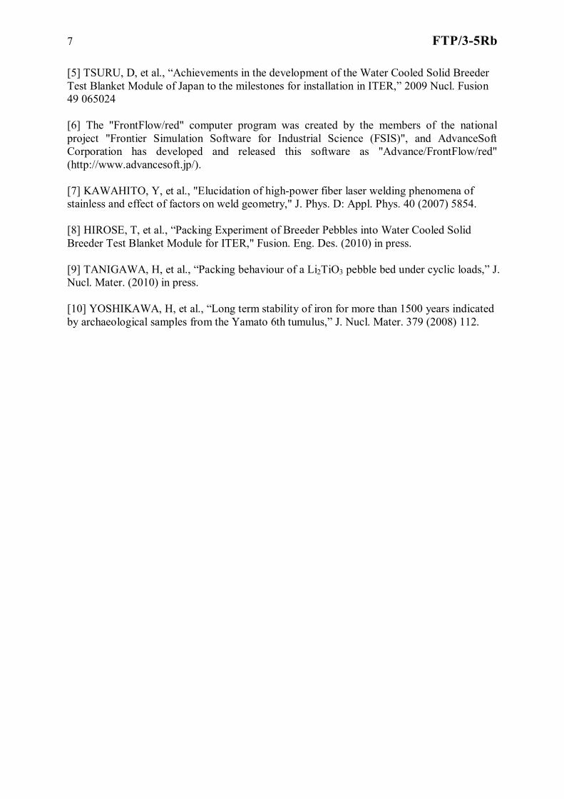
4. Packed Pebble Bed in Membrane Container For the container with the membrane structure, packing the pebbles uniformly into the container tends to be difficult due to its rugged shape. In view of the thermo-mechanical properties of the pebble bed, the higher packing factor is desirable and the packing factors of 65% to 67% are practically obtained for the containers with simple shapes [9]. The pebbles of Li2TiO3 1 mm in diameter were packed into the mock-up of the pebble bed container using a handy type vibrator. Taking into account the weight of the packed pebbles and the volume of the container, the packing factor of the pebble bed was calculated as about 67%. Packing state of the pebble bed was examined by uni-axial X-ray and X-ray computer tomography (CT). The uni-axial X-ray testing was conducted at the laboratory of the JAEA inspection division. X-ray CT images were obtained by X-ray with 6MeV of the maximum energy using a HiXCT-6M unit located at HITACHI, Ltd [10]. By comparison with reference data from test pieces of copper, aluminium and F82H, obtained CT values were calibrated, and the density of the pebble bed was calculated. Figure 9 shows a X-ray CT image for a cross section of the pebble bed container. By the X-ray CT measurement, no deflection of the packing was confirmed. These results show that the sufficient packing state can be obtained for the real scale pebble bed container with the membrane structure. In addition, helium gas was fed through the pebble bed in the container and the pressure drop was measured. The measured pressure drop was acceptable in view of the pumping power in the helium purging system.
6 FTP/3-5Rb
5. Conclusions The achievements of key technology for the TBM in JAEA can be summarized as follows. (1) The cooling path with parallel multi-channel structure was designed for the side wall
so that the necessary flow rate was kept. (2) The real scale mock-up for the side wall was successfully fabricated using the gun-
drill and plugging methods. (3) The water flow test showed that maximum decrease of the water flow rate
corresponded to the expectation and was acceptable in view of the heat removal capability.
(4) The side wall mock-ups and the U-shaped first wall mock-up that was previously fabricated were successfully assembled into an open box with five faces by EBW.
(5) The real scale mock-up of the pebble bed container with the membrane structure was successfully fabricated by the fiber laser welding, and required packing factor was obtained for Li2TiO3 pebbles.
The achieved technologies can be applied to the fabrication and the assembly of the back wall, and then the box structure of the TBM will promisingly be built in the next stage. References [1] NOMOTO, Y, et al., “Structural concept of Japanese solid breeder test blanket modules for ITER,” Fusion Eng. Des. 81 (2006) 719. [2] TANIGAWA, H, et al., "Technical issues of reduced activation ferritic/martensitic steels for fabrication of ITER test blanket modules," Fusion Eng. Des. 83 (2008) 1471. [3] HIROSE, T, et al., "Effects of Tube Milling on Structural Material for ITER Test Blanket Module," Fusion Sci. Technol. 52 (2007) 839. [4] HIROSE, T, et al., "Structural material properties and dimensional stability of components in first wall components of a breeding blanket module," Fusion Eng. Des. 83 (2008) 1176.
0
10
20
30
0 20 40 60He flow rate (L/min)
Pres
sure
dro
p in
peb
ble
bed
(kPa
)
pebble bedempty box
FIG. 9. X-ray CT image of cross section for pebble bed container.
FIG. 10. Pressure drop in real scale pebble bed.
7 FTP/3-5Rb
[5] TSURU, D, et al., “Achievements in the development of the Water Cooled Solid Breeder Test Blanket Module of Japan to the milestones for installation in ITER,” 2009 Nucl. Fusion 49 065024 [6] The "FrontFlow/red" computer program was created by the members of the national project "Frontier Simulation Software for Industrial Science (FSIS)", and AdvanceSoft Corporation has developed and released this software as "Advance/FrontFlow/red" (http://www.advancesoft.jp/). [7] KAWAHITO, Y, et al., "Elucidation of high-power fiber laser welding phenomena of stainless and effect of factors on weld geometry," J. Phys. D: Appl. Phys. 40 (2007) 5854. [8] HIROSE, T, et al., “Packing Experiment of Breeder Pebbles into Water Cooled Solid Breeder Test Blanket Module for ITER," Fusion. Eng. Des. (2010) in press. [9] TANIGAWA, H, et al., “Packing behaviour of a Li2TiO3 pebble bed under cyclic loads,” J. Nucl. Mater. (2010) in press. [10] YOSHIKAWA, H, et al., “Long term stability of iron for more than 1500 years indicated by archaeological samples from the Yamato 6th tumulus,” J. Nucl. Mater. 379 (2008) 112.
Related Documents


