HAL Id: tel-01552289 https://tel.archives-ouvertes.fr/tel-01552289 Submitted on 2 Jul 2017 HAL is a multi-disciplinary open access archive for the deposit and dissemination of sci- entific research documents, whether they are pub- lished or not. The documents may come from teaching and research institutions in France or abroad, or from public or private research centers. L’archive ouverte pluridisciplinaire HAL, est destinée au dépôt et à la diffusion de documents scientifiques de niveau recherche, publiés ou non, émanant des établissements d’enseignement et de recherche français ou étrangers, des laboratoires publics ou privés. Mobility and Security Management in Femtocell Networks Seifeddine Bouallegue To cite this version: Seifeddine Bouallegue. Mobility and Security Management in Femtocell Networks. Networking and Internet Architecture [cs.NI]. Université Pierre et Marie Curie - Paris VI; École nationale d’ingénieurs de Tunis (Tunisie), 2016. English. NNT: 2016PA066084. tel-01552289

Welcome message from author
This document is posted to help you gain knowledge. Please leave a comment to let me know what you think about it! Share it to your friends and learn new things together.
Transcript

HAL Id: tel-01552289https://tel.archives-ouvertes.fr/tel-01552289
Submitted on 2 Jul 2017
HAL is a multi-disciplinary open accessarchive for the deposit and dissemination of sci-entific research documents, whether they are pub-lished or not. The documents may come fromteaching and research institutions in France orabroad, or from public or private research centers.
L’archive ouverte pluridisciplinaire HAL, estdestinée au dépôt et à la diffusion de documentsscientifiques de niveau recherche, publiés ou non,émanant des établissements d’enseignement et derecherche français ou étrangers, des laboratoirespublics ou privés.
Mobility and Security Management in FemtocellNetworks
Seifeddine Bouallegue
To cite this version:Seifeddine Bouallegue. Mobility and Security Management in Femtocell Networks. Networking andInternet Architecture [cs.NI]. Université Pierre et Marie Curie - Paris VI; École nationale d’ingénieursde Tunis (Tunisie), 2016. English. NNT : 2016PA066084. tel-01552289

PIERRE AND MARIE CURIE UNIVERSITY
NATIONAL ENGINEERING SCHOOL OF TUNIS
Ph.D. Dissertation
Mobility and Security Management
in Femtocell Networks
Presented by:
Seifeddine BOUALLEGUE
To obtain the Degree of:
Doctor of Philosophy in CommunicationsSpecialty:
Technology of Information and Communications
Supervisor: Supervisor:
Pr. Guy PUJOLLE Dr. Kaouthar SETHOM
Defended on June 30th, 2016 in front of the Jury:
Mrs. Houria REZIG Professor, ENIT, Tunisia President
Mr. Kosai RAOOF Professor, ENSIM, France Reviewer
Mr. Noureddine HAMDI Professor, ENIT, France Reviewer
Mr. Anthony BUSSON Professor, IUT, France Examiner
Mr. Tahar EZZEDINE A. Professor, ENIT, Tunisia Examiner
Mr. Guy PUJOLLE Professor, UPMC, France Supervisor
Mrs. Kaouthar SETHOM A. Professor, ENIT, Tunisia Supervisor
University Year : 2015 / 2016

To my grand parents: Turkia, Makki, Habiba and Hedi.
To my parents: Ridha and Noura
To my sisters: Takwa and Sirine.
To my wife Abir.

AcknowledgmentI would like to gratefully thank my supervisors, Prof. Guy PUJOLLE and A. Prof. Kaouthar
SETHOM whose support and guidance made my thesis work possible. They have been actively
interested in my work and have always been available to advise me. I am very grateful for their
patience, motivation, enthusiasm, and immense knowledge that, taken together, make them great
mentors.
I would like to show my gratitude to my thesis reviewers: Prof. Kosai RAOOF and Prof.
Noureddine HAMDI, and to the jury members: Prof. Houria REZIG , Prof. Anthony BUSSON
and Dr. Tahar EZZEDINE, for evaluating my Ph.D. work.
This work was possible because of the unconditional support provided by Dr. Mazen Omar
HASNA. A person with an amicable and positive disposition, he has always made himself avail-
able to clarify my doubts despite his busy schedules.
I would like to express my sincere appreciation and gratitude to Dr. Ridha HAMILA, who has
been a constant source of encouragement and enthusiasm.
I would also like to sincerely thank Dr. Aymen OMRI for his precious help. He was there
when I needed him and he never declined a call for assistance. Thank you, for all your help and
support.
I truly thank Dr. Adel CHERIF for his continuous support and motivation. His words always
pushed me forward and inspired me to achieve better results.
To my grand-mother, Turkia, god bless her soul. I would like to thank her like no one did in
this world. I would like to tell her that if I had to dedicate this achievement to only one person
it would be you. I wish you could be there. Your prayers are with me whenever I go, protecting
me, pushing me and making me feel secure. I can never thank you as it should be. Rest in peace
grand-mother.
A few words about my father: Prof. Ridha BOUALLEGUE. This acknowledgment is not
enough, and will never be. It will not be enough if I wrote I totally owe him my success. It will
not be enough if I wrote he made me what I am now. It will not be enough if I wrote my father is
my only true hero. Superman may has super powers, but not as my father has. He could make me

4
a man, raise a happy family and be the reason behind thousands of smiles. Go home Superman,
my father is around.
My mother: Noura GZARA BOUALLEGUE, the most precious person on earth. Numbers on
this earth can not be enough to evaluate her kindness and love. I hope that I could make her proud
of me. I hope.
My sisters: Takwa and Syrine, thanking them is just not fair. They are part of me, and they are
part of this achievement. I grew up with Takwa as my best friend, had hard times, but we could
always figure out a solution. I mean, she could because I was stubborn and selfish, what she never
was. I raised Syrine, sometimes I see in her a little me, yes with the stubborn and selfish aspects
sometimes, but I find myself in her and I wish this achievement would make her proud of her big
brother. I wish.
Dr. Abir EDDHAOUI, the real Doctor in the house, the one I proudly call ’my wife’. My
beloved Dentist. Patience? Support? Not a day that passes without her waving at me to work
harder. She could always find the right words to get the best of me. I hope she will be proud to
call her husband Dr. Seifeddine BOUALLEGUE, because she contributed so much in making me
achieve this goal. So much.
Mohamed Said EDDHAOUI, god bless his soul, my father in law. I wish could be there to see
me. I hope you are proud of your son. Me.
A special and warm thanks to Naima SMAOUI, my mother in law. She provided me with
unending encouragement and support.
Seifeddine BOUALLEGUE

Résumé
Les réseaux de télécommunications sont soumis à des processus d’amélioration et d’opti-
misation continue. Chaque nouvelle itération apporte son lot de défis et limites. En effet,
la croissance exponentielle des appareils de télécommunication, des stations de base aux
équipements utilisateurs conduisent à de sérieuxproblèmes d’economie d’énergie. En
plus des menaces à la vie privée, en particulier pour les réseaux sans fil car les canaux
utilisés par les opérateurs peuvent également être utilisés par une oreille indiscrète quel-
conque. L’optimisation de l’utilisation du spectre est également un défi en raison du fait
que le spectre disponible dans les systèmes de communication sans fil est devenu une
ressource très rare en raison de la demande croissante. Les réseaux émergents, tels que
les femtocells, souffrent également des défis mentionnés précédemment.
Le travail de thèse actuel se concentre sur la proposition de solutions aux défis cités
précédemment: l’efficacité énergétique, le partage du spectre et la sécurité. Le travail
de recherche présenté dans cette thèse a porté sur trois axes principaux: Premièrement,
trouver un moyen de réduire au minimum la consommation d’énergie des femtocellules
dans les reseaux BWA femto/macro-cellulaire en diminuant le nombre d’événements de
mobilité non désirées et l’introduction de nouveaux états de puissance pour la femtocel-
lule. En second lieu, proposer une solution qui vise à réduire le temps de transmission
prévu dans le temps de séjour de l’utilisateur secondaire (SU) dans la couverture d’une
femtocellule en utilisant un algorithme basé sur le temps minimum prévu de transmission
dans le temps de séjour de l’équipement utilisateur (UE). Enfin, introduire un nouveau
modèle qui basé sur la sélection du meilleur relais qui maximise le taux de confidentialité
et les avantages de l’augmentation du nombre de relais sous la contrainte de qualité de
service à la destination.
Mots clés: Systèmes de radio cognitive, Informations d’état de canal imparfaite, Ges-
tion des interférences, Chaînes de Markov, Analyse de performance, Sélection de relais.

Abstract
Telecommunications networks are subject to continuous improvement and enhancement
processes. Every new iteration brings its set of challenges and limitations. In fact, the
exponential growth in telecommunication devices, from base stations to user equipments
lead to serious energy efficiency issues. Along with the privacy threats, especially for
wireless networks as the channels used by operators can also be used by any eavesdrop-
per. Spectrum usage optimization is also a challenge due to the fact that the available
spectrum in wireless communications systems has been a very rare resource because of
the increasing demand. Emerging networks, such as femtocells, suffer also from the pre-
viously mentioned challenges.
The current thesis work focuses on proposing several solutions to the previously cited
challenges: energy efficiency, spectrum sharing and security. The research work intro-
duced in this thesis has focused on three main axes: First, find a way to minimize the
energy consumption of femtocells in macro/femto-cellular BWA networks by decreasing
the number of unwanted mobility events and introducing new power states for the fem-
tocell device. Second, propose a solution that aims to reduce the expected transmission
time within the dwell time of Secondary User (SU) in the coverage of a femtocell using an
algorithm based on the minimum expected transmission time within the dwell time of the
User Equipment (UE) in the coverage of the femtocell. Finally, introduce a new scheme
that is based on best relay selection method that maximizes the secrecy rate and benefits
from increasing the number of relays under QoS constraint at the destination.
Keywords: Cognitive radio systems, Imperfect channel state information, Interfer-
ence management, Markov chains, Performance analysis, Relay selection.

Abbreviations
In this thesis, we have adopted the following abreviations:
A
AF Amplify-and-Forward
AWGN Additive White Gaussian Noise
B
BER Bit Error Rate
BS Base Station
BSH Best Second Hop
C
CF Compress-and-Forward
CR Cognitive Radio
CSI Channel State Information
D
DF Decode-and-Forward
E
E-UTRAN Evolved UMTS Terrestrial Radio Access Network
F
F-BS Femto-cell Base Station
FCC Federal Communications Commission
FDMA Frequency Division Multiple Access
FFR Fractional Frequency Reuse
FIA Full Interference Avoidance
F-MS Femto-cell Mobile Station

iv Abbreviations
G
GA Genetic Algorithm
GF General Form
H
HSH Highest Second-Hop
I
IA Interference Avoidance
IC Interference Cancellation
ICSI Imperfect Channel State Information
IM Interference Management
L
LI Low Interference
LS least square
LSH Lowest Second-Hop
LTE Long Term Evolution
M
MAC Media Access Control
M-BS Macro-cell Base Station
MIMO Multiple Input Multiple Output
MinI Minimum Interference based Selection Scheme
MLSE Maximum Likelihood Sequence Estimation
MMSE Minimum Mean Square Error
M-MS Macro-cell Mobile Station
M-PAM M-ary Pulse Amplitude Modulation
MS Mobile Station
M2H Maximum Second Hop
M2HScS Maximum Second Hop SNR Sub-channel Selection Scheme

v
O
OFCOM Office of Communications
OFDM Orthogonal Frequency Division Multiplexing
OSA Opportunistic Spectrum Access
P
PAScS Power Adjustment Sub-channel Selection Scheme
PCSI Perfect Channel State Information
PDF Probability Density Function
PIP Peack Interference Power
PN Primary Network
PSD Power Spectrum Density
PU Primary User
Q
QoS Quality of Service
R
RBSH Restricted Best Second
RS Relay Station
S
SC Standard Scheme Constellation
SOScS Sequential Order Sub-channel Selection Scheme
SN Secondary Network
SNR Signal to Noise Ratio
SS Standard Scheme
SU Secondary User
T
TDMA Time Division Multiple Access
W
WREL Worst Relay-Eavesdropper Link

Notations
In this thesis, we have adopted the following notations:
j j2 = −1
<( . ) Real part
=( . ) Imaginary part
| . | Magnitude
BI(.) Incomplete beta function
Q(.) Q-function
erfc(.) Complementary error function
E(.) Expectation function
exp (.) Exponential function
Eint(.) Exponential integral function
Es Transmitted energy per symbol
N0 Noise power spectral density
NR
Number of relays
N1 Number of relays that are satisfying the transmission and interference constraints
N2 Number of relays that are satisfying only the transmission constraint
NSC
Number of sub-carriers
SP
Primary source
SS
Secondary source
Rj
Relay index j
DP
Primary destination

vii
γSD
The instantaneous SNR of the link between the source and the destination.
γSE
The instantaneous SNR of the link between the source and the eavesdropper.
γRkD
The instantaneous SNR of the link between the kth relay and the destination.
γR∗D The instantaneous SNR of the selected relay and the destination for BSH scheme.
αR∗D The instantaneous SNR of the selected relay and the destination for RBSH scheme.
βR∗D The instantaneous SNR of the selected relay and the destination for RBSH scheme.
γRkE
The instantaneous SNR of the link between the kth relay and the eavesdropper.
γR∗E The instantaneous SNR of the selected relay and the eavesdropper
for BSH scheme.
αR∗E The instantaneous SNR of the selected relay and the eavesdropper
for WREL scheme.
βR∗E The instantaneous SNR of the selected relay and the eavesdropper
for RBSH scheme.
γSD
The average SNR of the link between the source and the destination.
γSE
The average SNR of the link between the source and the eavesdropper.
γRD
The average SNR of the link between the different relays and the destination.
γRE
The average SNR of the link between the different relays and the eavesdropper.
γeq
DThe instantaneous equivalent SNR of the link between the selected relay
and the destination for BSH scheme.
αeq
DThe instantaneous equivalent SNR of the link between the selected relay
and the destination for WREL scheme.
βeq
DThe instantaneous equivalent SNR of the link between the selected relay
and the destination for RBSH scheme.
γeq
EThe instantaneous equivalent SNR of the the link between the selected relay
and the eavesdropper for BSH scheme.
αeq
EThe instantaneous equivalent SNR of the link between the selected relay
and the eavesdropper for WREL scheme.

viii Notations
βeq
EThe instantaneous equivalent SNR of the link between the selected relay
and the eavesdropper for RBSH scheme.
pSD
PDF of γSD
.
pSE
PDF of γSE
.
pR∗D PDF of γ
R∗D .
fR∗D PDF of α
R∗D .
gR∗D PDF of β
R∗D .
pR∗E PDF of γ
R∗E .
fR∗E PDF of α
R∗E .
gR∗E PDF of β
R∗E .
pD
PDF of γeqD
.
fD
PDF of αeqD
.
gD
PDF of βeqD
.
pE
PDF of γeqE
.
fE
PDF of αeqE
.
gE
PDF of βeqE
.
PBSH
outThe average outage probability for BSH scheme at the destination.
PWREL
outThe average outage probability for WREL scheme at the destination.
PRBSH
outThe average outage probability for RBSH scheme at the destination.
PBSH
eThe average BER for BSH scheme at the destination.
PWREL
eThe average BER for WREL scheme at the destination.
PRBSH
eThe average BER for RBSH scheme at the destination.
CBSH
DThe average ergodic capacity for BSH scheme at the destination.
CWREL
DThe average ergodic capacity for WREL scheme at the destination.
CRBSH
DThe average ergodic capacity for RBSH scheme at the destination.
CBSH
EThe average ergodic capacity for BSH scheme at the eavesdropper.
CWREL
EThe average ergodic capacity for WREL scheme at the eavesdropper.
CRBSH
EThe average ergodic capacity for RBSH scheme at the eavesdropper.

List of Figures
2.1 Femtocells in E-UTRAN Architecture. . . . . . . . . . . . . . . . . . . . 9
2.2 Network Life Cycle. . . . . . . . . . . . . . . . . . . . . . . . . . . . . 12
2.3 Interference in Femtocell Network. . . . . . . . . . . . . . . . . . . . . . 17
3.1 System Model. . . . . . . . . . . . . . . . . . . . . . . . . . . . . . . . 29
3.2 Power saving algorithm . . . . . . . . . . . . . . . . . . . . . . . . . . . 31
3.3 Handover probability. . . . . . . . . . . . . . . . . . . . . . . . . . . . . 36
3.4 Prasun solution energy consumption[83]. . . . . . . . . . . . . . . . . . 37
3.5 Seifeddine solution energy consumption. . . . . . . . . . . . . . . . . . . 37
3.6 Energy gain of our solution compared to Prasun solution. . . . . . . . . . 38
3.7 Energy gain of our solution in function of the number of femtocells. . . . 39
4.1 LTE Architecture. . . . . . . . . . . . . . . . . . . . . . . . . . . . . . . 42
4.2 System Model. . . . . . . . . . . . . . . . . . . . . . . . . . . . . . . . 43
4.3 Flowchart of the Handover Decision Algorithm. . . . . . . . . . . . . . . 48
4.4 The dwell time. . . . . . . . . . . . . . . . . . . . . . . . . . . . . . . . 49
4.5 The Simulation Topology. . . . . . . . . . . . . . . . . . . . . . . . . . . 53
4.6 Total Transmission Time by data size. . . . . . . . . . . . . . . . . . . . 54
4.7 Total Transmission Time by Pu. . . . . . . . . . . . . . . . . . . . . . . 54
4.8 Total Transmission Time by PUs. . . . . . . . . . . . . . . . . . . . . . . 55
4.9 Throughput by data size. . . . . . . . . . . . . . . . . . . . . . . . . . . 56
5.1 System Model. . . . . . . . . . . . . . . . . . . . . . . . . . . . . . . . 58
5.2 Average outage probability vs. number of relays, with γth = 10 dB. . . . 69
5.3 average outage probability vs. SNR, with γth = 10 dB. . . . . . . . . . . 69
5.4 Average BER vs. number of relays. . . . . . . . . . . . . . . . . . . . . 70

x LIST OF FIGURES
5.5 Average secrecy rate vs. number of Relays. . . . . . . . . . . . . . . . . 70
5.6 Secrecy rate vs. average second hop SNR. . . . . . . . . . . . . . . . . . 71

Contents
Résumé i
Abstract ii
Abbreviations iii
Notations vi
List of Figures x
1 Introduction 1
1.1 Problem Statement and Motivations . . . . . . . . . . . . . . . . . . . . 1
1.2 Contributions . . . . . . . . . . . . . . . . . . . . . . . . . . . . . . . . 2
1.3 Thesis Organization . . . . . . . . . . . . . . . . . . . . . . . . . . . . . 4
2 State of the Art 5
2.1 Femtocell Overview . . . . . . . . . . . . . . . . . . . . . . . . . . . . . 6
2.1.1 GSM . . . . . . . . . . . . . . . . . . . . . . . . . . . . . . . . 7
2.1.2 UMTS . . . . . . . . . . . . . . . . . . . . . . . . . . . . . . . 7
2.1.3 High Speed Packet Access (HSPA) . . . . . . . . . . . . . . . . 7
2.1.4 UMTS/CDMA2000 Femtocells . . . . . . . . . . . . . . . . . . 7
2.1.5 LTE Femtocells . . . . . . . . . . . . . . . . . . . . . . . . . . . 8
2.2 Femtocells in E-UTRAN Architecture . . . . . . . . . . . . . . . . . . . 9
2.3 Access Control . . . . . . . . . . . . . . . . . . . . . . . . . . . . . . . 11
2.4 Challenges . . . . . . . . . . . . . . . . . . . . . . . . . . . . . . . . . . 12
2.4.1 Self Organization . . . . . . . . . . . . . . . . . . . . . . . . . . 12
2.4.2 Energy Efficiency . . . . . . . . . . . . . . . . . . . . . . . . . . 13

xii CONTENTS
2.4.3 Interference Management . . . . . . . . . . . . . . . . . . . . . 16
2.4.4 Interference management techniques classification . . . . . . . . 17
2.4.5 Security . . . . . . . . . . . . . . . . . . . . . . . . . . . . . . . 25
2.4.6 Spectrum Sharing . . . . . . . . . . . . . . . . . . . . . . . . . . 26
3 Energy Saving by Handover Classification in Femtocells Network 28
3.1 Introduction . . . . . . . . . . . . . . . . . . . . . . . . . . . . . . . . . 28
3.2 System Model . . . . . . . . . . . . . . . . . . . . . . . . . . . . . . . . 29
3.2.1 Main Scheme . . . . . . . . . . . . . . . . . . . . . . . . . . . . 29
3.2.2 Power Saving Algorithm. . . . . . . . . . . . . . . . . . . . . . . 30
3.3 Performance Analysis . . . . . . . . . . . . . . . . . . . . . . . . . . . . 31
3.4 Numerical Results . . . . . . . . . . . . . . . . . . . . . . . . . . . . . . 35
3.4.1 Simulation Setup . . . . . . . . . . . . . . . . . . . . . . . . . . 35
3.4.2 Simulation Results . . . . . . . . . . . . . . . . . . . . . . . . . 35
3.5 Conclusion . . . . . . . . . . . . . . . . . . . . . . . . . . . . . . . . . 39
4 Spectrum Mobility Management 40
4.1 Introduction . . . . . . . . . . . . . . . . . . . . . . . . . . . . . . . . . 40
4.2 Basic Ideas . . . . . . . . . . . . . . . . . . . . . . . . . . . . . . . . . 41
4.2.1 LTE Architecture . . . . . . . . . . . . . . . . . . . . . . . . . . 41
4.2.2 Proposition Context . . . . . . . . . . . . . . . . . . . . . . . . 44
4.3 Proposed Solution . . . . . . . . . . . . . . . . . . . . . . . . . . . . . . 47
4.3.1 Sensing Phase . . . . . . . . . . . . . . . . . . . . . . . . . . . 49
4.3.2 Handover Selection Criteria . . . . . . . . . . . . . . . . . . . . 50
4.3.3 Analytical Evaluation . . . . . . . . . . . . . . . . . . . . . . . . 51
4.4 Simulations Results . . . . . . . . . . . . . . . . . . . . . . . . . . . . . 52
4.4.1 Total Transmission Time . . . . . . . . . . . . . . . . . . . . . . 53
4.4.2 Throughput . . . . . . . . . . . . . . . . . . . . . . . . . . . . . 55
4.5 Conclusion . . . . . . . . . . . . . . . . . . . . . . . . . . . . . . . . . 56
5 Improved Relay Selection Under Secrecy Rate Maximization 57
5.1 Introduction . . . . . . . . . . . . . . . . . . . . . . . . . . . . . . . . . 57
5.2 System Model . . . . . . . . . . . . . . . . . . . . . . . . . . . . . . . . 58

CONTENTS xiii
5.3 Related and Proposed Schemes . . . . . . . . . . . . . . . . . . . . . . . 59
5.3.1 Best Second Hop (BSH) Scheme . . . . . . . . . . . . . . . . . . 59
5.3.2 Worst Relay-Eavesdropper Link (WREL) Scheme . . . . . . . . 60
5.3.3 Restricted Best Second Hop (RBSH) Scheme . . . . . . . . . . . 61
5.4 Performance Analysis . . . . . . . . . . . . . . . . . . . . . . . . . . . . 63
5.4.1 Outage Probability . . . . . . . . . . . . . . . . . . . . . . . . . 63
5.4.2 Average Bit Error Rate (BER) . . . . . . . . . . . . . . . . . . . 64
5.4.3 Average Ergodic Capacity and Secrecy Rate . . . . . . . . . . . . 65
5.5 Numerical Results . . . . . . . . . . . . . . . . . . . . . . . . . . . . . . 67
5.5.1 Simulation Setup . . . . . . . . . . . . . . . . . . . . . . . . . . 67
5.5.2 Simulation Results Interpretation . . . . . . . . . . . . . . . . . 68
5.6 Conclusion . . . . . . . . . . . . . . . . . . . . . . . . . . . . . . . . . 71
6 General Conclusion and Perspectives 72
6.1 General Conclusion . . . . . . . . . . . . . . . . . . . . . . . . . . . . . 72
6.2 Future Work . . . . . . . . . . . . . . . . . . . . . . . . . . . . . . . . . 74

Chapter 1
Introduction
1.1 Problem Statement and Motivations
The last two decades have seen an explosion in the growth of radio systems. The
wireless communication systems evolved from the first generation (1G) analog narrow-
band systems in the 1980s, to the second generation (2G) digital narrow-band systems in
the 1990s, to the third generation (3G) multimedia wide-band systems in the 2001, and to
the fourth generation (4G) with the high-speed mobile broadband [1–3].
Nowadays, and after evolving over a century, wireless communication can find its ap-
plications in various aspects of our lives, ranging from daily used WiFi networks to rarely
seen deep space communication systems, from highly commercialized cellular and satel-
lite communication systems to privately used amateur radio. New wireless applications
are still keeping emerging as the demand for them never stops [1].
The existing challenges of current communication networks such as: energy effi-
ciency, shadow zones, spectrum sharing, security, etc. urged researchers in this field to
come up with new technologies to overcome the latter challenges. Femtocells represents
an actual attempt to resolve these issues. In fact, using a small radio device (delivered
with the internet box of the communication operators) that is connected to the customer’s
DSL line can solve multiple issues at a time: reduce the load on macro base stations thus
reduce energy consumption, increase network coverage even in the toughest zones such
as houses, caves, etc.
In this thesis, we will propose several solutions to the previously cited challenges:
energy efficiency, spectrum sharing and security.

2 Introduction
1.2 Contributions
This thesis work focuses on studying and developing solutions for the following fem-
tocell networks challenges: energy efficiency, spectrum sharing and security.
The key contributions of the thesis are summarized as follows:
• New energy efficient handover decision algorithm:
Our first contribution is based on a new handover decision algorithm that aims
to reduce the energy consumed by femtocell/macrocell networks by prohibiting
unwanted handovers and introducing new femtocell energy states: idle, active-
minimal, active-average and active-maximal.
• Spectrum sharing handover decision algorithm:
The objective of this contribution is to improve the spectrum sharing through new
decision making algorithm that will optimize spectrum usage and reduce the num-
ber of unnecessary Handovers. The proposed solution aims to reduce the expected
transmission time within the dwell time of Secondary User (SU) in the coverage of
a Femtocell.
• Best relay selection algorithm:
We propose a best relay selection based cooperative scheme that maximizes the
secrecy rate and the QoS at the destination. The best relay is chosen over two steps.
In the first step, a sub-group of relays verifying a quality condition on the link
between them and the eavesdropper is first chosen. In the second step, the relay
among the selected sub-group that has the best link to the destination is selected as
the best one.

1.2 Contributions 3
The work presented in this thesis has led to the following publications:
Journal paper:
• S. Bouallegue, K. Sethom and G.Pujolle, "Spectrum Mobility Management in Cog-
nitive Two-Tier Networks", Submitted May 2015, Elsevier Computer Communica-
tions.
Conference papers:
1. S. Bouallegue, K. Sethom and G.Pujolle, "Power optimization in two-tier net-
works", I4CT 2015, Malaysia.
2. S. Bouallegue, M. O. Hasna, R. Hamila and K. Sethom, "Improved relay selec-
tion for decode-and-forward cooperative wireless networks under secrecy rate max-
imization", IEEE IWCMC 2014, Cyprus.
3. S. Bouallegue, K. Sethom and G.Pujolle, "Energy Saving by Handoff Classification
in Femtocells Network", IEEE CCNC 2014, Las Vegas.
4. S. Bouallegue, Nozha Cherif, K. Sethom and G.Pujolle, "Transparent real time
service on connected train", CCECE 2014, Canada.
5. A. Ben Salem, S. Bouallegue and K. Sethom, "A QoS Based Resource Allocation
in Femtocell Networks", EUC 2014, Italy.

4 Introduction
1.3 Thesis Organization
The outline of the thesis are as follows:
Chapter 2 is a study on the communication networks state of the art. It also presents
the benefits of using the femtocell technology as it is a solution for several ICT issues
such as energy consumption and coverage but also it brought a set of challenges that need
to be studied further.
Chapter 3 proposes an energy efficient solution which reduces energy consumed by
femto-cells based on the removal of unwanted mobility events by classifying them accord-
ing to their probabilistic importance in the context of BWA (Broadband Wireless Access)
networks. The analytical model of the solution is derived and validated by simulation
results.
In Chapter 4, a new decision making algorithm that will optimize spectrum usage and
reduce the number of unnecessary Handovers is proposed. It aims to reduce the expected
transmission time within the dwell time of SU in the coverage of a Femtocell. Simulation
results are used to validate the analytical expressions.
A best relay selection based cooperative scheme that maximizes the secrecy rate and
the QoS at the destination is proposed in Chapter 5. To evaluate the performance of
the proposed scheme, we derive the expressions of average secrecy rate, average outage
probability, and average BER. Monte Carlo simulations are used to confirm the analytical
results and the advantage of the proposed scheme when compared to related works.
Finally, a general conclusion and perspectives are drown.

Chapter 2
State of the Art
Introduction
Communication has always been a major need for living beings. Since the first forms of
primitive communication until the current era, humans have encountered the same chal-
lenges.
Indeed, when the Indian Americans started using the smoke as mean of communi-
cation between two tribes, they could not ensure that other tribes do not have access to
the message they are sending. Also, burning amounts of wood to make smoke is at a
cost. Finding and transporting the wood was also not an easy task. Another example in
the middle ages, when civilizations used pigeons as mean of communication, the same
challenges were encountered but in a different way; people could not ensure that a pigeon
sent from a village to another is not intercepted by the enemy. Also hunting, feeding and
teaching these birds comes at a cost.
The latest iteration of wireless standards Long Term Evolution (LTE) also known as
4G is not an exception to the previously mentioned challenges. In fact, one of the most
annoying issues existing in current wireless communication is the Network Coverage.
Numerous works and improvements have been made in the base stations (BSs) tech-
nologies in order to increase their coverage and improve the signal strength even in the

6 State of the Art
worst weather conditions of urban obstacles. But that was not enough, as the problem of
Shadow Zones is still persistent. These zones were, and still are, a headache for telecom-
munication researchers because of their hard to reach urban specifications which nearly
annihilates any signal sent from/to a BS.
This is where femtocells come to the rescue. The latter are considered as a major
candidate to overcome the shadow zone issues, but also a bunch of other challenges in
wireless telecommunications that we will discuss about in the rest of this chapter. A fem-
tocell is a radio equipment that is intended to be in the consumer’s building (house, plant,
etc.) in order to extend the operator’s telecommunication network thus ’enlighten’ the
shadow zones.
Femtocells are considered as emerging networks that are full of potential. In fact,
their existence will help telecommunication operators in various ways and also create
new limitations that we will details in the following sections.
2.1 Femtocell Overview
From a technology point of view, a femtocell is not only characterized by short com-
munication range and high throughput, but also by its ability to seamlessly interact with
the traditional cellular network at all layers of the network stack, performing tasks like
handovers (HOs), interference management, billing, and authentication. This necessitates
substantial support by the appropriate standards bodies.
The Femto Forum is the governing body with arguably most impact onto standard-
ization bodies. Founded in 2007, it is a not-for-profit membership organization which
aims to enable and promote femtocells and femto technology worldwide. More than 70
providers of femtocell technology joined the organization, including mobile operators,
telecommunication hardware and software vendors, content providers and start-ups.
It has had a major impact in various standardization bodies, such as ETSI and 3GPP.

2.1 Femtocell Overview 7
It aims, among others, for developing a policy framework that encourages and drives the
standardization of key aspects of femtocell technologies worldwide. It is active in two
main areas: 1) standardization, regulation interoperability; and 2) marketing promotion
of femtocell solutions across the industry and to journalists, analysts, regulators, special
interest groups and standards bodies. Below are the most commonly used radio technolo-
gies.
2.1.1 GSM
The most commonly used wireless technology, GSM accounts for 85% of the current mo-
bile market share. GSM cell sites are termed as picocells rather than femtocells because
they are no auto-configuring. They require the operator to get these cell sites up and
running for use.
2.1.2 UMTS
This technology is an evolution of GSM; hence it is also known as 3G. It was derived from
GSM by replacing the standard GSM radio sub-system, with one based on the CDMA
technique. It offers a much larger capacity as compared to GSM and also requires a
lesser number of cell sites. UMTS networks are usually used in combination with GSM
technologies.
2.1.3 High Speed Packet Access (HSPA)
This is an improved version of UMTS obtained by increasing coding on radio transmis-
sions, thereby improving throughput to a large extent. They provide data rates of up to
21Mbits/sec. They work satisfactorily with UMTS equipment. However, new handsets
would be required to take advantage of the high data rates provided by HSPA.
2.1.4 UMTS/CDMA2000 Femtocells
UMTS’ three main embodiments (put forward by 3GPP) and cdma2000 (put forward by
3GPP2) have similar architectures and are based on CDMA. Being IMT-2000 compli-
ant, they theoretically offer order of magnitude higher data rates than the GSM family,

8 State of the Art
although depending on the load, the user experience may not be much different.
CDMA networks are interference-limited and their performance has a fragile depen-
dence on power control. Without accurate centralized power control, the “near far effect”
causes nearby users to overwhelm the received power of farther users, since they use
the same band. With femtocells, such centralized power control is nearly impossible to
accomplish because the received power levels cannot be simultaneously equalized at nu-
merous points in space. For example, an uplink macrocell mobile user may transmit at
a power level that effectively disables many nearby femtocells in that band. Therefore,
adding even a small number of CDMA femtocells can have a profound impact, as seen
theoretically in [4].
Two straightforward solutions to this problem exist, however. The first is to go to
an open access control paradigm, where each mobile simply communicates with the
strongest available base station: thus, strong interferers are simply handed off and subse-
quently lower their power. When this is not possible, and the femtocells are closed access,
the mobile can switch to another 3G band (most operators have at least two paired 5 MHz
channels per market) or revert to GSM.
2.1.5 LTE Femtocells
3GPP is now focused on Long Term Evolution (i.e. LTE, formally 3GPP Release 8 on-
wards) and LTE-Advanced technologies (LTE-A, Release 10 onwards), while 3GPP2 ac-
tivities are now essentially discontinued. WiMAX marches on, including femtocell stan-
dardization activities [5], but its impact in developed markets figures to be small.
The physical and MAC layer impact of femtocells on LTE and WiMAX are quite
similar, due to their comparable physical and MAC layer designs, which are based on
orthogonal frequency division multiple access (OFDMA). Since LTE is likely to be the
dominant cellular data platform for the foreseeable future, the smooth integration of fem-
tocells into LTE is particularly important, and is the subject of a paper in the special issue
[6]. A key difference in OFDMA (both LTE and WiMAX) is the large quantity of dynam-

2.2 Femtocells in E-UTRAN Architecture 9
ically allocated time and frequency slots [7]. This considerable increase in the flexibility
of resource allocation is both a blessing and a curse.
Because femtocells can be allocated orthogonal resources to nearby pico and macro-
cells, the possibility for fine-tuned interference management exists, whereas it did not in
GSM or CDMA. That is, in theory, a complex network-wide optimization could be done
whereby femtocells claim just as much resources as they “need”, with the macrocells then
avoiding using those time and frequency slots. And therein lies the curse: potentially a
large amount of coordination is necessary.
2.2 Femtocells in E-UTRAN Architecture
Since LTE is likely to be the dominant cellular data platform for the foreseeable future,
the smooth integration of femtocells into LTE is particularly important , that’s why we
will focus on LTE femtocell Architecture.
Figure 2.1: Femtocells in E-UTRAN Architecture.
A simplified E-UTRAN architecture is as shown in Figure 2.1-(a). E-UTRAN mainly
consists of eNBs, providing the E-UTRA User Plane (PDCP/RLC/MAC/PHY) and con-

10 State of the Art
trol plane (RRC) protocol terminations towards the User Equipment (UE). The X2 inter-
face is used for interconnecting the eNBs with each other which is mainly used for inter-
eNodeB handover purpose. The eNBs are also connected by means of the S1 interface
to the Evolved Packet Core (EPC) and more specifically to the MME (Mobility Manage-
ment Entity) by means of the S1- MME and to the Serving Gateway (S-GW) by means of
the S1-U. The S1 interface supports a many-to-many relation between MMEs / Serving
Gateways (S-GW) and eNBs. The MME handles control plane signaling, especially for
mobility management and idle mode signaling. The S-GW processes the user plane data
and is the local mobility anchor point.
As hundreds of thousand of femtocells are deployed, the scalability issue imposes
costly reconfiguration and operation in MME/S-GW. Because femtocells use residential
broadband as the backhaul to connect to the mobile core network (CN), security issue
needs be considered in order to protect the integrity of the network from malicious oper-
ations. Therefore, the femtocell network needs to consider both of the problems.
Figure 2.1-(b). shows a femtocell E-UTRAN architecture where femtocell is referred
to as Femto-Base Station (F-BS). An intermediate node called Femto-Gateway (Femto-
GW) is proposed to be located between F-BSs and the mobile CN. It acts as a “virtual”
macro eNodeB towards CN and as a “virtual” CN node towards the F-BSs. The interface
between F-BS Femto-GW, and the interface between Femto GWMME/S-GW are S1 in-
terface, no X2 interface exists between neighboring F-BSs.
Two main functions are located in the Femto GW: Concentration/Distribution (CNT /
DST) and Security Gateway (SeGW). CNT/DST is a concentrator at Transport Network
Layer (TNL), i.e., the Femto GW transports many S1AP connections generated by a large
number of F-BSs in single SCTP association between Femto GW and MME (SCTP is the
protocol used for signaling transport). As a distributor, Femto-GW distributes messages
and traffic to different F-BSs with its range. Se-GW performs F-BS and UE authentica-
tion for the access to the mobile CN. It is the end point for an IP-Sec tunnel to protect
traffic in the public transport network between F-BS and Femto-GW. Femto GW also

2.3 Access Control 11
have interface to operator’s OM system for configuration and control.
Since the UMTS RNC was removed in LTE, most of the RNC functionalities are
shifted to eNodeB. The introduction of Femto GW in E-UTRAN will affect the functional
split. Accordingly, Femto-GW has the mobility management function, it needs also to an-
alyze dedicated S1AP messages for routing purpose at the Radio Network Layer (RNL).
2.3 Access Control
One important classification for femtocells that strongly affects the model is the type ac-
cess control. For a Closed Subscriber Group (CSG), only pre-registered mobile users
(subscribers) can use a certain femtocell. This would typically be a tiny fraction of the
mobile population. At the other extreme, in an Open Subscriber Group (OSG), any mo-
bile can use any femtocell, or at least one that is “open”. Naturally, hybrid approaches are
possible: it reaches a compromise between the impact on the performance of subscribers
and the level of access that is granted to non-subscribers.
Therefore, the sharing of femtocell resources between subscribers and non-subscribers
needs to be finely tuned. Otherwise, subscribers might feel that they are paying for a ser-
vice that is to be exploited by others. The impact to subscribers must thus be minimized
in terms of performance or via economic advantages, e.g. reduced costs. Unlike open
and closed, where the access mode is clearly defined, hybrid access offers a full range of
algorithms that can be defined in order to control who accesses the femtocell and how the
connection is configured.
Generally speaking, open access is a superior approach from a network capacity point
of view, and from the mobile users point of view. A particular femtocell owner might
expect to see degraded QoS by opening it up to all mobiles in the network, but in fact this
generally does not happen, and in the CDMA uplink in particular the femtocell perfor-
mance is much better even for the home user with open access, since strong interferers
are handed off, mitigating the near-far problem [8]. In any case, the type of access control

12 State of the Art
is one of the key features in any cellular model that includes femtocells.
2.4 Challenges
2.4.1 Self Organization
Femtocell networks are unique in that they are largely installed by customers or private
enterprises often in an ad hoc manner without traditional RF planning, site selection, de-
ployment and maintenance by the operator. Moreover, as the number of femtocells is
expected to be orders of magnitude greater than macrocells, manual network deployment
and maintenance is simply not scalable in a cost-effective manner for large femtocell
deployments. Femtocells must therefore support an essentially plug-and play operation,
with automatic configuration and network adaptation as it’s described by the figure fig 2.3.
Due to these features, femtocells are sometimes referred to as a self-organizing network
(SON).
Figure 2.2: Network Life Cycle.
The 3GPP standards body has placed considerable attention on SON features [9][10][11][12]
defining procedures for automatic registration and authentication of femtocells, manage-

2.4 Challenges 13
ment and provisioning, neighbor discovery, synchronization, cell ID selection and net-
work optimization. One aspect of SON that has attracted considerable research attention is
automatic channel selection, power adjustment and frequency assignment for autonomous
interference coordination and coverage optimization.
For example, a major challenge is the interference between femtocells and macro
cells. Therefore, there is a need to authenticate and identify the location of the F-BSs
before authorizing it to transmit in the licensed radio spectrum. The F-BSs also sniff the
configuration information broadcast by the surrounding macro cells, and select appropri-
ate physical cell IDs, location area IDs, etc. To reduce the work required from the operator
side and to improve the radio quality for the FBSs users, it is also possible to involve the
users more actively in the management of the FBSs.
An example of this is to use a trouble-shooting assistant similar to one that is available
in computer operating systems. The radio settings can also be optimized on the basis of
measurements made with the help of the users in a way that is analogous to a drive test
used for optimization of macro cells. Such problems are often formulated as a mathe-
matical optimization problems for which a number of algorithms have been considered
[13][14].
2.4.2 Energy Efficiency
World’s energy consumption reached a dangerous level in the last decade. Although crude
oil reserves are limited, human energy consumption is increasing everyday.
Information and communication technologies (ICT) represents 2% of the world’sCO2
emissions. The same amount as the global air transport. Wireless networks and land lines
represents 24% of the ICT emissions [15]. These numbers urged telecommunication re-
searchers to multiply their efforts and focus on finding ways to reduce ICT energy con-
sumption.
Femtocells, by their local nature, are intended to be on-site. In other words, the lo-

14 State of the Art
cation of these devices are the telecommunication operators consumers’ building. Users
will connect to their femtocells because of the signal strength they offer which allows
energy gain in multiple ways:
• The user equipment will use less energy to connect to a femtocell than to connect
to a macro BS
• The load on the macro BS will be reduced, thus a decrease in its energy consump-
tion
• The femtocell device consumption is intended to be minimal since it is a DSL box
extended with an antenna.
Telecommunication operators will see their electricity bills reduced since their con-
sumers will participate in the BS load reduction and pay their femtocells electricity bills.
Of course, as for any technology in the world, femtocells networks are not all benefits.
Let’s take and average residence building with 15 apartments each one equipped with a
femtocell. If a moving user walks near the building, its user equipment will detect several
femtocells signals and then will perform multiple handovers which will increase energy
consumption of both devices (the user equipment and the femtocell).
Several previous studies have dealt with the management of mobility in femtocell net-
works [16–18], to ensure continuity of service to users mainly due to the spontaneous and
ad hoc nature of these cells. We will briefly summarize the most interesting results. These
studies have been widely developed for the case Orthogonal Frequency-Division Multiple
Access (OFDMA) [19–22].
First, Moon and Cho [19] introduced a protocol for handover based on received signal
strength in a context of hierarchical macro / femtocell networks. The idea is to combine
the values of received signal strength from a macro BS and a target femto BS considering
the asymmetry between their transmission power. By not only considering the Signal-to-
noise ratio (SNR), other results also consider the speed of the User Equipment (UE) in

2.4 Challenges 15
designing a handover protocol [20–22].
Then, Wu and al. [20] proposed a handover algorithm in the context of a macro / fem-
tocell network, considering the received signal strength and the speed of the UE. Ulvan
and al. [21] and Zhang and al. [22] have recently proposed a new algorithm for handover
in the context of LTE femtocell based on the speed of the EU and the Quality of Service
(QoS).
Three different ranges of velocities were considered, i.e. low mobile state (0−15 km /
h), medium mobile state (15−30 km / h) and high mobile state (> 30 km / h). In addition,
real-time traffic and non-real-time were seen as affecting the quality of service. The main
purpose of the algorithms mentioned above is the establishment of handover in a transpar-
ent way to the user and to reduce latency. These algorithms consider the SNR and the UE
speed for the design of protocols handover, the energy consumption of femtocells is not
taken into account. This is why these mobility protocols are not energy efficient solutions.
The focus was increased on issues related to energy efficiency [23–25]. 3rd Genera-
tion Partnership Project (3GPP) TS 35.927 (release 10) [25] identified potential solutions
to save energy consumed by E-UTRAN, indicating that the cell can be completely turned
off during the energy saving procedure (ES). The ES procedure can be triggered in case
of light traffic or no traffic.
Ashraf and al. [23, 24] have recently proposed an improved energy efficiency of a
femto BS by detecting the activity of the user. The proposed energy-saving procedure is
to shut down the radio transmissions and associated treatments of a femto BS, when it is
not involved in an active call.
From our point of view, this method is not really efficient in terms of energy saving.
Indeed, if the signal strength of the EU is just larger than a threshold power, it suffices
that the UE approaches the coverage area of a femtocell to wake it up to perform a proce-
dure handover. This can cause a recurrent change between wake up and sleep modes for

16 State of the Art
femtocell a high density macro / femtocell network.
The table 2.1 contains a comparison between the previously mentioned protocols.
While the first four protocols are not energy efficient, the last one is considering green
handover to reduce energy consumption.
Protocol Moon [19] Wu [20] Ulvan [21] Zhang [22] Ashraf [23, 24]
User Velocity No Yes Yes Yes No
Signal Strength Yes Yes Yes No Yes
Traffic Load No No No No No
Energy Efficiency No No No No Yes
Table 2.1: Comparative table of handover algorithms.
2.4.3 Interference Management
Frequency planning in femtocell networks is very crucial. Without precise spectrum al-
location for the femtocell network could suffer from severe interference problems. When
dealing with a two tier network, two types of interference need to be addressed: co-layer
and cross-layer interference.
2.4.3.1 Co-layer Interference
Co-layer interference happens between two adjacent femtocells when no sufficient iso-
lation is presented, hence the quality of communication decreases. This is obvious, in
particular, between houses and apartments close to each other. This problem occurs be-
cause femtocell access points (FAPs) are deployed in a distributed manner according to
the users’ interest, which is not the case in macrocell BSs.
2.4.3.2 Cross-layer Interference
On the other hand, Cross-layer interference arises between a macrocell and a femtocell
base station, especially when sharing the same frequency band.

2.4 Challenges 17
Generally, two frequency planning schemes are specified; co-channel and orthogonal
frequency planning schemes.
Figure 2.3: Interference in Femtocell Network.
2.4.3.2.1 Orthogonal frequency planning scheme This scheme provides completely
separated frequencies to both femtocells and macrocells as in Figure 2.3 . This scheme
avoids any co-channel interference; however, it might not be an option for many operators
due to additional cost of extra spectrum.
2.4.3.2.2 Co-channel frequency planning scheme In this scheme, full frequency band-
width of the total system bandwidth is allocated to the macrocell base station (MBS). Part
of this bandwidth (BW) is shared with the bandwidth of the femtocell as in Figure 2.3 .
In this case, femtocells and macrocells might cause interference to each other depending
on their transmitting powers.
2.4.4 Interference management techniques classification
Precise characterizations of the interference conditions in such heterogeneous and multi-
tier networks have been the subject of extensive study [26], [27]. One of the important
and perhaps surprising results shown in [28] is that in principle, with open access and
strongest cell selection, heterogeneous, multi-tier deployments do not worsen the overall
interference conditions or even change the SINR statistics. This “invariance property” has

18 State of the Art
also been observed in real-world systems by Nokia Siemens [29] and Qualcomm [30], and
provides optimism that femtocell deployments need not compromise the integrity of the
existing macrocell network.
Recognizing these challenges, standards bodies have initiated several study efforts on
femtocell interference management including those by the Femto Forum [31] and 3GPP
[32], [33]. 4G LTE femtocells offer more tools for interference coordination including
backhaul-based coordination, dynamic orthogonalization, subband scheduling, and adap-
tive fractional frequency reuse. How to best exploit these techniques is an active area
of research, [34]–[35]. According to their self-organizing capability, two basic schemes
can be used for dynamic resource partitioning in femtocells network: centralized or dis-
tributed. In a centralized approach as in [36][37], sub-bands are assigned to the macro
BS and femtocells by means of a central controller, which generally achieves more ef-
ficient resource utilization, at the expense of higher complexity and signaling overhead.
From the overall performance point of view, the networks with centralized control can
achieve better performance than that with distributed control. However, the distributed
control avoids the bottleneck effect of a centralized control entity, which is quite advanta-
geous from the implementation point of view. Some examples of such approach are given
here-after.
2.4.4.1 Power Management
Power control methods generally focus on reducing transmission power of F-BSs for
crosstier interference mitigation. These methods are advantageous in that the macro-BSs
and F-BSs can use the entire bandwidth with interference coordination. Dynamic or ad-
justable power setting, which is preferred over fixed femtocells power setting. This can
be performed either in proactive or in reactive manner or in hybrid mode where the fem-
tocell switches between the two modes according to the operation scenarios [38]. Game
theoretic (GT) models were used to design and analyze distributed power control meth-
ods in a heterogeneous cellular wireless network with macrocells and femtocells [39][40].
This strategy is also considered the dominant method for interference coordination for 3G
CDMA femtocells network [33]–[41].

2.4 Challenges 19
Adjusting transmit power with the use of universal frequency reuse can be applied
to the mitigation of Inter-Femtocell-Interference IFI when femtocells are deployed in a
systematic way with low density [42] However, when multiple femtocells are densely
deployed in a building environment, they are more likely to interfere with each other.
2.4.4.2 Cross-tier Resource Partitioning
The basic mechanism of this method divides the entire frequency spectrum into several
sub-bands [43]. Afterwards, each sub-band is differently assigned to each macrocell or
femtocells. Since the resource for the macro and Femto-BS is not overlapped, interfer-
ence between them can be mitigated. S. Huan et al, in [44] in order to solve interference
problem in the OFDMA-based femtocell network had introduced the use of a spectrum
splitting which was done by assigning a subset of orthogonal subcarriers to the FAPs.
However, to ensure the subcarrier orthogonality, hence, not interfering with the existing
macro users, the signals from the strongest FAPs should be synchronous with the desired
macro signal, otherwise an intercarrier interference (ICI) and a potential multiple access
interference (MAI) will influence the users’ performance.
In [45] a Clustering Algorithm (CFCA) is proposed for OFMDA Femtocell and Macro-
cell Overlaid System FMOS. The entire frequency bandwidth is divided into two bands:
the FMOS reuse band and the macrocell dedicated band. Ratios of these two bands are
determined by the proposed clustering algorithm. Frequency reuse among femtocells
takes cluster as a unit. To mitigate the cross-tier and the same-tier interference and real-
ize co-channel reuse, the optimal clustering problem in terms of interference mitigation
is constructed, and an Adaptive Clustering Heuristic Algorithm (ACHA) is proposed to
solve the optimal clustering problem based on the graph method. Simulation results show
that high spectrum efficiency is achieved and probability of cross-tier spectrum reuse is
higher than 97.4%.
Therefore, the above limitation of the partitioning concept has become an obstacle in
attaining high channel efficiency and motivated the development of the Fractional Fre-
quency Reuse scheme.

20 State of the Art
2.4.4.3 Flexible Re-use Partitioning scheme
From a cell point of view, Flexible Re-use Partitioning (FRP) is a method which im-
plements different re-use zones per cell i.e. which divides the cell coverage area into
concentric zones with different re-use factors based on the received Broadcast Channel
(BCH) level. A “cell” is recognized by its BCH geographical coverage area. The inner
zone in each cell is re-use 1 zone and therefore will be exempted from resource parti-
tioning restrictions. The simplest yet promising form of implementing FRP is to divide
the cell into inner (re-use 1) and outer (e.g. re-use 3) zones. At network planning stage,
re-use resources are defined and set for the outer zones in the individual cells. This is a
one-time process to make the base stations aware of their partitions per zone before hand
and there are no further updates or signalling required in that sense. UEs in each zone will
be identified, grouped, and scheduled accordingly. Load balancing can take place by mu-
tual negotiations between base stations. In [46], the authors propose a frequency sharing
mechanism that uses frequency reuse coupled with pilot sensing to reduce cross-tier/co-
channel interference between macrocell and femtocells. In this scheme, FFR of 3 or above
is applied to the macrocell. When a F-BS is turned on, it senses the pilot signals from the
macro and discards the sub-band with the largest received signal power, and thus uses
the rest of the frequency sub-bands resulting in an increased SINR for MUEs. In [47] a
semi-dynamic inter-cell interference coordination (ICIC) scheme for multi-cell OFDMA
systems is proposed. The objective of this scheme is to strike a balance between ICI min-
imization and frequency reuse factor (FRF) maximization. Non-overlapping Cell-edge
user groups are formed based on users’ geometry, then a bandwidth allocation strategy
is applied, which includes both orthogonal resource and non-orthogonal resource, into
several ranks according to traffic load in neighboring groups.
In [48], an adaptive scheme is presented to minimize downlink interference caused by
the FBSs in the vicinities of a macrocell. The proposed scheme adopts frequency re-use
radio resource hopping or orthogonal FFR radio resource allocation based on the den-
sity (e.g., high or low) and location information (e.g., inner region or outer region) of the
F-BSs. The location information of the F-BSs may be obtained and maintained within
the network through using registered physical address associated with the broadband IP

2.4 Challenges 21
(Internet Protocol) address that a F-BSs uses. The proposed scheme only deals with the
cross-tier interference posed by the femtocells located (inner region) near the M-BS. If the
F-BS is situated in a high dense inner region, then orthogonal sub-channels are adopted
by the F-BSs. Otherwise, the F-BS selects a sub-channel arbitrarily, utilizes it for a cer-
tain period of time, and then hops to other subchannels. The proposed scheme reduces
downlink cross-tier interference.
However the schemes described above use a fixed partitioning, which would cause
a loss in throughput performance due to inefficient use of the bandwidth resources. A
dynamic partitioning scheme (in both time and frequency domain) can be used for band-
width sharing which minimizes cross-tier and co-tier interference.
As a result, a radio resource management scheme for each femto-network shall be
able to “autonomously” utilize the radio resources not occupied by the Macro-network so
as to mitigate interference while providing QoS guarantees. Cognitive approach seems to
be a good alternative for self-configuration and self-organization strategy.
2.4.4.4 Cognitive Approach
Cognitive Radio (CR) presents itself as a set of concepts and technologies that enable
radio equipments to have the autonomy and the cognitive abilities to become aware of
their environment as well as of their own operational abilities. Thus it is a device that has
the ability to collect information by sensing and that can use the past observations on its
surrounding environment, in order to improve its behavior consequently. Therefore the
equipment adapts its behavior to the local context. Cognitive radio approach based on dis-
tributed spectrum sensing can be used for interference mitigation in femtocell networks.
With different levels of cognitive capabilities, Femto-BS adopts different allocation ap-
proaches [49] to achieve different levels of spatial reuse. Different interference avoidance
schemes based on CR have been suggested in the literature [50–69]. Below are some of
the most cited ones.
2.4.4.4.1 Frequency scheduling scheme: Frequency scheduling scheme is specially
considered as Inter-cell interference mitigation by means of a cost/Utility function (CF/UF).

22 State of the Art
The allocation of UEs to resources is done by the scheduler that takes into consideration
QoS of the service, channel quality of the UEs (interference, path-loss) and data rate
achieved by the UEs so far. This scheduler evaluates a cost/utility function for all eligible
combinations of users and resources. The combinations leading to (a minimum cost / a
maximum utility ) function value are scheduled for transmission.
In [67], an interference handling method from close-by macrocell mobile stations is
proposed. It is required to handle the received interference by avoiding the use of their fre-
quency resources at the femtocell network and utilized the spectrum resources efficiently.
This scheme utilizes the result of spectrum sensing in terms of energy detection with re-
spect to the distance as availability of scheduling information. In chap2bib59 authors
propose an interference-aware (IA) scheduling algorithm where scheduling decisions are
made based on system performance maximization instead of intracell performance max-
imization. The proposed scheduler is structurally related to the non-interference aware
Proportional Fair (PF) scheduler. They propose a signaling framework for TDD systems
that enables distributed IA scheduling. In which, the receivers transmit a small broad-
cast interference report after reception of data, which allows other transmitters to become
active on the corresponding resources only in the case when it is beneficial for the over-
all system performance. They sketch the signaling implementation and characterize the
overhead caused. The performance of IA scheduler are evaluated in numerical examples,
it’s also compared to both PF scheduler and the global optimum transmission schedule
obtained by a centralized scheduler having full system-wide information. In [69], au-
thors formulate the resource allocation problem as a utility optimization and develop a
distributed algorithm for joint power control and user scheduling in response to channel
conditions.
In [55], authors design and implement one of the first resource management systems,
FERMI, for OFDMA-based femtocell networks. As part of its design, FERMI (i) pro-
vides resource isolation in the frequency domain (as opposed to time) to leverage power
pooling across cells to improve capacity; (ii) uses measurement-driven triggers to intelli-
gently distinguish clients that require just link adaptation from those that require resource

2.4 Challenges 23
isolation; (iii) incorporates mechanisms that enable the joint scheduling of both types of
clients in the same frame; and (iv) employs efficient, scalable algorithms to determine a
fair resource allocation across the entire network with high utilization.
It should also be mentioned that a tight interplay exists between the scheduler and
the transmit power restriction schemes themselves. A first attempt to define scheduling
policies prioritizing the cell-edge UEs into the sub-bands with lower interference levels
has shown the interest of this approach. Further studies should consequently investigate
this interplay deeper in order to reveal the full potential of this kind of resource man-
agement techniques. Moreover, the impact of adaptive transmit power on their perfor-
mance should be further addressed as well. Furthermore a cost based scheduler algorithm
with self-adaptive weight settings is recommended in order to maximize the total sys-
tem throughput and keep at the same time the percentage of unsatisfied users below the
predefined limit.
2.4.4.4.2 Q-LEARNING schemes: Due to the fact that femtocells are non-cooperative
with no mutual communication/ coordination, femtocells need to self-organize by gradu-
ally learning from their environment (through trials and errors), and adapt their strategy
until reaching convergence. Existing research on Reinforcement-Learning (RL) [58] and
heuristic issue have been carried out in cognitive radio networks (e.g., see [58, 61–63]).
In [62], the authors focused on the resource competition in a spectrum auction system,
where the channel allocation is determined by the spectrum regulator. In [62], a dis-
tributed opportunistic spectrum access for cognitive radio using correlated equilibrium
and no-regret learning was studied in which mutual communication among secondary
users is assumed. Therefore, a Q-learning based algorithm was investigated in [57] and
[61] in the context of network selection for heterogeneous wireless networks, and chan-
nel selection in multi-user cognitive radios, respectively. Due to the fact that there is no
mutual communication among different femtocells, many traditional learning techniques
(e.g., fictitious play, Nash-Q learning, and evolutionary games [60]) cannot be used since
they need information to be exchanged among players (e.g., exchanging their action and
payoff information).

24 State of the Art
In [58] A distributed Q-learning algorithm is proposed in which each Base Station
(FBS) gradually learns (by interacting with its local environment) through trials and er-
rors, and adapt the channel selection strategy until reaching convergence. The proposed
Q-learning algorithm is cast into high level and low level sub-problems, in which the for-
mer finds in a decentralized way the channel allocation through Q-learning, while the lat-
ter computes the optimal power allocation. In [64] a multi-agent learning approach is ex-
amined, based on distributed Qlearning, where femtocell base stations control their trans-
mit power, such that the femtocell capacity is maximized, while the aggregated downlink
interference generated at macro users receivers is maintained within acceptable limits.
The distributed Q-learning algorithm is carried out at the femto nodes, in the way that
the interference is controlled at each resource block. It consists to integrate multi-user
scheduling in the operation of the macrocell network, so that instantaneous changes, with
1 ms granularity, are encountered in the perception that the femtocell agents get of the
environment under observation. In [65], authors furthered the study by introducing the
concept of logit equilibrium (LE) and present its interpretation in terms of the trade-off
faced by femtocells when experimenting several actions to discover the network, and tak-
ing the action to maximize their instantaneous performance. the algorithm proposed relies
on the observations of the signal to interference plus noise ratio (SINR) of all active com-
munications in both macro and femtocells when they are fed back to the corresponding
base stations. Based on such observations, femto base stations learn the probability distri-
butions over the feasible transmit configurations (frequency band and power levels) such
that a minimum time-average SINR can be guaranteed in the macrocells, at the equilib-
rium.
Even as cognition and learning have received a considerable attention from various
communities in the past, the process of knowledge transfer, i.e., teaching over the wire-
less medium has received fairly little attention to date. indeed, when multiple femtocells
are densely deployed in a building environment, the network is no longer stationary, since
it consists of other nodes who are similarly adapting dynamically. This may generate
oscillating behaviors that not always reach an equilibrium and that are not yet fully un-
derstood, even by machine learning experts. The dynamics of learning may thus be long
and complex in terms of required operations and memory, with complexity increasing

2.4 Challenges 25
with an increasing observation space. A possible solution to mitigate this problem, to
speed up the learning process and to create rules for unseen situations, is to facilitate
expert knowledge exchange among learners.
2.4.5 Security
Securing transmissions is one of the biggest concerns in wireless communications since
their broadcast nature allows illegitimate users to receive a copy of the transmitted signal.
Shannon’s pioneering work [70] inspired some approaches based on cryptography
that tries to make it more difficult for illegitimate users to decode the received signal. But
cryptography started to show its limitations in the last decade due to the fact that it is
mostly based on calculation power which is growing exponentially. In fact, a code that
was seen unbreakable in the 70’s and took years to find the key, can be now easily broken
and its key found in minutes or even seconds.
Physical layer security approaches overtake the computational power limitation since
they are based on whether a positive data rate can be supported, and this is not depending
on the type of the decoding method the eavesdropper uses.
These approaches have been studied in [71],[72] and [73] based on previous works
in [74]. In fact, for the Gaussian channel, secrecy rate has been defined in [74] as the
difference between the capacity at the legitimate receiver (destination) and that at the
illegitimate receiver (eavesdropper). Also, it has been shown that this rate can be positive
if the channel to the illegitimate receiver is noisier than the channel to the legitimate
receiver.
The proposed Best Second Hop algorithms do not achieve the optimal security results.
In fact, when sending a message from a Source (S) to a Destination (D) through a set of
Relays (R), the choice of the best second hop means the choice of the best R-D channel.
This does not guarantee that the channel between R* (R* is the relay that ensures the best
second hop) and an eventual Eavesdropper (E) is weak enough to not let E intercept the
transmitted message. A better relaying algorithm needs to be studied in order to ensure a
better secrecy level.
Relaying techniques are used to improve the performance of relay-based wireless
networks. Cognitive networks received close attention in [75]. Performance Selective

26 State of the Art
OFDMA has been studied in [76]. Switch and Examine Combining (SEC) performance
was studied as a diversity scheme in [77].
2.4.6 Spectrum Sharing
The need to improve the Quality of Service (QoS) of communication in cellular networks
played an important role in developing the femtocell technology. This technology has the
ability to cover users with a low power, low cost and short range.
There are several research works have been published. The authors in [78] have
overviewed the 3GPP LTE and the characteristic of femtocell. Their work included the
description of mobility support in 3GPP LTE, the handover procedure in LTE and the de-
ployment scenario of femtocell.
Spectrum sharing introduces a cognitive aspect to femtocells networks. In fact, the
idea of multiple users sharing the same spectrum can resolve a lot of optimization and
energy efficiency issues.
Every femtocell will have a Primary User (PU the owner of the box) and one or more
Secondary Users (SU). The device can manage the connected users’ data transmissions
in an optimal way with taking into consideration the following parameters: user priority
(PU has a higher priority than SU) and spectrum availability (available resource blocks
and remaining data to transmit).
In [79], the author proposed a cross-layer protocol of spectrum mobility (layer2) and
handover (layer3) in cognitive LTE networks. With the consideration of the minimum
expected transmission time in cognitive LTE networks.
The idea is to observe the spectrum occupied ratio to predict the probability of the re-
source reclaiming by PUs to perform the spectrum mobility on the serving evolved Node
B (eNB) or the handover procedure to the new eNB. Their goal is to calculate the mini-
mum expected transmission time when selecting a new spectrum, where the spectrum is
in serving eNB or the next eNB.
In [80] it proposed a new green handover protocol that is designed in two-tier OFDMA
macrocell-femtocell networks. The green handover protocol can intelligently switch on

2.4 Challenges 27
the radio communication and association processing or wake up from the idle mode of
a femtocell. The smart decision of the wake up operation is based on the fact that the
remaining data of a mobile host can be completely uploaded through the wake up Femto-
cell.
A Handover decision algorithm in [81] is combined the values of received strength
from a serving macrocell and target femtocell in the consideration of large asymmetry in
their transmit powers in macrocell to femtocell handover scenario.
In [82], the handover procedure between the femtocell and macrocell has been pro-
posed to be modified. A new handover algorithm based on the UE’s speed and Quality of
Service (QoS) is proposed. Three different velocity environments have been considered
in the algorithm i.e., low speed is between 0 km/h and 15 km/h, medium speed is between
15 km/h and 30 km/h and high speed is higher than 30 km/h. In addition, the real-time
and non-real-time traffics have been considered as QoS parameters.
The table 2.2 summarizes the previously studied protocols. The assessment was done
on the following four aspects: User Velocity, Signal Strength, Transmission Time and
Energy Efficiency.
Protocol Yuh-Shyan [79] Yuh-Shyan [80] Ulvan [81] Zhang [82]
User Velocity No No No Yes
Signal Strength No No Yes No
Transmission Time Yes Yes No No
Energy Efficiency No Yes No Yes
Table 2.2: Spectrum mobility algorithms summary.
Conclusion
Femtocell Networks are a windfall for telecommunication operators and their consumers.
In fact, they come as a solution for several ICT issues such as energy consumption and
coverage, but also brings its lot of challenges i.e., security and interference management.
In following chapters, the challenges will be discussed and appropriate solutions pro-
posed.

Chapter 3
Energy Saving by Handover
Classification in Femtocells Network
3.1 Introduction
A femtocell is a radio equipment connected to an ADSL line, which aims to improve the
quality of the telecommunications network in customers’ homes and / or in places that do
not support the coverage of macro SBs (Station basis). The diameter of the cell coverage
can range from 10 to 100 meters, and can be used interchangeably by its owners and other
subscribers of the telecommunications operator. This solution raises several challenges,
such as: management of interference, security of personal data, self-organization and
especially energy consumption.
We focused our work on the issue of saving the energy consumed by femto-cells.
In this paper, we introduce an energy efficient solution, to the cited issue, based on the
removal of unwanted mobility events by classifying them according to their probabilistic
importance in the context of BWA (Broadband Wireless Access) networks. We derived
the analytical model of the solution, then we implemented simulations to validate the
analytical results and we observed an agreement. The results confirm the advantage of
our solution in reducing energy consumption.
In this chapter, we introduce an energy efficient solution which reduces energy con-
sumed by femto-cells based on the removal of unwanted mobility events by classifying
them according to their probabilistic importance in the context of BWA (Broadband Wire-

3.2 System Model 29
less Access) networks. The rest of this chapter is organized as follows: the Section 3.2
details the system model. The handover probability and consumed energy expressions of
the introduced solution are derived in section 3.3 . Section 3.4 presents the simulation
setup and the numerical results. Finally, conclusions are drawn in section 3.5.
3.2 System Model
3.2.1 Main Scheme
Figure 3.1: System Model.
We consider a BWA Network composed by a macro base station (BS), multiple femto
BSs and user equipments (UE). The disposition of the different components is showed
by the figure 3.1. The coverage radius of the macro BS is 1.2 Km. The femto BSs are
disposed randomly inside the coverage of the macro BS. We assume the following:
• No femto BSs inside the coverage of radius R because the Received Signal Strength
(RSS) of the UE inside this area is considered high. Mobile users are deployed ran-
domly under the coverage of the macro BS with different velocity and undergoing
varied service types.

30 Energy Saving by Handover Classification in Femtocells Network
• The femto BSs are intially considered to be in the idle mode with all the pilot
transmissions and associated radio processing disabled. They consume a low power
sniffer Psniff which allows the detection of an active call originating from a UE
under its coverage to the macro BS.
• When a femto BS detects an active call, it changes to active mode and requests the
macro BS to handoff the newly originated call to it. Thus, the femto BSs are active
only when any UE is undergoing an active call, which thereby enhances the energy
conservation.
The possible use cases described in figure 3.1 are:
• Case 1:The mobile user is moving at a high velocity. Conventional handoff is not
applied when a mobile user is moving with a very high velocity. As a user moves
with a very high velocity it undergoes huge number of macro/femto handoff within
a very short period of time. The overhead of the macro BS thus increases unneces-
sarily. We consider a velocity threshold ‘Vth’ of 10 Kmph. If a user’s velocity ‘V’
is higher than Vth, unlike conventional scenario the user will not undergo handoff.
Thus the unnecessary handoff is eliminated and improved QoS is guaranteed.
• Case 2:The mobile user is undergoing a real-time service. When a user is mov-
ing while undergoing a real-time connection, multiple handoffs degrades the QoS.
Hence, no handoff is triggered for them in order to maintain the QoS. Thereby un-
nesecessary handoff count decreases and improved QoS is assured to the real-time
users.
• Case 3:The femto BS is in active mode We propose an algorithm for saving the
energy consumed by the femto BS by counting the number of unecessary handoffs.
This algorithm is detailed in 3.2.2.
3.2.2 Power Saving Algorithm.
The figure 3.2 shows the proposed power management algorithm. The objective is to min-
imize the number of unwanted mobility events related to fast connection/disconnection
cycle of users passing by the coverage territory of the femtocell BS.

3.3 Performance Analysis 31
• If the number of unwanted events is lesser of equal to a predefined threshold value
’n1’ within a period ’t1’, the femtocell increases its power to the value ’P1’ to en-
large its coverage and resets the unwanted events counter for the new configuration.
• If the number of unwanted events is greater of equal to a predefined threshold value
’n2’ within a period ’t2’, the femtocell reduces its pilot power to a value ’P2’ to re-
duce its coverage and resets the unwanted events counter for the new configuration.
• Else, the femtocell keeps its power consumption to a value ’P3’ and resets the
unwanted events counter for the new configuration.
Figure 3.2: Power saving algorithm
3.3 Performance Analysis
In this section the performance of the proposed algorithm in terms of energy consumption
is studied.
We consider hierarchical WiMax networks in which there are multiple femtocell BSs
and only one macro BS. The latter receives the handover request directly from the user.
The state of this type of networks changes upon admission or termination of a service.

32 Energy Saving by Handover Classification in Femtocells Network
Moreover, we suppose that the above mentioned type of networks can admit or ter-
minate only one type of service at a particular moment. Thereby, the future state of the
hierarchical networks depends only from the last state and not from the previous ones.
In [83], the author modeled the hierarchical networks as a continuous-time Markov
chain with λ as Pareto distribution arrival rate and µ the dwell time which refers to the
time spend by a user while connected to the femtocell in a specific state. From the model,
the author could draw a state diagram from which he calculated the necessary parameters
to calculate the consumed energy by a femtocell during the period of one month.
The first step was to define the speed upper bound for our proposal. Given a mobile
user UE with an average speed v and traversing a two-tier network (for a distance δ),
a valid handover occurs if: the time that the mobile will spend in the femtocell is long
enough to compensate for the data loss due to the switching overhead. This means that:
v < vth =∆ (Rfemto −Rmacro − ρ)
(Rfemto − ρ)Th, (3.1)
where, vth is the speed upper bound, Th is the handover delay,Rfemto is the throughput
of the femtocell and Rmacro is the throughput of the macrocell. ρ is a hysteresis factor
introduced to avoid handover when the two competing cells have negligible bandwidth
difference.
Then we calculate the handover probability, ’HO_Prob’, which is used to compute the
probability that the femtocell is in ’active’ state like shown in the equation 3.2.
Prob(active) = 1− exp(−ρ) ∗HO_Prob, (3.2)
where, ρ = λ/µ for a specific service is called ’network load’. From 3.2, it trivial
to deduce the probability (equation 3.3) that the femtocell is in ’idle’ state because the
author considers only two possible states: active or idle.
Prob(idle) = 1− Prob(active). (3.3)
From the equations 3.2 and 3.3, the author modeled the consumed energy of a femto-
cell for a period of one month. The equation is:
3.3 Performance Analysis 33
E = (P_Active ∗ Prob(active) + (P_Sniff + P_Idle) ∗ Prob(idle)) ∗ 3600 ∗ 24 ∗ 30,(3.4)
where, P_Active is the energy consumed by the femtocell in the ’active’ state, P_Sniff
is the energy consumed by the’Sniffer’ which is needed to detect calls to the femtocell
and P_Idle is the energy consumed by the femtocell at the idle state.
However, we can easily notice that the equation 3.4 does not take into account the
adaptatif aspect of the femtocell. In fact, limiting the stated of the cell to two complimen-
tary states does not guarantee an optimal exploitation of the resources, thus, no energy
efficiency.
Our contribution consists on the introduction of new states to which the femtocell can
switch:
• Active-minimal: The femtocell consumes the minimum of energy in order to reduce
its coverage. It switches to this state when the number of unwanted mobility events
exceeds the maximal threshold.
• Active-average: The femtocell consumes more energy to increase its coverage but
it does not reach its maximum power. This state is activated when the number of
unwanted mobility events is at a tolerable level (between the minimal and maximal
thresholds).
• Active-maximal: It is the maximal consumption level. The femtocell switches to
this state when the number of unwanted mobility events is lower than the minimal
threshold.
As cited earlier in this section, the author in [83] calculated the handover probability
from the state diagram he modeled. However, in order to implement our solution, we
needed a handover probability formula that is in function of the number of users attached
to the femtocell. This is why we opted for the model proposed in [84], where the author
took into account the number of connected and leaving users for a given period of time.
The author made the following assumption: the dwell time of a connected user is
exponentially distributed. Thus, the probability of one user leaving the femtocell during
a period of time T is [84]:

34 Energy Saving by Handover Classification in Femtocells Network
Pleave1 = 1− exp(−µT ), (3.5)
where, µ is the average dwell time of user connected to the femtocell.
Therefore, the probability of l users, among Z connected users, leaving the femtocell
during a period of time T is described as following [84]:
Pleave(l) = (Pleave1)l.(1− Pleave1)Z−l
Z
l
, (3.6)
where, the first term indicated the probability of the l first users leaving the femtocell.
The second term shows the probability that the rest of the users, Z-l, stay connected to the
same cell. The last term represents the possible combinations of l leaving users among Z
connected users.
From the equation 3.6, the probability of each possible state of the femtocell could be
calculated:
• Active-minimal: Pleave(l >= n2).
• Active-average: Pleave(n1 < l < n2).
• Active-maximal: Pleave(l <= n1).
where, l is the number of leaving users, n1 and n2 are respectively the minimal and
maximal thresholds of unwanted mobility events number that may occur to the connected
users.
The probability that the femtocell is in idle state can be easily deduced:
Prob(idle) = 1− (Pleave(l >= n2) + Pleave(n1 < l < n2) + Pleave(l <= n1)).(3.7)
After the specification of the states to which the femtocell can switch and the calcu-
lation of the corresponding probabilities starting from 3.6, the energy consumption of a
femtocell during the period of one month is inspired from 3.4 and described as following:

3.4 Numerical Results 35
E = (P1 ∗ Pleave(l <= n1) + P2 ∗ Pleave(l >= n2) + P3 ∗ Pleave(n1 < l < n2)
+ (P_Sniff + P_Idle) ∗ Prob(idle)) ∗ 3600 ∗ 24 ∗ 30, (3.8)
where, l is the number of handovers during a period of time T. P1, P2 and P3 are
respectively: the maximal power, the minimal power and the average power.
It is clear that, from the equation 3.8, our solution covers multiple states of the femto-
cell which enables different thresholds of power consumption in function of the number
of unwanted mobility events that occurs during a specific period of time. Thus, our propo-
sition insures analytically a better energy efficiency than the described solution in [83].
3.4 Numerical Results
In this section, the numerical results of the implemented simulations of the solution pro-
posed earlier in the section 3.2.2 is presented. The different figures are interpreted and
conclusions drawn.
3.4.1 Simulation Setup
The table 3.4.1 resumes the parameters and values we used in order to achieve perfor-
mance simulations. Common fetmocellular networks parameters were used: the number
of connected users is fixed to 20 and the minimal and the maximal number of unwanted
mobility events thresholds are respectively 2 and 10.
3.4.2 Simulation Results
The simulations were implemented using Matlab version 7.12.1 (R2011a).
The figure 3.3 shows the handover probability in function of the number of leaving
users from the femtocell during the simulation time with Z=20 connected users. It is clear
that when the number of leaving users increases, the handover probability increases too.
When analysing the figures 3.4 and 3.5, it is clear that our solution ’Seifeddine’ pro-
duces better performance in terms of energy efficiency while tking into account the un-

36 Energy Saving by Handover Classification in Femtocells Network
Variable Description Value Unit
P1 Power consumed when l>=n2 0.1 mW
P2 Power consumed when l<=n1 0.07 mW
P3 Power consumed when n1<l<n2 0.08 mW
P_Idle Power consumed in ’Idle’ mode 0.06 mW
P_Sniff Power consumed in ’Sniffer’ mode 0.003 mW
Z Number of connected users to a femtocell 20 N/A
n1 Minimal number of unwanted mobility events 2 N/A
n2 Maximal number of unwanted mobility events 10 N/A
Table 3.1: Simulation parameters
Figure 3.3: Handover probability.
wanted mobility events.
The figure 3.5 emphasizes the adaptive nature of a femtocell energy consumption. In
fact, when the number of leaving users is less than or equal to n1 = 2, the consumed
energy is equal to P1 = 0.1mW . When the number of leaving users is greater than or

3.4 Numerical Results 37
Figure 3.4: Prasun solution energy consumption[83].
Figure 3.5: Seifeddine solution energy consumption.

38 Energy Saving by Handover Classification in Femtocells Network
equal to n2 = 10, the consumed energy is equal to P2 = 0.07mW . Else, the consumed
energy is equal to P3 = 0.08mW .
This adaptive scheme offers a better QoS for the processing of the handovers because
there is an attempt to distribute the resources optimally between users: connected and new.
Figure 3.6: Energy gain of our solution compared to Prasun solution.
The figure 3.6 shows a considerable gain in the energy consumed by our solution com-
pared to the Prasun solution [83] that do not adapt its energy consumption.
This gain is due to the fact that the energy consumed by the femtocell is adapted to the
actual context and is decreased when the number of unwanted mobility events exceeds
the predefined threshold.
The figure 3.7 shows the monthly energy gain of our solution in function of the number
of femtocells. It is clear that the more the femtocells are, bigger is the energy gain.

3.5 Conclusion 39
Figure 3.7: Energy gain of our solution in function of the number of femtocells.
3.5 Conclusion
The objective of this chapter was to find a way to minimize the energy consumption of
femtocells in macro/femto-cellular BWA networks. After a documentation phase, we
could determine where our contribution can lead us to the above mentioned objective.
In fact, the handovers classification by their probabilistic importance and their nature:
wanted or unwanted, allowed us to achieve a minimal gain of 5% in energy consumption
compared to another solution in literature.
We elaborated the mathematical model of our solution from which we could demonstrate,
with the help of the implemented simulations, that we achieved our goal by finding a way
to minimize the energy consumption of femtocells.
The subject treated in this chapter is considered by specialists as one of the most sensitive
topics in the field of telecommunications since it deals with energy management which is
a universal problem.

Chapter 4
Spectrum Mobility Management
4.1 Introduction
Cellular networks have experienced unprecedented growth in recent years. The increase in
the data usage, the emergence of new applications, the requirements in terms of Quality of
Service (QoS), and the growth of bandwidth demand have led to the creation of a variety
of new technology standards. The Long Term Evolution (LTE) is one of them. It is the 3.9
G or also called super 3G network proposed by the Third Generation Partnership Project
(3GPP), which provides broadband not only for fixed stations but also for mobile ones
[85].
In LTE networks, Femtocell have proposed as an efficient solution to provide benefits
not only to operator’s cellular networks but also to users. Indeed, they offer to opera-
tors an infrastructure with a low-cost and can significantly reduce energy transmission
infrastructure through low power [86][87][88].
They provide a more effective coverage which allows users to move from one cell to
another without a rupture of the communication. This concept is called handover, which
becomes a fundamental process in cellular networks [89].
Femtocells bring also a set of challenges and difficulties which constitutes an interest-
ing research field that can lead to new studies, such as: interference management (Inter-
Femtocells but also between Femtocells and Macrocells), mobility (handover manage-
ment), energy efficiency, security (the device belongs to his owner, so he can intercept its
data), etc.

4.2 Basic Ideas 41
We have identified two types of Femtocells users: primary user (PU) who is the sub-
scribed user (the legit owner) of the Femtocell and secondary user (SU) who is not the
owner of the Femtocell. PU can access the resources of the Femtocell anytime and any-
where while SU can only access the spectrum not used by PU.
When the PU requests the radio spectrum resources used by the SU, the SU detects
the request and moves immediately away the current radio spectrum resources and search
another free radio spectrum resources. If it finds free radio spectrum resources, the SU
will switch to them and continues the communication; Otherwise it will find neighboring
Femtocell that has free radio spectrum resources and switch to it through the Handover
procedure.
The key challenge of constructing a Cognitive Radio system is to detect spectrum
holes and assign them to appropriate users. Therefore, besides the conventional network
management functions like admission control, congestion control, and handover, a CRN
must implement at least two additional functions:
• Spectrum sensing: detecting spectrum holes in the licensed spectrum bands.
• Spectrum sharing: deciding proper spectrum allocation scheme among existing PUs
and SUs. This is also called the spectrum assignment.
The main contribution presented in this chapter is improving the spectrum sharing
through new decision making algorithm that will optimize spectrum usage and reduce the
number of unnecessary Handovers. The proposed algorithm aims to reduce the expected
transmission time within the dwell time of SU in the coverage of a Femtocell.
The rest of this chapter is organized as follows; Section 4.2 overviews the system
architecture and the basic ideas of the proposed scheme. Section 4.3 describes the pro-
posed algorithm of spectrum switching and Handover. Simulations results are presented
in Section 4.4. Section 4.5 concludes this paper.
4.2 Basic Ideas
4.2.1 LTE Architecture
Long Term Evolution (LTE) is the 3.9G generation cellular network that is being devel-
oped and specified by 3GPP Release 8 as very high flexible for radio interfacing. LTE

42 Spectrum Mobility Management
promises to provide greatest rate up to 300 Mbps.
LTE network architecture was designed with a focus on Macrocells, Femtocells being
are latively new addition to the existing components. Figure 4.1 illustrates the relevant
components of the LTE network architecture. The Serving Gateway (SGW) supports
user data and provides routing and forwarding functionality between eNodeBs (eNBs) or
Home e NodeBs (HeNBs) and the Packet Data Network (PDN). It also acts as the mo-
bility anchor during Handovers between LTE and other 3GPP systems. All base stations
Data Network (PDN) through the SGW for control signaling.
The Mobility Management Entity (MME) is the key control node for LTE access net-
work. It provides the control plane function for mobility between LTE and other access
networks, and is responsible for choosing the right SGW for a UE and for authenticating
them.
Figure 4.1: LTE Architecture.
The Femtocell concept can be applied on different cellular system it has been dis-
cussed in LTE network by the name of Home e-NodeB (HeNB). Femtocell is a small
cellular base station, a low-power wireless access point designed for use in residential

4.2 Basic Ideas 43
environment. This technology is a promising solution for operators to improve network
performance in terms of mobility, resources distribution and coverage optimization issues
in cellular networks [86][89][90].
Figure 4.2: System Model.
The system model used in this paper is illustrated in Figure 4.2. There are two types of
Femtocell users: Primary User or PU and Secondary User or SU. Generally, open access
Femtocells will lead to a decreased performance of primary user’s QoS, especially when
the number of second users is too high, due to the sharing of resources and the heavy
interference conditions.
Furthermore, in closed mode, it may be that the Macrocell coverage will not be suffi-
cient to satisfy the quality of service (QoS) requirements of the secondary users. Hence, it
is important that Femtocells can optimally balance their access control mechanisms. One
solution is that SU can access the spectrum not used by PUs.

44 Spectrum Mobility Management
4.2.2 Proposition Context
Cognitive radio can improve spectrum efficiency through intelligent spectrum manage-
ment technologies by allowing secondary users to temporarily access primary users’ non-
utilized licensed spectrum. In order to enhance spectrum management, cognitive radio
systems require many capabilities such as spectrum mobility (or spectrum handover) [85].
Spectrum mobility occurs when the high-priority PUs appear at its licensed band occu-
pied by the SUs. Spectrum mobility procedures aim to help the secondary users to vacate
the occupied licensed spectrum and find suitable target channel in the same Femtocell to
resume the unfinished transmission. If SU is in the overlapped area between two adjacent
Femtocells, the SU can make a spectrum mobility (at layer 2) if enough resources exist or
Layer 3 handover to a new Femtocell. Most of existing protocols [91] only consider the
spectrum mobility issue.
The work presented in this chapter has focused on two main axes:
1. In case of no overlapping cells, the UE can only make spectrum switching to the
best available spectrum hole SHi in the same Femtocell. In this case, we propose to
select the best sub-channel by the SU. This sub-channel is defined as the one having
the maximum SNR for the link between the Femtocell and the SU while satisfying
to interference threshold for the primary users.
2. In case of overlapping cells, a choice must be done (according to some criteria)
between spectrum or Femtocell handover. In case of no sufficient resource with the
current Femtocell, a switching to another one is necessary.
Secondary users need to select the appropriate target Femtocell among many candi-
dates by taking into account the amount of remaining data to transmit, the available
resources of the target cell and new femto power level ( with respect to green net-
working). In fact, most of energy consumption of the telecommunication networks
is caused by the base stations. In addition, in a high density Femtocell deployment,
the signaling overhead due to frequent physical handovers causes the decrease of
network performance.

4.2 Basic Ideas 45
Following these considerations, we propose a novel handover decision algorithm in
Femtocell cognitive networks.
4.2.2.1 Case of no-Overlapping: Proposed Spectrum Switching Algorithm
When SU is not in the overlapped area, SU is only attached to one Femtocell. Spectrum
mobility issues arise when the primary user appears at the channels being occupied by the
secondary users.
The secondary users need to return the occupied channel because the primary users
have the preemptive priority to access channels. Spectrum handover techniques can help
the interrupted secondary user vacate the occupied licensed channel and find a suitable tar-
get channel to resume its unfinished data transmission OFDM system has been introduced
to enhance the flexibility of the CR network, where individual carriers can be switched
off for occupied frequencies by the primary transmitter or for interfering sub-channels.
Two conditions can determine the existence of a spectrum opportunity: the recep-
tion at the secondary receiver being successful, and the transmission from the secondary
transmitter being harmless to the primary. This means:
• The interference levels of the links between the Femtocell and the primary users
have to be lower than a given interference threshold denoted by Ith
• In case of spectrum switching scheme, for each sub-channel where the threshold
constraint is respected the sub-channel with the higher SNR is selected.
In our scheme, a set of k femtocells is defined for each sub-channel where the inter-
ference threshold constraint is respected. Among this set, in case of spectrum switching
the sub-channel with the higher femto-second user SNR is selected.
In an attempt to simplify the performance analysis, the following assumptions are
used:
1. The relays are assumed geographically close, so they experience the same average
channel statistics.

46 Spectrum Mobility Management
2. Each relay gathers information about interference channel state.
3. Each sub-channel goes under frequency flat fading, and that all sub-channels are
Rayleigh faded and are subject to AWGN with zero mean and variance N0.
4. The interference caused by the macro-cell can badly affect the overall system and
leads to a transmission cancellation. In order to analyze the performance of the two
tier network transmissions, we assume that the macro does not interfere with the
Femtocell based on perfect spectrum sensing.
The first step is to obtain the set of sub-channels satisfying the transmission constraint.
Mathematically, the probability of satisfying this constraint is given by:
Pα = Pr(γSU,SHj > δSU,SH
)= exp
−δSU,SH¯γSU,SHj
. (4.1)
In order to average over all possible channel selection, a binomial distribution should
be used which is given by:
N∑j=1
=(Nj
)P jα (1− Pα)(N−j) , (4.2)
where,(Nj
)= N !
j!(N−j)! .
Finally, based on (4.2.1), (4.2.2), the order statistics [92], and the binomial expansion
form [93], the PDF of the received SNR within this scheme is expressed as follows:
f1 (γ) =N∑j=1
(Nj
)P jα (1− Pα)(N−j)
PNI
j∑i=1
(ji
)i (−1)i−1
γSH,SUexp
(−iγγSH,SU
)
+PI
γSU,PUexp
(−γ
γSU,PU
)+
(1− Pα)N
γSU,PUexp
(−γ
γSU,PU
), (4.3)
where, PNI = 1 − exp(−IthγSU,PU
)and PI = 1 − PNI are, respectively, the probabil-
ity that a Femtocell is not interfering with the primary user, and the probability that a
femtocell is interfering with a primary user.

4.3 Proposed Solution 47
4.2.2.2 Case of Overlapping: Proposed Handover Decision Algorithm
In case of overlapping networks, the SU can make a spectrum mobility following the
same method as in Section 4.2.2.1 if enough resources are available in the same femto-
cell. However, if this is not possible the SU has to find a new femtocell and need to make
a layer 3 handover.
The question that we need to answer to is what femtocell to select and how?
4.3 Proposed Solution
This section presents our handover decision algorithm. The proposed algorithm calcu-
lates and evaluated the distance between the SU and the neighbor femtocell, the expected
transmission time, the dwell time and the power of the neighbor femtocell.
This algorithm makes the decision to perform the spectrum mobility on the current
femtocell or handover to the neighbor femtocell. The detailed flow chart of the algorithm
is firstly shown in Figure 4.3.
The developed algorithm consists of two phases:
1. The first phase is sensing.
2. The second phase is making decision.
Let treq denote the SU service required time, SHi is the ith spectrum hole, and
Pu (SHi, treq) denote the probability of spectrum hole unoccupied by PUs.
Let Tdwell denote the Dwell Time of the SU that maintains the communication with
the femtocell where the SU is in the femtocell coverage. It is the time period from the
SU starting to communicate with the femtocell to the SU stopping to communicate with
the femtocell, where the SU is in the coverage of the femtocell as shown in Figure 4.4.

48 Spectrum Mobility Management
Figure 4.3: Flowchart of the Handover Decision Algorithm.
The function of Tdwell is determinate by the variation of the signal strength and the
distance between the SU and the Femtocell.

4.3 Proposed Solution 49
Figure 4.4: The dwell time.
Let TE (SHi) denote the expected transmission time of the spectrum hole i (SHi),
for data service of the SU . TE (SHi) is determinate by the spectrum occupied ratio, the
signal strength variation, and the available bandwidth of the spectrum hole.
The higher value of TE (SHi) indicates that the SU can perform spectrum mobility
or Handover procedure because the SU has the higher probability of resource claimed by
PUs. The smaller value of TE (SHi) indicates that the successful data transmission is
higher because there are no resources reclaimed by PUs.
4.3.1 Sensing Phase
Each SU senses all spectrum bands RBq in the transmission coverage of the current fem-
tocell, where 1 ≤ q ≤ N , and N is the maximum number of RBs. So, the unoccupied
adjacent RBq form a spectrum hole SUi, where 1 ≤ i ≤ j. Therefore, we can obtain
a spectrum hole sequence (SU1, SU2, ..., SUi, ..., SUj). The information of the occupied
50 Spectrum Mobility Management
frequency λmi is observed and recorded for all RBq.
Estimation and analysis allows evaluating the information that is used to calculate the
distance between the SU and the neighboring femtocell, the expected transmission time
TE (SHi) and the dwell time Tdwell of SU in the coverage of the femtocell E. The power
signal received from the current femtocell is also periodically estimated.
4.3.2 Handover Selection Criteria
Depending on the SU received signal from the current femtocell, if the received signal
power is higher than the threshold value, SU can perform data transmission through the
current femtocell if enough resources for the SU are available. Otherwise, SU cannot
perform data transmission through the current femtocell and handover is needed.
To select the best femtocell to handover to, the system follows the rules below:
1. Select the set f of neighboring femtocells eNBi having SNReNBj > SNRThreshold
(i.e. received signal at the SU is higher enough) and dUE−eNBi > dUE−eNBcurrent
(i.e the SU is moving to that femtocell)
2. Chose from f the set f ∗ of femtocells having :
• The expected transmission time TE (SHi) for SU less than the one of the
current femtocell. The smaller value of TE (SHi) is, the higher successful
data transmission will be. This is because that there is no resource reclaimed
by any PU . Therefore, each SU evaluates all possible expected transmission
times of the SU to determine to move to new eNB.
• The required time to transmit through the chosen SHi in the new femtocell
must be sufficient for SU data transmission this means that: TE (SHi) <
Tdwell
f ∗ = f/T ′E (SH ′i) < TE (SHi) , and T ′E (SH ′i) < Tdwell , (4.4)

4.3 Proposed Solution 51
3. The chosen Femtocell for handover will be the one from f ∗ having the minimum
transmitting power to respect green vision.
4.3.3 Analytical Evaluation
The expected transmission time TE (SUi) is calculated as follows:
1. Let SNRdB represent the received signal between the SU and the current Femtocell
and SNR′dB represent the received signal between the SU and the neighboring
Femtocell:
SNRdb = 10 log10
(PSignalPNoise
), and SNR′db = 10 log10
(P ′SignalP ′Noise
), (4.5)
2. Let Ri denotes the transmission rate of SHi that contains mi RBs. So the band-
width of SHi is mi ×RB. The required transmission time treq is:
treq =dt
mi ×RB × log2(1 + SNRdB), (4.6)
where, dt is the data size.
3. Let R′j denotes the transmission rate of SH ′j that contains m′j RBs. So the band-
width of SHi is mi ×RB. The required transmission time t′req is:
t′req =dt
m′j ×RB × log2(1 + SNR′dB), (4.7)
where, dt is the data size.
4. To predict the unoccupied SHi within a required time treq, the probability of k
events happened within a period time T is given by Poisson distribution : P (k, T ) =
(λT )k
k!exp−(λT ), where λ is the proportion of average event happened. If the SHi
containsmi RBs, the probability of spectrum hole SHi unoccupied by PUs within
the time period of treq will be:
Pu (SHi, treq) =
mi∏n=1
Pn (0, treq) = exp−∑min=1 λntreq . (4.8)

52 Spectrum Mobility Management
If the SH ′j contains m′j RBs, the probability of spectrum hole SH ′j unoccupied by
PUs within the time period of t′req is:
Pu(SH ′j, t
′req
)=
m′j∏n=1
Pn(0, t′req
)= exp−
∑m′jn=1 λnt
′req . (4.9)
5. For each spectrum hole SHi of the current Femtocell, TE (SHi):
TE (SHi) =dt
Pu (SHi, treq)×Ri
+ (1− Pu (SHi, treq))× TL2H . (4.10)
where, TL2H is designed the layer-2 switch time and (1− Pu (SHi, treq)) is the
probability of SHi that is occupied within the time period treq.
If no PU appears, the transmission time is dtRi
. So, this time will be interrupted by
the appearance of PU. Therefore, the expected transmission time will be extended
by Pu (SHi, treq) × Ri. If the deployment of SHi by SUn is interrupted another
time by the appearance of a PU , the SUn can perform the spectrum mobility. This
condition is introduced by (1− Pu (SHi, treq))× TL2H .
6. If the SUn is in the overlapped area between the current Femtocell and the neighbor-
ing femtocell, the SUn must calculate also T ′E (SH ′i) for the neighboring Femtocell.
T ′E (SH ′i) is given by the following equation:
T ′E (SH ′i) =dt
P ′u(SH ′i, t
′req
)×R′j
+(1− P ′u
(SH ′j, t
′req
))× TL2H + TL3H ,
(4.11)
where, TL3H is denoted the layer-3 Handover time.
4.4 Simulations Results
To evaluate our algorithm, simulations were implemented using Matlab. The SU is in
the overlapped area (Figure 4.5), it can perform the spectrum switching or the handover
procedure following schema in Figure 5.1. The proposed scheme is compared with the

4.4 Simulations Results 53
Figure 4.5: The Simulation Topology.
cross layer protocol which is only based on the minimum expected transmission time to
perform the spectrum mobility or handover.
In the following, we illustrate our simulation results for the total transmission time,
throughput and the power consumption. The efficient handover algorithm in the fem-
tocell LTE network is implemented with a low transmission time, low power and high
throughput.
4.4.1 Total Transmission Time
The simulation results of the total transmission time (TTT) under various data sizes and
spectrum hole unoccupied ratio, Pu, for the simulation of overlapping scenario are shown
in Figures 4.6, 4.7 and 4.8.
Figure 4.6 shows the TTT under various data sizes ranging from 10Mb to 50Mbwhere
the Pu is fixed at 0.5. TTT increases with the data size, because more time is needed for
more data processing. In contrast, TTT decreases when Pu increases i.e. the number of

54 Spectrum Mobility Management
holes increases. 4.7 illustrates the effect of TTT with various spectrum hole unoccupied
ratio, Pu, ranging from 0.1 to 0.9 where the data size is fixed at 10Mb.
Figure 4.6: Total Transmission Time by data size.
Figure 4.7: Total Transmission Time by Pu.
The great value of the Pu indicates that the SU has more opportunities to utilize the
spectrum holes without interruption caused by the appearance of the PUs; that’s why the
transmission time will decrease. The main conclusion here is that our proposed algorithm

4.4 Simulations Results 55
is faster in data delivery than the cross layer one. This is because our algorithm adopts a
dynamic real-time procedure of spectrum resources detection.
Figure 4.8: Total Transmission Time by PUs.
4.4.2 Throughput
The simulation results of the throughput under various data sizes and the spectrum holes
unoccupied ratio Pu for the simulation of the first scenario are presented in Figure 4.9.
Due to best total transmission time, the throughput observed by our algorithm is better
than the one of the cross-layer protocol.

56 Spectrum Mobility Management
Figure 4.9: Throughput by data size.
4.5 Conclusion
In this chapter, we have proposed a decision handover algorithm in the femtocell-LTE
networks. We developed a decision handover algorithm with consideration of the Poison
distribution model of spectrum mobility. This algorithm is based on the minimum ex-
pected transmission time within the dwell time of the UE in the coverage of the femtocell.
We have provided the mathematical analysis and the performance simulation to illus-
trate that the proposed algorithm reduces significantly the expected transmission time and
the spectrum mobility ratio.

Chapter 5
Improved Relay Selection Under
Secrecy Rate Maximization
5.1 Introduction
Security is one of the major concerns in Telecommunications since the first means ap-
peared. This threat is bigger when it comes to Wireless Networks since the legitimate
source, relays and destination are using a channel which is easily accessible: the air.
In the femtocells network scenario and since the device is the property of the telecom-
munication operator’s customer, there is a possibility for the latter to intercept the data
processed by the device thus become an eavesdropper of every communication handled
by the femtocell device.
In this chapter, we propose a best relay selection based cooperative scheme that max-
imizes the secrecy rate and the QoS at the destination. The best relay is chosen over two
steps. In the first step, a sub-group of relays verifying a quality condition on the link be-
tween them and the eavesdropper is first chosen. In the second step, the relay among the
selected sub-group that has the best link to the destination is selected as the best one. To
evaluate the performance of the proposed scheme, we derive the expressions of average
secrecy rate, average outage probability, and average BER. Monte Carlo simulations are
used to confirm the analytical results and the advantage of the proposed scheme when
compared to related works that will be detailed later.
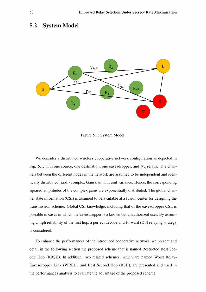
58 Improved Relay Selection Under Secrecy Rate Maximization
5.2 System Model
Figure 5.1: System Model.
We consider a distributed wireless cooperative network configuration as depicted in
Fig. 5.1, with one source, one destination, one eavesdropper, and NR
relays. The chan-
nels between the different nodes in the network are assumed to be independent and iden-
tically distributed (i.i.d.) complex Gaussian with unit variance. Hence, the corresponding
squared amplitudes of the complex gains are exponentially distributed. The global chan-
nel state information (CSI) is assumed to be available at a fusion center for designing the
transmission scheme. Global CSI knowledge, including that of the eavesdropper CSI, is
possible in cases in which the eavesdropper is a known but unauthorized user. By assum-
ing a high reliability of the first hop, a perfect decode-and-forward (DF) relaying strategy
is considered.
To enhance the performances of the introduced cooperative network, we present and
detail in the following section the proposed scheme that is named Restricted Best Sec-
ond Hop (RBSH). In addition, two related schemes, which are named Worst Relay-
Eavesdropper Link (WREL), and Best Second Hop (BSH), are presented and used in
the performances analysis to evaluate the advantage of the proposed scheme.
5.3 Related and Proposed Schemes 59
5.3 Related and Proposed Schemes
In this section we describe the principle of the related and proposed schemes, and we
derive the corresponding probability density functions (PDF) of the received SNR.
5.3.1 Best Second Hop (BSH) Scheme
Within the BSH scheme, the choice of the best relay does not rely on the best relay-
eavesdropper link, i.e., the relay that have the strongest link with the destination will be
chosen without take into consideration the quality of the link between the best relay and
the eavesdropper. In addition, within this scheme, the relays are assumed to perfectly
decode the message sent by the source and use the same codeword to send it to the des-
tination, and hence the first link will not be considered in the choice of the best relay.
Based on that, the best relay is the one that offers the best received SNR at the desti-
nation, which is denoted by γR∗D and verifies : γ
R∗D = max(γRkD
), where γRkD
is the
instantaneous SNRs of the links between the kth relay and the destination.
By using the order statistics and the binomial expansion form [94], the PDF of γR∗D for
this method is expressed as follows
pR∗D(γ
R∗D) =
NR∑k=1
(NRk
) k (−1)k−1
γRD
exp
(−kγ
R∗D
γRD
), (5.1)
where, γRD
is the average SNR of the link between a relay and the destination.
Let γSD
, γSE
, and γR∗E be the instantaneous SNRs of the source-destination link, the
source-eavesdropper link, and the best selected relay-eavesdropper link, respectively.
By assuming that all the link experience independent Rayleigh fading, the PDF expres-
sions of γSD
, γSE
and γR∗E are given, respectively, by
pSD
(γSD
) =1
γSD
exp
(−γSDγSD
), (5.2)
pSE
(γSE
) =1
γSE
exp
(−γSEγSE
), (5.3)
and
pR∗E(γ
R∗E) =1
γRE
exp
(−γR∗E
γRE
), (5.4)

60 Improved Relay Selection Under Secrecy Rate Maximization
where, γSD
, γSE
, and γRE
are the average SNRs of γSD
, γSE
, and γRE
, respectively.
At the destination, Maximum Ratio Combining (MRC) is adopted and the combined SNR
can be written as γeqD
= γR∗D + γ
SD. Due to the independence of γ
R∗D and γSD
, the PDF
of γeqD
can be obtained through the convolution of the PDFs of γR∗D and γ
SDas follows
pD
(γeq
D) =
∫ γeq
D
0
pR∗D(τ) p
SD(γ
eq
D− τ) dτ. (5.5)
After evaluating the integration in (5.5), p(γeqD
) can be expressed as
pD
(γeq
D) =
NR∑k=1
(NRk
) k (−1)k−1
k γSD− γ
RD
[exp
(−γeq
D
γSD
)− exp
(−kγ
eq
D
γRD
)]. (5.6)
At the eavesdropper, the PDF expression of the equivalent received SNR can be derived
as as follows
pE
(γeq
E) =
∫ γeq
E
0
pR∗E(τ) p
SE(γ
eq
E− τ) dτ
=1
γSE− γ
RE
[exp
(−γeq
E
γSE
)− exp
(−γeq
E
γRE
)], (5.7)
where, γeqE
= γR∗E + γ
SE.
5.3.2 Worst Relay-Eavesdropper Link (WREL) Scheme
The relay selection within WREL scheme is based on the relay-eavesdropper links with-
out take in consideration the link between the relay and the destination. In this scheme the
relay that provides the worst received SNR at the eavesdropper is selected to retransmit
the message. The instantaneous SNR of the link between the selected relay and the eaves-
dropper can be evaluated as follows : αR∗E = min(γ
RkE), where γ
RkEis the instantaneous
SNRs of the links between the kth relay and the eavesdropper.
Consequently, the PDF of the received SNR (αR∗E )for the link between the selected relay
and the Eavesdropper is expressed as
fR∗E(α
R∗E) =NR
γRE
exp
(−NRαR∗E
γRE
), (5.8)
and the PDF expression of the received SNR for the link between the selected relay and
the destination is given by
fR∗D(α
R∗D) =1
γRD
exp
(−αR∗D
γRD
). (5.9)

5.3 Related and Proposed Schemes 61
By using the MRC receiver at the destination, the PDF of the equivalent received SNR
(αeqD
= αR∗D + γ
SD) can be derived as follows
fD
(αeq
D) =
∫ αeq
D
0
fR∗D(τ) p
SD(α
eq
D− τ) dτ
=1
γSD− γ
RD
[exp
(−αeq
D
γSD
)− exp
(−αeq
D
γRD
)]. (5.10)
While, the PDF of the equivalent received SNR at the eavesdropper (αeqE
= αR∗E + γ
SE)
can be derived as follows
fE
(αeq
E) =
∫ αeq
E
0
fR∗E(τ) p
SE(α
eq
E− τ) dτ
=NR
NRγSE− γ
RE
[exp
(−αeq
E
γSE
)− exp
(−NRαeq
E
γRE
)]. (5.11)
5.3.3 Restricted Best Second Hop (RBSH) Scheme
The best relay selection algorithm within RBSH scheme consists of the following steps:
1. Choose a subgroup (Ω = Ri|γRiE < γth) of relays that comply with the con-
dition: γRiE
< γth, where γth
is an SNR threshold on below of which, the eaves-
dropper is considered not listening to the message sent from the ith relay to the
destination.
2. Choose the relay among Ω that has the highest received SNR:
βR∗D = max(γ
RiD|R
i∈ Ω).
3. If Ω = ∅, then only the direct transmission link will be used.
The probability that the eavesdropper is not listening to the message sent from a given
relay k to the destination can be expressed as follows
PNL
= P (γRkE
< γth)
=
∫ γth
0
1
γRE
exp
(−γRkE
γRE
)dγ
RkE
= 1− exp
(− γthγRE
). (5.12)
The next step is to choose from Ω the relay which maximizes the SNR of the second hop
γRiD
. The probability that at least one relay is satisfying the security constraint can be

62 Improved Relay Selection Under Secrecy Rate Maximization
written, by using the binomial distribution, as follows
NR∑
k=1
(NR
k
)Pk
NLPNR−k
L, (5.13)
where,(NR
k
)=
NR
!
k! (NR−k)!
, and PL(= 1 − P
NL) is the probability that the eavesdropper
is listening to the message sent from a given relay. By using the order statistics and the
binomial expansion form [94], the PDF of βR∗D under the above mentioned constraint is
given by
gR∗D(β
R∗D) =
NR∑
k=1
(NR
k
)Pk
NLPNR−k
L
k∑i=1
(ki
) i (−1)i−1
γRD
exp
(−iβ
R∗D
γRD
). (5.14)
By using an MRC receiver, the equivalent SNR at the destination, denoted by βeqD
, can
be evaluated as the sum of βR∗D and γ
SDif Ω 6= ∅, and it is equal to γ
SD, if only the
direct link is used, e.g., Ω = ∅. Consequently, the corresponding PDF can be written
as follows
gD
(βeq
D) =
∫ βeq
D
0
gR∗D(τ) p
SD(β
eq
D− τ) dτ + P
NR
LpSD
(βeq
D)
=
NR∑
k=1
(NR
k
)Pk
NLPNR−k
L
k∑i=1
(ki
) i(−1)i−1
γSDγRD
exp
(−βeqD
γSD
)∫ βeq
D
0
exp
(τ
γSD
− iτ
γRD
)dτ
+PNR
L
γSD
exp
(−βeqD
γSD
). (5.15)
By evaluating the integral in (5.15), gD
(βeq
D) can be further simplified to
gD
(βeq
D) =
NR∑
k=1
(NR
k
)P kNLP
NR−k
L
k∑i=1
(ki
) i(−1)i−1
iγSD− γ
RD
[exp
(−βeqD
γSD
)− exp
(−iβeqD
γRD
)]
+PNR
L
γSD
exp
(−βeqD
γSD
). (5.16)
By respecting the security constraint, when the source is transmitting, the eavesdrop-
per is not getting any information from the best relay. Hence, the total PDF expression of
the equivalent received SNR (βeqE
) at the eavesdropper is given by
gE
(βeq
E) = p
SE(β
eq
E). (5.17)
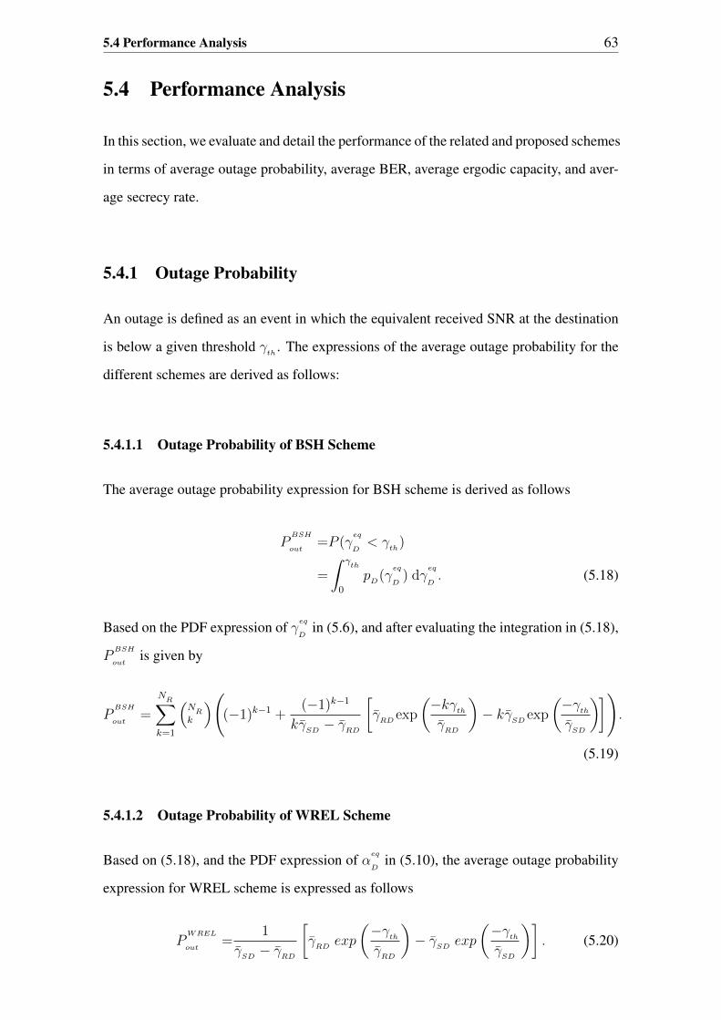
5.4 Performance Analysis 63
5.4 Performance Analysis
In this section, we evaluate and detail the performance of the related and proposed schemes
in terms of average outage probability, average BER, average ergodic capacity, and aver-
age secrecy rate.
5.4.1 Outage Probability
An outage is defined as an event in which the equivalent received SNR at the destination
is below a given threshold γth
. The expressions of the average outage probability for the
different schemes are derived as follows:
5.4.1.1 Outage Probability of BSH Scheme
The average outage probability expression for BSH scheme is derived as follows
PBSH
out=P (γ
eq
D< γ
th)
=
∫ γth
0
pD
(γeq
D) dγ
eq
D. (5.18)
Based on the PDF expression of γeqD
in (5.6), and after evaluating the integration in (5.18),
PBSH
outis given by
PBSH
out=
NR∑
k=1
(NR
k
)((−1)k−1 +
(−1)k−1
kγSD− γ
RD
[γRD
exp
(−kγ
th
γRD
)− kγ
SDexp
(−γ
th
γSD
)]).
(5.19)
5.4.1.2 Outage Probability of WREL Scheme
Based on (5.18), and the PDF expression of αeqD
in (5.10), the average outage probability
expression for WREL scheme is expressed as follows
PWREL
out=
1
γSD− γ
RD
[γRD
exp
(−γ
th
γRD
)− γ
SDexp
(−γ
th
γSD
)]. (5.20)

64 Improved Relay Selection Under Secrecy Rate Maximization
5.4.1.3 Outage Probability of RBSH Scheme
Based on the PDF expression of βeqD
in (5.16), and according to (5.18), the average outage
probability expression for BRSH scheme is expressed as follows
PRBSH
out=
NR∑
k=1
(NR
k
)P kNL
PNR−k
L
k∑i=1
(ki
)((−1)i−1 +
(−1)i−1
iγSD− γ
RD[γRD
exp
(−iγ
th
γRD
)− i γ
SDexp
(−γ
th
γSD
)])+ PN
RL
[1− exp
(−γ
th
γSD
)].
(5.21)
5.4.2 Average Bit Error Rate (BER)
In this section, we derive the expressions of BER for the different schemes. Without loss
of generality, the BPSK is the used modulation in this evaluation.
5.4.2.1 BER of BSH Scheme
For BPSK modulation, the average BER expression for BSH scheme is derived as follows
[95]
PBSH
e=
∫ ∞0
Q(√
2 γeqD
)pD
(γeq
D) dγ
eq
D. (5.22)
Based on ([95], Eq. A2), we have
∫ ∞0
Q(√
2 x)
exp(−µx) dx =1
2µBinc µ
1+µ
[1,
1
2
], ∀ µ > 0, (5.23)
where, Binc(.)[., .] is the incomplete Beta function [96], By using the expression of pD
in
(5.6), and (5.23), PBSH
ecan be derived and expressed as follows
PBSH
e=
NR∑
k=1
(NR
k
) (−1)k−1
2(k γSD− γ
RD)
(k γ
SDBincx
SD
[1,
1
2
]− γ
RDBincx
RD
[1,
1
2
]),
(5.24)
where, xSD
= 11+γ
SD, and x
RD= k
k+γRD
.

5.4 Performance Analysis 65
5.4.2.2 BER of WREL Scheme
Based on the derivation of (5.24), and the PDF fD
(αeq
D), the average BER for WREL
scheme is derived as follows
PWREL
e=
∫ ∞0
Q(√
2 αeqD
)fD
(αeq
D) dα
eq
D
=1
2( γSD− γ
RD)
(γSD
BincxSD
[1,
1
2
]− γ
RDBincy
RD
[1,
1
2
]), (5.25)
where, yRD
= 11+γ
RD.
5.4.2.3 BER of RBSH Scheme
The average BER of RBSH scheme with BPSK modulation can be derived as follows
PRBSH
e=
∫ ∞0
Q(√
2 βeqD
)gD
(βeq
D) dβ
eq
D. (5.26)
Based on the expression of gD
in (5.16), and (5.23), the average BER of SBSH scheme is
expressed as
PRBSH
e=
NR∑
k=1
(NR
k
)Pk
NLPNR−k
L
k∑i=1
(ki
) (−1)i−1
2(i γSD− γ
RD)(
i γSD
BincxSD
[1,
1
2
]− γ
RDBincz
RD
[1,
1
2
])+PNR
L
2
(1−
√γSD
1 + γSD
),
(5.27)
where, zRD
= ii+γ
RD.
5.4.3 Average Ergodic Capacity and Secrecy Rate
In this section, we derive the expressions of the average ergodic capacity for the differ-
ent schemes at the destination and the eavesdropper. The derived expressions are used
to evaluate the average secrecy rate for each scheme, which is given by the difference
between the average ergodic capacity at the destination and the average ergodic capacity
at the eavesdropper. The ergodic capacity characterizes the transmission channel. It is
defined as the number of bits that can be transmitted without error per unit time and via a
unit frequency, e.g., [bps/Hz].
In the following we derive the expressions of the ergodic capacity for the different schemes.

66 Improved Relay Selection Under Secrecy Rate Maximization
5.4.3.1 Average Ergodic Capacity of BSH Scheme
The average ergodic capacity for BSH scheme at the destination can be derived as follows
CBSH
=
∫ +∞
0
1
2log2(1 + γ
eq
D) p
D(γ
eq
D) dγ
eq
D. (5.28)
Based on ([96] , Eq. 4.331.2), we have∫ +∞
1
exp(−µx) ln(x) dx =−1
µEint(−µ), ∀µ > 0, (5.29)
where, Eint(.) is the exponential integral function [96]. By using the change in variable
: v = 1 + γeq
Din (5.28), and based on the expression of p
Din (5.6), the average ergodic
capacity of BSH scheme can be derived using (5.29) and expressed as
CBSH
D=
NR∑
k=1
(NR
k
) (−1)k−1
2ln(2)(γRD− γ
SD)
[γSD
exp
(1
γSD
)Eint
(−1
γSD
)
− γRD
kexp
(k
γRD
)Eint
(−kγRD
)]. (5.30)
At the eavesdropper, and based on the derivation of (5.30), the average ergodic capacity
expression is given by
CBSH
E=
1
2ln(2)(γRE− γ
SE)
[γSE
exp
(1
γSE
)Eint
(−1
γSE
)
− γRE
exp
(1
γRE
)Eint
(−1
γRE
)]. (5.31)
5.4.3.2 Average Ergodic Capacity of WREL Scheme
By analogy with the derivations of (5.30) and (5.31), the average ergodic capacity expres-
sions at the destination and the eavesdropper are given by
CWREL
D=
1
2ln(2)(γRD− γ
SD)
[γSD
exp
(1
γSD
)Eint
(−1
γSD
)
−γRD
exp
(1
γRD
)Eint
(−1
γRD
)], (5.32)
and
CWREL
E=
NR
2ln(2)(γRE−N
RγSE
)
[γSE exp
(1
γSE
)Eint
(−1
γSE
)
− γRE
NR
exp
(NR
γRE
)Eint
(−N
R
γRE
)], (5.33)
respectively.

5.5 Numerical Results 67
5.4.3.3 Average Ergodic Capacity of RBSH Scheme
For this scheme, the average ergodic capacity at the destination is derived as follows
CRBSH
D=
∫ +∞
0
1
2log2(1 + β
eq
D)g
D(β
eq
D|βeq
D= β
R∗D + γSD
) dβeq
D
+
∫ +∞
0
log2(1 + βeq
D)p
SD(β
eq
D|βeq
D= γ
SD) dβ
eq
D. (5.34)
After evaluating the integration in (5.34) using (5.29), CRBSH
Dcan be expressed as
CRBSH
D=
NR∑
k=1
(NR
k
) (−1)k−1
2ln(2)(γRD− γ
SD)
[γSD
exp
(1
γSD
)Eint
(−1
γSD
)
− γRD
kexp
(k
γRD
)Eint
(−kγRD
)]−PNR
L
ln(2)exp
(1
γSD
)Eint
(−1
γSD
). (5.35)
At the eavesdropper, and based on (5.17), and (5.29), the average ergodic capacity can
be derived as follows
CRBSH
E=
∫ +∞
0
1
2log2(1 + β
eq
E) p
SE(β
eq
E) dβ
eq
E
=−1
2ln(2)exp
(1
γSE
)Eint
(−1
γSE
). (5.36)
5.5 Numerical Results
In this section, we present the simulation setup, and the simulation results to evaluate the
derived expressions as well as the performances of the different schemes.
5.5.1 Simulation Setup
In the simulation setup, we assume that the average SNR of the direct link is proportional
to the average SNR of the second hop as: γSD
= 0.2 γRD
. The average SNR between the
relays and destination is the same as that between relays and eavesdropper. The source
and the relays are using a unit transmissions power. The number of relays and the value
of interference threshold are varying as shown in the simulation figures.

68 Improved Relay Selection Under Secrecy Rate Maximization
5.5.2 Simulation Results Interpretation
Fig. 5.2 presents the variations of the average outage probability for the different
scheme vs. the number of relays, with γth
= 10 dB. This figure reveals that the BSH
method offers a lower outage probability than the other three methods. This is because,
the probability to select the best relay in term of second hop SNR is high within this
scheme compared to the other schemes. We notice also that the outage probability of
WREL is constant, this is due to the fact that it does not depend on the number of relays,
i.e., it is based only on the quality of the selected relay-eavesdropper link.
Fig. 5.3 shows the outage probability behaviors for the different scheme vs. γRD
, with
γth
= 10 dB. As shown in this figure, when the average SNR is below 15 dB, RBSH
scheme offers a better result than WRLS scheme since there are relays that are satisfying
the security condition. But when the average SNR is higher than 15 dB, RBSH scheme
does not offer better results because none of the relays satisfies this condition. BSH
scheme outperforms the other schemes. This is because this scheme is not limited by the
security conditions as the case in the other schemes.
Fig. 5.4 shows the average BER performance of the different schemes vs. the number
of relays. Similar to the outage probability behavior, we remark that the BSH scheme
outperforms the other schemes in term of BER, and the WREL scheme presents a constant
lowest performance as it does not depend on the number of the relays.
Fig. 5.5 shows the secrecy rates achieved by the three studied methods while changing
the number of relays. It is noticeable that RBSH scheme is realizing better secrecy rate
than the other two methods. This is because the RBSH scheme is based on the quality of
both the best selected relay - destination link and the best selected relay - eavesdropper
link, which is not the case for the two other schemes.
Fig. 5.6 shows the secrecy rates achieved by the three methods while changing γRD
.
Similar to the outage probability behaviors, when the average SNR is below 12 dB, RBSH
scheme offers better results since there are relays that are satisfying the security condition.
But when the average SNR is higher than 12 dB, RBSH scheme does not offer better
results because none of the relays satisfies this condition.

5.5 Numerical Results 69
Number of relays1 2 3 4 5 6 7 8 9 10
Out
age
Pro
babi
lity
10-5
10-4
10-3
10-2
10-1
100
RBSH (Theo)
RBSH (Sim)
BSH (Theo)
BSH (Sim)
WREL (Theo)
WREL (Sim)
Figure 5.2: Average outage probability vs. number of relays, with γth = 10 dB.
SNR (dB)0 5 10 15 20 25 30
Out
age
Pro
babi
lity
10-10
10-9
10-8
10-7
10-6
10-5
10-4
10-3
10-2
10-1
100
RBSH (Theo)
RBSH (Sim)
BSH (Theo)
BSH (Sim)
WREL (Theo)
WREL (Sim)
Figure 5.3: average outage probability vs. SNR, with γth = 10 dB.

70 Improved Relay Selection Under Secrecy Rate Maximization
1 2 3 4 5 6 7 8 9 1010
−7
10−6
10−5
10−4
10−3
10−2
10−1
Number of relays
Unc
oded
BE
R
RBSH (Theo)BSH (Theo)WREL (Theo)RBSH (Sim)RBSH (Sim)RBSH (Sim)
Figure 5.4: Average BER vs. number of relays.
1 2 3 4 5 6 7 8 9 100
0.1
0.2
0.3
0.4
0.5
0.6
0.7
0.8
0.9
1
Number of relays
Sec
recy
Rat
e (
bits
/ s
/ Hz
)
RBSHBSHWREL
Figure 5.5: Average secrecy rate vs. number of Relays.

5.6 Conclusion 71
0 5 10 15
0.4
0.5
0.6
0.7
0.8
0.9
1
1.1
SNR (dB)
Sec
recy
Rat
e (
bits
/ s
/ Hz
)
RBSHBSHWREL
Figure 5.6: Secrecy rate vs. average second hop SNR.
5.6 Conclusion
In this chapter, we have proposed an efficient cooperative communications scheme which
maximizes the secrecy rate. The new scheme is based on best relay selection method
that maximizes the secrecy rate and benefits from increasing the number of relays under
QoS constraint at the destination. Performance analysis have been conducted in terms of
secrecy rate, outage probability, and BER. Simulations results have been used to confirm
the mathematical derivations and an agreement results have been observed. The results
confirm the better secrecy rate of the introduced transmission scheme compared to well
established techniques introduced in the literature.

Chapter 6
General Conclusion and Perspectives
6.1 General Conclusion
In this thesis, solutions were proposed to the following femtocell network challenges:
energy efficiency, spectrum sharing and security.
The Ph.D. thesis has been structured in 6 chapters:
The first chapter has presented the general introduction of the thesis. It has described
the problem statement and the motivations. After that, the contributions of this thesis
have been presented and detailed, and which have been mainly focusing on three axis;
proposing new handover algorithms or relay selection schemes, deriving closed form ex-
pressions of different evaluative performances metrics, and making proper simulations to
validate the analytical results. In addition the list of publications during the thesis period
has been introduced. Finally, the thesis organization has been presented.
In chapter 2, a study on the communication networks state of the art is made. We
detailed the challenges brought by the introduction of the femtocell networks and investi-
gated existing works in the field.
In chapter 3, the objective was to find a way to minimize the energy consumption
of femtocells in macro/femto-cellular BWA networks. After a documentation phase, we
could determine where our contribution can lead us to the above mentioned objective.
In fact, the handovers classification by their probabilistic importance and their nature:
wanted or unwanted, allowed us to achieve a minimal gain of 5% in energy consumption
compared to another solution in literature.
6.1 General Conclusion 73
We elaborated the mathematical model of our solution from which we could demonstrate,
with the help of the implemented simulations, that we achieved our goal by finding a way
to minimize the energy consumption of femtocells.
The subject treated in this chapter is considered by specialists as one of the most sensitive
topics in the field of telecommunications since it deals with energy management which is
a universal problem.
In chapter 4, we have proposed a decision handover algorithm in the femtocell-LTE
networks. We developed a decision handover algorithm with consideration of the Poi-
son distribution model of spectrum mobility. This algorithm is based on the minimum
expected transmission time within the dwell time of the UE in the coverage of the femto-
cell.
We have provided the mathematical analysis and the performance simulation to illustrate
that the proposed algorithm reduces significantly the expected transmission time and the
spectrum mobility ratio.
We have proposed in chapter 5 an efficient cooperative communications scheme which
maximizes the secrecy rate. The new scheme is based on best relay selection method
that maximizes the secrecy rate and benefits from increasing the number of relays under
QoS constraint at the destination. Performance analysis have been conducted in terms of
secrecy rate, outage probability, and BER. Simulations results have been used to confirm
the mathematical derivations and an agreement results have been observed. The results
confirm the better secrecy rate of the introduced transmission scheme compared to well
established techniques introduced in the literature.

74 General Conclusion and Perspectives
6.2 Future Work
When deployed, femtocell networks will count a huge number of devices spread on
the residential and industrial maps. The idea is to use this windfall as an opportunity
to optimize UEs connections under energy consumption constraint. In fact, femtocells
can be used as relays between sources and destinations. The latter can be, UEs or
macro/femtocells. Green IT is currently one of the hottest topics in ICT. In fact, En-
ergy efficiency is a key indicator in the communication systems with limited lifetime of
the batteries used to supply the wireless devices. Many efforts have been spent on the
efficient use of battery energy, especially in wireless sensor network, where battery in-
stalled on sensors are limited and replacing them becomes difficult due to inaccessibility
of the sensors. Therefore, seeking new source of energy to prolong the lifetime of the
energy-constrained wireless network becomes a spotlight.
Recent progress in electronics have revealed that energy harvesting, a process that
helps capturing and storing the energy derived from ambient or external sources, is an
alternative for prolonging the lifetime of a wireless network and a key enabling technology
in the development of wireless sensor networks (WSNs).
Energy harvesting has received significant attention recently, where the surrounding
energy can be harvested from a large variety of physical natures, such as solar, vibration,
thermal or acoustic energy sources. Apart from the conventional energy harvesting meth-
ods, a new emerging solution is to avail ambient RF signals, since RF signals can carry
energy and information at the same time. Thus, energy constrained nodes can scavenge
energy and process the information simultaneously.

Bibliography
[1] Prasun Chowdhury, Anindita Kundu, Saha Misra, and Salil K Sanyal, “Load bal-
ancing with reduced unnecessary handoff in hierarchical macro/femto-cell wimax
networks,” International Journal of Wireless & Mobile Networks (IJWMN), vol. 4,
no. 3, 2012.
[2] M. Rumney, LTE and the Evolution to 4G Wireless Design and Measurement Chal-
lenges, Agilent Technologies Publication, 2009.
[3] A. Omri, R. Hamila, M. Hasna, R. Bouallegue, and H. Chamkhia, “Estimation of
Highly Selective Channels for Downlink LTE MIMO-OFDM System by a Robust
Neural Network.,” International Journal of Ubiquitous Systems and Pervasive Net-
works (IJUSPN)., vol. 2, no. 1, pp. 31– 38, 2011.
[4] S.Frattasi, H.Fathi, F.H.P.Fitzek, R.Prasad, and M.D.Katz, “Defining 4G Technol-
ogy from the Users Perspective,” IEEE Network, vol. 20, pp. 35–41, 2006.
[5] Vikram Chandrasekhar and Jeffrey G. Andrews, “Uplink capacity and interference
avoidance for two-tier femtocell networks,” IEEE Transactions on Wireless Com-
munications, 2009.
[6] R. Kim, J. S. Kwak, and K. Etemad, “Wimax femtocell: requirements, challenges,
and solutions,” IEEE Transactions on Wireless Communications, vol. 47, no. 9, pp.
84 –91, 2009.
[7] A. Barbieri, A. Damnjanovic, T. Ji, J. Montojo, Y. Wei, D. P. Malladi, O. Song,
and G. Horn, “The downlink inter-cell interference problem in rel-10 lte femtocell
networks,” IEEE JSAC Special Issue on Femtocell Networks, 2012.

76 BIBLIOGRAPHY
[8] A. Ghosh, J. Zhang, J. G. Andrews, and R. Muhamed, Fundamentals of LTE.
Prentice-Hall, 2010.
[9] P. Xia, V. Chandrasekhar, and J. G. Andrews, “Open vs. closed access femtocells
in the uplink,” IEEE Transactions on Wireless Communications, vol. 9, no. 10, pp.
3798 – 3809, 2010.
[10] 3GPP TS 36.300, Evolved Universal Terrestrial Radio Access (E-UTRA) and
Evolved Universal Terrestrial Radio Access Network (E-UTRAN); Overall descrip-
tion; Stage 2), 2011.
[11] 3GPP TS 36.816, Evolved Study on Management of Evolved Universal Terrestrial
Radio Access Network (E-UTRAN) and Evolved Packet Core (EPC), 2011.
[12] 3GPP TS 32.500, Telecommunication Management; Self-Organizing Networks
(SON); Concepts and requirements, 2011.
[13] 3GPP TS 36.902, Self-Configuring and Self-Optimizing Network Use Cases and
Solutions, 2011.
[14] D. Lopez-Perez, A. Ladanyi, A. Juttner, and J. Zhang, “Ofdma femtocells: A self-
organizing approach for frequency assignment,” PIMRC, p. 2202–2207, 2009.
[15] S. Feng and E. Seidel, “Self-organizing networks (SON) in 3GPP long term evolu-
tion,” NOMOR whitepaper, 2010.
[16] Nestor Gonzalez and Luis Moron, Publication Telefonica, Green IT, Green Telecom
Networks, chapter 4, 2009.
[17] H. Zhou, H. Luo, H. Zhang, C.H. Lo, and H.C. Chao, “A network-based global mo-
bility management architecture,” International Journal of Ad Hoc and Ubiquitous
Computing, vol. 5, no. 1, pp. 1–6, 2010.
[18] A. Kumar, A.K. Sarje, and M. Misra, “Prioritised predicted region based cache re-
placement policy for location dependent data in mobile environment,” International
Journal of Ad Hoc and Ubiquitous Computing, vol. 5, no. 1, pp. 55–67, 2010.

BIBLIOGRAPHY 77
[19] H. Oh, K. Yoo, J. Na, and C. Kim, “A seamless handover scheme in ipv6-based
mobile networks,” International Journal of Ad Hoc and Ubiquitous Computing,
vol. 4, no. 1, pp. 54–60, 2010.
[20] J.M. Moon and D.H. Cho, “Novel handoff decision algorithm in hierarchical
macro/femto-cell networks,” Proc. IEEE Wireless Communications and Network-
ing Conference, WCNC, pp. 1–6, 2010.
[21] S. Wu, X. Zhang, R. Zheng, Z. Yin, Y. Fang, and D. Yang, “Handover study con-
cerning mobility in the two-hierarchy network,” Proc. IEEE Vehicular Technology
Conference, VTC, pp. 1–5, 2009.
[22] A. Ulvan, R. Bestak, and M. Ulvan, “The study of handover procedure in lte-
based femtocell network,” Proc. IEEE Wireless and Mobile Networking Conference,
WMNC, pp. 1–6, 2010.
[23] H. Zhang, X. Wen, B. Wang, W. Zheng, and Y. Sun, “A novel handover mecha-
nism between femtocell and macrocell for lte based networks,” Proc. International
Conference on Communication Software and Networks, ICCSN, pp. 228–231, 2010.
[24] I. Ashraf, Lester T.W. Ho, and H. Claussen, “Improving energy efficiency of femto-
cell base stations via user activity detection,” Proc. Communications and Network-
ing Conference, WCNC, pp. 1–5, 2010.
[25] H. Claussen, I. Ashraf, and Lester T.W. Ho, “Dynamic idle mode procedures for
femtocells,” Bell Labs Technical Journal, vol. 15, no. 2, pp. 95–116, 2010.
[26] Yuh-Shyan Chen and Cheng-You Wu, “A green handover protocol in two-tier ofdma
macrocell-femtocell networks,” Mathematical and Computer Modelling, 2012.
[27] S. Kishore, L. J. Greenstein, H. V. Poor, and S. C. Schwartz, “Soft handoff and
uplink capacity in a two-tier cdma system,” IEEE Transactions on Wireless Com-
munications, vol. 4, no. 4, pp. 1297–1301, 2005.
[28] A. Damnjanovic, J. Montojo, Y. Wei, T. Ji, T. Luo, M. Vajapeyam, T. Yoo, O. Song,
and D. Malladi, “A survey on 3gpp heterogeneous networks,” IEEE Wireless Com-
munications, vol. 18, no. 3, pp. 10 –21, 2011.

78 BIBLIOGRAPHY
[29] Sahin ME, Guvenc I, Moo-Ryong J, and Arslan H, “Handling cci and ici in ofdma
femtocell networks through frequency scheduling,” Consum. Elect. IEEE Transact.,
vol. 55, no. 4, pp. 1936–1944, 2009.
[30] H. S. Jo, P. Xia, and J. G. Andrews, “Downlink femtocell networks: Open or
closed?,” IEEE International Conference on Communications, 2011.
[31] Femto Forum, Interference Management in OFDMA Femtocells, 2010.
[32] 3GPP TR 25.820, 3G Home NodeB Study Item Technical Report, 2011.
[33] RP-100372, New Work Item Proposal: Enhanced ICIC for non-CA based deploy-
ments of heterogeneous networks for LTE, 2010.
[34] V. Chandrasekhar, J. Andrews, Z. Shen, T. Muharemovic, and A. Gatherer, “Power
control in two-tier femtocell networks,” IEEE Transactions on Wireless Communi-
cations, vol. 8, no. 8, pp. 4316–28, 2009.
[35] G. Fodor, C. Koutsimanis, A. Racz, N. Reider, A. Simonsson, and W. Muller, “Inter-
cell interference coordination in ofdma networks and in the 3gpp long term evolution
system,” J. Comm., vol. 4, no. 7, pp. 445–453, 2009.
[36] G. Boudreau, J. Panicker, N. Guo, R. Chang, N. Wang, and S. Vrzic, “Interference
coordination and cancellation for 4G networks,” IEEE Comm. Mag., vol. 47, no. 4,
pp. 74–81, 2009.
[37] Serkan Uygungelen, Gunther Auer, and Zubin Bharucha, “Graph-based dynamic
frequency reuse in femtocell networks,” VTC, 2011.
[38] H. Widiarti, S. Pyun, and D. Cho, “Interference mitigation based on femtocells
grouping in low duty operation,” Proc. IEEE 72nd Vehicular Technology Conference
Fall (VTC’10-Fall), 2010.
[39] 3GPP R1-105238, Further Discussion on HeNB Downlink Power Setting in HetNet,
2010.
[40] D. Niyato, E. Hossain, and Z. Han, “Dynamics of multiple-seller and multiple-
buyer spectrum trading in cognitive radio networks: A game-theoretic modeling
approach,” IEEE Trans. Mobile Comput., vol. 8, no. 8, pp. 1009–1022, 2009.

BIBLIOGRAPHY 79
[41] Jia-Shi Lin and Kai-Ten Feng, “Game theoretical model and existence of win-win
situation for femtocell networks,” IEEE ICC 2011 proceedings, 2011.
[42] H.-S. Jo, C. Mun, J. Moon, and J.-G. Yook, “Interference mitigation using uplink
power control for two-tier femtocell networks,” IEEE Trans. on Wireless Communi-
cations, vol. 8, no. 10, pp. 4906–4910, 2009.
[43] Femto Forum, Interference management in UMTS femtocells, 2008.
[44] L. Poongup, L. Taeyoung, J. Jangkeun, and S. Jitae, “Interference management in
lte femtocell systems using fractional frequency reuse,” Proc. 12th International
Conference on Advanced Communication Technology, vol. 2, pp. 1047–1051, 2010.
[45] Su Huan, Kuang Linling’, and Lu Jianhua, “Interference avoidance in ofdma-
based femtocell network,” IEEE Youth Conference on Information, Computing and
Telecommunication, pp. 126–129, 2009.
[46] Hongjia Li, Xiaodong Xu, Dan Hu, Xiqiang Qu, Xiaofeng Tao, and Ping Zhang,
“Graph method based clustering strategy for femtocell interference management and
spectrum efficiency improvement,” Wireless Communications Networking and Mo-
bile Computing (WiCOM), pp. 1–5, 2010.
[47] T. Kim and T. Lee, “Throughput enhancement of macro and femto networks by fre-
quency reuse and pilot sensing,” Proc. IEEE International Performance, Computing
and Communications Conference (IPCCC), p. 390–394, 2008.
[48] L. G. U. Garcia, K. I. Pedersen, and P. E. Mogensen, “Autonomous compo-
nent carrier selection: Interference management in local area environments for lte-
advanced,” Communications Magazine, IEEE, 2009.
[49] R. Juang, P. Ting, H. Lin, and D. Lin, “Interference management of femto-
cell in macro-cellular networks,” Proc. Wireless Telecommunications Symposium
(WTS’10), p. 1–4, 2010.
[50] S. Srinivasa and S. A. Jafar, “The throughput potential of cognitive radio: A theo-
retical perspective,” IEEE Commun. Mag., vol. 45, no. 5, pp. 73–79, 2007.

80 BIBLIOGRAPHY
[51] R. Madan, A. Sampath, A. Khandekar, J. Borran, and N. Bhushan, “Dis-
tributed interference management and scheduling in LTE-A femto networks,”
Proc.GLOBECOM, p. 1–5, 2010.
[52] T. Akbudak and A. Czylwik, “Distributed power control and scheduling for decen-
tralized ofdma networks,” International ITG Workshop on Smart Antennas (WSA),
p. 59 – 65, 2010.
[53] Sahin ME, Guvenc I, Moo-Ryong J, and Arslan H, “Handling cci and ici in ofdma
femtocell networks through frequency scheduling,” Consum. Elect. IEEE Transact.,
pp. 1936–1944, 2009.
[54] P. Jänis, V. Koivunen, and C.B. Ribeiro, “Interference-aware radio resource man-
agement for local area wireless networks,” EURASIP J. Wireless Comm. and Net-
working, 2011.
[55] T. Lan, K. Sinkar, L. Kant, and K.J. Kerpez, “Resource allocation and performance
study for lte networks integrated with femtocells,” Proc. GLOBECOM, 2010.
[56] Mustafa Y. Arslan, Jongwon Yoon, Karthikeyan Sundaresan, Srikanth V. Krishna-
murthy, and Suman Banerjee, “Fermi: a femtocell resource management system for
interference mitigation in ofdma networks,” MOBICOM, 2011.
[57] IST-WINNER II Deliverable 1.1.2 v.1.2, WINNER II Channel Models, 2007.
[58] D. Niyato and E. Hossain, “Dynamic of network selection in heterogeneous wireless
networks: an evolutionary game approach,” Proc. 12th International Conference on
Advanced Communication Technology, vol. 58, no. 2, pp. 2651–2660, 2009.
[59] L. Busoniu, R. Babuska, and B. D. Schutter, “A comprehensive survey of multiagent
reinforcement learning,” Trans. Systems, Man and Cybernetics, vol. 38, no. 2, pp.
156–172, 2008.
[60] Mehdi Bennis and Dusit Niyato, “A q-learning based approach to interference avoid-
ance in self-organized femtocell networks,” GLOBECOM Workshops (GC Wkshps),
2010 IEEE, 2010.

BIBLIOGRAPHY 81
[61] D. Fudenberg and D. K. Levine, “The theory of learning in games,” The MIT Press,
1998.
[62] H. Li, “Multi-agent q-learning of channel selection in multi-user cognitive radio
systems: A two by two case,” IEEE Conference on System, Man and Cybernetics
(SMC), 2009.
[63] F. Fu and M. van der Schaar, “Learning to compete for resources in wireless stochas-
tic games,” IEEE Trans. Veh. Technol., 2009.
[64] Z. Han, C. Pandana, and K. Liu, “Distributive opportunistic spectrum access for
cognitive radio using correlated equilibrium and no-regret learning,” Proc. of IEEE
Wireless Communications and Networking Conference (WCNC), 2007.
[65] Ana Galindo-Serrano, Lorenza Giupponi, and Gunther Auer, “Distributed learning
in multiuser ofdma femtocell networks,” VTC, 2011.
[66] M. Bennis and S. M. Perlaza, “Decentralized cross-tier interference mitigation in
cognitive femtocell networks,” IEEE International Conference on Communications
(ICC), 2011.
[67] T. Akbudak and A. Czylwik, “Distributed power control and scheduling for decen-
tralized ofdma networks,” International ITG Workshop on Smart Antennas (WSA),
p. 59 – 65, 2010.
[68] Sahin ME, Guvenc I, Moo-Ryong J, and Arslan H, “Handling cci and ici in ofdma
femtocell networks through frequency scheduling,” Consum. Elect. IEEE Transact.,
vol. 55, no. 4, pp. 1936–1944, 2009.
[69] P. Jänis, V. Koivunen, and C.B. Ribeiro, “Interference-aware radio resource man-
agement for local area wireless networks,” EURASIP J. Wireless Comm. and Net-
working, 2011.
[70] T. Lan, K. Sinkar, L. Kant, and K.J. Kerpez, “Resource allocation and performance
study for lte networks integrated with femtocells,” GLOBECOM, 2010.
[71] C. E. Shannon, “Communication theory of secrecy systems,” Bell Syst. Tech. J., vol.
28, pp. 656–715, 1949.

82 BIBLIOGRAPHY
[72] Y. Liang, H. V. Poor, and S. Shamai (Shitz), “Secure communication over fading
channels,” IEEE Trans. Inf. Theory, vol. 54, no. 6, pp. 2470–2492, 2008.
[73] Y. Liang, H. V. Poor, and S. Shamai (Shitz), “Physical layer security in broadcast
networks,” Security Comm. Networks, vol. 2, no. 3, pp. 227–238, 2009.
[74] R. Liu, T. Liu, H. V. Poor, and S. Shamai (Shitz), “MIMO Gaussian broadcast
channels with confidential messages,” IEEE Int. Symp. Inf. Theory (ISIT), vol. 56,
no. 9, pp. 4215–4227, September 2010.
[75] A. D. Wyner, “The wire-tap channel,” Bell Syst. Tech. J., vol. 54, no. 8, pp. 1355–
1387, 1975.
[76] H. Shamkhia, M. Hasna, and R. Hamila, “Performance analysis of relay selection
schemes in underlay cognitive networks with decode and forward relaying,” IEEE
International Symposium on Personal, Indoor and Mobile Radio Communications
(PIMRC’12), Sydney Australia, pp. 1552 – 1558, September 2012.
[77] A. Gouissem, M. Hasna, R. Hamila, H. Besbes, and F. Abdelkefi, “Optimized se-
lective ofdma in multihop network,” IEEE International Symposium on Personal,
Indoor and Mobile Radio Communications (PIMRC’12), Sydney Australia, pp. 1348
– 1353, September 2012.
[78] H. Chamkhia, M.O. Hasna, and R. Hamila, “Performances analysis of sec based
transmit diversity systems with mrc receivers,” Computing, Communications and
Applications Conference (ComComAp), Hong Kong, pp. 71 – 75, February 2012.
[79] H. Kwak, P. Lee, Y. Kim, N. Saxena, and J. Shin, “Mobility management survey
for home-e-nb based 3gpp lte systems,” Journal of Information Processing Systems,
vol. 4, no. 4, pp. 145–152, 2008.
[80] Yuh-Shyan Chen, Ching-Hsiung Cho, Ilsun You, and Han-Chieh Chao, “A cross-
layer protocol of spectrum mobility and handover in cognitive lte networks,” Simu-
lation Modelling Pratice and Theory, 2010.
[81] Yuh-Shyan Chen and Cheng-You Wu, “A green handover protocol in two-tier ofdma
macrocell–femtocell networks,” Mathematical and Computer Modelling, 2012.

BIBLIOGRAPHY 83
[82] A. Ulvan, R. Bestak, and M. Ulvan, “The study of handover procedure in lte-based
femtocell network,” IEEE Wireless and Mobile Networking Conference, pp. 1–6,
2010.
[83] H. Zhang, X. Wen, B. Wang, W. Zheng, and Y. Sun, “A novel handover mechanism
between femtocell and macrocell for lte based networks,” International Conference
on Communication Software and Networks, pp. 228–231, 2010.
[84] D. López-Pérez, A. Ladanyi, A. Jüttner, and J. Zhang, “Ofdma femtocells: A self-
organizing approach for frequency assignment,” IEEE PIMRC (Personal, Indoor
and Mobile Radio Communications), 2009.
[85] Evolved Universal Terrestrial Radio Access (E-UTRA) and Evolved Universal Ter-
restrial Radio Access Network (E-UTRAN): Overall Description, 3GPP TS36.300,
2010.
[86] V. Chandrasekhar and J. Andrews, “Femtocell netwoks : Survey,” IEEE Communi-
cation Magazine, vol. 46, no. 9, pp. 59–67, 2008.
[87] S. Carlow and C. Wheelock, Femtocell Market Challenges and Opportunities, 2007.
[88] Jie Zhang and Guillaume de la Roche, Femtocell: Technologies and Deployment,
2010.
[89] Tijane Fatima Zohra BADRI, SAADANE Rachid, Mohammed Wahbi, and Mbarki
Samir, “Handover management scheme in lte femtocell networks,” International
Journal of Computer Science & Information Technology (IJCSIT), vol. 5, no. 3,
2013.
[90] L. Wang, Y. Zhang, and Z. Wei, “Mobility management schemes at radio network
layer for lte femtocells,” IEEE VTC’09, p. 1–5, 2009.
[91] M. Hoyhtya, S. Pollin, and A. Mammela, “Performance improvement with predic-
tive channel selection for cognitive radios,” Cognitive Radio and Advanced Spec-
trum Management (CogART), pp. 1–5, 2008.
[92] Herbert A. David and H. N. Nagaraja, Order Statistics, 3rd Edition.

84 BIBLIOGRAPHY
[93] Milton Abramowitz and Irene A. Stegun, Handbook of Mathematical Functions:
with Formulas, Graphs, and Mathematical Tables (Dover Books on Mathematics),
1965.
[94] H. C. Yang and M. S. Alouini, Order Statistics in Wireless Communications Diver-
sity, Adaptation, and Scheduling in MIMO and OFDM Systems, Cambridge Univer-
sity Press, 2011.
[95] D. W. Yue and H. Nguyen, “Orthogonal df cooperative relay networks with multiple-
snr thresholds and multiple hard-decision detections,” Eurasip Journal on Wireless
Com. and Net., vol. 10, 2010.
[96] I.S. Gradshteyn and I.M. Ryzhik, Table of Integrals, 2007.
Related Documents


![Resource Allocation for Cognitive Radio-Enabled Femtocell ......The RA problem in the CR-based femtocell networks has been investigated in the literature. In [17] and [18], downlink](https://static.cupdf.com/doc/110x72/5e6aa6412af35f6187455a38/resource-allocation-for-cognitive-radio-enabled-femtocell-the-ra-problem.jpg)


