October, 2001 IEEE P802.15-1 IEEE P802.15 Wireless Personal Area Networks Project IEEE P802.15 Working Group for Wireless Personal Area Networks (WPANs) Title (Combined) Mobilian Text for Clause 6 Date Submitt ed [12 September, 2001] Source [Jim Lansford, Adrian P Stephens] [Mobilian Corporation] [7431 NW Evergreen Pkwy, Hillsboro, OR 97124, USA] [Robert E. Van Dyck, Amir Soltanian] [NIST] [100 Bureau Drive, MS 8920] [Gaithersburg, MD 20899] Voice: [ +1 (503) 681-8600 ] Fax: [ ] E-mail: [ [email protected] [email protected] m ] Voice: [(301) 975-2923] Fax: [(301) 590-0932] E-mail: [{vandyck,amirs}@antd.nist.gov Re: 00308r0P802-15_TG2-Stage0_PHY_Model.ppt 00360r0P802-15_TG2-Mobilian-coexistence-proposal.ppt 01164r0P802-15_TG2-Mobilian-Symbol-802.11-Bluetooth.ppt 01172r0P802-15_TG2-Mobilian-Symbol-summary.ppt 01324r1P802-15_TG2-Clause6.doc Abstrac t This document defines the analytical and simulation models for the BER resulting from interference between 802.11b and 802.15.1 transmissions. It also includes Submission Page 1 Jim Lansford, Adrian P Stephens, R. E. Van Dyck, A. Soltanian

Welcome message from author
This document is posted to help you gain knowledge. Please leave a comment to let me know what you think about it! Share it to your friends and learn new things together.
Transcript

October, 2001 IEEE P802.15-1
IEEE P802.15Wireless Personal Area Networks
Project IEEE P802.15 Working Group for Wireless Personal Area Networks (WPANs)
Title (Combined) Mobilian Text for Clause 6
Date Submitted
[12 September, 2001]
Source [Jim Lansford, Adrian P Stephens][Mobilian Corporation][7431 NW Evergreen Pkwy, Hillsboro, OR 97124, USA]
[Robert E. Van Dyck, Amir Soltanian][NIST][100 Bureau Drive, MS 8920][Gaithersburg, MD 20899]
Voice: [ +1 (503) 681-8600 ]Fax: [ ]E-mail:[ [email protected]@mobilian.com ]
Voice: [(301) 975-2923]Fax: [(301) 590-0932]E-mail: [{vandyck,amirs}@antd.nist.gov
Re: 00308r0P802-15_TG2-Stage0_PHY_Model.ppt00360r0P802-15_TG2-Mobilian-coexistence-proposal.ppt01164r0P802-15_TG2-Mobilian-Symbol-802.11-Bluetooth.ppt01172r0P802-15_TG2-Mobilian-Symbol-summary.ppt
01324r1P802-15_TG2-Clause6.doc
Abstract This document defines the analytical and simulation models for the BER resulting from interference between 802.11b and 802.15.1 transmissions. It also includes some introduction of the physical layer concepts and defines the path loss model used.
Purpose This document contains draft text for the 802.15.2 recommended practice.
Notice This document has been prepared to assist the IEEE P802.15. It is offered as a basis for discussion and is not binding on the contributing individual(s) or organization(s). The material in this document is subject to change in form and content after further study. The contributor(s) reserve(s) the right to add, amend or withdraw material contained herein.
Release The contributor acknowledges and accepts that this contribution becomes the property of IEEE and may be made publicly available by P802.15.
Submission Page 1 Jim Lansford, Adrian P Stephens, R. E. Van Dyck, A. Soltanian

October, 2001 IEEE P802.15-1
Note, comments by the author that are not intended to be part of the final document are introduced by: “[ed – “.APS comments on draft of 13/9/01 marked thus
Clause 6 Physical Layer Models
The outline of this clause is as follows. Section 6.1 introduces concepts that are useful for understanding the physical layer models, while Section 6.2 gives the path loss model.Section 6.3 describes an analytical model that is suitable for extended MAC-layer simulations.Section 6.4 discusses a simulation-based model that is more accurate but also more computationally intensive. Presently, the results provided by the two models are not directly compared because of different definitions of signal-to-interference ratio.
6.1 Physical Layer Model ConceptsThis section introduces concepts that are common to the physical models described in this clause. The most powerful simplifying concept in this model is the period of stationarity (POS). This is the period over which the parameters defining the transmissions of the devices being modeled do not change.
Consider the example shown in Figure 1. Here an 802.15.1 device transmits two packets. An 802.11b device transmits a single PHY protocol data unit (PPDU) using 11Mbps modulation type for the PHY service data unit (PSDU). The start of the PHY layer convergence protocol (PLCP) header overlaps the end of the first 802.15.1 packet. The end of the PSDU overlaps the start of the second 802.15.1 packet. There are six periods of stationarity. Note that a new POS starts at the end of the PLCP header because the modulation type changes at this point.
Figure 1 - Example showing Periods of Stationarity
By definition, during the POS the transmit power and modulation type do not change, and the position of the devices (and hence link loss) is constant. So receiving nodes experience constant signal, noise and interference powers from which a BER value can be calculated or simulated.
Submission Page 2 Jim Lansford, Adrian P Stephens, R. E. Van Dyck, A. Soltanian

October, 2001 IEEE P802.15-1
6.2 Path Loss Model
The path loss we use is given by Equation 1 and shown in Figure 2. This path loss model is described in [ed- cite Kamerman, IEEE 802.11-00/162, “Coexistence between Bluetooth and IEEE 802.11 CCK Solutions to avoid mutual interference”]. Path loss follows free-space propagation (coefficient is 2) up to 8m and then attenuates more rapidly (with a coefficient of 3.3).
Note that the model does not apply below about 0.5m due to near-field and other implementation effects.
Equation 1- Path Loss versus distance (m)
Path Loss = , d < 8mPath Loss = , d > 8m
Figure 2- Path Loss (dB) versus distance (m)
6.3 Analytical model for IEEE 802.11b and IEEE 802.15.1 transmissions
6.3.1 IntroductionThis section describes the analytical model that allows the bit error rate (BER) to be calculated for 802.11b and 802.15.1 packets in the presence of mutual interference.
Submission Page 3 Jim Lansford, Adrian P Stephens, R. E. Van Dyck, A. Soltanian

October, 2001 IEEE P802.15-1
6.3.2 Model InterfaceThe model is supplied with device positions and transmission parameters. The model calculates the BER derived from those parameters.
The parameters described in Table 1 are supplied to the PHY model for each transmission that is active during a POS.
Table 1 - Transmission Parameters
Field DescriptionSource Position Device position specified using Cartesian CoordinatesDestination PositionModulation Type Type of modulation used by the transmitter. One of:
802.15.1 802.11b 11Mbps 802.11b 5.5 Mbps 802.11b 1Mbps 802.11b 2Mbps
Transmit Power Transmit powerFrequency Center frequency of transmission
The output of the PHY model is a BER value at the receiver of each transmission.
6.3.3 BER CalculationFigure 3 shows the BER calculation in diagrammatic form.
The intended transmission is attenuated by the path loss (defined in section 6.2) to the receiver. This is the signal power at the receiver. Each interfering transmission is attenuated by its path loss to the receiver and by the spectrum factor (defined in 6.3.4) to account for the combined effect of receiver and transmitter masks and frequency offset. The resulting interference powers are added to give the total interference power. The signal to noise and interference (SNIR) value is the ratio of signal to total interference power at the receiver. The BER is calculated from the SNIR as defined in 6.3.7.
Submission Page 4 Jim Lansford, Adrian P Stephens, R. E. Van Dyck, A. Soltanian

October, 2001 IEEE P802.15-1
Figure 3 - BER Calculation
6.3.4 Spectrum FactorThe spectrum factor represents the combined effects of transmitter and receiver masks (defined in 6.3.6) and frequency offset. It also includes the effect of any CCK coding gain.
There are four possible combinations of transmitter and receiver. The spectrum factor is defined to be unity for like transmitter and receiver with a zero frequency offset. Other spectrum factors are defined by Table 2 to Table 4.
Table 2 - Spectrum Factor Values for 802.15.1 Receiver
Transmitter Receiver Frequency offset (d) in MHz1 2 3 Other
802.15.1 802.15.1 8.9433E-02 1.7943E-04 8.9433E-06 7.9433E-06802.11b 802.15.1 8.0433E-2 1.0794E-03 1.0079E-03, d<=11
1.7943E-05, d>11
Table 3 - Spectrum Factor Values for 802.15.1 to 802.11b
Transmitter Receiver Frequency offset (d) in MHz12 13 14 Other
802.15.1 802.11b (1 & 2 Mbps)
7.3197E-02 3.5219E-04 2.5219E-04 , d=14
1.0, d<122.5119E-04, d<23
2.5119E-06, d>=23
Submission Page 5 Jim Lansford, Adrian P Stephens, R. E. Van Dyck, A. Soltanian

October, 2001 IEEE P802.15-1
802.15.1 802.11b (5.5 & 11 Mbps)
1.1601E-02 5.5818E-05 3.9969E-05 1.0, d<123.9811E-05, d<23
3.9811E-07, d>=23
Table 4 - Spectrum Factor Values for 802.11b Self Interference
Transmitter Receiver Frequency offset (d) in MHz11 22 Other
802.11b 802.11b 0.5 6.7360E-03 1.2512E-05
6.3.5 SNIR Computation
The SNIR is given by the ratio of the received signal power to the total received interference power. Note that the powers are calculated after the spectrum factor has been applied, and so this ratio corresponds to the value after the receiver filter.
Receiver noise is not considered in this model.
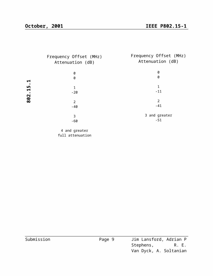
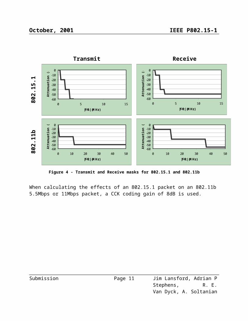
6.3.6 Transmit and Receive MasksThe transmit and receive masks used are defined in Table 5 and shown in Figure 4.
Table 5 - Transmit and Receive masks
Transmit Receive
Submission Page 6 Jim Lansford, Adrian P Stephens, R. E. Van Dyck, A. Soltanian

October, 2001 IEEE P802.15-180
2.15
.1
Frequency Offset (MHz)Attenuation (dB)
00
1-20
2-40
3-60
4 and greaterfull attenuation
Frequency Offset (MHz)Attenuation (dB)
00
1-11
2-41
3 and greater-51
802.
11b
Frequency Offset (MHz)Attenuation (dB)
00
1 to 11-30
12 and greater-50
Frequency Offset (MHz)Attenuation (dB)
00
1 to 12-12
13 to 36-36
37 and greater-56
Submission Page 7 Jim Lansford, Adrian P Stephens, R. E. Van Dyck, A. Soltanian

October, 2001 IEEE P802.15-1
Transmit Receive
802.
15.1
-60-50-40-30-20-10
0
0 5 10 15
|f-fc| (MHz)
Atte
nuat
ion
(dB
)
-60-50-40-30-20-10
0
0 5 10 15
|f-fc| (MHz)
Atte
nuat
ion
(dB
)
802.
11b
-60-50-40-30-20-10
0
0 10 20 30 40 50
|f-fc| (MHz)
Atte
nuat
ion
(dB
)
-60-50-40-30-20-10
0
0 10 20 30 40 50
|f-fc| (MHz)
Atte
nuat
ion
(dB
)
Figure 4 - Transmit and Receive masks for 802.15.1 and 802.11b
When calculating the effects of an 802.15.1 packet on an 802.11b 5.5Mbps or 11Mbps packet, a CCK coding gain of 8dB is used.
Submission Page 8 Jim Lansford, Adrian P Stephens, R. E. Van Dyck, A. Soltanian
October, 2001 IEEE P802.15-1
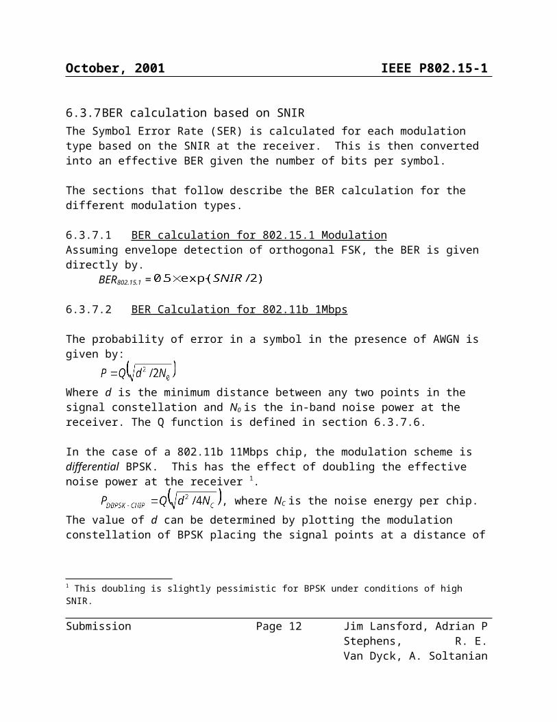
6.3.7 BER calculation based on SNIRThe Symbol Error Rate (SER) is calculated for each modulation type based on the SNIR at the receiver. This is then converted into an effective BER given the number of bits per symbol.
The sections that follow describe the BER calculation for the different modulation types.
6.3.7.1 BER calculation for 802.15.1 Modulation Assuming envelope detection of orthogonal FSK, the BER is given directly by.
BER802.15.1 =
6.3.7.2 BER Calculation for 802.11b 1Mbps
The probability of error in a symbol in the presence of AWGN is given by:
Where d is the minimum distance between any two points in the signal constellation and N0 is the in-band noise power at the receiver. The Q function is defined in section 6.3.7.6.
In the case of a 802.11b 11Mbps chip, the modulation scheme is differential BPSK. This has the effect of doubling the effective noise power at the receiver 1.
, where NC is the noise energy per chip.The value of d can be determined by plotting the modulation constellation of BPSK placing the signal points at a distance of from the origin, where EC is the received signal energy per chip. Thus dDBPSK-CHIP = 2 . So now:
This is the probability of an error in an individual 11Mbps chip.
To include the effect of the spreading code, the squared distance is summed over each chip. In the case of 802.15.1 1Mbps modulation, the 11-chip spreading code results in the squared distance being multiplied by a factor of 11. 2
Giving , where SNIR = EC/NC.
This is the 1Mbps symbol error rate. It is also the 1Mbps BER, because each symbol encodes a single bit.
6.3.7.3 BER Calculation for 802.11b 2Mbps This calculation follows the treatment for the 1Mbps calculation with a few differences.
1 This doubling is slightly pessimistic for BPSK under conditions of high SNIR.2 An alternative approach giving the same result is to consider the spreading sequence to be a block code of length 11.
Submission Page 9 Jim Lansford, Adrian P Stephens, R. E. Van Dyck, A. Soltanian

October, 2001 IEEE P802.15-1
The 2Mbps rate uses 11Mbps DQPSK chips. The minimum distance between points in the QPSK constellation is reduced by a factor of (compared to BPSK) giving dQBPSK-CHIP = . This substitution results in .Each 2Mbps symbol encodes two bits. However, because the symbols are gray coded, a decoding error between adjacent DQPSK constellation points yields only a single bit error in the decoded 2Mbps bitstream 3. So this symbol error rate is also the required BER.
6.3.7.4 802.11b 5.5 Mbps BER Calculation The symbol error rate can be determined by treating the modulation as a block code in the presence of AWGN interference. The general symbol error rate is , where Rc is the code rate, Wm is the codeword distance and the sum is over all other codewords. For 802.11b 5.5 Mbps, the symbol error rate, SER5.5, is given by:
SER5.5 =As each symbol encodes 4 bits, the effective BER is
in which the value has also been limited to 0.5 4.
6.3.7.5 802.11b 11 Mbps BER Calculation For 802.11b 11 Mbps, the symbol error rate, SER11 is given by:
As each symbol encodes 8 bits, the effective BER is
6.3.7.6 Q Function Definition The Q function is defined as the area under the tail of the Gaussian probability density function with zero mean and unit variance.
In this model, a fifth-order approximation to Q(x) is used:
6.3.7.7 SNIR Limits
3 Errors between adjacent DQPSK constellation points are much more likely that errors between opposing constellation points.4 BER values larger than 0.5 are meaningless.
Submission Page 10 Jim Lansford, Adrian P Stephens, R. E. Van Dyck, A. Soltanian
October, 2001 IEEE P802.15-1
The simulation is simplified by assuming that above a certain SNIR the BER is effectively zero and below a certain SNIR the BER is effectively 0.5. These limits are defined in Table 6.
Table 6 - Assumed Limits on SNIR
Receiver Upper limit on SNIR Lower limit on SNIR802.11b 10dB -3dB802.15.1 20dB 1dB
6.3.7.8 BER versus SNIR Results
Refer to section ??? for a presentation of the results of the analytical model.
Section ??? BER versus SNIR Results(Ed - please move into results sections in merged document)
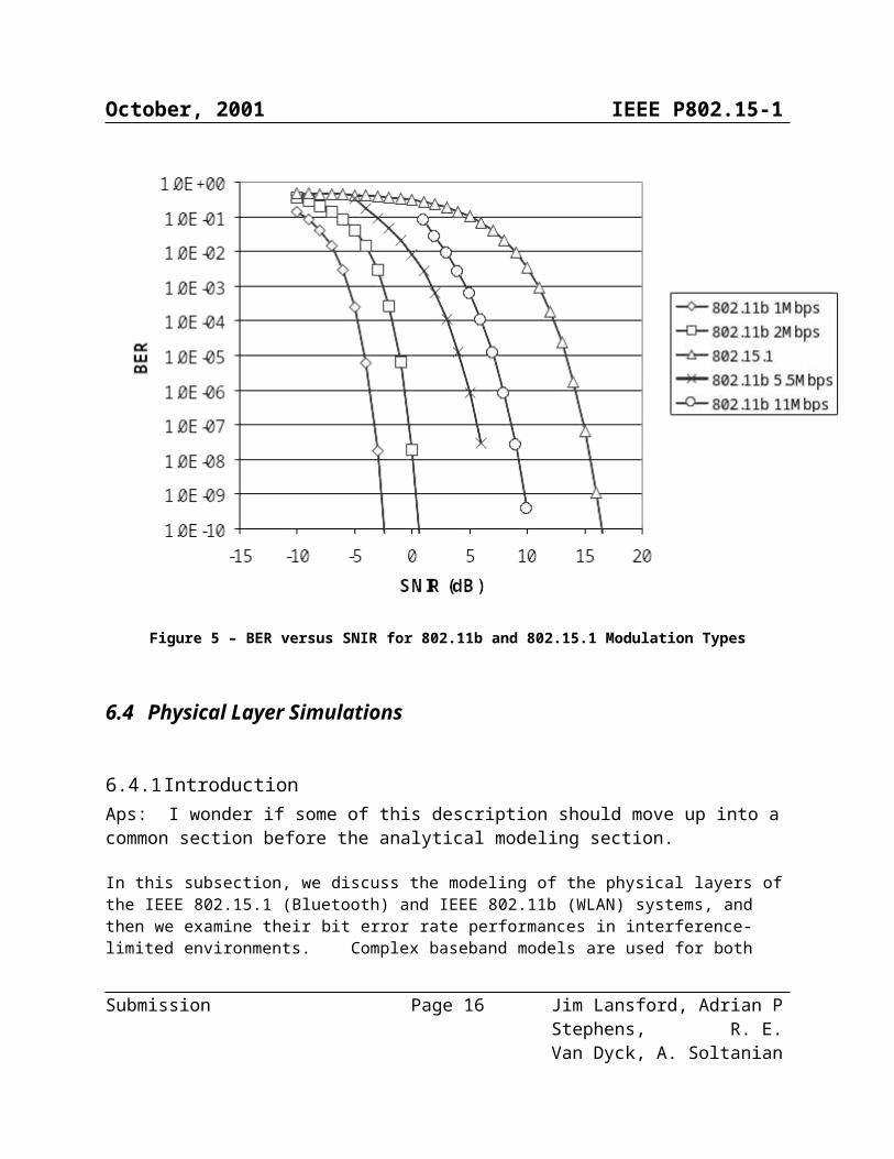
Figure 5 shows the results of calculating BER for SNIR values in the range –15 to 20dB for each modulation type 5.
5 The results for 802.11b 11Mbps do not show calculated values for SNIR < -2dB due to limitations of the tools used.
Submission Page 11 Jim Lansford, Adrian P Stephens, R. E. Van Dyck, A. Soltanian
October, 2001 IEEE P802.15-1
Figure 5 – BER versus SNIR for 802.11b and 802.15.1 Modulation Types
6.4 Physical Layer Simulations
6.4.1 IntroductionAps: I wonder if some of this description should move up into a common section before the analytical modeling section.
In this subsection, we discuss the modeling of the physical layers of the IEEE 802.15.1 (Bluetooth) and IEEE 802.11b (WLAN) systems, and then we examine their bit error rate performances in interference-limited environments. Complex baseband models are used for both Bluetooth and WLAN, and the performance is determined using Monte Carlo simulation methods. The resulting performance curves are quite accurate, but they are obtained at the expense of significant computation. While the analytical model uses transmitter power and distance as input parameters, the simulation model uses the signal-to-noise ratio (SNR) and the signal-to-interference ratio (SIR). In both cases, the output is bit error rate (BER).
Submission Page 12 Jim Lansford, Adrian P Stephens, R. E. Van Dyck, A. Soltanian

October, 2001 IEEE P802.15-1
The outline of the section is as follows: Section 6.4.2 describes the model for Bluetooth, while Section 6.4.3 does the same for 802.11b. Section 6.4.4 contains results for the 802.11b system in the presence of interference from Bluetooth, and Section 6.4.5 provides the results for Bluetooth in the presence of an 802.11b interferer. Some of the text and the figures have been taken from~\cite{soltanian:01}, which also contains additional results for flat fading channels.
The Bluetooth system operates at a channel bit rate of 1 Mbit/sec~\cite{haartsen:00,bluetooth:99}. The modulation is Gaussian frequency shift keying (GFSK) with a nominal modulation index of
and a normalized bandwidth of , where is the 3 dB Bandwidth of the transmitter's Gaussian low pass filter, and T is the bit period. The Bluetooth radio employs a frequency hopping scheme in which the carrier frequency is changed on a packet by packet basis. There are up to 79 different channels, each with 1 MHz separation. The entire structure of the simulated system is presented in Fig.~\ref{fig:BTawgn}. It includes the transmitter, the channel, the receiver and the interference source. Note that the interferer can be set to have a different carrier frequency and a random phase offset.
Title:C:\My Documents\report\figure\virBTAWGN.epsCreator:Jasc Software, Inc.Preview:This EPS picture was not savedwith a preview included in it.Comment:This EPS picture will print to aPostScript printer, but not toother types of printers.
\epsffile{fig/virBTAWGN.eps} \caption{Bluetooth system model.} \label{fig:BTawgn}
The 1 and 11 Mbits/sec modes of the IEEE 802.11b standard~\cite{ieee802:01} are implemented. The first rate is achieved by using differential BPSK (DBPSK) with DSSS and an 11 chip Barker code; the chip rate is 11 Mchips/sec. The last rate is obtained using complementary code keying (CCK), also at 11 Mchips/sec. The communications system model for the 1 Mbit/sec bit rate is presented in Fig.~\ref{fig:802awgn}, again consisting of the transmitter, the channel, the receiver and the Bluetooth interference source. We explain the details of this model in the following sections. The CCK system is shown in Fig.~\ref{fig:blkcck} and discussed in Section 6.4.3.2 below.
Submission Page 13 Jim Lansford, Adrian P Stephens, R. E. Van Dyck, A. Soltanian

October, 2001 IEEE P802.15-1
Title:C:\My Documents\report\figvir\vir802AWGN.epsCreator:Jasc Software, Inc.Preview:This EPS picture was not savedwith a preview included in it.Comment:This EPS picture will print to aPostScript printer, but not toother types of printers.
\epsffile{fig/vir802AWGN.eps} \caption{802.11b DSSS system model.} \label{fig:802awgn}
6.4.2 IEEE 802.15.1 System Model\label{sec:bluetooth}
6.4.2.1 The GFSK signal
The GFSK signal can be represented by~\cite{murota:81, aulin:81, steele:96}
, \label{GFSKBP}
where , is the energy per data bit, and is the carrier frequency;
aps: what is T?is the random input stream, comprised of the data bits . is the output phase deviation, given
by
,
where , and g(t) is the Gaussian-shaped pulse of the transmitter filter.
L is the length of g(t), and it determines the number of consecutive symbols required to transmit a single data bit. Sending a data bit over multiple symbols makes GFSK a partial response symbol, which reduces the required bandwidth. For Bluetooth with , we have L=2, which means that a single data bit is spread over two consecutive symbol intervals.
6.4.2.2 Interference Model \label{sec:inter}
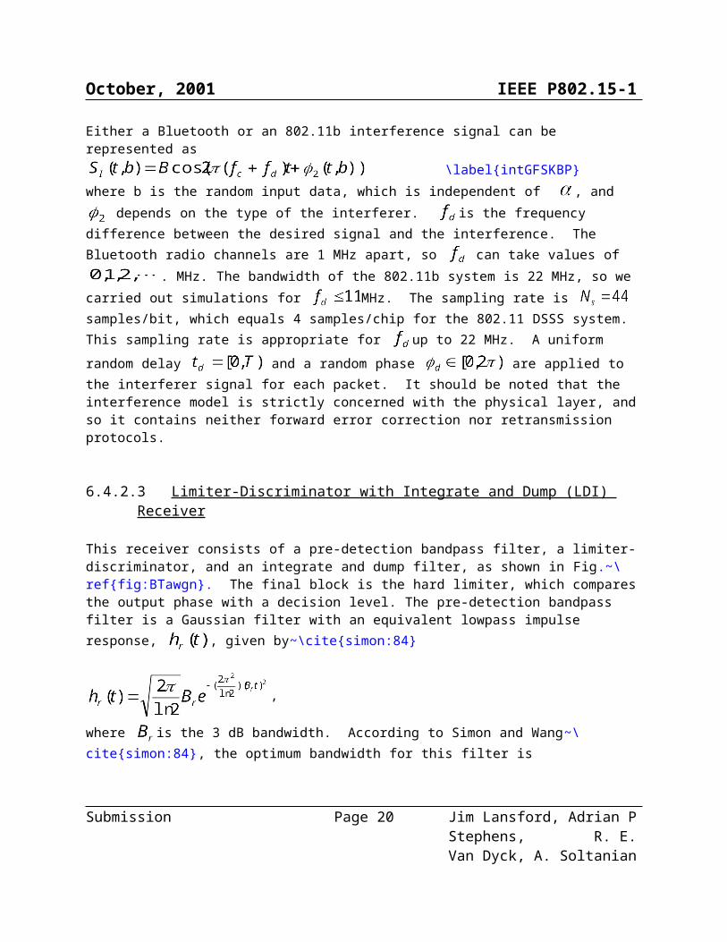
Either a Bluetooth or an 802.11b interference signal can be represented as \label{intGFSKBP}
Submission Page 14 Jim Lansford, Adrian P Stephens, R. E. Van Dyck, A. Soltanian

October, 2001 IEEE P802.15-1
where b is the random input data, which is independent of , and depends on the type of the interferer. is the frequency difference between the desired signal and the interference. The Bluetooth radio channels are 1 MHz apart, so can take values of . MHz. The bandwidth of the 802.11b system is 22 MHz, so we carried out simulations for MHz. The sampling rate is samples/bit, which equals 4 samples/chip for the 802.11 DSSS system. This sampling rate is appropriate for up to 22 MHz. A uniform random delay and a random phase are applied to the interferer signal for each packet. It should be noted that the interference model is strictly concerned with the physical layer, and so it contains neither forward error correction nor retransmission protocols.
6.4.2.3 Limiter-Discriminator with Integrate and Dump (LDI) Receiver
This receiver consists of a pre-detection bandpass filter, a limiter-discriminator, and an integrate and dump filter, as shown in Fig.~\ref{fig:BTawgn}. The final block is the hard limiter, which compares the output phase with a decision level. The pre-detection bandpass filter is a Gaussian filter with an equivalent lowpass impulse response, , given by~\cite{simon:84}
,
where is the 3 dB bandwidth. According to Simon and Wang~\cite{simon:84}, the optimum
bandwidth for this filter is . The discrete impulse response of this filter is obtained by
sampling and truncating . The output of the receiver pre-detection filter can be represented using its inphase and quadrature components. For a discussion of a digital implementation of this receiver,please see~\cite{soltanian:01}.
6.4.3 802.11b System Model\label{sec:w80211}
6.4.3.1 1 Mbit/sec DSSS
The basic 1 Mbit/sec rate is encoded using DBPSK. Thus, it is not necessary to have a coherent phase reference in the receiver to demodulate the received signal.
This system utilizes a spread spectrum scheme to mitigate the effect of interference. The Barker sequence with code length P = 11 is employed to spread the signal. The bit duration, T, is exactly 11 chip periods,
, long. The processing gain (PG) of this system is~\cite{proakis:95} , where is
Submission Page 15 Jim Lansford, Adrian P Stephens, R. E. Van Dyck, A. Soltanian
October, 2001 IEEE P802.15-1
the bit rate, and is the chip rate. If we calculate the power spectrum of the Barker codes, we
get~\cite{miller:98}
\label{barkersp}
The function, S(f), is illustrated in Fig.~\ref{fig:barker} for P=11. We see that a narrowband interference signal -like Bluetooth- located at the middle of the spectrum will be more attenuated than an interferer located 1 MHz away.
Ed. Note 1: replot Figure.~\ref{fig:barker} so that the points are not connected. Also, make the y axis normalized and in dB.
Title:/import/fs1/home/disk2/amirs/Matlab/results/802/barkspec.epsCreator:MATLAB, The Mathworks, Inc.Preview:This EPS picture was not savedwith a preview included in it.Comment:This EPS picture will print to aPostScript printer, but not toother types of printers.
\epsffile{fig/barkspec.eps} \caption{Power Spectrum of the Barker Code.} \label{fig:barker}
As shown in Fig.~\ref{fig:802awgn}, the input data bits are first differentially encoded. The resulting sequence is spread by the Barker code. The output of the spreader is fed to a square-root raised-cosine pulse-shaping filter. The impulse response of this filter with a roll-off factor can be found in~\cite{miller:98} The discrete time impulse response of this filter is obtained by sampling it.
At the receiver, the input samples are first passed through the square-root raised-cosine matched filter. The despreading filter is a rectangular filter that integrates the output of the multiplier during a bit period. The differential decoder compares the phase angle of the received symbol and the previous one to generate the output bit stream. It is assumed that the chip timing of the receiver is synchronized to the transmitter.
Submission Page 16 Jim Lansford, Adrian P Stephens, R. E. Van Dyck, A. Soltanian

October, 2001 IEEE P802.15-1
6.4.3.2 11 Mbits/sec CCK
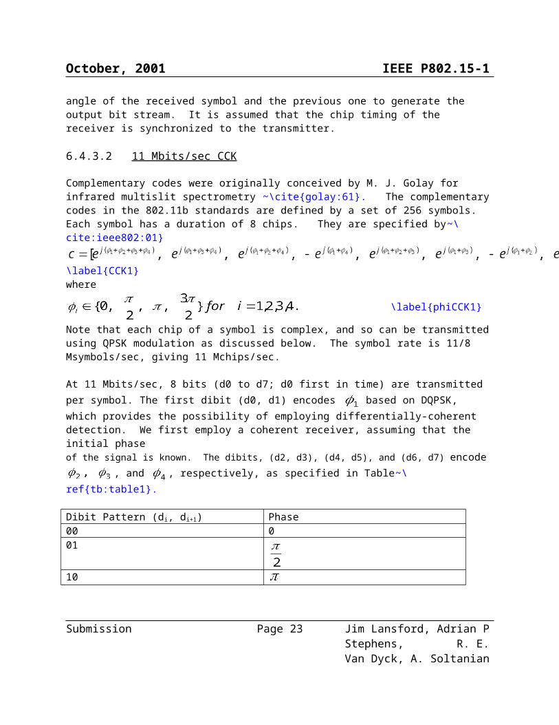
Complementary codes were originally conceived by M. J. Golay for infrared multislit spectrometry ~\cite{golay:61}. The complementary codes in the 802.11b standards are defined by a set of 256 symbols. Each symbol has a duration of 8 chips. They are specified by~\cite:ieee802:01}
\label{CCK1}where
\label{phiCCK1}
Note that each chip of a symbol is complex, and so can be transmitted using QPSK modulation as discussed below. The symbol rate is 11/8 Msymbols/sec, giving 11 Mchips/sec.
At 11 Mbits/sec, 8 bits (d0 to d7; d0 first in time) are transmitted per symbol. The first dibit (d0, d1) encodes based on DQPSK, which provides the possibility of employing differentially-coherent detection. We first employ a coherent receiver, assuming that the initial phase of the signal is known. The dibits, (d2, d3), (d4, d5), and (d6, d7) encode
, and , respectively, as specified in Table~\ref{tb:table1}.
Dibit Pattern (di, di+1) Phase00 001
1011
\caption{QPSK Encoding.} \label{tb:table1}
The system model is presented in Fig.~\ref {fig:blkcck}. Only an AWGN channel is considered in this case.
Submission Page 17 Jim Lansford, Adrian P Stephens, R. E. Van Dyck, A. Soltanian

October, 2001 IEEE P802.15-1
Title:C:\My Documents\report\figure\virCCK.epsCreator:Jasc Software, Inc.Preview:This EPS picture was not savedwith a preview included in it.Comment:This EPS picture will print to aPostScript printer, but not toother types of printers.
\epsffile{fig/virCCK.eps} \caption{CCK System Model.} \label{fig:blkcck}
A maximum likelihood decoder determines the valid symbol that is closest to the received symbol, and it maps that symbol back to eight data bits. This decoding method needs a bank of 256 correlators in the receiver. Although optimum, this method may be considered too complex for some implementations. There are also less complex sub-optimum algorithms. By looking at the code words of CCK, one can write these equations for the decoded phases~\cite{vannee:96}
\label{subopt}
where \label{subr}
is the received symbol. We employ the above sub-optimal receiver to measure the performance in the presence of interference.
6.4.4 IEEE 802.11b in the Presence of IEEE 802.15.1
Ed. Note 3: Replot all the curves using SNR and SIR intead of CNR and CIR, respectively.
Ed. Note 4: We measure SNR and SIR at the input to the bandpass filter. Therefore, our measurements are different from those used by Mobilian, since they define SNIR after the receiver’s filter. We need to explicitly mention in the text where the measurements are made. We also need to compare the two sets of results and make sure they agreeI am not in a position to make this comparison because none of the plots are visible to me in this word document.
Submission Page 18 Jim Lansford, Adrian P Stephens, R. E. Van Dyck, A. Soltanian

October, 2001 IEEE P802.15-1
I think there’s also a potential confusion about terminology here. The SNR, SIR and SNIR are ratios – but we always quote dB values. This makes “low” ratios become negative. Perhaps a note would clarify matters.
Now, we consider the performance of the 1 Mbit/sec 802.11b system, in an interference-limited environment with SNR = 35 dB. Note that we measure both SNR and SIR at the input to the receiver’s bandpass filter. Since the system takes advantage of DSSS, one observes in Fig.~\ref{fig:bt8021} that for co-channel interference, SIR = -11 dB is adequate to suppress the effect of interference (BER ). The most disturbing interference is located at MHz, which needs a minimum SIR of -5 dB. This difference stems from the null at the middle of the spectrum of the Barker code as described before. For frequency offsets greater than 8 MHz, the SIR value must be very low in order to get a high BER. This fact is due to the bandpass filter in the 802.11b receiver having high attenuation at frequencies near 11 MHz.
Title:/import/fs1/home/disk2/amirs/Matlab/results/BT802/bt802curve1.epsCreator:MATLAB, The Mathworks, Inc.Preview:This EPS picture was not savedwith a preview included in it.Comment:This EPS picture will print to aPostScript printer, but not toother types of printers.
\epsffile{fig/bt802curve1.eps} \caption{1 Mbit/sec 802.11b DSSS performance with Bluetooth interference. AWGN channel. SNR=35 dB.} \label{fig:bt8021}
Fig.~\ref{fig:cckawgn} shows the performance of the 11 Mbits/sec 802.11b CCK receiver in the AWGN channel. The optimum receiver performs about 2 dB better than QPSK, and the sub-optimum method is nearly the same as QPSK. The sub-optimal system provides a BER of for an dB. It must be noted that CCK was designed explicitly for fading channels, where its gain over QPSK is much more significant.
Submission Page 19 Jim Lansford, Adrian P Stephens, R. E. Van Dyck, A. Soltanian
October, 2001 IEEE P802.15-1
Title:/import/fs1/home/disk2/amirs/Matlab/results/cck/awgn.epsCreator:MATLAB, The Mathworks, Inc.Preview:This EPS picture was not savedwith a preview included in it.Comment:This EPS picture will print to aPostScript printer, but not toother types of printers.
\epsffile{fig/cckawgn.eps} \caption{11 Mbits/sec 802.11b CCK performance in an AWGN channel.} \label{fig:cckawgn}
Figure~\ref{fig:cckBT} illustrates the performance of the 11 Mbits/sec IEEE 802.11b receiver with Bluetooth interference. This figure indicates that the CCK modulation is more vulnerable to the interference signal than the 1 Mbit/sec DSSS. A minimum SIR of 3 dB must be achieved to get BER
for all frequency offsets. This result is not surprising, since the CCK provides a higher bit rate but occupies the same 22 MHz bandwidth, thereby having less of a coding gain. Generally, the receivers used for both 1 Mbit/sec and 11 Mbits/sec are fairly simple, and improved performance can most likely be obtained using more sophisticated signal processing. This fact is especially true for the 11 Mbits/sec CCK system.
Submission Page 20 Jim Lansford, Adrian P Stephens, R. E. Van Dyck, A. Soltanian

October, 2001 IEEE P802.15-1
Title:/import/fs1/home/disk2/amirs/Matlab/results/cck/cci.epsCreator:MATLAB, The Mathworks, Inc.Preview:This EPS picture was not savedwith a preview included in it.Comment:This EPS picture will print to aPostScript printer, but not toother types of printers.
\epsffile{fig/ccicckcurve.eps} \caption{11 Mbits/sec 802.11b CCK performance with Bluetooth interference. SNR=35 dB} \label{fig:cckBT}
6.4.5 IEEE 802.15.1 in the Presence of IEEE 802.11b\label{sec:Perfo}
The LDI receiver design meets the Bluetooth on Bluetooth interference specifications. While this model is not based on any particular implementation, it is meant to be indicative of a real implementation. Simulation results for the LDI receiver in the AWGN and Rician channels are presented in~\cite{soltanian:01}.
Here, we study the performance of IEEE 802.15.1 with 802.11b interference. Again, we measure SNR and SIR at the input to the receiver’s bandpass filter. The curves in Figs.~\ref{fig:i802AWGN} are for an interference-limited environment with SNR = 30 dB. The 802.11b signal looks like broadband noise at the input to the Bluetooth receiver. The performance degradation for carrier frequency differences up to 4 MHz is almost the same, and so we plot the results for as a representative case. The null in the Barker code spectrum does not improve the performance here, as it does for the 802.11b DSSS system. After 4 MHz, one gradually sees the effect of the pulse shaping filter of the 802.11b transmitter, which has a null at MHz. In fact, the SIR value at MHz has to be very low in order to cause high BER.
Submission Page 21 Jim Lansford, Adrian P Stephens, R. E. Van Dyck, A. Soltanian
October, 2001 IEEE P802.15-1
Title:/import/fs1/home/disk2/amirs/Matlab/results/802BT/AWGN802onBT.epsCreator:MATLAB, The Mathworks, Inc.Preview:This EPS picture was not savedwith a preview included in it.Comment:This EPS picture will print to aPostScript printer, but not toother types of printers.
\epsffile{fig/AWGN802onBT.eps} \caption{Bluetooth performance with 802.11b interference. AWGN channel. LDI receiver. SNR=30 dB.} \label{fig:i802AWGN}
The roll-off factor of the 802.11b transmitter determines the range of frequency offsets over which high BERs are observed. In this simulation, we chose , so the interference signal will occupy the maximum available bandwidth. Another observation from Fig.~\ref{fig:i802AWGN} is that if the SIR value is always greater than 6 dB, the BER for all frequency offsets is less than . Note that as an interferer the bit rate of the 802.11b physical layer is not important to the performance.
As a solution to mitigate the effect of interference, we use a simple two-state Viterbi receiver for Bluetooth. It must be noted that the main problem with this Viterbi receiver is that is assumes that the modulation index is known. Unfortunately, the actual modulation index is allowed to vary over a large range. Again, we assume that the phase of the transmitted signal is known to the receiver, and we measure the SNR and SIR at the input the receiver’s matched filter. The performance for 802.11 interference is shown in Fig.~\ref{fig:viterbi1}. A dramatic enhancement is observed in this figure, evidently at a cost of having a more complicated receiver.
Submission Page 22 Jim Lansford, Adrian P Stephens, R. E. Van Dyck, A. Soltanian
October, 2001 IEEE P802.15-1
Title:/import/fs1/home/disk2/amirs/Matlab/results/VTB/coh802onBT.epsCreator:MATLAB, The Mathworks, Inc.Preview:This EPS picture was not savedwith a preview included in it.Comment:This EPS picture will print to aPostScript printer, but not toother types of printers.
\epsffile{fig/vtbcoh802BT.eps} \caption{ Bluetooth Viterbi receiver performance with 802.11b interference. AWGN channel. SNR = 30 db} \label{fig:viterbi1}
Bibliography or References
\bibitem{soltanian:01} A. Soltanian and R. E. Van Dyck, “Physical layer performance for coexistence of Bluetooth and IEEE 802.11b,” Proc. 11th Virginia Tech/MPRG Symposium on Wireless Personnal Communications, Blacksburg, VA, pp. 31-41, June 6-8, 2001.
\bibitem{haartsen:00} J. C. Haartsen and S. Mattisson, ``Bluetooth - A new low-power radio interface providing short-range connectivity,'' Proc. of the IEEE, vol. 88, no. 10, pp. 1651-1661, Oct. 2000.
\bibitem{bluetooth:99} Bluetooth Special Interest Group, Specifications of the Bluetooth System, vol. 1, v.1.0B, Dec. 1999. Available : http:/www.bluetooth.com.
\bibitem{ieee802:01} IEEE Std. 802-11, IEEE Standard for Wireless LAN Medium Access Control (MAC) and Physical Layer (PHY) Specification, 2001 Edition.
\bibitem{murota:81} K. Murota and K. Hirade, “GMSK modulation for digital mobile radio telephony,” IEEE Trans. on Comm., Vol. 29, pp. 1044-1050, July 1981.
\bibitem{aulin:81} T. Aulin and C-E. Sundberg, “Continuous phase modulation – Part 2: Partial response signaling,” IEEE Trans. on Comm., Vol. 29, pp. 210-225, Mar. 1981.
\bibitem{steele:96} R. Steele (Ed.), Mobile Radio Communications, John Wiley & Sons Inc., 1996.
Submission Page 23 Jim Lansford, Adrian P Stephens, R. E. Van Dyck, A. Soltanian

October, 2001 IEEE P802.15-1
\bibitem{simon:84} M. K. Simon and C. C. Wang, ``Differential detection of Gaussian MSK in a mobile radio environment, ''IEEE Trans. Veh. Tech., pp. 307-320, Nov. 1984.
\bibitem{oppenheim:89} A. L. Oppenheim and R. W. Schafer, Discrete-Time Signal Processing, Prentice Hall, 1989.
\bibitem{proakis:95} J. G. Proakis, Digital Communications, McGraw-Hill, 1995.
\bibitem{miller:98} J. S. Lee and L. E. Miller, CDMA Engineering Handbook, Artech House, 1998.
\bibitem{golay:61} M. J. E. Golay,``Complementary series,'' IRE Trans. Information Theory, vol. IT-7, pp. 82-87, Apr. 1961.
\bibitem{vannee:96} R. D. J. Van Nee, ``OFDM codes for peak-to-average power reduction and error correction,'' Proc. IEEE Global Telecommun. Conf., vol. 1, London, pp. 740-744, Nov. 1996.
\bibitem{schilling:80} D. L. Schilling, L. B. Milstein, R. L. Pickholtz and R. W. Brown, ``Optimization of the processing gain of an M-ary direct sequence spread spectrum communication system,'' IEEE Trans. Comm., pp. 1389-1398, Aug. 1980.
\bibitem{milstein:82} L. B. Milstein, S. Davidovici, and D. L. Schilling, ``The effect of multiple-tone interfering signals on a direct sequence spread spectrum communication system,'' IEEE Trans. Comm., vol. 30, pp. 436-446, Mar. 1982.
\bibitem{simon:83} M. K. Simon and C. C. Wang, ``Differential versus limiter discriminator detection of narrow-band FM,'' IEEE Trans. Comm., pp. 1227-1234, Nov. 1983.
\bibitem{halford:99} S. Halford, K. Halford and M. Webster, ``Complementary code keying for RAKE-based indoor wireless communications,'' Proc. IEEE Int. Conf. on Circuits and Systems, pp. 427-430, May 1999.
Submission Page 24 Jim Lansford, Adrian P Stephens, R. E. Van Dyck, A. Soltanian

October, 2001 IEEE P802.15-1
Annex ??? – Source Code for Analytical ModelThis section contains source code for the Analytical Model.
/*--------------------------------------------------------------------------- * Title: Analytical Physical-Layer Model for 802.15.2 BER Calculations * Authors: Ron Nevo, Josie Ammer, Adrian Stephens * Mobilian Corporation 2001 * * This module contains the analytical PHY-layer model used to calculate * BER values for 802.11b and 802.15.1 transmissions in the presence of * mutual interference. *---------------------------------------------------------------------------*/
/*-- Standard Includes ------------------------------------------------------*/
#include <stdio.h>#include <math.h>#include <stdlib.h>#include <limits.h>
/*-- Type Definitions -------------------------------------------------------*/
typedef enum {WPAN, WLAN11, WLAN55, WLAN1, WLAN2// WPAN is non-FEC WPAN transmissions// WLAN11 is 11Mb/s 802.11// WLAN55 is 5.5Mb/s 802.11// WLAN1 is 1Mb/s 802.11// WLAN2 is 2Mb/s 802.11} ModulationType;
struct Node{ double x,y; // x and y positions in meters};
typedef Node *aNodePtr;
struct Transmission{ aNodePtr src, dst; ModulationType type; float txpower; // power in mW int frequency; // freq for WPAN is a number 1-79, is the center frequency // freq for WLAN is number 1-79, is the center frequency double BER; // the resulting BER};
typedef Transmission *aTransmissionPtr;
Submission Page 25 Jim Lansford, Adrian P Stephens, R. E. Van Dyck, A. Soltanian

October, 2001 IEEE P802.15-1
/*--------------------------------------------------------------------------- * Function: CalculateAnalyticalBER * * Description: * This function takes a list of transmissions and calculates * the BER at each receiver using the analytical model. * * Parameters: n - the number of transmissions in the list * tlist - an array of Transmissions each corresponding to * an active transmission * * Returns: in every tlist element a calculated BER value *---------------------------------------------------------------------------*/extern void CalculateAnalyticalBER(int n, Transmission tlist[]);
/*-- MACRO Definitions ------------------------------------------------------*/
#define WLAN_BANDWIDTH 22#define HALF_WLAN_BANDWIDTH 11#define PI acos(-1.0)
// assume the power of WPAN reception at the same station is unit power#define Tc 1
#define WPAN_Tx_1 inverse_db(-20.0) // -20dB spurious emmision per MHz from WPAN Tx when freq dif is 1MHz
#define WPAN_Tx_2 inverse_db(-40.0) // -40dB spurious emmision per MHz from WPAN Tx when freq dif is 2MHz
#define WPAN_Tx_3 inverse_db(-60.0) // -60dB spurious emmision per MHz from WPAN Tx when freq dif is 3MHz
#define WPAN_Tx_other 0 // no spurious emmision from WPAN Tx when freq dif > 3MHz
#define WPAN_Rx_1 inverse_db(-11.0) // -11dB adjacent channel interference from WPAN Rx when freq dif is 1MHz
#define WPAN_Rx_2 inverse_db(-41.0) // -41dB adjacent channel interference from WPAN Rx when freq dif is 2MHz
#define WPAN_Rx_other inverse_db(-51.0) // -51dB adjacent channel interference from WPAN Rx when freq dif >= 3MHz
#define WLAN_Tx_next inverse_db(-30) // -30dB spurious emmision from WLAN Tx when freq dif <= half bandwidth
#define WLAN_Tx_other inverse_db(-50.0) // -50dB spurious emmision from WLAN Tx when freq dif > half bandwidth
#define WLAN_Rx_next inverse_db(-12.0) // -12dB adjacent channel interference from WLAN Rx, 12 MHz
#define WLAN_Rx_middle inverse_db(-36.0)// -60dB adjacent channel interference from WLAN Rx, between 13MHz-36MHz
#define WLAN_Rx_other inverse_db(-56.0) // -60dB adjacent channel interference from WLAN Rx, >= 37MHz
#define CCK_factor inverse_db(-8.0) // 8dB gain for CCK coding
Submission Page 26 Jim Lansford, Adrian P Stephens, R. E. Van Dyck, A. Soltanian

October, 2001 IEEE P802.15-1
#define WLAN_EbNo_perfect 10.0 // if EbNo > 10dB, perfect reception#define WLAN_EbNo_impossible 0.5 // if EbNo < -3dB, impossible to receiver#define WPAN_EbNo_perfect 20.0 // if EbNo > 13dB, perfect reception#define WPAN_EbNo_impossible 1.0 // if EbNo < 0dB, impossible to receive
#define MIN_DISTANCE 0.1 // two nodes in the same spot act as if they are 0.1 apart
/*---------------------------------------------------------------------------*/
#define abs(a) ((a)>0 ? (a) : -(a))#define sqr(x) ((x)*(x))#define min(a,b) ((a)<(b) ? (a) : (b))
/*-- Forward References -----------------------------------------------------*/extern int isModulationTypeWPAN(ModulationType foo);// returns 1 if the type is WPAN// returns 0 otherwiseextern int isModulationTypeWLAN(ModulationType foo); // returns 1 if the type is one of the WLANs// returns 0 otherwise
extern double SER11(double);extern double SER55(double);extern double WLAN_BER_11(double);extern double WLAN_BER_55(double);extern double WLAN_BER_1(double);extern double WLAN_BER_2(double);extern double WPAN_BER(double);
extern double SpectrumFactor(Transmission &Src, Transmission &Dest);extern double Distance(Transmission &Src, Transmission &Dest);extern double PowerDistance(Transmission &Src, Transmission &Dest);
extern double inverse_db(double);extern double db(double);
/*-- Local Functions --------------------------------------------------------*/
int isModulationTypeWPAN(ModulationType foo){ switch (foo){ case WPAN: return 1; default: return 0; }}
int isModulationTypeWLAN(ModulationType foo){ switch (foo){ case WLAN11: return 1; case WLAN55: return 1; case WLAN1: return 1; case WLAN2: return 1; default: return 0; }}
Submission Page 27 Jim Lansford, Adrian P Stephens, R. E. Van Dyck, A. Soltanian

October, 2001 IEEE P802.15-1
// compute db from realdouble db(double x){ return(10 * log10(x));}
// compute real from dbdouble inverse_db(double x){ return(pow(10.0, x /10));}
// compute the Q function using approximation Q_5double Q_5(double x){ double x2,x3,x4,x5,x6; x2 = x*x; x3 = x2*x; x4 = x3*x; x5 = x4*x; x6 = x5*x;
return(exp(-x2/2) * (x4+9*x2+8) /(x5+10*x3+15*x) / sqrt(2*PI));}
// compute the codeword error probability of 802.11b 11Mbpsdouble SER11(double Eb_No){ double res; res = 24*Q_5(sqrt(4*Eb_No)) + 16*Q_5(sqrt(6*Eb_No)) + 174*Q_5(sqrt(8*Eb_No)) + 16*Q_5(sqrt(10*Eb_No)) + 24*Q_5(sqrt(12*Eb_No)) + Q_5(sqrt(16*Eb_No)); return(min(res,0.99999));}
// compute bit error rate from Eb/No for 802.11b 11Mbpsdouble WLAN_BER_11(double Eb_No){ if(Eb_No > WLAN_EbNo_perfect) return 0; // if Eb/No more than some threshold, perfect reception else if(Eb_No < WLAN_EbNo_impossible) return 0.5; // if Eb/No less than some threshold, impossible to receive else return(min(1-pow((1-SER11(Eb_No)),1.0/8),0.5));}
// compute the codeword error probability of 802.11b 5.5Mbpsdouble SER55(double Eb_No){ double res; res = 14*Q_5(sqrt(8*Eb_No)) + Q_5(sqrt(16*Eb_No)); return(min(res,0.99999));}
// compute bit error rate from Eb/No for 802.11b 11Mbpsdouble WLAN_BER_55(double Eb_No)
Submission Page 28 Jim Lansford, Adrian P Stephens, R. E. Van Dyck, A. Soltanian

October, 2001 IEEE P802.15-1
{ if(Eb_No > WLAN_EbNo_perfect) return 0; // if Eb/No more than some threshold, perfect reception else if(Eb_No < WLAN_EbNo_impossible) return 0.5; // if Eb/No less than some threshold, impossible to receive else return(min(1-pow(1-SER55(Eb_No),1.0/4),0.5));}
// compute the function number of choice of k elements from nint choose(int k,int n){ int i; int res = 1; for(i=n;i>n-k;i--) res *= i; for(i=1;i<=k;i++) res /= i; return(i);}
// compute the BER for WLAN 1Mbps, the BER is Q(sqrt(11*2*Eb_No/2))double WLAN_BER_1(double Eb_No){ if(Eb_No > WLAN_EbNo_perfect) return 0; // if Eb/No more than some threshold, perfect reception else if(Eb_No < WLAN_EbNo_impossible) return 0.5; // if Eb/No less than some threshold, impossible to receive else return(min(Q_5(sqrt(11*2*Eb_No/2)),0.5));}
// compute the BER for WLAN 2Mbps, the BER is Q(sqrt(5.5*2*Eb_No/2))double WLAN_BER_2(double Eb_No){ if(Eb_No > WLAN_EbNo_perfect) return 0; // if Eb/No more than some threshold, perfect reception else if(Eb_No < WLAN_EbNo_impossible) return 0.5; // if Eb/No less than some threshold, impossible to receive else return(min(Q_5(sqrt(5.5*2*Eb_No/2)),0.5));}
// compute the BER for WPANdouble WPAN_BER(double Eb_No){ if(Eb_No > 20) return 0; // if Eb/No more than 13dB, perfect reception else if(Eb_No < 1) return 0.5; // if Eb/No less than 0dB, impossible to receive else return(min(exp(-Eb_No/2),0.5));}
Submission Page 29 Jim Lansford, Adrian P Stephens, R. E. Van Dyck, A. Soltanian

October, 2001 IEEE P802.15-1
double Distance(Transmission &Src, Transmission &Dest){ return(sqrt(sqr(Src.src->x-Dest.dst->x) + sqr(Src.src->y-Dest.dst->y)));}
// power as function of distancedouble PowerDistance(Transmission &Src, Transmission &Dest){ double power_d0,dist; dist=Distance(Src,Dest); // calc distance function if (dist < MIN_DISTANCE) dist = MIN_DISTANCE;
if(isModulationTypeWPAN(Src.type)) { // transmitter is WPAN, power_d0 = Src.txpower; } else // transmitter is WLAN if(isModulationTypeWPAN(Dest.type)) // receiver is WPAN, power_d0 = Src.txpower/WLAN_BANDWIDTH; else power_d0 = Src.txpower; // receiver is WLAN if(dist < 8) // use 40.2+20log d for <8M power loss return(power_d0/(pow(dist,2.0) * pow(10.0, 4.02))); else // use 58.5 + 33log(d/8) for >8M power loss return(power_d0/(pow(dist/8.0,3.3) * pow(10.0, 5.85)));}
double SpectrumFactor(Transmission &Src, Transmission &Dest)// (int src0, int src,int dest)// dest is listenin to src0// dest gets interference from src{ int freq_dif;
if(isModulationTypeWPAN(Dest.type)) if(isModulationTypeWPAN(Src.type)) { // both src and dest WPAN freq_dif = abs(Src.frequency - Dest.frequency); switch(freq_dif) { case 0: // frequency collide return(1.0); case 1: return(WPAN_Tx_1+WPAN_Rx_1); case 2: return(WPAN_Tx_2+WPAN_Rx_2); case 3: return(WPAN_Tx_3+WPAN_Rx_other); default: return(WPAN_Tx_other+WPAN_Rx_other); } } else { // src WLAN and dest WPAN if(Dest.frequency >= Src.frequency + HALF_WLAN_BANDWIDTH) freq_dif = Dest.frequency - (Src.frequency + HALF_WLAN_BANDWIDTH) + 1; else if(Dest.frequency <= Src.frequency - HALF_WLAN_BANDWIDTH) freq_dif = (Src.frequency - HALF_WLAN_BANDWIDTH) - Dest.frequency + 1; else freq_dif = 0; switch(freq_dif) { case 0:
Submission Page 30 Jim Lansford, Adrian P Stephens, R. E. Van Dyck, A. Soltanian

October, 2001 IEEE P802.15-1
// frequency collide return(1.0); case 1: return(WLAN_Tx_next+WPAN_Rx_1); case 2: return(WLAN_Tx_next+WPAN_Rx_2); default: if(freq_dif<=HALF_WLAN_BANDWIDTH) return(WLAN_Tx_next+WPAN_Rx_other); else return(WLAN_Tx_other+WPAN_Rx_other); } } else // dest WLAN { if(isModulationTypeWPAN(Src.type)) { // src WPAN, dest WLAN double sf;
if(Src.frequency >= Dest.frequency + HALF_WLAN_BANDWIDTH) freq_dif = Src.frequency - (Dest.frequency + HALF_WLAN_BANDWIDTH) + 1; else if(Src.frequency <= Dest.frequency - HALF_WLAN_BANDWIDTH) freq_dif = (Dest.frequency - HALF_WLAN_BANDWIDTH) - Src.frequency + 1; else freq_dif = 0; switch(freq_dif) { case 0: // frequency collide sf = 1.0; break; case 1: sf = WPAN_Tx_1+WPAN_Tx_2+WPAN_Tx_3+WPAN_Tx_other*(WLAN_BANDWIDTH-3)+WLAN_Rx_next; break; case 2: sf = WPAN_Tx_2+WPAN_Tx_3+WPAN_Tx_other*(WLAN_BANDWIDTH-2)+WLAN_Rx_middle; break; case 3: sf = WPAN_Tx_3+WPAN_Tx_other*(WLAN_BANDWIDTH-1)+WLAN_Rx_middle; break; default: if(freq_dif<HALF_WLAN_BANDWIDTH){ sf = WPAN_Tx_other*WLAN_BANDWIDTH+WLAN_Rx_middle; break; } else{ sf = WPAN_Tx_other*WLAN_BANDWIDTH+WLAN_Rx_other; break; } } if (Dest.type == WLAN11 || Dest.type == WLAN55) sf *=CCK_factor; return(sf); } else { //both src and dest WLAN switch(abs(Src.frequency-Dest.frequency)) { case 0: return(1.0); case 11: return(0.5); case 22: return(WLAN_Rx_next/11+WLAN_Tx_next); default: return(WLAN_Rx_other+WLAN_Tx_other); } }
Submission Page 31 Jim Lansford, Adrian P Stephens, R. E. Van Dyck, A. Soltanian
October, 2001 IEEE P802.15-1
}}
/*-- Global Function --------------------------------------------------------*/
void CalculateAnalyticalBER(int n, Transmission tlist[]){// n should be the length of tlist double EbNo; for (int dst= 0; dst < n ; dst++) { //for each dest double Eb, No; No=0; for (int src = 0; src < n; src++) { //calculate the power from each source double pd,sf,pwr; sf=SpectrumFactor(tlist[src],tlist[dst]); pd=PowerDistance(tlist[src],tlist[dst]); pwr=sf*pd; #if defined(_DEBUG_) printf("rcpt power from %d to %d = %1.5g * %1.5g = %1.5g\n", src, dst, sf, pd, pwr); #endif if (src==dst) // if src and dest are from the same transmission pair, // pwr is signal power Eb=pwr*Tc; else // if not from the same transmission pair, // pwr is interference power No+=pwr; } EbNo=Eb/No; // calculate the EbNo for each dest //need to calc BER from SNR double ber0; switch (tlist[dst].type) { case WPAN: ber0 = WPAN_BER(EbNo); break; case WLAN11: ber0 = WLAN_BER_11(EbNo); break; case WLAN55: ber0 = WLAN_BER_55(EbNo); break; case WLAN1: ber0 = WLAN_BER_1(EbNo); break; case WLAN2: ber0 = WLAN_BER_2(EbNo); break; default: printf("Unknown ModulationType"); } #if defined(_DEBUG_) printf("EbNo for Transmission %d = %1.5g\n", dst, EbNo); printf("BER for Transmission %d = %1.5g\n", dst, ber0); #endif tlist[dst].BER = ber0; }}
Submission Page 32 Jim Lansford, Adrian P Stephens, R. E. Van Dyck, A. Soltanian
Related Documents