Mobile Phone STORM (Smartphone) Service Manual Page 1 of 38 SERVICE MANUAL For WILEY FOX STORM Only MOBILE TERMINAL (V1.0) COMPANY CONFIDENTIAL All Rights Reserved

Welcome message from author
This document is posted to help you gain knowledge. Please leave a comment to let me know what you think about it! Share it to your friends and learn new things together.
Transcript
Mobile Phone STORM (Smartphone) Service Manual
Page 1 of 38
SERVICE MANUAL
For WILEY FOX STORM Only
MOBILE TERMINAL
(V1.0)
COMPANY CONFIDENTIAL
All Rights Reserved

Mobile Phone STORM (Smartphone) Service Manual
Page 2 of 38
CONTENT
CHAPTER 1: SUMMARY .................................................................................................................... 4
CHAPTER 2: PCBA OVERVIEW ....................................................................................................... 6
2.1STORM-TOP SIDE-LAYOUT .......................................................................................................... 6
2.2STORM-BACK SIDE-LAYOUT....................................................................................................... 7
CHAPTER 3: EXPLANATION OF SCHEMATIC ............................................................................. 8
3.1 BASE BAND CHIP MSM8939 FEATURES.......................................................................................... 8
3.2POWER MANAGER UNIT PM8916 INTRODUCTION ........................................................................... 9
3.3 RF CHIP WTR4905 DEVICE INTRODUCTION .................................................................................. 10
3.4 INTERFACE FUNCTIONAL CIRCUIT ................................................................................................. 10
3.4.1 Charging Circuit .................................................................................................................... 10
3.4.2 Battery connector interface ................................................................................................... 11
3.4.3 Microphone Interface ............................................................................................................ 11
3.4.4 Receiver Interface ................................................................................................................. 12
3.4.5 LCD Connector Interface ...................................................................................................... 12
3.4.6 Camera Interface Circuit ....................................................................................................... 13
3.4.7 SIM Card Connector Interface .............................................................................................. 13
3.4.8 TF card Interface ................................................................................................................... 14
3.4.9 Sensor Interface ..................................................................................................................... 14
CHAPTER 4: MOBILE FAILURE ANALYSIS ................................................................................ 16
4.1 POWER ON ISSUE ANALYSIS ........................................................................................................... 17
4.2 CHARGING ISSUE ANALYSIS ........................................................................................................... 18
4.3 DISPLAY ISSUE ANALYSIS ............................................................................................................... 19
4.4 NO INCOMING & OUTGOING VOICE ISSUE ANALYSIS ..................................................................... 20
4.5HEADSET ISSUE ANALYSIS .............................................................................................................. 21
4.6 NO VOICE IN SPEAKER ISSUE ANALYSIS ......................................................................................... 22
4.7 TOUCH SCREEN ISSUE ANALYSIS.................................................................................................... 23
4.8 CAMERA ISSUE ANALYSIS .............................................................................................................. 24
4.9 VIBRATING ISSUE ANALYSIS ........................................................................................................... 25

Mobile Phone STORM (Smartphone) Service Manual
Page 3 of 38
4.10 BT/WI-FI ISSUE ANALYSIS ........................................................................................................... 26
4.11 FM ISSUE ANALYSIS ..................................................................................................................... 27
4.12 GPS ISSUE ANALYSIS ................................................................................................................... 28
4.13 CANNOT DOWNLOAD SOFTWARE ................................................................................................. 28
4.14 SIGNAL ISSUE ANALYSIS .............................................................................................................. 29
CHAPTER 5: SOFTWARE UPGRADE GUIDANCE ...................................................................... 30
5.1 PREPARATIONS BEFORE UPGRADE ................................................................................................. 30
5.2USB CABLE DRIVER INSTALL ........................................................................................................ 31
5.3 SOFTWARE UPGRADE PROCEDURE ................................................................................................ 34
5.4 SW DOWNLOAD TROUBLESHOOTING ............................................................................................ 38
CHAPTER 6: PRODUCT EXPLODE VIEW ................................................................................... 38
Mobile Phone STORM (Smartphone) Service Manual
Page 4 of 38
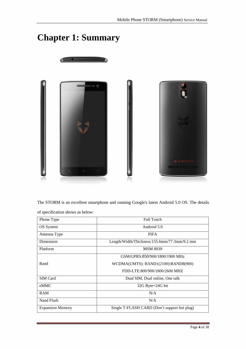
Chapter 1: Summary
The STORM is an excellent smartphone and running Google's latest Android 5.0 OS. The details
of specification shows as below:
Phone Type Full Touch
OS System Android 5.0
Antenna Type PIFA
Dimension Length/Width/Thickness:155.6mm/77.3mm/9.2 mm
Platform MSM 8939
Band
GSM/GPRS:850/900/1800/1900 MHz
WCDMA(UMTS): BAND1(2100)\BAND8(900)
FDD-LTE:800/900/1800/2600 MHZ
SIM Card Dual SIM, Dual online, One talk
eMMC 32G Byte+24G bit
RAM N/A
Nand Flash N/A
Expansion Memory Single T-FLASH CARD (Don‟t support hot plug)

Mobile Phone STORM (Smartphone) Service Manual
Page 5 of 38
Maximum Capacity of T-F card ( 32G ) Byte
Battery Capacity (2500 ) mAh
Charging Time < ( TBD ) Minutes
Talk Time > ( TBD) Minutes
Standby Time ( TBD ) Hours
Main LCD SIZE/Resolution/Screen Material:5.5'/FHD1920*1080/TFT
Touch Screen Capacitive
Function Key N/A
Side Key Yes(Power key ,Volume key)
Top Key N/A
Back Camera Pixel 20M AF
Front Camera Pixel 8.0Mega Fixed Focus
Bluetooth Bluetooth 4.0
USB USB 2.0
Wi-Fi YES, Support Access Point
PC Sync N/A
IrDA N/A
Input Method Google input
SMS Yes
MMS Yes
STK Yes
Polyphonic Melody 64-Tone Wavetable
Stereo Yes
Melody Format MP3/MIDI/WAV/AMR/AAC/AAC+
Video Format MP4/3GP
Recorder Yes
FM Radio Only support FM RX
TV N/A
TV-OUT N/A
I/O Connector 5PIN Micro USB
Independent Earphone Jack Φ3.5mm
Sensor G-Sensor, Proximity, ALS, Magnetic, Gyro
Number& Type of Speakers ( 1 ) PCS ( 1318 ) Speaker
Vibrator Mode Independent vibrator
GPS Yes, with navigation
Voice Recognize N/A
Others N/A
Mobile Phone STORM (Smartphone) Service Manual
Page 6 of 38
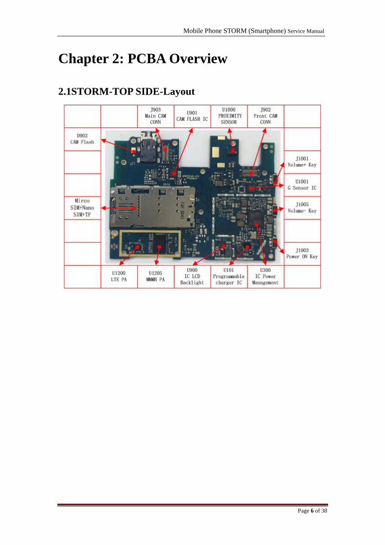
Chapter 2: PCBA Overview
2.1STORM-TOP SIDE-Layout

Mobile Phone STORM (Smartphone) Service Manual
Page 7 of 38
2.2STORM-BACK SIDE-Layout

Mobile Phone STORM (Smartphone) Service Manual
Page 8 of 38
Chapter 3: Explanation of Schematic
3.1 Base Band Chip MSM8939 Features
Mobile Phone STORM (Smartphone) Service Manual
Page 9 of 38
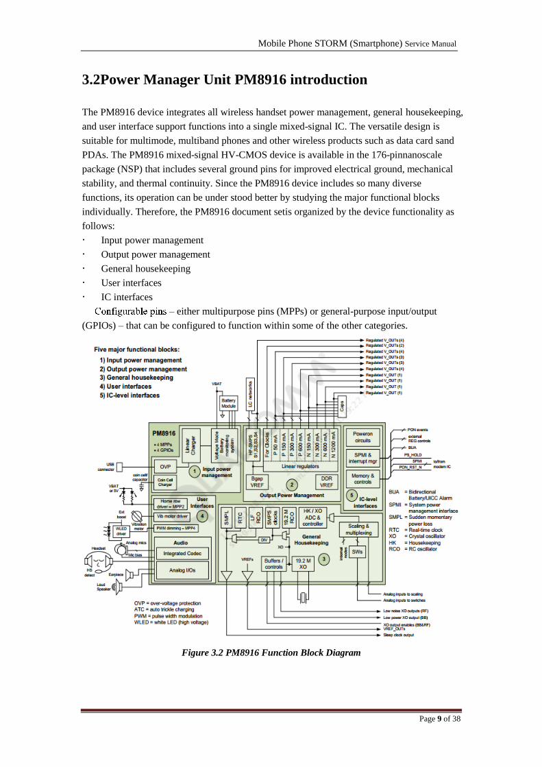
3.2Power Manager Unit PM8916 introduction
The PM8916 device integrates all wireless handset power management, general housekeeping,
and user interface support functions into a single mixed-signal IC. The versatile design is
suitable for multimode, multiband phones and other wireless products such as data card sand
PDAs. The PM8916 mixed-signal HV-CMOS device is available in the 176-pinnanoscale
package (NSP) that includes several ground pins for improved electrical ground, mechanical
stability, and thermal continuity. Since the PM8916 device includes so many diverse
functions, its operation can be under stood better by studying the major functional blocks
individually. Therefore, the PM8916 document setis organized by the device functionality as
follows:
Input power management
Output power management
General housekeeping
User interfaces
IC interfaces
– either multipurpose pins (MPPs) or general-purpose input/output
(GPIOs) – that can be configured to function within some of the other categories.
Figure 3.2 PM8916 Function Block Diagram

Mobile Phone STORM (Smartphone) Service Manual
Page 10 of 38
3.3 RF Chip WTR4905 device introduction
The WTR4x05 device is a highly-integrated multimode, multiband RF CMOS transceiver IC. The
WTR4x05 device cannot be used as stand-alone on MSM9x35/MSM8994
andMDM9x40/MDM9x45 modems.
All chipsets support advance RF techniques by adding a second RFIC
WTR4905-baseddesigns
– Add WTR2100 to support DSDA and/or SG-LTE
– Add WTR2605 to support SV-LTE
WTR3925-based designs supporting MSM8994, MSM8996, MDM9x35M, MDM9x45,
and Fusion 4.5
– Add WTR4605 to support DSDA, SG-LTE, and/or SV-LTE
It integrates RF
receive and transmit features into a 3.22 × 3.22 × 0.57 mm package to simplify handset
design, minimize parts count, and reduce DC power consumption.
3.4 Interface Functional Circuit
3.4.1 Charging Circuit
Figure 3.4.1-STORM Charging Circuit

Mobile Phone STORM (Smartphone) Service Manual
Page 11 of 38
3.4.2 Battery connector interface
Figure 3.4.2STORM Battery connector
3.4.3 Microphone Interface
Figure 3.4.3-1STORMMain Mic1 Circuit (On Sub-board)
Figure 3.4.3-2STORMANC Mic2 Circuit
Mobile Phone STORM (Smartphone) Service Manual
Page 12 of 38
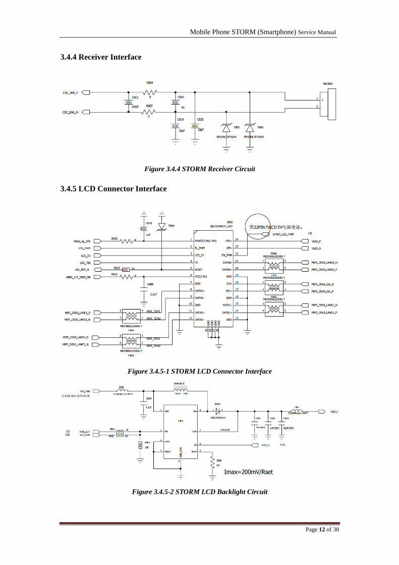
3.4.4 Receiver Interface
Figure 3.4.4 STORM Receiver Circuit
3.4.5 LCD Connector Interface
Figure 3.4.5-1 STORM LCD Connector Interface
Figure 3.4.5-2 STORM LCD Backlight Circuit
Mobile Phone STORM (Smartphone) Service Manual
Page 13 of 38
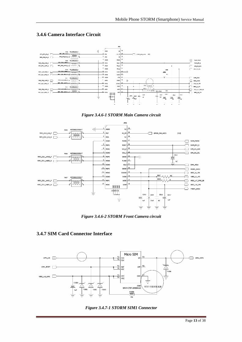
3.4.6 Camera Interface Circuit
Figure 3.4.6-1 STORM Main Camera circuit
Figure 3.4.6-2 STORM Front Camera circuit
3.4.7 SIM Card Connector Interface
Figure 3.4.7-1 STORM SIM1 Connector
Mobile Phone STORM (Smartphone) Service Manual
Page 14 of 38
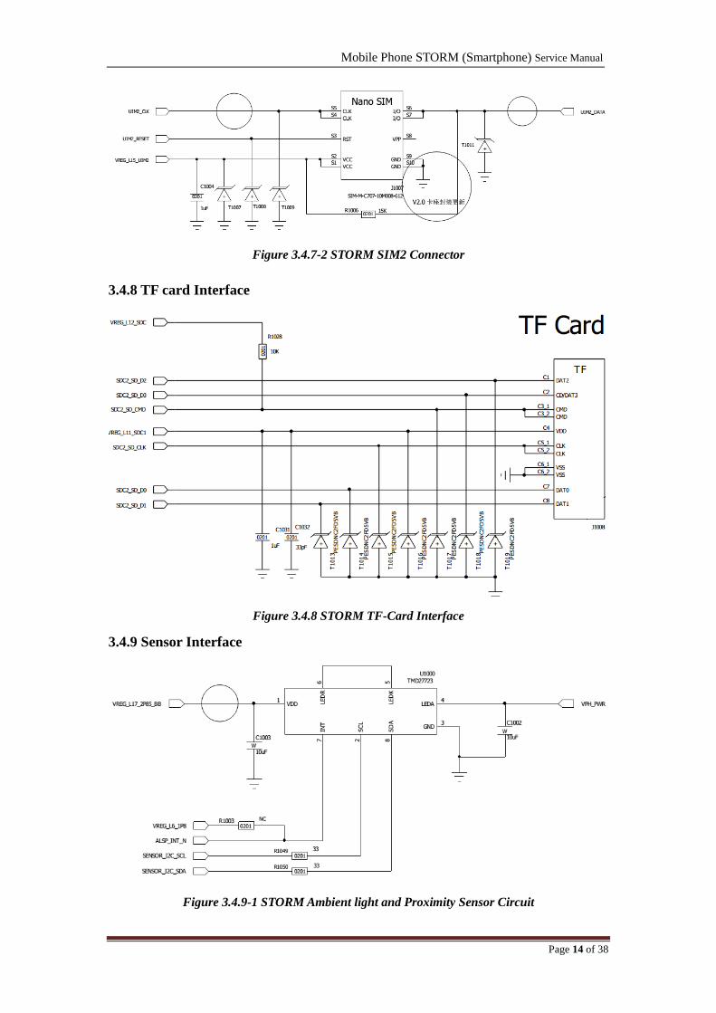
Figure 3.4.7-2 STORM SIM2 Connector
3.4.8 TF card Interface
Figure 3.4.8 STORM TF-Card Interface
3.4.9 Sensor Interface
Figure 3.4.9-1 STORM Ambient light and Proximity Sensor Circuit

Mobile Phone STORM (Smartphone) Service Manual
Page 15 of 38
Figure 3.4.9-2 STORM Magnetic Sensor
Figure 3.4.9-3 STORM Gyro and G-sensor connector

Mobile Phone STORM (Smartphone) Service Manual
Page 16 of 38
Chapter 4: Mobile Failure Analysis
Basically, STORM main failure cases including:
Power on problem (No power on, Auto-Power on/off, Phone totally dead, Restart
automatically)
Charging problem (No charging)
Camera issue ( cannot connect camera)
Touch failure (Cannot touch, shift)
Display failure (No display, LCD backlight malfunction, Segments missing, Black display,
and Contrast malfunction)
Signal problem (No signal, Weak signal, No signal intermittent)
Other Function problem ( No ringing tone, No vibration, Vibrator abnormity, Cannot read
SIM /T-F card, Phone password locked, Cannot upgrade software, Show "high
temperature", FM Radio fault, Bluetooth issue, Wi-Fi issue, etc.)
In the mobile circuit system, all the electrical connecting trace can be divided into three types,
such as power supply trace, controlling trace and data/ signal trace. When analyzing the RF failure
case, for the active circuit we should first check the power supply, then control circuit followed by
the signal flow path to remove the failure step by step. When debugging the RF malfunction, we
should diagnose the RX part first before TX.

Mobile Phone STORM (Smartphone) Service Manual
Page 17 of 38
4.1 Power on issue analysis
Cannot Power On
Is battery normal or not?
Go recharge
battery or
replace it
Measure
U300_E5(MSM_RESIN_N),
and other output circuit
Measure the Power On current
No Current Small Current Large Current
Measure VBAT,
PWRKEY and 26M
CLK
Check which chip
has abnormal temp
Re-flash FW
Replace Flash
Replace the
corresponding
IC
If all normal,
resolder or
replace CPU
N
Y
Figure 4.1 Power on failure repair process
1) Battery cannot power on
❶Check the battery is normal or not, if the battery is broken or lower voltage, replace it;
❷Check battery connector (J100) is normal or not, if the connector is broken, missing, disconnect,
re-solder or replace it; ❸Check the power on switcher is normal or not, if it is abnormal, replace
it; completed all above steps, you still cannot solve this issue, please follow the next steps.
2) No power on Current
❶If the mobile phone can‟t powered on by battery, we can use the DC Power Supply to check the
mobile phone‟s power on current. After connect mobile phone with DC Power Supply, press
power on key, then check the current value;❷For No current (0mA) issue, it means power supply
circuit problem, and we can follow the product circuit diagram to check this power supply circuit

Mobile Phone STORM (Smartphone) Service Manual
Page 18 of 38
step by step until find out the defective component.
3) Small power on Current
For small current issue, it means software or periphery circuit problem, we can try to upgrade the
new software or check all of the periphery circuit.
4) Large power on Current
For high current issue, it means this mobile phone must be short circuit, the most probable cause
chipset are Baseband IC (U600), Memory IC, RF IC, RF PA (GSM & WCDMA), ESD protection
Diode, etc.). We can attempt to touch these chipset, and feel the temperature is normal or not. If
one of the chipset‟s temperatures is abnormal, replace it.
4.2 Charging issue analysis
Cannot Charge
Upgrade FW
Is the connection of
USB Sub-board OK?
Reassemble or
replace connector
Is VBAT_SNS of
U300, VPH_PWR of
U101 OK?
Resolder or
Replace U300
Replace U101
Is the battery and
battery FPC OK?Replace battery
Y
Y
Y
N
N
N
Figure 4.2 Charging failure repair process
❶Upgrade new software for the mobile phone; ❷Check Battery and Charger; ❸Check Battery

Mobile Phone STORM (Smartphone) Service Manual
Page 19 of 38
Connector (J100) , USB Connector; ❹Replace the Switching charger U101 or PMU U300 and
test it again. If problem still not solved, you need to follow the product circuit diagram to check
CPU; ❺After repaired, enter into „Factory Mode‟ by press “Power on” key, volume “-”key the
same time for three seconds. Select “Battery” and then plug in USB cable you can verify the
function now.
4.3 Display issue analysis
Upgrade
Firmware
LCD Display Issue
Is the connection of
LCD and Sub board
OK?
Is LCD OK?
Is there backlight? Is PMW_OUT normal
Is
VPH_PWR,VLED_P
of U900 normal
IS VCC, LCD_VDDIO
of J900 are all normal?
Replace CPU
Replace PMU
Replace LCD
Module
Reassemble
connectors
Replace U900
N
Y
Y
Y
Y
N
N Y
N
Y
NN
1
Figure 4.3 Display failure repair process
❶ Upgrade new software for the mobile phone; ❷STORM‟s LCD is connected to mainboard
with FPC. We can check the FPC and FPC connector (J900) is normal or not, if it is abnormal, re-
solder or replace it. ❸After upgrade new software and LCD replaced, the problem is still not
solved. Please try to follow the product circuit diagram to check the LCD data path, LCD power

Mobile Phone STORM (Smartphone) Service Manual
Page 20 of 38
supply path and CPU.
4.4 No Incoming & Outgoing Voice issue analysis
REC Issue
Upgrade Firmware
Is signal
CDC_EAR_P/M
normal?
Is Receiver OK?
Check R804 and R807
especially.
Replace PMU
Replace REC
Y
Y
N
N
Is the connection of
receiver OK?
Reassemble
REC
Figure 4.4-1 No received voice failure repair process
Microphone Issue
Upgrade
Firmware
Measure Mic_IN1_P by
Oscilloscope is OK or
not.
Check R806,R805
and etc. Otherwise,
replace microphone
Replace PMU
N
Y
Figure 4.4-2 No outgoing voice failure repair process
Mobile Phone STORM (Smartphone) Service Manual
Page 21 of 38
These issues often occur in a mobile phone.
For incoming no voice failure
❶Upgrade the latest firmware and try again; ❷Check the phone call volume is OK or not;
❸Check if the connection of receiver is ok or not; ❹Measure the resistance of receiver and
check if it’s normal.
For outgoing no voice failure:
❶You can enter into „Factory Mode‟ by keep press “Power on” key, volume “-” key the same
time;❷Select “ Audio Handset” and blow at main microphone, the echo at the receiver indicate
the microphone is OK; ❸ If test fail, please check the microphone bias circuit, test bias
voltage and output signal.
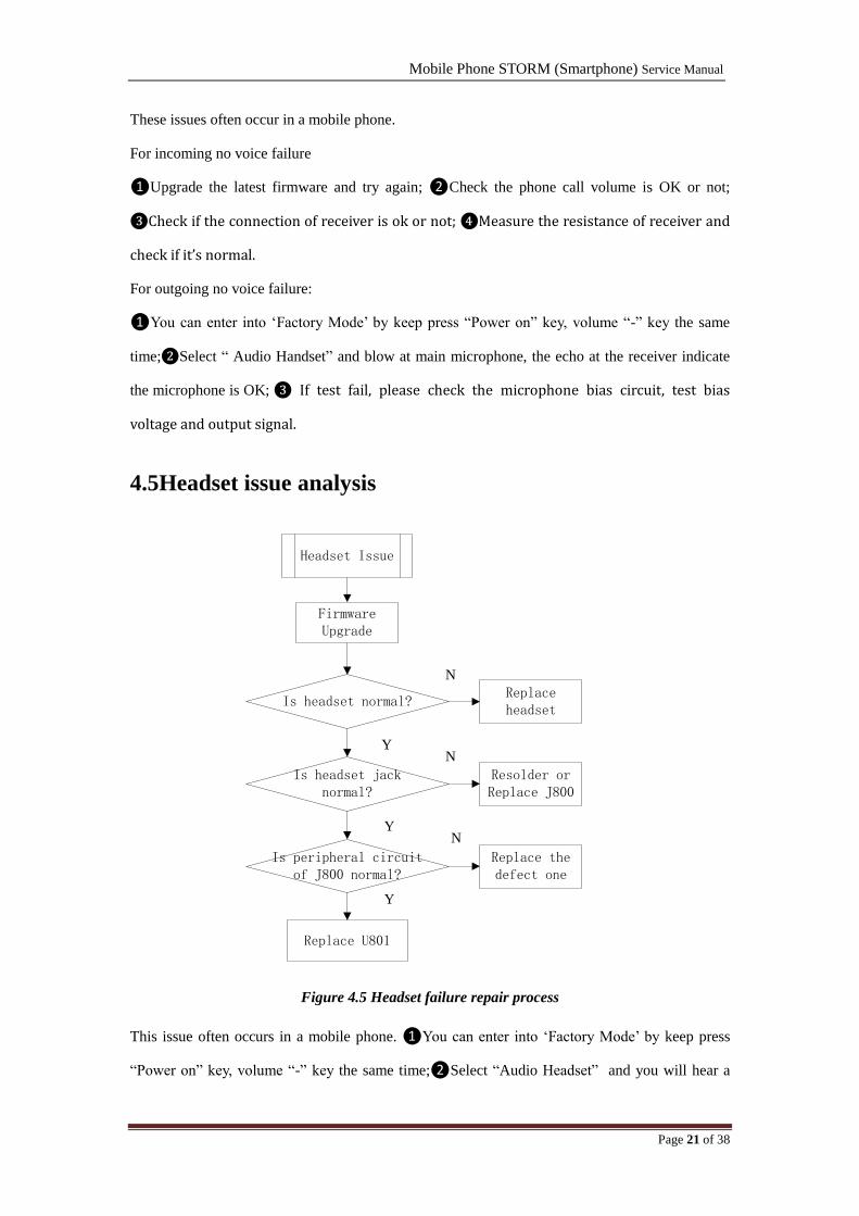
4.5Headset issue analysis
Firmware Upgrade
Headset Issue
Is headset normal?Replace headset
Is peripheral circuit of J800 normal?
Is headset jack normal?
Replace the defect one
Resolder or Replace J800
Replace U801
N
N
N
Y
Y
Y
Figure 4.5 Headset failure repair process
This issue often occurs in a mobile phone. ❶You can enter into „Factory Mode‟ by keep press
“Power on” key, volume “-” key the same time;❷Select “Audio Headset” and you will hear a

Mobile Phone STORM (Smartphone) Service Manual
Page 22 of 38
beep sound if the headset is good; ❸Otherwise you need to check the Earphone Jack (J800) and
its circuit to find the original issue and solve it.
4.6 No voice in Speaker issue analysis
SPK Issue
Upgrade
Firmware
Is SPK OK?
Is SPKR_OUT_P,
SPKR_OUT_M signal
OK?
Check the inductance that
SPK related especially.
Replace PMU
Replace SPK
Y
N
N
Y
Is the connection of
SPK and Sub-PCBA
connector OK?
Reassemble
SPK/sub-board
Y
N
Figure 4.6No voice in speaker failure repair process
❶Check whether the audio source can output from baseband chip with a headset; ❷Then check
speaker resistance to confirm whether the resistance of Speaker is 8ohm. If not, it means the
speaker is broken. Otherwise we need to check the Audio PA circuit to find out the
problem;❸When we solved the original issue, we can go to „Factory Mode‟ by press “Power on”
key, volume “-”key the same time;❹Select “ Audio Loudspeaker” to test the speaker function.

Mobile Phone STORM (Smartphone) Service Manual
Page 23 of 38
4.7 Touch Screen issue analysis
TP Issue
Is TP OK?
Upgrade
Firmware
Is VREG_L6 of
J901 normal?
Measure RESET,
INT,I2C signal
Replace CPU
Is connection of
TP and J901 OK?
Re-connect
connectors
Replace TP
Check PMU and
exterior
component
N
N
N
Y
Y
Y
Figure 4.7 TP failure repair process
❶Upgrade new software for the mobile phone; ❷Check FPC and TP connector (J901); ❸If
problem still not solved, you need to replace a new TP or CPU (U600); ❹After repaired, enter
into „Factory Mode‟ by press “Power on” key, volume “-”key the same time. Go to “Touch”Test
TP function.
Mobile Phone STORM (Smartphone) Service Manual
Page 24 of 38
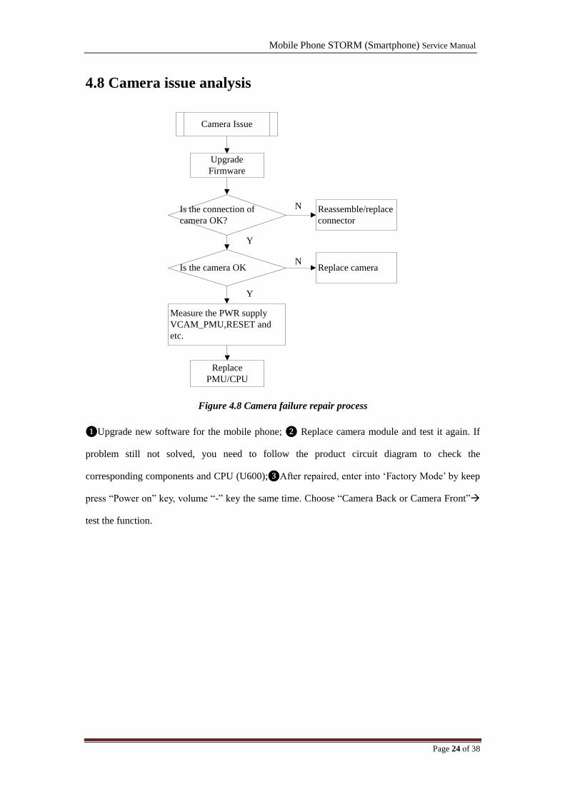
4.8 Camera issue analysis
Camera Issue
Upgrade
Firmware
Is the connection of
camera OK?
Is the camera OK
Measure the PWR supply
VCAM_PMU,RESET and
etc.
Replace
PMU/CPU
Reassemble/replace
connector
Replace camera
N
N
Y
Y
Figure 4.8 Camera failure repair process
❶Upgrade new software for the mobile phone; ❷ Replace camera module and test it again. If
problem still not solved, you need to follow the product circuit diagram to check the
corresponding components and CPU (U600);❸After repaired, enter into „Factory Mode‟ by keep
press “Power on” key, volume “-” key the same time. Choose “Camera Back or Camera Front”
test the function.

Mobile Phone STORM (Smartphone) Service Manual
Page 25 of 38
4.9 Vibrating issue analysis
Vibrator failure
Repair vibrator circuit
End
Is Vibrator normal?Resolder or replace
vibrator
N
Y
Upgrade firmware
Figure 4.9 Vibrator failure repair process
❶Upgrade new software for the mobile phone; ❷Check Vibrator; ❸Replace Vibrator and test it
again. If problem still not solved, you need to follow the product circuit diagram to corresponding
components; ❹After repaired, enter into „Factory Mode‟ by press “Power on” key, volume “-”key
the same time. Select “Vibrator” and then you can test the function.

Mobile Phone STORM (Smartphone) Service Manual
Page 26 of 38
4.10 BT/Wi-Fi issue analysis
BT/WiFi
Failure
Replace the defect
component
End
Is BT/WiFi antenna
normal?Replace antenna
N
Y
Upgrade firmware
Is the PA/Filter circuit
normal?
Replace U1504
N
Y
Figure 4.10 BT failure repair process
❶Upgrade new software for the mobile phone; ❷Check BT/Wi-Fi (Co-ANT); ❸Clean or
Replace the ANT and test it again. If problem still not solved, you need to follow the product
circuit diagram to check the PA, Filter and U1504;❹After repaired, enter into „Factory Mode‟ by
press “Power on” key, volume “-”key the same time, select “Bluetooth” and then you can test the
function.
Mobile Phone STORM (Smartphone) Service Manual
Page 27 of 38
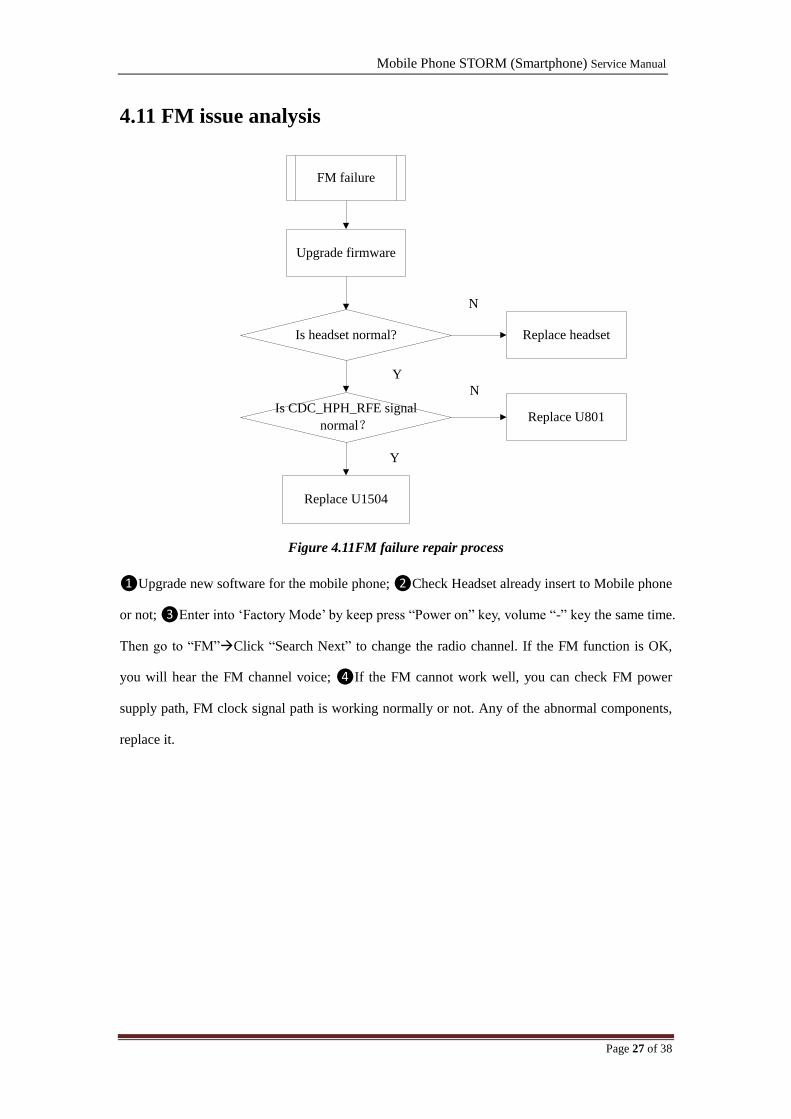
4.11 FM issue analysis
FM failure
Replace U1504
Y
Is headset normal? Replace headset
N
Upgrade firmware
Is CDC_HPH_RFE signal
normal?Replace U801
Y
N
Figure 4.11FM failure repair process
❶Upgrade new software for the mobile phone; ❷Check Headset already insert to Mobile phone
or not; ❸Enter into „Factory Mode‟ by keep press “Power on” key, volume “-” key the same time.
Then go to “FM”Click “Search Next” to change the radio channel. If the FM function is OK,
you will hear the FM channel voice; ❹If the FM cannot work well, you can check FM power
supply path, FM clock signal path is working normally or not. Any of the abnormal components,
replace it.
Mobile Phone STORM (Smartphone) Service Manual
Page 28 of 38
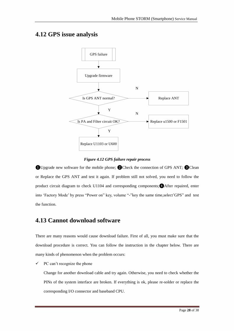
4.12 GPS issue analysis
GPS failure
Is GPS ANT normal? Replace ANT
N
Y
Upgrade firmware
Is PA and Filter circuit OK? Replace u1500 or F1501
Replace U1103 or U600
Y
N
Figure 4.12 GPS failure repair process
❶Upgrade new software for the mobile phone; ❷Check the connection of GPS ANT; ❸Clean
or Replace the GPS ANT and test it again. If problem still not solved, you need to follow the
product circuit diagram to check U1104 and corresponding components;❹After repaired, enter
into „Factory Mode‟ by press “Power on” key, volume “-”key the same time,select‟GPS” and test
the function.
4.13 Cannot download software
There are many reasons would cause download failure. First of all, you must make sure that the
download procedure is correct. You can follow the instruction in the chapter below. There are
many kinds of phenomenon when the problem occurs:
PC can‟t recognize the phone
Change for another download cable and try again. Otherwise, you need to check whether the
PINs of the system interface are broken. If everything is ok, please re-solder or replace the
corresponding I/O connector and baseband CPU.
Mobile Phone STORM (Smartphone) Service Manual
Page 29 of 38
Download tool hangs when downloading
You need to check the corresponding FLASH chip, baseband chip and trace between
baseband CPU and FLASH.
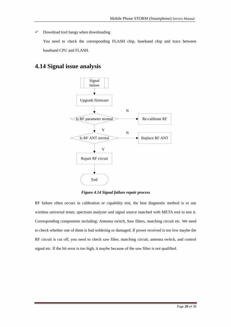
4.14 Signal issue analysis
Signal
failure
Repair RF circuit
End
Y
Is RF parameter normal Re-calibrate RF
Is RF ANT normal Replace RF ANT
N
YN
Upgrade firmware
Figure 4.14 Signal failure repair process
RF failure often occurs in calibration or capability test, the best diagnostic method is to use
wireless universal tester, spectrum analyzer and signal source matched with META tool to test it.
Corresponding components including: Antenna switch, Saw filters, matching circuit etc. We need
to check whether one of them is bad soldering or damaged. If power received is too low maybe the
RF circuit is cut off, you need to check saw filter, matching circuit, antenna switch, and control
signal etc. If the bit error is too high, it maybe because of the saw filter is not qualified.
Mobile Phone STORM (Smartphone) Service Manual
Page 30 of 38
Chapter 5: Software Upgrade Guidance
5.1 Preparations before Upgrade
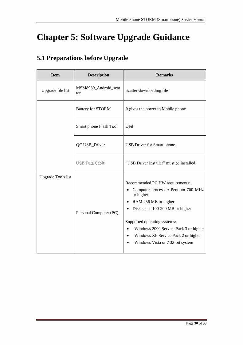
Item Description Remarks
Upgrade file list MSM8939_Android_scat
ter Scatter-downloading file
Upgrade Tools list
Battery for STORM It gives the power to Mobile phone.
Smart phone Flash Tool QFil
QC USB_Driver USB Driver for Smart phone
USB Data Cable “USB Driver Installer” must be installed.
Personal Computer (PC)
Recommended PC HW requirements:
Computer processor: Pentium 700 MHz
or higher
RAM 256 MB or higher
Disk space 100-200 MB or higher
Supported operating systems:
Windows 2000 Service Pack 3 or higher
Windows XP Service Pack 2 or higher
Windows Vista or 7 32-bit system

Mobile Phone STORM (Smartphone) Service Manual
Page 31 of 38
5.2USB Cable Driver Install
QC USB Port Driver Install
Step 1: Find the file of “QCUSB_Driver” package path, and then run the “QCUSB_Driver”.
(Attention: Do not connect the cable with PC when you install the “USB Driver”.)
Figure 5.2-1 “QCUSB_Driver” Package
Figure 5.2-2 USB driver installing progress
Mobile Phone STORM (Smartphone) Service Manual
Page 32 of 38
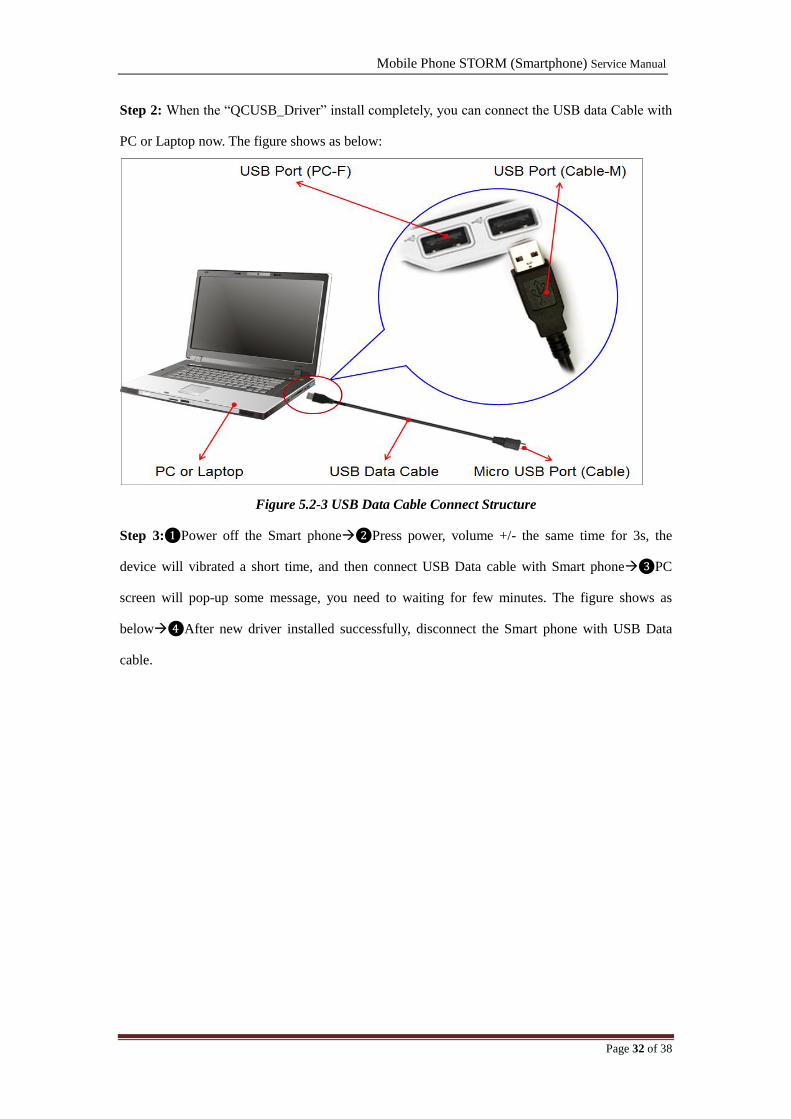
Step 2: When the “QCUSB_Driver” install completely, you can connect the USB data Cable with
PC or Laptop now. The figure shows as below:
Figure 5.2-3 USB Data Cable Connect Structure
Step 3:❶Power off the Smart phone❷Press power, volume +/- the same time for 3s, the
device will vibrated a short time, and then connect USB Data cable with Smart phone❸PC
screen will pop-up some message, you need to waiting for few minutes. The figure shows as
below❹After new driver installed successfully, disconnect the Smart phone with USB Data
cable.

Mobile Phone STORM (Smartphone) Service Manual
Page 33 of 38
Figure 5.2-4 USB Data Cable Connect Structure
The COM port will appear shortly in device manager as below picture:
Figure 5.2-5 Virtual COM port in device manager

Mobile Phone STORM (Smartphone) Service Manual
Page 34 of 38
5.3 Software Upgrade Procedure
Attention: Don‟t pull out the USB cable during downloading process. Otherwise,the handset‟s
memory will be broken by the unfinished upgrade process and cause the handset cannot be
powered on.
Step 1: double click the executable file “QDownload” to run the flash tool
The flash tool interface is as below:
Figure 5.3-1: Smart Phone Flash Tool Download window

Mobile Phone STORM (Smartphone) Service Manual
Page 35 of 38
Step 2: click the icon “Browser” to choose the file “prog_emmc_firehose_8936.mbn”which is
located in firmware folder, showing as Figure 5.3-2;
Figure 5.3-2: Choose mbn file
Step 3: click “Load XML” to choose the build files as Figure 5.3-3
Figure 5.3-3: Choose build file
1
3
2
1
Mobile Phone STORM (Smartphone) Service Manual
Page 36 of 38
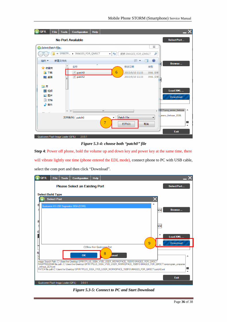
Figure 5.3-4: choose both “patch0” file
Step 4: Power off phone, hold the volume up and down key and power key at the same time, there
will vibrate lightly one time (phone entered the EDL mode), connect phone to PC with USB cable,
select the com port and then click “Download”.
Figure 5.3-5: Connect to PC and Start Download
6
8
9
7
Mobile Phone STORM (Smartphone) Service Manual
Page 37 of 38
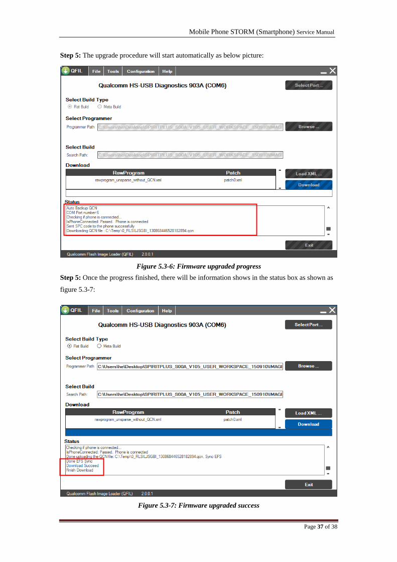
Step 5: The upgrade procedure will start automatically as below picture:
Figure 5.3-6: Firmware upgraded progress
Step 5: Once the progress finished, there will be information shows in the status box as shown as
figure 5.3-7:
Figure 5.3-7: Firmware upgraded success

Mobile Phone STORM (Smartphone) Service Manual
Page 38 of 38
5.4 SW Download Troubleshooting
Case one: How to confirm the downloading already successful?
Solution: When download successful, there will be “Download Succeed” in the status box;
If download failed, there will show failure reason.
Case two: What should we do, when the downloading process is completely?
Solution:
You should check if the “IMEI” is existed. Otherwise you should re-write the IMEI. The code to
check the IMEI: *#06#
Chapter 6: Product Explode View
1 LCD MODULE 6 MAIN CAM 11 MAIN FPC FLEX
2 FRONT COVER 7 MAIN PCBA 12 BATTERY
3 CABLE LINE 8 SPEAKER 13 SIM TRAY
4 EARPICECE 9 SPEAKER PCBA 14 REAR COVER
5 VICE CAM 10 SCREWS 15 BATTERY
Related Documents


