Bachelor thesis Electrical engineering with emphasis on telecommunication May 2015 Mobile Phone Antenna Design By Nazem Alsmadi & Khalid Saif ([email protected]) ([email protected]) 25 th of May 5, 2015 Supervisor Dr. Benny Lövström Examiner Dr. Sven Johansson Department of applied signal processing Blekinge Institute of Technology 37179 Karlskrona, Sweden

Welcome message from author
This document is posted to help you gain knowledge. Please leave a comment to let me know what you think about it! Share it to your friends and learn new things together.
Transcript

Bachelor thesis Electrical engineering with emphasis on telecommunication May 2015
Mobile Phone Antenna Design
By
Nazem Alsmadi & Khalid Saif
([email protected]) ([email protected])
25th of May 5, 2015
Supervisor Dr. Benny Lövström
Examiner
Dr. Sven Johansson Department of applied signal processing Blekinge Institute of Technology 37179 Karlskrona, Sweden


I
Abstract
This thesis focuses on mobile phones antenna design with brief description about the historical
development, basic parameters and the types of antennas which are used in mobile phones.
Mobile phones antenna design section consists of two proposed PIFA antennas. The first
design concerns a single band antenna with resonant frequency at GPS frequency (1.575GHz).
The first model is designed with main consideration that is to have the lower possible PIFA
single band dimensions with reasonable return loss (S11) and the efficiencies. Second design
concerns in a wideband PIFA antenna which cover the range from 1800MHz to 2600MHz.
This range covers certain important bands: GSM (1800MHz & 1900MHz), UMTS (2100MHz),
Bluetooth & Wi-Fi (2.4GHz) and LTE system (2.3GHz, 2.5GHz, and 2.6GHz). The wideband
PIFA design is achieved by using slotted ground plane technique. The simulations for both
models are performed in COMSOL Multiphysics.
The last two parts of the thesis present the problems of mobile phones antenna. Starting with
Specific absorption rate (SAR) problem, efficiency of Mobile phones antenna, and hand-held
environment.

II
Acknowledgements
The work of the thesis has been carried out of Blekinge Institute of Technology (BTH),
Karlskrona, Sweden under the supervision Dr. Benny Lövström.
Firstly, thanks to Allah who give us the ability and the strength to be managed to complete our
thesis work and we really thank the people who support us and guide as to success this thesis
work.
We would like to gratitude our thesis supervisor Dr. Benny Lövström for his encourages and his
comment he was behind this success and we extend our thanks for Prof. Ansel Berghuvud.
We would like to thank Dr. Sven Johansson.

III
Contents
Abstract I
Acknowledgment II
Contents III
Acronyms V
Chapter 1
1.1 Introduction 1 1.2 Thesis Motivation 2 1.3 The Development Of Mobile Phone Antennas 2
Chapter 2
2. Basic Mobile Phone Antennas 8 2.1 Parameters Of Mobile phone Antennas 8
Radiation pattern 8
Directivity 10
Polarization 12
Impedance 14
Antenna gain 14
Antenna efficiency 15
Antenna Beamwidth 15
Effective area 16
Band width 16
VSWR 17
2.2 Antenna Types 18
Dipole antenna 18
Monopole antenna 19

IV
PIFA antenna 20
Fractal antenna 22
Chapter 3
3 Mobile Phone Antennas Design 23 3.1 Mobile Phone GPS Antenna Design 23
Model descriptions 25
Calculations 26
Simulations 27
Result and Analysis 29
3.2 Wideband PIFA Antenna Design 34
Model description 34
Calculation 35
Result and analysis 39
3.3 Wi-Fi And Bluetooth 41
Chapter 4
4 Specification Absorption Rate (SAR) 42 4.1 How To Measure The SAR 43 4.2 The Technique Of Reducing SAR 44 4.3 The Limit Of SAR In Different Countries 46 4.4 SAR With Different Types Of Antenna 47
Chapter 5
5 Problem Of Mobile Phone Antenna Design 50 5.1 The Radiation Efficiency Of The Mobile Phone Antenna 50 5.2 Bandwidth 52 5.3 Mutual Coupling Antenna To Antenna Loss 54 5.4 The Hand-Held Environment Problem 55
Summary And Conclusion 59
Reference 60

V
Acronyms
LAN Local area network.
GSM Global system for mobile communication.
PIFA Planar inverted – F Antenna.
UMTS Universal mobile telecommunication system.
DECT Digital enhanced cordless tele communication.
PDC Personal digital cellular.
RFID Radio frequency identification.
HPBW Half – power beam width.
FNBW First null beam width.
IFS Iterative function system.
SAR Specific absorption rate.
RF Radio frequency.
PMA planar monopole antenna.
MOM Method of moments.
FDTD Finite difference time – domain.
ESA Electrically small antenna.
Wi-Fi Wireless fidelity
GPS Global positioning system
RHCP Right Hand circularly polarized
IFA Inverted F-antenna
PTFE Polytetrafluoroethylene
PEC Perfect electrically conductor
LTE Long term evaluation
1
Chapter1
1.1 Introduction The huge development of the mobile phones have grown up rapidly in the last years, frequency
bands have come up and the market is asking for smaller mobile phones with more services
which give the user the ability to use the mobile phone with good signal performance and helps to
use the mobile phone around the all world. On top of that it is important to reduce the risks
affecting in the human body because of the antenna radiation.
In the past the mobile phone was so heavy, big and had external antenna on the top of the phone
which effect badly on the human head and most of the signal radiate is reflected and absorbed by
the human head which lead to bad efficiency.
Nowadays the internal antenna has been using instead of the external antenna the main reason of
that is the internal antenna has a good relation with SAR rate, on the other hand the size of the
phone became smaller.
Recently there are many types of the internal antennas for example PIFA antenna (Planar
Inverted- F Antenna), fractal antenna and monopole antenna. Those kinds of antennas can cover a
single band, dual band, wideband and multiband based on the design of the antenna.
PIFA antennas are used widely in mobile phone antennas design due to its advantages such as
SAR rate and less interaction with hand-held environment, but one of the significant problems of
PIFA antennas that’s PIFA antennas have a narrow bandwidth. Wideband and multiband PIFA
antenna can be a solution of that problem. By designing multiband antenna or wideband antenna

2
it’s possible to have one antenna can cover more frequency such as using one antenna that can
cover the very important bands which are in use in most countries GSM, UMTS, Wi-Fi and LTE.
1.2 Thesis Motivation
The work in this thesis is motivated by the necessity to investigate antenna structures which can
be integrated in today is mobile phones which have a small available space for antennas inside.
Nowadays the demand on low profile antennas increases rapidly that’s in response to the huge
developments of mobile phone devices either in functions or in size.
The other motivation is to investigate and design a wideband PIFA antenna. In general PIFA
antennas have a disadvantage that’s PIFA antennas have a narrow bandwidth, but on other hand
PIFA antennas have many advantages such as best SAR rate, low profile and easy to be
integrated inside mobile phones which make PIFA antennas the best candidate for mobile phones
antennas. There are many papers published which study and discuss the narrow bandwidth of
PIFA antennas, but most of those papers give the solution of the problem in dual band PIFA or in
multiband design which in both cases do not solve the problem totally. Since there are some
bands remain without covering, consequently the need of several antennas appears for covering
low and high frequency bands.
So this thesis presents a study of a proposed wideband PIFA antenna with bandwidth more than
30% and the bandwidth cover an important range which could cover GSM, UMTS, and some
bands of LTE system.
1.3 The Development of Mobile Phone
Antennas
In the first generation 1G of mobile system, the system was operating at 800 MHz and as known
it was analog. The first antenna handset for one quarter of wavelength has length about 9.4 cm,
and it was one antenna only. The first mobile phone was Motorola DynaTAC8000X[1] with type

3
antenna is sleeve dipole as shown in the figure 1.3.1 which is not use any more in modern design
of mobile phones antennas, however it still is used in different wireless LAN access points.
Sleeve dipole antenna has an efficient performance; the length of it is about half the wave length
at its frequency. So at 850 MHz the antenna should be 176mm.
With the improvement on mobile phone and due to the dramatic minimizing size of the mobile
phone, there were no needs for a sleeve dipole to be proportional to the cellular phone.
Photo was loaded from http://mashable.com/2014/03/13/first-cellphone-on-sale/
Figure 1.3.1 Motorola DynaTAC8000X with Sleeve dipole antenna.
In 1990s 2G launched which offered new services such as text message, and it is operated at
GSM 900 MHz, where later on at 1800 MHz unlikely 1G, the second generation handset antenna
has two antennas monopole and helix with only single band supporting as shown below in figure
1.3.2 and 1.3.3.

4
http://tech-kid.com/nokia-phone.html http://www.northstandchat.com/showthread.php?289468-Your-first-ever- Mobile -Phone-and-what-make-
and-model-was-it-!/page3
Figure 1.3.2 Nokia 1011 supports only GSM900 single band Figure1.3.3 Motorola m300 support only GSM1800 single band.
In 1997, Motorola produced a mobile device Motorola mr601 which was the first dual band GSM
phone, it supported GSM900 and GSM1800 dual band and its antenna consists of two antennas
helix antenna which has travelling wave in the shape of corkscrew with circularly polarized and
whip antenna which can be consider as dipole antenna and it is Omni-directional radiation
pattern. That’s model phone offered the ability to access network in over 70 countries by the end
1997.
In the first dual band PIFA operating at GSM900 and GSM1800, invented by Prof. Peter Hall in
1996 U.K, the first dual band PIFA a slot with a certain geometric dimensions, lead to support
two different bands.
The development timeline of mobile phone has several significant steps, one of them was in
1999, when Nokia launched Nokia3210 as shown in figure 1.3.4 the first mobile with fully
internal antenna, support both GSM900 and GSM1800 dual band, and was one of the most
popular handset with over 160 million being sold [2].
In 1999, Prof. Peter Hall comes back with the first Triple Band PIFA which operates at
GSM800/1800/1900. He designed Triple Band PIFA with two slots in the ground plane of the
PIFA antenna, that’s let the antenna to transmit and receive different band of frequencies.

5
Internal Antenna

6
Table1.1 The timeline of development antenna use in mobile phones [1].
Year 1900 1950 1970 1990 2000 2010 Frequency < 10 kHz < 30 MHz < 800 MHz < 1.9 GHz < 2 GHz 3 GHz
5 GHz System Telegraph
/ telephone for train, ship, police cars
Vehicle and portable systems for business, Pager
Mobile phones (analog), cordless phones, pagers, GPS
Mobile phones (digital),aircraft (voice and data) personal phone
Mobile phones (multimedia), Wireless access, Bluetooth
Mobile phones (high data rate), Ultra wideband,
Antenna Monopole dipole, whip,
Blades, ferrite coil, helical antenna
Corner reflector, PIFA, helix
Meander line, normal mode helix, ceramic chip, adaptive array
Wideband, multiband built-in antennas, adaptive array, MIMO
Small compact functional antennas, implant antennas
Table 1.3.1 shows the time line of development in both sides’ frequencies and antenna which are
used for mobile phones systems. The frequencies are raised from 10 kHz till 3 or 6 GHz which is
considered as a 4G system.
Cordless phones navigation systems and multichannel access systems have contributed
dramatically to the development of antennas design, while the personalization of mobile
terminals raised the needs of small antennas. Other needs for small antennas are hybrid systems,
the handset of multiband GSM combined with DECT (Digital Enhanced Cordless
Telecommunications) for example.
The specifications of the handset small antennas are low profile, compact and lightweight, which
has led to modify and develop the antennas. One of the antennas is a modified PIFA, which has
changed that it is difficult to recognize it as an original PIFA. The modified PIFA was first used
in GSM handsets and has become more common in several different mobile terminals. Other
modified antennas such as monopole were used in PDC (Personal Digital Cellular) with a normal
mode helical antenna.
7
In modern mobile phone, we can conclude a summary of the considerations in design process as
following:
The requirement of multiband and built–in antenna.
The requirement of small size antenna due to small size mobile terminals,
for example RFID units (Radio-frequency identification).
The requirement of function antennas such as adaptive antennas and
MIMO for transmission high data rate.
Printed antenna has been used in mobile terminals; also Printed antennas have the smallest
dimensions comparing with other installed small antennas. Chip antennas or a printed antenna
consists of dielectric material and a ground plane which is a part of the antenna. Chip antennas
offer a high gain, appropriate radiation pattern, and high efficiency.

8
Chapter 2
Basic Mobile Phone Antennas Principles
2.1 Parameters of Mobile Phone Antennas Radiation pattern
Radiation pattern can be describe by power radiated through the antenna, which depends on the
direction, and it can be represented as graphical or mathematical function of the radiation
properties. There are two common types of antenna pattern , the first one is a power pattern and the second is
field pattern , the first type is considering the power radiated and the position of the spherical
coordinate and the second type which depend on the field if we have electrical field or magnetic
field with the position of spherical coordinate.
The field region of the antenna pattern can be dived to three regions. The first region is Reactive
Near Field Region which is the closest region to the antenna so it gives possibility to control the

9

10
Parameters of antenna pattern
1- Main lobe is the radiation lobe going in the same direction of the maximum radiation.
2- Side Lobe is the radiation lobe of any directional lobe except the intended direction.
3- Back lope which has the opposite direction of the main lobe.
4- Half-Power Beam width (HPBW) the angular between two directions the half power point
and the beam width which equal to -3db.
5- First Null Beam width (FNBW) - angular width between two directions the first zero and
other side in the side lobe.
http://www.antenna-theory.com/basics/whyantennasradiate.php Figure 2.1.2 A polar figure of an antenna with performance Parameters.

11
Directivity
Directivity is one of the antenna parameters that guide us to measure the direction of the radiation
pattern, the directivity help us to determine the efficiency of the antenna, directivity of isotropic
antenna equal to 1 (0 dB).
The directivity can be calculated by determining the maximum value of the magnitude of the
radiation pattern which is defined by F(θ, ϕ) and the average power of all the direction which is
equal to 1 so, the formula of calculating the directivity it can be written as:
𝑫 =𝟏
𝟏𝟒𝝅 ∫ ∫ |𝑭(𝜽,𝝓)|𝟐𝒔𝒊𝒏𝜽𝒅𝜽𝒅𝝓
𝝅𝟎
𝟐𝝅𝟎
(2.1.1)
𝜃 = The angle between the z-axis and the vector from the origin to the point
𝜙 = The angle between the x-axis and the projection onto the x-y plane.
Mobile phone antenna should have a low directivity, because is not useful to use an antenna with
high directivity, that is the received signal it can be from different directions. On the other hand
the base station needs a high directivity.
As showing in the table 2.1.1 above the directivity of different types of antenna so, the properties
of the antenna have to be chosen regarding to what we need, as we have mentioned if you want to
choose antenna for mobile station as cell phone, car or computer we will choose antenna with low
directivity.
Antenna Type Typical Directivity Typical Directivity (dB)
Short Dipole Antenna 1.5 1.76
Half-Wave Dipole Antenna 1.64 2.15
Patch (Microstrip) Antenna 3.2-6.3 5-8
Horn Antenna 10-100 10-20
Dish Antenna 10-10,000 10-40
Table 2.1.1 Directivity of different types of antennas [4].

12
Polarization
One of the characteristics for any types of antennas is the direction of the electrical field vector of
the electromagnetic wave. The polarizations of electromagnetic wave depend on the electrical
field, which is perpendicular with the magnetic field.
The polarization of antennas can be classified in three different types based on
electrical field
1- Linear polarization: as seen in the figure 2.1.3 the electrical field travels with the same
direction of the plane wave. There are two types of linear polarization:
Vertical polarization: the electrical field travelling orthogonally to the y-axis
and the magnetic field is travelling horizontally to x-axis.
Horizontal polarization: the electrical field is travelling horizontally to the x-
axis and the magnetic field is travelling orthogonally to the y-axis.
http://www.srh.noaa.gov/hun/?n=dualpol
Figure 2.1.3 Vertical polarization and horizontal polarization.
2- Circular polarization: the electrical field travels circularly as seen in figure 2.1.4. It can
be divided to two types regarding to direction of the circle:
Right Circular polarization: the direction of the circle is clockwise.
Left circular polarization: the direction of the circle is anti-clockwise.

13
http://www.antetec.com/news/2010/01/27-371.html
Figure 2.1.4 Right circular polarization and left circular polarization.
3- Elliptical polarization: the electrical field travels with an elliptical shape based on the
direction of the electrical field figure 2.1.5 it can be divided to two types:
Right elliptical polarization which is has direction with clockwise.
Left elliptical polarization which has direction anti-clockwise.
http://skullsinthestars.com/2012/09/23/hairy-balls-in-optics/
Figure 2.1.5 Right elliptical polarization and left elliptical polarization.

14
Impedance
The impedance of the antenna mainly depends on the input voltage and current for the power
losses equal to the power transmission of the antenna. The benefits of knowing the input
impedance it is lead you that to choose the suitable transmission line.
The impedance of an antenna ZA must be matched with its impedance transmission line ZS
(feeder). Otherwise there will be amount of a reflection wave back to the signal source. To have
maximum power at the antenna from source as shown in figure 2.1.6 ZS should be equal to ZA
http://www.antenna-theory.com/basics/whyantennasradiate.php
Figure 2.1.6 The equivalent circuit of an antenna and the transmission line.
Antenna gain One of the antenna properties to describe the value of the power transmission to the peak
radiation direction. The efficiency of the antenna always relate with the antenna gain so if the
efficiency is perfect 100% that’s mean the gain and the directivity are equal to each other, it can
be describe by the following formula:
𝑮 = 𝜺𝑹𝑫 (2.1.2)

15
Antenna efficiency The relation between the input power to the antenna and the dissipated power which is the losses
power within antenna, regarding to the relation between the power radiate and the power input
the efficiency of the antenna can be written by the following formula:
𝜺𝑹 =𝑷𝒓
𝑷𝒊𝒏 (2.1.3)
Antenna Beamwidth (θ) The angle between the two points of the half power of the radiation pattern, the beamwidh could
be clarify as the half power, the directivity become high if the beamwitdh very small. The
beamwidth is found by determining the two points with 3db as showing in figure 2.1.7.
http://happy.emu.id.au/lab/rep/rep/9510/txtspace/9510_010.htm
Figure 2.1.7 Half power Beamwidth.

16
Effective area
To calculate the transmission power (𝑃𝑡) and determine how much power has been lost due to the
plane wave, regarding to the relation between the power density (P) and the effective area (𝐴𝑒)
the following formula can be written as:
𝑷𝒕 = 𝑷𝑨𝒆 (2.1.4)
To calculate the effective area we should consider the relation between the effective area and the
antenna gain the formula can be written as:
𝑨𝒆 =𝝀𝟐
𝟒𝝅𝑮 (2.1.5)
Bandwidth
One of the other important parameters is bandwidth which determines the range of the
frequencies where the antenna is operating, table 2.1.2 shows different common types of antennas
with frequency range of each antenna. The percentage of the bandwidth can be calculated as
following:
𝑩𝒂𝒏𝒅𝒘𝒊𝒅𝒕𝒉% =𝒇𝒎𝒂𝒙−𝒇𝒎𝒊𝒏
𝒇𝑪𝒆𝒏𝒕𝒆𝒓× 𝟏𝟎𝟎 (2.1.6)
Antenna Center frequency Frequency range Percentage
bandwidth
Patch 1000MHz 985-1015MHz 3%
Dipole 1000MHz 960-1040MHz 8%
Horn 1000MHz 154-1848MHz 169.40%
Spiral 1000MHz 95-1900MHz 180.50%
Table 2.1.2 different common types of antennas with frequency range of each antenna [4].
17
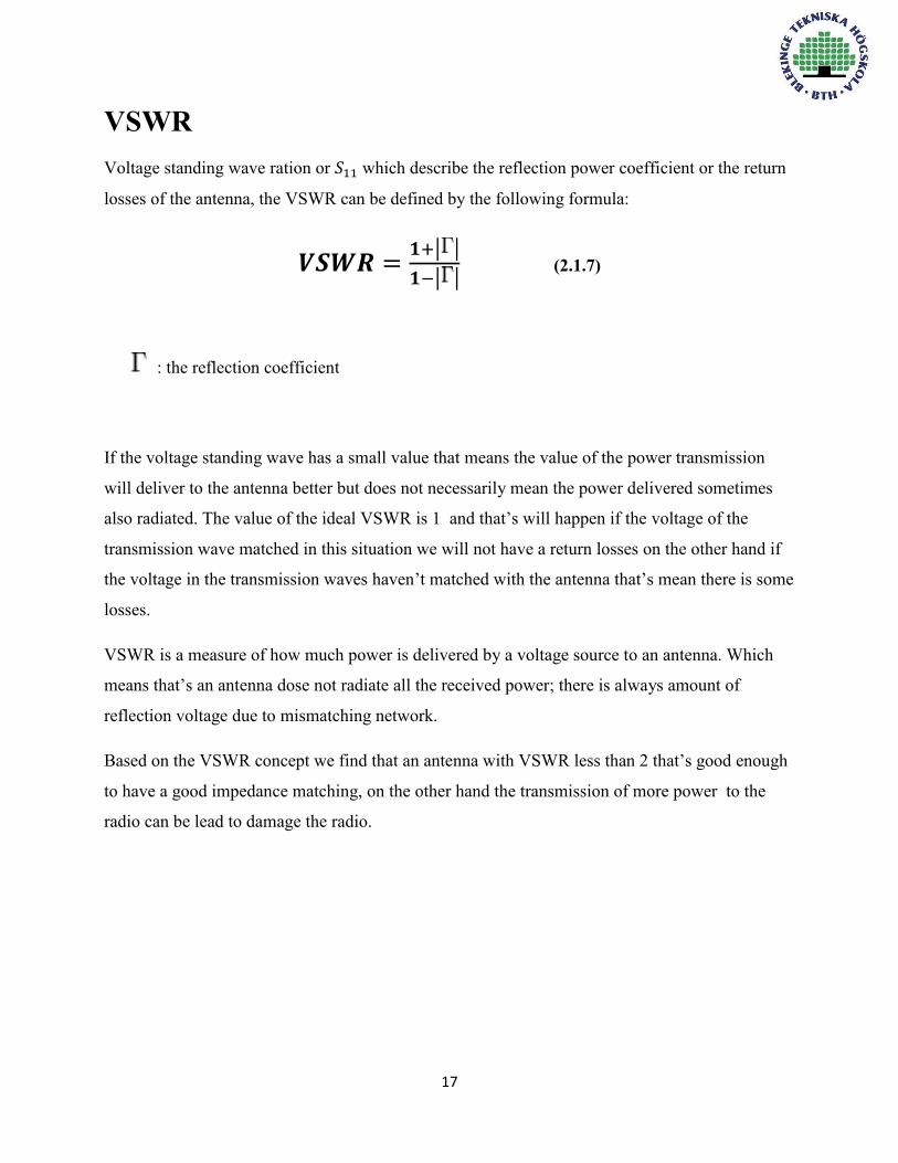
VSWR Voltage standing wave ration or 𝑆11 which describe the reflection power coefficient or the return
losses of the antenna, the VSWR can be defined by the following formula:
𝑽𝑺𝑾𝑹 =𝟏+| |
𝟏−| | (2.1.7)
: the reflection coefficient
If the voltage standing wave has a small value that means the value of the power transmission
will deliver to the antenna better but does not necessarily mean the power delivered sometimes
also radiated. The value of the ideal VSWR is 1 and that’s will happen if the voltage of the
transmission wave matched in this situation we will not have a return losses on the other hand if
the voltage in the transmission waves haven’t matched with the antenna that’s mean there is some
losses.
VSWR is a measure of how much power is delivered by a voltage source to an antenna. Which
means that’s an antenna dose not radiate all the received power; there is always amount of
reflection voltage due to mismatching network.
Based on the VSWR concept we find that an antenna with VSWR less than 2 that’s good enough
to have a good impedance matching, on the other hand the transmission of more power to the
radio can be lead to damage the radio.

18

19
Folded dipole antenna
A folded dipole antenna is half wavelength dipole but its wires are folded back as shown in figure 2.2.1.
Monopole antenna Unlikely dipole antenna Monopole antenna is an antenna which consists of a one straight rod conductor, and is installed over a ground plane (conductive surface) as seen in figure 2.2.2. Monopole antennas are fed at lower end, near to ground plane which works as a reflector. In case the ground plane conductive and valid in size, the efficiency of the ground plane is as well as a vertically installed dipole.
http://www.antenna-theory.com/antennas/monopole.php
Figure 2.2.2 Monopole antenna with length L.
There are other common types of monopole antenna such as Whip, helical, T-antenna, and mast radiator. Monopole antenna like dipole antenna both have omnidirectional radiation pattern, for that the monopole it could be used in cell phones and other applications, for example indoor applications such as airplane, or shopping center.
Monopole antennas are widely used in mobile communications, specially the quarter wave monopole -the length of the monopole L is approximately quarter of wavelength- which is a suitable for MIMO wireless communications systems, due to its low angle radiation and minimized ground losses [3].
For better efficiency of monopole antennas, many methods are applied, one of them type of the ground plane; The ground plane can be infinite or finite with different geometric shape such as spherical, cylindrical, or rectangular sheet. That’s affect characteristics monopole specially radiation pattern, and less effects in monopole’s impedance [4].

20
Feed point

21
The structure of the PIFA can deal with different frequency band
Single band
Multiband
Reconfigurable
The main advantages of using PIFA antenna
1- Due to the small size of PIFA antenna it gives the availability to insert the antenna inside
the cellular phone.
2- PIFA has availability to get high gain for both polarization states vertically and
horizontally there for it can receive the reflection wave easily from different directions.
3- The backward radiation of the PIFA has be reduced that’s mean the electromagnetic
waves power has reduced which lead us to get a good deal to less damage of the human
health.
4- The design and the material of the PIFA are not costly on top of that it has a very high
efficiency also It is easy to fabricate.
As we know the development of communication always come up with a new evaluation but until
now there are no antennas can work without disadvantages, So there is a problem in PIFA
antenna could not be solved until now which is the sensitivity of the bandwidth but in general
PIFA prove that is the best cellar phone antenna have been used regarding to the comparing
between the advantage and the disadvantage of the antenna.
There are a few di-electrical material can be used in PIFA, and when the air is the one which is
used, the gain will be better comparing with other material.
22
Fractal antenna
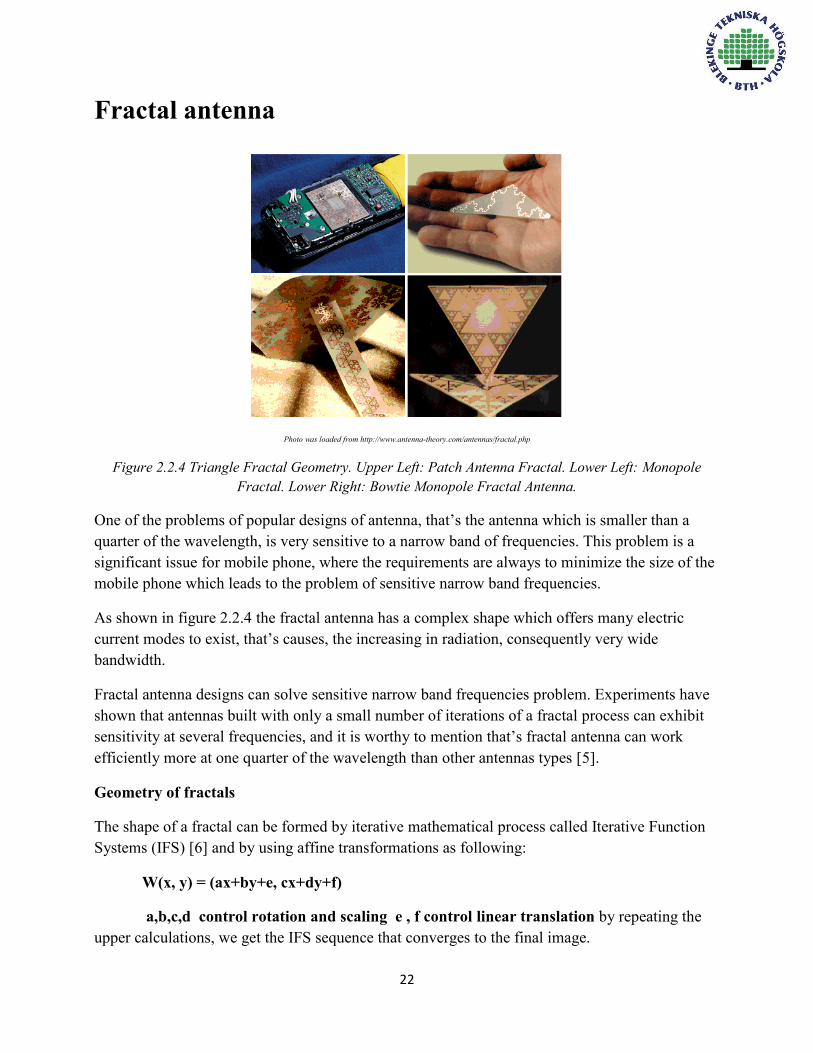
Photo was loaded from http://www.antenna-theory.com/antennas/fractal.php
Figure 2.2.4 Triangle Fractal Geometry. Upper Left: Patch Antenna Fractal. Lower Left: Monopole Fractal. Lower Right: Bowtie Monopole Fractal Antenna.
One of the problems of popular designs of antenna, that’s the antenna which is smaller than a quarter of the wavelength, is very sensitive to a narrow band of frequencies. This problem is a significant issue for mobile phone, where the requirements are always to minimize the size of the mobile phone which leads to the problem of sensitive narrow band frequencies.
As shown in figure 2.2.4 the fractal antenna has a complex shape which offers many electric current modes to exist, that’s causes, the increasing in radiation, consequently very wide bandwidth.
Fractal antenna designs can solve sensitive narrow band frequencies problem. Experiments have shown that antennas built with only a small number of iterations of a fractal process can exhibit sensitivity at several frequencies, and it is worthy to mention that’s fractal antenna can work efficiently more at one quarter of the wavelength than other antennas types [5].
Geometry of fractals
The shape of a fractal can be formed by iterative mathematical process called Iterative Function Systems (IFS) [6] and by using affine transformations as following:
W(x, y) = (ax+by+e, cx+dy+f)
a,b,c,d control rotation and scaling e , f control linear translation by repeating the upper calculations, we get the IFS sequence that converges to the final image.

23
Chapter 3
Mobile phones antenna design Mobile phones consist of several antennas for several purposes such as Wi-Fi antenna, GPS
antenna, low and high frequencies antennas. Each type of antennas is designed according to
certain considerations, of course, the small sizes the main issue.
As it is mentioned in the previous sections of this thesis. Dipole antenna is a useful type of
antennas; easy to be constructed, and integrated in cell phones
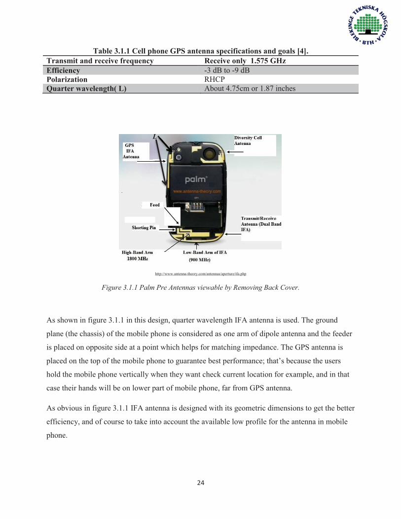
.3.1 Mobile phone GPS antenna design
GPS antenna is an omnidirectional small antenna with only receive mode that can be one of main
design’s considerations. The GPS frequency is 1.575 GHz, with practically no bandwidth, and the
GPS satellites are RHCP (table 3.1.1) to avoid Faraday rotation problems, and there is one other
benefit, that’s circular polarization does not need rotational alignment of a circularly polarized
antenna at mobile phone.
For a maximum received power the user terminal’s antenna must be RHCP. User terminal’s
antenna which is linearly polarized will have a loss 3dB in received power due to polarization
issue. By looking at the power density of the GPS received wave. We find that it is extremely low
level which equals to -160dB. Therefore, we need an efficient antenna at the receiver.

25
To obtain circularly polarized dipole antenna, we use two crossed dipoles to provide the two
orthogonal field components, and if the two dipoles are fed with a 90° time-phase difference the
polarization will be circular along zenith [28].
Single band PIFA Antenna design GPS antennas are received mode antennas. So we do not have to worry about SAR measurements. In this section we will design a single band antenna for GPS use and simulate the model by COMSOL.
Model descriptions The desired bandwidth is a single frequency 1.575 GHz (table 3.1.1). Thus we try to make the
resonant frequency of the PIFA antenna close to 1.575 GHz to provide high receiving efficiency
as much as possible. The gain of the antenna should be between -3dB to 0dB.
Figure 3.1.2 Zoom view of PIFA antenna block. It consists of Nylon block and the radiating part and the materials which are used in design.

26
Calculations
Figure 3.1.3 The antenna to the left and its dimensions 𝐿1 = 20𝑚𝑚, 𝐿2 = 10𝑚𝑚, 𝑤 = 2𝑚𝑚 , ℎ = 4𝑚𝑚 𝜖𝑟 = 3.8, Δ = 0.2𝑚𝑚 to the right the casing’s dimensions have length =119mm, width =60mm. The resonant wavelength of a PIFA antenna can be calculated as following:
𝑳𝟏 + 𝑳𝟐 − 𝑾 =𝝀𝟎
𝟒 (3.1.1)
And the relation between the resonant wavelength and the resonant frequency can be determined
by the equation:
𝝀𝟎 = 𝒄𝟎
𝒇𝟎√𝝐𝒓 (3.1.2)
𝜆0: Resonant wavelength of PIFA.
𝑐0: The speed of light in space.
𝑓0: Resonant frequency.
𝜖𝑟: Relative permittivity.

27
Mathematically, PIFA antenna’s size can be reduced by using factor √𝝐𝒓 (equation 3.1.2)
Therefore if we use a material with higher 𝜖𝑟 ,that reduces the size of the PIFA which is a useful
way to get a low profile antenna but that could affect the gain of the antenna as well. It is a big
challenge to keep the efficiency without any effects when the small size is required, so the PIFA
dimensions which are used in this design were chosen after many simulations, and based on the
best efficiency, lowest value in return loss S11, and the smallest size. We determined the
dimensions.
By applying equation 3.1.1 we find that:
20 + 10 − 2 =𝜆0
4 , 𝜆0 = 112 mm
Hence,
𝑓0 =3 × 10⁸
112 × 10−3√3.8 = 1.374 GHz
The calculated resonant frequency is not very close too much to the desired frequency 1.575
GHz. But by increasing and decreasing the gap impedance change, the resonant frequency will
shift to upper or lower than the calculated resonant frequency. Increasing and decreasing of the
impedance gap affects the input impedance, consequently effects at VSWR for the resonant
frequency.
Simulations
In simulation, first we installed the antenna to left of the casing figure 3.1.3 and inserted the
materials as shown in figure 3.1.2 and with dielectric constant as table 3.1.2 in addition the outer
shell of the casing is simulated with Polytetrafluoroethylene (PTFE). We use whole chassis as a
ground plane for better efficiency.

28
A 50 Ω lumped port is used to excite the antenna and determine the input impedance. The lumped
port is mounted between two metallic boundaries: the vertical feeding and the ground plane of
FR4 board as seen in figure 3.1.2. The distance Δ, the impedance matching gap affects
significantly the matching impedance. So another strip shorted to the ground plane is added. The
dielectrically material which will be used for the antenna block is Nylon.
Figure 3.1.4 Mesh model for the whole simulated model: PIFA antenna, casing of the mobile phone and the surrounded perfect matched layers.
The model consists of several domains; every domain has a certain material figure 3.1.2. In
addition there is one more domain encloses the casing. This domain is simulated as a sphere with
radius 100mm, material air, and has five perfect matched layers in order for the radiation to be
able to travel anywhere as shown in figure 3.1.2. The metal part of the antenna element at
frequency 1.575 GHz can be modeled using perfect electric conductor boundaries.
29
Table 3.1.2 the materials of the simulated model and its Dielectric constant according COMSOL’s materials libraries except Nylon.
Material Dielectric constant ( 𝝐𝒓) Air 1 FR-4 4.5 Nylon 3.8∗ Glass (quartz) 4.2 Silicon 11.7 PTEF 2.1
* The Dielectric constant of Nylon accordinghttp://www.professionalplastics.com/professionalplastics/ ElectricalPropertiesofPlastics.pdf
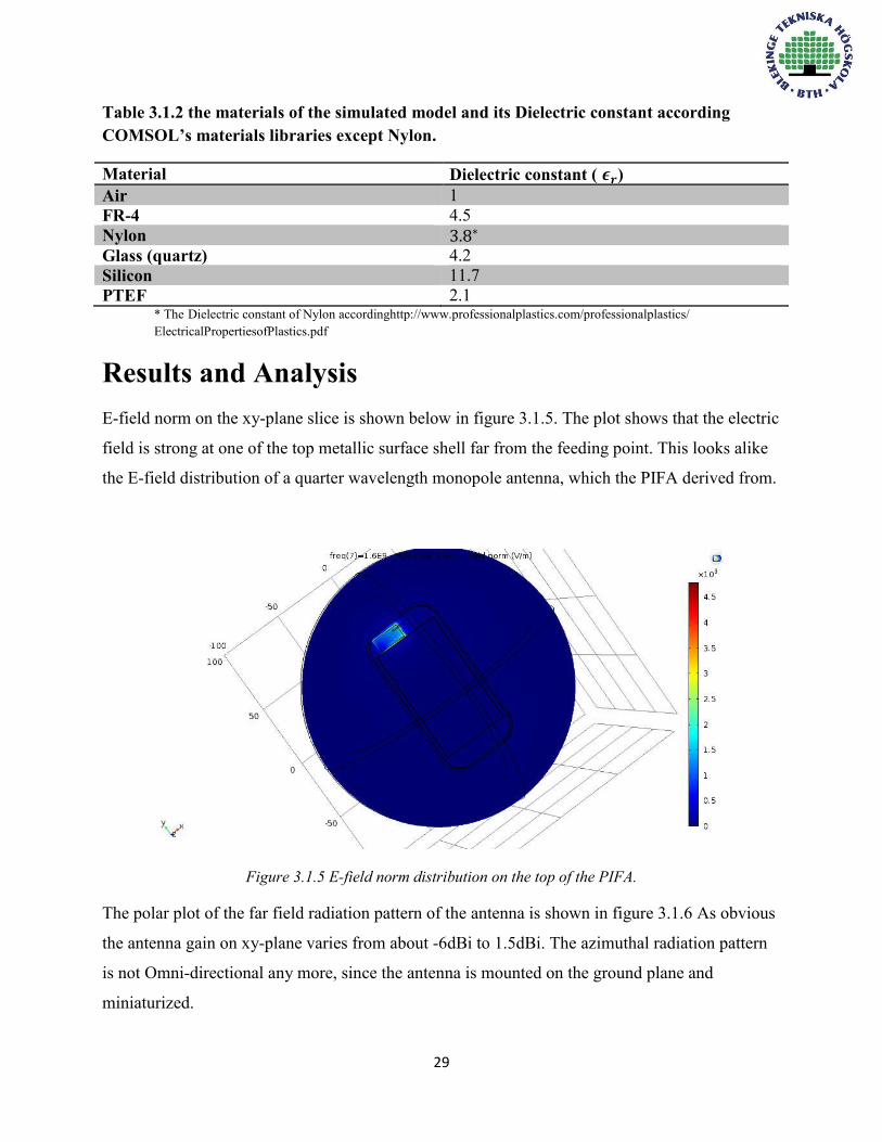
Results and Analysis
E-field norm on the xy-plane slice is shown below in figure 3.1.5. The plot shows that the electric
field is strong at one of the top metallic surface shell far from the feeding point. This looks alike
the E-field distribution of a quarter wavelength monopole antenna, which the PIFA derived from.
Figure 3.1.5 E-field norm distribution on the top of the PIFA.
The polar plot of the far field radiation pattern of the antenna is shown in figure 3.1.6 As obvious
the antenna gain on xy-plane varies from about -6dBi to 1.5dBi. The azimuthal radiation pattern
is not Omni-directional any more, since the antenna is mounted on the ground plane and
miniaturized.

30
Figure 3.1.6 Antenna gain pattern on the xy-plane.
Figure 3.1.7 Return loss S-parameters (S11) for the antenna by simulation.

31
S-parameters (S11) measurements indicate that at 1.575GHz is -13dB which means that
the reflected power is 5%. This describes how well the antenna input impedance is
matched to the 50 Ω reference impedance.
Antenna’s bandwidth regarding figure 3.1.7 is a narrow bandwidth:
𝐵𝑎𝑛𝑑𝑤𝑖𝑑𝑡ℎ ≈ 1.577 − 1.557
1.570× 100 = 1.2%
The wide bandwidth for GPS antenna is not required. So the bandwidth above is
sufficient.
Keeping the feeding point near to the shorting pin as much as possible reduces the
antenna size but that causes a narrow bandwidth. The electrical characteristics of PIFA
are affected by the size of ground plane. By varying the size of ground plane, the
efficiency and the bandwidth are changed; to increase the bandwidth we need the whole
possible free space in the chassis. In simulation we use the whole chassis as ground plane
in order to get a better efficiency.
The effective of the PIFA antenna geometric dimensions on the resonant frequency can be
summarized by the following table 3.1.3
Table 3.1.3 Effect of geometric dimensions on resonant frequency.
𝑳𝟏 𝑳𝟐 𝑾 𝑯
𝒇𝟎

32
Figure 3.1.8 3D far-field radiation pattern shown from three different angles.

33
Table 3.1.4 several mobile phones models and its internal type antenna [29].

34
3.2 Wideband PIFA Antenna Design PIFA antenna is used widely in mobile phones today as shown in the table 3.1.3, that’s due to
many advantages of PIFA which are mentioned in chapter 2 Antennas types. Hence in this
section PIFA antenna will be used to design a wideband antenna and simulate the model in
COMSOL. Model descriptions
Figure 3.2.1 the wideband PIFA antenna is mounted to left top of the slotted ground plane.
PIFA antenna design using slot technique, with desired range of frequency from 1800MHz to
2600MHz. This important range cover GSM (1800MHz & 1900MHz), UMTS (2100MHz),
Bluetooth and Wi-Fi (2.4GHz), and LTE system (2.3GHz, 2.5GHz, and 2.6GHz).
The wideband PIFA antenna design using slot technique model consists of the same materials
which are used in previous design table 3.1.2, except the dielectric material between the PIFA
and the ground plane which is air with dielectric constant (𝜖𝑟) equals to 1 to have a better
efficiency and a wider bandwidth.

35
Calculations
Figure 3.2.2 The illustration dimensions of the PIFA 𝐿1 = 24𝑚𝑚 , 𝐿2 = 10𝑚𝑚 , ℎ = 4𝑚𝑚 , 𝑊 = 2𝑚𝑚
and the ground plane with its slot dimension 𝑑𝑠 = 5𝑚, 𝐿𝑠 = 28𝑚𝑚 , 𝑊𝑠 = 2𝑚𝑚.
The resonant frequency of the PIFA antenna can be calculated using 3.1.1 and 3.1.2 formulas
respectively.
24 + 10 − 2 =𝜆0
4 , 𝜆0 = 128mm
𝑓0 =3×10⁸
128×10−3×√1= 2.343𝐺𝐻𝑧
The desired bandwidth percentage:
𝑓𝑐𝑒𝑛𝑡𝑒𝑟 =2600+1800
2= 2200𝑀𝐻𝑧
𝐵𝑎𝑛𝑑𝑤𝑖𝑑𝑡ℎ% = 2600−1800
2200× 100 = 36.36%
If the bandwidth percentage higher than 20%, that’s bandwidth is considered as a wide
bandwidth.

36
Simulations In this design we use a slotted ground plane in order to improve PIFA bandwidth. A slot in a
ground plane creates different paths of current flow which leads to kind of diversity in electric
field, consequently a wider bandwidth. The length of the slot should be proportional with the
desired resonant frequency. The simulations are performed for two cases, one without the slot
and other with slot, for different positions of the slot on the ground plane and for different
dimensions of PIFA except the width of the planar which is fixed at 10mm and width of the short
pin is 2mm.
Figure 3.2.3 Back view of E-field norm distribution on the top of the wideband PIFA.
In figure 3.2.3 the plot of the E-field shows that the electric field is strong at one of the top
metallic surface shell far from the feeding point on both corners of the planar which similar to E-
field plot in previous design.
Figure 3.2.4 shows the far-field gain in dBi for every frequency center of the desired bands and in
figure 3.2.5 the 3D far-field radiation pattern of wideband PIFA shown from three different
angles.

37
Figure 3.2.4 Antenna gain pattern on the xy-plane for each frequency band.

38
Figure 3.2.5 3D far-field radiation pattern of wideband PIFA shown from three different angles.

39
Results and Analysis
Figure 3.2.5 (a) Return loss (S11) for the wideband (b) Return loss (S11) for PIFA without slot.
PIFA using slotted ground plane by simulation.
As shown in figure 3.2.5 (a) the resonant frequency is 2.4GHz with -40dB and return loss of the
frequencies 1800MHz,1900MHz,2300MHz,2400MHz and 2500MHz is ≤ −10𝑑𝐵 . At
2600MHz is -8dB and at 2100MHz is -9dB which it’s still reasonable. With considering
2600MHz has a sufficient low return loss, the bandwidth will be 36.36%.
Figure 3.2.5 (b) shows the PIFA antenna without using a slot on ground plane with resonant
frequency at 2GHz, return loss -10dB and the bandwidth can be calculated as following:
𝐵𝑎𝑛𝑑𝑤𝑖𝑑𝑡ℎ% ≈2.01−1.99
2= 1%
Based on what is mentioned above, we can conclude that’s the slot has a big significant effect on
either bandwidth or on better matching impedance network. In bandwidth there is a huge
difference; without using slot the bandwidth is 1% and with slot is 36.36%. Even if we exclude
the band 2600MHz the bandwidth 32.36% which is still much wider rather, comparison is
nonessential. On other hand the effect of the slot on return loss (S11) is clear as well. Where
PIFA with slotted ground plane resonate at 2.4GHz with -40dB, and without slot resonate at
2GHz with poor return loss -10dB.

40
As seen in figure 3.2.4 it’s obvious that all frequencies bands have an Omni-directional behavior
with reasonable gain table 3.2.1 summary the maximum and minimum gain.
Table 3.2.1 Simulated gain of the frequencies which shown in figure 3.2.4.
Frequency Maximum gain Minimum gain
1800MHz 4.95dB -12.48dB
1900MHz 3.97dB -13.86dB
2.1GHz 2.89dB -14.72dB
2.3GHz 2.54dB -11.31dB
2.4GHz 2.78dB -9.33dB
2.5GHz 2.89dB -7.79dB
2.6GHz 2.25dB -7.1dB
In this design several methods are followed in order to improve the Bandwidth and the gain,
where the relation between the Bandwidth and the gain is not linear. Using dielectric material
with high dielectric constant causes a degraded gain; on other hand the effects on Bandwidth
could be neglected.
Techniques which are used to increase the Bandwidth for proposed PIFA:
Bandwidth depends very much on the size of the ground plane. So for better performance,
the whole available size of the chassis should be used as a ground plane. Reducing the
ground plane can effectively limit the bandwidth of the PIFA antenna.
Using slotted ground plane: using a slot with proper length to get other resonant
frequencies.
Using Air as a dielectric material between the PIFA element and the ground plane this
technique improves the Bandwidth and enhances the gain.
A wideband PIFA antenna has been designed and presented. The proposed PIFA antenna
occupies a compact envelope dimension of 24 × 10 × 4𝑚𝑚3while covering the required
wide band with a sufficient impedance matching (S11 ≤ -10 dB) covering GSM (1800MHz
&1900MHz), Bluetooth & Wi-Fi (2.4GHz), and LTE system (2.3GHz, 2.5GHz) except
UMTS (2.1GHz) and LTE (2.6GHz) which has acceptable return loses.

41
3.3 Wi-Fi and Bluetooth Antenna Wi-Fi and Bluetooth antennas work by transmitting and receiving the electromagnetic waves
from the antenna to the receiver. They are one of the most useful services in the new smart
phones, Wi-Fi antenna is the smallest antenna could be finding in the mobile phones because it
works with the highest frequencies.
One of the best advantages of the Wi-Fi antenna that can support dual-band, the first band is from
2400 MHz to 2484MHz and also can support 5150-5850MHz; therefore the Wi-Fi antenna can
cover the band of the Bluetooth too.
Nowadays, the most useful Wi-Fi antenna in mobile phone that’s is connect to small chip which
work for the Wi-Fi and the Bluetooth antennas in the same time, also we can have two antennas
one for the Wi-Fi antenna which cover 5GHz and the other one for the Bluetooth which cover
2.4GHz but it is not common to use two types of antennas it will need more space and it will be
costly than use one antenna.
As we mentioned Wi-Fi antenna is the smallest antenna in the mobile phones, the antenna half
wavelength which covering the Bluetooth 2.4 GHz supposed to be 6.25 cm and at 5GHz which is
mostly dipole antenna the half wavelength for sure will be smaller, it is 3 cm. also the quarter
wavelength could be used which mean that the size of the antenna will be much smaller which is
usually PIFA or PMA.
The quality of the Wi-Fi and Bluetooth antenna connection depend mainly on the gain of the
antenna as we have mentioned in the second chapter, by determining the antenna power gain we
can identify the efficiency and the directivity of the antenna, the order of the Wi-Fi mobile phone
antenna efficiency from -6 dB to -2dB.
In case the primary antenna of the mobile phone does not cover the Bluetooth and Wi-Fi
frequencies the Wi-Fi and Bluetooth antenna integrated on the top of the phone close to the GPS
antenna due to the hand held of the user.
42
Chapter 4
Specification Absorption Rate (SAR)
As the world care about the development of wireless communication and with the really huge
goals they have achieved on the other hand we should consider the human health and the risk
which is effect negatively in the human health.
The meaning of SAR is a short name of specification absorption rate which is the measurement
of the energy has absorbed by the human body during transmit the radio frequency
electromagnetic field. The human body absorbed the energy that’s mean we will lose some
energy the second problem that’s mean will affect the human body badly.
SAR can be calculated by integrating or averaging over 1 gram or 10 gram:
𝑺𝑨𝑹 = ∫𝝈(𝒓)|𝑬(𝒓)|𝟐
𝝆(𝒓)𝒅𝒓 (4.1)
Regarding to the equation 4.1 it explains that SAR is a function of the induced electrical field
which is from the radiated energy 𝐸 it can be measured by 𝑣𝑜𝑙𝑡𝑠 ⁄ 𝑚𝑒𝑡𝑒𝑟 , the electrical
conductivity 𝜎 which can measured in 𝑆𝑖𝑒𝑚𝑒𝑛𝑠 ⁄ 𝑚𝑒𝑡𝑒𝑟 and the mass density 𝜌 can be
measured in 𝑔 ⁄ (𝑐𝑢𝑏𝑖𝑐 𝑚𝑒𝑡𝑒𝑟) , finally the unit of the SAR is 𝑊 ⁄ 𝑘𝑔.

43
The SAR have different values regarding to the design of the mobile phone and the location of
the antenna in the mobile phone, therefore always, the mobile phone antenna located on the
bottom of the phone to keep the radiate as far as much of the user. Low SAR means that it is safer
than the high SAR while all the mobile phones has radio frequencies. On the other hand we don’t
forget to mention that the SAR will effect on the quality of the power by reducing the power level
because of the absorption.
4.1 How To Measure The SAR? Measuring the SAR by the DASY measurement system as shown in figure 4.1.1
http://www.antenna-theory.com/definitions/sar.php
Figure 4.1.1 The DASY SAR measurement system.
If we look at the figure 4.1.1 it shows different equipment which gives us availability for
picturing the same situation of using the mobile phone in the real life.

44
The hollow tub in the figure 4.1.1 has the same shape of the right side and the left side of the
human head, also there is a yellow robot with long arm which has in the end of the arm a
measuring probe, the measuring probe moves around the all the region of the right side of human
head and the left side too to lead us the measuring the SAR. But to get the correct measuring of
the SAR we should have the correct conductivity and correct density therefore the tub must be
filled with special fluid which has almost the same properties of the human tissue.
It is really worth to mention that the fluid has to change the standardized of the human tissue
regarding to the frequency we are dealing with.
The DUT which has a long arm, it is located under the hollow tub and close to the head shape due
to our need to place the mobile phone in the edge of the head as it must be in the reality.
Finally, the measurement shouldn’t be in one side of the human head and we should consider that
the measurement of the SAR very sensitive so we can get a very big different result because of
the complex nature of the near field.
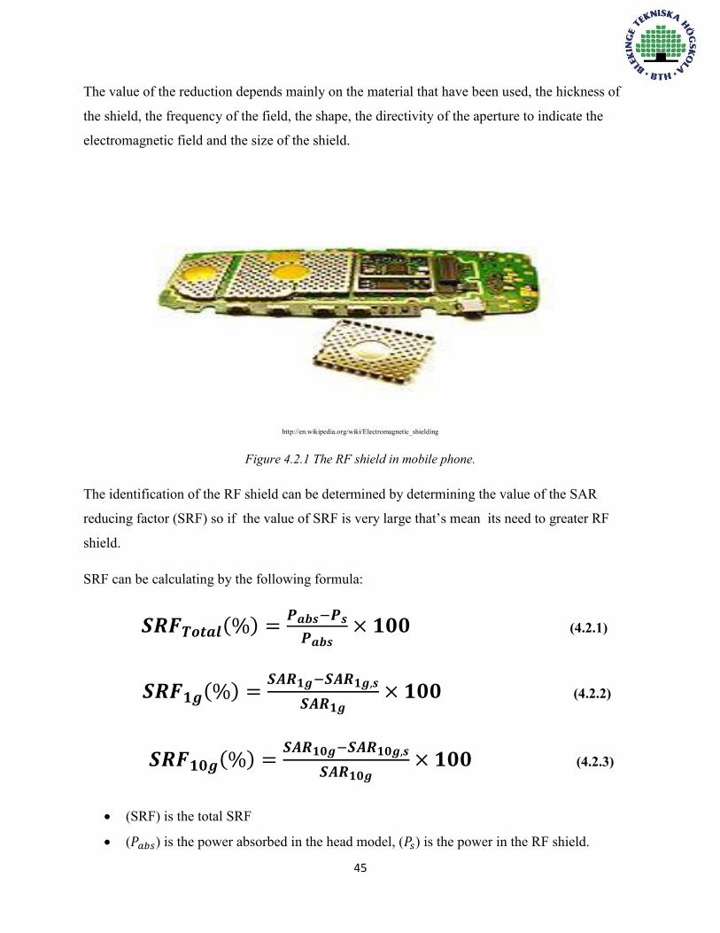
4.2 The Techniques Of Reducing SAR Reducing the electrical magnetic field of the antenna will effect to reduce the value of SAR in
human head that can be made by using the RF shield to the front side of the phone. The RF shield
which has been made of ferromagnetic material so it can help to reducing the value of the SAR
because of the suppression of the surface current on the front of the mobile phone box as shown
in figure 4.2.1.
During the travelling of the electrical magnetic wave through the free space the wave will be
divided to three parts, the first part of the wave going to transmitted, other parts will reflect and
absorbed, the function of the electrical magnetic wave material absorbed the energy of the wave
as magnetic loss then convert it to energy which it can be feel as heat.
The main materials that are used for making electromagnetic shield are sheet metal, metal foam
and material, the holes in the shield should be smaller than the wave length to keep it away.
45
The value of the reduction depends mainly on the material that have been used, the hickness of
the shield, the frequency of the field, the shape, the directivity of the aperture to indicate the
electromagnetic field and the size of the shield.
http://en.wikipedia.org/wiki/Electromagnetic_shielding
Figure 4.2.1 The RF shield in mobile phone.
The identification of the RF shield can be determined by determining the value of the SAR
reducing factor (SRF) so if the value of SRF is very large that’s mean its need to greater RF
shield.
SRF can be calculating by the following formula:
𝑺𝑹𝑭𝑻𝒐𝒕𝒂𝒍(%) =𝑷𝒂𝒃𝒔−𝑷𝒔
𝑷𝒂𝒃𝒔× 𝟏𝟎𝟎 (4.2.1)
𝑺𝑹𝑭𝟏𝒈(%) =𝑺𝑨𝑹𝟏𝒈−𝑺𝑨𝑹𝟏𝒈,𝒔
𝑺𝑨𝑹𝟏𝒈× 𝟏𝟎𝟎 (4.2.2)
𝑺𝑹𝑭𝟏𝟎𝒈(%) =𝑺𝑨𝑹𝟏𝟎𝒈−𝑺𝑨𝑹𝟏𝟎𝒈,𝒔
𝑺𝑨𝑹𝟏𝟎𝒈× 𝟏𝟎𝟎 (4.2.3)
(SRF) is the total SRF
(𝑃𝑎𝑏𝑠) is the power absorbed in the head model, (𝑃𝑠) is the power in the RF shield.
46
(𝑆𝑅𝐹1𝑔, 𝑆𝑅𝐹10𝑔) is the SRF for 1g and 10g peak SAR
(𝑆𝐴𝑅1𝑔, 𝑆𝐴𝑅10𝑔) is 1g and 10g peak SAR (without RF shielding)
(𝑆𝐴𝑅1𝑔,𝑠, 𝑆𝐴𝑅10𝑔,𝑠) is 1g and 10g peak SAR (with RF shielding)
Headset vs SAR
Based on the study of UK consumers association reported that the headset can reduce the value of
SAR, because of the wire that’s connect the headset to mobile phone therefore the wire is
working as channeled unshielded radiation and antenna to the human head. The SARtest discovered
that can reduce the absorbed radiation until 70%.
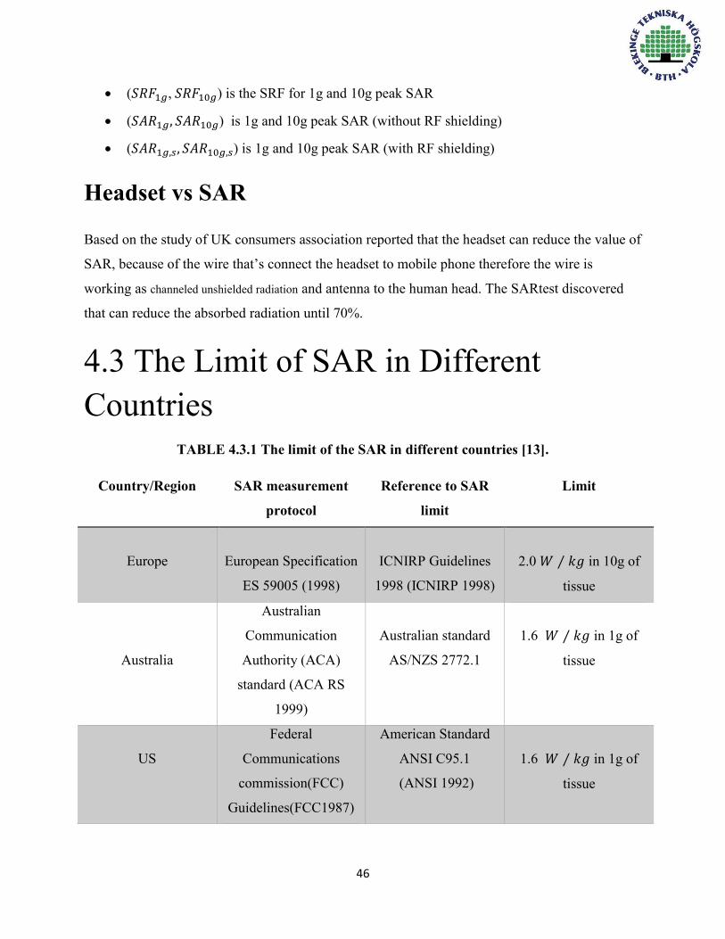
4.3 The Limit of SAR in Different Countries
TABLE 4.3.1 The limit of the SAR in different countries [13].
Country/Region SAR measurement
protocol
Reference to SAR
limit
Limit
Europe
European Specification
ES 59005 (1998)
ICNIRP Guidelines
1998 (ICNIRP 1998)
2.0 𝑊 ⁄ 𝑘𝑔 in 10g of
tissue
Australia
Australian
Communication
Authority (ACA)
standard (ACA RS
1999)
Australian standard
AS/NZS 2772.1
1.6 𝑊 ⁄ 𝑘𝑔 in 1g of
tissue
US
Federal
Communications
commission(FCC)
Guidelines(FCC1987)
American Standard
ANSI C95.1
(ANSI 1992)
1.6 𝑊 ⁄ 𝑘𝑔 in 1g of
tissue

47
Regarding to the table 4.3.1 the average limit of European countries is 2.0 𝑊 ⁄ 𝑘𝑔 in 10g of
tissue is absorbing the most signal, Australia and US has the same limitation 1.6 𝑊 ⁄ 𝑘𝑔 in 1g of
tissue.
In India they were following the same limitation as Europe until 2012 then they have switched to
follow the same limitation as US, and the test of India in SAR is done by Telecommunication
engineering center. There are many countries have been following the same limitation of US such
as Korea, Bolivia and Canada 1.6 𝑊 ⁄ 𝑘𝑔 in 1g of tissue.
4.4 SAR With Different Types Of Antenna There are some types of antenna that have a really good deal with SAR, the table 4.1.3 shows the
dealing between the level of SAR with different types of antenna.
Table 4.4.1 The level of SAR in different types of antenna.
Type of antenna Level of SAR
Helix High SAR
Slot LOW SAR
PIFA LOW SAR
PMA High SAR
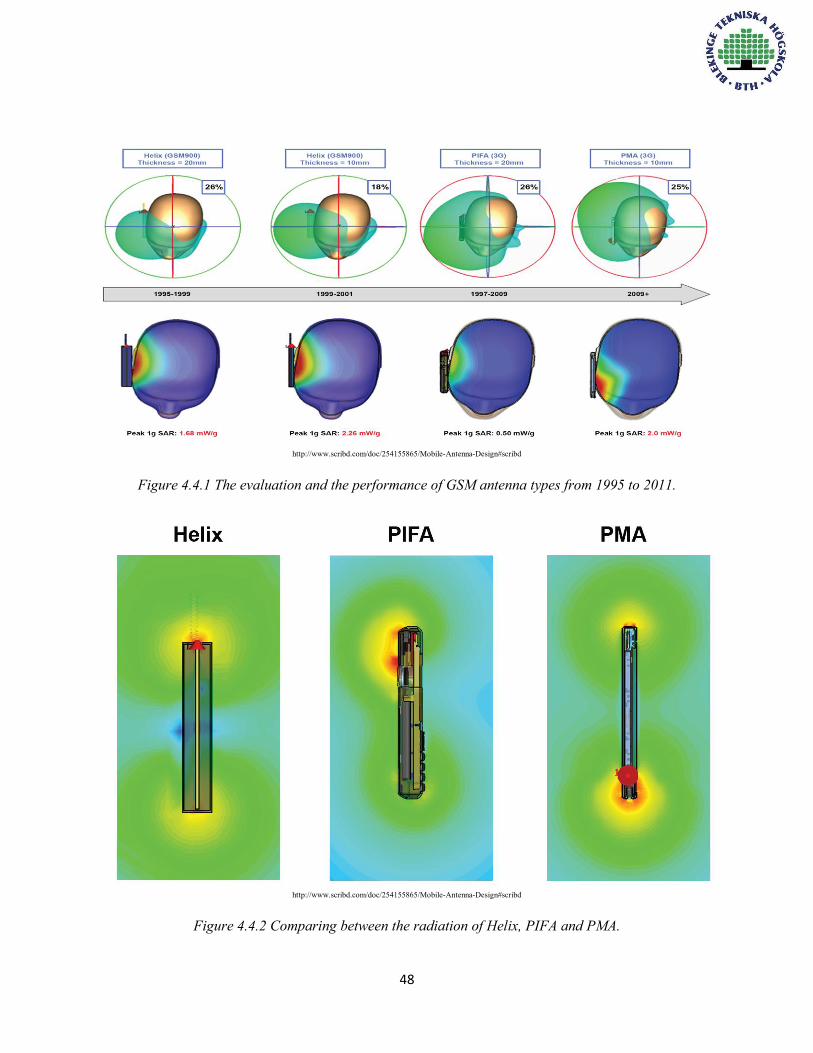
As showing in figure 4.4.1 first shape show the human head with Helix external antenna which
used since 1995 to 1999 with thickness 20 mm and the value of SAR 1.68 𝑚𝑊/𝑔 , we notice in
the second shape it had used the same type of antenna but the thickness have changed from
20mm to 10mm because of this change of the thickness the value has increased to 2.26 𝑚𝑊/𝑔,
the used of PIFA from 1997 to 2009 which has a really good deal with SAR as we mentioned in
table 4.4.1 and PMA which used above 2009 with SAR value 2.0 𝑚𝑊/𝑔.
48
http://www.scribd.com/doc/254155865/Mobile-Antenna-Design#scribd
Figure 4.4.1 The evaluation and the performance of GSM antenna types from 1995 to 2011.
http://www.scribd.com/doc/254155865/Mobile-Antenna-Design#scribd
Figure 4.4.2 Comparing between the radiation of Helix, PIFA and PMA.

49
We can notice from the previous figure 4.4.2 that he radiation of Helix and PMA are like a dipole antenna
but PIFA has different characteristics of radiation which guide us to notice that it is a type of microstrip
antenna. So we can mention that the dipole antenna hasn’t a good relation with SAR.
Table 4.4.1 The highest SAR values in different well known mobile phone manufacture companies [12].
Manufacture company Model SAR in
𝑾 ⁄ 𝒌𝒈
Apple IPhone 5 1.25
Nokia Lumia 630 1.52
Sony Ericsson Z1010 1.41
Samsung P400 1.18
Blackberry Curve 9320 1.56
Table 4.4.2 The lowest SAR values in different well known mobile phone manufacture companies [12].
Manufacture company Model SAR in
𝑾 ⁄ 𝒌𝒈
Apple IPhone 4,5c,4s,6 1.18
Nokia 9300 0.07
Sony Ericsson Tz600 0.16
Samsung X830 1.18
Blackberry Curve 8900 1.01

50
Chapter 5
Problems of Mobile Phone Antennas Design Mobile phones antenna design is a complicated process. There are a lot critical considerations, the place where the antennas will be installed in mobile phone chassis for example, and regulatory requirements, what are the possible bands of frequencies could be used. In addition, nowadays, mobile phones have multiple antenna for different functions.
5.1 The Radiation Efficiency of the Mobile Phone Antennas The performance of an antenna depends on the antenna element itself and the ground plane of the mobile phone. That leads to the small size antenna problem, which means that there are limitations for how much the antenna can be minimized, in term of available space in mobile phone or in the expectable good performance. Mobile phone antennas have low efficiencies, and low input resistance and high input reactance, that’s create a difficult for matching impedance between the antenna element and the transmission line.

51
Figure 5.1.1 Imaginary Sphere encloses an antenna in free space with radius a.
At the beginning Wheeler introduced a method to define the maximum volume radiation for electrically small antenna by two measurements, first one in free space and the other within an
imaginary closed sphere with radius 𝑎 =λ
2𝜋 as shown in figure 5.1.1 [18]. Wheeler considers that
the antenna resonance frequency can be described as two series resistances; radiation resistance 𝑅𝑟𝑎𝑑 and loss resistance 𝑅𝐿 (of used material) [18]. The radiation efficiency of a small antenna can be determined by the following formula:
𝜼𝒓𝒂𝒅 = 𝑹𝒓𝒂𝒅
𝑹𝑳+𝑹𝒓𝒂𝒅 (5.1.1)
The current distribution in the small electrically antennas has small space to flow as it’s obvious, that’s make the antenna to behave as a capacitor, and consequently the current will be zero, that means there is no radiation power. In that case we must satisfy a proper matching impedance network in term to get radiation power by the small antenna. Radiation resistance for small antennas becomes very small due to weak radiation [26].
Efficiency of a system- which consists of antenna and matching network- can be expressed with help of the radiation efficiency which described in equation 5.1.2 by:
𝜼𝒔 = 𝜼𝒓𝒂𝒅𝜼𝒎 (5.1.2)

52
𝜼𝒔: Efficiency of the system.
𝜼𝒎: Efficiency of the matching network.
Based on the equations 5.1.1 and 5.1.2 we can conclude that in order to get higher efficiency of a system, we have to take in account several parameters:
1. Maximum Radiation resistance. 2. The lowest value of loss resistance. 3. The lower mismatch network as possible (lower |Г|).
In addition, the mobile phone case’s material type, and the surrounding environment (such as hand-held, which it will be discussed later) have an additional effect on the radiation efficiency. Antennas with bigger size have better efficiencies than small antennas. On other hand the space which is available for antenna in chassis of mobile phones is very restricted. Thus there is always tradeoff between size and performance.
5.2 Bandwidth We can determine the bandwidth of an antenna by determining the impedance for all frequencies in that desired range. But in small antennas case the bandwidth depends on others factors. Small antennas such as PIFA have less real input resistance (it approaches to zero) and highly reactive input impedance, which leads to mismatching network problem. To match the impedance of a small antenna with its feeder’s impedance is a quite critical issue. The bandwidth depends on the reflection coefficient and matching networks.
The quality factor Q is a limit of the accessible impedance bandwidth at certain efficiency. Sometimes the small antenna is defined by Q.
As it’s mentioned in the previous chapters, we can define the bandwidth by the following formula:
𝑩𝒘 =𝒇𝒎𝒂𝒙−𝒇𝒎𝒊𝒏
𝒇𝟎=
𝟏
𝑸 Valid for Q >>1 (5.2.1)
53
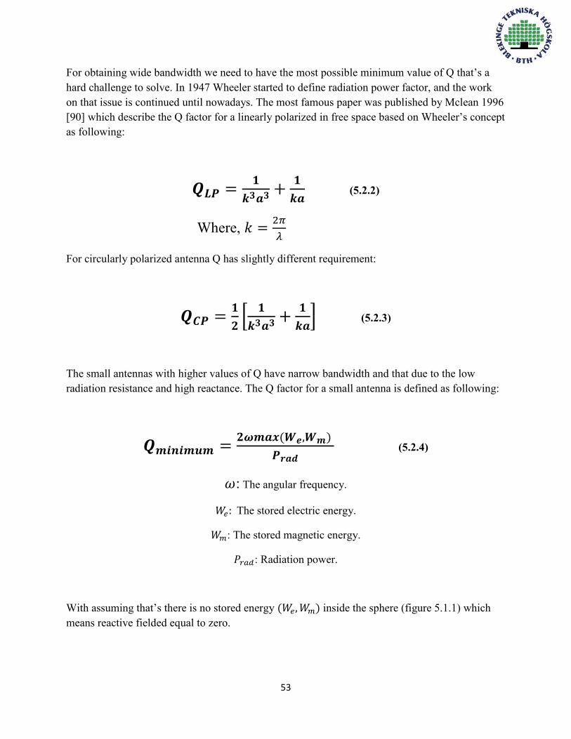
For obtaining wide bandwidth we need to have the most possible minimum value of Q that’s a hard challenge to solve. In 1947 Wheeler started to define radiation power factor, and the work on that issue is continued until nowadays. The most famous paper was published by Mclean 1996 [90] which describe the Q factor for a linearly polarized in free space based on Wheeler’s concept as following:
𝑸𝑳𝑷 =𝟏
𝒌𝟑𝒂𝟑 +𝟏
𝒌𝒂 (5.2.2)
Where, 𝑘 =2𝜋
𝜆
For circularly polarized antenna Q has slightly different requirement:
𝑸𝑪𝑷 =𝟏
𝟐[
𝟏
𝒌𝟑𝒂𝟑 +𝟏
𝒌𝒂] (5.2.3)
The small antennas with higher values of Q have narrow bandwidth and that due to the low radiation resistance and high reactance. The Q factor for a small antenna is defined as following:
𝑸𝒎𝒊𝒏𝒊𝒎𝒖𝒎 =𝟐𝝎𝒎𝒂𝒙(𝑾𝒆,𝑾𝒎)
𝑷𝒓𝒂𝒅 (5.2.4)
𝜔: The angular frequency.
𝑊𝑒: The stored electric energy.
𝑊𝑚: The stored magnetic energy.
𝑃𝑟𝑎𝑑: Radiation power.
With assuming that’s there is no stored energy (𝑊𝑒, 𝑊𝑚) inside the sphere (figure 5.1.1) which means reactive fielded equal to zero.

54
Based on equation 5.2.4 we note that’s, mathematically to get the lowest value of Q the power radiation should be maximized, that’s lead us to the efficiency problem. The mobile phones antenna design’s problems are related with each other. Consequently more challenges are added to design process.
Multiband antenna can be used in order to solve the bandwidth limitations problem partially, since there is no small multiband antennas can cover all desired bands. As obvious from the discussion above, the wide bandwidth is a hard challenge to achieve by an ESA due to low profile (small size). In modern mobile phones, there are several antennas for different functions as mentioned in mobile phones antennas design’s chapter. Each antenna operates with certain band; for example one antenna for higher band frequency, and one for GPS etc. Then all desired bands can be covered by that method. On other hand we have to take care on matching network, since we have several antennas to deal with, mutual coupling antenna to antenna loss, and the available space in mobile phone’s chassis.
5.3 Mutual Coupling Antenna to Antenna Loss The mutual coupling is the amount of the absorbed energy by an antenna when another nearby antenna is operating [4]. This interaction between near antennas is unwanted because that’s amount of the absorbed energy should be radiated instead. Thus the mutual coupling reduces the efficiency of the antenna on both receiving and transmitting mode.
Mobile phones consist of several antennas, and with mobile phones geometrical dimensions, we find that the antennas near to each other in such way make the mutual coupling loss inevitably exists. So a good isolation is required to keep the antennas in mobile phone’s chassis far from each other as possible. For that the antennas are generally distributed on top and bottom of the chassis which reduce the coupling loss. The coupling loss can be 1-2dB for antenna efficiency. Isolation values for smartphones which have same ground plane at the low band are about 10 dB, and can be 20 dB for the high band [28]. The coupling loss is not constant, it’s varying; the coupling loss at low frequencies and at high frequencies are different.
The isolation can be increased by:
Minimizing the correlation coefficient between the antennas. Increasing the separation space between antennas as much as possible. Using different polarizations for the antennas.

55
Using proper filters with the antennas to decrease the effects of opposite antennas
frequencies. Using dielectric walls between the antennas.
The isolation between two antennas is measured by connecting both of them to a Vector Network Analyzer and measuring of S12.
5.4 The Hand-Held Environment Problem
Table 5.4.1 Dipole performance at different locations of simulated distance from human head [24]. Distance from Head
cm Free space
5 4 3 2 1
Input Impedance
Ω 75+j1.3 64+j27 60+j28 62+j35 52+j17 60+j23
Radiation Efficiency
% 100 72.3 63.4 50.5 42.7 29.1
Max. Directive Gain
dB 2.15 4 2.15 0 -1 -2
Min. Directive Gain
dB 2.15 -7 -7.5 -8 -9 -12
As shown in table 5.4.1, when the antenna is closer to the human head, the input impedance decreases, consequently the resonant frequency of the antenna decreases also. The absorption which occurs by human head reduces the radiation efficiency to 29% when the distance 1cm as shown above.
Other effect of handheld is in the directivity of the antenna. The difference between two positions at free space and 5cm far from the head, shows that the directivity increases from 2.15 dB to 4 dB, that’s because the sum of radiation fields and fields scattered by the head which somehow compensate the loss in radiation of efficiency[24].
56
In general we can conclude that when the mobile phone is closer to the head the gain will fall quickly and the directivity is lost due to polarized fields.
Another model of a dipole antenna with a simulated distance is 0.6 cm from human head, and by applying the method of moments (MoM). The input impedance is 65 + j13 Ω, directional properties are same as 1cm and 15% radiation efficiency [25].
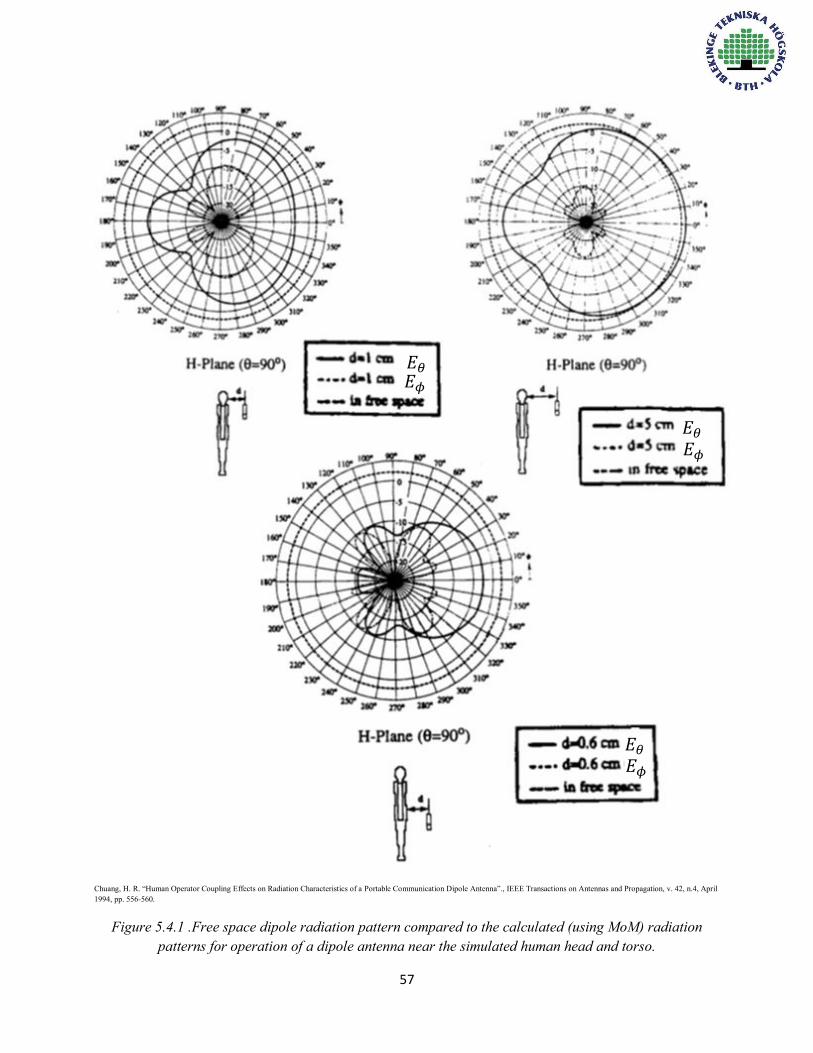
In figure 5.4.1 we can note that all three of the patterns radiation show -10dB nulls directly behind the user because absorption of energy by the modeled tissue, the attenuation increases as distance from the body decreases, and is worst for operation near the human torso [24].
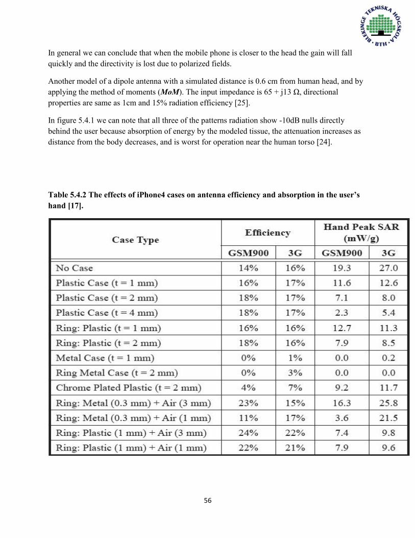
Table 5.4.2 The effects of iPhone4 cases on antenna efficiency and absorption in the user’s hand [17].
57
Chuang, H. R. “Human Operator Coupling Effects on Radiation Characteristics of a Portable Communication Dipole Antenna”., IEEE Transactions on Antennas and Propagation, v. 42, n.4, April 1994, pp. 556-560.
Figure 5.4.1 .Free space dipole radiation pattern compared to the calculated (using MoM) radiation patterns for operation of a dipole antenna near the simulated human head and torso.
𝐸𝜃
𝐸𝜃
𝐸𝜃
𝐸𝜙
𝐸𝜙
𝐸𝜙

58
Coupling of energy to the hand of the user is another problem caused by hand-held environment. Figure 5.4.1 shows the experimental and measured results of the reflected power radio at different distance from the human hand for internal PIFA antenna by using an FDTD model for human hand. As seen below in figure 5.4.2 when the distance 𝑑 becomes less more and more (the hand of the user gets closer to the antenna) the resonance frequency is shifted, and the reflected power radio becomes more, which means that’s the antenna’s efficiency is obviously degraded.
Photo was loaded from: Jensen, M., Rahmat-Samii, Y. “EM Interaction of Handset Antennas and a Human in Personal Communications”.
Proceedings of the IEEE, v. 83, n. 1, Jan. 1995, pp. 7-17.
Figure 5.4.2 The experimental and measured results of the reflected power radio at different distance from the human hand.
The hand-held environment problems add more challenges in design process. Since it’s so important to take in account the different scenarios. Some of that’s issues can be solved by design and installed the antenna in the lower part of the mobile phone to keep the antenna far as possible from the hand of user. Another critical factor can play big role in this term is a good isolation for antenna.
IPhone 4 suffers from isolation antenna problem. Many users reported that signal strength of the phone was reduced when touching the lower left of the phone, which causes dropped calls in some areas [26]. On other hand Apple recommended the consumers to do not grip the phone at that corner.
On July 16, 2010, Steve Jobs advertised that Apple would offer a case for the consumers to help solve the antenna issue [26]. Table 5.4.2 shows an iPhone4 and the effects of different material of casing on efficiency and SAR. Metal cases with thickness equal to 1mm, and 2mm, keep the efficiency without any effects and SAR values at almost zero.

59
Summary and Conclusion
Mobile phone antennas have several critical parameters such as the geometric dimensions,
dialectical materials which are used in design, and the ground plane of the antenna. All of that
should be taken into account for optimizations process. The fast development of mobile phones
devices add more demand on optimizations of the antennas.
In this thesis we investigate PIFA antenna type by design two models of it. The first model
handles one single band with resonant frequency 1.575GHz which could be suitable at that
frequency for GPS signal with reasonable gain from -6dBi to 1.5dBi and with return loss (S11)
-13dB. The bandwidth 1% which is sufficient since there is no bandwidth practically.
The second proposed PIFA is a wideband antenna with dimensions 24 × 10 × 4𝑚𝑚3cover range
from 1800MHz to 2600MHz. This important range covers GSM (1800MHz & 1900MHz),
UMTS (2100MHz), Bluetooth & Wi-Fi (2.4GHz), and LTE system (2.3GHz, 2.5GHz, and
2.6GHz). The Bandwidth is 36.36% which is considered as a wide bandwidth. This wideband
PIFA antenna is designed using slotted ground plane and air as a dielectric material between the
planar element and the ground plane.
Mobile phone antennas design is a big challenge. Mobile phone antennas designs have lot
problems. Low efficiencies can be the most critical problem which leads to tradeoff between size
and performance.
60
Reference [1] Mobile Antenna Systems Handbook page 17-19
[2] http://www.businessinsider.com/complete-visual-history-of-cell-phones-2011-5?op=1&IR=T
[3] C. Chiau, “Study of diversity antenna array for MIMO wireless communication systems,” Ph.D. dissertation, Queen Mary University of London, UK, April 2006.
[4] http://www.antenna-theory.com/
[5] http://classes.yale.edu/fractals/panorama/ManuFractals/FractalAntennas/FractalAntennas.html
[6] Mandelbrot, B. B., the Fractal Geometry of Nature, W.H. Freeman and Company, New York, 1983.
[7] http://www.iject.org/vol4/spl3/c0113.pdf
[8] http://www.ijstr.org/final-print/may2014/Response-Of-Planar-Inverted-F-Antenna-Over-Different-Dielectric-Substrates.pdf
[9] http://www.slideshare.net/NaveenKumar11/thesis-viva-presentation?related=1
[10] http://www.raymaps.com/index.php/planar-inverted-f-antenna-pifa/
[11] http://www.ece.msstate.edu/~donohoe/ece4990notes2.pdf
[12] http://www.s21.com/sar.htm
[13] http://sarvalues.com/what-is-sar-and-what-is-all-the-fuss-about/
[14] http://citeseerx.ist.psu.edu/viewdoc/download?doi=10.1.1.206.2791&rep=rep1&type=pdf
[15] http://www.ijrte.academypublisher.com/vol02/no05/ijrte02055862.pdf
[16] http://telecom.hellodirect.com/docs/Tutorials/HeadsetBenefits.1.110200.asp
[17] Mobile-phone antenna design, Author: ROWELL, CR; Lam, EYM, Issued Date 2012 URL: http://hdl.handle.net/10722/185908 Rights: IEEEE Antennas and Propagation Magazine. Copyright © IEEE.
[18] H. A. Wheeler, “The radiansphere around a small antenna”, Proceedings of the IRE, pp. 1325-1331, August1959.
[19] T. Taga and K. Tsunekawa, “Performance analysis of a built-in planar inverted F antenna for 800 MHz band portable radio units,” IEEE J.Select. Areas Commun, vol. SAC-5, pp. 921–929, June 1987.
[20] K. Sato, K. Matsumoto, K. Fujimoto, and K. Hirasawa, “Characteristics of a planar inverted-F antenna on a rectangular conducting body,” Electron. Commun. Japan, pt. 1, vol. 72, pp. 43–51, 1989.
[21] T. Taga, “Analysis of planar inverted-F antennas and antenna design for portable radio equipment,” in Analysis, Design, and Measurement of Small and Low-Profile Antennas, K. Hirasawa and M. Haneishi,Eds. Norwood, MA: Artech House, 1992, pp. 161–180.

61
[22] P. Vainikainen, J. Ollikainen, O. Kivekäs, and I. Kelander, “Resonator- based analysis of the combination of mobile handset antenna and chassis,” IEEE Trans. Antennas Propagat., vol. 50, pp. 1433–1444, Oct. 2002.
[23] http://scholar.lib.vt.edu/theses/available/etd-7697-21043/unrestricted/CH1_2.PDF
[24]Chuang, H. R. “Human Operator Coupling Effects on Radiation Characteristics of a Portable
Communication Dipole Antenna”., IEEE Transactions on Antennas and Propagation, v. 42, n. 4,
April 1994, pp. 556-560.
[25] http://en.wikipedia.org/wiki/IPhone_4
[26] The Annual Workshop and Feder Award Ceremony 2010. Speaker: Prof. Raphael Kastner, Tel Aviv University.
[27] Research Article: Novel Wideband MIMO Antennas That Can Cover the Whole LTE Spectrum in Handsets and Portable Computers, Mohamed Sanad1 and Noha Hassan2
[28] Balanis, Constantine A. "Antenna Theory - Analysis and Design", 2005, 3rd Edition, John Wiley & Sons ///page 80.
[29] IEEE Antennas and Propagation Magazine, Vol. 54, No. 4, August 2012.
[30] http://ecee.colorado.edu/~bart/ecen6355/app-04.pdf
Related Documents


