forum Mobile Broadcast Bearer Technologies A Comparison Update 02/2009

Welcome message from author
This document is posted to help you gain knowledge. Please leave a comment to let me know what you think about it! Share it to your friends and learn new things together.
Transcript
forum
Mobile Broadcast Bearer Technologies
A Comparison Update 02/2009
Mobile Broadcast Bearer Technologies A Comparison Update 02/2009:
With latest status and new technologies addressed
Main editors: Luigi Ardito, Claus Sattler
February 2009
Mobile Broadcast Bearer Technologies 02/2009 Page 2 of 92
Information contained in this report only reflects solely the author’s view on the
subject based on intensive best-effort research of published materials,
deductive reasoning and calculated speculations. While the author and
publishers have done their best to ensure the accuracy of all the information,
they, however, can accept no responsibility for any loss or inconvenience
sustained as a result of information contained in this volume.
Mobile Broadcast Bearer Technologies 02/2009 Page 3 of 92
Content:
1 Introduction ........................................................................................................5
2 Motivation ...........................................................................................................6
3 Bearer Technologies Overview...........................................................................7
3.1 Deployed Bearers................................................................................................... 7 3.1.1 BCMCS ........................................................................................................................7 3.1.2 CMMB STiMi ..............................................................................................................7 3.1.3 DAB/T-DMB................................................................................................................8 3.1.4 DVB-T ..........................................................................................................................9 3.1.5 DVB-H........................................................................................................................10 3.1.6 DVB-SH .....................................................................................................................11 3.1.7 Forward Link Only (FLOTM): .....................................................................................12 3.1.8 ISDB-T .......................................................................................................................13 3.1.9 Mobile Broadcast Multicast Service MBMS..............................................................14 3.1.10 TD-SCDMA (TD-MBMS services) ...........................................................................15
3.2 Pre-Commercial Bearers (2009-2010) ............................................................... 16 3.2.1 DVB-T2......................................................................................................................16
4 Bearer Technologies Technical Overview .......................................................18
4.1 Deployed Bearers................................................................................................. 18 4.1.1 BCMCS ......................................................................................................................18 4.1.2 CMMB STiMi ............................................................................................................25 4.1.3 DAB/T-DMB..............................................................................................................26 4.1.4 DVB-T ........................................................................................................................31 4.1.5 DVB-H........................................................................................................................34 4.1.6 DVB-SH .....................................................................................................................45 4.1.7 Forward Link Only .....................................................................................................51 4.1.8 ISDB-T .......................................................................................................................57 4.1.9 Multimedia Broadcast Multicast Service (MBMS) ....................................................59
4.2 Pre-Commercial Bearer Technologies............................................................... 62 4.2.1 DVB-T2......................................................................................................................62 4.2.2 UMB ...........................................................................................................................68
5 Comparison of Technical Parameters .............................................................73
5.1 Commercially Deployed Bearers........................................................................ 73 5.1.1 Bearer Layer Frequency..............................................................................................73 5.1.2 Bearer Layer Transmission.........................................................................................75 5.1.3 Bearer Layer Network ................................................................................................77 5.1.4 Transport Layer ..........................................................................................................78 5.1.5 Service Layer ..............................................................................................................79 5.1.6 Audio/ Video ..............................................................................................................80
5.2 Pre-commercial Bearers ..................................................................................... 82 5.2.1 Bearer Layer Frequency..............................................................................................82 5.2.2 Bearer Layer Transmission.........................................................................................82 5.2.3 Bearer Layer Network ................................................................................................83 5.2.4 Transport Layer ..........................................................................................................83
Mobile Broadcast Bearer Technologies 02/2009 Page 4 of 92
5.2.5 Service ........................................................................................................................83 5.2.6 Audio / Video .............................................................................................................83
6 Standards...........................................................................................................84
6.1 BCMCS ................................................................................................................ 84
6.2 CMMB STiMi...................................................................................................... 84
6.3 DAB, T-DMB ....................................................................................................... 84
6.4 DVB-H.................................................................................................................. 86 6.4.1 DVB-H & IPDC over DVB-H....................................................................................86 6.4.2 DVB-H & OMA BCAST ...........................................................................................87
6.5 DVB-SH................................................................................................................ 88
6.6 DVB-T .................................................................................................................. 88
6.7 DVB-T2 ................................................................................................................ 88
6.8 Forward Link Only ............................................................................................. 89
6.9 MBMS .................................................................................................................. 89
6.10 UMB BCMCS ...................................................................................................... 90
7 On the bmcoforum work item “Bearer Technologies” ...................................91
8 Authors..............................................................................................................92
Mobile Broadcast Bearer Technologies 02/2009 Page 5 of 92
1 Introduction This whitepaper sets out to update the technical detail published in
bmcoforum’s first Mobile Broadcast Bearer ‘A Comparison’ white paper
published in January 2007.
Additionally several new mobile broadcast bearer technologies identified by
bmcoforum as of immediate commercial interest have been added.
This white paper will seek to overview the following mobile broadcast bearer
technologies, BCMCS, CMMB STiMi, DAB/DMB, DVB-H, DVB-SH, DVB-T2, FLO,
MBMS, TD-SCDMA, UMB BCMCS.
Additional future emerging mobile broadcast bearer technologies could well be
the subject of future bmcoforum white papers.
Mobile Broadcast Bearer Technologies 02/2009 Page 6 of 92
2 Motivation In response to its membership and the general market place bmcoforum has
decided to undertake a second revision of its mobile broadcast bearer
comparison white paper. Our initial motivation remains intact however.
As its unique selling point mobile digital broadcast services has the ability to
combine the two best-selling consumer products in history, TVs and mobile
phones. The potential of mobile broadcast applications therefore holds massive
promise as the next “killer application” for the wireless consumer industry at
large. This consumer market perspective being one of the main motivation
factors for the formation of the bmcoforum.
From approximately 2004, a significant number of mobile operators launched
mobile TV services. These services allowed users to watch TV on their mobile
terminals. Today mobile TV is offered predominantly via streaming technology
over point-to-point connections in cellular networks. However, large-scale
market deployment of mass media services like mobile TV will require new
network capabilities commonly referred to as broadcast and multicast.
New mobile broadcast/multicast services have been specified in 3GPP and
3GPP2 for the cellular mobile network such as UMTS or CDMA2000. Additionally
broadcasting technologies, such as DVB-H, T-DMB, ISDB-T, MediaFLO (Forward
Link Only), DMB-T (China) have recently begun to address the challenges of
mobile environments and have become competitive bearers of the digital
broadcasting services.
In parallel with the emergence of these new mobile broadcast technologies
several commercial and technical questions arise from within the mobile
broadcast ecosystem:
• What are the differences in the service provisioning through these
systems?
• What do such differences imply for the network operators and end-
users?
• What are the pros and cons of these technologies when they deliver
similar services to the users?
This documents intention is to fully review the various broadcast bearer
technologies available today. This document is intended to enable a fair and
comprehensive comparison of all available technologies to the industry at large.
Paying particular attention to questions such as what technology and when with
respect to commercial exploitation.
Mobile Broadcast Bearer Technologies 02/2009 Page 7 of 92
3 Bearer Technologies Overview
3.1 Deployed Bearers 3.1.1 BCMCS BCMCS, acronym for “Broadcast and Multicast Service” and defined in a set of
specifications produced by 3GPP2, some of which are transposed as TIA
standards, provides point-to-multipoint transmission of multimedia data (e.g.,
text, audio, pictures, video) from a single source to all users or a group of users
in a specific area. The BCMCS system design aims to satisfy the market
demand for broadcast and multicast content while minimizing resource usage in
the radio access network (RAN).
Besides a mix of supported content types, BCMCS also supports different
delivery methods. Unicast enables delivery of a wide variety of personalized
content, whereas multicast should be used to distribute popular content to
realize efficiency gains. Whereas some content/program types needs to be
multicast “live” due to its time sensitive nature, other contents are time
insensitive, for which multicast delivery during network idle times allow for
greater efficiencies. A system capable of both unicast and multicast offers the
service/network operator maximum flexibility and control, since the operator
controls system loading by scheduling delivery of content on the network.
There are basically two BCMCS air interface technologies for cost-effective
delivery of popular content, and for which an unlimited number of users can be
supported:
• BCMCS – operation over cdma2000 1x/EV-DO technology offering 409.6
Kbps capacity with > 99% coverage
• E-BCMCS (Enhanced BCMCS) - 1.5 Mbps capacity with > 98% coverage
3.1.2 CMMB STiMi China Mobile Multimedia Broadcasting (CMMB) is a mobile television and
multimedia standard primarily used for broadcasting TV services to mobile and
portable devices, as mobile phones, PMPs, laptops and in-car TV receivers. The
standard has been defined by the CMMB Working Group, which was established
in August 2006. The group consists of over 150 Chinese and foreign members
and led by the Chinese State Administration of Radio, Film, and Television
(SARFT), an executive branch of the State Council of the People’s Republic of
China.
The CMMB is a hybrid satellite S-band (2635MHz-2660MHz) used for rural areas
and terrestrial UHF used for urban areas. The CMMB uses orthogonal frequency
division multiplex (OFDM) modulation for both terrestrial and satellite reception,
commonly used in other Mobile Digital TV (MDTV) standards.
The following bullets summaries the CMMB main attributes:
• Carrier spectrum: UHF and S-band
• Two channel bandwidth options:
Mobile Broadcast Bearer Technologies 02/2009 Page 8 of 92
o 8MHz (4K FFT)
o 2MHz (1K FFT)
• Operates in 2 or 8MHz channel bandwidths
• Supports Networks
o Single Frequency Network (SFN)
o Multiple Frequency Network (MFN)
• OFDM Modulation:
o BPSK / QPSK (satellite)
o BPSK / QPSK / 16QAM (UHF)
• Maximal bitrate:
o 16MBps (at 8MHz bandwidth, 4K FFT)
o 3Mbps (at 2MHz bandwidth, 1K FFT)
The CMMB employs low-density parity-check code (LDPC) and Reed Solomon
(RS) error correction codes in order to compensate and correct the received
signal being broadcasted in a noisy environment.
The CMMB video and audio content is compressed using the H.264 video
compression standard and AAC audio compression standard, respectively.
In addition the CMMB standard employs power consumption saving schemes,
allowing the CMMB receivers to consume minimal power by turning the receive
system on, only when the relevant time-slots containing the relevant data
arrives and entering inactive mode while no relevant data is required to be
received by the receiver, this scheme is referred to as the “Time-Slotting”
mechanism.
3.1.3 DAB/T-DMB DAB is designed to provide reliable, multi-service digital broadcasting for
reception by mobile, portable and fixed receivers. It occupies frequency blocks
of 1.7 MHz and can be operated at any frequency up to 3 GHz for mobile
reception (higher for fixed reception). It features individual quality of service
through independent error protection for each sub-channel within a multiplex as
well as time-interleaving for optimized mobile reception.
DAB has achieved a high reputation as the radio and multimedia broadcasting
system - with the first corresponding implementations dating back to the mid
90s. Nowadays DAB is implemented in around 50 countries all over the world.
Specifications for television broadcasting to mobile terminals were developed
for DAB initially within the European Eureka 147 Project in the late 90s. These
were based on MPEG-1 and MPEG-2 standards, but nowadays, with the
employment of MPEG-4 standards, Mobile TV via DAB has achieved its break-
through with commercial launches in Korea (December 2005, free-to-air
services only), and is known widely as DMB (also T-DMB).
Whereas first devices for the Mobile TV market naturally were mobile phones
with integrated DAB/DMB receivers, the choice is now extended towards PDA’s,
digital photo cameras, laptop computers and more.
Mobile Broadcast Bearer Technologies 02/2009 Page 9 of 92
For both Mobile TV applications, the highly efficient source coding algorithms
require extended error control schemes. Hence a second layer of error
protection was introduced for both DAB transport modes - Stream and Packet
Data. The key words here are “Enhanced Stream Mode” and “Enhanced Packet
Mode”.
As far as transport protocols are concerned, an independent selection for each
Service is enabled. Example options are Logical Frame Alignment (LFA),
Multimedia Object Transfer (MOT), Transparent Data Channel (TDC), MPEG-2
Transport Streams and, of course, the Internet Protocol.
Data Applications defined and in use reach from Traffic Information and
Navigation Support (TPEG, TMC) over scrolling text to multimedia ones like
Slide Shows and Broadcast Web Sites. Based on offered hooks like MPEG-2 TS
and IP, individual or proprietary applications can be applied.
Transport protocols and applications defined by the Open Mobile Alliance (OMA)
and by the DVB Project can be enabled for DAB transport as well. At the same
time interoperability between the different technical platforms is desired.
Through the recent adoption of state-of-the-art audio coding (HE AAC v2) for
radio services, DAB is now even better suited for entering new markets and for
enhancing existing.
DAB/DMB is a highly economical broadcasting system and due to its fine
granularity and the application of highly efficient coding, it facilitates new
business options also for small size/turnover and start-up companies.
3.1.4 DVB-T DVB-T is a technical standard developed by the DVB Project that specifies the
framing structure, channel coding and modulation for digital terrestrial
television (DTT) broadcasting. The first version of the standard was published in
March 1997 and in the ten years since then it has become the most widely
adopted such system in the world, with more than 40 million receivers deployed
in more than 30 countries.
The system transmits a compressed digital audio/video stream, using OFDM
modulation with concatenated channel coding (i.e. COFDM). The adopted
source coding methods are MPEG-2 and H.264/MPEG-4 AVC.
DVB-T is a method of transmission that is being adopted primarily for digital
television broadcasting, for example in the UK Freeview system.
OFDM works by splitting the wide-band digital signal into a large number of
slower digital streams, and then transmitting them all on a set of closely spaced
adjacent carrier frequencies, rather than just one. Typically, transmitters miles
apart can be operated on the same set of frequencies and a receiver in between
will demodulate correctly the signal coming from both. OFDM is also used for
digital radio broadcasting.
DVB-T, in common with almost all modern terrestrial transmission systems,
uses OFDM (orthogonal frequency division multiplex) modulation. This type of
modulation, which uses a large number of sub-carriers, delivers a robust signal
that has the ability to deal with very severe channel conditions. DVB-T has
technical characteristics that make it a very flexible system:
• 3 modulation options (QPSK, 16QAM, 64QAM)
Mobile Broadcast Bearer Technologies 02/2009 Page 10 of 92
• 5 different FEC (forward error correction) rates
• 4 Guard Interval options
• A choice of 2k or 8k carriers
• Can operate in 6, 7 or 8MHz channel bandwidths (with video at 50Hz or
60Hz)
Using different combinations of the above parameters a DVB-T network can be
designed to match the requirements of the network operator, finding the right
balance between robustness and capacity. Networks can be designed to deliver
a whole range of services: SDTV, radio, interactive services, HDTV and, using
multi-protocol encapsulation, even IP datacasting.
Whilst not originally designed to target mobile receivers, DVB-T performance is
such that mobile reception is not only possible, but forms the basis of some
commercial services.
The use of a diversity receiver with two antennas gives a typical improvement
of 5 dB in the home and a 50% reduction in errors is expected in a car.
The use of OFDM modulation with the appropriate “guard interval” allows DVB-T
to provide a valuable tool for regulators and operators in the form of the “single
frequency network” (SFN). An SFN is a network where a number of transmitters
operate on the same RF frequency. An SFN can cover a country, such as in
Spain, or be used to enhance in-door coverage using a simple “gap-filler”.
One final technical aspect of DVB-T worth mentioning is its capacity for
Hierarchical Modulation. Using this technique, two completely separate data
streams are modulated onto a single DVB-T signal. A “High Priority” (HP)
stream is embedded within a “Low Priority” (LP) stream. Broadcasters can thus
target two different types of receiver with two completely different services. For
example, DVB-H mobile TV services optimized for more difficult reception
conditions could be placed in the HP stream, with HDTV services targeted to
fixed antennas delivered in the LP stream.
3.1.5 DVB-H DVB-H technology is a spin-off of the DVB-T standard. It is to a large extent
compatible to DVB-T but takes into account the specific properties of the
addressed terminals - small, lightweight, portable, battery-powered devices.
The terminal equipment is offered a powerful downstream channel in addition to
the access to a mobile telecommunications network, which may be included in
most of the terminals anyway. DVB-H inherently has been designed to address
purely mobile receiving devices, both with and without any upstream
possibilities.
The broadband, high capacity downstream channel provided by DVB-H will
feature a total data rate of several Mbits/s and may be used for audio and video
streaming applications and in any other kinds of services. The system thereby
introduces new ways of distributing services to handheld terminals, offering
greatly extended possibilities to content providers and network operators.
The objective of DVB-H is to provide efficient means for carrying these
multimedia data over digital terrestrial broadcasting networks to handheld
terminals. DVB-H makes use of the following technology elements for the link
Mobile Broadcast Bearer Technologies 02/2009 Page 11 of 92
layer and the physical layer:
• Link layer; Time-slicing in order to reduce the average power
consumption of the terminal and enabling smooth and seamless
frequency handover; Forward error correction for multi protocol
encapsulated data (MPE-FEC) for an improvement in C/N-performance
and Doppler performance in mobile channels, also improving tolerance
to impulse interference.
• Physical layer; DVB-H signaling in the TPS-bits to enhance and speed up
service discovery. Cell identifier is also carried on TPS-bits to support
quicker signal scan and frequency handover on mobile receivers; 4K-
mode for trading off mobility and SFN cell size, allowing single antenna
reception in medium SFNs at very high speed, adding thus flexibility in
the network design; In-depth symbol interleaver for the 2K and 4K
modes for further improving their robustness in mobile environment and
impulse noise conditions.
• IP Datacast: Is an end-to-end broadcast system for delivery of any
types of digital content and services using IP-based mechanisms. An
inherent part of such IPDC system is that it comprises both
unidirectional DVB broadcast path and optional bi-directional
mobile/cellular interactivity path. IPDC over DVB-H is thus a platform for
convergence of services from mobile/cellular and broadcast/media
domains. The technical requirements and specifications were defined by
DVB TM ad hoc group CBMS during 2004. IP Datacast services is further
standardized via OMA BCAST over DVB-H. The relative merits of these
very similar standards will be reviewed briefly in this document section
4.1.9. Additionally WorldDMB are also working towards an IP system
layer specification.
3.1.6 DVB-SH DVB-SH is a radio interface technology designed to provide broadcast services
to handset terminals via a hybrid terrestrial & satellite network infrastructure.
The terrestrial network is deployed to provide optimal coverage in urban areas
whilst satellite segment can complement coverage over the rest of a country.
DVB-SH stems out of the DVB-H (Digital Video Broadcast to Handheld terminal)
standard. The key DVB-H technologies are re-used (OFDM modulation, time
slicing, IP datacasting).
The main modifications allow improving the reception quality in mobile
propagation environment thanks to efficient coding scheme (turbo code)
allowing very low coding rate and to an extended time interleaving at physical
layer. The use of adapted space technology (satellite with large antennas, high
power platform, etc.) allows the direct reception of a DVB-SH signal by a
handset.
In case of a hybrid satellite/terrestrial system, the system will operate in the S
band (2170-2200 MHz), which was allocated to Mobile Satellite Service (MSS)
in 1992. This frequency band is adjacent to the frequency bands used by UMTS.
Terrestrial Repeaters installed in urban areas retransmit satellite programs on
the same frequency and allow coverage to be extended inside buildings. To
Mobile Broadcast Bearer Technologies 02/2009 Page 12 of 92
increase the system’s capacity, the repeaters can broadcast additional DVB-SH
signals over adjacent frequencies.
The proximity of the S-UMTS and UMTS bands allows for an easy integration of
the terrestrial repeaters at existing mobile telephony sites. The cables and
aerial systems can be re-used and, in the majority of cases, the repeaters may
be installed in the existing UMTS frames.
Chipset processing of the DVB-H signal is adapted to take into account the
specific parameters of the DVB-SH in S-band (turbo code, interleaving) in
addition to DVB-H in UHF. Above 2 GHz, reception diversity (dual antenna
reception) can be introduced allowing a significant improvement in the link
budget.
The hybrid solution is targeting in future to support the application enablers
defined by the DVB (Digital Video Broadcast, CBMS group) and in the future by
the OMA (Open Mobile Alliance, BCAST group) forums. No change in these
standards will be necessary to support the DVB-SH.
3.1.7 Forward Link Only (FLO TM): The FLO Air Interface is the bearer technology of the MediaFLOTM system
developed by QUALCOMM as an alternative mobile broadcast technology for the
efficient transmission of multiple multi-media streams to mobile devices using
TV and multi-media channel bandwidths in VHF, UHF, or L-band.
The Forward Link Only specification for “Terrestrial Mobile Multimedia Multicast”
standardized within the Telecommunications Industry Association (TIA) as TIA-
1099 defines all aspects of FLO physical and link layers. The upper layer
features and protocols have been (and/or being) defined within the FLO Forum
(www.floforum.org) and some aspects of which have been included in ITU Draft
New Recommendation at ITU Radio Communication Sector Study Working Party
6M which is the group responsible for interactive and multimedia broadcasting.
Since FLO technology is designed from the ground up to enable a broadcast
network, which is overlaid over the cellular network, it doesn’t need to support
any backward compatibility constraints. More specifically, FLO targets
transmission over channel bandwidths of 5, 6, 7, and 8 MHz. Moreover, as the
name suggests, the technology relies on the use of a forward link (network to
device) only.
FLO enables the efficient multicasting of multiple, multimedia services, including
real-time (video/audio/teletext), non real-time (i.e., clipcastsTM, which are
downloaded for later viewing), and IP datacast, to mobile (FLO) devices.
FLO is designed to support 4 hours of streaming video watch time on handheld
devices without compromising channel switching time which is on average
targeted at 1.5 seconds. Furthermore, FLO is targeted to achieve a capacity of
1 bit per second per hertz (i.e., 8 Mbps in a RF bandwidth of 8 MHz). Since, the
FLO device typically uses a small display; it is possible to achieve an average
bit rate of 200 – 250 Kbps for a real time video/audio service with the use of
advanced compression techniques, such as H.264/AVC and its variants.
Mobile Broadcast Bearer Technologies 02/2009 Page 13 of 92
Hence, FLO can support the transmission of 26 to 301 real time services at
QVGA and 25 frames per second over an 8 MHz bandwidth. This is achieved by
using techniques such as statistical multiplexing and by supporting a mix of
various modes (constellation and code rates) and data rates for a given service
offering depending on multimedia content. FLO can support multiple
constellation modes including QPSK, 16QAM and a layered mode by which a
given application may divide a data stream into a base layer that all users can
decode and an enhancement layer that users with higher SNR may also decode,
which allows extended coverage (by ~ 2.6 dB) while achieving graceful
degradation of service with acceptable quality under conditions that wouldn’t
otherwise yield any coverage when using non-layered modes.
Additionally, FLO can support wide and local area content in the same RF
allocation under SFN operation. This is enabled by broadcasting different wave
forms for different local and wide coverage areas (transmission in the same
wide area may not be identical in its local portions).
3.1.8 ISDB-T Integrated Services Digital Broadcasting (ISDB) is the digital television (DTV)
and digital radio format that Japan created to allow radio and television station
there to convert to digital transmission services.
The three kinds of systems, ISDB-S (Satellite), ISDB-T (Terrestrial) and ISDB-C
(Cable) were developed in Japan to provide flexibility, expandability and
commonality for the multimedia broadcasting services using each network.
Based on the results of field trials, an ISDB-T system was adopted as the
Japanese standard for digital terrestrial television broadcasting (DTTB) and
digital terrestrial sound broadcasting (DTSB) in 1999.
The following are considered to be the main requirements for an ISDB-T
system. It should:
• Be capable of providing a variety of video, sound, and data services,
• Be sufficiently resistant to any multipath and fading interference
encountered during portable or mobile reception,
• Have separate receivers dedicated to television, sound, and data, as well
as fully integrated receivers,
• Be flexible enough to accommodate different service configurations and
ensure flexible use of transmission capacity,
• Be extendible enough to ensure that future needs can be met,
• Accommodate single frequency networks (SFN),
• Use vacant frequencies effectively,
• Be compatible with existing analogue services and other digital services
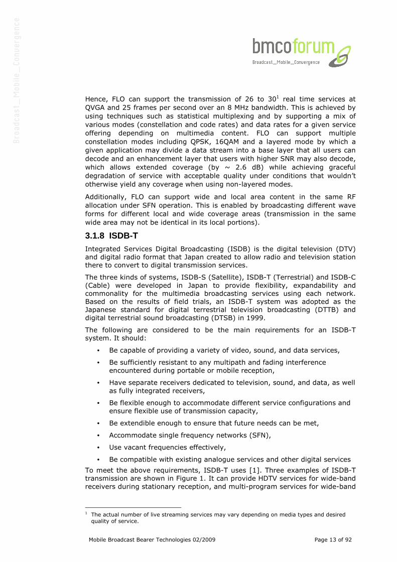
To meet the above requirements, ISDB-T uses [1]. Three examples of ISDB-T
transmission are shown in Figure 1. It can provide HDTV services for wide-band
receivers during stationary reception, and multi-program services for wide-band
1 The actual number of live streaming services may vary depending on media types and desired quality of service.
Mobile Broadcast Bearer Technologies 02/2009 Page 14 of 92
receivers during both stationary and mobile reception. The DTSB system, by
contrast, consists of either single or triple OFDM segments [2].
Figure 1: Examples of ISDB-T transmission
3.1.9 Mobile Broadcast Multicast Service MBMS UMTS started the process of defining the standard for third generation systems,
referred to as International Mobile Telecommunications 2000 (IMT-2000). In
Europe European Telecommunications Standards Institute (ETSI) was
responsible for the UMTS standardization process. 3G Systems are intended to
provide global mobility with a wide range of services including telephony,
paging, messaging, the Internet and broadband data.
In 1998 Third Generation Partnership Project (3GPP) was formed to continue
the technical specification work. 3GPP has five main standardization areas:
Radio Access Network, Core Network, Terminals, Services and System Aspects
and GERAN (for legacy GSM and EDGE). Third Generation Partnership Project 2
(3GPP2) was formed for technical development of cdma2000 technology which
is a member of IMT-2000 family. In February 1992 World Radio Conference
allocated frequencies for UMTS use. Frequencies 1885 - 2025 and 2110 - 2200
MHz were identified for IMT-2000 use.
In 1999 ETSI Standardisation finished for UMTS Phase 1 (Release ‘99, version
3) and next release is due in December 2001. Most of the European countries
and some countries round the world have already issued UMTS licenses either
by beauty contest or auctions.
In November 1999, the UMTS as specified by 3GPP was formally adopted by the
ITU as a member of its family of IMT-2000 Third Generation Mobile
Communication standards. By the end of 2004, there were more than 16 million
3G/UMTS customers subscribing to 60 networks based on WCDMA technology
in 25 countries – and many more networks were either in advanced testing or
in pre-commercial launch phase, with a total of more than 125 licenses
awarded to a mixture of incumbent operators and new players.
MBMS is split into the MBMS bearer service and the MBMS user service. The
MBMS bearer service provides a new point-to-multipoint transmission bearer,
Mobile Broadcast Bearer Technologies 02/2009 Page 15 of 92
which may use common radio resources (i.e. broadcast) in cells of high receiver
density. The MBMS bearer service is supported by both UMTS Terrestrial Radio
Access Network (UTRAN) and GSM/EDGE Radio Access Network (GERAN).
The MBMS user service defines a service layer toolbox, which includes a
streaming and a download delivery method. The MBMS User Service
specification is very similar to IP datacast, except that MBMS relies on the
BCAST ESG.MBMS services can make use of the MBMS bearer and conventional
uplink bearers from the cellular networks for use as in interaction channel for
interactive services.
The 3GPP is currently finalizing standardization of MBMS, a process that will be
frozen in 3GPP Release 6. Compared to streaming video services, MBMS scales
well – permitting efficient routing of data flows in the core network (e.g. one
data stream per channel, versus one data stream per user in point-to-point
systems). These data streams would be distributed through newly-deployed
MBMS “radio bearers” located in each cell.
3.1.10 TD-SCDMA (TD-MBMS services) On January 20, 2006, Ministry of Information Industry of the Peoples Republic
of China formally announced that TD-SCDMA is the country’s standard of 3G
mobile telecommunication.
On February 15th, 2006, a timeline for deployment of the network in China was
announced, stating pre-commercial trials would take place starting after
completion of a number of test networks in select cities. These trials ran from
March to October, 2006, but the results were apparently unsatisfactory.
In early 2007, the Chinese government instructed the dominant cellular carrier,
China Mobile, to build commercial trial networks in eight cities, and the two
fixed-line carriers, China Telecom and China Netcom, to build one each in two
other cities. Construction of these trial networks was scheduled to finish during
the fourth quarter of 2007, but delays meant that construction was not
complete until early 2008.
Time Division-Synchronous Code Division Multiple Access, (TD-SCDMA), is a 3G
mobile telecommunications standard and whilst the launch of a national TD-
SCDMA network was initially projected by 2005, “commercial trials” across
eight cities did not commence until April 1st 2008.
The standard has been adopted by 3GPP since Rel-4, known as “UTRA TDD
1.28Mcps Option”. This, and TD-CDMA (an independently developed TDD CDMA
system more closely related to W-CDMA), are offered as air interfaces for the
UMTS-TDD system, a version of UMTS used largely to provide Internet access.
The use of TDD is more efficient than FDD at dynamically providing asymmetric
data rates, which are typical in ordinary Internet use.
TD-SCDMA uses TDD in contrast to the FDD scheme used by W-CDMA. By
dynamically adjusting the number of timeslots used for downlink and uplink,
the system can more easily accommodate asymmetric traffic with different data
rate requirements on downlink and uplink than FDD schemes. Since it does not
require paired spectrum for downlink and uplink, spectrum allocation flexibility
is also increased. Also, using the same carrier frequency for uplink and
downlink means that the channel condition is the same on both directions, and
the base station can deduce the downlink channel information from uplink
channel estimates, which is helpful to the application of beam forming
techniques.
Mobile Broadcast Bearer Technologies 02/2009 Page 16 of 92
TD-SCDMA also uses TDMA in addition to the CDMA used in WCDMA. This
reduces the number of users in each timeslot, which reduces the
implementation complexity of multi-user detection and beam forming schemes,
but the non-continuous transmission also reduces coverage (because of the
higher peak power needed), mobility (because of lower power frequencies
frequency) and complicates radio resource management algorithms. The “S” in
TD-SCDMA stands for “synchronous”, which means that uplink signals are
synchronized at the base station receiver, achieved by continuous timing
adjustments.
As a new TD-SCDMA multimedia service, TD-MBMS targets the mid to high-end
segments of the 3G mobile market and should help bring new mobile
entertainment experiences, such as watching television on mobile devices to
consumers.
3.2 Pre-Commercial Bearers (2009-2010) 3.2.1 DVB-T2 The DVB organization defined a set of commercial requirements which acted as
a framework for the development of DVB-T2. These commercial requirements
included firstly that DVB-T2 transmissions must be able to use existing
domestic receive antenna installations and must be able to re-use existing
transmitter infrastructures.
Furthermore DVB-T2 should provide a minimum of 30% capacity increase over
DVB-T working within the same planning constraints and conditions as DVB-T
and also provide for improved single-frequency-network (SFN) performance
compared with DVB-T.
DVB-T2 should also have a mechanism for providing service-specific
robustness; i.e. it should be possible to give different levels of robustness to
some services compared to others. For example, within a single 8MHz channel,
it should be possible to target some services for roof-top reception and target
other services for reception on portables.
Moreover DVB-T2 should provide for bandwidth and frequency flexibility and
define a mechanism to reduce the peak-to-average-power ratio of the
transmitted signal in order to reduce transmission costs.
A few general principles were adopted in the design of T2: The DVB Project
provides a coherent family of standards where possible and the translation
between DVB-x2 standards (for example, between DVB-S2 and DVB-T2) should
be as easy as possible. Consequently, T2 adopted two key technologies from
DVB-S2, the system layer architecture and the same Low Density Parity Check
(LDPC) error-correcting codes. Extensions to the DVB-S2 standard have been
only made wherever necessary to optimize the performance for the terrestrial
channel.
The system input of DVB-T2 may be one or more MPEG Transport Stream(s)
and/or one or more Generic Stream(s), which have a one-to-one
correspondence with data channels in the modulator that are called Physical-
Layer Pipes (PLPs).
The multiple PLP and time-slicing approaches implemented by DVB-T2 allow for
different levels of coding, modulation and time interleaving depth to be applied
Mobile Broadcast Bearer Technologies 02/2009 Page 17 of 92
to the different PLPs, to provide variable robustness on a service-by-service
basis. The supported modulating and coding parameters for each PLP range
from QPSK, code rate ½ up to 256QAM, code rate 5/6, which result in a
minimum required signal-to-noise ratio of 0.8dB and a maximum payload bit
rate of more than 50Mbit/s in an 8MHz channel.
The range of COFDM parameters has been extended compared with DVB-T to
obtain highest performance in all sorts of use-cases:
• FFT sizes: 1K, 2K, 4K, 8K, 16K, 32K
• Guard Interval fractions: 1/128, 1/32, 1/16, 19/256, 1/8, 19/128, ¼
• Channel bandwidths: 1.7, 5, 6, 7 8, 10 MHz
• An extended-carrier mode to allow optimum use to be made of the
channel bandwidth together with the higher FFT sizes. When this option
is used (supported for 8K, 16K and 32K FFT) the carrier spacing is the
same as when the normal carrier is used, but additional carriers are
added at both ends of the spectrum.
• The application of transmit diversity (MISO) to increase performance
especially in single frequency networks.
The T2 system furthermore provides a number of new features for improved
versatility:
• A frame structure which contains a special (short) identification symbol,
which can be used for rapid channel scanning and signal acquisition, and
which also signals some basic frame-structure parameters
• Rotated constellations, which provide a form of modulation diversity, to
assist in the reception of higher-code-rate signals in demanding
transmission channels
• Special techniques to reduce the peak-to-average ratio of the
transmitted signal
• An option for extending the transmitted signal by including provision for
future-extension frames (FEFs), which are unspecified portions of the
signal that first-generation receivers will know to ignore, but which could
provide a compatible route for later upgrades.
The DVB-T2 standard is thus efficiently applicable in a variety of scenarios,
ranging from single transmitter to large single frequency networks, and also
from portable to stationary reception.
Mobile Broadcast Bearer Technologies 02/2009 Page 18 of 92
4 Bearer Technologies Technical Overview
4.1 Deployed Bearers 4.1.1 BCMCS
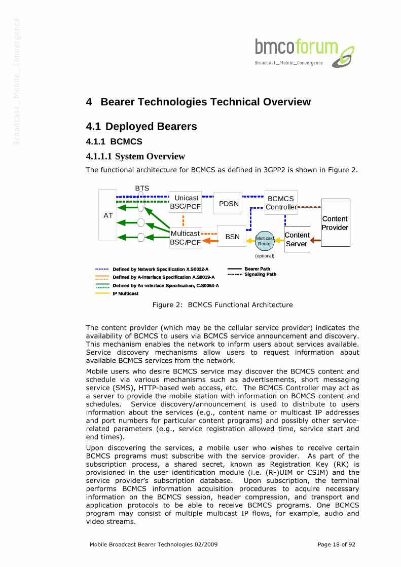
4.1.1.1 System Overview The functional architecture for BCMCS as defined in 3GPP2 is shown in Figure 2.
Defined by Network Specification X.S0022-A
Defined by A-interface Specification A.S0019-A
Defined by Air-interface Specification, C.S0054-A
IP Multicast
Bearer PathSignaling Path
Defined by Network Specification X.S0022-A
Defined by A-interface Specification A.S0019-A
Defined by Air-interface Specification, C.S0054-A
IP Multicast
Bearer PathSignaling Path
AT
BSN Content ServerContent Server
ContentProviderContentProvider
Multicast BSC/PCF
BTS
BCMCSControllerPDSN
UnicastBSC/PCF
MulticastRouter
(optional)
Figure 2: BCMCS Functional Architecture
The content provider (which may be the cellular service provider) indicates the
availability of BCMCS to users via BCMCS service announcement and discovery.
This mechanism enables the network to inform users about services available.
Service discovery mechanisms allow users to request information about
available BCMCS services from the network.
Mobile users who desire BCMCS service may discover the BCMCS content and
schedule via various mechanisms such as advertisements, short messaging
service (SMS), HTTP-based web access, etc. The BCMCS Controller may act as
a server to provide the mobile station with information on BCMCS content and
schedules. Service discovery/announcement is used to distribute to users
information about the services (e.g., content name or multicast IP addresses
and port numbers for particular content programs) and possibly other service-
related parameters (e.g., service registration allowed time, service start and
end times).
Upon discovering the services, a mobile user who wishes to receive certain
BCMCS programs must subscribe with the service provider. As part of the
subscription process, a shared secret, known as Registration Key (RK) is
provisioned in the user identification module (i.e. (R-)UIM or CSIM) and the
service provider’s subscription database. Upon subscription, the terminal
performs BCMCS information acquisition procedures to acquire necessary
information on the BCMCS session, header compression, and transport and
application protocols to be able to receive BCMCS programs. One BCMCS
program may consist of multiple multicast IP flows, for example, audio and
video streams.
Mobile Broadcast Bearer Technologies 02/2009 Page 19 of 92
After BCMCS information acquisition, the terminal determines whether a desired
multicast IP flow is available in a particular cell and sector by obtaining the
corresponding radio configuration information from a base station via overhead
messages on the control channel. If the BCMCS bearer path is not yet
established, the first terminal performing BCMCS registration may trigger the
PDSN (Packet Data Serving Node) to join the multicast group associated with
the BCMCS_FLOW_IDs, to subsequently set up a bearer path from the RAN to
the PDSN. This mode of operation makes more efficient use of air interface
resources; by eliminating the need for multiple terminals to each send multicast
join messages over the air.
When the network determines that there are no more terminals listening to a
specific multicast IP flow(s), it may release the associated bearer path. The
network may also release the bearer resources when the scheduled BCMCS
program is finished.
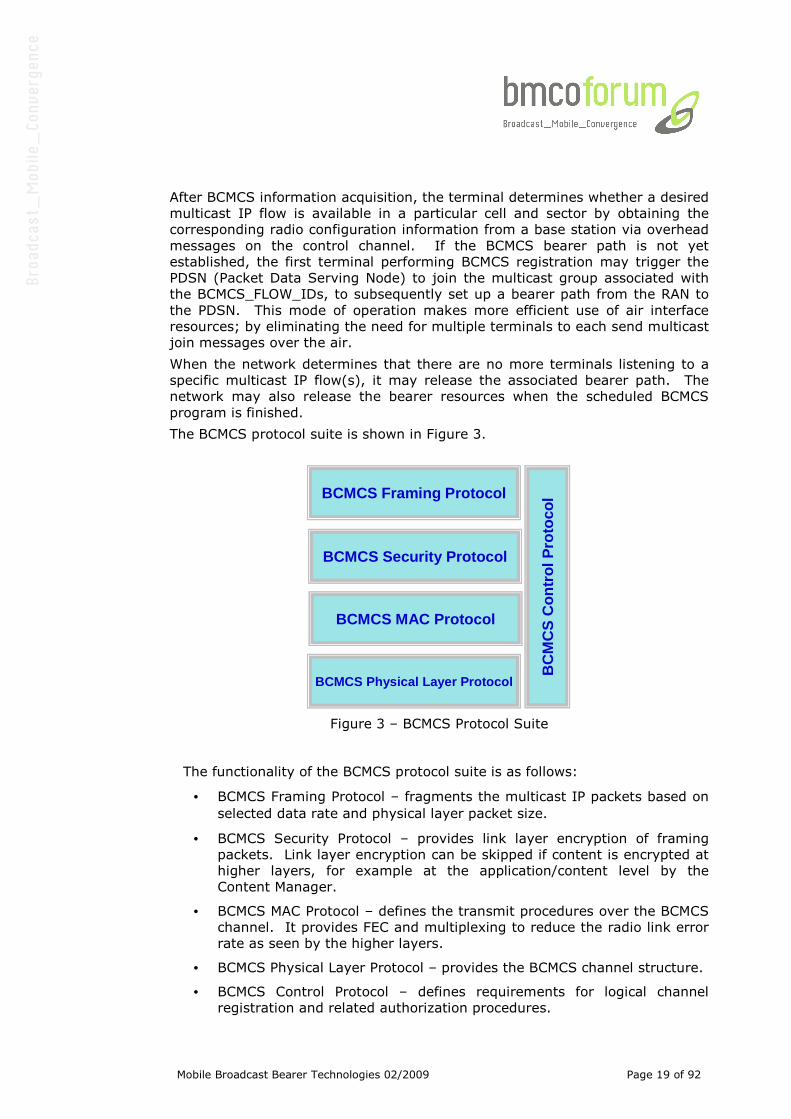
The BCMCS protocol suite is shown in Figure 3.
BCMCS Framing Protocol
BCMCS Physical Layer Protocol
BC
MC
S C
ontr
ol P
roto
col
BCMCS MAC Protocol
BCMCS Security Protocol
BCMCS Framing Protocol
BCMCS Physical Layer Protocol
BC
MC
S C
ontr
ol P
roto
col
BCMCS MAC Protocol
BCMCS Security Protocol
Figure 3 – BCMCS Protocol Suite
The functionality of the BCMCS protocol suite is as follows:
• BCMCS Framing Protocol – fragments the multicast IP packets based on
selected data rate and physical layer packet size.
• BCMCS Security Protocol – provides link layer encryption of framing
packets. Link layer encryption can be skipped if content is encrypted at
higher layers, for example at the application/content level by the
Content Manager.
• BCMCS MAC Protocol – defines the transmit procedures over the BCMCS
channel. It provides FEC and multiplexing to reduce the radio link error
rate as seen by the higher layers.
• BCMCS Physical Layer Protocol – provides the BCMCS channel structure.
• BCMCS Control Protocol – defines requirements for logical channel
registration and related authorization procedures.
Mobile Broadcast Bearer Technologies 02/2009 Page 20 of 92
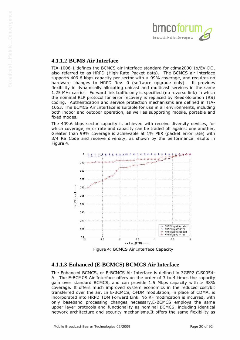
4.1.1.2 BCMS Air Interface TIA-1006-1 defines the BCMCS air interface standard for cdma2000 1x/EV-DO,
also referred to as HRPD (High Rate Packet data). The BCMCS air interface
supports 409.6 kbps capacity per sector with > 99% coverage, and requires no
hardware changes to HRPD Rev. 0 (software upgrade only). It provides
flexibility in dynamically allocating unicast and multicast services in the same
1.25 MHz carrier. Forward link traffic only is specified (no reverse link) in which
the nominal RLP protocol for error recovery is replaced by Reed-Solomon (RS)
coding. Authentication and service protection mechanisms are defined in TIA-
1053. The BCMCS Air Interface is suitable for use in all environments, including
both indoor and outdoor operation, as well as supporting mobile, portable and
fixed modes.
The 409.6 kbps sector capacity is achieved with receive diversity devices, for
which coverage, error rate and capacity can be traded off against one another.
Greater than 99% coverage is achievable at 1% PER (packet error rate) with
3/4 RS Code and receive diversity, as shown by the performance results in
Figure 4.
Figure 4: BCMCS Air Interface Capacity
4.1.1.3 Enhanced (E-BCMCS) BCMCS Air Interface The Enhanced BCMCS, or E-BCMCS Air Interface is defined in 3GPP2 C.S0054-
A. The E-BCMCS Air Interface offers on the order of 3 to 4 times the capacity
gain over standard BCMCS, and can provide 1.5 Mbps capacity with > 98%
coverage. It offers much improved system economics in the reduced cost/bit
transferred over the air. In E-BCMCS, OFDM modulation, in place of CDMA, is
incorporated into HRPD TDM Forward Link. No RF modification is incurred, with
only baseband processing changes necessary.E-BCMCS employs the same
upper layer protocols and functionality as nominal BCMCS, including identical
network architecture and security mechanisms.It offers the same flexibility as
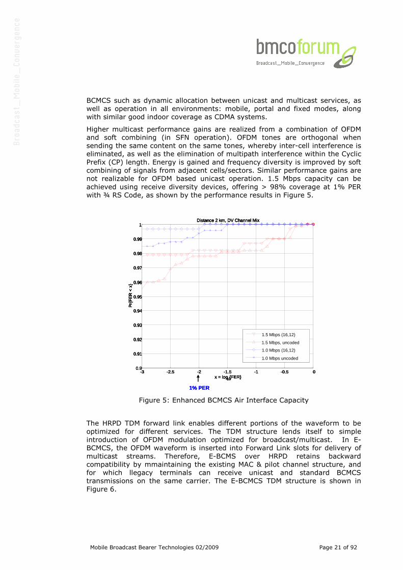
Mobile Broadcast Bearer Technologies 02/2009 Page 21 of 92
BCMCS such as dynamic allocation between unicast and multicast services, as
well as operation in all environments: mobile, portal and fixed modes, along
with similar good indoor coverage as CDMA systems.
Higher multicast performance gains are realized from a combination of OFDM
and soft combining (in SFN operation). OFDM tones are orthogonal when
sending the same content on the same tones, whereby inter-cell interference is
eliminated, as well as the elimination of multipath interference within the Cyclic
Prefix (CP) length. Energy is gained and frequency diversity is improved by soft
combining of signals from adjacent cells/sectors. Similar performance gains are
not realizable for OFDM based unicast operation. 1.5 Mbps capacity can be
achieved using receive diversity devices, offering > 98% coverage at 1% PER
with ¾ RS Code, as shown by the performance results in Figure 5.
1% PER
-3 -2.5 -2 -1.5 -1 -0.5 00.9
0.91
0.92
0.93
0.94
0.95
0.96
0.97
0.98
0.99
1Distance 2 km, DV Channel Mix
x = log10{FER}
Pr{
FE
R<
x}
1.5 Mbps (16,12)
1.5 Mbps, uncoded
1.0 Mbps (16,12)
1.0 Mbps uncoded
1% PER1% PER
-3 -2.5 -2 -1.5 -1 -0.5 00.9
0.91
0.92
0.93
0.94
0.95
0.96
0.97
0.98
0.99
1Distance 2 km, DV Channel Mix
x = log10{FER}
Pr{
FE
R<
x}
1.5 Mbps (16,12)
1.5 Mbps, uncoded
1.0 Mbps (16,12)
1.0 Mbps uncoded
-3 -2.5 -2 -1.5 -1 -0.5 00.9
0.91
0.92
0.93
0.94
0.95
0.96
0.97
0.98
0.99
1Distance 2 km, DV Channel Mix
x = log10{FER}
Pr{
FE
R<
x}
-3 -2.5 -2 -1.5 -1 -0.5 00.9
0.91
0.92
0.93
0.94
0.95
0.96
0.97
0.98
0.99
1Distance 2 km, DV Channel Mix
x = log10{FER}
Pr{
FE
R<
x}
1.5 Mbps (16,12)
1.5 Mbps, uncoded
1.0 Mbps (16,12)
1.0 Mbps uncoded
Figure 5: Enhanced BCMCS Air Interface Capacity
The HRPD TDM forward link enables different portions of the waveform to be
optimized for different services. The TDM structure lends itself to simple
introduction of OFDM modulation optimized for broadcast/multicast. In E-
BCMCS, the OFDM waveform is inserted into Forward Link slots for delivery of
multicast streams. Therefore, E-BCMS over HRPD retains backward
compatibility by mmaintaining the existing MAC & pilot channel structure, and
for which llegacy terminals can receive unicast and standard BCMCS
transmissions on the same carrier. The E-BCMCS TDM structure is shown in
Figure 6.
Mobile Broadcast Bearer Technologies 02/2009 Page 22 of 92
Can be replaced with alternate modulation (e.g., OFDM for E-
BCMCS)
Unicast Data(400 Chips)
MACChannel
(64 Chips)
PilotChannel
(96 Chips)Unicast Data(400 Chips)
MACChannel
(64 Chips)
Required forBackward Compatibility
½ Slot
Can be replaced with alternate modulation (e.g., OFDM for E-
BCMCS)
Unicast Data(400 Chips)
MACChannel
(64 Chips)
PilotChannel
(96 Chips)Unicast Data(400 Chips)
MACChannel
(64 Chips)
Unicast Data(400 Chips)
MACChannel
(64 Chips)
PilotChannel
(96 Chips)Unicast Data(400 Chips)
MACChannel
(64 Chips)
Required forBackward Compatibility
½ Slot
Figure 6: Enhanced BCMCS TDM Structure
4.1.1.4 BCMCS and E-BCMCS Physical Layer Structure BCMCS or E-BCMCS supports up to 4 Interlaces, whereby each interlace can be
further split into 4, 8 or 16 multiplexes. Interlace-multiplex pairs (i, m) are
used to map content onto logical channels, and each logical channel can have a
burst length from 1 to 64 slots. An interlace-multiplex pair defines a physical
resource that can be allocated to a logical channel. Flexibility is inherent
whereby multiple physical resources can be allocated to a logical channel to
satisfy its data rate, and conversely, lower increments of physical resources can
be allocated by time multiplexing the resource with unicast transmissions. An
example illustration of mapping content onto logical channels via interlace-
multiplex pairs is shown in Figure 7.
Unicast
Multicast
FL Traffic Channel Slots
Interlace 0 Interlace 3Interlace 2Interlace 1
m0 m1 m2 m3
Example: ¼ of PHY resource, or single Interlace dedicated to multicast; Interlace 0 contains 4 multiplexes, 3 of which are used for multicast; single burst length of 1 slot for PHY layer packet
Unicast
Multicast
Unicast
Multicast
FL Traffic Channel Slots
Interlace 0 Interlace 3Interlace 2Interlace 1
m0 m1 m2 m3
Example: ¼ of PHY resource, or single Interlace dedicated to multicast; Interlace 0 contains 4 multiplexes, 3 of which are used for multicast; single burst length of 1 slot for PHY layer packet
Figure 7: Example of ¼ by ¾ Physical Resource Allocation to Multicast
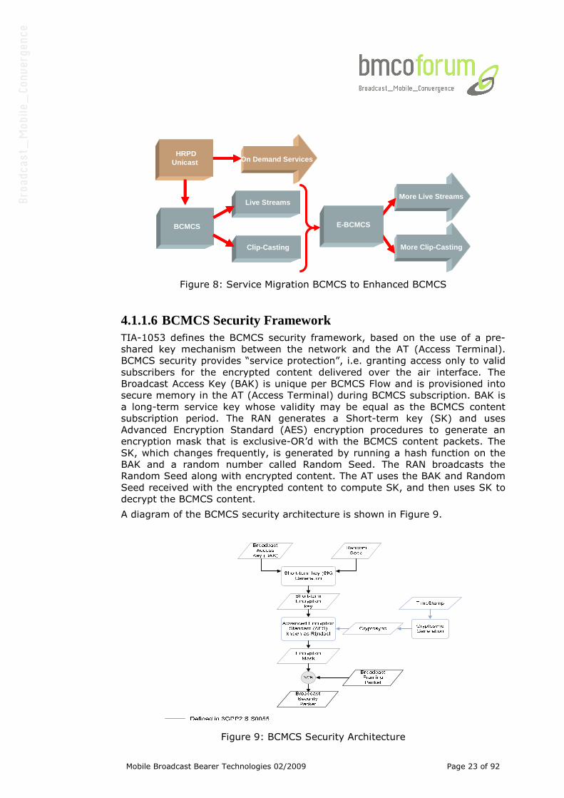
4.1.1.5 Service Migration Figure 8 illustrates a nominal means to evolve service deployment from BCMCS
to E-BCMCS from the air interface perspective.
Mobile Broadcast Bearer Technologies 02/2009 Page 23 of 92
HRPDUnicast
BCMCS
Clip-Casting
Live Streams
On Demand Services
More Live Streams
More Clip-Casting
E-BCMCS
HRPDUnicast
BCMCS
Clip-Casting
Live Streams
On Demand Services
More Live Streams
More Clip-Casting
E-BCMCS
Figure 8: Service Migration BCMCS to Enhanced BCMCS
4.1.1.6 BCMCS Security Framework TIA-1053 defines the BCMCS security framework, based on the use of a pre-
shared key mechanism between the network and the AT (Access Terminal).
BCMCS security provides “service protection”, i.e. granting access only to valid
subscribers for the encrypted content delivered over the air interface. The
Broadcast Access Key (BAK) is unique per BCMCS Flow and is provisioned into
secure memory in the AT (Access Terminal) during BCMCS subscription. BAK is
a long-term service key whose validity may be equal as the BCMCS content
subscription period. The RAN generates a Short-term key (SK) and uses
Advanced Encryption Standard (AES) encryption procedures to generate an
encryption mask that is exclusive-OR’d with the BCMCS content packets. The
SK, which changes frequently, is generated by running a hash function on the
BAK and a random number called Random Seed. The RAN broadcasts the
Random Seed along with encrypted content. The AT uses the BAK and Random
Seed received with the encrypted content to compute SK, and then uses SK to
decrypt the BCMCS content.
A diagram of the BCMCS security architecture is shown in Figure 9.
Figure 9: BCMCS Security Architecture
Mobile Broadcast Bearer Technologies 02/2009 Page 24 of 92
4.1.1.7 Summary BCMCS and Enhanced BCMCS air interfaces provide cost-effective means of
delivering popular content. The BCMCS Air Interface offers 409.6 Kbps capacity
with > 99% coverage, whereas E-BCMCS Air Interface offers 1.5 Mbps capacity
with > 98% coverage. In either implementation, an unlimited number of users
can be supported. BCMCS leverages existing network investments in HRPD, by
utilizing existing EV-DO carriers to provide new services, while offering the
same good indoor coverage as CDMA unicast systems. BCMCS provides
flexibility in expanding an existing service mix. The service/network operator
can dynamically allocate between unicast and multicast services depending on
usage requirements, which in turn allows the operator to mmonetize network
resources during off-peak traffic hours.
Mobile Broadcast Bearer Technologies 02/2009 Page 25 of 92
4.1.2 CMMB STiMi
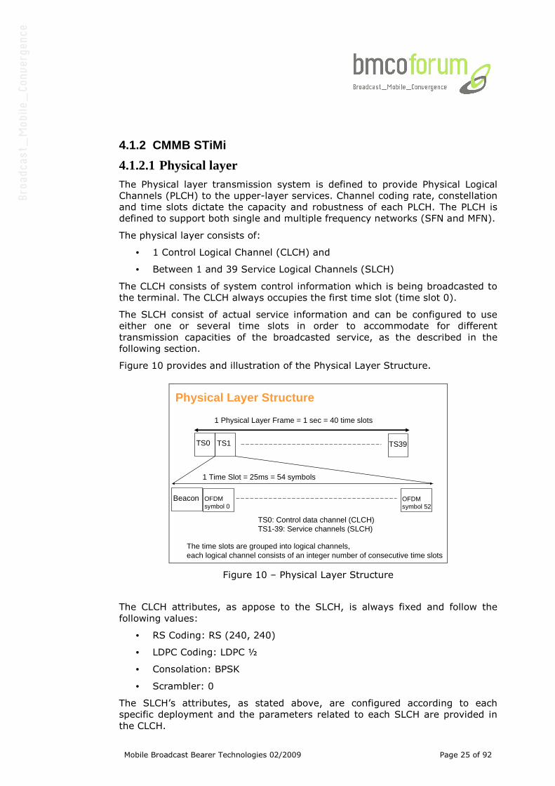
4.1.2.1 Physical layer The Physical layer transmission system is defined to provide Physical Logical
Channels (PLCH) to the upper-layer services. Channel coding rate, constellation
and time slots dictate the capacity and robustness of each PLCH. The PLCH is
defined to support both single and multiple frequency networks (SFN and MFN).
The physical layer consists of:
• 1 Control Logical Channel (CLCH) and
• Between 1 and 39 Service Logical Channels (SLCH)
The CLCH consists of system control information which is being broadcasted to
the terminal. The CLCH always occupies the first time slot (time slot 0).
The SLCH consist of actual service information and can be configured to use
either one or several time slots in order to accommodate for different
transmission capacities of the broadcasted service, as the described in the
following section.
Figure 10 provides and illustration of the Physical Layer Structure.
Physical Layer Structure
TS0 TS1 TS39
1 Physical Layer Frame = 1 sec = 40 time slots
1 Time Slot = 25ms = 54 symbols
Beacon OFDMsymbol 0
OFDMsymbol 52
TS0: Control data channel (CLCH)TS1-39: Service channels (SLCH)
The time slots are grouped into logical channels, each logical channel consists of an integer number of consecutive time slots
Figure 10 – Physical Layer Structure
The CLCH attributes, as appose to the SLCH, is always fixed and follow the
following values:
• RS Coding: RS (240, 240)
• LDPC Coding: LDPC ½
• Consolation: BPSK
• Scrambler: 0
The SLCH’s attributes, as stated above, are configured according to each
specific deployment and the parameters related to each SLCH are provided in
the CLCH.
Mobile Broadcast Bearer Technologies 02/2009 Page 26 of 92
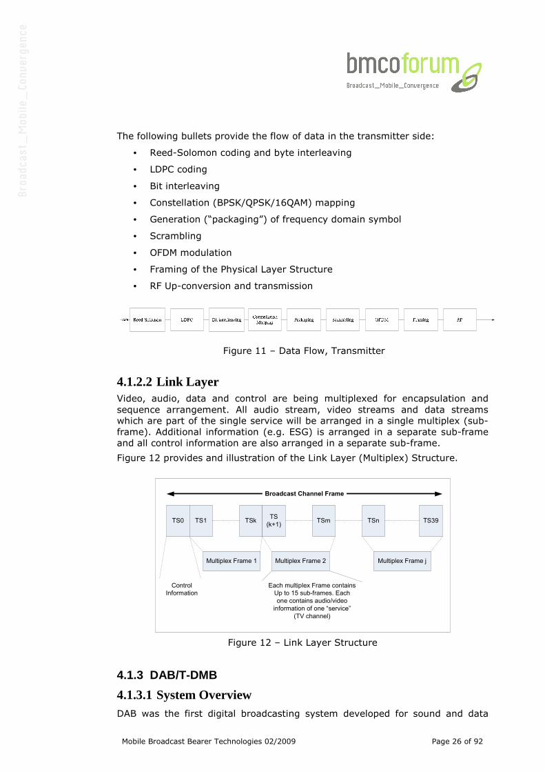
The following bullets provide the flow of data in the transmitter side:
• Reed-Solomon coding and byte interleaving
• LDPC coding
• Bit interleaving
• Constellation (BPSK/QPSK/16QAM) mapping
• Generation (“packaging”) of frequency domain symbol
• Scrambling
• OFDM modulation
• Framing of the Physical Layer Structure
• RF Up-conversion and transmission
Figure 11 – Data Flow, Transmitter
4.1.2.2 Link Layer Video, audio, data and control are being multiplexed for encapsulation and
sequence arrangement. All audio stream, video streams and data streams
which are part of the single service will be arranged in a single multiplex (sub-
frame). Additional information (e.g. ESG) is arranged in a separate sub-frame
and all control information are also arranged in a separate sub-frame.
Figure 12 provides and illustration of the Link Layer (Multiplex) Structure.
TS0 TS1 TSkTS
(k+1)TSm TSn TS39
Multiplex Frame 1 Multiplex Frame 2 Multiplex Frame j
Each multiplex Frame contains
Up to 15 sub-frames. Each
one contains audio/video
information of one “service”
(TV channel)
Broadcast Channel Frame
Control
Information
Figure 12 – Link Layer Structure
4.1.3 DAB/T-DMB
4.1.3.1 System Overview DAB was the first digital broadcasting system developed for sound and data
Mobile Broadcast Bearer Technologies 02/2009 Page 27 of 92
broadcasting. With its first edition finalized in 1995, this most widespread
standard has been defined for an audio reproduction quality similar to the one
of the Compact Disc. Today, DAB Eureka-147 is a mature technology exploited
by most of the radio broadcasters in Europe and around the world.
Figure 13 outlines the signal generation.
Fast InformationBlock assemblermultiplex
controller
ServiceInformationassembler
Energydispersalscrambler
Convolutionalencoder
MainService
Multiplexer
DAB transmissionsignal
FIC Dataservices
ProgrammeAssociated Data
24 kHz or 48 kHzPCM audio signal
Streammodedata
DABAudio frame
Packetmodedata
Timeinterleaver
packetmultiplex
assembler
packet modeSI
Transmissionframe
multiplexer
FIC and MSC(frequencyinterleaved)
symbolgenerator
Synch. channelsymbol
generator
OFDMsignal generator
TII signalgenerator
CIFs
Audio ProgrammeServices
ServiceInformation
Energydispersalscrambler
Convolutionalencoder
Timeinterleaver
Timeinterleaver
Convolutionalencoder
Energydispersalscrambler
packetmultiplex
assembler
Energydispersalscrambler
Convolutionalencoder
Timeinterleaver
Energydispersalscrambler
Convolutionalencoder
FIBsFIDC
MCI
SI
MPEGAudio Layer II
encoder
general
Data
services
control
s(t)
optionalConditional
Accessscrambler
FIDCassembler
multiplexcontroldata
s (t)TII
optionalConditional
Accessscrambler
optionalConditional
Accessscrambler
optionalConditional
Accessscrambler
optionalConditional
Accessscrambler
optionalConditional
Accessscrambler
Figure 13: DAB signal generation
Data is mainly transported via the Main Service Channel (MSC), whereas the
Service and Multiplex Configuration Information are transported via the Fast
Information Channel (FIC). Opposite to the MSC, the latter is not time-
interleaved, protected with a fixed code rate and a fixed data rate.
Each sub-channel within the MSC can be individually error-protected; whereby
Layer II audio is accompanied by Unequal Error Protection for a higher
reception reliability of the most sensitive parts of the audio stream (e.g. Scale
Factor CRCs).
Time and frequency interleaving lead to the necessary robustness for mobile
and portable reception.
Power consumption can be reduced through macro time slicing as well as
through power cycling, i.e. grabbing just those OFDM symbols that are relevant
for the service to be reproduced.
Seamless reconfiguration of services, e.g. changing data rates, error protection
code rates or is enabled by the system and provides for a high degree of
Mobile Broadcast Bearer Technologies 02/2009 Page 28 of 92
flexibility - incl. the removal or addition of services on the fly.
DAB currently provides two variants of Mobile Television - DMB and DAB-IP-
based ones. Conditional Access as well as Digital Rights Management is enabled
as well.
In addition, DAB features an extensive set of multimedia and traffic
information/navigation support applications:
• Middleware / DAB Java
• Digital Music Download (DMD)
• Voice Applications
• Broadcast WebSite (BWS)
• SlideShow (SlS)
• TopNews
• Dynamic Label
• TPEG
• TMC
Figure 14 outlines the DAB protocol stack, its particular elements shall be
further elaborated here.
Figure 14: DAB protocol stack
4.1.3.2 Enhanced Stream and Packet Mode The Enhanced Stream Mode - an evolution of what is identified with “MSC
Stream Data” in the central DAB Standard EN 300 401 - is in fact an additional
Packet Mode, consisting of a structure of 188-Byte long Packets with 16 Reed-
Solomon Parity Bytes attached. Furthermore a Forney Interleaver is applied to
those FEC’ed 204-Byte long Packets. This structure is in use for DMB with the
MPEG-2 Transport Stream - see ETSI TS 102 427.
Mobile Broadcast Bearer Technologies 02/2009 Page 29 of 92
In parallel and once again for Mobile TV applications the Enhanced Packet is
build in a similar way, whereby the same RS FEC scheme is in use, but here
virtual time interleaving is realised via an Application Data Table - in reality a
buffer that needs to be filled before the second error control code layer can be
calculated (Figure 15).
1
Application Data Table (2 256 bytes)
row RS Data Table (192 bytes)
column 1 188 1 16
12
Figure 15: Enhanced packet structure
4.1.3.3 Digital Multimedia Broadcasting / Mobile TV DMB is a data application that resides on top of the DAB physical layer and it’s
Enhanced Stream Mode.
It makes use of the following standards and settings:
• Transport: MPEG-2 TS plus RS (204, 188, t=8)
• AV and Data Synchronisation: MPEG-4 System Layer
• Video encoding: MPEG-4 AVC/H.264 baseline profile
• Audio encoding: MPEG-4 HE AAC v2 or BSAC
4.1.3.4 Additional Audio System AAC is built up as a hierarchical system consisting of the AAC core codec,
Spectral Band Replication (� HE AAC (v1)) and Parametric Stereo (� HE AAC
v2). Providers have the choice to use the core, the core plus SBR or the core
plus SBR plus PS. Of course, the receivers must be prepared for all cases and
hence the implementation of v2 is mandatory.
In the light of the fact that audio coded with MPEG Layer II will remain to be on
air for many years to come, a new DAB Radio needs to cover both coding
algorithms - MPEG-1/2 Layer II and HE AAC V2.
Due to the high efficiency of the new coding algorithms, the impact of lost bits
is more significant. Already introduced for DMB, the concatenation of the inner
convolutional coding (Viterbi) being an element of the original DAB set-up and
an outer block code in the form of Reed-Solomon coding was chosen as the
most appropriate solution. The advantages gained with this combination lead to
a slightly extended geographical coverage area.
Mobile Broadcast Bearer Technologies 02/2009 Page 30 of 92
Assuming that the audio quality of an audio
stream encoded with a HE AAC V2 year 2006
implementation with a bitrate of about 36 kbit/s
is equivalent to the audio quality of a MPEG-1
Layer II coded stream of 128 kbit/s, the
number of Radio Services per DAB Ensembles
can be increased from 9 to 29. Already this step
would be equivalent to a factor of 3.2 in terms
of the number of audio services transportable
per DAB Ensemble.
The structure applied consists of super-frames
covering a fixed number of AAC access units.
Each Access Unit carries its PAD part
(Programme Associated Data) in a similar way
as it is the case for MPEG Layer II audio frames. The required additional error
protection is realised with interleaving and an RS scheme (120, 110, t=5)
derived from the same mother code as the RS schemes for Enhanced Stream
and Packet Mode. The 10 parity bytes per 110 data bytes lead to an ability of
correcting up to 5 erroneous bytes in those 120 bytes.
4.1.3.5 Internet Protocol Datacast (IPDC) / Mobile TV As illustrated in the Figure 17 an improved IP DataCast system for the bearer
DAB shall be optimized towards two targets - low overhead and low power
consumption of the terminals employing it. At the same time the closest
possible alignment to the stacks of other bearers like 3G or DVB-H shall be
realised as well.
DAB Enhanced Stream Mode - well known as
the basis for the application DMB - was chosen
as the baseline. The outer error protection and
interleaving is identical with the corresponding
elements of the DVB and the DMB stack.
Structurally once again a Transport Stream with
Packets of length 188 bytes is combined with
16 Reed-Solomon parity bytes.
The IP(/UDP/RTP) headers might be
compressed with Robust Header Compression
according to RFC 3095.
On that basis proprietary Mobile TV applications
as well as transport protocols and applications
specified by the Open Mobile Alliance (OMA)
and/or the DVB-CBMS group might be adapted
for and used with DAB.
Figure 17: IPDC over DAB
Figure 16: AAC structure
Mobile Broadcast Bearer Technologies 02/2009 Page 31 of 92
4.1.4 DVB-T
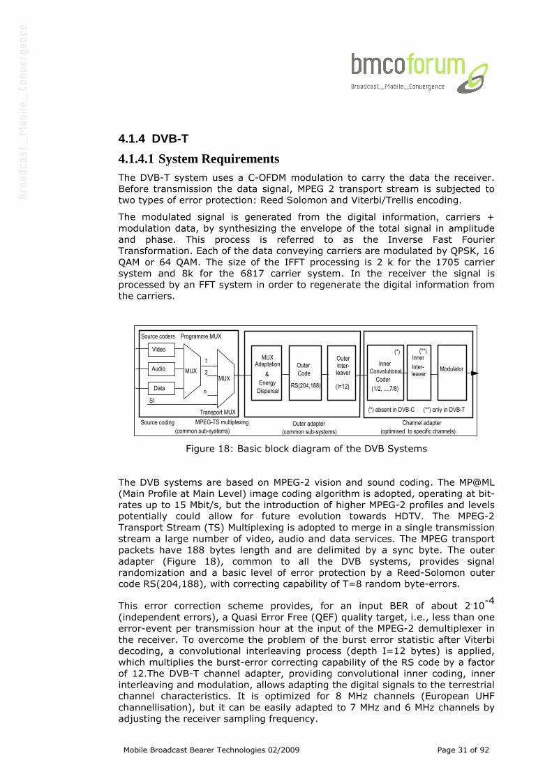
4.1.4.1 System Requirements The DVB-T system uses a C-OFDM modulation to carry the data the receiver.
Before transmission the data signal, MPEG 2 transport stream is subjected to
two types of error protection: Reed Solomon and Viterbi/Trellis encoding.
The modulated signal is generated from the digital information, carriers +
modulation data, by synthesizing the envelope of the total signal in amplitude
and phase. This process is referred to as the Inverse Fast Fourier
Transformation. Each of the data conveying carriers are modulated by QPSK, 16
QAM or 64 QAM. The size of the IFFT processing is 2 k for the 1705 carrier
system and 8k for the 6817 carrier system. In the receiver the signal is
processed by an FFT system in order to regenerate the digital information from
the carriers.
Audio
Data
MUX
MPEG-TS multiplexingSource coding Outer adapter
Video
MUXAdaptation
&
Energy
Dispersal
Outer
Code
RS(204,188)
Inter-leaver
(I=12)
Programme MUX
1
2
n
MUX
Transport MUX
Channel adapter
Convolutional
InnerInner
Coder
(1/2, ...,7/8)
(common sub-systems)(common sub-systems) (optimised to specific channels)
(*)
(*) absent in DVB-C (**) only in DVB-T
SI
ModulatorInter-leaver
Outer(**)
Source coders
Figure 18: Basic block diagram of the DVB Systems
The DVB systems are based on MPEG-2 vision and sound coding. The MP@ML
(Main Profile at Main Level) image coding algorithm is adopted, operating at bit-
rates up to 15 Mbit/s, but the introduction of higher MPEG-2 profiles and levels
potentially could allow for future evolution towards HDTV. The MPEG-2
Transport Stream (TS) Multiplexing is adopted to merge in a single transmission
stream a large number of video, audio and data services. The MPEG transport
packets have 188 bytes length and are delimited by a sync byte. The outer
adapter (Figure 18), common to all the DVB systems, provides signal
randomization and a basic level of error protection by a Reed-Solomon outer
code RS(204,188), with correcting capability of T=8 random byte-errors.
This error correction scheme provides, for an input BER of about 2.10-4
(independent errors), a Quasi Error Free (QEF) quality target, i.e., less than one
error-event per transmission hour at the input of the MPEG-2 demultiplexer in
the receiver. To overcome the problem of the burst error statistic after Viterbi
decoding, a convolutional interleaving process (depth I=12 bytes) is applied,
which multiplies the burst-error correcting capability of the RS code by a factor
of 12.The DVB-T channel adapter, providing convolutional inner coding, inner
interleaving and modulation, allows adapting the digital signals to the terrestrial
channel characteristics. It is optimized for 8 MHz channels (European UHF
channellisation), but it can be easily adapted to 7 MHz and 6 MHz channels by
adjusting the receiver sampling frequency.
Mobile Broadcast Bearer Technologies 02/2009 Page 32 of 92
The DVB-T system has been designed in order to cope with short “natural”
echoes due to multipath propagation, as well as with relatively long “artificial”
echoes due to self-interference occurring in SFNs. The system also provides
good protection against high levels of interference emanating from PAL/SECAM
TV services. These characteristics are achieved by using an OFDM modulation
system associated with convolutional error correcting coding [3], and by
separating adjacent OFDM symbols by means of a “guard interval”. Two modes
of operation are defined: a “2K mode” with guard intervals up to 56 µs and a
“8K mode” with guard intervals up to 224 µs. The “2K mode” is suitable for
single transmitter operation and for “dense” SFN networks with limited
transmitter distances, of the order of 10 to 20 Km. The “8K mode” can be used
both for single transmitter operation and for large SFN networks, with
transmitter distances of the order of 40 to 80 Km. The system allows different
levels of QAM modulation (4, 16 and 64) and different convolutional code rates
(1/2, 2/3, ¾, 5/6 or 7/8) to be used to trade bit rate versus ruggedness.
The system also allows two level hierarchical channel coding and modulation,
including uniform and multi-resolution constellations, to improve the
ruggedness against channel impairments of part of the transmitted bit-stream.
A low-bit-rate programme service can thus be received under severe reception
conditions, while the other programmes in the multiplex can be correctly
decoded only under less critical conditions. The transmitted signal is organized
in “frames” of 68 OFDM “symbols”. Each OFDM symbol is constituted by a set of
K carriers (1705 for 2K and 6817 for 8K) with a minimum frequency separation
to avoid inter-carrier interference (4464 Hz for 2K and 1116 Hz for 8K) and
transmitted simultaneously with a symbol duration Ts. The symbol is composed
of two parts: a “useful” part with duration Tu(224 µs for 2K, 896 µs for 8K),
and a “guard interval” with a duration Tg(where Tg/Tu can be ¼, 1/8, 1/16 or
1/32). Not all of the carriers are modulated with data, since some of them (the
“pilot carriers” or “pilots”) are used to transmit reference information required
by the receiver for synchronization (frame, frequency, phase), channel
estimation, transmission mode identification. There are three types of pilots:
scattered, continual, TPS (transmission parameter signaling). The spacing
between first and last carriers of the spectrum is 7.61 MHz, approximately
corresponding also to the total spectrum occupation because of the steep roll-
off of the OFDM signals:
This highlights the DVB-T specific flexibility, which allows the user to tailor the
system by using the most appropriate mode among the different possible
modes of operation proposed. Comprehensive discussion of the optimum use of
all parameters is complex and would be lengthy. However, the following
features should be kept in mind:
• The hierarchical modes when applicable split the channel in two with
different (and adjustable) requirements in terms of C/N. This permits
different reception conditions for the same or for different programme
content;
• The code rate and the modulation scheme can be selected in order to
lower down the C/N requirements to the desired form of service;
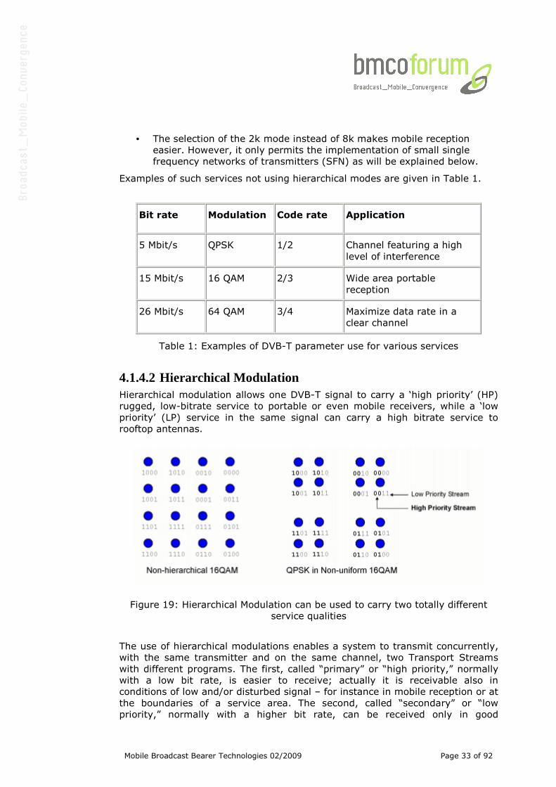
Mobile Broadcast Bearer Technologies 02/2009 Page 33 of 92
• The selection of the 2k mode instead of 8k makes mobile reception
easier. However, it only permits the implementation of small single
frequency networks of transmitters (SFN) as will be explained below.
Examples of such services not using hierarchical modes are given in Table 1.
Bit rate Modulation Code rate Application
5 Mbit/s QPSK 1/2 Channel featuring a high
level of interference
15 Mbit/s 16 QAM 2/3 Wide area portable
reception
26 Mbit/s 64 QAM 3/4 Maximize data rate in a
clear channel
Table 1: Examples of DVB-T parameter use for various services
4.1.4.2 Hierarchical Modulation Hierarchical modulation allows one DVB-T signal to carry a ‘high priority’ (HP)
rugged, low-bitrate service to portable or even mobile receivers, while a ‘low
priority’ (LP) service in the same signal can carry a high bitrate service to
rooftop antennas.
Figure 19: Hierarchical Modulation can be used to carry two totally different
service qualities
The use of hierarchical modulations enables a system to transmit concurrently,
with the same transmitter and on the same channel, two Transport Streams
with different programs. The first, called “primary” or “high priority,” normally
with a low bit rate, is easier to receive; actually it is receivable also in
conditions of low and/or disturbed signal – for instance in mobile reception or at
the boundaries of a service area. The second, called “secondary” or “low
priority,” normally with a higher bit rate, can be received only in good
Mobile Broadcast Bearer Technologies 02/2009 Page 34 of 92
conditions; for instance, with an adequate fixed receiving antenna and a good
signal level.
According to the DVB-T standard, explained above, an OFDM modulation is
formed by various carriers (1705 or 6817, all equally spaced, from less than 1
kHz to over 4 kHz, depending on the width of the occupied channel), each one
modulated according to the QPSK, 16-QAM, or 64-QAM scheme. With
hierarchical modulation (that can be only 16-QAM or 64-QAM) the primary
Transport Stream defines only the quadrant of the modulation symbol (as if it is
a QPSK modulation scheme). The secondary Transport Stream defines, within
the quadrant set by the primary Stream, the exact position of phase and
amplitude taken by the symbol. In this way, in spite of using a 16-QAM or 64-
QAM modulation, the primary Transport Stream has modulation robustness
almost similar to that of a QPSK.
Furthermore, it is possible to choose different error correction codes (code
rates) for each Transport Stream, in order to find the best compromise between
the available bit rate and the “robustness” (i.e. immunity to noise, disturbances
etc.). In hierarchical modulations it is also possible to define the uniformity
degree of the modulation constellation; such a degree is called “α” and can take
the values 1, 2 and 4. It is possible, in practice, to decide to adequately space
the symbols from the axis of the constellation, in order to further facilitate, in
the receivers, the decoding of the primary Stream (but to the detriment of the
secondary Stream). To get a concrete idea of the differences between the
primary and the secondary Stream, please consider that, depending on
parameters chosen, the minimum reception levels can reach a difference up to
about 20 dB (that is like the primary Stream transmitted with a power 100
times higher compared to the one of the secondary Stream).
4.1.5 DVB-H
4.1.5.1 System requirements The commercial requirements of the system were determined by the DVB
Project in 2002: DVB-H shall offer broadcast services for portable and mobile
usage, including audio and video streaming in acceptable quality. The data
rates feasible in practice have to be sufficient for this purpose. For the DVB-H
system a useful data rate of up to 10 Mbit/s per channel is envisaged.
Transmission channels will mostly be allocated in the regular UHF broadcasting
band. VHF Band III may be used alternatively. Non-broadcast frequencies
should be useable.
The typical user environment of a DVB-H handheld terminal is very much
comparable to the mobile radio environment. The term handheld terminal
includes multimedia mobile phones with color displays as well as portable
receivers only as personal digital assistant (PDA) and pocket PC types of
equipment. All these kinds of devices have a number of features in common:
small dimensions, light weight, and battery operation. These properties are a
precondition for mobile usage but also imply several severe restrictions on the
transmission system. The terminal devices lack an external power supply in
most cases and have to be operated with a limited power budget. Low power
consumption is necessary to obtain reasonable usage and standby cycles.
Mobility is an additional requirement, meaning that access to services shall be
possible not only at almost all indoor and outdoor locations but also while
moving in a vehicle at high speed.
Mobile Broadcast Bearer Technologies 02/2009 Page 35 of 92
Also, the handover between adjacent DVB-H radio cells shall happen
imperceptibly when moving along larger distances. However, fast varying
channels are very error-prone.
The situation is worsened by the fact that antennas built into handheld devices
have limited dimensions and cannot be pointed at the transmitter if the
terminal is in motion. A multi-antenna diversity approach is mostly impossible
because of space limitations. Moreover, interference results from GSM mobile
radio signals transmitted and received in the same device. As a result,
accessing a downstream of several Mbit/s with handheld terminals is a very
demanding task.
Finally, the system needs to be similar to the existing DVB-T system for digital
terrestrial television. The DVB-H and the DVB-T network structures shall be as
compatible to each other as possible in order to enable the re-use of the same
transmission equipment.
4.1.5.2 System Overview DVB-H, as a transmission standard, specifies the physical layer as well as the
elements of the lowest protocol layers. It uses a power saving algorithm based
on the time-multiplexed transmission of different services. The technique,
called time slicing, results in a large battery power saving effect. Additionally,
time slicing allows soft handover if the receiver moves from network cell to
network cell with only one receiver unit. For reliable transmission at poor signal
reception conditions an enhanced error protection scheme on the link layer is
introduced. This scheme is called MPE-FEC (Multi-Protocol Encapsulation
Forward Error Correction). MPE-FEC employs powerful channel coding on top of
the channel coding included in the DVB-T specification and offers a degree of
time interleaving. Furthermore, the DVB-H standard features an additional
network mode, the ’4K mode’, offering additional flexibility in designing single
frequency networks which still are well suited for mobile reception, and also
provides an enhanced signaling channel for improving access to the various
services.
4.1.5.3 The Physical Layer The physical radio transmission is performed by means of the DVB-T standard
employing OFDM multi-carrier modulation [2]. There is only one obligatory new
feature on the physical layer which makes the DVB-H signal distinguishable
from a DVB-T signal - namely an extended parameter signaling for the DVB-H
elementary streams in the multiplex. Several further optional new elements
exist which will be described in paragraph 4.1.6. The signaling is realized in a
way which is downwards compatible to the DVB-T system. Furthermore, the
DVB-H data stream is fully compatible with DVB transport streams carrying
“classical” DVB-T offerings. These properties guarantee that the DVB-H data
stream can be broadcast via DVB-T transmitter networks totally dedicated to
DVB-H services as well as via DVB-T networks carrying these classical services
in addition to DVB-H services. For this reason essential technologies specific to
DVB-H like time slicing and the enhanced forward error correction are
deliberately put onto the protocol layer above the DVB Transport stream.
4.1.5.4 Time slicing A special feature of the DVB-H terminals is the limited battery capacity. In a
Mobile Broadcast Bearer Technologies 02/2009 Page 36 of 92
way, being compatible with DVB-T would place a burden on the DVB-H terminal
because demodulating and decoding a broadband, high data rate stream like
the DVB-T stream involves certain power dissipation in the tuner and the
demodulator part.
An investigation at the beginning of the development of DVB-H showed that the
total power consumption of a DVB-T front end was more than 1 Watt at the
time of the examination and was expected not to decrease below 600 mW until
2006 (in reality 400mW); meanwhile a somewhat lower value seems possible
but the envisaged target of 100 Mw (in reality 40mW) as a maximum threshold
for the entire front end incorporated in a DVB-H terminal is still inaccessible for
a DVB-T receiver.
A considerable drawback for the battery-operated terminals is the fact that with
DVB-T the whole data stream has to be decoded before one of the services (TV
programs) of the multiplex can be accessed. The power saving made possible
by DVB-H is derived from the fact that essentially only those parts of the
stream have to be processed which carry data of the service currently selected.
However, the data stream needs to be reorganized in a suitable way for that
purpose.
With DVB-H, service multiplexing is performed in a pure time division multiplex.
The data of one particular service are therefore not transmitted continuously
but in compact periodical bursts with interruptions in between. Multiplexing of
several services leads again to a continuous, uninterrupted transmitted stream
of constant data rate. This kind of signal can be received time-selectively by the
terminals synchronizing to the bursts of the wanted service and switching to a
power-save mode during the intermediate time when other services are
transmitted. The power-save time between bursts relative to the on-time
required for the reception of an individual service is a direct measure of the
power saving provided by DVB-H.
This technique is called time slicing. Bursts entering the receiver have to be
buffered and read out of the buffer at the service data rate. The amount of data
contained in one burst needs to be sufficient for bridging the power-save period
of the front end. The position of the bursts is signaled in terms of the relative
time difference between two consecutive bursts of the same service. Practically,
the duration of one burst is in the range of several hundred milliseconds
whereas the power-save time may amount to several seconds. A lead time for
powering up the front end, for resynchronization etc. has to be taken into
account; this time is assumed to be less than 250 ms. Depending on the ratio
of on-time / power-save time the resulting power saving may be more than
90 %. As an example, Figure 20 shows a cut-out of a data stream containing
time-sliced services. One quarter of the assumed total capacity of the DVB-T
channel of 13.27 Mbit/s is assigned to DVB-H services whereas the remaining
capacity is shared between ordinary DVB-T services. This example shows that it
is feasible to transmit both DVB-T and DVB-H within the same network.
Time slicing requires a sufficiently high number of multiplexed services and a
certain minimum burst data rate to guarantee effective power saving. Basically,
the power consumption of the front end correlates inversely with the service
data rate of the service currently selected.
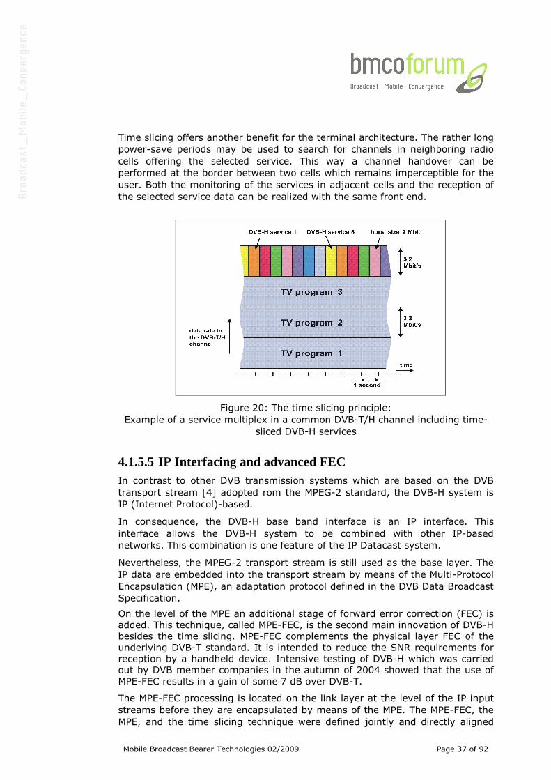
Mobile Broadcast Bearer Technologies 02/2009 Page 37 of 92
Time slicing offers another benefit for the terminal architecture. The rather long
power-save periods may be used to search for channels in neighboring radio
cells offering the selected service. This way a channel handover can be
performed at the border between two cells which remains imperceptible for the
user. Both the monitoring of the services in adjacent cells and the reception of
the selected service data can be realized with the same front end.
Figure 20: The time slicing principle:
Example of a service multiplex in a common DVB-T/H channel including time-
sliced DVB-H services
4.1.5.5 IP Interfacing and advanced FEC In contrast to other DVB transmission systems which are based on the DVB
transport stream [4] adopted rom the MPEG-2 standard, the DVB-H system is
IP (Internet Protocol)-based.
In consequence, the DVB-H base band interface is an IP interface. This
interface allows the DVB-H system to be combined with other IP-based
networks. This combination is one feature of the IP Datacast system.
Nevertheless, the MPEG-2 transport stream is still used as the base layer. The
IP data are embedded into the transport stream by means of the Multi-Protocol
Encapsulation (MPE), an adaptation protocol defined in the DVB Data Broadcast
Specification.
On the level of the MPE an additional stage of forward error correction (FEC) is
added. This technique, called MPE-FEC, is the second main innovation of DVB-H
besides the time slicing. MPE-FEC complements the physical layer FEC of the
underlying DVB-T standard. It is intended to reduce the SNR requirements for
reception by a handheld device. Intensive testing of DVB-H which was carried
out by DVB member companies in the autumn of 2004 showed that the use of
MPE-FEC results in a gain of some 7 dB over DVB-T.
The MPE-FEC processing is located on the link layer at the level of the IP input
streams before they are encapsulated by means of the MPE. The MPE-FEC, the
MPE, and the time slicing technique were defined jointly and directly aligned
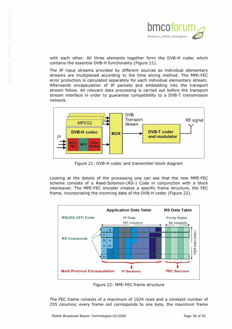
Mobile Broadcast Bearer Technologies 02/2009 Page 38 of 92
with each other. All three elements together form the DVB-H codec which
contains the essential DVB-H functionality (Figure 21).
The IP input streams provided by different sources as individual elementary
streams are multiplexed according to the time slicing method. The MPE-FEC
error protection is calculated separately for each individual elementary stream.
Afterwards encapsulation of IP packets and embedding into the transport
stream follow. All relevant data processing is carried out before the transport
stream interface in order to guarantee compatibility to a DVB-T transmission
network.
Figure 21: DVB-H codec and transmitter block diagram
Looking at the details of the processing one can see that the new MPE-FEC
scheme consists of a Reed-Solomon-(RS-) Code in conjunction with a block
interleaver. The MPE-FEC encoder creates a specific frame structure, the FEC
frame, incorporating the incoming data of the DVB-H codec (Figure 22).
Figure 22: MPE-FEC frame structure
The FEC frame consists of a maximum of 1024 rows and a constant number of
255 columns; every frame cell corresponds to one byte, the maximum frame
Mobile Broadcast Bearer Technologies 02/2009 Page 39 of 92
size is approx. 2 Mbit. The frame is separated into two parts, the application
data table on the left (191 columns) and the RS data table on the right (64
columns). The application data table is filled with the IP packets of the service
to be protected.
After applying the RS (255,191) code to the application data row-by-row, the
RS data table contains the parity bytes of the RS code. After the coding the IP
packets are read out of the application data table and are encapsulated in IP
sections in a way which is well known from the MPE method. These application
data are followed by the parity data which are read out of the RS data table
column-by-column and are encapsulated in separate FEC sections.
The FEC frame structure also contains a ‘virtual’ block interleaving effect in
addition to the coding. Writing to and reading from the FEC frame is performed
in column direction whereas coding is applied in row direction.
The MPE-FEC is directly related to the time slicing. Both techniques are applied
on elementary stream level, and one time slicing burst includes the content of
exactly one FEC frame. This enables the re-use of memory in the receiver
chips. Separating IP data and parity data of each burst makes the use of
MPE-FEC decoding in the receiver optional since the application data can be
utilized while ignoring the parity information.
4.1.5.6 Physical Layer extensions The signaling of parameters of the DVB-H elementary streams in the multiplex
uses an extension of the Transmission Parameter Signaling (TPS) channel
known from the DVB-T standard.
TPS creates a reserved information channel which provides tuning parameters
to the receiver. The new elements of the TPS channel provide the information
that time sliced DVB-H elementary streams are available in the multiplex and
indicate whether MPE-FEC protection is used in at least one of the elementary
streams.
The additional physical transmission modes being described in this paragraph
are also signaled in the TPS channel.
Finally, broadcasting of the cell identifier known as an optional element of DVB-
T is made mandatory for DVB-H. The availability of this identifier simplifies the
discovery of neighboring network cells in which the selected same service is
available.
DVB-H can be transmitted using an OFDM transmission mode which is not part
of the DVB-T specification. DVB-T already provides a 2K and an 8K mode for
the optimum support of different network topologies. DVB-H allows a 4K mode
to be used in addition which is created via a 4096-point Inverse Discrete
Fourier Transform (IDFT) in the OFDM modulator.
mode
OFDM parameter 2K 4K 8K
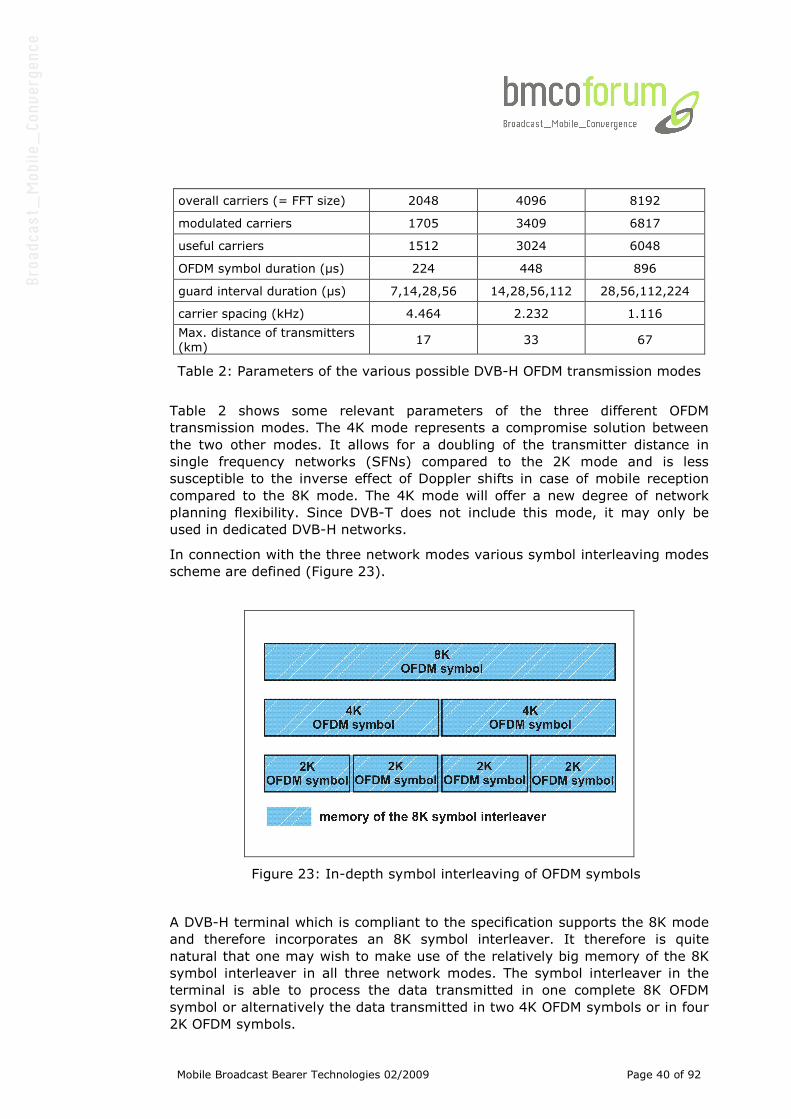
Mobile Broadcast Bearer Technologies 02/2009 Page 40 of 92
overall carriers (= FFT size) 2048 4096 8192
modulated carriers 1705 3409 6817
useful carriers 1512 3024 6048
OFDM symbol duration (µs) 224 448 896
guard interval duration (µs) 7,14,28,56 14,28,56,112 28,56,112,224
carrier spacing (kHz) 4.464 2.232 1.116
Max. distance of transmitters
(km) 17 33 67
Table 2: Parameters of the various possible DVB-H OFDM transmission modes
Table 2 shows some relevant parameters of the three different OFDM
transmission modes. The 4K mode represents a compromise solution between
the two other modes. It allows for a doubling of the transmitter distance in
single frequency networks (SFNs) compared to the 2K mode and is less
susceptible to the inverse effect of Doppler shifts in case of mobile reception
compared to the 8K mode. The 4K mode will offer a new degree of network
planning flexibility. Since DVB-T does not include this mode, it may only be
used in dedicated DVB-H networks.
In connection with the three network modes various symbol interleaving modes
scheme are defined (Figure 23).
Figure 23: In-depth symbol interleaving of OFDM symbols
A DVB-H terminal which is compliant to the specification supports the 8K mode
and therefore incorporates an 8K symbol interleaver. It therefore is quite
natural that one may wish to make use of the relatively big memory of the 8K
symbol interleaver in all three network modes. The symbol interleaver in the
terminal is able to process the data transmitted in one complete 8K OFDM
symbol or alternatively the data transmitted in two 4K OFDM symbols or in four
2K OFDM symbols.
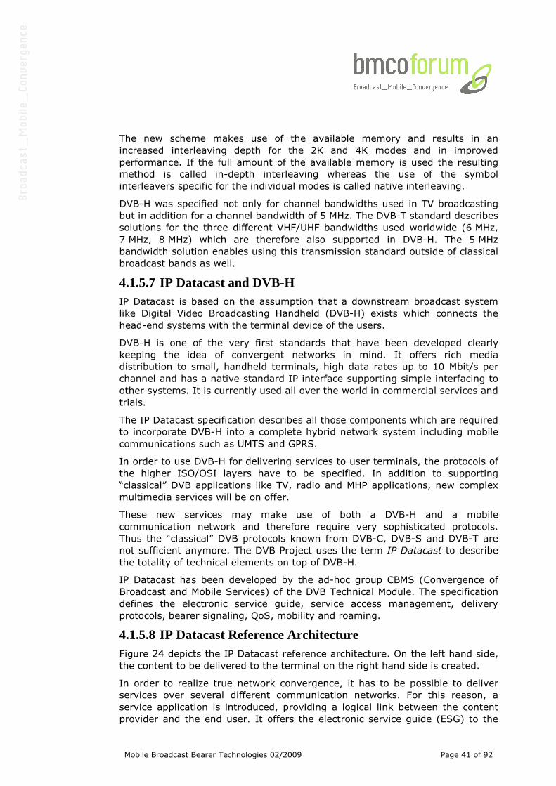
Mobile Broadcast Bearer Technologies 02/2009 Page 41 of 92
The new scheme makes use of the available memory and results in an
increased interleaving depth for the 2K and 4K modes and in improved
performance. If the full amount of the available memory is used the resulting
method is called in-depth interleaving whereas the use of the symbol
interleavers specific for the individual modes is called native interleaving.
DVB-H was specified not only for channel bandwidths used in TV broadcasting
but in addition for a channel bandwidth of 5 MHz. The DVB-T standard describes
solutions for the three different VHF/UHF bandwidths used worldwide (6 MHz,
7 MHz, 8 MHz) which are therefore also supported in DVB-H. The 5 MHz
bandwidth solution enables using this transmission standard outside of classical
broadcast bands as well.
4.1.5.7 IP Datacast and DVB-H IP Datacast is based on the assumption that a downstream broadcast system
like Digital Video Broadcasting Handheld (DVB-H) exists which connects the
head-end systems with the terminal device of the users.
DVB-H is one of the very first standards that have been developed clearly
keeping the idea of convergent networks in mind. It offers rich media
distribution to small, handheld terminals, high data rates up to 10 Mbit/s per
channel and has a native standard IP interface supporting simple interfacing to
other systems. It is currently used all over the world in commercial services and
trials.
The IP Datacast specification describes all those components which are required
to incorporate DVB-H into a complete hybrid network system including mobile
communications such as UMTS and GPRS.
In order to use DVB-H for delivering services to user terminals, the protocols of
the higher ISO/OSI layers have to be specified. In addition to supporting
“classical” DVB applications like TV, radio and MHP applications, new complex
multimedia services will be on offer.
These new services may make use of both a DVB-H and a mobile
communication network and therefore require very sophisticated protocols.
Thus the “classical” DVB protocols known from DVB-C, DVB-S and DVB-T are
not sufficient anymore. The DVB Project uses the term IP Datacast to describe
the totality of technical elements on top of DVB-H.
IP Datacast has been developed by the ad-hoc group CBMS (Convergence of
Broadcast and Mobile Services) of the DVB Technical Module. The specification
defines the electronic service guide, service access management, delivery
protocols, bearer signaling, QoS, mobility and roaming.
4.1.5.8 IP Datacast Reference Architecture Figure 24 depicts the IP Datacast reference architecture. On the left hand side,
the content to be delivered to the terminal on the right hand side is created.
In order to realize true network convergence, it has to be possible to deliver
services over several different communication networks. For this reason, a
service application is introduced, providing a logical link between the content
provider and the end user. It offers the electronic service guide (ESG) to the
Mobile Broadcast Bearer Technologies 02/2009 Page 42 of 92
user who can select the services he wishes to consume, independently of the
bearer network over which they will be delivered.
Interactivebearer
Broadcastbearer
Contentcreation
Serviceapplication
Servicemanagement
Terminal
- Carriage of A/V streams, files
- Bearer specific L2 signaling, eg DVB PSI/SI
- ESG metadata and ptm delivery
-Access control to service applications-ESG metadata and ptpdelivery
-IP broadcast bearer, egDVB-H
Point-to-point transport services:- SMS/MMS- IP connectivity
IPDC-2
IPDC-3
IPDC-1
IPDC-4
IPDC-5
X-1
X-2
IPDC-6
IPDC-7
Fully specified in IPDC
Partly specified in IPDCNot specified in IPDC
Not in scope of IPDC
In direct scope of IPDC
X-5
- Bearer specific L2 signaling, eg 3GPP
Fully specified in DVB-H
In direct scope of DVB-H
Figure 24: IP Datacast reference architecture
The service management is in charge of allocating resources from the different
bearer technologies. Additionally, it performs the billing together with the
service application.
The IPDC Service Application aggregates content from multiple sources and
their related metadata in order to provide a particular service application.
The Service Management consists of four sub-entities, which may be
instantiated independently:
1. Service configuration & resource allocation: Registration of service
applications that contend for bandwidth of the broadcast bearer (i.e.
one DVB-H IP platform in one DVB transport stream). Assignment of
services to location (with respect to. Broadcast network topology), to
bandwidth and schedules services over time. There is one instance of
this sub-entity associated with a broadcast bandwidth contention
domain.
2. Service Guide Provisioning application: Aggregation of ESG (metadata
information) pieces from the service applications. There may be multiple
instances of this sub-entity.
3. Security/service protection provision: Management of user access to
service applications.
4. Location services: The service management entity may provide location
services to service application(s) in a manner that is independent of the
way they are actually obtained (such as interaction bearer network
Mobile Broadcast Bearer Technologies 02/2009 Page 43 of 92
functionality or GPS).
The Broadcast Network multiplexes service applications at IP level. It also
performs the assignment of IP flows on DVB-H time slices (IP Encapsulation)
the transmission over DVB-H and the Security/service protection.
The terminal represents the user device as point of acquisition and consumption
for content and client of network and service resources. The terminal may or
may not implement the support of an interaction channel.
4.1.5.9 OMA BCAST BCAST 1.0 supports three underlying broadcast bearers. These are DVB-H,
3GPP MBMS and 3GPP2 BCMCS (for the European setting BCMCS can be
considered as out of scope).
For each underlying bearer OMA BCAST has created two types of adaptation
specifications. The first type of adaptation specification describes how pure
BCAST functionality can be deployed over the underlying bearer. The second
type of adaptation describes how BCAST functionality should be adapted to
create interoperability between the ‘native’ service layer of the underlying
bearer and the OMA BCAST service layer, i.e. how IPDC and BCAST can coexist
over DVB-H with maximised reuse of overlapping service functionality.
The OMA BCAST reference architecture is shown in Figure 25.
ContentCreation
BCASTService
Application
InteractionNetwork
Note : Interface over (*) reference points to be defined
in Adaptation Specification
BCASTSubscriptionManagement
BCAST - 1
BCAST-2 BCAST-3
BDSBDSBDSBDS----1*1*1*1*
BCAST-4
BDSBDSBDSBDS----2*2*2*2*
Air Interface
BCAST-5BCAST-7
BCAST-8
BCAST-6
XXXX----3333
XXXX----1111 XXXX----2222
XXXX----6666
BroadcastDistribution
System
BDS ServiceDistribution/Adaptation
BCASTService
Distribution/Adaptation
XXXX----5555
Terminal
BCAST -BDS Reference Points
Other Reference Points
Legend
BCAST Logical Entities
BCAST Functional EntitiesMandatory Non -BCAST Entities
Legend
BCAST Logical Entities
BCAST Functional EntitiesMandatory Non -BCAST EntitiesBCAST Functional Entities
Mandatory Non -BCAST Entities
Optional Non-BCAST Entities
XXXX----4444
ContentCreationContentCreationContentCreationContentCreation
BCASTService
Application
InteractionNetwork
InteractionNetwork
InteractionNetwork
Note : Interface over (*) reference points to be defined
in Adaptation Specification
Note : Interface over (*) reference points to be defined
in Adaptation Specification
BCASTSubscriptionManagement
BCASTSubscriptionManagement
BCAST - 1
BCAST-2 BCAST-2 BCAST-3 BCAST-3
BDSBDSBDSBDS----1*1*1*1*BDSBDSBDSBDS----1*1*1*1*
BCAST-4BCAST-4
BDSBDSBDSBDS----2*2*2*2*BDSBDSBDSBDS----2*2*2*2*
Air InterfaceAir Interface
BCAST-5BCAST-5BCAST-7BCAST-7
BCAST-8 BCAST-8
BCAST-6BCAST-6
XXXX----3333XXXX----3333
XXXX----1111XXXX----1111XXXX----1111 XXXX----2222XXXX----2222
XXXX----6666XXXX----6666
BroadcastDistribution
System
BroadcastDistribution
System
BroadcastDistribution
System
BDS ServiceDistribution/Adaptation
BDS ServiceDistribution/Adaptation
BCASTService
Distribution/Adaptation
BCASTService
Distribution/Adaptation
BCASTService
Distribution/Adaptation
XXXX----5555XXXX----5555
TerminalTerminal
BCAST -BDS Reference Points
Other Reference Points
Legend
BCAST Logical Entities
BCAST Functional EntitiesMandatory Non -BCAST Entities
Legend
BCAST Logical Entities
BCAST Functional EntitiesMandatory Non -BCAST EntitiesBCAST Functional Entities
Mandatory Non -BCAST Entities
Optional Non-BCAST Entities
BCAST -BDS Reference Points
Other Reference Points
BCAST -BDS Reference Points
Other Reference Points
Legend
BCAST Logical Entities
BCAST Functional EntitiesMandatory Non -BCAST Entities
Legend
BCAST Logical Entities
BCAST Functional EntitiesMandatory Non -BCAST EntitiesBCAST Functional Entities
Mandatory Non -BCAST Entities
Optional Non-BCAST EntitiesOptional Non-BCAST Entities
XXXX----4444XXXX----4444
Figure 25: OMA BCAST Reference Architecture
“BCAST Service Application” represents the service application of the BCAST
Service, such as, streaming audio/video or movie file download.
“BCAST Service Distribution/Adaptation” is responsible for the aggregation and
delivery of BCAST Services, and performs the adaptation of the BCAST Enabler
Mobile Broadcast Bearer Technologies 02/2009 Page 44 of 92
to underlying Broadcast Distribution Systems.
“BCAST Subscription Management” is responsible for service provisioning such
as subscription and payment related functions, the provision of information
used for BCAST Service reception, and BCAST Terminal management.
“Terminal” represents the user device that receives broadcast content as well
as the BCAST service related information, such as, Service Guide, Content
Protection information.
Mobile Broadcast Bearer Technologies 02/2009 Page 45 of 92
4.1.6 DVB-SH
4.1.6.1 General Description The purpose of the DVB-SH standard is to provide an efficient transmission
system using any frequencies below 3 GHz. In addition, DVB-SH is design to
allow Satellite Services to Handheld devices, in terms of reception threshold
and resistance to mobile satellite channel impairments.
DVB-SH includes two transmission modes:
• An OFDM/OFDM mode: the OFDM signal is based on DVB-H standard
with enhancements. It is used on both the direct and the indirect paths;
the signals are combined in the receiver to strengthen the reception in a
SFN configuration. This mode is particularly of interest for spectrum
limited system.
• A TDM/OFDM mode: the TDM signal is partly derived from DVB-S2
standard. Its use allows optimising transmission through satellite
towards mobile terminals. It is used on the direct path only. OFDM with
same characteristics as here-above is used for the indirect path. The
system supports code diversity recombination between satellite TDM and
terrestrial OFDM signals so as to increase the robustness of the
transmission in relevant areas (mainly suburban). This optional mode
may be of interest in power limited satellite system. For equivalent
capacity, the TDM/OFDM mode requires higher spectrum than the
OFDM/OFDM mode and therefore TDM/OFDM mode is not considered
further in this description.
Addressing handheld terminals, features already defined within DVB are reused,
in particular Time Slicing for power saving purpose, handover between
frequencies/coverage beams and IP datacast protocols. The main specific
features are efficient turbo coding, allowing very low coding rate, and extended
time interleaving, at physical layer for maximum robustness in severe
shadowed environments.
The DVB-SH radio interface has been designed to support the application
enablers defined by the DVB (Digital Video Broadcast, CBMS group) and by the
OMA (Open Mobile Alliance, BCAST group) forums. No change in these
standards will be necessary to support the DVB-SH. The same platform will be
able to deliver services via DVB-H and/or DVB-SH infrastructure.
4.1.6.2 Physical Layer The DVB-SH radio interface is based on Orthogonal Frequency Division
Multiplexing (OFDM) waveform technology well adapted to SFN transmission. It
implements a high degree of flexibility in terms of configuration:
• Channel bandwidth: 1.7, 5, 6, 7 or 8 MHz channel. 5 MHz is the
preferred choice in the S-band allowing alignment with UMTS
channelization. 6 or 8 MHz are preferred when reusing UHF TV channels,
• FFT size: 1K, 2K, 4K or 8K. In case of S band, 2K is the preferred choice
to maximize the Doppler tolerance and hence allow terminal speed as
high as 160 km/h. In case of UHF, 8K is preferred to avoid interference
in SFN deployment,
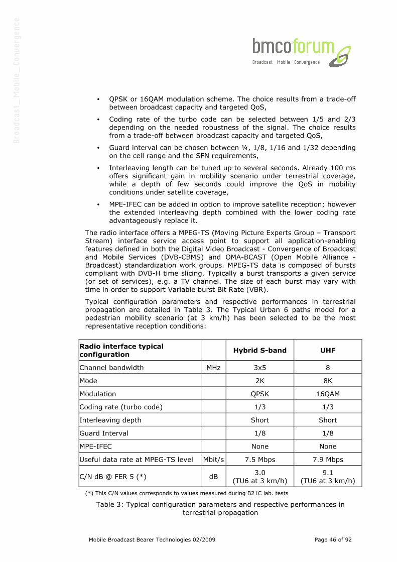
Mobile Broadcast Bearer Technologies 02/2009 Page 46 of 92
• QPSK or 16QAM modulation scheme. The choice results from a trade-off
between broadcast capacity and targeted QoS,
• Coding rate of the turbo code can be selected between 1/5 and 2/3
depending on the needed robustness of the signal. The choice results
from a trade-off between broadcast capacity and targeted QoS,
• Guard interval can be chosen between ¼, 1/8, 1/16 and 1/32 depending
on the cell range and the SFN requirements,
• Interleaving length can be tuned up to several seconds. Already 100 ms
offers significant gain in mobility scenario under terrestrial coverage,
while a depth of few seconds could improve the QoS in mobility
conditions under satellite coverage,
• MPE-IFEC can be added in option to improve satellite reception; however
the extended interleaving depth combined with the lower coding rate
advantageously replace it.
The radio interface offers a MPEG-TS (Moving Picture Experts Group – Transport
Stream) interface service access point to support all application-enabling
features defined in both the Digital Video Broadcast - Convergence of Broadcast
and Mobile Services (DVB-CBMS) and OMA-BCAST (Open Mobile Alliance -
Broadcast) standardization work groups. MPEG-TS data is composed of bursts
compliant with DVB-H time slicing. Typically a burst transports a given service
(or set of services), e.g. a TV channel. The size of each burst may vary with
time in order to support Variable burst Bit Rate (VBR).
Typical configuration parameters and respective performances in terrestrial
propagation are detailed in Table 3. The Typical Urban 6 paths model for a
pedestrian mobility scenario (at 3 km/h) has been selected to be the most
representative reception conditions:
Radio interface typical
configuration Hybrid S-band UHF
Channel bandwidth MHz 3x5 8
Mode 2K 8K
Modulation QPSK 16QAM
Coding rate (turbo code) 1/3 1/3
Interleaving depth Short Short
Guard Interval 1/8 1/8
MPE-IFEC None None
Useful data rate at MPEG-TS level Mbit/s 7.5 Mbps 7.9 Mbps
C/N dB @ FER 5 (*) dB 3.0
(TU6 at 3 km/h)
9.1
(TU6 at 3 km/h)
(*) This C/N values corresponds to values measured during B21C lab. tests
Table 3: Typical configuration parameters and respective performances in
terrestrial propagation

Mobile Broadcast Bearer Technologies 02/2009 Page 47 of 92
4.1.6.3 Service Layer The Service layer is compliant with the DVB-IP Datacast over DVB-H
specifications. It supports streaming and download delivery modes. The
streaming mode applies to the delivery of real time TV and radio programs,
whereas the download mode is used to securely broadcast segmented radio and
TV contents, music downloads, data files and Rich Media contents. The system
targets reception by handset as well as vehicular terminals.
4.1.6.4 System Overview for Hybrid deployment DVB-SH can be used for terrestrial only deployment but it is particularly
adapted for hybrid system combining terrestrial and satellite. In that case, the
system relies on a hybrid satellite/terrestrial infrastructure. The signals are
broadcast to mobile terminals on two paths:
• A direct path from a broadcast station to the terminals via the satellite,
• An indirect path from a broadcast station to terminals via terrestrial
repeaters that form the Complementary Ground Component (CGC) to
the satellite. The CGC can be fed through satellite and/or terrestrial
distribution networks.
Figure 26 provides a high-level view of a typical hybrid solution.
Figure 26: High-level view of a typical hybrid solution.
The overall solution combines a dedicated broadcast system based on a hybrid
infrastructure, integrated, at service and application levels, with existing cellular
networks to provide end-users with a full range of entertainment services with
interactivity.
This hybrid satellite/terrestrial broadcast system encompasses:
• A space segment made of high-power geo-stationary satellites for TV
broadcast to mobile terminals over nationwide coverage (“1” in Figure
26),
• A network of medium and low power repeaters (“2” in Figure 26), co-
sited with mobile base stations for TV broadcast to mobile terminals in
urban areas. Repeaters in urban areas complement satellite coverage for
indoor service quality, which may be weakened by multiple walls and
Ruralareas
U rban areas
1
2
3
Spacesegment
CellularBase stations
Broadcasttransmitters
Serviceplatform
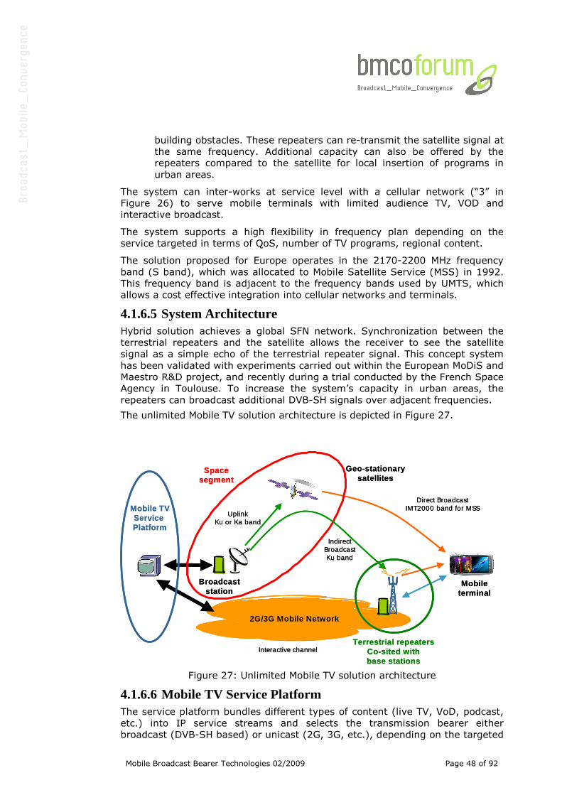
Mobile Broadcast Bearer Technologies 02/2009 Page 48 of 92
building obstacles. These repeaters can re-transmit the satellite signal at
the same frequency. Additional capacity can also be offered by the
repeaters compared to the satellite for local insertion of programs in
urban areas.
The system can inter-works at service level with a cellular network (“3” in
Figure 26) to serve mobile terminals with limited audience TV, VOD and
interactive broadcast.
The system supports a high flexibility in frequency plan depending on the
service targeted in terms of QoS, number of TV programs, regional content.
The solution proposed for Europe operates in the 2170-2200 MHz frequency
band (S band), which was allocated to Mobile Satellite Service (MSS) in 1992.
This frequency band is adjacent to the frequency bands used by UMTS, which
allows a cost effective integration into cellular networks and terminals.
4.1.6.5 System Architecture Hybrid solution achieves a global SFN network. Synchronization between the
terrestrial repeaters and the satellite allows the receiver to see the satellite
signal as a simple echo of the terrestrial repeater signal. This concept system
has been validated with experiments carried out within the European MoDiS and
Maestro R&D project, and recently during a trial conducted by the French Space
Agency in Toulouse. To increase the system’s capacity in urban areas, the
repeaters can broadcast additional DVB-SH signals over adjacent frequencies.
The unlimited Mobile TV solution architecture is depicted in Figure 27.
Figure 27: Unlimited Mobile TV solution architecture
4.1.6.6 Mobile TV Service Platform The service platform bundles different types of content (live TV, VoD, podcast,
etc.) into IP service streams and selects the transmission bearer either
broadcast (DVB-SH based) or unicast (2G, 3G, etc.), depending on the targeted
2G/3G Mobile Network
Mobile TVService Platform
Broadcaststation
Geo-stationarysatellites
Mobileterminal
Terrestrial repeatersCo-sited withbase stations
Spacesegment
Direct BroadcastIMT2000 band for MSS
IndirectBroadcastKu band
UplinkKu or Ka band
Interactive channel
2G/3G Mobile Network
Mobile TVService Platform
Broadcaststation
Geo-stationarysatellites
Mobileterminal
Terrestrial repeatersCo-sited withbase stations
Spacesegment
Direct BroadcastIMT2000 band for MSS
IndirectBroadcastKu band
UplinkKu or Ka band
Interactive channel
Mobile Broadcast Bearer Technologies 02/2009 Page 49 of 92
audience. No specific Mobile TV service platform is required since DVB-SH is
fully backward compatible with DVB-H.
4.1.6.7 Broadcast Station The broadcast station includes a Hub and a Mission Control Centre. There is
typically at least one broadcast station per dedicated satellite. Several
broadcast stations may be co-located.
The Hub encompasses:
• A Network Head End responsible for the mapping of the IP services
streams received from the Mobile TV service platform into MPEG2-
Transpot streams. It also adds some time stamp information (MIP
insertion) so that terrestrial repeaters can achieve a single frequency
network with the dedicated satellite in a spot beam,
• A Broadcast Head End in charge of the transmission of the services
streams towards the satellite in DVB-SH format for the direct broadcast
link and in DVB-S2 format for the indirect broadcast link. It also
monitors and controls the satellite signal transmission.
The Mission control centre provides tools to manage the spectrum resources. It
allocates the frequency carriers to the spot beams of the dedicated satellites. It
then transfers the frequency plan to the terrestrial repeater network
management system. It also interfaces with the satellite Control centre that
controls and operates the dedicated satellites.
4.1.6.8 Space Segment The space segment involves high-power, dedicated geo-stationary satellites (12
to 18 KW power class), with large deployable reflectors (12 meters) to
accommodate the handset terminals’ low performance without any antenna
add-ons. European coverage is provided through several beams, each of
nationwide size. These satellites are transparent to the radio interface
technology, occupying 5 MHz channel bandwidth. They can all be co-located at
the same orbit location. Typically, a satellite broadcast one 5 MHz frequency
carrier per beam. Furthermore, one shall note any standard satellite can be
used for backhauling the TV programs multiplex towards the terrestrial
repeaters in Ku band using the DVB-S2 radio interface format.
4.1.6.9 Terrestrial Repeater Network The terrestrial repeater network is deployed to provide indoor coverage in
urban areas where the satellite signal is insufficient. Each terrestrial repeater
can broadcast up to three 5 MHz frequency carriers in the IMT2000 band
allocated to Mobile Satellite Systems. The terrestrial repeaters are designed for
smooth integration in existing 2G and/or 3G cellular sites. The antenna systems
can be shared. As well as a clear cost reduction, this integration avoids
renegotiation with the site owners since it is a mere upgrade of the existing
equipment.
4.1.6.10 Terminals As the system is designed to operate at 2.2 GHz, reception diversity can be
introduced in handsets allowing to significantly improve the link budget (the
signal is received on two antennas separated by few centimeters, and then

Mobile Broadcast Bearer Technologies 02/2009 Page 50 of 92
recombined). Both reception chains are integrated into a single module
interfacing to the base band host processor via a standard SD/SPI interface.
This module includes two multi-band tuners able to operate at 2.2 GHz and
UHF, a base band receiver with two OFDM demodulators, and a controller.
Chipsets currently developed allow indifferently reception of DVB-H or DVB-SH
in UHF or S-band.
This reception module can be embedded in 2.5G or 3G standard mobile phones,
smart phones, pocket PCs and vehicle receivers. DVB-CBMS & OMA application
enabling features can be fully re-used to support service protection, service and
program guides.
Mobile Broadcast Bearer Technologies 02/2009 Page 51 of 92
4.1.7 Forward Link Only
4.1.7.1 System Overview The FLO air interface specification (TIA-1099) covers protocols and services
corresponding to OSI Layers 1 (physical layer) and Layer 2 (Data Link layer)
only. The Link layer is further subdivided into three sub-layers, namely, Medium
Access (MAC) sub-layer, Control sub-layer and Stream sub-layer. The physical
layer provides the channel structure, frequency, power output, modulation and
encoding specification for FLO. The MAC sub-layer (within the Link layer)
performs multiplexing of packets belonging to different media streams. The
stream sub-layer provides for binding upper layer flows to FLO streams. The
control sub-layer, which is at the same level as the stream sub-layer in FLO air
interface architecture, is used by the network to disseminate information to
facilitate device operation in FLO systems.
The FLO upper layer is primarily defined by Forward Link Only Transport
Specification (TIA-1120), Forward Link Only Media Adaptation Layer
Specification (TIA-1130) and the System Information (SI) Specification (FLO
Forum Technical Specification, floforum2006.088.00). TIA-1120 and TIA-1130
specifications define protocols for delivering services over the FLO Air Interface.
SI specification defines the meta-data format for service discovery, content
information and purchase information in FLO systems.
4.1.7.2 FLO Air Interface At the Physical layer, FLO uses Orthogonal Frequency Division Multiplexing
(OFDM) as the modulation technique. In addition, it incorporates advanced
forward error correction techniques involving the concatenation of a parallel
concatenated convolutional code (PCCC), also called Turbo code, and a Reed-
Solomon erasure correcting code. Compared to convolutional coding, it is well
known that a system employing Turbo coding requires lower signal to noise
ratio (SNR) and, thus, has a higher system capacity (more bits per Hertz). This
advantage is especially significant for an OFDM system when the channel has
spectral nulls, which are likely to occur in an SFN environment. In addition to
Turbo coding, various parts of the physical layer have been carefully designed
to further improve receiver performance and to ensure a most satisfactory user
experience.
In FLO, transmission and reception are based on using 4096 (4K) subcarriers
and the QAM modulation symbols are chosen from a QPSK or 16-QAM alphabet.
The actual FLO physical layer transmission parameters are outlined in Table 4.
As stated above, in each FLO OFDM symbol, there are 4000 active subcarriers.
These active subcarriers are further equally divided into eight disjoint groups
called interlaces. An interlace consists of 500 subcarriers that are evenly spaced
across the FLO signal bandwidth. In each OFDM symbol, either interlace 2 or 6
is assigned to the FDM Pilot and is used for channel estimation.
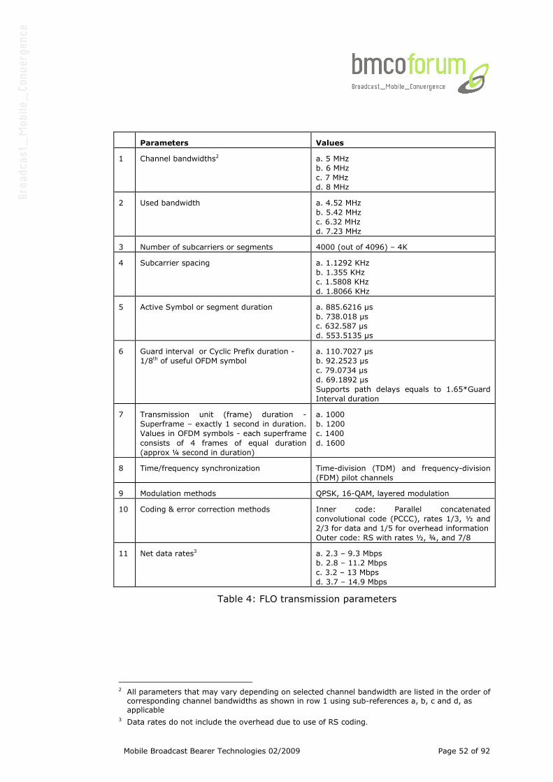
Mobile Broadcast Bearer Technologies 02/2009 Page 52 of 92
Parameters Values
1 Channel bandwidths2
a. 5 MHz
b. 6 MHz
c. 7 MHz
d. 8 MHz
2 Used bandwidth a. 4.52 MHz
b. 5.42 MHz
c. 6.32 MHz
d. 7.23 MHz
3 Number of subcarriers or segments 4000 (out of 4096) – 4K
4 Subcarrier spacing a. 1.1292 KHz
b. 1.355 KHz
c. 1.5808 KHz
d. 1.8066 KHz
5 Active Symbol or segment duration a. 885.6216 µs
b. 738.018 µs
c. 632.587 µs
d. 553.5135 µs
6 Guard interval or Cyclic Prefix duration -
1/8th of useful OFDM symbol
a. 110.7027 µs
b. 92.2523 µs
c. 79.0734 µs
d. 69.1892 µs
Supports path delays equals to 1.65*Guard
Interval duration
7 Transmission unit (frame) duration -
Superframe – exactly 1 second in duration.
Values in OFDM symbols - each superframe
consists of 4 frames of equal duration
(approx ¼ second in duration)
a. 1000
b. 1200
c. 1400
d. 1600
8 Time/frequency synchronization Time-division (TDM) and frequency-division
(FDM) pilot channels
9 Modulation methods QPSK, 16-QAM, layered modulation
10 Coding & error correction methods Inner code: Parallel concatenated
convolutional code (PCCC), rates 1/3, ½ and
2/3 for data and 1/5 for overhead information
Outer code: RS with rates ½, ¾, and 7/8
11 Net data rates3 a. 2.3 – 9.3 Mbps
b. 2.8 – 11.2 Mbps
c. 3.2 – 13 Mbps
d. 3.7 – 14.9 Mbps
Table 4: FLO transmission parameters
2 All parameters that may vary depending on selected channel bandwidth are listed in the order of corresponding channel bandwidths as shown in row 1 using sub-references a, b, c and d, as applicable
3 Data rates do not include the overhead due to use of RS coding.
Mobile Broadcast Bearer Technologies 02/2009 Page 53 of 92
The main advantages of the interlace structure are:
• It enables the frequency-division multiplexing of FLO logical channels,
referred to as Multicast Logical Channels (MLCs), within each OFDM
symbol without the loss of frequency diversity. The minimum frequency
allocation to an MLC, within a single OFDM symbol, is an interlace.
Hence, at most 7 MLCs can be multiplexed within a single OFDM symbol.
Since, the subcarriers within an interlace span the total FLO signal
bandwidth there is no loss of frequency diversity, compared to the case
where all the active subcarriers are used.
• It enables the transmission of MLCs with finer granularity. For
transmission at high spectral efficiency, tens of kbits can potentially be
transmitted within a single OFDM symbol. Hence, having the ability to
allocate a fraction of the subcarriers to MLCs enables supporting low
data rate MLCs without incurring a large overhead expense.
• The interlace structure is also beneficial from a receiver power
consumption point of view. The FFT block in the receiver can be
designed such that only the required subset of interlaces, corresponding
to the desired MLCs, are demodulated. Hence, when combined with the
frequency multiplexing of MLCs, the receiver need not always be
performing a 4096-point FFT, thereby saving on power consumption.
Each FLO service is carried over one or more logical channels, MLCs. An MLC
has the attribute that it contains one or more decodable subcomponents of a
service that is of independent reception interest. Furthermore, an important
aspect is that MLCs are distinguishable at the Physical layer.
For example, the video and audio components of a given service can be sent
over two different MLCs. A device that is interested in the audio component
only can receive the corresponding MLC without receiving the MLC for the video
component, thereby saving on battery resources.
The data rates required by these services are expected to vary over a wide
range, depending on their multimedia content. While low to moderate data
rates, i.e., tens of kbps, are sufficient for data and audio streams, video
streams may require instantaneous rates ranging from a few kbps to a few
Mbps even though the average rate is in the range of 200 – 300 kbps. Thus,
effective use of statistical multiplexing can significantly improve a system’s
spectral efficiency.
Statistical multiplexing of different services, or MLCs, is achieved by varying
only the time and frequency allocations of the MLCs. Specifically, MLCs are
transmitted over a certain number of OFDM symbols to achieve Time-Division
Multiplexing (TDM) and a subset of the interlaces in these OFDM symbols to
achieve Frequency-Division Multiplexing (FDM). The MLC allocations are varied
across FLO superframes to match the variability in the MLC’s source rates. The
duration of a FLO superframe is exactly 1 second and the allocations for the
MLCs are signaled at the beginning of each superframe through an overhead
information service (OIS) channel. While the MLC allocation is varied,
constellation and code rate assigned to an MLC are kept fixed in order to
maintain a constant coverage area for each MLC. In addition, the transmission

Mobile Broadcast Bearer Technologies 02/2009 Page 54 of 92
of the OIS every second allows for rapid channel switch times that do not
depend on the varying MLC allocations. In case of layered modulation, a video
or audio stream can be sent in two layers, i.e., a base (B) layer that enjoys
reception over a wide area and an enhancement (E) layer that improves the
audio-visual experience provided by the base layer over a more limited
coverage area. The base and enhancement layers of a given service are sent
within a single MLC. The choice of constellation and code rate for each MLC is
based on various factors, including the service (wide-area/local-area) area, the
content (video/audio/data), coverage requirements and whether layered
modulation is used.
FLO provides several choices for constellation and code rate that allow a service
provider to tradeoff spectral efficiency against coverage. The FLO design is
based on the use of a concatenated coding scheme, consisting of an outer
Reed-Solomon (RS) code and an inner Turbo code. For the Turbo code, the
code rates used are 1/5, for transmitting critical overhead information, and
{1/3, ½, 2/3} for transmitting MLCs. The higher code rates are obtained from
the base code rate using puncturing. The inner code exploits the frequency-
diversity inherent in the channel.
The outer code consists of an ( , )N K Reed-Solomon code over the Galois Field
with 256 elements, (256)GF . The value of N is fixed at 16, while the value of
K can be chosen from the set {8, 12, 14, 16}. The case of 16K = corresponds
to the case when no RS encoding is actually performed. For MLCs containing a
base and enhancement layer, the encoding is done independently for each
layer.
The Reed-Solomon encoding is performed on information packets, which are
also referred to as MAC layer packets. During the Reed-Solomon encoding
process, KN − parity packets are generated for every K information packets.
CRC bits are generated for each of the N packets. The packets with data and
CRC bits are Turbo encoded and transmitted. Thus, the minimum number of
information packets of an MLC that can be transmitted in a superframe is K .
The collection of K information packets and N K− parity packets is referred to
as an RS, or outer, code block. Finally, MLC transmissions in each superframe
are always in integer multiples of outer code blocks.
The FLO superframe consists of 4 frames of equal duration, each roughly ¼ of a
second. During transmission, each RS code block is split into 4 equal sub-
blocks, with each sub-block sent in an unique frame within a super-frame. The
main purpose of utilizing RS-coding is to exploit the time diversity of the
packets across the frames. The time span of the packets of an RS code block is
at least 0.75 seconds. Such a time span ensures de-correlation of these
packets even at low vehicle or walking speed.
As mentioned above, FLO supports the transmission of both wide-area and
local-area services. Because a wide-area may consist of multiple local-areas,
and there is the possibility of interference between transmissions received at
the boundary between neighboring local-areas, the waveforms corresponding to
the two types of services are time-division multiplexed. This enables the
independent optimization of the transmit waveforms intended for the different
coverage areas. Hence each frame is subdivided into two parts.
Mobile Broadcast Bearer Technologies 02/2009 Page 55 of 92
The first part is referred to as the Wide-area Data Channel and is dedicated to
the transmission of wide-area services, and the second part is referred to as
the Local-area Data Channel and is used solely for the transmission of local-
area services. Correspondingly, the OIS carries information regarding the
location of the wide and local data channels.
The percentage of capacity allocated to wide-area (or local-area) data channel
can vary from 0 to 100%. Although the percentage can be set in every
superframe, it is expected to vary infrequently. The available time-frequency
(channel) resources are allocated once for both the wide-area and the local-
area MLCs in each superframe.
4.1.7.3 FLO Upper Layers The FLO upper layers provide multiple functions including compression of
multimedia content, controlling access to the multimedia content and
formatting of control information. The FLO Device is capable of receiving and
interpreting services delivered over the FLO Network using the FLO Air
Interface. Typically, it has an integrated receiver that allows it to detect and
acquire the FLO waveform, and to process the content transmitted over it to
deliver it in a form intelligible to the user (e.g. as video or audio).
In the upper layers context, the tasks performed by a FLO network include:
• Transcoding of real-time content, e.g. scaling video resolution for display
on a small form-factor mobile devices, and compression of audio and
video media for spectrally efficient transmission
• Application of forward error correction (FEC) encoding to files containing
Non Real-Time content
• Aggregation, formatting and delivery of SI
• Delivery of IP datacast content
• Delivery of content to the Stream sub-layer of the FLO Air Interface.
The FLO Upper Layer Architecture is shown in Figure 28.
TIA-1120 specifies the Framing Layer and the Stream Encryption/Decryption
Layer. The function of the Framing Layer is to deliver variable-sized application
service packets over the Stream Layer. The service layers deliver service
packets to the Framing Layer at the Network which fragments them into a
sequence of fixed size frames. The Framing Layer at the Device recovers the
packet fragments from the frames and recombines them to restore the original
packets for delivery to the service layers at the Device. In addition, the Framing
Layer provides an optional CRC to verify data integrity. Stream
Encryption/Decryption Layer respectively performs scrambling and
descrambling of the frames to provide conditional access functionality.
TIA-1130 specifies the Media Adaptation Layer which includes the Sync Layer,
File Delivery Layer and IP Adaptation Layer. The Sync Layer is used to provide
synchronization within and between Real-time flows such as video, audio and
timed data over a FLO Network. The File Delivery Layer is used to deliver Non
Real-time files reliably and efficiently over a FLO Network. The IP Adaptation
Protocol adapts IP packets to the FLO Framing layer and maps IP Addresses to
Flows as required to deliver IP Datacast Services over a FLO Network.
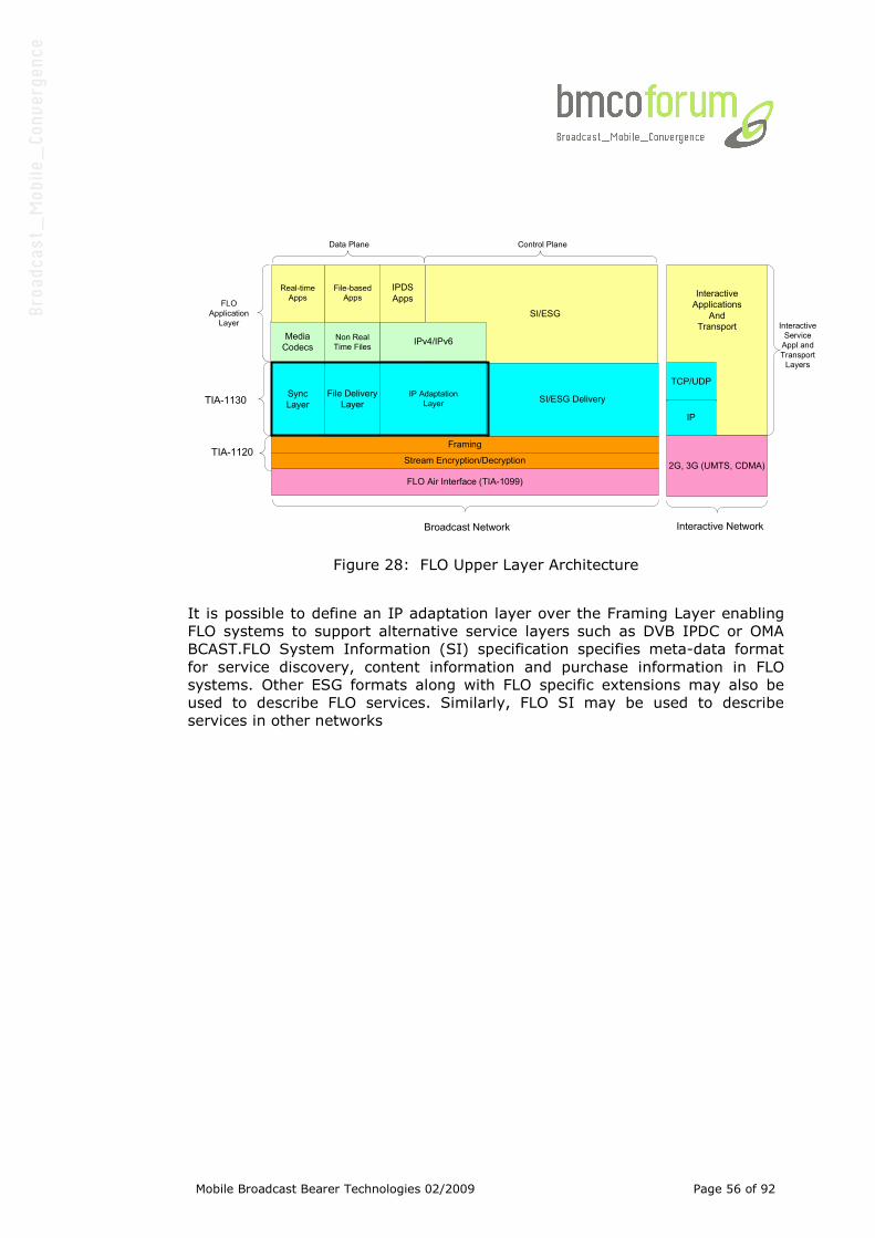
Mobile Broadcast Bearer Technologies 02/2009 Page 56 of 92
Interactive
Applications
And
Transport
IP Adaptation
Layer
File-based
Apps
2G, 3G (UMTS, CDMA)
TCP/UDP
IP
FLO Air Interface (TIA-1099)
Sync
Layer
Framing
Stream Encryption/Decryption
SI/ESG Delivery
Media
Codecs
IPDS
Apps
Real-time
Apps
Broadcast Network Interactive Network
Interactive
Service
Appl and
Transport
Layers
TIA-1120
Non Real
Time Files
TIA-1130
IPv4/IPv6
File Delivery
Layer
SI/ESGFLO
Application
Layer
Data Plane Control Plane
Figure 28: FLO Upper Layer Architecture
It is possible to define an IP adaptation layer over the Framing Layer enabling
FLO systems to support alternative service layers such as DVB IPDC or OMA
BCAST.FLO System Information (SI) specification specifies meta-data format
for service discovery, content information and purchase information in FLO
systems. Other ESG formats along with FLO specific extensions may also be
used to describe FLO services. Similarly, FLO SI may be used to describe
services in other networks
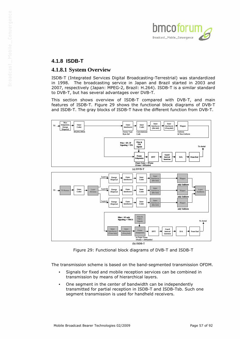
Mobile Broadcast Bearer Technologies 02/2009 Page 57 of 92
4.1.8 ISDB-T
4.1.8.1 System Overview ISDB-T (Integrated Services Digital Broadcasting-Terrestrial) was standardized
in 1998. The broadcasting service in Japan and Brazil started in 2003 and
2007, respectively (Japan: MPEG-2, Brazil: H.264). ISDB-T is a similar standard
to DVB-T, but has several advantages over DVB-T.
This section shows overview of ISDB-T compared with DVB-T, and main
features of ISDB-T. Figure 29 shows the functional block diagrams of DVB-T
and ISDB-T. The gray blocks of ISDB-T have the different function from DVB-T.
Figure 29: Functional block diagrams of DVB-T and ISDB-T
The transmission scheme is based on the band-segmented transmission OFDM.
• Signals for fixed and mobile reception services can be combined in
transmission by means of hierarchical layers.
• One segment in the center of bandwidth can be independently
transmitted for partial reception in ISDB-T and ISDB-Tsb. Such one
segment transmission is used for handheld receivers.
MuxAdaptation,
EnergyDispersal
TS OuterCoder
RS(204,188,8)
OuterInterleaver
Forney TypeByte-Intl
InnerCoder
ConvolutionalCode
InnerInterleaver(Bit-Intl)
Mapper
Uniform& Non-Uniform
TS RemuxTS OuterCoder
OuterInterleaver
InnerCoder
InnerInterleaver(Bit-Intl)
Mapper
only Uniform
IFFTGuard
IntervalInsertion
D/A Front End
To Aerial
LayerDivision
EnergyDispersal
InnerInterleaver(Freq-Intl)
Layer-B
OuterInterleaver
InnerCoder
InnerInterleaver(Bit-Intl)
Mapper
only Uniform
EnergyDispersal
Layer-A
OuterInterleaver
InnerCoder
InnerInterleaver(Bit-Intl)
Mapper
only Uniform
EnergyDispersal
Layer-C
FrameAdaptation
Pilot &TPS
Signals
Pilot = SP, CP Signaling = TPS
IFFTGuard
IntervalInsertion
D/A Front End
To Aerial
1Super frame = 4Frame1Frame = 68Symbol
LayerSynthesis
FrameAdaptation
Pilot &TMCCSignals
Pilot = SP onlySignaling = TMCC
no Super frame1Frame = 204Symbol
InnerInterleaver(Time-Intl)
InnerInterleaver(Freq-Intl)
(a) DVB-T
(b) ISDB-T
MuxAdaptation,
EnergyDispersal
TS OuterCoder
RS(204,188,8)
OuterInterleaver
Forney TypeByte-Intl
InnerCoder
ConvolutionalCode
InnerInterleaver(Bit-Intl)
Mapper
Uniform& Non-Uniform
TS RemuxTS OuterCoder
OuterInterleaver
InnerCoder
InnerInterleaver(Bit-Intl)
Mapper
only Uniform
IFFTGuard
IntervalInsertion
D/A Front End
To Aerial
LayerDivision
EnergyDispersal
InnerInterleaver(Freq-Intl)
Layer-B
OuterInterleaver
InnerCoder
InnerInterleaver(Bit-Intl)
Mapper
only Uniform
EnergyDispersal
Layer-A
OuterInterleaver
InnerCoder
InnerInterleaver(Bit-Intl)
Mapper
only Uniform
EnergyDispersal
Layer-C
FrameAdaptation
Pilot &TPS
Signals
Pilot = SP, CP Signaling = TPS
IFFTGuard
IntervalInsertion
D/A Front End
To Aerial
1Super frame = 4Frame1Frame = 68Symbol
FrameAdaptation
Pilot &TPS
Signals
Pilot = SP, CP Signaling = TPS
IFFTGuard
IntervalInsertion
D/A Front End
To Aerial
1Super frame = 4Frame1Frame = 68Symbol
LayerSynthesis
FrameAdaptation
Pilot &TMCCSignals
Pilot = SP onlySignaling = TMCC
no Super frame1Frame = 204Symbol
InnerInterleaver(Time-Intl)
InnerInterleaver(Freq-Intl)
(a) DVB-T
(b) ISDB-T
Mobile Broadcast Bearer Technologies 02/2009 Page 58 of 92
4.1.8.2 Main Features ISDB-T One segment broadcasting service of ISDB-T in Japan started in 2006. As
shown in Figure 29(a), ISDB-T broadcasting operators use 6MHz bandwidth, the
bandwidth is divided into 13 segments (bandwidth of 1 segment = 6/14MHz).
Layer-A is mapped into a center segment for handheld reception, and layer-B is
mapped into other 12 segments for HDTV service.
One TS (Transport Stream) occupies 13 segments, and a partial TS occupies
the center segment. Because of this hierarchical transmission structure,
handheld receivers can do partial reception of only the center segment. ISDB-
Tsb is similar standard to ISDB-T.
As shown in Figure 29, ISDB-Tsb broadcasting operators use 0.43MHz
bandwidth (1segment) or 1.29MHz (3 segments). Because hierarchical
transmission can be done by using 3 segments, handheld receivers can do
partial reception of the center segment. Another feature of ISDB-Tsb is that
bulk transmission of plural TSs is possible (the maximum is 13 segments).
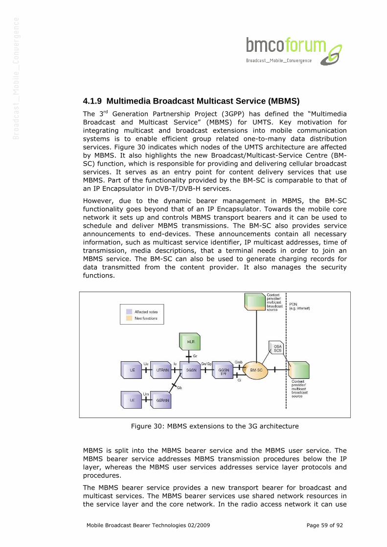
Mobile Broadcast Bearer Technologies 02/2009 Page 59 of 92
4.1.9 Multimedia Broadcast Multicast Service (MBMS) The 3rd Generation Partnership Project (3GPP) has defined the “Multimedia
Broadcast and Multicast Service” (MBMS) for UMTS. Key motivation for
integrating multicast and broadcast extensions into mobile communication
systems is to enable efficient group related one-to-many data distribution
services. Figure 30 indicates which nodes of the UMTS architecture are affected
by MBMS. It also highlights the new Broadcast/Multicast-Service Centre (BM-
SC) function, which is responsible for providing and delivering cellular broadcast
services. It serves as an entry point for content delivery services that use
MBMS. Part of the functionality provided by the BM-SC is comparable to that of
an IP Encapsulator in DVB-T/DVB-H services.
However, due to the dynamic bearer management in MBMS, the BM-SC
functionality goes beyond that of an IP Encapsulator. Towards the mobile core
network it sets up and controls MBMS transport bearers and it can be used to
schedule and deliver MBMS transmissions. The BM-SC also provides service
announcements to end-devices. These announcements contain all necessary
information, such as multicast service identifier, IP multicast addresses, time of
transmission, media descriptions, that a terminal needs in order to join an
MBMS service. The BM-SC can also be used to generate charging records for
data transmitted from the content provider. It also manages the security
functions.
Figure 30: MBMS extensions to the 3G architecture
MBMS is split into the MBMS bearer service and the MBMS user service. The
MBMS bearer service addresses MBMS transmission procedures below the IP
layer, whereas the MBMS user services addresses service layer protocols and
procedures.
The MBMS bearer service provides a new transport bearer for broadcast and
multicast services. The MBMS bearer services use shared network resources in
the service layer and the core network. In the radio access network it can use
Mobile Broadcast Bearer Technologies 02/2009 Page 60 of 92
point-to-multipoint (e.g. true broadcast) or point-to-point bearers, depending
on what’s more efficient.
The MBMS bearer service is supported by both UMTS Terrestrial Radio Access
Network (UTRAN) and GSM/EDGE Radio Access Network (GERAN).
The MBMS Bearer Service offers a Broadcast, an Enhanced Broadcast and a
Multicast Mode for data delivery. The main difference between the Modes is the
level of group management in the radio- and core-network.
The MBMS Broadcast Mode offers a semi-static Point-to Multipoint distribution
system. The BM-SC determines the broadcast area when activating the
distribution bearers. The network has no information about active receivers in
the Broadcast Area and cannot optimize any resource usage. The MBMS
Broadcast Mode is very similar to existing Broadcast systems like DVB-T/DVB-
H.
The Enhanced Broadcast Mode allows a more resource efficient delivery than
the Broadcast Mode. Terminals indicate service “joining” up to the Radio
Network. The Radio Network may perform the so-called “counting” or “re-
counting” procedures to determine the number of terminals in each cell. The
MBMS radio bearer can use a point-to-multipoint (ptm, e.g. true broadcast) or
point-to-point (ptp) radio bearers. The ptp bearers like HSDPA have precise
knowledge of the radio channel at the UE due to feedback from the UE.
Transmit parameters like the modulation and channel coding are optimised for
the individual UE and retransmissions are possible, thereby increasing the
efficiency.
In contrast, ptm radio bearers in UTRAN do not support feedback from UEs and
therefore the transmit parameters have to be statically dimensioned to achieve
a desired coverage. Therefore the ptm radio bearers are more efficient than the
ptp radio bearers only if a sufficiently higher number of terminals are located in
a cell. The switching threshold between point-to-point and point-to-multipoint
bearers depends on the terminal capabilities. The switching point is between 1
and 2 terminals per cell in case of soft-combining that means the combination,
in the terminal, of radio signals received from several transmitters in adjacent
cells, and between 5 and 10 otherwise. Intermediate values are also possible
depending on the propagation environment (i.e. power delay profile).
End of 2006 3GPP has started a new Work Item on MBMS improvements (see
3GPP Technical Report 25.905 v2.0.0). One focus area is the avoidance of
intercell interference that is the capacity limiting factor in Release 6. 3GPP
contributions propose to dedicate a UMTS carrier to MBMS and use the same
scrambling code in all cells of an MBMS service area, thereby achieving similar
conditions as in a broadcasting SFN known from OFDM based technologies. This
new functionality is scheduled for Release 7 of UMTS.
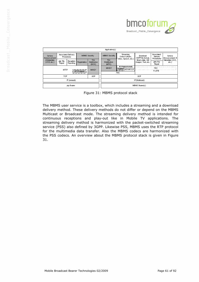
Mobile Broadcast Bearer Technologies 02/2009 Page 61 of 92
Figure 31: MBMS protocol stack
The MBMS user service is a toolbox, which includes a streaming and a download
delivery method. These delivery methods do not differ or depend on the MBMS
Multicast or Broadcast mode. The streaming delivery method is intended for
continuous receptions and play-out like in Mobile TV applications. The
streaming delivery method is harmonized with the packet-switched streaming
service (PSS) also defined by 3GPP. Likewise PSS, MBMS uses the RTP protocol
for the multimedia data transfer. Also the MBMS codecs are harmonized with
the PSS codecs. An overview about the MBMS protocol stack is given in Figure
31.
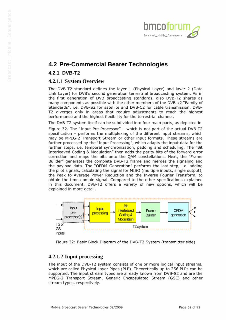
Mobile Broadcast Bearer Technologies 02/2009 Page 62 of 92
4.2 Pre-Commercial Bearer Technologies
4.2.1 DVB-T2
4.2.1.1 System Overview The DVB-T2 standard defines the layer 1 (Physical Layer) and layer 2 (Data
Link Layer) for DVB’s second generation terrestrial broadcasting system. As in
the first generation of DVB broadcasting standards, also DVB-T2 shares as
many components as possible with the other members of the DVB-x2 “Family of
Standards”, i.e. DVB-S2 for satellite and DVB-C2 for cable transmission. DVB-
T2 diverges only in areas that require adjustments to reach the highest
performance and the highest flexibility for the terrestrial channel.
The DVB-T2 system itself can be subdivided into four main parts, as depicted in
Figure 32. The “Input Pre-Processor” – which is not part of the actual DVB-T2
specification – performs the multiplexing of the different input streams, which
may be MPEG-2 Transport Stream or other input formats. These streams are
further processed by the “Input Processing”, which adapts the input data for the
further steps, i.e. temporal synchronization, padding and scheduling. The “Bit
Interleaved Coding & Modulation” then adds the parity bits of the forward error
correction and maps the bits onto the QAM constellations. Next, the “Frame
Builder” generates the complete DVB-T2 frame and merges the signaling and
the payload data. The “OFDM Generation” performs the last step, i.e. adding
the pilot signals, calculating the signal for MISO (multiple inputs, single output),
the Peak to Average Power Reduction and the Inverse Fourier Transform, to
obtain the time domain signal. Compared to the other specifications explained
in this document, DVB-T2 offers a variety of new options, which will be
explained in more detail.
Bit
Interleaved Coding &
Modulation
Frame Builder
OFDM
generation
TS or GS inputs
Input processing
Input pre-
processor(s)
T2 system
Figure 32: Basic Block Diagram of the DVB-T2 System (transmitter side)
4.2.1.2 Input processing The input of the DVB-T2 system consists of one or more logical input streams,
which are called Physical Layer Pipes (PLP). Theoretically up to 256 PLPs can be
supported. The input stream types are already known from DVB-S2 and are the
MPEG-2 Transport Stream, Generic Encapsulated Stream (GSE) and other
stream types, respectively.
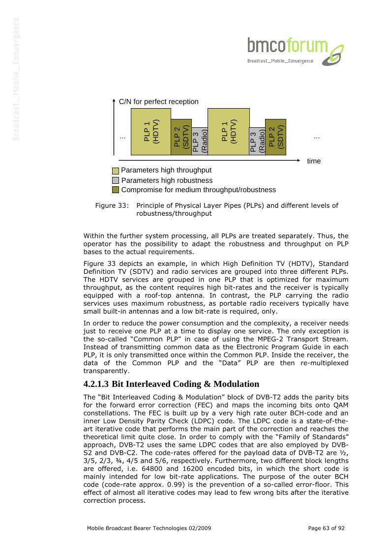
Mobile Broadcast Bearer Technologies 02/2009 Page 63 of 92
Parameters high throughputParameters high robustnessCompromise for medium throughput/robustness
C/N for perfect reception
PLP
3
(Rad
io)
PLP
2(S
DT
V)
time
... ...PLP
1(H
DT
V)
PLP
1(H
DT
V)
PLP
2(S
DT
V)
PLP
3
(Rad
io)
Figure 33: Principle of Physical Layer Pipes (PLPs) and different levels of
robustness/throughput
Within the further system processing, all PLPs are treated separately. Thus, the
operator has the possibility to adapt the robustness and throughput on PLP
bases to the actual requirements.
Figure 33 depicts an example, in which High Definition TV (HDTV), Standard
Definition TV (SDTV) and radio services are grouped into three different PLPs.
The HDTV services are grouped in one PLP that is optimized for maximum
throughput, as the content requires high bit-rates and the receiver is typically
equipped with a roof-top antenna. In contrast, the PLP carrying the radio
services uses maximum robustness, as portable radio receivers typically have
small built-in antennas and a low bit-rate is required, only.
In order to reduce the power consumption and the complexity, a receiver needs
just to receive one PLP at a time to display one service. The only exception is
the so-called “Common PLP” in case of using the MPEG-2 Transport Stream.
Instead of transmitting common data as the Electronic Program Guide in each
PLP, it is only transmitted once within the Common PLP. Inside the receiver, the
data of the Common PLP and the “Data” PLP are then re-multiplexed
transparently.
4.2.1.3 Bit Interleaved Coding & Modulation The “Bit Interleaved Coding & Modulation” block of DVB-T2 adds the parity bits
for the forward error correction (FEC) and maps the incoming bits onto QAM
constellations. The FEC is built up by a very high rate outer BCH-code and an
inner Low Density Parity Check (LDPC) code. The LDPC code is a state-of-the-
art iterative code that performs the main part of the correction and reaches the
theoretical limit quite close. In order to comply with the “Family of Standards”
approach, DVB-T2 uses the same LDPC codes that are also employed by DVB-
S2 and DVB-C2. The code-rates offered for the payload data of DVB-T2 are ½,
3/5, 2/3, ¾, 4/5 and 5/6, respectively. Furthermore, two different block lengths
are offered, i.e. 64800 and 16200 encoded bits, in which the short code is
mainly intended for low bit-rate applications. The purpose of the outer BCH
code (code-rate approx. 0.99) is the prevention of a so-called error-floor. This
effect of almost all iterative codes may lead to few wrong bits after the iterative
correction process.
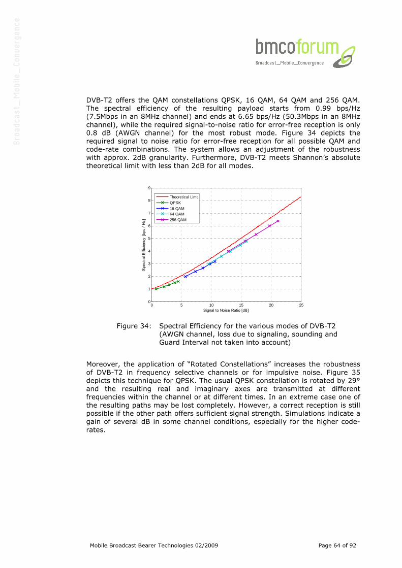
Mobile Broadcast Bearer Technologies 02/2009 Page 64 of 92
DVB-T2 offers the QAM constellations QPSK, 16 QAM, 64 QAM and 256 QAM.
The spectral efficiency of the resulting payload starts from 0.99 bps/Hz
(7.5Mbps in an 8MHz channel) and ends at 6.65 bps/Hz (50.3Mbps in an 8MHz
channel), while the required signal-to-noise ratio for error-free reception is only
0.8 dB (AWGN channel) for the most robust mode. Figure 34 depicts the
required signal to noise ratio for error-free reception for all possible QAM and
code-rate combinations. The system allows an adjustment of the robustness
with approx. 2dB granularity. Furthermore, DVB-T2 meets Shannon’s absolute
theoretical limit with less than 2dB for all modes.
0 5 10 15 20 250
1
2
3
4
5
6
7
8
9
Signal to Noise Ratio [dB]
Spe
ctra
l Eff
icie
ncy
[bps
/ H
z]
Theoretical Limt
QPSK
16 QAM64 QAM
256 QAM
Figure 34: Spectral Efficiency for the various modes of DVB-T2
(AWGN channel, loss due to signaling, sounding and
Guard Interval not taken into account)
Moreover, the application of “Rotated Constellations” increases the robustness
of DVB-T2 in frequency selective channels or for impulsive noise. Figure 35
depicts this technique for QPSK. The usual QPSK constellation is rotated by 29°
and the resulting real and imaginary axes are transmitted at different
frequencies within the channel or at different times. In an extreme case one of
the resulting paths may be lost completely. However, a correct reception is still
possible if the other path offers sufficient signal strength. Simulations indicate a
gain of several dB in some channel conditions, especially for the higher code-
rates.
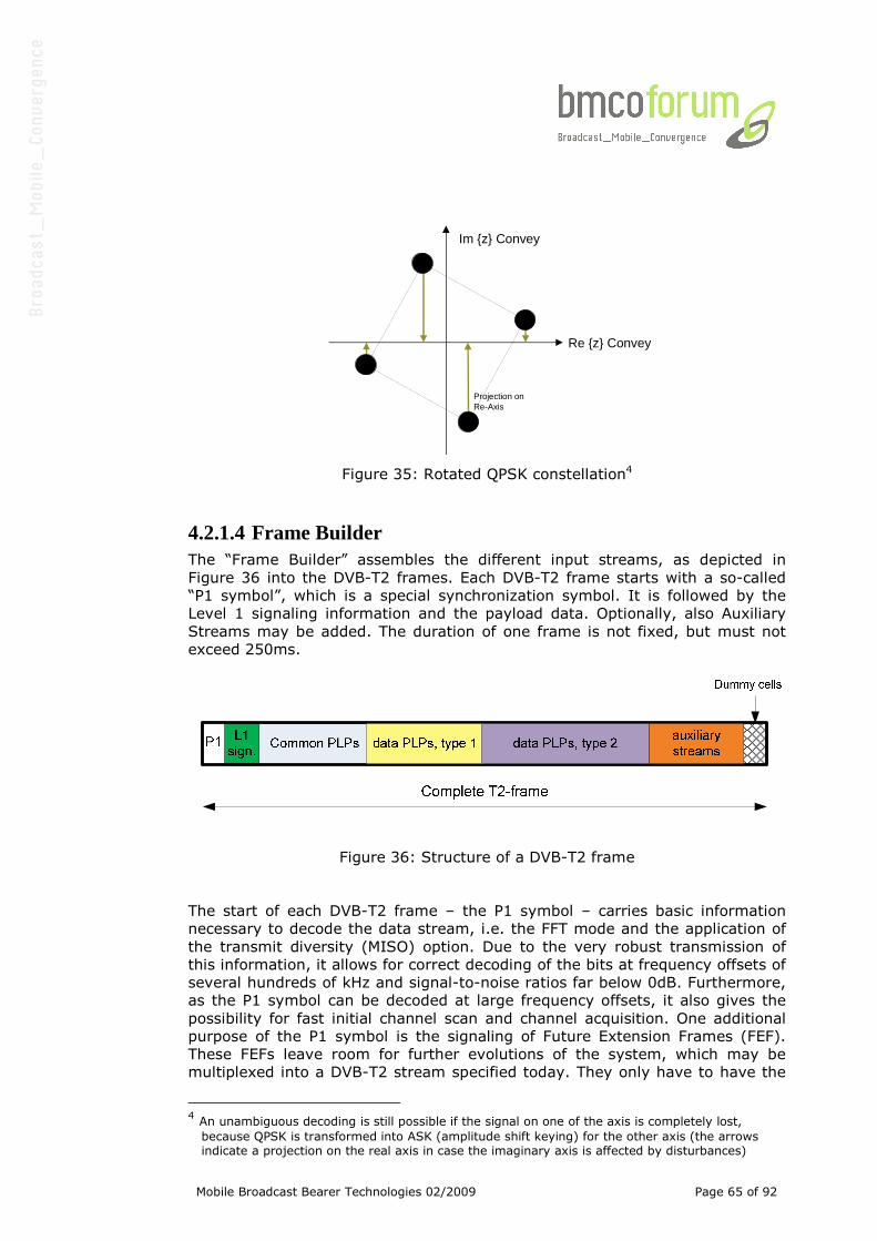
Mobile Broadcast Bearer Technologies 02/2009 Page 65 of 92
Re {z} Convey
Im {z} Convey
Projection on Re-Axis
Figure 35: Rotated QPSK constellation4
4.2.1.4 Frame Builder The “Frame Builder” assembles the different input streams, as depicted in
Figure 36 into the DVB-T2 frames. Each DVB-T2 frame starts with a so-called
“P1 symbol”, which is a special synchronization symbol. It is followed by the
Level 1 signaling information and the payload data. Optionally, also Auxiliary
Streams may be added. The duration of one frame is not fixed, but must not
exceed 250ms.
Figure 36: Structure of a DVB-T2 frame
The start of each DVB-T2 frame – the P1 symbol – carries basic information
necessary to decode the data stream, i.e. the FFT mode and the application of
the transmit diversity (MISO) option. Due to the very robust transmission of
this information, it allows for correct decoding of the bits at frequency offsets of
several hundreds of kHz and signal-to-noise ratios far below 0dB. Furthermore,
as the P1 symbol can be decoded at large frequency offsets, it also gives the
possibility for fast initial channel scan and channel acquisition. One additional
purpose of the P1 symbol is the signaling of Future Extension Frames (FEF).
These FEFs leave room for further evolutions of the system, which may be
multiplexed into a DVB-T2 stream specified today. They only have to have the
4 An unambiguous decoding is still possible if the signal on one of the axis is completely lost,
because QPSK is transformed into ASK (amplitude shift keying) for the other axis (the arrows indicate a projection on the real axis in case the imaginary axis is affected by disturbances)
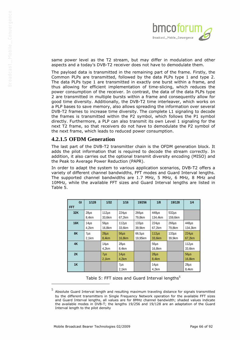
Mobile Broadcast Bearer Technologies 02/2009 Page 66 of 92
same power level as the T2 stream, but may differ in modulation and other
aspects and a today’s DVB-T2 receiver does not have to demodulate them.
The payload data is transmitted in the remaining part of the frame. Firstly, the
Common PLPs are transmitted, followed by the data PLPs type 1 and type 2.
The data PLPs type 1 are transmitted in exactly one burst within a frame, and
thus allowing for efficient implementation of time-slicing, which reduces the
power consumption of the receiver. In contrast, the data of the data PLPs type
2 are transmitted in multiple bursts within a frame and consequently allow for
good time diversity. Additionally, the DVB-T2 time interleaver, which works on
a PLP bases to save memory, also allows spreading the information over several
DVB-T2 frames to increase time diversity. The complete L1 signaling to decode
the frames is transmitted within the P2 symbol, which follows the P1 symbol
directly. Furthermore, a PLP can also transmit its own Level 1 signaling for the
next T2 frame, so that receivers do not have to demodulate the P2 symbol of
the next frame, which leads to reduced power consumption.
4.2.1.5 OFDM Generation The last part of the DVB-T2 transmitter chain is the OFDM generation block. It
adds the pilot information that is required to decode the stream correctly. In
addition, it also carries out the optional transmit diversity encoding (MISO) and
the Peak to Average Power Reduction (PAPR).
In order to adapt the system to various application scenarios, DVB-T2 offers a
variety of different channel bandwidths, FFT modes and Guard Interval lengths.
The supported channel bandwidths are 1.7 MHz, 5 MHz, 6 MHz, 8 MHz and
10MHz, while the available FFT sizes and Guard Interval lengths are listed in
Table 5.
28µs8,4km
14µs4,2km
7µs2,1km
1K
56µs16,8km
28µs8,4km
14µs4,2km
7µs2,1km
2K
112µs33,6km
56µs16,8km
28µs8,4km
14µs4,2km
4K
224µs67,2km
133µs39,9km
112µs33,6km
66,5µs19,95km
56µs16,8km
28µs8,4km
7µs2,1km
8K
448µs134,3km
266µs79,8km
224µs67,2km
133µs39,9km
112µs33,6km
56µs16,8km
14µs4,2km
16K
532µs159,6km
448µs134,4km
266µs79,8km
224µs67,2km
112µs33,6km
28µs8,4km
32K
1/419/1281/819/2561/161/321/128GIFFT
Table 5: FFT sizes and Guard Interval lengths5
5 Absolute Guard Interval length and resulting maximum traveling distance for signals transmitted
by the different transmitters in Single Frequency Network operation for the available FFT sizes and Guard Interval lengths, all values are for 8MHz channel bandwidth; shaded values indicate the available modes in DVB-T; the lengths 19/256 and 19/128 are an adaptation of the Guard Interval length to the pilot density
Mobile Broadcast Bearer Technologies 02/2009 Page 67 of 92
The higher FFT sizes are especially aiming at large single frequency networks
with mainly stationary reception, while the small ones are suited for the narrow
channel bandwidths and high speed mobile reception. Furthermore, there are
optimized pilot schemes for each Guard Interval length, which allow for a
maximum reduction of pilot overhead.
A completely new technique in broadcasting is the availability of a transmit
diversity option. This MISO (multiple input, single output) technique is based on
the Alamouti scheme. The feature is especially interesting for Single Frequency
Networks. The transmitters within the network do no longer transmit identical,
but specially pre-coded data. This results in a significant reduction of the
frequency selectivity, and thus a gain of several dB in many use-cases.
Moreover, DVB-T2 also offers means to reduce the Peak to Average Power
(PAPR) ratios of OFDM. Hence, transmitters may be deployed at higher power
levels.
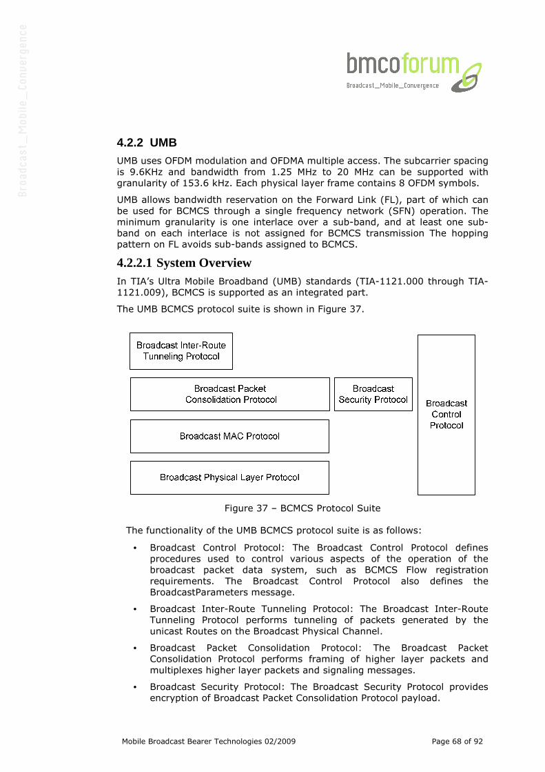
Mobile Broadcast Bearer Technologies 02/2009 Page 68 of 92
4.2.2 UMB UMB uses OFDM modulation and OFDMA multiple access. The subcarrier spacing
is 9.6KHz and bandwidth from 1.25 MHz to 20 MHz can be supported with
granularity of 153.6 kHz. Each physical layer frame contains 8 OFDM symbols.
UMB allows bandwidth reservation on the Forward Link (FL), part of which can
be used for BCMCS through a single frequency network (SFN) operation. The
minimum granularity is one interlace over a sub-band, and at least one sub-
band on each interlace is not assigned for BCMCS transmission The hopping
pattern on FL avoids sub-bands assigned to BCMCS.
4.2.2.1 System Overview In TIA’s Ultra Mobile Broadband (UMB) standards (TIA-1121.000 through TIA-
1121.009), BCMCS is supported as an integrated part.
The UMB BCMCS protocol suite is shown in Figure 37.
Figure 37 – BCMCS Protocol Suite
The functionality of the UMB BCMCS protocol suite is as follows:
• Broadcast Control Protocol: The Broadcast Control Protocol defines
procedures used to control various aspects of the operation of the
broadcast packet data system, such as BCMCS Flow registration
requirements. The Broadcast Control Protocol also defines the
BroadcastParameters message.
• Broadcast Inter-Route Tunneling Protocol: The Broadcast Inter-Route
Tunneling Protocol performs tunneling of packets generated by the
unicast Routes on the Broadcast Physical Channel.
• Broadcast Packet Consolidation Protocol: The Broadcast Packet
Consolidation Protocol performs framing of higher layer packets and
multiplexes higher layer packets and signaling messages.
• Broadcast Security Protocol: The Broadcast Security Protocol provides
encryption of Broadcast Packet Consolidation Protocol payload.
Mobile Broadcast Bearer Technologies 02/2009 Page 69 of 92
• Broadcast MAC Protocol: The Broadcast MAC Protocol defines procedures
used to transmit via the Forward Broadcast and Multicast Services
Channel. The Broadcast MAC Protocol also provides Forward Error
Correction (FEC) and multiplexing to reduce the radio link error rate as
seen by the higher layers.
• Broadcast Physical Layer Protocol: The Broadcast Physical Layer Protocol
provides the channel structure for the Forward Broadcast and Multicast
Services Channel.
4.2.2.2 UMB BCMCS Physical layer TIA-1121.001 defines the BCMCS physical layer standard for UMB.
In each physical layer frame, one or more sub-bands (approximately 1.25 MHz
each) can be dedicated to BCMCS transmission. The unicast traffic avoids using
subcarriers corresponding to those sub-bands. For BCMCS transmission in each
sub-band, OFDM modulation is used.
The positions of the BCMCS sub-bands within each physical layer frame are
synchronized between sectors and the same BCMCS OFDM symbol is
transmitted from all sectors. T he Cyclic Prefix (CP) length of BCMCS signalling
is longer than normal unicast transmission, so longer multipath delay profile
caused by combination of the signals from all adjacent sectors can be
accommodated without introducing inter-symbol interference. Therefore the
received signal from all sectors can be soft combined and higher multicast
performance gains are realized.
Two radio configurations are defined for UMB BCMCS transmission. Radio
Configuration 1 uses 9.6 kHz subcarrier spacing and has 7 OFDM symbols per
physical layer frame. Radio Configuration 2 uses 3.8 kHz subcarrier spacing
and has 3 OFDM symbols per physical layer frame. Radio Configuration 2 has
even longer CP length and is mainly used for deployment with extremely long
multipath delay profile.
UMB BCMCS transmission can use 16-QAM or QPSK modulation. It is also
possible to use hierarchical modulation with two layers, where base layer uses
either 16-QAM or QPSK and enhancement layer uses QPSK. For each Radio
Configuration and modulation method, four coding Rate Sets are defined and a
maximum of three (re-)transmissions are allowed. The packet formats defined
for UMB BCMCS transmission are listed in Table 6 for the base layer. If the
enhancement layer is used, packet formats in Table 6 with QPSK modulation
can be applied.
By using different coding rate, modulation order, and number of layers, a wide
range in spectral efficiency can be selected to match the coverage requirement
of a given deployment. For example, for a 2 km site-to-site deployment, using
Rate Set 1, Radio Configuration 1, 16-QAM modulation, the UMB BCMCS
transmission can achieve a throughput of 1.685 Mbps per sub-band. The
coverage performance under different channel models is shown in Figure 38.
More than 99% of the users can achieve a frame error rate less than 1%.
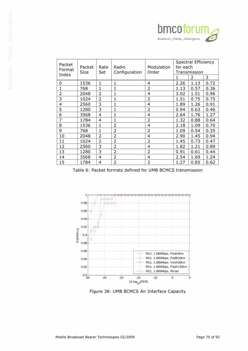
Mobile Broadcast Bearer Technologies 02/2009 Page 70 of 92
Spectral Efficiency
for each
Transmission
Packet
Format
Index
Packet
Size
Rate
Set
Radio
Configuration
Modulation
Order
1 2 3
0 1536 1 1 4 2.26 1.13 0.72
1 768 1 1 2 1.13 0.57 0.36
2 2048 2 1 4 3.02 1.51 0.96
3 1024 2 1 2 1.51 0.75 0.75
4 2560 3 1 4 1.89 1.26 0.91
5 1280 3 1 2 0.94 0.63 0.46
6 3568 4 1 4 2.64 1.76 1.27
7 1784 4 1 2 1.32 0.88 0.64
8 1536 1 2 4 2.18 1.09 0.70
9 768 1 2 2 1.09 0.54 0.35
10 2048 2 2 4 2.90 1.45 0.94
11 1024 2 2 2 1.45 0.73 0.47
12 2560 3 2 4 1.82 1.21 0.89
13 1280 3 2 2 0.91 0.61 0.44
14 3568 4 2 4 2.54 1.69 1.24
15 1784 4 2 2 1.27 0.85 0.62
Table 6: Packet formats defined for UMB BCMCS transmission
Figure 38: UMB BCMCS Air Interface Capacity
-30 -25 -20 -15 -10 -5 00.8
0.82
0.84
0.86
0.88
0.9
0.92
0.94
0.96
0.98
1
10 log10
(FER)
Pr{
FE
R<
x}
RS1, 1.685Mbps, PedA3km
RS1, 1.685Mbps, PedB10km
RS1, 1.685Mbps, VehA30kmRS1, 1.685Mbps, PedA120km
RS1, 1.685Mbps, Rician
Mobile Broadcast Bearer Technologies 02/2009 Page 71 of 92
4.2.2.3 UMB BCMCS Upper layer TIA-1121.009 defines the BCMCS upper layer standard for UMB. In UMB,
broadcast Flows are identified by Flow IDs, which might correspond to either
local or global TV channels, e.g. CNN or ESPN. Broadcast Flows could also carry
other types of service information such as stock quotes or audio entertainment.
A collection of broadcast Flows constitute the BCMCS Logical Channel (BLC).
One or more BLCs is in turn sent over a Broadcast Physical Channel (BPC)
which is transmitted over the air. BPCs are numbered consecutively over
available resources. These resources are contiguous in frequency. This helps
reduce the AT (Access Terminal) wake-up time and increase battery life.
BLCs are characterized by scrambling sequences, PL (Physical Layer) packet
transmission formats (including modulation hierarchy), and outer-code
parameters. Different BLCs are mapped to disjoint sets of BPCs, while
maintaining the modulation hierarchy. BLCs that use the BPC are transmitted
with the same modulation and coding scheme. SFN zones are defined per BLC,
with many BLCs mapping to one SFN zone. Each SFN zone is distinguished by
an unique scrambling code that is used for transmission of the BPCs in that SFN
zone.
The Broadcast Parameters Message (BPM) is sent over each individual cell
(using cell broadcast), and carries BLC(s) information. The BPM contains the
following information:
• The BLC transmission format
• The error control block (ECB) parameters
• The periodicity of the BPC,
• Pilot information
• The scrambling sequence
• The Glows mapped to BLC
• The partition of PL resources into BPCs
• The BPCs occupied by various Broadcast Channel,
• The mapping of BLCs to corresponding Broadcast Mapping Messages
(BMM).
All parameters have an expiry timer. The AT need not continuously monitor the
BPC, which is sent often enough for reasonable initial acquisition, and points to
location of BMM. The basic unit of transmission is an ultraframe (UF) that
consists of 48 PL super-frames (~1.1 sec). Thus, the average switching time
between channels is ~1.7 seconds. Each UF is divided into N Outer Frames
(OF), N=1,2,4 or 8.
Each UF logically multiplexes channels. Note that the instantaneous source
rates of individual channels vary with time, while the aggregate payload from
all channels is approximately constant. This results in better approximation
with larger UF, and provides statistical multiplexing gain and time-diversity.
However, larger buffer sizes and longer latencies for source (video/audio)
decoding and longer switching times are needed for larger UFs.
Mobile Broadcast Bearer Technologies 02/2009 Page 72 of 92
Up to 4 BMMs / sector are allowed. BLC information contained in one BMM
maps all the allocated BPCs into BCMCS flows. The BMM is a special BLC, and
provides time diversity for reliable decoding. The BMM repeated every OF, and
transmitted every UF. The BMM is valid for next UF or until contents updated.
Channels carry in-band signaling for next UF. Thus, if the user does not switch
channels, there is no need to decode the BMM.
The PL packets carrying a BLC are protected by an outer code. The ECB is a
matrix of R rows and C columns (R = 1, 16 or 32). The row width determined
by sequence of PL packets transmitted on ECB. R and C are signaled on BPM.
A sequence of BPC packets (or erasures) on BLC over S UFs are written row-
wise into matrix of R rows and C columns. The missing entries are filled with
all-zero packets. The receiver needs to buffer all UF hard decisions if outer
code is used for best diversity. Each sub-matrix of R rows X 1 byte denotes a
received codeword of (R, k) Reed-Solomon code.
The remaining protocols are very similar to the UMB and cdma2000-1xEVDO
upper layers.
4.2.2.4 Summary The Physical Layer UMB BCMCS design offers high-spectral efficiency, SFN
operation with multiple zones, OFDM transmission formats, and high level of
Doppler robustness and delay tolerance.
The MAC Layer allows reservation of bandwidth for broadcast, flexibility
depending on unicast and broadcast loads, fast switching times, and small wake
up time for ATs, making them battery efficient. The remaining protocols
conform to UMB and cdma2000-1xEVDO protocols
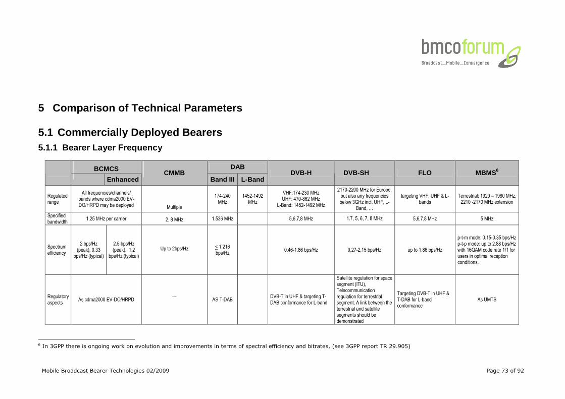
Mobile Broadcast Bearer Technologies 02/2009 Page 73 of 92
5 Comparison of Technical Parameters
5.1 Commercially Deployed Bearers 5.1.1 Bearer Layer Frequency
BCMCS DAB
Enhanced
CMMB
Band III L-Band DVB-H DVB-SH FLO MBMS6
Regulated range
All frequencies/channels/ bands where cdma2000 EV-DO/HRPD may be deployed
Multiple
174-240 MHz
1452-1492 MHz
VHF:174-230 MHz UHF: 470-862 MHz
L-Band: 1452-1492 MHz
2170-2200 MHz for Europe, but also any frequencies below 3GHz incl. UHF, L-
Band, …
targeting VHF, UHF & L-bands
Terrestrial: 1920 – 1980 MHz, 2210 -2170 MHz extension
Specified bandwidth
1.25 MHz per carrier 2, 8 MHz 1.536 MHz
5,6,7,8 MHz 1.7, 5, 6, 7, 8 MHz 5,6,7,8 MHz 5 MHz
Spectrum efficiency
2 bps/Hz (peak), 0.33
bps/Hz (typical)
2.5 bps/Hz (peak), 1.2
bps/Hz (typical)
Up to 2bps/Hz < 1.216 bps/Hz
0.46-1.86 bps/Hz 0,27-2,15 bps/Hz up to 1.86 bps/Hz
p-t-m mode: 0.15-0.35 bps/Hz p-t-p mode: up to 2.88 bps/Hz with 16QAM code rate 1/1 for users in optimal reception conditions.
Regulatory aspects
As cdma2000 EV-DO/HRPD
---
AS T-DAB
DVB-T in UHF & targeting T-DAB conformance for L-band
Satellite regulation for space segment (ITU), Telecommunication regulation for terrestrial segment, A link between the terrestrial and satellite segments should be demonstrated
Targeting DVB-T in UHF & T-DAB for L-band conformance
As UMTS
6 In 3GPP there is ongoing work on evolution and improvements in terms of spectral efficiency and bitrates, (see 3GPP report TR 29.905)
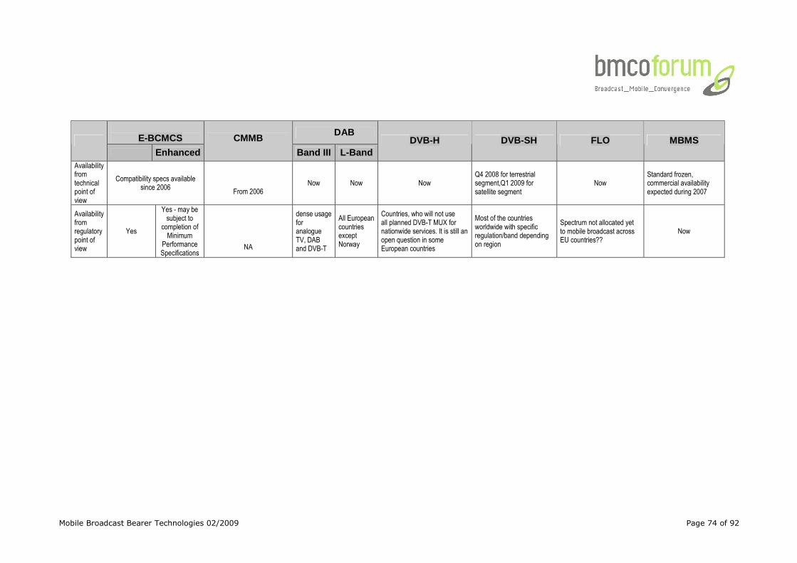
Mobile Broadcast Bearer Technologies 02/2009 Page 74 of 92
E-BCMCS
DAB
Enhanced
CMMB
Band III L-Band DVB-H DVB-SH FLO MBMS
Availability from technical point of view
Compatibility specs available since 2006
From 2006 Now Now Now
Q4 2008 for terrestrial segment,Q1 2009 for satellite segment
Now Standard frozen, commercial availability expected during 2007
Availability from regulatory point of view
Yes
Yes - may be subject to
completion of Minimum
Performance Specifications
NA
dense usage for analogue TV, DAB and DVB-T
All European countries except Norway
Countries, who will not use all planned DVB-T MUX for nationwide services. It is still an open question in some European countries
Most of the countries worldwide with specific regulation/band depending on region
Spectrum not allocated yet to mobile broadcast across EU countries??
Now
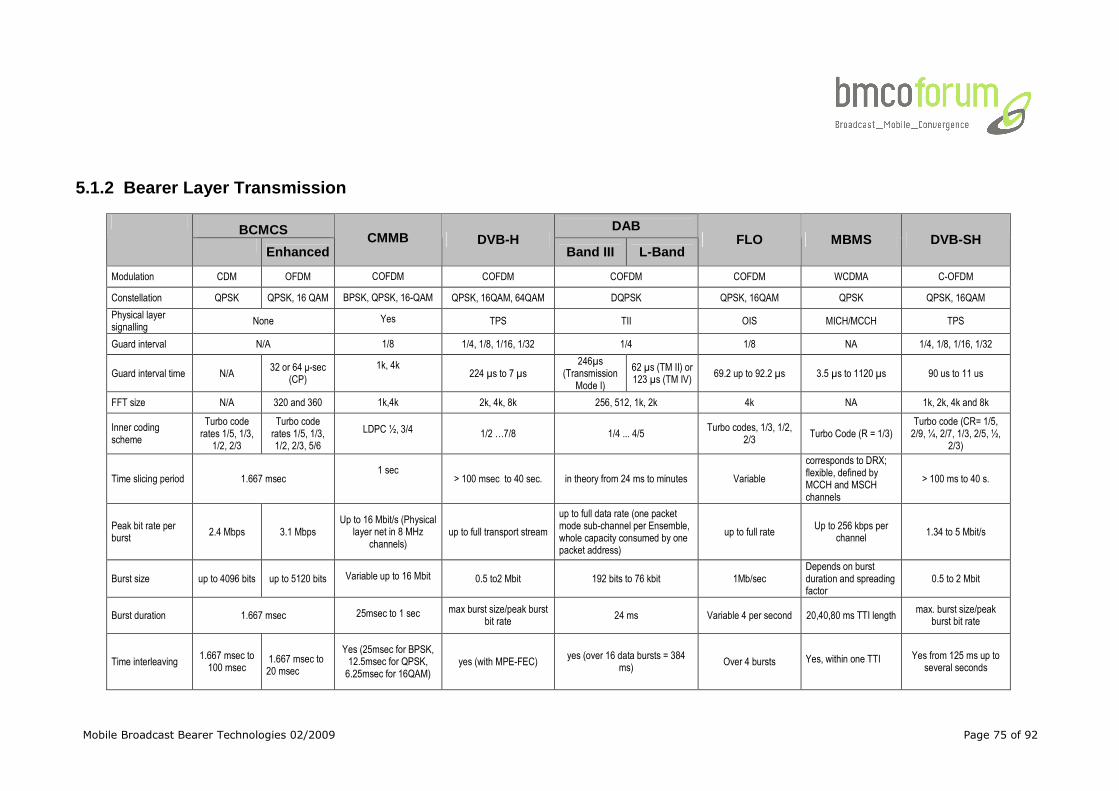
Mobile Broadcast Bearer Technologies 02/2009 Page 75 of 92
5.1.2 Bearer Layer Transmission
BCMCS DAB
Enhanced CMMB DVB-H
Band III L-Band FLO MBMS DVB-SH
Modulation CDM OFDM COFDM COFDM COFDM COFDM WCDMA C-OFDM
Constellation QPSK QPSK, 16 QAM BPSK, QPSK, 16-QAM QPSK, 16QAM, 64QAM DQPSK QPSK, 16QAM QPSK QPSK, 16QAM
Physical layer signalling
None Yes TPS TII OIS MICH/MCCH TPS
Guard interval N/A 1/8 1/4, 1/8, 1/16, 1/32 1/4 1/8 NA 1/4, 1/8, 1/16, 1/32
Guard interval time N/A 32 or 64 µ-sec
(CP)
1k, 4k 224 µs to 7 µs
246µs (Transmission
Mode I)
62 µs (TM II) or 123 µs (TM IV)
69.2 up to 92.2 µs 3.5 µs to 1120 µs 90 us to 11 us
FFT size N/A 320 and 360 1k,4k 2k, 4k, 8k 256, 512, 1k, 2k 4k NA 1k, 2k, 4k and 8k
Inner coding scheme
Turbo code rates 1/5, 1/3,
1/2, 2/3
Turbo code rates 1/5, 1/3, 1/2, 2/3, 5/6
LDPC ½, 3/4 1/2 …7/8 1/4 ... 4/5 Turbo codes, 1/3, 1/2,
2/3 Turbo Code (R = 1/3)
Turbo code (CR= 1/5, 2/9, ¼, 2/7, 1/3, 2/5, ½,
2/3)
Time slicing period 1.667 msec 1 sec
> 100 msec to 40 sec. in theory from 24 ms to minutes Variable
corresponds to DRX; flexible, defined by MCCH and MSCH channels
> 100 ms to 40 s.
Peak bit rate per burst
2.4 Mbps 3.1 Mbps Up to 16 Mbit/s (Physical
layer net in 8 MHz channels)
up to full transport stream
up to full data rate (one packet mode sub-channel per Ensemble, whole capacity consumed by one packet address)
up to full rate Up to 256 kbps per
channel 1.34 to 5 Mbit/s
Burst size up to 4096 bits up to 5120 bits Variable up to 16 Mbit 0.5 to2 Mbit 192 bits to 76 kbit 1Mb/sec Depends on burst duration and spreading factor
0.5 to 2 Mbit
Burst duration 1.667 msec 25msec to 1 sec max burst size/peak burst bit rate
24 ms Variable 4 per second 20,40,80 ms TTI length max. burst size/peak
burst bit rate
Time interleaving 1.667 msec to 100 msec
1.667 msec to 20 msec
Yes (25msec for BPSK, 12.5msec for QPSK, 6.25msec for 16QAM)
yes (with MPE-FEC) yes (over 16 data bursts = 384
ms) Over 4 bursts Yes, within one TTI
Yes from 125 ms up to several seconds
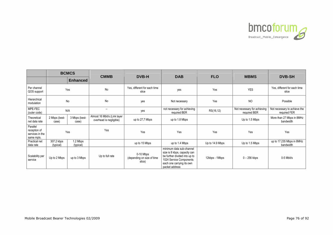
Mobile Broadcast Bearer Technologies 02/2009 Page 76 of 92
BCMCS
Enhanced
CMMB DVB-H DAB FLO MBMS DVB-SH
Per channel QOS support
Yes
No
Yes, different for each time slice
yes Yes YES Yes, different for each time
slice
Hierarchical modulation
No
No yes Not necessary Yes NO Possible
MPE-FEC (outer code)
N/A --
yes not necessary for achieving
required BER RS(16,12)
Not necessary for achieving required BER
Not necessary to achieve the required FER
Theoretical net data rate
2 Mbps (best-case)
3 Mbps (best-case)
Almost 16 Mbit/s (Link layer overhead is negligible) up to 27,7 Mbps up to 1.8 Mbps Up to 1.5 Mbps
More than 27 Mbps in 8MHz bandwidth
Parallel reception of services in the same mplx.
Yes
Yes
Yes Yes Yes Yes Yes
Practical net data rate
307.2 kbps (typical)
1.2 Mbps (typical)
up to 15 Mbps up to 1.4 Mbps Up to 14.9 Mbps Up to 1.5 Mbps
up to 17.235 Mbps in 8MHz bandwidth
Scalability per service
Up to 2 Mbps up to 3 Mbps
Up to full rate 0-10 Mbps
(depending on size of time slice)
minimum data sub-channel size is 8 kbps, capacity can be further divided into up to 1024 Service Components each one carrying its own packet address
12kbps - 1Mbps 0 – 256 kbps 0-5 Mbit/s
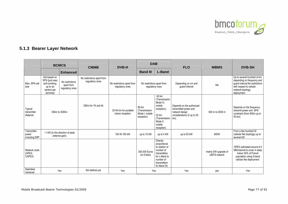
Mobile Broadcast Bearer Technologies 02/2009 Page 77 of 92
5.1.3 Bearer Layer Network
BCMCS DAB
Enhanced
CMMB DVB-H Band III L-Band
FLO MBMS DVB-SH
Max. SFN cell size
Not-based on SFN (just uses soft-combing;
up to six sectors per terminal)
No restrictions apart from
regulatory ones
No restrictions apart from regulatory ones
No restrictions apart from regulatory ones
No restrictions apart from regulatory ones
Depending on c/n and guard interval
NA
Up to several hundred of km depending on frequency and guard interval.No restrictions with respect to cellular network topology deployment
Typical transmitter distance
500m to 3000m
32Km for 1K and 4k
25-40 km for portable indoor reception
89 km (Transmission Mode I, mobile reception)
45 km (Transmission Mode IV, mobile reception), 22 km (Transmission Mode II, mobile reception)
Depends on the authorized transmitted power and network design considerations (2 up to 25 km)
500 m to 2000 m
Depends on the frequency, transmit power and SFN constraint (from 500m up to 50 km)
Transmitter power including ERP
~1 kW (in the direction of peak antenna gain)
100 W-100 kW up to 10 kW up to 4 kW up to 50 kW 600W
From a few hundred W (cellular like topology) up to several kW
Network costs (OPEX, CAPEX)
200,000 Euros for 8 kbit/s
Directly proportional to relation of number of transmitters for L-Band to number of transmitters for Band III)
mainly SW upgrade of
UMTS network
OPEX estimated around 4,5 M€/channel to cover in deep
indoor 50% of French population using S-band cellular like deployment
Seamless handover
Yes Not defined yet Yes Yes Yes yes Yes
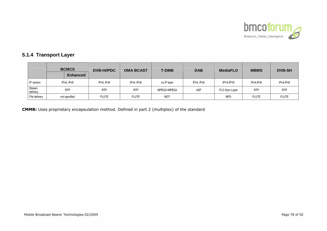
Mobile Broadcast Bearer Technologies 02/2009 Page 78 of 92
5.1.4 Transport Layer
BCMCS
Enhanced DVB-H/IPDC OMA BCAST T-DMB DAB MediaFLO MBMS DVB-SH
IP version IPv4, IPv6 IPv4, IPv6 IPv4, IPv6 no IP layer IPv4, IPv6 IPV4,IPV6 IPv4,IPv6 IPv4,IPv6
Stream delivery
RTP RTP RTP MPEG2+MPEG4 ASF FLO Sync Layer RTP RTP
File delivery not specified FLUTE FLUTE MOT MFD FLUTE FLUTE
CMMB: Uses proprietary encapsulation method. Defined in part 2 (multiplex) of the standard
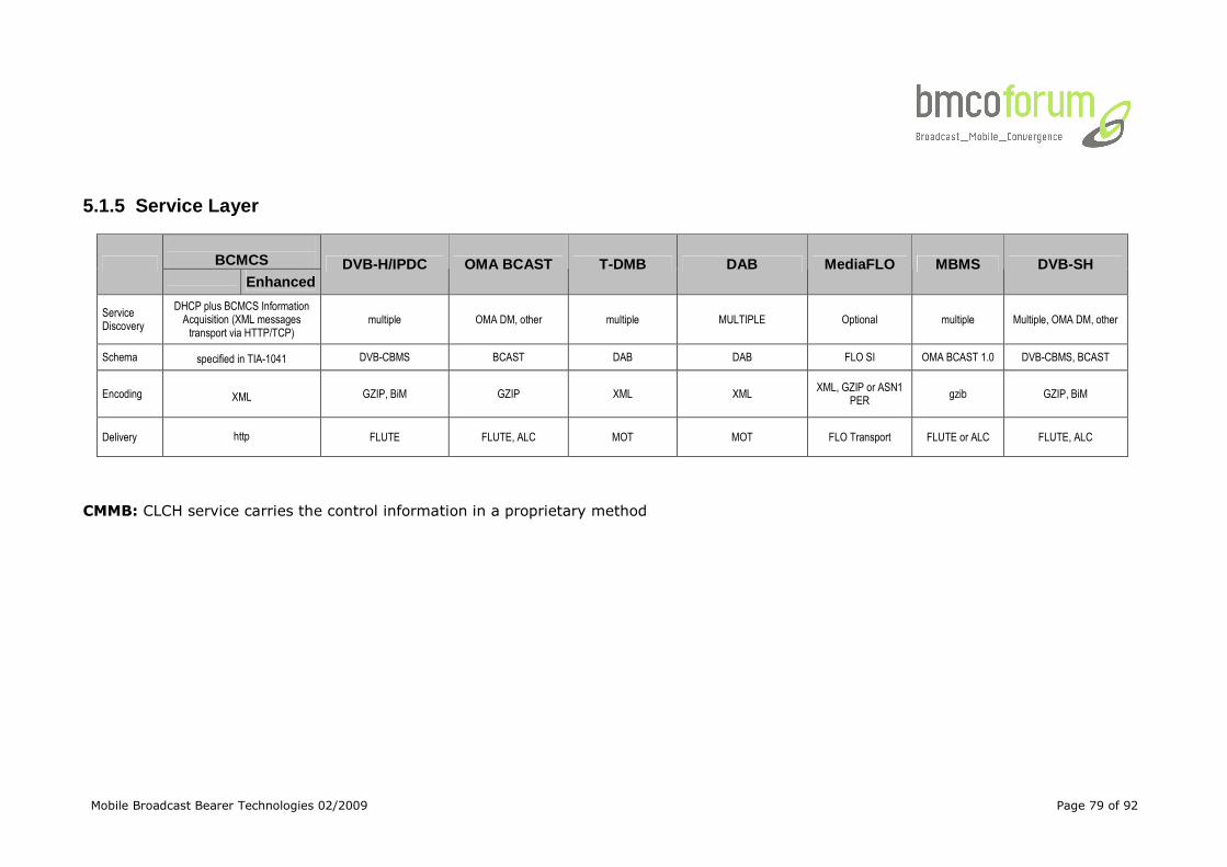
Mobile Broadcast Bearer Technologies 02/2009 Page 79 of 92
5.1.5 Service Layer
BCMCS
Enhanced DVB-H/IPDC OMA BCAST T-DMB DAB MediaFLO MBMS DVB-SH
Service Discovery
DHCP plus BCMCS Information Acquisition (XML messages transport via HTTP/TCP)
multiple OMA DM, other multiple MULTIPLE Optional multiple Multiple, OMA DM, other
Schema specified in TIA-1041 DVB-CBMS BCAST DAB DAB FLO SI OMA BCAST 1.0 DVB-CBMS, BCAST
Encoding XML
GZIP, BiM GZIP XML XML XML, GZIP or ASN1
PER gzib GZIP, BiM
Delivery http
FLUTE FLUTE, ALC MOT MOT FLO Transport FLUTE or ALC FLUTE, ALC
CMMB: CLCH service carries the control information in a proprietary method
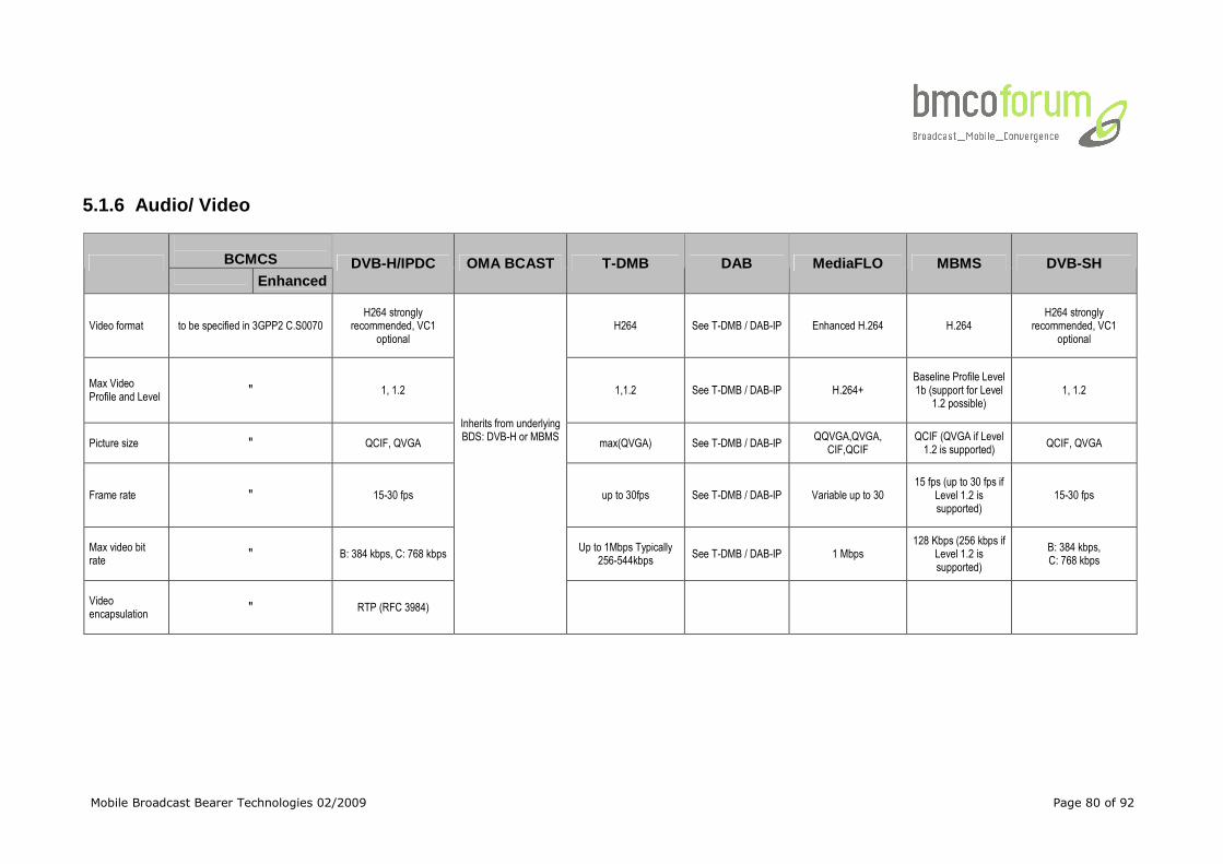
Mobile Broadcast Bearer Technologies 02/2009 Page 80 of 92
5.1.6 Audio/ Video
BCMCS
Enhanced DVB-H/IPDC OMA BCAST T-DMB DAB MediaFLO MBMS DVB-SH
Video format to be specified in 3GPP2 C.S0070 H264 strongly
recommended, VC1 optional
H264 See T-DMB / DAB-IP Enhanced H.264 H.264 H264 strongly
recommended, VC1 optional
Max Video Profile and Level
" 1, 1.2 1,1.2 See T-DMB / DAB-IP H.264+ Baseline Profile Level 1b (support for Level
1.2 possible) 1, 1.2
Picture size " QCIF, QVGA max(QVGA) See T-DMB / DAB-IP QQVGA,QVGA,
CIF,QCIF QCIF (QVGA if Level 1.2 is supported)
QCIF, QVGA
Frame rate " 15-30 fps up to 30fps See T-DMB / DAB-IP Variable up to 30 15 fps (up to 30 fps if
Level 1.2 is supported)
15-30 fps
Max video bit rate
" B: 384 kbps, C: 768 kbps
Inherits from underlying BDS: DVB-H or MBMS
Up to 1Mbps Typically 256-544kbps
See T-DMB / DAB-IP 1 Mbps 128 Kbps (256 kbps if
Level 1.2 is supported)
B: 384 kbps, C: 768 kbps
Video encapsulation
" RTP (RFC 3984)
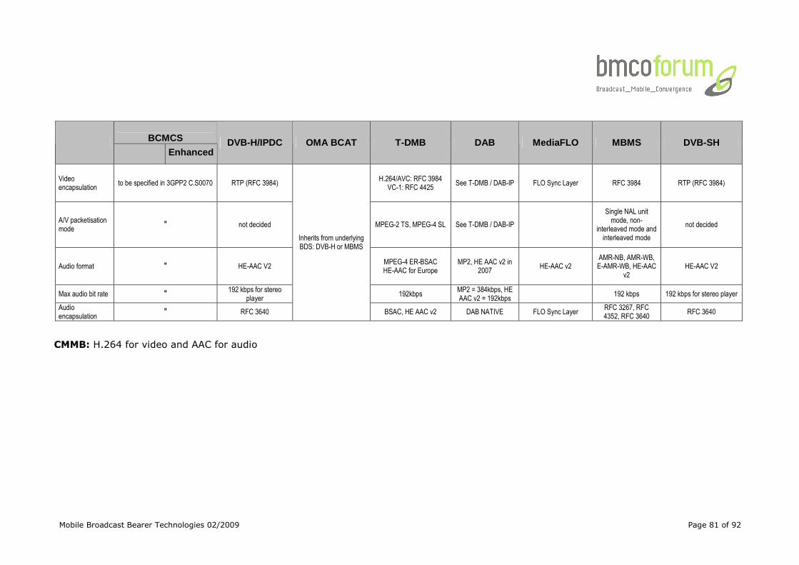
Mobile Broadcast Bearer Technologies 02/2009 Page 81 of 92
BCMCS
Enhanced DVB-H/IPDC OMA BCAT T-DMB DAB MediaFLO MBMS DVB-SH
Video encapsulation
to be specified in 3GPP2 C.S0070 RTP (RFC 3984) H.264/AVC: RFC 3984
VC-1: RFC 4425 See T-DMB / DAB-IP FLO Sync Layer RFC 3984 RTP (RFC 3984)
A/V packetisation mode
" not decided MPEG-2 TS, MPEG-4 SL See T-DMB / DAB-IP
Single NAL unit mode, non-
interleaved mode and interleaved mode
not decided
Audio format " HE-AAC V2 MPEG-4 ER-BSAC HE-AAC for Europe
MP2, HE AAC v2 in 2007
HE-AAC v2 AMR-NB, AMR-WB, E-AMR-WB, HE-AAC
v2 HE-AAC V2
Max audio bit rate " 192 kbps for stereo player
192kbps MP2 = 384kbps, HE AAC v2 = 192kbps
192 kbps 192 kbps for stereo player
Audio encapsulation
" RFC 3640
Inherits from underlying BDS: DVB-H or MBMS
BSAC, HE AAC v2 DAB NATIVE FLO Sync Layer RFC 3267, RFC 4352, RFC 3640
RFC 3640
CMMB: H.264 for video and AAC for audio
Mobile Broadcast Bearer Technologies 02/2009 Page 82 of 92
5.2 Pre-commercial Bearers 5.2.1 Bearer Layer Frequency
DVB-T2
Regulated range Multiple
Specified bandwidth 1.7, 5, 6, 7, 8, 10 MHz
(10 MHz only for professional applications)
Spectrum efficiency up to 6.65bps/Hz7
Regulatory aspects --
Availability from technical point of view UK End of 2009
Availability from regulatory point of view UK End of 2009
5.2.2 Bearer Layer Transmission
DVB-T2
Modulation COFDM
Constellation QPSK, 16-QAM, 64-QAM, 256-QAM. BPSK for L1-Signalling. Rotated constellation possible.
Physical layer signaling L1 pre and post signaling
Guard Interval 1/128, 1/32, 1/16, 19/256, 1/8, 19/128, 1/4
FFT size 1K, 2K, 4K, 8K, 16K, 32K
Inner coding scheme LDPC 1/2, 3/5, 2/3, 3/4, 4/5, 5/6
Time slicing period variable
Peak bit rate per Burst up to 60 Mbit/s (in 8 MHz channels)
Burst size variable
Burst duration variable
Time interleaving Yes. (up to 64s)
DVB-T2
7 Spectral efficiency does not take into account loss due to signalling, synchronization, sounding and guard interval
Mobile Broadcast Bearer Technologies 02/2009 Page 83 of 92
Per channel QOS support Yes. Different for each PLP
Hierarchical Modulation No
Theoretical net data rate up to 50 Mbit/s (in 8 MHz channels)
Parallel reception pf services in the same multiplex
Yes
Scalability per service Up to full rate
PAPR-Reduction Technology Yes
Transmit Diversity (MISO) Yes
Rotated constellation Yes
Pilot-Scheme adaptable Yes
Extendable in the future Yes. Use of Future Extension Frames.
5.2.3 Bearer Layer Network
DVB-T2
Max. SFN cell size No restrictions apart from regulatory ones
Typical transmitter distance 2-160 km for 8K
Seamless Handover Yes
5.2.4 Transport Layer
5.2.4.1 DVB-T2 • MPEG2 Transport Stream
• Generic Encapsulated Stream – GSE (for IPv4 or IPv6 encapsulation)
• Generic Continuous Stream – GCS
• Generic Fixed-length Packetised Stream – GFPS
5.2.5 Service
5.2.5.1 DVB-T2 Multiple possibilities (e.g. SI) for DVB-T2
5.2.6 Audio / Video
5.2.6.1 DVB-T2 Multiple possibilities (DVB-T2 is independent from the used A/V- coding)
Mobile Broadcast Bearer Technologies 02/2009 Page 84 of 92
6 Standards
6.1 BCMCS [TIA-1006], “cdma2000 High Rate Broadcast-Multicast Packet Data Air
Interface Specification”, http://www.tiaonline.org/standards/catalog/.
[TIA-1041], “Broadcast and Multicast Service in cdma2000 Wireless IP
Network”, http://www.tiaonline.org/standards/catalog/.
[TIA-1053], “Broadcast/Multicast Service Security Framework”,
http://www.tiaonline.org/standards/catalog/.
[TIA-2006], Interoperabiolity Specification (IOS) for Broadcast Multicast
Services (BCMCS), http://www.tiaonline.org/standards/catalog/.
[3GPP2 A.S0019-A], “Interoperability Specification (IOS) for Broadcast
Multicast Services (BCMCS)”, Version 2.0, April 2008, http://www.3gpp2.org.
[3GPP2 C.S0023-C], “Removable User Identity Module for Spread Spectrum
Systems”, Version 1.0, June 2006, http://www.3gpp2.org.
[3GPP2 C.S0024-B], “cdma2000 High Rate Packet Data Air Interface
Specification”, Version 1.0, June 2006,
http://www.3gpp2.org.
[3GPP2 C.S0077-0], “Broadcast Multicast Service for cdma2000 1x Systems”,
Version 1.0, May 2006, http://www.3gpp2.org.
6.2 CMMB STiMi GY/T 220.1 - 2006 - Mobile multimedia broadcasting: Frame structure, channel
coding and modulation for broadcast channel
GY/T 220.2 - 2006 - Mobile multimedia broadcasting: Multiplexing
GY/T 220.3 - 2007 - Mobile multimedia broadcasting: Electronic service guide
GY/T 220.4 - 2007 - Mobile multimedia broadcasting: Emergency broadcasting;
GY/T 220.5 - 2008 - Mobile multimedia broadcasting: Data broadcasting;
GY/T 220.6 - 2008 - Mobile multimedia broadcasting: Conditional access;
GY/T 220.7 - 2008- Mobile multimedia broadcasting: Technical requirements of
terminal decoding;
GY/T 220.8 - 2008 - Mobile multimedia broadcasting: Technical requirements
and measurement methods of multiplexer;
GY/T 220.9 - 2008 - Mobile multimedia broadcasting: Frame structure, channel
coding and modulation for satellite distribution channel.
GY/T 220.10 - 2008: Mobile multimedia broadcasting: Secure broadcasting
6.3 DAB, T-DMB ETSI EN 300 401 V1.4.1 (2006-06): “Radio Broadcasting Systems; Digital
Mobile Broadcast Bearer Technologies 02/2009 Page 85 of 92
Audio Broadcasting (DAB) to mobile, portable and fixed receivers”.
ETSI EN 300 797 V1.2.1 (2005-05): “Digital Audio Broadcasting (DAB);
Distribution interfaces; Service Transport Interface (STI)”
ETSI EN 300 798 V1.2.1 (2005-05): “Digital Audio Broadcasting (DAB);
Distribution interfaces; Digital baseband In-phase and Quadrature (DIQ)
interface”
ETSI EN 301 234 V2.1.1 (2006-06): “Digital Audio Broadcasting (DAB);
Multimedia Object Transfer (MOT) Protocol”.
ETSI EN 301 700 V1.1.1 (2000-03): “Digital Audio Broadcasting (DAB); VHF/FM
Broadcasting: Cross-referencing to simulcast DAB services by RDS-ODA 147”
ETSI EN 302 077-1 V1.1.1 (2005-01): “ Title: Electromagnetic compatibility and
Radio spectrum Matters (ERM); Transmitting equipment for the Terrestrial -
Digital Audio Broadcasting (T-DAB) service; Part 1: Technical characteristics
and test methods”
ETSI EN 302 077-2 V1.1.1 (2005-01): “ Title: Electromagnetic compatibility and
Radio spectrum Matters (ERM); Transmitting equipment for the Terrestrial -
Digital Audio Broadcasting (T-DAB) service; Part 2: Harmonized EN under
article 3.2 of the R&TTE Directive”
ETSI ES 201 735 V1.1.1 (2000-09): “ Digital Audio Broadcasting (DAB);
Internet Protocol (IP) datagram tunnelling”
ETSI ES 201 736 V1.1.1 (2000-09): “ Digital Audio Broadcasting (DAB);
Network Independent Protocols for Interactive Services”
ETSI ES 201 737 V1.1.1 (2000-04): “Digital Audio Broadcasting (DAB);
Interaction channel through Global System for Mobile communications (GSM)
the Public switched Telecommunications System (PSTN); Integrated Services
Digital Network (ISDN) and Digital Enhanced Cordless Telecommunications
(DECT)”
ETSI TS 101 498-1 V2.1.1 (2006-01): “Digital Audio Broadcasting (DAB);
Broadcast website; Part 1: User application specification”
ETSI TS 101 498-2 V1.1.1 (2000-09): “Digital Audio Broadcasting (DAB);
Broadcast website; Part 2: Basic profile specification”
ETSI TS 101 498-3 V2.1.1 (2005-10): “Digital Audio Broadcasting (DAB);
Broadcast website; Part 3: TopNews basic profile specification”
ETSI TS 101 499 V2.1.1 (2006-01): “Digital Audio Broadcasting (DAB); MOT
Slide Show; User Application Specification”
ETSI TS 101 756: V1.3.1 (2006-02): “Digital Audio Broadcasting (DAB);
Registered Tables”
ETSI TS 101 757 V1.1.1 (2000-06): “Digital Audio Broadcasting (DAB);
Conformance testing for DAB Audio”
ETSI TS 101 759 V1.2.1 (2005-01): “Digital Audio Broadcasting (DAB); Data
Broadcasting - Transparent Data Channel (TDC)”
ETSI TS 101 860 V1.1.1 (2001-12): “Digital Audio Broadcasting (DAB);
Mobile Broadcast Bearer Technologies 02/2009 Page 86 of 92
Distribution Interfaces; Service Transport Interface (STI); STI levels”
ETSI TS 101 993 V1.1.1 (2002-03): “Digital Audio Broadcasting (DAB); A
Virtual Machine for DAB: DAB Java Specification”
ETSI TS 102 367 V1.2.1 (2006-01): “Digital Audio Broadcasting (DAB);
Conditional access”
ETSI TS 102 368 V1.1.1 (2005-01): “Digital Audio Broadcasting (DAB); DAB-
TMC (Traffic Message Channel)”
ETSI TS 102 371 V1.2.1 (2006-02): “Digital Audio Broadcasting (DAB); Digital
Radio Mondiale (DRM); Transportation and Binary Encoding Specification for
Electronic Programme Guide (EPG)”
ETSI TS 102 427 V1.1.1 (2005-07): “Digital Audio Broadcasting (DAB); Data
Broadcasting - MPEG-2 TS Streaming”
ETSI TS 102 428 V1.1.1 (2005-06): “Digital Audio Broadcasting (DAB); DMB
video service; User Application Specification”
ETSI TS 102 563 V1.1.1 (2007-02): “Digital Audio Broadcasting (DAB);
Transport of AAC audio”
ETSI TS 102 818 V1.3.1 (2006-02): “Digital Audio Broadcasting (DAB); Digital
Radio Mondiale (DRM); XML Specification for DAB Electronic Programme Guide
(EPG)”
ETSI TR 101 495 V1.3.1 (2006-01): “Digital Audio Broadcasting (DAB); Guide
to DAB Standards; Guidelines and Bibliography”
ETSI TR 101 496-1 V1.1.1 (2000-11): “Digital Audio Broadcasting (DAB);
Guidelines and rules for implementation and operation; Part 1: System outline”
ETSI TR 101 496-2 V1.1.2 (2001-05): “Digital Audio Broadcasting (DAB);
Guidelines and rules for implementation and operation; Part 2: System
features”
ETSI TR 101 496-3 V1.1.2 (2001-05): “Digital Audio Broadcasting (DAB);
Guidelines and rules for implementation and operation; Part 3: Broadcast
network”
ETSI TR 101 758 V2.1.1 (2000-11): “Digital Audio Broadcasting (DAB); Signal
strengths and receiver parameters; Targets for typical operation”
IEC 62104 Second edition 2003-03: “Characteristics of DAB receivers”
IEC 62105 First edition 1999-12: “Digital audio broadcasting system -
Specification of the receiver data interface (RDI)”
6.4 DVB-H 6.4.1 DVB-H & IPDC over DVB-H ETSI EN 302 304 v1.1.1 (2004-11): “Digital Video Broadcasting (DVB):
Transmission System for Handheld Terminals (DVB-H)”
ETSI 300 744 v1.5.1 (2004-11): “Digital Video Broadcasting (DVB): framing
Mobile Broadcast Bearer Technologies 02/2009 Page 87 of 92
structure, channel coding and modulation for digital terrestrial television”
ETSI ETSI EN 302 304: “Digital Video Broadcasting (DVB): Transmission
System for Handheld Terminals (DVB-H)”
ETSI TS 102 470: “Digital Video Broadcasting (DVB); IP Datacast over DVB-H:
Program Specific Information (PSI) / Service Information (SI)
ETSI TS 102 471: Digital Video Broadcasting (DVB); IP Datacast over DVB-H:
Electronic Service Guide (ESG)
ETSI TS 102 472: Digital Video Broadcasting (DVB); IP Datacast over DVB-H:
Content Delivery Protocols
ETSI TS 102 005: Digital Video Broadcasting (DVB); Specification for the use of
Video and Audio Coding in DVB services delivered directly over IP protocols
ETSI TR 102 469: Digital Video Broadcasting (DVB); IP Datacast over DVB-H:
Architecture
ETSI TR 102 473: Digital Video Broadcasting (DVB); IP Datacast over DVB-H:
Use cases and Services
ETSI TS 102 474: Digital Video Broadcasting (DVB); IP Datacast over DVB-H:
Service Purchase and Protection
ETSI TR 102 468: Digital Video Broadcasting (DVB); IP Datacast over DVB-H:
Set of Specifications for Phase 1
Tr102 377 Implementation Guidelines for DVB-H Services
Tr102 401 Validation Taskforce Report
ETSI TS 102 005: “Digital Video Broadcasting (DVB); Specification for the use
of Video and Audio Coding in DVB services delivered directly over IP”
6.4.2 DVB-H & OMA BCAST [BCAST10-Services] “Mobile Broadcast Services”, Open Mobile Alliance™, OMA-
TS-BCAST_Services-V1_0, http://www.openmobilealliance.org/
[BCAST10-ESG] “Service Guide for Mobile Broadcast Services”, Open Mobile
Alliance™,OMA-TS-BCAST_ServiceGuide-V1_0,
http://www.openmobilealliance.org/
[BCAST10-ServContProt] “Service and Content Protection for Mobile Broadcast
Services”, Open Mobile Alliance™, OMA-TS-BCAST_SvcCntProtection-V1_0,
http://www.openmobilealliance.org/
[BCAST10-Distribution] “File and Stream Distribution for Mobile Broadcast
Services “, Open Mobile Alliance™, OMA-TS-BCAST_Distribution-V1_0,
http://www.openmobilealliance.org/
[BCAST10-MBMS-Adaptation] “Broadcast Distribution System Adaptation –
3GPP/MBMS”, Open Mobile Alliance™, OMA-TS-BCAST_MBMS_Adaptation-V1_0,
http://www.openmobilealliance.org/
[BCAST10-BCMCS-Adaptation] “Broadcast Distribution System Adaptation –
3GPP2/BCMCS”, Open Mobile Alliance™, OMA-TS-BCAST_BCMCS_Adaptation-
V1_0, http://www.openmobilealliance.org/
Mobile Broadcast Bearer Technologies 02/2009 Page 88 of 92
[BCAST10-DVBH-IPDC-Adaptation] “Broadcast Distribution System Adaptation
– IPDC over DVB-H”, Open Mobile Alliance™, OMA-TS-BCAST_DVB_Adaptation-
V1_0, http://www.openmobilealliance.org/
[BCAST10-ERELD] “Enabler Release Definition for Mobile Broadcast Services”,
Open Mobile Alliance™, OMA-ERELD-BCAST-V1_0,
http://www.openmobilealliance.org/
[BCAST10-Requirements] “Mobile Broadcast Services Requirements”, Open
Mobile Alliance™, OMA-RD-BCAST-V1_0, http://www.openmobilealliance.org/
[BCAST10-ETR] “Enabler Test Requirements for Mobile Broadcast Services”,
Open Mobile Alliance™, OMA-ETR-BCAST-V1_0,
http://www.openmobilealliance.org/
[BCAST10-Architecure] “Mobile Broadcast Services Architecture”, Open Mobile
Alliance™, OMA-AD- BCAST-V1_0, http://www.openmobilealliance.org/
6.5 DVB-SH ETSI EN 302 583 v1.1.0 (2007-08): “Framing Structure, channel coding and
modulation for Satellite Services to Handheld devices (SH) below 3 GHz”
ETSI TS 102 585 v1.1.1 (2007-07): “System Specifications for Satellite services
to Handheld devices (SH) below 3 GHz”
ETSI TS 102 584 (Draft): “ DVB-SH Implementation Guidelines”
Update of the following documents are required to take into account DVB-SH:
ETSI EN 301 192: ”DVB specification for data broadcasting”
ETSI EN 300 468: ”Specification for Service Information (SI) in DVB systems”
ETSI EN 101 191: ”DVB mega-frame for Single Frequency Network (SFN)
synchronization”
6.6 DVB-T ETSI 300 744 v1.5.1 (2004-11): “Digital Video Broadcasting (DVB): Framing
structure, channel coding and modulation for digital terrestrial television”
ETSI TS 101 154, Specification for the use of Video and Audio Coding in
Broadcasting Applications based on the MPEG-2 Transport Stream
6.7 DVB-T2 ETSI EN 302 755 V1.1.1 (2008-10): Digital Video Broadcasting (DVB); Frame
structure channel coding and modulation for a second generation digital
terrestrial television broadcasting system (DVB-T2)
ETSI TR 102 831 (document not yet available): Digital Video Broadcasting
(DVB); Implementation Guidelines for a second generation digital terrestrial
television broadcasting system (DVB-T2). (currently as a DVB internal
document available. Document-ID TM-T20447)
Mobile Broadcast Bearer Technologies 02/2009 Page 89 of 92
ETSI EN 102 773 (document not yet available): Modulator Interface (T2-MI) for
a second generation digital terrestrial television broadcasting system (DVB-T2)
ETSI EN 300 468: Specification for Service Information (SI) in DVB systems
(document will be amended by the new T2 delivery system descriptor (T2dsd))
ETSI TS 102 606 V1.1.1 (2007-10): Digital Video Broadcasting (DVB); Generic
Stream Encapsulation (GSE) Protocol
6.8 Forward Link Only [TIA-1099], “Forward Link Only Air Interface Specification for Terrestrial Mobile
Multimedia Multicast”, http://www.tiaonline.org/standards/catalog/.
[TIA-1120], “Forward Link Only Transport Specification”,
http://www.tiaonline.org/standards/catalog/.
[TIA-1130], “Forward Link Only Media Adaptation Layer Specification”,
http://www.tiaonline.org/standards/catalog/.
[TIA-1146], “Forward Link Only Open Conditional Access (OpenCA)
Specification”, http://www.tiaonline.org/standards/catalog/.
[TIA-1102], “Minimum Performance Specification for Terrestrial Mobile
Multimedia Multicast Forward Link Only Devices”,
http://www.tiaonline.org/standards/catalog/.
[TIA-1103], “Minimum Performance Specification for Terrestrial Mobile
Multimedia Multicast Forward Link Only Transmitters”,
http://www.tiaonline.org/standards/catalog/.
[TIA-1104], “Test Application Protocol for Terrestrial Mobile Multimedia
Multicast Forward Link Only Transmitters and Devices”,
http://www.tiaonline.org/standards/catalog/.
[TIA-1132], “Minimum Performance Specification for Terrestrial Mobile
Multimedia Multicast Forward Link Only Repeaters”,
http://www.tiaonline.org/standards/catalog/.
6.9 MBMS Physical Layer: ETSI TS 125 346, TR 25.803, TS 43.246
Encapsulation: ETSI TS 125 323, ETSI TS 129 060
Data transport: IETF RFC 3550 (RTP), IETF RFC 3926 (FLUTE), IETF RFC 768
(UDP/IP), IETF RFC 761 (IPv4), IETF RFC 2460 (IP v6)
Security: TS 33.246
Multimedia file format: ETSI TS 126 244 (3GP)
Speech Codecs:
AMR Narrowband: ETSI TS 126 071, ETSI TS 126 090, ETSI TS 126 073, ETSI
TS 126 074
AMR Wideband: 3GPP TS 26.171, ETSI TS 126 190, ETSI TS 126 173, ETSI TS
Mobile Broadcast Bearer Technologies 02/2009 Page 90 of 92
126 204
Audio codecs:
Enhanced aacPlus: ETSI TS 126 401, ETSI TS 126 410, ETSI TS 126 411
Extended AMR-WB:ETSI TS 126 290, ETSI TS 126 304, ETSI TS 126 273
Video codecs: ITU-T Rec. H.264 and ISO/IEC 14496-10 AVC
Other codecs:
Synthetic Audio: Scalable Polyphony MIDI Specification Version 1.0, Scalable
Polyphony MIDI Device 5-to-24 Note Profile for 3GPP Version 1.0
Vector Graphics: W3C Working Draft 27 October 2004: “Scalable Vector
Graphics (SVG) 1.2”, W3C Working Draft 13 August 2004: “Mobile SVG Profile:
SVG Tiny, Version 1.2”, Standard ECMA-327 (June 2001): “ECMAScript 3rd
Edition Compact Profile”
Still images: ISO/IEC JPEG
Bitmap graphics: GIF87a, GIF89a, PNG
6.10 UMB BCMCS [TIA-1121.000], “Overview for Ultra Mobile Broadband (UMB) Air Interface
Specification”, http://www.tiaonline.org/standards/catalog/
[TIA-1121.001], “Physical Layer for Ultra Mobile Broadband (UMB) Air Interface
Specification”, http://www.tiaonline.org/standards/catalog/
[TIA-1121.009], “Broadcast-Multicast Upper Layers for Ultra Mobile Broadband
(UMB) Air Interface Specification”, http://www.tiaonline.org/standards/catalog/
Mobile Broadcast Bearer Technologies 02/2009 Page 91 of 92
7 On the bmco forum work item “Bearer Technologies”
From the user’s point of view mobile broadcast services can be provided based
on different technologies:
• DAB/T-DMB
• DVB-T
• DVB-H
• DVB-SH
• Forward Link Only (FLO)
• ISDB-T
• MBMS
• TD-SCDMA
• BCMCS
• CMMB STiMi
• DVB-T2
• DVB-NGH
Each of these technologies has its own pros and cons when comparing them
under special business model requirements.
The bmcoforum bearer technologies work item targets on the evaluation of the
different approaches under technological, frequency, regulatory and business
aspects.
Mobile Broadcast Bearer Technologies 02/2009 Page 92 of 92
8 Authors This report has been compiled as part of the “Bearer Technology” work item of
bmcoforum.
The following members of the “Bearer Technology” Group contributed to this
study:
• Alcatel-Lucent
• Ericsson
• Institut für Rundfunktechnik
• LG
• Nagra
• Nokia
• NXP Semiconductors
• Panasonic
• Qualcomm
• Siano
• T-Systems
• Technical University of Braunschweig
The main editors of the report are Luigi Ardito, Senior Manager, Technical
Marketing at Qualcomm, and Claus Sattler, Executive Director of bmcoforum.
Mobile Broadcast Bearer Technologies
A Comparison
bmcoforum e.V.
Attilastr. 61-67
12105 Berlin
Germany
Tel: +49 30 255 680-0
Fax: +49 30 255 680-99
www.bmcoforum.org
Broadcast Mobile Convergence Forum
forum
Update 02/2009Main Editors:
Claus Sattler
Luigi Ardito (Qualcomm)
Related Documents