M.M./E.G.A. Technical Manual ISSUE: 20.11.00 Autoflame Technical Manual Section M.M./E.G.A. Technical Manual This manual and all the information contained herein is copyright of Autoflame Engineering Limited. It may not be copied in the whole or part without the consent of the Managing Director. Autoflame Engineering's policy is one of continuous improvement in both design and manufacture. We therefore reserve the right to amend specifications and/or data without prior notice. All details correct at time of going to press. Registered Holder: Company: Department: ® 0 Mk6 MM60001 Mini Mk5 MMM50016/IR Mini Mk6 MMM60016 Issued by: AUTOFLAME ENGINEERING LIMITED Unit 19, Bellingham Trading Estate Franthorne Way, Bellingham London SE6 3BX Tel. +44 (0)20 8695 2000 Fax. +44 (0)20 8695 2010 Email: [email protected] Website: http://www.autoflame.com/

Welcome message from author
This document is posted to help you gain knowledge. Please leave a comment to let me know what you think about it! Share it to your friends and learn new things together.
Transcript
M.M./E.G.A. Technical Manual
ISSUE: 20.11.00 Autoflame Technical Manual Section
M.M./E.G.A. Technical Manual
This manual and all the information contained herein is copyright of Autoflame Engineering Limited.It may not be copied in the whole or part without the consent of the Managing Director.
Autoflame Engineering's policy is one of continuous improvement in both design and manufacture.We therefore reserve the right to amend specifications and/or data without prior notice. All detailscorrect at time of going to press.
Registered Holder:
Company:
Department:
®
0
Mk6MM60001
Mini Mk5MMM50016/IR
Mini Mk6MMM60016
Issued by:
AUTOFLAME ENGINEERING LIMITEDUnit 19, Bellingham Trading Estate
Franthorne Way, BellinghamLondon SE6 3BX
Tel. +44 (0)20 8695 2000Fax. +44 (0)20 8695 2010Email: [email protected]
Website: http://www.autoflame.com/

M.M./E.G.A. Technical Manual
ISSUE: 20.11.00 Autoflame Technical Manual Section
123456789012345678901234567890121234567890123456789012345678901212123456789012345678901234567890121234567890123456789012345678901212123456789012345678901234567890121234567890123456789012345678901212123456789012345678901234567890121234567890123456789012345678901212123456789012345678901234567890121234567890123456789012345678901212123456789012345678901234567890121234567890123456789012345678901212123456789012345678901234567890121234567890123456789012345678901212123456789012345678901234567890121234567890123456789012345678901212123456789012345678901234567890121234567890123456789012345678901212123456789012345678901234567890121234567890123456789012345678901212123456789012345678901234567890121234567890123456789012345678901212123456789012345678901234567890121234567890123456789012345678901212123456789012345678901234567890121234567890123456789012345678901212123456789012345678901234567890121234567890123456789012345678901212123456789012345678901234567890121234567890123456789012345678901212123456789012345678901234567890121234567890123456789012345678901212123456789012345678901234567890121234567890123456789012345678901212123456789012345678901234567890121234567890123456789012345678901212123456789012345678901234567890121234567890123456789012345678901212123456789012345678901234567890121234567890123456789012345678901212123456789012345678901234567890121234567890123456789012345678901212123456789012345678901234567890121234567890123456789012345678901212123456789012345678901234567890121234567890123456789012345678901212123456789012345678901234567890121234567890123456789012345678901212123456789012345678901234567890121234567890123456789012345678901212123456789012345678901234567890121234567890123456789012345678901212123456789012345678901234567890121234567890123456789012345678901212123456789012345678901234567890121234567890123456789012345678901212123456789012345678901234567890121234567890123456789012345678901212123456789012345678901234567890121234567890123456789012345678901212123456789012345678901234567890121234567890123456789012345678901212123456789012345678901234567890121234567890123456789012345678901212123456789012345678901234567890121234567890123456789012345678901212123456789012345678901234567890121234567890123456789012345678901212123456789012345678901234567890121234567890123456789012345678901212
1234567890123456789012345678901212345678901234567890123456789012123456789012345678901234567890121234567890123456789012345678901212345678901234567890112345678901234567890123456789012123456789012345678901234567890121234567890123456789012345678901212345678901234567890123456789012123456789012345678901123456789012345678901234567890121234567890123456789012345678901212345678901234567890123456789012123456789012345678901234567890121234567890123456789011234567890123456789012345678901212345678901234567890123456789012123456789012345678901234567890121234567890123456789012345678901212345678901234567890112345678901234567890123456789012123456789012345678901234567890121234567890123456789012345678901212345678901234567890123456789012123456789012345678901123456789012345678901234567890121234567890123456789012345678901212345678901234567890123456789012123456789012345678901234567890121234567890123456789011234567890123456789012345678901212345678901234567890123456789012123456789012345678901234567890121234567890123456789012345678901212345678901234567890112345678901234567890123456789012123456789012345678901234567890121234567890123456789012345678901212345678901234567890123456789012123456789012345678901123456789012345678901234567890121234567890123456789012345678901212345678901234567890123456789012123456789012345678901234567890121234567890123456789011234567890123456789012345678901212345678901234567890123456789012123456789012345678901234567890121234567890123456789012345678901212345678901234567890112345678901234567890123456789012123456789012345678901234567890121234567890123456789012345678901212345678901234567890123456789012123456789012345678901123456789012345678901234567890121234567890123456789012345678901212345678901234567890123456789012123456789012345678901234567890121234567890123456789011234567890123456789012345678901212345678901234567890123456789012123456789012345678901234567890121234567890123456789012345678901212345678901234567890112345678901234567890123456789012123456789012345678901234567890121234567890123456789012345678901212345678901234567890123456789012123456789012345678901123456789012345678901234567890121234567890123456789012345678901212345678901234567890123456789012123456789012345678901234567890121234567890123456789011234567890123456789012345678901212345678901234567890123456789012123456789012345678901234567890121234567890123456789012345678901212345678901234567890112345678901234567890123456789012123456789012345678901234567890121234567890123456789012345678901212345678901234567890123456789012123456789012345678901123456789012345678901234567890121234567890123456789012345678901212345678901234567890123456789012123456789012345678901234567890121234567890123456789011234567890123456789012345678901212345678901234567890123456789012123456789012345678901234567890121234567890123456789012345678901212345678901234567890112345678901234567890123456789012123456789012345678901234567890121234567890123456789012345678901212345678901234567890123456789012123456789012345678901123456789012345678901234567890121234567890123456789012345678901212345678901234567890123456789012123456789012345678901234567890121234567890123456789011234567890123456789012345678901212345678901234567890123456789012123456789012345678901234567890121234567890123456789012345678901212345678901234567890112345678901234567890123456789012123456789012345678901234567890121234567890123456789012345678901212345678901234567890123456789012123456789012345678901123456789012345678901234567890121234567890123456789012345678901212345678901234567890123456789012123456789012345678901234567890121234567890123456789011234567890123456789012345678901212345678901234567890123456789012123456789012345678901234567890121234567890123456789012345678901212345678901234567890112345678901234567890123456789012123456789012345678901234567890121234567890123456789012345678901212345678901234567890123456789012123456789012345678901123456789012345678901234567890121234567890123456789012345678901212345678901234567890123456789012123456789012345678901234567890121234567890123456789011234567890123456789012345678901212345678901234567890123456789012123456789012345678901234567890121234567890123456789012345678901212345678901234567890112345678901234567890123456789012123456789012345678901234567890121234567890123456789012345678901212345678901234567890123456789012123456789012345678901123456789012345678901234567890121234567890123456789012345678901212345678901234567890123456789012123456789012345678901234567890121234567890123456789011234567890123456789012345678901212345678901234567890123456789012123456789012345678901234567890121234567890123456789012345678901212345678901234567890112345678901234567890123456789012123456789012345678901234567890121234567890123456789012345678901212345678901234567890123456789012123456789012345678901123456789012345678901234567890121234567890123456789012345678901212345678901234567890123456789012123456789012345678901234567890121234567890123456789011234567890123456789012345678901212345678901234567890123456789012123456789012345678901234567890121234567890123456789012345678901212345678901234567890112345678901234567890123456789012123456789012345678901234567890121234567890123456789012345678901212345678901234567890123456789012123456789012345678901
M.M./E.G.A. Technical Manual
ISSUE: 20.11.00 Autoflame Technical Manual Section
10
9
8
7
6
5
4
3
1
2
01
2E.G.A.
M.M.
I.B.S.
I.I.F.
D.T.I.
INDEX
Overview and Introduction to the Features and Benefits of the
Micro Modulation Fuel Air Ratio Control, ControlBox Functions & P.I.D. Load Controller.
Exhaust Gas Analysis Trim System CO2 + CO + O2+ Flue Temp. + Eff. Monitoring NO & SO
2.
Intelligent Boiler SequencingLead Lag Selection.
Inverter Interface.
Data Transfer Interface Remote Control, Monitoringand Data Acquisition from Total System.
Application Possibilities for the M.M. E.G.A. System.
Ancillary & Peripheral Equipment for the M.M. E.G.A. System,Oil & Gas Valves, Positioning Motors, Load Detectors.
Miscellaneous Component Information: Parts List.
Appendix: Approvals, Compatibility, Warranty,Terms and Conditions etc.
M.M./E.G.A. System.
M.M./E.G.A. Technical Manual
ISSUE: 20.11.00 Autoflame Technical Manual Section 02
Important Notes
A knowledge of combustion related procedures and commissioning is essential before embarking workon any of the M.M./E.G.A. systems. This is for safety reasons and effective use of the M.M./ E.G.A.system. Hands on training is required. For details on schedules and fees relating to group trainingcourses and individual instruction, please contact the Autoflame Engineering Ltd. offices at the addresslisted on the front.
Introduction.
Short Form - General Terms and Conditions
A full statement of our business terms and conditions are printed on the reverse of all invoices. A copyof these can be issued upon application, if requested in writing.
The System equipment and control concepts referred to in this Manual MUST be installed, commis-sioned and applied by personnel skilled in the various technical disciplines that are inherent to theAutoflame product range, i.e. combustion, electrical and control.
The sale of Autoflame’s systems and equipment referred to in this Manual assume that the dealer,purchaser and installer has the necessary skills at his disposal. i.e. A high degree of combustionengineering experience, and a thorough understanding of the local electrical codes of practiceconcerning boilers, burners and their ancillary systems and equipment.
Autoflame’s warranty from point of sale is two years on all electronic systems and components.One year on all mechanical systems, components and sensors.
The warranty assumes that all equipment supplied will be used for the purpose that it was intended andin strict compliance with our technical recommendations. Autoflame’s warranty and guarantee islimited strictly to product build quality, and design. Excluded absolutely are any claims arising frommisapplication, incorrect installation and/or incorrect commissioning.
If in doubt regarding any technical aspect of the system contact your authorised dealer or the AutoflameTechnical Sales Department. Either of the above will be pleased to give advice and TechnicalInformation.
M.M./E.G.A. Technical Manual
ISSUE: 20.11.00 Autoflame Technical Manual Section
Section 1: Overview and Introduction of M.M. E.G.A. System
1.1 Schematic of M.M./E.G.A. System Capabilities and Inter-Relationship of Software Modules
1.2 Schematic Illustrating Burner Combination Possibilities
1.3 Schematic Illustrating Typical System Application
1.4 Burner Management Systems Comparison
1.5 Overview of Micro Modulation System
1.6 Overview of Exhaust Gas Analysis
1.7 Overview of Intelligent Boiler Sequencing
1.8 Overview of the Data Transfer Interface
1.9 Overview of the Inverter Interface
1.10 Overview of P.C. Compatibility
1.11 Overview of the Analogue Output Unit
1: Index
M.M./E.G.A. Technical Manual
ISSUE: 20.11.00 Autoflame Technical Manual Section
DDDD D.T
.I..T
.I..T
.I..T
.I..T
.I.
DA
TA TR
AN
SFER
INTE
RFA
CE
REM
OTE
MO
NIT
ORI
NG
&C
ON
TRO
L V
IA D
.T.I.
ALT
ER S
ETPO
INTS
, TU
RNBU
RNER
S O
N O
R O
FF.
VIE
W &
HA
RD C
OPY
OF
ALL
SYS
TEM
DA
TA.
E.C.
E.C.
E.C.
E.C.
E.C.
ERR
OR
CH
ECK
ING
DIA
GN
OST
IC S
OFT
WA
RETO
INTE
NSI
VEL
Y IN
TERR
OG
ATE
TOTA
L SYS
TEM
.
SHO
WS
ERRO
R C
OD
E FO
RC
OM
PON
ENT O
R D
ATA
STO
RAG
E FA
ILU
RE.
Pod
LOC
AL
DIS
PLA
Y
DIS
PLA
Y
CO
MBU
STIO
N V
ALU
ES
ON
REM
OTE
FAC
IA
I.I.S.
I.I.S.
I.I.S.
I.I.S.
I.I.S.
INV
ERTE
R IN
TERF
AC
ESP
LITT
ER M
OD
ULE
FRE
-Q
UEN
CY
CO
NTR
OL
EXIS
TIN
G O
2 TR
IMP.C
.C.
DO
WN
LOA
D A
LLC
OM
MIS
SIO
NIN
G D
ATA
FRO
M M
.M.E
.G.A
. MO
DU
LE.
SET
UP
AN
D C
ALI
BRA
TE E
.G.A
.V
IA R
S232
SER
IAL
PORT
.LO
G R
UN
NIN
GPA
RAM
ETER
S O
FIN
VER
TER
INTE
RFA
CE
TELE
CO
MN
ETW
ORK
PC
W
ITH
MO
NIT
ORI
NG
SOFT
WA
RE
CLI
ENT'
SB.
M.S
.
MO
DEM
I.B.S
.I.B.S
.I.B.S
.I.B.S
.I.B.S
.IN
TELL
IGEN
T B
OIL
ER
SEQ
UEN
CIN
G.
HO
T W
ATE
R-ST
EAM
LEA
D/L
AG
LO
AD
DIS
TRIB
UTI
ON
F.F.
M.
F.F.
M.
F.F.
M.
F.F.
M.
F.F.
M.
FUEL
FLO
WM
EASU
REM
ENT
IN
STA
NTA
NEO
US
&TO
TALI
ZED
VA
LUES
M.M
.M
.M.
M.M
.M
.M.
M.M
.M
icro
Mo
dul
ati
on
FU
EL A
IR R
ATI
O C
ON
TRO
L.P.
I.D.
LOA
D C
ON
TRO
LC
ON
TRO
LS 2
/4/8
PO
SITI
ON
ING
MO
TORS
SOFT
WA
RE F
OR
TEM
PERA
TURE
OR
PRES
SURE
TWIN
BU
RNER
CA
PABI
LITY
AS
STA
ND
ARD
.V
ARI
OU
S LO
AD
DET
ECTO
RS A
VA
ILA
BLE.
DIS
PLA
YS C
HA
NN
EL P
OSI
TIO
NS,
SETP
OIN
T D
ESIR
ED &
AC
TUA
L,FU
EL M
EASU
RED
.
LIM
ITS
CO, C
O², O
²
USE
R SE
LEC
TABL
E
UPP
ER &
LO
WER
LIM
ITS
CO
, CO
², 0²
SHU
T D
OW
N S
YSTE
M,
ALA
RM O
N,
IGN
ORE
TRI
M (
M.M
. O
NLY
).
E.G
.A.
E.G
.A.
E.G
.A.
E.G
.A.
E.G
.A.
EXH
AU
ST G
AS
AN
ALY
SIS
3 P
ARA
MET
ER T
RIM
CO
, CO
² & O
²EF
FIC
IEN
CY
& E
XH
AU
ST T
EMPE
RATU
RE
OPT
ION
AN
ALY
SIS
FOR
NO
& S
O²
DIS
PLA
YS A
LL O
F A
BOV
E"C
OM
MIS
SIO
NED
"&"O
N-L
INE"
VA
LUES
.
6 O
PTIO
NA
L OU
TPU
TSI
GN
ALS
4-2
0m
A.
I.O
.I.O
.I.O
.I.O
.I.O
.M
OD
ULE
MO
DU
LEM
OD
ULE
MO
DU
LEM
OD
ULE
Ana
logu
eIn
put/
Out
put
Mod
ule
6 in
/6 o
ut x
4-2
0mA
.
I.O
.I.O
.I.O
.I.O
.I.O
.M
OD
ULE
MO
DU
LEM
OD
ULE
MO
DU
LEM
OD
ULE
Dig
ital
Inpu
t/O
utpu
t U
nit
8 x
Vol
t Fr
ee O
utpu
ts16
x L
ine
Inpu
ts
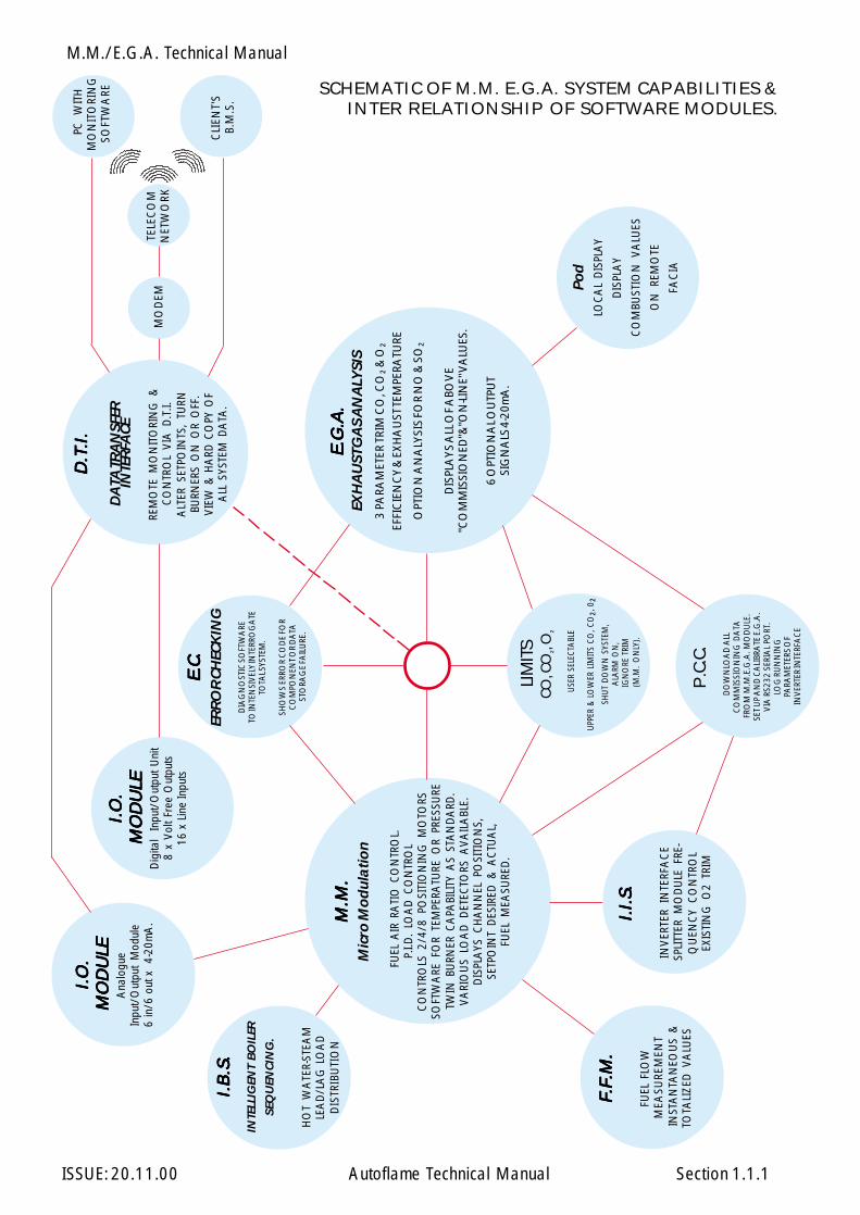
SCHEMATIC OF M.M. E.G.A. SYSTEM CAPABILITIES &INTER RELATIONSHIP OF SOFTWARE MODULES.
1.1.1
M.M./E.G.A. Technical Manual
ISSUE: 20.11.00 Autoflame Technical Manual Section
Overview - Features and Benefits of the Autoflame MicroModulation and Exhaust Gas Analysis Trim Systems
M.M. Micro Modulation/Flame Safeguard
* Fuel/air ratio control
* Control up to 4 positioning motors for up to 4 fuel programs
* Fully adjustable P.I.D. load control for temperature and pressure
* External voltage load control
* Various boiler load detectors available
* Twin burner capability
* Fully compatible with control frequency drives
* Fuel Flow Metering software
* Full Flame Supervision with UV self check
* Gas valve train leak supervision
* Air windbox pressure proving
E.G.A. Exhaust Gas Analysis
* 3 parameter Trim of CO² - CO and O²
* Displays CO², CO, O² Efficiency, Delta T and exhaust gas temperature.
* NO, SO² monitoring.
* System can be used as a stand alone analyser with display pod and 6adjustable 4-20mA outputs to interface with other controls.
I.B.S. Intelligent Boiler Sequencing.
* System will Sequence hot water boilers and steam boilers via lead/lag loaddistribution.
* Fully adjustable via user option with the system to enable the control to betailored to the application.
* System control for isolation of valves or pumps.
1.1.2
M.M./E.G.A. Technical Manual
ISSUE: 20.11.00 Autoflame Technical Manual Section
D.T.I. Data Transfer Interface
* System will collect operational data up to 10 M.M. modules on one site, trans-mit via RS232 data link to a local PC running WinPCDTI or Building Manage-ment System (B.M.S.).
* Modem compatibility software to give information and control of boiler houseoperation remotely.
I.I.F. Inverter Interface, Splitter
* Fully compatible with variable frequency controllers via 4-20mA or 0-10V.
* Interface with existing on-line O² analysers via 4-20mA or 0-10V.
* Split one E.G.A. signal for two M.M.s for use on common or twin furnaceboilers.
P.C.C. Personal Computer Compatible
* Down load all commissioning data from M.M. E.G.A. module.
* Set up and calibrate E.G.A. via RS232 serial port.
* Log running parameters of Inverter Interface.
I/O.U. Digital & Analogue Input/Output Units.
* These units can be configured to give inputs and outputs for the DTI system.Additionally the Analogue unit can communicate directly with a Mini Mk5MM.
1.1.3
M.M./E.G.A. Technical Manual
ISSUE: 20.11.00 Autoflame Technical Manual Section 1.2.1
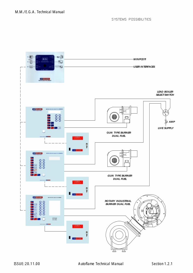
LIVE SUPPLY
WINPCDTI
USER INTERFACES
GUN TYPE BURNERDUAL FUEL
GUN TYPE BURNERDUAL FUEL
ROTARY INDUSTRIALBURNER DUAL FUEL
LEAD BOILERSELECT SWITCH
1 AMP
M.M./E.G.A. Technical Manual
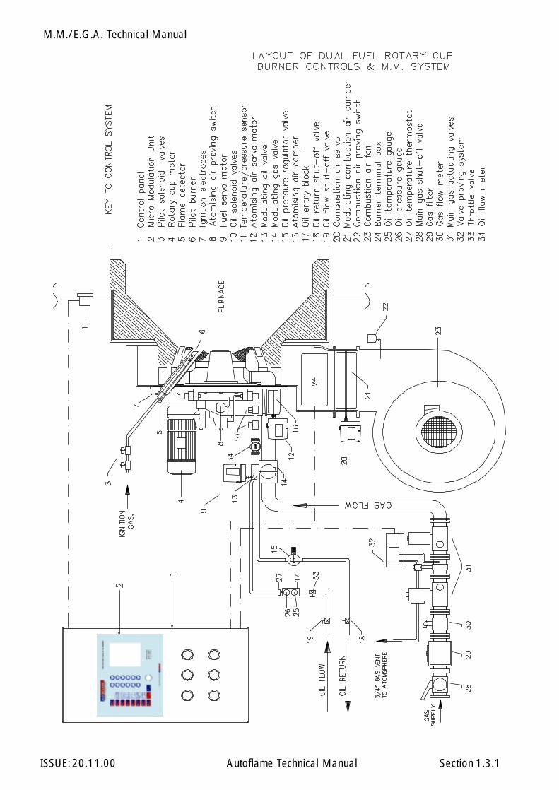
ISSUE: 20.11.00 Autoflame Technical Manual Section 1.3.1
M.M./E.G.A. Technical Manual
ISSUE: 20.11.00 Autoflame Technical Manual Section
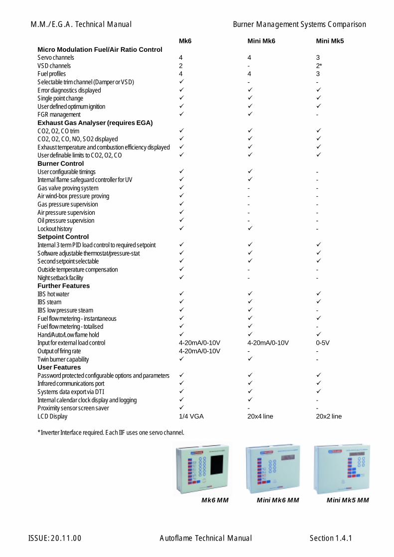
Burner Management Systems Comparison
1.4.1
Mini Mk5 MMMini Mk6 MMMk6 MM
Mk6 Mini Mk6 Mini Mk5Micro Modulation Fuel/Air Ratio ControlServo channels 4 4 3VSD channels 2 - 2*Fuel profiles 4 4 3Selectable trim channel (Damper or VSD) - -Error diagnostics displayedSingle point changeUser defined optimum ignitionFGR management -Exhaust Gas Analyser (requires EGA)CO2, O2, CO trimCO2, O2, CO, NO, SO2 displayedExhaust temperature and combustion efficiency displayedUser definable limits to CO2, O2, COBurner ControlUser configurable timings -Internal flame safeguard controller for UV -Gas valve proving system - -Air wind-box pressure proving - -Gas pressure supervision - -Air pressure supervision - -Oil pressure supervision - -Lockout history -Setpoint ControlInternal 3 term PID load control to required setpointSoftware adjustable thermostat/pressure-statSecond setpoint selectableOutside temperature compensation - -Night setback facility - -Further FeaturesIBS hot waterIBS steamIBS low pressure steam -Fuel flow metering - instantaneousFuel flow metering - totalised -Hand/Auto/Low flame holdInput for external load control 4-20mA/0-10V 4-20mA/0-10V 0-5VOutput of firing rate 4-20mA/0-10V - -Twin burner capability -User FeaturesPassword protected configurable options and parametersInfrared communications portSystems data export via DTIInternal calendar clock display and logging -Proximity sensor screen saver - -LCD Display 1/4 VGA 20x4 line 20x2 line
* Inverter Interface required. Each IIF uses one servo channel.

M.M./E.G.A. Technical Manual
ISSUE: 20.11.00 Autoflame Technical Manual Section
Overview: M.M.
1.5.1
MICRO MODULATION (M M)
Overview of System Operation: Features and Benefits
To ensure maximum efficiency in the operation of any boiler, two requirements are of paramountimportance, the first being that the air to fuel ratio is kept to the minimum to ensure completecombustion within the limitations of the combustion head design and that these settings once arrivedat are infinately repeatable to an incredibly high degree of accuracy. The second requirement shouldbe that the target temperature or pressure of the boiler is monitored by the combustion system andthat at all times exactly the right amount of fuel and air is fire to achieve the target value and thatat no time irrespective of load change is this target exceeded or fallen short of.
The inherent hysterisis of all mechanical systems that have traditionally involved cams and linkagesto characterise the fuel air ratio have made this sort of accuracy impossible. The accuracy of responseof fuel input to the monitored target temperature/pressure of the boiler has meant that the targetvalue set by the operator has at most times been exceeded or fallen short of.
The Micro Modulation system provides an easily programmable and flexible means of optimisingcombustion quality throughout the load requirement range of the boiler/burner unit whilst ensuringthe temperature is accurate to within 1 deg C (2 deg. F.) and pressure to within 1.5 p.s.i. The maximumerror in degrees angular rotation between the two servo motors at any position in the load range is 0.1degrees.
At the heart of the system is the control module which contains the micro computer and power supply.The display panel features touch sensitive key pad entry data, readouts and status indicators, allprotected beneath a tamper-proof transparent plastic cover. The M.M. system shows angular positionof air damper motor and fuel valve. “Required” and “Actual” temperatures are displayed.
Interfaced with the control module by means of high speed solid state switching are up to three dualwound servo motors. One motor is responsible for positioning the air damper and the other operatesa fuel valve by which it is possible to meter the input of gas, oil, or dual fuel.
The position of each servo motor is monitored by a voltage dividing system enabling digitalisedposition information to be encoded into the control modules memory. The relative positions of theair and fuel motors are constantly checked by the system at the rate of 50 times per second.
This new system of burner control achieves ‘Locked On’ near stoichiometric air fuel mixing throughoutthe fuel input range of the boiler while maintaining exact temperature or pressure target values.The load control incorporates user variable P.I.D. values.
Operating in conjunction with the above control specification is a full three term infinitely adjustableP.I.D. load control package. This ensures that the control of set point temperature is accurate to within1 deg C (2 deg F.) and pressure to within 0.1 bar (1.5 P.S.I.) Software for temperature or pressure is auser variable option, also various ranges of temperature and pressure are selectable by the user.

M.M./E.G.A. Technical Manual
ISSUE: 20.11.00 Autoflame Technical Manual Section
Overview: M.M.
1.5.2
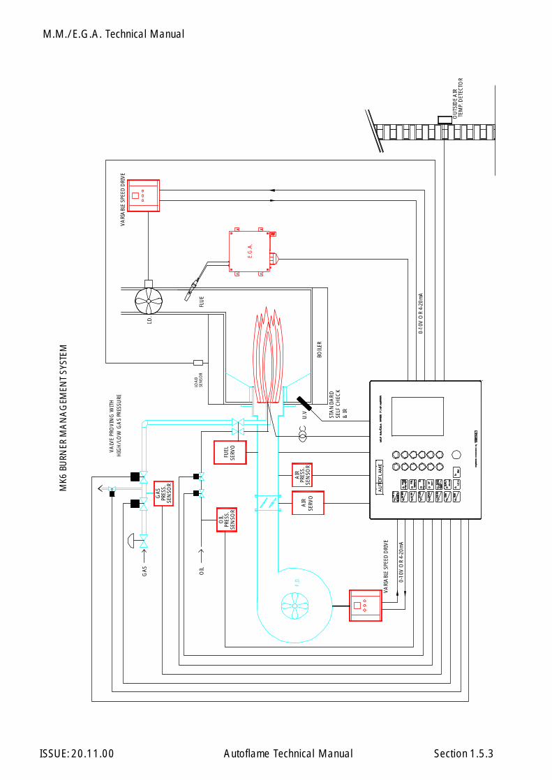
The Micro Modulation (M.M.) module is the basic building block of the M.M./E.G.A. system. Acomplete system based on the Mk6 MM incorporates all of the following control facilities and features:
· 6 channel: 4 positioning motors and 2 Variable Speed Drive interfaces.· 4 separate fuel profiles· Full flame supervision control with UV self check - system meets self check criteria on all outputs.· A lockout history of the last 16 incidents held in memory. Time, date, function re-set· Single point change capability· IBS steam sequencing with lead/lag· IBS heating boiler sequencing - lead/lag - control of return line 2 port valve· Gas valve train leak proving system· Gas pressure monitoring and display· High and Low gas pressure supervision· Oil pressure high/low limits.· Oil pressure monitoring & display· User definable optimum ignition position selection- User definable flue gas recirculation ignition position selection· Variable Modulation speed (motor travel time user variable)· Selectable trim channel· Burner control selectable operation - first/second safety times· Air wind box pressure proving - display & supervision· Internal PID 3 term load control - temperature & pressure· Outside temperature compensation of boiler set point, user adjustable with night seback facility· Fuel flow metering - instantaneous and totalised readings - all fuels - user defined units of meas-
urement· Exhaust temperature and ambient temperature net and absolute readings displayed.· 3 parameter trim - CO2, O2 & CO· Combustion efficiency calculation - net or gross displayed· NO and SO2 monitoring & display· User definable combustion limits on all CO2, O2 & CO values· Second set point user selectable· Internal calendar clock display and logging functions· Software adjustable thermostat/pressure stat. facility· Hand/Auto/Low flame hold facilities· Password protection of all safety related options and parameters· Infrared Coms port for upload and download of commissioned data and lockout history· Twin burner control capability· 4-20mA/0-10V input for external load control of firing rate· 4-20mA/0-10V output confirming firing rate position· Changeover of fuels without shutdown (Special PROM)· Quarter VGA screen with dynamic display capabilities and IR proximity screen saver· 110 or 230 volt standard operation· Panel facing mounting
M.M./E.G.A. Technical Manual
ISSUE: 20.11.00 Autoflame Technical Manual Section 1.5.3
VARI
ABL
E SP
EED
DRI
VE
BOIL
ER
0-10
V O
R 4-
20m
A
FLU
E
SERV
OA
IR
SERV
OFU
EL
E.G
.A.
I.D.
0-10
V O
R 4-
20m
A
OU
TSID
E A
IRTE
MP.
DET
ECTO
R
U.V
VARI
ABL
E SP
EED
DRI
VE
STA
NDA
RD
MK6
BU
RNER
MA
NA
GEM
ENT
SYST
EM
VALV
E PR
OVI
NG
WIT
H
F.D.
GA
S
PRES
S.O
IL
OIL
PRES
S.G
AS
AIR
PRES
S.
LOA
D
SELF
CH
ECK
& IR
SEN
SOR
HIG
H/L
OW
GA
S PR
ESSU
RE
SEN
SOR
SEN
SOR
SEN
SOR

M.M./E.G.A. Technical Manual
ISSUE: 20.11.00 Autoflame Technical Manual Section
EXHAUST GAS ANALYSIS (E.G.A.) TRIM SYSTEM
Overview of E.G.A. System Operation
With the E.G.A. trim system it is possible to expand the M.M. so that it will measure and display O2, CO2,CO and exhaust temperature, together with boiler efficiency: At the same time inflicting minutecorrections on the air damper position to ensure that the originally entered commissioning data isadhered to, irrespective of variations in stack pressure or barometric conditions. As standard, outputsare available which can be connected with appropriate interfacing to an energy management computerto track and record the information that is generated by the E.G.A. system. To expand the M.M. systemto the above E.G.A. specification the additional sampling unit and exhaust gas sampling probe must bepurchased. The M.M./E.G.A. control form is P + I + D feed forward, and interpolates between all entereddata, it also carries error checking self diagnostic software for self identification of system componentor data handling failure.
The system trim function is achieved by every paired value for air and fuel having stored values for O2,CO2 and CO at the commissioned value. Deviations from these ideal values are held, this data isintegrated and expressed as a degree angular value, so that an exact amount of air damper trim maybe inflicted at any time to return the system to it’s commissioned value at any load condition.
The E.G.A. can also be fitted with NO and SO2 sensors for monitoring.
All the information available on the E.G.A. can be accessed by one or all three of the following methods:
1. Displayed on the M.M. facia.2. 6 channel 4-20mA output facility for the above values.3. Optional display pod on the front of the unit or mounted remotely on a flying lead.
Options 2 and 3 enable the E.G.A. to be used as a Stand Alone on-line continuous monitoring system.
E.G.A. setup and calibration is carried out via a PC using an RS232 serial port.
Overview: E.G.A.
1.6.1

M.M./E.G.A. Technical Manual
ISSUE: 20.11.00 Autoflame Technical Manual Section
Overview: I.B.S.
1.7.1
INTELLIGENT BOILER SEQUENCING (I.B.S)
Overview of I.B.S. System Operation
The Intelligent Boiler Sequencing software, which is included in every M.M./E.G.A. module, furtherextends the application possibilities of the system. The objective of this control form is to ensure thatthe minimum number of boiler/burner units are in operation at any one time to satisfy the heatrequirement imposed upon the boiler plant, particularly in the case of multi boiler installations.
There are two variations of I.B.S. software that can be selected by the user via the Options procedure.The first variation relates to heating boilers and the second variation to steam boilers.
Heating Boilers Sequential Control:
A maximum of ten M.M./E.G.A. modules may be interconnected by a two wire screened data cable:(See interconnection drawing). Any string of modules interconnected as detailed can have one of it’snumber designated No. 1 or lead boiler. This identifying of “lead” boiler is achieved by either of thefollowing methods:
a) Connecting a mains voltage onto terminal No. 41.b) Instructing the modules via the D.T.I. module (Data Transfer Interface) by software.
Once a “lead” boiler has been selected the system works in the following way:
Typically every five minutes the sequencing software in the lead boiler identifies it’s own firing rate bylooking at the position of the fuel valve in the load index and also the maximum heating capacity of theNo 1. “lead” boiler. This information would normally be entered when this boiler/burner unit iscommissioned. Having established percentage firing rate, and maximum heating capacity, the I.B.S.software calculates the amount of heat being contributed to the system by this boiler. The I.B.S. softwarein the “lead” M.M./E.G.A. module then contacts in turn each of the modules connected to this loopand gathers similar information from each. The “lead” module’s I.B.S. software then calculates theminimum number of boiler/burner units that need to be operational to satisfy the building load, imposedupon the plant at that time, and switches the remainder off.
There is a terminal connection on the M.M./E.G.A. module for controlling a two port valve that wouldnormally be installed in the boiler’s return pipe connection to the common return header. This facilityensures that boilers that are switched “off line” do not contribute return temperature water to the flowheader thereby diluting the flow temperature to the building: (See relevant data sheets and drawingsshowing the control sequence detailed above).
Example:There are four boilers interconnected as above, each with a heating capacity of 586kW(2MBtu.) In theevent of each boiler firing 440 kW (1.5MBtu) (3/4 of it’s maximum rate), the No. 1 lead boiler wouldinstruct the No. 4 boiler to shut down and boilers No.s 1, 2 and 3 would adjust their firing rate tomaximum.
In both cases the boilers are contributing 1758kW (6MBtu) to the system but, after intervention of theI.B.S. sequencing software, three boilers only are carrying the load which is a more fuel efficient methodof operation.
M.M./E.G.A. Technical Manual
ISSUE: 20.11.00 Autoflame Technical Manual Section
Overview: I.B.S.
1.7.2
If the building load continued to decrease the three boilers would reach a point where they were eachfiring 381kW (1.3MBtu) each. At this point the I.B.S. software would switch off the No. 3 boiler as twoboilers would be capable of generating the 1172kW (4MBtu) required. When the load on the systemincreases, the reverse procedure applies, i.e. when, for example, two boilers are firing at near 100%load and the setpoint temperature on either of the modules is not being achieved, the I.B.S. softwarewould switch on a third boiler to assist with the generation of the heat requirement. Any boiler can benominated “lead” boiler by the connection of an input to the appropriate terminal or by a softwareinstruction via the D.T.I.
Steam Boiler Sequential Control:
When the I.B.S. software control package is applied to steam boilers, it’s operation is exactly the sameas above but with the additional features and enhancements as explained in the following.
In the case of heating boilers only two states in the control form exist, either on or off. When steam boilervariation of I.B.S. is optioned there are three states which are controlled sequentially. The first is “on-line”, this is when the boiler is operating purely under the control of the M.M./E.G.A. module's internalP.I.D. load controller.
The second state is “stand-by”: In this case the boiler is operated at a reduced pressure setpoint, e.g. ifthe on-line boiler or boilers are set at a setpoint of 7 bar (100 p.s.i.) the stand-by boiler controls at asetpoint of 5 bar (72 p.s.i.). In this way if the load increases the stand-by boiler can begin to contributesteam quickly. The reduced setpoint is a user variable option in the same way as the normal controlpressure setpoint.
The third state is “off-line”, this is with the burner shut down and the boiler is cold. If the load on the boilerhouse increases, this boiler would move into a “Stand By” condition.
Apart from the variations detailed above, the steam sequencing works in precisely the same way as theheating boiler sequencing: The sequencing software package ensures that at all times the minimumnumber of boilers are operational to satisfy the load imposed on the boiler house.

M.M./E.G.A. Technical Manual
ISSUE: 20.11.00 Autoflame Technical Manual Section
REMOTE MONITORING AND CONTROL (D.T.I.)
Overview of Data Transfer Interface Operation
By means of our Data Transfer Interface (D.T.I.) module, all the operational data, stored within eachof up to ten M.M. modules, can be collected by the D.T.I. for transmission by direct RS232 data linkto a local terminal, screen and printer or Building Management System (B.M.S.). This facility can alsobe achieved remotely via modem/telecom link up. This cost effective system more than meets therequirements of today’s E.M.S. and B.M.S. systems in providing all the necessary operational and alarmstatus and control of boiler plant to achieve its maximum energy efficient operation.
Up to a maximum of ten M.M. modules (one per burner) can be connected to one D.T.I. module bymeans of a series RS485 data link. The information gathered by the D.T.I. from each M.M. module isthen available for transmission to the E.M.S. or B.M.S. via either an RS232 data link or modem/telecomdata link.
Remote on/off control of the burners can also be achieved as well as adjustment of the temperature orpressure setpoints and selection of sequence lead boiler. To accommodate the status information fromother plant related equipment, the D.T.I. can handle upto 160 direct mains voltage inputs, 80 volt freeoutputs, 60 4-20mA inputs and 60 4-20mA outputs. Typical remote E.M.S., B.M.S. information andoperational facilities that can be achieved are as follows, but are subject to the particular site andmanagement system requirements that are to be accommodated.
The capability exists within the standard D.T.I. software for the end user to label any mains voltage signalinput as an "Alarm" condition. When labelled as an "Alarm" condition the system can 'autodial' out ontothe general telephone network to a word pager and/or a remote office.
Possible Input/Output Values:
Values available from each MM :
Required boiler temperature (deg. C) or pressure (Bar).Actual boiler temperature (deg. C) or pressure (Bar).Burner on/off (CR relay on/off status).Burner maximum firing rate.Burner firing rate (%).Fuel selected.Boiler control detector type (temperature/pressure).Error conditions.Low flame hold operation.Hand operation.All MM channels (positioning motors and variable speed drives).
Overview: D.T.I.
1.8.1

M.M./E.G.A. Technical Manual
ISSUE: 20.11.00 Autoflame Technical Manual Section
Overview: D.T.I.
Values available from each MM : cont../...
Maximum set point accepted from DTI.Minimum set point accepted from DTI.Lead boiler status.Burner firing status (off, firing, purge, ignition).Sequencing optioned.Sequence status (on, stand-by, warm, off).Enabled/disabled status.
Additional information available if system has E.G.A.:
E.G.A. operation optioned.Flue gas oxygen present value.Flue gas carbon dioxide present value.Flue gas carbon monoxide (unburnt combustibles) present value.Flue gas exhaust temperature present value.Combustion efficiency present value.Flue gas oxygen commission value.Flue gas carbon dioxide commission value.Flue gas carbon monoxide (unburnt combustibles) commission value.Flue gas exhaust temperature commission value.Combustion efficiency commission value.E.G.A. error conditions.
DTI control input values:
Change set point.Select lead boiler.Boiler enable/disable.
1.8.2

M.M./E.G.A. Technical Manual
ISSUE: 20.11.00 Autoflame Technical Manual Section
INVERTER INTERFACE MODULE
The I.I.F. module retains the same hardware but by a change of software can perform any one of thefollowing 3 functions:
1. Inverter Interface (Mini Mk.5 only)
It is possible to control an inverter (variable frequency/speed drive) as if it were a servo motor, retain-ing all the T.U.V. Approved Error Checking software. The module is connected to the M.M. as astandard servo motor but the output signals can take the form of 4-20mA or 0-10V. The unit thenexpects to see a feedback signal as proof of condition in the form of 0-10V or 0-20mA.
Inverters are generally used for controlling the speed of the combustion air fan motor in conjunctionwith an air damper to achieve more precise control, a greater turndown and considerable electricalsavings. Control over a recirculation motor is also possible.
2. O2 Interface.
Where an existing O2 measuring device is fitted the interface module can receive a 0-10V or 0-20mA.signal for use by the M.M. for one parameter O2 trim. Values for CO2, CO, Exhaust Gas Temperatureand Efficiency will be displayed as 0.
3. EGA Splitter.
On water tube or common furnace boilers it is possible to use one E.G.A. unit to sample the commonflue gases and split the signal for use by two M.M. modules. Trim is inflicted on both burners based onthe common products of combustion and will therefore not optimise the combustion performance ofeach burner.
Overview: I.F.F
1.9.1
M.M./E.G.A. Technical Manual
ISSUE: 20.11.00 Autoflame Technical Manual Section
Overview: P.C.C.
1.10 P.C. COMPATIBILITY
M.M. Infrared Upload/Download
The Mk.6, Mini Mk.6 and Mini Mk.5 MMs each contain an Infra Red Upload/Download port whichenables all the commissioning data from a single unit to be downloaded onto a PC using Autoflame IRlead and software. Data can be stored on disk. Stored backup data can be uploaded in to the MM.Information includes:
1. Site name, Engineer, Boiler Type, Data, Software No., M.M. identification number.2. All fuel/air positions entered during commissioning.3. E.G.A. values O2%, CO2%, COppm, NOppm, SO2ppm, Ambient Temperature, Exhaust
temperature, Delta T, Efficiency % for commissioned, and also autotrim values of O2,CO2 and CO at each position.
4. All Option number setting, default - * indicates options changed.5. All Parameter numbers, setting, default - * indicates Parameters changed.6. Flow Metering - if entered.
which can then be used to generate a hard copy Commissioning Report and be stored on disk forfuture reference.
E.G.A.
The E.G.A. is fitted with an RS232 serial port for connection to a P.C. All Set Up and Calibration tasksare carried out with the use of this link. Each cell is provided with its own unique calibration numberwhich alleviates the need for costly on site calibration with test gas etc.
Inverter Interface
When connected to an Inverter Interface via a logic/232 link it is possible to list all the runningparameters. This enables the operation of the Inverter to be monitored in relation to the M.M. ErrorChecking during commissioning and highlight any unacceptable conditions.
1.10.1
M.M./E.G.A. Technical Manual
ISSUE: 20.11.00 Autoflame Technical Manual Section
1.11 ANALOGUE INPUT/OUTPUT UNIT
This unit has 6 individually programmable outputs and 6 individually programmable inputs providinga means of converting items of data within the M.M./E.G.A. system in 4-20mA signals.
The unit can be supplied with outputs readily configured or with the use of the DTI lead and WindowsTerminal mode software the outputs are user configurable.
The following functions are available for output data:-
Firing Rate - Percentage %Actual - Temperature/Pressure, °C/°F or bar/psi.Required - Temperature/Pressure, °C/°F or bar/psi.NO - p.p.m.CH1 - Angular Degrees of travel.CH2 - Angular Degrees of travel.CH3 - Angular Degrees of travel.CH4 - Angular Degrees of travel.% O2 Flue - Percentage %% CO2 Flue - Percentage %CO Flue - p.p.m.Exhaust Temp. - Degrees °CEfficiency - Percentage %Fuel Flow Rate - Units/Min.MM Error - 4mA no error, 20mA error.EGA Error - 4mA no error, 20mA error.
Additionally, the A I/O can be connected directly to a Mini Mk5. In this case, the A I/O uses terminals48 and 49 of the M.M. therefore neither Sequencing nor the D.T.I. may be used with the A I/O.Channel 1 input can be used as the Remote setpoint change.
Overview: A.O.U.
1.11.1

Micro Modulation
ISSUE: 20.11.00 Autoflame Technical Manual Section
MiniMk5
2: MM Index
Section 2: M.M. Micro Modulation
Section 2 Mini Mk5 M.M.
Section 2.14 Mk6 M.M.
Section 2.15 Mini Mk6 M.M.

Micro Modulation
ISSUE: 20.11.00 Autoflame Technical Manual Section
MiniMk5
Micro Modulation
ISSUE: 20.11.00 Autoflame Technical Manual Section
MiniMk5
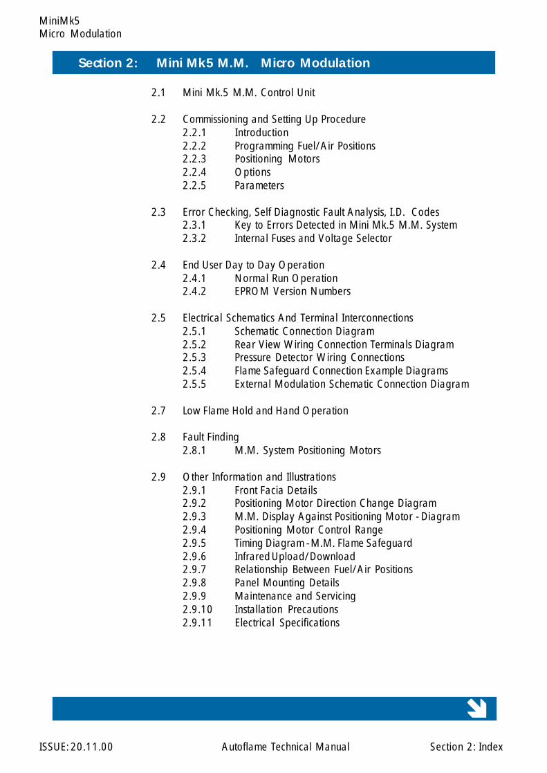
Section 2: Mini Mk5 M.M. Micro Modulation
2.1 Mini Mk.5 M.M. Control Unit
2.2 Commissioning and Setting Up Procedure2.2.1 Introduction2.2.2 Programming Fuel/Air Positions2.2.3 Positioning Motors2.2.4 Options2.2.5 Parameters
2.3 Error Checking, Self Diagnostic Fault Analysis, I.D. Codes2.3.1 Key to Errors Detected in Mini Mk.5 M.M. System2.3.2 Internal Fuses and Voltage Selector
2.4 End User Day to Day Operation2.4.1 Normal Run Operation2.4.2 EPROM Version Numbers
2.5 Electrical Schematics And Terminal Interconnections2.5.1 Schematic Connection Diagram2.5.2 Rear View Wiring Connection Terminals Diagram2.5.3 Pressure Detector Wiring Connections2.5.4 Flame Safeguard Connection Example Diagrams2.5.5 External Modulation Schematic Connection Diagram
2.7 Low Flame Hold and Hand Operation
2.8 Fault Finding2.8.1 M.M. System Positioning Motors
2.9 Other Information and Illustrations2.9.1 Front Facia Details2.9.2 Positioning Motor Direction Change Diagram2.9.3 M.M. Display Against Positioning Motor - Diagram2.9.4 Positioning Motor Control Range2.9.5 Timing Diagram - M.M. Flame Safeguard2.9.6 Infrared Upload/Download2.9.7 Relationship Between Fuel/Air Positions2.9.8 Panel Mounting Details2.9.9 Maintenance and Servicing2.9.10 Installation Precautions2.9.11 Electrical Specifications
2: Index
123456789012345678901234123456789012345678901234123456789012345678901234123456789012345678901234123456789012345678901234123456789012345678901234123456789012345678901234123456789012345678901234123456789012345678901234123456789012345678901234123456789012345678901234123456789012345678901234
Micro Modulation
ISSUE: 20.11.00 Autoflame Technical Manual Section
MiniMk5
2: Index
2.10 Fuel Flow Measurement and Metering Operation
2.11 Golden Start (Choke) Operation
2.12 One Point Change Facility
2.13 A.A. Facility
123456789012345678901234123456789012345678901234123456789012345678901234123456789012345678901234123456789012345678901234123456789012345678901234123456789012345678901234123456789012345678901234123456789012345678901234123456789012345678901234123456789012345678901234123456789012345678901234
Section 2: Mini Mk5 M.M. Micro Modulation
Micro Modulation
ISSUE: 20.11.00 Autoflame Technical Manual Section
MiniMk5MM Control Unit
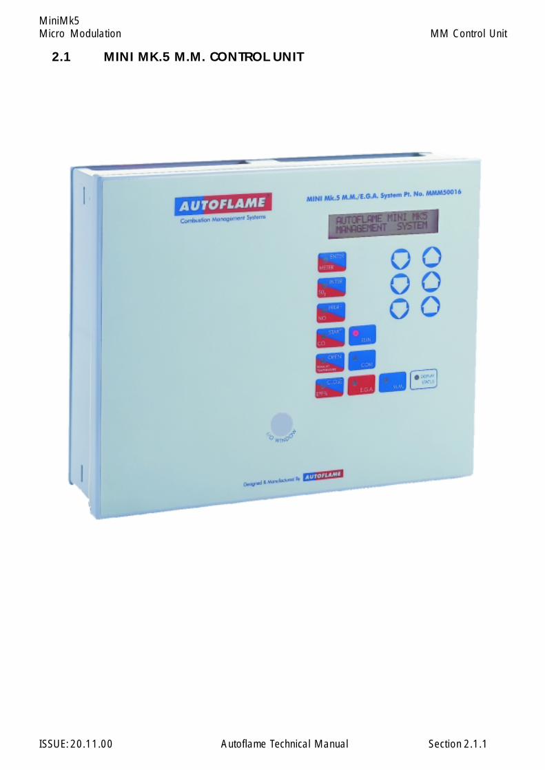
2.1 MINI MK.5 M.M. CONTROL UNIT
2.1.1
Micro Modulation
ISSUE: 20.11.00 Autoflame Technical Manual Section
MiniMk5
In the following text fuel and air positions are referred to. On the Mini Mk5 M.M. these are CH1 andCH2 respectively. CH1 is used for fuel control. If an E.G.A. is optioned CH2 must be used for the trimchannel.
The commissioning procedure as described must be strictly adhered to. Anybody commissioning aMicro Modulation system must have an adequate understanding of combustion plant. In the wronghands hazardous conditions could be made to exist.
The fundamental idea of the system is to set a fuel valve position and then set a corresponding air valveposition. Care must be taken when adjusting the fuel and air positions so as not to create any unstablecombustion conditions, e.g. moving the fuel valve to the open position without increasing the air valvecorrespondingly.
If the system being commissioned is an M.M., without E.G.A., then a combustion monitor is required tocheck the exhaust gases. If the system does have an E.G.A. then a combustion monitor should not benecessary as the E.G.A. performs all normal exhaust gas measurements. When burning oil a smokedetection device is necessary to check smoke generated is within limits.
Ideally to implement commissioning as quickly as possible arrange for a substantial load on the boiler.The commissioning procedure can be interrupted due to excess temperature or pressure, causing theburner to turn off. In these instances the commissioning data accumulated so far is not lost. When theburner is called back on the system starts up automatically and commissioning can proceed from whereit left off.
Once the burner has been fired the maximum fuel position is entered first then descending fuel positionsare entered consecutively until finally a minimum fuel position is entered. The CH1 and CH2 positionsmust always be less than the ones previously entered. However with CH3 it is possible to move theposition above or below the previously entered point.
COMMISSIONING PROCEDURE (Systems without Exhaust Gas Analyser).
On a newly installed system the following procedures should be carried out as listed.
1. Check all interconnecting wiring between the M.M. and external components is correct.2. Set options and parameters as required.3. Set up positioning motors.4. Programme fuel/air positions.
On a previously commissioned system, it is possible to omit steps No.s 1, 2 or 3.
2.2.1 Introduction
2.2 COMMISSIONING AND SETTING UP PROCEDURES
2.2.1.1
Commissioning Procedure
Micro Modulation
ISSUE: 20.11.00 Autoflame Technical Manual Section
MiniMk5
Notes on Programming Fuel Air Positions
If during commissioning the burner turns off, due to the 'stat' circuit opening or a lockout, it is possibleto carry on commissioning from the last entered position. This is possible as long as the HIGH positionhas been entered, and the fuel selected is not changed. When the 'stat' circuit is closed again, or lockoutcleared, the system will purge automatically. Commissioning will then be resumed at Step 7.Automatically the system bypasses the HIGH position entry and resumes the commissioning procedurefrom the last entered INTER position . Effectively commissioning can now be carried on from Step 12.
If remains flashing when pressed, this indicates that the 'stat' control circuit is probablynot closed. Please refer to Fault Finding section.
If remains flashing when pressed, this indicates that the M.M. is not receiving a 'go to purgeposition' signal. Please refer to Fault Finding section.
During commissioning press to display the positioning motor values. Pressto display the fuel selected and Actual value. (The Required value will also be displayed but cannotbe adjusted during commissioning. During commissioning the CR1 relay stays closed all the timeregardless of the Actual value).
2.2.1.2
CLOSE
OPEN
M.M. STATUS
Commissioning Procedure

Micro Modulation
ISSUE: 20.11.00 Autoflame Technical Manual Section
MiniMk5
2.2.2 Programming Fuel Air Positions (systems without EXHAUST GAS ANALYSER)
Ch1 & Ch2 refers to the top two rows of buttons respectively on the Mini Mk5 M.M.
Note: Throughout the commissioning procedure the COM l.e.d. is illuminated.
1. Ensure 'stat' control circuit is closed.
2. Select fuel. CLOSE flashes. PAS is displayed in Actual display window.
Note: If fuel selected is being re-commissioned, press before COM l.e.d.stops flashing (five seconds).
3. Enter Access Code. Adjust the numbers in the CH1 and CH2 Position windows using therespective buttons.
When numbers are set, press (CLOSE l.e.d. steady, ENTER flashes. CH1 and CH2position windows indicate angular position of positioning motors).
4. Use CH1 and CH2 to set positioning motors to 0.0. Press(OPEN flashes).
5. Press (OPEN steady, ENTER MEMORY flashes).
6. Use CH1 and CH2 to set positioning motors to their fully open positions. Thisis nominally 90.0 for gas butterfly valves and burner air dampers.
Press (System purges, at end of purge START flashes).
7. Press (START steady, ENTER MEMORY flashes).
**WARNING** Do not enter START position before reducing fuel input.
8. Use CH1 and CH2 to set positioning motors to positions where ignition cantake place.
9. Press (Burner ignites, HIGH flashes).
OPEN
START
ENTER
MEMORY
COM
ENTER
MEMORY
ENTER
MEMORY
2.2.2.1
CLOSE
Commissioning Procedure: Fuel/Air Positions

Micro Modulation
ISSUE: 20.11.00 Autoflame Technical Manual Section
MiniMk5
10. Press (HIGH steady, ENTER MEMORY flashes).
11. Use CH1 and CH2 to set maximum firing input (do not exceed OPEN positionvalues).
12. Press (INTER, or INTER and START flash).
Note: Only INTER flashes if the number of INTER positions entered so far is less or equal tothree, thereafter INTER and START flash.
13. Press or (INTER or START steady, ENTER MEMORY flashes).
14. Use CH1 and CH2 to reduce the positions.
If present position is an INTER position, go back to 12, otherwise proceed further.
15. Press (After a short pause RUN flashes).
16. Press to set system into normal modulating mode.
HIGH
ENTER
MEMORY
STARTINTER
ENTER
MEMORY
RUN
2.2.2.2
Commissioning Procedure: Fuel/Air Positions
Micro Modulation
ISSUE: 20.11.00 Autoflame Technical Manual Section
MiniMk5
2.2.3 Setting Positioning Motors
Autoflame supply three standard sizes of positioning motors - large, small and industrial. All can beused for positioning fuel and air dampers.Both types can be configured to drive clockwise or counter clockwise to open a valve or damper.
Refer to drawing numbers: Layout of large positioning motor, Section 2.2.3.4Layout of small positioning motor, Section 2.2.3.3Industrial Positioning Motor, Refer Section 8.10
Viewing the shaft end-on, from the potentiometer end, all positioning motors drive in a clockwisedirection if power is applied between the LIVE and CW terminals, and counter clockwise if the poweris applied between the LIVE and CCW terminal.
The operation of fuel valves and air dampers is often such that they open in a clockwise direction.If operation needs to be reversed, it is necessary to swop various wiring connections between theM.M. and the positioning motor(s). An example of reversing the operation of a fuel valve is shownin figure B, Section 2.9. Figure A shows the connections for normal operation.
Set Up Procedure:
Before a burner is fired it is essential to set up each Micro Modulation positioning motor.
A tamper proof screwdriver is required. (These can be ordered from Autoflame)
Usually control valves/air dampers, that the positioning motors drive, move through up to 90 degreesangular. The M.M. system has the ability to drive valves through up to 96 degrees. Please contactAutoflame technical department for advice on applications for ranges greater than 90 degrees.
All readings displayed on the MM are in degrees angular. It is necessary to adjust the potentiometerin the positioning motor assembly so that the M.M. reads 0.0 when the relevant valve/damperis at its closed position.
To set up a positioning motor, first ensure Option 12 is set to 0, (this prevents E.G.A. ‘COOL’ frombeing displayed). Put the M.M. into the commissioning mode so that the CLOSE l.e.d. is steady andthe ENTER l.e.d. flashes (see section on Commissioning). By doing this it is possible to positionthe valve/damper mechanically by using the appropriate up and down buttons.
Remove the positioning motor cover.
**Warning** Electrical Connections are live.
2.2.3.1
Commissioning Procedure: Positioning Motors
Micro Modulation
ISSUE: 20.11.00 Autoflame Technical Manual Section
MiniMk5
For air positioning motor(s) carry out the following procedure:
Use the up/down buttons for the relevant air damper to position the air damper to its physically closedposition. Loosen the three tamper proof screws just sufficiently to enable the potentiometer torotate. Rotate the potentiometer clockwise or counter clockwise until the relevant display windowreads 0.0. Tighten the three tamper proof screws gently until the pot. is secure. Do not overtightenthe screws. Check display still reads 0.0, if not repeat adjustment process.
For fuel positioning motor(s) carry out the following procedure:
On Autoflame gas, oil and gas/oil combination valves it is necessary to remove the positioning motor.Manually position the oil/gas valve slot to its closed position. Observe the position of the drivepin on the positioning motor. Use the relevant up/down buttons to position the pin so that when thepositioning motor is reassembled to the valve it is in line with the slot. Reassemble the positioningmotor to the valve, loosen the three tamper proof screws and proceed to adjust the potentiometerposition until 0.0 is displayed.
2.2.3.2
Commissioning Procedure: Positioning Motors
Micro Modulation
ISSUE: 20.11.00 Autoflame Technical Manual Section
MiniMk5
2.2.3.3
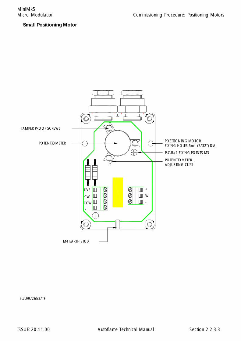
Small Positioning Motor
TAMPER PROOF SCREWS
POTENTIOMETER
P.C.B./1 FIXING POINTS M3
M4 EARTH STUD
POSITIONING MOTORFIXING HOLES 5mm (7/32") DIA.
POTENTIOMETER ADJUSTING CLIPS
5:7:99/2653/TF
-
+
CCW
CW
LIVE
W
Commissioning Procedure: Positioning Motors

Micro Modulation
ISSUE: 20.11.00 Autoflame Technical Manual Section
MiniMk5
2.2.3.4
Large Positioning Motor
5:7:99/2652/TF
W
+
-
LIVE
CW
CCW
POSITIONING MOTOR
ADJUSTING CLIPSPOTENTIOMETER
P.C.B./1 FIXING POINTS M3
FIXING HOLES 5mm (7/32") DIA.
M4 EARTH STUD
POTENTIOMETER
TAMPER PROOF SCREWS
Commissioning Procedure: Positioning Motors
Micro Modulation
ISSUE: 20.11.00 Autoflame Technical Manual Section
MiniMk5
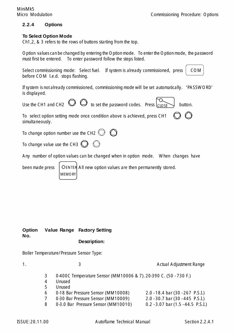
2.2.4 Options
To Select Option ModeCh1,2, & 3 refers to the rows of buttons starting from the top.
Option values can be changed by entering the Option mode. To enter the Option mode, the passwordmust first be entered. To enter password follow the steps listed.
Select commissioning mode: Select fuel. If system is already commissioned, press COMbefore COM l.e.d. stops flashing.
If system is not already commissioned, commissioning mode will be set automatically. ‘PASSWORD’is displayed.
Use the CH1 and CH2 to set the password codes. Press button.
To select option setting mode once condition above is achieved, press CH1simultaneously.
To change option number use the CH2
To change value use the CH3
Any number of option values can be changed when in option mode. When changes have
been made press All new option values are then permanently stored.
Option Value Range Factory SettingNo.
Description:
Boiler Temperature/Pressure Sensor Type:
1. 3 Actual Adjustment Range
3 0-400C Temperature Sensor (MM10006 & 7). 20-390 C. (50 - 730 F.)4 Unused5 Unused6 0-18 Bar Pressure Sensor (MM10008) 2.0 - 18.4 bar (30 - 267 P.S.I.)7 0-30 Bar Pressure Sensor (MM10009) 2.0 - 30.7 bar (30 - 445 P.S.I.)8 0-3.0 Bar Pressure Sensor (MM10010) 0.2 - 3.07 bar (1.5 - 44.5 P.S.I.)
CLOSE
2.2.4.1
ENTER
MEMORY
Commissioning Procedure: Options

Micro Modulation
ISSUE: 20.11.00 Autoflame Technical Manual Section
MiniMk5
Option Value Range Factory SettingNo. Description:
Motor Travel Speed: The value is not specific to a time/distance ratio. If the speed of the motor istoo fast then increase this option value. If too slow, decrease the value. This speed adjustment is onlyrelevant during modulation. At other times the motors move at full speed - See Option 75.
2. 60
5-240 Adjustment Range
Post Purge: If system is required to do post purge, set this option value to 1. The period of time thatthe air fan runs for is governed by the flame safety control. The M.M. will open the air damper to theHIGH or OPEN position, if this option is set. It opens the damper immediately after the stat control circuitopens. The M.M. keeps the damper open for the period of time specified in option 4. This period oftime is completely unassociated with the flame safety control. The full period of time set in option4 elapses before the M.M. will consider another burner start up.
3. 0
0 System does not post purge.1 System does post purge.
Post purge time: (Only relevant if option 3 is set to 1).
4. 40
10-250 Seconds.
Purge position: This selects the purge position: (Applicable to Channel 2/3 when selected, SeeOptions 68 - 74). It applies to pre-purge and post purge if option 3 is set to 1.
5. 0
0 Selected Channel purges at HIGH position.1 Selected Channel purges at OPEN position.
P & I control: Options 6 and 7 are used for adjusting the proportional and integral settings of theM.M.'s built in P + I + D controller. See Option 37 for the derivative adjustments.
2.2.4.2
Commissioning Procedure: Options
Micro Modulation
ISSUE: 20.11.00 Autoflame Technical Manual Section
MiniMk5
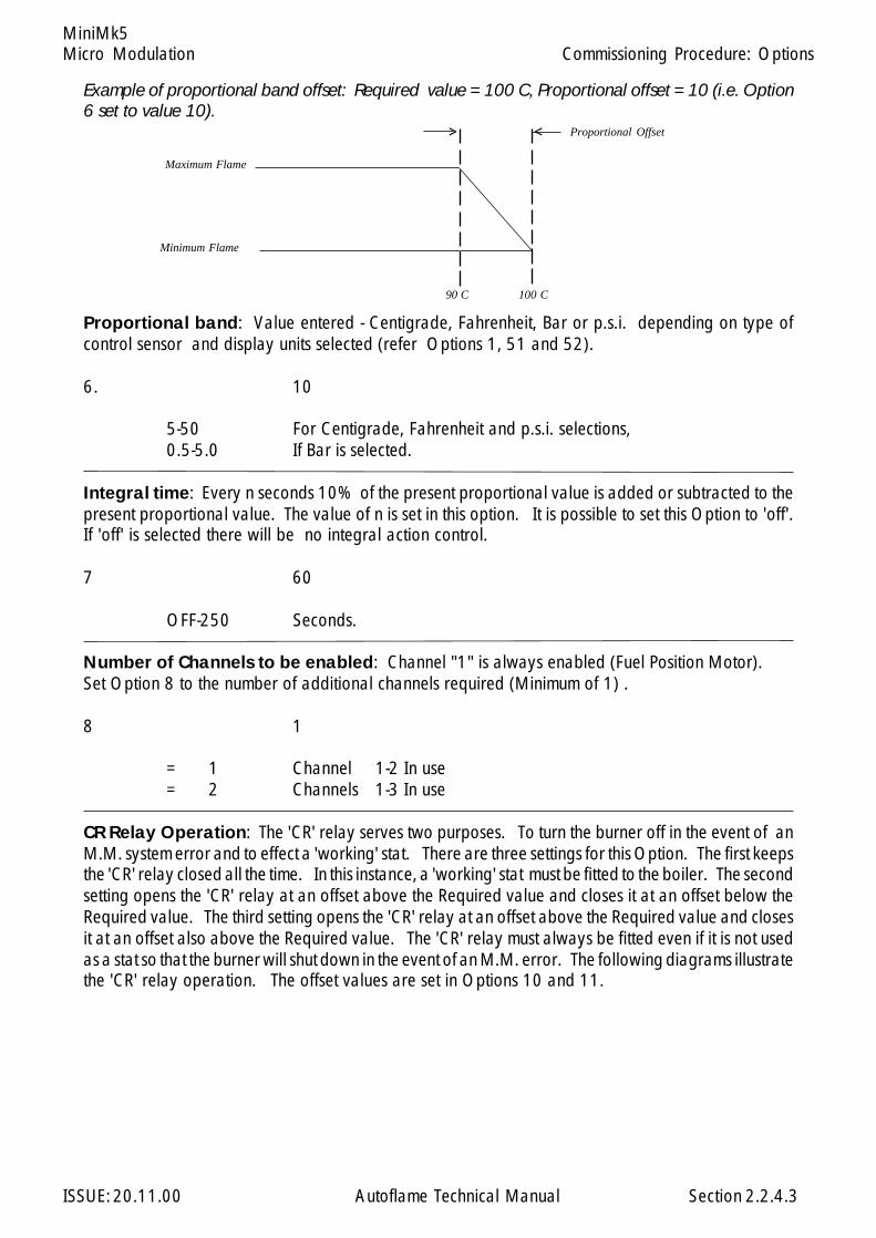
Example of proportional band offset: Required value = 100 C, Proportional offset = 10 (i.e. Option6 set to value 10).
> <
Proportional band: Value entered - Centigrade, Fahrenheit, Bar or p.s.i. depending on type ofcontrol sensor and display units selected (refer Options 1, 51 and 52).
6. 10
5-50 For Centigrade, Fahrenheit and p.s.i. selections,0.5-5.0 If Bar is selected.
Integral time: Every n seconds 10% of the present proportional value is added or subtracted to thepresent proportional value. The value of n is set in this option. It is possible to set this Option to 'off'.If 'off' is selected there will be no integral action control.
7 60
OFF-250 Seconds.
Number of Channels to be enabled: Channel "1" is always enabled (Fuel Position Motor).Set Option 8 to the number of additional channels required (Minimum of 1) .
8 1
= 1 Channel 1-2 In use= 2 Channels 1-3 In use
CR Relay Operation: The 'CR' relay serves two purposes. To turn the burner off in the event of anM.M. system error and to effect a 'working' stat. There are three settings for this Option. The first keepsthe 'CR' relay closed all the time. In this instance, a 'working' stat must be fitted to the boiler. The secondsetting opens the 'CR' relay at an offset above the Required value and closes it at an offset below theRequired value. The third setting opens the 'CR' relay at an offset above the Required value and closesit at an offset also above the Required value. The 'CR' relay must always be fitted even if it is not usedas a stat so that the burner will shut down in the event of an M.M. error. The following diagrams illustratethe 'CR' relay operation. The offset values are set in Options 10 and 11.
Minimum Flame
Maximum Flame
Proportional Offset
90 C 100 C
2.2.4.3
Commissioning Procedure: Options

Micro Modulation
ISSUE: 20.11.00 Autoflame Technical Manual Section
MiniMk5
CR relay open at this point and above
Required Value 100 C
97 C
103 C
CR relay closed at this point and below
Required Value 100 C
103 C
106 C
CR relay closed at this point and below
CR relay open at this point and above
Offset = 6 (value set in Option 10)
Offset = 3 (value set in Option 11)
Offset = 3 (value set in Option 11)
Offset = 3 (value set in Option 10)
Option 9 = 2, example using 100 C. Required Value.
Option 9 = 1, example using 100 C. Required Value.
9. 10 CR always closed.1 CR closes below Required value.2 CR closes above Required value.
Offset above desired value at which CR relay opens: (Only relevant if option 9.1 or 9.2 selected).
10. 32-50 If Centigrade, Fahrenheit or p.s.i. units effective.0.2-5.0 If Bar units effective.
Offset below/above desired value at which CR relay closes: (Only relevant if option 9.1 or 9.2selected).
11. 32-50 If Centigrade, Fahrenheit or p.s.i. units effective,0.2-5.0 If Bar units effective.
E.G.A. Options: There are numerous E.G.A. Options, briefly they are as follows:- The E.G.A. isoperational and the system trims. If the E.G.A. develops a fault, the system reverts to M.M. onlyoperation. The system can be further optioned so that in the event of an E.G.A. error the 'CR' relaywill open and stop the burner. If this type of option is set, the 'CR' relay will not close until the E.G.A.has cooled down to it's operating temperature. Further Options can be set which perform limit checkson the values that the E.G.A. measures. In the event of a limit being exceeded the system can revertto M.M. only operation, alternatively the 'CR' relay can be optioned to open. A last Option existsto enable an E.G.A. to give readings on the M.M. for just monitor purposes. i.e. the system iscommissioned on M.M. only but E.G.A. values are displayed just for information. All Option valuesexcept 0 make the E.G.A. operational. If Options 5 or 6 are selected , refer to Options 19-27 toset limits to be tested for.
2.2.4.4
Commissioning Procedure: Options
Micro Modulation
ISSUE: 20.11.00 Autoflame Technical Manual Section
MiniMk5
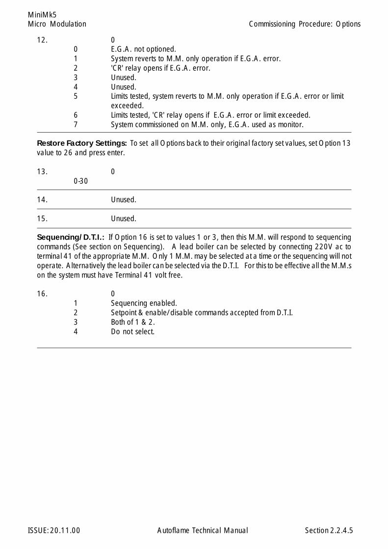
12. 00 E.G.A. not optioned.1 System reverts to M.M. only operation if E.G.A. error.2 'CR' relay opens if E.G.A. error.3 Unused.4 Unused.5 Limits tested, system reverts to M.M. only operation if E.G.A. error or limit
exceeded.6 Limits tested, 'CR' relay opens if E.G.A. error or limit exceeded.7 System commissioned on M.M. only, E.G.A. used as monitor.
Restore Factory Settings: To set all Options back to their original factory set values, set Option 13value to 26 and press enter.
13. 00-30
14. Unused.
15. Unused.
Sequencing/D.T.I.: If Option 16 is set to values 1 or 3, then this M.M. will respond to sequencingcommands (See section on Sequencing). A lead boiler can be selected by connecting 220V ac toterminal 41 of the appropriate M.M. Only 1 M.M. may be selected at a time or the sequencing will notoperate. Alternatively the lead boiler can be selected via the D.T.I. For this to be effective all the M.M.son the system must have Terminal 41 volt free.
16. 01 Sequencing enabled.2 Setpoint & enable/disable commands accepted from D.T.I.3 Both of 1 & 2.4 Do not select.
2.2.4.5
Commissioning Procedure: Options

Micro Modulation
ISSUE: 20.11.00 Autoflame Technical Manual Section
MiniMk5
NO & CO displayed when running on oil: If fuel 2 or fuel 3 are selected, then the displaying ofCO & NO can be on or off. This Option is only relevant if an E.G.A. is operational on the system.
17. 0
0 NO & CO display always zero.1 NO & CO is displayed normally.
Carry forward of Trim: When the system modulates, the correction that may be existing on theair damper position can be carried forward. Only air plus correction is carried forward. This Optionis only relevant if an E.G.A. is operational on the system.
18. 1
0 No carry forward of trim.1 Trim carried forward.
E.G.A. Limits: Options 19-27 are only relevant if an E.G.A. is operational on the system. Option 12value 5 or 6 must be selected if any of the following limit checks are to be invoked. To enable thechecking of a particular limit, make the value of the appropriate Option a non-zero value. The amountof 'limit offset' is specified by the value entered. e.g. If the 'upper limit offset O2' is to be enabled andthe value of the offset is 2.0%, then enter the value of 2.0 for Option No. 19.
19. 0
0-10.0 Upper offset limit % O2.
20. 0
0-10.0 Upper offset limit % CO2.
21. 0
0-200 Upper offset limit CO (Multiply entered value by 10 to getoffset value in ppm).
22. 0
0-10.0 Lower offset limit % O2
23 0
0-10.0 Lower offset limit % CO2
24. Unused.
25. 0
0-20.0 Absolute value % O2 (System checks for O2 values lower than valuespecified in this Option).
2.2.4.6
Commissioning Procedure: Options
Micro Modulation
ISSUE: 20.11.00 Autoflame Technical Manual Section
MiniMk5
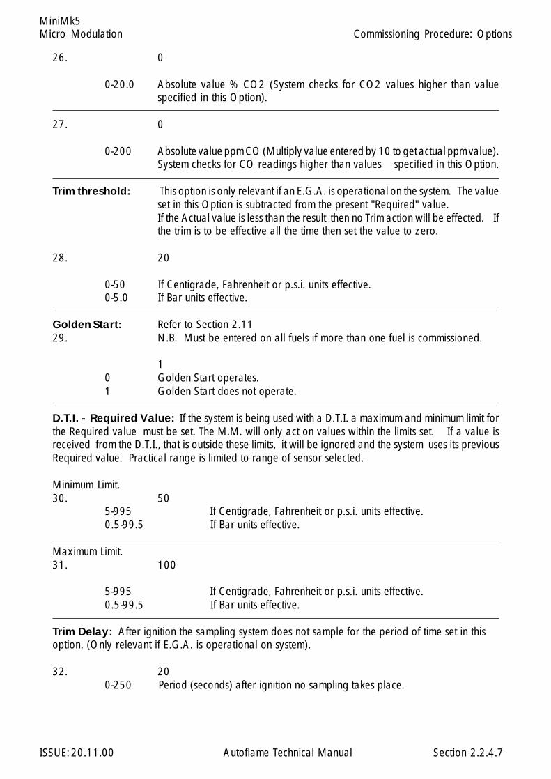
26. 0
0-20.0 Absolute value % CO2 (System checks for CO2 values higher than valuespecified in this Option).
27. 0
0-200 Absolute value ppm CO (Multiply value entered by 10 to get actual ppm value).System checks for CO readings higher than values specified in this Option.
Trim threshold: This option is only relevant if an E.G.A. is operational on the system. The valueset in this Option is subtracted from the present "Required" value.If the Actual value is less than the result then no Trim action will be effected. Ifthe trim is to be effective all the time then set the value to zero.
28. 20
0-50 If Centigrade, Fahrenheit or p.s.i. units effective.0-5.0 If Bar units effective.
Golden Start: Refer to Section 2.1129. N.B. Must be entered on all fuels if more than one fuel is commissioned.
10 Golden Start operates.1 Golden Start does not operate.
D.T.I. - Required Value: If the system is being used with a D.T.I. a maximum and minimum limit forthe Required value must be set. The M.M. will only act on values within the limits set. If a value isreceived from the D.T.I., that is outside these limits, it will be ignored and the system uses its previousRequired value. Practical range is limited to range of sensor selected.
Minimum Limit.30. 50
5-995 If Centigrade, Fahrenheit or p.s.i. units effective.0.5-99.5 If Bar units effective.
Maximum Limit.31. 100
5-995 If Centigrade, Fahrenheit or p.s.i. units effective.0.5-99.5 If Bar units effective.
Trim Delay: After ignition the sampling system does not sample for the period of time set in thisoption. (Only relevant if E.G.A. is operational on system).
32. 200-250 Period (seconds) after ignition no sampling takes place.
2.2.4.7
Commissioning Procedure: Options

Micro Modulation
ISSUE: 20.11.00 Autoflame Technical Manual Section
MiniMk5
Sequencing Options: If this M.M. is configured as part of a sequencing system and/or required tocommunicate with a D.T.I. then the following three options must be set: The first is an identificationnumber for this M.M. The second is the rating of the burner, and the third is the "sequencing scan time".Refer to Sequencing Section for further explanation.
33. 1
1-10 Identification Number.
34. 5
1-100 Rating of Burner kW x 100 (h.p x 100)
35. 10
1-100 Sequence Scan time (Minutes).
E.G.A. Sensor Selection:Available when using an E.G.A. System fitted with NO/SO2 sensors. Thefollowing option is for selecting the type of Sensor required: Part No. EGA20005 for NO; EGA20006for SO2.
36 0
SO2 NO0 Off Off1 Off On2 On Off3 On On
Explanation of D. (Derivative Action): The user adjustable control variables to set up the Daction are as detailed below.
37. Time between readings 0 (0=off)
0-200 Secs The time interval between the controller comparing Actual and DesiredSetpoint values.
38. Deadband
0-15 If Centigrade, Fahrenheit or PSI units optioned.
0-1.5 If Bar units optioned.
The Deadband is the margin above and below the Setpoint within which no derivative control actionoccurs.
2.2.4.8
Commissioning Procedure: Options
Micro Modulation
ISSUE: 20.11.00 Autoflame Technical Manual Section
MiniMk5
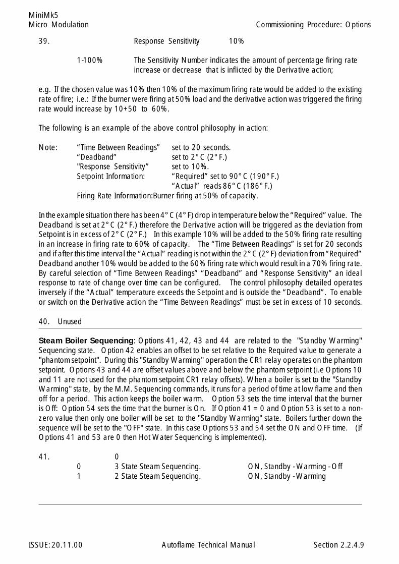
39. Response Sensitivity 10%
1-100% The Sensitivity Number indicates the amount of percentage firing rateincrease or decrease that is inflicted by the Derivative action;
e.g. If the chosen value was 10% then 10% of the maximum firing rate would be added to the existingrate of fire; i.e.: If the burner were firing at 50% load and the derivative action was triggered the firingrate would increase by 10+50 to 60%.
The following is an example of the above control philosophy in action:
Note: “Time Between Readings” set to 20 seconds.“Deadband” set to 2°C (2°F.)"Response Sensitivity” set to 10%.Setpoint Information: “Required” set to 90°C (190°F.)
“Actual” reads 86°C (186°F.)Firing Rate Information:Burner firing at 50% of capacity.
In the example situation there has been 4°C (4°F) drop in temperature below the “Required” value. TheDeadband is set at 2°C (2°F.) therefore the Derivative action will be triggered as the deviation fromSetpoint is in excess of 2°C (2°F.) In this example 10% will be added to the 50% firing rate resultingin an increase in firing rate to 60% of capacity. The “Time Between Readings” is set for 20 secondsand if after this time interval the “Actual” reading is not within the 2°C (2°F) deviation from “Required”Deadband another 10% would be added to the 60% firing rate which would result in a 70% firing rate.By careful selection of “Time Between Readings” “Deadband” and “Response Sensitivity” an idealresponse to rate of change over time can be configured. The control philosophy detailed operatesinversely if the “Actual” temperature exceeds the Setpoint and is outside the “Deadband”. To enableor switch on the Derivative action the “Time Between Readings” must be set in excess of 10 seconds.
40. Unused
Steam Boiler Sequencing: Options 41, 42, 43 and 44 are related to the "Standby Warming"Sequencing state. Option 42 enables an offset to be set relative to the Required value to generate a"phantom setpoint". During this "Standby Warming" operation the CR1 relay operates on the phantomsetpoint. Options 43 and 44 are offset values above and below the phantom setpoint (i.e Options 10and 11 are not used for the phantom setpoint CR1 relay offsets). When a boiler is set to the "StandbyWarming" state, by the M.M. Sequencing commands, it runs for a period of time at low flame and thenoff for a period. This action keeps the boiler warm. Option 53 sets the time interval that the burneris Off: Option 54 sets the time that the burner is On. If Option 41 = 0 and Option 53 is set to a non-zero value then only one boiler will be set to the "Standby Warming" state. Boilers further down thesequence will be set to the "OFF" state. In this case Options 53 and 54 set the ON and OFF time. (IfOptions 41 and 53 are 0 then Hot Water Sequencing is implemented).
41. 00 3 State Steam Sequencing. ON, Standby - Warming - Off1 2 State Steam Sequencing. ON, Standby - Warming
2.2.4.9
Commissioning Procedure: Options
Micro Modulation
ISSUE: 20.11.00 Autoflame Technical Manual Section
MiniMk5
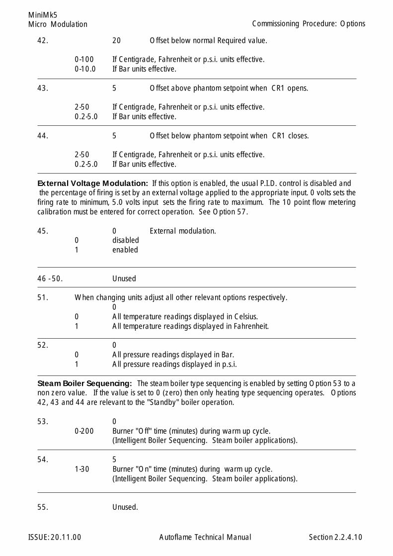
42. 20 Offset below normal Required value.
0-100 If Centigrade, Fahrenheit or p.s.i. units effective.0-10.0 If Bar units effective.
43. 5 Offset above phantom setpoint when CR1 opens.
2-50 If Centigrade, Fahrenheit or p.s.i. units effective.0.2-5.0 If Bar units effective.
44. 5 Offset below phantom setpoint when CR1 closes.
2-50 If Centigrade, Fahrenheit or p.s.i. units effective.0.2-5.0 If Bar units effective.
External Voltage Modulation: If this option is enabled, the usual P.I.D. control is disabled and the percentage of firing is set by an external voltage applied to the appropriate input. 0 volts sets thefiring rate to minimum, 5.0 volts input sets the firing rate to maximum. The 10 point flow meteringcalibration must be entered for correct operation. See Option 57.
45. 0 External modulation.0 disabled1 enabled
46 - 50. Unused
51. When changing units adjust all other relevant options respectively.0
0 All temperature readings displayed in Celsius.1 All temperature readings displayed in Fahrenheit.
52. 00 All pressure readings displayed in Bar.1 All pressure readings displayed in p.s.i.
Steam Boiler Sequencing: The steam boiler type sequencing is enabled by setting Option 53 to anon zero value. If the value is set to 0 (zero) then only heating type sequencing operates. Options42, 43 and 44 are relevant to the "Standby" boiler operation.
53. 00-200 Burner "Off" time (minutes) during warm up cycle.
(Intelligent Boiler Sequencing. Steam boiler applications).
54. 51-30 Burner "On" time (minutes) during warm up cycle.
(Intelligent Boiler Sequencing. Steam boiler applications).
55. Unused.
2.2.4.10
Commissioning Procedure: Options
Micro Modulation
ISSUE: 20.11.00 Autoflame Technical Manual Section
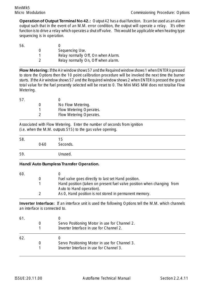
MiniMk5
Operation of Output Terminal No 42.: Output 42 has a dual function. It can be used as an alarmoutput such that in the event of an M.M. error condition, the output will operate a relay. It's otherfunction is to drive a relay which operates a shut off valve. This would be applicable when heating typesequencing is in operation.
56. 00 Sequencing Use.1 Relay normally Off, On when Alarm.2 Relay normally On, Off when alarm.
Flow Metering: If the Air window shows 57 and the Required window shows 1 when ENTER is pressedto store the Options then the 10 point calibration procedure will be invoked the next time the burnerstarts. If the Air window shows 57 and the Required window shows 2 when ENTER is pressed the grandtotal value for the fuel presently selected will be reset to 0. The Mini Mk5 MM does not totalise FlowMetering.
57. 00 No Flow Metering.1 Flow Metering Operates.2 Flow Metering Operates.
Associated with Flow Metering. Enter the number of seconds from ignition(i.e. when the M.M. outputs S15) to the gas valve opening.
58. 150-60 Seconds.
59. Unused.
Hand/Auto Bumpless Transfer Operation.
60. 00 Fuel valve goes directly to last set Hand position.1 Hand position (taken on present fuel valve position when changing from
Auto to Hand operation).2 As 0, Hand position is not stored in permanent memory.
Inverter Interface: If an interface unit is used the following Options tell the M.M. which channelsan interface is connected to.
61. 00 Servo Positioning Motor in use for Channel 2.1 Inverter Interface in use for Channel 2.
62. 00 Servo Positioning Motor in use for Channel 3.1 Inverter Interface in use for Channel 3.
2.2.4.11
Commissioning Procedure: Options
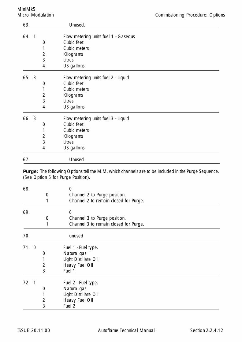
Micro Modulation
ISSUE: 20.11.00 Autoflame Technical Manual Section
MiniMk5
63. Unused.
64. 1 Flow metering units fuel 1 - Gaseous0 Cubic feet1 Cubic meters2 Kilograms3 Litres4 US gallons
65. 3 Flow metering units fuel 2 - Liquid0 Cubic feet1 Cubic meters2 Kilograms3 Litres4 US gallons
66. 3 Flow metering units fuel 3 - Liquid0 Cubic feet1 Cubic meters2 Kilograms3 Litres4 US gallons
67. Unused
Purge: The following Options tell the M.M. which channels are to be included in the Purge Sequence.(See Option 5 for Purge Position).
68. 00 Channel 2 to Purge position.1 Channel 2 to remain closed for Purge.
69. 00 Channel 3 to Purge position.1 Channel 3 to remain closed for Purge.
70. unused
71. 0 Fuel 1 - Fuel type.0 Natural gas1 Light Distillate Oil2 Heavy Fuel Oil3 Fuel 1
72. 1 Fuel 2 - Fuel type.0 Natural gas1 Light Distillate Oil2 Heavy Fuel Oil3 Fuel 2
2.2.4.12
Commissioning Procedure: Options
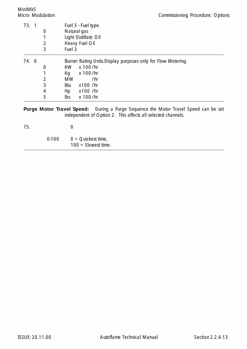
Micro Modulation
ISSUE: 20.11.00 Autoflame Technical Manual Section
MiniMk5
73. 1 Fuel 3 - Fuel type.0 Natural gas1 Light Distillate Oil2 Heavy Fuel Oil3 Fuel 3
74. 0 Burner Rating Units.Display purposes only for Flow Metering.0 KW x 100/hr1 Kg x 100/hr2 MW /hr3 Btu x100 /hr4 Hp x100 /hr5 lbs x 100/hr
Purge Motor Travel Speed: During a Purge Sequence the Motor Travel Speed can be setindependent of Option 2. This affects all selected channels.
75. 0
0-100 0 = Quickest time,100 = Slowest time.
2.2.4.13
Commissioning Procedure: Options
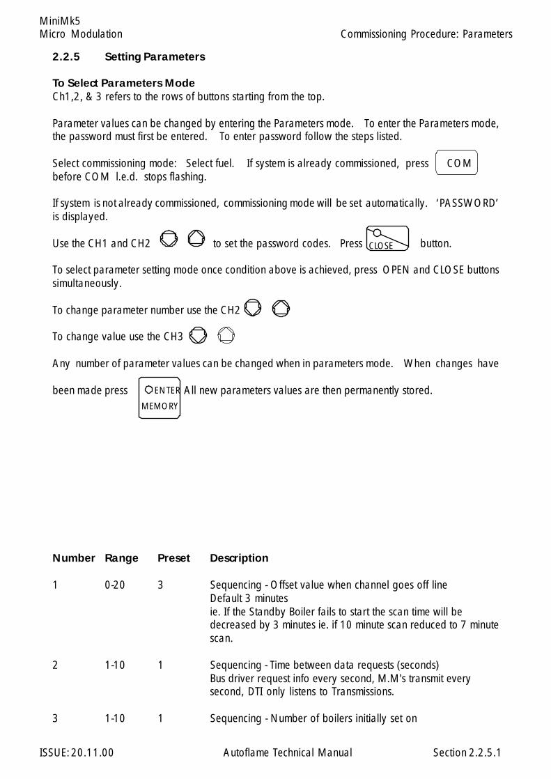
Micro Modulation
ISSUE: 20.11.00 Autoflame Technical Manual Section
MiniMk5
Number Range Preset Description
1 0-20 3 Sequencing - Offset value when channel goes off lineDefault 3 minutesie. If the Standby Boiler fails to start the scan time will bedecreased by 3 minutes ie. if 10 minute scan reduced to 7 minutescan.
2 1-10 1 Sequencing - Time between data requests (seconds)Bus driver request info every second, M.M's transmit everysecond, DTI only listens to Transmissions.
3 1-10 1 Sequencing - Number of boilers initially set on
Commissioning Procedure: Parameters
2.2.5 Setting Parameters
To Select Parameters ModeCh1,2, & 3 refers to the rows of buttons starting from the top.
Parameter values can be changed by entering the Parameters mode. To enter the Parameters mode,the password must first be entered. To enter password follow the steps listed.
Select commissioning mode: Select fuel. If system is already commissioned, press COMbefore COM l.e.d. stops flashing.
If system is not already commissioned, commissioning mode will be set automatically. ‘PASSWORD’is displayed.
Use the CH1 and CH2 to set the password codes. Press button.
To select parameter setting mode once condition above is achieved, press OPEN and CLOSE buttonssimultaneously.
To change parameter number use the CH2
To change value use the CH3
Any number of parameter values can be changed when in parameters mode. When changes have
been made press All new parameters values are then permanently stored.
CLOSE
ENTER
MEMORY
2.2.5.1

Micro Modulation
ISSUE: 20.11.00 Autoflame Technical Manual Section
MiniMk5
Number Range Preset Description
4 5-100 45 E.G.A. -Seconds ENTER button disabled after E.G.A. pressed
5 1-50 4 Sequencing -Number of minutes ,time out value to reachmodulation.ie. If Boiler is not Modulating after being asked to contribute toload, it is kicked out of sequence loop, after being asked tomodulate, must modulate in 4 minutes.
6 5-100 60 MM - Test time for cr1 relay (seconds)ie. If S4 signal still present after 60 seconds from turning offthen = ERROR 40
7 unused8 5-240 30 E.G.A. - Delay after draining before trim cycle start ie. Wash out
period, When cells being cleaned with air, this value main-tains the last readings until the air sampled during the drainperiod has gone.
9 5-240 60 E.G.A. - Auto commission time10 unused11 5-60 25 Air flush time during Auto Commission - (Seconds).
12 0-1 0 E.G.A. - CO included in trim calculation on F2 & F3(See Option 17).
0 - no1 - yesi.e Required when running gas on F2 or F3
13 5-30 20 E.G.A. - DO NOT ADJUST
14 1-100 20 E.G.A. - DO NOT ADJUST
15 0-255 5 Number of seconds positioning motors are held at "choke"position.
16 1-50 12 Time between calibrations, = (÷ 2 = Hours)Calibrates every 6 hours if burner does not turn off.
17 0-10 3 E.G.A. - Number of trims before error flagged whenlimits exceeded. (each Trim = 30 Seconds)
18 5-30 20 E.G.A. - DO NOT ADJUST
19 unused
20 Set value to 26 press enter to restore all preset factory settings.
0-40 0 I.I.F. - Inverter Interface operation.0 - 'Straight line'1 - 'Points curve'
2.2.5.2
Commissioning Procedure: Parameters
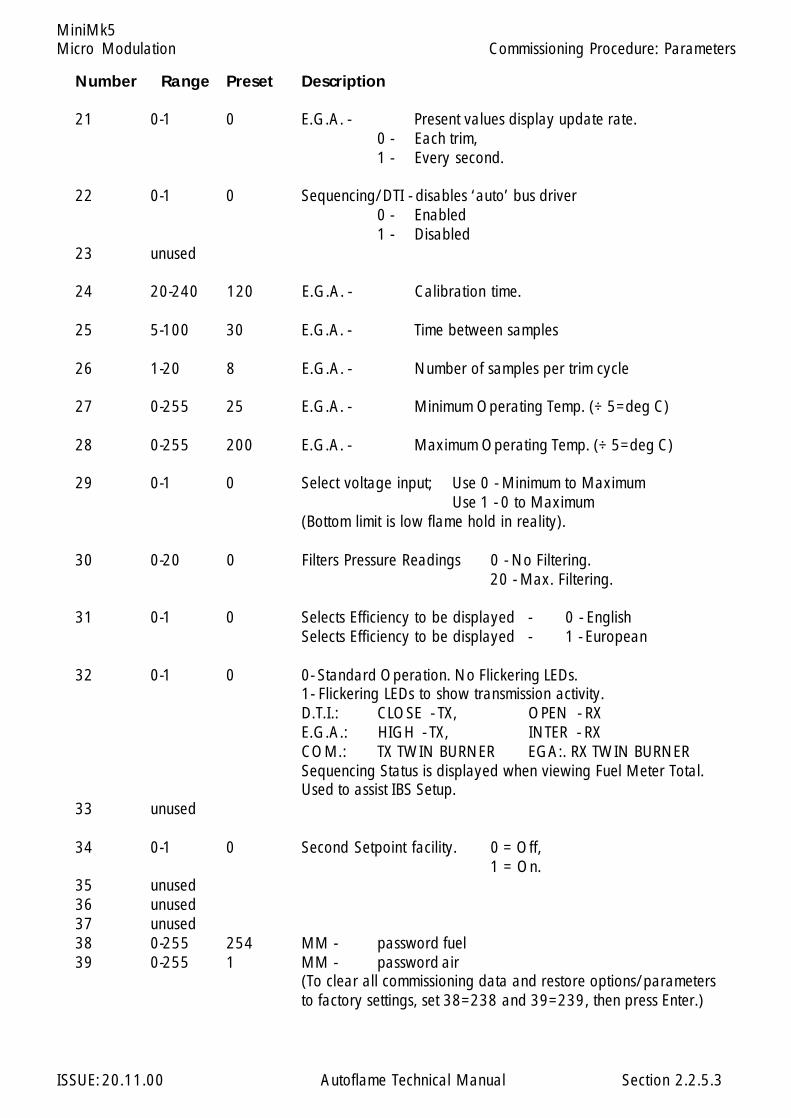
Micro Modulation
ISSUE: 20.11.00 Autoflame Technical Manual Section
MiniMk5
Number Range Preset Description
21 0-1 0 E.G.A. - Present values display update rate.0 - Each trim,1 - Every second.
22 0-1 0 Sequencing/DTI - disables ‘auto’ bus driver0 - Enabled1 - Disabled
23 unused
24 20-240 120 E.G.A. - Calibration time.
25 5-100 30 E.G.A. - Time between samples
26 1-20 8 E.G.A. - Number of samples per trim cycle
27 0-255 25 E.G.A. - Minimum Operating Temp. (÷ 5=deg C)
28 0-255 200 E.G.A. - Maximum Operating Temp. (÷ 5=deg C)
29 0-1 0 Select voltage input; Use 0 - Minimum to MaximumUse 1 - 0 to Maximum
(Bottom limit is low flame hold in reality).
30 0-20 0 Filters Pressure Readings 0 - No Filtering.20 - Max. Filtering.
31 0-1 0 Selects Efficiency to be displayed - 0 - EnglishSelects Efficiency to be displayed - 1 - European
32 0-1 0 0- Standard Operation. No Flickering LEDs.1- Flickering LEDs to show transmission activity.D.T.I.: CLOSE - TX, OPEN - RXE.G.A.: HIGH - TX, INTER - RXCOM.: TX TWIN BURNER EGA:. RX TWIN BURNERSequencing Status is displayed when viewing Fuel Meter Total.Used to assist IBS Setup.
33 unused
34 0-1 0 Second Setpoint facility. 0 = Off,1 = On.
35 unused36 unused37 unused38 0-255 254 MM - password fuel39 0-255 1 MM - password air
(To clear all commissioning data and restore options/parametersto factory settings, set 38=238 and 39=239, then press Enter.)
2.2.5.3
Commissioning Procedure: Parameters
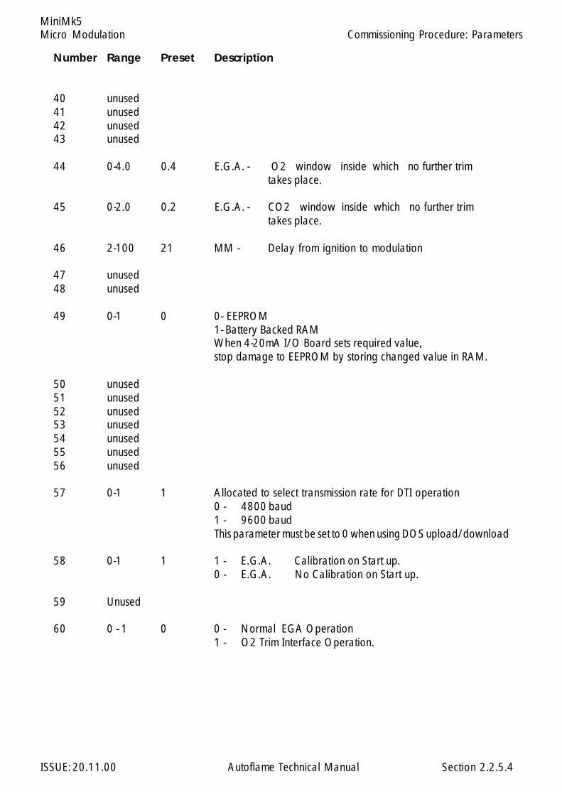
Micro Modulation
ISSUE: 20.11.00 Autoflame Technical Manual Section
MiniMk5
Number Range Preset Description
40 unused41 unused42 unused43 unused
44 0-4.0 0.4 E.G.A. - O2 window inside which no further trimtakes place.
45 0-2.0 0.2 E.G.A. - CO2 window inside which no further trimtakes place.
46 2-100 21 MM - Delay from ignition to modulation
47 unused48 unused
49 0-1 0 0- EEPROM1- Battery Backed RAMWhen 4-20mA I/O Board sets required value,stop damage to EEPROM by storing changed value in RAM.
50 unused51 unused52 unused53 unused54 unused55 unused56 unused
57 0-1 1 Allocated to select transmission rate for DTI operation0 - 4800 baud1 - 9600 baudThis parameter must be set to 0 when using DOS upload/download
58 0-1 1 1 - E.G.A. Calibration on Start up.0 - E.G.A. No Calibration on Start up.
59 Unused
60 0 - 1 0 0 - Normal EGA Operation1 - O2 Trim Interface Operation.
2.2.5.4
Commissioning Procedure: Parameters
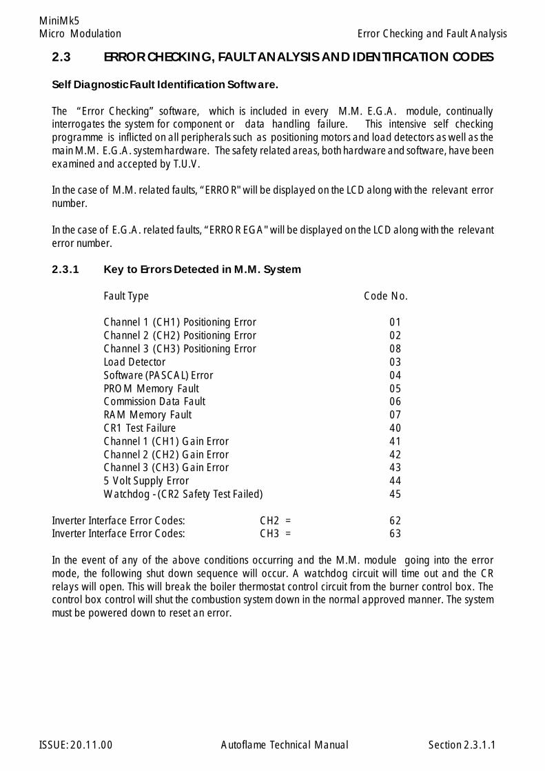
Micro Modulation
ISSUE: 20.11.00 Autoflame Technical Manual Section
MiniMk5Error Checking and Fault Analysis
2.3 ERROR CHECKING, FAULT ANALYSIS AND IDENTIFICATION CODES
Self Diagnostic Fault Identification Software.
The “Error Checking” software, which is included in every M.M. E.G.A. module, continuallyinterrogates the system for component or data handling failure. This intensive self checkingprogramme is inflicted on all peripherals such as positioning motors and load detectors as well as themain M.M. E.G.A. system hardware. The safety related areas, both hardware and software, have beenexamined and accepted by T.U.V.
In the case of M.M. related faults, “ERROR" will be displayed on the LCD along with the relevant errornumber.
In the case of E.G.A. related faults, “ERROR EGA" will be displayed on the LCD along with the relevanterror number.
2.3.1 Key to Errors Detected in M.M. System
Fault Type Code No.
Channel 1 (CH1) Positioning Error 01Channel 2 (CH2) Positioning Error 02Channel 3 (CH3) Positioning Error 08Load Detector 03Software (PASCAL) Error 04PROM Memory Fault 05Commission Data Fault 06RAM Memory Fault 07CR1 Test Failure 40Channel 1 (CH1) Gain Error 41Channel 2 (CH2) Gain Error 42Channel 3 (CH3) Gain Error 435 Volt Supply Error 44Watchdog - (CR2 Safety Test Failed) 45
Inverter Interface Error Codes: CH2 = 62Inverter Interface Error Codes: CH3 = 63
In the event of any of the above conditions occurring and the M.M. module going into the errormode, the following shut down sequence will occur. A watchdog circuit will time out and the CRrelays will open. This will break the boiler thermostat control circuit from the burner control box. Thecontrol box control will shut the combustion system down in the normal approved manner. The systemmust be powered down to reset an error.
2.3.1.1

Micro Modulation
ISSUE: 20.11.00 Autoflame Technical Manual Section
MiniMk5
2.3.2.1
Fuses are "Time Lag" type, manufactured in accordance with IEC 127. Size 5x20mm.
2.3.2 Internal Fuses
If an LED is not illuminated, check adjacent fuse.
1234567890123456789012345678901212345678901234567890123456789012123456789012345678901234567890121234567890123456789012312345678901234567890123456789012123456789012345678901234567890121234567890123456789012345678901212345678901234567890123123456789012345678901234567890121234567890123456789012345678901212345678901234567890123456789012123456789012345678901231234567890123456789012345678901212345678901234567890123456789012123456789012345678901234567890121234567890123456789012312345678901234567890123456789012123456789012345678901234567890121234567890123456789012345678901212345678901234567890123123456789012345678901234567890121234567890123456789012345678901212345678901234567890123456789012123456789012345678901231234567890123456789012345678901212345678901234567890123456789012123456789012345678901234567890121234567890123456789012312345678901234567890123456789012123456789012345678901234567890121234567890123456789012345678901212345678901234567890123123456789012345678901234567890121234567890123456789012345678901212345678901234567890123456789012123456789012345678901231234567890123456789012345678901212345678901234567890123456789012123456789012345678901234567890121234567890123456789012312345678901234567890123456789012123456789012345678901234567890121234567890123456789012345678901212345678901234567890123123456789012345678901234567890121234567890123456789012345678901212345678901234567890123456789012123456789012345678901231234567890123456789012345678901212345678901234567890123456789012123456789012345678901234567890121234567890123456789012312345678901234567890123456789012123456789012345678901234567890121234567890123456789012345678901212345678901234567890123123456789012345678901234567890121234567890123456789012345678901212345678901234567890123456789012123456789012345678901231234567890123456789012345678901212345678901234567890123456789012123456789012345678901234567890121234567890123456789012312345678901234567890123456789012123456789012345678901234567890121234567890123456789012345678901212345678901234567890123123456789012345678901234567890121234567890123456789012345678901212345678901234567890123456789012123456789012345678901231234567890123456789012345678901212345678901234567890123456789012123456789012345678901234567890121234567890123456789012312345678901234567890123456789012123456789012345678901234567890121234567890123456789012345678901212345678901234567890123123456789012345678901234567890121234567890123456789012345678901212345678901234567890123456789012123456789012345678901231234567890123456789012345678901212345678901234567890123456789012123456789012345678901234567890121234567890123456789012312345678901234567890123456789012123456789012345678901234567890121234567890123456789012345678901212345678901234567890123123456789012345678901234567890121234567890123456789012345678901212345678901234567890123456789012123456789012345678901231234567890123456789012345678901212345678901234567890123456789012123456789012345678901234567890121234567890123456789012312345678901234567890123456789012123456789012345678901234567890121234567890123456789012345678901212345678901234567890123123456789012345678901234567890121234567890123456789012345678901212345678901234567890123456789012123456789012345678901231234567890123456789012345678901212345678901234567890123456789012123456789012345678901234567890121234567890123456789012312345678901234567890123456789012123456789012345678901234567890121234567890123456789012345678901212345678901234567890123123456789012345678901234567890121234567890123456789012345678901212345678901234567890123456789012123456789012345678901231234567890123456789012345678901212345678901234567890123456789012123456789012345678901234567890121234567890123456789012312345678901234567890123456789012123456789012345678901234567890121234567890123456789012345678901212345678901234567890123123456789012345678901234567890121234567890123456789012345678901212345678901234567890123456789012123456789012345678901231234567890123456789012345678901212345678901234567890123456789012123456789012345678901234567890121234567890123456789012312345678901234567890123456789012123456789012345678901234567890121234567890123456789012345678901212345678901234567890123123456789012345678901234567890121234567890123456789012345678901212345678901234567890123456789012123456789012345678901231234567890123456789012345678901212345678901234567890123456789012123456789012345678901234567890121234567890123456789012312345678901234567890123456789012123456789012345678901234567890121234567890123456789012345678901212345678901234567890123123456789012345678901234567890121234567890123456789012345678901212345678901234567890123456789012123456789012345678901231234567890123456789012345678901212345678901234567890123456789012123456789012345678901234567890121234567890123456789012312345678901234567890123456789012123456789012345678901234567890121234567890123456789012345678901212345678901234567890123123456789012345678901234567890121234567890123456789012345678901212345678901234567890123456789012123456789012345678901231234567890123456789012345678901212345678901234567890123456789012123456789012345678901234567890121234567890123456789012312345678901234567890123456789012123456789012345678901234567890121234567890123456789012345678901212345678901234567890123123456789012345678901234567890121234567890123456789012345678901212345678901234567890123456789012123456789012345678901231234567890123456789012345678901212345678901234567890123456789012123456789012345678901234567890121234567890123456789012312345678901234567890123456789012123456789012345678901234567890121234567890123456789012345678901212345678901234567890123123456789012345678901234567890121234567890123456789012345678901212345678901234567890123456789012123456789012345678901231234567890123456789012345678901212345678901234567890123456789012123456789012345678901234567890121234567890123456789012312345678901234567890123456789012123456789012345678901234567890121234567890123456789012345678901212345678901234567890123123456789012345678901234567890121234567890123456789012345678901212345678901234567890123456789012123456789012345678901231234567890123456789012345678901212345678901234567890123456789012123456789012345678901234567890121234567890123456789012312345678901234567890123456789012123456789012345678901234567890121234567890123456789012345678901212345678901234567890123123456789012345678901234567890121234567890123456789012345678901212345678901234567890123456789012123456789012345678901231234567890123456789012345678901212345678901234567890123456789012123456789012345678901234567890121234567890123456789012312345678901234567890123456789012123456789012345678901234567890121234567890123456789012345678901212345678901234567890123123456789012345678901234567890121234567890123456789012345678901212345678901234567890123456789012123456789012345678901231234567890123456789012345678901212345678901234567890123456789012123456789012345678901234567890121234567890123456789012312345678901234567890123456789012123456789012345678901234567890121234567890123456789012345678901212345678901234567890123123456789012345678901234567890121234567890123456789012345678901212345678901234567890123456789012123456789012345678901231234567890123456789012345678901212345678901234567890123456789012123456789012345678901234567890121234567890123456789012312345678901234567890123456789012123456789012345678901234567890121234567890123456789012345678901212345678901234567890123123456789012345678901234567890121234567890123456789012345678901212345678901234567890123456789012123456789012345678901231234567890123456789012345678901212345678901234567890123456789012123456789012345678901234567890121234567890123456789012312345678901234567890123456789012123456789012345678901234567890121234567890123456789012345678901212345678901234567890123123456789012345678901234567890121234567890123456789012345678901212345678901234567890123456789012123456789012345678901231234567890123456789012345678901212345678901234567890123456789012123456789012345678901234567890121234567890123456789012312345678901234567890123456789012123456789012345678901234567890121234567890123456789012345678901212345678901234567890123123456789012345678901234567890121234567890123456789012345678901212345678901234567890123456789012123456789012345678901231234567890123456789012345678901212345678901234567890123456789012123456789012345678901234567890121234567890123456789012312345678901234567890123456789012123456789012345678901234567890121234567890123456789012345678901212345678901234567890123123456789012345678901234567890121234567890123456789012345678901212345678901234567890123456789012123456789012345678901231234567890123456789012345678901212345678901234567890123456789012123456789012345678901234567890121234567890123456789012312345678901234567890123456789012123456789012345678901234567890121234567890123456789012345678901212345678901234567890123123456789012345678901234567890121234567890123456789012345678901212345678901234567890123456789012123456789012345678901231234567890123456789012345678901212345678901234567890123456789012123456789012345678901234567890121234567890123456789012312345678901234567890123456789012123456789012345678901234567890121234567890123456789012345678901212345678901234567890123123456789012345678901234567890121234567890123456789012345678901212345678901234567890123456789012123456789012345678901231234567890123456789012345678901212345678901234567890123456789012123456789012345678901234567890121234567890123456789012312345678901234567890123456789012123456789012345678901234567890121234567890123456789012345678901212345678901234567890123123456789012345678901234567890121234567890123456789012345678901212345678901234567890123456789012123456789012345678901231234567890123456789012345678901212345678901234567890123456789012123456789012345678901234567890121234567890123456789012312345678901234567890123456789012123456789012345678901234567890121234567890123456789012345678901212345678901234567890123123456789012345678901234567890121234567890123456789012345678901212345678901234567890123456789012123456789012345678901231234567890123456789012345678901212345678901234567890123456789012123456789012345678901234567890121234567890123456789012312345678901234567890123456789012123456789012345678901234567890121234567890123456789012345678901212345678901234567890123123456789012345678901234567890121234567890123456789012345678901212345678901234567890123456789012123456789012345678901231234567890123456789012345678901212345678901234567890123456789012123456789012345678901234567890121234567890123456789012312345678901234567890123456789012123456789012345678901234567890121234567890123456789012345678901212345678901234567890123123456789012345678901234567890121234567890123456789012345678901212345678901234567890123456789012123456789012345678901231234567890123456789012345678901212345678901234567890123456789012123456789012345678901234567890121234567890123456789012312345678901234567890123456789012123456789012345678901234567890121234567890123456789012345678901212345678901234567890123123456789012345678901234567890121234567890123456789012345678901212345678901234567890123456789012123456789012345678901231234567890123456789012345678901212345678901234567890123456789012123456789012345678901234567890121234567890123456789012312345678901234567890123456789012123456789012345678901234567890121234567890123456789012345678901212345678901234567890123123456789012345678901234567890121234567890123456789012345678901212345678901234567890123456789012123456789012345678901231234567890123456789012345678901212345678901234567890123456789012123456789012345678901234567890121234567890123456789012312345678901234567890123456789012123456789012345678901234567890121234567890123456789012345678901212345678901234567890123123456789012345678901234567890121234567890123456789012345678901212345678901234567890123456789012123456789012345678901231234567890123456789012345678901212345678901234567890123456789012123456789012345678901234567890121234567890123456789012312345678901234567890123456789012123456789012345678901234567890121234567890123456789012345678901212345678901234567890123123456789012345678901234567890121234567890123456789012345678901212345678901234567890123456789012123456789012345678901231234567890123456789012345678901212345678901234567890123456789012123456789012345678901234567890121234567890123456789012312345678901234567890123456789012123456789012345678901234567890121234567890123456789012345678901212345678901234567890123123456789012345678901234567890121234567890123456789012345678901212345678901234567890123456789012123456789012345678901231234567890123456789012345678901212345678901234567890123456789012123456789012345678901234567890121234567890123456789012312345678901234567890123456789012123456789012345678901234567890121234567890123456789012345678901212345678901234567890123123456789012345678901234567890121234567890123456789012345678901212345678901234567890123456789012123456789012345678901231234567890123456789012345678901212345678901234567890123456789012123456789012345678901234567890121234567890123456789012312345678901234567890123456789012123456789012345678901234567890121234567890123456789012345678901212345678901234567890123123456789012345678901234567890121234567890123456789012345678901212345678901234567890123456789012123456789012345678901231234567890123456789012345678901212345678901234567890123456789012123456789012345678901234567890121234567890123456789012312345678901234567890123456789012123456789012345678901234567890121234567890123456789012345678901212345678901234567890123123456789012345678901234567890121234567890123456789012345678901212345678901234567890123456789012123456789012345678901231234567890123456789012345678901212345678901234567890123456789012123456789012345678901234567890121234567890123456789012312345678901234567890123456789012123456789012345678901234567890121234567890123456789012345678901212345678901234567890123123456789012345678901234567890121234567890123456789012345678901212345678901234567890123456789012123456789012345678901231234567890123456789012345678901212345678901234567890123456789012123456789012345678901234567890121234567890123456789012312345678901234567890123456789012123456789012345678901234567890121234567890123456789012345678901212345678901234567890123123456789012345678901234567890121234567890123456789012345678901212345678901234567890123456789012123456789012345678901231234567890123456789012345678901212345678901234567890123456789012123456789012345678901234567890121234567890123456789012312345678901234567890123456789012123456789012345678901234567890121234567890123456789012345678901212345678901234567890123123456789012345678901234567890121234567890123456789012345678901212345678901234567890123456789012123456789012345678901231234567890123456789012345678901212345678901234567890123456789012123456789012345678901234567890121234567890123456789012312345678901234567890123456789012123456789012345678901234567890121234567890123456789012345678901212345678901234567890123123456789012345678901234567890121234567890123456789012345678901212345678901234567890123456789012123456789012345678901231234567890123456789012345678901212345678901234567890123456789012123456789012345678901234567890121234567890123456789012312345678901234567890123456789012123456789012345678901234567890121234567890123456789012345678901212345678901234567890123123456789012345678901234567890121234567890123456789012345678901212345678901234567890123456789012123456789012345678901231234567890123456789012345678901212345678901234567890123456789012123456789012345678901234567890121234567890123456789012312345678901234567890123456789012123456789012345678901234567890121234567890123456789012345678901212345678901234567890123123456789012345678901234567890121234567890123456789012345678901212345678901234567890123456789012123456789012345678901231234567890123456789012345678901212345678901234567890123456789012123456789012345678901234567890121234567890123456789012312345678901234567890123456789012123456789012345678901234567890121234567890123456789012345678901212345678901234567890123123456789012345678901234567890121234567890123456789012345678901212345678901234567890123456789012123456789012345678901231234567890123456789012345678901212345678901234567890123456789012123456789012345678901234567890121234567890123456789012312345678901234567890123456789012123456789012345678901234567890121234567890123456789012345678901212345678901234567890123123456789012345678901234567890121234567890123456789012345678901212345678901234567890123456789012123456789012345678901231234567890123456789012345678901212345678901234567890123456789012123456789012345678901234567890121234567890123456789012312345678901234567890123456789012123456789012345678901234567890121234567890123456789012345678901212345678901234567890123123456789012345678901234567890121234567890123456789012345678901212345678901234567890123456789012123456789012345678901231234567890123456789012345678901212345678901234567890123456789012123456789012345678901234567890121234567890123456789012312345678901234567890123456789012123456789012345678901234567890121234567890123456789012345678901212345678901234567890123123456789012345678901234567890121234567890123456789012345678901212345678901234567890123456789012123456789012345678901231234567890123456789012345678901212345678901234567890123456789012123456789012345678901234567890121234567890123456789012312345678901234567890123456789012123456789012345678901234567890121234567890123456789012345678901212345678901234567890123123456789012345678901234567890121234567890123456789012345678901212345678901234567890123456789012123456789012345678901231234567890123456789012345678901212345678901234567890123456789012123456789012345678901234567890121234567890123456789012312345678901234567890123456789012123456789012345678901234567890121234567890123456789012345678901212345678901234567890123123456789012345678901234567890121234567890123456789012345678901212345678901234567890123456789012123456789012345678901231234567890123456789012345678901212345678901234567890123456789012123456789012345678901234567890121234567890123456789012312345678901234567890123456789012123456789012345678901234567890121234567890123456789012345678901212345678901234567890123123456789012345678901234567890121234567890123456789012345678901212345678901234567890123456789012123456789012345678901231234567890123456789012345678901212345678901234567890123456789012123456789012345678901234567890121234567890123456789012312345678901234567890123456789012123456789012345678901234567890121234567890123456789012345678901212345678901234567890123123456789012345678901234567890121234567890123456789012345678901212345678901234567890123456789012123456789012345678901231234567890123456789012345678901212345678901234567890123456789012123456789012345678901234567890121234567890123456789012312345678901234567890123456789012123456789012345678901234567890121234567890123456789012345678901212345678901234567890123123456789012345678901234567890121234567890123456789012345678901212345678901234567890123456789012123456789012345678901231234567890123456789012345678901212345678901234567890123456789012123456789012345678901234567890121234567890123456789012312345678901234567890123456789012123456789012345678901234567890121234567890123456789012345678901212345678901234567890123123456789012345678901234567890121234567890123456789012345678901212345678901234567890123456789012123456789012345678901231234567890123456789012345678901212345678901234567890123456789012123456789012345678901234567890121234567890123456789012312345678901234567890123456789012123456789012345678901234567890121234567890123456789012345678901212345678901234567890123123456789012345678901234567890121234567890123456789012345678901212345678901234567890123456789012123456789012345678901231234567890123456789012345678901212345678901234567890123456789012123456789012345678901234567890121234567890123456789012312345678901234567890123456789012123456789012345678901234567890121234567890123456789012345678901212345678901234567890123123456789012345678901234567890121234567890123456789012345678901212345678901234567890123456789012123456789012345678901231234567890123456789012345678901212345678901234567890123456789012123456789012345678901234567890121234567890123456789012312345678901234567890123456789012123456789012345678901234567890121234567890123456789012345678901212345678901234567890123123456789012345678901234567890121234567890123456789012345678901212345678901234567890123456789012123456789012345678901231234567890123456789012345678901212345678901234567890123456789012123456789012345678901234567890121234567890123456789012312345678901234567890123456789012123456789012345678901234567890121234567890123456789012345678901212345678901234567890123123456789012345678901234567890121234567890123456789012345678901212345678901234567890123456789012123456789012345678901231234567890123456789012345678901212345678901234567890123456789012123456789012345678901234567890121234567890123456789012312345678901234567890123456789012123456789012345678901234567890121234567890123456789012345678901212345678901234567890123123456789012345678901234567890121234567890123456789012345678901212345678901234567890123456789012123456789012345678901231234567890123456789012345678901212345678901234567890123456789012123456789012345678901234567890121234567890123456789012312345678901234567890123456789012123456789012345678901234567890121234567890123456789012345678901212345678901234567890123123456789012345678901234567890121234567890123456789012345678901212345678901234567890123456789012123456789012345678901231234567890123456789012345678901212345678901234567890123456789012123456789012345678901234567890121234567890123456789012312345678901234567890123456789012123456789012345678901234567890121234567890123456789012345678901212345678901234567890123
0.3
15
A (T
)
LED
0.63
0 A
(T)LE
D
LED
0.3
15
A (T
)
1234567123456712345671234567123456712345671234567123456712345671234567123456712345671234567123456712345671234567123456712345671234567123456712345671234567123456712345671234567123456712345671234567
123456123456123456123456123456123456123456123456123456123456123456123456123456123456123456123456123456123456123456123456123456123456123456123456123456123456123456123456123456123456123456123456123456123456123456123456
123456123456123456123456123456123456123456123456123456123456123456123456123456123456123456123456123456123456123456123456123456
1234567123456712345671234567123456712345671234567123456712345671234567123456712345671234567123456712345671234567123456712345671234567123456712345671234567123456712345671234567123456712345671234567123456712345671234567123456712345671234567123456712345671234567123456712345671234567
1234567890112345678901123456789011234567890112345678901123456789011234567890112345678901123456789011234567890112345678901
123456789123456789123456789123456789123456789123456789123456789123456789123456789
Vo
ltag
e Se
lect
or
Error Checking and Fault Analysis
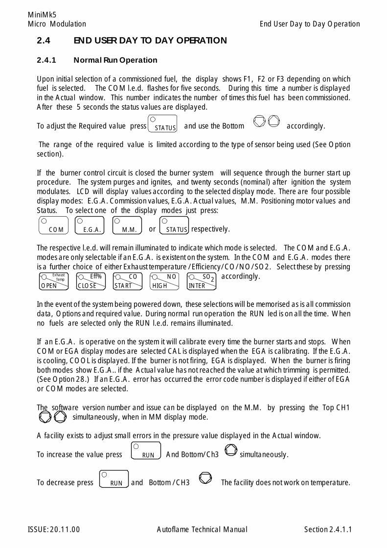
Micro Modulation
ISSUE: 20.11.00 Autoflame Technical Manual Section
MiniMk5
2.4 END USER DAY TO DAY OPERATION
2.4.1 Normal Run Operation
Upon initial selection of a commissioned fuel, the display shows F1, F2 or F3 depending on whichfuel is selected. The COM l.e.d. flashes for five seconds. During this time a number is displayedin the Actual window. This number indicates the number of times this fuel has been commissioned.After these 5 seconds the status values are displayed.
To adjust the Required value press and use the Bottom accordingly.
The range of the required value is limited according to the type of sensor being used (See Optionsection).
If the burner control circuit is closed the burner system will sequence through the burner start upprocedure. The system purges and ignites, and twenty seconds (nominal) after ignition the systemmodulates. LCD will display values according to the selected display mode. There are four possibledisplay modes: E.G.A. Commission values, E.G.A. Actual values, M.M. Positioning motor values andStatus. To select one of the display modes just press:
or respectively.
The respective l.e.d. will remain illuminated to indicate which mode is selected. The COM and E.G.A.modes are only selectable if an E.G.A. is existent on the system. In the COM and E.G.A. modes thereis a further choice of either Exhaust temperature /Efficiency/CO/NO/SO2. Select these by pressing
accordingly.
In the event of the system being powered down, these selections will be memorised as is all commissiondata, Options and required value. During normal run operation the RUN led is on all the time. Whenno fuels are selected only the RUN l.e.d. remains illuminated.
If an E.G.A. is operative on the system it will calibrate every time the burner starts and stops. WhenCOM or EGA display modes are selected CAL is displayed when the EGA is calibrating. If the E.G.A.is cooling, COOL is displayed. If the burner is not firing, EGA is displayed. When the burner is firingboth modes show E.G.A.. if the Actual value has not reached the value at which trimming is permitted.(See Option 28.) If an E.G.A. error has occurred the error code number is displayed if either of EGAor COM modes are selected.
The software version number and issue can be displayed on the M.M. by pressing the Top CH1 simultaneously, when in MM display mode.
A facility exists to adjust small errors in the pressure value displayed in the Actual window.
To increase the value press And Bottom/Ch3 simultaneously.
To decrease press and Bottom /CH3 The facility does not work on temperature.
End User Day to Day Operation
2.4.1.1
STATUS
COM E.G.A. M.M. STATUS
INTEROPEN START HIGHCLOSEEff%Exhaust
Temp CO NO SO2
RUN
RUN
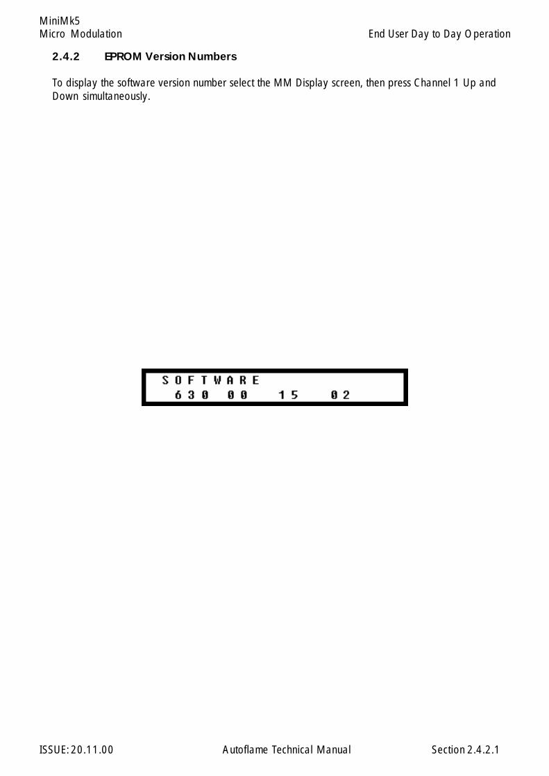
Micro Modulation
ISSUE: 20.11.00 Autoflame Technical Manual Section
MiniMk5
2.4.2.1
2.4.2 EPROM Version Numbers
To display the software version number select the MM Display screen, then press Channel 1 Up andDown simultaneously.
End User Day to Day Operation
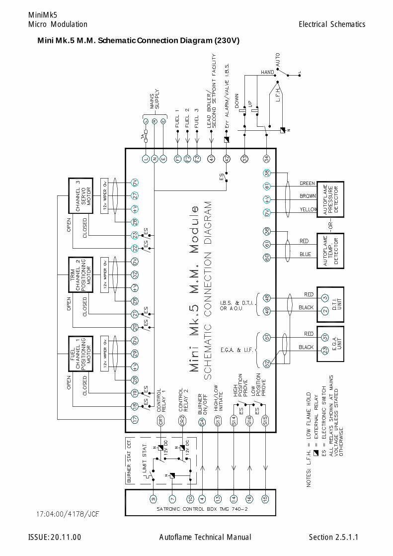
Micro Modulation
ISSUE: 20.11.00 Autoflame Technical Manual Section
MiniMk5
2.5.1.1
Mini Mk.5 M.M. Schematic Connection Diagram (230V)
Electrical Schematics
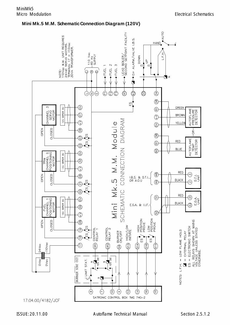
Micro Modulation
ISSUE: 20.11.00 Autoflame Technical Manual Section
MiniMk5
2.5.1.2
Mini Mk.5 M.M. Schematic Connection Diagram (120V)
Electrical Schematics

Micro Modulation
ISSUE: 20.11.00 Autoflame Technical Manual Section
MiniMk5
2.5.2.1
Electrical Schematics
Mini Mk.5 MM Wiring Connection Temrinals Diagram

Micro Modulation
ISSUE: 20.11.00 Autoflame Technical Manual Section
MiniMk5
NB: Any physical damage to the stainless steel diaphram may result in sensor failure. The maximum depth that a male fitting can be screwed into the sensor is 10mm.
2.5.3.1
Autoflame Boiler Steam Pressure Sensor - Part No. MM10008/9/10
C o n n e c t io n s
S e n s o r M k 6 / M in iM k 6 M in i M k 5
G re e n 3 8 6 1
Y e l lo w 3 7 O V
B ro w n 3 9 + V
W h ite u n u se d
S c re e n S 3 8
Electrical Schematics
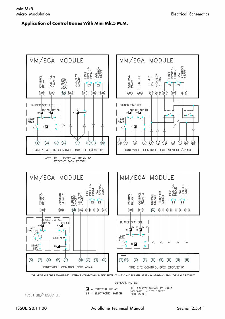
Micro Modulation
ISSUE: 20.11.00 Autoflame Technical Manual Section
MiniMk5
2.5.4.1
Application of Control Boxes With Mini Mk.5 M.M.
Electrical Schematics
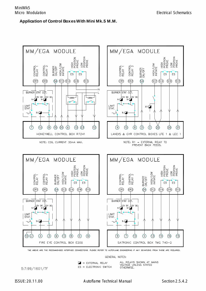
Micro Modulation
ISSUE: 20.11.00 Autoflame Technical Manual Section
MiniMk5
2.5.4.2
Application of Control Boxes With Mini Mk.5 M.M.
Electrical Schematics
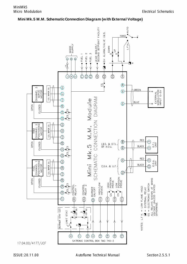
Micro Modulation
ISSUE: 20.11.00 Autoflame Technical Manual Section
MiniMk5
2.5.5.1
Electrical Schematics
Mini Mk.5 M.M. Schematic Connection Diagram (with External Voltage)
Micro Modulation
ISSUE: 20.11.00 Autoflame Technical Manual Section
MiniMk5
2.7 LOW FLAME HOLD AND HAND OPERATION
‘Low Flame Hold’ and ‘Hand’ operation are only effective when the burner is firing. They have no effectwhen the burner is off or during the burner start up cycle. They are effected by applying mains voltagesignals to terminals 33 and 34 on the MM unit. When inputs 33 and 34 have no mains signals appliedthe system modulates according to the PID control.
LFH is brought into operation if 34 has a signal applied when the ignition part of the burner start up cycletakes place. 33 must not have a signal applied at this time or ‘Hand’ operation will come into effect.The minimum flame position will be maintained from now on, until the signal from 34 is removed ora signal is applied to 33 also. The only way to establish LFH again is to restart the burner. During LFHthe PID control is obviously ignored.
‘Hand’ operation enables the fuel valve position to be set to a specific position, in the range ofminimum to maximum flame. Once a position has been set it is recorded in the MM units memory.Each time the burner starts the fuel valve will be positioned to the ‘hand’ position set previously, evenif the MM unit has been powered down. The MM system sets the fuel valve to the hand positionwhenever there is a mains signal on both 33 and 34. During ignition LFH will not be selected in thissituation or if a signal exists on 33 only. Once the burner is firing the ‘hand’ position can be adjusted.To increase the ‘hand’ position the signal on 34 is removed and the signal on 33 maintained. Todecrease the ‘hand’ position the signal on 33 is removed and the signal on 34 maintained. If the signalsare removed from both 33 and 34 then the system reverts to modulation according to the PID control.
Hand/Auto & Low Flame Hold Facilities.
2.7.1

Micro Modulation
ISSUE: 20.11.00 Autoflame Technical Manual Section
MiniMk5
2 .8 FAULT FINDING
2.8.1 M.M. System and Positioning Motors
WARNING ! ! ! !MAINS AND HIGHER VOLTAGES EXIST ON THE MM AND POSITIONING MOTORS.THE SYSTEM CONTROLS A COMBUSTION PROCESS.
Only competent personnel aware of the implications of the above warning should attempt fault finding.Personnel must be responsible for the conditions under which fault finding takes place. (e.g.. isolationof fuel supply)
Please Note: Personnel not familiar with the system should carry out tests in the order written.
The method of fault finding described is for a system that has been working correctly and has gonewrong. It is not for trouble shooting new systems which may for e.g.. have incorrect wiring. It also willnot turn up faults which are a result of tampering.
Before commencing any fault finding:-
Set Option 12 to 0Set option 9 to value 0 ( NOTE - only limit stat effective ) or ensure actual value is less that requiredvalue sufficiently to energise cr relay.
The CR relay must be energised for the stat circuit to be made.
1 PRELIMINARY CHECKS
Remove cover of M.M. & check that all three LED's on the lower circuit board are illuminated, if all threeare off check the mains supply to the unit on the 4 way connector, if an LED is not illuminated, checkits respective fuse.
If unit is still blank it is likely there is a fault on the M.M.
Ensure there is no lockout condition.
Deselect fuelSelect fuel
Press COM before COM l.e.d. stops flashing (5 seconds)
Check stat circuit is made.
Fault Finding - Micro Modulation System
2.8.1.1
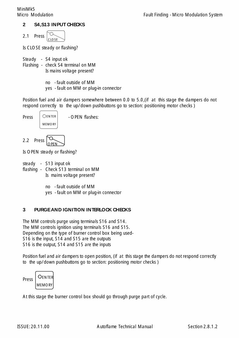
Micro Modulation
ISSUE: 20.11.00 Autoflame Technical Manual Section
MiniMk5Fault Finding - Micro Modulation System
2 S4,S13 INPUT CHECKS
2.1 Press
Is CLOSE steady or flashing?
Steady - S4 input okFlashing - check S4 terminal on MM
Is mains voltage present?
no - fault outside of MMyes - fault on MM or plug-in connector
Position fuel and air dampers somewhere between 0.0 to 5.0,(if at this stage the dampers do notrespond correctly to the up/down pushbuttons go to section: positioning motor checks )
Press - OPEN flashes:
2.2 Press
Is OPEN steady or flashing?
steady - S13 input okflashing - Check S13 terminal on MM
Is mains voltage present?
no - fault outside of MMyes - fault on MM or plug-in connector
3 PURGE AND IGNITION INTERLOCK CHECKS
The MM controls purge using terminals S16 and S14.The MM controls ignition using terminals S16 and S15.Depending on the type of burner control box being used-S16 is the input, S14 and S15 are the outputsS16 is the output, S14 and S15 are the inputs
Position fuel and air dampers to open position, (if at this stage the dampers do not respond correctlyto the up/down pushbuttons go to section: positioning motor checks )
Press
At this stage the burner control box should go through purge part of cycle.
ENTER
MEMORY
CLOSE
ENTER
MEMORY
OPEN
2.8.1.2

Micro Modulation
ISSUE: 20.11.00 Autoflame Technical Manual Section
MiniMk5
3.1 Does control box progress through purge?
yes - S16,S14 interlock okno - Is voltage present on input?
no - fault outside of MMyes - is voltage present on output?
yes - fault outside of MMno - fault on MM or plug-in connector.
Wait until START flashes. START should flash when the burner control box reaches the end of the purgepart of the cycle.
Press .
Position fuel and air dampers to ignition position, (if at this stage the dampers do not respond correctlyto the up/down pushbuttons go to section: positioning motor checks )
Press
At this stage the burner control box should go through ignition part of cycle.
3.2 Does control box progress through ignition?
yes - S16,S15 interlock okno - is voltage present on input?
no - fault outside of MMyes - is voltage present on output?
yes - fault outside of MMno - fault on MM or plug-in connector.
4 POSITIONING MOTOR CHECKS
It is not possible to find positioning motor related faults by following a set procedure. It is more a matterof carrying out a number of tests and making an assessment.
The following applies to fuel and air positioning motors. Repeat the tests for each motor
The following tests are for a motor that is connected normally. i.e. when is pressed, the shaftof the motor moves clockwise.
START
MEMORY
ENTER
Fault Finding - Micro Modulation System
2.8.1.3
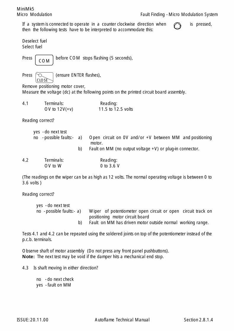
Micro Modulation
ISSUE: 20.11.00 Autoflame Technical Manual Section
MiniMk5
If a system is connected to operate in a counter clockwise direction when is pressed,then the following tests have to be interpreted to accommodate this:
Deselect fuelSelect fuel
Press before COM stops flashing (5 seconds),
Press (ensure ENTER flashes),
Remove positioning motor cover,Measure the voltage (dc) at the following points on the printed circuit board assembly.
4.1 Terminals: Reading:OV to 12V(+v) 11.5 to 12.5 volts
Reading correct?
yes - do next testno - possible faults:- a) Open circuit on 0V and/or +V between MM and positioning
motor.b) Fault on MM (no output voltage +V) or plug-in connector.
4.2 Terminals: Reading:OV to W 0 to 3.6 V
(The readings on the wiper can be as high as 12 volts. The normal operating voltage is between 0 to3.6 volts )
Reading correct?
yes - do next testno - possible faults:- a) Wiper of potentiometer open circuit or open circuit track on
positioning motor circuit boardb) Fault on MM has driven motor outside normal working range.
Tests 4.1 and 4.2 can be repeated using the soldered joints on top of the potentiometer instead of thep.c.b. terminals.
Observe shaft of motor assembly (Do not press any front panel pushbuttons).Note: The next test may be void if the damper hits a mechanical end stop.
4.3 Is shaft moving in either direction?
no - do next checkyes - fault on MM
COM
CLOSE
Fault Finding - Micro Modulation System
2.8.1.4
Micro Modulation
ISSUE: 20.11.00 Autoflame Technical Manual Section
MiniMk5
4.4 Observe fuel and air displaysIs value steadily increasing or decreasing?
no - do next checkyes - possible faults: a) MM permanently driving motor up or down.
b) Wiper of potentiometer open circuit or open circuit track onprinted circuit board.
Note: All following voltage measurements are with respect to neutral.
4.5 Measure voltage on LIVE terminal:
Is mains voltage present?
yes - do next checkno - possible faults: a) fault on MM no output from terminal 17
b) open circuit between MM and positioning motorc) fault on plug in connector on MM.
4.6 Measure voltage on CW terminal
Is mains voltage present?
yes - do next checkno - possible faults: a) fault on motor winding
b) fault on positioning motor circuit board.
4.7 Measure voltage on CCW terminal
Is mains voltage present?
yes - do next checkno - possible faults: a) fault on motor winding
b) fault on positioning motor circuit board.
Observe positioning motor shaft
4.8 Press
Does shaft move in clockwise direction?
yes - do next checkno - possible faults: a) motor or damper jammed.
b) fault on MM or plug-in connector.c) open circuit between MM and CW terminal on motor.d) faulty motor assembly (possibly stripped gears) or fault on
positioning motor circuitboard.
Fault Finding - Micro Modulation System.
2.8.1.5
Micro Modulation
ISSUE: 20.11.00 Autoflame Technical Manual Section
MiniMk5
4.9 Press
Does shaft move in counter clockwise direction?
yes - do next checkno - possible faults: a) motor or damper jammed.
b) fault on MM or plug-in connector.c) open circuit between MM and CCW terminal on motor.d) faulty motor assembly (possibly stripped gears) or fault on
positioning motor circuitboard.
4.10 Measure voltage (ac) between LIVE and CW on positioning motor and press
Is voltage reading zero?
yes - do next checkno - possible faults: a) fault on MM or plug-in connector.
b) open circuit between MM and CW terminal on motor.
4.11 Measure voltage (ac) between LIVE and CCW on positioning motor and press
Is voltage reading zero?
yes - motor okno - possible faults: a) fault on MM or plug-in connector.
b) open circuit between MM and CCW terminal on motor.
If the above tests have been carried out and no specific fault is found proceed as follows:
Detach positioning motor from valve or damper. press one at a time and check forcorrect movement of positioning motor shaft. This will indicate whether valve/damper mechanism isjammed.
Replace "Servo" motor with known working unit see if fault disappears.Replace MM with known working unit see if fault disappears.
After rectifying system, set Options for usual operation required.
Fault Finding - Micro Modulation System
2.8.1.6
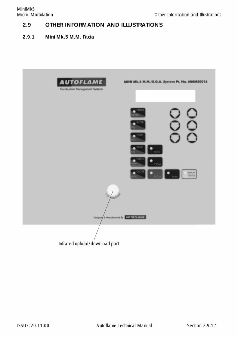
Micro Modulation
ISSUE: 20.11.00 Autoflame Technical Manual Section
MiniMk5
2.9 OTHER INFORMATION AND ILLUSTRATIONS
2.9.1 Mini Mk.5 M.M. Facia
Infrared upload/download port
2.9.1.1
Other Information and Illustrations
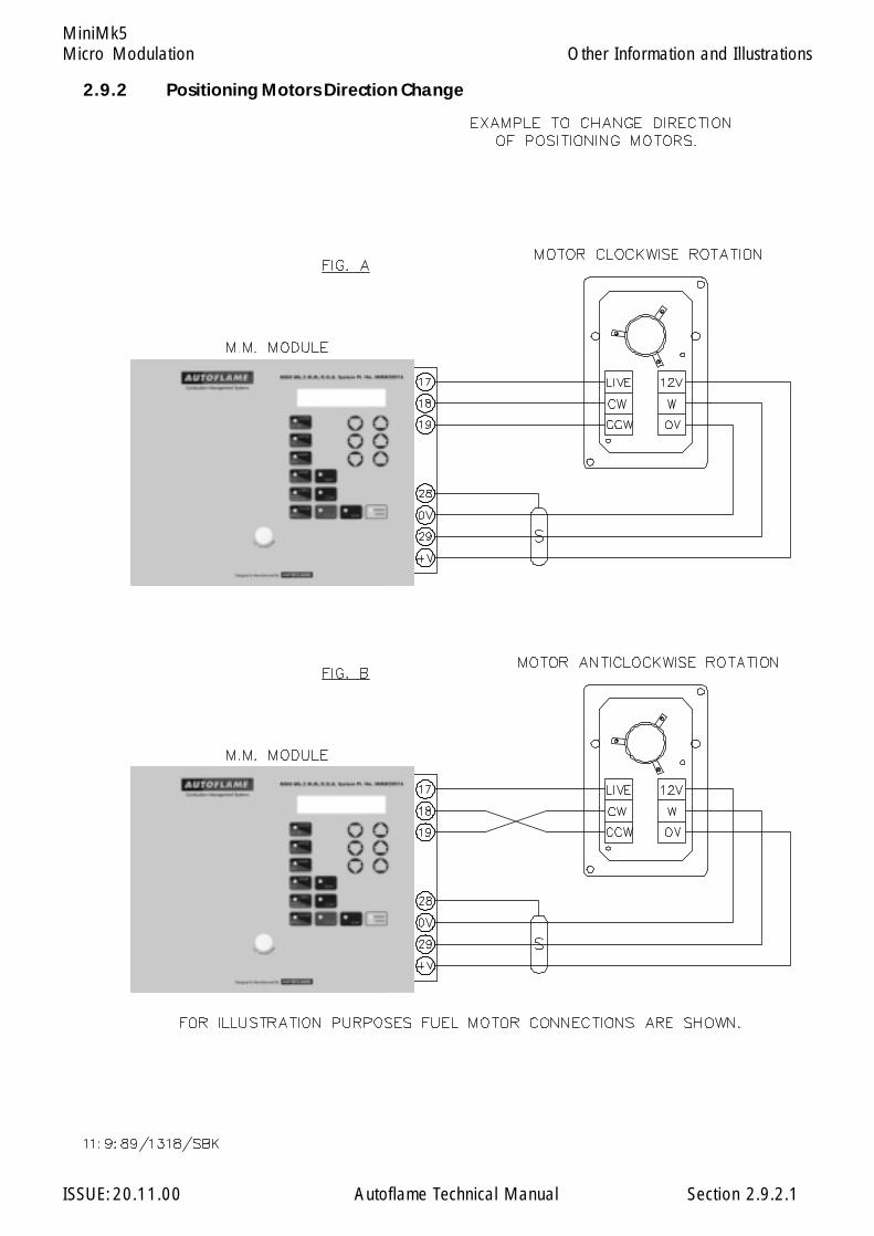
Micro Modulation
ISSUE: 20.11.00 Autoflame Technical Manual Section
MiniMk5
2.9.2.1
Other Information and Illustrations
2.9.2 Positioning Motors Direction Change
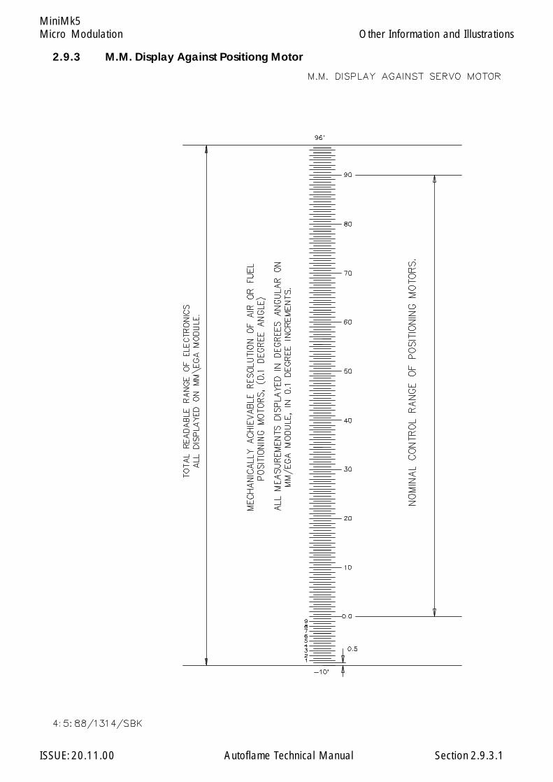
Micro Modulation
ISSUE: 20.11.00 Autoflame Technical Manual Section
MiniMk5
2.9.3.1
Other Information and Illustrations
2.9.3 M.M. Display Against Positiong Motor
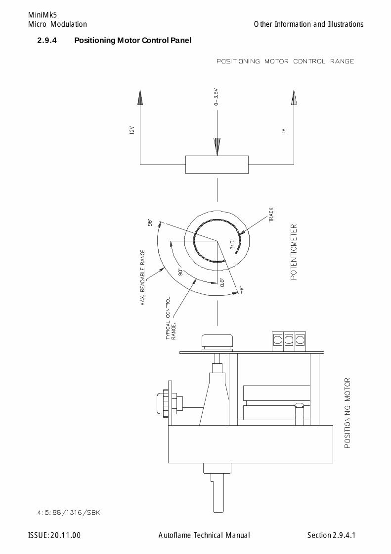
Micro Modulation
ISSUE: 20.11.00 Autoflame Technical Manual Section
MiniMk5
2.9.4.1
Other Information and Illustrations
2.9.4 Positioning Motor Control Panel
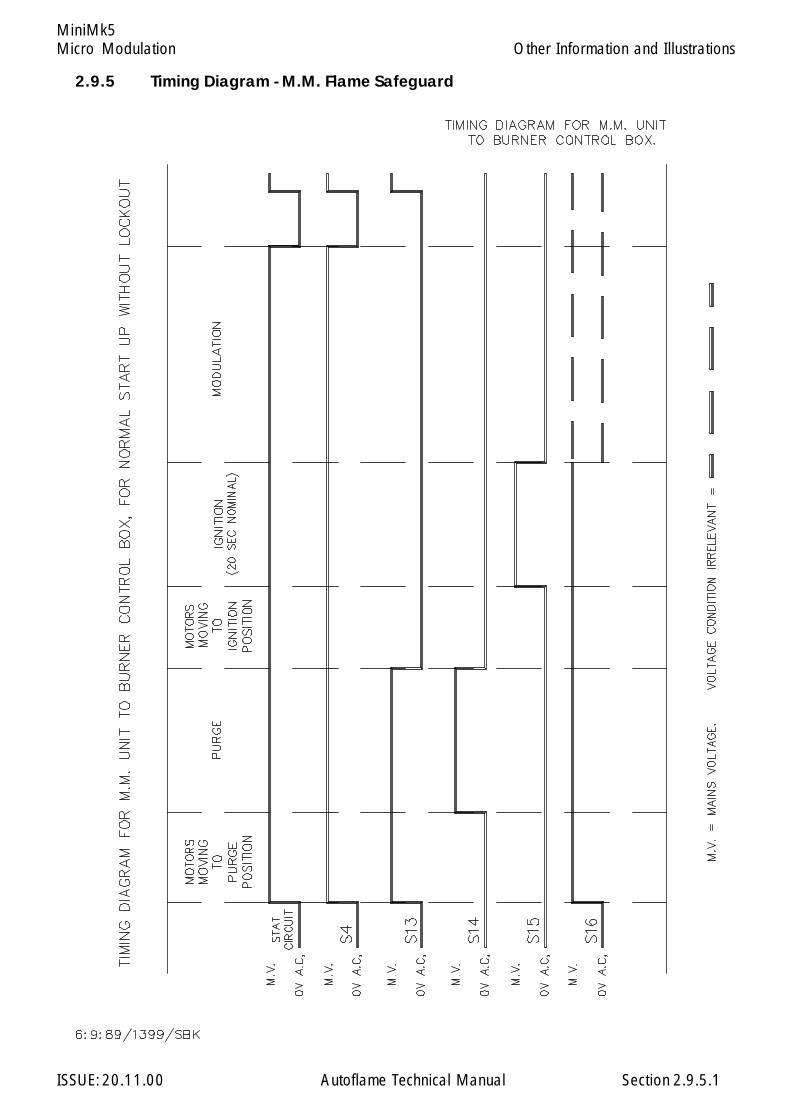
Micro Modulation
ISSUE: 20.11.00 Autoflame Technical Manual Section
MiniMk5
2.9.5.1
Other Information and Illustrations
2.9.5 Timing Diagram - M.M. Flame Safeguard

Micro Modulation
ISSUE: 20.11.00 Autoflame Technical Manual Section
MiniMk5
2.9.6.1
2.9.6 Infrared Upload/Download
MINI Mk.5 M.M./E. G.A. System Pt. No.MMM50016
Software Installation
Insert diskette 1 into drive A: (your first floppy drive) and from Windows click on the Start button andchoose Run. Type A:\SETUP and press the enter key, then follow the instructions on the screen.
When SETUP has completed, insert the key diskette into drive A:, click on Start and choose Run. TypeA:\INSTALL and press enter.
The software need to be configured to the serial (COM) port that the IR lead is connected to. Thishappens the first time the IR Upload/Download software is run.
WARNING
IT IS THE RESPONSIBILITY OF THE OPERATOR TO ENSURE THATAFTER AN UPLOAD ALL THE OPTIONS, PARAMETERS ANDFUEL/AIR RATIO COMMISSION DATA ARE CHECKED FORCORRECTNESS.
The Mini Mk.5 M.M. has an infared upload/download facility.The infrared I/O window is situated on the front facia. A specificinfrared upload/download lead and PC hosted software arerequired to utilise this facility.
To download, the Mini Mk.5 must be set to commissioning mode,but the password does not need to be entered. To upload, thepassword must be entered and the close LED must be flashing orsteady.
Other Information and Illustrations
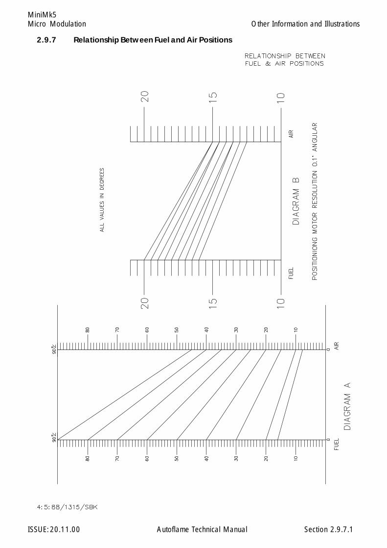
Micro Modulation
ISSUE: 20.11.00 Autoflame Technical Manual Section
MiniMk5
2.9.7.1
Other Information and Illustrations
2.9.7 Relationship Between Fuel and Air Positions
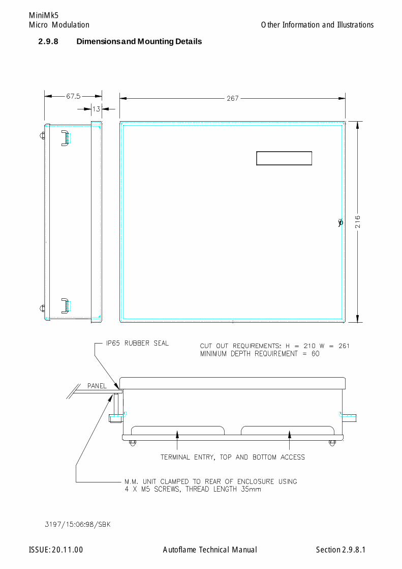
Micro Modulation
ISSUE: 20.11.00 Autoflame Technical Manual Section
MiniMk5
óÿ
2.9.8.1
2.9.8 Dimensions and Mounting Details
12345678901234567890123456789012123456789012345678901234567890121234567890123456789012341234567890123456789012345678901212345678901234567890123456789012123456789012345678901234123456789012345678901234567890121234567890123456789012345678901212345678901234567890123412345678901234567890123456789012123456789012345678901234567890121234567890123456789012341234567890123456789012345678901212345678901234567890123456789012123456789012345678901234123456789012345678901234567890121234567890123456789012345678901212345678901234567890123412345678901234567890123456789012123456789012345678901234567890121234567890123456789012341234567890123456789012345678901212345678901234567890123456789012123456789012345678901234123456789012345678901234567890121234567890123456789012345678901212345678901234567890123412345678901234567890123456789012123456789012345678901234567890121234567890123456789012341234567890123456789012345678901212345678901234567890123456789012123456789012345678901234123456789012345678901234567890121234567890123456789012345678901212345678901234567890123412345678901234567890123456789012123456789012345678901234567890121234567890123456789012341234567890123456789012345678901212345678901234567890123456789012123456789012345678901234123456789012345678901234567890121234567890123456789012345678901212345678901234567890123412345678901234567890123456789012123456789012345678901234567890121234567890123456789012341234567890123456789012345678901212345678901234567890123456789012123456789012345678901234123456789012345678901234567890121234567890123456789012345678901212345678901234567890123412345678901234567890123456789012123456789012345678901234567890121234567890123456789012341234567890123456789012345678901212345678901234567890123456789012123456789012345678901234123456789012345678901234567890121234567890123456789012345678901212345678901234567890123412345678901234567890123456789012123456789012345678901234567890121234567890123456789012341234567890123456789012345678901212345678901234567890123456789012123456789012345678901234123456789012345678901234567890121234567890123456789012345678901212345678901234567890123412345678901234567890123456789012123456789012345678901234567890121234567890123456789012341234567890123456789012345678901212345678901234567890123456789012123456789012345678901234123456789012345678901234567890121234567890123456789012345678901212345678901234567890123412345678901234567890123456789012123456789012345678901234567890121234567890123456789012341234567890123456789012345678901212345678901234567890123456789012123456789012345678901234123456789012345678901234567890121234567890123456789012345678901212345678901234567890123412345678901234567890123456789012123456789012345678901234567890121234567890123456789012341234567890123456789012345678901212345678901234567890123456789012123456789012345678901234123456789012345678901234567890121234567890123456789012345678901212345678901234567890123412345678901234567890123456789012123456789012345678901234567890121234567890123456789012341234567890123456789012345678901212345678901234567890123456789012123456789012345678901234123456789012345678901234567890121234567890123456789012345678901212345678901234567890123412345678901234567890123456789012123456789012345678901234567890121234567890123456789012341234567890123456789012345678901212345678901234567890123456789012123456789012345678901234123456789012345678901234567890121234567890123456789012345678901212345678901234567890123412345678901234567890123456789012123456789012345678901234567890121234567890123456789012341234567890123456789012345678901212345678901234567890123456789012123456789012345678901234123456789012345678901234567890121234567890123456789012345678901212345678901234567890123412345678901234567890123456789012123456789012345678901234567890121234567890123456789012341234567890123456789012345678901212345678901234567890123456789012123456789012345678901234123456789012345678901234567890121234567890123456789012345678901212345678901234567890123412345678901234567890123456789012123456789012345678901234567890121234567890123456789012341234567890123456789012345678901212345678901234567890123456789012123456789012345678901234123456789012345678901234567890121234567890123456789012345678901212345678901234567890123412345678901234567890123456789012123456789012345678901234567890121234567890123456789012341234567890123456789012345678901212345678901234567890123456789012123456789012345678901234123456789012345678901234567890121234567890123456789012345678901212345678901234567890123412345678901234567890123456789012123456789012345678901234567890121234567890123456789012341234567890123456789012345678901212345678901234567890123456789012123456789012345678901234123456789012345678901234567890121234567890123456789012345678901212345678901234567890123412345678901234567890123456789012123456789012345678901234567890121234567890123456789012341234567890123456789012345678901212345678901234567890123456789012123456789012345678901234123456789012345678901234567890121234567890123456789012345678901212345678901234567890123412345678901234567890123456789012123456789012345678901234567890121234567890123456789012341234567890123456789012345678901212345678901234567890123456789012123456789012345678901234123456789012345678901234567890121234567890123456789012345678901212345678901234567890123412345678901234567890123456789012123456789012345678901234567890121234567890123456789012341234567890123456789012345678901212345678901234567890123456789012123456789012345678901234
12345678901234567890123456789012123456789011234567890123456789012345678901212345678901123456789012345678901234567890121234567890112345678901234567890123456789012123456789011234567890123456789012345678901212345678901123456789012345678901234567890121234567890112345678901234567890123456789012123456789011234567890123456789012345678901212345678901123456789012345678901234567890121234567890112345678901234567890123456789012123456789011234567890123456789012345678901212345678901123456789012345678901234567890121234567890112345678901234567890123456789012123456789011234567890123456789012345678901212345678901123456789012345678901234567890121234567890112345678901234567890123456789012123456789011234567890123456789012345678901212345678901123456789012345678901234567890121234567890112345678901234567890123456789012123456789011234567890123456789012345678901212345678901123456789012345678901234567890121234567890112345678901234567890123456789012123456789011234567890123456789012345678901212345678901
Other Information and Illustrations

Micro Modulation
ISSUE: 20.11.00 Autoflame Technical Manual Section
MiniMk5
2.9.9.1
2.9.9 Maintenance and Servicing
The Micro Modulation Unit uses solid state technology. It requires no routine maintenance. If itdevelops a fault that it can diagnose and display it will do so.
The positioning motors/gas/oil valves also do not require routine maintenance. Any fault associatedwith these parts is usually diagnosed by the MM.
Other Information and Illustrations
Micro Modulation
ISSUE: 20.11.00 Autoflame Technical Manual Section
MiniMk5
2.9.10 Installation Precautions
The reliability of the equipment may be impaired if used in environments where strong electro magneticfields exist. If for example the equipment is installed in a boiler house at the top of a high rise buildingwhere radio systems exist then additional EMC (Electro Magnetic Compatability) measures may haveto be considered.
2.9.10.1
Other Information and Illustrations
Micro Modulation
ISSUE: 20.11.00 Autoflame Technical Manual Section
MiniMk5
2.9.11.1
2.9.11 Electrical Specifications
General Information
Mains supply voltage input range: +10 -15% nominal
Power consumption: Approximately 10 watts
Load Ratings Individual Terminals
Input terminals:33, 34, F1, F2, F3, S4, S13, 41 current loading: Approximately 1 milliamp (240v)
Approximately 2 milliamp (110v)
Output terminals maximum current loading:
CR1, CR2 110 milliamps (dc)
42 40 milliamps
S16,S15,S14 30 milliamps
Other terminals:
17, 18, 19, 20, 21, 22, 23 Dedicated for use with Autoflame Positioning Motors29, 32, 27, 0V, +V, 28 Dedicated for use with Autoflame Positioning Motors
38, 61, 60 Dedicated for Autoflame Temperature/Pressure Detectors.
52, 51, 49, 48 Dedicated for use only as detailed in this manual.
E, N, L Mains Supply
Other Information and Illustrations

Micro Modulation
ISSUE: 20.11.00 Autoflame Technical Manual Section
MiniMk5
2.9.11.2
Screened Cable
The screened cable used from the MM to the servo motors and detectors must conform to thefollowing specification:
16/0.2mm PVC Insulated Overall Braid, Screened, PVC Sheathed.
Sixteen wires per core;Diameter of wires in each core 0.2mm;Rated at 440 volts a.c. rms at 1600 Hz;DEF 61-12 current rating per core 2.5 Amps;Maximum operating temperature 70 degrees C.;Nominal conductor area 0.5 square mm per core;Nominal insulation radial thickness on core 0.45mm;Nominal conductor diameter per core 0.93mm;Nominal core resistance at 20 degrees C. 40.1 Ohm/1000m.;Nominal overall diameter per core 1.83 mm.;Fill factor of braid screen 0.7;Equivalent imperial conductor sizes 14/0.0076.
Use the number of cores suitable for the application.A universal part numbering system appears to have been adopted for this type of cable as follows:
16-2-2C 2 Cores16-2-3C 3 Cores16-2-4C 4 Cores16-2-6C 6 Cores
(5 Cores not readily available).
Data Cable
Data cable must be used for connections between MMs for twin burner/sequencing applicationsand between MMs and EGAs.
Types of data cable that can be used:
1. Beldon 9501;2. STC OS1P24.
Samples are available upon request.Cable can be ordered directly from Autoflame Engineering.
Other Information and Illustrations

Micro Modulation
ISSUE: 20.11.00 Autoflame Technical Manual Section
MiniMk5
DESCRIPTION OF CONNECTIONS
Throughout this description, unless otherwise stated, ‘signal’ is to be interpreted as meaning 240Vac.The term Control Box is to be interpreted as meaning the flame safe guard control unit.
The following information will be more meaningful if read in conjunction with the input/outputschematic and timing sequence diagram found in Section 2.
For correct operation between the M.M. unit and a burner control box a specific sequence ofsignal timing pulses is necessary. The M.M. has five specific input/output terminals (S4, S13, S14,S15 and 16) which are solely for the purpose of the interaction to and from the control box.
The terminals S16,S15,S14 are described here, such that S16 is an input, S15 and S14 are outputs.On some control boxes S15 and S14 are inputs and S16 is an output. The following descriptionsmay have to be interpreted to accommodate this when appropriate.
The timing sequence starts with the completion of the burner stat circuit . This must be indicated tothe M.M. by a signal input on S4. At the same time the M.M./E.G.A. expects a signal input on S13.Together these signals are a directive for the M.M. to attain the purge position. On correct receiptof both signals the M.M. unit drives the positioning motors to their purge positions. When thepurge positions are reached, the M.M. outputs a signal on S14. This indicates to the control boxthat it must now proceed through purge. On completion of the purge period the control box re-moves the signal from S13. The M.M. interprets this as a directive to drive the positioning motors tothe ignition position. The M.M. removes the signal output from S14 and drives the valves to theignition position. When in position the M.M. outputs a signal on S15. The control box thenproceeds through the burner ignition sequence. The M.M. holds the ignition positions for a nomi-nal period of 20 seconds (adjustable) after outputting the signal on S15. The M.M. thereafterremoves the signal output on S15 and modulates.
DESCRIPTION OF INDIVIDUAL INPUTS/OUTPUTS RELEVANT TO THE CONTROL BOX
S4 Input to M.M.:- Signal must be present whenever the stat circuit is made. Indicates burneris to be firing. Whenever this signal is removed the M.M. maintains the CR1 relay open for tenseconds thereafter and sets the positioning motors to their closed positions.
S13 Input to M.M.:- Signal directs positioning motors to purge position (provided signal ispresent on S4). When signal is removed M.M. directs positioning motors to ignition positions.Ifdetected during modulation CR1 relay is opened.
S14 Output from M.M.: Signal indicating the positioning motors are at the purge position. Onlyoutput during burner start up.
S15 Output from M.M.: Signal indicating the positioning motors are at the ignition position.Onlyoutput during burner start up.
S16 Input to M.M.: This signal must come from a proving output on the control box. i.e. anoutput that is only available when there is no lockout or other fault condition on the control box.This input is used by the M.M. as a source for the signal outputs on S14 & S15.
2.9.11.3
Other Information and Illustrations
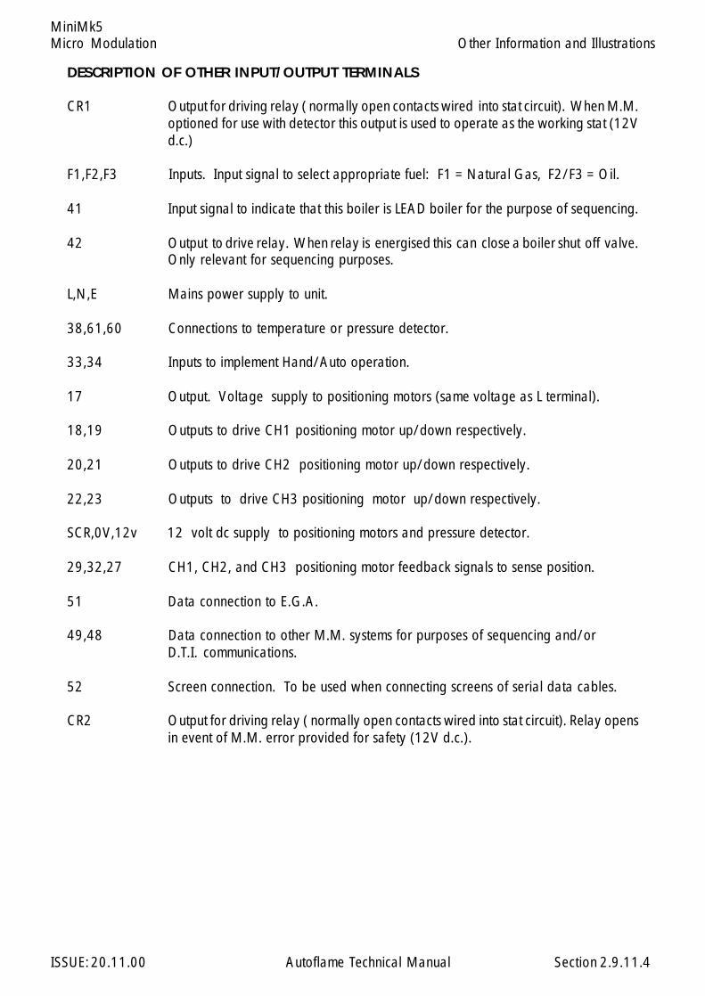
Micro Modulation
ISSUE: 20.11.00 Autoflame Technical Manual Section
MiniMk5
DESCRIPTION OF OTHER INPUT/OUTPUT TERMINALS
CR1 Output for driving relay ( normally open contacts wired into stat circuit). When M.M.optioned for use with detector this output is used to operate as the working stat (12Vd.c.)
F1,F2,F3 Inputs. Input signal to select appropriate fuel: F1 = Natural Gas, F2/F3 = Oil.
41 Input signal to indicate that this boiler is LEAD boiler for the purpose of sequencing.
42 Output to drive relay. When relay is energised this can close a boiler shut off valve.Only relevant for sequencing purposes.
L,N,E Mains power supply to unit.
38,61,60 Connections to temperature or pressure detector.
33,34 Inputs to implement Hand/Auto operation.
17 Output. Voltage supply to positioning motors (same voltage as L terminal).
18,19 Outputs to drive CH1 positioning motor up/down respectively.
20,21 Outputs to drive CH2 positioning motor up/down respectively.
22,23 Outputs to drive CH3 positioning motor up/down respectively.
SCR,0V,12v 12 volt dc supply to positioning motors and pressure detector.
29,32,27 CH1, CH2, and CH3 positioning motor feedback signals to sense position.
51 Data connection to E.G.A.
49,48 Data connection to other M.M. systems for purposes of sequencing and/orD.T.I. communications.
52 Screen connection. To be used when connecting screens of serial data cables.
CR2 Output for driving relay ( normally open contacts wired into stat circuit). Relay opensin event of M.M. error provided for safety (12V d.c.).
2.9.11.4
Other Information and Illustrations
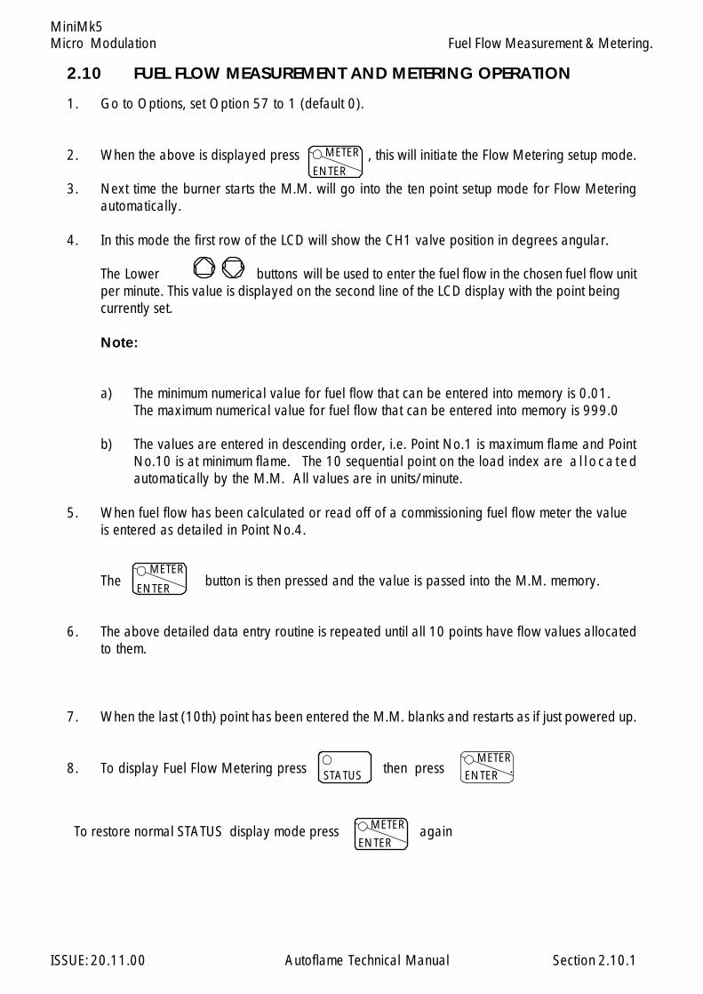
Micro Modulation
ISSUE: 20.11.00 Autoflame Technical Manual Section
MiniMk5
1. Go to Options, set Option 57 to 1 (default 0).
2. When the above is displayed press , this will initiate the Flow Metering setup mode.
3. Next time the burner starts the M.M. will go into the ten point setup mode for Flow Meteringautomatically.
4. In this mode the first row of the LCD will show the CH1 valve position in degrees angular.
The Lower buttons will be used to enter the fuel flow in the chosen fuel flow unitper minute. This value is displayed on the second line of the LCD display with the point beingcurrently set.
Note:
a) The minimum numerical value for fuel flow that can be entered into memory is 0.01.The maximum numerical value for fuel flow that can be entered into memory is 999.0
b) The values are entered in descending order, i.e. Point No.1 is maximum flame and PointNo.10 is at minimum flame. The 10 sequential point on the load index are a l l oca tedautomatically by the M.M. All values are in units/minute.
5. When fuel flow has been calculated or read off of a commissioning fuel flow meter the valueis entered as detailed in Point No.4.
The button is then pressed and the value is passed into the M.M. memory.
6. The above detailed data entry routine is repeated until all 10 points have flow values allocatedto them.
7. When the last (10th) point has been entered the M.M. blanks and restarts as if just powered up.
8. To display Fuel Flow Metering press then press .
Fuel Flow Measurement & Metering.
To restore normal STATUS display mode press again
2.10.1
ENTER
METER
ENTER
METER
ENTER
METER
STATUS
ENTER
METER
2.10 FUEL FLOW MEASUREMENT AND METERING OPERATION
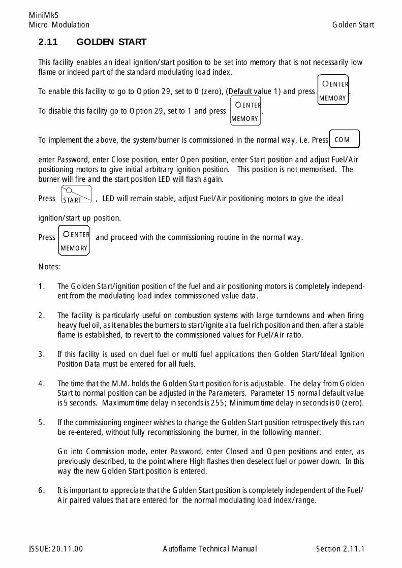
Micro Modulation
ISSUE: 20.11.00 Autoflame Technical Manual Section
MiniMk5Golden Start
2.11 GOLDEN START
This facility enables an ideal ignition/start position to be set into memory that is not necessarily lowflame or indeed part of the standard modulating load index.
To enable this facility to go to Option 29, set to 0 (zero), (Default value 1) and press .
To disable this facility go to Option 29, set to 1 and press .
To implement the above, the system/burner is commissioned in the normal way, i.e. Press
enter Password, enter Close position, enter Open position, enter Start position and adjust Fuel/Airpositioning motors to give initial arbitrary ignition position. This position is not memorised. Theburner will fire and the start position LED will flash again.
Press , LED will remain stable, adjust Fuel/Air positioning motors to give the ideal
ignition/start up position.
Press and proceed with the commissioning routine in the normal way.
Notes:
1. The Golden Start/ignition position of the fuel and air positioning motors is completely independ-ent from the modulating load index commissioned value data.
2. The facility is particularly useful on combustion systems with large turndowns and when firingheavy fuel oil, as it enables the burners to start/ignite at a fuel rich position and then, after a stableflame is established, to revert to the commissioned values for Fuel/Air ratio.
3. If this facility is used on duel fuel or multi fuel applications then Golden Start/Ideal IgnitionPosition Data must be entered for all fuels.
4. The time that the M.M. holds the Golden Start position for is adjustable. The delay from GoldenStart to normal position can be adjusted in the Parameters. Parameter 15 normal default valueis 5 seconds. Maximum time delay in seconds is 255; Minimum time delay in seconds is 0 (zero).
5. If the commissioning engineer wishes to change the Golden Start position retrospectively this canbe re-entered, without fully recommissioning the burner, in the following manner:
Go into Commission mode, enter Password, enter Closed and Open positions and enter, aspreviously described, to the point where High flashes then deselect fuel or power down. In thisway the new Golden Start position is entered.
6. It is important to appreciate that the Golden Start position is completely independent of the Fuel/Air paired values that are entered for the normal modulating load index/range.
ENTER
MEMORYENTER
MEMORY
COM
START
ENTER
MEMORY
2.11.1

Micro Modulation
ISSUE: 20.11.00 Autoflame Technical Manual Section
MiniMk5
One point change facility
To change a point:-
Start up the burner in the normal way.
Once modulating press and simultaneously. The password should be
displayed. Set the password and press in the same way as if going into normal
commissioning, the channel position values should be displayed. The valves track to the nearestcommission point (e.g. HIGH/INTER/START).
When all the values have settled at their appropriate positions ENTER flashes. If this point is to be
changed press If not press the CH1 button to move to the next point up or
the CH1 button to go to the next point down. The M.M. detects which point has been
selected and will steady the appropriate LED on either HIGH, INTER or START as during normalcommissioning. If EGA is not optioned ENTER will be flashing otherwise EGA will flash. It should nowbe possible to adjust each value individually.
Adjust the values as desired and proceed to press The M.M. will revert to justENTER and
RUN flashing. If desired another point can be selected and changed otherwise
press and the M.M. reverts to normal modulation. If the CH1 (fuel) HIGH or START
position has been adjusted check the flow metering. It is likely that the 10 point flow calibration mustbe carried out again.
2.12 ONE POINT CHANGE
2.12.1
STARTCO
COM
CLOSE
Eff%
FUELMETER
ENTERMEMORY
RUN
FUELMETER
ENTERMEMORY
One Point Change
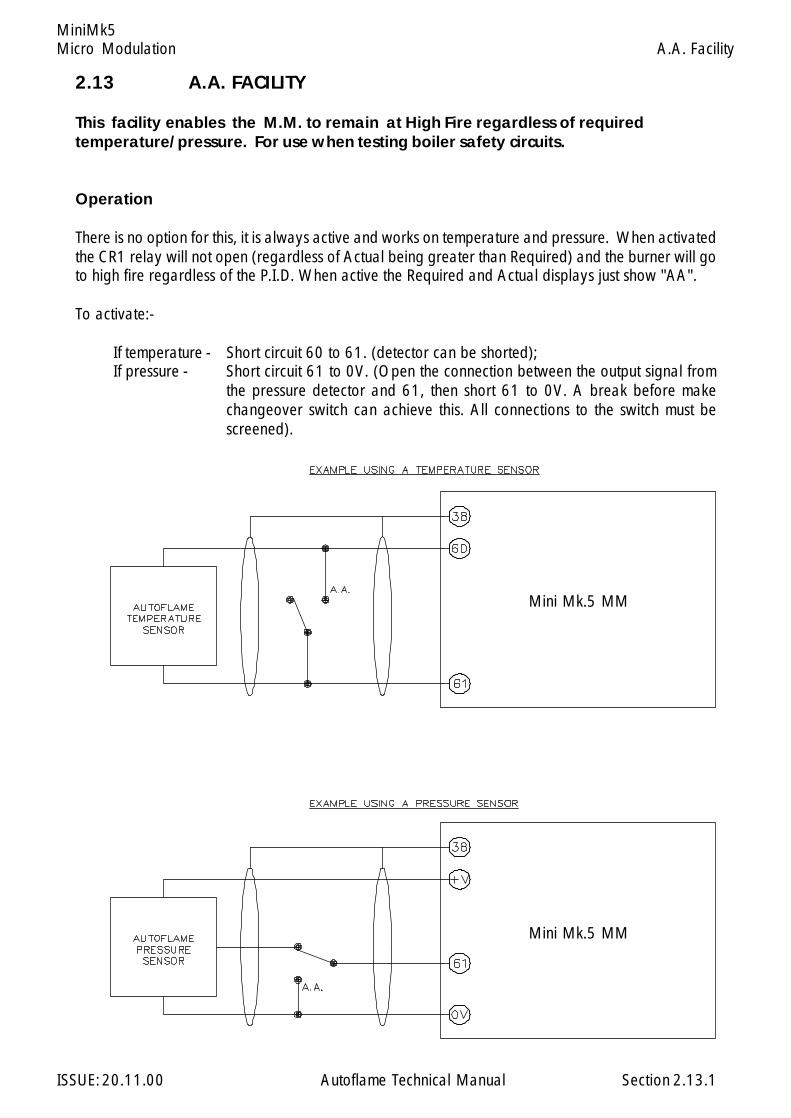
Micro Modulation
ISSUE: 20.11.00 Autoflame Technical Manual Section
MiniMk5
2.13 A.A. FACILITY
This facility enables the M.M. to remain at High Fire regardless of requiredtemperature/pressure. For use when testing boiler safety circuits.
Operation
There is no option for this, it is always active and works on temperature and pressure. When activatedthe CR1 relay will not open (regardless of Actual being greater than Required) and the burner will goto high fire regardless of the P.I.D. When active the Required and Actual displays just show "AA".
To activate:-
If temperature - Short circuit 60 to 61. (detector can be shorted);If pressure - Short circuit 61 to 0V. (Open the connection between the output signal from
the pressure detector and 61, then short 61 to 0V. A break before makechangeover switch can achieve this. All connections to the switch must bescreened).
2.13.1
Mini Mk.5 MM
Mini Mk.5 MM
A.A. Facility
Micro Modulation
ISSUE: 20.11.00 Autoflame Technical Manual Section
Mk6
2.14.1 Mk.6 M.M. Control Unit
2.14.2 Commissioning and Setting Up Procedure2.14.2.1 Introduction2.14.2.2 Programming Fuel/Air Positions2.14.2.3 Setting Positioning Motors2.14.2.4 Setting Options2.14.2.5 Parameters2.14.2.6 Valve Proving
2.14.2.6.1 Explanation2.14.2.6.2 Gas Pressure Sensor2.14.2.6.2.1 Oil Pressure Sensor2.14.2.6.3 Commissioning Valve Proving
2.14.2.7 Air Pressure Proving2.14.2.7.1 Explanation2.14.2.7.2 Air Pressure Sensor2.14.2.7.3 Air Pressure Tapped Fitting
2.14.2.8 Outside Air Temperature Compensation2.14.2.8.1 Explanation2.14.2.8.2 Outside Air Sensor
2.14.2.9 Electrical Specifications2.14.2.9.1 Classifications2.14.2.9.2 Fuse Ratings2.14.2.9.3 Terminals Description2.14.2.9.4 Cables
2.14.2.10 Variable Speed Drives2.14.2.11 Installation Checks
2.14.3 Control Box Functions2.14.3.1 Burner Control Sequence Diagrams2.14.3.2 Self Check UV Scanner2.14.3.3 Standard European UV Scanner - Side viewing2.14.3.4 Standard North American UV Scanner - End viewing2.14.3.5 Selection of UV Scanner Types2.14.3.6 UV Self Adaptive Pulse Width Modulation
2.14.4 Error Checking, Self Diagnostic Fault Analysis, I.D. Codes2.14.4.1 Key to Errors2.14.4.2 Key to Lockouts2.14.4.3 Troubleshooting
2.14.5 End User Day to Day Operation2.14.5.1 Normal Run Operation2.14.5.2 Adjusting Clock Settings, Contrast and Actual Load Reading2.14.5.3 EPROM Version Numbers
2.14: Index
Section 2.14: Mk6 M.M. Micro Modulation

Micro Modulation
ISSUE: 20.11.00 Autoflame Technical Manual Section
Mk6
2.14.6 Electrical Schematics Showing all Terminal Interconnections2.14.6.1 Mk.6 Connection Diagram2.14.6.2 Mk.6 Wiring Diagram 110V ac2.14.6.3 Boiler Steam Pressure Detector Connection Diagram2.14.6.4 Flame Safeguard Connection Example Diagrams2.14.6.6 EGA Mk6 Interconnection Diagram2.14.6.10 Splitter Interface Interconnection Diagram2.14.6.11 O2 Interface Interconnection Diagram
2.14.7 Twin Burner Operation2.14.7.1 Operations/Guidelines2.14.7.3 Interconnecting Wiring
2.14.8 Hand/Auto and Low Flame Hold Facilities
2.14.9 Fault Finding
2.14.10 Other Information and Illustrations2.14.10.1 Mk.6 M.M. Front Facia Details2.14.10.2 Positioning Motor Direction Change Diagram2.14.10.3 Timing Diagram - for Mk.6 with external Flame Safeguard2.14.10.4 Mk.6 M.M. Enclosure Dimensions2.14.10.5 IR Download Lead2.14.10.6 Maintenance and Servicing2.14.10.7 Installation Precautions
2.14.11 Fuel Flow Measurement and Metering operation
2.14.12 Golden Start choke operation
2.14.13 One Point Change Facility
2.14.14 Flue Gas Recirculation
2.14.15 Pause Facility
2.14.16 Time Clock Facility
2.14.18 Automatic Commission Of Gas Pressure Values
2.14.19 Flame Detection Using External Flame Switch
2.14: Index
Section 2.14: Mk6 M.M. Micro Modulation
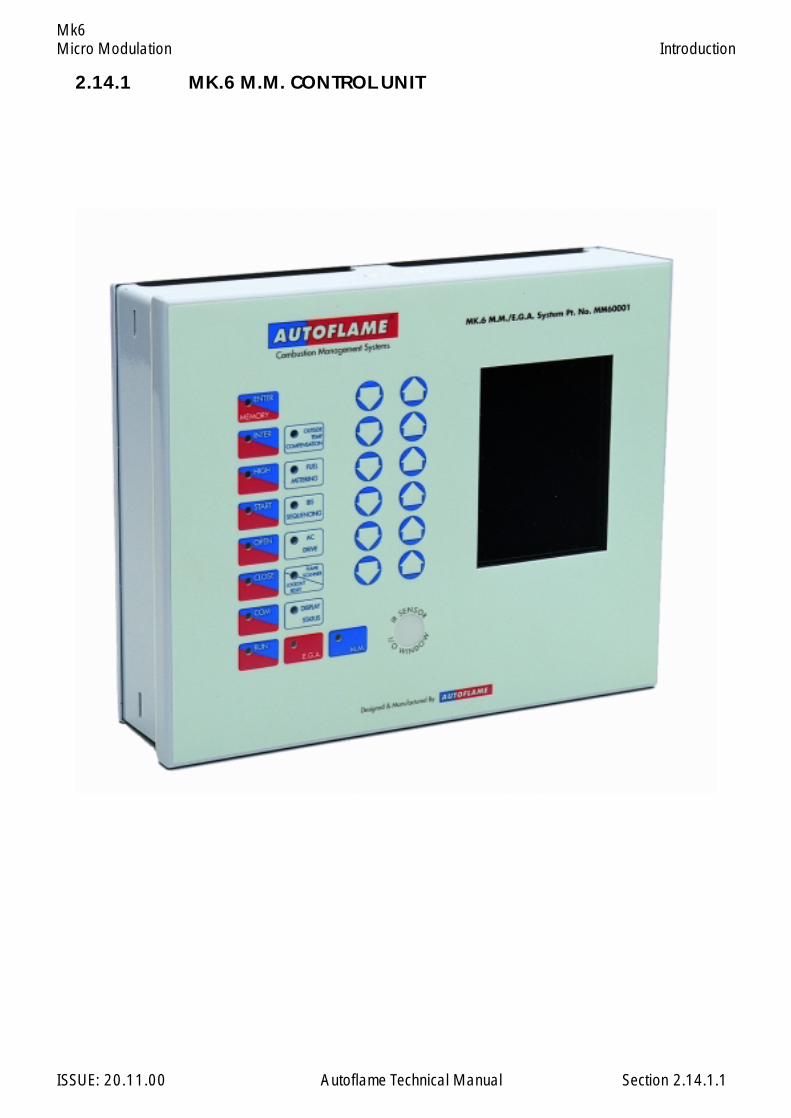
Micro Modulation
ISSUE: 20.11.00 Autoflame Technical Manual Section
Mk6Introduction
2.14.1 MK.6 M.M. CONTROL UNIT
2.14.1.1
Micro Modulation
ISSUE: 20.11.00 Autoflame Technical Manual Section
Mk6
2.14.2 MK.6 COMMISSIONING AND SETTING UP PROCEDURES.
2.14.2.1 Introduction.
The commissioning procedure as described must be strictly adhered to. Anybody commissioning aMicro Modulation system must have an adequate understanding of combustion plant. In the wronghands hazardous conditions could be made to exist.
The fundamental idea of the system is to set a fuel valve position and then set a corresponding air valveposition. Care must be taken when adjusting the fuel and air positions so as not to create any unstablecombustion conditions, e.g. moving the fuel valve to the open position without increasing the air valvecorrespondingly.
If the system being commissioned is an M.M., without E.G.A., then a combustion monitor is required tocheck the exhaust gases. If the system does have an E.G.A., then a combustion monitor should not benecessary as the E.G.A. performs all normal exhaust gas measurements. When burning oil a smokedetection device is necessary to check smoke generated is within limits.
Ideally to implement commissioning as quickly as possible arrange for a substantial load on the boiler.The commissioning procedure can be interrupted due to excess temperature or pressure, causing theburner to turn off. In these instances the commissioning data accumulated so far is not lost. When theburner is called back on the system starts up automatically and commissioning can proceed from whereit left off.
Once the burner has been fired the maximum fuel position is entered first, then descending fuel positionsare entered consecutively until finally a minimum fuel position is entered. The CH1 and CH2 positionsmust always be less than the ones previously entered. However with CH3 - CH6 it is possible to movethe position above or below the previously entered point.
COMMISSIONING PROCEDURE (Systems without Exhaust Gas Analyser).
On a newly installed system the following procedures should be carried out as listed.
1. Check all interconnecting wiring between the M.M. and external components is correct.2. Set Options required (Refer to Option Section 2.14.2.4).3. Set up positioning motors.4. Programme fuel/air positions.
On a previously commissioned system, it is possible to omit steps No.s 1, 2 or 3.
Commissioning and Setting up Procedure: Introduction
2.14.2.1.1
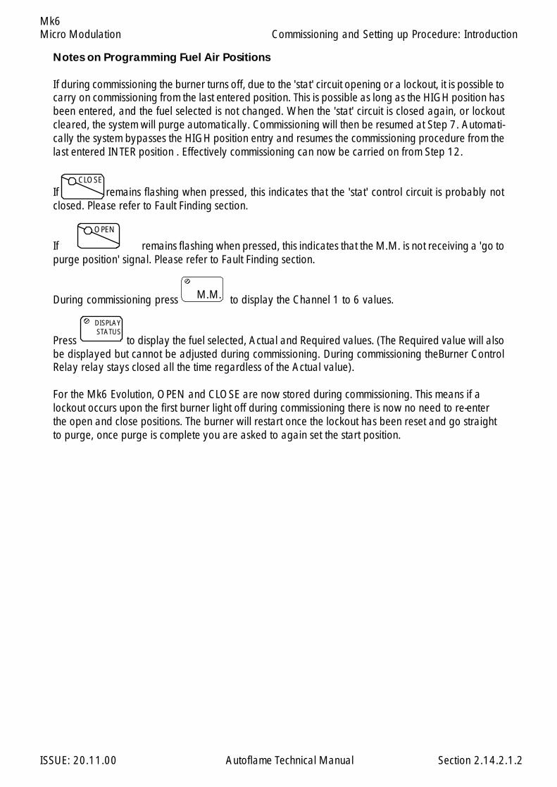
Micro Modulation
ISSUE: 20.11.00 Autoflame Technical Manual Section
Mk6
Notes on Programming Fuel Air Positions
If during commissioning the burner turns off, due to the 'stat' circuit opening or a lockout, it is possible tocarry on commissioning from the last entered position. This is possible as long as the HIGH position hasbeen entered, and the fuel selected is not changed. When the 'stat' circuit is closed again, or lockoutcleared, the system will purge automatically. Commissioning will then be resumed at Step 7. Automati-cally the system bypasses the HIGH position entry and resumes the commissioning procedure from thelast entered INTER position . Effectively commissioning can now be carried on from Step 12.
If remains flashing when pressed, this indicates that the 'stat' control circuit is probably notclosed. Please refer to Fault Finding section.
If remains flashing when pressed, this indicates that the M.M. is not receiving a 'go topurge position' signal. Please refer to Fault Finding section.
During commissioning press to display the Channel 1 to 6 values.
Press to display the fuel selected, Actual and Required values. (The Required value will alsobe displayed but cannot be adjusted during commissioning. During commissioning theBurner ControlRelay relay stays closed all the time regardless of the Actual value).
For the Mk6 Evolution, OPEN and CLOSE are now stored during commissioning. This means if alockout occurs upon the first burner light off during commissioning there is now no need to re-enterthe open and close positions. The burner will restart once the lockout has been reset and go straightto purge, once purge is complete you are asked to again set the start position.
OPEN
M.M.
123123
DISPLAYSTATUS
123123
2.14.2.1.2
Commissioning and Setting up Procedure: Introduction
CLOSE
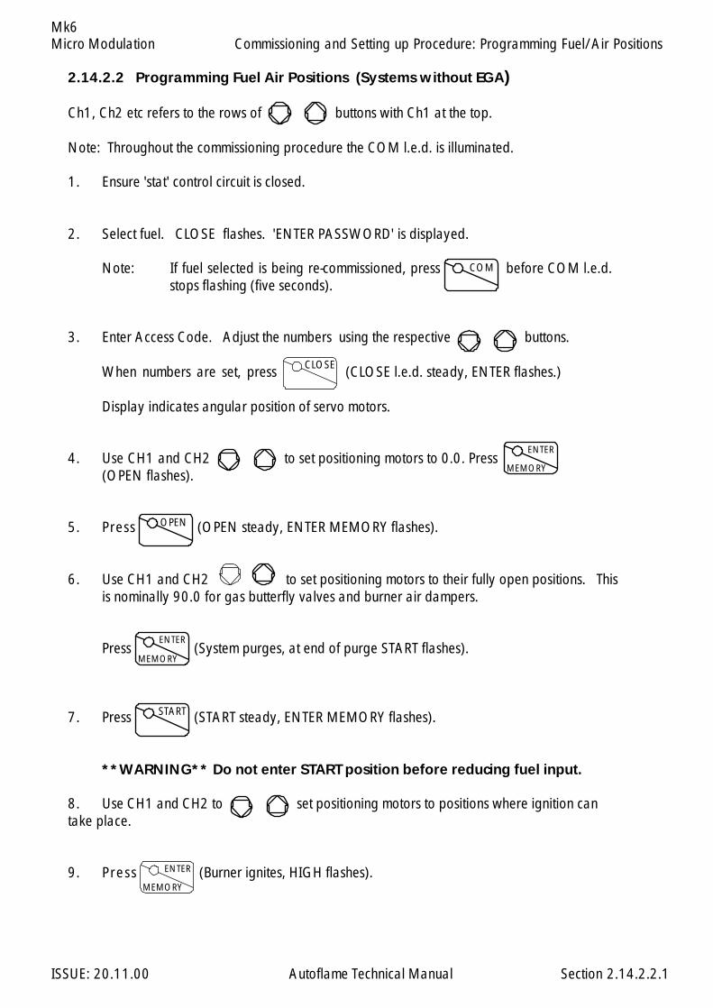
Micro Modulation
ISSUE: 20.11.00 Autoflame Technical Manual Section
Mk6
2.14.2.2 Programming Fuel Air Positions (Systems without EGA)
Ch1, Ch2 etc refers to the rows of buttons with Ch1 at the top.
Note: Throughout the commissioning procedure the COM l.e.d. is illuminated.
1. Ensure 'stat' control circuit is closed.
2. Select fuel. CLOSE flashes. 'ENTER PASSWORD' is displayed.
Note: If fuel selected is being re-commissioned, press before COM l.e.d.stops flashing (five seconds).
3. Enter Access Code. Adjust the numbers using the respective buttons.
When numbers are set, press (CLOSE l.e.d. steady, ENTER flashes.)
Display indicates angular position of servo motors.
4. Use CH1 and CH2 to set positioning motors to 0.0. Press(OPEN flashes).
5. Press (OPEN steady, ENTER MEMORY flashes).
6. Use CH1 and CH2 to set positioning motors to their fully open positions. Thisis nominally 90.0 for gas butterfly valves and burner air dampers.
Press (System purges, at end of purge START flashes).
7. Press (START steady, ENTER MEMORY flashes).
**WARNING** Do not enter START position before reducing fuel input.
8. Use CH1 and CH2 to set positioning motors to positions where ignition cantake place.
9. Press (Burner ignites, HIGH flashes).
COM
CLOSE
OPEN
ENTER
MEMORY
ENTER
MEMORY
START
ENTER
MEMORY
2.14.2.2.1
Commissioning and Setting up Procedure: Programming Fuel/Air Positions

Micro Modulation
ISSUE: 20.11.00 Autoflame Technical Manual Section
Mk6
10. Press (HIGH steady, ENTER MEMORY flashes).
11. Use CH1 and CH2 to set maximum firing input (do not exceed OPEN positionvalues).
12. Press (INTER, or INTER and START flash).
Note: Only INTER flashes if the number of INTER positions entered so far is less or equal tothree, thereafter INTER and START flash.
13. Press o r (INTER or START steady, ENTER MEMORY flashes).
14. Use CH1 and CH2 to reduce the positions.
If present position is an INTER position, go back to 12/, otherwise proceed further.
15. Press (After a short pause RUN flashes).
16. Press to set system into normal modulating mode.
HIGH
ENTER
MEMORY
INTER START
ENTER
MEMORY
RUN
2.14.2.2.2
Commissioning and Setting up Procedure: Programming Fuel/Air Positions

Micro Modulation
ISSUE: 20.11.00 Autoflame Technical Manual Section
Mk6
Setting Positioning Motors.
Autoflame supply three standard sizes of positioning motors - large, small and industrial. All can be usedfor positioning fuel and air dampers.Both types can be configured to drive clockwise or counter clockwise to open a valve or damper.
Refer to drawing numbers: Layout of large positioning motor, Section 2.2.3.4Layout of small positioning motor, Section 2.2.3.3Industrial Positioning Motor, Refer Section 8.10
Viewing the shaft end-on, from the potentiometer end, all positioning motors drive in a clockwise directionif power is applied between the LIVE and CW terminals, and counter clockwise if the power is appliedbetween the LIVE and CCW terminal.
The operation of fuel valves and air dampers is often such that they open in a clockwise direction. Ifoperation needs to be reversed, it is necessary to swop various wiring connections between the M.M.and the positioning motor(s). An example of reversing the operation of a fuel valve is shown in figure B,Section 2.9.2. Figure A shows the connections for normal operation.
Set Up Procedure:
Before a burner is fired it is essential to set up each Micro Modulation positioning motor.
A tamper proof screwdriver is required. (These can be ordered from Autoflame)
Usually control valves/air dampers, that the positioning motors drive, move through up to 90 degreesangular. The M.M. system has the ability to drive valves through up to 96 degrees. Please contactAutoflame technical department for advice on applications for ranges greater than 90 degrees.
All readings displayed on the MM are in degrees angular. It is necessary to adjust the potentiometer inthe positioning motor assembly so that the M.M. reads 0.0 when the relevant valve/damper is at itsclosed position.
To set up a positioning motor, first ensure Option 12 is set to 0, (this prevents E.G.A. ‘COOL’ from beingdisplayed). Put the M.M. into the commissioning mode so that the CLOSE l.e.d. is steady and the ENTERl.e.d. flashes (see section on Commissioning). By doing this it is possible to position the valve/dampermechanically by using the appropriate up and down buttons.
Remove the positioning motor cover.
**Warning** Electrical Connections are live.
2.14.2.3.1
Commissioning and Setting up Procedure: Setting Positioning Motors
Micro Modulation
ISSUE: 20.11.00 Autoflame Technical Manual Section
Mk6
For air positioning motor(s) carry out the following procedure:
Use the up/down buttons for the relevant air damper to position the air damper to its physically closedposition. Loosen the three tamper proof screws just sufficiently to enable the potentiometer to rotate.Rotate the potentiometer clockwise or counter clockwise until the relevant display window reads 0.0.Tighten the three tamper proof screws gently until the pot. is secure. Do not overtighten the screws. Checkdisplay still reads 0.0, if not repeat adjustment process.
For fuel positioning motor(s) carry out the following procedure:
On Autoflame gas, oil and gas/oil combination valves it is necessary to remove the positioning motor.Manually position the oil/gas valve slot to its closed position. Observe the position of the drive pin onthe positioning motor. Use the relevant up/down buttons to position the pin so that when the positioningmotor is reassembled to the valve it is in line with the slot. Reassemble the positioning motor to the valve,loosen the three tamper proof screws and proceed to adjust the potentiometer position until 0.0 isdisplayed.
2.14.2.3.2
Commissioning and Setting up Procedure: Setting Positioning Motors
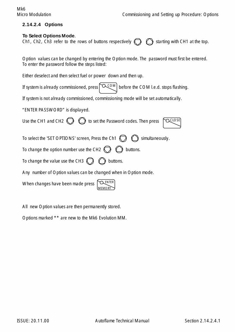
Micro Modulation
ISSUE: 20.11.00 Autoflame Technical Manual Section
Mk6
2.14.2.4 Options
To Select Options Mode.Ch1, Ch2, Ch3 refer to the rows of buttons respectively starting with CH1 at the top.
Option values can be changed by entering the Option mode. The password must first be entered.To enter the password follow the steps listed:
Either deselect and then select fuel or power down and then up.
If system is already commissioned, press before the COM l.e.d. stops flashing.
If system is not already commissioned, commissioning mode will be set automatically.
“ENTER PASSWORD” is displayed.
Use the CH1 and CH2 to set the Password codes. Then press
To select the 'SET OPTIONS' screen, Press the Ch1 simultaneously.
To change the option number use the CH2 buttons.
To change the value use the CH3 buttons.
Any number of Option values can be changed when in Option mode.
When changes have been made press
All new Option values are then permanently stored.
Options marked ** are new to the Mk6 Evolution MM.
COM
CLOSE
ENTER
MEMORY
2.14.2.4.1
Commissioning and Setting up Procedure: Options

Micro Modulation
ISSUE: 20.11.00 Autoflame Technical Manual Section
Mk6
1. 3 Boiler Temperature/Pressure Sensor Type:
3 0-400C Temperature Sensor (MM10006 & 7).20-390 C. (50 - 730 F.)4 Unused5 Unused6 0-18 Bar Pressure Sensor (MM10008) 2.0 - 23.0 bar (5 - 330 P.S.I.)7 0-30 Bar Pressure Sensor (MM10009) 2.0 - 45.0 bar (30 - 650 P.S.I.)8 0-3.0 Bar Pressure Sensor (MM10010) 0.2 - 3.80 bar (3.0 - 55.0 P.S.I.)
2. 60 Motor Travel Speed: The value is not specific to a time/distance ratio. If thespeed of the motor is too fast then increase this option value. If too slow, decreasethe value. This speed adjustment is only relevant during modulation. At other timesthe motors move at full speed or as set for Purge in Option 75.
5-240 Adjustment Range
3. 0 Post Purge: If system is required to do post purge, set this option value to 1. Theperiod of time that the air fan runs for is governed by the flame safety control. TheM.M. will open the air damper to the HIGH or OPEN position, if this option is set.It opens the damper immediately after the stat control circuit opens. The M.M.keeps the damper open for the period of time specified in option 4. This period oftime is completely unassociated with the flame safety control. The full period of timeset in option 4 elapses before the M.M. will consider another burner start up.NB This option only applies when an external flame safeguard is being used.
0 System does not post purge.1 System does post purge.
4. 40 Post purge time: (Only relevant if option 3 is set to 1).NB This option only applies when an external flame safeguard is being used.
10-250 Seconds.
5. 0 Purge position: This selects the purge position. (Applicable to Channel 1-4 whenselected, See Options 67 - 70). VSD channels 5 & 6, if optioned, purge at openposition regardless of this option setting. It also applies to post purge if option 3 isset to 1.
0 Selected Channel purges at HIGH position.(High Fire Position)1 Selected Channel purges at OPEN position.(Full span of servomotor as entered
during commissioning)
Option N
o.
Facto
ry Setti
ng
Option V
alue
Descrip
tion
2.14.2.4.2
Commissioning and Setting up Procedure: Options
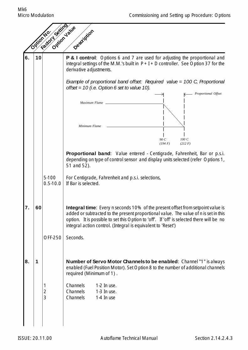
Micro Modulation
ISSUE: 20.11.00 Autoflame Technical Manual Section
Mk6
6. 10 P & I control: Options 6 and 7 are used for adjusting the proportional andintegral settings of the M.M.'s built in P + I + D controller. See Option 37 for thederivative adjustments.
Example of proportional band offset: Required value = 100 C, Proportionaloffset = 10 (i.e. Option 6 set to value 10).
Proportional band: Value entered - Centigrade, Fahrenheit, Bar or p.s.i.depending on type of control sensor and display units selected (refer Options 1,51 and 52).
5-100 For Centigrade, Fahrenheit and p.s.i. selections,0.5-10.0 If Bar is selected.
7. 60 Integral time: Every n seconds 10% of the present offset from setpoint value isadded or subtracted to the present proportional value. The value of n is set in thisoption. It is possible to set this Option to 'off'. If 'off' is selected there will be nointegral action control. (Integral is equivalent to 'Reset')
OFF-250 Seconds.
8. 1 Number of Servo Motor Channels to be enabled: Channel "1" is alwaysenabled (Fuel Position Motor). Set Option 8 to the number of additional channelsrequired (Minimum of 1) .
1 Channels 1-2 In use.2 Channels 1-3 In use.3 Channels 1-4 In use
Option N
o.Fa
ctory
Setting
Option V
alue
Descrip
tion
2.14.2.4.3
Minimum Flame
Maximum Flame
Proportional Offset
90 C(194 F)
100 C(212 F)
Commissioning and Setting up Procedure: Options
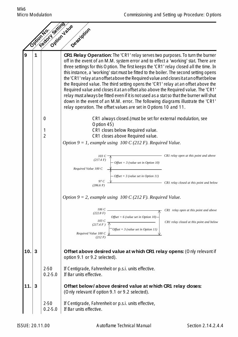
Micro Modulation
ISSUE: 20.11.00 Autoflame Technical Manual Section
Mk6
9 1 CR1 Relay Operation: The 'CR1' relay serves two purposes. To turn the burneroff in the event of an M.M. system error and to effect a 'working' stat. There arethree settings for this Option. The first keeps the 'CR1' relay closed all the time. Inthis instance, a 'working' stat must be fitted to the boiler. The second setting opensthe 'CR1' relay at an offset above the Required value and closes it at an offset belowthe Required value. The third setting opens the 'CR1' relay at an offset above theRequired value and closes it at an offset also above the Required value. The 'CR1'relay must always be fitted even if it is not used as a stat so that the burner will shutdown in the event of an M.M. error. The following diagrams illustrate the 'CR1'relay operation. The offset values are set in Options 10 and 11.
0 CR1 always closed.(must be set for external modulation, seeOption 45)
1 CR1 closes below Required value.2 CR1 closes above Required value.
10. 3 Offset above desired value at which CR1 relay opens: (Only relevant ifoption 9.1 or 9.2 selected).
2-50 If Centigrade, Fahrenheit or p.s.i. units effective.0.2-5.0 If Bar units effective.
11. 3 Offset below/above desired value at which CR1 relay closes:(Only relevant if option 9.1 or 9.2 selected).
2-50 If Centigrade, Fahrenheit or p.s.i. units effective,0.2-5.0 If Bar units effective.
Option N
o.
Facto
ry Setti
ng
Option V
alue
Descrip
tion
2.14.2.4.4
Offset = 3 (value set in Option 11)
Option 9 = 2, example using 100 C (212 F). Required Value.
Option 9 = 1, example using 100 C (212 F). Required Value.
Commissioning and Setting up Procedure: Options
CR1 relay open at this point and above
Required Value 100 C
97 C(206.6 F)
103 C(217.4 F)
CR1 relay closed at this point and below
Required Value 100 C(212 F)
103 C(217.4 F )
106 C(222.8 F)
CR1 relay closed at this point and below
CR1 relay open at this point and above
Offset = 6 (value set in Option 10)
Offset = 3 (value set in Option 11)
Offset = 3 (value set in Option 10)
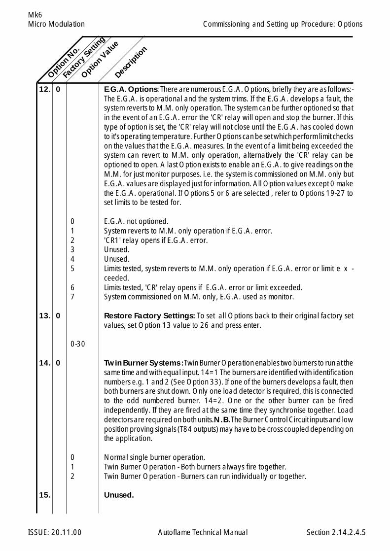
Micro Modulation
ISSUE: 20.11.00 Autoflame Technical Manual Section
Mk6
12. 0 E.G.A. Options: There are numerous E.G.A. Options, briefly they are as follows:-The E.G.A. is operational and the system trims. If the E.G.A. develops a fault, thesystem reverts to M.M. only operation. The system can be further optioned so thatin the event of an E.G.A. error the 'CR' relay will open and stop the burner. If thistype of option is set, the 'CR' relay will not close until the E.G.A. has cooled downto it's operating temperature. Further Options can be set which perform limit checkson the values that the E.G.A. measures. In the event of a limit being exceeded thesystem can revert to M.M. only operation, alternatively the 'CR' relay can beoptioned to open. A last Option exists to enable an E.G.A. to give readings on theM.M. for just monitor purposes. i.e. the system is commissioned on M.M. only butE.G.A. values are displayed just for information. All Option values except 0 makethe E.G.A. operational. If Options 5 or 6 are selected , refer to Options 19-27 toset limits to be tested for.
0 E.G.A. not optioned.1 System reverts to M.M. only operation if E.G.A. error.2 'CR1' relay opens if E.G.A. error.3 Unused.4 Unused.5 Limits tested, system reverts to M.M. only operation if E.G.A. error or limit e x -
ceeded.6 Limits tested, 'CR' relay opens if E.G.A. error or limit exceeded.7 System commissioned on M.M. only, E.G.A. used as monitor.
13. 0 Restore Factory Settings: To set all Options back to their original factory setvalues, set Option 13 value to 26 and press enter.
0-30
14. 0 Twin Burner Systems : Twin Burner Operation enables two burners to run at thesame time and with equal input. 14=1 The burners are identified with identificationnumbers e.g. 1 and 2 (See Option 33). If one of the burners develops a fault, thenboth burners are shut down. Only one load detector is required, this is connectedto the odd numbered burner. 14=2. One or the other burner can be firedindependently. If they are fired at the same time they synchronise together. Loaddetectors are required on both units. N.B. The Burner Control Circuit inputs and lowposition proving signals (T84 outputs) may have to be cross coupled depending onthe application.
0 Normal single burner operation.1 Twin Burner Operation - Both burners always fire together.2 Twin Burner Operation - Burners can run individually or together.
15. Unused.
Option N
o.
Facto
ry Setti
ng
Option V
alue
Descrip
tion
2.14.2.4.5
Commissioning and Setting up Procedure: Options
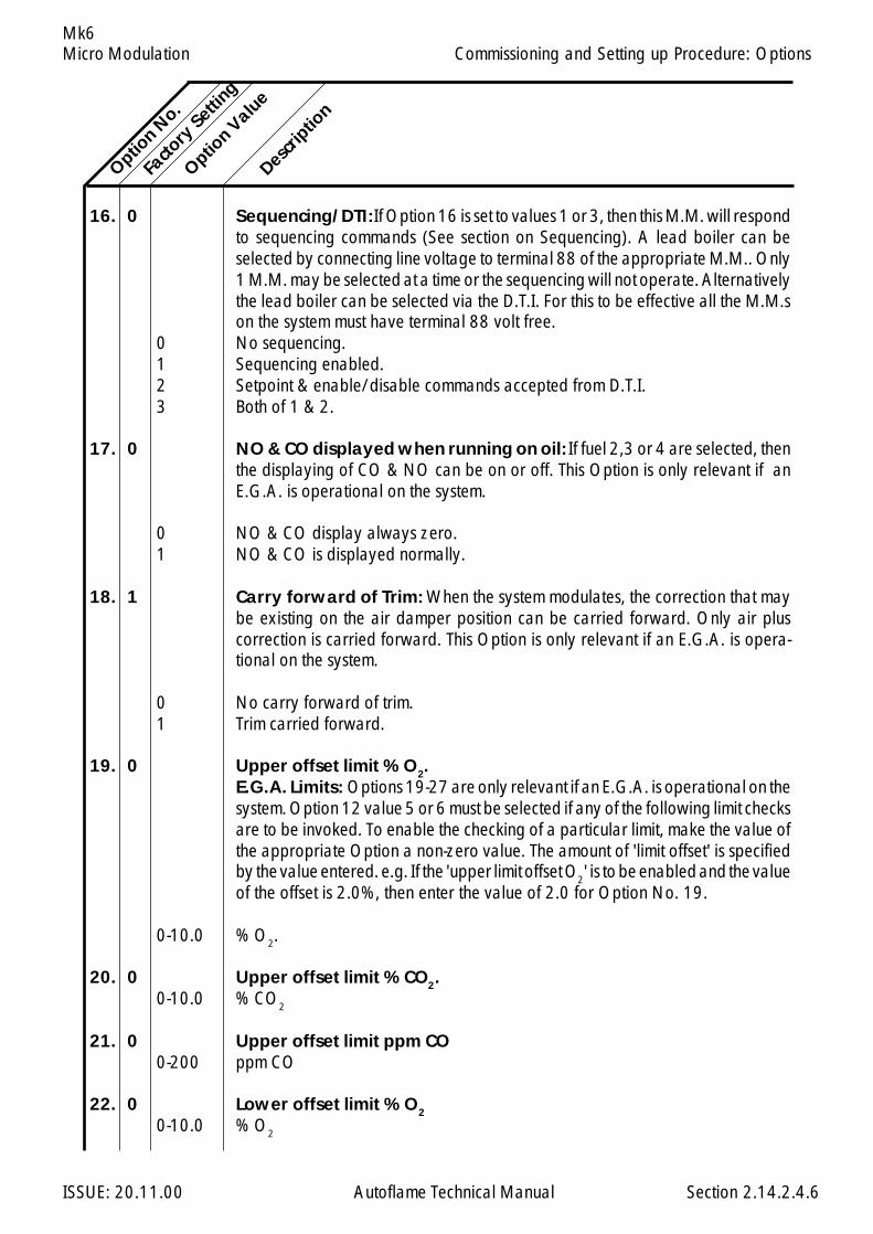
Micro Modulation
ISSUE: 20.11.00 Autoflame Technical Manual Section
Mk6
16. 0 Sequencing/DTI: If Option 16 is set to values 1 or 3, then this M.M. will respondto sequencing commands (See section on Sequencing). A lead boiler can beselected by connecting line voltage to terminal 88 of the appropriate M.M.. Only1 M.M. may be selected at a time or the sequencing will not operate. Alternativelythe lead boiler can be selected via the D.T.I. For this to be effective all the M.M.son the system must have terminal 88 volt free.
0 No sequencing.1 Sequencing enabled.2 Setpoint & enable/disable commands accepted from D.T.I.3 Both of 1 & 2.
17. 0 NO & CO displayed when running on oil: If fuel 2,3 or 4 are selected, thenthe displaying of CO & NO can be on or off. This Option is only relevant if anE.G.A. is operational on the system.
0 NO & CO display always zero.1 NO & CO is displayed normally.
18. 1 Carry forward of Trim: When the system modulates, the correction that maybe existing on the air damper position can be carried forward. Only air pluscorrection is carried forward. This Option is only relevant if an E.G.A. is opera-tional on the system.
0 No carry forward of trim.1 Trim carried forward.
19. 0 Upper offset limit % O2.E.G.A. Limits: Options 19-27 are only relevant if an E.G.A. is operational on thesystem. Option 12 value 5 or 6 must be selected if any of the following limit checksare to be invoked. To enable the checking of a particular limit, make the value ofthe appropriate Option a non-zero value. The amount of 'limit offset' is specifiedby the value entered. e.g. If the 'upper limit offset O2' is to be enabled and the valueof the offset is 2.0%, then enter the value of 2.0 for Option No. 19.
0-10.0 % O2.
20. 0 Upper offset limit % CO2.0-10.0 % CO2
21. 0 Upper offset limit ppm CO0-200 ppm CO
22. 0 Lower offset limit % O2
0-10.0 % O2
Option N
o.
Facto
ry Setti
ng
Option V
alue
Descrip
tion
2.14.2.4.6
Commissioning and Setting up Procedure: Options
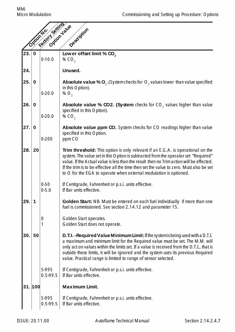
Micro Modulation
ISSUE: 20.11.00 Autoflame Technical Manual Section
Mk6
23. 0 Lower offset limit % CO2
0-10.0 % CO2
24. Unused.
25. 0 Absolute value % O2 .(System checks for O2 values lower than value specifiedin this Option).
0-20.0 % O2
26. 0 Absolute value % CO2. (System checks for CO2 values higher than valuespecified in this Option).
0-20.0 % CO2
27. 0 Absolute value ppm CO. System checks for CO readings higher than valuespecified in this Option.
0-200 ppm CO
28. 20 Trim threshold: This option is only relevant if an E.G.A. is operational on thesystem. The value set in this Option is subtracted from the operator set "Required"value. If the Actual value is less than the result then no Trim action will be effected.If the trim is to be effective all the time then set the value to zero. Must also be setto O for the EGA to operate when external modulation is optioned.
0-50 If Centigrade, Fahrenheit or p.s.i. units effective.0-5.0 If Bar units effective.
29. 1 Golden Start: NB. Must be entered on each fuel individually if more than onefuel is commissioned. See section 2.14.12 and parameter 15.
0 Golden Start operates.1 Golden Start does not operate.
30. 50 D.T.I. - Required Value Minimum Limit: If the system is being used with a D.T.I.a maximum and minimum limit for the Required value must be set. The M.M. willonly act on values within the limits set. If a value is received from the D.T.I., that isoutside these limits, it will be ignored and the system uses its previous Requiredvalue. Practical range is limited to range of sensor selected.
5-995 If Centigrade, Fahrenheit or p.s.i. units effective.0.5-99.5 If Bar units effective.
31. 100 Maximum Limit.
5-995 If Centigrade, Fahrenheit or p.s.i. units effective.0.5-99.5 If Bar units effective.
Option N
o.Fa
ctory
Setting
Option V
alue
Descrip
tion
2.14.2.4.7
Commissioning and Setting up Procedure: Options
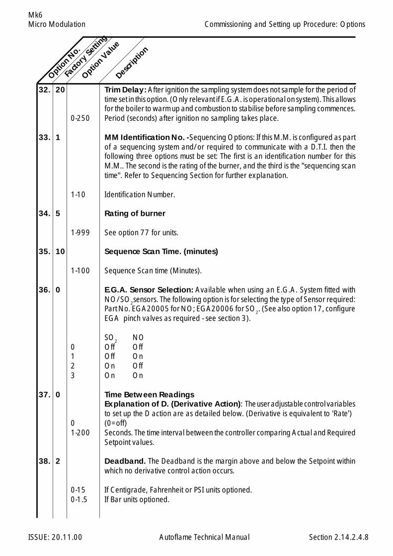
Micro Modulation
ISSUE: 20.11.00 Autoflame Technical Manual Section
Mk6
32. 20 Trim Delay: After ignition the sampling system does not sample for the period oftime set in this option. (Only relevant if E.G.A. is operational on system). This allowsfor the boiler to warm up and combustion to stabilise before sampling commences.
0-250 Period (seconds) after ignition no sampling takes place.
33. 1 MM Identification No. - Sequencing Options: If this M.M. is configured as partof a sequencing system and/or required to communicate with a D.T.I. then thefollowing three options must be set: The first is an identification number for thisM.M.. The second is the rating of the burner, and the third is the "sequencing scantime". Refer to Sequencing Section for further explanation.
1-10 Identification Number.
34. 5 Rating of burner
1-999 See option 77 for units.
35. 10 Sequence Scan Time. (minutes)
1-100 Sequence Scan time (Minutes).
36. 0 E.G.A. Sensor Selection: Available when using an E.G.A. System fitted withNO/SO2sensors. The following option is for selecting the type of Sensor required:Part No. EGA20005 for NO; EGA20006 for SO2. (See also option 17, configureEGA pinch valves as required - see section 3).
SO2 NO0 Off Off1 Off On2 On Off3 On On
37. 0 Time Between ReadingsExplanation of D. (Derivative Action): The user adjustable control variablesto set up the D action are as detailed below. (Derivative is equivalent to 'Rate')
0 (0=off)1-200 Seconds. The time interval between the controller comparing Actual and Required
Setpoint values.
38. 2 Deadband. The Deadband is the margin above and below the Setpoint withinwhich no derivative control action occurs.
0-15 If Centigrade, Fahrenheit or PSI units optioned.0-1.5 If Bar units optioned.
Option N
o.Fa
ctory
Setting
Option V
alue
Descrip
tion
2.14.2.4.8
Commissioning and Setting up Procedure: Options
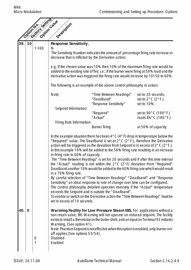
Micro Modulation
ISSUE: 20.11.00 Autoflame Technical Manual Section
Mk6
39. 10 Response Sensitivity.1-100 %
The Sensitivity Number indicates the amount of percentage firing rate increase ordecrease that is inflicted by the Derivative action;
e.g. If the chosen value was 10% then 10% of the maximum firing rate would beadded to the existing rate of fire; i.e.: If the burner were firing at 50% load and thederivative action was triggered the firing rate would increase by 10+50 to 60%.
The following is an example of the above control philosophy in action:
Note: “Time Between Readings” set to 20 seconds.“Deadband” set to 2°C (2°F.)"Response Sensitivity” set to 10%.
Setpoint Information:“Required” set to 90°C (190°F.)“Actual” reads 86°C (186°F.)
Firing Rate Information:Burner firing at 50% of capacity.
In the example situation there has been 4°C (4°F) drop in temperature below the“Required” value. The Deadband is set at 2°C (2°F.), therefore the Derivativeaction will be triggered as the deviation from Setpoint is in excess of 2°C (2°F.).In this example 10% will be added to the 50% firing rate resulting in an increasein firing rate to 60% of capacity. The “Time Between Readings” is set for 20 seconds and if after this time intervalthe “Actual” reading is not within the 2°C (2°F) deviation from “Required”Deadband another 10% would be added to the 60% firing rate which would resultin a 70% firing rate.By careful selection of “Time Between Readings” “Deadband” and “ResponseSensitivity” an ideal response to rate of change over time can be configured.The control philosophy detailed operates inversely if the “Actual” temperatureexceeds the Setpoint and is outside the “Deadband”.To enable or switch on the Derivative action the “Time Between Readings” must beset in excess of 10 seconds.
40. 0 Warming Facility for Low Pressure Steam IBS. For applications without anon return valve, IBS Warming will not operate on reduced setpoint. The facilityexists to install a thermostat in the boiler shell, and an input on Terminal 93 initiatesWarming. (See option 41).Note: Phantom Setpoint is not effective when this option is enabled, only burner on/off applies (See options 53/54).
0 Disabled1 Enabled
Option N
o.
Facto
ry Setti
ng
Option V
alue
Descrip
tion
2.14.2.4.9
Commissioning and Setting up Procedure: Options

Micro Modulation
ISSUE: 20.11.00 Autoflame Technical Manual Section
Mk6
41. 0 Steam Boiler SequencingOptions 41, 42, 43 and 44 are related to the "Standby Warming" Sequencingstate. Option 42 enables an offset to be set relative to the Required value togenerate a "phantom setpoint". During this "Standby Warming" operation theBoiler Control Circuit relay operates on the phantom setpoint. Options 43 and 44are offset values above and below the phantom setpoint (i.e. Options 10 and 11are not used for the phantom setpoint Boiler Control Circuit relay offsets). Whena boiler is set to the "Standby Warming" state, by the M.M. Sequencing commands,it runs for a period of time at low flame and then off for a period. This action keepsthe boiler warm. Option 53 sets the time interval that the burner is Off: Option 54sets the time that the burner is On. If Option 41 = 0 only one boiler will be set tothe "Standby Warming" state. Boilers further down the sequence will be set to the"OFF" state. In this case Options 53 and 54 set the ON and OFF time. (If Options41 and 53 are 0 then Hot Water Sequencing is implemented).
0 3 State Steam Sequencing. ON, STANDBY, OFF...1 2 State Steam Sequencing. ON, STANDBY, STANDBY...
If option 1 is set to 6 (Boiler pressure sensor type MM10008) and PSI units areselected, low pressure steam IBS will cut in automatically if the required value is setlower than 20psi.
42. 20 Phantom Setpoint. Offset below normal Required value.Note: When phantom setpoint is in effect, burner is held at low flame.
0-100 If Centigrade, Fahrenheit or p.s.i. units effective.0-10.0 If Bar units effective.
43. 5 Offset above phantom setpoint when Boiler Control Circuit opens.2-50 If Centigrade, Fahrenheit or p.s.i. units effective.0.2-5.0 If Bar units effective.
44. 5 Offset below phantom setpoint when Boiler Control Circuit closes.2-50 If Centigrade, Fahrenheit or p.s.i. units effective.0.2-5.0 If Bar units effective.
45. 0 External Modulation: If this option is enabled, the usual P.I.D. control isdisabled and the percentage of firing is set by an external controller applied to theappropriate input (terminals 7,8 & 9). This can be 0-10V, 2-10V, 0-20mA or 4-20mA representing low to high fire. See Parameter 69. The 10 point flow meteringcalibration must be entered for correct operation. See Option 57. Typically aworking stat and a high limit stat would need to be fitted, However if option 46 isset to 0 the internal working stat facility of the MM can be used. Note: A high limitstat must be used regardless.
0 Disabled1 Enabled - input from auxilliary analogue input
Option N
o.
Facto
ry Setti
ng
Option V
alue
Descrip
tion
2.14.2.4.10
Commissioning and Setting up Procedure: Options
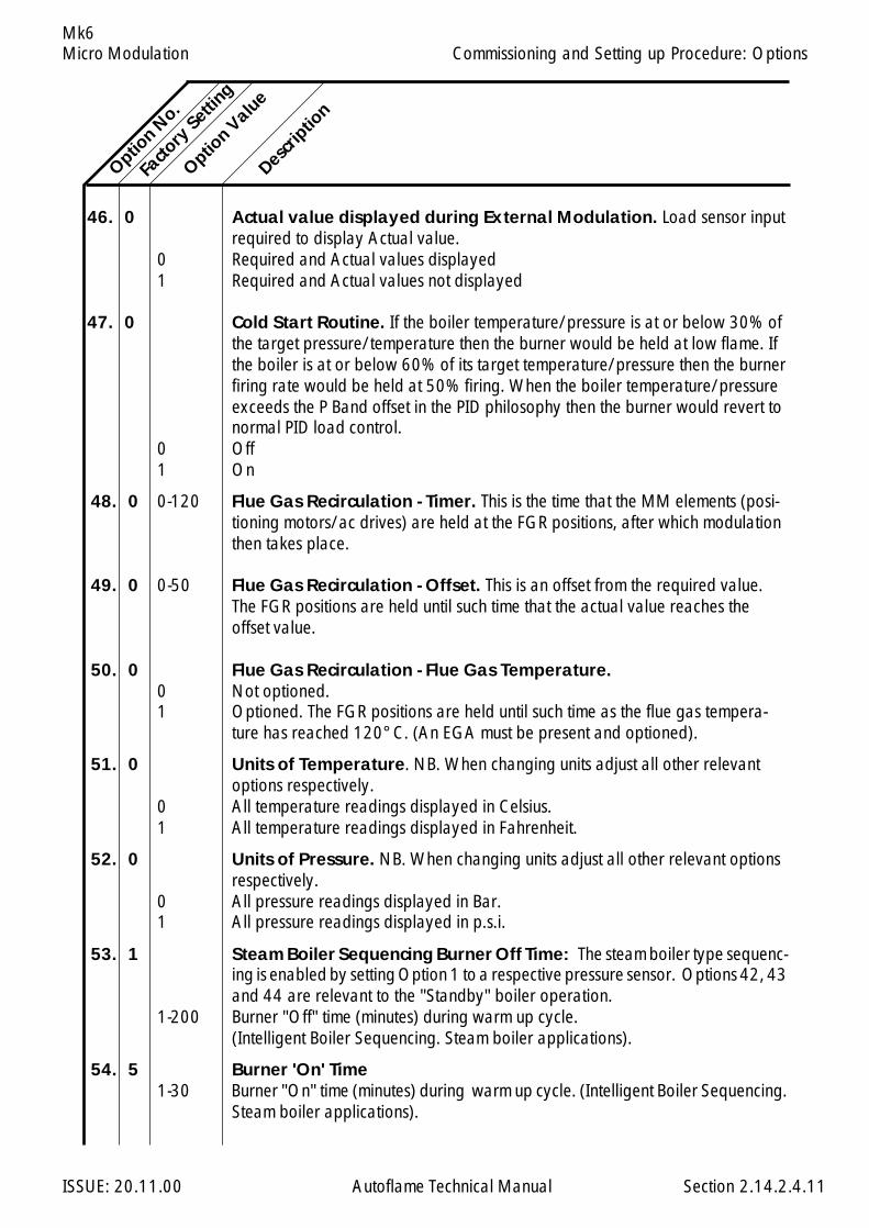
Micro Modulation
ISSUE: 20.11.00 Autoflame Technical Manual Section
Mk6
46. 0 Actual value displayed during External Modulation. Load sensor inputrequired to display Actual value.
0 Required and Actual values displayed1 Required and Actual values not displayed
47. 0 Cold Start Routine. If the boiler temperature/pressure is at or below 30% ofthe target pressure/temperature then the burner would be held at low flame. Ifthe boiler is at or below 60% of its target temperature/pressure then the burnerfiring rate would be held at 50% firing. When the boiler temperature/pressureexceeds the P Band offset in the PID philosophy then the burner would revert tonormal PID load control.
0 Off1 On
48. 0 0-120 Flue Gas Recirculation - Timer. This is the time that the MM elements (posi-tioning motors/ac drives) are held at the FGR positions, after which modulationthen takes place.
49. 0 0-50 Flue Gas Recirculation - Offset. This is an offset from the required value.The FGR positions are held until such time that the actual value reaches theoffset value.
50. 0 Flue Gas Recirculation - Flue Gas Temperature.0 Not optioned.1 Optioned. The FGR positions are held until such time as the flue gas tempera-
ture has reached 120°C. (An EGA must be present and optioned).
51. 0 Units of Temperature. NB. When changing units adjust all other relevantoptions respectively.
0 All temperature readings displayed in Celsius.1 All temperature readings displayed in Fahrenheit.
52. 0 Units of Pressure. NB. When changing units adjust all other relevant optionsrespectively.
0 All pressure readings displayed in Bar.1 All pressure readings displayed in p.s.i.
53. 1 Steam Boiler Sequencing Burner Off Time: The steam boiler type sequenc-ing is enabled by setting Option 1 to a respective pressure sensor. Options 42, 43and 44 are relevant to the "Standby" boiler operation.
1-200 Burner "Off" time (minutes) during warm up cycle.(Intelligent Boiler Sequencing. Steam boiler applications).
54. 5 Burner 'On' Time1-30 Burner "On" time (minutes) during warm up cycle. (Intelligent Boiler Sequencing.
Steam boiler applications).
Option N
o.
Facto
ry Setti
ng
Option V
alue
Descrip
tion
2.14.2.4.11
Commissioning and Setting up Procedure: Options
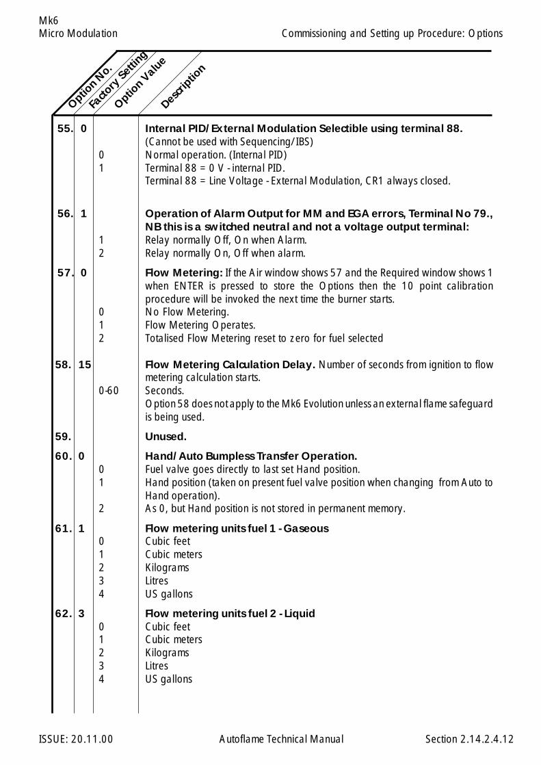
Micro Modulation
ISSUE: 20.11.00 Autoflame Technical Manual Section
Mk6
55. 0 Internal PID/External Modulation Selectible using terminal 88.(Cannot be used with Sequencing/IBS)
0 Normal operation. (Internal PID)1 Terminal 88 = 0 V - internal PID.
Terminal 88 = Line Voltage - External Modulation, CR1 always closed.
56. 1 Operation of Alarm Output for MM and EGA errors, Terminal No 79.,NB this is a switched neutral and not a voltage output terminal:
1 Relay normally Off, On when Alarm.2 Relay normally On, Off when alarm.
57. 0 Flow Metering: If the Air window shows 57 and the Required window shows 1when ENTER is pressed to store the Options then the 10 point calibrationprocedure will be invoked the next time the burner starts.
0 No Flow Metering.1 Flow Metering Operates.2 Totalised Flow Metering reset to zero for fuel selected
58. 15 Flow Metering Calculation Delay. Number of seconds from ignition to flowmetering calculation starts.
0-60 Seconds.Option 58 does not apply to the Mk6 Evolution unless an external flame safeguardis being used.
59. Unused.
60. 0 Hand/Auto Bumpless Transfer Operation.0 Fuel valve goes directly to last set Hand position.1 Hand position (taken on present fuel valve position when changing from Auto to
Hand operation).2 As 0, but Hand position is not stored in permanent memory.
61. 1 Flow metering units fuel 1 - Gaseous0 Cubic feet1 Cubic meters2 Kilograms3 Litres4 US gallons
62. 3 Flow metering units fuel 2 - Liquid0 Cubic feet1 Cubic meters2 Kilograms3 Litres4 US gallons
Option N
o.
Facto
ry Setti
ng
Option V
alue
Descrip
tion
2.14.2.4.12
Commissioning and Setting up Procedure: Options
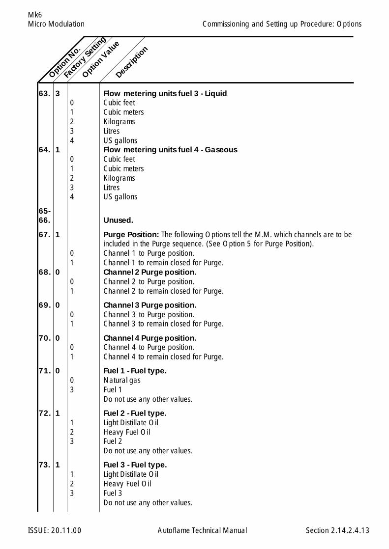
Micro Modulation
ISSUE: 20.11.00 Autoflame Technical Manual Section
Mk6
63. 3 Flow metering units fuel 3 - Liquid0 Cubic feet1 Cubic meters2 Kilograms3 Litres4 US gallons
64. 1 Flow metering units fuel 4 - Gaseous0 Cubic feet1 Cubic meters2 Kilograms3 Litres4 US gallons
65-66. Unused.
67. 1 Purge Position: The following Options tell the M.M. which channels are to beincluded in the Purge sequence. (See Option 5 for Purge Position).
0 Channel 1 to Purge position.1 Channel 1 to remain closed for Purge.
68. 0 Channel 2 Purge position.0 Channel 2 to Purge position.1 Channel 2 to remain closed for Purge.
69. 0 Channel 3 Purge position.0 Channel 3 to Purge position.1 Channel 3 to remain closed for Purge.
70. 0 Channel 4 Purge position.0 Channel 4 to Purge position.1 Channel 4 to remain closed for Purge.
71. 0 Fuel 1 - Fuel type.0 Natural gas3 Fuel 1
Do not use any other values.
72. 1 Fuel 2 - Fuel type.1 Light Distillate Oil2 Heavy Fuel Oil3 Fuel 2
Do not use any other values.
73. 1 Fuel 3 - Fuel type.1 Light Distillate Oil2 Heavy Fuel Oil3 Fuel 3
Do not use any other values.
Option N
o.
Facto
ry Setti
ng
Option V
alue
Descrip
tion
2.14.2.4.13
Commissioning and Setting up Procedure: Options
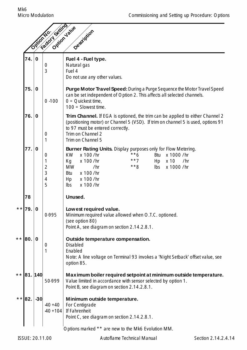
Micro Modulation
ISSUE: 20.11.00 Autoflame Technical Manual Section
Mk6
74. 0 Fuel 4 - Fuel type.0 Natural gas3 Fuel 4
Do not use any other values.
75. 0 Purge Motor Travel Speed: During a Purge Sequence the Motor Travel Speedcan be set independent of Option 2. This affects all selected channels.
0 -100 0 = Quickest time,100 = Slowest time.
76. 0 Trim Channel. If EGA is optioned, the trim can be applied to either Channel 2(positioning motor) or Channel 5 (VSD). If trim on channel 5 is used, options 91to 97 must be entered correctly.
0 Trim on Channel 21 Trim on Channel 5
77. 0 Burner Rating Units. Display purposes only for Flow Metering.0 KW x 100 /hr **6 Btu x 1000 /hr1 Kg x 100 /hr **7 Hp x 10 /hr2 MW /hr **8 lbs x 1000 /hr3 Btu x 100 /hr4 Hp x 100 /hr5 lbs x 100 /hr
78 Unused.
79. 0 Lowest required value.0-995 Minimum required value allowed when O.T.C. optioned.
(see option 80)Point A, see diagram on section 2.14.2.8.1.
80. 0 Outside temperature compensation.0 Disabled1 Enabled
Note: A line voltage on Terminal 93 invokes a 'Night Setback' offset value, seeoption 85.
81. 140 Maximum boiler required setpoint at minimum outside temperature.50-999 Value limited in accordance with sensor selected by option 1.
Point B, see diagram on section 2.14.2.8.1.
82. -30 Minimum outside temperature.-40 +40 For Centigrade-40 +104 If Fahrenheit
Point C, see diagram on section 2.14.2.8.1.
Option N
o.
Facto
ry Setti
ng
Option V
alue
Descrip
tion
2.14.2.4.14
Commissioning and Setting up Procedure: Options
Options marked ** are new to the Mk6 Evolution MM.
**
**
**
**
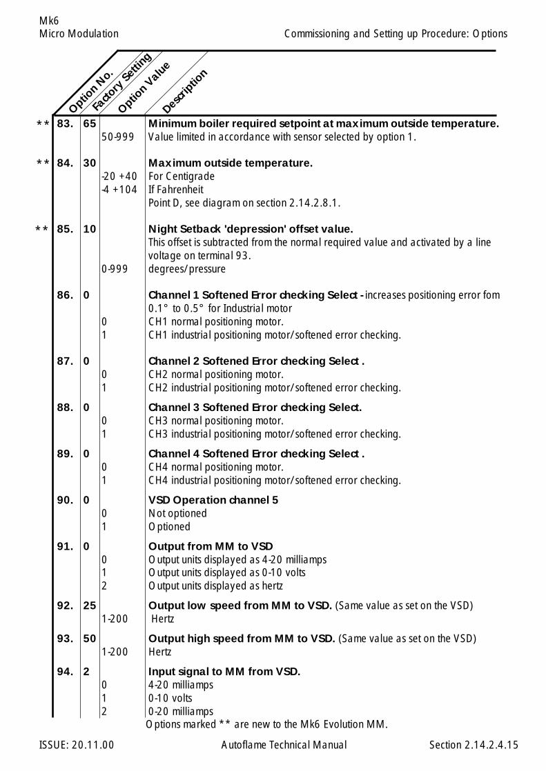
Micro Modulation
ISSUE: 20.11.00 Autoflame Technical Manual Section
Mk6
83. 65 Minimum boiler required setpoint at maximum outside temperature.50-999 Value limited in accordance with sensor selected by option 1.
84. 30 Maximum outside temperature.-20 +40 For Centigrade-4 +104 If Fahrenheit
Point D, see diagram on section 2.14.2.8.1.
85. 10 Night Setback 'depression' offset value.This offset is subtracted from the normal required value and activated by a linevoltage on terminal 93.
0-999 degrees/pressure
86. 0 Channel 1 Softened Error checking Select - increases positioning error fom0.1° to 0.5° for Industrial motor
0 CH1 normal positioning motor.1 CH1 industrial positioning motor/softened error checking.
87. 0 Channel 2 Softened Error checking Select .0 CH2 normal positioning motor.1 CH2 industrial positioning motor/softened error checking.
88. 0 Channel 3 Softened Error checking Select.0 CH3 normal positioning motor.1 CH3 industrial positioning motor/softened error checking.
89. 0 Channel 4 Softened Error checking Select .0 CH4 normal positioning motor.1 CH4 industrial positioning motor/softened error checking.
90. 0 VSD Operation channel 50 Not optioned1 Optioned
91. 0 Output from MM to VSD0 Output units displayed as 4-20 milliamps1 Output units displayed as 0-10 volts2 Output units displayed as hertz
92. 25 Output low speed from MM to VSD. (Same value as set on the VSD)1-200 Hertz
93. 50 Output high speed from MM to VSD. (Same value as set on the VSD)1-200 Hertz
94. 2 Input signal to MM from VSD.0 4-20 milliamps1 0-10 volts2 0-20 milliamps
Option N
o.Fa
ctory
Setting
Option V
alue
Descrip
tion
2.14.2.4.15
Commissioning and Setting up Procedure: Options
**
**
**
Options marked ** are new to the Mk6 Evolution MM.
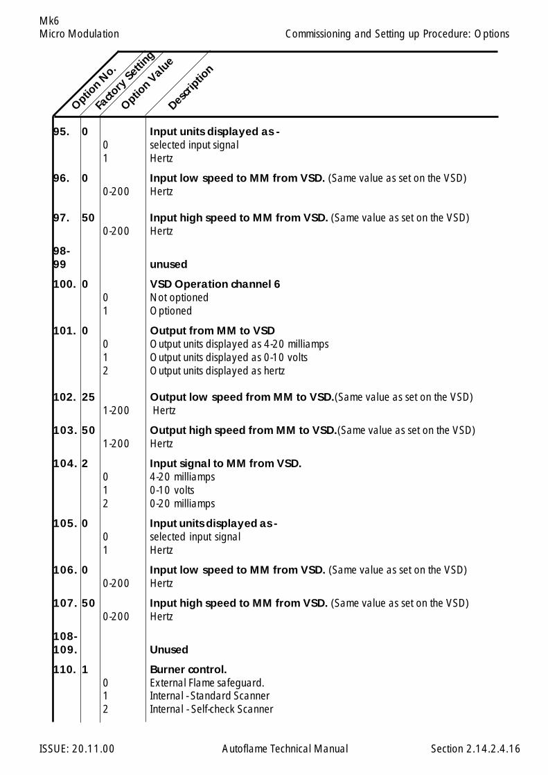
Micro Modulation
ISSUE: 20.11.00 Autoflame Technical Manual Section
Mk6
95. 0 Input units displayed as -0 selected input signal1 Hertz
96. 0 Input low speed to MM from VSD. (Same value as set on the VSD)0-200 Hertz
97. 50 Input high speed to MM from VSD. (Same value as set on the VSD)0-200 Hertz
98-99 unused
100. 0 VSD Operation channel 60 Not optioned1 Optioned
101. 0 Output from MM to VSD0 Output units displayed as 4-20 milliamps1 Output units displayed as 0-10 volts2 Output units displayed as hertz
102. 25 Output low speed from MM to VSD.(Same value as set on the VSD)1-200 Hertz
103. 50 Output high speed from MM to VSD.(Same value as set on the VSD)1-200 Hertz
104. 2 Input signal to MM from VSD.0 4-20 milliamps1 0-10 volts2 0-20 milliamps
105. 0 Input units displayed as -0 selected input signal1 Hertz
106. 0 Input low speed to MM from VSD. (Same value as set on the VSD)0-200 Hertz
107. 50 Input high speed to MM from VSD. (Same value as set on the VSD)0-200 Hertz
108-109. Unused
110. 1 Burner control.0 External Flame safeguard.1 Internal - Standard Scanner2 Internal - Self-check Scanner
Option N
o.Fa
ctory
Setting
Option V
alue
Descrip
tion
2.14.2.4.16
Commissioning and Setting up Procedure: Options
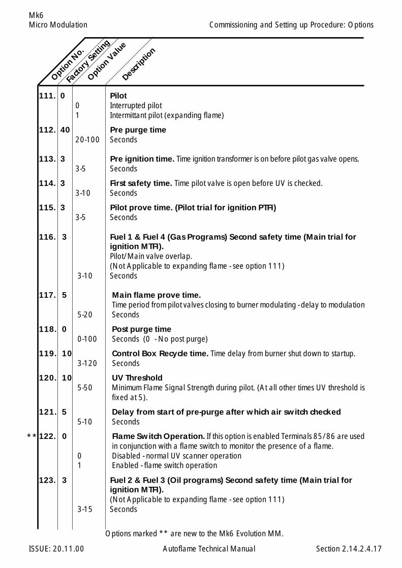
Micro Modulation
ISSUE: 20.11.00 Autoflame Technical Manual Section
Mk6
111. 0 Pilot0 Interrupted pilot1 Intermittant pilot (expanding flame)
112. 40 Pre purge time20-100 Seconds
113. 3 Pre ignition time. Time ignition transformer is on before pilot gas valve opens.3-5 Seconds
114. 3 First safety time. Time pilot valve is open before UV is checked.3-10 Seconds
115. 3 Pilot prove time. (Pilot trial for ignition PTFI)3-5 Seconds
116. 3 Fuel 1 & Fuel 4 (Gas Programs) Second safety time (Main trial forignition MTFI).Pilot/Main valve overlap.(Not Applicable to expanding flame - see option 111)
3-10 Seconds
117. 5 Main flame prove time.Time period from pilot valves closing to burner modulating - delay to modulation
5-20 Seconds
118. 0 Post purge time0-100 Seconds (0 - No post purge)
119. 10 Control Box Recycle time. Time delay from burner shut down to startup.3-120 Seconds
120. 10 UV Threshold5-50 Minimum Flame Signal Strength during pilot. (At all other times UV threshold is
fixed at 5).
121. 5 Delay from start of pre-purge after which air switch checked5-10 Seconds
122. 0 Flame Switch Operation. If this option is enabled Terminals 85/86 are usedin conjunction with a flame switch to monitor the presence of a flame.
0 Disabled - normal UV scanner operation1 Enabled - flame switch operation
123. 3 Fuel 2 & Fuel 3 (Oil programs) Second safety time (Main trial forignition MTFI).(Not Applicable to expanding flame - see option 111)
3-15 Seconds
Option N
o.
Facto
ry Setti
ng
Option V
alue
Descrip
tion
2.14.2.4.17
Commissioning and Setting up Procedure: Options
Options marked ** are new to the Mk6 Evolution MM.
**
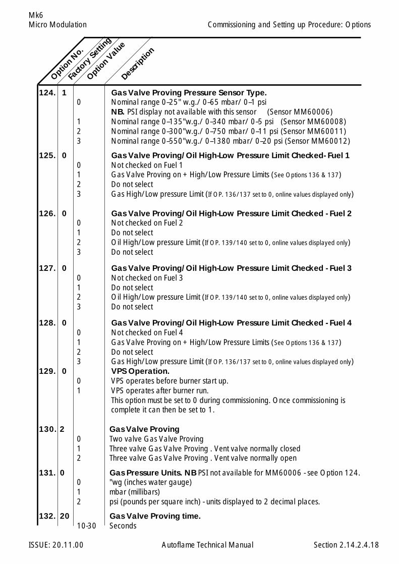
Micro Modulation
ISSUE: 20.11.00 Autoflame Technical Manual Section
Mk6
124. 1 Gas Valve Proving Pressure Sensor Type.0 Nominal range 0–25" w.g./ 0–65 mbar/ 0–1 psi
NB. PSI display not available with this sensor (Sensor MM60006)1 Nominal range 0–135"w.g./ 0–340 mbar/ 0–5 psi (Sensor MM60008)2 Nominal range 0–300"w.g./ 0–750 mbar/ 0–11 psi (Sensor MM60011)3 Nominal range 0–550"w.g./ 0–1380 mbar/ 0–20 psi (Sensor MM60012)
125. 0 Gas Valve Proving/Oil High-Low Pressure Limit Checked- Fuel 10 Not checked on Fuel 11 Gas Valve Proving on + High/Low Pressure Limits (See Options 136 & 137)2 Do not select3 Gas High/Low pressure Limit (If OP. 136/137 set to 0, online values displayed only)
126. 0 Gas Valve Proving/Oil High-Low Pressure Limit Checked - Fuel 20 Not checked on Fuel 21 Do not select2 Oil High/Low pressure Limit (If OP. 139/140 set to 0, online values displayed only)3 Do not select
127. 0 Gas Valve Proving/Oil High-Low Pressure Limit Checked - Fuel 30 Not checked on Fuel 31 Do not select2 Oil High/Low pressure Limit (If OP. 139/140 set to 0, online values displayed only)3 Do not select
128. 0 Gas Valve Proving/Oil High-Low Pressure Limit Checked - Fuel 40 Not checked on Fuel 41 Gas Valve Proving on + High/Low Pressure Limits (See Options 136 & 137)2 Do not select3 Gas High/Low pressure Limit (If OP. 136/137 set to 0, online values displayed only)
129. 0 VPS Operation.0 VPS operates before burner start up.1 VPS operates after burner run.
This option must be set to 0 during commissioning. Once commissioning iscomplete it can then be set to 1.
130. 2 Gas Valve Proving0 Two valve Gas Valve Proving1 Three valve Gas Valve Proving . Vent valve normally closed2 Three valve Gas Valve Proving . Vent valve normally open
131. 0 Gas Pressure Units. NB PSI not available for MM60006 - see Option 124.0 "wg (inches water gauge)1 mbar (millibars)2 psi (pounds per square inch) - units displayed to 2 decimal places.
132. 20 Gas Valve Proving time.10-30 Seconds
Option N
o.Fa
ctory
Setting
Option V
alue
Descrip
tion
2.14.2.4.18
Commissioning and Setting up Procedure: Options

Micro Modulation
ISSUE: 20.11.00 Autoflame Technical Manual Section
Mk6
133. 0.5 Maximium pressure change allowed during proving time. NoteOption 124 for Pressure Sensor range in use, default value will change accord-ingly. See Section 2.14.2.6.2
0.1-5 "wg/ 0.2-12.4mbar/ psi not available (Sensor MM60006)0.5-25 "wg/ 1.1-63 mbar/ 0.02 - 0.91 psi (Sensor MM60008)1-56 "wg/ 2.5-140 mbar/ 0.04 - 2.03 psi (Sensor MM60011)1.9-103 "wg/ 4.6-356 mbar/ 0.07 - 5.16 psi (Sensor MM60012)
134. 3 VPS Valve Opening Time.3-10 Seconds
135. Unused
136. 1.0 Gas Pressure Switch - Lower Limit. This option has two functions:- Static Inlet Pressure Check - Lower Limit. This is checked prior to Burner Firing.- Run Pressure Check - Lower LimitNote settings of options 124 & 131
0 off - lower limit not checked0.1-5 "wg/ 0.2-12.4mbar/ psi not available (Sensor MM60006)0.5-25 "wg/ 1.1-63 mbar/ 0.02 - 0.91 psi (Sensor MM60008)1-56 "wg/ 2.5-140 mbar/ 0.04 - 2.03 psi (Sensor MM60011)1.9-103 "wg/ 4.6-356 mbar/ 0.07 - 5.16 psi (Sensor MM60012)
137. 1.0 Gas Pressure Switch - Upper Limit. Note settings of options 124 & 1310 off - Upper limit not checked0.1-5 "wg/ 0.2-12.4mbar/ psi not available (Sensor MM60006)0.5-25 "wg/ 1.1-63 mbar/ 0.02 - 0.91 psi (Sensor MM60008)1-56 "wg/ 2.5-140 mbar/ 0.04 - 2.03 psi (Sensor MM60011)1.9-103 "wg/ 4.6-356 mbar/ 0.07 - 5.16 psi (Sensor MM60012)
138. 0 Oil Pressure Units.0 Bar1 PSI
139. 1.0 Lower Limit Oil Pressure Switch0 off - lower limit not checked0-3.5 bar - Lower limit from operating pressure0-50 psi - Lower limit from operating pressure
140. 1.0 Upper Limit Oil Pressure Switch0 off - Upper limit not checked0-3.5 bar - Upper limit from operating pressure0-50 psi - Upper limit from operating pressure
Option N
o.Fa
ctory
Setting
Option V
alue
Descrip
tion
2.14.2.4.19
Commissioning and Setting up Procedure: Options
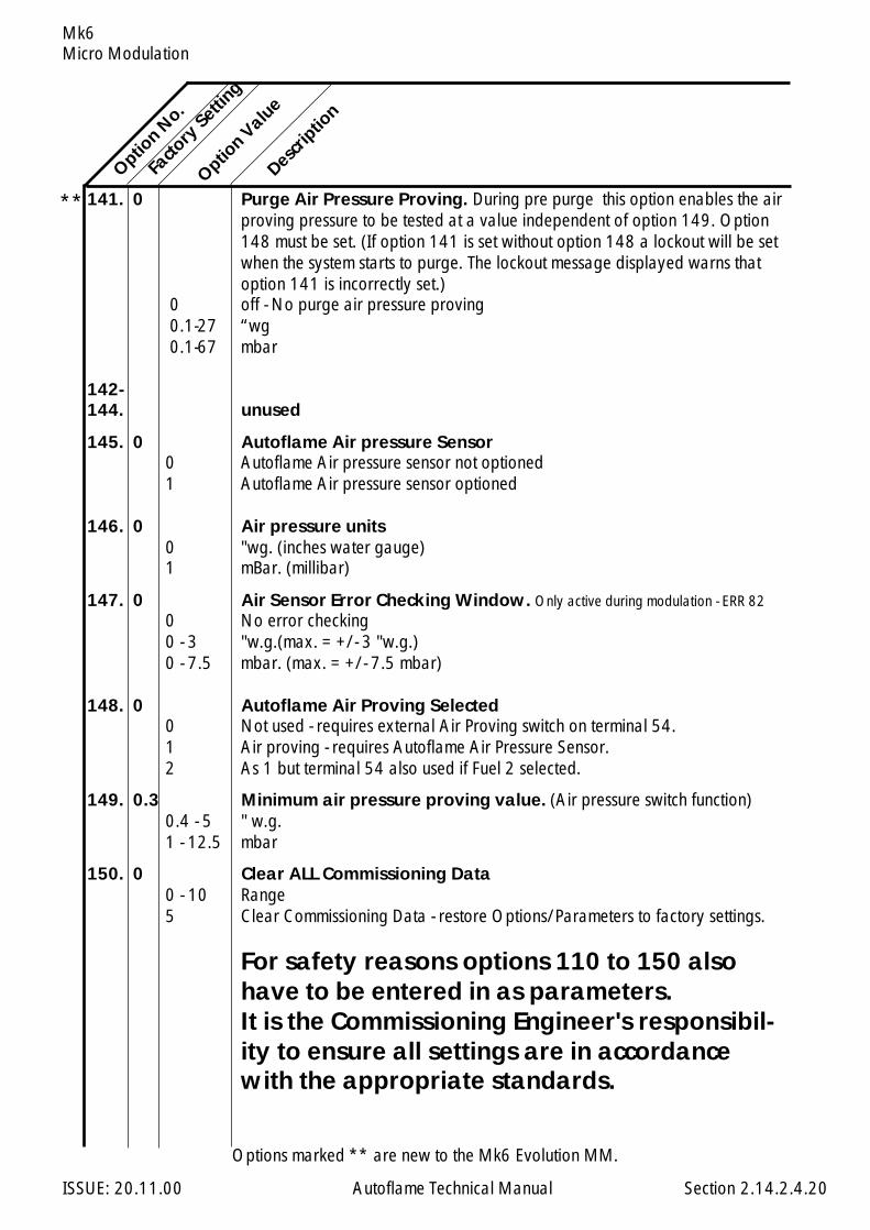
Micro Modulation
ISSUE: 20.11.00 Autoflame Technical Manual Section
Mk6
Option N
o.
Descrip
tion
Facto
ry Setti
ng
Option V
alue
141. 0 Purge Air Pressure Proving. During pre purge this option enables the airproving pressure to be tested at a value independent of option 149. Option148 must be set. (If option 141 is set without option 148 a lockout will be setwhen the system starts to purge. The lockout message displayed warns thatoption 141 is incorrectly set.)
0 off - No purge air pressure proving0.1-27 “wg0.1-67 mbar
142-144. unused
145. 0 Autoflame Air pressure Sensor0 Autoflame Air pressure sensor not optioned1 Autoflame Air pressure sensor optioned
146. 0 Air pressure units0 "wg. (inches water gauge)1 mBar. (millibar)
147. 0 Air Sensor Error Checking Window. Only active during modulation - ERR 820 No error checking0 - 3 "w.g.(max. = +/- 3 "w.g.)0 - 7.5 mbar. (max. = +/- 7.5 mbar)
148. 0 Autoflame Air Proving Selected0 Not used - requires external Air Proving switch on terminal 54.1 Air proving - requires Autoflame Air Pressure Sensor.2 As 1 but terminal 54 also used if Fuel 2 selected.
149. 0.3 Minimum air pressure proving value. (Air pressure switch function)0.4 - 5 " w.g.1 - 12.5 mbar
150. 0 Clear ALL Commissioning Data0 - 10 Range5 Clear Commissioning Data - restore Options/Parameters to factory settings.
For safety reasons options 110 to 150 alsohave to be entered in as parameters.It is the Commissioning Engineer's responsibil-ity to ensure all settings are in accordancewith the appropriate standards.
2.14.2.4.20
Options marked ** are new to the Mk6 Evolution MM.
**
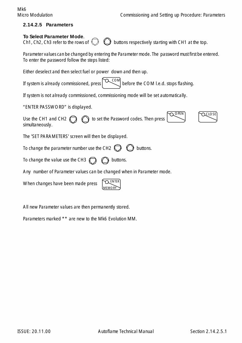
Micro Modulation
ISSUE: 20.11.00 Autoflame Technical Manual Section
Mk6
2.14.2.5 Parameters
To Select Parameter Mode.Ch1, Ch2, Ch3 refer to the rows of buttons respectively starting with CH1 at the top.
Parameter values can be changed by entering the Parameter mode. The password must first be entered.To enter the password follow the steps listed:
Either deselect and then select fuel or power down and then up.
If system is already commissioned, press before the COM l.e.d. stops flashing.
If system is not already commissioned, commissioning mode will be set automatically.
“ENTER PASSWORD” is displayed.
Use the CH1 and CH2 to set the Password codes. Then presssimultaneously.
The 'SET PARAMETERS' screen will then be displayed.
To change the parameter number use the CH2 buttons.
To change the value use the CH3 buttons.
Any number of Parameter values can be changed when in Parameter mode.
When changes have been made press
All new Parameter values are then permanently stored.
Parameters marked ** are new to the Mk6 Evolution MM.
COM
CLOSEOPEN
2.14.2.5.1
ENTER
MEMORY
Commissioning and Setting up Procedure: Parameters
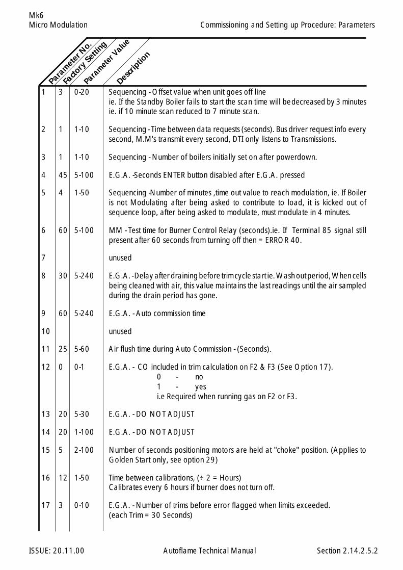
Micro Modulation
ISSUE: 20.11.00 Autoflame Technical Manual Section
Mk6
1 3 0-20 Sequencing - Offset value when unit goes off lineie. If the Standby Boiler fails to start the scan time will bedecreased by 3 minutesie. if 10 minute scan reduced to 7 minute scan.
2 1 1-10 Sequencing - Time between data requests (seconds). Bus driver request info everysecond, M.M's transmit every second, DTI only listens to Transmissions.
3 1 1-10 Sequencing - Number of boilers initially set on after powerdown.
4 45 5-100 E.G.A. -Seconds ENTER button disabled after E.G.A. pressed
5 4 1-50 Sequencing -Number of minutes ,time out value to reach modulation, ie. If Boileris not Modulating after being asked to contribute to load, it is kicked out ofsequence loop, after being asked to modulate, must modulate in 4 minutes.
6 60 5-100 MM - Test time for Burner Control Relay (seconds).ie. If Terminal 85 signal stillpresent after 60 seconds from turning off then = ERROR 40.
7 unused
8 30 5-240 E.G.A. - Delay after draining before trim cycle start ie. Wash out period, When cellsbeing cleaned with air, this value maintains the last readings until the air sampledduring the drain period has gone.
9 60 5-240 E.G.A. - Auto commission time
10 unused
11 25 5-60 Air flush time during Auto Commission - (Seconds).
12 0 0-1 E.G.A. - CO included in trim calculation on F2 & F3 (See Option 17).0 - no1 - yesi.e Required when running gas on F2 or F3.
13 20 5-30 E.G.A. - DO NOT ADJUST
14 20 1-100 E.G.A. - DO NOT ADJUST
15 5 2-100 Number of seconds positioning motors are held at "choke" position. (Applies toGolden Start only, see option 29)
16 12 1-50 Time between calibrations, (÷ 2 = Hours)Calibrates every 6 hours if burner does not turn off.
17 3 0-10 E.G.A. - Number of trims before error flagged when limits exceeded.(each Trim = 30 Seconds)
Param
eter N
o.
Facto
ry Setti
ng
Parameter V
alueDesc
riptio
n
2.14.2.5.2
Commissioning and Setting up Procedure: Parameters

Micro Modulation
ISSUE: 20.11.00 Autoflame Technical Manual Section
Mk6
Parameter V
alue
18 20 5-30 E.G.A. - DO NOT ADJUST
19 unused
20 0 0-40 Set value to 26 press enter to restore all preset factory settings.
21 0 E.G.A. - Present values display update rate.0 Each trim,1 Every second.
22 0 DTI - DO NOT ADJUST
23 unused
24 120 20-240 E.G.A. - Calibration time - seconds
25 30 5-100 E.G.A. - Time between samples
26 8 1-20 E.G.A. - Number of samples per trim cycle
27 25 0-255 E.G.A. - Minimum Operating Temp. (÷ 5=deg C)
28 200 0-255 E.G.A. - Maximum Operating Temp. (÷ 5=deg C)
29 unused
30 20 0-20 Filters Load Sensor Readings( Temp. & Pressure) 0 - No Filtering.20 - Max. Filtering.
31 0 0-1 Selects Efficiency to be displayed- 0 - English (USA/Canada)(incorporates Hydrogen & moisture loss)- 1 - European
32-37 unused
38 254 0-255 MM - password fuel
39 1 0-255 MM - password air
40-43 unused
44 0.4 0-4.0 E.G.A. - O2 window inside which no further trim takes place.
45 0.2 0-2.0 E.G.A. - CO2 window inside which no further trim takes place.
46 21 2-100 MM - Delay from ignition to modulation when using an external Flame Safeguard. Number of seconds burner is held at low flame/start position.
47-48 unused
Param
eter N
o.
Facto
ry Setti
ng
Descrip
tion
2.14.2.5.3
Commissioning and Setting up Procedure: Parameters

Micro Modulation
ISSUE: 20.11.00 Autoflame Technical Manual Section
Mk6
49 0 0-1 Set to 1 if required value not to be stored permanently in memory.
50-57 unused
58 1 0-1 1 - E.G.A. Calibration on Start up.0 - E.G.A. No Calibration on Start up.
59 Unused
60 0 0 - 1 0 - Normal EGA Operation1 - O2 Trim Interface Operation.
61 900 0 - 999 Display Backlight on time. ( = seconds)
62 Unused
63 0 0 - 1 Set to 1 for 2 seconds, then set back to 0 to clear lockout history.
64 0 0 - 1 Set to 1 for 2 seconds, then set back to 0 to reset totalised fuel metering valuesfor all 4 fuels.
65 0 0 - 1 Set to 1 for 2 seconds, then set back to 0 to reset burner history.
66-68 Unused
69 0 0 - 1 0 - External Modulation input range 0-20mA, 0-10V1 - External Modulation input range 4-20mA, 2-10V
70 0 0 - 20 Filtering of Analogue input, terminals 7,8,9.0 - default value of 51 - minimum20 - maximumThe value set is the number of readings over which an average is taken, thesmaller the setting the quicker the response time.
71 0 0 - 20 Resolution of Analogue input, terminals 7,8,9.0 - default value of 51 - minimum20 - maximum.The effect of resolution is to filter noise on the input which causes hunting as theMM responds to a changing signal.
Param
eter N
o.
Facto
ry Setti
ng
Descrip
tion
Parameter V
alue
2.14.2.5.4
Commissioning and Setting up Procedure: Parameters
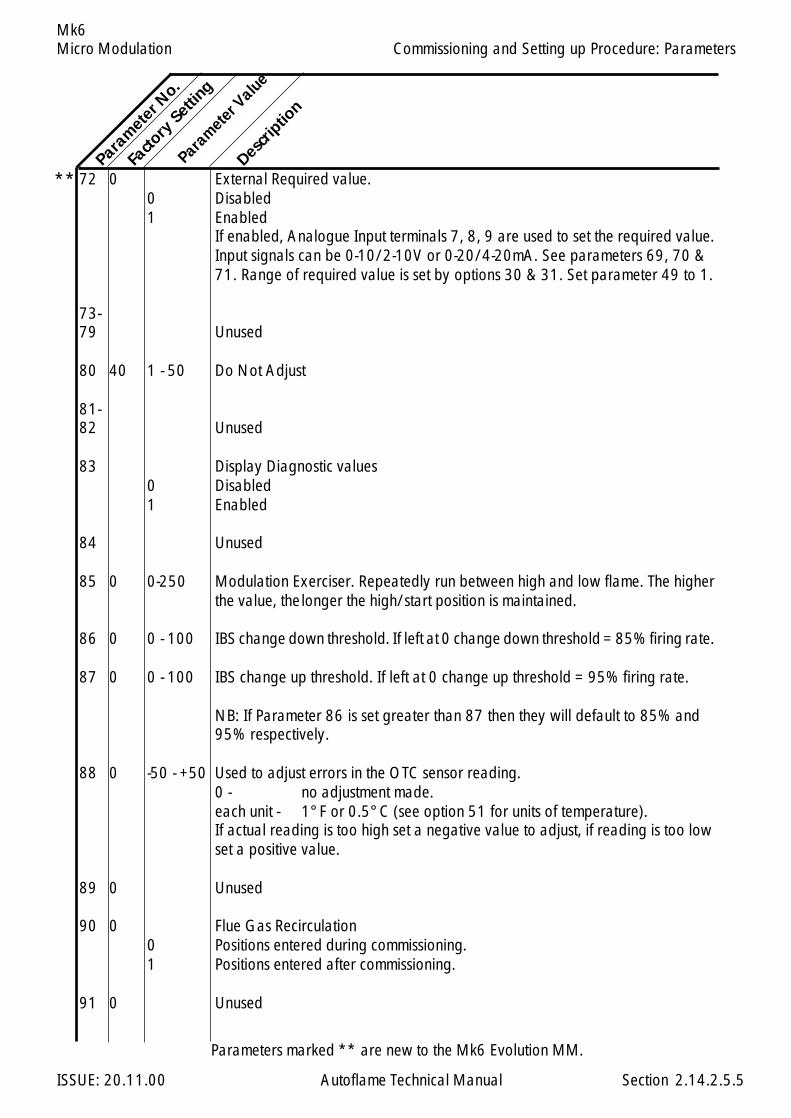
Micro Modulation
ISSUE: 20.11.00 Autoflame Technical Manual Section
Mk6
72 0 External Required value.0 Disabled1 Enabled
If enabled, Analogue Input terminals 7, 8, 9 are used to set the required value.Input signals can be 0-10/2-10V or 0-20/4-20mA. See parameters 69, 70 &71. Range of required value is set by options 30 & 31. Set parameter 49 to 1.
73-79 Unused
80 40 1 - 50 Do Not Adjust
81-82 Unused
83 Display Diagnostic values0 Disabled1 Enabled
84 Unused
85 0 0-250 Modulation Exerciser. Repeatedly run between high and low flame. The higherthe value, thelonger the high/start position is maintained.
86 0 0 - 100 IBS change down threshold. If left at 0 change down threshold = 85% firing rate.
87 0 0 - 100 IBS change up threshold. If left at 0 change up threshold = 95% firing rate.
NB: If Parameter 86 is set greater than 87 then they will default to 85% and95% respectively.
88 0 -50 - +50 Used to adjust errors in the OTC sensor reading.0 - no adjustment made.each unit - 1°F or 0.5°C (see option 51 for units of temperature).If actual reading is too high set a negative value to adjust, if reading is too lowset a positive value.
89 0 Unused
90 0 Flue Gas Recirculation0 Positions entered during commissioning.1 Positions entered after commissioning.
91 0 Unused
Param
eter N
o.
Facto
ry Setti
ng
Descrip
tion
Parameter V
alue
2.14.2.5.5
Commissioning and Setting up Procedure: Parameters
Parameters marked ** are new to the Mk6 Evolution MM.
**
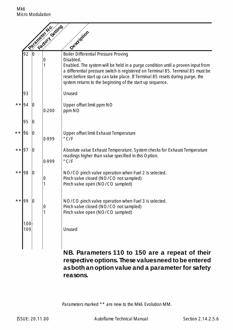
Micro Modulation
ISSUE: 20.11.00 Autoflame Technical Manual Section
Mk6
92 0 Boiler Differential Pressure Proving0 Disabled.1 Enabled. The system will be held in a purge condition until a proven input from
a differential pressure switch is registered on Terminal 85. Terminal 85 must bereset before start up can take place. If Terminal 85 resets during purge, thesystem returns to the beginning of the start up sequence.
93 Unused
94 0 Upper offset limit ppm NO0-200 ppm NO
95 0
96 0 Upper offset limit Exhaust Temperature0-999 °C/F
97 0 Absolute value Exhaust Temperature. System checks for Exhaust Temperaturereadings higher than value specified in this Option.
0-999 °C/F
98 0 NO/CO pinch valve operation when Fuel 2 is selected.0 Pinch valve closed (NO/CO not sampled)1 Pinch valve open (NO/CO sampled)
99 0 NO/CO pinch valve operation when Fuel 3 is selected.0 Pinch valve closed (NO/CO not sampled)1 Pinch valve open (NO/CO sampled)
100-109 Unused
NB. Parameters 110 to 150 are a repeat of theirrespective options. These values need to be enteredas both an option value and a parameter for safetyreasons.
2.14.2.5.6
Param
eter N
o.
Facto
ry Setti
ng
Descrip
tion
Parameters marked ** are new to the Mk6 Evolution MM.
**
**
**
**
**
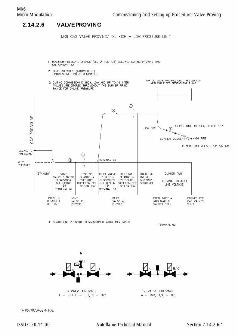
Micro Modulation
ISSUE: 20.11.00 Autoflame Technical Manual Section
Mk6
2.14.2.6 VALVE PROVING
2.14.2.6.1
Commissioning and Setting up Procedure: Valve Proving
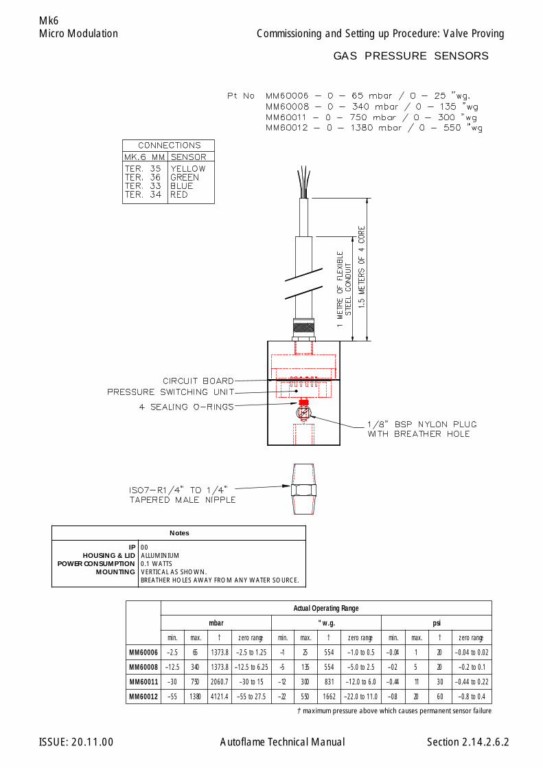
Micro Modulation
ISSUE: 20.11.00 Autoflame Technical Manual Section
Mk6
2.14.2.6.2
egnaRgnitarepOlautcA
rabm .g.w" isp
.nim .xam † egnarorez .nim .xam † egnarorez .nim .xam † egnarorez
60006MM 5.2– 56 8.3731 52.1ot5.2– 1– 52 455 5.0ot0.1– 40.0– 1 02 20.0ot40.0–
80006MM 5.21– 043 8.3731 52.6ot5.21– 5– 531 455 5.2ot0.5– 2.0– 5 02 1.0ot2.0–
11006MM 03– 057 7.0602 51ot03– 21– 003 138 0.6ot0.21– 44.0– 11 03 22.0ot44.0–
21006MM 55– 0831 4.1214 5.72ot55– 22– 055 2661 0.11ot0.22– 8.0– 02 06 4.0ot8.0–
setoN
PIDIL&GNISUOHNOITPMUSNOCREWOPGNITNUOM
00MUINIMULLA
STTAW1.0.NWOHSSALACITREV
.ECRUOSRETAWYNAMORFYAWASELOHREHTAERB
Commissioning and Setting up Procedure: Valve Proving
† maximum pressure above which causes permanent sensor failure
GAS PRESSURE SENSORS
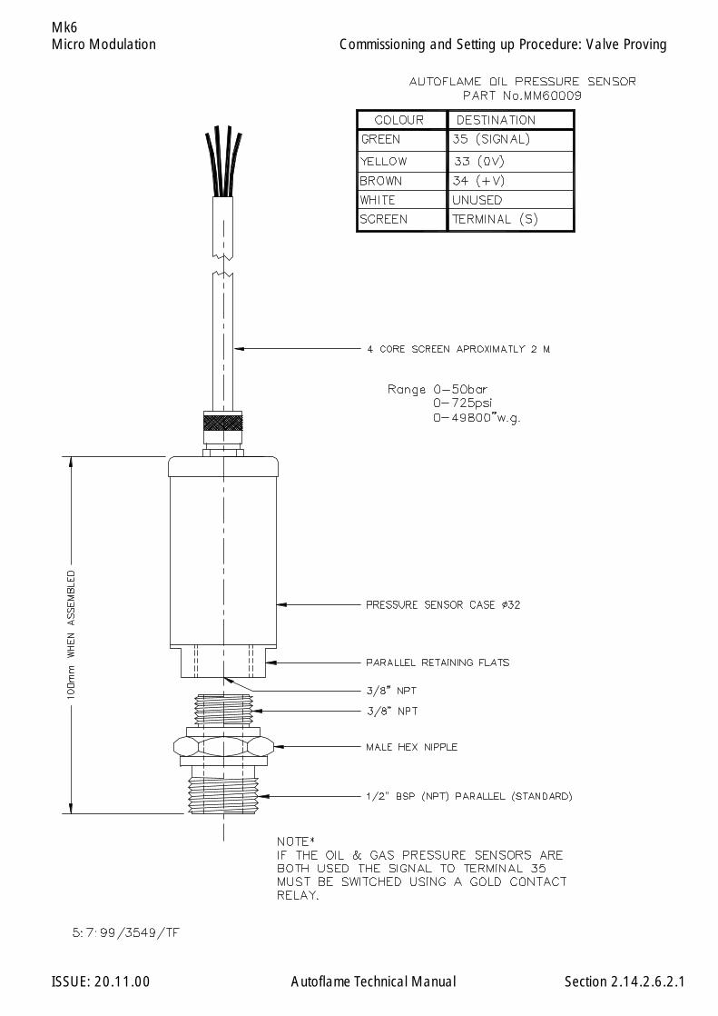
Micro Modulation
ISSUE: 20.11.00 Autoflame Technical Manual Section
Mk6
2.14.2.6.2.1
Commissioning and Setting up Procedure: Valve Proving
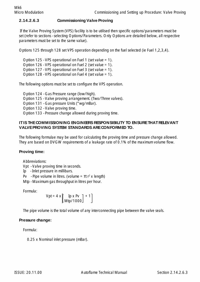
Micro Modulation
ISSUE: 20.11.00 Autoflame Technical Manual Section
Mk6
If the Valve Proving System (VPS) facility is to be utilised then specific options/parameters must beset (refer to sections - selecting Options/Parameters. Only Options are detailed below, all respectiveparameters must be set to the same value).
Options 125 through 128 set VPS operation depending on the fuel selected (ie Fuel 1,2,3,4).
Option 125 - VPS operational on Fuel 1 (set value = 1). Option 126 - VPS operational on Fuel 2 (set value = 1). Option 127 - VPS operational on Fuel 3 (set value = 1). Option 128 - VPS operational on Fuel 4 (set value = 1).
The following options must be set to configure the VPS operation.
Option 124 - Gas Pressure range (low/high). Option 125 - Valve proving arrangement. (Two/Three valves). Option 131 - Gas pressure Units (“wg/mBar). Option 132 - Valve proving time. Option 133 - Pressure change allowed during proving time.
IT IS THE COMMISSIONING ENGINEERS RESPONSIBILITY TO ENSURE THAT RELEVANTVALVE PROVING SYSTEM STANDARDS ARE CONFORMED TO.
The following formulae may be used for calculating the proving time and pressure change allowed.They are based on DVGW requirements of a leakage rate of 0.1% of the maximum volume flow.
Proving time:
Abbreviations: Vpt - Valve proving time in seconds. Ip - Inlet pressure in millibars. Pv - Pipe volume in litres. (volume = π r2 x length) Mtp - Maximum gas throughput in litres per hour.
Formula: Vpt = 4 x Ip x Pv + 1
Mtp/1000
The pipe volume is the total volume of any interconnecting pipe between the valve seals.
Pressure change:
Formula:
0.25 x Nominal inlet pressure (mBar).
2.14.2.6.3 Commissioning Valve Proving
2.14.2.6.3
Commissioning and Setting up Procedure: Valve Proving
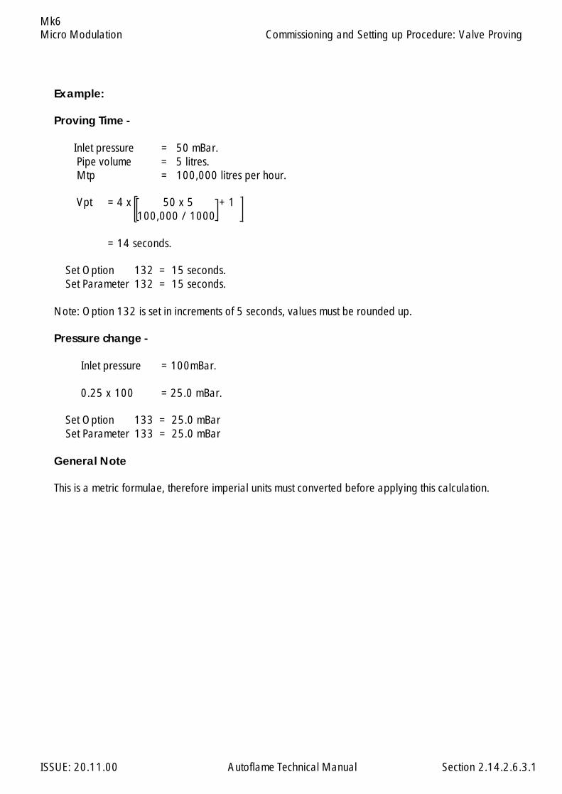
Micro Modulation
ISSUE: 20.11.00 Autoflame Technical Manual Section
Mk6
Example:
Proving Time -
Inlet pressure = 50 mBar. Pipe volume = 5 litres. Mtp = 100,000 litres per hour.
Vpt = 4 x 50 x 5 + 1 100,000 / 1000
= 14 seconds.
Set Option 132 = 15 seconds. Set Parameter 132 = 15 seconds.
Note: Option 132 is set in increments of 5 seconds, values must be rounded up.
Pressure change -
Inlet pressure = 100mBar.
0.25 x 100 = 25.0 mBar.
Set Option 133 = 25.0 mBar Set Parameter 133 = 25.0 mBar
General Note
This is a metric formulae, therefore imperial units must converted before applying this calculation.
2.14.2.6.3.1
Commissioning and Setting up Procedure: Valve Proving
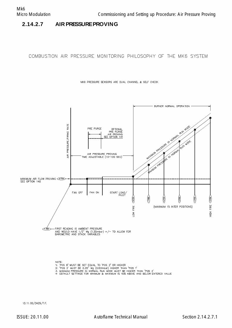
Micro Modulation
ISSUE: 20.11.00 Autoflame Technical Manual Section
Mk6
2.14.2.7 AIR PRESSURE PROVING
2.14.2.7.1
Commissioning and Setting up Procedure: Air Pressure Proving
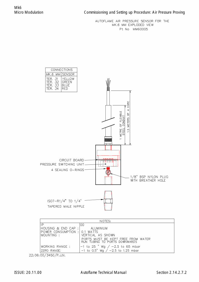
Micro Modulation
ISSUE: 20.11.00 Autoflame Technical Manual Section
Mk6
2.14.2.7.2
Commissioning and Setting up Procedure: Air Pressure Proving
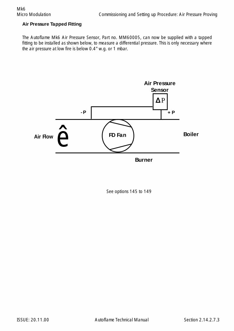
Micro Modulation
ISSUE: 20.11.00 Autoflame Technical Manual Section
Mk6
Air Pressure Tapped Fitting
The Autoflame Mk6 Air Pressure Sensor, Part no. MM60005, can now be supplied with a tappedfitting to be installed as shown below, to measure a differential pressure. This is only necessary wherethe air pressure at low fire is below 0.4" w.g. or 1 mbar.
See options 145 to 149
- P
Air Flow BoilerFD Fan
+ P
Burner
Air PressureSensor
ê
∆∆∆∆∆ P
2.14.2.7.3
Commissioning and Setting up Procedure: Air Pressure Proving

Micro Modulation
ISSUE: 20.11.00 Autoflame Technical Manual Section
Mk6
2.14.2.8.1
This enables the boiler setpoint to be varied accordingto the outside air temperature, i.e. as the airtemperature drops the boiler setpoint can beincreased accordingly.
On the MK6 Evolution the Outside TemperatureCompensation graph is displayed such that theOutside Temperature scale is from left to right asthe outside temperature increases. In the options themaximum and minimum values of each scale areentered for the outside temperature and boilersetpoint. Previously on the Mk6, the OutsideTemperature scale ran from right to left as the outsidetemperature increased and nominal values were set.
2.14.2.8 OUTSIDE AIR TEMPERATURE COMPENSATION
Commissioning and Setting up Procedure: Outside Air Temperature Compensation
79. 0 Lowest required value.0-995 Minimum required value allowed when O.T.C. optioned.
(see option 80)
80. 0 Outside temperature compensation.0 Disabled1 Enabled
Note: A line voltage on Terminal 93 invokes a 'Night Setback' offset value, seeoption 85.
81. 140 Maximum boiler required setpoint at minimum outside temperature.50-999 Value limited in accordance with sensor selected by option 1.
82. -30 Minimum outside temperature.-40 +40 For Centigrade-40 +104 If Fahrenheit
83. 65 Minimum boiler required setpoint at maximum outside temperature.50-999 Value limited in accordance with sensor selected by option 1.
84. 30 Maximum outside temperature.-20 +40 For Centigrade-4 +104 If Fahrenheit
85. 10 Night Setback 'depression' offset value.This offset is subtracted from the normal required value and activated by a linevoltage on terminal 93.
0-999 degrees/pressure
Option N
o.
Facto
ry Setti
ng
Option V
alue
Descrip
tion
A
D
C
B
A
D
C
B
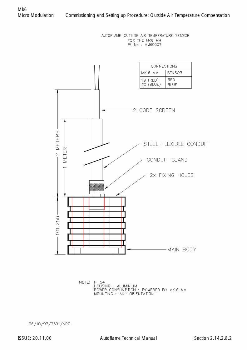
Micro Modulation
ISSUE: 20.11.00 Autoflame Technical Manual Section
Mk6
2.14.2.8.2
Commissioning and Setting up Procedure: Outside Air Temperature Compensation

Micro Modulation
ISSUE: 20.11.00 Autoflame Technical Manual Section
Mk6
2.14.2.9 MK.6 ELECTRICAL SPECIFICATIONS
2.14.2.9.1 Classifications
Classification According to EN298 - F B L L J B
Mains Supply: 230V, +10%/-15% 120V, +10%/-15%
Climate: Temperature 0 to +60 oCHumidity 0 to 90% non-condensing.
Protection Rating: The unit is designed to be panel mounted in any orientation and the front facia is IP65.The back of the unit is IP20.
Inputs & Outputs: 230V Unit:Outputs Terminal 57 250 mA Must be connected through contactor
58 250 mA Must be connected through contactor59 1Amp, 0.6 power factor60 1Amp, 0.6 power factor61 1Amp, 0.6 power factor62 1Amp, 0.6 power factor63 1Amp, 0.6 power factor64 250mA To drive relay/lamp only78 100mA To drive relay only - switched neutral79 100mA To drive relay/lamp only - switched neutral
Input/Outputs 80 0.5 Amp81 0.5 Amp82 0.5 Amp83 0.5 Amp84 0.5 Amp
Analogue I/O.s 240 Ω or less.
120V Unit:Outputs Terminal 57 250 mA Must be connected through contactor
58 250 mA Must be connected through contactor59 2Amp, 0.6 power factor60 2Amp, 0.6 power factor61 2Amp, 0.6 power factor62 2Amp, 0.6 power factor63 2Amp, 0.6 power factor64 250mA
Input/Outputs 80 1 Amp81 1 Amp82 1 Amp83 1 Amp84 1 Amp
Analogue I/O.s 240 Ω or less.N.B.1. The Low voltage connections are not safe to touch. Protection against electric shock is provided by correct installation.2. All Sensor cables should be maximum 25 m and use Screened cable as specified in Section 2.9.11.2.3. The burner 'High Limit Stat' must be of the manual reset type.
Commissioning and Setting up Procedure: Mk.6 Electrical Specification
2.14.2.9.1
47.5 - 63 Hz, Unit max. power consumption 20W
Max
. loa
d 6
Am
p.
External Flame Safeguard
External Flame Safeguard
Max
. loa
d 6
Am
p.
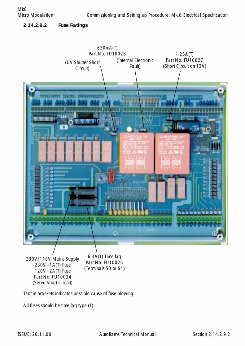
Micro Modulation
ISSUE: 20.11.00 Autoflame Technical Manual Section
Mk6
2.14.2.9.2
2.14.2.9.2 Fuse Ratings
630mA(T)Part No. FU10028 1.25A(T)
Part No. FU10027(Short Circuit on 12V)
6.3A(T) Time lagPart No. FU10026
(Terminals 50 to 64)
230V/110V Mains Supply230V - 1A(T) Fuse120V - 2A(T) FusePart No. FU10034
(Servo Short Circuit)
(UV Shutter ShortCircuit)
(Internal ElectronicFault)
Commissioning and Setting up Procedure: Mk.6 Electrical Specification
Text in brackets indicates possible cause of fuse blowing.
All fuses should be time lag type (T).

Micro Modulation
ISSUE: 20.11.00 Autoflame Technical Manual Section
Mk6
2.14.2.9.3.1
2.14.2.9.3 Terminals Description
Commissioning and Setting up Procedure: Mk.6 Electrical Specification
1 Voltage Input, 0-10V. For Channel 5 VSD use only. Can be connected to the voltage
output of a VSD or tachometer system as appropriate.
2 Current Input, 0-20mA. For Channel 5 VSD use only. Can be connected to the current
output of a VSD or tachometer system as appropriate.
3 0V common for terminals 1 and 2.
4 Voltage Input, 0-10V. For Channel 6 VSD use only. Can be connected to the voltage
output of a VSD or tachometer system as appropriate.
5 Current Input, 0-20mA. For Channel 6 VSD use only. Can be connected to the current
output of a VSD or tachometer system as appropriate.
6 0V common for terminals 4 and 5.
7 Voltage Input, 0-10V. Used for external modulation or external required value.
8 Current Input, 0-20mA. Used for external modulation or external required value.
9 0V common for terminals 7 and 8.
10 Voltage Output, 0-10V. For Channel 5 VSD use only. Can be connected to the volt-
age input of a VSD.
11 Current Output, 4-20mA. For Channel 5 VSD use only. Can be connected to the
current input of a VSD.
12 0V common for terminals 10 and 11.
13 Voltage Output, 0-10V. For Channel 6 VSD use only. Can be connected to the volt-
age input of a VSD.
14 Current Output, 4-20mA. For Channel 6 VSD use only. Can be connected to the
current input of a VSD.
15 0V common for terminals 13 and 14.
16 Voltage Output, 0-10V. Varies in accordance with firing rate.
17 Current Output, 4-20mA. Varies in accordance with firing rate.
18 0V common for terminals 16 and 17.
Note that all the 0V terminals (3, 6, 9, 12, 15, 18) are common to each other. All of the circuitry,associated with the analogue inputs and outputs detailed above, is isolated from earth potential (iefloating).

Micro Modulation
ISSUE: 20.11.00 Autoflame Technical Manual Section
Mk6
2.14.2.9.3.2
Commissioning and Setting up Procedure: Mk.6 Electrical Specification
19, 20 Connections to the Autoflame outside temperature sensor.
21, 22 Connections to an Autoflame self check UV sensor.
23, 24 Communications port connections for Twin Burner operation.
25, 26 Communications port connections to an Exhaust Gas Analyser.
27, 28 Communications port connections for DTI and/or IBS operation.
29, 30 Communications port (currently unassigned).
31, 32 Signal inputs from Autoflame Air pressure sensor.
33 0V supply to Autoflame Air/Gas/Oil pressure sensors.
34 +12V supply to Autoflame Air/Gas/Oil pressure sensors.
35 Signal input from Autoflame Oil pressure sensor.
35, 36 Signal inputs from Autoflame Gas pressure sensor.
37, 38 Connections to an Autoflame Boiler temperature detector.
37, 38, 39 Connections to an Autoflame Boiler pressure detector.
40 0V Supply to Channel 1 and Channel 2 positioning motors.
41 +12V Supply to Channel 1 and Channel 2 positioning motors.
42 Signal from Channel 1 positioning motor, indicating position.
43 Signal from Channel 2 positioning motor, indicating position.
44 Signal from Channel 3 positioning motor, indicating position.
45 Signal from Channel 4 positioning motor, indicating position.
46 0V Supply to Channel 3 and Channel 4 positioning motors.
47 +12V Supply to Channel 3 and Channel 4 positioning motors.
48, 49 No terminals allocated.

Micro Modulation
ISSUE: 20.11.00 Autoflame Technical Manual Section
Mk6
50,51 Connections to an Autoflame UV sensor.
52 Unused – do not connect.
53 Mains voltage input. Burner on/off signal.
54 Mains voltage input. Safety circuits (eg Air proving).
55 Mains voltage input. Proving circuits (eg Gas valve proof of closure)
56 Mains voltage input. Lockout reset.
57 Mains voltage output. Call for heat.
58 Mains voltage output. Burner motor.
59 Mains voltage output. Start/Pilot valve.
60 Mains voltage output. Main fuel valve 1.
61 Mains voltage output. Main fuel valve 2.
62 Mains voltage output. Vent valve.
63 Mains voltage output. Ignition transformer.
64 Mains voltage output. Burner lockout indication.
65 No terminal allocated.
66 Mains supply earth.
67 Main supply neutral.
68 Mains supply live/hot.
69 Mains voltage output. Power to positioning motors.
70 Switched neutral – drives Channel 1 positioning motor clockwise.
71 Switched neutral – drives Channel 1 positioning motor counter clockwise.
72 Switched neutral – drives Channel 2 positioning motor clockwise.
73 Switched neutral – drives Channel 2 positioning motor counter clockwise.
74 Switched neutral – drives Channel 3 positioning motor clockwise.
75 Switched neutral – drives Channel 3 positioning motor counter clockwise.
76 Switched neutral – drives Channel 4 positioning motor clockwise.
77 Switched neutral – drives Channel 4 positioning motor counter clockwise.
78 Switched neutral – to drive 2-port valve for IBS operation.
79 Switched neutral - Alarm output.
Commissioning and Setting up Procedure: Mk.6 Electrical Specification
2.14.2.9.3.3
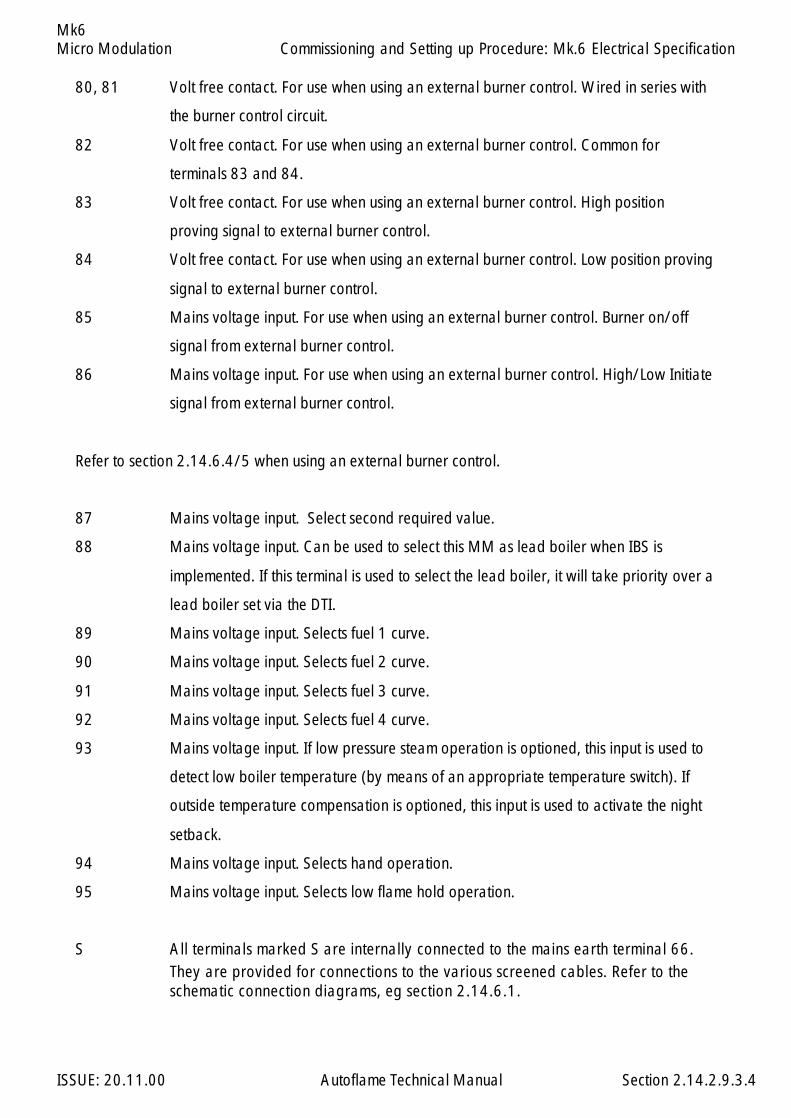
Micro Modulation
ISSUE: 20.11.00 Autoflame Technical Manual Section
Mk6
80, 81 Volt free contact. For use when using an external burner control. Wired in series with
the burner control circuit.
82 Volt free contact. For use when using an external burner control. Common for
terminals 83 and 84.
83 Volt free contact. For use when using an external burner control. High position
proving signal to external burner control.
84 Volt free contact. For use when using an external burner control. Low position proving
signal to external burner control.
85 Mains voltage input. For use when using an external burner control. Burner on/off
signal from external burner control.
86 Mains voltage input. For use when using an external burner control. High/Low Initiate
signal from external burner control.
Refer to section 2.14.6.4/5 when using an external burner control.
87 Mains voltage input. Select second required value.
88 Mains voltage input. Can be used to select this MM as lead boiler when IBS is
implemented. If this terminal is used to select the lead boiler, it will take priority over a
lead boiler set via the DTI.
89 Mains voltage input. Selects fuel 1 curve.
90 Mains voltage input. Selects fuel 2 curve.
91 Mains voltage input. Selects fuel 3 curve.
92 Mains voltage input. Selects fuel 4 curve.
93 Mains voltage input. If low pressure steam operation is optioned, this input is used to
detect low boiler temperature (by means of an appropriate temperature switch). If
outside temperature compensation is optioned, this input is used to activate the night
setback.
94 Mains voltage input. Selects hand operation.
95 Mains voltage input. Selects low flame hold operation.
S All terminals marked S are internally connected to the mains earth terminal 66.They are provided for connections to the various screened cables. Refer to theschematic connection diagrams, eg section 2.14.6.1.
Commissioning and Setting up Procedure: Mk.6 Electrical Specification
2.14.2.9.3.4

Micro Modulation
ISSUE: 20.11.00 Autoflame Technical Manual Section
Mk6
2.14.2.9.4 Cables
Screened Cable
The screened cable used from the MM to the servo motors and detectors must conform to the followingspecification:
16/0.2mm PVC Insulated Overall Braid, Screened, PVC Sheathed.
Sixteen wires per core;Diameter of wires in each core 0.2mm;Rated at 440 volts a.c. rms at 1600 Hz;DEF 61-12 current rating per core 2.5 Amps;Maximum operating temperature 70 degrees C.;Nominal conductor area 0.5 square mm per core;Nominal insulation radial thickness on core 0.45mm;Nominal conductor diameter per core 0.93mm;Nominal core resistance at 20 degrees C. 40.1 Ohm/1000m.;Nominal overall diameter per core 1.83 mm.;Fill factor of braid screen 0.7;Equivalent imperial conductor sizes 14/0.0076.
Use the number of cores suitable for the application.A universal part numbering system appears to have been adopted for this type of cable as follows:
16-2-2C 2 Cores16-2-3C 3 Cores16-2-4C 4 Cores16-2-6C 6 Cores
(5 Cores not readily available).
Data Cable
Data cable must be used for connections between MMs for twin burner/sequencing applications andbetween MMs and EGAs.
Types of data cable that can be used:
1. Beldon 9501;2. STC OS1P24.
Samples are available upon request.Cable can be ordered directly from Autoflame Engineering.
2.14.2.9.4.1
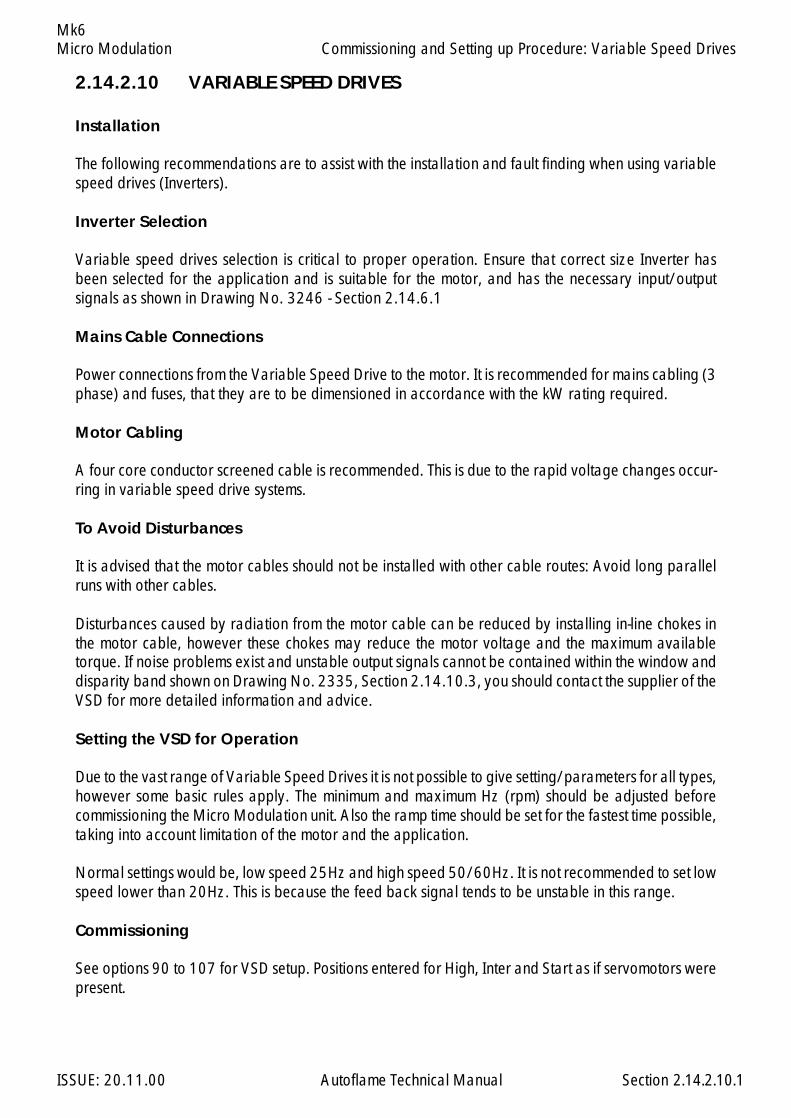
Micro Modulation
ISSUE: 20.11.00 Autoflame Technical Manual Section
Mk6
2.14.2.10 VARIABLE SPEED DRIVES
Installation
The following recommendations are to assist with the installation and fault finding when using variablespeed drives (Inverters).
Inverter Selection
Variable speed drives selection is critical to proper operation. Ensure that correct size Inverter hasbeen selected for the application and is suitable for the motor, and has the necessary input/outputsignals as shown in Drawing No. 3246 - Section 2.14.6.1
Mains Cable Connections
Power connections from the Variable Speed Drive to the motor. It is recommended for mains cabling (3phase) and fuses, that they are to be dimensioned in accordance with the kW rating required.
Motor Cabling
A four core conductor screened cable is recommended. This is due to the rapid voltage changes occur-ring in variable speed drive systems.
To Avoid Disturbances
It is advised that the motor cables should not be installed with other cable routes: Avoid long parallelruns with other cables.
Disturbances caused by radiation from the motor cable can be reduced by installing in-line chokes inthe motor cable, however these chokes may reduce the motor voltage and the maximum availabletorque. If noise problems exist and unstable output signals cannot be contained within the window anddisparity band shown on Drawing No. 2335, Section 2.14.10.3, you should contact the supplier of theVSD for more detailed information and advice.
Setting the VSD for Operation
Due to the vast range of Variable Speed Drives it is not possible to give setting/parameters for all types,however some basic rules apply. The minimum and maximum Hz (rpm) should be adjusted beforecommissioning the Micro Modulation unit. Also the ramp time should be set for the fastest time possible,taking into account limitation of the motor and the application.
Normal settings would be, low speed 25Hz and high speed 50/60Hz. It is not recommended to set lowspeed lower than 20Hz. This is because the feed back signal tends to be unstable in this range.
Commissioning
See options 90 to 107 for VSD setup. Positions entered for High, Inter and Start as if servomotors werepresent.
2.14.2.10.1
Commissioning and Setting up Procedure: Variable Speed Drives
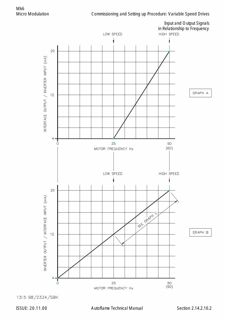
Micro Modulation
ISSUE: 20.11.00 Autoflame Technical Manual Section
Mk6
Input and Output Signalsin Relationship to Frequency
2.14.2.10.2
Commissioning and Setting up Procedure: Variable Speed Drives
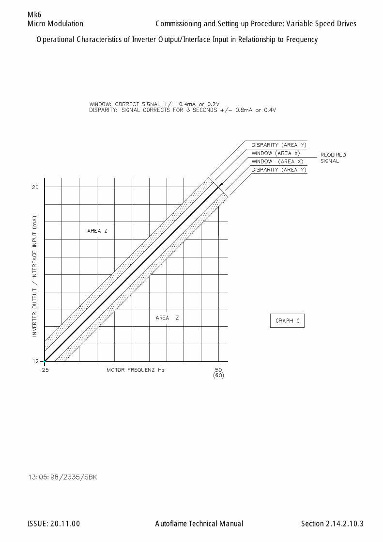
Micro Modulation
ISSUE: 20.11.00 Autoflame Technical Manual Section
Mk6
Operational Characteristics of Inverter Output/Interface Input in Relationship to Frequency
2.14.2.10.3
Commissioning and Setting up Procedure: Variable Speed Drives
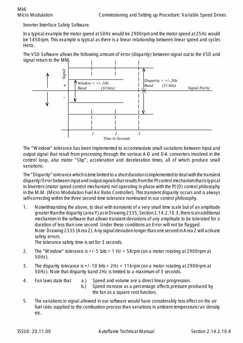
Micro Modulation
ISSUE: 20.11.00 Autoflame Technical Manual Section
Mk6
Inverter Interface Safety Software.
In a typical example the motor speed at 50Hz would be 2900rpm and the motor speed at 25Hz wouldbe 1450rpm. This example is typical as there is a linear relationship between linear speed and cyclesHertz.
The VSD Software allows the following amount of error (disparity) between signal out to the VSD andsignal return to the MM.
The “Window” tolerance has been implemented to accommodate small variations between input andoutput signal that result from processing through the various A-D and D-A converters involved in thecontrol loop, also motor “Slip”, acceleration and deceleration times, all of which produce smallvariations.
The “Disparity” tolerance which is time limited to a short duration is implemented to deal with the transientdisparity/Error between input and output signals that results from the PI control mechanism that is typicalin Inverters (motor speed control mechanism) not operating in phase with the PI (D) control philosophyin the M.M. (Micro Modulation Fuel Air Ratio Controller). This transient disparity occurs and is alwaysself-correcting within the three second time tolerance nominated in our control philosophy.
1. Notwithstanding the above, to deal with transients of a very small time scale but of an amplitudegreater than the disparity (area Y) as in Drawing 2335, Section 2.14.2.10.3, there is an additionalmechanism in the software that allows transient deviations of any amplitude to be tolerated for aduration of less than one second. Under these conditions an Error will not be flagged.Note: Drawing 2335 (Area Z). Any signal deviation longer than one second in Area Z will activatesafety errors.The tolerance safety time is set for 3 seconds.
2. The “Window” tolerance is +/- 5 bits = 1 Hz = 58rpm (on a motor rotating at 2900rpm at50Hz).
3. The disparity tolerance is +/- 10 bits = 2Hz = 116rpm (on a motor rotating at 2900rpm at50Hz). Note that disparity band 2Hz is limited to a maximum of 3 seconds.
4. Fan laws state that a.) Speed and volume are a direct linear progression.b.) Speed increase as a percentage affects pressure produced by
the fan as a square root function.
5. The variations in signal allowed in our software would have considerably less effect on the airfuel ratio supplied to the combustion process than variations in ambient temperature/air densityetc.
2.14.2.10.4
V
Disparity = +/- 2HzBand (15 bits)
1 2 3Time in Seconds
+
-
Sign
al
Signal Parity
VV
VV
V
Window = +/- 1HzBand (10 bits)
Commissioning and Setting up Procedure: Variable Speed Drives
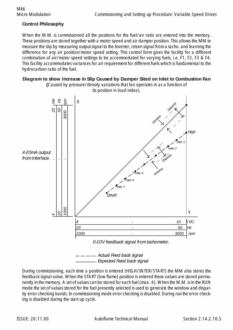
Micro Modulation
ISSUE: 20.11.00 Autoflame Technical Manual Section
Mk6
Control Philosophy
When the M.M. is commissioned all the positions for the fuel/air ratio are entered into the memory.These positions are stored together with a motor speed and air damper position. This allows the MM tomeasure the slip by measuring output signal to the Inverter, return signal from a tacho. and learning thedifference for any air position/motor speed setting. This control form gives the facility for a differentcombination of air/motor speed settings to be accommodated for varying fuels, i.e. F1, F2, F3 & F4.This facility accommodates variances for air requirement for different fuels which is fundamental to thehydrocarbon ratio of the fuel.
2.14.2.10.5
X
Y
4 - 10 V DC
20 - 50 Hz
1000 - 3000 rpm
4-
20
mA
20-
50
Hz
1000
-
300
0
rpm
Window
Disparity
Dispar
ity
Wind
ow
High
Inter 1
Inter 2
Inter 5
Inter 6
Inter 7
START
4-20mA outputfrom Interface.
0-10V feedback signal from tachometer.
Diagram to show Increase in Slip Caused by Damper Sited on Inlet to Combustion Fan(Caused by pressure/density variations that fan operates in as a function of
its position in load index).
Actual Feed back signalExpected Feed back signal
During commissioning, each time a position is entered (HIGH/INTER/START) the MM also stores thefeedback signal value. When the START (low flame) position is entered these values are stored perma-nently in the memory. A set of values can be stored for each fuel (max. 4). When the M.M. is in the RUNmode the set of values stored for the fuel presently selected is used to generate the window and dispar-ity error checking bands. In commissioning mode error checking is disabled. During run the error check-ing is disabled during the start up cycle.
Commissioning and Setting up Procedure: Variable Speed Drives

Micro Modulation
ISSUE: 20.11.00 Autoflame Technical Manual Section
Mk6
2.14.2.11 INSTALLATION CHECKS
Commissioning Checks
When the installation and all burner adjustments are completed, the entire burner control system shouldbe tested in accordance with the manufacturer’s instructions. The procedure should verify the correctoperation of:
1. Each operating control (temperature, pressure, etc.)2. Each limit switch (temperature, pressure, low water cutoff, etc.)3. Each interlock switch (airflow switch, high and low fuel pressure or temperature switches, purge
and low fire switches, fuel valve proof of closure interlock, etc.)4. Pilot flame failure response and lockout.5. Main flame failure response and lockout.6. Tight shut off of all valves.
Operational Checks
1. Close manual main shut-off valve2. Recheck all limit circuit wiring for proper operation and correct connection3. Confirm that the automatic main fuel valves are wired correctly4. Power the control and electronically check the proper sequence of operation5. After assuring yourself that all the interlocks and valves are properly wired and that the sequence
of operation is correct, open the manual main shut-off fuel valve and proceed cautiously throughthe boiler light off process. Check all safety interlocks for proper shutdown of the boiler.
2.14.2.11
Commissioning and Setting up Procedure: Installation Checks
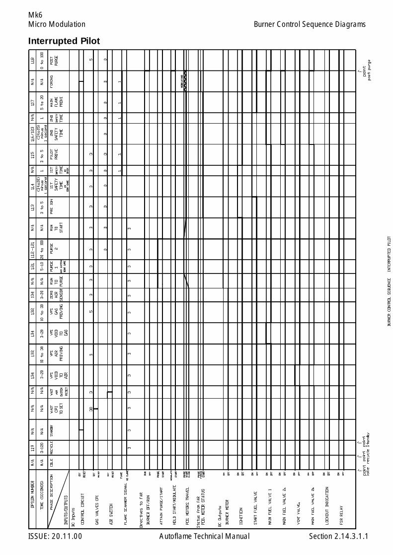
Micro Modulation
ISSUE: 20.11.00 Autoflame Technical Manual Section
Mk6
2.14.3.1.1
Interrupted Pilot
Burner Control Sequence Diagrams
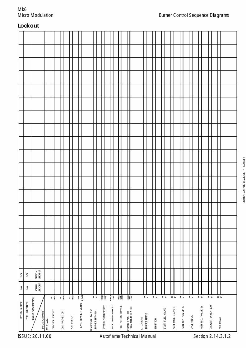
Micro Modulation
ISSUE: 20.11.00 Autoflame Technical Manual Section
Mk6
2.14.3.1.2
Burner Control Sequence Diagrams
Lockout

Micro Modulation
ISSUE: 20.11.00 Autoflame Technical Manual Section
Mk6
2.14.3.1.3
Burner Control Sequence Diagrams
Intermittent Pilot
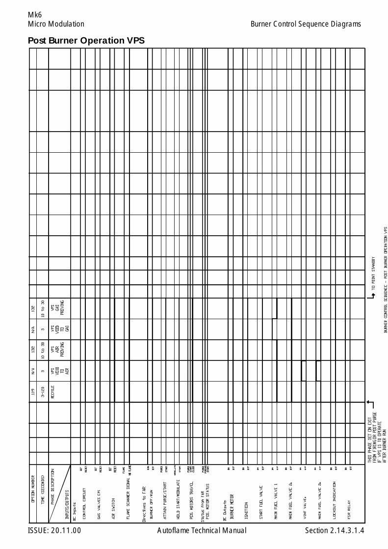
Micro Modulation
ISSUE: 20.11.00 Autoflame Technical Manual Section
Mk6Burner Control Sequence Diagrams
2.14.3.1.4
Post Burner Operation VPS
Micro Modulation
ISSUE: 20.11.00 Autoflame Technical Manual Section
Mk6Burner Control Sequence Diagrams
Diagram Notes
If VPS not optioned on fuel selected VPS phases are bypassed.
point idle:this phase is set at power up when no fuel selected on exit from lockout.
point recycle:this phase is set on exit from firing and post purge if VPS has not operated after burner run.
point post purge:this phase is set only if post purge is optioned.
point standby:this phase is set if VPS has operated after burner run.
Normal lockout is reset when either the mains lockout reset input is set for 1 second or the front facialockout reset button is pressed for 1 second.
Special lockout is set if either the mains lockout reset input Lockout Reset or front facia Lockout Resetinput is set for 10 or more seconds. Normal lockout is set on exit from special lockout and is reset in thenormal way.
Bold waveforms indicate required condition. Values above/below waveform are time in seconds thatthe state must be continuosly incorrect after which a lockout is set. Shown monitor inputs are don’t careif no bold waveform.
2.14.3.1.5

Micro Modulation
ISSUE: 20.11.00 Autoflame Technical Manual Section
Mk6
2.14.3.2
Control Box Functions Overview
2.14.3.2 Self Check UV Scanner
Part Numbers: MM60003MM60003/HS

Micro Modulation
ISSUE: 20.11.00 Autoflame Technical Manual Section
Mk6
2.14.3.3
Control Box Functions Overview
2.14.3.3 Standard European UV Scanner - Side-viewing
Part Numbers: MM60004MM60004/HS
Connections
Red Terminal 51Blue Terminal 50Black Screen
IP 54HOUSING: ALUMINIUMPOWER COMSUMPTION: POWERED BY MK.6 MMMOUNTING: ANY ORIENTATION AS LONG AS PHOTO TUBE FACES THE FLAME
View A
View A(with cover removed)
Two red LEDs show UV detection
50 51
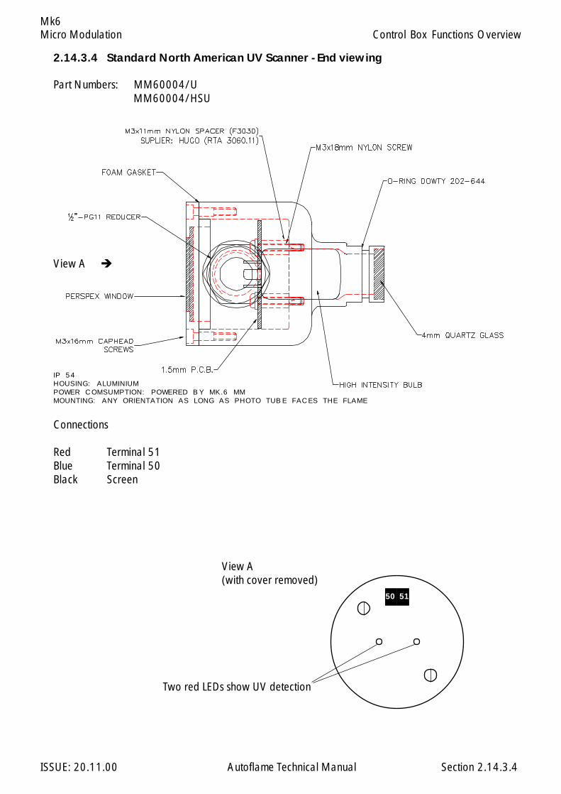
Micro Modulation
ISSUE: 20.11.00 Autoflame Technical Manual Section
Mk6
2.14.3.4
Control Box Functions Overview
2.14.3.4 Standard North American UV Scanner - End viewing
Part Numbers: MM60004/UMM60004/HSU
Connections
Red Terminal 51Blue Terminal 50Black Screen
IP 54HOUSING: ALUMINIUMPOWER COMSUMPTION: POWERED BY MK.6 MMMOUNTING: ANY ORIENTATION AS LONG AS PHOTO TUBE FACES THE FLAME
View A
View A(with cover removed)
Two red LEDs show UV detection
50 51

Micro Modulation
ISSUE: 20.11.00 Autoflame Technical Manual Section
Mk6
2.14.3.5 Selection of UV Scanner Types
Normal Sensitivity
If the distance from the UV scanner to the flame is upto 20 inches (500mm) the normal sensitivity UVscanner types may be used.
Normal Sensitivity Scanner Types:
MM60003 Self CheckMM60004 Standard (Side View)MM60004/U Standard (End View)
Dependant on the application (e.g. flame size/shape/intensity, flame obscruation etc.) where the sig-nal strength is low, a high sensitivity scanner type may be necessary for distances below 20 inches.
High Sensitivity
If the distance from the UV scanner to the flame exceeds 20 inches (500mm) the high sensitivity UVscanner types are recommended.
High Sensitivity Scanner Types:
MM60003/HS Self CheckMM60004/HS Standard (Side View)MM60004/HSU Standard (End View)
The information above is based on the results of tests using a simulated pilot flame. The flame wassimulated by means of a bunsen burner flame with a size of 100x20mm.
2.14.3.5
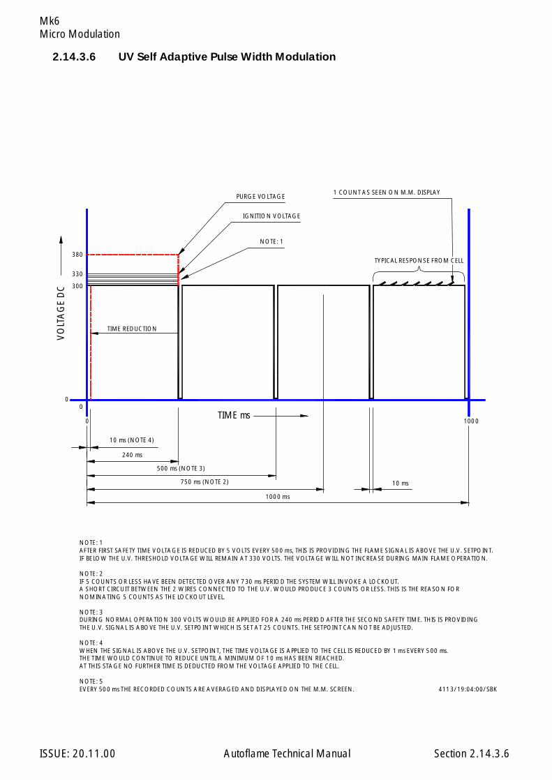
Micro Modulation
ISSUE: 20.11.00 Autoflame Technical Manual Section
Mk6
2.14.3.6 UV Self Adaptive Pulse Width Modulation
2.14.3.6
1000 ms
750 ms (NOTE 2)
500 ms (NOTE 3)
240 ms
10 ms
0
0 1000
0
300
380
330
PURGE VOLTAGE
IGNITION VOLTAGE
NOTE: 1
TYPICAL RESPONSE FROM CELL
1 COUNT AS SEEN ON M.M. DISPLAY
10 ms (NOTE 4)
TIME ms
VO
LTA
GE
DC
TIME REDUCTION
NOTE: 1AFTER FIRST SAFETY TIME VOLTAGE IS REDUCED BY 5 VOLTS EVERY 500 ms, THIS IS PROVIDING THE FLAME SIGNAL IS ABOVE THE U.V. SETPOINT.IF BELOW THE U.V. THRESHOLD VOLTAGE WILL REMAIN AT 330 VOLTS. THE VOLTAGE WILL NOT INCREASE DURING MAIN FLAME OPERATION.
NOTE: 2IF 5 COUNTS OR LESS HAVE BEEN DETECTED OVER ANY 730 ms PERIOD THE SYSTEM WILL INVOKE A LOCKOUT.A SHORT CIRCUIT BETWEEN THE 2 WIRES CONNECTED TO THE U.V. WOULD PRODUCE 3 COUNTS OR LESS. THIS IS THE REASON FOR
NOTE: 3DURING NORMAL OPERATION 300 VOLTS WOULD BE APPLIED FOR A 240 ms PERIOD AFTER THE SECOND SAFETY TIME. THIS IS PROVIDING
NOTE: 4WHEN THE SIGNAL IS ABOVE THE U.V. SETPOINT, THE TIME VOLTAGE IS APPLIED TO THE CELL IS REDUCED BY 1 ms EVERY 500 ms.
AT THIS STAGE NO FURTHER TIME IS DEDUCTED FROM THE VOLTAGE APPLIED TO THE CELL.
NOTE: 5EVERY 500 ms THE RECORDED COUNTS ARE AVERAGED AND DISPLAYED ON THE M.M. SCREEN.
NOMINATING 5 COUNTS AS THE LOCKOUT LEVEL.
THE U.V. SIGNAL IS ABOVE THE U.V. SETPOINT WHICH IS SET AT 25 COUNTS. THE SETPOINT CAN NOT BE ADJUSTED.
THE TIME WOULD CONTINUE TO REDUCE UNTIL A MINIMUM OF 10 ms HAS BEEN REACHED.
4113/19:04:00/SBK

Micro Modulation
ISSUE: 20.11.00 Autoflame Technical Manual Section
Mk6
2.14.4 ERROR CHECKING, SELF DIAGNOSTICS FAULT ANALYSIS, I.D. CODES.
Self Diagnostic Fault Identification Software.
The “Error Checking” software, which is included in every M.M. E.G.A. module, continually interrogatesthe system for component or data handling failure. This intensive self checking programme is inflicted onall peripherals such as positioning motors and load detectors as well as the main M.M./E.G.A. systemhardware. The safety related areas, both hardware and software, have been examined and acceptedfor CE & UL.
Any error identified by the system is indicated by “ERROR” being displayed and the relevant errornumber. In the case of E.G.A. related faults, “ERROR EGA” is displayed with the corresponding erroridentification code.
2.14.4.1 Key to Errors Detected in Mk.6 M.M. System
E R ROR - confirms that error has been detected in the M.M. System.
Fault Type Code No.
CH1 Positioning Error 01CH2 Positioning Error 02CH3 Positioning Error 08CH4 Positioning Error 09
CH1 Gain Error 41CH2 Gain Error 42CH3 Gain Error 43CH4 Gain Error 46
CH5 Error 80 Ch5 AC drive feedback signal incorrectCH6 Error 81 Ch6 AC drive feedback signal incorrect
See Section 2.14.2.10
Load Detector 03 - Open circuit on temp. sensorCR1 Test Failure 40 - MM opened Burner Control Circuit,
expects voltage on T85 to be removed within 60 sec.s (Parameter 6)
12V/5V Supply Error 44 - Internal 5V/12V supply outside limits. Check 12V on terminal 40 & 41.
Watchdog - Error CR2 45 - Unit hardware failureA/D Converter Error 47 - Check 12V supply on terminals 40, 41Twin Burner Communications Failed 100 - Flashing Error, see Section 2.3.1.3
Air Pressure Outside Limits 82 - During run mode actual air pressure outside limits, commissioned +/- 0.3 “wg (See Option 147).
Gas Pressure Sensor MM60008 optioned 110 - See Option 124 & 133 to 137.together with psi units. PSI display cannot be chosen for this
sensor range.
Error Checking, Self Diagnostic Fault Analysis Codes, I.D. Codes
2.14.4.1.1
Check Wiring & Motor
Check Wiring & Potentiometers arezeroed correctly
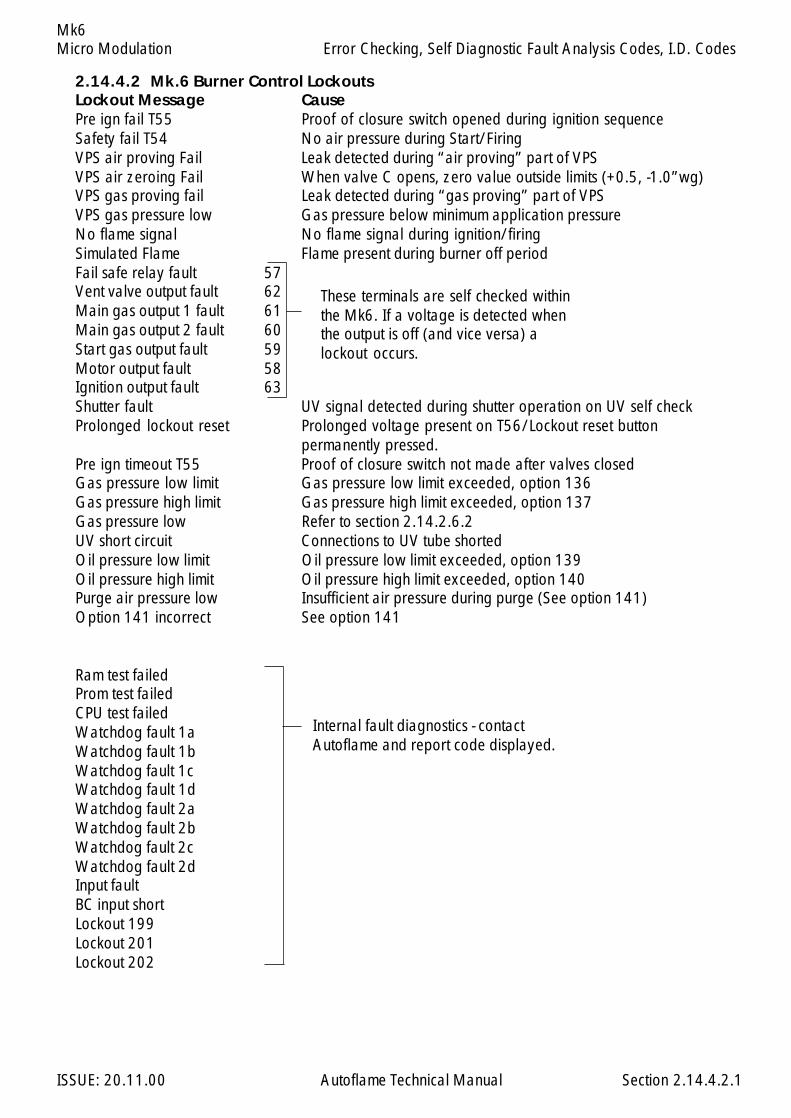
Micro Modulation
ISSUE: 20.11.00 Autoflame Technical Manual Section
Mk6
2.14.4.2.1
2.14.4.2 Mk.6 Burner Control LockoutsLockout Message CausePre ign fail T55 Proof of closure switch opened during ignition sequenceSafety fail T54 No air pressure during Start/FiringVPS air proving Fail Leak detected during “air proving” part of VPSVPS air zeroing Fail When valve C opens, zero value outside limits (+0.5, -1.0”wg)VPS gas proving fail Leak detected during “gas proving” part of VPSVPS gas pressure low Gas pressure below minimum application pressureNo flame signal No flame signal during ignition/firingSimulated Flame Flame present during burner off periodFail safe relay fault 57Vent valve output fault 62Main gas output 1 fault 61Main gas output 2 fault 60Start gas output fault 59Motor output fault 58Ignition output fault 63Shutter fault UV signal detected during shutter operation on UV self checkProlonged lockout reset Prolonged voltage present on T56/Lockout reset button
permanently pressed.Pre ign timeout T55 Proof of closure switch not made after valves closedGas pressure low limit Gas pressure low limit exceeded, option 136Gas pressure high limit Gas pressure high limit exceeded, option 137Gas pressure low Refer to section 2.14.2.6.2UV short circuit Connections to UV tube shortedOil pressure low limit Oil pressure low limit exceeded, option 139Oil pressure high limit Oil pressure high limit exceeded, option 140Purge air pressure low Insufficient air pressure during purge (See option 141)Option 141 incorrect See option 141
Ram test failedProm test failedCPU test failedWatchdog fault 1aWatchdog fault 1bWatchdog fault 1cWatchdog fault 1dWatchdog fault 2aWatchdog fault 2bWatchdog fault 2cWatchdog fault 2dInput faultBC input shortLockout 199Lockout 201Lockout 202
These terminals are self checked withinthe Mk6. If a voltage is detected whenthe output is off (and vice versa) alockout occurs.
Internal fault diagnostics - contactAutoflame and report code displayed.
Error Checking, Self Diagnostic Fault Analysis Codes, I.D. Codes
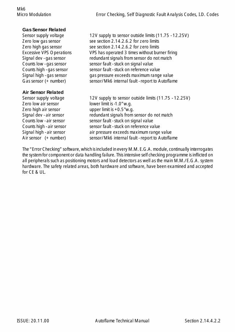
Micro Modulation
ISSUE: 20.11.00 Autoflame Technical Manual Section
Mk6
Gas Sensor RelatedSensor supply voltage 12V supply to sensor outside limits (11.75 - 12.25V)Zero low gas sensor see section 2.14.2.6.2 for zero limitsZero high gas sensor see section 2.14.2.6.2 for zero limitsExcessive VPS Operations VPS has operated 3 times without burner firingSignal dev - gas sensor redundant signals from sensor do not matchCounts low - gas sensor sensor fault - stuck on signal valueCounts high - gas sensor sensor fault - stuck on reference valueSignal high - gas sensor gas pressure exceeds maximum range valueGas sensor (+ number) sensor/Mk6 internal fault - report to Autoflame
Air Sensor RelatedSensor supply voltage 12V supply to sensor outside limits (11.75 - 12.25V)Zero low air sensor lower limit is -1.0”w.g.Zero high air sensor upper limit is +0.5"w.g.Signal dev - air sensor redundant signals from sensor do not matchCounts low - air sensor sensor fault - stuck on signal valueCounts high - air sensor sensor fault - stuck on reference valueSignal high - air sensor air pressure exceeds maximum range valueAir sensor (+ number) sensor/Mk6 internal fault - report to Autoflame
The “Error Checking” software, which is included in every M.M. E.G.A. module, continually interrogatesthe system for component or data handling failure. This intensive self checking programme is inflicted onall peripherals such as positioning motors and load detectors as well as the main M.M./E.G.A. systemhardware. The safety related areas, both hardware and software, have been examined and acceptedfor CE & UL.
2.14.4.2.2
Error Checking, Self Diagnostic Fault Analysis Codes, I.D. Codes

Micro Modulation
ISSUE: 20.11.00 Autoflame Technical Manual Section
Mk6
2.14.4.3 TROUBLESHOOTING
Gas/air sensor Diagnostic Codes
Shown at bottom of MM display if parameter 83=1
Example:
Explanation:
Typical reference signals are 1000±14.
Each sensor has two channels. Each channel gives out two values - a pressure signal and a referencesignal. The values displayed are ‘digitised’ signals (range 0-1023). The two pressure signals shouldbe the same. The two reference signals should be the same.
If the two pressure signals are different by more than 10 the averaged value will show 01 and notthe average of the two signals.
With no pressure applied to the sensor the pressure signal value should be between 20 to 60. (Typi-cally between 40 to 50).
Error Checking, Self Diagnostic Fault Analysis Codes, I.D. Codes
2.14.4.3.1
egarevAlangiS
erusserPlangiS
ecnerefeRlangiS
saGsaG 34 1001 1lennahCrosneS
24 24 0001 2lennahCrosneS
riAriA 05 969 1lennahCrosneS
15 15 079 2lennahCrosneS
saG 34 1001
24 24 0001
riA 05 969
15 15 079

Micro Modulation
ISSUE: 20.11.00 Autoflame Technical Manual Section
Mk6
AC Drive Diagnostic Codes
Shown at bottom right of AC drive display if parameter 83=1
Example:
Explanation:
1 & 2 should normally be 0.
3 to 5 are digitised values, 0-255.
3 represents linearly (0-255) 4-20mA/0-10V the analog output from the MK6.5 represents linearly (0-255) 0-20mA/0-10V the analog input into the MK6.
The Window error count value will increment if the difference between 4 & 5 is greater than 10. AnMM error will occur if the count reaches 150. This takes approx 3 seconds.
The Disparity error count value - will increment up if the difference between 4 & 5 is greater than 15.An MM error will occur if the count reaches 50. This takes approx 1 second.
Error checking is only carried out when the burner is firing.
The correct feedback signals must be attained for purge & ignition to progress.IE 5 must be as 4 ± 15.
Error Checking, Self Diagnostic Fault Analysis Codes, I.D. Codes
2.14.4.3.2
1 2 3 4 5
evirDCA5HC 0 0 052 352 452
evirDCA6HC 0 0 001 021 121
0 0 052 352 452
0 0 001 021 121

Micro Modulation
ISSUE: 20.11.00 Autoflame Technical Manual Section
Mk6
UV Shutter Faults
UV Shutter Fault – there are two LED’s on the back of the self-check UV, red indicates prescence of aflame, yellow indicates shutter operation. The red LED will flicker in the presnce of UV light, every 60seconds the yellow LED will come on, indicating shutter closing, the red LED should then extinguishbriefly. If this is not happening check wiring to self check UV sensor. Green wire = Terminal 22,Yellow wire = terminal 21, blue wire = terminal 50, red wire = terminal 51.
Error Checking, Self Diagnostic Fault Analysis Codes, I.D. Codes
2.14.4.3.3
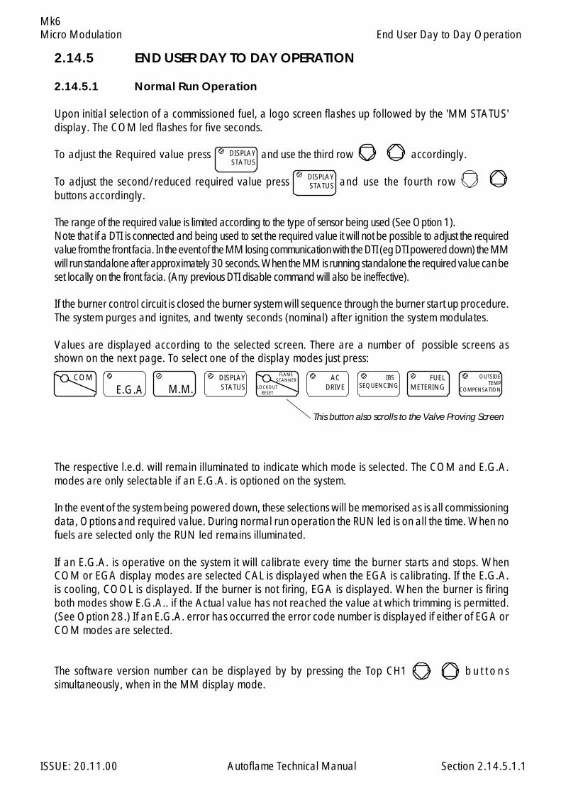
Micro Modulation
ISSUE: 20.11.00 Autoflame Technical Manual Section
Mk6
2.14.5 END USER DAY TO DAY OPERATION
2.14.5.1 Normal Run Operation
Upon initial selection of a commissioned fuel, a logo screen flashes up followed by the 'MM STATUS'display. The COM led flashes for five seconds.
To adjust the Required value press and use the third row accordingly.
To adjust the second/reduced required value press and use the fourth rowbuttons accordingly.
The range of the required value is limited according to the type of sensor being used (See Option 1).Note that if a DTI is connected and being used to set the required value it will not be possible to adjust the requiredvalue from the front facia. In the event of the MM losing communication with the DTI (eg DTI powered down) the MMwill run standalone after approximately 30 seconds. When the MM is running standalone the required value can beset locally on the front facia. (Any previous DTI disable command will also be ineffective).
If the burner control circuit is closed the burner system will sequence through the burner start up procedure.The system purges and ignites, and twenty seconds (nominal) after ignition the system modulates.
Values are displayed according to the selected screen. There are a number of possible screens asshown on the next page. To select one of the display modes just press:
The respective l.e.d. will remain illuminated to indicate which mode is selected. The COM and E.G.A.modes are only selectable if an E.G.A. is optioned on the system.
In the event of the system being powered down, these selections will be memorised as is all commissioningdata, Options and required value. During normal run operation the RUN led is on all the time. When nofuels are selected only the RUN led remains illuminated.
If an E.G.A. is operative on the system it will calibrate every time the burner starts and stops. WhenCOM or EGA display modes are selected CAL is displayed when the EGA is calibrating. If the E.G.A.is cooling, COOL is displayed. If the burner is not firing, EGA is displayed. When the burner is firingboth modes show E.G.A.. if the Actual value has not reached the value at which trimming is permitted.(See Option 28.) If an E.G.A. error has occurred the error code number is displayed if either of EGA orCOM modes are selected.
The software version number can be displayed by by pressing the Top CH1 b u t t o n ssimultaneously, when in the MM display mode.
End User Day to Day Operation
COM
E.G.A
123123123
M.M.
121212 DISPLAY
STATUS
123123123
2.14.5.1.1
FLAMESCANNER
LOCKOUTRESET
ACDRIVE
123123123 IBS
SEQUENCING
123123123 FUEL
METERING
123123123 OUTSIDE
TEMPCOMPENSATION
123123123
This button also scrolls to the Valve Proving Screen
DISPLAYSTATUS
123123123
DISPLAYSTATUS
123123
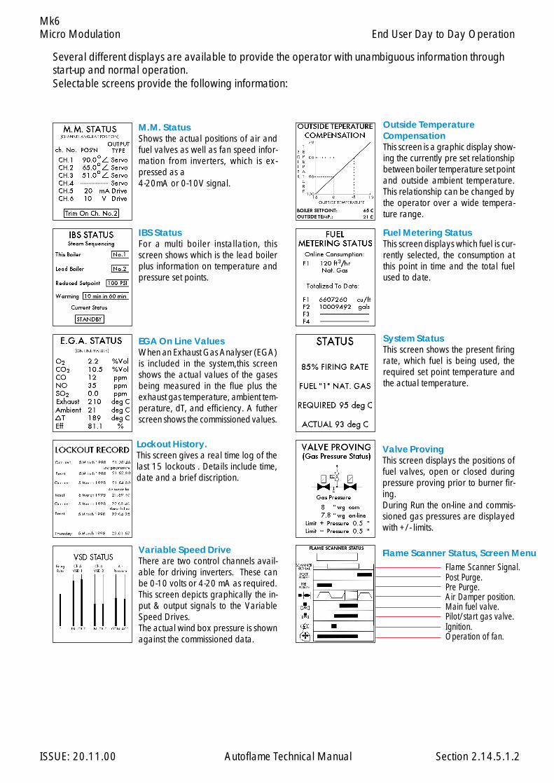
Micro Modulation
ISSUE: 20.11.00 Autoflame Technical Manual Section
Mk6
Variable Speed DriveThere are two control channels avail-able for driving inverters. These canbe 0-10 volts or 4-20 mA as required.This screen depicts graphically the in-put & output signals to the VariableSpeed Drives.The actual wind box pressure is shownagainst the commissioned data.
EGA On Line ValuesWhen an Exhaust Gas Analyser (EGA)is included in the system,this screenshows the actual values of the gasesbeing measured in the flue plus theexhaust gas temperature, ambient tem-perature, dT, and efficiency. A futherscreen shows the commissioned values.
Outside TemperatureCompensationThis screen is a graphic display show-ing the currently pre set relationshipbetween boiler temperature set pointand outside ambient temperature.This relationship can be changed bythe operator over a wide tempera-ture range.
M.M. StatusShows the actual positions of air andfuel valves as well as fan speed infor-mation from inverters, which is ex-pressed as a4-20mA or 0-10V signal.
IBS StatusFor a multi boiler installation, thisscreen shows which is the lead boilerplus information on temperature andpressure set points.
Lockout History.This screen gives a real time log of thelast 15 lockouts . Details include time,date and a brief discription.
System StatusThis screen shows the present firingrate, which fuel is being used, therequired set point temperature andthe actual temperature.
Fuel Metering StatusThis screen displays which fuel is cur-rently selected, the consumption atthis point in time and the total fuelused to date.
Several different displays are available to provide the operator with unambiguous information throughstart-up and normal operation.Selectable screens provide the following information:
Flame Scanner Signal.Post Purge.Pre Purge.Air Damper position.Main fuel valve.Pilot/start gas valve.Ignition.Operation of fan.
Valve ProvingThis screen displays the positions offuel valves, open or closed duringpressure proving prior to burner fir-ing.During Run the on-line and commis-sioned gas pressures are displayedwith +/- limits.
Flame Scanner Status, Screen Menu
2.14.5.1.2
End User Day to Day Operation

Micro Modulation
ISSUE: 20.11.00 Autoflame Technical Manual Section
Mk6
2.14.5.2.1
2.14.5.2 Adjusting Clock Settings, Contrast and Actual Load Reading
Setting Time & Date
To adjust the time and date settings go into COM mode. (Power down the unit and restart. The
light will be flashing and you have 5 seconds to press it.)
'ENTER PASSWORD' screen is displayed. Set password to: , Press
'Set Clock' screen is displayed:
To adjust the values use the corresponding buttons.
When finished press the flashing button to submit to memory.
Adjusting the Screen Contrast
Hold down any of the screen select buttons,
and then use the top row to adjust the contrast accordingly.
Calibrating Actual Load Reading
A facility exists to adjust small errors in the actual pressure or temperature displayed on the status screen.
To increase the value press and the Ch3 simultaneously.
To decrease press and the CH3 .
COM
1010
ENTER
MEMORY
CLOSE
DISPLAYSTATUS
123123123
M.M.
123123123
E.G.A
123123123OUTSIDE
TEMPCOMPENSATION
123123123 FUEL
METERING
121212 IBS
SEQUENCING
121212 AC
DRIVE
121212 FLAME
SCANNERLOCKOUT
RESET
RUN
RUN
End User Day to Day Operation
SET CLOCK
DAY MONDAYDATE 17MONTH NOVEMBERYEAR 97HOURS 12MINUTES 30 24 hour clock
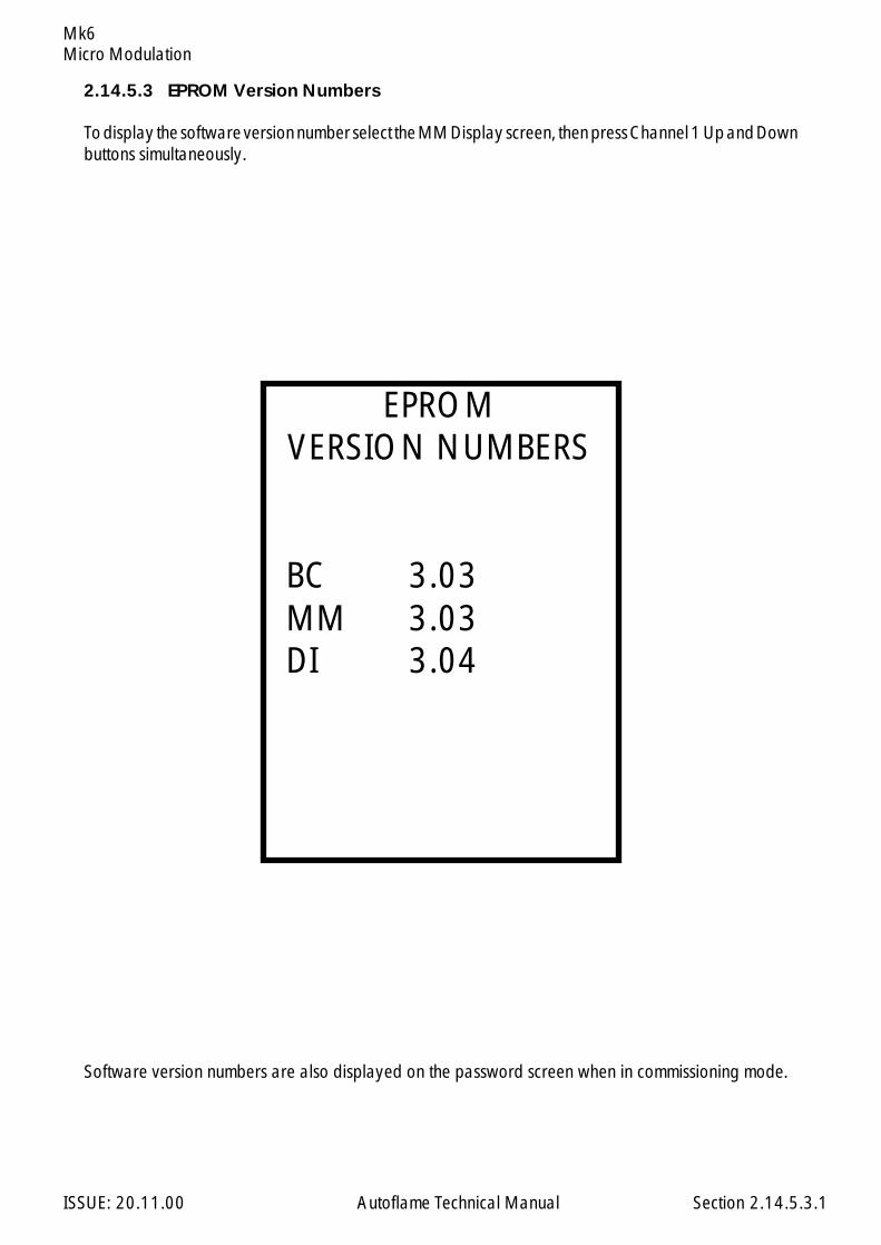
Micro Modulation
ISSUE: 20.11.00 Autoflame Technical Manual Section
Mk6
2.14.5.3 EPROM Version Numbers
To display the software version number select the MM Display screen, then press Channel 1 Up and Downbuttons simultaneously.
Software version numbers are also displayed on the password screen when in commissioning mode.
2.14.5.3.1
EPROMVERSION NUMBERS
BC 3.03 MM 3.03 DI 3.04
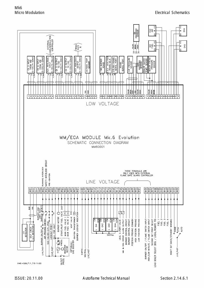
Micro Modulation
ISSUE: 20.11.00 Autoflame Technical Manual Section
Mk6
2.14.6.1
Electrical Schematics
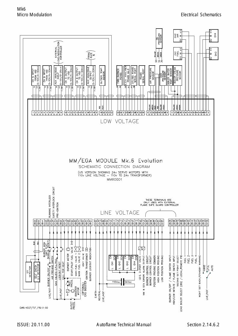
Micro Modulation
ISSUE: 20.11.00 Autoflame Technical Manual Section
Mk6
2.14.6.2
Electrical Schematics
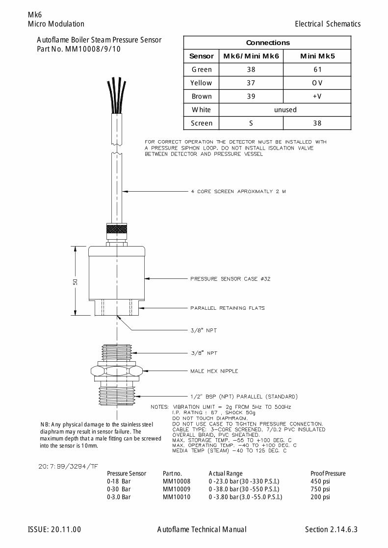
Micro Modulation
ISSUE: 20.11.00 Autoflame Technical Manual Section
Mk6
NB: Any physical damage to the stainless steel diaphram may result in sensor failure. The maximum depth that a male fitting can be screwed into the sensor is 10mm.
2.14.6.3
Autoflame Boiler Steam Pressure SensorPart No. MM10008/9/10
Electrical Schematics
Pressure Sensor Part no. Actual Range Proof Pressure0-18 Bar MM10008 0 - 23.0 bar (30 - 330 P.S.I.) 450 psi0-30 Bar MM10009 0 - 38.0 bar (30 - 550 P.S.I.) 750 psi0-3.0 Bar MM10010 0 - 3.80 bar (3.0 - 55.0 P.S.I.) 200 psi
snoitcennoC
rosneS 6kMiniM/6kM 5kMiniM
neerG 83 16
wolleY 73 VO
nworB 93 V+
etihW desunu
neercS S 83

Micro Modulation
ISSUE: 20.11.00 Autoflame Technical Manual Section
Mk6
LANDIS & GYR CONTROL BOX LFL 1/LGK 16
4 5 6 9 8 10
ES ES
ES = ELECTRONIC SWITCH
81 83 82 8480
3
86
= EXTERNAL RELAY
N
10:10:97/3399/NPG
BURNER STAT CCT.
BURNER
ON/OFF
BURNER
CONTROL
BURNER
CONTROL HIGH
POSITION
PROVE
LOW
POSITION
PROVE
HIGH/LOW
INITIATE
ALL RELAYS SHOWN AT MAINSVOLTAGE UNLESS STATED OTHERWISE.
LIMITSTAT.
MM/EGA MODULE Mk.6
NOTE: R1 = EXTERNAL RELAY TOPREVENT BACK FEEDS.
GENERAL NOTES:
APPLICATION OF CONTROL BOXESWITH MM/EGA MODULE Mk.6
N
R1
11
SATRONIC CONTROL BOX TMO 720-2
20 9 4 13 14 16 15
ES ES
81 83 82 8480 86
BURNER STAT CCT.
BURNER
ON/OFF
MM/EGA MODULE Mk.6
BURNER
CONTROL
BURNER
CONTROL HIGH
POSITION
PROVE
LOW
POSITION
PROVE
HIGH/LOW
INITIATE
LIMITSTAT.
LIMIT
INITIATE
HIGH/LOW
PROVE
POSITION
LOW
PROVE
POSITION
HIGH
CONTROL
BURNER
CONTROL
BURNER
MM/EGA MODULE Mk.6
ON/OFF
BURNER
BURNER STAT CCT.
N
86
15
80 84828381
ESES
8144103
HONEYWELL CONTROL BOX 4344
5
AIRSWITCH
67
STARTINT.
THE ABOVE ARE THE RECOMMENDED INTERFACE CONNECTIONS. PLEASE REFER TO AUTOFLAME ENGINEERING IF ANY DEVIATIONS FROM THESE ARE REQUIRED
10
STAT.LIMIT
INITIATE
HIGH/LOW
PROVE
POSITION
LOW
PROVE
POSITION
HIGH
CONTROL
BURNER
CONTROL
BURNER
MM/EGA MODULE Mk.6
ON/OFF
BURNER
BURNER STAT CCT.
N
86
A
80 84828381
ESES
MD8XM13L1
FIRE EYE CONTROL BOX E100
85 85
85 85
2.14.6.4
Electrical Schematics

Micro Modulation
ISSUE: 20.11.00 Autoflame Technical Manual Section
Mk6
LANDIS & GYR CONTROL BOXES LFE 1 & LEC 1
9 8 3 2 22 20 21
ES ES
81 83 82 8480
12
86
N
10:10:97/3400/NPG
BURNER STAT CCT.
BURNER
ON/OFF
MM/EGA MODULE Mk.6
BURNER
CONTROL
BURNER
CONTROL HIGH
POSITION
PROVE
LOW
POSITION
PROVE
HIGH/LOW
INITIATE
LIMITSTAT.
STAT.LIMIT
INITIATE
HIGH/LOW
PROVE
POSITION
LOW
PROVE
POSITION
HIGH
CONTROL
BURNER
CONTROL
BURNER
MM/EGA MODULE Mk.6
ON/OFF
BURNER
BURNER STAT CCT.
N
86
7
80 84828381
ESES
151614134109
SATRONIC CONTROL BOX TMG 740-2FIRE EYE CONTROL BOX E200
L1 3 M 13 8 D M
ES ES
81 83 82 8480
A
86
N
BURNER STAT CCT.
BURNER
ON/OFF
MM/EGA MODULE Mk.6
BURNER
CONTROL
BURNER
CONTROL HIGH
POSITION
PROVE
LOW
POSITION
PROVE
HIGH/LOW
INITIATE
LIMITSTAT.
MM/EGA MODULE Mk.6
HONEYWELL CONTROL BOX R7241
12
STAT.LIMIT
INITIATE
HIGH/LOW
PROVE
POSITION
LOW
PROVE
POSITION
HIGH
CONTROL
BURNER
CONTROL
BURNER
ON/OFF
BURNER
BURNER STAT CCT.
N
86
10
80 84828381
ES
13620158
N
L
23
ES
NOTE: COIL CURRENT 10mA MAX. NOTE: R1 = EXTERNAL RELAY TOPREVENT BACK FEEDS.
APPLICATION OF CONTROL BOXESWITH MM/EGA MODULE Mk.6
7
R1
10
THE ABOVE ARE THE RECOMMENDED INTERFACE CONNECTIONS. PLEASE REFER TO AUTOFLAME ENGINEERING IF ANY DEVIATIONS FROM THESE ARE REQUIRED
GENERAL NOTES:
OTHERWISE.VOLTAGE UNLESS STATED ALL RELAYS SHOWN AT MAINS= EXTERNAL RELAY
ES = ELECTRONIC SWITCH
85 85
85 85
2.14.6.5
Electrical Schematics
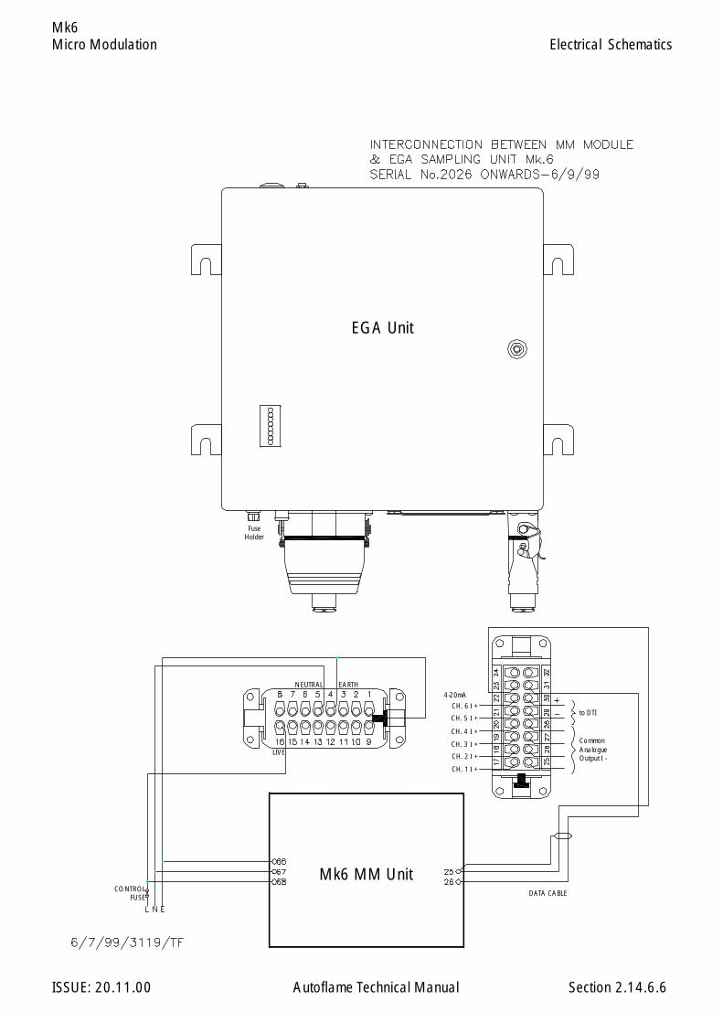
Micro Modulation
ISSUE: 20.11.00 Autoflame Technical Manual Section
Mk6
2.14.6.6
Electrical Schematics
EGA Unit
Mk6 MM UnitDATA CABLE
NEUTRAL EARTH
LIVE
CONTROL FUSE
to DTICH. 6 I +
CH. 5 I +
CH. 4 I +
CH. 3 I +
CH. 2 I +
CH. 1 I +
4-20mA
Common Analogue Output I -
Fuse Holder

Micro Modulation
ISSUE: 20.11.00 Autoflame Technical Manual Section
Mk6
2.14.6.10
Electrical Schematics
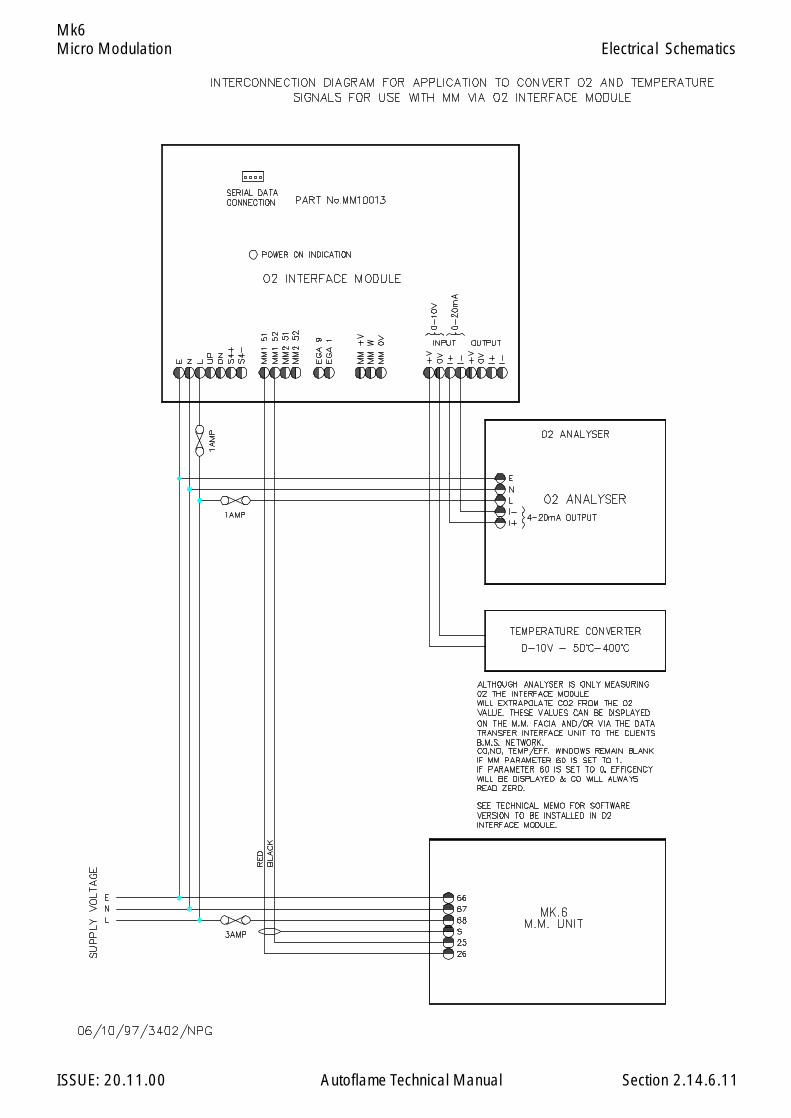
Micro Modulation
ISSUE: 20.11.00 Autoflame Technical Manual Section
Mk6
2.14.6.11
Electrical Schematics
Micro Modulation
ISSUE: 20.11.00 Autoflame Technical Manual Section
Mk6
2.14.7 TWIN BURNER OPERATION
2.14.7.1 Twin Burner Commissioning
Option numbers 14 and 33 have to be set to correctly implement twin burner operation. Refer to Optionsection. For commissioning purposes it is easiest to set option 14 on each M.M. to value 0, andcommission each burner individually. It is the commissioning engineer’s responsibility to ensure that noadverse effects are caused as a result of this. Particularly, stress to a boiler not designed to have only oneburner firing. If this is the case then both burners can be commissioned simultaneously. AFTERCOMMISSIONING SET OPTION 14 TO IT'S TWIN BURNER VALUE ON BOTH M.M.s
Note: On twin burner applications if Option 14 = 1 then the CR relays of each M.M. should be wiredin series. Also in the event of one of the burners locking out the controls circuit to the other burner mustbe opened.
Before commencing commissioning set the following Options: (Refer to Options Section for more details)
Option 33:
Set value of left hand burner to its appropriate Identification number e.g. 1. Set the right hand burnerto the Identification of the left hand burner +1 i.e. 2.
Option 33 will have to be interpreted if the boilers are numbered right to left. The details here are forleft to right numbering.
Other options may be set as usual.
Normal Operation:
Only the odd numbered M.M. needs an input on terminal 88 to make this boiler lead boiler. If aconnection is made to the even number M.M. it will be ignored. The same applies for the hand/auto/lowflame hold inputs 94, 95, i.e. they do not need any connection on the even number M.M. if Option 14= 1. If Option 14 = 2 then 94 and 95 should be wired as normal for hand operation.
The even number burner always takes its load index from the odd number burner including when in‘Hand’ mode. If communications between the two burners fail, each M.M. will open its CR relay andapproximately every three seconds the displays on each M.M. show ERR 100 to indicate communicationfailure if Option 14 = 1. If Option 14 = 2 then the 2 M.M.s run stand-alone.
When entering the flow metering for sequencing purposes it is necessary to put both M.M.s into the “FlowMetering” mode at the same time,
i.e. Start up both burners, wait until both are modulating then press and on oneof the M.M. units:
Twin Burner Operation
2.14.7.1.1
M.M.
123123 COM
Micro Modulation
ISSUE: 20.11.00 Autoflame Technical Manual Section
Mk6
Within 10 seconds press a n d on the other M.M.
Keep the firing rate of each burner similar when entering profile, i.e. do ‘point 1’ on each M.M. then‘point 2’ on each M.M. etc. This is important as the boiler may be susceptible to stress if one tube isfired at a different rate to the other. The required and actual values on the even numbered M.M. willmimic the values on the odd number M.M.
The CR1 relay of the even numbered M.M. follows the odd number M.M.
If Option 14 = 1 then the CR1 relay of both M.M.s will open if there is a period of more than 10 secondswhen one M.M. is modulating and the other is not.
One M.M. unit will remain at the low fire position until the other unit is at the low fire position beforeoutputting the low position interlock to the burner control box.
The load detector input in the even numbered M.M. can be left open circuit, it will not be error checked.
If an error condition arises on one or other of the M.M. units and Option 14 = 1 then the other unit willopen its CR1 relay and flash ERR 100.
2.14.7.1.2
M.M.
121212COM
Twin Burner Operation
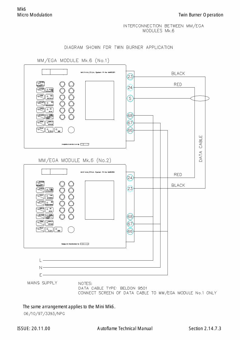
Micro Modulation
ISSUE: 20.11.00 Autoflame Technical Manual Section
Mk6
2.14.7.3
Twin Burner Operation
The same arrangement applies to the Mini Mk6.

Micro Modulation
ISSUE: 20.11.00 Autoflame Technical Manual Section
Mk6
Low Flame Hold and Hand Operation
‘Low Flame Hold’ and ‘Hand’ operation are only effective when the burner is firing. They have no effectwhen the burner is off or during the burner start up cycle. They are effected by applying a mains voltagesignal to terminal 95 for Low Flame Hold, or terminal 94 for Hand Operation. When these inputs haveno mains signals applied, the system modulates according to the PID control.
LFH is brought into operation if terminal 94 has a signal applied when the ignition part of the burner startup cycle takes place. The minimum flame position will be maintained from now on, until the signal from94 is removed. LFH will be established again by applying an input to 94 again. During LFH the PIDcontrol is obviously ignored.
‘Hand’ operation enables the fuel valve position to be set to a specific position, in the range of minimumto maximum flame. Once a position has been set it is recorded in the MM units memory. Each time theburner starts the fuel valve will be positioned to the ‘hand’ position set previously, even if the MM unithas been powered down. The MM system sets the fuel valve to the hand position whenever there is amains signal on terminal 95. Once the burner is firing the ‘hand’ position can be adjusted by switchingto the 'MM' screen and using the bottom row of buttons on the Mk6 facia.
See Option 60 for details on Bumpless Transfer.
If hand and low flame hold operations are selected at the same time, via inputs both on terminals 94and on 95, then low flame hold takes priority.
2.14.8 HAND/AUTO AND LOW FLAME HOLD FACILITIES
Hand/Auto & Low Flame Hold Facilities
2.14.8
Micro Modulation
ISSUE: 20.11.00 Autoflame Technical Manual Section
Mk6
2 .14.9 FAULT FINDING
WARNING ! ! ! !MAINS AND HIGHER VOLTAGES EXIST ON THE MM AND POSITIONING MOTORS.THE SYSTEM CONTROLS A COMBUSTION PROCESS.
Only competent personnel aware of the implications of the above warning should attempt fault finding.Personnel must be responsible for the conditions under which fault finding takes place. (e.g. isolation offuel supply)
Please Note: Personnel not familiar with the system should carry out tests in the order written.
The method of fault finding described is for a system that has been working correctly and has gonewrong. It is not for trouble shooting new systems which may for example have incorrect wiring. It alsowill not turn up faults which are a result of tampering.
Before commencing any fault finding:-
Set option 12 to 0Set option 9 to value 0 ( NOTE - only limit stat effective ) or ensure actual value is less that
required value sufficiently to energise CR relay.
The CR relay must be energised for the stat circuit to be made.
PRELIMINARY CHECK
If display is blank check for RUN led, if RUN led is also blank check mains supply to unit. Remove backcover of MM and check mains supply on 4 way terminal block. If supply to unit is good, remove supplyto unit and check fuse.
If unit is still blank it is likely there is a fault on the M.M.
Ensure there is no lockout condition.
Deselect fuelSelect fuel
Press before COM l.e.d. stops flashing (5 seconds).
Check stat circuit is made.
Refer to Section 2.14.3.1 for the burner start up sequence and timings. Follow these through to find apossible fault.
If using an external control box refer to the MiniMk5 section 2.3.
Fault Finding
2.14.9
COM

Micro Modulation
ISSUE: 20.11.00 Autoflame Technical Manual Section
Mk6
2.14.10.1
2.14.10 OTHER INFORMATION AND ILLUSTRATIONS
2.14.10.1 Mk6 MM Front Facia Details
Other Information and Illustrations

Micro Modulation
ISSUE: 20.11.00 Autoflame Technical Manual Section
Mk6
2.14.10.2
Other Information and Illustrations
The same arrangement applies to the Mini Mk6.
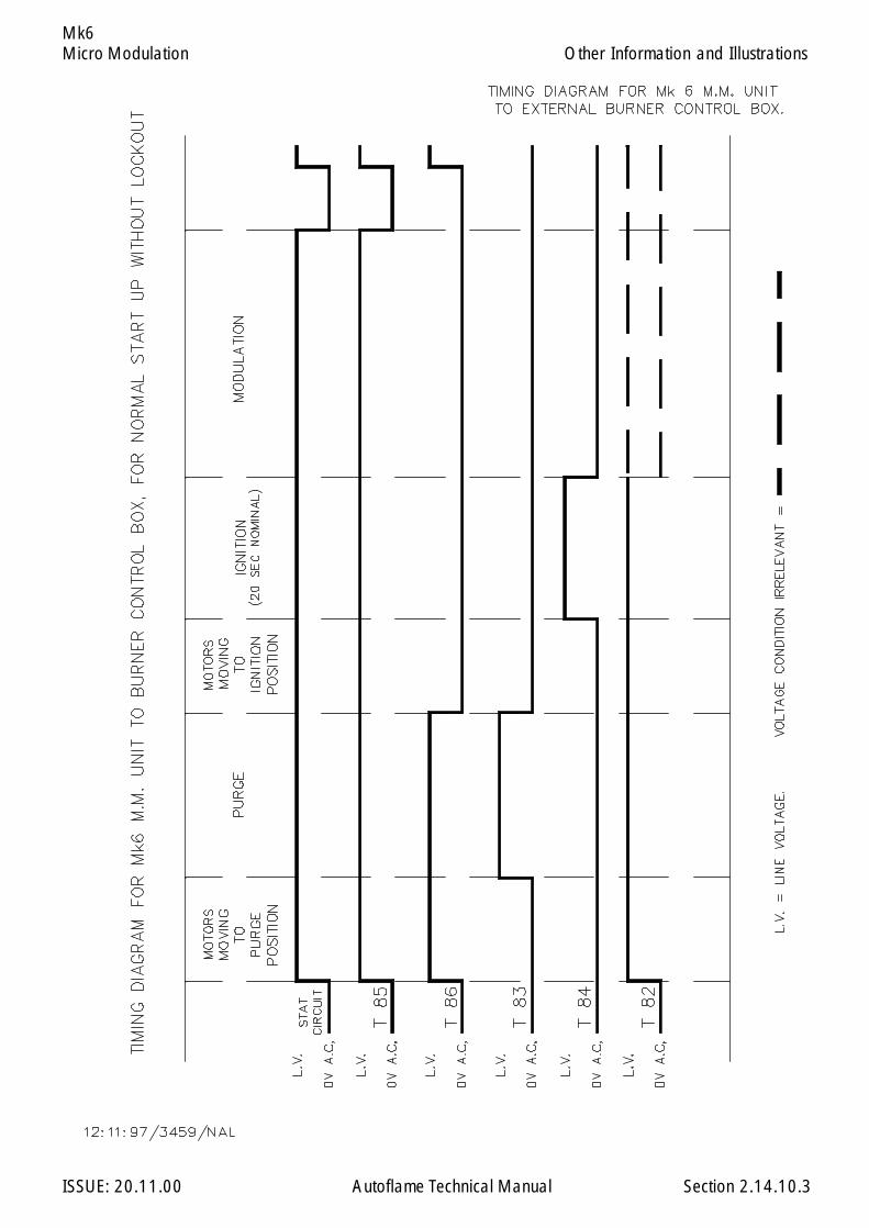
Micro Modulation
ISSUE: 20.11.00 Autoflame Technical Manual Section
Mk6
2.14.10.3
Other Information and Illustrations

Micro Modulation
ISSUE: 20.11.00 Autoflame Technical Manual Section
Mk6
Bottom View shown with lid in position.
2.14.10.4
Other Information and Illustrations
Mk.6 M.M. Fixing Holes & Dimensional Details

Micro Modulation
ISSUE: 20.11.00 Autoflame Technical Manual Section
Mk6
2.14.10.5
Other Information and Illustrations
Schematic View Of IR Upload Download
Software Installation
Insert diskette 1 into drive A: (your first floppy drive) and from Windows click on the Start button andchoose Run. Type A:\SETUP and press the enter key, then follow the instructions on the screen.
When SETUP has completed, insert the key diskette into drive A:, click on Start and choose Run. TypeA:\INSTALL and press enter.
The software need to be configured to the serial (COM) port that the IR lead is connected to. Thishappens the first time the Mk6 Upload/Download software is run.
WARNING
IT IS THE RESPONSIBILITY OF THE OPERATOR TO ENSURETHAT AFTER AN UPLOAD ALL THE OPTIONS, PARAMETERSAND FUEL/AIR RATIO COMMISSION DATA ARE CHECKEDFOR CORRECTNESS.

Micro Modulation
ISSUE: 20.11.00 Autoflame Technical Manual Section
Mk6
2.14.10.6 Maintenance and Servicing
The Micro Modulation Unit uses solid state technology. It requires no routine maintenance. If itdevelops a fault that it can diagnose and display it will do so.
The positioning motors/gas/oil valves also do not require routine maintenance. Any fault associatedwith these parts is usually diagnosed by the MM.
2.14.10.6
Other Information and Illustrations

Micro Modulation
ISSUE: 20.11.00 Autoflame Technical Manual Section
Mk6
2.14.10.7 Installation Precautions
The reliability of the equipment may be impaired if used in environments where strong electro magneticfields exist. If for example the equipment is installed in a boiler house at the top of a high rise buildingwhere radio systems exist then additional EMC (Electro Magnetic Compatability) measures may haveto be considered
2.14.10.7
Other Information and Illustrations

Micro Modulation
ISSUE: 20.11.00 Autoflame Technical Manual Section
Mk6
1. Go to Options, set Option 57 to 1 (default 0).
2. When the above is displayed press , this will initiate the Flow Metering setup mode.
3. Next time the burner starts the M.M. will go into the ten point setup mode for Flow Meteringautomatically.
4. In this mode the display will show fuel valve position in degrees angular and the flow units whichcan be adjusted by using the third row of buttons.
Note:
a) The CH4 window confirms to the commissioning engineer which of the 10 points are currentlybeing measured.
b) The minimum numerical value for fuel flow that can be entered into memory is 0.01.The maximum numerical value for fuel flow that can be entered into memory is 999.0
c) The values are entered in descending order, i.e. Point No.1 is maximum flame and PointNo.10 is at minimum flame. The 10 sequential point on the load index are a l l o c a t e dautomatically by the M.M. All values are in units/minute.
5. When fuel flow has been calculated or read off of a commissioning fuel flow meter the value isentered as detailed in Point No.4.
The button is then pressed and the value is logged in the M.M. memory.
6. The above detailed data entry routine is repeated until all 10 points have flow values allocated tothem.
7. When the last (10th) point has been entered the burner continues to fire.
8. To display Fuel Flow Metering press button.
9. To reset Totalising value to 0 (zero) set Option 57 to 2, press at that time.
Note: Fuel flow metering measurement now automatically starts totalling the amount of fuel used from themoment the main gas valves are energised. Previously this was counted from the ignition output and adelay time then had to be set via option 58. This option no longer applies with the Mk6 Evolution unlessan external flame safeguard is being used.
2.14.11 FUEL FLOW MEASUREMENT AND METERING OPERATION
Fuel Flow Measurement & Metering
2.14.11
ENTER
MEMORY
ENTER
MEMORY
FUELMETERING
123123123
ENTER
MEMORY

Micro Modulation
ISSUE: 20.11.00 Autoflame Technical Manual Section
Mk6Golden Start
2.14.12 GOLDEN START
This facility enables an ideal ignition/start position to be set into memory that is not necessarily lowflame or indeed part of the standard modulating load index.
To enable this facility to go to Option 29, set to 0 (zero), (Default value 1) and press .
To disable this facility go to Option 29, set to 1 and press
To implement the above, the system/burner is commissioned in the normal way, i.e. Press
enter Password, enter Close position, enter Open position, enter Start position and adjust Fuel/Airpositioning motors to give initial arbitrary ignition position. This position is not memorised. Theburner will fire and the start position LED will flash again.
Press , LED will remain stable, adjust Fuel/Air positioning motors to give the ideal
ignition/start up position.
Press and proceed with the commissioning routine in the normal way.
Notes:
1. The Golden Start/ignition position of the fuel and air positioning motors is completely independentfrom the modulating load index commissioned value data.
2. The facility is particularly useful on combustion systems with large turndowns and when firing heavyfuel oil, as it enables the burners to start/ignite at a fuel rich position and then, after a stable flameis established, to revert to the commissioned values for Fuel/Air ratio.
3. WARNING this facility is common to all fuels (F1, F2, F3 & F4). A value must be entered on eachprogrammed fuel.
4. The time that the M.M. holds the Golden Start position for is adjustable, see parameter 15.(default value is 5 seconds, range 0-255 seconds).
5. If the commissioning engineer wishes to change the Golden Start position retrospectively this canbe re-entered, without fully recommissioning the burner, in the following manner:
Go into Commission mode, enter Password, enter Closed and Open positions and enter, aspreviously described, to the point where High flashes then deselect fuel or power down. In this waythe new Golden Start position is entered.
6. It is important to appreciate that the Golden Start position is completely independent of the Fuel/Air paired values that are entered for the normal modulating load index/range.
2.14.12
ENTER
MEMORY
ENTER
MEMORY
COM
START
ENTER
MEMORY
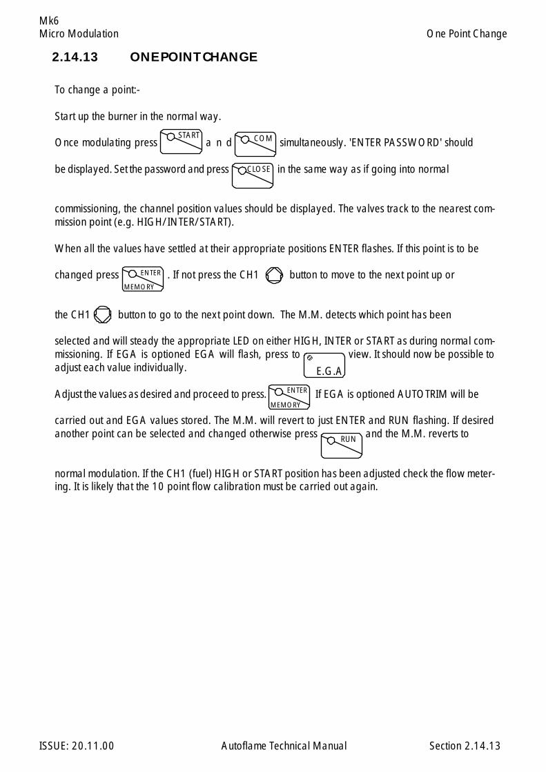
Micro Modulation
ISSUE: 20.11.00 Autoflame Technical Manual Section
Mk6
2.14.13 ONE POINT CHANGE
To change a point:-
Start up the burner in the normal way.
Once modulating press a n d simultaneously. 'ENTER PASSWORD' should
be displayed. Set the password and press in the same way as if going into normal
commissioning, the channel position values should be displayed. The valves track to the nearest com-mission point (e.g. HIGH/INTER/START).
When all the values have settled at their appropriate positions ENTER flashes. If this point is to be
changed press . If not press the CH1 button to move to the next point up or
the CH1 button to go to the next point down. The M.M. detects which point has been
selected and will steady the appropriate LED on either HIGH, INTER or START as during normal com-missioning. If EGA is optioned EGA will flash, press to view. It should now be possible toadjust each value individually.
Adjust the values as desired and proceed to press. If EGA is optioned AUTOTRIM will be
carried out and EGA values stored. The M.M. will revert to just ENTER and RUN flashing. If desiredanother point can be selected and changed otherwise press and the M.M. reverts to
normal modulation. If the CH1 (fuel) HIGH or START position has been adjusted check the flow meter-ing. It is likely that the 10 point flow calibration must be carried out again.
2.14.13
One Point Change
START COM
CLOSE
ENTER
MEMORY
ENTER
MEMORY
RUN
E.G.A
123123123
Micro Modulation
ISSUE: 20.11.00 Autoflame Technical Manual Section
Mk6
2.14.14 FLUE GAS RECIRCULATION
Flue Gas Recirculation (FGR) is a method whereby a quantity (approximately 15%) of the boilerflue gases are fed back to the burner and mixed with the combustion air. The virtue of FGR is thereduction of NOx gases. With the FGR facility, positioning motor channels 3 or 4 can be used tocontrol the amount of flue gas fed back. It is not good practice to feed back the gases when the fluegas is cold, so all the elements (ie positioning motors and AC drives) can be set at ‘FGR’ positionsuntil the gases are hot. During this time the element (CH3 or CH4) controlling the FGR would nor-mally be set closed. Once the gases are hot, modulation takes place in the normal way using thecurve entered during commissioning.
To ascertain if the gases are hot a number of options have been added:
Option 48A Time in seconds that the FGR positions are held for (once ignition has taken place) after
which modulation can take place.
Option 49An offset amount (eg 20) below the Required value (eg 100). This gives a threshold value
of 80 (100 – 20). The FGR positions are held until the Actual value has attained the thresholdvalue (80). Thereafter normal modulation can take place.
Option 50This is an enable/disable type option. If enabled an Exhaust Gas Analyser must be present
on the system. The FGR positions are held until the Exhaust Temperature value from the EGAreaches 120C. Thereafter normal modulation takes place.
2.14.14
Flue Gas Recirculation
Micro Modulation
ISSUE: 20.11.00 Autoflame Technical Manual Section
Mk6
2.14.15 PAUSE FACILITY
When the system is in commissioning mode only, a facility has been provided that enables acommissioning engineer to pause the ignition sequence of the burner. If the lockout button is pressedduring the first safety time the burner control will ‘pause’ at this position. This enables the commission-ing engineer to make adjustments to the start gas flame. If the flame goes out during this time alockout is set after 15 seconds. If the flame is present and the ‘pause’ condition is left indefinitely alockout will be set after 10 minutes. If the lockout button is pressed again the ignition sequencecontinues. While paused the lockout LED on the front fascia flashes. The ‘pause’ facility can also beactivated during the pilot prove and main flame prove phases. When the system is in a run mode thefacility is disabled.
WARNING
IT IS THE RESPONSIBILITY OF THE OPERATOR TO ENSURETHAT USE OF THE PAUSE FACILITY DOES NOT LEAD TO AHAZADOUS SITUATION.
2.14.15
Pause Facility
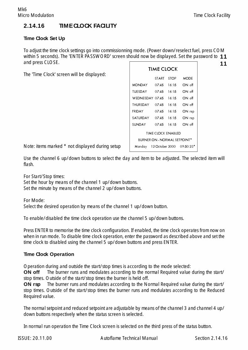
Micro Modulation
ISSUE: 20.11.00 Autoflame Technical Manual Section
Mk6
2.14.16 TIME CLOCK FACILITY
Time Clock Set Up
To adjust the time clock settings go into commissionning mode. (Power down/reselect fuel, press COMwithin 5 seconds). The 'ENTER PASSWORD' screen should now be displayed. Set the password toand press CLOSE.
The 'Time Clock' screen will be displayed:
Note: items marked * not displayed during setup
Use the channel 6 up/down buttons to select the day and item to be adjusted. The selected item willflash.
For Start/Stop times:Set the hour by means of the channel 1 up/down buttons.Set the minute by means of the channel 2 up/down buttons.
For Mode:Select the desired operation by means of the channel 1 up/down button.
To enable/disabled the time clock operation use the channel 5 up/down buttons.
Press ENTER to memorise the time clock configuration. If enabled, the time clock operates from now onwhen in run mode. To disable time clock operation, enter the password as described above and set thetime clock to disabled using the channel 5 up/down buttons and press ENTER.
Time Clock Operation
Operation during and outside the start/stop times is according to the mode selected:ON off The burner runs and modulates according to the normal Required value during the start/stop times. Outside of the start/stop times the burner is held off.ON rsp The burner runs and modulates according to the Normal Required value during the start/stop times. Outside of the start/stop times the burner runs and modulates according to the ReducedRequired value.
The normal setpoint and reduced setpoint are adjustable by means of the channel 3 and channel 4 up/down buttons respectively when the status screen is selected.
In normal run operation the Time Clock screen is selected on the third press of the status button.
2.14.16
Time Clock Facility
1111

Micro Modulation
ISSUE: 20.11.00 Autoflame Technical Manual Section
Mk6
2.14.18 AUTOMATIC COMMISSION OF GAS PRESSURE VALUES
A facility has been added to the Mk6 Evolution so that the gas pressure values (during VPS and for eachfuel/air ratio point entered) can be commissioned without having to carry out a full fuel air ratiocommission.
To invoke this facility the system must already be commissioned on fuel /air ratio. Option/parameter 150must be set to value 8 then the enter button pressed. Options/parameters 136/137 must be noted andset to 0-off so that gas pressure limit errors do not occur while the system is running.
Start up the system as normal. Once the burner is firing the system attains the high fire positions andsamples and stores the gas pressure at that point. The first fuel/air ratio inter positions are then attainedand the gas pressure again sampled and stored. This process is repeated until all fuel/air ratio inter andstart positions are complete. The new gas pressure values are then permanently stored and thereafter anMM ERROR is set - GAS RECOMMSSION. (This is to bring to the attention of the operator that Options/Parameters must be adjusted back to operational settings). The error must be cleared and option/parameter 150 set back to 0. If not set back to 0 the gas values will be commissioned again and the MMERROR will ensue. Options/parameters 136/137 must also be adjusted to their appropriate values.
THE OPERATOR MUST NOW CHECK THE SYSTEM FORCORRECT OPERATION.
Check the gas pressure commission value displayed during VPS operation. Once the burner is firing,check the gas pressure commission values for each fuel/air ratio point entered - this can be achieved bymeans of the hand operation facility.
Automatic Commission Of Gas Pressure Values
2.14.18
Micro Modulation
ISSUE: 20.11.00 Autoflame Technical Manual Section
Mk6
2.14.19 FLAME DETECTION USING EXTERNAL FLAME SWITCH
To configure operation with a flame switch Option/Parameter 122 must be set to 1.
The operation of terminals 85 and 86 must be as follows:
When the flame switch is indicating no flame, the voltage on Terminal 85 must be 0Vac.
When the flame switch is indicating the presence of a flame, the voltage on Terminal 85 must bemains voltage (110/230Vac).
Terminal 85 is the functional input for detecting the flame.
Terminal 86 is solely for the purpose of checking that terminal 85 is operating correctly. Terminal 86must seen to be the inverse of terminal 85.
If terminal 85 is at 0Vac, terminal 86 must be at mains voltage.
If terminal 85 is at mains voltage, terminal 86 must be at 0Vac.
If terminal 86 does not follow the inverse of terminal 85 the following lockout will occur - Terminal 86Inverse.
Flame Switch Configuration
Within the MM there is a latency of 250 milliseconds on the monitoring of terminal 85. To ensure a 1second overall flame failure response time, it is essential that the response time of the flame switch isset to no more than 750 milliseconds.
Flame switches often provide a volt free change over contact to indicate the flame status. Alterna-tively, they may provide a pair of `inverse’ outputs. If the flame switch only provides a single outputterminal, a relay will have to be installed between the flame switch and the MM to provide a set ofvolt free changeover contacts.
Flame Detection Using External Flame Switch
2.14.19
Micro Modulation
ISSUE: 20.11.00 Autoflame Technical Manual Section
MiniMk6
2.15.1 Mini Mk.6 M.M. Control Unit
2.15.2 Commissioning2.15.2.1 Options2.15.2.2 Parameters2.15.2.3 Fuel Flow Metering
2.15.3 End User Day to Day Operation2.15.3.1 Normal Run Operation2.15.3.2 Routine Adjustments2.15.3.3 EPROM Version Numbers
2.15.4 Other Information and Illustrations2.15.4.1 Mini Mk.6 M.M. Facia2.15.4.2 Schemaic Connection Diagram - 240V2.15.4.3 Schemaic Connection Diagram - 110V
2.15: Index
Section 2.15: Mini Mk6 M.M. Micro Modulation
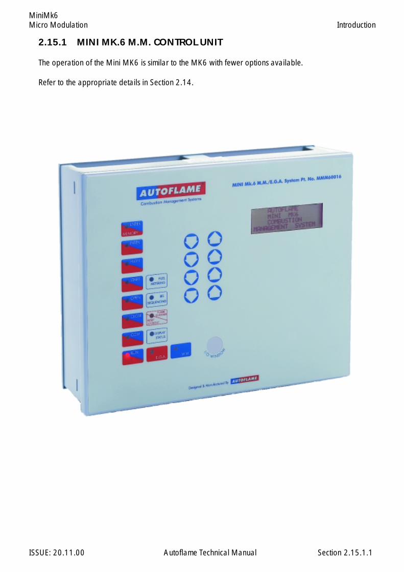
Micro Modulation
ISSUE: 20.11.00 Autoflame Technical Manual Section
MiniMk6
2.15.1 MINI MK.6 M.M. CONTROL UNIT
The operation of the Mini MK6 is similar to the MK6 with fewer options available.
Refer to the appropriate details in Section 2.14.
2.15.1.1
Introduction

Micro Modulation
ISSUE: 20.11.00 Autoflame Technical Manual Section
MiniMk6
2.15.2 MINI MK.6 COMMISSIONING
2.15.2.1 Options
To Select Options Mode.Ch1, Ch2, & Ch3 etc. refer to the rows of buttons respectively starting with CH1 at thetop.
Option values can be changed by entering the Option mode. The password must first be entered. Toenter the password follow the steps listed:
Either deselect and then select fuel or power down and then up
If system is already commissioned, press before the COM l.e.d. stops flashing
If system is not already commissioned, commissioning mode will be set automatically
The password screen is displayed:
Use the CH1 and CH2 buttons to set the Password codes. Then press
To select the Options screen, Press the Ch1 buttons simultaneously. The following screenshould be displayed:
Rows 2, 3 & 4 display textual descriptions of the option number and value
To change the Option number use the CH2 buttons
To change the value use CH3 buttons
Any number of Option values can be changed when in Option mode
When changes have been made press
All new Option values are then permanently stored
2.15.2.1.1
Commissioning: Options
ENTER
MEMORY
COM
CLOSE
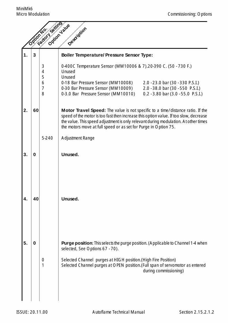
Micro Modulation
ISSUE: 20.11.00 Autoflame Technical Manual Section
MiniMk6
1. 3 Boiler Temperature/Pressure Sensor Type:
3 0-400C Temperature Sensor (MM10006 & 7).20-390 C. (50 - 730 F.)4 Unused5 Unused6 0-18 Bar Pressure Sensor (MM10008) 2.0 - 23.0 bar (30 - 330 P.S.I.)7 0-30 Bar Pressure Sensor (MM10009) 2.0 - 38.0 bar (30 - 550 P.S.I.)8 0-3.0 Bar Pressure Sensor (MM10010) 0.2 - 3.80 bar (3.0 - 55.0 P.S.I.)
2. 60 Motor Travel Speed: The value is not specific to a time/distance ratio. If thespeed of the motor is too fast then increase this option value. If too slow, decreasethe value. This speed adjustment is only relevant during modulation. At other timesthe motors move at full speed or as set for Purge in Option 75.
5-240 Adjustment Range
3. 0 Unused.
4. 40 Unused.
5. 0 Purge position: This selects the purge position. (Applicable to Channel 1-4 whenselected, See Options 67 - 70).
0 Selected Channel purges at HIGH position.(High Fire Position)1 Selected Channel purges at OPEN position.(Full span of servomotor as entered
during commissioning)
Option N
o.
Facto
ry Setti
ng
Option V
alue
Descrip
tion
2.15.2.1.2
Commissioning: Options

Micro Modulation
ISSUE: 20.11.00 Autoflame Technical Manual Section
MiniMk6
6. 10 P & I control: Options 6 and 7 are used for adjusting the proportional andintegral settings of the M.M.'s built in P + I + D controller. See Option 37 for thederivative adjustments.
Example of proportional band offset: Required value = 100 C, Proportionaloffset = 10 (i.e. Option 6 set to value 10).
Proportional band: Value entered - Centigrade, Fahrenheit, Bar or p.s.i.depending on type of control sensor and display units selected (refer Options 1,51 and 52).
5-50 For Centigrade, Fahrenheit and p.s.i. selections,0.5-5.0 If Bar is selected.
7. 60 Integral time: Every n seconds 10% of the present offset from setpoint value isadded or subtracted to the present proportional value. The value of n is set in thisoption. It is possible to set this Option to 'off'. If 'off' is selected there will be nointegral action control. (Integral is equivalent to 'Reset')
OFF-250 Seconds.
8. 1 Number of Servo Motor Channels to be enabled: Channel "1" is alwaysenabled (Fuel Position Motor). Set Option 8 to the number of additional channelsrequired (Minimum of 1) .
1 Channels 1-2 In use.2 Channels 1-3 In use.3 Channels 1-4 In use
Option N
o.Fa
ctory
Setting
Option V
alue
Descrip
tion
Minimum Flame
Maximum Flame
Proportional Offset
90 C(194 F)
100 C(212 F)
2.15.2.1.3
Commissioning: Options
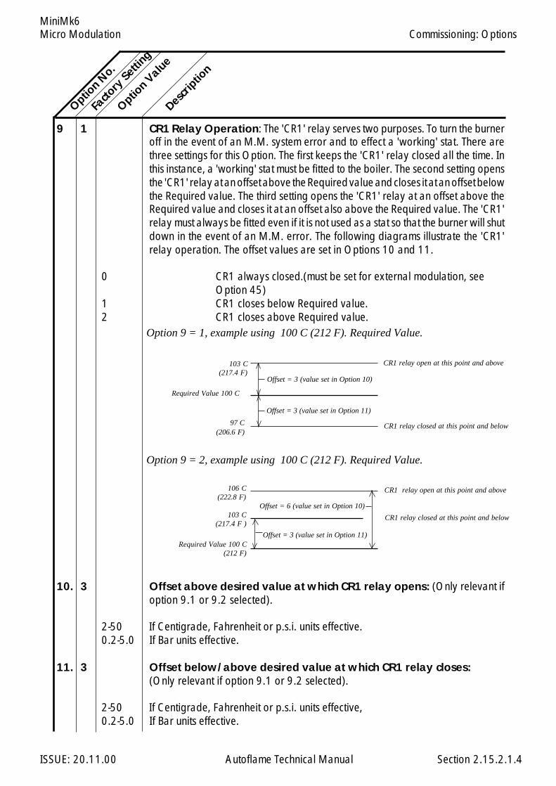
Micro Modulation
ISSUE: 20.11.00 Autoflame Technical Manual Section
MiniMk6
9 1 CR1 Relay Operation: The 'CR1' relay serves two purposes. To turn the burneroff in the event of an M.M. system error and to effect a 'working' stat. There arethree settings for this Option. The first keeps the 'CR1' relay closed all the time. Inthis instance, a 'working' stat must be fitted to the boiler. The second setting opensthe 'CR1' relay at an offset above the Required value and closes it at an offset belowthe Required value. The third setting opens the 'CR1' relay at an offset above theRequired value and closes it at an offset also above the Required value. The 'CR1'relay must always be fitted even if it is not used as a stat so that the burner will shutdown in the event of an M.M. error. The following diagrams illustrate the 'CR1'relay operation. The offset values are set in Options 10 and 11.
0 CR1 always closed.(must be set for external modulation, seeOption 45)
1 CR1 closes below Required value.2 CR1 closes above Required value.
10. 3 Offset above desired value at which CR1 relay opens: (Only relevant ifoption 9.1 or 9.2 selected).
2-50 If Centigrade, Fahrenheit or p.s.i. units effective.0.2-5.0 If Bar units effective.
11. 3 Offset below/above desired value at which CR1 relay closes:(Only relevant if option 9.1 or 9.2 selected).
2-50 If Centigrade, Fahrenheit or p.s.i. units effective,0.2-5.0 If Bar units effective.
Option N
o.
Facto
ry Setti
ng
Option V
alue
Descrip
tion
2.15.2.1.4
Commissioning: Options
Offset = 3 (value set in Option 11)
Option 9 = 2, example using 100 C (212 F). Required Value.
Option 9 = 1, example using 100 C (212 F). Required Value.
CR1 relay open at this point and above
Required Value 100 C
97 C(206.6 F)
103 C(217.4 F)
CR1 relay closed at this point and below
Required Value 100 C(212 F)
103 C(217.4 F )
106 C(222.8 F)
CR1 relay closed at this point and below
CR1 relay open at this point and above
Offset = 6 (value set in Option 10)
Offset = 3 (value set in Option 11)
Offset = 3 (value set in Option 10)
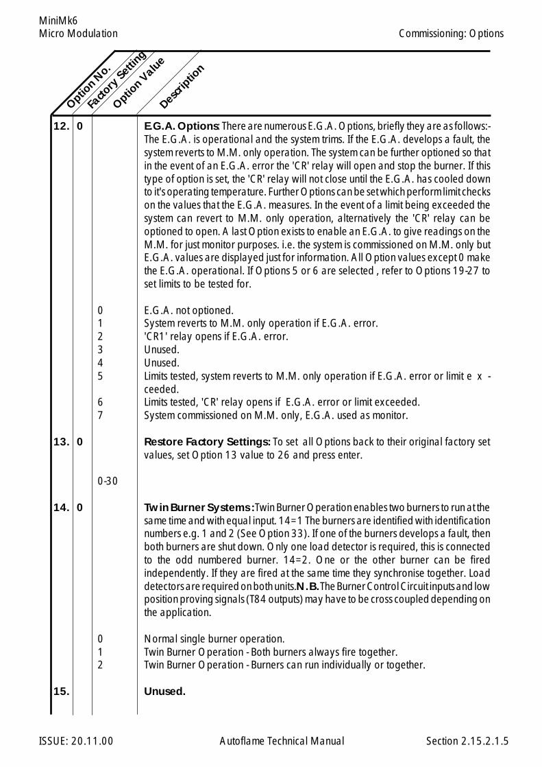
Micro Modulation
ISSUE: 20.11.00 Autoflame Technical Manual Section
MiniMk6
12. 0 E.G.A. Options: There are numerous E.G.A. Options, briefly they are as follows:-The E.G.A. is operational and the system trims. If the E.G.A. develops a fault, thesystem reverts to M.M. only operation. The system can be further optioned so thatin the event of an E.G.A. error the 'CR' relay will open and stop the burner. If thistype of option is set, the 'CR' relay will not close until the E.G.A. has cooled downto it's operating temperature. Further Options can be set which perform limit checkson the values that the E.G.A. measures. In the event of a limit being exceeded thesystem can revert to M.M. only operation, alternatively the 'CR' relay can beoptioned to open. A last Option exists to enable an E.G.A. to give readings on theM.M. for just monitor purposes. i.e. the system is commissioned on M.M. only butE.G.A. values are displayed just for information. All Option values except 0 makethe E.G.A. operational. If Options 5 or 6 are selected , refer to Options 19-27 toset limits to be tested for.
0 E.G.A. not optioned.1 System reverts to M.M. only operation if E.G.A. error.2 'CR1' relay opens if E.G.A. error.3 Unused.4 Unused.5 Limits tested, system reverts to M.M. only operation if E.G.A. error or limit e x -
ceeded.6 Limits tested, 'CR' relay opens if E.G.A. error or limit exceeded.7 System commissioned on M.M. only, E.G.A. used as monitor.
13. 0 Restore Factory Settings: To set all Options back to their original factory setvalues, set Option 13 value to 26 and press enter.
0-30
14. 0 Twin Burner Systems : Twin Burner Operation enables two burners to run at thesame time and with equal input. 14=1 The burners are identified with identificationnumbers e.g. 1 and 2 (See Option 33). If one of the burners develops a fault, thenboth burners are shut down. Only one load detector is required, this is connectedto the odd numbered burner. 14=2. One or the other burner can be firedindependently. If they are fired at the same time they synchronise together. Loaddetectors are required on both units. N.B. The Burner Control Circuit inputs and lowposition proving signals (T84 outputs) may have to be cross coupled depending onthe application.
0 Normal single burner operation.1 Twin Burner Operation - Both burners always fire together.2 Twin Burner Operation - Burners can run individually or together.
15. Unused.
Option N
o.
Facto
ry Setti
ng
Option V
alue
Descrip
tion
2.15.2.1.5
Commissioning: Options
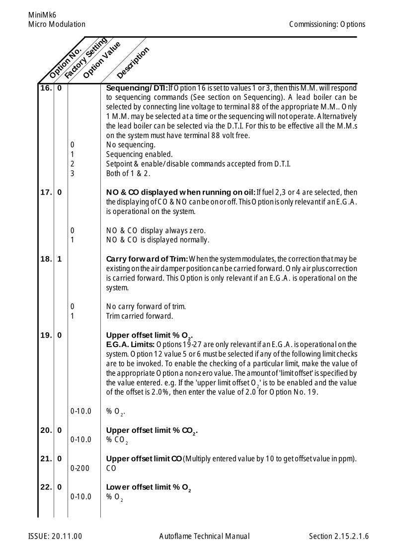
Micro Modulation
ISSUE: 20.11.00 Autoflame Technical Manual Section
MiniMk6
16. 0 Sequencing/DTI: If Option 16 is set to values 1 or 3, then this M.M. will respondto sequencing commands (See section on Sequencing). A lead boiler can beselected by connecting line voltage to terminal 88 of the appropriate M.M.. Only1 M.M. may be selected at a time or the sequencing will not operate. Alternativelythe lead boiler can be selected via the D.T.I. For this to be effective all the M.M.son the system must have terminal 88 volt free.
0 No sequencing.1 Sequencing enabled.2 Setpoint & enable/disable commands accepted from D.T.I.3 Both of 1 & 2.
17. 0 NO & CO displayed when running on oil: If fuel 2,3 or 4 are selected, thenthe displaying of CO & NO can be on or off. This Option is only relevant if an E.G.A.is operational on the system.
0 NO & CO display always zero.1 NO & CO is displayed normally.
18. 1 Carry forward of Trim: When the system modulates, the correction that may beexisting on the air damper position can be carried forward. Only air plus correctionis carried forward. This Option is only relevant if an E.G.A. is operational on thesystem.
0 No carry forward of trim.1 Trim carried forward.
19. 0 Upper offset limit % O2.E.G.A. Limits: Options 19-27 are only relevant if an E.G.A. is operational on thesystem. Option 12 value 5 or 6 must be selected if any of the following limit checksare to be invoked. To enable the checking of a particular limit, make the value ofthe appropriate Option a non-zero value. The amount of 'limit offset' is specified bythe value entered. e.g. If the 'upper limit offset O2' is to be enabled and the valueof the offset is 2.0%, then enter the value of 2.0 for Option No. 19.
0-10.0 % O2.
20. 0 Upper offset limit % CO2.0-10.0 % CO2
21. 0 Upper offset limit CO (Multiply entered value by 10 to get offset value in ppm).0-200 CO
22. 0 Lower offset limit % O2
0-10.0 % O2
Option N
o.
Facto
ry Setti
ng
Option V
alue
Descrip
tion
2.15.2.1.6
Commissioning: Options

Micro Modulation
ISSUE: 20.11.00 Autoflame Technical Manual Section
MiniMk6
23. 0 Lower offset limit % CO2
0-10.0 % CO2
24. Unused.
25. 0 Absolute value % O2 .(System checks for O2 values lower than value specifiedin this Option).
0-20.0 % O2
26. 0 Absolute value % CO2. (System checks for CO2 values higher than valuespecified in this Option).
0-20.0 % CO2
27. 0 Absolute value ppm CO. (Multiply value entered by 10 to get actual ppmvalue). System checks for CO readings higher than values specified in this Option.
0-200 CO ppm
28. 20 Trim threshold: This option is only relevant if an E.G.A. is operational on thesystem. The value set in this Option is subtracted from the operator set "Required"value. If the Actual value is less than the result then no Trim action will be effected.If the trim is to be effective all the time then set the value to zero. Must also be setto O for the EGA to operate when external modulation is optioned.
0-50 If Centigrade, Fahrenheit or p.s.i. units effective.0-5.0 If Bar units effective.
29. 1 Golden Start: NB. Must be entered on each fuel individually if more than onefuel is commissioned. Refer to section 2.14.12 for further details.
0 Golden Start operates.1 Golden Start does not operate.
30. 50 D.T.I. - Required Value Minimum Limit: If the system is being used with a D.T.I.a maximum and minimum limit for the Required value must be set. The M.M. willonly act on values within the limits set. If a value is received from the D.T.I., that isoutside these limits, it will be ignored and the system uses its previous Requiredvalue. Practical range is limited to range of sensor selected.
5-995 If Centigrade, Fahrenheit or p.s.i. units effective.0.5-99.5 If Bar units effective.
31. 100 Maximum Limit.
5-995 If Centigrade, Fahrenheit or p.s.i. units effective.0.5-99.5 If Bar units effective.
Option N
o.Fa
ctory
Setting
Option V
alue
Descrip
tion
2.15.2.1.7
Commissioning: Options

Micro Modulation
ISSUE: 20.11.00 Autoflame Technical Manual Section
MiniMk6
32. 20 Trim Delay: After ignition the sampling system does not sample for the period oftime set in this option. (Only relevant if E.G.A. is operational on system). This allowsfor the boiler to warm up and combustion to stabilise before sampling commences.
0-250 Period (seconds) after ignition no sampling takes place.
33. 1 MM Identification No. - Sequencing Options: If this M.M. is configured as partof a sequencing system and/or required to communicate with a D.T.I. then thefollowing three options must be set: The first is an identification number for thisM.M.. The second is the rating of the burner, and the third is the "sequencing scantime". Refer to Sequencing Section for further explanation.
1-10 Identification Number.
34. 5 Rating of burner
1-999 See option 77 for units.
35. 10 Sequence Scan Time. (minutes)
1-100 Sequence Scan time (Minutes).
36. 0 E.G.A. Sensor Selection: Available when using an E.G.A. System fitted withNO/SO2sensors. The following option is for selecting the type of Sensor required:Part No. EGA20005 for NO; EGA20006 for SO2.
SO2 NO0 Off Off1 Off On2 On Off3 On On
37. 0 Time Between ReadingsExplanation of D. (Derivative Action): The user adjustable control variablesto set up the D action are as detailed below. (Derivative is equivalent to 'Rate')
0 (0=off)1-200 Seconds. The time interval between the controller comparing Actual and Required
Setpoint values.
38. 2 Deadband. The Deadband is the margin above and below the Setpoint withinwhich no derivative control action occurs.
0-15 If Centigrade, Fahrenheit or PSI units optioned.0-1.5 If Bar units optioned.
Option N
o.Fa
ctory
Setting
Option V
alue
Descrip
tion
2.15.2.1.8
Commissioning: Options
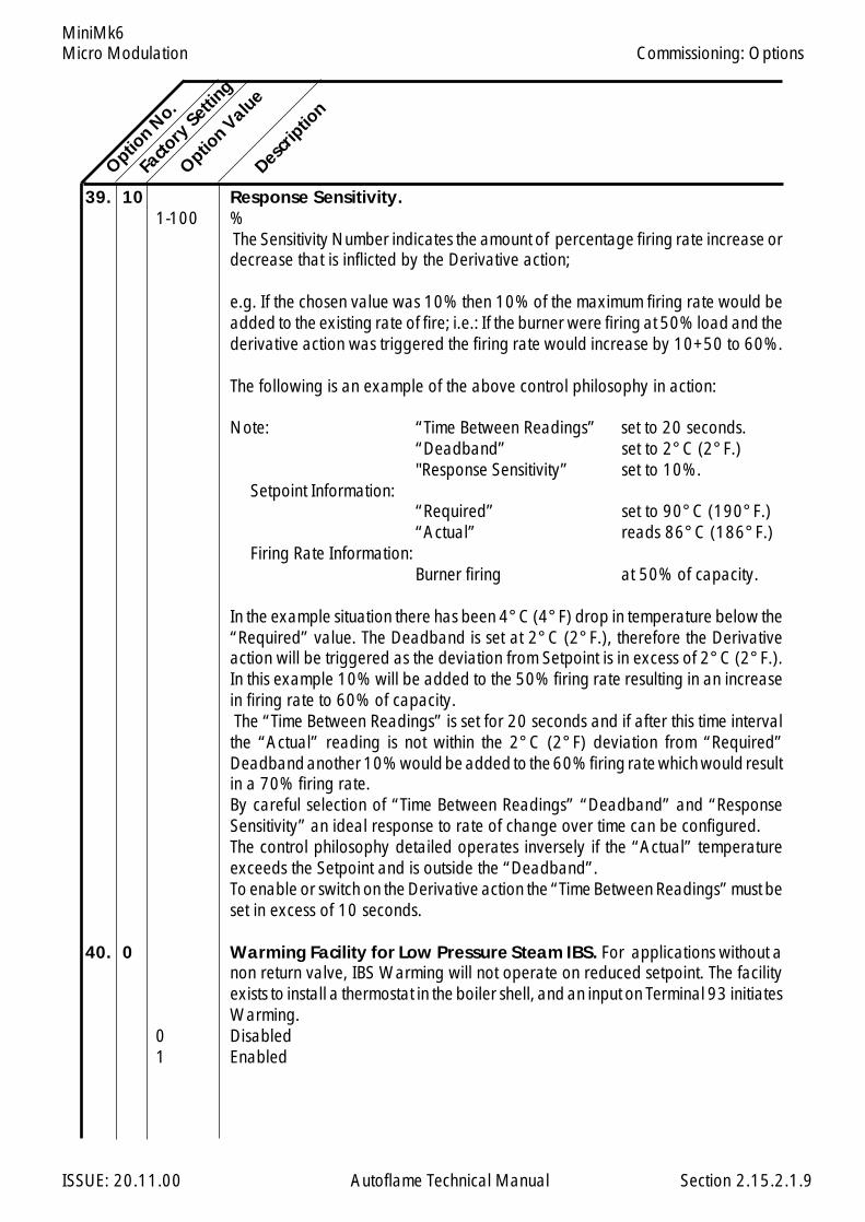
Micro Modulation
ISSUE: 20.11.00 Autoflame Technical Manual Section
MiniMk6
39. 10 Response Sensitivity.1-100 %
The Sensitivity Number indicates the amount of percentage firing rate increase ordecrease that is inflicted by the Derivative action;
e.g. If the chosen value was 10% then 10% of the maximum firing rate would beadded to the existing rate of fire; i.e.: If the burner were firing at 50% load and thederivative action was triggered the firing rate would increase by 10+50 to 60%.
The following is an example of the above control philosophy in action:
Note: “Time Between Readings” set to 20 seconds.“Deadband” set to 2°C (2°F.)"Response Sensitivity” set to 10%.
Setpoint Information:“Required” set to 90°C (190°F.)“Actual” reads 86°C (186°F.)
Firing Rate Information:Burner firing at 50% of capacity.
In the example situation there has been 4°C (4°F) drop in temperature below the“Required” value. The Deadband is set at 2°C (2°F.), therefore the Derivativeaction will be triggered as the deviation from Setpoint is in excess of 2°C (2°F.).In this example 10% will be added to the 50% firing rate resulting in an increasein firing rate to 60% of capacity. The “Time Between Readings” is set for 20 seconds and if after this time intervalthe “Actual” reading is not within the 2°C (2°F) deviation from “Required”Deadband another 10% would be added to the 60% firing rate which would resultin a 70% firing rate.By careful selection of “Time Between Readings” “Deadband” and “ResponseSensitivity” an ideal response to rate of change over time can be configured.The control philosophy detailed operates inversely if the “Actual” temperatureexceeds the Setpoint and is outside the “Deadband”.To enable or switch on the Derivative action the “Time Between Readings” must beset in excess of 10 seconds.
40. 0 Warming Facility for Low Pressure Steam IBS. For applications without anon return valve, IBS Warming will not operate on reduced setpoint. The facilityexists to install a thermostat in the boiler shell, and an input on Terminal 93 initiatesWarming.
0 Disabled1 Enabled
Option N
o.
Facto
ry Setti
ng
Option V
alue
Descrip
tion
2.15.2.1.9
Commissioning: Options
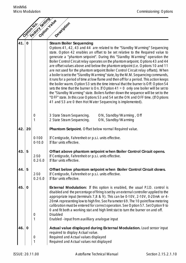
Micro Modulation
ISSUE: 20.11.00 Autoflame Technical Manual Section
MiniMk6
41. 0 Steam Boiler SequencingOptions 41, 42, 43 and 44 are related to the "Standby Warming" Sequencingstate. Option 42 enables an offset to be set relative to the Required value togenerate a "phantom setpoint". During this "Standby Warming" operation theBoiler Control Circuit relay operates on the phantom setpoint. Options 43 and 44are offset values above and below the phantom setpoint (i.e. Options 10 and 11are not used for the phantom setpoint Boiler Control Circuit relay offsets). Whena boiler is set to the "Standby Warming" state, by the M.M. Sequencing commands,it runs for a period of time at low flame and then off for a period. This action keepsthe boiler warm. Option 53 sets the time interval that the burner is Off: Option 54sets the time that the burner is On. If Option 41 = 0 only one boiler will be set tothe "Standby Warming" state. Boilers further down the sequence will be set to the"OFF" state. In this case Options 53 and 54 set the ON and OFF time. (If Options41 and 53 are 0 then Hot Water Sequencing is implemented).
0 3 State Steam Sequencing. ON, Standby/Warming , Off1 2 State Steam Sequencing. ON, Standby/Warming
42. 20 Phantom Setpoint. Offset below normal Required value.
0-100 If Centigrade, Fahrenheit or p.s.i. units effective.0-10.0 If Bar units effective.
43. 5 Offset above phantom setpoint when Boiler Control Circuit opens.2-50 If Centigrade, Fahrenheit or p.s.i. units effective.0.2-5.0 If Bar units effective.
44. 5 Offset below phantom setpoint when Boiler Control Circuit closes.2-50 If Centigrade, Fahrenheit or p.s.i. units effective.0.2-5.0 If Bar units effective.
45. 0 External Modulation: If this option is enabled, the usual P.I.D. control isdisabled and the percentage of firing is set by an external controller applied to theappropriate input (terminals 7,8 & 9). This can be 0-10V, 2-10V, 0-20mA or 4-20mA representing low to high fire. See Parameter 69. The 10 point flow meteringcalibration must be entered for correct operation. See Option 57. Set Option 9 to0 and fit both a working stat and high limit stat to turn the burner on and off.
0 Disabled1 Enabled - input from auxilliary analogue input
46. 0 Actual value displayed during External Modulation. Load sensor inputrequired to display Actual value.
0 Required and Actual values displayed1 Required and Actual values not displayed
Option N
o.
Facto
ry Setti
ng
Option V
alue
Descrip
tion
2.15.2.1.10
Commissioning: Options
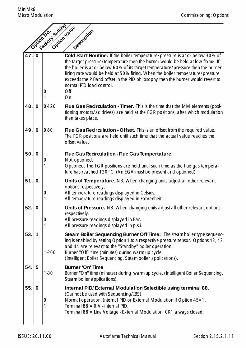
Micro Modulation
ISSUE: 20.11.00 Autoflame Technical Manual Section
MiniMk6
47. 0 Cold Start Routine. If the boiler temperature/pressure is at or below 30% ofthe target pressure/temperature then the burner would be held at low flame. Ifthe boiler is at or below 60% of its target temperature/pressure then the burnerfiring rate would be held at 50% firing. When the boiler temperature/pressureexceeds the P Band offset in the PID philosophy then the burner would revert tonormal PID load control.
0 Off1 On
48. 0 0-120 Flue Gas Recirculation - Timer. This is the time that the MM elements (posi-tioning motors/ac drives) are held at the FGR positions, after which modulationthen takes place.
49. 0 0-50 Flue Gas Recirculation - Offset. This is an offset from the required value.The FGR positions are held until such time that the actual value reaches theoffset value.
50. 0 Flue Gas Recirculation - Flue Gas Tempertature.0 Not optioned.1 Optioned. The FGR positions are held until such time as the flue gas tempera-
ture has reached 120°C. (An EGA must be present and optioned)..
51. 0 Units of Temperature. NB. When changing units adjust all other relevantoptions respectively.
0 All temperature readings displayed in Celsius.1 All temperature readings displayed in Fahrenheit.
52. 0 Units of Pressure. NB. When changing units adjust all other relevant optionsrespectively.
0 All pressure readings displayed in Bar.1 All pressure readings displayed in p.s.i.
53. 1 Steam Boiler Sequencing Burner Off Time: The steam boiler type sequenc-ing is enabled by setting Option 1 to a respective pressure sensor. Options 42, 43and 44 are relevant to the "Standby" boiler operation.
1-200 Burner "Off" time (minutes) during warm up cycle.(Intelligent Boiler Sequencing. Steam boiler applications).
54. 5 Burner 'On' Time1-30 Burner "On" time (minutes) during warm up cycle. (Intelligent Boiler Sequencing.
Steam boiler applications).
55. 0 Internal PID/External Modulation Selectible using terminal 88.(Cannot be used with Sequencing/IBS)
0 Normal operation, Internal PID or External Modulation if Option 45=1.1 Terminal 88 = 0 V - internal PID.
Terminal 88 = Line Voltage - External Modulation, CR1 always closed.
Option N
o.
Facto
ry Setti
ng
Option V
alue
Descrip
tion
2.15.2.1.11
Commissioning: Options
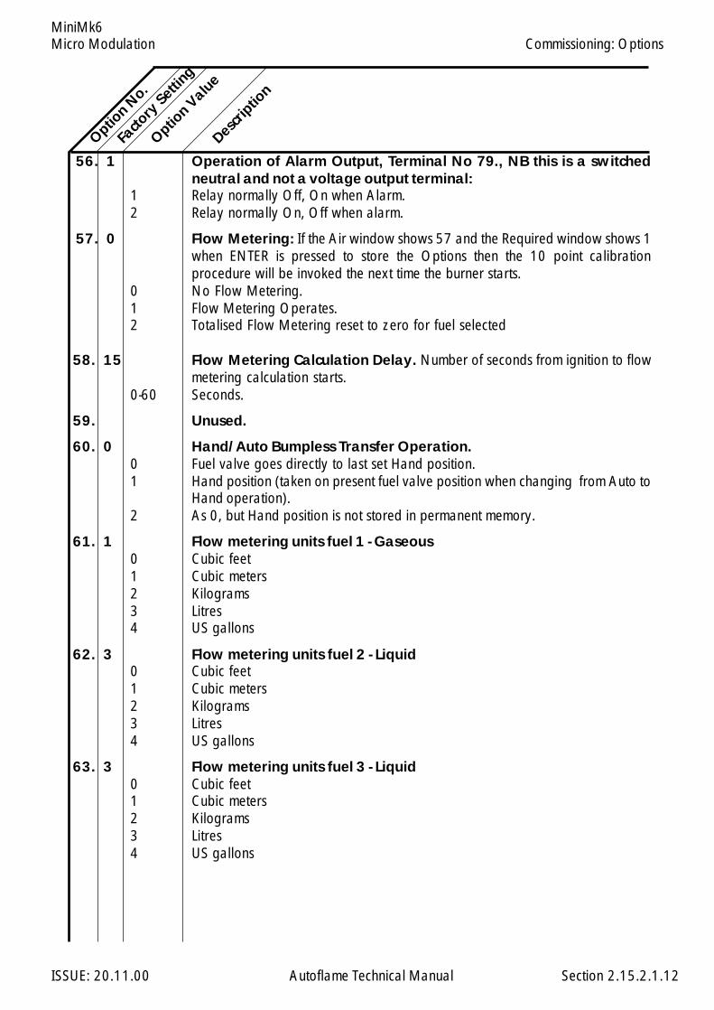
Micro Modulation
ISSUE: 20.11.00 Autoflame Technical Manual Section
MiniMk6
56. 1 Operation of Alarm Output, Terminal No 79., NB this is a switchedneutral and not a voltage output terminal:
1 Relay normally Off, On when Alarm.2 Relay normally On, Off when alarm.
57. 0 Flow Metering: If the Air window shows 57 and the Required window shows 1when ENTER is pressed to store the Options then the 10 point calibrationprocedure will be invoked the next time the burner starts.
0 No Flow Metering.1 Flow Metering Operates.2 Totalised Flow Metering reset to zero for fuel selected
58. 15 Flow Metering Calculation Delay. Number of seconds from ignition to flowmetering calculation starts.
0-60 Seconds.
59. Unused.
60. 0 Hand/Auto Bumpless Transfer Operation.0 Fuel valve goes directly to last set Hand position.1 Hand position (taken on present fuel valve position when changing from Auto to
Hand operation).2 As 0, but Hand position is not stored in permanent memory.
61. 1 Flow metering units fuel 1 - Gaseous0 Cubic feet1 Cubic meters2 Kilograms3 Litres4 US gallons
62. 3 Flow metering units fuel 2 - Liquid0 Cubic feet1 Cubic meters2 Kilograms3 Litres4 US gallons
63. 3 Flow metering units fuel 3 - Liquid0 Cubic feet1 Cubic meters2 Kilograms3 Litres4 US gallons
Option N
o.
Facto
ry Setti
ng
Option V
alue
Descrip
tion
2.15.2.1.12
Commissioning: Options
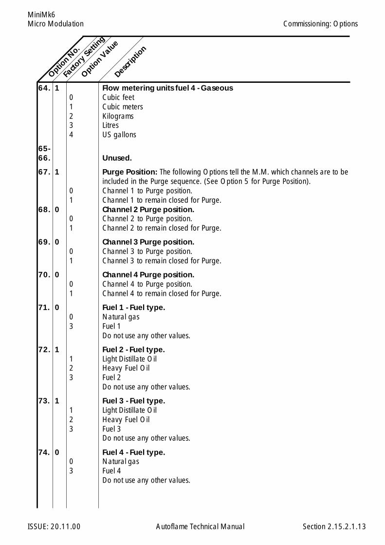
Micro Modulation
ISSUE: 20.11.00 Autoflame Technical Manual Section
MiniMk6
64. 1 Flow metering units fuel 4 - Gaseous0 Cubic feet1 Cubic meters2 Kilograms3 Litres4 US gallons
65-66. Unused.
67. 1 Purge Position: The following Options tell the M.M. which channels are to beincluded in the Purge sequence. (See Option 5 for Purge Position).
0 Channel 1 to Purge position.1 Channel 1 to remain closed for Purge.
68. 0 Channel 2 Purge position.0 Channel 2 to Purge position.1 Channel 2 to remain closed for Purge.
69. 0 Channel 3 Purge position.0 Channel 3 to Purge position.1 Channel 3 to remain closed for Purge.
70. 0 Channel 4 Purge position.0 Channel 4 to Purge position.1 Channel 4 to remain closed for Purge.
71. 0 Fuel 1 - Fuel type.0 Natural gas3 Fuel 1
Do not use any other values.
72. 1 Fuel 2 - Fuel type.1 Light Distillate Oil2 Heavy Fuel Oil3 Fuel 2
Do not use any other values.
73. 1 Fuel 3 - Fuel type.1 Light Distillate Oil2 Heavy Fuel Oil3 Fuel 3
Do not use any other values.
74. 0 Fuel 4 - Fuel type.0 Natural gas3 Fuel 4
Do not use any other values.
Option N
o.
Facto
ry Setti
ng
Option V
alue
Descrip
tion
2.15.2.1.13
Commissioning: Options
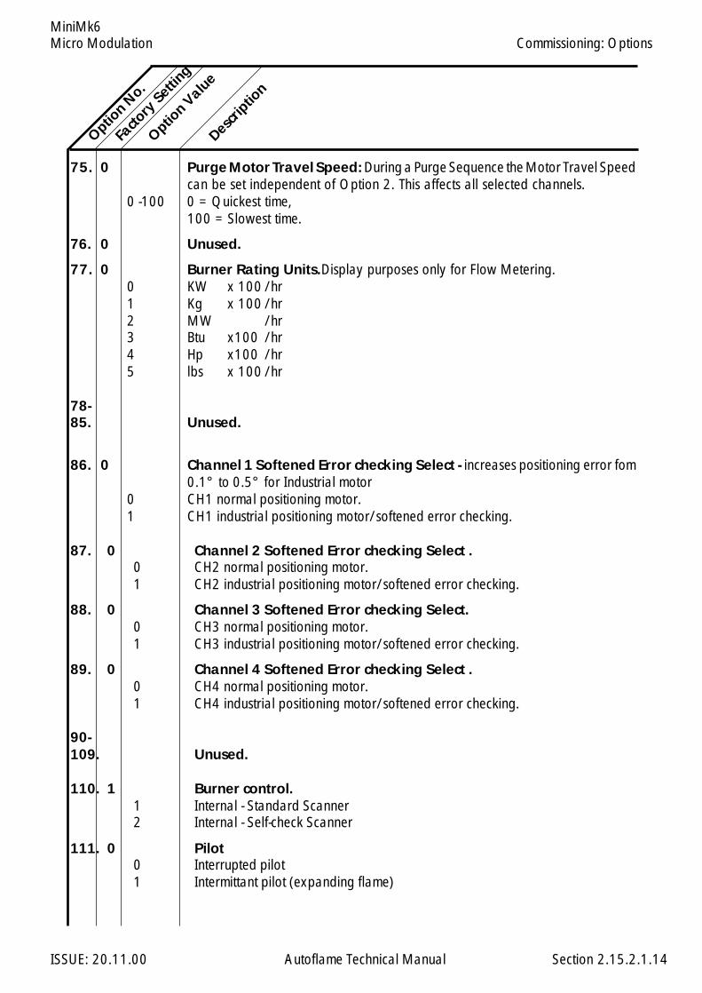
Micro Modulation
ISSUE: 20.11.00 Autoflame Technical Manual Section
MiniMk6
75. 0 Purge Motor Travel Speed: During a Purge Sequence the Motor Travel Speedcan be set independent of Option 2. This affects all selected channels.
0 -100 0 = Quickest time,100 = Slowest time.
76. 0 Unused.
77. 0 Burner Rating Units.Display purposes only for Flow Metering.0 KW x 100 /hr1 Kg x 100 /hr2 MW /hr3 Btu x100 /hr4 Hp x100 /hr5 lbs x 100 /hr
78-85. Unused.
86. 0 Channel 1 Softened Error checking Select - increases positioning error fom0.1° to 0.5° for Industrial motor
0 CH1 normal positioning motor.1 CH1 industrial positioning motor/softened error checking.
87. 0 Channel 2 Softened Error checking Select .0 CH2 normal positioning motor.1 CH2 industrial positioning motor/softened error checking.
88. 0 Channel 3 Softened Error checking Select.0 CH3 normal positioning motor.1 CH3 industrial positioning motor/softened error checking.
89. 0 Channel 4 Softened Error checking Select .0 CH4 normal positioning motor.1 CH4 industrial positioning motor/softened error checking.
90-109. Unused.
110. 1 Burner control.1 Internal - Standard Scanner2 Internal - Self-check Scanner
111. 0 Pilot0 Interrupted pilot1 Intermittant pilot (expanding flame)
Option N
o.
Facto
ry Setti
ng
Option V
alue
Descrip
tion
2.15.2.1.14
Commissioning: Options
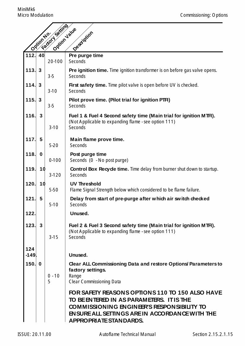
Micro Modulation
ISSUE: 20.11.00 Autoflame Technical Manual Section
MiniMk6
112. 40 Pre purge time20-100 Seconds
113. 3 Pre ignition time. Time ignition transformer is on before gas valve opens.3-5 Seconds
114. 3 First safety time. Time pilot valve is open before UV is checked.3-10 Seconds
115. 3 Pilot prove time. (Pilot trial for ignition PTFI)3-5 Seconds
116. 3 Fuel 1 & Fuel 4 Second safety time (Main trial for ignition MTFI).(Not Applicable to expanding flame - see option 111)
3-10 Seconds
117. 5 Main flame prove time.5-20 Seconds
118. 0 Post purge time0-100 Seconds (0 - No post purge)
119. 10 Control Box Recycle time. Time delay from burner shut down to startup.3-120 Seconds
120. 10 UV Threshold5-50 Flame Signal Strength below which considered to be flame failure.
121. 5 Delay from start of pre-purge after which air switch checked5-10 Seconds
122. Unused.
123. 3 Fuel 2 & Fuel 3 Second safety time (Main trial for ignition MTFI).(Not Applicable to expanding flame - see option 111)
3-15 Seconds
124-149. Unused.
150. 0 Clear ALL Commissioning Data and restore Options/Parameters tofactory settings.
0 - 10 Range5 Clear Commissioning Data
FOR SAFETY REASONS OPTIONS 110 TO 150 ALSO HAVETO BE ENTERED IN AS PARAMETERS. IT IS THECOMMISSIONING ENGINEER'S RESPONSIBILITY TOENSURE ALL SETTINGS ARE IN ACCORDANCE WITH THEAPPROPRIATE STANDARDS.
Option N
o.Fa
ctory
Setting
Option V
alue
Descrip
tion
2.15.2.1.15
Commissioning: Options
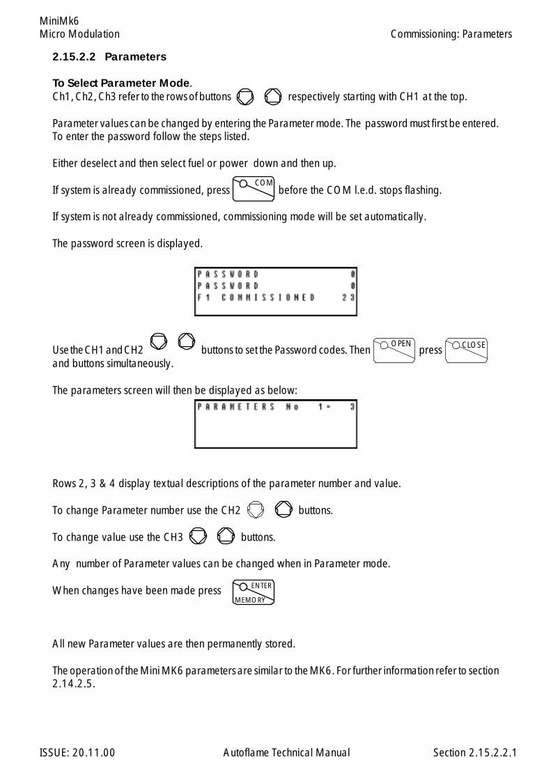
Micro Modulation
ISSUE: 20.11.00 Autoflame Technical Manual Section
MiniMk6
2.15.2.2 Parameters
To Select Parameter Mode.Ch1, Ch2, Ch3 refer to the rows of buttons respectively starting with CH1 at the top.
Parameter values can be changed by entering the Parameter mode. The password must first be entered.To enter the password follow the steps listed.
Either deselect and then select fuel or power down and then up.
If system is already commissioned, press before the COM l.e.d. stops flashing.
If system is not already commissioned, commissioning mode will be set automatically.
The password screen is displayed.
Use the CH1 and CH2 buttons to set the Password codes. Then pressand buttons simultaneously.
The parameters screen will then be displayed as below:
Rows 2, 3 & 4 display textual descriptions of the parameter number and value.
To change Parameter number use the CH2 buttons.
To change value use the CH3 buttons.
Any number of Parameter values can be changed when in Parameter mode.
When changes have been made press
All new Parameter values are then permanently stored.
The operation of the Mini MK6 parameters are similar to the MK6. For further information refer to section2.14.2.5.
COM
CLOSEOPEN
ENTER
MEMORY
Commissioning: Parameters
2.15.2.2.1

Micro Modulation
ISSUE: 20.11.00 Autoflame Technical Manual Section
MiniMk6
2.15.2.3 Fuel Flow Metering
1. Go to Options, set Option 57 to 1 (default 0).
2. When the above is displayed press , this will initiate the Flow Metering setup mode.
3. The next time the burner starts and reaches modulation, the M.M. will automatically go into the tenpoint setup mode for Flow Metering. The following screen will be displayed:
4. In this mode the display will show the channel 1 fuel valve position in degrees angular, and the flow
units which can be adjusted by using the third row of buttons.
Note:
a) The third row of text confirms to the commissioning engineer which of the 10 points arecurrently being measured.
b) The minimum numerical value for fuel flow that can be entered into memory is 0.01.The maximum numerical value for fuel flow that can be entered into memory is 999.99.
c) The values are entered in descending order, i.e. Point No.1 is maximum flame and PointNo.10 is at minimum flame. The 10 sequential points on the load index are allocatedautomatically by the M.M. All values are in units/minute.
5. When fuel flow has been calculated or read off of a commissioning fuel flow meter the value isentered as detailed in Point No.4.
T h e button is then pressed and the value is logged in the M.M. memory.
6. The above detailed data entry routine is repeated until all 10 points have flow values allocated tothem.
7. When the last (10th) point has been entered the burner continues to fire.
8. To display Fuel Flow Metering press button.
9. To reset the Totalised value to zero set Option 57 to 2, press while 57 and 2 are beingdisplayed.
10. To ensure maximum accuracy, Option 58 can be altered from its default value (15). This is thedelaytime from the flame failure control box starting the combustion sequence to the main flamebeing established. (This option is only of relevance when an external burner control is being used).
Commissioning: Fuel Flow Metering
ENTER
MEMORY
ENTER
MEMORY
FUELMETERING
123123123
ENTER
MEMORY
2.15.2.3.1
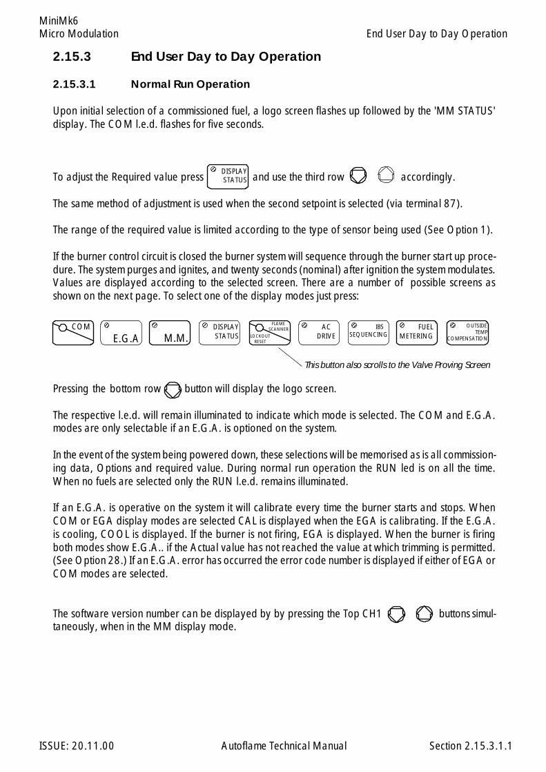
Micro Modulation
ISSUE: 20.11.00 Autoflame Technical Manual Section
MiniMk6
2.15.3 End User Day to Day Operation
2.15.3.1 Normal Run Operation
Upon initial selection of a commissioned fuel, a logo screen flashes up followed by the 'MM STATUS'display. The COM l.e.d. flashes for five seconds.
To adjust the Required value press and use the third row accordingly.
The same method of adjustment is used when the second setpoint is selected (via terminal 87).
The range of the required value is limited according to the type of sensor being used (See Option 1).
If the burner control circuit is closed the burner system will sequence through the burner start up proce-dure. The system purges and ignites, and twenty seconds (nominal) after ignition the system modulates.Values are displayed according to the selected screen. There are a number of possible screens asshown on the next page. To select one of the display modes just press:
Pressing the bottom row button will display the logo screen.
The respective l.e.d. will remain illuminated to indicate which mode is selected. The COM and E.G.A.modes are only selectable if an E.G.A. is optioned on the system.
In the event of the system being powered down, these selections will be memorised as is all commission-ing data, Options and required value. During normal run operation the RUN led is on all the time.When no fuels are selected only the RUN l.e.d. remains illuminated.
If an E.G.A. is operative on the system it will calibrate every time the burner starts and stops. WhenCOM or EGA display modes are selected CAL is displayed when the EGA is calibrating. If the E.G.A.is cooling, COOL is displayed. If the burner is not firing, EGA is displayed. When the burner is firingboth modes show E.G.A.. if the Actual value has not reached the value at which trimming is permitted.(See Option 28.) If an E.G.A. error has occurred the error code number is displayed if either of EGA orCOM modes are selected.
The software version number can be displayed by by pressing the Top CH1 buttons simul-taneously, when in the MM display mode.
End User Day to Day Operation
DISPLAYSTATUS
121212
COM
E.G.A
123123
M.M.
1212
DISPLAYSTATUS
123123
2.15.3.1.1
FLAMESCANNER
LOCKOUTRESET
ACDRIVE
123123
IBSSEQUENCING
123123
FUELMETERING
123123 OUTSIDE
TEMPCOMPENSATION
123123
This button also scrolls to the Valve Proving Screen

Micro Modulation
ISSUE: 20.11.00 Autoflame Technical Manual Section
MiniMk6
Several different displays are available to provide the operator with information through start-up andnormal operation.
Selectable screens provide the following information:
2.15.3.1.2
End User Day to Day Operation
Startup/Fuel Select
Displayed at startup and when no fuel selected.
M.M. Status
Shows the angular value for each of the positioning motors,channels 1 to 4. The bottom row displays additional statusinformation, including Low Flame Hold, Hand Operation,Golden Start, FGR Start.
IBS Status
For a multi boiler installation, this screen shows which is thelead boiler plus information on temperature and pressure setpoints.
EGA On Line Values
When an Exhaust Gas Analyser (EGA) is included in the sys-tem, this screen shows the actual values of the gases beingmeasured in the flue plus the exhaust gas temperature, ambi-ent temperature, dT, and efficiency. A similar screen shows thecommissioned values.
Lockout History
Upto the last 16 lockouts are displayed here. Details includetime and date of lockout and reset, the cause of the lockoutand at what stage of the sequence the lockout occured. Onlyone lockout record can be displayed at a time. Press the flamescanner button to scroll through the records.
Fuel Metering Status
This screen displays which fuel is currently selected, the con-sumption at this point in time and the total fuel used to date.
System Status
This screen shows the present firing rate, which fuel is beingused, and the required/actual values.
History
The hours run and the number of startups for the currently se-lected fuel are displayed on this screen. The screen is selectedby pressing the display status button.
Burner Control Status / Time
Row 1 indicates the burner sequence state, row 2 gives theflame signal strength.
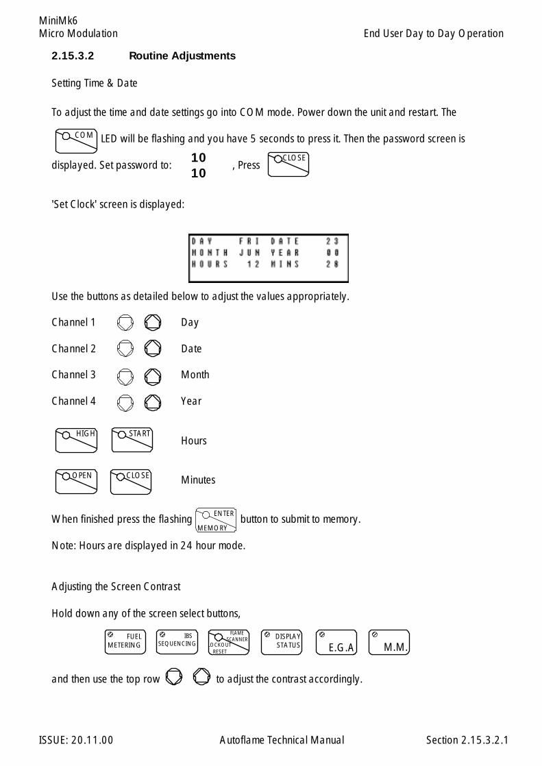
Micro Modulation
ISSUE: 20.11.00 Autoflame Technical Manual Section
MiniMk6
2.15.3.2.1
End User Day to Day Operation
2.15.3.2 Routine Adjustments
Setting Time & Date
To adjust the time and date settings go into COM mode. Power down the unit and restart. The
LED will be flashing and you have 5 seconds to press it. Then the password screen is
displayed. Set password to: , Press
'Set Clock' screen is displayed:
Use the buttons as detailed below to adjust the values appropriately.
Channel 1 Day
Channel 2 Date
Channel 3 Month
Channel 4 Year
Hours
Minutes
When finished press the flashing button to submit to memory.
Note: Hours are displayed in 24 hour mode.
Adjusting the Screen Contrast
Hold down any of the screen select buttons,
and then use the top row to adjust the contrast accordingly.
COM
1010
ENTER
MEMORY
CLOSE
DISPLAYSTATUS
1212
M.M.
123123
E.G.A
1212
FUELMETERING
1212 IBS
SEQUENCING
1212 FLAME
SCANNERLOCKOUT
RESET
HIGH START
OPEN CLOSE

Micro Modulation
ISSUE: 20.11.00 Autoflame Technical Manual Section
MiniMk6
Calibrating Actual Pressure Reading
A facility exists to adjust small errors in the pressure value displayed in the Actual window.
To increase the value press and the Ch3 simultaneously.
To decrease press and the CH3 . The facility does not work on temperature.
RUN
RUN
2.15.3.2.2
End User Day to Day Operation

Micro Modulation
ISSUE: 20.11.00 Autoflame Technical Manual Section
MiniMk6
2.15.3.3.1
2.15.3.3 EPROM Version Numbers
To display the software version number select the MM Display screen, then press Channel 1 Up andDown simultaneously.
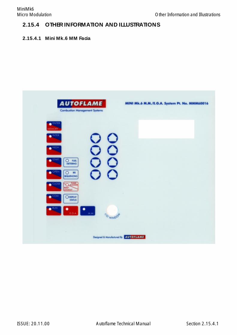
Micro Modulation
ISSUE: 20.11.00 Autoflame Technical Manual Section
MiniMk6Other Information and Illustrations
2.15.4 OTHER INFORMATION AND ILLUSTRATIONS
2.15.4.1 Mini Mk.6 MM Facia
2.15.4.1

Micro Modulation
ISSUE: 20.11.00 Autoflame Technical Manual Section
MiniMk6
2.15.4.2 Schematic Connection Diagram - 240V
2.15.4.2
Other Information and Illustrations

Micro Modulation
ISSUE: 20.11.00 Autoflame Technical Manual Section
MiniMk6
2.15.4.3
2.15.4.3 Schematic Connection Diagram -110V

E.G.A. Exhaust Gas Analysis
ISSUE: 20.11.00 Autoflame Technical Manual Section
Section 3: E.G.A. Exhaust Gas Analysis
3: Index
3.1 Introduction
3.1.1 Features and Benefits3.1.2 Overview of System Operation3.1.3 An inside View3.1.3.1 An inside view Schematic
3.2 Sensor Characteristics
3.2.1 O2 Sensor3.2.2 CO, NO and SO2 Sensors3.2.3 CO2 Sensor
3.3 Commissioning and Setting up Procedures
3.3.1 Introduction3.3.2 Programming of Fuel/Air Positions3.3.3 Combustion Trim Operation3.3.4 Trim Timing Operation3.3.5 Graphical Trim Operation3.3.6 Efficiency Calculation3.3.7 Programming the EGA Display Pod
3.4 Error Checking, Self Diagnostics
3.4.1 Keys to Errors Detected3.4.2 LED Status Indication
3.5 End user Day to Day Operation
3.5.1 Normal run Operation
3.6 Electrical Schematics Showing all Terminal Interconnections
3.6.1 Interconnections Between M.M and EGA Mk63.6.2 Interconnections Between MM, EGA and DTI
3.7 Test and Calibration
3.7.1 Approach to Testing & Calibrating on EGA Mk.6
3.8 EGA Setup Software Introduction
3.8.1 Software Possibilities
123456789012345678901234123456789012345678901234123456789012345678901234123456789012345678901234123456789012345678901234123456789012345678901234123456789012345678901234123456789012345678901234123456789012345678901234123456789012345678901234123456789012345678901234123456789012345678901234
E.G.A. Exhaust Gas Analysis
ISSUE: 20.11.00 Autoflame Technical Manual Section
Section 3: E.G.A. Exhaust Gas Analysis.
3.9 Using the Software (EGATOPC)
3.9.1 Calibrate Sensor (Replacing a Sensor)3.9.2 Status3.9.3 Options3.9.3.1 4-20mA outputs3.9.3.2 EGA Operating Mode3.9.3.3 Pinch Valve Control.3.9.3.4 System Configuration3.9.3.5 Test & Calibration Menu3.9.3.6 Return to Main Menu3.9.3.7 Quit
3.10 Limits on Three Measured Combustion Parameters:- O2 CO2 CO
3.10.1 Overview of System Operation Features & Benefits3.10.2 Example of Limits for O2
3.10.3 Example of Limits for CO2
3.10.4 Example of Limits for CO
3.11 EGA Dimensions & Fixing Details
3.12 Standard EGA Sampling Probe
3.12.1 Installation and Maintenance3.12.2 EGA Sampling Probe Assembly3.12.3 EGA Sampling Probe Assembled3.12.4 Maintenance of Sampling Probe3.12.5 Installation Precautions3.12.6 Servicing the Sampling Probe
3.13 Internal Tubing Diagram
3.14 EGA With Bubble Filter
3.15 High Temperature Probes
3.16 Shipping the EGA
3: Index
123456789012345678901234561234567890123456789012345612345678901234567890123456123456789012345678901234561234567890123456789012345612345678901234567890123456123456789012345678901234561234567890123456789012345612345678901234567890123456123456789012345678901234561234567890123456789012345612345678901234567890123456
1
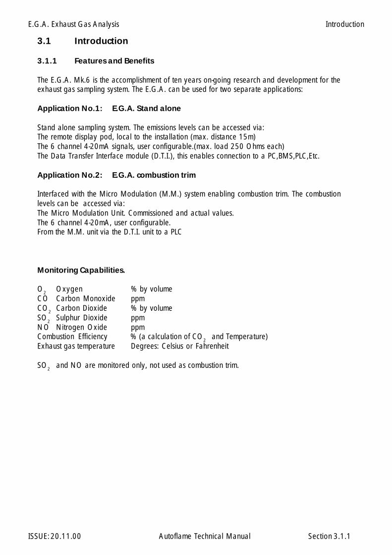
E.G.A. Exhaust Gas Analysis
ISSUE: 20.11.00 Autoflame Technical Manual Section
3.1 Introduction
3.1.1 Features and Benefits
The E.G.A. Mk.6 is the accomplishment of ten years on-going research and development for theexhaust gas sampling system. The E.G.A. can be used for two separate applications:
Application No.1: E.G.A. Stand alone
Stand alone sampling system. The emissions levels can be accessed via:The remote display pod, local to the installation (max. distance 15m)The 6 channel 4-20mA signals, user configurable.(max. load 250 Ohms each)The Data Transfer Interface module (D.T.I.), this enables connection to a PC,BMS,PLC,Etc.
Application No.2: E.G.A. combustion trim
Interfaced with the Micro Modulation (M.M.) system enabling combustion trim. The combustionlevels can be accessed via:The Micro Modulation Unit. Commissioned and actual values.The 6 channel 4-20mA, user configurable.From the M.M. unit via the D.T.I. unit to a PLC
Monitoring Capabilities.
O2 Oxygen % by volumeCO Carbon Monoxide ppmCO2 Carbon Dioxide % by volumeSO2 Sulphur Dioxide ppmNO Nitrogen Oxide ppmCombustion Efficiency % (a calculation of CO2 and Temperature)Exhaust gas temperature Degrees: Celsius or Fahrenheit
SO2 and NO are monitored only, not used as combustion trim.
3.1.1
Introduction
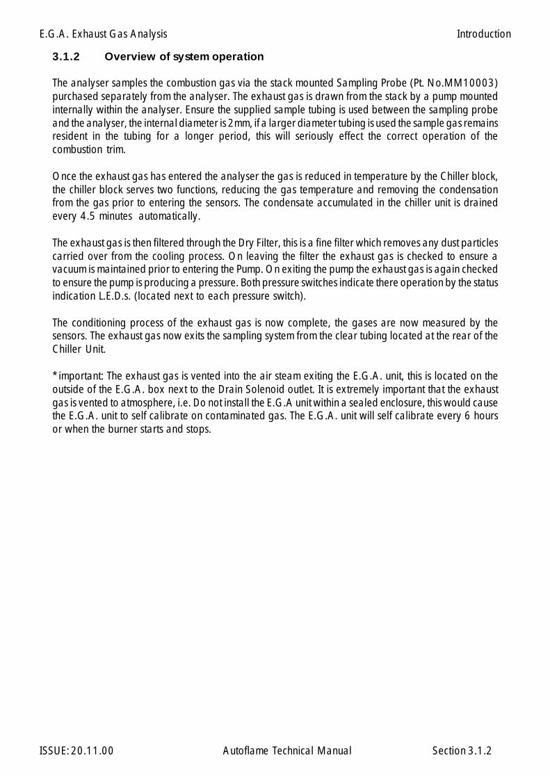
E.G.A. Exhaust Gas Analysis
ISSUE: 20.11.00 Autoflame Technical Manual Section
3.1.2 Overview of system operation
The analyser samples the combustion gas via the stack mounted Sampling Probe (Pt. No.MM10003)purchased separately from the analyser. The exhaust gas is drawn from the stack by a pump mountedinternally within the analyser. Ensure the supplied sample tubing is used between the sampling probeand the analyser, the internal diameter is 2mm, if a larger diameter tubing is used the sample gas remainsresident in the tubing for a longer period, this will seriously effect the correct operation of thecombustion trim.
Once the exhaust gas has entered the analyser the gas is reduced in temperature by the Chiller block,the chiller block serves two functions, reducing the gas temperature and removing the condensationfrom the gas prior to entering the sensors. The condensate accumulated in the chiller unit is drainedevery 4.5 minutes automatically.
The exhaust gas is then filtered through the Dry Filter, this is a fine filter which removes any dust particlescarried over from the cooling process. On leaving the filter the exhaust gas is checked to ensure avacuum is maintained prior to entering the Pump. On exiting the pump the exhaust gas is again checkedto ensure the pump is producing a pressure. Both pressure switches indicate there operation by the statusindication L.E.D.s. (located next to each pressure switch).
The conditioning process of the exhaust gas is now complete, the gases are now measured by thesensors. The exhaust gas now exits the sampling system from the clear tubing located at the rear of theChiller Unit.
*important: The exhaust gas is vented into the air steam exiting the E.G.A. unit, this is located on theoutside of the E.G.A. box next to the Drain Solenoid outlet. It is extremely important that the exhaustgas is vented to atmosphere, i.e. Do not install the E.G.A unit within a sealed enclosure, this would causethe E.G.A. unit to self calibrate on contaminated gas. The E.G.A. unit will self calibrate every 6 hoursor when the burner starts and stops.
3.1.2
Introduction

E.G.A. Exhaust Gas Analysis
ISSUE: 20.11.00 Autoflame Technical Manual Section
Thermocouple I/P
Sample In FromE.G.A. Probe
Sample InletPinch Valve
NO Cell
CO/NO BypassPinch Valve
Pump
Data Port& 4-20mA
Outputs
PressureSwitch
FanVacuumSwitch
DrainSolenoid
MainsInput
Filter
ChillerBlock
L.E.D.Bank
(See Note)
Green O.K.Red Fault
PC Output(Via Lead)
Pt.No. DTI20018)
O² Cell
SO² Pump
CO² Cell
SO² Cell
SO²Pinch Valve
CO Cell
*Note*Green No.1 = O.K.Red No.2 = Fault or ServiceYellow No.s 3 to 8 = Service Period Indicators (1 LED extinguishes Every 2 Months)Mains Supply = 230V/110V Standard
3.1.3 EGA MK6 an Inside View (cover removed)
3.1.3
Introduction
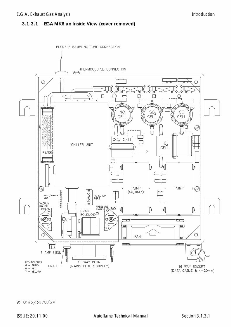
E.G.A. Exhaust Gas Analysis
ISSUE: 20.11.00 Autoflame Technical Manual Section
3.1.3.1 EGA MK6 an Inside View (cover removed)
3.1.3.1
Introduction
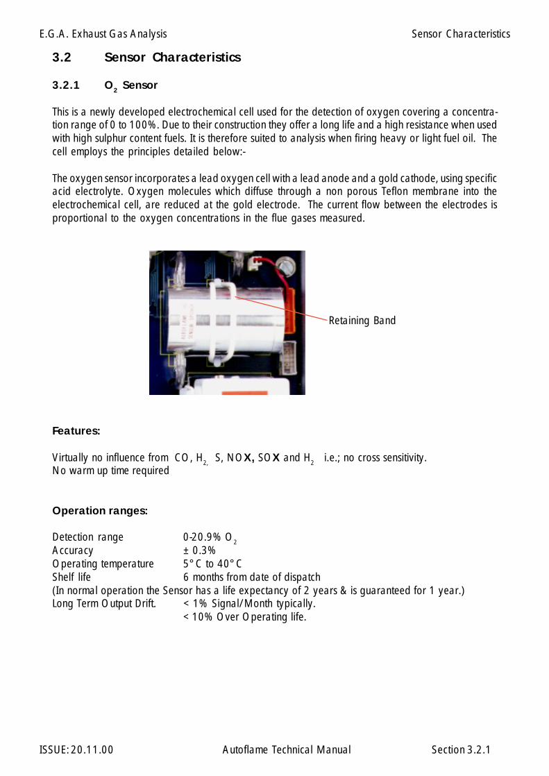
E.G.A. Exhaust Gas Analysis
ISSUE: 20.11.00 Autoflame Technical Manual Section 3.2.1
3.2 Sensor Characteristics
3.2.1 O2 Sensor
This is a newly developed electrochemical cell used for the detection of oxygen covering a concentra-tion range of 0 to 100%. Due to their construction they offer a long life and a high resistance when usedwith high sulphur content fuels. It is therefore suited to analysis when firing heavy or light fuel oil. Thecell employs the principles detailed below:-
The oxygen sensor incorporates a lead oxygen cell with a lead anode and a gold cathode, using specificacid electrolyte. Oxygen molecules which diffuse through a non porous Teflon membrane into theelectrochemical cell, are reduced at the gold electrode. The current flow between the electrodes isproportional to the oxygen concentrations in the flue gases measured.
Features:
Virtually no influence from CO, H2, S, NOX, SOX and H2 i.e.; no cross sensitivity.No warm up time required
Operation ranges:
Detection range 0-20.9% O2
Accuracy ± 0.3%Operating temperature 5°C to 40°CShelf life 6 months from date of dispatch(In normal operation the Sensor has a life expectancy of 2 years & is guaranteed for 1 year.)Long Term Output Drift. < 1% Signal/Month typically.
< 10% Over Operating life.
Retaining Band
Sensor Characteristics
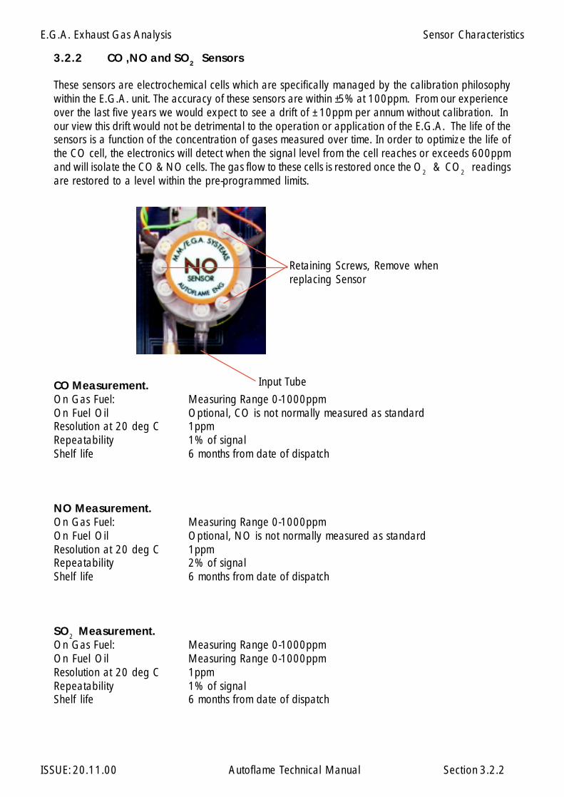
E.G.A. Exhaust Gas Analysis
ISSUE: 20.11.00 Autoflame Technical Manual Section 3.2.2
3.2.2 CO ,NO and SO2 Sensors
These sensors are electrochemical cells which are specifically managed by the calibration philosophywithin the E.G.A. unit. The accuracy of these sensors are within ±5% at 100ppm. From our experienceover the last five years we would expect to see a drift of ± 10ppm per annum without calibration. Inour view this drift would not be detrimental to the operation or application of the E.G.A. The life of thesensors is a function of the concentration of gases measured over time. In order to optimize the life ofthe CO cell, the electronics will detect when the signal level from the cell reaches or exceeds 600ppmand will isolate the CO & NO cells. The gas flow to these cells is restored once the O2 & CO2 readingsare restored to a level within the pre-programmed limits.
CO Measurement.On Gas Fuel: Measuring Range 0-1000ppmOn Fuel Oil Optional, CO is not normally measured as standardResolution at 20 deg C 1ppmRepeatability 1% of signalShelf life 6 months from date of dispatch
NO Measurement.On Gas Fuel: Measuring Range 0-1000ppmOn Fuel Oil Optional, NO is not normally measured as standardResolution at 20 deg C 1ppmRepeatability 2% of signalShelf life 6 months from date of dispatch
SO2 Measurement.On Gas Fuel: Measuring Range 0-1000ppmOn Fuel Oil Measuring Range 0-1000ppmResolution at 20 deg C 1ppmRepeatability 1% of signalShelf life 6 months from date of dispatch
Sensor Characteristics
Retaining Screws, Remove whenreplacing Sensor
Input Tube
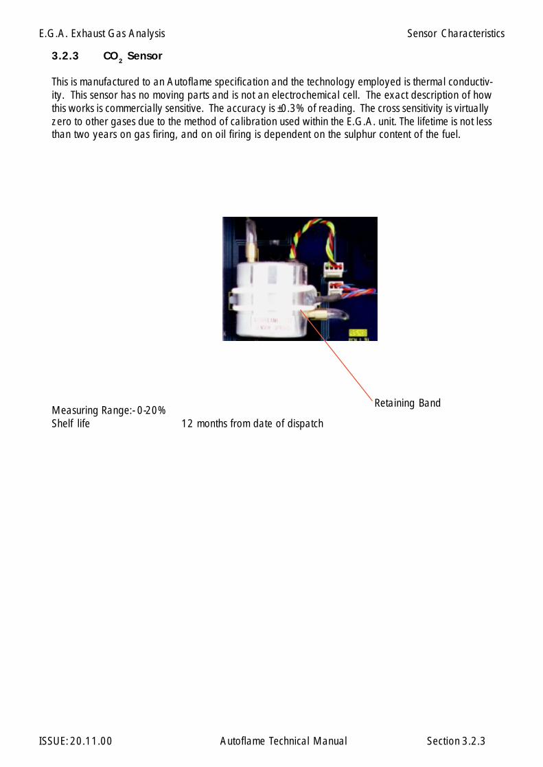
E.G.A. Exhaust Gas Analysis
ISSUE: 20.11.00 Autoflame Technical Manual Section 3.2.3
Retaining Band
3.2.3 CO2 Sensor
This is manufactured to an Autoflame specification and the technology employed is thermal conductiv-ity. This sensor has no moving parts and is not an electrochemical cell. The exact description of howthis works is commercially sensitive. The accuracy is ±0.3% of reading. The cross sensitivity is virtuallyzero to other gases due to the method of calibration used within the E.G.A. unit. The lifetime is not lessthan two years on gas firing, and on oil firing is dependent on the sulphur content of the fuel.
Measuring Range:- 0-20%Shelf life 12 months from date of dispatch
Sensor Characteristics
E.G.A. Exhaust Gas Analysis
ISSUE: 20.11.00 Autoflame Technical Manual Section
3.3 Commissioning and Setting up Procedures
3.3.1 Introduction
Commissioning with E.G.A. is an extension to commissioning with M.M. The operator must becompletely familiar with the commissioning of the M.M. unit before commissioning with E.G.A. Section2 of the Technical manual clearly explains commissioning with the M.M. unit.
The commissioning procedure as described must be strictly adhered to, anybody commissioning anM.M./E.G.A. system must have adequate understanding of combustion plant and be officially certifiedby Autoflame Eng. or their registered Distributors. In the wrong hands, hazardous conditions could bemade to exist.
The fundamental idea of the system is to set a fuel valve position and then set a corresponding air valveposition. Care must be taken when adjusting the fuel and air positions so as not to create any unstablecombustion conditions, e.g. moving the fuel valve to the open position without increasing the air valvecorrespondingly.
If the system being commissioned is an M.M. without E.G.A. then a combustion monitor is required tocheck the exhaust gases. If the system does have an E.G.A. then a combustion monitor should not benecessary as the E.G.A. performs all normal exhaust gas measurements. When burning oil a smokedetection device is necessary to check smoke generated is within government guide lines.
Ideally, to implement commissioning as quickly as possible arrange for a substantial load on the boiler.The commissioning procedure can be interrupted due to excess temperature or pressure, causing theburner to turn off. In these instances the commissioning data accumulated so far is not lost. When theburner is called back on the system starts up automatically and commissioning can proceed from whereit left off.
Once the burner has been fired the maximum fuel position is entered first then descending fuel positionsare entered consecutively until finally a minimum fuel position is entered. The CH1 and CH2 positionsmust always be less than he ones previously entered. However with CH3 - CH8 it is possible to movethe position above or below the previously entered points.
On a newly installed system the following procedures should be carried out as listed.1. Check all interconnecting wiring between the M.M. and external components are correct.2. Set Options required (Refer to Option Section).3. Set up positioning motors.4. Programme fuel/air positions.
3.3.1
Commissioning and Setting Up Procedures

E.G.A. Exhaust Gas Analysis
ISSUE: 20.11.00 Autoflame Technical Manual Section
3.3.2 Programming Fuel Air Positions (Systems with Exhaust Gas Analyser)
Note: Throughout the commissioning procedure the COM l.e.d. is illuminated.
1. Ensure 'stat' control circuit is closed.
2. Select fuel. CLOSE flashes. PAS is displayed in Actual display window.
Note: If fuel selected is being re-commissioned, press before COM l.e.d.stops flashing (five seconds).
3. Enter Access Code. Adjust the numbers in the CH1 and CH2 Position windows using therespective buttons.
When numbers are set, press (CLOSE l.e.d. steady, ENTER flashes. CH1 and CH2position windows indicate angular position of positioning motors.
4. Use CH1 and CH2 to set positioning motors to 0.0. Press(OPEN flashes).
5. Press (OPEN steady, ENTER MEMORY flashes).
6. Use CH1 and CH2 to set positioning motors to their fully open positions.This is nominally 90.0 for gas butterfly valves and burner air dampers.(EGA will now carry out a "CAL" Calibration for 2 minutes)
Press (System purges, at end of purge START flashes).
7. Press (START steady, ENTER MEMORY flashes).
8. Use CH1 and CH2 to set positioning motors to positions where ignitioncan take place.
9. Press (Burner ignites, HIGH flashes).
10. Press (HIGH steady, MM steady, E.G.A. flashes).
11. Use CH1 and CH2 to set maximum firing input (do not exceed OPENposition values).
12. Press E.G.A. (HIGH steady, EGA steady, MM flashes)
ENTER
MEMORY
OPEN
ENTER
MEMORY
START
ENTER
MEMORY
HIGH
COM
CLOSE
3.3.2
Commissioning and Setting Up Procedures
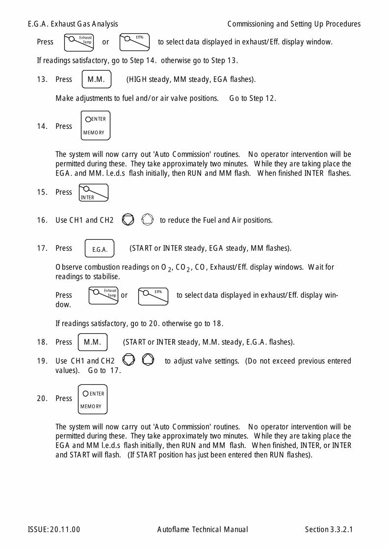
E.G.A. Exhaust Gas Analysis
ISSUE: 20.11.00 Autoflame Technical Manual Section
Press or to select data displayed in exhaust/Eff. display window.
If readings satisfactory, go to Step 14. otherwise go to Step 13.
13. Press M.M. (HIGH steady, MM steady, EGA flashes).
Make adjustments to fuel and/or air valve positions. Go to Step 12.
14. Press
The system will now carry out 'Auto Commission' routines. No operator intervention will bepermitted during these. They take approximately two minutes. While they are taking place theEGA. and MM. l.e.d.s flash initially, then RUN and MM flash. When finished INTER flashes.
15. Press
16. Use CH1 and CH2 to reduce the Fuel and Air positions.
17. Press (START or INTER steady, EGA steady, MM flashes).
Observe combustion readings on O , CO , CO, Exhaust/Eff. display windows. Wait forreadings to stabilise.
Press or to select data displayed in exhaust/Eff. display win-dow.
If readings satisfactory, go to 20. otherwise go to 18.
18. Press M.M. (START or INTER steady, M.M. steady, E.G.A. flashes).
19. Use CH1 and CH2 to adjust valve settings. (Do not exceed previous enteredvalues). Go to 17.
20. Press
The system will now carry out 'Auto Commission' routines. No operator intervention will bepermitted during these. They take approximately two minutes. While they are taking place theEGA and MM l.e.d.s flash initially, then RUN and MM flash. When finished, INTER, or INTERand START will flash. (If START position has just been entered then RUN flashes).
Exhaust Temp
Eff%
ENTER
MEMORY
INTER
E.G.A.
Eff%Exhaust Temp
MEMORY
ENTER
22
3.3.2.1
Commissioning and Setting Up Procedures

E.G.A. Exhaust Gas Analysis
ISSUE: 20.11.00 Autoflame Technical Manual Section
Note: Only INTER flashes if the number of INTER positions entered so far is less or equal to three,thereafter INTER and START flash.If the position just entered was the START position, go to 22. otherwise go to 21.
21. Press or (START or INTER steady, MM steady, EGA flashes).
Go to 16.
22. Press to set system into normal modulating mode.
23. If an EGA error occurs in commissioning mode, it cannot be reset using the "press close/openbutton". If the fault in the EGA can be cleared the error will reset automatically.
INTER START
RUN
3.3.2.2
Commissioning and Setting Up Procedures
E.G.A. Exhaust Gas Analysis
ISSUE: 20.11.00 Autoflame Technical Manual Section
3.3.3 E.G.A. combustion trim operation
With the E.G.A. trim facility it is possible to expand the M.M. so it will measure and display O2 , CO,CO2 and exhaust gas temperature, together with boiler temperature or Pressure. At the same time thesoftware within the M.M. unit will inflict minute corrections to the Channel 2 positions, Channel 2would normally be controlling the air damper but could alternatively be controlling a variable speeddrive. These minute changes ensure that the originally entered commissioning data is adhered to,irrespective of variations in stack pressure or barometric conditions.
The system trim function is achieved by every paired value for air and fuel having stored values for O2 , CO2 and CO at the commissioned value. Deviations from these ideal values are held andaccessible via the "COM" button on the MM facia when in E.G.A mode, this data is integrated andexpressed as a degree angular value, this ensures the exact amount of Channel 2 trim may be inflictedat any time to return the system to it’s commissioned value at any load condition.
The E.G.A. control strategy operates error checking self diagnostic software for self identification ofsystem component or data handling failure.
3.3.3
Commissioning and Setting Up Procedures
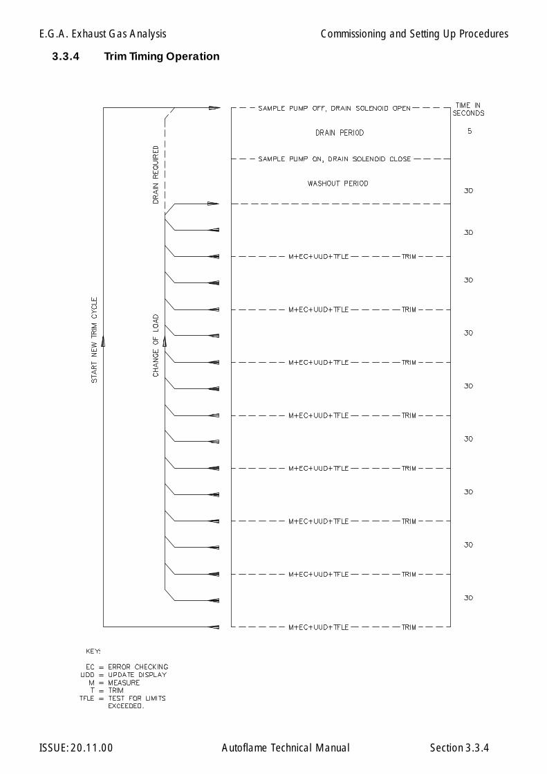
E.G.A. Exhaust Gas Analysis
ISSUE: 20.11.00 Autoflame Technical Manual Section
3.3.4 Trim Timing Operation
3.3.4
Commissioning and Setting Up Procedures
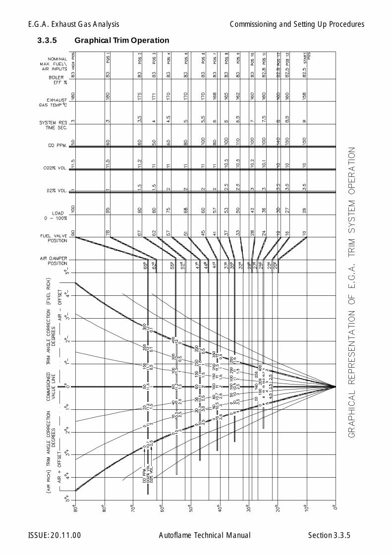
E.G.A. Exhaust Gas Analysis
ISSUE: 20.11.00 Autoflame Technical Manual Section 3.3.5
3.3.5 Graphical Trim Operation
Commissioning and Setting Up Procedures
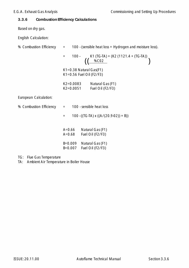
E.G.A. Exhaust Gas Analysis
ISSUE: 20.11.00 Autoflame Technical Manual Section 3.3.6
3.3.6 Combustion Efficiency Calculations
Based on dry gas.
English Calculation:
% Combustion Efficiency = 100 - (sensible heat loss + Hydrogen and moisture loss).
= 100 - K1 (TG-TA) + (K2 (1121.4 + (TG-TA)) %C02
K1=0.38 Natural Gas(F1)K1=0.56 Fuel Oil (F2/F3)
K2=0.0083 Natural Gas (F1)K2=0.0051 Fuel Oil (F2/F3)
European Calculation:
% Combustion Efficiency = 100 - sensible heat loss
= 100 - ((TG-TA) x ((A/(20.9-02)) + B))
A=0.66 Natural Gas (F1)A=0.68 Fuel Oil (F2/F3)
B=0.009 Natural Gas (F1)B=0.007 Fuel Oil (F2/F3)
TG: Flue Gas TemperatureTA: Ambient Air Temperature in Boiler House
(( )
Commissioning and Setting Up Procedures
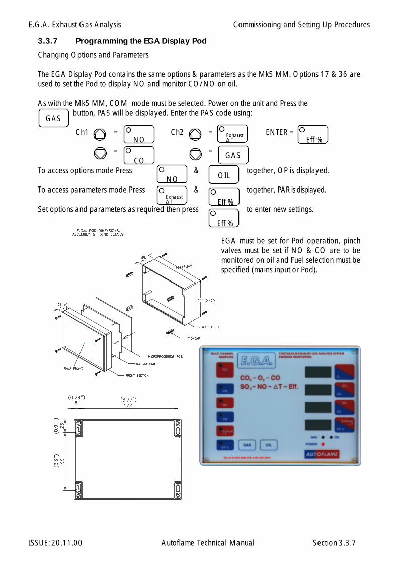
E.G.A. Exhaust Gas Analysis
ISSUE: 20.11.00 Autoflame Technical Manual Section 3.3.7
EGA must be set for Pod operation, pinchvalves must be set if NO & CO are to bemonitored on oil and Fuel selection must bespecified (mains input or Pod).
3.3.7 Programming the EGA Display Pod
Changing Options and Parameters
The EGA Display Pod contains the same options & parameters as the Mk5 MM. Options 17 & 36 areused to set the Pod to display NO and monitor CO/NO on oil.
As with the Mk5 MM, COM mode must be selected. Power on the unit and Press the button, PAS will be displayed. Enter the PAS code using:
Ch1 = Ch2 = ENTER =
= =
To access options mode Press & together, OP is displayed.
To access parameters mode Press & together, PAR is displayed.
Set options and parameters as required then press to enter new settings.
NO
CO
Exhaust∆ T
GAS
Eff %
NO OIL
Exhaust∆ T Eff %
Eff %
GAS
Commissioning and Setting Up Procedures
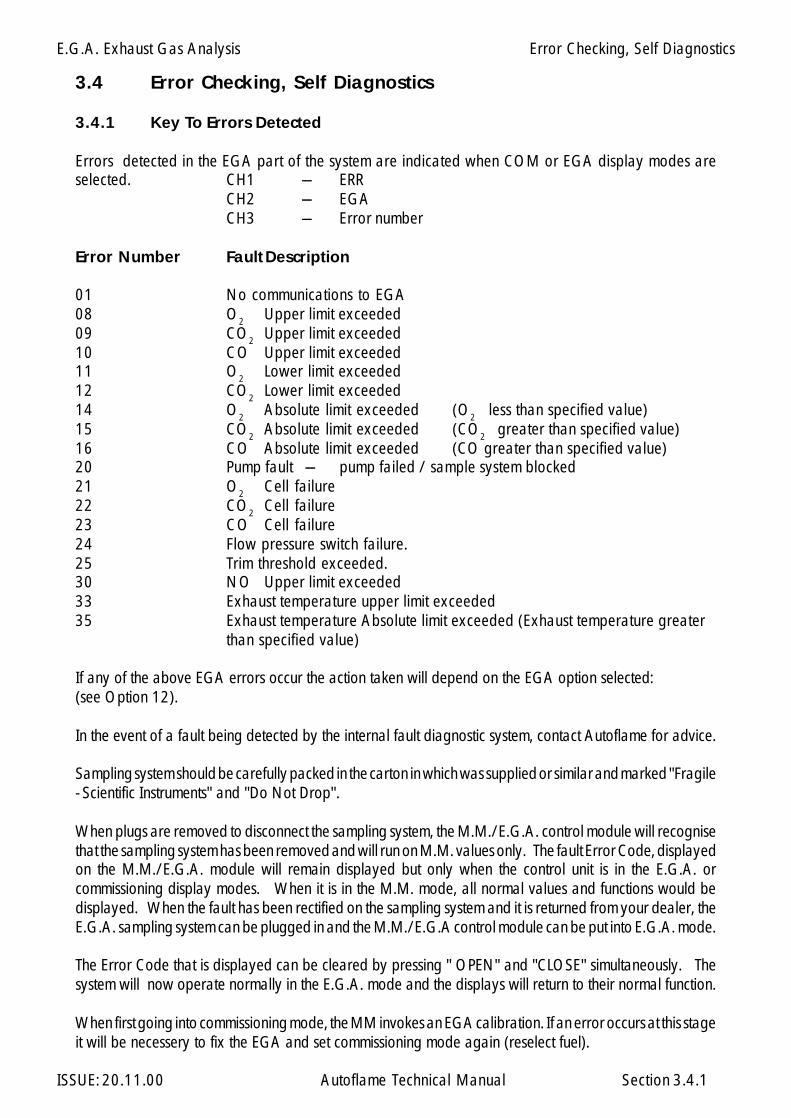
E.G.A. Exhaust Gas Analysis
ISSUE: 20.11.00 Autoflame Technical Manual Section
3.4 Error Checking, Self Diagnostics
3.4.1 Key To Errors Detected
Errors detected in the EGA part of the system are indicated when COM or EGA display modes areselected. CH1 --- ERR
CH2 --- EGACH3 --- Error number
Error Number Fault Description
01 No communications to EGA08 O2 Upper limit exceeded09 CO2 Upper limit exceeded10 CO Upper limit exceeded11 O2 Lower limit exceeded12 CO2 Lower limit exceeded14 O2 Absolute limit exceeded (O2 less than specified value)15 CO2 Absolute limit exceeded (CO2 greater than specified value)16 CO Absolute limit exceeded (CO greater than specified value)20 Pump fault --- pump failed / sample system blocked21 O2 Cell failure22 CO2 Cell failure23 CO Cell failure24 Flow pressure switch failure.25 Trim threshold exceeded.30 NO Upper limit exceeded33 Exhaust temperature upper limit exceeded35 Exhaust temperature Absolute limit exceeded (Exhaust temperature greater
than specified value)
If any of the above EGA errors occur the action taken will depend on the EGA option selected:(see Option 12).
In the event of a fault being detected by the internal fault diagnostic system, contact Autoflame for advice.
Sampling system should be carefully packed in the carton in which was supplied or similar and marked "Fragile- Scientific Instruments" and "Do Not Drop".
When plugs are removed to disconnect the sampling system, the M.M./E.G.A. control module will recognisethat the sampling system has been removed and will run on M.M. values only. The fault Error Code, displayedon the M.M./E.G.A. module will remain displayed but only when the control unit is in the E.G.A. orcommissioning display modes. When it is in the M.M. mode, all normal values and functions would bedisplayed. When the fault has been rectified on the sampling system and it is returned from your dealer, theE.G.A. sampling system can be plugged in and the M.M./E.G.A control module can be put into E.G.A. mode.
The Error Code that is displayed can be cleared by pressing " OPEN" and "CLOSE" simultaneously. Thesystem will now operate normally in the E.G.A. mode and the displays will return to their normal function.
When first going into commissioning mode, the MM invokes an EGA calibration. If an error occurs at this stageit will be necessery to fix the EGA and set commissioning mode again (reselect fuel).
3.4.1
Error Checking, Self Diagnostics
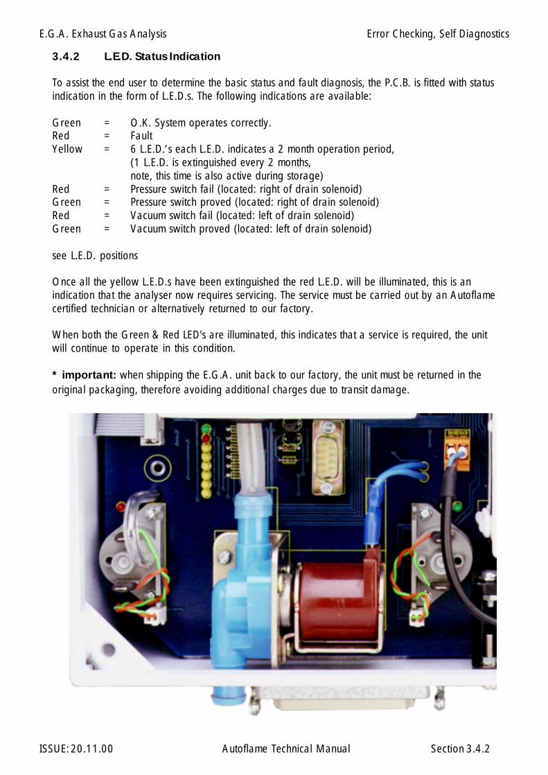
E.G.A. Exhaust Gas Analysis
ISSUE: 20.11.00 Autoflame Technical Manual Section
3.4.2 L.E.D. Status Indication
To assist the end user to determine the basic status and fault diagnosis, the P.C.B. is fitted with statusindication in the form of L.E.D.s. The following indications are available:
Green = O.K. System operates correctly.Red = FaultYellow = 6 L.E.D.’s each L.E.D. indicates a 2 month operation period,
(1 L.E.D. is extinguished every 2 months,note, this time is also active during storage)
Red = Pressure switch fail (located: right of drain solenoid)Green = Pressure switch proved (located: right of drain solenoid)Red = Vacuum switch fail (located: left of drain solenoid)Green = Vacuum switch proved (located: left of drain solenoid)
see L.E.D. positions
Once all the yellow L.E.D.s have been extinguished the red L.E.D. will be illuminated, this is anindication that the analyser now requires servicing. The service must be carried out by an Autoflamecertified technician or alternatively returned to our factory.
When both the Green & Red LED's are illuminated, this indicates that a service is required, the unitwill continue to operate in this condition.
* important: when shipping the E.G.A. unit back to our factory, the unit must be returned in theoriginal packaging, therefore avoiding additional charges due to transit damage.
3.4.2
Error Checking, Self Diagnostics

E.G.A. Exhaust Gas Analysis
ISSUE: 20.11.00 Autoflame Technical Manual Section 3.5.1
3.5 End User Day to Day Operation
3.5.1 Normal Run Operation
Upon initial selection of a commissioned fuel, the display shows F1, F2 or F3 depending on whichfuel is selected. The COM l.e.d. flashes for five seconds. During this time a number is displayedin the Actual window. This number indicates the number of times this fuel has been commissioned.After these 5 seconds the M.M. positioning motor values are displayed.
To adjust the Required value press and use the required accordingly.
The range of the required value is limited according to the type of sensor being used (See Optionsection).
If the burner control circuit is closed the burner system will sequence through the burner start upprocedure. The system purges and ignites, and twenty seconds (nominal) after ignition the systemmodulates. The four display windows will display values according to the selected display mode.There are four possible display modes: E.G.A. Commission values, E.G.A. Actual values, M.M.Positioning motor values and Status. To select one of the display modes just press:
COM E.G.A. M.M. or respectively.
The respective LED will remain illuminated to indicate which mode is selected. The COM and E.G.A.modes are only selectable if an E.G.A. exists on the system. In the COM and E.G.A. modes thereis a further choice of either Exhaust temperature /Efficiency/CO/NO/SO2. Select these by
pressing accordingly.
In the event of the system being powered down, these selections will be memorised as is all commissiondata, Options and required value. During normal run operation the RUN led is on all the time. Whenno fuels are selected only the RUN LED remains illuminated.
If an E.G.A. is operative on the system it will calibrate every time the burner starts and stops. WhenCOM or EGA display modes are selected 'CAL' is displayed in the Temp/Eff. window when the EGAis calibrating. If the E.G.A. is cooling, 'COOL' is displayed. If the burner is not firing, EGA is displayedin the top window. When the burner is firing and both the COM and E.G.A. modes show 'E.G.A.'in the top window, this indicates that the Actual value has not reached the value at which trimming ispermitted. (See Option 28.) If an E.G.A. error has occurred, the error code number is displayedif either of EGA or COM modes are selected.
The software version number and issue can be displayed on the M.M. by pressing the Channel 1 simultaneously.
Exhaust Temp
Eff %
STATUS
STATUS
CO NO
INTER
SO2
End User Day to Day Operation

E.G.A. Exhaust Gas Analysis
ISSUE: 20.11.00 Autoflame Technical Manual Section
3.6 Electrical Schematics
3.6.1 Interconnection between Mk6 EGA and Mk6 MM Module
3.6.1
EGA Unit
Mk6 MM UnitDATA CABLE
NEUTRAL EARTH
LIVE
CONTROL FUSE
to DTICH. 6 I +
CH. 5 I +
CH. 4 I +
CH. 3 I +
CH. 2 I +
CH. 1 I +
4-20mA
Common Analogue Output I -
Fuse Holder
Electrical Schematics
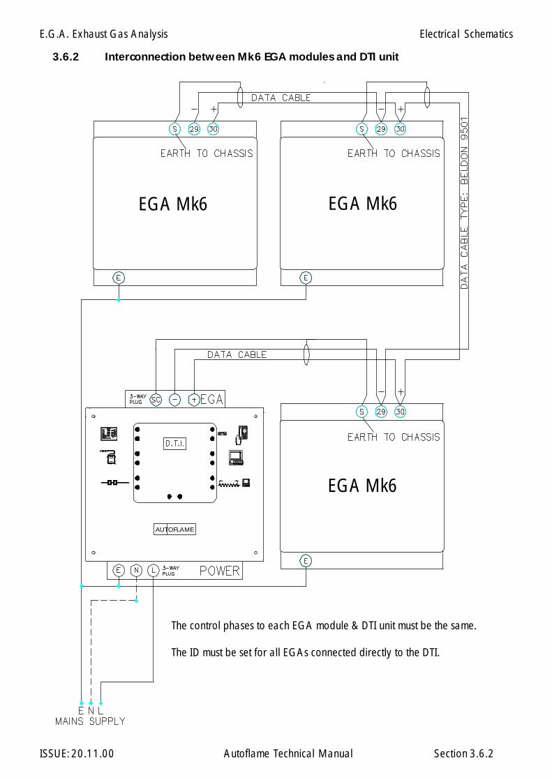
E.G.A. Exhaust Gas Analysis
ISSUE: 20.11.00 Autoflame Technical Manual Section
AUTOFLAME
EGA Mk6EGA Mk6
EGA Mk6
3.6.2 Interconnection between Mk6 EGA modules and DTI unit
The control phases to each EGA module & DTI unit must be the same.
The ID must be set for all EGAs connected directly to the DTI.
3.6.2
Electrical Schematics
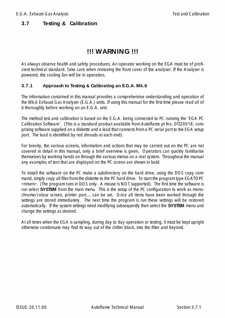
E.G.A. Exhaust Gas Analysis
ISSUE: 20.11.00 Autoflame Technical Manual Section
!!! WARNING !!!
As always observe health and safety procedures. An operator working on the EGA must be of profi-cient technical standard. Take care when removing the front cover of the analyser. If the Analyser ispowered, the cooling fan will be in operation.
3.7.1 Approach to Testing & Calibrating an E.G.A. Mk.6
The information contained in this manual provides a comprehensive understanding and operation ofthe Mk.6 Exhaust Gas Analyser (E.G.A.) units. If using this manual for the first time please read all ofit thoroughly before working on an E.G.A. unit.
The method test and calibration is based on the E.G.A. being connected to PC running the ‘EGA PCCalibration Software’. (This is a standard product available from Autoflame pt No. DTI20018, com-prising software supplied on a diskette and a lead that connects from a PC serial port to the EGA setupport. The lead is identified by red shrouds at each end).
For brevity, the various screens, information and actions that may be carried out on the PC are notcovered in detail in this manual, only a brief overview is given. Operators can quickly familiarisethemselves by working hands on through the various menus on a real system. Throughout the manualany examples of text that are displayed on the PC screen are shown in bold.
To install the software on the PC make a subdirectory on the hard drive, using the DOS copy com-mand, simply copy all files from the diskette to the PC hard drive. To start the program type EGATOPC<return>. (The program runs in DOS only. A mouse is NOT supported). The first time the software isrun select SYSTEM from the main menu. This is the setup of the PC configuration to work as mono-chrome/colour screen, printer port.... can be set. Once all items have been worked through thesettings are stored immediately. The next time the program is run these settings will be restoredautomatically. If the system settings need modifying subsequently then select the SYSTEM menu andchange the settings as desired.
At all times when the EGA is sampling, during day to day operation or testing, it must be kept uprightotherwise condensate may find its way out of the chiller block, into the filter and beyond.
3.7 Testing & Calibration
3.7.1
Test and Calibration
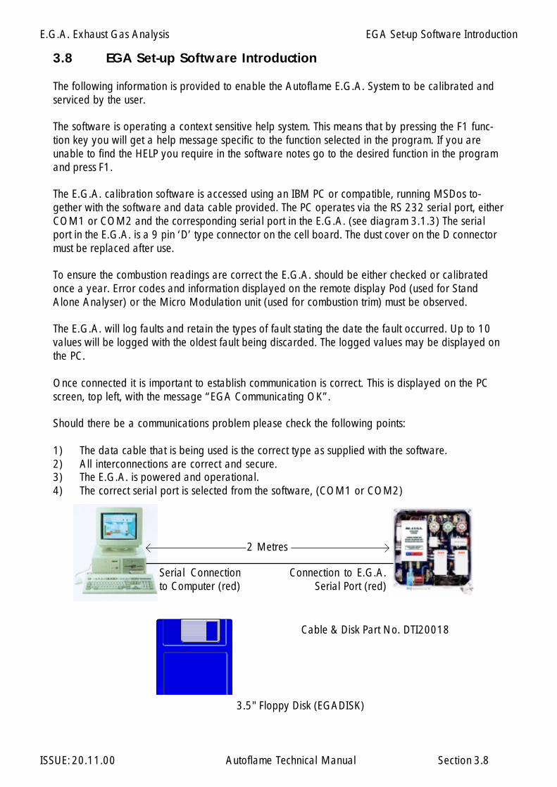
E.G.A. Exhaust Gas Analysis
ISSUE: 20.11.00 Autoflame Technical Manual Section
3.8 EGA Set-up Software Introduction
The following information is provided to enable the Autoflame E.G.A. System to be calibrated andserviced by the user.
The software is operating a context sensitive help system. This means that by pressing the F1 func-tion key you will get a help message specific to the function selected in the program. If you areunable to find the HELP you require in the software notes go to the desired function in the programand press F1.
The E.G.A. calibration software is accessed using an IBM PC or compatible, running MSDos to-gether with the software and data cable provided. The PC operates via the RS 232 serial port, eitherCOM1 or COM2 and the corresponding serial port in the E.G.A. (see diagram 3.1.3) The serialport in the E.G.A. is a 9 pin ‘D’ type connector on the cell board. The dust cover on the D connectormust be replaced after use.
To ensure the combustion readings are correct the E.G.A. should be either checked or calibratedonce a year. Error codes and information displayed on the remote display Pod (used for StandAlone Analyser) or the Micro Modulation unit (used for combustion trim) must be observed.
The E.G.A. will log faults and retain the types of fault stating the date the fault occurred. Up to 10values will be logged with the oldest fault being discarded. The logged values may be displayed onthe PC.
Once connected it is important to establish communication is correct. This is displayed on the PCscreen, top left, with the message “EGA Communicating OK”.
Should there be a communications problem please check the following points:
1) The data cable that is being used is the correct type as supplied with the software.2) All interconnections are correct and secure.3) The E.G.A. is powered and operational.4) The correct serial port is selected from the software, (COM1 or COM2)
3.8
2 Metres
Cable & Disk Part No. DTI20018
Serial Connectionto Computer (red)
Connection to E.G.A.Serial Port (red)
3.5" Floppy Disk (EGADISK)
EGA Set-up Software Introduction

E.G.A. Exhaust Gas Analysis
ISSUE: 20.11.00 Autoflame Technical Manual Section
22
2
3.8.1 Software Possiblities
The E.G.A. 6 channel output facility is PC configurable to enable the user to set the range and items ofdata required and also user selectable. Via the same software and connection lead (part no. DTI 20018)the E.G.A. can be configured and operated as required, this can also be used to service, fault find andcalibrate the unit in two ways:-
Replacement sensors are supplied pre-coded which is entered into the EPROM of the unit tocalibrate the cell.
Selecting the output signals of the 4-20mAThere are eleven possibilities:-
1. O range adjustable
2. CO range adjustable3. CO range adjustable4. NO range adjustable5. SO range adjustable.6. Exhaust gas temperature7. Efficiency/nett/gross8. Input for ambient air temperature i.e.; combustion air inlet on burner9. Air temperature input 4-20mA10. E.G.A. unit air temperature ambient11. Smoke density auxiliary input/output 0-10v from smoke obscuration 4 to 20 mA output.
3.8.1
EGA Set-up Software Introduction
E.G.A. Exhaust Gas Analysis
ISSUE: 20.11.00 Autoflame Technical Manual Section 3.9
3.9 Using The Software
Calibrate Sensor (Replacing a Sensor)
The use of this facility will enable the user to calibrate the sensors within the E.G.A.. Each sensor issupplied by Autoflame complete with it’s own unique calibration code number.
step 1. Removing the sensor to be replaced,
a) For O2 and CO2 sensors disconnect the corresponding plug associated with the sensor and thetwo plastic tubes, now remove the sensor retaining strap and install the new sensor following the stepsin reverse order.
b) For CO, SO2 and NO sensors, disconnect the corresponding plug associated with the sensor, nowremove the three screws located on the top of the sensor, only replace the sensor head. Do not removethe plastic tubing from the sensor housing.
step 2. Select Calibrate Sensor from the tool bar displayed at the bottom of the screen page. Thiscommand will allow you to change a sensor without the need for test calibration gas.
step 3. After selection of the desired type of sensor from the menu listing, press the Enter key.
step 4. Type in the calibration code at the prompt and type Enter.
step 5. The E.G.A. communications will update the P.C. with information regarding the types ofsensor fitted, i.e. CO, NO, SO2 , CO2 and O2 .
step 6. Changing of the Sensor is now complete, remove serial connection and replace cover onthe E.G.A. unit. If the cover is left off the E.G.A. the internal components may over heat due to lack ofcooling air from the fan located on the base of the unit. If the internal temperature is above +40 deg Cor below +5 deg C the Pod or M.M. unit will display “EGA HI” or “COOL” respectively.
NOTE* Only sensors purchased as spares have a code number issued.
EGATOPC Software

E.G.A. Exhaust Gas Analysis
ISSUE: 20.11.00 Autoflame Technical Manual Section
3.9.2 Status
When the status toolbar option is selected the P.C. will display all the information from the E.G.A. unit.The information will only be received provided the E.G.A. is communicating with the P.C. Ensure theE.G.A. is powered.
The Status screen will display the following information typically:
EGA Identification Number: 1Operating Mode: EGA with MMOperating Status: Ready for operationMonitoring: Oxygen O2
Carbon Dioxide CO2
Carbon Monoxide 1 CONitrous Oxide NOSulphur Dioxide SO2
Run Time (Fuel 1) 433 HoursRun Time (Fuel 2) 120 HoursRun Time (Fuel 3) 10 Hours
Note: The above information is an example of Status information available
3.9.3 Faults
The Faults screen page shows the listing of all fault conditions that have occurred on either the M.M.unit or the Stand alone display Pod. Up to 10 faults can be stored and displayed after this, subsequentfaults will erase the oldest fault listed. The date the error was detected and the Error number will alsobe listed.
Example:
1 : 12/09/96 O2 cell failed (21) Error number2 : 04/10/96 Pump failed (20) Error number
3.9.2
EGATOPC Software
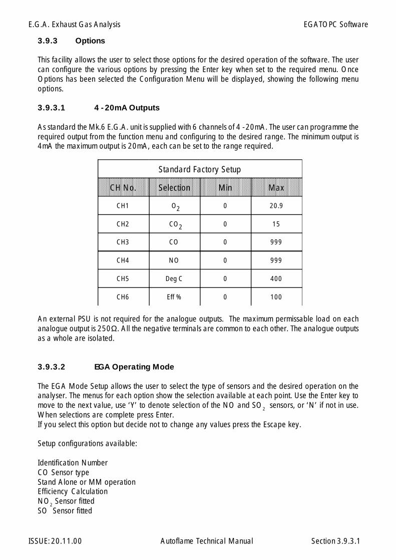
E.G.A. Exhaust Gas Analysis
ISSUE: 20.11.00 Autoflame Technical Manual Section
3.9.3 Options
This facility allows the user to select those options for the desired operation of the software. The usercan configure the various options by pressing the Enter key when set to the required menu. OnceOptions has been selected the Configuration Menu will be displayed, showing the following menuoptions.
3.9.3.1 4 - 20mA Outputs
As standard the Mk.6 E.G.A. unit is supplied with 6 channels of 4 - 20mA. The user can programme therequired output from the function menu and configuring to the desired range. The minimum output is4mA the maximum output is 20mA, each can be set to the range required.
An external PSU is not required for the analogue outputs. The maximum permissable load on eachanalogue output is 250Ω. All the negative terminals are common to each other. The analogue outputsas a whole are isolated.
3.9.3.2 EGA Operating Mode
The EGA Mode Setup allows the user to select the type of sensors and the desired operation on theanalyser. The menus for each option show the selection available at each point. Use the Enter key tomove to the next value, use ‘Y’ to denote selection of the NO and SO2 sensors, or ‘N’ if not in use.When selections are complete press Enter.If you select this option but decide not to change any values press the Escape key.
Setup configurations available:
Identification NumberCO Sensor typeStand Alone or MM operationEfficiency CalculationNO2 Sensor fittedSO Sensor fitted
Standard Factory Setup
CH No. Selection Min Max
CH1 O 0 20.9
CH2 CO 0 15
CH3 CO 0 999
CH4 NO 0 999
CH5 Deg C 0 400
CH6 Eff % 0 100
2
2
3.9.3.1
EGATOPC Software

E.G.A. Exhaust Gas Analysis
ISSUE: 20.11.00 Autoflame Technical Manual Section
3.9.3.3 Pinch Valve Control
This facility allows the user to measure CO and NO when operating on F2 or F3 fuel programmes. Asstandard, CO and NO will only be measured when operating on fuel programme F1 programmeshould always be used for the operating of gas firing. This facility may be required if gas is operatingon F2 programme or the user would like to measure CO and NO when burning fuel oil.
V1 = Pinch valve No.1 .(Brown) This pinch valve is located at the top of the cell P.C.B. .Second from theleft, with a brown top to the valve.V2 = Pinch valve No.2: SO2 Pinch valve
To check the pinch valves operate correctly:
The Pinch valves are checked in the M.M. Run mode. Select fuel 1 (F1), Press E.G.A. to display theE.G.A. information. Check that pinch valve 1 is open. The black topped pinch valve should close whenan E.G.A. calibration takes place, at this stage the sample line is closed and the drain solenoid isopened. At all other times (i.e. when no calibration is taking place) the black topped valve should beopen.
Select fuel 2. Check pinch valve 1 is closed all the time Fuel 2 is selected. Unless this has beenchanged by the user as described earlier in Pinch Valve Control.
V1 Pinch valve No.1V3 pinch valve. V2 Pinch valve No 2.
3.9.3.3
EGATOPC Software
E.G.A. Exhaust Gas Analysis
ISSUE: 20.11.00 Autoflame Technical Manual Section
3.9.3.4 System Configuration.
This function allows the user to select the following:Language: English, German or French.Serial Port: 1 or 2Monitor: Colour: Yes or NoPrinter Port: PRN as standardBaud Rate: 9600 as standard
3.9.3.5 Test and Calibration Menu.
Options available:a. Enter report detailsb. Set time and datec. Clear fault recordsd. Print reporte. Modify Distributor detailsf. Load fault record to diskg. Sensor calibration datesh. Return to main menu
3.9.3.6 Return to Main Menu (press ESC key)
3.9.3.7 Quit.
This will return the user to the DOS prompt.
3.9.3.4
EGATOPC Software
E.G.A. Exhaust Gas Analysis
ISSUE: 20.11.00 Autoflame Technical Manual Section
3.10 Limits on Three Measured Combustion Parameters O2 ,CO, CO2
3.10.1 Overview of System Operation: Features and Benefits.
The limits control software, which is included in every M.M. E.G.A. module, further extends theapplication and control possibilities of the system when the E.G.A. sampling system is fitted. The functionof the Limits control software enables the end user or commissioning engineer to insert upper and lowerlimits on either or all of the three combustion parameters that the E.G.A. system measures; O2, CO2, CO.To invoke this additional control facility, follow the commissioning data and technical information sheetwithin this section.
The Limits control software is configured in two distinct forms: “Standard” Limits or “Absolute” Limits.Either configuration is a user variable selection via the Options listing detailed and listed elsewhere inthis publication.
“Standard” Limits:
“Standard” Limits are a set percentage volume above or below the commissioned value for O2 and CO2.In the case of CO, it is a specific amount of p.p.m. (parts per million) above the commissioned value.These values are entered when commissioning of the E.G.A. system has been completed throughout theload index of the burner.
“Absolute” Limits:
“Absolute” Limits are a specific percentage volume (numerical value). In this form only an ultimate lowvalue may be put on O2 in percentage volume and an ultimate high value for CO2 in percentage volume:In the case of CO, an ultimate high value in p.p.m. may be entered. These values are entered whencommissioning of the E.G.A. system has been completed throughout the load index of the burner.
The values for either “Absolute” or “Standard” Limits are implemented via the Micro ModulationController options. When an entered Limit is exceeded, either in “Absolute” or “Standard” configura-tion, the following alternative control functions are available to the user: (Selected via Options).
Control Function 1.
The Trim function is turned off automatically and the system runs on M.M. fuel and air positions only.Also an Error value is displayed (See ERRor listings). The error value displayed can be cleared and theTrim function reinstated by pressing the “Open” and “Close” buttons on the switch facia simultaneously.
Control Function 2.
The combustion system is shut down (the CR relays are opened). Also an error value is displayed (SeeError listings). The error value displayed can be cleared and the combustion system restarted by pressingthe “Open” and “Close” buttons on the switch facia simultaneously.
(See relevant data sheets and drawings showing the control forms and facilities detailed above).
3.10.1
Limits on Three Measured Combustion Parameters O2 ,CO, CO2
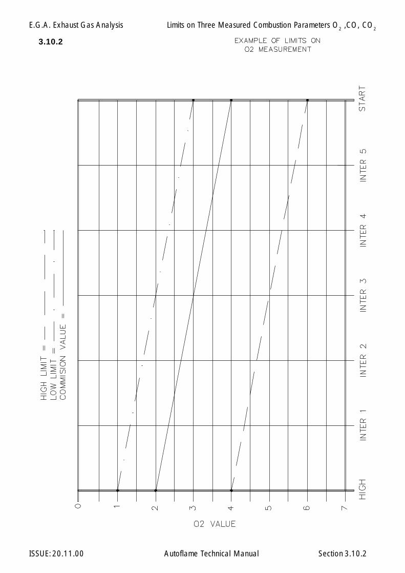
E.G.A. Exhaust Gas Analysis
ISSUE: 20.11.00 Autoflame Technical Manual Section
3.10.2
3.10.2
Limits on Three Measured Combustion Parameters O2 ,CO, CO2
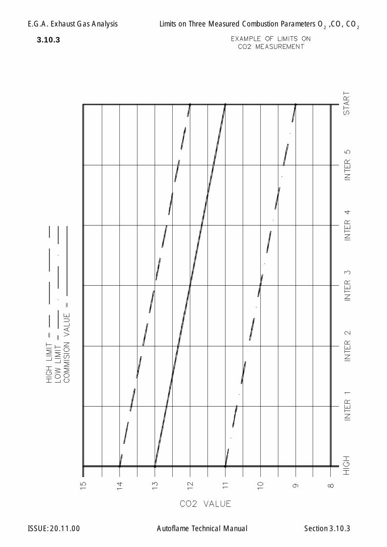
E.G.A. Exhaust Gas Analysis
ISSUE: 20.11.00 Autoflame Technical Manual Section
3.10.3
3.10.3
Limits on Three Measured Combustion Parameters O2 ,CO, CO2
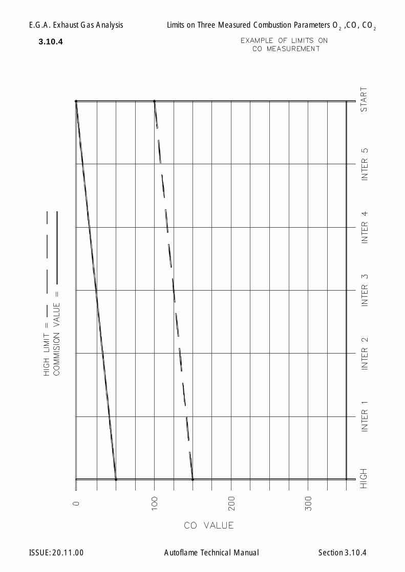
E.G.A. Exhaust Gas Analysis
ISSUE: 20.11.00 Autoflame Technical Manual Section
3.10.4
3.10.4
Limits on Three Measured Combustion Parameters O2 ,CO, CO2
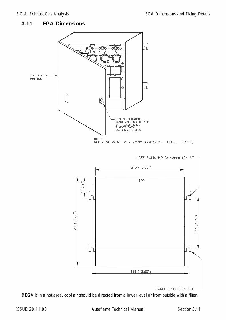
E.G.A. Exhaust Gas Analysis
ISSUE: 20.11.00 Autoflame Technical Manual Section
3.11 EGA Dimensions
3.11
If EGA is in a hot area, cool air should be directed from a lower level or from outside with a filter.
EGA Dimensions and Fixing Details
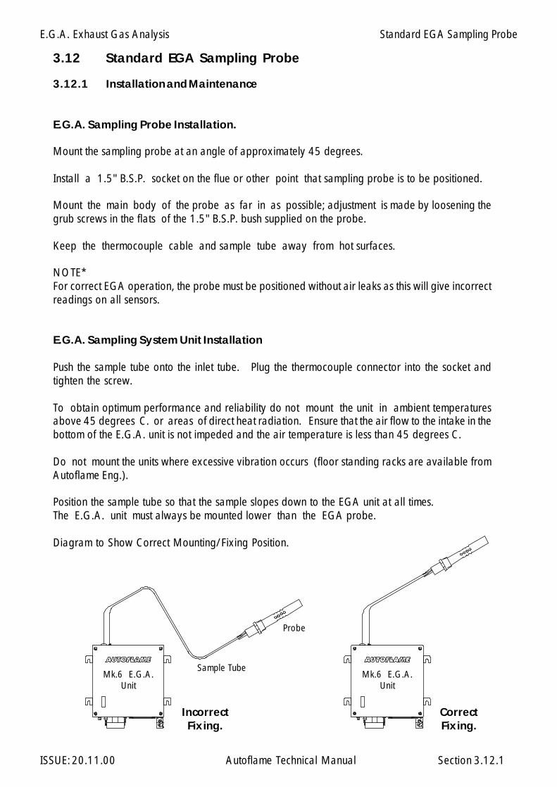
E.G.A. Exhaust Gas Analysis
ISSUE: 20.11.00 Autoflame Technical Manual Section
3.12.1 Installation and Maintenance
E.G.A. Sampling Probe Installation.
Mount the sampling probe at an angle of approximately 45 degrees.
Install a 1.5" B.S.P. socket on the flue or other point that sampling probe is to be positioned.
Mount the main body of the probe as far in as possible; adjustment is made by loosening thegrub screws in the flats of the 1.5" B.S.P. bush supplied on the probe.
Keep the thermocouple cable and sample tube away from hot surfaces.
NOTE*For correct EGA operation, the probe must be positioned without air leaks as this will give incorrectreadings on all sensors.
E.G.A. Sampling System Unit Installation
Push the sample tube onto the inlet tube. Plug the thermocouple connector into the socket andtighten the screw.
To obtain optimum performance and reliability do not mount the unit in ambient temperaturesabove 45 degrees C. or areas of direct heat radiation. Ensure that the air flow to the intake in thebottom of the E.G.A. unit is not impeded and the air temperature is less than 45 degrees C.
Do not mount the units where excessive vibration occurs (floor standing racks are available fromAutoflame Eng.).
Position the sample tube so that the sample slopes down to the EGA unit at all times.The E.G.A. unit must always be mounted lower than the EGA probe.
Diagram to Show Correct Mounting/Fixing Position.
3.12.1
CorrectFixing.
IncorrectFixing.
Probe
Sample TubeMk.6 E.G.A.
UnitMk.6 E.G.A.
Unit
3.12 Standard EGA Sampling Probe
Standard EGA Sampling Probe

E.G.A. Exhaust Gas Analysis
ISSUE: 20.11.00 Autoflame Technical Manual Section
3.12.2
3.12.2
Standard EGA Sampling Probe
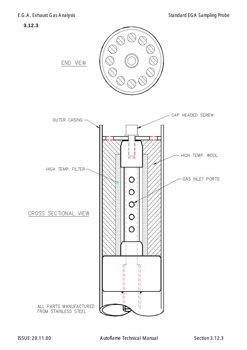
E.G.A. Exhaust Gas Analysis
ISSUE: 20.11.00 Autoflame Technical Manual Section
3.12.3
3.12.3
Standard EGA Sampling Probe
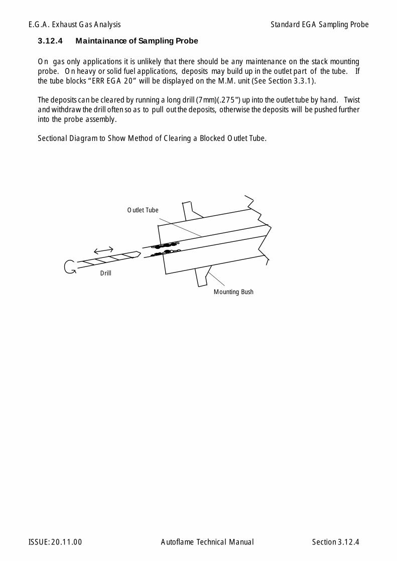
E.G.A. Exhaust Gas Analysis
ISSUE: 20.11.00 Autoflame Technical Manual Section
Outlet Tube
Drill
Mounting Bush
On gas only applications it is unlikely that there should be any maintenance on the stack mountingprobe. On heavy or solid fuel applications, deposits may build up in the outlet part of the tube. Ifthe tube blocks “ERR EGA 20” will be displayed on the M.M. unit (See Section 3.3.1).
The deposits can be cleared by running a long drill (7mm)(.275") up into the outlet tube by hand. Twistand withdraw the drill often so as to pull out the deposits, otherwise the deposits will be pushed furtherinto the probe assembly.
Sectional Diagram to Show Method of Clearing a Blocked Outlet Tube.
3.12.4 Maintainance of Sampling Probe
3.12.4
Standard EGA Sampling Probe
E.G.A. Exhaust Gas Analysis
ISSUE: 20.11.00 Autoflame Technical Manual Section
3.12.5 Installation Precautions
The reliability of the equipment may be impaired if used in environments where strong electro magneticfields exist. If for example the equipment is installed in a boiler house at the top of a high rise buildingwhere radio systems exist then additional EMC (Electro Magnetic Compatability) measures may haveto be considered
3.12.5
Standard EGA Sampling Probe

E.G.A. Exhaust Gas Analysis
ISSUE: 20.11.00 Autoflame Technical Manual Section
3.12.6 Servicing E.G.A. Sampling Probe.
If the filter assembly in the E.G.A. sampling probe is blocked then it is necessary to disassemble the probeand fit a new pre-formed fine filter and coarse filter material. To check if the E.G.A. probe is blockedconnect it to the E.G.A. If the flow drops by more than 100 cc/min. then the filtering materials must bereplaced.
To disassemble the probe, remove the two cap headed screws visible on the outside of the assembly (oneeach end). The whole of the internal assembly can now be withdrawn from the sample connection end.Remove all traces of the filtering materials from the stainless steel filter. Check that the ways in thestainless steel filter are clear and also the inner sample tube. Very carefully (the pre-formed fine filteris delicate) push the pre-formed filter onto the stainless steel filter.Slide the inner assembly back into the stainless steel outer casing. Pack the void between the fine filterand the outer casing with coarse filtering material as shown on the Filter Assembly Diagram. Use a smallrod to pack the material down a little at a time. Reassemble the Exhaust Gas Inlet End Plate and the twoscrews.
After reassembly connect the probe to the E.G.A. and check that the drop in flow is no more than50 cc/min.
Plug in the thermocouple lead and set the M.M. to read E.G.A. Values in Commissioning Mode. Applyheat to the thermocouple (put a soldering iron through the holes in the outer casing) and check that thethermocouple gives a reading.If there is any doubt to the accuracy of the thermocouple then replacement is advised.
3.12.6
Standard EGA Sampling Probe
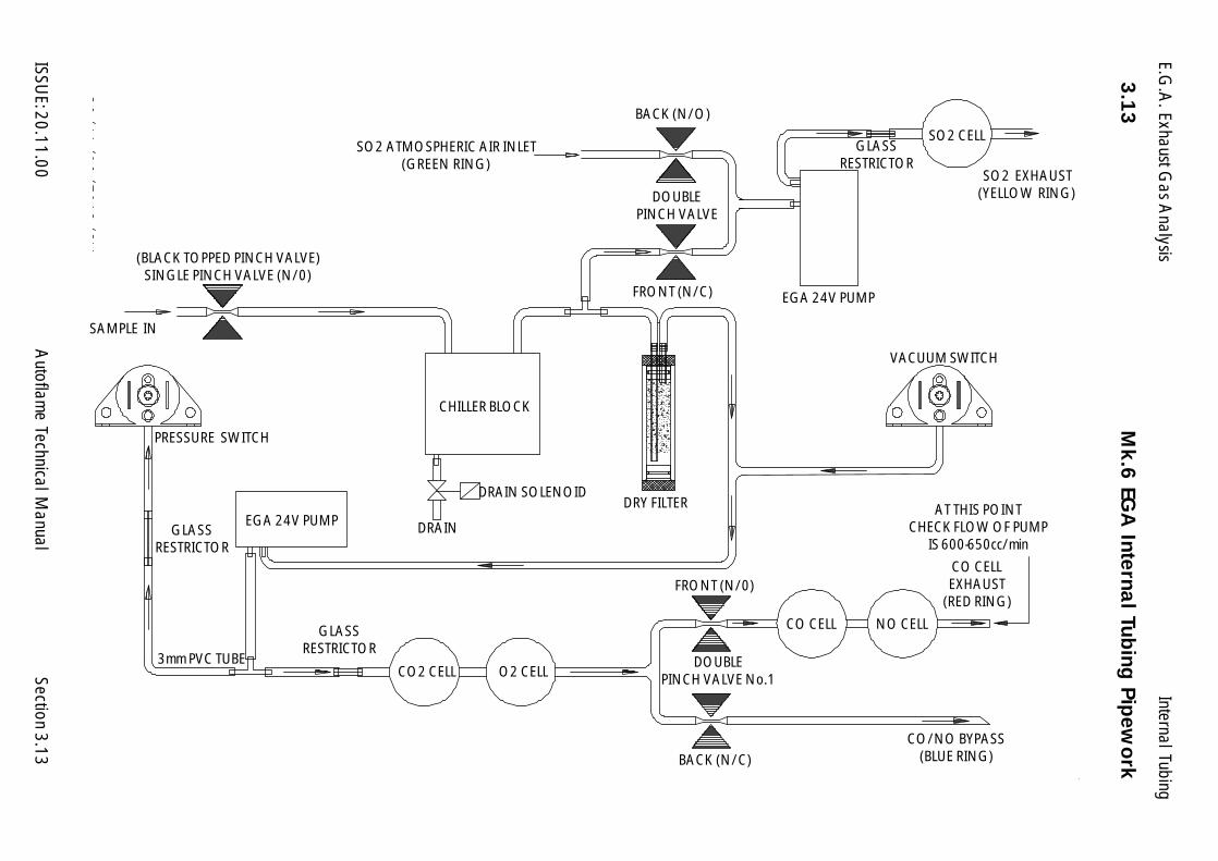
E.G.A
. Exhaust Gas A
nalysis
ISSUE: 20.11.00
Autoflam
e Technical Manual
Section3.13
3.13M
k.6 EG
A Interna
l Tubing
Pipew
ork
SAMPLE IN
SO2 EXHAUST(YELLOW RING)
DOUBLEPINCH VALVE No.1
BACK (N/C)
FRONT (N/0)
CO/NO BYPASS(BLUE RING)
CO CELLEXHAUST
(RED RING)
AT THIS POINTCHECK FLOW OF PUMP
IS 600-650cc/min
VACUUM SWITCH
DRAIN
CO2 CELL O2 CELL
GLASSRESTRICTOR
3mm PVC TUBE
PRESSURE SWITCH
DRAIN SOLENOID
GLASSRESTRICTOR
(BLACK TOPPED PINCH VALVE)SINGLE PINCH VALVE (N/0)
SO2 ATMOSPHERIC AIR INLET(GREEN RING)
FRONT (N/C)
BACK (N/O)
DOUBLEPINCH VALVE
SO2 CELLGLASS
RESTRICTOR
EGA 24V PUMP
CO CELL NO CELL
DRY FILTER
CHILLER BLOCK
EGA 24V PUMP
Internal Tubing
E.G.A. Exhaust Gas Analysis
ISSUE: 20.11.00 Autoflame Technical Manual Section
3.14.1 Overview.
3.14.2 Operation.
3.14.3 Maintenance.
3.14.4 Standard Setup.
3.14.5 Fault Finding.
3.14.6 Technical Specifications.
3.14.7 General Assembly of Bubble Filter & EGA Display Pod.
3.14.8 Plan view of Connection (Actual & Schematic)
3.14.9 Enlarged View of Bubble Filter Pot top cap Connections.
3.14.10 Wiring Diagram Display Pod & EGA Sampling Unit.
3.14.11 Mk.6 EGA Internal Layout (Shown without cover)
3.14.12 General Assembly of Dry Filter.
3.14.13 General Assembly & Exploded View of Particulate Filter.
3.14.14 General Assembly of Bubble Pot.
3.14.15 "S" Type High Temperature Thermocouple Assembly.
Section 3.14 E.G.A. with Bubble Filter
3.14 Index
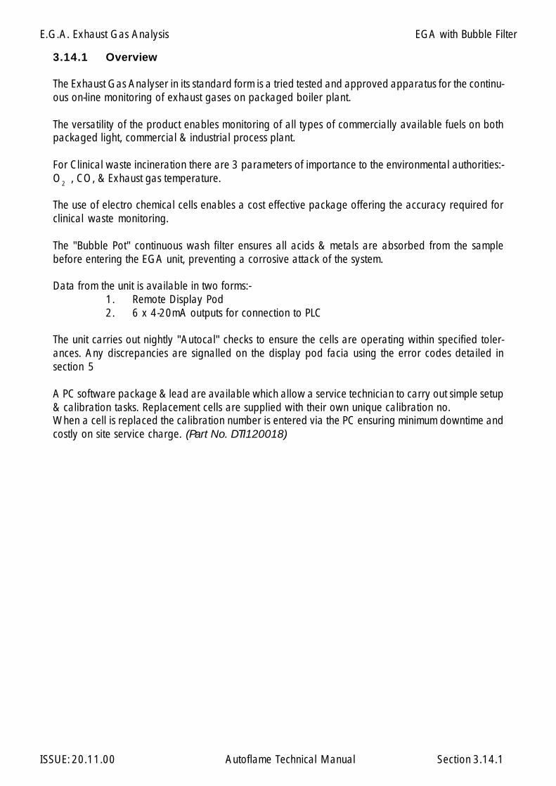
E.G.A. Exhaust Gas Analysis
ISSUE: 20.11.00 Autoflame Technical Manual Section
3.14.1 Overview
The Exhaust Gas Analyser in its standard form is a tried tested and approved apparatus for the continu-ous on-line monitoring of exhaust gases on packaged boiler plant.
The versatility of the product enables monitoring of all types of commercially available fuels on bothpackaged light, commercial & industrial process plant.
For Clinical waste incineration there are 3 parameters of importance to the environmental authorities:-O2 , CO, & Exhaust gas temperature.
The use of electro chemical cells enables a cost effective package offering the accuracy required forclinical waste monitoring.
The "Bubble Pot" continuous wash filter ensures all acids & metals are absorbed from the samplebefore entering the EGA unit, preventing a corrosive attack of the system.
Data from the unit is available in two forms:-1. Remote Display Pod2. 6 x 4-20mA outputs for connection to PLC
The unit carries out nightly "Autocal" checks to ensure the cells are operating within specified toler-ances. Any discrepancies are signalled on the display pod facia using the error codes detailed insection 5
A PC software package & lead are available which allow a service technician to carry out simple setup& calibration tasks. Replacement cells are supplied with their own unique calibration no.When a cell is replaced the calibration number is entered via the PC ensuring minimum downtime andcostly on site service charge. (Part No. DTI120018)
3.14.1
EGA with Bubble Filter
E.G.A. Exhaust Gas Analysis
ISSUE: 20.11.00 Autoflame Technical Manual Section
3.14.2 Operation
The E.G.A. & filters are designed to operate with the minimum amount of user input.
The unit is supplied prewired & prepiped ensuring simple installation.
Section A1 shows a typical layout for the unit with all connection information detailed separatelyunder their respective figure illustrations.
Day to day Operation.
Once installed all necessary inputs & outputs are automatic.
The unit must always be powered.
A mains 230Vac input on terminal 7 tells the unit when to start sampling. This signal should come fromthe PLC & should be set to give an output when the furnace temperature has reached 1000 deg C.
NB. Experience shows that when the furnace is below 1000 deg C considerable amounts of unburntash/solids are given off which quickly block the sampling system. It is not advisable to control theprocess until the combustion has reached a steady state condition.
Setting up Water Flow.
Water input must be greater than water out through the drain,.The greater the water flow, the more acids are absorbed from the sample.Ideally water "in" should = water "out", however on initial start-up the filter would not be able tofill,therefore the water "in" should be slightly greater than the water "out". If the difference is too greatthe water "in" solenoid will be constantly be turning on & off creating a pulsed sample, a controlregulating valve on the inlet water line will enable optimum setup.
3.14.2
EGA with Bubble Filter

E.G.A. Exhaust Gas Analysis
ISSUE: 20.11.00 Autoflame Technical Manual Section
3.14.3 Maintenance
The on/off signal for sampling is controlled by the PLC.
Daily Checks
1. Check the condition of the hot filter on the end of the probe.experience shows that this needs replacing every 2 to 3 days dependingon waste being burnt. (see section A1)
2. Check there is a gentle flow of water from the bottom of the Bubble Filter.
The unit has self diagnostic error checking software & any fault conditions are notified via error codeson the facia. (see fault finding Section 3.14.5)
Monthly Checks
4. Remove EGA lid and visually check the condition of the E.G.A. "Dry" filter, (see section3.14.12) the condition of this filter varies greatly with the type of waste being burnt.All the following conditions necessitate change:-
a) Discoloration of the wool filter.b) Build up of white deposit in the filter.c) Any signs of condensate.
3.14.3
EGA with Bubble Filter

E.G.A. Exhaust Gas Analysis
ISSUE: 20.11.00 Autoflame Technical Manual Section
3.14.4 Standard Setup
The EGA is setup to work with a display pod & Bubble Pot. If any item is not connected an errorcondition will be signalled.
4-20mA Output Setup
The above are factory set. These can be changed at time of manufacture or by the user with the aid ofthe EGATOPC software disk & lead.
CHANNEL DESCRIPTION 4mA 20mA
1 O2% 0 16
2 - - -
3 CO ppm 0 200
4Type "K"
Thermocouple500 1600
5Type "S"
Thermocouple500 1600
6Fault -
-operationalFault Operational
3.14.4
EGA with Bubble Filter
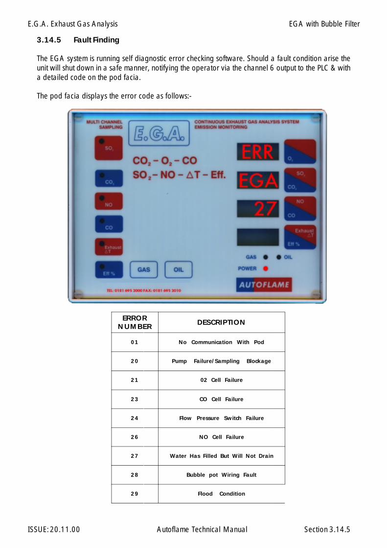
E.G.A. Exhaust Gas Analysis
ISSUE: 20.11.00 Autoflame Technical Manual Section
3.14.5 Fault Finding
The EGA system is running self diagnostic error checking software. Should a fault condition arise theunit will shut down in a safe manner, notifying the operator via the channel 6 output to the PLC & witha detailed code on the pod facia.
The pod facia displays the error code as follows:-
ERRORNUMBER DESCRIPTION
01 No Communication With Pod
20 Pump Failure/Sampling Blockage
21 02 Cell Failure
23 CO Cell Failure
24 Flow Pressure Switch Failure
26 NO Cell Failure
27 Water Has Filled But Will Not Drain
28 Bubble pot Wiring Fault
29 Flood Condition
3.14.5
EGA with Bubble Filter
E.G.A. Exhaust Gas Analysis
ISSUE: 20.11.00 Autoflame Technical Manual Section
Possible Problems
01 Check Wiring connection between EGA & Pod. (see section A4)
20 Pump failure/Sampling Blockage, remove sample tube at inlet to EGAIf error goes then the sampling line/Bubble Pot has a blockage.Isolate each section & check for blockage.
If error persists then blockage/Fault is within the EGA.
Remove the input to pump (lower pipe connection)If error persists then faulty pump.If input clears then the pump is O.K. check the following:-
a) Filterb) Visually check sampling line.
If unable to find problem then contact your distributor. (see section A5)
21 Replace O2 cell.
23 Replace CO cell.
24 Change pressure switch.
26 Replace NO Cell.
27 Water has filled but will not drain.Possible Problems:-
a) Drain cock is blocked.b) Blockage in Sampling probe.
28 Bubble Pot wiring fault.Check the connector for the Bubble Pot is securely fixed.Check wiring.
29 Flood condition - Water has reached the high level water probe.Possible Problems:-
a) Sampling probe/Line Blocked.b) Small restriction in drain cock.
N.B. For both 26 & 27 if the sampling probe is significantly blocked, atmospheric air willenter through the drain hole.
3.14.5.1
EGA with Bubble Filter
E.G.A. Exhaust Gas Analysis
ISSUE: 20.11.00 Autoflame Technical Manual Section
Other Possible Problems
Fuse keeps blowing.
If the EGA is mounted in an excessively dusty environment a build up of particles on the terminals cancause arcing. If the particles are corrosive then any attack to the conformal coating on the printedcircuit boards can cause tracks to arc & component failure. Any sign of this activity & the unit shouldbe returned to the supplier.
Continuous O2 Reading at 20.9%Check all piping is airtightCheck sample tube is not blocked.Check air solenoid is closed.Check air is not being drawn from the Bubble Pot drain.Check Bubble Pot head for cracks.
!!Warning!!The Bubble Pot head is made of a corrosive resistant medical grade plastic, the top is drilled & tappedto accept the small tapered pipe fittings,the Bubble Pot is working at a minimal pressure of 10" WG.Fittings need only be finger tight, overtightening these tapered fittings will build up mechanical stressin the plastic resulting in hairline cracking.
Water level
If the water level continually oscillates no sampling takes place, depending on the type of water beingused, electrolysis can cause a build up of non conducting solids on the water level probes. This issimply cured by cleaning the probes (see Section A5.4 for assembly of Bubble Pot)
High displayed on Pod Facia.
The ambient is in excess of 40 deg C and the chiller cannot cool down.
Low displayed on Pod Facia.
The ambient temp is less than 5 deg C
3.14.5.2
EGA with Bubble Filter
E.G.A. Exhaust Gas Analysis
ISSUE: 20.11.00 Autoflame Technical Manual Section 3.14.6
3.14.6 Technical Specifications
Electrical Supply:- 230V/50Hz or 110V/60Hz (Selectable)
Pump Flow:- 0.5L @ 60" W.G.
Water Supply:- This should be a constant head of between 10' & 15' of clean waterfrom the header tank,DO NOT CONNECT DIRECTLY TO THE MAINS SUPPLY
Temperature Range:-
Min. +10 deg CMax. +40 deg C
Ceramic sampling Probe 0 - 1600 deg C
Type "S" Thermocouple 0 - 1600 deg C
Type "K" Thermocouple 0 - 400 deg C
EGA with Bubble Filter
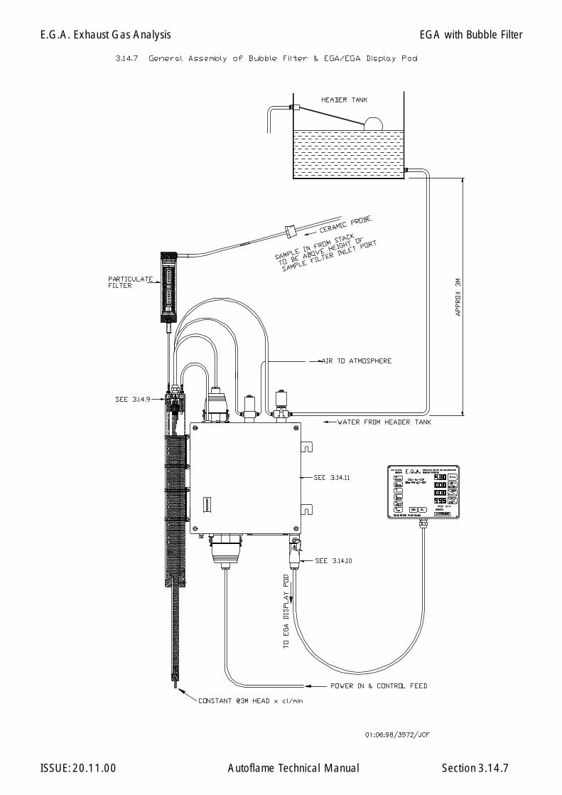
E.G.A. Exhaust Gas Analysis
ISSUE: 20.11.00 Autoflame Technical Manual Section 3.14.7
EGA with Bubble Filter
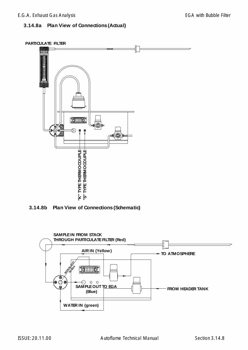
E.G.A. Exhaust Gas Analysis
ISSUE: 20.11.00 Autoflame Technical Manual Section
WATER IN (green)
SAMPLE OUT TO EGA (Blue)
TO ATMOSPHERE
FROM HEADER TANK
SIG
NAL O
UT
TO EG
A
"K"
TYP
E TH
ERM
OCO
UP
LE"S
" TY
PE
THER
MO
COU
PLE
PARTICULATE FILTER
AIR IN (Yellow)
SAMPLE IN FROM STACKTHROUGH PARTICULATE FILTER (Red)
3.14.8a Plan View of Connections (Actual)
3.14.8b Plan View of Connections (Schematic)
3.14.8
EGA with Bubble Filter

E.G.A. Exhaust Gas Analysis
ISSUE: 20.11.00 Autoflame Technical Manual Section
WA
TER
IN (
Gre
en)
AIR
IN (Y
ello
w)
SAMPLE OUT TO EGA (Blue)
SIG
NAL
OUT
TO E
GA
SAMPLE IN FROM STACK (Red)
3.14.9 Enlarged View of Bubble Filter Top Cap Connections
3.14.9
EGA with Bubble Filter
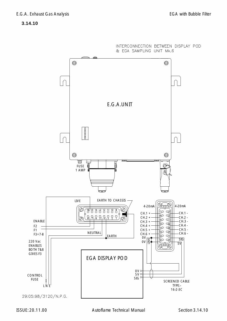
E.G.A. Exhaust Gas Analysis
ISSUE: 20.11.00 Autoflame Technical Manual Section 3.14.10
3.14.10
EARTHNEUTRAL
E.G.A.UNIT
EGA DISPLAY POD
FUSE1 AMP
4-20mA
L N E
CONTROLFUSE SCREENED CABLE
TYPE:-16-2-3C
EGA with Bubble Filter
F2F1F3=7-8
ENABLE
220 VacENABLESBOTH 7&8GIVES F3
0V5V
SIG
CH.1 + CH.1 -CH.2 + CH.2 -CH.3 +CH.4 + CH.4 -CH.5 + CH.5 -CH.6 + CH.6 -0V SIG
5VLIN
K
4-20mA
CH.3 -
0V
LIVE EARTH TO CHASSIS
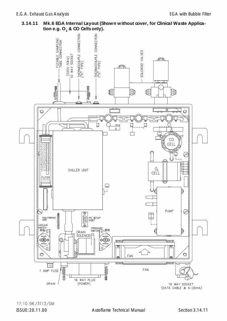
E.G.A. Exhaust Gas Analysis
ISSUE: 20.11.00 Autoflame Technical Manual Section
3.14.11 Mk.6 EGA Internal Layout (Shown without cover, for Clinical Waste Applica-tion e.g. O2 & CO Cells only).
3.14.11
EGA with Bubble Filter

E.G.A. Exhaust Gas Analysis
ISSUE: 20.11.00 Autoflame Technical Manual Section
3.14.12 General Assembly of Dry Filter
FILTERING MATERIAL (AS SUPPLIED)
FILTER MATERIAL ISPACKED UP TO THE TOP
REDGREEN
SAM
PLE
IN
SAM
PLE
OU
T
SPACE ALLOWS EVENFILTERING OVER TOTAL
SURFACE AREA OF FILTER
N.B. FREE SPACE MUST BE LEFT AT BOTTOM TO STOP ANY PREMATURE BLOCKAGETHE SAMPLE IN & OUT PIPES MUST BE CONNECTED CORRECTLY OR BLOCKAGE
WILL OCCUR WITHIN A FEW HOURS.
3.14.12
EGA with Bubble Filter
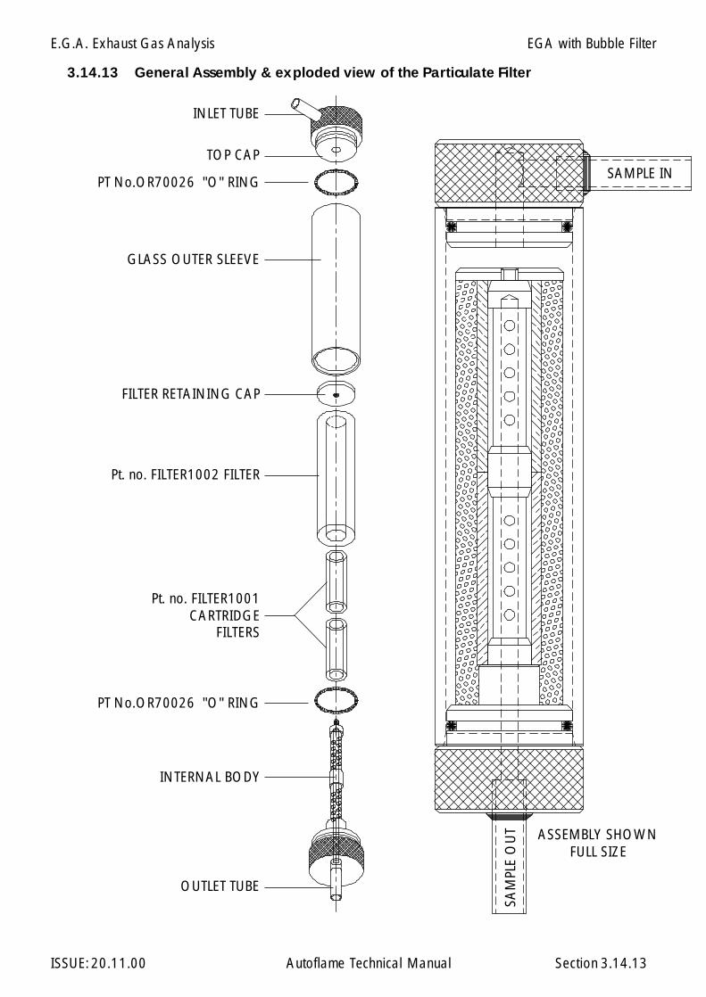
E.G.A. Exhaust Gas Analysis
ISSUE: 20.11.00 Autoflame Technical Manual Section
3.14.13 General Assembly & exploded view of the Particulate Filter
GLASS OUTER SLEEVE
Pt. no. FILTER1002 FILTER
INTERNAL BODY
OUTLET TUBE
Pt. no. FILTER1001CARTRIDGE
FILTERS
PT No.OR70026 "O" RING
FILTER RETAINING CAP
INLET TUBE
SAMPLE IN
SAM
PLE
OU
T
TOP CAP
ASSEMBLY SHOWNFULL SIZE
PT No.OR70026 "O" RING
3.14.13
EGA with Bubble Filter
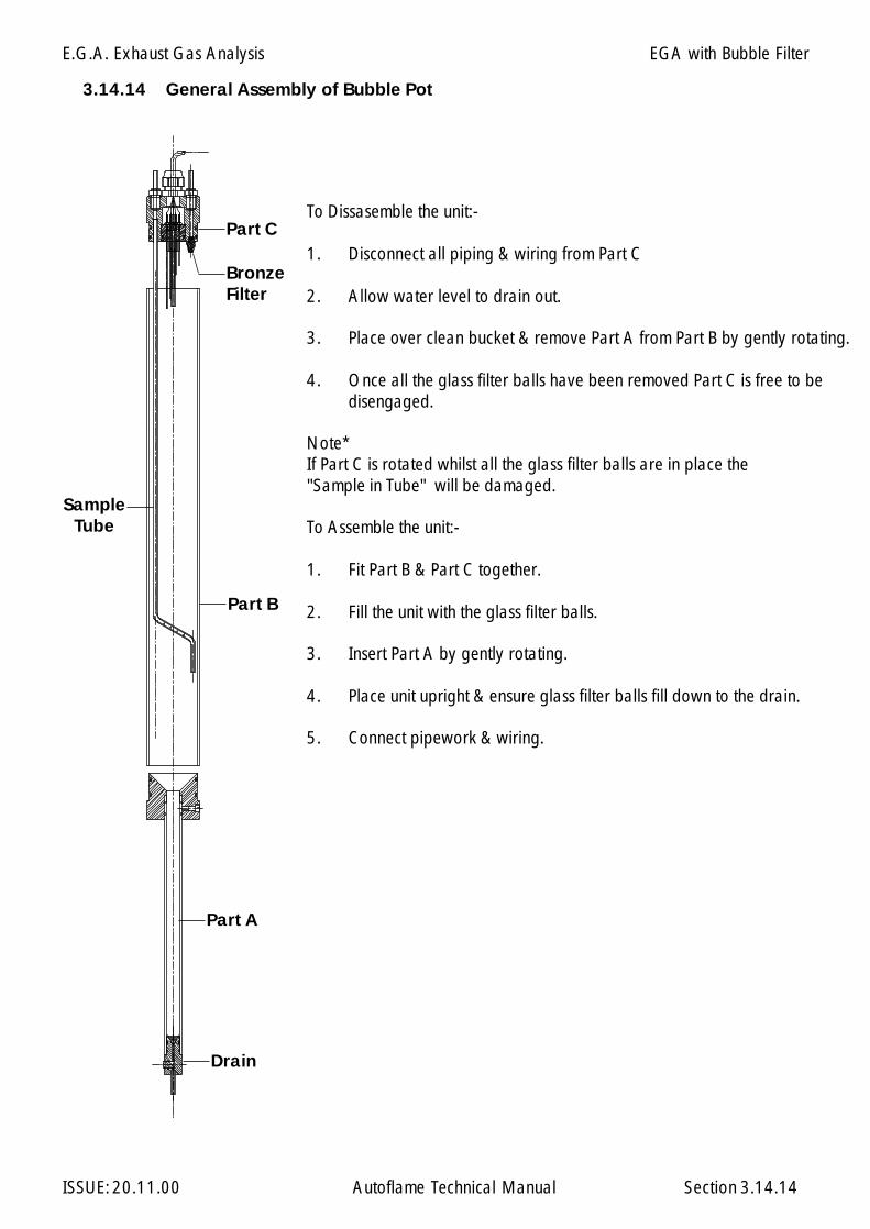
E.G.A. Exhaust Gas Analysis
ISSUE: 20.11.00 Autoflame Technical Manual Section
Part A
Part B
Part CTo Dissasemble the unit:-
1. Disconnect all piping & wiring from Part C
2. Allow water level to drain out.
3. Place over clean bucket & remove Part A from Part B by gently rotating.
4. Once all the glass filter balls have been removed Part C is free to bedisengaged.
Note*If Part C is rotated whilst all the glass filter balls are in place the"Sample in Tube" will be damaged.
To Assemble the unit:-
1. Fit Part B & Part C together.
2. Fill the unit with the glass filter balls.
3. Insert Part A by gently rotating.
4. Place unit upright & ensure glass filter balls fill down to the drain.
5. Connect pipework & wiring.
3.14.14 General Assembly of Bubble Pot
SampleTube
Drain
BronzeFilter
3.14.14
EGA with Bubble Filter
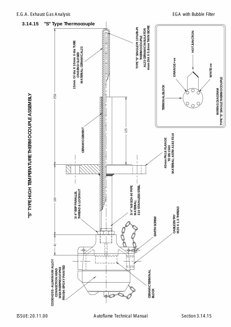
E.G.A. Exhaust Gas Analysis
ISSUE: 20.11.00 Autoflame Technical Manual Section
"S"
TYP
E H
IGH
TEM
PER
ATU
RE
THER
MO
COU
PLE
ASS
EMB
LY
WIR
ING
DIA
GR
AM
TYP
E "S
" SI
NG
LE T
HER
MO
COU
PLE
OR
AN
GE
+ve
TYP
E "S
" SI
NG
LE P
t 10
%R
h-P
tTH
ERM
OCO
UPL
EA
L23
CER
AM
IC IN
SULA
TOR
4m
m D
IA X
0.8
mm
TW
IN B
OR
E
3/4
" N
B S
CH 4
0 P
IPE
MA
TER
IAL:
31
0 S
TAIN
LESS
STE
EL
HO
T JU
NCT
ION
WH
ITE
-ve
TER
MIN
AL
BLO
CK15
mm
O/d
ia X
10
mm
I/d
ia T
UB
EO
NE
END
CLO
SED
MA
TER
IAL:
CER
AM
IC A
L23
40
mm
PN
16
FLA
NG
ETO
BS
1560
MA
TER
IAL:
AST
M A
18
2 F
31
6
CER
AM
IC C
EMEN
T
EAR
TH S
CREW
CAB
LE E
NTR
YM
20
X 1
.5 T
HR
EAD
3/4
" B
SP P
AR
ALL
ELTH
REA
D &
LO
CKN
UT
CER
AM
IC TE
RM
INA
LB
LOCK
COD
E H
20
S - A
LUM
INIU
M A
LLO
YCO
NN
ECTI
ON
HEA
DW
EATH
ERP
RO
OF
IP6
8FI
NIS
H: E
PO
XY
PA
INTE
D
3.14.15 "S" Type Thermocouple
3.14.15
EGA with Bubble Filter
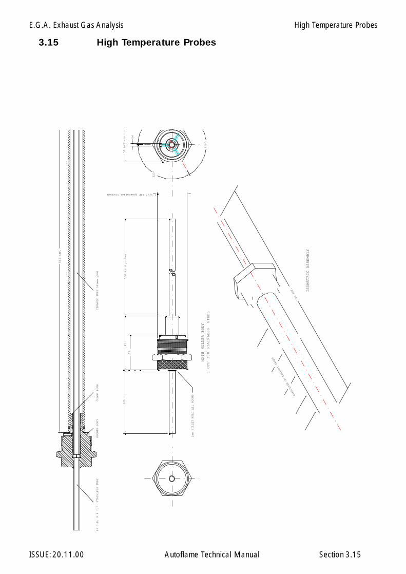
E.G.A. Exhaust Gas Analysis
ISSUE: 20.11.00 Autoflame Technical Manual Section
3.15 High Temperature Probes
85
55
500 (std probe)
120°
120°
55 A/Flats M4
1-1/2" BSP (parrallel thread)
MAIN HOLDER BODY
1 OFF 308 STAINLESS STEEL
2mm FILLET WELD ALL ROUND
10 O.D. X 8 I.D. STAINLESS TUBE
100
565 REF.
DIRECTION OF EXHAUST GASES
HOLDER BODY
CERAMIC TUBE 555mm LONG
CLAMP BUSH
ISOMETRIC ASSEMBLY
720 REF.
3.15
High Temperature Probes
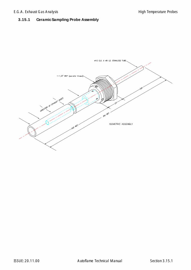
E.G.A. Exhaust Gas Analysis
ISSUE: 20.11.00 Autoflame Technical Manual Section
3.15.1 Ceramic Sampling Probe Assembly
3.15.1
High Temperature Probes
E.G.A. Exhaust Gas Analysis
ISSUE: 20.11.00 Autoflame Technical Manual Section
3.16 Shipping the E.G.A.
3.16
The EGA is a scientific instrument with delicate components. Whenever the EGA is shipped, it isessential that the EGA is packed carefully in an Autoflame EGA shipping carton as originally sup-plied.
Ensure that delivery carriers treat the package appropriately. Label the package as containingdelicate scienctific instrument.
If the EGA is damaged, repair costs will be incurred.
Please contact Autoflame Engineering or your local dealer to obtain a new Autoflame carton.
IBS Intelligent Boiler Sequencing
ISSUE: 20.11.00 Autoflame Technical Manual Section
Section 4: I.B.S. Intelligent Boiler Sequencing
4.1 Overview - Features & Benefits of I.B.S. control
4.2 Commissioning and Setting Up Procedure
4.2.1 Guide to Commissioning Sequencing
4.4 Electrical Schematics Showing all Terminal Interconnections
4.4.1 Sequencing Connection Diagram4.4.2 DTI/Sequencing Connection Diagram
4.5 Other Information and Illustrations.
4.5.1 Sequencing Operation4.5.2 Sequencing Combinations4.5.3 Diagram showing Data Transmission/Reception4.5.4 Mini Mk5 Sequencing Status Information
4: Index
123456789012345678901234123456789012345678901234123456789012345678901234123456789012345678901234123456789012345678901234123456789012345678901234123456789012345678901234123456789012345678901234123456789012345678901234123456789012345678901234123456789012345678901234123456789012345678901234123456789012345678901234123456789012345678901234

IBS Intelligent Boiler Sequencing
ISSUE: 20.11.00 Autoflame Technical Manual Section
4.1 INTELLIGENT BOILER SEQUENCING (I.B.S.)
Overview of System Operation: Features and Benefits
The Intelligent Boiler Sequencing software, which is included in every M.M. E.G.A. module, furtherextends the application possibilities of the system. The objective of this control form is to ensurethat the minimum number of boiler/burner units are in operation at any one time to satisfy the heatrequirement imposed upon the boiler plant, particularly in the case of multi boiler installations.
There are two variations of I.B.S. software that can be selected by the user via the Options procedure.The first variation relates to heating boilers and the second variation to steam boilers.
Heating Boilers Sequential Control:
A maximum of ten M.M. E.G.A. modules may be interconnected by a two wire screened data cable:(See interconnection drawing). Any string of modules interconnected as detailed can have one ofit’s number designated No. 1 or lead boiler. This identifying of “lead” boiler is achieved by either ofthe following methods:
a) Connecting a mains voltage onto terminal No. 41.b) Instructing the modules via the D.T.I. module (Data Transfer Interface) by software.
Once a “lead” boiler has been selected the system works in the following way:
Typically every five minutes the sequencing software in the lead boiler identifies it’s own firing rate bylooking at the position of the fuel valve in the load index and also the maximum heating capacity ofthe No 1. “lead” boiler. This information would normally be entered when this boiler/burner unitis commissioned. Having established percentage firing rate, and maximum heating capacity, the I.B.S.software calculates the amount of heat being contributed to the system by this boiler. The I.B.S.software in the “lead” M.M. E.G.A. module then contacts in turn each of the modules connected tothis loop and gathers similar information from each. The “lead” module’s I.B.S. software thencalculates the minimum number of boiler/burner units that need to be operational to satisfy the buildingload, imposed upon the plant at that time, and switches the remainder off. There is a terminalconnection on the M.M. E.G.A. module for controlling a two port valve that would normally beinstalled in the boiler’s return pipe connection to the common return header. This facility ensures thatboilers that are switched “off line” do not contribute return temperature water to the flow headerthereby diluting the flow temperature to the building: (See relevant data sheets and drawings showingthe control sequence detailed above).
Example:
There are four boilers interconnected as above, each with a heating capacity of 586kw (2 Mbtu.)In the event of each boiler firing 440kW (1.5 Mbtu) (3/4 of it’s maximum rate), the No. 1 lead boilerwould instruct the No. 4 boiler to shut down and boilers No.s 1, 2 and 3 would adjust their firing rateto maximum. In both cases the boilers are contributing 1758kW (6 Mbtu) to the system but, afterintervention of the I.B.S. sequencing software, three boilers only are carrying the load which is a morefuel efficient method of operation.
If the building load continued to decrease the three boilers would reach a point where they were eachfiring 390kW (1.33 Mbtu) each.
4.1.1
IBS Intelligent Boiler Sequencing
ISSUE: 20.11.00 Autoflame Technical Manual Section
At this point the I.B.S. software would switch off the No. 3 boiler as two boilers would be capableof generating the 1172kW (4 Mbtu) required. When the load on the system increases, the reverseprocedure applies, i.e. when, for example, two boilers are firing at near 100% load and the setpointtemperature on either of the modules is not being achieved, the I.B.S. software would switch on a thirdboiler to assist with the generation of the heat requirement. Any boiler can be nominated “lead” boilerby the connection of an input to the appropriate terminal or by a software instruction via the D.T.I.
Steam Boiler Sequential Control:
When the I.B.S. software control package is applied to steam boilers, it’s operation is exactly the sameas above but with the additional features and enhancements as explained in the following.
In the case of heating boilers only two states in the control form exist, either on or off. When steamboiler variation of I.B.S. is optioned there are three states which are controlled sequentially.
The first is “on-line”, this is when the boiler is operating purely under the control of the M.M. E.G.A.module's internal P.I.D. load controller.
The second state is “Standby Warming”: In this case the boiler is operated at a reduced pressuresetpoint, and runs for a number of minutes each hour: e.g. if the on-line boiler or boilers are set at asetpoint of 7 bar (100 p.s.i.) the standby warming boiler controls at a setpoint of 5 bar (72 p.s.i.). Inthis way if the load increases the standby warming boiler can begin to contribute steam quickly. Thereduced setpoint is a user variable option in the same way as the normal control pressure setpoint.The number of minutes run time is also adjustable.
The third state is “off-line”, this is with the burner shut down and the boiler cold. If the load on the boilerhouse increases, this boiler would move into a “warming” condition.
Apart from the variations detailed above, the steam sequencing works in precisely the same way asthe heating boiler sequencing: The sequencing software package ensures that at all times the minimumnumber of boilers are operational to satisfy the load imposed on the boiler house.
Note:
It should be appreciated that all data and control variables can be shown on a screen via the additionof the D.T.I. module to the data loop. The screen and keyboard can be sited locally in the boiler houseor the whole system can be addressed remotely via the normal telecommunications network.In the software in the D.T.I. there is a histogram facility which shows the firing rate and state of eachboiler in the boiler house.
4.1.2

IBS Intelligent Boiler Sequencing
ISSUE: 20.11.00 Autoflame Technical Manual Section
4.2.1 GUIDE TO COMMISSIONING SEQUENCING
Before any attempt is made to implement Sequencing operation, it is necessary that the fuel/air positionsand load index are already entered. Refer to Sections 2 or 3 for Commissioning fuel/air positions.
The load index is implemented using the same ten point load index entry method used for the FlowMetering as detailed in Sections 2 and 3 of the manual. If the Flow Metering has already been optionedand the ten point load index entered then it is not necessary to enter this again. However if it is notentered, proceed as detailed below.
1. Set Option 57 to Value 1 (Refer to Section 2.2.4 - Setting Options).
2. Press whilst 57 and 1 are being displayed in the Air and Required windowsrespectively.
3. Next time the burner starts the M.M. will automatically go into the ten point load index entrymode. The firing range is automatically divided into ten equal parts. Each of the ten divisionsfrom high to low has a fuel flow value in whatever unit of flow measurement the user requiresallocated to it. (All extrapolated fuel flow values between the ten points are calculated from a“best fit” mathematical formula).
4. In this mode the window will show fuel value in degrees angular.
The window will be blank.
The window and its associated buttons will be used to enter the
fuel flow in the chosen fuel flow unit per minute value.
Note:
a) The window confirms to the commissioning engineer which of the 10points are currently being measured.
When the positioning motors are moving from one calibrated point to another the
display flashes. When it reaches the next point to be calibrated, with aflow value, the display remains steady.
b) The minimum numerical value for fuel flow that can be entered into memory is 0.01.The maximum numerical value for fuel flow that can be entered into memory is 999.
c) The values are entered in descending order, i.e. Point No.1 is maximum flame andPoint No.10 is at minimum flame.
ENTER
MEMORY
FuelPosition
AirPosition
Required
Actual
Actual
Guide to Commissioning Sequencing
4.2.1.1
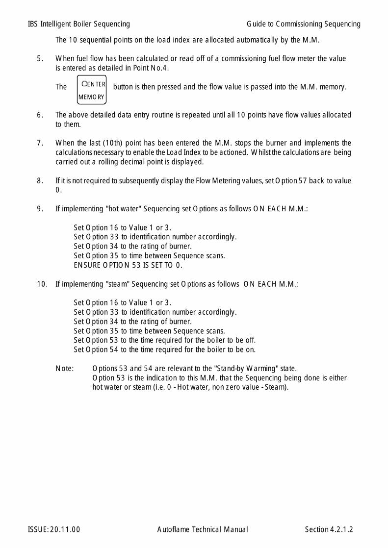
IBS Intelligent Boiler Sequencing
ISSUE: 20.11.00 Autoflame Technical Manual Section
The 10 sequential points on the load index are allocated automatically by the M.M.
5. When fuel flow has been calculated or read off of a commissioning fuel flow meter the valueis entered as detailed in Point No.4.
The button is then pressed and the flow value is passed into the M.M. memory.
6. The above detailed data entry routine is repeated until all 10 points have flow values allocatedto them.
7. When the last (10th) point has been entered the M.M. stops the burner and implements thecalculations necessary to enable the Load Index to be actioned. Whilst the calculations are beingcarried out a rolling decimal point is displayed.
8. If it is not required to subsequently display the Flow Metering values, set Option 57 back to value0.
9. If implementing "hot water" Sequencing set Options as follows ON EACH M.M.:
Set Option 16 to Value 1 or 3.Set Option 33 to identification number accordingly.Set Option 34 to the rating of burner.Set Option 35 to time between Sequence scans.ENSURE OPTION 53 IS SET TO 0.
10. If implementing "steam" Sequencing set Options as follows ON EACH M.M.:
Set Option 16 to Value 1 or 3.Set Option 33 to identification number accordingly.Set Option 34 to the rating of burner.Set Option 35 to time between Sequence scans.Set Option 53 to the time required for the boiler to be off.Set Option 54 to the time required for the boiler to be on.
Note: Options 53 and 54 are relevant to the "Stand-by Warming" state.Option 53 is the indication to this M.M. that the Sequencing being done is eitherhot water or steam (i.e. 0 - Hot water, non zero value - Steam).
MEMORY
ENTER
Guide to Commissioning Sequencing
4.2.1.2

IBS Intelligent Boiler Sequencing
ISSUE: 20.11.00 Autoflame Technical Manual Section
MINI Mk.5 M.M./E.G.A. System Pt. No.MMM50016
M EM ORY
RUN
E.G .A. M .M.
DISPLAYSTATUS
LO CKO UTR E SE T
C OM
MI NI M k.6 M.M ./E.G. A. System P t. No. MM M60016
METERING
SEQUENCING
C LO SES CAN NE RF LAM E
OPE N IBS
START FUEL
HIGH
INTER
ENTER
Combustion Management Systems
4.4 ELECTRICAL SCHEMATICS
Sequencing Connection Diagram
4.4.1
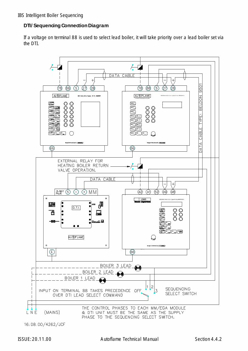
IBS Intelligent Boiler Sequencing
ISSUE: 20.11.00 Autoflame Technical Manual Section 4.4.2
MINI Mk.5 M.M./E.G.A. System Pt. No.MMM50016
M EM ORY
RUN
E.G .A. M .M.
DISPLAY
STATUS
LO CKO UTR E SE T
C OM
MI NI M k.6 M .M ./E.G.A . System P t. No. MM M60016
METERING
SEQUENCING
C LO SE S CAN NE RF LAM E
OPE N IBS
START FUEL
HIGH
INTER
ENTER
Combustion Management Systems
DTI/Sequencing Connection Diagram
If a voltage on terminal 88 is used to select lead boiler, it will take priority over a lead boiler set viathe DTI.

IBS Intelligent Boiler Sequencing
ISSUE: 20.11.00 Autoflame Technical Manual Section 4.5.1

IBS Intelligent Boiler Sequencing
ISSUE: 20.11.00 Autoflame Technical Manual Section 4.5.2

IBS Intelligent Boiler Sequencing
ISSUE: 20.11.00 Autoflame Technical Manual Section 4.5.3
A0
A0
A2
A0
A3
A0
A4
A
0
R0
R
1
A
1R
0R
2 R
0R
3R
0 R
4
R0
R0
A
0
R
1
A1
R0
A
0R
2A
2R
0A
0R
3R
0A
0 R
4 A
4
R0
A
0
A3
Sam
e w
avef
orm
sap
ply
to M
.M. N
o.s
5 to
10.
Dia
gram
sho
win
g Ex
ampl
e of
Dat
a C
omm
unic
atio
ns w
ith R
efer
ence
to F
licke
ring
L.E.
D.s
This
is th
e M
.M. t
hat i
s w
orki
ng c
omm
unic
atio
ns:
Eg.:
- M.M
. No.
1.
This
is a
n M
.M. t
hat i
s no
t wor
king
com
mun
icat
ions
.Eg
.: M
.M. N
o. 3
.
A0
-A
nsw
er fr
om D
.T.I.
A1
-A
nsw
er fr
om M
.M. 1
A2
-A
nsw
er fr
om M
.M. 2
A3
-A
nsw
er fr
om M
.M. 3
A4
-A
nsw
er fr
om M
.M. 4
A5
-A
nsw
er fr
om M
.M. 5
A6
-A
nsw
er fr
om M
.M. 6
A7
-A
nsw
er fr
om M
.M. 7
A8
-A
nsw
er fr
om M
.M. 8
A9
-A
nsw
er fr
om M
.M. 9
A10
-Ans
wer
from
M.M
. 10
R0 -
Requ
est t
o D
.T.I.
R1 -
Requ
est t
o M
.M. 1
R2 -
Requ
est t
o M
.M. 2
R3 -
Requ
est t
o M
.M. 3
R4 -
Requ
est t
o M
.M. 4
R5 -
Requ
est t
o M
.M. 5
R6 -
Requ
est t
o M
.M. 6
R7 -
Requ
est t
o M
.M. 7
R8 -
Requ
est t
o M
.M. 8
R9 -
Requ
est t
o M
.M. 9
R10
- Req
uest
to M
.M. 1
0
Ope
n
Clo
se
Ope
n
Clo
se
Not
e:-
Onl
y 1
M.M
. wor
ksth
e co
mm
unic
atio
ns.
> > > >

IBS Intelligent Boiler Sequencing
ISSUE: 20.11.00 Autoflame Technical Manual Section 4.5.4
4.5.4 Mini Mk5 Sequencing Status Information
If parameter 32 = 1 then the information below is displayed instead of the Flow Metering GrandTotal. (Totalising still continues to work in the background).
Sequencing Status Information
Lead Boiler
0 = No Lead Boiler Selected1 to 10 = Number of Lead Boiler
ReceivingSequencing Information
0 = No1 = Yes
CR1Relay Status
0 = Off1 = On
WorkingCommunications/
Sequencing
0 = No1 = Yes
Unused
Status of Input 41
0 = 0V AC 1 = 230V AC
(110V AC)
Disabled Status
0 = Enabled 1 = Disabled
*1
*2
*3
*4
Sequence Code:
Steam
0 On1 Standby/Warming2 Off3 Off
Sequence Code:
Hot Water
OnOffOffOff
*1 *2
*3 *4
I.I.F. Inverter Interface
ISSUE: 20.11.00 Autoflame Technical Manual Section
Section 5: I.I.F. Inverter Interface
5: Index
5.1 Inverter Interface (Mini Mk5 MM only)
5.1.1 Interconnections Diagram M.M. - I.I.F. - Inverter5.1.2 Control Flow Diagram for I.I.F "Straight Line" Operation5.1.3 Graph showing Input/Output Signal Relationship5.1.4 Graph showing Characteristics of Inverter Output/I.I.F. Input5.1.5 Notes on Installation5.1.6 Inverter Interface Safety Software5.1.7 Example: Cable Connections Specifications5.1.8 Cable Specifications.5.1.9 "Points" Curve Operation5.1.10 Diagram to show Increase in Slip caused by Damper sited on
Inlet to Combustion Fan5.1.11 Installation Precautions5.1.12 O2 Interface Wiring Diagram5.1.13 Splitter Module Wiring Diagram
123456789012345678901234512345678901234567890123451234567890123456789012345123456789012345678901234512345678901234567890123451234567890123456789012345123456789012345678901234512345678901234567890123451234567890123456789012345123456789012345678901234512345678901234567890123451234567890123456789012345
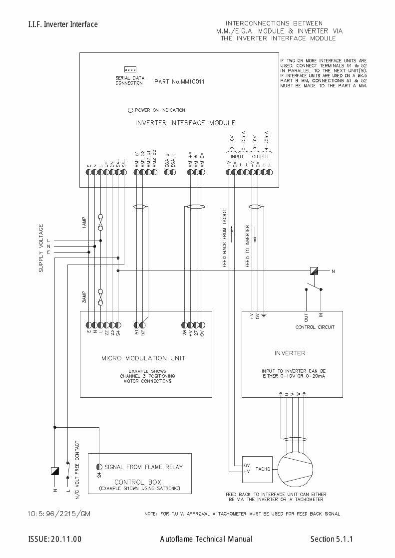
I.I.F. Inverter Interface
ISSUE: 20.11.00 Autoflame Technical Manual Section 5.1.1

I.I.F. Inverter Interface
ISSUE: 20.11.00 Autoflame Technical Manual Section
Control Flow Diagram forInverter Interface Operation
5.1.2
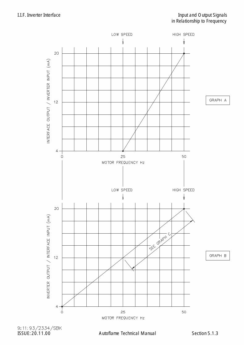
I.I.F. Inverter Interface
ISSUE: 20.11.00 Autoflame Technical Manual Section
Input and Output Signalsin Relationship to Frequency
5.1.3

I.I.F. Inverter Interface
ISSUE: 20.11.00 Autoflame Technical Manual Section
Operational Characteristics of Inverter Output/InterfaceInput in Relationship to Frequency
5.1.4

I.I.F. Inverter Interface
ISSUE: 20.11.00 Autoflame Technical Manual Section
Installation
The following recommendations are to assist with the installation and fault finding when using partnumber MM10011 with variable speed drives (Inverters).
Inverter Selection
Variable speed drives selection is critical to proper operation. Ensure that correct size Inverter hasbeen selected for the application and is suitable for the motor, and has the necessary input/outputsignals as shown in Drawing No. 2215 - Section 5.1.1.
Mains Cable Connections
Power connections from the Inverter to the motor. It is recommended for mains cabling (3 phase) andfuses, that they are to be dimensioned in accordance with the kW rating required.
Motor Cabling
A four core conductor screened cable is recommended. This is due to the rapid voltage changesoccurring in variable speed drive systems.
To Avoid Disturbances
It is advised that the motor cables should not be installed with other cable routes: Avoid long parallelruns with other cables.
Disturbances caused by radiation from the motor cable can be reduced by installing in-line chokes inthe motor cable, however these chokes may reduce the motor voltage and the maximum availabletorque. If noise problems exist and unstable output signals can not be contained within the windowand disparity band shown on Drawing No. 2335, Section 5.1.4, you should contact the supplier ofthe Inverter for more detailed information and advice. It is recommended that if the current input onthe Inverter Interface is used then a wire link should be installed across the 0V/+V input terminals.
Setting the Inverter for Operation
Due to the vast range of Variable Speed Drives it is not possible to give setting/parameters for alltypes, however the basic rules apply. The minimum and maximum Hz (rpm) should be adjusted beforecommissioning the Micro Modulation unit. Also the ramp time should be set for the fastest time possi-ble, taking into account limitation of the motor and the application.
Normal settings would be, low speed 25Hz and high speed 50Hz. It is not recommended to set lowspeed lower than 20Hz. This is because the feed back signal tends to be unstable in this range.
5.1.5
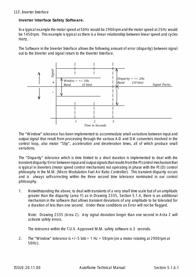
I.I.F. Inverter Interface
ISSUE: 20.11.00 Autoflame Technical Manual Section
Inverter Interface Safety Software.
In a typical example the motor speed at 50Hz would be 2900rpm and the motor speed at 25Hz wouldbe 1450rpm. This example is typical as there is a linear relationship between linear speed and cyclesHertz.
The Software in the Inverter Interface allows the following amount of error (disparity) between signalout to the Inverter and signal return to the Inverter Interface.
The “Window” tolerance has been implemented to accommodate small variations between input andoutput signal that result from processing through the various A-D and D-A converters involved in thecontrol loop, also motor “Slip”, acceleration and deceleration times, all of which produce smallvariations.
The “Disparity” tolerance which is time limited to a short duration is implemented to deal with thetransient disparity/Error between input and output signals that results from the PI control mechanism thatis typical in Inverters (motor speed control mechanism) not operating in phase with the PI (D) controlphilosophy in the M.M. (Micro Modulation Fuel Air Ratio Controller). This transient disparity occursand is always self-correcting within the three second time tolerance nominated in our controlphilosophy.
1. Notwithstanding the above, to deal with transients of a very small time scale but of an amplitudegreater than the disparity (area Y) as in Drawing 2335, Section 5.1.4, there is an additionalmechanism in the software that allows transient deviations of any amplitude to be tolerated fora duration of less than one second. Under these conditions an Error will not be flagged.
Note: Drawing 2335 (Area Z). Any signal deviation longer than one second in Area Z willactivate safety errors.
The tolerance within the T.U.V. Approved M.M. safety software is 3 seconds.
2. The “Window” tolerance is +/- 5 bits = 1 Hz = 58rpm (on a motor rotating at 2900rpm at50Hz).
V
Disparity = +/- 2HzBand (10 bits)
1 2 3Time in Seconds
+
-
Sign
al
Signal Parity
VV
VV
V
Window = +/- 1HzBand (5 bits)
5.1.6.1
I.I.F. Inverter Interface
ISSUE: 20.11.00 Autoflame Technical Manual Section
3. The disparity tolerance is +/- 10 bits = 2Hz = 116rpm (on a motor rotating at 2900rpm at50Hz). Note that disparity band 2Hz is limited to a maximum of 3 seconds.
4. Fan laws state that a.) Speed and volume are a direct linear progression.b.) Speed increase as a percentage affects pressure produced by
the fan as a square root function.
5. The variations in signal allowed in our software would have considerably less effect on the airfuel ratio supplied to the combustion process than variations in ambient temperature/air densityetc.
5.1.6.2

I.I.F. Inverter Interface
ISSUE: 20.11.00 Autoflame Technical Manual Section
Cable Type Used:
A = 16-2-3c Cores B = 16-2-2c Cores ScreenedC = Beldon 9501 or STC 0S1P24D = 16-2-6c Cores E = 4 Core Screened Screened
Please note the information in 2.9.11.2
5.1.7
Fuel Servo MotorMM10005
Air Servo MotorMM10004
Inverter InterfaceMM10011 Variable
FrequencyDrive
EXAMPLE CABLE CONNECTIONS SPECIFICATIONS
Temperature SensorMM10006
Mk.6 E.G.AMM60002
SamplingProbe
MM10003
Mini Mk.5 M.M. UnitMMM50016
Fuel 1/Gas Fuel 2/Oil
B
C
ED
AA
A
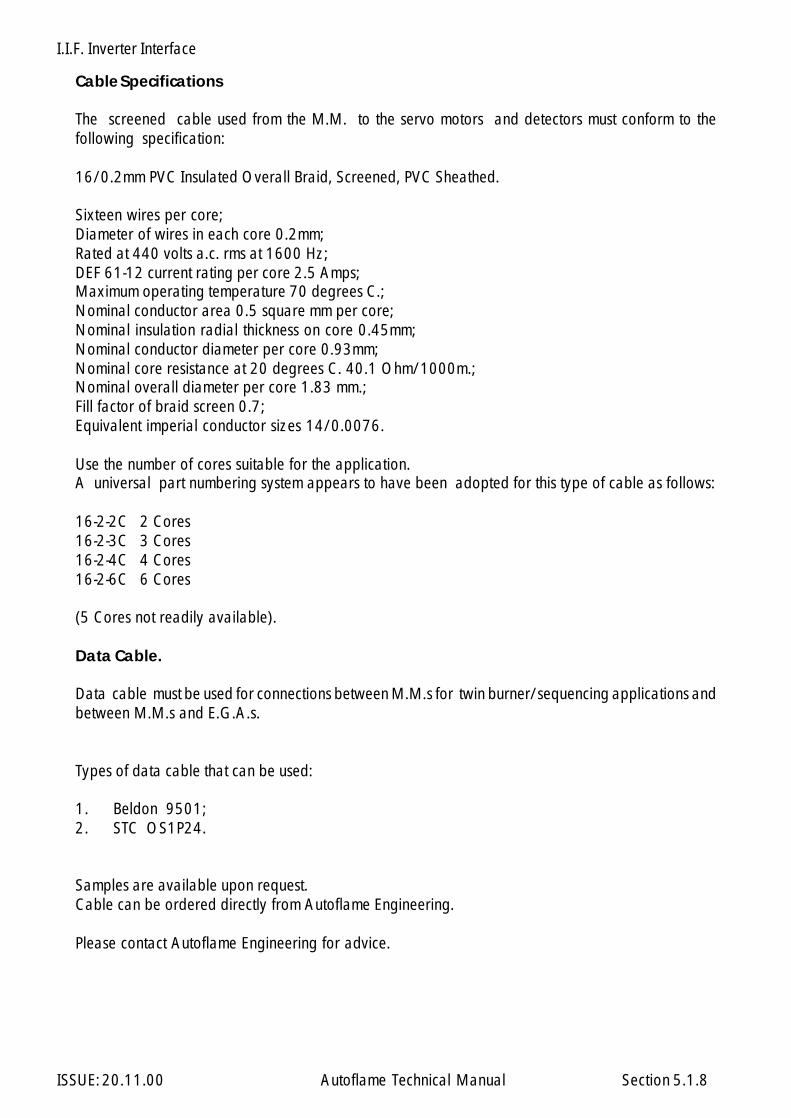
I.I.F. Inverter Interface
ISSUE: 20.11.00 Autoflame Technical Manual Section
Cable Specifications
The screened cable used from the M.M. to the servo motors and detectors must conform to thefollowing specification:
16/0.2mm PVC Insulated Overall Braid, Screened, PVC Sheathed.
Sixteen wires per core;Diameter of wires in each core 0.2mm;Rated at 440 volts a.c. rms at 1600 Hz;DEF 61-12 current rating per core 2.5 Amps;Maximum operating temperature 70 degrees C.;Nominal conductor area 0.5 square mm per core;Nominal insulation radial thickness on core 0.45mm;Nominal conductor diameter per core 0.93mm;Nominal core resistance at 20 degrees C. 40.1 Ohm/1000m.;Nominal overall diameter per core 1.83 mm.;Fill factor of braid screen 0.7;Equivalent imperial conductor sizes 14/0.0076.
Use the number of cores suitable for the application.A universal part numbering system appears to have been adopted for this type of cable as follows:
16-2-2C 2 Cores16-2-3C 3 Cores16-2-4C 4 Cores16-2-6C 6 Cores
(5 Cores not readily available).
Data Cable.
Data cable must be used for connections between M.M.s for twin burner/sequencing applications andbetween M.M.s and E.G.A.s.
Types of data cable that can be used:
1. Beldon 9501;2. STC OS1P24.
Samples are available upon request.Cable can be ordered directly from Autoflame Engineering.
Please contact Autoflame Engineering for advice.
5.1.8
I.I.F. Inverter Interface
ISSUE: 20.11.00 Autoflame Technical Manual Section
"Points" Curve Operation
The essential differences between the existing and the improved new control philosophy for theInverter Interface Module (With and Without 485 data line interconnection).
The essential philosophical differences in the control form are as detailed below under “The ExistingControl Philosophy” and “The Improved/New Control Philosophy”.
The Existing/Original Control Philosophy EPROM 2.2
The existing control philosophy assumes that the fan speed moves in a linear progression from lowspeed to high speed as a function of the control output signal from the Inverter Interface to the In-verter. It assumes that the signal back from the Inverter to the Inverter Interface or from the tacho. tothe Inverter Interface is a close facsimile of the output signal. There is a “window” and “disparity”band that is imposed on the return signal to accommodate tiny amounts of system hysteresis and pickup noise.
The control philosophy as detailed above assumes that the fan is operating in an air supply of un-changing density and pressure. (This is the case when the air damper is situated on the exhaust orpressurised side of the fan). The new control philosophy detailed below has been created to accom-modate the situation where an air damper is on the inlet to the combustion air fan. This configurationcauses slip between the magnetic circuit created by the Inverter and the measured R.P.M. (mechanicalaction) measured by the Tacho. When the damper is shut there is a fall in air pressure/density to thesupply side of the fan. When the damper is open the density/supply pressure of the air to the fanincreases. This means that if the M.M. is to tightly control and monitor the air component of the fuel/air ratio the M.M. and Inverter Interface must “learn” every combination of damper opening as anangular function and motor speed so that the slip in any combination of these two variables is meas-ured and known. In this way the M.M. can inflict close control and monitoring of the air componentinto the system.
The Improved/New Control Philosophy EPROM 4.02
The new control philosophy will be additional to the existing and will not interfere with the integrity ofthe presently approved control philosophy.
A 485 data communication line is connected between the M.M. and the Inverter Interface. In thisway the Inverter Interface module will be continually updated with the exact status of the M.M., i.e.Purge, Run, Commission, etc. In this way it will be possible for the Inverter Interface to learn andremember the slip component for any motor speed/air damper position combination.
When the M.M. is commissioned the commissioning status is passed to the Inverter Interface and allof the positions for fuel/air ratio that are entered into the M.M. during the commissioning process arepassed to the Inverter Interface. These positions are stored together with a motor speed air damperposition. This allows the Inverter Interface to measure the slip by measuring output signal to theInverter, return signal to the tacho. and learning the difference for any air position/motor speed set-ting. This improved control form also gives the facility for a different combination of air/motor speedsettings to be accommodated for varying fuels, i.e. F1, F2, F3. This facility accommodates variancesfor air requirement for different fuels which are fundamental to the hydrocarbon ratio of the fuel.
A diagram showing Slip is shown over.
5.1.9
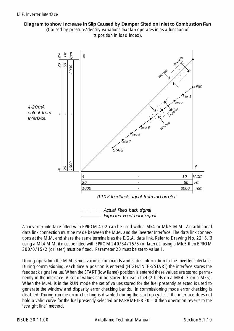
I.I.F. Inverter Interface
ISSUE: 20.11.00 Autoflame Technical Manual Section
X
Y
4 - 10 V DC
20 - 50 Hz
1000 - 3000 rpm
4-
20
m
A
20-
50
H
z
1000
-
30
00
r
pm
Window
Disparity
Disparit
y
Wind
ow
High
Inter 1
Inter 2
Inter 5
Inter 6
Inter 7
START
4-20mAoutput fromInterface.
0-10V feedback signal from tachometer.
Actual Feed back signalExpected Feed back signal
Diagram to show Increase in Slip Caused by Damper Sited on Inlet to Combustion Fan(Caused by pressure/density variations that fan operates in as a function of
its position in load index).
An inverter interface fitted with EPROM 4.02 can be used with a Mk4 or Mk.5 M.M.. An additionaldata link connection must be made between the M.M. and the Inverter Interface. The data link connec-tions at the M.M. end share the same terminals as the E.G.A. data link. Refer to Drawing No. 2215. Ifusing a Mk4 M.M. it must be fitted with EPROM 240/34/15/5 (or later). If using a Mk.5 then EPROM300/0/15/2 (or later) must be fitted. Parameter 20 must be set to value 1.
During operation the M.M. sends various commands and status information to the Inverter Interface.During commissioning, each time a position is entered (HIGH/INTER/START) the interface stores thefeedback signal value. When the START (low flame) position is entered these values are stored perma-nently in the interface. A set of values can be stored for each fuel (2 fuels on a MK4, 3 on a Mk5).When the M.M. is in the RUN mode the set of values stored for the fuel presently selected is used togenerate the window and disparity error checking bands. In commissioning mode error checking isdisabled. During run the error checking is disabled during the start up cycle. If the interface does nothold a valid curve for the fuel presently selected or PARAMETER 20 = 0 then operation reverts to the‘straight line’ method.
5.1.10
I.I.F. Inverter Interface
ISSUE: 20.11.00 Autoflame Technical Manual Section
The window and disparity bands have been increased on EPROM 4.02. The window to 10 units, thedisparity to 15 units. Here units is used in terms of the value displayed on the test data output repre-senting the signal value on the interface input; 0-20 mA → 0-255; 0-10Volts DC → 0-255. For aninverter set at maximum 50Hz this represents ± 2 Hz for the window , ± 3 Hz for disparity.
Three sets of test output data are displayed. Details are listed below. During commissioning mode atthe beginning of each line the point being entered is shown. (CLOSE,OPEN,HIGH...)
To view this data a special test lead (Pt. No. DTI20019) is required to connect the Interface to a P.C.The communication format is 4800 baud, no parity, 8 data bits, 2 stop bits.
Test Output Data:
RUN modeS4+ = 0V AC
a. a is the signal value on 1+, 1-/0V, +V inputs; range 0-255.b. b is the reading at low rpm, range 0-255.c. c is the reading at high rpm, range 0-255.d. d is a count value: The value is initially 000. When S4+ goes from 0V AC to 220V AC the value
increases. If 350 is reached then the IIF will generate an error condition. It takes 40 seconds forthe count to reach 350. 40 seconds is the time allowed for the start up sequence. Void if l=001.
e. e indicates the status of the S4+ input. 000 = 0V AC, 001 = 220V AC.f. f is the error number of the last error condition that occurred.l. If l = 001 this indicates that Parameter 20 = 1 and a valid curve has been programmed. If
Parameter 20 = 0 or the curve has not been programmed then 000 is displayed (“straight line”operation).
RUN ModeS4+ = 230V AC.:
g. g is the signal value on 1+,1-/0V, +V inputs range 0-255. (Same as a.).h. h is the expected value on g.i. If the signal g goes outside the window into the disparity, then this value is set to 30 and counts
down to 0. If the signal go goes back into the window then this value is set directly back to 0.10 counts = 1 second. The signal g is allowed to be in the disparity for 3 seconds.
j. If the signal g is outside the disparity, this value is set to 10 and counts down to 0. If the signalg goes back into the window/disparity then this value is set directly back to 0. 10 counts = 1second. The signal g is allowed to be outside the disparity for 1 second.
k. k indicates the status of the S4+ input. 000 = 0V AC, 001 = 220V AC. (Same as e.)
5.1.10.1

I.I.F. Inverter Interface
ISSUE: 20.11.00 Autoflame Technical Manual Section
COMMISSIONING Mode.
m. m is the input signal value on 1+, 1-/0V, +V inputs. Range = 0-255 (same as a.).n. n is a digital value generated in the Inverter Interface. As each point is entered it is stored
alongside value m. (Autoflame use for diagnostic purposes).o. Value of m stored for previous point entered.p. Value of n stored for previous point entered.q. If l = 001 this indicates that Parameter 20 = 1 and a valid curve has been programmed. If
Parameter 20 = 0 or the curve has not been programmed then 000 is displayed (“straight line”operation).
If the IIF generates an error condition the test data output stops so that the events leading up to theerror can be analysed. The IIF has to be powered down and up quickly in order to see the errornumber that has just occurred.
Error Numbers
1. Start up sequence not complete in 40 seconds.3. Signal “g” in disparity for 3 seconds.4. Signal “g” outside disparity for 1 second.5. Wiper (w) value output error (Electronics fault).6. Analogue to digital converter faults (Electronics fault).7. S4+/S4- inputs not inverse of each other.10. EPROM Check Error. (Electronics fault).11. RAM Check Error. (Electronics fault).
Any other error number void.
During commissioning ensure that the value of m.) for Inter 1 is less than the HIGH position value ofm.). Similarly each subsequent value of m.) entered must be less than the value entered immediatelybefore. It is recommended that values o.) and p.) are recorded for each point entered as part of thecommissioning data for the system.
After commissioning is complete the engineer must run the burner from low to high fire and check thatthe output values g.) and h.) are correct and that no M.M. errors occur.
5.1.10.2
I.I.F. Inverter Interface
ISSUE: 20.11.00 Autoflame Technical Manual Section
5.1.11 Installation Precautions
The reliability of the equipment may be impaired if used in environments where strong electro magneticfields exist. If for example the equipment is installed in a boiler house at the top of a high rise buildingwhere radio systems exist then additional EMC (Electro Magnetic Compatability) measures may haveto be considered
5.1.11

I.I.F. Inverter Interface
ISSUE: 20.11.00 Autoflame Technical Manual Section 5.1.12

I.I.F. Inverter Interface
ISSUE: 20.11.00 Autoflame Technical Manual Section 5.1.13
D.T.I. Data Transfer Interface
ISSUE: 20.11.00 Autoflame Technical Manual Section
Section 6: D.T.I. Data Transfer Interface
6.1 DTI Module
6.2 Information Available from the DTI system
6.3 Complete DTI Standard System Application Example
6.4 Multi Kiln DTI Special System Application Example
6.5 Front Facia Layout
6.7 I/O System Capabilities
6.8 Communication Interface schematic system capabilities
6.9 Wiring Connection Terminals Diagram
6.10 DTI Fixing Holes and Dimensional Details
6.11 DTI Interconnections
6.11.1 MM Modules6.11.2 EGA Modules
6.12 PCB Switch Settings and Link Arrangements
6.12.1 Restore To Factory Settings
6.13 DTI, PC and Modem Interconnections
6.14 Analogue Input/Output Module Index
6.15 Digital Input/Output Module Index
6.17 Modbus Interface Index
6.18 Autoflame WinPCDTI Software
6.19 Johnson Metasys Interface Index
6.20 Other Information and Illustrations
6.20.1 Loop Back Test6.20.2 Communication Interfaces
6 Index
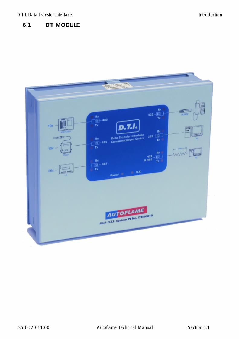
D.T.I. Data Transfer Interface
ISSUE: 20.11.00 Autoflame Technical Manual Section
6.1 DTI MODULE
6.1
Introduction
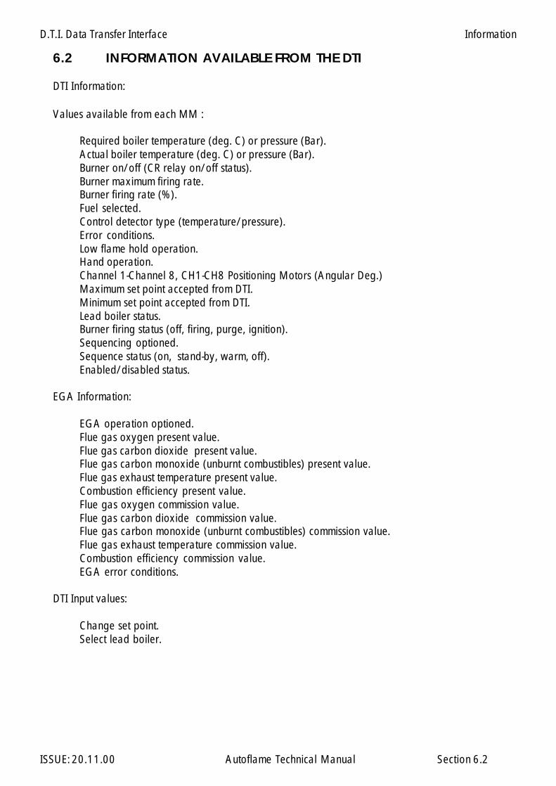
D.T.I. Data Transfer Interface
ISSUE: 20.11.00 Autoflame Technical Manual Section
Values available from each MM :
Required boiler temperature (deg. C) or pressure (Bar).Actual boiler temperature (deg. C) or pressure (Bar).Burner on/off (CR relay on/off status).Burner maximum firing rate.Burner firing rate (%).Fuel selected.Control detector type (temperature/pressure).Error conditions.Low flame hold operation.Hand operation.Channel 1-Channel 8, CH1-CH8 Positioning Motors (Angular Deg.)Maximum set point accepted from DTI.Minimum set point accepted from DTI.Lead boiler status.Burner firing status (off, firing, purge, ignition).Sequencing optioned.Sequence status (on, stand-by, warm, off).Enabled/disabled status.
EGA Information:
EGA operation optioned.Flue gas oxygen present value.Flue gas carbon dioxide present value.Flue gas carbon monoxide (unburnt combustibles) present value.Flue gas exhaust temperature present value.Combustion efficiency present value.Flue gas oxygen commission value.Flue gas carbon dioxide commission value.Flue gas carbon monoxide (unburnt combustibles) commission value.Flue gas exhaust temperature commission value.Combustion efficiency commission value.EGA error conditions.
DTI Input values:
Change set point.Select lead boiler.
6.2 INFORMATION AVAILABLE FROM THE DTI
DTI Information:
6.2
Information
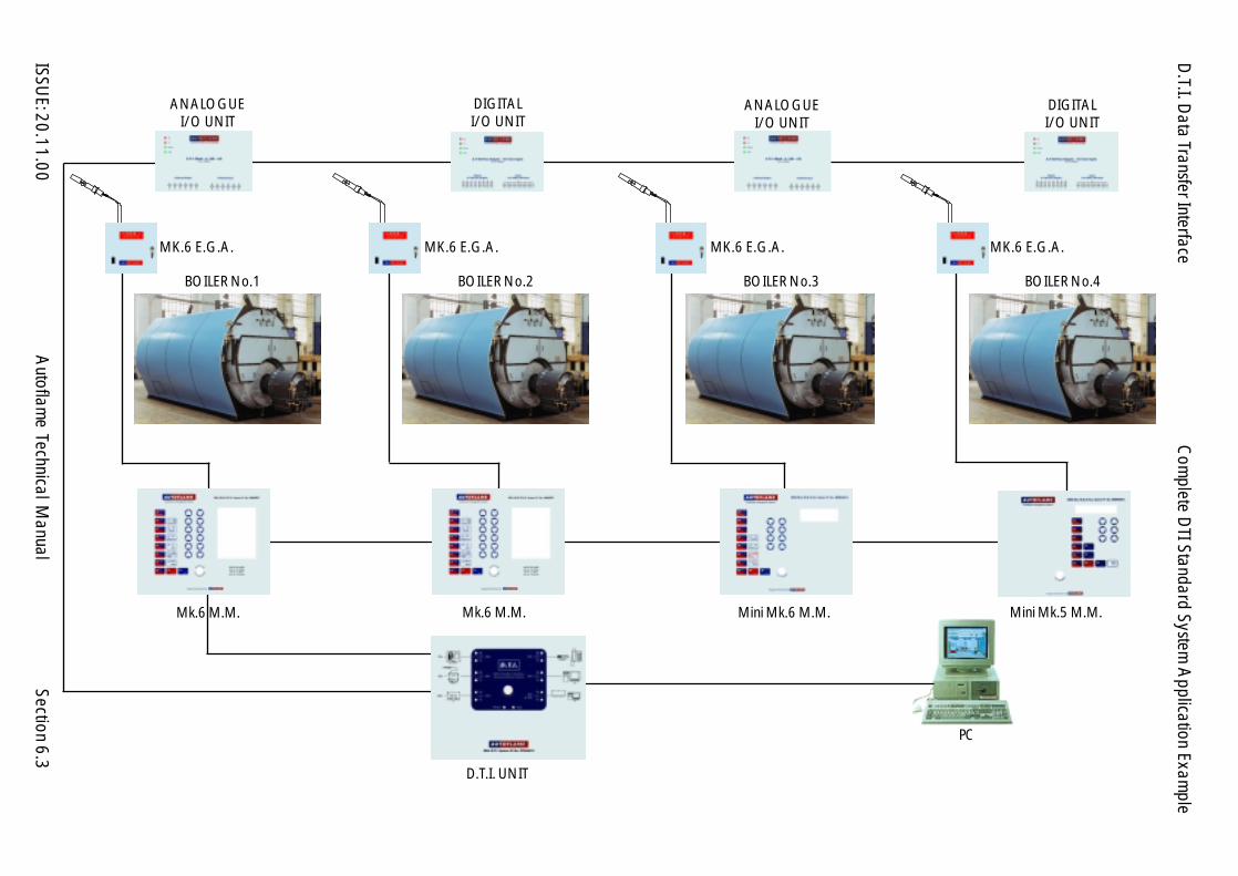
D.T.I. D
ata Transfer Interface
ISSUE: 20.11.00
Autoflam
e Technical Manual
Section
BOILER No.3BOILER No.2
D.T.I. UNIT
Mk.6 M.M.
MK.6 E.G.A. MK.6 E.G.A. MK.6 E.G.A.
PC
ANALOGUEI/O UNIT
DIGITALI/O UNIT
BOILER No.4
ANALOGUEI/O UNIT
DIGITALI/O UNIT
Com
plete DTI Standard System
Application Exam
ple
6.3
BOILER No.1
MK.6 E.G.A.
Mk.6 M.M. Mini Mk.6 M.M. Mini Mk.5 M.M.

D.T.I. D
ata Transfer Interface
ISSUE: 20.11.00
Autoflam
e Technical Manual
Section6.4
KILN No.2
4 X
THER
MO
CO
UPL
ES
Mini Mk.5 M.M.
KILN No.14
X TH
ERM
OC
OU
PLES
OTHERCONTROL
X 8
ALARMSX 16
DIGITALI/O UNIT
DTI UNIT
ANALOGUEI/O UNIT
BURNER RATE SIGNALKILN No.1
BURNER RATE SIGNALKILN No.2
PC
Multi K
iln Special System A
pplication Example
Mini Mk.5 M.M.
ANALOGUEI/O UNIT
Mini Mk.5 M.M.
Mini Mk.5 M.M.Mini Mk.5 M.M.
Mini Mk.5 M.M.Mini Mk.5 M.M.
Mini Mk.5 M.M.
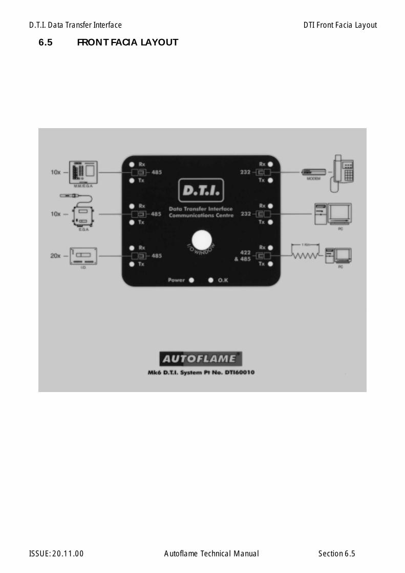
D.T.I. Data Transfer Interface
ISSUE: 20.11.00 Autoflame Technical Manual Section
6.5 FRONT FACIA LAYOUT
6.5
DTI Front Facia Layout

D.T.I. Data Transfer Interface
ISSUE: 20.11.00 Autoflame Technical Manual Section
6.7 INPUT/OUTPUT SYSTEM CAPABILITIES
6.7
Input/Output System Capabilities

D.T.I. Data Transfer Interface
ISSUE: 20.11.00 Autoflame Technical Manual Section 6.8
6.8 COMMUNICATION INTERFACE SCHEMATIC SYSTEM CAPABILITIES
Communication Interface Schematic System Capabilities
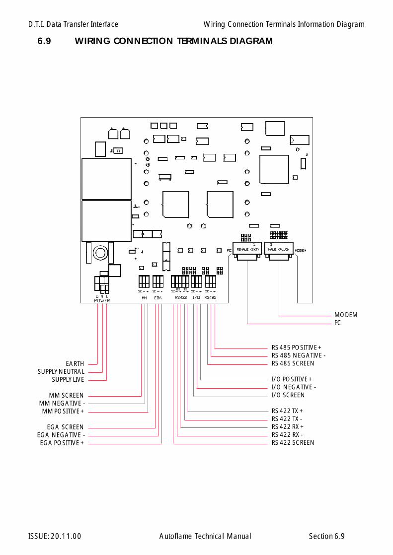
D.T.I. Data Transfer Interface
ISSUE: 20.11.00 Autoflame Technical Manual Section
6.9 WIRING CONNECTION TERMINALS DIAGRAM
6.9
EARTHSUPPLY NEUTRAL
SUPPLY LIVE
MM SCREENMM NEGATIVE -MM POSITIVE +
EGA SCREENEGA NEGATIVE -EGA POSITIVE +
RS 485 POSITIVE +RS 485 NEGATIVE -RS 485 SCREEN
I/O POSITIVE +I/O NEGATIVE -I/O SCREEN
RS 422 TX +RS 422 TX -RS 422 RX +RS 422 RX -RS 422 SCREEN
MODEMPC
Wiring Connection Terminals Information Diagram
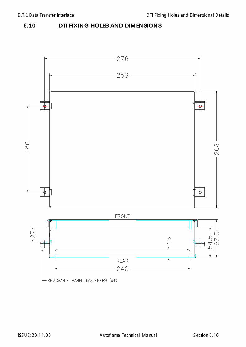
D.T.I. Data Transfer Interface
ISSUE: 20.11.00 Autoflame Technical Manual Section
6.10 DTI FIXING HOLES AND DIMENSIONS
6.10
DTI Fixing Holes and Dimensional Details
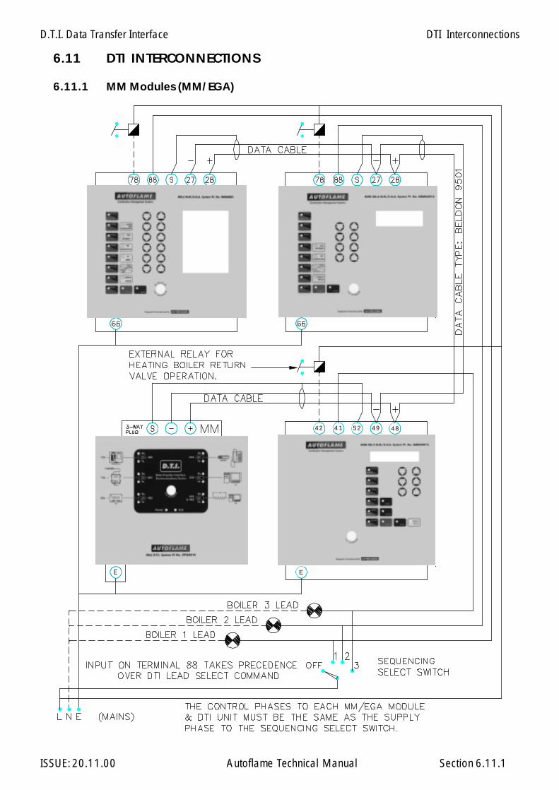
D.T.I. Data Transfer Interface
ISSUE: 20.11.00 Autoflame Technical Manual Section
6.11 DTI INTERCONNECTIONS
6.11.1 MM Modules (MM/EGA)
6.11.1
DTI Interconnections
42 52 49 4841
E
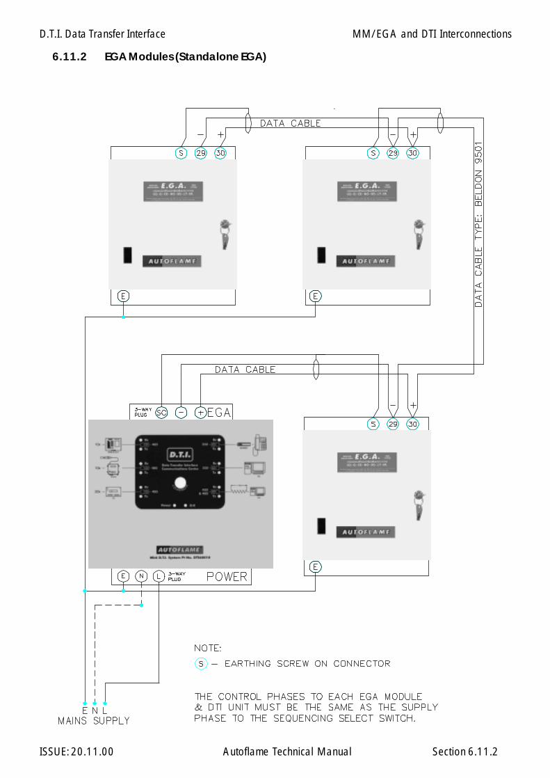
D.T.I. Data Transfer Interface
ISSUE: 20.11.00 Autoflame Technical Manual Section 6.11.2
6.11.2 EGA Modules (Standalone EGA)
MM/EGA and DTI Interconnections
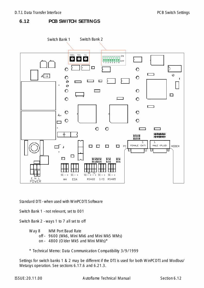
D.T.I. Data Transfer Interface
ISSUE: 20.11.00 Autoflame Technical Manual Section
6.12 PCB SWITCH SETTINGS
PCB Switch Settings
6.12
Standard DTI - when used with WinPCDTI Software
Switch Bank 1 - not relevant, set to 001
Switch Bank 2 - ways 1 to 7 all set to off
Way 8 MM Port Baud Rateoff - 9600 (Mk6, Mini Mk6 and Mini Mk5 MMs)on - 4800 (Older Mk5 and Mini MMs)*
* Technical Memo: Data Communication Compatibility 3/9/1999
Settings for switch banks 1 & 2 may be different if the DTI is used for both WinPCDTI and Modbus/Metasys operation. See sections 6.17.6 and 6.21.3.
ON
OFF1 2 3 4 5 6 7 8
10s100s 1s
Switch Bank 1 Switch Bank 2
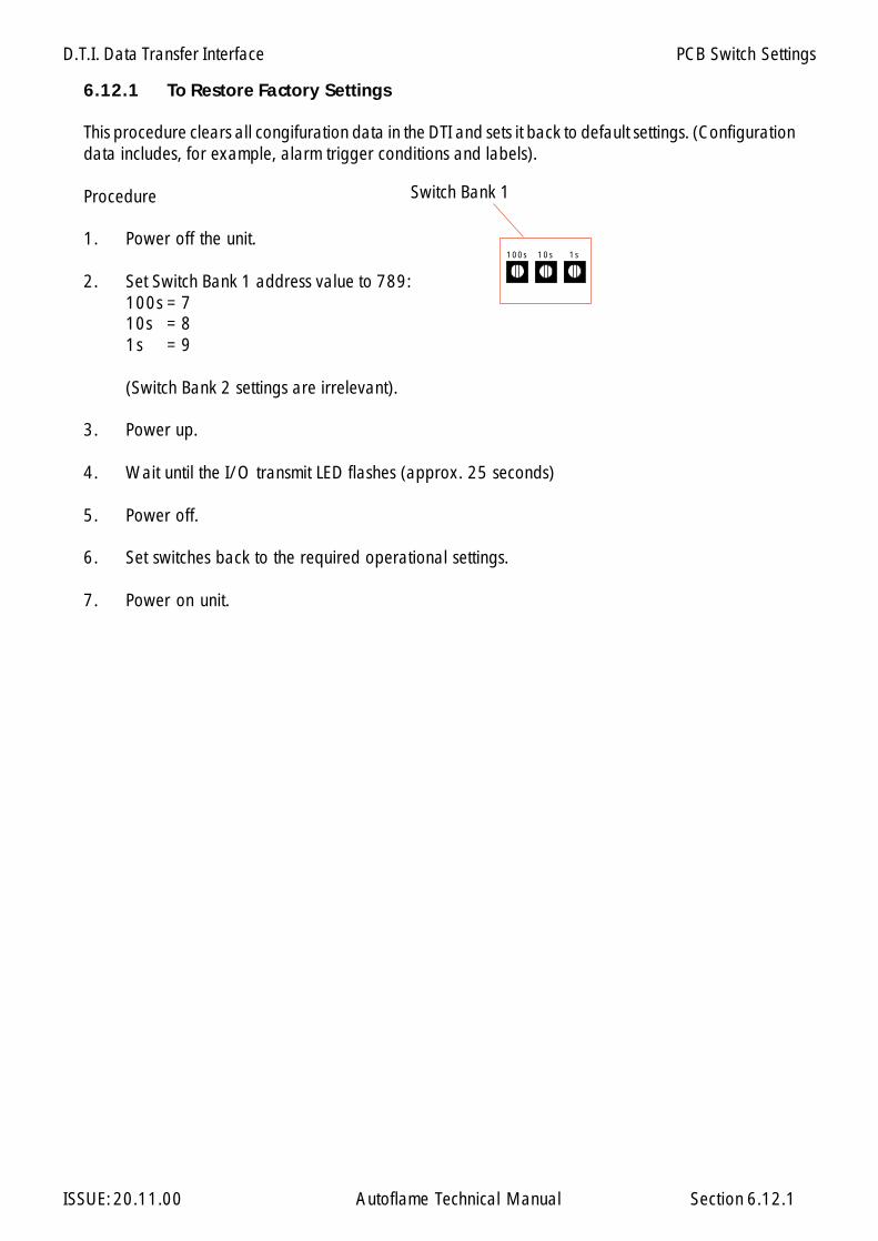
D.T.I. Data Transfer Interface
ISSUE: 20.11.00 Autoflame Technical Manual Section 6.12.1
6.12.1 To Restore Factory Settings
This procedure clears all congifuration data in the DTI and sets it back to default settings. (Configurationdata includes, for example, alarm trigger conditions and labels).
Procedure
1. Power off the unit.
2. Set Switch Bank 1 address value to 789:100s = 710s = 81s = 9
(Switch Bank 2 settings are irrelevant).
3. Power up.
4. Wait until the I/O transmit LED flashes (approx. 25 seconds)
5. Power off.
6. Set switches back to the required operational settings.
7. Power on unit.
PCB Switch Settings
Switch Bank 1
10s100s 1s
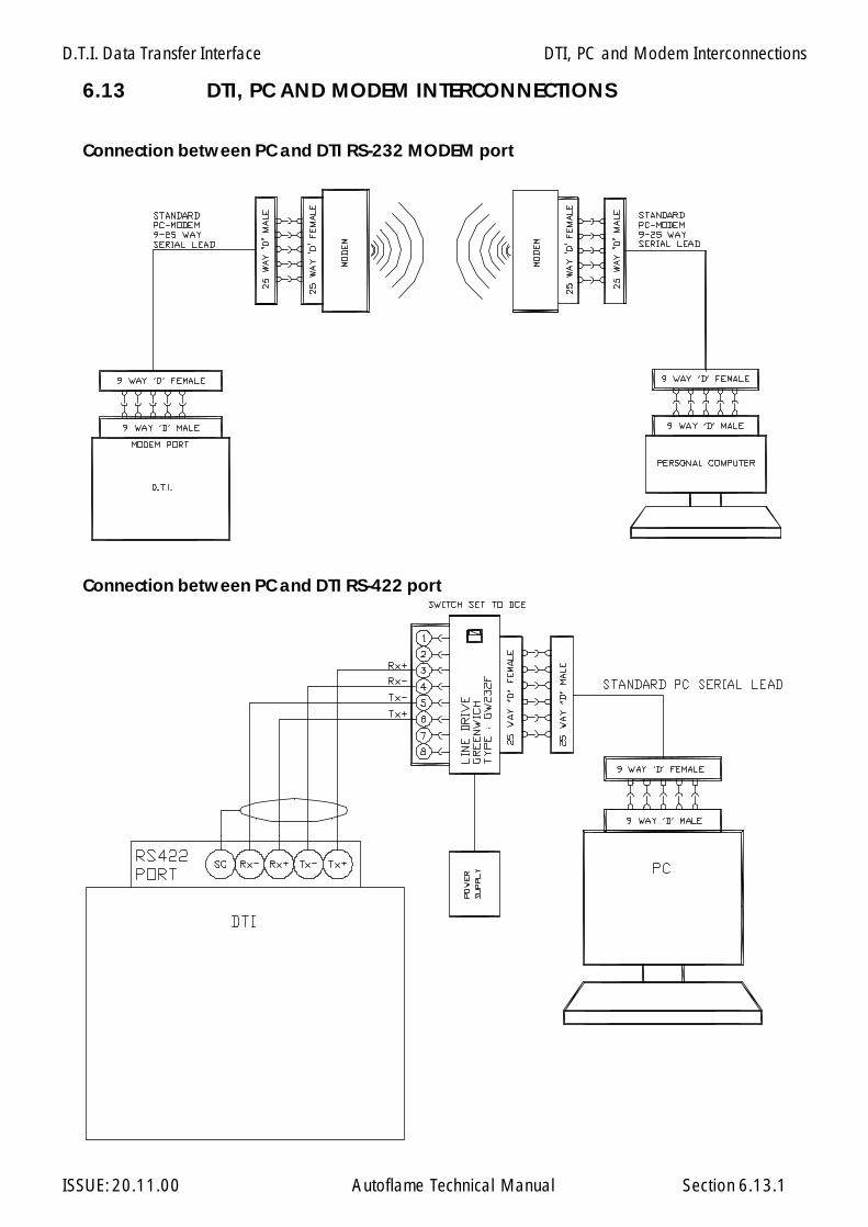
D.T.I. Data Transfer Interface
ISSUE: 20.11.00 Autoflame Technical Manual Section
6.13 DTI, PC AND MODEM INTERCONNECTIONS
6.13.1
DTI, PC and Modem Interconnections
Connection between PC and DTI RS-232 MODEM port
Connection between PC and DTI RS-422 port
Example shown using line drive typeGW232F made by Greenwich InstrumentsLimited.
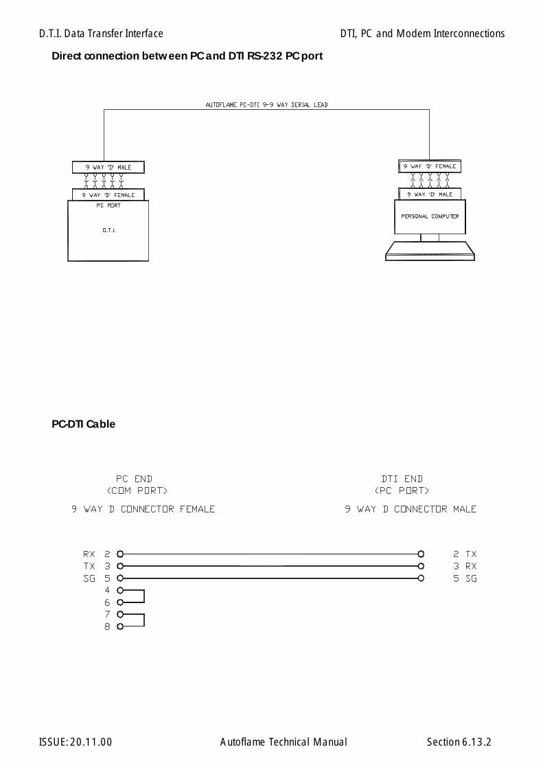
D.T.I. Data Transfer Interface
ISSUE: 20.11.00 Autoflame Technical Manual Section 6.13.2
DTI, PC and Modem Interconnections
Direct connection between PC and DTI RS-232 PC port
PC-DTI Cable

D.T.I. Data Transfer Interface
ISSUE: 20.11.00 Autoflame Technical Manual Section
Section 6.14: Analogue Input/Output Module Index
6.14.1 Introduction, Features & Benefits
6.14.2 Facia Layout and Internal Connections
6.14.3 Setup Configuration for direct connection to M.M. unit
6.14.4 Front Facia Layout with LED description
6.14.5 Fixing Holes & Dimensional Details
6.14.6 Wiring Connection Diagram
6.14.7 M.M. to Analogue Input/Output Unit Connection Diagram
6.14.8 DTI to Analogue Input/Output Unit Connection Diagram
6.14.9 Application Example
6.14 Index
D.T.I. Data Transfer Interface
ISSUE: 20.11.00 Autoflame Technical Manual Section
This unit has 6 analogue inputs and 6 analogue outputs. Each analog input can be individually configuredfor 0-10 Volts, 0-20milliamps or 4-20 milliamps. Each analog output can be individually configuredfor 0-10 Volts or 4-20 milliamps. The unit is primarily for use with a Data Transfer Interface (DTI) unit.It can also be used in conjunction with most MM units to convert MM items of data to analogueoutputs. Before operation the unit must be setup for its particular modes of operation by means of aserial port and a personal computer (emulating a terminal - e.g. Windows Hyperterminal). Each ana-log input and output must also have a jumper set to select voltage or current operation.
When used with a DTI up to 10 analogue input/output units can be linked together. As well as theactual analogue inputs and outputs being configurable, the data range for each input and output canalso be individually set. Text labels can also be assigned to each input and output. The latter items(data range / text labels) can be of use when the DTI is being used for a building management systemor programmable logic controller type interface. However, in the vast majority of cases, these setupscan be left as supplied. Refer to DTI manual for interconnections between the Analogue I/O unit & theDTI.
An external PSU is not required for the analogue outputs. The maximum permissable load on eachanalogue output is 250Ω. All the negative terminals are common to each other. The analogue outputsas a whole are isolated.
6.14.1 Introduction , Features and Benefits
6.14.1
Analogue I/O Module
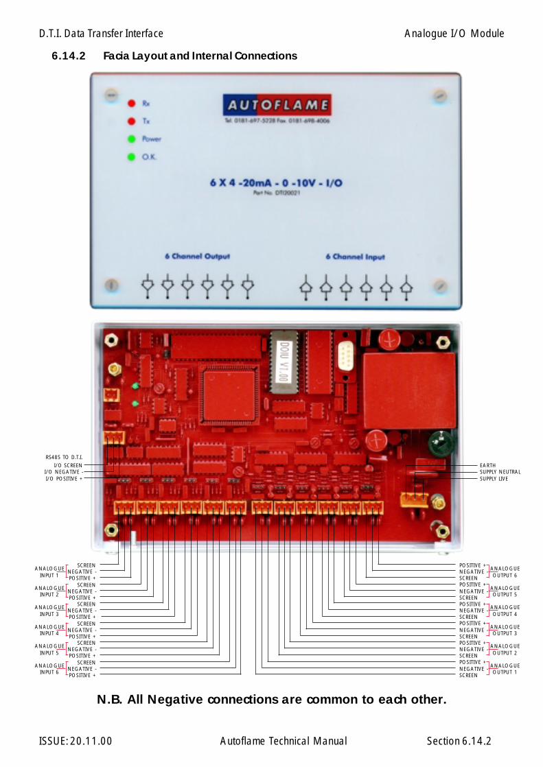
D.T.I. Data Transfer Interface
ISSUE: 20.11.00 Autoflame Technical Manual Section
SCREENNEGATIVE -POSITIVE +
ANALOGUEINPUT 1
SCREENNEGATIVE -POSITIVE +
ANALOGUEINPUT 2
SCREENNEGATIVE -POSITIVE +
ANALOGUEINPUT 3
SCREENNEGATIVE -POSITIVE +
ANALOGUEINPUT 4
SCREENNEGATIVE -POSITIVE +
ANALOGUEINPUT 5
SCREENNEGATIVE -POSITIVE +
ANALOGUEINPUT 6
POSITIVE +NEGATIVE -SCREENPOSITIVE +NEGATIVE -SCREEN
ANALOGUEOUTPUT 5
POSITIVE +NEGATIVE -SCREEN
ANALOGUEOUTPUT 4
POSITIVE +NEGATIVE -SCREENPOSITIVE +NEGATIVE -SCREEN
ANALOGUEOUTPUT 2
POSITIVE +NEGATIVE -SCREEN
ANALOGUEOUTPUT 1
EARTHSUPPLY NEUTRALSUPPLY LIVE
I/O SCREENI/O NEGATIVE -I/O POSITIVE +
RS485 TO D.T.I.
ANALOGUEOUTPUT 6
ANALOGUEOUTPUT 3
6.14.2 Facia Layout and Internal Connections
6.14.2
N.B. All Negative connections are common to each other.
Analogue I/O Module

D.T.I. Data Transfer Interface
ISSUE: 20.11.00 Autoflame Technical Manual Section
SETUP
To configure the unit connect a pc serial port to the setup port (use the Autoflame I/O setup lead). Thepc must be running a terminal emulation program with the transmit and receive parameters set asfollows:
Baud rate: 4800Data bits 8Parity noneStop bits 1
(Check the COM port is set to the one actually being used).
Pressing the <return> key should bring up the following opening message:
Analog I/O unit setup mode
Pressing the <ESC> key at any time during setup will cause exit from setup. If no keys are pressed fora period of approximately 5 minutes the unit will automatically exit from setup and revert to normaloperation. During setup the unit will not carry out its normal functions. A test mode can be invokedduring set up so the operation of the inputs and outputs can be checked. Every detail of the setup is notcovered here as it is very repetitive. Experience can be quickly gained by working with an actual unitin setup mode. (Note that during normal operation if the PC is connected textual messages are dis-played indicating communication between input/output units and the DTI).
If an existing setting is to be left unchanged then just press the <return> key.
The following shows samples of the various items that can be set. Text that is displayed on the screenis shown in bold.
Present input range for analog input 1 is A 0-10 volts
Ranges available0 - 10 volts A0 - 20 milliamps B4 - 20 milliamps C
Make new selection or <return>This can be set for all 6 inputs. The appropriate link on the circuit board must be set for current/voltage. The link for each input is directly behind the 3 way terminal block.
Present mode of operation is with DTIPress M to set MM mode or <return to proceed>
If DTI mode is selected, by just pressing <return> in this example, the following items are displayed
6.14.3 Setup Configuration for direct connection to M.M. unit
6.14.3
Analogue I/O Module
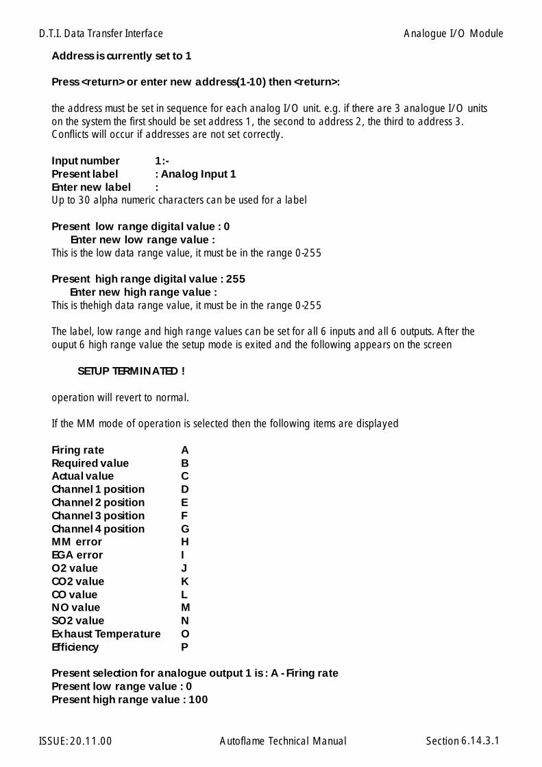
D.T.I. Data Transfer Interface
ISSUE: 20.11.00 Autoflame Technical Manual Section
Address is currently set to 1
Press <return> or enter new address(1-10) then <return>:
the address must be set in sequence for each analog I/O unit. e.g. if there are 3 analogue I/O unitson the system the first should be set address 1, the second to address 2, the third to address 3.Conflicts will occur if addresses are not set correctly.
Input number 1:-Present label : Analog Input 1Enter new label :Up to 30 alpha numeric characters can be used for a label
Present low range digital value : 0 Enter new low range value :This is the low data range value, it must be in the range 0-255
Present high range digital value : 255 Enter new high range value :This is thehigh data range value, it must be in the range 0-255
The label, low range and high range values can be set for all 6 inputs and all 6 outputs. After theouput 6 high range value the setup mode is exited and the following appears on the screen
SETUP TERMINATED !
operation will revert to normal.
If the MM mode of operation is selected then the following items are displayed
Firing rate ARequired value BActual value CChannel 1 position DChannel 2 position EChannel 3 position FChannel 4 position GMM error HEGA error IO2 value JCO2 value KCO value LNO value MSO2 value NExhaust Temperature OEfficiency P
Present selection for analogue output 1 is : A - Firing ratePresent low range value : 0Present high range value : 100
6.14.3.1
Analogue I/O Module

D.T.I. Data Transfer Interface
ISSUE: 20.11.00 Autoflame Technical Manual Section 6.14.3.2
if the <return> key is pressed the screen refreshes with the same display but for analogue output 2. Ifa selection is made then a low range value and a high range value are subsequently requested.The low and high range values are values at which the output ranges itself from zero to span (ie 0-10volts or 4-20 milliamps). After all 6 analog outputs have been covered the setup mode isautomatically exited and the screen displays
SETUP TERMINATED !
It must be noted that the numeric values for the low and high range do not accept decimal points. If thevalue normally has a decimal point then the value should be entered without the decimal point. (e.g.for the channel 2 position, if the output was set to give 0-10 volts over 10.0 to 80.0 degrees then thelow and high range should be entered as 100 and 800 respectively.
Analogue I/O Module
Configuration of MM when used directly with an Analogue I/O unit
If an analog I/O unit is connected directly to an MM to provide analog outputs, the first analogueinput may be used to set the Required value. (Input channels 2 to 6 are of no relevance when the unitis used with an MM).
If the Required value is to be set by the channel 1 input then the following options/parameters shouldbe set on the MM.
Option 16 = 2Option 30 = lowest Required valueOption 31 = highest Required valueOption 33 = 1Parameter 49 = 1
The channel 1 input can be configured for voltage/current as described in the earlier sections of thesetup procedure.
On later versions of the Analogue I/O unit software (3.01 onwards) there is an additional set up to setthe type of MM connected.
Example:
RS485 port baud rate is set at 9600 (Mk6, MiniMk6, MiniMk5)Press 4 for to set to 4800 <return> to proceed.
Also on the later versions the following text is displayed when not in set up mode.
MM comms = nnn required value = nnn
MM comms increments each time the Analogue I/O unit receives data from the MM. Required valueis the value that has been calculated for transmission back to the MM.
NB: Sequencing/D.T.I. and Analogue I/O unit cannot be used at the same time.
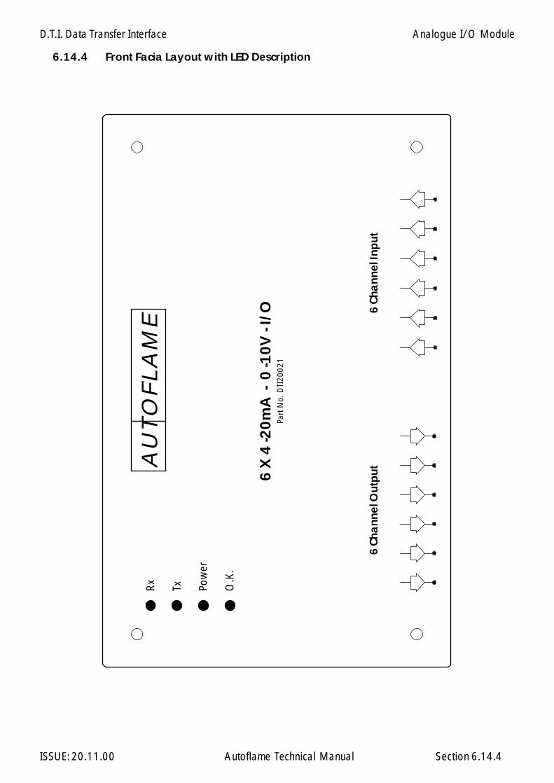
D.T.I. Data Transfer Interface
ISSUE: 20.11.00 Autoflame Technical Manual Section
6 X
4 -2
0m
A -
0 -1
0V
- I/
OPa
rt N
o. D
TI20
021
6 C
hann
el In
put
6 Ch
ann
el O
utp
ut
Rx
Tx Pow
er
O.K
.
AU
TO
FLA
ME
6.14.4 Front Facia Layout with LED Description
6.14.4
Analogue I/O Module
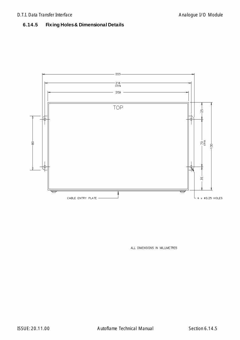
D.T.I. Data Transfer Interface
ISSUE: 20.11.00 Autoflame Technical Manual Section
6.14.5 Fixing Holes & Dimensional Details
6.14.5
Analogue I/O Module
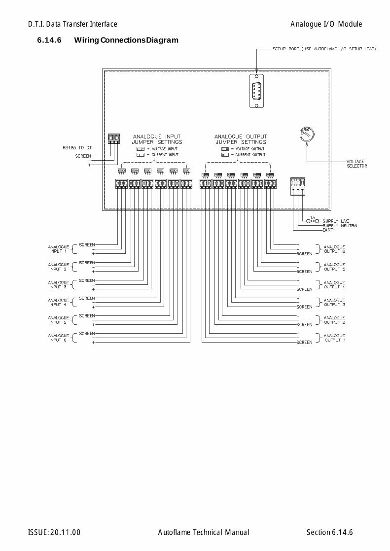
D.T.I. Data Transfer Interface
ISSUE: 20.11.00 Autoflame Technical Manual Section
6.14.6 Wiring Connections Diagram
6.14.6
Analogue I/O Module

D.T.I. Data Transfer Interface
ISSUE: 20.11.00 Autoflame Technical Manual Section
6.14.7 M.M. to Analogue Input/Output Unit Connection Diagram
6.14.7
Analogue I/O Module
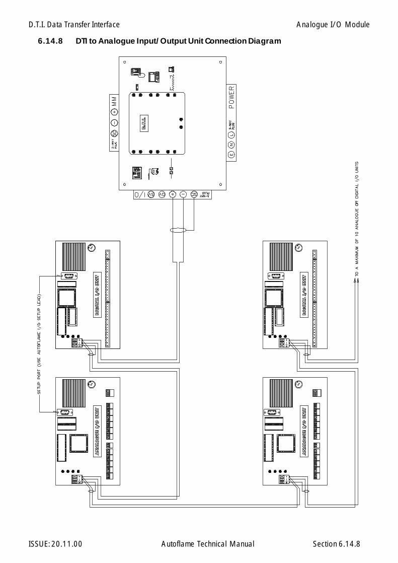
D.T.I. Data Transfer Interface
ISSUE: 20.11.00 Autoflame Technical Manual Section
6.14.8 DTI to Analogue Input/Output Unit Connection Diagram
6.14.8
Analogue I/O Module

D.T.I. D
ata Transfer Interface
ISSUE: 20.11.00
Autoflam
e Technical Manual
Section
CLLIENT'S CONTROL ROOM X 12
6.1
4.9
Ap
plica
tion Ex
am
ple: M
.M. unit to
Ana
log
ue Input/O
utput U
nit Direct Co
nnection
6.14.9
FUEL
PO
SITI
ON
AIR
PISI
TIO
NFI
RIIN
G R
ATE
ERRO
R /
FAU
LTSP
ARE
SPA
RE
LOA
D C
ON
TRO
L
4-20 mA i/OModule
DTI20021
M.M. UNITMMM50016
LOCALSERVICES
PANEL
MM
1000
4
MM
1007
2
BURNERNo.1
OV37021OIL
AIR DAMPER
FUEL
PO
SITI
ON
AIR
PISI
TIO
NFI
RIIN
G R
ATE
ERRO
R /
FAU
LTSP
ARE
SPA
RE
LOA
D C
ON
TRO
L
4-20 mA i/OModule
DTI20021
M.M. UNITMMM50016
LOCALSERVICES
PANEL
MM
1000
4
MM
1007
2
BURNERNo.2
OV37021
AIR DAMPER
FUEL
PO
SITI
ON
AIR
PISI
TIO
NFI
RIIN
G R
ATE
ERRO
R /
FAU
LTSP
ARE
SPA
RE
LOA
D C
ON
TRO
L
4-20 mA i/OModule
DTI20021
M.M. UNITMMM50016
LOCALSERVICES
PANEL
MM
1000
4
MM
1007
2
BURNERNo.3
OV37021
AIR DAMPER
FUEL
PO
SITI
ON
AIR
PISI
TIO
NFI
RIIN
G R
ATE
ERRO
R /
FAU
LTSP
ARE
SPA
RE
LOA
D C
ON
TRO
L
4-20 mA i/OModule
DTI20021
M.M. UNITMMM50016
LOCALSERVICES
PANEL
MM
1000
4
MM
1007
2
BURNERNo.4
OV37021
AIR DAMPER
Analogue I/O
Module

D.T.I. Data Transfer Interface
ISSUE: 20.11.00 Autoflame Technical Manual Section
Section 6.15: Digital Input/Output Module Index
6.15 Index
6.15.1 Introduction, Features & Benefits
6.15.2 Facia Layout and Internal Connections
6.15.3 Setup Configuration for direct connection to DTI unit only
6.15.4 Front Facia Layout with LED Description
6.15.5 Fixing Holes & dimensional Details
6.15.6 Wiring Connection Diagram
6.15.7 DTI to Digital Input/Output Unit Connection Diagram

D.T.I. Data Transfer Interface
ISSUE: 20.11.00 Autoflame Technical Manual Section
This unit has 16 mains voltage inputs and 8 individual volt free mains voltage switches.The unit is used in conjunction with a Data Transfer Interface (DTI) unit. Before operation the unit mustbe setup for operation by means of a serial port and a personal computer (emulating a terminal). Aspecial lead supplied by Autoflame is required to connect the personnel computer to the unit. Up to10 digital input/output units can be chained together.Text labels can also be assigned to each inputand output. The latter items (data range / text labels) can be of use when the DTI is being used for abuilding management system or programmable logic controller type interface.Refer to DTI manual for interconnections between the Analogue I/O unit & the DTI
6.15.1 Introduction , Features and Benefits
6.15.1
Digital I/O Module

D.T.I. Data Transfer Interface
ISSUE: 20.11.00 Autoflame Technical Manual Section
COMMONINPUT 1INPUT 2INPUT 3INPUT 4INPUT 5INPUT 6INPUT 7INPUT 8INPUT 9
INPUT 10INPUT 11INPUT 12INPUT 13INPUT 14INPUT 15INPUT 16
SUPPLY LIVESUPPLY NEUTRALEARTH
OUTPUT 8
OUTPUT 7
OUTPUT 6
OUTPUT 5
OUTPUT 4
OUTPUT 3
OUTPUT 2
OUTPUT 1
I/O SCREENI/O NEGATIVE -I/O POSITIVE +
RS485 TO D.T.I.
6.15.2 Facia Layout and Internal Connections
6.15.2
Digital I/O Module

D.T.I. Data Transfer Interface
ISSUE: 20.11.00 Autoflame Technical Manual Section
To configure the unit connect a pc serial port to the setup port (use the Autoflame I/O setup lead).The pc must be running a terminal emulation program with the transmit and receive parameters setas follows:
Baud rate: 4800Data bits 8Parity noneStop bits 1
(Check the COM port is set to the one actually being used).
Pressing the <return> key should bring up the following opening message:
Digital I/O unit setup mode
Pressing the <ESC> key at any time during setup will cause exit from setup. If no keys are pressedfor a period of approximately 5 minutes the unit will automatically exit from setup and revert tonormal operation. During setup the unit will not carry out its normal functions. A test mode can beinvoked during set up so the operation of the inputs and outputs can be checked. Every detail of thesetup is not covered here as it is very repetitive. Experience can be quickly gained by working withan actual unit in setup mode. (Note that during normal operation if the pc is connected textualmessages are displayed indicating communication between input/output units and the DTI).
If an existing setting is to be left unchanged then just press the <return> key.
The following shows samples of the various items that can be set. Text that is displayed on thescreen is shown in bold.
Address is currently set to 1
Press <return> or enter new address(1-10) then <return>:
The address must be set in sequence for each digital I/O unit. e.g. if there are 3 digital I/O units onthe system the first should be set address 1, the second to address 2, the third to address 3. Conflictswill occur if addresses are not set correctly
Input number 1:-Present label : Digital Input 1Enter new label :Up to 30 alpha numeric characters can be used for the label
Present Monitor/Alarm status is : MonitorEnter M/A or <return to proceed>
Present Active High/Low status is : HighEnter H/L or <return> to proceed
The label, M/A status and H/L status are repeated for all 16 inputs.
6.15.3 Setup configuration for direct connection to D.T.I. unit
6.15.3
Digital I/O Module
D.T.I. Data Transfer Interface
ISSUE: 20.11.00 Autoflame Technical Manual Section
Output number1:-Present label : Digital Output 1Enter new label :Up to 30 alpha numeric characters can be used for the label.
The label entry is repeated for all eight outputs. After all 8 digital outputs have been covered thesetup mode is automatically exited and the screen displays
SETUP TERMINATED !
6.15.3.1
Digital I/O Module
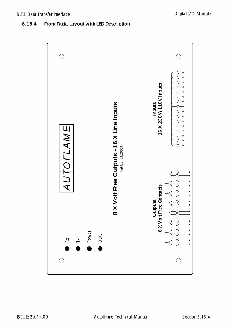
D.T.I. Data Transfer Interface
ISSUE: 20.11.00 Autoflame Technical Manual Section
Rx
Tx Pow
er
O.K
.
8 X
Vo
lt F
ree
Out
put
s -
16
X L
ine
Inp
uts
Part
No.
DTI
2002
0
Out
put
s8
X V
olt
Fre
e Co
nta
cts
Inp
uts
16
X 2
30
V/1
10
V In
put
s
AU
TO
FLA
ME
6.15.4 Front Facia Layout with LED Description
6.15.4
Digital I/O Module
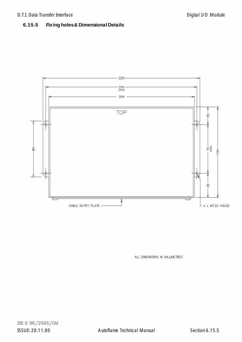
D.T.I. Data Transfer Interface
ISSUE: 20.11.00 Autoflame Technical Manual Section
6.15.5 Fixing holes & Dimensional Details
6.15.5
Digital I/O Module
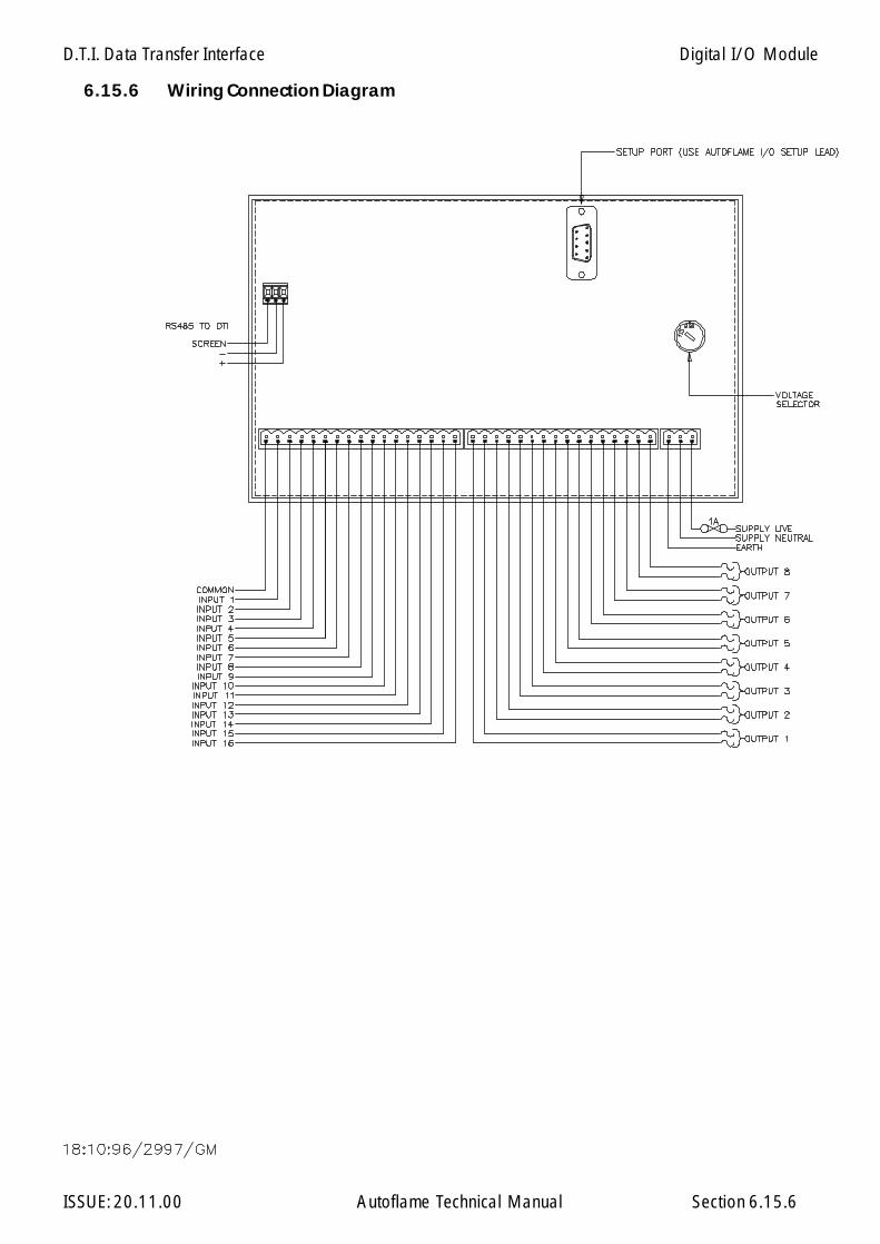
D.T.I. Data Transfer Interface
ISSUE: 20.11.00 Autoflame Technical Manual Section
6.15.6 Wiring Connection Diagram
6.15.6
Digital I/O Module
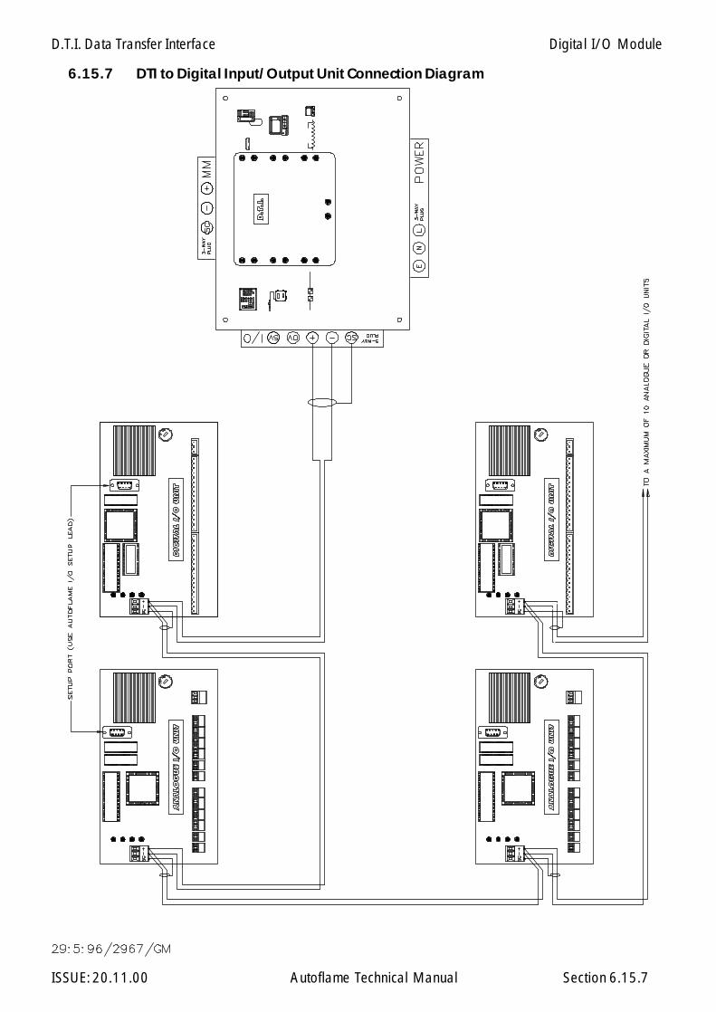
D.T.I. Data Transfer Interface
ISSUE: 20.11.00 Autoflame Technical Manual Section
6.15.7 DTI to Digital Input/Output Unit Connection Diagram
6.15.7
Digital I/O Module
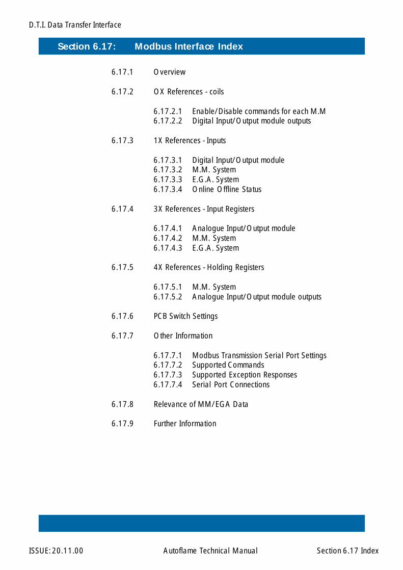
D.T.I. Data Transfer Interface
ISSUE: 20.11.00 Autoflame Technical Manual Section
Section 6.17: Modbus Interface Index
6.17 Index
6.17.1 Overview
6.17.2 OX References - coils
6.17.2.1 Enable/Disable commands for each M.M6.17.2.2 Digital Input/Output module outputs
6.17.3 1X References - Inputs
6.17.3.1 Digital Input/Output module6.17.3.2 M.M. System6.17.3.3 E.G.A. System6.17.3.4 Online Offline Status
6.17.4 3X References - Input Registers
6.17.4.1 Analogue Input/Output module6.17.4.2 M.M. System6.17.4.3 E.G.A. System
6.17.5 4X References - Holding Registers
6.17.5.1 M.M. System6.17.5.2 Analogue Input/Output module outputs
6.17.6 PCB Switch Settings
6.17.7 Other Information
6.17.7.1 Modbus Transmission Serial Port Settings6.17.7.2 Supported Commands6.17.7.3 Supported Exception Responses6.17.7.4 Serial Port Connections
6.17.8 Relevance of MM/EGA Data
6.17.9 Further Information
D.T.I. Data Transfer Interface
ISSUE: 20.11.00 Autoflame Technical Manual Section 6.17.1
6.17.1 Overview
This manual details information regarding the Data Transfer Interface (DTI) 'Modbus' type interface.This interface allows the DTI to simultaneously communicate with the standard Autoflame Windows95 PCDTI System.
Some knowledge of the Micro Modultion system is necessary to appreciate the meaning of the infor-mation contained within this manual.
Modbus

D.T.I. Data Transfer Interface
ISSUE: 20.11.00 Autoflame Technical Manual Section 6.17.2.1
6.17.2 0X Reference Addresses - Coils
6.17.2.1 Enable/Disable command for each MM
MM 1 00001MM 2 00002MM 3 00003MM 4 00004MM 5 00005MM 6 00006MM 7 00007MM 8 00008MM 9 00009MM 10 00010
Modbus
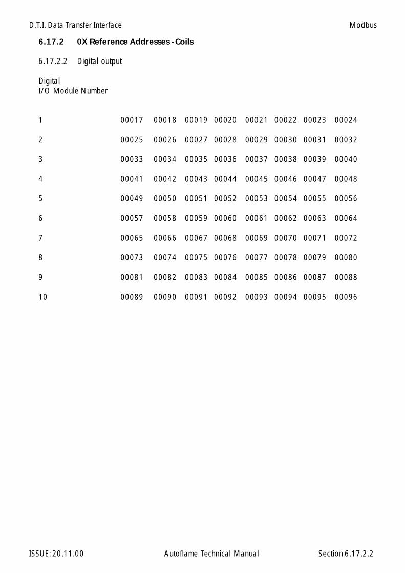
D.T.I. Data Transfer Interface
ISSUE: 20.11.00 Autoflame Technical Manual Section 6.17.2.2
6.17.2 0X Reference Addresses - Coils
6.17.2.2 Digital output
DigitalI/O Module Number
1 00017 00018 00019 00020 00021 00022 00023 00024
2 00025 00026 00027 00028 00029 00030 00031 00032
3 00033 00034 00035 00036 00037 00038 00039 00040
4 00041 00042 00043 00044 00045 00046 00047 00048
5 00049 00050 00051 00052 00053 00054 00055 00056
6 00057 00058 00059 00060 00061 00062 00063 00064
7 00065 00066 00067 00068 00069 00070 00071 00072
8 00073 00074 00075 00076 00077 00078 00079 00080
9 00081 00082 00083 00084 00085 00086 00087 00088
10 00089 00090 00091 00092 00093 00094 00095 00096
Modbus

D.T.I. Data Transfer Interface
ISSUE: 20.11.00 Autoflame Technical Manual Section 6.17.3.1
6.17.3 1X Reference Addresses - Inputs
6.17.3.1 Digital Input
DigitalI/O Module Number
1 10001 10002 10003 10004 10005 10006 10007 100082 10017 10018 10019 10020 10021 10022 10023 100243 10033 10034 10035 10036 10037 10038 10039 100404 10049 10050 10051 10052 10053 10054 10055 100565 10065 10066 10067 10068 10069 10070 10071 100726 10081 10082 10083 10084 10085 10086 10087 100887 10097 10098 10099 10100 10101 10102 10103 101048 10113 10114 10115 10116 10117 10118 10119 101209 10129 10130 10131 10132 10133 10134 10135 1013610 10145 10146 10147 10148 10149 10150 10151 10152
Digital Input
DigitalI/O Module Number
1 10009 10010 10011 10012 10013 10014 10015 100162 10025 10026 10027 10028 10029 10030 10031 100323 10041 10042 10043 10044 10045 10046 10047 100484 10057 10058 10059 10060 10061 10062 10063 100645 10073 10074 10075 10076 10077 10078 10079 100806 10089 10090 10091 10092 10093 10094 10095 100967 10105 10106 10107 10108 10109 10110 10111 101128 10121 10122 10123 10124 10125 10126 10127 101289 10137 10138 10139 10140 10141 10142 10143 1014410 10153 10154 10155 10156 10157 10158 10159 10160
1 2 3 4 5 6 7 8
9 10 11 12 13 14 15 16
Modbus
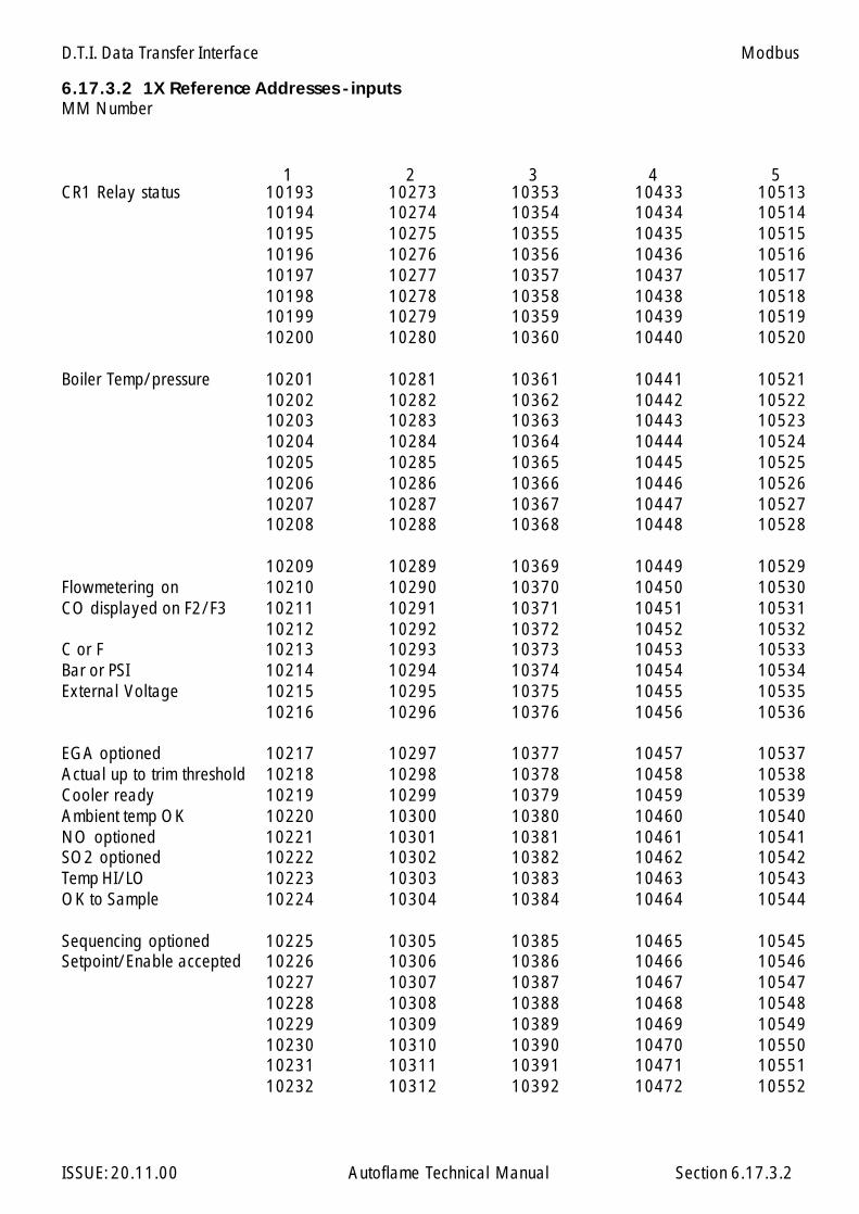
D.T.I. Data Transfer Interface
ISSUE: 20.11.00 Autoflame Technical Manual Section 6.17.3.2
6.17.3.2 1X Reference Addresses - inputsMM Number
CR1 Relay status 10193 10273 10353 10433 1051310194 10274 10354 10434 1051410195 10275 10355 10435 1051510196 10276 10356 10436 1051610197 10277 10357 10437 1051710198 10278 10358 10438 1051810199 10279 10359 10439 1051910200 10280 10360 10440 10520
Boiler Temp/pressure 10201 10281 10361 10441 1052110202 10282 10362 10442 1052210203 10283 10363 10443 1052310204 10284 10364 10444 1052410205 10285 10365 10445 1052510206 10286 10366 10446 1052610207 10287 10367 10447 1052710208 10288 10368 10448 10528
10209 10289 10369 10449 10529Flowmetering on 10210 10290 10370 10450 10530CO displayed on F2/F3 10211 10291 10371 10451 10531
10212 10292 10372 10452 10532C or F 10213 10293 10373 10453 10533Bar or PSI 10214 10294 10374 10454 10534External Voltage 10215 10295 10375 10455 10535
10216 10296 10376 10456 10536
EGA optioned 10217 10297 10377 10457 10537Actual up to trim threshold 10218 10298 10378 10458 10538Cooler ready 10219 10299 10379 10459 10539Ambient temp OK 10220 10300 10380 10460 10540NO optioned 10221 10301 10381 10461 10541SO2 optioned 10222 10302 10382 10462 10542Temp HI/LO 10223 10303 10383 10463 10543OK to Sample 10224 10304 10384 10464 10544
Sequencing optioned 10225 10305 10385 10465 10545Setpoint/Enable accepted 10226 10306 10386 10466 10546
10227 10307 10387 10467 1054710228 10308 10388 10468 1054810229 10309 10389 10469 1054910230 10310 10390 10470 1055010231 10311 10391 10471 1055110232 10312 10392 10472 10552
1 5432
Modbus
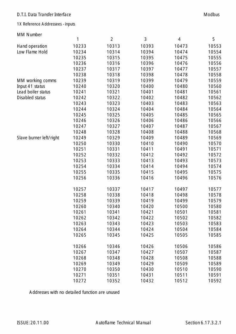
D.T.I. Data Transfer Interface
ISSUE: 20.11.00 Autoflame Technical Manual Section 6.17.3.2.1
1X Reference Addressees - inputs
MM Number
Hand operation 10233 10313 10393 10473 10553Low Flame Hold 10234 10314 10394 10474 10554
10235 10315 10395 10475 1055510236 10316 10396 10476 1055610237 10317 10397 10477 1055710238 10318 10398 10478 10558
MM working comms 10239 10319 10399 10479 10559Input 41 status 10240 10320 10400 10480 10560Lead boiler status 10241 10321 10401 10481 10561Disabled status 10242 10322 10402 10482 10562
10243 10323 10403 10483 1056310244 10324 10404 10484 1056410245 10325 10405 10485 1056510246 10326 10406 10486 1056610247 10327 10407 10487 1056710248 10328 10408 10488 10568
Slave burner left/right 10249 10329 10409 10489 1056910250 10330 10410 10490 1057010251 10331 10411 10491 1057110252 10332 10412 10492 1057210253 10333 10413 10493 1057310254 10334 10414 10494 1057410255 10335 10415 10495 1057510256 10336 10416 10496 10576
10257 10337 10417 10497 1057710258 10338 10418 10498 1057810259 10339 10419 10499 1057910260 10340 10420 10500 1058010261 10341 10421 10501 1058110262 10342 10422 10502 1058210263 10343 10423 10503 1058310264 10344 10424 10504 1058410265 10345 10425 10505 10585
10266 10346 10426 10506 1058610267 10347 10427 10507 1058710268 10348 10428 10508 1058810269 10349 10429 10509 1058910270 10350 10430 10510 1059010271 10351 10431 10511 1059110272 10352 10432 10512 10592
Addresses with no detailed function are unused
1 2 3 4 5
Modbus
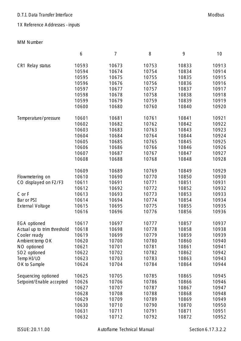
D.T.I. Data Transfer Interface
ISSUE: 20.11.00 Autoflame Technical Manual Section 6.17.3.2.2
1X Reference Addresses - inputs
MM Number
CR1 Relay status 10593 10673 10753 10833 1091310594 10674 10754 10834 1091410595 10675 10755 10835 1091510596 10676 10756 10836 1091610597 10677 10757 10837 1091710598 10678 10758 10838 1091810599 10679 10759 10839 1091910600 10680 10760 10840 10920
Temperature/pressure 10601 10681 10761 10841 1092110602 10682 10762 10842 1092210603 10683 10763 10843 1092310604 10684 10764 10844 1092410605 10685 10765 10845 1092510606 10686 10766 10846 1092610607 10687 10767 10847 1092710608 10688 10768 10848 10928
10609 10689 10769 10849 10929Flowmetering on 10610 10690 10770 10850 10930CO displayed on F2/F3 10611 10691 10771 10851 10931
10612 10692 10772 10852 10932C or F 10613 10693 10773 10853 10933Bar or PSI 10614 10694 10774 10854 10934External Voltage 10615 10695 10775 10855 10935
10616 10696 10776 10856 10936
EGA optioned 10617 10697 10777 10857 10937Actual up to trim threshold 10618 10698 10778 10858 10938Cooler ready 10619 10699 10779 10859 10939Ambient temp OK 10620 10700 10780 10860 10940NO optioned 10621 10701 10781 10861 10941SO2 optioned 10622 10702 10782 10862 10942Temp HI/LO 10623 10703 10783 10863 10943OK to Sample 10624 10704 10784 10864 10944
Sequencing optioned 10625 10705 10785 10865 10945Setpoint/Enable accepted 10626 10706 10786 10866 10946
10627 10707 10787 10867 1094710628 10708 10788 10868 1094810629 10709 10789 10869 1094910630 10710 10790 10870 1095010631 10711 10791 10871 1095110632 10712 10792 10872 10952
6 10987
Modbus
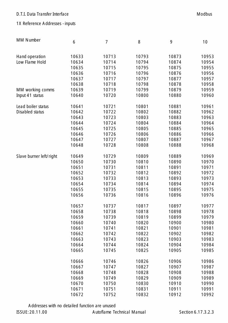
D.T.I. Data Transfer Interface
ISSUE: 20.11.00 Autoflame Technical Manual Section 6.17.3.2.3
1X Reference Addresses - inputs
MM Number
Hand operation 10633 10713 10793 10873 10953Low Flame Hold 10634 10714 10794 10874 10954
10635 10715 10795 10875 1095510636 10716 10796 10876 1095610637 10717 10797 10877 1095710638 10718 10798 10878 10958
MM working comms 10639 10719 10799 10879 10959Input 41 status 10640 10720 10800 10880 10960
Lead boiler status 10641 10721 10801 10881 10961Disabled status 10642 10722 10802 10882 10962
10643 10723 10803 10883 1096310644 10724 10804 10884 1096410645 10725 10805 10885 1096510646 10726 10806 10886 1096610647 10727 10807 10887 1096710648 10728 10808 10888 10968
Slave burner left/right 10649 10729 10809 10889 1096910650 10730 10810 10890 1097010651 10731 10811 10891 1097110652 10732 10812 10892 1097210653 10733 10813 10893 1097310654 10734 10814 10894 1097410655 10735 10815 10895 1097510656 10736 10816 10896 10976
10657 10737 10817 10897 1097710658 10738 10818 10898 1097810659 10739 10819 10899 1097910660 10740 10820 10900 1098010661 10741 10821 10901 1098110662 10742 10822 10902 1098210663 10743 10823 10903 1098310664 10744 10824 10904 1098410665 10745 10825 10905 10985
10666 10746 10826 10906 1098610667 10747 10827 10907 1098710668 10748 10828 10908 1098810669 10749 10829 10909 1098910670 10750 10830 10910 1099010671 10751 10831 10911 1099110672 10752 10832 10912 10992
Addresses with no detailed function are unused
6 10987
Modbus
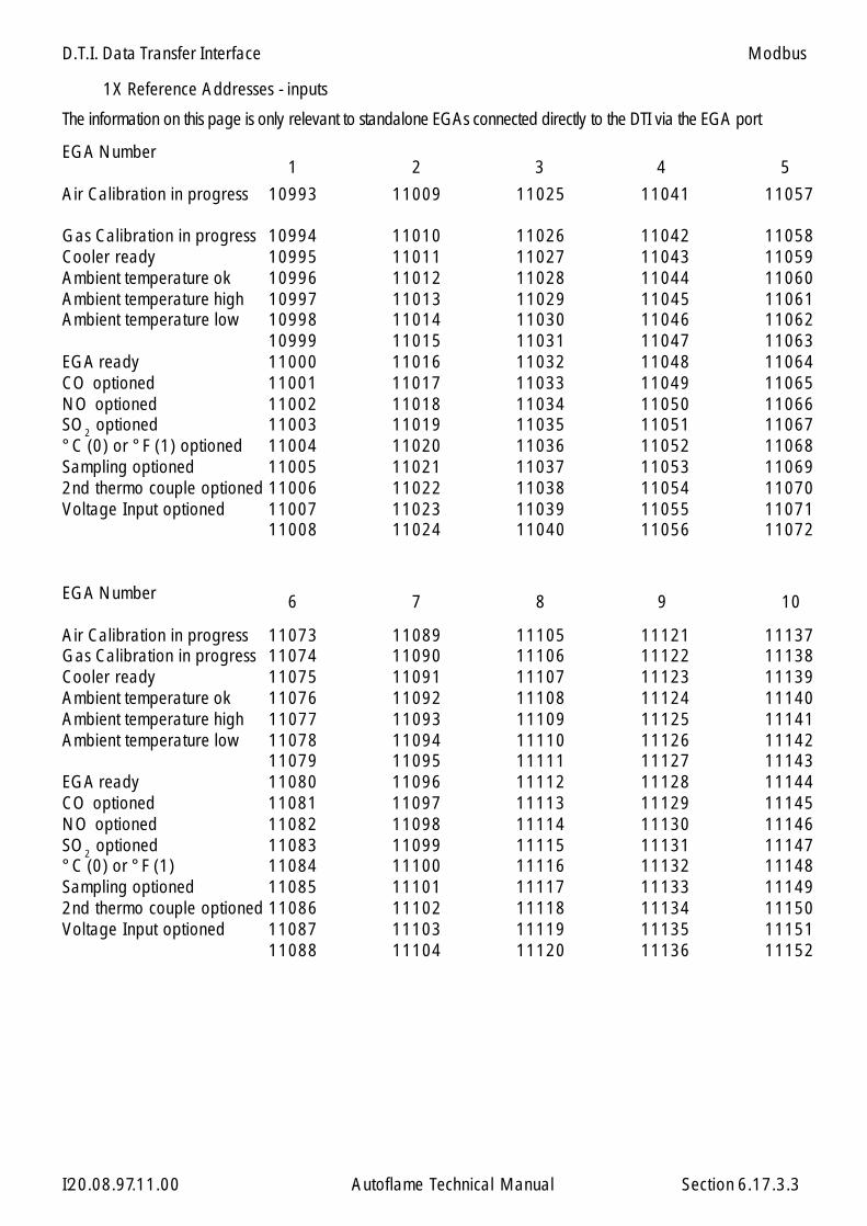
D.T.I. Data Transfer Interface
ISSUE: 20.11.00 Autoflame Technical Manual Section 6.17.3.3
1X Reference Addresses - inputs
EGA Number
Air Calibration in progress 10993 11009 11025 11041 11057
Gas Calibration in progress 10994 11010 11026 11042 11058Cooler ready 10995 11011 11027 11043 11059Ambient temperature ok 10996 11012 11028 11044 11060Ambient temperature high 10997 11013 11029 11045 11061Ambient temperature low 10998 11014 11030 11046 11062
10999 11015 11031 11047 11063EGA ready 11000 11016 11032 11048 11064CO optioned 11001 11017 11033 11049 11065NO optioned 11002 11018 11034 11050 11066SO2 optioned 11003 11019 11035 11051 11067°C (0) or °F (1) optioned 11004 11020 11036 11052 11068Sampling optioned 11005 11021 11037 11053 110692nd thermo couple optioned 11006 11022 11038 11054 11070Voltage Input optioned 11007 11023 11039 11055 11071
11008 11024 11040 11056 11072
EGA Number
Air Calibration in progress 11073 11089 11105 11121 11137Gas Calibration in progress 11074 11090 11106 11122 11138Cooler ready 11075 11091 11107 11123 11139Ambient temperature ok 11076 11092 11108 11124 11140Ambient temperature high 11077 11093 11109 11125 11141Ambient temperature low 11078 11094 11110 11126 11142
11079 11095 11111 11127 11143EGA ready 11080 11096 11112 11128 11144CO optioned 11081 11097 11113 11129 11145NO optioned 11082 11098 11114 11130 11146SO2 optioned 11083 11099 11115 11131 11147°C (0) or °F (1) 11084 11100 11116 11132 11148Sampling optioned 11085 11101 11117 11133 111492nd thermo couple optioned 11086 11102 11118 11134 11150Voltage Input optioned 11087 11103 11119 11135 11151
11088 11104 11120 11136 11152
1 5432
6 10987
20.08.97
Modbus
The information on this page is only relevant to standalone EGAs connected directly to the DTI via the EGA port
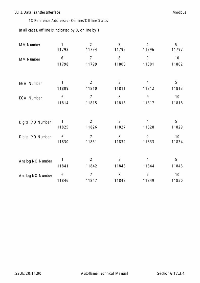
D.T.I. Data Transfer Interface
ISSUE: 20.11.00 Autoflame Technical Manual Section 6.17.3.4
1X Reference Addresses - On line/Off line Status
In all cases, off line is indicated by 0, on line by 1
MM Number11793 11794 11795 11796 11797
MM Number11798 11799 11800 11801 11802
EGA Number11809 11810 11811 11812 11813
EGA Number11814 11815 11816 11817 11818
Digital I/O Number11825 11826 11827 11828 11829
Digital I/O Number11830 11831 11832 11833 11834
Analog I/O Number11841 11842 11843 11844 11845
Analog I/O Number11846 11847 11848 11849 11850
6 10987
1 5432
6 10987
1 5432
6 10987
1 5432
6 10987
1 5432
Modbus

D.T.I. Data Transfer Interface
ISSUE: 20.11.00 Autoflame Technical Manual Section 6.17.4
6.17.4 3X Reference Addresses - Input Registers
Analog Inputs
Input Number
Analog I/O Module Number
1 30017 30018 30019 30020 30021 30022
2 30025 30026 30027 30028 30029 30030
3 30033 30034 30035 30036 30037 30038
4 30041 30042 30043 30044 30045 30046
5 30049 30050 30051 30052 30053 30054
6 30057 30058 30059 30060 30061 30062
7 30065 30066 30067 30068 30069 30070
8 30073 30074 30075 30076 30077 30078
9 30081 30082 30083 30084 30085 30086
10 30089 30090 30091 30092 30093 30094
1 2 3 4 5 6
Software Version
30097 Software Version Number30098 Software Issue Number
Modbus

D.T.I. Data Transfer Interface
ISSUE: 20.11.00 Autoflame Technical Manual Section 6.17.4.1
3X Reference Addresses - Input Registers
MM number 1 2 3 4 5
Load index 30101 30151 30201 30251 30301Startup/Firing status 30102 30152 30202 30252 30302Sequence status 30103 30153 30203 30253 30303Boiler Capacity 30104 30154 30204 30254 30304Actual value 30105 30155 30205 30255 30305Required value 30106 30156 30206 30256 30306Fuel selected 30107 30157 30207 30257 30307Number of channels 30108 30158 30208 30258 30308Channel 1 position 30109 30159 30209 30259 30309Channel 2 position 30110 30160 30210 30260 30310Channel 3 position 30111 30161 30211 30261 30311Channel 4 position 30112 30162 30212 30262 30312MM Error number 30113 30163 30213 30263 30313Single/Twin operation 30114 30164 30214 30264 30314Run O2 30115 30165 30215 30265 30315Run CO2 30116 30166 30216 30266 30316Run CO 30117 30167 30217 30267 30317Run Exhaust Temperature 30118 30168 30218 30268 30318Run Efficiency 30119 30169 30219 30269 30319Run NO 30120 30170 30220 30270 30320Run SO2 30121 30171 30221 30271 30321Comm. O2 30122 30172 30222 30272 30322Comm. CO2 30123 30173 30223 30273 30323Comm. CO 30124 30174 30224 30274 30324Comm. Exh. Temp. 30125 30175 30225 30275 30325Comm. Efficiency 30126 30176 30226 30276 30326Comm. NO 30127 30177 30227 30277 30327Comm SO2 30128 30178 30228 30278 30328EGA error number 30129 30179 30229 30279 30329Minimum Required value 30130 30180 30230 30280 30330Maximum Required value 30131 30181 30231 30281 30331Present flow units 30132 30182 30232 30282 30332Present flow thousands 30133 30183 30233 30283 30333Fuel 1 flow total units 30134 30184 30234 30284 30334Fuel 1 flow total thousands 30135 30185 30235 30285 30335Fuel 1 flow total millions 30136 30186 30236 30286 30336Fuel 2 flow total units 30137 30187 30237 30287 30337Fuel 2 flow total thousands 30138 30188 30238 30288 30338Fuel 2 flow total millions 30139 30189 30239 30289 30339Fuel 3 flow total units 30140 30190 30240 30290 30340Fuel 3 flow total thousands 30141 30191 30241 30291 30341Fuel 3 flow total millions 30142 30192 30242 30292 30342Run Ambient 30143 30193 30243 30293 30343Run ∆T 30144 30194 30244 30294 30344COM Ambient 30145 30195 30245 30295 30345COM ∆T 30146 30196 30246 30296 30346Mk6/Mini6/Mini5 (0,4,5) 30147 30197 30247 30297 30347
Modbus
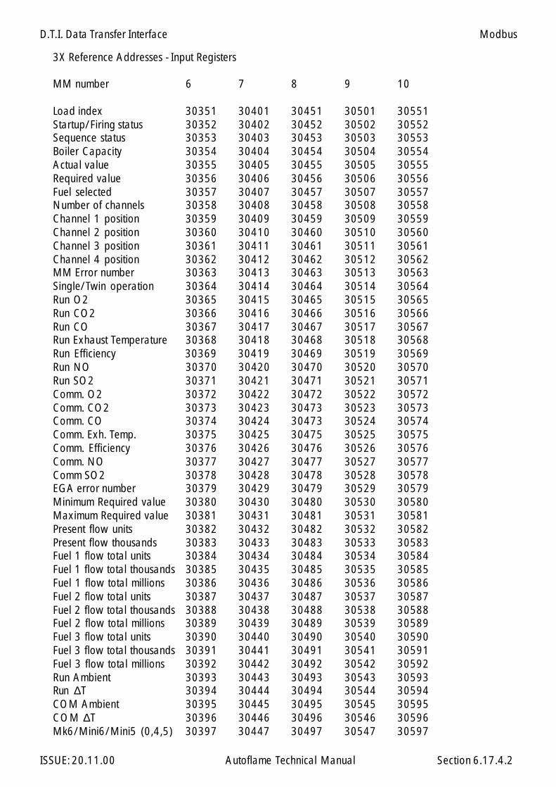
D.T.I. Data Transfer Interface
ISSUE: 20.11.00 Autoflame Technical Manual Section 6.17.4.2
3X Reference Addresses - Input Registers
MM number 6 7 8 9 10
Load index 30351 30401 30451 30501 30551Startup/Firing status 30352 30402 30452 30502 30552Sequence status 30353 30403 30453 30503 30553Boiler Capacity 30354 30404 30454 30504 30554Actual value 30355 30405 30455 30505 30555Required value 30356 30406 30456 30506 30556Fuel selected 30357 30407 30457 30507 30557Number of channels 30358 30408 30458 30508 30558Channel 1 position 30359 30409 30459 30509 30559Channel 2 position 30360 30410 30460 30510 30560Channel 3 position 30361 30411 30461 30511 30561Channel 4 position 30362 30412 30462 30512 30562MM Error number 30363 30413 30463 30513 30563Single/Twin operation 30364 30414 30464 30514 30564Run O2 30365 30415 30465 30515 30565Run CO2 30366 30416 30466 30516 30566Run CO 30367 30417 30467 30517 30567Run Exhaust Temperature 30368 30418 30468 30518 30568Run Efficiency 30369 30419 30469 30519 30569Run NO 30370 30420 30470 30520 30570Run SO2 30371 30421 30471 30521 30571Comm. O2 30372 30422 30472 30522 30572Comm. CO2 30373 30423 30473 30523 30573Comm. CO 30374 30424 30473 30524 30574Comm. Exh. Temp. 30375 30425 30475 30525 30575Comm. Efficiency 30376 30426 30476 30526 30576Comm. NO 30377 30427 30477 30527 30577Comm SO2 30378 30428 30478 30528 30578EGA error number 30379 30429 30479 30529 30579Minimum Required value 30380 30430 30480 30530 30580Maximum Required value 30381 30431 30481 30531 30581Present flow units 30382 30432 30482 30532 30582Present flow thousands 30383 30433 30483 30533 30583Fuel 1 flow total units 30384 30434 30484 30534 30584Fuel 1 flow total thousands 30385 30435 30485 30535 30585Fuel 1 flow total millions 30386 30436 30486 30536 30586Fuel 2 flow total units 30387 30437 30487 30537 30587Fuel 2 flow total thousands 30388 30438 30488 30538 30588Fuel 2 flow total millions 30389 30439 30489 30539 30589Fuel 3 flow total units 30390 30440 30490 30540 30590Fuel 3 flow total thousands 30391 30441 30491 30541 30591Fuel 3 flow total millions 30392 30442 30492 30542 30592Run Ambient 30393 30443 30493 30543 30593Run ∆T 30394 30444 30494 30544 30594COM Ambient 30395 30445 30495 30545 30595COM ∆T 30396 30446 30496 30546 30596Mk6/Mini6/Mini5 (0,4,5) 30397 30447 30497 30547 30597
Modbus

D.T.I. Data Transfer Interface
ISSUE: 20.11.00 Autoflame Technical Manual Section 6.17.4.3
3X Reference Addresses - Input Registers
The information on this page is only relevant to standalone EGAs connected directly to the DTI via the EGA port.
EGA number
Fuel Selected 30601 30621 30641 30661 30681% O2 30602 30622 30642 30662 30682% CO2 30603 30623 30643 30663 30683ppm CO 30604 30624 30644 30664 30684ppm NO 30605 30625 30645 30665 30685ppm SO2 30606 30626 30646 30666 30686Exhaust Temperature 30607 30627 30647 30667 30687Efficiency 30608 30628 30648 30668 30688Error Number 30609 30629 30649 30669 30689% Voltage input 30610 30630 30650 30670 30690Exhaust ∆T 30611 30631 30651 30671 30691Ambient 30612 30632 30652 30672 30692Auxiliary Temp. 30613 30633 30653 30673 30693Service LED's 30614 30634 30654 30674 30694
EGA number
Fuel Selected 30701 30721 30741 30761 30781% O2 30702 30722 30742 30762 30782% CO2 30703 30723 30743 30763 30783ppm CO 30704 30724 30744 30764 30784ppm NO 30705 30725 30745 30765 30785ppm SO2 30706 30726 30746 30766 30786Exhaust Temperature 30707 30727 30747 30767 30787Efficiency 30708 30728 30748 30768 30788Error Number 30709 30729 30749 30769 30789% Voltage input 30710 30730 30750 30770 30790Exhaust ∆T 30711 30731 30751 30771 30791Ambient 30712 30732 30752 30772 30792Auxiliary Temp. 30713 30733 30753 30773 30793Service LED's 30714 30734 30754 30774 30794
1 5432
6 10987
Modbus
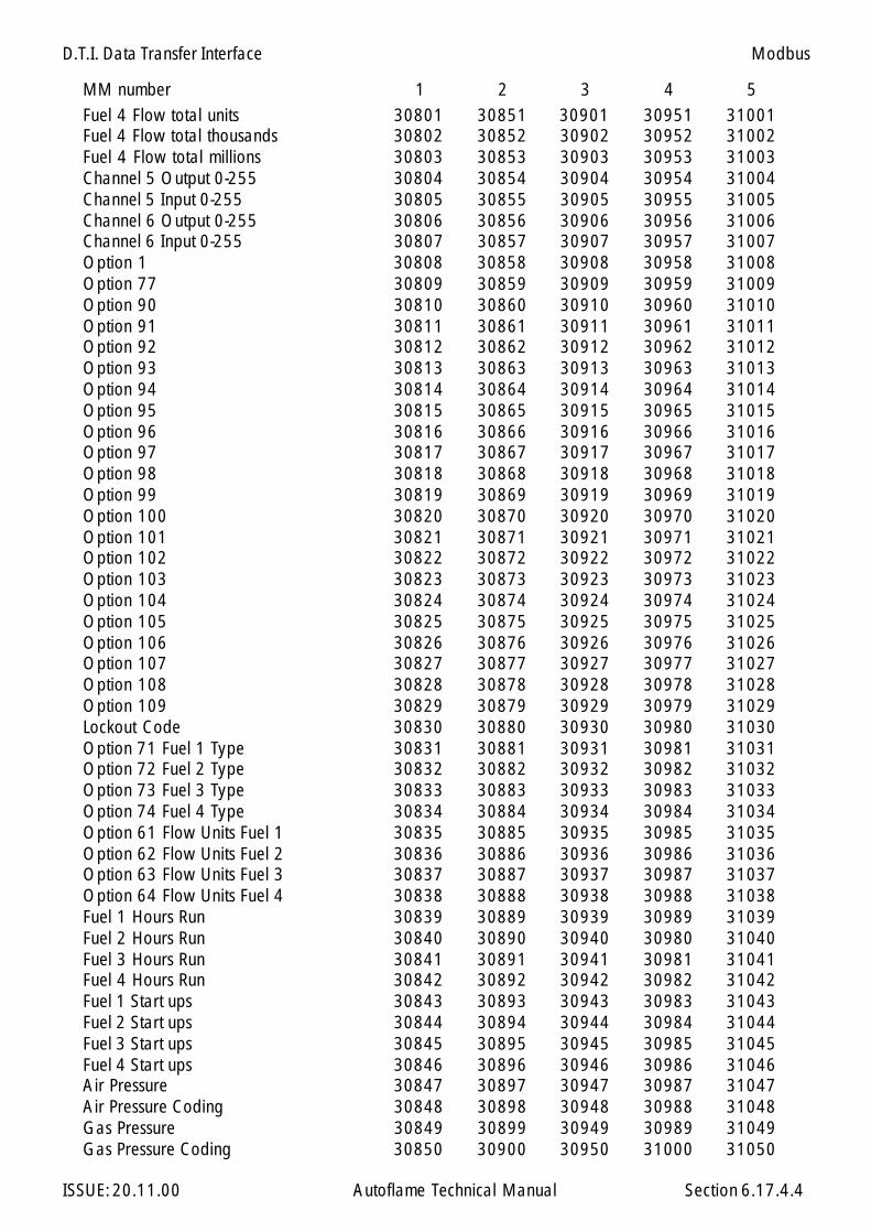
D.T.I. Data Transfer Interface
ISSUE: 20.11.00 Autoflame Technical Manual Section 6.17.4.4
MM number 1 2 3 4 5Fuel 4 Flow total units 30801 30851 30901 30951 31001Fuel 4 Flow total thousands 30802 30852 30902 30952 31002Fuel 4 Flow total millions 30803 30853 30903 30953 31003Channel 5 Output 0-255 30804 30854 30904 30954 31004Channel 5 Input 0-255 30805 30855 30905 30955 31005Channel 6 Output 0-255 30806 30856 30906 30956 31006Channel 6 Input 0-255 30807 30857 30907 30957 31007Option 1 30808 30858 30908 30958 31008Option 77 30809 30859 30909 30959 31009Option 90 30810 30860 30910 30960 31010Option 91 30811 30861 30911 30961 31011Option 92 30812 30862 30912 30962 31012Option 93 30813 30863 30913 30963 31013Option 94 30814 30864 30914 30964 31014Option 95 30815 30865 30915 30965 31015Option 96 30816 30866 30916 30966 31016Option 97 30817 30867 30917 30967 31017Option 98 30818 30868 30918 30968 31018Option 99 30819 30869 30919 30969 31019Option 100 30820 30870 30920 30970 31020Option 101 30821 30871 30921 30971 31021Option 102 30822 30872 30922 30972 31022Option 103 30823 30873 30923 30973 31023Option 104 30824 30874 30924 30974 31024Option 105 30825 30875 30925 30975 31025Option 106 30826 30876 30926 30976 31026Option 107 30827 30877 30927 30977 31027Option 108 30828 30878 30928 30978 31028Option 109 30829 30879 30929 30979 31029Lockout Code 30830 30880 30930 30980 31030Option 71 Fuel 1 Type 30831 30881 30931 30981 31031Option 72 Fuel 2 Type 30832 30882 30932 30982 31032Option 73 Fuel 3 Type 30833 30883 30933 30983 31033Option 74 Fuel 4 Type 30834 30884 30934 30984 31034Option 61 Flow Units Fuel 1 30835 30885 30935 30985 31035Option 62 Flow Units Fuel 2 30836 30886 30936 30986 31036Option 63 Flow Units Fuel 3 30837 30887 30937 30987 31037Option 64 Flow Units Fuel 4 30838 30888 30938 30988 31038Fuel 1 Hours Run 30839 30889 30939 30989 31039Fuel 2 Hours Run 30840 30890 30940 30980 31040Fuel 3 Hours Run 30841 30891 30941 30981 31041Fuel 4 Hours Run 30842 30892 30942 30982 31042Fuel 1 Start ups 30843 30893 30943 30983 31043Fuel 2 Start ups 30844 30894 30944 30984 31044Fuel 3 Start ups 30845 30895 30945 30985 31045Fuel 4 Start ups 30846 30896 30946 30986 31046Air Pressure 30847 30897 30947 30987 31047Air Pressure Coding 30848 30898 30948 30988 31048Gas Pressure 30849 30899 30949 30989 31049Gas Pressure Coding 30850 30900 30950 31000 31050
Modbus
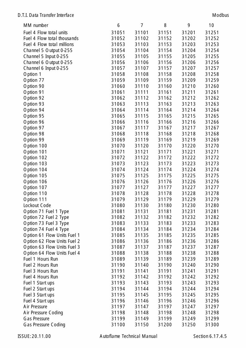
D.T.I. Data Transfer Interface
ISSUE: 20.11.00 Autoflame Technical Manual Section 6.17.4.5
MM number 6 7 8 9 10Fuel 4 Flow total units 31051 31101 31151 31201 31251Fuel 4 Flow total thousands 31052 31102 31152 31202 31252Fuel 4 Flow total millions 31053 31103 31153 31203 31253Channel 5 Output 0-255 31054 31104 31154 31204 31254Channel 5 Input 0-255 31055 31105 31155 31205 31255Channel 6 Output 0-255 31056 31106 31156 31206 31256Channel 6 Input 0-255 31057 31107 31157 31207 31257Option 1 31058 31108 31158 31208 31258Option 77 31059 31109 31159 31209 31259Option 90 31060 31110 31160 31210 31260Option 91 31061 31111 31161 31211 31261Option 92 31062 31112 31162 31212 31262Option 93 31063 31113 31163 31213 31263Option 94 31064 31114 31164 31214 31264Option 95 31065 31115 31165 31215 31265Option 96 31066 31116 31166 31216 31266Option 97 31067 31117 31167 31217 31267Option 98 31068 31118 31168 31218 31268Option 99 31069 31119 31169 31219 31269Option 100 31070 31120 31170 31220 31270Option 101 31071 31121 31171 31221 31271Option 102 31072 31122 31172 31222 31272Option 103 31073 31123 31173 31223 31273Option 104 31074 31124 31174 31224 31274Option 105 31075 31125 31175 31225 31275Option 106 31076 31126 31176 31226 31276Option 107 31077 31127 31177 31227 31277Option 110 31078 31128 31178 31228 31278Option 111 31079 31129 31179 31229 31279Lockout Code 31080 31130 31180 31230 31280Option 71 Fuel 1 Type 31081 31131 31181 31231 31281Option 72 Fuel 2 Type 31082 31132 31182 31232 31282Option 73 Fuel 3 Type 31083 31133 31183 31233 31283Option 74 Fuel 4 Type 31084 31134 31184 31234 31284Option 61 Flow Units Fuel 1 31085 31135 31185 31235 31285Option 62 Flow Units Fuel 2 31086 31136 31186 31236 31286Option 63 Flow Units Fuel 3 31087 31137 31187 31237 31287Option 64 Flow Units Fuel 4 31088 31138 31188 31238 31288Fuel 1 Hours Run 31089 31139 31189 31239 31289Fuel 2 Hours Run 31190 31140 31190 31240 31290Fuel 3 Hours Run 31191 31141 31191 31241 31291Fuel 4 Hours Run 31192 31142 31192 31242 31292Fuel 1 Start ups 31193 31143 31193 31243 31293Fuel 2 Start ups 31194 31144 31194 31244 31294Fuel 3 Start ups 31195 31145 31195 31245 31295Fuel 4 Start ups 31196 31146 31196 31246 31296Air Pressure 31197 31147 31197 31247 31297Air Pressure Coding 31198 31148 31198 31248 31298Gas Pressure 31199 31149 31199 31249 31299Gas Pressure Coding 31100 31150 31200 31250 31300
Modbus

D.T.I. Data Transfer Interface
ISSUE: 20.11.00 Autoflame Technical Manual Section 6.17.4.6
MM1 Error 31301MM2 Error 31302MM3 Error 31303MM4 Error 31304MM5 Error 31305MM6 Error 31306MM7 Error 31307MM8 Error 31308MM9 Error 31309MM10 Error 31310MM1 Lockout 31311MM2 Lockout 31312MM3 Lockout 31313MM4 Lockout 31314MM5 Lockout 31315MM6 Lockout 31316MM7 Lockout 31317MM8 Lockout 31318MM9 Lockout 31319MM10 Lockout 31320
Modbus
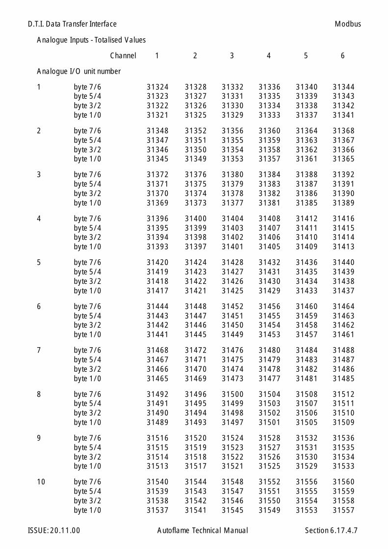
D.T.I. Data Transfer Interface
ISSUE: 20.11.00 Autoflame Technical Manual Section 6.17.4.7
Analogue Inputs - Totalised Values
Channel 1 2 3 4 5 6
Analogue I/O unit number
1 byte 7/6 31324 31328 31332 31336 31340 31344byte 5/4 31323 31327 31331 31335 31339 31343byte 3/2 31322 31326 31330 31334 31338 31342byte 1/0 31321 31325 31329 31333 31337 31341
2 byte 7/6 31348 31352 31356 31360 31364 31368byte 5/4 31347 31351 31355 31359 31363 31367byte 3/2 31346 31350 31354 31358 31362 31366byte 1/0 31345 31349 31353 31357 31361 31365
3 byte 7/6 31372 31376 31380 31384 31388 31392byte 5/4 31371 31375 31379 31383 31387 31391byte 3/2 31370 31374 31378 31382 31386 31390byte 1/0 31369 31373 31377 31381 31385 31389
4 byte 7/6 31396 31400 31404 31408 31412 31416byte 5/4 31395 31399 31403 31407 31411 31415byte 3/2 31394 31398 31402 31406 31410 31414byte 1/0 31393 31397 31401 31405 31409 31413
5 byte 7/6 31420 31424 31428 31432 31436 31440byte 5/4 31419 31423 31427 31431 31435 31439byte 3/2 31418 31422 31426 31430 31434 31438byte 1/0 31417 31421 31425 31429 31433 31437
6 byte 7/6 31444 31448 31452 31456 31460 31464byte 5/4 31443 31447 31451 31455 31459 31463byte 3/2 31442 31446 31450 31454 31458 31462byte 1/0 31441 31445 31449 31453 31457 31461
7 byte 7/6 31468 31472 31476 31480 31484 31488byte 5/4 31467 31471 31475 31479 31483 31487byte 3/2 31466 31470 31474 31478 31482 31486byte 1/0 31465 31469 31473 31477 31481 31485
8 byte 7/6 31492 31496 31500 31504 31508 31512byte 5/4 31491 31495 31499 31503 31507 31511byte 3/2 31490 31494 31498 31502 31506 31510byte 1/0 31489 31493 31497 31501 31505 31509
9 byte 7/6 31516 31520 31524 31528 31532 31536byte 5/4 31515 31519 31523 31527 31531 31535byte 3/2 31514 31518 31522 31526 31530 31534byte 1/0 31513 31517 31521 31525 31529 31533
10 byte 7/6 31540 31544 31548 31552 31556 31560byte 5/4 31539 31543 31547 31551 31555 31559byte 3/2 31538 31542 31546 31550 31554 31558byte 1/0 31537 31541 31545 31549 31553 31557
Modbus
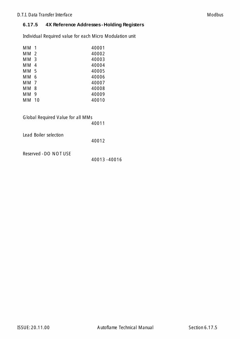
D.T.I. Data Transfer Interface
ISSUE: 20.11.00 Autoflame Technical Manual Section 6.17.5
6.17.5 4X Reference Addresses - Holding Registers
Individual Required value for each Micro Modulation unit
MM 1 40001MM 2 40002MM 3 40003MM 4 40004MM 5 40005MM 6 40006MM 7 40007MM 8 40008MM 9 40009MM 10 40010
Global Required Value for all MMs40011
Lead Boiler selection40012
Reserved - DO NOT USE40013 - 40016
Modbus

D.T.I. Data Transfer Interface
ISSUE: 20.11.00 Autoflame Technical Manual Section 6.17.5.1
4X Reference Addresses - Holding Registers
Analog Outputs
Output Number 1 2 3 4 5 6
AnalogI/O Module Number
1 40017 40018 40019 40020 40021 40022
2 40025 40026 40027 40028 40029 40030
3 40033 40034 40035 40036 40037 40038
4 40041 40042 40043 40044 40045 40046
5 40049 40050 40051 40052 40053 40054
6 40057 40058 40059 40060 40061 40062
7 40065 40066 40067 40068 40069 40070
8 40073 40074 40075 40076 40077 40078
9 40081 40082 40083 40084 40085 40086
10 40089 40090 40091 40092 40093 40094
Modbus

D.T.I. Data Transfer Interface
ISSUE: 20.11.00 Autoflame Technical Manual Section 6.17.6
Switch Bank 1
Set the Modbus address accordingly.
For example, to set address number 123:
100s = 110s = 21s = 3
6.17.6 Switch Settings - Modbus Operation
Modbus
Switch Bank 2
1 off - Modbus 'ASCII' modeon - Modbus 'RTU' mode
2 Transmission settingsoff - 8 data bits, 1 stop bit, no parity.on - 8 data bits, 1 stop bit, even parity.
3-5 no user function, must be set off
6 Windows PCDTI/MODBUS operationoff - 422 port set for Windows PCDTIon - 422 port set for MODBUS
7 Windows PCDTI/MODBUS operationoff - PC port set for WinPCDTIon - PC port set for MODBUS
8 MM Port Baud Rateoff - 9600 (Mk6, Mini Mk6 and Mini Mk5 MMs)on - 4800 (Older Mk5 and Mini MMs)** Technical Memo: Data Communication Compatibility 3/9/1999
ON
OFF1 2 3 4 5 6 7 8
10s100s 1s
Switch Bank 1 Switch Bank 2

D.T.I. Data Transfer Interface
ISSUE: 20.11.00 Autoflame Technical Manual Section 6.17.7
6.17.7 Other Information
Modbus Transmission Interface
There is no hardware or software flow control on any port.
Baud Rate 9600.
Supported MODBUS Commands
1 Read coil status2 Read input status3 Read holding registers4 Read input registers5 Force single coil6 Preset single register15 Force multiple coils16 Preset multiple registers
6.17.7.3 Supported Exception Responses
Exception responses are not supported. No response is given to an unrecognised request.
6.17.7.4 Serial Port Connections
RS232 'PC' port - 9 Way Female D connector
PIN Function
2 Data out 3 Data in 5 Signal ground
RS422 port - Screw terminal blocks
Receive and transmit connections are as identified on printed circuit board.
Modbus

D.T.I. Data Transfer Interface
ISSUE: 20.11.00 Autoflame Technical Manual Section
6.17.8 Relevance of MM/EGA data
Each MM/EGA can provide the following information. All values are instantaneous. Each MM/EGA system updates the DTI approximately once every 20 seconds. Certain values and somevalues under certain conditions may require a decimal point. In these cases the user must add thedecimal point accordingly (* only valid if EGA operational on system)
Digital Inputs (1x references)
Command status of M.M. ‘CR Relay’ O - Off,1 - On
Flow detector type O - Temperature,1 - Pressure
Optioned for flow metering O - No,1 - Yes
CO off/on on fuel 2 (fuel 1 CO always on)O - Off, 1 - OnTemperature units O - C,
1 - FPressure units O - bar,
1 - psiOptioned for voltage input modulation O - No,
1 - YesOptioned for EGA O - No,
1 - YesBoiler up to ‘trimming’ temperature O - No,
1 - YesEGA cooler temperature ready O - No,
1 - YesEGA ambient temperature OK O - No,
1 - YesOptioned to display NO O - No,
1 - YesOption to display SO O - No,
1 - YesEGA ambient temperature low/high(relevant if bit 3 (ambient temperature) is O) O - LOW,
1 - HIGHOptioned for sequencing O - NO,
1 - YESSetpoint/Disable commands accepted O - NO,
1 - YESHand operation status O - Modulating,
1 - Hand OperationLow flame hold status O - Modulating
1 - Low Flame HoldThis MM controlling DTI bus communication O - NO,
1 - YESInput 41 set (lead boiler select) O - NO,
1 - YES
6.17.8
Modbus

D.T.I. Data Transfer Interface
ISSUE: 20.11.00 Autoflame Technical Manual Section
Lead boiler status O - not lead boiler1 - lead boiler
‘Disabled’ status O - enabled1 - disabled
Slave burner indication status - test bit O O - master plus one,1 - master minus one
Analogue Inputs (3x references)
0-100 Firing rate/load index - percentage19-26 Indicates burner firing status
19 waiting for stat circuit to complete20 waiting for command to drive air damper to purge position21 driving air damper to purge position22 purging, waiting for command to drive valves to ignition position23 driving valves to ignition position24 ignition taking place25 burner firing and modulating26 post purge taking place(if O indicated transmission is direct from EGA)
0-3 Sequencing command status for this boilerSequence state0 - ON1 - STANDBY2 - WARM3 - OFF
0-250 Maximum firing rate - just the number entered in option 340-999 Actual value of boiler flow temperature - degrees C0.0-99.9 (Pressure Bar)0-999 Desired value of boiler flow temperature - degrees C0.0-99.9 (Pressure Bar)0-2 Present fuel selected 0 - Fuel 1 (usually GAS)
1 - Fuel 2 (usually OIL)2 - Fuel 3 (usually OIL)
1-7 Number of Channels in operation (add one to this to get total number)-6.0-96.0 CH1 positioning motor position degrees angular-6.0-96.0 CH2 positioning motor position degrees angular-6.0-96.0 CH3 positioning motor position degrees angular-6.0-96.0 Ch4 positioning motor position degrees angular0-N Fatal Error Code 0 - System is OK
1 - N system shut downValue is as MM ERR display
0-2 Single/twin burner operation0 - single burner1 - twin burner (both together only)2 - twin burner (both together/one or the other)
0-25.5 Present value percentage oxygen in flue gas0-25.5 Present value percentage carbon dioxide in flue gas0-999 Present value ppm carbon monoxide in flue gas0-999 Present value flue gas temperature0-99.9 Present value percentage combustion efficiency
6.17.8.1
Modbus
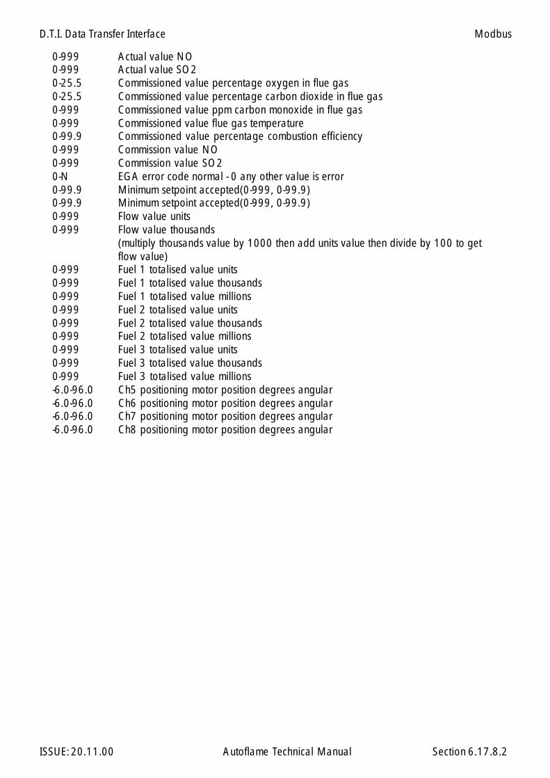
D.T.I. Data Transfer Interface
ISSUE: 20.11.00 Autoflame Technical Manual Section
0-999 Actual value NO0-999 Actual value SO20-25.5 Commissioned value percentage oxygen in flue gas0-25.5 Commissioned value percentage carbon dioxide in flue gas0-999 Commissioned value ppm carbon monoxide in flue gas0-999 Commissioned value flue gas temperature0-99.9 Commissioned value percentage combustion efficiency0-999 Commission value NO0-999 Commission value SO20-N EGA error code normal - 0 any other value is error0-99.9 Minimum setpoint accepted(0-999, 0-99.9)0-99.9 Minimum setpoint accepted(0-999, 0-99.9)0-999 Flow value units0-999 Flow value thousands
(multiply thousands value by 1000 then add units value then divide by 100 to getflow value)
0-999 Fuel 1 totalised value units0-999 Fuel 1 totalised value thousands0-999 Fuel 1 totalised value millions0-999 Fuel 2 totalised value units0-999 Fuel 2 totalised value thousands0-999 Fuel 2 totalised value millions0-999 Fuel 3 totalised value units0-999 Fuel 3 totalised value thousands0-999 Fuel 3 totalised value millions-6.0-96.0 Ch5 positioning motor position degrees angular-6.0-96.0 Ch6 positioning motor position degrees angular-6.0-96.0 Ch7 positioning motor position degrees angular-6.0-96.0 Ch8 positioning motor position degrees angular
6.17.8.2
Modbus

D.T.I. Data Transfer Interface
ISSUE: 20.11.00 Autoflame Technical Manual Section
Modbus
6.17.9 Further Information
For more detailed information regarding the Modbus protocol, refer to the following publication:
Modicon Modbus Protocol Reference Guide,PI-MBUS-300
Also visit the website: www.modicon.com
6.17.9

D.T.I. Data Transfer Interface
ISSUE: 20.11.00 Autoflame Technical Manual Section
6.18 AUTOFLAME WINPCDTI SOFTWARE
The Autoflame WinPCDTI software runs under Windows 95/98/NT4 and brings together our currentrange of products.
There are two modes of program operation:
Plant Supervisor for local controlPlant Manager for remote monitoring via modem for a number of sites.
The software is presented in an intuitive graphical format where pictures and buttons are used to leadthe operator through all the available functions.
6.18.1
Software Installation
To install WinPCDTI to your computer, follow the instructions supplied with the diskettes.
During the installation, you will be prompted for your serial number. This is the four part code printedon one side of your dongle, e.g. DTI-1111-AAAA-1111.
The dongle must be attached to your PC for WinPCDTI to operate. The first time the program is run, theWelcome screen prompts the user to select the mode of operation, either Plant Manager or PlantSupervisor. You will need to specify which serial port you are using (COM1/COM2).
WinPCDTI Software
D.T.I. Data Transfer Interface
ISSUE: 20.11.00 Autoflame Technical Manual Section
Section 6.19: Johnson Metasys Interface Index
6.19 Index
6.19.1 Overview
6.19.2 Connecting the DTI to Metasys
6.19.3 Network Point Table
6.19.3.1 First 10 addresses (MM/EGA units)6.19.3.2 Eleventh address (I/O units)
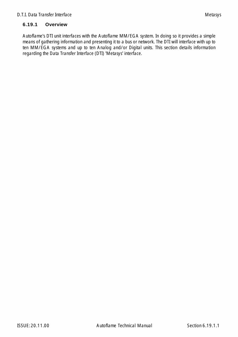
D.T.I. Data Transfer Interface
ISSUE: 20.11.00 Autoflame Technical Manual Section 6.19.1.1
6.19.1 Overview
Autoflame's DTI unit interfaces with the Autoflame MM/EGA system. In doing so it provides a simplemeans of gathering information and presenting it to a bus or network. The DTI will interface with up toten MM/EGA systems and up to ten Analog and/or Digital units. This section details informationregarding the Data Transfer Interface (DTI) 'Metasys' interface.
Metasys
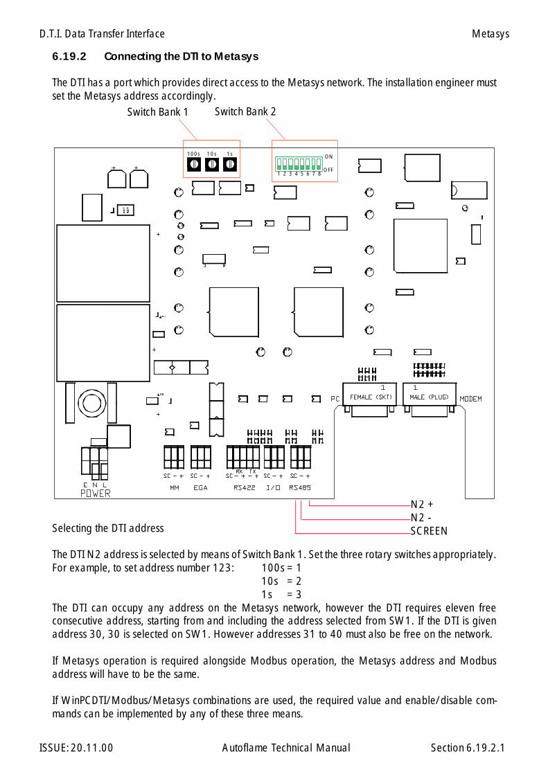
D.T.I. Data Transfer Interface
ISSUE: 20.11.00 Autoflame Technical Manual Section 6.19.2.1
6.19.2 Connecting the DTI to Metasys
The DTI has a port which provides direct access to the Metasys network. The installation engineer mustset the Metasys address accordingly.
Selecting the DTI address
The DTI N2 address is selected by means of Switch Bank 1. Set the three rotary switches appropriately.For example, to set address number 123: 100s = 1
10s = 21s = 3
The DTI can occupy any address on the Metasys network, however the DTI requires eleven freeconsecutive address, starting from and including the address selected from SW1. If the DTI is givenaddress 30, 30 is selected on SW1. However addresses 31 to 40 must also be free on the network.
If Metasys operation is required alongside Modbus operation, the Metasys address and Modbusaddress will have to be the same.
If WinPCDTI/Modbus/Metasys combinations are used, the required value and enable/disable com-mands can be implemented by any of these three means.
Metasys
N2 +N2 -SCREEN
ON
OFF1 2 3 4 5 6 7 8
10s100s 1s
Switch Bank 1 Switch Bank 2

D.T.I. Data Transfer Interface
ISSUE: 20.11.00 Autoflame Technical Manual Section 6.19.3
6.19.3 Network Point Table
The DTI occupies 11 (eleven) address on the network. The first 10 address are used to read data fromthe 10 MM/EGA systems. The last address is used to read and write data to the analog and digitalunits. This address is also used to read the status of MM/EGA systems and write values to them. Tosummarize the first 10 addresses are read only and are only used for the MM/EGA's. The last (elev-enth) address is used to read and write values to both the analog and digital units as well as the MM's.All of the systems addresses implement internal integer and byte values only. A full network pointtable follows.
Technical Note
Please be aware that the Change of State feature is not implemented on the DTI/Metasys interface.Therefore, normal Metasys COS (Alarm Limits for analog values and normal condition for Binary)notification will be defeated. If COS notification is required, then it is necessary for the operator to:
- map the specific object(s) requiring COS to a CS Object- define a AD or BD object with the CS object of the required COS point as the Associated In- assign Alarm Limits to the AD- The AD or BD point will only be scanned at a minimum of 30 seconds- The normal state of the BO must be updated (written to) by GPL.
Analog/Binary Input points that are mapped in directly that do not support COS will never report achange of state condition. They will report the current value when read but no alarm notification willoccur. A read will only occur if a focus window is open or a feature requires the current value.
Metasys

D.T.I. Data Transfer Interface
ISSUE: 20.11.00 Autoflame Technical Manual Section 6.19.3.1.1
6.19.3.1 Network Point Table - First Ten Addresses (MM/EGA values)
NPT NPA UNITS DESCRIPTION RANGE NOTEAI Not usedBI Not used
AO Not usedBO Not usedADF Not usedADI 01 % Load index 0 to 100
02 Startup/Firing status 19 - 28 19 = Waiting for stat. circuit to complete.20 = Waiting for command to drive airdamper to purge position.21 = Driving air damper to purge position.22 = Purging, waiting for command to drivevalues to ignition position.23 = Driving valves to ignition position.24 = Ignition taking place.25 = Burner firing and modulating.26 = Post purge taking place.27 = Not used.28 = Golden start.
03 Sequence status 1 to 1004 Boiler capacity see option 34 on MM05 Actual value see option 1 on MM06 Required value see option 1 on MM07 Fuel selected 0 to 3 0 = Fuel 1 (usually gas)
1 = Fuel 2 (usually oil)2 = Fuel 3 (usually oil)3 = Fuel 4 (Aux.)
08 Number of channels 0 to 809 Channel 1 position -6.0 to 96.0 Displayed as -60 to 96010 Channel 2 position -6.0 to 96.0 Displayed as -60 to 96011 Channel 3 position -6.0 to 96.0 Displayed as -60 to 96012 Channel 4 position -6.0 to 96.0 Displayed as -60 to 96013 MM error number 00 to 73 see section 2.3.1.2 of manual14 Single/Twin operation 0 to 1 0 = single
1 = twin burner15 % Run O2 0 to 20.9 Displayed as 0 to 20916 % Run CO2 0 to 1517 ppm Run CO 0 to 99918 Run exhaust temperature 0 to 999 for units see option 51 on MM19 % Run efficiency 0 to 10020 ppm Run NO 0 to 99921 ppm Run SO2 0 to 99922 % Comm. O2 0 to 20.9 Displayed as 0 to 20923 % Comm. CO2 0 to 1524 ppm Comm. CO 0 to 99925 Comm. exhaust temp 0 to 999 for units see option 51 on MM26 % Comm. efficiency 0 to 10027 ppm Comm. NO 0 to 99928 ppm Comm. SO2 0 to 99929 EGA error number 0 to 25 see section 3.4.1 of manual30 Minimum required value see option 30 on MM31 Maximum required value see option 31 on MM32 Present flow units 0 to 99933 Present flow thousands 0 to 99934 Fuel 1 flow total units 0 to 99935 Fuel 1 flow total units 0 to 99936 Fuel 1 flow total thousands 0 to 99937 Fuel 1 flow total millions 0 to 99938 Fuel 2 flow total units 0 to 99939 Fuel 2 flow total thousands 0 to 99940 Fuel 2 flow total millions 0 to 99941 Fuel 3 flow total units 0 to 99942 Fuel 3 flow total thousands 0 to 999
Metasys
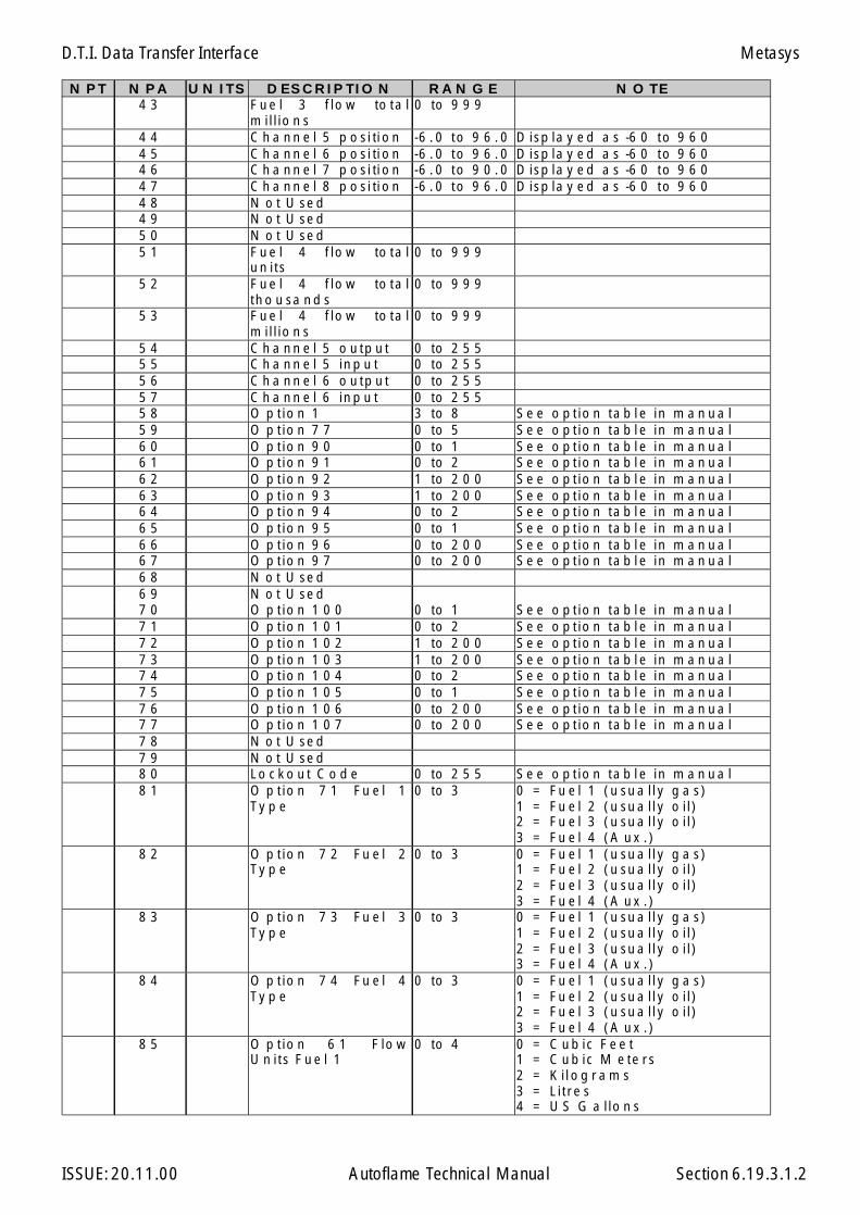
D.T.I. Data Transfer Interface
ISSUE: 20.11.00 Autoflame Technical Manual Section 6.19.3.1.2
N P T N P A U N I T S D E S C R I P T I O N R A N G E N O T E4 3 F u e l 3 f lo w to t a l
m i l l io n s0 to 9 9 9
4 4 C h a n n e l 5 p o s i ti o n -6 . 0 t o 9 6 . 0 D is p la y e d a s -6 0 t o 9 6 04 5 C h a n n e l 6 p o s i ti o n -6 . 0 t o 9 6 . 0 D is p la y e d a s -6 0 t o 9 6 04 6 C h a n n e l 7 p o s i ti o n -6 . 0 t o 9 0 . 0 D is p la y e d a s -6 0 t o 9 6 04 7 C h a n n e l 8 p o s i ti o n -6 . 0 t o 9 6 . 0 D is p la y e d a s -6 0 t o 9 6 04 8 N o t U s e d4 9 N o t U s e d5 0 N o t U s e d5 1 F u e l 4 f lo w to t a l
u n i t s0 to 9 9 9
5 2 F u e l 4 f lo w to t a lt h o u s a n d s
0 to 9 9 9
5 3 F u e l 4 f lo w to t a lm i l l io n s
0 to 9 9 9
5 4 C h a n n e l 5 o u t p u t 0 to 2 5 55 5 C h a n n e l 5 in p u t 0 to 2 5 55 6 C h a n n e l 6 o u t p u t 0 to 2 5 55 7 C h a n n e l 6 in p u t 0 to 2 5 55 8 O p t io n 1 3 to 8 S e e o p t io n t a b l e in m a n u a l5 9 O p t io n 7 7 0 to 5 S e e o p t io n t a b l e in m a n u a l6 0 O p t io n 9 0 0 to 1 S e e o p t io n t a b l e in m a n u a l6 1 O p t io n 9 1 0 to 2 S e e o p t io n t a b l e in m a n u a l6 2 O p t io n 9 2 1 to 2 0 0 S e e o p t io n t a b l e in m a n u a l6 3 O p t io n 9 3 1 to 2 0 0 S e e o p t io n t a b l e in m a n u a l6 4 O p t io n 9 4 0 to 2 S e e o p t io n t a b l e in m a n u a l6 5 O p t io n 9 5 0 to 1 S e e o p t io n t a b l e in m a n u a l6 6 O p t io n 9 6 0 to 2 0 0 S e e o p t io n t a b l e in m a n u a l6 7 O p t io n 9 7 0 to 2 0 0 S e e o p t io n t a b l e in m a n u a l6 8 N o t U s e d6 9 N o t U s e d7 0 O p t io n 1 0 0 0 to 1 S e e o p t io n t a b l e in m a n u a l7 1 O p t io n 1 0 1 0 to 2 S e e o p t io n t a b l e in m a n u a l7 2 O p t io n 1 0 2 1 to 2 0 0 S e e o p t io n t a b l e in m a n u a l7 3 O p t io n 1 0 3 1 to 2 0 0 S e e o p t io n t a b l e in m a n u a l7 4 O p t io n 1 0 4 0 to 2 S e e o p t io n t a b l e in m a n u a l7 5 O p t io n 1 0 5 0 to 1 S e e o p t io n t a b l e in m a n u a l7 6 O p t io n 1 0 6 0 to 2 0 0 S e e o p t io n t a b l e in m a n u a l7 7 O p t io n 1 0 7 0 to 2 0 0 S e e o p t io n t a b l e in m a n u a l7 8 N o t U s e d7 9 N o t U s e d8 0 L o c k o u t C o d e 0 to 2 5 5 S e e o p t io n t a b l e in m a n u a l8 1 O p t io n 7 1 F u e l 1
T y p e0 to 3 0 = F u e l 1 ( u s u a l l y g a s )
1 = F u e l 2 ( u s u a l l y o i l )2 = F u e l 3 ( u s u a l l y o i l )3 = F u e l 4 ( A u x . )
8 2 O p t io n 7 2 F u e l 2T y p e
0 to 3 0 = F u e l 1 ( u s u a l l y g a s )1 = F u e l 2 ( u s u a l l y o i l )2 = F u e l 3 ( u s u a l l y o i l )3 = F u e l 4 ( A u x . )
8 3 O p t io n 7 3 F u e l 3T y p e
0 to 3 0 = F u e l 1 ( u s u a l l y g a s )1 = F u e l 2 ( u s u a l l y o i l )2 = F u e l 3 ( u s u a l l y o i l )3 = F u e l 4 ( A u x . )
8 4 O p t io n 7 4 F u e l 4T y p e
0 to 3 0 = F u e l 1 ( u s u a l l y g a s )1 = F u e l 2 ( u s u a l l y o i l )2 = F u e l 3 ( u s u a l l y o i l )3 = F u e l 4 ( A u x . )
8 5 O p t io n 6 1 F lo wU n i t s F u e l 1
0 to 4 0 = C u b ic F e e t1 = C u b ic M e t e r s2 = K i l o g r a m s3 = L i t r e s4 = U S G a l lo n s
Metasys
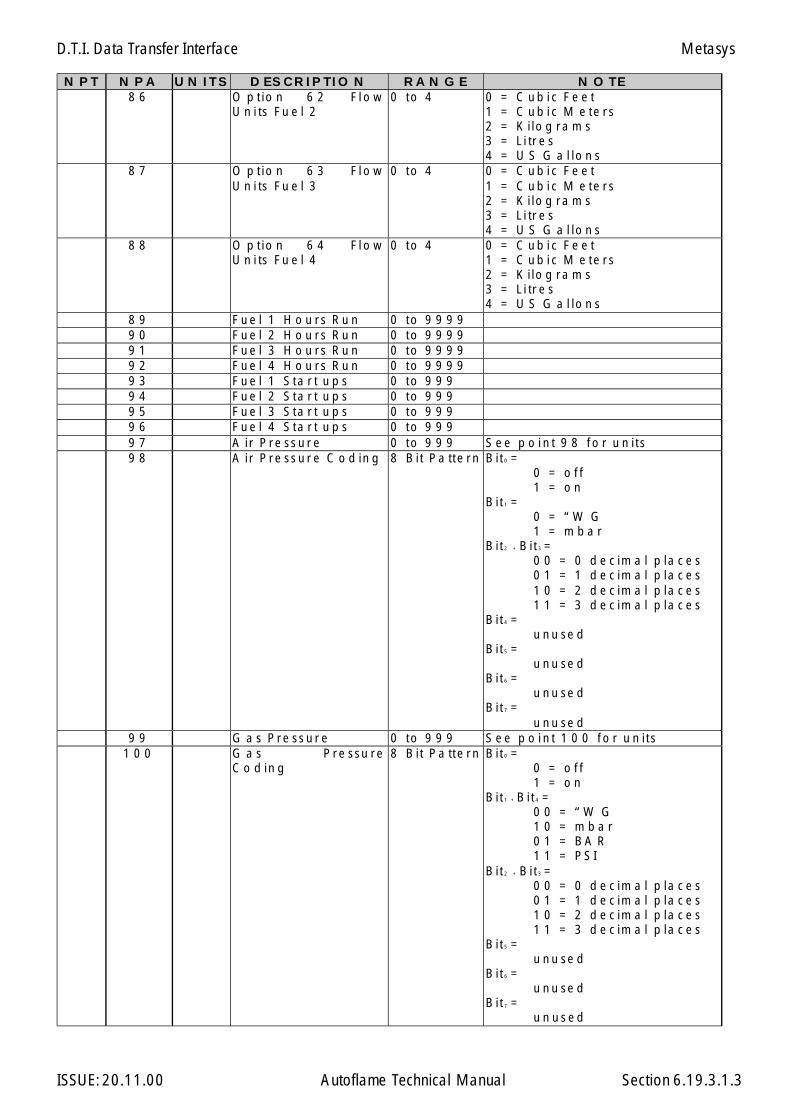
D.T.I. Data Transfer Interface
ISSUE: 20.11.00 Autoflame Technical Manual Section 6.19.3.1.3
N P T N P A U N I T S D E S C R I P T I O N R A N G E N O T E8 6 O p t io n 6 2 F l o w
U n i ts F u e l 20 t o 4 0 = C u b i c F e e t
1 = C u b i c M e t e r s2 = K i lo g r a m s3 = L i tr e s4 = U S G a l lo n s
8 7 O p t io n 6 3 F l o wU n i ts F u e l 3
0 t o 4 0 = C u b i c F e e t1 = C u b i c M e t e r s2 = K i lo g r a m s3 = L i tr e s4 = U S G a l lo n s
8 8 O p t io n 6 4 F l o wU n i ts F u e l 4
0 t o 4 0 = C u b i c F e e t1 = C u b i c M e t e r s2 = K i lo g r a m s3 = L i tr e s4 = U S G a l lo n s
8 9 F u e l 1 H o u r s R u n 0 t o 9 9 9 99 0 F u e l 2 H o u r s R u n 0 t o 9 9 9 99 1 F u e l 3 H o u r s R u n 0 t o 9 9 9 99 2 F u e l 4 H o u r s R u n 0 t o 9 9 9 99 3 F u e l 1 S t a r t u p s 0 t o 9 9 99 4 F u e l 2 S t a r t u p s 0 t o 9 9 99 5 F u e l 3 S t a r t u p s 0 t o 9 9 99 6 F u e l 4 S t a r t u p s 0 t o 9 9 99 7 A ir P r e s s u r e 0 t o 9 9 9 S e e p o i n t 9 8 f o r u n i t s9 8 A ir P r e s s u r e C o d in g 8 B i t P a tt e r n B i t 0 =
0 = o f f1 = o n
B i t 1 =0 = “ W G1 = m b a r
B i t 2 + B i t 3 =0 0 = 0 d e c im a l p la c e s0 1 = 1 d e c im a l p la c e s1 0 = 2 d e c im a l p la c e s1 1 = 3 d e c im a l p la c e s
B i t 4 =u n u s e d
B i t 5 =u n u s e d
B i t 6 =u n u s e d
B i t 7 =u n u s e d
9 9 G a s P r e s s u r e 0 t o 9 9 9 S e e p o i n t 1 0 0 f o r u n i t s1 0 0 G a s P r e s s u r e
C o d in g8 B i t P a tt e r n B i t 0 =
0 = o f f1 = o n
B i t 1 + B i t 4 =0 0 = “ W G1 0 = m b a r0 1 = B A R1 1 = P S I
B i t 2 + B i t 3 =0 0 = 0 d e c im a l p la c e s0 1 = 1 d e c im a l p la c e s1 0 = 2 d e c im a l p la c e s1 1 = 3 d e c im a l p la c e s
B i t 5 =u n u s e d
B i t 6 =u n u s e d
B i t 7 =u n u s e d
Metasys

D.T.I. Data Transfer Interface
ISSUE: 20.11.00 Autoflame Technical Manual Section 6.19.3.1.4
NPT NPA UNITS DESCRIPTION RANGE NOTE101 Fuel Selected 0 to 3 0 = Fuel 1 (usually gas)
1 = Fuel 2 (usually oil)2 = Fuel 3 (usually oil)3 = Fuel 4 (Aux.)
102 % E.G.A. O 2 0 to 20.9 Displayed as 0 to 209103 % E.G.A. CO2 0 to 15104 ppm E.G.A. CO 0 to 999105 ppm E.G.A. NO 0 to 999106 ppm E.G.A. SO2 0 to 999107 E.G.A. Exhaust temp 0 to 999108 % E.G.A. Efficiency 0 to 100109 E.G.A. Error Number 0 to 25110 % E.G.A. Voltage Input 0 to 100111 E.G.A. Exhaust ∆T 0 to 999112 E.G.A. Ambient 0 to 50113 E.G.A. Auxiliary Temp 0 to 9999114 Service LEDS 8 Bit Pattern Bit0 to Bit5 =
000000 = EGA requires servicing
000001 = 2 Months to service
000011 = 4 Months “”000111 = 6 Months “”001111 = 8 Months “”011111 = 10 Months “”111111 = 1 Year “”
Bit6 =1 = System Fault
Bit7 =1 = O.K. System Operates
CorrectlyBD 01 CR Relay status 1 = burner run
0 = burner off02 Not used03 Not used04 Not used05 Not used06 Not used07 Not used08 Not used09 Temp./Pressure 0 = Temp.
1 = Press.10 Not used11 Not used12 Not used13 Not used14 Not used15 Not used16 Not used17 Not used18 Flow metering on 1 = yes
0 = no19 CO displayed on F2/F3 1 = Displayed
0 = notdisplayed
20 Not used21 ºC or ºF 1 = F
0 = C22 Bar or PSI 1 = PSI
0 = Bar23 External Voltage 1 = yes
0 = no
Metasys
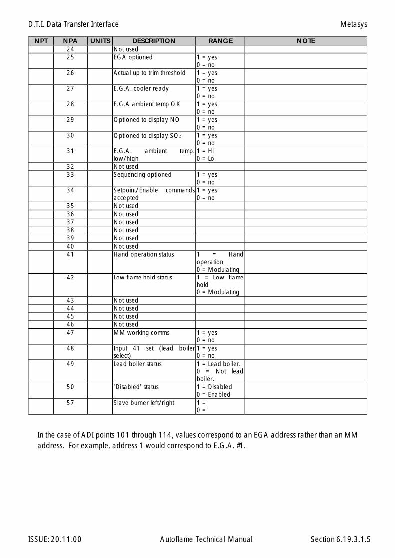
D.T.I. Data Transfer Interface
ISSUE: 20.11.00 Autoflame Technical Manual Section 6.19.3.1.5
NPT NPA UNITS DESCRIPTION RANGE NOTE24 Not used25 EGA optioned 1 = yes
0 = no26 Actual up to trim threshold 1 = yes
0 = no27 E.G.A. cooler ready 1 = yes
0 = no28 E.G.A ambient temp OK 1 = yes
0 = no29 Optioned to display NO 1 = yes
0 = no30 Optioned to display SO2 1 = yes
0 = no31 E.G.A. ambient temp.
low/high1 = Hi0 = Lo
32 Not used33 Sequencing optioned 1 = yes
0 = no34 Setpoint/Enable commands
accepted1 = yes0 = no
35 Not used36 Not used37 Not used38 Not used39 Not used40 Not used41 Hand operation status 1 = Hand
operation0 = Modulating
42 Low flame hold status 1 = Low flamehold0 = Modulating
43 Not used44 Not used45 Not used46 Not used47 MM working comms 1 = yes
0 = no48 Input 41 set (lead boiler
select)1 = yes0 = no
49 Lead boiler status 1 = Lead boiler.0 = Not leadboiler.
50 ‘Disabled’ status 1 = Disabled0 = Enabled
57 Slave burner left/right 1 =0 =
In the case of ADI points 101 through 114, values correspond to an EGA address rather than an MMaddress. For example, address 1 would correspond to E.G.A. #1.
Metasys
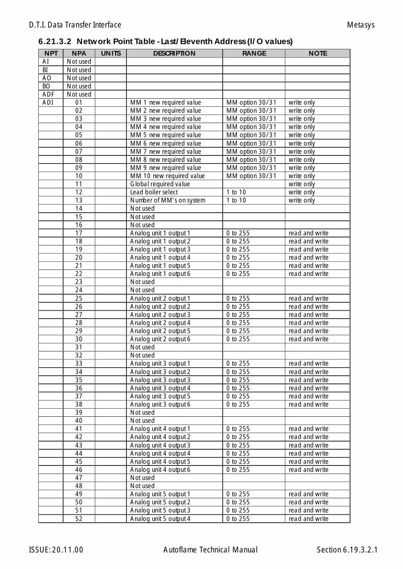
D.T.I. Data Transfer Interface
ISSUE: 20.11.00 Autoflame Technical Manual Section
6.21.3.2 Network Point Table - Last/Eleventh Address (I/O values)NPT NPA UNITS DESCRIPTION RANGE NOTE
AI Not usedBI Not usedAO Not usedBO Not usedADF Not usedADI 01 MM 1 new required value MM option 30/31 write only
02 MM 2 new required value MM option 30/31 write only03 MM 3 new required value MM option 30/31 write only04 MM 4 new required value MM option 30/31 write only05 MM 5 new required value MM option 30/31 write only06 MM 6 new required value MM option 30/31 write only07 MM 7 new required value MM option 30/31 write only08 MM 8 new required value MM option 30/31 write only09 MM 9 new required value MM option 30/31 write only10 MM 10 new required value MM option 30/31 write only11 Global required value write only12 Lead boiler select 1 to 10 write only13 Number of MM’s on system 1 to 10 write only14 Not used15 Not used16 Not used17 Analog unit 1 output 1 0 to 255 read and write18 Analog unit 1 output 2 0 to 255 read and write19 Analog unit 1 output 3 0 to 255 read and write20 Analog unit 1 output 4 0 to 255 read and write21 Analog unit 1 output 5 0 to 255 read and write22 Analog unit 1 output 6 0 to 255 read and write23 Not used24 Not used25 Analog unit 2 output 1 0 to 255 read and write26 Analog unit 2 output 2 0 to 255 read and write27 Analog unit 2 output 3 0 to 255 read and write28 Analog unit 2 output 4 0 to 255 read and write29 Analog unit 2 output 5 0 to 255 read and write30 Analog unit 2 output 6 0 to 255 read and write31 Not used32 Not used33 Analog unit 3 output 1 0 to 255 read and write34 Analog unit 3 output 2 0 to 255 read and write35 Analog unit 3 output 3 0 to 255 read and write36 Analog unit 3 output 4 0 to 255 read and write37 Analog unit 3 output 5 0 to 255 read and write38 Analog unit 3 output 6 0 to 255 read and write39 Not used40 Not used41 Analog unit 4 output 1 0 to 255 read and write42 Analog unit 4 output 2 0 to 255 read and write43 Analog unit 4 output 3 0 to 255 read and write44 Analog unit 4 output 4 0 to 255 read and write45 Analog unit 4 output 5 0 to 255 read and write46 Analog unit 4 output 6 0 to 255 read and write47 Not used48 Not used49 Analog unit 5 output 1 0 to 255 read and write50 Analog unit 5 output 2 0 to 255 read and write51 Analog unit 5 output 3 0 to 255 read and write52 Analog unit 5 output 4 0 to 255 read and write
6.19.3.2.1
Metasys

D.T.I. Data Transfer Interface
ISSUE: 20.11.00 Autoflame Technical Manual Section
NPT NPA UNITS DESCRIPTION RANGE NOTE53 Analog unit 5 output 5 0 to 255 read and write54 Analog unit 5 output 6 0 to 255 read and write55 Not used56 Not used57 Analog unit 6 output 1 0 to 255 read and write58 Analog unit 6 output 2 0 to 255 read and write59 Analog unit 6 output 3 0 to 255 read and write60 Analog unit 6 output 4 0 to 255 read and write61 Analog unit 6 output 5 0 to 255 read and write62 Analog unit 6 output 6 0 to 255 read and write63 Not used64 Not used65 Analog unit 7 output 1 0 to 255 read and write66 Analog unit 7 output 2 0 to 255 read and write67 Analog unit 7 output 3 0 to 255 read and write68 Analog unit 7 output 4 0 to 255 read and write69 Analog unit 7 output 5 0 to 255 read and write70 Analog unit 7 output 6 0 to 255 read and write71 Not used72 Not used73 Analog unit 8 output 1 0 to 255 read and write74 Analog unit 8 output 2 0 to 255 read and write75 Analog unit 8 output 3 0 to 255 read and write76 Analog unit 8 output 4 0 to 255 read and write77 Analog unit 8 output 5 0 to 255 read and write78 Analog unit 8 output 6 0 to 255 read and write79 Not used80 Not used81 Analog unit 9 output 1 0 to 255 read and write82 Analog unit 9 output 2 0 to 255 read and write83 Analog unit 9 output 3 0 to 255 read and write84 Analog unit 9 output 4 0 to 255 read and write85 Analog unit 9 output 5 0 to 255 read and write86 Analog unit 9 output 6 0 to 255 read and write87 Not used88 Not used89 Analog unit 10 output 1 0 to 255 read and write90 Analog unit 10 output 2 0 to 255 read and write91 Analog unit 10 output 3 0 to 255 read and write92 Analog unit 10 output 4 0 to 255 read and write93 Analog unit 10 output 5 0 to 255 read and write94 Analog unit 10 output 6 0 to 255 read and write95 Not used96 Not used97 Not used98 Not used99 Not used
100 Not used101 Not used102 Not used103 Not used104 Not used105 Not used106 Not used107 Not used108 Not used109 Not used
6.19.3.1.2
Metasys

D.T.I. Data Transfer Interface
ISSUE: 20.11.00 Autoflame Technical Manual Section
NPT NPA UNITS DESCRIPTION RANGE NOTE110 Not used111 Not used112 Analog unit 1 input 1 0 to 255 read only113 Analog unit 1 input 2 0 to 255 read only114 Analog unit 1 input 3 0 to 255 read only115 Analog unit 1 input 4 0 to 255 read only116 Analog unit 1 input 5 0 to 255 read only117 Analog unit 1 input 6 0 to 255 read only118 Not used119 Not used120 Analog unit 2 input 1 0 to 255 read only121 Analog unit 2 input 2 0 to 255 read only122 Analog unit 2 input 3 0 to 255 read only123 Analog unit 2 input 4 0 to 255 read only124 Analog unit 2 input 5 0 to 255 read only125 Analog unit 2 input 6 0 to 255 read only126 Not used127 Not used128 Analog unit 3 input 1 0 to 255 read only129 Analog unit 3 input 2 0 to 255 read only130 Analog unit 3 input 3 0 to 255 read only131 Analog unit 3 input 4 0 to 255 read only132 Analog unit 3 input 5 0 to 255 read only133 Analog unit 3 input 6 0 to 255 read only134 Not used135 Not used136 Analog unit 4 input 1 0 to 255 read only137 Analog unit 4 input 2 0 to 255 read only138 Analog unit 4 input 3 0 to 255 read only139 Analog unit 4 input 4 0 to 255 read only140 Analog unit 4 input 5 0 to 255 read only141 Analog unit 4 input 6 0 to 255 read only142 Not used143 Not used144 Analog unit 5 input 1 0 to 255 read only145 Analog unit 5 input 2 0 to 255 read only146 Analog unit 5 input 3 0 to 255 read only147 Analog unit 5 input 4 0 to 255 read only148 Analog unit 5 input 5 0 to 255 read only149 Analog unit 5 input 6 0 to 255 read only150 Not used151 Not used152 Analog unit 6 input 1 0 to 255 read only153 Analog unit 6 input 2 0 to 255 read only154 Analog unit 6 input 3 0 to 255 read only155 Analog unit 6 input 4 0 to 255 read only156 Analog unit 6 input 5 0 to 255 read only157 Analog unit 6 input 6 0 to 255 read only158 Not used159 Not used160 Analog unit 7 input 1 0 to 255 read only161 Analog unit 7 input 2 0 to 255 read only162 Analog unit 7 input 3 0 to 255 read only163 Analog unit 7 input 4 0 to 255 read only164 Analog unit 7 input 5 0 to 255 read only165 Analog unit 7 input 6 0 to 255 read only166 Not used
6.19.3.1.3
Metasys
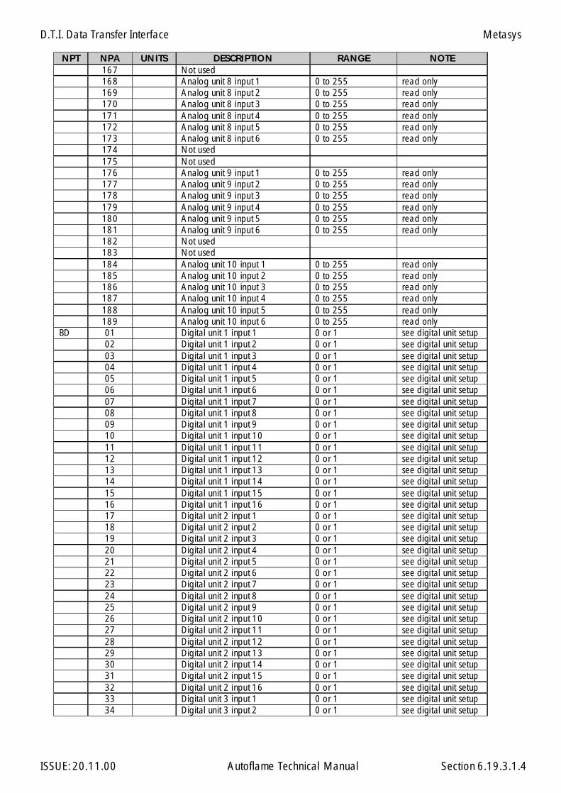
D.T.I. Data Transfer Interface
ISSUE: 20.11.00 Autoflame Technical Manual Section
NPT NPA UNITS DESCRIPTION RANGE NOTE167 Not used168 Analog unit 8 input 1 0 to 255 read only169 Analog unit 8 input 2 0 to 255 read only170 Analog unit 8 input 3 0 to 255 read only171 Analog unit 8 input 4 0 to 255 read only172 Analog unit 8 input 5 0 to 255 read only173 Analog unit 8 input 6 0 to 255 read only174 Not used175 Not used176 Analog unit 9 input 1 0 to 255 read only177 Analog unit 9 input 2 0 to 255 read only178 Analog unit 9 input 3 0 to 255 read only179 Analog unit 9 input 4 0 to 255 read only180 Analog unit 9 input 5 0 to 255 read only181 Analog unit 9 input 6 0 to 255 read only182 Not used183 Not used184 Analog unit 10 input 1 0 to 255 read only185 Analog unit 10 input 2 0 to 255 read only186 Analog unit 10 input 3 0 to 255 read only187 Analog unit 10 input 4 0 to 255 read only188 Analog unit 10 input 5 0 to 255 read only189 Analog unit 10 input 6 0 to 255 read only
BD 01 Digital unit 1 input 1 0 or 1 see digital unit setup02 Digital unit 1 input 2 0 or 1 see digital unit setup03 Digital unit 1 input 3 0 or 1 see digital unit setup04 Digital unit 1 input 4 0 or 1 see digital unit setup05 Digital unit 1 input 5 0 or 1 see digital unit setup06 Digital unit 1 input 6 0 or 1 see digital unit setup07 Digital unit 1 input 7 0 or 1 see digital unit setup08 Digital unit 1 input 8 0 or 1 see digital unit setup09 Digital unit 1 input 9 0 or 1 see digital unit setup10 Digital unit 1 input 10 0 or 1 see digital unit setup11 Digital unit 1 input 11 0 or 1 see digital unit setup12 Digital unit 1 input 12 0 or 1 see digital unit setup13 Digital unit 1 input 13 0 or 1 see digital unit setup14 Digital unit 1 input 14 0 or 1 see digital unit setup15 Digital unit 1 input 15 0 or 1 see digital unit setup16 Digital unit 1 input 16 0 or 1 see digital unit setup17 Digital unit 2 input 1 0 or 1 see digital unit setup18 Digital unit 2 input 2 0 or 1 see digital unit setup19 Digital unit 2 input 3 0 or 1 see digital unit setup20 Digital unit 2 input 4 0 or 1 see digital unit setup21 Digital unit 2 input 5 0 or 1 see digital unit setup22 Digital unit 2 input 6 0 or 1 see digital unit setup23 Digital unit 2 input 7 0 or 1 see digital unit setup24 Digital unit 2 input 8 0 or 1 see digital unit setup25 Digital unit 2 input 9 0 or 1 see digital unit setup26 Digital unit 2 input 10 0 or 1 see digital unit setup27 Digital unit 2 input 11 0 or 1 see digital unit setup28 Digital unit 2 input 12 0 or 1 see digital unit setup29 Digital unit 2 input 13 0 or 1 see digital unit setup30 Digital unit 2 input 14 0 or 1 see digital unit setup31 Digital unit 2 input 15 0 or 1 see digital unit setup32 Digital unit 2 input 16 0 or 1 see digital unit setup33 Digital unit 3 input 1 0 or 1 see digital unit setup34 Digital unit 3 input 2 0 or 1 see digital unit setup
6.19.3.1.4
Metasys
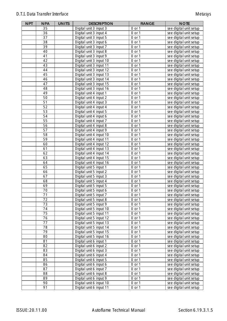
D.T.I. Data Transfer Interface
ISSUE: 20.11.00 Autoflame Technical Manual Section
NPT NPA UNITS DESCRIPTION RANGE NOTE35 Digital unit 3 input 3 0 or 1 see digital unit setup36 Digital unit 3 input 4 0 or 1 see digital unit setup37 Digital unit 3 input 5 0 or 1 see digital unit setup38 Digital unit 3 input 6 0 or 1 see digital unit setup39 Digital unit 3 input 7 0 or 1 see digital unit setup40 Digital unit 3 input 8 0 or 1 see digital unit setup41 Digital unit 3 input 9 0 or 1 see digital unit setup42 Digital unit 3 input 10 0 or 1 see digital unit setup43 Digital unit 3 input 11 0 or 1 see digital unit setup44 Digital unit 3 input 12 0 or 1 see digital unit setup45 Digital unit 3 input 13 0 or 1 see digital unit setup46 Digital unit 3 input 14 0 or 1 see digital unit setup47 Digital unit 3 input 15 0 or 1 see digital unit setup48 Digital unit 3 input 16 0 or 1 see digital unit setup49 Digital unit 4 input 1 0 or 1 see digital unit setup50 Digital unit 4 input 2 0 or 1 see digital unit setup51 Digital unit 4 input 3 0 or 1 see digital unit setup52 Digital unit 4 input 4 0 or 1 see digital unit setup53 Digital unit 4 input 5 0 or 1 see digital unit setup54 Digital unit 4 input 6 0 or 1 see digital unit setup55 Digital unit 4 input 7 0 or 1 see digital unit setup56 Digital unit 4 input 8 0 or 1 see digital unit setup57 Digital unit 4 input 9 0 or 1 see digital unit setup58 Digital unit 4 input 10 0 or 1 see digital unit setup59 Digital unit 4 input 11 0 or 1 see digital unit setup60 Digital unit 4 input 12 0 or 1 see digital unit setup61 Digital unit 4 input 13 0 or 1 see digital unit setup62 Digital unit 4 input 14 0 or 1 see digital unit setup63 Digital unit 4 input 15 0 or 1 see digital unit setup64 Digital unit 4 input 16 0 or 1 see digital unit setup65 Digital unit 5 input 1 0 or 1 see digital unit setup66 Digital unit 5 input 2 0 or 1 see digital unit setup67 Digital unit 5 input 3 0 or 1 see digital unit setup68 Digital unit 5 input 4 0 or 1 see digital unit setup69 Digital unit 5 input 5 0 or 1 see digital unit setup70 Digital unit 5 input 6 0 or 1 see digital unit setup71 Digital unit 5 input 7 0 or 1 see digital unit setup72 Digital unit 5 input 8 0 or 1 see digital unit setup73 Digital unit 5 input 9 0 or 1 see digital unit setup74 Digital unit 5 input 10 0 or 1 see digital unit setup75 Digital unit 5 input 11 0 or 1 see digital unit setup76 Digital unit 5 input 12 0 or 1 see digital unit setup77 Digital unit 5 input 13 0 or 1 see digital unit setup78 Digital unit 5 input 14 0 or 1 see digital unit setup79 Digital unit 5 input 15 0 or 1 see digital unit setup80 Digital unit 5 input 16 0 or 1 see digital unit setup81 Digital unit 6 input 1 0 or 1 see digital unit setup82 Digital unit 6 input 2 0 or 1 see digital unit setup83 Digital unit 6 input 3 0 or 1 see digital unit setup84 Digital unit 6 input 4 0 or 1 see digital unit setup85 Digital unit 6 input 5 0 or 1 see digital unit setup86 Digital unit 6 input 6 0 or 1 see digital unit setup87 Digital unit 6 input 7 0 or 1 see digital unit setup88 Digital unit 6 input 8 0 or 1 see digital unit setup89 Digital unit 6 input 9 0 or 1 see digital unit setup90 Digital unit 6 input 10 0 or 1 see digital unit setup91 Digital unit 6 input 11 0 or 1 see digital unit setup
6.19.3.1.5
Metasys
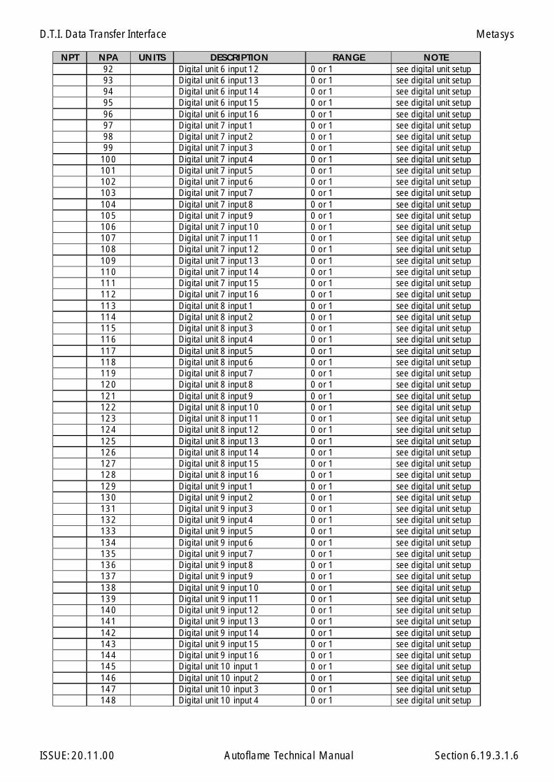
D.T.I. Data Transfer Interface
ISSUE: 20.11.00 Autoflame Technical Manual Section
NPT NPA UNITS DESCRIPTION RANGE NOTE92 Digital unit 6 input 12 0 or 1 see digital unit setup93 Digital unit 6 input 13 0 or 1 see digital unit setup94 Digital unit 6 input 14 0 or 1 see digital unit setup95 Digital unit 6 input 15 0 or 1 see digital unit setup96 Digital unit 6 input 16 0 or 1 see digital unit setup97 Digital unit 7 input 1 0 or 1 see digital unit setup98 Digital unit 7 input 2 0 or 1 see digital unit setup99 Digital unit 7 input 3 0 or 1 see digital unit setup
100 Digital unit 7 input 4 0 or 1 see digital unit setup101 Digital unit 7 input 5 0 or 1 see digital unit setup102 Digital unit 7 input 6 0 or 1 see digital unit setup103 Digital unit 7 input 7 0 or 1 see digital unit setup104 Digital unit 7 input 8 0 or 1 see digital unit setup105 Digital unit 7 input 9 0 or 1 see digital unit setup106 Digital unit 7 input 10 0 or 1 see digital unit setup107 Digital unit 7 input 11 0 or 1 see digital unit setup108 Digital unit 7 input 12 0 or 1 see digital unit setup109 Digital unit 7 input 13 0 or 1 see digital unit setup110 Digital unit 7 input 14 0 or 1 see digital unit setup111 Digital unit 7 input 15 0 or 1 see digital unit setup112 Digital unit 7 input 16 0 or 1 see digital unit setup113 Digital unit 8 input 1 0 or 1 see digital unit setup114 Digital unit 8 input 2 0 or 1 see digital unit setup115 Digital unit 8 input 3 0 or 1 see digital unit setup116 Digital unit 8 input 4 0 or 1 see digital unit setup117 Digital unit 8 input 5 0 or 1 see digital unit setup118 Digital unit 8 input 6 0 or 1 see digital unit setup119 Digital unit 8 input 7 0 or 1 see digital unit setup120 Digital unit 8 input 8 0 or 1 see digital unit setup121 Digital unit 8 input 9 0 or 1 see digital unit setup122 Digital unit 8 input 10 0 or 1 see digital unit setup123 Digital unit 8 input 11 0 or 1 see digital unit setup124 Digital unit 8 input 12 0 or 1 see digital unit setup125 Digital unit 8 input 13 0 or 1 see digital unit setup126 Digital unit 8 input 14 0 or 1 see digital unit setup127 Digital unit 8 input 15 0 or 1 see digital unit setup128 Digital unit 8 input 16 0 or 1 see digital unit setup129 Digital unit 9 input 1 0 or 1 see digital unit setup130 Digital unit 9 input 2 0 or 1 see digital unit setup131 Digital unit 9 input 3 0 or 1 see digital unit setup132 Digital unit 9 input 4 0 or 1 see digital unit setup133 Digital unit 9 input 5 0 or 1 see digital unit setup134 Digital unit 9 input 6 0 or 1 see digital unit setup135 Digital unit 9 input 7 0 or 1 see digital unit setup136 Digital unit 9 input 8 0 or 1 see digital unit setup137 Digital unit 9 input 9 0 or 1 see digital unit setup138 Digital unit 9 input 10 0 or 1 see digital unit setup139 Digital unit 9 input 11 0 or 1 see digital unit setup140 Digital unit 9 input 12 0 or 1 see digital unit setup141 Digital unit 9 input 13 0 or 1 see digital unit setup142 Digital unit 9 input 14 0 or 1 see digital unit setup143 Digital unit 9 input 15 0 or 1 see digital unit setup144 Digital unit 9 input 16 0 or 1 see digital unit setup145 Digital unit 10 input 1 0 or 1 see digital unit setup146 Digital unit 10 input 2 0 or 1 see digital unit setup147 Digital unit 10 input 3 0 or 1 see digital unit setup148 Digital unit 10 input 4 0 or 1 see digital unit setup
6.19.3.1.6
Metasys
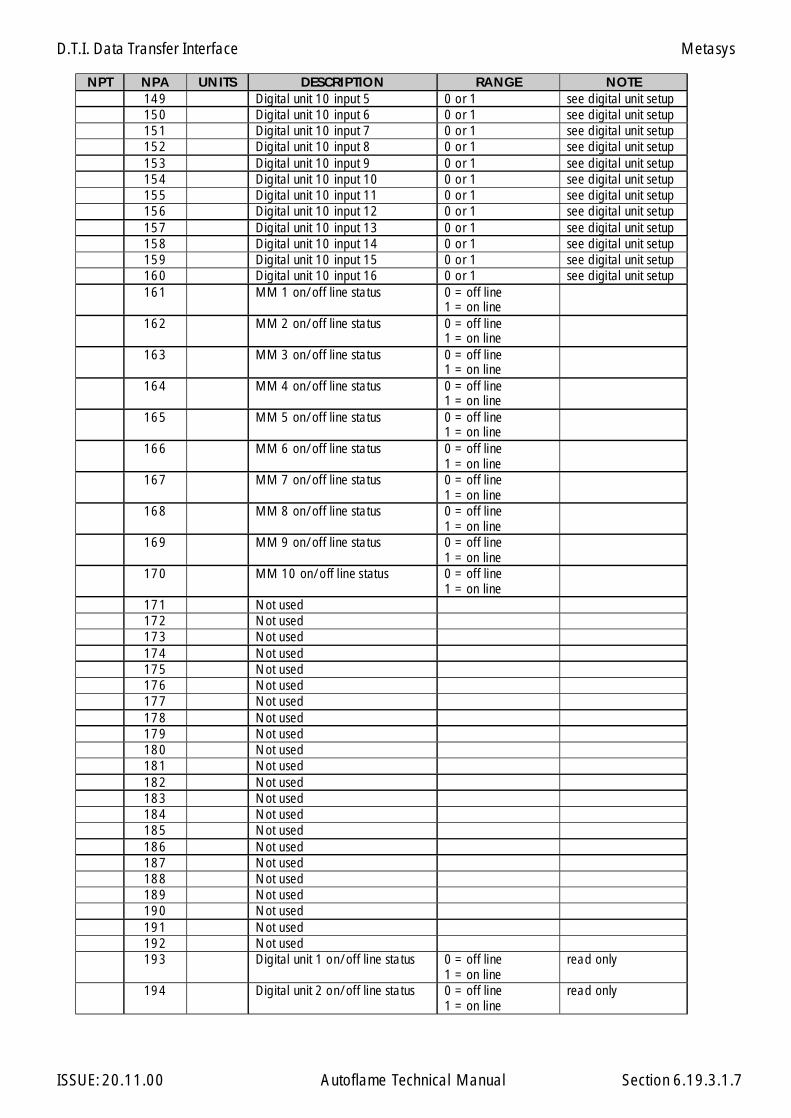
D.T.I. Data Transfer Interface
ISSUE: 20.11.00 Autoflame Technical Manual Section
NPT NPA UNITS DESCRIPTION RANGE NOTE149 Digital unit 10 input 5 0 or 1 see digital unit setup150 Digital unit 10 input 6 0 or 1 see digital unit setup151 Digital unit 10 input 7 0 or 1 see digital unit setup152 Digital unit 10 input 8 0 or 1 see digital unit setup153 Digital unit 10 input 9 0 or 1 see digital unit setup154 Digital unit 10 input 10 0 or 1 see digital unit setup155 Digital unit 10 input 11 0 or 1 see digital unit setup156 Digital unit 10 input 12 0 or 1 see digital unit setup157 Digital unit 10 input 13 0 or 1 see digital unit setup158 Digital unit 10 input 14 0 or 1 see digital unit setup159 Digital unit 10 input 15 0 or 1 see digital unit setup160 Digital unit 10 input 16 0 or 1 see digital unit setup161 MM 1 on/off line status 0 = off line
1 = on line162 MM 2 on/off line status 0 = off line
1 = on line163 MM 3 on/off line status 0 = off line
1 = on line164 MM 4 on/off line status 0 = off line
1 = on line165 MM 5 on/off line status 0 = off line
1 = on line166 MM 6 on/off line status 0 = off line
1 = on line167 MM 7 on/off line status 0 = off line
1 = on line168 MM 8 on/off line status 0 = off line
1 = on line169 MM 9 on/off line status 0 = off line
1 = on line170 MM 10 on/off line status 0 = off line
1 = on line171 Not used172 Not used173 Not used174 Not used175 Not used176 Not used177 Not used178 Not used179 Not used180 Not used181 Not used182 Not used183 Not used184 Not used185 Not used186 Not used187 Not used188 Not used189 Not used190 Not used191 Not used192 Not used193 Digital unit 1 on/off line status 0 = off line
1 = on lineread only
194 Digital unit 2 on/off line status 0 = off line1 = on line
read only
6.19.3.1.7
Metasys
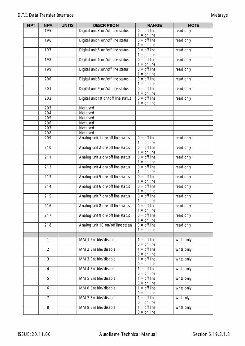
D.T.I. Data Transfer Interface
ISSUE: 20.11.00 Autoflame Technical Manual Section
NPT NPA UNITS DESCRIPTION RANGE NOTE195 Digital unit 3 on/off line status 0 = off line
1 = on lineread only
196 Digital unit 4 on/off line status 0 = off line1 = on line
read only
197 Digital unit 5 on/off line status 0 = off line1 = on line
read only
198 Digital unit 6 on/off line status 0 = off line1 = on line
read only
199 Digital unit 7 on/off line status 0 = off line1 = on line
read only
200 Digital unit 8 on/off line status 0 = off line1 = on line
read only
201 Digital unit 9 on/off line status 0 = off line1 = on line
read only
202 Digital unit 10 on/off line status 0 = off line1 = on line
read only
203 Not used204 Not used205 Not used206 Not used207 Not used208 Not used209 Analog unit 1 on/off line status 0 = off line
1 = on lineread only
210 Analog unit 2 on/off line status 0 = off line1 = on line
read only
211 Analog unit 3 on/off line status 0 = off line1 = on line
read only
212 Analog unit 4 on/off line status 0 = off line1 = on line
read only
213 Analog unit 5 on/off line status 0 = off line1 = on line
read only
214 Analog unit 6 on/off line status 0 = off line1 = on line
read only
215 Analog unit 7 on/off line status 0 = off line1 = on line
read only
216 Analog unit 8 on/off line status 0 = off line1 = on line
read only
217 Analog unit 9 on/off line status 0 = off line1 = on line
read only
218 Analog unit 10 on/off line status 0 = off line1 = on line
read only
1 MM 1 Enable/disable 1 = off line0 = on line
write only
2 MM 2 Enable/disable 1 = off line0 = on line
write only
3 MM 3 Enable/disable 1 = off line0 = on line
write only
4 MM 4 Enable/disable 1 = off line0 = on line
write only
5 MM 5 Enable/disable 1 = off line0 = on line
write only
6 MM 6 Enable/disable 1 = off line0 = on line
write only
7 MM 7 Enable/disable 1 = off line0 = on line
writ only
8 MM 8 Enable/disable 1 = off line0 = on line
write only
6.19.3.1.8
Metasys
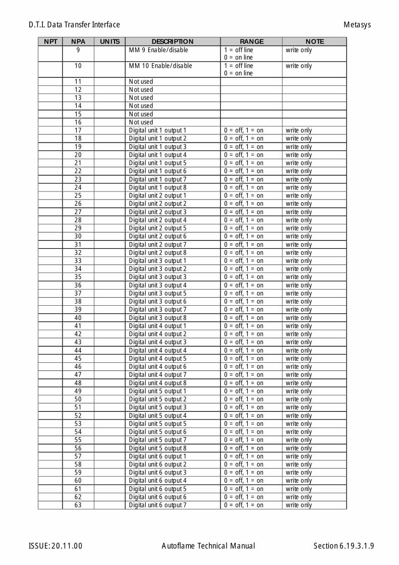
D.T.I. Data Transfer Interface
ISSUE: 20.11.00 Autoflame Technical Manual Section
NPT NPA UNITS DESCRIPTION RANGE NOTE9 MM 9 Enable/disable 1 = off line
0 = on linewrite only
10 MM 10 Enable/disable 1 = off line0 = on line
write only
11 Not used12 Not used13 Not used14 Not used15 Not used16 Not used17 Digital unit 1 output 1 0 = off, 1 = on write only18 Digital unit 1 output 2 0 = off, 1 = on write only19 Digital unit 1 output 3 0 = off, 1 = on write only20 Digital unit 1 output 4 0 = off, 1 = on write only21 Digital unit 1 output 5 0 = off, 1 = on write only22 Digital unit 1 output 6 0 = off, 1 = on write only23 Digital unit 1 output 7 0 = off, 1 = on write only24 Digital unit 1 output 8 0 = off, 1 = on write only25 Digital unit 2 output 1 0 = off, 1 = on write only26 Digital unit 2 output 2 0 = off, 1 = on write only27 Digital unit 2 output 3 0 = off, 1 = on write only28 Digital unit 2 output 4 0 = off, 1 = on write only29 Digital unit 2 output 5 0 = off, 1 = on write only30 Digital unit 2 output 6 0 = off, 1 = on write only31 Digital unit 2 output 7 0 = off, 1 = on write only32 Digital unit 2 output 8 0 = off, 1 = on write only33 Digital unit 3 output 1 0 = off, 1 = on write only34 Digital unit 3 output 2 0 = off, 1 = on write only35 Digital unit 3 output 3 0 = off, 1 = on write only36 Digital unit 3 output 4 0 = off, 1 = on write only37 Digital unit 3 output 5 0 = off, 1 = on write only38 Digital unit 3 output 6 0 = off, 1 = on write only39 Digital unit 3 output 7 0 = off, 1 = on write only40 Digital unit 3 output 8 0 = off, 1 = on write only41 Digital unit 4 output 1 0 = off, 1 = on write only42 Digital unit 4 output 2 0 = off, 1 = on write only43 Digital unit 4 output 3 0 = off, 1 = on write only44 Digital unit 4 output 4 0 = off, 1 = on write only45 Digital unit 4 output 5 0 = off, 1 = on write only46 Digital unit 4 output 6 0 = off, 1 = on write only47 Digital unit 4 output 7 0 = off, 1 = on write only48 Digital unit 4 output 8 0 = off, 1 = on write only49 Digital unit 5 output 1 0 = off, 1 = on write only50 Digital unit 5 output 2 0 = off, 1 = on write only51 Digital unit 5 output 3 0 = off, 1 = on write only52 Digital unit 5 output 4 0 = off, 1 = on write only53 Digital unit 5 output 5 0 = off, 1 = on write only54 Digital unit 5 output 6 0 = off, 1 = on write only55 Digital unit 5 output 7 0 = off, 1 = on write only56 Digital unit 5 output 8 0 = off, 1 = on write only57 Digital unit 6 output 1 0 = off, 1 = on write only58 Digital unit 6 output 2 0 = off, 1 = on write only59 Digital unit 6 output 3 0 = off, 1 = on write only60 Digital unit 6 output 4 0 = off, 1 = on write only61 Digital unit 6 output 5 0 = off, 1 = on write only62 Digital unit 6 output 6 0 = off, 1 = on write only63 Digital unit 6 output 7 0 = off, 1 = on write only
6.19.3.1.9
Metasys
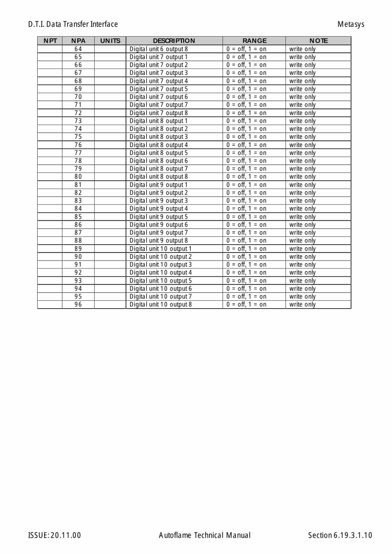
D.T.I. Data Transfer Interface
ISSUE: 20.11.00 Autoflame Technical Manual Section
NPT NPA UNITS DESCRIPTION RANGE NOTE64 Digital unit 6 output 8 0 = off, 1 = on write only65 Digital unit 7 output 1 0 = off, 1 = on write only66 Digital unit 7 output 2 0 = off, 1 = on write only67 Digital unit 7 output 3 0 = off, 1 = on write only68 Digital unit 7 output 4 0 = off, 1 = on write only69 Digital unit 7 output 5 0 = off, 1 = on write only70 Digital unit 7 output 6 0 = off, 1 = on write only71 Digital unit 7 output 7 0 = off, 1 = on write only72 Digital unit 7 output 8 0 = off, 1 = on write only73 Digital unit 8 output 1 0 = off, 1 = on write only74 Digital unit 8 output 2 0 = off, 1 = on write only75 Digital unit 8 output 3 0 = off, 1 = on write only76 Digital unit 8 output 4 0 = off, 1 = on write only77 Digital unit 8 output 5 0 = off, 1 = on write only78 Digital unit 8 output 6 0 = off, 1 = on write only79 Digital unit 8 output 7 0 = off, 1 = on write only80 Digital unit 8 output 8 0 = off, 1 = on write only81 Digital unit 9 output 1 0 = off, 1 = on write only82 Digital unit 9 output 2 0 = off, 1 = on write only83 Digital unit 9 output 3 0 = off, 1 = on write only84 Digital unit 9 output 4 0 = off, 1 = on write only85 Digital unit 9 output 5 0 = off, 1 = on write only86 Digital unit 9 output 6 0 = off, 1 = on write only87 Digital unit 9 output 7 0 = off, 1 = on write only88 Digital unit 9 output 8 0 = off, 1 = on write only89 Digital unit 10 output 1 0 = off, 1 = on write only90 Digital unit 10 output 2 0 = off, 1 = on write only91 Digital unit 10 output 3 0 = off, 1 = on write only92 Digital unit 10 output 4 0 = off, 1 = on write only93 Digital unit 10 output 5 0 = off, 1 = on write only94 Digital unit 10 output 6 0 = off, 1 = on write only95 Digital unit 10 output 7 0 = off, 1 = on write only96 Digital unit 10 output 8 0 = off, 1 = on write only
6.19.3.1.10
Metasys
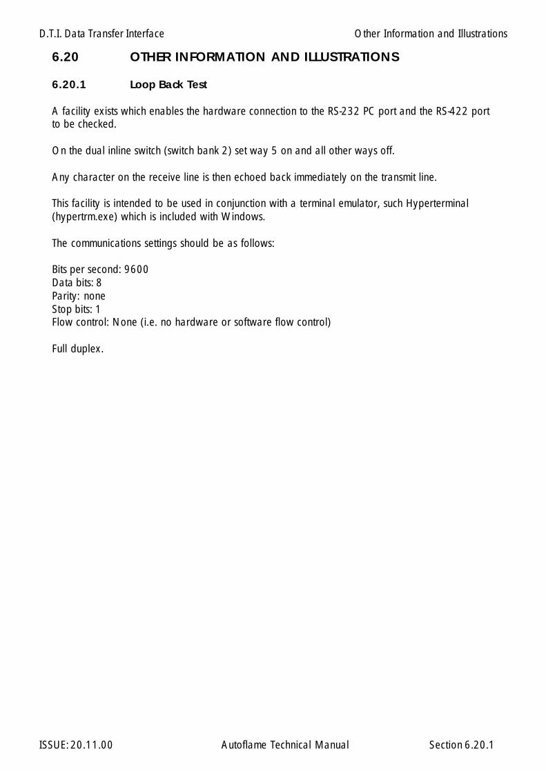
D.T.I. Data Transfer Interface
ISSUE: 20.11.00 Autoflame Technical Manual Section
6.20 OTHER INFORMATION AND ILLUSTRATIONS
6.20.1 Loop Back Test
A facility exists which enables the hardware connection to the RS-232 PC port and the RS-422 portto be checked.
On the dual inline switch (switch bank 2) set way 5 on and all other ways off.
Any character on the receive line is then echoed back immediately on the transmit line.
This facility is intended to be used in conjunction with a terminal emulator, such Hyperterminal(hypertrm.exe) which is included with Windows.
The communications settings should be as follows:
Bits per second: 9600Data bits: 8Parity: noneStop bits: 1Flow control: None (i.e. no hardware or software flow control)
Full duplex.
Other Information and Illustrations
6.20.1
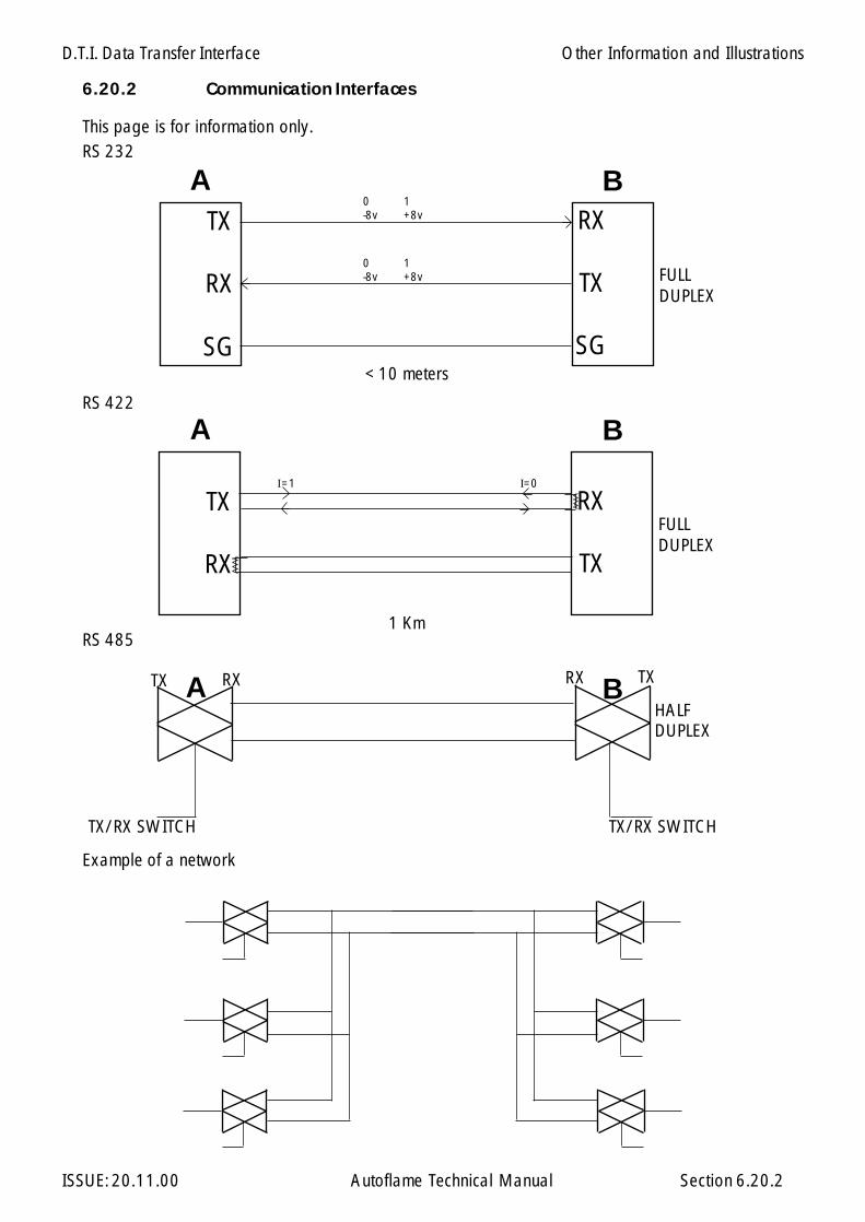
D.T.I. Data Transfer Interface
ISSUE: 20.11.00 Autoflame Technical Manual Section 6.20.2
6.20.2 Communication Interfaces
This page is for information only.
Example of a network
FULLDUPLEX
RS 232
FULLDUPLEX
RS 422
1 Km
TX
RX
RX
TX
A B
I=0I=1
RS 485
HALFDUPLEX
TX/RX SWITCH
A BTX RX RX TX
TX/RX SWITCH
< 10 meters
0 1-8v +8vTX
RX
SG
RX
TX
SG
A B
0 1-8v +8v
Other Information and Illustrations
Application Possibilities
ISSUE: 20.11.00 Autoflame Technical Manual Section
Section 7: Application Possibilities for M.M./E.G.A.
7.1 Pressure Jet/Gun Type Burners
7.2 Rotary Burners
7.2.1 Diagram showing System with Rotary Burner
7.3 Flue Gas Recirculation Control (N.O.X.).
7.4 Steam Generator Feed Water Control
7.5 Water Injection
7.7 System Configurations
7.7.1 Mk6 MM/EGA System Schematic7.7.2 Mini Mk6 MM/EGA System Schematic7.7.3 Mini Mk5 MM/EGA System Schematic
7: Index
123456789012345678901234561234567890123456789012345612345678901234567890123456123456789012345678901234561234567890123456789012345612345678901234567890123456123456789012345678901234561234567890123456789012345612345678901234567890123456123456789012345678901234561234567890123456789012345612345678901234567890123456
Application Possibilities
ISSUE: 20.11.00 Autoflame Technical Manual Section
Pressure Jet/Gun Type Burners
7.1 APPLICATION POSSIBILITIES FOR M.M. /E.G.A. SYSTEM
The M.M. system is basically an air/fuel ratio control designed to improve the energy efficiency andcontrol of a standard pressure jet or rotary burner. The ability to control up to 6 channels howevergreatly expands the areas in which it can be used and any application in which it is necessary toprecisely mix fuel and air from up to 6 sources is a possibility.
Pressure Jet/Gun Type Burners
The simplest system requiring only two servo motors for control. The energy saving benefits come fromfour sources:
a.) Elimination of mechanical hysteresis due to cams and linkages;
b.) Precise control of the air/fuel ratio throughout the combustion range without thecompromises which limit a cam.
c.) Control of the output to ±1 degree C. (± 2 degrees F.) or ±1.5 psi via the PID controller,eliminating the wastage or pressure higher than required.
d.) No compromise required when changing between fuels since the air/fuel ratio for each arecompletely seperate.
7.1
Application Possibilities
ISSUE: 20.11.00 Autoflame Technical Manual Section
Rotary Burners
The M.M. system is basically an air/fuel ratio control designed to improve the energy efficiency andcontrol of a standard pressure jet or rotary burner.
The ability to control up to 6 channels however greatly expands the areas in which it can be used.Any application in which it is necessary to precisely mix fuel and air from up to 8 sources is a possibilityand one of the possible applications is the use of rotary burners.
The benefits of this system are similar to that of pressure jet/gun burners but by utilising the thirdchannel , to control the primary air supply, the best possible mixing is achieved. The energy savingbenefits are as follows:
a.) Elimination of mechanical hysteresis due to cams and linkages;
b.) Precise control of the air/fuel ratio throughout the combustion range without thecompromises which limit a cam.
c.) Control of the output to ±1 degree C. (± 2 degrees F.) or ± 1.5 psi via the P.I.D. controller,eliminating the wastage or pressure higher than required.
d.) No compromise required when changing between fuels since the air/fuel ratio for each arecompletely seperate.
7.2 APPLICATION POSSIBILITIES FOR M.M. /E.G.A. SYSTEM
Rotary Burners
7.2

Application Possibilities
ISSUE: 20.11.00 Autoflame Technical Manual Section 7.2.1

Application Possibilities
ISSUE: 20.11.00 Autoflame Technical Manual Section
The M.M. system is basically an air/fuel ratio control designed to improve the energy efficiency andcontrol of a standard pressure jet or rotary burner. The ability to control up to 8 channels howevergreatly expands the areas in which it can be used and any application in which it is necessary toprecisely mix fuel and air from up to 6 sources is a possibility.
The additional channels can be used to control a recirculation damper which is a common method inthe control of NOX production. As with most forms of NOX control this method reduces thetemperature in the combustion chamber and hence reduces thermal efficiency. Use of the M.M./E.G.A.will minimise the excess air to the burner which itself reduces NOX and will also affect some of this lossof efficiency.
7.3 APPLICATION POSSIBILITIES FOR M.M. /E.G.A. SYSTEM
Flue Gas Re-Circulation Control (NOx)
7.3

Application Possibilities
ISSUE: 20.11.00 Autoflame Technical Manual Section
7.4 APPLICATION POSSIBILITIES FOR M.M. /E.G.A. SYSTEM
Steam Generator Feed Water Control
The M.M. system is basically an air/fuel ratio control designed to improve the energy efficiency andcontrol of a standard pressure jet or rotary burner. The ability to control up to 8 channels howevergreatly expands the areas in which it can be used and any application in which it is necessary toprecisely mix fuel and air from up to 6 sources is a possibility.
Steam Generator Feed Water Control
7.4

Application Possibilities
ISSUE: 20.11.00 Autoflame Technical Manual Section
7.5 APPLICATION POSSIBILITIES FOR M.M. /E.G.A. SYSTEM
Water Injection
The M.M. system is basically an air/fuel ratio control designed to improve the energy efficiency andcontrol of a standard pressure jet or rotary burner. The ability to control up to 8 channels howevergreatly expands the areas in which it can be used and any application in which it is necessary toprecisely mix fuel and air from up to 6 sources is a possibility.
The 3rd channel can be used in this instance to control the water injection.
Water Injection
7.5
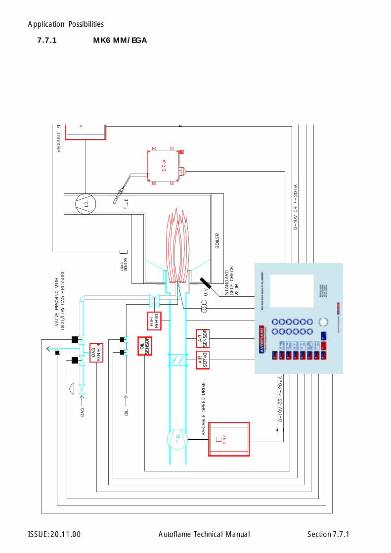
Application Possibilities
ISSUE: 20.11.00 Autoflame Technical Manual Section 7.7.1
7.7.1 MK6 MM/EGA

Application Possibilities
ISSUE: 20.11.00 Autoflame Technical Manual Section
7.7.2 MINI MK6 MM/EGA
7.7.2
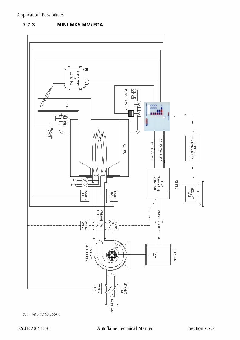
Application Possibilities
ISSUE: 20.11.00 Autoflame Technical Manual Section 7.7.3
7.7.3 MINI MK5 MM/EGA
M.M./E.G.A. Peripherals
ISSUE: 20.11.00 Autoflame Technical Manual Section
Section 8: Ancillary & Peripheral Equipment.
8: Index
8.0 Valve Specifications
8.0.1 Oil Valve Selection
8.1 Screwed Gas Valves (small positioning motor)8.2 Flanged Gas Valves (small positioning motor)8.3 Flanged Gas Valves (large positioning motor)
8.3.1 Screwed Gas Valve + Oil Valve + Small positioning motor8.3.2 Flanged Gas Valve + Oil Valve + Small positioning motor8.3.3 Gas Valve Pressure Drop Graph
8.4 Type 1,2,5,6,8,9, Oil Control ValvesSmall positioning motor8.4.1 Small Metering Valve
8.5 Type 4 Oil Control ValveLarge positioning motor
8.6 Type 3 Oil Control ValveLarge positioning motor
8.6.1 Type 1 Spillback Graph8.6.2 Type 2 Spillback Graph8.6.3 Type 4 Spillback Graph8.6.4 Type 5 Spillback Graph8.6.5 Type 3 Metering Graph8.6.6 Type 6 Metering Graph8.6.7 Type 8 Metering Graph8.6.8 Type 9 Metering Graph
8.7 Small Positioning Motor
8.8 Large Positioning Motor
8.9 Temperature Detector8.9.1 Pressure Detector
8.10 Industrial Positioning Motor
8.10.0 Overview8.10.1 External Drawings8.10.2 Specification8.10.3 Installation8.10.4 Manual Operation8.10.5 Troubleshooting
12345678901234567890123123456789012345678901231234567890123456789012312345678901234567890123123456789012345678901231234567890123456789012312345678901234567890123123456789012345678901231234567890123456789012312345678901234567890123123456789012345678901231234567890123456789012312345678901234567890123
1
Gas Valves:
Oil Valves:
Positioning Motors:
Load Detectors:

M.M./E.G.A. Peripherals
ISSUE: 20.11.00 Autoflame Technical Manual Section
8.0 VALVE SPECIFICATIONS
When using high viscosity low temperature fuel oils through smaller valves, turbulent flow charac-teristics can reduce volume throughput significantly.
All flow pressure graphs published for oil valves are using Light distillate oil @ 20°C and a viscosityof 5 centistokes.
Autoflame will carry out flow characteristic tests on specific valves against customer fuel/viscosityand temperature specifications. Price on application.
Standard oil valve build execution is mild steel valve body with cast bronze metering bobbin.
All valves can be supplied in nonstandard material at extra cost, price on application.
For very heavy fuel oil or contaminated fuels it is recommended that execution is stainless steelbody and bobbin. The cost for all stainless steel construction is standard price x3.
Gas Valve's standard execution is Nickel Plate mild steel body with stainless steel metering disk.Gas valves can also be supplied for corrosive/contaminated fuels in all stainless steel constructionat standard price x4.
For further information please contact your supplier.
8.0

M.M./E.G.A. Peripherals
ISSUE: 20.11.00 Autoflame Technical Manual Section
8.0.1 OIL VALVE SELECTION
8.0.1.1 Spillback/Bypass Application
8.0.1.1
For assistance, fill in the actual data and return to Autoflame.
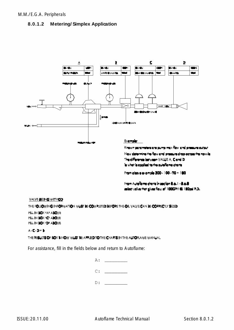
M.M./E.G.A. Peripherals
ISSUE: 20.11.00 Autoflame Technical Manual Section
8.0.1.2 Metering/Simplex Application
8.0.1.2
For assistance, fill in the fields below and return to Autoflame:
A: ________
C: ________
D: ________
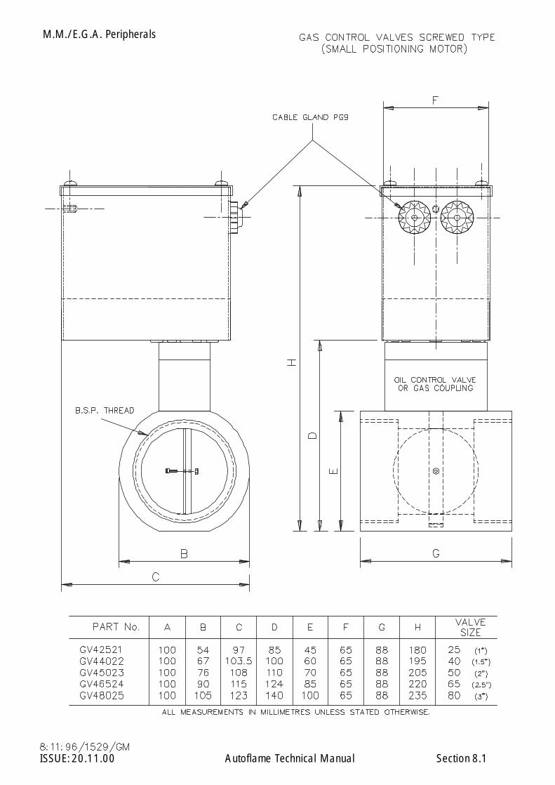
M.M./E.G.A. Peripherals
ISSUE: 20.11.00 Autoflame Technical Manual Section 8.1

M.M./E.G.A. Peripherals
ISSUE: 20.11.00 Autoflame Technical Manual Section 8.1.a
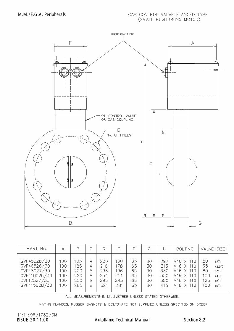
M.M./E.G.A. Peripherals
ISSUE: 20.11.00 Autoflame Technical Manual Section 8.2

M.M./E.G.A. Peripherals
ISSUE: 20.11.00 Autoflame Technical Manual Section 8.2.a
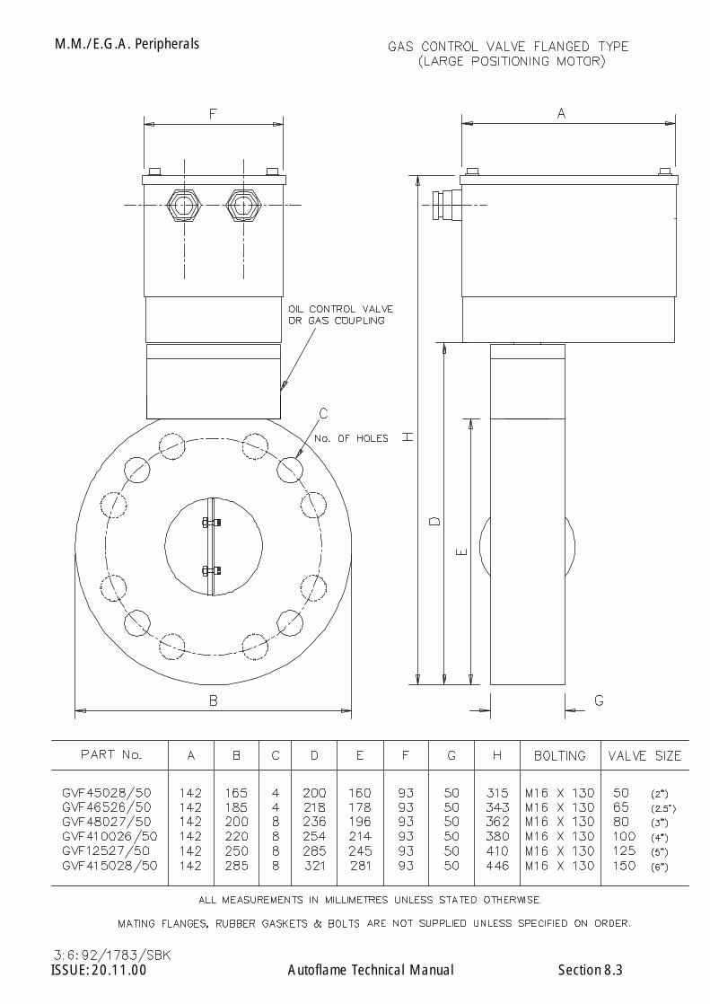
M.M./E.G.A. Peripherals
ISSUE: 20.11.00 Autoflame Technical Manual Section 8.3
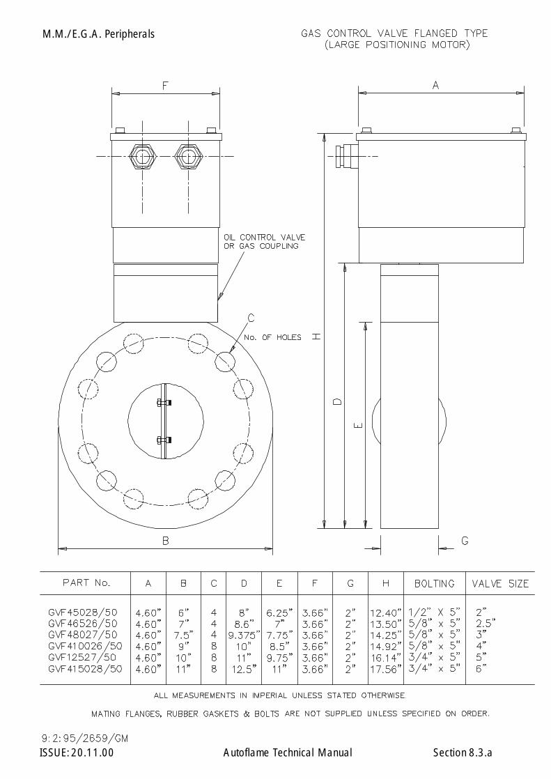
M.M./E.G.A. Peripherals
ISSUE: 20.11.00 Autoflame Technical Manual Section 8.3.a

M.M./E.G.A. Peripherals
ISSUE: 20.11.00 Autoflame Technical Manual Section 8.3.1
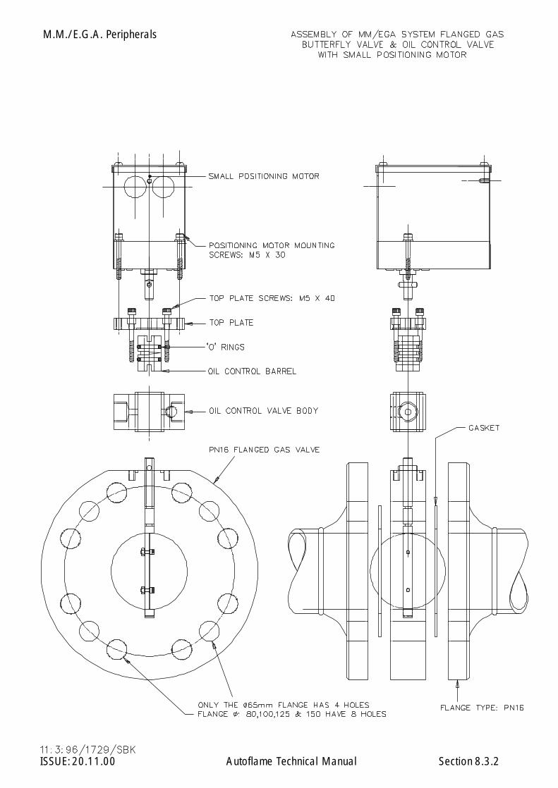
M.M./E.G.A. Peripherals
ISSUE: 20.11.00 Autoflame Technical Manual Section 8.3.2
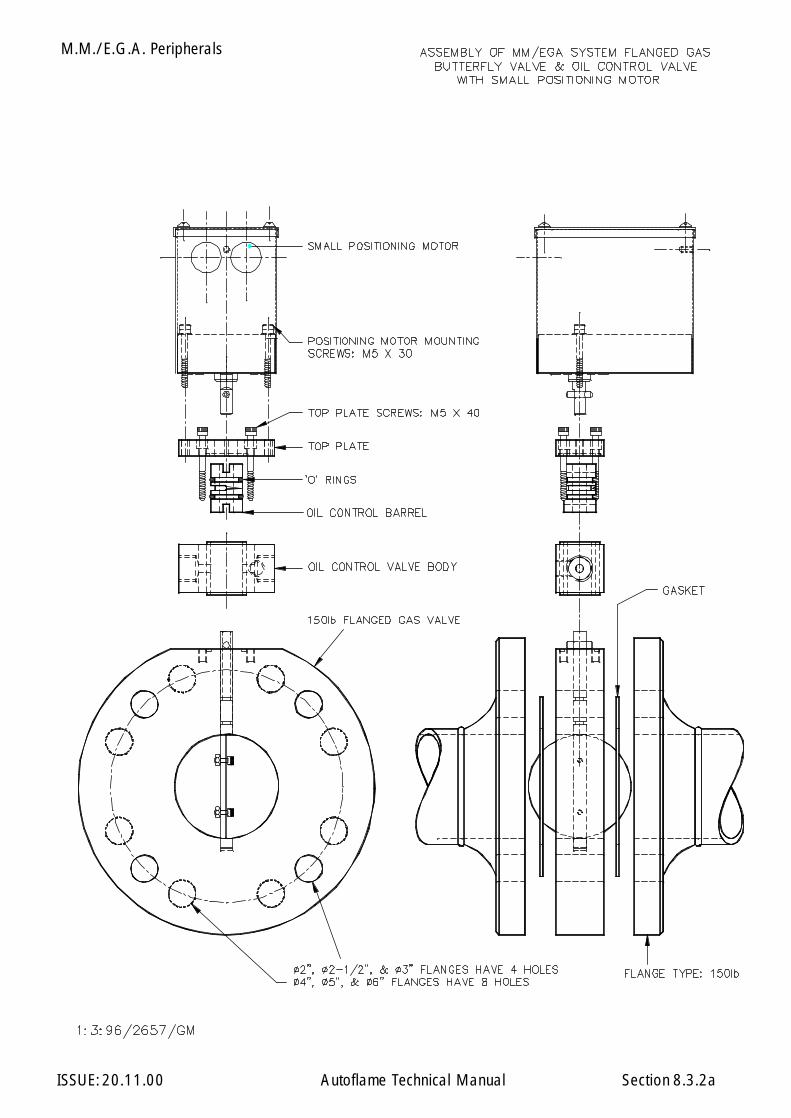
M.M./E.G.A. Peripherals
ISSUE: 20.11.00 Autoflame Technical Manual Section 8.3.2a
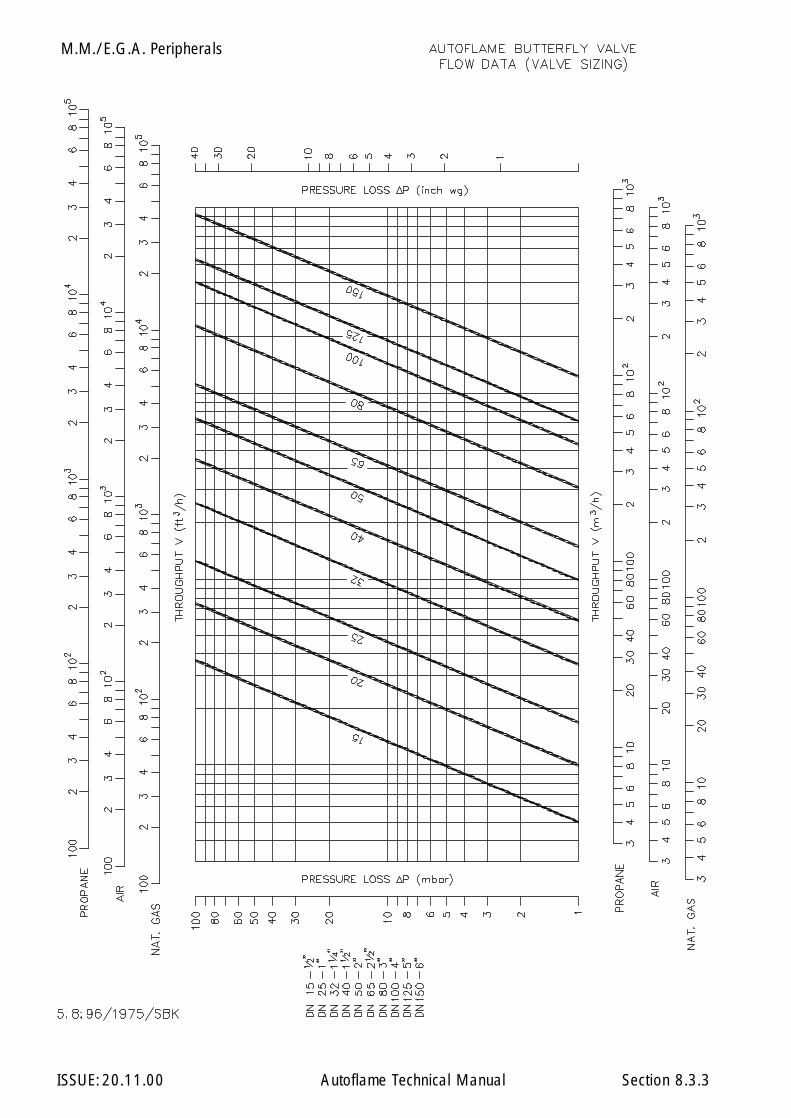
M.M./E.G.A. Peripherals
ISSUE: 20.11.00 Autoflame Technical Manual Section 8.3.3

M.M./E.G.A. Peripherals
ISSUE: 20.11.00 Autoflame Technical Manual Section 8.4

M.M./E.G.A. Peripherals
ISSUE: 20.11.00 Autoflame Technical Manual Section20.08.97 8.4.1
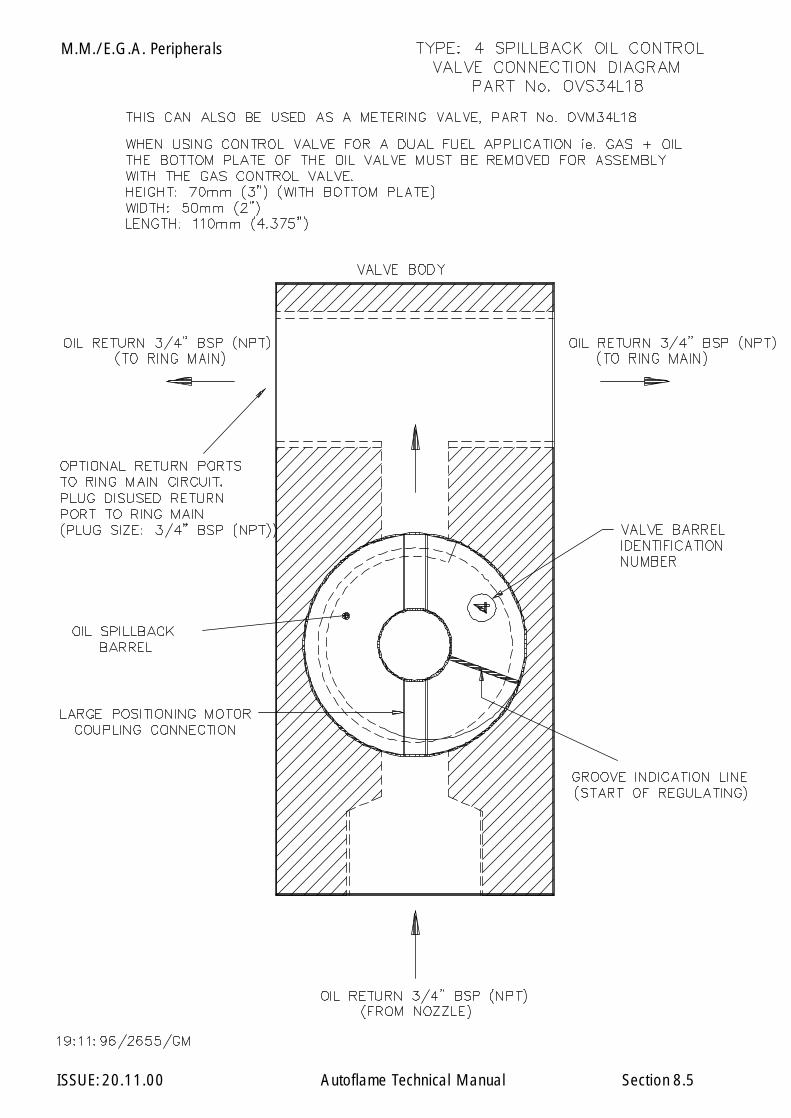
M.M./E.G.A. Peripherals
ISSUE: 20.11.00 Autoflame Technical Manual Section 8.5
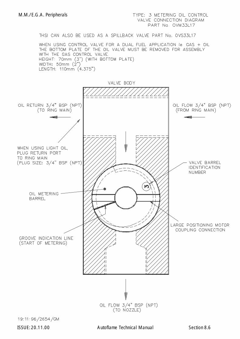
M.M./E.G.A. Peripherals
ISSUE: 20.11.00 Autoflame Technical Manual Section 8.6
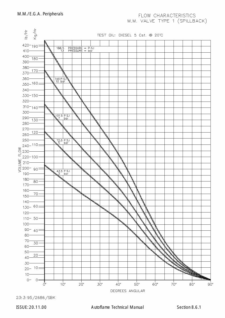
M.M./E.G.A. Peripherals
ISSUE: 20.11.00 Autoflame Technical Manual Section 8.6.1

M.M./E.G.A. Peripherals
ISSUE: 20.11.00 Autoflame Technical Manual Section 8.6.2

M.M./E.G.A. Peripherals
ISSUE: 20.11.00 Autoflame Technical Manual Section 8.6.3

M.M./E.G.A. Peripherals
ISSUE: 20.11.00 Autoflame Technical Manual Section 8.6.4
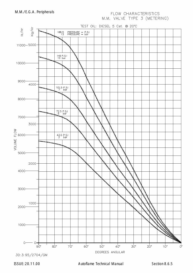
M.M./E.G.A. Peripherals
ISSUE: 20.11.00 Autoflame Technical Manual Section 8.6.5
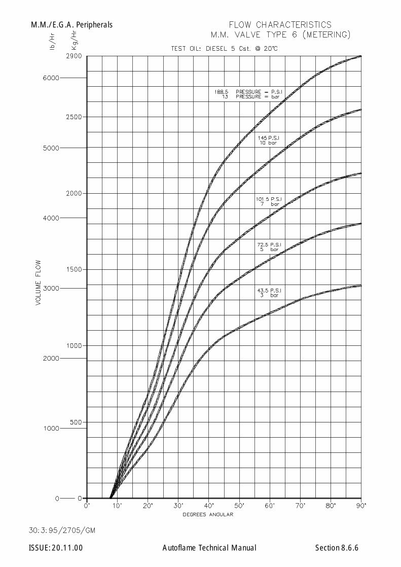
M.M./E.G.A. Peripherals
ISSUE: 20.11.00 Autoflame Technical Manual Section 8.6.6
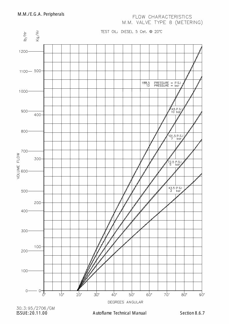
M.M./E.G.A. Peripherals
ISSUE: 20.11.00 Autoflame Technical Manual Section 8.6.7
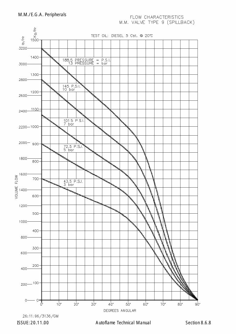
M.M./E.G.A. Peripherals
ISSUE: 20.11.00 Autoflame Technical Manual Section 8.6.8

M.M./E.G.A. Peripherals
ISSUE: 20.11.00 Autoflame Technical Manual Section 8.7

M.M./E.G.A. Peripherals
ISSUE: 20.11.00 Autoflame Technical Manual Section 8.7.1
M.M./E.G.A. Small Positioning Motor
noitacificepS
egatloVylppuS zH06/05,V032/42
euqroTtfahStuptuO mN2.1
elgnAgnitarepO °09-0
emiTgnitarepO sdnoces02lanimoN
rewoPdetaRxaM W3
erutarepmeTtneibmA F°041otF°23/C°06otC°0
gnitaRnoitcetorPlairtsudnI 31AMEN/45PI
elgnAgnitnuoM °063
gninoitisoP evirDMM
rotoMevirD suonorhcnyS
lairetaMydoB 4RCleetSdliM
gnitaoC taoCredwoP007nopretnI
thgieW gk55.0
snoisnemiD mm46x29x99
noitcennoCgniriW dnalG11GP
Tamper Proof Screws
Potentiometer
M4 Earth Stud
P.C.B./1 Fixing Points M3
Potentiometer Adjusting Clips
Positioning MotorFixing Holes 5mm (7/ 32") Diameter
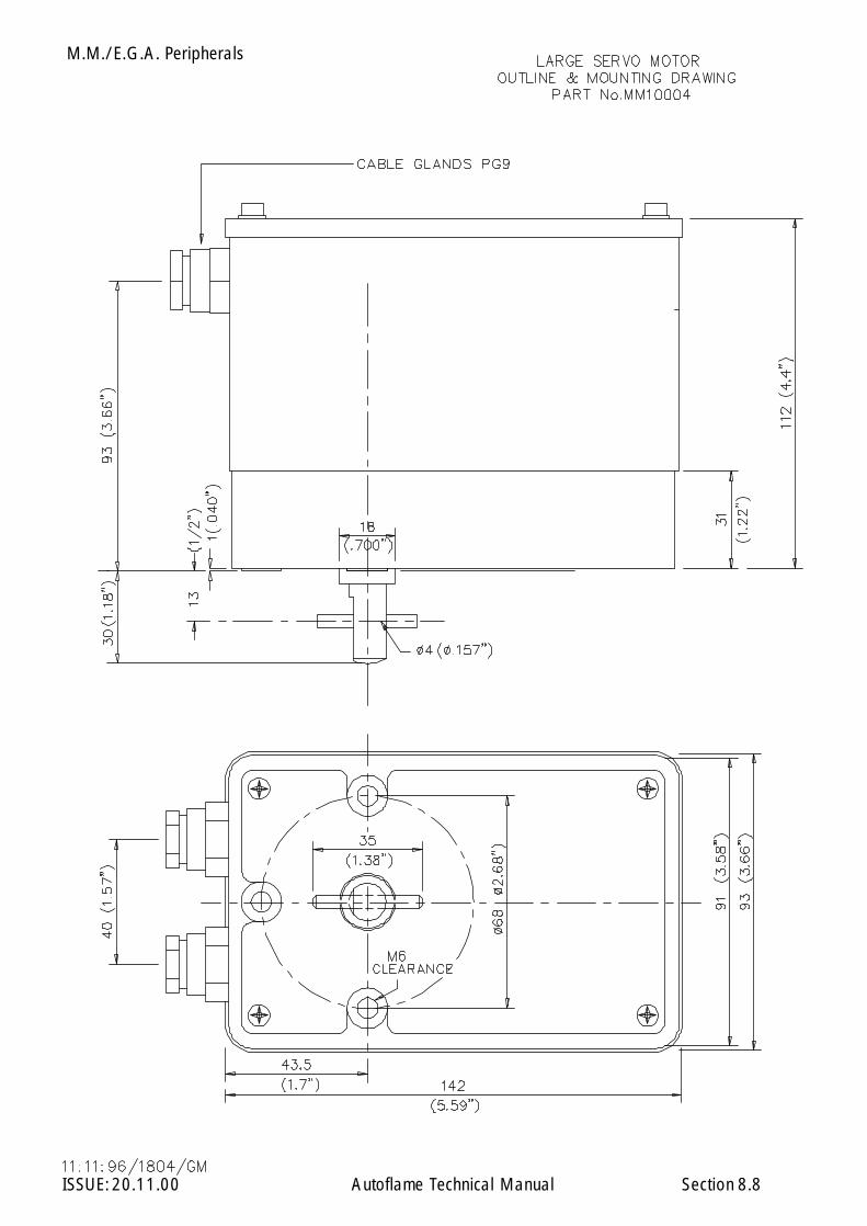
M.M./E.G.A. Peripherals
ISSUE: 20.11.00 Autoflame Technical Manual Section 8.8
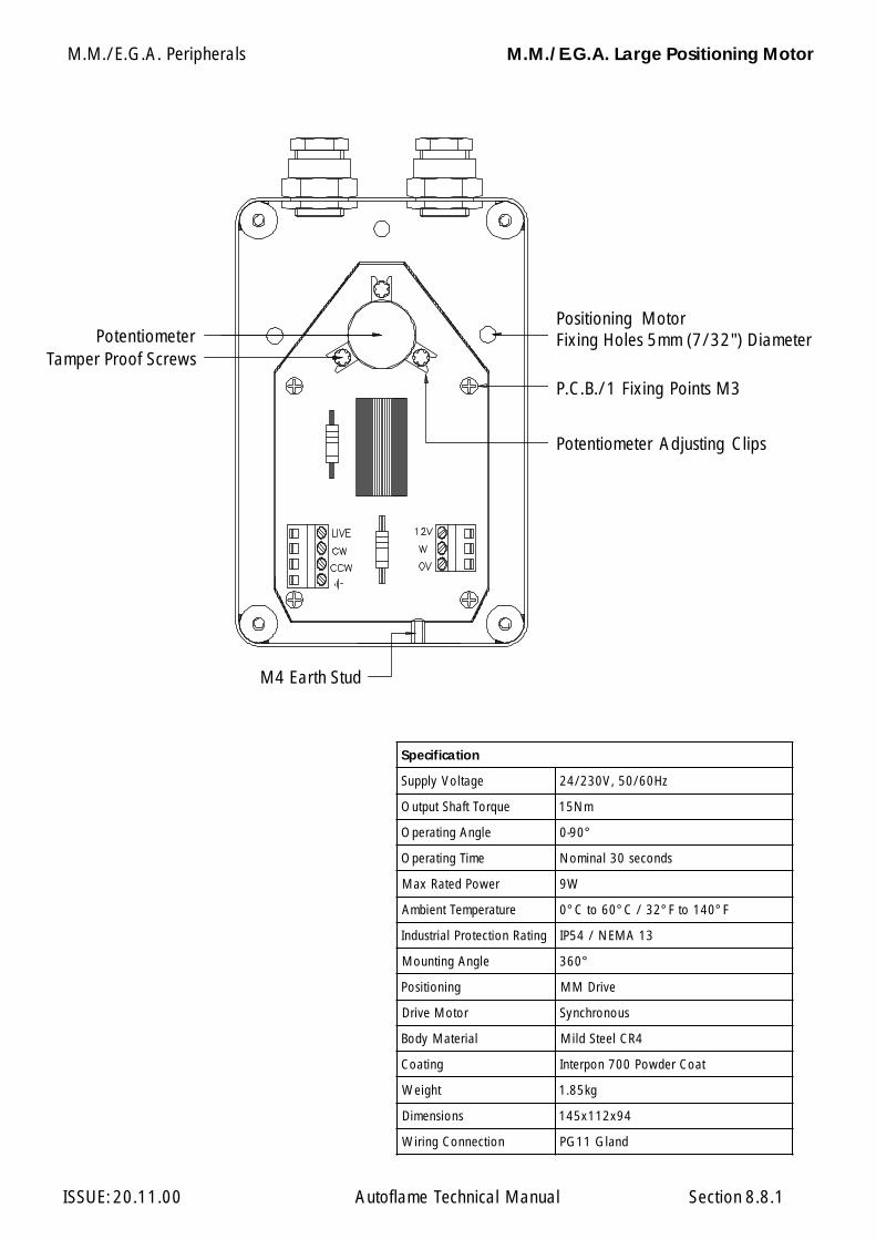
M.M./E.G.A. Peripherals
ISSUE: 20.11.00 Autoflame Technical Manual Section 8.8.1
M.M./E.G.A. Large Positioning Motor
noitacificepS
egatloVylppuS zH06/05,V032/42
euqroTtfahStuptuO mN51
elgnAgnitarepO °09-0
emiTgnitarepO sdnoces03lanimoN
rewoPdetaRxaM W9
erutarepmeTtneibmA F°041otF°23/C°06otC°0
gnitaRnoitcetorPlairtsudnI 31AMEN/45PI
elgnAgnitnuoM °063
gninoitisoP evirDMM
rotoMevirD suonorhcnyS
lairetaMydoB 4RCleetSdliM
gnitaoC taoCredwoP007nopretnI
thgieW gk58.1
snoisnemiD 49x211x541
noitcennoCgniriW dnalG11GP
PotentiometerTamper Proof Screws
M4 Earth Stud
Positioning MotorFixing Holes 5mm (7/32") Diameter
P.C.B./1 Fixing Points M3
Potentiometer Adjusting Clips
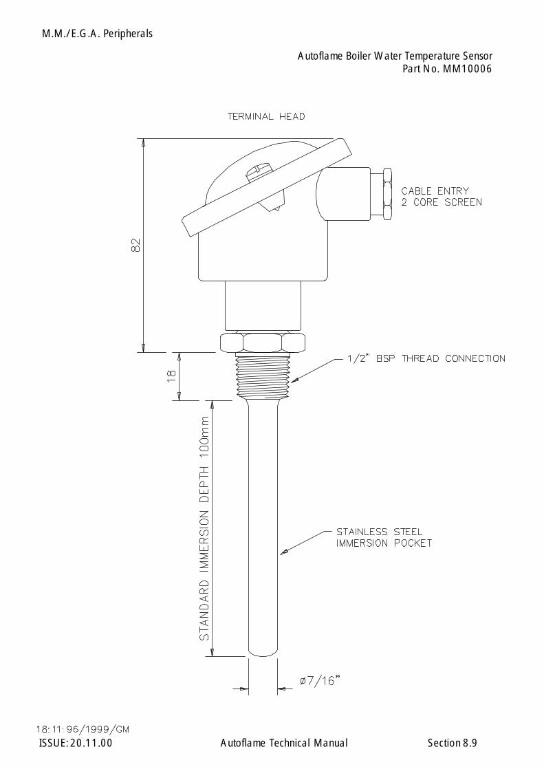
M.M./E.G.A. Peripherals
ISSUE: 20.11.00 Autoflame Technical Manual Section 8.9
Autoflame Boiler Water Temperature SensorPart No. MM10006
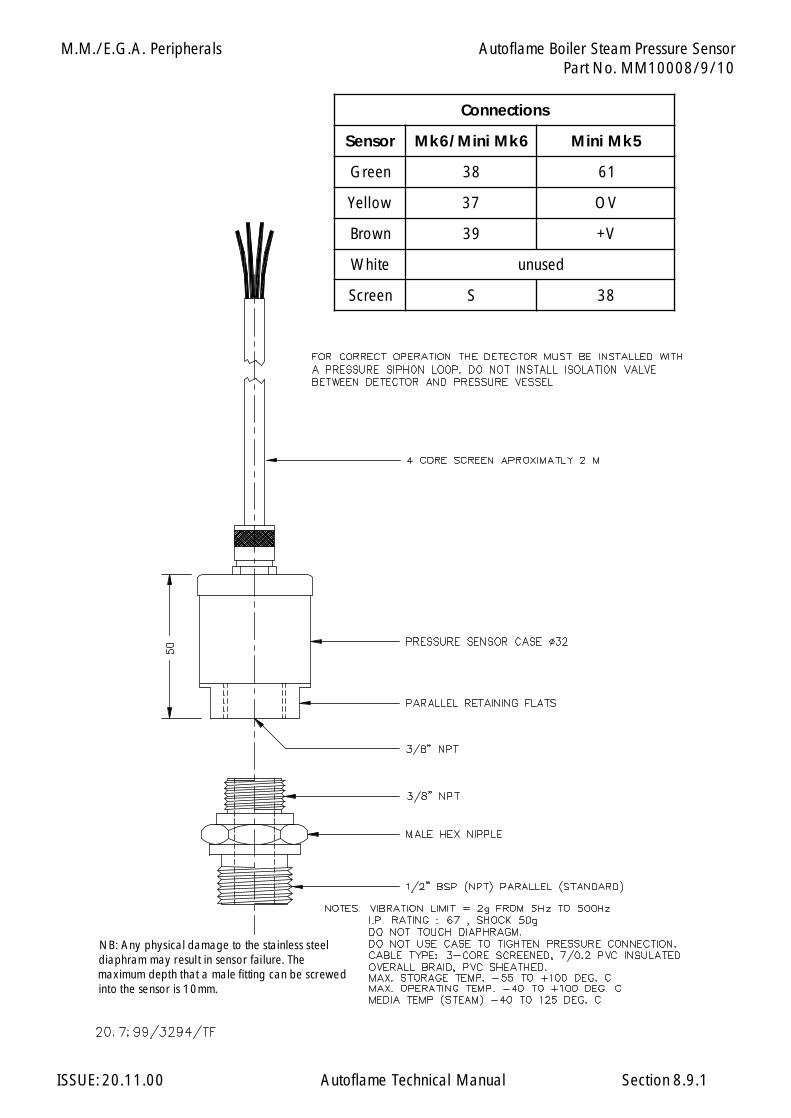
M.M./E.G.A. Peripherals
ISSUE: 20.11.00 Autoflame Technical Manual Section
NB: Any physical damage to the stainless steel diaphram may result in sensor failure. The maximum depth that a male fitting can be screwed into the sensor is 10mm.
8.9.1
Autoflame Boiler Steam Pressure SensorPart No. MM10008/9/10
snoitcennoC
rosneS 6kMiniM/6kM 5kMiniM
neerG 83 16
wolleY 73 VO
nworB 93 V+
etihW desunu
neercS S 83

M.M./E.G.A. Peripherals
ISSUE: 20.11.00 Autoflame Technical Manual Section 8.10
8.10 INDUSTRIAL ACTUATOR
Part No. MM10072.
Overview/Outline
This system is a rotary type electric actuator, suitable for use with the M.M. module.
*WARNING* Must NOT be used without relays, and requires software version 309.
The body is made with aluminium die-cast, thus it is light, compact, highly efficient and powerful.
* Features *
* Light and compact.
* Easy to handle and suitable for use in narrow spaces.
* Simple structure design.
* Trouble free mounting on air damper, maintenance and testing.
* Manual operation function.Manual operation is possible when the power is disconnected, with the attached manualcrank handle.
* Protect function.Thermal protector is built-in to prevent motor burn out by overloading.
* Easy for wiring.Connection is simplified by a terminal block inside.
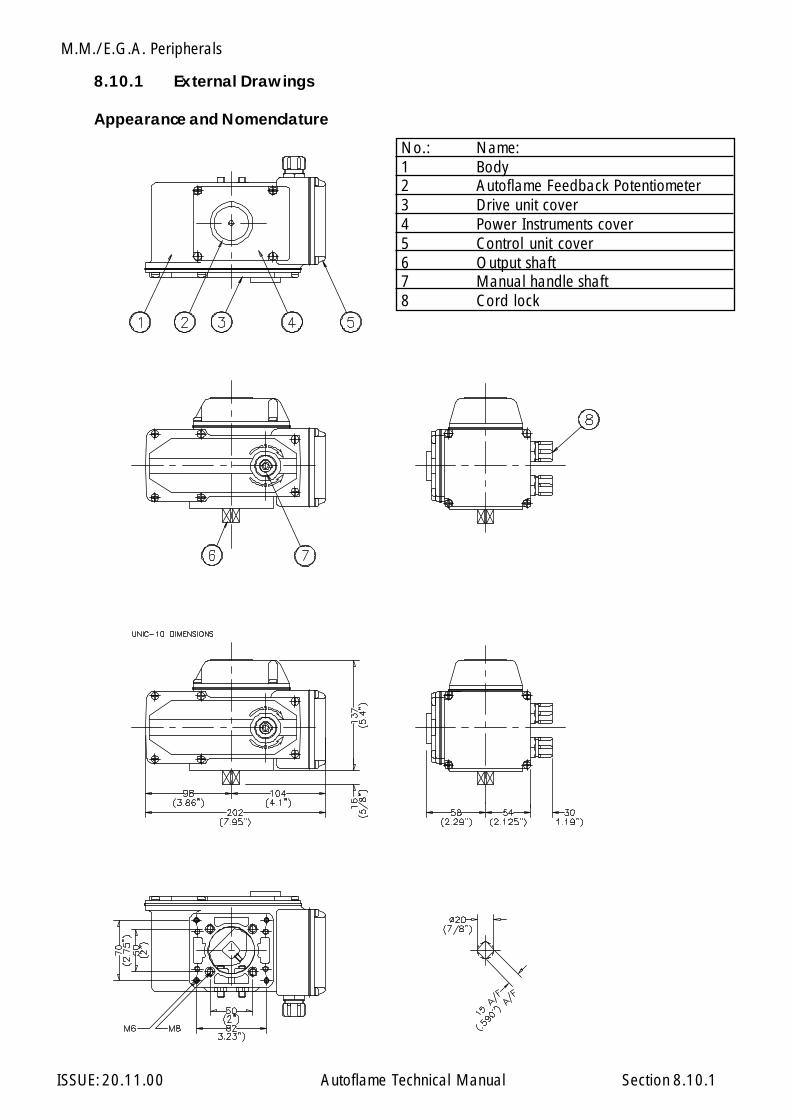
M.M./E.G.A. Peripherals
ISSUE: 20.11.00 Autoflame Technical Manual Section
No.: Name:1 Body2 Autoflame Feedback Potentiometer3 Drive unit cover4 Power Instruments cover5 Control unit cover6 Output shaft7 Manual handle shaft8 Cord lock
8.10.1
8.10.1 External Drawings
Appearance and Nomenclature

M.M./E.G.A. Peripherals
ISSUE: 20.11.00 Autoflame Technical Manual Section
Type UNIC 10/30
Power 220/240 VAC 50/60Hz(110V 60Hz)Output Shaft Torque 10kg fmOperating Angle 0-90°Operating Time 30 sec/50HzProtect System THERMAL PROTECTOR BUILT-INAmbient Temperature -25°C - 50°CRated Power 0.4 A/100VInsulation Resistance 100M W/500 V DCWithstand Voltage 1500 V AC / MinuteManual Operation Crank Handle AttachedStopper Mechanical Stopper Open/Close Adjustable.Enclosure IP65 / NEMA 4Mounting Angle 360° All Directions.Positioning M.M. Drive.Drive Motor 20 W/E TypeBody Material Aluminium Die-cast ADC12Coating Baking VarnishWeight 4.5kgWiring Conduit PF1/2 x1
Resin Connector Attached.
8.10.2 Specification
8.10.2
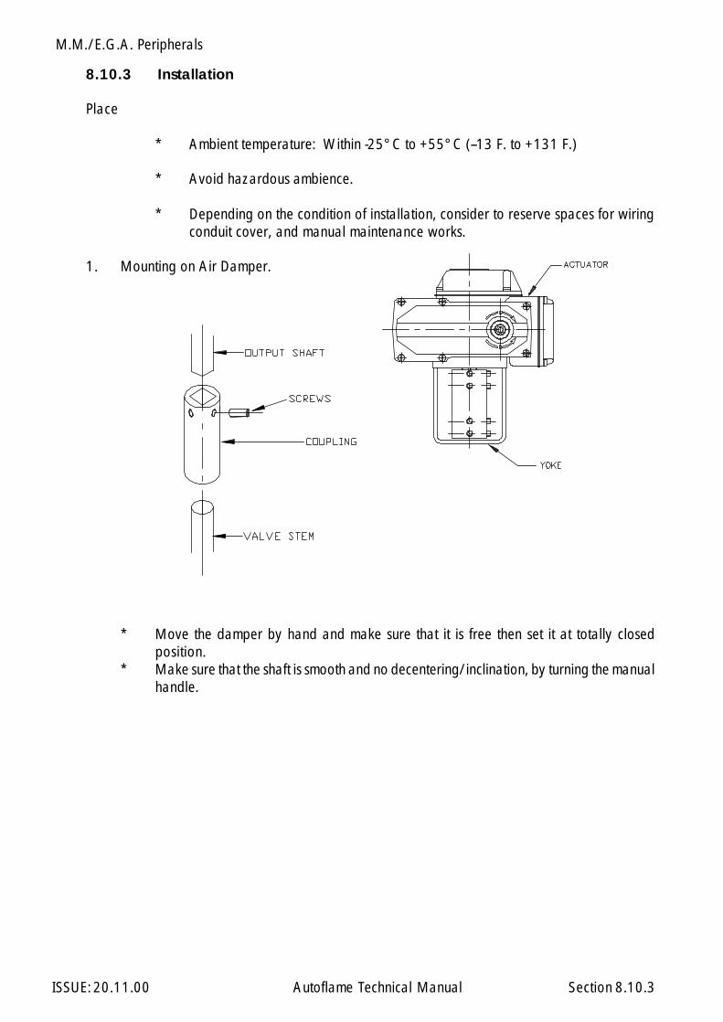
M.M./E.G.A. Peripherals
ISSUE: 20.11.00 Autoflame Technical Manual Section 8.10.3
8.10.3 Installation
Place
* Ambient temperature: Within -25°C to +55°C (--13 F. to +131 F.)
* Avoid hazardous ambience.
* Depending on the condition of installation, consider to reserve spaces for wiringconduit cover, and manual maintenance works.
1. Mounting on Air Damper.
* Move the damper by hand and make sure that it is free then set it at totally closedposition.
* Make sure that the shaft is smooth and no decentering/inclination, by turning the manualhandle.

M.M./E.G.A. Peripherals
ISSUE: 20.11.00 Autoflame Technical Manual Section
8.10.3.1 Positioning Motor Connections
8.10.3.1
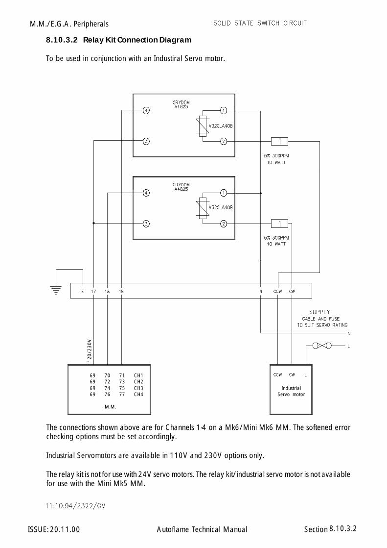
M.M./E.G.A. Peripherals
ISSUE: 20.11.00 Autoflame Technical Manual Section
8.10.3.2 Relay Kit Connection Diagram
To be used in conjunction with an Industiral Servo motor.
8.10.3.2
120/
230V
The connections shown above are for Channels 1-4 on a Mk6/Mini Mk6 MM. The softened errorchecking options must be set accordingly.
Industrial Servomotors are available in 110V and 230V options only.
The relay kit is not for use with 24V servo motors. The relay kit/industrial servo motor is not availablefor use with the Mini Mk5 MM.
123456789012123456789012123456789012123456789012123456789012123456789012123456789012123456789012123456789012
IndustrialServo motor
12345678901234567890121234567890123456789012123456789012345678901212345678901234567890121234567890123456789012123456789012345678901212345678901234567890121234567890123456789012123456789012345678901212345678901234567890121234567890123456789012123456789012345678901212345678901234567890121234567890123456789012123456789012345678901212345678901234567890121234567890123456789012123456789012345678901212345678901234567890121234567890123456789012
69 70 71 CH169 72 73 CH269 74 75 CH369 76 77 CH4
M.M.
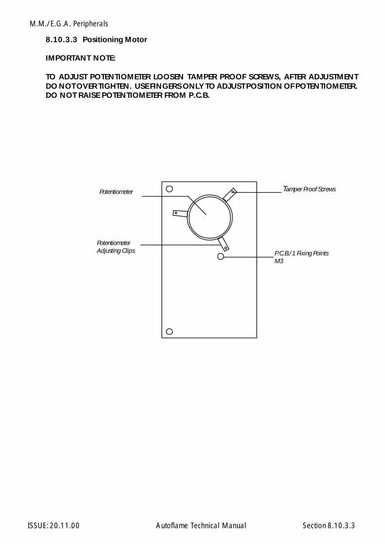
M.M./E.G.A. Peripherals
ISSUE: 20.11.00 Autoflame Technical Manual Section
8.10.3.3 Positioning Motor
IMPORTANT NOTE:
TO ADJUST POTENTIOMETER LOOSEN TAMPER PROOF SCREWS, AFTER ADJUSTMENTDO NOT OVER TIGHTEN. USE FINGERS ONLY TO ADJUST POSITION OF POTENTIOMETER.DO NOT RAISE POTENTIOMETER FROM P.C.B.
P.C.B./1 Fixing PointsM3
Tamper Proof ScrewsPotentiometer
PotentiometerAdjusting Clips
8.10.3.3
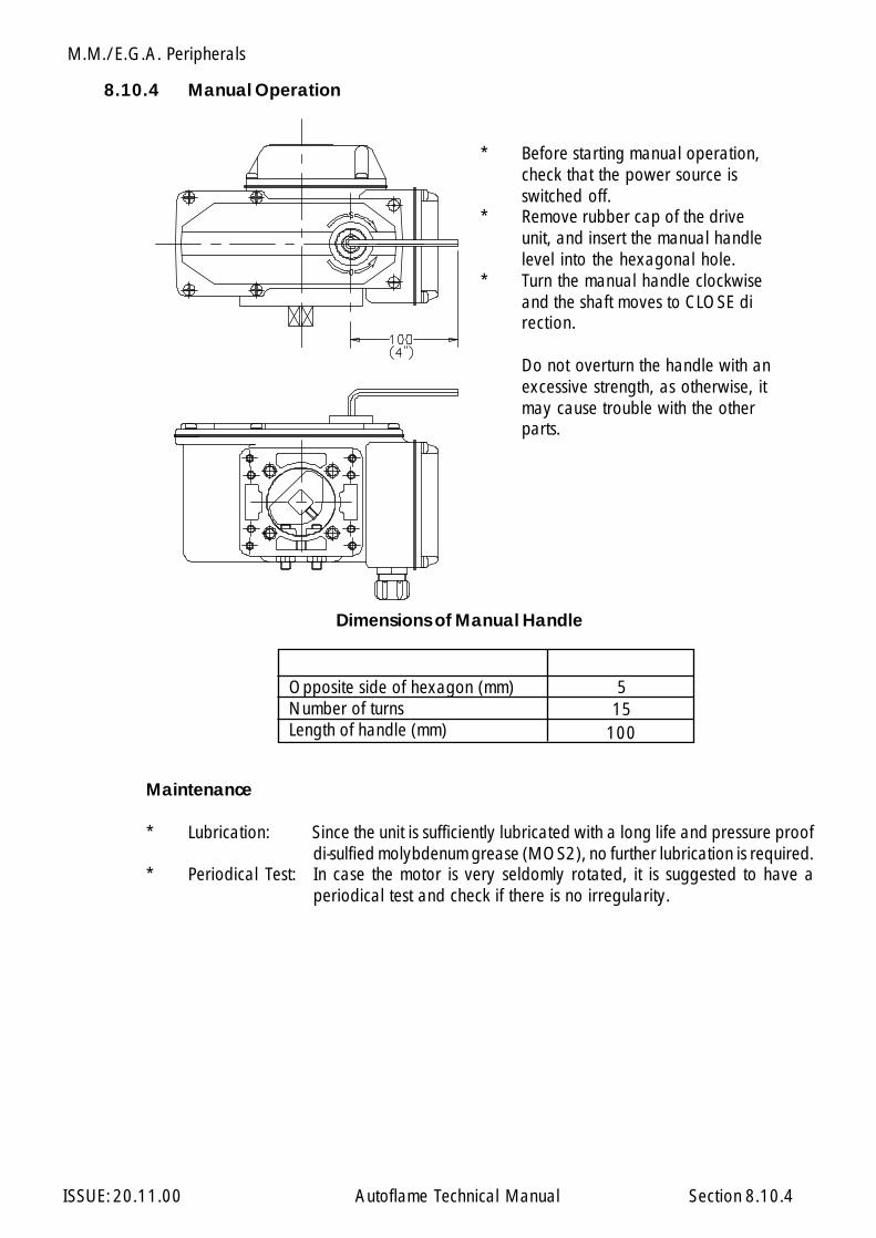
M.M./E.G.A. Peripherals
ISSUE: 20.11.00 Autoflame Technical Manual Section
8.10.4 Manual Operation
* Before starting manual operation,check that the power source isswitched off.
* Remove rubber cap of the driveunit, and insert the manual handlelevel into the hexagonal hole.
* Turn the manual handle clockwiseand the shaft moves to CLOSE direction.
Do not overturn the handle with anexcessive strength, as otherwise, itmay cause trouble with the otherparts.
Dimensions of Manual Handle
Maintenance
* Lubrication: Since the unit is sufficiently lubricated with a long life and pressure proofdi-sulfied molybdenum grease (MOS2), no further lubrication is required.
* Periodical Test: In case the motor is very seldomly rotated, it is suggested to have aperiodical test and check if there is no irregularity.
Opposite side of hexagon (mm)Number of turnsLength of handle (mm)
515
100
8.10.4
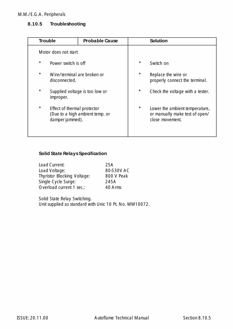
M.M./E.G.A. Peripherals
ISSUE: 20.11.00 Autoflame Technical Manual Section
8.10.5 Troubleshooting
Trouble Probable Cause Solution
Motor does not start
* Power switch is off * Switch on
* Wire/terminal are broken or * Replace the wire ordisconnected. properly connect the terminal.
* Supplied voltage is too low or * Check the voltage with a tester.improper.
* Effect of thermal protector * Lower the ambient temperature,(Due to a high ambient temp. or or manually make test of open/damper jammed). close movement.
Solid State Relays Specification
Load Current: 25ALoad Voltage: 80-530V ACThyristor Blocking Voltage: 800 V PeakSingle Cycle Surge: 245AOverload current 1 sec.: 40 Arms
Solid State Relay Switching.Unit supplied as standard with Unic 10 Pt. No. MM10072.
8.10.5

Miscellaneous Component Information
ISSUE: 20.11.00 Autoflame Technical Manual Section
9.1 Parts List
Section 9: Miscellaneous Component Information
9: Index
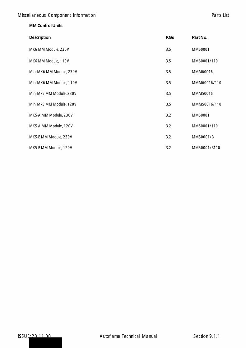
Miscellaneous Component Information
ISSUE: 20.11.00 Autoflame Technical Manual Section
MM Control Units
Description KGs Part No.
MK6 MM Module, 230V 3.5 MM60001
MK6 MM Module, 110V 3.5 MM60001/110
Mini MK6 MM Module, 230V 3.5 MMM60016
Mini MK6 MM Module, 110V 3.5 MMM60016/110
Mini Mk5 MM Module, 230V 3.5 MMM50016
Mini Mk5 MM Module, 120V 3.5 MMM50016/110
MK5-A MM Module, 230V 3.2 MM50001
MK5-A MM Module, 120V 3.2 MM50001/110
MK5-B MM Module, 230V 3.2 MM50001/B
MK5-B MM Module, 120V 3.2 MM50001/B110
9.1.1
Parts List
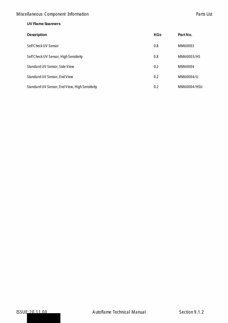
Miscellaneous Component Information
ISSUE: 20.11.00 Autoflame Technical Manual Section
UV Flame Scanners
Description KGs Part No.
Self Check UV Sensor 0.8 MM60003
Self Check UV Sensor, High Sensitivity 0.8 MM60003/HS
Standard UV Sensor, Side View 0.2 MM60004
Standard UV Sensor, End View 0.2 MM60004/U
Standard UV Sensor, End View, High Sensitivity 0.2 MM60004/HSU
9.1.2
Parts List
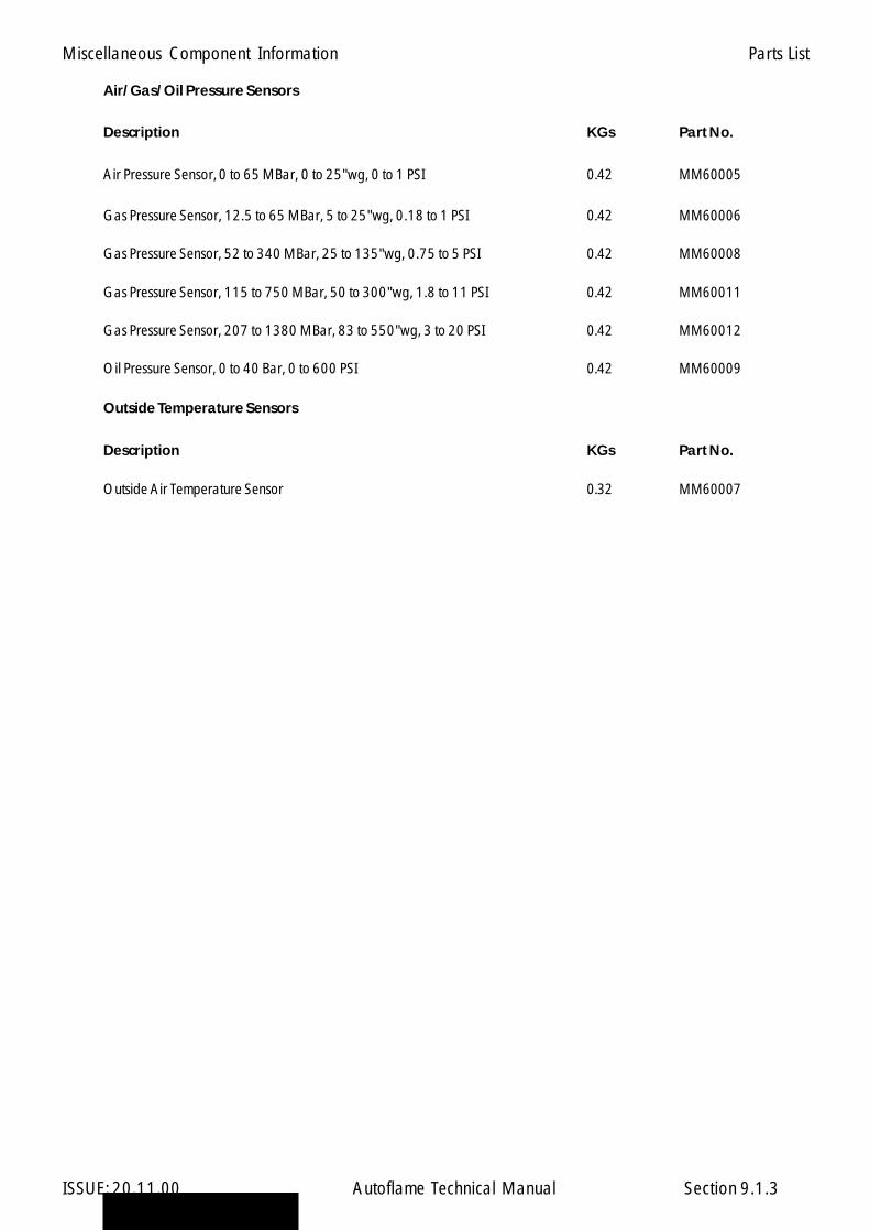
Miscellaneous Component Information
ISSUE: 20.11.00 Autoflame Technical Manual Section
Air/Gas/Oil Pressure Sensors
Description KGs Part No.
Air Pressure Sensor, 0 to 65 MBar, 0 to 25"wg, 0 to 1 PSI 0.42 MM60005
Gas Pressure Sensor, 12.5 to 65 MBar, 5 to 25"wg, 0.18 to 1 PSI 0.42 MM60006
Gas Pressure Sensor, 52 to 340 MBar, 25 to 135"wg, 0.75 to 5 PSI 0.42 MM60008
Gas Pressure Sensor, 115 to 750 MBar, 50 to 300"wg, 1.8 to 11 PSI 0.42 MM60011
Gas Pressure Sensor, 207 to 1380 MBar, 83 to 550"wg, 3 to 20 PSI 0.42 MM60012
Oil Pressure Sensor, 0 to 40 Bar, 0 to 600 PSI 0.42 MM60009
Outside Temperature Sensors
Description KGs Part No.
Outside Air Temperature Sensor 0.32 MM60007
9.1.3
Parts List

Miscellaneous Component Information
ISSUE: 20.11.00 Autoflame Technical Manual Section
Boiler Load Detectors
Description KGs Part No.
Temp. Detector, 100mm length 0.45 MM10006/100
Temp. Detector, 150mm length 0.45 MM10006/150
Temp. Detector, 200mm length 0.45 MM10006/200
Temp. Detector, 250mm length 0.45 MM10006/250
Temp. Detector, 400mm length 0.45 MM10006/400
Pressure Detector, 0-18 Bar 0.21 MM10008
Pressure Detector, 0-30 Bar 0.21 MM10009
Pressure Detector, 0-2 Bar 0.21 MM10010
Pressure Detector, 0-267 PSI 0.21 MM10008U
Pressure Detector, 0-435 PSI 0.21 MM10009U
Pressure Detector, 0-45 PSI 0.21 MM10010U
9.1.4
Parts List

Miscellaneous Component Information
ISSUE: 20.11.00 Autoflame Technical Manual Section
Servo Motors
Description KGs Part No.
Large Servo Motor 15 Nm, 230V 50/60 Hz 1.85 MM10004
Large Servo Motor 15 Nm, 24V 50/60 Hz 1.85 MM10004/D
Small Servo Motor 1.2 Nm, 230V 50Hz 0.55 MM10005
Small Servo Motor 1.2 Nm, 230V 60HZ 0.55 MM10005/B
Small Servo Motor 1.2 Nm, 24V 50/60Hz 0.55 MM10005/D
Industrial Servo Motor 10, 230V + Relay Kit 4 MM10072
Industrial Servo Motor 10, 120V + Relay Kit 4 MM10072/110
Industrial Servo Motor 20, 230V + Relay Kit 6 MM10074/B
Industrial Servo Motor 20, 120V + Relay Kit 6 MM10074/B/110
Industrial Servo Motor 40, 230V + Relay Kit 8 MM10078
Industrial Servo Motor 40, 120V + Relay Kit 8 MM10078/110
9.1.5
Parts List
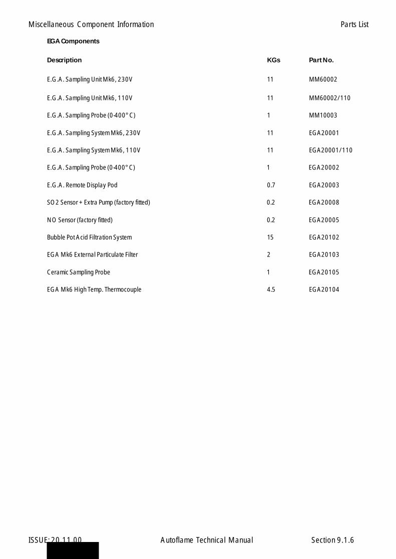
Miscellaneous Component Information
ISSUE: 20.11.00 Autoflame Technical Manual Section
EGA Components
Description KGs Part No.
E.G.A. Sampling Unit Mk6, 230V 11 MM60002
E.G.A. Sampling Unit Mk6, 110V 11 MM60002/110
E.G.A. Sampling Probe (0-400°C) 1 MM10003
E.G.A. Sampling System Mk6, 230V 11 EGA20001
E.G.A. Sampling System Mk6, 110V 11 EGA20001/110
E.G.A. Sampling Probe (0-400°C) 1 EGA20002
E.G.A. Remote Display Pod 0.7 EGA20003
SO2 Sensor + Extra Pump (factory fitted) 0.2 EGA20008
NO Sensor (factory fitted) 0.2 EGA20005
Bubble Pot Acid Filtration System 15 EGA20102
EGA Mk6 External Particulate Filter 2 EGA20103
Ceramic Sampling Probe 1 EGA20105
EGA Mk6 High Temp. Thermocouple 4.5 EGA20104
9.1.6
Parts List

Miscellaneous Component Information
ISSUE: 20.11.00 Autoflame Technical Manual Section
Inverter, Splitter & Interface Modules
Description KGs Part No.
Inverter Interface Module, 230V 0.65 MM10011
Inverter Interface Module, 120V 0.65 MM10011/110
Splitter Module, 230V 0.65 MM10012
Splitter Module, 120V 0.65 MM10012/110
O2 Interface Module, 230V 0.65 MM10013
O2 Interface Module, 120V 0.65 MM10013/110
9.1.7
Parts List

Miscellaneous Component Information
ISSUE: 20.11.00 Autoflame Technical Manual Section
DTI Modules
Description KGs Part No.
Data Transfer Interface MK6, 230V 3 DTI60010/IR
Data Transfer Interface MK6, 120V 3 DTI60010/IR/110
Digital I/O Module, 230V 1 DTI20020
Digital I/O Module, 120V 1 DTI20020/110
Analogue I/O Module, 230V 1 DTI20021
Analogue I/O Module, 120V 1 DTI20021/110
9.1.8
Parts List
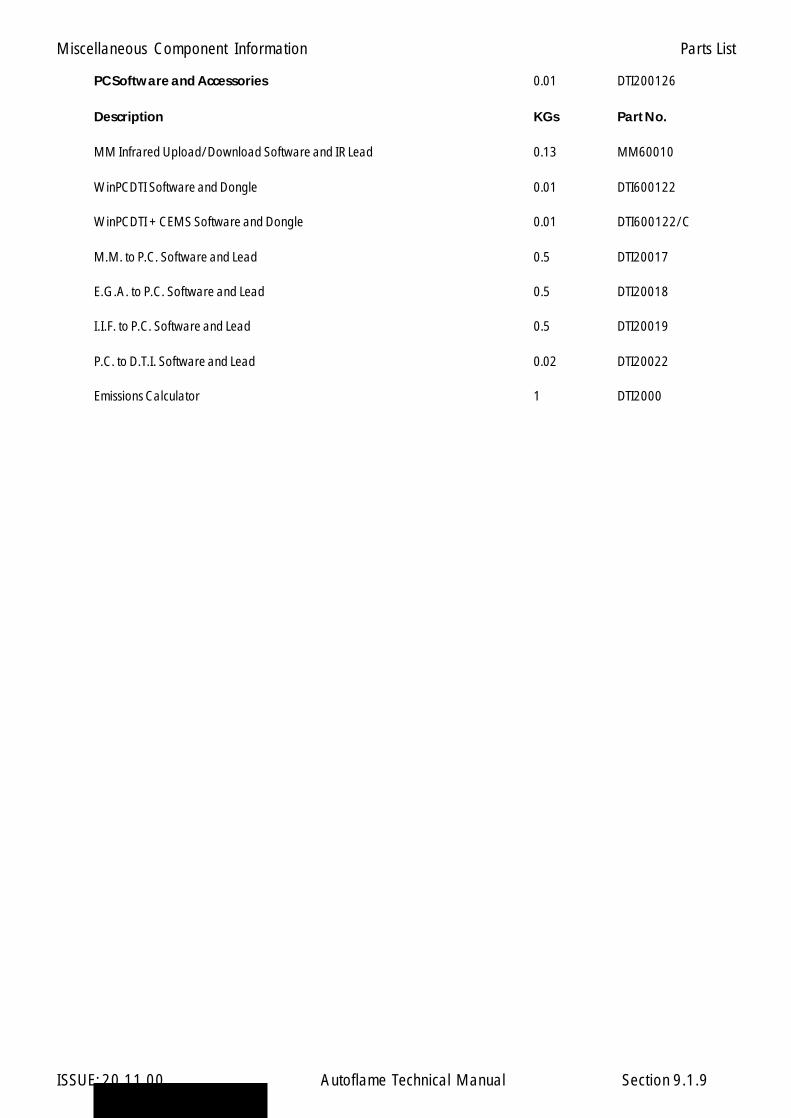
Miscellaneous Component Information
ISSUE: 20.11.00 Autoflame Technical Manual Section
PC Software and Accessories 0.01 DTI200126
Description KGs Part No.
MM Infrared Upload/Download Software and IR Lead 0.13 MM60010
WinPCDTI Software and Dongle 0.01 DTI600122
WinPCDTI + CEMS Software and Dongle 0.01 DTI600122/C
M.M. to P.C. Software and Lead 0.5 DTI20017
E.G.A. to P.C. Software and Lead 0.5 DTI20018
I.I.F. to P.C. Software and Lead 0.5 DTI20019
P.C. to D.T.I. Software and Lead 0.02 DTI20022
Emissions Calculator 1 DTI2000
9.1.9
Parts List
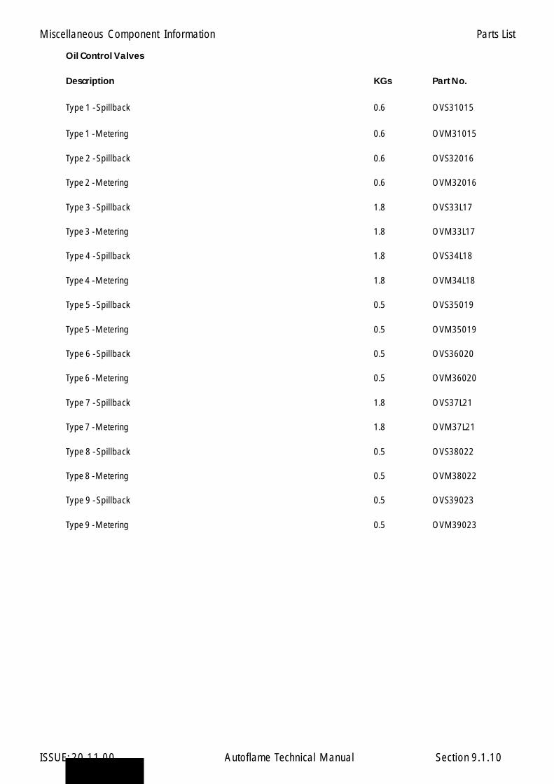
Miscellaneous Component Information
ISSUE: 20.11.00 Autoflame Technical Manual Section
Oil Control Valves
Description KGs Part No.
Type 1 - Spillback 0.6 OVS31015
Type 1 - Metering 0.6 OVM31015
Type 2 - Spillback 0.6 OVS32016
Type 2 - Metering 0.6 OVM32016
Type 3 - Spillback 1.8 OVS33L17
Type 3 - Metering 1.8 OVM33L17
Type 4 - Spillback 1.8 OVS34L18
Type 4 - Metering 1.8 OVM34L18
Type 5 - Spillback 0.5 OVS35019
Type 5 - Metering 0.5 OVM35019
Type 6 - Spillback 0.5 OVS36020
Type 6 - Metering 0.5 OVM36020
Type 7 - Spillback 1.8 OVS37L21
Type 7 - Metering 1.8 OVM37L21
Type 8 - Spillback 0.5 OVS38022
Type 8 - Metering 0.5 OVM38022
Type 9 - Spillback 0.5 OVS39023
Type 9 - Metering 0.5 OVM39023
9.1.10
Parts List
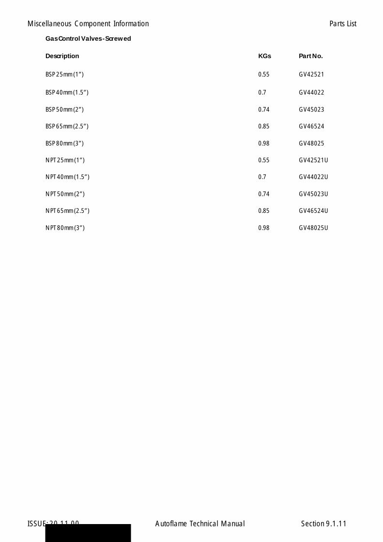
Miscellaneous Component Information
ISSUE: 20.11.00 Autoflame Technical Manual Section
Gas Control Valves - Screwed
Description KGs Part No.
BSP 25mm (1”) 0.55 GV42521
BSP 40mm (1.5”) 0.7 GV44022
BSP 50mm (2”) 0.74 GV45023
BSP 65mm (2.5”) 0.85 GV46524
BSP 80mm (3”) 0.98 GV48025
NPT 25mm (1”) 0.55 GV42521U
NPT 40mm (1.5”) 0.7 GV44022U
NPT 50mm (2”) 0.74 GV45023U
NPT 65mm (2.5”) 0.85 GV46524U
NPT 80mm (3”) 0.98 GV48025U
9.1.11
Parts List
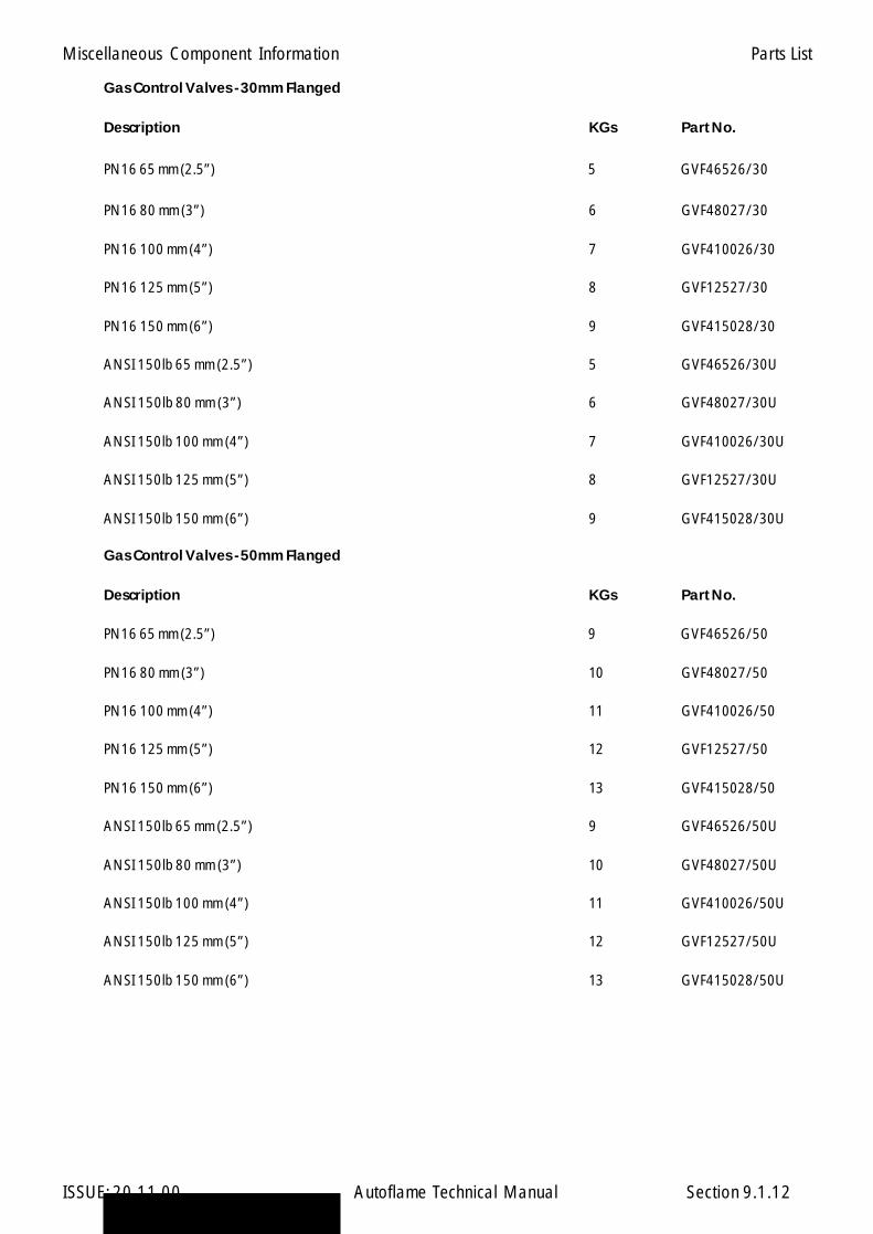
Miscellaneous Component Information
ISSUE: 20.11.00 Autoflame Technical Manual Section
Gas Control Valves - 30mm Flanged
Description KGs Part No.
PN16 65 mm (2.5”) 5 GVF46526/30
PN16 80 mm (3”) 6 GVF48027/30
PN16 100 mm (4”) 7 GVF410026/30
PN16 125 mm (5”) 8 GVF12527/30
PN16 150 mm (6”) 9 GVF415028/30
ANSI 150lb 65 mm (2.5”) 5 GVF46526/30U
ANSI 150lb 80 mm (3”) 6 GVF48027/30U
ANSI 150lb 100 mm (4”) 7 GVF410026/30U
ANSI 150lb 125 mm (5”) 8 GVF12527/30U
ANSI 150lb 150 mm (6”) 9 GVF415028/30U
Gas Control Valves - 50mm Flanged
Description KGs Part No.
PN16 65 mm (2.5”) 9 GVF46526/50
PN16 80 mm (3”) 10 GVF48027/50
PN16 100 mm (4”) 11 GVF410026/50
PN16 125 mm (5”) 12 GVF12527/50
PN16 150 mm (6”) 13 GVF415028/50
ANSI 150lb 65 mm (2.5”) 9 GVF46526/50U
ANSI 150lb 80 mm (3”) 10 GVF48027/50U
ANSI 150lb 100 mm (4”) 11 GVF410026/50U
ANSI 150lb 125 mm (5”) 12 GVF12527/50U
ANSI 150lb 150 mm (6”) 13 GVF415028/50U
9.1.12
Parts List
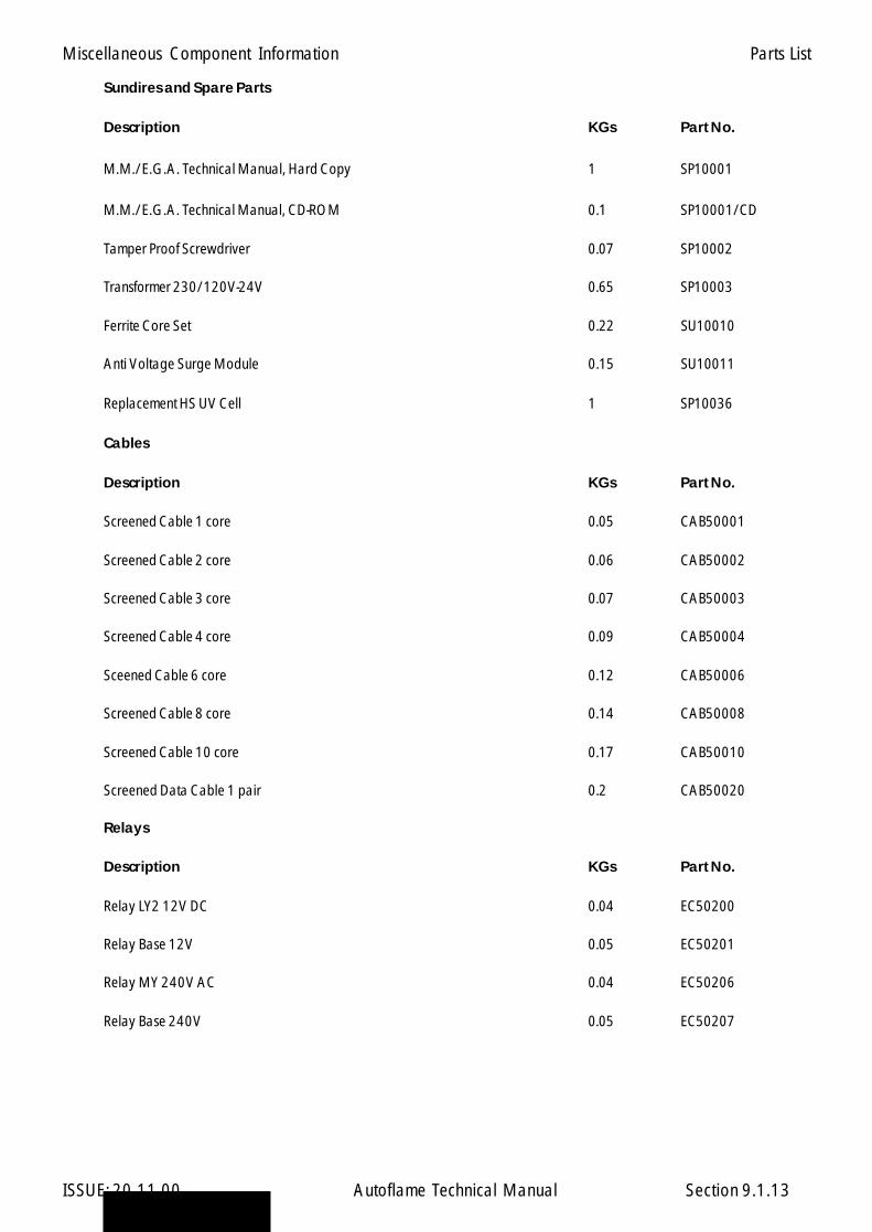
Miscellaneous Component Information
ISSUE: 20.11.00 Autoflame Technical Manual Section
Sundires and Spare Parts
Description KGs Part No.
M.M./E.G.A. Technical Manual, Hard Copy 1 SP10001
M.M./E.G.A. Technical Manual, CD-ROM 0.1 SP10001/CD
Tamper Proof Screwdriver 0.07 SP10002
Transformer 230/120V-24V 0.65 SP10003
Ferrite Core Set 0.22 SU10010
Anti Voltage Surge Module 0.15 SU10011
Replacement HS UV Cell 1 SP10036
Cables
Description KGs Part No.
Screened Cable 1 core 0.05 CAB50001
Screened Cable 2 core 0.06 CAB50002
Screened Cable 3 core 0.07 CAB50003
Screened Cable 4 core 0.09 CAB50004
Sceened Cable 6 core 0.12 CAB50006
Screened Cable 8 core 0.14 CAB50008
Screened Cable 10 core 0.17 CAB50010
Screened Data Cable 1 pair 0.2 CAB50020
Relays
Description KGs Part No.
Relay LY2 12V DC 0.04 EC50200
Relay Base 12V 0.05 EC50201
Relay MY 240V AC 0.04 EC50206
Relay Base 240V 0.05 EC50207
9.1.13
Parts List

Miscellaneous Component Information
ISSUE: 20.11.00 Autoflame Technical Manual Section
MM System Spares
Description KGs Part No.
Mk6 MM Fuse Set 0.1 SP1031
Mini Mk6 MM Fuse Set 0.1 SP1032
Mini Mk5 MM Fuse Set 0.1 SP1033
Mk6 MM Connector Plugs 0.5 CON1060
Mini Mk6 MM Connector Plugs 0.5 CON1064
Mini Mk5 MM Connector Plugs 0.5 CON1063
Mk5 MM Connector Plugs 0.5 CON1050
MM Enclosure Mounting Clamps 0.1 ENC10061
9.1.14
Parts List
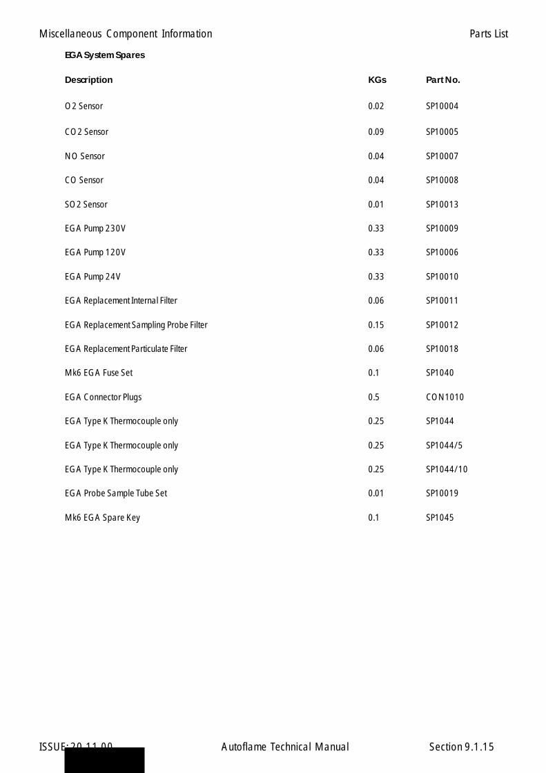
Miscellaneous Component Information
ISSUE: 20.11.00 Autoflame Technical Manual Section
EGA System Spares
Description KGs Part No.
O2 Sensor 0.02 SP10004
CO2 Sensor 0.09 SP10005
NO Sensor 0.04 SP10007
CO Sensor 0.04 SP10008
SO2 Sensor 0.01 SP10013
EGA Pump 230V 0.33 SP10009
EGA Pump 120V 0.33 SP10006
EGA Pump 24V 0.33 SP10010
EGA Replacement Internal Filter 0.06 SP10011
EGA Replacement Sampling Probe Filter 0.15 SP10012
EGA Replacement Particulate Filter 0.06 SP10018
Mk6 EGA Fuse Set 0.1 SP1040
EGA Connector Plugs 0.5 CON1010
EGA Type K Thermocouple only 0.25 SP1044
EGA Type K Thermocouple only 0.25 SP1044/5
EGA Type K Thermocouple only 0.25 SP1044/10
EGA Probe Sample Tube Set 0.01 SP10019
Mk6 EGA Spare Key 0.1 SP1045
9.1.15
Parts List

Miscellaneous Component Information
ISSUE: 20.11.00 Autoflame Technical Manual Section
DTI System Spares
Description KGs Part No.
Mk6 DTI Fuse Set 0.1 SP1060
Digital I/O Fuse Set 0.1 SP1061
Analogue I/O Fuse Set 0.1 SP1062
Mk6 DTI Connector Plugs 0.5 CON1065
Digital I/O Connector Plugs 0.5 CON1066
Analogue I/O Connector Plugs 0.5 CON1067
9.1.16
Parts List
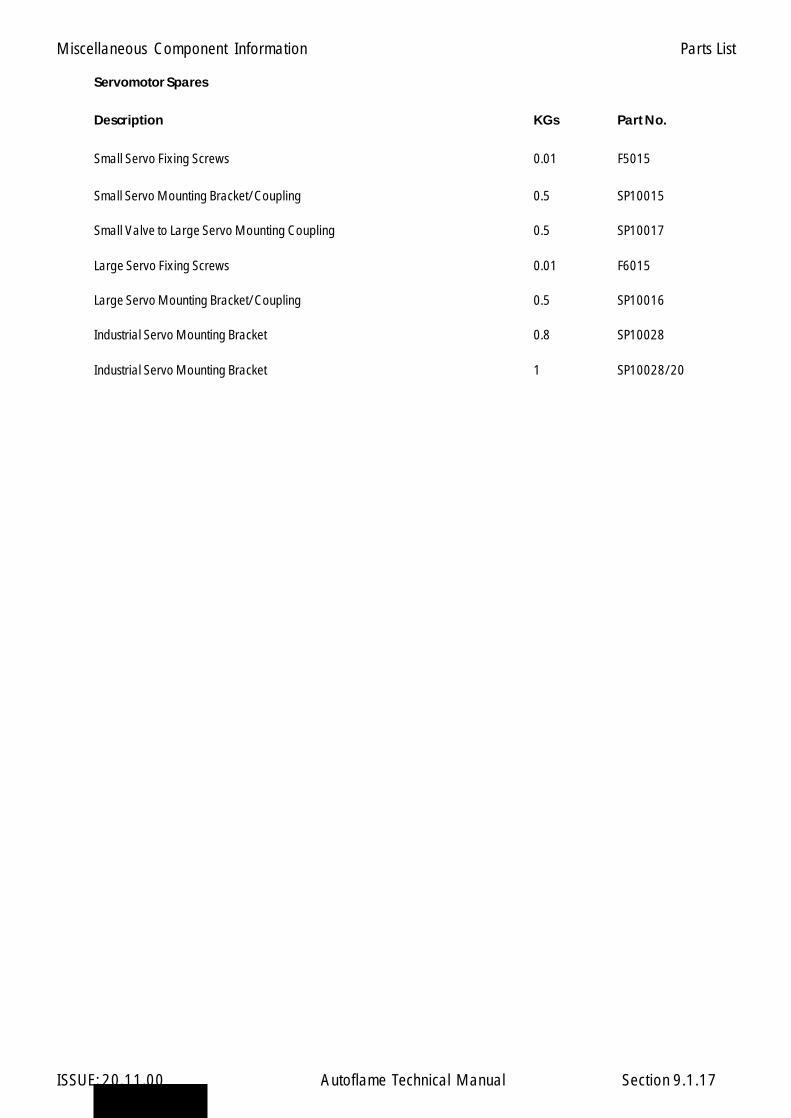
Miscellaneous Component Information
ISSUE: 20.11.00 Autoflame Technical Manual Section
Servomotor Spares
Description KGs Part No.
Small Servo Fixing Screws 0.01 F5015
Small Servo Mounting Bracket/Coupling 0.5 SP10015
Small Valve to Large Servo Mounting Coupling 0.5 SP10017
Large Servo Fixing Screws 0.01 F6015
Large Servo Mounting Bracket/Coupling 0.5 SP10016
Industrial Servo Mounting Bracket 0.8 SP10028
Industrial Servo Mounting Bracket 1 SP10028/20
9.1.17
Parts List

Miscellaneous Component Information
ISSUE: 20.11.00 Autoflame Technical Manual Section
Gas/Oil Valve Spares
Description KGs Part No.
O-ring 50mm Gas Valve 0.01 OR70001
O-ring 30mm Gas Valve 0.01 OR70002
O-ring Type 1,2,5,6,8,9 Small Oil Valve 0.01 OR70003
O-ring Type 3,4,7 Large Oil Valve 0.01 OR70004
9.1.18
Parts List

Miscellaneous Component Information
ISSUE: 20.11.00 Autoflame Technical Manual Section
Demo/Test Equipment
Description KGs Part No.
Mk6 MM Demo Case, 230V 12 MM10022
Mk6 MM Demo Case, 120V 12 MM10023
Mini MK6 Demo Case, 230V 12 MM10030
Mini MK6 Demo Case, 120V 12 MM10030/110
Mini MK5 Demo Case, 230V 12 MM10029
Mini MK5 Demo Case, 120V 12 MM10029/110
Mini MK5 Demo Case, 230V 12 MM10031
Mini MK5 Demo Case, 120V 12 MM10031/110
DTI Demo Case, 230V 12 MM10027
DTI Demo Case, 120V 12 MM10027/110
9.1.19
Parts List
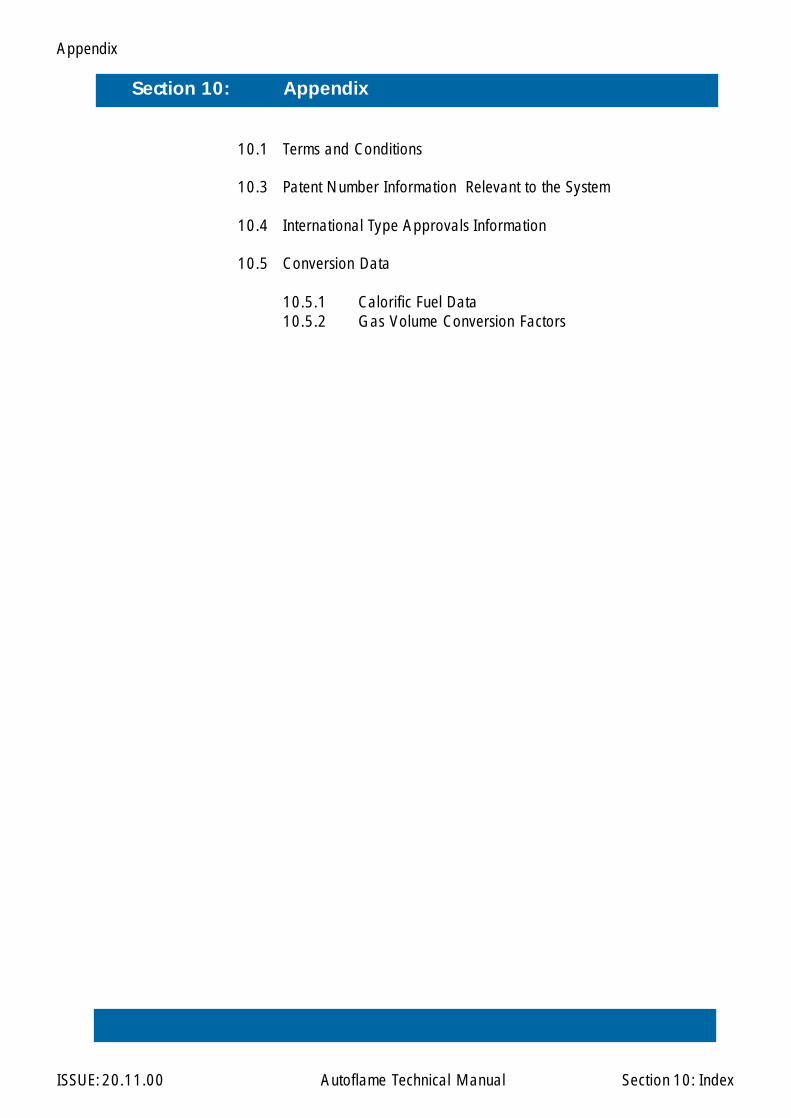
Appendix
ISSUE: 20.11.00 Autoflame Technical Manual Section
Section 10: Appendix
10: Index
10.1 Terms and Conditions
10.3 Patent Number Information Relevant to the System
10.4 International Type Approvals Information
10.5 Conversion Data
10.5.1 Calorific Fuel Data10.5.2 Gas Volume Conversion Factors
12345678901234567890123451234567890123456789012345123456789012345678901234512345678901234567890123451234567890123456789012345123456789012345678901234512345678901234567890123451234567890123456789012345123456789012345678901234512345678901234567890123451234567890123456789012345123456789012345678901234512345678901234567890123451234567890123456789012345

Appendix
ISSUE: 20.11.00 Autoflame Technical Manual Section
10.1 Terms and Conditions
All equipment and services offered and sold by Autoflame Engineering are subject to our publishedterms and conditions of business a copy of which is supplied with each consignment of goods and acopy of which will be supplied seperately on request.
All terms and conditions are subject to English law.
10.1
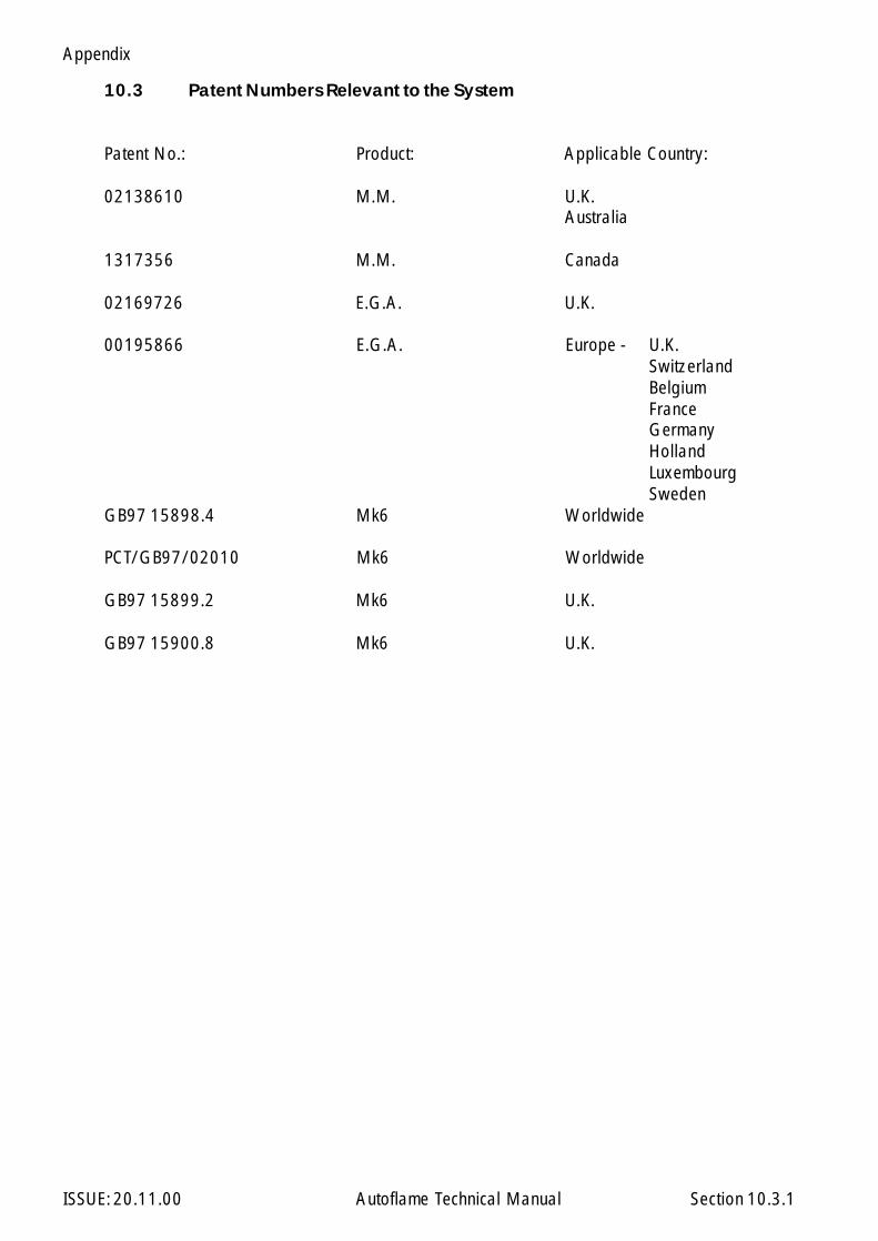
Appendix
ISSUE: 20.11.00 Autoflame Technical Manual Section
10.3 Patent Numbers Relevant to the System
Patent No.: Product: Applicable Country:
02138610 M.M. U.K.Australia
1317356 M.M. Canada
02169726 E.G.A. U.K.
00195866 E.G.A. Europe - U.K.SwitzerlandBelgiumFranceGermanyHollandLuxembourgSweden
GB97 15898.4 Mk6 Worldwide
PCT/GB97/02010 Mk6 Worldwide
GB97 15899.2 Mk6 U.K.
GB97 15900.8 Mk6 U.K.
10.3.1
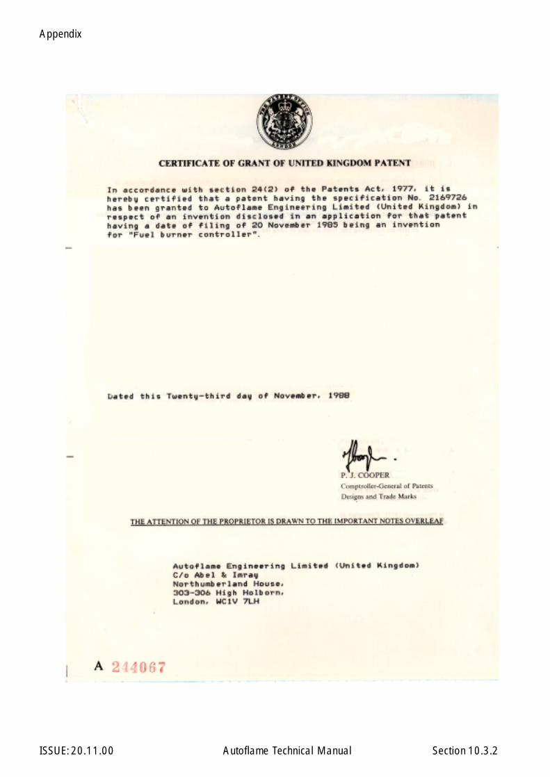
Appendix
ISSUE: 20.11.00 Autoflame Technical Manual Section 10.3.2
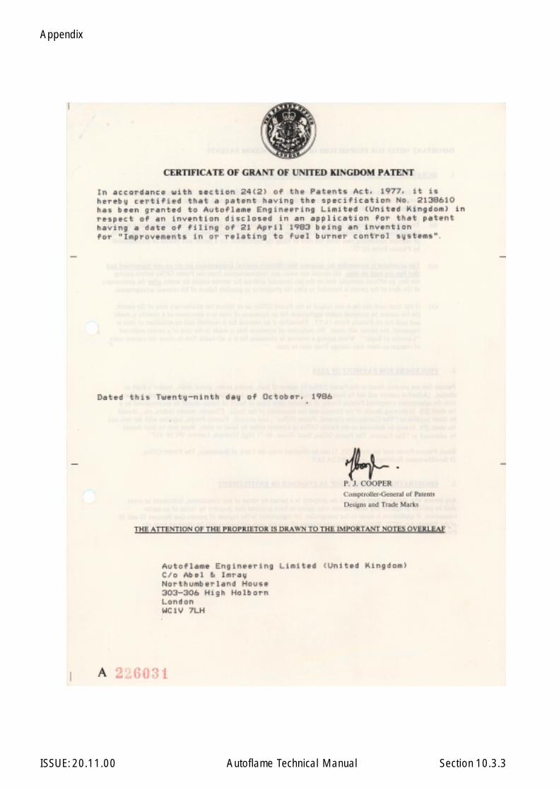
Appendix
ISSUE: 20.11.00 Autoflame Technical Manual Section 10.3.3
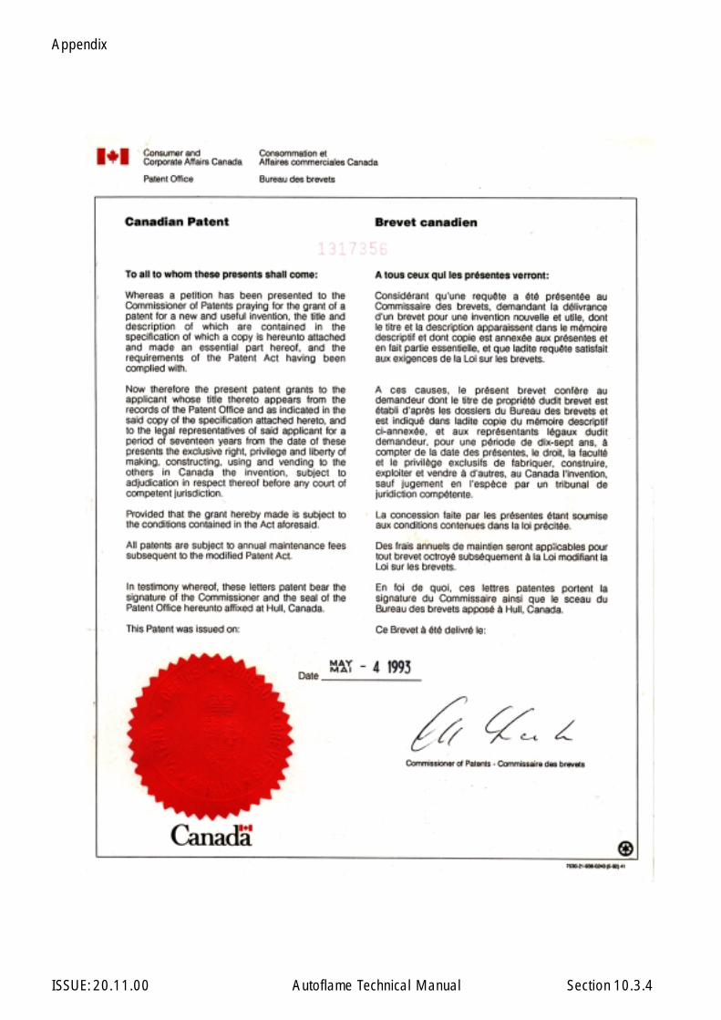
Appendix
ISSUE: 20.11.00 Autoflame Technical Manual Section 10.3.4
Appendix
ISSUE: 20.11.00 Autoflame Technical Manual Section 10.3.5

Appendix
ISSUE: 20.11.00 Autoflame Technical Manual Section 10.4.1
Appendix
ISSUE: 20.11.00 Autoflame Technical Manual Section 10.4.2

Appendix
ISSUE: 20.11.00 Autoflame Technical Manual Section 10.4.4.1

Appendix
ISSUE: 20.11.00 Autoflame Technical Manual Section 10.4.4.2
Appendix
ISSUE: 20.11.00 Autoflame Technical Manual Section 10.4.4.3
Appendix
ISSUE: 20.11.00 Autoflame Technical Manual Section 10.4.520.08.97
Appendix
ISSUE: 20.11.00 Autoflame Technical Manual Section 10.4.6
Appendix
ISSUE: 20.11.00 Autoflame Technical Manual Section 10.4.7
Appendix
ISSUE: 20.11.00 Autoflame Technical Manual Section 10.4.8
Appendix
ISSUE: 20.11.00 Autoflame Technical Manual Section 10.4.9

Appendix
ISSUE: 20.11.00 Autoflame Technical Manual Section 10.4.10

Appendix
ISSUE: 20.11.00 Autoflame Technical Manual Section 10.4.11

Appendix
ISSUE: 20.11.00 Autoflame Technical Manual Section 10.4.11.120.08.97
Appendix
ISSUE: 20.11.00 Autoflame Technical Manual Section
10.4.11 Additional Approvals
Approvals
10.4.11
Approval No.: Product: Applicable TypeApproval Authority:
MH25659 Mk6 Burner Management System UL, CUL, UR
0063AT5181 Mk6 Burner Management System CE
TU 12/94 0167 Mk5. M.M./E.G.A. System T.U.V. Bayern e.v.
TU 12/96 171 Mini M.M./E.G.A. System T.U.V. Bayern e.v.

Appendix
ISSUE: 20.11.00 Autoflame Technical Manual Section
10.5 CONVERSION DATA
10.5 .1 Calorific Fuel Data
10.5.1
Conversion Data
Stats KeroseneSG
Gas OilCI/SH
Light fuel OilSG
Medium fuelOil SG
Heavy Fuel OilSG
Relative density15.6 C (60 F) approx./ = litres x = kg
0.79 0.835 0.93 0.94 0.96
Flash point (closed) min C ( F) 37.8 (100) 65.6 (150) 65.6 (150) 65.6 (150) 65.6 (150)Viscosity kinematic (cSt) at15.6 C (60 F) approx.37.8 C (100 F) approx.82.2 C (180 F) approx.
-2.0
--
--
3.0
---
12.5
---
30
---
70
Equivalent Redwood No.1Viscosity at 37.8 C (100 F)
- 33 approx 250 max 1000 max 3500 max
Freezing point C / F Below -40 Below -40 Below -40 Below -40 Below -40Cloud point C max - -2.2 - - -Gross calorific valuesKJ/kg approx.Btu/ib approx.KWh/litre approx.Therms/gallon approx.kW/kg
46,52020,00010.181.58
-
45,59019,60010.571.64
12.66
43,49618,70011.281.75
12.08
43,03018,50011.221.74
-
42,80018,40011.421.77
11.89Sulphur content % wt. 0.2 0.6 2.3 2.4 2.5Water content % vol. Negligible 0.05 0.1 0.20 0.30Sediment content % wt - Negligible 0.2 0.03 0.04Ash content % wt - Negligible 0.02 0.03 0.04Mean specific heat between0 C - 100 C approx. 0.50 0.49 0.46 0.45 0.45Volume correction factor per 1 C 0.00083 0.00083 0.00070 0.00070 0.00068Volume correction factor per 1 F 0.00046 0.00046 0.00039 0.00039 0.00038Btu/U.S. gallon (US standard) - 140,000 - 150,000 160,000Lb/U.S. gallon (US standard) - 7.01 - - 7.01% lighter than water 20% 4%1 u.s. Gallon of oil / ft of air 1402
Conversion Factor for Imperial Gas Flow Meters
Required Data: Pressure of gas at meter in “wgRequired gas flow in ftĆ/min
Calculations: Correction factor = (pressure of gas at meter x 0.00228 ) + 0.948Reading on gas meter = Required gas flow / correction factor
Example: Pressure of gas at meter = 58” wgRequired gas flow = 95 ftĆ/minConversion factor = (58 x 0.00228) + 0.948 = 1.08Reading on Meter = 95 / 1.08 = 88 ftĆ/min
Correction Factor for burners significantly above sea level. I.e. >200m (1 ft = 0.3048m)
Height above sea level in meters, Calculation for correction factor: =
(Pressure of gas at meter x 0.00228) + (0.948 – (height above sea level x 0.0001075))
Example: As above but 250 m above sea level: Correction factor = (58x0.00228) + (0.948 – (250 x 0.0001075)) = 1.05

Appendix
ISSUE: 20.11.00 Autoflame Technical Manual Section
10.5 .2 Gas Volume Conversion Factors - Measured conditions to standard reference
Assumed gas temperature 10 °C 50 °FStandard pressure 760 mmHg 101.3612 KpaStandard temperature 15.56 °CAmbient pressure 101.325 Kpa
How to use this information:-1. Measure Volumetric flow of gas for 1min in ft3 (i.e. ft3/min). Note 1m3 = 35.31ft32. Multiply this volume flow by 60 to give volumetric flow per hour (i.e. ft3/hr).3. Measure the pressure of the gas supply.4. Use the table above to obtain a conversion factor.5. Multiply the volume flow per hour by the conversion factor to obtain a volume at reference conditions.6. For natural gas, the calorific value is typically 1000 Btu/ft3. To obtain the firing rate of the boiler atstandard reference conditions multiply the volume at reference conditions by 1000.
Represented as an equation:-Firing rate = ( Measured Volumetric flow per minute * 60 * Conversion factor * 1000 ) Btu/hr
10.5.2
Conversion Data
"Wg PSI mmH2O mmHg Kpa Millibar Conversion factor1 0.036 25.4 1.867 0.249 2.490 1.02182 0.072 50.8 3.734 0.498 4.980 1.02433 0.108 76.2 5.601 0.747 7.470 1.02684 0.144 101.6 7.468 0.996 9.960 1.02935 0.181 127.0 9.335 1.245 12.451 1.03186 0.217 152.4 11.202 1.494 14.941 1.03437 0.253 177.8 13.069 1.743 17.431 1.03688 0.289 203.2 14.936 1.993 19.921 1.03939 0.325 228.6 16.804 2.242 22.411 1.041810 0.361 254.0 18.671 2.491 24.901 1.044315 0.542 381.0 28.006 3.736 37.352 1.056920 0.722 508.0 37.341 4.981 49.802 1.069425 0.903 635.0 46.677 6.227 62.253 1.081930 1.083 762.0 56.012 7.472 74.703 1.094435 1.264 889.0 65.347 8.717 87.154 1.107040 1.444 1016.0 74.682 9.963 99.604 1.119545 1.625 1143.0 84.018 11.208 112.055 1.132050 1.805 1270.0 93.353 12.453 124.505 1.144555 1.986 1397.0 102.688 13.699 136.956 1.157160 2.166 1524.0 112.024 14.944 149.406 1.169665 2.347 1651.0 121.359 16.189 161.857 1.182170 2.527 1778.0 130.694 17.435 174.307 1.194775 2.708 1905.0 140.030 18.680 186.758 1.207280 2.889 2032.0 149.365 19.925 199.208 1.219785 3.069 2159.0 158.700 21.171 211.659 1.232290 3.250 2286.0 168.035 22.416 224.109 1.244895 3.430 2413.0 177.371 23.661 236.560 1.2573
100 3.611 2540.0 186.706 24.907 249.010 1.2698110 3.972 2794.0 205.377 27.397 273.911 1.2949120 4.333 3048.0 224.047 29.888 298.812 1.3199130 4.694 3302.0 242.718 32.379 323.713 1.3450140 5.055 3556.0 261.388 34.869 348.614 1.3700150 5.416 3810.0 280.059 37.360 373.515 1.3951160 5.777 4064.0 298.730 39.851 398.416 1.4201170 6.138 4318.0 317.400 42.341 423.317 1.4452180 6.499 4572.0 336.071 44.832 448.218 1.4703190 6.860 4826.0 354.741 47.323 473.119 1.4953200 7.221 5080.0 373.412 49.813 498.020 1.5204
Related Documents