MMDS11OM/D NOVEMBER 1993 MMDS11 MOTOROLA MODULAR DEVELOPMENT SYSTEM OPERATIONS MANUAL MOTOROLA, Inc., 1991, 1993; All Rights Reserved. Freescale Semiconductor, I Freescale Semiconductor, Inc. For More Information On This Product, Go to: www.freescale.com nc...

Welcome message from author
This document is posted to help you gain knowledge. Please leave a comment to let me know what you think about it! Share it to your friends and learn new things together.
Transcript
MMDS11OM/D
NOVEMBER 1993
MMDS11
MOTOROLA MODULAR
DEVELOPMENT SYSTEM
OPERATIONS MANUAL
MOTOROLA, Inc., 1991, 1993; All Rights Reserved.
Fre
esc
ale
Se
mic
on
du
cto
r, I
Freescale Semiconductor, Inc.
For More Information On This Product, Go to: www.freescale.com
nc
...
Motorola reserves the right to make changes without further notice to any products herein to improvereliability, function, or design. Motorola does not assume any liability arising out of the application or useof any product or circuit described herein; neither does it convey any license under its patent rights nor therights of others. Motorola products are not designed, intended, or authorized for use as components insystems intended for surgical implant into the body, or other application in which the failure of theMotorola product could create a situation where personal injury or death may occur. Should Buyer purchaseor use Motorola products for any such unintended or unauthorized application, Buyer shall indemnify andhold Motorola and its officers, employees, subsidiaries, affiliates, and distributors harmless against allclaims, costs, damages, and expenses, and reasonable attorney fees arising out of, directly or indirectly, anyclaim of personal injury or death associated with such unintended or unauthorized use, even if such claimalleges that Motorola was negligent regarding the design or manufacture of the part.
Motorola and the Motorola logo are registered trademarks of Motorola Inc.
Motorola Inc. is an Equal Opportunity/Affirmative Action Employer.
MS-DOS is a registered trademark of Microsoft Corporation. IBM is a registered trademark ofIBM Corporation.
Fre
esc
ale
Se
mic
on
du
cto
r, I
Freescale Semiconductor, Inc.
For More Information On This Product, Go to: www.freescale.com
nc
...
CONTENTS
MMDS11OM/D i MOTOROLA
CONTENTS
CHAPTER 1 INTRODUCTION
1 . 1 G e n e r a l . . . . . . . . . . . . . . . . . . . . . . . . . . . . . . . . . . . . . . . . . . . . . . . . . . . . . . . . . . . . . . . . . . . . . . . . . . . . . . . . 1 - 11 . 2 S ys t e m Fe a t u r e s . . . . . . . . . . . . . . . . . . . . . . . . . . . . . . . . . . . . . . . . . . . . . . . . . . . . . . . . . . . . . . . . . . . . . 1 - 11 . 3 S ys t e m C o m p o n e n t s . . . . . . . . . . . . . . . . . . . . . . . . . . . . . . . . . . . . . . . . . . . . . . . . . . . . . . . . . . . . . . . 1 - 31 . 4 H o s t C o m p u t e r R e q u i r e m e n t s . . . . . . . . . . . . . . . . . . . . . . . . . . . . . . . . . . . . . . . . . . . . . . . . . . . 1 - 41 . 5 A b o u t T h i s M a n u a l . . . . . . . . . . . . . . . . . . . . . . . . . . . . . . . . . . . . . . . . . . . . . . . . . . . . . . . . . . . . . . . . 1 - 5
CHAPTER 2 LOADING AND INITIALIZATION
2 . 1 S o f t w a r e D i s t r i b u t i o n Fo r m a t . . . . . . . . . . . . . . . . . . . . . . . . . . . . . . . . . . . . . . . . . . . . . . . . . . 2 - 12 . 2 In s t a l l i n g M M D S 1 1 S o f t w a r e . . . . . . . . . . . . . . . . . . . . . . . . . . . . . . . . . . . . . . . . . . . . . . . . . . . 2 - 1
2 . 2 . 1 P e r s o n a l i t y F i l e s . . . . . . . . . . . . . . . . . . . . . . . . . . . . . . . . . . . . . . . . . . . . . . . . . . . . . . . . . . . . . 2 - 12 . 2 . 2 T h e H e l p F i l e . . . . . . . . . . . . . . . . . . . . . . . . . . . . . . . . . . . . . . . . . . . . . . . . . . . . . . . . . . . . . . . . . 2 - 2
2 . 3 U s i n g T h e S o f t w a r e . . . . . . . . . . . . . . . . . . . . . . . . . . . . . . . . . . . . . . . . . . . . . . . . . . . . . . . . . . . . . . . . 2 - 2
CHAPTER 3 USER SCREENS
3 . 1 G e n e r a l D e s c r i p t i o n . . . . . . . . . . . . . . . . . . . . . . . . . . . . . . . . . . . . . . . . . . . . . . . . . . . . . . . . . . . . . . . 3 - 13 . 2 T h e D e b u g S c r e e n . . . . . . . . . . . . . . . . . . . . . . . . . . . . . . . . . . . . . . . . . . . . . . . . . . . . . . . . . . . . . . . . . . 3 - 1
3 . 2 . 1 T h e S t a t u s A r e a . . . . . . . . . . . . . . . . . . . . . . . . . . . . . . . . . . . . . . . . . . . . . . . . . . . . . . . . . . . . . 3 - 33 . 2 . 2 T h e C P U W i n d o w . . . . . . . . . . . . . . . . . . . . . . . . . . . . . . . . . . . . . . . . . . . . . . . . . . . . . . . . . . . 3 - 43 . 2 . 3 T h e S o u r c e / C o d e F2 W i n d o w . . . . . . . . . . . . . . . . . . . . . . . . . . . . . . . . . . . . . . . . . . . 3 - 43 . 2 . 4 T h e V a r i a b l e s F8 W i n d o w . . . . . . . . . . . . . . . . . . . . . . . . . . . . . . . . . . . . . . . . . . . . . . . . 3 - 53 . 2 . 5 T h e M e m o r y F3 W i n d o w . . . . . . . . . . . . . . . . . . . . . . . . . . . . . . . . . . . . . . . . . . . . . . . . . . 3 - 63 . 2 . 6 T h e D e b u g F1 0 W i n d o w . . . . . . . . . . . . . . . . . . . . . . . . . . . . . . . . . . . . . . . . . . . . . . . . . . 3 - 63 . 2 . 7 T h e S t a c k W i n d o w . . . . . . . . . . . . . . . . . . . . . . . . . . . . . . . . . . . . . . . . . . . . . . . . . . . . . . . . . . 3 - 73 . 2 . 8 T h e A n a l yz e r T r a c e W i n d o w . . . . . . . . . . . . . . . . . . . . . . . . . . . . . . . . . . . . . . . . . . . . 3 - 83 . 2 . 9 T h e S e t M e m o r y W i n d o w . . . . . . . . . . . . . . . . . . . . . . . . . . . . . . . . . . . . . . . . . . . . . . . . . 3 - 83 . 2 . 1 0 T h e O p t i o n s W i n d o w . . . . . . . . . . . . . . . . . . . . . . . . . . . . . . . . . . . . . . . . . . . . . . . . . . . . . . 3 - 93 . 2 . 1 1 T h e Ba u d W i n d o w . . . . . . . . . . . . . . . . . . . . . . . . . . . . . . . . . . . . . . . . . . . . . . . . . . . . . . . . . . 3 - 93 . 2 . 1 2 T h e E m u l a t o r C l o c k F r e q u e n c y W i n d o w . . . . . . . . . . . . . . . . . . . . . . . . . . . 3 - 1 03 . 2 . 1 3 T h e T i m e T a g W i n d o w . . . . . . . . . . . . . . . . . . . . . . . . . . . . . . . . . . . . . . . . . . . . . . . . . . 3 - 1 0
3 . 3 M o u s e O p e r a t i o n . . . . . . . . . . . . . . . . . . . . . . . . . . . . . . . . . . . . . . . . . . . . . . . . . . . . . . . . . . . . . . . . . 3 - 1 13 . 4 C h a n g i n g S c r e e n C o l o r s . . . . . . . . . . . . . . . . . . . . . . . . . . . . . . . . . . . . . . . . . . . . . . . . . . . . . . . . 3 - 1 2
Fre
esc
ale
Se
mic
on
du
cto
r, I
Freescale Semiconductor, Inc.
For More Information On This Product, Go to: www.freescale.com
nc
...
CONTENTS
MMDS11OM/D ii MOTOROLA
CHAPTER 4 OPERATION
4 . 1 In t r o d u c t i o n . . . . . . . . . . . . . . . . . . . . . . . . . . . . . . . . . . . . . . . . . . . . . . . . . . . . . . . . . . . . . . . . . . . . . . . . . . 4 - 14 . 2 In i t i a l i z a t i o n . . . . . . . . . . . . . . . . . . . . . . . . . . . . . . . . . . . . . . . . . . . . . . . . . . . . . . . . . . . . . . . . . . . . . . . . . 4 - 1
4 . 2 . 1 C o m m u n i c a t i o n s Ba u d R a t e . . . . . . . . . . . . . . . . . . . . . . . . . . . . . . . . . . . . . . . . . . . . . . 4 - 14 . 2 . 2 S t a n d a r d M e m o r y M a p p i n g . . . . . . . . . . . . . . . . . . . . . . . . . . . . . . . . . . . . . . . . . . . . . . . 4 - 24 . 2 . 3 C u s t o m M e m o r y M a p p i n g . . . . . . . . . . . . . . . . . . . . . . . . . . . . . . . . . . . . . . . . . . . . . . . . . 4 - 24 . 2 . 4 In i t i a l i z i n g t h e E m u l a t o r . . . . . . . . . . . . . . . . . . . . . . . . . . . . . . . . . . . . . . . . . . . . . . . . . . 4 - 24 . 2 . 5 Lo a d i n g t h e T a r ge t S o f t w a r e . . . . . . . . . . . . . . . . . . . . . . . . . . . . . . . . . . . . . . . . . . . . . 4 - 34 . 2 . 6 M e m o r y In i t i a l i z a t i o n . . . . . . . . . . . . . . . . . . . . . . . . . . . . . . . . . . . . . . . . . . . . . . . . . . . . . . 4 - 44 . 2 . 7 C P U R e g i s t e r s . . . . . . . . . . . . . . . . . . . . . . . . . . . . . . . . . . . . . . . . . . . . . . . . . . . . . . . . . . . . . . . . 4 - 44 . 2 . 8 Lo g In i t i a l i z a t i o n . . . . . . . . . . . . . . . . . . . . . . . . . . . . . . . . . . . . . . . . . . . . . . . . . . . . . . . . . . . . 4 - 4
4 . 3 C o m m o n O p e r a t i o n s . . . . . . . . . . . . . . . . . . . . . . . . . . . . . . . . . . . . . . . . . . . . . . . . . . . . . . . . . . . . . . . 4 - 54 . 3 . 1 S ys t e m C o m m a n d s . . . . . . . . . . . . . . . . . . . . . . . . . . . . . . . . . . . . . . . . . . . . . . . . . . . . . . . . . . . 4 - 54 . 3 . 2 O p e r a t i n g C o m m a n d s . . . . . . . . . . . . . . . . . . . . . . . . . . . . . . . . . . . . . . . . . . . . . . . . . . . . . . . 4 - 6
CHAPTER 5 BUS STATE ANALYSIS
5 . 1 In t r o d u c t i o n . . . . . . . . . . . . . . . . . . . . . . . . . . . . . . . . . . . . . . . . . . . . . . . . . . . . . . . . . . . . . . . . . . . . . . . . . . 5 - 15 . 2 O p e r a t i n g T h e Bu s S t a t e A n a l yz e r . . . . . . . . . . . . . . . . . . . . . . . . . . . . . . . . . . . . . . . . . . . . 5 - 1
5 . 2 . 1 D e f i n i n g E v e n t s ( T e r m s ) . . . . . . . . . . . . . . . . . . . . . . . . . . . . . . . . . . . . . . . . . . . . . . . . . . 5 - 25 . 2 . 2 S e l e c t i n g t h e T r i gge r M o d e . . . . . . . . . . . . . . . . . . . . . . . . . . . . . . . . . . . . . . . . . . . . . . 5 - 55 . 2 . 3 S e l e c t i n g O p t i o n s . . . . . . . . . . . . . . . . . . . . . . . . . . . . . . . . . . . . . . . . . . . . . . . . . . . . . . . . . . . . 5 - 75 . 2 . 4 C o l l e c t i n g Bu s D a t a . . . . . . . . . . . . . . . . . . . . . . . . . . . . . . . . . . . . . . . . . . . . . . . . . . . . . . . . 5 - 85 . 2 . 5 V i e w i n g D a t a . . . . . . . . . . . . . . . . . . . . . . . . . . . . . . . . . . . . . . . . . . . . . . . . . . . . . . . . . . . . . . . . . . . 5 - 85 . 2 . 6 S e a r c h i n g t h e T r a c e B u f f e r . . . . . . . . . . . . . . . . . . . . . . . . . . . . . . . . . . . . . . . . . . . . . 5 - 1 45 . 2 . 7 U s i n g t h e T i m e - T a g C l o c k . . . . . . . . . . . . . . . . . . . . . . . . . . . . . . . . . . . . . . . . . . . . . . 5 - 1 5
CHAPTER 6 COMMAND-LINE COMMANDS
6 . 1 In t r o d u c t i o n . . . . . . . . . . . . . . . . . . . . . . . . . . . . . . . . . . . . . . . . . . . . . . . . . . . . . . . . . . . . . . . . . . . . . . . . . . 6 - 16 . 2 C o m m a n d S yn t a x . . . . . . . . . . . . . . . . . . . . . . . . . . . . . . . . . . . . . . . . . . . . . . . . . . . . . . . . . . . . . . . . . . . 6 - 16 . 3 S u b o r d i n a t e K e y C o m m a n d s . . . . . . . . . . . . . . . . . . . . . . . . . . . . . . . . . . . . . . . . . . . . . . . . . . . . 6 - 36 . 4 C o m m a n d E x p l a n a t i o n s . . . . . . . . . . . . . . . . . . . . . . . . . . . . . . . . . . . . . . . . . . . . . . . . . . . . . . . . . . . 6 - 3
A . . . . . . . . . . . . . . . . . . . . . . . . . . . . . . . . . . . . . . . . . . . . . . . . . . . . . . . . . . . . . . . . . . . . . . . . . . . . . . . . . . . . . . . 6 - 6A R M . . . . . . . . . . . . . . . . . . . . . . . . . . . . . . . . . . . . . . . . . . . . . . . . . . . . . . . . . . . . . . . . . . . . . . . . . . . . . . . . . . 6 - 7A S M . . . . . . . . . . . . . . . . . . . . . . . . . . . . . . . . . . . . . . . . . . . . . . . . . . . . . . . . . . . . . . . . . . . . . . . . . . . . . . . . . . . 6 - 8B . . . . . . . . . . . . . . . . . . . . . . . . . . . . . . . . . . . . . . . . . . . . . . . . . . . . . . . . . . . . . . . . . . . . . . . . . . . . . . . . . . . . . . . 6 - 9BA U D . . . . . . . . . . . . . . . . . . . . . . . . . . . . . . . . . . . . . . . . . . . . . . . . . . . . . . . . . . . . . . . . . . . . . . . . . . . . . . . 6 - 1 0BA U D C H K . . . . . . . . . . . . . . . . . . . . . . . . . . . . . . . . . . . . . . . . . . . . . . . . . . . . . . . . . . . . . . . . . . . . . . . . 6 - 1 1BE LL . . . . . . . . . . . . . . . . . . . . . . . . . . . . . . . . . . . . . . . . . . . . . . . . . . . . . . . . . . . . . . . . . . . . . . . . . . . . . . . 6 - 1 2
Fre
esc
ale
Se
mic
on
du
cto
r, I
Freescale Semiconductor, Inc.
For More Information On This Product, Go to: www.freescale.com
nc
...
CONTENTS
MMDS11OM/D iii MOTOROLA
CHAPTER 6 COMMAND-LINE COMMANDS (continued)
BF . . . . . . . . . . . . . . . . . . . . . . . . . . . . . . . . . . . . . . . . . . . . . . . . . . . . . . . . . . . . . . . . . . . . . . . . . . . . . . . . . . . 6 - 1 3BP R O T . . . . . . . . . . . . . . . . . . . . . . . . . . . . . . . . . . . . . . . . . . . . . . . . . . . . . . . . . . . . . . . . . . . . . . . . . . . . . 6 - 1 4BR . . . . . . . . . . . . . . . . . . . . . . . . . . . . . . . . . . . . . . . . . . . . . . . . . . . . . . . . . . . . . . . . . . . . . . . . . . . . . . . . . . . 6 - 1 6C . . . . . . . . . . . . . . . . . . . . . . . . . . . . . . . . . . . . . . . . . . . . . . . . . . . . . . . . . . . . . . . . . . . . . . . . . . . . . . . . . . . . . 6 - 1 7C C R . . . . . . . . . . . . . . . . . . . . . . . . . . . . . . . . . . . . . . . . . . . . . . . . . . . . . . . . . . . . . . . . . . . . . . . . . . . . . . . . . 6 - 1 8C H IP IN FO . . . . . . . . . . . . . . . . . . . . . . . . . . . . . . . . . . . . . . . . . . . . . . . . . . . . . . . . . . . . . . . . . . . . . . . . . 6 - 1 9C LE A R M A P . . . . . . . . . . . . . . . . . . . . . . . . . . . . . . . . . . . . . . . . . . . . . . . . . . . . . . . . . . . . . . . . . . . . . . 6 - 2 0C O LO R S . . . . . . . . . . . . . . . . . . . . . . . . . . . . . . . . . . . . . . . . . . . . . . . . . . . . . . . . . . . . . . . . . . . . . . . . . . . 6 - 2 1D . . . . . . . . . . . . . . . . . . . . . . . . . . . . . . . . . . . . . . . . . . . . . . . . . . . . . . . . . . . . . . . . . . . . . . . . . . . . . . . . . . . . . 6 - 2 2D A R M . . . . . . . . . . . . . . . . . . . . . . . . . . . . . . . . . . . . . . . . . . . . . . . . . . . . . . . . . . . . . . . . . . . . . . . . . . . . . . 6 - 2 3D A S M . . . . . . . . . . . . . . . . . . . . . . . . . . . . . . . . . . . . . . . . . . . . . . . . . . . . . . . . . . . . . . . . . . . . . . . . . . . . . . 6 - 2 4E M U BP . . . . . . . . . . . . . . . . . . . . . . . . . . . . . . . . . . . . . . . . . . . . . . . . . . . . . . . . . . . . . . . . . . . . . . . . . . . . . 6 - 2 5E M U R A M . . . . . . . . . . . . . . . . . . . . . . . . . . . . . . . . . . . . . . . . . . . . . . . . . . . . . . . . . . . . . . . . . . . . . . . . . 6 - 2 6E N D BS A . . . . . . . . . . . . . . . . . . . . . . . . . . . . . . . . . . . . . . . . . . . . . . . . . . . . . . . . . . . . . . . . . . . . . . . . . . . 6 - 2 7E V A L . . . . . . . . . . . . . . . . . . . . . . . . . . . . . . . . . . . . . . . . . . . . . . . . . . . . . . . . . . . . . . . . . . . . . . . . . . . . . . . 6 - 2 8E X IT . . . . . . . . . . . . . . . . . . . . . . . . . . . . . . . . . . . . . . . . . . . . . . . . . . . . . . . . . . . . . . . . . . . . . . . . . . . . . . . . 6 - 2 9E X P A N D E D . . . . . . . . . . . . . . . . . . . . . . . . . . . . . . . . . . . . . . . . . . . . . . . . . . . . . . . . . . . . . . . . . . . . . . 6 - 3 0G . . . . . . . . . . . . . . . . . . . . . . . . . . . . . . . . . . . . . . . . . . . . . . . . . . . . . . . . . . . . . . . . . . . . . . . . . . . . . . . . . . . . . 6 - 3 1G E T BS A . . . . . . . . . . . . . . . . . . . . . . . . . . . . . . . . . . . . . . . . . . . . . . . . . . . . . . . . . . . . . . . . . . . . . . . . . . . 6 - 3 2G O . . . . . . . . . . . . . . . . . . . . . . . . . . . . . . . . . . . . . . . . . . . . . . . . . . . . . . . . . . . . . . . . . . . . . . . . . . . . . . . . . . . 6 - 3 3G O T IL . . . . . . . . . . . . . . . . . . . . . . . . . . . . . . . . . . . . . . . . . . . . . . . . . . . . . . . . . . . . . . . . . . . . . . . . . . . . . . 6 - 3 4H . . . . . . . . . . . . . . . . . . . . . . . . . . . . . . . . . . . . . . . . . . . . . . . . . . . . . . . . . . . . . . . . . . . . . . . . . . . . . . . . . . . . . 6 - 3 5H E LP . . . . . . . . . . . . . . . . . . . . . . . . . . . . . . . . . . . . . . . . . . . . . . . . . . . . . . . . . . . . . . . . . . . . . . . . . . . . . . . 6 - 3 6H O M E BS A . . . . . . . . . . . . . . . . . . . . . . . . . . . . . . . . . . . . . . . . . . . . . . . . . . . . . . . . . . . . . . . . . . . . . . . . 6 - 3 7I . . . . . . . . . . . . . . . . . . . . . . . . . . . . . . . . . . . . . . . . . . . . . . . . . . . . . . . . . . . . . . . . . . . . . . . . . . . . . . . . . . . . . . 6 - 3 8IN FO . . . . . . . . . . . . . . . . . . . . . . . . . . . . . . . . . . . . . . . . . . . . . . . . . . . . . . . . . . . . . . . . . . . . . . . . . . . . . . . . 6 - 3 9IN IT . . . . . . . . . . . . . . . . . . . . . . . . . . . . . . . . . . . . . . . . . . . . . . . . . . . . . . . . . . . . . . . . . . . . . . . . . . . . . . . . . 6 - 4 0IN IT 2 . . . . . . . . . . . . . . . . . . . . . . . . . . . . . . . . . . . . . . . . . . . . . . . . . . . . . . . . . . . . . . . . . . . . . . . . . . . . . . . 6 - 4 2LF . . . . . . . . . . . . . . . . . . . . . . . . . . . . . . . . . . . . . . . . . . . . . . . . . . . . . . . . . . . . . . . . . . . . . . . . . . . . . . . . . . . . 6 - 4 4LO A D . . . . . . . . . . . . . . . . . . . . . . . . . . . . . . . . . . . . . . . . . . . . . . . . . . . . . . . . . . . . . . . . . . . . . . . . . . . . . . . 6 - 4 5LO A D M A P . . . . . . . . . . . . . . . . . . . . . . . . . . . . . . . . . . . . . . . . . . . . . . . . . . . . . . . . . . . . . . . . . . . . . . . . 6 - 4 6LO A D M E M . . . . . . . . . . . . . . . . . . . . . . . . . . . . . . . . . . . . . . . . . . . . . . . . . . . . . . . . . . . . . . . . . . . . . . . 6 - 4 7LO A D T R IG G E R S . . . . . . . . . . . . . . . . . . . . . . . . . . . . . . . . . . . . . . . . . . . . . . . . . . . . . . . . . . . . . . . 6 - 4 8M D . . . . . . . . . . . . . . . . . . . . . . . . . . . . . . . . . . . . . . . . . . . . . . . . . . . . . . . . . . . . . . . . . . . . . . . . . . . . . . . . . . 6 - 4 9M M . . . . . . . . . . . . . . . . . . . . . . . . . . . . . . . . . . . . . . . . . . . . . . . . . . . . . . . . . . . . . . . . . . . . . . . . . . . . . . . . . . 6 - 5 0M O D E . . . . . . . . . . . . . . . . . . . . . . . . . . . . . . . . . . . . . . . . . . . . . . . . . . . . . . . . . . . . . . . . . . . . . . . . . . . . . . 6 - 5 1N . . . . . . . . . . . . . . . . . . . . . . . . . . . . . . . . . . . . . . . . . . . . . . . . . . . . . . . . . . . . . . . . . . . . . . . . . . . . . . . . . . . . . 6 - 5 2N E X T A . . . . . . . . . . . . . . . . . . . . . . . . . . . . . . . . . . . . . . . . . . . . . . . . . . . . . . . . . . . . . . . . . . . . . . . . . . . . . 6 - 5 3N E X T B . . . . . . . . . . . . . . . . . . . . . . . . . . . . . . . . . . . . . . . . . . . . . . . . . . . . . . . . . . . . . . . . . . . . . . . . . . . . . 6 - 5 4N E X T C . . . . . . . . . . . . . . . . . . . . . . . . . . . . . . . . . . . . . . . . . . . . . . . . . . . . . . . . . . . . . . . . . . . . . . . . . . . . . 6 - 5 5N E X T D . . . . . . . . . . . . . . . . . . . . . . . . . . . . . . . . . . . . . . . . . . . . . . . . . . . . . . . . . . . . . . . . . . . . . . . . . . . . . 6 - 5 6N E X T E . . . . . . . . . . . . . . . . . . . . . . . . . . . . . . . . . . . . . . . . . . . . . . . . . . . . . . . . . . . . . . . . . . . . . . . . . . . . . 6 - 5 7N O BR . . . . . . . . . . . . . . . . . . . . . . . . . . . . . . . . . . . . . . . . . . . . . . . . . . . . . . . . . . . . . . . . . . . . . . . . . . . . . . . 6 - 5 8
Fre
esc
ale
Se
mic
on
du
cto
r, I
Freescale Semiconductor, Inc.
For More Information On This Product, Go to: www.freescale.com
nc
...
CONTENTS
MMDS11OM/D iv MOTOROLA
CHAPTER 6 COMMAND-LINE COMMANDS (continued)
O P T IO N . . . . . . . . . . . . . . . . . . . . . . . . . . . . . . . . . . . . . . . . . . . . . . . . . . . . . . . . . . . . . . . . . . . . . . . . . . . . 6 - 5 9O S C . . . . . . . . . . . . . . . . . . . . . . . . . . . . . . . . . . . . . . . . . . . . . . . . . . . . . . . . . . . . . . . . . . . . . . . . . . . . . . . . . 6 - 6 1P C . . . . . . . . . . . . . . . . . . . . . . . . . . . . . . . . . . . . . . . . . . . . . . . . . . . . . . . . . . . . . . . . . . . . . . . . . . . . . . . . . . . 6 - 6 2Q U IT . . . . . . . . . . . . . . . . . . . . . . . . . . . . . . . . . . . . . . . . . . . . . . . . . . . . . . . . . . . . . . . . . . . . . . . . . . . . . . . . 6 - 6 3R E G . . . . . . . . . . . . . . . . . . . . . . . . . . . . . . . . . . . . . . . . . . . . . . . . . . . . . . . . . . . . . . . . . . . . . . . . . . . . . . . . . 6 - 6 4R E M . . . . . . . . . . . . . . . . . . . . . . . . . . . . . . . . . . . . . . . . . . . . . . . . . . . . . . . . . . . . . . . . . . . . . . . . . . . . . . . . . 6 - 6 5R E S E T . . . . . . . . . . . . . . . . . . . . . . . . . . . . . . . . . . . . . . . . . . . . . . . . . . . . . . . . . . . . . . . . . . . . . . . . . . . . . . 6 - 6 6R E S E T G O . . . . . . . . . . . . . . . . . . . . . . . . . . . . . . . . . . . . . . . . . . . . . . . . . . . . . . . . . . . . . . . . . . . . . . . . . 6 - 6 7R E S E T IN . . . . . . . . . . . . . . . . . . . . . . . . . . . . . . . . . . . . . . . . . . . . . . . . . . . . . . . . . . . . . . . . . . . . . . . . . . 6 - 6 8R E S E T O U T . . . . . . . . . . . . . . . . . . . . . . . . . . . . . . . . . . . . . . . . . . . . . . . . . . . . . . . . . . . . . . . . . . . . . . . 6 - 6 9R T M E M . . . . . . . . . . . . . . . . . . . . . . . . . . . . . . . . . . . . . . . . . . . . . . . . . . . . . . . . . . . . . . . . . . . . . . . . . . . . 6 - 7 0R T V A R . . . . . . . . . . . . . . . . . . . . . . . . . . . . . . . . . . . . . . . . . . . . . . . . . . . . . . . . . . . . . . . . . . . . . . . . . . . . . 6 - 7 1S . . . . . . . . . . . . . . . . . . . . . . . . . . . . . . . . . . . . . . . . . . . . . . . . . . . . . . . . . . . . . . . . . . . . . . . . . . . . . . . . . . . . . 6 - 7 3S C R E E N BS A . . . . . . . . . . . . . . . . . . . . . . . . . . . . . . . . . . . . . . . . . . . . . . . . . . . . . . . . . . . . . . . . . . . . . 6 - 7 4S C R IP T . . . . . . . . . . . . . . . . . . . . . . . . . . . . . . . . . . . . . . . . . . . . . . . . . . . . . . . . . . . . . . . . . . . . . . . . . . . . 6 - 7 5S E T M E M . . . . . . . . . . . . . . . . . . . . . . . . . . . . . . . . . . . . . . . . . . . . . . . . . . . . . . . . . . . . . . . . . . . . . . . . . . 6 - 7 6S H E LL. . . . . . . . . . . . . . . . . . . . . . . . . . . . . . . . . . . . . . . . . . . . . . . . . . . . . . . . . . . . . . . . . . . . . . . . . . . . . . 6 - 7 8S H O W M E M . . . . . . . . . . . . . . . . . . . . . . . . . . . . . . . . . . . . . . . . . . . . . . . . . . . . . . . . . . . . . . . . . . . . . . . 6 - 7 9S H O W T R IG G E R . . . . . . . . . . . . . . . . . . . . . . . . . . . . . . . . . . . . . . . . . . . . . . . . . . . . . . . . . . . . . . . . 6 - 8 0S IN G LE C H IP . . . . . . . . . . . . . . . . . . . . . . . . . . . . . . . . . . . . . . . . . . . . . . . . . . . . . . . . . . . . . . . . . . . . . 6 - 8 1S O U R C E . . . . . . . . . . . . . . . . . . . . . . . . . . . . . . . . . . . . . . . . . . . . . . . . . . . . . . . . . . . . . . . . . . . . . . . . . . . 6 - 8 2S P E C IA LBO O T . . . . . . . . . . . . . . . . . . . . . . . . . . . . . . . . . . . . . . . . . . . . . . . . . . . . . . . . . . . . . . . . . . 6 - 8 3S P E C IA LT E S T . . . . . . . . . . . . . . . . . . . . . . . . . . . . . . . . . . . . . . . . . . . . . . . . . . . . . . . . . . . . . . . . . . . 6 - 8 4S T A C K . . . . . . . . . . . . . . . . . . . . . . . . . . . . . . . . . . . . . . . . . . . . . . . . . . . . . . . . . . . . . . . . . . . . . . . . . . . . . 6 - 8 5S T E P . . . . . . . . . . . . . . . . . . . . . . . . . . . . . . . . . . . . . . . . . . . . . . . . . . . . . . . . . . . . . . . . . . . . . . . . . . . . . . . . 6 - 8 6S T E P FO R . . . . . . . . . . . . . . . . . . . . . . . . . . . . . . . . . . . . . . . . . . . . . . . . . . . . . . . . . . . . . . . . . . . . . . . . . . 6 - 8 7S T E P T IL . . . . . . . . . . . . . . . . . . . . . . . . . . . . . . . . . . . . . . . . . . . . . . . . . . . . . . . . . . . . . . . . . . . . . . . . . . . 6 - 8 8S T O P . . . . . . . . . . . . . . . . . . . . . . . . . . . . . . . . . . . . . . . . . . . . . . . . . . . . . . . . . . . . . . . . . . . . . . . . . . . . . . . 6 - 8 9S X B . . . . . . . . . . . . . . . . . . . . . . . . . . . . . . . . . . . . . . . . . . . . . . . . . . . . . . . . . . . . . . . . . . . . . . . . . . . . . . . . . 6 - 9 0S Y S IN FO . . . . . . . . . . . . . . . . . . . . . . . . . . . . . . . . . . . . . . . . . . . . . . . . . . . . . . . . . . . . . . . . . . . . . . . . . . 6 - 9 1T . . . . . . . . . . . . . . . . . . . . . . . . . . . . . . . . . . . . . . . . . . . . . . . . . . . . . . . . . . . . . . . . . . . . . . . . . . . . . . . . . . . . . 6 - 9 2T IM E T A G . . . . . . . . . . . . . . . . . . . . . . . . . . . . . . . . . . . . . . . . . . . . . . . . . . . . . . . . . . . . . . . . . . . . . . . . . 6 - 9 3T M S K 2 . . . . . . . . . . . . . . . . . . . . . . . . . . . . . . . . . . . . . . . . . . . . . . . . . . . . . . . . . . . . . . . . . . . . . . . . . . . . . 6 - 9 5V . . . . . . . . . . . . . . . . . . . . . . . . . . . . . . . . . . . . . . . . . . . . . . . . . . . . . . . . . . . . . . . . . . . . . . . . . . . . . . . . . . . . . 6 - 9 7V A R . . . . . . . . . . . . . . . . . . . . . . . . . . . . . . . . . . . . . . . . . . . . . . . . . . . . . . . . . . . . . . . . . . . . . . . . . . . . . . . . . 6 - 9 8V E R S IO N . . . . . . . . . . . . . . . . . . . . . . . . . . . . . . . . . . . . . . . . . . . . . . . . . . . . . . . . . . . . . . . . . . . . . . . . . . 6 - 9 9W A IT . . . . . . . . . . . . . . . . . . . . . . . . . . . . . . . . . . . . . . . . . . . . . . . . . . . . . . . . . . . . . . . . . . . . . . . . . . . . . . 6 - 1 0 0W A IT 4 R E S E T . . . . . . . . . . . . . . . . . . . . . . . . . . . . . . . . . . . . . . . . . . . . . . . . . . . . . . . . . . . . . . . . . . . 6 - 1 0 1W H E R E IS . . . . . . . . . . . . . . . . . . . . . . . . . . . . . . . . . . . . . . . . . . . . . . . . . . . . . . . . . . . . . . . . . . . . . . . . 6 - 1 0 2X . . . . . . . . . . . . . . . . . . . . . . . . . . . . . . . . . . . . . . . . . . . . . . . . . . . . . . . . . . . . . . . . . . . . . . . . . . . . . . . . . . . . 6 - 1 0 3X M A S K . . . . . . . . . . . . . . . . . . . . . . . . . . . . . . . . . . . . . . . . . . . . . . . . . . . . . . . . . . . . . . . . . . . . . . . . . . . 6 - 1 0 4Y . . . . . . . . . . . . . . . . . . . . . . . . . . . . . . . . . . . . . . . . . . . . . . . . . . . . . . . . . . . . . . . . . . . . . . . . . . . . . . . . . . . . 6 - 1 0 5Z . . . . . . . . . . . . . . . . . . . . . . . . . . . . . . . . . . . . . . . . . . . . . . . . . . . . . . . . . . . . . . . . . . . . . . . . . . . . . . . . . . . . 6 - 1 0 6ZO O M . . . . . . . . . . . . . . . . . . . . . . . . . . . . . . . . . . . . . . . . . . . . . . . . . . . . . . . . . . . . . . . . . . . . . . . . . . . . . 6 - 1 0 7
Fre
esc
ale
Se
mic
on
du
cto
r, I
Freescale Semiconductor, Inc.
For More Information On This Product, Go to: www.freescale.com
nc
...
CONTENTS
MMDS11OM/D v MOTOROLA
CHAPTER 7 INSTALLATION
7 . 1 R e m o v i n g t h e E M . . . . . . . . . . . . . . . . . . . . . . . . . . . . . . . . . . . . . . . . . . . . . . . . . . . . . . . . . . . . . . . . . . 7 - 37 . 2 In s t a l l i n g t h e E M . . . . . . . . . . . . . . . . . . . . . . . . . . . . . . . . . . . . . . . . . . . . . . . . . . . . . . . . . . . . . . . . . . . 7 - 37 . 3 M a k i n g S ys t e m C o n n e c t i o n s . . . . . . . . . . . . . . . . . . . . . . . . . . . . . . . . . . . . . . . . . . . . . . . . . . . . 7 - 4
7 . 3 . 1 H o s t C o m p u t e r C o n n e c t i o n . . . . . . . . . . . . . . . . . . . . . . . . . . . . . . . . . . . . . . . . . . . . . . . 7 - 47 . 3 . 2 Bu s S t a t e A n a l yz e r C o n n e c t i o n . . . . . . . . . . . . . . . . . . . . . . . . . . . . . . . . . . . . . . . . . 7 - 47 . 3 . 3 T a r ge t C a b l e C o n n e c t i o n . . . . . . . . . . . . . . . . . . . . . . . . . . . . . . . . . . . . . . . . . . . . . . . . . . 7 - 57 . 3 . 4 P o w e r C o n n e c t i o n . . . . . . . . . . . . . . . . . . . . . . . . . . . . . . . . . . . . . . . . . . . . . . . . . . . . . . . . . . . 7 - 5
7 . 4 R e s e t S w i t c h . . . . . . . . . . . . . . . . . . . . . . . . . . . . . . . . . . . . . . . . . . . . . . . . . . . . . . . . . . . . . . . . . . . . . . . . . 7 - 67 . 5 R u n n i n g S e l f t e s t s . . . . . . . . . . . . . . . . . . . . . . . . . . . . . . . . . . . . . . . . . . . . . . . . . . . . . . . . . . . . . . . . . . 7 - 7
7 . 5 . 1 Ba s i c S e l f t e s t . . . . . . . . . . . . . . . . . . . . . . . . . . . . . . . . . . . . . . . . . . . . . . . . . . . . . . . . . . . . . . . . . 7 - 77 . 5 . 2 A d v a n c e d S e l f t e s t . . . . . . . . . . . . . . . . . . . . . . . . . . . . . . . . . . . . . . . . . . . . . . . . . . . . . . . . . . . 7 - 8
7 . 6 C o n n e c t o r a n d C a b l e In f o r m a t i o n . . . . . . . . . . . . . . . . . . . . . . . . . . . . . . . . . . . . . . . . . . . . . 7 - 97 . 6 . 1 Lo g i c C a b l e s a n d C o n n e c t o r s . . . . . . . . . . . . . . . . . . . . . . . . . . . . . . . . . . . . . . . . . . . . 7 - 97 . 6 . 2 S e r i a l C o n n e c t o r a n d C a b l e . . . . . . . . . . . . . . . . . . . . . . . . . . . . . . . . . . . . . . . . . . . . 7 - 1 17 . 6 . 3 9 - P i n t o 2 5 - P i n A d a p t e r . . . . . . . . . . . . . . . . . . . . . . . . . . . . . . . . . . . . . . . . . . . . . . . . . 7 - 1 27 . 6 . 4 2 5 - P i n C o n n e c t o r . . . . . . . . . . . . . . . . . . . . . . . . . . . . . . . . . . . . . . . . . . . . . . . . . . . . . . . . . . 7 - 1 3
7 . 7 P o w e r S u p p l y F u s e R e p l a c e m e n t . . . . . . . . . . . . . . . . . . . . . . . . . . . . . . . . . . . . . . . . . . . . 7 - 1 4
I n d e x . . . . . . . . . . . . . . . . . . . . . . . . . . . . . . . . . . . . . . . . . . . . . . . . . . . . . . . . . . . . . . . . . . . . . . . . . . . . . . . . . . i n d e x - 1
Fre
esc
ale
Se
mic
on
du
cto
r, I
Freescale Semiconductor, Inc.
For More Information On This Product, Go to: www.freescale.com
nc
...
CONTENTS
MMDS11OM/D vi MOTOROLA
FIGURES
Figure Page
3 - 1 D e b u g S c r e e n . . . . . . . . . . . . . . . . . . . . . . . . . . . . . . . . . . . . . . . . . . . . . . . . . . . . . . . . . . . . . . . . . . . . . . 3 - 23 - 2 S t a c k W i n d o w . . . . . . . . . . . . . . . . . . . . . . . . . . . . . . . . . . . . . . . . . . . . . . . . . . . . . . . . . . . . . . . . . . . . . . 3 - 73 - 3 A n a l yz e r T r a c e W i n d o w . . . . . . . . . . . . . . . . . . . . . . . . . . . . . . . . . . . . . . . . . . . . . . . . . . . . . . . . 3 - 83 - 4 S e t M e m o r y W i n d o w . . . . . . . . . . . . . . . . . . . . . . . . . . . . . . . . . . . . . . . . . . . . . . . . . . . . . . . . . . . . . 3 - 83 - 5 O p t i o n s W i n d o w . . . . . . . . . . . . . . . . . . . . . . . . . . . . . . . . . . . . . . . . . . . . . . . . . . . . . . . . . . . . . . . . . . 3 - 93 - 6 Ba u d W i n d o w . . . . . . . . . . . . . . . . . . . . . . . . . . . . . . . . . . . . . . . . . . . . . . . . . . . . . . . . . . . . . . . . . . . . . . 3 - 93 - 7 E m u l a t o r C l o c k F r e q u e n c y W i n d o w . . . . . . . . . . . . . . . . . . . . . . . . . . . . . . . . . . . . . . . 3 - 1 03 - 8 T i m e T a g W i n d o w . . . . . . . . . . . . . . . . . . . . . . . . . . . . . . . . . . . . . . . . . . . . . . . . . . . . . . . . . . . . . . 3 - 1 0
5 - 1 Bu s S t a t e A n a l yz e r S e t u p S c r e e n . . . . . . . . . . . . . . . . . . . . . . . . . . . . . . . . . . . . . . . . . . . . 5 - 25 - 2 Bu s S t a t e A n a l yz e r D a t a S c r e e n . . . . . . . . . . . . . . . . . . . . . . . . . . . . . . . . . . . . . . . . . . . . . 5 - 95 - 3 In s t r u c t i o n s D i s p l a y . . . . . . . . . . . . . . . . . . . . . . . . . . . . . . . . . . . . . . . . . . . . . . . . . . . . . . . . . . . 5 - 1 15 - 4 M i x e d R a w C yc l e s a n d In s t r u c t i o n s D i s p l a y . . . . . . . . . . . . . . . . . . . . . . . . . . . 5 - 1 25 - 5 S o u r c e C o d e D i s p l a y . . . . . . . . . . . . . . . . . . . . . . . . . . . . . . . . . . . . . . . . . . . . . . . . . . . . . . . . . . . 5 - 1 35 - 6 F i n d P a t t e r n W i n d o w . . . . . . . . . . . . . . . . . . . . . . . . . . . . . . . . . . . . . . . . . . . . . . . . . . . . . . . . . . 5 - 1 4
6 - 1 O p t i o n s W i n d o w . . . . . . . . . . . . . . . . . . . . . . . . . . . . . . . . . . . . . . . . . . . . . . . . . . . . . . . . . . . . . . . . 6 - 1 46 - 2 T o p i c s W i n d o w . . . . . . . . . . . . . . . . . . . . . . . . . . . . . . . . . . . . . . . . . . . . . . . . . . . . . . . . . . . . . . . . . . 6 - 1 96 - 3 O p t i o n s W i n d o w . . . . . . . . . . . . . . . . . . . . . . . . . . . . . . . . . . . . . . . . . . . . . . . . . . . . . . . . . . . . . . . . 6 - 4 06 - 4 O p t i o n s W i n d o w . . . . . . . . . . . . . . . . . . . . . . . . . . . . . . . . . . . . . . . . . . . . . . . . . . . . . . . . . . . . . . . . 6 - 4 26 - 5 O p t i o n s W i n d o w . . . . . . . . . . . . . . . . . . . . . . . . . . . . . . . . . . . . . . . . . . . . . . . . . . . . . . . . . . . . . . . . 6 - 5 96 - 6 C u s t o m M a p W i n d o w . . . . . . . . . . . . . . . . . . . . . . . . . . . . . . . . . . . . . . . . . . . . . . . . . . . . . . . . . . 6 - 7 66 - 7 O p t i o n s W i n d o w . . . . . . . . . . . . . . . . . . . . . . . . . . . . . . . . . . . . . . . . . . . . . . . . . . . . . . . . . . . . . . . . 6 - 9 5
7 - 1 M M D S 1 1 S t a t i o n M o d u l e ( R i gh t S i d e ) . . . . . . . . . . . . . . . . . . . . . . . . . . . . . . . . . . . . 7 - 27 - 2 M M D S 1 1 S t a t i o n M o d u l e ( Le f t S i d e ) . . . . . . . . . . . . . . . . . . . . . . . . . . . . . . . . . . . . . . 7 - 27 - 3 P o w e r S w i t c h / C o n n e c t o r A s s e m b l y . . . . . . . . . . . . . . . . . . . . . . . . . . . . . . . . . . . . . . . 7 - 1 4
Fre
esc
ale
Se
mic
on
du
cto
r, I
Freescale Semiconductor, Inc.
For More Information On This Product, Go to: www.freescale.com
nc
...
CONTENTS
MMDS11OM/D vii MOTOROLA
TABLES
Table Page
2 - 1 M M D S 1 1 S o f t w a r e F i l e s . . . . . . . . . . . . . . . . . . . . . . . . . . . . . . . . . . . . . . . . . . . . . . . . . . . . . . . . 2 - 1
3 - 1 K e y C o m m a n d s f o r D e b u g S c r e e n W i n d o w s . . . . . . . . . . . . . . . . . . . . . . . . . . . . . . 3 - 23 - 2 S t a t u s A r e a In d i c a t o r s . . . . . . . . . . . . . . . . . . . . . . . . . . . . . . . . . . . . . . . . . . . . . . . . . . . . . . . . . . 3 - 33 - 3 S o u r c e / C o d e F2 W i n d o w K e y C o m m a n d s . . . . . . . . . . . . . . . . . . . . . . . . . . . . . . . . . 3 - 53 - 4 D e b u g F1 0 W i n d o w K e y C o m m a n d s . . . . . . . . . . . . . . . . . . . . . . . . . . . . . . . . . . . . . . . . 3 - 7
4 - 1 M C 6 8 H C 1 1 M C U A d d r e s s i n g M o d e s . . . . . . . . . . . . . . . . . . . . . . . . . . . . . . . . . . . . . . . 4 - 3
5 - 1 E v e n t D e f i n i t i o n V a l u e s . . . . . . . . . . . . . . . . . . . . . . . . . . . . . . . . . . . . . . . . . . . . . . . . . . . . . . . . 5 - 35 - 2 S e t u p S c r e e n K e y C o m m a n d s . . . . . . . . . . . . . . . . . . . . . . . . . . . . . . . . . . . . . . . . . . . . . . . . . 5 - 45 - 3 A n a l yz e r M o d e s . . . . . . . . . . . . . . . . . . . . . . . . . . . . . . . . . . . . . . . . . . . . . . . . . . . . . . . . . . . . . . . . . . . 5 - 55 - 4 D a t a S c r e e n K e y C o m m a n d s . . . . . . . . . . . . . . . . . . . . . . . . . . . . . . . . . . . . . . . . . . . . . . . . . 5 - 1 05 - 5 F i n d P a t t e r n W i n d o w K e y C o m m a n d s . . . . . . . . . . . . . . . . . . . . . . . . . . . . . . . . . . . . 5 - 1 4
6 - 1 A r gu m e n t T yp e s . . . . . . . . . . . . . . . . . . . . . . . . . . . . . . . . . . . . . . . . . . . . . . . . . . . . . . . . . . . . . . . . . . . 6 - 26 - 2 S u b o r d i n a t e W i n d o w K e y C o m m a n d s . . . . . . . . . . . . . . . . . . . . . . . . . . . . . . . . . . . . . . . 6 - 36 - 3 C o m m a n d S u m m a r y . . . . . . . . . . . . . . . . . . . . . . . . . . . . . . . . . . . . . . . . . . . . . . . . . . . . . . . . . . . . . . 6 - 46 - 4 O p t i o n s W i n d o w R e g i s t e r s . . . . . . . . . . . . . . . . . . . . . . . . . . . . . . . . . . . . . . . . . . . . . . . . . . . 6 - 1 56 - 5 O p t i o n s W i n d o w R e g i s t e r s . . . . . . . . . . . . . . . . . . . . . . . . . . . . . . . . . . . . . . . . . . . . . . . . . . . 6 - 4 16 - 6 O p t i o n s W i n d o w R e g i s t e r s . . . . . . . . . . . . . . . . . . . . . . . . . . . . . . . . . . . . . . . . . . . . . . . . . . . 6 - 4 36 - 7 O p t i o n s W i n d o w R e g i s t e r s . . . . . . . . . . . . . . . . . . . . . . . . . . . . . . . . . . . . . . . . . . . . . . . . . . . 6 - 6 06 - 8 O p t i o n s W i n d o w R e g i s t e r s . . . . . . . . . . . . . . . . . . . . . . . . . . . . . . . . . . . . . . . . . . . . . . . . . . . 6 - 9 6
7 - 1 S e l f t e s t C a b l e P r o b e P i n C o n n e c t i o n s . . . . . . . . . . . . . . . . . . . . . . . . . . . . . . . . . . . . . . 7 - 97 - 2 P o d a n d Lo g i c C a b l e P i n A s s i gn m e n t s . . . . . . . . . . . . . . . . . . . . . . . . . . . . . . . . . . . 7 - 1 07 - 3 S e r i a l C o n n e c t o r a n d C a b l e P i n A s s i gn m e n t s . . . . . . . . . . . . . . . . . . . . . . . . . . 7 - 1 17 - 4 A d a p t e r S i gn a l In f o r m a t i o n . . . . . . . . . . . . . . . . . . . . . . . . . . . . . . . . . . . . . . . . . . . . . . . . . 7 - 1 27 - 5 2 5 - P i n C o n n e c t o r P i n A s s i gn m e n t s . . . . . . . . . . . . . . . . . . . . . . . . . . . . . . . . . . . . . . . 7 - 1 3
Fre
esc
ale
Se
mic
on
du
cto
r, I
Freescale Semiconductor, Inc.
For More Information On This Product, Go to: www.freescale.com
nc
...

CONTENTS
MMDS11OM/D viii MOTOROLA
Fre
esc
ale
Se
mic
on
du
cto
r, I
Freescale Semiconductor, Inc.
For More Information On This Product, Go to: www.freescale.com
nc
...
INTRODUCTION
MMDS11OM/D 1-1 MOTOROLA
CHAPTER 1
INTRODUCTION
1.1 GENERAL
The M68MMDS11 Motorola Modular Development System (MMDS11) is a tool for developingembedded systems based on an M68HC11 microcontroller unit (MCU). The MMDS11 is anemulator system that provides a bus state analyzer and real-time memory windows. The unit’sintegrated design environment includes an editor, an assembler, user interface, and source-leveldebug. These features significantly reduce the time necessary to develop and debug an embeddedMCU system. The unit’s compact size requires a minimum of laboratory space.
The MMDS11 station module is a metal enclosure that contains a printed circuit board (thecontrol board), a test emulator module (TEM), and an internal power supply. A power cable, anRS-232 serial cable, two logic clip cables (with clips), and a 9- to 25-pin RS-232 adapter alsocome with your MMDS11.
MMDS11 connection to a target system is via a separately purchased active probe or emulatormodule (EM). The active probe or EM completes MMDS11 functionality for a particular MCUor MCU family. The many active probes and EMs available let your MMDS11 emulate a varietyof different MCUs. Refer to the appropriate user’s manual for active probe or EM installationinstructions.
To use the MMDS11, you need an IBM (or compatible) host computer. For connection to atarget system, you also need a separately purchased target cable with the appropriate connector.
1.2 SYSTEM FEATURES
Chapter 7 explains connections, configuration, specifications, and other related information. Forsimilar information with regard to EMs, see the corresponding EM user’s manual. Forinformation with regard to active probes, see the user’s manual for the target control board(TCB), and the user’s manuals for the appropriate MCU personality board (MPB) and packagepersonality board (PPB).
The MMDS11 is a full-featured development system that provides both in-circuit emulation andbus analysis capabilities. Its features include:
• Real-time, non-intrusive, in-circuit emulation
• Real-time bus state analysis
Fre
esc
ale
Se
mic
on
du
cto
r, I
Freescale Semiconductor, Inc.
For More Information On This Product, Go to: www.freescale.com
nc
...

INTRODUCTION
MMDS11OM/D 1-2 MOTOROLA
• MC68HC11K1 system controller for fast command transfer
• Meets ECC92 European electromagnetic compatibility standards
• 64 possible hardware instruction breakpoints over the 64K HC11 memory map or a onemegabyte bank selected memory map.
• Four data breakpoints (hardware breakpoints), via the analyzer breakpoint chip. A databreakpoint can be qualified by an address, an address range, data, or clips.
• 32 variables or real-time variables, plus a 32-byte block of real-time memory, mappableanywhere within a 1K byte window over the 64K HC11 memory map.
• A DOS personality file for each EM. Each personality file provides a foreground memory-map description and a chip information file.
• 64K bytes of emulation memory, to accommodate the largest available ROM size ofcurrent HC11 MCUs.
• Latch-up resistant design (47 ohm series resistor on I/O connections to the target system),to make power-up sequencing unimportant. The target system is powered from a separatepower supply.
• Built-in bus state analyzer:
8K x 64 real-time trace buffer
Four hardware triggers for controlling real-time bus analysis and to providebreakpoints
Nine triggering modes
Display of real-time trace data as raw data, disassembled instructions, raw data anddisassembled instructions, or assembly-language source code
As many as 8190 pre- or post-trigger points
Trace buffer can be filled while single-stepping through user software
16-bit time tag, or an optional 24-bit time tag that sacrifices eight logic clips
Eight software selections for the time tag clock source, permitting wide timevariance between analyzer events
16 general-purpose logic clips, four of which can be used to trigger the bus state analyzer sequencer
• Six software-selectable oscillator clock sources: five internally generated frequencies or anexternal frequency via a bus analyzer logic clip
• Built-in power supply with 85 to 264 VAC input
• Command and response logging to disk files
• SCRIPT command for automatic execution of a sequence of MMDS11 commands
• Assembly-language source-level debugging
Fre
esc
ale
Se
mic
on
du
cto
r, I
Freescale Semiconductor, Inc.
For More Information On This Product, Go to: www.freescale.com
nc
...

INTRODUCTION
MMDS11OM/D 1-3 MOTOROLA
• RS-232 operation speeds as high as 57600 baud
• On-screen, context-sensitive help via pop-up menus and windows
• CHIPINFO command for memory-map, vectors, register, and pin-out informationpertaining to the device being emulated
• Emulation that allows multiple types of reset:
RESET command resets target
RESETGO command resets target and begins execution
WAIT4RESET command resets target via target hardware assertion of the RESETsignal
Internal MCU resets target via COP
• Mouse or keyboard control of software
• Status line that displays such information as emulator state, state of the bus state analyzer,sequencer trace mode, communications port, and communications rate.
• Compact size: 15.38 inches (390.6 mm) deep, 10.19 inches (258.83 mm) wide, and 2.75inches (69.85 mm) high. The station module weighs 6.0 pounds (2.72 kg).
1.3 SYSTEM COMPONENTS
An MMDS11 system consists of:
• station module: the MMDS11 enclosure, containing the control board and the internalpower supply. The sliding panel in the enclosure top lets you insert an EM easily.
• two logic clip cable assemblies: twisted-pair cables that connect the station module toyour target system, a test fixture, a clock, an oscillator, or any other circuitry useful forevaluation or analysis. One end of each cable assembly has a molded connector, which fitsinto pod A or pod B of the station module. Leads at the other end of each cable terminatein female probe tips. Ball clips come with the cables.
• 9-lead RS-232 serial cable: the cable that connects the station module to the hostcomputer RS-232 port.
• 9- to 25-pin adapter: a molded assembly that lets you connect the nine-lead cable to a25-pin serial port.
• system software: software, on 3-1/2 inch diskettes.
• optional target cable: a separately purchased cable assembly, to connect your targetsystem to the MMDS11 system.
• MMDS11 documentation: An MMDS11 operations manual (MMDS11OM/D — thismanual).
Fre
esc
ale
Se
mic
on
du
cto
r, I
Freescale Semiconductor, Inc.
For More Information On This Product, Go to: www.freescale.com
nc
...
INTRODUCTION
MMDS11OM/D 1-4 MOTOROLA
• test emulator module (TEM): A printed circuit board that fits onto the 64-pin connectorsof the control board, for basic circuit testing of the control board and station module. (Youdo not use the TEM during actual analysis or debugging.)
To use an MMDS11, you also need a separately purchased active probe or EM:
• emulator module (EM): one of many printed circuit boards that complete MMDS11functionality for one or more particular MCUs. The two DIN connectors on the bottom ofthe EM fit into connectors on the top of the MMDS11 control board, for power and signalconnections. The EM has a connector for the target cable. The appropriate EM user’smanual comes with the EM. (A test emulator module comes with your MMDS11.)
• active probe, with cables: The active probe consists of three printed circuit boards thatassume the unique requirements of a particular MCU: an MCU personality board (MPB),a target control board (TCB), and a package personality board (PPB). Changing emulationmicrocontrollers becomes only configuring the appropriate active-probe components, forexample, selecting the MCU and package type for your target system. Used with differentactive probes, the MMDS11 control board takes on a more generic role. The hardwareuser’s manuals for each component of the active probe contains specific information forthe active probe assembly.
The two active probe cables connect the active probe to the station module via twoconnectors on the top of the control board. These cables are a low-noise, controlled-impedance interface between the active probe board and the station module. Either end ofthe cables can be attached to the station module or the active probe. The cables are 16inches long.
1.4 HOST COMPUTER REQUIREMENTS
The host computer for the MMDS11 must be hardware and software compatible with IBM AT orPS/2 computers. The host computer must run DOS 3.3 or later. Motorola recommends at least640Kb of memory, as the host software requires approximately 512Kb.
An asynchronous communications port, configured as COM1, COM2, COM3, or COM4, isrequired for communications between the MMDS11 and the host computer.
For improved product performance, you may add additional system enhancements. These are:80386- or 80486-based systems, a fixed disk drive, and a high-resolution color monitor witheither an EGA or VGA graphics adapter card. The MMDS11 system software also supports aMicrosoft, Logitech, or IBM mouse. (Other mice may be acceptable, but Motorola does notguarantee their satisfactory performance with MMDS11 software.)
Fre
esc
ale
Se
mic
on
du
cto
r, I
Freescale Semiconductor, Inc.
For More Information On This Product, Go to: www.freescale.com
nc
...
INTRODUCTION
MMDS11OM/D 1-5 MOTOROLA
1.5 ABOUT THIS MANUAL
The rest of this manual covers MMDS11 software, hardware, and reference information:
• Chapter 2 explains how to load and initialize software.
• Chapter 3 explains the purpose and use of screens, as well as how to use a mouse.
• Chapter 4 explains initialization and other common operations.
• Chapter 5 explains bus state analysis.
• Chapter 6 explains MMDS11 commands.
• Chapter 7 explains MMDS11 hardware.
• Appendix A gives reference information about Motorola S-records.
Fre
esc
ale
Se
mic
on
du
cto
r, I
Freescale Semiconductor, Inc.
For More Information On This Product, Go to: www.freescale.com
nc
...

INTRODUCTION
MMDS11OM/D 1-6 MOTOROLA
Fre
esc
ale
Se
mic
on
du
cto
r, I
Freescale Semiconductor, Inc.
For More Information On This Product, Go to: www.freescale.com
nc
...
LOADING AND INITIALIZATION
MMDS11OM/D 2-1 MOTOROLA
CHAPTER 2
LOADING AND INITIALIZATION
2.1 SOFTWARE DISTRIBUTION FORMAT
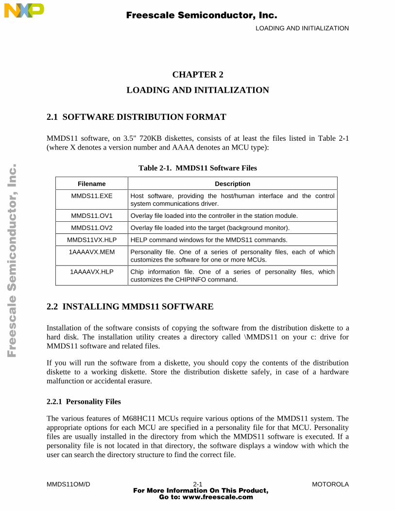
MMDS11 software, on 3.5" 720KB diskettes, consists of at least the files listed in Table 2-1(where X denotes a version number and AAAA denotes an MCU type):
Table 2-1. MMDS11 Software Files
Filename Description
MMDS11.EXE Host software, providing the host/human interface and the controlsystem communications driver.
MMDS11.OV1 Overlay file loaded into the controller in the station module.
MMDS11.OV2 Overlay file loaded into the target (background monitor).
MMDS11VX.HLP HELP command windows for the MMDS11 commands.
1AAAAVX.MEM Personality file. One of a series of personality files, each of whichcustomizes the software for one or more MCUs.
1AAAAVX.HLP Chip information file. One of a series of personality files, whichcustomizes the CHIPINFO command.
2.2 INSTALLING MMDS11 SOFTWARE
Installation of the software consists of copying the software from the distribution diskette to ahard disk. The installation utility creates a directory called \MMDS11 on your c: drive forMMDS11 software and related files.
If you will run the software from a diskette, you should copy the contents of the distributiondiskette to a working diskette. Store the distribution diskette safely, in case of a hardwaremalfunction or accidental erasure.
2.2.1 Personality Files
The various features of M68HC11 MCUs require various options of the MMDS11 system. Theappropriate options for each MCU are specified in a personality file for that MCU. Personalityfiles are usually installed in the directory from which the MMDS11 software is executed. If apersonality file is not located in that directory, the software displays a window with which theuser can search the directory structure to find the correct file.
Fre
esc
ale
Se
mic
on
du
cto
r, I
Freescale Semiconductor, Inc.
For More Information On This Product, Go to: www.freescale.com
nc
...
LOADING AND INITIALIZATION
MMDS11OM/D 2-2 MOTOROLA
More than one personality file can be installed; the MMDS11 operating software loads thepersonality file that corresponds to the currently-connected EM (personality board).
2.2.2 The Help File
The MMDS11Vx.HLP file contains screens for the HELP command. Note that this file must bein the same directory as file MMDS11.EXE.
The MMDS11 on-screen help system features pop-up menus and windows. In most situations,the system is context-sensitive: highlight a term or expression of interest, then press the F1 keyfor help information about the term.
2.3 USING THE SOFTWARE
The executable software consists of the host program, MMDS11.EXE. (Before running thesoftware, make sure that an EM is installed in the station module.)
Make sure that the asynchronous communications cable has been connected between the stationmodule and the host computer, and power has been applied to the station module. If thecommunication cable is connected to the COM1 computer port (the default), enter this DOSstartup command:
C:\MMDS11>MMDS11
Note these six options for the startup command:
• If the MMDS11 is connected to COM2, COM3, or COM4, add the correspondinginteger to the command:
C:\MMDS11>MMDS11 2
• If the computer has a monochrome monitor, add BW to the command:
C:\MMDS11>MMDS11 BW
• To specify a default .MEM file, to be loaded automatically, add the -M filenameoption (do not put a space between the M and the filename):
C:\MMDS11>MMDS11 -M<filename.mem>
• To specify an S-record file (and any map file with the same name) to be loadedautomatically, add the filename option:
C:\MMDS11>MMDS11 <filename>
Fre
esc
ale
Se
mic
on
du
cto
r, I
Freescale Semiconductor, Inc.
For More Information On This Product, Go to: www.freescale.com
nc
...

LOADING AND INITIALIZATION
MMDS11OM/D 2-3 MOTOROLA
• To specify a default baud rate of 9600, add the -B option:
C:\MMDS11>MMDS11 -B
• To bypass the initial version screen, going directly to the debug screen, add theasterisk option:
C:\MMDS11>MMDS11 *
NOTEYou may concatenate multiple options in the startup command.
The host program establishes communications with the MMDS11 station module; a versionscreen for MMDS11 software confirms this communication. If this screen does not appear, anerror screen does: the information in this screen helps determine the reason the software does notrun. When the version screen appears, press <CR> (that is, the ENTER, RETURN, or carriage-return key) to move to the debug screen (Figure 3-1).
For best performance of the system, communications between the host and the station moduleshould be at the maximum available baud rate. At power-up the MMDS11 system automaticallysets the maximum baud for your system. Use the BAUD command to change the baud rate.
NOTEReduce the baud rate if a communication error message appears. Ifcommunication errors persist, it may be necessary to turn off disk cache.
Enter commands in response to the MMDS11 command prompt ( > ). When the emulation anddebugging session has been completed, terminate the session by entering the EXIT or QUITcommand.
Fre
esc
ale
Se
mic
on
du
cto
r, I
Freescale Semiconductor, Inc.
For More Information On This Product, Go to: www.freescale.com
nc
...

LOADING AND INITIALIZATION
MMDS11OM/D 2-4 MOTOROLA
Fre
esc
ale
Se
mic
on
du
cto
r, I
Freescale Semiconductor, Inc.
For More Information On This Product, Go to: www.freescale.com
nc
...
USER SCREENS
MMDS11OM/D 3-1 MOTOROLA
CHAPTER 3
USER SCREENS
3.1 GENERAL DESCRIPTION
Several screens support MMDS11 software. The debug screen is an example for the way allscreens work. This screen implements these MMDS11 features:
• Debugging assembly-language programs
• Viewing and modifying variables, using their source language names
• Providing help dialogs for all commands
• Displaying register contents
• Displaying memory contents
• Displaying emulator status
For instructions on changing the colors of MMDS11 screens, see paragraph 3.4 or theexplanation of the COLORS command (in Chapter 6). Chapter 5 explains the screens unique tothe MMDS11 bus state analyzer.
3.2 THE DEBUG SCREEN
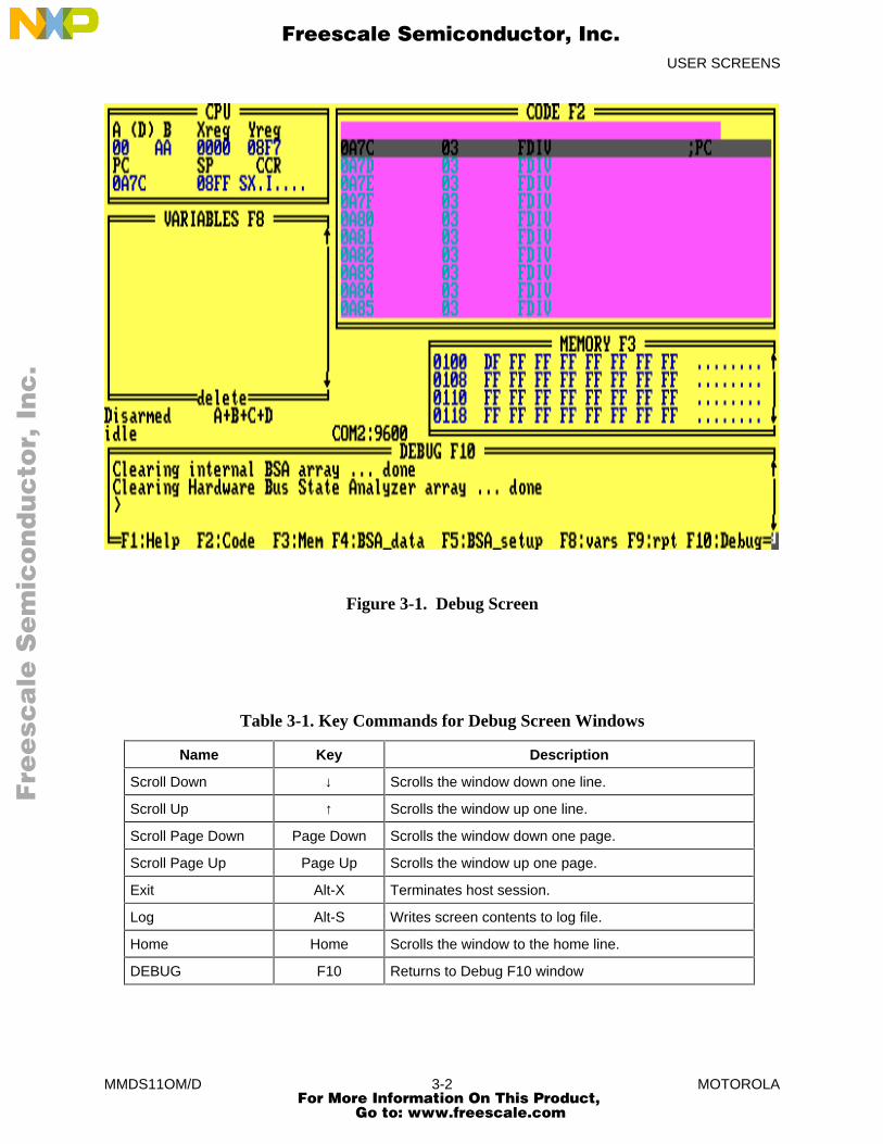
Figure 3-1 shows the debug screen, which consists of a status area and five windows that displaythe CPU registers, source or object code, variables, memory contents, commands, and results.Paragraph 3.2.1 explains the status area; paragraphs 3.2.2 through 3.2.6 explain the five normalwindows. Paragraphs 3.2.7 and 3.2.13 explain two temporary windows that appear duringspecific operations.
To carry out actions associated with a window of the debug screen, you select (or move to) thewindow. To select a window, press the numbered function key included in the window title:press the F2 key to select the source/code F2 window, press the F8 key to select the variables F8window, and so forth. Activating the debug screen includes selecting the debug F10 window.Table 3-1 lists the key commands available in any of these windows.
Fre
esc
ale
Se
mic
on
du
cto
r, I
Freescale Semiconductor, Inc.
For More Information On This Product, Go to: www.freescale.com
nc
...
USER SCREENS
MMDS11OM/D 3-2 MOTOROLA
Figure 3-1. Debug Screen
Table 3-1. Key Commands for Debug Screen Windows
Name Key Description
Scroll Down ↓ Scrolls the window down one line.
Scroll Up ↑ Scrolls the window up one line.
Scroll Page Down Page Down Scrolls the window down one page.
Scroll Page Up Page Up Scrolls the window up one page.
Exit Alt-X Terminates host session.
Log Alt-S Writes screen contents to log file.
Home Home Scrolls the window to the home line.
DEBUG F10 Returns to Debug F10 window
Fre
esc
ale
Se
mic
on
du
cto
r, I
Freescale Semiconductor, Inc.
For More Information On This Product, Go to: www.freescale.com
nc
...
USER SCREENS
MMDS11OM/D 3-3 MOTOROLA
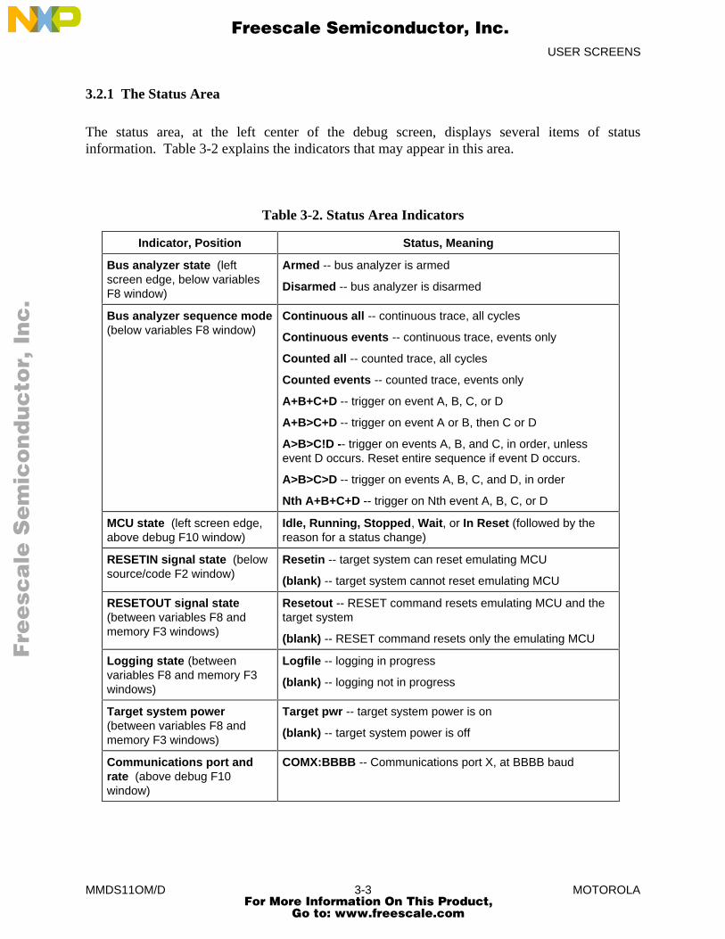
3.2.1 The Status Area
The status area, at the left center of the debug screen, displays several items of statusinformation. Table 3-2 explains the indicators that may appear in this area.
Table 3-2. Status Area Indicators
Indicator, Position Status, Meaning
Bus analyzer state (leftscreen edge, below variablesF8 window)
Armed -- bus analyzer is armed
Disarmed -- bus analyzer is disarmed
Bus analyzer sequence mode(below variables F8 window)
Continuous all -- continuous trace, all cycles
Continuous events -- continuous trace, events only
Counted all -- counted trace, all cycles
Counted events -- counted trace, events only
A+B+C+D -- trigger on event A, B, C, or D
A+B>C+D -- trigger on event A or B, then C or D
A>B>C!D -- trigger on events A, B, and C, in order, unlessevent D occurs. Reset entire sequence if event D occurs.
A>B>C>D -- trigger on events A, B, C, and D, in order
Nth A+B+C+D -- trigger on Nth event A, B, C, or D
MCU state (left screen edge,above debug F10 window)
Idle, Running, Stopped, Wait, or In Reset (followed by thereason for a status change)
RESETIN signal state (belowsource/code F2 window)
Resetin -- target system can reset emulating MCU
(blank) -- target system cannot reset emulating MCU
RESETOUT signal state(between variables F8 andmemory F3 windows)
Resetout -- RESET command resets emulating MCU and thetarget system
(blank) -- RESET command resets only the emulating MCU
Logging state (betweenvariables F8 and memory F3windows)
Logfile -- logging in progress
(blank) -- logging not in progress
Target system power(between variables F8 andmemory F3 windows)
Target pwr -- target system power is on
(blank) -- target system power is off
Communications port andrate (above debug F10window)
COMX:BBBB -- Communications port X, at BBBB baud
Fre
esc
ale
Se
mic
on
du
cto
r, I
Freescale Semiconductor, Inc.
For More Information On This Product, Go to: www.freescale.com
nc
...
USER SCREENS
MMDS11OM/D 3-4 MOTOROLA
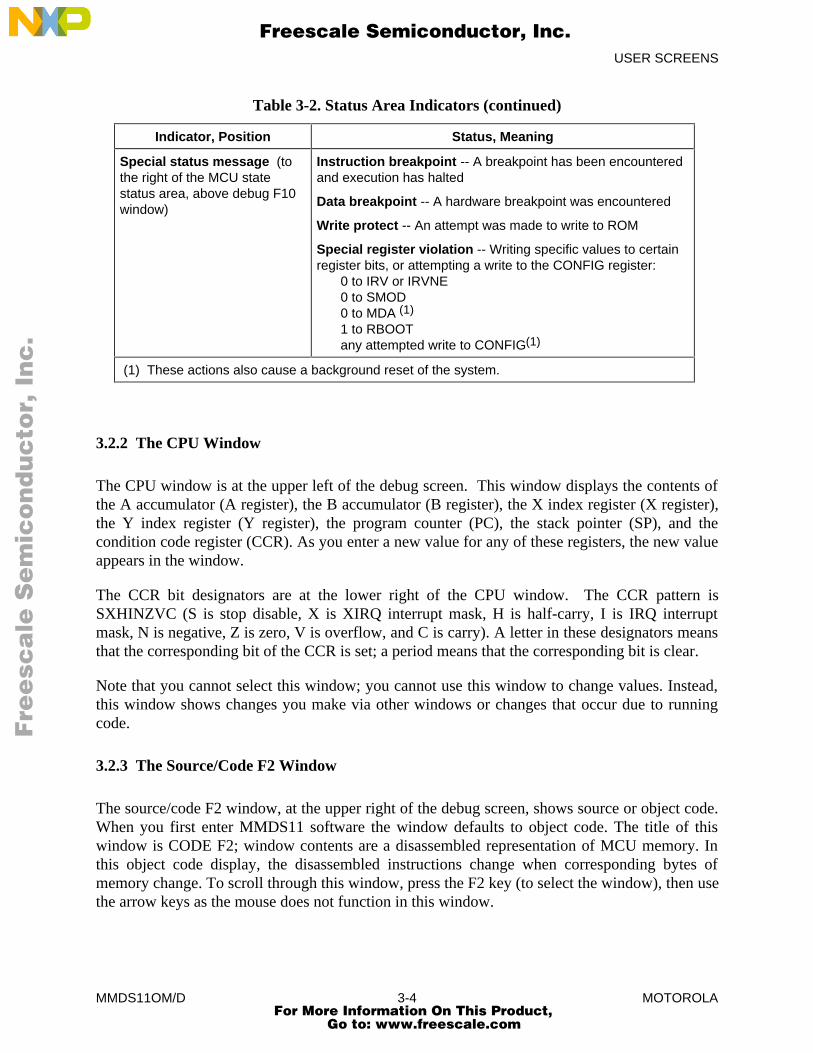
Table 3-2. Status Area Indicators (continued)
Indicator, Position Status, Meaning
Special status message (tothe right of the MCU statestatus area, above debug F10window)
Instruction breakpoint -- A breakpoint has been encounteredand execution has halted
Data breakpoint -- A hardware breakpoint was encountered
Write protect -- An attempt was made to write to ROM
Special register violation -- Writing specific values to certainregister bits, or attempting a write to the CONFIG register:
0 to IRV or IRVNE0 to SMOD0 to MDA (1)
1 to RBOOTany attempted write to CONFIG(1)
(1) These actions also cause a background reset of the system.
3.2.2 The CPU Window
The CPU window is at the upper left of the debug screen. This window displays the contents ofthe A accumulator (A register), the B accumulator (B register), the X index register (X register),the Y index register (Y register), the program counter (PC), the stack pointer (SP), and thecondition code register (CCR). As you enter a new value for any of these registers, the new valueappears in the window.
The CCR bit designators are at the lower right of the CPU window. The CCR pattern isSXHINZVC (S is stop disable, X is XIRQ interrupt mask, H is half-carry, I is IRQ interruptmask, N is negative, Z is zero, V is overflow, and C is carry). A letter in these designators meansthat the corresponding bit of the CCR is set; a period means that the corresponding bit is clear.
Note that you cannot select this window; you cannot use this window to change values. Instead,this window shows changes you make via other windows or changes that occur due to runningcode.
3.2.3 The Source/Code F2 Window
The source/code F2 window, at the upper right of the debug screen, shows source or object code.When you first enter MMDS11 software the window defaults to object code. The title of thiswindow is CODE F2; window contents are a disassembled representation of MCU memory. Inthis object code display, the disassembled instructions change when corresponding bytes ofmemory change. To scroll through this window, press the F2 key (to select the window), then usethe arrow keys as the mouse does not function in this window.
Fre
esc
ale
Se
mic
on
du
cto
r, I
Freescale Semiconductor, Inc.
For More Information On This Product, Go to: www.freescale.com
nc
...
USER SCREENS
MMDS11OM/D 3-5 MOTOROLA
The contents of this window change to source code (and the title changes toSOURCE:filename.asm) if:
1. You have loaded a map file, and
2. The program counter (PC) points to a memory area covered by the map file.
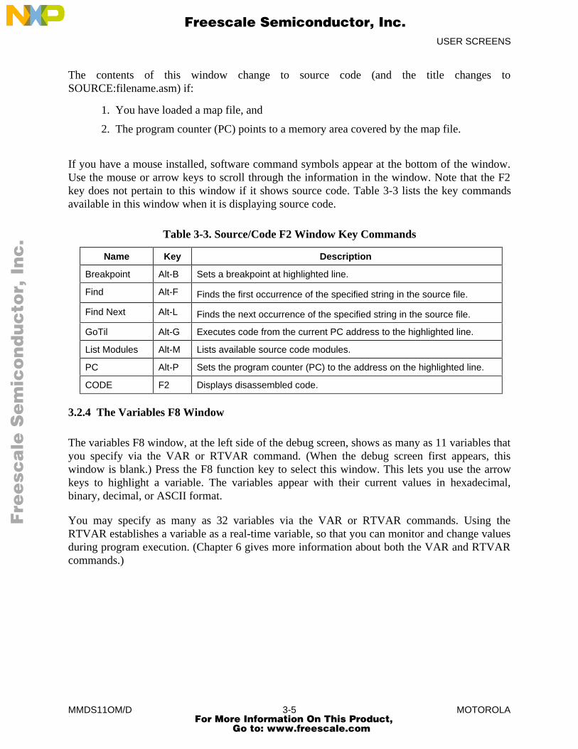
If you have a mouse installed, software command symbols appear at the bottom of the window.Use the mouse or arrow keys to scroll through the information in the window. Note that the F2key does not pertain to this window if it shows source code. Table 3-3 lists the key commandsavailable in this window when it is displaying source code.
Table 3-3. Source/Code F2 Window Key Commands
Name Key Description
Breakpoint Alt-B Sets a breakpoint at highlighted line.
Find Alt-F Finds the first occurrence of the specified string in the source file.
Find Next Alt-L Finds the next occurrence of the specified string in the source file.
GoTil Alt-G Executes code from the current PC address to the highlighted line.
List Modules Alt-M Lists available source code modules.
PC Alt-P Sets the program counter (PC) to the address on the highlighted line.
CODE F2 Displays disassembled code.
3.2.4 The Variables F8 Window
The variables F8 window, at the left side of the debug screen, shows as many as 11 variables thatyou specify via the VAR or RTVAR command. (When the debug screen first appears, thiswindow is blank.) Press the F8 function key to select this window. This lets you use the arrowkeys to highlight a variable. The variables appear with their current values in hexadecimal,binary, decimal, or ASCII format.
You may specify as many as 32 variables via the VAR or RTVAR commands. Using theRTVAR establishes a variable as a real-time variable, so that you can monitor and change valuesduring program execution. (Chapter 6 gives more information about both the VAR and RTVARcommands.)
Fre
esc
ale
Se
mic
on
du
cto
r, I
Freescale Semiconductor, Inc.
For More Information On This Product, Go to: www.freescale.com
nc
...
USER SCREENS
MMDS11OM/D 3-6 MOTOROLA
3.2.5 The Memory F3 Window
The memory F3 window, at the right side of the debug screen, displays the contents of 32memory locations, either standard or real-time. As you modify the contents of these locations,the new values appear in this window. You can use the scroll bar to the right of the window todisplay other areas of memory.
To select this window, press the F3 function key. The scroll bar disappears; use the arrow keys todisplay lower or higher addresses.
If the window shows memory values, dashes replace the values when you execute code. Valuesreappear when execution stops.
If you set up a real-time memory range, via the RTMEM command, this window shows real-timememory values during code execution. You can modify these values when idle or during codeexecution, via the block fill (BF) and memory modify (MM) commands. Changes to these valuesappear in the window as the code executes.
3.2.6 The Debug F10 Window
The debug F10 window, at the bottom of the debug screen, is the selected window initially. Thiswindow contains the command line, identified by the command prompt ( > ). You enter (type) acommand at the prompt. To activate the command, press <CR> (that is, press the ENTER,RETURN, or carriage-return key). The software displays any additional prompts, messages, ordata that pertain to the command. If the command is not entered correctly, or is not valid, thesoftware displays an appropriate error message. Table 6-3 is a summary of the availablecommands, detailed command descriptions follow the table.
After executing the command, the software again displays the command prompt. As a new lineappears in the debug F10 window, preceding lines scroll upward. The window displays as manyas four lines. When you select any other window, the cursor disappears from the debug F10window. To return to the debug F10 window, press the F10 function key; this restores the cursor.
Table 3-4 lists the key commands that pertain to the debug F10 window.
Fre
esc
ale
Se
mic
on
du
cto
r, I
Freescale Semiconductor, Inc.
For More Information On This Product, Go to: www.freescale.com
nc
...
USER SCREENS
MMDS11OM/D 3-7 MOTOROLA
Table 3-4. Debug F10 Window Key Commands
Name Key Description
HELP F1 Access Help screens.
CODE F2 Activate Code F2 window.
MEMORY F3 Activate Memory F3 window.
BSA Display F4 Activate bus state analyzer data screen.
BSA Setup F5 Activate bus state analyzer setup screen.
VARIABLES F8 Activate Variables F8 window.
Repeat F9 Repeat preceding command.
DEBUG F10 Activate Debug F10 window.
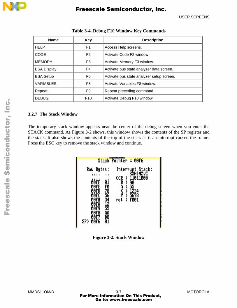
3.2.7 The Stack Window
The temporary stack window appears near the center of the debug screen when you enter theSTACK command. As Figure 3-2 shows, this window shows the contents of the SP register andthe stack. It also shows the contents of the top of the stack as if an interrupt caused the frame.Press the ESC key to remove the stack window and continue.
Figure 3-2. Stack Window
Fre
esc
ale
Se
mic
on
du
cto
r, I
Freescale Semiconductor, Inc.
For More Information On This Product, Go to: www.freescale.com
nc
...
USER SCREENS
MMDS11OM/D 3-8 MOTOROLA
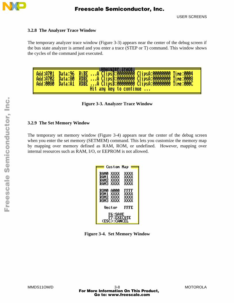
3.2.8 The Analyzer Trace Window
The temporary analyzer trace window (Figure 3-3) appears near the center of the debug screen ifthe bus state analyzer is armed and you enter a trace (STEP or T) command. This window showsthe cycles of the command just executed.
Figure 3-3. Analyzer Trace Window
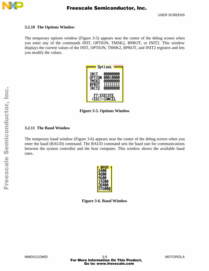
3.2.9 The Set Memory Window
The temporary set memory window (Figure 3-4) appears near the center of the debug screenwhen you enter the set memory (SETMEM) command. This lets you customize the memory mapby mapping over memory defined as RAM, ROM, or undefined. However, mapping overinternal resources such as RAM, I/O, or EEPROM is not allowed.
Figure 3-4. Set Memory Window
Fre
esc
ale
Se
mic
on
du
cto
r, I
Freescale Semiconductor, Inc.
For More Information On This Product, Go to: www.freescale.com
nc
...
USER SCREENS
MMDS11OM/D 3-9 MOTOROLA
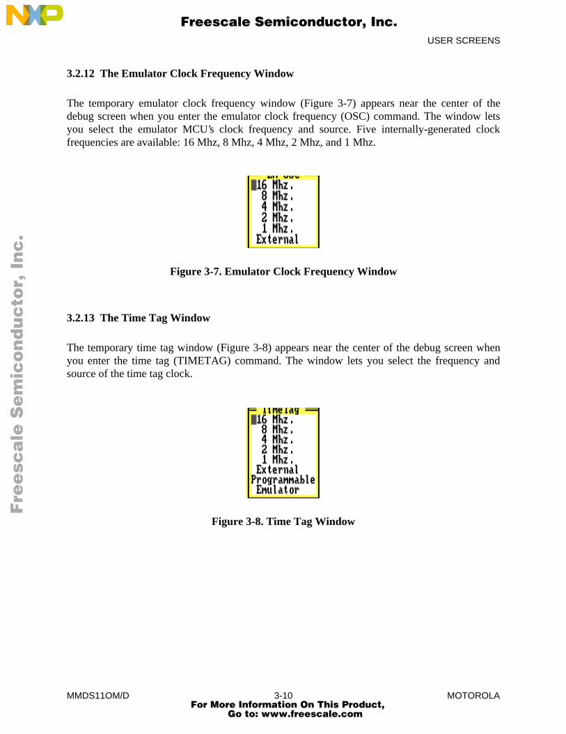
3.2.10 The Options Window
The temporary options window (Figure 3-5) appears near the center of the debug screen whenyou enter any of the commands INIT, OPTION, TMSK2, BPROT, or INIT2. This windowdisplays the current values of the INIT, OPTION, TMSK2, BPROT, and INIT2 registers and letsyou modify the values.
Figure 3-5. Options Window
3.2.11 The Baud Window
The temporary baud window (Figure 3-6) appears near the center of the debug screen when youenter the baud (BAUD) command. The BAUD command sets the baud rate for communicationsbetween the system controller and the host computer. This window shows the available baudrates.
Figure 3-6. Baud Window
Fre
esc
ale
Se
mic
on
du
cto
r, I
Freescale Semiconductor, Inc.
For More Information On This Product, Go to: www.freescale.com
nc
...
USER SCREENS
MMDS11OM/D 3-10 MOTOROLA
3.2.12 The Emulator Clock Frequency Window
The temporary emulator clock frequency window (Figure 3-7) appears near the center of thedebug screen when you enter the emulator clock frequency (OSC) command. The window letsyou select the emulator MCU’s clock frequency and source. Five internally-generated clockfrequencies are available: 16 Mhz, 8 Mhz, 4 Mhz, 2 Mhz, and 1 Mhz.
Figure 3-7. Emulator Clock Frequency Window
3.2.13 The Time Tag Window
The temporary time tag window (Figure 3-8) appears near the center of the debug screen whenyou enter the time tag (TIMETAG) command. The window lets you select the frequency andsource of the time tag clock.
Figure 3-8. Time Tag Window
Fre
esc
ale
Se
mic
on
du
cto
r, I
Freescale Semiconductor, Inc.
For More Information On This Product, Go to: www.freescale.com
nc
...
USER SCREENS
MMDS11OM/D 3-11 MOTOROLA
3.3 MOUSE OPERATION
MMDS11 software supports a Microsoft, Logitech, or IBM mouse. Install the mouse accordingto the manufacturer’s instructions, using the accompanying mouse driver software. A mouse froma different manufacturer may be satisfactory, but Motorola cannot guarantee its performance withthe MMDS11 system.
When a program is loaded, the PC is set to the start address, and the debug F10 window isselected, you can use the mouse to scroll through the source F2, variables F8, and memory F3windows.
Clicking on an item means positioning the mouse cursor on the item, then quickly pressing andreleasing the left mouse button. Some of the operations that you can perform require clicking ona command name; these names are visible only if a mouse is connected. These operations are:
• Delete the highlighted variable in the variables F8 window -- click on the wordDELETE at the bottom of the window.
• Set the PC to the address of the instruction on a highlighted line -- click on PC.
• Set or clear a breakpoint at the highlighted instruction in the source F2 window -- clickon the BR command name at the bottom of the window.
• Execute instructions beginning with the instruction at the address in the PC andstopping at the highlighted instruction in the source F2 window -- click on the GOTILcommand name at the bottom of the window.
• Execute the instruction at the address in the PC -- click on the STEP command name atthe bottom of the source F2 window.
• Begin executing instructions at the instruction at the address in the PC -- click on theGO command name at the bottom of the source F2 window.
• Display the source file line number of the highlighted line of the source F2 window,along with its address, disassembled contents, and the name of the file -- click on theINFO command name at the bottom of the window.
• Stop executing instructions -- click on the STOP command name at the bottom of thesource F2 window.
Pressing the right button of your mouse is the same as pressing the <ESC> key. When you areusing the bus state analyzer, clicking both left and right buttons simultaneously is the same aspressing the help (F1) key. (Chapter 5 explains more information about the bus state analyzer.)
Fre
esc
ale
Se
mic
on
du
cto
r, I
Freescale Semiconductor, Inc.
For More Information On This Product, Go to: www.freescale.com
nc
...

USER SCREENS
MMDS11OM/D 3-12 MOTOROLA
3.4 CHANGING SCREEN COLORS
To change screen colors, enter the COLORS command, from the debug screen; the colorswindow appears. This window includes a list of screen elements and a matrix offoreground/background color combinations; each color combination has a two-digit hexadecimalnumber.
A prompt asks for the color of the first screen element. To accept the current color, press <CR>.To change the color, enter the number of your choice, then press <CR>. A new prompt asks forthe color of the next element. Select the color for each element in the same way. The commandends when you have selected a color for the last screen element, or when you press ESC.
In the color matrix, rows correspond to background colors, and columns correspond toforeground colors. This means that color choices from the same row result in differently coloredletters and numbers against the same background color. Making the background of highlights andhelp screens a different color sets these elements off from the main screen.
The software stores color selections in file COLORS.11; when you execute MMDS11 again thesoftware applies the newly selected colors. You can use the color selection file with anothersystem to retain the selected colors.
NOTE
Delete the COLORS.11 file from the \MMDS11 subdirectory to return to thedefault colors.
Fre
esc
ale
Se
mic
on
du
cto
r, I
Freescale Semiconductor, Inc.
For More Information On This Product, Go to: www.freescale.com
nc
...
OPERATION
MMDS11OM/D 4-1 MOTOROLA
CHAPTER 4
OPERATION
4.1 INTRODUCTION
Operation of the MMDS11 consists of appropriately using the MMDS11 commands (whichChapter 6 explains) and of using the user interface to perform debugging and bus state analysis.Chapter 5 explains bus state analysis. This chapter describes the use of commands that:
• Initialize the MMDS11
• Support both debugging and bus state analysis
4.2 INITIALIZATION
Initializing the MMDS11 system includes initializing the communications baud rate, the memorymap, and the emulator; loading the target software and the symbol table; initializing the CPUregisters; and initializing the memory and the log. Paragraphs 4.2.1 through 4.2.8 discuss eachtype of initialization.
If you wish, you can set up a script file to perform these initialization actions automatically eachtime you run the MMDS11 software. This file must have the name STARTUP.11.
4.2.1 Communications Baud Rate
For best performance of the system, communications between the host and the station moduleshould be at the maximum available baud rate. At power-up the MMDS11 system automaticallysets the maximum baud for your system. Use the BAUD command to change the baud rate.Other possible rates are 2400, 4800, 9600, 19200, 38400, and 57600 baud.
If you enter the BAUD command with no rate value, the baud window appears over the debugscreen. To select a rate from this window, use the arrow keys to highlight the rate, then press<CR>. You may also double click the mouse when the cursor is on the desired baud rate.
All data transfers between the host computer and the station module are at the specified baudrate; maximum performance is at the highest rate the computer supports. Use the BAUDCHKcommand to determine that rate. However, if the software displays communications errormessages, reduce the baud rate. If communication errors persist, it may be necessary to turn offdisk cache.
Fre
esc
ale
Se
mic
on
du
cto
r, I
Freescale Semiconductor, Inc.
For More Information On This Product, Go to: www.freescale.com
nc
...
OPERATION
MMDS11OM/D 4-2 MOTOROLA
4.2.2 Standard Memory Mapping
To emulate the target system effectively, emulator memory needs the same mapping as the targetsystem memory. The MMDS11 automatically loads memory mapping information from thepersonality file. This standard memory mapping applies to the MCU in the emulator module.
4.2.3 Custom Memory Mapping
For custom memory configurations, use the customize memory map (SETMEM) command.When you enter this command, the set memory window appears over the debug screen. Via thiswindow, you can define as many as four blocks of RAM and four blocks of ROM. (ROM iswrite-protected; attempting to write to ROM stops program execution.)
For each memory block, specify the address range, memory type, and reset vector. To write themap to a file, press the F6 function key, then enter a file name in response to the prompt. Thefilename must not duplicate the name of any .MEM filename that comes as part of yourMMDS11 system. Press the F7 key to apply the map to memory.
Use the load personality file (LOADMEM) command to load the stored custom map duringfuture emulation sessions. Note that the LOADMEM command can be part of the STARTUP.11script file, so that loading the custom map becomes an automatic part of MMDS11 startup.
You also can use the LOADMEM command to restore the standard memory mapping or to loadany other standard map file for the MCU in the EM. The display memory map (SHOWMEM)command displays the RAM and ROM range of the current map.
4.2.4 Initializing the Emulator
The MCU clock source and frequency must be specified, and control signals from the target tothe emulator must be enabled or disabled. Enter the select emulator clock frequency (OSC)command to specify the clock signal states; this brings up the OSC command window. Fiveinternally-generated clock frequencies are available: 16 Mhz, 8 Mhz, 4 Mhz, 2 Mhz, and 1 Mhz.Alternatively, you can use an external clock signal supplied to the MMDS11 through pod A logicclip 9 (white). (When using the logic clip cables, attach the black clip to ground.) Refer to theEM hardware user’s manual for EM clock information.
The default emulator clock rate is 8 MHz. Before changing the clock rate, make sure that youremulation MCU is specified to run at the new rate.
Fre
esc
ale
Se
mic
on
du
cto
r, I
Freescale Semiconductor, Inc.
For More Information On This Product, Go to: www.freescale.com
nc
...
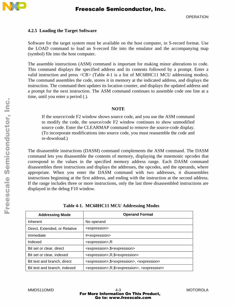
OPERATION
MMDS11OM/D 4-3 MOTOROLA
4.2.5 Loading the Target Software
Software for the target system must be available on the host computer, in S-record format. Usethe LOAD command to load an S-record file into the emulator and the accompanying map(symbol) file into the host computer.
The assemble instructions (ASM) command is important for making minor alterations to code.This command displays the specified address and its contents followed by a prompt. Enter avalid instruction and press <CR> (Table 4-1 is a list of MC68HC11 MCU addressing modes).The command assembles the code, stores it in memory at the indicated address, and displays theinstruction. The command then updates its location counter, and displays the updated address anda prompt for the next instruction. The ASM command continues to assemble code one line at atime, until you enter a period (.).
NOTE
If the source/code F2 window shows source code, and you use the ASM commandto modify the code, the source/code F2 window continues to show unmodifiedsource code. Enter the CLEARMAP command to remove the source-code display.(To incorporate modifications into source code, you must reassemble the code andre-download.)
The disassemble instructions (DASM) command complements the ASM command. The DASMcommand lets you disassemble the contents of memory, displaying the mnemonic opcodes thatcorrespond to the values in the specified memory address range. Each DASM commanddisassembles three instructions and displays the addresses, the opcodes, and the operands, whereappropriate. When you enter the DASM command with two addresses, it disassemblesinstructions beginning at the first address, and ending with the instruction at the second address.If the range includes three or more instructions, only the last three disassembled instructions aredisplayed in the debug F10 window.
Table 4-1. MC68HC11 MCU Addressing Modes
Addressing Mode Operand Format
Inherent No operand
Direct, Extended, or Relative <expression>
Immediate #<expression>
Indexed <expression>,R
Bit set or clear, direct <expression>,$<expression>
Bit set or clear, indexed <expression>,R,$<expression>
Bit test and branch, direct <expression>,$<expression>, <expression>
Bit test and branch, indexed <expression>,R,$<expression>, <expression>
Fre
esc
ale
Se
mic
on
du
cto
r, I
Freescale Semiconductor, Inc.
For More Information On This Product, Go to: www.freescale.com
nc
...
OPERATION
MMDS11OM/D 4-4 MOTOROLA
4.2.6 Memory Initialization
During a debugging or bus analysis session, specific memory locations should contain knownvalues. The required values are stored in memory as numeric values or as instructions assembledindividually. The block fill and memory modify commands let you initialize or modify memorycontents.
The block fill (BF) command lets you place required numeric values in memory addresses. Thiscommand defines a block of memory, then places a byte or word pattern throughout the range.
The memory modify (MM) command stores a value or values you supply into a specified addressin memory. When you supply only an address, the command displays the contents of the addressfollowed by a prompt. Enter the value and press <CR>. The command displays the next addressand its contents. The command continues to store the values you enter until you enter a period (.).
4.2.7 CPU Registers
The software dynamically displays the contents of the CPU registers and the condition coderegister in the CPU window. These registers (A, B, X, Y, PC, SP, and CCR) contain theenvironment for execution of an instruction and, after the instruction has been executed, theresults. You can initialize any of these registers by entering the corresponding register designatorcommand and an appropriate value. Typically, at least the program counter (PC) must beinitialized with the start address. The SP register is set initially to FF. When you press <CR>, theregister display shows the new value. These examples show how to initialize some of the CPUregisters:
PC 100 Set the program counter to 100 hexadecimal.
CCR 00 Clear the bits in the condition code register.
One limitation of the MMDS11 software is that it reserves nine bytes below the user stack toinitialize the CPU registers.
4.2.8 Log Initialization
The MMDS11 maintains a command log that can be written to a file. Entries in the log include:
• Commands entered on the command line
• Commands read from a script file
• Responses to commands
Fre
esc
ale
Se
mic
on
du
cto
r, I
Freescale Semiconductor, Inc.
For More Information On This Product, Go to: www.freescale.com
nc
...
OPERATION
MMDS11OM/D 4-5 MOTOROLA
• Error messages
• Notifications of asynchronous events (such as breakpoints)
With the log file (LF) command, you can open a file to receive information being logged. If thespecified file already exists, the system lets you append the current log information to that file, orreplace file contents with the current log information. While the log file remains open, the loginformation is written to the file. Enter another LF command to terminate logging to the file ordevice.
NOTE
The LF command does not automatically append a filename extenuation to logfiles. Motorola recommends that you use the extension .log for log files.
4.3 COMMON OPERATIONS
The commands described in the following paragraphs are common to debugging and bus stateanalysis. Some apply to the MMDS11 itself, and others relate to operation in more than onemode.
4.3.1 System Commands
The execute script file (SCRIPT) command reads commands from a script file and passes themto the command interpreter for execution. A script file is a text file of MMDS11 commands;script files are appropriate for any sequence of commands that you use often. Entering the oneSCRIPT command has the same effect as entering a sequence of other commands. Using scriptfiles saves time and promotes accuracy.
Sometimes, a script file must contain a pause between commands. The pause between commands(WAIT) command causes the command interpreter to wait before processing subsequentcommands. As part of the WAIT command, you can enter the wait time, in seconds. If you donot enter a time value for the WAIT command, the command interpreter pauses for five seconds.
NOTE
All values you enter on the MMDS11 command line are hexadecimal. The inputvalue 10, for example, is the decimal value 16.
To display the value of a symbol defined in a map (symbol) file, use the WHEREIS command.
For information about a highlighted line in the source/code F2 window (filename, line number,address, and so forth), use the INFO command.
Fre
esc
ale
Se
mic
on
du
cto
r, I
Freescale Semiconductor, Inc.
For More Information On This Product, Go to: www.freescale.com
nc
...
OPERATION
MMDS11OM/D 4-6 MOTOROLA
The VERSION command displays the version number of the host software and the personalityfile.
The system information (SYSINFO) command tells you the amount of host computer memoryremaining.
The HELP command displays a dialog window from which to access the MMDS11 help system.Note that the help system is context sensitive: highlight an element of a screen, then press the F1help key, for corresponding help information. (When you are in the bus state analyzer, pressingleft and right mouse buttons at the same time is the same as pressing the F1 key.)
4.3.2 Operating Commands
The RESET command resets the emulation MCU and sets the PC to the contents of the resetvector. User code is not executed using this command. The RESETGO command carries out thesame actions as the RESET command, then starts code execution from the PC-value address. TheRESETIN command allows the reset signal to come into the emulation system through the targetcable; this signal must be enabled for correct operation of the WAIT4RESET command. TheRESETOUT command allows the RESET command to send a reset signal out the target cable.
The go (G or GO) command starts emulation at the address in the PC, or at an address enteredwith the command. Execution continues until it encounters a breakpoint, until the bus analyzer(optionally) stops it, or until you enter the STOP command. If you enter a second address withthe G or GO command, execution stops at the second address. The GOTIL command startsemulation at the location in the PC and stops at the address entered with the command. TheSTOP command stops the emulator.
The STEP or T commands execute a specified number of instructions, beginning at the currentPC value. The STEPFOR command begins instruction execution at the current PC value,continuing until you press a key or until execution arrives at a breakpoint. The STEPTILcommand executes instructions from the current PC value to an address you specify.
An instruction breakpoint occurs when the MCU accesses an instruction at a specified address oran address within a specified address range. When execution arrives at a breakpoint address,emulation stops just before execution of the instruction at that address, and the software displaysthis message:
idle Inst brkpt
Fre
esc
ale
Se
mic
on
du
cto
r, I
Freescale Semiconductor, Inc.
For More Information On This Product, Go to: www.freescale.com
nc
...

OPERATION
MMDS11OM/D 4-7 MOTOROLA
A properly defined breakpoint permits analysis of the contents of registers and memory locationsand the states of various signals at designated addresses in the program.
The set instruction breakpoint (BR) command sets a breakpoint at a specific address or at eachaddress of a range. Breakpoint addresses must be instruction fetch (opcode) addresses. You canset a maximum of 64 breakpoints. If you enter the BR command without any address, thecommand displays all active breakpoints. To clear breakpoints, use the clear breakpoints(NOBR) command.
You can set as many as four special breakpoints via the bus state analyzer setup screen. Thesedata breakpoints (hardware breakpoints) can occur at any address or any data value, and you canspecify a read or write cycle. In addition, one of the four low-order logic clips in pod A can beused in defining these breakpoints (when using the logic clip cables, attach the black clip toground). An emulation RAM match or breakpoint bank match can also be used to defining thesebreakpoints.
To define a data breakpoint, press the F5 function key. This brings up the bus state analyzersetup screen (Figure 5-1). Using the arrow keys or mouse, move the cursor to the space betweenbrackets for the desired breakpoint marked Brk en. Press the space bar (or point to the spacewith the cursor and click the left mouse button) to display an X in this space. Then move thecursor to the control signals, logic clips, address, or data for the breakpoint. For control signals.logic clips, and bank comparator, type 0, 1, or X (don’t care). For the address or data, use eitherthe hexadecimal field or the binary field. Type a hexadecimal digit or an X in the hexadecimalfield, or 0, 1, or X in the binary field. When you have defined your data breakpoints, press the F7key to apply the definitions. If you want to save the definitions to a file, press F6 (then enter afilename in response to the prompt) before you press F7.
When execution arrives at a data breakpoint, execution stops and the message Data brkptappears in the status area of the debug screen. (Note that data breakpoints, unlike instructionbreakpoints, stop the processor after the execution of the instruction. In some cases, dependingon the data break pattern, a data breakpoint may execute an additional instruction.)
Fre
esc
ale
Se
mic
on
du
cto
r, I
Freescale Semiconductor, Inc.
For More Information On This Product, Go to: www.freescale.com
nc
...

OPERATION
MMDS11OM/D 4-8 MOTOROLA
Fre
esc
ale
Se
mic
on
du
cto
r, I
Freescale Semiconductor, Inc.
For More Information On This Product, Go to: www.freescale.com
nc
...
BUS STATE ANALYSIS
MMDS11OM/D 5-1 MOTOROLA
CHAPTER 5
BUS STATE ANALYSIS
5.1 INTRODUCTION
The MMDS11 bus state analyzer (BSA) shows the logical state of the target MCU bus. Next toemulation of a target-system MCU, this is the most important capability of a development tool:it enables you to determine what is occurring in a system without actually disturbing the system.
At the end of each MCU clock cycle, the BSA takes a snapshot of the logical states of the targetMCU bus. Then the analyzer stores the snapshots in the trace buffer, according to its mode.(This action is known as storing cycles.) The trace buffer can hold as many as 8191 cycles.(Note that the analyzer is a bus state analyzer: it does not show signal hold or setup times.)
As part of analyzer initialization, you define certain patterns of logical states as events (orterms). Then you select the analyzer mode: continuous, counted, or any of five sequentialmodes. This determines which and how many cycles the analyzer stores.
Data collection (cycle storage) begins when you arm the analyzer and start program execution.Data collection continues until execution stops, through a specified number of events, orthrough a defined sequence of events.
The bus state analyzer provides several ways to view collected data: raw data, disassembledinstructions, mixed raw data and disassembled instructions, or source code.
5.2 OPERATING THE BUS STATE ANALYZER
To operate the bus state analyzer, you must define events (or terms), select the bus state analyzermode, specify any options, collect data, then view the data. Paragraphs 5.2.1 through 5.2.5explain these actions.
Fre
esc
ale
Se
mic
on
du
cto
r, I
Freescale Semiconductor, Inc.
For More Information On This Product, Go to: www.freescale.com
nc
...
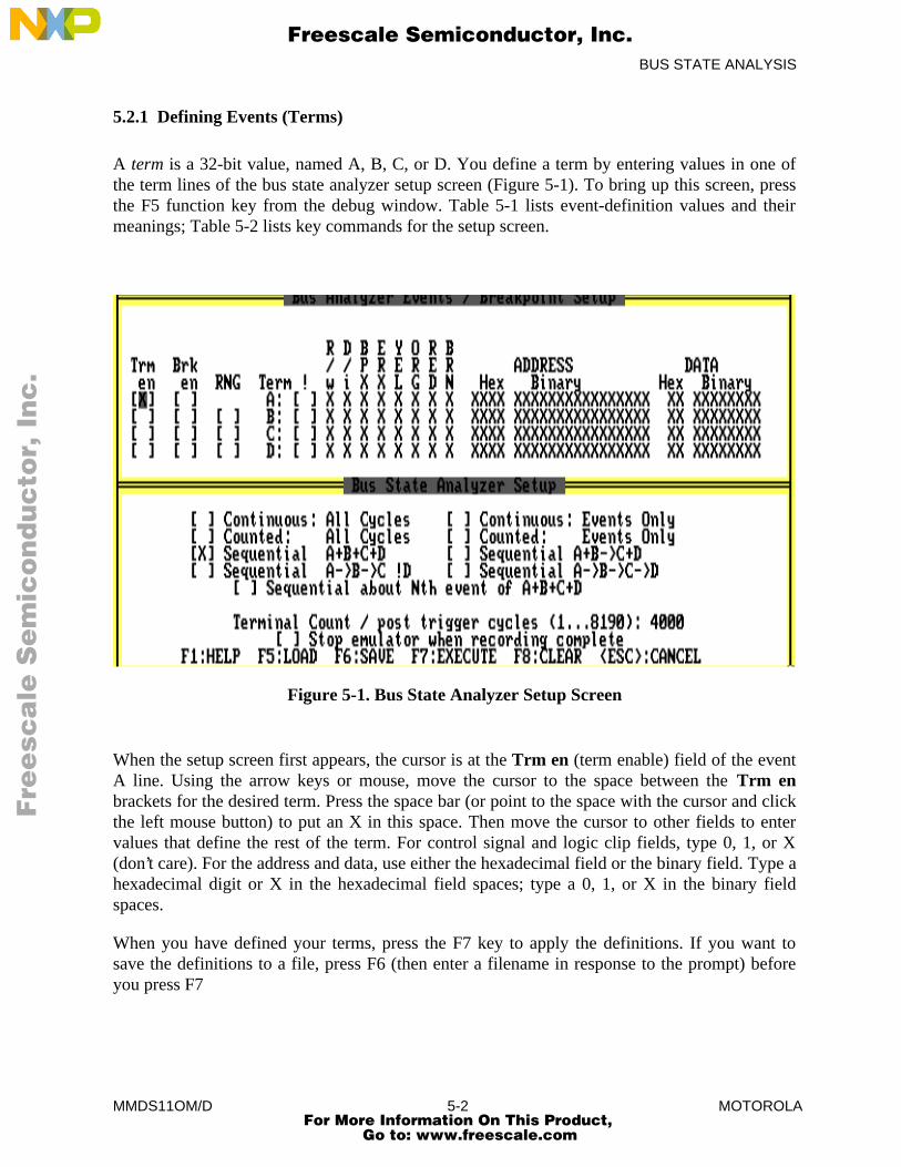
BUS STATE ANALYSIS
MMDS11OM/D 5-2 MOTOROLA
5.2.1 Defining Events (Terms)
A term is a 32-bit value, named A, B, C, or D. You define a term by entering values in one ofthe term lines of the bus state analyzer setup screen (Figure 5-1). To bring up this screen, pressthe F5 function key from the debug window. Table 5-1 lists event-definition values and theirmeanings; Table 5-2 lists key commands for the setup screen.
Figure 5-1. Bus State Analyzer Setup Screen
When the setup screen first appears, the cursor is at the Trm en (term enable) field of the eventA line. Using the arrow keys or mouse, move the cursor to the space between the Trm enbrackets for the desired term. Press the space bar (or point to the space with the cursor and clickthe left mouse button) to put an X in this space. Then move the cursor to other fields to entervalues that define the rest of the term. For control signal and logic clip fields, type 0, 1, or X(don’t care). For the address and data, use either the hexadecimal field or the binary field. Type ahexadecimal digit or X in the hexadecimal field spaces; type a 0, 1, or X in the binary fieldspaces.
When you have defined your terms, press the F7 key to apply the definitions. If you want tosave the definitions to a file, press F6 (then enter a filename in response to the prompt) beforeyou press F7
Fre
esc
ale
Se
mic
on
du
cto
r, I
Freescale Semiconductor, Inc.
For More Information On This Product, Go to: www.freescale.com
nc
...
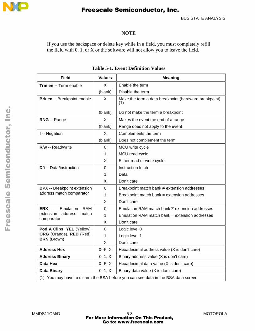
BUS STATE ANALYSIS
MMDS11OM/D 5-3 MOTOROLA
NOTE
If you use the backspace or delete key while in a field, you must completely refillthe field with 0, 1, or X or the software will not allow you to leave the field.
Table 5-1. Event Definition Values
Field Values Meaning
Trm en -- Term enable X
(blank)
Enable the term
Disable the term
Brk en -- Breakpoint enable X
(blank)
Make the term a data breakpoint (hardware breakpoint)(1)
Do not make the term a breakpoint
RNG -- Range X
(blank)
Makes the event the end of a range
Range does not apply to the event
! -- Negation X
(blank)
Complements the term
Does not complement the term
R/w -- Read/write 0
1
X
MCU write cycle
MCU read cycle
Either read or write cycle
D/i -- Data/instruction 0
1
X
Instruction fetch
Data
Don’t care
BPX -- Breakpoint extensionaddress match comparator
0
1
X
Breakpoint match bank ≠ extension addresses
Breakpoint match bank = extension addresses
Don’t care
ERX -- Emulation RAMextension address matchcomparator
0
1
X
Emulation RAM match bank ≠ extension addresses
Emulation RAM match bank = extension addresses
Don’t care
Pod A Clips: YEL (Yellow),ORG (Orange), RED (Red),BRN (Brown)
0
1
X
Logic level 0
Logic level 1
Don’t care
Address Hex 0--F, X Hexadecimal address value (X is don’t care)
Address Binary 0, 1, X Binary address value (X is don’t care)
Data Hex 0--F, X Hexadecimal data value (X is don’t care)
Data Binary 0, 1, X Binary data value (X is don’t care)
(1) You may have to disarm the BSA before you can see data in the BSA data screen.
Fre
esc
ale
Se
mic
on
du
cto
r, I
Freescale Semiconductor, Inc.
For More Information On This Product, Go to: www.freescale.com
nc
...

BUS STATE ANALYSIS
MMDS11OM/D 5-4 MOTOROLA
Table 5-2. Setup Screen Key Commands
Name Key Description
Move Down ↓ Moves cursor down to lower line.
Move Up ↑ Moves cursor up to higher line.
Move Left ← Moves cursor to selection to the left.
Move Right → Moves cursor to selection to the right.
Next Item Tab Moves cursor to next item
Preceding Item Shift-Tab Moves cursor to preceding item
HELP F1 Displays Help window.
LOAD F5 Loads a trigger file (.SET).
SAVE F6 Writes definitions to a trigger file (.SET).
EXECUTE F7 Applies definitions to bus analyzer and returns toDebug screen.
CLEAR F8 Clears definitions.
CANCEL ESC Cancels definitions and returns to Debug screen.
Part of term definition can be defining ranges from one term to another. To establish a range,you put an X in the range field of a term-definition line of the setup screen. But note that theevent A line does not have a range field. This is because event A can only start a range.
To configure any of the four range patterns:
A to B : Put an X in the event B range field.
B to C: Put an X in the event C range field.
C to D: Put an X in the event D range field.
A to B and C to D: Put Xs in the range fields of events B and D.
Also note that you need not define all four terms. When you have defined all appropriate terms,you are ready to select the bus state analyzer trigger mode, per paragraph 5.2.2.
Remember that the MMDS11 stores event definitions as 32-bit values. The R/w bit is the mostsignificant bit (MSB); the D0 bit is the least significant bit (LSB). A range is between two such32-bit values, not between values of address fields. In range mode, the BSA triggers every timethe input falls between the range starting term (the first 32-bit value) and the range ending term(the second 32-bit value).
Fre
esc
ale
Se
mic
on
du
cto
r, I
Freescale Semiconductor, Inc.
For More Information On This Product, Go to: www.freescale.com
nc
...
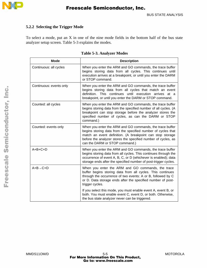
BUS STATE ANALYSIS
MMDS11OM/D 5-5 MOTOROLA
5.2.2 Selecting the Trigger Mode
To select a mode, put an X in one of the nine mode fields in the bottom half of the bus stateanalyzer setup screen. Table 5-3 explains the modes.
Table 5-3. Analyzer Modes
Mode Description
Continuous: all cycles When you enter the ARM and GO commands, the trace bufferbegins storing data from all cycles. This continues untilexecution arrives at a breakpoint, or until you enter the DARMor STOP command.
Continuous: events only When you enter the ARM and GO commands, the trace bufferbegins storing data from all cycles that match an eventdefinition. This continues until execution arrives at abreakpoint, or until you enter the DARM or STOP command.
Counted: all cycles When you enter the ARM and GO commands, the trace bufferbegins storing data from the specified number of all cycles. (Abreakpoint can stop storage before the analyzer stores thespecified number of cycles, as can the DARM or STOPcommand.)
Counted: events only When you enter the ARM and GO commands, the trace bufferbegins storing data from the specified number of cycles thatmatch an event definition. (A breakpoint can stop storagebefore the analyzer stores the specified number of cycles, ascan the DARM or STOP command.)
A+B+C+D When you enter the ARM and GO commands, the trace bufferbegins storing data from all cycles. This continues through theoccurrence of event A, B, C, or D (whichever is enabled); datastorage ends after the specified number of post-trigger cycles.
A+B→C+D When you enter the ARM and GO commands, the tracebuffer begins storing data from all cycles. This continuesthrough the occurrence of two events: A or B, followed by Cor D. Data storage ends after the specified number of post-trigger cycles.
If you select this mode, you must enable event A, event B, orboth. You must enable event C, event D, or both. Otherwise,the bus state analyzer never can be triggered.
Fre
esc
ale
Se
mic
on
du
cto
r, I
Freescale Semiconductor, Inc.
For More Information On This Product, Go to: www.freescale.com
nc
...
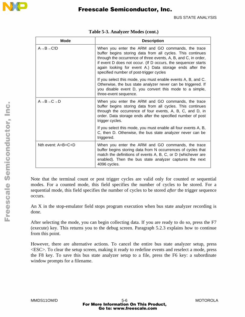
BUS STATE ANALYSIS
MMDS11OM/D 5-6 MOTOROLA
Table 5-3. Analyzer Modes (cont.)
Mode Description
A→B→C!D When you enter the ARM and GO commands, the tracebuffer begins storing data from all cycles. This continuesthrough the occurrence of three events, A, B, and C, in order,if event D does not occur. (If D occurs, the sequencer startsagain looking for event A.) Data storage ends after thespecified number of post-trigger cycles
If you select this mode, you must enable events A, B, and C.Otherwise, the bus state analyzer never can be triggered. Ifyou disable event D, you convert this mode to a simple,three-event sequence.
A→B→C→D When you enter the ARM and GO commands, the tracebuffer begins storing data from all cycles. This continuesthrough the occurrence of four events, A, B, C, and D, inorder. Data storage ends after the specified number of posttrigger cycles.
If you select this mode, you must enable all four events A, B,C, then D. Otherwise, the bus state analyzer never can betriggered.
Nth event: A+B+C+D When you enter the ARM and GO commands, the tracebuffer begins storing data from N occurrences of cycles thatmatch the definitions of events A, B, C, or D (whichever areenabled). Then the bus state analyzer captures the next4096 cycles.
Note that the terminal count or post trigger cycles are valid only for counted or sequentialmodes. For a counted mode, this field specifies the number of cycles to be stored. For asequential mode, this field specifies the number of cycles to be stored after the trigger sequenceoccurs.
An X in the stop-emulator field stops program execution when bus state analyzer recording isdone.
After selecting the mode, you can begin collecting data. If you are ready to do so, press the F7(execute) key. This returns you to the debug screen. Paragraph 5.2.3 explains how to continuefrom this point.
However, there are alternative actions. To cancel the entire bus state analyzer setup, press<ESC>. To clear the setup screen, making it ready to redefine events and reselect a mode, pressthe F8 key. To save this bus state analyzer setup to a file, press the F6 key: a subordinatewindow prompts for a filename.
Fre
esc
ale
Se
mic
on
du
cto
r, I
Freescale Semiconductor, Inc.
For More Information On This Product, Go to: www.freescale.com
nc
...
BUS STATE ANALYSIS
MMDS11OM/D 5-7 MOTOROLA
To load a bus state analyzer setup already saved to a file, press the F5 key: a subordinatewindow prompts for the filename. Entering the filename fills in the setup-screen values; pressthe F7 key to return to the debug screen. (An alternative way to load a saved setup is to enter theLOADTRIGGERS command from the debug screen. This method bypasses the setup screen.)
5.2.3 Selecting Options
An optional part of analyzer setup is specifying the frequency and source of the time tag clock.This clock provides a time reference value in each frame of the trace buffer. (Paragraph 5.2.7gives more information about the time tag clock.) Enter the time tag clock source (TIMETAG)command; this command brings up the small time-tag window in the center of the debug screen.This window gives you these choices (16 Mhz is the default):
16 Mhz Selects the 16 MHz oscillator.
8 Mhz Selects the 8 MHz oscillator.
4 Mhz Selects the 4 MHz oscillator.
2 Mhz Selects the 2 MHz oscillator.
1 Mhz Selects the 1 MHz oscillator.
External Selects the external clock
Programmable Selects the programmable clock.
Emulator Selects the emulator clock, the bus clock of the emulating MCU.
If you select External, connect logic clip 9 (white) of the pod B logic clip cable to the externalclock source. (The pod B connector is the closest to the front of the station module. Logic clip 9is available for external clock input whether or not you select the pod B logic clips for the tracedisplay.) When using the logic clip cables, attach the black clip to ground.
If you select Programmable, you must enter a frequency in the range of 50 Hz to 50 kHz, as thepop-up window requests.
If you select Emulator, the system stores the number of bus cycles.
Another setup option is specifying whether to store high-order time tag bits (increasing the timetag from 16 to 24 bits) or data from the pod B logic clips. To do so, enter the set multiplexer(SXB) command with the appropriate tags or clips parameter value. (The default is clips.)
Fre
esc
ale
Se
mic
on
du
cto
r, I
Freescale Semiconductor, Inc.
For More Information On This Product, Go to: www.freescale.com
nc
...
BUS STATE ANALYSIS
MMDS11OM/D 5-8 MOTOROLA
5.2.4 Collecting Bus Data
To begin data collection, enter the ARM command, which arms the bus state analyzer. The BSAstatus changes to Armed. The bus state analyzer mode appears on the status line.
Next, enter the GO command, which starts program execution. The MCU status changes toRunning. If you are in a sequential mode, you may be able to follow the occurrence of eventsfrom the highlighting changes. (Such highlighting changes may be too fast to be helpful.) Datacollection continues through the specified number of counted events or post-trigger cycles, oruntil code execution stops.
NOTES
The GO command is not the only program-execution command that works withthe bus state analyzer. Alternative commands are: G, GOTIL, STEP, STEPFOR,STEPTIL, and T.
If you enter either trace command (STEP or T) without a parameter value whenthe bus state analyzer is armed, the analyzer trace window appears over thedebug screen. This temporary window shows the cycles of the instruction justtraced.
To manually halt data collection, enter the DARM or STOP command. Entering the DARMcommand disarms the analyzer; the analyzer state changes to Disarmed. (The DARMcommand does not stop emulation.) Entering the STOP command stops data collection andemulation.
When data collection stops, you are ready to view data, per paragraph 5.2.5.
5.2.5 Viewing Data
To view bus analyzer data, press the F4 function key from the debug screen; this key brings upthe bus state analyzer data screen (Figure 5-2). The word loading flashes in the upper rightcorner of the screen as the software loads trace-buffer contents into the host computer. The datadisplay is not entirely valid until loading is done (loading stops flashing), although cyclesimmediately preceding and following the trigger cycle become valid early during loading.
NOTE
Be sure to use the highest possible baud rate. If you use a lower baud rate, it cantake several minutes to load trace-buffer data into the host computer.
Fre
esc
ale
Se
mic
on
du
cto
r, I
Freescale Semiconductor, Inc.
For More Information On This Product, Go to: www.freescale.com
nc
...
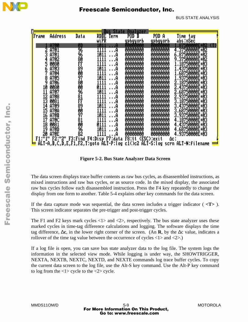
BUS STATE ANALYSIS
MMDS11OM/D 5-9 MOTOROLA
Figure 5-2. Bus State Analyzer Data Screen
The data screen displays trace buffer contents as raw bus cycles, as disassembled instructions, asmixed instructions and raw bus cycles, or as source code. In the mixed display, the associatedraw bus cycles follow each disassembled instruction. Press the F4 key repeatedly to change thedisplay from one form to another. Table 5-4 explains other key commands for the data screen.
If the data capture mode was sequential, the data screen includes a trigger indicator ( <T> ).This screen indicator separates the pre-trigger and post-trigger cycles.
The F1 and F2 keys mark cycles <1> and <2>, respectively. The bus state analyzer uses thesemarked cycles in time-tag difference calculations and logging. The software displays the timetag difference, ∆c, in the lower right corner of the screen. (An R, by the ∆c value, indicates arollover of the time tag value between the occurrence of cycles <1> and <2>.)
If a log file is open, you can save bus state analyzer data to the log file. The system logs theinformation in the selected view mode. While logging is under way, the SHOWTRIGGER,NEXTA, NEXTB, NEXTC, NEXTD, and NEXTE commands log trace buffer cycles. To copythe current data screen to the log file, use the Alt-S key command. Use the Alt-P key commandto log from the <1> cycle to the <2> cycle.
Fre
esc
ale
Se
mic
on
du
cto
r, I
Freescale Semiconductor, Inc.
For More Information On This Product, Go to: www.freescale.com
nc
...
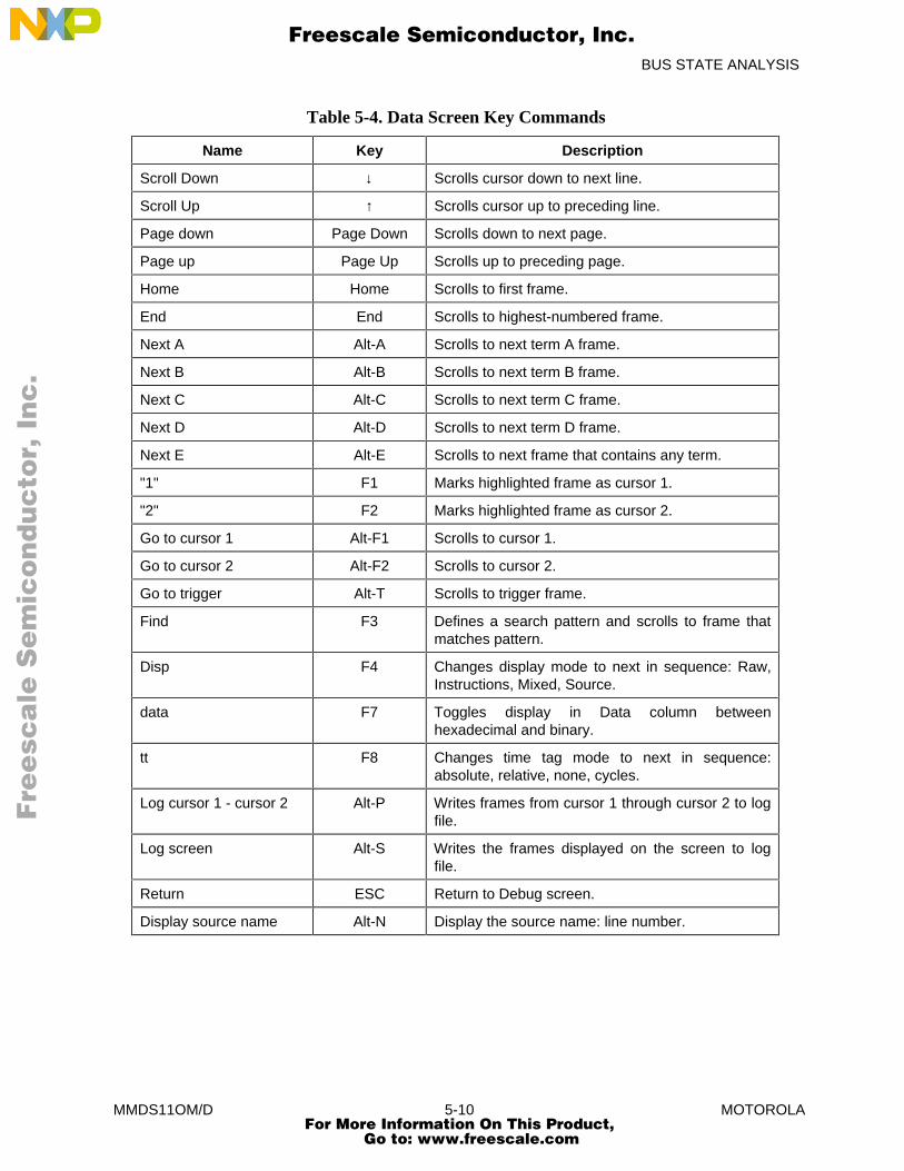
BUS STATE ANALYSIS
MMDS11OM/D 5-10 MOTOROLA
Table 5-4. Data Screen Key Commands
Name Key Description
Scroll Down ↓ Scrolls cursor down to next line.
Scroll Up ↑ Scrolls cursor up to preceding line.
Page down Page Down Scrolls down to next page.
Page up Page Up Scrolls up to preceding page.
Home Home Scrolls to first frame.
End End Scrolls to highest-numbered frame.
Next A Alt-A Scrolls to next term A frame.
Next B Alt-B Scrolls to next term B frame.
Next C Alt-C Scrolls to next term C frame.
Next D Alt-D Scrolls to next term D frame.
Next E Alt-E Scrolls to next frame that contains any term.
"1" F1 Marks highlighted frame as cursor 1.
"2" F2 Marks highlighted frame as cursor 2.
Go to cursor 1 Alt-F1 Scrolls to cursor 1.
Go to cursor 2 Alt-F2 Scrolls to cursor 2.
Go to trigger Alt-T Scrolls to trigger frame.
Find F3 Defines a search pattern and scrolls to frame thatmatches pattern.
Disp F4 Changes display mode to next in sequence: Raw,Instructions, Mixed, Source.
data F7 Toggles display in Data column betweenhexadecimal and binary.
tt F8 Changes time tag mode to next in sequence:absolute, relative, none, cycles.
Log cursor 1 - cursor 2 Alt-P Writes frames from cursor 1 through cursor 2 to logfile.
Log screen Alt-S Writes the frames displayed on the screen to logfile.
Return ESC Return to Debug screen.
Display source name Alt-N Display the source name: line number.
Fre
esc
ale
Se
mic
on
du
cto
r, I
Freescale Semiconductor, Inc.
For More Information On This Product, Go to: www.freescale.com
nc
...
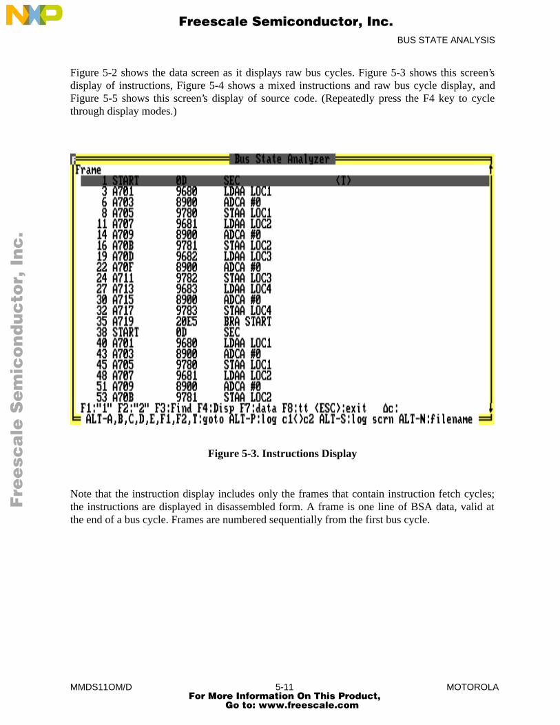
BUS STATE ANALYSIS
MMDS11OM/D 5-11 MOTOROLA
Figure 5-2 shows the data screen as it displays raw bus cycles. Figure 5-3 shows this screen’sdisplay of instructions, Figure 5-4 shows a mixed instructions and raw bus cycle display, andFigure 5-5 shows this screen’s display of source code. (Repeatedly press the F4 key to cyclethrough display modes.)
Figure 5-3. Instructions Display
Note that the instruction display includes only the frames that contain instruction fetch cycles;the instructions are displayed in disassembled form. A frame is one line of BSA data, valid atthe end of a bus cycle. Frames are numbered sequentially from the first bus cycle.
Fre
esc
ale
Se
mic
on
du
cto
r, I
Freescale Semiconductor, Inc.
For More Information On This Product, Go to: www.freescale.com
nc
...
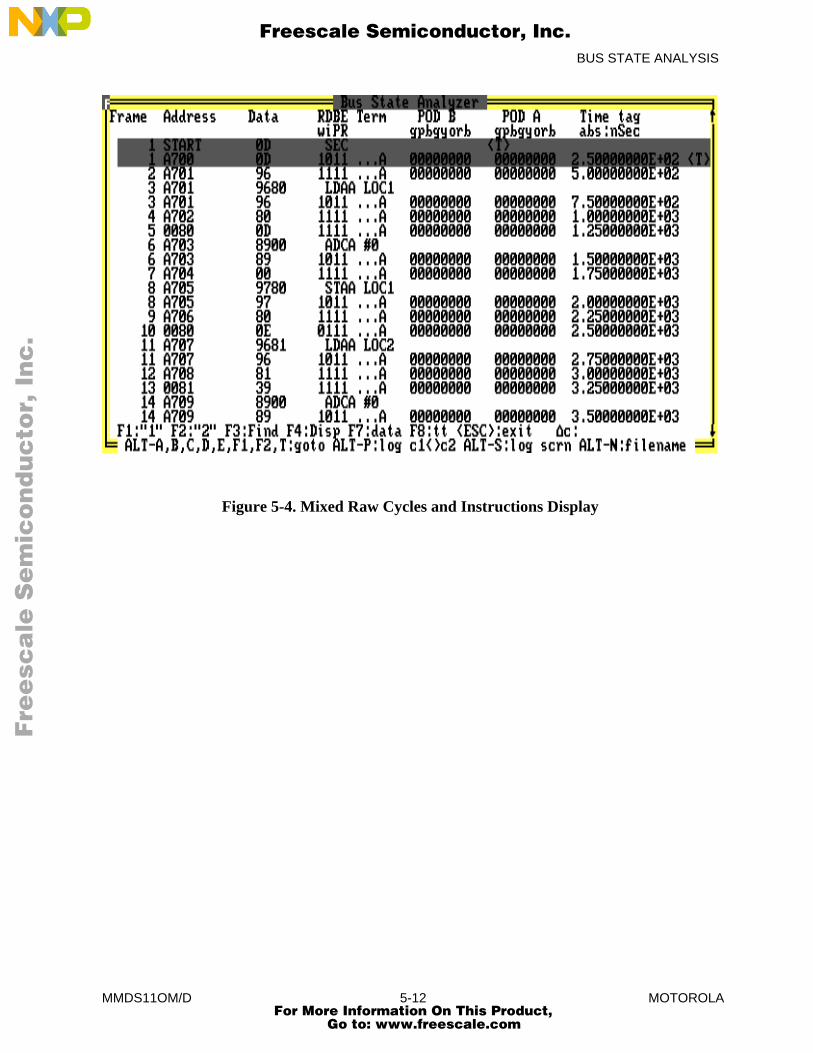
BUS STATE ANALYSIS
MMDS11OM/D 5-12 MOTOROLA
Figure 5-4. Mixed Raw Cycles and Instructions Display
Fre
esc
ale
Se
mic
on
du
cto
r, I
Freescale Semiconductor, Inc.
For More Information On This Product, Go to: www.freescale.com
nc
...
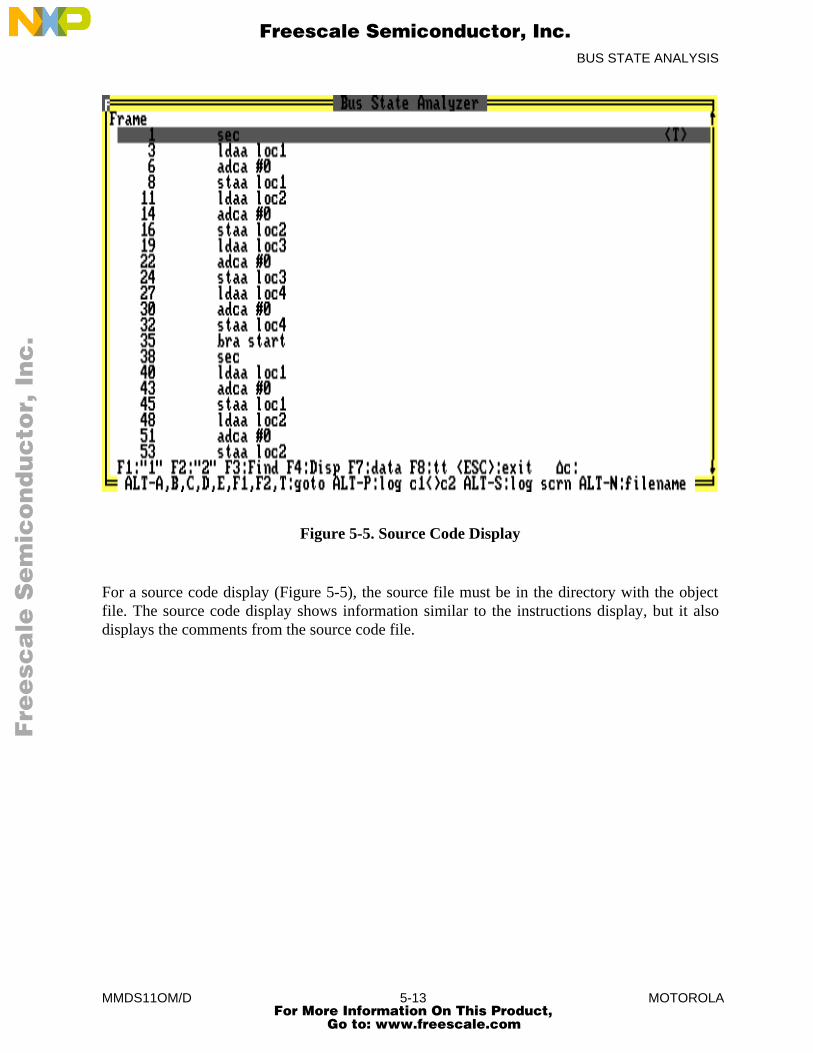
BUS STATE ANALYSIS
MMDS11OM/D 5-13 MOTOROLA
Figure 5-5. Source Code Display
For a source code display (Figure 5-5), the source file must be in the directory with the objectfile. The source code display shows information similar to the instructions display, but it alsodisplays the comments from the source code file.
Fre
esc
ale
Se
mic
on
du
cto
r, I
Freescale Semiconductor, Inc.
For More Information On This Product, Go to: www.freescale.com
nc
...
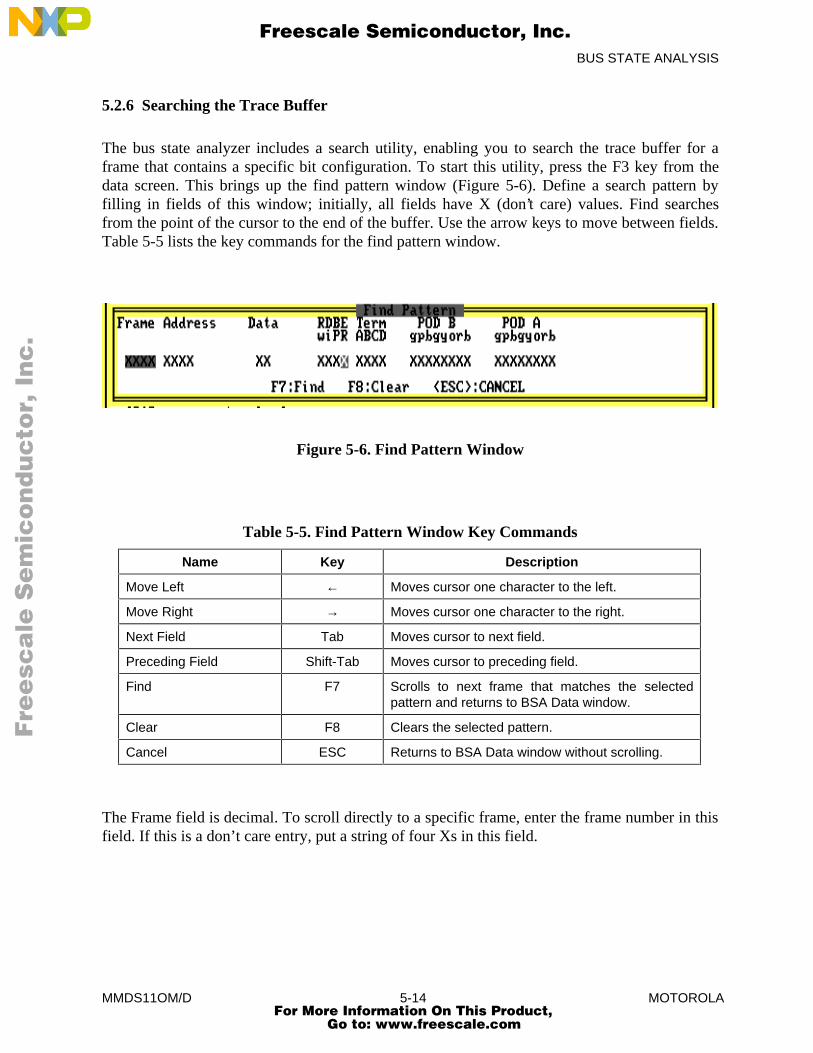
BUS STATE ANALYSIS
MMDS11OM/D 5-14 MOTOROLA
5.2.6 Searching the Trace Buffer
The bus state analyzer includes a search utility, enabling you to search the trace buffer for aframe that contains a specific bit configuration. To start this utility, press the F3 key from thedata screen. This brings up the find pattern window (Figure 5-6). Define a search pattern byfilling in fields of this window; initially, all fields have X (don’t care) values. Find searchesfrom the point of the cursor to the end of the buffer. Use the arrow keys to move between fields.Table 5-5 lists the key commands for the find pattern window.
Figure 5-6. Find Pattern Window
Table 5-5. Find Pattern Window Key Commands
Name Key Description
Move Left ← Moves cursor one character to the left.
Move Right → Moves cursor one character to the right.
Next Field Tab Moves cursor to next field.
Preceding Field Shift-Tab Moves cursor to preceding field.
Find F7 Scrolls to next frame that matches the selectedpattern and returns to BSA Data window.
Clear F8 Clears the selected pattern.
Cancel ESC Returns to BSA Data window without scrolling.
The Frame field is decimal. To scroll directly to a specific frame, enter the frame number in thisfield. If this is a don’t care entry, put a string of four Xs in this field.
Fre
esc
ale
Se
mic
on
du
cto
r, I
Freescale Semiconductor, Inc.
For More Information On This Product, Go to: www.freescale.com
nc
...

BUS STATE ANALYSIS
MMDS11OM/D 5-15 MOTOROLA
The Address and Data fields are hexadecimal. In these fields, you can specify a range by usingthe Xs for the less-significant digits. For example, 03XX in the Address field searches foraddresses in the range of 0300--03FF. You can specify an X in any digit position to cause thatdigit to be ignored in the search.
The R/w, D/i, BP, and ER fields and the two pod fields are binary. Enter 0 or 1 for each bit to beused in the search, and Xs for the bits to be ignored. Setting the R/w bit searches for read buscycles; clearing this bit searches for write bus cycles. Setting the D/i bit searches for data buscycles; clearing this bit searches for instruction fetch bus cycles. Setting the BP bit searches fora breakpoint bank match; clearing this bit searches for a pattern where there are no breakpointbank matches. Setting the ER bit searches for an emulation RAM bank match; clearing this bitsearches for a pattern where there are no emulation RAM bank matches.
You can search for bus cycles in which one or more terms are true by entering A, B, C, or D inthe Term field. When you have defined the search pattern completely, press F7 to start thesearch. The search begins at the current (highlighted) frame, and proceeds toward the highest-numbered frame in the trace buffer. (To clear the fields of the screen, press the F8 key.)
MMDS11 provides a 1 megabyte bank selected memory map. You may have breakpoints oremulation RAM installed in any one of the banks. Breakpoints and emulation RAM may beinstalled in different banks. Four extension address lines XA16..XA19 are available as inputs.The breakpoint comparator (BPX) checks the breakpoint bank match value against the data onthe XA16..XA19 address lines. When the extension address lines XA16..XA19 equal thebreakpoint match value, instruction breakpoints are enabled (BPX = 1). Use the EMUBPcommand to set the breakpoint bank match value.
The emulation RAM comparator (ERX) checks the emulation RAM bank match value againstthe data on the XA16..XA19 address lines. When the extension address lines XA16..XA19equal the emulation RAM match value, instruction breakpoints are enabled (ERX = 1). Use theEMURAM command to set the emulation RAM bank match value.
5.2.7 Using the Time-Tag Clock
There are four time-tag display modes: absolute, relative, cycles, and none. An absolute displaymode shows the time reference from the first bus cycle. A relative display mode shows the timebetween bus cycles. A cycle display mode shows the cycle reference from the first bus cycle.None blanks the time tag display. You can cycle through these display modes using the F8 keywhile the BSA data screen is open.
Fre
esc
ale
Se
mic
on
du
cto
r, I
Freescale Semiconductor, Inc.
For More Information On This Product, Go to: www.freescale.com
nc
...

BUS STATE ANALYSIS
MMDS11OM/D 5-16 MOTOROLA
The data screen displays the time tag as a number of seconds when you use the 1 MHz, 2 MHz,4 MHz, 8 MHz, or 16 MHz clock. To time the execution of a portion of the code, use either theraw bus cycle mode or the mixed mode of the display, with the absolute time-tag format. Selectthe beginning cycle, and press the F1 key to mark it <1>. Select the ending cycle, and press theF2 key to mark it <2>. The software calculates the time between the two frames, then displaysthe difference ( ∆c ) in the lower right corner of the data screen. (An R, by the ∆c value,indicates a rollover of the time tag value between the occurrence of cycles <1> and <2>.)
For example, if the beginning time tag is 3.26778887E03 and the ending time tag is3.2677928E03, the difference is 0.00000400 seconds, or 4 µs.
If the time tag is represented in clock periods, the procedure is the same, but the ∆c value is thenumber of time-tag clock cycles. Multiply the result by the time-tag clock period to obtain theelapsed time between the beginning and ending cycles.
For example, if the beginning time-tag value is 219, and the ending time-tag value is 234, thedifference is 15 time-tag cycles. At a time-tag clock frequency of 4 MHz, the time-tag clockperiod is 0.25 µs, and the elapsed time is 3.75 µs. Had the same time-tag values been obtainedwith a time-tag clock frequency of 500 kHz (a clock period of 2 µs), the elapsed time would be30 µs.
Fre
esc
ale
Se
mic
on
du
cto
r, I
Freescale Semiconductor, Inc.
For More Information On This Product, Go to: www.freescale.com
nc
...
COMMAND-LINE COMMANDS
MMDS11OM/D 6-1 MOTOROLA
CHAPTER 6
COMMAND-LINE COMMANDS
6.1 INTRODUCTION
Command-line commands are the most important for emulation, debugging, and analysis. Astheir name implies, you enter these commands on the command line, in the debug F10 window ofthe debug screen.
This chapter explains the rules for command syntax and arguments, then gives individualexplanations for each command.
6.2 COMMAND SYNTAX
A command-line command is a line of ASCII text that you enter on the computer keyboard. Press<CR> to terminate each line, activating the command. The typical command syntax is:
> <command> [<argument>]...
where:
> The command prompt. The system displays this prompt when ready foranother command.
<command> A command name, in upper- or lower-case letters.<argument> One or more arguments. Table 6-1 explains the many kinds of possible
argument values.
In command syntax descriptions, brackets ( [] ) enclose optional items, a vertical line(|) means or, and an ellipsis (...) means that you can repeat the preceding item.
Except where otherwise noted, numerical values in examples are hexadecimal.
Fre
esc
ale
Se
mic
on
du
cto
r, I
Freescale Semiconductor, Inc.
For More Information On This Product, Go to: www.freescale.com
nc
...
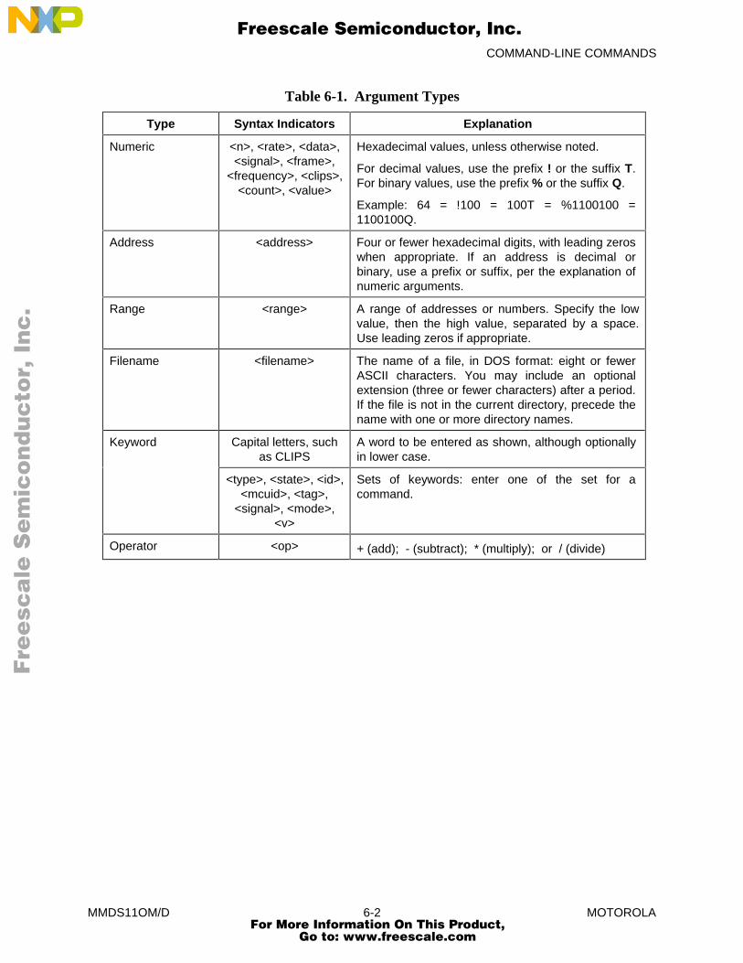
COMMAND-LINE COMMANDS
MMDS11OM/D 6-2 MOTOROLA
Table 6-1. Argument Types
Type Syntax Indicators Explanation
Numeric <n>, <rate>, <data>,<signal>, <frame>,
<frequency>, <clips>,<count>, <value>
Hexadecimal values, unless otherwise noted.
For decimal values, use the prefix ! or the suffix T.For binary values, use the prefix % or the suffix Q.
Example: 64 = !100 = 100T = %1100100 =1100100Q.
Address <address> Four or fewer hexadecimal digits, with leading zeroswhen appropriate. If an address is decimal orbinary, use a prefix or suffix, per the explanation ofnumeric arguments.
Range <range> A range of addresses or numbers. Specify the lowvalue, then the high value, separated by a space.Use leading zeros if appropriate.
Filename <filename> The name of a file, in DOS format: eight or fewerASCII characters. You may include an optionalextension (three or fewer characters) after a period.If the file is not in the current directory, precede thename with one or more directory names.
Keyword Capital letters, suchas CLIPS
A word to be entered as shown, although optionallyin lower case.
<type>, <state>, <id>,<mcuid>, <tag>,
<signal>, <mode>,<v>
Sets of keywords: enter one of the set for acommand.
Operator <op> + (add); - (subtract); * (multiply); or / (divide)
Fre
esc
ale
Se
mic
on
du
cto
r, I
Freescale Semiconductor, Inc.
For More Information On This Product, Go to: www.freescale.com
nc
...
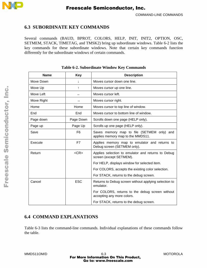
COMMAND-LINE COMMANDS
MMDS11OM/D 6-3 MOTOROLA
6.3 SUBORDINATE KEY COMMANDS
Several commands (BAUD, BPROT, COLORS, HELP, INIT, INIT2, OPTION, OSC,SETMEM, STACK, TIMETAG, and TMSK2) bring up subordinate windows. Table 6-2 lists thekey commands for these subordinate windows. Note that certain key commands functiondifferently for the subordinate windows of certain commands.
Table 6-2. Subordinate Window Key Commands
Name Key Description
Move Down ↓ Moves cursor down one line.
Move Up ↑ Moves cursor up one line.
Move Left ← Moves cursor left.
Move Right → Moves cursor right.
Home Home Moves cursor to top line of window.
End End Moves cursor to bottom line of window.
Page down Page Down Scrolls down one page (HELP only).
Page up Page Up Scrolls up one page (HELP only).
Save F6 Saves memory map to file (SETMEM only) andapplies memory map to the MMDS11.
Execute F7 Applies memory map to emulator and returns toDebug screen (SETMEM only).
Return <CR> Applies selection to emulator and returns to Debugscreen (except SETMEM).
For HELP, displays window for selected item.
For COLORS, accepts the existing color selection.
For STACK, returns to the debug screen.
Cancel ESC Returns to Debug screen without applying selection toemulator.
For COLORS, returns to the debug screen withoutaccepting any more colors.
For STACK, returns to the debug screen.
6.4 COMMAND EXPLANATIONS
Table 6-3 lists the command-line commands. Individual explanations of these commands followthe table.
Fre
esc
ale
Se
mic
on
du
cto
r, I
Freescale Semiconductor, Inc.
For More Information On This Product, Go to: www.freescale.com
nc
...
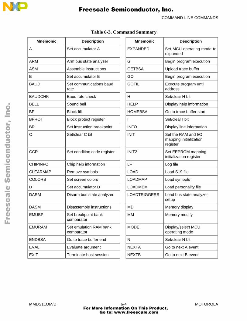
COMMAND-LINE COMMANDS
MMDS11OM/D 6-4 MOTOROLA
Table 6-3. Command Summary
Mnemonic Description Mnemonic Description
A Set accumulator A EXPANDED Set MCU operating mode toexpanded
ARM Arm bus state analyzer G Begin program execution
ASM Assemble instructions GETBSA Upload trace buffer
B Set accumulator B GO Begin program execution
BAUD Set communications baudrate
GOTIL Execute program untiladdress
BAUDCHK Baud rate check H Set/clear H bit
BELL Sound bell HELP Display help information
BF Block fill HOMEBSA Go to trace buffer start
BPROT Block protect register I Set/clear I bit
BR Set instruction breakpoint INFO Display line information
C Set/clear C bit INIT Set the RAM and I/Omapping initializationregister
CCR Set condition code register INIT2 Set EEPROM mappinginitialization register
CHIPINFO Chip help information LF Log file
CLEARMAP Remove symbols LOAD Load S19 file
COLORS Set screen colors LOADMAP Load symbols
D Set accumulator D LOADMEM Load personality file
DARM Disarm bus state analyzer LOADTRIGGERS Load bus state analyzersetup
DASM Disassemble instructions MD Memory display
EMUBP Set breakpoint bankcomparator
MM Memory modify
EMURAM Set emulation RAM bankcomparator
MODE Display/select MCUoperating mode
ENDBSA Go to trace buffer end N Set/clear N bit
EVAL Evaluate argument NEXTA Go to next A event
EXIT Terminate host session NEXTB Go to next B event
Fre
esc
ale
Se
mic
on
du
cto
r, I
Freescale Semiconductor, Inc.
For More Information On This Product, Go to: www.freescale.com
nc
...
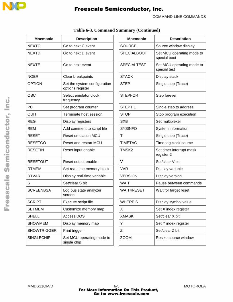
COMMAND-LINE COMMANDS
MMDS11OM/D 6-5 MOTOROLA
Table 6-3. Command Summary (Continued)
Mnemonic Description Mnemonic Description
NEXTC Go to next C event SOURCE Source window display
NEXTD Go to next D event SPECIALBOOT Set MCU operating mode tospecial boot
NEXTE Go to next event SPECIALTEST Set MCU operating mode tospecial test
NOBR Clear breakpoints STACK Display stack
OPTION Set the system configurationoptions register
STEP Single step (Trace)
OSC Select emulator clockfrequency
STEPFOR Step forever
PC Set program counter STEPTIL Single step to address
QUIT Terminate host session STOP Stop program execution
REG Display registers SXB Set multiplexer
REM Add comment to script file SYSINFO System information
RESET Reset emulation MCU T Single step (Trace)
RESETGO Reset and restart MCU TIMETAG Time tag clock source
RESETIN Reset input enable TMSK2 Set timer interrupt maskregister 2
RESETOUT Reset output enable V Set/clear V bit
RTMEM Set real-time memory block VAR Display variable
RTVAR Display real-time variable VERSION Display version
S Set/clear S bit WAIT Pause between commands
SCREENBSA Log bus state analyzerscreen
WAIT4RESET Wait for target reset
SCRIPT Execute script file WHEREIS Display symbol value
SETMEM Customize memory map X Set X index register
SHELL Access DOS XMASK Set/clear X bit
SHOWMEM Display memory map Y Set Y index register
SHOWTRIGGER Print trigger Z Set/clear Z bit
SINGLECHIP Set MCU operating mode tosingle chip
ZOOM Resize source window
Fre
esc
ale
Se
mic
on
du
cto
r, I
Freescale Semiconductor, Inc.
For More Information On This Product, Go to: www.freescale.com
nc
...
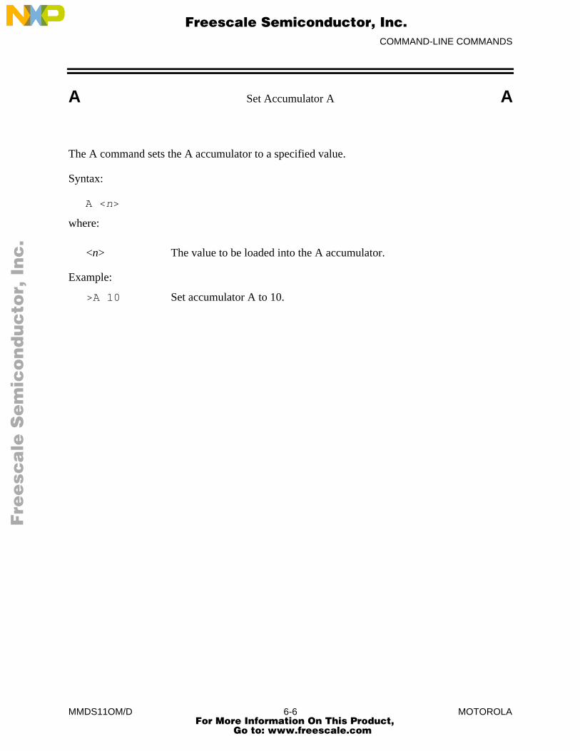
COMMAND-LINE COMMANDS
MMDS11OM/D 6-6 MOTOROLA
A Set Accumulator A A
The A command sets the A accumulator to a specified value.
Syntax:
A <n>
where:
<n> The value to be loaded into the A accumulator.
Example:
>A 10 Set accumulator A to 10.
Fre
esc
ale
Se
mic
on
du
cto
r, I
Freescale Semiconductor, Inc.
For More Information On This Product, Go to: www.freescale.com
nc
...

COMMAND-LINE COMMANDS
MMDS11OM/D 6-7 MOTOROLA
ARM Arm Bus State Analyzer ARM
The ARM command arms the bus state analyzer. When armed, the analyzer records bus cycleswhile the emulator is executing user code. Arming the analyzer clears the current contents of theanalyzer trace buffer. The word armed appears in the status area of the debug screen.
Syntax:
ARM
Example:
>ARM Arm the bus state analyzer for user code bus cycles.
Fre
esc
ale
Se
mic
on
du
cto
r, I
Freescale Semiconductor, Inc.
For More Information On This Product, Go to: www.freescale.com
nc
...
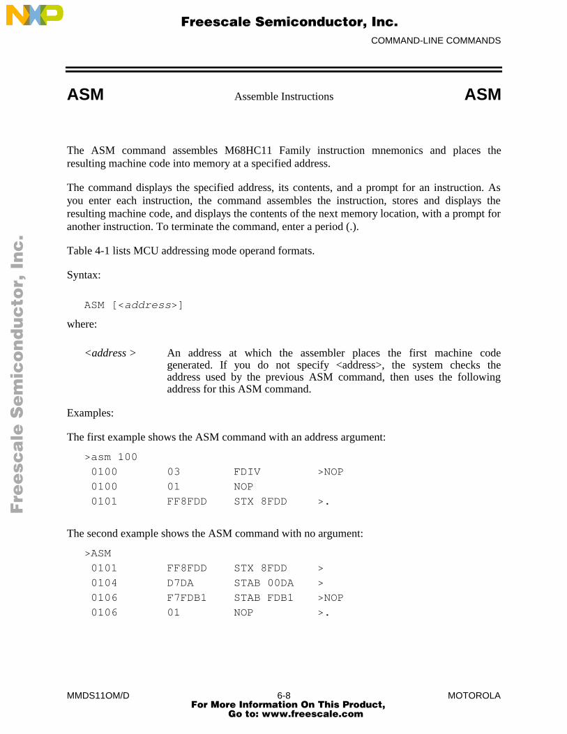
COMMAND-LINE COMMANDS
MMDS11OM/D 6-8 MOTOROLA
ASM Assemble Instructions ASM
The ASM command assembles M68HC11 Family instruction mnemonics and places theresulting machine code into memory at a specified address.
The command displays the specified address, its contents, and a prompt for an instruction. Asyou enter each instruction, the command assembles the instruction, stores and displays theresulting machine code, and displays the contents of the next memory location, with a prompt foranother instruction. To terminate the command, enter a period (.).
Table 4-1 lists MCU addressing mode operand formats.
Syntax:
ASM [<address>]
where:
<address > An address at which the assembler places the first machine codegenerated. If you do not specify <address>, the system checks theaddress used by the previous ASM command, then uses the following
address for this ASM command.
Examples:
The first example shows the ASM command with an address argument:
>asm 100
0100 03 FDIV >NOP
0100 01 NOP
0101 FF8FDD STX 8FDD >.
The second example shows the ASM command with no argument:
>ASM
0101 FF8FDD STX 8FDD >
0104 D7DA STAB 00DA >
0106 F7FDB1 STAB FDB1 >NOP
0106 01 NOP >.
Fre
esc
ale
Se
mic
on
du
cto
r, I
Freescale Semiconductor, Inc.
For More Information On This Product, Go to: www.freescale.com
nc
...
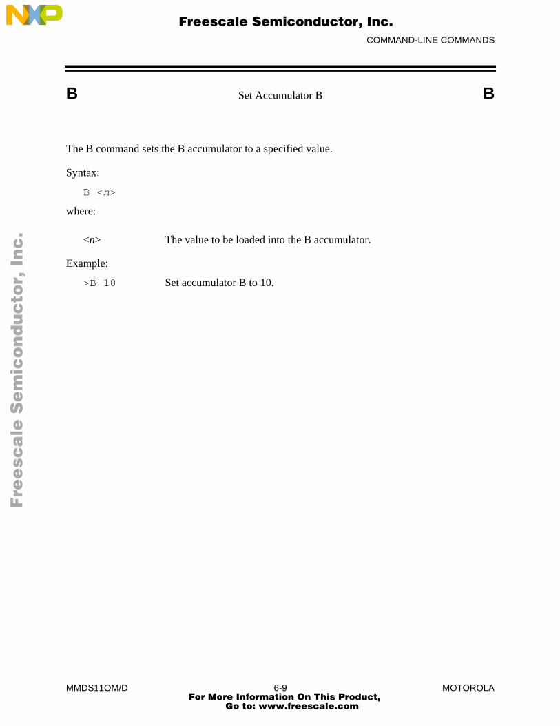
COMMAND-LINE COMMANDS
MMDS11OM/D 6-9 MOTOROLA
B Set Accumulator B B
The B command sets the B accumulator to a specified value.
Syntax:
B <n>
where:
<n> The value to be loaded into the B accumulator.
Example:
>B 10 Set accumulator B to 10.
Fre
esc
ale
Se
mic
on
du
cto
r, I
Freescale Semiconductor, Inc.
For More Information On This Product, Go to: www.freescale.com
nc
...
COMMAND-LINE COMMANDS
MMDS11OM/D 6-10 MOTOROLA
BAUD Set Communications Baud Rate BAUD
The BAUD command changes the baud rate for communications between the system controllerand the host computer. For best performance of your system, communications should be at themaximum available baud rate. Reduce this rate if the software displays communications errormessages. Entering this command without a rate argument calls up the baud rate window. Youcan select a baud rate via this window.
NOTE
At power-up, MMDS11 software automatically sets the maximum baud rate foryour system. If you reduce the baud rate but communication errors persist, youmay need to turn off disk cache.
Syntax:
BAUD [<rate>]
where:
<rate> One of these decimal baud-rate values:
240048009600192003840057600
Example:
>BAUD 9600 Change the communications baud rate to 9600.
Fre
esc
ale
Se
mic
on
du
cto
r, I
Freescale Semiconductor, Inc.
For More Information On This Product, Go to: www.freescale.com
nc
...
COMMAND-LINE COMMANDS
MMDS11OM/D 6-11 MOTOROLA
BAUDCHK Baud Rate Check BAUDCHK
The BAUDCHK command checks communication at 57600 baud and successively lower rates todetermine the maximum available baud rate for a host computer.
Syntax:
BAUDCHK
Example:
>BAUDCHK
57600 baud communicates well
The command displays a message indicating the maximum available baud rate.
Fre
esc
ale
Se
mic
on
du
cto
r, I
Freescale Semiconductor, Inc.
For More Information On This Product, Go to: www.freescale.com
nc
...
COMMAND-LINE COMMANDS
MMDS11OM/D 6-12 MOTOROLA
BELL Sound Bell BELL
The BELL command sounds the computer bell the specified hexadecimal number of times. Thebell sounds once if you do not enter an argument. To turn off the bell as it is sounding, press anykey.
Syntax:
BELL [<n>]
where:
<n> The hexadecimal number of times to sound the bell.
Examples:
>BELL Sound the bell once.>BELL C Sound the bell 12 (decimal) times.>BELL 12 Sound the bell 18 (decimal) times.
Fre
esc
ale
Se
mic
on
du
cto
r, I
Freescale Semiconductor, Inc.
For More Information On This Product, Go to: www.freescale.com
nc
...
COMMAND-LINE COMMANDS
MMDS11OM/D 6-13 MOTOROLA
BF Block Fill BF
The BF command fills a block of memory with a specified byte or word.
Syntax:
BF[.<length>] <range> <n>
where:
<length> Size of <n>:
B <n> is an 8-bit value (the default).
W <n> is a 16-bit value.
<range> A block (range) of memory defined by beginning and ending addresses,$0000 to $FFFF.
<n> A value to be stored in a byte or word of the specified block. If <n> is an 8-bit value, it is stored in each byte of the block; if <n> is a 16-bitvalue, it is stored in each word of the block.
Examples:
>BF 200 20F FF Store FF hexadecimal in bytes at addresses 200 20F.>BF.W 100 11F 4143 Store 4143 in words at addresses 100 11F.
Fre
esc
ale
Se
mic
on
du
cto
r, I
Freescale Semiconductor, Inc.
For More Information On This Product, Go to: www.freescale.com
nc
...
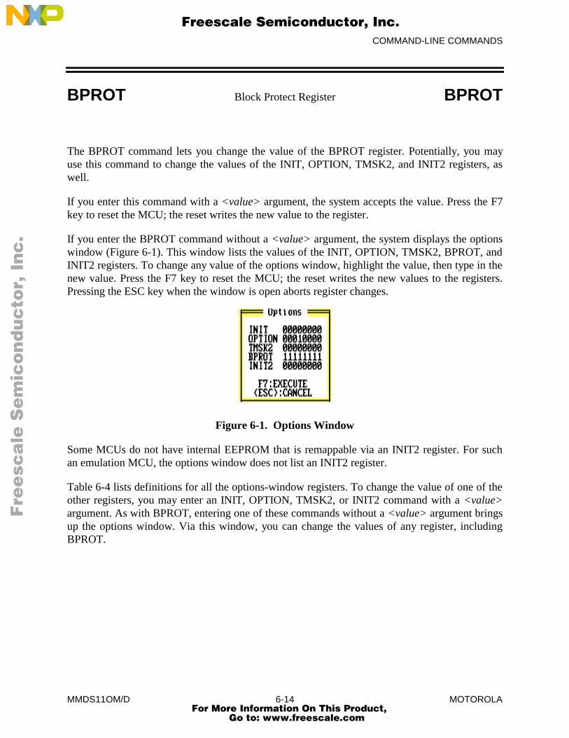
COMMAND-LINE COMMANDS
MMDS11OM/D 6-14 MOTOROLA
BPROT Block Protect Register BPROT
The BPROT command lets you change the value of the BPROT register. Potentially, you mayuse this command to change the values of the INIT, OPTION, TMSK2, and INIT2 registers, aswell.
If you enter this command with a <value> argument, the system accepts the value. Press the F7key to reset the MCU; the reset writes the new value to the register.
If you enter the BPROT command without a <value> argument, the system displays the optionswindow (Figure 6-1). This window lists the values of the INIT, OPTION, TMSK2, BPROT, andINIT2 registers. To change any value of the options window, highlight the value, then type in thenew value. Press the F7 key to reset the MCU; the reset writes the new values to the registers.Pressing the ESC key when the window is open aborts register changes.
Figure 6-1. Options Window
Some MCUs do not have internal EEPROM that is remappable via an INIT2 register. For suchan emulation MCU, the options window does not list an INIT2 register.
Table 6-4 lists definitions for all the options-window registers. To change the value of one of theother registers, you may enter an INIT, OPTION, TMSK2, or INIT2 command with a <value>argument. As with BPROT, entering one of these commands without a <value> argument bringsup the options window. Via this window, you can change the values of any register, includingBPROT.
Fre
esc
ale
Se
mic
on
du
cto
r, I
Freescale Semiconductor, Inc.
For More Information On This Product, Go to: www.freescale.com
nc
...
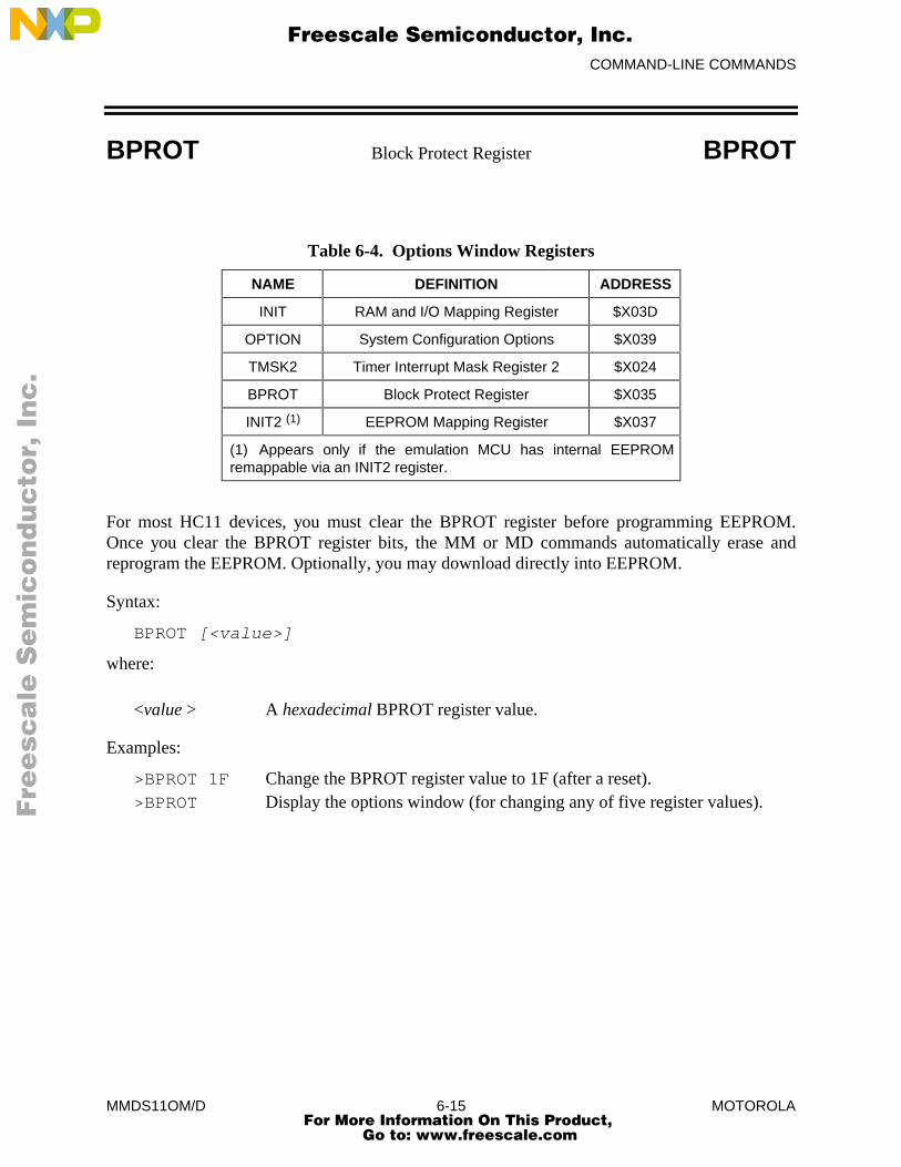
COMMAND-LINE COMMANDS
MMDS11OM/D 6-15 MOTOROLA
BPROT Block Protect Register BPROT
Table 6-4. Options Window Registers
NAME DEFINITION ADDRESS
INIT RAM and I/O Mapping Register $X03D
OPTION System Configuration Options $X039
TMSK2 Timer Interrupt Mask Register 2 $X024
BPROT Block Protect Register $X035
INIT2 (1) EEPROM Mapping Register $X037
(1) Appears only if the emulation MCU has internal EEPROMremappable via an INIT2 register.
For most HC11 devices, you must clear the BPROT register before programming EEPROM.Once you clear the BPROT register bits, the MM or MD commands automatically erase andreprogram the EEPROM. Optionally, you may download directly into EEPROM.
Syntax:
BPROT [<value>]
where:
<value > A hexadecimal BPROT register value.
Examples:
>BPROT 1F Change the BPROT register value to 1F (after a reset).>BPROT Display the options window (for changing any of five register values).
Fre
esc
ale
Se
mic
on
du
cto
r, I
Freescale Semiconductor, Inc.
For More Information On This Product, Go to: www.freescale.com
nc
...
COMMAND-LINE COMMANDS
MMDS11OM/D 6-16 MOTOROLA
BR Set Instruction Breakpoint BR
The BR command sets an instruction breakpoint at a specified address or range of addresses. Themaximum number of all instruction breakpoints is 64. For a list of all active breakpoints, enterthis command without any parameter value.
A breakpoint occurs only on an address that contains an instruction (that is, an instruction fetchaddress). Although this command sets breakpoints at each address of a range, breakpoints occuronly at the instruction fetch addresses within the range. The system displays an error message ifthe address is within the range defined by a previous BR command, or if the range of a new BRcommand overlaps the range of an existing BR command. An error message also appears if youattempt to set a 65th breakpoint.
Syntax:
BR [<address>|<range>]
where:
<address > The address for a breakpoint.
<range> The range of addresses for breakpoints: a beginning address and anending address, separated by a space.
Examples:
>BR 100 Set a breakpoint at address 100.>BR 1000 103F Set 64 breakpoints, at addresses 1000 through 103F. Note that
trying to set additional breakpoints, without clearing some ofthese breakpoints, would bring up the error message:
Too many breakpoints
Fre
esc
ale
Se
mic
on
du
cto
r, I
Freescale Semiconductor, Inc.
For More Information On This Product, Go to: www.freescale.com
nc
...
COMMAND-LINE COMMANDS
MMDS11OM/D 6-17 MOTOROLA
C Set/Clear C Bit C
The C command sets the C bit of the condition code register (CCR) to the specified value.
NOTE
The CCR bit designators are at the lower right of the CPU window. The CCRpattern is SXHINZVC (S is stop disable, X is XIRQ interrupt mask, H is half-carry, I is IRQ interrupt mask, N is negative, Z is zero, V is overflow, and C iscarry). A letter in these designators means that the corresponding bit of the CCR isset; a period means that the corresponding bit is clear.
Syntax:
C 0|1
where:
0 Clears the C bit
1 Sets the C bit
Example:
>C 0 Clear the C bit of the CCR.
Fre
esc
ale
Se
mic
on
du
cto
r, I
Freescale Semiconductor, Inc.
For More Information On This Product, Go to: www.freescale.com
nc
...
COMMAND-LINE COMMANDS
MMDS11OM/D 6-18 MOTOROLA
CCR Set Condition Code Register CCR
The CCR command sets the condition code register (CCR) to the specified hexadecimal value.
NOTE
The CCR bit designators are at the lower right of the CPU window. The CCRpattern is SXHINZVC (S is stop disable, X is XIRQ interrupt mask, H is half-carry, I is IRQ interrupt mask, N is negative, Z is zero, V is overflow, and C iscarry). A letter in these designators means that the corresponding bit of the CCR isset; a period means that the corresponding bit is clear.
Syntax:
CCR <n>
where:
<n> The new hexadecimal value for the CCR.
Example:
>CCR E4 Set the CCR to E4 (S, X, H, and Z bits set, others clear).
Fre
esc
ale
Se
mic
on
du
cto
r, I
Freescale Semiconductor, Inc.
For More Information On This Product, Go to: www.freescale.com
nc
...
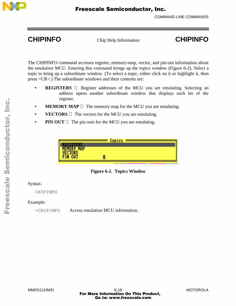
COMMAND-LINE COMMANDS
MMDS11OM/D 6-19 MOTOROLA
CHIPINFO Chip Help Information CHIPINFO
The CHIPINFO command accesses register, memory-map, vector, and pin-out information aboutthe emulation MCU. Entering this command brings up the topics window (Figure 6-2). Select atopic to bring up a subordinate window. (To select a topic, either click on it or highlight it, thenpress <CR>.) The subordinate windows and their contents are:
• REGISTERS Register addresses of the MCU you are emulating. Selecting anaddress opens another subordinate window that displays each bit of theregister.
• MEMORY MAP The memory map for the MCU you are emulating.
• VECTORS The vectors for the MCU you are emulating.
• PIN OUT The pin outs for the MCU you are emulating.
Figure 6-2. Topics Window
Syntax:
CHIPINFO
Example:
>CHIPINFO Access emulation MCU information.
Fre
esc
ale
Se
mic
on
du
cto
r, I
Freescale Semiconductor, Inc.
For More Information On This Product, Go to: www.freescale.com
nc
...
COMMAND-LINE COMMANDS
MMDS11OM/D 6-20 MOTOROLA
CLEARMAP Remove Symbols CLEARMAP
The CLEARMAP command removes the symbol definitions in the host computer.
Syntax:
CLEARMAP
Example:
>CLEARMAP Clear symbols and their definitions.
Fre
esc
ale
Se
mic
on
du
cto
r, I
Freescale Semiconductor, Inc.
For More Information On This Product, Go to: www.freescale.com
nc
...

COMMAND-LINE COMMANDS
MMDS11OM/D 6-21 MOTOROLA
COLORS Set Screen Colors COLORS
The COLORS command sets the screen colors. Entering this command brings up the colorswindow. This window includes a list of screen elements and a matrix of foreground/backgroundcolor combinations; each color combination has a two-digit hexadecimal number.
A prompt asks for the color of the first screen element. To accept the current color, press <CR>.To change the color, enter the number of your choice, then press <CR>. A new prompt asks forthe color of the next element. Select the color for each element in the same way. The commandends when you select a color for the last screen element, or when you press ESC.
In the color matrix, rows correspond to background colors, and columns correspond toforeground colors. This means that color choices from the same row result in differently coloredletters and numbers against the same background color. Making the background of highlights andhelp screens a different color sets these elements off from the main screen.
The software stores color selections in file COLORS.11; when you execute MMDS11 again thesoftware applies the newly selected colors
NOTE
Delete the COLORS.11 file from the \MMDS11 subdirectory to return to thedefault colors.
Syntax:
COLORS
Fre
esc
ale
Se
mic
on
du
cto
r, I
Freescale Semiconductor, Inc.
For More Information On This Product, Go to: www.freescale.com
nc
...
COMMAND-LINE COMMANDS
MMDS11OM/D 6-22 MOTOROLA
D Set Accumulator D D
The D command sets the D accumulator to a specified value. The D accumulator is aconcatenation of the A accumulator and the B accumulator.
Syntax:
D <n>
where:
<n> The value to be loaded into the D accumulator.
Example:
>D 1234 Set accumulator D to 1234.
Fre
esc
ale
Se
mic
on
du
cto
r, I
Freescale Semiconductor, Inc.
For More Information On This Product, Go to: www.freescale.com
nc
...
COMMAND-LINE COMMANDS
MMDS11OM/D 6-23 MOTOROLA
DARM Disarm Bus State Analyzer DARM
The DARM command disarms the bus state analyzer. When disarmed, the analyzer does notrecord bus cycles. The word Disarmed appears in the status area of the debug screen. (If thebus state analyzer is already disarmed, this command does nothing.)
Syntax:
DARM
Example:
>DARM Disarm the bus state analyzer.
Fre
esc
ale
Se
mic
on
du
cto
r, I
Freescale Semiconductor, Inc.
For More Information On This Product, Go to: www.freescale.com
nc
...
COMMAND-LINE COMMANDS
MMDS11OM/D 6-24 MOTOROLA
DASM Disassemble Instructions DASM
The DASM command disassembles three or more machine instructions, displaying the addressesand the contents as disassembled instructions. Disassembly begins at the specified address. Thevalid address range is $0000 to $FFFF.
Syntax:
DASM <address1> [<address2>]
where:
<address1> The starting address for disassembly. <Address1> must be aninstruction opcode. If you enter only an <address1> value, the systemdisassembles three instructions.
<address2> The ending address for disassembly. If you enter an <address2> value, disassembly begins at <address1> and continues through<address2>. The screen scrolls upward as addresses and their contentsare displayed, leaving the last instructions in the range displayed in thewindow.
Example: disassemble and display three instructions, beginning at address 100:
>DASM 100
0100 01 NOP
0101 FF8FDD STX 8FDD
0104 D7DA STAB 00DA
Fre
esc
ale
Se
mic
on
du
cto
r, I
Freescale Semiconductor, Inc.
For More Information On This Product, Go to: www.freescale.com
nc
...
COMMAND-LINE COMMANDS
MMDS11OM/D 6-25 MOTOROLA
EMUBP Set Breakpoint Bank Comparator EMUBP
The EMUBP command sets the breakpoint bank comparator match value. The breakpointcomparator (BPX) checks the breakpoint bank match value against the data on the extensionaddress lines XA16 XA19. When these lines equal the breakpoint match value, instructionbreakpoints are enabled (BPX = 1). BPX may be used in a term to trigger the bus state analyzer.Power-up or a system reset clears the comparator (that is, gives it the value zero) and pulls XA16 XA19 low. This enables the breakpoints in bank $0.
Syntax:
EMUBP <n>
where:
<n> A four-bit hexadecimal value.
Example:
>EMUBP 5 Write $5 to the breakpoint bank comparator.
Fre
esc
ale
Se
mic
on
du
cto
r, I
Freescale Semiconductor, Inc.
For More Information On This Product, Go to: www.freescale.com
nc
...
COMMAND-LINE COMMANDS
MMDS11OM/D 6-26 MOTOROLA
EMURAM Set Emulation RAM Bank Comparator EMURAM
The EMURAM command sets the emulation RAM bank comparator match value. The emulationRAM comparator (ERX) checks the emulation RAM bank match value against the data onextension address lines XA16 XA19. When these lines equal the emulation RAM matchvalue, instruction breakpoints are enabled (ERX = 1). ERX may be used in a term to trigger thebus state analyzer. Power-up or a system reset clears the comparator (that is, gives it the valuezero) and pulls XA16 XA19 low. This enables the emulation RAM in bank $0.
Syntax:
EMURAM <n>
where:
<n> A four-bit hexadecimal value.
Example:
>EMURAM C Write $C to the emulation RAM bank comparator.
Fre
esc
ale
Se
mic
on
du
cto
r, I
Freescale Semiconductor, Inc.
For More Information On This Product, Go to: www.freescale.com
nc
...
COMMAND-LINE COMMANDS
MMDS11OM/D 6-27 MOTOROLA
ENDBSA Go to Trace Buffer End ENDBSA
The ENDBSA command shows end-of-buffer data in the data screen when you return to the BSAdata screen (F5).
Syntax:
ENDBSA
Example:
>ENDBSA Show end-of-buffer data in the data screen.
Fre
esc
ale
Se
mic
on
du
cto
r, I
Freescale Semiconductor, Inc.
For More Information On This Product, Go to: www.freescale.com
nc
...
COMMAND-LINE COMMANDS
MMDS11OM/D 6-28 MOTOROLA
EVAL Evaluate Argument EVAL
The EVAL command displays the value of the operand in hexadecimal, decimal, octal, andbinary formats, denoted by the suffixes H, T, O, and Q. (Note that octal numbers are not valid asoperand values. Operand values are 16 bits or less.) If the value is printable, this command alsodisplays the value in ASCII characters. The operand can be a number or the sequence number,space, operator, space, and number. This command supports addition (+), subtraction (-),multiplication (*) and division (/).
Syntax:
EVAL <n1> [<op> <n2>]
where:
<n1> A number to be evaluated, or the first operand of a simple expression tobe evaluated.
<op> The arithmetic operator (+, -, *, or /) of a simple expression to beevaluated.
<n2> The second operand of a simple expression to be evaluated.
Example: evaluate the sum of hexadecimal numbers 45 and 32, then display the result in fourbases, and as an ASCII character:
>EVAL 45 + 32
0077H 119T 000167O 0000000001110111Q "w"
Fre
esc
ale
Se
mic
on
du
cto
r, I
Freescale Semiconductor, Inc.
For More Information On This Product, Go to: www.freescale.com
nc
...
COMMAND-LINE COMMANDS
MMDS11OM/D 6-29 MOTOROLA
EXIT Terminate Host Session EXIT
The EXIT command terminates the host session and returns to DOS. (The EXIT and QUITcommands are identical. Another way to end a host session is to enter the ALT-X keyboardcombination.)
Syntax:
EXIT
Example:
>EXIT Return to DOS.
Fre
esc
ale
Se
mic
on
du
cto
r, I
Freescale Semiconductor, Inc.
For More Information On This Product, Go to: www.freescale.com
nc
...
COMMAND-LINE COMMANDS
MMDS11OM/D 6-30 MOTOROLA
EXPANDED Set MCU Operating Mode to Expanded EXPANDED
The EXPANDED command sets the MCU operating mode to expanded. This command worksonly if the MCU mode is set to user selectable by the MODE command. Related commands areSINGLECHIP, SPECIALBOOT, and SPECIALTEST.
Some HC11 emulator modules (EMs) do not let you select (from the host) the polarity ofMODEB. This limits operation to single-chip or expanded mode. If you enter the target valuewith the MODE command, the target selects any MCU operating mode on powerup or reset. Thespecial bootstrap mode is emulated in special test mode with the PRU enabled. The bootstrapfirmware may be loaded into emulation RAM and the RESETGO command issued by a scriptfile.
NOTE
The current hardware does not let you switch from special boot or special test tosingle chip or expanded by writing to the MDA bit of the HPRIO register. Modeselection takes effect only upon powerup or reset.
Syntax:
EXPANDED
Example:
>EXPANDED Set the MCU to expanded mode.>MODE Display the current mode. MODE: USER SELECTED - Expanded
>
Fre
esc
ale
Se
mic
on
du
cto
r, I
Freescale Semiconductor, Inc.
For More Information On This Product, Go to: www.freescale.com
nc
...
COMMAND-LINE COMMANDS
MMDS11OM/D 6-31 MOTOROLA
G Begin Program Execution G
The G command starts execution of code in the emulator at the current address or at a specifiedaddress. If you enter one address, it is the starting address. If you enter two addresses, executionbegins at the first and stops at the second. (The G and GO commands are identical.)
If you specify only one address, execution continues until you enter a STOP command, abreakpoint occurs, a trigger condition set to stop execution in the analyzer occurs, or an erroroccurs.
Syntax:
G [<address1>] [<address2>]
where:
<address1> Execution starting address. If you enter an <address1> value, thesystem loads the value into the program counter (PC), then startsexecution at the address in the PC. If you do not enter an <address1>value, execution begins at the address already in the PC.
<address2> Execution stop address. The <address2> value must be an instructionfetch address; if it is not, code execution continues as if the commandhad no <address2> value.
NOTE
Be careful about using the G, GO, or GOTIL commands if the PC points tointernal RAM or EEPROM (or if the code branches into internal RAM orEEPROM). In these situations, the STOP command does not work unless theCCR I bit is clear. If you do want to execute out of internal RAM or EEPROM,clear the I bit before you enter the execution command.
Example:
>G Begin code execution at the current PC value.>G 146 Begin code execution at address 146.>G 200 271 Begin code execution at address 200. End code execution just before
the instruction at address 271.>G A000 LOOP Begin code execution at address A000. End code execution just
before the LOOP instruction.
Fre
esc
ale
Se
mic
on
du
cto
r, I
Freescale Semiconductor, Inc.
For More Information On This Product, Go to: www.freescale.com
nc
...
COMMAND-LINE COMMANDS
MMDS11OM/D 6-32 MOTOROLA
GETBSA Upload Trace Buffer GETBSA
The GETBSA command uploads the contents of the bus state analyzer trace buffer to the hostcomputer. This is convenient when using a script file in conjunction with the bus state analyzer.
Syntax:
GETBSA
Example:
>GETBSA Upload trace buffer contents to the host computer.
Fre
esc
ale
Se
mic
on
du
cto
r, I
Freescale Semiconductor, Inc.
For More Information On This Product, Go to: www.freescale.com
nc
...
COMMAND-LINE COMMANDS
MMDS11OM/D 6-33 MOTOROLA
GO Begin Program Execution GO
The GO command starts execution of code in the emulator at the current address or at a specifiedaddress. If you enter one address, it is the starting address. If you enter two addresses, executionbegins at the first and stops at the second. (The GO and G commands are identical.)
If you specify only one address, execution continues until you enter a STOP command, abreakpoint occurs, a trigger condition set to stop execution in the analyzer occurs, or an erroroccurs.
Syntax:
GO [<address1>] [<address2>]
where:
<address1> Execution starting address. If you enter an <address1> value, thesystem loads the value into the program counter (PC), then startsexecution at the address in the PC. If you do not enter an <address1>value, execution begins at the address already in the PC.
<address2> Execution stop address. The <address2> value must be an instructionfetch address; if it is not, code execution continues as if the commandhad no <address2> value.
NOTE
Be careful about using the GO, GOTIL, or G commands if the PC points tointernal RAM or EEPROM (or if the code branches into internal RAM orEEPROM). In these situations, the STOP command does not work unless theCCR I bit is clear. If you do want to execute out of internal RAM or EEPROM,clear the I bit before you enter the execution command.
Example:
>GO Begin code execution at the current PC value.>GO 232 Begin code execution at address 232.>GO 100 171 Begin code execution at address 100. End code execution just
before the instruction at address 171.
Fre
esc
ale
Se
mic
on
du
cto
r, I
Freescale Semiconductor, Inc.
For More Information On This Product, Go to: www.freescale.com
nc
...
COMMAND-LINE COMMANDS
MMDS11OM/D 6-34 MOTOROLA
GOTIL Execute Program until Address GOTIL
The GOTIL command executes the program in the emulator, beginning at the address in theprogram counter (PC). Execution continues until the program counter contains the specifiedaddress.
Syntax:
GOTIL <address>
where:
<address> Execution stop address. The <address> value must be an instructionfetch address; if it is not, code execution continues as if the commandhad no <address> value.
NOTE
Be careful about using the GOTIL, G, or GO commands if the PC points tointernal RAM or EEPROM (or if the code branches into internal RAM orEEPROM). In these situations, the STOP command does not work unless theCCR I bit is clear. If you do want to execute out of internal RAM or EEPROM,clear the I bit before you enter the execution command.
Example:
>GOTIL 0FF0 Execute the program in the emulator up to address 0FF0.
Fre
esc
ale
Se
mic
on
du
cto
r, I
Freescale Semiconductor, Inc.
For More Information On This Product, Go to: www.freescale.com
nc
...

COMMAND-LINE COMMANDS
MMDS11OM/D 6-35 MOTOROLA
H Set/Clear H Bit H
The H command sets the H bit of the condition code register (CCR) to the specified value.
NOTE
The CCR bit designators are at the lower right of the CPU window. The CCRpattern is SXHINZVC (S is stop disable, X is XIRQ interrupt mask, H is half-carry, I is IRQ interrupt mask, N is negative, Z is zero, V is overflow, and C iscarry). A letter in these designators means that the corresponding bit of the CCR isset; a period means that the corresponding bit is clear.
Syntax:
H 0|1
where:
0 Clears the H bit
1 Sets the H bit
Example:
>H 1 Set the H bit of the CCR.
Fre
esc
ale
Se
mic
on
du
cto
r, I
Freescale Semiconductor, Inc.
For More Information On This Product, Go to: www.freescale.com
nc
...

COMMAND-LINE COMMANDS
MMDS11OM/D 6-36 MOTOROLA
HELP Display Help Information HELP
The HELP command displays a list of help topics: commands, bus state analyzer, and functionkeys.
If you select commands, the software displays an alphabetic index of command names fromwhich you can select a command. The command description screen shows the command nameand its syntax and describes the command. When appropriate, the description includes examplesand clarifying notes.
Selecting bus state analyzer brings up a description of bus state analyzer operation.
Selecting function keys brings up a list of screens in which function-key assignments differ.Select a screen to see its function-key assignments.
Use the arrow keys to scroll within the page; use the page up and page down keys to see otherpages.
To exit the HELP database and return to the previous screen, press the ESC key.
Syntax:
HELP [<command>]
where:
<command> Name of a command for which a description is needed.
Example:
>HELP Display the HELP screens.>HELP ASM Display the description of the ASM command.
Related Key Command:
F1 while in DEBUG window or bus state analyzer setup window.
Fre
esc
ale
Se
mic
on
du
cto
r, I
Freescale Semiconductor, Inc.
For More Information On This Product, Go to: www.freescale.com
nc
...

COMMAND-LINE COMMANDS
MMDS11OM/D 6-37 MOTOROLA
HOMEBSA Go to Trace Buffer Start HOMEBSA
The HOMEBSA command shows start-of-buffer data in the data screen when you return to theBSA data screen (F5).
Syntax:
HOMEBSA
Example:
>HOMEBSA Show start-of-buffer data in the data screen upon return to the BSA datascreen.
Fre
esc
ale
Se
mic
on
du
cto
r, I
Freescale Semiconductor, Inc.
For More Information On This Product, Go to: www.freescale.com
nc
...

COMMAND-LINE COMMANDS
MMDS11OM/D 6-38 MOTOROLA
I Set/Clear I Bit I
The I command sets the I bit of the condition code register (CCR) to the specified value.
NOTE
The CCR bit designators are at the lower right of the CPU window. The CCRpattern is SXHINZVC (S is stop disable, X is XIRQ interrupt mask, H is half-carry, I is IRQ interrupt mask, N is negative, Z is zero, V is overflow, and C iscarry). A letter in these designators means that the corresponding bit of the CCR isset; a period means that the corresponding bit is clear.
Syntax:
I 0|1
where:
0 Clears the I bit
1 Sets the I bit
Example:
>I 1 Set the I bit of the CCR.
Fre
esc
ale
Se
mic
on
du
cto
r, I
Freescale Semiconductor, Inc.
For More Information On This Product, Go to: www.freescale.com
nc
...
COMMAND-LINE COMMANDS
MMDS11OM/D 6-39 MOTOROLA
INFO Display Line Information INFO
The INFO command displays information about the highlighted line in the source F2 window.This information includes the name of the file being displayed in the window, the line number,address, corresponding object code, and the disassembled instruction.
Syntax:
INFO
Example:
>INFO Display information about the highlighted line.Filename : 11TESTCO.ASM Line number : 117
Address : $A700
Disassembly : A700 0D SEC
Fre
esc
ale
Se
mic
on
du
cto
r, I
Freescale Semiconductor, Inc.
For More Information On This Product, Go to: www.freescale.com
nc
...
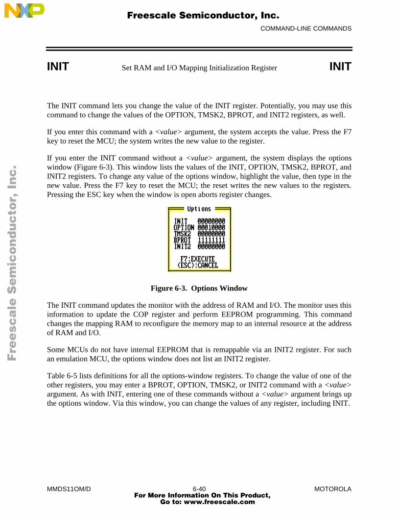
COMMAND-LINE COMMANDS
MMDS11OM/D 6-40 MOTOROLA
INIT Set RAM and I/O Mapping Initialization Register INIT
The INIT command lets you change the value of the INIT register. Potentially, you may use thiscommand to change the values of the OPTION, TMSK2, BPROT, and INIT2 registers, as well.
If you enter this command with a <value> argument, the system accepts the value. Press the F7key to reset the MCU; the system writes the new value to the register.
If you enter the INIT command without a <value> argument, the system displays the optionswindow (Figure 6-3). This window lists the values of the INIT, OPTION, TMSK2, BPROT, andINIT2 registers. To change any value of the options window, highlight the value, then type in thenew value. Press the F7 key to reset the MCU; the reset writes the new values to the registers.Pressing the ESC key when the window is open aborts register changes.
Figure 6-3. Options Window
The INIT command updates the monitor with the address of RAM and I/O. The monitor uses thisinformation to update the COP register and perform EEPROM programming. This commandchanges the mapping RAM to reconfigure the memory map to an internal resource at the addressof RAM and I/O.
Some MCUs do not have internal EEPROM that is remappable via an INIT2 register. For suchan emulation MCU, the options window does not list an INIT2 register.
Table 6-5 lists definitions for all the options-window registers. To change the value of one of theother registers, you may enter a BPROT, OPTION, TMSK2, or INIT2 command with a <value>argument. As with INIT, entering one of these commands without a <value> argument brings upthe options window. Via this window, you can change the values of any register, including INIT.
Fre
esc
ale
Se
mic
on
du
cto
r, I
Freescale Semiconductor, Inc.
For More Information On This Product, Go to: www.freescale.com
nc
...
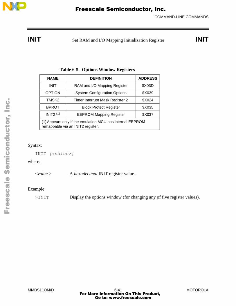
COMMAND-LINE COMMANDS
MMDS11OM/D 6-41 MOTOROLA
INIT Set RAM and I/O Mapping Initialization Register INIT
Table 6-5. Options Window Registers
NAME DEFINITION ADDRESS
INIT RAM and I/O Mapping Register $X03D
OPTION System Configuration Options $X039
TMSK2 Timer Interrupt Mask Register 2 $X024
BPROT Block Protect Register $X035
INIT2 (1) EEPROM Mapping Register $X037
(1) Appears only if the emulation MCU has internal EEPROMremappable via an INIT2 register.
Syntax:
INIT [<value>]
where:
<value > A hexadecimal INIT register value.
Example:
>INIT Display the options window (for changing any of five register values).
Fre
esc
ale
Se
mic
on
du
cto
r, I
Freescale Semiconductor, Inc.
For More Information On This Product, Go to: www.freescale.com
nc
...
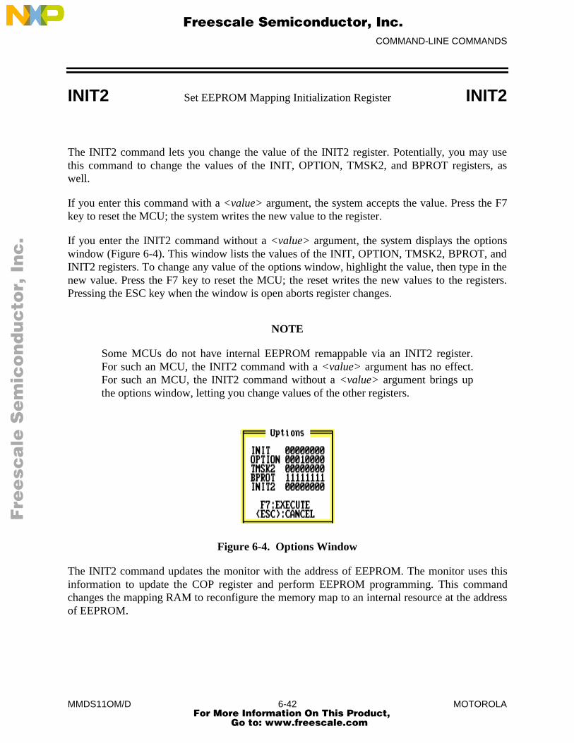
COMMAND-LINE COMMANDS
MMDS11OM/D 6-42 MOTOROLA
INIT2 Set EEPROM Mapping Initialization Register INIT2
The INIT2 command lets you change the value of the INIT2 register. Potentially, you may usethis command to change the values of the INIT, OPTION, TMSK2, and BPROT registers, aswell.
If you enter this command with a <value> argument, the system accepts the value. Press the F7key to reset the MCU; the system writes the new value to the register.
If you enter the INIT2 command without a <value> argument, the system displays the optionswindow (Figure 6-4). This window lists the values of the INIT, OPTION, TMSK2, BPROT, andINIT2 registers. To change any value of the options window, highlight the value, then type in thenew value. Press the F7 key to reset the MCU; the reset writes the new values to the registers.Pressing the ESC key when the window is open aborts register changes.
NOTE
Some MCUs do not have internal EEPROM remappable via an INIT2 register.For such an MCU, the INIT2 command with a <value> argument has no effect.For such an MCU, the INIT2 command without a <value> argument brings upthe options window, letting you change values of the other registers.
Figure 6-4. Options Window
The INIT2 command updates the monitor with the address of EEPROM. The monitor uses thisinformation to update the COP register and perform EEPROM programming. This commandchanges the mapping RAM to reconfigure the memory map to an internal resource at the addressof EEPROM.
Fre
esc
ale
Se
mic
on
du
cto
r, I
Freescale Semiconductor, Inc.
For More Information On This Product, Go to: www.freescale.com
nc
...
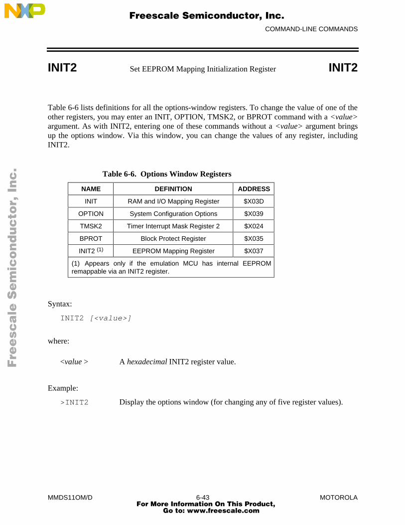
COMMAND-LINE COMMANDS
MMDS11OM/D 6-43 MOTOROLA
INIT2 Set EEPROM Mapping Initialization Register INIT2
Table 6-6 lists definitions for all the options-window registers. To change the value of one of theother registers, you may enter an INIT, OPTION, TMSK2, or BPROT command with a <value>argument. As with INIT2, entering one of these commands without a <value> argument bringsup the options window. Via this window, you can change the values of any register, includingINIT2.
Table 6-6. Options Window Registers
NAME DEFINITION ADDRESS
INIT RAM and I/O Mapping Register $X03D
OPTION System Configuration Options $X039
TMSK2 Timer Interrupt Mask Register 2 $X024
BPROT Block Protect Register $X035
INIT2 (1) EEPROM Mapping Register $X037
(1) Appears only if the emulation MCU has internal EEPROMremappable via an INIT2 register.
Syntax:
INIT2 [<value>]
where:
<value > A hexadecimal INIT2 register value.
Example:
>INIT2 Display the options window (for changing any of five register values).
Fre
esc
ale
Se
mic
on
du
cto
r, I
Freescale Semiconductor, Inc.
For More Information On This Product, Go to: www.freescale.com
nc
...
COMMAND-LINE COMMANDS
MMDS11OM/D 6-44 MOTOROLA
LF Log File LF
The LF command starts or stops logging of commands and responses to an external file. Iflogging is not enabled, enter this command to start logging. While logging remains in effect, anyline that is appended to the command log window is also written to the log file. Loggingcontinues until you enter another LF command; this second command disables logging andcloses the log file.
If the specified file does not already exist, this command creates the file. If the specified file doesexist already, the command prompts for overwrite or append:
File exists, Rewrite or Append? [R]:
If you press <CR> (accept the default), or R and <CR>, the log entries overwrite the data in theexisting file. If you press A and <CR>, the system appends log entries to the file.
Syntax:
LF <filename>
where:
<filename> The DOS filename of the log file. The command interpreter does notassume a filename extension.
Examples:
>LF logfile Start logging. Write to file logfile (in the current directory) alllines added to the command log window.
>LF (If logging is enabled): Disable logging and close the log file.
Fre
esc
ale
Se
mic
on
du
cto
r, I
Freescale Semiconductor, Inc.
For More Information On This Product, Go to: www.freescale.com
nc
...
COMMAND-LINE COMMANDS
MMDS11OM/D 6-45 MOTOROLA
LOAD Load S19 File LOAD
The LOAD command loads a file in .S19 format (and any map file with the same name) into theemulator.
Syntax:
LOAD <filename>
where:
<filename> The name of the .S19 file to be loaded; the .S19 extension is optional. You can enter a pathname followed by the asterisk (*) wildcard
character. In that case, the command displays a window that lists thefiles in the specified directory that have the .S19 extension.
Examples:
>LOAD PROG1.S19 Load file PROG1.S19 and its map file into the emulator at the load addresses in the file.
>LOAD PROG2 Load file PROG2.S19 and its map file into the emulator at the load addresses in the file.
>LOAD A:* Display the names of the .S19 files on the diskette indrive A:, for user selection of a file.
Fre
esc
ale
Se
mic
on
du
cto
r, I
Freescale Semiconductor, Inc.
For More Information On This Product, Go to: www.freescale.com
nc
...
COMMAND-LINE COMMANDS
MMDS11OM/D 6-46 MOTOROLA
LOADMAP Load Symbols LOADMAP
The LOADMAP command loads a map file that contains source level debug information into thehost computer. The command requests an appropriate filename.
Syntax:
LOADMAP <filename>
where:
<filename> The name of the map file to be loaded; the .MAP extension is optional.You can enter a pathname followed by the asterisk (*) wildcardcharacter. In that case, the command displays a window that lists thefiles in the specified directory that have the .MAP extension.
Examples:
>LOADMAP PROG1.MAP Load map file PROG1.MAP into the host computer.>LOADMAP PROG2 Load map file PROG2.MAP into the host computer.>LOADMAP A:* Display the names of the .MAP files on the diskette in
drive A:, for user selection of a file.
Fre
esc
ale
Se
mic
on
du
cto
r, I
Freescale Semiconductor, Inc.
For More Information On This Product, Go to: www.freescale.com
nc
...
COMMAND-LINE COMMANDS
MMDS11OM/D 6-47 MOTOROLA
LOADMEM Load Personality File LOADMEM
The LOADMEM command loads the memory map for the emulator with the map informationfrom the specified file.
Syntax:
LOADMEM <filename>
where:
<filename> The name of the memory-mapping file to be loaded: a personality or.MEM file written by pressing the F6 key in the SETMEM window. The .MEM extension is optional. You can enter a pathname followed by the
asterisk (*) wildcard character. In that case, the command displays awindow that lists the files in the specified directory that have the .MEMextension.
Examples:
>LOADMEM 10001V01.MEM Make file 10001V01.MEM the current memory-mapping file.
>LOADMEM 01FF Make file 01FF.MEM the current memory-mapping file.
>LOADMEM A:* Display the names of the .MEM files on thediskette in drive A:, for user selection of a file.
Fre
esc
ale
Se
mic
on
du
cto
r, I
Freescale Semiconductor, Inc.
For More Information On This Product, Go to: www.freescale.com
nc
...
COMMAND-LINE COMMANDS
MMDS11OM/D 6-48 MOTOROLA
LOADTRIGGERS Load Bus State Analyzer Setup LOADTRIGGERS
The LOADTRIGGERS command loads the bus state analyzer setup information from thespecified file. To write such a file, use the bus state analyzer setup screen to define the triggers,then press the F6 key.
Syntax:
LOADTRIGGERS <filename>
where:
<filename> The name of the setup file to be loaded; the .SET extension is optional.You can enter a pathname followed by the asterisk (*) wildcardcharacter. In that case, the command displays a window that lists thefiles in the specified directory that have the .SET extension.
Example:
>LOADTRIGGERS BSA.SET Make file BSA.SET the current BSA setup file.>LOADTRIGGERS BSA8 Make file BSA8.SET the current BSA setup file.>LOADTRIGGERS A:* Display the names of the .SET files on the diskette
in drive A:, for user selection of a file.
Fre
esc
ale
Se
mic
on
du
cto
r, I
Freescale Semiconductor, Inc.
For More Information On This Product, Go to: www.freescale.com
nc
...
COMMAND-LINE COMMANDS
MMDS11OM/D 6-49 MOTOROLA
MD Memory Display MD
The MD command displays (in the memory F3 window) the contents of 32 emulation memorylocations. The specified address is the first of the 32 locations. If a log file is open, this commandalso writes the first 16 values to the log file.
Syntax:
MD <address>
where:
<address> The starting memory address for display in the memory window.
Example:
>MD 1000 Display the contents of 32 bytes of memory beginning at address 1000.
Fre
esc
ale
Se
mic
on
du
cto
r, I
Freescale Semiconductor, Inc.
For More Information On This Product, Go to: www.freescale.com
nc
...
COMMAND-LINE COMMANDS
MMDS11OM/D 6-50 MOTOROLA
MM Memory Modify MM
The MM command lets you interactively examine and modify contents of memory locations.
If you enter any values with this command, the system stores the values, beginning at thespecified address. If you do not enter a data value, the command displays the address andprompts for a value to be stored at that address. You can modify and verify data according to thecommand terminator:
[<data>]<CR>Update location and sequence forward.
[<data>]^<CR> Update location and sequence backward.
[<data>]=<CR> Update location and reopen the same location.
[<data>].<CR> Update location and terminate.
The MM command displays consecutive addresses and prompts until you enter a period (.). Thiscommand does not alter the contents of the program counter (PC).
Syntax:
MM <address>[<n> ...]
where:
<address> The address of a memory location to be modified.
<n> The value to be stored in the address.
Examples:
The first example does not have an <n> value in the command line, permitting entry of newvalues for consecutive addresses. Entering a period instead of a new value stops the command:
>MM 1000
1000 = 0F >05
1001 = 10 >.
The second example includes an <n> value, so the command modifies only one memorylocation:
>MM 100 00
Fre
esc
ale
Se
mic
on
du
cto
r, I
Freescale Semiconductor, Inc.
For More Information On This Product, Go to: www.freescale.com
nc
...
COMMAND-LINE COMMANDS
MMDS11OM/D 6-51 MOTOROLA
MODE Display/Select MCU Operating Mode MODE
The MODE command displays or lets you select the input (target or user) that controls the MCUoperation mode. Entering this command without a parameter value displays the current controlmode.
Some HC11 emulator modules (EMs) do not let you select (from the host) the polarity ofMODEB. This limits operation to single-chip or expanded mode. If you enter the target valuewith the MODE command, the target selects any MCU operating mode on powerup or reset. Thespecial bootstrap mode is emulated in special test mode with the PRU enabled. The bootstrapfirmware may be loaded into emulation RAM and the RESETGO command issued by a scriptfile.
NOTE
Current hardware does not let you switch from special boot or special test tosingle chip or expanded by writing to the MDA bit of the HPRIO register. Modeselection takes effect only upon powerup or reset.
Syntax:
MODE [user|target]where:
user Lets you set the MCU operating mode; the default value for the MODEcommand. In this user mode, you may enter single-chip, expanded,special-boot, or special-test commands.
target Lets the target set the MCU operating mode. Before you enter single-chip, expanded, special-boot, or special-test commands, you mustchange from this target mode to user mode.
Examples:>MODE Display the current mode.MODE: USER SELECTED - Expanded
>
>MODE TARGET Let the target set the operating mode.MODE: TARGET SELECTED
>
>MODE USER Let the user set the operating mode via the keyboard.MODE: USER SELECTED - Single Chip (Shows current mode.)
Fre
esc
ale
Se
mic
on
du
cto
r, I
Freescale Semiconductor, Inc.
For More Information On This Product, Go to: www.freescale.com
nc
...

COMMAND-LINE COMMANDS
MMDS11OM/D 6-52 MOTOROLA
N Set/Clear N Bit N
The N command sets the N bit of the condition code register (CCR) to the specified value.
NOTE
The CCR bit designators are at the lower right of the CPU window. The CCRpattern is SXHINZVC (S is stop disable, X is XIRQ interrupt mask, H is half-carry, I is IRQ interrupt mask, N is negative, Z is zero, V is overflow, and C iscarry). A letter in these designators means that the corresponding bit of the CCR isset; a period means that the corresponding bit is clear.
Syntax:
N 0|1
where:
0 Clears the N bit
1 Sets the N bit
Example:
>N 1 Set the N bit of the CCR.
Fre
esc
ale
Se
mic
on
du
cto
r, I
Freescale Semiconductor, Inc.
For More Information On This Product, Go to: www.freescale.com
nc
...

COMMAND-LINE COMMANDS
MMDS11OM/D 6-53 MOTOROLA
NEXTA Go to Next A Event NEXTA
The NEXTA command positions the bus state analyzer display at the next occurrence of an Aevent. If a log file is open, this command also writes that frame to the log file.
Syntax:
NEXTA
Example:
>NEXTA Scroll the bus state analyzer display to the next A event.
Related Key Command:
Alt-A while in bus state analyzer data window.
Fre
esc
ale
Se
mic
on
du
cto
r, I
Freescale Semiconductor, Inc.
For More Information On This Product, Go to: www.freescale.com
nc
...

COMMAND-LINE COMMANDS
MMDS11OM/D 6-54 MOTOROLA
NEXTB Go to Next B Event NEXTB
The NEXTB command positions the bus state analyzer display at the next occurrence of a Bevent. If a log file is open, this command also writes that frame to the log file.
Syntax:
NEXTB
Example:
>NEXTB Scroll the bus state analyzer display to the next B event.
Related Key Command:
Alt-B while in the bus state analyzer data window.
Fre
esc
ale
Se
mic
on
du
cto
r, I
Freescale Semiconductor, Inc.
For More Information On This Product, Go to: www.freescale.com
nc
...

COMMAND-LINE COMMANDS
MMDS11OM/D 6-55 MOTOROLA
NEXTC Go to Next C Event NEXTC
The NEXTC command positions the bus state analyzer display at the next occurrence of a Cevent. If a log file is open, this command also writes that frame to the log file.
Syntax:
NEXTC
Example:
>NEXTC Scroll the bus state analyzer display to the next C event.
Related Key Command:
Alt-C while in the bus state analyzer data window.
Fre
esc
ale
Se
mic
on
du
cto
r, I
Freescale Semiconductor, Inc.
For More Information On This Product, Go to: www.freescale.com
nc
...

COMMAND-LINE COMMANDS
MMDS11OM/D 6-56 MOTOROLA
NEXTD Go to Next D Event NEXTD
The NEXTD command positions the bus state analyzer display at the next occurrence of a Devent. If a log file is open, this command also writes that frame to the log file.
Syntax:
NEXTD
Example:
>NEXTD Scroll the bus state analyzer display to the next D event.
Related Key Command:
Alt-D while in the bus state analyzer data window.
Fre
esc
ale
Se
mic
on
du
cto
r, I
Freescale Semiconductor, Inc.
For More Information On This Product, Go to: www.freescale.com
nc
...

COMMAND-LINE COMMANDS
MMDS11OM/D 6-57 MOTOROLA
NEXTE Go to Next Event NEXTE
The NEXTE command positions the bus state analyzer display at the next occurrence of anyevent. If a log file is open, this command also writes that frame to the log file.
Syntax:
NEXTE
Example:
>NEXTE Scroll the bus state analyzer display to the next event.
Related Key Command:
Alt-E while in the bus state analyzer data window.
Fre
esc
ale
Se
mic
on
du
cto
r, I
Freescale Semiconductor, Inc.
For More Information On This Product, Go to: www.freescale.com
nc
...
COMMAND-LINE COMMANDS
MMDS11OM/D 6-58 MOTOROLA
NOBR Clear Breakpoints NOBR
The NOBR command clears one instruction breakpoint, all instruction breakpoints, or allinstruction breakpoints within an address range. If this command has one address value, it clearsthe breakpoint at that address. If this command has no address value, it clears all currentbreakpoints. If this command has two address values, it clears all instruction breakpoints in therange the addresses define.
Syntax:
NOBR [<address1> <address2>]
where:
<address1> If the only address value, the address of the single breakpoint to beremoved. If the first of two address values, the beginning of the addressrange from which all breakpoints are to be removed.
<address2> The last address of the range from which all breakpoints are to beremoved.
Examples:
>NOBR Clear all current instruction breakpoints.>NOBR A051 Clear the instruction breakpoint at address $A051.>NOBR A000 A010 Clear all instruction breakpoints in the address range $A000 to $A010.
Fre
esc
ale
Se
mic
on
du
cto
r, I
Freescale Semiconductor, Inc.
For More Information On This Product, Go to: www.freescale.com
nc
...
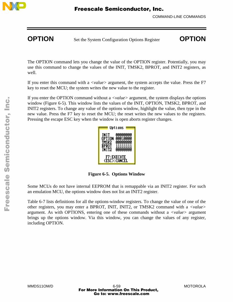
COMMAND-LINE COMMANDS
MMDS11OM/D 6-59 MOTOROLA
OPTION Set the System Configuration Options Register OPTION
The OPTION command lets you change the value of the OPTION register. Potentially, you mayuse this command to change the values of the INIT, TMSK2, BPROT, and INIT2 registers, aswell.
If you enter this command with a <value> argument, the system accepts the value. Press the F7key to reset the MCU; the system writes the new value to the register.
If you enter the OPTION command without a <value> argument, the system displays the optionswindow (Figure 6-5). This window lists the values of the INIT, OPTION, TMSK2, BPROT, andINIT2 registers. To change any value of the options window, highlight the value, then type in thenew value. Press the F7 key to reset the MCU; the reset writes the new values to the registers.Pressing the escape ESC key when the window is open aborts register changes.
Figure 6-5. Options Window
Some MCUs do not have internal EEPROM that is remappable via an INIT2 register. For suchan emulation MCU, the options window does not list an INIT2 register.
Table 6-7 lists definitions for all the options-window registers. To change the value of one of theother registers, you may enter a BPROT, INIT, INIT2, or TMSK2 command with a <value>argument. As with OPTIONS, entering one of these commands without a <value> argumentbrings up the options window. Via this window, you can change the values of any register,including OPTION.
Fre
esc
ale
Se
mic
on
du
cto
r, I
Freescale Semiconductor, Inc.
For More Information On This Product, Go to: www.freescale.com
nc
...
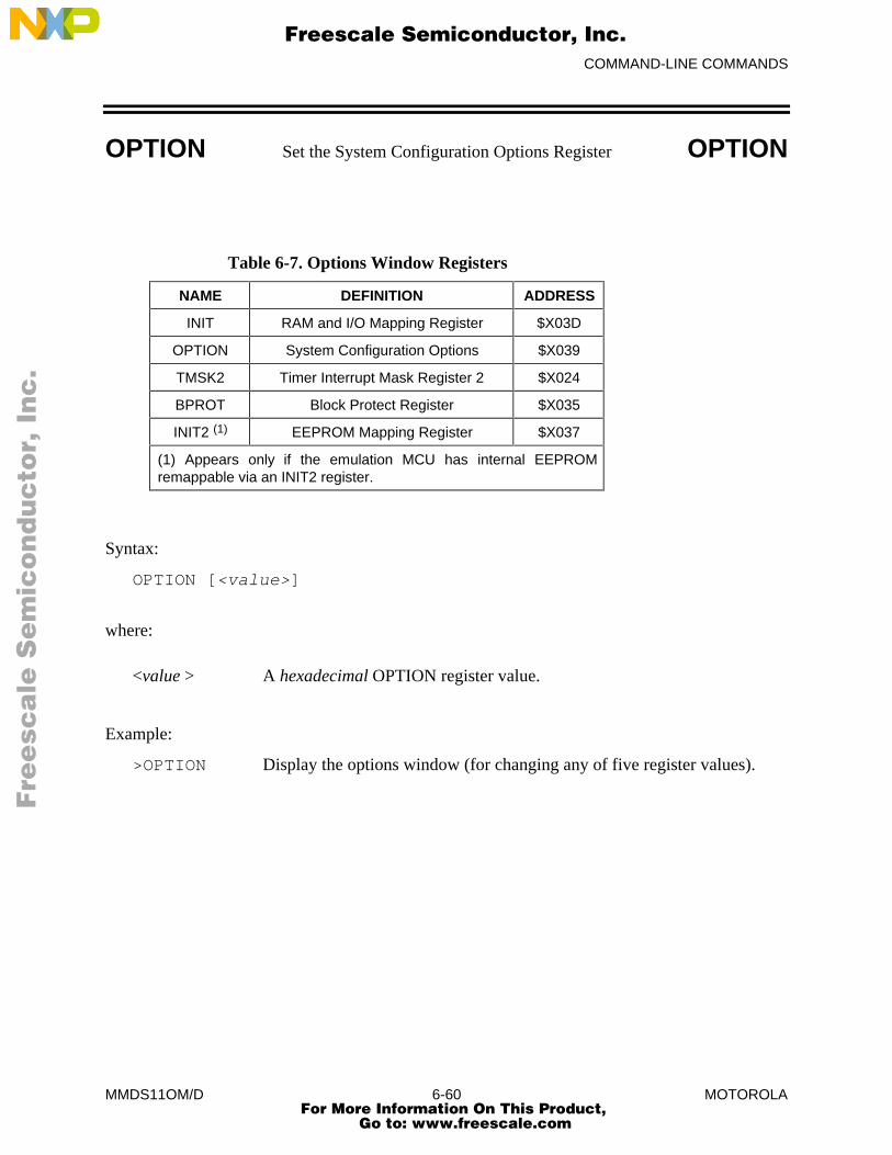
COMMAND-LINE COMMANDS
MMDS11OM/D 6-60 MOTOROLA
OPTION Set the System Configuration Options Register OPTION
Table 6-7. Options Window Registers
NAME DEFINITION ADDRESS
INIT RAM and I/O Mapping Register $X03D
OPTION System Configuration Options $X039
TMSK2 Timer Interrupt Mask Register 2 $X024
BPROT Block Protect Register $X035
INIT2 (1) EEPROM Mapping Register $X037
(1) Appears only if the emulation MCU has internal EEPROMremappable via an INIT2 register.
Syntax:
OPTION [<value>]
where:
<value > A hexadecimal OPTION register value.
Example:
>OPTION Display the options window (for changing any of five register values).
Fre
esc
ale
Se
mic
on
du
cto
r, I
Freescale Semiconductor, Inc.
For More Information On This Product, Go to: www.freescale.com
nc
...
COMMAND-LINE COMMANDS
MMDS11OM/D 6-61 MOTOROLA
OSC Select Emulator Clock Frequency OSC
The OSC command selects the clock frequency and source. Five internally-generated clockfrequencies are available: 16 Mhz, 8 Mhz, 4 Mhz, 2 Mhz, and 1 Mhz. Alternatively, you can usean external clock signal supplied to the MMDS11 through pod A logic clip 9 (white). (Whenusing the logic clip cables, attach the black clip to ground.) Refer to the EM user’s manual forEM clock information.
The default emulator clock rate is 8 MHz. Before changing the clock rate, make sure that youremulation MCU is specified to run at the new rate.
Entering this command without the <rate> argument brings up the EM oscillator window. Youcan select a frequency or source via this window.
Syntax:
OSC [<rate>]
where:
<rate> 16, 8, 4, 2, 1, or External.
Examples:
>OSC 4 Use the 4 Mhz internal emulator clock.>OSC External Use an external emulator clock.>OSC Bring up the emulator clock window.
Fre
esc
ale
Se
mic
on
du
cto
r, I
Freescale Semiconductor, Inc.
For More Information On This Product, Go to: www.freescale.com
nc
...
COMMAND-LINE COMMANDS
MMDS11OM/D 6-62 MOTOROLA
PC Set Program Counter PC
The PC command sets the program counter (PC) to the specified address.
Syntax:
PC <address>
where:
<address> The new address value for the PC.
Example:
>PC 0500 Set the PC to 0500.
Fre
esc
ale
Se
mic
on
du
cto
r, I
Freescale Semiconductor, Inc.
For More Information On This Product, Go to: www.freescale.com
nc
...

COMMAND-LINE COMMANDS
MMDS11OM/D 6-63 MOTOROLA
QUIT Terminate Host Session QUIT
The QUIT command terminates the host session and returns to DOS. (The QUIT and EXITcommands are identical. Another way to end a host session is to enter the ALT-X keyboardcombination.)
Syntax:
QUIT
Example:
>QUIT Return to DOS.
Fre
esc
ale
Se
mic
on
du
cto
r, I
Freescale Semiconductor, Inc.
For More Information On This Product, Go to: www.freescale.com
nc
...
COMMAND-LINE COMMANDS
MMDS11OM/D 6-64 MOTOROLA
REG Display Registers REG
The REG command displays the contents of the CPU registers in the debug F10 window.
Syntax:
REG
Example:
>REG Display the contents of the CPU registers.
Fre
esc
ale
Se
mic
on
du
cto
r, I
Freescale Semiconductor, Inc.
For More Information On This Product, Go to: www.freescale.com
nc
...
COMMAND-LINE COMMANDS
MMDS11OM/D 6-65 MOTOROLA
REM Add Comment to Script File REM
The REM command adds a display comment to a script file. When you execute the script file, thesystem displays this comment.
Syntax:
REM <text>
where:
<text> The display comment. You need not enclose <text> in quotes; pressing <CR> terminates <text>.
Example:
>REM Program executing. Display Program executing only duringscript file execution.
Fre
esc
ale
Se
mic
on
du
cto
r, I
Freescale Semiconductor, Inc.
For More Information On This Product, Go to: www.freescale.com
nc
...
COMMAND-LINE COMMANDS
MMDS11OM/D 6-66 MOTOROLA
RESET Reset Emulation MCU RESET
The RESET command resets the emulation MCU and sets the program counter to the contents ofthe reset vector. This command does not start execution of user code. To reset and execute usercode, use the RESETGO or WAIT4RESET command.
Syntax:
RESET
Example:
>RESET Reset the MCU.
Fre
esc
ale
Se
mic
on
du
cto
r, I
Freescale Semiconductor, Inc.
For More Information On This Product, Go to: www.freescale.com
nc
...
COMMAND-LINE COMMANDS
MMDS11OM/D 6-67 MOTOROLA
RESETGO Reset and Restart MCU RESETGO
The RESETGO command resets the emulation MCU, sets the program counter (PC) to thecontents of the reset vector, then starts execution from that address.
Syntax:
RESETGO
Example:
>RESETGO Reset the MCU and go.
Fre
esc
ale
Se
mic
on
du
cto
r, I
Freescale Semiconductor, Inc.
For More Information On This Product, Go to: www.freescale.com
nc
...
COMMAND-LINE COMMANDS
MMDS11OM/D 6-68 MOTOROLA
RESETIN Reset Input Enable RESETIN
The RESETIN command makes it possible for the target system to reset the emulating MCU.
Entering this command toggles the MMDS11 state with regard to a reset signal from the targetsystem. If this state is enabled, a reset signal from the target system resets the emulating MCU. Ifthis state is disabled, a reset signal from the target system cannot reset the emulating MCU. (Theword Resetin appears in the debug screen status area to show the enabled state.)
The state must be enabled for proper operation of the WAIT4RESET command.
Syntax:
RESETIN
Example:
>RESETIN Toggle the MMDS11 RESETIN state.
Fre
esc
ale
Se
mic
on
du
cto
r, I
Freescale Semiconductor, Inc.
For More Information On This Product, Go to: www.freescale.com
nc
...
COMMAND-LINE COMMANDS
MMDS11OM/D 6-69 MOTOROLA
RESETOUT Reset Output Enable RESETOUT
The RESETOUT command makes it possible for the MMDS11 RESET command to reset thetarget system.
Entering this command toggles the MMDS11 state with regard to resetting the target system. Ifthis state is enabled, entering the RESET command resets both the emulating MCU and the targetsystem. If this state is disabled, entering the RESET command resets only the emulating MCU.(The word Resetout appears in the debug screen status area to show the enabled state.)
The RESETOUT command also pertains to resets done via the RESETGO command.
Syntax:
RESETOUT
Example:
>RESETOUT Toggle the MMDS11 RESETOUT state.
Fre
esc
ale
Se
mic
on
du
cto
r, I
Freescale Semiconductor, Inc.
For More Information On This Product, Go to: www.freescale.com
nc
...
COMMAND-LINE COMMANDS
MMDS11OM/D 6-70 MOTOROLA
RTMEM Set Real-Time Memory Block RTMEM
The RTMEM command enables real-time-memory, starting at a specified address. The real-timememory consists of 32 bytes of dual-ported memory that is assigned to any valid memory addressby this command. While the emulator is running, the system displays enabled real-time memoryin the real-time memory window (this window replaces the memory F3 window). The displayupdates as the memory contents change. Entering the RTMEM command without an argumentdisables real-time memory, restoring previous memory map attributes.
Real-time memory consists of memory enabled by the RTMEM command, plus real-timevariables created via the RTVAR command. All this real-time memory must fit within a 1Kblock. If an RTMEM command would result in real-time memory that would not fit within the1K block (due to established real-time variables), the system will not accept the RTMEMcommand.
If any of the real-time memory overlays internal MCU I/O, RAM, or EEPROM addresses, it isavailable only for monitoring emulation MCU writes. (You should not try to modify suchlocations.) You can monitor and modify real-time memory locations that do not overlay internalMCU I/O, RAM, or EEPROM addresses.
Syntax:
RTMEM [<address>]
where:
<address> The beginning address of the real-time-memory.
Example:
>RTMEM 0200 Set the address of the real-time-memory to 0200 through 021F.
Fre
esc
ale
Se
mic
on
du
cto
r, I
Freescale Semiconductor, Inc.
For More Information On This Product, Go to: www.freescale.com
nc
...

COMMAND-LINE COMMANDS
MMDS11OM/D 6-71 MOTOROLA
RTVAR Display Real-Time Variable RTVAR
The RTVAR command displays the specified address and its contents in the variables F8window as a real-time variable.
As many as 32 variables can be available for display in the variables F8 window (although thewindow shows 11 at a time). Using the RTVAR command establishes such variables as real-time: their values change in the variables F8 window during emulation. You can also enter a newvalue for a real-time variable during emulation. Variants of this command display byte, word, orstring values. A byte display is hexadecimal and binary, a word display is hexadecimal anddecimal, and a string display is ASCII.
For an ASCII string, the optional <n> argument specifies the number of characters; 12 charactersis the default. Control and other non-printing characters appear as periods (.).
(The VAR command also establishes variables for display in the variables F8 window, but suchvariables are not real-time. The 32-variable maximum applies to variables established by both theRTVAR and VAR commands.)
Real-time memory consists of memory enabled by the RTMEM command, plus real-timevariables created via the RTVAR command. All this real-time memory must fit within a 1Kblock. If an RTVAR command would create a real-time variable that would not fit within the 1Kblock (due to established real-time variables or memory enabled by the RTMEM command), thesystem will not accept the RTVAR command.
If any of the real-time memory overlays internal MCU I/O, RAM, or EEPROM addresses, it isavailable only for monitoring emulation MCU writes. (You should not try to modify suchlocations.) You can monitor and modify real-time memory locations that do not overlay internalMCU I/O, RAM, or EEPROM addresses.
Fre
esc
ale
Se
mic
on
du
cto
r, I
Freescale Semiconductor, Inc.
For More Information On This Product, Go to: www.freescale.com
nc
...
COMMAND-LINE COMMANDS
MMDS11OM/D 6-72 MOTOROLA
RTVAR Display Real-Time Variable RTVAR
Syntax:
RTVAR[.<v>] <address> [<n>]
where:
<v> The display variant: B (byte, the default), W (word), or S (string).
<address> The address of the real-time-memory variable.
<n> The number of characters for a string variable; does not apply to byte or word variables.
Examples:
>RTVAR 100 Display (in hexadecimal and binary) the real-time-memory byteat address 100.
>RTVAR.B 110 Display (in hexadecimal and binary) the real-time-memory byteat address 110.
>RTVAR.W 102 Display (in hexadecimal and decimal) the real-time-memory word at address 102.
>RTVAR.S 200 5 Display the five-character ASCII string at address 200 of the real-time-memory-window.
Fre
esc
ale
Se
mic
on
du
cto
r, I
Freescale Semiconductor, Inc.
For More Information On This Product, Go to: www.freescale.com
nc
...
COMMAND-LINE COMMANDS
MMDS11OM/D 6-73 MOTOROLA
S Set/Clear S Bit S
The S command sets the S bit of the condition code register (CCR) to the specified value.
NOTE
The CCR bit designators are at the lower right of the CPU window. The CCRpattern is SXHINZVC (S is stop disable, X is XIRQ interrupt mask, H is half-carry, I is IRQ interrupt mask, N is negative, Z is zero, V is overflow, and C iscarry). A letter in these designators means that the corresponding bit of the CCR isset; a period means that the corresponding bit is clear.
Syntax:
S 0|1
where:
0 Clears the S bit
1 Sets the S bit
Example:
>S 1 Set the S bit of the CCR.
Fre
esc
ale
Se
mic
on
du
cto
r, I
Freescale Semiconductor, Inc.
For More Information On This Product, Go to: www.freescale.com
nc
...
COMMAND-LINE COMMANDS
MMDS11OM/D 6-74 MOTOROLA
SCREENBSA Log Bus State Analyzer Screen SCREENBSA
The SCREENBSA command copies the current bus state analyzer display to a log file.
Syntax:
SCREENBSA
Example:
>SCREENBSA Copy the bus state analyzer display to the log file.
Fre
esc
ale
Se
mic
on
du
cto
r, I
Freescale Semiconductor, Inc.
For More Information On This Product, Go to: www.freescale.com
nc
...
COMMAND-LINE COMMANDS
MMDS11OM/D 6-75 MOTOROLA
SCRIPT Execute Script File SCRIPT
The SCRIPT command executes a script file. A script file contains a sequence of emulatorcommands. Executing the script file has the same effect as executing the individual commands,one after another. This makes a script file convenient for any sequence of commands that youneed often: it saves time and promotes accuracy.
The REM and WAIT commands are useful primarily within script files. The REM command letsyou add to a script file a comment displayed while the script file executes. The WAIT commandestablishes a delay between the execution of commands of the script file.
Note that a script file can contain the SCRIPT command. In this way, you can nest script files asmany as 16 levels deep.
If you give a script file the filename STARTUP.11, startup routines run the script file each timeyou start MMDS11.
Syntax:
SCRIPT <filename>
where:
<filename> The name of a script file; the .SCR extension is optional. You can entera pathname followed by the asterisk (*) wildcard character. In that case,the command lists the files in the specified directory that have the .SCRextension; you can select a file from the list.
Examples:
>SCRIPT INIT.SCR Execute commands in file INIT.SCR.>SCRIPT * Display all .SCR files (then execute the selected file).>SCRIPT A:* Display all .SCR files in drive A (then execute the
selected file).>SCRIPT B:*.xyz Display all drive B files that have the extension .xyz (then
execute the selected file).
Fre
esc
ale
Se
mic
on
du
cto
r, I
Freescale Semiconductor, Inc.
For More Information On This Product, Go to: www.freescale.com
nc
...
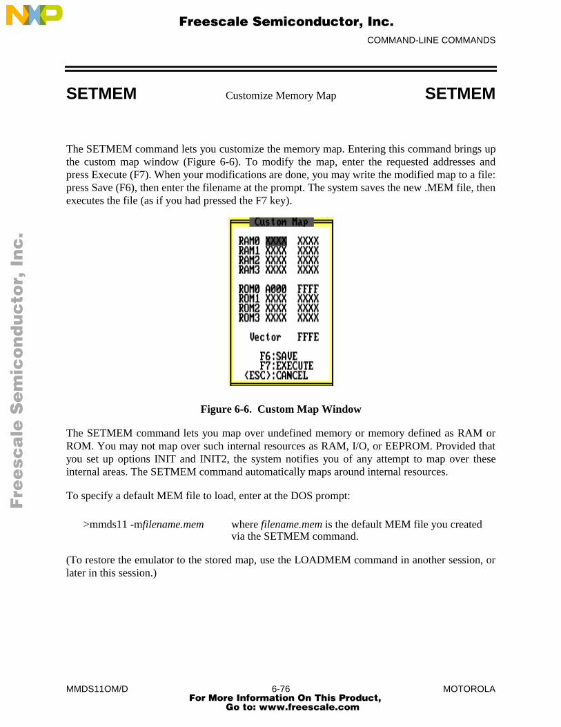
COMMAND-LINE COMMANDS
MMDS11OM/D 6-76 MOTOROLA
SETMEM Customize Memory Map SETMEM
The SETMEM command lets you customize the memory map. Entering this command brings upthe custom map window (Figure 6-6). To modify the map, enter the requested addresses andpress Execute (F7). When your modifications are done, you may write the modified map to a file:press Save (F6), then enter the filename at the prompt. The system saves the new .MEM file, thenexecutes the file (as if you had pressed the F7 key).
Figure 6-6. Custom Map Window
The SETMEM command lets you map over undefined memory or memory defined as RAM orROM. You may not map over such internal resources as RAM, I/O, or EEPROM. Provided thatyou set up options INIT and INIT2, the system notifies you of any attempt to map over theseinternal areas. The SETMEM command automatically maps around internal resources.
To specify a default MEM file to load, enter at the DOS prompt:
>mmds11 -mfilename.mem where filename.mem is the default MEM file you created via the SETMEM command.
(To restore the emulator to the stored map, use the LOADMEM command in another session, orlater in this session.)
Fre
esc
ale
Se
mic
on
du
cto
r, I
Freescale Semiconductor, Inc.
For More Information On This Product, Go to: www.freescale.com
nc
...
COMMAND-LINE COMMANDS
MMDS11OM/D 6-77 MOTOROLA
SETMEM Customize Memory Map SETMEM
NOTES
You may use the SETMEM command to expand MCU memory temporarilyduring debugging. If you do, be sure to restore the original size and configurationof the MCU memory before you end debugging. Otherwise, your code could failto run in the target-system MCU.
The SETMEM and SHOWMEM commands only show MMDS11 resources. Usethe CHIPINFO command memory map feature in combination with options INITand INIT2 to view internal I/O, RAM, and EEPROM locations.
Syntax:
SETMEM
Fre
esc
ale
Se
mic
on
du
cto
r, I
Freescale Semiconductor, Inc.
For More Information On This Product, Go to: www.freescale.com
nc
...
COMMAND-LINE COMMANDS
MMDS11OM/D 6-78 MOTOROLA
SHELL Access DOS SHELL
The SHELL command lets you access DOS in the host computer. To return to MMDS11 fromDOS, enter EXIT at the DOS prompt.
MMDS11 continues to run during your shell to DOS. This means that there could be insufficientmemory for your DOS commands.
Syntax:
SHELL
Example:
>SHELL Access the DOS shell. To return to the emulator session, type EXIT atthe DOS prompt.
Fre
esc
ale
Se
mic
on
du
cto
r, I
Freescale Semiconductor, Inc.
For More Information On This Product, Go to: www.freescale.com
nc
...
COMMAND-LINE COMMANDS
MMDS11OM/D 6-79 MOTOROLA
SHOWMEM Display Memory Map SHOWMEM
The SHOWMEM command displays the currently defined blocks of RAM and ROM in the usermemory map.
Syntax:
SHOWMEM
Example:
>SHOWMEM Display current memory map blocks.
Fre
esc
ale
Se
mic
on
du
cto
r, I
Freescale Semiconductor, Inc.
For More Information On This Product, Go to: www.freescale.com
nc
...

COMMAND-LINE COMMANDS
MMDS11OM/D 6-80 MOTOROLA
SHOWTRIGGER Print Trigger SHOWTRIGGER
The SHOWTRIGGER command displays the trigger frame of the bus state analyzer buffer. If alog file is open, the command also writes the trigger frame to the log file.
Syntax:
SHOWTRIGGER
Example:
>SHOWTRIGGER Display the bus state analyzer trigger frame.
Fre
esc
ale
Se
mic
on
du
cto
r, I
Freescale Semiconductor, Inc.
For More Information On This Product, Go to: www.freescale.com
nc
...
COMMAND-LINE COMMANDS
MMDS11OM/D 6-81 MOTOROLA
SINGLECHIP Set MCU Operating Mode to Single Chip SINGLECHIP
The SINGLECHIP command sets the MCU operating mode to single chip. This command worksonly if the MCU mode is set to user selectable by the MODE command. Related commands areEXPANDED, SPECIALBOOT, and SPECIALTEST.
Some HC11 emulator modules (EMs) do not let you select (from the host) the polarity ofMODEB. This limits operation to single-chip or expanded mode. If you enter the target valuewith the MODE command, the target selects any MCU operating mode on powerup or reset. Thespecial bootstrap mode is emulated in special test mode with the PRU enabled. The bootstrapfirmware may be loaded into emulation RAM and the RESETGO command issued by a scriptfile.
NOTE
The current hardware does not let you switch from special boot or special test tosingle chip or expanded by writing to the MDA bit of the HPRIO register. Modeselection takes effect only upon powerup or reset.
Syntax:
SINGLECHIP
Example:
>SINGLECHIP Set the MCU to single-chip mode.>MODE Display the current mode.MODE: USER SELECTED - Single chip
>
Fre
esc
ale
Se
mic
on
du
cto
r, I
Freescale Semiconductor, Inc.
For More Information On This Product, Go to: www.freescale.com
nc
...
COMMAND-LINE COMMANDS
MMDS11OM/D 6-82 MOTOROLA
SOURCE Source Window Display SOURCE
The SOURCE command toggles between source code and disassembled code in the source/codeF2 window (if a map file is loaded and the PC points to a memory area covered by the map file).
If the source/code F2 window displays source code when you enter this command, the windowdisplay changes to disassembled code, and the title of the window changes to CODE.
If you enter this command when the source/code F2 window displays disassembled code, when amap file is loaded, and when the PC points to a memory area covered by the map file, thewindow display changes to source code. (The title of the window changes to SOURCE.)
NOTE
When you alter memory data that was generated from a source file, the modifiedcode appears in the code window but not the source file window. Use theCLEARMAP command to clear the source file from the host system.
Syntax:
SOURCE
Example:
>SOURCE Toggle the display in the source/code F2 window.
Fre
esc
ale
Se
mic
on
du
cto
r, I
Freescale Semiconductor, Inc.
For More Information On This Product, Go to: www.freescale.com
nc
...
COMMAND-LINE COMMANDS
MMDS11OM/D 6-83 MOTOROLA
SPECIALBOOTSet MCU Operating Mode to Special BootSPECIALBOOT
The SPECIALBOOT command sets the MCU operating mode to special boot. This commandworks only if the MCU mode is set to user selectable by the MODE command. Relatedcommands are EXPANDED, SINGLECHIP, and SPECIALTEST.
Some HC11 emulator modules (EMs) do not let you select (from the host) the polarity ofMODEB. This limits operation to single-chip or expanded mode. If you enter the target valuewith the MODE command, the target selects any MCU operating mode on powerup or reset. Thespecial bootstrap mode is emulated in special test mode with the PRU enabled. The bootstrapfirmware may be loaded into emulation RAM and the RESETGO command issued by a scriptfile.
NOTE
The current hardware does not let you switch from special boot or special test tosingle chip or expanded by writing to the MDA bit of the HPRIO register. Modeselection takes effect only upon powerup or reset.
Syntax:
SPECIALBOOT
Example:
>SPECIALBOOT Set the MCU to special boot mode.>MODE Display the current mode.MODE: USER SELECTED - Special Boot
>
Fre
esc
ale
Se
mic
on
du
cto
r, I
Freescale Semiconductor, Inc.
For More Information On This Product, Go to: www.freescale.com
nc
...

COMMAND-LINE COMMANDS
MMDS11OM/D 6-84 MOTOROLA
SPECIALTEST Set MCU Operating Mode to Special Test SPECIALTEST
The SPECIALTEST command sets the MCU operating mode to special test. This commandworks only if the MCU mode is set to user selectable by the MODE command. Relatedcommands are EXPANDED, SINGLECHIP, and SPECIALBOOT.
Some HC11 emulator modules (EMs) do not let you select (from the host) the polarity ofMODEB. This limits operation to single-chip or expanded mode. If you enter the target valuewith the MODE command, the target selects any MCU operating mode on power-up or reset.The special bootstrap mode is emulated in special test mode with the PRU enabled. Thebootstrap firmware may be loaded into emulation RAM and the RESETGO command issued bya script file.
NOTE
The current hardware does not let you switch from special boot or special test tosingle chip or expanded by writing to the MDA bit of the HPRIO register. Modeselection takes effect only upon powerup or reset.
Syntax:
SPECIALTEST
Example:
>SPECIALTEST Set the MCU to special test mode.>MODE Display the current mode.MODE: USER SELECTED - Special Test
>
Fre
esc
ale
Se
mic
on
du
cto
r, I
Freescale Semiconductor, Inc.
For More Information On This Product, Go to: www.freescale.com
nc
...
COMMAND-LINE COMMANDS
MMDS11OM/D 6-85 MOTOROLA
STACK Display Stack STACK
The STACK command displays the contents of the current stack. Entering this command bringsup the stack window (Figure 3-2). This window shows the stack contents as raw data and as datainterpreted as if an interrupt had caused the data to be written to the stack. This data is only validwhen an interrupt has occurred.
Syntax:
STACK
Example:
>STACK Display the current configuration of the stack.
Fre
esc
ale
Se
mic
on
du
cto
r, I
Freescale Semiconductor, Inc.
For More Information On This Product, Go to: www.freescale.com
nc
...
COMMAND-LINE COMMANDS
MMDS11OM/D 6-86 MOTOROLA
STEP Single Step (Trace) STEP
The STEP command executes a specified hexadecimal number of instructions, beginning at thecurrent program counter (PC) address value. If you do not specify a number, this commandexecutes one instruction. (The STEP and T commands are identical.)
Syntax:
STEP [<n>]
where:
<n> The hexadecimal number of instructions to be executed.
NOTES
Do not use any step command (STEP, STEPFOR, STEPTIL, or T) if the PCpoints to internal RAM or EEPROM (or if the code branches into internal RAMor EEPROM).
The step commands are not real-time: they execute one instruction at a time, thenreturn control to the monitor. Do not rely on time tag values during any stepcommand, as the system reinitializes the time tag after executing each instruction.
Examples:
>STEP Execute the instruction at the current PC address value.>STEP 2 Execute two instructions, beginning at the current PC address value.
Fre
esc
ale
Se
mic
on
du
cto
r, I
Freescale Semiconductor, Inc.
For More Information On This Product, Go to: www.freescale.com
nc
...
COMMAND-LINE COMMANDS
MMDS11OM/D 6-87 MOTOROLA
STEPFOR Step Forever STEPFOR
The STEPFOR command begins continuous instruction execution, beginning at the currentprogram counter (PC) address value. Execution stops when you press a key.
Syntax:
STEPFOR
NOTES
Do not use any step command (STEP, STEPFOR, STEPTIL, or T) if the PCpoints to internal RAM or EEPROM (or if the code branches into internal RAMor EEPROM).
The step commands are not real-time: they execute one instruction at a time, thenreturn control to the monitor. Do not rely on time tag values during any stepcommand, as the system reinitializes the time tag after executing each instruction.
Example:
>STEPFOR Execute instructions continuously until the user presses a key.
Fre
esc
ale
Se
mic
on
du
cto
r, I
Freescale Semiconductor, Inc.
For More Information On This Product, Go to: www.freescale.com
nc
...
COMMAND-LINE COMMANDS
MMDS11OM/D 6-88 MOTOROLA
STEPTIL Single Step to Address STEPTIL
The STEPTIL command continuously executes instructions, from the current program counter(PC) address value until the PC reaches the specified address.
Syntax:
STEPTIL <address>
where:
<address> The address at which instruction execution stops. This must be aninstruction address.
NOTES
Do not use any step command (STEP, STEPFOR, STEPTIL, or T) if the PCpoints to internal RAM or EEPROM (or if the code branches into internal RAMor EEPROM).
The step commands are not real-time: they execute one instruction at a time, thenreturn control to the monitor. Do not rely on time tag values during any stepcommand, as the system reinitializes the time tag after executing each instruction.
Example:
>STEPTIL 0400 Execute instructions continuously until the PC value is 0400.
Fre
esc
ale
Se
mic
on
du
cto
r, I
Freescale Semiconductor, Inc.
For More Information On This Product, Go to: www.freescale.com
nc
...
COMMAND-LINE COMMANDS
MMDS11OM/D 6-89 MOTOROLA
STOP Stop Program Execution STOP
The STOP command stops program execution in the emulation MCU.
Syntax:
STOP
Example:
>STOP Stop program execution in the emulation MCU.
Fre
esc
ale
Se
mic
on
du
cto
r, I
Freescale Semiconductor, Inc.
For More Information On This Product, Go to: www.freescale.com
nc
...
COMMAND-LINE COMMANDS
MMDS11OM/D 6-90 MOTOROLA
SXB Set Multiplexer SXB
The SXB command sets the analyzer multiplexer outputs to be the eight logic clips of pod B oreight additional bits of the time tag.
NOTE
When using the logic clip cables, always attach the black clip to ground.
Syntax:
SXB CLIPS|TAGS
where:
CLIPS Specifies the pod B logic clips.
TAGS Specifies bits 23...16 of the time tag.
Example:
>SXB TAGS Select extended time tag bits.
Fre
esc
ale
Se
mic
on
du
cto
r, I
Freescale Semiconductor, Inc.
For More Information On This Product, Go to: www.freescale.com
nc
...
COMMAND-LINE COMMANDS
MMDS11OM/D 6-91 MOTOROLA
SYSINFO System Information SYSINFO
The SYSINFO command calls to DOS for the amount of memory available, then displays thisinformation in the debug F10 window.
Syntax:
SYSINFO
Example:
>SYSINFO Show system information.Total memory available: 187488 Largest free block: 187488
Fre
esc
ale
Se
mic
on
du
cto
r, I
Freescale Semiconductor, Inc.
For More Information On This Product, Go to: www.freescale.com
nc
...

COMMAND-LINE COMMANDS
MMDS11OM/D 6-92 MOTOROLA
T Single Step (Trace) T
The T command executes a specified hexadecimal number of instructions, beginning at thecurrent program counter (PC) address value. If you do not specify a number, this commandexecutes one instruction. (The T and STEP commands are identical.)
Syntax:
T [<n>]
where:
<n> The hexadecimal number of instructions to be executed.
NOTES
Do not use any step command (STEP, STEPFOR, STEPTIL, or T) if the PCpoints to internal RAM or EEPROM (or if the code branches into internal RAMor EEPROM).
The step commands are not real-time: they execute one instruction at a time, thenreturn control to the monitor. Do not rely on time tag values during any stepcommand, as the system reinitializes the time tag after executing each instruction.
Examples:
>T Execute the instruction at the current PC address value.>T 4 Execute four instructions, beginning at the current PC address value.
Fre
esc
ale
Se
mic
on
du
cto
r, I
Freescale Semiconductor, Inc.
For More Information On This Product, Go to: www.freescale.com
nc
...

COMMAND-LINE COMMANDS
MMDS11OM/D 6-93 MOTOROLA
TIMETAG Time Tag Clock Source TIMETAG
The TIMETAG command selects the frequency and source for the analyzer time tag clock. Youmay enter this command with one parameter value (<val>), which indicates the frequency. If youenter this command with a <val> parameter value that indicates a source, you also must enter anappropriate <val2> frequency value.
Entering this command with no parameter values brings up the time tag window, from which youcan select a frequency or a source. If you select a frequency, the system accepts the value. If youselect a source, the system prompts for an appropriate frequency value.
If you select the external source, connect logic clip 9 (white) of the pod B logic clip cable to theexternal clock source. (The pod B connector is the closest to the front of the station module.Logic clip 9 is available for external clock input whether or not you select the pod B logic clipsfor the trace display.) When using the logic clip cables, always attach the black clip to ground.
Syntax:
TIMETAG [<val>] [<val2>]
where:
<val> A number frequency indicator or letter source indicator:
1: 1 MHz
2: 2 MHz
4: 4 MHz
8: 8 MHz
16: 16 MHz
EX: external
PR: programmable
EM: emulator
<val2> A frequency value, according to the source-indicator value of <val>:
PR: an integer, 50 to 50000
EX or EM: a real, 1.0 to 16000000.0
Fre
esc
ale
Se
mic
on
du
cto
r, I
Freescale Semiconductor, Inc.
For More Information On This Product, Go to: www.freescale.com
nc
...
COMMAND-LINE COMMANDS
MMDS11OM/D 6-94 MOTOROLA
TIMETAG Time Tag Clock Source TIMETAG
Examples:
>TIMETAG Display the time tag window (for user selection of afrequency or source).
>TIMETAG 8 Select the 8 MHz time tag frequency.>TIMETAG PR 120 Select a 120 Hz programmable source.>TIMETAG EX 30.5 Select a 30.5 Hz external source.
Fre
esc
ale
Se
mic
on
du
cto
r, I
Freescale Semiconductor, Inc.
For More Information On This Product, Go to: www.freescale.com
nc
...

COMMAND-LINE COMMANDS
MMDS11OM/D 6-95 MOTOROLA
TMSK2 Set Timer Interrupt Mask Register 2 TMSK2
The TMSK2 command lets you change the value of the TMSK2 register. Potentially, you mayuse this command to change the values of the INIT, OPTION, BPROT, and INIT2 registers, aswell.
If you enter this command with a <value> argument, the system accepts the value. Press the F7key to reset the MCU; the system writes the new value to the register.
If you enter the TMSK2 command without a <value> argument, the system displays the optionswindow (Figure 6-7). This window lists the values of the INIT, OPTION, TMSK2, BPROT, andINIT2 registers. To change any value of the options window, highlight the value, then type in thenew value. Press the F7 key to reset the MCU; the reset writes the new values to the registers.Pressing the ESC key when the window is open aborts register changes.
Figure 6-7. Options Window
Some MCUs do not have internal EEPROM that is remappable via an INIT2 register. For suchan emulation MCU, the options window does not list an INIT2 register.
Table 6-8 lists definitions for all the options-window registers. To change the value of one of theother registers, you may enter a BPROT, OPTION, TMSK2, or INIT2 command with a <value>argument. As with TMSK2, entering one of these commands without a <value> argument bringsup the options window. Via this window, you can change the values of any register, includingTMSK2.
Fre
esc
ale
Se
mic
on
du
cto
r, I
Freescale Semiconductor, Inc.
For More Information On This Product, Go to: www.freescale.com
nc
...
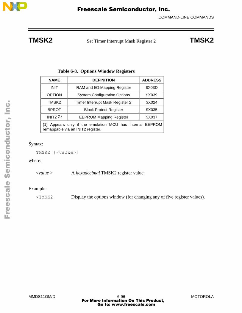
COMMAND-LINE COMMANDS
MMDS11OM/D 6-96 MOTOROLA
TMSK2 Set Timer Interrupt Mask Register 2 TMSK2
Table 6-8. Options Window Registers
NAME DEFINITION ADDRESS
INIT RAM and I/O Mapping Register $X03D
OPTION System Configuration Options $X039
TMSK2 Timer Interrupt Mask Register 2 $X024
BPROT Block Protect Register $X035
INIT2 (1) EEPROM Mapping Register $X037
(1) Appears only if the emulation MCU has internal EEPROMremappable via an INIT2 register.
Syntax:
TMSK2 [<value>]
where:
<value > A hexadecimal TMSK2 register value.
Example:
>TMSK2 Display the options window (for changing any of five register values).
Fre
esc
ale
Se
mic
on
du
cto
r, I
Freescale Semiconductor, Inc.
For More Information On This Product, Go to: www.freescale.com
nc
...
COMMAND-LINE COMMANDS
MMDS11OM/D 6-97 MOTOROLA
V Set/Clear V Bit V
The V command sets the V bit of the condition code register (CCR) to the specified value.
NOTE
The CCR bit designators are at the lower right of the CPU window. The CCRpattern is SXHINZVC (S is stop disable, X is XIRQ interrupt mask, H is half-carry, I is IRQ interrupt mask, N is negative, Z is zero, V is overflow, and C iscarry). A letter in these designators means that the corresponding bit of the CCR isset; a period means that the corresponding bit is clear.
Syntax:
V 0|1
where:
0 Clears the V bit
1 Sets the V bit
Example:
>V 1 Set the V bit of the CCR.
Fre
esc
ale
Se
mic
on
du
cto
r, I
Freescale Semiconductor, Inc.
For More Information On This Product, Go to: www.freescale.com
nc
...
COMMAND-LINE COMMANDS
MMDS11OM/D 6-98 MOTOROLA
VAR Display Variable VAR
The VAR command displays the specified address and its contents in the variables F8 window.
As many as 32 variables can be available for display in the variables F8 window (although thewindow shows 11 at a time). Using the VAR command establishes such a variable. Variants ofthis command display byte, word, or string values. A byte display is hexadecimal and binary, aword display is hexadecimal and decimal, and a string display is ASCII.
For an ASCII string, the optional <n> argument specifies the number of characters; 12 charactersis the default. Control and other non-printing characters appear as periods (.).
(The RTVAR command also establishes variables for display in the variables F8 window, but asreal-time variables. The 32-variable maximum applies to variables established by both the VARand RTVAR commands.)
Syntax:
VAR[.<v>] <address> [<n>]
where:
<v> The display variant: B (byte, the default), W (word), or S (string).
<address> The address of the memory variable.
<n> The number of characters for a string variable; does not apply to byte orword variables.
Examples:
>VAR 100 Display (in hexadecimal and binary) the byte at address 100.>VAR.B 110 Display (in hexadecimal and binary) the byte at address 110.>VAR.W 102 Display (in hexadecimal and decimal) the word at address 102.>VAR.S 200 5 Display the five-character ASCII string at address 200.
Fre
esc
ale
Se
mic
on
du
cto
r, I
Freescale Semiconductor, Inc.
For More Information On This Product, Go to: www.freescale.com
nc
...
COMMAND-LINE COMMANDS
MMDS11OM/D 6-99 MOTOROLA
VERSION Display Version VERSION
The VERSION command displays the version of the host software and of the current personality(.MEM) file. You may use the abbreviated VER form of this command if you wish.
Syntax:
VERSION
Example:
>VERSION Display the version numbers of the host software and the .MEM file.
Fre
esc
ale
Se
mic
on
du
cto
r, I
Freescale Semiconductor, Inc.
For More Information On This Product, Go to: www.freescale.com
nc
...
COMMAND-LINE COMMANDS
MMDS11OM/D 6-100 MOTOROLA
WAIT Pause between Commands WAIT
The WAIT command causes the command interpreter to pause for a specified hexadecimalnumber of seconds. (The default is five.) This command primarily is useful in script files.
Syntax:
WAIT [<n>]
where:
<n> The hexadecimal number of seconds to pause.
Example:
>WAIT A Pause the command interpreter for 10 seconds.
Fre
esc
ale
Se
mic
on
du
cto
r, I
Freescale Semiconductor, Inc.
For More Information On This Product, Go to: www.freescale.com
nc
...
COMMAND-LINE COMMANDS
MMDS11OM/D 6-101 MOTOROLA
WAIT4RESET Wait for Target Reset WAIT4RESET
The WAIT4RESET command puts the emulation MCU into the reset state until the target systemprovides a reset signal.
For this command to function properly, you must enable the state of the MMDS11 with regard toa reset signal from the target system. (See the explanation of the RESETIN command.) Torestore the emulator to the IDLE state, enter the RESET command.
Syntax:
WAIT4RESET
Example:
>WAIT4RESET Wait for reset.
Fre
esc
ale
Se
mic
on
du
cto
r, I
Freescale Semiconductor, Inc.
For More Information On This Product, Go to: www.freescale.com
nc
...
COMMAND-LINE COMMANDS
MMDS11OM/D 6-102 MOTOROLA
WHEREIS Display Symbol Value WHEREIS
The WHEREIS command displays a symbol or address. If the argument is a symbol, thiscommand displays the symbol’s address. If the argument is an address, this command displays thecorresponding symbol (if one is assigned). If the symbol is the same as a hexadecimal address,the command shows the hexadecimal address (not the address of the symbol).
Syntax:
WHEREIS <symbol> | <value>
where:
<symbol> A symbol listed in the symbol table.
<value> A value for which a symbol is desired.
Example:
>WHEREIS START Display the symbol START and its value.>WHEREIS 0100 Display value 0100 and its symbol, if any.
Fre
esc
ale
Se
mic
on
du
cto
r, I
Freescale Semiconductor, Inc.
For More Information On This Product, Go to: www.freescale.com
nc
...

COMMAND-LINE COMMANDS
MMDS11OM/D 6-103 MOTOROLA
X Set X Index Register X
The X command sets the X index register to the specified value.
Syntax:
X <value>
where:
<value> The new value for the X register.
Example:
>X 05 Set the X index register value to 05.
Fre
esc
ale
Se
mic
on
du
cto
r, I
Freescale Semiconductor, Inc.
For More Information On This Product, Go to: www.freescale.com
nc
...
COMMAND-LINE COMMANDS
MMDS11OM/D 6-104 MOTOROLA
XMASK Set/Clear X Bit XMASK
The XMASK command sets the X bit of the condition code register (CCR) to a specified value.
If you use the XMASK command to clear the X bit, you cannot subsequently use the commandto set the X bit without doing a reset. (If you do subsequently use the XMASK command to enterthe value 1 for the X bit, the display gives a false indication that the X bit value is 1.)
To reset the X bit after it has been cleared, you first must reset the MCU by entering the RESETcommand or by cycling MMDS11 power.
NOTE
The CCR bit designators are at the lower right of the CPU window. The CCRpattern is SXHINZVC (S is stop disable, X is XIRQ interrupt mask, H is half-carry, I is IRQ interrupt mask, N is negative, Z is zero, V is overflow, and C iscarry). A letter in these designators means that the corresponding bit of the CCR isset; a period means that the corresponding bit is clear.
Syntax:
XMASK 0|1
where:
0 Clears the X bit
1 Sets the X bit
Example:
>XMASK 1 Set the X bit of the CCR.
Fre
esc
ale
Se
mic
on
du
cto
r, I
Freescale Semiconductor, Inc.
For More Information On This Product, Go to: www.freescale.com
nc
...

COMMAND-LINE COMMANDS
MMDS11OM/D 6-105 MOTOROLA
Y Set Y Index Register Y
The Y command sets the Y index register to the specified value.
Syntax:
Y <value>
where:
<value> The new value for the Y register.
Example:
>Y 10 Set the Y index register value to 10.
Fre
esc
ale
Se
mic
on
du
cto
r, I
Freescale Semiconductor, Inc.
For More Information On This Product, Go to: www.freescale.com
nc
...
COMMAND-LINE COMMANDS
MMDS11OM/D 6-106 MOTOROLA
Z Set/Clear Z Bit Z
The Z command sets the Z bit in the condition code register (CCR) to the specified value.
NOTE
The CCR bit designators are at the lower right of the CPU window. The CCRpattern is SXHINZVC (S is stop disable, X is XIRQ interrupt mask, H is half-carry, I is IRQ interrupt mask, N is negative, Z is zero, V is overflow, and C iscarry). A letter in these designators means that the corresponding bit of the CCR isset; a period means that the corresponding bit is clear.
Syntax:
Z 0|1
where:
0 Clears the Z bit
1 Sets the Z bit
Example:
>Z 0 Clear the Z bit in the CCR.
Fre
esc
ale
Se
mic
on
du
cto
r, I
Freescale Semiconductor, Inc.
For More Information On This Product, Go to: www.freescale.com
nc
...
COMMAND-LINE COMMANDS
MMDS11OM/D 6-107 MOTOROLA
ZOOM Resize Source Window ZOOM
The ZOOM command toggles the size of the source window between normal and enlarged.
Syntax:
ZOOM
Example:
>ZOOM Resize the source window.
Fre
esc
ale
Se
mic
on
du
cto
r, I
Freescale Semiconductor, Inc.
For More Information On This Product, Go to: www.freescale.com
nc
...

COMMAND-LINE COMMANDS
MMDS11OM/D 6-108 MOTOROLA
Fre
esc
ale
Se
mic
on
du
cto
r, I
Freescale Semiconductor, Inc.
For More Information On This Product, Go to: www.freescale.com
nc
...
INSTALLATION
MMDS11OM/D 7-1 MOTOROLA
CHAPTER 7
INSTALLATION
Complete MMDS11 installation consists of configuring and installing the appropriate emulatormodule (EM) or active probe, and making system cable connections. If necessary, consultChapter 1 to make sure that you have all the system components, including the separatelypurchased EM. Note that EM configuration is specific to the particular EM; follow the guidanceof the EM user’s manual.
Figure 7-1 shows the right side of the station module, with the access panel open. The recessedreset switch and power LED are on the front of the station module. The logic cable A and Bconnectors (pod A and pod B) are on the right (as you face the station module). When using thelogic clip cables, always attach the black clip to ground.
Figure 7-2 shows the left side of the station module, with the access panel closed. The powercord socket, the power switch, and the 9-pin RS-232 serial connector are on the left (as you facethe unit). Also on this side of the unit is a 25-pin connector for future use.
NOTE
This manual uses the terms left and right relative to your left and right hands, asyou face the front of the station module.
Follow the guidance of this chapter to complete the installation of your MMDS11.
Fre
esc
ale
Se
mic
on
du
cto
r, I
Freescale Semiconductor, Inc.
For More Information On This Product, Go to: www.freescale.com
nc
...
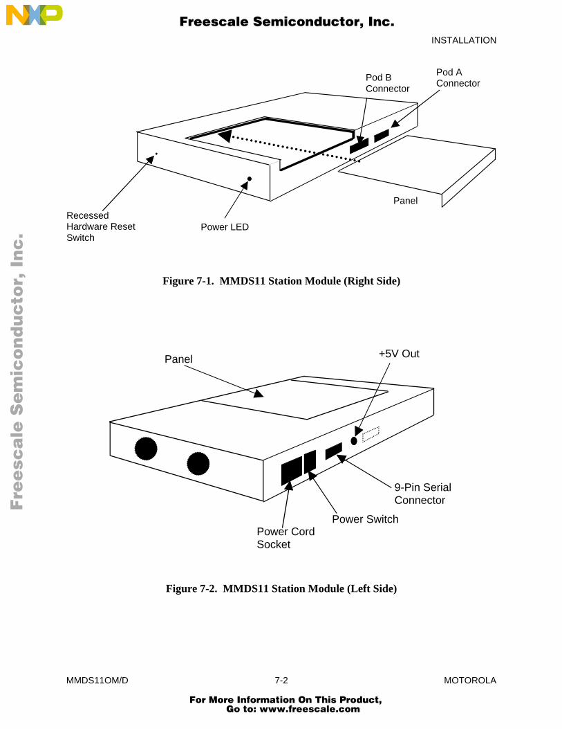
INSTALLATION
MMDS11OM/D 7-2 MOTOROLA
Power LEDRecessedHardware ResetSwitch
Pod BConnector
Pod AConnector
Panel
Figure 7-1. MMDS11 Station Module (Right Side)
Panel
Power CordSocket
Power Switch
9-Pin SerialConnector
+5V Out
Figure 7-2. MMDS11 Station Module (Left Side)
Fre
esc
ale
Se
mic
on
du
cto
r, I
Freescale Semiconductor, Inc.
For More Information On This Product, Go to: www.freescale.com
nc
...
INSTALLATION
MMDS11OM/D 7-3 MOTOROLA
7.1 REMOVING THE EM
NOTE
Always turn off station-module power before removing or installing an EM.
Follow steps 1 through 3 to remove an EM:
1. Turn off station-module power.
2. Unscrew (one quarter turn) the two captive screws of the access panel, then slide thepanel off.
3. Disconnect the target cable from the EM target connector. Unsnap all nylon spacersfrom the edges of the EM. Then carefully lift the EM straight up, separating it fromthe control board. This completes EM removal.
7.2 INSTALLING THE EM
Follow steps 1 through 6 to install an EM:
1. Make sure that station-module power is off.
2. Make sure that nylon spacers are in the correct positions for the new EM.
3. Install the new EM on the control board: carefully fit the female 64-pin connectors(on the bottom of the EM) onto the corresponding male 64-pin connectors on the topof the control board. Snap the EM onto the nylon spacers and make sure that the 64-pin connectors are firmly joined together.
4. Connect the target cable to the EM target connector. Lay the cable over the loweredge of the enclosure opening. (See the EM user’s manual for specific information onthe target connector and the appropriate target cable.)
CAUTION
Make sure that pin 1 of the target cable connector corresponds to pin 1of the target system connector, via the red wire. Connecting the targetcable any other way may damage your system. A black wire, if any, isthe ground wire.
When connecting a target cable, press only on the connectors. Do notpress on the wire part of the cable, as this can damage the cable.
Fre
esc
ale
Se
mic
on
du
cto
r, I
Freescale Semiconductor, Inc.
For More Information On This Product, Go to: www.freescale.com
nc
...
INSTALLATION
MMDS11OM/D 7-4 MOTOROLA
5. Some HC11 EMs have an extended address connector. Such a connector lets you usethe MMDS11 1-megabyte bank selected memory map. To do so, connect the desiredtarget-system address lines XA16 through XA19 to the EM extended addressconnector. Use individual wires or a cable assembly you make for these connections.Lay the wires or cable over the lower edge of the station-module enclosure opening,as you did with the target cable. (The EM user’s manual gives additional informationabout the extended address connector.)
6. Slide the access panel back into position. The target cable should run out of the slit atthe bottom edge of the access panel. The extended address wires or cable, if any, alsoshould run out through the same slit. Secure the panel with the two screws. Thiscompletes EM installation.
7.3 MAKING SYSTEM CONNECTIONS
Your specific application determines the number of MMDS11 connections required. At the veryleast, you must connect the station module to your host computer and to line power. Paragraphs7.3.1 through 7.3.4 explain MMDS11 connections.
7.3.1 Host Computer Connection
Make sure that power is turned off at your host computer. Use the 9-lead serial cable to connect ahost computer serial port to the MMDS11 serial cable connector (on the left side of the stationmodule). Note which computer serial port you use: if you do not use the COM1 port (thedefault), you must include the port number in your MMDS11 software startup command.
If the serial port is a 25-pin connector, use the 9- to 25-pin adapter between the port and thecable.
7.3.2 Bus State Analyzer Connection
If your work session includes bus state analysis, you may need the logic cable assemblies. Thesecables permit selection of signals not available through the target cable or through selection ofexternal clock signals. Note that the molded triangle of each cable connector designates pin 1.The cable connectors also may be keyed to the pod connectors on the right side of the stationmodule.
The pod A and pod B connectors correspond to the Cable A and Cable B selections available inthe bus state analyzer window.
Fre
esc
ale
Se
mic
on
du
cto
r, I
Freescale Semiconductor, Inc.
For More Information On This Product, Go to: www.freescale.com
nc
...

INSTALLATION
MMDS11OM/D 7-5 MOTOROLA
If you need only one logic cable assembly, connect it to either pod A or pod B. Orient the cableconnector so that its pin 1 connects to pin 1 of the pod.
Connect the other end of the logic cable assembly to your target system. To do so, connect cableprobe tips to pins of a target-system header or to pins of a test clip. Optionally, connect the probetips to the ball clips that come with the cable assembly, then connect the ball clips to appropriatepoints on the target system.
NOTE
Always connect the black (ground) probe tip to an appropriate ground point of thetarget system first. Use the white clip to input clock signals to the bus stateanalyzer.
If you need the second logic cable assembly, connect it in the same way to the remaining podconnector of the station module. Make target-system connections as for the first cable.
7.3.3 Target Cable Connection
During EM installation you connected one end of your target cable to the EM. Now, connect theother end of the target cable to your target system.
CAUTION
Make sure that pin 1 of the EM target connector corresponds to pin 1 of the targetsystem connector, via the red wire. Connecting the target cable any other way maydamage your system. A black wire, if any, is the ground wire.
When connecting a target cable, press only on the connectors. Do not press on thewire part of the cable, as this can damage the cable.
NOTE
During system operation, if you select an external clock source, the length of thetarget cable may prevent the target oscillator from starting.
7.3.4 Power Connection
The final MMDS11 connection is line power. The MMDS11 power switch is the rocker switchon the left side of the station module. Set the power switch to OFF.
Insert the female end of the power cord into the power cord socket. Then plug the other end ofthe cord into a line-power outlet and set the power switch to ON. The green LED on the front ofthe station module lights to confirm system power.
Fre
esc
ale
Se
mic
on
du
cto
r, I
Freescale Semiconductor, Inc.
For More Information On This Product, Go to: www.freescale.com
nc
...
INSTALLATION
MMDS11OM/D 7-6 MOTOROLA
Once the MMDS11 is powered, you may turn on power for your host computer. This completesconnections. You are ready to install MMDS11 software in the host computer, per theinstructions of chapter 2.
7.4 RESET SWITCH
RS-232 handshake signals control MMDS11 resets. A reset initializes the control board from itsstartup point. If your computer serial port does not implement handshaking, you may need toreset the MMDS11 manually. The reset switch is recessed, behind the small hole in the front ofthe station module. To reset your system manually, insert a probe or stiff wire into the resetswitch hole. Press gently to trip the switch.
7.5 RUNNING SELFTESTS
If your MMDS11 fails to function as specified, check the EM configuration to make sure alljumpers are in the correct positions. If you confirm correct EM configuration, you may run twoselftests to determine whether your station module or your EM is malfunctioning.
NOTE
Always turn off station module power before removing or installing an EM orselftest board. You must have a mouse installed for either the basic or theadvanced selftests; otherwise, the tests always will fail.
7.5.1 Basic Selftest
This test is a software test of any MMDS11 EM. To conduct this test, you must have installedMMDS11 software with the selftest option. Follow steps 1 through 8:
1. Install the EM in the station module. Do not, however, connect a target cable.
2. Turn on station module power.
3. Bring up the DOS prompt on your computer. If you are not in the SELFTESTdirectory, change to that directory.
4. At the DOS prompt, enter the command: EMT [comm port#], where thecomm port number is 1 (the default), 2, 3, or 4.
5. The system begins the selftest. At the end of the test, a results message appears on thecomputer screen.
6. If the results message indicates an error, the EM may be bad. To verify this, run theadvanced selftest (paragraph 7.5.2).
Fre
esc
ale
Se
mic
on
du
cto
r, I
Freescale Semiconductor, Inc.
For More Information On This Product, Go to: www.freescale.com
nc
...

INSTALLATION
MMDS11OM/D 7-7 MOTOROLA
7. If the results message does not indicate an error, but you still feel there’s a problem,run the advanced selftest (paragraph 7.5.2).
8. Turn off station module power and remove the EM. This completes the basic selftest.
7.5.2 Advanced Selftest
The advanced selftest can resolve whether your EM or your control board is bad. To conductthis test, you must install the selftest board (which comes with your MMDS11) into the stationmodule, you must have installed MMDS11 software with the selftest option, and you must havea mouse installed. Follow steps 1 through 11:
1. Install the selftest board in the station module, as you would install an EM. Do not,however, connect a target cable; do not replace the access panel.
2. Plug the logic cable assemblies into the pod A and pod B connectors.
3. Consult Table 7-1, then connect the logic cable assembly probe tips to the correct pinsof selftest board connector J3.
4. Turn on station module power.
5. Bring up the DOS prompt on you computer. If you are not in the SELFTESTdirectory, change to that directory.
6. At the DOS prompt, enter the command: RGG [comm port#], where thecomm port number is 1 (the default), 2, 3, or 4.
7. The system begins the selftest. The test takes five minutes or longer, according toyour computer. At the end of the test, a results message appears on the computerscreen.
8. If the results message indicates an error, the MMDS11 control board is bad. Writedown the results message; this message indicates the probable problem.
9. If the results message does not indicate an error, but the basic selftest results messagedid indicate an error, the EM is bad.
10. If the results message does not indicate an error, and the basic selftest results messagedid not indicate an error, either, then the system seems to be working withinparameters. If you still feel that there’s a problem, recheck your EM jumperconfiguration and your system cable connections.
11. Turn off station module power. Remove the selftest board, as you would remove anEM. This completes the selftest.
If either selftest indicates an error, report your results to the Motorola service support center (1-800-451-3464). A technician may be able to resolve the problem over the phone. If the techniciandetermines that a board needs repair, he or she will arrange for you to send the board to thecenter.
Fre
esc
ale
Se
mic
on
du
cto
r, I
Freescale Semiconductor, Inc.
For More Information On This Product, Go to: www.freescale.com
nc
...
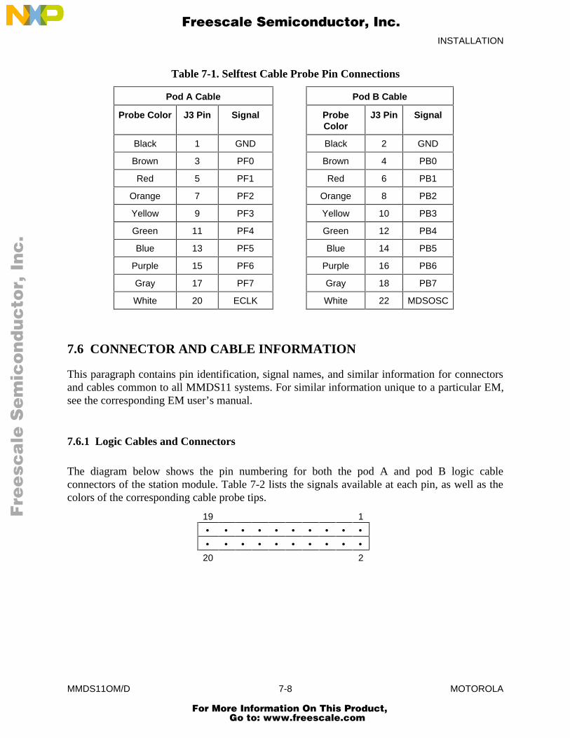
INSTALLATION
MMDS11OM/D 7-8 MOTOROLA
Table 7-1. Selftest Cable Probe Pin Connections
Pod A Cable Pod B Cable
Probe Color J3 Pin Signal ProbeColor
J3 Pin Signal
Black 1 GND Black 2 GND
Brown 3 PF0 Brown 4 PB0
Red 5 PF1 Red 6 PB1
Orange 7 PF2 Orange 8 PB2
Yellow 9 PF3 Yellow 10 PB3
Green 11 PF4 Green 12 PB4
Blue 13 PF5 Blue 14 PB5
Purple 15 PF6 Purple 16 PB6
Gray 17 PF7 Gray 18 PB7
White 20 ECLK White 22 MDSOSC
7.6 CONNECTOR AND CABLE INFORMATION
This paragraph contains pin identification, signal names, and similar information for connectorsand cables common to all MMDS11 systems. For similar information unique to a particular EM,see the corresponding EM user’s manual.
7.6.1 Logic Cables and Connectors
The diagram below shows the pin numbering for both the pod A and pod B logic cableconnectors of the station module. Table 7-2 lists the signals available at each pin, as well as thecolors of the corresponding cable probe tips.
19 1
• • • • • • • • • •• • • • • • • • • •
20 2
Fre
esc
ale
Se
mic
on
du
cto
r, I
Freescale Semiconductor, Inc.
For More Information On This Product, Go to: www.freescale.com
nc
...
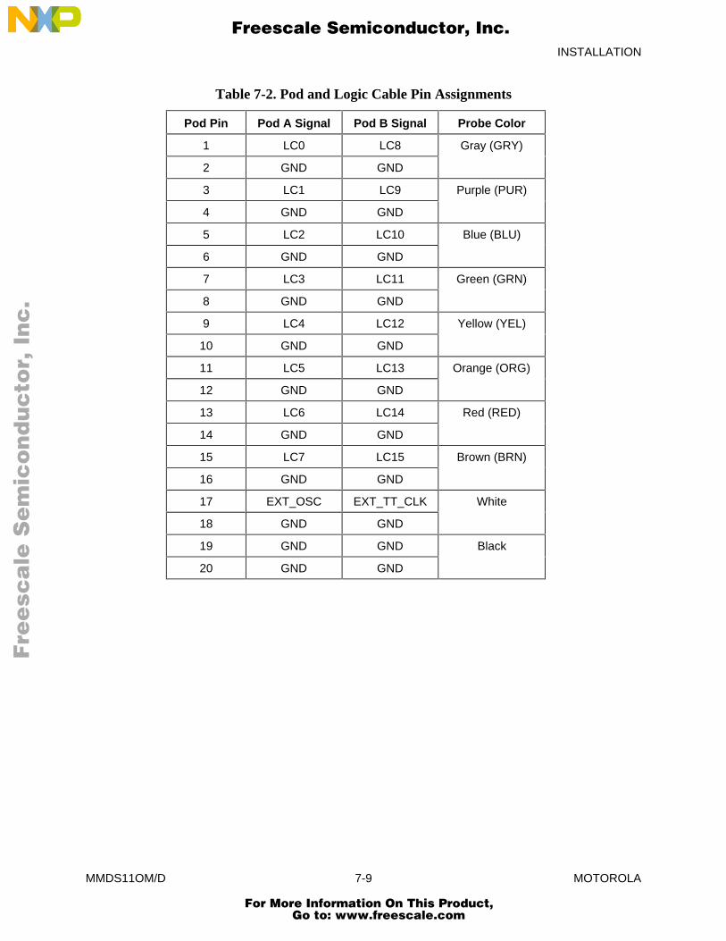
INSTALLATION
MMDS11OM/D 7-9 MOTOROLA
Table 7-2. Pod and Logic Cable Pin Assignments
Pod Pin Pod A Signal Pod B Signal Probe Color
1 LC0 LC8 Gray (GRY)
2 GND GND
3 LC1 LC9 Purple (PUR)
4 GND GND
5 LC2 LC10 Blue (BLU)
6 GND GND
7 LC3 LC11 Green (GRN)
8 GND GND
9 LC4 LC12 Yellow (YEL)
10 GND GND
11 LC5 LC13 Orange (ORG)
12 GND GND
13 LC6 LC14 Red (RED)
14 GND GND
15 LC7 LC15 Brown (BRN)
16 GND GND
17 EXT_OSC EXT_TT_CLK White
18 GND GND
19 GND GND Black
20 GND GND
Fre
esc
ale
Se
mic
on
du
cto
r, I
Freescale Semiconductor, Inc.
For More Information On This Product, Go to: www.freescale.com
nc
...
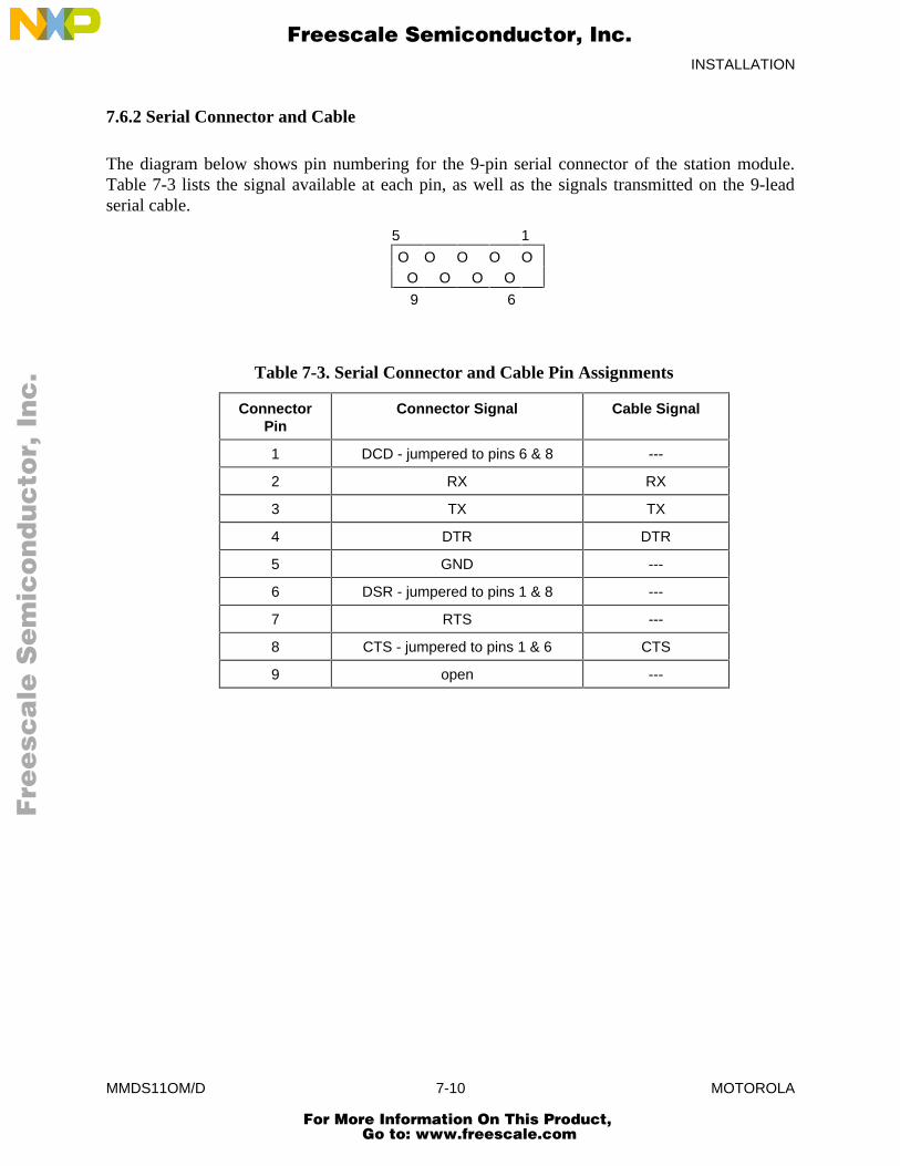
INSTALLATION
MMDS11OM/D 7-10 MOTOROLA
7.6.2 Serial Connector and Cable
The diagram below shows pin numbering for the 9-pin serial connector of the station module.Table 7-3 lists the signal available at each pin, as well as the signals transmitted on the 9-leadserial cable.
5 1
O O O O OO O O O
9 6
Table 7-3. Serial Connector and Cable Pin Assignments
ConnectorPin
Connector Signal Cable Signal
1 DCD - jumpered to pins 6 & 8 ---
2 RX RX
3 TX TX
4 DTR DTR
5 GND ---
6 DSR - jumpered to pins 1 & 8 ---
7 RTS ---
8 CTS - jumpered to pins 1 & 6 CTS
9 open ---
Fre
esc
ale
Se
mic
on
du
cto
r, I
Freescale Semiconductor, Inc.
For More Information On This Product, Go to: www.freescale.com
nc
...
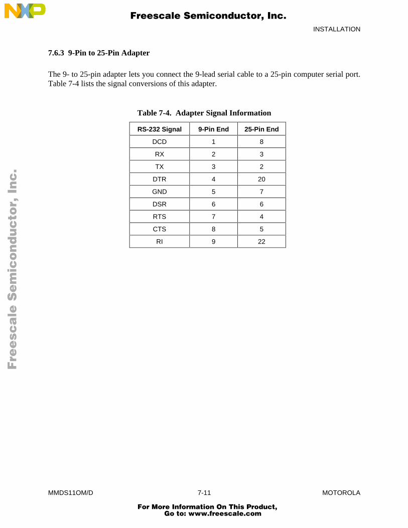
INSTALLATION
MMDS11OM/D 7-11 MOTOROLA
7.6.3 9-Pin to 25-Pin Adapter
The 9- to 25-pin adapter lets you connect the 9-lead serial cable to a 25-pin computer serial port.Table 7-4 lists the signal conversions of this adapter.
Table 7-4. Adapter Signal Information
RS-232 Signal 9-Pin End 25-Pin End
DCD 1 8
RX 2 3
TX 3 2
DTR 4 20
GND 5 7
DSR 6 6
RTS 7 4
CTS 8 5
RI 9 22
Fre
esc
ale
Se
mic
on
du
cto
r, I
Freescale Semiconductor, Inc.
For More Information On This Product, Go to: www.freescale.com
nc
...
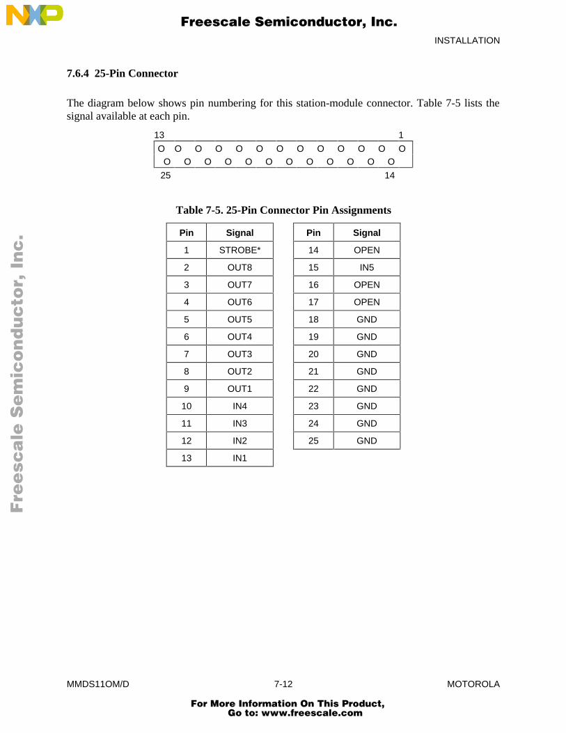
INSTALLATION
MMDS11OM/D 7-12 MOTOROLA
7.6.4 25-Pin Connector
The diagram below shows pin numbering for this station-module connector. Table 7-5 lists thesignal available at each pin.
13 1
O O O O O O O O O O O O OO O O O O O O O O O O O
25 14
Table 7-5. 25-Pin Connector Pin Assignments
Pin Signal Pin Signal
1 STROBE* 14 OPEN
2 OUT8 15 IN5
3 OUT7 16 OPEN
4 OUT6 17 OPEN
5 OUT5 18 GND
6 OUT4 19 GND
7 OUT3 20 GND
8 OUT2 21 GND
9 OUT1 22 GND
10 IN4 23 GND
11 IN3 24 GND
12 IN2 25 GND
13 IN1
Fre
esc
ale
Se
mic
on
du
cto
r, I
Freescale Semiconductor, Inc.
For More Information On This Product, Go to: www.freescale.com
nc
...
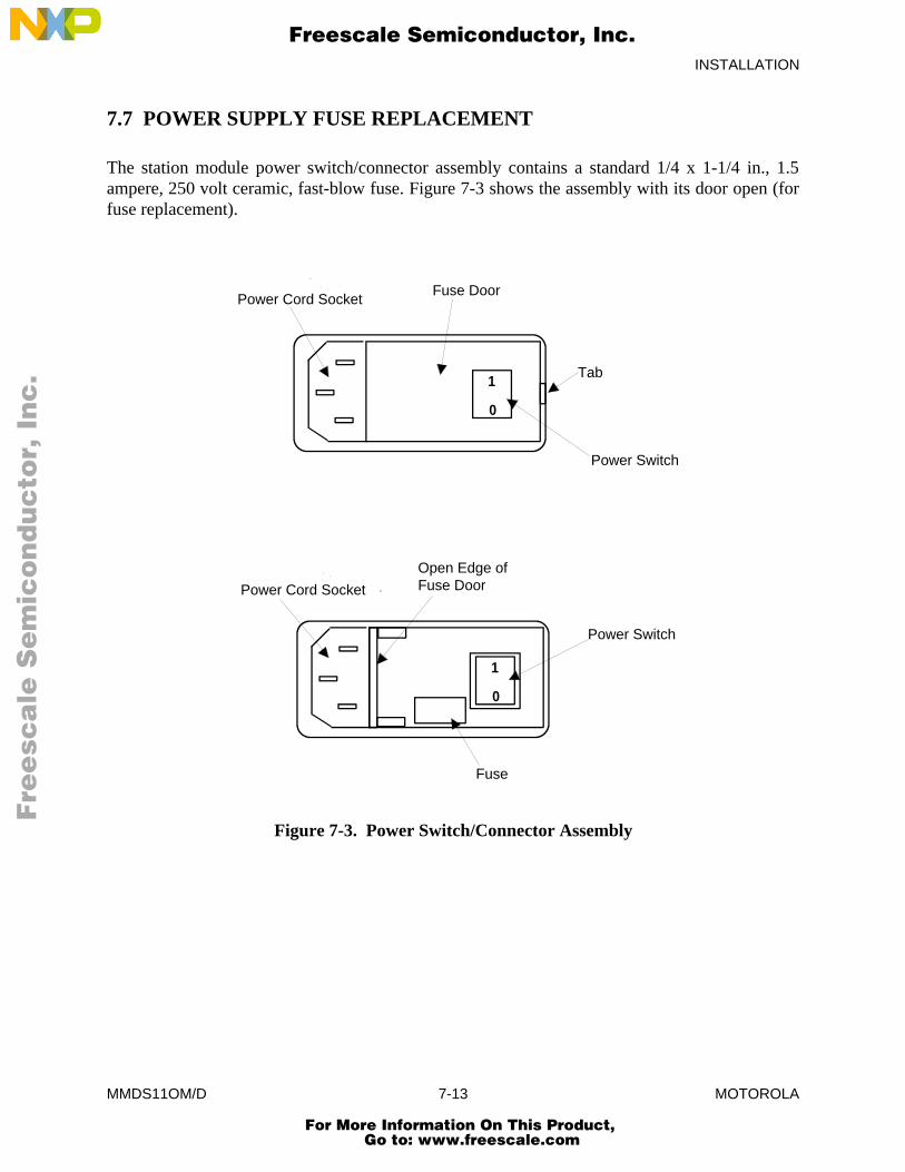
INSTALLATION
MMDS11OM/D 7-13 MOTOROLA
7.7 POWER SUPPLY FUSE REPLACEMENT
The station module power switch/connector assembly contains a standard 1/4 x 1-1/4 in., 1.5ampere, 250 volt ceramic, fast-blow fuse. Figure 7-3 shows the assembly with its door open (forfuse replacement).
Power Cord SocketFuse Door
1
0
Tab
Power Switch
1
0
Power Cord Socket
Open Edge of Fuse Door
Power Switch
Fuse
Figure 7-3. Power Switch/Connector Assembly
Fre
esc
ale
Se
mic
on
du
cto
r, I
Freescale Semiconductor, Inc.
For More Information On This Product, Go to: www.freescale.com
nc
...
INSTALLATION
MMDS11OM/D 7-14 MOTOROLA
To replace the fuse, follow steps 1-5:
1. Press the power switch OFF and disconnect the power cord.
2. Insert a small screwdriver at the tab on the right edge of the switch/connectorassembly. (Figure 7-3 shows where to insert the screwdriver.) Gently pry open theassembly door, which swings open to the left.
3. Remove the fuse holder from the switch/connector assembly. Remove the fuse fromthe holder.
4. Insert the replacement fuse into the holder. Then re-install the holder in theswitch/connector assembly. Make sure that the fuse holder arrow points down. Closethe assembly door.
5. Reconnect the power cord. This completes fuse replacement.
Fre
esc
ale
Se
mic
on
du
cto
r, I
Freescale Semiconductor, Inc.
For More Information On This Product, Go to: www.freescale.com
nc
...
INDEX
MMDS11OM/D index-1 MOTOROLA
INDEX
A: 6-6
Addressing modes, MCU: 4-3
Analyzer trace window, debug screen: 3-8
Arguments, command-line commands: 6-2
ARM: 5-8, 6-7
ASM: 4-3, 6-8
B: 6-9
BAUD: 3-9, 4-1, 6-10
BAUDCHK: 4-1, 6-11
Baud rate: 4-1
Baud window, debug screen: 3-9
BELL: 6-12
BF: 3-6, 4-4, 6-13
BPROT: 3-9, 6-14, 6-15
BR: 4-7, 6-16
Breakpoints:data: 4-7instruction: 4-6, 4-7
Bus state analysis: 5-1 5-16
Bus state analyzer:collecting bus data: 5-8defining events (terms): 5-2 5-4introduction: 5-1modes: 5-5 5-7operating: 5-1 5-16screens:
data: 5-8 5-13setup: 4-7, 5-2 5-4
searching the trace buffer: 5-14, 5-15selecting options: 5-7time tag clock: 5-15, 5-16viewing data: 5-8 5-13
Fre
esc
ale
Se
mic
on
du
cto
r, I
Freescale Semiconductor, Inc.
For More Information On This Product, Go to: www.freescale.com
nc
...
INDEX
MMDS11OM/D index-2 MOTOROLA
C: 6-17
Cables, connecting: 7-4 7-6
CCR: 6-18
Changing screen colors: 3-12, 6-21
CHIPINFO: 6-19
CLEARMAP: 4-3, 6-20
Clock:signal: 4-2time tag: 5-15, 5-16
Collecting bus data, bus state analyzer: 5-8
COLORS: 3-1, 3-12, 6-21
Colors, changing: 3-12, 6-21
Commands:command-line: 6-1 6-107:
A: 6-6arguments: 6-2ARM: 5-8, 6-7ASM: 4-3, 6-8B: 6-9BAUD: 3-9, 4-1, 6-10BAUDCHK: 4-1, 6-11BELL: 6-12BF: 3-6, 4-4, 6-13BPROT: 3-9, 6-14, 6-15BR: 4-7, 6-16C: 6-17CCR: 6-18CHIPINFO: 6-19CLEARMAP: 4-3, 6-20COLORS: 3-1, 3-12, 6-21D: 6-22DARM: 5-8, 6-23DASM: 4-3, 6-24EMUBP: 5-15, 6-25EMURAM: 5-15, 6-26ENDBSA: 6-27EVAL: 6-28EXIT: 6-29EXPANDED: 6-30
Fre
esc
ale
Se
mic
on
du
cto
r, I
Freescale Semiconductor, Inc.
For More Information On This Product, Go to: www.freescale.com
nc
...
INDEX
MMDS11OM/D index-3 MOTOROLA
Commands (cont.): command-line (cont.):
G: 4-6, 5-8, 6-31GETBSA: 6-32GO: 4-6, 5-8, 6-33GOTIL: 4-6, 5-8, 6-34H: 6-35HELP: 4-6, 6-36HOMEBSA: 6-37I: 6-38INFO: 6-39INIT: 3-9, 6-40, 6-41INIT2: 3-9, 6-42, 6-43LF: 4-5, 6-44LOAD: 4-3, 6-45LOADMAP: 6-46LOADMEM: 4-2, 6-47LOADTRIGGERS: 5-7, 6-48MD: 6-49MM: 3-6, 4-4, 6-50MODE: 6-51N: 6-52NEXTA: 5-9, 6-53NEXTB: 5-9, 6-54NEXTC: 5-9, 6-55NEXTD: 5-9, 6-56NEXTE: 5-9, 6-57NOBR: 4-7, 6-58OPTION: 3-9, 6-59, 6-60OSC: 3-10, 4-2, 6-61PC: 6-62QUIT: 6-63REG: 6-64REM: 6-65RESET: 4-6, 6-66RESETGO: 4-6, 6-67RESETIN: 4-6, 6-68RESETOUT: 4-6, 6-69RTMEM: 3-6, 6-70RTVAR: 3-5, 6-43, 6-71, 6-72S: 6-73SCREENBSA: 6-74SCRIPT: 4-5, 6-75
Fre
esc
ale
Se
mic
on
du
cto
r, I
Freescale Semiconductor, Inc.
For More Information On This Product, Go to: www.freescale.com
nc
...
INDEX
MMDS11OM/D index-4 MOTOROLA
Commands (cont): command-line (cont):
SETMEM: 3-8, 4-2, 6-76, 6-77SHELL: 6-78SHOWMEM: 4-2, 6-79SHOWTRIGGER: 5-9, 6-80SINGLECHIP: 6-81SOURCE: 6-82SPECIALBOOT: 6-83SPECIALTEST: 6-84STACK: 3-7, 6-85STEP: 3-8, 4-6, 5-8, 6-86STEPFOR: 4-6, 5-8, 6-87STEPTIL: 4-6, 5-8, 6-88STOP: 4-6, 5-8, 6-89summary (table): 6-4, 6-5SXB: 5-7, 6-90syntax: 6-1, 6-2SYSINFO: 4-6, 6-91T: 3-8, 4-6, 5-8, 6-92TIMETAG: 3-10, 5-7, 6-93, 94TMSK2: 3-9, 6-95, 6-96V: 6-97VAR: 3-5, 6-98VERSION: 4-6, 6-99WAIT: 4-5, 6-100WAIT4RESET: 4-6, 6-101WHEREIS: 4-5, 6-102X: 6-103XMASK: 6-104Y: 6-105Z: 6-106ZOOM: 6-107
key:data screen, bus state analyzer: 5-10debug F10 window: 3-7debug screen windows: 3-2find pattern window: 5-14setup screen, bus state analyzer: 5-4source/code F2 window: 3-5subordinate window: 6-3
operating: 4-6, 4-7system: 4-5, 4-6
Fre
esc
ale
Se
mic
on
du
cto
r, I
Freescale Semiconductor, Inc.
For More Information On This Product, Go to: www.freescale.com
nc
...
INDEX
MMDS11OM/D index-5 MOTOROLA
Common operations: 4-5 4-7
Components, system: 1-3, 1-4
Connecting cables:bus state analyzer: 7-4, 7-5host computer: 7-4power: 7-5, 7-6target: 7-5
Connector, cable:pin assignments: 7-9 7-13signal descriptions: 7-9 7-13
CPU registers, initializing: 4-4
CPU window, debug screen: 3-4
D: 6-22
DARM: 5-8, 6-23
DASM: 4-3, 6-24
Data breakpoints: 4-7
Data screen, bus state analyzer: 5-8 5-13
Debug screen: 3-1 3-10analyzer trace window: 3-8baud window: 3-9CPU window: 3-4debug F10 window: 3-6emulator clock frequency window: 3-10memory F3 window: 3-6options window: 3-9set memory window: 3-8source/code F2 window: 3-4, 3-5stack window: 3-7status area: 3-3, 3-4time tag window: 3-10variables F8 window: 3-5
Debug F10 window, debug screen: 3-6
Defining events, bus state analyzer: 5-2 5-4
Description, general:MMDS11: 1-1 1-4user screens: 3-1
Distribution format: 2-1
Fre
esc
ale
Se
mic
on
du
cto
r, I
Freescale Semiconductor, Inc.
For More Information On This Product, Go to: www.freescale.com
nc
...
INDEX
MMDS11OM/D index-6 MOTOROLA
EM:installing: 7-3removing: 7-3. 7-4
EMUBP: 5-15, 6-25
Emulator:clock: 4-2initializing: 4-2
Emulator clock frequency window, debug screen: 3-10
EMURAM: 5-15, 6-26
ENDBSA: 6-27
EVAL: 6-28
Events, defining, bus state analyzer: 5-2 5-4
EXIT: 6-29
EXPANDED: 6-30
External clock: 4-2
Features: 1-1 1-3
Find pattern window: 5-14
Format, software distribution: 2-1
Fuse replacement: 7-14, 7-15
G: 4-6, 5-8, 6-31
General description:MMDS11: 1-1 1-4user screens: 3-1
GETBSA: 6-32
GO: 4-6, 5-8, 6-33
GOTIL: 4-6, 5-8, 6-34
H: 6-35
Fre
esc
ale
Se
mic
on
du
cto
r, I
Freescale Semiconductor, Inc.
For More Information On This Product, Go to: www.freescale.com
nc
...
INDEX
MMDS11OM/D index-7 MOTOROLA
Hardware installation: 7-1 7-15connecting cables: 7-4 7-6fuse replacement: 7-14, 7-15installing the EM: 7-3introduction: 7-1, 7-2pin assignments, connector: 7-9 7-13removing the EM: 7-3, 7-4reset switch: 7-6selftests: 7-7 7-9signal descriptions, connector: 7-9 7-13
HELP: 4-6, 6-36
Help:file: 2-2system: 4-6
HOMEBSA: 6-37
Host computercable connection: 7-4requirements: 1-4
I: 6-38
INFO: 6-39
INIT: 3-9, 6-40, 6-41
INIT2: 3-9, 6-42, 6-43
Initialization:and loading: 2-1 2-3communications baud rate: 4-1CPU registers: 4-4emulator: 4-2loading target software: 4-3log: 4-4, 4-5memory: 4-4memory mapping: 4-2MMDS11: 4-1 4-5
Installation, hardware: 7-1 7-15
Installing:EM: 7-6software: 2-1, 2-2
Instruction breakpoints: 4-6, 4-7
Introduction: 1-1 1-5
Fre
esc
ale
Se
mic
on
du
cto
r, I
Freescale Semiconductor, Inc.
For More Information On This Product, Go to: www.freescale.com
nc
...
INDEX
MMDS11OM/D index-8 MOTOROLA
Key commands:data screen, bus state analyzer: 5-10debug F10 window: 3-7debug screen windows: 3-2find pattern window: 5-14setup screen, bus state analyzer: 5-4source/code F2 window: 3-5subordinate window: 6-3
LF: 4-5, 6-44
LOAD: 4-3, 6-45
Loading:and initialization: 2-1 2-3target software: 4-3
LOADMAP: 6-46
LOADMEM: 4-2, 6-47
LOADTRIGGERS: 5-7, 6-48
Log, initializing: 4-4, 4-5
Manual organization: 1-5
MCU addressing modes: 4-3
MD: 6-49
Memory:initialization: 4-4mapping: 4-2
Mouse operation: 3-11
Memory F3 window, debug screen: 3-6
MM: 3-6, 4-4, 6-50
MMDS11:general description: 1-1 1-4initialization: 4-1 4-5operation: 4-1 4-7
MODE: 6-51
Modes:analyzer: 5-5, 5-6MCU addressing: 4-3selecting: 5-5 5-7
Fre
esc
ale
Se
mic
on
du
cto
r, I
Freescale Semiconductor, Inc.
For More Information On This Product, Go to: www.freescale.com
nc
...
INDEX
MMDS11OM/D index-9 MOTOROLA
N: 6-52
NEXTA: 5-9, 6-53
NEXTB: 5-9, 6-54
NEXTC: 5-9, 6-55
NEXTD: 5-9, 6-56
NEXTE: 5-9, 6-57
NOBR: 4-7, 6-58
Operating:bus state analyzer: 5-1 5-16commands: 4-6, 4-7
Operation:MMDS11: 4-1 4-7mouse: 3-11
Operations, common: 4-5 4-7
OPTION: 3-9, 6-59, 6-60
Options, selecting, bus state analyzer: 5-7
Options window, debug screen: 3-9
Organization, manual: 1-5
OSC: 3-10, 4-2, 6-61
Personality files: 2-1, 2-2
PC: 6-37, 6-62
Pin assignments, connector: 7-9 7-13
Pod (bus state analyzer) cable connection: 7-4
Power cable connection: 7-5, 7-6
QUIT: 6-63
REG: 6-64
Registers, CPU, initializing: 4-4
REM: 6-65
Removing the EM: 7-3
Requirements, host computer: 1-4
RESET: 4-6, 6-66
Fre
esc
ale
Se
mic
on
du
cto
r, I
Freescale Semiconductor, Inc.
For More Information On This Product, Go to: www.freescale.com
nc
...

INDEX
MMDS11OM/D index-10 MOTOROLA
RESETGO: 4-6, 6-67
RESETIN: 4-6, 6-68
RESETOUT: 4-6, 6-69
Reset switch: 7-6
RTMEM: 3-6, 6-70
RTVAR: 3-5, 6-43, 6-71, 6-72
S: 6-73
SCREENBSA: 6-74
Screens:bus state analyzer data: 5-8 5-13bus state analyzer setup: 4-7, 5-2 5-4debug: 3-1 3-11:
analyzer trace window: 3-7baud window: 3-9CPU window: 3-4debug F10 window: 3-6emulator clock frequency window: 3-10memory F3 window: 3-6options window: 3-9set memory window: 3-8source/code F2 window: 3-4, 3-5stack window: 3-7status area: 3-3, 3-4time tag window: 3-10variables F8 window: 3-5
description, general: 3-1help file: 2-2installation: 2-1, 2-2personality files: 2-1, 2-2user: 3-1 3-12
SCRIPT: 4-5, 6-75
Script files: 4-1, 4-5STARTUP.11: 4-1, 4-2, 6-75
Searching the trace buffer, bus state analyzer: 5-14, 5-15
Selecting options, bus state analyzer: 5-7
selftests: 7-7 7-9
Fre
esc
ale
Se
mic
on
du
cto
r, I
Freescale Semiconductor, Inc.
For More Information On This Product, Go to: www.freescale.com
nc
...
INDEX
MMDS11OM/D index-11 MOTOROLA
Set memory window, debug screen: 3-8
SETMEM: 3-8, 4-2, 6-76, 6-77
Setup screen, bus state analyzer: 4-7, 5-2 5-4
SHELL: 6-78
SHOWMEM: 4-2, 6-79
SHOWTRIGGER: 5-9, 6-80
Signal descriptions, connector: 7-10 7-13
SINGLECHIP: 6-81
Software:distribution format: 2-1help file: 2-2installation: 2-1, 2-2personality files: 2-1, 2-2target, loading: 4-3using: 2-2, 2-3; 4-1 4-7
SOURCE: 6-82
Source/code F2 window, debug screen: 3-4, 3-5
SPECIALBOOT: 6-83
SPECIALTEST: 6-84
STACK: 6-85
Stack window, debug screen: 3-7
STARTUP.11 (script file): 4-1, 4-2
Status area, debug screen: 3-3, 3-4
STEP: 3-8, 4-6, 5-8, 6-86
STEPFOR: 4-6, 5-8, 6-87
STEPTIL: 4-6, 5-8, 6-88
STOP: 4-6, 5-8, 6-89
SXB: 5-7, 6-90
Syntax, command-line commands: 6-1, 6-2
SYSINFO: 4-6, 6-91
Fre
esc
ale
Se
mic
on
du
cto
r, I
Freescale Semiconductor, Inc.
For More Information On This Product, Go to: www.freescale.com
nc
...
INDEX
MMDS11OM/D index-12 MOTOROLA
System:commands: 4-5, 4-6components: 1-3, 1-4features: 1-1 1-3
T: 3-8, 4-6, 5-8, 6-92
Target cable connection: 7-5
Target software, loading: 4-3
TIMETAG: 3-10, 5-7, 6-93. 6-94
Time tag clock: 5-15, 5-16
Time tag window, debug screen: 3-10
TMSK2: 3-9, 6-95, 6-96
Trace buffer, searching, bus state analyzer: 5-14, 5-15
Using software: 2-2, 2-3
V: 6-97
VAR: 3-5, 6-98
Variables F8 window, debug screen: 3-5
VERSION: 4-6, 6-99
Viewing data, bus state analyzer: 5-8 5-13
WAIT: 4-5, 6-100
WAIT4RESET: 4-6, 6-101
WHEREIS: 4-5, 6-102
Windows:analyzer trace: 3-8baud: 3-9colors: 3-12, 6-21CPU: 3-4debug F10: 3-6emulator clock frequency: 3-10find pattern: 5-14memory F3: 3-6options: 3-9set memory: 3-8source/code F2: 3-4, 3-5stack: 3-7subordinate, key commands: 6-3time tag: 3-10variables F8: 3-5
Fre
esc
ale
Se
mic
on
du
cto
r, I
Freescale Semiconductor, Inc.
For More Information On This Product, Go to: www.freescale.com
nc
...

INDEX
MMDS11OM/D index-13 MOTOROLA
X: 6-103
XMASK: 6-104
Y: 6-105
Z: 6-106
ZOOM: 6-107
Fre
esc
ale
Se
mic
on
du
cto
r, I
Freescale Semiconductor, Inc.
For More Information On This Product, Go to: www.freescale.com
nc
...

INDEX
MMDS11OM/D index-14 MOTOROLA
Fre
esc
ale
Se
mic
on
du
cto
r, I
Freescale Semiconductor, Inc.
For More Information On This Product, Go to: www.freescale.com
nc
...
Related Documents


