MLT 3000 Headlight Tester Original Operating Instructions BA380701-en

Welcome message from author
This document is posted to help you gain knowledge. Please leave a comment to let me know what you think about it! Share it to your friends and learn new things together.
Transcript

MLT 3000 Headlight Tester
Original Operating Instructions BA380701-en

2
BA380701-en
BA380701-en 2021-03-16
© MAHA Maschinenbau Haldenwang GmbH & Co. KG
The reproduction, distribution and utilization of this document as well as the communication of its con-tents to others without explicit authorization is prohibited. Offenders will be held liable for the payment of damages. All rights reserved in the event of the grant of a patent, utility model or design. The contents of this edition have been checked with great care. However, errors cannot be fully excluded. Subject to technical change without notice.
Manufacturer
MAHA Maschinenbau Haldenwang GmbH & Co. KG Hoyen 20 87490 Haldenwang Germany
Phone: +49 8374 585-0 Fax: +49 8374 585-590 Mail: [email protected] Web: www.maha.de
Service
MAHA SERVICE CENTER Maybachstraße 8 87437 Kempten Germany
Phone: +49 8374 585-100 Fax: +49 8374 585-491 Mail: [email protected] Web: www.mahaservicecenter.de
3
BA380701-en
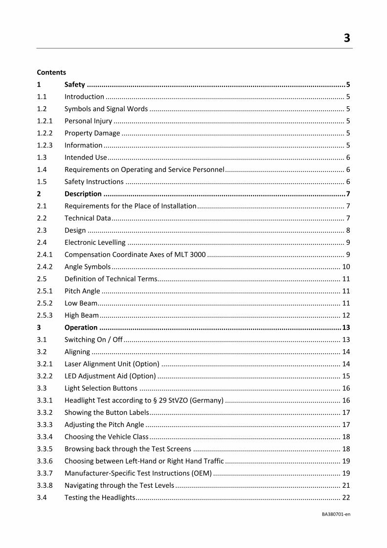
Contents
1 Safety ............................................................................................................................. 5
1.1 Introduction ........................................................................................................................ 5
1.2 Symbols and Signal Words .................................................................................................. 5
1.2.1 Personal Injury .................................................................................................................... 5
1.2.2 Property Damage ................................................................................................................ 5
1.2.3 Information ......................................................................................................................... 5
1.3 Intended Use ....................................................................................................................... 6
1.4 Requirements on Operating and Service Personnel ............................................................ 6
1.5 Safety Instructions .............................................................................................................. 6
2 Description ..................................................................................................................... 7
2.1 Requirements for the Place of Installation .......................................................................... 7
2.2 Technical Data ..................................................................................................................... 7
2.3 Design ................................................................................................................................. 8
2.4 Electronic Levelling ............................................................................................................. 9
2.4.1 Compensation Coordinate Axes of MLT 3000 ..................................................................... 9
2.4.2 Angle Symbols ................................................................................................................... 10
2.5 Definition of Technical Terms............................................................................................ 11
2.5.1 Pitch Angle ........................................................................................................................ 11
2.5.2 Low Beam .......................................................................................................................... 11
2.5.3 High Beam ......................................................................................................................... 12
3 Operation ..................................................................................................................... 13
3.1 Switching On / Off ............................................................................................................. 13
3.2 Aligning ............................................................................................................................. 14
3.2.1 Laser Alignment Unit (Option) .......................................................................................... 14
3.2.2 LED Adjustment Aid (Option) ............................................................................................ 15
3.3 Light Selection Buttons ..................................................................................................... 16
3.3.1 Headlight Test according to § 29 StVZO (Germany) .......................................................... 16
3.3.2 Showing the Button Labels ................................................................................................ 17
3.3.3 Adjusting the Pitch Angle .................................................................................................. 17
3.3.4 Choosing the Vehicle Class ................................................................................................ 18
3.3.5 Browsing back through the Test Screens .......................................................................... 18
3.3.6 Choosing between Left-Hand or Right Hand Traffic .......................................................... 19
3.3.7 Manufacturer-Specific Test Instructions (OEM) ................................................................ 19
3.3.8 Navigating through the Test Levels ................................................................................... 21
3.4 Testing the Headlights ....................................................................................................... 22
4
BA380701-en
3.4.1 Test Phase Indication via Light Buttons ............................................................................. 22
3.4.2 Measuring ......................................................................................................................... 22
3.4.3 Light Selection Buttons Disabled ....................................................................................... 23
3.4.4 Adjusting: Setting the Headlights in Real Time .................................................................. 24
3.4.5 Saving the Measurement Values to PDF ........................................................................... 25
3.5 Settings ............................................................................................................................. 27
3.5.1 Variables ........................................................................................................................... 27
3.5.2 User Settings ..................................................................................................................... 29
3.5.3 Language ........................................................................................................................... 30
3.5.4 Calibrating the Camera according to Directive .................................................................. 31
3.5.5 Country Specifications ....................................................................................................... 33
3.5.6 Settings with Password ..................................................................................................... 34
3.5.7 List of Variables (Extract) ................................................................................................... 35
3.6 Interfaces and Software Updates ...................................................................................... 36
3.7 EUROSYSTEM .................................................................................................................... 39
4 Energy Management and Troubleshooting ................................................................... 45
4.1 Charging the Battery ......................................................................................................... 45
4.2 Battery Status .................................................................................................................... 46
4.2.1 Battery Life ........................................................................................................................ 46
4.2.2 Energy Saving Function ..................................................................................................... 46
4.2.3 Protection against Deep Discharge ................................................................................... 46
4.2.4 Protection against Mechanical Damage ............................................................................ 46
4.2.5 Data Recording for Error Analysis ..................................................................................... 47
4.3 Troubleshooting ................................................................................................................ 48
5 Maintenance ................................................................................................................. 48
5.1 Care Instructions ............................................................................................................... 48
5.2 Spare Parts ........................................................................................................................ 48
6 Disposal ........................................................................................................................ 49
7 Contents of the Declaration of Conformity ................................................................... 49
5
BA380701-en
1 Safety
1.1 Introduction
Thoroughly read this manual before operating the equipment and comply with the instructions. Always display the manual in a conspicuous location.
Personal injury and property damage incurred due to non-compliance with these safety instructions are not covered by the product liability regulations.
1.2 Symbols and Signal Words
1.2.1 Personal Injury
DANGER
indicates an immediate hazard which, if not avoided, will result in death or severe per-sonal injury.
WARNING
indicates a potential hazard which, if not avoided, could result in death or severe per-sonal injury.
CAUTION
indicates a potential hazard which, if not avoided, could result in moderate or minor personal injury.
1.2.2 Property Damage
NOTICE
indicates a potentially harmful situation which, if not avoided, could result in damage to the equipment or surrounding objects.
1.2.3 Information
indicates important information notes.

6
BA380701-en
1.3 Intended Use
This device only serves to check and adjust the alignment of vehicle headlights.
This device cannot be modified without the express, written consent of the manufacturer. Any infringement renders the conformity declaration invalid.
1.4 Requirements on Operating and Service Personnel
WARNING
All persons employed in the operation, maintenance, installation, removal and disposal of the device must
• be at least 18 years old,
• be mentally and physically suited for these activities,
• be demonstrably trained and instructed in writing,
• have read and understood the operating instructions, especially the instructions what to do in the event of defects or malfunctions,
• be on record as having been instructed in safety guidelines,
• have practical experience in working with vehicle lifts and the hazards inherent in such equipment.
1.5 Safety Instructions
NOTICE
• This device must only ever be operated within its performance limits.
• All parts of the electrical system must be protected against damp and humidity.
• All service work must be performed by service technicians employed by the manu-facturer or by authorized service partners.
• Never expose the lens to direct sunlight. The bundling of light may cause fire dam-age inside the housing.
• Only ever clean the lens with a soft cloth and a glass cleaning agent.
CAUTION
Optional laser alignment unit: Never look into the laser beam (laser class 2M). Comply with work safety and accident prevention directives (H&SW regulations) in respect of laser radiation.

7
BA380701-en
2 Description
2.1 Requirements for the Place of Installation
Please observe your national guidelines and specifications.
2.2 Technical Data
Measuring range above hotspot 0…800 mm / 10 m (0…8 %)
above pitch angle 0…300 mm / 10 m (0…3 %)
below 0…700 mm / 10 m (0…7 %)
left 0…1000 mm / 10 m (0…10 %)
right 0…1000 mm / 10 m (0…10 %)
Light intensity 0…125 000 cd
Illuminance 0…200 lx
Measuring distance 100…500 mm
Adjustment path of lens centre above floor 240…1500 mm
Deviation of intensity ±5 %
Deviation from one axle ±5'
Compensation of ground unevenness ±3 %
Temperature +5…+40 °C
Relative humidity 20…80 %
Supply voltage 100…240 V AC, 50/60 Hz
Charging voltage / Battery voltage 24 V DC / 12 V DC
Dimensions (W x H x D) 655 x 1770 x 720 mm
Net weight / Shipping weight 65 kg / 80 kg
Prototype release number TPN100110935

8
BA380701-en
2.3 Design
A Mirror, with optional laser alignment unit
E Charging socket
B Column F Casing, with adjusting handle
C Display G Carriage, with spirit level
D USB port H Battery compartment
A
B
D
G
H
C
E
F

9
BA380701-en
2.4 Electronic Levelling
This headlight tester comes standard with an electronic position sensor which determines the inclination angle of the device. The software compensates possible deviations in the X- and Z-axes while calculating the position of the headlights.
The headlight tester may be set up on uneven surfaces even if the ground unevenness is outside the permissible tolerances, provided that the maximum unevenness does not exceed the headlight tester’s self-levelling capacity of 3%.
After enabling the respective function, the compensation values can be checked using a dot or cross hair laser. See section “Operation > Settings > Calibrating the Camera according to Directive”.
NOTICE
This function must be enabled exclusively by authorised service technicians and is ap-plicable for the respective test surface only.
2.4.1 Compensation Coordinate Axes of MLT 3000

10
BA380701-en
2.4.2 Angle Symbols
Once the adjustment of the inclination sensor has been completed, an angle symbol appears in the info bar to indicate the adjusted/active inclination axes.
Overview of symbols:
Both axes adjusted/active, headlight tester ready for op-eration
Z-axis active, headlight tester ready for operation
Both axes active, inclination of Z- and X-axis too large, no measurement possible
Z-axis active, inclination too large, no measurement possi-
ble
Both axes active, inclination of X-axis too large, no measure-ment possible
X-axis active, headlight tester ready for operation
Both axes active, inclination of Z-axis too large, no measure-ment possible
X-axis active, inclination too large, no measurement possi-
ble

11
BA380701-en
2.5 Definition of Technical Terms
2.5.1 Pitch Angle
Angle of inclination of light-dark limit against the test surface.
The inclination of headlight lighting bundle against the test surface is expressed as a percentage, using 10 m as a reference parameter:
1000
hH −X 100
2.5.2 Low Beam

12
BA380701-en
A Light-dark limit Boundary for light distribution between ‘top dark’ and ‘bottom light’ for low-beam lights.
B
Inflection point Synonymous with the light-dark limit for asymmetric low-beam lighting. The deviation of the inflection point is expressed in %. 10 meters is used as the ref-erence dimension.
α Yaw angle Angle between the inflection point on the rising component of the light-dark limit and the horizontal line for asymmetric low-beam light.
β Rolling angle Angle between the left component of the light-dark limit and the horizontal, usually 0°.
2.5.3 High Beam
C Central mark From the central mark, the deviation of hot-spot is specified in X and Y direc-tions.
D Hot spot Center of light beam for high-beam. The deviation of hot spot from central mark is expressed in %.10 meters is used as the reference dimension.
13
BA380701-en
3 Operation
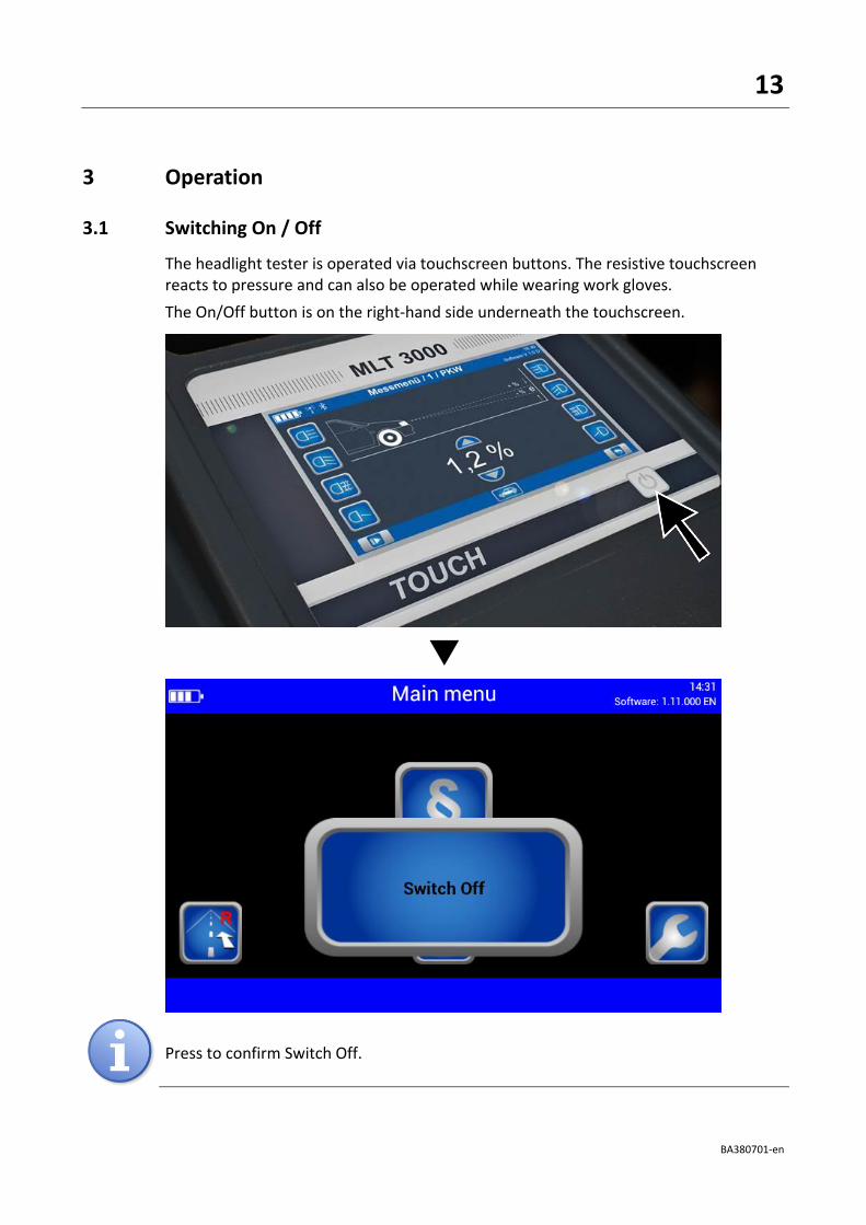
3.1 Switching On / Off
The headlight tester is operated via touchscreen buttons. The resistive touchscreen reacts to pressure and can also be operated while wearing work gloves.
The On/Off button is on the right-hand side underneath the touchscreen.
Press to confirm Switch Off.

14
BA380701-en
3.2 Aligning
When using guide rails, position the device centrally in front of the vehicle.
Without guide rails, the device must be adjusted in front of each headlight. Please ob-serve your national guidelines and specifications.
The device is correctly aligned when two symmetrical reference points on the front of the vehicle are located on the black line of the alignment mirror.
3.2.1 Laser Alignment Unit (Option)
The optional unit is integrated into the mirror holder. The device is correctly aligned when the laser pointer is parallel to two symmetrical reference points on the front of the vehicle.
Observe manufacturer’s instructions according to workshop manual.
CAUTION
Never look into the laser beam (laser class 2M). Comply with work safety and accident prevention directives (H&SW regulations) in respect of laser radiation.
The AA Mignon batteries powering the laser are located in the alignment unit and can be easily replaced.

15
BA380701-en
3.2.2 LED Adjustment Aid (Option)
This optional unit is integrated into the window housing (A) above the Fresnel lens. The colour LEDs (B) pointing toward the vehicle indicate the direction of adjustment.
Green LED = Optimum setting (corresponds to green rating in the display centre)
Yellow LED = Minor deviation within tolerance range (corresponds to yellow direction arrows on the display)
Red LED = Outside tolerance (corresponds to red direction arrows on the display)
A B

16
BA380701-en
3.3 Light Selection Buttons
3.3.1 Headlight Test according to § 29 StVZO (Germany)
Headlight test according to § 29 StVZO (Germany).
Use the OEM button for manufacturer-specific test instructions.

17
BA380701-en
3.3.2 Showing the Button Labels
When the Info button is activated, the button labels are shown instead of the symbols.
3.3.3 Adjusting the Pitch Angle
The pitch angle can be increased or reduced using the Arrow buttons.

18
BA380701-en
3.3.4 Choosing the Vehicle Class
The Truck/Car button activates the appropriate settings for the respective vehicle class.
3.3.5 Browsing back through the Test Screens
Use the Back Arrow button to browse back through the test screens one by one.

19
BA380701-en
3.3.6 Choosing between Left-Hand or Right Hand Traffic
Left-hand/Right-hand traffic can be changed under “User Settings”. Right-hand traffic is preset by default.
3.3.7 Manufacturer-Specific Test Instructions (OEM)
OEM area! Perform the test according to manufacturer’s instructions.

20
BA380701-en
Button “ALL“ makes several test levels available.
Example: testing Volkswagen matrix headlights
OEM area! Perform the test according to manufacturer’s instructions.

21
BA380701-en
3.3.8 Navigating through the Test Levels
Use the Play button to open the activated test levels one by one.

22
BA380701-en
3.4 Testing the Headlights
3.4.1 Test Phase Indication via Light Buttons
Green dot = Headlight tested, measurement OK
Red dot = Headlight tested, not OK
Grey dot = Headlight without evaluation
Adjusting direction:
Yellow arrow = Minor deviation within tolerance range
Red arrow = Outside tolerance
3.4.2 Measuring
Rating in centre = Headlight within tolerance range

23
BA380701-en
PA = Pitch Angle; IP = Inflection Point; I = Intensity
Yaw and Rolling angles can be additionally activated under “User Settings”.
Use the Camera button (bottom centre) to change from the Measuring menu to the Adjusting menu.
3.4.3 Light Selection Buttons Disabled
During measurement the light selection buttons are disabled.

24
BA380701-en
3.4.4 Adjusting: Setting the Headlights in Real Time
Green light button = Current measurement
Use the “New vehicle” button to change back to the Main menu.
25
BA380701-en
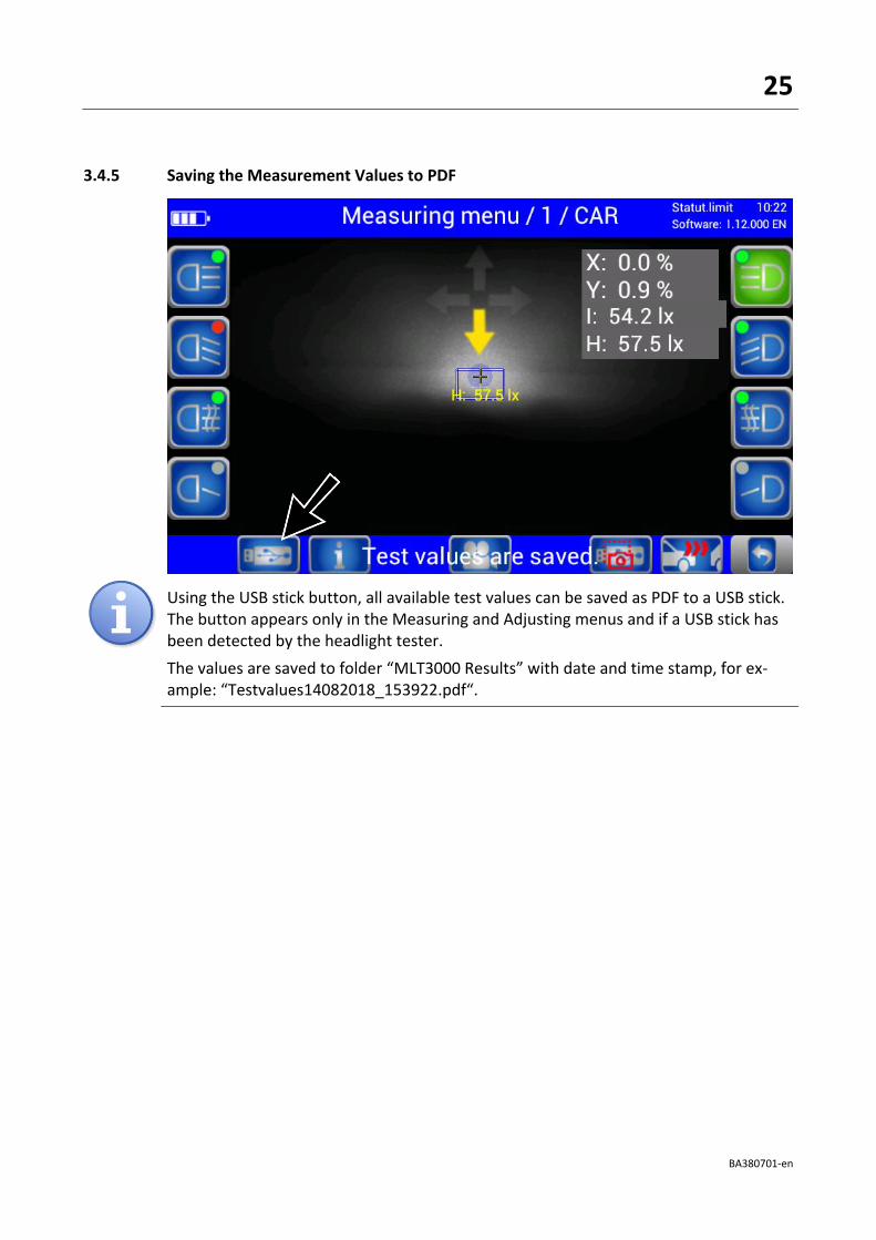
3.4.5 Saving the Measurement Values to PDF
Using the USB stick button, all available test values can be saved as PDF to a USB stick. The button appears only in the Measuring and Adjusting menus and if a USB stick has been detected by the headlight tester.
The values are saved to folder “MLT3000 Results” with date and time stamp, for ex-ample: “Testvalues14082018_153922.pdf“.

26
BA380701-en
Overview of test results as PDF file (example)

27
BA380701-en
3.5 Settings
3.5.1 Variables
Limit values as well as user and customer variables can be set directly at the headlight tester.

28
BA380701-en
Limit values, user and customer variables can be adjusted directly on the equipment.

29
BA380701-en
3.5.2 User Settings
Quick access to all important settings.

30
BA380701-en
3.5.3 Language
Use the flag button to open the language selection.
Choose the desired language.

31
BA380701-en
3.5.4 Calibrating the Camera according to Directive
Compensation values can be checked using button “Calibrate camera according to di-rective”. No password required.
Choose between Cross hair / Spot laser.

32
BA380701-en
33
BA380701-en
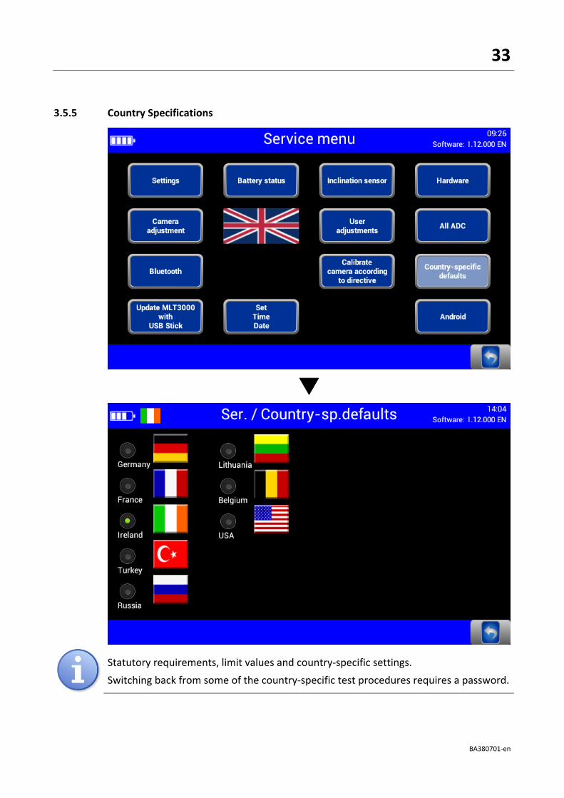
3.5.5 Country Specifications
Statutory requirements, limit values and country-specific settings.
Switching back from some of the country-specific test procedures requires a password.

34
BA380701-en
3.5.6 Settings with Password
The disabled (greyed out) menu items can be accessed only by entering a service technician password.
Adjustment of the headlight tester is permitted exclusively with the following calibration equipment approved by MAHA and must be performed by an authorised service technician.
VP 990175 Laser calibration device with spot laser, model LK1 (no longer available)
VP 990471 Laser calibration device with cross hair laser, model LK2

35
BA380701-en
3.5.7 List of Variables (Extract)
No. User variables Default Min Max
3.0 Percentage 0 / Degrees 1 0 0 1
4.0 Lux 0 / Candela 1 0 0 1
6.0 Target value Pitch angle Car 11 0 50
6.1 Target value Pitch angle HGV 30 0 50
8.0 Switch-off time of display in minutes 10 2 1200
10.1 RHT/LHT button enabled 1 / disabled 0 0 0 1
11.0 OEM in main menu enabled 1 0 1
12.0.1 Output yaw/rolling angle on display 0 0 1 Customer variables
1.0 Customer header line 1 0 20
1.0 Customer header line 2 0 20

36
BA380701-en
3.6 Interfaces and Software Updates
Software updates are normally performed using a USB stick (FAT32). Procedure:
1 Download the software update from the MAHA homepage. https://www.maha.de/en/software/downloads
2 Start the exe file. Accept the recom-mended destination folder, or choose a different one.
3 Unpack and copy folder “maha” to a USB stick.
4 Connect the USB stick to the USB port outside at the casing. Start installation in the Service menu (see Fig. below).
USB

37
BA380701-en

38
BA380701-en
Please wait until the software has been installed and restarted.
Interfaces for connecting a computer:
• RS232 as cable connection (round connector, see section “Energy Management and Troubleshooting > Charging the Battery”)
• Wireless connection via Bluetooth, order number: VZ 990312
• These interfaces can be used for establishing a connection to MAHA’s EUROSYSTEM software, which is included with the cable or Bluetooth module. Alternatively, the headlight tester can also be integrated into a EUROSYSTEM test lane.

39
BA380701-en
3.7 EUROSYSTEM
After the connection has been established, the yellow indicator lamp is ON. A Bluetooth symbol appears in the info bar of the headlight tester.
Set variables using “Settings / Section, Lanes, External Devices”:
Variable 1 → 100 (standalone device only); Var. 25 → 1; Var. 26 → free COM port
Reboot EUROSYSTEM.

40
BA380701-en
Test devices are connected automatically.
After the measurement has been started, all measurement values are transferred to EUROSYSTEM. The connection to the MLT 3000 is retained until EUROSYSTEM is quit.

41
BA380701-en
Select menu item <Results>.
Select menu item <Light tester>.

42
BA380701-en
An overview of the measurement values appears. Select the desired measurement.
The selected measurement data is displayed in detail.

43
BA380701-en
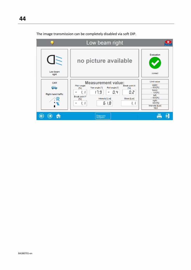
Use the camera button on the MLT 3000 display to switch over to headlight adjustment. EUROSYSTEM shows the coordinates, the measurement values and the headlight image in real time.
The headlight pattern graphics can be updated manually using the <Request graphic> button.
44
BA380701-en
The image transmission can be completely disabled via soft DIP.
45
BA380701-en
4 Energy Management and Troubleshooting
4.1 Charging the Battery
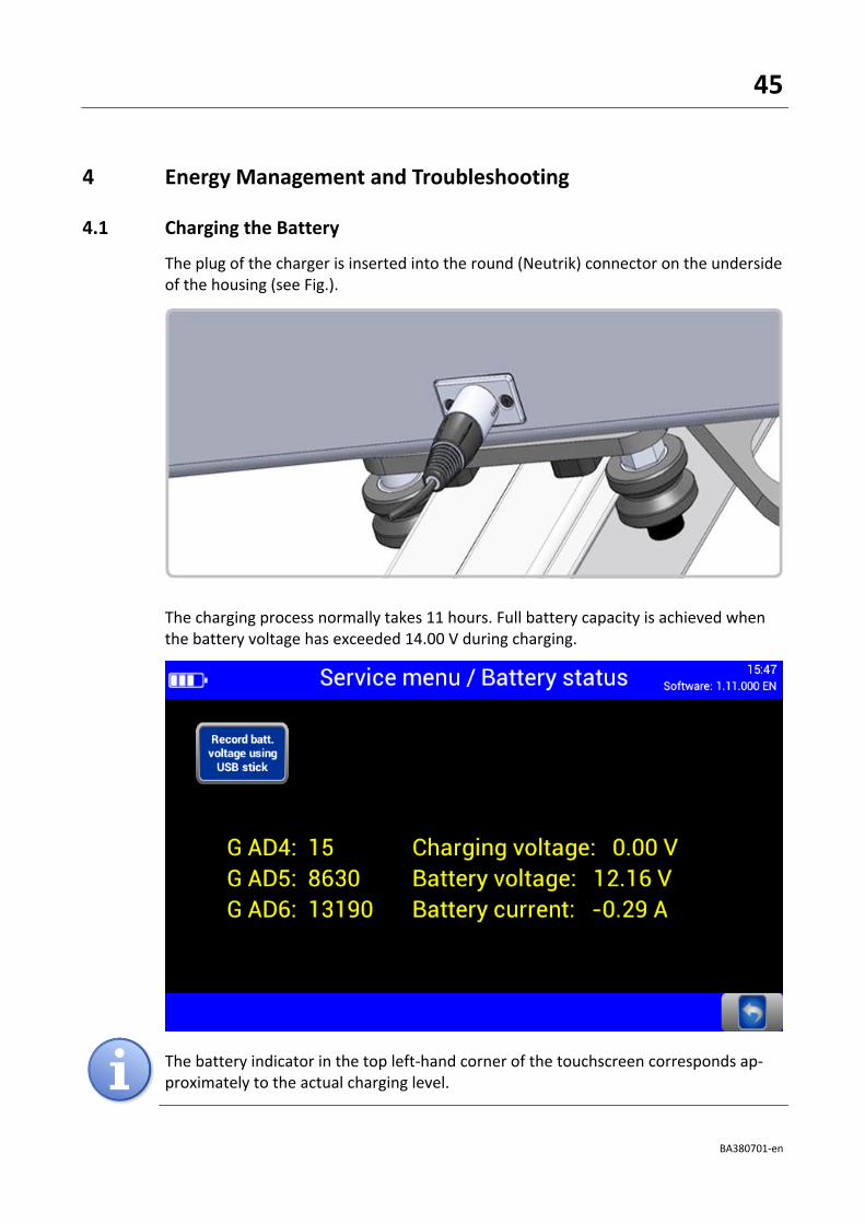
The plug of the charger is inserted into the round (Neutrik) connector on the underside of the housing (see Fig.).
The charging process normally takes 11 hours. Full battery capacity is achieved when the battery voltage has exceeded 14.00 V during charging.
The battery indicator in the top left-hand corner of the touchscreen corresponds ap-proximately to the actual charging level.

46
BA380701-en
4.2 Battery Status
4.2.1 Battery Life
The battery has a rated capacity of 9500mAh and can provide up to 20 hours of continuous workshop operation at an optimum environmental temperature of 20°C.
4.2.2 Energy Saving Function
After 10 minutes of no activity, the display switches off. By tapping the touchscreen, the device is immediately ready for operation. After 120 minutes of no activity, the unit switches off completely and then needs to be switched back on manually. These standard settings can be customised in the user variables.
4.2.3 Protection against Deep Discharge
To protect the battery from deep discharge, the unit switches off beyond 10.8V battery voltage.
4.2.4 Protection against Mechanical Damage
In the event that the device is set into motion while the charger is connected, the following image is displayed and accompanied by an audible alert: (Alert must be enabled, see section “Operation > Settings > User Settings”.)
47
BA380701-en
4.2.5 Data Recording for Error Analysis
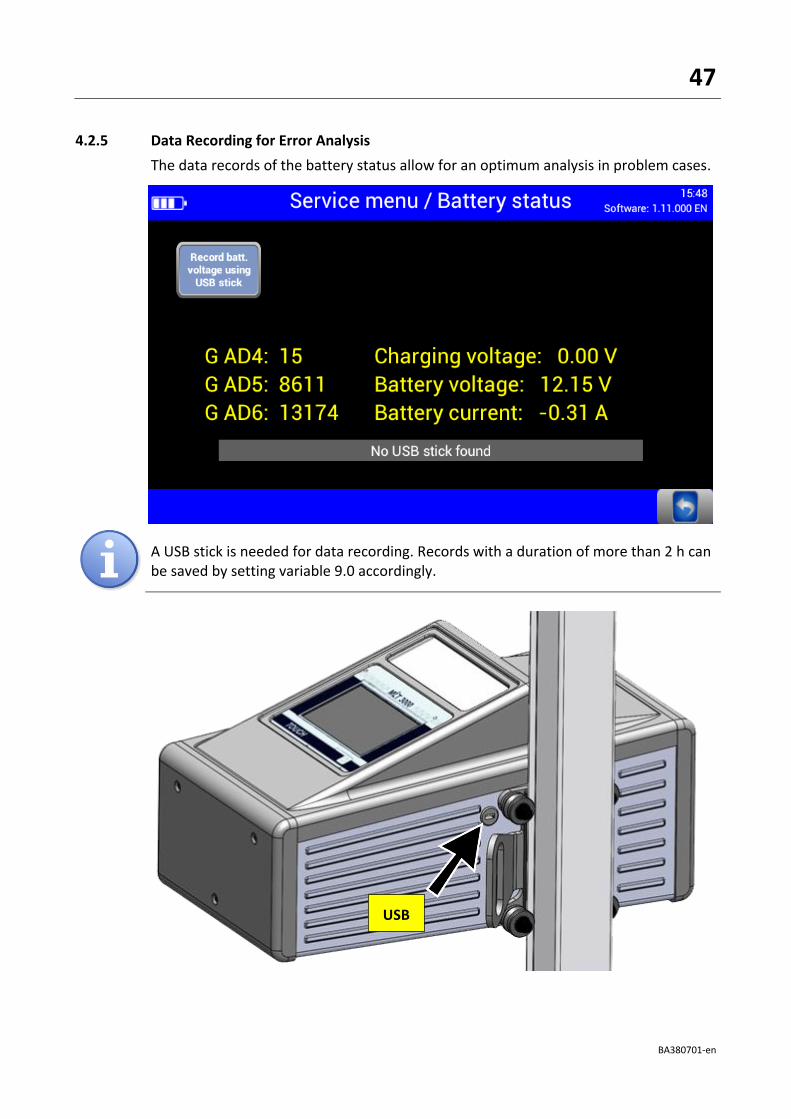
The data records of the battery status allow for an optimum analysis in problem cases.
A USB stick is needed for data recording. Records with a duration of more than 2 h can be saved by setting variable 9.0 accordingly.
USB
48
BA380701-en
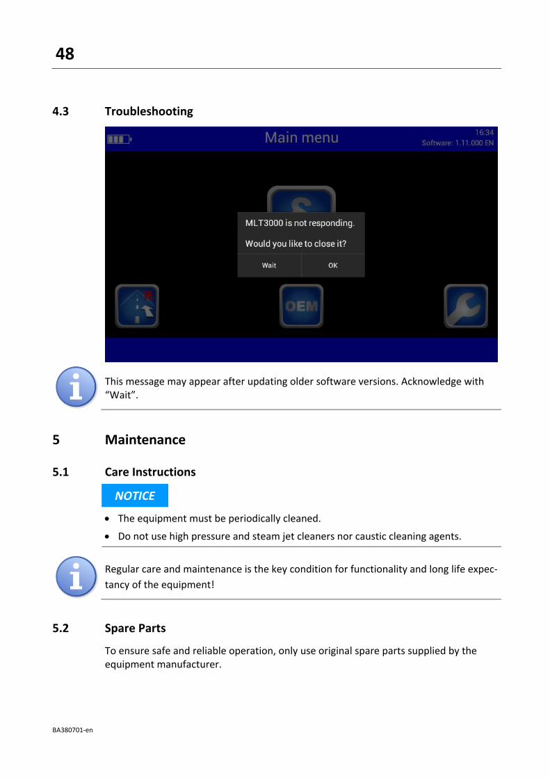
4.3 Troubleshooting
This message may appear after updating older software versions. Acknowledge with “Wait”.
5 Maintenance
5.1 Care Instructions
NOTICE
• The equipment must be periodically cleaned.
• Do not use high pressure and steam jet cleaners nor caustic cleaning agents.
Regular care and maintenance is the key condition for functionality and long life expec-
tancy of the equipment!
5.2 Spare Parts
To ensure safe and reliable operation, only use original spare parts supplied by the equipment manufacturer.

49
BA380701-en
6 Disposal
If you want to dispose of the equipment, please contact your MAHA dealer or the following address, indicating equipment type, date of purchase and serial number:
MAHA Maschinenbau Haldenwang GmbH & Co. KG Hoyen 20 | 87490 Haldenwang | Germany
Phone: +49 (0) 8374 585 0 Fax: +49 (0) 8374 585 500 Email: [email protected]
Alternatively, you may take the equipment to a specialised waste management plant to ensure that all components and operating liquids are properly disposed of.
7 Contents of the Declaration of Conformity
MAHA Maschinenbau Haldenwang GmbH & Co. KG
herewith declares as a manufacturer its sole responsibility to ensure that the product named hereafter meets the safety and health regulations both in design and construction required by the EC directives stated below. This declaration becomes void if any change is made to the product that was not discussed and approved by named company beforehand.
Model: MLT 3000 / SEP Comfort
Designation: Headlight Tester
Directives: 2014/30/EU; 2014/35/EU
Standards: DIN EN ISO 12100:2010; DIN EN 60204-1; DIN EN 61000-6-3, DIN EN 61000-6-4
Related Documents