1 MLR INSTITUTE OF TECHNOLOGY & MANAGEMENT Dundigal, Quthbullapur (m), Hyderabad-500043 CIVIL DEPARTMENT FLUID MECHANICS AND HYDRAULIC MACHINES LAB MANUAL By Mr L.Vishnu Vardhan M.Tech Assistant professor

Welcome message from author
This document is posted to help you gain knowledge. Please leave a comment to let me know what you think about it! Share it to your friends and learn new things together.
Transcript

1
MLR INSTITUTE OF TECHNOLOGY & MANAGEMENT
Dundigal, Quthbullapur (m), Hyderabad-500043
CIVIL DEPARTMENT
FLUID MECHANICS AND HYDRAULIC MACHINES
LAB MANUAL
ByMr L.Vishnu Vardhan M.Tech
Assistant professor

2
LIST OF EXPERIMENTS
1) Calibration of Venturimeter & Orifice meter.
2) Determination of coefficient of discharge for a small orifice /mouthpiece by
constant head method.
3) Calibration of contracted Rectangular Notch and / Triangular Notch.
4) Determination of friction factor of a pipe.
5) Determination of Coefficient for minor losses.
6) Verification of Bernoulli’s equation.
7) Impact of jet on vanes.
8) Study of hydraulic jump.
9) Performance test on Pelton wheel turbine.
10) Performance test on Francis turbine.
11) Performance Characteristics of a single Stage/multi-Stage centrifugal Pump.
12) Performance characteristics of a reciprocating pump.
3
EXPERIMENT-1CALIBRATION OF VENTURI METER

4
G.B.Venturi (Italian Physicist)
5
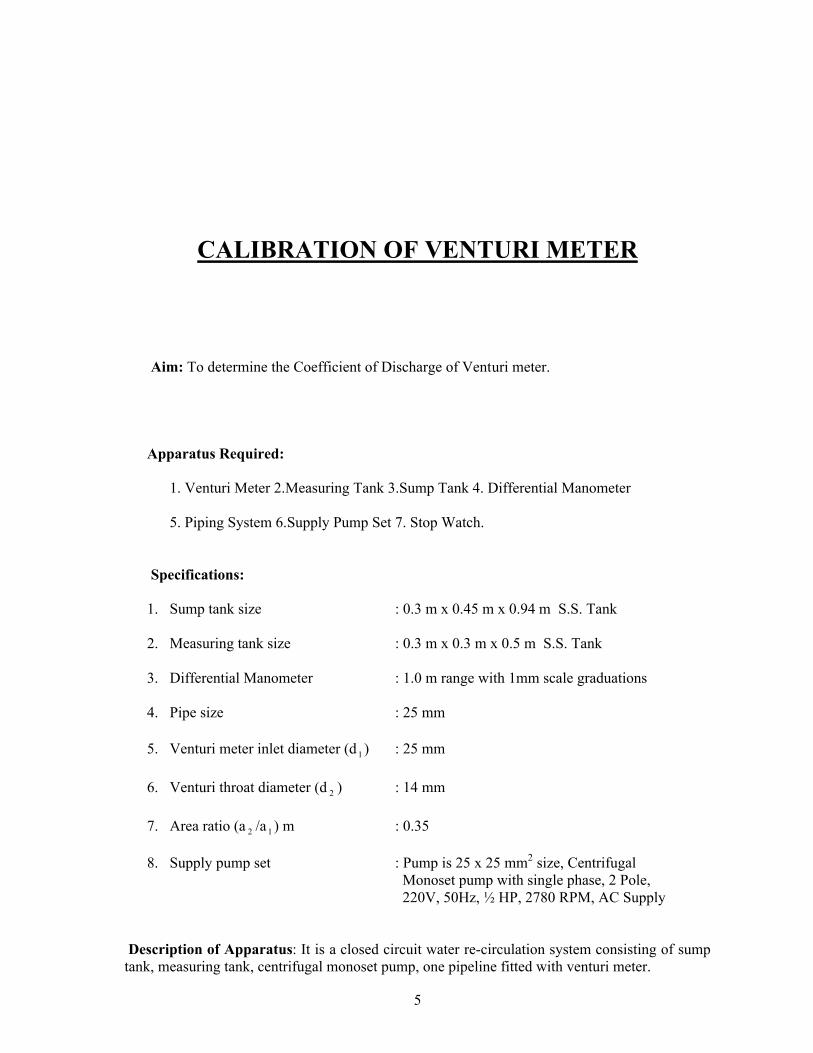
CALIBRATION OF VENTURI METER
Aim: To determine the Coefficient of Discharge of Venturi meter.
Apparatus Required:
1. Venturi Meter 2.Measuring Tank 3.Sump Tank 4. Differential Manometer
5. Piping System 6.Supply Pump Set 7. Stop Watch.
Specifications:
1. Sump tank size : 0.3 m x 0.45 m x 0.94 m S.S. Tank
2. Measuring tank size : 0.3 m x 0.3 m x 0.5 m S.S. Tank
3. Differential Manometer : 1.0 m range with 1mm scale graduations
4. Pipe size : 25 mm
5. Venturi meter inlet diameter (d1 ) : 25 mm
6. Venturi throat diameter (d 2 ) : 14 mm
7. Area ratio (a 2 /a1 ) m : 0.35
8. Supply pump set : Pump is 25 x 25 mm2 size, Centrifugal Monoset pump with single phase, 2 Pole, 220V, 50Hz, ½ HP, 2780 RPM, AC Supply
Description of Apparatus: It is a closed circuit water re-circulation system consisting of sump tank, measuring tank, centrifugal monoset pump, one pipeline fitted with venturi meter.
6
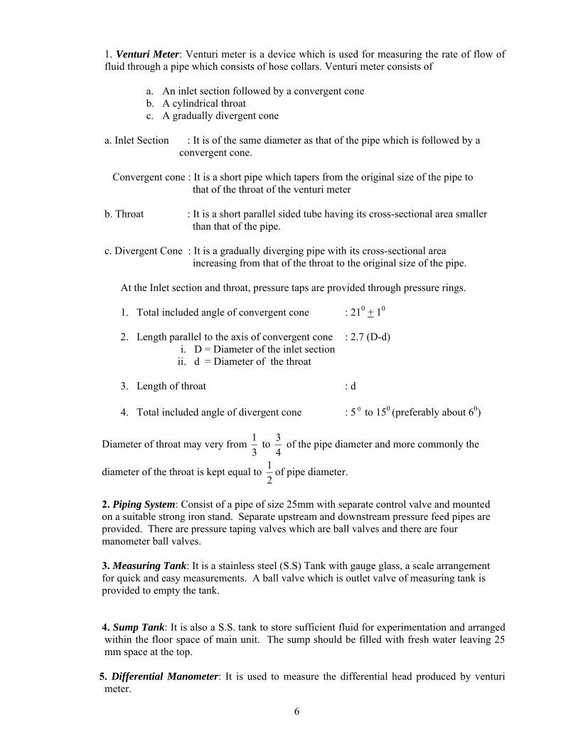
1. Venturi Meter: Venturi meter is a device which is used for measuring the rate of flow of fluid through a pipe which consists of hose collars. Venturi meter consists of
a. An inlet section followed by a convergent coneb. A cylindrical throatc. A gradually divergent cone
a. Inlet Section : It is of the same diameter as that of the pipe which is followed by a convergent cone.
Convergent cone : It is a short pipe which tapers from the original size of the pipe to that of the throat of the venturi meter
b. Throat : It is a short parallel sided tube having its cross-sectional area smaller than that of the pipe.
c. Divergent Cone : It is a gradually diverging pipe with its cross-sectional area increasing from that of the throat to the original size of the pipe.
At the Inlet section and throat, pressure taps are provided through pressure rings.
1. Total included angle of convergent cone : 210 + 10
2. Length parallel to the axis of convergent cone : 2.7 (D-d)i. D = Diameter of the inlet section
ii. d = Diameter of the throat
3. Length of throat : d
4. Total included angle of divergent cone : 5 0 to 150 (preferably about 60)
Diameter of throat may very from 3
1to
4
3of the pipe diameter and more commonly the
diameter of the throat is kept equal to 2
1of pipe diameter.
2. Piping System: Consist of a pipe of size 25mm with separate control valve and mounted on a suitable strong iron stand. Separate upstream and downstream pressure feed pipes are provided. There are pressure taping valves which are ball valves and there are four manometer ball valves.
3. Measuring Tank: It is a stainless steel (S.S) Tank with gauge glass, a scale arrangement for quick and easy measurements. A ball valve which is outlet valve of measuring tank is provided to empty the tank. 4. Sump Tank: It is also a S.S. tank to store sufficient fluid for experimentation and arranged
within the floor space of main unit. The sump should be filled with fresh water leaving 25 mm space at the top.
5. Differential Manometer: It is used to measure the differential head produced by venturi meter.

7
6.Pumpset: It is used to pump water from sump tank to measuring tank through pipe.
Theory: A Venturi meter is a device which is used for measuring the rate of flow or discharge of fluid through a pipe. The principle of the venturi meter was first demonstrated in 1797 by Italian Physicist G.B.Venturi(1746 - 1822), but the principle was first applied by C. Hershel(1842 - 1930) in 1887.
The basic principle on which a venturi works is that by reducing the cross sectional area of the flow passage, a pressure difference is created and the measurement of the pressure difference enables the determination of the discharge through the pipe. To avoid the possibility of flow separation and the consequent energy loss, the divergent cone of the venturi meter is made longer with a gradual divergence. Since the separation of flow may occur in the divergent cone of the venturi meter, this portion is not used for discharge measurement.
Since the cross sectional area of the throat is smaller than the cross-sectional area of the inlet section, the velocity of flow at the throat will become greater than that at the inlet section, according to continuity equation. The increase in the velocity of flow at the throat results in the decrease in the pressure at this section. As such a pressure difference is developed between the inlet section and the throat of the venturi meter. The pressure difference between these sections can be determined by connecting a differential manometer. The formation of vapour and air pockets in the liquid results in a phenomenon called cavitation which is not desirable. In order to avoid cavitation to occur, the diameter of the throat can be reduced only up to a certain limited value.
Procedure:
1. Before starting the experiment, do priming of pump to remove air bubbles by pouring water in the priming device.
2. Then open the inlet valve of the piping system of pump and Venturi meter pipe outletvalve and close orifice meter pipe outlet valve.
3. Start the motor and open the pressure feed pipes valves to remove the air bubbles if any.
4. Close all the valves, except upstream and downstream ball valves of pipes connected with Venturi meter.
5. Note the readings in differential manometer6. Close the outlet valve of measuring tank and note the 10 cm raise of water using stop
watch.7. Repeat the process 3 to 4 times and note the values for different flow rates of water.8. After conducting experiment close all the pressure feed pipe valves and switch off the
power supply.
Formulae:
Actual discharge:
Actual discharge (Q act ) =t
RA. m3/s
A = Area of measuring (or) collecting tank = 0.3 x 0.3 m2
8
R = Rise of water level taken in meters (say 0.1 m or 10 cm)
t = time taken for rise of water level to rise ‘R’ in ‘t’ seconds
The actual discharge is measured with the help of measuring tank and by noting the time for definite raise of water level in the tank
Theoretical discharge:
Theoretical discharge (Q th ) = 22
21
21 2
aa
ghaa
m3/s
Where
h =
2
2121 S
SShh / 100 m of water
h 1 -h 2 = Difference in Manometric liquid in cm
S 1 = Specific gravity of Manometric liquid
S 2 = Specific gravity of flowing liquid
g = Acceleration due to gravity (9.81 m/s 2 )
a1 = Inlet area of Venturi meter in m 2
a 2 = Area of throat in m 2
Coefficient of discharge:
Coefficient of discharge(C d ) =th
act
Q
Q=
elDischTheoritica
ehActualDisc
arg
arg
Table of Readings:
S.NO Manometer reading cm of hg
Manometer head h
(m)
Time for (10 cm)rise of water level
t in Sec.h1 h 2 h m

9
Sample Calculations:
Area of inlet (a1 ) =
4
21d
in m 2 =
Where d1 = Venturi inlet diameter = 25 mm = 25x10-3 m
Area of throat (a 2 ) =
4
22d
in m 2 =
Where d2 = Throat diameter = 14 mm = 14x10-3 m
Manometer head h in m =
Theoretical discharge of Venturi meter (Q th ) in s
m3
=
Time for 100 mm rise in sec (t) =
Actual discharge of Venturi meter (Q act ) in s
m3
=
Coefficient of discharge of Venturi meter (C d ) = th
act
Q
Q=
Table of Calculations:
Precautions:
1. All the joints should be leak proof and water tight2. Manometer should be filled to about half the height with mercury3. All valves on the pressure feed pipes and manometer should be closed to prevent
damage and over loading of the manometer before starting the motor.4. Ensure that gauge glass and meter scale assembly of the measuring tank is fixed
vertically and water tight5. Ensure that the pump is primed before starting the motor6. Remove the air bubbles in differential manometer by opening air release valves7. Take the differential manometer readings without parallax error8. Ensure that the electric switch does not come in contact with water9. The water filled in the sump tank should be 2 inches below the upper end.
Fig:
S.NOActual Discharge
Qact
m3/sec
Theoretical Discharge Qth
m3/sec
Coefficient of Discharge
Cd = Qact / Qth

10
Model Graph: A graph between Qact vs √H
√H
Qact
Results:
Actual discharge of Venturi meter( Q act ) = m3/sec
Theoretical discharge of Venturi meter (Q th ) = m3/sec
Coefficient of discharge of Venturi meter (C d ) =

11
Viva Questions:
1. What are the applications of Bernoulli’s equation? A. Venturi meter, Orifice meter, Pitot tube, Nozzle meter
2. What is Venturi meter? And what is its use? A. Venturi meter is a device which is used for measuring the rate of flow of fluid
through a pipe
3. Who demonstrated the principle of Venturi meter first?A. The Principle of Venturi meter was first demonstrated in 1797 by Italian Physicist
G.B. Venturi (1746 - 1822).
4. Who applied Venturi meter principle?A. C. Herschel (1842-1930) applied Venturi meter principle in 1887.
5. What is the basic principle of venturi meter?A. The basic principle on which a venturi meter works is that by reducing the cross-
sectional area of the flow passage, a pressure difference is created and the measurement of the pressure difference enables the determination of the discharge through the pipe.
6. What are the parts of Venturi meter?A. a. An inlet section followed by a convergent cone
b. A Cylindrical throatc. A gradually divergent cone
7. What is convergent cone?A. It is a short pipe which tapers from the original size of the pipe to that of the throat of the venturi meter
8. What is throat of Venturi meter?A. The throat of the Venturi meter is a short parallel sided tube having its cross- sectional area smaller than that of the pipe.
9. What is divergent cone?A. It is a gradually diverging pipe with its cross-sectional area increasing from that of the throat to the original size of the pipe.
10. Where pressure taps are provided?A. At the inlet section and throat.

12
11. What is the total included angle of convergent cone of Venturi meter?A. 210 + 10
12. What is the length of the convergent cone?A. 2.7 (D-d) D = Diameter of the inlet section d = Diameter of the throat
13. What is the included angle of divergent cone?A. 50 to 150 (preferably about 60)
14. Which part is smaller, convergent cone or divergent cone? Why?A. Convergent cone is smaller. To avoid the possibility of flow separation and the
consequent energy loss, the divergent cone of the venturi meter is made longer with a gradual divergence.
15. Where separation of flow occurs?A. In Divergent cone of Venturi meter
16. Which portion is not used for discharge measurement?A. Divergent cone
17. Which cross-sectional area is smaller than cross sectional area of inlet section?A. Throat
18. Where velocity of flow greater?A. Throat
19. Where pressure is low in Venturi meter?A. Throat
20. How pressure difference is determined?A. By connecting a differential manometer
21. Between which sections the pressure difference can be determined?A. Inlet section and Throat
22. What we should do for getting greater accuracy in the measurement of the pressure difference?
A. The cross sectional area of the throat should be reduced so that the pressure at throat is very much reduced.
23. What is cavitation?A. The formation of the vapour and air pockets in the liquid ultimately results in a
phenomenon called Cavitation.
24. What is value of diameter of throat?A. The diameter of throat may very from 1/3 to ¾ of the pipe diameter and more commonly the diameter of the throat is kept equal to ½ of the pipe diameter.
25. What should be done to avoid cavitation?A. The diameter of throat should be reduced only up to a certain limited value

13
26. Write the formula for actual discharge.
A. Q act = t
AR
27. Write the formula for theoretical discharge.
A. Q th = 22
21
21 2
aa
ghaa
28. Write the co-efficient discharge
A. Coefficient of discharge (C d ) = th
act
Q
Q
29. Venturi meter based on which principles?A. Bemoulli’s equation.
30. What is the value of C d for Venturi meter?
A. It is less than 1 and it may be between 0.95 and 0.99.

14
EXPERIMENT-1B) CALIBRATION OF ORIFICEMETER
15
CALIBRATION OF ORIFICE METER
Aim: To determine the Coefficient of Discharge of Orifice meter.
Apparatus required:
1. Orifice Meter 2.Measuring Tank 3.Sump Tank 4.Differential Manometer 5.Piping
System 6.Supply Pump set and 7.Stop Watch.
Specifications:
1. Sump tank size : 0.3 m x 0.45 m x 0.95 m S.S. Tank
2. Measuring tank size : 0.3 m x 0.3 m x 0.5 m S.S. Tank
3. Differential Manometer : 1.0 m range with 1mm scale graduations
4. Supply pump set : Pump is 25 x 25 mm2 size, Centrifugal monoset pump with single phase, 2 pole, 220V,
50Hz, ½ HP, 2780 RPM, AC supply
5. Pipe size : 25 mm
6. Orifice meter inlet diameter(d1 ) : 25 mm
7. Orifice meter diameter(d 2 ) : 13 mm
8. Area ratio (a 2 /a 1 ) m : 0.45
Description of Apparatus: It is a closed circuit water re-circulation system consisting of Sump tank, Measuring tank, Centrifugal Monoset pump, one pipeline fitted with Orifice meter.
1.Orifice Meter: It is a cheaper arrangement for discharge measurement through pipes and its installations requires a smaller length as compared with venturi meter .It consists

16
of a flat circular plate with a circular hole called orifice which is concentric with the pipe axis. The thickness of the plate t is less than or equal to 0.05 times the diameter of the pipe
From the upstream face of the plate the edge of the orifice is made flat for a thickness t 1 less than or equal to 0.02 times the diameter of the pipe and for the remaining thickness
of the plate it is bevelled with the bevel angel lying between 30 0 to 45 0 . If the plate thickness t is equal to t 1 , then no bevelling is done for the edge of the orifice. The diameter of the orifice may vary from 0.2 to 0.85 times the pipe diameter, but generally the orifice diameter is kept as 0.5 times the pipe diameter. Two pressure taps are provided, one on upstream side of the orifice plate, and the other on the downstream side of the orifice plate. The upstream pressure tap is located at a distance of 0.9 to 1.1 times the pipe diameter from the orifice plate .The position of the downstream pressure tap, depends on the ratio of the orifice diameter and pipe diameter.
2. Piping System: Consist of a pipe of size 25mm with separate control valve and mounted on a suitable strong iron stand. Separate upstream and downstream pressure feed pipes are provided. There are pressure taping valves which are ball valves and there are four manometer ball valves.
3. Measuring Tank: It is a stainless steel (S.S) Tank with gauge glass, a scale arrangement for quick and easy measurements. A ball valve which is outlet valve of measuring tank is provided to empty the tank.
4. Sump Tank: It is also S.S. tank to store sufficient fluid for experimentation and arranged within the floor space of main unit. The sump should be filled with fresh water leaving 25 mm space at the top.
5. Differential Manometer: It is used to measure the differential head produced by Orifice meter.
6. Pump set: It is used to pump water from sump tank to measuring tank through pipe.
Theory:
An orifice meter is another simple device used for measuring the discharge through pipes. Orifice meter also works on the same principle as that of venturi meter i.e, by reducing the cross sectional area of the flow passage a pressure difference between the two sections is developed and the measurement of the pressure difference enables the determination of the discharge through the pipe. On the downstream side the pressure tap is provided quite close to the orifice plate at the section where the converging jet of the fluid has almost the smallest cross sectional area( which is known as vena contracta) resulting in almost the maximum velocity of the flow and consequently minimum pressure at this section. Therefore the maximum possible pressure difference exists between the sections 1 and 2, which is measured by connecting a differential manometer. The jet of the fluid coming out of the orifice meter gradually expands from the vena contracta to again fill the pipe. Since in the case an orifice meter an abrupt change in the cross sectional area of the flow passage is provided and there being no gradual change in the cross sectional area of the flow passage as in the case of a venturi meter, there is a greater loss of energy in an orifice meter than in a venturi meter .
Procedure:

17
1. Before starting the experiment, do priming of pump to remove air bubbles by pouring water in the priming device.
2. Then open the inlet valve of the piping system of pump and orifice meter outlet valve and close venturimeter pipe outlet valve.
3. Start the motor and open the pressure feed pipe valves to remove the air bubbles if any.
4. Close all the valves, except upstream and downstream ball valves of pipes connected with orifice meter
5. Note the readings in differential manometer6. Close the outlet valve of measuring tank and note the 100 mm raise of water using
stop watch.7. Repeat the process 3 to 4 times and note the values for different flow rates of water.8. After conducting experiment close all the pressure feed pipe valves and switch off the
power supply.
Formulae:
Actual discharge:
Actual discharge (Q act ) = t
ARm3/s
A = Area of measuring (or) collecting tank = 0.3 x 0.3 m2
R = Rise of water level taken in meters (say 0.1 m or 10 cm)
t = time taken for rise of water level to rise ‘R’ in ‘t’ seconds The actual discharge is measured with the help of measuring tank and by noting the time for
definite rise of water level in the tank
Theoretical discharge:
Theoretical discharge (Q th ) = 22
21
21 2
aa
ghaa
h =
2
2121 S
SShh / 100 m of water
h 1 - h 2 = Difference in manometric liquid in cm
S 1 = Specific gravity of manometric liquid
S 2 = Specific gravity of flowing liquid
g = Acceleration due to gravity (9.81 m/s 2 )a1 = Area of inlet diameter of orifice meter in m 2
a 2 = Area of orifice meter in m 2
Coefficient of discharge:

18
Coefficient of discharge(C d ) =th
act
Q
Q=
elDischTheoritica
ehActualDisc
arg
arg
Table of Readings:
Sample Calculations:
Area of inlet diameter of orificemeter (a 1 ) =
4
21d
in m 2 =
Where d1 = orifice inlet diameter = 25 mm = 25x10-3 m
Area of orifice meter (a 2 ) =
4
22d
in m 2 =
Where d2 = orifice diameter = 13.0 mm = 13x10-3 m
Manometer head h in m =
Theoretical discharge of Orifice meter (Q th ) in s
m3
=
Time for 100 mm rise t in sec =
Actual discharge of Orifice meter (Q act ) in s
m3
=
Coefficient of discharge of Orifice meter (C d ) = th
act
Q
Q=
Table of Calculations:
S.NO Manometer reading cm of hg
Manometer head h
(m)
Time for (10 cm)rise of water level
t in Sec.h1 h 2 h m
S.NOActual Discharge
Qact
m3/sec
Theoretical Discharge Qth
m3/sec
Coefficient of Discharge
Cd = Qact / Qth

19
Precautions:
1. All the joints should be leak proof and water tight2. Manometer should be filled to about half the height with mercury3. All valves on the pressure feed pipes and manometer should be closed to prevent
damage and over loading of the manometer before starting the motor.4. Ensure that gauge glass and meter scale assembly of the measuring tank is fixed
vertically and water tight5. Ensure that the pump is primed before starting the motor6. Remove the air bubbles in differential manometer by opening air release valve7. Take the differential manometer readings without parallax error8. Ensure that the electric switch does not come in contact with water9. The water filled in the sump tank should be 2 inches below the upper end.
Graph: A graph between Qact vs √H
Fig:
Model Graph:
Results:

20
Actual discharge of Orifice meter (Q act ) = m3/sec
Theoretical discharge of Orifice meter (Q th ) = m3/sec
Coefficient of discharge of Orifice meter (C d ) =
Viva Questions:
1. For which one, the coefficient of discharge is smaller, venturimeter or Orificemeter?A. Orifice meter
2. What is the reason for smaller value of C d ?
A. There are no gradual converging and diverging flow passages as in the case of venturimeter which results in a greater loss of energy and consequent reduction of the coefficient of discharge for an orifice meter
3. What is Orifice meter? A. An orifice meter is another simple device used for measuring the discharge through pipes.
4. What is the principle of Orifice meter?A. Orifice meter also works on the same principle as that of venturi meter i.e, by reducing the cross sectional area of the flow passage a pressure difference between the two sections is developed and the measurement of the pressure difference enables the determination of the discharge through the pipe.
5. For discharge measurement through pipes which is having cheaper arrangement and whose installation requires a smaller length?
A. Orifice meter
6. What are the parts of Orifice meter?A. Flat circular plate with a circular hole
7. What is the thickness of the plate t?A. t 0.05d
d= diameter of the pipe
8. What is the range of bevel angle in orifice meter?A. 300 to 450 ( preferably 450 )
9. What is the diameter of the orifice?A. It may very from 0.2 to 0.85 times the pipe diameter, but generally the orifice diameter is kept as 0.5 times pipe diameter
10. Where two pressure taps are provided?A. One on upstream side of the orifice plate and the other on downstream side of the orifice plate.
11. Where upstream pressure tap is located?

21
A. It is located at a distance of 0.9 to 1.1 times the pipe diameter from the orifice plate.
12. Which diameter is less, orifice or pipe?A. Orifice meter13. What is vena contracta?A. Smallest cross sectional area
14. At which section on the downstream side the pressure tap is provided quite close to orifice plate?
A. At the section where the converging jet of fluid has almost the smallest cross sectional area (which is known as vena contracta)
15. Where the velocity of flow is maximum and pressure is minimum?A. At vena contracta
16. Maximum possible pressure difference that exists between upstream side of the orifice plate and downstream side of the orifice plate is measured by means of what?
A. Differential manometer
17. Where there is a greater loss of energy, whether in venturi meter or in orifice meter?A. In orifice meter
18. Why there is a greater loss of energy in orifice meter?A. Because there is an abrupt change in the cross-sectional area of flow passage
19. What is value of c d ?
A. It is the range of 0.6 to 0.68
20. What is the manometer liquid?A. Mercury
21. When an orifice is called large orifice?A. When head of liquid from the center of the orifice is less than 5 times the depth of orifice
22. On what the position of downstream pressure tap depends?A. It depends on the ratio of the orifice diameter and the pipe diameter.

22
EXPERIMENT-3A) CALIBRATION OF CONTRACTED
RECTANGULAR NOTCH

23
CALIBRATION OF CONTRACTED RECTANGULAR NOTCH
Aim: To find out the coefficient of discharge of Rectangular notch plate
Apparatus Required:
1. Notch tank 2. Sump Tank 3. Measuring tank 4. Notch plate 5. Rectangular notch 6.
Supply pump set 7.Hook gauge 8.StopWatch
Specifications :
1) Sump Tank size : 1.2 m x 0.3 m x 0.42 m S.S. Tank
2) Notch tank size : 1.0 m x 0.2 m x 0.18 m S.S. Tank
3) Rectangular notch : 100 mm
4) Supply pump set : Pump is 25 x 25 mm2 size, centrifugal monoset pump
with single phase, 2pole, 230 V, 50 Hz, ½ HP, 2820
rpm, AC supply
5) Measuring tank Size : 0.6 m x 0.3 m x 0.5 m S.S. Tank
Description of apparatus:
1. Notch Tank: It is having steady arrangement with baffles and a provision for fixing interchangeable notch plates. There are three baffles.
2. Hook Gauge: It is fixed in notch tank top edge. The Hook gauge is kept in vertical position with the help of spiral level. It is used to measure the depth of water.
3. Measuring tank: It is a Stainless steel tank (S.S) with gauge glass and scale arrangement for quick and easy measurements. A ball valve which is outlet valve of measuring tank is provided to empty the tank.
4. Sump tank: It is also a S.S. tank to store sufficient fluid for experimentation and arranged within the floor space of main unit. The sump tank should be filled with fresh water leaving 25 mm space at the top.

24
Theory:
A Notch is defined as an opening provided in the side of a tank (or vessel) such that the liquid surface in the tank is below the top edge of the opening.
Notches made of metallic plates are provided in narrow channels (particularly in laboratory channels) in order to measure the rate of flow of liquid. As such in general notches are used for measuring the rate of flow of liquid from a tank or a channel
The sheet of water flowing through a notch is known as the nape (French term meaningsheet or vein) .The bottom edge of a notch over which the water flows is known as the Sill or Crest, and its height above the bottom of the tank or channel is known as Crest height.
The notches are usually classified according to the shape of the opening as Rectangular notch, Triangular notch (or V-notch), Trapezoidal notch, Parabolic notch and Stepped notch. The edges of all these notches are bevelled on the downstream side so as to have sharp-edged sides and crest, resulting in minimum contact with the flowing liquid. Since the liquid surface is always below the top edge of the notch, a notch is usually provided with only a crest and sides with no top edge.
Notches may also be classified according to the effect of the sides on the nappe emerging from a notch, as notch with end contraction and notch without end contraction or suppressed notch. Notches provided in the sides of tanks or vessels are essentially the notches with end contraction. However, in a channel if the crest length of the notch is less than the width of the channel then it is a notch with end contraction. But if the crest length of the notch is equal to the width of the channel then it is a notch without end contraction or a suppressed notch.
The expression for discharge over a rectangular notch is given by,
where,L= width of the notch,(m)h= head of water over the notch,(m)g= acceleration due to gravity (m/s2)
25
Procedure:
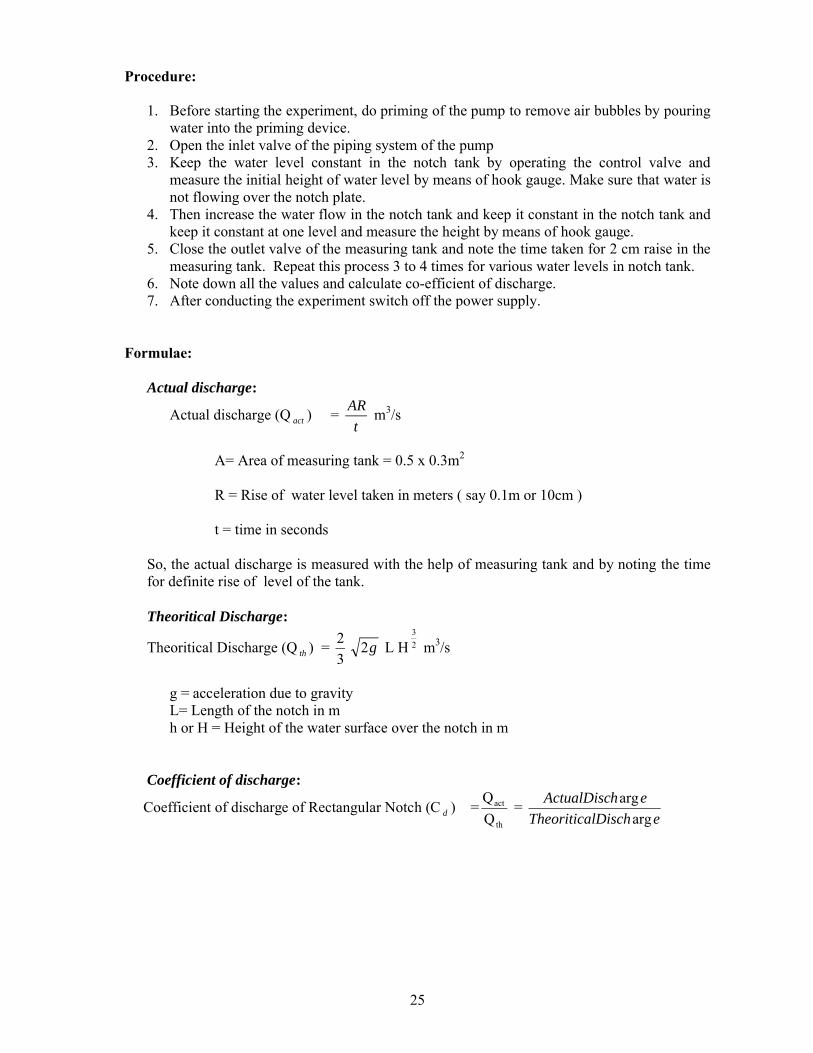
1. Before starting the experiment, do priming of the pump to remove air bubbles by pouring water into the priming device.
2. Open the inlet valve of the piping system of the pump3. Keep the water level constant in the notch tank by operating the control valve and
measure the initial height of water level by means of hook gauge. Make sure that water is not flowing over the notch plate.
4. Then increase the water flow in the notch tank and keep it constant in the notch tank and keep it constant at one level and measure the height by means of hook gauge.
5. Close the outlet valve of the measuring tank and note the time taken for 2 cm raise in the measuring tank. Repeat this process 3 to 4 times for various water levels in notch tank.
6. Note down all the values and calculate co-efficient of discharge.7. After conducting the experiment switch off the power supply.
Formulae:
Actual discharge:
Actual discharge (Q act ) = t
ARm3/s
A= Area of measuring tank = 0.5 x 0.3m2
R = Rise of water level taken in meters ( say 0.1m or 10cm )
t = time in seconds
So, the actual discharge is measured with the help of measuring tank and by noting the time for definite rise of level of the tank.
Theoritical Discharge:
Theoritical Discharge (Q th ) = 3
2g2 L H 2
3
m3/s
g = acceleration due to gravityL= Length of the notch in mh or H = Height of the water surface over the notch in m
Coefficient of discharge:
Coefficient of discharge of Rectangular Notch (C d ) =th
act
Q
Q=
elDischTheoritica
ehActualDisc
arg
arg

26
Observations:
S.NO Depth of water Theoretical discharge (Q th ) in
m3/s
Time for 100 mm rise
Actual discharge(Q act )
in m3/s
Co-efficient of discharge (C d )
Hook guage readingInitial mm Final
mmDepth
mh1 h 2
H
Sample Calculations:
Area of the measuring tank =
Time for 100 mm rise (t) in sec =
Actual discharge (Q act ) in m3/s =
Length of the notch in m (L) =
Height of the water surface over the notch in m (H) =
Theoretical discharge (Q th ) in m3/s =
Coefficient of discharge of Rectangular Notch (C d ) =th
act
Q
Q=
11. Precautions:
1. All the joints should be leak proof and water tight2. Ensure the at gauge glass and meter scale assembly of the measuring tank is fixed
vertically and water tight3. Ensure that the pump is primed before starting the motor4. Ensure that the electric switch does not come in contact with water5. The water filled in the sump tank should be 2 inches below the upper end.6. Check that hook gauge is firmly fixed and perpendicular to base7. Ensure that the notch plate fitted in the notch tank should be vertical8. Notch plate should be properly fixed and wing nuts should not be loose.
Results:
Actual discharge of rectangular notch (Q act ) =
Theoretical discharge rectangular notch (Q th ) =
Co-efficient of discharge of rectangular notch(C d ) =
27
Viva Questions:
a. What is a Notch? A. A notch may be defined as an opening provided in the side of a tank (or vessel) such that the liquid surface in the tank is below the top edge of the opening.
b. Where notches made of metallic plates are used? And why?A. In narrow channels, in order to measure the rate of flow of liquid
c. What is the use of notch?A. It is used to measure the rate of flow of liquid from a tank or in a channel
d. What is Nappe?A. The sheet of water flowing through a notch
e. Which word is nappe? What is the meaning?A. French word. Means sheet
f. What is Sill or Crest?A. Bottom edge of a notch over which water flows
g. What is crest height?A. Notch height above the bottom of the tank is crest height
h. What are the types of notches according to shape of opening?A. 1. Rectangular Notch 2.Triangular Notch (V Notch) 3. Trapezoidal Notch 4. Parabolic Notch 5.Stepped Notch
i. On which the edges of all these notches are bevelled? And why?A. On down stream side so as to have sharp edged sides and crest, resulting in minimum contact with flowing liquid
j. What are the types of notches according to the effect of sides on the nappe emerging from a notch?
A. 1. Notch with end contraction2. Notch without end contraction or suppressed notch
k. What is notch with end contraction?A. If the sides of a notch cause the contraction of nappe , then it is said to be notch with end contraction.
l. What is notch without end contraction?A. If there is no contraction of the nappe due to the sides then it is known as a notch without end contraction
m. What is theoretical discharge for Rectangular notch?
A. Theoritical Discharge (Q th ) = 3
2g2 L H 2
3
m3/s

28
EXPERIMENT-3 B) CALIBRATION OF CONTRACTED
TRIANGULAR NOTCH

29
CALIBRATION OF CONTRACTED TRIANGULAR NOTCH
1. Aim: To find out the coefficient of discharge of Triangular notch plate
2. Apparatus Required:
1. Notch tank 2.Sump Tank 3.Measuring tank 4.Notch plate 5.Rectangular notch
6. Supply pump set 7.Hook gauge 8. Stop Watch
Specifications :
1. Sump Tank size : 1.2 m x 0.3 m x 0.42m S.S. Tank
2. Notch tank size : 1.0m x 0.2m x 0.18m S.S. Tank
3. Triangular notch :90˚ (Angle of the Notch)4. Supply pump set : Pump is 25 x 25 mm2 size centrifugal monoset pump with single phase, 2pole, 230 V, 50 Hz, ½ HP, 2880 RPM, AC supply
5. Measuring tank Size : 0.6 m x 0.3 m x 0.5 m S.S. Tank
Description of apparatus:
1. Notch Tank: It is having steady arrangement with baffles and a provision for fixing interchangeable notch plates. There are three baffles
2. Hook Gauge: It is fixed in notch tank top edge. The Hook gauge is kept in vertical position with the help of spiral level. It is used to measure the depth of water.
3. Measuring tank: It is a Stainless steel tank (S.S) with gauge glass and scale arrangement for quick and easy measurements. A ball valve which is outlet valve of measuring tank is provided to empty the tank.
4. Sump tank: It is also a S.S. tank to store sufficient fluid for experimentation and arranged within the floor space of main unit. The sump tank should be filled with fresh water leaving 25 mm space at the top.
Theory:A notch is defined as an opening provided in the side of a tank ( or vessel) such that the
liquid surface in the tank is below the top edge of the opening.
Notches made of metallic plates are provided in narrow channels (particularly in laboratory channels) in order to measure the rate of flow of liquid. As such in general notches are used for measuring the rate of flow of liquid from a tank or in a channel

30
The sheet of water flowing through a notch is known as the nappe (French term meaningsheet) .The bottom edge of a notch over which the water flows is known as the Sill or Crest, and its height above the bottom of the tank or channel is known as Crest height.
The notches are usually classified according to the shape of the opening as Rectangular notch, Triangular notch (or V-notch), Trapezoidal notch, Parabolic notch and Stepped notch. The edges of all these notches are bevelled on the downstream side so as to have sharp-edged sides and crest, resulting in minimum contact with the flowing liquid. Since the liquid surface is always below the top edge of the notch, a notch is usually provided with only a crest and sides with no top edge.
Notches may also be classified according to the effect of the sides on the nappe emerging from a notch, as notch with end contraction and notch without end contraction or suppressed notch. Notches provided in the sides of tanks or vessels are essentially the notches with end contraction. However, in a channel if the crest length of the notch is less than the width of the channel then it is a notch with end contraction. But if the crest length of the notch is equal to the width of the channel then it is a notch without end contraction or a suppressed notch.
The expression for discharge over a Triangular notch is given by,
Where
L= width of the notch,(m)θ= angle of the notch,(deg)h= head of water over the notch,(m)g= acceleration due to gravity (m/s2)
Procedure:
1. Before starting the experiment, do priming of the pump to remove air bubbles by pouring water into the priming device.
2. Open the inlet valve of the piping system of the pump

31
3. Keep the water level constant in the notch tank by operating three various control valves and measure the initial height of water level by means of hook gauge making sure that water is flowing on the notch plate.
4. Then increase the water flow in the notch tank and keep it constant in the notch tank and keep it constant at one level and measure the height by means of hook gauge.
5. Close the outlet valve of the measuring tank and note the time taken for 100 mm raise in the measuring tank. Repeat this process 3 to 4 times for various water levels in notch tank.
6. Note down all the values and calculate co-efficient of discharge.7. After conducting the experiment switch off the power supply.
Formulae:
Actual discharge:
Actual discharge (Q act ) = t
ARm3/s
A= Area of measuring tank = 0.5 x 0.3m2
R = Rise of water level taken in meters ( say 0.1m or 10cm )
t = time taken for rise of water level to rise ‘R’ in ‘t’ seconds
So, the actual discharge is measured with the help of measuring tank and by noting the time for definite rise of water level of the tank.
Theoritical Discharge:
Theoritical Discharge of Triangular Nocth (Q th ) = 15
8g2 Tan
2
H 2
5
m 3 /s
g = acceleration due to gravity
L= Length of the notch in m
H = Height of the water surface over the notch in m
Ө = Angle of the Notch = 90˚
Coefficient of discharge:
Coefficient of discharge of Triangular Notch (C d ) =th
act
Q
Q=
elDischTheoritica
ehActualDisc
arg
arg

32
Observations:
S. NO Depth of water Theoretical discharge (Q th ) in
m3/s
Time for 100 mm rise
Actual discharge(Q act )
in m3/s
Co-efficient of discharge
(C d )Hook guage reading
Initial mm
Final mm
Depth m
h1 h 2H
10. Sample Calculations:
Area of the measuring tank =
Time for 100 mm rise (t) in sec =
Actual discharge (Q act ) in m3/s =
Height of the water surface over the notch in m (H) =
Theoretical discharge (Q th ) in m3/s =
Coefficient of discharge of Triangular Notch (C d ) =th
act
Q
Q=
Precautions:
1. All the joints should be leak proof and water tight2. Ensure the at gauge glass and meter scale assembly of the measuring tank is fixed
vertically and water tight3. Ensure that the pump is primed before starting the motor4. Ensure that the electric switch does not come in contact with water5. The water filled in the sump tank should be 2” below the upper end6. Check that hook gauge is firmly fixed and perpendicular to base7. Ensure that the notch plate fitted in the notch tank should be vertical8. Notch plate should be properly fixed and wing nuts should not be loose.
Results:
1. Actual discharge of Triangular notch (Q act ) =
2. Theoretical discharge Triangular notch (Q th ) =
3. Co-efficient of discharge of Triangular notch(C d ) =

33
Viva Questions:
1. What is notch? A. A notch may be defined as a opening provided in the side of a tank (or vessel) such that the liquid surface in the tank is below the top edge of the opening.
2. Where notches made of metallic plates are used? And why?A. In narrow channels in order to measure the rate of flow of liquid
3. What is the use of notch?A. It is used to measure the rate of flow of liquid from a tank or in a channel
4. What is nappe?A. The sheet of water flowing through a notch
5. Which word is nappe? What is the meaning?A. French word means sheet
6. What is Sill or Crest?A. Bottom edge of a notch over which water flows
7. What is crest height?A. Notch height above the bottom of the tank is crest height
8. What are the types of notches according to shape of opening?A. 1. Rectangular Notch 2.Triangular Notch (V Notch) 3. Trapezoidal Notch 4. Parabolic Notch 5.Stepped Notch
9. On which the edges of all these notches are bevelled? And why?A. On down stream side so as to have sharp edged sides and crest, resulting in minimum contact with flowing liquid
10. What are the types of notches according to the effect of sides on the nappe emerging from a notch?A. 1. Notch with end contraction
2. Notch without end contraction or suppressed notch
11. What is notch with end contraction?A. If the sides of a notch cause the contraction of nappe , then it is said to be notch with end contraction.
12. What is notch without end contraction?A. If there is no contraction of the nappe due to the sides then it is known as a notch without end contraction
13. What is theoretical discharge for Triangular notch?
A. Theoritical Discharge (Q th ) =15
8g2 Tan
2
H 2
5
m3/s

34
EXPERIMENT-4
DETERMINATION OF FRICTION FACTOR FOR A GIVEN PIPE LINE

35
DETERMINATION OF FRICTION FACTOR FOR A GIVEN PIPE LINE
Aim: To measure the frictional losses in pipes of different sizes.
Apparatus Required:
1. Piping system 2.Sump Tank 3.Measuring Tank 4.Differential Manometer 5.Pump Set.
6. Stop Watch
Specifications:
1. Sump tank size : 0.95 m x 0.45 m x 0.3 m S.S. tank
2. Measuring Tank Size : 0.3 m x 0.3m x 0.5 m S.S. Tank
3. Differential Manometer : 1 m range with 1mm scale of graduation
4. No. of pipes : 1S.S, 2 Galvanized Iron(GI) pipes
5. Piping system sizes : 20 mm, 20mm, 12.7mm
6. Pressure taping distance : 0.1 m
7. Pump set : Pump is 25x25mm2 size, centrifugal, moonset
pump with single phase, 2pole, 220V, 1/2HP, 50
Hz, 2880 rpm, AC supply.
Description of apparatus:
1. Piping system: Consists of a set of 2G.I pipes and 1 S.S pipes of size 20mm, 12.7mm and 20mm and length 1 m between pressure tapings with separate flow control valves. Separate upstream and downstream pressure feed pipes are provided for the measurement of pressure heads with control situated at common place for easy operation.
2. Sump tank: It is S.S. tank to store sufficient fluid for experimentation and arranged within the floor space of main unit. The sump should be filled with fresh water having 25 mm space at the top.
3. Measuring tank: It is also a S.S tank with gauge glass, a scale arrangement for quick and easy measurements. A ball valve which is outlet valve of measuring tank is provided to empty the tank.

36
4. Differential manometer: It is used to measure the differential head produced by piping system.
5. Pump set: It is used to pump water from sump tank to measuring tank through pipe.
Theory:
A pipe is a closed conduit which is used for carrying fluids under pressure. Pipes are commonly circular section. As the pipes carry fluids under pressure, the pipes always run full.
The fluid flowing in a pipe is always subjected to resistance due to shear forces between fluid particles and the boundary walls of the pipe and between the fluid particles themselves resulting from the viscosity of the fluid. The resistance to the flow of fluid is, in general known as frictional resistance. Since certain amount of energy possessed by the flowing fluid will be consumed in overcoming this resistance to the flow, there will always be some loss of energy in the direction of flow, which however depends on the type of flow, W.froude conducted a series of experiments to investigate frictional resistance offered to the flowing water by different
surfaces h f = gD
fLV
2
2
is Darcy Weisbach equation Which is commonly used for computing the
loss of head due to friction of pipes. Here is f friction factor. In order to determine the loss of head due to friction correctly, it is essential to estimate the value of the factor f correctly when a fluid flows through a pipe, certain resistance is offered to the flowing fluid, which results in causing a loss of energy. The various energy losses in pipes may be classified as
i) major lossesii) minor losses
The major loss of energy, as a fluid of flows through a pipe, is caused by friction. It may be computed by Darcy-Weisbach equation. The loss of energy due to friction is classified as a major loss because in the case of long pipelines it is usually much more than the loss of energy Incurred by other causes.
Procedure:
1. Before starting the experiment, do priming of the pump to remove air bubbles by pouring water into the priming device.
2. Open the inlet valve in the piping systems of the pump and outlet valve of one of the 3 pipes and remaining 2 valves will be in closed condition
3. Start the motor and open the upstream pressure feed pipe valves and downstream pressure feed pipe valves of the concerned pipe
4. Remove the air bubbles by opening the pressure feed pipe valves if any.5. Note down the manometer reading6. Close the outlet valve of measuring tank and measure the time taken for 10 cm raise
in water level by measuring tank.7. Repeat the procedure 2 to 3 times for various flow rates of water8. Same procedure is adopted for 2 other pipes by opening the concerned valves and
remaining valves in closed condition.9. Note the values and do the calculation to find out the frictional loss.
Formulae:
The actual loss of head is determined from the manometer readings. The frictional loss of head pipes is given by the following formula

37
h f = gD
fLV
2
2
f = Coefficient of friction for the pipe (frictional factor)L= Distance between two sections from which loss of head is measured (3 m)
V = Average velocity of flow = a
Q
Q = Discharge in s
m3
a=Area of the pipe
a=4
2d
g = acceleration due to gravityD = Pipe diameter in meters
h f =
f
fm
S
SS*
100
mh
S m = specific gravity of manometric liquid
S f = specific gravity of flowing liquid
h m = h1 – h 2 cm of Hg
Table of Readings:
Type of
Pipe
Diameterof the Pipe
‘d’
Area of PipeA m2
Manometer reading
Water collected in collecting
tank
‘R’
Time for (10 cm) rise of water level t in Sec.
h1 h2 hm
mm m cm of Hg cm m Sec
Sample calculations:
Actual discharge in m3/s =
Area of the pipe =4
2d= m2
Average velocity of water in the pipe v =a
Qact= m/sec
Frictional loss of head in pipe h f =
Frictional factor f =

38
Table of Calculations:
Loss Of Head
(12.6 x hm)
100‘hf’
Actual Discharge
Qact = A R/t
TheoreticalVelocity
V = a
ctQa
V 2Friction Factor
f
m m3/sec m3/sec
Graph: A graph between V2 on X-axis and hf on Y-axis is drawn
Model Graph:
hf
V2
Precautions:
1. Ensure that the pump is primed before starting the motor2. While doing the experiment on a particular pipe keep the other pipe line
closed3. Take the differential manometer readings without parallax error4. Ensure that the electric switch does not come in contact with water5. Remove air bubbles in differential manometer by opening air release valve6. Ensure that opening and closing of manometer valves should be done
carefully to avoid leakage of mercury7. Check that gauge glass and meter scale assembly of the measuring tank is
fixed vertically and water tight8. Manometer should be filled to about half the height with mercury9. Ensure that all valves on the pressure feed pipes and manometer should be
closed to prevent damage and over loading of the manometer10. All the joints should be leak proof and water tight.11. The water filled in the sump tank should be 2” below the upper end
Results:
Coefficient of loss of head h f =
Friction factor f =

39
Viva Questions:
a. What is pipe?A. A pipe is a closed circuit which is used for carrying fluids under pressure
b. The fluid flowing by a pie is always subjected to what?A. It is subjected to resistance due to shear forces between fluid particles and the boundary walls of the pipe and between the fluid articles themselves resulting from the viscosity of the fluid
c. What is frictional resistance?A. The resistance to the flow of fluid is frictional resistance.
d. In overcoming the frictional resistance what is consumed?A. Certain amount of energy possessed by the flowing fluid will be consumed
e. What will be there in the direction of flow and it depends on what?A. There will be some loss of energy in the direction of flow and depends on the type of flow.
f. What are the types of flow of fluid in a pipe?A. Laminar, turbulent
g. On what the frictional resistance offered to the flow depends on?A. Type of flow
h. What is Darcy-Weisbach equation?
A. h f = gD
fLV
2
2
i. What is the use of Darcy-Weisbach equation?A. It is used for computing the loss of head due to friction in pipes
j. On what friction factor f depends upon?A. f is not a constant, but its value depends on the roughness condition of the pipe surface and the Reynolds number of flow
k. Which is essential to determine the loss of head due to friction correctly?A. Correct estimation of the value of the factor
l. In addition to Darcy-Weisbach equation what are the other formulae for head loss due to friction in pipes?
A. Chezy’s formula, Manning’s formula, Hazen-Williams formula

40
EXPERIMENT-6VERIFICATION OF BERNOULLI’S
EQUATION

41
BERNOULLI .DANIEL

42
VERIFICATION OF BERNOULLIS EQUATION
Aim: To prove that the total head at any point along the flow is same i.e, datum head + pressure head + velocity head is constant along the flow
Or
w
p1 + g
v
2
21 +z1 =
w
p2 + g
v
2
22 +z2
Apparatus Required:
1. Bernoullis apparatus which consists of supply and receiving chambers with scales and glass tubes
2. Piezometer glass tubes
3. Sump tank
4. Measuring tank (collecting tank)
5. Supply pump set
6. Stop Watch
Specifications:
1. Sump tank size : 1.25 m x 0.3m x 0.3m S.S. tank
2. Measuring Tank size : 0.3 m x 0.5 m
3. Pump size : 25mm x 25 mm
4. Supply pump set : Pump is centrifugal manometer pump with single phase, 2 pole, 220V, 50 Hz, ½ Hp, 2880 RPM, AC supply
Description of apparatus:
There are supply and receiving chambers and interlinking experimental sides made out of perspex sheets for the purpose of observing the flow. The interlinking duct is smoothly varying in cross section so that the velocity of flow changes gradually for the purpose of experiments with minimum friction loss and loss due to turbulence. Piezometer glass tubes are provided at suitable intervals along the duct for the measurement of pressure head at various points. A flow control valve is provided at the exit of the receiving chamber for adjusting and keeping different flow rates through the apparatus. A collecting tank

43
(receiving chamber) is provided for the measurement of rate of flow. The apparatus is kept in the spirit level position horizontally by means of adjusting the screw arrangement provided at the bottom of the sump.
Measuring Tank: It is a stainless steel (S.S) Tank with gauge glass, a scale arrangement for quick and easy measurements. A ball valve which is outlet valve of measuring tank is provided to empty the tank.
Sump Tank: It is also S.S. tank to store sufficient fluid for experimentation and arranged within the floor space of main unit. The sump should be filled with fresh water leaving 25 mm space at the top.
Pump set: It is used to pump water from sump tank to measuring tank through pipe.
Theory: The Bernoullis equation is
w
p+
g
v
2
2
+z = c
Which is applicable for steady, irrotational flow of incompressible fluidsP= pressure
W= g=specificweight
V= velocity at any point
g=gravitational acceleration
= mass density
w
p= pressure head or static head
g
v
2
2
= velocity head or kinetic head
Z = potential head or datum head
C= arbitrary constant
The sum of pressure head, velocity head and the potential head is known as the total head or the total energy per unit weight of the fluid. Bernoullis equation states that in a steady irrotational flow of an incompressible fluid the total energy at any point is constant.
If Bernoulli’s equation is applied between any two points in a steady irrotational flow of an incompressible fluid, then we get
w
p1 + g
v
2
21 +z1 =
w
p2 + g
v
2
22 +z2
Where the different terms with subscripts and 2 correspond to the two points considered.
44
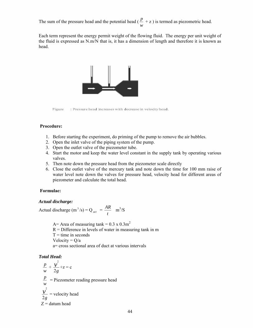
The sum of the pressure head and the potential head (w
p+ z ) is termed as piezometric head.
Each term represent the energy permit weight of the flowing fluid. The energy per unit weight of the fluid is expressed as N.m/N that is, it has a dimension of length and therefore it is known as head.
Procedure:
1. Before starting the experiment, do priming of the pump to remove the air bubbles.2. Open the inlet valve of the piping system of the pump.3. Open the outlet valve of the piezometer tube.4. Start the motor and keep the water level constant in the supply tank by operating various
valves.5. Then note down the pressure head from the piezometer scale directly6. Close the outlet valve of the mercury tank and note down the time for 100 mm raise of
water level note down the valves for pressure head, velocity head for different areas of piezometer and calculate the total head.
Formulae:
Actual discharge:
Actual discharge (m 3 /s) = Q act = t
ARm3/S
A= Area of measuring tank = 0.3 x 0.3m2
R = Difference in levels of water in measuring tank in mT = time in secondsVelocity = Q/aa= cross sectional area of duct at various intervals
Total Head:
w
p+
gv2
2
+z = c
w
p = Piezometer reading pressure head
g
v2
2
= velocity head
Z = datum head

45
Observations Table:
Cross sectional area (a)
Time for R= 10cm rise
Actual discharge= Q act =
t
AR
Velocity
V=a
QVelocity
head
gv2
2
Piozometer reading pressure
head w
p
Datum Head
z
Total head
gv2
2
+w
p+ +z = c
m 2 Sec m3/s m/s m m m m
Sample calculations:
Time for 100 mm raise (t) in sec =
Actual discharge (Q) in m3/s = t
AR
a = cross sectional area =
Velocity (v) = a
Q
Velocity head = g
V
2
2
=
Piezometer reading pressure headw
p=
Datum head (z) =
Total head = w
p+
gv2
2
+ z = c
Precautions:
1. Be careful to avoid leakage of the piezometer tubes2. The water filled in the sump tank should be 2 inches below the upper end3. Ensure that the electric switch does not come in contact with water4. Ensure that the water level is constant in the supply tank during the experiment5. Check that the gauge glass and meter scale assembly of the measuring tank is fixed
vertically and water tight.6. Ensure that the pump is primed before starting the motor.7. All joints should be leak proof and water tight
Result:
The total head at any point along the flow is same.

46
Viva Questions:
1. What is Bernoulli’s equation?
A. w
p+
gv2
2
+z = Constant
2. What isw
p?
A. Pressure energy per unit weight of fluid or pressure head or static head.
3. What isg
v2
2
?
A. Kinetic energy per unit weight or kinetic head or velocity head
4. What is z?A. Potential energy per unit weight or potential head or datum head
5. What are the assumptions of Bernoulli’s equation?A. 1) The fluid is ideal (i.e, viscosity is zero)
2) The flow is steady3) The flow is incompressible4) The flow is irrotational
6. What Bernoulli’s equation states?A. It states that in a steady, ideal, irrotational flow of an incompressible fluid, the total
energy at any point of the fluid in constant
7. For which type of fluids Bernoulli’s equation is applicable?A. For steady, irrotational flow of incompressible fluids
8. What is total head?A. Sum of pressure head, velocity head, and potential head is known as total head
9. If Bernoulli’s equation is applicable between two points what is the equation of Bernoulli?
A. w
p1 + g
v
2
21 +z1 =
w
p2 + g
v
2
22 +z2
10. What is Piezometric head?A. Sum of pressure head and potential head
11. In Bernoulli’s equation each term represents what?A. The energy per unit weight of the flowing fluid.
12. Why each term is called head?A. The energy per unit weight of the fluid is expressed as N.m/N that is it has a dimension of length and therefore it is known as head
13. What is viscosity?A. It is the property of fluid which offers resistance to the movement of one layer of fluid over another adjacent layer of fluid.

47
EXPERIMENT-5Determination of Minor Losses of Head Due To
Sudden Contraction in a Pipe Line
48
Determination of Minor Losses Of Head Due To Sudden Contraction In a Pipe Line
Aim: To determine the coefficient of Minor losses of head due to sudden contraction
Apparatus Required:
1. Piping system 2.Sump Tank 3.Measuring Tank 4.Differential Manometer 5.Pump Set.
6. Stop Watch
Specifications:
1. Sump tank size : 0.9 m x 0.45 m x 0.3 m S.S. tank
2. Measuring Tank Size : 0.6 m x 0.3m x 0.3 m S.S. Tank
3. Differential Manometer : 1 m range with 1mm scale of graduation
4. No. of pipes : 2 Galvanized Iron(GI)
5. Piping system sizes : 25 mm,12.5mm
6. Pressure taping distance : 0.5 m
7. Pump set : Pump is 25x25mm2 size, centrifugal, moonset
pump with single phase, 2pole, 220V, 1/2HP, 50
Hz, 2880 rpm, AC supply.
Description of apparatus:
1. Piping system: piping system of size 25 mm diameter and 12.5 mm with a flow control valve.
2. Sump tank: It is S.S. tank to store sufficient fluid for experimentation and arranged within the floor space of main unit. The sump should be filled with fresh water having 25 mm space at the top.
3. Measuring tank: It is also a S.S tank with gauge glass, a scale arrangement for quick and easy measurements. A ball valve which is outlet valve of measuring tank is provided to empty the tank.
4. Differential manometer: It is used to measure the differential head produced by piping system.
5. Pump set: It is used to pump water from sump tank to measuring tank through pipe.

49
Procedure:
1. Start the motor keeping the delivery valve close. Make sure that the ball valve is fully open which is at the collecting tank
2. Slowly open the cocks which are fitted at sudden contraction end and make sure that manometer is free from air bubbles
3. Make sure while taking the readings, that the manometer is properly primed. Priming is the operation of removing the air bubbles from the pipes. Note down the loss of head “hc” from the manometer scale.
4. Note down the time required for the rise of 10 cm (i.e 0.1 m) water in the collecting tank by using stopwatch. Calculate the discharge using below formula.
Discharge: The time taken to collect some ‘X’ cm of water in the collecting tank
in m3/sec
Q = t
AR
Where
A = Area of measuring (or) collecting tank = 0.3 x 0.3 m2
R = Rise of water level taken in meters (say 0.1 m or 10 cm)
t = time taken for rise of water level to rise ‘R’ in‘t’ seconds
5. Calculate the velocity of the jet by following formula
V = Discharge / Area of pipe = Q / A m/sec Where
A = Cross sectional area of the pipe = Π / 4 * d2
d = diameter of the pipe
6. Calculate the coefficient of contraction for the given pipe by
hc = v2 / 2g * K
Where hc = loss of head due to sudden contraction = (h1-h2) * 12.6/100 m
K = co-efficient for loss of head in contraction
= [1/Cc - 1]2
V = Average Velocity of flow in m/sec
7. Repeat the steps 2 to 6 for different sets of readings by regulating the discharge valve.

50
Table of Readings:
Type of
Pipe
Diameterof the Pipe
‘d’
Area of PipeA m2
Manometer reading
Water collected in collecting
tank
‘R’
Time for (10 cm) rise of water level
t in Sec.h1 h2 hm
mm m cm of Hg cm m Sec
Table of Calculations:
Actual Discharge
Qact = A R/t
TheoreticalVelocity
V = a
Q
hc
Coefficient of contraction
Cc
m3/sec m/sec m
Precautions:
1. Ensure that the pump is primed before starting the motor2. While doing the experiment on a particular pipe keep the other pipe line
closed3. Take the differential manometer readings without parallax error4. Ensure that the electric switch does not come in contact with water5. Remove air bubbles in differential manometer by opening air release valve6. Ensure that opening and closing of manometer valves should be done
carefully to avoid leakage of mercury7. Check that gauge glass and meter scale assembly of the measuring tank is
fixed vertically and water tight8. Manometer should be filled to about half the height with mercury9. Ensure that all valves on the pressure feed pipes and manometer should be
closed to prevent damage and over loading of the manometer10. All the joints should be leak proof and water tight.11. The water filled in the sump tank should be 2” below the upper end
Results:
Loss of head due to sudden contraction hc =
Coefficient of Contraction Cc =

51
Viva Questions:
a. Write the classification of various energy losses.A. Major losses, minor losses
b. What causes major loss of energy?A. Friction
c. Major loss of energy computed by which equation?A. Darcy-Weisbach equation
d. What is the reason for the classification of loss of energy due to friction as major loss?
A. In the case of long pipelines it is usually much more than the loss of energy incurred by other causes.
e. Due to what the minor losses of energy are caused?A. Due to change in the velocity of flowing fluid (either by magnitude or direction)
f. Why these are called minor losses?A. In case of long pipes these losses are usually quite small as compared with the loss of energy due to friction and hence these are termed. Minor losses which may be neglected without serious error.
g. In where minor losses outweigh the friction loss?A. In Short pipes
h. Write some minor losses which may be caused due to the change of velocity.A. Loss of energy due to sudden enlargementB. Loss of energy due to sudden contractionC. Loss of energy at entrance to a pipeD. Loss of energy at the exit from a pipeE. Loss of energy due to gradual contraction or enlargementF. Loss of energy in bends G. Loss of energy in various pipe fit
52
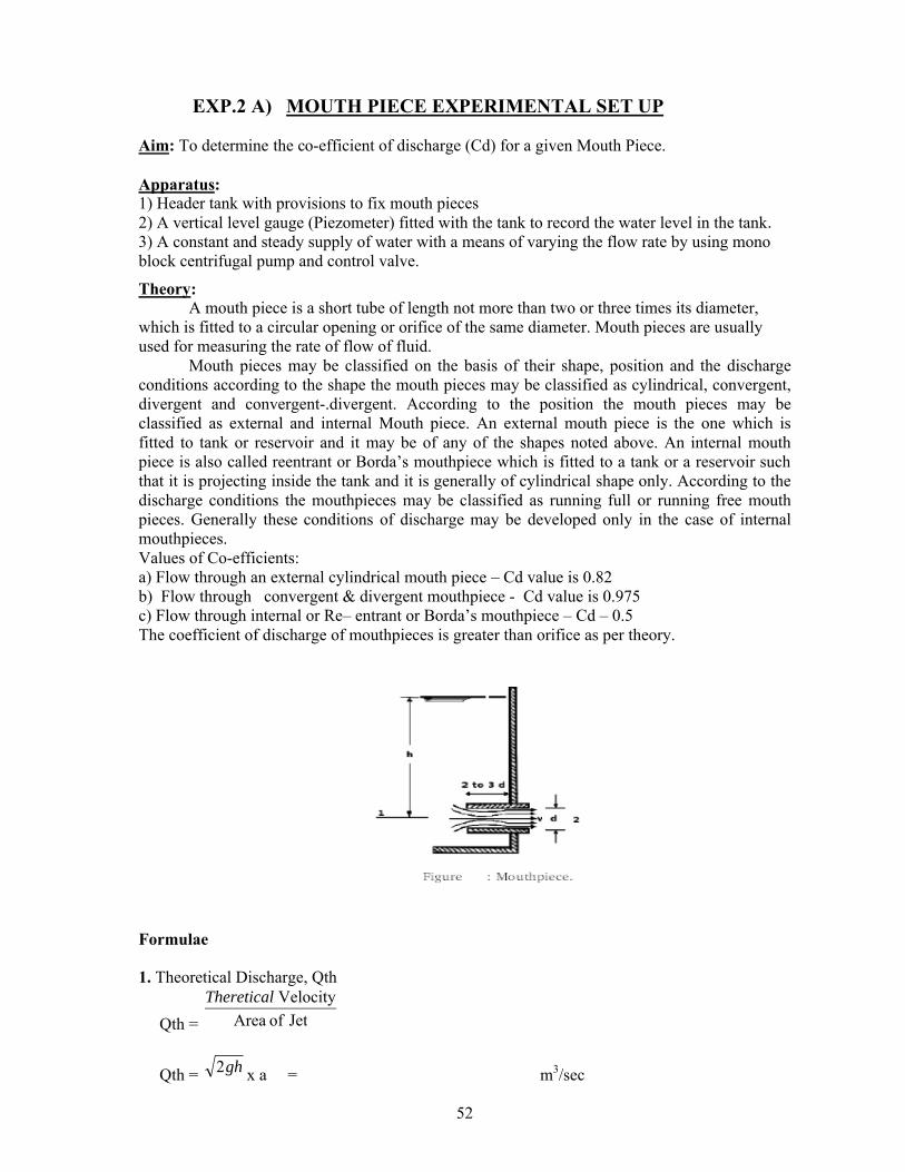
EXP.2 A) MOUTH PIECE EXPERIMENTAL SET UP
Aim: To determine the co-efficient of discharge (Cd) for a given Mouth Piece.
Apparatus:1) Header tank with provisions to fix mouth pieces 2) A vertical level gauge (Piezometer) fitted with the tank to record the water level in the tank.3) A constant and steady supply of water with a means of varying the flow rate by using mono block centrifugal pump and control valve.
Theory:A mouth piece is a short tube of length not more than two or three times its diameter,
which is fitted to a circular opening or orifice of the same diameter. Mouth pieces are usually used for measuring the rate of flow of fluid.
Mouth pieces may be classified on the basis of their shape, position and the discharge conditions according to the shape the mouth pieces may be classified as cylindrical, convergent, divergent and convergent-.divergent. According to the position the mouth pieces may be classified as external and internal Mouth piece. An external mouth piece is the one which is fitted to tank or reservoir and it may be of any of the shapes noted above. An internal mouth piece is also called reentrant or Borda’s mouthpiece which is fitted to a tank or a reservoir such that it is projecting inside the tank and it is generally of cylindrical shape only. According to the discharge conditions the mouthpieces may be classified as running full or running free mouth pieces. Generally these conditions of discharge may be developed only in the case of internal mouthpieces.Values of Co-efficients: a) Flow through an external cylindrical mouth piece – Cd value is 0.82b) Flow through convergent & divergent mouthpiece - Cd value is 0.975c) Flow through internal or Re– entrant or Borda’s mouthpiece – Cd – 0.5The coefficient of discharge of mouthpieces is greater than orifice as per theory.
Formulae
1. Theoretical Discharge, Qth
Qth = JetofArea
VelocityTheretical
Qth = gh2 x a = m3/sec
53
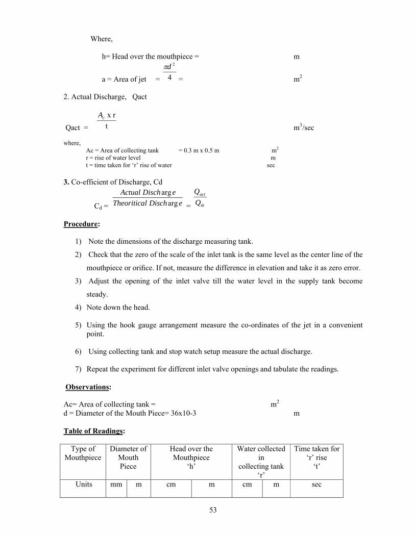
Where,
h= Head over the mouthpiece = m
a = Area of jet = 4
2d
= m2
2. Actual Discharge, Qact
Qact = t
r x cA
m3/sec
where, Ac = Area of collecting tank = 0.3 m x 0.5 m m2 r = rise of water level m t = time taken for ‘r’ rise of water sec
3. Co-efficient of Discharge, Cd
Cd = eDischlTheoritica
eDischActual
arg
arg
= th
act
Q
Q
Procedure:
1) Note the dimensions of the discharge measuring tank.
2) Check that the zero of the scale of the inlet tank is the same level as the center line of the
mouthpiece or orifice. If not, measure the difference in elevation and take it as zero error.
3) Adjust the opening of the inlet valve till the water level in the supply tank become
steady.
4) Note down the head.
5) Using the hook gauge arrangement measure the co-ordinates of the jet in a convenient point.
6) Using collecting tank and stop watch setup measure the actual discharge.
7) Repeat the experiment for different inlet valve openings and tabulate the readings.
Observations:
Ac= Area of collecting tank = m2
d = Diameter of the Mouth Piece= 36x10-3 m
Table of Readings:
Type of Mouthpiece
Diameter of Mouth Piece
Head over the Mouthpiece
‘h’
Water collected in
collecting tank‘r’
Time taken for‘r’ rise
‘t’
Units
mm m cm m cm m sec

54
Table of Calculations:
Actual Discharge
(Qact)
Theoretical Discharge
(Qth)
Coefficient of Discharge
(Cd)m3/sec m3/sec
Graphs: A graph between Qact and √H is drawn.
Results:
Co-efficient of Discharge for the given Mouth Piece from Experiment =
Viva Questions:
1) Define Mouthpiece?2) What is meant by running free and running full?3) What is the difference between orifice and mouthpiece?
55
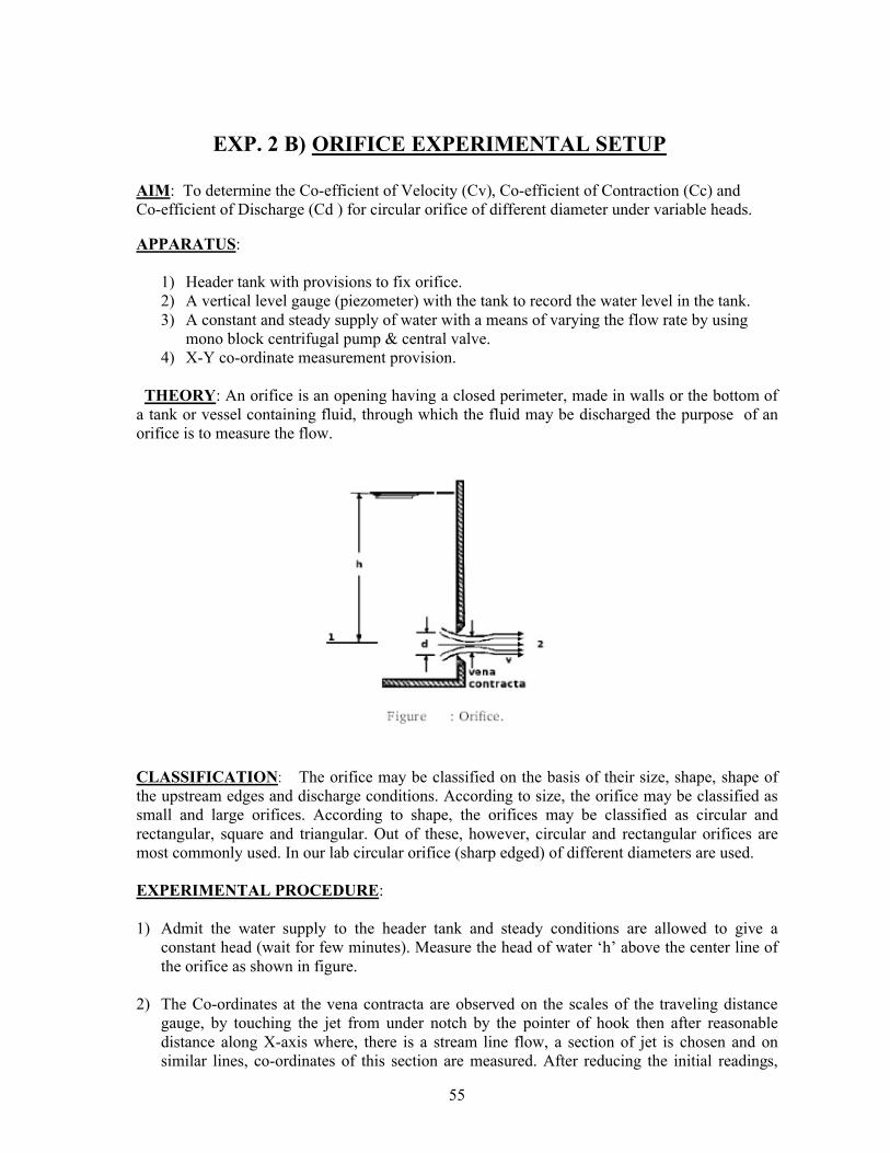
EXP. 2 B) ORIFICE EXPERIMENTAL SETUP
AIM: To determine the Co-efficient of Velocity (Cv), Co-efficient of Contraction (Cc) and Co-efficient of Discharge (Cd ) for circular orifice of different diameter under variable heads.
APPARATUS:
1) Header tank with provisions to fix orifice.2) A vertical level gauge (piezometer) with the tank to record the water level in the tank.3) A constant and steady supply of water with a means of varying the flow rate by using
mono block centrifugal pump & central valve.4) X-Y co-ordinate measurement provision.
THEORY: An orifice is an opening having a closed perimeter, made in walls or the bottom of a tank or vessel containing fluid, through which the fluid may be discharged the purpose of an orifice is to measure the flow.
CLASSIFICATION: The orifice may be classified on the basis of their size, shape, shape of the upstream edges and discharge conditions. According to size, the orifice may be classified as small and large orifices. According to shape, the orifices may be classified as circular and rectangular, square and triangular. Out of these, however, circular and rectangular orifices are most commonly used. In our lab circular orifice (sharp edged) of different diameters are used.
EXPERIMENTAL PROCEDURE:
1) Admit the water supply to the header tank and steady conditions are allowed to give a constant head (wait for few minutes). Measure the head of water ‘h’ above the center line of the orifice as shown in figure.
2) The Co-ordinates at the vena contracta are observed on the scales of the traveling distance gauge, by touching the jet from under notch by the pointer of hook then after reasonable distance along X-axis where, there is a stream line flow, a section of jet is chosen and on similar lines, co-ordinates of this section are measured. After reducing the initial readings,

56
the vertical and horizontal distances of the sections chosen are found out. From this, the coefficient of the velocity can be calculated by the formula mentioned.
3) Collect the water discharging from the orifice in a collecting tank of known dimensions and
measure the rise of water level “r” in the collecting tank, for certain period of “ t ” sec and repeat the above for different heads. From these values the co efficient of discharge can be calculated. Co- efficient of discharge can also be obtained by multiplying Cc & Cv.
Some Definitions:
a) Co-efficient of Contraction (Cc): The ratio of the area of jet at vena- contracta to the area of the orifice.
Let, Cc = Co-efficient of contraction,
Cc = a
caarea jorificeofarea
contractaat venajet of
Area of jet, (aj) = 4
2d
m2 d = the diameter of the orifice, m
The value of ‘Cc’ depends on a number of factors like the size and shape of the orifice, the head on the orifice, the viscosity of the liquid etc. For sharp edged orifice the value of Cc is generally equal to 0.62.
b). Co-efficient of Velocity (Cv): The ratio of the actual velocity of the jet at vena contracta to the theoretical velocity of the jet.
Let Cv = Co efficient of velocity.
Vth = Theoretical velocity = gh2 m/sec Vact = Actual Velocity at vena contract m/sec
Cv = velocityltheoretica
contractaat vena velocity actual
= act
th
V
V
Cv varies between 0.95 to 0.99.
Generally Cv is taken equal to 0.98 for sharp edged orifice
c) Determination of Co-efficient of Discharge (Cd): The ratio of the actual discharge to the theoretical discharge of the orifice.
Theoretical Discharge, Qth = Theoretical Velocity x area of orifice
Qth = gh2 x a m3/sec
Area of orifice, (a) = 4
2d
m2 d = the diameter of the orifice m
Actual discharge, Q act = t
r x cA
m3/sec

57
Where,Ac = area of collecting tank = 0.3 m x 0.5 m mr = rise of water mt = time taken for ‘r’ rise of water sec
Coefficient of Discharge, Cd = th
act
Q
QActual
dischargelTheoritica
discharge
Usually Cd varies between 0.61 to 0.65
Relation between the Co-efficients of an orifice: Cd =
vc xCC
Determination of the co-efficient of velocity : Constant head of water is maintained
over the orifice
Let, Vact = Velocity of the jet at vena contracta
Consider any point ‘P’ on the centre line of the jet. Let the horizontal and vertical Co –ordinates of ‘P’ be ‘X’ and ‘Y’ with respect to the centre of the jet at vena contracta as origin.
Let, the time taken by a particle of water to move from vena - contract to ‘P’ be ‘t’Horizontal displacement X = Vact x t -- (1)Vertical displacement Y = ½ g t2 – (2)
From (1) & (2),
Vact = Y
gX
2
2
Theoretical velocity,
Vth = gh2
Co-efficient of velocity (Cv) = th
act
V
V
= Yh
X
4
2
The experiments may be repeated taking other points on the center line of the jet and the values of Cv obtained may be averaged.
c) Determination of the co-efficient of contractionFirst method: In this method the area of the jet at vena contracta is measured by using an instrument called the Micrometer Contraction gauge. This instrument consists of a ring provided with four radial screw gauges, equally spaced. The ring is held at the vena-contracta section so, that the jet can pass through its centre. The screws of the screw gauges are now adjusted so, that
58
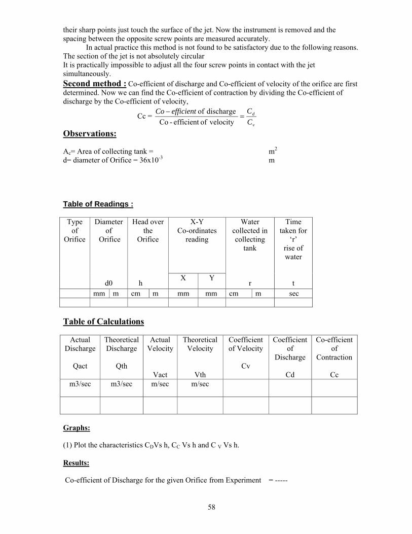
their sharp points just touch the surface of the jet. Now the instrument is removed and the spacing between the opposite screw points are measured accurately.
In actual practice this method is not found to be satisfactory due to the following reasons.The section of the jet is not absolutely circularIt is practically impossible to adjust all the four screw points in contact with the jet simultaneously. Second method : Co-efficient of discharge and Co-efficient of velocity of the orifice are firstdetermined. Now we can find the Co-efficient of contraction by dividing the Co-efficient of discharge by the Co-efficient of velocity,
Cc = v
d
C
CefficientCo
velocityofefficient -Co
dischargeof
Observations:
Ac= Area of collecting tank = m2
d= diameter of Orifice = 36x10-3 m
Table of Readings :
Type of
Orifice
Diameter of
Orifice
d0
Head overthe
Orifice
h
X-YCo-ordinates
reading
Water collected in collecting
tank
r
Time taken for
‘r’rise of water
tX Y
mm m cm m mm mm cm m sec
Table of Calculations
Actual Discharge
Qact
Theoretical Discharge
Qth
Actual Velocity
Vact
Theoretical Velocity
Vth
Coefficient of Velocity
Cv
Coefficient of
Discharge
Cd
Co-efficientof
Contraction
Ccm3/sec m3/sec m/sec m/sec
Graphs:
(1) Plot the characteristics CDVs h, CC Vs h and C V Vs h.
Results:
Co-efficient of Discharge for the given Orifice from Experiment = -----

59
Viva Questions:
1) Define Orifice?2) For what purpose orifices are used?3) Name the different hydraulic co-efficients?
60
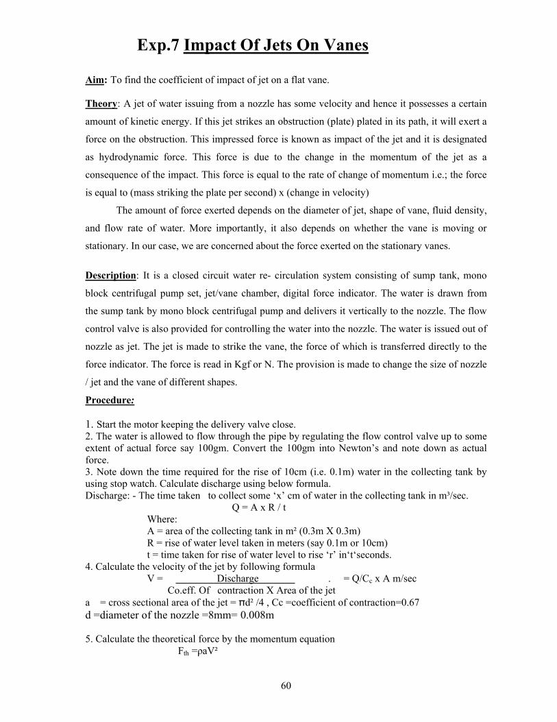
Exp.7 Impact Of Jets On Vanes
Aim: To find the coefficient of impact of jet on a flat vane.
Theory: A jet of water issuing from a nozzle has some velocity and hence it possesses a certain
amount of kinetic energy. If this jet strikes an obstruction (plate) plated in its path, it will exert a
force on the obstruction. This impressed force is known as impact of the jet and it is designated
as hydrodynamic force. This force is due to the change in the momentum of the jet as a
consequence of the impact. This force is equal to the rate of change of momentum i.e.; the force
is equal to (mass striking the plate per second) x (change in velocity)
The amount of force exerted depends on the diameter of jet, shape of vane, fluid density,
and flow rate of water. More importantly, it also depends on whether the vane is moving or
stationary. In our case, we are concerned about the force exerted on the stationary vanes.
Description: It is a closed circuit water re- circulation system consisting of sump tank, mono
block centrifugal pump set, jet/vane chamber, digital force indicator. The water is drawn from
the sump tank by mono block centrifugal pump and delivers it vertically to the nozzle. The flow
control valve is also provided for controlling the water into the nozzle. The water is issued out of
nozzle as jet. The jet is made to strike the vane, the force of which is transferred directly to the
force indicator. The force is read in Kgf or N. The provision is made to change the size of nozzle
/ jet and the vane of different shapes.
Procedure:
1. Start the motor keeping the delivery valve close. 2. The water is allowed to flow through the pipe by regulating the flow control valve up to some extent of actual force say 100gm. Convert the 100gm into Newton’s and note down as actual force. 3. Note down the time required for the rise of 10cm (i.e. 0.1m) water in the collecting tank by using stop watch. Calculate discharge using below formula.Discharge: - The time taken to collect some ‘x’ cm of water in the collecting tank in m³/sec. Q = A x R / t
Where: A = area of the collecting tank in m² (0.3m X 0.3m) R = rise of water level taken in meters (say 0.1m or 10cm) t = time taken for rise of water level to rise ‘r’ in‘t‘seconds.
4. Calculate the velocity of the jet by following formula V = Discharge . = Q/Cc x A m/sec Co.eff. Of contraction X Area of the jet
a = cross sectional area of the jet = πd² /4 , Cc =coefficient of contraction=0.67d =diameter of the nozzle =8mm= 0.008m
5. Calculate the theoretical force by the momentum equation Fth =ρaV²
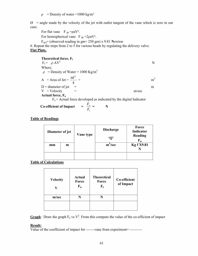
61
ρ = Density of water =1000 kg/m³
Ø = angle made by the velocity of the jet with outlet tangent of the vane which is zero in our case.
For flat vane F th =ρaV². For hemispherical vane F th =2ρaV². Fact= (observed reading in gm+ 250 gm) x 9.81 Newton
6. Repeat the steps from 2 to 5 for various heads by regulating the delivery valve.Flat Plate,
Theoretical force, Ft
Ft = AV2 NWhere, = Density of Water = 1000 Kg/m3
A = Area of Jet =4
2d= m2
D = diameter of jet = mV = Velocity = m/sec Actual force, Fa
Fa = Actual force developed as indicated by the digital Indicator
Co-efficient of Impact = t
a
F
F= N
Table of Readings
Diameter of jet Vane type
Discharge
‘Q’
Force Indicator Reading
Fa
mm m m3/sec Kg f X9.81N
Table of Calculations
Velocity
V
Actual Force
Fa
Theoretical Force
Ft
Co-efficient of Impact
m/sec N N
Graph: Draw the graph Fa vs V2. From this compute the value of the co-efficient of impact
Result: Value of the coefficient of impact for -------vane from experiment= ----------

62
Viva Questions:
1. Define Impact of jet?2. Write the formula for force exerted by a jet of water on a stationary & moving plate.3. Write the formula for force exerted by a jet of water on a curved plate at center & at one
of the tips of the jet.

63
CONVERSION FACTORS
1 kgf =9.81 N
Atmospheric Pressure = 1.01325 bar =1.01325 x 10⁵ Pascal
760 mm of Hg = 10.33 meters of Water
1 kgf/cm2 = 10 meters of water
1 Poise = 0.1 N-s/m2
1 Stoke = 10-4 m2/s
1 Metric HP = 75 kgf-m/s =746 W
1 Bar =105 Pascal
1 m3 =1000 L
Related Documents