ML296DFV MERIT ® SERIES Downflow - Two-Stage Heating - Variable Speed Blower - 60 Hz Bulletin No. 210870 August 2021 Supersedes April 2021 AFUE - 96% Input - 44,000 to 88,000 Btuh Nominal Add-on Cooling - 3 to 5 Tons ML 2 96 DF 070 X V 48 B Unit Type ML = Merit ® Series Stages 2 = Two-Stage Nominal Gas Heat Input 045 = 44,000 Btuh 070 = 66,000 Btuh 090 = 88,000 Btuh Blower V = Variable Speed Blower Motor Nominal Add-On Cooling Capacity 36 = 2 - 3 tons 48 = 2.5 - 4 tons 60 = 3 - 5 tons Configuration DF = Downflow 1 Downflow indoor coils with the same letter designation will physically match the furnace supply air opening. AFUE 96 = 96% Low NOX X = Units meet California Nitrogen Oxides Standard (40ng/J) 1 Cabinet Width B = 17-1/2 in. C = 21 in. GAS FURNACES RESIDENTIAL PRODUCT SPECIFICATIONS MODEL NUMBER IDENTIFICATION

Welcome message from author
This document is posted to help you gain knowledge. Please leave a comment to let me know what you think about it! Share it to your friends and learn new things together.
Transcript
ML296DFVMERIT® SERIES
Downflow - Two-Stage Heating - Variable Speed Blower - 60 HzBulletin No. 210870
August 2021 Supersedes April 2021
AFUE - 96%Input - 44,000 to 88,000 Btuh
Nominal Add-on Cooling - 3 to 5 Tons
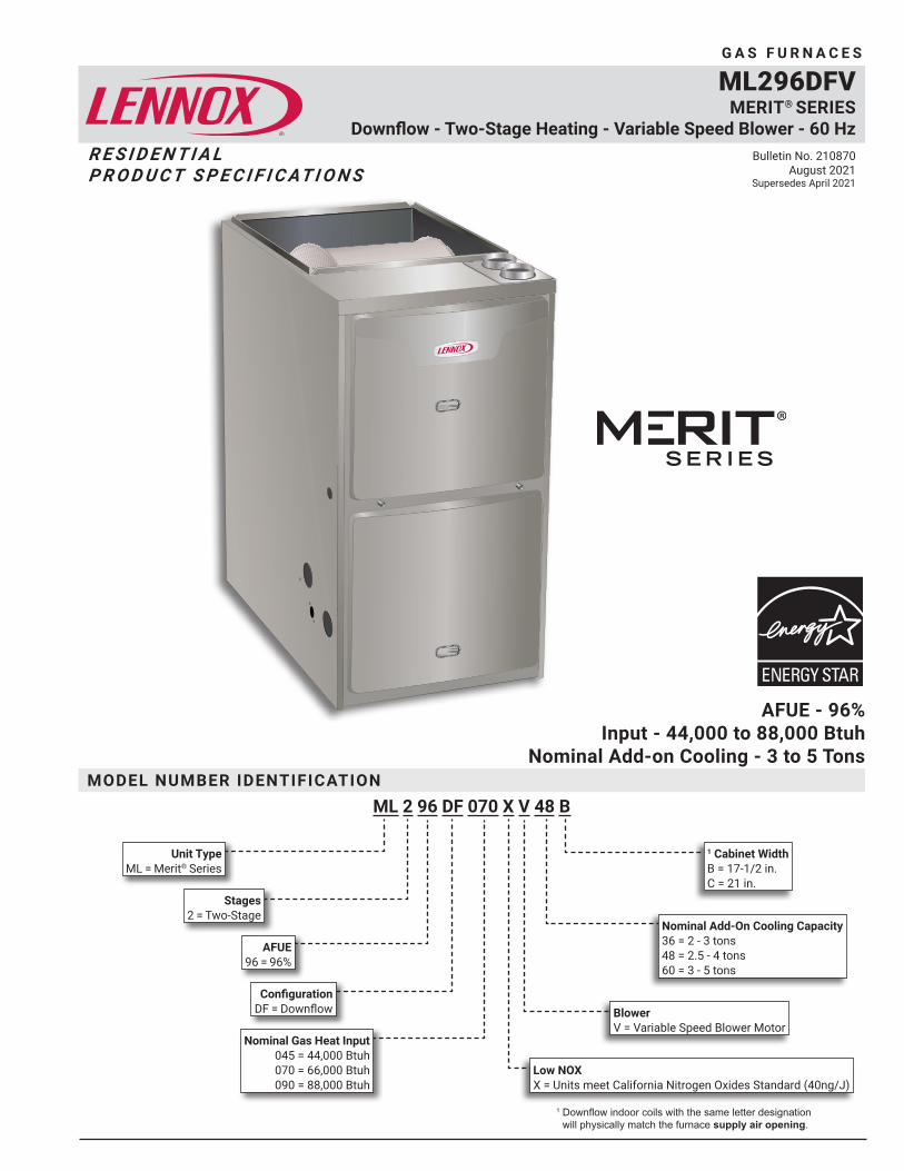
ML 2 96 DF 070 X V 48 B
Unit Type ML = Merit® Series
Stages 2 = Two-Stage
Nominal Gas Heat Input 045 = 44,000 Btuh 070 = 66,000 Btuh 090 = 88,000 Btuh
Blower V = Variable Speed Blower Motor
Nominal Add-On Cooling Capacity 36 = 2 - 3 tons 48 = 2.5 - 4 tons 60 = 3 - 5 tons
Configuration DF = Downflow
1 Downflow indoor coils with the same letter designation will physically match the furnace supply air opening.
AFUE 96 = 96%
Low NOX X = Units meet California Nitrogen Oxides Standard (40ng/J)
1 Cabinet Width B = 17-1/2 in. C = 21 in.
ML296DFV DOWNFLOW GAS FURNACES
G A S F U R N A C E S
R E S I D E N T I A L P R O D U C T S P E C I F I C AT I O N S
MODEL NUMBER IDENTIFICATION
ML296DFV / Page 2
OF
F
ON
LOLO
HI
HI
CC CC
HIHIII II
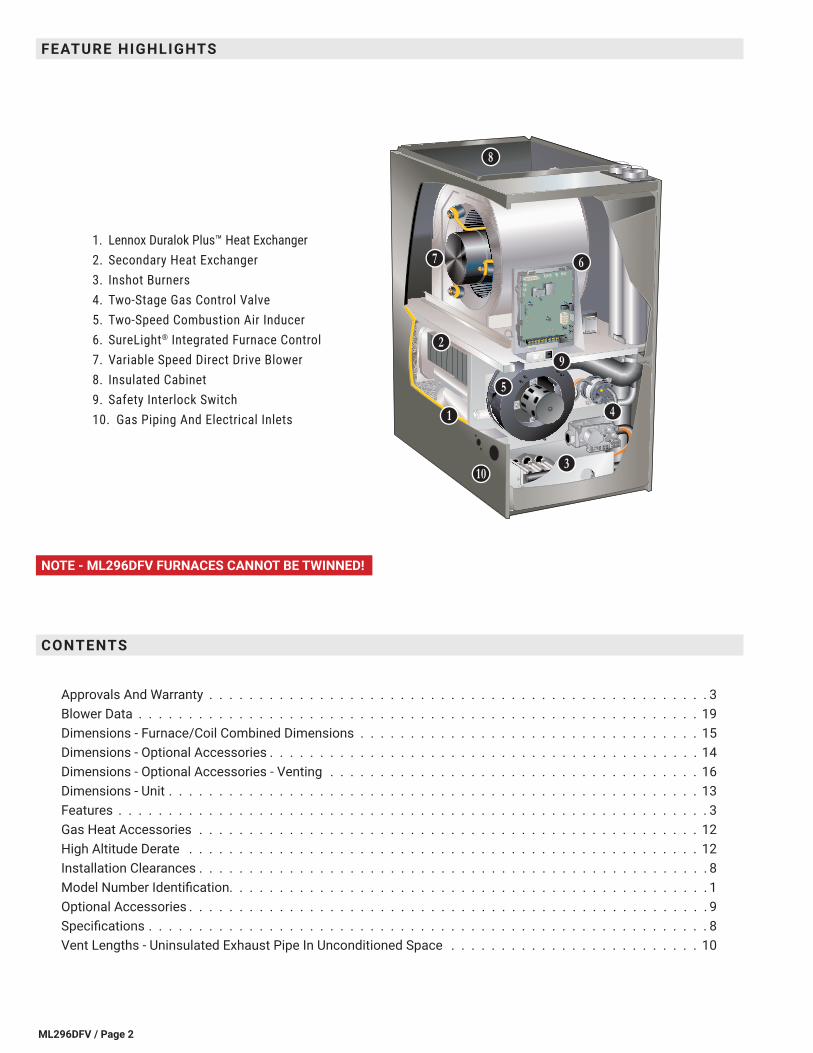
NOTE - ML296DFV FURNACES CANNOT BE TWINNED!
1. Lennox Duralok Plus™ Heat Exchanger2. Secondary Heat Exchanger3. Inshot Burners4. Two-Stage Gas Control Valve5. Two-Speed Combustion Air Inducer6. SureLight® Integrated Furnace Control7. Variable Speed Direct Drive Blower8. Insulated Cabinet9. Safety Interlock Switch10. Gas Piping And Electrical Inlets
FEATURE HIGHLIGHTS
CONTENTS
Approvals And Warranty . . . . . . . . . . . . . . . . . . . . . . . . . . . . . . . . . . . . . . . . . . . . . . . . . . 3Blower Data . . . . . . . . . . . . . . . . . . . . . . . . . . . . . . . . . . . . . . . . . . . . . . . . . . . . . . . . 19Dimensions - Furnace/Coil Combined Dimensions . . . . . . . . . . . . . . . . . . . . . . . . . . . . . . . . . . 15Dimensions - Optional Accessories . . . . . . . . . . . . . . . . . . . . . . . . . . . . . . . . . . . . . . . . . . . 14Dimensions - Optional Accessories - Venting . . . . . . . . . . . . . . . . . . . . . . . . . . . . . . . . . . . . . 16Dimensions - Unit . . . . . . . . . . . . . . . . . . . . . . . . . . . . . . . . . . . . . . . . . . . . . . . . . . . . . 13Features . . . . . . . . . . . . . . . . . . . . . . . . . . . . . . . . . . . . . . . . . . . . . . . . . . . . . . . . . . . 3Gas Heat Accessories . . . . . . . . . . . . . . . . . . . . . . . . . . . . . . . . . . . . . . . . . . . . . . . . . . 12High Altitude Derate . . . . . . . . . . . . . . . . . . . . . . . . . . . . . . . . . . . . . . . . . . . . . . . . . . . 12Installation Clearances . . . . . . . . . . . . . . . . . . . . . . . . . . . . . . . . . . . . . . . . . . . . . . . . . . . 8Model Number Identification. . . . . . . . . . . . . . . . . . . . . . . . . . . . . . . . . . . . . . . . . . . . . . . . 1Optional Accessories . . . . . . . . . . . . . . . . . . . . . . . . . . . . . . . . . . . . . . . . . . . . . . . . . . . . 9Specifications . . . . . . . . . . . . . . . . . . . . . . . . . . . . . . . . . . . . . . . . . . . . . . . . . . . . . . . . 8Vent Lengths - Uninsulated Exhaust Pipe In Unconditioned Space . . . . . . . . . . . . . . . . . . . . . . . . . 10
BB
CC
KK
JJ
II
HH
FF
GG
EE
DD
ML296DFV / Page 3
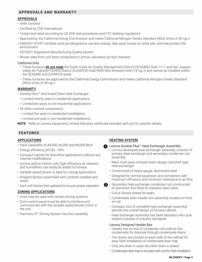
APPLICATIONS• Input capacities of 44,000, 66,000 and 88,000 Btuh• Energy efficiency (AFUE) - 96%• Compact cabinet for downflow applications without any
internal modifications• Lennox add-on indoor coils, high-efficiency air cleaners
and humidifiers can easily be added to furnace• Variable speed blower is ideal for zoning applications• Shipped factory assembled with controls installed and
wired• Each unit factory test operated to ensure proper operation
ZONING APPLICATIONS• Units may be used with certain zoning systems• Zone control panel must be able to interface and
communicate with the variable speed blower motor in the unit
• Harmony III™ Zoning System has this capability
HEATING SYSTEM
Lennox Duralok Plus™ Heat Exchanger Assembly• Lennox developed heat exchanger assembly consists of
primary heat exchanger and secondary condenser coil assembly
• Main multi-pass crimped seam design clamshell type heat exchanger
• Constructed of heavy-gauge, aluminized steel• Designed for normal expansion and contraction with
maximum efficiency and minimum resistance to air flow• Secondary heat exchanger condenser coil constructed
of aluminum fins fitted to stainless steel tubes• Coil is factory tested for leaks• Condensate drain header box assembly located on front
of coil• Compact size of complete heat exchanger assembly
permits low overall design of furnace cabinet• Heat exchanger assembly has been laboratory life cycle
tested in excess of industry standards
Lennox Designed Header Box• Header box on end of condenser coil collects flue
condensate for disposal through condensate drains• The drains are located on each side of the cabinet for
easy field installation of condensate drain trap• Only one drain is used, the other drain is sealed• Condensate drain trap is included with unit for field installation
BB
CC
APPROVALS AND WARRANTY
APPROVALS• AHRI Certified• Certified by CSA International• Tested and rated according to US DOE test procedures and FTC labeling regulations• Approved by the California Energy Commission and meets California Nitrogen Oxides Standard (NOx) limits of 40 ng/J• ENERGY STAR® certified units are designed to use less energy, help save money on utility bills, and help protect the
environment• ISO 9001 Registered Manufacturing Quality System• Blower data from unit tests conducted in Lennox Laboratory air test chamber
California Only• These furnaces do not meet the South Coast Air Quality Management District (SCAQMD) Rule 1111 and San Joaquin
Valley Air Pollution Control District (SJVAPCD) Rule 4905 NOx emission limit (14 ng/J) and cannot be installed within the SCAQMD and SJVAPCD areas
• These furnaces are approved by the California Energy Commission and meets California Nitrogen Oxides Standard (NOx) limits of 40 ng/J
WARRANTY• Duralok Plus™ Aluminized Steel Heat Exchanger:
• Limited twenty years in residential applications• Limited ten years in non-residential applications
• All other covered components:• Limited five years in residential installations• Limited one year in non-residential installations
NOTE - Refer to Lennox Equipment Limited Warranty certificate included with unit for specific details.
FEATURES
ML296DFV / Page 4
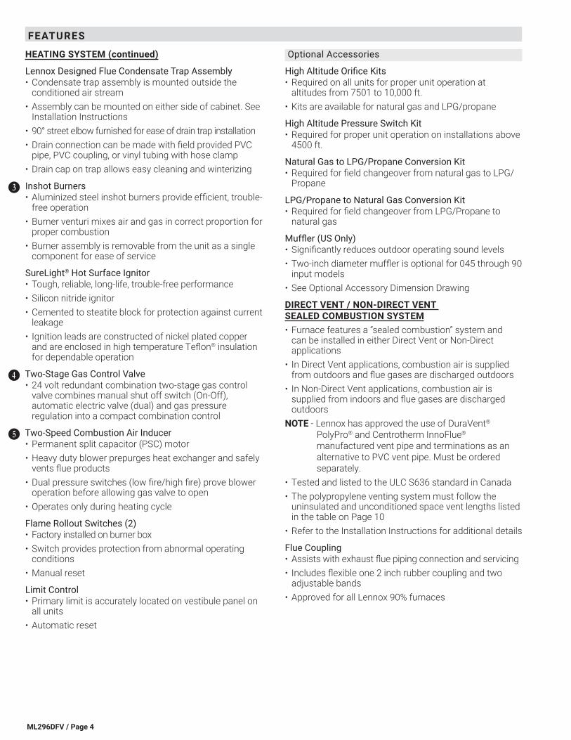
HEATING SYSTEM (continued)
Lennox Designed Flue Condensate Trap Assembly• Condensate trap assembly is mounted outside the
conditioned air stream• Assembly can be mounted on either side of cabinet. See
Installation Instructions• 90° street elbow furnished for ease of drain trap installation• Drain connection can be made with field provided PVC
pipe, PVC coupling, or vinyl tubing with hose clamp• Drain cap on trap allows easy cleaning and winterizing
Inshot Burners• Aluminized steel inshot burners provide efficient, trouble-
free operation• Burner venturi mixes air and gas in correct proportion for
proper combustion• Burner assembly is removable from the unit as a single
component for ease of service
SureLight® Hot Surface Ignitor• Tough, reliable, long-life, trouble-free performance• Silicon nitride ignitor• Cemented to steatite block for protection against current
leakage• Ignition leads are constructed of nickel plated copper
and are enclosed in high temperature Teflon® insulation for dependable operation
Two-Stage Gas Control Valve• 24 volt redundant combination two-stage gas control
valve combines manual shut off switch (On-Off), automatic electric valve (dual) and gas pressure regulation into a compact combination control
Two-Speed Combustion Air Inducer• Permanent split capacitor (PSC) motor• Heavy duty blower prepurges heat exchanger and safely
vents flue products• Dual pressure switches (low fire/high fire) prove blower
operation before allowing gas valve to open• Operates only during heating cycle
Flame Rollout Switches (2)• Factory installed on burner box• Switch provides protection from abnormal operating
conditions• Manual reset
Limit Control• Primary limit is accurately located on vestibule panel on
all units• Automatic reset
DD
EE
FF
Optional Accessories
High Altitude Orifice Kits• Required on all units for proper unit operation at
altitudes from 7501 to 10,000 ft.• Kits are available for natural gas and LPG/propane
High Altitude Pressure Switch Kit• Required for proper unit operation on installations above
4500 ft.
Natural Gas to LPG/Propane Conversion Kit• Required for field changeover from natural gas to LPG/
Propane
LPG/Propane to Natural Gas Conversion Kit• Required for field changeover from LPG/Propane to
natural gas
Muffler (US Only)• Significantly reduces outdoor operating sound levels• Two-inch diameter muffler is optional for 045 through 90
input models• See Optional Accessory Dimension Drawing
DIRECT VENT / NON-DIRECT VENT SEALED COMBUSTION SYSTEM• Furnace features a “sealed combustion” system and
can be installed in either Direct Vent or Non-Direct applications
• In Direct Vent applications, combustion air is supplied from outdoors and flue gases are discharged outdoors
• In Non-Direct Vent applications, combustion air is supplied from indoors and flue gases are discharged outdoors
NOTE - Lennox has approved the use of DuraVent® PolyPro® and Centrotherm InnoFlue® manufactured vent pipe and terminations as an alternative to PVC vent pipe. Must be ordered separately.
• Tested and listed to the ULC S636 standard in Canada• The polypropylene venting system must follow the
uninsulated and unconditioned space vent lengths listed in the table on Page 10
• Refer to the Installation Instructions for additional details
Flue Coupling• Assists with exhaust flue piping connection and servicing• Includes flexible one 2 inch rubber coupling and two
adjustable bands• Approved for all Lennox 90% furnaces
FEATURES
ML296DFV / Page 5
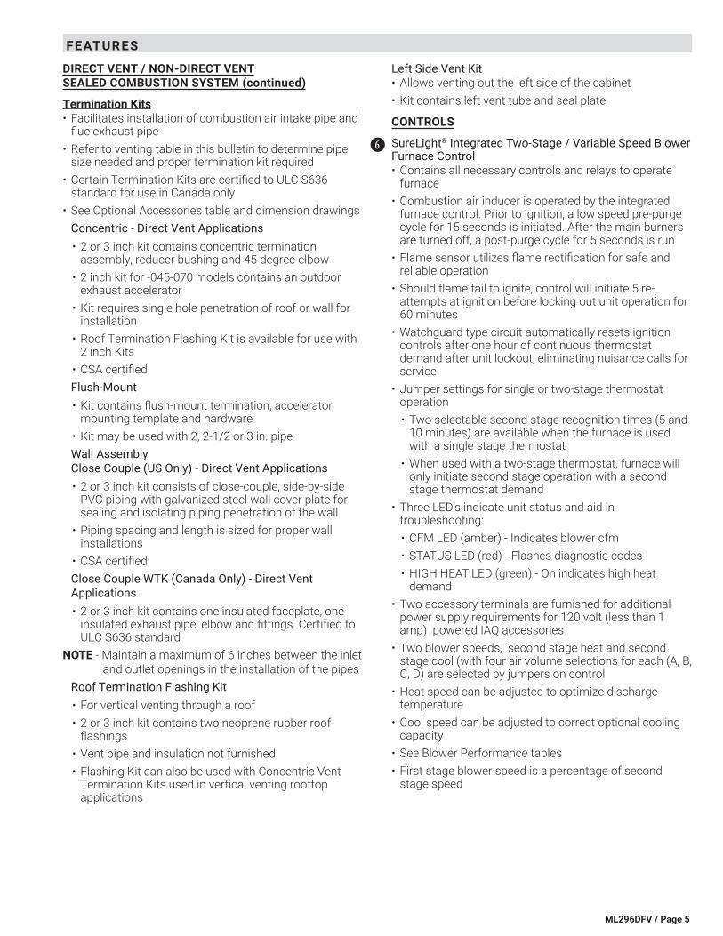
DIRECT VENT / NON-DIRECT VENT SEALED COMBUSTION SYSTEM (continued)
Termination Kits• Facilitates installation of combustion air intake pipe and
flue exhaust pipe• Refer to venting table in this bulletin to determine pipe
size needed and proper termination kit required• Certain Termination Kits are certified to ULC S636
standard for use in Canada only• See Optional Accessories table and dimension drawings
Concentric - Direct Vent Applications• 2 or 3 inch kit contains concentric termination
assembly, reducer bushing and 45 degree elbow• 2 inch kit for -045-070 models contains an outdoor
exhaust accelerator• Kit requires single hole penetration of roof or wall for
installation• Roof Termination Flashing Kit is available for use with
2 inch Kits• CSA certifiedFlush-Mount• Kit contains flush-mount termination, accelerator,
mounting template and hardware• Kit may be used with 2, 2-1/2 or 3 in. pipeWall Assembly Close Couple (US Only) - Direct Vent Applications• 2 or 3 inch kit consists of close-couple, side-by-side
PVC piping with galvanized steel wall cover plate for sealing and isolating piping penetration of the wall
• Piping spacing and length is sized for proper wall installations
• CSA certifiedClose Couple WTK (Canada Only) - Direct Vent Applications• 2 or 3 inch kit contains one insulated faceplate, one
insulated exhaust pipe, elbow and fittings. Certified to ULC S636 standard
NOTE - Maintain a maximum of 6 inches between the inlet and outlet openings in the installation of the pipes
Roof Termination Flashing Kit• For vertical venting through a roof• 2 or 3 inch kit contains two neoprene rubber roof
flashings• Vent pipe and insulation not furnished• Flashing Kit can also be used with Concentric Vent
Termination Kits used in vertical venting rooftop applications
Left Side Vent Kit• Allows venting out the left side of the cabinet• Kit contains left vent tube and seal plate
CONTROLS
SureLight® Integrated Two-Stage / Variable Speed Blower Furnace Control• Contains all necessary controls and relays to operate
furnace• Combustion air inducer is operated by the integrated
furnace control. Prior to ignition, a low speed pre-purge cycle for 15 seconds is initiated. After the main burners are turned off, a post-purge cycle for 5 seconds is run
• Flame sensor utilizes flame rectification for safe and reliable operation
• Should flame fail to ignite, control will initiate 5 re-attempts at ignition before locking out unit operation for 60 minutes
• Watchguard type circuit automatically resets ignition controls after one hour of continuous thermostat demand after unit lockout, eliminating nuisance calls for service
• Jumper settings for single or two-stage thermostat operation• Two selectable second stage recognition times (5 and
10 minutes) are available when the furnace is used with a single stage thermostat
• When used with a two-stage thermostat, furnace will only initiate second stage operation with a second stage thermostat demand
• Three LED’s indicate unit status and aid in troubleshooting:• CFM LED (amber) - Indicates blower cfm• STATUS LED (red) - Flashes diagnostic codes• HIGH HEAT LED (green) - On indicates high heat
demand• Two accessory terminals are furnished for additional
power supply requirements for 120 volt (less than 1 amp) powered IAQ accessories
• Two blower speeds, second stage heat and second stage cool (with four air volume selections for each (A, B, C, D) are selected by jumpers on control
• Heat speed can be adjusted to optimize discharge temperature
• Cool speed can be adjusted to correct optional cooling capacity
• See Blower Performance tables• First stage blower speed is a percentage of second
stage speed
GG
FEATURES
ML296DFV / Page 6
FEATURES
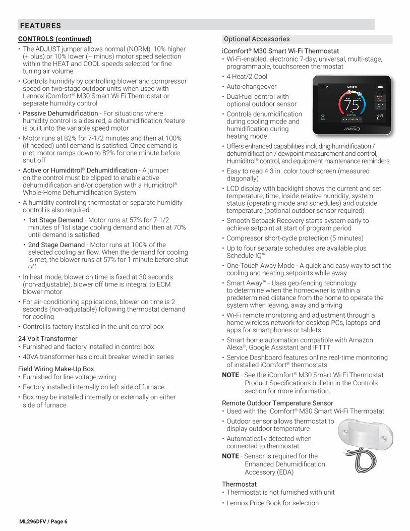
CONTROLS (continued)• The ADJUST jumper allows normal (NORM), 10% higher
(+ plus) or 10% lower (– minus) motor speed selection within the HEAT and COOL speeds selected for fine tuning air volume
• Controls humidity by controlling blower and compressor speed on two-stage outdoor units when used with Lennox iComfort® M30 Smart Wi-Fi Thermostat or separate humidity control
• Passive Dehumidification - For situations where humidity control is a desired, a dehumidification feature is built into the variable speed motor
• Motor runs at 82% for 7-1/2 minutes and then at 100% (if needed) until demand is satisfied. Once demand is met, motor ramps down to 82% for one minute before shut off
• Active or Humiditrol® Dehumidification - A jumper on the control must be clipped to enable active dehumidification and/or operation with a Humiditrol® Whole-Home Dehumidification System
• A humidity controlling thermostat or separate humidity control is also required• 1st Stage Demand - Motor runs at 57% for 7-1/2
minutes of 1st stage cooling demand and then at 70% until demand is satisfied
• 2nd Stage Demand - Motor runs at 100% of the selected cooling air flow. When the demand for cooling is met, the blower runs at 57% for 1 minute before shut off
• In heat mode, blower on time is fixed at 30 seconds (non-adjustable), blower off time is integral to ECM blower motor
• For air-conditioning applications, blower on time is 2 seconds (non-adjustable) following thermostat demand for cooling
• Control is factory installed in the unit control box
24 Volt Transformer• Furnished and factory installed in control box• 40VA transformer has circuit breaker wired in series
Field Wiring Make-Up Box• Furnished for line voltage wiring• Factory installed internally on left side of furnace• Box may be installed internally or externally on either
side of furnace
Optional Accessories
iComfort® M30 Smart Wi-Fi Thermostat• Wi-Fi-enabled, electronic 7-day, universal, multi-stage,
programmable, touchscreen thermostat• 4 Heat/2 Cool• Auto-changeover• Dual-fuel control with
optional outdoor sensor • Controls dehumidification
during cooling mode and humidification during heating mode
• Offers enhanced capabilities including humidification / dehumidification / dewpoint measurement and control, Humiditrol® control, and equipment maintenance reminders
• Easy to read 4.3 in. color touchscreen (measured diagonally)
• LCD display with backlight shows the current and set temperature, time, inside relative humidity, system status (operating mode and schedules) and outside temperature (optional outdoor sensor required)
• Smooth Setback Recovery starts system early to achieve setpoint at start of program period
• Compressor short-cycle protection (5 minutes)• Up to four separate schedules are available plus
Schedule IQ™• One-Touch Away Mode - A quick and easy way to set the
cooling and heating setpoints while away• Smart Away™ - Uses geo-fencing technology
to determine when the homeowner is within a predetermined distance from the home to operate the system when leaving, away and arriving
• Wi-Fi remote monitoring and adjustment through a home wireless network for desktop PCs, laptops and apps for smartphones or tablets
• Smart home automation compatible with Amazon Alexa®, Google Assistant and IFTTT
• Service Dashboard features online real-time monitoring of installed iComfort® thermostats
NOTE - See the iComfort® M30 Smart Wi-Fi Thermostat Product Specifications bulletin in the Controls section for more information.
Remote Outdoor Temperature Sensor• Used with the iComfort® M30 Smart Wi-Fi Thermostat• Outdoor sensor allows thermostat to
display outdoor temperature• Automatically detected when
connected to thermostatNOTE - Sensor is required for the
Enhanced Dehumidification Accessory (EDA)
Thermostat• Thermostat is not furnished with unit• Lennox Price Book for selection
ML296DFV / Page 7
FEATURES
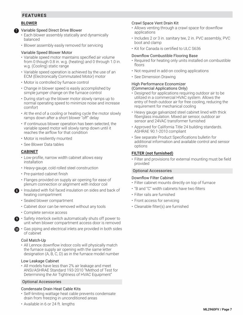
BLOWER
Variable Speed Direct Drive Blower• Each blower assembly statically and dynamically
balanced• Blower assembly easily removed for servicing
Variable Speed Blower Motor• Variable speed motor maintains specified air volume
from 0 though 0.8 in. w.g. (heating) and 0 through 1.0 in. w.g. (Cooling) static range
• Variable speed operation is achieved by the use of an ECM (Electronically Commutated Motor) motor
• Motor is controlled by furnace control• Change in blower speed is easily accomplished by
simple jumper change on the furnace control• During start-up the blower motor slowly ramps up to
normal operating speed to minimize noise and increase comfort
• At the end of a cooling or heating cycle the motor slowly ramps down after a short blower “off” delay
• If continuous blower operation has been selected, the variable speed motor will slowly ramp down until it reaches the airflow for that condition
• Motor is resiliently mounted• See Blower Data tables
CABINET• Low-profile, narrow width cabinet allows easy
installation• Heavy-gauge, cold rolled steel construction• Pre-painted cabinet finish• Flanges provided on supply air opening for ease of
plenum connection or alignment with indoor coil• Insulated with foil faced insulation on sides and back of
heating compartment• Sealed blower compartment• Cabinet door can be removed without any tools• Complete service access• Safety interlock switch automatically shuts off power to
unit when blower compartment access door is removed• Gas piping and electrical inlets are provided in both sides
of cabinet
Coil Match-Up• All Lennox downflow indoor coils will physically match
the furnace supply air opening with the same letter designation (A, B, C, D) as in the furnace model number
Low Leakage Cabinet• All models have less than 2% air leakage and meet
ANSI/ASHRAE Standard 193-2010 “Method of Test for Determining the Air Tightness of HVAC Equipment”
Optional Accessories
Condensate Drain Heat Cable Kits• Self-limiting wattage heat cable prevents condensate
drain from freezing in unconditioned areas• Available in 6 or 24 ft. lengths
HH
II
JJ
KK
Crawl Space Vent Drain Kit• Allows venting through a crawl space for downflow
applications• Includes 2 or 3 in. sanitary tee, 2 in. PVC assembly, PVC
boot and clamp• Kit for Canada is certified to ULC S636
Downflow Combustible Flooring Base• Required for heating only units installed on combustible
floors• Not required in add-on cooling applications• See Dimension Drawing
High Performance Economizer (Commercial Applications Only) • Designed for applications requiring outdoor air to be
utilized in a commercial HVAC system. Allows the entry of fresh outdoor air for free cooling, reducing the requirement for mechanical cooling
• Heavy gauge galvanized steel cabinet lined with thick fiberglass insulation. Mixed air sensor, outdoor air sensor and 24VAC transformer furnished
• Approved for California Title 24 building standards. ASHRAE 90.1-2010 compliant
• See separate Product Specifications bulletin for additional information and available control and sensor options
FILTER (not furnished)• Filter and provisions for external mounting must be field
provided
Optional Accessories
Downflow Filter Cabinet• Filter cabinet mounts directly on top of furnace• “B and “C” width cabinets have two filters• Filter rails are furnished• Front access for servicing• Cleanable filter(s) are furnished
ML296DFV / Page 8
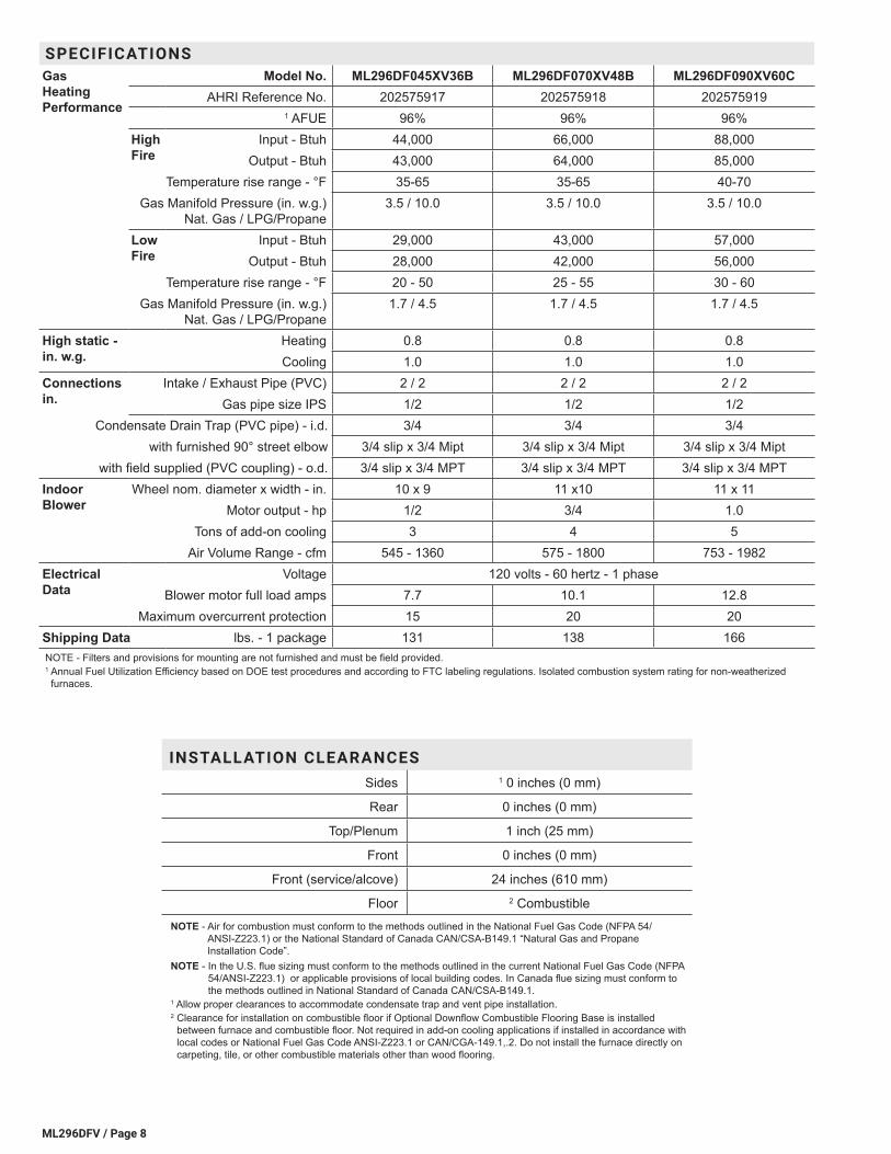
INSTALLATION CLEARANCESSides 1 0 inches (0 mm)
Rear 0 inches (0 mm)
Top/Plenum 1 inch (25 mm)
Front 0 inches (0 mm)
Front (service/alcove) 24 inches (610 mm)
Floor 2 CombustibleNOTE - Air for combustion must conform to the methods outlined in the National Fuel Gas Code (NFPA 54/
ANSI-Z223.1) or the National Standard of Canada CAN/CSA-B149.1 “Natural Gas and Propane Installation Code”.
NOTE - In the U.S. flue sizing must conform to the methods outlined in the current National Fuel Gas Code (NFPA 54/ANSI-Z223.1) or applicable provisions of local building codes. In Canada flue sizing must conform to the methods outlined in National Standard of Canada CAN/CSA-B149.1.
1 Allow proper clearances to accommodate condensate trap and vent pipe installation.2 Clearance for installation on combustible floor if Optional Downflow Combustible Flooring Base is installed
between furnace and combustible floor. Not required in add-on cooling applications if installed in accordance with local codes or National Fuel Gas Code ANSI-Z223.1 or CAN/CGA-149.1,.2. Do not install the furnace directly on carpeting, tile, or other combustible materials other than wood flooring.
SPECIFICATIONSGas Heating Performance
Model No. ML296DF045XV36B ML296DF070XV48B ML296DF090XV60CAHRI Reference No. 202575917 202575918 202575919
1 AFUE 96% 96% 96%High Fire
Input - Btuh 44,000 66,000 88,000Output - Btuh 43,000 64,000 85,000
Temperature rise range - °F 35-65 35-65 40-70Gas Manifold Pressure (in. w.g.)
Nat. Gas / LPG/Propane3.5 / 10.0 3.5 / 10.0 3.5 / 10.0
Low Fire
Input - Btuh 29,000 43,000 57,000Output - Btuh 28,000 42,000 56,000
Temperature rise range - °F 20 - 50 25 - 55 30 - 60Gas Manifold Pressure (in. w.g.)
Nat. Gas / LPG/Propane1.7 / 4.5 1.7 / 4.5 1.7 / 4.5
High static - in. w.g.
Heating 0.8 0.8 0.8Cooling 1.0 1.0 1.0
Connections in.
Intake / Exhaust Pipe (PVC) 2 / 2 2 / 2 2 / 2Gas pipe size IPS 1/2 1/2 1/2
Condensate Drain Trap (PVC pipe) - i.d. 3/4 3/4 3/4with furnished 90° street elbow 3/4 slip x 3/4 Mipt 3/4 slip x 3/4 Mipt 3/4 slip x 3/4 Mipt
with field supplied (PVC coupling) - o.d. 3/4 slip x 3/4 MPT 3/4 slip x 3/4 MPT 3/4 slip x 3/4 MPTIndoor Blower
Wheel nom. diameter x width - in. 10 x 9 11 x10 11 x 11Motor output - hp 1/2 3/4 1.0
Tons of add-on cooling 3 4 5Air Volume Range - cfm 545 - 1360 575 - 1800 753 - 1982
Electrical Data
Voltage 120 volts - 60 hertz - 1 phaseBlower motor full load amps 7.7 10.1 12.8
Maximum overcurrent protection 15 20 20Shipping Data lbs. - 1 package 131 138 166NOTE - Filters and provisions for mounting are not furnished and must be field provided.1 Annual Fuel Utilization Efficiency based on DOE test procedures and according to FTC labeling regulations. Isolated combustion system rating for non-weatherized furnaces.
ML296DFV / Page 9
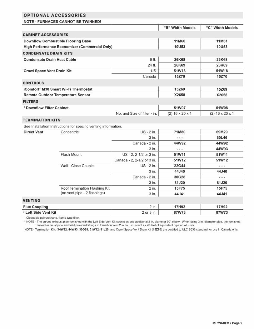
OPTIONAL ACCESSORIESNOTE - FURNACES CANNOT BE TWINNED!
“B” Width Models “C” Width Models
CABINET ACCESSORIES
Downflow Combustible Flooring Base 11M60 11M61High Performance Economizer (Commercial Only) 10U53 10U53CONDENSATE DRAIN KITS
Condensate Drain Heat Cable 6 ft. 26K68 26K6824 ft. 26K69 26K69
Crawl Space Vent Drain Kit US 51W18 51W18Canada 15Z70 15Z70
CONTROLSiComfort® M30 Smart Wi-Fi Thermostat 15Z69 15Z69Remote Outdoor Temperature Sensor X2658 X2658FILTERS1 Downflow Filter Cabinet 51W07 51W08
No. and Size of filter - in. (2) 16 x 20 x 1 (2) 16 x 20 x 1
TERMINATION KITS
See Installation Instructions for specific venting information.Direct Vent Concentric US - 2 in. 71M80 69M29
3 in. - - - 60L46Canada - 2 in. 44W92 44W92
3 in. - - - 44W93Flush-Mount US - 2, 2-1/2 or 3 in. 51W11 51W11
Canada - 2, 2-1/2 or 3 in. 51W12 51W12Wall - Close Couple US - 2 in. 22G44 - - -
3 in. 44J40 44J40Canada - 2 in. 30G28 - - -
3 in. 81J20 81J20Roof Termination Flashing Kit (no vent pipe - 2 flashings)
2 in. 15F75 15F753 in. 44J41 44J41
VENTING
Flue Coupling 2 in. 17H92 17H922 Left Side Vent Kit 2 or 3 in. 87W73 87W73
1 Cleanable polyurethane, frame-type filter.2 NOTE - The curved exhaust pipe furnished with the Left Side Vent Kit counts as one additional 2 in. diameter 90° elbow. When using 3 in. diameter pipe, the furnished
curved exhaust pipe and field provided fittings to transition from 2 in. to 3 in. count as 20 feet of equivalent pipe on all units.NOTE - Termination Kits (44W92, 44W93, 30G28, 51W12, 81J20) and Crawl Space Vent Drain Kit (15Z70) are certified to ULC S636 standard for use in Canada only.
ML296DFV / Page 10
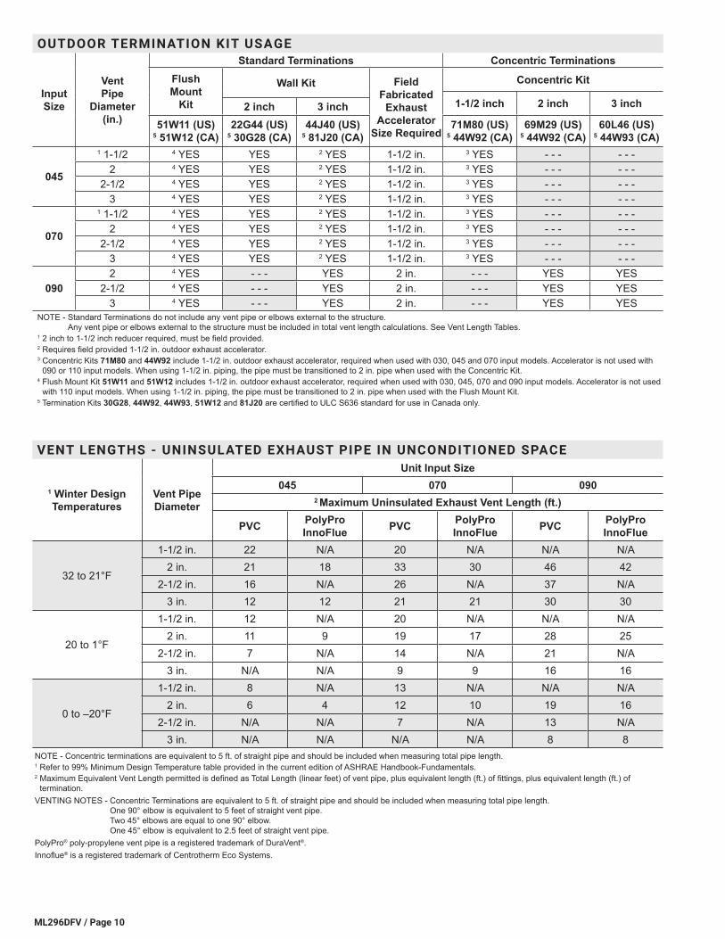
VENT LENGTHS - UNINSULATED EXHAUST PIPE IN UNCONDITIONED SPACE
1 Winter Design Temperatures
Vent Pipe Diameter
Unit Input Size045 070 090
2 Maximum Uninsulated Exhaust Vent Length (ft.)
PVC PolyPro InnoFlue PVC PolyPro
InnoFlue PVC PolyPro InnoFlue
32 to 21°F
1-1/2 in. 22 N/A 20 N/A N/A N/A2 in. 21 18 33 30 46 42
2-1/2 in. 16 N/A 26 N/A 37 N/A3 in. 12 12 21 21 30 30
20 to 1°F
1-1/2 in. 12 N/A 20 N/A N/A N/A2 in. 11 9 19 17 28 25
2-1/2 in. 7 N/A 14 N/A 21 N/A3 in. N/A N/A 9 9 16 16
0 to –20°F
1-1/2 in. 8 N/A 13 N/A N/A N/A2 in. 6 4 12 10 19 16
2-1/2 in. N/A N/A 7 N/A 13 N/A3 in. N/A N/A N/A N/A 8 8
NOTE - Concentric terminations are equivalent to 5 ft. of straight pipe and should be included when measuring total pipe length.1 Refer to 99% Minimum Design Temperature table provided in the current edition of ASHRAE Handbook-Fundamentals.2 Maximum Equivalent Vent Length permitted is defined as Total Length (linear feet) of vent pipe, plus equivalent length (ft.) of fittings, plus equivalent length (ft.) of
termination.VENTING NOTES - Concentric Terminations are equivalent to 5 ft. of straight pipe and should be included when measuring total pipe length.
One 90° elbow is equivalent to 5 feet of straight vent pipe. Two 45° elbows are equal to one 90° elbow. One 45° elbow is equivalent to 2.5 feet of straight vent pipe.
PolyPro® poly-propylene vent pipe is a registered trademark of DuraVent®.Innoflue® is a registered trademark of Centrotherm Eco Systems.
OUTDOOR TERMINATION KIT USAGE
Input Size
Vent Pipe
Diameter (in.)
Standard Terminations Concentric TerminationsFlush Mount
Kit
Wall Kit Field Fabricated
Exhaust Accelerator
Size Required
Concentric Kit
1-1/2 inch 2 inch 3 inch2 inch 3 inch51W11 (US)
5 51W12 (CA)22G44 (US)
5 30G28 (CA)44J40 (US)
5 81J20 (CA)71M80 (US)
5 44W92 (CA)69M29 (US)
5 44W92 (CA)60L46 (US)
5 44W93 (CA)
045
1 1-1/2 4 YES YES 2 YES 1-1/2 in. 3 YES - - - - - -2 4 YES YES 2 YES 1-1/2 in. 3 YES - - - - - -
2-1/2 4 YES YES 2 YES 1-1/2 in. 3 YES - - - - - -3 4 YES YES 2 YES 1-1/2 in. 3 YES - - - - - -
070
1 1-1/2 4 YES YES 2 YES 1-1/2 in. 3 YES - - - - - -2 4 YES YES 2 YES 1-1/2 in. 3 YES - - - - - -
2-1/2 4 YES YES 2 YES 1-1/2 in. 3 YES - - - - - -3 4 YES YES 2 YES 1-1/2 in. 3 YES - - - - - -
0902 4 YES - - - YES 2 in. - - - YES YES
2-1/2 4 YES - - - YES 2 in. - - - YES YES3 4 YES - - - YES 2 in. - - - YES YES
NOTE - Standard Terminations do not include any vent pipe or elbows external to the structure. Any vent pipe or elbows external to the structure must be included in total vent length calculations. See Vent Length Tables.
1 2 inch to 1-1/2 inch reducer required, must be field provided.2 Requires field provided 1-1/2 in. outdoor exhaust accelerator.3 Concentric Kits 71M80 and 44W92 include 1-1/2 in. outdoor exhaust accelerator, required when used with 030, 045 and 070 input models. Accelerator is not used with
090 or 110 input models. When using 1-1/2 in. piping, the pipe must be transitioned to 2 in. pipe when used with the Concentric Kit.4 Flush Mount Kit 51W11 and 51W12 includes 1-1/2 in. outdoor exhaust accelerator, required when used with 030, 045, 070 and 090 input models. Accelerator is not used
with 110 input models. When using 1-1/2 in. piping, the pipe must be transitioned to 2 in. pipe when used with the Flush Mount Kit.5 Termination Kits 30G28, 44W92, 44W93, 51W12 and 81J20 are certified to ULC S636 standard for use in Canada only.
ML296DFV / Page 11
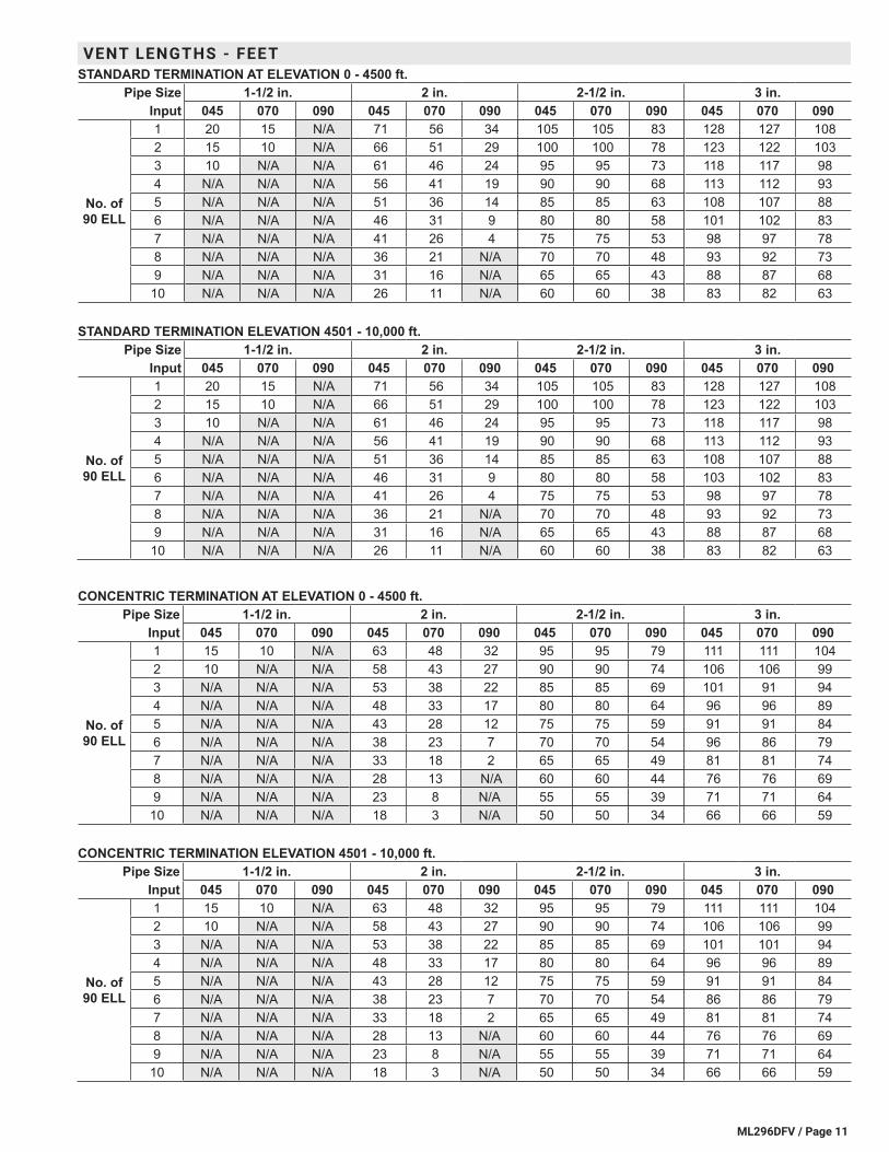
VENT LENGTHS - FEETSTANDARD TERMINATION AT ELEVATION 0 - 4500 ft.
Pipe Size 1-1/2 in. 2 in. 2-1/2 in. 3 in.Input 045 070 090 045 070 090 045 070 090 045 070 090
No. of 90 ELL
1 20 15 N/A 71 56 34 105 105 83 128 127 108 2 15 10 N/A 66 51 29 100 100 78 123 122 103 3 10 N/A N/A 61 46 24 95 95 73 118 117 98 4 N/A N/A N/A 56 41 19 90 90 68 113 112 93 5 N/A N/A N/A 51 36 14 85 85 63 108 107 88 6 N/A N/A N/A 46 31 9 80 80 58 101 102 83 7 N/A N/A N/A 41 26 4 75 75 53 98 97 78 8 N/A N/A N/A 36 21 N/A 70 70 48 93 92 73 9 N/A N/A N/A 31 16 N/A 65 65 43 88 87 68
10 N/A N/A N/A 26 11 N/A 60 60 38 83 82 63
STANDARD TERMINATION ELEVATION 4501 - 10,000 ft.Pipe Size 1-1/2 in. 2 in. 2-1/2 in. 3 in.
Input 045 070 090 045 070 090 045 070 090 045 070 090
No. of 90 ELL
1 20 15 N/A 71 56 34 105 105 83 128 127 108 2 15 10 N/A 66 51 29 100 100 78 123 122 103 3 10 N/A N/A 61 46 24 95 95 73 118 117 98 4 N/A N/A N/A 56 41 19 90 90 68 113 112 93 5 N/A N/A N/A 51 36 14 85 85 63 108 107 88 6 N/A N/A N/A 46 31 9 80 80 58 103 102 83 7 N/A N/A N/A 41 26 4 75 75 53 98 97 78 8 N/A N/A N/A 36 21 N/A 70 70 48 93 92 73 9 N/A N/A N/A 31 16 N/A 65 65 43 88 87 68
10 N/A N/A N/A 26 11 N/A 60 60 38 83 82 63
CONCENTRIC TERMINATION AT ELEVATION 0 - 4500 ft.Pipe Size 1-1/2 in. 2 in. 2-1/2 in. 3 in.
Input 045 070 090 045 070 090 045 070 090 045 070 090
No. of 90 ELL
1 15 10 N/A 63 48 32 95 95 79 111 111 104 2 10 N/A N/A 58 43 27 90 90 74 106 106 99 3 N/A N/A N/A 53 38 22 85 85 69 101 91 94 4 N/A N/A N/A 48 33 17 80 80 64 96 96 89 5 N/A N/A N/A 43 28 12 75 75 59 91 91 84 6 N/A N/A N/A 38 23 7 70 70 54 96 86 79 7 N/A N/A N/A 33 18 2 65 65 49 81 81 74 8 N/A N/A N/A 28 13 N/A 60 60 44 76 76 69 9 N/A N/A N/A 23 8 N/A 55 55 39 71 71 64
10 N/A N/A N/A 18 3 N/A 50 50 34 66 66 59
CONCENTRIC TERMINATION ELEVATION 4501 - 10,000 ft.Pipe Size 1-1/2 in. 2 in. 2-1/2 in. 3 in.
Input 045 070 090 045 070 090 045 070 090 045 070 090
No. of 90 ELL
1 15 10 N/A 63 48 32 95 95 79 111 111 104 2 10 N/A N/A 58 43 27 90 90 74 106 106 99 3 N/A N/A N/A 53 38 22 85 85 69 101 101 94 4 N/A N/A N/A 48 33 17 80 80 64 96 96 89 5 N/A N/A N/A 43 28 12 75 75 59 91 91 84 6 N/A N/A N/A 38 23 7 70 70 54 86 86 79 7 N/A N/A N/A 33 18 2 65 65 49 81 81 74 8 N/A N/A N/A 28 13 N/A 60 60 44 76 76 69 9 N/A N/A N/A 23 8 N/A 55 55 39 71 71 64
10 N/A N/A N/A 18 3 N/A 50 50 34 66 66 59
ML296DFV / Page 12
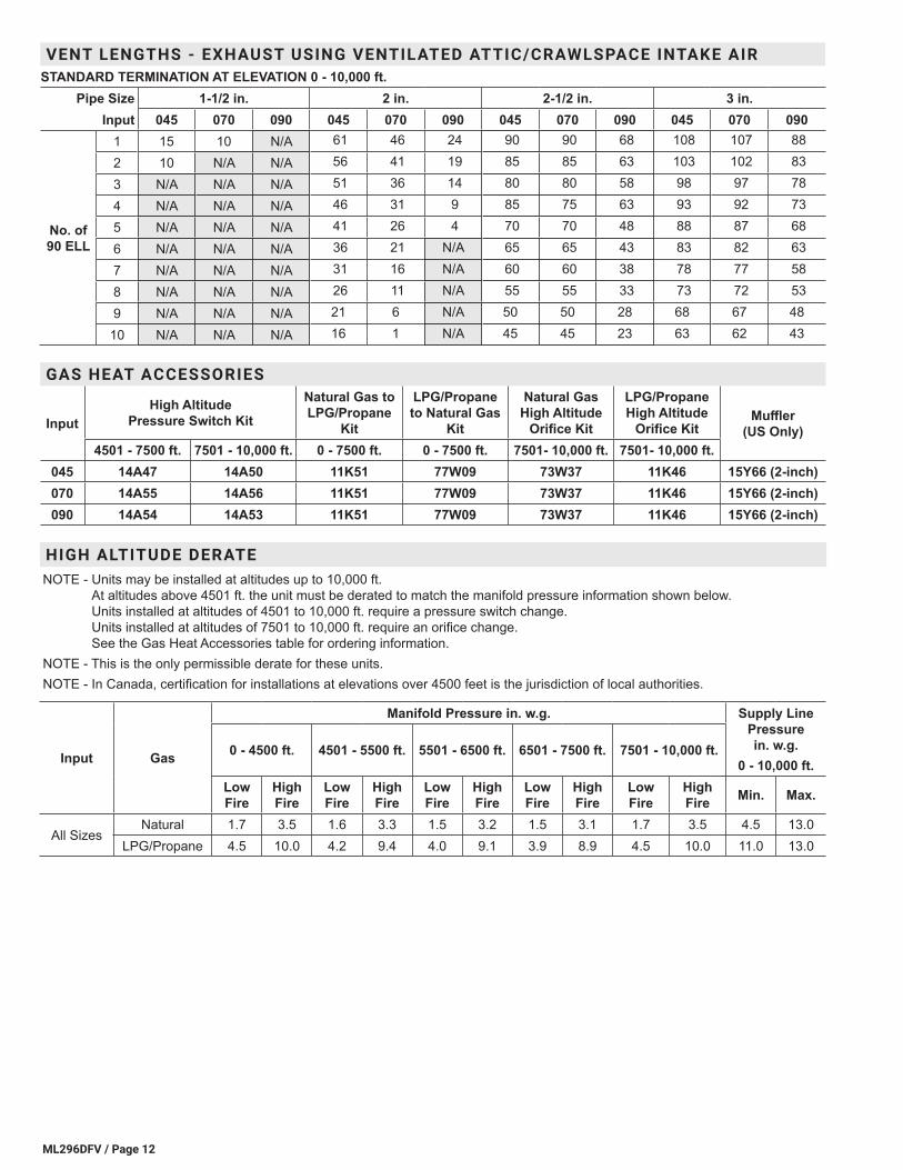
GAS HEAT ACCESSORIES
Input High Altitude
Pressure Switch Kit
Natural Gas to LPG/Propane
Kit
LPG/Propane to Natural Gas
Kit
Natural Gas High Altitude
Orifice Kit
LPG/Propane High Altitude
Orifice KitMuffler
(US Only)4501 - 7500 ft. 7501 - 10,000 ft. 0 - 7500 ft. 0 - 7500 ft. 7501- 10,000 ft. 7501- 10,000 ft.
045 14A47 14A50 11K51 77W09 73W37 11K46 15Y66 (2-inch)070 14A55 14A56 11K51 77W09 73W37 11K46 15Y66 (2-inch)090 14A54 14A53 11K51 77W09 73W37 11K46 15Y66 (2-inch)
HIGH ALTITUDE DERATENOTE - Units may be installed at altitudes up to 10,000 ft.
At altitudes above 4501 ft. the unit must be derated to match the manifold pressure information shown below. Units installed at altitudes of 4501 to 10,000 ft. require a pressure switch change. Units installed at altitudes of 7501 to 10,000 ft. require an orifice change. See the Gas Heat Accessories table for ordering information.
NOTE - This is the only permissible derate for these units. NOTE - In Canada, certification for installations at elevations over 4500 feet is the jurisdiction of local authorities.
Input Gas
Manifold Pressure in. w.g. Supply Line Pressure in. w.g.
0 - 10,000 ft.0 - 4500 ft. 4501 - 5500 ft. 5501 - 6500 ft. 6501 - 7500 ft. 7501 - 10,000 ft.
Low Fire
High Fire
Low Fire
High Fire
Low Fire
High Fire
Low Fire
High Fire
Low Fire
High Fire Min. Max.
All SizesNatural 1.7 3.5 1.6 3.3 1.5 3.2 1.5 3.1 1.7 3.5 4.5 13.0
LPG/Propane 4.5 10.0 4.2 9.4 4.0 9.1 3.9 8.9 4.5 10.0 11.0 13.0
VENT LENGTHS - EXHAUST USING VENTILATED ATTIC/CRAWLSPACE INTAKE AIRSTANDARD TERMINATION AT ELEVATION 0 - 10,000 ft.
Pipe Size 1-1/2 in. 2 in. 2-1/2 in. 3 in.Input 045 070 090 045 070 090 045 070 090 045 070 090
No. of 90 ELL
1 15 10 N/A 61 46 24 90 90 68 108 107 88
2 10 N/A N/A 56 41 19 85 85 63 103 102 83
3 N/A N/A N/A 51 36 14 80 80 58 98 97 78
4 N/A N/A N/A 46 31 9 85 75 63 93 92 73
5 N/A N/A N/A 41 26 4 70 70 48 88 87 68
6 N/A N/A N/A 36 21 N/A 65 65 43 83 82 63
7 N/A N/A N/A 31 16 N/A 60 60 38 78 77 58
8 N/A N/A N/A 26 11 N/A 55 55 33 73 72 53
9 N/A N/A N/A 21 6 N/A 50 50 28 68 67 48
10 N/A N/A N/A 16 1 N/A 45 45 23 63 62 43
ML296DFV / Page 13
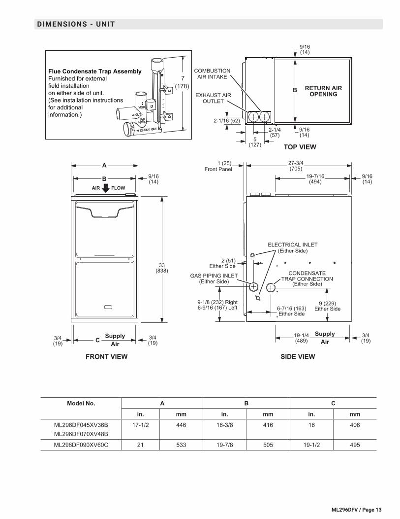
DIMENSIONS - UNIT
Model No. A B C
in. mm in. mm in. mm
ML296DF045XV36BML296DF070XV48B
17-1/2 446 16-3/8 416 16 406
ML296DF090XV60C 21 533 19-7/8 505 19-1/2 495
AIR
EXHAUST AIROUTLET
COMBUSTIONAIR INTAKE
FLOW
2-1/16 (52)
GAS PIPING INLET(Either Side)
ELECTRICAL INLET(Either Side)
RETURN AIROPENING
FRONT VIEW SIDE VIEW
TOP VIEW
A
B
C 3/4(19)
27-3/4(705)
19-1/4(489)
9-1/8 (232) Right6-9/16 (167) Left
2 (51)Either Side33
(838)
3/4(19)
B
SupplyAir
SupplyAir
9/16(14)
9/16(14)
9/16(14)
9/16(14)
19-7/16(494)
3/4(19)
CONDENSATETRAP CONNECTION
5(127)
6-7/16 (163)Either Side
9 (229)Either Side
2-1/4(57)
(Either Side)
1 (25)Front Panel
Flue Condensate Trap AssemblyFurnished for external
field installation
on either side of unit.
(See installation instructions
for additional
information.)
7
(178)
ML296DFV / Page 14
TOP VIEW
SUPPLYAIR
OPENING
SIDE VIEW
DOWNFLOWCOMBUSTIBLE
FLOORINGBASE
DOWNFLOW
FURNACE
A
B
27-1/4(692)
19-13/16(503)
1-1/2(38)
21-13/16(554)
FLOOROPENING
1-1/2(38)
1-1/2(38)
1-1/2(38)
Front Of Furnace
22(559) C
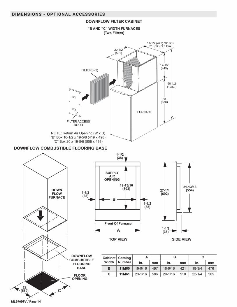
DOWNFLOW COMBUSTIBLE FLOORING BASE
Cabinet Width
Catalog Number
A B Cin. mm in. mm in. mm
B 11M60 19-9/16 497 16-9/16 421 18-3/4 476 C 11M61 23-1/16 586 20-1/16 510 22-1/4 565
DOWNFLOW FILTER CABINET
“B AND ”C” WIDTH FURNACES(Two Filters)
FILTERS (2)
FILTER ACCESSDOOR
FURNACE
17-1/2
33(838)
(445)
50-1/2(1283 )
17-1/2 (445) “B” Box21 (533) “C” Box
20-1/2(521)
NOTE: Return Air Opening (W x D)
“B” Box 16-1/2 x 19-5/8 (419 x 498)
“C” Box 20 x 19-5/8 (508 x 498)
DIMENSIONS - OPTIONAL ACCESSORIES
ML296DFV / Page 15
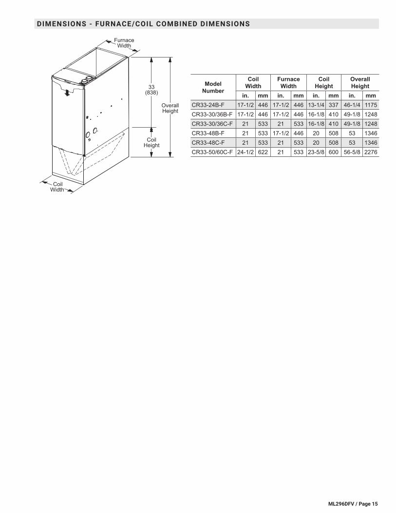
Model Number
Coil Width
Furnace Width
Coil Height
Overall Height
in. mm in. mm in. mm in. mmCR33-24B-F 17-1/2 446 17-1/2 446 13-1/4 337 46-1/4 1175CR33-30/36B-F 17-1/2 446 17-1/2 446 16-1/8 410 49-1/8 1248CR33-30/36C-F 21 533 21 533 16-1/8 410 49-1/8 1248CR33-48B-F 21 533 17-1/2 446 20 508 53 1346CR33-48C-F 21 533 21 533 20 508 53 1346CR33-50/60C-F 24-1/2 622 21 533 23-5/8 600 56-5/8 2276
CoilWidth
CoilHeight
OverallHeight
33(838)
FurnaceWidth
DIMENSIONS - FURNACE/COIL COMBINED DIMENSIONS

ML296DFV / Page 16
FLUSH-MOUNT VENT TERMINATION KIT 51W11 (US) or 51W12 (CANADA)
With 2 or 2-1/2 in. (51 or 64 mm) PVC pipe With 3 in. (76 mm) PVC pipe
3 (76) PVC pipe2 (51) PVC pipe
2-1/2 (64) PVC pipe
When required UseField Provided
2-1/2 to 2 in. (64 to 51 mm)Coupling
Seal all openings(typical)
2-3/8 (60)
12 (305) minimum(recommended)
Intake
(Behind Plate)
Exhaust Intake
(Behind Plate)
Exhaust
NOTE - PVC pipe and fittings are not furnished
and must be field furnished.
4-1/2
(114)
2-Inch - 18-3/4 (476)
3-Inch - 25 (635)
MUFFLERS15Y66 - 2-inch16A56 - 3-inch
(Installed Vertically
in the Exhaust Pipe)
NOTE - Two-inch mufflers
do not have reducers
at each end.
DIMENSIONS - OPTIONAL ACCESSORIES - VENTING
ML296DFV / Page 17
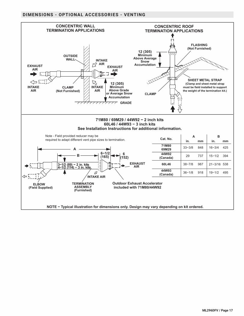
CONCENTRIC WALLTERMINATION APPLICATIONS
INTAKEAIR
EXHAUSTAIR
INTAKEAIR
INTAKEAIR
EXHAUSTAIR
OUTSIDEWALL
12 (305)MinimumAbove Grade
or Average SnowAccumulation
12 (305)Minimum
Above AverageSnow
Accumulation
SHEET METAL STRAP(Clamp and sheet metal strap
must be field installed to supportthe weight of the termination kit.)
FLASHING(Not Furnished)
CLAMP
GRADE
6−1/2(165)
(Field Supplied)ELBOW
INTAKE AIR
EXHAUSTAIR
TERMINATIONASSEMBLY(Furnished)
71M80 / 69M29 / 44W92 − 2 inch kits60L46 / 44W93 − 3 inch kits
See Installation Instructions for additional information.
CONCENTRIC ROOFTERMINATION APPLICATIONS
CLAMP(Not Furnished)
6(152)
A
3−1/2 (89) − 2 in. kits4−1/2 (114) − 3 in. kits
Outdoor Exhaust Acceleratorincluded with 71M80/44W92
NOTE − Typical illustration for dimensions only. Design may vary depending on kit ordered.
Cat. No.A B
in. mm in. mm71M8069M29 33−3/8 848 16−3/4 425
44W92(Canada) 29 737 15−1/2 394
60L46 38−7/8 987 21−3/16 538
44W93(Canada) 36−1/8 918 19−1/2 495
Note - Field provided reducer may be
required to adapt different vent pipe sizes to termination.
B
DIMENSIONS - OPTIONAL ACCESSORIES - VENTING
ML296DFV / Page 18
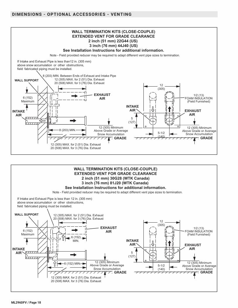
12 (305) MinimumAbove Grade or Average
Snow Accumulation
1/2 (13)FOAM INSULATION
(Field Furnished)
5
(127)
5-1/2
(140)
EXHAUSTAIR
INTAKEAIR
GRADE
12
(305)
INTAKEAIR
EXHAUSTAIR
GRADE
8 (203) MIN. Between Ends of Exhaust and Intake Pipe
12 (305) MAX. for 2 (51) Dia. Exhaust
20 (508) MAX. for 3 (76) Dia. ExhaustWALL SUPPORT
12 (305) MAX. for 2 (51) Dia. Exhaust
20 (508) MAX. for 3 (76) Dia. Exhaust
12 (305) MinimumAbove Grade or Average
Snow Accumulation
WALL TERMINATION KITS (CLOSE-COUPLE)EXTENDED VENT FOR GRADE CLEARANCE
2 inch (51 mm) 22G44 (US) 3 inch (76 mm) 44J40 (US)
See Installation Instructions for additional information.
6 (152)
Maximum
If Intake and Exhaust Pipe is less than12 in. (305 mm)
above snow accumulation or other obstructions,
field fabricated piping must be installed.
8 (203) MIN.
Note - Field provided reducer may be required to adapt different vent pipe sizes to termination.
12 (305) MinimumAbove Grade or Average
Snow Accumulation
1/2 (13)FOAM INSULATION
(Field Furnished)
5
(127)
5-1/2
(140)
EXHAUSTAIR
INTAKEAIR
GRADE
12
(305)
INTAKEAIR
EXHAUSTAIR
GRADE
WALL SUPPORT
12 (305) MinimumAbove Grade or Average
Snow Accumulation
WALL TERMINATION KITS (CLOSE-COUPLE)EXTENDED VENT FOR GRADE CLEARANCE
2 inch (51 mm) 30G28 (WTK Canada)3 inch (76 mm) 81J20 (WTK Canada)
See Installation Instructions for additional information.
6 (152)
Maximum
If Intake and Exhaust Pipe is less than 12 in. (305 mm)
above snow accumulation or other obstructions,
field fabricated piping must be installed.
12 (305) MAX. for 2 (51) Dia. Exhaust20 (508) MAX. for 3 (76) Dia. Exhaust
12 (305) MAX. for 2 (51) Dia. Exhaust
20 (508) MAX. for 3 (76) Dia. Exhaust
Note - Field provided reducer may be required to adapt different vent pipe sizes to termination.
6 (152) MIN.
6 (152)
MIN.
DIMENSIONS - OPTIONAL ACCESSORIES - VENTING
ML296DFV / Page 19
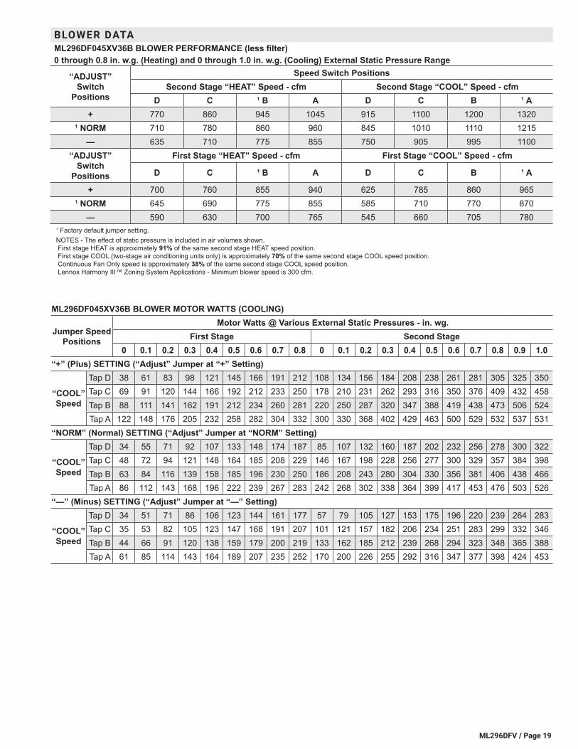
BLOWER DATAML296DF045XV36B BLOWER PERFORMANCE (less filter)0 through 0.8 in. w.g. (Heating) and 0 through 1.0 in. w.g. (Cooling) External Static Pressure Range
“ADJUST” Switch
Positions
Speed Switch PositionsSecond Stage “HEAT” Speed - cfm Second Stage “COOL” Speed - cfm
D C 1 B A D C B 1 A+ 770 860 945 1045 915 1100 1200 1320
1 NORM 710 780 860 960 845 1010 1110 1215— 635 710 775 855 750 905 995 1100
“ADJUST” Switch
Positions
First Stage “HEAT” Speed - cfm First Stage “COOL” Speed - cfm
D C 1 B A D C B 1 A
+ 700 760 855 940 625 785 860 9651 NORM 645 690 775 855 585 710 770 870
— 590 630 700 765 545 660 705 7801 Factory default jumper setting.NOTES - The effect of static pressure is included in air volumes shown. First stage HEAT is approximately 91% of the same second stage HEAT speed position. First stage COOL (two-stage air conditioning units only) is approximately 70% of the same second stage COOL speed position. Continuous Fan Only speed is approximately 38% of the same second stage COOL speed position. Lennox Harmony III™ Zoning System Applications - Minimum blower speed is 300 cfm.
ML296DF045XV36B BLOWER MOTOR WATTS (COOLING)
Jumper Speed Positions
Motor Watts @ Various External Static Pressures - in. wg.First Stage Second Stage
0 0.1 0.2 0.3 0.4 0.5 0.6 0.7 0.8 0 0.1 0.2 0.3 0.4 0.5 0.6 0.7 0.8 0.9 1.0“+” (Plus) SETTING (“Adjust” Jumper at “+” Setting)
“COOL” Speed
Tap D 38 61 83 98 121 145 166 191 212 108 134 156 184 208 238 261 281 305 325 350Tap C 69 91 120 144 166 192 212 233 250 178 210 231 262 293 316 350 376 409 432 458Tap B 88 111 141 162 191 212 234 260 281 220 250 287 320 347 388 419 438 473 506 524Tap A 122 148 176 205 232 258 282 304 332 300 330 368 402 429 463 500 529 532 537 531
“NORM” (Normal) SETTING (“Adjust” Jumper at “NORM” Setting)
“COOL” Speed
Tap D 34 55 71 92 107 133 148 174 187 85 107 132 160 187 202 232 256 278 300 322Tap C 48 72 94 121 148 164 185 208 229 146 167 198 228 256 277 300 329 357 384 398Tap B 63 84 116 139 158 185 196 230 250 186 208 243 280 304 330 356 381 406 438 466Tap A 86 112 143 168 196 222 239 267 283 242 268 302 338 364 399 417 453 476 503 526
“—” (Minus) SETTING (“Adjust” Jumper at “—” Setting)
“COOL” Speed
Tap D 34 51 71 86 106 123 144 161 177 57 79 105 127 153 175 196 220 239 264 283Tap C 35 53 82 105 123 147 168 191 207 101 121 157 182 206 234 251 283 299 332 346Tap B 44 66 91 120 138 159 179 200 219 133 162 185 212 239 268 294 323 348 365 388Tap A 61 85 114 143 164 189 207 235 252 170 200 226 255 292 316 347 377 398 424 453
ML296DFV / Page 20
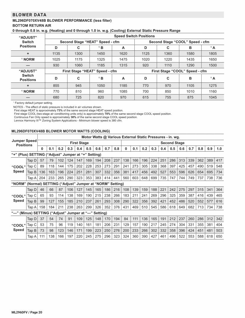
BLOWER DATAML296DF070XV48B BLOWER PERFORMANCE (less filter)BOTTOM RETURN AIR0 through 0.8 in. w.g. (Heating) and 0 through 1.0 in. w.g. (Cooling) External Static Pressure Range
“ADJUST” Switch
Positions
Speed Switch PositionsSecond Stage “HEAT” Speed - cfm Second Stage “COOL” Speed - cfm
D C 1 B A D C B 1 A+ 1135 1300 1450 1620 1125 1360 1580 1805
1 NORM 1025 1175 1325 1475 1020 1220 1435 1650— 930 1060 1185 1315 920 1110 1290 1500
“ADJUST” Switch
Positions
First Stage “HEAT” Speed - cfm First Stage “COOL” Speed - cfm
D C 1 B A D C B 1 A
+ 855 945 1050 1185 770 970 1105 12751 NORM 770 810 960 1085 700 850 1010 1160
— 680 725 820 970 615 755 875 10451 Factory default jumper setting.NOTES - The effect of static pressure is included in air volumes shown. First stage HEAT is approximately 73% of the same second stage HEAT speed position. First stage COOL (two-stage air conditioning units only) is approximately 70% of the same second stage COOL speed position. Continuous Fan Only speed is approximately 38% of the same second stage COOL speed position. Lennox Harmony III™ Zoning System Applications - Minimum blower speed is 380 cfm.
ML296DF070XV48B BLOWER MOTOR WATTS (COOLING)
Jumper Speed Positions
Motor Watts @ Various External Static Pressures - in. wg.First Stage Second Stage
0 0.1 0.2 0.3 0.4 0.5 0.6 0.7 0.8 0 0.1 0.2 0.3 0.4 0.5 0.6 0.7 0.8 0.9 1.0“+” (Plus) SETTING (“Adjust” Jumper at “+” Setting)
“COOL” Speed
Tap D 57 79 102 124 147 169 194 208 237 138 166 196 224 251 286 313 339 362 389 417Tap C 89 118 144 175 202 228 253 273 291 241 273 305 338 368 397 425 457 490 519 548Tap B 136 163 196 224 251 281 307 332 356 381 417 456 492 527 553 596 626 654 695 734Tap A 204 233 265 290 323 353 383 414 441 560 603 648 699 735 747 744 749 737 738 736
“NORM” (Normal) SETTING (“Adjust” Jumper at “NORM” Setting)
“COOL” Speed
Tap D 46 66 87 106 127 145 165 186 216 108 139 159 188 221 242 275 297 315 341 364Tap C 65 93 114 138 169 190 215 238 266 183 211 241 269 296 325 359 387 416 439 465Tap B 99 127 155 185 210 237 261 293 308 290 322 356 392 421 452 486 520 552 577 616Tap A 158 184 211 238 263 299 326 352 376 431 469 510 545 586 618 649 682 713 734 738
“—” (Minus) SETTING (“Adjust” Jumper at “—” Setting)
“COOL” Speed
Tap D 37 54 74 91 109 125 148 170 194 84 111 136 165 191 212 237 260 286 312 342Tap C 53 75 96 119 140 161 181 206 231 129 157 190 217 245 274 304 331 355 381 404Tap B 73 98 123 146 171 199 223 250 276 200 233 266 302 332 358 396 424 451 481 503Tap A 111 138 166 197 220 245 275 296 323 324 360 390 427 461 496 522 553 588 618 650
ML296DFV / Page 21
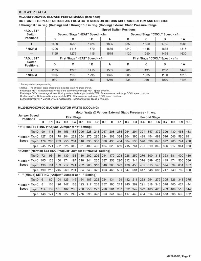
BLOWER DATAML296DF090XV60C BLOWER PERFORMANCE (less filter)BOTTOM RETURN AIR, RETURN AIR FROM BOTH SIDES OR RETURN AIR FROM BOTTOM AND ONE SIDE0 through 0.8 in. w.g. (Heating) and 0 through 1.0 in. w.g. (Cooling) External Static Pressure Range
“ADJUST” Switch
Positions
Speed Switch PositionsSecond Stage “HEAT” Speed - cfm Second Stage “COOL” Speed - cfm
D C 1 B A D C B 1 A+ 1430 1555 1725 1865 1350 1550 1755 1985
1 NORM 1300 1415 1570 1685 1240 1445 1635 1815— 1195 1275 1415 1515 1120 1290 1455 1630
“ADJUST” Switch
Positions
First Stage “HEAT” Speed - cfm First Stage “COOL” Speed - cfm
D C 1 B A D C B 1 A
+ 1175 1275 1415 1505 985 1130 1280 14401 NORM 1075 1165 1295 1375 905 1035 1180 1315
— 980 1045 1160 1240 835 940 1070 11951 Factory default jumper setting.NOTES - The effect of static pressure is included in air volumes shown. First stage HEAT is approximately 80% of the same second stage HEAT speed position. First stage COOL (two-stage air conditioning units only) is approximately 70% of the same second stage COOL speed position. Continuous Fan Only speed is approximately 38% of the same second stage COOL speed position. Lennox Harmony III™ Zoning System Applications - Minimum blower speed is 460 cfm.
ML296DF090XV60C BLOWER MOTOR WATTS (COOLING)
Jumper Speed Positions
Motor Watts @ Various External Static Pressures - in. wg.First Stage Second Stage
0 0.1 0.2 0.3 0.4 0.5 0.6 0.7 0.8 0 0.1 0.2 0.3 0.4 0.5 0.6 0.7 0.8 0.9 1.0“+” (Plus) SETTING (“Adjust” Jumper at “+” Setting)
“COOL” Speed
Tap D 90 113 139 156 181 206 228 248 267 208 235 264 294 321 347 372 396 430 453 483Tap C 127 151 178 204 222 254 275 295 324 302 334 364 396 429 454 482 516 546 580 611Tap B 179 205 233 255 284 310 333 368 388 430 464 504 536 576 598 640 672 703 744 768Tap A 245 271 302 325 349 381 409 432 464 620 659 715 764 791 819 849 896 917 944 963
“NORM” (Normal) SETTING (“Adjust” Jumper at “NORM” Setting)
“COOL” Speed
Tap D 72 93 116 139 158 180 202 226 244 179 203 228 250 276 300 318 353 381 400 430Tap C 105 128 150 174 197 218 244 265 287 258 290 312 344 374 399 423 449 474 506 536Tap B 138 161 189 217 241 262 288 310 340 368 392 436 456 485 513 543 574 594 631 667Tap A 190 216 245 269 291 324 343 372 403 466 501 547 581 617 648 686 717 749 782 808
“—” (Minus) SETTING (“Adjust” Jumper at “—” Setting)
“COOL” Speed
Tap D 61 80 104 125 146 164 187 202 224 134 159 182 211 233 254 279 305 326 348 375Tap C 81 103 126 147 168 193 217 238 257 190 213 245 269 291 318 348 378 400 427 444Tap B 114 137 161 182 205 230 256 273 298 261 287 322 347 372 403 428 453 489 516 544Tap A 148 174 199 227 249 276 298 328 353 341 375 417 449 484 514 544 573 608 639 662


REVISIONS
NOTE - Due to Lennox’ ongoing commitment to quality, Specifications, Ratings and Dimensions subject to change without notice and without incurring liability. Improper installation, adjustment, alteration, service or maintenance can cause property damage or personal injury. Installation and service must be performed by a qualified installer and servicing agency. ©2021 Lennox Industries, Inc.
Visit us at www.lennox.com For the latest technical information, www.LennoxPros.com Contact us at 1-800-4-LENNOX
REVISIONS
Sections Description of Change
Vent LengthsVent Lengths - Uninsulated Exhaust Pipe in Unconditioned SpaceVent Lengths - Exhaust Using Ventilated Attic/Crawlspace Intake AirOutdoor Termination Kit Usage
Added 1-1/2 inch venting data.
Related Documents