SAMSON ® S83 / S63 AMPLIFIER MIXER

Welcome message from author
This document is posted to help you gain knowledge. Please leave a comment to let me know what you think about it! Share it to your friends and learn new things together.
Transcript

SAMSON®
S83 / S63
AMPLIFIERMIXER
Introduction 1
S83/S63 Features 2
Guided Tour - S83 4Overview 4Channel 5Main Section 6Rear Panel 8
Guided Tour - S63 10Overview 10Channel 11Main Section 12Rear Panel 14
Connecting The S83/S63 - General Suggestions 15
Setting Up and Using the S83/S63 16
Setting the Correct Gain Structure 17
Suggested Performance Applications 20S83 20S63 21
Grounding Techniques 22
Using Equalization 23
Using the Effects Sends and Returns 25
Using the Monitor Output 26
Using the Internal Reverb 26
Specifications 27

Introduction
Congratulations on purchasing the Samson S83/S63 Mixer Amplifier! In thismanual, we’ll take you on a guided tour through all the features of this powerfuland flexible device, and we’ll tell you how to get the most out of the S83/S63.Although designed for easy operation, we suggest you take some time out firstto go through these pages so you can fully understand how we’ve implementeda number of unique features.
The S83 and S63 both combine a flexible multi-channel mixer with a clean, pow-erful amplifier and high-quality spring reverb unit—all in a single compact chas-sis that mounts easily in any standard 19” rack. Simply plug in your micro-phones and line-level instruments (such as keyboards, tape decks, CD players,etc.) and connect the unit to any standard speaker system, and you’ve got acomplete PA system suitable for use in permanent installations such as church-es, conference rooms, small clubs, or similar environments.
The S83 and S63 differ in the number of input channels (the S83 has eight whilethe S63 has six); the type of equalization (the S83 provides four bands per chan-nel, while the S63 has three); their amplifier power ratings (the S83 delivers 300watts into 4 ohms, while the S63 delivers 210 watts into 4 ohms); the number ofEffects returns (the S83 has four while the S63 has two) and the presence orabsence of a master metering section, peak LEDs, and headphone preamplifier(the S83 has all of these while the S63 does not). Both units include a 10-bandgraphic master equalizer, a master level control, phantom power, two Effectssends, and a Monitor output as well as dedicated tape/CD input.
In these pages, we’ll begin with an overview of the main S83/S63 features, fol-lowed by a guided tour of both units’ front and rear panels. Then we’ll describethe various input and output connections (including wiring diagrams) and tell youin detail how to set up your S83/S63 as well as showing you how best to use theunit in live performance. Finally, we’ll cover a number of specific topics (such asgrounding techniques, using equalization, and using the effects sends andreturns) and then wrap things up with full specifications.
Oh, and one last thing—don’t forget to fill out and mail in the enclosed warranteecard! This will enable you to receive online technical support and will allow us tosend you updated information about other Samson products in the future.
1
S83/S63 Features
The Samson S83/S63 utilizes state-of-the-art technology in integratedmixer/amplifier design. Here are some of its main features:
• Standard 19” rack-mount design (taking just four rack spaces) allows theS83 and S63 to be easily integrated into any setup.
• Multiple channels (eight in the S83; six in the S63) and mic and line inputsfor each channel allow you to blend together a variety of source signals,including dynamic or condenser microphones, keyboards, CD/tape players,etc. Standard XLR mic connectors (for microphone inputs) and electronical-ly balanced 1/4” jacks (for line-level inputs) are provided for each channel;in addition, there is a dedicated CD/Tape input that provides dual phono(RCA) jacks.
• Power to spare—both units include a clean, high-quality amplifier, delivering300 watts (in the case of the S83) or 210 watts (in the case of the S63) intofour ohms. Any standard speaker cabinets (two, four, eight, or sixteenohms) can be connected to the rear-panel 1/4” speaker output jacks.
• A built-in three-spring reverb unit allows you to add reverberation effects toyour vocals or instruments without having to use an expensive external signal processor. A front-panel reverb master volume control allows you toprecisely define the amount of reverb to be added to the signal.
• Each channel provides independent equalization controls (four-band in theS83; three-band in the S63), enabling you to shape the sound of your inputsignal sources. In addition, a ten-band graphic master equalizer allows youto “tune” the output of the S83/S63 to the particular room environment youare in. This can be particularly useful for eliminating ringing or feedbackproblems.
• In the S83, Peak LEDs for each channel show you at a glance when aninput signal is on the verge of overloading. In the S63, a master Peak LEDshows you at a glance when the internal amplifier is overloading. In bothunits, other front-panel LEDs show the current status of the amplifier’s pro-tection relay circuitry and whether or not phantom power is being applied.
• Independent input Trim controls for each channel that allows you to precise-ly set the correct input gain.
• Two Effects sends per channel (one pre-fade and the other post-fade) allowyou to route multiple signals to the internal reverb unit or to external signalprocessors. The pre-fade send (Effects send 1) can be used as a Monitorcontrol, allowing you to set up an onstage monitor mix that is independent ofthe main house mix. A separate Monitor level control is provided on thefront panel.
• In the S83, four Effects returns give you the ability to blend in the return sig-nal from external signal processors or other line-level devices without havingto utilize input channels. Two front-panel Effects return level controls (onefor Effects returns 1-2 and the other for Effects returns 3-4) allow you tobring in stereo signals, which are then automatically mixed together in mono.In the S63, two Effects returns are provided, with a single front-panel controlfor the two.
2

S83/S63 Features
• A phantom power switch enables you to use the S83 and S63 with high-quality condenser microphones. When turned on, 48 volts of phantompower is provided to the mic connectors of all input channels.
• Protection relay circuitry prevents “thumps” when powering on or off. Thismeans that you can use the S83/S63 with a single power strip into whichother audio devices are connected, without danger of damage to connectedspeakers.
• A rear-panel amplifier input allows you to bring external signals from othermixers or audio devices into the S83/S63 power amplifier.
• A rear-panel preamplifier output allows you to connect the S83/S63 to exter-nal power amplifiers when higher power ratings are required and/or when additional amplifier feeds are necessary.
• In the S83, a built-in headphone amplifier, with a front-panel 1/4” stereo connector and dedicated level control allows you to monitor your main mix.
• In the S83, a convenient front-panel meter allows you to see at a glance thecontinuous output signal level.
We’ll elaborate on many of these terms and features later in this manual. Nowit’s time to take a guided tour of the units, starting with the S83.
3

Guided Tour - S83 Overview
The following illustration shows an overview of the front panel of the S83:
4
-12 +122.5K
0
-15 +15HIGH
0
-12 +12500Hz
0
-15 +15LOW
0
+15LEVEL
0
+10EFF1 MON
0
+4 -40TRIM
0
10
+10EFF2 REV
0
LINE
MIC
CHANNEL 1
PEAK
LOW
+15LEVEL
0
+10EFF1 MON
0
+4 -40TRIM
0
10
+10EFF2 REV
0
LINE
MIC
CHANNEL 2
PEAK
LOW
+15LEVEL
0
+10EFF1 MON
0
+4 -40TRIM
0
10
+10EFF2 REV
0
LINE
MIC
CHANNEL 3
PEAK
LOW
+15LEVEL
0
+10EFF1 MON
0
+4 -40TRIM
0
10
+10EFF2 REV
0
LINE
MIC
CHANNEL 4
PEAK
LOW
+15LEVEL
0
+10EFF1 MON
0
+4 -40TRIM
0
10
+10EFF2 REV
0
LINE
MIC
CHANNEL 5
PEAK
LOW
+15LEVEL
0
+10EFF1 MON
0
+4 -40TRIM
0
10
+10EFF2 REV
0
LINE
MIC
CHANNEL 6
PEAK
LOW
+15LEVEL
0
+10EFF1 MON
0
+4 -40TRIM
0
10
+10EFF2 REV
0
LINE
MIC
CHANNEL 7
PEAK
LOW
−∞ +15LEVEL
0
−∞ +10EFF1 MON
0
+4 -40TRIM
0
10
−∞ +10EFF2 REV
0
LINE
MIC
CHANNEL 8
PEAK
8 CHANNEL MIXER 300 WATT AMPLIFIER
-18 -12 -8 -5 -3 0 +2
PHANTOM PROTECTION POWER
30Hz 64Hz 125Hz 250Hz 500Hz 1K 2K 3K 5K 10K
+15dB
0dB
-15dB
30Hz 64Hz 125Hz 250Hz 500Hz 1K 2K 3K 5K 10K
PHANTOM
+10
RETURN 1-2
0
MAIN LEVEL
+10
RETURN 3-4
0
0 10
HEADPHONES
0 10
REVERB−∞ +10
MONITOR
0
S8 MIXER AMPLIFIER−∞
−∞
−∞
−∞
−∞
−∞
−∞
−∞
−∞
−∞
−∞
−∞
−∞
−∞
−∞
−∞
−∞
−∞
−∞
−∞
−∞
−∞ −∞
-12 +122.5K
0
-15 +15HIGH
0
-12 +12500Hz
0
-15 +15
0
-12 +122.5K
0
-15 +15HIGH
0
-12 +12500Hz
0
-15 +15
0
-12 +122.5K
0
-15 +15HIGH
0
-12 +12500Hz
0
-15 +15
0
-12 +122.5K
0
-15 +15HIGH
0
-12 +12500Hz
0
-15 +15
0
-12 +122.5K
0
-15 +15HIGH
0
-12 +12500Hz
0
-15 +15
0
-12 +122.5K
0
-15 +15HIGH
0
-12 +12500Hz
0
-15 +15
0
-12 +122.5K
0
-15 +15HIGH
0
-12 +12500Hz
0
-15 +15
0
Main SectionChannels
+10
0
−∞
Guided Tour - S83 Channel
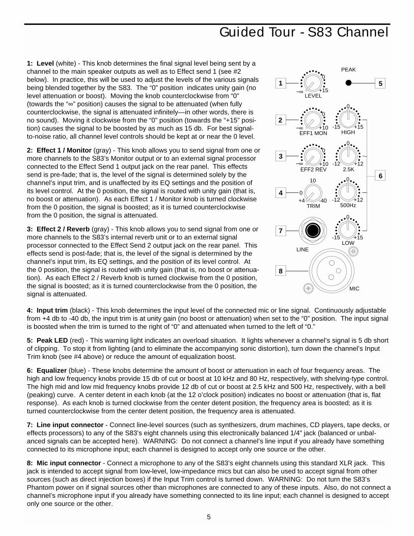
1: Level (white) - This knob determines the final signal level being sent by achannel to the main speaker outputs as well as to Effect send 1 (see #2below). In practice, this will be used to adjust the levels of the various signalsbeing blended together by the S83. The “0” position indicates unity gain (nolevel attenuation or boost). Moving the knob counterclockwise from “0”(towards the “∞” position) causes the signal to be attenuated (when fullycounterclockwise, the signal is attenuated infinitely—in other words, there isno sound). Moving it clockwise from the “0” position (towards the “+15” posi-tion) causes the signal to be boosted by as much as 15 db. For best signal-to-noise ratio, all channel level controls should be kept at or near the 0 level.
2: Effect 1 / Monitor (gray) - This knob allows you to send signal from one ormore channels to the S83’s Monitor output or to an external signal processorconnected to the Effect Send 1 output jack on the rear panel. This effectssend is pre-fade; that is, the level of the signal is determined solely by thechannel’s input trim, and is unaffected by its EQ settings and the position ofits level control. At the 0 position, the signal is routed with unity gain (that is,no boost or attenuation). As each Effect 1 / Monitor knob is turned clockwisefrom the 0 position, the signal is boosted; as it is turned counterclockwisefrom the 0 position, the signal is attenuated.
3: Effect 2 / Reverb (gray) - This knob allows you to send signal from one ormore channels to the S83’s internal reverb unit or to an external signalprocessor connected to the Effect Send 2 output jack on the rear panel. Thiseffects send is post-fade; that is, the level of the signal is determined by thechannel’s input trim, its EQ settings, and the position of its level control. Atthe 0 position, the signal is routed with unity gain (that is, no boost or attenua-tion). As each Effect 2 / Reverb knob is turned clockwise from the 0 position,the signal is boosted; as it is turned counterclockwise from the 0 position, the signal is attenuated.
4: Input trim (black) - This knob determines the input level of the connected mic or line signal. Continuously adjustablefrom +4 db to -40 db, the input trim is at unity gain (no boost or attenuation) when set to the “0” position. The input signalis boosted when the trim is turned to the right of “0” and attenuated when turned to the left of “0.”
5: Peak LED (red) - This warning light indicates an overload situation. It lights whenever a channel’s signal is 5 db shortof clipping. To stop it from lighting (and to eliminate the accompanying sonic distortion), turn down the channel’s InputTrim knob (see #4 above) or reduce the amount of equalization boost.
6: Equalizer (blue) - These knobs determine the amount of boost or attenuation in each of four frequency areas. Thehigh and low frequency knobs provide 15 db of cut or boost at 10 kHz and 80 Hz, respectively, with shelving-type control.The high mid and low mid frequency knobs provide 12 db of cut or boost at 2.5 kHz and 500 Hz, respectively, with a bell(peaking) curve. A center detent in each knob (at the 12 o’clock position) indicates no boost or attenuation (that is, flatresponse). As each knob is turned clockwise from the center detent position, the frequency area is boosted; as it isturned counterclockwise from the center detent position, the frequency area is attenuated.
7: Line input connector - Connect line-level sources (such as synthesizers, drum machines, CD players, tape decks, oreffects processors) to any of the S83’s eight channels using this electronically balanced 1/4” jack (balanced or unbal-anced signals can be accepted here). WARNING: Do not connect a channel’s line input if you already have somethingconnected to its microphone input; each channel is designed to accept only one source or the other.
8: Mic input connector - Connect a microphone to any of the S83’s eight channels using this standard XLR jack. Thisjack is intended to accept signal from low-level, low-impedance mics but can also be used to accept signal from othersources (such as direct injection boxes) if the Input Trim control is turned down. WARNING: Do not turn the S83’sPhantom power on if signal sources other than microphones are connected to any of these inputs. Also, do not connect achannel’s microphone input if you already have something connected to its line input; each channel is designed to acceptonly one source or the other.
5
-12 +122.5K
0
-15 +15HIGH
0
-12 +12500Hz
0
-15 +15LOW
0
+15LEVEL
0
+10EFF1 MON
0
+4 -40TRIM
0
10
+10EFF2 REV
0
LINE
MIC
PEAK
−∞
−∞
−∞
1
2
3
4
7
8
6
5
Guided Tour - S83 Main Section
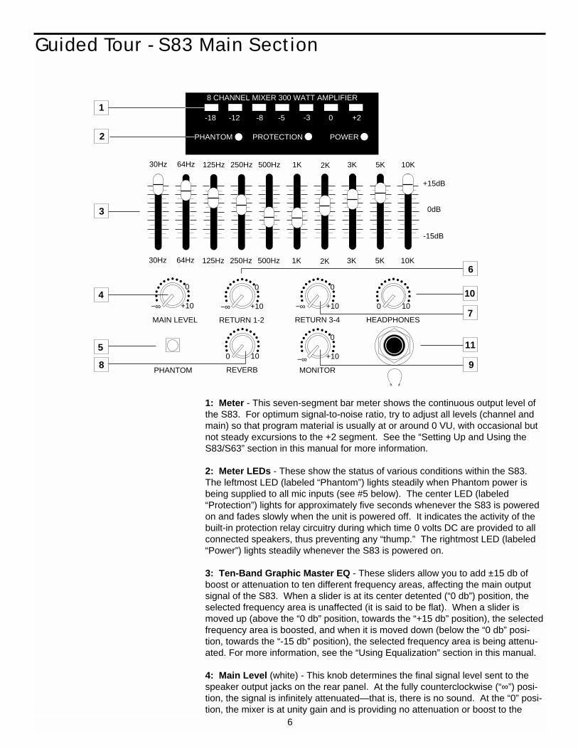
1: Meter - This seven-segment bar meter shows the continuous output level ofthe S83. For optimum signal-to-noise ratio, try to adjust all levels (channel andmain) so that program material is usually at or around 0 VU, with occasional butnot steady excursions to the +2 segment. See the “Setting Up and Using theS83/S63” section in this manual for more information.
2: Meter LEDs - These show the status of various conditions within the S83. The leftmost LED (labeled “Phantom”) lights steadily when Phantom power isbeing supplied to all mic inputs (see #5 below). The center LED (labeled“Protection”) lights for approximately five seconds whenever the S83 is poweredon and fades slowly when the unit is powered off. It indicates the activity of thebuilt-in protection relay circuitry during which time 0 volts DC are provided to allconnected speakers, thus preventing any “thump.” The rightmost LED (labeled“Power”) lights steadily whenever the S83 is powered on.
3: Ten-Band Graphic Master EQ - These sliders allow you to add ±15 db ofboost or attenuation to ten different frequency areas, affecting the main outputsignal of the S83. When a slider is at its center detented (“0 db”) position, theselected frequency area is unaffected (it is said to be flat). When a slider ismoved up (above the “0 db” position, towards the “+15 db” position), the selectedfrequency area is boosted, and when it is moved down (below the “0 db” posi-tion, towards the “-15 db” position), the selected frequency area is being attenu-ated. For more information, see the “Using Equalization” section in this manual.
4: Main Level (white) - This knob determines the final signal level sent to thespeaker output jacks on the rear panel. At the fully counterclockwise (“∞”) posi-tion, the signal is infinitely attenuated—that is, there is no sound. At the “0” posi-tion, the mixer is at unity gain and is providing no attenuation or boost to the
8 CHANNEL MIXER 300 WATT AMPLIFIER
-18 -12 -8 -5 -3 0 +2
PHANTOM PROTECTION POWER
30Hz 64Hz 125Hz 250Hz 500Hz 1K 2K 3K 5K 10K
+15dB
0dB
-15dB
30Hz 64Hz 125Hz 250Hz 500Hz 1K 2K 3K 5K 10K
PHANTOM
+10
RETURN 1-2
0
MAIN LEVEL
+10
RETURN 3-4
0
0 10
HEADPHONES
0 10
REVERB−∞ +10
MONITOR
0
−∞ −∞
1
2
3
4
5
8 9
11
7
10
6
+10
0
−∞
6
Guided Tour - S83 Main Section
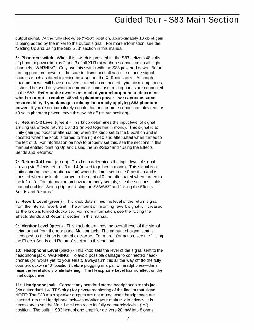
output signal. At the fully clockwise (“+10”) position, approximately 10 db of gainis being added by the mixer to the output signal. For more information, see the“Setting Up and Using the S83/S63” section in this manual.
5: Phantom switch - When this switch is pressed in, the S83 delivers 48 voltsof phantom power to pins 2 and 3 of all XLR microphone connectors in all eightchannels. WARNING: Only use this switch with the S83 powered down. Beforeturning phantom power on, be sure to disconnect all non-microphone signalsources (such as direct injection boxes) from the XLR mic jacks. Althoughphantom power will have no adverse affect on connected dynamic microphones,it should be used only when one or more condenser microphones are connectedto the S83. Refer to the owners manual of your microphone to determinewhether or not it requires 48 volts phantom power—we cannot assumeresponsibility if you damage a mic by incorrectly applying S83 phantompower. If you’re not completely certain that one or more connected mics require48 volts phantom power, leave this switch off (its out position).
6: Return 1-2 Level (green) - This knob determines the input level of signalarriving via Effects returns 1 and 2 (mixed together in mono). This signal is atunity gain (no boost or attenuation) when the knob set to the 0 position and isboosted when the knob is turned to the right of 0 and attenuated when turned tothe left of 0. For information on how to properly set this, see the sections in thismanual entitled “Setting Up and Using the S83/S63” and “Using the EffectsSends and Returns.”
7: Return 3-4 Level (green) - This knob determines the input level of signalarriving via Effects returns 3 and 4 (mixed together in mono). This signal is atunity gain (no boost or attenuation) when the knob set to the 0 position and isboosted when the knob is turned to the right of 0 and attenuated when turned tothe left of 0. For information on how to properly set this, see the sections in thismanual entitled “Setting Up and Using the S83/S63” and “Using the EffectsSends and Returns.”
8: Reverb Level (green) - This knob determines the level of the return signalfrom the internal reverb unit. The amount of incoming reverb signal is increasedas the knob is turned clockwise. For more information, see the “Using theEffects Sends and Returns” section in this manual.
9: Monitor Level (green) - This knob determines the overall level of the signalbeing output from the rear panel Monitor jack. The amount of signal sent isincreased as the knob is turned clockwise. For more information, see the “Usingthe Effects Sends and Returns” section in this manual.
10: Headphone Level (black) - This knob sets the level of the signal sent to theheadphone jack. WARNING: To avoid possible damage to connected head-phones (or, worse yet, to your ears!), always turn this all the way off (to the fullycounterclockwise “0” position) before plugging in a pair of headphones—thenraise the level slowly while listening. The Headphone Level has no effect on thefinal output level.
11: Headphone jack - Connect any standard stereo headphones to this jack(via a standard 1/4” TRS plug) for private monitoring of the final output signal.NOTE: The S83 main speaker outputs are not muted when headphones areinserted into the Headphone jack—to monitor your main mix in privacy, it isnecessary to set the Main Level control to its fully counterclockwise (“∞”)position. The built-in S83 headphone amplifier delivers 20 mW into 8 ohms.
7

Guided Tour - S83 Rear Panel
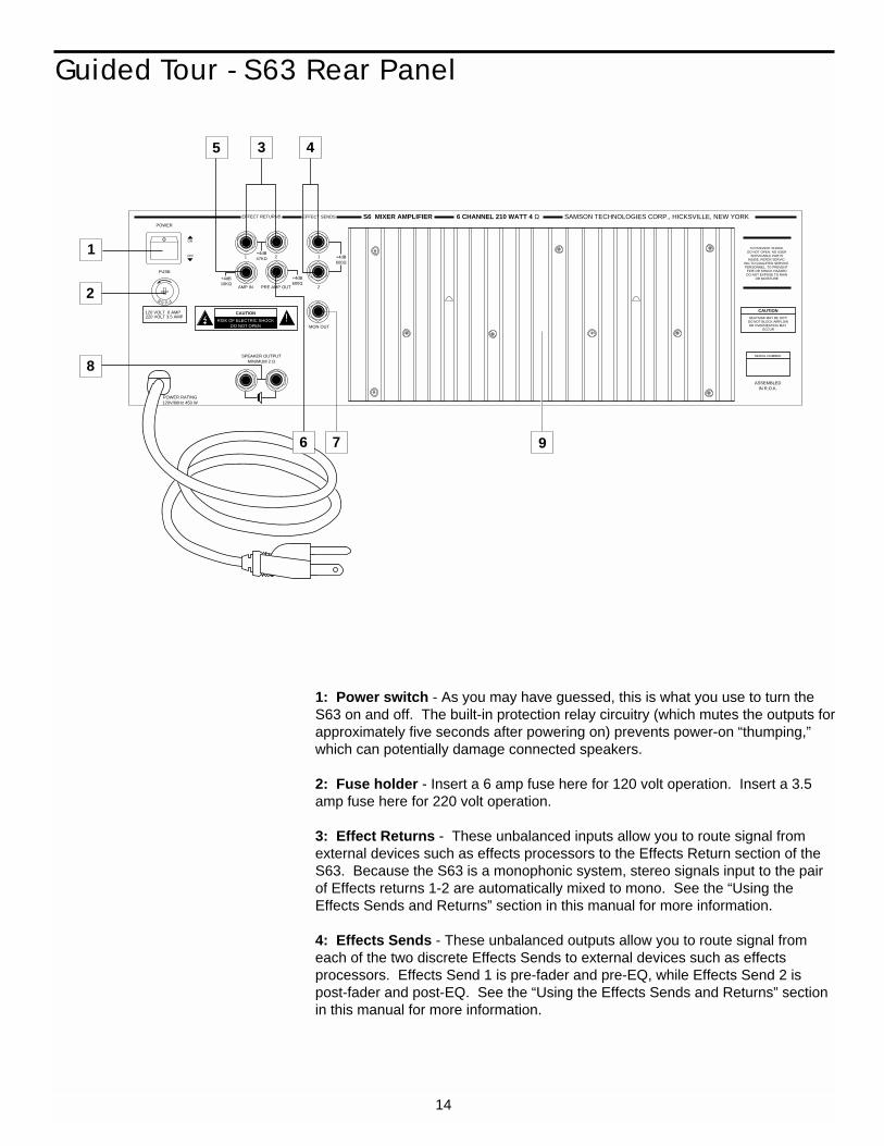
1: Power switch - As you may have guessed, this is what you use to turn theS83 on and off. The built-in protection relay circuitry (which mutes the outputsfor approximately five seconds after powering on) prevents power-on “thumping,”which can potentially damage connected speakers.
2: Fuse holder - Insert a 6 amp fuse here for 120 volt operation. Insert a 3.5amp fuse here for 220 volt operation.
3: Effect Returns - These unbalanced inputs allow you to route signal fromexternal devices such as effects processors to the Effects Return section of theS83. Stereo devices should be connected to the matched pairs 1-2 and 3-4;mono devices should be connected to one input in each pair (that is, 1 and 3 or 2and 4). Because the S83 is a monophonic system, stereo signals routed toeither pair of Effects returns are automatically mixed to mono. See the “Usingthe Effects Sends and Returns” section in this manual for more information.
4: Effects Sends - These unbalanced outputs allow you to route signal fromeach of the two discrete Effects Sends to external devices such as effectsprocessors. Effects Send 1 is pre-fader and pre-EQ, while Effects Send 2 ispost-fader and post-EQ. See the “Using the Effects Sends and Returns” sectionin this manual for more information.
8
S8 MIXER AMPLIFIER 8 CHANNEL 300 WATT 4 Ω SAMSON TECHNOLOGIES CORP., HICKSVILLE, NEW YORK EFFECT RETURNS EFFECT SENDS
MON OUT
1
2
2
4
1
3
AMP IN PRE AMP OUT
SPEAKER OUTPUTMINIMUM 2 Ω
+4dB10KΩ
+4dB600Ω
+4dB600Ω
+4dB47KΩ
LEFT RIGHT
CD/TAPEIN
CAUTION
RISK OF ELECTRIC SHOCKDO NOT OPEN
!
o
FUSE
120 VOLT 6 AMP220 VOLT 3.5 AMP
TO PREVENT SHOCK,DO NOT OPEN. NO USER
SERVICABLE PARTSINSIDE. REFER SERVIC-
ING TO QUALIFIED SERVICE PERSONNEL. TO PREVENT
FIRE OR SHOCK HAZARDDO NOT EXPOSE TO RAIN
OR MOISTURE
CAUTION
HEATSINK MAY BE HOT!DO NOT BLOCK AIRFLOWOR OVERHEATING MAY
OCCUR
SERIAL NUMBER
ASSEMBLEDIN R.O.K.
POWER RATING120V/60Hz 450 W
POWER
FUSE
ON
OFF1
2
5
8
6 9
10
3 4 7
Guided Tour - S83 Rear Panel
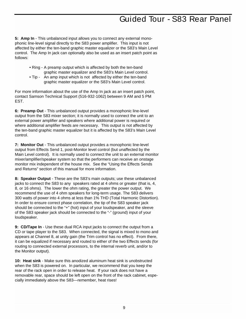
5: Amp In - This unbalanced input allows you to connect any external mono-phonic line-level signal directly to the S83 power amplifier. This input is notaffected by either the ten-band graphic master equalizer or the S83’s Main Levelcontrol. The Amp In jack can optionally also be used as an insert patch point asfollows:
• Ring - A preamp output which is affected by both the ten-band graphic master equalizer and the S83’s Main Level control.
• Tip - An amp input which is not affected by either the ten-band graphic master equalizer or the S83’s Main Level control.
For more information about the use of the Amp In jack as an insert patch point,contact Samson Technical Support (516-932-1062) between 9 AM and 5 PMEST.
6: Preamp Out - This unbalanced output provides a monophonic line-leveloutput from the S83 mixer section; it is normally used to connect the unit to anexternal power amplifier and speakers where additional power is required orwhere additional amplifier feeds are necessary. This output is not affected bythe ten-band graphic master equalizer but it is affected by the S83’s Main Levelcontrol.
7: Monitor Out - This unbalanced output provides a monophonic line-level output from Effects Send 1, post-Monitor level control (but unaffected by theMain Level control). It is normally used to connect the unit to an external monitormixer/amplifier/speaker system so that the performers can receive an onstagemonitor mix independent of the house mix. See the “Using the Effects Sendsand Returns” section of this manual for more information.
8: Speaker Output - These are the S83’s main outputs; use these unbalancedjacks to connect the S83 to any speakers rated at 4 ohms or greater (that is, 4,8, or 16 ohms). The lower the ohm rating, the greater the power output. Werecommend the use of 4 ohm speakers for long-term usage. The S83 delivers300 watts of power into 4 ohms at less than 1% THD (Total Harmonic Distortion).In order to ensure correct phase correlation, the tip of the S83 speaker jackshould be connected to the “+” (hot) input of your loudspeaker, and the sleeveof the S83 speaker jack should be connected to the “-” (ground) input of yourloudspeaker.
9: CD/Tape In - Use these dual RCA input jacks to connect the output from aCD or tape player to the S83. When connected, the signal is mixed to mono andappears at Channel 8, at unity gain (the Trim control has no effect). From there,it can be equalized if necessary and routed to either of the two Effects sends (forrouting to connected external processors, to the internal reverb unit, and/or tothe Monitor output).
10: Heat sink - Make sure this anodized aluminum heat sink is unobstructedwhen the S83 is powered on. In particular, we recommend that you keep therear of the rack open in order to release heat. If your rack does not have aremovable rear, space should be left open on the front of the rack cabinet, espe-cially immediately above the S83—remember, heat rises!
9

Guided Tour - S63 Overview
The following illustration shows an overview of the front panel of the S63:
10
Main SectionChannels
-12 +121 kHz
0
-15 +15HIGH
0
-15 +15LOW
0
+15LEVEL
0
+10EFF1 MON
0
+4 -40TRIM
0
10
+10EFF2 REV
0
LINE
MIC
CHANNEL 1
30Hz 64Hz 125Hz 250Hz 500Hz 1K 2K 3K 5K 10K
+15dB
0dB
-15dB
30Hz 64Hz 125Hz 250Hz 500Hz 1K 2K 3K 5K
PHANTOM
+10
RETURN 1-2
0
MAIN LEVEL
0 10
REVERB
−∞ +10
MONITOR
0
S6 MIXER AMPLIFIER−∞
−∞
−∞
−∞
-12 +121 kHz
0
-15 +15HIGH
0
-15 +15LOW
0
+15LEVEL
0
+10EFF1 MON
0
+4 -40TRIM
0
10
+10EFF2REV
0
LINE
MIC
CHANNEL 2
−∞
−∞
−∞ -12 +121 kHz
0
-15 +15HIGH
0
-15 +15LOW
0
+15LEVEL
0
+10EFF1 MON
0
+4 -40TRIM
0
10
+10EFF2 REV
0
LINE
MIC
CHANNEL 3
−∞
−∞
−∞ -12 +121 kHz
0
-15 +15HIGH
0
-15 +15LOW
0
+15LEVEL
0
+10EFF1 MON
0
+4 -40TRIM
0
10
+10EFF2 REV
0
LINE
MIC
CHANNEL 4
−∞
−∞
−∞ -12 +121 kHz
0
-15 +15HIGH
0
-15 +15LOW
0
+15LEVEL
0
+10EFF1 MON
0
+4 -40TRIM
0
10
+10EFF2 REV
0
LINE
MIC
CHANNEL 5
−∞
−∞
−∞ -12 +121 kHz
0
-15 +15HIGH
0
-15 +15LOW
0
+15LEVEL
0
+10EFF1 MON
0
+4 -40TRIM
0
10
+10EFF2 REV
0
LINE
MIC
CHANNEL 6
−∞
−∞
−∞
CD/TAPEIN
PEAK PROTECTION POWER LEFT RIGHT
10K
+10
0
−∞
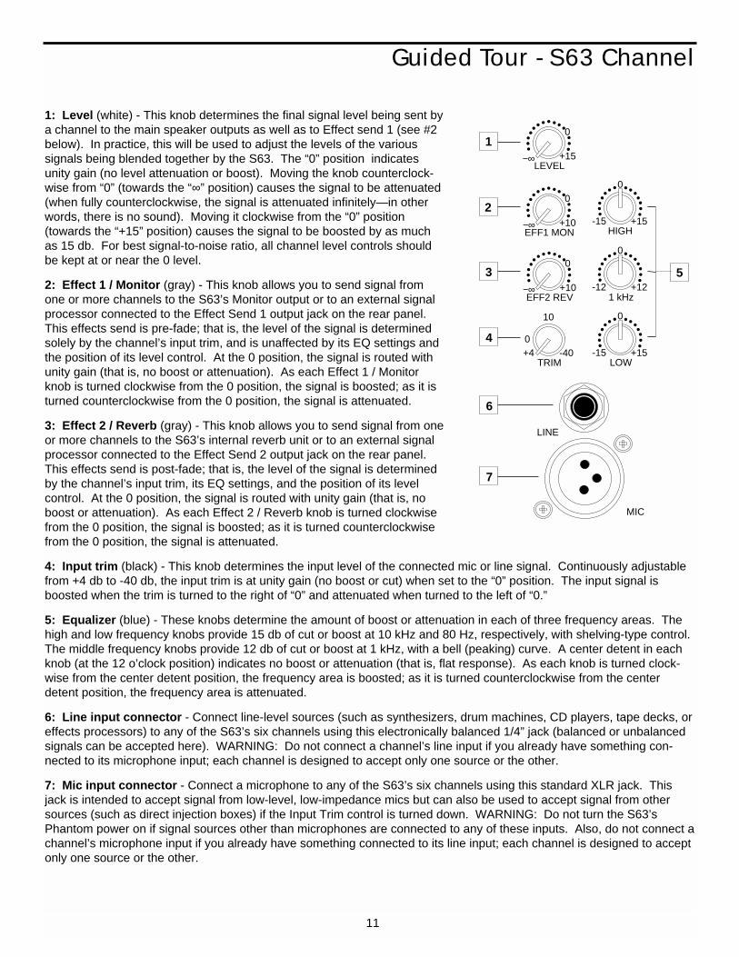
1: Level (white) - This knob determines the final signal level being sent bya channel to the main speaker outputs as well as to Effect send 1 (see #2below). In practice, this will be used to adjust the levels of the various signals being blended together by the S63. The “0” position indicatesunity gain (no level attenuation or boost). Moving the knob counterclock-wise from “0” (towards the “∞” position) causes the signal to be attenuated(when fully counterclockwise, the signal is attenuated infinitely—in otherwords, there is no sound). Moving it clockwise from the “0” position(towards the “+15” position) causes the signal to be boosted by as muchas 15 db. For best signal-to-noise ratio, all channel level controls shouldbe kept at or near the 0 level.
2: Effect 1 / Monitor (gray) - This knob allows you to send signal fromone or more channels to the S63’s Monitor output or to an external signalprocessor connected to the Effect Send 1 output jack on the rear panel.This effects send is pre-fade; that is, the level of the signal is determinedsolely by the channel’s input trim, and is unaffected by its EQ settings andthe position of its level control. At the 0 position, the signal is routed withunity gain (that is, no boost or attenuation). As each Effect 1 / Monitorknob is turned clockwise from the 0 position, the signal is boosted; as it isturned counterclockwise from the 0 position, the signal is attenuated.
3: Effect 2 / Reverb (gray) - This knob allows you to send signal from oneor more channels to the S63’s internal reverb unit or to an external signalprocessor connected to the Effect Send 2 output jack on the rear panel.This effects send is post-fade; that is, the level of the signal is determinedby the channel’s input trim, its EQ settings, and the position of its levelcontrol. At the 0 position, the signal is routed with unity gain (that is, noboost or attenuation). As each Effect 2 / Reverb knob is turned clockwisefrom the 0 position, the signal is boosted; as it is turned counterclockwisefrom the 0 position, the signal is attenuated.
4: Input trim (black) - This knob determines the input level of the connected mic or line signal. Continuously adjustablefrom +4 db to -40 db, the input trim is at unity gain (no boost or cut) when set to the “0” position. The input signal isboosted when the trim is turned to the right of “0” and attenuated when turned to the left of “0.”
5: Equalizer (blue) - These knobs determine the amount of boost or attenuation in each of three frequency areas. Thehigh and low frequency knobs provide 15 db of cut or boost at 10 kHz and 80 Hz, respectively, with shelving-type control.The middle frequency knobs provide 12 db of cut or boost at 1 kHz, with a bell (peaking) curve. A center detent in eachknob (at the 12 o’clock position) indicates no boost or attenuation (that is, flat response). As each knob is turned clock-wise from the center detent position, the frequency area is boosted; as it is turned counterclockwise from the centerdetent position, the frequency area is attenuated.
6: Line input connector - Connect line-level sources (such as synthesizers, drum machines, CD players, tape decks, oreffects processors) to any of the S63’s six channels using this electronically balanced 1/4” jack (balanced or unbalancedsignals can be accepted here). WARNING: Do not connect a channel’s line input if you already have something con-nected to its microphone input; each channel is designed to accept only one source or the other.
7: Mic input connector - Connect a microphone to any of the S63’s six channels using this standard XLR jack. Thisjack is intended to accept signal from low-level, low-impedance mics but can also be used to accept signal from othersources (such as direct injection boxes) if the Input Trim control is turned down. WARNING: Do not turn the S63’sPhantom power on if signal sources other than microphones are connected to any of these inputs. Also, do not connect achannel’s microphone input if you already have something connected to its line input; each channel is designed to acceptonly one source or the other.
11
Guided Tour - S63 Channel
-12 +121 kHz
0
-15 +15HIGH
0
-15 +15LOW
0
+15LEVEL
0
+10EFF1 MON
0
+4 -40TRIM
0
10
+10EFF2 REV
0
LINE
MIC
−∞
−∞
−∞
1
2
3 5
7
6
4
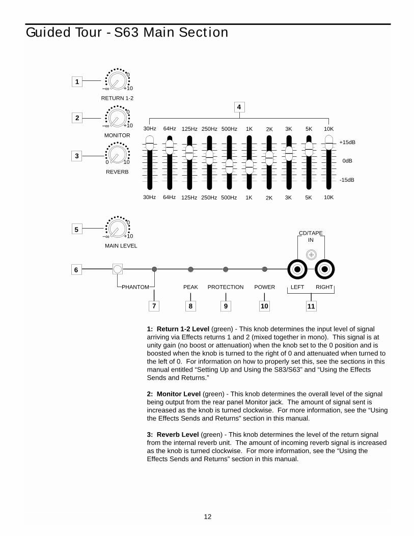
1: Return 1-2 Level (green) - This knob determines the input level of signalarriving via Effects returns 1 and 2 (mixed together in mono). This signal is atunity gain (no boost or attenuation) when the knob set to the 0 position and isboosted when the knob is turned to the right of 0 and attenuated when turned tothe left of 0. For information on how to properly set this, see the sections in thismanual entitled “Setting Up and Using the S83/S63” and “Using the EffectsSends and Returns.”
2: Monitor Level (green) - This knob determines the overall level of the signalbeing output from the rear panel Monitor jack. The amount of signal sent isincreased as the knob is turned clockwise. For more information, see the “Usingthe Effects Sends and Returns” section in this manual.
3: Reverb Level (green) - This knob determines the level of the return signalfrom the internal reverb unit. The amount of incoming reverb signal is increasedas the knob is turned clockwise. For more information, see the “Using theEffects Sends and Returns” section in this manual.
12
Guided Tour - S63 Main Section
30Hz 64Hz 125Hz 250Hz 500Hz 1K 2K 3K 5K 10K
+15dB
0dB
-15dB
30Hz 64Hz 125Hz 250Hz 500Hz 1K 2K 3K 5K
PHANTOM
+10
RETURN 1-2
0
MAIN LEVEL
0 10
REVERB
−∞ +10
MONITOR
0
−∞
CD/TAPEIN
PEAK PROTECTION POWER LEFT RIGHT
10K
1
2
3
4
5
6
7 8 9 10 11
+10
0
−∞

4: Ten-Band Graphic Master EQ - These sliders allow you to add ±15 db ofboost or attenuation to ten different frequency areas, affecting the main outputsignal of the S63. When a slider is at its center detented (“0 db”) position, theselected frequency area is unaffected (it is said to be flat). When a slider ismoved up (above the “0 db” position, towards the “+15 db” position), the selectedfrequency area is boosted, and when it is moved down (below the “0 db” posi-tion, towards the “-15 db” position), the selected frequency area is being attenu-ated. For more information, see the “Using Equalization” section in this manual.
5: Main Level (white) - This knob determines the final signal level sent to thespeaker output jacks on the rear panel. At the fully counterclockwise (“∞”) position, the signal is infinitely attenuated—that is, there is no sound. At the “0”position, the mixer is at unity gain and is providing no attenuation or boost to theoutput signal. At the fully clockwise (“+10”) position, approximately 10 db of gainis being added by the mixer to the output signal. For more information, see the“Setting Up and Using the S83/S63” section in this manual.
6: Phantom switch - When this switch is pressed in, the S63 delivers 48 voltsof phantom power to pins 2 and 3 of all XLR microphone connectors in all sixchannels. WARNING: Only use this switch with the S63 powered down. Beforeturning phantom power on, be sure to disconnect all non-microphone signalsources (such as direct injection boxes) from the XLR mic jacks. Althoughphantom power will have no adverse affect on connected dynamic microphones,it should be used only when one or more condenser microphones are connectedto the S63. Refer to the owners manual of your microphone to determinewhether or not it requires 48 volts phantom power—we cannot assumeresponsibility if you damage a mic by incorrectly applying S63 phantompower. If you’re not completely certain that one or more connected mics require48 volts phantom power, leave this switch off (its out position).
7: Phantom LED - This lights steadily when Phantom power is being suppliedto all mic inputs (see #6 above).
8: Peak LED - This warning light indicates an overload situation in the S63amplifier. To stop it from lighting (and to eliminate the accompanying sonic dis-tortion), turn down one or more channel’s Input Trim knob or reduce the amountof equalization boost in the offending channel(s). See the “Setting Up and Usingthe S83/S63” and “Using Equalization” sections in this manual for more informa-tion.
9: Protection LED - This lights for approximately five seconds whenever theS63 is powered on and fades slowly when the unit is powered off. It indicatesthe activity of the built-in protection relay circuitry during which time 0 volts DCare provided to all connected speakers, thus preventing any “thump.”
10: Power LED - This lights steadily whenever the S63 is powered on.
11: CD/Tape In - Use these dual RCA input jacks to connect the output from aCD or tape player to the S63. When connected, the signal is mixed to mono andappears at Channel 6, at unity gain (the Trim control has no effect). From there,it can be equalized if necessary and routed to either of the two Effects sends (forrouting to connected external processors, to the internal reverb unit, and/or tothe Monitor output).
13
Guided Tour - S63 Main Section
1: Power switch - As you may have guessed, this is what you use to turn theS63 on and off. The built-in protection relay circuitry (which mutes the outputs forapproximately five seconds after powering on) prevents power-on “thumping,”which can potentially damage connected speakers.
2: Fuse holder - Insert a 6 amp fuse here for 120 volt operation. Insert a 3.5amp fuse here for 220 volt operation.
3: Effect Returns - These unbalanced inputs allow you to route signal fromexternal devices such as effects processors to the Effects Return section of theS63. Because the S63 is a monophonic system, stereo signals input to the pairof Effects returns 1-2 are automatically mixed to mono. See the “Using theEffects Sends and Returns” section in this manual for more information.
4: Effects Sends - These unbalanced outputs allow you to route signal fromeach of the two discrete Effects Sends to external devices such as effectsprocessors. Effects Send 1 is pre-fader and pre-EQ, while Effects Send 2 ispost-fader and post-EQ. See the “Using the Effects Sends and Returns” sectionin this manual for more information.
14
Guided Tour - S63 Rear Panel
S6 MIXER AMPLIFIER 6 CHANNEL 210 WATT 4 Ω SAMSON TECHNOLOGIES CORP., HICKSVILLE, NEW YORK EFFECT RETURNS EFFECT SENDS
MON OUT
1
2
21
AMP IN PRE AMP OUT
SPEAKER OUTPUTMINIMUM 2 Ω
+4dB10KΩ
+4dB600Ω
+4dB600Ω
+4dB47KΩ
CAUTION
RISK OF ELECTRIC SHOCKDO NOT OPEN
!
o
FUSE
120 VOLT 6 AMP220 VOLT 3.5 AMP
TO PREVENT SHOCK,DO NOT OPEN. NO USER
SERVICABLE PARTSINSIDE. REFER SERVIC-
ING TO QUALIFIED SERVICE PERSONNEL. TO PREVENT
FIRE OR SHOCK HAZARDDO NOT EXPOSE TO RAIN
OR MOISTURE
CAUTION
HEATSINK MAY BE HOT!DO NOT BLOCK AIRFLOWOR OVERHEATING MAY
OCCUR
SERIAL NUMBER
ASSEMBLEDIN R.O.K.
POWER RATING120V/60Hz 450 W
POWER
FUSE
ON
OFF
3
2
8
1
5 4
6 7 9
Guided Tour - S63 Rear Panel
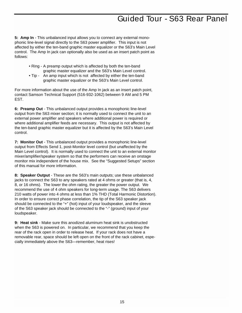
5: Amp In - This unbalanced input allows you to connect any external mono-phonic line-level signal directly to the S63 power amplifier. This input is notaffected by either the ten-band graphic master equalizer or the S63’s Main Levelcontrol. The Amp In jack can optionally also be used as an insert patch point asfollows:
• Ring - A preamp output which is affected by both the ten-band graphic master equalizer and the S63’s Main Level control.
• Tip - An amp input which is not affected by either the ten-band graphic master equalizer or the S63’s Main Level control.
For more information about the use of the Amp In jack as an insert patch point,contact Samson Technical Support (516-932-1062) between 9 AM and 5 PMEST.
6: Preamp Out - This unbalanced output provides a monophonic line-level output from the S63 mixer section; it is normally used to connect the unit to anexternal power amplifier and speakers where additional power is required orwhere additional amplifier feeds are necessary. This output is not affected bythe ten-band graphic master equalizer but it is affected by the S63’s Main Levelcontrol.
7: Monitor Out - This unbalanced output provides a monophonic line-level output from Effects Send 1, post-Monitor level control (but unaffected by theMain Level control). It is normally used to connect the unit to an external monitormixer/amplifier/speaker system so that the performers can receive an onstagemonitor mix independent of the house mix. See the “Suggested Setups” sectionof this manual for more information.
8: Speaker Output - These are the S63’s main outputs; use these unbalancedjacks to connect the S63 to any speakers rated at 4 ohms or greater (that is, 4,8, or 16 ohms). The lower the ohm rating, the greater the power output. We recommend the use of 4 ohm speakers for long-term usage. The S63 delivers210 watts of power into 4 ohms at less than 1% THD (Total Harmonic Distortion).In order to ensure correct phase correlation, the tip of the S63 speaker jackshould be connected to the “+” (hot) input of your loudspeaker, and the sleeveof the S63 speaker jack should be connected to the “-” (ground) input of yourloudspeaker.
9: Heat sink - Make sure this anodized aluminum heat sink is unobstructedwhen the S63 is powered on. In particular, we recommend that you keep therear of the rack open in order to release heat. If your rack does not have aremovable rear, space should be left open on the front of the rack cabinet, espe-cially immediately above the S63—remember, heat rises!
15

16
The actual connections you’ll make to and from the S83/S63 will vary accordingto the environment you use it in and the particular equipment you have.However, here are a few basic rules concerning connections that will apply inpretty much all situations:
• In general, it’s best to make all connections with the S83/S63 turned off—this particularly applies to speaker connections. If you must make connec-tions with the power on, make sure that the Main Level control is completelydown (turn the knob fully counterclockwise). Before powering down, turnthe Main Level control completely down.
• When using line inputs, try to use balanced connectors and cabling wherever possible. These kind of connections do a better job of rejectingextraneous noise and hum and generally provide a cleaner signal. If yourequipment doesn’t provide balanced outputs, however, not to worry: AllS83/S63 channel line inputs will accept either balanced or unbalanced connectors. The diagram below shows how balanced 1/4” TRS(Tip/Ring/Sleeve) connectors should be wired:
Unbalanced cables use standard 1/4” phone connectors, wired as follows:
• Make one connection at a time and then monitor the incoming signal. If youhear a distinct hum or buzz, you may have a grounding problem with thatparticular device. See the section in this manual entitled “GroundingTechniques” for information on how to avoid grounding problems.
• NEVER connect a microphone and line level input to the same channelsimultaneously—use one or the other. You can have some channels connected to microphones and others to line level signals (for example, youmight want to plug mics into channels 1 - 4 and line level signals into theremaining channels)—just don’t have both kinds of inputs connected to thesame channel. The diagram below shows how your mic connectors shouldbe wired:
Connecting The S83/S63 - General Suggestions
TIP +GROUNDRING -RING
TIP
SLEEVE
+ SIGNAL
GROUND
+ SIGNAL
GROUND
3 - SIGNAL1 GROUND2 + SIGNAL
TO MIXER

17
Setting up your S83/S63 is a simple procedure which takes only a few minutes:
1. Remove all packing materials (save them in case of need for future service)and decide where the unit is to be physically placed—it can be mounted in anystandard 19” rack, requiring four rack spaces. Be careful when handling theS83/S63—the rear heat sink fins and side rack panels have sharp edges. Makesure that the rear heat sink fins are unobstructed and that there is good ventila-tion around the entire unit. If your rack contains multiple amplifiers, we recom-mend that you avoid potential overheating problems by using spacer panels toensure that the amps are not directly on top of one another.
2. Before even plugging the unit into an AC socket, begin by making the speak-er connections. It is never a good idea to power up any amplifier that is not con-nected to loudspeakers. Any loudspeakers with a minimum impedance load of 2 ohms (that is, 2 ohms or greater) can be used. However, we recommend theuse of 4 ohm speakers for long-term usage. In order to ensure correct phasecorrelation, be sure that the connection from the tip of the S83/S63 speaker jackgoes to the “+” (hot) input of your loudspeaker, and that the sleeve of theS83/S63 speaker jack is connected to the “-” (ground) input of your loudspeaker.
3. Next, make the signal input connections to the mic or line inputs of the vari-ous channels. WARNING: Do not connect a channel’s line input if you alreadyhave something connected to its microphone input, or vice versa; each channelis designed to accept only one source or the other.
4. Turn all channel Trim and Level controls as well as the Main Level controlfully counterclockwise, to their “∞” setting. Then plug the unit into any groundedAC socket. Because of the special relay protection circuitry built into theS83/S63, you can even plug it into the same power strip that other audio devices(such as a mixing console) are connected to. You can then turn on all devices atonce with the single power strip on-off switch, with no danger of damaging con-nected speakers by generating “thumps.”
5. Press the rear panel Power switch in order to turn on the unit. The ProtectionLED will go on for approximately five seconds, and then switch off (you’ll hear aclick when it does).
Setting Up and Using the S83/S63

18
You’re now ready to establish the correct gain structure—the key to getting thebest performance from the S83/S63, or from any mixer, for that matter. This is asimple procedure that ensures optimum input and output levels so that nounnecessary noise (caused by too low a signal) or overload distortion (caused bytoo high a signal) is created. Here’s a step-by-step description of how to do so:
a. With all connections made (as described above) but with the power off, startby setting all channel level controls fully counterclockwise (to their “∞” position),and then set the Main Level knob to its “0” position.
b. Set all channel input trim knobs to their fully counterclockwise (+4) position.
c. Set all channel equalizer knobs to their center detent “0” positions and set theten-band graphic master equalizer completely flat (all sliders at their centerdetent “0” positions).
d. Set all channel Effects send knobs and all Effects return level knobs to theirfully counterclockwise (“∞”) position.
e. Turn on all devices connected to channel line inputs and Effects returns andset their level controls to unity gain or, if there is no unity gain indicated on theiroutput control, to maximum. If you’ve got outboard effects processors connectedto Effects returns, make sure they are sending completely “wet” (processed) sig-nal, with no “dry” (unprocessed) signal mixed in.
f. If any condenser microphones are connected to the S83/S63, turn on thePhantom switch.* Then turn on the S83/S63’s main power.
g. Play an instrument connected to one of the S83/S63’s line inputs** and, whiledoing so, raise the corresponding channel level control to the “0” position. If youare using an S83, you should see the segment meter begin to move—adjust theinput trim control for that channel so that the “0” segment lights frequently andthe “+2” segment lights only occasionally. If you are using an S63, adjust theinput trim control for that channel until the Peak LED just begins flashing andthen back off just to the point at which it does not flash at even the highest levelinput signals. In both the S83 and S63, if the incoming signal seems too hoteven with the input channel trim all the way at its minimum (+4) setting, you mayneed to lower the output level of the instrument, though this will rarely occur.Conversely, if the signal is too low even with the input channel trim all the wayup, something’s definitely wrong: in all likelihood, the connecting audio cable isfaulty.
h. Once you’ve set the optimum level in step (g) above, continue playing theinstrument and slowly raise the main level knob until you get the level you wantto hear.
* CAUTION: Before turning phantom power on, be sure to verify that the con-nected mic(s) require 48 volts. Also, disconnect all non-microphone signalsources (such as direct injection boxes) from the XLR mic jacks.
** If you’re using an instrument such as electric guitar or bass, we recommendthat you connect it to the S83/S63 with a direct injection box to ensure correctimpedance.
Setting the Correct Gain Structure
19
i. Repeat step (g) above for each instrument connected to the S83/S63 channelline inputs.
j. The procedure for setting optimum microphone levels is virtually identical; singor speak into the mic at the level you expect to use in performance while slowlyraising the level control for that channel to its “0” position. Then adjust the inputtrim control for that channel while watching the meter (if you’re using an S83) orPeak LED (if you’re using an S63). You should expect that microphone inputswill require rather more in the way of input trim boost than line inputs.
k. If you have any outboard signal processors connected to the Effects sendjacks on the rear panel, follow this step. Because outboard effects processorscan sometimes be quite noisy, it’s particularly important to maximize the amountof signal being sent to them via the S83/S63 Effects sends. The idea is to drivethese devices as hot as possible (short of overloading them) and then to use thecorresponding Effects return level to carefully adjust the amount of processedsignal being blended with the dry signal. To set optimum Effects send levels,use a channel that has already had its gain structure adjusted in step (g) or (j)above. Turn both Effects send knobs for that channel to their “0” (unity gain)position and then play the instrument (or sing into the microphone) connected tothat channel. Adjust the input levels of connected outboard effects processorsso that their meter shows incoming signal normally in the 0 vu range (with justoccasional higher excursions). Then it’s time to optimize the Effects return lev-els. While continuing to play your instrument (or continuing to sing into themicrophone), slowly raise each Effects return level control until you hear thedesired amount of processed signal added to the dry signal. For information onhow to correctly set the levels for the internal reverb unit or Monitor output, seethe “Using the Effects Sends and Returns” section in this manual.
l. The gain structure is now correctly set—you’ve optimized the level of all sig-nals coming into and out of the S83/S63, and the end result will be minimumnoise and distortion and maximum clean sound. You’ll now find that the majorityof your mixes can be accomplished with most channel level controls at or neartheir 0 (unity gain) position and that (in the case of the S83) channel peak LEDsor (in the case of the S63) the main Peak LED rarely if ever lights (remember, ifthey do light, it means that something is distorting!). If you need to make adjust-ments to the overall level, use the main level control.
If you encounter difficulty with any aspect of setting up or using your S83/S63,you can call Samson Technical Support (516-932-1062) between 9 AM and 5PM EST.
Setting the Correct Gain Structure

20
Suggested Performance Application - S83
The following illustration shows the basic interconnections between an S83 and external equipment when used in a typi-cal live performance application:
The main connections here involve connecting the S83 speaker outputs to PA speakers and the Monitor output to theinput of an external amplifier driving onstage monitors. Various microphones and line level signals are connected tochannel mic and line inputs and a tape player is connected to the CD/Tape input. A signal processor is connected toEffects Send 2, with the resulting processed signal returned to Effects Returns 1 and 2.
S8 MIXER AMPLIFIER 8 CHANNEL 300 WATT 4 Ω SAMSON TECHNOLOGIES CORP., HICKSVILLE, NEW YORK EFFECT RETURNS EFFECT SENDS
MON OUT
1
2
2
4
1
3
AMP IN PRE AMP OUT
SPEAKER OUTPUTMINIMUM 2 Ω
+4dB10KΩ
+4dB600Ω
+4dB600Ω
+4dB47KΩ
LEFT RIGHT
CD/TAPEIN
CAUTION
RISK OF ELECTRIC SHOCKDO NOT OPEN
!
o
FUSE
120 VOLT 6 AMP220 VOLT 3.5 AMP
TO PREVENT SHOCK,DO NOT OPEN. NO USER
SERVICABLE PARTSINSIDE. REFER SERVIC-
ING TO QUALIFIED SERVICE PERSONNEL. TO PREVENT
FIRE OR SHOCK HAZARDDO NOT EXPOSE TO RAIN
OR MOISTURE
CAUTION
HEATSINK MAY BE HOT!DO NOT BLOCK AIRFLOWOR OVERHEATING MAY
OCCUR
SERIAL NUMBER
ASSEMBLEDIN R.O.K.
POWER RATING120V/60Hz 450 W
POWER
FUSE
ON
OFF
-12 +122.5K
0
-15 +15HIGH
0
-12 +12500Hz
0
-15 +15LOW
0
+15LEVEL
0
+10EFF1 MON
0
+4 -40TRIM
0
10
+10EFF2 REV
0
LINE
MIC
CHANNEL 1
PEAK
LOW
+15LEVEL
0
+10EFF1 MON
0
+4 -40TRIM
0
10
+10EFF2 REV
0
LINE
MIC
CHANNEL 2
PEAK
LOW
+15LEVEL
0
+10EFF1 MON
0
+4 -40TRIM
0
10
+10EFF2 REV
0
LINE
MIC
CHANNEL 3
PEAK
LOW
+15LEVEL
0
+10EFF1 MON
0
+4 -40TRIM
0
10
+10EFF2 REV
0
LINE
MIC
CHANNEL 4
PEAK
LOW
+15LEVEL
0
+10EFF1 MON
0
+4 -40TRIM
0
10
+10EFF2 REV
0
LINE
MIC
CHANNEL 5
PEAK
LOW
+15LEVEL
0
+10EFF1 MON
0
+4 -40TRIM
0
10
+10EFF2 REV
0
LINE
MIC
CHANNEL 6
PEAK
LOW
+15LEVEL
0
+10EFF1 MON
0
+4 -40TRIM
0
10
+10EFF2 REV
0
LINE
MIC
CHANNEL 7
PEAK
LOW
−∞ +15LEVEL
0
−∞ +10EFF1 MON
0
+4 -40TRIM
0
10
−∞ +10EFF2 REV
0
LINE
MIC
CHANNEL 8
PEAK
8 CHANNEL MIXER 300 WATT AMPLIFIER
-18 -12 -8 -5 -3 0 +2
PHANTOM PROTECTION POWER
30Hz 64Hz 125Hz 250Hz 500Hz 1K 2K 3K 5K 10K
+15dB
0dB
-15dB
30Hz 64Hz 125Hz 250Hz 500Hz 1K 2K 3K 5K 10K
PHANTOM
+10
RETURN 1-2
0
MAIN LEVEL
+10
RETURN 3-4
0
0 10
HEADPHONES
0 10
REVERB−∞ +10
MONITOR
0
S8 MIXER AMPLIFIER−∞
−∞
−∞
−∞
−∞
−∞
−∞
−∞
−∞
−∞
−∞
−∞
−∞
−∞
−∞
−∞
−∞
−∞
−∞
−∞
−∞
−∞ −∞
-12 +122.5K
0
-15 +15HIGH
0
-12 +12500Hz
0
-15 +15
0
-12 +122.5K
0
-15 +15HIGH
0
-12 +12500Hz
0
-15 +15
0
-12 +122.5K
0
-15 +15HIGH
0
-12 +12500Hz
0
-15 +15
0
-12 +122.5K
0
-15 +15HIGH
0
-12 +12500Hz
0
-15 +15
0
-12 +122.5K
0
-15 +15HIGH
0
-12 +12500Hz
0
-15 +15
0
-12 +122.5K
0
-15 +15HIGH
0
-12 +12500Hz
0
-15 +15
0
-12 +122.5K
0
-15 +15HIGH
0
-12 +12500Hz
0
-15 +15
0
AMPLIFIER
0 0 000
MIDI TONE GENERATOR
0 0 000
SIGNAL PROCESSOR
+10
0
−∞

21
Suggested Performance Application - S63
The following illustration shows the basic interconnections between an S63 and external equipment when used in a typi-cal live performance application:
The main connections here involve connecting the S63 speaker outputs to PA speakers and the Monitor output to theinput of an external amplifier driving onstage monitors. Various microphones and line level signals are connected tochannel mic and line inputs and a tape player is connected to the CD/Tape input. A signal processor is connected toEffects Send 2, with the resulting processed signal returned to Effects Returns 1 and 2.
AMPLIFIER
0 0 000
MIDI TONE GENERATOR
0 0 000
SIGNAL PROCESSOR
-12 +121 kHz
0
-15 +15HIGH
0
-15 +15LOW
0
+15LEVEL
0
+10EFF1 MON
0
+4 -40TRIM
0
10
+10EFF2 REV
0
LINE
MIC
CHANNEL 1
30Hz 64Hz 125Hz 250Hz 500Hz 1K 2K 3K 5K 10K
+15dB
0dB
-15dB
30Hz 64Hz 125Hz 250Hz 500Hz 1K 2K 3K 5K
PHANTOM
+10
RETURN 1-2
0
0 10
REVERB
−∞ +10
MONITOR
0
S6 MIXER AMPLIFIER−∞
−∞
−∞
−∞
-12 +121 kHz
0
-15 +15HIGH
0
-15 +15LOW
0
+15LEVEL
0
+10EFF1 MON
0
+4 -40TRIM
0
10
+10EFF2REV
0
LINE
MIC
CHANNEL 2
−∞
−∞
−∞ -12 +121 kHz
0
-15 +15HIGH
0
-15 +15LOW
0
+15LEVEL
0
+10EFF1 MON
0
+4 -40TRIM
0
10
+10EFF2 REV
0
LINE
MIC
CHANNEL 3
−∞
−∞
−∞ -12 +121 kHz
0
-15 +15HIGH
0
-15 +15LOW
0
+15LEVEL
0
+10EFF1 MON
0
+4 -40TRIM
0
10
+10EFF2 REV
0
LINE
MIC
CHANNEL 4
−∞
−∞
−∞ -12 +121 kHz
0
-15 +15HIGH
0
-15 +15LOW
0
+15LEVEL
0
+10EFF1 MON
0
+4 -40TRIM
0
10
+10EFF2 REV
0
LINE
MIC
CHANNEL 5
−∞
−∞
−∞ -12 +121 kHz
0
-15 +15HIGH
0
-15 +15LOW
0
+15LEVEL
0
+10EFF1 MON
0
+4 -40TRIM
0
10
+10EFF2 REV
0
LINE
MIC
CHANNEL 6
−∞
−∞
−∞
CD/TAPEIN
PEAK PROTECTION POWER LEFT RIGHT
10K
S6 MIXER AMPLIFIER 6 CHANNEL 210 WATT 4 Ω SAMSON TECHNOLOGIES CORP., HICKSVILLE, NEW YORK EFFECT RETURNS EFFECT SENDS
MON OUT
1
2
21
AMP IN PRE AMP OUT
SPEAKER OUTPUTMINIMUM 2 Ω
+4dB10KΩ
+4dB600Ω
+4dB600Ω
+4dB47KΩ
CAUTION
RISK OF ELECTRIC SHOCKDO NOT OPEN
!
o
FUSE
120 VOLT 6 AMP220 VOLT 3.5 AMP
TO PREVENT SHOCK,DO NOT OPEN. NO USER
SERVICABLE PARTSINSIDE. REFER SERVIC-
ING TO QUALIFIED SERVICE PERSONNEL. TO PREVENT
FIRE OR SHOCK HAZARDDO NOT EXPOSE TO RAIN
OR MOISTURE
CAUTION
HEATSINK MAY BE HOT!DO NOT BLOCK AIRFLOWOR OVERHEATING MAY
OCCUR
SERIAL NUMBER
ASSEMBLEDIN R.O.K.
POWER RATING120V/60Hz 450 W
POWER
FUSE
ON
OFF
MAIN LEVEL
+10
0
−∞
22
Grounding Techniques
Hum and buzz are the biggest enemies you face when interconnecting a large number of different piecesof equipment to a central audio mixer. This is because each piece of equipment may operate at a mar-ginally different voltage (this difference is called potential) and, when two devices at slightly differentpotential are physically connected with audio cabling, the end result can be nasty, extraneous noise(mind you, connecting two devices at very different potential can result in a major electrical shock!).
However, there are several steps you can take to avoid grounding problems. First, assuming you havean isolated electrical circuit that can handle the electrical demands of your mixer and all connected audioequipment (these needs will usually be modest), you should always plug your mixer and all connectedequipment into the same circuit. If possible, nothing else but this equipment should be connected to thatcircuit. If you can’t do this, at least avoid plugging your mixer and audio equipment into the same circuitthat is already powering things like heavy machinery, air conditioners, heaters, refrigerators, washingmachines, neon signs or fluorescent light fixtures. One particular culprit that will almost certainly createproblems is the standard light dimmer (the kind that uses silicon controlled rectifiers). Where low-levellighting is desired, use incandescent fixtures with autotransformer-type dimmers (sometimes calledVariacs) instead—these cost considerably more than the standard dimmer you’ll find at your local hard-ware store, but are well worth the extra expense.
Three-prong plugs (such as the one used by the S83/S63) should always be used as is; don’t useadapters to lift the ground (unless you’re using a “star ground network”—see below). If you hear hum orbuzz from a device that uses a two-prong plug (or an external two-prong AC/DC adapter), you can tryreversing the plug in the socket. If that doesn’t work, you may need to physically ground that device’schassis by connecting a wire (called a strap) from it to a grounded piece of metal such as rack ears.Some pieces of equipment have a screw-type ground post to which the strap can be connected; if not,you can attach some kind of metallic binding post to the case itself. If you are using rack-mounted audiodevices and are experiencing hum or buzz, there’s a simple test to determine the source of the problem:while keeping all devices powered on and connected with audio cabling, physically remove each device,one by one, from the rack. If the hum disappears when a particular device is removed, you’ll know thatthat device is the culprit.
We also recommend that you use balanced audio cabling and connectors wherever possible. TheS83/S63 provides electronically balanced inputs for all line channel inputs. The wiring diagram in the“Connecting The S83/S63” section of this manual shows how 1/4” TRS (Tip/Ring/Sleeve) connectorsshould be wired for use with these inputs and outputs.
In addition, you can minimize possible interference by planning your audio, electrical, and computer cableruns so that they are as far apart from one another as possible and so they don’t run parallel to oneanother. If they have to cross, try to ensure that they do so at a 90° angle (that is, perpendicular to oneanother). In particular, try to keep audio cabling away from external AC/DC adapters
If you’re using the S83 or S63 in a fixed location such as a recording studio, you may want to invest thetime and money into creating a star ground network. This is by far the best technique for avoidinggrounding problems. It involves using a formidable ground source such as a cold water pipe or a copperspike driven into the earth. A thick grounding cable is connected to that source and is then brought to acentral distribution point; from there, individual cables are connected to each piece of equipment. Thissetup also requires that you lift the ground plug of all three-prong AC connectors, so there is the possibili-ty of danger if it is done incorrectly. We strongly recommend that you contract with a qualified profes-sional to carry out this or any kind of electrical work.
Another, less common problem you may encounter is that of oscillation (a ringing tone), which, apart frombeing annoying, is potentially dangerous to your speakers. This is generally caused either by poor out-side wiring or by returning a signal out of phase (most commonly from an outboard signal processor). Ifaudible oscillation occurs, try isolating each input signal by turning down all other inputs. If one signalalone is causing the problem, you should be able to eliminate the oscillation by reversing that signal’sphase (many signal processors have a switch that allows you to do this).

23
Using Equalization
One of the most exciting aspects to using a mixer such as the S83 or S63 is hav-ing the ability to shape a sound, using a process called equalization. But thereare few areas of sound engineering more misunderstood than equalization, and,just as good EQ can really help a sound, bad EQ can really hurt it, so read on...
Every naturally occurring sound consists of a broad range of pitches, or frequen-cies, combined together in a unique way. This blend is what gives every soundits distinctive tonal color. The EQ section in a mixer allows you to alter a soundby boosting or attenuating specific frequency areas. Both the S83 and S63 pro-vide a ten-band graphic master equalizer (more about this shortly) as well as independent equalization for each channel. The S83 offers four-band equaliza-tion controls for each of the eight input channels. The center frequency areasare, from high to low: 10 kHz, 2.5 kHz, 500 Hz, and 80 Hz. Each EQ knob islabeled with the maximum amount of cut or boost provided (± 15 db in the caseof the highest and lowest frequencies and ± 12 db in the case of the two mid frequencies). The S63 provides three-band equalization controls for each of thesix input channels. The center frequency areas are, from high to low: 10 kHz,1 kHz, and 80 Hz. Again, each EQ knob is labeled with the maximum amount ofcut or boost provided (± 15 db in the case of the highest and lowest frequencies and ± 12 db in the case of the middle frequency).
We provided these particular frequency areas because they have maximumimpact on musical signals—that’s why they are sometimes known as “sweetspots.” When an EQ knob is in its center detented position (“0”), it is having noeffect. When it is moved right of center, the particular frequency area is beingboosted; when it is moved left of center, the frequency area is being attenuated.In both the S83 and S63, the high and low EQ controls employ what is known asa shelving curve (where frequencies either above or below the specified area areaffected) while the mid frequency controls employ what is known as a bell curve(where frequencies both above and below the specified area are affected).
The ten-band graphic master equalizer affects the overall output signal of theS83/S63. Its main function is to allow you to “tune” the device to the particularroom environment you are in. Perhaps its most important job is to enable you toeliminate ringing or feedback problems caused when a microphone is too closeto a loudspeaker. To accomplish this, start with all ten bands flat (that is, all tensliders at their detented “0” center position). Then, one by one, raise each slideruntil you hear the feedback or ringing markedly increase. This allows you toidentify the problematic frequency area (it will most commonly be one or more ofthe high mid-range or high frequency areas). When you’ve located the problemarea(s), it’s simply a matter of lowering that slider or sliders below the 0 point
-12 +122.5K
0
-15 +15HIGH
0
-12 +12500Hz
0
-15 +15LOW
0
-12 +121 kHz
0
-15 +15HIGH
0
-15 +15LOW
0
30Hz 64Hz 125Hz 250Hz 500Hz 1K 2K 3K 5K 10K
+15dB
0dB
-15dB
30Hz 64Hz 125Hz 250Hz 500Hz 1K 2K 3K 5K 10K
S83 EQ section
S63 EQ section
Ten-band graphic master equalizer

24
Using Equalization
until the ringing or feedback disappears. Don’t lower the frequency area any further than you need to, or the quality of the overall sound may suffer. If youdon’t specifically need to utilize the ten-band graphic master equalizer in a partic-ular environment, leave it completely flat (all sliders at their center detented “0”position).
In most instances, the best way to approach equalization is to think in terms ofwhich frequency areas you need to attenuate, as opposed to which ones youneed to boost (boosting a frequency area also has the effect of boosting theoverall signal; too much EQ boost can actually cause overload—with the accompanying Peak LED warning!). Be aware of the phenomenon of masking,where loud sounds in one frequency range obscure softer sounds in the samerange; by cutting EQ “notches” in a loud signal, you can actually make room for asofter one to shine through. And try not to think of EQ as a miracle worker—noamount of equalization can put a singer in tune or remove the distortion from anoverloaded input signal! The key is to get the signal right in the first place, byusing correct gain structure and mic placement.
Although the specific EQ you will apply to a channel signal is very much a matterof personal taste, here are a few general suggestions: Boosting the low frequency of instruments such as bass drums or bass guitar will add warmth andmake the sound “fatter”; conversely, you may want to attenuate the low frequency component of instruments such as cymbals, high-hats, and shakersso as to “thin” them out. The mid-range controls are particularly effective forvocals—attenuating the low-mid control can give a vocal performance more ofan “FM-radio” feel and boosting the high-mid control can help a vocal cut throughdense instrumentation. Be careful not to boost high frequencies too much or yourisk adding hiss to the signal, though just a touch can help add “shimmer” to anacoustic guitar, ride cymbal, or high-hat.

25
Using The Effects Sends and Returns
The two Effects sends provided by the S83 and S63 allow you to combine thesignal from multiple channels and send the resulting mix to the rear panelMonitor output jack, to the internal reverb unit, or to external devices such aseffects processors.
When an Effects send knob is at the “0” position, the signal is routed with unitygain (that is, no boost or attenuation). As it is turned clockwise from the 0 posi-tion, the signal is boosted; as it is turned counterclockwise from the 0 position, itis attenuated. Effects send 1 (Monitor) is pre-fade; that is, the level of the signalis determined solely by the input trim and is unaffected by the EQ settings or theposition of the channel level control. In contrast, Effects send 2 (Reverb) is post-fade; that is, the level of the signal is determined by the input trim, the EQ set-tings, and the position of the channel level control (raising or lowering the level ofthe channel will affect the send level as well). It is particularly important to keepthis distinction in mind when you connect external signal processors to theS83/S63 via either or both of the two Effects Send jacks on the rear panel.
In addition, both the S83 and S63 offer a number of Effects returns (the S83 pro-vides four while the S63 provides two). These allow you to return signal fromoutboard devices, either in stereo pairs or monophonically (many popular effectsprocessors provide a single mono input but two stereo outputs). In practice,you’ll probably want to use the Effects returns to bring in signal from connectedeffects processors. Because both the S83 and S63 are monophonic devices,the signal returned to the Effects return pair (1-2 in the S63) or pairs (1-2 and 3-4in the S83) are automatically mixed down to mono. The front panel Effectsreturn knob controls the input level of both signals mixed together.
1
2
+4dB600Ω
+10EFF1 MON
0
+10EFF2 REV
0
−∞
−∞
2
4
1
3
+4dB47KΩ
21+4dB47KΩ
+10
RETURN 1-2
0
+10
RETURN 3-4
0
−∞ −∞
+10
RETURN 1-2
0
−∞
Effects Send knobs
Effects Send jacks
S83 Effects Return jacks
S63 Effects Return jacks
S63 Effects Return knob
S83 Effects Return knobs

26
Using the Monitor Output and Internal Reverb
Using the Monitor Output
In live performance, it is usually desirable to have onstage monitor speakers that allowthe performer to clearly hear the music being played. Often, however, the performerrequires a different mix than that being sent to the house speakers. The S83 and S63Monitor output accommodates this need. A separate output jack on the rear panelallows an independent Monitor mix (sometimes called a submix) to be routed to anexternal amplifier/speaker system. The blend of sounds sent to the Monitor mix is con-trolled by the Effects send 1 knob for each channel, with the master Monitor mix volumecontrolled by the main section Monitor Level knob. Because Effects send 1 is pre-fade,the Monitor mix is completely independent of the Main Level control setting, the 10-bandgraphic master EQ setting, the individual channel levels, and the individual channel EQsettings.
Using the Internal Reverb
Both the S83 and S63 contain a high-quality internal three-spring reverb unit that adds aquality called ambience; this is roughly equivalent to the diffuse kinds of echoes pro-duced when you make a sound in a large hall or “live” room such as a tiled bathroom.To add reverb to a sound, simply raise the Effects send 2 knob for the channel you wantto affect* and then slowly raise the Reverb Level knob in the front panel main section.For best signal-to-noise ratio, keep the Reverb level as low as possible while raising theindividual channel Effects 2 sends as necessary (don’t raise them too high, though, ordistortion may result). If you are not using the S83/S63 internal reverb unit, keep theReverb Level knob at its fully counterclockwise (“0”) position so that no unwanted noiseis added to the master output.
* Bear in mind that this will also route signal to any devices connected to the S83/S63Effects Send 2 jack.
MON OUT
−∞ +10
MONITOR
0
0 10
REVERB
Monitor output jack
Monitor Level knob
Reverb Level knob

27
Specifications
Mixer / Pre Amp Section:
Total Harmonic Distortion (with 30 kHz LPF, trim center)S83 0.045%S63 0.01%
Signal To Noise Ratio (both models, with 30 kHz LPF, trim center) 78 dBMaximum Voltage Gain (both models)
Mic in to Pre Amp out: Eff send 1, 2, mon out 62 dBLine in to Pre Amp out: Eff send 1, 2, mon out 52 dBTape in to Pre Amp out: Eff send 2 10 dBTape Return to Pre Amp out 5 dB
Residual Noise (with 30 kHz LPF, VR min)Pre Amp out (S83) -110 dBPre Amp out (S63) -115 dBMon out (both models) -100 dB
Trim Gain (both models) 40 dBTone Control
S83High (10 kHz) ±15 dB2.5 kHz ±12 dB500 Hz ±12 dBLow (80 Hz) ±15 dB
S63High (10 kHz) ±15 dBMid (1 kHz) ±12 dBLow (80 Hz) ±15 dB
Graphic Equalizer (both models)(30, 64, 125, 250, 500 Hz, 1, 2, 3, 5, 10 kHz) ±15 dB
Peak LED 5 dB before clippingTape Input Sensitivity (-10 dB) 300 mVHeadphone (S83) 20 mW (8 ohms)
Power Amp Section:
Rated Output Power (1 kHz) @ 4 ohm @ 8 ohmS83 300 watt 220 wattS63 200 watt 130 watt
Total Harmonic Distortion (with 30 kHz LPF)S83 0.0045%S63 0.0035%
Signal To Noise Ratio (with 30 kHz LPF)S83 105 dBS63 110 dB
Frequency Response (-1 dB) 10 Hz - 28 kHzInput Sensitivity / Impedance 1.2 V / 10 kOhmResidual Noise (VR min) 74 dB typicalIdle Current (across the 0.47Ω emitter resistor) less than 7 mADC Offset Voltage 0 ± 50 mV
General:
Dimensions (W x D x H) 480 x 125 x 280 mmWeight
S83 31 lb • 14 kgS63 29 lb • 13 kg
Power Requirements 115 V AC 50/60 Hz 230/240 V AC 50/60 HzPower Consumption (1/3 power) 220 w 340 w
Related Documents