Millimeter Wave Products Inc. Mi-Wave is a world wide leader in microwave and millimeter wave products for commercial and military applications. Mi-Waves history incorporates the funda- mental millimeter wave engineering and product lines of Alpha Industries inc. / TRG Division, Northeast Microwave Systems inc. and Millimeter Products inc. / Center Technologies Div. along with new designs in both passive and active com- ponents and systems engineering. Telecommunication, Industrial and Military, Radar, Automotive Collision Avoidance, Test and Instrumentation, Electronic Warfare, Research and Development Projects Millimeter Wave Products, Inc. 2200 Tall Pines Drive, Suite 100 Largo, Florida 33771 Tel. (727) 536-0033 Fax (727) 536-0012 Webb Site www.miwv.com E-mail [email protected] Mi-Wave June 2007 Edition

Welcome message from author
This document is posted to help you gain knowledge. Please leave a comment to let me know what you think about it! Share it to your friends and learn new things together.
Transcript

Millimeter Wave Products Inc. Mi-Wave is a world wide leader in microwave and millimeter wave products for commercial and military applications. Mi-Waves history incorporates the funda-mental millimeter wave engineering and product lines of Alpha Industries inc. / TRG Division, Northeast Microwave Systems inc. and Millimeter Products inc. / Center Technologies Div. along with new designs in both passive and active com-ponents and systems engineering.
Telecommunication, Industrial and Military, Radar, Automotive Collision Avoidance, Test and Instrumentation, Electronic Warfare, Research and Development Projects
Millimeter Wave Products, Inc. 2200 Tall Pines Drive, Suite 100
Largo, Florida 33771 Tel. (727) 536-0033 Fax (727) 536-0012
Webb Site www.miwv.com E-mail [email protected]
Mi-Wave
June 2007 Edition

Page Page Series 115 Full Waveguide Band Isolators.......... 1 Series 526 Dial-Driven Calibrated Series 145 Polarization Switches......................... 3 Phase Shifters............................................... 69 Series 150 Ferrite Phase Shifters......................... 5 Series 527 Micrometer-Driven Calibrated Series 172 Y-Junction Isolators........................... 7 Phase Shifters............................................... 71 Series 173 Y-Junction Circualtors....................... 9 Series 528 Direct-Reading Phase Shifters............ 73 Series 178 Y-Junction Isolators........................... 11 Series 529 Motorized Rotary Vane Series 179 Y-Junction Circulators....................... 13 Phase Shifters.............................................. 75 Series 202 Prime Focus Antennas 15 Series 530 Manual Waveguide Switches.............. 77 Series 222 Cassegrain Antennas.......................... 17 Series 535 Two-Position Solenoid Switches......... 79 Series 258 Horn Lens Antennas.......................... 19 Series 550 Frequency Meters............................... 81 Series 261 Standard Gain Horns.......................... 21 Series 551 Direct-Reading Frequency Meters..... 83 Series 262 Conical Horns...................................... 23 Series 555 Bidirectional Couplers........................ 85 Series 263 Scalar Feed Horns........................... 25 Series 559 Broadband Directional Couplers....... 87 Series 267 Omni-Directional Antennas.......... 27 Series 560 Broadband Directional Couplers....... 89 Series 268 Wide AngleScalar Feed Horns.................... 29 Series 561 Broadband Directional Couplers....... 91 Series 281 Orthomode Transducers.................... 31 Series 564 Cross Guide Directional Couplers..... 93 Series 282 Circular Polarizers............................. 33 Series 565 Cross Guide Directional Couplers..... 95 Series 283 Linear-Circular Switchable Series 566 Cross Guide Directional Couplers..... 97 Polarizers..................................................... 35 Series 580 Terminations...................................... 99 Series 284 Tapered Mode Transitions................. 37 Series 581 Medium Power Load Terminations... 101 Series 330 Mode Transitions............................... 39 Series 582 High Power Load Terminations......... 103 Series 340 Mode Filters....................................... 41 Series 585 Sliding Matched Terminations........... 105 Series 355 Rotary Joints...................................... 43 Series 590 Adjustable Waveguide Short Circuits 107 Series 365 TE 01 Circular Waveguide Series 600 Single Hybrid Rings........................... 109 Terminations................................................ 45 Series 605 3dB Short Slot Hybrids...................... 111 Series 370 Flanged & Unflanged Series 610 Triple Hybrid Rings........................... 113 Circular Waveguides.................................... 47 Series 620 E/H Plane Tuners............................... 115 Series 380 Circular Waveguide Series 630 Hybrid Tees........................................ 117 Flange Set..................................................... 49 Series 640 E-Plane and Series 650 Series 410 Waveguide to Coax H-Plane Tees................................................ 119 Transitions................... ................................ 51 Series 660, Series 661, Series 662, Series 450 High Pass Filters................................ 52 Series 665 E-Plane Bends..................................... 121 Series 460 Band Pass Filters................................ 53 Series 670, Series 671, Series 672, Series 510 Direct-Reading Series 675 H-Plane Bends.................................... 123 Precision Antenuators.................................. 55 Series 680 45° Twists, Series 681 Series 511 Programmable Rotary 90° Twists..................................................... 125 Vane Attenuators......................................... 57 Series 688 Flanged Series 520 Uncalibrated Adapters....................................................... 127 Variable Attenuators.................................... 59 Series 690 Flanged Waveguide Sections.............. 129 Series 521 Fixed Attenuators............................... 61 Series 691 Unflanged Waveguides....................... 131 Series 522 Dial-Driven Callibrated eries 692 Tapered Transitions........................... 133 Attenuators................................................... 63 Series 695 Waveguide Stands.............................. 135 Series 523 Micrometer-Driven Calibrated Series 700 Precision Drill Jigs.............................. 136 Attenuators................................................... 65 Series 705 Pressurizing Units............................... 137 Series 525 Uncalibrated Phase Shifters............... 67 Series 712 Bulkhead Waveguide Adapters.......... 138
Table Of Contents

Page Page Series 750 Waveguide Flanges............................ 139 Appendix A Series 830 Mechanically Tuned Gunn Rectangular Waveguides.......................... 170 Oscillators.................................................... 140 Appendix B Series 840 Electronically Tuned Gunn Contact Flanges-Finished Flanges Oscillators.................................................... 141 and Waveguides........................................ 171 Series 900, 905 Pin Diode Attenuators................ 142 Appendix C Series 910 Pin Diode Switches............................. 143 Flange Blanks............................................ 172 Series 911 High Speed Pin Diode Appendix D Switches....................................................... 144 Pin Flanges................................................ 173 Series 912 SPDT Pin Diode Switches.................. 145 Appendix E Series 915 Full Bandwidth Pin Flange Blanks-Pin Type Flanges............... 172 Diode Switches............................................. 146 Appendix F Series 920 Harmonic Mixers............................... 147 Cover Flanges-Flange Blanks.................... 175 Series 922 Harmonic Mixers............................... 149 Appendix G Series 932,933, 934, 936 High Power Choke Flanges........................................... 176 Multipliers.................................................. 151 Appendix H Series 938 Broadband Multipliers...................... 153 Cover Flanges-Finished Flanges.................. 177 Series 950 Finline Detectors................................ 155 Appendix I Series 955 Amplifiers ......................... 157 Cover Flanges-Flange Blanks................... 178 Series 957 Phase-Locked Oscillators.................. 159 Appendix J Series 960 Balanced Mixers................................ 161 Antenna TE 11 Circular Waveguides........ 179 Series 970 Wide-Band Balanced Appendix K Mixers.......................................................... 163 he Effect of VSWR on Transmitted Series 980, 985 Upconverters.............................. 165 Power........................................................ 180 Series 990 Balanced Phase Appendix L Detectors...................................................... 167 Table 2-1 TE 01 Circular Waveguides...... 181 Custom Assemblies.............................................. 169 Terms and Conditons of Quotes and Sale........... 182
Table Of Contents
All dimensions and technical specifications are subject to change without notice. Mi-Wave is not responsible for errors and changes. Consult Mi-Wave at time of order for current production specifications.

115 Series Full Waveguide Band Isolators
• Low Insertion Loss • Full Waveguide Band • Lightweight and Compact Design • Excellent Isolation Across the Band • Faraday Rotation Principle of
Operation
Features
Mi-Waves’ 115 series isolators use the Faraday principle of rotation in a broadband dielectric waveguide design to achieve high isolation across full waveguide bands. These isolators are available in standard waveguide sizes from 18.0 to 110 GHz. High-quality ferrite material is used in these isolators, and the magnetic field is produced by an integral Alnico V permanent magnet. To ensure maximum reproducibility and performance, a combination of precise machining operations and refined assembly techniques is used. Applications Designed for full waveguide band operation, the 115 series isolator is used in swept frequency applications. These components provide a high degree of isolation between signal sources and mismatched loads by attenuating the reflected signals. The insertion loss in the forward direction is minimized to allow for the full available power from the signal source-isolator combination. Typical applications for these broadband isolators include laboratory setups as well as millimeter wave test sets and EW / ELINT hardware.
Mi-Wave Millimeter Wave Products Inc.
www.miwv.com 2200 Tall Pines Drive, Suite 100 Largo, FL 33771 Tel. (727) 536-0033 Fax. (727) 536-0012 E: [email protected]
Description 115 Series Isolators
WARNING Sensitive ferromagnetic devices are susceptible to the effects of stray magnetic fields and the presence of other ferrous components. These isolators should be kept at least two inches from all possible sources of interference.
Ordering Information
115
Specify RF Band Designator
Specify Flange (See Appendix A)
1
115 Series Full Waveguide Band Isolators
Mi-Wave Millimeter Wave Products, Inc. www.miwv.com Tel. (727) 536-0033 Fax. (727) 536-0012 E: [email protected]
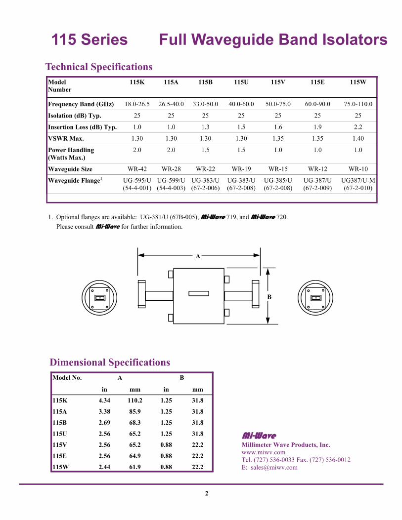
Dimensional Specifications Model No. A
in mm in mm
115K 4.34 110.2 1.25 31.8
115A 3.38 85.9 1.25 31.8
115B 2.69 68.3 1.25 31.8
115U 2.56 65.2 1.25 31.8
115V 2.56 65.2 0.88 22.2
115E 2.56 64.9 0.88 22.2
115W 2.44 61.9 0.88 22.2
B
A
B
1. Optional flanges are available: UG-381/U (67B-005), Mi-Wave 719, and Mi-Wave 720. Please consult Mi-Wave for further information.
Technical Specifications Model Number
115K 115A 115B 115U 115V 115E 115W
Frequency Band (GHz) 18.0-26.5 26.5-40.0 33.0-50.0 40.0-60.0 50.0-75.0 60.0-90.0 75.0-110.0
Isolation (dB) Typ. 25 25 25 25 25 25 25
Insertion Loss (dB) Typ. 1.0 1.0 1.3 1.5 1.6 1.9 2.2
VSWR Max. 1.30 1.30 1.30 1.30 1.35 1.35 1.40
Power Handling (Watts Max.)
2.0 2.0 1.5 1.5 1.0 1.0 1.0
Waveguide Size WR-42 WR-28 WR-22 WR-19 WR-15 WR-12 WR-10
Waveguide Flange1 UG-595/U (54-4-001)
UG-599/U (54-4-003)
UG-383/U (67-2-006)
UG-383/U (67-2-008)
UG-385/U (67-2-008)
UG-387/U (67-2-009)
UG387/U-M (67-2-010)
2

145 Series Polarization Switches
3
Mi-Waves’ 145 series polarization switch is a TE11 mode device with both the input and output in circular waveguide. It is equipped with a standard pin-aligned circular flange similar to most of Mi-Waves’ standard 200 series antenna components. Typical units are continuously adjustable over ±90º of rotation. Please note that the rotation in Faraday rotators is frequency sensitive. The instantaneous bandwidth of these devices is limited to approximately 1% of the center frequency for a fixed drive current value. Applications Used primarily in conjunction with the antenna product line, the 145 series polarization switch provides a means of remote controlled polarization change. These switches can be used to align polarization between satellite and ground station communication when the satellite polarization is unknown. They are also useful in the test and measurement of circular TE11 mode components where axial ratio and elipticity must be calculated.
Description 145 Series Polarization Switches
• Low VSWR • Low Insertion Loss • Faraday Rotation Devices • Low Cross-Polarized Components
Features
Ordering Information
145
Specify RF Band Designator
Mi-Wave Millimeter Wave Products Inc.
www.miwv.com 2200 Tall Pines Drive, Suite 100 Largo, FL 33771 Tel. (727) 536-0033 Fax. (727) 536-0012 E: [email protected]

145 Series Polarization Switches Technical Specifications Circular waveguide components usually have different frequency bands than the rectangular waveguide components. Therefore, it is usually incorrect to refer to the common rectangular waveguide letter designations when specifying circular waveguide. For the ease of describing electrical specifications, it is convenient to group components in the standard rectangular waveguide frequency bands. Please refer to the circular waveguide chart for actual waveguide sizes.
A
B
Dimensional Specifications Model No. A
in mm in mm 145-550 3.25 82.6 1.75 44.5 145-396 3.00 76.2 1.25 31.8 145-328 2.50 63.5 1.25 31.8 145-281 2.50 63.5 1.25 31.8 145-250 2.50 63.5 1.25 31.8 145-219 2.50 63.5 1.25 31.8 145-188 2.50 63.5 1.25 31.8 145-172 On Request 145-165 1.69 42.9 .88 22.4 145-141 On Request 145-125 1.69 42.9 .88 22.4 145-110 1.69 42.9 .88 22.4 145-094 1.69 42.9 .88 22.4 145-082 On Request 145-075 On Request 145-067 1.50 38.1 .88 22.4 145-059 On Request
B
1. Insertion Loss and cross-polarization figures are shown for instantaneous bandwidths of approximately 1%. Drive current must be adjusted over the full RF bandwidth. 2. VSWR was measured using two Mi-Wave series 284 transitions.
Model Number
145A 145B 145U 145V 145E 145W 145F
Frequency Band (GHz) 26.5-40.0 33.0-50.0 40.0-60.0 50.0-70.0 60.0-90.0 75.0-110.0 90.0-140.0
Insertion Loss (dB) 1 0.5 0.5 0.6 0.6 0.7 0.7 1.0
Cross Polarization (dB) 20 20 20 20 20 20 20
VSWR Max. 2 1.25 1.25 1.25 1.25 1.30 1.30 1.30
Average Power (Watts) 12.0 8.0 3.0 3.0 2.0 1.5 1.0
Peak Power (kW) 4.0 2.5 1.0 1.0 0.7 0.5 0.3
Bandwidth (GHz)1 2 2 2 3 3 3 3
Coil Resistance (Ohms) 12 12 12 5 5 5 3
Coil Inductance (mH) 4 4 4 2 2 2 1.5
Switching Speed (usec) 5-10 5-10 5-10 2-5 2-5 2-5 2-5
Current Drive (mA) 0-250
4
Mi-Wave Millimeter Wave Products, Inc. www.miwv.com Tel. (727) 536-0033 Fax. (727) 536-0012 E: [email protected]

150 Series Ferrite Phase Shifters
5
• Fast Rise Time • 360º Phase Shift • Remote Controlled
Features
Mi-Waves’ 150 series is a suppressed rotation reciprocal ferrite phase shifter, built completely in rectangular waveguide to suppress Faraday rotational tendencies in the ferrite at the frequency of operation. This construction allows a low variation in loss as phase is changed. Rise time is optimized through the use of stainless steel waveguide. Applications The 150 series phase shifters are designed for applications that require high speed phase modulation or remote controlled operation.
Description 150 Series Phase Shifters
Ordering Information
150 /
Specify RF Band Designation
Specify Flange (See Appendix A)
Mi-Wave Millimeter Wave Products Inc.
www.miwv.com 2200 Tall Pines Drive, Suite 100 Largo, FL 33771 Tel. (727) 536-0033 Fax. (727) 536-0012 E: [email protected]

150 Series Ferrite Phase Shifters
6
Dimensional Specifications
Mi-Wave Millimeter Wave Products, Inc. 2200 Tall Pines Drive, Suite 100 Largo, FL 33771 Tel. (727) 536-0033 Fax. (727) 536-0012 E: [email protected]
Model A
B
B
No. in mm in mm in mm
150A 6.00 152.4 1.25 31.8 1.53 38.9
150B 3.30 83.8 1.25 31.8 1.53 38.9
150U 3.30 83.8 1.25 31.8 1.53 38.9
150V 3.00 76.2 0.88 22.4 1.13 28.7
150E 2.50 63.5 0.88 22.4 1.13 28.7
150W 2.50 63.5 0.88 22.4 1.13 28.7
C
1. Consult factory for amount of phase shift. 2. Specify center frequency.
A
B
Indicates Polarity
C
Technical Specifications Model Number
150A 150B 150U 150V 150E 150W
Frequency Band (GHz) 26.5-40.0 33.0-50.0 40.0-60.0 50.0-75.0 60.0-90.0 75.0-110.0
Insertion Loss (db) Max. 2.5 2.7 2.7 3.0 3.0 3.0
VSWR Max. 1.30 1.30 1.30 1.30 1.35 1.35
Phase Shift 1
Bandwidth 2 2% 2% 2% 2% 2% 1%
Switching Speed (usec) 20 20 20 15 15 15
Average Power (Watts) 5.0 4.0 2.0 1.0 1.0 0.5
Power, Peak (kW) 2.0 1.5 1.0 0.7 0.5 0.3
Weight (oz) 9.0 8.0 6.0 4.0 3.0 3.0

172 Series Y-Junction Isolators
7
• Low Loss • Low VSWR • High Isolation • Broad Bandwidth • Compact & Rugged • Optimal Temperature Response
Features
Mi-Waves’ 172 series is an H-plane, three port Y-junction ferrite device with one arm internally terminated in a matched load. Reflected energy is circulated into this load to isolate the input. All external mating surfaces are machined to extreme flatness to provide connection to standard waveguide flanges for minimum discontinuity. The 172 series isolators are available in standard waveguide sizes from 12.4 to 50 GHz, using square UG-419, UG-595 and 599 style flanges only. Applications The 172 series Y-junction isolators are useful in test setup and operational systems. These devices provide a high degree of isolation between signal sources and system loads by sharply attenuating reflected signals with very low loss in the forward direction.
Description 172 Series Isolators
Ordering Information
172
Specify Flange 595/599
Specify Center Frequency
Specify RF Band Designator
Mi-Wave Millimeter Wave Products Inc.
www.miwv.com 2200 Tall Pines Drive, Suite 100 Largo, FL 33771 Tel. (727) 536-0033 Fax. (727) 536-0012 E: [email protected]

172 Series Y-Junction Isolators Technical Specifications
1. Specify center frequency. 2. Specification shown is for band edges.
Dimensional Specifications Model A B C D
No. in mm in mm in mm in mm in mm
172K 1.50 38.1 .88 22.4 1.25 31.8 .63 16.0 .63 16.0
172A 1.20 30.5 .75 19.1 .75 19.1 .38 9.7 .38 9.7
172B 1.20 30.5 .75 19.1 .75 19.1 .38 9.7 .38 9.7
E
Please Note: Smaller versions of certain model numbers are available. Please consult Mi-Wave for dimensions.
Output
B
A
C
D
E
Input
Model Number
172K 172A 172B
Frequency Band (GHz) 18.0-26.5 26.5-40.0 33.0-50.0
Bandwidth 1 2.0GHz 1.5GHz 1.3GHz
Isolation 2 (dB) 20.0 20.0 20.0
Insertion Loss (dB) 0.3 0.4 0.5
VSWR 2 Max. 1.30 1.30 1.30
Temperature Range -15° C to +65° C
Peak Power (kW) 1.0 1.0 1.0
Average Power (Watts) Forward Backward
30 1.5
30 1.0
25 0.8
Weight (oz) 4.0 4.0 4.0
Flange Type UG-595/U UG-599/U UG-599/U
8
Mi-Wave Millimeter Wave Products, Inc. www.miwv.com Tel. (727) 536-0033 Fax. (727) 536-0012 E: [email protected]
173 Series Y-Junction Circulators
9
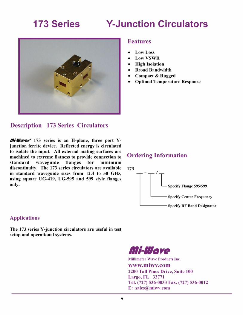
• Low Loss • Low VSWR • High Isolation • Broad Bandwidth • Compact & Rugged • Optimal Temperature Response
Features
Mi-Waves’ 173 series is an H-plane, three port Y-junction ferrite device. Reflected energy is circulated to isolate the input. All external mating surfaces are machined to extreme flatness to provide connection to standard waveguide flanges for minimum discontinuity. The 173 series circulators are available in standard waveguide sizes from 12.4 to 50 GHz, using square UG-419, UG-595 and 599 style flanges only. Applications The 173 series Y-junction circulators are useful in test setup and operational systems.
Description 173 Series Circulators
Ordering Information
173
Specify RF Band Designator
Specify Flange 595/599
Specify Center Frequency
Mi-Wave Millimeter Wave Products Inc.
www.miwv.com 2200 Tall Pines Drive, Suite 100 Largo, FL 33771 Tel. (727) 536-0033 Fax. (727) 536-0012 E: [email protected]

173 Series Y-Junction Circulators
C
D
E
Port 2
A
Port 1
Port 3
B
B
Please Note: Smaller versions of certain model numbers are available. Please consult Mi-Wave for dimensions.
Dimensional Specifications Model No. A B C D
in mm in mm in mm in mm in mm 173K 1.50 38.1 .88 22.4 1.25 31.8 .63 16.0 .63 16.0 173A 1.20 30.5 .75 19.1 19.1 19.1 .38 19.7 .38 19.7 173B 1.20 30.5 .75 19.1 19.1 19.1 .38 19.7 .38 19.7
E
Technical Specifications Model Number
173K 173A 173B
Frequency Band (GHz) 18.0-26.5 26.5-40.0 33.0-50.0
Bandwidth 1 1.8GHz 1.5GHz 1.3GHz
Isolation 2 (dB) 18.0 18.0 18.0
Insertion Loss (dB) 0.3 0.4 0.5
VSWR 2 Max. 1.30 1.30 1.30
Temperature Range -15° C to +65° C
Peak Power (kW) 1.0 1.0 1.0
Average Power (Watts) 30 30 25
Weight (oz) 4.0 4.0 4.0
Flange Type UG-595/U UG-599/U UG-599/U
10
Mi-Wave Millimeter Wave Products, Inc. www.miwv.com Tel. (727) 536-0033 Fax. (727) 536-0012 E: [email protected]

178 Series Y-Junction Isolators
11
Mi-Waves’ 178 series is an H-plane, three port Y-junction ferrite device with one arm internally terminated in a matched load. Reflected energy is circulated into this load to isolate the input. All external mating surfaces are machined to extreme flatness to provide connection to standard waveguide flanges for minimum discontinuity. The 178 series isolators are available in standard waveguide sizes from 18.0 to 110 GHz, in round style flanges only. Applications The 178 series Y-junction isolators are useful in test setup and operational systems. These devices provide a high degree of isolation between signal sources and system loads by sharply attenuating reflected signals with very low loss in the forward direction.
Description 178 Series Isolators
• Low Loss • Low VSWR • High Isolation • Broad Bandwidth • Compact & Rugged • Optimal Temperature Response
Features
Ordering Information
178
Specify RF Band Designator
Specify Center Frequency
Specify Flange (See Appendix A)
Mi-Wave Millimeter Wave Products Inc.
www.miwv.com 2200 Tall Pines Drive, Suite 100 Largo, FL 33771 Tel. (727) 536-0033 Fax. (727) 536-0012 E: [email protected]

178 Series Y-Junction Isolators Technical Specifications
Dimensional Specifications Model A B C D
No. in mm in mm in mm in mm in mm 178K 1.50 38.1 1.25 31.8 1.18 29.97 .59 14.9 .59 14.9 178A 1.50 38.1 1.25 31.8 1.18 29.97 .59 14.9 .59 14.9 178B 1.50 38.1 1.25 31.8 1.18 29.97 .59 14.9 .59 14.9 178U 1.50 38.1 1.25 31.8 1.18 29.97 .59 14.9 .59 14.9 178V 1.10 27.9 1.00 25.4 .90 22.9 .50 12.7 .45 11.4 178E 1.10 27.9 1.00 25.4 .90 22.9 .50 12.7 .45 11.4 178W 1.10 27.9 1.00 25.4 .90 22.9 .49 12.7 .50 11.4
E
Output Input
A
B
C
E
D
1. Specify center frequency. 2. Specification shown is for band edges.
Model Number
178K 178A 178B 178U 178V 178E 178W
Frequency Band (GHz) 18.0-26.5 26.5-40.0 33.0- 50.0 40.0-60.0 50.0-75.0 60.0-90.0 75.0-110.0
Bandwidth 1 2.0GHz 1.5GHz 1.3GHz 1.3GHz 1.5GHz 1.5GHz 1.5GHz
Isolation 2 (dB) 20.0 20.0 20.0 15.0 15.0 15.0 15.0
Insertion Loss (dB) 0.4 0.4 0.5 0.7 1.0 1.0 1.0
VSWR 2 Max. 1.30 1.30 1.30 1.35 1.40 1.4 1.4
Temperature Range 15º to + 65ºC 0º - 50º
Peak Power (kW) 1.0 1.0 1.0 1.0 1.0 1.0 1.0
Average Power (Watts) Forward Backward
30 1.5
30 1.0
25 0.8
15 0.4
10 0.3
5
0.2
5
0.2
Weight (oz) 3.0 3.0 3.0 3.0 5.0 5.0 5.0
Flange Type UG425/U UG381/U UG383/U UG383/U UG385/U UG387/U UG387/U
12
Mi-Wave Millimeter Wave Products, Inc. www.miwv.com Tel. (727) 536-0033 Fax. (727) 536-0012 E: [email protected]

179 Series Y-Junction Circulators
13
• Low Loss • Low VSWR • High Isolation • Broad Bandwidth • Compact & Rugged • Optimal Temperature Response
Features
Mi-Waves’ 179 series is an H-plane, three port Y-junction ferrite device. All external mating surfaces are machined to extreme flatness to provide connection to standard waveguide flanges for minimum discontinuity. The 179 series circulators are available in standard waveguide sizes from 18.0 to 110 GHz, in round style flanges only. Applications The 179 series Y-junction circulators are useful in test setup and operational systems.
Description 179 Series Circulators
Ordering Information
Specify RF Band Designator
179
Specify Center Frequency
Specify Flange (See Appendix A)
Mi-Wave Millimeter Wave Products Inc.
www.miwv.com 2200 Tall Pines Drive, Suite 100 Largo, FL 33771 Tel. (727) 536-0033 Fax. (727) 536-0012 E: [email protected]

179 Series Y-Junction Circulators
Port 2
A
B
C
E
D Port 1
Port 3
Technical Specifications
1. Specify center frequency. 2. Specification shown is for band edges.
Model Number
179K 179A 179B 179U 179V 179E 179W
Frequency Band (GHz) 18.0-26.5 26.5-40.0 33.0-50.0 40.0-60.0 50.0-75.0 60.0-90.0 75.0-110.0
Bandwidth 1 1.8GHz 1.3GHz 1.2GHz 1.2GHz 1.3GHz 1.3GHz 1.3GHz
Isolation 2 (dB) 18 18 18 15 15 15 15
Insertion Loss (dB) 0.4 0.4 0.5 0.7 1.0 1.0 1.0
VSWR 2 Max. 1.30 1.30 1.30 1.35 1.40 1.40 1.40
Temperature Range -15º C to + 65º C 0º C to + 50º C
Peak Power (kW) 1.0 1.0 1.0 1.0 1.0 1.0 1.0
Average Power (Watts) 30 30 25 15 10 5 5
Weight (oz.) 3.0 3.0 3.0 3.0 5.0 5.0 5.0
Flange Type UG425/U UG381/U UG383/U UG383/U UG385/U UG387/U UG387/U
Dimensional Specifications Model A B C D
No. in mm in mm in mm in mm in mm 179K 1.50 38.1 1.25 31.8 1.18 29.97 .59 14.9 .59 14.9 179A 1.50 38.1 1.25 31.8 1.18 29.97 .59 14.9 .59 14.9 179B 1.50 38.1 1.25 31.8 1.18 29.97 .59 14.9 .59 14.9 179U 1.50 38.1 1.25 31.8 1.18 29.97 .59 14.9 .59 14.9 179V 1.10 27.9 1.00 25.4 .90 22.9 .50 12.7 .45 11.4 179E 1.10 27.9 1.00 25.4 .90 22.9 .50 12.7 .45 11.4 179W 1.10 27.9 1.00 25.4 .90 22.9 .50 12.7 .45 11.4
E
14
Mi-Wave Millimeter Wave Products, Inc. www.miwv.com Tel. (727) 536-0033 Fax. (727) 536-0012 E: [email protected]
202 & 203 Series Prime Focus Parabolic Antennas
15
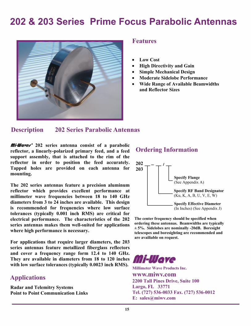
Mi-Waves’ 202 series antenna consist of a parabolic reflector, a linearly-polarized primary feed, and a feed support assembly, that is attached to the rim of the reflector in order to position the feed accurately. Tapped holes are provided on each antenna for mounting. The 202 series antennas feature a precision aluminum reflector which provides excellent performance at millimeter wave frequencies between 18 to 140 GHz diameters from 3 to 24 inches are available. This design is recommended for frequencies where low surface tolerances (typically 0.001 inch RMS) are critical for electrical performance. The characteristics of the 202 series antennas makes them well-suited for applications where high performance is necessary. For applications that require larger diameters, the 203 series antennas feature metallized fiberglass reflectors and cover a frequency range form 12.4 to 140 GHz. They are available in diameters from 18 to 120 inches with low surface tolerances (typically 0.0023 inch RMS).
Radar and Telemitry Systems Point to Point Communication Links
Description 202 Series Parabolic Antennas
Applications
The center frequency should be specified when ordering these antennas. Beamwidths are typically ± 5%. Sidelobes are nominally -20dB. Boresight telescopes and boresighting are recommended and are availiable on request.
• Low Cost • High Directivity and Gain • Simple Mechanical Design • Moderate Sidelobe Performance • Wide Range of Available Beamwidths
and Reflector Sizes
Features
Specify RF Band Designator (Ku, K, A, B, U, V, E, W)
Ordering Information
202 203
Specify Effective Diameter (In Inches) (See Appendix J)
Specify Flange (See Appendix A)
Mi-Wave Millimeter Wave Products Inc.
www.miwv.com 2200 Tall Pines Drive, Suite 100 Largo, FL 33771 Tel. (727) 536-0033 Fax. (727) 536-0012 E: [email protected]

202 & 203 Series Prime Focus Parabolic Antennas
Model No.
Effective Diameter (Inches)
A in mm
B in mm
202 3 3.4 86 3.7 94
202 6 7.3 185 5.1 129
202 12 15.0 381 10.5 266
202 18 22.0 558 11.0 279
202 24 28.2 716 15.7 399
202 36
202 48
203 3
203 6
203 12
203 18 11.8 300 22.0 558
203 24 15.0 381 27.4 696
203 36 20.3 515 39.2 996
203 48 23.5 597 54.0 1372
Dimensional Specifications
Please Note: Antenna feeds amy vary due to reflector diameter and performance requirements. Please consult Mi-Wave for further information.
16
A
B
Series 203
B
A
Series 202
Mi-Wave Millimeter Wave Products, Inc. www.miwv.com Tel. (727) 536-0033 Fax. (727) 536-0012 E: [email protected]

222 & 223 Series Cassegrain Antennas
17
• Low VWSR • Aluminum or Fiberglass
Construction • Low Loss Performance at Millimeter
Wave Frequencies
Features
Mi-Waves’ 222 series cassegrain antenna consists of a parabolic reflector, a primary feed, subreflector, and a feed support assembly of four low profile aluminum spars that are attached to the rim if the reflector to position the feed. The 222 series antennas feature a precision aluminum main reflector which provides excellent performance at millimeter wave frequencies between 18 to 140 GHz. The 223 series antennas feature metallized fiberglass reflectors and are available from 12.4 to 140 GHz. They offer very high performance in a lightweight antenna structure. These antennas are available in effective diameters of 10 to 120 inches. Because of the low surface tolerance (typically 0.0025 inch RMS) they provide excellent high frequency radiation characteristics.
Radars Satellite Tracking Communication Systems
Description 222 Series Cassegrain Antennas
Applications
Ordering Information
222
Specify Effective Diameter (In Inches) (See Appendix J)
Specify Circular Waveguide Diameter (See Appendix J)
Specify RF Band Designator
Specify Required Flange (See Appendix A)
The center frequency should be specified when ordering these antennas.
Mi-Wave Millimeter Wave Products Inc.
www.miwv.com 2200 Tall Pines Drive, Suite 100 Largo, FL 33771 Tel. (727) 536-0033 Fax. (727) 536-0012 E: [email protected]

222 & 223 Series Cassegrain Antennas
Dimensional Specifications Model No.
Effective Diameter (Inches)
A in mm
B in mm
822 12 14 376 12 257
822 18 16 564 18 338
822 24 20 716 28 394
822 36
822 48
823 12
823 18 13.3 338 22.2 564
823 24 15.5 394 28.2 706
823 36 20.9 531 39.1 993
823 48 23.0 594 54.0 1372
Series 222-18
A
B
Series 223-36
A
B
18
Mi-Wave Millimeter Wave Products, Inc. www.miwv.com Tel. (727) 536-0033 Fax. (727) 536-0012 E: [email protected]

258 Series Horn Lens Antennas
19
• Low Sidelobes • Wide Bandwidths • No Aperture Blockage • Symetrical E and H Plane
Beamwidths
Features
Mi-Waves’ 258 series horn lens antenna consists of a circular scalar feel horn illuminating a plano-convex lens. Housed in either aluminum or plastic, these horn lens antennas provide a high efficiency beam with equal E and H plane amplitude patterns. The 258 series antenna are available from 12.4 to 170 GHz in standard sizes of 3, 6, 9, and 12 inch lens apertures. Other custom sizes and configurations are available, please consult Mi-Wave for further information. Applications Radioastronomy Surveillance Equipment Communication Systems
Description 258 Series Horn Lens Antennas
Ordering Information
258 X XXX
Specify Frequency
Specify Circular Size (See Appendix J)
Specify Size (In Inches)
Mi-Wave Millimeter Wave Products Inc.
www.miwv.com 2200 Tall Pines Drive, Suite 100 Largo, FL 33771 Tel. (727) 536-0033 Fax. (727) 536-0012 E: [email protected]

258 Series Horn Lens Antennas
Frequency 12.4 to 140 GHz
Sizes 3, 6, 19, 12
Sidelobes 25dB (typical)
VSWR 1.2:1 (typical)
Cross Polarization 25dB (typical)
Typical Electrical Specifications
B
B
A
A Outline of 6, 9, 12”
Please Note: Final dimensions are subject to variations from the tabulated data due to tuning, focusing, and mechanical tolerances.
Outline of 3,”
Dimensional Specifications Model No. Effective
Diameter (Inches)
A
in mm
B
in mm
258KU -12 14.0 356 21.0 533
258K -9 11.0 279 15.7 399
258K -12 14.0 356 19.5 495
258A -3 4.1 104 8.30 210
258A -6 7.6 193 11.1 282
258A -9 11.0 279 14.0 356
258A -12 14.0 356 18.2 462
258B, U -3 4.1 104 8.3 210
258B, U -6 7.60 193 10.6 269
258B, U -9 11.0 279 14.0 356
258B, U -12 14.0 356 17.7 450
258V, E, W -3 4.2 107 6.0 152
258V, E, W -6 7.6 193 9.6 244
258V, E, W -9 11.0 279 13.0 330
258V, E, W -12 14.0 356 16.7 424
20
Mi-Wave Millimeter Wave Products, Inc. www.miwv.com Tel. (727) 536-0033 Fax. (727) 536-0012 E: [email protected]

261 Series Standard Gain Horns
21
• Nominal Gain of 25 dBi • Available from 12.4 to 220 GHz • Made with Precise Dimensional
Tolerance Control • Gain Calibration is Accurate to 0.5
dB Over Full Waveguide Bandwidth • Other Gain Values Availible upon
Request, ex: 10, 15, 20, etc.
Features
Mi-Waves’ 261 series standard gain horns are fabricated with very close tolerances to ensure the precision of every horn manufactured by Mi-Wave. Each unit is joined to a short section of rectangular wave-guide and terminated in a standard flange. Standard gain horns can be used to determine experimentally the gain of other antennas by using the substitution method. The standard gain horn and the antenna under test are alternately connected to a well-matched detector system in order to compare their relative power levels. The power level difference is then added to the appropriate level of the calibration curve the determine the absolute gain of the antenna under test. Standard gain horns are also useful as power monitors in radar transmitter tests, known-gain radiators in field propagation studies, and transmitting or receiving antennas in test bench applications. The completed units are gold-plated to protect from corrosion and for minimum RF losses. Please Note: 15 dB models available in all bands.
Description 261 Series Gain Horns
Ordering Information
261
Specify RF Band Designator (Ku, K, A, B, U, V, E, W, F, D, G)
Specify Flange (See Appendix A)
For Example: Model number 261 W/387 is a standard gain horn operating in W-band with a 387 type flange.
Mi-Wave Millimeter Wave Products Inc.
www.miwv.com 2200 Tall Pines Drive, Suite 100 Largo, FL 33771 Tel. (727) 536-0033 Fax. (727) 536-0012 E: [email protected]

261 Series Standard Gain Horns
Specifications Model Number
Frequency Band (GHz)
Waveguide Dimension
Waveguide WR-
Flange Types
A in mm
B in mm
261Ku 12.4-18.0 .622 x .311 62 425 5.62 142.8 4.18 106.2 12.50 317.5
261K 18.0-26.5 .420 x.170 42 595 4.12 104.7 3.40 86.4 9.20 233.7
261A 26.5-40.0 .280 x .140 28 599 2.84 72.1 2.35 59.7 6.60 167.6
261B 30.0-50.0 .224 x .112 22 383 2.30 58.4 1.91 48.5 5.10 129.5
261U 40.0-60.0 .188 x .094 19 385 1.81 46.0 1.38 35.1 4.05 102.9
261V 50.0-75.0 .148 x .074 15 387 1.72 43.7 1.43 36.3 3.90 99.1
261E 60.0-90.0 .122 x .061 12 387 1.46 37.1 1.21 30.8 3.20 81.3
261W 75.0-110.0 .100 x .050 10 387 1.21 30.7 1.02 25.9 2.80 71.1
261F 90.0-140.0 .080 x .040 8 387 1.00 25.4 0.84 21.3 2.10 53.3
261D 110.0-170.0 .065 x .0325 6 387 0.83 21.1 0.70 17.8 1.73 43.9
261G 140.0-220.0 .051 x .0255 5 387 0.54 13.7 0.64 16.3 1.25 31.8
C in mm
A
B
C
22
Mi-Wave Millimeter Wave Products, Inc. www.miwv.com Tel. (727) 536-0033 Fax. (727) 536-0012 E: [email protected]

262 Series Conical Horn Antennas
23
Features
• Available from 12.4 to 220 GHz • Nominal Gain of 15, 20 and 25 dbi • Made with Precise Dimensional
Tolerance Control • Gain Calibration is Accurate to
0.5 dB Over Full Waveguide Bandwidth
Mi-Waves’ 262 series conical horns are fabricated with very close tolerances to ensure the precision of every horn manufactured by Mi-Wave. Each unit is supplied with a short section of circular waveguide and terminated in a standard round flange. Conical horns can be used to determine experimentally the gain of other antennas by using the substitution method. The conical horn and the antenna under test are alternately connected to a well-matched detector system in order to compare their relative power levels. The power level difference is then added to the appropriate level of the calibration curve the determine the absolute gain of the antenna under test. Conical horns are also useful as power monitors in radar transmitter tests, known-gain radiators in field propagation studies, and transmitting or receiving antennas in test bench applications. The completed units are gold-plated. Please Note: 10, 15, and 20 dB models are available in all bands.
Ordering Information
262
Specify RF Band Designator (Ku, K, A, B, U, V, E, W, F, D, G)
Specify Gain (In dbi)
For Example: Model number 262 W/387 is a conical horn operating in W-band with a 387 type flange.
Description 262 Series Horn Antennas
Specify Flange (See Appendix A)
Mi-Wave Millimeter Wave Products Inc.
www.miwv.com 2200 Tall Pines Drive, Suite 100 Largo, FL 33771 Tel. (727) 536-0033 Fax. (727) 536-0012 E: [email protected]

262 Series Conical Horn Antennas
A B
A
Specifications
Please Note: Please refer to chart for correct pipe size based on center frequency and bandwidth.
Model Number
Frequency Band (GHz)
Pipe Diameter A in mm
262Ku 12.4-18.0 (see note)
262K 18.0-26.5 (see note)
262A 26.5-40.0 (see note)
262B 30.0-50.0 (see note)
262U 40.0-60.0 (see note)
262V 50.0-75.0 (see note)
262E 60.0-90.0 (see note)
262W 75.0-110.0 (see note)
262F 90.0-140.0 (see note)
262D 110.0-170.0 (see note)
262G 140.0-220.0 (see note)
B in mm
Consult Mi-Wave for Dimensions Due to Wide Variety of Circular Waveguide Sizes and Gain Options.
24
Mi-Wave Millimeter Wave Products, Inc. www.miwv.com Tel. (727) 536-0033 Fax. (727) 536-0012 E: [email protected]

263 Series Wide Angle Scalar Feed Horns
25
• Low VSWR • Wide Beamwidths • Polarization Insensitive • Partial Waveguide Bandwidths
Features
Mi-Waves’ 263 series wide angle scalar feed horn or also called a choke horn, has been designed to be used in applications where wide beamwidth (55 Deg.) is required such as low F/D ratios of .5 and .4 in parabolic reflectors and offset feed applications. Applications Low F/D Antennas Surveillance Systems Offset Feed Antennas
Description 263 Series Scalar Feed Horns
Specify RF Band Designator (Ku, K, A, B, U, V, E, W, F, D, G)
Specify Flange (See Appendix A)
Ordering Information
263
For Example: Model number 263W/387 is a wide beam scalar feed horn operating in W-Band with a UG-387 flange.
Mi-Wave Millimeter Wave Products Inc.
www.miwv.com 2200 Tall Pines Drive, Suite 100 Largo, FL 33771 Tel. (727) 536-0033 Fax. (727) 536-0012 E: [email protected]

263 Series Wide Angle Scalar Feed Horns
Dimensional Specifications Model No.
Frequency Band (GHz)
EIA-WG Designation
A in mm
B in mm
263 12.4 18.0 WR62 1.8 45.7 2.72 69.1
263 18.0 26.5 WR42 1.5 38.1 1.86 47.2
263 26.5 40.0 WR28 1.5 38.1 1.17 29.7
263 33.0 50.0 WR22 1.2 30.5 1.00 25.4
263 40.0 60.0 WR19 1.0 25.4 0.83 21.1
263 50.0 75.0 WR15 .08 20.3 0.66 16.8
263 60.0 90.0 WR12 0.80 20.3 0.55 14.0
263 75.0 110.0 WR10 0.60 15.2 0.45 11.4
263 90.0 140.0 WR8 0.36 9.10 0.60 15.2
Beamwidth (3dB)
E-Plane 55 Deg. H- Plane 56 Deg.
Sidelobes E-Plane -25dB H-Plane -25dB
Bandwidth 50 %
Typical Electrical Specifications
A
B
Please Note: 263 series Feed Horns are normally supplied with a standard rectangular waveguide, circular is also available.
26
Mi-Wave Millimeter Wave Products, Inc. www.miwv.com Tel. (727) 536-0033 Fax. (727) 536-0012 E: [email protected]
267 Series Omni-Directional Antennas
Specify Flange (See Appendix A)
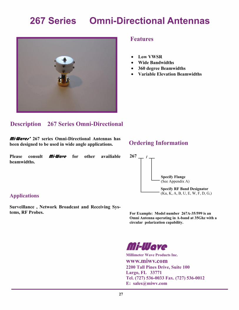
For Example: Model number 267A-35/599 is an Omni Antenna operating in A-band at 35Ghz with a circular polarization capability.
27
• Low VWSR • Wide Bandwidths • 360 degree Beamwidths • Variable Elevation Beamwidths
Features
Mi-Waves’ 267 series Omni-Directional Antennas has been designed to be used in wide angle applications. Please consult Mi-Wave for other availiable beamwidths. Applications Surveillance , Network Broadcast and Receiving Sys-tems, RF Probes.
Ordering Information
Description 267 Series Omni-Directional
267
Specify RF Band Designator (Ku, K, A, B, U, E, W, F, D, G,)
Mi-Wave Millimeter Wave Products Inc.
www.miwv.com 2200 Tall Pines Drive, Suite 100 Largo, FL 33771 Tel. (727) 536-0033 Fax. (727) 536-0012 E: [email protected]

267 Series Omni-Directional Antennas
28
Technical Specifications
Consult MI-Wave for complete dimensional outline for the application and specifications required.
170 GHz Omni-Directional
Mi-Wave Millimeter Wave Products Inc.
www.miwv.com 2200 Tall Pines Drive, Suite 100 Largo, FL 33771 Tel. (727) 536-0033 Fax. (727) 536-0012 E: [email protected]
268 Series Scalar Feed Horns
Specify Flange (See Appendix A)
For Example: Model number 268A is a scalar feed horn operating in A-band at 35Ghz with a circular polarization capability.
29
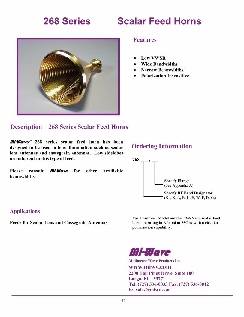
• Low VWSR • Wide Bandwidths • Narrow Beamwidths • Polarization Insensitive
Features
Mi-Waves’ 268 series scalar feed horn has been designed to be used in lens illumination such as scalar lens antennas and cassegrain antennas. Low sidelobes are inherent in this type of feed. Please consult Mi-Wave for other availiable beamwidths. Applications Feeds for Scalar Lens and Cassegrain Antennas
Ordering Information
Description 268 Series Scalar Feed Horns
268
Specify RF Band Designator (Ku, K, A, B, U, E, W, F, D, G,)
Mi-Wave Millimeter Wave Products Inc.
www.miwv.com 2200 Tall Pines Drive, Suite 100 Largo, FL 33771 Tel. (727) 536-0033 Fax. (727) 536-0012 E: [email protected]

268 Series Scalar Feed Horns
A
B 20°
Beamwidth (3dB)
E-Plane 22 Deg. H-Plane 26 Deg.
Sidelobes E-Plane -25dB H-Plane -25dB
Bandwidth 35 %
Typical Electrical Specifications
Specifications Model Number
Frequency Band (GHz)
EIA-WG Designation
A in mm
B in mm
268 12.4 - 18.0 WR62 5.00 127.0 3.12 79.3
268 18.0 - 26.5 WR42 3.50 88.9 2.15 54.6
268 26.5 - 40.0 WR28 2.75 69.9 1.52 38.6
268 33.0 - 50.0 WR22 2.50 63.5 1.25 31.8
268 40.0 - 60.0 WR19 2.25 57.2 1.12 28.5
268 50.0 - 75.0 WR15 1.75 44.5 0.88 22.4
268 60.0 - 90.0 WR12 1.62 41.2 0.75 19.0
268 75.0 -100.0 WR10 1.50 38.1 0.62 15.8
268 90.0 -140.0 WR8
30
Mi-Wave Millimeter Wave Products, Inc. www.miwv.com Tel. (727) 536-0033 Fax. (727) 536-0012 E: [email protected]

281 Series Orthomode Transducers
31
Mi-Waves’ 281 series orthomode transducer couples two orthogonal linearly polarized signals simultaneously while providing polarization isolation between transmit and receive. Applications The 281 series used primarily in conjunction with the antenna product line, which can be combined with cassegrain, horn lens, or circular horn antennas to provide dual linear orthognal/dual circular othogonal polarization.
• VSWR < 1.2 • Isolation > 30 dB in Linear Mode • Higher Frequency Units will be Quoted
on Request • Available from 18.0 to 110 GHz with
3% or Greater Bandwidth
Features
Description 281 Series Transducers
Ordering Information
Specify RF Band Designator
281
Circular Waveguide Flange (See Appendix A)
Three Digit Pipe Inside Diameter (See Appendix J)
Rectangular Wageuide Flange
Mi-Wave Millimeter Wave Products Inc.
www.miwv.com 2200 Tall Pines Drive, Suite 100 Largo, FL 33771 Tel. (727) 536-0033 Fax. (727) 536-0012 E: [email protected]

281 Series Orthomode Transducers
32
Specifications
1. Please specify circular waveguide size per appendix, include both ends. 2. For rectangular straight through, please add a Model No. 284-XXX at time of order.
Model Number
Frequency Band (GHz)
% Bandwidth
A in mm
B in mm
C in mm
281K 18.0-26.5 4 % 1.25 31.8 1.25 31.8 1.25 31.8
281A 26.5-40.0 4 % 1.25 31.8 1.25 31.8 1.25 31.8
281B 30.0-50.0 4 % 1.25 31.8 1.25 31.8 1.25 31.8
281U 40.0-60.0 3 % 1.25 31.8 1.25 31.8 1.25 31.8
281V 50.0-75.0 3 % 1.25 31.8 1.25 31.8 1.25 31.8
281E 60.0-90.0 3 % 1.25 31.8 1.25 31.8 1.25 31.8
281W 75.0-110.0 3 % 1.25 31.8 1.25 31.8 1.25 31.8
281F 90.0-140.0 3 % 1.25 31.8 1.25 31.8 1.25 31.8
A
B
.625
.625
C
Mi-Wave Millimeter Wave Products, Inc. www.miwv.com Tel. (727) 536-0033 Fax. (727) 536-0012 E: [email protected]

282 Series Circular Polarizers
33
• VSWR < 1.2 • Higher Frequency Units will be
Quoted on Request • Axial Ratio < 1.0 dB Over the
Indicated Bandwidth • Converts Linear Input Signals to
Circular Out • Specify Sense of Circular
Polarization (RHCP or LHCP) • Available from 18.0 to 110 GHz
with 3% or Greater Bandwidth
Features
Mi-Waves’ 282 series circular polarizer converts input linear signals to circularly polarized output signals. The circular polarization sense (RHCP or LHCP) and center frequency should be specified at the time of the order. This polarizer will yield a maximum VSWR of 1.2 an an axial ratio of 1.0 dB maximum over the indicated bandwidth. Applications Satellite Links Radio Astronomy Communication Systems
Description 282 Series Polarizers
Ordering Information
282
Specify RF Band Designator
Three Digit Pipe Inside Diameter (See Appendix J )
Specify Flange (See Appendix A)
Mi-Wave Millimeter Wave Products Inc.
www.miwv.com 2200 Tall Pines Drive, Suite 100 Largo, FL 33771 Tel. (727) 536-0033 Fax. (727) 536-0012 E: [email protected]

282 Series Circular Polarizers
Specifications
Performance Curve
A
1.35 1.30 1.25 1.20 1.15 1.10 1.05
1.0
1.4 1.2 1.0 0.8 0.6 0.4 0.02
0.0
0.91fo 0.94fo 0.97fo fo 1.03fo 1.06fo
TYPICAL 3% BAND
VSWR AXIAL RATIO
VSW
R
Frequency
Model No.
Frequency Band (GHz)
A in mm
282K 18.0-26.5 2.3 58.4
282A 26.5-40.0 1.5 38.1
282B 33.0-50.0 1.5 38.1
282U 40.0-60.0 1.5 38.1
282V 50.0-75.0 1.1 28.0
282E 60.0-90.0 1.1 28.0
282W 75.0-110.0 1.0 25.4
34
Mi-Wave Millimeter Wave Products, Inc. www.miwv.com Tel. (727) 536-0033 Fax. (727) 536-0012 E: [email protected]

283 Series Linear-Circular Switchable Polarizers
35
• VSWR < 1.2 • Extremely Compact • Manual Switch for Polarization
Selection • Higher Frequency Units will be Quoted
on Request • Axial Ratio < 1.0 dB Over the Indicated
Bandwidth • Converts Linear Input Signals to
Selectable Output Signals • Available from 18.0 to 110 GHz with
3% or Greater Bandwidth • Output Signal Options: Right-Hand
Circular / Left-Hand Circular / Linear
Features
Mi-Waves’ 283 series polarizer, similar to the 282 series, will convert linear input signals to circular output signals with selectable output features. A manual switch on the unit allows for selection of the output signal’s polarization sense or conversion back to a linear polarization. Therefore, for any linearly polarized input signal, the output may be selected to be right circular, left circular or linear polarization. The characteristics of the circularly polarized signal are similar to the 282 models. Applications Radio Astronomy Communication Links Communication Systems
Description 283 Series Polarizers
Ordering Information
283
Specify RF Band Designator (Ku, K, A, B, U, V, E, W, F, D, G)
Specify Flange (See Appendix A)
Three Digit Pipe Inside Diameter (See Appendix J)
Mi-Wave Millimeter Wave Products Inc.
www.miwv.com 2200 Tall Pines Drive, Suite 100 Largo, FL 33771 Tel. (727) 536-0033 Fax. (727) 536-0012 E: [email protected]

283 Series Linear-Circular Switchable Polarizers
Performance Curve
1.35 1.30 1.25 1.20 1.15 1.10 1.05
1.0
1.4 1.2 1.0 0.8 0.6 0.4 0.02
0.91fo 0.94fo 0.97fo fo 1.03fo 1.06fo
TYPICAL 3% BAND
VSWR AXIAL RATIO
VW
SR
Frequency
A
INPUT OUTPUT RC
LIN
LC
Specifications Model No.
Frequency Band (GHz)
A in
mm
283K 18.0-26.5 2.3 58.4
283A 26.5-40.0 1.5 38.1
283B 33.0-50.0 1.5 38.1
283U 40.0-60.0 1.5 38.1
283V 50.0-75.0 1.1 27.9
283E 60.0-90.0 1.1 27.9
283W 75.0-110.0 1.0 25.4
36
Mi-Wave Millimeter Wave Products, Inc. www.miwv.com Tel. (727) 536-0033 Fax. (727) 536-0012 E: [email protected]

284 Series Tapered Mode Transitions
37
• Low Insertion Loss • Precision-Fabricated • VSWR < 1.15 Over a 10% Bandwidth • Converts from Rectangular TE10
Mode to Circular TE11 Mode • Available from 18.0 to 110 GHz with
10% or Greater Bandwidth
Features
Mi-Waves’ 284 series tapered mode transitions is a precision formed adapter used to transform rectangular TE10 mode waveguide to a circular TE11 mode waveguide. Mainly used in antenna systems and associated components to adapt to conventional waveguide. Applications Antenna Systems Orthomode Transducers Polarization for Antennas
Description 284 Series Mode Transitions
Ordering Information
284 XXX
Specify RF Band Designator (Ku, K, A, B, U, V, E, W, F, D, G)
Specify Pipe Inside Diameter (See Appendix J)
Specify Flange (See Appendix A)
Mi-Wave Millimeter Wave Products Inc.
www.miwv.com 2200 Tall Pines Drive, Suite 100 Largo, FL 33771 Tel. (727) 536-0033 Fax. (727) 536-0012 E: [email protected]

284 Series Tapered Mode Transitions
A
Specifications Model Number
Frequency Band (GHz)
Waveguide I.D. (Inches)
Waveguide Type
Maximum VSWR
284Ku 12.4-18.0 0.622 x 0.311 WR-62 1.15 2.5 63.5
284K 18.0-26.5 0.420 x 0.170 WR-42 1.15 2.0 50.8
284A 26.5-40.0 0.280 x 0.140 WR-28 1.15 1.5 38.1
284B 33.0-50.0 0.224 x 0.122 WR-22 1.15 1.5 38.1
284U 40.0-60.0 0.188 x .094 WR-19 1.15 1.5 38.1
284V 50.0-75.0 0.148 x 0.074 WR-15 1.15 1.1 27.9
284E 60.0-90.0 0.122 x 0.061 WR-12 1.15 1.1 27.9
284W 75.0-110.0 0.100 x 0.050 WR-10 1.15 1.1 27.9
284F 90.0-140.0 0.080 x 0.040 WR- 8 1.15 1.1 27.9
284D 110.0-170.0 0.065 x 0.0325 WR- 7 1.15 1.1 27.9
284G 140.0-220.0 0.051 x 0.0255 WR- 5 1.15 1.1 27.9
A in mm
1. Dimensions, specifications, and configurations are subject to change without notice. 2. Other flanges available on request at additional cost.
38
Mi-Wave Millimeter Wave Products, Inc. www.miwv.com Tel. (727) 536-0033 Fax. (727) 536-0012 E: [email protected]

330 Series Mode Transitions
39
• Minimum VSWR • Minimum Insertion Loss • Optional Pressurized Models
Available • Efficient Conversion from TE10
Mode Rectangular Waveguide to TE01 Mode Circular Waveguide
Features
Mi-Waves’ 330 Series TE01 mode transitions are available for operation from 18.0 to 140.0 GHz. These reciprocal devices have a standard rectangular TE10 mode waveguide input and a circular TE01 mode output. Because of the different frequency ranges of circular TE01 mode waveguide, it is possible for a standard sized rectangular waveguide input to have one of several different circular waveguide size outputs. The 330 series circular mode waveguide features low VSWR and insertion loss. The flanges used for circular wave-guide output are Mi-Waves’ standard male/female type. For maximum mode purity, filtering is recommended for all TE01 propagation (please refer to Appendix L). Applications The 330 series rectangular-to-circular waveguide transitions are useful in millimeter wave radar systems or laboratory setups where long transmission lines are required. These transitions will provide efficient conversion from the TE10 rectangular waveguide mode to the TE01 circular waveguide mode for high-power, low-loss transmission.
Description 330 Series Mode Transitions
Ordering Information
330 ___ - ___ - XXX / ___
A) RF Band Designator B) Three Digit Pipe Inside Diameter (See Appendix L) C) Circular Waveguide Flange: Male (M) or Female (F) D) Rectangular Waveguide Flange (See Appendix A)
A B C D
For Example: 330A-M-688/599 is a mode transition in A-band with a UG/599/U flange and an 0.688 inside diameter circular waveguide with a male circular flange.
Please Note: Due to the non-standardization of this product line, we recommend that you contact Mi-Wave for more specific information about your requirements.
Please specify center frequency at time of order.
Mi-Wave Millimeter Wave Products Inc.
www.miwv.com 2200 Tall Pines Drive, Suite 100 Largo, FL 33771 Tel. (727) 536-0033 Fax. (727) 536-0012 E: [email protected]

330 Series Mode Transitions
40
* Dimension Varies
Technical Specifications
1. Loss measured using two 330 series and 340 series mode filters. 2. Estimated 3. Average: Weight varies with circular waveguide size and flange configuration
Model Number
330KU 330K 330A 330B 330U 330V 330E 330W 330F
Frequency Band (GHz)
12.4- 18.0
18.0- 26.5
26.5- 40.0
33.0- 50.0
40.0- 60.0
50.0- 75.0
60.0- 90.0
75.0- 110.0
90.0- 140.0
Insertion Loss TE 01 (dB) Max. 1
0.3 0.3 0.3 0.4 0.4 0.5 0.5 0.6 0.8
VSWR Max. 1.40 1.40 1.40 1.40 1.40 1.40 1.40 1.50 1.60
Bandwidth 6% 6% 6% 6% 5% 5% 4% 4% 3%
Average Power (Watts)2
4000 2000 1000 1000 600 400 200 100 50
Peak Power (kW)2
20 10 5 4 3 2 1 0.5 0.2
Weight (oz)3 40 30 25 25 25 10 5 5 4
Dimensional Specifications Model No. A B C D E
in mm in mm in mm in mm in mm in mm
330KU 5.17 131.3 4.46 113.3 .267 6.78 2.00 50.80 5.14 130.6 2.75 130.6 330K 3.50 88.9 2.56 65.02 .267 6.78 1.25 31.75 * *
330A,B,U 3.62 91.95 2.79 70.87 .267 6.78 1.12 28.45 2.25 57.15 1.30 33.02
330V 2.00 50.80 1.41 35.81 .211 5.36 .75 19.05 1.16 29.46 .59 14.99 330E, W 1.98 50.29 1.39 35.31 .211 5.36 .75 19.05 1.16 29.46 .59 14.99
330F 1.98 50.29 1.39 35.31 .211 5.36 .75 19.05 1.16 29.46 .59 14.99
F
D
B A
C
E
F
* Varies Per Frequency Range
Mi-Wave Millimeter Wave Products, Inc. Tel.(727) 536-0033 Fax.(727) 536-0012 Email. [email protected]

340 Series Mode Filters
41
• Low Loss • High Spurious Mode Attenuation
Features
Mi-Waves’ 340 series a critical consideration when using TE01 mode circular waveguide is the preservation of mode purity. Due to the similarities between the TE01 and TM11 modes, even the slightest irregularities in the circular waveguide will cause mode conversion from TE01 to TM11. And the large waveguide diameters will readily propagate TEM1 modes which degrade the purity of the TE01 signal. Extraneous TEM1 and TEMN modes cannot be reconverted to the TE10 rectangular mode - they show up as large spurious losses. Each 340 series mode filter consists of a section of lossy wall waveguide. Because the higher order modes (TMM1, TEMN) have wall currents, they are sharply attenuated and do not propagate. Although the energy transferred to these modes is minimal, mode filters must be placed periodically along the transmission line. The TE01 mode, which does not have wall currents, passes through this section unaffected. The 340 series mode filters are available in circular waveguide sizes from 12.4 to 140 GHz. They are fitted with one male and one female type of Mi-Waves’ standard circular flanges.
Applications The 340 series mode filters are used to prevent TE01 conversion to higher order modes. By attenuating unwanted TEM1 modes, the 340 series filters allow for the low loss transmission of TE01,02 modes in circular waveguide and eliminate unwanted resonances, it is recommended that the 340 series filters be placed at least every 10 feet in long
Description 340 Series Mode Filters Three Digit of Waveguide Inside Diameter (See Appendix L)
For Example: Mi-Wave’s model number 340-688 is a mode filter for a frequency range of 25.3 to 34.9 GHz with an 0.688” inside
Please Note: Due to the non-standardization of this product line, we recommend that you contact Mi-Wave for more specific information
Ordering Information
340 - XXX
Mi-Wave Millimeter Wave Products Inc.
www.miwv.com 2200 Tall Pines Drive, Suite 100 Largo, FL 33771 Tel. (727) 536-0033 Fax. (727) 536-0012 E: [email protected]

340 Series Mode Filters
Dimensional Specifications Model No. A B C D F G H
in mm in mm in mm in mm in mm in mm in mm in mm 340-201 4.28 108.71 3.18 80.77 1.38 35.05 .292 7.42 .201 5.11 .48 12.19 .28 7.11 1.20 30.48
340-250 4.28 108.71 3.18 80.77 1.38 35.05 .292 7.42 .250 6.35 .48 12.19 .28 7.11 1.20 30.48
340-291 4.28 108.71 3.18 80.77 1.38 35.05 .376 9.55 .291 7.39 .48 12.19 .28 7.11 1.20 30.48
340-353 4.28 108.71 3.18 80.77 1.38 35.05 .437 11.1 .353 8.97 .48 12.19 .28 7.11 1.20 30.48
340-495 6.85 173.99 4.70 119.38 2.12 53.85 .626 15.9 .495 12.6 .42 10.67 .30 7.62 1.95 49.53
340-545 7.56 192.02 5.45 138.43 2.12 53.85 .626 15.9 .545 13.8 .42 10.67 .30 7.62 1.95 49.53
340-634 7.56 192.02 5.45 138.43 2.12 53.85 .789 20.0 .688 17.5 .42 10.67 .30 7.62 1.95 49.53
K
A
B
H
G
K F C D
Technical Specifications Frequency Band (GHz)
11.6- 48.0
48.0- 96.0
96.0- 150.0
Insertion Loss TE01 (dB) Max.
0.2
0.3
0.4
Insertion Loss TE11 (dB) Min.
10.0
10.0
10.0
VSWR Min. 1.20 1.20 1.25
42
Mi-Wave Millimeter Wave Products, Inc. www.miwv.com Tel. (727) 536-0033 Fax. (727) 536-0012 E: [email protected]

355 Series Rotary Joints
43
Mi-Waves’ 355 series rotary joints are available in standard circular waveguide sizes from 11.6 to 150 GHz. Each rotary joint consists of two circular waveguide sections mounted on ball bearings. Connections to the guides are made at standard male and female circular flanges. Precise alignment of the waveguide sections prevents spurious mode generation, and the very small gap between abutting surfaces contributes a negligible loss in the TE01 circular mode. In all models, amplitude variation with rotation is less than 0.2 dB and phase variation is less than 2 degrees. Applications The 355 series rotary joints provide efficient energy transfer in radar antenna systems or in other applications requiring relative rotation between two sections of waveguide. Designed for low phase variation, low insertion loss, and low wow, they are also useful in special laboratory test set-ups for the measurement of millimeter wave parameters including phase variation in radiated fields. Operating in the low-loss TE01 circular mode, these rotary joints are designed for use in circular waveguide transmission lines. The 355 series rotary joint can also be fitted with two series 330 mode transitions and a 340 series mode filter to provide a rotary joint assembly for rectangular waveguide applications. Despite the assembly’s size, it is a useful design at frequencies that are too high for conventional rotary joints. For use in rectangular waveguide systems, they must be adapted with Mi-Waves’ Series 330 mode transitions.
• Negligible Variation During Rotation
• Minimum Effects on Transferred Signals
Features
Description 355 Series Rotary Joints
For Example: Mi-Wave’s model number 355-250 is a rotary joint for a frequency range of 69.7 to 95.9 GHz with an inside pipe diameter of 0.250
Please Note: Due to non-standardization of this product line, we recommend that you contact Mi-Wave for more specific information about your requirements.
Ordering Information
355 - XXX
Three Digit of Waveguide Inside Diameter (See Appendix L)
Mi-Wave
Mi-Wave Millimeter Wave Products Inc.
www.miwv.com 2200 Tall Pines Drive, Suite 100 Largo, FL 33771 Tel. (727) 536-0033 Fax. (727) 536-0012 E: [email protected]

355 Series Rotary Joints
Dimensional Specifications Model No. A B C D
in mm in mm in mm in mm in mm
355-180 2.35 59.69 1.82 46.23 1.38 35.05 .180 4.57 .211 5.36
355-250 2.35 59.69 1.82 46.23 1.38 35.05 .291 7.39 .211 5.36
355-291 2.35 59.69 1.82 46.23 1.38 35.05 .375 9.53 .211 5.36
355-353 2.35 59.69 1.82 46.23 1.38 35.05 .437 11.10 .211 5.36
355-495 3.35 85.09 3.01 76.45 2.50 63.5 .625 15.88 .264 6.71
355-545 3.35 85.09 3.01 76.45 2.50 63.5 .625 15.88 .264 6.71
355-634 3.35 85.09 3.01 76.45 2.50 63.5 .750 19.05 .264 6.71
E
Technical Specifications Frequency Band (GHz)
11.6- 48.0
48.0- 96.0
96.0- 150.0
Insertion Loss TE01 (dB) Max.
0.3
0.4
0.5
VSWR Min. 1.10 1.10 1.15
Weight (oz) 30 24 15
30º Typ.
A
C D B
E
D
44
Mi-Wave Millimeter Wave Products, Inc. www.miwv.com Tel. (727) 536-0033 Fax. (727) 536-0012 E: [email protected]

365 Series TE01 Circular Waveguide Terminations
45
• Low VSWR • Full Waveguide Bandwidth
Features
Mi-Waves’ 365 series termination is a section of circular waveguide with an integral conical load made from a dielectric absorber material. The long precise taper allows optimum absorption of the microwave energy with minimum reflection. Each termination is fitted with a standard male or female circular flange, specified at the time of order. Applications The 365 series terminations are used in experimental and developmental test set-ups where a low VSWR waveguide load is essential for measurement validity. When measuring the VSWR that results from insertion of various waveguide components in a system, these terminations ensure precise determination of the individual effects.
Description 365 Series Terminations
For Example: Mi-Wave’s model number 365 F-495 is a circular load for a frequency range of 34.8 to 48.0 GHz with an inside waveguide diameter of 0.500” inches.
Please Note: Due to the non-standardization of this product line, we recommend that you contact Mi-Wave for more specific information about your requirements.
Ordering Information
365 ___ - XXX
Three Digit of Waveguide Inside Diameter (See Appendix L)
Specify Flange M: Male F: Female
Mi-Wave Millimeter Wave Products Inc.
www.miwv.com 2200 Tall Pines Drive, Suite 100 Largo, FL 33771 Tel. (727) 536-0033 Fax. (727) 536-0012 E: [email protected]

365 Series TE01 Circular Waveguide
Dimensional Specifications Model No. A B C
in mm in mm in mm in mm
365-201 2.22 56.39 .211 5.36 .250 6.35 1.20 30.48
365-250 2.22 56.39 .211 5.36 .291 7.39 1.20 30.48
365-291 2.22 56.39 .211 5.36 .375 9.53 1.20 30.48
365-353 2.22 56.39 .211 5.36 .437 11.10 1.20 30.48
365-495 4.26 108.2 .264 6.71 .625 15.88 1.95 49.53
365-545 3.76 95.5 .264 6.71 .625 15.88 1.95 49.53
365-634 3.76 95.5 .264
6.71 .750 19.05 1.95 49.53
365-688 4.76 120.9 .264 .
6.71 .788 20.02 1.95 49.53
D
Technical Specifications Frequency Band (GHz)
11.6- 48.0
48.0- 96.0
96.0- 150.0
VSWR 1.05 1.08 1.10
C D
B
C
A
46
Mi-Wave Millimeter Wave Products, Inc. www.miwv.com Tel. (727) 536-0033 Fax. (727) 536-0012 E: [email protected]

370-371 Series Flanged/Unflanged Circular Waveguides
47
• Low VSWR • Precision Size
Features
Mi-Waves’ 370 series flanged waveguide and 371 series unflanged waveguide is available in standard sizes from 12.6 to 320 GHz. The 370 series waveguide sections are fitted with Mi-Waves’ standard male/female flanges. Both waveguide types are manufactured primarily in copper. Mi-Wave recommends using the 340 series mode filters in any circular waveguide system to maintain mode purity. Please Note: Due to the non-standardization of this product line, we recommend that you contact Mi-Wave for more specific information about your requirements.
Description 370 Series Flanged Circular Waveguides 371 Series Unflanged Circular Waveguides
For Example: Mi-Wave’s model number 370-12.7-688 is a 12.7” section of circular waveguide for a frequency range of 25.3 to 34.9 GHz with an inside pipe diameter of 0.688 inches.
Ordering Information
370 ___ - ___
Specify Waveguide Inside Diameter (See Appendix L)
Length (In Inches) (A)
A
Mi-Wave Millimeter Wave Products Inc.
www.miwv.com 2200 Tall Pines Drive, Suite 100 Largo, FL 33771 Tel. (727) 536-0033 Fax. (727) 536-0012 E: [email protected]

370-371 Series Flanged/Unflanged Circular Waveguides TE 01 Circular Waveguides
48
1.500 X 1.750 11.6-16.0 1.500 X 1.700 11.6-16.0 WRC530D14
1.265 X 1.375 13.2-18.9 1.281 X 1.441 13.6-18.7 WRC621D14
1.106 X 1.250 15.9-21.9 1.094 X 1.224 15.9-21.9 WRC727D14
0.951 X 1.125 18.6-25.6 0.938 X 1.068 18.6-25.6 WRC849D14
0.686 X 0.750 25.3-34.9 0.797 X 0.897 21.9-30.1 WRC997D14
0.688 X 0.888 25.3-34.9 0.688 X 0.788 25.3-34.9 WRC116C14
0.634 X 0.750 27.3-38.0 0.594 X 0.674 29.3-40.4 WRC134C14
0.545 X 0.625 32.0-44.0 N/A
0.495 X 0.625 34.8-48.0 0.500 X 0.580 34.8-48.0 WRC159C14
04.38 X 0.518 39.8-54.8 WRC182C14
0.370 X 0.500 46.4-63.9 0.375 X 0.435 46.4-63.9 WRC212C14
0.353 X 0.438 50.0-68.0 0.328 X 0.388 53.1-73.1 WRC243C14
0.291 X 0.375 62.0-84.0 0.281 X .0341 61.9-85.2 WRC283C14
0.249 X 0.313 69.7-95.9 0.250 X 0.290 69.7-95.9 WRC318C14
0.201 X 0.290 86.0-115.0 0.219 X 0.259 79.6-110.0 WRC364C14
0.186 X 0.250 93.0-128.0 0.188 X 0.228 92.9-128.0 WRC424C14
0.172 X 0.212 101.0-139.0 WRC463C14
0.141 X 0.181 124.0-171.0 WRC566C14
Standard Waveguide I.D. O.D. Frequency (inches) (GHz)
MIL-W-23068 Circular Waveguide I.D. O.D. Frequency Type (inches) (GHz)
Mi-Wave Millimeter Wave Products Inc.
www.miwv.com 2200 Tall Pines Drive, Suite 100 Largo, FL 33771 Tel. (727) 536-0033 Fax. (727) 536-0012 E: [email protected]

380 Series Circular Waveguide Flange Set
49
Mi-Waves’ 380 series circular waveguide flanges have been designed specifically for the TE01 low loss mode circular waveguide components. These flanges are precision-machined to facilitate low loss, low reflection waveguide connections at millimeter wave frequencies. O-ring gaskets are included to make these flanges appropriate for use in pressurized waveguide systems. The 380 series flanges are self-aligning male/female connectors and are available in both standard and custom size waveguide.
Description 380 Series Flange Set
• Self-Aligning Connectors • Supplied in Male and Female Pairs
Features
Example: Mi-Wave’s model number 380-688 is a circular waveguide flange with an inside waveguide diameter of 0.688 inches.
Please Note: Due to the non-standardization of this product line, we recommend that you contact Mi-Wave for more specific information about your requirements.
Ordering Information
380
Specify Waveguide Inside Diameter (See Appendix L)
Mi-Wave Millimeter Wave Products Inc.
www.miwv.com 2200 Tall Pines Drive, Suite 100 Largo, FL 33771 Tel. (727) 536-0033 Fax. (727) 536-0012 E: [email protected]

380 Series Circular Waveguide Flange Set
Dimensional Specifications Model No. A B C D E
in mm in mm in mm in mm in mm in mm 380-688 0.55 13.97 0.30 7.62 1.95 49.53 .450 11.43 .185 4.70 .788 20.02
380-635 0.55 13.97 0.30 7.62 1.95 49.53 .450 11.43 .185 4.70 .750 19.05
380-545 0.55 13.97 0.30 7.62 1.95 49.53 .450 11.43 .185 4.70 .625 15.88
380-495 0.55 13.97 0.30 7.62 1.95 49.53 .450 11.43 .185 4.70 .625 15.88
380-353 0.40 10.16 0.27 6.86 1.20 30.48 .300 7.62 .141 3.58 .437 11.10
380-291 0.40 10.16 0.27 6.86 1.20 30.48 .300 7.62 .141 3.58 .375 9.53
380-250 0.40 10.16 0.27 6.86 1.20 30.48 .300 7.62 .141 3.58 .291 7.39
H
A
H
B
D
E
C
Pipe shown for reference only.
50
Mi-Wave Millimeter Wave Products, Inc. www.miwv.com Tel. (727) 536-0033 Fax. (727) 536-0012 E: [email protected]

410 Series Waveguide to Coax Transitions
51
• Low Cost Versions Available • Frequency Ranges 12.4 to 75 GHz • Wide Variety of Coax Connectors
Available • High Performance Versions for
Laboratory Use
Features
Mi-Waves’ 410 series waveguide to coax transitions allow an efficient method of adapting from rectangular waveguide to a coaxial connector. Full waveguide bands available from 12.4 to 75 GHz. Low insertion losses and VSWR’s are typical for these adapters. Low cost production versions available for equipment use and OEM’s. Laboratory grades are also offered on some models. Applications Test Equipment Power Measurment Broadband Systems
Description 410 Series Coax Transitions
Ordering Information
410
Specify RF Band Designator
Specify Connector
Specify Flange (See Appendix A)
Mi-Wave Millimeter Wave Products Inc.
www.miwv.com 2200 Tall Pines Drive, Suite 100 Largo, FL 33771 Tel. (727) 536-0033 Fax. (727) 536-0012 E: [email protected]

410 Series Waveguide to Coax Transitions
Technical Specifications
Please consult Mi-Wave for outline drawings for desired
Connector Flange
Model Number
Frequency Band (GHz)
Waveguide Flange Standard Connection Available
Insertion (Loss) (dB)
VWSR
410KU 12.4 - 18.0 WR-62 UG-419/U N, SMA 0.30 1.20:1
410K 18.0 - 26.5 WR-42 UG-595/U K, 2.4 mm 0.30 1.20:1
410(WR-34) 22.0 - 33.0 WR-34 UG-595/UM K, 2.4 mm 0.35 1.25:1
410A 26.5 - 40.0 WR-28 UG-599/U K, 2.4 mm 0.40 1.30:1
410B 33.0 - 50.0 WR-22 UG-599/UM K, 2.4 mm 0.60 1.40:1
410U 40.0 - 60.0 WR-19 UG-383/UM 2.4 mm 0.80 1.50:1
410V 50.0-75.0 WR-15 UG-385/U 2.4mm,V 1.2 1.65:1
Please Note: Lower frequency versions are available from 6.0 GHz and up.
52
Mi-Wave Millimeter Wave Products, Inc. www.miwv.com Tel. (727) 536-0033 Fax. (727) 536-0012 E: [email protected]

450 Series High Pass Filters
53
• Low Cost • Wide Bandwidths • Low Insertion Loss • Low VSWR in Band
Features
Mi-Waves’ 450 series high pass filters use a simple yet effective waveguide cut-off filter technique. This design is useful for eliminating unwanted side bands in upconverters and out-of band frequencies in communication systems. These filters are small in size and compact by design. The 450 series can be designed for any frequency range from 12.4 to 220 GHz. Low insertion losses from 0.15 dB and cut off rejections of up to 80dB are possible. Consult Mi-Wave for dimensions due to the wide range of waveguide sizes and frequency ranges. Applications Side Band Filters Frequency Diplexers Telecommunications Systems
Description 450 Series High Pass Filters
Ordering Information
450
Specify RF Band Designator
Specify Flange (See Appendix A)
Specify Center Frequency
Mi-Wave Millimeter Wave Products Inc.
www.miwv.com 2200 Tall Pines Drive, Suite 100 Largo, FL 33771 Tel. (727) 536-0033 Fax. (727) 536-0012 E: [email protected]

460 Series Band Pass Filters
54
• Low Cost • Low VSWR • Narrow Bandwidths • High Rejection Levels • Low in-Band Insertion
Features
Mi-Wave’s 460 series band pass filter is primarily used for narrow band applications. Pass bands are typically from 1% to 4%. This design is well suited for frequency diplexers used in communication systems or any application where narrow bandwidths are required. Insertion losses are typically in the 0.8 dB to 2.0dB area depending upon rejection levels. The 460 series band pass filter can be designed from 12.4 to 60 GHz. Please consult Mi-Wave for further dimensions and specific technical data. Applications Side Band Filters Frequency Diplexers Telecommunications Systems
Description 460 Series Band Pass Filters
Ordering Information
460
Specify RF Band Designator
Specify Flange (See Appendix A)
Specify Center Frequency
Mi-Wave Millimeter Wave Products Inc.
www.miwv.com 2200 Tall Pines Drive, Suite 100 Largo, FL 33771 Tel. (727) 536-0033 Fax. (727) 536-0012 E: [email protected]
510 Series Direct-Reading Precision Attenuators
55
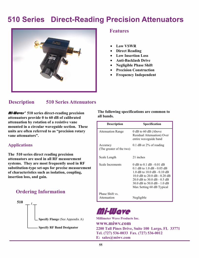
• Low VSWR • Direct Reading • Low Insertion Loss • Anti-Backlash Drive • Negligible Phase Shift • Precision Construction • Frequency Independent
Features
Mi-Waves’ 510 series direct-reading precision attenuators provide 0 to 60 dB of calibrated attenuation by rotation of a resistive vane mounted in a circular waveguide section. These units are often referred to as “precision rotary vane attenuators”. Applications The 510 series direct reading precision attenuators are used in all RF measurement systems. They are most frequently used in RF substitution-type set-ups for precise measurement of characteristics such as isolation, coupling, insertion loss, and gain.
Description 510 Series Attenuators
Description Specification
Attenuation Range 0 dB to 60 dB (Above Residual Attenuation) Over entire waveguide band
Accuracy (The greater of the two)
0.1 dB or 2% of reading
Scale Length 21 inches
Scale Increments 0 dB to 0.1 dB - 0.01 dB 0.1 dB to 1.0 dB - 0.05 dB 1.0 dB to 10.0 dB - 0.10 dB 10.0 dB to 20.0 dB - 0.20 dB 20.0 dB to 30.0 dB - 0.5 dB 30.0 dB to 50.0 dB - 1.0 dB Max Setting 60 dB Typical
Phase Shift vs. Attenuation
Negligible
The following specifications are common to all bands.
Ordering Information
510
Specify RF Band Designator
Specify Flange (See Appendix A)
Mi-Wave Millimeter Wave Products Inc.
www.miwv.com 2200 Tall Pines Drive, Suite 100 Largo, FL 33771 Tel. (727) 536-0033 Fax. (727) 536-0012 E: [email protected]

510 Series Direct-Reading Precision Attenuators
56
Flange (both ends) per customer spec.- see tabulation
Dimensional Specifications Model No.
510K 8.48 215.0 510A 6.87 174.0 510B 6.25 159.0 510U 5.76 146.0 510V 4.50 114.3 510E 4.50 114.3 510W 4.50 114.3 510F 3.53 89.7 510D 3.44 87.4 510G 3.20 81.3
A
88 (22.4) 3.50 (88.9) 3.00 (76.2) Adjustable
3.56 (90.4) 3.44 (87.4)
A
Technical Specifications Model Number
510K 510A 510B 510U 510V 510E 510W 510F 510D 510G
Frequency Band (GHz)
18.0- 26.5
26.5- 40.0
33.0- 50.0
40.0- 50.0
50.0- 75.0
60.0- 90.0
75.0- 110.0
90.0- 140.0
110.0- 170.0
140.0 220.0
Insertion Loss (dB) Max.
0.5 0.5 0.6 0.7 0.8 0.9 1.0 1.2 1.5 1.8
VSWR 1 Max. 1.30 1.15 1.15 1.15 1.20 1.20 1.20 1.25 1.25 1.25
Average Power (Watts)
1.0 0.5 0.5 0.4 0.3 0.2 0.2 0.1 0.1 0.1
Weight (oz) 52 38 38 36 29 28 28 .26 .24 24
.3.37 (85.6)
4.08 (103.6) 4.90 (124.5)
1.75 (44.5)
3.00 (76.2)
2.00 (50.8)
1.78 (4.52)
Mi-Wave Millimeter Wave Products, Inc. Tel. (727) 536-0033 Fax. (727) 536-0012 Email. [email protected]

511 Series Programmable Rotary Vane Attenuators
57
• Low Cost • Compact Size • 7.0 to 170 GHz • High Accuracy • Highly Reliable • Digital Readout • Low Insertion Loss • IEEE-488 Interface • Full Waveguide Bands • Manual Operation Mode
Features
Mi-Waves’ 511 series precision programmable rotary vane attenuators are available in full waveguide bands from 7.0 to 220.0 GHz. Attenuation control is either manually via a front panel or remote controlled using a standard IEEE-488 interface. The attenuators’ small compact size incorporates both the electronic controller and microwave components. The unit operates from a single +24 volt DC source or with an optional AC adapter. Attenuation range is from 0 to 60 dB in 0.1 dB steps with 0.05 dB steps from 0 to 20 dB. A digital readout is provided on the front panel to display attenuation settings. The attenuators are highly reliable and designed to be used in ATE and remote power control applications. RS-232 Control Also Available Applications Instrumentation Remote Control of RF Power Levels Fade Margin Testing of Microwave Radios Fade Margin Testing of Microwave Radio Equipment
Description 511 Series Attenuators
Example : 511A/599 Frequency Range 26.5 to 40 GHz UG-599/U Flange
Specify Flange (See Appendix A)
Ordering Information
511
Specify RF Band Designator
Mi-Wave Millimeter Wave Products Inc.
www.miwv.com 2200 Tall Pines Drive, Suite 100 Largo, FL 33771 Tel. (727) 536-0033 Fax. (727) 536-0012 E: [email protected]

511 Series Programmable Rotary Vane Attenuators
58
Dimensional Specifications Model No.
A in mm
B in mm
C in mm
D in mm
E in mm
511XL 11.69 296.9 4.66 118.3 6.32 160.5 4.04 102.6 2.29 58.2
511X 11.69 296.9 4.66 118.3 6.32 160.5 4.04 102.6 2.29 58.2
511XS 11.19 284.2 4.66 118.3 6.32 160.5 4.04 102.6 2.29 58.2
511KU 10.94 277.8 4.00 101.6 5.50 139.7 3.50 88.9 2.29 58.2
511K 8.48 215.4 4.00 101.6 5.50 139.7 3.50 88.9 2.29 58.2
511A 6.87 174.5 4.00 101.6 5.50 139.7 3.50 88.9 2.29 58.2
511B 6.24 158.4 4.00 101.6 5.50 139.7 3.50 88.9 2.29 58.2
511U 5.74 145.7 4.00 101.6 5.50 139.7 3.50 88.9 2.29 58.2
511V 4.50 114.3 4.00 101.6 5.50 139.7 3.50 88.9 2.29 58.2
511E 4.50 114.3 4.00 101.6 5.50 139.7 3.50 88.9 2.29 58.2
511W 4.50 114.3 4.00 101.6 5.50 139.7 3.50 88.9 2.29 58.2
511F 4.50 114.3 4.00 101.6 5.50 139.7 3.50 88.9 2.29 58.2
511G 4.50 114.3 4.00 101.6 5.50 139.7 3.50 88.9 2.29 58.2
Technical Specifications Model Number
Frequency Band (GHz)
Waveguide (WR)
Insertion Loss (Max.)
VSWR (Max.)
Power (Max.)
511XL 7.0 - 10.0 112 0.5 dB 1.2:1 5 watts
511X 8.2 - 12.4 90 0.5 dB 1.2:1 2 watts
511XS 10.0 - 15.0 75 0.5 dB 1.25:1 2 watts
511KU 12.4 - 18.0 62 0.5 dB 1.25:1 2 watts
511K 18.0 - 26.5 42 0.5 dB 1.15:1 1 watt
511A 26.5 - 40.0 28 0.5 dB 1.15:1 0.5 watt
511B 33.0 - 50.0 22 0.6 dB 1.15:1 0.5 watt
511U 40.0 - 60.0 19 0.7 dB 1.15:1 0.4 watt
511V 50.0 - 75.0 15 0.8 dB 1.20:1 0.3 watt
511E 60.0 - 90.0 12 1.0 dB 1.2:1 0.25 watt
511W 75.0 - 110.0 10 1.0 dB 1.2:1 0.25 watt
511F 90.0 - 140.0 8 1.2 dB 1.3:1 0.2 watt
511G 110.0 - 170.0 5 1.4 dB 1.3:1 0.2 watt
Attenuation
A
B
C
D E
Up
Down
Mi-Wave Millimeter Wave Products, inc. Tel. (727) 536-0033 Fax. (727) 536-0012 Email. [email protected]

520 Series Uncalibrated Variable Attenuators
59
• Dial Driven • Compact, Mechanically Stable
Design • Wide Range of Attenuation
Values • Smooth, Spring-Loaded Setting
Control
Features
Mi-Waves’ 520 series uncalibrated variable attenuators are available in standard waveguide sizes from 26.5 to 220 GHz. The attenuating element in each unit provides variable attenuation, from 0 dB to 25 dB minimum. Precision-designed internal controls are accurately contoured to provide a low bilateral VSWR and minimum variation of attenuation with frequency. Applications The 520 series uncalibrated variable attenuators are useful in applications that require a reliable level-setting or isolating pad. They provide maximum accuracy in establishing initial power levels in substitution-method attenuation measurements. Designed to maintain reliable performance for accurate test measurements, the stable setting control of these devices maintains constant attenuation under all normal conditions of vibration and orientation.
Description 520 Series Attenuators
Ordering Information
520
Specify RF Band Designator
Specify Flange (See Appendix A)
Mi-Wave Millimeter Wave Products Inc.
www.miwv.com 2200 Tall Pines Drive, Suite 100 Largo, FL 33771 Tel. (727) 536-0033 Fax. (727) 536-0012 E: [email protected]

520 Series Uncalibrated Variable Attenuators
A
B
Dimensional Specifications Model No. A
in mm in mm 520K 3.00 76.2 2.35 59.7 520A 2.75 69.9 2.16 54.9 520B 2.75 69.9 2.16 54.9 520U 2.75 69.9 2.16 54.9 520V 2.50 63.5 1.94 49.3 520E 2.50 63.5 1.94 49.3 520W 2.50 63.5 1.94 49.3 520F 2.00 50.8 1.94 49.3 520D 2.00 50.8 1.94 49.3 520G 2.00 50.8 1.94 49.3
B
Technical Specifications Model Number
520K 520A 520B 520U 520V 520E 520W 520F 520D 520G
Frequency Band (GHz)
18.0-26.5
26.5-40.0
33.0-50.0
40.0-60.0
50.0-75.0
60.0-90.0
75.0-110.0
90.0-140.0
110.0-170.0
140-220
VSWR Max. 1.15 1.15 1.15 1.15 1.15 1.15 1.20 1.25 1.25 1.30
Attenuation Range (dB) Min.
0-30 0-30 0-30 0-30 0-30 0-25 0-25 0-25 0-25 0-25
Insertion Loss @ 0 Setting (dB)
0.3 0.3 0.3 0.3 0.4 0.4 0.4 0.5 0.6 0.7
Weight (oz.) 8.0 6.0 6.0 6.0 3.0 3.0 3.0 2.5 2.5 2.5
Average Power (Watts)
1.5 1.0 1.0 1.0 0.6 0.6 0.5 0.3 0.2 0.1
60
Mi-Wave Millimeter Wave Products, Inc. www.miwv.com Tel. (727) 536-0033 Fax. (727) 536-0012 E: [email protected]

521 Series Fixed Attenuators
61
• Wide Range of Accurately Calibrated Values
• Available in Every Waveguide Size from 18.0 to 220 GHz
Features
Mi-Waves’ 521 series fixed attenuators are available in attenuation values up to 30 dB for each waveguide band from 18.0 to 220 GHz. Each fixed attenuator is calibrated at the exact frequency specified and is accurate within 0.1 dB or 1%. Applications The 521 series fixed attenuators are used in millimeter wave applications that require accurate fixed attenuation levels in waveguide transmission lines. All units are H-plane fixed attenuators. The attenuators are useful for isolating generators from mismatched load effects. They are also used for extending the frequency ranges of power measuring equipment and for accurately reducing signal source output levels.
Description 521 Series Attenuators
Specify RF Band Designator
Ordering Information
521
Specify Flange (See Appendix A)
Specify Attenuation Value
Please specify center frequency at time of order.
Mi-Wave Millimeter Wave Products Inc.
www.miwv.com 2200 Tall Pines Drive, Suite 100 Largo, FL 33771 Tel. (727) 536-0033 Fax. (727) 536-0012 E: [email protected]
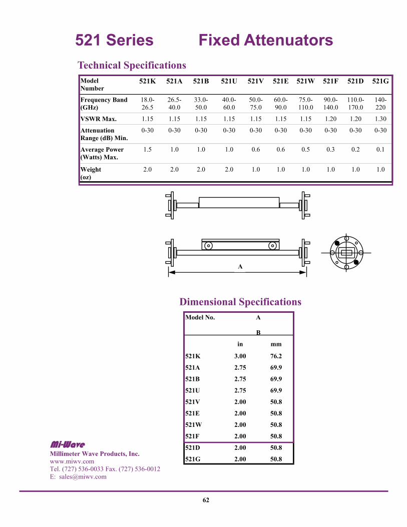
521 Series Fixed Attenuators
A
Technical Specifications Model Number
521K 521A 521B 521U 521V 521E 521W 521F 521D 521G
Frequency Band (GHz)
18.0-26.5
26.5-40.0
33.0-50.0
40.0-60.0
50.0-75.0
60.0-90.0
75.0-110.0
90.0-140.0
110.0-170.0
140-220
VSWR Max. 1.15 1.15 1.15 1.15 1.15 1.15 1.15 1.20 1.20 1.30
Attenuation Range (dB) Min.
0-30 0-30 0-30 0-30 0-30 0-30 0-30 0-30 0-30 0-30
Average Power (Watts) Max.
1.5 1.0 1.0 1.0 0.6 0.6 0.5 0.3 0.2 0.1
Weight (oz)
2.0 2.0 2.0 2.0 1.0 1.0 1.0 1.0 1.0 1.0
Dimensional Specifications Model No.
in mm
521K 3.00 76.2
521A 2.75 69.9
521B 2.75 69.9
521U 2.75 69.9
521V 2.00 50.8
521E 2.00 50.8
521W 2.00 50.8
521F 2.00 50.8
521D 2.00 50.8
521G 2.00 50.8
A
B
62
Mi-Wave Millimeter Wave Products, Inc. www.miwv.com Tel. (727) 536-0033 Fax. (727) 536-0012 E: [email protected]
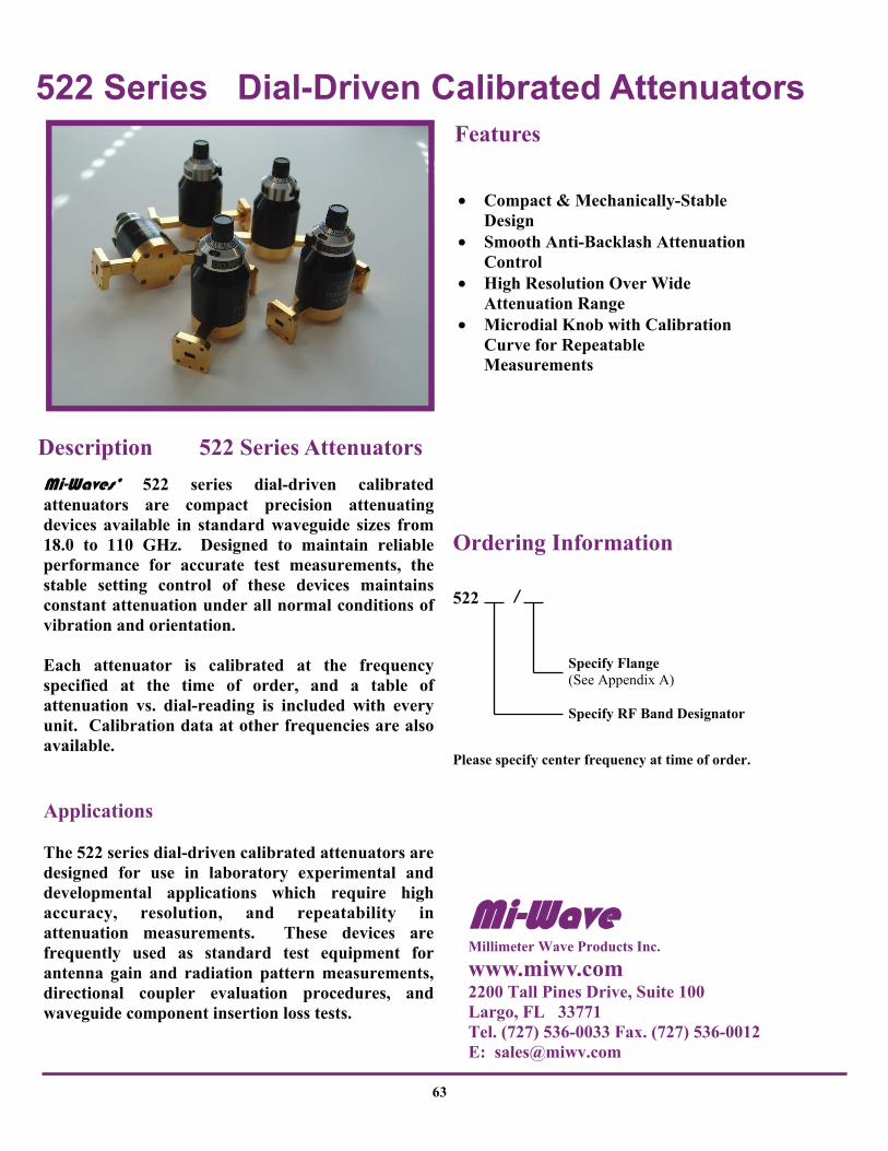
522 Series Dial-Driven Calibrated Attenuators
63
• Compact & Mechanically-Stable Design
• Smooth Anti-Backlash Attenuation Control
• High Resolution Over Wide Attenuation Range
• Microdial Knob with Calibration Curve for Repeatable Measurements
Features
Mi-Waves’ 522 series dial-driven calibrated attenuators are compact precision attenuating devices available in standard waveguide sizes from 18.0 to 110 GHz. Designed to maintain reliable performance for accurate test measurements, the stable setting control of these devices maintains constant attenuation under all normal conditions of vibration and orientation. Each attenuator is calibrated at the frequency specified at the time of order, and a table of attenuation vs. dial-reading is included with every unit. Calibration data at other frequencies are also available. Applications The 522 series dial-driven calibrated attenuators are designed for use in laboratory experimental and developmental applications which require high accuracy, resolution, and repeatability in attenuation measurements. These devices are frequently used as standard test equipment for antenna gain and radiation pattern measurements, directional coupler evaluation procedures, and waveguide component insertion loss tests.
Description 522 Series Attenuators
Ordering Information
522
Specify RF Band Designator
Specify Flange (See Appendix A)
Please specify center frequency at time of order.
Mi-Wave Millimeter Wave Products Inc.
www.miwv.com 2200 Tall Pines Drive, Suite 100 Largo, FL 33771 Tel. (727) 536-0033 Fax. (727) 536-0012 E: [email protected]

522 Series Dial-Driven Calibrated Attenuators
Dimensional Specifications Model No. A
B
in mm in mm
522K 3.00 76.2 2.35 59.7
522A 2.75 69.9 2.16 54.9
522B 2.75 69.9 2.16 2.16
54.9
522U 2.75 69.9 2.16 54.9
522V 2.50 63.5 1.94 49.3
522E 2.50 63.5 1.94 49.3
522W 2.50 63.5 1.94 49.3
B Attenuation Range . . . . . . . . 0 dB to 25 dB Minimum Calibration Accuracy . . . . . . 0.1 dB to 1% VSWR (Max.) . . . . . . . . . . . .1.15 Calibration Curve . . . . . . . . .Supplied for calibraion frequency specified at time of order.
Operating Specifications
A
B
Technical Specifications Model Number
522K 522A 522B 522U 522V 522E 522W
Frequency Band (GHz)
18.0- 26.5
26.5- 40.0
33.0- 50.0
40.0- 60.0
50.0- 75.0
60.0- 90.0
75.0- 110.0
Insertion Loss @ 0 Setting (dB)
0.3 0.3 0.3 0.3 0.4 0.4 0.4
Average Power (Watts) 1.5 1.0 1.0 1.0 0.6 0.6 0.5
Weight (oz.) 8.0 6.0 6.0 6.0 3.0 3.0 3.0
64
Mi-Wave Millimeter Wave Products, Inc. www.miwv.com Tel. (727) 536-0033 Fax. (727) 536-0012 E: [email protected]
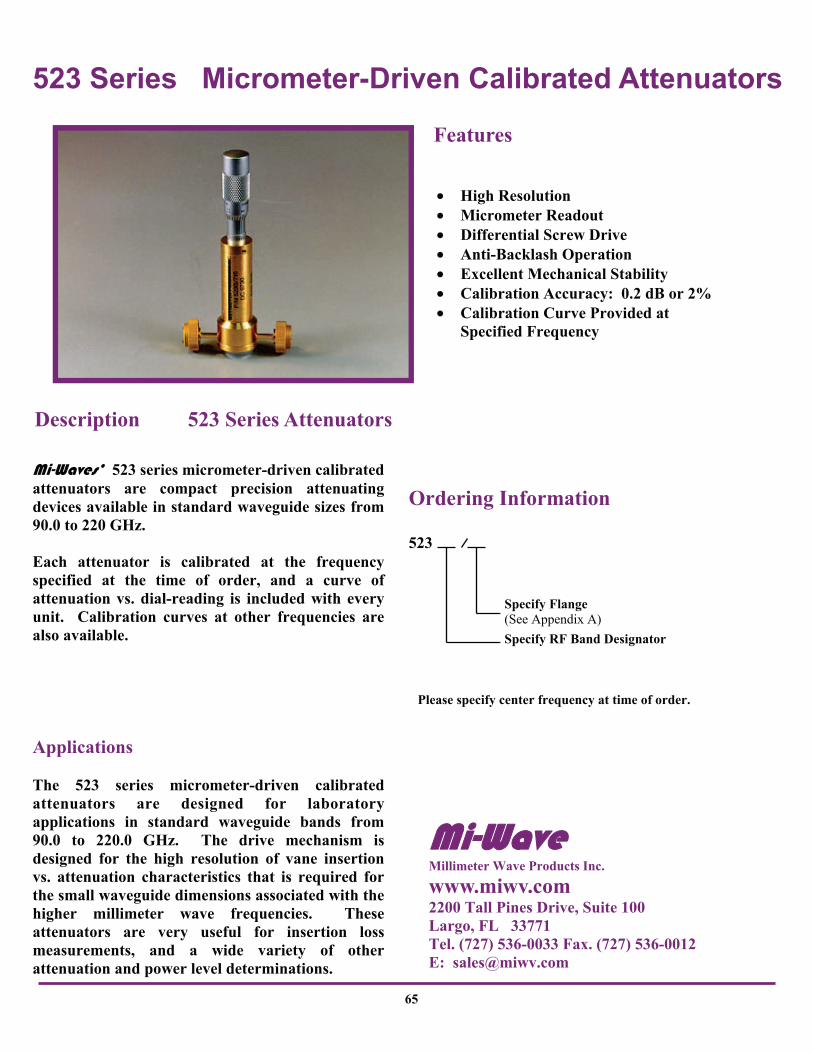
523 Series Micrometer-Driven Calibrated Attenuators
65
• High Resolution • Micrometer Readout • Differential Screw Drive • Anti-Backlash Operation • Excellent Mechanical Stability • Calibration Accuracy: 0.2 dB or 2% • Calibration Curve Provided at Specified Frequency
Features
Mi-Waves’ 523 series micrometer-driven calibrated attenuators are compact precision attenuating devices available in standard waveguide sizes from 90.0 to 220 GHz. Each attenuator is calibrated at the frequency specified at the time of order, and a curve of attenuation vs. dial-reading is included with every unit. Calibration curves at other frequencies are also available. Applications The 523 series micrometer-driven calibrated attenuators are designed for laboratory applications in standard waveguide bands from 90.0 to 220.0 GHz. The drive mechanism is designed for the high resolution of vane insertion vs. attenuation characteristics that is required for the small waveguide dimensions associated with the higher millimeter wave frequencies. These attenuators are very useful for insertion loss measurements, and a wide variety of other attenuation and power level determinations.
Description 523 Series Attenuators
Ordering Information
523
Specify RF Band Designator
Specify Flange (See Appendix A)
Please specify center frequency at time of order.
Mi-Wave Millimeter Wave Products Inc.
www.miwv.com 2200 Tall Pines Drive, Suite 100 Largo, FL 33771 Tel. (727) 536-0033 Fax. (727) 536-0012 E: [email protected]

523 Series Micrometer-Driven Calibrated Attenuators
B
A
Dimensional Specifications
1. 4.15 in (105.4 mm) maximum dimension with micrometer fully extended.
Model No. A
in mm in mm 523F 2.00 50.8 3.65 92.7
523D 2.00 50.8 3.65 92.7
523G 2.00 50.8 3.65 92.7
B1
Technical Specifications Model Number
523F 523D 523G 1
Frequency Band (GHz)
90.0- 140.0
110.0-170.0
140.0- 220.0
Calibration Accuracy 0.2 dB - 2% 0.2 dB - 2% 0.2 dB - 2%
Attenuation Range
0 dB - 25 dB
0 dB - 25 dB
0 dB - 25 dB
VSWR 1.25 1.25 1.25
Insertion Loss 0.5 dB 0.6 dB 0.7 dB
Average (W) Avg. 0.3 0.2 0.1
Weight (oz) 5.5 5.5 5.5
1. Full attenuation range may not be available for all G-band frequencies.
66
Mi-Wave Millimeter Wave Products, Inc. www.miwv.com Tel. (727) 536-0033 Fax. (727) 536-0012 E: [email protected]
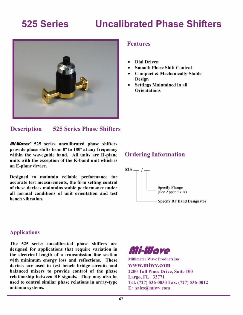
525 Series Uncalibrated Phase Shifters
67
Mi-Waves’ 525 series uncalibrated phase shifters provide phase shifts from 0º to 180º at any frequency within the waveguide band. All units are H-plane units with the exception of the K-band unit which is an E-plane device. Designed to maintain reliable performance for accurate test measurements, the firm setting control of these devices maintains stable performance under all normal conditions of unit orientation and test bench vibration. Applications The 525 series uncalibrated phase shifters are designed for applications that require variation in the electrical length of a transmission line section with minimum energy loss and reflections. These devices are used in test bench bridge circuits and balanced mixers to provide control of the phase relationship between RF signals. They may also be used to control similar phase relations in array-type antenna systems.
• Dial Driven • Smooth Phase Shift Control • Compact & Mechanically-Stable
Design • Settings Maintained in all
Orientations
Features
Description 525 Series Phase Shifters
Ordering Information
525
Specify RF Band Designator
Specify Flange (See Appendix A)
Mi-Wave Millimeter Wave Products Inc.
www.miwv.com 2200 Tall Pines Drive, Suite 100 Largo, FL 33771 Tel. (727) 536-0033 Fax. (727) 536-0012 E: [email protected]

525 Series Uncalibrated Phase Shifters
Technical Specifications
A
B
Dimensional Specifications Model No. A
in mm in mm 525K 3.00 76.2 2.35 59.7 525A 2.75 69.9 2.16 54.9 525B 2.75 69.9 2.16 54.9 525U 2.75 69.9 2.16 54.9 525V 2.50 63.5 1.94 49.9 525E 2.50 63.5 1.94 49.9 525W 2.50 63.5 1.94 49.9 525F 2.00 50.8 1.94 49.9 525D 2.00 50.8 1.94 49.9 525G 2.00 50.8 1.94 49.9
B
Model Number
525K 525A 525B 525U 525V 525E 525W 525F 525D 525G
Frequency Band (GHz)
18.0-26.5
26.5-40.0
33.0-50.0
40.0-60.0
50.0-75.0
60.0-90.0
75.0-110.0
90.0-140.0
110-170.0
140.0-220.0
VSWR Max. 1.15 1.15 1.15 1.20 1.20 1.20 1.20 1.25 1.25 1.25
Phase Shift (degrees) Min.
180 180 180 180 180 180 180 180 180 180
Insertion Loss (dB) 0.3 0.3 0.3 0.3 0.4 0.5 0.5 0.6 0.8 1.0
Average Power (Watts)
1.5 1.0 1.0 1.0 0.8 0.7 0.6 0.4 0.3 0.2
Weight (oz.) 8.0 6.0 6.0 6.0 3.0 3.0 3.0 2.5 2.5 2.5
68
Mi-Wave Millimeter Wave Products, Inc. www.miwv.com Tel. (727) 536-0033 Fax. (727) 536-0012 E: [email protected]

526 Series Dial-Driven Calibrated Phase Shifters
69
Mi-Waves’ 526 series dial-driven calibrated phase shifters are precision phase-shifting devices, designed for operation from 18.0 to 110 GHz to provide phase shifts from 0º to 180º at any frequency within the waveguide band. All units are H-plane units with the exception of the K-band unit which is an E-plane device. Designed to maintain reliable performance for accurate test measurements, the firm setting control of these devices maintains stable performance under all normal conditions of unit orientation and test bench vibration. Each phase shifter is calibrated at the frequency specified at the time of order, and a curve of attenuation vs. dial-reading is included with every unit. Calibration curves at other frequencies are also available.
Applications The 526 series dial-driven calibrated phase shifters are designed to provide accurate variations in the electrical length of transmission line sections with minimum energy loss and reflections. The accuracy, resolution, and repeatability of these devices permit the measurement of standard test equipment applications. They can also provide accurate field phase data in the determination of antenna primary
• Compact & Mechanically-Stable Design
• Smooth Anti-Backlash Phase Shift Control
• High Resolution Over A Wide Phase-Shifting Range
Features
Description 526 Series Phase Shifters
Ordering Information
526
Specify RF Band Designator
Specify Flange (See Appendix A)
Please specify center frequency at time of order.
Mi-Wave Millimeter Wave Products Inc.
www.miwv.com 2200 Tall Pines Drive, Suite 100 Largo, FL 33771 Tel. (727) 536-0033 Fax. (727) 536-0012 E: [email protected]

526 Series Dial-Driven Calibrated Phase Shifters
Technical Specifications
A
B
Phase Shift ..................... 0º to 180º Minimum Accuracy......................... ± 3.0º Calibration Curve .......... Supplied at the frequency specified at time of order.
Operating Specifications Dimensional Specifications Model No. A
B
in mm in mm
526K 3.00 76.2 2.35 59.7
526A 2.75 69.9 2.16 54.9
526B 2.75 69.9 2.16 2.16
54.9
526U 2.75 69.9 2.16 54.9
526V 2.50 63.5 1.94 49.3
526E 2.50 63.5 1.94 49.3
526W 2.50 63.5 1.94 49.3
B
Model Number
526K 526A 526B 526U 526V 526E 526W
Frequency Band (GHz)
18.0- 26.5
26.5- 40.0
33.0- 50.0
40.0- 60.0
50.0- 75.0
60.0- 90.0
75.0- 110.0
VSWR 1.15 1.15 1.15 1.2 1.2 1.2 1.2
Insertion Loss (dB) 0.3 0.3 0.3 0.3 0.4 0.5 0.5
Average Power (Watts) 1.5 1.0 1.0 1.0 0.8 0.7 0.6
Weight (oz.) 8.0 6.0 6.0 6.0 3.0 3.0 3.0
70
Mi-Wave Millimeter Wave Products, Inc. www.miwv.com Tel. (727) 536-0033 Fax. (727) 536-0012 E: [email protected]
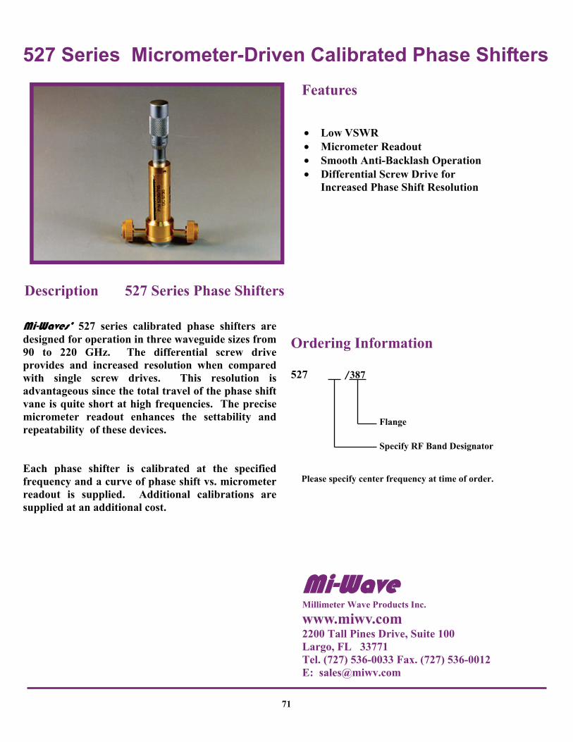
527 Series Micrometer-Driven Calibrated Phase Shifters
71
• Low VSWR • Micrometer Readout • Smooth Anti-Backlash Operation • Differential Screw Drive for
Increased Phase Shift Resolution
Features
Mi-Waves’ 527 series calibrated phase shifters are designed for operation in three waveguide sizes from 90 to 220 GHz. The differential screw drive provides and increased resolution when compared with single screw drives. This resolution is advantageous since the total travel of the phase shift vane is quite short at high frequencies. The precise micrometer readout enhances the settability and repeatability of these devices. Each phase shifter is calibrated at the specified frequency and a curve of phase shift vs. micrometer readout is supplied. Additional calibrations are supplied at an additional cost.
Description 527 Series Phase Shifters
Ordering Information
527 387
Specify RF Band Designator
Please specify center frequency at time of order.
Flange
Mi-Wave Millimeter Wave Products Inc.
www.miwv.com 2200 Tall Pines Drive, Suite 100 Largo, FL 33771 Tel. (727) 536-0033 Fax. (727) 536-0012 E: [email protected]

527 Series Micrometer-Driven Calibrated Phase Shifters
Technical Specifications Model Number
527F 527D 527G
Frequency Band (GHz)
90.0- 140.0
110.0-170.0
140.0- 220.0
VSWR Max. 1.15 1.15 1.15
Phase Shift (degree) Min.
180
180
180
Accuracy (º) ±3.0 ±3.0 ±3.0
Weight (oz) 5.5 5.5 5.5
Dimensional Specifications Model No. A
in mm in mm
527F 2.00 50.8 4.00 101.6
527D 2.00 50.8 4.00 101.6
527G 2.00 50.8 4.00 101.6
B
B
A
72
Mi-Wave Millimeter Wave Products, Inc. www.miwv.com Tel. (727) 536-0033 Fax. (727) 536-0012 E: [email protected]

528 Series Direct-Reading Phase Shifters
73
• High Accuracy • Direct Reading Dial • Frequency Independent • Direct Drive With No Gears • Covers Full Waveguide Band • Continuously Adjustable Phase • Low VSWR & Low Insertion Loss
Features
Mi-Waves’ 528 series direct reading phase shifters provide highly accurate measurement of phase shift over each full waveguide band from 26.5 to 110.0 GHz. They feature low VSWR, low insertion loss, and low insertion loss variation due to the rotation of the phasing section. Applications The 528 series direct-reading precision phase shifters offer a convenient, frequency insensitive method of measuring phase shift. These devices are useful in waveguide systems where the phase and amplitude must be measured or adjusted independently. Typical applications include bridge circuits, phased arrays, and interferometers.
Description 528 Series Phase Shifters
Ordering Information
528
Specify RF Band Designator
Specify Flange (See Appendix A)
Mi-Wave Millimeter Wave Products Inc.
www.miwv.com 2200 Tall Pines Drive, Suite 100 Largo, FL 33771 Tel. (727) 536-0033 Fax. (727) 536-0012 E: [email protected]
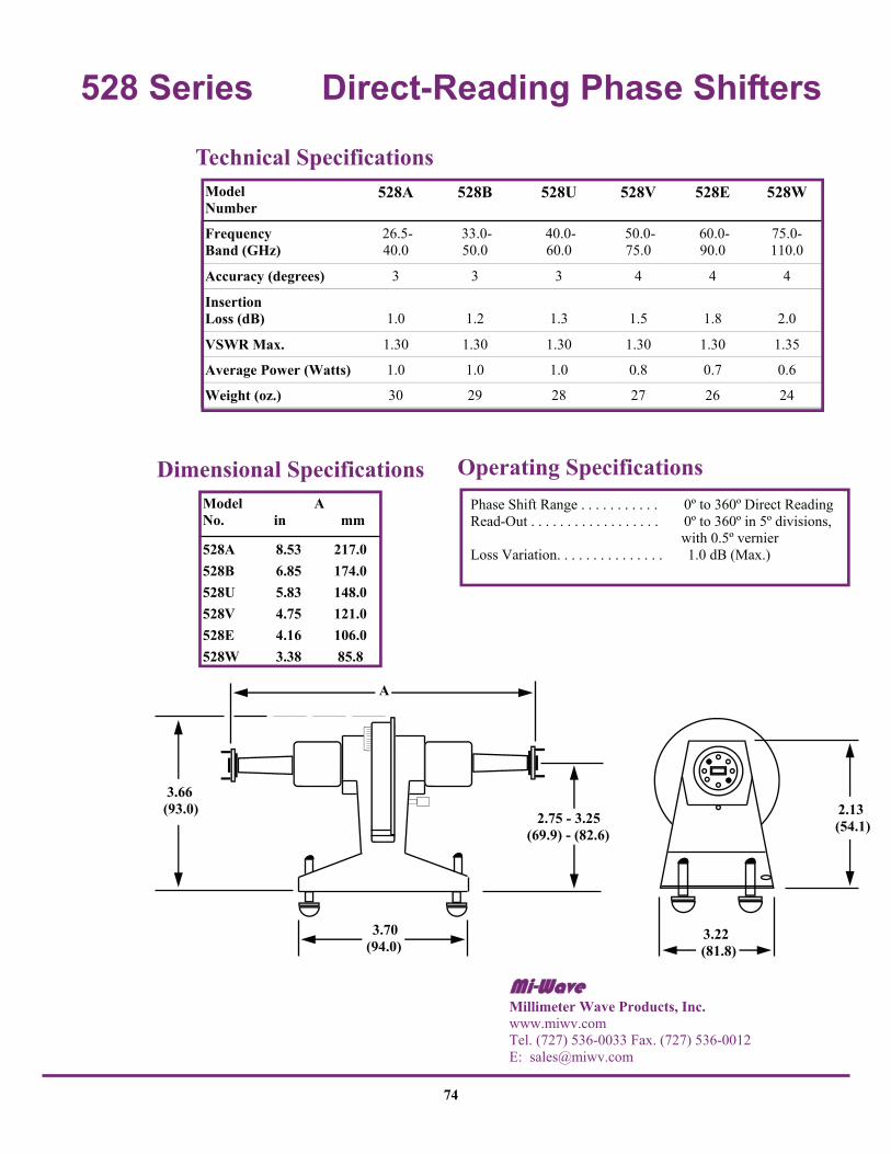
528 Series Direct-Reading Phase Shifters
Phase Shift Range . . . . . . . . . . . 0º to 360º Direct Reading Read-Out . . . . . . . . . . . . . . . . . . 0º to 360º in 5º divisions, with 0.5º vernier Loss Variation. . . . . . . . . . . . . . . 1.0 dB (Max.)
Operating Specifications Dimensional Specifications Model No.
528A 8.53 217.0 528B 6.85 174.0 528U 5.83 148.0 528V 4.75 121.0 528E 4.16 106.0 528W 3.38 85.8
A in mm
2.13 (54.1)
3.22 (81.8)
A
2.75 - 3.25 (69.9) - (82.6)
3.70 (94.0)
3.66 (93.0)
Technical Specifications Model Number
528A 528B 528U 528V 528E 528W
Frequency Band (GHz)
26.5- 40.0
33.0- 50.0
40.0- 60.0
50.0- 75.0
60.0- 90.0
75.0- 110.0
Accuracy (degrees) 3 3 3 4 4 4
Insertion Loss (dB)
1.0
1.2
1.3
1.5
1.8
2.0
VSWR Max. 1.30 1.30 1.30 1.30 1.30 1.35
Average Power (Watts) 1.0 1.0 1.0 0.8 0.7 0.6
Weight (oz.) 30 29 28 27 26 24
74
Mi-Wave Millimeter Wave Products, Inc. www.miwv.com Tel. (727) 536-0033 Fax. (727) 536-0012 E: [email protected]

529 Series Motorized Rotary Vane Phase Shifters
75
Mi-Wave has developed a new motorized rotary vane phase shifter which is available in W/G bands from 18.0 to 110 GHz. The 529 series is a computer controlled version of Mi-Waves’ standard direct reading phase shifter and features a 0 to 360º range with 0.5 degree resolution. The phase shifter is controlled by a precision stepping motor and all electronics required to drive the motor are contained within the phase shifter housing. Custom microprocessor based electronics translate the desired phase shifter setting into the required motor position and provide the proper drive signals for the motor. Motor speed is ramped up and down ensuring accurated positioning and smooth operation. The unit can be controlled remotely through an IEEE-488 interface or manually with a front panel switch. A three digit readout on the front panel displays the setting. All that is required is a 24 volt, 500 mA supply, which is included. Applications The 529 series motorized direct reading phase shifters are used in all RF automated measurement systems. They are most frequently used in RF substitution type set-ups for precise measurement of characteristics including bridge circuits and phased arrays.
Description 529 Series Phase Shifters
• High Accuracy • Digital Readout • Low Insertion Loss • Computer Controlled • Precision Construction • Full Waveguide Bands
Features
Ordering Information
529 ___ ___
Specify RF Band Designator
Specify Flange (See Appendix A)
Example : 529 W/387 75-110 GHz with /387 Flange
Principles of Operation Remote Local When the unit is connected to 24 VDC with no connection to the IEEE interface, phase shifter is controlled by a front panel toggle switch. If the toggle is held up or down from 5 counts or more, the phase shifter changes at a rapid rate to facilitate larger changes.
Mi-Wave Millimeter Wave Products Inc.
www.miwv.com 2200 Tall Pines Drive, Suite 100 Largo, FL 33771 Tel. (727) 536-0033 Fax. (727) 536-0012 E: [email protected]

529 Series Motorized Rotary Vane Phase Shifters Technical Specifications
Model No. Frequency Band (GHz)
Insertion Loss VSWR Average Power Weight
529K 18.0 - 26.5 1.0 dB 1.30 1.0 Watts 63 oz
529A 26.5 - 40.0 1.0 dB 1.15 0.5 Watts 60 oz
529B 33.0 - 50.0 1.0 dB 1.15 0.5 watts 60 oz
529U 40.0 - 60.0 1.1 dB 1.15 0.4 watts 59 oz
529V 50.0 - 75.0 1.2 dB 1.20 0.3 watts 50 oz
529E 50.0 - 90.0 1.4 dB 1.20 0.2 watts 30 oz
529W 75.0 - 110.0 1.5 dB 1.20 0.2 watt 30 oz
C
Dimensional Specifications
Model No.
Resolution (degree)
Repeatability
Accuracy Speed (Sec) 0-360
529K 0.5 0.5 4 deg. 5 sec
529A 0.5 0.5 4 deg. 5 sec
529B 0.5 0.5 4 deg. 5 sec
529U 0.5 0.5 4 deg. 5 sec
529V 0.5 0.5 4 deg. 5 sec
529E 0.5 0.5 4 deg. 5 sec
529W 0.5 0.5 4 deg. 5 sec
Electrical Specifications
Model No.
A in mm
B in mm
C in mm
D in mm
529K 8.48 215.4 4.00 101.6 5.50 139.7 3.50 88.9
529A 6.87 174.5 4.00 101.6 5.50 139.7 3.50 88.9
529B 6.24 158.4 4.00 101.6 5.50 139.7 3.50 88.9
529U 5.74 145.7 4.00 101.6 5.50 139.7 3.50 88.9
529V 4.50 114.3 4.00 101.6 5.50 139.7 3.50 88.9
529E 4.50 114.3 4.00 101.6 5.50 139.7 3.50 88.9
529W 4.50 114.3 4.00 101.6 5.50 139.7 3.50 88.9
Dimensional Specifications
Phase Shift
A
B
D
Up
Down
76
Mi-Wave Millimeter Wave Products, Inc. www.miwv.com Tel. (727) 536-0033 Fax. (727) 536-0012 E: [email protected]

530 Series Manual Waveguide Switches
77
• Positive Indexing • Optimum Isolation • Non-Contacting Choke Coupling • Versatile Switching Combinations
Features
Mi-Waves’ 530 series manual switches are designed for use in standard millimeter wave frequency bands from 12.4 to 220 GHz. Each unit will operate over the full waveguide bandwidth with minimum insertion loss, minimum VSWR, and maximum isolation between coupled and uncoupled waveguide sections. Applications The 530 series manual waveguide switches are used for transmission switching applications in millimeter wave systems. These versatile devices provide a variety of switching combinations using three waveguide channels and three positions. In a typical radar application, a three-position switch can be used manually to switch one of two transmitters to a common antenna, while simultaneously connecting the other transmitter to a suitable termination. A manual switch will also provide a convenient means for alternately connecting a test antenna and standard horn to gain-measuring test equipment.
Description 530 Series Switches
Ordering Information
530
Specify RF Band Designator
Specify Flange (See Appendix A)
Mi-Wave Millimeter Wave Products Inc.
www.miwv.com 2200 Tall Pines Drive, Suite 100 Largo, FL 33771 Tel. (727) 536-0033 Fax. (727) 536-0012 E: [email protected]

530 Series Manual Waveguide Switches Technical Specifications
Model Number 530A 530B 530U 530V 530E 530W 530F 530D 530G
Frequency Band (GHz)
26.5- 40.0
33.0- 50.0
40.0- 60.0
50.0- 75.0
60.0- 90.0
75.0- 110.0
90.0- 140.0
110.0- 170.0
140.0- 220.0
Isolation (dB) Min. 50 50 50 50 45 40 40 35 30
Inmsertion Loss (dB) Max.
0.3 0.3 0.3 0.3 0.4 0.5 0.7 0.9 1.0
VSWR Max. 1.15 1.15 1.15 1.15 1.15 1.15 1.15 1.20 1.25
Dimensional Specifications Model Number A B C
in mm in mm in mm in mm
530A/599 1.97 50.0 1.85 47.0 2.10 53.3 .985 25.0
530B/383 1.97 50.0 1.85 47.0 2.10 53.3 .985 25.0
530U/383 1.97 50.0 1.85 47.0 2.10 53.3 .985 25.0
530V/385 1.97 50.0 1.85 47.0 2.10 53.3 .985 25.0
530E/387 1.97 50.0 1.85 47.0 2.10 53.3 .985 25.0
530W/387 1.97 50.0 1.85 47.0 2.10 53.3 .985 25.0
530D/387 1.76 44.7 1.85 47.0 2.10 53.3 .880 22.4
530G/387 1.76 44.7 1.85 47.0 2.10 53.3 .880 22.4
D
C
D
A B
78
Mi-Wave Millimeter Wave Products, Inc. www.miwv.com Tel. (727) 536-0033 Fax. (727) 536-0012 E: [email protected]

535 Series Two-Position Solenoid Switches
79
• Low Loss • Low VSWR • Accurate Positioning • High Isolation Between Ports • GPIB IEEE-488 Control Available
Features
Each of Mi-Waves’ 535 series waveguide switches consists of a waveguide switch selection similar to the 530 series switch and a rotary solenoid stepping motor encased in a machined housing. Applications The 535 series solenoid switches are used in applications that require remote-controlled or timed transmission line switching. They are particularly useful in operational systems and test setups where they supply a variety of switching combinations.
Description 535 Series Solenoid Switches
Ordering Information
535
Specify RF Band Designator
Specify Flange (See Appendix A)
GPIB Controlled Switch 4 port 4 position
Mi-Wave Millimeter Wave Products Inc.
www.miwv.com 2200 Tall Pines Drive, Suite 100 Largo, FL 33771 Tel. (727) 536-0033 Fax. (727) 536-0012 E: [email protected]

535 Series Two Position Solenoid Switches
Dimensional Specifications Model A B C
No. in mm in mm in mm in mm
535A 5.21 132.0 1.28 32.5 2.61 66.3 2.73 69.3
535B 5.21 132.0 1.28 32.5 2.61 66.3 2.73 69.3
535U 5.21 132.0 1.28 32.5 2.61 66.3 2.73 69.3
535V 5.41 137.0 1.14 28.9 1.92 48.8 2.50 63.5
535E 5.41 137.0 1.14 28.9 1.92 48.8 2.50 63.5
535W 5.41 137.0 1.14 28.9 1.92 48.8 2.50 63.5
D
C
B
A
D
Technical Specifications Model Number 535A 535B 535U 535V 535E 535W
Frequency Band (GHz)
26.5- 40.0
33.0- 50.0
40.0- 60.0
50.0- 75.0
60.0- 90.0
75.0- 110.0
Isolation (dB) Min. 50 50 50 40 40 40
Insertion Loss (dB) Max.
0.3 0.3 0.3 0.3 0.4 0.5
VSWR Max. 1.15 1.15 1.15 1.15 1.15 1.15
Average Switching Speed (Seconds)
0.5 0.5 0.5 0.5 0.5 0.5
80
Please Check with MI-Wave for current outline drawings.
Mi-Wave Millimeter Wave Products, Inc. www.miwv.com Tel. (727) 536-0033 Fax. (727) 536-0012 E: [email protected]

550 Series Frequency Meters
81
Features
• High Frequency Operation from 90.0 to 220 GHz
• Circular Waveguide Cavity for High-Q Resonances
• Micrometer Readout for Accurate Frequency Determination
Mi-Waves’ 550 series frequency meters are available in three standard waveguide sizes for operation over 90 to 220 GHz frequency range. Each unit is supplied with a calibration table and curve. The calibration is performed by using the micrometer-driven plunger to measure the distance between electrical resonances for a known frequency. These distances are recorded for several frequencies and then plotted on a curve to allow extrapolation for all frequencies. Applications The 550 series frequency meters are reaction-type cavity wavemeters designed for the accurate determination of millimeter wave signal frequencies.
Description 550 Series Frequency Meters
Ordering Information
550 387
Specify RF Band Designator
Flange
Mi-Wave Millimeter Wave Products Inc.
www.miwv.com 2200 Tall Pines Drive, Suite 100 Largo, FL 33771 Tel. (727) 536-0033 Fax. (727) 536-0012 E: [email protected]

550 Series Frequency Meters
Dimensional Specifications Model Number
A in mm
B in mm
550F 1.20 30.5 .50 12.7 2.50 63.5
550D 1.20 30.5 .50 12.7 2.50 63.5
550G 1.20 30.5 .50 12.7 2.50 63.5
C in mm
Technical Specifications Model Number
550F
550D
550G
Frequency Band (GHz)
90.0- 140.0
110.0- 170.0
140.0- 220.0
Absolute Accuracy (%)
0.5 0.5 0.7
VSWR Max. 1 1.20 1.20 1.20
Insertion Loss (dB) Typical
0.5
0.6
0.8
Dip at Resonance (dB) 0.3-1.0 0.3-1.0 0.3-1.0
Weight (oz) 3.0 2.5 2.5
1. Off Resonance.
C
B
A
387 Flange
82
Mi-Wave Millimeter Wave Products, Inc. www.miwv.com Tel. (727) 536-0033 Fax. (727) 536-0012 E: [email protected]

551 Series Direct-Reading Frequency Meters
83
• Full Band • Direct Reading • High Resolution • Anti-Backlash Drive
Features
Mi-Waves’ 551 series direct-reading frequency meters are available in standard waveguide sizes from 18.0 to 110.0 GHz and are designed to provide easy direct readout of frequency with a high degree of resolution and accuracy. Applications The 551 series direct-reading frequency meters provide a quick and accurate method of determining frequency over the complete waveguide band to facilitate measurements in any research, development, or production applications.
Description 551 Series Frequency Meters
Ordering Information
551
Specify RF Band Designator
Specify Flange (See Appendix A)
Mi-Wave Millimeter Wave Products Inc.
www.miwv.com 2200 Tall Pines Drive, Suite 100 Largo, FL 33771 Tel. (727) 536-0033 Fax. (727) 536-0012 E: [email protected]

551 Series Direct-Reading Frequency Meters
Technical Specifications
3.50 (88.9) 3.00 (76.2) Adjustable
3.00 (76.2)
MPI
2.70
4.69 (119.1)
3.89 (98.8)
2.125 Dia.
4.00 (101.6)
5.00
Scale
Model Number 551K 551A 551B 551U 551V 551E 551W
Frequency Band (GHz)
18.0-26.5
26.5-40.0
33.0-50.0
40.0-60.0
50.0-75.0
60.0-90.0
75.0-110.0
Absolute Accuracy (%) 0.11 0.12 0.12 0.20 0.20 0.20 0.20
Resonance Dip (dB)
0.5- 1.0
0.5- 1.0
0.5- 1.0
0.5- 1.0
1.0- 3.0
0.5- 1.0
1.5- 3.5
VSWR 1 Max. 1.10 1.15 1.15 1.15 1.20 1.20 1.20
Insertion Loss (dB) Max. .25 .30 .40 .50 .60 .70 .70
Scale Divisions (MHz) Min. 10 10 10 20 20 20 20
Scale Length (in) 74.0 76.0 78.0 78.5 77.0 75.0 58.0
Weight (oz) 55 54 54 54 53 53 53
1. Off Resonance.
84
Mi-Wave Millimeter Wave Products, Inc. www.miwv.com Tel. (727) 536-0033 Fax. (727) 536-0012 E: [email protected]

555 Series Bidirectional Couplers
85
• High Directivity • Accurate Coupling • Full Waveguide Bandwidth
Features
Mi-Waves’ 555 series bidirectional couplers are broadband, broadwall components with a multi-hole pattern that features an inherently high directivity. The 555 series couplers are available in 3 dB, 6 dB, 10 dB, 20 dB, 30 dB, and 40 dB coupling values for standard waveguide bands from 26.5 to 110.0 GHz. Applications The 555 series bidirectional couplers are used in applications that require precise sampling of both incident and reflected energy. The 3 dB couplers are especially useful in balanced mixer work where broadband power division of RF and LO signals is required to supply both sides of a balanced mixer unit. The 3 dB bidirectional couplers can provide full bandwidth power division.
Description 555 Series Couplers
Ordering Information
555 ___ - ___ / ___
Specify Coupling Valve (3, 6, 10, 20, 30, 40)
Specify Flange (See Appendix A)
Specify RF Band Designator
Mi-Wave Millimeter Wave Products Inc.
www.miwv.com 2200 Tall Pines Drive, Suite 100 Largo, FL 33771 Tel. (727) 536-0033 Fax. (727) 536-0012 E: [email protected]

555 Series Bidirectional Couplers
Dimensional Specifications Model Number
A in mm
B in mm
C in mm
555A/10, 20, 30, 40 9.62 244.0 1.75 445 1.38 35.1 .16 4.06
555A/3, 6 dB 12.0 304.8 1.75 445 1.38 35.1 .16 4.06
555B/10, 20, 30, 40 8.40 213.0 1.64 41.7 1.30 33.0 .13 3.30
555B/3, 6 dB 10.25 259.1 1.64 41.7 1.30 33.0 .13 3.30
555U/10, 20, 30, 40 7.38 187.4 1.38 35.1 1.12 28.5 .11 2.80
555U/3, 6 dB 9.12 231.6 1.38 35.1 1.12 28.5 .11 2.80
555V/10, 20, 30, 40 6.25 159.0 1.13 28.6 0.88 22.4 .08 2.03
555V/3, 6 dB 7.25 184.1 1.13 28.7 0.88 22.4 .08 2.03
555E/10, 20, 30, 40 5.50 140.0 1.13 28.5 0.88 22.4 .07 1.78
555E/3, 6 dB 6.62 168.1 1.13 28.7 0.88 22.4 .07 1.78
555W/10, 20, 30, 40 4.50 114.0 1.00 25.4 0.81 20.6 .06 1.52
555W/3, 6 dB 5.50 139.7 1.00 25.4 0.81 20.6 .06 1.52
D in mm
Technical Specifications Model Number 555A 555B 555U 555V 555E 555W
Frequency Band (GHz)
26.5- 40.0
33.0- 50.0
40.0- 60.0
50.0- 75.0
60.0- 90.0
75.0- 110.0
Coupling (dB)
Coupling Variation (dB) ± 0.7 ± 0.7 ± 0.8 ± 1.0 ± 1.0 ± 1.0
Coupling Accuracy (dB) ± 1.0 ± 1.0 ± 1.2 ± 1.5 ± 1.5 ± 1.5
Directivity (dB) Typical 30 30 30 30 30 30
Main Line VSWR 1.05 1.05 1.10 1.10 1.10 1.10
Auxiliary Line VSWR 1.15 1.15 1.20 1.20 1.20 1.20
Weight (oz) 6.0 5.0 4.0 3.0 2.5 2.0
3, 6, 10, 20, 30, 40
C
A
B
D
86
Mi-Wave Millimeter Wave Products, Inc. www.miwv.com Tel. (727) 536-0033 Fax. (727) 536-0012 E: [email protected]

559 Series Broadband Directional Couplers
87
• Broadband • Low VSWR • High Directivity • Rugged Construction • High Coupling Accuracy • Calibrated Coupling Values • Minimum Coupling Variation
with Frequency
Features
Mi-Waves’ 559 series broadband directional couplers are broadwall multi-hole energy-coupling devices. The 559 series couplers are designed in 7 waveguide sizes from 18.0 to 110 GHz. Nominal couplings of 3 dB, 6 dB, 10 dB, 20 dB, 30 dB, and 40 dB are offered to complement specific test set requirements. Other custom configurations are available upon request. Applications The 559 series directional couplers provide an efficient and convenient means for sampling a finite quantity of power flowing in a transmission line or for injecting a desired signal into the line.
Description 559 Series Couplers
Ordering Information
559 ___ - ___ / ___
Specify Coupling Valve (3, 6, 10, 20, 30, 40)
Specify Flange (See Appendix A)
Specify RF Band Designator
Mi-Wave Millimeter Wave Products Inc.
www.miwv.com 2200 Tall Pines Drive, Suite 100 Largo, FL 33771 Tel. (727) 536-0033 Fax. (727) 536-0012 E: [email protected]

559 Series Broadband Directional Couplers Technical Specifications
Dimensional Specifications Model Number
A in mm
B in mm
C in mm
559K/10, 20, 30, 40 11.50 292.0 2.00 50.8 1.50 38.1 .25 6.35
559K/3, 6 dB 12.75 323.9 2.00 50.8 1.50 38.1 .25 6.35
559A/10, 20, 30, 40 9.62 244.0 1.75 44.5 1.38 35.1 .16 4.06
559A/3, 6 dB 12.0 304.8 1.75 44.5 1.38 35.1 .16 4.06
559B/10, 20, 30, 40 8.40 213.0 1.64 41.7 1.30 33.0 .13 3.30
559B/3, 6 dB 10.25 259.1 1.64 41.7 1.30 33.0 .13 3.30
559U/10, 20, 30, 40 7.38 187.4 1.38 35.1 1.12 28.5 .11 2.80
559U/3, 6 dB 9.12 231.6 1.38 35.1 1.12 28.5 .11 2.80
559V/10, 20, 30, 40 6.25 159.0 1.13 28.6 0.88 22.4 .08 2.03
559V/3, 6 dB 7.25 184.1 1.13 28.7 0.88 22.4 .08 2.03
559E/10, 20, 30, 40 5.50 140.0 1.13 28.5 0.88 22.4 .07 1.78
559E/3, 6 dB 6.62 168.1 1.13 28.7 0.88 22.4 .07 1.78
559W/10, 20, 30, 40 4.50 114.0 1.00 25.4 0.81 20.6 .06 1.52
559W/3, 6 dB 5.50 139.7 1.00 25.4 0.81 20.6 .06 1.52
D in mm
D
B
C
A
Model Number 559K 559A 559B 559U 559V 559E 559W
Frequency Band (GHz)
18.0- 26.5
26.5- 40.0
33.0- 50.0
40.0- 60.0
50.0- 75.0
60.0- 90.0
75.0- 110.0
Coupling (dB)
Coupling Variation (dB) ± 0.6 ± 0.6 ± 0.6 ± 0.8 ± 1.0 ± 1.0 ± 1.0
Coupling Accuracy (dB) ± 1.0 ± 1.0 ± 1.0 ± 1.2 ± 1.5 ± 1.5 ± 1.5
Directivity (dB) Typical 40 40 40 40 40 40 40
Main Line VSWR 1.05 1.05 1.05 1.10 1.10 1.10 1.10
Auxiliary Line VSWR 1.12 1.12 1.12 1.15 1.15 1.15 1.17
3, 6, 10, 20, 30, 40
88
Mi-Wave Millimeter Wave Products, Inc. www.miwv.com Tel. (727) 536-0033 Fax. (727) 536-0012 E: [email protected]

560 Series Broadband Directional Couplers
89
• Broadband • Low VSWR • E-plane design • High Directivity • Rugged Construction • High Coupling Accuracy • Calibrated Coupling Values • Minimum Coupling Variation
with Frequency
Features
Mi-Waves’ 560 series broadband directional couplers are broadwall E-plane multi-hole energy-coupling devices. The 560 series couplers are designed in 8 waveguide sizes from 12.4 to 110 GHz. Nominal couplings of 3 dB, 6 dB, 10 dB, 20 dB, 30 dB, and 40 dB re offered to complement specific test set requirements. Applications The 560 series directional couplers provide an efficient and convenient means for sampling a finite quantity of power flowing in a transmission line or for injecting a desired signal into the line.
Description 560 Series Couplers
Ordering Information
560 ___ - ___ / ___
Specify Coupling Valve (3, 6, 10, 20, 30, 40)
Specify Flange (See Appendix A)
Specify RF Band Designator
Mi-Wave Millimeter Wave Products Inc.
www.miwv.com 2200 Tall Pines Drive, Suite 100 Largo, FL 33771 Tel. (727) 536-0033 Fax. (727) 536-0012 E: [email protected]

560 Series Broadband Directional Couplers Technical Specifications Model Number 560K 560A 560B 560U 560V 560E 560W
Frequency Band (GHz)
18.0- 26.5
26.5- 40.0
33.0- 50.0
40.0- 60.0
50.0- 75.0
60.0- 90.0
75.0- 110.0
Coupling (dB)
Coupling Variation (dB) ± 0.6 ± 0.6 ± 0.6 ± 0.8 ± 1.0 ± 1.0 ± 1.0
Coupling Accuracy (dB) ± 1.0 ± 1.0 ± 1.0 ± 1.2 ± 1.5 ± 1.5 ± 1.5
Directivity (dB) Typical 40 40 40 40 40 40 40
Main Line VSWR 1.05 1.05 1.05 1.10 1.10 1.10 1.10
Auxiliary Line VSWR 1.12 1.12 1.12 1.15 1.15 1.15 1.17
3, 6, 10, 20, 30, 40
B
A C
Dimensional Specifications Model Number
A in mm
B in mm
C in mm
560K/10, 20, 30, 40 11.50 292.0 2.00 50.8 1.50 38.1
560K/3, 6 dB 12.75 323.9 2.00 50.8 1.50 38.1
560A/10, 20, 30, 40 9.62 244.0 1.75 44.5 1.38 35.1
560A/3, 6 dB 12.0 304.8 1.75 44.5 1.38 35.1
560B/10, 20, 30, 40 8.40 213.0 1.64 41.7 1.30 33.0
560B/3, 6 dB 10.25 259.1 1.64 41.7 1.30 33.0
560U/10, 20, 30, 40 7.38 187.4 1.38 35.1 1.12 28.5
560U/3, 6 dB 9.12 231.6 1.38 35.1 1.12 28.5
560V/10, 20, 30, 40 6.25 159.0 1.13 28.6 0.88 22.4
560V/3, 6 dB 7.25 184.1 1.13 28.7 0.88 22.4
560E/10, 20, 30, 40 5.50 140.0 1.13 28.5 0.88 22.4
560E/3, 6 dB 6.62 168.1 1.13 28.7 0.88 22.4
560W/10, 20, 30, 40 4.50 114.0 1.00 25.4 0.81 20.6
560W/3, 6 dB 5.50 139.7 1.00 25.4 0.81 20.6
90
Mi-Wave Millimeter Wave Products, Inc. www.miwv.com Tel. (727) 536-0033 Fax. (727) 536-0012 E: [email protected]

561 Series Broadband Directional Couplers
91
• Broadband • Low VSWR • High Directivity • Rugged Construction • High Coupling Accuracy • Calibrated Coupling Values • Minimum Coupling Variation
with Frequency
Features
Mi-Waves’ 561 series broadband directional couplers are broadwall multi-hole energy-coupling devices. The 561 series devices are available in various waveguide sizes ranging in frequency from 18.0 to 220 GHz. Nominal couplings of 3 dB, 6 dB, 10 dB, 20 dB, 30 dB, and 40 dB are offered to complement specific test set requirements. Applications The 561 series directional couplers provide an efficient and convenient means for sampling a finite quantity of power flowing in a transmission line or for injecting a desired signal into the line.
Description 561 Series Couplers
Ordering Information
561 ___ - ___ / ___
Specify Coupling Valve (3, 6, 10, 20, 30, 40)
Specify Flange (See Appendix A)
Specify RF Band Designator
Mi-Wave Millimeter Wave Products Inc.
www.miwv.com 2200 Tall Pines Drive, Suite 100 Largo, FL 33771 Tel. (727) 536-0033 Fax. (727) 536-0012 E: [email protected]

561 Series Broadband Directional Couplers Technical Specifications Model Number 561 A 561 B 561U 561V 561E 561W 561F 561D 561G
Frequency Band (GHz)
26.5- 40.0
33.0- 50.0
40.0- 60.0
50.0- 75.0
60.0- 90.0
75.0- 110.0
90.0- 140.0
110.0- 170.0
140.0- 220.0
Coupling (dB)
Coupling Variation (dB) ± .06 ± .06 ± .08 ± 1.0 ± 1.0 ± 1.0 ± 1.5 ± 1.5 ± 1.5
Coupling Accuracy (dB) ± 1.0 ± 1.0 ± 1.0 ± 1.5 ± 1.5 ±1.5 ± 2.0 ± 2.0 ± 2.0
Directivity (dB) Typical 35 35 35 35 35 35 25 25 25
Main Line VSWR 1.05 1.05 1.05 1.10 1.10 1.10 1.15 1.15 1.15
Auxiliary Line VSWR 1.12 1.12 1.12 1.15 1.15 1.17 1.20 1.20 1.20
3, 6, 10, 20, 30, 40
A
C B
D E
Dimensional Specifications Model Number
A in mm
B in mm
C in mm
D in mm
E in mm
561A 9.5 241.3 1.50 38.1 1.50 38.1 1.30 33.0 0.65 16.5
561B 8.0 203.2 1.30 33.0 1.50 38.1 1.30 33.0 0.65 16.5
561U 7.0 177.8 1.30 33.0 1.30 33.0 1.30 33.0 0.65 16.5
561 V 6.0 152.4 1.30 33.0 1.25 31.8 1.00 25.4 0.50 12.7
561E 5.0 127.0 1.10 27.9 1.00 25.4 1.00 25.4 0.50 12.7
561W 4.0 101.6 1.10 27.9 0.80 20.32 1.00 25.4 0.50 12.7
561F 2.88 73.15 1.10 27.9 0.80 20.32 1.00 25.4 0.50 12.7
561D 2.88 73.15 1.10 27.9 0.80 20.32 1.00 25.4 0.50 12.7
561 G 2.88 73.15 1.10 27.9 0.80 20.32 1.00 25.4 0.50 12.7
92
Mi-Wave Millimeter Wave Products, Inc. www.miwv.com Tel. (727) 536-0033 Fax. (727) 536-0012 E: [email protected]

564 Series Cross Guide Directional Couplers
93
• Low VSWR • Four-Port Device • Rugged Construction • Broadband Operation
Features
Mi-Waves’ 564 series cross guide coupler consists of two waveguides at right angles to each other, joined by small coupling slots whose size, location, and orientation determine the coupling and directivity of the unit. All ports are available for sampling or injecting energy and are clearly marked to indicate the coupling direction. Applications The 564 series cross guide directional couplers provide an efficient means for sampling power or injecting a signal into a waveguide transmission line.
Description 564 Series Couplers
Ordering Information
564 ___ - ___ / ___
Specify RF Band Designator
Specify Flange (See Appendix A)
Specify Coupling Value
Mi-Wave Millimeter Wave Products Inc.
www.miwv.com 2200 Tall Pines Drive, Suite 100 Largo, FL 33771 Tel. (727) 536-0033 Fax. (727) 536-0012 E: [email protected]

564 Series Cross Guide Directional Couplers
94
Dimensional Specifications Model A B C
Number in mm in mm in mm in mm
564K .568 14.4 0.18 4.6 1.62 41.1 1.31 33.3
564A .580 14.7 0.15 3.8 1.62 41.1 1.31 33.3
564B .594 15.1 0.12 3.0 1.62 41.1 1.31 33.3
564U .603 15.3 0.10 2.5 1.62 41.1 1.31 33.3
564V .588 8.595
14.9 0.08 2.01 1.25 31.8 1.25 31.8
564E .595 15.1 0.07 1.8 1.25 31.8 1.25 31.8
564W .600 15.2 0.05 1.3 1.25 31.8 1.25 31.8
564F .600 15.2 0.05 1.3 1.25 31.8 1.25 31.8
D
1. Any coupling values are available upon request. 2. Nominal ± 2.0dB coupling variation over the waveguide band when set for coupling value at the band center.
D
A B
C
C
Technical Specifications Model Number 564K 564A 564B 564U 564V 564E 564W 564F
Frequency Band (GHz)
18.0- 26.5
26.5- 40.0
33.0- 50.0
40.0- 60.0
50.0- 75.0
60.0- 90.0
75.0- 110.0
90.0- 140.0
Standard Coupling 1, 2 Values (dB) Nom.
Directivity (dB) Typical 15 15 15 15 10 10 10 10
VSWR Max. 1.15 1.15 1.15 1.15 1.20 1.20 1.20 1.20
Weight (oz) 3.0 3.0 3.0 3.0 9.0 8.0 8.0 7.0
16, 20, 30, 40, 50
Mi-Wave Millimeter Wave Products, Inc. www.miwv.com Tel. (727) 536-0033 Fax. (727) 536-0012 E: [email protected]

565 Series Cross Guide Directional Couplers
95
• Low VSWR • High Isolation • High Directivity • Rugged Construction • Broadband Operation
Features
Mi-Waves’ 565 series cross guide couplers are similar in construction to the 564 series cross guide couplers. The units consist of two waveguides at right angles to each other, joined by small coupling slots whose size, location, and orientation determine the coupling and directivity of the unit. The 565 series couplers are unidirectional because one arm is internally terminated with a matched load. Applications The 565 series cross guide directional couplers provide an efficient means for sampling power or injecting a signal into a waveguide transmission line.
Description 565 Series Couplers
Ordering Information
565
Specify RF Band Designator
Specify Flange (See Appendix A)
Specify Coupling Value
Mi-Wave Millimeter Wave Products Inc.
www.miwv.com 2200 Tall Pines Drive, Suite 100 Largo, FL 33771 Tel. (727) 536-0033 Fax. (727) 536-0012 E: [email protected]

564 Series Cross Guide Directional Couplers
94
Dimensional Specifications Model A B C
Number in mm in mm in mm in mm 564K .568 14.4 0.18 4.6 1.62 41.1 1.31 33.3
564A .580 14.7 0.15 3.8 1.62 41.1 1.31 33.3
564B .594 15.1 0.12 3.0 1.62 41.1 1.31 33.3
564U .603 15.3 0.10 2.5 1.62 41.1 1.31 33.3
564V .588 14.9 0.08 2.01 1.25 31.8 1.25 31.8
564E .595 15.1 0.07 1.8 1.25 31.8 1.25 31.8
564W .600 15.2 0.05 1.3 1.25 31.8 1.25 31.8
564F .600 15.2 0.05 1.3 1.25 31.8 1.25 31.8
D
1. Any coupling values are available upon request. 2. Nominal ± 2.0dB coupling variation over the waveguide band when set for coupling value at the band center.
D
A B
C
C
Technical Specifications Model Number 564K 564A 564B 564U 564V 564E 564W 564F
Frequency Band (GHz)
18.0- 26.5
26.5- 40.0
33.0- 50.0
40.0- 60.0
50.0- 75.0
60.0- 90.0
75.0- 110.0
90.0- 140.0
Standard Coupling 1, 2 Values (dB) Nom.
Directivity (dB) Typical 15 15 15 15 10 10 10 10
VSWR Max. 1.15 1.15 1.15 1.15 1.20 1.20 1.20 1.20
Weight (oz) 3.0 3.0 3.0 3.0 9.0 8.0 8.0 7.0
16, 20, 30, 40, 50
Mi-Wave Millimeter Wave Products, Inc. www.miwv.com Tel. (727) 536-0033 Fax. (727) 536-0012 E: [email protected]

565 Series Cross Guide Directional Couplers
95
• Low VSWR • High Isolation • High Directivity • Rugged Construction • Broadband Operation
Features
Mi-Waves’ 565 series cross guide couplers are similar in construction to the 564 series cross guide couplers. The units consist of two waveguides at right angles to each other, joined by small coupling slots whose size, location, and orientation determine the coupling and directivity of the unit. The 565 series couplers are unidirectional because one arm is internally terminated with a matched load. Applications The 565 series cross guide directional couplers provide an efficient means for sampling power or injecting a signal into a waveguide transmission line.
Description 565 Series Couplers
Ordering Information
565
Specify RF Band Designator
Specify Flange (See Appendix A)
Specify Coupling Value
Mi-Wave Millimeter Wave Products Inc.
www.miwv.com 2200 Tall Pines Drive, Suite 100 Largo, FL 33771 Tel. (727) 536-0033 Fax. (727) 536-0012 E: [email protected]

565 Series Cross Guide Directional Couplers
Dimensional Specifications Model A B C D E
Number in mm in mm in mm in mm in mm in mm 565K 1.50 38.1 1.31 33.3 4.75 120.7 0.75 19.0 0.187 4.74 0.58 14.7
565A 1.50 38.1 1.31 33.3 2.60 66.0 0.75 19.0 0.151 3.84 0.58 14.7
565B 1.50 38.1 1.31 33.3 2.60 66.0 0.75 19.0 0.121 3.07 0.59 15.0
565U 1.50 38.1 1.31 33.3 2.60 66.0 0.75 19.0 0.102 2.59 0.60 15.2
565V 1.25 31.8 1.25 31.8 1.70 43.2 0.62 15.7 0.080 2.03 0.58 14.7
565E 1.25 31.8 1.25 31.8 1.70 43.2 0.62 15.7 0.066 1.68 0.59 15.0
565W 1.25 31.8 1.25 31.8 1.70 43.2 0.62 15.7 0.054 1.37 0.59 15.0
565F 1.25 31.8 1.25 31.8 1.70 43.2 0.62 15.7 0.045 1.14 0.60 15.3
F
A
Technical Specifications Model Number 565K 565A 565B 565U 565V 565E 565W 565F
Frequency Band (GHz)
18.0- 26.5
26.5- 40.0
33.0- 50.0
40.0- 60.0
50.0- 75.0
60.0- 90.0
75.0- 110.0
90.0- 140.0
Standard Coupling 1, 2 Values (dB) Nom.
Directivity (dB) Typical 15 15 15 15 10 10 10 10
VSWR Max. 1.15 1.15 1.15 1.15 1.20 1.20 1.20 1.20
16, 20, 30, 40, 50
1. Any coupling values are available upon request. 2. Nominal ± 2.0dB coupling variation over the waveguide band when set for coupling value at the band center.
B
D
F
E
C
96
Mi-Wave Millimeter Wave Products, Inc. www.miwv.com Tel. (727) 536-0033 Fax. (727) 536-0012 E: [email protected]

566 Series Cross Guide Directional Couplers
97
• Low Cost • Low VSWR • Four-Port Device • Rugged Construction • Broadband Operation
Features
Mi-Waves’ 566 series cross guide coupler consists of two waveguides at right angles to each other, joined by small coupling slots whose size, location, and orientation determine the coupling and directivity of the unit. All ports are available for sampling or injecting energy and are clearly marked to indicate the coupling direction. Applications The 566 series cross guide directional couplers provide an efficient means for sampling power or injecting a signal into a waveguide transmission line.
Description 566 Series Couplers
Ordering Information
566
Specify RF Band Designator
Specify Flange (See Appendix A)
Specify Coupling Value
Mi-Wave Millimeter Wave Products Inc.
www.miwv.com 2200 Tall Pines Drive, Suite 100 Largo, FL 33771 Tel. (727) 536-0033 Fax. (727) 536-0012 E: [email protected]

566 Series Cross Guide Directional Couplers Technical Specifications
Dimensional Specifications Model A B C
Number in mm in mm in mm in mm
566K 1.00 25.4 2.00 50.8 2.00 50.8 .187 4.74
566A .75 .19 1.50 38.1 1.50 38.1 .161 4.09
566B .75 .19 1.50 38.1 1.50 38.1 .127 3.22
566U .75 .19 1.50 38.1 1.50 38.1 .11 2.80
566V .75 .19 1.50 38.1 1.50 38.1 .090 2.29
566E .75 .19 1.50 38.1 1.50 38.1 .075 1.90
566W .75 .19 1.50 38.1 1.50 38.1 .065 1.65
D
Model Number 566K 566A 566B 566U 566V 566E 566W
Frequency Band (GHz)
18.0- 26.5
26.5- 40.0
33.0- 50.0
40.0- 60.0
50.0- 75.0
60.0- 90.0
75.0- 110
Standard Coupling 1, 2
Values (dB) Nom.
Directivity (dB) Typical 15 15 15 15 10 10 10
VSWR Max. 1.15 1.15 1.15 1.15 1.20 1.20 1.20
Weight (oz) 3.0 3.0 3.0 3.0 2.0 2.0 2.0
16, 20, 30, 40, 50
1. Any coupling values are available upon request. 2. Nominal ± 2.0dB coupling variation over the waveguide band when set for coupling value at the band center.
B
D
A
C
98
Mi-Wave Millimeter Wave Products, Inc. www.miwv.com Tel. (727) 536-0033 Fax. (727) 536-0012 E: [email protected]

580 Series Terminations
99
• Low VSWR • Compact Size • Full Waveguide Bandwidths • Available for Low Power and
Medium Power Applications
Features
Mi-Waves’ 580 series terminations are designed with standard waveguide flanges for use from 12.4 to 220 GHz. Each unit consists of a short length of waveguide and an integral matched terminal load. Individual resistive dielectric loads are tapered to precise wedge configurations for maximum effective energy absorption. The gradual taper provides a low VSWR over the full waveguide bandwidth. Applications The 580 series terminations are used in experimental and developmental test sets where a low VSWR wave-guide load is essential for valid and accurate measurements. These terminations will ensure precise measurement of the VSWR resulting from insertion of various waveguide components into a system.
Ordering Information
580 ___ / ___
Specify RF Band Designator
Specify Flange (See Appendix A)
Description 580 Series Terminations
Mi-Wave Millimeter Wave Products Inc.
www.miwv.com 2200 Tall Pines Drive, Suite 100 Largo, FL 33771 Tel. (727) 536-0033 Fax. (727) 536-0012 E: [email protected]

580 Series Terminations
Dimensional Specifications Model
Number in mm
580Ku 3.31 84.1
580K 3.00 76.2
580A 2.38 60.5
580B 2.00 50.8
580U 1.75 44.5
580V 1.50 38.1
580E 1.50 38.1
580W 1.50 38.1
580F 0.88 22.4
580D 0.88 22.4
580G 0.88 22.4
A
A
Technical Specifications Model Number 580Ku 580K 580A 580B 580U 580V 580E 580W 580F 580D 580G
Frequency Band (GHz)
12.4- 18.0
18.0- 26.5
26.5- 40.0
33.0- 50.0
40.0- 60.0
50.0- 75.0
60.0- 90.0
75.0- 110.0
90.0- 140.0
110.0- 170.0
140- 220
VSWR Max. 1.05 1.05 1.05 1.05 1.06 1.06 1.06 1.06 1.10 1.10 1.10
Average Power (Watts)
7.0
6.0
5.0
4.0
2.0
1.0
0.6
0.4
0.2
0.1
0.1
100
Mi-Wave Millimeter Wave Products, Inc. www.miwv.com Tel. (727) 536-0033 Fax. (727) 536-0012 E: [email protected]

581 Series Medium Power Load Terminations
101
• Low VSWR • Compact Size • Full Waveguide Bandwidths • Available for Low Power and
Medium Power Applications
Features
Mi-Waves’ 581 series terminations are designed with standard waveguide flanges for use from 12.4 to 220 GHz. Each unit consists of a short length of waveguide and an integral matched terminal load. Individual resistive dielectric loads are tapered to precise wedge configurations for maximum effective energy absorption. The gradual taper provides a low VSWR over the full waveguide bandwidth. Please Note: For higher power requirements 582 series up to 100 watts CW, please consult Mi-Wave for technical specifications. Applications The 581 series terminations are used in experimental and developmental test sets where a low VSWR wave-guide load is essential for valid and accurate measurements. These terminations will ensure precise measurement of the VSWR resulting from insertion of various waveguide components into a system.
Description 581 Series Terminations
Ordering Information
581
Specify RF Band Designator
Specify Flange (See Appendix A)
Mi-Wave Millimeter Wave Products Inc.
www.miwv.com 2200 Tall Pines Drive, Suite 100 Largo, FL 33771 Tel. (727) 536-0033 Fax. (727) 536-0012 E: [email protected]

581 Series Medium Power Load Terminations
102
Technical Specifications
Dimensional Specifications Model A
Number in mm in mm 581Ku 3.88 98.6 1.50 38.1
581K 2.88 73.2 1.00 25.4
581A 2.43 61.7 1.25 31.8
581B 2.43 61.7 1.12 28.4
581U 2.43 61.7 0.75 19.1
581V 2.00 50.8 0.75 19.1
581E 2.00 50.8 0.75 19.1
581W 2.00 50.8 0.75 19.1
581F 1.38 35.1 0.75 19.1
581D 1.38 35.1 0.75 19.1
581G 1.38 35.1 0.75 19.1
B
Model Number 581Ku 581K 581A 581B 581U 581V 581E 581W 581F 581D 581G
Frequency Band (GHz)
12.4- 18.0
18.0- 26.5
26.5- 40.0
33.0- 50.0
40.0- 60.0
50.0- 75.0
60.0- 90.0
75.0- 110.0
90.0- 140.0
110.0- 170.0
140.0- 220.0
VSWR Max. 1.10 1.10 1.10 1.10 1.10 1.10 1.10 1.10 1.15 1.15 1.15
Average Power (Watts)
10.0
8.0
7.0
5.0
3.0
2.0
1.8
1.2
0.4
0.3
0.2
B
A
Mi-Wave Millimeter Wave Products, Inc. www.miwv.com Tel. (727) 536-0033 Fax. (727) 536-0012 E: [email protected]

582 Series High Power Load Terminations
103
• Low VSWR • Compact Size • Full Waveguide Bandwidths • Available for High Power up
to 250 watts CW Applications
Features
Mi-Waves’ 582 series terminations are designed with standard waveguide flanges for use from 12.4 to 220 GHz. Each unit consists of a short length of waveguide and an integral matched terminal load. Individual resistive dielectric loads are tapered to precise wedge configurations for maximum effective energy absorption. The gradual taper provides a low VSWR over the full waveguide bandwidth. Power requirements for the 582 series is up to 250 watts CW, please consult Mi-Wave for other power availabilities and further technical information. Applications The 582 series terminations are used in experimental and developmental test sets where a low VSWR wave-guide load is essential for valid and accurate measurements. These terminations will ensure precise measurement of the VSWR resulting from insertion of various waveguide components into a system.
Description 582 Series Terminations
Ordering Information
582
Specify RF Band Designator
Specify Flange (See Appendix A)
Mi-Wave Millimeter Wave Products Inc.
www.miwv.com 2200 Tall Pines Drive, Suite 100 Largo, FL 33771 Tel. (727) 536-0033 Fax. (727) 536-0012 E: [email protected]

582 Series High Power Load Terminations
Dimensional Specifications Model A
Number in mm in mm
582Ku 5.00 127.0 4.00 101.6
582K 4.00 101.6 3.00 76.2
582A 4.00 101.6 3.00 76.2
582B 4.00 101.6 3.00 76.2
582U 4.00 101.6 3.00 76.2
582V 3.50 88.9 2.50 63.5
582E 3.50 88.9 2.50 63.5
582W 3.50 88.9 2.50 63.5
582F 3.00 76.2 2.00 50.8
582D 3.00 76.2 2.00 50.8
582G 3.00 .3.
76.2 2.00 50.8
B
Technical Specifications Model Number 581Ku 581K 581A 581B 581U 581V 581E 581W 581F 581D 581G
Frequency Band (GHz)
12.4- 18.0
18.0- 26.5
26.5- 40.0
33.0- 50.0
40.0- 60.0
50.0- 75.0
60.0- 90.0
75.0- 110.0
90.0- 140.0
110.0- 170.0
140.0- 220.0
VSWR Max. 1.10 1.10 1.10 1.10 1.10 1.10 1.10 1.10 1.15 1.15 1.15
Average Power (Watts)
300
250
250
200
150
100
100
75
50
50
50
104
B
A
Mi-Wave Millimeter Wave Products, Inc. www.miwv.com Tel. (727) 536-0033 Fax. (727) 536-0012 E: [email protected]

585 Series Sliding Matched Terminations
105
• Low VSWR • Precision Adjustment
Features
Mi-Waves’ 585 series sliding matched load consists of a precision-tapered waveguide load coupled to a micrometer drive. The load is machined to precise tolerances to permit the close fit necessary for sliding without binding. Applications The 585 series sliding matched loads are designed for use in test and development sets where low VSWR is being measured. By changing the position of the sliding load, the test engineer can determine a minimum/maximum VSWR due to the phasing between the VSWR of the load and VSWR of the unit under test. This min/max VSWR is used to determine the true VSWR of the unit under test. The 585 series loads are also used to measure coupler directivity and residual VSWR in slotted line or other reflection measuring devices.
Description 585 Series Terminations
Ordering Information
585
Specify RF Band Designator
Specify Flange (See Appendix A)
Mi-Wave Millimeter Wave Products Inc.
www.miwv.com 2200 Tall Pines Drive, Suite 100 Largo, FL 33771 Tel. (727) 536-0033 Fax. (727) 536-0012 E: [email protected]

585 Series Sliding Matched Terminations Technical Specifications
Dimensional Specifications Model
Number in mm
585Ku 6.93 176.0
585K 6.32 160.5
585A 4.94 125.5
585B 4.38 111.1
585U 3.94 100.0
585V 3.78 96.0
585E 3.78 96.0
585W 3.28 83.3
585F 3.03 76.9
585D 3.03 76.9
585G 3.03 76.9
A
Model Number 585Ku 585K 585A 585B 585U 585V 585E 585W 585F 585D 585G
Frequency Band (GHz)
12.4- 18.0
18.0- 26.5
26.5- 40.0
33.0- 50.0
40.0- 60.0
50.0- 75.0
60.0- 90.0
75.0- 110.0
90.0- 140.0
110.0- 170.0
140.0- 220.0
VSWR Max. 1.05 1.05 1.05 1.05 1.05 1.06 1.06 1.08 1.08 1.08 1.10
Average Power (Watts)
1.0
1.0
1.0
0.7
0.3
0.3
0.3
0.2
0.1
0.1
0.1
Weight (oz) 3.0 3.0 3.0 2.0 2.0 2.0 2.0 1.5 1.5 1.5 1.5
A @ Zero Set
106
Mi-Wave Millimeter Wave Products, Inc. www.miwv.com Tel. (727) 536-0033 Fax. (727) 536-0012 E: [email protected]

590 Series Adjustable Waveguide Short Circuits
107
• Full Waveguide Coverage • Non-Contacting Choke Type Short • Precision Micrometer Tuning and
Readout • Minimum Travel of One-Half
Wavelength at Lowest Operating Frequency
Features
Mi-Waves’ 590 series waveguide short circuits are available in standard waveguide sizes from 12.4 to 220 GHz. The non-contacting choke type short circuit is designed to operate with high electrical stability over a broad range of frequencies. The micrometer drive provides smooth, accurate positional tuning over the entire distance traveled and a positive locking device ensures continued setting reliability.
Description 590 Series Short Circuits
10 5 0 45
Mi-W
ave
Ordering Information
590
Specify RF Band Designator
Specify Flange (See Appendix A)
Mi-Wave Millimeter Wave Products Inc.
www.miwv.com 2200 Tall Pines Drive, Suite 100 Largo, FL 33771 Tel. (727) 536-0033 Fax. (727) 536-0012 E: [email protected]

590 Series Adjustable Waveguide Short Circuits Technical Specifications
Dimensional Specifications Model
Number in mm 585Ku 5.02 127.5
585K 4.59 116.6
585A 3.43 87.1
585B 3.43 87.1
585U 3.03 100.0
585V 3.03 76.9
585E 3.03 76.9
585W 3.03 76.9
585F 3.03 76.9
585D 2.42 61.5
585G 2.42 61.5
A
Model Number 590Ku 590K 590A 590B 590U 590V 590E 590W 590F 590D 590G
Frequency Band (GHz)
12.4- 18.0
18.0- 26.5
26.5- 40.0
33.0- 50.0
40.0- 60.0
50.0- 75.0
60.0- 90.0
75.0- 110.0
90.0- 140.0
110.0- 170.0
140.0- 220.0
VSWR Max.
Average Power (Watts)
1.0
1.0
1.0
0.7
0.3
0.3
0.3
0.2
0.1
0.1
0.1
Weight (oz) 5.0 4.0 3.0 3.0 3.0 2.0 2.0 2.5 1.5 1.5 1.5
A @ Zero Set
108
Mi-Wave Millimeter Wave Products, Inc. www.miwv.com Tel. (727) 536-0033 Fax. (727) 536-0012 E: [email protected]
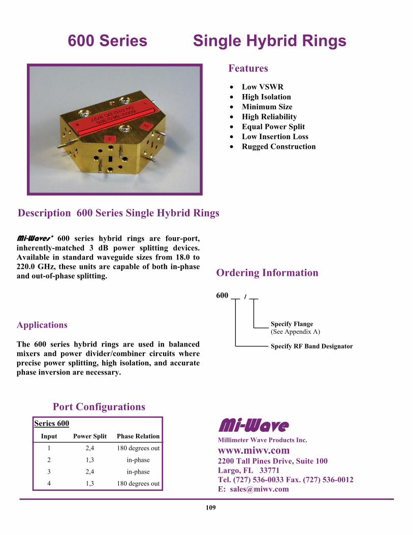
600 Series Single Hybrid Rings
109
• Low VSWR • High Isolation • Minimum Size • High Reliability • Equal Power Split • Low Insertion Loss • Rugged Construction
Features
Mi-Waves’ 600 series hybrid rings are four-port, inherently-matched 3 dB power splitting devices. Available in standard waveguide sizes from 18.0 to 220.0 GHz, these units are capable of both in-phase and out-of-phase splitting. Applications The 600 series hybrid rings are used in balanced mixers and power divider/combiner circuits where precise power splitting, high isolation, and accurate phase inversion are necessary.
Description 600 Series Single Hybrid Rings
Port Configurations
Input Power Split Phase Relation
1 2,4 180 degrees out
2 1,3 in-phase
3 2,4 in-phase
4 1,3 180 degrees out
Series 600
Ordering Information
600
Specify RF Band Designator
Specify Flange (See Appendix A)
Mi-Wave Millimeter Wave Products Inc.
www.miwv.com 2200 Tall Pines Drive, Suite 100 Largo, FL 33771 Tel. (727) 536-0033 Fax. (727) 536-0012 E: [email protected]

600 Series Single Hybrid Rings Technical Specifications Model Number 600K 600A 600B 600U 600V 600E 600W 600F 600D 600G
Frequency Band (GHz)
18.0- 26.5
26.5- 40.0
33.0- 50.0
40.0- 60.0
50.0- 75.0
60.0- 90.0
75.0- 110.0
90.0- 140.0
110.0- 170.0
140.0- 220.0
Isolation (dB) Max. 20 20 20 20 20 20 20 20 20 20
Insertion Loss (dB) Max.
0.5 0.5 0.5 0.5 0.5 0.5 0.7 0.7 0.8 0.8
Power Imbalance Max. (dB)
0.5 0.5 0.5 0.5 0.5 0.5 0.5 0.5 0.5 0.5
VSWR Max. 1.25 1.25 1.25 1.25 1.25 1.25 1.25 1.25 1.25 1.30
Bandwidth (%) 5 5 5 5 5 5 5 5 5 4
Weight (oz) 22 22 22 22 9.0 9.0 9.0 2.5 2.5 2.5
Dimensional Specifications Model A B C D
Number in mm in mm in mm in mm
600K 2.50 63.5 1.14 28.9 0.57 14.5 0.63 16.0
600A 2.38 60.9 1.25 31.7 0.63 16.0 0.63 16.0
600B 2.38 60.9 1.25 31.7 0.65 16.5 0.63 16.0
600U 2.34 59.4 1.12 28.4 0.55 14.0 0.57 14.5
600V 1.90 48.3 0.76 19.3 0.38 9.6 0.46 11.7
600E 1.90 48.3 0.76 19.3 0.38 9.6 0.46 11.7
600W 1.90 48.3 0.76 19.3 0.38 9.6 0.46 11.7
600F, D, G On Request
A
4
3 2 60º Typ.
1
D
C
B
110
Mi-Wave Millimeter Wave Products, Inc. www.miwv.com Tel. (727) 536-0033 Fax. (727) 536-0012 E: [email protected]

605 Series 3dB Short Slot Hybrids
111
• Small • Compact • Negligible Coupling Variation
Features
Mi-Waves’ 605 series short slot hybrid is a narrow wall 3 dB coupler, available in standard wave-guide sizes from 18.0 to 110.0 GHz. This compact, four-port device is inherently matched and well-suited for balanced mixers and power splitting circuits. There is a 90 degree phase difference between the output signals, while the fourth port is isolated from the input. Access to the input and output ports of these hybrids is achieved with a special dual-waveguide, single-flange arrangement. Applications The 605 series short slot hybrids are compact 3 dB couplers that can be used in waveguide bridge circuits, balanced mixers, phase shifters, and power splitters where space is limited.
Description 605 Series Short Slot Hybrids
Ordering Information
605
Specify RF Band Designator
Mi-Wave Millimeter Wave Products Inc.
www.miwv.com 2200 Tall Pines Drive, Suite 100 Largo, FL 33771 Tel. (727) 536-0033 Fax. (727) 536-0012 E: [email protected]
605 Series 3dB Short Slot Hybrids
Model Number
605Ku
605K
605A
605B
605U
605V
605E
605W
Coupling (dB) 3 3 3 3 3 3 3 3
VSWR Max. 1.15 1.15 1.15 1.15 1.15 1.15 1.15 1.15
Isolation (dB) Min. 20 20 20 20 20 20 20 18
Bandwidth (%) 6 6 6 6 6 6 6 6
Model Number
A in mm
B in mm
C in mm
605K 3.75 95.3 2.47 62.7 1.12 28.5 1.38 35.1
605A 3.50 88.9 2.47 62.7 1.12 28.5 1.38 35.1
605B 2.60 66.0 2.37 60.2 1.14 29.0 1.18 30.2
605U 2.60 66.0 2.37 60.2 1.14 29.0 1.18 30.2
605V 1.75 44.5 1.75 44.5 1.0 25.4 0.90 22.86
605E 1.75 44.5 1.75 44.5 1.0 25.4 0.90 22.86
605W 1.75 44.5 1.75 44.5 1.0 25.4 0.90 22.86
D in mm
Dimensional Specifications
Technical Specifications
C
D B
A
112
Mi-Wave Millimeter Wave Products, Inc. www.miwv.com Tel. (727) 536-0033 Fax. (727) 536-0012 E: [email protected]

610 Series Triple Hybrid Rings
113
• Low VSWR • High Isolation • Minimum Size • High Reliability • Equal Power Split • Low Insertion Loss • Rugged Construction
Features
Mi-Waves’ 610 series triple hybrid rings consist of three single hybrid rings integrated into one compact component. This device provides four 6 dB outputs for use in dual balanced mixers and power divider/combiner circuits. Applications The 610 series hybrid rings are used in balanced mixers and power divider/combiner circuits where precise power splitting, high isolation, and accurate phase inversion are necessary.
Description 610 Series Triple Hybrid Rings
Port Configurations
Input Output Phase Relation
“input” 1,2 in-phase
5,6 in-phase
3,4 isolated
Series 610
Please Note: Outputs 1, 2 are 180 degrees out of phase with ouptuts 5, 6.
Ordering Information
610
Specify RF Band Designator
Specify Flange (See Appendix A)
Mi-Wave
Mi-Wave Millimeter Wave Products Inc.
www.miwv.com 2200 Tall Pines Drive, Suite 100 Largo, FL 33771 Tel. (727) 536-0033 Fax. (727) 536-0012 E: [email protected]

610 Series Triple Hybrid Rings Technical Specifications Model Number 610K 610A 610B 610U 610V 610E 610W 610F 610D 610G
Isolation (dB) Max. 20 20 20 20 20 20 20 20 20 20
Insertion Loss (dB) Max. 0.5 0.5 0.5 0.5 0.5 0.5 0.7 0.7 0.8 0.8
Power Imbalance Max. (dB)
0.5
0.5
0.5
0.5
0.5
0.5
0.5
0.5
0.5
0.5
VSWR Max. 1.25 1.25 1.25 1.25 1.25 1.25 1.25 1.25 1.25 1.30
Bandwidth (%) 5 5 5 5 5 5 5 5 5 4
Dimensional Specifications Model A B C D
Number in mm in mm in mm in mm
610K
610A 4.53 115.0 0.76 19.3 2.30 58.4 0.38 9.65
610B 4.98 126.0 1.12 28.6 2.59 65.9 0.56 14.22
610U 4.98 126.0 1.12 28.6 2.59 65.9 0.56 14.22
610V 3.48 88.4 0.76 19.3 1.91 48.5 0.38 9.65
610E 3.48 88.4 0.76 19.3 1.91 48.5 0.38 9.65
610W 3.48 88.4 0.76 19.3 1.91 48.5 0.38 9.65
610F, D, G On Request
2
4
6
1
3
5
INPUT 60º Typ.
A
C
D
B
Consult Factory
114
Mi-Wave Millimeter Wave Products, Inc. www.miwv.com Tel. (727) 536-0033 Fax. (727) 536-0012 E: [email protected]

620 Series E/H Plane Tuners
115
• Micrometer Driven • Non-Contacting Choke-Type
Short Circuits
Features
Mi-Waves’ 620 series E/H plane tuners are hybrid tee section available in standard waveguide sizes for operation from 12.4 to 220 GHz. The devices feature micrometer-driven tunable shorts in both the E-plane and H-plane arms for accurate tuning and reproducible settings. The internal short circuits are non-contacting, choke-type plungers that provide a highly stable electrical short. Locking devices ensure continued setting reliability under all normal conditions of test bench shock and vibration. The shorts travel a minimum of one-half wavelength at the lowest frequency. Applications The 620 series tuners are excellent millimeter wave impedance matching networks designed to provide the reliable mismatch control required in most experimental and developmental test applications. These tuners introduce discontinuities into the waveguide transmission line for simultaneous control of both phase and amplitude of the RF reflection coefficient. They can be used as matching devices to cancel reflections in transmission lines or to match detectors, terminations, and similar components.
Description 620 Series E/H Plane Tuners
Ordering Information
620
Specify RF Band Designator
Specify Flange (See Appendix A)
Mi-Wave Millimeter Wave Products Inc.
www.miwv.com 2200 Tall Pines Drive, Suite 100 Largo, FL 33771 Tel. (727) 536-0033 Fax. (727) 536-0012 E: [email protected]

620 Series E/H Plane Tuners
Dimensional Specifications Model A Weight
Number in mm in mm (oz)
620Ku 2.50 63.5 5.78 146.81 12 620K 2.50 63.5 4.86 123.44 10
620A 2.50 63.5 2.95 74.93 9.5
620B 2.50 63.5 2.92 74.17 9.0
620U 2.50 63.5 2.90 73.66 7.0
620V 2.00 50.8 2.28 57.91 3.5
620E 2.00 50.8 2.26 57.40 2.0
620W 2.00 50.8 2.25 57.15 2.0
620F 1.50 38.1 2.12 53.8 1.5
620D 1.50 38.1 2.12 53.8 1.5
620G 1.50 38.1 2.12 53.8 1.3
B
A
B
B
116
Mi-Wave Millimeter Wave Products, Inc. www.miwv.com Tel. (727) 536-0033 Fax. (727) 536-0012 E: [email protected]

630 / 635 Series Magic & Hybrid Tees
117
• Equal Power Division • Available from 12.4 to 220 GHz • High Isolation Provided by
Symmetrical Construction
Features
Mi-Waves’ 630 series E/H hybrid tees consist of three mutually perpendicular flanged sections of a standard waveguide. Two of these sections are symmetrically located on the broad and narrow walls of the main tee section to provide E-plane and H-plane connections. The internal geometry of these hybrids provides a power-dividing and phase-inverting characteristic. Power applied to the shunt H-plane arm is divided between the tow in-line ports of the main tee section to result in equal power, in-phase output signals. Power applied to the series E-plane arm is also divided between these two ports, but with a phase reversal which provides equal-power, opposite-phase outputs. With symmetrical construction, good isolation is maintained between the E-plane and H-plane arms. The 630 series hybrid tees are available in standard wave-guide sizes from 12.4 to 220 GHz. Applications The 630 series hybrid tees are four-port transmission line components designed for basic power-splitting and mixing applications. These devices are useful as integral parts of RF bridge circuits for routine impedance comparisons and reflection coefficient measurements or as power dividers and isolators in radar balanced mixer circuits. Because the series (E) and shunt (H) arms are not matched, these units are not suited for low VSWR applications. For these applications, Mi-Wave recommends the 600 series and 605 hybrids. Also 635 Magic Tee.
Description 630 Series Hybrid Tees
Ordering Information
630
Specify RF Band Designator
Specify Flange (See Appendix A)
Mi-Wave Millimeter Wave Products Inc.
www.miwv.com 2200 Tall Pines Drive, Suite 100 Largo, FL 33771 Tel. (727) 536-0033 Fax. (727) 536-0012 E: [email protected]

630 Series Hybrid Tees
Dimensional Specifications Model A B Weight
Number in mm in mm in mm (oz)
630Ku 2.50 63.5 1.25 31.7 2.25 57.2 5.5 630K 2.50 63.5 1.25 31.7 1.63 41.4 5.5
630A 2.50 63.5 1.25 31.7 1.20 30.5 5.0
630B 2.50 63.5 1.25 31.7 1.17 29.7 4.8
630U 2.50 63.5 1.25 31.7 1.15 29.2 4.4
630V 2.00 50.8 1.00 25.4 0.85 21.6 3.4
630E 2.00 50.8 1.00 25.4 0.83 21.1 3.2
630W 2.00 50.8 1.00 25.4 0.82 20.8 3.0
630F 1.50 38.1 0.75 19.1 0.56 14.2 2.2
630D 1.50 38.1 0.75 19.1 0.55 14.0 1.6
630G 1.50 38.1 0.75 19.1 0.54 13.7 1.5
C
B A
C
C
118
Mi-Wave Millimeter Wave Products, Inc. www.miwv.com Tel. (727) 536-0033 Fax. (727) 536-0012 E: [email protected]

640 E-Plane Series & 650 H-Plane Series Tees
119
• Unmatched Ports • Geometrical Symmetry • Available from 12.4 to 220 GHz • Equal Power Division Between
the Two Outputs
Features
Mi-Waves’ 640 series E-plane tees consist of a length of standard flanged waveguide with a perpendicular E-plane coupling arm symmetrically located on the broad waveguide wall. Input power is divided equally and in opposite phase between the two outputs. Similarly, the 650 series H-plane tees feature an H-plane coupling arm located on the narrow waveguide wall. Power at the coupling arm input is divided into equal signals in phase at the main outputs. These devices are available in standard waveguide sizes from 12.4 to 220 GHz. Neither the 640 series or the 650 series tees have matched junctions and therefore are not recommended for low VSWR applications.
Description 640 and 650 Series Tees
Ordering Information
640
Specify RF Band Designator
Specify Flange (See Appendix A)
650
Specify RF Band Designator
Specify Flange (See Appendix A)
Mi-Wave Millimeter Wave Products Inc.
www.miwv.com 2200 Tall Pines Drive, Suite 100 Largo, FL 33771 Tel. (727) 536-0033 Fax. (727) 536-0012 E: [email protected]

640 E-Plane Series & 650 H-Plane Series Tees
Dimensional Specifications
Model A Weight
Number in mm in mm (oz)
640Ku 2.50 63.50 1.25 31.75 3.7
640K 2.40 60.96 1.20 30.48 3.7
640A 2.40 60.96 1.20 30.48 3.7
640B 2.40 60.96 1.20 30.48 3.4
640U 2.40 60.96 1.20 30.48 3.2
640V 2.00 50.80 1.00 25.40 2.6
640E 2.00 50.80 1.00 25.40 2.4
640W 2.00 50.80 1.00 25.40 2.3
640F 1.50 38.10 0.75 19.05 1.7
640D 1.50 38.10 0.75 19.05 1.3
640G 1.50 38.10 0.75 19.05 1.3
B Model A Weight
Number in mm in mm (oz)
650Ku 2.50 63.50 1.25 31.75 3.7
650K 2.40 60.96 1.20 30.48 3.7
640A 2.40 60.96 1.20 30.48 3.7
650B 2.40 60.96 1.20 30.48 3.4
650U 2.40 60.96 1.20 30.48 3.2
650V 2.40 60.96 1.00 25.40 2.6
650E 2.00 50.80 1.00 25.40 2.4
650W 2.00 50.80 1.00 25.40 2.3
650F 1.50 38.10 0.75 19.05 1.7
640D 1.50 38.10 0.75 19.05 1.3
650G 1.50 38.10 0.75 19.05 1.3
B
640 E-Plane 650 H-Plane
B
MPI
B
A
B
A B
640
650
118
120
Mi-Wave Millimeter Wave Products, Inc. www.miwv.com Tel. (727) 536-0033 Fax. (727) 536-0012 E: [email protected]

660, 661, 662, & 665 Series E-Plane Bends
121
• Available from 12.4 to 220 GHz • Additional Radius and Angle Bends
by Special Order • Smooth Precision Bends Minimize
Energy Reflections
Features
Mi-Waves’ 660, 661, 662 and 665 series E-plane bends are sections of high-precision waveguide accurately shaped to either 30º (661), 45º (665), 60º (662), or 90º (660) bends. Special angles, radii, and configurations for particular application can be developed on special order. All E-plane series bends are available from 12.4 to 320 GHz. Applications The E-plane bends series provide accurate offsets and directional changes in waveguide transmission lines for test and developmental applications. Manufactured to rigid specifications, these transmission line components provide minimum detrimental effects on the overall system VSWR.
Description 660, 661, 662 & 665 Series Bends
Ordering Information
660
Specify RF Band Designator
Specify Flange (See Appendix A)
Specify Series (660, 661, 662 or 665)
Mi-Wave Millimeter Wave Products Inc.
www.miwv.com 2200 Tall Pines Drive, Suite 100 Largo, FL 33771 Tel. (727) 536-0033 Fax. (727) 536-0012 E: [email protected]

660, 661, 662, & 665 Series E-Plane Bends
Dimensional Specifications
Model Weight
Number in mm (oz)
660Ku, 661 Ku, 662Ku 2.00 50.0 2.7
660K, 661K, 662K 1.50 38.1 2.7
660A, 661A, 662A 1.50 38.1 2.5
660B, 661B, 662B 1.50 38.1 2.3
660U, 661U, 662U 1.50 38.1 2.2
660V, 661V, 662V 1.00 25.4 1.7
660E, 661E, 662E 1.00 25.4 1.6
660W, 661W, 662W 1.00 25.4 1.5
660F, 661F, 662F 1.00 25.4 1.1
660D, 661D, 662D 1.00 25.4 0.8
660G, 661G, 662G 1.00 25.4 0.8
665Ku 2.00 50.0 2.4
665K 1.50 38.1 2.4
665A 1.50 38.1 2.5
665B 1.50 38.1 2.3
665U 1.50 38.1 2.2
665V 1.00 25.4 1.7
665E 1.00 25.4 1.6
665W 1.00 25.4 1.5
665F 1.00 25.4 1.0
665D 1.00 25.4 0.8
665G 1.00 25.4 0.8
A
Model Frequency Band Band
Number (GHz) VSWR
660Ku, 661Ku, 662Ku, 665KU 665Ku
12.4 - 18.0 1.10
660K, 661K, 662K, 665K 18.0 - 26.5 1.10
660A, 661A, 662A, 665A 26.5 - 40.0 1.10
660B, 661B, 662B, 665B 33.0 - 50.0 1.10
660U, 661U, 662U, 665U 40.0 - 60.0 1.12
660V, 661V, 662V, 665V 50.0 - 75.0 1.12
660E, 661E, 662E, 665E 60.0 - 90.0 1.12
660W, 661W, 662W, 665W
75.0 - 110.0 1.15
660F, 661F, 662F, 665F 90.0 - 140.0 1.15
660D, 661D, 662D, 665D 110.0 - 170.0 1.15
660G, 661G, 662G, 665G 1.15 140.0 - 220.0
Technical Specifications
A
A
45º
A
A
660
665
660 90º
661 30º
662 60º
665 45º
122
Mi-Wave Millimeter Wave Products, Inc. www.miwv.com Tel. (727) 536-0033 Fax. (727) 536-0012 E: [email protected]

670, 671, 672, & 675 Series H-Plane Bends
123
• Available from 12.4 to 220 GHz • Additional Radius and Angle Bends
by Special Order • Smooth Precision Bends Minimize
Energy Reflections
Features
Mi-Waves’ 670, 671, 672 and 675 series H-plane bends are sections of high-precision waveguide accurately shaped to either 30º (671), 45º (675), 60º (672), or 90º (670). Special angles, radii, and configurations for particular application can be developed on special order. All H-plane bends are available from 12.4 to 320 GHz. Applications The H-plane bends series provide accurate offsets and directional changes in waveguide transmission lines for test and developmental applications. Manufactured to rigid specifications, these transmission line components provide minimum detrimental effects on the overall system VSWR.
Description 670, 671, 672 & 675 Series Bends
Ordering Information
___-___ / ___
Specify RF Band Designator
Specify Flange (See Appendix A)
Specify Series (670, 671, 672 or 675)
Mi-Wave Millimeter Wave Products Inc.
www.miwv.com 2200 Tall Pines Drive, Suite 100 Largo, FL 33771 Tel. (727) 536-0033 Fax. (727) 536-0012 E: [email protected]

670, 671, 672, & 675 Series H-Plane Bends
Model Frequency Band BBand
Number (GHz) VSWR
670Ku, 671Ku, 672Ku, 675Ku 665Ku
12.4 - 18.0 1.10
670K, 671K, 672K, 675K 18.0 - 26.5 1.10
670A, 671A, 672A, 675A 26.5 - 40.0 1.10
670B, 671B, 672B, 675B 33.0 - 50.0 1.10
670U, 671U, 672U, 675U 40.0 - 60.0 1.12
670V, 671V, 672V, 675V 50.0 - 75.0 1.12
670E, 671E, 672E, 675E 60.0 - 90.0 1.12
670W, 671W, 672W, 675W 75.0 - 110.0 1.15
670F, 671F, 672F, 675F 90.0 - 140.0 1.15
670D, 671D, 672D, 675D 110.0 - 170.0 1.15
670G, 671G, 672G, 675G 1.15 140.0 - 220.0
Technical Specifications
Dimensional Specifications Model Weight
Number in mm (oz)
670Ku, 671Ku, 672Ku 1.80 45.7 2.7
670K, 671K, 672K 1.50 38.1 2.7
670A, 671A, 672A 1.50 38.1 2.5
670B, 671B, 672B 1.50 38.1 2.3
670U, 671U, 672U 1.50 38.1 2.2
670V, 671V, 672V 1.00 25.4 1.7
670E, 671E, 672E 1.00 25.4 1.6
670W, 671W, 672W 1.00 25.4 1.5
670F, 671F, 672F 1.00 25.4 1.1
670D, 671D, 672D 1.00 25.4 0.8
670G, 671G, 672G 1.00 25.4 0.8
675Ku 1.80 45.7 2.4
675K 1.50 38.1 2.4
675A 1.50 38.1 2.5
675B 1.50 38.1 2.3
675U 1.50 38.1 2.2
675V 1.00 25.4 1.7
675E 1.00 25.4 1.6
675W 1.00 25.4 1.5
675F 1.00 25.4 1.1
675D 1.00 25.4 0.8
675G 1.00 25.4 0.8
A
670
675
A
A
660 90º
661 30º
662 60º
665 45º
45º
A
A
124
Mi-Wave Millimeter Wave Products, Inc. www.miwv.com Tel. (727) 536-0033 Fax. (727) 536-0012 E: [email protected]

680 & 681 Series 45° and 90° Twists
125
• Smooth 45º / 90º Polarization Changes for Minimum Energy Reflections
Features
Mi-Waves’ 680 series twists are short sections of standard flanged waveguide with left-hand or right-hand 45º twist configurations while the 681 series twists provide 90º twist configurations. The units are available in standard waveguide sizes from 12.4 to 320 GHz. Please be sure to specify the left-hand or right-hand configuration when ordering. Applications The 680 series and the 681 series waveguide twists are designed to provide changes in waveguide orientation with minimum energy loss and reflections. As integral parts in many of Mi-Waves’ ferrite devices, these twists efficiently adapt polarization-rotated RF fields to the orientation of the remaining transmission line components.
Description 680 and 681 Series Twists
Ordering Information
680 ___-___ / ___
Specify Twist Orientation RH: Right-Hand LH: Left-Hand
Specify Flange (See Appendix A)
Specify RF Band Designator
681 ___-___ / ___
Specify Twist Orientation RH: Right-Hand LH: Left- Hand
Specify Flange (See Appendix A)
Specify RF Band Designator
Mi-Wave Millimeter Wave Products Inc.
www.miwv.com 2200 Tall Pines Drive, Suite 100 Largo, FL 33771 Tel. (727) 536-0033 Fax. (727) 536-0012 E: [email protected]

680 & 681 Series 45° and 90° Twists
Dimensional Specifications Model Weight
Number in mm (oz)
680Ku, 681Ku 3.20 81.28 3.2 680K, 681K 2.70 68.58 2.7 680A, 681A 1.50 38.1 1.9 680B, 681B 1.50 38.1 1.9 680U, 681U 1.50 38.1 1.8 680V, 681V 1.25 31.75 1.7 680E, 681E 1.25 31.75 1.6
680W, 681W 1.25 31.75 1.6
680F, 681F 1.25 31.75 1.3
680D, 681D 1.25 31.75 1.2
680G, 681G 1.25 31.75 1.2
A Please Note: Any twist angle between 0 and 90 degrees are available. Please consult Mi-Wave for further information.
681
A
A
680
45 D
eg.
126
Mi-Wave Millimeter Wave Products, Inc. www.miwv.com Tel. (727) 536-0033 Fax. (727) 536-0012 E: [email protected]

688 Series Flange Adapters
127
• Precision Built • Available from 12.4 to 220 GHz
Features
Mi-Waves’ 688 series flange adapters are manufactured in standard waveguide sizes from 12.4 to 220 GHz. Each section is precision-machined and terminated in a variety of flange combinations. Please refer to Appendix A for a full list of available flanges. Precise control of the waveguide dimensions and elimination of surface discontinuities makes these sections useful in transmission line applications that require low waveguide loss and VSWR effects. In addition to the standard 688 series flanges, specialized flange adapters are available on request. Applications The 688 series flange adapters are used in operational millimeter wave transmission systems that require a transition between components or systems with different flanges.
Description 688 Flange Adapters
Ordering Information
688 ___-___ / ___
Specify Second Flange (See Appendix A)
Specify RF Band Designator
Specify First Flange (See Appendix A)
Mi-Wave Millimeter Wave Products Inc.
www.miwv.com 2200 Tall Pines Drive, Suite 100 Largo, FL 33771 Tel. (727) 536-0033 Fax. (727) 536-0012 E: [email protected]

688 Series Flange Adapters
Dimensional Specifications Model Flanges Weight
Number A B in mm (oz)
688Ku/419/541 UG-419/U UG-541/U 1.00 25.40 3.0 688K/595/596 UG-595/U UG-596/U 1.00 25.40 1.3 688K/595/425 UG-595/U UG-425/U 1.00 25.40 1.4 688A/381/599 UG-381/U UG-599/U 1.00 25.40 1.2 688A/381/600 UG-381/U UG-600/U 1.00 25.40 1.1 688A/599/600 UG-599/U UG-600/U 1.00 25.40 1.1 688B/383/719 UG-383/U 719 1.00 25.40 0.8
688B/383/385 UG-383/U UG-385/U 1.00 25.40 0.8
688U/383/720 UG-383/U 720 1.00 25.40 0.8
688F/714/724 714 724 0.38 9.65 0.6
688F/714/387 714 UG-387/U-M 0.75 19.05 0.6
688F/724/387 724 UG-387/U-M 0.75 19.05 0.6
688D/716/726 716 726 0.38 9.65 0.6
688D/716/387 716 UG-387/U-M 0.75 19.05 0.6
688D/726/387 726 UG-387/U-M 0.75 19.05 0.6
688G/715/725 715 725 0.38 9.65 0.6
688G/715/385 715 UG-385/U-M 0.75 19.05 0.6
C
B A
C
128
Mi-Wave Millimeter Wave Products, Inc. www.miwv.com Tel. (727) 536-0033 Fax. (727) 536-0012 E: [email protected]

690 Series Flanged Waveguide Sections
129
• Available from 12.4 to 220 GHz • Precision Fabricated to Meet
Electrical & Mechanical Specifications
Features
Mi-Waves’ 690 series flanged waveguide sections are available in standard waveguide sizes from 12.4 to 320 GHz. Each section is precisely fabricated using MIL-SPEC waveguide and flanges. Precise control of the fabrication processes eliminates waveguide discontinuities and distortion. The 690 series waveguide is available in a wide variety of materials. Available lengths are limited by raw waveguide which varies in length with each waveguide size. Check with an Mi-Wave sales engineer for available lengths. Longer sections, different wave-guide materials, and special flanges are all available upon request. Applications The 690 series straight waveguide sections with standard flanges are used in operational millimeter wave transmission systems and as basic transmission sections in test and laboratory sets.
Description 690 Waveguide Sections
Ordering Information
690 ___-___ / ___
Specify Length (In Inches)
Specify Flange (See Appendix A)
Specify RF Band Designator
Flexguide Available from 8.2 to 50 GHz Consult Mi-Wave for Lengths, Mate-rials and Jacketing.
Mi-Wave Millimeter Wave Products Inc.
www.miwv.com 2200 Tall Pines Drive, Suite 100 Largo, FL 33771 Tel. (727) 536-0033 Fax. (727) 536-0012 E: [email protected]

690 Series Flanged Waveguide Sections
Dimensional Specifications Model
Number in mm
690Ku 0.622 x 0.311 15.80 x 7.90
690K 0.420 x 0.170 10.66 x 5.33
690A 0.280 x 0.140 7.12 x 3.56
690B 0.224 x 0.112 5.68 x 2.84
690U 0.188 x 0.094 4.78 x 2.39
690V 0.148 x 0.074 3.76 x 1.88
690E 0.122 x 0.061 3.10 x 1.55
690W 0.100 x 0.050 2.54 x 1.27
690F 0.080 x 0.040 2.04 x 1.02
690D 0.065 x 0.0325 1.65 x .8255
690G 0.051 x 0.0255 1.30 x 0.650
Inside Dimensions
Mi-Wave
690B
690A
130
Mi-Wave Millimeter Wave Products, Inc. www.miwv.com Tel. (727) 536-0033 Fax. (727) 536-0012 E: [email protected]

691 Series Unflanged Waveguides
131
• Precise Fabrication
Features
Mi-Waves’ 691 series unflanged waveguide is manufactured to precise specifications in accordance with MIL-W-85. It is available in various maximum lengths and optional materials. Typically, larger waveguide sizes are manufactured in larger lengths than the smaller sizes. Please consult Mi-Wave for maximum available lengths.
Description 691 Unflanged Waveguides
Ordering Information
691 ___-___ / ___
Specify Material Designator
Specify Length (In Inches)
Specify RF Band Designator Material
Designation
Material
CS Coin Silver
SS Stainless Steel (0.010” wall thickness)
OFC Oxygen Free Copper
BR Bronze
AL Aluminum
Please Note: Other Materials available upon request.
Mi-Wave Millimeter Wave Products Inc.
www.miwv.com 2200 Tall Pines Drive, Suite 100 Largo, FL 33771 Tel. (727) 536-0033 Fax. (727) 536-0012 E: [email protected]

M
i-Wav
e B
and
W
aveg
uide
D
esig
nato
r(s)
(J
AN
& W
R)
W
aveg
uide
In
ner
Dim
ensi
ons
in In
ches
Rec
omm
ende
d O
pera
ting
Ran
ge fo
r T
E10
Mod
e
Freq
uenc
y
W
avel
engt
h (G
Hz)
(m
m)
The
oret
ical
Po
wer
CW
B
reak
dow
n
Low
est t
o
Hig
hest
Fr
eque
ncy
(KW
)
T
heor
etic
al
Att
enua
tion
Low
est t
o H
ighe
st
Freq
uenc
y (d
B/ff
)
Fl
ange
T
ype
H
isto
ric
Des
igna
tion
N
ew M
IL
Part
Num
ber
KU
R
G-9
1/U
W
R-6
2 0.
622
x 0.
311
12.4
- 18
.0
24.2
- 16
.6
9.48
6 31
.60
400
- 600
.0
64 -
.030
C
over
1 C
hoke
U
G-4
19/U
U
G-5
41/U
M
3922
/53-
4/00
5 M
3922
/59-
2/00
1
K
RG
-53/
U
WR
-42
0.42
0 x
0.17
0 18
.0 -
26.5
16
.6 -
11.3
14
.047
21
.34
160
- 240
.1
7 - .
11
Cov
er1
Cho
ke
Cov
er
UG
-595
/U
UG
-596
A/U
U
G-4
25/U
M39
22/5
4-4/
001
M39
22/5
9-2/
003
M39
22/6
7-2/
004
A
RG
-96/
U
WR
-28
0.28
0 x
0.14
0 26
.5 -
40.0
11
.3 -
7.5
21.0
81
14.2
2 95
- 14
5 0.
22 -
0.15
C
over
1 C
hoke
C
over
UG
-599
/U
UG
-600
/U
UG
-381
/U
M39
22/5
4-4/
003
M39
22/5
9-2/
005
M39
22/6
7-2/
005
B
RG
-97/
U
WR
-22
0.22
4 x
0.11
2 33
.0 -
50.0
9.
1 - 6
.0
26.3
42
11.3
8 62
- 90
0.
31 -
0.21
C
over
1 C
over
C
over
UG
-383
/U
719
7
19T
M39
22/6
7-2/
006
N/A
N
/A
U
WR
-19
0.18
8 x
0.09
4 40
.0 -
60.0
7.
5 - 5
.0
31.3
57
9.56
47
- 64
0.
39 -
0.27
C
over
12
Cov
er
Cov
er
UG
-383
/U-M
71
0 7
20T
M39
22/6
7-2/
007
N/A
N
/A
V
RG
-98/
U
WR
-15
0.14
8 x
0.07
4 50
.0 -
75.0
6.
0 - 4
.0
39.8
63
7.52
29
- 42
0.
57 -
0.39
C
over
1 U
G-3
85/U
M
3922
/67-
2/00
8
E
RG
-99/
U
WR
-12
0.12
2 x
0.06
1 60
.0 -
90.0
5.
0 - 3
.3
48.3
50
6.20
20
- 29
0.
78 -
0.53
C
over
1 U
G-3
87/U
M
3922
/67-
2/00
9
W
WR
-10
0.10
0 x
0.05
0 75
.0 -
110.
0 4.
0 - 2
.7
59.0
10
5.08
14
- 20
1.
02 -
0.71
C
over
12
UG
-387
/U-M
M39
22/6
7-2/
010
F R
G-1
38/U
W
R-8
0.
080
x 0.
040
90.0
- 14
0.0
3.3
- 2.1
73
.764
4.
06
8.5
- 13.
5 1.
52 -
0.98
P
in1
Cov
er2
714
U
G-3
87/U
-M
M39
22/7
4-00
1 N
/A
D
RG
-136
/U
WR
-7
0.06
5 x
0.03
25
110.
0 - 1
70.0
2.
7 - 1
.8
90.7
86
3.30
5.
8 - 9
.0
2.12
- 1.
35
Pin
1 C
over
2 7
16
UG
-387
/U-M
M
3922
/74-
002
N/A
G
RG
-135
/U
WR
-5
0.05
1 x
0.02
55
140.
0 - 2
20.0
2.
1 - 1
.4
115.
71
2.59
3.
7 - 6
.1
3.05
- 1.
93
Pin
1
Cov
er2
715
U
G-3
87/U
-M
M39
22/7
4-00
3 N
/A
Cut
-Off
fo
r T
E10
Mod
e
Freq
uenc
y
W
avel
engt
h (G
Hz)
(m
m)
1. S
tand
ard
flang
e un
less
oth
erw
ise
spec
ified
. 2.
Mod
ified
(-M
) mea
ns w
aveg
uide
ope
ning
has
bee
n re
duce
d ap
prop
riate
ly.
Scre
w a
nd p
in p
atte
rn a
re u
ncha
nged
.
Rectangular Waveguides
132

692 Series Tapered Transitions
133
• Low Loss • Minimum Reflections • Precise Fabricated Tapers • Shortest Possible Insertion Length
Consistent with High Mode Purity
Features
Mi-Waves’ 692 series tapered transitions are precision tapers with standard flanges for two different waveguide sizes. In each transition, the fabrication process allows precise control of taper dimensions to provide a good impedance match. As a result, high mode purity is maintained in the transfer process with minimum VSWR effects and energy loss. These transitions are available in many waveguide size combinations from 12.4 to 220 GHz. In addition to the standard configurations listed in this section, many special transitions will be developed upon request.
Description 692 Tapered Transitions
Ordering Information
692 ___-___/___/___
Specify Output RF Band Designator
Specify Input Flange (See Appendix A)
Specify Input RF Band Designator
Specify Output Flange (See Appendix A)
Mi-Wave Millimeter Wave Products Inc.
www.miwv.com 2200 Tall Pines Drive, Suite 100 Largo, FL 33771 Tel. (727) 536-0033 Fax. (727) 536-0012 E: [email protected]

692 Series Tapered Transitions
Specifications Model Number
Input Waveguide Dimension (in.)
Output Waveguide Dimension (in.)
VSWR Max.
692K-A 0.422 X 0.170 0.2280 X 0.140 1.10 2.10 53.3
692A-B 0.280 X 0.140 0.224 X 0.112 1.10 2.00 50.8
692A-U 0.280 X 0.140 0.188 X 0.094 1.10 2.00 50.8
692A-V 0.280 X 0.140 0.148 X 0.074 1.10 2.00 50.8
692B-U 0.224 X 0.112 0.188 X 0.094 1.10 2.00 50.8
692B-V 0.224 X 0.112 0.148 X 0.074 1.10 2.00 50.8
692B-E 0.224 X 0.112 0.122 X 0.061 1.10 2.00 50.8
692B-W 0.224 X 0.112 0.100 X 0.050 1.10 2.00 50.8
692U-V 0.188 X 0.094 0.148 X 0.074 1.10 1.50 38.1
692U-E 0.188 X 0.094 0.122 X 0.061 1.10 1.50 38.1
692U-W 0.188 X 0.094 0.100 X 0.050 1.10 1.50 38.1
692V-E 0.148 X 0.074 0.122 X 0.061 1.10 1.50 38.1
692V-W 0.148 X 0.074 0.100 X 0.050 1.10 1.50 38.1
692V-F 0.148 X 0.074 0.080 X 0.040 1.10 1.50 38.1
692V-D 0.148 X 0.074 0.065 X 0.0325 1.15 1.50 38.1
692V-G 0.148 X 0.074 0.051 X 0.0255 1.15 1.50 38.1
692E-W 0.122 X 0.061 0.100 X 0.050 1.10 1.00 25.4
692E-F 0.122 X 0.061 0.080 X 0.040 1.10 1.00 25.4
692E-D 0.122 X 0.061 0.065 X 0.0325 1.15 1.00 25.4
692E-G 0.122 X 0.061 0.051 X 0.0255 1.15 1.00 25.4
692W-F 0.100 X 0.050 0.080 X 0.040 1.10 1.00 25.4
692W-D 0.100 X 0.050 0.065 X 0.0325 1.15 1.00 25.4
692W-G 0.100 X 0.050 0.051 X 0.0255 1.15 1.00 25.4
692F-D 0.080 X 0.040 0.065 X 0.0325 1.15 1.00 25.4
692F-G 0.080 X 0.040 0.051 X 0.0255 1.15 1.00 25.4
692D-G 0.065 X 0.0325 0.051 X 0.0255 1.15 1.00 25.4
A in mm
A
134
Mi-Wave Millimeter Wave Products, Inc. www.miwv.com Tel. (727) 536-0033 Fax. (727) 536-0012 E: [email protected]

695 Series Waveguide Stands
135
• Clamp Rigidly Secures Waveguide with Single Thumbscrew
• Adjusts to Fit all Millimeter Waveguides Mounted in Either Polarization
Features
Mi-Waves’ 695 series waveguide stand consists of an adjustable clamp mounted on an “adjustable height” rugged base stand. The unique waveguide clamp may be readily adjusted to fit the clamping jaws to particular waveguide sizes or orientations. The cast stand has a large base area to prevent moving or tipping under normal test bench conditions. For further stability, the base may be secured to the bench with mounting bolts. Applications The 695 series waveguide stand is used to support millimeter wave components in laboratory test bench setups. Designed to fit all standard waveguide sizes from 18.0 to 220 GHz, this versatile device may be easily adjusted for a wide variety of setup conditions.
Description 695 Waveguide Stands
300 (76.2) DIA.
2.00 (50.8) 3.15 (80.0)
0-.625 (15.9)
Mi-Wave Millimeter Wave Products Inc.
www.miwv.com 2200 Tall Pines Drive, Suite 100 Largo, FL 33771 Tel. (727) 536-0033 Fax. (727) 536-0012 E: [email protected]

700 Series Precision Drill Jigs
136
• Hardened Steel Provides Continued Accurate Drilling Alignment
• Tapered Locating Tab Uses Waveguide Surfaces as Location Reference to Ensure a Perfect Mate
Features
Each of Mi-Wave’s 700 series drill jigs consists of a solid steel block with accurately positioned drill holes and a tapered locating tab that will locate the drill holes in precise relation to the internal waveguide surfaces. Hardened steel minimizes wear to ensure drilling accuracy. Applications The 700 series precision drill jigs are designed to facilitate accurate fabrication of flanged waveguide sections for standard waveguide sizes from 26.5 to 220 GHz. These jigs are used to locate alignment pins, mating pin holes, and connecting screw holes in the waveguide flanges. By using the interior waveguide surface as the primary location reference, they ensure accurate waveguide alignment at each flanged junction with low loss and
Description 700 Series Drill Jigs
Model A
Number in mm in mm
700A 1.38 35.05 0.62 15.75
700B 1.38 35.05 0.62 15.75
700U 1.38 35.05 0.62 15.75
700V 1.00 25.4 0.62 15.75
700E 1.00 25.4 0.62 15.75
700W 1.00 25.4 0.62 15.75
700F 0.75 19.05 0.51 12.95
700D 0.75 19.05 0.51 12.95
700G 0.75 19.05 0.51 12.95
B
Dimensional Specifications
A
B
Ordering Information
700
Specify RF Band Designator
Specify Flange (See Appendix A)
Mi-Wave Millimeter Wave Products Inc.
www.miwv.com 2200 Tall Pines Drive, Suite 100 Largo, FL 33771 Tel. (727) 536-0033 Fax. (727) 536-0012 E: [email protected]

705 Series Pressurizing Units
137
• System Pressure Continuously Monitored
• Convenient Means for Pressurizing Waveguide Transmission Lines
Features
Each of Mi-Wave 705 series pressurizing units consists of a short length of flanged, rectangular waveguide fitted with a Schrader valve and optional pressure gauge. These units are available in all standard wave-guide sizes from 12.4 to 220 GHz. In A-band, the choke-to-cover flange combination makes allowances for the insertion of a standard O-ring gasket to ensure maintenance of pressurization over operation. Provision is made for gaskets in the case of the round flanges used for millimeter wave frequencies. Applications The 705 series pressurizing units are designed for applications such as high power radar systems that require a pressurized transmission line to prevent arcing during peak power operation. The pressurizing units can also be used to purge systems with dry gasses in order to prevent condensation. These devices provide a simple means for introducing the desired pressurizing gas into the system and for continuous monitoring of the internal pressure level.
Description 705 Series Pressurizing Units
Model
Number in mm 705A 2.64 67.06 705B 2.62 66.55 705U 2.61 66.29
705V 2.60 66.04 705E 2.60 66.04
705W 2.59 65.79
705F 2.58 65.53
705D 2.58 66.53
705G 2.57 65.28
A
Dimensional Specifications
20
25
30
15
10
0
5
PSI
A
Specify Flange (See Appendix A)
Ordering Information
705
Specify RF Band Designator
Shown with optional pressure guage Mi-Wave
Millimeter Wave Products Inc.
www.miwv.com 2200 Tall Pines Drive, Suite 100 Largo, FL 33771 Tel. (727) 536-0033 Fax. (727) 536-0012 E: [email protected]

712 Series Bulkhead Waveguide Adapters
138
• Full Waveguide Bandwidths • O-Ring, Provided for Moisture
Resistance • Waveguide Feedthru for Panel
Mount Applications
Features
Mi-Wave 712 series waveguide bulkhead adapter was developed for panel feedthru use in systems. These 712 adapters operate over the full waveguide bands from 18.0 to 140 GHz. O-rings are provided on the panel mount for moisture resistance and a wide variety of flange types and configurations. Units come with body, two nuts and two O-rings. Standard lengths are 1.50 inches with custom lengths available upon request. Consult Mi-Wave for further details.
Description 712 Series Waveguide Adapters
Ordering Information
712
RF Band Designator (K, A, B, U, V, E, W, F)
Specify Flange (See Appendix A)
Dimensional Specifications Model No. A
in mm in mm 712K 1.75 44.45 1.00 25.4 712A 1.75 44.45 1.00 25.4 712B 1.75 44.45 1.00 25.4 712U 1.75 44.45 1.00 25.4 712V 1.125 28.57 1.00 25.4 712E 1.125 28.57 1.00 25.4 712W 1.125 28.57 1.00 25.4
B
A B
Mi-Wave Millimeter Wave Products Inc.
www.miwv.com 2200 Tall Pines Drive, Suite 100 Largo, FL 33771 Tel. (727) 536-0033 Fax. (727) 536-0012 E: [email protected]

750 Series Waveguide Flanges
139
• WR-62, 42, 28, 22, 19 • Cover and Choke Style Available • Standard UG Models • Milistar Type Available (See Appendix H For Specifications)
• WR-42, 28, 22, 19 • UG-381, 383 Style (See Appendix C For Specifications)
• WR-15, 12, 10, 8, 7, 5 • UG-385 and 387 Style (See Appendix C For Specifications)
Flange Hardware
752 Series .062 Diameter Stainless Steel Pins - Per 100 754 Series 4-40 Captivated Flange Screws - Per 100
Precision Machined Materials Brass, Aluminum, Copper
Mi-Wave Millimeter Wave Products Inc.
www.miwv.com 2200 Tall Pines Drive, Suite 100 Largo, FL 33771 Tel. (727) 536-0033 Fax. (727) 536-0012 E: [email protected]

830 Series Mechanically Tuned Gunn Oscillators
140
• Low Noise • High Stability • 12.4 to 110 GHz • Broadband Tuning • Excellent Reliability
Features
Mi-Wave 830 series mechanically tuned gunn oscillators have been designed to be used where a low noise stable frequency source is required. This source can be used for a mixer local oscillator or transmit source. The 830 series is a moderate stability gunn oscillator typically ± 750 KHz / º C with power outputs up to 300 milliwatts. Higher power options and stabilities are available upon request. Please consult Mi-Wave for further information.
Description 830 Oscillators
Applications Radar Radiometers Local Oscillators Telecommunications Model
Number Frequency
Band (GHz)
Power Output
(up to) mw
Frequency Stability MHz/Cº
Mech. Tuning Range MHz
Min.
830Ku 12.4 - 18.0 300 .300 250
830K 18.0 - 26.5 275 .500 250
830A 26.5 - 40.0 250 .750 250
830B 33.0 - 50.0 250 .800 300
830U 40.0 - 60.0 200 1.00 350
830V 50.0 - 75.0 150 2.00 500
830E 60.0 - 90.0 100 2.50 500
830W 75.0 - 110.0 50 3.00 500
Technical Specifications
Ordering Information
830
Specify Output Power
Specify Center Frequency
Specify RF Band Designator (Ku, K, A, B, U, V, E, W)
Specify Flange (See Appendix A)
Mi-Wave Millimeter Wave Products Inc.
www.miwv.com 2200 Tall Pines Drive, Suite 100 Largo, FL 33771 Tel. (727) 536-0033 Fax. (727) 536-0012 E: [email protected]

840 Series Electronically Tuned Gunn Oscillators
141
• Low Noise • High Reliability • 12.4 to 110 GHz • Electronic Tuning
Features
Applications Radar Swept Sources Telecommunication Systems
Mi-Waves’ 840 series electronically tuned gunn oscillators have been designed to be used where a frequency agile millimeter source is required. This source can be used as a modulated transmitter or local oscillator. This 840 series gunn oscillator can provide up to 500 MHz of electronic tuning with power outputs of up to 250 milliwatts. Frequency stabilities of 100 KHz / º C can be provided.
Description 840 Series Oscillators
Model No.
Frequency Band (GHz)
Power Output
(up to mw)
Electronic Tuning (MHz)
Mech. Tuning
Freq. Stability
MHz / º C
840Ku 12.4 - 18.0 250 100 250 .30
840K 18.0 - 26.5 250 125 250 .50
840A 26.5 - 40.0 200 140 250 .70
840B 33.0 - 50.0 200 175 300 .90
840U 40.0 - 60.0 150 200 300 1.10
840V 50.0 - 75.0 100 200 400 2.2
840E 60.0 - 90.0 75 225 500 2.6
840W 75.0 - 110.0 50 250 500 3.5
Technical Specifications
Ordering Information
840
Specify Output Power
Specify Center Frequency
Specify RF Band Designator (Ku, K, A, B, U, V, E, W)
Specify Flange (See Appendix A)
Mi-Wave Millimeter Wave Products Inc.
www.miwv.com 2200 Tall Pines Drive, Suite 100 Largo, FL 33771 Tel. (727) 536-0033 Fax. (727) 536-0012 E: [email protected]

900 & 905 Series Pin Diode Attenuators
142
Please specify center frequency at time of order.
* V, E, W are 50% bandwidth.
Operating Specifications Control Input................... 0 to +10 Vdc Operating Temperature... 0º C to +60º C Storage Temperature....... -55º C to +125º C VSWR............................. 1.5 Typical (Low Loss Condition)
Technical Performance
35
40
30
0
1
2
Insertion Loss (dB
) 0 V
dc
Isol
atio
n L
oss (
dB)
+ 10
Vdc
34.0 35.0 36.0
fo (GHz)
Mi-Wave 900 series PIN diode attenuator is a SPST reflective attenuator that combines low loss, high isolation performance in a compact package. Attenuation options are available for the 900 series attenuation with isolation versions up to 60 dB. These attenuators are supplied without drivers, control is typically 0 to +10 Vdc. For full band applications, the 905 series attenuation feature an excellent on/off ratio and a full bandwidth.
Applications Both series of PIN attenautors can be used for a variety of applications including wave shaping, amplitude modulation, signal switching, and receiver protection.
Description 900 & 905 Series Attenuators
• Series 900 Attenuators 10 to 60 dB - 6% Bandwidth
• Series 905 Attenuator 10 to 40 dB Full Bandwidth (K, A, B, U)
Features
Ordering Information
900
Specify Attenuation
Specify RF Band Designator (K, A, B, U, V, E, W) *
-10 dB -20 dB -30 dB -40 dB -50 dB -60 dB
905
Mi-Wave Millimeter Wave Products Inc.
www.miwv.com 2200 Tall Pines Drive, Suite 100 Largo, FL 33771 Tel. (727) 536-0033 Fax. (727) 536-0012 E: [email protected]

910 Series Pin Diode Switches
143
Mi-Waves’ 910 series PIN diode switch is a SPST reflective switch that combines low loss, high isolation performance with an integra TTL driver in a compact package. Various driver options are available and the 910 series switches are available in higher isolation versions up to 60 dB. These switches can also be supplied without drivers. For higher speed applications, the 911 series switches feature an excellent on/off ratio and a 6% bandwidth. Integral drivers are standard with various driver options available. Custom units will be quoted on request.
Applications Both series of PIN switches can be used for a variety of applications including wave shaping, duplexing,
Description 910 Series Switches
Technical Performance
35
40
30
0
1
2
Insertion Loss (dB
) L
ogic 1
Isol
atio
n L
oss (
dB)
Logi
c 0
34.0 35.0 36.0
fo (GHz)
Operating Specifications Control Input.................. TTL DC Power....................... +5/-12 Vdc with Driver................... +100/-10 mA Operating Temperature.. 0º C to +60º C Storage Temperature..... -55º C to +125º C VSWR............................ 1.5 Typical (Low Loss Condition)
• Millimeter Wave Switches with Integral TTL drivers
• Series 910 Single Throw Switches (SPST) - 6% Bandwidth (100 ns)
Features
Please specify center frequency at time of order.
Ordering Information 910
Specify Logic/Driver Option
Specify RF Band Designator (K, A, B)
Standard
High Isolation
Loss State for Logic “1”
-01 -03 Low Loss
-02 -04 Isolation
Mi-Wave Millimeter Wave Products Inc.
www.miwv.com 2200 Tall Pines Drive, Suite 100 Largo, FL 33771 Tel. (727) 536-0033 Fax. (727) 536-0012 E: [email protected]

911 Series High Speed Pin Diode Switches
144
Technical Performance
35
40
30
0
1
2
Insertion Loss (dB
) L
ogic 1
Isol
atio
n L
oss (
dB)
Log
ic 0
34.0 35.0 36.0
fo (GHz)
• Series 911 Single Throw Switches (SPST) - 6% Bandwidth
• Series 911 Single Throw Switches (SPST) - 6% Bandwidth (10 ns)
Features
Ordering Information
Please specify center frequency at time of order.
911 Specify Logic/Driver Option (-01 Standard)
Specify RF Band Designator (K, A, B)
Standard
High Isolation
Loss State for Logic “1”
-01 -03 Low Loss
-02 -04 Isolation
Operating Specifications Control Input................... TTL DC Power........................ +5/-12 Vdc with Driver.................... +100/-10 mA Operating Temperature... 0º C to +60º C Storage Temperature....... -55º C to +125º C VSWR............................. 1.5 Typical (Low Loss Condition)
Mi-wave’s 911 series PIN diode switch is a SPST reflective switch that combines low loss, high isolation performance with an integra TTL driver in a compact package. Various driver options are available and the 911 series switches are available in higher isolation versions up to 60 dB. These switches can also be supplied without drivers. For higher speed applications, the 911 series switches feature an excellent on/off ratio and a 6% bandwidth. Integral drivers are standard with various driver options available.
Applications Both series of PIN switches can be used for a variety of applications including wave shaping, duplexing, pulse modulation, signal switching, and receiver protection.
Description 911 Series Switches
Mi-Wave Millimeter Wave Products Inc.
www.miwv.com 2200 Tall Pines Drive, Suite 100 Largo, FL 33771 Tel. (727) 536-0033 Fax. (727) 536-0012 E: [email protected]

912 Series SPDT Pin Diode Switches
fo (GHz)
145
Technical Performance
25
30
20
0
3
6
Insertion Loss (dB
) L
ogic 1
Isol
atio
n L
oss (
dB)
Log
ic 0
34.0 35.0 36.0
• Series 912 Double Throw Switches (SPDT) - 6% Bandwidth
Features
Ordering Information
Please specify center frequency at time of order.
912 Specify Logic/Driver Option (-01 Standard)
Specify RF Band Designator (K, A, B)
Standard
High Isolation
Loss State for Logic “1”
-01 -03 Low Loss
-02 -04 Isolation
Operating Specifications Control Input................... TTL DC Power........................ +5/-12 Vdc with Driver.................... +100/-10 mA Operating Temperature... 0º C to +60º C Storage Temperature....... -55º C to +125º C VSWR............................. 1.5 Typical (Low Loss Condition)
Mi-Waves’ 912 series PIN diode switch is a SPDT reflective switch that combines low loss, high isolation performance with an integra TTL driver in a compact package. Various driver options are available and the 912 series switches are available in higher isolation versions up to 40 dB. These switches can also be supplied without drivers.
Applications The 912 series of PIN switches can be used for a variety of applications including wave shaping, duplexing, pulse modulation, signal switching, and receiver protection.
Description 912 Series Switches
Mi-Wave Millimeter Wave Products Inc.
www.miwv.com 2200 Tall Pines Drive, Suite 100 Largo, FL 33771 Tel. (727) 536-0033 Fax. (727) 536-0012 E: [email protected]

915 Series Full Bandwidth Pin Diode Switches
146
Mi-Wave’s 915 series SPST PIN diode switches are full waveguide band units with integral TTL drivers. Full band performance is available in K-band thru V-band and 10 GHz bandwidths are available in E-band and W-band. Fast switching and high isolation options are available and these assemblies can be tailored to customer specifications. Applications These switches can be used in pulse shaping, amplitude modulation, and receiver protection applications.
Description 915 Series Switches
Operating Specifications Control Input . . . . . . . . . . . . . . . TTL DC Power (standard unit) . . . . . . +5/-12 Vdc +10/-2 mA DC Power (fast switching) . . . . . +5/-20 Vdc +10/-2 mA CW Power (Max.) . . . . . . . . . . . 0.2 Watt Operating Temperature . . . . . . . . 0 to +60º C Storage Temperature . . . . . . . . . -55º C to +125º C VSWR . . . . . . . . . . . . . . . . . . . . 1.8 Typical (Low Loss) 3.5 Typical (Isolation)
Please specify center frequency at time of order.
• 18.0 to 110.0 GHz • Various On/Off Ratios Available • 10 GHz Bandwidths from 75 to 110
GHz • Full Waveguide Band Coverage up
to 75 GHz • Broadband SPST Diode Switches
with Integral TTL Devices
Features
Ordering Information
915 Specify Logic/Driver Option (-01 Standard)
Specify RF Band Designator (K, A, B, U, V, E, W)
Standard
High Isolation
Loss State for Logic “1”
-01 -03 Low Loss
-02 -04 Isolation
-05 No Driver
Mi-Wave Millimeter Wave Products Inc.
www.miwv.com 2200 Tall Pines Drive, Suite 100 Largo, FL 33771 Tel. (727) 536-0033 Fax. (727) 536-0012 E: [email protected]

920 Series Harmonic Mixers
147
• Full Waveguide Band Coverage • Extends the Useful Frequency
Range of Spectrum Analyzers
Features
Mi-Waves’ 920 series harmonic mixers are used to downconvert millimeter wave signals using a Schottky barrier mixer diode. Measurements can be made by mixing the harmonic of the LO with the desired RF signal and observing the resulting IF. The 920 series is designed for applications where a Diplexer is not required.
Description 920 Series Harmonic Mixers
Operating Specifications RF Input Power.................... +15 dBm, Max. LO Input Power.................... +18 dBm, Max. Storage Temperature............ -55º C to +125º C Operating Temperature........ 0º C to +60º C Bias Requirements: Diode........................... -0.7 Vdc @ 5 mA
Optional IF amplifiers are available. Please consult Mi-Wave for further information.
Ordering Information
920
Specify RF Frequency Designator (A, B, U, V, E, W, F)
IF Band Designator 02: 10-110 MHz 05: 100-600 MHz 09: 100-1000 MHz 10: 1000-2000 MHz
LO Band Designator S: 2-4 GHz C: 4-8 GHz X: 8-12 GHz Ku: 12-18 GHz
(Without Diplexer)
Mi-Wave Millimeter Wave Products Inc.
www.miwv.com 2200 Tall Pines Drive, Suite 100 Largo, FL 33771 Tel. (727) 536-0033 Fax. (727) 536-0012 E: [email protected]

920 Series Harmonic Mixers
Nominal Conversion Loss vs. Harmonic Number and RF Band
2 4 6 8 10 12 14 16 18 20
E-Band
45 40 35 30 25 20 15
Harmonic Number
Con
vers
ion
Los
s (dB
)
Ka-Band
V-Band
W-Band
G-Band
U-Band B-Band
F-Band
Technical Specifications Standard Mixer
Frequency Band (GHz)
Waveguide
Flange
LO Band
SSB Conversion Loss (dB)
920K 26.5 - 40.0 WR - 28 UG - 599 18
920A 33.0 - 50.0 WR - 22 UG - 383 20
920B 40.0 - 60.0 WR - 19 UG - 383M 22
920U 50.0 - 75.0 WR - 15 UG - 385 8.0 - 12.0 GHz 24
920V 60.0 - 90.0 WR - 12 UG - 387 27
920E 75.0 - 110.0 WR - 10 UG - 387M 30
920W 90.0 - 140.0 WR - 8 UG - 387M 40
148
Mi-Wave Millimeter Wave Products, Inc. www.miwv.com Tel. (727) 536-0033 Fax. (727) 536-0012 E: [email protected]

922 Series Harmonic Mixers
149
• Full Waveguide Band Coverage • Available With or Without IF
Amplifier • Extends the Useful Frequency
Range of Spectrum Analyzers
Features
Mi-Waves’ 922 series harmonic mixers are used to downconvert millimeter wave signals using a Schottky barrier mixer diode and a Diplexer circuit to separate the local oscillator, and IF paths. Measurements can be made by mixing the harmonic of the LO with the desired RF signal and observing the resulting IF. Designed for use with spectrum analyzers such as the HP 8566B and the HP 8569B, the 922 series harmonic mixers are used to extend the operating range of spectrum analyzers and other commercial test equipment. The mixers feature separate LO output and IF input ports with a standard triplexer circuit. The units can also be supplied with an optional 30 dB IF amplifier. For applications where a Diplexer is not required, please order 920 series harmonic mixers.
Description 922 Series Harmonic Mixers
Operating Specifications RF Input Power...................... +15 dBm, Max. LO Input Power..................... +18 dBm, Max. Storage Temperature............. -55º C to +125º C Operating Temperature......... º C to +60º C Bias Requirements: Diode....................... -0.7 Vdc @ 5 mA Amplifier................. +15 Vdc @ 60 mA
922
Ordering Information
Bias Designator N: Negative (STD) P: Positive (When Required)
Specify RF Frequency Designator (A, B, U, V, E, W, F)
Optional IF amplifiers are available. Please consult Mi-Wave for further information.
Amplifier Option A: 30 dB IF Amplifier H: Without Amplifier
IF Band Designator 02: 10-110 MHz 05: 100-600 MHz 09: 100-1000 MHz 10: 1000-2000 MHz
LO Band Designator S: 2-4 GHz C: 4-8 GHz X: 8-12 GHz Ku: 12-18 GHz
Mi-Wave Millimeter Wave Products Inc.
www.miwv.com 2200 Tall Pines Drive, Suite 100 Largo, FL 33771 Tel. (727) 536-0033 Fax. (727) 536-0012 E: [email protected]

922 Series Harmonic Mixers
Technical Specifications
Nominal Conversion Loss vs. Harmonic Number and RF Band
2 4 6 8 10 12 14 16 18 20
E-Band
45 40 35 30 25 20 15
Harmonic Number
Con
vers
ion
Los
s (dB
)
Ka-Band
V-Band
W-Band
G-Band
U-Band
F-Band
Standard Mixer
Frequency Band (GHz)
Waveguide
Flange
LO Band
SSB Conversion Loss (dB)
922K 26.5 - 40.0 WR - 28 UG - 599 18
922A 33.0 - 50.0 WR - 22 UG - 383 20
922B 40.0 - 60.0 WR - 19 UG - 383M 22
922U 50.0 - 75.0 WR - 15 UG - 385 8.0 - 12.0 GHz 24
922V 60.0 - 90.0 WR - 12 UG - 387 27
922E 75.0 - 110.0 WR - 10 UG - 387M 30
922W 90.0 - 140.0 WR - 8 UG - 387M 40
150
Mi-Wave Millimeter Wave Products, Inc. www.miwv.com Tel. (727) 536-0033 Fax. (727) 536-0012 E: [email protected]

932, 933, 934, 936 Series High-Power Multipliers
151
• Operation to 150 GHz • High Efficiency (to 40 Percent) • X2, X3, X4, X6, X9 Multiplication • 1 Percent to 5 Percent Bandwidths
Features
Mi-Waves’ 932 series frequency multipliers offer high power, high efficiency designs that can be used to generate millimeter wave frequencies from lower frequency microwave sources. GaAs varactor diodes mounted in high-Q housings provide for minimal circuit losses and optimal harmonic generation. An SMA female input connector is available up to an input frequency of 40 GHz. X2, X3, and most X4 multipliers use only a single multiplier stage. In a two-stage X4, X6, or X9 multiplier, an interstage isolator is provided. The 932 series multipliers are designed for input power levels from 30 mW to 1 W. The multipliers are optimized for specific power levels in this range for an input dynamic range of 3 to 4 dB. These units are used for LO sources, frequency extension of synthesizers, and CW transmitters. Options such as isolators and filters can be supplied for many specialized applications. Please consult Mi-Wave for
Description 932, 933, 934, 936 Series Multipliers
Operating Specifications Input VSWR (Typ.).................. 2:1 Harmonic Rejection.................. -20 dBc Operating Temperature............ 0 to +60º C Storage Temperature................ -55º C to +125º C
Please be sure to specify:
• Input Power • Input Flange • Output Power • Output Flange
932 933 934 936
Ordering Information
___ / ___
Specify Output Band (Ku, K, A, B, U, V, E, W, F, D, G)
Specify Input Band (X, Ku, K, A, B, U, V, E, W)
Mi-Wave Millimeter Wave Products Inc.
www.miwv.com 2200 Tall Pines Drive, Suite 100 Largo, FL 33771 Tel. (727) 536-0033 Fax. (727) 536-0012 E: [email protected]

932, 933, 934, 936 Series High-Power Multipliers
1. Maximum levels, specify required input/output levels.
Technical Specifications ( X2, X3 ) Model Number
932X 933X
932Ku 933Ku
932K 933K
932A 933A
932B 933B
Frequency Input (GHz) 8.2 - 12.4 12.4 - 18.0 18.0 - 26.5 26.5 - 40.0 33.0 - 50.0
Input Flange UG-39 UG-419 UG-595 UG-599 UG-599M
Bandwidth (3 dB) 2% 2% 1% 1% 1%
Power Input (mW)1 650 650 500 300 200
Power Output (mW)1
X2 X3
280 230
250 200
180 125
50 20
40 10
Output Flange X2 X3
UG-595 UG-599
UG-599 UG-599M
UG-599M UG-385
UG-385 UG-387M
UG-387M
714
Model Number
934X 936X 939X
934Ku 936Ku 939Ku
Frequency Input (GHz) 8.2 - 12.4 12.4 - 18.0
Input Flange UG-39 or SMA-F
UG-419 or SMA-F
Bandwidth (3 dB) 1% 1%
Power Input Max. 650 mW 650 mW
Power Output Max. X4: X6: X9:
15% 10% 5%
12% 8%
On Request
Output Flange X4: X6: X9:
UG-599 UG-385/387 UG-387
UG-383 or 599M UG-387M UG-387M
Technical Specifications ( X4, X6, X9 )
152
Mi-Wave Millimeter Wave Products, Inc. www.miwv.com Tel. (727) 536-0033 Fax. (727) 536-0012 E: [email protected]

938 Series Active & Passive Broadband Multipliers
153
• Operation thru 140 GHz • X2, X3, X4, X6 Multiplication • High Efficiency • 10° Percent to 100 Percent
Bandwidth’s
Features
Mi-Waves’ 938 series frequency multipliers offer broad-band, high efficiency designs that can be used to generate millimeter wave frequencies from lower frequency microwave sources. The Passive Designs use GaAs varactor diodes mounted on a fin line design provides for minimal circuit losses and optimal harmonic generation. An SMA female input connector is available up to an input frequency of 50 GHz. X2, X3, and most X4 multipliers use only a single multiplier stage. The 938 series multipliers are designed for input power levels from 30 mW to 100 mW. The multipliers are optimized for specific power levels in this range for an input dynamic range of 3 to 4 dB. These units are used for LO sources, frequency extension of synthesizers, and CW transmitters. Options such as isolators and filters can be supplied for many specialized applications. Please consult Mi-Wave for further
Description 938 Series Multipliers
Operating Specifications Input VSWR (Typ.)....................... 2:1 Harmonic Rejection...................... -20 dBc Operating Temperature................. 0 to + 60º C Storage Temperature..................... -55º C to + 125º C
Please be sure to specify:
• Input Power • Input Flange • Output Power • Output Flange
938
Ordering Information
___ / ___
Specify Output Band (Ku, K, A, B, U, V, E, W, F, D, G)
Specify Input Band (X, Ku, K, A, B, U, V, E, W)
Mi-Wave Millimeter Wave Products Inc.
www.miwv.com 2200 Tall Pines Drive, Suite 100 Largo, FL 33771 Tel. (727) 536-0033 Fax. (727) 536-0012 E: [email protected]

938 Series Broadband Multipliers
Operating Specifications Input VSWR (Typ.)....................... 2:1 Harmonic Rejection...................... -20 dBc Operating Temperature................. 0 to + 60º C Storage Temperature..................... -55º C to + 125º C
154
1. Maximum levels, specify required input/output levels.
Technical Specifications ( X2, X3 ) Passive Model Number
938X
938Ku
938K
938A
938B
Frequency Input (GHz) 8.2 - 12.4 12.4 - 18.0 18.0 - 26.5 26.5 - 40.0 33.0 - 50.0
Input Flange SMA SMA K UG-599 UG-599M
Bandwidth (3 dB) 15% 15% 10% 10% 10%
Power Input (mW)1 50 40 40 20 20
Power Output (mW)1
X2 X3
5 2
5 1
3 1
1
1
Output Flange X2 X3
UG-595 UG-599
UG-599 UG-599M
UG-599M UG-385
UG-385 UG-387M
UG-387M
714
Mi-Wave Millimeter Wave Products Inc.
www.miwv.com 2200 Tall Pines Drive, Suite 100 Largo, FL 33771 Tel. (727) 536-0033 Fax. (727) 536-0012 E: [email protected]

950 Series Finline Detectors
155
• Full Waveguide Band • High Video Sensitivity • No Bias Voltage Required • Planar Finline Construction • Lightweight Compact Design
Features
Mi-Waves’ 950 series detectors convert incident RF energy into a DC voltage signal. The function of these detectors is similar to power sensors, with two exceptions. The 950 series detectors perform measurements more quickly and have a greater dynamic range than that obtainable from comparable power sensors. Ideally suited for rapid power measurements, these finline detectors are designed for a variety of instrumentation setups such as scalar analyzer applications. For low signal level measurement, the detectors provide significantly more sensitivity than that available from power sensors.
Description 950 Series Detectors
Ordering Information
950
Specify RF Band Designator (K, A, B, U, V, E, W)
Specify Flange (See Appendix A)
Mi-Wave Millimeter Wave Products Inc.
www.miwv.com 2200 Tall Pines Drive, Suite 100 Largo, FL 33771 Tel. (727) 536-0033 Fax. (727) 536-0012 E: [email protected]

950 Series Finline Detectors
Technical Video Sensitivity with Frequency
800
100
10
1
Vid
eo S
ensi
tivity
(m
V /
mW
)
26.5 40.0
Frequency
RF Power Input vs. Detector Output
1000
100
10
1
Det
ecto
r O
utpu
t Vol
tage
(m
v)
-40 -30 -20 -10 0 10
RF Power Input
950A • 1000
Technical Specifications at 25º C Model Number
950K
950A
950B
950U
950V
950E
950W
Frequency Band (GHz)
18.0-26.5 26.5-40.0 33.0-50.0 40.0-60.0 50.0-75.0 60.0-90.0 75.0-110.0
Video Sensitivity (mV/mW) Typ.
800
800
700
600
500
450
400
Tangential Sensitivity (dBm)
-55
-55
-50
-50
-50
-45
-45
Flatness (dB) ± 1.5 ± 1.5 ± 1.5 ± 1.5 ± 2.0 ± 2.0 ± 2.0
156
Detectors up to 320 GHz are now available. Consult Mi-Wave for tech-nical specifications.
Mi-Wave Millimeter Wave Products, Inc. www.miwv.com Tel. (727) 536-0033 Fax. (727) 536-0012 E: [email protected]
955 Series Amplifiers
157
• Low Noise • High Gain • Full Bandwidths • High 1 db Comp. Points • Wide Varity of Frequency Ranges • 2 GHz to 140 GHz
Features
Mi-Waves’ 955 series microwave and millimeter wave amplifiers offer a wide variety of frequency ranges, bandwidths, gain and power outputs. Low Noise versions are now available. Frequencies from 2 GHz to 140 GHz. Low cost production designs to meet the demanding needs of communications are also now available. High Power Outputs in the Mil-limeter Wave Frequencies up to +43 dbm. Please consult Mi-Wave for technical specifications and outline drawings
Description 955 Series Amplifiers
Ordering Information
955
Specify Frequency (44 GHz)
Specify Flange (See Appendix A)
Specify RF Band Designator (K, A, B)
Mi-Wave Millimeter Wave Products Inc.
www.miwv.com 2200 Tall Pines Drive, Suite 100 Largo, FL 33771 Tel. (727) 536-0033 Fax. (727) 536-0012 E: [email protected]

955 Series Amplifiers Technical Specifications
1. Please Consult Mi-Wave with your technical requirements.
Typical Output Power Ka Band Instrumentation Amplifier
RF input -20 dBm
26.5 30.0 35.0 40.0
200 150
100 50
fo (GHz)
(mw
)
955, A-Band
158
Frequency Ranges 2 to 140 GHz Gain 10 to 60 db Noise Figures 0.6 db +43 dbm power outputs Coaxial and waveguide interfaces
Mi-Wave Millimeter Wave Products, Inc. www.miwv.com Tel. (727) 536-0033 Fax. (727) 536-0012 E: [email protected]

957 Series Phase-Locked Oscillators
159
Mi-Waves’ 957 series miniature phase-locked source provides a high-stability, spectrally pure millimeter wave signal. To ensure high performance, a low noise, high-Q varactor-tuned oscillator is phase-locked to a precision crystal reference. Through the use of state-of-the-art millimeter wave component integration and beam-lead diode technology, the RF portion has been drastically reduced in size over conventional waveguide methods. The sophisticated millimeter wave components of the 957 series source, coupled with the advanced electronic design of the loop system, enable high performance to be achieved with miniaturized packaging. A variety of options are possible in the selection of the crystal reference. Crystals are available that offer low noise, superior aging, and improved temperature stability. Mi-Wave will assist in the selection of the appropriate crystal. When an output frequency in excess of approximately 50 GHz is required, an additional stage is used for the 957 series. This stage consists of a doubler or tripler for output frequencies in the 60 to 140 GHz range. In addition, the multiplier stage may have to be followed with an injection-locked Gunn oscillator depending on the power level required at these frequencies. Mi-Wave will provide any additional stages necessary to produce the specified output frequency and power level. Applications
The 957 series miniature phase-locked source is ideally suited for applications demanding low noise and high stability in a compact design. Typical applications for phase-locked oscillators include frequency synthesizers, frequency upconverters, monopulse transmit/receive systems, FM CW radar systems, and low noise local oscillators for millimeter wave mixers.
The 957 series PLO can also be used in applications requiring laboratory bench type millimeter wave source either as a single oscillator or in a multiple configuration to provide frequency selection.
Description 957 Series Oscillators
• Several Stability Options • High Power Models Available • Several Spectral Purity Options • Available from 18.0 to 140.0 GHz • Miniaturized Lightweight Assembly
Features
Ordering Information
957
Specify Crystal Reference Options 1: External 2: Standard Stability Internal Oscillator 3: High stability Internal Oscillator 4: Super Stability Internal Oscillator 5: Low Phase-Noise Internal Oscillator 6: 10 MHz External
Specify Power Output in mW (005, 010, 025, 050, 100, 200)
Specify RF Band Designator (K, A, B, U, V, E, W, F)
Please specify center frequency at time of order.
Mi-Wave Millimeter Wave Products Inc.
www.miwv.com 2200 Tall Pines Drive, Suite 100 Largo, FL 33771 Tel. (727) 536-0033 Fax. (727) 536-0012 E: [email protected]

957 Series Phase-Locked Oscillators Technical Specifications
Performance Specifications Operating Temperature............................................ 0º C to +50º C Frequency Stability (internal reference)................... 0ºC to +50º C Standard Stability.................................................. ± 3 x 10⁻⁶ High Stability........................................................ ± 1 x 10⁻⁸ Super Stability...................................................... ± 2 x 10⁻⁹ Low Phase Noise................................................... ± 1 x 10⁻⁸ Harmonic Suppression............................................ -30 dBc (Min.) Non-Harmonic Spurious Response.......................... -40 dBc (Min.) Power Stability........................................................ ± 1.0 dB Load VSWR............................................................ 2:1 (Max.) External Reference Signal Frequency (determined by required output frequency)............ 90-120 MHz Input Power........................................................... 10 dBm (Min.) DC Power1............................................................... + 15 V Weight (external reference)..................................... 8 ounces (Max.) 0.7 kg (Max.) Dimensions1 External Reference (K-band)................................. 4.0” L x 3.0” W x 1.57” H External Reference (other bands).......................... 4.0” L x 3.0” W x 1.57” H Internal Reference (standard crystal)..................... Consult Mi-Wave Internal Reference (high stability)......................... Consult Mi-Wave
Aging/Year ± 5 x 10⁻⁶ ± 3 x 10⁻⁶ ± 3 x 10⁻⁷ ± 3 x 10⁻⁶
1. For output frequencies greater than approximately 60 GHz, an external doubler or tripler must be used which alters the physical size requirements. For higher power levels at these frequencies, an injection-locked Gunn oscillator may be necessary, thus requiring an additional DC power supply. Gunn oscillator bias voltage may vary from 3 to 7 vdc depending on operating frequency.
Model Number
957K
957A
957B
957U
957V
957E
957W
957F
Frequency Band (GHz) 18.0-26.5 26.5-40.0 33.0-50.0 40.0-60.0 50.0-75.0 60.0-90.0 75.0-110.0 90.0-140.0
Waveguide WR-42 WR-28 WR-22 WR-19 WR-15 WR-12 WR-10 WR-8
Power Output (mW)
10 50
100 200
10 50
100 200
10 50 100
10 50
100
10 25 50
10 25 50
10 25 40
5 10
Waveguide Flange (MIL-F3922/Equivalent)
UG-595/U (54-001)
UG-599/U (54-001)
719 (-)
720 (-)
UG-385/U (678-078)
UG-387/U (678-009)
UG-387/u-M (678-010)
UG-387/U-M (-)
160
Mi-Wave Millimeter Wave Products, Inc. www.miwv.com Tel. (727) 536-0033 Fax. (727) 536-0012 E: [email protected]

960 Series Balanced Mixers
161
• Low Cost • Low Noise Figures • Moderate RF Bandwidths • With or Without IF Amplifier
Features
Mi-Waves’ 960 series balanced mixers offers low conversion losses, 7dB nominal at 35 GHz with a 1Ghz IF. These units are available with or without IF amplifiers and have low DSB noise figures. Improved performance results from the use of GaAs beam-lead diodes and MIC construction. IF amplifier designs from 1 to 8 GHz use GaAs FETs to ensure low noise figure. Bipolar transistor amplifiers are used between 10 and 1000 MHz. This low cost 960 series design can be used in applications where critical conversion loss or noise figures are not essential. Possible applications include breadboard or feasibility models and in commercial test equipment.
Description 960 Series Mixers
Ordering Information
960
Specify Amplifier Requirement A: With IF Amplifier
Specify L. O. Options P: Phase-Locked Oscillator L: Gunn Oscillator M: Multiplier
Specify RF Band Designator (K, A, B, U, V, E, W, F)
Please be sure to specify center RF frequency, LO frequency, and IF output frequency. Optimized performance units are available.
Mi-Wave Millimeter Wave Products Inc.
www.miwv.com 2200 Tall Pines Drive, Suite 100 Largo, FL 33771 Tel. (727) 536-0033 Fax. (727) 536-0012 E: [email protected]

960 Series Balanced Mixers
Operating Specifications
1. Starved or high LO drive versions available upon request, e. g. O dBm > LO > +16 dBm.
LO Bandwidth..................................... 2 GHz LO Drive.............................................. +9 dBm Type1 LO/RF Isolation................................... 20 dB Typ VSWR-RFPort.................................... 2:1Typ CW RF Burnout Level........................ +20 dBm Max. Pulsed RF Burnout.............................. +23 dBm Max. Level.................................................. 200 ns -40 KHz PRF Operating Temperature........................ -40º C to +70º C IF Amplifier - Typical Performance for 10 - 1000 MHz Gain..................................................... 23 + 1 dB Standard Output Power...................................... 0 dBm (1 dB Compressed) Output Impedance............................... 50 Ohm Nom. Output VSWR..................................... 1:5:1 Max. DC Power............................................ +15 Vdc @ 80 mA Max.
Technical Specifications Model Number
960K
960A
960B
960U
960V
960E
960W
960F
Frequency Band (GHz) 18.0-26.5 26.5-40.0 33.0-50.0 40.0-60.0 50.0-75.0 60.0-90.0 75.0-110.0 90.0-140.0
Waveguide WR-42 WR-28 WR-22 WR-19 WR-15 WR-12 WR-10 WR-8
DSB Noise Figure (dB) Max.1
3.5
4.0
4.0
4.5
4.5
5.0
5.0
5.5
Conversion Loss (dB) Max.2
5.0
5.5
5.5
6.0
6.0
6.5
6.5
7.0
1. DSB noise figure assumes +7 dBm L. O., IF frequency 10-1000 MHz, and 1.5 dB IF amplifier noise figure. Please note that noise figure and conversion loss both increase with increasing IF bandwidth. 2. Conversion loss SSB (dB) assumes +7 dBm L. O. Please note that noise figure and conversion loss both increase with increasing IF bandwidth. Starved or high LO drive versions available upon request, e. g. O dBm > LO > +16 dBm.
162
Mi-Wave Millimeter Wave Products, Inc. www.miwv.com Tel. (727) 536-0033 Fax. (727) 536-0012 E: [email protected]

970 Series Wide-Band Balanced Mixers
Mi-Wave’s 970 series balanced mixers have been designed to cover extremely wide RF bandwidths for EW/ELINT applications. These units offer excellent SSB conversion loss figures and are available up to 110 GHz. GaAs beam-lead diodes are used with a broadband circuit to provide excellent IF response. The 970 series mixers are available with low noise IF amplifiers that use premium GaAs FETs to ensure low noise figures.
Description 970 Series Mixers
1. Conversion loss SSB (dB) assumes +12 dBm L. O. and 8 GHz IF. Please note that noise figure and conversion loss both increase with increasing IF.
Bandwidth.................................... 18 GHz LO Drive...................................... +12 dBm Typ. LO/RF Isolation........................... 20 dB, Typ. VSWR-RF................................... 2:5:1 Typ. CW RF Burnout Level................. +20 dBm Max. Pulsed RF Burnout Level............. +23 dBm Max. 200 ns 40 KHz PRF Operating Temperature................ -40º C to +70º C
Operating Specifications
• Very Wide RF Bandwidth • Available With or Without
IF Amplifiers
Features
Ordering Information
970
Specify Amplifier Requirement A: With IF Amplifier
Specify L. O. Options P: Phase-Locked Oscillator L: Gunn Oscillator
Specify RF Band Designator
Please be sure to specify center frequency and IF output frequency.
Model Number
970K 7.0 6.5
970A 8.0 7.5
970B 8.5 8.0
970U 9.0 8.5
970V 9.5 9.0
970E 9.5 9.0
970W 10.0 9.5
Conversion Loss Max.1 Typ.1
Technical Specifications
163
Mi-Wave Millimeter Wave Products Inc.
www.miwv.com 2200 Tall Pines Drive, Suite 100 Largo, FL 33771 Tel. (727) 536-0033 Fax. (727) 536-0012 E: [email protected]

970 Series Wide-Band Balanced Mixers
Bandwidth.................................... 18 GHz LO Drive...................................... +12 dBm Typ. LO/RF Isolation........................... 20 dB, Typ. VSWR-RF................................... 2:5:1 Typ. CW RF Burnout Level................. +20 dBm Max. Pulsed RF Burnout Level............. +23 dBm Max. 200 ns 40 KHz PRF Operating Temperature................ -40º C to +70º C
Operating Specifications
1. Conversion loss SSB (dB) assumes +12 dBm L. O. and 8 GHz IF. Please note that noise figure and conversion loss both increase with increasing IF.
Model Number
970K 7.0 6.5
970A 8.0 7.5
970B 8.5 8.0
970U 9.0 8.5
970V 9.5 9.0
970E 9.5 9.0
970W 10.0 9.5
Conversion Loss Max.1 Typ.1
Technical Specifications
164
Mi-Wave Millimeter Wave Products Inc.
www.miwv.com 2200 Tall Pines Drive, Suite 100 Largo, FL 33771 Tel. (727) 536-0033 Fax. (727) 536-0012 E: [email protected]

980 & 985 Series Upconverters
165
• Low Drive (Biased) • Low Conversion Loss • Wide Choice of IF Inputs • With or Without RF Filter • High Drive (Unbiased) Options
Features
Mi-Waves’ 980/985 series millimeter wave upconverters use MIC balanced mixers to provide optimum electrical performance throughout the standard product line. Mi-Waves’ GaAs beam-lead diode technology means power levels as high as +5 dBm. Low conversion loss specifications ensure efficient upconversion.
Description 980/985 Series Upconverters
RF Bandwidth........................... Up to Full Band Conversion Flatness................... ±1 dB, Typ. LO Input Power......................... +20 dBm, Max. IF Input Power........................... +20 dBm, Max. Combined Power....................... +23 dBm, Max. RF Output Power....................... ±0 dBm, Typ. LO VSWR................................. 2:1, Typ. IF VSWR................................... 2:1, Typ. LO/RF Isolation......................... 20 dB, Min. Operating Temperature.............. -40º C to +70º C
Operating Specifications
Ordering Information
980
Specify Bias Requirement B: With Bias U: Without Bias
Specify RF Band Designator (K, A, B, U, V, E, W, F)
985 includes RF filter with -30 dbc lower sideband suppression at IF’s greater than 3 GHz. Please be sure to specify center RF frequency
Mi-Wave Millimeter Wave Products Inc.
www.miwv.com 2200 Tall Pines Drive, Suite 100 Largo, FL 33771 Tel. (727) 536-0033 Fax. (727) 536-0012 E: [email protected]

980 & 985 Series Upconverters
Typical Performance
IF Input vs. RF Power Output
+10 dBm LO +5 dBm LO 0 dBm LO RF Power
Out (dBm)
-20 -15 -10 -5 0
IF Input dBm
0 -5 -10 -15 -20 -25 -30
IF in + 17 +10 +5 0 -5 -10 -15 -20
LO Input vs. RF Power Output
+10 dBm RF Power
Out (dBm)
-15 -10 -5 0 +5 +10 +15 +20
LO Input Power (dBm)
Technical Specifications Model Number
980K
980A
980B
980U
980V
980E
980W
Frequency Band (GHz)
18.0-26.5 26.5-40.0 33.0-50.0 40.0-60.0 50.0-75.0 60.0-90.0 75.0-110.0
Waveguide WR-42 WR-28 WR-22 WR-19 WR-15 WR-12 WR-10
IF Input Range
10 MHz- 14 GHz
10 MHz- 16 GHz
10 MHz- 18 GHz
10 MHz- 18 GHz
10 MHz- 18 GHz
10 MHz- 18 GHz
10 MHz- 18 GHz
RF Output Power1 (dbm)
2.0 2.0 2.0 1.5 1.0 0 0
1. LO drive +14 dBm, IF drive +10 dBm @2
166
Mi-Wave Millimeter Wave Products, Inc. www.miwv.com Tel. (727) 536-0033 Fax. (727) 536-0012 E: [email protected]

990 Series Balanced Phase Detectors
167
• High Sensitivity • Good RF Isolation • High-Reliability Beam-Lead
Diodes
Features
Mi-Waves’ 990 series balanced phase detectors feature a pair of Schottky diodes that that mix or beat two input signals at the same frequency to produce a DC output voltage proportional to the phase difference of the input signals. Matching the two Schottky diodes ensures low DC offset results as well as good port-to-port isolation. The 990 series phase detectors can be used in applications such as phased-lock loops, phase-encoded systems and phase bridges.
Description 990 Series Detectors
Ordering Information
990 ___
Specify RF Band Designator (K, A, B, U, V, E, W)
Please specify center frequency at time of order.
Specify Flange (See Appendix A)
Mi-Wave Millimeter Wave Products Inc.
www.miwv.com 2200 Tall Pines Drive, Suite 100 Largo, FL 33771 Tel. (727) 536-0033 Fax. (727) 536-0012 E: [email protected]

990 Series Balanced Phase Detectors
168
Technical Specifications Model Number
990K
990A
990B
990U
990V
990E
990W
Frequency Band (GHz)
18.0- 26.5
26.5- 40.0
33.0- 50.0
40.0- 60.0
50.0- 75.0
60.0- 90.0
75.0- 110.0
Waveguide WR-42 WR-28 WR-22 WR-19 WR-15 WR-12 WR-10
Sensitivity1 (mV/o), Typ.
4
4
4
3
3
2
2
Bandwidth (%), Typ. 4 4 4 4 4 4 4
RF Isolation (dB), Typ. 20 20 20 20 20 20 20
AM Suppression (dB), Typ.
20
20
20
20
20
20
20
1. The sensitivity given above was measured with 4 dBm incident onto each input port with a 1 megohm load on the output port.
Typical Transfer Characteristics
0º 90° 180º
Phase Detector Output (mV)
+240 +120 0 -120 -240
990A Mid Band
Phase Difference
Mi-Wave Millimeter Wave Products, Inc. www.miwv.com Tel. (727) 536-0033 Fax. (727) 536-0012 E: [email protected]

169
Down Converter Assembly Filter / Diplexer
Filter with Coax Adapter Custom Waveguide Assemblies
Circulator with Coax Adapter 170 GHz Omni-directional Antenna
Multifunction Directional Coupler
Satellite Ground Terminal Link
Custom Assemblies
Mi-Wave
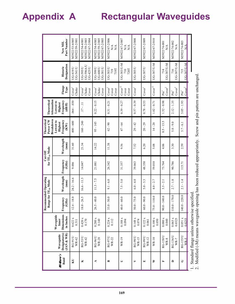
M
i-Wav
e’s
Ban
d
W
aveg
uide
D
esig
nato
r(s)
(J
AN
& W
R)
W
aveg
uide
In
ner
Dim
ensi
ons
in In
ches
Rec
omm
ende
d O
pera
ting
Ran
ge fo
r T
E10
Mod
e
Freq
uenc
y
W
avel
engt
h (G
Hz)
(m
m)
The
oret
ical
Po
wer
CW
B
reak
dow
n
Low
est t
o
Hig
hest
Fr
eque
ncy
(KW
)
T
heor
etic
al
Att
enua
tion
Low
est t
o H
ighe
st
Freq
uenc
y (d
B/ff
)
Fl
ange
T
ype
H
isto
ric
Des
igna
tion
N
ew M
IL
Part
Num
ber
KU
R
G-9
1/U
W
R-6
2 0.
622
x 0.
311
12.4
- 18
.0
24.2
- 16
.6
9.48
6 31
.60
400
- 600
.0
64 -
.030
C
over
1 C
hoke
U
G-4
19/U
U
G-5
41/U
M
3922
/53-
4/00
5 M
3922
/59-
2/00
1
K
RG
-53/
U
WR
-42
0.42
0 x
0.17
0 18
.0 -
26.5
16
.6 -
11.3
14
.047
21
.34
160
- 240
.1
7 - .
11
Cov
er1
Cho
ke
Cov
er
UG
-595
/U
UG
-596
A/U
U
G-4
25/U
M39
22/5
4-4/
001
M39
22/5
9-2/
003
M39
22/6
7-2/
004
A
RG
-96/
U
WR
-28
0.28
0 x
0.14
0 26
.5 -
40.0
11
.3 -
7.5
21.0
81
14.2
2 95
- 14
5 0.
22 -
0.15
C
over
1 C
hoke
C
over
UG
-599
/U
UG
-600
/U
UG
-381
/U
M39
22/5
4-4/
003
M39
22/5
9-2/
005
M39
22/6
7-2/
005
B
RG
-97/
U
WR
-22
0.22
4 x
0.11
2 33
.0 -
50.0
9.
1 - 6
.0
26.3
42
11.3
8 62
- 90
0.
31 -
0.21
C
over
1 C
over
C
over
UG
-383
/U
719
7
19T
M39
22/6
7-2/
006
N/A
N
/A
U
WR
-19
0.18
8 x
0.09
4 40
.0 -
60.0
7.
5 - 5
.0
31.3
57
9.56
47
- 64
0.
39 -
0.27
C
over
12
Cov
er
Cov
er
UG
-383
/U-M
7
10
720
T
M39
22/6
7-2/
007
N/A
N
/A
V
RG
-98/
U
WR
-15
0.14
8 x
0.07
4 50
.0 -
75.0
6.
0 - 4
.0
39.8
63
7.52
29
- 42
0.
57 -
0.39
C
over
1 U
G-3
85/U
M
3922
/67-
2/00
8
E
RG
-99/
U
WR
-12
0.12
2 x
0.06
1 60
.0 -
90.0
5.
0 - 3
.3
48.3
50
6.20
20
- 29
0.
78 -
0.53
C
over
1 U
G-3
87/U
M
3922
/67-
2/00
9
W
WR
-10
0.10
0 x
0.05
0 75
.0 -
110.
0 4.
0 - 2
.7
59.0
10
5.08
14
- 20
1.
02 -
0.71
C
over
12
UG
-387
/U-M
M39
22/6
7-2/
010
F R
G-1
38/U
W
R-8
0.
080
x 0.
040
90.0
- 14
0.0
3.3
- 2.1
73
.764
4.
06
8.5
- 13.
5 1.
52 -
0.98
P
in1
Cov
er2
714
U
G-3
87/U
-M
M39
22/7
4-00
1 N
/A
D
RG
-136
/U
WR
-7
0.06
5 x
0.03
25
110.
0 - 1
70.0
2.
7 - 1
.8
90.7
86
3.30
5.
8 - 9
.0
2.12
- 1.
35
Pin
1 C
over
2 7
16
UG
-387
/U-M
M
3922
/74-
002
N/A
G
RG
-135
/U
WR
-5
0.05
1 x
0.02
55
140.
0 - 2
20.0
2.
1 - 1
.4
115.
71
2.59
3.
7 - 6
.1
3.05
- 1.
93
Pin
1
Cov
er2
715
U
G-3
87/U
-M
M39
22/7
4-00
3 N
/A
Cut
-Off
fo
r T
E10
Mod
e
Freq
uenc
y
W
avel
engt
h (G
Hz)
(m
m)
1. S
tand
ard
flang
e un
less
oth
erw
ise
spec
ified
. 2.
Mod
ified
(-M
) mea
ns w
aveg
uide
ope
ning
has
bee
n re
duce
d ap
prop
riate
ly.
Scre
w a
nd p
in p
atte
rn a
re u
ncha
nged
.
Appendix A Rectangular Waveguides
169

Appendix B Contact Flanges
MIWV Band
Frequency Band (GHz)
MIL Part Number
M3922/67
K ± .0015
(.04)
L ± .0015
(.04)
M ± .000/.002
(.05)
N BSC
P ± .005 (.13)
R ± .005 (.13)
EIA Waveguide Designatio
MIWV Flange
Designation
MIWV Flange Bank
K 18.0 26.5
-004 .4200 (10.67)
.1700 (4.32)
1.125 (28.58)
.9375 (23.81)
.625 (15.88)
.625 (15.88)
WR-42 UG-425/U
101957-10
A 26.5 40.0
-005 .2800 (7.11)
.1400 (3.56)
1.125 (28.58)
.9375 (23.81)
.500 (12.70)
.468 (11.89)
WR-28 UG-381/U 101957-1
B 33.0 50.0
-006 .2240 (5.69)
.1120 (2.84)
1.125 (28.58)
.9375 (23.81)
.500 (12.70)
.468 (11.89)
WR-22 UG-383/U 101957-2
U 40.0 60.0
-007 .1880 (4.78)
.0940 (2.39)
1.125 (28.58)
.9375 (23.81)
.500 (12.70)
.468 (11.89)
WR-19 UG-383/U-M 101957-3
V 50.0 75.0
-008 .1480 (3.76)
.0740 (1.88)
.750 (19.05)
.5625 (14.29)
.375 (9.53)
.312 (7.92)
WR-15 UG-385/U 101957-4
E 60.0 90.0
-009 .1220 (3.10)
.0610 (1.55)
.750 (19.05)
.5625 (14.29)
.375 (9.53)
.312 (7.92)
WR-12 UG-387/U 101957-5
W 75.0 110.0
-010 .1000 (2.54)
.0500 (1.27)
.750 (19.05)
.5625 (14.29)
.375 (9.53)
.312 (7.92)
WR-10 UG-387/U-M 101957-6
F 90.0 140.0
N/A .0800 (2.03)
.0400 (1.02)
.750 (19.05)
.5625 (14.29)
.375 (9.53)
.312 (7.92)
WR-8 UG-387/U-M 101957-7
D 110.0 170.0
N/A .0650 (1.65)
.0325 (.83)
.750 (19.05)
.5625 (14.29)
.375 (9.53)
.312 (7.92)
WR-7 UG-387/U-M 101957-8
G 140.0 220.0
N/A .0510 (1.30)
.0255 (.65)
.750 (19.05)
.5625 (14.29)
.375 (9.53)
.312 (7.92)
WR-5 UG-387/U-M 101957-9
Finished Flange and Waveguide
L
K
.068 (1.73)
.067 (1.70) 2 Places
.112-40 UNC 2B THD. 4 Holes EQ. SP. REF. X Y Z 004 DIA (.10)
45º BSC
45º BSC
.0615 (1.56)
.0610 (1.55) 2 EACH
DIA ALIGNMENT PIN
M
N REF
X
X Y .001
.032
.028 160 (4.06)
.250 (6.35) X
P R
.156 (3.96)
Y
170

Appendix C Flange Blanks
.006 Max. Typ.
MIWV Band
Frequency Band (GHz)
MIL Part Number
M3922/67
A +.002/-.000
(.05)
B +.002/-.000
(.05)
C +.000/-.002
(.05)
D ± .005 (.13)
E ± .005 (.13)
F BSC
MIWV Flange
Designation
K 180.0 260.5
-004 .502 (12.75)
.252 (6.40)
1.125 (28.58)
.625 (15.88)
.625 (15.88)
.312 (7.92)
UG-425/U
A 26.5 40.0
-005 .362 (9.19)
.222 (5.64)
1.125 (28.58)
.500 (12.70)
.468 (11.89)
.9375 (23.81)
UG-381/U
B 33.0 50.0
-006 .306 (7.77)
.194 (4.93)
1.125 (28.58)
.500 (12.70)
.468 (11.89)
.9375 (23.81)
UG-383/U
U 40.0 60.0
-007 .270 (6.86)
.167 (4.47)
1.125 (28.58)
.500 (12.70)
.468 (11.89)
.5625 (14.29)
UG-383/U-M
V 50.0 75.0
-008 .230 (5.84)
.156 (3.96)
.750 (19.05)
.375 (9.53)
.312 (7.92)
.5625 (14.29)
UG-385/U
E 60.0 90.0
-009 .204 (5.18)
.143 (3.63)
.750 (19.05)
.375 (9.53)
.312 (7.92)
.5625 (14.29)
UG-387/U
W 75.0 110.0
-010 .182 (4.62)
.132 (3.35)
.750 (19.05)
.375 (9.53)
.312 (7.92)
.5625 (14.29)
UG-387/U-M
F 90.0 140.0
N/A .141 (3.58)
.101 (2.56)
.750 (19.05)
.375 (9.53)
.312 (7.92)
.5625 (14.29)
UG-387/U-M
D 110.0 170.0
N/A .126 (3.20)
.094 (2.39)
.750 (19.05)
.375 (9.53)
.312 (7.92)
.5625 (14.29)
UG-387/U-M
G 140.0 220.0
N/A .112 (2.84)
.089 (2.21)
.750 (19.05)
.375 (9.53)
.312 (7.92)
.9375 (23.81)
UG-387/U-M
A
.112-40 UNC 2B THD. 4 Holes EQ. SP. REF. X Y Z 004 DIA(.10)
B
- Y -
X Y .001
-Z-
.250 (6.39)
E C D
.94 .037
.84 .033 .165 (4.19) .158 (4.01)
X Y .004 (.10)
// Z .002 X Y .005 (.13)
.125 (3.18) REF.
010 (.25) x 45” 32
F BSC
172

Appendix D Pin Flanges
16
MIWV Band
MIWV Part
Frequency Band (GHz)
MIL Part Number
M3922/74
C ± .0005
(.01)
D ± .0005
(.01)
EIA Waveguide Designation
F 714 90.0 140.0
-001 .0800 (2.03)
.0400 (1.02)
WR 8
D 716 110.0 170.0
-002 .0650 (1.63)
.0325 (.83)
WR 7
G 715 140.0 220.0
-003 .0510 (1.30)
.0255 (.65)
WR 5
H 717 180.0 260.5
-004 .430 (1.09)
.0215 (.55)
WR 4
J 718 220.0 325.0
-005 .0340 (.86)
.0170 (.43)
WR 3
Finished Flange and Waveguide .0495 (1.26) .0485 (1.23) 2 Places
X Y Z 001 (.02)
X
Y 45 º
45 º
.2800
.088 (2.24)
.212 (5.38)
.010 (.25) .234 (5.94)
.312 (7.92)
.374 (9.50)
.012 (.30)
.010 (.25)
.116 (2.95)
.110 (2.79)
.31 (7.87)
X Y .001 (.02) Z
.05 (1.27)
X Y Z 001 (.02)
Alignment Pin .0460 (1.17) .0450 (1.14) DIA. 2 Each
Union # 101544 Captive Nut # 101544
Retaining Ring # 101925-4
Washer # 101545
Flange Assembly
173

Appendix E Flange Blanks
MIWV Band
TRG Part No.
Frequency Band (GHz)
A ±.001 (.02)
B ± .001 (.02)
EIA Waveguide Designation
F 714 90.0 140.0
.143 (3.63)
.103 (2.62)
WR 8
D 716 110.0 170.0
.128 (3.25)
.098 (2.49)
WR 7
G 715 140.0 220.0
.115 (2.92)
.089 (2.26)
WR 5
H 717 170.0 260.0
.430 (1.09)
.0845 (2.15)
WR 4
J 718 220.0 325.0
.106 (2.69)
.080 (2.03)
WR 3
For Pin Type Flange
Y
.312 (7.92)
X Y .004 (.10)
.234 (5.94)
.05 (1.27)
.31 (7.87)
.375 (9.52)
.374 (9.50)
.125 (3.17)
.122 (3.10)
X Y 002 (.50)
B
B 2
A 2
A Y .001 (.02)
X
.004 (.10) Max. Typ.
174

Appendix F Cover Flanges-Flange Blanks UG-419/U (WR-62)
.956 BSC
1.327 1.297
.708
.705
.994 BSC
1.327 1.297
.147
.144 4 Places
Dia Thru
.396
.394
.12 x 45” Chamfer 4 Places .03R
1.00 DIA
.06R .140 .110 .327
.297
B
D
D
C
A X
Y
F Hole 4 Places
X .015 (.38)
Y .015 (.38) E E
C
G Dia.
Z .001 (.02)
H
J
MIWV Band
Frequency Band (GHz)
MIL Part Number
M3922/53
A B C .015 (.38)
D BSC
E BSC
F ± .003 (.08)
G ± .015 (.38)
H ± .015 (.38)
J ± .015 (.38)
MIWV Flange Bank
Ku 12.4 18.0
-4/005 .622 ± .002 (15.8) (.05)
.311 ± .002 (.79) (.05)
1.312 33.32
4.78 (12.14)
.497 (12.62)
.144 (3.66)
1.000 (25.40)
.125 (3.18)
.313 (7.95)
UG-419/U
Cover Flanges - Finished Flange and Waveguide UG-419/U (WR-62)
175

Appendix G Choke Flanges Finished Flange and Waveguide
Z 001 (.02)
A X
F TH’D 4 Places
Y
B
E E
C A .015 (.38)
D
D
C
B .015 (.38)
G
H
J
P
M
R N
L
K
Q
X Y Z .002 (.05) DIA
X Y Z .002 (.05) DIA
X Y Z .002 (.05) DIA
MIWV Band
Freq. Band (GHz)
MIL Part Number
M3922/59
MIWV FLG.
DESIG.
A B C .015 (.38)
D BSC
E BSC
F G ±.015 (.38)
H ±.015 (.38)
J ±.015 (.38)
K ±.002 (.05)
L ±.002 (.05)
M ±.002 (.05)
N ±.002 (.05)
P ±.002 (.05)
Q ±.00
1 (.03)
R ±.002 (.05)
KU 12.4 18.0
-2/001 UG541 .622±.002 (15.8)(.05)
.311±.002 (7.9)(.05)
1.312 (33.32
)
.478 (12.14
)
.497 (12.62
)
.138-32 UNC-
2B
1.000 (25.40
)
.188 (4.78)
.375 (9.53)
.113 (2.87)
.190 (4.83)
1.58 (4.01)
.710 (18.03
)
1.208 (30.68
)
.0075 (.19)
.828 (21.03)
K 18.0 26.5
-2/003 UG596 .420±.002 (10.67)(.05)
.170±.002 (4.32)(.05)
.875 (22.23
)
.335 (8.51)
.320 (8.13)
.112-40 UNC-
2B
.625 (15.88
)
.156 (3.96)
.285 (7.24)
0.42 (1.07)
.129 (3.28)
0.87 (2.21)
.472 (11.99
)
.761 (19.33
)
.005 (.13)
.536 (13.61)
A 26.5 40.0
-2/005 UG600 .280±.0014 (7.11)(.04)
.140±.0014 (3.56)(.04)
.750 (19.05
)
.265 (6.73)
.250 (6.35)
.112-40 UNC-
2B
.500 (12.70
)
.109 (2.77)
.210 (5.33)
.050 (1.27)
.086 (2.18)
.096 (2.44)
.321 (8.15)
.596 (15.14
)
.003 (.08)
.372 (9.45)
176

Finished Flange and Waveguide
Appendix H Cover Flanges
177
MIWV Band
Frequency Band (GHz)
MIL Part Number
M3922/54-4
A ± .0015
(.04)
B ± .0015
(.04)
C D BSC
E BSC
F H MIWV Flange
K 18.0 26.5
-001 .4200 (10.67)
.1700 (4.32)
.875±.015 (22.22)(.38)
.335 (8.51)
.320 (8.13)
.156±.015 (3.96)(.38)
.116+.002 (2.95)(.05)
UG-595/U
A 26.5 40.0
-003 .2800 (7.11)
.1400 (3.56)
.750±.005 (19.05)(1.3)
.265 (6.75)
.250 (6.35)
.109±.005 (2.77)(.38)
.116+.002 (2.95)(.05)
UG-599/U
B 33.0 50.0
N/A .2240 (5.69)
.1120 (2.84)
.750±.005 (19.05)(1.3)
.265 (6.75)
.250 (6.35)
.156±.005 (3.96)(.38)
.116+.002 (2.95)(.05)
719 (UG-599/UM)
B 33.0 50.0
N/A .2240 (5.69)
.1120 (2.84)
.750±.005 (19.05)(1.3)
.265 (6.75)
.250 (6.35)
.156±.005 (3.96)(.38)
.112-40 UNC-2B
719T
U 40.0 60.0
N/A .1880 (4.78)
.0940 (2.39)
.750±.005 (19.05)(1.3)
.265 (6.75)
.250 (6.35)
.187±.005 (4.75)(.38)
.116+.002 (2.95)(.05)
720 (UG-599/UM)
U 40.0 60.0
N/A .1880 (4.78)
.0940 (2.39)
.750±.005 (19.05)(1.3)
.265 (6.75)
.250 (6.35)
.187±.005 (4.75)(.38)
.112-40 UNC-2B
720T
Z
F
.001 (.02)
E
E
C
B Y
H Hole 4 Places
X .015 (.38)
Y .015 (.38)
X
D D
C
A

Flange Blank
Appendix I Cover Flanges
178
MIWV Flange
Designation
A B C D BSC
E BSC
UG 599A .364 .362
.224
.222 .755 .745
.530 .500
UG 595K .505 .503
.255
.253 .890 .860
.670 .640
MIWV Part
Number
A +.002 - .000
B +.002 - .000
719B .306 .194
720U .270 .176
.192
.182
.05 R Max.
.202
.179
.061 R. Typ.
.031 R. Typ.
A
.765
.735
A .765 .735
.478 R. Typ.
.458 R. Typ.
B .010 R Max. Typ.
D .020 R Max.
E C

Appendix J Antenna TE 11 Circular Waveguides
MIWV Band
M + .000 / .002
(.05)
N BSC
P +.005 (.13)
R +.005 (.13)
MIWV Flange
Designation
MIWV Flange Blank
Ku 1.44 (36.58)
1.250 (28.6)
.967 (24.6)
.967 (24.6)
731 108872
K 1.125 (28.58)
.9375 (23.8)
.625 (15.88)
.625 (15.88)
UG-425/U 107729-7
A 1.125 (28.58)
.9375 (23.81)
.500 (12.70)
.468 (11.89)
UG-381/U 107729-1
B 1.125 (28.58)
.9375 (23.81)
.500 (12.70)
.468 (11.89)
UG-383/U 107729-2
U 1.125 (28.58)
.9375 (23.81)
.500 (12.70)
.468 (11.89)
UG-385/U-M 107729-3
V .750 (19.05)
.5625 (14.29)
.375 (9.53)
.312 (7.92)
UG-387/U 107729-4
E .750 (19.50)
.5625 (14.29)
.375 (9.53)
.312 (7.92)
UG-387/U-M 107729-5
W .750 (19.50)
.5625 (14.29)
.375 (9.53)
.312 (7.92)
UG-387/U-M 107729-6
F .750 (19.50)
.5625 (14.29)
.375 (9.53)
.312 (7.92)
UG-387/U-M 107729-8
D .750 (19.50)
.5625 (14.29)
.375 (9.53)
.312 (7.92)
UG-387/U-M 107729-9
G .750 (19.50)
.5625 (14.29)
.375 (9.53)
.312 (7.92)
UG-387/U-M 107729-10
Band Pipe ID Frequency Band
Ku-1 .660 12.4 - 14.6
Ku-2 .550 14.6 - 17.5
K-1 .470 17.5 - 20.5
K-2 .396 20.5 - 24.5
K-3 .328 24.5 - 26.5
A-0 .328 26 - 28.5
A-1 .281 28.5 - 33
A-2 .250 33 - 38.5
A-3 .219 38.5 - 43
B-0 .250 33 - 38.5
B-1 .219 38.5 - 43
B-2 .188 43 - 50
U-0 .219 38.5 - 43
U-1 .188 43 - 50
U-2 .165 50 - 58
V-0 .165 50 - 58
V-1 .141 58 - 68
V-2 .125 68 - 77
E-0 .141 58 - 68
E-1 .125 68 - 77
E-2 .110 77 - 87
E-3 .094 87 - 100
W-0 .110 77 - 87
W-1 .094 87 - 100
W-2 .082 100 - 112
F-0 .094 87 - 100
F-1 .082 100 - 112
F-2 .075 112 - 125
F-3 .067 125 - 140
D-0 .082 100 -112
D-1 .075 112 - 125
D-2 .067 125 - 140
D-3 .059 140 - 160
G-0 .067 125 - 140
G-1 .059 140 - 220
Where frequency has two pipe sizes take smaller pipe, except for 100 GHZ and higher, then take larger pipe.
16
Y X .001 (03) .0005
.160
REF
Pipe I.D.
45º BSC
45º BSC
.0615 (1.56)
.0610 (1.55) 2 EACH
DIA ALIGNMENT PIN
M
N
X
.032 (.81)
.028 (.71) (4.06)
.250 (6.35)
P REF
R REF
.156 (3.96)
.068 (1.73)
.067 (1.70) 2 Places
DIA
.112-40 UNC .2B THD.
.140 (3.50) DIA Deep
4 HOLES EQ. SP. REF. X Y .004 DIA (.10)
.028(.71)
.032(.81)
179

Appendix K The Effect of VSWR on Transmitted Power VSWR Return
Loss (dB)
VSWR (dB)
Volt REFL
COEFF
XMSN Loss (dB)
Power XMIT
(%)
Power REFL (%)
VSWR Return Loss (dB)
VSWR (dB)
Volt REFL
COEFF
XMSN Loss (dB)
Power XMIT
(%)
Power REFL (%)
1.006 50.00 0.05 0.00 .0000 100. 0.00 1.31 17.45 2.35 0.13 0.08 98.20 1.80
1.01 46.06 0.09 0.00 .0001 100. 0.00 1.32 17.21 2.41 0.14 0.08 98.10 1.90
1.011 45.00 0.10 0.01 .0001 100. 0.00 1.329 17.00 2.47 0.14 0.09 98.00 2.00
1.02 40.09 0.17 0.01 .0004 99.99 0.01 1.33 16.98 2.48 0.14 0.09 97.99 2.01
1.020 40.00 0.17 0.01 .0004 99.99 0.01 1.34 16.75 2.54 0.15 0.09 97.89 2.11
1.03 36.61 0.26 0.01 .0009 99.98 0.02 1.35 18.54 2.61 0.15 0.10 97.78 2.22
1.036 35.00 0.31 0.02 .0014 99.97 0.03 1.36 16.33 2.61 0.15 0.10 97.67 2.33
1.04 34.15 0.34 0.02 .0017 99.96 0.04 1.37 16.13 2.73 0.16 0.11 97.56 2.44
1.045 33.15 0.38 0.02 .0021 99.95 0.05 1.377 16.00 2.78 0.16 0.11 97.49 2.51
1.05 32.26 0.42 0.02 .0026 99.94 0.06 1.38 15.94 2.80 0.16 0.11 97.45 2.55
1.06 30.71 0.51 0.03 .0037 99.92 0.08 1.39 15.75 2.86 0.16 0.12 97.34 2.66
1.065 30.00 0.55 0.03 .0043 99.90 0.10 1.40 15.56 2.92 0.17 0.12 97.22 2.78
1.07 29.42 0.59 0.03 .0050 99.89 0.11 1.41 15.38 2.98 0.17 0.13 97.11 2.89
1.08 28.30 0.67 0.04 .0064 99.85 0.15 1.42 15.21 3.05 0.17 0.13 96.99 3.01
1.09 27.32 0.75 0.04 .0081 99.81 0.19 1.43 15.04 3.11 0.18 0.14 96.87 3.13
1.10 26.44 0.83 0.05 .0099 99.77 0.23 1.433 15.00 3.12 0.18 0.14 96.84 3.16
1.11 25.66 0.91 0.05 .0118 99.73 0.27 1.44 14.88 3.17 0.18 0.14 96.75 3.25
1.119 25.00 0.98 0.06 .0138 99.68 0.32 1.45 14.72 3.23 0.18 0.15 96.63 3.37
1.12 24.94 0.98 0.06 .0139 99.68 0.32 1.46 14.56 3.29 0.19 0.15 96.50 3.50
1.13 24.29 1.06 0.06 .0162 99.63 0.37 1.464 14.50 3.31 0.19 0.16 96.45 3.55
1.135 24.00 1.10 0.06 .0173 99.60 0.40 1.47 14.41 3.35 0.19 0.16 96.38 3.62
1.14 23.69 1.14 0.07 .0186 99.57 0.43 1.48 14.26 3.41 0.19 0.17 96.25 3.75
1.15 23.13 1.21 0.07 .0212 99.51 0.49 1.49 14.12 3.46 0.20 0.17 96.13 3.87
1.152 23.00 1.23 0.07 .0218 99.50 0.50 1.499 14.00 3.51 0.20 0.18 96.02 3.98
1.16 22.61 1.29 0.07 .0239 99.45 0.55 1.50 13.96 3.52 0.20 0.18 96.00 4.00
1.17 22.12 1.36 0.08 .0267 99.39 0.61 1.536 13.50 3.73 0.21 0.20 95.53 4.47
1.173 22.00 1.38 0.08 .0275 99.37 0.63 1.55 13.32 3.81 0.22 0.21 95.35 4.65
1.18 21.66 1.44 0.08 .0297 99.32 0.68 1.577 13.00 3.96 0.22 0.22 94.99 5.01
1.19 21.23 1.51 0.09 .0328 99.25 0.75 1.60 12.74 4.08 0.23 0.24 94.67 5.33
1.196 21.00 1.55 0.09 .0346 99.21 0.79 1.622 12.50 4.20 0.24 0.25 94.38 5.62
1.20 20.83 1.58 0.09 .0360 99.17 0.83 1.65 12.21 4.35 0.25 0.27 93.98 6.02
1.21 20.44 1.66 0.10 .0394 99.10 0.90 1.671 12.00 4.46 0.25 0.28 93.69 6.31
1.22 21.08 1.73 0.10 .0429 99.02 0.98 1.70 11.73 4.61 0.26 0.30 93.28 6.72
1.222 20.00 1.74 0.10 .0436 99.00 1.00 1.725 11.50 4.74 0.27 0.32 92.92 7.08
1.23 19.73 1.80 0.10 .0464 98.94 1.06 1.75 11.29 4.86 0.27 0.34 92.56 7.44
1.24 19.40 1.87 0.11 .0501 98.85 1.15 1.785 11.00 5.03 0.28 0.36 92.06 7.94
1.25 19.08 1.94 0.11 .0540 98.77 1.23 1.80 10.88 5.11 0.29 0.37 91.84 8.16
1.253 19.00 1.96 0.11 .0550 98.74 1.26 1.851 10.50 5.35 0.30 0.41 91.09 8.16
1.26 18.78 2.01 0.12 .0579 98.68 1.32 1.90 10.16 5.58 0.31 0.44 90.37 9.63
1.27 18.49 2.08 0.12 .0619 98.59 1.41 1.925 10.00 5.69 0.32 0.46 90.00 10.00
1.28 18.22 2.14 0.12 .0660 98.49 1.51 2.00 9.54 6.02 0.33 0.51 88.89 11.11
1.288 18.00 2.20 0.13 .0694 98.42 1.58 2.50 7.36 7.96 0.43 0.88 81.63 18.37
1.29 17.95 2.21 0.13 .0702 98.40 1.60 3.00 6.02 9.54 0.50 1.25 75.00 25.00
1.30 17.89 2.28 0.13 .0745 98.30 1.70 3.50 5.11 10.88 0.56 1.60 69.14 30.86
180

Appendix L Table 2-1 TE 01 Circular Waveguides
1.500 X 1.750 11.6-16.0 1.500 X 1.700 11.6-16.0 WRC530D14
1.265 X 1.375 13.2-18.9 1.281 X 1.441 13.6-18.7 WRC621D14
1.106 X 1.250 15.9-21.9 1.094 X 1.224 15.9-21.9 WRC727D14
0.951 X 1.125 18.6-25.6 0.938 X 1.068 18.6-25.6 WRC849D14
0.686 X 0.750 25.3-34.9 0.797 X 0.897 21.9-30.1 WRC997D14
0.688 X 0.888 25.3-34.9 0.688 X 0.788 25.3-34.9 WRC116C14
0.634 X 0.750 27.3-38.0 0.594 X 0.674 29.3-40.4 WRC134C14
0.545 X 0.625 32.0-44.0 N/A
0.495 X 0.625 34.8-48.0 0.500 X 0.580 34.8-48.0 WRC159C14
04.38 X 0.518 39.8-54.8 WRC182C14
0.370 X 0.500 46.4-63.9 0.375 X 0.435 46.4-63.9 WRC212C14
0.353 X 0.438 50.0-68.0 0.328 X 0.388 53.1-73.1 WRC243C14
0.291 X 0.375 62.0-84.0 0.281 X .0341 61.9-85.2 WRC283C14
0.249 X 0.313 69.7-95.9 0.250 X 0.290 69.7-95.9 WRC318C14
0.201 X 0.290 86.0-115.0 0.219 X 0.259 79.6-110.0 WRC364C14
0.186 X 0.250 93.0-128.0 0.188 X 0.228 92.9-128.0 WRC424C14
0.172 X 0.212 101.0-139.0 WRC463C14
0.141 X 0.181 124.0-171.0 WRC566C14
Standard Waveguide I.D. O.D. Frequency (inches) (GHz)
MIL-W-23068 Circular Waveguide I.D. O.D. Frequency Type (inches) (GHz)
181

Terms and Conditions of Quotation & Sale The following terms and conditions apply to all purchase orders accepted and all quotations submitted by Mi-Wave, hereinafter referred to as Mi-Wave. Orders accepted by Mi-Wave are based on Buyer’s acceptance of these Terms and Conditions. Return of this acknowledgement by Mi-Wave, and only such acknowledgement, constitutes acceptance of the Buyer’s purchase order. Acceptance by the Buyer of merchandise shipped against any purchase order acknowledges acceptance of the Terms and Conditions set forth in this document. Failure of Mi-Wave to enforce any of these provisions does not relieve Buyer from all Terms and Conditions contained herein. The term payment is net thirty (30) days FOB the Mi-Wave facility where commitment to shipping carrier is made. Firms not on open account will be required to prepay or accept material COD. Cancellation of an order by the Buyer will be subject to payment of all costs incurred up to the date of notification of termination. Buyer will accept all finished goods, work in progress, and direct material. Costs will be calculated using standard accounting procedures including profit and G & A. If said termination is a result of reduction or cancellation of a Government contract to the Buyer, the provisions of the current applicable Defense Acquisition Regulations shall apply. Mi-Waves’ warranty obligations shall be limited to, at Mi-Waves’ option, repairing, replacing, or granting a credit at the purchase order price for items returned to Mi-Wave at the Buyer’s expense within 90 days of delivery that are determined to be defective by analysis at Mi-Waves’ facility. Material that has been misapplied, mechanically or electrically over stressed, repaired or altered in any way will not be warranteed. Mi-Wave warrants that its products conform to applicable specifications and are free from defects in material or workmanship. No other warranties exist or are implied. This warranty is not transferable. Repairs at the Buyer’s expense will only be accepted when accompanied by a purchase order issued to Mi-Wave for estimated cost to repair. RMA’s are issued only for in warrenty repairs. Quoted prices shall be valid and firm for thirty (30) days. All prices are subject to change without notice. Prices accepted by the Buyer and acknowledged by Mi-Wave shall remain in effect throughout the term of the
Mi-Wave will not be responsible for delays caused by events outside of its control. Mi-Wave assumes no liability of any kind resulting from failure to meet delivery schedules. All applicable taxes will appear on invoices issued by Mi-Wave to be paid by the Buyer, unless a properly executed exemption certificate is received with the purchase order or shipment and invoicing. Mi-Wave agrees to indemnify Buyer against actions brought against the Buyer for infringement of valid patents. Mi-Wave will not be a party to an action resulting from the use of its components in a collection or assembly of components that are alleged to violate a patented circuit, system, equipment, assembly or any combination of components so described. Immediate notification of Mi-Wave regarding any action relating to patents or infringement of same is required but in no case shall such notice be delayed in excess of five (5) working days. Further, delivery of components to the Buyer does in no way imply any license agreement regarding patents or disclosures held or in process by Mi-Wave. All rights under such patents remain with Mi-Wave. Source inspection of material or components by the Buyer or any designate of his will be quoted as a separate line item. Failure to include this line item will not relieve the Buyer from the obligation of payment for said service. Source inspection that requires witnessing of electrical tests must be preceded by mutual acceptance of a test procedure. Such test procedure, if generated by Mi-Wave, will be at the expense of the Buyer. Mi-Wave may change, delete, or add additional conditions without notice. Such changes will be made a part of all quotes and acceptance of purchase orders.
182
Mi-Wave Millimeter Wave Products Inc.
www.miwv.com 2200 Tall Pines Drive, Suite 100 Largo, FL 33771 Tel. (727) 536-0033 Fax. (727) 536-0012 E: [email protected]
Related Documents