MULTIPORT FUEL INJECTION (MFI) DIAGNOSIS TSB Revision MULTIPORT FUEL INJECTION (MFI) 13A-537 13A DTC P0441: Evaporative Emission Control System Incorrect Purge Flow . TECHNICAL DESCRIPTION • PCM detects stuck open condition of evaporative emission purge solenoid and stuck closed condi- tion of evaporative emission ventilation solenoid by pressure change in fuel tank. • Stuck open evaporative emission purge solenoid is judged through monitoring leak of evaporative emission system. • Stuck closed evaporative emission ventilation solenoid is judged after 20 seconds from end of monitoring leak of evaporative emission system, or of usual operation of evaporative emission purge solenoid from ON to OFF. . DESCRIPTIONS OF MONITOR METHODS Fuel tank pressure decreases largely during purge- cut. . MONITOR EXECUTION Continuous . MONITOR EXECUTION CONDITIONS (Other monitor and Sensor) Other Monitor (There is no temporary DTC stored in memory for the item monitored below) • Fuel tank pressure sensor monitor Sensor (The sensor below is determined to be normal) • Not applicable . AK200968 EVAPORATIVE EMISSION PURGE SOLENOID AB B-06(B) CONNECTOR: B-06 AK201059 G-27(B) AD CONNECTOR: G-27 EVAPORATIVE EMISSION VENTILATION SOLENOID

Welcome message from author
This document is posted to help you gain knowledge. Please leave a comment to let me know what you think about it! Share it to your friends and learn new things together.
Transcript

MULTIPORT FUEL INJECTION (MFI) DIAGNOSISMULTIPORT FUEL INJECTION (MFI) 13A-537
13A
DTC P0441: Evaporative Emission Control System Incorrect Purge Flow
.
TECHNICAL DESCRIPTION• PCM detects stuck open condition of evaporative
emission purge solenoid and stuck closed condi-tion of evaporative emission ventilation solenoid by pressure change in fuel tank.
• Stuck open evaporative emission purge solenoid is judged through monitoring leak of evaporative emission system.
• Stuck closed evaporative emission ventilation solenoid is judged after 20 seconds from end of monitoring leak of evaporative emission system, or of usual operation of evaporative emission purge solenoid from ON to OFF.
.
DESCRIPTIONS OF MONITOR METHODSFuel tank pressure decreases largely during purge-
cut..
MONITOR EXECUTIONContinuous.
MONITOR EXECUTION CONDITIONS (Other monitor and Sensor)Other Monitor (There is no temporary DTC stored
in memory for the item monitored below)• Fuel tank pressure sensor monitor
Sensor (The sensor below is determined to be normal)
• Not applicable.
AK200968
EVAPORATIVEEMISSION PURGE SOLENOID
AB
B-06(B)
CONNECTOR: B-06
AK201059AK201059
G-27(B)
AD
CONNECTOR: G-27
EVAPORATIVE EMISSIONVENTILATION SOLENOID
TSB Revision
RZiegler
<<PREVIOUS

MULTIPORT FUEL INJECTION (MFI) DIAGNOSISMULTIPORT FUEL INJECTION (MFI)13A-538
DTC SET CONDITIONS
Logic Flow Chart
.
Check Conditions• ON duty cycle of the evaporative emission purge
solenoid is 0 percent.• Engine is running.• 20 seconds have elapsed since the duty cycle of
the evaporative emission purge solenoid has turned to 0 percent.
Judgement Criterion• The pressure in the fuel tank is −1961 Pa (−0.58
in.Hg) or less for 0.1 second.
.
OBD-II DRIVE CYCLE PATTERNRefer to Diagnostic Function − OBD-II Drive Cycle −
Pattern 6 P.13A-4..
TROUBLESHOOTING HINTS (The most likely causes for this code to be set are:)• Evaporative emission purge solenoid failed.• Evaporative emission ventilation solenoid failed.• Fuel tank differential pressure sensor circuit
related part failed.
START
END
NO
NONO
NO
YES
YES
YES
NO
MALFUNCTION GOOD
CONTINUOUSFAILURE FOR 100msecs
MONITORING CONDITIONS FORMALFUNCTION DETECTION
AK302953
FUEL-TANK PRESSURE< -1961Pa (-0.58in.Hg)
MONITORING CONDITIONS FORPASS JUDGEMENT?
REVERTING PRESSURE DETECTED DURING
EVAP MONITOR?
YES
YES
TSB Revision

MULTIPORT FUEL INJECTION (MFI) DIAGNOSISMULTIPORT FUEL INJECTION (MFI) 13A-539
DIAGNOSISRequired Special Tools:• MB991958: Scan Tool (MUT-III Sub Assembly)
• MB991824: V.C.I.• MB991827: USB Cable• MB991911: Main Harness B
STEP 1. Using scan tool MB991958, read the diagnostic trouble code (DTC).
CAUTIONTo prevent damage to scan tool MB991958, always turn the ignition switch to the "LOCK" (OFF) position before con-necting or disconnecting scan tool MB991958.(1) Connect scan tool MB991958 to the data link connector.(2) Turn the ignition switch to the "ON" position.(3) Read the DTC.(4) Turn the ignition switch to the "LOCK" (OFF) position.Q: Is DTC P0451 set?
YES : Refer to DTC P0451 - Evaporative Emission Control System Pressure Sensor Range/Performance P.13A-596.
NO : Go to Step 2.
STEP 2. Using scan tool MB991958, check data list item 73: Fuel Tank Differential Pressure Sensor.(1) Turn the ignition switch to the "ON" position.(2) Remove the fuel cap.(3) Set scan tool MB991958 to the data reading mode for item
73, Fuel Tank Differential Pressure Sensor.• The fuel tank differential pressures should be −3.3 to 3.3
kPa (−0.97 to 0.97 in.Hg).(4) Turn the ignition switch to the "LOCK" (OFF) position.Q: Is the fuel tank pressure −3.3 to 3.3 kPa (−0.97 to 0.97
in.Hg)?YES : Go to Step 3.NO : Refer to DTC P0451 - Evaporative Emission Control
System Pressure Sensor Range/Performance P.13A-596.
AK302970AB
MB991911
MB991824
MB991827
AK302970AB
MB991911
MB991824
MB991827
TSB Revision
MULTIPORT FUEL INJECTION (MFI) DIAGNOSISMULTIPORT FUEL INJECTION (MFI)13A-540
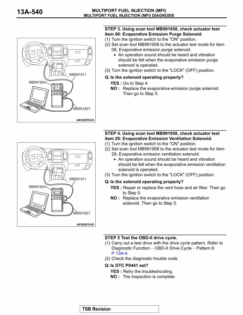
STEP 3. Using scan tool MB991958, check actuator test item 08: Evaporative Emission Purge Solenoid.(1) Turn the ignition switch to the "ON" position.(2) Set scan tool MB991958 to the actuator test mode for item
08, Evaporative emission purge solenoid.• An operation sound should be heard and vibration
should be felt when the evaporative emission purge solenoid is operated.
(3) Turn the ignition switch to the "LOCK" (OFF) position.Q: Is the solenoid operating properly?
YES : Go to Step 4.NO : Replace the evaporative emission purge solenoid.
Then go to Step 5.
STEP 4. Using scan tool MB991958, check actuator test item 29: Evaporative Emission Ventilation Solenoid.(1) Turn the ignition switch to the "ON" position.(2) Set scan tool MB991958 to the actuator test mode for item
29, Evaporative emission ventilation solenoid.• An operation sound should be heard and vibration
should be felt when the evaporative emission ventilation solenoid is operated.
(3) Turn the ignition switch to the "LOCK" (OFF) position.Q: Is the solenoid operating properly?
YES : Repair or replace the vent hose and air filter. Then go to Step 5.
NO : Replace the evaporative emission ventilation solenoid. Then go to Step 5.
STEP 5 Test the OBD-II drive cycle. (1) Carry out a test drive with the drive cycle pattern. Refer to
Diagnostic Function − OBD-II Drive Cycle − Pattern 6 P.13A-4.
(2) Check the diagnostic trouble code.Q: Is DTC P0441 set?
YES : Retry the troubleshooting.NO : The inspection is complete.
AK302970AB
MB991911
MB991824
MB991827
AK302970AB
MB991911
MB991824
MB991827
TSB Revision

MULTIPORT FUEL INJECTION (MFI) DIAGNOSISMULTIPORT FUEL INJECTION (MFI) 13A-541
DTC P0442: Evaporative Emission System Leak Detected (Small Leak)
.
AC203991
SYSTEM DIAGRAM
A
B C D
EF
G
H
I
J
K
LM
N
OQ
S
R
P
FUEL TANK
CHECK VALVE B
CHECK VALVE AEVAPORATIVEEMISSIONPURGESOLENOID
EVAPORATIVE EMISSIONVENTILATION SOLENOID
EVAPORATIVEEMISSIONCANISTER
VENT PIPEASSEMBLY
AD
ONBOARD REFUELINGVAPOR RECOVERY(ORVR)VENT VALVE MODULE
AC101766
EVAPORATIVE EMISSION CANISTER
AB AC203904AC
EVAPORATIVE EMISSIONPURGE SOLENOID
INTAKE AIR DUCT
AC101763 AB
REAR COIL SPRING (RH)
EVAPORATIVE EMISSION VENTILATION SOLENOID
TSB Revision

MULTIPORT FUEL INJECTION (MFI) DIAGNOSISMULTIPORT FUEL INJECTION (MFI)13A-542
TECHNICAL DESCRIPTION• The PCM monitors the Evaporative Emission
(EVAP) System pressure.• The PCM controls the evaporative emission ven-
tilation solenoid. It closes the evaporative emis-sion ventilation solenoid to seal the evaporative emission canister side of the system.
• The evaporative emission purge solenoid is opened to allow manifold vacuum to create low pressure (vacuum) in the EVAP system.
• When the EVAP system develops a vacuum of 2 kPa (0.29 psi), the evaporative emission purge solenoid is closed and the fuel system vacuum is maintained at 2 kPa. (0.29 psi).
• The PCM determines whether there is a leak in the EVAP system by monitoring the vacuum inside the fuel tank.
• The test is stopped when fuel vapor pressure exceeds predetermined limits.
.
DESCRIPTIONS OF MONITOR METHODS• Measure reverting pressure after depressurizing
by intake manifold negative pressure and detect malfunction if reverting pressure rises largely.
.
MONITOR EXECUTION• Once per driving cycle.
.
MONITOR EXECUTION CONDITIONS (OTHER MONITOR AND SENSOR)Other Monitor (There is no temporary DTC stored
in memory for the item monitored below)• Evaporative emission purge solenoid monitor• Evaporative emission purge system monitor• Fuel tank differential pressure sensor monitor• Evaporative emission ventilation solenoid monitor• Fuel level sensor monitor• Fuel temperature sensor monitor
Sensor (The sensors below are determined to be normal)
• Volume airflow sensor• Barometric pressure sensor• Intake air temperature sensor• Engine coolant temperature sensor
.
TSB Revision
MULTIPORT FUEL INJECTION (MFI) DIAGNOSISMULTIPORT FUEL INJECTION (MFI) 13A-543
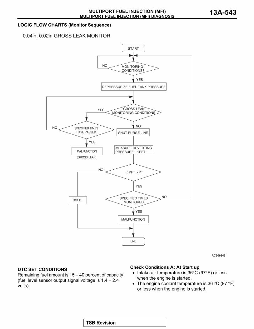
LOGIC FLOW CHARTS (Monitor Sequence)
.
DTC SET CONDITIONSRemaining fuel amount is 15 − 40 percent of capacity (fuel level sensor output signal voltage is 1.4 − 2.4 volts).
Check Conditions A: At Start up• Intake air temperature is 36°C (97°F) or less
when the engine is started.• The engine coolant temperature is 36 °C (97 °F)
or less when the engine is started.
AC306649
0.04in, 0.02in GROSS LEAK MONITOR
START
YES
YES
YES
YES
YES
NO
NONO
NO
NO
MONITORINGCONDITIONS?
DEPRESSURIZE FUEL TANK PRESSURE
GROSS LEAKMONITORING CONDITIONS
SHUT PURGE LINE
MEASURE REVERTINGPRESSURE : PFT
PFT > PT
SPECIFIED TIMESMONITORED
MALFUNCTION
END
SPECIFIED TIMESHAVE PASSED
MALFUNCTION
(GROSS LEAK)
GOOD
TSB Revision

MULTIPORT FUEL INJECTION (MFI) DIAGNOSISMULTIPORT FUEL INJECTION (MFI)13A-544
Check Conditions B: For Test to Run• Fuel temperature is less than 36 °C (97 °F), and
less than 13 minutes have elapsed since the engine was started.
• Engine coolant temperature is greater than 54°C (129°F).
• Power steering pressure switch: "OFF"• Barometric pressure is greater than 76 kPa (11
psi).• Fuel tank differential pressure sensor output volt-
age is 1 to 4 volts.• Vehicle speed is greater than or equal to 20 km/h
(12.4 mph).
Check Conditions C: For Test to Stop• Intake air temperature is greater than −10°C
(14°F).• When the evaporative emission purge solenoid
and evaporative emission ventilation solenoid are closed, the pressure in the fuel tank is less than 451 Pa (0.065 psi).
• The pressure fluctuation is less than 647 Pa (0.094 psi).
• 10 seconds have elapsed since the start of the previous monitoring.
• Monitoring time: 75 − 125 seconds.
Judgment Criterion• Internal pressure of the fuel tank has changed
more than 785 Pa (0.114 psi) in 20 seconds after the tank and vapor line were closed.NOTE: The monitoring time (75 − 125 seconds) depends on the fuel level and the temperature in the fuel tank.The next monitoring occurs at least 10 seconds later.
.
DTC SET CONDITIONSRemaining fuel amount is 40 − 85 percent of capacity (fuel level sensor output voltage is 2.4 − 3.7 volts).
Check Conditions A: At Start up• Intake air temperature is less than 36 °C (97 °F)
when the engine is started.
• The engine coolant temperature is less than 36 °C (97 °F) when the engine is started.
Check Conditions B: For Test to Run• The fuel temperature is less than 36 °C (97 °F).• Barometric pressure is greater than 76 kPa (11
psi).• Fuel tank differential pressure sensor output volt-
age is 1 to 4 volts.
Check Conditions C: For Test to Stop• Intake air temperature is greater than −10 °C
(14°F).• Engine coolant temperature is greater than 20 °C
(68 °F).• When the evaporative emission purge solenoid
and evaporative emission ventilation solenoid are closed, the pressure in the fuel tank is less than 324 Pa (0.047 psi).
• 10 seconds have elapsed since the start of the previous monitoring.
• Monitoring time: 10 − 14 minutes.
Judgment Criterion• Internal pressure of the fuel tank has changed
more than 2 kPa (0.29 psi) in 128 seconds after the tank and vapor line were closed.NOTE: The monitoring time (10 − 14 minutes) depends on the fuel level and the temperature in the fuel tank.The next monitoring occurs at least 10 seconds later.
.
OBD-ll DRIVE CYCLE PATTERNRefer to Diagnostic Function − OBD-ll Drive Cycle − Pattern 5 P.13A-4..
TROUBLESHOOTING HINTS (THE MOST LIKELY CAUSES FOR THIS CODE TO BE SET ARE:)• Loose fuel cap.• Fuel cap relief pressure is incorrect.• Evaporative emission canister seal is leaking.• Fuel tank, purge line or vapor line seal is leaking.• Evaporative emission ventilation solenoid does
not seal.
TSB Revision
MULTIPORT FUEL INJECTION (MFI) DIAGNOSISMULTIPORT FUEL INJECTION (MFI) 13A-545
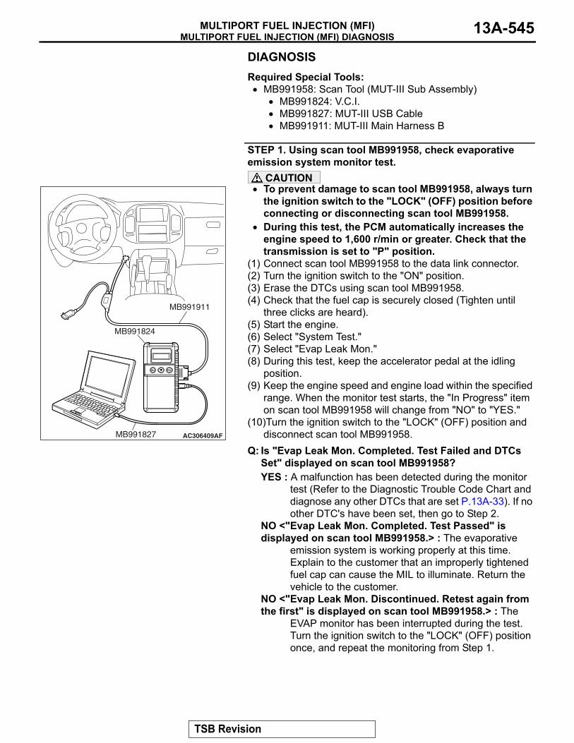
DIAGNOSISRequired Special Tools:• MB991958: Scan Tool (MUT-III Sub Assembly)
• MB991824: V.C.I.• MB991827: MUT-III USB Cable• MB991911: MUT-III Main Harness B
STEP 1. Using scan tool MB991958, check evaporative emission system monitor test.
CAUTION• To prevent damage to scan tool MB991958, always turn
the ignition switch to the "LOCK" (OFF) position before connecting or disconnecting scan tool MB991958.
• During this test, the PCM automatically increases the engine speed to 1,600 r/min or greater. Check that the transmission is set to "P" position.
(1) Connect scan tool MB991958 to the data link connector.(2) Turn the ignition switch to the "ON" position.(3) Erase the DTCs using scan tool MB991958.(4) Check that the fuel cap is securely closed (Tighten until
three clicks are heard).(5) Start the engine.(6) Select "System Test."(7) Select "Evap Leak Mon."(8) During this test, keep the accelerator pedal at the idling
position.(9) Keep the engine speed and engine load within the specified
range. When the monitor test starts, the "In Progress" item on scan tool MB991958 will change from "NO" to "YES."
(10)Turn the ignition switch to the "LOCK" (OFF) position and disconnect scan tool MB991958.
Q: Is "Evap Leak Mon. Completed. Test Failed and DTCs Set" displayed on scan tool MB991958?YES : A malfunction has been detected during the monitor
test (Refer to the Diagnostic Trouble Code Chart and diagnose any other DTCs that are set P.13A-33). If no other DTC's have been set, then go to Step 2.
NO <"Evap Leak Mon. Completed. Test Passed" is displayed on scan tool MB991958.> : The evaporative
emission system is working properly at this time. Explain to the customer that an improperly tightened fuel cap can cause the MIL to illuminate. Return the vehicle to the customer.
NO <"Evap Leak Mon. Discontinued. Retest again from the first" is displayed on scan tool MB991958.> : The
EVAP monitor has been interrupted during the test. Turn the ignition switch to the "LOCK" (OFF) position once, and repeat the monitoring from Step 1.
AC306409AF
MB991911
MB991824
MB991827
TSB Revision

MULTIPORT FUEL INJECTION (MFI) DIAGNOSISMULTIPORT FUEL INJECTION (MFI)13A-546
STEP 2. Check for leaks in the evaporative emission purge solenoid.(1) Disconnect hose B from the evaporative emission purge
solenoid and connect a hand vacuum pump to the nipple of the evaporative emission purge solenoid.
(2) Use the hand vacuum pump to confirm that the evaporative emission purge solenoid holds vacuum.
(3) Disconnect the hand vacuum pump and connect hose B to the evaporative emission purge solenoid.
Q: Does the evaporative emission purge solenoid hold vacuum?YES : Go to Step 3.NO : Replace the evaporative emission purge solenoid. Go
to Step 18.
STEP 3. Check for leaks in the evaporative emission system hose A and hose B.
Perform a leakage test with a hand vacuum pump on each hose A and B.
Q: Does the hoses hold vacuum?YES : Go to Step 4.NO : Replace any damaged hose. Go to Step 18.
AC203994AB
HOSE A
HOSE B
EVAPORATIVE EMISSIONPURGE SOLENOID
AC203996AB
EVAPORATIVE EMISSIONPURGE SOLENOID
AC203994AB
HOSE A
HOSE B
EVAPORATIVE EMISSIONPURGE SOLENOID
TSB Revision
MULTIPORT FUEL INJECTION (MFI) DIAGNOSISMULTIPORT FUEL INJECTION (MFI) 13A-547
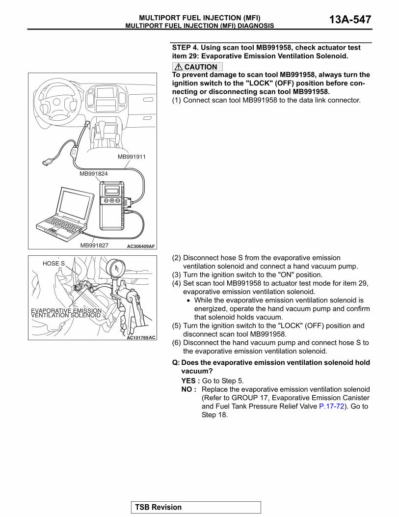
STEP 4. Using scan tool MB991958, check actuator test item 29: Evaporative Emission Ventilation Solenoid.
CAUTIONTo prevent damage to scan tool MB991958, always turn the ignition switch to the "LOCK" (OFF) position before con-necting or disconnecting scan tool MB991958.(1) Connect scan tool MB991958 to the data link connector.
(2) Disconnect hose S from the evaporative emission ventilation solenoid and connect a hand vacuum pump.
(3) Turn the ignition switch to the "ON" position.(4) Set scan tool MB991958 to actuator test mode for item 29,
evaporative emission ventilation solenoid.• While the evaporative emission ventilation solenoid is
energized, operate the hand vacuum pump and confirm that solenoid holds vacuum.
(5) Turn the ignition switch to the "LOCK" (OFF) position and disconnect scan tool MB991958.
(6) Disconnect the hand vacuum pump and connect hose S to the evaporative emission ventilation solenoid.
Q: Does the evaporative emission ventilation solenoid hold vacuum?YES : Go to Step 5.NO : Replace the evaporative emission ventilation solenoid
(Refer to GROUP 17, Evaporative Emission Canister and Fuel Tank Pressure Relief Valve P.17-72). Go to Step 18.
AC306409AF
MB991911
MB991824
MB991827
AC101769
HOSE S
AC
EVAPORATIVE EMISSIONVENTILATION SOLENOID
TSB Revision

MULTIPORT FUEL INJECTION (MFI) DIAGNOSISMULTIPORT FUEL INJECTION (MFI)13A-548
STEP 5. Check for leaks in the evaporative emission system hose S.
Perform a leakage test with a hand vacuum pump on hose S.
Q: Does hose S hold vacuum?YES : Go to Step 6.NO : Replace hose S. Go to Step 18.
STEP 6. Check for leaks in the evaporative emission system hose E.
Perform a leakage test with a hand vacuum pump on hose E.
Q: Does hose E hold vacuum?YES : Go to Step 7.NO : Replace hose E. Go to Step 18.
AC102452
HOSE S
AC
OVER VENTVALVEMODULE
AC101772
HOSE E
ACEVAPORATIVE EMISSIONCANISTER
TSB Revision

MULTIPORT FUEL INJECTION (MFI) DIAGNOSISMULTIPORT FUEL INJECTION (MFI) 13A-549
STEP 7. Pressure test the evaporative emission system lines between hose F and R.(1) Disconnect hose F from the evaporative emission canister
and plug hose F securely.(2) Confirm that the evaporative emission system pressure
pump (Miller number 6872A) is operating properly. Perform the self-test as described in the manufacturer's instructions.
(3) Remove the fuel cap.
(4) Connect the evaporative emission system pressure pump to the fuel tank filler tube.
(5) Pressure test the system to determine whether any leaks are present.NOTE: The "Pressure test" in this procedure refers to the I/M240 Simulation Test. The eight steps of this test are described in the manufacturer's instructions for the evapo-rative emission system pressure pump, Miller number 6872A.
(6) Disconnect the evaporative emission system pressure pump and reinstall the fuel cap.
(7) Connect hose F to the evaporative emission canister.Q: Is the evaporative emission system line free of leaks?
YES : Go to Step 15.NO : Go to Step 8.
STEP 8. Check for leaks in the evaporator line hose F.(1) Remove the fuel tank filler tube protector (Refer to GROUP
13B, Fuel Tank P.13B-8).(2) Disconnect hose F from the evaporative emission canister
and plug hose F securely.(3) Disconnect hose G from the evaporative emission canister
side, and connect a hand vacuum pump.(4) Apply vacuum with the hand vacuum pump and confirm that
the vacuum holds.(5) Disconnect the hand vacuum pump and connect hose F
and G. Q: Does hose F hold vacuum?
YES : Go to Step 9.NO : Replace hose F and reinstall the fuel tank filler tube
protector (Refer to GROUP 13B, Fuel Tank P.13B-8). Go to Step 18.
AC102602 AC
HOSE F
ACX01358
AC101767AC
HOSE F
HOSE G
TSB Revision

MULTIPORT FUEL INJECTION (MFI) DIAGNOSISMULTIPORT FUEL INJECTION (MFI)13A-550
STEP 9. Check for leaks in the evaporative emission system hoses G through N.(1) Remove the fuel tank filler tube (Refer to GROUP 13B, Fuel
Tank P.13B-8).(2) Perform a leakage test with a hand vacuum pump on each
hose from hose G to N.Q: Does the hoses hold vacuum?
YES : Go to Step 10.NO : Replace any damaged hose, and reinstall the fuel
tank filler tube and the fuel tank filler tube protector (Refer to GROUP 13B, Fuel Tank P.13B-8). Go to Step 18.
STEP 10. Check the check valve A.(1) Check valve A is a one-way check valve.
(2) Check valve A should allow air to flow in only one direction.Q: Does check valve A allow air to press in one direction
only?YES : Go to Step 11.NO : Replace check valve A, and reinstall the fuel tank filler
tube and the fuel tank filler tube protector (Refer to GROUP 13B, Fuel Tank P.13B-8). Go to Step 18.
AC102673 AC
HOSE GHOSE L
HOSE M
HOSE N
AC102646 AC
HOSE KHOSE I
HOSE H
HOSE J
AC102646AD
CHECKVALVE A
AC002076AB
CHECK VALVE A
TSB Revision

MULTIPORT FUEL INJECTION (MFI) DIAGNOSISMULTIPORT FUEL INJECTION (MFI) 13A-551
STEP 11. Check the check valve B.(1) Check valve B is a one-way check valve.
(2) Check valve B should allow air to flow in only one direction.Q: Does check valve B allow air to press in one direction
only?YES : Go to Step 12.NO : Replace check valve B, and reinstall the fuel tank filler
tube and the fuel tank filler tube protector (Refer to GROUP 13B, Fuel Tank P.13B-8). Go to Step 18.
STEP 12. Check for cracks in the fuel tank filler tube assembly.
Visually check for cracks in the fuel tank filler tube assembly.
Q: Is the fuel tank filler tube assembly in good condition?YES : Go to Step 13.NO : Replace the fuel tank filler tube assembly and reinstall
the fuel tank filler tube protector (Refer to GROUP 13B, Fuel Tank P.13B-8). Go to Step 18 .
AC102646 AE
CHECKVALVE B
AC002078
CHECK VALVE B
AB
TSB Revision

MULTIPORT FUEL INJECTION (MFI) DIAGNOSISMULTIPORT FUEL INJECTION (MFI)13A-552
STEP 13. Check for leaks in the evaporative emission system hoses O through R.(1) Remove the fuel tank (Refer to GROUP 13B, Fuel Tank
P.13B-8).(2) Perform a leakage test with a hand vacuum pump on each
hose from hose O to R.Q: Does the hoses hold vacuum?
YES : Go to Step 14.NO : Replace any damaged hose, and reinstall the fuel
tank, the fuel tank filler tube and the fuel tank filler tube protector (Refer to GROUP 13B, Fuel Tank P.13B-8). Go to Step 18.
STEP 14. Check for leaks in the fuel tank.(1) Visually check for cracks and leaks, etc.
NOTE: Carefully check the fuel pump assembly, the fuel level sensor, the fuel tank rollover valve and fuel tank level-ing valve installation section in the fuel tank.
AC101748
HOSE P
HOSE R
AD
HOSE O
ACX01353AC
HOSE Q
ACX01357
TSB Revision
MULTIPORT FUEL INJECTION (MFI) DIAGNOSISMULTIPORT FUEL INJECTION (MFI) 13A-553
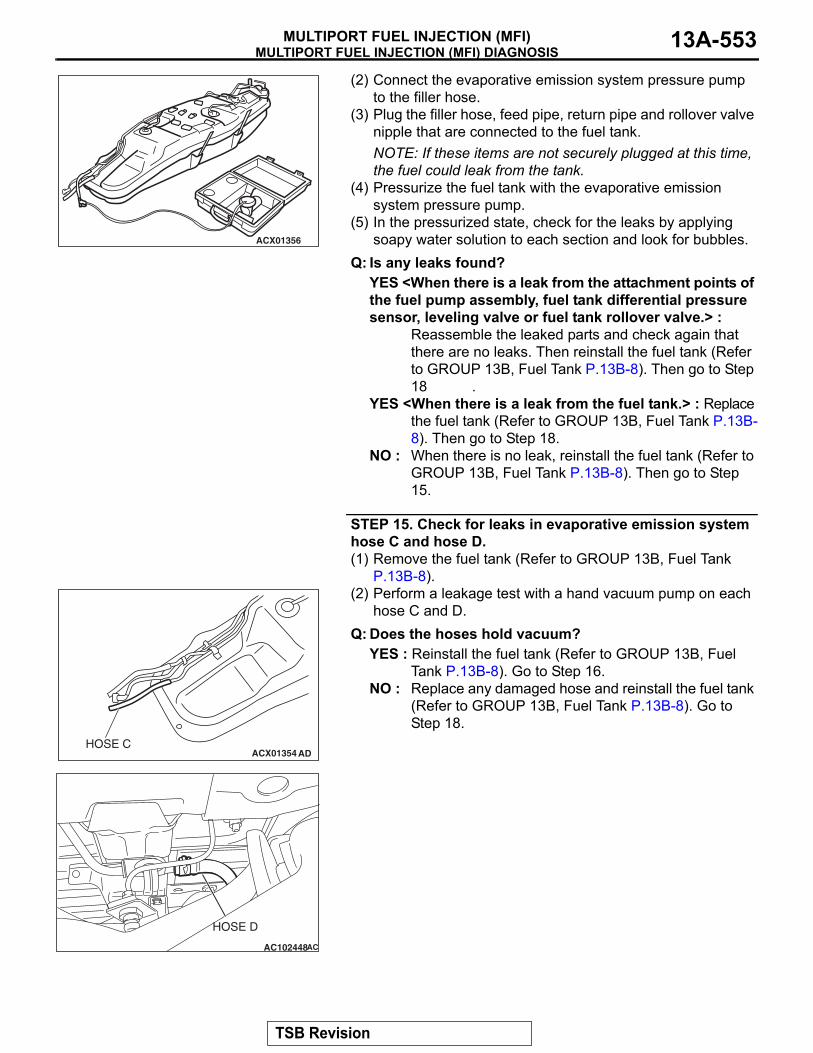
(2) Connect the evaporative emission system pressure pump to the filler hose.
(3) Plug the filler hose, feed pipe, return pipe and rollover valve nipple that are connected to the fuel tank.NOTE: If these items are not securely plugged at this time, the fuel could leak from the tank.
(4) Pressurize the fuel tank with the evaporative emission system pressure pump.
(5) In the pressurized state, check for the leaks by applying soapy water solution to each section and look for bubbles.
Q: Is any leaks found?YES <When there is a leak from the attachment points of the fuel pump assembly, fuel tank differential pressure sensor, leveling valve or fuel tank rollover valve.> :
Reassemble the leaked parts and check again that there are no leaks. Then reinstall the fuel tank (Refer to GROUP 13B, Fuel Tank P.13B-8). Then go to Step 18 .
YES <When there is a leak from the fuel tank.> : Replace the fuel tank (Refer to GROUP 13B, Fuel Tank P.13B-8). Then go to Step 18.
NO : When there is no leak, reinstall the fuel tank (Refer to GROUP 13B, Fuel Tank P.13B-8). Then go to Step 15.
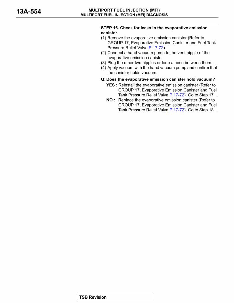
STEP 15. Check for leaks in evaporative emission system hose C and hose D.(1) Remove the fuel tank (Refer to GROUP 13B, Fuel Tank
P.13B-8).(2) Perform a leakage test with a hand vacuum pump on each
hose C and D.Q: Does the hoses hold vacuum?
YES : Reinstall the fuel tank (Refer to GROUP 13B, Fuel Tank P.13B-8). Go to Step 16.
NO : Replace any damaged hose and reinstall the fuel tank (Refer to GROUP 13B, Fuel Tank P.13B-8). Go to Step 18.
ACX01356
ACX01354 ADHOSE C
AC102448
HOSE D
AC
TSB Revision
MULTIPORT FUEL INJECTION (MFI) DIAGNOSISMULTIPORT FUEL INJECTION (MFI)13A-554
STEP 16. Check for leaks in the evaporative emission canister.(1) Remove the evaporative emission canister (Refer to
GROUP 17, Evaporative Emission Canister and Fuel Tank Pressure Relief Valve P.17-72).
(2) Connect a hand vacuum pump to the vent nipple of the evaporative emission canister.
(3) Plug the other two nipples or loop a hose between them.(4) Apply vacuum with the hand vacuum pump and confirm that
the canister holds vacuum.Q: Does the evaporative emission canister hold vacuum?
YES : Reinstall the evaporative emission canister (Refer to GROUP 17, Evaporative Emission Canister and Fuel Tank Pressure Relief Valve P.17-72). Go to Step 17 .
NO : Replace the evaporative emission canister (Refer to GROUP 17, Evaporative Emission Canister and Fuel Tank Pressure Relief Valve P.17-72). Go to Step 18 .
TSB Revision

MULTIPORT FUEL INJECTION (MFI) DIAGNOSISMULTIPORT FUEL INJECTION (MFI) 13A-555
STEP 17. Using scan tool MB991958, check evaporative emission system monitor test.
CAUTION• To prevent damage to scan tool MB991958, always turn
the ignition switch to the "LOCK" (OFF) position before connecting or disconnecting scan tool MB991958.
• During this test, the PCM automatically increases the engine speed to 1,600 r/min or greater. Check that the transmission is set to "P" position.
(1) Connect scan tool MB991958 to the data link connector.(2) Turn the ignition switch to the "ON" position.(3) Erase the DTCs using scan tool MB991958.(4) Check that the fuel cap is securely closed (Tighten until
three clicks are heard).(5) Start the engine.(6) Select "System Test."(7) Select "Evap Leak Mon."(8) During this test, keep the accelerator pedal at the idling
position.(9) Keep the engine speed and engine load within the specified
range. When the monitor test starts, the "In Progress" item on scan tool MB991958 will change from "NO" to "YES."
(10)Turn the ignition switch to the "LOCK" (OFF) position and disconnect scan tool MB991958.
Q: Is "Evap Leak Mon. Completed. Test Failed and DTCs Set" displayed on scan tool MB991958?YES : Replace the PCM (Refer to P.13A-1066). Then go to
Step 18 .NO <"Evap Leak Mon. Completed. Test Passed" is displayed on scan tool MB991958.> : The evaporative
emission system is working properly at this time. Then go to Step 18 .
NO <"Evap Leak Mon. Discontinued. Retest again from the first" is displayed on scan tool MB991958.> : The
EVAP monitor has been interrupted during the test. Turn the ignition switch to the "LOCK" (OFF) position once, and repeat the monitoring from Step 17.
STEP 18. Perform the OBD-II drive cycle.(1) Confirm the repair by performing the appropriate drive cycle
(Refer to Diagnostic Function − OBD-ll Drive Cycle − Pattern 5 P.13A-4).
(2) Read the diagnostic trouble code (DTC).Q: Is DTC P0442 set?
YES : Repeat the troubleshooting from Step 1.NO : The procedure is complete.
AC306409AF
MB991911
MB991824
MB991827
TSB Revision

MULTIPORT FUEL INJECTION (MFI) DIAGNOSISMULTIPORT FUEL INJECTION (MFI)13A-556
DTC P0443: Evaporative Emission Control System Purge Control Valve Circuit
WH
ITE
-B
LAC
K
WH
ITE
-B
LAC
K
BR
OW
N-
WH
ITE
AK401001
RE
D
MFI RELAY
23
2
1
1
4
3
2
POWERTRAINCONTROLMODULE (PCM)
EVAPORATIVE EMISSIONPURGE SOLENOID
Evaporative Emission Purge Solenoid Circuit
1 2
B-06MU802779
1 2 35 6 7 8 9
4
2021 22 232425 2627
1011121314 15 161718 19
D-132(MU803802)
87651 2 3 4
B-44MU802609
BR
OW
N-
WH
ITE
4
1 23 4
B-22X
FUSIBLE LINK (5)
TO PCM
AK201039
MFI RELAY
B-22X
AB
CONNECTOR: B-22X
AK200968
EVAPORATIVEEMISSION PURGE SOLENOID
AB
B-06(B)
CONNECTOR: B-06
TSB Revision

MULTIPORT FUEL INJECTION (MFI) DIAGNOSISMULTIPORT FUEL INJECTION (MFI) 13A-557
.
CIRCUIT OPERATION• The evaporative emission purge solenoid power
is supplied from the MFI relay (terminal No. 1).• The PCM controls ground evaporative emission
purge solenoid by turning the power transistor in the PCM ON and OFF.
.
TECHNICAL DESCRIPTION• To judge if there is open circuit in the evaporative
emission purge solenoid drive circuit, the PCM measures the surge voltage of the evaporative emission ventilation solenoid coil.
.
DESCRIPTIONS OF MONITOR METHODSOff-surge does not occur after solenoid is operated
from on to off.
.
MONITOR EXECUTIONContinuous.
MONITOR EXECUTION CONDITIONS (Other monitor and Sensor)Other Monitor (There is no temporary DTC stored
in memory for the item monitored below)• Not applicable
Sensor (The sensor below is determined to be normal)
• Not applicable.
AK201038
CONNECTOR: D-132
AB
PCM
D-132(GR)
AK201050
B-44(B)
AB
CONNECTOR: B-44
TSB Revision

MULTIPORT FUEL INJECTION (MFI) DIAGNOSISMULTIPORT FUEL INJECTION (MFI)13A-558
DTC SET CONDITIONS
Logic Flow Chart
.
Check Conditions• Engine is being cranked.• Battery positive voltage is between 10 and 16.5
volts.
Judgement Criteria• The evaporative emission purge solenoid coil
surge voltage (battery positive voltage + 2 volts) is not detected for 0.2 second.
• The PCM monitors for this condition once during the drive cycle.
Check Conditions• Battery positive voltage is between 10 and 16.5
volts.• ON duty cycle of the evaporative emission purge
solenoid is between 10 and 90 percent.• Evaporative emission ventilation solenoid is OFF.• More than 1 second has elapsed after the above
mentioned conditions have been met.
Judgement Criterion• The evaporative emission purge solenoid coil
surge voltage (battery positive voltage + 2 volts) is not detected for 1 second after the evaporative emission purge solenoid is turned OFF.
.
OBD-II DRIVE CYCLE PATTERNRefer to Diagnostic Function − OBD-II Drive Cycle −
Pattern 20 P.13A-4..
TROUBLESHOOTING HINTS (The most likely causes for this code to be set are:)• Evaporative emission purge solenoid failed.• Open or shorted evaporative emission purge
solenoid circuit, harness damage, or connector damage.
• PCM failed.
MONITORINGCONDITIONS
NO
NO
YES
YES
GOODMALFUNCTION
WAS SURGE VOLTAGE(> VB+2V) DETECTED?
START
END
AK302954
TSB Revision

MULTIPORT FUEL INJECTION (MFI) DIAGNOSISMULTIPORT FUEL INJECTION (MFI) 13A-559
DIAGNOSISRequired Special Tools:• MB991958: Scan Tool (MUT-III Sub Assembly)
• MB991824: V.C.I.• MB991827: USB Cable• MB991911: Main Harness B
STEP 1. Using scan tool MB991958, check actuator test item 08: Evaporative Emission Purge Solenoid.
CAUTIONTo prevent damage to scan tool MB991958, always turn the ignition switch to the "LOCK" (OFF) position before con-necting or disconnecting scan tool MB991958.(1) Connect scan tool MB991958 to the data link connector.(2) Turn the ignition switch to the "ON" position.(3) Set scan tool MB991958 to the actuator test mode for item
08, Evaporative emission purge solenoid.• An operation sound should be heard and vibration
should be felt when the evaporative emission purge solenoid is operated.
(4) Turn the ignition switch to the "LOCK" (OFF) position.Q: Is the solenoid operating properly?
YES : It can be assumed that this malfunction is intermittent. Refer to GROUP 00, How to Use Troubleshooting/Inspection Service Points − How to Cope with Intermittent Malfunctions P.00-13.
NO : Go to Step 2.
STEP 2 Check harness connector B-06 at the evaporative emission purge solenoid for damage.Q: Is the harness connector in good condition?
YES : Go to Step 3.NO : Repair or replace it. Refer to GROUP 00E, Harness
Connector Inspection P.00E-2. Then go to Step 12.
AK302970AB
MB991911
MB991824
MB991827
AK201272
12
AB
CONNECTOR: B-06
HARNESS CONNECTOR: COMPONENT SIDE
B-06(B)
TSB Revision

MULTIPORT FUEL INJECTION (MFI) DIAGNOSISMULTIPORT FUEL INJECTION (MFI)13A-560
STEP 3 Check the evaporative emission purge solenoid.(1) Disconnect the evaporative emission purge solenoid
connector B-06.
(2) Measure the resistance between evaporative emission purge solenoid side connector terminal No. 1 and No. 2.
Standard value: 30 − 34 ohms [at 20°C (68°F)]Q: Is the resistance between 30 and 34 ohms [at 20°C
(68°F)]?YES : Go to Step 4NO : Replace the evaporative emission purge solenoid.
Then go to Step 12.
STEP 4. Measure the power supply voltage at evaporative emission purge solenoid harness side connector B-06.(1) Disconnect the connector B-06 and measure at the harness
side.(2) Turn the ignition switch to the "ON" position.
(3) Measure the voltage between terminal No. 2 and ground.• Voltage should be battery positive voltage.
(4) Turn the ignition switch to the "LOCK" (OFF) position.Q: Is battery positive voltage (approximately 12 volts)
present?YES : Go to Step 6.NO : Go to Step 5.
AK201272
12
AB
CONNECTOR: B-06
HARNESS CONNECTOR: COMPONENT SIDE
B-06(B)
1 2
AK401158
EVAPORATIVEEMISSION PURGESOLENOID CONNECTOR
AC
AK201272
12
AB
CONNECTOR: B-06
HARNESS CONNECTOR: COMPONENT SIDE
B-06(B)
AKX01502
12
B-06 HARNESS CONNECTOR: COMPONENT SIDE
AV
TSB Revision
MULTIPORT FUEL INJECTION (MFI) DIAGNOSISMULTIPORT FUEL INJECTION (MFI) 13A-561
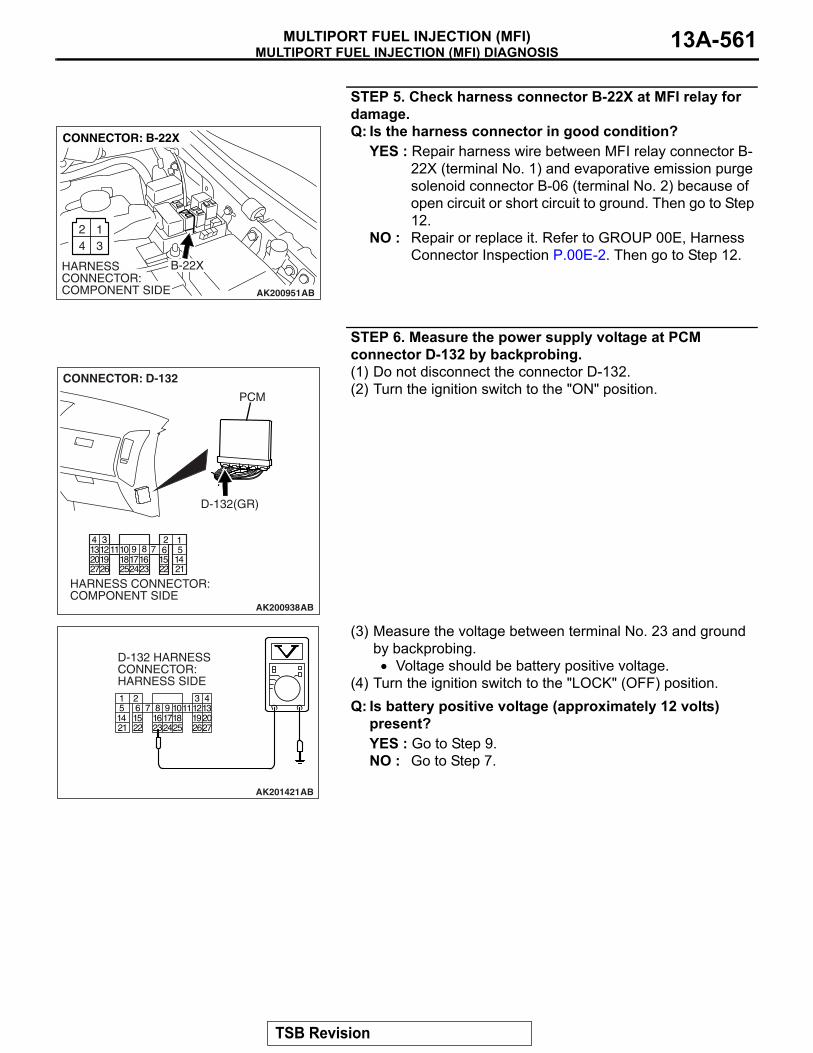
STEP 5. Check harness connector B-22X at MFI relay for damage.Q: Is the harness connector in good condition?
YES : Repair harness wire between MFI relay connector B-22X (terminal No. 1) and evaporative emission purge solenoid connector B-06 (terminal No. 2) because of open circuit or short circuit to ground. Then go to Step 12.
NO : Repair or replace it. Refer to GROUP 00E, Harness Connector Inspection P.00E-2. Then go to Step 12.
STEP 6. Measure the power supply voltage at PCM connector D-132 by backprobing.(1) Do not disconnect the connector D-132.(2) Turn the ignition switch to the "ON" position.
(3) Measure the voltage between terminal No. 23 and ground by backprobing.• Voltage should be battery positive voltage.
(4) Turn the ignition switch to the "LOCK" (OFF) position.Q: Is battery positive voltage (approximately 12 volts)
present?YES : Go to Step 9.NO : Go to Step 7.
AK200951
2 134
B-22X
AB
CONNECTOR: B-22X
HARNESS CONNECTOR: COMPONENT SIDE
AK200938
234567891
101415161718192021222324252627
111213
AB
CONNECTOR: D-132
HARNESS CONNECTOR: COMPONENT SIDE
PCM
D-132(GR)
AK201421
1 2 35 6 7 8 9
4
2021 22 232425 2627
1011121314 15 161718 19
D-132 HARNESS CONNECTOR: HARNESS SIDE
AB
TSB Revision

MULTIPORT FUEL INJECTION (MFI) DIAGNOSISMULTIPORT FUEL INJECTION (MFI)13A-562
STEP 7. Check harness connector D-132 at PCM for damage.Q: Is the harness connector in good condition?
YES : Go to Step 8.NO : Repair or replace it. Refer to GROUP 00E, Harness
Connector Inspection P.00E-2. Then go to Step 12.
STEP 8. Check for open circuit and short circuit to ground between evaporative emission purge solenoid connector B-06 (terminal No. 1) and PCM connector D-132 (terminal No. 23).
AK200938
234567891
101415161718192021222324252627
111213
AB
CONNECTOR: D-132
HARNESS CONNECTOR: COMPONENT SIDE
PCM
D-132(GR)
AK201272
12
AB
CONNECTOR: B-06
HARNESS CONNECTOR: COMPONENT SIDE
B-06(B)
AK200938
234567891
101415161718192021222324252627
111213
AB
CONNECTOR: D-132
HARNESS CONNECTOR: COMPONENT SIDE
PCM
D-132(GR)
TSB Revision

MULTIPORT FUEL INJECTION (MFI) DIAGNOSISMULTIPORT FUEL INJECTION (MFI) 13A-563
NOTE: Check harness after checking intermediate connector B-44. If intermediate connector B-44 is damaged, repair or replace it. Refer to GROUP 00E, Harness Connector Inspec-tion P.00E-2.Q: Is the harness wire in good condition?
YES : Replace the PCM. Then go to Step 12.NO : Repair it. Then go to Step 12.
STEP 9. Check harness connector D-132 at PCM for damage.Q: Is the harness connector in good condition?
YES : Go to Step 10.NO : Repair or replace it. Refer to GROUP 00E, Harness
Connector Inspection P.00E-2. Then go to Step 12.
STEP 10. Check for harness damage between MFI relay connector B-22X (terminal No. 1) and evaporative emission purge solenoid connector B-06 (terminal No. 2).Q: Is the harness wire in good condition?
YES : Go to Step 11.NO : Repair it. Then go to Step 12.
AK200938
234567891
101415161718192021222324252627
111213
AB
CONNECTOR: D-132
HARNESS CONNECTOR: COMPONENT SIDE
PCM
D-132(GR)
AK200951
2 134
B-22X
AB
CONNECTOR: B-22X
HARNESS CONNECTOR: COMPONENT SIDE
AK201272
12
AB
CONNECTOR: B-06
HARNESS CONNECTOR: COMPONENT SIDE
B-06(B)
TSB Revision
MULTIPORT FUEL INJECTION (MFI) DIAGNOSISMULTIPORT FUEL INJECTION (MFI)13A-564
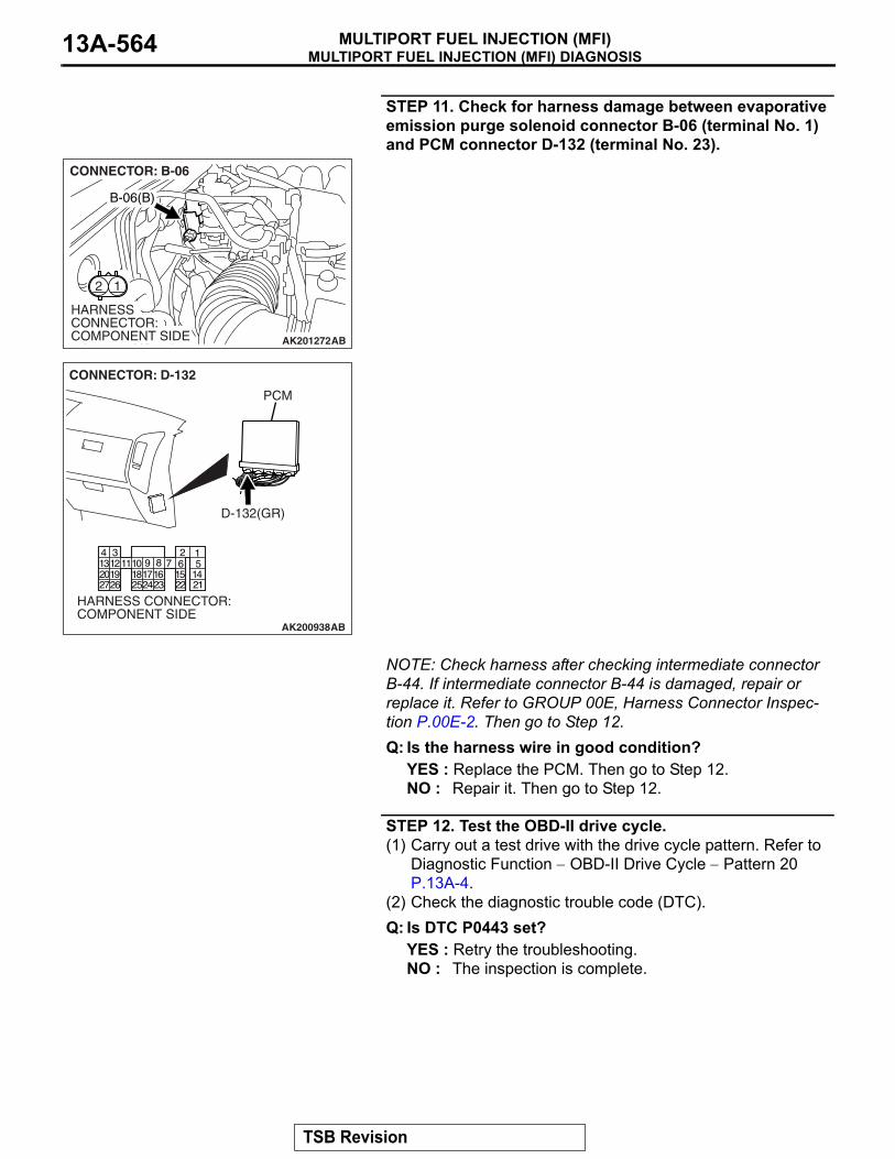
STEP 11. Check for harness damage between evaporative emission purge solenoid connector B-06 (terminal No. 1) and PCM connector D-132 (terminal No. 23).
NOTE: Check harness after checking intermediate connector B-44. If intermediate connector B-44 is damaged, repair or replace it. Refer to GROUP 00E, Harness Connector Inspec-tion P.00E-2. Then go to Step 12.Q: Is the harness wire in good condition?
YES : Replace the PCM. Then go to Step 12.NO : Repair it. Then go to Step 12.
STEP 12. Test the OBD-II drive cycle.(1) Carry out a test drive with the drive cycle pattern. Refer to
Diagnostic Function − OBD-II Drive Cycle − Pattern 20 P.13A-4.
(2) Check the diagnostic trouble code (DTC).Q: Is DTC P0443 set?
YES : Retry the troubleshooting.NO : The inspection is complete.
AK201272
12
AB
CONNECTOR: B-06
HARNESS CONNECTOR: COMPONENT SIDE
B-06(B)
AK200938
234567891
101415161718192021222324252627
111213
AB
CONNECTOR: D-132
HARNESS CONNECTOR: COMPONENT SIDE
PCM
D-132(GR)
TSB Revision

MULTIPORT FUEL INJECTION (MFI) DIAGNOSISMULTIPORT FUEL INJECTION (MFI) 13A-565
DTC P0446: Evaporative Emission Control System Vent Control Circuit
AK400985
1 2
7 85
3 4
3534
10 11 12
2122 23 24
13 14 15
25 26 27
16
281718 19 20
2930 31 32 33 36 37
38
9
1 2
615 16
26 27 28 29
32 33 34
17 18 19 20 2122 23 24 25
30 31
36 3735
38
10 1112 131 2 3 4 5 6 7 8 9
14
1
12
23 24 25 26
2
13
3
14
4
15
5
16
6
17
7
18
8
19
9
20 21 22
27 28 29 30 31 32 33
10 11
7 9
1 3
6 11
2 4
8
5
10 1312 14
536
1 24
1 2 35 6 7 8 9
4
2021 22 232425 2627
1011121314 15 161718 19
1 23 4
WH
ITE
-B
LAC
K
WH
ITE
-B
LAC
K
MFI RELAY
2
1
B-22X3
Evaporative Emission Ventilation Solenoid Circuit
RE
D
1
25
6
D-116 E-111
D-112F-10
4
2
EVAPORATIVEEMISSIONVENTILATIONSOLENOID
RE
DR
ED
RE
D
RE
D
2
6
E-111
D-112
D-116
TO PCM
11
E-113
1
POWERTRAINCONTROLMODULE (PCM)
G-27MU802779
GR
EE
N-
RE
D
5
1
3
E-113
GR
EE
N-
RE
DG
RE
EN
-R
ED
GR
EE
N-
RE
D
F-10
D-132(MU803802)
FUSIBLE LINK (5)
TSB Revision
MULTIPORT FUEL INJECTION (MFI) DIAGNOSISMULTIPORT FUEL INJECTION (MFI)13A-566
.
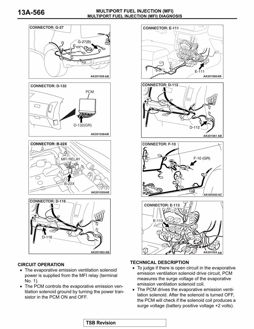
CIRCUIT OPERATION• The evaporative emission ventilation solenoid
power is supplied from the MFI relay (terminal No. 1).
• The PCM controls the evaporative emission ven-tilation solenoid ground by turning the power tran-sistor in the PCM ON and OFF.
.
TECHNICAL DESCRIPTION• To judge if there is open circuit in the evaporative
emission ventilation solenoid drive circuit, PCM measures the surge voltage of the evaporative emission ventilation solenoid coil.
• The PCM drives the evaporative emission venti-lation solenoid. After the solenoid is turned OFF, the PCM will check if the solenoid coil produces a surge voltage (battery positive voltage +2 volts).
.
AK201059
G-27(B)
AB
CONNECTOR: G-27
AK201038
CONNECTOR: D-132
AB
PCM
D-132(GR)
AK201039
MFI RELAY
B-22X
AB
CONNECTOR: B-22X
AK201063
CONNECTOR: D-116
D-116
AB
AK201060
E-111AB
CONNECTOR: E-111
AK201061
CONNECTOR: D-112
D-112
AB
AK304350
F-10 (GR)
AC
CONNECTOR: F-10
AK201053
E-113
AB
CONNECTOR: E-113
TSB Revision

MULTIPORT FUEL INJECTION (MFI) DIAGNOSISMULTIPORT FUEL INJECTION (MFI) 13A-567
DESCRIPTIONS OF MONITOR METHODSOff-surge does not occur after solenoid is operated
on to off..
MONITOR EXECUTIONContinuous.
MONITOR EXECUTION CONDITIONS (Other monitor and Sensor)Other Monitor (There is no temporary DTC stored
in memory for the item monitored below)• Not applicable
Sensor (The sensor below is determined to be normal)
• Not applicable.
DTC SET CONDITIONS
Logic Flow Chart
.
Check Conditions• Engine is being cranked.• Battery positive voltage is between 10 and 16.5
volts.
Judgement Criteria• The evaporative emission ventilation solenoid
coil surge voltage (battery positive voltage + 2 volts) is not detected for 0.2 second.
• The PCM monitors for this condition once during the drive cycle.
Check Conditions• Battery positive voltage is at between 10 and
16.5 volts.• ON duty cycle of the evaporative emission purge
solenoid is 0 percent.• Evaporative emission ventilation solenoid is ON.• More than 1 second has elapsed after the above
mentioned conditions have been met.
MONITORINGCONDITIONS
NO
NO
YES
YES
GOODMALFUNCTION
WAS SURGE VOLTAGE(> VB+2V) DETECTED?
START
END
AK302954
TSB Revision

MULTIPORT FUEL INJECTION (MFI) DIAGNOSISMULTIPORT FUEL INJECTION (MFI)13A-568
Judgement Criterion• The evaporative emission ventilation solenoid
coil surge voltage (battery positive voltage + 2 volts) is not detected for 1 second after the evap-orative emission ventilation solenoid is turned OFF.
.
OBD-II DRIVE CYCLE PATTERNRefer to Diagnostic Function − OBD-II Drive Cycle −
Pattern 20 P.13A-4.
.
TROUBLESHOOTING HINTS (The most likely causes for this code to be set are:)• Evaporative emission ventilation solenoid failed.• Open or shorted evaporative emission ventilation
solenoid circuit, harness damage, or connector damage.
• PCM failed.
DIAGNOSISRequired Special Tools:• MB991958: Scan Tool (MUT-III Sub Assembly)
• MB991824: V.C.I.• MB991827: USB Cable• MB991911: Main Harness B
STEP 1. Using scan tool MB991958, check actuator test item 29: Evaporative Emission Ventilation Solenoid.
CAUTIONTo prevent damage to scan tool MB991958, always turn the ignition switch to the "LOCK" (OFF) position before con-necting or disconnecting scan tool MB991958.(1) Connect scan tool MB991958 to the data link connector.(2) Turn the ignition switch to the "ON" position.(3) Set scan tool MB991958 to the actuator test mode for item
29, Evaporative emission ventilation solenoid.• An operation sound should be heard and vibration
should be felt when the evaporative emission ventilation solenoid is operated.
(4) Turn the ignition switch to the "LOCK" (OFF) position.Q: Is the solenoid operating properly?
YES : It can be assumed that this malfunction is intermittent. Refer to GROUP 00, How to Use Troubleshooting/Inspection Service Points − How to Cope with Intermittent Malfunctions P.00-13.
NO : Go to Step 2.
STEP 2. Check harness connector G-27 at the evaporative emission ventilation solenoid for damage.Q: Is the harness connector in good condition?
YES : Go to Step 3.NO : Repair or replace it. Refer to GROUP 00E, Harness
Connector Inspection P.00E-2. Then go to Step 12.
AK302970AB
MB991911
MB991824
MB991827
AK200969
12
G-27(B)
AB
CONNECTOR: G-27
HARNESS CONNECTOR: COMPONENT SIDE
TSB Revision
MULTIPORT FUEL INJECTION (MFI) DIAGNOSISMULTIPORT FUEL INJECTION (MFI) 13A-569
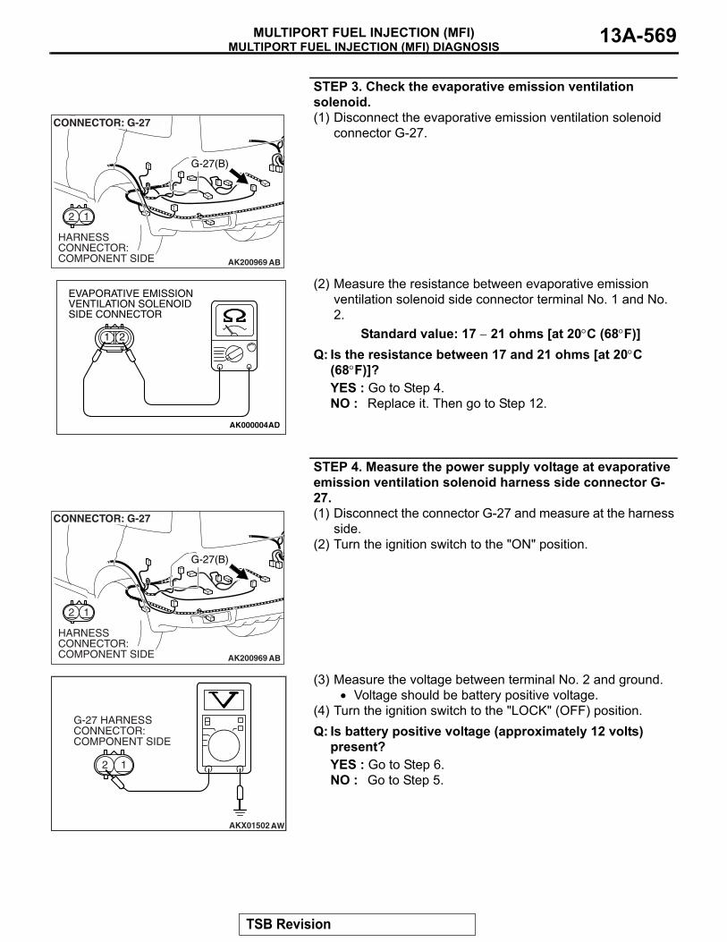
STEP 3. Check the evaporative emission ventilation solenoid.(1) Disconnect the evaporative emission ventilation solenoid
connector G-27.
(2) Measure the resistance between evaporative emission ventilation solenoid side connector terminal No. 1 and No. 2.
Standard value: 17 − 21 ohms [at 20°C (68°F)]Q: Is the resistance between 17 and 21 ohms [at 20°C
(68°F)]?YES : Go to Step 4.NO : Replace it. Then go to Step 12.
STEP 4. Measure the power supply voltage at evaporative emission ventilation solenoid harness side connector G-27.(1) Disconnect the connector G-27 and measure at the harness
side.(2) Turn the ignition switch to the "ON" position.
(3) Measure the voltage between terminal No. 2 and ground.• Voltage should be battery positive voltage.
(4) Turn the ignition switch to the "LOCK" (OFF) position.Q: Is battery positive voltage (approximately 12 volts)
present?YES : Go to Step 6.NO : Go to Step 5.
AK200969
12
G-27(B)
AB
CONNECTOR: G-27
HARNESS CONNECTOR: COMPONENT SIDE
AK000004
21
AD
EVAPORATIVE EMISSION VENTILATION SOLENOID SIDE CONNECTOR
AK200969
12
G-27(B)
AB
CONNECTOR: G-27
HARNESS CONNECTOR: COMPONENT SIDE
AKX01502
G-27 HARNESS CONNECTOR: COMPONENT SIDE
1
AW
2
TSB Revision
MULTIPORT FUEL INJECTION (MFI) DIAGNOSISMULTIPORT FUEL INJECTION (MFI)13A-570
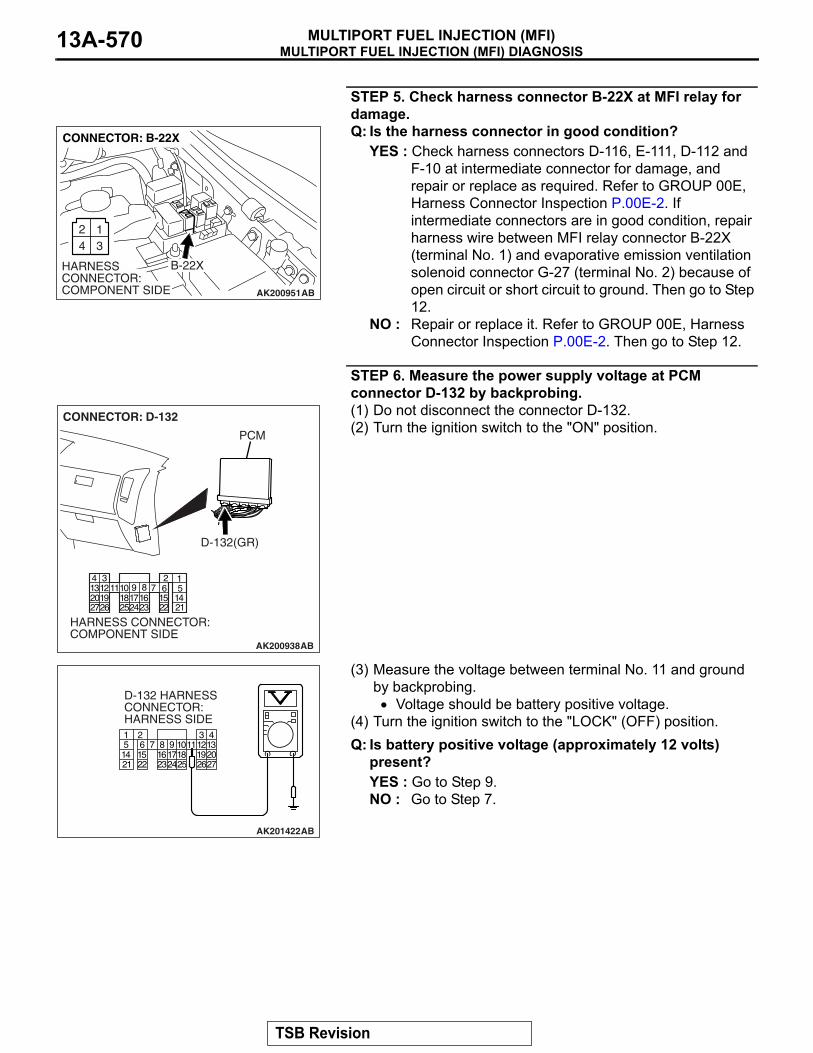
STEP 5. Check harness connector B-22X at MFI relay for damage.Q: Is the harness connector in good condition?
YES : Check harness connectors D-116, E-111, D-112 and F-10 at intermediate connector for damage, and repair or replace as required. Refer to GROUP 00E, Harness Connector Inspection P.00E-2. If intermediate connectors are in good condition, repair harness wire between MFI relay connector B-22X (terminal No. 1) and evaporative emission ventilation solenoid connector G-27 (terminal No. 2) because of open circuit or short circuit to ground. Then go to Step 12.
NO : Repair or replace it. Refer to GROUP 00E, Harness Connector Inspection P.00E-2. Then go to Step 12.
STEP 6. Measure the power supply voltage at PCM connector D-132 by backprobing.(1) Do not disconnect the connector D-132.(2) Turn the ignition switch to the "ON" position.
(3) Measure the voltage between terminal No. 11 and ground by backprobing.• Voltage should be battery positive voltage.
(4) Turn the ignition switch to the "LOCK" (OFF) position.Q: Is battery positive voltage (approximately 12 volts)
present?YES : Go to Step 9.NO : Go to Step 7.
AK200951
2 134
B-22X
AB
CONNECTOR: B-22X
HARNESS CONNECTOR: COMPONENT SIDE
AK200938
234567891
101415161718192021222324252627
111213
AB
CONNECTOR: D-132
HARNESS CONNECTOR: COMPONENT SIDE
PCM
D-132(GR)
AK201422
1 2 35 6 7 8 9
4
2021 22 232425 2627
1011121314 15 161718 19
AB
D-132 HARNESS CONNECTOR: HARNESS SIDE
TSB Revision

MULTIPORT FUEL INJECTION (MFI) DIAGNOSISMULTIPORT FUEL INJECTION (MFI) 13A-571
STEP 7. Check harness connector D-132 at PCM for damage.Q: Is the harness connector in good condition?
YES : Go to Step 8.NO : Repair or replace it. Refer to GROUP 00E, Harness
Connector Inspection P.00E-2. Then go to Step 12.
STEP 8. Check for open circuit and short circuit to ground between evaporative emission ventilation solenoid connector G-27 (terminal No. 1) and PCM connector D-132 (terminal No. 11).
AK200938
234567891
101415161718192021222324252627
111213
AB
CONNECTOR: D-132
HARNESS CONNECTOR: COMPONENT SIDE
PCM
D-132(GR)
AK200969
12
G-27(B)
AB
CONNECTOR: G-27
HARNESS CONNECTOR: COMPONENT SIDE
AK200938
234567891
101415161718192021222324252627
111213
AB
CONNECTOR: D-132
HARNESS CONNECTOR: COMPONENT SIDE
PCM
D-132(GR)
TSB Revision

MULTIPORT FUEL INJECTION (MFI) DIAGNOSISMULTIPORT FUEL INJECTION (MFI)13A-572
NOTE: Check harness after checking intermediate connectors F-10, D-112 and E-113. If intermediate connectors are dam-aged, repair or replace them. Refer to GROUP 00E, Harness Connector Inspection P.00E-2. Then go to Step 12.Q: Is the harness wire in good condition?
YES : Replace the PCM. Then go to Step 12.NO : Repair it. Then go to Step 12.
STEP 9. Check harness connector D-132 at PCM for damage.Q: Is the harness connector in good condition?
YES : Go to Step 10.NO : Repair or replace it. Refer to GROUP 00E, Harness
Connector Inspection P.00E-2. Then go to Step 12.
STEP 10. Check for harness damage between MFI relay connector B-22X (terminal No. 1) and evaporative emission ventilation solenoid connector G-27 (terminal No. 2).
AK200938
234567891
101415161718192021222324252627
111213
AB
CONNECTOR: D-132
HARNESS CONNECTOR: COMPONENT SIDE
PCM
D-132(GR)
AK200951
2 134
B-22X
AB
CONNECTOR: B-22X
HARNESS CONNECTOR: COMPONENT SIDE
AK200969
12
G-27(B)
AB
CONNECTOR: G-27
HARNESS CONNECTOR: COMPONENT SIDE
TSB Revision

MULTIPORT FUEL INJECTION (MFI) DIAGNOSISMULTIPORT FUEL INJECTION (MFI) 13A-573
NOTE: Check harness after checking intermediate connectors D-116, E-111, D-112 and F-10. If intermediate connectors are damaged, repair or replace them. Refer to GROUP 00E, Har-ness Connector Inspection P.00E-2. Then go to Step 12.Q: Is the harness wire in good condition?
YES : Go to Step 11.NO : Repair it. Then go to Step 12.
STEP 11. Check for harness damage between evaporative emission ventilation solenoid connector G-27 (terminal No. 1) and PCM connector D-132 (terminal No. 11).
NOTE: Check harness after checking intermediate connectors F-10, D-112 and E-113. If intermediate connectors are dam-aged, repair or replace them. Refer to GROUP 00E, Harness Connector Inspection P.00E-2. Then go to Step 12.Q: Is the harness wire in good condition?
YES : Replace the PCM. Then go to Step 12.NO : Repair it. Then go to Step 12.
AK200969
12
G-27(B)
AB
CONNECTOR: G-27
HARNESS CONNECTOR: COMPONENT SIDE
AK200938
234567891
101415161718192021222324252627
111213
AB
CONNECTOR: D-132
HARNESS CONNECTOR: COMPONENT SIDE
PCM
D-132(GR)
TSB Revision

MULTIPORT FUEL INJECTION (MFI) DIAGNOSISMULTIPORT FUEL INJECTION (MFI)13A-574
STEP 12. Test the OBD-II drive cycle.(1) Carry out a test drive with the drive cycle pattern. Refer to
Diagnostic Function − OBD-II Drive Cycle − Pattern 20 P.13A-4.
(2) Check the diagnostic trouble code (DTC).Q: Is DTC P0446 set?
YES : Retry the troubleshooting.NO : The inspection is complete.
DTC P0450: Evaporative Emission System Pressure Sensor malfunction
AC203991
SYSTEM DIAGRAM
A
B C D
EF
G
H
I
J
K
LM
N
OQ
S
R
P
FUEL TANK
CHECK VALVE B
CHECK VALVE AEVAPORATIVEEMISSIONPURGESOLENOID
EVAPORATIVE EMISSIONVENTILATION SOLENOID
EVAPORATIVEEMISSIONCANISTER
VENT PIPEASSEMBLY
AC
FUEL TANK DIFFERENTIALPRESSURE SENSOR
ONBOARD REFUELINGVAPOR RECOVERY(ORVR)VENT VALVE MODULE
TSB Revision

MULTIPORT FUEL INJECTION (MFI) DIAGNOSISMULTIPORT FUEL INJECTION (MFI) 13A-575
FUEL TANKDIFFERENTIALPRESSURESENSOR
POWERTRAIN CONTROLMODULE (PCM)
AC309251
Fuel Tank Differential Pressure Sensor Circuit
AC
FUEL TANKDIFFERENTIALPRESSURESENSOR
POWERTRAIN CONTROLMODULE (PCM)
AC309251
TSB Revision

MULTIPORT FUEL INJECTION (MFI) DIAGNOSISMULTIPORT FUEL INJECTION (MFI)13A-576
AC401282
CONNECTOR: D-112
AB
D-112
AC401283
CONNECTORS: D-134, D-135
AB
D-134(GR)
D-134
D-135(GR)
D-135
PCM
AC401286
CONNECTORS: E-111, E-113
AB
E-113
E-113
E-111
E-111AC204000
CONNECTOR: F-07
AC
F-07 (B)
F-07 HARNESSCONNECTOR:COMPONENT SIDE
84321
5 6 7
TSB Revision

MULTIPORT FUEL INJECTION (MFI) DIAGNOSISMULTIPORT FUEL INJECTION (MFI) 13A-577
.
CIRCUIT OPERATION• The PCM (terminal 97) supplies a 5-volt refer-
ence signal to the fuel tank differential pressure sensor (terminal 3). The fuel tank differential pressure sensor (terminal 2) is grounded through the PCM (terminal 96).
• The fuel tank differential pressure sensor (termi-nal 1) returns a voltage signal to the PCM (termi-nal 82) that is proportional to the pressure in the fuel tank.
.
TECHNICAL DESCRIPTION• The PCM monitors the fuel tank differential pres-
sure sensor output voltage.• The PCM determines whether the fuel tank differ-
ential pressure sensor signal voltage is within normal operating parameters.
.
DESCRIPTIONS OF MONITOR METHODS• Compare purge solenoid status with fuel tank dif-
ferential pressure sensor output voltage.
.
MONITOR EXECUTION• Continuous.
.
MONITOR EXECUTION CONDITIONS (OTHER MONITOR AND SENSOR)Other Monitor (There is no temporary DTC stored
in memory for the item monitored below)• Evaporative emission purge solenoid monitor• Evaporative emission ventilation solenoid monitor• Fuel level sensor monitor• Fuel temperature sensor monitor
Sensor (The sensors below are determined to be normal)
• Volume airflow sensor• Barometric pressure sensor• Intake air temperature sensor• Engine coolant temperature sensor• Accelerator pedal position sensor
.
ACX00218
CONNECTOR : G-05
AU
G-05 (B)
SECOND SEAT UNDERSERVICE HOLE
TSB Revision

MULTIPORT FUEL INJECTION (MFI) DIAGNOSISMULTIPORT FUEL INJECTION (MFI)13A-578
LOGIC FLOW CHARTS (Monitor Sequence)
.
DTC SET CONDITIONSCheck Conditions • Intake air temperature is greater than 5°C (41°F).• Engine speed is 1,600 r/min or greater.• Volumetric efficiency is between 20 and 70 per-
cent.
Judgment Criterion• When the evaporative emission purge solenoid is
off, the fuel differential pressure sensor output voltage remains 1.0 volt or less for ten seconds.
Check Conditions • Intake air temperature is between 5°C (41°F) and
45°C (113°F) or greater.• Engine speed is 1,600 r/min or greater.• Volumetric efficiency is between 20 and 70 per-
cent.
Judgment Criterion• When the evaporative emission purge solenoid
valve is fully operational (100 percent ratio), the fuel differential pressure sensor output voltage remains at 4.0 volts or greater for ten seconds.
.
OBD-ll DRIVE CYCLE PATTERNRefer to Diagnostic Function − OBD-ll Drive Cycle − Pattern 5 P.13A-4..
TROUBLESHOOTING HINTS (THE MOST LIKELY CAUSES FOR THIS CODE TO BE SET ARE:)• Malfunction of the fuel tank differential pressure
sensor.• A damaged harness in the fuel tank differential
pressure sensor circuit.• Malfunction of the PCM.
.
NO
YES
CONTINUOUSFAILURE FOR 10 SECS
START
END
NO
NO
NO
YES
YES
YES
MALFUNCTION GOOD
MONITORING CONDITIONS
OUTPUT VOLTAGE < 1.0V
OUTPUT VOLTAGE > 4.0V
AC401446
RATIONALITY - HIGH/LOW
TSB Revision
MULTIPORT FUEL INJECTION (MFI) DIAGNOSISMULTIPORT FUEL INJECTION (MFI) 13A-579
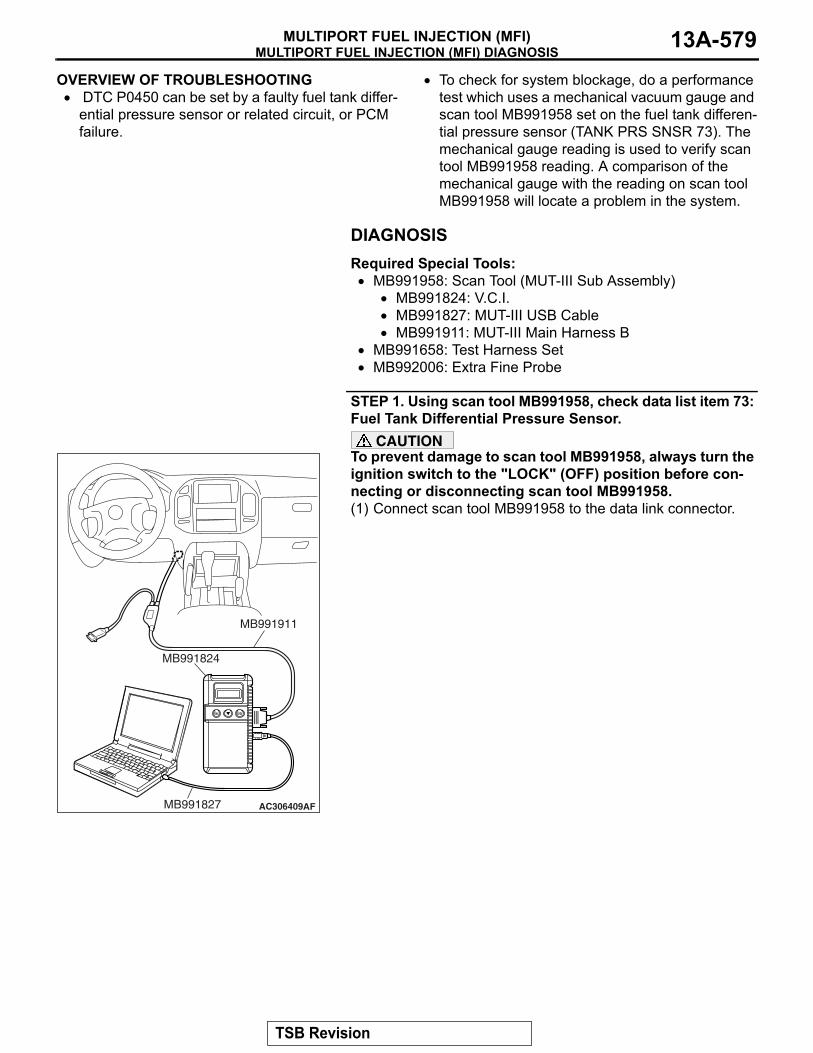
OVERVIEW OF TROUBLESHOOTING• DTC P0450 can be set by a faulty fuel tank differ-
ential pressure sensor or related circuit, or PCM failure.
• To check for system blockage, do a performance test which uses a mechanical vacuum gauge and scan tool MB991958 set on the fuel tank differen-tial pressure sensor (TANK PRS SNSR 73). The mechanical gauge reading is used to verify scan tool MB991958 reading. A comparison of the mechanical gauge with the reading on scan tool MB991958 will locate a problem in the system.
DIAGNOSISRequired Special Tools:• MB991958: Scan Tool (MUT-III Sub Assembly)
• MB991824: V.C.I.• MB991827: MUT-III USB Cable• MB991911: MUT-III Main Harness B
• MB991658: Test Harness Set• MB992006: Extra Fine Probe
STEP 1. Using scan tool MB991958, check data list item 73: Fuel Tank Differential Pressure Sensor.
CAUTIONTo prevent damage to scan tool MB991958, always turn the ignition switch to the "LOCK" (OFF) position before con-necting or disconnecting scan tool MB991958.(1) Connect scan tool MB991958 to the data link connector.
AC306409AF
MB991911
MB991824
MB991827
TSB Revision

MULTIPORT FUEL INJECTION (MFI) DIAGNOSISMULTIPORT FUEL INJECTION (MFI)13A-580
(2) Disconnect hose F from the evaporative emission canister side, and plug the hose.
(3) Turn the ignition switch to the "ON" position.(4) Remove the fuel cap.(5) Set scan tool MB991958 to the data reading mode.
Item 73, Fuel Tank Differential Pressure Sensor.• The fuel tank pressures reading on the scan tool
should be −1.5 to 1.5 kPa (−0.443 to 0.443 inHg).
(6) Connect an evaporative emission system pressure pump to the fuel tank filler tube and pressurize the fuel tank.• The fuel tank pressure reading should increase.
(7) Disconnect an evaporative emission system pressure pump and connect hose F.
(8) Turn the ignition switch to the "LOCK" (OFF) position and disconnect scan tool MB991958.
Q: Is the fuel tank pressure between −1.5 and 1.5 kPa (−0.443 and 0.443 inHg)?YES : It can be assumed that this malfunction is intermittent
(Refer to GROUP 00, How to Use Troubleshooting/Inspection Service Points − How to Cope with Intermittent Malfunctions P.00-13). Go to Step 15.
NO : Go to Step 2.
STEP 2. Measure the signal voltage at fuel tank differential pressure sensor connector G-05.(1) Tumble the second seat.(2) Remove the service hole cover (upper) and packing.(3) Remove the service hole cover (lower) and packing.(4) Disconnect fuel tank differential pressure sensor connector
G-05.
(5) Connect special tool MB991658 between fuel tank differential pressure sensor connector G-05 terminals 1, 2 and 3.
(6) Turn the ignition switch to the "ON" position.(7) Remove the fuel cap.(8) Measure the voltage between fuel tank differential pressure
sensor connector G-05 terminal 1 and ground.• The voltage should measure between 2.0 and 3.0 volts.
(9) Turn the ignition switch to the "LOCK" (OFF) position.Q: Is the measured voltage between 2.0 and 3.0 volts?
YES : Go to Step 10.NO : Go to Step 3.
AC102602 AC
HOSE F
ACX01358
ACX00218
CONNECTOR : G-05
AS
G-05 (B)
SERVICE HOLE (UPPER)
G-05 HARNESSCONNECTOR:COMPONENT SIDE
123
SERVICE HOLE (LOWER)
AC002081AB
MB991658
FUEL TANK DIFFERENTIAL PRESSURE SENSOR
TSB Revision

MULTIPORT FUEL INJECTION (MFI) DIAGNOSISMULTIPORT FUEL INJECTION (MFI) 13A-581
STEP 3. Measure the 5-volt reference signal at fuel tank differential pressure sensor connector G-05.(1) Disconnect fuel tank differential pressure sensor connector
G-05.
(2) Connect special tool MB991658 between fuel tank differential pressure sensor connector G-05 terminals 1, 2 and 3.
(3) Turn the ignition switch to the "ON" position.(4) Measure the voltage between fuel tank differential pressure
sensor connector G-05 terminal 3 and ground.• The voltage should measure between 4.9 and 5.1 volts.
(5) Turn the ignition switch to the "LOCK" (OFF) position.Q: Is the measured voltage between 4.9 and 5.1 volts?
YES : Go to Step 8.NO : Go to Step 4.
ACX00218
CONNECTOR : G-05
AR
G-05 (B)
SECOND SEAT UNDERSERVICE HOLE
G-05 HARNESSCONNECTOR:COMPONENT SIDE
123
AC002081AB
MB991658
FUEL TANK DIFFERENTIAL PRESSURE SENSOR
TSB Revision

MULTIPORT FUEL INJECTION (MFI) DIAGNOSISMULTIPORT FUEL INJECTION (MFI)13A-582
STEP 4. Measure the 5-volt reference signal at PCM connector D-135 by backprobing.(1) Do not disconnect PCM connector D-135.(2) Turn the ignition switch to the "ON" position.
(3) Measure the voltage between PCM connector D-135 terminal 97 and ground by backprobing.• The voltage should measure between 4.9 and 5.1 volts.
(4) Turn the ignition switch to the "LOCK" (OFF) position.Q: Is the measured voltage between 4.9 and 5.1 volts?
YES : Go to Step 6.NO : Go to Step 5.
AC203997
CONNECTOR: D-135
AB
D-135 (GR)
PCM
D-135 HARNESS CONNECTOR:HARNESS SIDE
9493 9596 97 98 99 100
9291101 102103 104
105 106 107 108 109 110 111 112113 114 115 116 117 118 119 120
9493 9596 97 98 99 100
9291101 102 103 104
105 106 107 108 109 110 111 112113 114 115 116 117 118 119 120
AC204160AB
D-135 HARNESS CONNECTOR:HARNESS SIDE
TSB Revision

MULTIPORT FUEL INJECTION (MFI) DIAGNOSISMULTIPORT FUEL INJECTION (MFI) 13A-583
STEP 5. Check PCM connector D-135 for loose, corroded or damaged terminals, or terminals pushed back in the connector.Q: Are the connector and terminals in good condition?
YES : Go to Step 14.NO : Repair or replace the faulty component (Refer to
GROUP 00E, Harness Connector Inspection P.00E-2). Go to Step 15.
AC203997
CONNECTOR: D-135
AB
D-135 (GR)
PCM
D-135 HARNESS CONNECTOR:HARNESS SIDE
9493 9596 97 98 99 100
9291101 102103 104
105 106 107 108 109 110 111 112113 114 115 116 117 118 119 120
TSB Revision

MULTIPORT FUEL INJECTION (MFI) DIAGNOSISMULTIPORT FUEL INJECTION (MFI)13A-584
STEP 6. Check intermediate connectors D-112, E-111 and F-07, and fuel tank differential pressure sensor connector G-05 for loose, corroded or damaged terminals, or terminals pushed back in the connector.
AC401282
CONNECTOR: D-112
AB
D-112
AC401286
CONNECTOR: E-111
AC
E-111
TSB Revision

MULTIPORT FUEL INJECTION (MFI) DIAGNOSISMULTIPORT FUEL INJECTION (MFI) 13A-585
Q: Are the connectors and terminals in good condition?YES : Go to Step 7.NO : Repair or replace the faulty component (Refer to
GROUP 00E, Harness Connector Inspection P.00E-2). Go to Step 15.
AC204000
CONNECTOR: F-07
AC
F-07 (B)
F-07 HARNESSCONNECTOR:COMPONENT SIDE
84321
5 6 7
ACX00218
CONNECTOR : G-05
AR
G-05 (B)
SECOND SEAT UNDERSERVICE HOLE
G-05 HARNESSCONNECTOR:COMPONENT SIDE
123
TSB Revision

MULTIPORT FUEL INJECTION (MFI) DIAGNOSISMULTIPORT FUEL INJECTION (MFI)13A-586
STEP 7. Check the harness wires between PCM connector D-135 terminal 97 and fuel tank differential pressure sensor connector G-05 terminal 3 for damage. Q: Are the harness wires in good condition?
YES : It can be assumed that this malfunction is intermittent (Refer to GROUP 00, How to Use Troubleshooting/Inspection Service Points − How to Cope with Intermittent Malfunctions P.00-13). Go to Step 15.
NO : Repair the damaged harness wires. Go to Step 15.
AC203997
CONNECTOR: D-135
AB
D-135 (GR)
PCM
D-135 HARNESS CONNECTOR:HARNESS SIDE
9493 9596 97 98 99 100
9291101 102103 104
105 106 107 108 109 110 111 112113 114 115 116 117 118 119 120
ACX00218
CONNECTOR : G-05
AR
G-05 (B)
SECOND SEAT UNDERSERVICE HOLE
G-05 HARNESSCONNECTOR:COMPONENT SIDE
123
TSB Revision
MULTIPORT FUEL INJECTION (MFI) DIAGNOSISMULTIPORT FUEL INJECTION (MFI) 13A-587
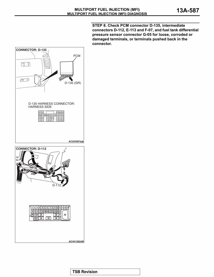
STEP 8. Check PCM connector D-135, intermediate connectors D-112, E-113 and F-07, and fuel tank differential pressure sensor connector G-05 for loose, corroded or damaged terminals, or terminals pushed back in the connector.
AC203997
CONNECTOR: D-135
AB
D-135 (GR)
PCM
D-135 HARNESS CONNECTOR:HARNESS SIDE
9493 9596 97 98 99 100
9291101 102103 104
105 106 107 108 109 110 111 112113 114 115 116 117 118 119 120
AC401282
CONNECTOR: D-112
AB
D-112
TSB Revision

MULTIPORT FUEL INJECTION (MFI) DIAGNOSISMULTIPORT FUEL INJECTION (MFI)13A-588
Q: Are the connectors and terminals in good condition?YES : Go to Step 9.NO : Repair or replace the faulty component (Refer to
GROUP 00E, Harness Connector Inspection P.00E-2). Go to Step 15.
AC203999
CONNECTOR: E-113
AD
E-113
E-113 HARNESSCONNECTOR:COMPONENT SIDE
11
21
6 7 98 10 14
43
1213
5
AC204000
CONNECTOR: F-07
AC
F-07 (B)
F-07 HARNESSCONNECTOR:COMPONENT SIDE
84321
5 6 7
ACX00218
CONNECTOR : G-05
AR
G-05 (B)
SECOND SEAT UNDERSERVICE HOLE
G-05 HARNESSCONNECTOR:COMPONENT SIDE
123
TSB Revision

MULTIPORT FUEL INJECTION (MFI) DIAGNOSISMULTIPORT FUEL INJECTION (MFI) 13A-589
STEP 9. Check the harness wires between PCM connector D-135 terminal 96 and fuel tank differential pressure sensor connector G-05 terminal 2 for damage. Q: Are the harness wires in good condition?
YES : Replace the fuel tank differential pressure sensor (Refer to GROUP 13B, Fuel Tank P.13B-8). Go to Step 14.
NO : Repair the damaged harness wires. Go to Step 15.
AC203997
CONNECTOR: D-135
AB
D-135 (GR)
PCM
D-135 HARNESS CONNECTOR:HARNESS SIDE
9493 9596 97 98 99 100
9291101 102103 104
105 106 107 108 109 110 111 112113 114 115 116 117 118 119 120
ACX00218
CONNECTOR : G-05
AR
G-05 (B)
SECOND SEAT UNDERSERVICE HOLE
G-05 HARNESSCONNECTOR:COMPONENT SIDE
123
TSB Revision

MULTIPORT FUEL INJECTION (MFI) DIAGNOSISMULTIPORT FUEL INJECTION (MFI)13A-590
STEP 10. Measure the signal voltage at PCM connector D-134 by backprobing.(1) Do not disconnect PCM connector D-134.(2) Turn the ignition switch to the "ON" position.(3) Remove the fuel cap.
(4) Measure the voltage between PCM connector D-134 terminal 82 and ground by backprobing.• The voltage should measure between 2.0 and 3.0 volts.
(5) Turn the ignition switch to the "LOCK" (OFF) position.Q: Is the measured voltage between 2.0 and 3.0 volts?
YES : Go to Step 14.NO : Go to Step 11.
AC203997
CONNECTOR: D-134
AC
D-134 (GR)
PCM
D-134 HARNESS CONNECTOR:HARNESS SIDE
646365 6667 68
6261697071 7273
74 7576 77 787980818283 84 85 8687 8889
AC204161
646365 66 6768
62616970717273
74 75 7677787980818283 84 858687 88 89
AB
D-134 HARNESS CONNECTOR:HARNESS SIDE
TSB Revision

MULTIPORT FUEL INJECTION (MFI) DIAGNOSISMULTIPORT FUEL INJECTION (MFI) 13A-591
STEP 11. Check PCM connector D-134 for loose, corroded or damaged terminals, or terminals pushed back in the connector.Q: Are the connector and terminals in good condition?
YES : Go to Step 12.NO : Repair or replace the faulty component (Refer to
GROUP 00E, Harness Connector Inspection P.00E-2). Go to Step 15.
AC203997
CONNECTOR: D-134
AC
D-134 (GR)
PCM
D-134 HARNESS CONNECTOR:HARNESS SIDE
646365 6667 68
6261697071 7273
74 7576 77 787980818283 84 85 8687 8889
TSB Revision

MULTIPORT FUEL INJECTION (MFI) DIAGNOSISMULTIPORT FUEL INJECTION (MFI)13A-592
STEP 12. Check intermediate connectors D-112, E-111 and F-07, and fuel tank differential pressure sensor connector G-05 for loose, corroded or damaged terminals, or terminals pushed back in the connector.
AC401282
CONNECTOR: D-112
AB
D-112
AC401286
CONNECTOR: E-111
AC
E-111
TSB Revision

MULTIPORT FUEL INJECTION (MFI) DIAGNOSISMULTIPORT FUEL INJECTION (MFI) 13A-593
Q: Are the connectors and terminals in good condition?YES : Go to Step 13.NO : Repair or replace the faulty component (Refer to
GROUP 00E, Harness Connector Inspection P.00E-2). Go to Step 15.
AC204000
CONNECTOR: F-07
AC
F-07 (B)
F-07 HARNESSCONNECTOR:COMPONENT SIDE
84321
5 6 7
ACX00218
CONNECTOR : G-05
AR
G-05 (B)
SECOND SEAT UNDERSERVICE HOLE
G-05 HARNESSCONNECTOR:COMPONENT SIDE
123
TSB Revision

MULTIPORT FUEL INJECTION (MFI) DIAGNOSISMULTIPORT FUEL INJECTION (MFI)13A-594
STEP 13. Check the harness wires between PCM connector D-134 terminal 82 and fuel tank differential pressure sensor connector G-05 terminal 1 for damage. Q: Are the harness wires in good condition?
YES : It can be assumed that this malfunction is intermittent (Refer to GROUP 00, How to Use Troubleshooting/Inspection Service Points − How to Cope with Intermittent Malfunctions P.00-13). Go to Step 15.
NO : Repair the damaged harness wires. Go to Step 15.
AC203997
CONNECTOR: D-134
AC
D-134 (GR)
PCM
D-134 HARNESS CONNECTOR:HARNESS SIDE
646365 6667 68
6261697071 7273
74 7576 77 787980818283 84 85 8687 8889
ACX00218
CONNECTOR : G-05
AR
G-05 (B)
SECOND SEAT UNDERSERVICE HOLE
G-05 HARNESSCONNECTOR:COMPONENT SIDE
123
TSB Revision

MULTIPORT FUEL INJECTION (MFI) DIAGNOSISMULTIPORT FUEL INJECTION (MFI) 13A-595
STEP 14. Using scan tool MB991958, check data list item 73: Fuel Tank Differential Pressure Sensor.
CAUTIONTo prevent damage to scan tool MB991958, always turn the ignition switch to the "LOCK" (OFF) position before con-necting or disconnecting scan tool MB991958.(1) Connect scan tool MB991958 to the data link connector.
(2) Disconnect hose F from the evaporative emission canister side, and plug the hose.
(3) Turn the ignition switch to the "ON" position.(4) Remove the fuel cap.(5) Set scan tool MB991958 to the data reading mode.
Item 73, Fuel Tank Differential Pressure Sensor.• The fuel tank pressures reading on the scan tool
should be −1.5 to 1.5 kPa (−0.443 to 0.443 inHg).
(6) Connect an evaporative emission system pressure pump to the fuel tank filler tube and pressurize the fuel tank.• The fuel tank pressure reading should increase.
(7) Disconnect an evaporative emission system pressure pump and connect hose F.
(8) Turn the ignition switch to the "LOCK" (OFF) position and disconnect scan tool MB991958.
Q: Is the fuel tank pressure between −1.5 and 1.5 kPa (−0.443 and 0.443 inHg)?YES : It can be assumed that this malfunction is intermittent
(Refer to GROUP 00, How to Use Troubleshooting/Inspection Service Points − How to Cope with Intermittent Malfunctions P.00-13). Go to Step 15.
NO : Replace the PCM (Refer to P.13A-1066). Go to Step 15.
AC306409AF
MB991911
MB991824
MB991827
AC102602 AC
HOSE F
ACX01358
TSB Revision

MULTIPORT FUEL INJECTION (MFI) DIAGNOSISMULTIPORT FUEL INJECTION (MFI)13A-596
STEP 15. Perform the OBD-II drive cycle.(1) Carry out a test drive with the drive cycle pattern (Refer to
Diagnostic Function − OBD-ll Drive Cycle − Pattern 5 P.13A-4).
(2) Read the diagnostic trouble code (DTC).Q: Is DTC P0450 set?
YES : Repeat the troubleshooting from Step 2.NO : The procedure is complete.
DTC P0451: Evaporative Emission System Pressure Sensor Range/Performance
AC203991
SYSTEM DIAGRAM
A
B C D
EF
G
H
I
J
K
LM
N
OQ
S
R
P
FUEL TANK
CHECK VALVE B
CHECK VALVE AEVAPORATIVEEMISSIONPURGESOLENOID
EVAPORATIVE EMISSIONVENTILATION SOLENOID
EVAPORATIVEEMISSIONCANISTER
VENT PIPEASSEMBLY
AC
FUEL TANK DIFFERENTIALPRESSURE SENSOR
ONBOARD REFUELINGVAPOR RECOVERY(ORVR)VENT VALVE MODULE
TSB Revision

MULTIPORT FUEL INJECTION (MFI) DIAGNOSISMULTIPORT FUEL INJECTION (MFI) 13A-597
FUEL TANKDIFFERENTIALPRESSURESENSOR
POWERTRAIN CONTROLMODULE (PCM)
AC309251
Fuel Tank Differential Pressure Sensor Circuit
AC
FUEL TANKDIFFERENTIALPRESSURESENSOR
POWERTRAIN CONTROLMODULE (PCM)
AC309251
TSB Revision

MULTIPORT FUEL INJECTION (MFI) DIAGNOSISMULTIPORT FUEL INJECTION (MFI)13A-598
AC401282
CONNECTOR: D-112
AB
D-112
AC401283
CONNECTORS: D-134, D-135
AB
D-134(GR)
D-134
D-135(GR)
D-135
PCM
AC401286
CONNECTORS: E-111, E-113
AB
E-113
E-113
E-111
E-111AC204000
CONNECTOR: F-07
AC
F-07 (B)
F-07 HARNESSCONNECTOR:COMPONENT SIDE
84321
5 6 7
TSB Revision
MULTIPORT FUEL INJECTION (MFI) DIAGNOSISMULTIPORT FUEL INJECTION (MFI) 13A-599
.
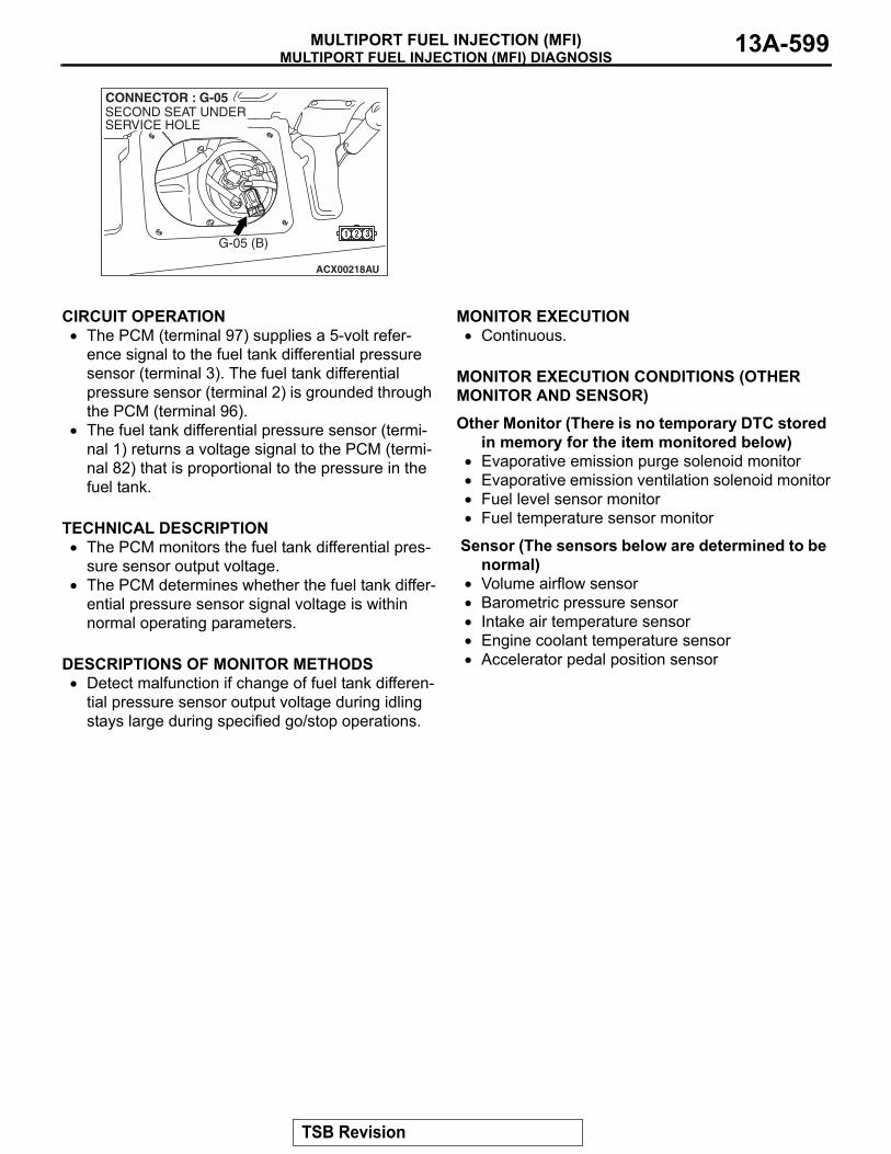
CIRCUIT OPERATION• The PCM (terminal 97) supplies a 5-volt refer-
ence signal to the fuel tank differential pressure sensor (terminal 3). The fuel tank differential pressure sensor (terminal 2) is grounded through the PCM (terminal 96).
• The fuel tank differential pressure sensor (termi-nal 1) returns a voltage signal to the PCM (termi-nal 82) that is proportional to the pressure in the fuel tank.
.
TECHNICAL DESCRIPTION• The PCM monitors the fuel tank differential pres-
sure sensor output voltage.• The PCM determines whether the fuel tank differ-
ential pressure sensor signal voltage is within normal operating parameters.
.
DESCRIPTIONS OF MONITOR METHODS• Detect malfunction if change of fuel tank differen-
tial pressure sensor output voltage during idling stays large during specified go/stop operations.
.
MONITOR EXECUTION• Continuous.
.
MONITOR EXECUTION CONDITIONS (OTHER MONITOR AND SENSOR)Other Monitor (There is no temporary DTC stored
in memory for the item monitored below)• Evaporative emission purge solenoid monitor• Evaporative emission ventilation solenoid monitor• Fuel level sensor monitor• Fuel temperature sensor monitor
Sensor (The sensors below are determined to be normal)
• Volume airflow sensor• Barometric pressure sensor• Intake air temperature sensor• Engine coolant temperature sensor• Accelerator pedal position sensor
.
ACX00218
CONNECTOR : G-05
AU
G-05 (B)
SECOND SEAT UNDERSERVICE HOLE
TSB Revision

MULTIPORT FUEL INJECTION (MFI) DIAGNOSISMULTIPORT FUEL INJECTION (MFI)13A-600
LOGIC FLOW CHARTS (Monitor Sequence)
.
DTC SET CONDITIONSCheck Conditions• Throttle valve is closed.• Vehicle speed is 1.5 km/h (0.93 mph) or less.
START
YES
NO
NO
OFF-IDLING CONDITION
IDLING CONDITION?
F1 = 0
END
NO
NO
YES
YES
MALFUNCTION
F1 > 20
SPECIFIED TIMESMONITORED
FTPS OUTPUT VOLTAGE > 0.2V FLUCTUATION
NO
YES
YES
F1 = F1 + 1
GOOD
YES
NO
OFF-IDLING CONDITION
AC306647
RATIONALITY - NOISE
TSB Revision

MULTIPORT FUEL INJECTION (MFI) DIAGNOSISMULTIPORT FUEL INJECTION (MFI) 13A-601
Judgment Criteria• If the voltage signal from the fuel tank differential
pressure sensor changes by 0.2 volt or more, DTC P0451 will set. The code may also set if a sudden pressure fluctuation occurs twenty times while the engine is idling, and then four consecu-tive times during normal driving.NOTE: If the number of sudden pressure fluctua-tions does not reach twenty during any one period of engine idling, or if the ignition switch is turned OFF, the counter will reset to zero.NOTE: The conditions for deviating from idling operation are as follows:.• Vehicle speed is 50 km/h (31 mph) or greater.
.
OBD-ll DRIVE CYCLE PATTERNRefer to Diagnostic Function − OBD-ll Drive Cycle − Pattern 15 P.13A-4.
.
TROUBLESHOOTING HINTS (THE MOST LIKELY CAUSES FOR THIS CODE TO BE SET ARE:)• Malfunction of the fuel tank differential pressure
sensor.• A damaged harness in the fuel tank differential
pressure sensor circuit.• Malfunction of the PCM.
.
OVERVIEW OF TROUBLESHOOTING• DTC P0451 can be set by a faulty fuel tank differ-
ential pressure sensor or related circuit, or PCM failure.
• To check for system blockage, do a performance test which uses a mechanical vacuum gauge and scan tool MB991958 set on the fuel tank differen-tial pressure sensor (TANK PRS SNSR 73). The mechanical gauge reading is used to verify scan tool MB991958 reading. A comparison of the mechanical gauge with the reading on scan tool MB991958 will locate a problem in the system.
DIAGNOSISRequired Special Tools:• MB991958: Scan Tool (MUT-III Sub Assembly)
• MB991824: V.C.I.• MB991827: MUT-III USB Cable• MB991911: MUT-III Main Harness B
• MB991658: Test Harness Set• MB992006: Extra Fine Probe
TSB Revision

MULTIPORT FUEL INJECTION (MFI) DIAGNOSISMULTIPORT FUEL INJECTION (MFI)13A-602
STEP 1. Using scan tool MB991958, check data list item 73: Fuel Tank Differential Pressure Sensor.
CAUTIONTo prevent damage to scan tool MB991958, always turn the ignition switch to the "LOCK" (OFF) position before con-necting or disconnecting scan tool MB991958.(1) Connect scan tool MB991958 to the data link connector.
(2) Disconnect hose F from the evaporative emission canister side, and plug the hose.
(3) Turn the ignition switch to the "ON" position.(4) Remove the fuel cap.(5) Set scan tool MB991958 to the data reading mode.
Item 73, Fuel Tank Differential Pressure Sensor.• The fuel tank pressures reading on the scan tool
should be −1.5 to 1.5 kPa (−0.443 to 0.443 inHg).
(6) Connect an evaporative emission system pressure pump to the fuel tank filler tube and pressurize the fuel tank.• The fuel tank pressure reading should increase.
(7) Disconnect an evaporative emission system pressure pump and connect hose F.
(8) Turn the ignition switch to the "LOCK" (OFF) position and disconnect scan tool MB991958.
Q: Is the fuel tank pressure between −1.5 and 1.5 kPa (−0.443 and 0.443 inHg)?YES : It can be assumed that this malfunction is intermittent
(Refer to GROUP 00, How to Use Troubleshooting/Inspection Service Points − How to Cope with Intermittent Malfunctions P.00-13). Go to Step 15.
NO : Go to Step 2.
AC306409AF
MB991911
MB991824
MB991827
AC102602 AC
HOSE F
ACX01358
TSB Revision

MULTIPORT FUEL INJECTION (MFI) DIAGNOSISMULTIPORT FUEL INJECTION (MFI) 13A-603
STEP 2. Measure the signal voltage at fuel tank differential pressure sensor connector G-05.(1) Tumble the second seat.(2) Remove the service hole cover (upper) and packing.(3) Remove the service hole cover (lower) and packing.(4) Disconnect fuel tank differential pressure sensor connector
G-05.
(5) Connect special tool MB991658 between fuel tank differential pressure sensor connector G-05 terminals 1, 2 and 3.
(6) Turn the ignition switch to the "ON" position.(7) Remove the fuel cap.(8) Measure the voltage between fuel tank differential pressure
sensor connector G-05 terminal 1 and ground.• The voltage should measure between 2.0 and 3.0 volts.
(9) Turn the ignition switch to the "LOCK" (OFF) position.Q: Is the measured voltage between 2.0 and 3.0 volts?
YES : Go to Step 10.NO : Go to Step 3.
STEP 3. Measure the 5-volt reference signal at fuel tank differential pressure sensor connector G-05.(1) Disconnect fuel tank differential pressure sensor connector
G-05.
(2) Connect special tool MB991658 between fuel tank differential pressure sensor connector G-05 terminals 1, 2 and 3.
(3) Turn the ignition switch to the "ON" position.(4) Measure the voltage between fuel tank differential pressure
sensor connector G-05 terminal 3 and ground.• The voltage should measure between 4.9 and 5.1 volts.
(5) Turn the ignition switch to the "LOCK" (OFF) position.Q: Is the measured voltage between 4.9 and 5.1 volts?
YES : Go to Step 8.NO : Go to Step 4.
ACX00218
CONNECTOR : G-05
AS
G-05 (B)
SERVICE HOLE (UPPER)
G-05 HARNESSCONNECTOR:COMPONENT SIDE
123
SERVICE HOLE (LOWER)
AC002081AB
MB991658
FUEL TANK DIFFERENTIAL PRESSURE SENSOR
ACX00218
CONNECTOR : G-05
AR
G-05 (B)
SECOND SEAT UNDERSERVICE HOLE
G-05 HARNESSCONNECTOR:COMPONENT SIDE
123
AC002081AB
MB991658
FUEL TANK DIFFERENTIAL PRESSURE SENSOR
TSB Revision
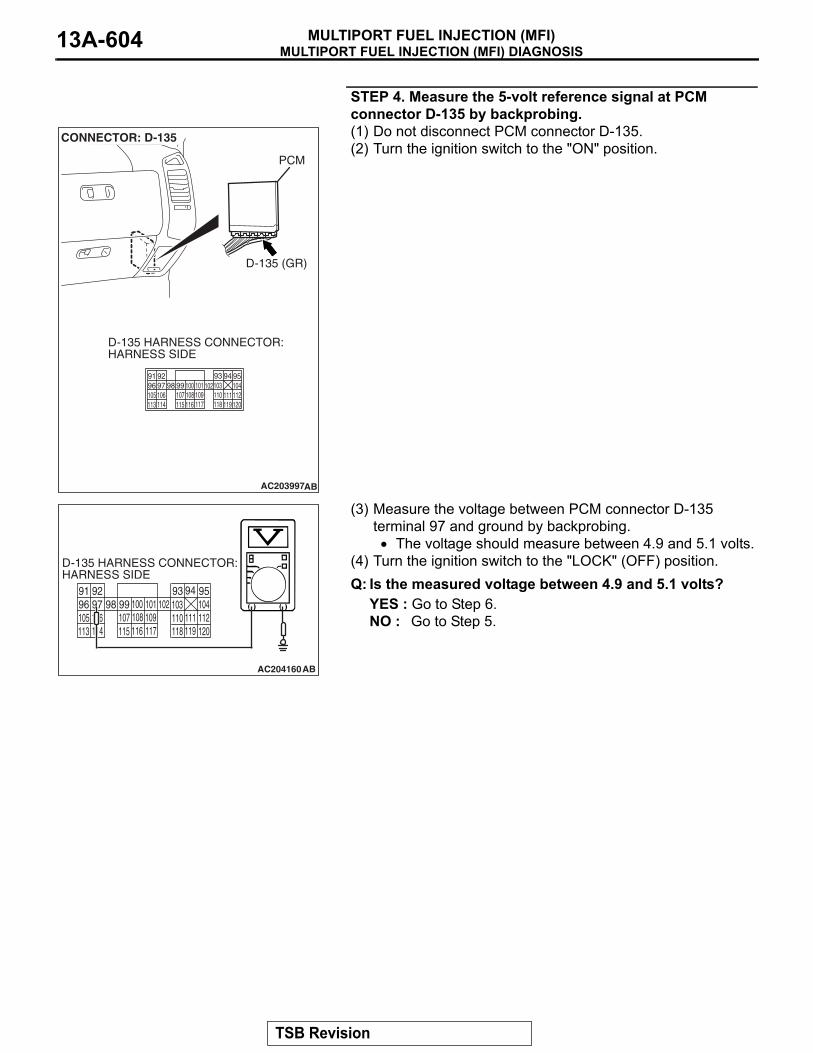
MULTIPORT FUEL INJECTION (MFI) DIAGNOSISMULTIPORT FUEL INJECTION (MFI)13A-604
STEP 4. Measure the 5-volt reference signal at PCM connector D-135 by backprobing.(1) Do not disconnect PCM connector D-135.(2) Turn the ignition switch to the "ON" position.
(3) Measure the voltage between PCM connector D-135 terminal 97 and ground by backprobing.• The voltage should measure between 4.9 and 5.1 volts.
(4) Turn the ignition switch to the "LOCK" (OFF) position.Q: Is the measured voltage between 4.9 and 5.1 volts?
YES : Go to Step 6.NO : Go to Step 5.
AC203997
CONNECTOR: D-135
AB
D-135 (GR)
PCM
D-135 HARNESS CONNECTOR:HARNESS SIDE
9493 9596 97 98 99 100
9291101 102103 104
105 106 107 108 109 110 111 112113 114 115 116 117 118 119 120
9493 9596 97 98 99 100
9291101 102 103 104
105 106 107 108 109 110 111 112113 114 115 116 117 118 119 120
AC204160AB
D-135 HARNESS CONNECTOR:HARNESS SIDE
TSB Revision

MULTIPORT FUEL INJECTION (MFI) DIAGNOSISMULTIPORT FUEL INJECTION (MFI) 13A-605
STEP 5. Check PCM connector D-135 for loose, corroded or damaged terminals, or terminals pushed back in the connector.Q: Are the connector and terminals in good condition?
YES : Go to Step 14.NO : Repair or replace the faulty component (Refer to
GROUP 00E, Harness Connector Inspection P.00E-2). Go to Step 15.
AC203997
CONNECTOR: D-135
AB
D-135 (GR)
PCM
D-135 HARNESS CONNECTOR:HARNESS SIDE
9493 9596 97 98 99 100
9291101 102103 104
105 106 107 108 109 110 111 112113 114 115 116 117 118 119 120
TSB Revision

MULTIPORT FUEL INJECTION (MFI) DIAGNOSISMULTIPORT FUEL INJECTION (MFI)13A-606
STEP 6. Check intermediate connectors D-112, E-111 and F-07, and fuel tank differential pressure sensor connector G-05 for loose, corroded or damaged terminals, or terminals pushed back in the connector.
AC401282
CONNECTOR: D-112
AB
D-112
AC401286
CONNECTOR: E-111
AC
E-111
TSB Revision
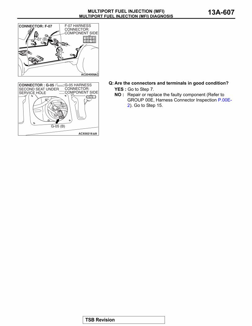
MULTIPORT FUEL INJECTION (MFI) DIAGNOSISMULTIPORT FUEL INJECTION (MFI) 13A-607
Q: Are the connectors and terminals in good condition?YES : Go to Step 7.NO : Repair or replace the faulty component (Refer to
GROUP 00E, Harness Connector Inspection P.00E-2). Go to Step 15.
AC204000
CONNECTOR: F-07
AC
F-07 (B)
F-07 HARNESSCONNECTOR:COMPONENT SIDE
84321
5 6 7
ACX00218
CONNECTOR : G-05
AR
G-05 (B)
SECOND SEAT UNDERSERVICE HOLE
G-05 HARNESSCONNECTOR:COMPONENT SIDE
123
TSB Revision

MULTIPORT FUEL INJECTION (MFI) DIAGNOSISMULTIPORT FUEL INJECTION (MFI)13A-608
STEP 7. Check the harness wires between PCM connector D-135 terminal 97 and fuel tank differential pressure sensor connector G-05 terminal 3 for damage. Q: Are the harness wires in good condition?
YES : It can be assumed that this malfunction is intermittent (Refer to GROUP 00, How to Use Troubleshooting/Inspection Service Points − How to Cope with Intermittent Malfunctions P.00-13). Go to Step 15.
NO : Repair the damaged harness wires. Go to Step 15.
AC203997
CONNECTOR: D-135
AB
D-135 (GR)
PCM
D-135 HARNESS CONNECTOR:HARNESS SIDE
9493 9596 97 98 99 100
9291101 102103 104
105 106 107 108 109 110 111 112113 114 115 116 117 118 119 120
ACX00218
CONNECTOR : G-05
AR
G-05 (B)
SECOND SEAT UNDERSERVICE HOLE
G-05 HARNESSCONNECTOR:COMPONENT SIDE
123
TSB Revision
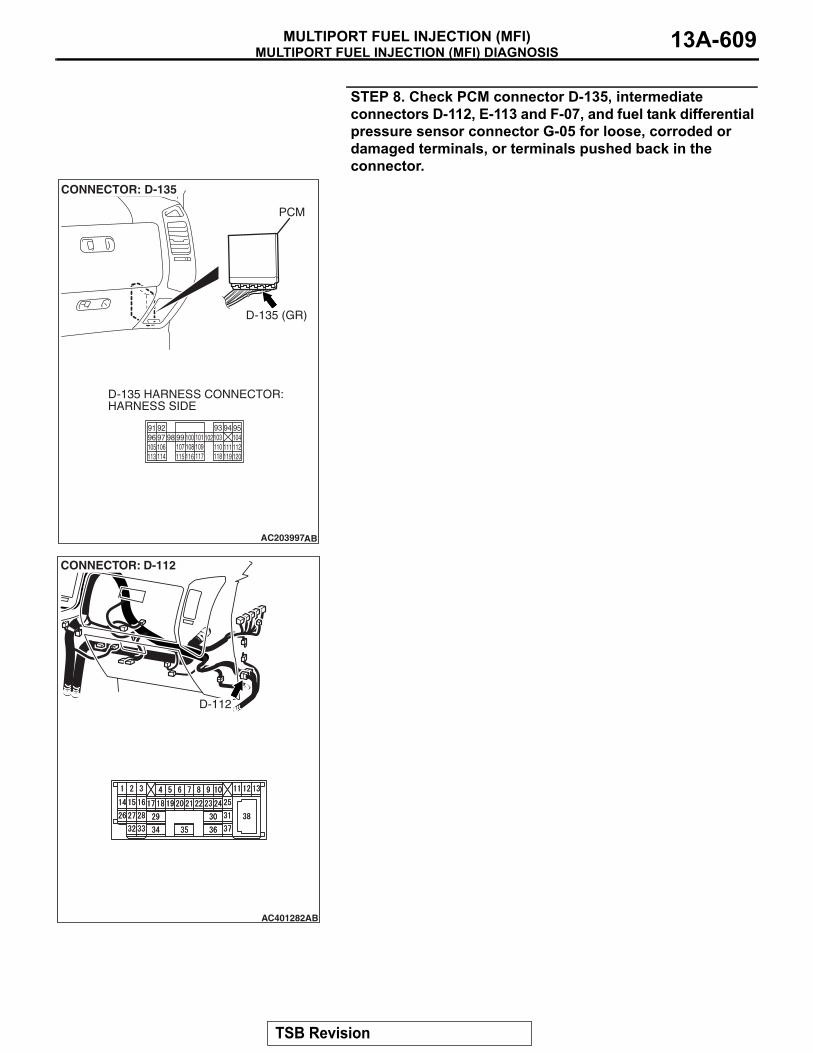
MULTIPORT FUEL INJECTION (MFI) DIAGNOSISMULTIPORT FUEL INJECTION (MFI) 13A-609
STEP 8. Check PCM connector D-135, intermediate connectors D-112, E-113 and F-07, and fuel tank differential pressure sensor connector G-05 for loose, corroded or damaged terminals, or terminals pushed back in the connector.
AC203997
CONNECTOR: D-135
AB
D-135 (GR)
PCM
D-135 HARNESS CONNECTOR:HARNESS SIDE
9493 9596 97 98 99 100
9291101 102103 104
105 106 107 108 109 110 111 112113 114 115 116 117 118 119 120
AC401282
CONNECTOR: D-112
AB
D-112
TSB Revision

MULTIPORT FUEL INJECTION (MFI) DIAGNOSISMULTIPORT FUEL INJECTION (MFI)13A-610
Q: Are the connectors and terminals in good condition?YES : Go to Step 9.NO : Repair or replace the faulty component (Refer to
GROUP 00E, Harness Connector Inspection P.00E-2). Go to Step 15.
AC203999
CONNECTOR: E-113
AD
E-113
E-113 HARNESSCONNECTOR:COMPONENT SIDE
11
21
6 7 98 10 14
43
1213
5
AC204000
CONNECTOR: F-07
AC
F-07 (B)
F-07 HARNESSCONNECTOR:COMPONENT SIDE
84321
5 6 7
ACX00218
CONNECTOR : G-05
AR
G-05 (B)
SECOND SEAT UNDERSERVICE HOLE
G-05 HARNESSCONNECTOR:COMPONENT SIDE
123
TSB Revision

MULTIPORT FUEL INJECTION (MFI) DIAGNOSISMULTIPORT FUEL INJECTION (MFI) 13A-611
STEP 9. Check the harness wires between PCM connector D-135 terminal 96 and fuel tank differential pressure sensor connector G-05 terminal 2 for damage. Q: Are the harness wires in good condition?
YES : Replace the fuel tank differential pressure sensor (Refer to GROUP 13B, Fuel Tank P.13B-8). Go to Step 14.
NO : Repair the damaged harness wires. Go to Step 15.
AC203997
CONNECTOR: D-135
AB
D-135 (GR)
PCM
D-135 HARNESS CONNECTOR:HARNESS SIDE
9493 9596 97 98 99 100
9291101 102103 104
105 106 107 108 109 110 111 112113 114 115 116 117 118 119 120
ACX00218
CONNECTOR : G-05
AR
G-05 (B)
SECOND SEAT UNDERSERVICE HOLE
G-05 HARNESSCONNECTOR:COMPONENT SIDE
123
TSB Revision

MULTIPORT FUEL INJECTION (MFI) DIAGNOSISMULTIPORT FUEL INJECTION (MFI)13A-612
STEP 10. Measure the signal voltage at PCM connector D-134 by backprobing.(1) Do not disconnect PCM connector D-134.(2) Turn the ignition switch to the "ON" position.(3) Remove the fuel cap.
(4) Measure the voltage between PCM connector D-134 terminal 82 and ground by backprobing.• The voltage should measure between 2.0 and 3.0 volts.
(5) Turn the ignition switch to the "LOCK" (OFF) position.Q: Is the measured voltage between 2.0 and 3.0 volts?
YES : Go to Step 14.NO : Go to Step 11.
AC203997
CONNECTOR: D-134
AC
D-134 (GR)
PCM
D-134 HARNESS CONNECTOR:HARNESS SIDE
646365 6667 68
6261697071 7273
74 7576 77 787980818283 84 85 8687 8889
AC204161
646365 66 6768
62616970717273
74 75 7677787980818283 84 858687 88 89
AB
D-134 HARNESS CONNECTOR:HARNESS SIDE
TSB Revision

MULTIPORT FUEL INJECTION (MFI) DIAGNOSISMULTIPORT FUEL INJECTION (MFI) 13A-613
STEP 11. Check PCM connector D-134 for loose, corroded or damaged terminals, or terminals pushed back in the connector.Q: Are the connector and terminals in good condition?
YES : Go to Step 12.NO : Repair or replace the faulty component (Refer to
GROUP 00E, Harness Connector Inspection P.00E-2). Go to Step 15.
AC203997
CONNECTOR: D-134
AC
D-134 (GR)
PCM
D-134 HARNESS CONNECTOR:HARNESS SIDE
646365 6667 68
6261697071 7273
74 7576 77 787980818283 84 85 8687 8889
TSB Revision
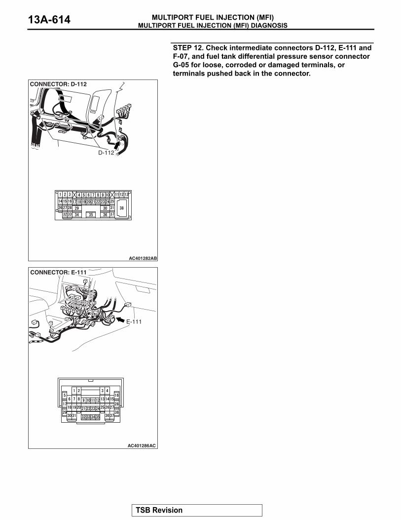
MULTIPORT FUEL INJECTION (MFI) DIAGNOSISMULTIPORT FUEL INJECTION (MFI)13A-614
STEP 12. Check intermediate connectors D-112, E-111 and F-07, and fuel tank differential pressure sensor connector G-05 for loose, corroded or damaged terminals, or terminals pushed back in the connector.
AC401282
CONNECTOR: D-112
AB
D-112
AC401286
CONNECTOR: E-111
AC
E-111
TSB Revision

MULTIPORT FUEL INJECTION (MFI) DIAGNOSISMULTIPORT FUEL INJECTION (MFI) 13A-615
Q: Are the connectors and terminals in good condition?YES : Go to Step 13.NO : Repair or replace the faulty component (Refer to
GROUP 00E, Harness Connector Inspection P.00E-2). Go to Step 15.
AC204000
CONNECTOR: F-07
AC
F-07 (B)
F-07 HARNESSCONNECTOR:COMPONENT SIDE
84321
5 6 7
ACX00218
CONNECTOR : G-05
AR
G-05 (B)
SECOND SEAT UNDERSERVICE HOLE
G-05 HARNESSCONNECTOR:COMPONENT SIDE
123
TSB Revision

MULTIPORT FUEL INJECTION (MFI) DIAGNOSISMULTIPORT FUEL INJECTION (MFI)13A-616
STEP 13. Check the harness wires between PCM connector D-134 terminal 82 and fuel tank differential pressure sensor connector G-05 terminal 1 for damage. Q: Are the harness wires in good condition?
YES : It can be assumed that this malfunction is intermittent (Refer to GROUP 00, How to Use Troubleshooting/Inspection Service Points − How to Cope with Intermittent Malfunctions P.00-13). Go to Step 15.
NO : Repair the damaged harness wires. Go to Step 15.
AC203997
CONNECTOR: D-134
AC
D-134 (GR)
PCM
D-134 HARNESS CONNECTOR:HARNESS SIDE
646365 6667 68
6261697071 7273
74 7576 77 787980818283 84 85 8687 8889
ACX00218
CONNECTOR : G-05
AR
G-05 (B)
SECOND SEAT UNDERSERVICE HOLE
G-05 HARNESSCONNECTOR:COMPONENT SIDE
123
TSB Revision

MULTIPORT FUEL INJECTION (MFI) DIAGNOSISMULTIPORT FUEL INJECTION (MFI) 13A-617
STEP 14. Using scan tool MB991958, check data list item 73: Fuel Tank Differential Pressure Sensor.
CAUTIONTo prevent damage to scan tool MB991958, always turn the ignition switch to the "LOCK" (OFF) position before con-necting or disconnecting scan tool MB991958.(1) Connect scan tool MB991958 to the data link connector.
(2) Disconnect hose F from the evaporative emission canister side, and plug the hose.
(3) Turn the ignition switch to the "ON" position.(4) Remove the fuel cap.(5) Set scan tool MB991958 to the data reading mode.
Item 73, Fuel Tank Differential Pressure Sensor.• The fuel tank pressures reading on the scan tool
should be −1.5 to 1.5 kPa (−0.443 to 0.443 inHg).
(6) Connect an evaporative emission system pressure pump to the fuel tank filler tube and pressurize the fuel tank.• The fuel tank pressure reading should increase.
(7) Disconnect an evaporative emission system pressure pump and connect hose F.
(8) Turn the ignition switch to the "LOCK" (OFF) position and disconnect scan tool MB991958.
Q: Is the fuel tank pressure between −1.5 and 1.5 kPa (−0.443 and 0.443 inHg)?YES : It can be assumed that this malfunction is intermittent
(Refer to GROUP 00, How to Use Troubleshooting/Inspection Service Points − How to Cope with Intermittent Malfunctions P.00-13). Go to Step 15.
NO : Replace the PCM (Refer to P.13A-1066). Go to Step 15.
AC306409AF
MB991911
MB991824
MB991827
AC102602 AC
HOSE F
ACX01358
TSB Revision
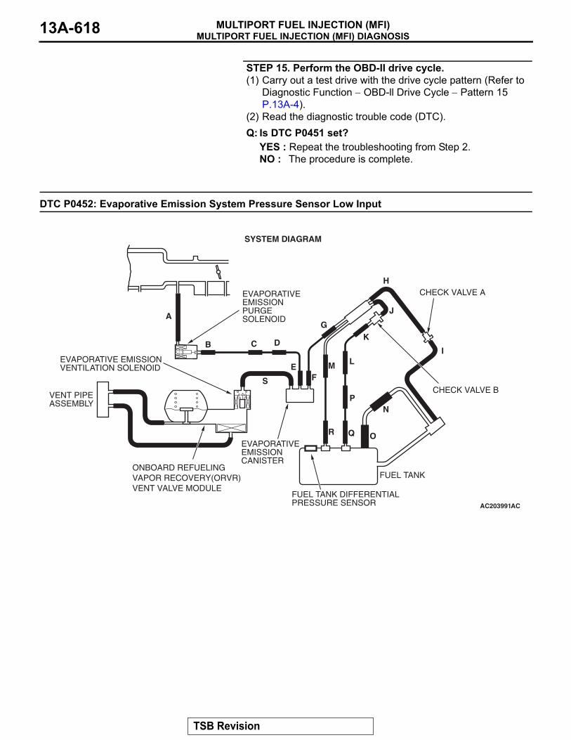
MULTIPORT FUEL INJECTION (MFI) DIAGNOSISMULTIPORT FUEL INJECTION (MFI)13A-618
STEP 15. Perform the OBD-II drive cycle.(1) Carry out a test drive with the drive cycle pattern (Refer to
Diagnostic Function − OBD-ll Drive Cycle − Pattern 15 P.13A-4).
(2) Read the diagnostic trouble code (DTC).Q: Is DTC P0451 set?
YES : Repeat the troubleshooting from Step 2.NO : The procedure is complete.
DTC P0452: Evaporative Emission System Pressure Sensor Low Input
AC203991
SYSTEM DIAGRAM
A
B C D
EF
G
H
I
J
K
LM
N
OQ
S
R
P
FUEL TANK
CHECK VALVE B
CHECK VALVE AEVAPORATIVEEMISSIONPURGESOLENOID
EVAPORATIVE EMISSIONVENTILATION SOLENOID
EVAPORATIVEEMISSIONCANISTER
VENT PIPEASSEMBLY
AC
FUEL TANK DIFFERENTIALPRESSURE SENSOR
ONBOARD REFUELINGVAPOR RECOVERY(ORVR)VENT VALVE MODULE
TSB Revision
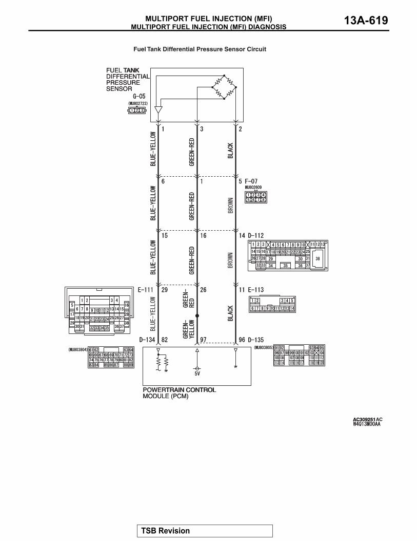
MULTIPORT FUEL INJECTION (MFI) DIAGNOSISMULTIPORT FUEL INJECTION (MFI) 13A-619
FUEL TANKDIFFERENTIALPRESSURESENSOR
POWERTRAIN CONTROLMODULE (PCM)
AC309251
Fuel Tank Differential Pressure Sensor Circuit
AC
FUEL TANKDIFFERENTIALPRESSURESENSOR
POWERTRAIN CONTROLMODULE (PCM)
AC309251
TSB Revision
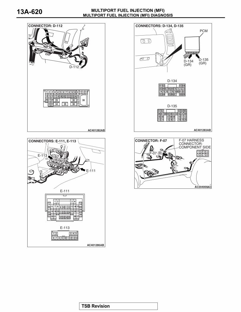
MULTIPORT FUEL INJECTION (MFI) DIAGNOSISMULTIPORT FUEL INJECTION (MFI)13A-620
AC401282
CONNECTOR: D-112
AB
D-112
AC401283
CONNECTORS: D-134, D-135
AB
D-134(GR)
D-134
D-135(GR)
D-135
PCM
AC401286
CONNECTORS: E-111, E-113
AB
E-113
E-113
E-111
E-111AC204000
CONNECTOR: F-07
AC
F-07 (B)
F-07 HARNESSCONNECTOR:COMPONENT SIDE
84321
5 6 7
TSB Revision

MULTIPORT FUEL INJECTION (MFI) DIAGNOSISMULTIPORT FUEL INJECTION (MFI) 13A-621
.
CIRCUIT OPERATION• The PCM (terminal 97) supplies a 5-volt refer-
ence signal to the fuel tank differential pressure sensor (terminal 3). The fuel tank differential pressure sensor (terminal 2) is grounded through the PCM (terminal 96).
• The fuel tank differential pressure sensor (termi-nal 1) returns a voltage signal to the PCM (termi-nal 82) that is proportional to the pressure in the fuel tank.
.
TECHNICAL DESCRIPTION• The PCM monitors the fuel tank differential pres-
sure sensor output voltage.• The PCM determines whether the fuel tank differ-
ential pressure sensor signal voltage is within normal operating parameters.
.
DESCRIPTIONS OF MONITOR METHODS• Compare purge solenoid status with fuel tank dif-
ferential pressure sensor output voltage.
.
MONITOR EXECUTION• Continuous.
.
MONITOR EXECUTION CONDITIONS (OTHER MONITOR AND SENSOR)Other Monitor (There is no temporary DTC stored
in memory for the item monitored below)• Evaporative emission purge solenoid monitor• Evaporative emission ventilation solenoid monitor• Fuel level sensor monitor• Fuel temperature sensor monitor
Sensor (The sensors below are determined to be normal)
• Volume airflow sensor• Barometric pressure sensor• Intake air temperature sensor• Engine coolant temperature sensor• Accelerator pedal position sensor
.
ACX00218
CONNECTOR : G-05
AU
G-05 (B)
SECOND SEAT UNDERSERVICE HOLE
TSB Revision
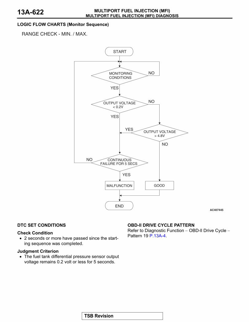
MULTIPORT FUEL INJECTION (MFI) DIAGNOSISMULTIPORT FUEL INJECTION (MFI)13A-622
LOGIC FLOW CHARTS (Monitor Sequence)
.
DTC SET CONDITIONSCheck Condition• 2 seconds or more have passed since the start-
ing sequence was completed.
Judgment Criterion• The fuel tank differential pressure sensor output
voltage remains 0.2 volt or less for 5 seconds.
.
OBD-ll DRIVE CYCLE PATTERNRefer to Diagnostic Function − OBD-ll Drive Cycle − Pattern 19 P.13A-4..
AC407445
RANGE CHECK - MIN. / MAX.
NO
YES
CONTINUOUSFAILURE FOR 5 SECS
START
END
NO
NO
NO
YES
YES
YES
MALFUNCTION GOOD
MONITORING CONDITIONS
OUTPUT VOLTAGE < 0.2V
OUTPUT VOLTAGE > 4.8V
TSB Revision

MULTIPORT FUEL INJECTION (MFI) DIAGNOSISMULTIPORT FUEL INJECTION (MFI) 13A-623
TROUBLESHOOTING HINTS (THE MOST LIKELY CAUSES FOR THIS CODE TO BE SET ARE:)• Malfunction of the fuel tank differential pressure
sensor.• A damaged harness in the fuel tank differential
pressure sensor circuit.• Malfunction of the PCM.
.
OVERVIEW OF TROUBLESHOOTING• DTC P0452 can be set by a faulty fuel tank differ-
ential pressure sensor or related circuit, or PCM failure.
• To check for system blockage, do a performance test which uses a mechanical vacuum gauge and scan tool MB991958 set on the fuel tank differen-tial pressure sensor (TANK PRS SNSR 73). The mechanical gauge reading is used to verify scan tool MB991958 reading. A comparison of the mechanical gauge with the reading on scan tool MB991958 will locate a problem in the system.
DIAGNOSISRequired Special Tools:• MB991958: Scan Tool (MUT-III Sub Assembly)
• MB991824: V.C.I.• MB991827: MUT-III USB Cable• MB991911: MUT-III Main Harness B
• MB991658: Test Harness Set• MB992006: Extra Fine Probe
TSB Revision
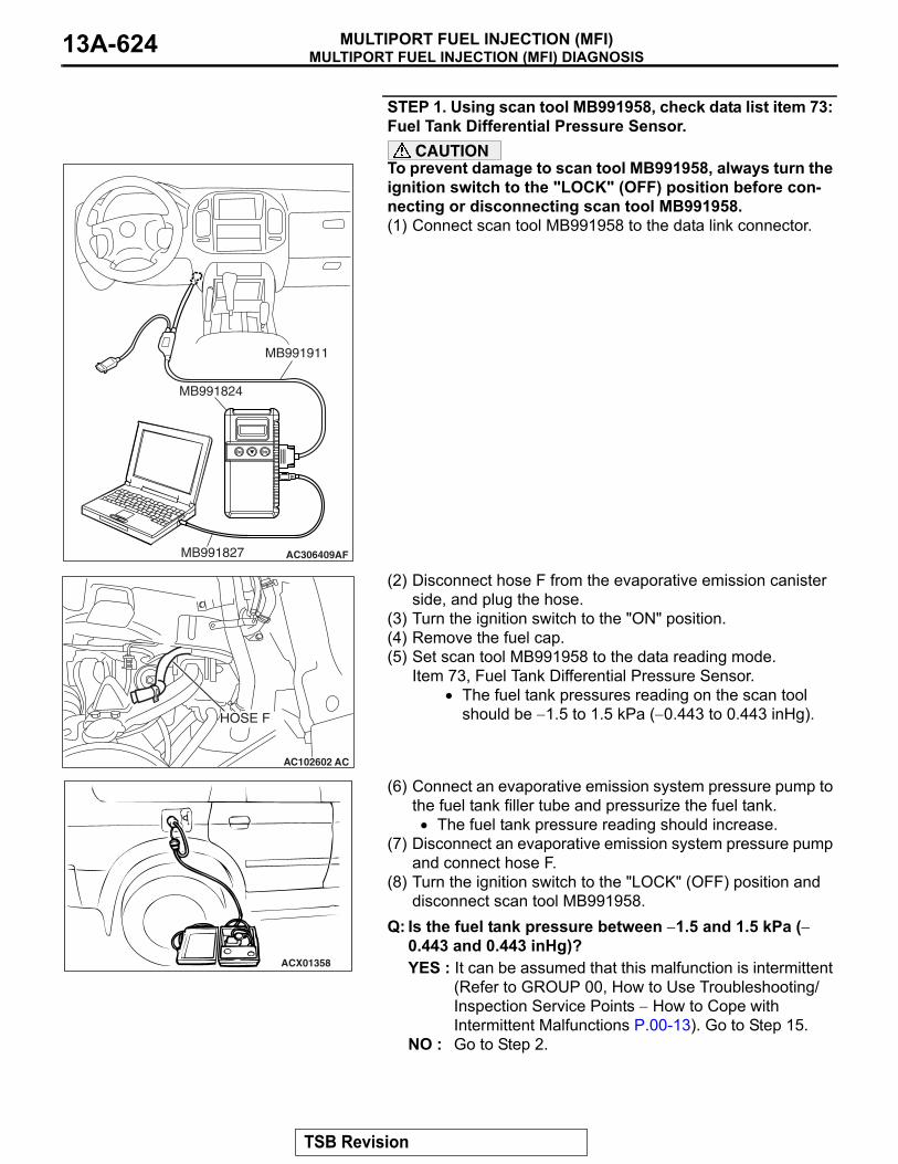
MULTIPORT FUEL INJECTION (MFI) DIAGNOSISMULTIPORT FUEL INJECTION (MFI)13A-624
STEP 1. Using scan tool MB991958, check data list item 73: Fuel Tank Differential Pressure Sensor.
CAUTIONTo prevent damage to scan tool MB991958, always turn the ignition switch to the "LOCK" (OFF) position before con-necting or disconnecting scan tool MB991958.(1) Connect scan tool MB991958 to the data link connector.
(2) Disconnect hose F from the evaporative emission canister side, and plug the hose.
(3) Turn the ignition switch to the "ON" position.(4) Remove the fuel cap.(5) Set scan tool MB991958 to the data reading mode.
Item 73, Fuel Tank Differential Pressure Sensor.• The fuel tank pressures reading on the scan tool
should be −1.5 to 1.5 kPa (−0.443 to 0.443 inHg).
(6) Connect an evaporative emission system pressure pump to the fuel tank filler tube and pressurize the fuel tank.• The fuel tank pressure reading should increase.
(7) Disconnect an evaporative emission system pressure pump and connect hose F.
(8) Turn the ignition switch to the "LOCK" (OFF) position and disconnect scan tool MB991958.
Q: Is the fuel tank pressure between −1.5 and 1.5 kPa (−0.443 and 0.443 inHg)?YES : It can be assumed that this malfunction is intermittent
(Refer to GROUP 00, How to Use Troubleshooting/Inspection Service Points − How to Cope with Intermittent Malfunctions P.00-13). Go to Step 15.
NO : Go to Step 2.
AC306409AF
MB991911
MB991824
MB991827
AC102602 AC
HOSE F
ACX01358
TSB Revision

MULTIPORT FUEL INJECTION (MFI) DIAGNOSISMULTIPORT FUEL INJECTION (MFI) 13A-625
STEP 2. Measure the signal voltage at fuel tank differential pressure sensor connector G-05.(1) Tumble the second seat.(2) Remove the service hole cover (upper) and packing.(3) Remove the service hole cover (lower) and packing.(4) Disconnect fuel tank differential pressure sensor connector
G-05.
(5) Connect special tool MB991658 between fuel tank differential pressure sensor connector G-05 terminals 1, 2 and 3.
(6) Turn the ignition switch to the "ON" position.(7) Remove the fuel cap.(8) Measure the voltage between fuel tank differential pressure
sensor connector G-05 terminal 1 and ground.• The voltage should measure between 2.0 and 3.0 volts.
(9) Turn the ignition switch to the "LOCK" (OFF) position.Q: Is the measured voltage between 2.0 and 3.0 volts?
YES : Go to Step 10.NO : Go to Step 3.
STEP 3. Measure the 5-volt reference signal at fuel tank differential pressure sensor connector G-05.(1) Disconnect fuel tank differential pressure sensor connector
G-05.
(2) Connect special tool MB991658 between fuel tank differential pressure sensor connector G-05 terminals 1, 2 and 3.
(3) Turn the ignition switch to the "ON" position.(4) Measure the voltage between fuel tank differential pressure
sensor connector G-05 terminal 3 and ground.• The voltage should measure between 4.9 and 5.1 volts.
(5) Turn the ignition switch to the "LOCK" (OFF) position.Q: Is the measured voltage between 4.9 and 5.1 volts?
YES : Go to Step 8.NO : Go to Step 4.
ACX00218
CONNECTOR : G-05
AS
G-05 (B)
SERVICE HOLE (UPPER)
G-05 HARNESSCONNECTOR:COMPONENT SIDE
123
SERVICE HOLE (LOWER)
AC002081AB
MB991658
FUEL TANK DIFFERENTIAL PRESSURE SENSOR
ACX00218
CONNECTOR : G-05
AR
G-05 (B)
SECOND SEAT UNDERSERVICE HOLE
G-05 HARNESSCONNECTOR:COMPONENT SIDE
123
AC002081AB
MB991658
FUEL TANK DIFFERENTIAL PRESSURE SENSOR
TSB Revision

MULTIPORT FUEL INJECTION (MFI) DIAGNOSISMULTIPORT FUEL INJECTION (MFI)13A-626
STEP 4. Measure the 5-volt reference signal at PCM connector D-135 by backprobing.(1) Do not disconnect PCM connector D-135.(2) Turn the ignition switch to the "ON" position.
(3) Measure the voltage between PCM connector D-135 terminal 97 and ground by backprobing.• The voltage should measure between 4.9 and 5.1 volts.
(4) Turn the ignition switch to the "LOCK" (OFF) position.Q: Is the measured voltage between 4.9 and 5.1 volts?
YES : Go to Step 6.NO : Go to Step 5.
AC203997
CONNECTOR: D-135
AB
D-135 (GR)
PCM
D-135 HARNESS CONNECTOR:HARNESS SIDE
9493 9596 97 98 99 100
9291101 102103 104
105 106 107 108 109 110 111 112113 114 115 116 117 118 119 120
9493 9596 97 98 99 100
9291101 102 103 104
105 106 107 108 109 110 111 112113 114 115 116 117 118 119 120
AC204160AB
D-135 HARNESS CONNECTOR:HARNESS SIDE
TSB Revision

MULTIPORT FUEL INJECTION (MFI) DIAGNOSISMULTIPORT FUEL INJECTION (MFI) 13A-627
STEP 5. Check PCM connector D-135 for loose, corroded or damaged terminals, or terminals pushed back in the connector.Q: Are the connector and terminals in good condition?
YES : Go to Step 14.NO : Repair or replace the faulty component (Refer to
GROUP 00E, Harness Connector Inspection P.00E-2). Go to Step 15.
AC203997
CONNECTOR: D-135
AB
D-135 (GR)
PCM
D-135 HARNESS CONNECTOR:HARNESS SIDE
9493 9596 97 98 99 100
9291101 102103 104
105 106 107 108 109 110 111 112113 114 115 116 117 118 119 120
TSB Revision

MULTIPORT FUEL INJECTION (MFI) DIAGNOSISMULTIPORT FUEL INJECTION (MFI)13A-628
STEP 6. Check intermediate connectors D-112, E-111 and F-07, and fuel tank differential pressure sensor connector G-05 for loose, corroded or damaged terminals, or terminals pushed back in the connector.
AC401282
CONNECTOR: D-112
AB
D-112
AC401286
CONNECTOR: E-111
AC
E-111
TSB Revision

MULTIPORT FUEL INJECTION (MFI) DIAGNOSISMULTIPORT FUEL INJECTION (MFI) 13A-629
Q: Are the connectors and terminals in good condition?YES : Go to Step 7.NO : Repair or replace the faulty component (Refer to
GROUP 00E, Harness Connector Inspection P.00E-2). Go to Step 15.
AC204000
CONNECTOR: F-07
AC
F-07 (B)
F-07 HARNESSCONNECTOR:COMPONENT SIDE
84321
5 6 7
ACX00218
CONNECTOR : G-05
AR
G-05 (B)
SECOND SEAT UNDERSERVICE HOLE
G-05 HARNESSCONNECTOR:COMPONENT SIDE
123
TSB Revision

MULTIPORT FUEL INJECTION (MFI) DIAGNOSISMULTIPORT FUEL INJECTION (MFI)13A-630
STEP 7. Check the harness wires between PCM connector D-135 terminal 97 and fuel tank differential pressure sensor connector G-05 terminal 3 for damage. Q: Are the harness wires in good condition?
YES : It can be assumed that this malfunction is intermittent (Refer to GROUP 00, How to Use Troubleshooting/Inspection Service Points − How to Cope with Intermittent Malfunctions P.00-13). Go to Step 15.
NO : Repair the damaged harness wires. Go to Step 15.
AC203997
CONNECTOR: D-135
AB
D-135 (GR)
PCM
D-135 HARNESS CONNECTOR:HARNESS SIDE
9493 9596 97 98 99 100
9291101 102103 104
105 106 107 108 109 110 111 112113 114 115 116 117 118 119 120
ACX00218
CONNECTOR : G-05
AR
G-05 (B)
SECOND SEAT UNDERSERVICE HOLE
G-05 HARNESSCONNECTOR:COMPONENT SIDE
123
TSB Revision

MULTIPORT FUEL INJECTION (MFI) DIAGNOSISMULTIPORT FUEL INJECTION (MFI) 13A-631
STEP 8. Check PCM connector D-135, intermediate connectors D-112, E-113 and F-07, and fuel tank differential pressure sensor connector G-05 for loose, corroded or damaged terminals, or terminals pushed back in the connector.
AC203997
CONNECTOR: D-135
AB
D-135 (GR)
PCM
D-135 HARNESS CONNECTOR:HARNESS SIDE
9493 9596 97 98 99 100
9291101 102103 104
105 106 107 108 109 110 111 112113 114 115 116 117 118 119 120
AC401282
CONNECTOR: D-112
AB
D-112
TSB Revision

MULTIPORT FUEL INJECTION (MFI) DIAGNOSISMULTIPORT FUEL INJECTION (MFI)13A-632
Q: Are the connectors and terminals in good condition?YES : Go to Step 9.NO : Repair or replace the faulty component (Refer to
GROUP 00E, Harness Connector Inspection P.00E-2). Go to Step 15.
AC203999
CONNECTOR: E-113
AD
E-113
E-113 HARNESSCONNECTOR:COMPONENT SIDE
11
21
6 7 98 10 14
43
1213
5
AC204000
CONNECTOR: F-07
AC
F-07 (B)
F-07 HARNESSCONNECTOR:COMPONENT SIDE
84321
5 6 7
ACX00218
CONNECTOR : G-05
AR
G-05 (B)
SECOND SEAT UNDERSERVICE HOLE
G-05 HARNESSCONNECTOR:COMPONENT SIDE
123
TSB Revision

MULTIPORT FUEL INJECTION (MFI) DIAGNOSISMULTIPORT FUEL INJECTION (MFI) 13A-633
STEP 9. Check the harness wires between PCM connector D-135 terminal 96 and fuel tank differential pressure sensor connector G-05 terminal 2 for damage. Q: Are the harness wires in good condition?
YES : Replace the fuel tank differential pressure sensor (Refer to GROUP 13B, Fuel Tank P.13B-8). Go to Step 14.
NO : Repair the damaged harness wires. Go to Step 15.
AC203997
CONNECTOR: D-135
AB
D-135 (GR)
PCM
D-135 HARNESS CONNECTOR:HARNESS SIDE
9493 9596 97 98 99 100
9291101 102103 104
105 106 107 108 109 110 111 112113 114 115 116 117 118 119 120
ACX00218
CONNECTOR : G-05
AR
G-05 (B)
SECOND SEAT UNDERSERVICE HOLE
G-05 HARNESSCONNECTOR:COMPONENT SIDE
123
TSB Revision

MULTIPORT FUEL INJECTION (MFI) DIAGNOSISMULTIPORT FUEL INJECTION (MFI)13A-634
STEP 10. Measure the signal voltage at PCM connector D-134 by backprobing.(1) Do not disconnect PCM connector D-134.(2) Turn the ignition switch to the "ON" position.(3) Remove the fuel cap.
(4) Measure the voltage between PCM connector D-134 terminal 82 and ground by backprobing.• The voltage should measure between 2.0 and 3.0 volts.
(5) Turn the ignition switch to the "LOCK" (OFF) position.Q: Is the measured voltage between 2.0 and 3.0 volts?
YES : Go to Step 14.NO : Go to Step 11.
AC203997
CONNECTOR: D-134
AC
D-134 (GR)
PCM
D-134 HARNESS CONNECTOR:HARNESS SIDE
646365 6667 68
6261697071 7273
74 7576 77 787980818283 84 85 8687 8889
AC204161
646365 66 6768
62616970717273
74 75 7677787980818283 84 858687 88 89
AB
D-134 HARNESS CONNECTOR:HARNESS SIDE
TSB Revision
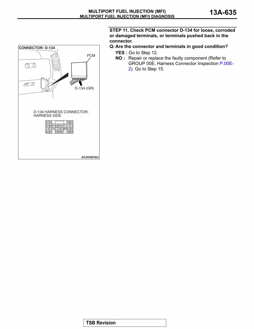
MULTIPORT FUEL INJECTION (MFI) DIAGNOSISMULTIPORT FUEL INJECTION (MFI) 13A-635
STEP 11. Check PCM connector D-134 for loose, corroded or damaged terminals, or terminals pushed back in the connector.Q: Are the connector and terminals in good condition?
YES : Go to Step 12.NO : Repair or replace the faulty component (Refer to
GROUP 00E, Harness Connector Inspection P.00E-2). Go to Step 15.
AC203997
CONNECTOR: D-134
AC
D-134 (GR)
PCM
D-134 HARNESS CONNECTOR:HARNESS SIDE
646365 6667 68
6261697071 7273
74 7576 77 787980818283 84 85 8687 8889
TSB Revision

MULTIPORT FUEL INJECTION (MFI) DIAGNOSISMULTIPORT FUEL INJECTION (MFI)13A-636
STEP 12. Check intermediate connectors D-112, E-111 and F-07, and fuel tank differential pressure sensor connector G-05 for loose, corroded or damaged terminals, or terminals pushed back in the connector.
AC401282
CONNECTOR: D-112
AB
D-112
AC401286
CONNECTOR: E-111
AC
E-111
TSB Revision
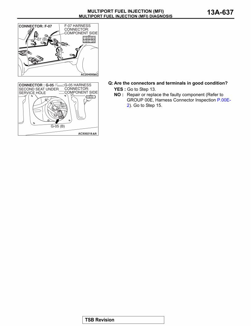
MULTIPORT FUEL INJECTION (MFI) DIAGNOSISMULTIPORT FUEL INJECTION (MFI) 13A-637
Q: Are the connectors and terminals in good condition?YES : Go to Step 13.NO : Repair or replace the faulty component (Refer to
GROUP 00E, Harness Connector Inspection P.00E-2). Go to Step 15.
AC204000
CONNECTOR: F-07
AC
F-07 (B)
F-07 HARNESSCONNECTOR:COMPONENT SIDE
84321
5 6 7
ACX00218
CONNECTOR : G-05
AR
G-05 (B)
SECOND SEAT UNDERSERVICE HOLE
G-05 HARNESSCONNECTOR:COMPONENT SIDE
123
TSB Revision

MULTIPORT FUEL INJECTION (MFI) DIAGNOSISMULTIPORT FUEL INJECTION (MFI)13A-638
STEP 13. Check the harness wires between PCM connector D-134 terminal 82 and fuel tank differential pressure sensor connector G-05 terminal 1 for damage. Q: Are the harness wires in good condition?
YES : It can be assumed that this malfunction is intermittent (Refer to GROUP 00, How to Use Troubleshooting/Inspection Service Points − How to Cope with Intermittent Malfunctions P.00-13). Go to Step 15.
NO : Repair the damaged harness wires. Go to Step 15.
AC203997
CONNECTOR: D-134
AC
D-134 (GR)
PCM
D-134 HARNESS CONNECTOR:HARNESS SIDE
646365 6667 68
6261697071 7273
74 7576 77 787980818283 84 85 8687 8889
ACX00218
CONNECTOR : G-05
AR
G-05 (B)
SECOND SEAT UNDERSERVICE HOLE
G-05 HARNESSCONNECTOR:COMPONENT SIDE
123
TSB Revision
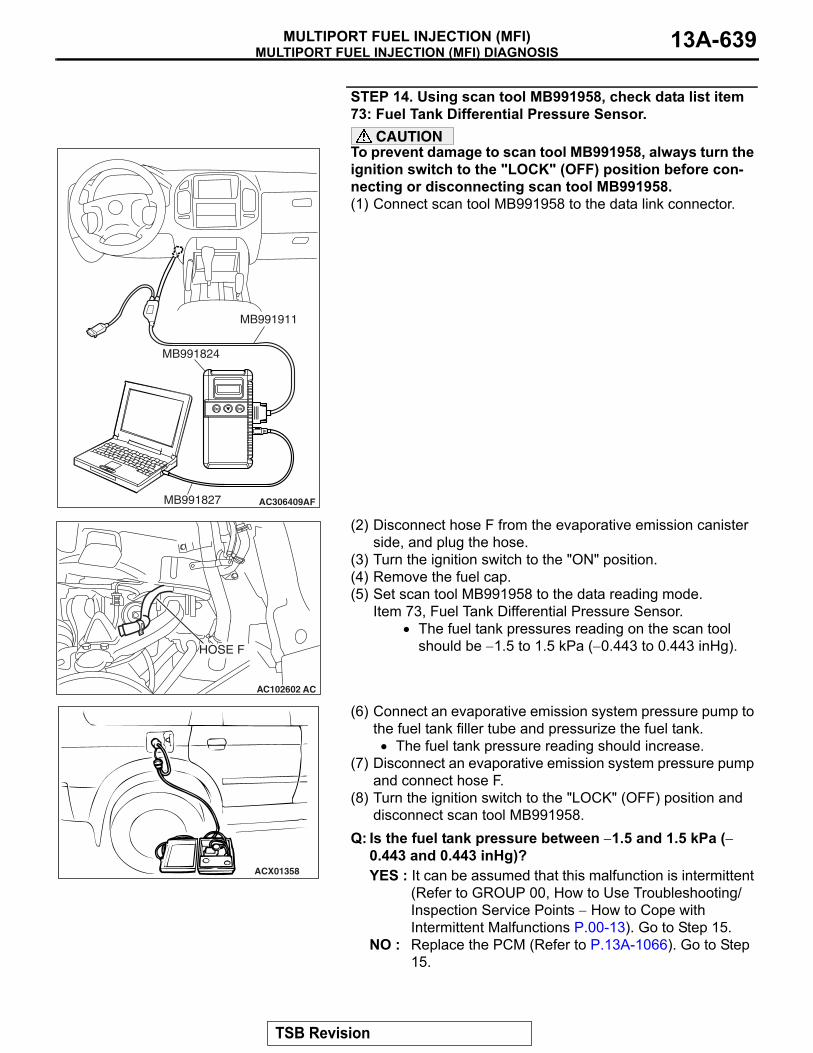
MULTIPORT FUEL INJECTION (MFI) DIAGNOSISMULTIPORT FUEL INJECTION (MFI) 13A-639
STEP 14. Using scan tool MB991958, check data list item 73: Fuel Tank Differential Pressure Sensor.
CAUTIONTo prevent damage to scan tool MB991958, always turn the ignition switch to the "LOCK" (OFF) position before con-necting or disconnecting scan tool MB991958.(1) Connect scan tool MB991958 to the data link connector.
(2) Disconnect hose F from the evaporative emission canister side, and plug the hose.
(3) Turn the ignition switch to the "ON" position.(4) Remove the fuel cap.(5) Set scan tool MB991958 to the data reading mode.
Item 73, Fuel Tank Differential Pressure Sensor.• The fuel tank pressures reading on the scan tool
should be −1.5 to 1.5 kPa (−0.443 to 0.443 inHg).
(6) Connect an evaporative emission system pressure pump to the fuel tank filler tube and pressurize the fuel tank.• The fuel tank pressure reading should increase.
(7) Disconnect an evaporative emission system pressure pump and connect hose F.
(8) Turn the ignition switch to the "LOCK" (OFF) position and disconnect scan tool MB991958.
Q: Is the fuel tank pressure between −1.5 and 1.5 kPa (−0.443 and 0.443 inHg)?YES : It can be assumed that this malfunction is intermittent
(Refer to GROUP 00, How to Use Troubleshooting/Inspection Service Points − How to Cope with Intermittent Malfunctions P.00-13). Go to Step 15.
NO : Replace the PCM (Refer to P.13A-1066). Go to Step 15.
AC306409AF
MB991911
MB991824
MB991827
AC102602 AC
HOSE F
ACX01358
TSB Revision

MULTIPORT FUEL INJECTION (MFI) DIAGNOSISMULTIPORT FUEL INJECTION (MFI)13A-640
STEP 15. Perform the OBD-II drive cycle.(1) Carry out a test drive with the drive cycle pattern (Refer to
Diagnostic Function − OBD-ll Drive Cycle − Pattern 19 P.13A-4).
(2) Read the diagnostic trouble code (DTC).Q: Is DTC P0452 set?
YES : Repeat the troubleshooting from Step 2.NO : The procedure is complete.
DTC P0453: Evaporative Emission System Pressure Sensor High Input
AC203991
SYSTEM DIAGRAM
A
B C D
EF
G
H
I
J
K
LM
N
OQ
S
R
P
FUEL TANK
CHECK VALVE B
CHECK VALVE AEVAPORATIVEEMISSIONPURGESOLENOID
EVAPORATIVE EMISSIONVENTILATION SOLENOID
EVAPORATIVEEMISSIONCANISTER
VENT PIPEASSEMBLY
AC
FUEL TANK DIFFERENTIALPRESSURE SENSOR
ONBOARD REFUELINGVAPOR RECOVERY(ORVR)VENT VALVE MODULE
TSB Revision

MULTIPORT FUEL INJECTION (MFI) DIAGNOSISMULTIPORT FUEL INJECTION (MFI) 13A-641
FUEL TANKDIFFERENTIALPRESSURESENSOR
POWERTRAIN CONTROLMODULE (PCM)
AC309251
Fuel Tank Differential Pressure Sensor Circuit
AC
FUEL TANKDIFFERENTIALPRESSURESENSOR
POWERTRAIN CONTROLMODULE (PCM)
AC309251
TSB Revision

MULTIPORT FUEL INJECTION (MFI) DIAGNOSISMULTIPORT FUEL INJECTION (MFI)13A-642
AC401282
CONNECTOR: D-112
AB
D-112
AC401283
CONNECTORS: D-134, D-135
AB
D-134(GR)
D-134
D-135(GR)
D-135
PCM
AC401286
CONNECTORS: E-111, E-113
AB
E-113
E-113
E-111
E-111AC204000
CONNECTOR: F-07
AC
F-07 (B)
F-07 HARNESSCONNECTOR:COMPONENT SIDE
84321
5 6 7
TSB Revision

MULTIPORT FUEL INJECTION (MFI) DIAGNOSISMULTIPORT FUEL INJECTION (MFI) 13A-643
.
CIRCUIT OPERATION• The PCM (terminal 97) supplies a 5-volt refer-
ence signal to the fuel tank differential pressure sensor (terminal 3). The fuel tank differential pressure sensor (terminal 2) is grounded through the PCM (terminal 96).
• The fuel tank differential pressure sensor (termi-nal 1) returns a voltage signal to the PCM (termi-nal 82) that is proportional to the pressure in the fuel tank.
.
TECHNICAL DESCRIPTION• The PCM monitors the fuel tank differential pres-
sure sensor output voltage.• The PCM determines whether the fuel tank differ-
ential pressure sensor signal voltage is within normal operating parameters.
.
DESCRIPTIONS OF MONITOR METHODS• Compare purge solenoid status with fuel tank dif-
ferential pressure sensor output voltage.
.
MONITOR EXECUTION• Continuous.
.
MONITOR EXECUTION CONDITIONS (OTHER MONITOR AND SENSOR)Other Monitor (There is no temporary DTC stored
in memory for the item monitored below)• Evaporative emission purge solenoid monitor• Evaporative emission ventilation solenoid monitor• Fuel level sensor monitor• Fuel temperature sensor monitor
Sensor (The sensors below are determined to be normal)
• Volume airflow sensor• Barometric pressure sensor• Intake air temperature sensor• Engine coolant temperature sensor• Accelerator pedal position sensor
.
ACX00218
CONNECTOR : G-05
AU
G-05 (B)
SECOND SEAT UNDERSERVICE HOLE
TSB Revision

MULTIPORT FUEL INJECTION (MFI) DIAGNOSISMULTIPORT FUEL INJECTION (MFI)13A-644
LOGIC FLOW CHARTS (Monitor Sequence)
.
DTC SET CONDITIONSCheck Conditions• 2 seconds or more have passed since the start-
ing sequence was completed.• The fuel temperature is 36°C (97°F) or less.• Remaining fuel level is 85% or less when the
engine is started.
Judgment Criterion• The fuel tank differential pressure sensor output
voltage remains 4.8 volt or greater for 5 seconds..
OBD-ll DRIVE CYCLE PATTERNRefer to Diagnostic Function − OBD-ll Drive Cycle − Pattern 19 P.13A-4..
AC407445
RANGE CHECK - MIN. / MAX.
NO
YES
CONTINUOUSFAILURE FOR 5 SECS
START
END
NO
NO
NO
YES
YES
YES
MALFUNCTION GOOD
MONITORING CONDITIONS
OUTPUT VOLTAGE < 0.2V
OUTPUT VOLTAGE > 4.8V
TSB Revision
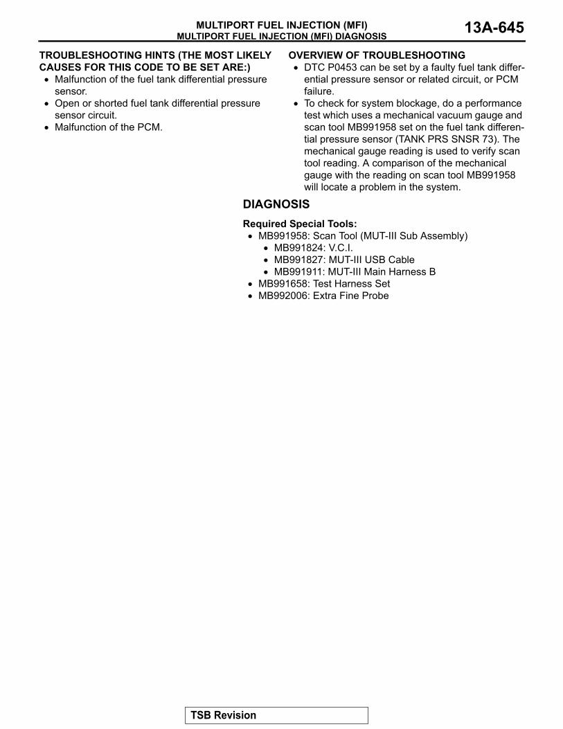
MULTIPORT FUEL INJECTION (MFI) DIAGNOSISMULTIPORT FUEL INJECTION (MFI) 13A-645
TROUBLESHOOTING HINTS (THE MOST LIKELY CAUSES FOR THIS CODE TO BE SET ARE:)• Malfunction of the fuel tank differential pressure
sensor.• Open or shorted fuel tank differential pressure
sensor circuit.• Malfunction of the PCM.
.
OVERVIEW OF TROUBLESHOOTING• DTC P0453 can be set by a faulty fuel tank differ-
ential pressure sensor or related circuit, or PCM failure.
• To check for system blockage, do a performance test which uses a mechanical vacuum gauge and scan tool MB991958 set on the fuel tank differen-tial pressure sensor (TANK PRS SNSR 73). The mechanical gauge reading is used to verify scan tool reading. A comparison of the mechanical gauge with the reading on scan tool MB991958 will locate a problem in the system.
DIAGNOSISRequired Special Tools:• MB991958: Scan Tool (MUT-III Sub Assembly)
• MB991824: V.C.I.• MB991827: MUT-III USB Cable• MB991911: MUT-III Main Harness B
• MB991658: Test Harness Set• MB992006: Extra Fine Probe
TSB Revision

MULTIPORT FUEL INJECTION (MFI) DIAGNOSISMULTIPORT FUEL INJECTION (MFI)13A-646
STEP 1. Using scan tool MB991958, check data list item 73: Fuel Tank Differential Pressure Sensor.
CAUTIONTo prevent damage to scan tool MB991958, always turn the ignition switch to the "LOCK" (OFF) position before con-necting or disconnecting scan tool MB991958.(1) Connect scan tool MB991958 to the data link connector.
(2) Disconnect hose F from the evaporative emission canister side, and plug the hose.
(3) Turn the ignition switch to the "ON" position.(4) Remove the fuel cap.(5) Set scan tool MB991958 to the data reading mode.
Item 73, Fuel Tank Differential Pressure Sensor.• The fuel tank pressures reading on the scan tool
should be −1.5 to 1.5 kPa (−0.443 to 0.443 inHg).
(6) Connect an evaporative emission system pressure pump to the fuel tank filler tube and pressurize the fuel tank.• The fuel tank pressure reading should increase.
(7) Disconnect an evaporative emission system pressure pump and connect hose F.
(8) Turn the ignition switch to the "LOCK" (OFF) position and disconnect scan tool MB991958.
Q: Is the fuel tank pressure between −1.5 and 1.5 kPa (−0.443 and 0.443 inHg)?YES : It can be assumed that this malfunction is intermittent
(Refer to GROUP 00, How to Use Troubleshooting/Inspection Service Points − How to Cope with Intermittent Malfunctions P.00-13). Go to Step 15.
NO : Go to Step 2.
AC306409AF
MB991911
MB991824
MB991827
AC102602 AC
HOSE F
ACX01358
TSB Revision

MULTIPORT FUEL INJECTION (MFI) DIAGNOSISMULTIPORT FUEL INJECTION (MFI) 13A-647
STEP 2. Measure the signal voltage at fuel tank differential pressure sensor connector G-05.(1) Tumble the second seat.(2) Remove the service hole cover (upper) and packing.(3) Remove the service hole cover (lower) and packing.(4) Disconnect fuel tank differential pressure sensor connector
G-05.
(5) Connect special tool MB991658 between fuel tank differential pressure sensor connector G-05 terminals 1, 2 and 3.
(6) Turn the ignition switch to the "ON" position.(7) Remove the fuel cap.(8) Measure the voltage between fuel tank differential pressure
sensor connector G-05 terminal 1 and ground.• The voltage should measure between 2.0 and 3.0 volts.
(9) Turn the ignition switch to the "LOCK" (OFF) position.Q: Is the measured voltage between 2.0 and 3.0 volts?
YES : Go to Step 10.NO : Go to Step 3.
STEP 3. Measure the 5-volt reference signal at fuel tank differential pressure sensor connector G-05.(1) Disconnect fuel tank differential pressure sensor connector
G-05.
(2) Connect special tool MB991658 between fuel tank differential pressure sensor connector G-05 terminals 1, 2 and 3.
(3) Turn the ignition switch to the "ON" position.(4) Measure the voltage between fuel tank differential pressure
sensor connector G-05 terminal 3 and ground.• The voltage should measure between 4.9 and 5.1 volts.
(5) Turn the ignition switch to the "LOCK" (OFF) position.Q: Is the measured voltage between 4.9 and 5.1 volts?
YES : Go to Step 8.NO : Go to Step 4.
ACX00218
CONNECTOR : G-05
AS
G-05 (B)
SERVICE HOLE (UPPER)
G-05 HARNESSCONNECTOR:COMPONENT SIDE
123
SERVICE HOLE (LOWER)
AC002081AB
MB991658
FUEL TANK DIFFERENTIAL PRESSURE SENSOR
ACX00218
CONNECTOR : G-05
AR
G-05 (B)
SECOND SEAT UNDERSERVICE HOLE
G-05 HARNESSCONNECTOR:COMPONENT SIDE
123
AC002081AB
MB991658
FUEL TANK DIFFERENTIAL PRESSURE SENSOR
TSB Revision

MULTIPORT FUEL INJECTION (MFI) DIAGNOSISMULTIPORT FUEL INJECTION (MFI)13A-648
STEP 4. Measure the 5-volt reference signal at PCM connector D-135 by backprobing.(1) Do not disconnect PCM connector D-135.(2) Turn the ignition switch to the "ON" position.
(3) Measure the voltage between PCM connector D-135 terminal 97 and ground by backprobing.• The voltage should measure between 4.9 and 5.1 volts.
(4) Turn the ignition switch to the "LOCK" (OFF) position.Q: Is the measured voltage between 4.9 and 5.1 volts?
YES : Go to Step 6.NO : Go to Step 5.
AC203997
CONNECTOR: D-135
AB
D-135 (GR)
PCM
D-135 HARNESS CONNECTOR:HARNESS SIDE
9493 9596 97 98 99 100
9291101 102103 104
105 106 107 108 109 110 111 112113 114 115 116 117 118 119 120
9493 9596 97 98 99 100
9291101 102 103 104
105 106 107 108 109 110 111 112113 114 115 116 117 118 119 120
AC204160AB
D-135 HARNESS CONNECTOR:HARNESS SIDE
TSB Revision

MULTIPORT FUEL INJECTION (MFI) DIAGNOSISMULTIPORT FUEL INJECTION (MFI) 13A-649
STEP 5. Check PCM connector D-135 for loose, corroded or damaged terminals, or terminals pushed back in the connector.Q: Are the connector and terminals in good condition?
YES : Go to Step 14.NO : Repair or replace the faulty component (Refer to
GROUP 00E, Harness Connector Inspection P.00E-2). Go to Step 15.
AC203997
CONNECTOR: D-135
AB
D-135 (GR)
PCM
D-135 HARNESS CONNECTOR:HARNESS SIDE
9493 9596 97 98 99 100
9291101 102103 104
105 106 107 108 109 110 111 112113 114 115 116 117 118 119 120
TSB Revision

MULTIPORT FUEL INJECTION (MFI) DIAGNOSISMULTIPORT FUEL INJECTION (MFI)13A-650
STEP 6. Check intermediate connectors D-112, E-111 and F-07, and fuel tank differential pressure sensor connector G-05 for loose, corroded or damaged terminals, or terminals pushed back in the connector.
AC401282
CONNECTOR: D-112
AB
D-112
AC401286
CONNECTOR: E-111
AC
E-111
TSB Revision

MULTIPORT FUEL INJECTION (MFI) DIAGNOSISMULTIPORT FUEL INJECTION (MFI) 13A-651
Q: Are the connectors and terminals in good condition?YES : Go to Step 7.NO : Repair or replace the faulty component (Refer to
GROUP 00E, Harness Connector Inspection P.00E-2). Go to Step 15.
AC204000
CONNECTOR: F-07
AC
F-07 (B)
F-07 HARNESSCONNECTOR:COMPONENT SIDE
84321
5 6 7
ACX00218
CONNECTOR : G-05
AR
G-05 (B)
SECOND SEAT UNDERSERVICE HOLE
G-05 HARNESSCONNECTOR:COMPONENT SIDE
123
TSB Revision
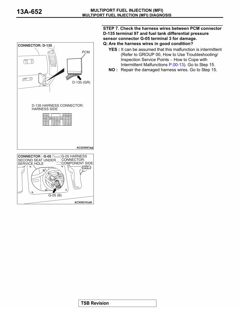
MULTIPORT FUEL INJECTION (MFI) DIAGNOSISMULTIPORT FUEL INJECTION (MFI)13A-652
STEP 7. Check the harness wires between PCM connector D-135 terminal 97 and fuel tank differential pressure sensor connector G-05 terminal 3 for damage. Q: Are the harness wires in good condition?
YES : It can be assumed that this malfunction is intermittent (Refer to GROUP 00, How to Use Troubleshooting/Inspection Service Points − How to Cope with Intermittent Malfunctions P.00-13). Go to Step 15.
NO : Repair the damaged harness wires. Go to Step 15.
AC203997
CONNECTOR: D-135
AB
D-135 (GR)
PCM
D-135 HARNESS CONNECTOR:HARNESS SIDE
9493 9596 97 98 99 100
9291101 102103 104
105 106 107 108 109 110 111 112113 114 115 116 117 118 119 120
ACX00218
CONNECTOR : G-05
AR
G-05 (B)
SECOND SEAT UNDERSERVICE HOLE
G-05 HARNESSCONNECTOR:COMPONENT SIDE
123
TSB Revision

MULTIPORT FUEL INJECTION (MFI) DIAGNOSISMULTIPORT FUEL INJECTION (MFI) 13A-653
STEP 8. Check PCM connector D-135, intermediate connectors D-112, E-113 and F-07, and fuel tank differential pressure sensor connector G-05 for loose, corroded or damaged terminals, or terminals pushed back in the connector.
AC203997
CONNECTOR: D-135
AB
D-135 (GR)
PCM
D-135 HARNESS CONNECTOR:HARNESS SIDE
9493 9596 97 98 99 100
9291101 102103 104
105 106 107 108 109 110 111 112113 114 115 116 117 118 119 120
AC401282
CONNECTOR: D-112
AB
D-112
TSB Revision

MULTIPORT FUEL INJECTION (MFI) DIAGNOSISMULTIPORT FUEL INJECTION (MFI)13A-654
Q: Are the connectors and terminals in good condition?YES : Go to Step 9.NO : Repair or replace the faulty component (Refer to
GROUP 00E, Harness Connector Inspection P.00E-2). Go to Step 15.
AC203999
CONNECTOR: E-113
AD
E-113
E-113 HARNESSCONNECTOR:COMPONENT SIDE
11
21
6 7 98 10 14
43
1213
5
AC204000
CONNECTOR: F-07
AC
F-07 (B)
F-07 HARNESSCONNECTOR:COMPONENT SIDE
84321
5 6 7
ACX00218
CONNECTOR : G-05
AR
G-05 (B)
SECOND SEAT UNDERSERVICE HOLE
G-05 HARNESSCONNECTOR:COMPONENT SIDE
123
TSB Revision

MULTIPORT FUEL INJECTION (MFI) DIAGNOSISMULTIPORT FUEL INJECTION (MFI) 13A-655
STEP 9. Check the harness wires between PCM connector D-135 terminal 96 and fuel tank differential pressure sensor connector G-05 terminal 2 for damage. Q: Are the harness wires in good condition?
YES : Replace the fuel tank differential pressure sensor (Refer to GROUP 13B, Fuel Tank P.13B-8). Go to Step 14.
NO : Repair the damaged harness wires. Go to Step 15.
AC203997
CONNECTOR: D-135
AB
D-135 (GR)
PCM
D-135 HARNESS CONNECTOR:HARNESS SIDE
9493 9596 97 98 99 100
9291101 102103 104
105 106 107 108 109 110 111 112113 114 115 116 117 118 119 120
ACX00218
CONNECTOR : G-05
AR
G-05 (B)
SECOND SEAT UNDERSERVICE HOLE
G-05 HARNESSCONNECTOR:COMPONENT SIDE
123
TSB Revision

MULTIPORT FUEL INJECTION (MFI) DIAGNOSISMULTIPORT FUEL INJECTION (MFI)13A-656
STEP 10. Measure the signal voltage at PCM connector D-134 by backprobing.(1) Do not disconnect PCM connector D-134.(2) Turn the ignition switch to the "ON" position.(3) Remove the fuel cap.
(4) Measure the voltage between PCM connector D-134 terminal 82 and ground by backprobing.• The voltage should measure between 2.0 and 3.0 volts.
(5) Turn the ignition switch to the "LOCK" (OFF) position.Q: Is the measured voltage between 2.0 and 3.0 volts?
YES : Go to Step 14.NO : Go to Step 11.
AC203997
CONNECTOR: D-134
AC
D-134 (GR)
PCM
D-134 HARNESS CONNECTOR:HARNESS SIDE
646365 6667 68
6261697071 7273
74 7576 77 787980818283 84 85 8687 8889
AC204161
646365 66 6768
62616970717273
74 75 7677787980818283 84 858687 88 89
AB
D-134 HARNESS CONNECTOR:HARNESS SIDE
TSB Revision

MULTIPORT FUEL INJECTION (MFI) DIAGNOSISMULTIPORT FUEL INJECTION (MFI) 13A-657
STEP 11. Check PCM connector D-134 for loose, corroded or damaged terminals, or terminals pushed back in the connector.Q: Are the connector and terminals in good condition?
YES : Go to Step 12.NO : Repair or replace the faulty component (Refer to
GROUP 00E, Harness Connector Inspection P.00E-2). Go to Step 15.
AC203997
CONNECTOR: D-134
AC
D-134 (GR)
PCM
D-134 HARNESS CONNECTOR:HARNESS SIDE
646365 6667 68
6261697071 7273
74 7576 77 787980818283 84 85 8687 8889
TSB Revision

MULTIPORT FUEL INJECTION (MFI) DIAGNOSISMULTIPORT FUEL INJECTION (MFI)13A-658
STEP 12. Check intermediate connectors D-112, E-111 and F-07, and fuel tank differential pressure sensor connector G-05 for loose, corroded or damaged terminals, or terminals pushed back in the connector.
AC401282
CONNECTOR: D-112
AB
D-112
AC401286
CONNECTOR: E-111
AC
E-111
TSB Revision

MULTIPORT FUEL INJECTION (MFI) DIAGNOSISMULTIPORT FUEL INJECTION (MFI) 13A-659
Q: Are the connectors and terminals in good condition?YES : Go to Step 13.NO : Repair or replace the faulty component (Refer to
GROUP 00E, Harness Connector Inspection P.00E-2). Go to Step 15.
AC204000
CONNECTOR: F-07
AC
F-07 (B)
F-07 HARNESSCONNECTOR:COMPONENT SIDE
84321
5 6 7
ACX00218
CONNECTOR : G-05
AR
G-05 (B)
SECOND SEAT UNDERSERVICE HOLE
G-05 HARNESSCONNECTOR:COMPONENT SIDE
123
TSB Revision

MULTIPORT FUEL INJECTION (MFI) DIAGNOSISMULTIPORT FUEL INJECTION (MFI)13A-660
STEP 13. Check the harness wires between PCM connector D-134 terminal 82 and fuel tank differential pressure sensor connector G-05 terminal 1 for damage. Q: Are the harness wires in good condition?
YES : It can be assumed that this malfunction is intermittent (Refer to GROUP 00, How to Use Troubleshooting/Inspection Service Points − How to Cope with Intermittent Malfunctions P.00-13). Go to Step 15.
NO : Repair the damaged harness wires. Go to Step 15.
AC203997
CONNECTOR: D-134
AC
D-134 (GR)
PCM
D-134 HARNESS CONNECTOR:HARNESS SIDE
646365 6667 68
6261697071 7273
74 7576 77 787980818283 84 85 8687 8889
ACX00218
CONNECTOR : G-05
AR
G-05 (B)
SECOND SEAT UNDERSERVICE HOLE
G-05 HARNESSCONNECTOR:COMPONENT SIDE
123
TSB Revision

MULTIPORT FUEL INJECTION (MFI) DIAGNOSISMULTIPORT FUEL INJECTION (MFI) 13A-661
STEP 14. Using scan tool MB991958, check data list item 73: Fuel Tank Differential Pressure Sensor.
CAUTIONTo prevent damage to scan tool MB991958, always turn the ignition switch to the "LOCK" (OFF) position before con-necting or disconnecting scan tool MB991958.(1) Connect scan tool MB991958 to the data link connector.
(2) Disconnect hose F from the evaporative emission canister side, and plug the hose.
(3) Turn the ignition switch to the "ON" position.(4) Remove the fuel cap.(5) Set scan tool MB991958 to the data reading mode.
Item 73, Fuel Tank Differential Pressure Sensor.• The fuel tank pressures reading on the scan tool
should be −1.5 to 1.5 kPa (−0.443 to 0.443 inHg).
(6) Connect an evaporative emission system pressure pump to the fuel tank filler tube and pressurize the fuel tank.• The fuel tank pressure reading should increase.
(7) Disconnect an evaporative emission system pressure pump and connect hose F.
(8) Turn the ignition switch to the "LOCK" (OFF) position and disconnect scan tool MB991958.
Q: Is the fuel tank pressure between −1.5 and 1.5 kPa (−0.443 and 0.443 inHg)?YES : It can be assumed that this malfunction is intermittent
(Refer to GROUP 00, How to Use Troubleshooting/Inspection Service Points − How to Cope with Intermittent Malfunctions P.00-13). Go to Step 15.
NO : Replace the PCM (Refer to P.13A-1066). Go to Step 15.
AC306409AF
MB991911
MB991824
MB991827
AC102602 AC
HOSE F
ACX01358
TSB Revision

MULTIPORT FUEL INJECTION (MFI) DIAGNOSISMULTIPORT FUEL INJECTION (MFI)13A-662
STEP 15. Perform the OBD-II drive cycle.(1) Carry out a test drive with the drive cycle pattern (Refer to
Diagnostic Function − OBD-ll Drive Cycle − Pattern 19 P.13A-4).
(2) Read the diagnostic trouble code (DTC).Q: Is DTC P0453 set?
YES : Repeat the troubleshooting from Step 2.NO : The procedure is complete.
DTC P0455: Evaporative Emission System Leak Detected (Gross Leak)
AC203991
SYSTEM DIAGRAM
A
B C D
EF
G
H
I
J
K
LM
N
OQ
S
R
P
FUEL TANK
CHECK VALVE B
CHECK VALVE AEVAPORATIVEEMISSIONPURGESOLENOID
EVAPORATIVE EMISSIONVENTILATION SOLENOID
EVAPORATIVEEMISSIONCANISTER
VENT PIPEASSEMBLY
AD
ONBOARD REFUELINGVAPOR RECOVERY(ORVR)VENT VALVE MODULE
AC101766
EVAPORATIVE EMISSION CANISTER
AB AC203904AC
EVAPORATIVE EMISSIONPURGE SOLENOID
INTAKE AIR DUCT
TSB Revision
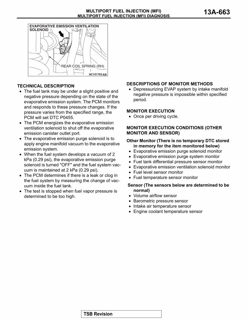
MULTIPORT FUEL INJECTION (MFI) DIAGNOSISMULTIPORT FUEL INJECTION (MFI) 13A-663
.
TECHNICAL DESCRIPTION• The fuel tank may be under a slight positive and
negative pressure depending on the state of the evaporative emission system. The PCM monitors and responds to these pressure changes. If the pressure varies from the specified range, the PCM will set DTC P0455.
• The PCM energizes the evaporative emission ventilation solenoid to shut off the evaporative emission canister outlet port.
• The evaporative emission purge solenoid is to apply engine manifold vacuum to the evaporative emission system.
• When the fuel system develops a vacuum of 2 kPa (0.29 psi), the evaporative emission purge solenoid is turned "OFF" and the fuel system vac-uum is maintained at 2 kPa (0.29 psi).
• The PCM determines if there is a leak or clog in the fuel system by measuring the change of vac-uum inside the fuel tank.
• The test is stopped when fuel vapor pressure is determined to be too high.
.
DESCRIPTIONS OF MONITOR METHODS• Depressurizing EVAP system by intake manifold
negative pressure is impossible within specified period.
.
MONITOR EXECUTION• Once per driving cycle.
.
MONITOR EXECUTION CONDITIONS (OTHER MONITOR AND SENSOR)Other Monitor (There is no temporary DTC stored
in memory for the item monitored below)• Evaporative emission purge solenoid monitor• Evaporative emission purge system monitor• Fuel tank differential pressure sensor monitor• Evaporative emission ventilation solenoid monitor• Fuel level sensor monitor• Fuel temperature sensor monitor
Sensor (The sensors below are determined to be normal)
• Volume airflow sensor• Barometric pressure sensor• Intake air temperature sensor• Engine coolant temperature sensor
.
AC101763 AB
REAR COIL SPRING (RH)
EVAPORATIVE EMISSION VENTILATION SOLENOID
TSB Revision

MULTIPORT FUEL INJECTION (MFI) DIAGNOSISMULTIPORT FUEL INJECTION (MFI)13A-664
LOGIC FLOW CHARTS (Monitor Sequence)
.
DTC SET CONDITIONSCheck Conditions A: At Start up• Intake air temperature is 36°C (97°F) or less
upon engine start up.
• The engine coolant temperature is 36°C (97°F) or less upon engine start up.
AC306649
0.04in, 0.02in GROSS LEAK MONITOR
START
YES
YES
YES
YES
YES
NO
NONO
NO
NO
MONITORINGCONDITIONS?
DEPRESSURIZE FUEL TANK PRESSURE
GROSS LEAKMONITORING CONDITIONS
SHUT PURGE LINE
MEASURE REVERTINGPRESSURE : PFT
PFT > PT
SPECIFIED TIMESMONITORED
MALFUNCTION
END
SPECIFIED TIMESHAVE PASSED
MALFUNCTION
(GROSS LEAK)
GOOD
TSB Revision
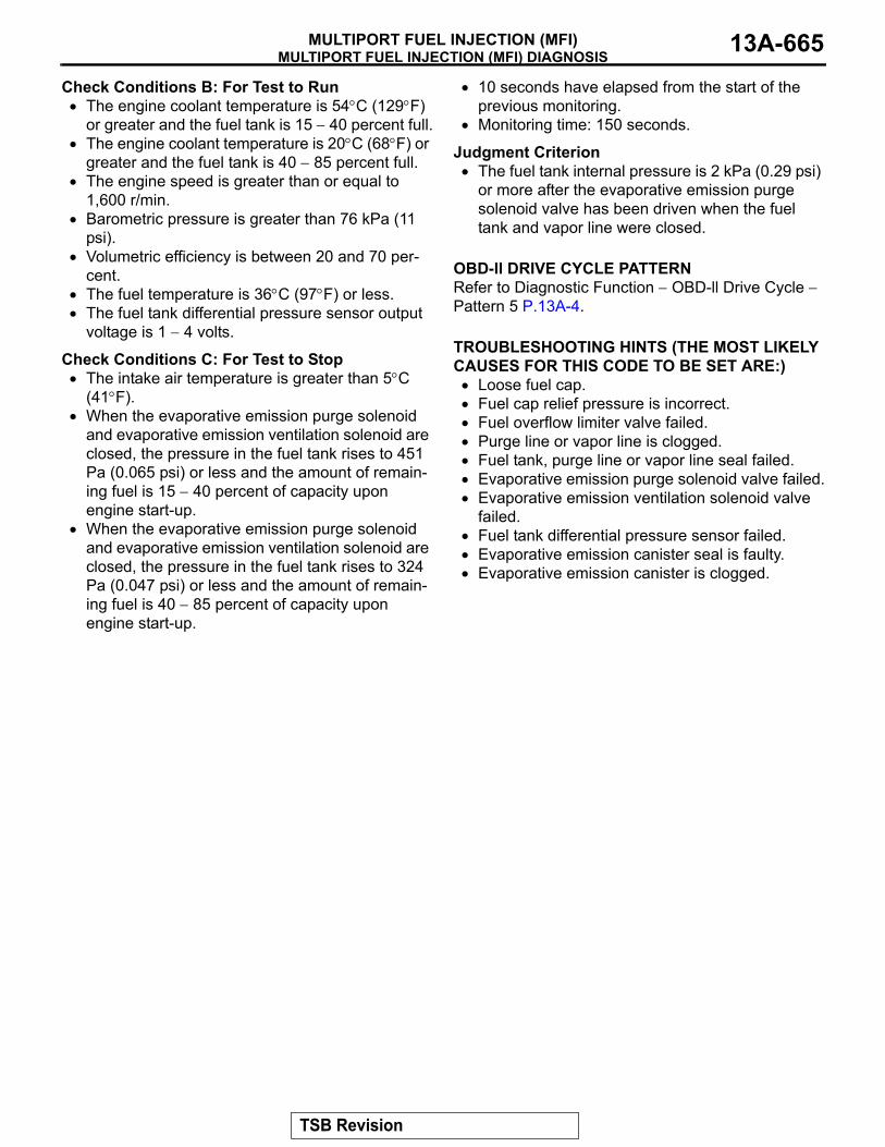
MULTIPORT FUEL INJECTION (MFI) DIAGNOSISMULTIPORT FUEL INJECTION (MFI) 13A-665
Check Conditions B: For Test to Run• The engine coolant temperature is 54°C (129°F)
or greater and the fuel tank is 15 − 40 percent full.• The engine coolant temperature is 20°C (68°F) or
greater and the fuel tank is 40 − 85 percent full.• The engine speed is greater than or equal to
1,600 r/min.• Barometric pressure is greater than 76 kPa (11
psi).• Volumetric efficiency is between 20 and 70 per-
cent.• The fuel temperature is 36°C (97°F) or less.• The fuel tank differential pressure sensor output
voltage is 1 − 4 volts.
Check Conditions C: For Test to Stop• The intake air temperature is greater than 5°C
(41°F).• When the evaporative emission purge solenoid
and evaporative emission ventilation solenoid are closed, the pressure in the fuel tank rises to 451 Pa (0.065 psi) or less and the amount of remain-ing fuel is 15 − 40 percent of capacity upon engine start-up.
• When the evaporative emission purge solenoid and evaporative emission ventilation solenoid are closed, the pressure in the fuel tank rises to 324 Pa (0.047 psi) or less and the amount of remain-ing fuel is 40 − 85 percent of capacity upon engine start-up.
• 10 seconds have elapsed from the start of the previous monitoring.
• Monitoring time: 150 seconds.
Judgment Criterion• The fuel tank internal pressure is 2 kPa (0.29 psi)
or more after the evaporative emission purge solenoid valve has been driven when the fuel tank and vapor line were closed.
.
OBD-ll DRIVE CYCLE PATTERNRefer to Diagnostic Function − OBD-ll Drive Cycle − Pattern 5 P.13A-4..
TROUBLESHOOTING HINTS (THE MOST LIKELY CAUSES FOR THIS CODE TO BE SET ARE:)• Loose fuel cap.• Fuel cap relief pressure is incorrect.• Fuel overflow limiter valve failed.• Purge line or vapor line is clogged.• Fuel tank, purge line or vapor line seal failed.• Evaporative emission purge solenoid valve failed.• Evaporative emission ventilation solenoid valve
failed.• Fuel tank differential pressure sensor failed.• Evaporative emission canister seal is faulty.• Evaporative emission canister is clogged.
TSB Revision
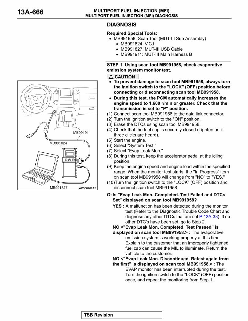
MULTIPORT FUEL INJECTION (MFI) DIAGNOSISMULTIPORT FUEL INJECTION (MFI)13A-666
DIAGNOSISRequired Special Tools:• MB991958: Scan Tool (MUT-III Sub Assembly)
• MB991824: V.C.I.• MB991827: MUT-III USB Cable• MB991911: MUT-III Main Harness B
STEP 1. Using scan tool MB991958, check evaporative emission system monitor test.
CAUTION• To prevent damage to scan tool MB991958, always turn
the ignition switch to the "LOCK" (OFF) position before connecting or disconnecting scan tool MB991958.
• During this test, the PCM automatically increases the engine speed to 1,600 r/min or greater. Check that the transmission is set to "P" position.
(1) Connect scan tool MB991958 to the data link connector.(2) Turn the ignition switch to the "ON" position.(3) Erase the DTCs using scan tool MB991958.(4) Check that the fuel cap is securely closed (Tighten until
three clicks are heard).(5) Start the engine.(6) Select "System Test."(7) Select "Evap Leak Mon."(8) During this test, keep the accelerator pedal at the idling
position.(9) Keep the engine speed and engine load within the specified
range. When the monitor test starts, the "In Progress" item on scan tool MB991958 will change from "NO" to "YES."
(10)Turn the ignition switch to the "LOCK" (OFF) position and disconnect scan tool MB991958.
Q: Is "Evap Leak Mon. Completed. Test Failed and DTCs Set" displayed on scan tool MB991958?YES : A malfunction has been detected during the monitor
test (Refer to the Diagnostic Trouble Code Chart and diagnose any other DTCs that are set P.13A-33). If no other DTC's have been set, go to Step 2.
NO <"Evap Leak Mon. Completed. Test Passed" is displayed on scan tool MB991958.> : The evaporative
emission system is working properly at this time. Explain to the customer that an improperly tightened fuel cap can cause the MIL to illuminate. Return the vehicle to the customer.
NO <"Evap Leak Mon. Discontinued. Retest again from the first" is displayed on scan tool MB991958.> : The
EVAP monitor has been interrupted during the test. Turn the ignition switch to the "LOCK" (OFF) position once, and repeat the monitoring from Step 1.
AC306409AF
MB991911
MB991824
MB991827
TSB Revision

MULTIPORT FUEL INJECTION (MFI) DIAGNOSISMULTIPORT FUEL INJECTION (MFI) 13A-667
STEP 2. Using scan tool MB991958, check actuator test item 08: Evaporative Emission Purge Solenoid.
CAUTIONTo prevent damage to scan tool MB991958, always turn the ignition switch to the "LOCK" (OFF) position before con-necting or disconnecting scan tool MB991958.(1) Connect scan tool MB991958 to the data link connector.
(2) Disconnect hoses A and B from the evaporative emission purge solenoid.
(3) Connect the hand vacuum pump to the evaporative emission purge solenoid instead of hose A.
(4) Turn the ignition switch to the "ON" position.(5) Set scan tool MB991958 to actuator test mode for item 08,
evaporative emission purge solenoid.• When the evaporative emission purge solenoid is oper-
ated, apply a pressure on the hand vacuum pump and confirm that air is blown from the other side nipple.
(6) Turn the ignition switch to the "LOCK" (OFF) position.(7) Disconnect the hand vacuum pump and connect hoses A
and B to the evaporative emission purge solenoid.Q: Does the evaporative emission purge solenoid nipple
blow the air?YES : Go to Step 3.NO : Replace the evaporative emission purge solenoid. Go
to Step 26.
AC306409AF
MB991911
MB991824
MB991827
AC203994AB
HOSE A
HOSE B
EVAPORATIVE EMISSIONPURGE SOLENOID
AC203995AB
EVAPORATIVE EMISSIONPURGE SOLENOID
TSB Revision
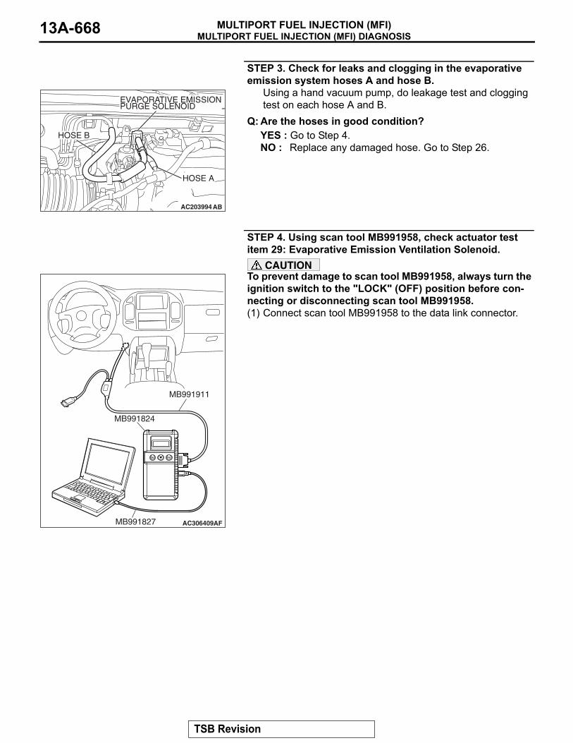
MULTIPORT FUEL INJECTION (MFI) DIAGNOSISMULTIPORT FUEL INJECTION (MFI)13A-668
STEP 3. Check for leaks and clogging in the evaporative emission system hoses A and hose B.
Using a hand vacuum pump, do leakage test and clogging test on each hose A and B.
Q: Are the hoses in good condition?YES : Go to Step 4.NO : Replace any damaged hose. Go to Step 26.
STEP 4. Using scan tool MB991958, check actuator test item 29: Evaporative Emission Ventilation Solenoid.
CAUTIONTo prevent damage to scan tool MB991958, always turn the ignition switch to the "LOCK" (OFF) position before con-necting or disconnecting scan tool MB991958.(1) Connect scan tool MB991958 to the data link connector.
AC203994AB
HOSE A
HOSE B
EVAPORATIVE EMISSIONPURGE SOLENOID
AC306409AF
MB991911
MB991824
MB991827
TSB Revision
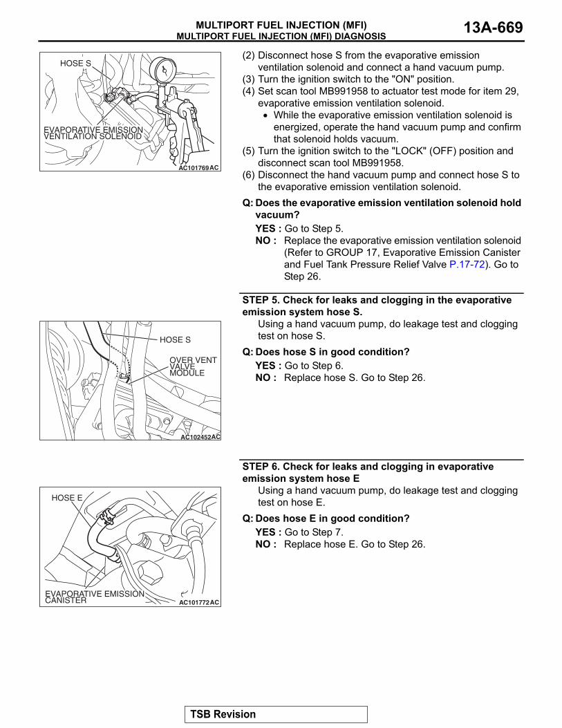
MULTIPORT FUEL INJECTION (MFI) DIAGNOSISMULTIPORT FUEL INJECTION (MFI) 13A-669
(2) Disconnect hose S from the evaporative emission ventilation solenoid and connect a hand vacuum pump.
(3) Turn the ignition switch to the "ON" position.(4) Set scan tool MB991958 to actuator test mode for item 29,
evaporative emission ventilation solenoid.• While the evaporative emission ventilation solenoid is
energized, operate the hand vacuum pump and confirm that solenoid holds vacuum.
(5) Turn the ignition switch to the "LOCK" (OFF) position and disconnect scan tool MB991958.
(6) Disconnect the hand vacuum pump and connect hose S to the evaporative emission ventilation solenoid.
Q: Does the evaporative emission ventilation solenoid hold vacuum?YES : Go to Step 5.NO : Replace the evaporative emission ventilation solenoid
(Refer to GROUP 17, Evaporative Emission Canister and Fuel Tank Pressure Relief Valve P.17-72). Go to Step 26.
STEP 5. Check for leaks and clogging in the evaporative emission system hose S.
Using a hand vacuum pump, do leakage test and clogging test on hose S.
Q: Does hose S in good condition?YES : Go to Step 6.NO : Replace hose S. Go to Step 26.
STEP 6. Check for leaks and clogging in evaporative emission system hose E
Using a hand vacuum pump, do leakage test and clogging test on hose E.
Q: Does hose E in good condition?YES : Go to Step 7.NO : Replace hose E. Go to Step 26.
AC101769
HOSE S
AC
EVAPORATIVE EMISSIONVENTILATION SOLENOID
AC102452
HOSE S
AC
OVER VENTVALVEMODULE
AC101772
HOSE E
ACEVAPORATIVE EMISSIONCANISTER
TSB Revision
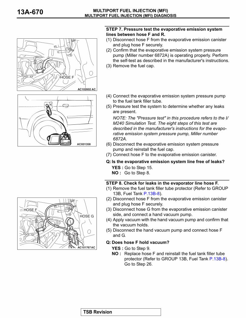
MULTIPORT FUEL INJECTION (MFI) DIAGNOSISMULTIPORT FUEL INJECTION (MFI)13A-670
STEP 7. Pressure test the evaporative emission system lines between hose F and R.(1) Disconnect hose F from the evaporative emission canister
and plug hose F securely.(2) Confirm that the evaporative emission system pressure
pump (Miller number 6872A) is operating properly. Perform the self-test as described in the manufacturer's instructions.
(3) Remove the fuel cap.
(4) Connect the evaporative emission system pressure pump to the fuel tank filler tube.
(5) Pressure test the system to determine whether any leaks are present.NOTE: The "Pressure test" in this procedure refers to the I/M240 Simulation Test. The eight steps of this test are described in the manufacturer's instructions for the evapo-rative emission system pressure pump, Miller number 6872A.
(6) Disconnect the evaporative emission system pressure pump and reinstall the fuel cap.
(7) Connect hose F to the evaporative emission canister.Q: Is the evaporative emission system line free of leaks?
YES : Go to Step 15.NO : Go to Step 8.
STEP 8. Check for leaks in the evaporator line hose F.(1) Remove the fuel tank filler tube protector (Refer to GROUP
13B, Fuel Tank P.13B-8).(2) Disconnect hose F from the evaporative emission canister
and plug hose F securely.(3) Disconnect hose G from the evaporative emission canister
side, and connect a hand vacuum pump.(4) Apply vacuum with the hand vacuum pump and confirm that
the vacuum holds.(5) Disconnect the hand vacuum pump and connect hose F
and G. Q: Does hose F hold vacuum?
YES : Go to Step 9.NO : Replace hose F and reinstall the fuel tank filler tube
protector (Refer to GROUP 13B, Fuel Tank P.13B-8). Go to Step 26.
AC102602 AC
HOSE F
ACX01358
AC101767AC
HOSE F
HOSE G
TSB Revision

MULTIPORT FUEL INJECTION (MFI) DIAGNOSISMULTIPORT FUEL INJECTION (MFI) 13A-671
STEP 9. Check for leaks in the evaporative emission system hoses G through N.(1) Remove the fuel tank filler tube (Refer to GROUP 13B, Fuel
Tank P.13B-8).(2) Perform a leakage test with a hand vacuum pump on each
hose from hose G to N.Q: Does the hoses hold vacuum?
YES : Go to Step 10.NO : Replace any damaged hose, and reinstall the fuel
tank filler tube and the fuel tank filler tube protector (Refer to GROUP 13B, Fuel Tank P.13B-8). Go to Step 26.
STEP 10. Check the check valve A.(1) Check valve A is a one-way check valve.
(2) Check valve A should allow air to flow in only one direction.Q: Does check valve A allow air to press in one direction
only?YES : Go to Step 11.NO : Replace check valve A, and reinstall the fuel tank filler
tube and the fuel tank filler tube protector (Refer to GROUP 13B, Fuel Tank P.13B-8). Go to Step 26.
AC102673 AC
HOSE GHOSE L
HOSE M
HOSE N
AC102646 AC
HOSE KHOSE I
HOSE H
HOSE J
AC102646AD
CHECKVALVE A
AC002076AB
CHECK VALVE A
TSB Revision

MULTIPORT FUEL INJECTION (MFI) DIAGNOSISMULTIPORT FUEL INJECTION (MFI)13A-672
STEP 11. Check the check valve B.(1) Check valve B is a one-way check valve.
(2) Check valve B should allow air to flow in only one direction.Q: Does check valve B allow air to press in one direction
only?YES : Go to Step 12.NO : Replace check valve B, and reinstall the fuel tank filler
tube and the fuel tank filler tube protector (Refer to GROUP 13B, Fuel Tank P.13B-8). Go to Step 26.
STEP 12.Check for cracks in the fuel tank filler tube assembly.
Visually check for cracks in the fuel tank filler tube assembly.
Q: Is the fuel tank filler tube assembly in good condition?YES : Go to Step 13.NO : Replace the fuel tank filler tube assembly and reinstall
the fuel tank filler tube protector (Refer to GROUP 13B, Fuel Tank P.13B-8). Go to Step 26 .
AC102646 AE
CHECKVALVE B
AC002078
CHECK VALVE B
AB
TSB Revision
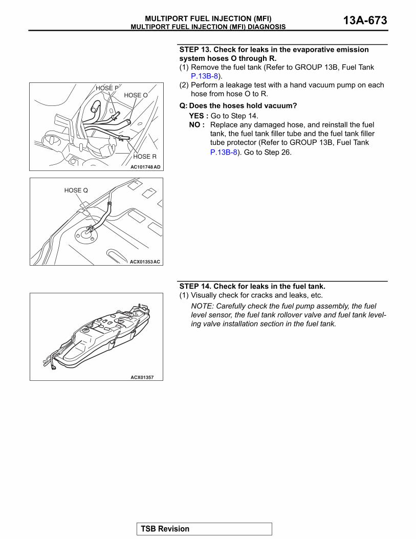
MULTIPORT FUEL INJECTION (MFI) DIAGNOSISMULTIPORT FUEL INJECTION (MFI) 13A-673
STEP 13. Check for leaks in the evaporative emission system hoses O through R.(1) Remove the fuel tank (Refer to GROUP 13B, Fuel Tank
P.13B-8).(2) Perform a leakage test with a hand vacuum pump on each
hose from hose O to R.Q: Does the hoses hold vacuum?
YES : Go to Step 14.NO : Replace any damaged hose, and reinstall the fuel
tank, the fuel tank filler tube and the fuel tank filler tube protector (Refer to GROUP 13B, Fuel Tank P.13B-8). Go to Step 26.
STEP 14. Check for leaks in the fuel tank.(1) Visually check for cracks and leaks, etc.
NOTE: Carefully check the fuel pump assembly, the fuel level sensor, the fuel tank rollover valve and fuel tank level-ing valve installation section in the fuel tank.
AC101748
HOSE P
HOSE R
AD
HOSE O
ACX01353AC
HOSE Q
ACX01357
TSB Revision
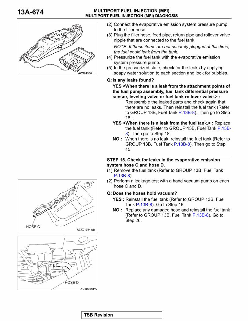
MULTIPORT FUEL INJECTION (MFI) DIAGNOSISMULTIPORT FUEL INJECTION (MFI)13A-674
(2) Connect the evaporative emission system pressure pump to the filler hose.
(3) Plug the filler hose, feed pipe, return pipe and rollover valve nipple that are connected to the fuel tank.NOTE: If these items are not securely plugged at this time, the fuel could leak from the tank.
(4) Pressurize the fuel tank with the evaporative emission system pressure pump.
(5) In the pressurized state, check for the leaks by applying soapy water solution to each section and look for bubbles.
Q: Is any leaks found?YES <When there is a leak from the attachment points of the fuel pump assembly, fuel tank differential pressure sensor, leveling valve or fuel tank rollover valve.> :
Reassemble the leaked parts and check again that there are no leaks. Then reinstall the fuel tank (Refer to GROUP 13B, Fuel Tank P.13B-8). Then go to Step 18 .
YES <When there is a leak from the fuel tank.> : Replace the fuel tank (Refer to GROUP 13B, Fuel Tank P.13B-8). Then go to Step 18.
NO : When there is no leak, reinstall the fuel tank (Refer to GROUP 13B, Fuel Tank P.13B-8). Then go to Step 15.
STEP 15. Check for leaks in the evaporative emission system hose C and hose D.(1) Remove the fuel tank (Refer to GROUP 13B, Fuel Tank
P.13B-8).(2) Perform a leakage test with a hand vacuum pump on each
hose C and D.Q: Does the hoses hold vacuum?
YES : Reinstall the fuel tank (Refer to GROUP 13B, Fuel Tank P.13B-8). Go to Step 16.
NO : Replace any damaged hose and reinstall the fuel tank (Refer to GROUP 13B, Fuel Tank P.13B-8). Go to Step 26.
ACX01356
ACX01354 ADHOSE C
AC102448
HOSE D
AC
TSB Revision

MULTIPORT FUEL INJECTION (MFI) DIAGNOSISMULTIPORT FUEL INJECTION (MFI) 13A-675
STEP 16. Check for leaks in the evaporative emission canister.(1) Remove the evaporative emission canister (Refer to
GROUP 17, Evaporative Emission Canister and Fuel Tank Pressure Relief Valve P.17-72).
(2) Connect a hand vacuum pump to the vent nipple of the evaporative emission canister.
(3) Plug the other two nipples or loop a hose between them.(4) Apply vacuum with the hand vacuum pump and confirm that
the canister holds vacuum.Q: Does the evaporative emission canister hold vacuum?
YES : Reinstall the evaporative emission canister (Refer to GROUP 17, Evaporative Emission Canister and Fuel Tank Pressure Relief Valve P.17-72). Go to Step 17 .
NO : Replace the evaporative emission canister (Refer to GROUP 17, Evaporative Emission Canister and Fuel Tank Pressure Relief Valve P.17-72). Go to Step 26 .
STEP 17. Pressure test for clogging in evaporative emission system lines between hose F and R.(1) Disconnect hose F from the evaporative emission canister
and plug hose F securely.(2) Confirm that the evaporative emission system pressure
pump (Miller number 6872A) is operating properly. Perform the self-test as described in the manufacturer's instructions.
(3) Remove the fuel cap.
(4) Connect the evaporative emission system pressure pump to the fuel tank filler tube.
(5) After it is confirmed that pressure maintained, unplug hose F.
(6) Disconnect the evaporative emission system pressure pump and reinstall the fuel cap.
(7) Connect hose F to the evaporative emission canister.Q: Does hose F blow the air?
YES : Go to Step 23.NO : Go to Step 18.
AC102602 AC
HOSE F
ACX01358
AC102548
HOSE F
AC
TSB Revision

MULTIPORT FUEL INJECTION (MFI) DIAGNOSISMULTIPORT FUEL INJECTION (MFI)13A-676
STEP 18. Check for clogging in the evaporator line hose F.(1) Remove the fuel tank filler tube protector (Refer to GROUP
13B, Fuel Tank P.13B-8).(2) Disconnect hose F from the evaporative emission canister
and plug hose F securely.(3) Disconnect hose G from the evaporative emission canister
side, and connect a hand vacuum pump.
(4) Apply vacuum with the hand vacuum pump, unplug hose F.(5) Disconnect the hand vacuum pump and connect hose F
and G. Q: Does hose F blow the air?
YES : Go to Step 19.NO : Replace hose F and reinstall the fuel tank filler tube
protector (Refer to GROUP 13B, Fuel Tank P.13B-8). Go to Step 26.
STEP 19. Check for clogging in the evaporative emission system hoses G through N.(1) Remove the fuel tank filler tube (Refer to GROUP 13B, Fuel
Tank P.13B-8).(2) Use a hand vacuum pump to clogging test on each hose
from hose G to hose N. Q: Are the hoses in good condition?
YES : Go to Step 20.NO : Replace any damaged hose, and reinstall the fuel
tank filler tube and the fuel tank filler tube protector (Refer to GROUP 13B, Fuel Tank P.13B-8). Go to Step 26.
AC101767AC
HOSE F
HOSE G
AC102548
HOSE F
AC
AC102673 AC
HOSE GHOSE L
HOSE M
HOSE N
AC102646 AC
HOSE KHOSE I
HOSE H
HOSE J
TSB Revision

MULTIPORT FUEL INJECTION (MFI) DIAGNOSISMULTIPORT FUEL INJECTION (MFI) 13A-677
STEP 20. Check the check valve A.(1) Check valve A is a one-way check valve.
(2) Check valve A should allow air to flow in only one direction.Q: Does check valve A allow air to press in one direction
only?YES : Go to Step 21.NO : Replace check valve A, and reinstall the fuel tank filler
tube and the fuel tank filler tube protector (Refer to GROUP 13B, Fuel Tank P.13B-8). Go to Step 26.
STEP 21. Check the check valve B.(1) Check valve B is a one-way check valve.
(2) Check valve B should allow air to flow in only one direction.Q: Does check valve B allow air to press in one direction
only?YES : Go to Step 22.NO : Replace check valve B, and reinstall the fuel tank filler
tube and the fuel tank filler tube protector (Refer to GROUP 13B, Fuel Tank P.13B-8). Go to Step 26.
AC102646AD
CHECKVALVE A
AC002076AB
CHECK VALVE A
AC102646 AE
CHECKVALVE B
AC002078
CHECK VALVE B
AB
TSB Revision
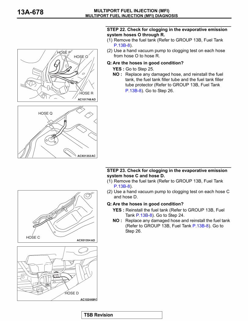
MULTIPORT FUEL INJECTION (MFI) DIAGNOSISMULTIPORT FUEL INJECTION (MFI)13A-678
STEP 22. Check for clogging in the evaporative emission system hoses O through R.(1) Remove the fuel tank (Refer to GROUP 13B, Fuel Tank
P.13B-8).(2) Use a hand vacuum pump to clogging test on each hose
from hose O to hose R.Q: Are the hoses in good condition?
YES : Go to Step 25.NO : Replace any damaged hose, and reinstall the fuel
tank, the fuel tank filler tube and the fuel tank filler tube protector (Refer to GROUP 13B, Fuel Tank P.13B-8). Go to Step 26.
STEP 23. Check for clogging in the evaporative emission system hose C and hose D.(1) Remove the fuel tank (Refer to GROUP 13B, Fuel Tank
P.13B-8).(2) Use a hand vacuum pump to clogging test on each hose C
and hose D.Q: Are the hoses in good condition?
YES : Reinstall the fuel tank (Refer to GROUP 13B, Fuel Tank P.13B-8). Go to Step 24.
NO : Replace any damaged hose and reinstall the fuel tank (Refer to GROUP 13B, Fuel Tank P.13B-8). Go to Step 26.
AC101748
HOSE P
HOSE R
AD
HOSE O
ACX01353AC
HOSE Q
ACX01354 ADHOSE C
AC102448
HOSE D
AC
TSB Revision

MULTIPORT FUEL INJECTION (MFI) DIAGNOSISMULTIPORT FUEL INJECTION (MFI) 13A-679
STEP 24. Check for clogging in the evaporative emission canister.(1) Remove the evaporative emission canister (Refer to
GROUP 17, Evaporative Emission Canister and Fuel Tank Pressure Relief Valve P.17-72).
(2) Connect a hand vacuum pump to the vent nipple of the evaporative emission canister.
(3) Plug the other two nipples or loop a hose between the other nipples.
(4) Apply a pressure on the vacuum pump.(5) When each nipple is unplugged, air should pass through the
unplugged nipple.Q: Is the evaporative emission canister in good condition?
YES : Reinstall the evaporative emission canister (Refer to GROUP 17, Evaporative Emission Canister and Fuel Tank Pressure Relief Valve P.17-72). Go to Step 25 .
NO : Replace the evaporative emission canister (Refer to GROUP 17, Evaporative Emission Canister and Fuel Tank Pressure Relief Valve P.17-72). Go to Step 26 .
TSB Revision
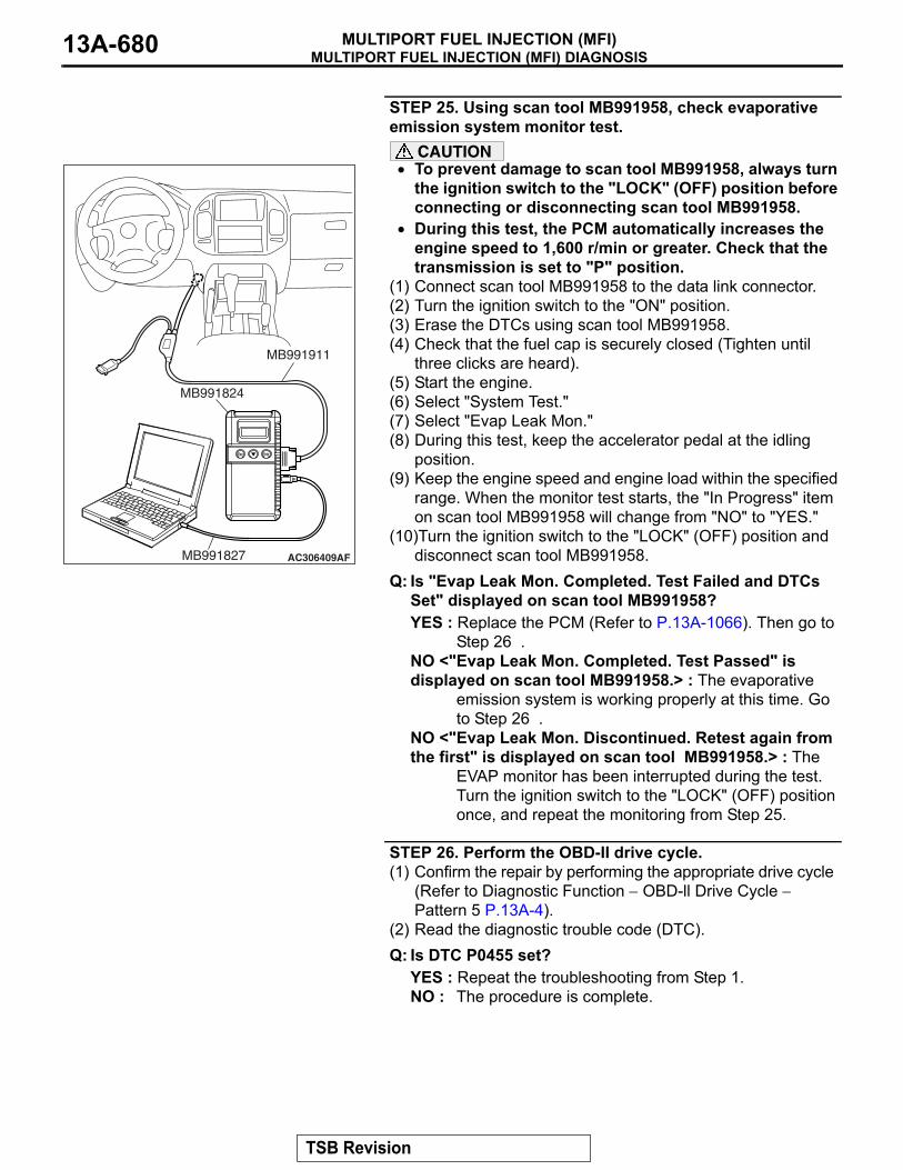
MULTIPORT FUEL INJECTION (MFI) DIAGNOSISMULTIPORT FUEL INJECTION (MFI)13A-680
STEP 25. Using scan tool MB991958, check evaporative emission system monitor test.
CAUTION• To prevent damage to scan tool MB991958, always turn
the ignition switch to the "LOCK" (OFF) position before connecting or disconnecting scan tool MB991958.
• During this test, the PCM automatically increases the engine speed to 1,600 r/min or greater. Check that the transmission is set to "P" position.
(1) Connect scan tool MB991958 to the data link connector.(2) Turn the ignition switch to the "ON" position.(3) Erase the DTCs using scan tool MB991958. (4) Check that the fuel cap is securely closed (Tighten until
three clicks are heard).(5) Start the engine.(6) Select "System Test."(7) Select "Evap Leak Mon."(8) During this test, keep the accelerator pedal at the idling
position.(9) Keep the engine speed and engine load within the specified
range. When the monitor test starts, the "In Progress" item on scan tool MB991958 will change from "NO" to "YES."
(10)Turn the ignition switch to the "LOCK" (OFF) position and disconnect scan tool MB991958.
Q: Is "Evap Leak Mon. Completed. Test Failed and DTCs Set" displayed on scan tool MB991958?YES : Replace the PCM (Refer to P.13A-1066). Then go to
Step 26 .NO <"Evap Leak Mon. Completed. Test Passed" is displayed on scan tool MB991958.> : The evaporative
emission system is working properly at this time. Go to Step 26 .
NO <"Evap Leak Mon. Discontinued. Retest again from the first" is displayed on scan tool MB991958.> : The
EVAP monitor has been interrupted during the test. Turn the ignition switch to the "LOCK" (OFF) position once, and repeat the monitoring from Step 25.
STEP 26. Perform the OBD-II drive cycle.(1) Confirm the repair by performing the appropriate drive cycle
(Refer to Diagnostic Function − OBD-ll Drive Cycle − Pattern 5 P.13A-4).
(2) Read the diagnostic trouble code (DTC).Q: Is DTC P0455 set?
YES : Repeat the troubleshooting from Step 1.NO : The procedure is complete.
AC306409AF
MB991911
MB991824
MB991827
TSB Revision

MULTIPORT FUEL INJECTION (MFI) DIAGNOSISMULTIPORT FUEL INJECTION (MFI) 13A-681
DTC P0456: Evaporative Emission System Leak Detected (Very Small Leak)
.
AC203991
SYSTEM DIAGRAM
A
B C D
EF
G
H
I
J
K
LM
N
OQ
S
R
P
FUEL TANK
CHECK VALVE B
CHECK VALVE AEVAPORATIVEEMISSIONPURGESOLENOID
EVAPORATIVE EMISSIONVENTILATION SOLENOID
EVAPORATIVEEMISSIONCANISTER
VENT PIPEASSEMBLY
AD
ONBOARD REFUELINGVAPOR RECOVERY(ORVR)VENT VALVE MODULE
AC101766
EVAPORATIVE EMISSION CANISTER
AB AC203904AC
EVAPORATIVE EMISSIONPURGE SOLENOID
INTAKE AIR DUCT
AC101763 AB
REAR COIL SPRING (RH)
EVAPORATIVE EMISSION VENTILATION SOLENOID
TSB Revision

MULTIPORT FUEL INJECTION (MFI) DIAGNOSISMULTIPORT FUEL INJECTION (MFI)13A-682
TECHNICAL DESCRIPTION• The PCM monitors the Evaporative Emission
(EVAP) System pressure.• The PCM controls the evaporative emission ven-
tilation solenoid. It closes the evaporative emis-sion ventilation solenoid to seal the evaporative emission canister side of the system.
• The evaporative emission purge solenoid is opened to allow manifold vacuum to create low pressure (vacuum) in the EVAP system.
• When the EVAP system develops a vacuum of 2 kPa (0.29 psi), the evaporative emission purge solenoid is closed and the fuel system vacuum is maintained at 2 kPa (0.29 psi).
• The PCM determines whether there is a leak in the EVAP system by monitoring the vacuum inside the fuel tank.
• The test is stopped when fuel vapor pressure exceeds predetermined limits.
.
DESCRIPTIONS OF MONITOR METHODS• Measure reverting pressure after depressurizing
by intake manifold negative pressure and detect malfunction if reverting pressure rises largely.
.
MONITOR EXECUTION• Once per driving cycle.
.
MONITOR EXECUTION CONDITIONS (OTHER MONITOR AND SENSOR)Other Monitor (There is no temporary DTC stored
in memory for the item monitored below)• Evaporative emission purge solenoid monitor• Evaporative emission purge system monitor• Fuel tank differential pressure sensor monitor• Evaporative emission ventilation solenoid monitor• Fuel level sensor monitor• Fuel temperature sensor monitor
Sensor (The sensors below are determined to be normal)
• Volume airflow sensor• Barometric pressure sensor• Intake air temperature sensor• Engine coolant temperature sensor
.
TSB Revision

MULTIPORT FUEL INJECTION (MFI) DIAGNOSISMULTIPORT FUEL INJECTION (MFI) 13A-683
LOGIC FLOW CHARTS (Monitor Sequence)
.
DTC SET CONDITIONSCheck Conditions A: At Start up• Intake air temperature is 36°C (97°F) or less
when the engine is started.
• The engine coolant temperature is 36°C (97°F) or less when the engine is started.
• The fuel level sensor output voltage is 2.4 − 3.7 volts when the engine starts and the amount of remaining fuel is 40 − 85 percent of capacity.
AC306649
0.04in, 0.02in GROSS LEAK MONITOR
START
YES
YES
YES
YES
YES
NO
NONO
NO
NO
MONITORINGCONDITIONS?
DEPRESSURIZE FUEL TANK PRESSURE
GROSS LEAKMONITORING CONDITIONS
SHUT PURGE LINE
MEASURE REVERTINGPRESSURE : PFT
PFT > PT
SPECIFIED TIMESMONITORED
MALFUNCTION
END
SPECIFIED TIMESHAVE PASSED
MALFUNCTION
(GROSS LEAK)
GOOD
TSB Revision

MULTIPORT FUEL INJECTION (MFI) DIAGNOSISMULTIPORT FUEL INJECTION (MFI)13A-684
Check Conditions B: For Test to Run• Barometric pressure is greater than 76 kPa (11
psi).• The fuel temperature is 33°C (91°F) or less.• Fuel tank differential pressure sensor output volt-
age is 1 to 4 volts.
Check Conditions C: For Test to Stop• Engine coolant temperature is greater than 20 °C
(68 °F).• Intake air temperature is greater than -10 °C (14 °F).
• When the evaporative emission purge solenoid and evaporative emission ventilation solenoid are closed, the pressure rises in the fuel tank is less than 324 Pa (0.047 psi).
• 10 seconds have elapsed from the start of the previous monitoring.
• Monitoring time: 10 − 14 minutes.
Judgment Criterion• Internal pressure of the fuel tank has changed
more than 1,177 − 1,373 Pa (0.177 − 0.199 psi) in 128 seconds after the tank and vapor line were closed.
.
OBD-ll DRIVE CYCLE PATTERNRefer to Diagnostic Function − OBD-ll Drive Cycle − Pattern 6 P.13A-4..
TROUBLESHOOTING HINTS (THE MOST LIKELY CAUSES FOR THIS CODE TO BE SET ARE:)• Loose fuel cap.• Fuel cap relief pressure is incorrect.• Malfunction of the evaporative emission canister
seal.• Malfunction of the fuel tank, purge line or vapor
line seal.• Malfunction of the evaporative emission ventila-
tion solenoid.
TSB Revision

MULTIPORT FUEL INJECTION (MFI) DIAGNOSISMULTIPORT FUEL INJECTION (MFI) 13A-685
DIAGNOSISRequired Special Tools:• MB991958: Scan Tool (MUT-III Sub Assembly)
• MB991824: V.C.I.• MB991827: MUT-III USB Cable• MB991911: MUT-III Main Harness B
STEP 1. Using scan tool MB991958, check evaporative emission system monitor test.
CAUTION• To prevent damage to scan tool MB991958, always turn
the ignition switch to the "LOCK" (OFF) position before connecting or disconnecting scan tool MB991958.
• During this test, the PCM automatically increases the engine speed to 1,600 r/min or greater. Check that the transmission is set to "P" position.
(1) Connect scan tool MB991958 to the data link connector.(2) Turn the ignition switch to the "ON" position.(3) Erase the DTCs using scan tool MB991958. (4) Check that the fuel cap is securely closed (Tighten until
three clicks are heard).(5) Start the engine.(6) Select "System Test."(7) Select "Evap Leak Mon."(8) During this test, keep the accelerator pedal at the idling
position.(9) Keep the engine speed and engine load within the specified
range. When the monitor test starts, the "In Progress" item on scan tool MB991958 will change from "NO" to "YES."
(10)Turn the ignition switch to the "LOCK" (OFF) position and disconnect scan tool MB991958.
Q: Is "Evap Leak Mon. Completed. Test Failed and DTCs Set" displayed on scan tool MB991958?YES : A malfunction has been detected during the monitor
test (Refer to the Diagnostic Trouble Code Chart and diagnose any other DTCs that are set P.13A-33). If no other DTC's have been set, then go to Step 2.
NO <"Evap Leak Mon. Completed. Test Passed" is displayed on scan tool MB991958.> : The evaporative
emission system is working properly at this time. Explain to the customer that an improperly tightened fuel cap can cause the MIL to illuminate. Return the vehicle to the customer.
NO <"Evap Leak Mon. Discontinued. Retest again from the first" is displayed on scan tool MB991958.> : The
EVAP monitor has been interrupted during the test. Turn the ignition switch to the "LOCK" (OFF) position once, and repeat the monitoring from Step 1.
AC306409AF
MB991911
MB991824
MB991827
TSB Revision
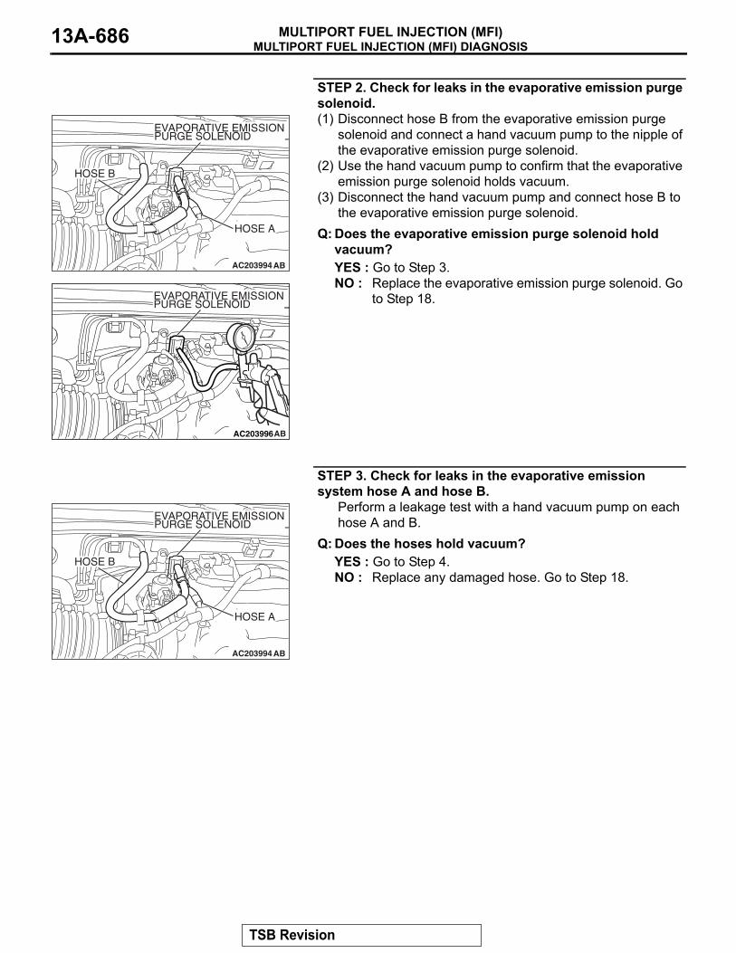
MULTIPORT FUEL INJECTION (MFI) DIAGNOSISMULTIPORT FUEL INJECTION (MFI)13A-686
STEP 2. Check for leaks in the evaporative emission purge solenoid.(1) Disconnect hose B from the evaporative emission purge
solenoid and connect a hand vacuum pump to the nipple of the evaporative emission purge solenoid.
(2) Use the hand vacuum pump to confirm that the evaporative emission purge solenoid holds vacuum.
(3) Disconnect the hand vacuum pump and connect hose B to the evaporative emission purge solenoid.
Q: Does the evaporative emission purge solenoid hold vacuum?YES : Go to Step 3.NO : Replace the evaporative emission purge solenoid. Go
to Step 18.
STEP 3. Check for leaks in the evaporative emission system hose A and hose B.
Perform a leakage test with a hand vacuum pump on each hose A and B.
Q: Does the hoses hold vacuum?YES : Go to Step 4.NO : Replace any damaged hose. Go to Step 18.
AC203994AB
HOSE A
HOSE B
EVAPORATIVE EMISSIONPURGE SOLENOID
AC203996AB
EVAPORATIVE EMISSIONPURGE SOLENOID
AC203994AB
HOSE A
HOSE B
EVAPORATIVE EMISSIONPURGE SOLENOID
TSB Revision

MULTIPORT FUEL INJECTION (MFI) DIAGNOSISMULTIPORT FUEL INJECTION (MFI) 13A-687
STEP 4. Using scan tool MB991958, check actuator test item 29: Evaporative Emission Ventilation Solenoid.
CAUTIONTo prevent damage to scan tool MB991958, always turn the ignition switch to the "LOCK" (OFF) position before con-necting or disconnecting scan tool MB991958.(1) Connect scan tool MB991958 to the data link connector.
(2) Disconnect hose S from the evaporative emission ventilation solenoid and connect a hand vacuum pump.
(3) Turn the ignition switch to the "ON" position.(4) Set scan tool MB991958 to actuator test mode for item 29,
evaporative emission ventilation solenoid.• While the evaporative emission ventilation solenoid is
energized, operate the hand vacuum pump and confirm that solenoid holds vacuum.
(5) Turn the ignition switch to the "LOCK" (OFF) position and disconnect scan tool MB991958.
(6) Disconnect the hand vacuum pump and connect hose S to the evaporative emission ventilation solenoid.
Q: Does the evaporative emission ventilation solenoid hold vacuum?YES : Go to Step 5.NO : Replace the evaporative emission ventilation solenoid
(Refer to GROUP 17, Evaporative Emission Canister and Fuel Tank Pressure Relief Valve P.17-72). Go to Step 18.
AC306409AF
MB991911
MB991824
MB991827
AC101769
HOSE S
AC
EVAPORATIVE EMISSIONVENTILATION SOLENOID
TSB Revision
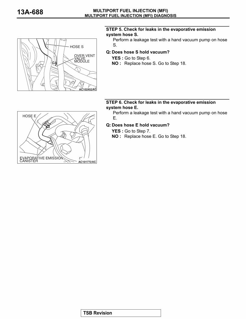
MULTIPORT FUEL INJECTION (MFI) DIAGNOSISMULTIPORT FUEL INJECTION (MFI)13A-688
STEP 5. Check for leaks in the evaporative emission system hose S.
Perform a leakage test with a hand vacuum pump on hose S.
Q: Does hose S hold vacuum?YES : Go to Step 6.NO : Replace hose S. Go to Step 18.
STEP 6. Check for leaks in the evaporative emission system hose E.
Perform a leakage test with a hand vacuum pump on hose E.
Q: Does hose E hold vacuum?YES : Go to Step 7.NO : Replace hose E. Go to Step 18.
AC102452
HOSE S
AC
OVER VENTVALVEMODULE
AC101772
HOSE E
ACEVAPORATIVE EMISSIONCANISTER
TSB Revision

MULTIPORT FUEL INJECTION (MFI) DIAGNOSISMULTIPORT FUEL INJECTION (MFI) 13A-689
STEP 7. Pressure test the evaporative emission system lines between hose F and R.(1) Disconnect hose F from the evaporative emission canister
and plug hose F securely.(2) Confirm that the evaporative emission system pressure
pump (Miller number 6872A) is operating properly. Perform the self-test as described in the manufacturer's instructions.
(3) Remove the fuel cap.
(4) Connect the evaporative emission system pressure pump to the fuel tank filler tube.
(5) Pressure test the system to determine whether any leaks are present.NOTE: The "Pressure test" in this procedure refers to the I/M240 Simulation Test. The eight steps of this test are described in the manufacturer's instructions for the evapo-rative emission system pressure pump, Miller number 6872A.
(6) Disconnect the evaporative emission system pressure pump and reinstall the fuel cap.
(7) Connect hose F to the evaporative emission canister.Q: Is the evaporative emission system line free of leaks?
YES : Go to Step 15.NO : Go to Step 8.
STEP 8. Check for leaks in the evaporator line hose F.(1) Remove the fuel tank filler tube protector (Refer to GROUP
13B, Fuel Tank P.13B-8).(2) Disconnect hose F from the evaporative emission canister
and plug hose F securely.(3) Disconnect hose G from the evaporative emission canister
side, and connect a hand vacuum pump.(4) Apply vacuum with the hand vacuum pump and confirm that
the vacuum holds.(5) Disconnect the hand vacuum pump and connect hose F
and G. Q: Does hose F hold vacuum?
YES : Go to Step 9.NO : Replace hose F and reinstall the fuel tank filler tube
protector (Refer to GROUP 13B, Fuel Tank P.13B-8). Go to Step 18.
AC102602 AC
HOSE F
ACX01358
AC101767AC
HOSE F
HOSE G
TSB Revision

MULTIPORT FUEL INJECTION (MFI) DIAGNOSISMULTIPORT FUEL INJECTION (MFI)13A-690
STEP 9. Check for leaks in the evaporative emission system hoses G through N.(1) Remove the fuel tank filler tube (Refer to GROUP 13B, Fuel
Tank P.13B-8).(2) Perform a leakage test with a hand vacuum pump on each
hose from hose G to N.Q: Does the hoses hold vacuum?
YES : Go to Step 10.NO : Replace any damaged hose, and reinstall the fuel
tank filler tube and the fuel tank filler tube protector (Refer to GROUP 13B, Fuel Tank P.13B-8). Go to Step 18.
STEP 10. Check the check valve A.(1) Check valve A is a one-way check valve.
(2) Check valve A should allow air to flow in only one direction.Q: Does check valve A allow air to press in one direction
only?YES : Go to Step 11.NO : Replace check valve A, and reinstall the fuel tank filler
tube and the fuel tank filler tube protector (Refer to GROUP 13B, Fuel Tank P.13B-8). Go to Step 18.
AC102673 AC
HOSE GHOSE L
HOSE M
HOSE N
AC102646 AC
HOSE KHOSE I
HOSE H
HOSE J
AC102646AD
CHECKVALVE A
AC002076AB
CHECK VALVE A
TSB Revision

MULTIPORT FUEL INJECTION (MFI) DIAGNOSISMULTIPORT FUEL INJECTION (MFI) 13A-691
STEP 11. Check the check valve B.(1) Check valve B is a one-way check valve.
(2) Check valve B should allow air to flow in only one direction.Q: Does check valve B allow air to press in one direction
only?YES : Go to Step 12.NO : Replace check valve B, and reinstall the fuel tank filler
tube and the fuel tank filler tube protector (Refer to GROUP 13B, Fuel Tank P.13B-8). Go to Step 18.
STEP 12. Check for cracks in the fuel tank filler tube assembly.
Visually check for cracks in the fuel tank filler tube assembly.
Q: Is the fuel tank filler tube assembly in good condition?YES : Go to Step 13.NO : Replace the fuel tank filler tube assembly and reinstall
the fuel tank filler tube protector (Refer to GROUP 13B, Fuel Tank P.13B-8). Go to Step 18 .
AC102646 AE
CHECKVALVE B
AC002078
CHECK VALVE B
AB
TSB Revision
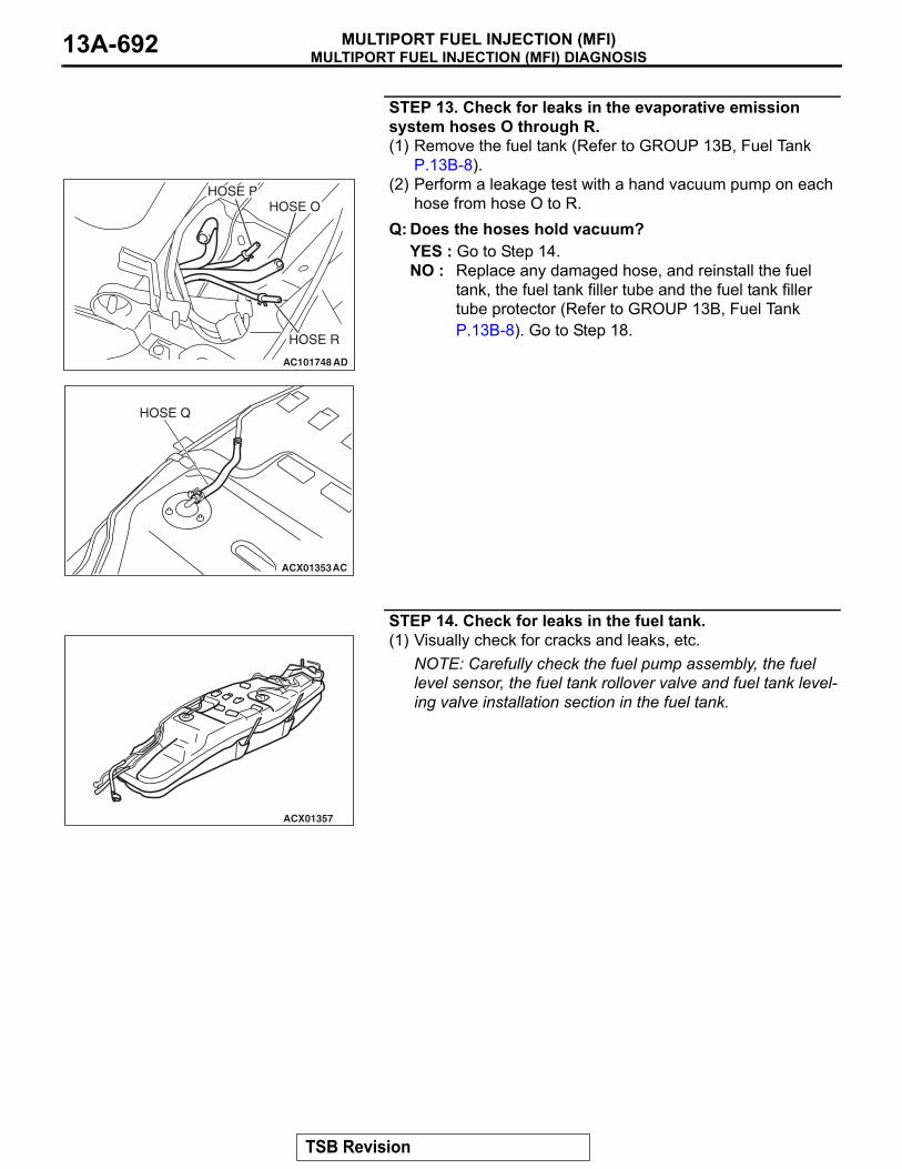
MULTIPORT FUEL INJECTION (MFI) DIAGNOSISMULTIPORT FUEL INJECTION (MFI)13A-692
STEP 13. Check for leaks in the evaporative emission system hoses O through R.(1) Remove the fuel tank (Refer to GROUP 13B, Fuel Tank
P.13B-8).(2) Perform a leakage test with a hand vacuum pump on each
hose from hose O to R.Q: Does the hoses hold vacuum?
YES : Go to Step 14.NO : Replace any damaged hose, and reinstall the fuel
tank, the fuel tank filler tube and the fuel tank filler tube protector (Refer to GROUP 13B, Fuel Tank P.13B-8). Go to Step 18.
STEP 14. Check for leaks in the fuel tank.(1) Visually check for cracks and leaks, etc.
NOTE: Carefully check the fuel pump assembly, the fuel level sensor, the fuel tank rollover valve and fuel tank level-ing valve installation section in the fuel tank.
AC101748
HOSE P
HOSE R
AD
HOSE O
ACX01353AC
HOSE Q
ACX01357
TSB Revision

MULTIPORT FUEL INJECTION (MFI) DIAGNOSISMULTIPORT FUEL INJECTION (MFI) 13A-693
(2) Connect the evaporative emission system pressure pump to the filler hose.
(3) Plug the filler hose, feed pipe, return pipe and rollover valve nipple that are connected to the fuel tank.NOTE: If these items are not securely plugged at this time, the fuel could leak from the tank.
(4) Pressurize the fuel tank with the evaporative emission system pressure pump.
(5) In the pressurized state, check for the leaks by applying soapy water solution to each section and look for bubbles.
Q: Is any leaks found?YES <When there is a leak from the attachment points of the fuel pump assembly, fuel tank differential pressure sensor, leveling valve or fuel tank rollover valve.> :
Reassemble the leaked parts and check again that there are no leaks. Then reinstall the fuel tank (Refer to GROUP 13B, Fuel Tank P.13B-8). Then go to Step 18 .
YES <When there is a leak from the fuel tank.> : Replace the fuel tank (Refer to GROUP 13B, Fuel Tank P.13B-8). Then go to Step 18.
NO : When there is no leak, reinstall the fuel tank (Refer to GROUP 13B, Fuel Tank P.13B-8). Then go to Step 15.
STEP 15. Check for leaks in evaporative emission system hose C and hose D.(1) Remove the fuel tank (Refer to GROUP 13B, Fuel Tank
P.13B-8).(2) Perform a leakage test with a hand vacuum pump on each
hose C and D.Q: Does the hoses hold vacuum?
YES : Reinstall the fuel tank (Refer to GROUP 13B, Fuel Tank P.13B-8). Go to Step 16.
NO : Replace any damaged hose and reinstall the fuel tank (Refer to GROUP 13B, Fuel Tank P.13B-8). Go to Step 18.
ACX01356
ACX01354 ADHOSE C
AC102448
HOSE D
AC
TSB Revision

MULTIPORT FUEL INJECTION (MFI) DIAGNOSISMULTIPORT FUEL INJECTION (MFI)13A-694
STEP 16. Check for leaks in the evaporative emission canister.(1) Remove the evaporative emission canister (Refer to
GROUP 17, Evaporative Emission Canister and Fuel Tank Pressure Relief Valve P.17-72).
(2) Connect a hand vacuum pump to the vent nipple of the evaporative emission canister.
(3) Plug the other two nipples or loop a hose between them.(4) Apply vacuum with the hand vacuum pump and confirm that
the canister holds vacuum.Q: Does the evaporative emission canister hold vacuum?
YES : Reinstall the evaporative emission canister (Refer to GROUP 17, Evaporative Emission Canister and Fuel Tank Pressure Relief Valve P.17-72). Go to Step 17 .
NO : Replace the evaporative emission canister (Refer to GROUP 17, Evaporative Emission Canister and Fuel Tank Pressure Relief Valve P.17-72). Go to Step 18 .
TSB Revision
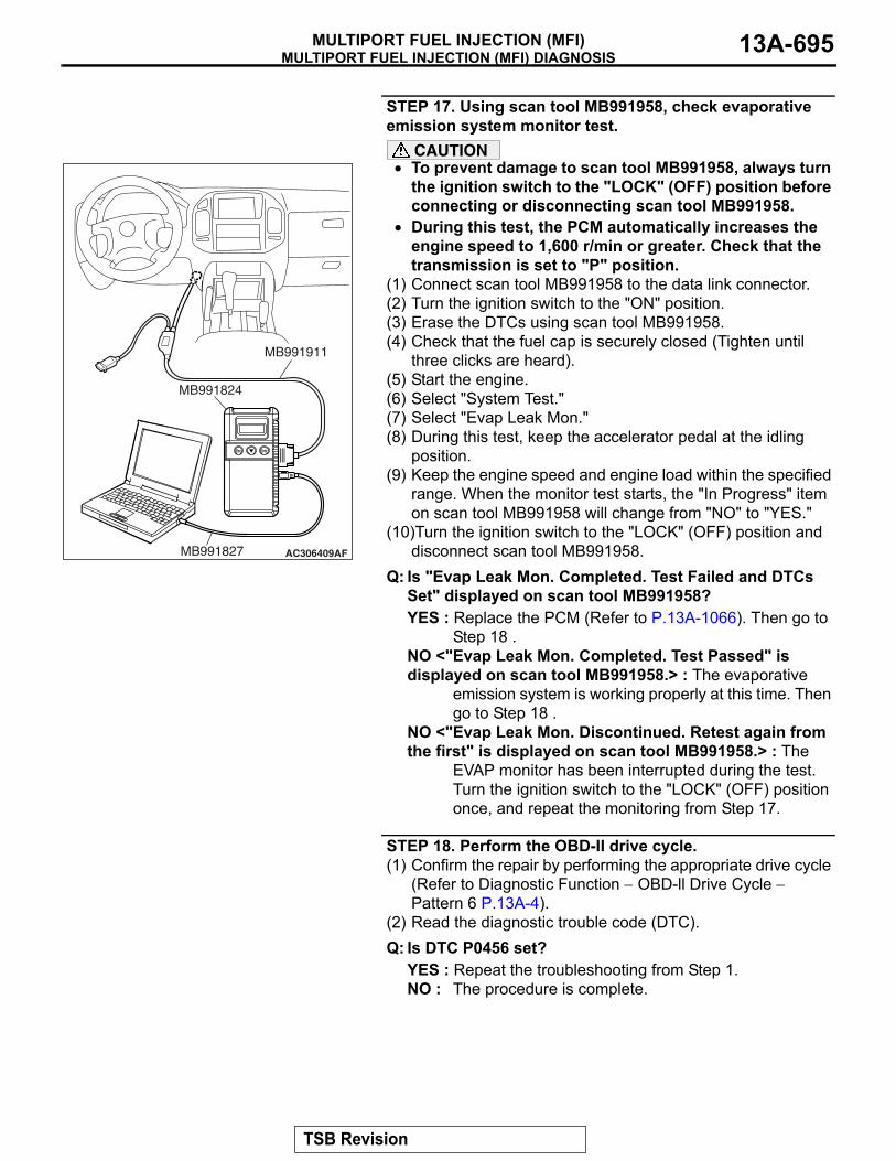
MULTIPORT FUEL INJECTION (MFI) DIAGNOSISMULTIPORT FUEL INJECTION (MFI) 13A-695
STEP 17. Using scan tool MB991958, check evaporative emission system monitor test.
CAUTION• To prevent damage to scan tool MB991958, always turn
the ignition switch to the "LOCK" (OFF) position before connecting or disconnecting scan tool MB991958.
• During this test, the PCM automatically increases the engine speed to 1,600 r/min or greater. Check that the transmission is set to "P" position.
(1) Connect scan tool MB991958 to the data link connector.(2) Turn the ignition switch to the "ON" position.(3) Erase the DTCs using scan tool MB991958. (4) Check that the fuel cap is securely closed (Tighten until
three clicks are heard).(5) Start the engine.(6) Select "System Test."(7) Select "Evap Leak Mon."(8) During this test, keep the accelerator pedal at the idling
position.(9) Keep the engine speed and engine load within the specified
range. When the monitor test starts, the "In Progress" item on scan tool MB991958 will change from "NO" to "YES."
(10)Turn the ignition switch to the "LOCK" (OFF) position and disconnect scan tool MB991958.
Q: Is "Evap Leak Mon. Completed. Test Failed and DTCs Set" displayed on scan tool MB991958?YES : Replace the PCM (Refer to P.13A-1066). Then go to
Step 18 .NO <"Evap Leak Mon. Completed. Test Passed" is displayed on scan tool MB991958.> : The evaporative
emission system is working properly at this time. Then go to Step 18 .
NO <"Evap Leak Mon. Discontinued. Retest again from the first" is displayed on scan tool MB991958.> : The
EVAP monitor has been interrupted during the test. Turn the ignition switch to the "LOCK" (OFF) position once, and repeat the monitoring from Step 17.
STEP 18. Perform the OBD-II drive cycle.(1) Confirm the repair by performing the appropriate drive cycle
(Refer to Diagnostic Function − OBD-ll Drive Cycle − Pattern 6 P.13A-4).
(2) Read the diagnostic trouble code (DTC).Q: Is DTC P0456 set?
YES : Repeat the troubleshooting from Step 1.NO : The procedure is complete.
AC306409AF
MB991911
MB991824
MB991827
TSB Revision

MULTIPORT FUEL INJECTION (MFI) DIAGNOSISMULTIPORT FUEL INJECTION (MFI)13A-696
DTC P0461: Fuel Level Sensor Circuit Range/Performance
POWERTRAIN CONTROLMODULE (PCM)
METER AND GAUGE
Fuel Level Sensor Circuit
8
17
13
2
7
2
BLA
CK
BLA
CK
YE
LLO
W-
GR
EE
N
G-03MU802337
1 2 3
AK401678
72
FUEL LEVEL SENSOR
FROM PCM
YE
LLO
W-
GR
EE
NY
ELL
OW
-G
RE
EN
YE
LLO
W-
GR
EE
NY
ELL
OW
-G
RE
EN
4
17
1
121314 18
30
4134
3
1610
6 7
19
31
42
20
32
43
21
332524 26
3635 37
2928
15
27
38
8 9
3940
11
2
22
5
23
D-111
87651 2 3 4
F-07MU802609
11
1
9 10 13
2
12
3 4
7
5
146 8
E-113
616566676869707172737475767778798081828384 858687 8889
62 6364
D-134(MU803804)
TSB Revision
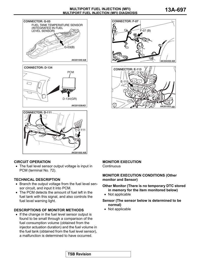
MULTIPORT FUEL INJECTION (MFI) DIAGNOSISMULTIPORT FUEL INJECTION (MFI) 13A-697
.
CIRCUIT OPERATION• The fuel level sensor output voltage is input in
PCM (terminal No. 72)..
TECHNICAL DESCRIPTION• Branch the output voltage from the fuel level sen-
sor circuit, and input it into PCM.• The PCM detects the amount of fuel left in the
fuel tank with this signal, and also controls the fuel level warning light.
.
DESCRIPTIONS OF MONITOR METHODS• If the change in the fuel level sensor output is
found to be small through a comparison of the fuel consumption volume (obtained from the injector actuation duration) and the fuel volume in the fuel tank (obtained from the fuel level sensor), a malfunction is determined to have occurred.
.
MONITOR EXECUTIONContinuous.
MONITOR EXECUTION CONDITIONS (Other monitor and Sensor)Other Monitor (There is no temporary DTC stored
in memory for the item monitored below)• Not applicable
Sensor (The sensor below is determined to be normal)
• Not applicable.
AK201040 AB
CONNECTOR: G-03
G-03(B)
FUEL TANK TEMPERATURE SENSOR(INTEGRATED IN FUEL LEVEL SENSOR)
AK201038
CONNECTOR: D-134
AD
PCM
D-134(GR)
AK201055
CONNECTOR: D-111
D-111
AB
AK304350
F-07 (B)
AB
CONNECTOR: F-07
AK201053
E-113
AB
CONNECTOR: E-113
TSB Revision

MULTIPORT FUEL INJECTION (MFI) DIAGNOSISMULTIPORT FUEL INJECTION (MFI)13A-698
DTC SET CONDITIONS
Logic Flow Chart
.
INDICATED FUEL LEVELCHANGE < 2L
ACCUMULATE FUEL CONSUMPTIONTHROUGH FUEL INJECTORS.
ACCUMULATED FUEL CONSUMPTION WILL NOT RESET WHEN KEY-OFF/ON.
ACCUMULATED FUEL CONSUMPTION > =20L
START
END
NO
NO
NO
YES
YES
YES
MALFUNCTION GOOD
MONITORINGCONDITIONS
RESET ACCUMULATEFUEL CONSUMPTION.
AK401679
TSB Revision
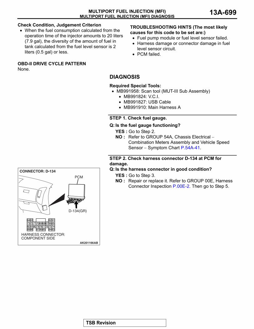
MULTIPORT FUEL INJECTION (MFI) DIAGNOSISMULTIPORT FUEL INJECTION (MFI) 13A-699
Check Condition, Judgement Criterion• When the fuel consumption calculated from the
operation time of the injector amounts to 20 liters (7.9 gal), the diversity of the amount of fuel in tank calculated from the fuel level sensor is 2 liters (0.5 gal) or less.
.
OBD-II DRIVE CYCLE PATTERNNone.
.
TROUBLESHOOTING HINTS (The most likely causes for this code to be set are:)• Fuel pump module or fuel level sensor failed.• Harness damage or connector damage in fuel
level sensor circuit.• PCM failed.
DIAGNOSISRequired Special Tools:• MB991958: Scan tool (MUT-III Sub Assembly)
• MB991824: V.C.I.• MB991827: USB Cable• MB991910: Main Harness A
STEP 1. Check fuel gauge.Q: Is the fuel gauge functioning?
YES : Go to Step 2.NO : Refer to GROUP 54A, Chassis Electrical −
Combination Meters Assembly and Vehicle Speed Sensor − Symptom Chart P.54A-41.
STEP 2. Check harness connector D-134 at PCM for damage.Q: Is the harness connector in good condition?
YES : Go to Step 3.NO : Repair or replace it. Refer to GROUP 00E, Harness
Connector Inspection P.00E-2. Then go to Step 5.
AK201166
6162636465666768697071
76777879858687
807273
7475818283848889
CONNECTOR: D-134
AB
PCM
D-134(GR)
HARNESS CONNECTOR: COMPONENT SIDE
TSB Revision

MULTIPORT FUEL INJECTION (MFI) DIAGNOSISMULTIPORT FUEL INJECTION (MFI)13A-700
STEP 3. Check for harness damage between fuel level sensor connector G-03 (terminal No. 1) and PCM connector D-134 (terminal No. 72).
NOTE: Check harness after checking intermediate connectors E-113, D-111 and F-07. If intermediate connectors are dam-aged, repair or replace them. Refer to GROUP 00E, Harness Connector Inspection P.00E-2. Then go to Step 5.Q: Is the harness wire in good condition?
YES : Go to Step 4.NO : Repair it. Then go to Step 5.
STEP 4. Check the trouble symptoms.Check that the fuel gauge operates correctly.Q: Does the fuel gauge operate correctly?
YES : It can be assumed that this malfunction is intermittent. Refer to GROUP 00, How to Use Troubleshooting/Inspection Service Points − How to Cope with Intermittent Malfunctions P.00-13.
NO : Replace the PCM. Then go to Step 5.
STEP 5. Check the trouble symptoms.Check that the fuel gauge operates correctly.Q: Does the fuel gauge operate correctly?
YES : The inspection is complete.NO : Retry the troubleshooting.
AK200959
123
AB
CONNECTOR: G-03
G-03(B)
HARNESS CONNECTOR: COMPONENT SIDE
AK201166
6162636465666768697071
76777879858687
807273
7475818283848889
CONNECTOR: D-134
AB
PCM
D-134(GR)
HARNESS CONNECTOR: COMPONENT SIDE
TSB Revision

MULTIPORT FUEL INJECTION (MFI) DIAGNOSISMULTIPORT FUEL INJECTION (MFI) 13A-701
DTC P0462: Fuel Level Sensor Circuit Low Input
POWERTRAIN CONTROLMODULE (PCM)
Fuel Level Sensor Circuit
8
17
13
2
7
2
BLA
CK
BLA
CK
YE
LLO
W-
GR
EE
N
G-03MU802337
1 2 3
AK501065
72
FUEL LEVEL SENSOR
FROM PCM
YE
LLO
W-
GR
EE
N
COMBINATION METER
63
LIGHET-GREENYE
LLO
W-
GR
EE
NY
ELL
OW
-G
RE
EN
YE
LLO
W-
GR
EE
N
4
17
1
121314 18
30
4134
3
1610
6 7
19
31
42
20
32
43
21
332524 26
3635 37
2928
15
27
38
8 9
3940
11
2
22
5
23
D-111
87651 2 3 4
F-07MU802609
11
1
9 10 13
2
12
3 4
7
5
146 8
E-113
616566676869707172737475767778798081828384 858687 8889
62 6364
D-134(MU803804)
D-03
57 5859
60 636162 64 6765 66
5251 5354 5556
TSB Revision

MULTIPORT FUEL INJECTION (MFI) DIAGNOSISMULTIPORT FUEL INJECTION (MFI)13A-702
.
CIRCUIT OPERATION• The fuel level sensor output voltage is input in
PCM (terminal No. 72)..
TECHNICAL DESCRIPTION• Branch the output voltage from the fuel level sen-
sor circuit, and input it into PCM.• The PCM checks whether this voltage is within a
specified range..
DESCRIPTIONS OF MONITOR METHODSA short circuit is detected while monitoring the fuel
level sensor output.
.
MONITOR EXECUTIONContinuous.
MONITOR EXECUTION CONDITIONS (Other monitor and Sensor)Other Monitor (There is no temporary DTC stored
in memory for the item monitored below)• Not applicable
Sensor (The sensor below is determined to be normal)
• Not applicable.
AK201040 AB
CONNECTOR: G-03
G-03(B)
FUEL TANK TEMPERATURE SENSOR(INTEGRATED IN FUEL LEVEL SENSOR)
AK201038
CONNECTOR: D-134
AD
PCM
D-134(GR)
AK201055
CONNECTOR: D-111
D-111
AB
AK304350
F-07 (B)
AB
CONNECTOR: F-07
AK201053
E-113
AB
CONNECTOR: E-113
AK304351
D-03(GR)CONNECTOR: D-03
AB
TSB Revision

MULTIPORT FUEL INJECTION (MFI) DIAGNOSISMULTIPORT FUEL INJECTION (MFI) 13A-703
DTC SET CONDITIONS
Logic Flow Chart
.
Check Conditions• Battery positive voltage is between 11 and 16.5
volts.• 2 seconds or more have passed since the engine
staring sequence was completed.
Judgement Criterion• Fuel level sensor output voltage has continued to
be lower than 0.2 volt for 2 seconds..
OBD-II DRIVE CYCLE PATTERNRefer to Diagnostic Function − OBD-II Drive Cycle −
Pattern 20 P.13A-4..
TROUBLESHOOTING HINTS (The most likely causes for this code to be set are:)• Fuel level sensor failed.• Shorted fuel level sensor circuit or connector
damage.• PCM failed.
END
MALFUNCTION
YES
YES
YES
NO
NO
NO CONTINUOUSFAILURE FOR 2secs
OUTPUT VOLTAGE< 0.2V
OUTPUT VOLTAGE> 4.2V
MONITORINGCONDITIONS
GOOD
START
AK401549
YES
NO
TSB Revision
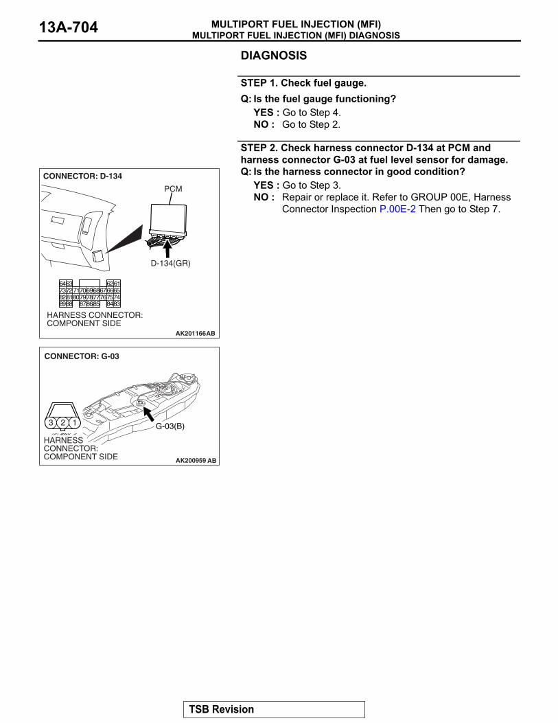
MULTIPORT FUEL INJECTION (MFI) DIAGNOSISMULTIPORT FUEL INJECTION (MFI)13A-704
DIAGNOSIS
STEP 1. Check fuel gauge.Q: Is the fuel gauge functioning?
YES : Go to Step 4.NO : Go to Step 2.
STEP 2. Check harness connector D-134 at PCM and harness connector G-03 at fuel level sensor for damage. Q: Is the harness connector in good condition?
YES : Go to Step 3.NO : Repair or replace it. Refer to GROUP 00E, Harness
Connector Inspection P.00E-2 Then go to Step 7.
AK201166
6162636465666768697071
76777879858687
807273
7475818283848889
CONNECTOR: D-134
AB
PCM
D-134(GR)
HARNESS CONNECTOR: COMPONENT SIDE
AK200959
123
AB
CONNECTOR: G-03
G-03(B)
HARNESS CONNECTOR: COMPONENT SIDE
TSB Revision

MULTIPORT FUEL INJECTION (MFI) DIAGNOSISMULTIPORT FUEL INJECTION (MFI) 13A-705
STEP 3. Check for short circuit to ground between fuel level sensor connector G-03 (terminal No. 1) and PCM connector D-134 (terminal No. 72).
NOTE: Check harness after checking intermediate connectors E-113, D-111 and F-07. If intermediate connectors are dam-aged, repair or replace them. Refer to GROUP 00E, Harness Connector Inspection P.00E-2. Then go to Step 7.Q: Is the harness wire in good condition?
YES : Refer to GROUP 54A, Chassis Electrical − Combination Meters Assembly and Vehicle Speed Sensor − Equipment Diagnosis − Symptom Chart P.54A-41.
NO : Repair it. Then go to Step 7.
AK200959
123
AB
CONNECTOR: G-03
G-03(B)
HARNESS CONNECTOR: COMPONENT SIDE
AK201166
6162636465666768697071
76777879858687
807273
7475818283848889
CONNECTOR: D-134
AB
PCM
D-134(GR)
HARNESS CONNECTOR: COMPONENT SIDE
TSB Revision

MULTIPORT FUEL INJECTION (MFI) DIAGNOSISMULTIPORT FUEL INJECTION (MFI)13A-706
STEP 4. Check harness connector D-134 at PCM and harness connector D-03 at combination meter for damage Q: Is the harness connector in good condition?
YES : Go to Step 5.NO : Repair or replace it. Refer to GROUP 00E, Harness
Connector Inspection P.00E-2 Then go to Step 7.
AK201166
6162636465666768697071
76777879858687
807273
7475818283848889
CONNECTOR: D-134
AB
PCM
D-134(GR)
HARNESS CONNECTOR: COMPONENT SIDE
AK304354
515253545559
565758
6061626364656667
D-03(GR)CONNECTOR: D-03
AB
HARNESS CONNECTOR: COMPONENT SIDE
TSB Revision
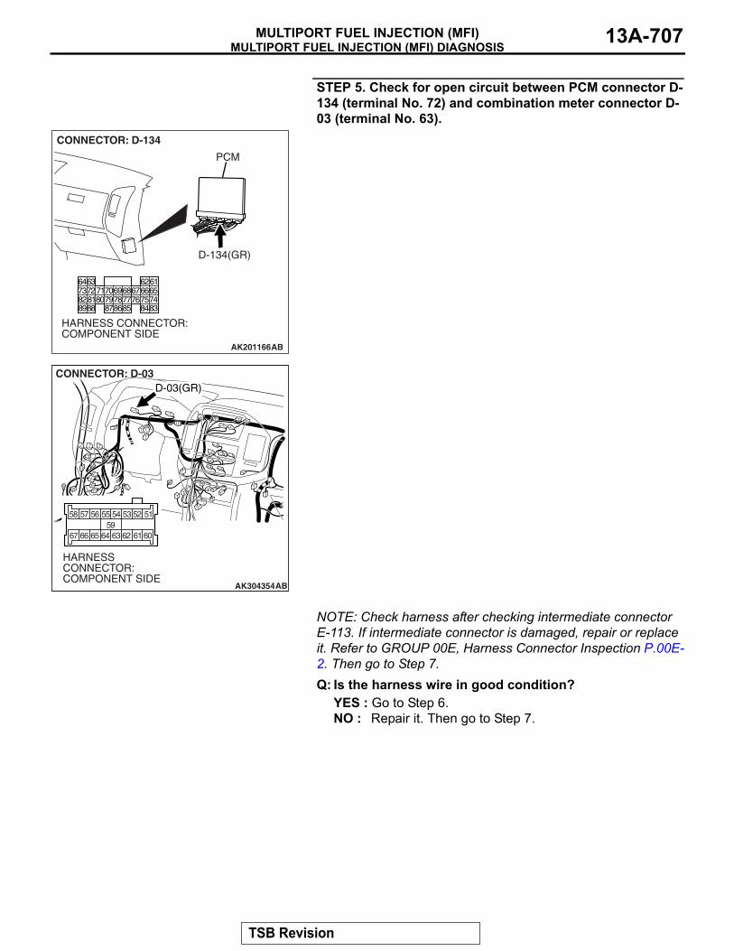
MULTIPORT FUEL INJECTION (MFI) DIAGNOSISMULTIPORT FUEL INJECTION (MFI) 13A-707
STEP 5. Check for open circuit between PCM connector D-134 (terminal No. 72) and combination meter connector D-03 (terminal No. 63).
NOTE: Check harness after checking intermediate connector E-113. If intermediate connector is damaged, repair or replace it. Refer to GROUP 00E, Harness Connector Inspection P.00E-2. Then go to Step 7.Q: Is the harness wire in good condition?
YES : Go to Step 6.NO : Repair it. Then go to Step 7.
AK201166
6162636465666768697071
76777879858687
807273
7475818283848889
CONNECTOR: D-134
AB
PCM
D-134(GR)
HARNESS CONNECTOR: COMPONENT SIDE
AK304354
515253545559
565758
6061626364656667
D-03(GR)CONNECTOR: D-03
AB
HARNESS CONNECTOR: COMPONENT SIDE
TSB Revision

MULTIPORT FUEL INJECTION (MFI) DIAGNOSISMULTIPORT FUEL INJECTION (MFI)13A-708
STEP 6. Check the trouble symptoms.(1) Carry out a test drive with the drive cycle pattern. Refer to
Diagnostic Function − OBD-II Drive Cycle − Pattern 20 P.13A-4.
(2) Check the diagnostic trouble code (DTC).Q: Is DTC P0462 set?
YES : Replace the PCM. Then go to Step 7.NO : It can be assumed that this malfunction is intermittent.
Refer to GROUP 00, How to Use Troubleshooting/Inspection Service Points − How to Cope with Intermittent MalfunctionsP.00-13.
STEP 7. Test the OBD-II drive cycle.(1) Carry out a test drive with the drive cycle pattern. Refer to
Diagnostic Function − OBD-II Drive Cycle − Pattern 20 P.13A-4.
(2) Check the diagnostic trouble code (DTC).Q: Is DTC P0462 set?
YES : Retry the troubleshooting.NO : The inspection is complete.
TSB Revision
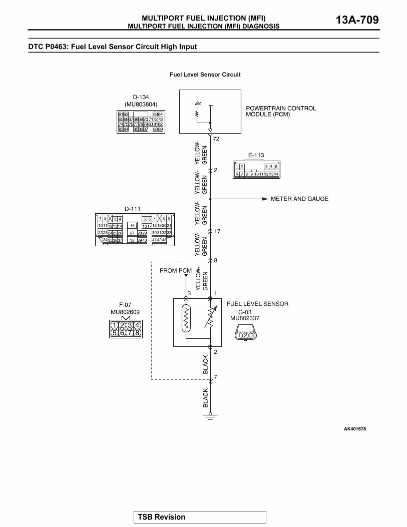
MULTIPORT FUEL INJECTION (MFI) DIAGNOSISMULTIPORT FUEL INJECTION (MFI) 13A-709
DTC P0463: Fuel Level Sensor Circuit High Input
POWERTRAIN CONTROLMODULE (PCM)
METER AND GAUGE
Fuel Level Sensor Circuit
8
17
13
2
7
2
BLA
CK
BLA
CK
YE
LLO
W-
GR
EE
N
G-03MU802337
1 2 3
AK401678
72
FUEL LEVEL SENSOR
FROM PCM
YE
LLO
W-
GR
EE
NY
ELL
OW
-G
RE
EN
YE
LLO
W-
GR
EE
NY
ELL
OW
-G
RE
EN
4
17
1
121314 18
30
4134
3
1610
6 7
19
31
42
20
32
43
21
332524 26
3635 37
2928
15
27
38
8 9
3940
11
2
22
5
23
D-111
87651 2 3 4
F-07MU802609
11
1
9 10 13
2
12
3 4
7
5
146 8
E-113
616566676869707172737475767778798081828384 858687 8889
62 6364
D-134(MU803804)
TSB Revision

MULTIPORT FUEL INJECTION (MFI) DIAGNOSISMULTIPORT FUEL INJECTION (MFI)13A-710
.
CIRCUIT OPERATION• The fuel level sensor output voltage is input in
PCM (terminal No. 72)..
TECHNICAL DESCRIPTION• Branch the output voltage from the fuel level sen-
sor circuit, and input it into PCM.• The PCM checks whether this voltage is within a
specified range..
DESCRIPTIONS OF MONITOR METHODSAn open circuit is detected while monitoring the fuel
level sensor output.
.
MONITOR EXECUTIONContinuous.
MONITOR EXECUTION CONDITIONS (Other monitor and Sensor)Other Monitor (There is no temporary DTC stored
in memory for the item monitored below)• Not applicable
Sensor (The sensor below is determined to be normal)
• Not applicable.
AK201040 AB
CONNECTOR: G-03
G-03(B)
FUEL TANK TEMPERATURE SENSOR(INTEGRATED IN FUEL LEVEL SENSOR)
AK201038
CONNECTOR: D-134
AD
PCM
D-134(GR)
AK201055
CONNECTOR: D-111
D-111
AB
AK304350
F-07 (B)
AB
CONNECTOR: F-07
AK201053
E-113
AB
CONNECTOR: E-113
TSB Revision

MULTIPORT FUEL INJECTION (MFI) DIAGNOSISMULTIPORT FUEL INJECTION (MFI) 13A-711
DTC SET CONDITIONS
Logic Flow Chart
.
Check Conditions• Battery positive voltage is between 11 and 16.5
volts.• 2 seconds or more have passed since the engine
staring sequence was completed.
Judgement Criterion• Fuel level sensor output voltage has continued to
be higher than 4.2 volt for 2 seconds..
OBD-II DRIVE CYCLE PATTERNRefer to Diagnostic Function − OBD-II Drive Cycle −
Pattern 20 P.13A-4..
TROUBLESHOOTING HINTS (The most likely causes for this code to be set are:)• Fuel level sensor failed.• Open or shorted fuel level sensor circuit, or con-
nector damage.• PCM failed.
END
MALFUNCTION
YES
YES
YES
NO
NO
NO CONTINUOUSFAILURE FOR 2secs
OUTPUT VOLTAGE< 0.2V
OUTPUT VOLTAGE> 4.2V
MONITORINGCONDITIONS
GOOD
START
AK401549
YES
NO
TSB Revision

MULTIPORT FUEL INJECTION (MFI) DIAGNOSISMULTIPORT FUEL INJECTION (MFI)13A-712
DIAGNOSIS
STEP 1. Check fuel gauge.Q: Is the fuel gauge functioning?
YES : Go to Step 2.NO : Refer to GROUP 54A, Chassis Electrical −
Combination Meters Assembly and Vehicle Speed Sensor − Equipment Diagnosis − Symptom Chart P.54A-41.
STEP 2. Check the trouble symptoms.(1) Carry out a test drive with the drive cycle pattern. Refer to
Diagnostic Function − OBD-II Drive Cycle − Pattern 20 P.13A-4.
(2) Check the diagnostic trouble code (DTC).Q: Is DTC P0463 set?
YES : Replace the PCM. Then go to Step 3.NO : It can be assumed that this malfunction is intermittent.
Refer to GROUP 00, How to Use Troubleshooting/Inspection Service Points − How to Cope with Intermittent Malfunctions P.00-13.
STEP 3. Test the OBD-II drive cycle.(1) Carry out a test drive with the drive cycle pattern. Refer to
Diagnostic Function − OBD-II Drive Cycle − Pattern 20 P.13A-4.
(2) Check the diagnostic trouble code (DTC).Q: Is DTC P0463 set?
YES : Retry the troubleshooting.NO : The inspection is complete.
DTC P0506: Idle Control System RPM Lower Than Expected
.
TECHNICAL DESCRIPTION• The amount of air taken in during idling is regu-
lated by the opening and closing of the throttle valve.
• The PCM checks the difference between the actual engine speed and the target engine speed.
.
DESCRIPTIONS OF MONITOR METHODSDifference between actual and target idle speed is
over the specified value..
MONITOR EXECUTIONContinuous.
MONITOR EXECUTION CONDITIONS (Other monitor and Sensor)Other Monitor (There is no temporary DTC stored
in memory for the item monitored below)• Misfire monitor• Exhaust gas recirculation (EGR) system monitor• Fuel system monitor
Sensor (The sensor below is determined to be normal)
• Volume airflow sensor• Engine coolant temperature sensor• Intake air temperature sensor• Barometric pressure sensor• Throttle position sensor
.
TSB Revision

MULTIPORT FUEL INJECTION (MFI) DIAGNOSISMULTIPORT FUEL INJECTION (MFI) 13A-713
DTC SET CONDITIONS
Logic Flow Chart
.
Check Conditions• Under the closed loop idle speed control.• Engine coolant temperature is more than 77°C
(171°F).• Battery positive voltage is higher than 10 volts.• Power steering pressure switch: OFF.• Volumetric efficiency is lower than 40 percent.• Barometric pressure is higher than 76 kPa (22.4
in.Hg).• Intake air temperature is higher than −10°C
(14°F).• 3 seconds have elapsed from the start of the pre-
vious monitoring.
• Target throttle actuator control motor position is more than 255 steps.
Judgement Criterion• The actual idle speed is more than 100 r/min
lower than the target idle speed for 12 seconds..
OBD-II DRIVE CYCLE PATTERNRefer to Diagnostic Function − OBD-II Drive Cycle −
Pattern 18 P.13A-4..
TROUBLESHOOTING HINTS (The most likely causes for this code to be set are:)• Throttle valve area is dirty.• PCM failed.
END
NO
NO
NO
YES
YES
YES
MALFUNCTION GOOD
START
CALCULATE Ne
MONITORINGCONDITIONS
Ne = (ACTUAL-Ne) - (TARGET-Ne)Ne: ENGINE SPEED
Ne < -100 r/min OR> 200 r/min
HAVE 12secs PASSED?
AK501066
TSB Revision
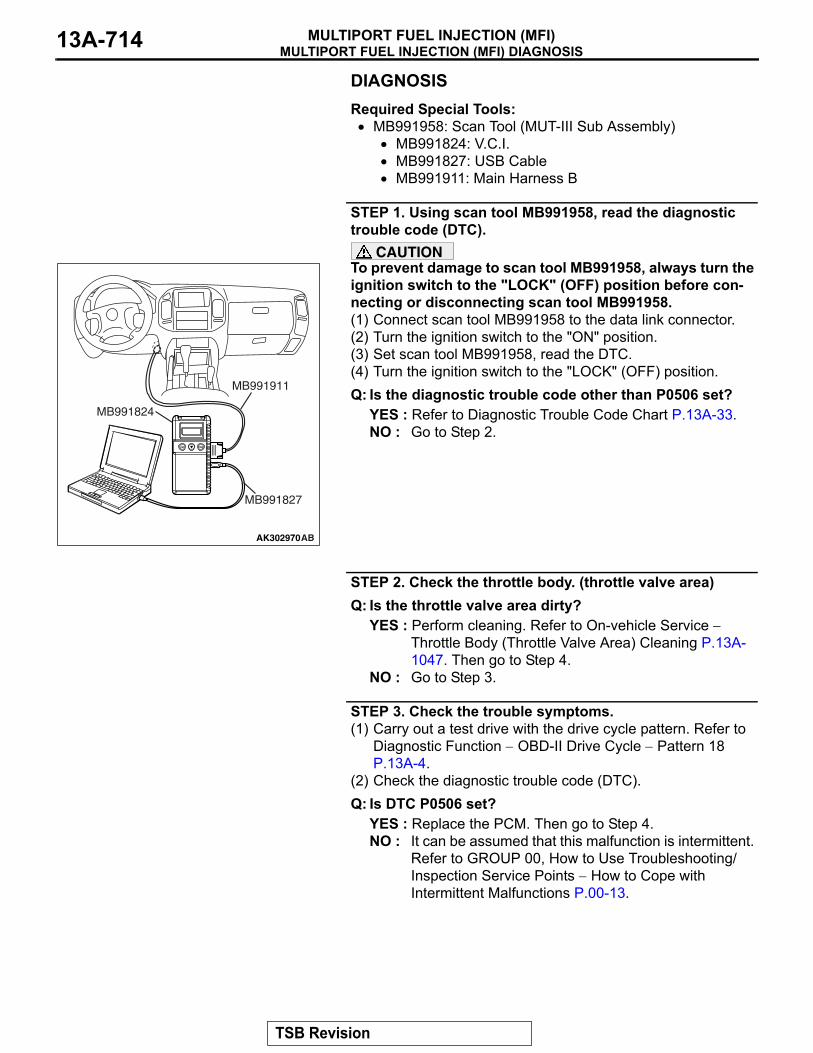
MULTIPORT FUEL INJECTION (MFI) DIAGNOSISMULTIPORT FUEL INJECTION (MFI)13A-714
DIAGNOSISRequired Special Tools:• MB991958: Scan Tool (MUT-III Sub Assembly)
• MB991824: V.C.I.• MB991827: USB Cable• MB991911: Main Harness B
STEP 1. Using scan tool MB991958, read the diagnostic trouble code (DTC).
CAUTIONTo prevent damage to scan tool MB991958, always turn the ignition switch to the "LOCK" (OFF) position before con-necting or disconnecting scan tool MB991958.(1) Connect scan tool MB991958 to the data link connector.(2) Turn the ignition switch to the "ON" position.(3) Set scan tool MB991958, read the DTC.(4) Turn the ignition switch to the "LOCK" (OFF) position.Q: Is the diagnostic trouble code other than P0506 set?
YES : Refer to Diagnostic Trouble Code Chart P.13A-33.NO : Go to Step 2.
STEP 2. Check the throttle body. (throttle valve area)Q: Is the throttle valve area dirty?
YES : Perform cleaning. Refer to On-vehicle Service − Throttle Body (Throttle Valve Area) Cleaning P.13A-1047. Then go to Step 4.
NO : Go to Step 3.
STEP 3. Check the trouble symptoms.(1) Carry out a test drive with the drive cycle pattern. Refer to
Diagnostic Function − OBD-II Drive Cycle − Pattern 18 P.13A-4.
(2) Check the diagnostic trouble code (DTC).Q: Is DTC P0506 set?
YES : Replace the PCM. Then go to Step 4.NO : It can be assumed that this malfunction is intermittent.
Refer to GROUP 00, How to Use Troubleshooting/Inspection Service Points − How to Cope with Intermittent Malfunctions P.00-13.
AK302970AB
MB991911
MB991824
MB991827
TSB Revision

MULTIPORT FUEL INJECTION (MFI) DIAGNOSISMULTIPORT FUEL INJECTION (MFI) 13A-715
STEP 4. Test the OBD-II drive cycle.(1) Carry out a test drive with the drive cycle pattern. Refer to
Diagnostic Function − OBD-II Drive Cycle − Pattern 18 P.13A-4.
(2) Check the diagnostic trouble code (DTC).Q: Is DTC P0506 set?
YES : Retry the troubleshooting.NO : The inspection is complete.
DTC P0507: Idle Control System RPM Higher Than Expected
.
TECHNICAL DESCRIPTION• The amount of air taken in during idling is regu-
lated by the opening and closing of the throttle valve.
• The PCM checks the difference between the actual engine speed and the target engine speed.
.
DESCRIPTIONS OF MONITOR METHODSDifference between actual and target idle speed is
over the specified value..
MONITOR EXECUTIONContinuous.
MONITOR EXECUTION CONDITIONS (Other monitor and Sensor)Other Monitor (There is no temporary DTC stored
in memory for the item monitored below)• Misfire monitor• Exhaust gas recirculation (EGR) system monitor• Fuel system monitor
Sensor (The sensor below is determined to be normal)
• Volume airflow sensor• Engine coolant temperature sensor• Intake air temperature sensor• Barometric pressure sensor• Throttle position sensor
.
TSB Revision
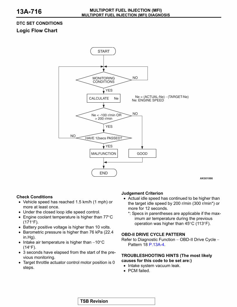
MULTIPORT FUEL INJECTION (MFI) DIAGNOSISMULTIPORT FUEL INJECTION (MFI)13A-716
DTC SET CONDITIONS
Logic Flow Chart
.
Check Conditions• Vehicle speed has reached 1.5 km/h (1 mph) or
more at least once.• Under the closed loop idle speed control.• Engine coolant temperature is higher than 77°C
(171°F).• Battery positive voltage is higher than 10 volts.• Barometric pressure is higher than 76 kPa (22.4
in.Hg).• Intake air temperature is higher than −10°C
(14°F).• 3 seconds have elapsed from the start of the pre-
vious monitoring.• Target throttle actuator control motor position is 0
steps.
Judgement Criterion• Actual idle speed has continued to be higher than
the target idle speed by 200 r/min (300 r/min*) or more for 12 seconds.*: Specs in parentheses are applicable if the max-
imum air temperature during the previous operation was higher than 45°C (113°F).
.
OBD-II DRIVE CYCLE PATTERNRefer to Diagnostic Function − OBD-II Drive Cycle −
Pattern 18 P.13A-4..
TROUBLESHOOTING HINTS (The most likely causes for this code to be set are:)• Intake system vacuum leak.• PCM failed.
END
NO
NO
NO
YES
YES
YES
MALFUNCTION GOOD
START
CALCULATE Ne
MONITORINGCONDITIONS
Ne = (ACTUAL-Ne) - (TARGET-Ne)Ne: ENGINE SPEED
Ne < -100 r/min OR> 200 r/min
HAVE 12secs PASSED?
AK501066
TSB Revision
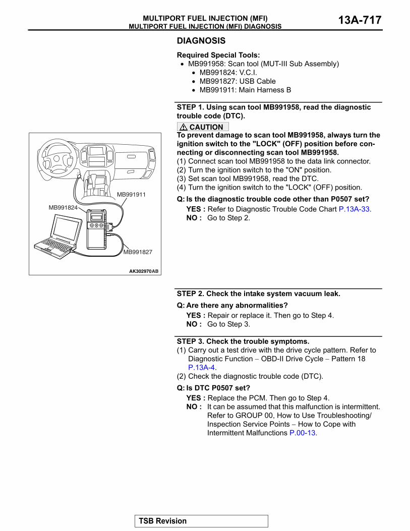
MULTIPORT FUEL INJECTION (MFI) DIAGNOSISMULTIPORT FUEL INJECTION (MFI) 13A-717
DIAGNOSISRequired Special Tools:• MB991958: Scan tool (MUT-III Sub Assembly)
• MB991824: V.C.I.• MB991827: USB Cable• MB991911: Main Harness B
STEP 1. Using scan tool MB991958, read the diagnostic trouble code (DTC).
CAUTIONTo prevent damage to scan tool MB991958, always turn the ignition switch to the "LOCK" (OFF) position before con-necting or disconnecting scan tool MB991958.(1) Connect scan tool MB991958 to the data link connector.(2) Turn the ignition switch to the "ON" position.(3) Set scan tool MB991958, read the DTC.(4) Turn the ignition switch to the "LOCK" (OFF) position.Q: Is the diagnostic trouble code other than P0507 set?
YES : Refer to Diagnostic Trouble Code Chart P.13A-33.NO : Go to Step 2.
STEP 2. Check the intake system vacuum leak.Q: Are there any abnormalities?
YES : Repair or replace it. Then go to Step 4.NO : Go to Step 3.
STEP 3. Check the trouble symptoms.(1) Carry out a test drive with the drive cycle pattern. Refer to
Diagnostic Function − OBD-II Drive Cycle − Pattern 18 P.13A-4.
(2) Check the diagnostic trouble code (DTC).Q: Is DTC P0507 set?
YES : Replace the PCM. Then go to Step 4.NO : It can be assumed that this malfunction is intermittent.
Refer to GROUP 00, How to Use Troubleshooting/Inspection Service Points − How to Cope with Intermittent Malfunctions P.00-13.
AK302970AB
MB991911
MB991824
MB991827
TSB Revision

MULTIPORT FUEL INJECTION (MFI) DIAGNOSISMULTIPORT FUEL INJECTION (MFI)13A-718
STEP 4. Test the OBD-II drive cycle.(1) Carry out a test drive with the drive cycle pattern. Refer to
Diagnostic Function − OBD-II Drive Cycle − Pattern 18 P.13A-4.
(2) Check the diagnostic trouble code (DTC).Q: Is DTC P0507 set?
YES : Retry the troubleshooting.NO : The inspection is complete.
DTC P0510: Accelerator Pedal Position Switch Circuit
YE
LLO
W-B
LAC
K
BLA
CK
AK201165
ACCELERATOR PEDAL POSITIONSWITCH (BUILT INTO ACCELERATOR PEDAL POSITION SENSOR)
POWERTRAIN CONTROL MODULE(PCM)
5V
96 38
45
D-138 (MU802073)
3135363738394041 42 43444546474849 50 515253 545556 57 58
32 33 349192 93949596979899100
105
113114 115116117 118119120
106 107108109 110111112
101102103 104
D-133(MU803803)
D-135(MU803805)
Accelerator Pedal Position Switch Circuit
6 7 81 2 3 4 5
TSB Revision
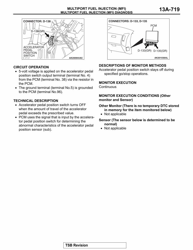
MULTIPORT FUEL INJECTION (MFI) DIAGNOSISMULTIPORT FUEL INJECTION (MFI) 13A-719
.
CIRCUIT OPERATION• 5-volt voltage is applied on the accelerator pedal
position switch output terminal (terminal No. 4) from the PCM (terminal No. 38) via the resistor in the PCM.
• The ground terminal (terminal No.5) is grounded to the PCM (terminal No.96).
.
TECHNICAL DESCRIPTION• Accelerator pedal position switch turns OFF
when the amount of travel of the accelerator pedal exceeds the prescribed value.
• PCM uses the signal that is input by the accelera-tor pedal position switch for determining the abnormal characteristics of the accelerator pedal position sensor (sub).
.
DESCRIPTIONS OF MONITOR METHODSAccelerator pedal position switch stays off during
specified go/stop operations..
MONITOR EXECUTIONContinuous.
MONITOR EXECUTION CONDITIONS (Other monitor and Sensor)Other Monitor (There is no temporary DTC stored
in memory for the item monitored below)• Not applicable
Sensor (The sensor below is determined to be normal)
• Not applicable.
AK200944AC
CONNECTOR: D-138
ACCELERATORPEDAL POSITION SWITCH
D-138(GR)
AK201038AL
CONNECTORS: D-133, D-135
PCM
D-135(GR)D-133(GR)
TSB Revision

MULTIPORT FUEL INJECTION (MFI) DIAGNOSISMULTIPORT FUEL INJECTION (MFI)13A-720
DTC SET CONDITIONS
Logic Flow Chart
.
Check Condition• Drive for 2 seconds or more with the vehicle
speed is 30 km/h (19 mph) or more. Stop the vehicle [vehicle speed is 1.5 km/h (1 mph) or less]. Repeat 15 times or more.
Judgement Criterion• Accelerator pedal position switch continuous to
be OFF.
.
OBD-II DRIVE CYCLE PATTERNNone..
TROUBLESHOOTING HINTS (The most likely causes for this code to be set are:)• Accelerator pedal position switch failed.• Open or shorted accelerator pedal position switch
circuit, or loose connector.• PCM failed.
AK401575
END
YES
NO
NO
NO
START
YES NO
YES
MALFUNCTION
GOOD
VEHICLE SPEED > 30km/h(19mph)
F1 = F2 = 0
NOTE: THE COUNTER “F2” IS NOT RESET AFTER EACH DRIVE CYCLE
NO
NO
YES
F2 > 15
F1 = 1
F1 = 1
F2 = F2 + 1, F1 = 0
YES
HAVE 2secs PASSED?
YES
VEHICLE SPEED <
APS SWITCH STATUS = OFF
1.5km/h(0.93mph)
TSB Revision

MULTIPORT FUEL INJECTION (MFI) DIAGNOSISMULTIPORT FUEL INJECTION (MFI) 13A-721
DIAGNOSISRequired Special Tools:• MB991958: Scan Tool (MUT-III Sub Assembly)
• MB991824: V.C.I.• MB991827: USB Cable• MB991911: Main Harness B
STEP 1. Using scan tool MB991958, check data list item 26: Accelerator Pedal Position Switch.
CAUTIONTo prevent damage to scan tool MB991958, always turn the ignition switch to the "LOCK" (OFF) position before con-necting or disconnecting scan tool MB991958. (1) Connect scan tool MB991958 to the data link connector.(2) Turn the ignition switch to the "ON" position.(3) Set scan tool MB991958 to the data reading mode for item
26, Accelerator Pedal Position Switch.• When accelerator pedal is depressed slightly, OFF will
be displayed.• When foot is released from accelerator pedal, ON will be
displayed.(4) Turn the ignition switch to the "LOCK" (OFF) position.Q: Is the switch operating properly?
YES : It can be assumed that this malfunction is intermittent. Refer to GROUP 00, How to Use Troubleshooting/Inspection Service Points − How to Cope with Intermittent Malfunctions P.00-13.
NO : Go to Step 2.
STEP 2. Check harness connector D-138 at accelerator pedal position switch for damage.Q: Is the harness connector in good condition?
YES : Go to Step 3.NO : Repair or replace it. Refer to GROUP 00E, Harness
Connector Inspection P.00E-2. Then confirm that the malfunction symptom is eliminated.
AK302970AB
MB991911
MB991824
MB991827
AK200945
345 128 67
AB
CONNECTOR: D-138
HARNESS CONNECTOR: COMPONENT SIDED-138(GR)
TSB Revision
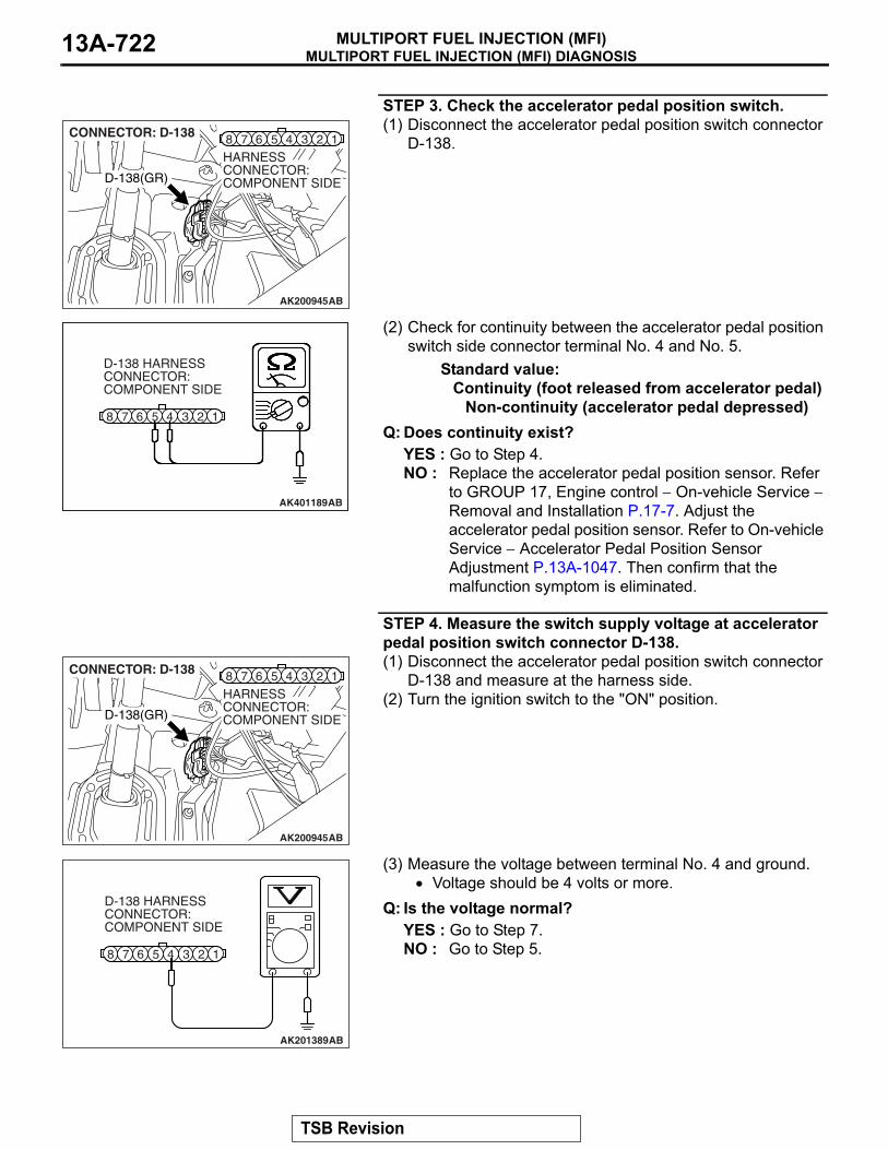
MULTIPORT FUEL INJECTION (MFI) DIAGNOSISMULTIPORT FUEL INJECTION (MFI)13A-722
STEP 3. Check the accelerator pedal position switch.(1) Disconnect the accelerator pedal position switch connector
D-138.
(2) Check for continuity between the accelerator pedal position switch side connector terminal No. 4 and No. 5.
Standard value:Continuity (foot released from accelerator pedal)
Non-continuity (accelerator pedal depressed)Q: Does continuity exist?
YES : Go to Step 4.NO : Replace the accelerator pedal position sensor. Refer
to GROUP 17, Engine control − On-vehicle Service − Removal and Installation P.17-7. Adjust the accelerator pedal position sensor. Refer to On-vehicle Service − Accelerator Pedal Position Sensor Adjustment P.13A-1047. Then confirm that the malfunction symptom is eliminated.
STEP 4. Measure the switch supply voltage at accelerator pedal position switch connector D-138.(1) Disconnect the accelerator pedal position switch connector
D-138 and measure at the harness side.(2) Turn the ignition switch to the "ON" position.
(3) Measure the voltage between terminal No. 4 and ground.• Voltage should be 4 volts or more.
Q: Is the voltage normal?YES : Go to Step 7.NO : Go to Step 5.
AK200945
345 128 67
AB
CONNECTOR: D-138
HARNESS CONNECTOR: COMPONENT SIDED-138(GR)
345 128 67
AK401189
D-138 HARNESS CONNECTOR: COMPONENT SIDE
AB
AK200945
345 128 67
AB
CONNECTOR: D-138
HARNESS CONNECTOR: COMPONENT SIDED-138(GR)
345 128 67
AK201389
D-138 HARNESS CONNECTOR: COMPONENT SIDE
AB
TSB Revision
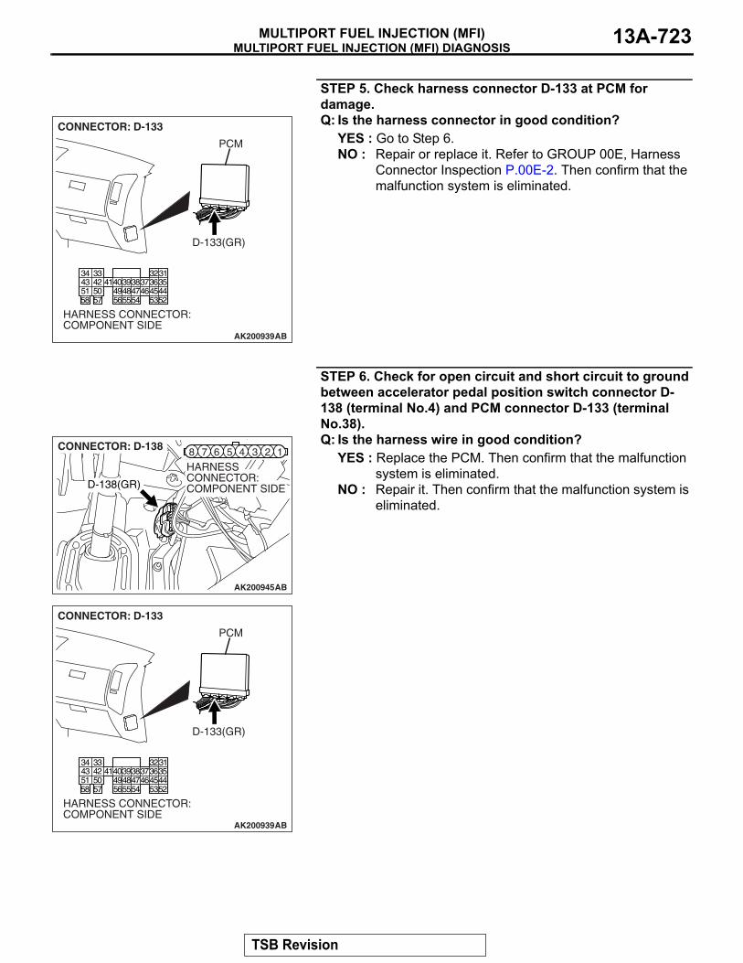
MULTIPORT FUEL INJECTION (MFI) DIAGNOSISMULTIPORT FUEL INJECTION (MFI) 13A-723
STEP 5. Check harness connector D-133 at PCM for damage.Q: Is the harness connector in good condition?
YES : Go to Step 6.NO : Repair or replace it. Refer to GROUP 00E, Harness
Connector Inspection P.00E-2. Then confirm that the malfunction system is eliminated.
STEP 6. Check for open circuit and short circuit to ground between accelerator pedal position switch connector D-138 (terminal No.4) and PCM connector D-133 (terminal No.38).Q: Is the harness wire in good condition?
YES : Replace the PCM. Then confirm that the malfunction system is eliminated.
NO : Repair it. Then confirm that the malfunction system is eliminated.
AK200939
3132333435363738394041424344454647484952535455565758
5051
AB
CONNECTOR: D-133
HARNESS CONNECTOR: COMPONENT SIDE
PCM
D-133(GR)
AK200945
345 128 67
AB
CONNECTOR: D-138
HARNESS CONNECTOR: COMPONENT SIDED-138(GR)
AK200939
3132333435363738394041424344454647484952535455565758
5051
AB
CONNECTOR: D-133
HARNESS CONNECTOR: COMPONENT SIDE
PCM
D-133(GR)
TSB Revision

MULTIPORT FUEL INJECTION (MFI) DIAGNOSISMULTIPORT FUEL INJECTION (MFI)13A-724
STEP 7. Check the continuity at accelerator pedal position switch harness side connector D-138.(1) Disconnect the connector D-138 and measure at the
harness side.(2) Check for the continuity between terminal No. 5 and
ground.• Should be less than 2 ohms.
Q: Does continuity exist?YES : Go to Step 10.NO : Go to Step 8.
STEP 8. Check harness connector D-135 at PCM for damage.Q: Is the harness connector in good condition?
YES : Go to Step 9.NO : Repair or replace it. Refer to GROUP 00E, Harness
Connector Inspection P.00E-2. Then confirm that the malfunction system is eliminated.
345 128 67
AK201390
D-138 HARNESS CONNECTOR: COMPONENT SIDE
AK201390AB
AK200947
919293949596979899100101102103104
105106107108109110111112
113114115116117118119120
CONNECTOR: D-135
HARNESS CONNECTOR: COMPONENT SIDE
AB
PCM
D-135(GR)
TSB Revision
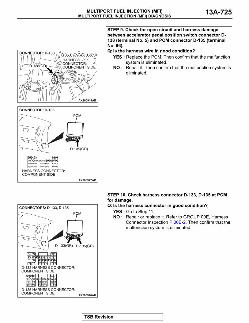
MULTIPORT FUEL INJECTION (MFI) DIAGNOSISMULTIPORT FUEL INJECTION (MFI) 13A-725
STEP 9. Check for open circuit and harness damage between accelerator pedal position switch connector D-138 (terminal No. 5) and PCM connector D-135 (terminal No. 96).Q: Is the harness wire in good condition?
YES : Replace the PCM. Then confirm that the malfunction system is eliminated.
NO : Repair it. Then confirm that the malfunction system is eliminated.
STEP 10. Check harness connector D-133, D-135 at PCM for damage.Q: Is the harness connector in good condition?
YES : Go to Step 11.NO : Repair or replace it. Refer to GROUP 00E, Harness
Connector Inspection P.00E-2. Then confirm that the malfunction system is eliminated.
AK200945
345 128 67
AB
CONNECTOR: D-138
HARNESS CONNECTOR: COMPONENT SIDED-138(GR)
AK200947
919293949596979899100101102103104
105106107108109110111112
113114115116117118119120
CONNECTOR: D-135
HARNESS CONNECTOR: COMPONENT SIDE
AB
PCM
D-135(GR)
AK200946
919293949596979899100101102103104
105106107108109110111112
113114115116117118119120
3132333435363738394041424344454647484952535455565758
5051
AB
CONNECTORS: D-133, D-135
D-133 HARNESS CONNECTOR: COMPONENT SIDE
D-135 HARNESS CONNECTOR: COMPONENT SIDE
PCM
D-135(GR)D-133(GR)
TSB Revision

MULTIPORT FUEL INJECTION (MFI) DIAGNOSISMULTIPORT FUEL INJECTION (MFI)13A-726
STEP 11. Check for harness damage between accelerator pedal position switch connector D-138 (terminal No. 4) and PCM connector D-133 (terminal No. 38).Q: Is the harness wire in good condition?
YES : Replace the PCM. Then Go to Step 12.NO : Repair it. Then Go to Step 12.
STEP 12. Using scan tool MB991958, check data list item 26: Accelerator Pedal Position Switch.
CAUTIONTo prevent damage to scan tool MB991958, always turn the ignition switch to the "LOCK" (OFF) position before con-necting or disconnecting scan tool MB991958. (1) Connect scan tool MB991958 to the data link connector. (2) Turn the ignition switch to the "ON" position.(3) Set scan tool MB991958 to the data reading mode for item
26, Accelerator Pedal Position Switch.• When accelerator pedal is depressed slightly, "OFF" will
be displayed. • When foot is released from accelerator pedal, "ON" will
be displayed. (4) Turn the ignition switch to the "LOCK" (OFF) position.Q: Is the switch operating properly?
YES : The inspection is complete.NO : Retry the troubleshooting.
AK200945
345 128 67
AB
CONNECTOR: D-138
HARNESS CONNECTOR: COMPONENT SIDED-138(GR)
AK200939
3132333435363738394041424344454647484952535455565758
5051
AB
CONNECTOR: D-133
HARNESS CONNECTOR: COMPONENT SIDE
PCM
D-133(GR)
AK302970AB
MB991911
MB991824
MB991827
TSB Revision

MULTIPORT FUEL INJECTION (MFI) DIAGNOSISMULTIPORT FUEL INJECTION (MFI) 13A-727
DTC P0513: Immobilizer Malfunction
.
TECHNICAL DESCRIPTION• PCM monitors the communication condition with
the immobilizer-ECU and the message from the immobilizer-ECU, and when the abnormality is found, PCM makes the engine not to start.
.
DTC SET CONDITIONSCheck Condition• Ignition switch: ON
Judgement Criterion• When the communication error between PCM
and the immobilizer-ECU continues for 2 seconds or more.
.
TROUBLESHOOTING HINTS (The most likely causes for this code to be set are:)
• Malfunction of harness or connector.• Malfunction of immobilizer-ECU.• Malfunction of PCM.
DIAGNOSISRequired Special Tools:• MB991958: Scan Tool (MUT-III Sub Assembly)
• MB991824: V.C.I.• MB991827: USB Cable• MB991911: Main Harness B
STEP 1. Using scan tool MB991958, read the immobilizer diagnostic trouble code (DTC).
CAUTIONTo prevent damage to scan tool MB991958, always turn the ignition switch to the "LOCK" (OFF) position before con-necting or disconnecting scan tool MB991958.(1) Connect scan tool MB991958 to the data link connector.(2) Turn the ignition switch to the "ON" position.(3) Read the immobilizer system-DTC.(4) Turn the ignition switch to the "LOCK" (OFF) position.Q: Is the immobilizer − DTC set?
YES : Refer to GROUP 54A, Ignition Switch and Immobilizer System − Diagnostic Trouble Code Chart P.54A-11.
NO : If DTC P0513 is output again after the MFI − DTC has been erased, replace the PCM. Then check that the DTC P0513 does not reset.
AK302970AB
MB991911
MB991824
MB991827
TSB Revision
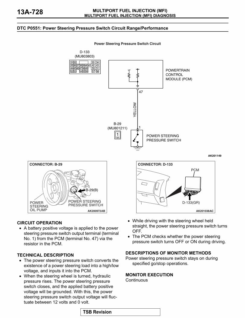
MULTIPORT FUEL INJECTION (MFI) DIAGNOSISMULTIPORT FUEL INJECTION (MFI)13A-728
DTC P0551: Power Steering Pressure Switch Circuit Range/Performance
.
CIRCUIT OPERATION• A battery positive voltage is applied to the power
steering pressure switch output terminal (terminal No. 1) from the PCM (terminal No. 47) via the resistor in the PCM.
.
TECHNICAL DESCRIPTION• The power steering pressure switch converts the
existence of a power steering load into a high/low voltage, and inputs it into the PCM.
• When the steering wheel is turned, hydraulic pressure rises. The power steering pressure switch closes, and the applied battery positive voltage will be grounded. With this, the power steering pressure switch output voltage will fluc-tuate between 12 volts and 0 volt.
• While driving with the steering wheel held straight, the power steering pressure switch turns OFF.
• The PCM checks whether the power steering pressure switch turns OFF or ON during driving.
.
DESCRIPTIONS OF MONITOR METHODSPower steering pressure switch stays on during
specified go/stop operations..
MONITOR EXECUTIONContinuous.
AK201149
YE
LLO
W
POWERTRAINCONTROLMODULE (PCM)
1
B-29(MU801211)
POWER STEERINGPRESSURE SWITCH
47
1
Power Steering Pressure Switch Circuit
3135363738394041 42 43444546474849 50 515253 545556 57 58
32 33 34
D-133(MU803803)
AK200972
POWER STEERING OIL PUMP
POWER STEERING PRESSURE SWITCH
AB
B-29(B)
CONNECTOR: B-29
AK201038
CONNECTOR: D-133
AC
PCM
D-133(GR)
TSB Revision

MULTIPORT FUEL INJECTION (MFI) DIAGNOSISMULTIPORT FUEL INJECTION (MFI) 13A-729
MONITOR EXECUTION CONDITIONS (Other monitor and Sensor)Other Monitor (There is no temporary DTC stored
in memory for the item monitored below)• Not applicable
Sensor (The sensor below is determined to be normal)
• Engine coolant temperature sensor.
DTC SET CONDITIONS
Logic Flow Chart
.
Check Conditions • Engine coolant temperature is higher than 10°C
(50°F). • Drive for 4 seconds or more with the vehicle
speed is 50 km/h (31 mph) or more. Stop the vehicle [vehicle speed is 1.5 km/h (1 mph) or less]. Repeat 10 times or more.
Judgement Criterion • Power steering pressure switch continues to be
ON. .
OBD-II DRIVE CYCLE PATTERNNone..
YES
NO
NO
NO
MONITORINGCONDITIONS
END
MALFUNCTION
GOOD
START
POWER STEERINGSWITCH = "ON"
YES
GO/STOP OPERATIONFOR SPECIFIED TIMES
YES
AK302957
TSB Revision

MULTIPORT FUEL INJECTION (MFI) DIAGNOSISMULTIPORT FUEL INJECTION (MFI)13A-730
TROUBLESHOOTING HINTS (The most likely causes for this code to be set are:) • Power steering pressure switch failed. • Open or shorted power steering pressure switch
circuit, harness damage, or connector damage. • PCM failed.
DIAGNOSIS Required Special Tools:• MB991958: Scan Tool (MUT-III Sub Assembly)
• MB991824: V.C.I.• MB991827: USB Cable• MB991911: Main Harness B
STEP 1. Using scan tool MB991958, check data list item 27: Power Steering Pressure Switch.
CAUTIONTo prevent damage to scan tool MB991958, always turn the ignition switch to the "LOCK" (OFF) position before con-necting or disconnecting scan tool MB991958. (1) Connect scan tool MB991958 to the data link connector. (2) Start the engine and run at idle. (3) Set scan tool MB991958 to the data reading mode for item
27, Power Steering Pressure Switch. • If the steering wheel is not turned while idling, OFF will
be displayed.• If the steering wheel is turned while idling, ON will be
displayed.(4) Turn the ignition switch to the "LOCK" (OFF) position. Q: Is the switch operating properly?
YES : It can be assumed that this malfunction is intermittent. Refer to GROUP 00, How to Use Troubleshooting/Inspection Service Points − How to Cope with Intermittent Malfunctions P.00-13.
NO : Go to Step 2.
AK302970AB
MB991911
MB991824
MB991827
TSB Revision
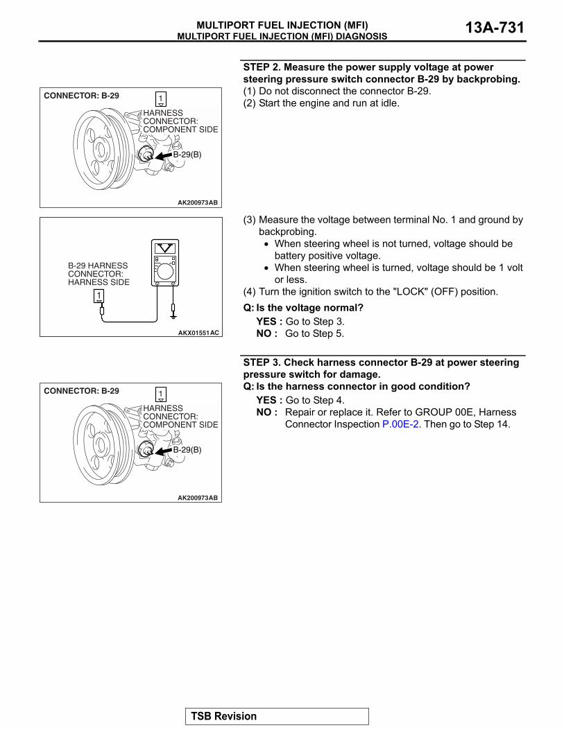
MULTIPORT FUEL INJECTION (MFI) DIAGNOSISMULTIPORT FUEL INJECTION (MFI) 13A-731
STEP 2. Measure the power supply voltage at power steering pressure switch connector B-29 by backprobing. (1) Do not disconnect the connector B-29. (2) Start the engine and run at idle.
(3) Measure the voltage between terminal No. 1 and ground by backprobing. • When steering wheel is not turned, voltage should be
battery positive voltage. • When steering wheel is turned, voltage should be 1 volt
or less. (4) Turn the ignition switch to the "LOCK" (OFF) position. Q: Is the voltage normal?
YES : Go to Step 3. NO : Go to Step 5.
STEP 3. Check harness connector B-29 at power steering pressure switch for damage. Q: Is the harness connector in good condition?
YES : Go to Step 4. NO : Repair or replace it. Refer to GROUP 00E, Harness
Connector Inspection P.00E-2. Then go to Step 14.
AK200973
1
AB
CONNECTOR: B-29
B-29(B)
HARNESS CONNECTOR: COMPONENT SIDE
AKX01551
1
AC
B-29 HARNESS CONNECTOR: HARNESS SIDE
AK200973
1
AB
CONNECTOR: B-29
B-29(B)
HARNESS CONNECTOR: COMPONENT SIDE
TSB Revision

MULTIPORT FUEL INJECTION (MFI) DIAGNOSISMULTIPORT FUEL INJECTION (MFI)13A-732
STEP 4. Using scan tool MB991958, check data list item 27: Power Steering Pressure Switch.
CAUTIONTo prevent damage to scan tool MB991958, always turn the ignition switch to the "LOCK" (OFF) position before con-necting or disconnecting scan tool MB991958. (1) Connect scan tool MB991958 to the data link connector. (2) Start the engine and run at idle. (3) Set scan tool MB991958 to the data reading mode for item
27, Power Steering Pressure Switch. • If the steering wheel is not turned while idling, OFF will
be displayed. • If the steering wheel is turned while idling, ON will be
displayed. (4) Turn the ignition switch to the "LOCK" (OFF) position. Q: Is the switch operating properly?
YES : It can be assumed that this malfunction is intermittent. Refer to GROUP 00, How to Use Troubleshooting/Inspection Service Points − How to Cope with Intermittent Malfunctions P.00-13.
NO : Replace the PCM. Then go to Step 14.
STEP 5. Check harness connector B-29 at power steering pressure switch for damage. Q: Is the harness connector in good condition?
YES : Go to Step 6. NO : Repair or replace it. Refer to GROUP 00E, Harness
Connector Inspection P.00E-2. Then go to Step 14.
AK302970AB
MB991911
MB991824
MB991827
AK200973
1
AB
CONNECTOR: B-29
B-29(B)
HARNESS CONNECTOR: COMPONENT SIDE
TSB Revision
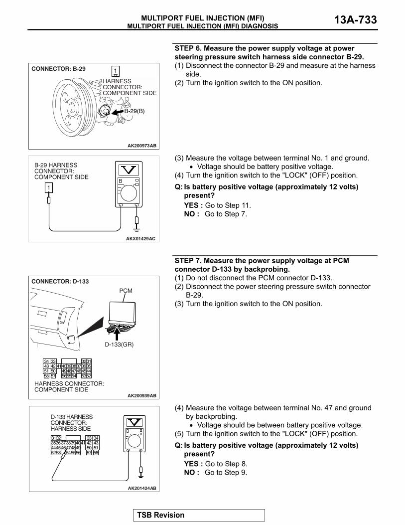
MULTIPORT FUEL INJECTION (MFI) DIAGNOSISMULTIPORT FUEL INJECTION (MFI) 13A-733
STEP 6. Measure the power supply voltage at power steering pressure switch harness side connector B-29. (1) Disconnect the connector B-29 and measure at the harness
side. (2) Turn the ignition switch to the ON position.
(3) Measure the voltage between terminal No. 1 and ground. • Voltage should be battery positive voltage.
(4) Turn the ignition switch to the "LOCK" (OFF) position. Q: Is battery positive voltage (approximately 12 volts)
present?YES : Go to Step 11. NO : Go to Step 7.
STEP 7. Measure the power supply voltage at PCM connector D-133 by backprobing. (1) Do not disconnect the PCM connector D-133. (2) Disconnect the power steering pressure switch connector
B-29. (3) Turn the ignition switch to the ON position.
(4) Measure the voltage between terminal No. 47 and ground by backprobing. • Voltage should be between battery positive voltage.
(5) Turn the ignition switch to the "LOCK" (OFF) position. Q: Is battery positive voltage (approximately 12 volts)
present?YES : Go to Step 8. NO : Go to Step 9.
AK200973
1
AB
CONNECTOR: B-29
B-29(B)
HARNESS CONNECTOR: COMPONENT SIDE
AKX01429AC
1
B-29 HARNESS CONNECTOR: COMPONENT SIDE
AK200939
3132333435363738394041424344454647484952535455565758
5051
AB
CONNECTOR: D-133
HARNESS CONNECTOR: COMPONENT SIDE
PCM
D-133(GR)
3132
AK201424
33 3435363738394041 42 434445464748495253 545556 57 58
50 51
D-133 HARNESS CONNECTOR: HARNESS SIDE
AB
TSB Revision

MULTIPORT FUEL INJECTION (MFI) DIAGNOSISMULTIPORT FUEL INJECTION (MFI)13A-734
STEP 8. Check harness connector D-133 at PCM for damage. Q: Is the harness connector in good condition?
YES : Repair harness wire between power steering pressure switch connector B-29 (terminal No. 1) and PCM connector D-133 (terminal No. 47) because of open circuit. Then go to Step 14.
NO : Repair or replace it. Refer to GROUP 00E, Harness Connector Inspection P.00E-2. Then go to Step 14.
STEP 9. Check harness connector D-133 at PCM for damage. Q: Is the harness connector in good condition?
YES : Go to Step 10. NO : Repair or replace it. Refer to GROUP 00E, Harness
Connector Inspection P.00E-2. Then go to Step 14.
AK200939
3132333435363738394041424344454647484952535455565758
5051
AB
CONNECTOR: D-133
HARNESS CONNECTOR: COMPONENT SIDE
PCM
D-133(GR)
AK200939
3132333435363738394041424344454647484952535455565758
5051
AB
CONNECTOR: D-133
HARNESS CONNECTOR: COMPONENT SIDE
PCM
D-133(GR)
TSB Revision
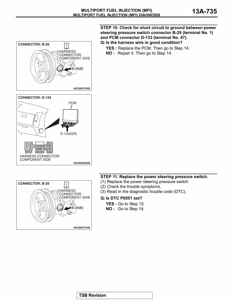
MULTIPORT FUEL INJECTION (MFI) DIAGNOSISMULTIPORT FUEL INJECTION (MFI) 13A-735
STEP 10. Check for short circuit to ground between power steering pressure switch connector B-29 (terminal No. 1) and PCM connector D-133 (terminal No. 47). Q: Is the harness wire in good condition?
YES : Replace the PCM. Then go to Step 14.NO : Repair it. Then go to Step 14.
STEP 11. Replace the power steering pressure switch. (1) Replace the power steering pressure switch. (2) Check the trouble symptoms. (3) Read in the diagnostic trouble code (DTC). Q: Is DTC P0551 set?
YES : Go to Step 12. NO : Go to Step 14.
AK200973
1
AB
CONNECTOR: B-29
B-29(B)
HARNESS CONNECTOR: COMPONENT SIDE
AK200939
3132333435363738394041424344454647484952535455565758
5051
AB
CONNECTOR: D-133
HARNESS CONNECTOR: COMPONENT SIDE
PCM
D-133(GR)
AK200973
1
AB
CONNECTOR: B-29
B-29(B)
HARNESS CONNECTOR: COMPONENT SIDE
TSB Revision

MULTIPORT FUEL INJECTION (MFI) DIAGNOSISMULTIPORT FUEL INJECTION (MFI)13A-736
STEP 12. Check harness connector D-133 at PCM for damage. Q: Is the harness connector in good condition?
YES : Go to Step 13. NO : Repair or replace it. Refer to GROUP 00E, Harness
Connector Inspection P.00E-2. Then go to Step 14.
STEP 13. Check for harness damage between power steering pressure switch connector B-29 (terminal No. 1) and PCM connector D-133 (terminal No. 47). Q: Is the harness wire in good condition?
YES : Replace the PCM. Then go to Step 14.NO : Repair it. Then go to Step 14.
AK200939
3132333435363738394041424344454647484952535455565758
5051
AB
CONNECTOR: D-133
HARNESS CONNECTOR: COMPONENT SIDE
PCM
D-133(GR)
AK200973
1
AB
CONNECTOR: B-29
B-29(B)
HARNESS CONNECTOR: COMPONENT SIDE
AK200939
3132333435363738394041424344454647484952535455565758
5051
AB
CONNECTOR: D-133
HARNESS CONNECTOR: COMPONENT SIDE
PCM
D-133(GR)
TSB Revision
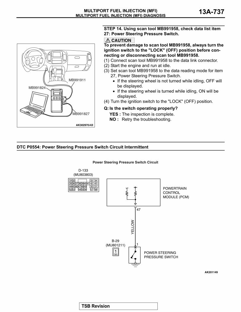
MULTIPORT FUEL INJECTION (MFI) DIAGNOSISMULTIPORT FUEL INJECTION (MFI) 13A-737
STEP 14. Using scan tool MB991958, check data list item 27: Power Steering Pressure Switch.
CAUTIONTo prevent damage to scan tool MB991958, always turn the ignition switch to the "LOCK" (OFF) position before con-necting or disconnecting scan tool MB991958. (1) Connect scan tool MB991958 to the data link connector. (2) Start the engine and run at idle. (3) Set scan tool MB991958 to the data reading mode for item
27, Power Steering Pressure Switch. • If the steering wheel is not turned while idling, OFF will
be displayed. • If the steering wheel is turned while idling, ON will be
displayed. (4) Turn the ignition switch to the "LOCK" (OFF) position.Q: Is the switch operating properly?
YES : The inspection is complete.NO : Retry the troubleshooting.
DTC P0554: Power Steering Pressure Switch Circuit Intermittent
AK302970AB
MB991911
MB991824
MB991827
AK201149
YE
LLO
W
POWERTRAINCONTROLMODULE (PCM)
1
B-29(MU801211)
POWER STEERINGPRESSURE SWITCH
47
1
Power Steering Pressure Switch Circuit
3135363738394041 42 43444546474849 50 515253 545556 57 58
32 33 34
D-133(MU803803)
TSB Revision
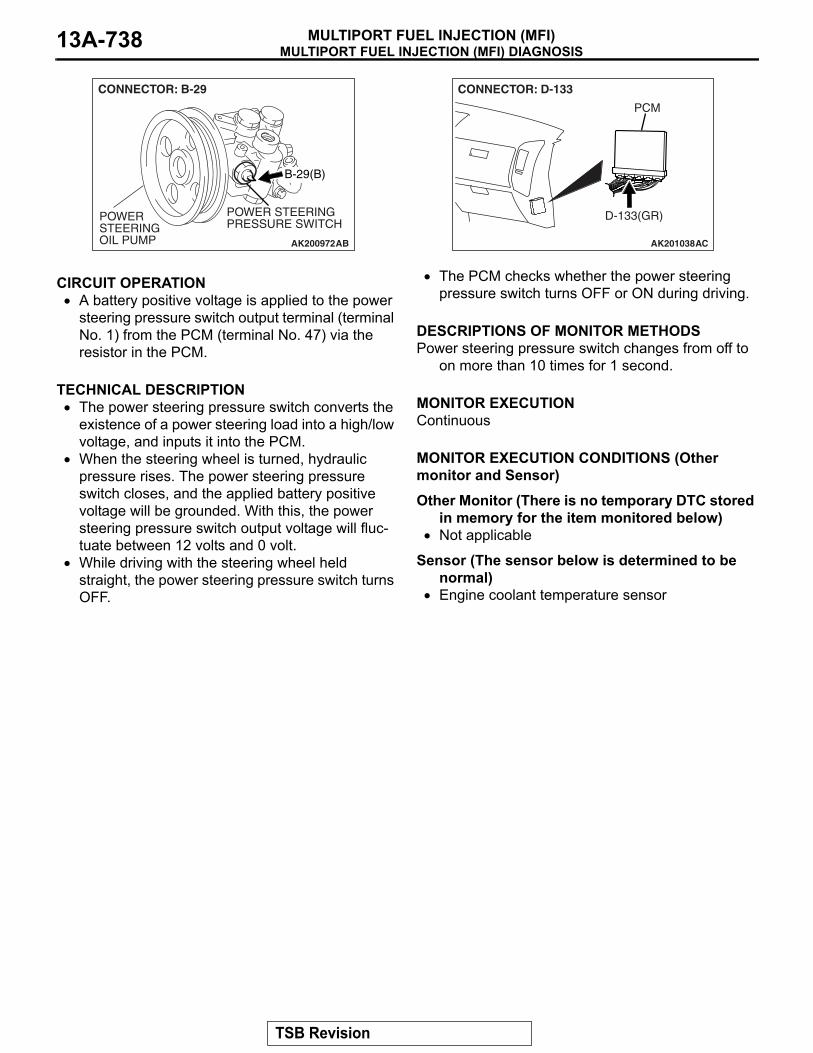
MULTIPORT FUEL INJECTION (MFI) DIAGNOSISMULTIPORT FUEL INJECTION (MFI)13A-738
.
CIRCUIT OPERATION• A battery positive voltage is applied to the power
steering pressure switch output terminal (terminal No. 1) from the PCM (terminal No. 47) via the resistor in the PCM.
.
TECHNICAL DESCRIPTION• The power steering pressure switch converts the
existence of a power steering load into a high/low voltage, and inputs it into the PCM.
• When the steering wheel is turned, hydraulic pressure rises. The power steering pressure switch closes, and the applied battery positive voltage will be grounded. With this, the power steering pressure switch output voltage will fluc-tuate between 12 volts and 0 volt.
• While driving with the steering wheel held straight, the power steering pressure switch turns OFF.
• The PCM checks whether the power steering pressure switch turns OFF or ON during driving.
.
DESCRIPTIONS OF MONITOR METHODSPower steering pressure switch changes from off to
on more than 10 times for 1 second..
MONITOR EXECUTIONContinuous.
MONITOR EXECUTION CONDITIONS (Other monitor and Sensor)Other Monitor (There is no temporary DTC stored
in memory for the item monitored below)• Not applicable
Sensor (The sensor below is determined to be normal)
• Engine coolant temperature sensor.
AK200972
POWER STEERING OIL PUMP
POWER STEERING PRESSURE SWITCH
AB
B-29(B)
CONNECTOR: B-29
AK201038
CONNECTOR: D-133
AC
PCM
D-133(GR)
TSB Revision

MULTIPORT FUEL INJECTION (MFI) DIAGNOSISMULTIPORT FUEL INJECTION (MFI) 13A-739
DTC SET CONDITIONS
Logic Flow Chart
.
Check Conditions• Engine coolant temperature is higher than 10°C
(50°F).• Vehicle speed is higher than 50 km/h (31 mph).
Judgement Criterion• The ON/OFF frequency of a power steering pres-
sure switch is 10 Hz or more for 20 seconds..
OBD-II DRIVE CYCLE PATTERNRefer to Diagnostic Function − OBD-II Drive Cycle −
Pattern 17 P.13A-4..
TROUBLESHOOTING HINTS (The most likely causes for this code to be set are:)• Power steering pressure switch failed.• Incorrect power steering fluid level.• Incorrect oil pump pressure.• Harness damage in power steering pressure
switch circuit, or connector damage.• PCM failed.
START
END
NO
NO
YES
YES
YES
NO
MALFUNCTION GOOD
CONTINUOUS FAILURE FOR 20secs
FREQUENCY > 10Hz
MONITORINGCONDITIONS
AK302958
TSB Revision

MULTIPORT FUEL INJECTION (MFI) DIAGNOSISMULTIPORT FUEL INJECTION (MFI)13A-740
DIAGNOSISRequired Special Tools:• MB991958: Scan Tool (MUT-III Sub Assembly)
• MB991824: V.C.I.• MB991827: USB Cable• MB991911: Main Harness B
STEP 1. Using scan tool MB991958, check data list item 27: Power Steering Pressure Switch.
CAUTIONTo prevent damage to scan tool MB991958, always turn the ignition switch to the "LOCK" (OFF) position before con-necting or disconnecting scan tool MB991958.(1) Connect scan tool MB991958 to the data link connector.(2) Start the engine and run at idle.(3) Set scan tool MB991958 to the data reading mode for item
27, Power Steering Pressure Switch.• If the steering wheel is not turned while idling, OFF will
be displayed.• If the steering wheel is turned while idling, ON will be
displayed.(4) Turn the ignition switch to the "LOCK" (OFF) position.Q: Is the sensor operating properly?
YES : It can be assumed that this malfunction is intermittent. Refer to GROUP 00, How to Use Troubleshooting/Inspection Service Points − How to Cope with Intermittent Malfunctions P.00-13.
NO : Go to Step 2.
STEP 2. Check the power steering fluid level.Refer to GROUP 37A, On-Vehicle Service − Fluid Level Check P.37-17.Q: Are there any abnormalities?
YES : Repair it. Then go to Step 7.NO : Go to Step 3.
STEP 3. Check the power steering pressure switch.Refer to GROUP 37A, On-Vehicle Service − Power Steering Pressure Switch CheckP.37-20.Q: Are there any abnormalities?
YES : Replace the power steering pressure switch. Then go to Step 7.
NO : Go to Step 4.
STEP 4. Check the oil pump pressure.Refer to GROUP 37A, On-Vehicle Service − Oil Pump Pressure Test P.37-19.Q: Are there any abnormalities?
YES : Repair it. Then go to Step 7.NO : Go to Step 5.
AK302970AB
MB991911
MB991824
MB991827
TSB Revision

MULTIPORT FUEL INJECTION (MFI) DIAGNOSISMULTIPORT FUEL INJECTION (MFI) 13A-741
STEP 5. Check connector B-29 at the power steering pressure switch and connector D-133 at PCM for damage.Q: Is the connector in good condition?
YES : Go to Step 6.NO : Repair or replace it. Refer to GROUP 00E, Harness
Connector Inspection P.00E-2. Then go to Step 7.
AK200973
1
AB
CONNECTOR: B-29
B-29(B)
HARNESS CONNECTOR: COMPONENT SIDE
AK200939
3132333435363738394041424344454647484952535455565758
5051
AB
CONNECTOR: D-133
HARNESS CONNECTOR: COMPONENT SIDE
PCM
D-133(GR)
TSB Revision

MULTIPORT FUEL INJECTION (MFI) DIAGNOSISMULTIPORT FUEL INJECTION (MFI)13A-742
STEP 6. Check for harness damage between power steering pressure switch connector B-29 (terminal No. 1) and PCM connector D-133 (terminal No. 47).Q: Is the harness wire in good condition?
YES : Replace the PCM. Then go to Step 7.NO : Repair it. Then go to Step 7.
STEP 7. Test the OBD-II drive cycle.(1) Carry out a test drive with the drive cycle pattern. Refer to
Diagnostic Function − OBD-II Drive Cycle − Pattern 17 P.13A-4.
(2) Check the diagnostic trouble code (DTC).Q: Is DTC P0554 set?
YES : Retry the troubleshooting.NO : The inspection is complete.
DTC P0603: EEPROM Malfunction
.
TECHNICAL DESCRIPTION• PCM stored the information such as the idle
learned value and so on in the memory of PCM..
DESCRIPTIONS OF MONITOR METHODSTo check whether the information such as the idle
learned value and so on is stored in the memory of PCM.
.
MONITOR EXECUTIONOnce per driving cycle.
AK200973
1
AB
CONNECTOR: B-29
B-29(B)
HARNESS CONNECTOR: COMPONENT SIDE
AK200939
3132333435363738394041424344454647484952535455565758
5051
AB
CONNECTOR: D-133
HARNESS CONNECTOR: COMPONENT SIDE
PCM
D-133(GR)
TSB Revision

MULTIPORT FUEL INJECTION (MFI) DIAGNOSISMULTIPORT FUEL INJECTION (MFI) 13A-743
MONITOR EXECUTION CONDITIONS (Other monitor and Sensor)Other Monitor (There is no temporary DTC stored
in memory for the item monitored below)• Not applicable
Sensor (The sensor below is determined to be normal)
• Not applicable.
DTC SET CONDITIONS
Logic Flow Chart
Check Condition• Ignition switch is in "ON" position.
Judgement Criterion• The latest data that was flashed while the ignition
switch was in "LOCK" (OFF) position are not stored correctly.
.
OBD-II DRIVE CYCLE PATTERNNone..
TROUBLESHOOTING HINTS (The most likely causes for this code to be set are:)• PCM failed.
START
END
NO
NO
YES
YES
YES
NO
MALFUNCTION GOOD
SPECIFIEDTIMES MONOTORED
COMUNICATION STATUSFAILS
MONITORINGCONDITIONS
AK401535
TSB Revision

MULTIPORT FUEL INJECTION (MFI) DIAGNOSISMULTIPORT FUEL INJECTION (MFI)13A-744
DIAGNOSISRequired Special Tools:• MB991958: Scan tool (MUT-III Sub Assembly)
• MB991824: V.C.I.• MB991827: USB Cable• MB991911: Main Harness B
STEP 1. Using scan tool MB991958, read the diagnostic trouble code (DTC)
CAUTIONTo prevent damage to scan tool MB991958, always turn the ignition switch to the "LOCK"(OFF) position before con-necting or disconnecting scan tool MB991958.(1) Connect scan tool MB991958 to the data link connector.(2) Turn the ignition switch to the "ON" position.(3) After the DTC has been deleted, read the DTC again.(4) Turn the ignition switch to the "LOCK"(OFF) position.Q: Is DTC P0603 set?
YES : Replace the PCM. NO : It can be assumed that this malfunction is intermittent.
Refer to GROUP 00, How to Use Troubleshooting/Inspection Service Points − How to Cope with Intermittent Malfunctions P.00-13.
DTC P0606: Powertrain Control Module Main Processor Malfunction
.
TECHNICAL DESCRIPTION• Throttle actuator control module processor
checks the PCM for abnormal conditions..
DESCRIPTIONS OF MONITOR METHODSNo watch dog pulse is detected..
MONITOR EXECUTIONContinuous.
MONITOR EXECUTION CONDITIONS (Other monitor and Sensor)Other Monitor (There is no temporary DTC stored
in memory for the item monitored below)• Not applicable
Sensor (The sensor below is determined to be normal)
• Not applicable.
DTC SET CONDITIONSCheck Condition• Ignition switch is "ON" position.
Judgement Criterion• No surveillance pulse signals should be input for
0.5 second..
OBD-II DRIVE CYCLE PATTERNNone..
TROUBLESHOOTING HINTS (The most likely causes for this code to be set are:)• PCM failed.
AK302970AB
MB991911
MB991824
MB991827
TSB Revision
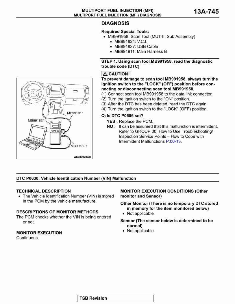
MULTIPORT FUEL INJECTION (MFI) DIAGNOSISMULTIPORT FUEL INJECTION (MFI) 13A-745
DIAGNOSISRequired Special Tools:• MB991958: Scan Tool (MUT-III Sub Assembly)
• MB991824: V.C.I.• MB991827: USB Cable• MB991911: Main Harness B
STEP 1. Using scan tool MB991958, read the diagnostic trouble code (DTC)
CAUTIONTo prevent damage to scan tool MB991958, always turn the ignition switch to the "LOCK" (OFF) position before con-necting or disconnecting scan tool MB991958.(1) Connect scan tool MB991958 to the data link connector.(2) Turn the ignition switch to the "ON" position.(3) After the DTC has been deleted, read the DTC again.(4) Turn the ignition switch to the "LOCK" (OFF) position.Q: Is DTC P0606 set?
YES : Replace the PCM.NO : It can be assumed that this malfunction is intermittent.
Refer to GROUP 00, How to Use Troubleshooting/Inspection Service Points − How to Cope with Intermittent Malfunctions P.00-13.
DTC P0630: Vehicle Identification Number (VIN) Malfunction
.
TECHNICAL DESCRIPTION• The Vehicle Identification Number (VIN) is stored
in the PCM by the vehicle manufacture..
DESCRIPTIONS OF MONITOR METHODSThe PCM checks whether the VIN is being entered
or not..
MONITOR EXECUTIONContinuous
.
MONITOR EXECUTION CONDITIONS (Other monitor and Sensor)Other Monitor (There is no temporary DTC stored
in memory for the item monitored below)• Not applicable
Sensor (The sensor below is determined to be normal)
• Not applicable.
AK302970AB
MB991911
MB991824
MB991827
TSB Revision

MULTIPORT FUEL INJECTION (MFI) DIAGNOSISMULTIPORT FUEL INJECTION (MFI)13A-746
DTC SET CONDITIONS
Logic Flow Chart
Check Conditions• Ignition switch is in "ON" position.• EEPROM is normal.
Judgement Criterion• VIN (current) has not been written.
.
OBD-II DRIVE CYCLE PATTERNNone..
TROUBLESHOOTING HINTS (The most likely causes for this code to be set are:)• PCM failed.
END
MALFUNCTION
YES
YES
NO
NO
VIN STORED
DTC & MILPREVIOUSLY SET
MONITORINGCONDITIONS
CLEAR DTC & MIL
START
AK401536
YES
GOOD
NO
TSB Revision

MULTIPORT FUEL INJECTION (MFI) DIAGNOSISMULTIPORT FUEL INJECTION (MFI) 13A-747
DIAGNOSISRequired Special Tools:• MB991958: Scan tool (MUT-III Sub Assembly)
• MB991824: V.C.I.• MB991827: USB Cable• MB991911: Main Harness B
STEP 1. Using scan tool MB991958, check VIN Information.CAUTION
To prevent damage to scan tool MB991958, always turn the ignition switch to the "LOCK" (OFF) position before con-necting or disconnecting scan tool MB991958.(1) Connect scan tool MB991958 to the data link connector.(2) Turn the ignition switch to the "ON" position.(3) Set scan tool MB991958 to the coding mode for VIN
Information.(4) Turn the ignition switch to the "LOCK" (OFF) position.Q: Has VIN (current) been written?
YES : Go to Step 2.NO : Write VIN. Then go to Step 3.
STEP 2. Using scan tool MB991958, read the diagnostic trouble code (DTC)(1) Turn the ignition switch to the "ON" position.(2) Check the diagnostic trouble code (DTC).(3) Turn the ignition switch to the "LOCK" (OFF) position.Q: Is DTC P0630 set?
YES : Replace the PCM.NO : It can be assumed that this malfunction is intermittent.
Refer to GROUP 00, How to Use Troubleshooting/Inspection Service Points − How to Cope with Intermittent Malfunctions P.00-13.
AK302970AB
MB991911
MB991824
MB991827
AK302970AB
MB991911
MB991824
MB991827
TSB Revision

MULTIPORT FUEL INJECTION (MFI) DIAGNOSISMULTIPORT FUEL INJECTION (MFI)13A-748
STEP 3. Using scan tool MB991958, read the diagnostic trouble code (DTC)(1) Turn the ignition switch to the "ON" position.(2) Check the diagnostic trouble code (DTC).(3) Turn the ignition switch to the "LOCK" (OFF) position.Q: Is DTC P0630 set?
YES : Replace the PCM.NO : The inspection is complete.
DTC P0638: Throttle Actuator Control Motor Circuit Range/Performance Problem
.
Throttle Actuator Control Motor Circuit• Refer to, DTC P0657 − Throttle Actuator Control
Motor Relay Circuit P.13A-761.• Refer to, DTC P2101 − Throttle Actuator Control
Motor Magneto Malfunction P.13A-794..
CIRCUIT OPERATION• Refer to, DTC P0657 − Throttle Actuator Control
Motor Relay Circuit P.13A-761.• Refer to, DTC P2101 − Throttle Actuator Control
Motor Magneto Malfunction P.13A-794..
TECHNICAL DESCRIPTION• PCM checks the electronic controlled throttle sys-
tem for abnormal conditions..
DESCRIPTIONS OF MONITOR METHODSDifference between throttle position sensor (main)
output and target opening is greater than the specified value.
.
MONITOR EXECUTIONContinuous.
MONITOR EXECUTION CONDITIONS (Other monitor and Sensor)Other Monitor (There is no temporary DTC stored
in memory for the item monitored below)• Not applicable
Sensor (The sensor below is determined to be normal)
• Not applicable.
DTC SET CONDITIONSCheck Conditions• Battery positive voltage is higher than 8.3 volts.• Throttle position sensor (main) output voltage is
between 0.35 and 4.8 volts.• Drop of throttle position sensor (main) output volt-
age per 100 milliseconds is more than 0.04 volt.
Judgement Criterion• Throttle position sensor (main) output voltage has
continued to be higher than the target throttle position sensor (main) voltage by 0.5 volt or more for 0.5 second.
Check Conditions• Battery positive voltage is higher than 8.3 volts.• Throttle position sensor (main) output voltage is
between 0.35 and 4.8 volts.
AK302970AB
MB991911
MB991824
MB991827
TSB Revision

MULTIPORT FUEL INJECTION (MFI) DIAGNOSISMULTIPORT FUEL INJECTION (MFI) 13A-749
Judgement Criterion• Difference between throttle position sensor
(main) output voltage and target throttle position sensor (main) voltage is 1 volt or higher for 1 sec-onds.
.
OBD-II DRIVE CYCLE PATTERNNone..
TROUBLESHOOTING HINTS (The most likely causes for this code to be set are:)• Throttle valve return spring failed.
• Throttle actuator control motor relay failed or mal-adjusted.
• Open or shorted throttle actuator control motor relay circuit, harness damage, or connector dam-age.
• Throttle valve operation failed.• Throttle actuator control motor failed.• Harness damage in throttle actuator control
motor circuit, or connector damage.• PCM failed.
DIAGNOSISRequired Special Tools:• MB991958: Scan Tool (MUT-III Sub Assembly)
• MB991824: V.C.I.• MB991827: USB Cable• MB991911: Main Harness B
STEP 1. Using scan tool MB991958, check data list item 9A: Throttle Position Sensor (main) Mid Opening Learning Value.
CAUTIONTo prevent damage to scan tool MB991958, always turn the ignition switch to the "LOCK"(OFF) position before con-necting or disconnecting scan tool MB991958.(1) Connect scan tool MB991958 to the data link connector.(2) Turn the ignition switch to the "ON" position.(3) Set scan tool MB991958 to the data reading mode for item
9A, Throttle position sensor (main) mid opening learning value.• Check that it is 4 volts or less.
(4) Turn the ignition switch to the "LOCK"(OFF) position.Q: Is voltage 4 volts or less?
YES : Go to Step 2.NO : Replace the throttle body assembly. Then go to Step
17.
AK302970AB
MB991911
MB991824
MB991827
TSB Revision

MULTIPORT FUEL INJECTION (MFI) DIAGNOSISMULTIPORT FUEL INJECTION (MFI)13A-750
STEP 2. Check harness connector B-23X at throttle actuator control motor relay for damage.Q: Is the harness connector in good condition?
YES : Go to Step 3.NO : Repair or replace it. Refer to GROUP 00E, Harness
Connector Inspection P.00E-2. Then go to Step 17.
STEP 3. Check the throttle actuator control motor relay.(1) Remove the throttle actuator control motor relay.
(2) Check for continuity between the throttle actuator control motor relay side connector terminal No. 2 and No. 4.• There should be continuity (approximately 70 ohms).
(3) Use jumper wires to connect throttle actuator control motor relay side connector terminal No. 4 to the positive battery terminal and terminal No. 2 to the negative battery terminal.
(4) Check the continuity between the throttle actuator control motor relay side connector terminal No. 1 and No. 3 while connecting and disconnecting the jumper wire at the negative battery terminal.• Should be less than 2 ohms. (Negative battery terminal
connected.)• Should be open loop. (Negative battery terminal discon-
nected.)(5) Install the throttle actuator control motor relay.Q: Is the resistance normal?
YES : Go to Step 4.NO : Replace the throttle actuator control motor relay.
Then go to Step 17.
AK201172
2 134
B-23X
AB
CONNECTOR: B-23X
HARNESS CONNECTOR: COMPONENT SIDE
AK201172
2 134
B-23X
AB
CONNECTOR: B-23X
HARNESS CONNECTOR: COMPONENT SIDE
1 23 4
AK201380AC
THROTTLE ACTUATOR CONTROL MOTOR RELAYSIDE CONNECTOR
1 23 4
AK201381
THROTTLE ACTUATOR CONTROL MOTOR RELAYSIDE CONNECTOR
AC
TSB Revision

MULTIPORT FUEL INJECTION (MFI) DIAGNOSISMULTIPORT FUEL INJECTION (MFI) 13A-751
STEP 4. Measure the power supply voltage at throttle actuator control motor relay harness side connector B-23X(1) Disconnect the connector B-23X and measure at the
harness side.
(2) Measure the voltage between terminal No. 3 and ground.• Voltage should be battery positive voltage.
Q: Is battery positive voltage (approximately 12 volts) present?YES : Go to Step 5.NO : Check harness connector A-03 at intermediate
connector for damage, and repair or replace as required. Refer to GROUP 00E, Harness Connector Inspection P.00E-2. If intermediate connector A-03 is in good condition, repair it because of open circuit or short circuit to ground between fusible link (5) and throttle actuator control motor relay connector B-23X (terminal No. 3). Then go to Step 17.
STEP 5. Measure the power supply voltage at throttle actuator control motor relay harness side connector B-23X.(1) Disconnect the connector B-23X and measure at the
harness side.(2) Turn the ignition switch to the "ON" position.
(3) Measure the voltage between terminal No. 4 and ground.• Voltage should be battery positive voltage.
(4) Turn the ignition switch to the "LOCK"(OFF) position.Q: Is battery positive voltage (approximately 12 volts)
present?YES : Go to Step 7.NO : Go to Step 6.
AK201172
2 134
B-23X
AB
CONNECTOR: B-23X
HARNESS CONNECTOR: COMPONENT SIDE
2 134
AK401162AC
B-23X HARNESSCONNECTOR:COMPONENT SIDE
AK201172
2 134
B-23X
AB
CONNECTOR: B-23X
HARNESS CONNECTOR: COMPONENT SIDE
2 134
AK201383
B-23X HARNESSCONNECTOR:COMPONFNT SIDE
AC
TSB Revision

MULTIPORT FUEL INJECTION (MFI) DIAGNOSISMULTIPORT FUEL INJECTION (MFI)13A-752
STEP 6. Check harness connector B-22X at MFI relay for damage.Q: Is the harness connector in good condition?
YES : Repair harness wire between MFI relay connector B-22X (terminal No. 1) and throttle actuator control motor relay connector B-23X (terminal No. 4) because of open circuit or short circuit to ground. Then go to Step 17.
NO : Repair or replace it. Refer to GROUP 00E, Harness Connector Inspection P.00E-2. Then go to Step 17.
STEP 7. Measure the power supply voltage at PCM harness side connector D-132.(1) Disconnect the connector D-132 and measure at the
harness side.(2) Turn the ignition switch to the "ON" position.
(3) Measure the voltage between terminal No. 15 and ground.• Voltage should be battery positive voltage.
(4) Turn the ignition switch to the "LOCK"(OFF) position.Q: Is battery positive voltage (approximately 12 volts)
present?YES : Go to Step 8.NO : Repair harness wire between throttle actuator control
motor relay connector B-23X (terminal No. 2) and PCM connector D-132 (terminal No. 15) because of open circuit or short circuit to ground. Then go to Step 17.
AK200951
2 134
B-22X
AB
CONNECTOR: B-22X
HARNESS CONNECTOR: COMPONENT SIDE
AK200938
234567891
101415161718192021222324252627
111213
AB
CONNECTOR: D-132
HARNESS CONNECTOR: COMPONENT SIDE
PCM
D-132(GR)
234567891
101415161718192021222324252627
111213
AK201447
D-132 HARNESS CONNECTOR: COMPONENT SIDE
AB
TSB Revision
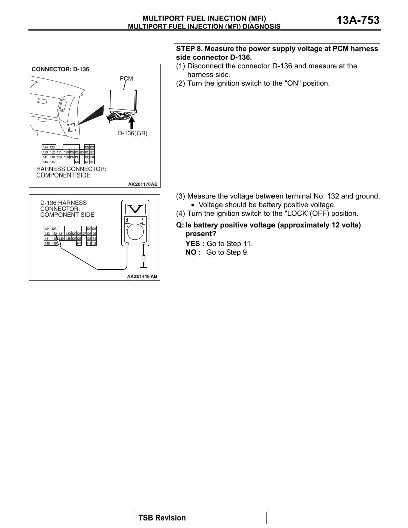
MULTIPORT FUEL INJECTION (MFI) DIAGNOSISMULTIPORT FUEL INJECTION (MFI) 13A-753
STEP 8. Measure the power supply voltage at PCM harness side connector D-136.(1) Disconnect the connector D-136 and measure at the
harness side.(2) Turn the ignition switch to the "ON" position.
(3) Measure the voltage between terminal No. 132 and ground.• Voltage should be battery positive voltage.
(4) Turn the ignition switch to the "LOCK"(OFF) position.Q: Is battery positive voltage (approximately 12 volts)
present?YES : Go to Step 11.NO : Go to Step 9.
AK201170
121122123124
125126127128129130131132133
134135136137138139140141
142143144145146
CONNECTOR: D-136
PCM
D-136(GR)
HARNESS CONNECTOR: COMPONENT SIDE
AB
121122123124
125126127128129130131132133
134135136137138139140141
142143144145146
AK201448 AB
D-136 HARNESS CONNECTOR: COMPONENT SIDE
TSB Revision

MULTIPORT FUEL INJECTION (MFI) DIAGNOSISMULTIPORT FUEL INJECTION (MFI)13A-754
STEP 9. Check for open circuit and short circuit to ground between throttle actuator control motor relay connector B-23X (terminal No. 1) and PCM connector D-136 (terminal No. 132).Q: Is the harness wire in good condition?
YES : Go to Step 10.NO : Repair it. Then go to Step 17.
AK201172
2 134
B-23X
AB
CONNECTOR: B-23X
HARNESS CONNECTOR: COMPONENT SIDE
AK201170
121122123124
125126127128129130131132133
134135136137138139140141
142143144145146
CONNECTOR: D-136
PCM
D-136(GR)
HARNESS CONNECTOR: COMPONENT SIDE
AB
TSB Revision

MULTIPORT FUEL INJECTION (MFI) DIAGNOSISMULTIPORT FUEL INJECTION (MFI) 13A-755
STEP 10. Check for harness damage between MFI relay connector B-22X (terminal No. 1) and throttle actuator control motor relay connector B-23X (terminal No. 4).Q: Is the harness wire in good condition?
YES : Repair harness wire between throttle actuator control motor relay connector B-23X (terminal No. 2) and PCM connector D-132 (terminal No. 15) because of harness damage. Then go to Step 17.
NO : Repair it. Then go to Step 17.
STEP 11. Check harness connectors D-132 and D-136 at PCM for damage.Q: Are the harness connectors in good condition?
YES : Go to Step 12.NO : Repair or replace them. Refer to GROUP 00E,
Harness Connector Inspection P.00E-2. Then go to Step 17.
AK200951
2 134
B-22X
AB
CONNECTOR: B-22X
HARNESS CONNECTOR: COMPONENT SIDE
AK201172
2 134
B-23X
AB
CONNECTOR: B-23X
HARNESS CONNECTOR: COMPONENT SIDE
234567891
101415161718192021222324252627
111213
AK201566
121122123124
125126127128129130131132133
134135136137138139140141
142143144145146
CONNECTORS: D-132, D-136
D-132 HARNESS CONNECTOR: COMPONENT SIDE
PCM
D-132(GR) D-136(GR)
AB
D-136 HARNESS CONNECTOR: COMPONENT SIDE
TSB Revision
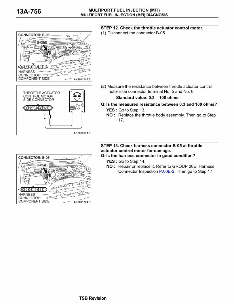
MULTIPORT FUEL INJECTION (MFI) DIAGNOSISMULTIPORT FUEL INJECTION (MFI)13A-756
STEP 12. Check the throttle actuator control motor.(1) Disconnect the connector B-05.
(2) Measure the resistance between throttle actuator control motor side connector terminal No. 5 and No. 6.
Standard value: 0.3 − 100 ohmsQ: Is the measured resistance between 0.3 and 100 ohms?
YES : Go to Step 13.NO : Replace the throttle body assembly. Then go to Step
17.
STEP 13. Check harness connector B-05 at throttle actuator control motor for damage.Q: Is the harness connector in good condition?
YES : Go to Step 14.NO : Repair or replace it. Refer to GROUP 00E, Harness
Connector Inspection P.00E-2. Then go to Step 17.
AK201174
16 5 4 3 2
B-05(B)
CONNECTOR: B-05
HARNESS CONNECTOR: COMPONENT SIDE AB
61 2 3 4 5
AK201513AB
THROTTLE ACTUATORCONTROL MOTORSIDE CONNECTOR
AK201174
16 5 4 3 2
B-05(B)
CONNECTOR: B-05
HARNESS CONNECTOR: COMPONENT SIDE AB
TSB Revision

MULTIPORT FUEL INJECTION (MFI) DIAGNOSISMULTIPORT FUEL INJECTION (MFI) 13A-757
STEP 14. Check for harness damage between throttle actuator control motor connector B-05 (terminal No. 6) and PCM connector D-136 (terminal No. 133).Q: Is the harness wire in good condition?
YES : Go to Step 15.NO : Repair it. Then go to Step 17.
AK201174
16 5 4 3 2
B-05(B)
CONNECTOR: B-05
HARNESS CONNECTOR: COMPONENT SIDE AB
AK201170
121122123124
125126127128129130131132133
134135136137138139140141
142143144145146
CONNECTOR: D-136
PCM
D-136(GR)
HARNESS CONNECTOR: COMPONENT SIDE
AB
TSB Revision

MULTIPORT FUEL INJECTION (MFI) DIAGNOSISMULTIPORT FUEL INJECTION (MFI)13A-758
STEP 15. Check for harness damage between throttle actuator control motor connector B-05 (terminal No. 5) and PCM connector D-136 (terminal No. 141).Q: Is the harness wire in good condition?
YES : Go to Step 16.NO : Repair it. Then go to Step 17.
STEP 16. Using scan tool MB991958, read the diagnostic trouble code (DTC).
CAUTIONTo prevent damage to scan tool MB991958, always turn the ignition switch to the "LOCK"(OFF) position before con-necting or disconnecting scan tool MB991958.(1) Connect scan tool MB991958 to the data link connector.(2) Turn the ignition switch to the "ON" position.(3) After the DTC has been deleted, read the DTC again.(4) Turn the ignition switch to the "LOCK"(OFF) position.Q: Is DTC P0638 set?
YES : Replace the PCM. Then go to Step 17.NO : It can be assumed that this malfunction is intermittent.
Refer to GROUP 00, How to Use Troubleshooting/Inspection Service Points.
AK201174
16 5 4 3 2
B-05(B)
CONNECTOR: B-05
HARNESS CONNECTOR: COMPONENT SIDE AB
AK201170
121122123124
125126127128129130131132133
134135136137138139140141
142143144145146
CONNECTOR: D-136
PCM
D-136(GR)
HARNESS CONNECTOR: COMPONENT SIDE
AB
AK302970AB
MB991911
MB991824
MB991827
TSB Revision

MULTIPORT FUEL INJECTION (MFI) DIAGNOSISMULTIPORT FUEL INJECTION (MFI) 13A-759
STEP 17. Using scan tool MB991958, read the diagnostic trouble code (DTC).(1) Connect scan tool MB991958 to the data link connector.(2) Turn the ignition switch to the "ON" position.(3) After the DTC has been deleted, read the DTC again.(4) Turn the ignition switch to the "LOCK"(OFF) position.Q: Is DTC P0638 set?
YES : Retry the troubleshooting.NO : The inspection is complete.
DTC P0642: Throttle Position Sensor Power Supply
.
TECHNICAL DESCRIPTION• PCM checks the throttle position sensor power
voltage for abnormal conditions..
DESCRIPTIONS OF MONITOR METHODSThrottle position sensor source voltage is smaller
than the specified value..
MONITOR EXECUTIONContinuous.
MONITOR EXECUTION CONDITIONS (Other monitor and Sensor)Other Monitor (There is no temporary DTC stored
in memory for the item monitored below)• Not applicable
Sensor (The sensor below is determined to be normal)
• Not applicable.
DTC SET CONDITIONSCheck Condition• Battery positive voltage is higher than 6.3 volts.
Judgement Criterion• Throttle position sensor power voltage should be
4.1 volts or lower for 0.5 second..
OBD-II DRIVE CYCLE PATTERNNone..
TROUBLESHOOTING HINTS (The most likely causes for this code to be set are:)• PCM failed.
AK302970AB
MB991911
MB991824
MB991827
TSB Revision
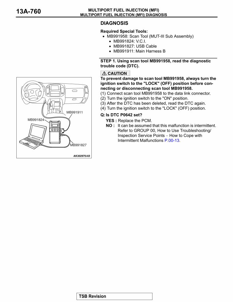
MULTIPORT FUEL INJECTION (MFI) DIAGNOSISMULTIPORT FUEL INJECTION (MFI)13A-760
DIAGNOSISRequired Special Tools:• MB991958: Scan Tool (MUT-III Sub Assembly)
• MB991824: V.C.I.• MB991827: USB Cable• MB991911: Main Harness B
STEP 1. Using scan tool MB991958, read the diagnostic trouble code (DTC).
CAUTIONTo prevent damage to scan tool MB991958, always turn the ignition switch to the "LOCK" (OFF) position before con-necting or disconnecting scan tool MB991958.(1) Connect scan tool MB991958 to the data link connector.(2) Turn the ignition switch to the "ON" position.(3) After the DTC has been deleted, read the DTC again.(4) Turn the ignition switch to the "LOCK" (OFF) position.Q: Is DTC P0642 set?
YES : Replace the PCM.NO : It can be assumed that this malfunction is intermittent.
Refer to GROUP 00, How to Use Troubleshooting/Inspection Service Points − How to Cope with Intermittent Malfunctions P.00-13.
AK302970AB
MB991911
MB991824
MB991827
TSB Revision

MULTIPORT FUEL INJECTION (MFI) DIAGNOSISMULTIPORT FUEL INJECTION (MFI) 13A-761
DTC P0657: Throttle Actuator Control Motor Relay Circuit Malfunction
AK501067
1 2 3 4 5 67 8 9 10 11 12
1 23 4
1 23 4
1 2 35 6 7 8 9
4
2021 22 232425 2627
1011121314 15 161718 19
121122 123
125126127128129 130 131 132
134135 136137 138 139 140
142143 144 145
124
133
141
146
Throttle Actuator Control Motor Relay Circuit
THROTTLEACTUATORCONTROLMOTORRELAY
B-22X
B-23X
A-03(MU802611)
WH
ITE
-B
LAC
K
WH
ITE
-B
LAC
K
WHITE-BLACK
WH
ITE
-B
LAC
K
TO PCM TO PCM
MFIRELAY
RE
D
RE
DR
ED
FUSIBLE LINK(5)
2 3
6
4 1
4 3
THROTTLE ACTUATORCONTROL MOTORPOWER SURCE
BR
OW
N-W
HIT
E
SK
Y B
LUE
2 1
15 132D-136D-132
POWERTRAIN CONTROL MODULE
D-132(MU803802)
D-136(MU803801)
OFF
ON
OFF
ON
TSB Revision

MULTIPORT FUEL INJECTION (MFI) DIAGNOSISMULTIPORT FUEL INJECTION (MFI)13A-762
.
CIRCUIT OPERATION• Battery positive voltage is applied to the throttle
actuator control motor relay terminal (terminal No. 3).
• Battery positive voltage is applied to the throttle actuator control motor relay terminal (terminal No. 4) from the MFI relay (terminal No. 1).
• PCM (terminal No. 15) applies current to the throttle actuator control motor relay coil by turning ON the power transistor in the unit in order to turn the relay ON.
• When the throttle actuator control motor relay turns ON, battery positive voltage is supplied by the throttle actuator control motor relay (terminal No. 1) to the PCM (terminal No. 132).
.
TECHNICAL DESCRIPTION• When the ignition switch ON signal is input into
the PCM, the PCM turns ON the throttle actuator control motor relay.
.
DESCRIPTIONS OF MONITOR METHODSThrottle actuator control motor relay circuit voltage is
smaller than the specified value..
MONITOR EXECUTIONContinuous.
MONITOR EXECUTION CONDITIONS (Other monitor and Sensor)Other Monitor (There is no temporary DTC stored
in memory for the item monitored below)• Not applicable
Sensor (The sensor below is determined to be normal)
• Not applicable.
DTC SET CONDITIONSCheck Condition• Battery positive voltage is higher than 8.3 volts.
Judgement Criterion• The power line voltage of the electronic controlled
throttle valve system should be 6.0 volts or less for 0.35 second.
.
OBD-II DRIVE CYCLE PATTERNNone..
TROUBLESHOOTING HINTS (The most likely causes for this code to be set are:)• Throttle actuator control motor relay failed.• Open or shorted throttle actuator control motor
relay circuit, harness damage, or connector dam-age.
• PCM failed.
AK201046
A-03(B)
AB
CONNECTOR: A-03
AK201171
B-23X
AB
CONNECTOR: B-23X
THROTTLE ACTUATORCONTROL MOTOR RELAY
AK201039
MFI RELAY
B-22X
AB
CONNECTOR: B-22X
AK201565
CONNECTORS: D-132, D-136
AB
PCM
D-132(GR) D-136(GR)
TSB Revision

MULTIPORT FUEL INJECTION (MFI) DIAGNOSISMULTIPORT FUEL INJECTION (MFI) 13A-763
DIAGNOSISRequired Special Tools:• MB991958: Scan Tool (MUT-III Sub Assembly)
• MB991824: V.C.I.• MB991827: USB Cable• MB991911: Main Harness B
STEP 1. Check harness connector B-23X at throttle actuator control motor relay for damage.Q: Is the harness connector in good condition?
YES : Go to Step 2.NO : Repair or replace it. Refer to GROUP 00E, Harness
Connector Inspection P.00E-2. Then go to Step 14.
STEP 2. Check the throttle actuator control motor relay.(1) Remove the throttle actuator control motor relay.
(2) Check for continuity between the throttle actuator control motor relay side connector terminal No. 2 and No. 4.• There should be continuity (approximately 70 ohms).
AK201172
2 134
B-23X
AB
CONNECTOR: B-23X
HARNESS CONNECTOR: COMPONENT SIDE
AK201172
2 134
B-23X
AB
CONNECTOR: B-23X
HARNESS CONNECTOR: COMPONENT SIDE
1 23 4
AK201380AC
THROTTLE ACTUATOR CONTROL MOTOR RELAYSIDE CONNECTOR
TSB Revision

MULTIPORT FUEL INJECTION (MFI) DIAGNOSISMULTIPORT FUEL INJECTION (MFI)13A-764
(3) Use jumper wires to connect throttle actuator control motor relay side connector terminal No. 4 to the positive battery terminal and terminal No. 2 to the negative battery terminal.
(4) Check the continuity between the throttle actuator control motor relay side connector terminal No. 1 and No. 3 while connecting and disconnecting the jumper wire at the negative battery terminal.• Should be less than 2 ohms. (Negative battery terminal
connected.)• Should be open loop. (Negative battery terminal discon-
nected.)(5) Install the throttle actuator control motor relay.Q: Is the resistance normal?
YES : Go to Step 3.NO : Replace the throttle actuator control motor relay.
Then go to Step 14.
STEP 3. Measure the power supply voltage at throttle actuator control motor relay harness side connector B-23X(1) Disconnect the connector B-23X and measure at the
harness side.
(2) Measure the voltage between terminal No. 3 and ground.• Voltage should be battery positive voltage.
Q: Is battery positive voltage (approximately 12 volts) present?YES : Go to Step 4.NO : Check harness connector A-03 at intermediate
connector for damage, and repair or replace as required. Refer to GROUP 00E, Harness Connector Inspection P.00E-2. If intermediate connector A-03 is in good condition, repair it because of open circuit or short circuit to ground between fusible link (5) and throttle actuator control motor relay connector B-23X (terminal No. 3). Then go to Step 14.
1 23 4
AK201381
THROTTLE ACTUATOR CONTROL MOTOR RELAYSIDE CONNECTOR
AC
AK201172
2 134
B-23X
AB
CONNECTOR: B-23X
HARNESS CONNECTOR: COMPONENT SIDE
2 134
AK401162AC
B-23X HARNESSCONNECTOR:COMPONENT SIDE
TSB Revision

MULTIPORT FUEL INJECTION (MFI) DIAGNOSISMULTIPORT FUEL INJECTION (MFI) 13A-765
STEP 4. Measure the power supply voltage at throttle actuator control motor relay harness side connector B-23X.(1) Disconnect the connector B-23X and measure at the
harness side.(2) Turn the ignition switch to the "ON" position.
(3) Measure the voltage between terminal No. 4 and ground.• Voltage should be battery positive voltage.
(4) Turn the ignition switch to the "LOCK" (OFF) position.Q: Is battery positive voltage (approximately 12 volts)
present?YES : Go to Step 6.NO : Go to Step 5.
STEP 5. Check harness connector B-22X at MFI relay for damage.Q: Is the harness connector in good condition?
YES : Repair harness wire between MFI relay connector B-22X (terminal No. 1) and throttle actuator control motor relay connector B-23X (terminal No. 4) because of open circuit or short circuit to ground. Then go to Step 14.
NO : Repair or replace it. Refer to GROUP 00E, Harness Connector Inspection P.00E-2. Then go to Step 14.
AK201172
2 134
B-23X
AB
CONNECTOR: B-23X
HARNESS CONNECTOR: COMPONENT SIDE
2 134
AK201383
B-23X HARNESSCONNECTOR:COMPONFNT SIDE
AC
AK200951
2 134
B-22X
AB
CONNECTOR: B-22X
HARNESS CONNECTOR: COMPONENT SIDE
TSB Revision
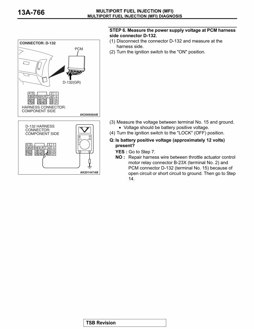
MULTIPORT FUEL INJECTION (MFI) DIAGNOSISMULTIPORT FUEL INJECTION (MFI)13A-766
STEP 6. Measure the power supply voltage at PCM harness side connector D-132.(1) Disconnect the connector D-132 and measure at the
harness side.(2) Turn the ignition switch to the "ON" position.
(3) Measure the voltage between terminal No. 15 and ground.• Voltage should be battery positive voltage.
(4) Turn the ignition switch to the "LOCK" (OFF) position.Q: Is battery positive voltage (approximately 12 volts)
present?YES : Go to Step 7.NO : Repair harness wire between throttle actuator control
motor relay connector B-23X (terminal No. 2) and PCM connector D-132 (terminal No. 15) because of open circuit or short circuit to ground. Then go to Step 14.
AK200938
234567891
101415161718192021222324252627
111213
AB
CONNECTOR: D-132
HARNESS CONNECTOR: COMPONENT SIDE
PCM
D-132(GR)
234567891
101415161718192021222324252627
111213
AK201447
D-132 HARNESS CONNECTOR: COMPONENT SIDE
AB
TSB Revision

MULTIPORT FUEL INJECTION (MFI) DIAGNOSISMULTIPORT FUEL INJECTION (MFI) 13A-767
STEP 7. Measure the power supply voltage at PCM harness side connector D-136.(1) Disconnect the connector D-136 and measure at the
harness side.(2) Turn the ignition switch to the "ON" position.
(3) Measure the voltage between terminal No. 132 and ground.• Voltage should be battery positive voltage.
(4) Turn the ignition switch to the "LOCK" (OFF) position.Q: Is battery positive voltage (approximately 12 volts)
present?YES : Go to Step 10.NO : Go to Step 8.
AK201170
121122123124
125126127128129130131132133
134135136137138139140141
142143144145146
CONNECTOR: D-136
PCM
D-136(GR)
HARNESS CONNECTOR: COMPONENT SIDE
AB
121122123124
125126127128129130131132133
134135136137138139140141
142143144145146
AK201448 AB
D-136 HARNESS CONNECTOR: COMPONENT SIDE
TSB Revision

MULTIPORT FUEL INJECTION (MFI) DIAGNOSISMULTIPORT FUEL INJECTION (MFI)13A-768
STEP 8. Check for open circuit and short circuit to ground between throttle actuator control motor relay connector B-23X (terminal No. 1) and PCM connector D-136 (terminal No. 132).Q: Is the harness wire in good condition?
YES : Go to Step 9.NO : Repair it. Then go to Step 14.
AK201172
2 134
B-23X
AB
CONNECTOR: B-23X
HARNESS CONNECTOR: COMPONENT SIDE
AK201170
121122123124
125126127128129130131132133
134135136137138139140141
142143144145146
CONNECTOR: D-136
PCM
D-136(GR)
HARNESS CONNECTOR: COMPONENT SIDE
AB
TSB Revision

MULTIPORT FUEL INJECTION (MFI) DIAGNOSISMULTIPORT FUEL INJECTION (MFI) 13A-769
STEP 9. Check for harness damage between MFI relay connector B-22X (terminal No. 1) and throttle actuator control motor relay connector B-23X (terminal No. 4).Q: Is the harness wire in good condition?
YES : Repair harness wire between throttle actuator control motor relay connector B-23X (terminal No. 2) and PCM connector D-132 (terminal No. 15) because of harness damage. Then go to Step 14.
NO : Repair it. Then go to Step 14.
STEP 10. Check harness connectors D-132 and D-136 at PCM for damage.Q: Are the harness connectors in good condition?
YES : Go to Step 11.NO : Repair or replace them. Refer to GROUP 00E,
Harness Connector Inspection P.00E-2. Then go to Step 14.
AK200951
2 134
B-22X
AB
CONNECTOR: B-22X
HARNESS CONNECTOR: COMPONENT SIDE
AK201172
2 134
B-23X
AB
CONNECTOR: B-23X
HARNESS CONNECTOR: COMPONENT SIDE
234567891
101415161718192021222324252627
111213
AK201566
121122123124
125126127128129130131132133
134135136137138139140141
142143144145146
CONNECTORS: D-132, D-136
D-132 HARNESS CONNECTOR: COMPONENT SIDE
PCM
D-132(GR) D-136(GR)
AB
D-136 HARNESS CONNECTOR: COMPONENT SIDE
TSB Revision

MULTIPORT FUEL INJECTION (MFI) DIAGNOSISMULTIPORT FUEL INJECTION (MFI)13A-770
STEP 11. Check for harness damage between fusible link (5) and throttle actuator control motor relay connector B-23X (terminal No. 3).
NOTE: Check harness after checking intermediate connector A-03. If intermediate connector is damaged, repair or replace it. Refer to GROUP 00E, Harness Connector Inspection P.00E-2. Then go to Step 14.Q: Is the harness wire in good condition?
YES : Go to Step 12.NO : Repair it. Then go to Step 14.
STEP 12. Check for harness damage between throttle actuator control motor relay connector B-23X (terminal No. 1) and PCM connector D-136 (terminal No. 132).Q: Is the harness wire in good condition?
YES : Go to Step 13.NO : Repair it. Then go to Step 14.
AK201172
2 134
B-23X
AB
CONNECTOR: B-23X
HARNESS CONNECTOR: COMPONENT SIDE
AK201172
2 134
B-23X
AB
CONNECTOR: B-23X
HARNESS CONNECTOR: COMPONENT SIDE
AK201170
121122123124
125126127128129130131132133
134135136137138139140141
142143144145146
CONNECTOR: D-136
PCM
D-136(GR)
HARNESS CONNECTOR: COMPONENT SIDE
AB
TSB Revision

MULTIPORT FUEL INJECTION (MFI) DIAGNOSISMULTIPORT FUEL INJECTION (MFI) 13A-771
STEP 13. Using scan tool MB991958, read the diagnostic trouble code (DTC).
CAUTIONTo prevent damage to scan tool MB991958, always turn the ignition switch to the "LOCK" (OFF) position before con-necting or disconnecting scan tool MB991958.(1) Connect scan tool MB991958 to the data link connector.(2) Turn the ignition switch to the "ON" position.(3) After the DTC has been deleted, read the DTC again.(4) Turn the ignition switch to the "LOCK" (OFF) position.Q: Is DTC P0657 set?
YES : Replace the PCM. Then go to Step 14.NO : It can be assumed that this malfunction is intermittent.
Refer to GROUP 00, How to Use Troubleshooting/Inspection Service Points − How to Cope with Intermittent Malfunctions P.00-13.
STEP 14. Using scan tool MB991958, read the diagnostic trouble code (DTC).(1) Connect scan tool MB991958 to the data link connector.(2) Turn the ignition switch to the "ON" position.(3) After the DTC has been deleted, read the DTC again.(4) Turn the ignition switch to the "LOCK" (OFF) position.Q: Is DTC P0657 set?
YES : Retry the troubleshooting.NO : The inspection is complete.
AK302970AB
MB991911
MB991824
MB991827
AK302970AB
MB991911
MB991824
MB991827
TSB Revision

MULTIPORT FUEL INJECTION (MFI) DIAGNOSISMULTIPORT FUEL INJECTION (MFI)13A-772
DTC P0660: Intake Manifold Tuning Solenoid Circuit Malfunction
AK400988
1 2
1 2 35 6 7 8 9
4
2021 22 232425 2627
1011121314 15 161718 19
1 23 4
WH
ITE
-B
LAC
K
WH
ITE
-BLA
CK
GR
EE
N-W
HIT
ER
ED
MFI RELAY
4
2
1
B-22X
2
4
3
1
POWERTRAINCONTROLMODULE (PCM)
INTAKE MANIFOLDTUNING SOLENOID
B-04(MU802722)
Intake Manifold Tuning Solenoid Circuit
D-132(MU803802)
TO PCM
FUSIBLE LINK (5)
AK200970AB
B-04(B)
CONNECTOR: B-04
VARIABLE INDUCTION CONTROL SOLENOID
AK201038
CONNECTOR: D-132
AB
PCM
D-132(GR)
TSB Revision

MULTIPORT FUEL INJECTION (MFI) DIAGNOSISMULTIPORT FUEL INJECTION (MFI) 13A-773
.
CIRCUIT OPERATION• The intake manifold tuning solenoid power is sup-
plied from the MFI relay (terminal No. 1).• The PCM controls the intake manifold tuning
solenoid ground by turning the power transistor in the PCM ON and OFF.
.
TECHNICAL DESCRIPTION• To judge if there is open circuit in the intake man-
ifold tuning solenoid drive circuit, PCM measures the surge voltage of the intake manifold tuning solenoid coil.
• The PCM drives the intake manifold tuning sole-noid. After the solenoid is turned off, the PCM will check if the solenoid coil produces a surge volt-age (battery positive voltage +2 volts).
.
DTC SET CONDITIONSCheck Conditions• Engine is being cranked.• Battery positive voltage is between 10 and 16
volts.
Judgement Criterion• The intake manifold tuning solenoid coil surge
voltage (battery positive voltage + 2 volts) is not detected for 0.2 second.
Check Conditions• Battery positive voltage is between 10 and 16
volts.• Intake manifold tuning solenoid is ON.
• More than 1 second has elapsed after the above mentioned conditions have been met.
Judgement Criterion• The intake manifold tuning solenoid coil surge
voltage (battery positive voltage + 2 volts) is not detected for 1 second after the intake manifold tuning solenoid is turned OFF.
.
TROUBLESHOOTING HINTS (The most likely causes for this code to be set are:)• Intake manifold tuning solenoid failed.• Open or shorted intake manifold tuning solenoid
circuit, harness damage, or connector damage.• PCM failed.
AK201039
MFI RELAY
B-22X
AB
CONNECTOR: B-22X
TSB Revision

MULTIPORT FUEL INJECTION (MFI) DIAGNOSISMULTIPORT FUEL INJECTION (MFI)13A-774
DIAGNOSISRequired Special Tools:• MB991958: Scan Tool (MUT-III Sub Assembly)
• MB991824: V.C.I.• MB991827: USB Cable• MB991911: Main Harness B
STEP 1. Using scan tool MB991958, check actuator test item 11: Intake Manifold Tuning Solenoid.
CAUTIONTo prevent damage to scan tool MB991958, always turn the ignition switch to the "LOCK" (OFF) position before con-necting or disconnecting scan tool MB991958.(1) Connect scan tool MB991958 to the data link connector.(2) Turn the ignition switch to the "ON" position.(3) Set scan tool MB991958 to the actuator test mode for item
11, Intake manifold tuning solenoid.• An operation sound should be heard and vibration
should be felt when the intake manifold tuning solenoid is operated.
(4) Turn the ignition switch to the "LOCK" (OFF) position.Q: Is the solenoid operating properly?
YES : It can be assumed that this malfunction is intermittent. Refer to GROUP 00, How to Use Troubleshooting/Inspection Service Points − How to Cope with Intermittent Malfunctions P.00-13.
NO : Go to Step 2.
STEP 2. Check harness connector B-04 at the intake manifold tuning solenoid for damage.Q: Is the harness connector in good condition?
YES : Go to Step 3.NO : Repair or replace it. Refer to GROUP 00E, Harness
Connector Inspection P.00E-2. Then go to Step 12.
AK302970AB
MB991911
MB991824
MB991827
AK200971
12
AB
HARNESS CONNECTOR: COMPONENT SIDE
CONNECTOR: B-04
B-04(B)
TSB Revision

MULTIPORT FUEL INJECTION (MFI) DIAGNOSISMULTIPORT FUEL INJECTION (MFI) 13A-775
STEP 3. Check the intake manifold tuning solenoid.(1) Disconnect the intake manifold tuning solenoid connector
B-04.
(2) Measure the resistance between intake manifold tuning solenoid side connector terminal No. 1 and No. 2.
Standard value: 29 − 35 ohms [at 20°C (68°F)]Q: Is the resistance between 29 and 35 ohms [at 20°C
(68°F)]?YES : Go to Step 4.NO : Replace the intake manifold tuning solenoid. Then go
to Step 12.
STEP 4. Measure the power supply voltage at intake manifold tuning solenoid harness side connector B-04.(1) Disconnect the connector B-04 and measure at the harness
side.(2) Turn the ignition switch to the "ON" position.
(3) Measure the voltage between terminal No. 1 and ground.• Voltage should be battery positive voltage.
(4) Turn the ignition switch to the "LOCK" (OFF) position.Q: Is battery positive voltage (approximately 12 volts)
present?YES : Go to Step 6.NO : Go to Step 5.
AK200971
12
AB
HARNESS CONNECTOR: COMPONENT SIDE
CONNECTOR: B-04
B-04(B)
1 2
AK401159 AC
INTAKE MANIFOLDTUNING SOLENOIDSIDE CONNECTOR
AK200971
12
AB
HARNESS CONNECTOR: COMPONENT SIDE
CONNECTOR: B-04
B-04(B)
AK103038
12
B-04 HARNESS CONNECTOR: COMPONENT SIDE
AC
TSB Revision

MULTIPORT FUEL INJECTION (MFI) DIAGNOSISMULTIPORT FUEL INJECTION (MFI)13A-776
STEP 5. Check harness connector B-22X at MFI relay for damage.Q: Is the harness connector in good condition?
YES : Repair harness wire between MFI relay connector B-22X terminal No. 1 and intake manifold tuning solenoid connector B-04 terminal No. 1 because of open circuit or short circuit to ground. Then go to Step 12.
NO : Repair or replace it. Refer to GROUP 00E, Harness Connector Inspection P.00E-2. Then go to Step 12.
STEP 6. Measure the power supply voltage at PCM connector D-132 by backprobing.(1) Do not disconnect the connector D-132.(2) Turn the ignition switch to the "ON" position.
(3) Measure the voltage between terminal No. 4 and ground by backprobing.• Voltage should be battery positive voltage.
(4) Turn the ignition switch to the "LOCK" (OFF) position.Q: Is battery positive voltage (approximately 12 volts)
present?YES : Go to Step 9.NO : Go to Step 7.
AK200951
2 134
B-22X
AB
CONNECTOR: B-22X
HARNESS CONNECTOR: COMPONENT SIDE
AK200938
234567891
101415161718192021222324252627
111213
AB
CONNECTOR: D-132
HARNESS CONNECTOR: COMPONENT SIDE
PCM
D-132(GR)
AK201426
2 3 45 6 7 8 91
1014 15 161718 192021 22 232425 2627
111213
AB
D-132 HARNESS CONNECTOR: HARNESS SIDE
TSB Revision

MULTIPORT FUEL INJECTION (MFI) DIAGNOSISMULTIPORT FUEL INJECTION (MFI) 13A-777
STEP 7. Check harness connector D-132 at PCM for damage.Q: Is the harness connector in good condition?
YES : Go to Step 8.NO : Repair or replace it. Refer to GROUP 00E, Harness
Connector Inspection P.00E-2. Then go to Step 12.
STEP 8. Check for open circuit and short circuit to ground between intake manifold tuning solenoid connector B-04 (terminal No. 2) and PCM connector D-132 (terminal No. 4).Q: Is the harness wire in good condition?
YES : Replace the PCM. Then go to Step 12.NO : Repair it. Then go to Step 12.
AK200938
234567891
101415161718192021222324252627
111213
AB
CONNECTOR: D-132
HARNESS CONNECTOR: COMPONENT SIDE
PCM
D-132(GR)
AK200971
12
AB
HARNESS CONNECTOR: COMPONENT SIDE
CONNECTOR: B-04
B-04(B)
AK200938
234567891
101415161718192021222324252627
111213
AB
CONNECTOR: D-132
HARNESS CONNECTOR: COMPONENT SIDE
PCM
D-132(GR)
TSB Revision

MULTIPORT FUEL INJECTION (MFI) DIAGNOSISMULTIPORT FUEL INJECTION (MFI)13A-778
STEP 9. Check harness connector D-132 at PCM for damage.Q: Is the harness connector in good condition?
YES : Go to Step 10.NO : Repair or replace it. Refer to GROUP 00E, Harness
Connector Inspection P.00E-2. Then go to Step 12.
STEP 10. Check for harness damage between MFI relay connector B-22X (terminal No. 1) and intake manifold tuning solenoid connector B-04 (terminal No. 1).Q: Is the harness wire in good condition?
YES : Go to Step 11.NO : Repair it. Then go to Step 12.
AK200938
234567891
101415161718192021222324252627
111213
AB
CONNECTOR: D-132
HARNESS CONNECTOR: COMPONENT SIDE
PCM
D-132(GR)
AK200951
2 134
B-22X
AB
CONNECTOR: B-22X
HARNESS CONNECTOR: COMPONENT SIDE
AK200971
12
AB
HARNESS CONNECTOR: COMPONENT SIDE
CONNECTOR: B-04
B-04(B)
TSB Revision

MULTIPORT FUEL INJECTION (MFI) DIAGNOSISMULTIPORT FUEL INJECTION (MFI) 13A-779
STEP 11. Check for harness damage between intake manifold tuning solenoid connector B-04 (terminal No. 2) and PCM connector D-132 (terminal No. 4).Q: Is the harness wire in good condition?
YES : Replace the PCM. Then go to Step 12.NO : Repair it. Then go to Step 12.
STEP 12. Using scan tool MB991958, check actuator test item 11: Intake Manifold Tuning Solenoid.
CAUTIONTo prevent damage to scan tool MB991958, always turn the ignition switch to the "LOCK" (OFF) position before con-necting or disconnecting scan tool MB991958.(1) Connect scan tool MB991958 to the data link connector.(2) Turn the ignition switch to the "ON" position.(3) Set scan tool MB991958 to the actuator test mode for item
11, Intake manifold tuning solenoid.• An operation sound should be heard and vibration
should be felt when the intake manifold tuning solenoid is operated.
(4) Turn the ignition switch to the "LOCK" (OFF) position.Q: Is the solenoid operating properly?
YES : The inspection is complete.NO : Retry the troubleshooting.
AK200971
12
AB
HARNESS CONNECTOR: COMPONENT SIDE
CONNECTOR: B-04
B-04(B)
AK200938
234567891
101415161718192021222324252627
111213
AB
CONNECTOR: D-132
HARNESS CONNECTOR: COMPONENT SIDE
PCM
D-132(GR)
AK302970AB
MB991911
MB991824
MB991827
TSB Revision

MULTIPORT FUEL INJECTION (MFI) DIAGNOSISMULTIPORT FUEL INJECTION (MFI)13A-780
DTC P1530: A/C1 Switch Circuit Intermittent
.
TECHNICAL DESCRIPTION• The A/C controller <Manual A/C system> or the
A/C-ECU <Automatic A/C system> sends the "ON" signal of the A/C to the PCM.
• The A/C controller <Manual A/C system> or the A/C-ECU <Automatic A/C system> turns the A/C relay to "ON" position.
.
DTC SET CONDITIONSCheck Condition• Engine is running.
Judgement Criterion• The A/C switch repeats on-off switches 255 times
per second..
TROUBLESHOOTING HINTS (The most likely causes for this code to be set are:)• The A/C controller <Manual A/C system>• The A/C-ECU <Automatic A/C system>
DIAGNOSISRequired Special Tools:• MB991958: Scan tool (MUT-III Sub Assembly)
• MB991824: V.C.I.• MB991827: USB Cable• MB991911: Main Harness B
STEP 1. Using scan tool MB991958, read the diagnostic trouble code (DTC)
CAUTIONTo prevent damage to scan tool MB991958, always turn the ignition switch to the "LOCK"(OFF) position before con-necting or disconnecting scan tool MB991958.(1) Connect scan tool MB991958 to the data link connector.(2) Turn the ignition switch to the "ON" position.(3) After the DTC has been deleted, read the DTC again.(4) Turn the ignition switch to the "LOCK"(OFF) position.Q: Is DTC P1530 set?
YES : Replace the A/C controller <Manual A/C system> or the A/C-ECU <Automatic A/C system>.
NO : It can be assumed that this malfunction is intermittent. Refer to GROUP 00, How to Use Troubleshooting/Inspection Service Points − How to Cope with Intermittent Malfunctions P.00-13.
AK302970AB
MB991911
MB991824
MB991827
TSB Revision

MULTIPORT FUEL INJECTION (MFI) DIAGNOSISMULTIPORT FUEL INJECTION (MFI) 13A-781
DTC P1602: Communication Malfunction (between PCM Main Processor and System LSI)
.
TECHNICAL DESCRIPTION• PCM checks the communication lines for abnor-
mal conditions..
DESCRIPTIONS OF MONITOR METHODSCommunication between PCM main processor and
system LSI..
MONITOR EXECUTIONContinuous.
MONITOR EXECUTION CONDITIONS (Other monitor and Sensor)Other Monitor (There is no temporary DTC stored
in memory for the item monitored below)• Not applicable
Sensor (The sensor below is determined to be normal)
• Not applicable.
DTC SET CONDITIONSCheck Condition• Ignition switch is "ON" position.
Judgement Criterion• PCM detects an error in communication between
PCM main processor and system LSI for 0.07 second.
.
OBD-II DRIVE CYCLE PATTERNNone..
TROUBLESHOOTING HINTS (The most likely causes for this code to be set are:)• PCM failed.
DIAGNOSISRequired Special Tools:• MB991958: Scan Tool (MUT-III Sub Assembly)
• MB991824: V.C.I.• MB991827: USB Cable• MB991911: Main Harness B
STEP 1. Using scan tool MB991958, read the diagnostic trouble code (DTC)
CAUTIONTo prevent damage to scan tool MB991958, always turn the ignition switch to the "LOCK" (OFF) position before con-necting or disconnecting scan tool MB991958.(1) Connect scan tool MB991958 to the data link connector.(2) Turn the ignition switch to the "ON" position.(3) After the DTC has been deleted, read the DTC again.(4) Turn the ignition switch to the "LOCK" (OFF) position.Q: Is DTC P01602 set?
YES : Replace the PCM.NO : It can be assumed that this malfunction is intermittent.
Refer to GROUP 00, How to Use Troubleshooting/Inspection Service Points − How to Cope with Intermittent Malfunctions P.00-13.
AK302970AB
MB991911
MB991824
MB991827
TSB Revision
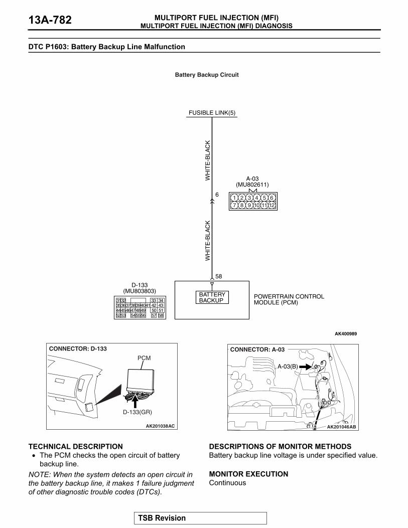
MULTIPORT FUEL INJECTION (MFI) DIAGNOSISMULTIPORT FUEL INJECTION (MFI)13A-782
DTC P1603: Battery Backup Line Malfunction
.
TECHNICAL DESCRIPTION• The PCM checks the open circuit of battery
backup line.NOTE: When the system detects an open circuit in the battery backup line, it makes 1 failure judgment of other diagnostic trouble codes (DTCs).
.
DESCRIPTIONS OF MONITOR METHODSBattery backup line voltage is under specified value..
MONITOR EXECUTIONContinuous.
AK400989
WH
ITE
-BLA
CK
WH
ITE
-BLA
CK
FUSIBLE LINK(5)
58
BATTERYBACKUP
POWERTRAIN CONTROLMODULE (PCM)
6
Battery Backup Circuit
3135363738394041 42 43444546474849 50 515253 545556 57 58
32 33 34
D-133(MU803803)
A-03(MU802611)
1 2 3 4 5 67 8 9 10 11 12
AK201038
CONNECTOR: D-133
AC
PCM
D-133(GR)
AK201046
A-03(B)
AB
CONNECTOR: A-03
TSB Revision

MULTIPORT FUEL INJECTION (MFI) DIAGNOSISMULTIPORT FUEL INJECTION (MFI) 13A-783
MONITOR EXECUTION CONDITIONS (Other monitor and Sensor)Other Monitor (There is no temporary DTC stored
in memory for the item monitored below)• Not applicable
Sensor (The sensor below is determined to be normal)
• Not applicable.
DTC SET CONDITIONS
Logic Flow Chart
.
Check Conditions• Engine starting sequence was completed.• Battery positive voltage is higher than 10 volts.
Judgement Criterion• Battery backup line voltage has continued to be
lower than 6 volts for 2 seconds..
OBD-II DRIVE CYCLE PATTERNNone..
TROUBLESHOOTING HINTS (The most likely causes for this code to be set are:)• Open or shorted battery backup line, harness
damage, or connector damage.• PCM failed.
START
MONITORINGCONDITIONS
CIRCUIT VOLTAGE
MALFUNCTION
CONTINUOUSFAILURE FOR 2secs
NO
YES
YES
NO< 6V
END
GOODNO
Yes
AK302959
TSB Revision

MULTIPORT FUEL INJECTION (MFI) DIAGNOSISMULTIPORT FUEL INJECTION (MFI)13A-784
DIAGNOSISRequired Special Tools:• MB991958: Scan Tool (MUT-III Sub Assembly)
• MB991824: V.C.I.• MB991827: USB Cable• MB991911: Main Harness B
STEP 1. Using scan tool MB991958, read the diagnostic trouble code (DTC).
CAUTIONTo prevent damage to scan tool MB991958, always turn the ignition switch to the "LOCK" (OFF) position before con-necting or disconnecting scan tool MB991958.(1) Connect scan tool MB991958 to the data link connector.(2) Turn the ignition switch to the "ON" position.(3) Erase the DTC.(4) Start the engine and run it at idle.(5) Read the DTC.(6) Turn the ignition switch to the "LOCK" (OFF) position.Q: Is DTC P1603 set?
YES : Go to Step 2.NO : The inspection is complete.
STEP 2. Measure the backup power supply voltage at PCM connector D-133 by backprobing.(1) Do not disconnect the PCM connector D-133.
AK302970AB
MB991911
MB991824
MB991827
AK200939
3132333435363738394041424344454647484952535455565758
5051
AB
CONNECTOR: D-133
HARNESS CONNECTOR: COMPONENT SIDE
PCM
D-133(GR)
TSB Revision

MULTIPORT FUEL INJECTION (MFI) DIAGNOSISMULTIPORT FUEL INJECTION (MFI) 13A-785
(2) Measure the voltage between terminal No. 58 and ground by backprobing.• Voltage should be battery positive voltage.
Q: Is battery positive voltage (approximately 12 volts) present?YES : Go to Step 5.NO : Go to Step 3.
STEP 3. Measure the backup power supply voltage at PCM harness side connector D-133.(1) Disconnect the PCM connector D-133 and measure at the
harness side.
(2) Measure the voltage between terminal No. 58 and ground.• Voltage should be battery positive voltage.
Q: Is battery positive voltage (approximately 12 volts) present?YES : Go to Step 4.NO : Check connector A-03 at intermediate connector for
damage, and repair or replace as required. Refer to GROUP 00E, Harness Connector Inspection P.00E-2. If intermediate connector is in good condition, repair harness wire between fusible link (5) and PCM connector D-133 (terminal No. 58) because of open circuit or short circuit to ground. Then go to Step 6.
AK201427
3135363738394041 42 43444546474849 50 515253 545556 57 58
32 33 34
AB
D-133 HARNESS CONNECTOR: HARNESS SIDE
AK200939
3132333435363738394041424344454647484952535455565758
5051
AB
CONNECTOR: D-133
HARNESS CONNECTOR: COMPONENT SIDE
PCM
D-133(GR)
AK201428
3132333435363738394041424344454647484952535455565758
5051
AB
D-133 HARNESS CONNECTOR: COMPONENT SIDE
TSB Revision

MULTIPORT FUEL INJECTION (MFI) DIAGNOSISMULTIPORT FUEL INJECTION (MFI)13A-786
STEP 4. Check harness connector D-133 at PCM for damage.Q: Is the harness connector in good condition?
YES : Check connector A-03 at intermediate connector for damage, and repair or replace as required. Refer to GROUP 00E, Harness Connector Inspection P.00E-2. If intermediate connector is in good condition, repair harness wire between fusible link (5) and PCM connector D-133 (terminal No. 58) because of harness damage. Then go to Step 6.
NO : Repair or replace it. Refer to GROUP 00E, Harness Connector Inspection P.00E-2. Then go to Step 6.
STEP 5. Check harness connector D-133 at PCM for damage.Q: Is the harness connector in good condition?
YES : Replace the PCM. Then go to Step 6.NO : Repair or replace it. Refer to GROUP 00E, Harness
Connector Inspection P.00E-2. Then go to Step 6.
AK200939
3132333435363738394041424344454647484952535455565758
5051
AB
CONNECTOR: D-133
HARNESS CONNECTOR: COMPONENT SIDE
PCM
D-133(GR)
AK200939
3132333435363738394041424344454647484952535455565758
5051
AB
CONNECTOR: D-133
HARNESS CONNECTOR: COMPONENT SIDE
PCM
D-133(GR)
TSB Revision

MULTIPORT FUEL INJECTION (MFI) DIAGNOSISMULTIPORT FUEL INJECTION (MFI) 13A-787
STEP 6. Using scan tool MB991958, read the diagnostic trouble code (DTC).
CAUTIONTo prevent damage to scan tool MB991958, always turn the ignition switch to the "LOCK" (OFF) position before con-necting or disconnecting scan tool MB991958.(1) Connect scan tool MB991958 to the data link connector.(2) Turn the ignition switch to the "ON" position.(3) Read the DTC.(4) Turn the ignition switch to the "LOCK" (OFF) position.Q: Is DTC P1603 set?
YES : Retry the troubleshooting.NO : The inspection is complete.
AK302970AB
MB991911
MB991824
MB991827
TSB Revision
RZiegler
NEXT>>
Related Documents