MITSUBISHI Mitsubishi Industrial Robot BFP-A5991-J CR2/CR2A/CR2B Controller INSTRUCTION MANUAL Controller setup, basic operation, and maintenance

Welcome message from author
This document is posted to help you gain knowledge. Please leave a comment to let me know what you think about it! Share it to your friends and learn new things together.
Transcript

MITSUBISHIMitsubishi Industrial Robot
BFP-A5991-J
CR2/CR2A/CR2B Controller INSTRUCTION MANUAL
Controller setup, basic operation, and maintenance
All teaching work must be carried out by an operator who has received special training. (This also applies to maintenance work with the power source turned ON.) → Enforcement of safety training
For teaching work, prepare a work plan related to the methods and procedures of oper-ating the robot, and to the measures to be taken when an error occurs or when restart-ing. Carry out work following this plan. (This also applies to maintenance work with the power source turned ON.) → Preparation of work plan
Prepare a device that allows operation to be stopped immediately during teaching work. (This also applies to maintenance work with the power source turned ON.) → Setting of emergency stop switch
During teaching work, place a sign indicating that teaching work is in progress on the start switch, etc. (This also applies to maintenance work with the power source turned ON.) → Indication of teaching work in progress
Provide a fence or enclosure during operation to prevent contact of the operator and robot. → Installation of safety fence
Establish a set signaling method to the related operators for starting work, and follow this method. → Signaling of operation start
As a principle turn the power OFF during maintenance work. Place a sign indicating that maintenance work is in progress on the start switch, etc. → Indication of maintenance work in progress
Before starting work, inspect the robot, emergency stop switch and other related devices, etc., and confirm that there are no errors. → Inspection before starting work
CAUTION
CAUTION
WARNING
CAUTION
WARNING
CAUTION
CAUTION
CAUTION
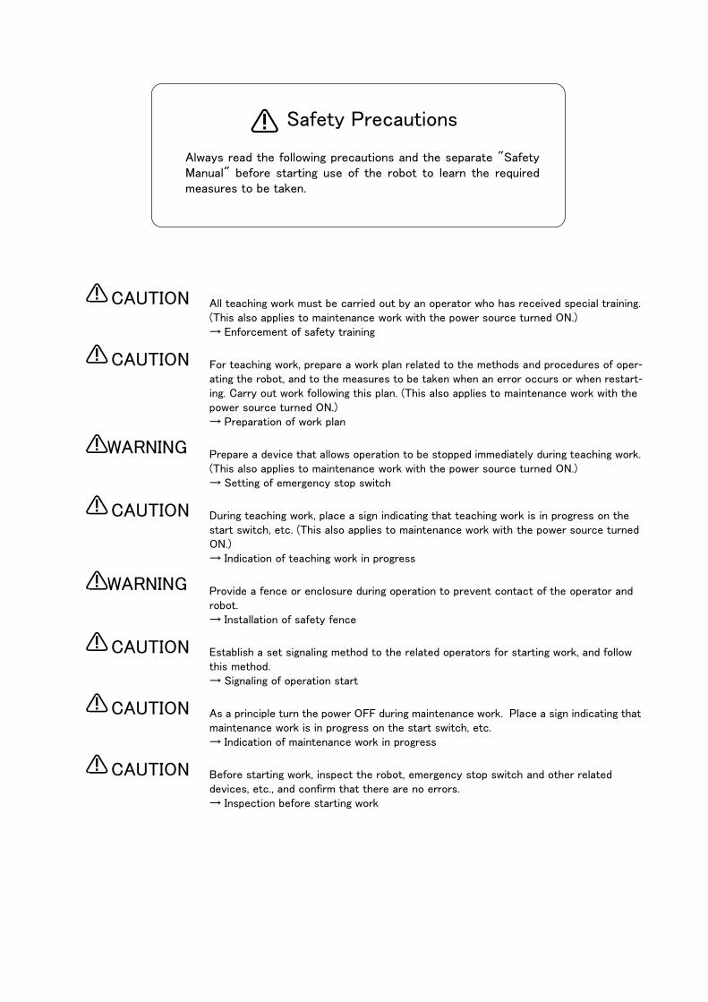
Always read the following precautions and the separate "Safety Manual" before starting use of the robot to learn the required measures to be taken.
Safety Precautions
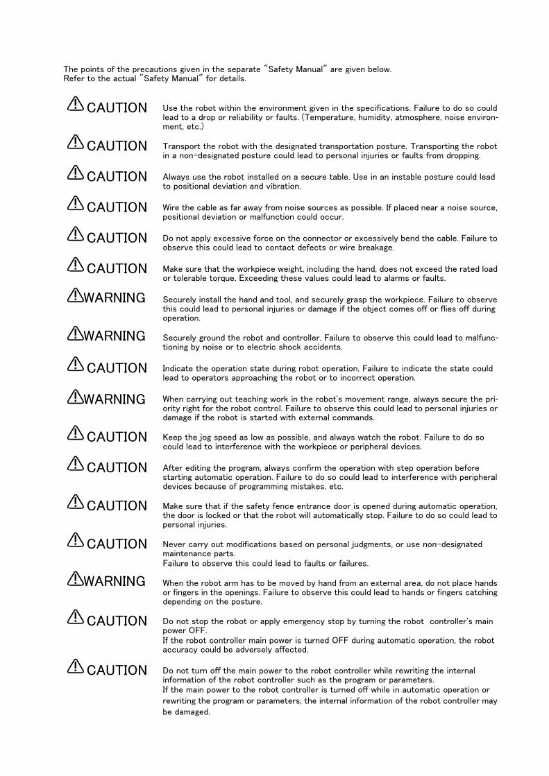
The points of the precautions given in the separate "Safety Manual" are given below. Refer to the actual "Safety Manual" for details.
Use the robot within the environment given in the specifications. Failure to do so could lead to a drop or reliability or faults. (Temperature, humidity, atmosphere, noise environ-ment, etc.)
Transport the robot with the designated transportation posture. Transporting the robot in a non-designated posture could lead to personal injuries or faults from dropping.
Always use the robot installed on a secure table. Use in an instable posture could lead to positional deviation and vibration.
Wire the cable as far away from noise sources as possible. If placed near a noise source, positional deviation or malfunction could occur.
Do not apply excessive force on the connector or excessively bend the cable. Failure to observe this could lead to contact defects or wire breakage.
Make sure that the workpiece weight, including the hand, does not exceed the rated load or tolerable torque. Exceeding these values could lead to alarms or faults.
Securely install the hand and tool, and securely grasp the workpiece. Failure to observe this could lead to personal injuries or damage if the object comes off or flies off during operation.
Securely ground the robot and controller. Failure to observe this could lead to malfunc-tioning by noise or to electric shock accidents.
Indicate the operation state during robot operation. Failure to indicate the state could lead to operators approaching the robot or to incorrect operation.
When carrying out teaching work in the robot's movement range, always secure the pri-ority right for the robot control. Failure to observe this could lead to personal injuries or damage if the robot is started with external commands.
Keep the jog speed as low as possible, and always watch the robot. Failure to do so could lead to interference with the workpiece or peripheral devices.
After editing the program, always confirm the operation with step operation before starting automatic operation. Failure to do so could lead to interference with peripheral devices because of programming mistakes, etc.
Make sure that if the safety fence entrance door is opened during automatic operation, the door is locked or that the robot will automatically stop. Failure to do so could lead to personal injuries.
Never carry out modifications based on personal judgments, or use non-designated maintenance parts. Failure to observe this could lead to faults or failures.
When the robot arm has to be moved by hand from an external area, do not place hands or fingers in the openings. Failure to observe this could lead to hands or fingers catching depending on the posture.
Do not stop the robot or apply emergency stop by turning the robot controller's main power OFF.If the robot controller main power is turned OFF during automatic operation, the robot accuracy could be adversely affected.
Do not turn off the main power to the robot controller while rewriting the internal information of the robot controller such as the program or parameters.If the main power to the robot controller is turned off while in automatic operation or rewriting the program or parameters, the internal information of the robot controller may be damaged.
CAUTION
CAUTION
CAUTION
CAUTION
CAUTION
CAUTION
WARNING
WARNING
CAUTION
WARNING
CAUTION
CAUTION
CAUTION
CAUTION
WARNING
CAUTION
CAUTION
For using RH-5AH/10AH/15AH. While pressing the brake releasing switch on the robot arm, beware of the arm which may drop with its own weight.
Dropping of the hand could lead to a collision with the peripheral equipment or catch the hands or fingers.
WARNING

Revision history
Date of print Specifications No. Details of revisions
1999-06-16 BFP-A5991Z-* ・ First print
1999-09-24 BFP-A5991Z-a ・ Error in writing correction.
1999-11-12 BFP-A5991 ・ Error in writing correction.
2000-03-21 BFP-A5991-A ・ "Removing and Installing the R6CPU Option Fixing Plate" is added.
・ "The procedures for installing the pneumatic hand interface" is added.
・ "Replacing the battery" is changed.
・ Error in writing correction.
2000-12-18 BFP-A5991-B ・ Error in writing correction.
2001-04-05 BFP-A5991-C ・ CR2A controller was added.
2001-06-28 BFP-A5991-D ・ CR2-532M controller was added.
2001-10-31 BFP-A5991-E ・ Standard configuration of RH-5AH series was added.
2002-02-20 BFP-A5991-F ・ Error in writing correction.
2002-03-18 BFP-A5991-G ・ CR2A-MB (controller protection box) was added.
・ Error in writing correction.
2003-01-27 BFP-A5991-H ・ "Cleaning of the radiating fins in the controller protection box (CR2A-MB)" was added.
・ "Removal of the protection sheet on the teaching pendant" was added.
・ "MC control output (AXMC) for addition axes" was added.
・ Error in writing correction.
2003-10-29 BFP-A5991-J ・ CR2B-574 controller was added.
・ Error in writing correction.

■ Introduction
Thank you for purchasing the Mitsubishi industrial robot.
This instruction manual explains the unpacking methods, installation, basic operation, maintenance and inspection of the controller.
The optional equipments and power supply voltage are different according to connecting robot type.
Refer to separate "Standard Specifications Manual" for detail.
Always read through this manual before starting use to ensure correct usage of the robot.
The information contained in this document has been written to be accurate as much as possible. Please interpret that items not described in this document "cannot be performed."
・ No part of this manual may be reproduced by any means or in any form, without prior consent from Mitsubishi.
・ The details of this manual are subject to change without notice.・ An effort has been made to make full descriptions in this manual. However, if any discrepancies or
unclear points are found, please contact your dealer. ・ Please contact your nearest dealer if you find any doubtful, wrong or skipped point.
Copyright(C) 2000 MITSUBISHI ELECTRIC CORPORATION
Contents
i
Page
1 Before starting use ......................................................................................................................................................................... 1-1
1.1 Using the instruction manuals ............................................................................................................................................ 1-11.1.1 The details of each instruction manuals ................................................................................................................ 1-11.1.2 Symbols used in instruction manual ........................................................................................................................ 1-2
1.2 Safety Precautions ................................................................................................................................................................. 1-31.2.1 Precautions given in the separate Safety Manual ............................................................................................. 1-4
2 Unpacking to installation .............................................................................................................................................................. 2-5
2.1 Confirming the products ....................................................................................................................................................... 2-5
2.2 Installation .................................................................................................................................................................................. 2-62.2.1 Unpacking procedures ................................................................................................................................................... 2-62.2.2 Transportation procedures .......................................................................................................................................... 2-82.2.3 Installation procedures .................................................................................................................................................. 2-92.2.4 Connecting the power cable and grounding cable ........................................................................................... 2-112.2.5 Connecting the external emergency stop ........................................................................................................... 2-142.2.6 Magnet contactor control connector output (AXMC) for addition axes
(When using the CR2A-572/CR2B-574 controller) ........................................................................................................... 2-162.2.7 Connecting to the robot arm .................................................................................................................................... 2-17
2.3 Setting the origin ................................................................................................................................................................... 2-17
2.4 Confirming the operation .................................................................................................................................................... 2-17
3 Installing the option devices ..................................................................................................................................................... 3-18
3.1 For the CR2-532 Controller ............................................................................................................................................. 3-183.1.1 Removing and Installing the R6x2CPU Option Fixing Plate ......................................................................... 3-183.1.2 The procedures for installing the pneumatic hand interface ...................................................................... 3-20
3.2 For the CR2A-572/CR2B-574 Controller .................................................................................................................. 3-213.2.1 Installing the Option Card .......................................................................................................................................... 3-213.2.2 The procedures for installing the pneumatic hand interface ...................................................................... 3-22
3.3 For the CR2-532M Controller .......................................................................................................................................... 3-233.3.1 Removing and Installing the R6x2CPU (Installing the Option Card ) ....................................................... 3-233.3.2 The procedures for installing the pneumatic hand interface ...................................................................... 3-25
3.4 Installation of the controller protection box (CR2A-MB) (CR2A-574 controller only) ........................... 3-263.4.1 Name of each part ......................................................................................................................................................... 3-263.4.2 Confirmation before installation .............................................................................................................................. 3-273.4.3 Unpacking procedures ................................................................................................................................................. 3-273.4.4 Transportation procedures ........................................................................................................................................ 3-273.4.5 Installation procedures ................................................................................................................................................ 3-283.4.6 Handling the protection box ...................................................................................................................................... 3-34
4 Basic operations ............................................................................................................................................................................ 4-35
4.1 Handling the controller ........................................................................................................................................................ 4-364.1.1 Functions of each key ................................................................................................................................................. 4-36
4.2 Handling the T/B ................................................................................................................................................................... 4-394.2.1 Installing and removing the T/B .............................................................................................................................. 4-39
(1) Installing with the control power OFF .............................................................................................................. 4-39(2) Removing with the control power ON ............................................................................................................... 4-39(3) Installing with the control power ON ................................................................................................................ 4-39
4.2.2 Functions of each key ................................................................................................................................................. 4-40
4.3 Turning the power ON and OFF ...................................................................................................................................... 4-424.3.1 Turning the control power ON ................................................................................................................................. 4-424.3.2 Shutting OFF the control power ............................................................................................................................. 4-42
4.4 Turning the servo power ON/OFF ................................................................................................................................. 4-434.4.1 Turning the servo power ON (servo ON) ............................................................................................................. 4-434.4.2 Shutting OFF the servo power (servo OFF) ...................................................................................................... 4-43
4.5 Jog operation .......................................................................................................................................................................... 4-44
ii
Page
4.6 Opening and closing the hand .......................................................................................................................................... 4-44
4.7 Programming ............................................................................................................................................................................ 4-45(1) Creation procedures ................................................................................................................................................ 4-45(2) Robot work ................................................................................................................................................................... 4-45
4.7.1 Creating the program ................................................................................................................................................... 4-46(1) Deciding the operation order ................................................................................................................................ 4-46(2) Deciding the operation position name .............................................................................................................. 4-47(3) Describing and creating the program ................................................................................................................ 4-48(4) Confirming the program .......................................................................................................................................... 4-53(5) Correcting the program .......................................................................................................................................... 4-54(6) Start automatic operation. .................................................................................................................................... 4-58
5 Maintenance and Inspection ..................................................................................................................................................... 5-60
5.1 Maintenance and inspection interval ............................................................................................................................. 5-60
5.2 Inspection items ..................................................................................................................................................................... 5-615.2.1 Daily inspection items .................................................................................................................................................. 5-615.2.2 Periodic inspections ..................................................................................................................................................... 5-61
5.3 Maintenance and inspection procedures ..................................................................................................................... 5-625.3.1 Inspecting, cleaning and replacing the filter ....................................................................................................... 5-625.3.2 Replacing the battery ................................................................................................................................................... 5-63
(1) For the CR2-532 Controller ................................................................................................................................. 5-63(2) For the CR2A-572/CR2B-574 Controller ...................................................................................................... 5-64(3) For the CR2-532M Controller ............................................................................................................................. 5-65
5.3.3 Cleaning the heat radiating fins of the controller protection box (CR2A-MB) ................................... 5-66
5.4 Maintenance parts ................................................................................................................................................................. 5-67

1Before starting use
Using the instruction manuals 1-1
1 Before starting use
This chapter explains the details and usage methods of the instruction manuals, the basic terminology and the safety precautions.
1.1 Using the instruction manuals
1.1.1 The details of each instruction manualsThe contents and purposes of the documents enclosed with this product are shown below. Use these documents according to the application.
For special specifications, a separate instruction manual describing the special section may be enclosed.
Explains the common precautions and safety measures to be taken for robot handling, system design and manufacture to ensure safety of the operators involved with the robot.
Explains the product's standard specifications, factory-set special specifications, option configuration and maintenance parts, etc. Precautions for safety and technology, when incorporating the robot, are also explained.
Explains the procedures required to operate the robot arm (unpacking, transportation, installation, confirmation of operation), and the maintenance and inspection procedures.
Explains the procedures required to operate the controller (unpacking, transportation, installation, confirmation of operation), basic operation from creating the program to automatic operation, and the maintenance and inspection procedures.
Explains details on the functions and operations such as each function and operation, commands used in the program, connection with the external input/output device, and parameters, etc.
Explains the causes and remedies to be taken when an error occurs. Explanations are given for each error No.
Safety Manual
StandardSpecifications
Robot ArmSetup &Maintenance
ControllerSetup, BasicOperation andMaintenance
Detailed Explanation ofFunctions andOperations
Troubleshooting
1-2 Using the instruction manuals
1Before starting use
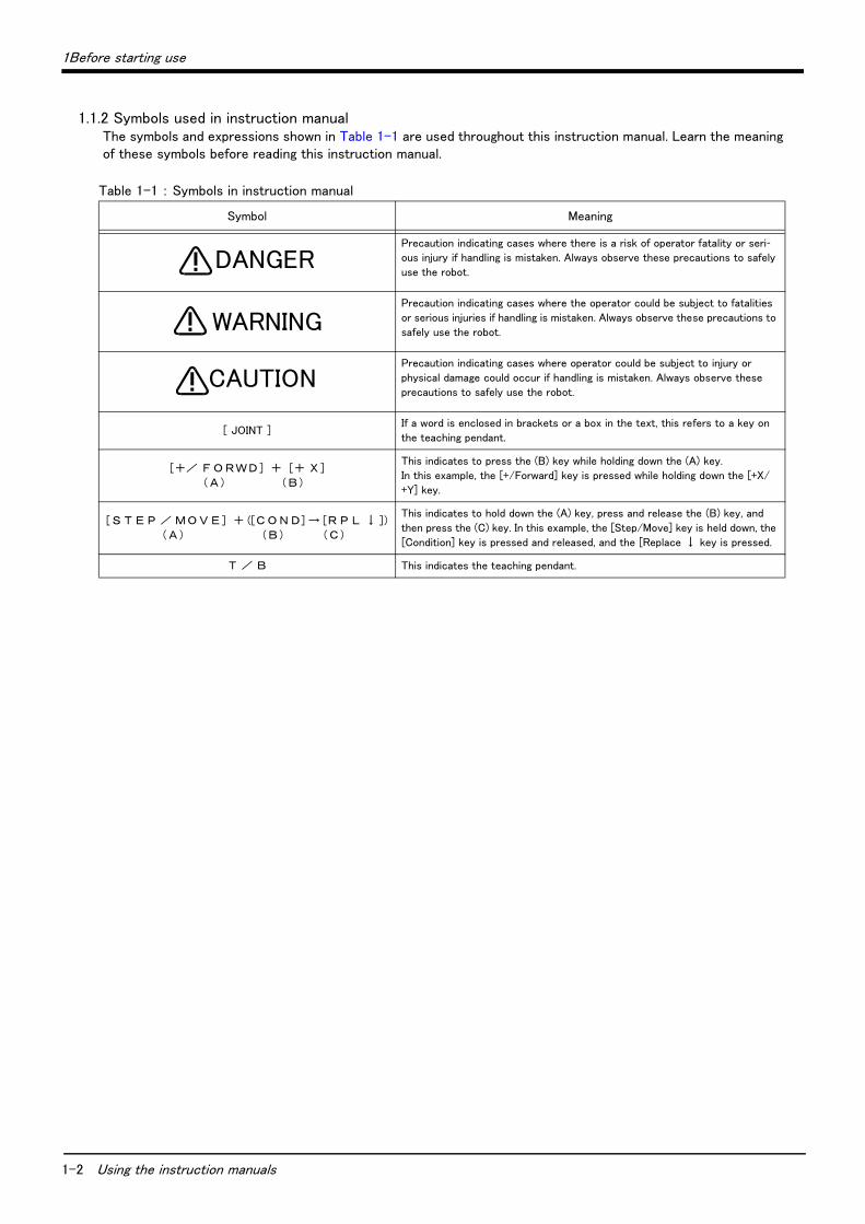
1.1.2 Symbols used in instruction manualThe symbols and expressions shown in Table 1-1 are used throughout this instruction manual. Learn the meaning of these symbols before reading this instruction manual.
Table 1-1 : Symbols in instruction manual
Symbol Meaning
Precaution indicating cases where there is a risk of operator fatality or seri-ous injury if handling is mistaken. Always observe these precautions to safely
use the robot.
Precaution indicating cases where the operator could be subject to fatalities
or serious injuries if handling is mistaken. Always observe these precautions to
safely use the robot.
Precaution indicating cases where operator could be subject to injury or
physical damage could occur if handling is mistaken. Always observe these
precautions to safely use the robot.
[ JOINT ]If a word is enclosed in brackets or a box in the text, this refers to a key on
the teaching pendant.
[+/ F O RWD] + [+ X ]
(A) (B)
This indicates to press the (B) key while holding down the (A) key.
In this example, the [+/Forward] key is pressed while holding down the [+X/
+Y] key.
[S T E P / MO V E] + ([C O N D] → [R P L ↓ ])
(A) (B) (C)
This indicates to hold down the (A) key, press and release the (B) key, and
then press the (C) key. In this example, the [Step/Move] key is held down, the
[Condition] key is pressed and released, and the [Replace ↓ key is pressed.
T / B This indicates the teaching pendant.
DANGER
WARNING
CAUTION
1Before starting use
Safety Precautions 1-3
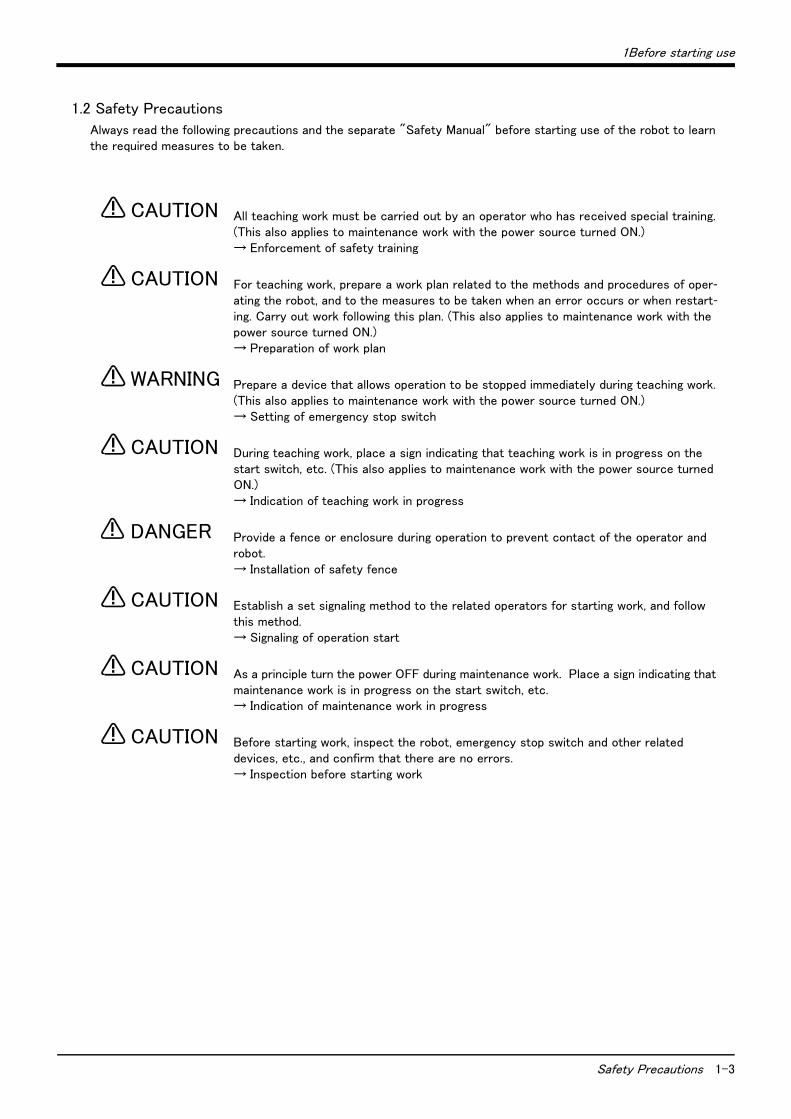
1.2 Safety Precautions
Always read the following precautions and the separate "Safety Manual" before starting use of the robot to learn the required measures to be taken.
All teaching work must be carried out by an operator who has received special training. (This also applies to maintenance work with the power source turned ON.) → Enforcement of safety training
For teaching work, prepare a work plan related to the methods and procedures of oper-ating the robot, and to the measures to be taken when an error occurs or when restart-ing. Carry out work following this plan. (This also applies to maintenance work with the power source turned ON.) → Preparation of work plan
Prepare a device that allows operation to be stopped immediately during teaching work. (This also applies to maintenance work with the power source turned ON.) → Setting of emergency stop switch
During teaching work, place a sign indicating that teaching work is in progress on the start switch, etc. (This also applies to maintenance work with the power source turned ON.) → Indication of teaching work in progress
Provide a fence or enclosure during operation to prevent contact of the operator and robot. → Installation of safety fence
Establish a set signaling method to the related operators for starting work, and follow this method. → Signaling of operation start
As a principle turn the power OFF during maintenance work. Place a sign indicating that maintenance work is in progress on the start switch, etc. → Indication of maintenance work in progress
Before starting work, inspect the robot, emergency stop switch and other related devices, etc., and confirm that there are no errors. → Inspection before starting work
CAUTION
CAUTION
WARNING
CAUTION
DANGER
CAUTION
CAUTION
CAUTION

1-4 Safety Precautions
1Before starting use
1.2.1 Precautions given in the separate Safety ManualThe points of the precautions given in the separate "Safety Manual" are given below. Refer to the actual "Safety Manual" for details.
Use the robot within the environment given in the specifications. Failure to do so could lead to a drop or reliability or faults. (Temperature, humidity, atmosphere, noise envi-ronment, etc.)
Transport the robot with the designated transportation posture. Transporting the robot in a non-designated posture could lead to personal injuries or faults from drop-ping.
Always use the robot installed on a secure table. Use in an instable posture could lead to positional deviation and vibration.
Wire the cable as far away from noise sources as possible. If placed near a noise source, positional deviation or malfunction could occur.
Do not apply excessive force on the connector or excessively bend the cable. Failure to observe this could lead to contact defects or wire breakage.
Make sure that the workpiece weight, including the hand, does not exceed the rated load or tolerable torque. Exceeding these values could lead to alarms or faults.
Securely install the hand and tool, and securely grasp the workpiece. Failure to observe this could lead to personal injuries or damage if the object comes off or flies off during operation.
Securely ground the robot and controller. Failure to observe this could lead to mal-functioning by noise or to electric shock accidents.
Indicate the operation state during robot operation. Failure to indicate the state could lead to operators approaching the robot or to incorrect operation.
When carrying out teaching work in the robot's movement range, always secure the priority right for the robot control. Failure to observe this could lead to personal inju-ries or damage if the robot is started with external commands.
Keep the jog speed as low as possible, and always watch the robot. Failure to do so could lead to interference with the workpiece or peripheral devices.
After editing the program, always confirm the operation with step operation before starting automatic operation. Failure to do so could lead to interference with periph-eral devices because of programming mistakes, etc.
Make sure that if the safety fence entrance door is opened during automatic opera-tion, the door is locked or that the robot will automatically stop. Failure to do so could lead to personal injuries.
Never carry out modifications based on personal judgments, or use non-designated maintenance parts. Failure to observe this could lead to faults or failures.
When the robot arm has to be moved by hand from an external area, do not place hands or fingers in the openings. Failure to observe this could lead to hands or fingers catching depending on the posture.
Do not stop the robot or apply emergency stop by turning the robot controller's main power OFF.If the robot controller main power is turned OFF during automatic operation, the robot accuracy could be adversely affected.
Do not turn off the main power to the robot controller while rewriting the internal information of the robot controller such as the program or parameters.If the main power to the robot controller is turned off while in automatic operation or rewriting the program or parameters, the internal information of the robot controller may be damaged.
CAUTION
CAUTION
CAUTION
CAUTION
CAUTION
CAUTION
WARNING
WARNING
CAUTION
WARNING
CAUTION
CAUTION
CAUTION
CAUTION
WARNING
CAUTION
CAUTION

2Unpacking to installation
Confirming the products 2-5
2 Unpacking to installation
2.1 Confirming the products
Confirm that the parts shown in the standard configuration of the controller shown in Table 2-1 are enclosed with the purchased product.
Users who have purchased options should refer to the separate "Standard Specifications". The primary power supply cable and grounding cable must be prepared by the customer.
Table 2-1 : Standard configuration
No. Part name Type Qty. Remarks
1 Controller CR2-532
CR2-532M
CR2A-572
CR2B-574
1 of
these
units
With machine cable.
The fixing plate of memory cassette is attached
to the CR2A-572/CR2B-574 controller.
2 Safety Manual BFP-A8006 1 copy
3 Standard Specifications BFP-A8026
1 of
these
copy
RV-4A/5AJ/3AL/4AJL series type.
(CR2-532/CR2-532M controller)
BFP-A8228 RV-4A/5AJ/3AL/4AJL series type.
(CR2A-572 controller)
BFP-A8174 RH-5AH/10AH/15AH series type.
BFP-A8322 RV-6S series type.
4 Instruction Manual
(Robot arm setup and maintenance) BFP-A8034
1 of these copy
RV-4A/5AJ/3AL/4AJL series type.
(CR2-532/CR2-532M controller)
BFP-A8229 RV-4A/5AJ/3AL/4AJL series type.
(CR2A-572 controller)
BFP-A8175 RH-5AH/10AH/15AH series type.
BFP-A8323 RV-6S series type.
5 Instruction Manual
(Controller setup, basic operation and maintenance) BFP-A5991 1 copy This book
6 Instruction Manual
(Detailed explanations of functions and operations) BFP-A5992 1 copy
7 Instruction Manual
(Troubleshooting) BFP-A5993 1 copy
8 Guarantee Card 1 copy

2-6 Installation
2Unpacking to installation
2.2 Installation
2.2.1 Unpacking proceduresThe following shows how to unpack the controller.
The unpacking method differs, depending on the controller being used.
When the CR2-532/CR2A-572 controller is used, refer to " ■ For the CR2-532/CR2A-572/CR2B-574 Control-ler". When the CR2-532M controller is used, refer to " ■ For the CR2-532M Controller" on page 7.
■ For the CR2-532/CR2A-572/CR2B-574 Controller
Fig.2-1 : Unpacking the controller (CR2-532/CR2A-572/CR2B-574)
The controller is shipped from the factory packaged in cardboard. Unpack the controller with the following proce-dure.
(1) Open the front of the outer cardboard box.(2) Hold the handle on the inner case (cardboard) with cushioning material, and pull it out.(3) Remove the accessory set placed on the controller.(4) Hold the controller with both hands, and remove the inner case with cushioning material.
Exercise caution, since the center of gravity of the controller is located toward the front of the unit.(5) Set down the controller to complete the unpacking procedure.
Accessory set
Controller
Inner case with cushioning material
① ②
③
[Caution] The packaging material is required when transporting the controller again, so keep it in safekeeping.
<CR2-532/CR2A-572/CR2B-574>
2Unpacking to installation
Installation 2-7
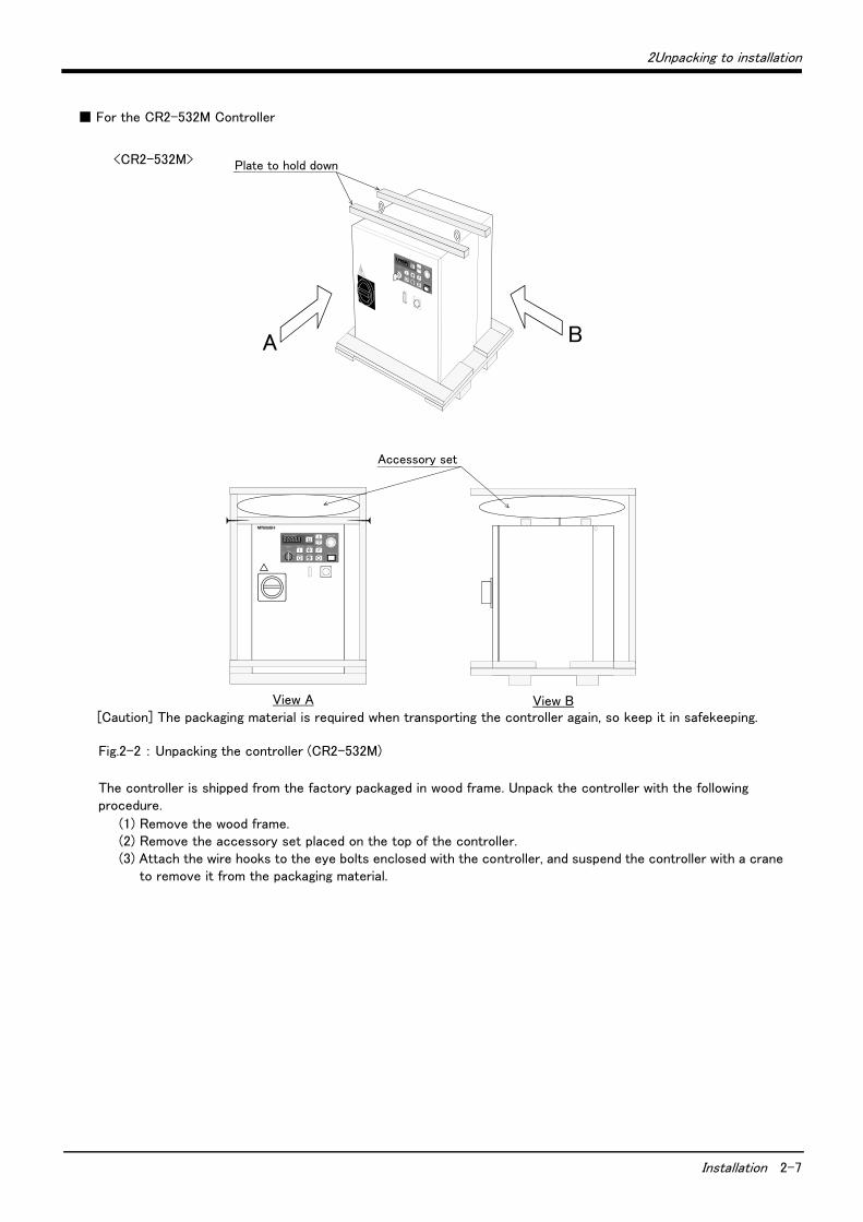
■ For the CR2-532M Controller
Fig.2-2 : Unpacking the controller (CR2-532M)
The controller is shipped from the factory packaged in wood frame. Unpack the controller with the following procedure.
(1) Remove the wood frame.(2) Remove the accessory set placed on the top of the controller.(3) Attach the wire hooks to the eye bolts enclosed with the controller, and suspend the controller with a crane
to remove it from the packaging material.
SVO OFF STOP END
SVO ONMODE
TEACH
AUTO (Ext.)
AUTO (Op.)
START RESET
DOWN
UP
REMOVE T/B
EMG.STOPCHANG DISPSTATUS NUMBER
A B
View A View B
Plate to hold down
Accessory set
<CR2-532M>
[Caution] The packaging material is required when transporting the controller again, so keep it in safekeeping.
2-8 Installation
2Unpacking to installation
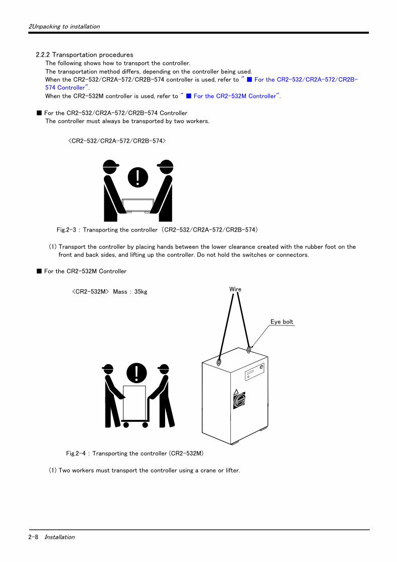
2.2.2 Transportation proceduresThe following shows how to transport the controller.
The transportation method differs, depending on the controller being used. When the CR2-532/CR2A-572/CR2B-574 controller is used, refer to " ■ For the CR2-532/CR2A-572/CR2B-574 Controller".
When the CR2-532M controller is used, refer to " ■ For the CR2-532M Controller".
■ For the CR2-532/CR2A-572/CR2B-574 ControllerThe controller must always be transported by two workers.
Fig.2-3 : Transporting the controller (CR2-532/CR2A-572/CR2B-574)
(1) Transport the controller by placing hands between the lower clearance created with the rubber foot on the front and back sides, and lifting up the controller. Do not hold the switches or connectors.
■ For the CR2-532M Controller
Fig.2-4 : Transporting the controller (CR2-532M)
(1) Two workers must transport the controller using a crane or lifter.
!!
<CR2-532/CR2A-572/CR2B-574>
!!
Wire
Eye bolt
<CR2-532M> Mass : 35kg
2Unpacking to installation
Installation 2-9
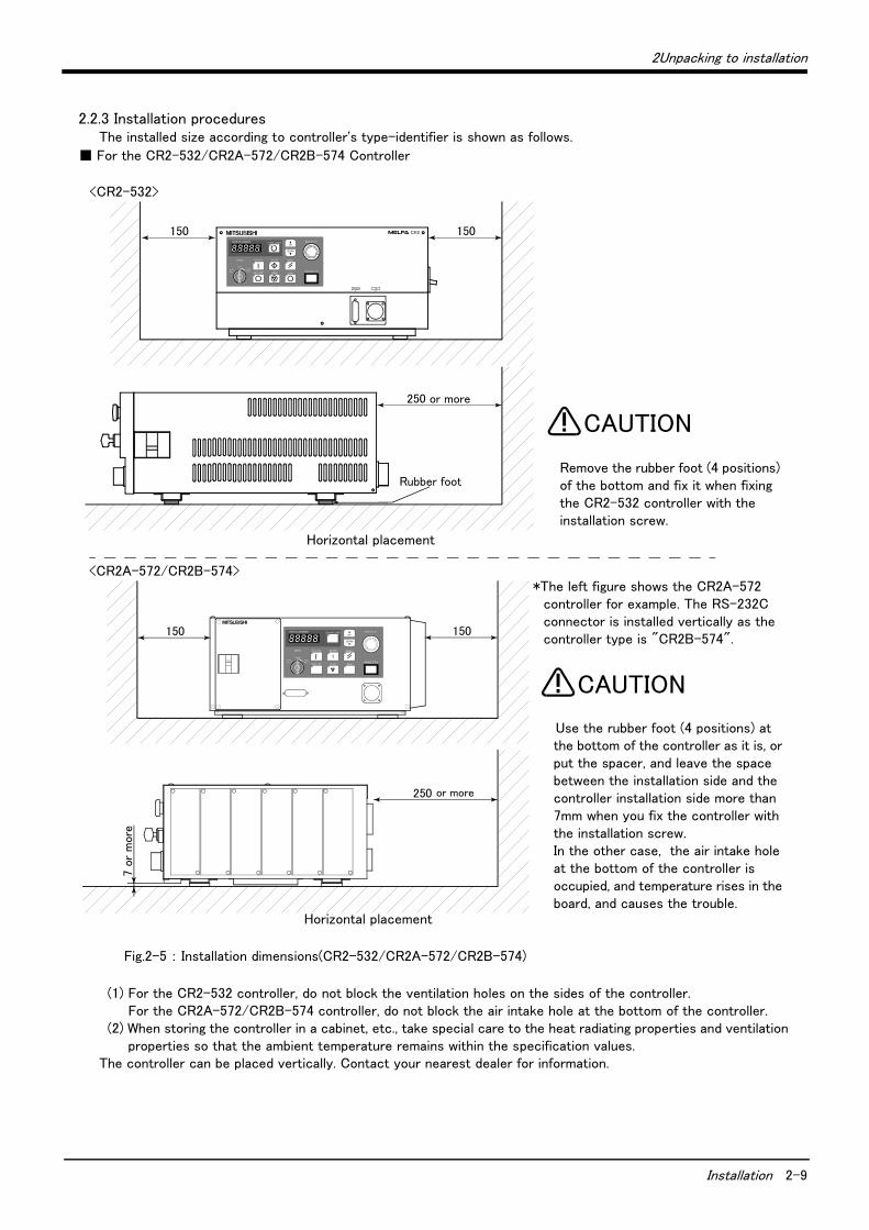
2.2.3 Installation proceduresThe installed size according to controller's type-identifier is shown as follows.
■ For the CR2-532/CR2A-572/CR2B-574 Controller
Fig.2-5 : Installation dimensions(CR2-532/CR2A-572/CR2B-574)
(1) For the CR2-532 controller, do not block the ventilation holes on the sides of the controller. For the CR2A-572/CR2B-574 controller, do not block the air intake hole at the bottom of the controller.
(2) When storing the controller in a cabinet, etc., take special care to the heat radiating properties and ventilation properties so that the ambient temperature remains within the specification values.
The controller can be placed vertically. Contact your nearest dealer for information.
150 150
250 or more
7 o
r m
ore
150 150
250 or more
Rubber foot
Horizontal placement
Horizontal placement
<CR2A-572/CR2B-574>
<CR2-532>
Remove the rubber foot (4 positions) of the bottom and fix it when fixing the CR2-532 controller with the installation screw.
CAUTION
Use the rubber foot (4 positions) at the bottom of the controller as it is, or put the spacer, and leave the space between the installation side and the controller installation side more than 7mm when you fix the controller with the installation screw.In the other case, the air intake hole at the bottom of the controller is occupied, and temperature rises in the board, and causes the trouble.
CAUTION
*The left figure shows the CR2A-572 controller for example. The RS-232C connector is installed vertically as the controller type is "CR2B-574".

2-10 Installation
2Unpacking to installation
■ For the CR2-532M Controller
Fig.2-6 : Installation dimensions (CR2-532M)
(1) Install the controller so that it is level.
Install the rubber cover for the T/B connector when the T/B un-connection.
In the same way, install the mold cover for the RS-232C connector when the RS-232C cable un-connection. When it is not so, it has the possibility that the controller breaks down due to the penetration such as oil.
315
Controller(up side)
(View from upside)
Maintenance area
110Fro
ntA
ppro
x. 3
50
Bac
kA
ppro
x.
250
or
less
460
315
Side
Approx.200
The rubber cover for the T/B connector
SideApprox.
300
The mold cover for the RS-232C connector
<CR2-532M>
CAUTION

2Unpacking to installation
Installation 2-11
2.2.4 Connecting the power cable and grounding cableThe following shows how to connect the power and grounding cables.
The cable-connection method differs, depending on the controller being used. When the CR2-532 controller is used, refer to " ■ For the CR2-532 Controller". When the CR2A-572/CR2B-574 controller is used, refer to " ■ For the CR2A-572/CR2B-574 Controller" on page 12. When the CR2-532M controller is used, refer to " ■ For the CR2-532M Controller" on page 13.
■ For the CR2-532 Controller
Fig.2-7 : Connecting the power cable and grounding cable(CR2-532)
(1) Prepare the power cable and grounding cable (both must be AWG#14(2mm2) or more thickly).(2) Remove the controller's chassis cover. Remove screw A, slide the cover by approx. 100mm to the back side,
and lift it upward.(3) Remove the upper rear cover by removing the four screws B on the rear side.(4) Confirm that the primary power supply matches the specifications.(5) Confirm that the primary power supply is OFF and that the power switch on the controller is OFF.(6) Pull out the power switch terminal cover C by pulling on the U-character projection on the front with fingers.(7) Connect the power cable to the power switch terminals. (L1, L2 and L3 from left)(8) Connect the grounding cable to the controller chassis screw hole (M4) at the right side of the power switch.
(PE mark)(9) Press in the power switch terminal cover C (removed in step (6)), until a "click" is heard.(10) Install the upper rear cover.
At this time, sandwich the power cable and grounding cable with the rubber bushing installed on the lower rear cover and upper rear cover. If required, cut the rubber bushing to a round shape.
(11) Securely fix the chassis cover (removed in step (2)) with screw A. The chassis cover is structured to sand-wich the chassis sides, so carefully fit and slide it into position, and then fix.
This completes the connection of the power and grounding cables of the CR2-532 controller.
MODE
AUTO (Ext.)
Screw A
Chassis cover
Power cable
Screw B
Upper rear cover
Lower rear cover
PE (grounding)
A Terminal cover C
U-character projection
Power switch View A
PE
L1 L2 L3
Three-phase AC200/210/230V
View A
PE
L1 L2 L3
Single-phase AC230V
2-12 Installation
2Unpacking to installation
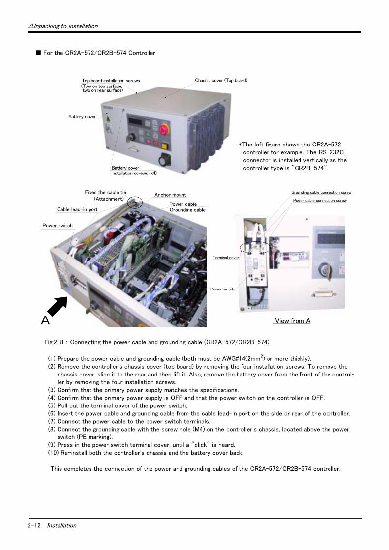
■ For the CR2A-572/CR2B-574 Controller
Fig.2-8 : Connecting the power cable and grounding cable (CR2A-572/CR2B-574)
(1) Prepare the power cable and grounding cable (both must be AWG#14(2mm2) or more thickly).(2) Remove the controller's chassis cover (top board) by removing the four installation screws. To remove the
chassis cover, slide it to the rear and then lift it. Also, remove the battery cover from the front of the control-ler by removing the four installation screws.
(3) Confirm that the primary power supply matches the specifications.(4) Confirm that the primary power supply is OFF and that the power switch on the controller is OFF.(5) Pull out the terminal cover of the power switch.(6) Insert the power cable and grounding cable from the cable lead-in port on the side or rear of the controller.(7) Connect the power cable to the power switch terminals. (8) Connect the grounding cable with the screw hole (M4) on the controller's chassis, located above the power
switch (PE marking).(9) Press in the power switch terminal cover, until a "click" is heard.(10) Re-install both the controller's chassis and the battery cover back.
This completes the connection of the power and grounding cables of the CR2A-572/CR2B-574 controller.
Chassis cover (Top board)Top board installation screws(Two on top surface, two on rear surface)
Battery cover
Battery coverinstallation screws (x4)
Cable lead-in port Grounding cable
Power switch
Power cable
A
Anchor mountFixes the cable tie(Attachment)
Grounding cable connection screw
Terminal cover
Power cable connection screw
Power switch
View from A
*The left figure shows the CR2A-572 controller for example. The RS-232C connector is installed vertically as the controller type is "CR2B-574".

2Unpacking to installation
Installation 2-13
■ For the CR2-532M Controller
Fig.2-9 : Connecting the power cable and grounding cable (CR2-532M)
(1) Prepare the power cable and grounding cable (both must be AWG#14(2mm2) or more thickly).(2) Loosen the two screws fixing the controller's front door, and open the front door.(3) Pull out the disengagement prevention projection on the terminal cover surface of the earth leakage breaker
by disengaging it with your finger.(4) Confirm that the primary power matches the specifications.(5) Confirm that the primary power is OFF and that the controller power switch is OFF.(6) Insert the power cable and grounding cable from the cable lead-in port on the bottom of the controller.(7) Connect the power cable to the power switch terminal. (L1, L2 and L3 from left)(8) Connect the grounding cable to the grounding plate terminal.(9) Insert the power switch terminal cover removed in step (3) until a "click" is heard.(10) Close the controller's front door, and fix with the fixing screws.
This completes the connection of the power and grounding cables of the CR2-532M controller.
Grounding plate
Power switch
Cable lead-in port
Section B
Power cable
Grounding wire
Section A
Terminal cover
L1, L2 and L3 from left
Power cable
(a) Details of section A
Earth leakage breaker
Grounding cable
Grounding plate
(b) Details of section B
External emergency stopinput terminal block
Front door fixing screwTwo screws
Disengagement prevention projection

2-14 Installation
2Unpacking to installation
2.2.5 Connecting the external emergency stopThe following shows how to connect the external emergency stop.
Please note that the connection method differs, depending on the controller being used. When the CR2-532/CR2-532M controller is used, refer to " ■ For the CR2-532/CR2-532M Controller". When the CR2A-572/CR2B-574 controller is used, refer to " ■ For the CR2A-572/CR2B-574 Controller" on page 15.
■ For the CR2-532/CR2-532M Controller
Fig.2-10 : Connecting the external emergency stop (CR2-532/CR2-532M)
For safety purposes, install the External emergency stop switch at an easy-to-operate place.
The external emergency stop input and door switch input terminal block are short-circuited with a short bar (short piece) as shown in Fig. 2-10.
Connect the external emergency stop switch and door switch with the following procedures. The emergency stop circuit in the controller is redundant (duplex), so use a 2-contact type switch for the emergency stop switch.
1) Prepare the emergency stop switch and door switch.2) Loosen the wire fixing screw on the terminal block, and remove the short bars 1 and 2.3) Securely connect the external emergency stop contact across "1-2" on the terminal block, and connect the
door switch contact across "3-4" on the terminal block. The connection method is indicated below.
[Caution] When wiring the emergency stop switch (duble emergency line type), wire both contacts to the two ter- minal blocks on the controller. If both contacts are wired to only one of the terminal blocks, errors can- not be cancelled using the door switch.
This completes the connection of the external emergency stop of the CR2-532/CR2B-532M controller.
24VSTOP SWITCH
6
EXTEMG1
Relay
GND (24G)EXTEMG2
5
4
3
2
1
6
5
4
3
2
1
EMG. DOOR
24V
Relay
GND (24G)
RA
RA
×
×
×
×
×
×
×
×
×
×
×
EXTEMG1
Wire insert
Wire fixing screw
654321
EXTEMG2
×
AWG#24 to #12(0.2 to 2.5mm2)Maker:Phoenix ContactType:FRONT-MSTB2.5/6-ST-5.08
EXTEMG connector (Same for both left and right outputs)
Control unit
Example of wiring for external emergency stop and door switch
(customer-prepared wiring)
Warning Do not check the voltage which withstand insulation.And, failure will be caused if it connects incorrectly.
System emergency stop line(Prepared by cusotmer)
System emergency stop line(Prepared by cusotmer)
Note 1) Emergency stop output opens when either one of the emergency stop switches shown below or an input signal turns on.
・Emergency stop switch of the controller.・Emergency stop switch of the T/B (option).・External emergency stop input.・The T/B mount/dismount switch is OFF when the T/B is unconnected.
RA1
RA2
1
2
3
4
5
6
RA11
24V
1
2
3
4
5
6
RA21
RG (24G)
24V
Short piece 1
Short piece 2
EXTEMG1
EXTEMG2
Short piece 1
Short piece 2
External emergency stop input
RA31:Emergency stop output Note1)
Internal circuit composition of external emergency stop and door switch
External door switch input
External emergency stop input
External door switch input
RA3:Emergency stop output Note1)
(Customer-prepared wiring) (Controller side)
2Unpacking to installation
Installation 2-15
■ For the CR2A-572/CR2B-574 Controller
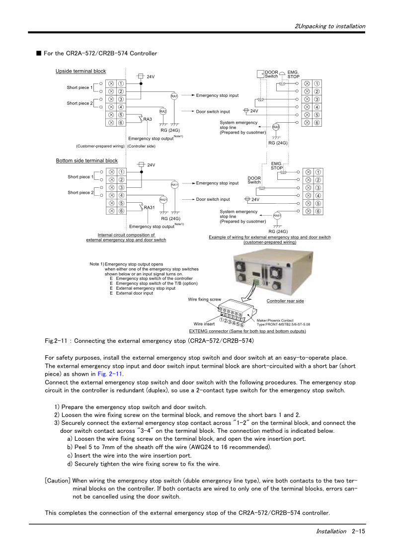
Fig.2-11 : Connecting the external emergency stop (CR2A-572/CR2B-574)
For safety purposes, install the external emergency stop switch and door switch at an easy-to-operate place.
The external emergency stop input and door switch input terminal block are short-circuited with a short bar (short piece) as shown in Fig. 2-11.
Connect the external emergency stop switch and door switch with the following procedures. The emergency stop circuit in the controller is redundant (duplex), so use a 2-contact type switch for the emergency stop switch.
1) Prepare the emergency stop switch and door switch.2) Loosen the wire fixing screw on the terminal block, and remove the short bars 1 and 2.3) Securely connect the external emergency stop contact across "1-2" on the terminal block, and connect the
door switch contact across "3-4" on the terminal block. The connection method is indicated below.a) Loosen the wire fixing screw on the terminal block, and open the wire insertion port.
b) Peel 5 to 7mm of the sheath off the wire (AWG24 to 16 recommended).
c) Insert the wire into the wire insertion port.
d) Securely tighten the wire fixing screw to fix the wire.
[Caution] When wiring the emergency stop switch (duble emergency line type), wire both contacts to the two ter- minal blocks on the controller. If both contacts are wired to only one of the terminal blocks, errors can- not be cancelled using the door switch.
This completes the connection of the external emergency stop of the CR2A-572/CR2B-574 controller.
RG (24G)
24V
EMG. STOP
DOOR Switch
RA5
1
2
3
4
5
6
RA1
RA2
RA3
Emergency stop input
Emergency stop output
Door switch input
RG (24G)
Short piece 1
24V1
2
3
4
5
6
Note1)
Upside terminal block
Short piece 2
System emergencystop line(Prepared by cusotmer)
RG (24G)
24V
EMG. STOP
DOOR Switch
1
2
3
4
5
6RA51
RA11
RA31
RG (24G)
24V1
2
3
4
5
6
RA21
Bottom side terminal block
①②③④⑤⑥
Controller rear side
Emergency stop input
Door switch input
Short piece 1
Short piece 2
Emergency stop outputNote1)
System emergencystop line(Prepared by cusotmer)
Wire fixing screw
Wire insert
Note 1) Emergency stop output opens when either one of the emergency stop switches shown below or an input signal turns on.
�E Emergency stop switch of the controller�E Emergency stop switch of the T/B (option)�E External emergency stop input�E External door input
Maker:Phoenix ContactType:FRONT-MSTB2.5/6-ST-5.08
(Customer-prepared wiring) (Controller side)
EXTEMG connector (Same for both top and bottom outputs)
Internal circuit composition of external emergency stop and door switch Example of wiring for external emergency stop and door switch
(customer-prepared wiring)
2-16 Installation
2Unpacking to installation
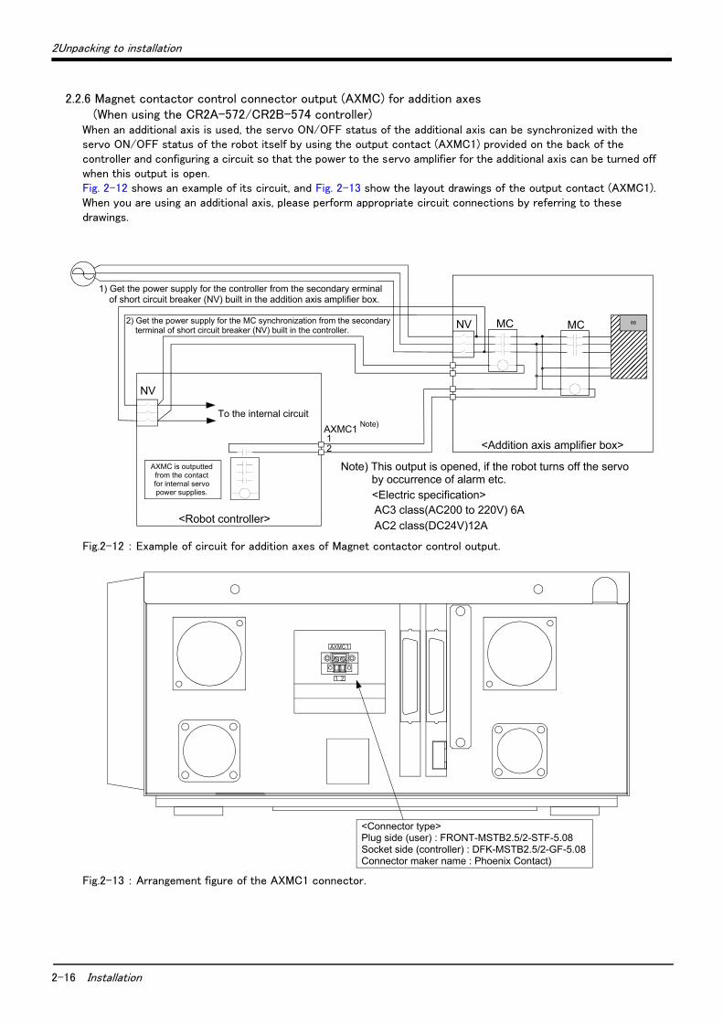
2.2.6 Magnet contactor control connector output (AXMC) for addition axes (When using the CR2A-572/CR2B-574 controller)
When an additional axis is used, the servo ON/OFF status of the additional axis can be synchronized with the servo ON/OFF status of the robot itself by using the output contact (AXMC1) provided on the back of the controller and configuring a circuit so that the power to the servo amplifier for the additional axis can be turned off when this output is open. Fig. 2-12 shows an example of its circuit, and Fig. 2-13 show the layout drawings of the output contact (AXMC1). When you are using an additional axis, please perform appropriate circuit connections by referring to these drawings.
Fig.2-12 : Example of circuit for addition axes of Magnet contactor control output.
Fig.2-13 : Arrangement figure of the AXMC1 connector.
��������NV MC MC
AXMC1
NV
12
88
1) Get the power supply for the controller from the secondary erminal of short circuit breaker (NV) built in the addition axis amplifier box.
To the internal circuitNote)
<Addition axis amplifier box>
<Robot controller>
2) Get the power supply for the MC synchronization from the secondary terminal of short circuit breaker (NV) built in the controller.
<Electric specification> AC3 class(AC200 to 220V) 6A AC2 class(DC24V)12A
AXMC is outputted from the contact for internal servo power supplies.
Note) This output is opened, if the robot turns off the servo by occurrence of alarm etc.
<Connector type>Plug side (user) : FRONT-MSTB2.5/2-STF-5.08Socket side (controller) : DFK-MSTB2.5/2-GF-5.08Connector maker name : Phoenix Contact)

2Unpacking to installation
Setting the origin 2-17
2.2.7 Connecting to the robot armRefer to the separate manual "Robot arm setup and maintenance", and connect the controller and robot arm with machine cables.
The machine cable connectors are dedicated for the controller side and robot arm side, so take special care when connecting.
If connected incorrectly, the connector pins could bend or break. Thus, even if connected correctly, the robot will not operate correctly, creating a dangerous situation.
2.3 Setting the origin
Refer to the separate manual "Robot arm setup and maintenance", and set the origin.
2.4 Confirming the operation
Refer to the separate manual "Robot arm setup and maintenance", and confirm the robot operation with jog operation.
CAUTION

3-18 For the CR2-532 Controller
3Installing the option devices
3 Installing the option devices
The T/B can be installed in the power OFF state as described in the separate manual "Robot arm setup and main-tenance", or can be installed/removed in the power ON state as described in "4.2.1 Installing and removing the T/B" on page 39 of this manual. Refer to the respective explanations. Refer to the separate "Standard Specifications" for the optional devices other than those described in this man-ual.
The method of installation of option equipment differs, depending on the controller being used. When the CR2-532 control is used, refer to "3.1For the CR2-532 Controller". When the CR2A-572/CR2B-574 control is used, refer to "3.2 For the CR2A-572/CR2B-574 Controller" on page 21. When the CR2-532M control is used, refer to "3.3 For the CR2-532M Controller" on page 23.
3.1 For the CR2-532 ControllerTo install an option card in the control unit (R6x2CPU) when the CR2-532 controller is used, remove the R6x2CPU's option fixing plate. The procedures are explained in "3.1.1Removing and Installing the R6x2CPU Option Fixing Plate" below, so refer to that section when installing the option card.
3.1.1 Removing and Installing the R6x2CPU Option Fixing PlateThe option card, mounted on the control unit (R6x2CPU), is mounted after removing the R6x2CPU option fixing plate. The procedure of removing is explained below.
Confirm that the controller's main power supply and controller power switch are OFF before starting this work. Wait at least three minutes after turning the power OFF before removing the controller chassis cover.
(1) Wait at least three minutes after turning the power OFF, and then remove the controller chassis cover. (Refer to Fig. 3-1.) To remove the cover, remove the one installation screw A, and slide the cover approx. 100mm toward the back. Then, lift it up.
(2) Remove the upper rear cover by removing the four installation screws B on the back. (Refer to Fig. 3-1.)
Fig.3-1 : Remove the R6x2CPU(CR2-532)
CAUTION
MODE
AUTO (Ext .)
Screw A(One)
Chassis cover
Power cable
Screw B(Four)
Upper rear cover
Lower rear cover option fixing plate
R6x2CPU
R6xCPU
R6x2CPU
The rear direction
Rubber bush
3Installing the option devices
For the CR2-532 Controller 3-19
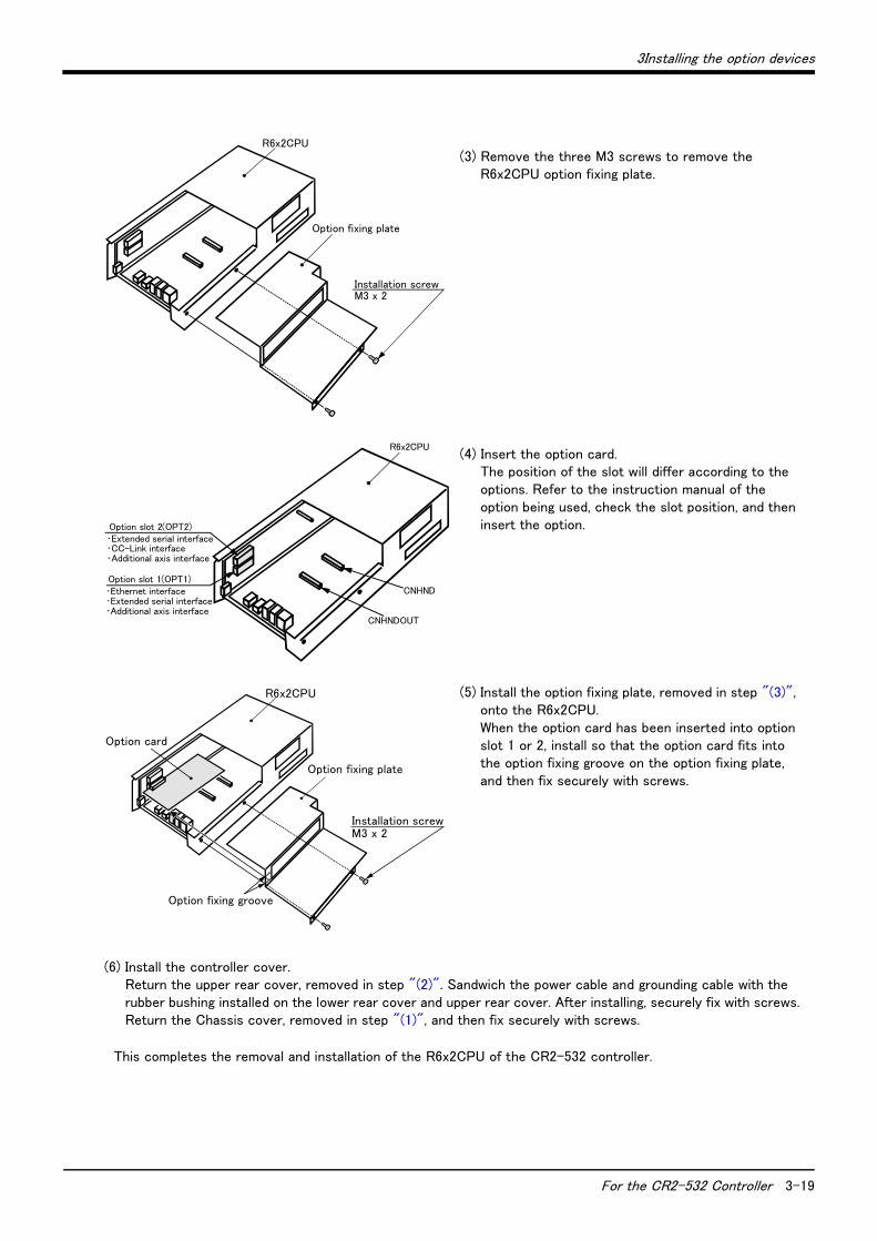
(3) Remove the three M3 screws to remove the R6x2CPU option fixing plate.
(4) Insert the option card. The position of the slot will differ according to the options. Refer to the instruction manual of the option being used, check the slot position, and then insert the option.
(5) Install the option fixing plate, removed in step "(3)", onto the R6x2CPU. When the option card has been inserted into option slot 1 or 2, install so that the option card fits into the option fixing groove on the option fixing plate, and then fix securely with screws.
(6) Install the controller cover. Return the upper rear cover, removed in step "(2)". Sandwich the power cable and grounding cable with the rubber bushing installed on the lower rear cover and upper rear cover. After installing, securely fix with screws. Return the Chassis cover, removed in step "(1)", and then fix securely with screws.
This completes the removal and installation of the R6x2CPU of the CR2-532 controller.
Installation screwM3 x 2
Option fixing plate
R6x2CPU
R6x2CPU
Option slot 2(OPT2)
Option slot 1(OPT1)CNHND
CNHNDOUT
・Ethernet interface・Extended serial interface・Additional axis interface
・Extended serial interface・CC-Link interface・Additional axis interface
Installation screwM3 x 2
Option fixing plate
R6x2CPU
Option fixing groove
Option card

3-20 For the CR2-532 Controller
3Installing the option devices
3.1.2 The procedures for installing the pneumatic hand interfaceThe procedures for installing the pneumatic hand interface, mounted on R6x2CPU, are explained below.
Confirm that the controller's main power supply and controller power switch are OFF before starting this work.
(1) Refer to steps "(1)" to "(3)" section "3.1.1Removing and Installing the R6x2CPU Option Fixing Plate", and remove the controller over. Remove the R6x2CPU option fixing plate.
(2) The pneumatic hand interface is mounted on the RZ181 card in the R6x2CPU. Install by securely inserting the CNHDNOUT/CNHND connectors on the card into the pneumatic hand interface connectors.
Fig.3-2 : Installing the pneumatic hand interface (CR2-532)
(3) Refer to steps "(5)" and "(6)" of section "3.1.1Removing and Installing the R6x2CPU Option Fixing Plate", and install the R6x2CPU option fixing plate, and return the controller cover.
This completes the installation of the CR2-532 controller's pneumatic hand interface.
CAUTION
<RZ181 card>
CNHNDOUT
CNHNDOUT
CNHND
CNHND
Pneumatic hand interface
Connector surface figure
R6x2CPU
CNHND
CNHNDOUT
RZ181 card
3Installing the option devices
For the CR2A-572/CR2B-574 Controller 3-21
3.2 For the CR2A-572/CR2B-574 Controller
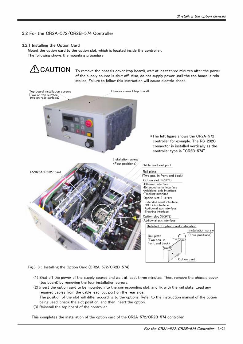
3.2.1 Installing the Option Card Mount the option card to the option slot, which is located inside the controller. The following shows the mounting procedure
To remove the chassis cover (top board), wait at least three minutes after the power of the supply source is shut off. Also, do not supply power until the top board is rein-stalled. Failure to follow this instruction will cause electric shock.
Fig.3-3 : Installing the Option Card (CR2A-572/CR2B-574)
(1) Shut off the power of the supply source and wait at least three minutes. Then, remove the chassis cover (top board) by removing the four installation screws.
(2) Insert the option card to be mounted into the corresponding slot, and fix with the rail plate. Lead any required cables from the cable lead-out port on the rear side. The position of the slot will differ according to the options. Refer to the instruction manual of the option being used, check the slot position, and then insert the option.
(3) Reinstall the top board of the controller.
This completes the installation of the option card of the CR2A-572/CR2B-574 controller.
CAUTION
RZ326A/RZ327 card
Installation screw(Four positions) Cable lead-out port
Rail plate(Two pcs. in front and back)
Option card
Option slot 1(OPT1)
Option slot 2(OPT2)
Option slot 3(OPT3)
Installation screw
(Four positions)Rail plate(Two pcs. in front and back)
Detailed of option card installation
・Ethernet interface・Extended serial interface・Additional axis interface・Tracking interface
・Extended serial interface・CC-Link interface・Additional axis interface・Tracking interface
・Additional axis interface
Top board installation screws(Two on top surface,two on rear surface)
Chassis cover (Top board)
*The left figure shows the CR2A-572 controller for example. The RS-232C connector is installed vertically as the controller type is "CR2B-574".
3-22 For the CR2A-572/CR2B-574 Controller
3Installing the option devices
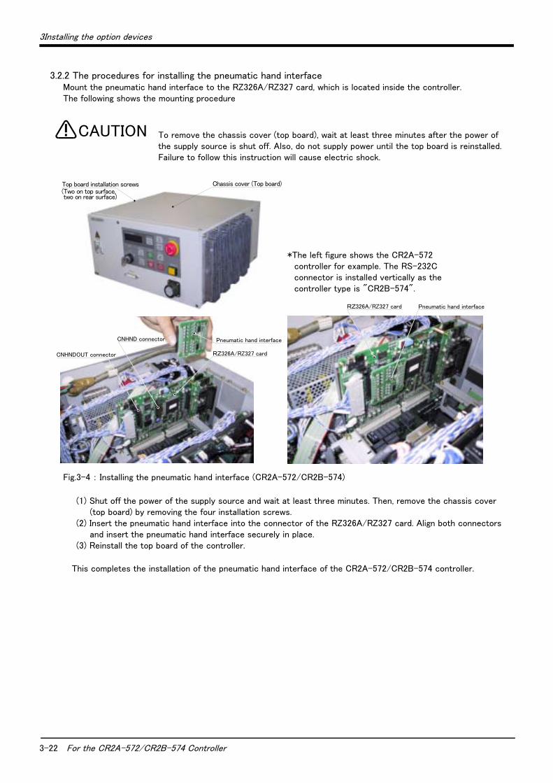
3.2.2 The procedures for installing the pneumatic hand interfaceMount the pneumatic hand interface to the RZ326A/RZ327 card, which is located inside the controller. The following shows the mounting procedure
To remove the chassis cover (top board), wait at least three minutes after the power of the supply source is shut off. Also, do not supply power until the top board is reinstalled. Failure to follow this instruction will cause electric shock.
Fig.3-4 : Installing the pneumatic hand interface (CR2A-572/CR2B-574)
(1) Shut off the power of the supply source and wait at least three minutes. Then, remove the chassis cover (top board) by removing the four installation screws.
(2) Insert the pneumatic hand interface into the connector of the RZ326A/RZ327 card. Align both connectors and insert the pneumatic hand interface securely in place.
(3) Reinstall the top board of the controller.
This completes the installation of the pneumatic hand interface of the CR2A-572/CR2B-574 controller.
CAUTION
Top board installation screws(Two on top surface,two on rear surface)
Chassis cover (Top board)
Pneumatic hand interface
CNHNDOUT connector
CNHND connector
RZ326A/RZ327 card
RZ326A/RZ327 card Pneumatic hand interface
*The left figure shows the CR2A-572 controller for example. The RS-232C connector is installed vertically as the controller type is "CR2B-574".

3Installing the option devices
For the CR2-532M Controller 3-23
3.3 For the CR2-532M Controller
To install an option card in the control unit (R6x2CPU) when the CR2-532 controller is used, remove the R6x2CPU's option fixing plate. The procedures are explained in "3.3.1Removing and Installing the R6x2CPU (Installing the Option Card )" below, so refer to that section when installing the option card.
3.3.1 Removing and Installing the R6x2CPU (Installing the Option Card )The option card, mounted on the control unit (R6x2CPU), after removing the R6x2CPU option fixing plate. The procedure of removing is explained below.
Confirm that the controller's main power supply and controller power switch are OFF before starting this work. Wait at least three minutes after turning the power OFF before opening the controller front door.
On the R6x2CPU, the cables are connected with the connectors and terminal block. Take care not to pull the cables when removing.
(1) Wait at least three minutes after turning the power OFF, then loosen the fixing screws on the controller front door, and open the front door.
(2) Remove the two M5 screws (top/bottom) fixing the R6x2CPU, and then pull out the R6x2CPU. Take care not to pull the cables at this time.
(3) Disconnect the connectors and FG cable connected to the R6x2CPU, and pull out the unit. The connectors and terminal block to be disconnected are shown in Fig. 3-5 (c)
Fig.3-5 : Remove the R6x2CPU (CR2-532M)
CAUTION
R6x2CPU
(a)The position of R6x2CPUControl unit(R6x2CPU)
(b)Removing of R6x2CPU
Fixing screwM5×2
(c)Removing of connector and terminal cable
Front door(Fixing screws x 2)
R6x2CPU
Connector:CN1A
Connector:CONOP
Connector:CNSIO1
Connector:CNSIO2
Connector:CNHND1
Connector:CNHND2
Connector:CNEMG
Connector:EXTEMG
Connector:DCIN
Front viewBottom view
Front
3-24 For the CR2-532M Controller
3Installing the option devices
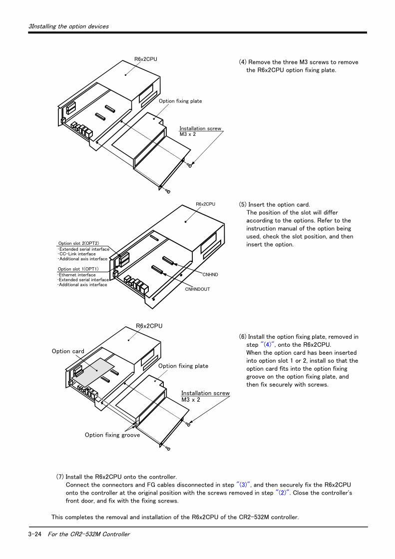
(4) Remove the three M3 screws to remove the R6x2CPU option fixing plate.
(5) Insert the option card. The position of the slot will differ according to the options. Refer to the instruction manual of the option being used, check the slot position, and then insert the option.
(6) Install the option fixing plate, removed in step "(4)", onto the R6x2CPU. When the option card has been inserted into option slot 1 or 2, install so that the option card fits into the option fixing groove on the option fixing plate, and then fix securely with screws.
(7) Install the R6x2CPU onto the controller. Connect the connectors and FG cables disconnected in step "(3)", and then securely fix the R6x2CPU onto the controller at the original position with the screws removed in step "(2)". Close the controller's front door, and fix with the fixing screws.
This completes the removal and installation of the R6x2CPU of the CR2-532M controller.
Installation screwM3 x 2
Option fixing plate
R6x2CPU
R6x2CPU
Option slot 2(OPT2)
Option slot 1(OPT1)CNHND
CNHNDOUT
・Ethernet interface・Extended serial interface・Additional axis interface
・Extended serial interface・CC-Link interface・Additional axis interface
Installation screwM3 x 2
Option fixing plate
R6x2CPU
Option fixing groove
Option card

3Installing the option devices
For the CR2-532M Controller 3-25
3.3.2 The procedures for installing the pneumatic hand interfaceThe procedures for installing the pneumatic hand interface, mounted on R6x2CPU, are explained below.
Confirm that the controller's main power supply and controller power switch are OFF before starting this work.
(1) Refer to steps "(1)" to "(4)" section "3.3.1Removing and Installing the R6x2CPU (Installing the Option Card )", and remove the controller over. Remove the R6x2CPU option fixing plate.
(2) The pneumatic hand interface is mounted on the RZ181 card in the R6x2CPU. Install by securely inserting the CNHDNOUT/CNHND connectors on the card into the pneumatic hand interface connectors.
Fig.3-6 : Installing the pneumatic hand interface(CR2-532M)
(3) Refer to steps "(6)" and "(7)" of section "3.1.1Removing and Installing the R6x2CPU Option Fixing Plate", and install the R6x2CPU option fixing plate, and return the controller cover.
This completes the installation of the CR2-532M controller's pneumatic hand interface.
CAUTION
<RZ181 card>
CNHNDOUT
CNHNDOUT
CNHND
CNHND
Pneumatic hand interface
Connector surface figure
R6x2CPU
CNHND
CNHNDOUT
RZ181 card
3-26 Installation of the controller protection box (CR2A-MB) (CR2A-574 controller only)
3Installing the option devices
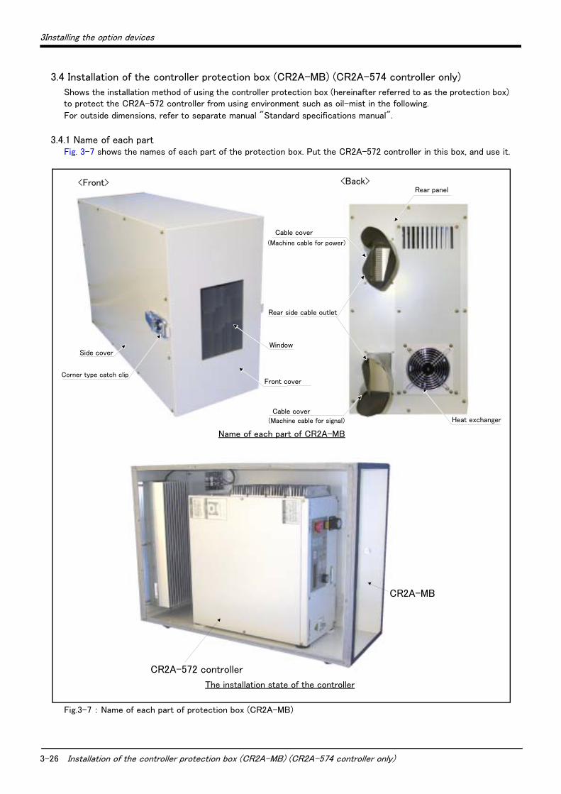
3.4 Installation of the controller protection box (CR2A-MB) (CR2A-574 controller only)
Shows the installation method of using the controller protection box (hereinafter referred to as the protection box) to protect the CR2A-572 controller from using environment such as oil-mist in the following.
For outside dimensions, refer to separate manual "Standard specifications manual".
3.4.1 Name of each partFig. 3-7 shows the names of each part of the protection box. Put the CR2A-572 controller in this box, and use it.
Fig.3-7 : Name of each part of protection box (CR2A-MB)
Side cover
<Front> <Back>
Rear side cable outlet
Front cover
Window
Corner type catch clip
Cable cover
(Machine cable for power)
Cable cover(Machine cable for signal) Heat exchanger
Rear panel
The installation state of the controller
CR2A-572 controller
CR2A-MB
Name of each part of CR2A-MB
3Installing the option devices
Installation of the controller protection box (CR2A-MB) (CR2A-574 controller only) 3-27
3.4.2 Confirmation before installation
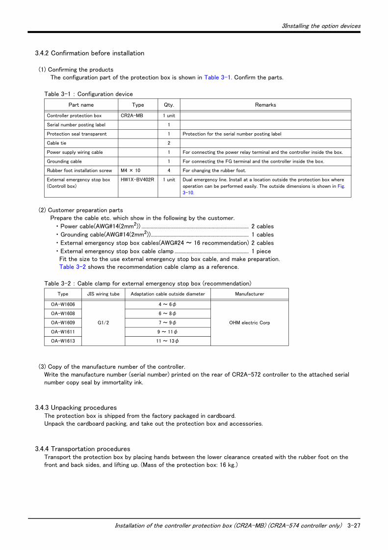
(1) Confirming the productsThe configuration part of the protection box is shown in Table 3-1. Confirm the parts.
Table 3-1 : Configuration device
(2) Customer preparation partsPrepare the cable etc. which show in the following by the customer.
・ Power cable(AWG#14(2mm2)) ................................................................................. 2 cables
・ Grounding cable(AWG#14(2mm2)).......................................................................... 1 cables
・ External emergency stop box cables(AWG#24 ~ 16 recommendation) 2 cables
・ External emergency stop box cable clamp ........................................................ 1 piece Fit the size to the use external emergency stop box cable, and make preparation. Table 3-2 shows the recommendation cable clamp as a reference.
Table 3-2 : Cable clamp for external emergency stop box (recommendation)
(3) Copy of the manufacture number of the controller.Write the manufacture number (serial number) printed on the rear of CR2A-572 controller to the attached serial number copy seal by immortality ink.
3.4.3 Unpacking proceduresThe protection box is shipped from the factory packaged in cardboard. Unpack the cardboard packing, and take out the protection box and accessories.
3.4.4 Transportation proceduresTransport the protection box by placing hands between the lower clearance created with the rubber foot on the front and back sides, and lifting up. (Mass of the protection box: 16 kg.)
Part name Type Qty. Remarks
Controller protection box CR2A-MB 1 unit
Serial number posting label 1
Protection seal transparent 1 Protection for the serial number posting label
Cable tie 2
Power supply wiring cable 1 For connecting the power relay terminal and the controller inside the box.
Grounding cable 1 For connecting the FG terminal and the controller inside the box.
Rubber foot installation screw M4 × 10 4 For changing the rubber foot.
External emergency stop box
(Controll box)
HW1X-BV402R 1 unit Dual emergency line. Install at a location outside the protection box where
operation can be performed easily. The outside dimensions is shown in Fig.
3-10.
Type JIS wiring tube Adaptation cable outside diameter Manufacturer
OA-W1606
G1/2
4 ~ 6φ
OHM electric Corp
OA-W1608 6 ~ 8φ
OA-W1609 7 ~ 9φ
OA-W1611 9 ~ 11φ
OA-W1613 11 ~ 13φ
3-28 Installation of the controller protection box (CR2A-MB) (CR2A-574 controller only)
3Installing the option devices
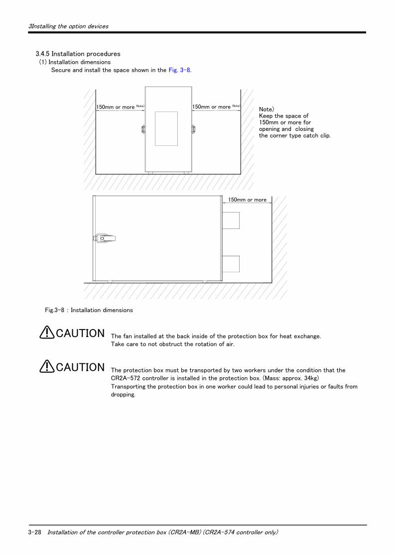
3.4.5 Installation procedures(1) Installation dimensions
Secure and install the space shown in the Fig. 3-8.
Fig.3-8 : Installation dimensions
The fan installed at the back inside of the protection box for heat exchange. Take care to not obstruct the rotation of air.
The protection box must be transported by two workers under the condition that the CR2A-572 controller is installed in the protection box. (Mass: approx. 34kg)
Transporting the protection box in one worker could lead to personal injuries or faults from dropping.
150mm or more
150mm or more Note)150mm or more Note)Note)Keep the space of 150mm or more for opening and closing the corner type catch clip.
CAUTION
CAUTION
3Installing the option devices
Installation of the controller protection box (CR2A-MB) (CR2A-574 controller only) 3-29
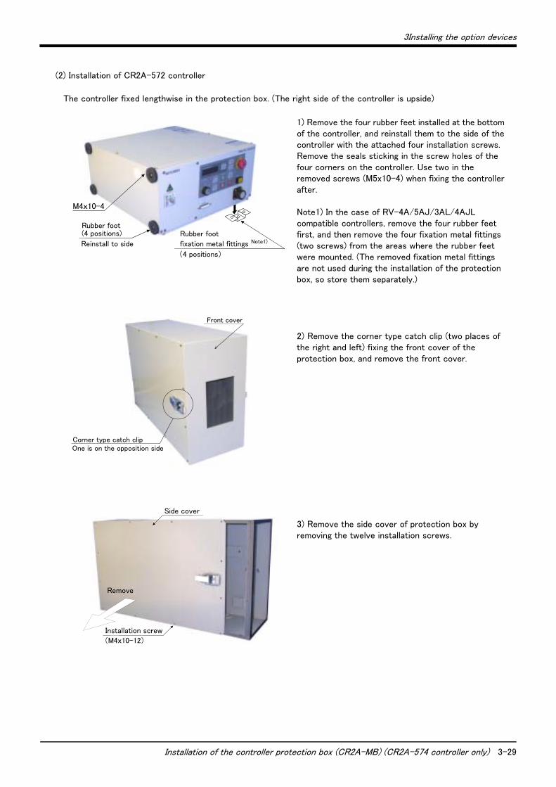
(2) Installation of CR2A-572 controller
The controller fixed lengthwise in the protection box. (The right side of the controller is upside)
1) Remove the four rubber feet installed at the bottom of the controller, and reinstall them to the side of the controller with the attached four installation screws. Remove the seals sticking in the screw holes of the four corners on the controller. Use two in the removed screws (M5x10-4) when fixing the controller after. Note1) In the case of RV-4A/5AJ/3AL/4AJL compatible controllers, remove the four rubber feet first, and then remove the four fixation metal fittings (two screws) from the areas where the rubber feet were mounted. (The removed fixation metal fittings are not used during the installation of the protection box, so store them separately.)
2) Remove the corner type catch clip (two places of the right and left) fixing the front cover of the protection box, and remove the front cover.
3) Remove the side cover of protection box by removing the twelve installation screws.
M4x10-4
Rubber foot
fixation metal fittings Note1)
(4 positions)
Rubber foot (4 positions)
Reinstall to side
Front cover
Corner type catch clip One is on the opposition side
Remove
Side cover
(M4x10-12)
Installation screw
3-30 Installation of the controller protection box (CR2A-MB) (CR2A-574 controller only)
3Installing the option devices
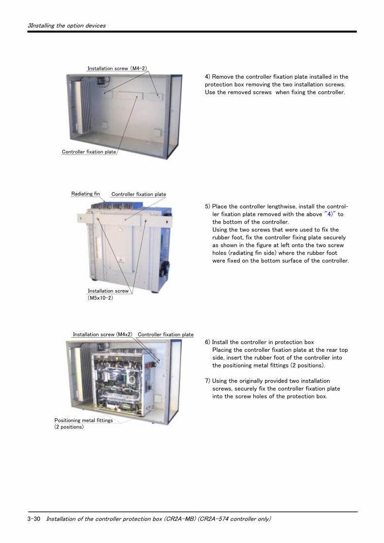
4) Remove the controller fixation plate installed in the protection box removing the two installation screws. Use the removed screws when fixing the controller.
5) Place the controller lengthwise, install the control-ler fixation plate removed with the above "4)" to the bottom of the controller. Using the two screws that were used to fix the rubber foot, fix the controller fixing plate securely as shown in the figure at left onto the two screw holes (radiating fin side) where the rubber foot were fixed on the bottom surface of the controller.
6) Install the controller in protection box Placing the controller fixation plate at the rear top side, insert the rubber foot of the controller into the positioning metal fittings (2 positions).
7) Using the originally provided two installation screws, securely fix the controller fixation plate into the screw holes of the protection box.
Installation screw (M4-2)
Controller fixation plate
Controller fixation plate
Installation screw
(M5x10-2)
Radiating fin
Controller fixation plateInstallation screw (M4x2)
Positioning metal fittings(2 positions)
3Installing the option devices
Installation of the controller protection box (CR2A-MB) (CR2A-574 controller only) 3-31
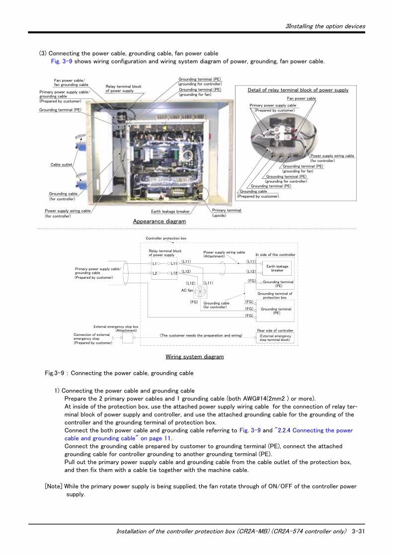
(3) Connecting the power cable, grounding cable, fan power cableFig. 3-9 shows wiring configuration and wiring system diagram of power, grounding, fan power cable.
Fig.3-9 : Connecting the power cable, grounding cable
1) Connecting the power cable and grounding cable Prepare the 2 primary power cables and 1 grounding cable (both AWG#14(2mm2 ) or more). At inside of the protection box, use the attached power supply wiring cable for the connection of relay ter-minal block of power supply and controller, and use the attached grounding cable for the grounding of the controller and the grounding terminal of protection box. Connect the both power cable and grounding cable referring to Fig. 3-9 and "2.2.4 Connecting the power cable and grounding cable" on page 11. Connect the grounding cable prepared by customer to grounding terminal (PE), connect the attached grounding cable for controller grounding to another grounding terminal (PE). Pull out the primary power supply cable and grounding cable from the cable outlet of the protection box, and then fix them with a cable tie together with the machine cable.
[Note] While the primary power supply is being supplied, the fan rotate through of ON/OFF of the controller power supply.
Relay terminal block of power supply
Grounding terminal (PE)
(Prepared by customer)
Primary power supply cable/grounding cable
Fan power cable/ fan grounding cable
Grounding terminal (PE)
Grounding terminal (PE)
(grounding for controller)
(grounding for fan)
Earth leakage breaker Primary terminal
(for controller)
Grounding cable
Cable outlet
(for controller)
Power supply wiring cable(upside)
Appearance diagram
Detail of relay terminal block of power supply
(Prepared by customer)Primary power supply cable
Fan power cable
Grounding terminal (PE)
(grounding for controller)
(grounding for fan)
(for controller)Power supply wiring cable
Grounding terminal (PE)
Grounding terminal (PE)
Grounding cable(Prepared by customer)
In side of the controller
Controller protection box
Rear side of controller
(FG)
AC fan
(L11)
(L12)
L1
L2
L11
L12
(L12) (L11)
(The customer needs the preparation and wiring)
(Attachment)
(Prepared by customer)
Primary power supply cable/grounding cable
Power supply wiring cableRelay terminal block of power supply
Grounding cable(for controller)
Grounding terminal (PE)
Earth leakage breaker
External emergency stop box(Attachment)
(Prepared by customer)
(External emergency stop terminal block)
Grounding terminal (PE)
Wiring system diagram
Connecton of external emergency stop
Grounding terminal of protection box
(L11)
(L12)
(FG)
(FG)
(FG)
(FG)
3-32 Installation of the controller protection box (CR2A-MB) (CR2A-574 controller only)
3Installing the option devices
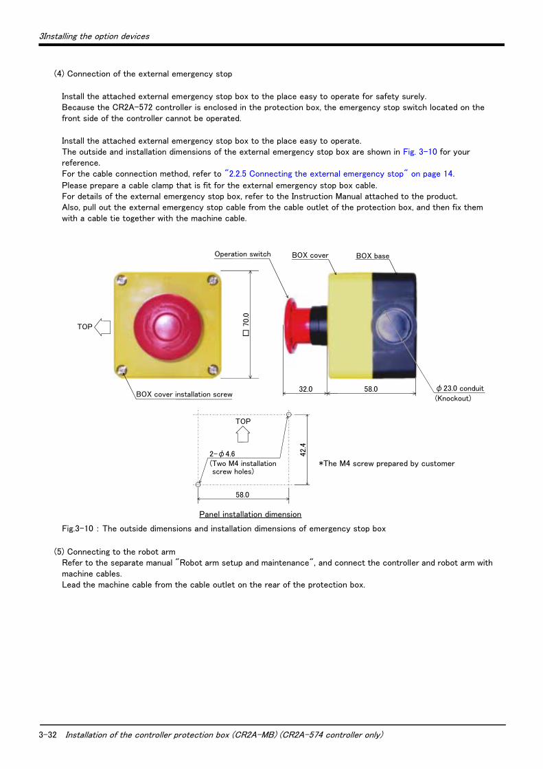
(4) Connection of the external emergency stop
Install the attached external emergency stop box to the place easy to operate for safety surely. Because the CR2A-572 controller is enclosed in the protection box, the emergency stop switch located on the front side of the controller cannot be operated.
Install the attached external emergency stop box to the place easy to operate. The outside and installation dimensions of the external emergency stop box are shown in Fig. 3-10 for your reference. For the cable connection method, refer to "2.2.5 Connecting the external emergency stop" on page 14.
Please prepare a cable clamp that is fit for the external emergency stop box cable. For details of the external emergency stop box, refer to the Instruction Manual attached to the product. Also, pull out the external emergency stop cable from the cable outlet of the protection box, and then fix them with a cable tie together with the machine cable.
Fig.3-10 : The outside dimensions and installation dimensions of emergency stop box
(5) Connecting to the robot armRefer to the separate manual "Robot arm setup and maintenance", and connect the controller and robot arm with machine cables. Lead the machine cable from the cable outlet on the rear of the protection box.
Operation switch
TOP
32.0 58.0
□ 7
0.0
BOX cover BOX base
BOX cover installation screwφ23.0 conduit
(Knockout)
*The M4 screw prepared by customer
TOP
2-φ4.6(Two M4 installation screw holes)
58.0
42.4
Panel installation dimension
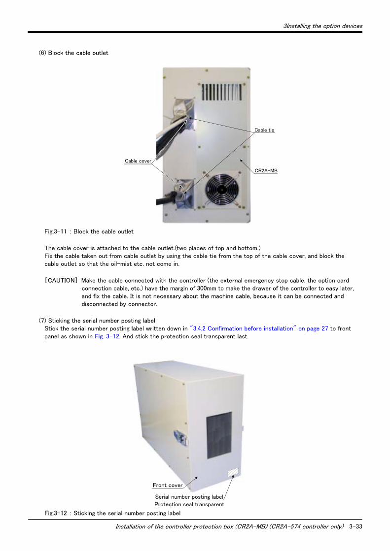
3Installing the option devices
Installation of the controller protection box (CR2A-MB) (CR2A-574 controller only) 3-33
(6) Block the cable outlet
Fig.3-11 : Block the cable outlet
The cable cover is attached to the cable outlet.(two places of top and bottom.) Fix the cable taken out from cable outlet by using the cable tie from the top of the cable cover, and block the cable outlet so that the oil-mist etc. not come in.
[CAUTION] Make the cable connected with the controller (the external emergency stop cable, the option card connection cable, etc.) have the margin of 300mm to make the drawer of the controller to easy later, and fix the cable. It is not necessary about the machine cable, because it can be connected and disconnected by connector.
(7) Sticking the serial number posting labelStick the serial number posting label written down in "3.4.2 Confirmation before installation" on page 27 to front panel as shown in Fig. 3-12. And stick the protection seal transparent last.
Fig.3-12 : Sticking the serial number posting label
Cable cover
CR2A-MB
Cable tie
Front cover
Serial number posting labelProtection seal transparent

3-34 Installation of the controller protection box (CR2A-MB) (CR2A-574 controller only)
3Installing the option devices
(8) Installation of side cover and front panelRemove the sheet on the surface of packing stuck on the side cover contact part at the up side of the protection box. Reinstall the side cover and securely fix with twelve screws. Reinstall the front panel, and close the catch clip (two places of the right and left) for fixing the panel.
Fig.3-13 : Installation of side cover, front panel
(9) Installing of the protection boxSecure and install the installation dimension shown in "3.4.5 Installation procedures" on page 28. The installation is only put with the rubber foot facing the bottom, because the protection box is self-contained floor type. Moreover when fixing the protection box by fixing screw, remove the rubber feet removing the installation screws of rubber feet, and fix the protection box by M4 screw with the screw holes (M4) which the rubber feet were fixed on.
The protection box must be transported by two workers under the condition that the CR2A-572 controller is installed in the protection box. (Mass: approx. 34kg)
Transporting the protection box in one worker could lead to personal injuries or faults from dropping.
This completes the installation of the protection box.
3.4.6 Handling the protection box(1) Operation with removing the panel
The power supply ON/OFF of the controller, the operation of the front panel, the operation under the condition that T/B is connected are carried out under the condition that the front panel of protection box is removed.
CR2A-MBRemove the seetPacking
CAUTION
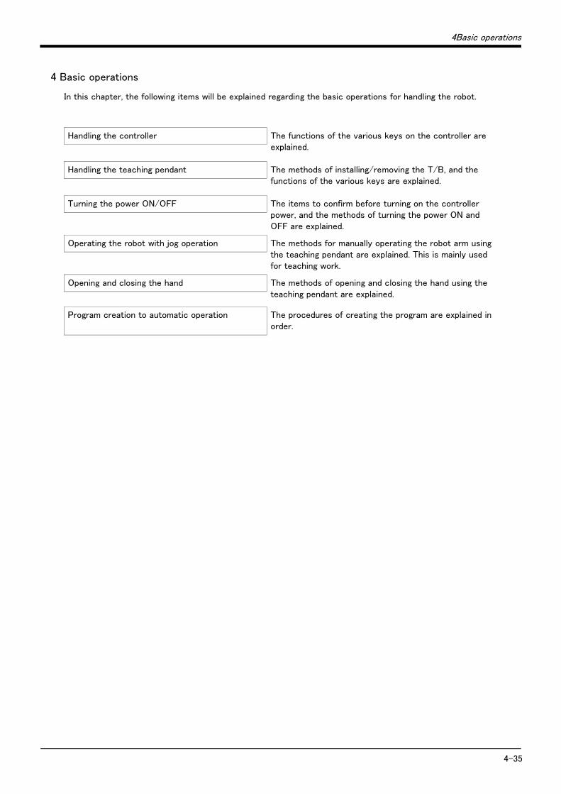
4Basic operations
4-35
4 Basic operations
In this chapter, the following items will be explained regarding the basic operations for handling the robot.
Handling the controller The functions of the various keys on the controller are explained.
Handling the teaching pendant The methods of installing/removing the T/B, and the functions of the various keys are explained.
Turning the power ON/OFF The items to confirm before turning on the controller power, and the methods of turning the power ON and OFF are explained.
Operating the robot with jog operation The methods for manually operating the robot arm using the teaching pendant are explained. This is mainly used for teaching work.
Opening and closing the hand The methods of opening and closing the hand using the teaching pendant are explained.
Program creation to automatic operation The procedures of creating the program are explained in order.

4-36 Handling the controller
4Basic operations
4.1 Handling the controller
4.1.1 Functions of each key
Fig.4-1 : Names of controller parts(CR2-532/CR2A-572/CR2B-574)
Front operation panel
12)10)13) 3) 8)1)
6)
5)15)4)7)
2)9)
11)14)
<CR2-532>
<CR2A-572>
12)
11)
7)
8)9)
5)
6)10)
2)
3)
4) 1)
SVO OFF STOP END
SVO ONMODE
TEACH
AUTO (Ext.)
AUTO (Op.)
START RESET
DOWN
UP
STATUS NUMBER
DSUB
CR2
REMOVE T/B
EMG.STOPCHANG DISP
T/B
13)
15)
Front operation panel
<Front>
SVO OFFSTOP
END
SVO ON
MODE
TEACH
AUTO (Ext.)
AUTO (Op.)
STARTRESET
DOWN
UP
STATUS NUMBER
DSUB
CR2
REMOVE T/B
EMG.STOP
CHANG DISP
T/B
14)
<Front side of operation panel>
Front operation panel
12)10) 13)3) 8)1)
6)
5)15)4)7)2)9)11)14)
<CR2B-574>
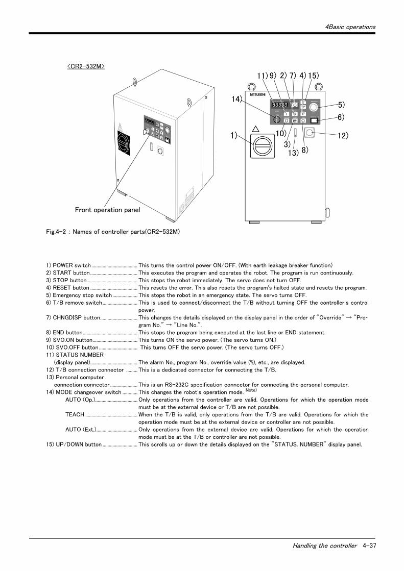
4Basic operations
Handling the controller 4-37
Fig.4-2 : Names of controller parts(CR2-532M)
1) POWER switch ..................................... This turns the control power ON/OFF. (With earth leakage breaker function)2) START button...................................... This executes the program and operates the robot. The program is run continuously.3) STOP button......................................... This stops the robot immediately. The servo does not turn OFF.4) RESET button ...................................... This resets the error. This also resets the program's halted state and resets the program.5) Emergency stop switch .................... This stops the robot in an emergency state. The servo turns OFF.6) T/B remove switch............................ This is used to connect/disconnect the T/B without turning OFF the controller's control
power.7) CHNGDISP button.............................. This changes the details displayed on the display panel in the order of "Override" → "Pro-
gram No." → "Line No.".8) END button............................................ This stops the program being executed at the last line or END statement.9) SVO.ON button.................................... This turns ON the servo power. (The servo turns ON.)10) SVO.OFF button............................... This turns OFF the servo power. (The servo turns OFF.)11) STATUS NUMBER (display panel)...................................... The alarm No., program No., override value (%), etc., are displayed.12) T/B connection connector ......... This is a dedicated connector for connecting the T/B.13) Personal computer connection connector ...................... This is an RS-232C specification connector for connecting the personal computer.14) MODE changeover switch ............ This changes the robot's operation mode. Note)
AUTO (Op.).................................. Only operations from the controller are valid. Operations for which the operation mode must be at the external device or T/B are not possible.
TEACH .......................................... When the T/B is valid, only operations from the T/B are valid. Operations for which the operation mode must be at the external device or controller are not possible.
AUTO (Ext.)................................. Only operations from the external device are valid. Operations for which the operation mode must be at the T/B or controller are not possible.
15) UP/DOWN button ............................ This scrolls up or down the details displayed on the "STATUS. NUMBER" display panel.
1)
SVO OFF STOP END
SVO ONMODE
TEACH
AUTO (Ext.)
AUTO (Op.)
START RESET
DOWN
UP
REMOVE T/B
EMG.STOPCHANG DISP
7)2) 15)
5)
4)11)
14)
8)
9)
6)
3)12)
13)
Front operation panel
10)
STATUS NUMBER
<CR2-532M>
4-38 Handling the controller
4Basic operations
Note) The servo will turn OFF when the controller's [MODE] switch is changed. Note that axes not provided with brakes could drop with their own weight. Carry out the following operations to prevent the servo from turning OFF whenthe [MODE] switch is changed.
The servo on status can be maintained by changing the mode with keeping pressing lightly the deadman switch of T/B. The operating method is shown below.
■ When the mode is changed from TEACH to AUTO.1) While holding down the deadman switch on the T/B, set the [ENABLE/DISABLE]
switch to "DISABLE".2) While holding down the deadman switch on the T/B, set the controller [MODE]
switch to "AUTO".3) Release the T/B deadman switch.
■ When the mode is changed from AUTO to TEACH.1) While the [ENABLE/DISABLE] switch on the T/B is "DISABLE", hold down the
deadman switch.2) While holding down the deadman switch on the T/B, set the controller [MODE]
switch to "TEACH".3) While holding down the deadman switch on the T/B, set the [ENABLE/DISABLE]
switch to "ENABLE", then do the operation of T/B that you wish.
CAUTION
◇◆◇ What are the operation rights? ◇◆◇Even when multiple devices, such as a T/B and personal computer, are connected to the controller, the operation at one time is limited to one device. This limited device (has the operation rights)
◇◆◇ What operations require the operation rights? ◇◆◇Operations that start the robot, such as program start and alarm reset, and operations that can cause starting require the operation rights.Conversely, operation that stop the robot, such as stopping and servo OFF, can be used without the operation rights for safety purposes. Refer to the separate manual "Explanation of functions and operations" for details on the functions related to operation rights.
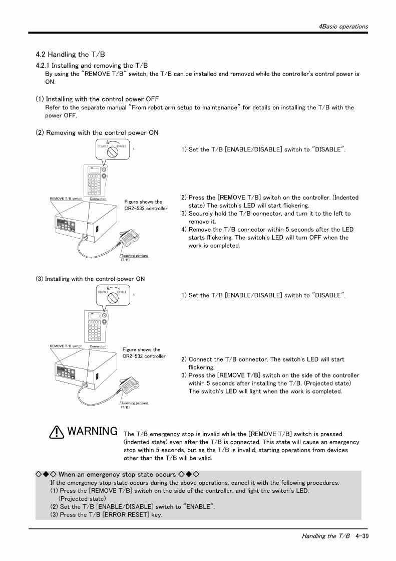
4Basic operations
Handling the T/B 4-39
4.2 Handling the T/B
4.2.1 Installing and removing the T/BBy using the "REMOVE T/B" switch, the T/B can be installed and removed while the controller's control power is ON.
(1) Installing with the control power OFFRefer to the separate manual "From robot arm setup to maintenance" for details on installing the T/B with the power OFF.
(2) Removing with the control power ON
1) Set the T/B [ENABLE/DISABLE] switch to "DISABLE".
2) Press the [REMOVE T/B] switch on the controller. (Indented state) The switch's LED will start flickering.
3) Securely hold the T/B connector, and turn it to the left to remove it.
4) Remove the T/B connector within 5 seconds after the LED starts flickering. The switch's LED will turn OFF when the work is completed.
(3) Installing with the control power ON
1) Set the T/B [ENABLE/DISABLE] switch to "DISABLE".
2) Connect the T/B connector. The switch's LED will start flickering.
3) Press the [REMOVE T/B] switch on the side of the controller within 5 seconds after installing the T/B. (Projected state) The switch's LED will light when the work is completed.
The T/B emergency stop is invalid while the [REMOVE T/B] switch is pressed (indented state) even after the T/B is connected. This state will cause an emergency stop within 5 seconds, but as the T/B is invalid, starting operations from devices other than the T/B will be valid.
SVO OFFSTOP
END
SVO ON
MODE
TEACH
AUTO (Ext.)
AUTO (Op.)
STARTRESET
DOWN
UP
STATUS NUMBER
DSUB
CR2
REMOVE T/B
EMG.STOP
CHANG DISP
T/B
Teaching pendant(T/B)
REMOVE T/B switch
Connector
P8TB-TE
DISABLE ENABLE
EMG.STOP
DISABLE ENABLE
Figure shows the
CR2-532 controller
P8TB-TE
DISABLE ENABLE
EMG.STOP
DISABLE ENABLE
SVO OFFSTOP
END
SVO ON
MODE
TEACH
AUTO (Ext.)
AUTO (Op.)
STARTRESET
DOWN
UP
STATUS NUMBER
DSUB
CR2
REMOVE T/B
EMG.STOP
CHANG DISP
T/B
Teaching pendant(T/B)
REMOVE T/B switch
ConnectorFigure shows the
CR2-532 controller
WARNING
◇◆◇ When an emergency stop state occurs ◇◆◇If the emergency stop state occurs during the above operations, cancel it with the following procedures.(1) Press the [REMOVE T/B] switch on the side of the controller, and light the switch's LED. (Projected state)(2) Set the T/B [ENABLE/DISABLE] switch to "ENABLE".(3) Press the T/B [ERROR RESET] key.
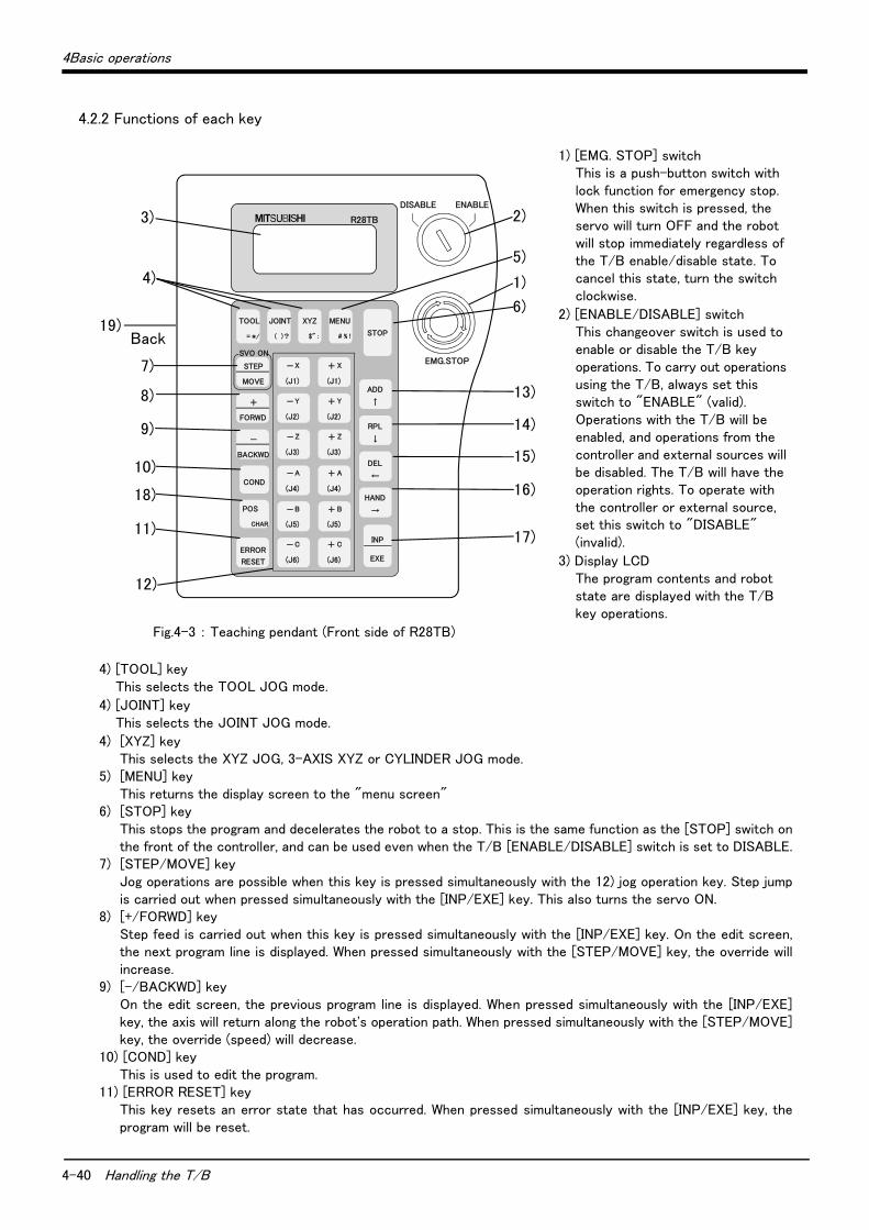
4-40 Handling the T/B
4Basic operations
4.2.2 Functions of each key
1) [EMG. STOP] switch This is a push-button switch with lock function for emergency stop. When this switch is pressed, the servo will turn OFF and the robot will stop immediately regardless of the T/B enable/disable state. To cancel this state, turn the switch clockwise.
2) [ENABLE/DISABLE] switch This changeover switch is used to enable or disable the T/B key operations. To carry out operations using the T/B, always set this switch to "ENABLE" (valid). Operations with the T/B will be enabled, and operations from the controller and external sources will be disabled. The T/B will have the operation rights. To operate with the controller or external source, set this switch to "DISABLE" (invalid).
3) Display LCD The program contents and robot state are displayed with the T/B key operations.
Fig.4-3 : Teaching pendant (Front side of R28TB)
4) [TOOL] key This selects the TOOL JOG mode.
4) [JOINT] key This selects the JOINT JOG mode.
4) [XYZ] key This selects the XYZ JOG, 3-AXIS XYZ or CYLINDER JOG mode.
5) [MENU] key This returns the display screen to the "menu screen"
6) [STOP] key This stops the program and decelerates the robot to a stop. This is the same function as the [STOP] switch on the front of the controller, and can be used even when the T/B [ENABLE/DISABLE] switch is set to DISABLE.
7) [STEP/MOVE] key Jog operations are possible when this key is pressed simultaneously with the 12) jog operation key. Step jump is carried out when pressed simultaneously with the [INP/EXE] key. This also turns the servo ON.
8) [+/FORWD] key Step feed is carried out when this key is pressed simultaneously with the [INP/EXE] key. On the edit screen, the next program line is displayed. When pressed simultaneously with the [STEP/MOVE] key, the override will increase.
9) [-/BACKWD] key On the edit screen, the previous program line is displayed. When pressed simultaneously with the [INP/EXE] key, the axis will return along the robot's operation path. When pressed simultaneously with the [STEP/MOVE] key, the override (speed) will decrease.
10) [COND] key This is used to edit the program.
11) [ERROR RESET] key This key resets an error state that has occurred. When pressed simultaneously with the [INP/EXE] key, the program will be reset.
R28TB
1)
6)
5)
13)
2)
14)
15)
16)
17)
10)
3)
4)
12)
11)
18)
7)
8)
9)
DISABLE
EMG.STOP
TOOL
=*/
STEP
MOVE
+
FORWD
-
BACKWD
ADD
↑
RPL
↓
DEL
←
HAND
→
INP
EXE
COND
ERROR
RESET
POS
CHAR
JOINT
( )?
XYZ
$" :
MENU
STOP
-X
(J1)
+ X
(J1)
-Y
(J2)
+ Y
(J2)
-Z
(J3)
+ Z
(J3)
-A
(J4)
+ A
(J4)
-B
(J5)
+ B
(J5)
-C
(J6)
+ C
(J6)
SVO ON
ENABLE
# % !19)
Back
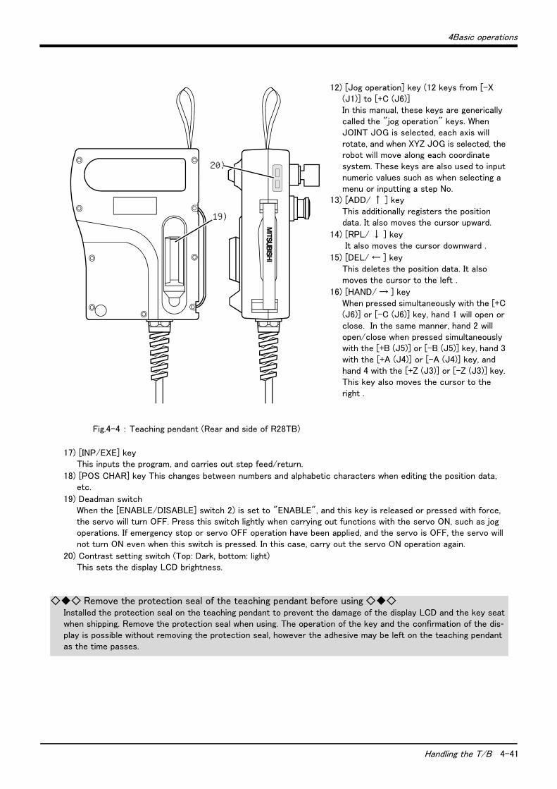
4Basic operations
Handling the T/B 4-41
12) [Jog operation] key (12 keys from [-X (J1)] to [+C (J6)] In this manual, these keys are generically called the "jog operation" keys. When JOINT JOG is selected, each axis will rotate, and when XYZ JOG is selected, the robot will move along each coordinate system. These keys are also used to input numeric values such as when selecting a menu or inputting a step No.
13) [ADD/ ↑ ] key This additionally registers the position data. It also moves the cursor upward.
14) [RPL/ ↓ ] key It also moves the cursor downward .
15) [DEL/ ← ] key This deletes the position data. It also moves the cursor to the left .
16) [HAND/ → ] key When pressed simultaneously with the [+C (J6)] or [-C (J6)] key, hand 1 will open or close. In the same manner, hand 2 will open/close when pressed simultaneously with the [+B (J5)] or [-B (J5)] key, hand 3 with the [+A (J4)] or [-A (J4)] key, and hand 4 with the [+Z (J3)] or [-Z (J3)] key. This key also moves the cursor to the right .
Fig.4-4 : Teaching pendant (Rear and side of R28TB)
17) [INP/EXE] key This inputs the program, and carries out step feed/return.
18) [POS CHAR] key This changes between numbers and alphabetic characters when editing the position data, etc.
19) Deadman switch When the [ENABLE/DISABLE] switch 2) is set to "ENABLE", and this key is released or pressed with force, the servo will turn OFF. Press this switch lightly when carrying out functions with the servo ON, such as jog operations. If emergency stop or servo OFF operation have been applied, and the servo is OFF, the servo will not turn ON even when this switch is pressed. In this case, carry out the servo ON operation again.
20) Contrast setting switch (Top: Dark, bottom: light) This sets the display LCD brightness.
19)
20)
◇◆◇ Remove the protection seal of the teaching pendant before using ◇◆◇Installed the protection seal on the teaching pendant to prevent the damage of the display LCD and the key seat when shipping. Remove the protection seal when using. The operation of the key and the confirmation of the dis-play is possible without removing the protection seal, however the adhesive may be left on the teaching pendant as the time passes.
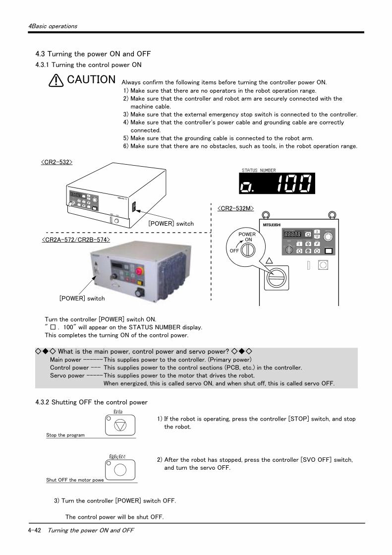
4-42 Turning the power ON and OFF
4Basic operations
4.3 Turning the power ON and OFF
4.3.1 Turning the control power ON
Always confirm the following items before turning the controller power ON.
1) Make sure that there are no operators in the robot operation range.2) Make sure that the controller and robot arm are securely connected with the
machine cable.3) Make sure that the external emergency stop switch is connected to the controller.4) Make sure that the controller's power cable and grounding cable are correctly
connected.5) Make sure that the grounding cable is connected to the robot arm.6) Make sure that there are no obstacles, such as tools, in the robot operation range.
Turn the controller [POWER] switch ON. " □ . 100" will appear on the STATUS NUMBER display. This completes the turning ON of the control power.
4.3.2 Shutting OFF the control power
1) If the robot is operating, press the controller [STOP] switch, and stop the robot.
2) After the robot has stopped, press the controller [SVO OFF] switch, and turn the servo OFF.
3) Turn the controller [POWER] switch OFF.
The control power will be shut OFF.
CAUTION
STATUS NUMBER
SVO OFFSTOP
END
SVO ON
MODE
TEACH
AUTO (Ext.)
AUTO (Op.)
STARTRESET
DOWN
UP
STATUS NUMBER
DSUB
CR2
REMOVE T/B
EMG.STOP
CHANG DISP
T/B
<CR2-532>
<CR2A-572/CR2B-574>
[POWER] switch
SVO OFF STOP END
SVO ONMODE
TEACH
AUTO (Ext.)
AUTO (Op.)
START RESET
DOWN
UP
STATUS NUMBER
REMOVE T/B
EMG.STOPCHANG DISP
ON
OFF
POWER
<CR2-532M>
[POWER] switch
◇◆◇ What is the main power, control power and servo power? ◇◆◇Main power ------This supplies power to the controller. (Primary power)Control power --- This supplies power to the control sections (PCB, etc.) in the controller.Servo power -----This supplies power to the motor that drives the robot.
When energized, this is called servo ON, and when shut off, this is called servo OFF.
STOP
SVO OFF
Shut OFF the motor powe
Stop the program

4Basic operations
Turning the servo power ON/OFF 4-43
4.4 Turning the servo power ON/OFF
4.4.1 Turning the servo power ON (servo ON)
1) Confirm that the T/B [ENABLE/DISABLE] switch is set to "DISABLE".
2) Confirm that the [MODE] switch on the front of the controller is set to "TEACH" or "Auto (Op.)".
3) Press the [SVO ON] switch on the front of the controller. The switch's lamp will light indicating that the servo is ON.
Make sure that there are not operators in the robot operation range before turning ON the servo.
4.4.2 Shutting OFF the servo power (servo OFF)
1) If the robot is operating, press the controller [STOP] switch on the front of the controller, and stop the robot.
2) After the robot has stopped, press the controller [SVO OFF] switch on the front of the controller, and turn the servo OFF. The switch's lamp will light indicating that the servo is OFF.
SVO ON
Controller enable
T/B disable
Turn ON the servo power
DISABLE ENABLE
TEACH
AUTO
(Ext.)AUTO (Op.)
MODE
CAUTION
STOP
SVO OFF
Stop the program
Shut OFF the servo
◇◆◇ Operation rights not required ◇◆◇This operation does not require the operation rights, so the servo can be turned OFF at any time by pressing the [SVO OFF] switch.
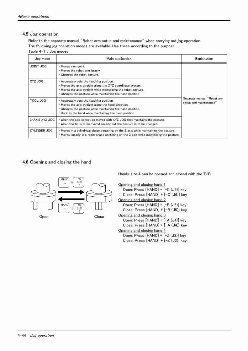
4-44 Jog operation
4Basic operations
4.5 Jog operation
Refer to the separate manual "Robot arm setup and maintenance" when carrying out jog operation.
The following jog operation modes are available. Use these according to the purpose.
Table 4-1 : Jog modes
4.6 Opening and closing the hand
Hands 1 to 4 can be opened and closed with the T/B.
Opening and closing hand 1 Open: Press [HAND] + [+C (J6)] key Close: Press [HAND] + [-C (J6)] key
Opening and closing hand 2 Open: Press [HAND] + [+B (J5)] key Close: Press [HAND] + [-B (J5)] key
Opening and closing hand 3 Open: Press [HAND] + [+A (J4)] key Close: Press [HAND] + [-A (J4)] key
Opening and closing hand 4 Open: Press [HAND] + [+Z (J3)] key Close: Press [HAND] + [-Z (J3)] key
Jog mode Main application Explanation
JOINT JOG ・ Moves each joint.
・ Moves the robot arm largely.
・ Changes the robot posture.
Separate manual "Robot arm
setup and maintenance"
XYZ JOG ・ Accurately sets the teaching position.
・ Moves the axis straight along the XYZ coordinate system.
・ Moves the axis straight while maintaining the robot posture.
・ Changes the posture while maintaining the hand position.
TOOL JOG ・ Accurately sets the teaching position.
・ Moves the axis straight along the hand direction.
・ Changes the posture while maintaining the hand position.
・ Rotates the hand while maintaining the hand position.
3-AXIS XYZ JOG ・ When the axis cannot be moved with XYZ JOG that maintains the posture.
・ When the tip is to be moved linearly but the posture is to be changed.
CYLINDER JOG ・ Moves in a cylindrical shape centering on the Z axis while maintaining the posture.
・ Moves linearly in a radial shape centering on the Z axis while maintaining the posture.
+
Open Close
HAND
→
+C(J6)5
HAND
→ +-C(J6)0
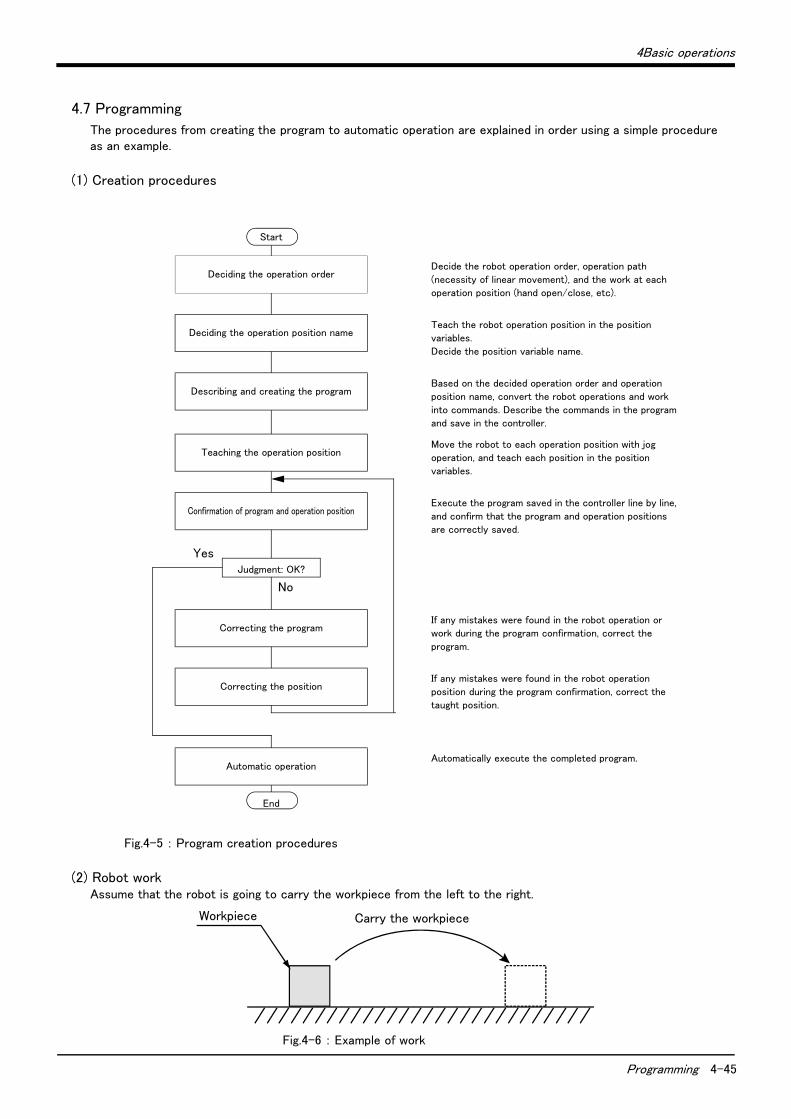
4Basic operations
Programming 4-45
4.7 Programming
The procedures from creating the program to automatic operation are explained in order using a simple procedure as an example.
(1) Creation procedures
Fig.4-5 : Program creation procedures
(2) Robot workAssume that the robot is going to carry the workpiece from the left to the right.
Fig.4-6 : Example of work
No
Yes
Start
Deciding the operation orderDecide the robot operation order, operation path
(necessity of linear movement), and the work at each
operation position (hand open/close, etc).
Deciding the operation position nameTeach the robot operation position in the position
variables.
Decide the position variable name.
Describing and creating the programBased on the decided operation order and operation
position name, convert the robot operations and work
into commands. Describe the commands in the program
and save in the controller.
Teaching the operation positionMove the robot to each operation position with jog
operation, and teach each position in the position
variables.
Confirmation of program and operation positionExecute the program saved in the controller line by line,
and confirm that the program and operation positions
are correctly saved.
Judgment: OK?
Correcting the programIf any mistakes were found in the robot operation or
work during the program confirmation, correct the
program.
Correcting the positionIf any mistakes were found in the robot operation
position during the program confirmation, correct the
taught position.
Automatic operationAutomatically execute the completed program.
End
Carry the workpieceWorkpiece
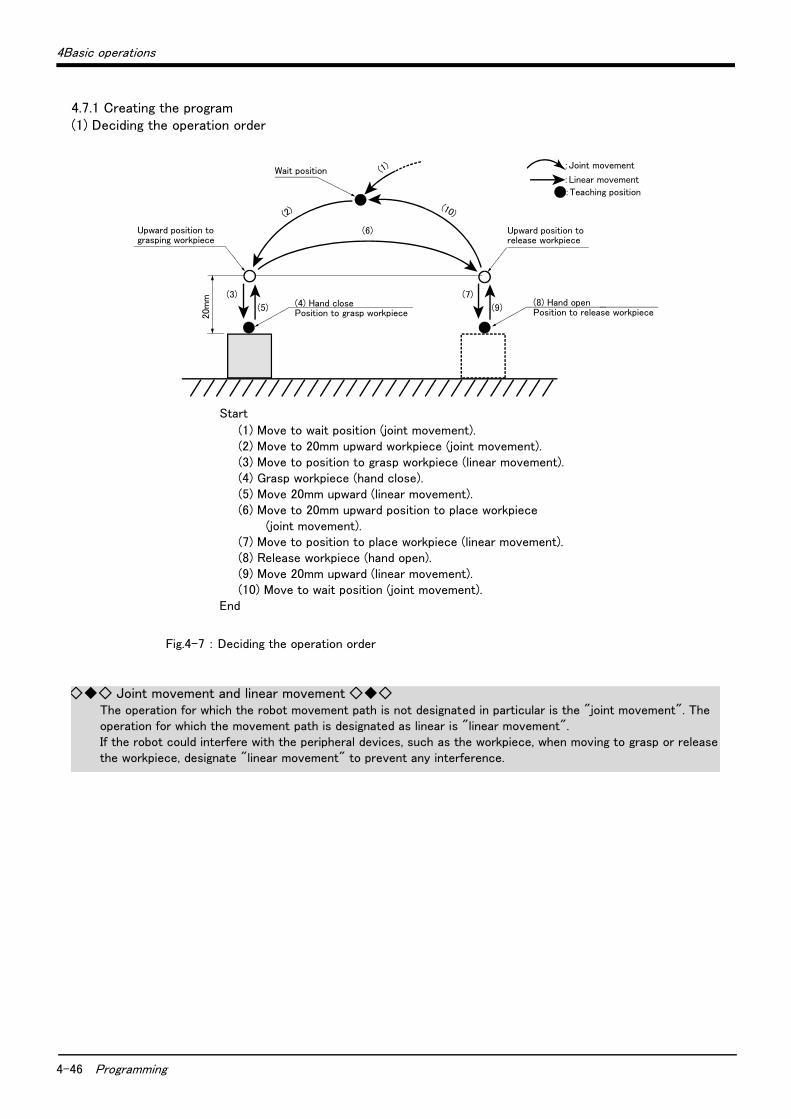
4-46 Programming
4Basic operations
4.7.1 Creating the program(1) Deciding the operation order
Fig.4-7 : Deciding the operation order
20m
m (3) (7)
(5) (9)
(10)
(4) Hand closePosition to grasp workpiece
Wait position
(6)
(2)
(1)
(8) Hand openPosition to release workpiece
:Joint movement
:Linear movement
:Teaching position
Upward position tograsping workpiece
Upward position torelease workpiece
Start
(1) Move to wait position (joint movement).(2) Move to 20mm upward workpiece (joint movement).(3) Move to position to grasp workpiece (linear movement).(4) Grasp workpiece (hand close).(5) Move 20mm upward (linear movement).(6) Move to 20mm upward position to place workpiece
(joint movement).(7) Move to position to place workpiece (linear movement).(8) Release workpiece (hand open).(9) Move 20mm upward (linear movement).(10) Move to wait position (joint movement).
End
◇◆◇ Joint movement and linear movement ◇◆◇The operation for which the robot movement path is not designated in particular is the "joint movement". The operation for which the movement path is designated as linear is "linear movement". If the robot could interfere with the peripheral devices, such as the workpiece, when moving to grasp or release the workpiece, designate "linear movement" to prevent any interference.

4Basic operations
Programming 4-47
(2) Deciding the operation position name
Fig.4-8 : Deciding the operation position name
20m
m Position to grasp workpiece
(PGET)
Position to releaseworkpiece
(PPUT)
Wait position
(PWAIT)
Upward position tograsping workpiece
Upward position torelease workpiece
Position variable name ・・・・ Designate a random character string starting with "P". Up to eight characters can be designated.
NamePosition
variable nameTeaching Remarks
Wait position PWAIT Required
Upward position to grasping
workpiece
- Not required Designate with commands.
Position to grasp workpiece PGET Required
Upward position to release workpiece - Not required Designate with commands.
Position to release workpiece PPUT Required
◇◆◇ Teaching the operation position ◇◆◇The operation position does not necessarily need to be taught.The positions shown with white circles in Fig. 4-8 can be designated with commands as "position 20mm away from target position". Refer to "(3) Describing and creating the program" on page 48.
The designation of the direction separated from the target position differs according to the robot type.
The position is along the Z axis of the TOOL coordinate system, and the direction is designated with the + and - signs.
Refer to the section on the TOOL JOG operation in the separate "Instruction Manual/ Robot arm setup and maintenance", and confirm the Z axis direction of the TOOL coordinate system. Then, designate the correct sign (direction) that matches the robot being used.
Designating the reverse direction could lead to interference with the peripheral devices and damage.
Generally (in the default state), the hand retract direction is the "-" sign with the vertical articulate type robot, and the "+" sign is the robot's upward direction with the other robots
CAUTION

4-48 Programming
4Basic operations
(3) Describing and creating the program■ Convert the target robot operations and work into commands.
Refer to the separate manual "Instruction Manual: Detailed explanations of functions and operations" for details on the commands.
Table 4-2 : Commands used
■ Program the converted commands
Fig.4-9 : Describing the program
Note) Upward movement is designated at a position along the Z axis of the TOOL coor-dinate system, and the direction is designated with the + and - signs. Refer to the section on the TOOL JOG operation in the separate "Installation Manual/ Robot arm setup and maintenance", and confirm the Z axis direction of the TOOL coordinate system. Then, designate the correct sign (direction) that matches the robot being used. Designating the reverse direction could lead to interference with the peripheral devices and damage. Generally (in the default state), the hand retract direction is the "-" sign with the vertical articulate type robot, and the "+" sign is the robot's upward direction with the other robots.
Target operation and work Command Example of designation
Joint movement MOV Move to position variable PWAIT MOV PWAIT
Move to 20mm upward position variable PGET MOV PGET,+20 Note)
Linear movement MVS Move to position variable PGET MVS PWAIT
Move to 20mm upward position variable PGET MVS PGET,+20 Note)
Hand open HOPEN Open hand 1 HOPEN 1
Hand close HCLOSE Close hand 1 HCLOSE 1
Wait DLY Wait 1 second DLY 1.0
End END End the program END
Start
(1) Move to wait position (joint movement) ...................................................................10 MOV PWAIT(2) Move to 20mm upward workpiece (joint movement) ...........................................20 MOV PGET,+20 Note)
(3) Move to position to grasp workpiece (linear movement)...................................30 MVS PGET(4) Grasp workpiece (hand close).......................................................................................40 HCLOSE 1
.......................................................................................50 DLY 1.0(5) Move 20mm upward (linear movement).....................................................................60 MVS PGET,+20 Note)
(6) Move to 20mm upward position to place workpiece (joint movement) .......70 MOV PPUT,+20 Note)
(7) Move to position to place workpiece (linear movement) ...................................80 MVS PPUT(8) Release workpiece (hand open)....................................................................................90 HOPEN 1
....................................................................................100 DLY 1.0(9) Move 20mm upward (linear movement).....................................................................110 MVS PPUT,+20 Note)
(10) Move to wait position (joint movement) .................................................................120 MOV PWAITEnd...................................................................................................................................................130 END
Hand ・・・・ Up to four hands can be installed. However, in the above program, the 1st hand connected to hand 1 is the target.
20m
m Position to grasp workpiece
(PGET)
Position to releaseworkpiece
(PPUT)
Wait position
(PWAIT)
Upward position tograsping workpiece
Upward position torelease workpiece
CAUTION
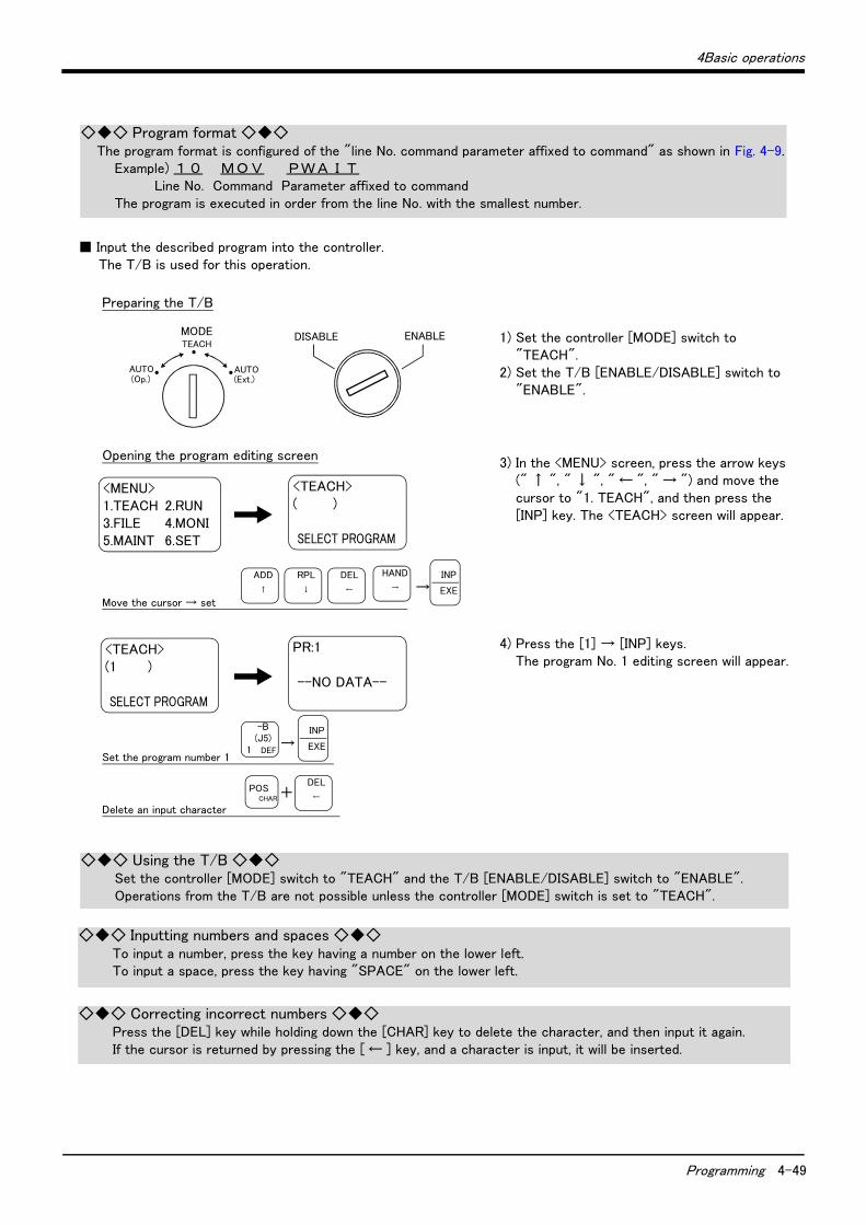
4Basic operations
Programming 4-49
■ Input the described program into the controller.The T/B is used for this operation.
1) Set the controller [MODE] switch to "TEACH".
2) Set the T/B [ENABLE/DISABLE] switch to "ENABLE".
3) In the <MENU> screen, press the arrow keys (" ↑ ", " ↓ ", " ← ", " → ") and move the cursor to "1. TEACH", and then press the [INP] key. The <TEACH> screen will appear.
4) Press the [1] → [INP] keys. The program No. 1 editing screen will appear.
◇◆◇ Program format ◇◆◇The program format is configured of the "line No. command parameter affixed to command" as shown in Fig. 4-9.
Example) 1 0 MO V P W A I T Line No. Command Parameter affixed to commandThe program is executed in order from the line No. with the smallest number.
DISABLE ENABLE TEACH
AUTO (Ext.)
AUTO (Op.)
MODE
<MENU> 1.TEACH 2.RUN 3.FILE 4.MONI 5.MAINT 6.SET
Preparing the T/B
Opening the program editing screen
Move the cursor → set
<TEACH> ( ) SELECT PROGRAM
<TEACH> (1 ) SELECT PROGRAM
PR:1 --NO DATA--
Set the program number 1 →
→
Delete an input character
ADD
↑
RPL
↓
DEL
←
HAND
→
INP
EXE
-B(J5)
1 DEF
INP
EXE
DEL
←POS
CHAR +
◇◆◇ Using the T/B ◇◆◇Set the controller [MODE] switch to "TEACH" and the T/B [ENABLE/DISABLE] switch to "ENABLE". Operations from the T/B are not possible unless the controller [MODE] switch is set to "TEACH".
◇◆◇ Inputting numbers and spaces ◇◆◇To input a number, press the key having a number on the lower left.To input a space, press the key having "SPACE" on the lower left.
◇◆◇ Correcting incorrect numbers ◇◆◇Press the [DEL] key while holding down the [CHAR] key to delete the character, and then input it again.If the cursor is returned by pressing the [ ← ] key, and a character is input, it will be inserted.

4-50 Programming
4Basic operations
5) Press the [ ↓ ] key three times. The cursor will move to the command editing line.
6) Press the [1], [0] and [SPACE] keys. The line No. "10" will be input.
7) Press the [M] key while holding down the [POS CHAR] key. "M" will appear.
8) Hold down the [CHAR] key. The four commands assigned to "M" will appear.
9) Press the [1] key while holding down the [CHAR] key. The "MOV" command will be input.
Input the program 10 MOV PWAIT
PR:1 ST:1 LN:0
--NO DATA--
PR:1 ST:1 LN:0
CODE EDIT
Using the cursor
PR:1 ST:1 LN:0
CODE EDIT
PR:1 ST:1 LN:0
10 CODE EDIT
Input "1","0" →
PR:1 ST:1 LN:0
10 CODE EDIT
PR:1 ST:1 LN:0
10 M CODE EDIT
Input "M" +
PR:1 ST:1 LN:0
10 M CODE EDIT
1.MOV 2.MVS 3.MVC 4.MVR 10 M CODE EDIT
1.MOV 2.MVS 3.MVC 4.MVR 10 M CODE EDIT
Input "M"
PR:1 ST:1 LN:0
10 MOV CODE EDIT
Input "MOV"
+
RPL
↓
-C(J6)
0 ABC
-B(J5)
1 DEF
-X(J1)
SPACE PQR→
-Y(J2)
4 MNO
POSCHAR
POSCHAR
POSCHAR
-B(J5)
1 DEF
◇◆◇ Inputting characters ◇◆◇The characters that can be input are indicated, three in a group, on the lower right of each key.To input a character, hold down the [CHAR] key and press the key having the character to be input. Each time the corresponding character key is pressed while the [CHAR] key is pressed, the three characters will appear alternately.Release the [CHAR] key when the target character appears, and set the character.
◇◆◇ Inputting commands ◇◆◇The commands can be input one character at a time (ex., for "M" → "O" → "V" for the MOV command), but ifthe head character of the command is input, the command can be selected as a number from the list of commands that appears.After inputting the head character of the command, press the [CHAR] key. The list of commands will appear. While holding down the [CHAR] key, press the numeral key for the target command No., and select the commandIf the target command is not found in the list, press the [CHAR] key again to update the list.
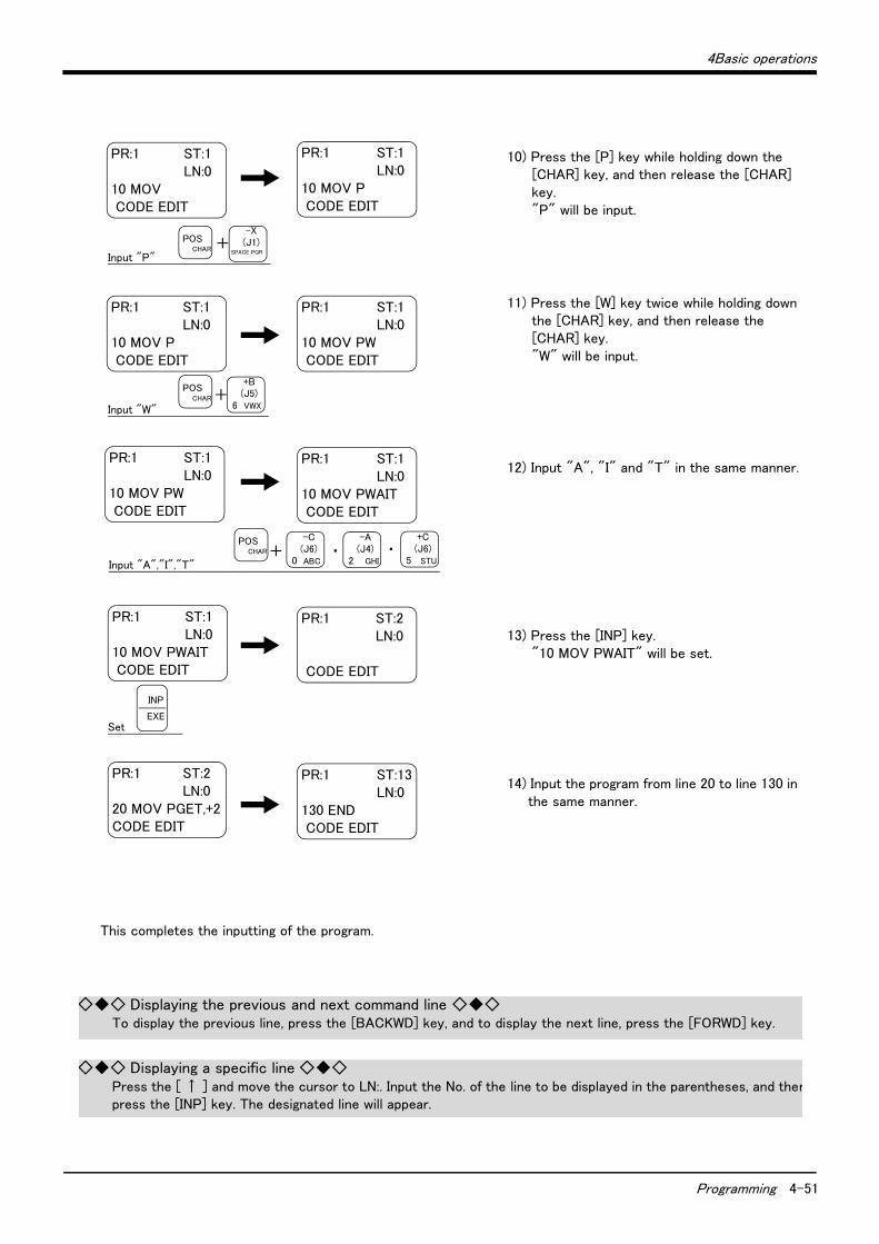
4Basic operations
Programming 4-51
10) Press the [P] key while holding down the [CHAR] key, and then release the [CHAR] key. "P" will be input.
11) Press the [W] key twice while holding down the [CHAR] key, and then release the [CHAR] key. "W" will be input.
12) Input "A", "I" and "T" in the same manner.
13) Press the [INP] key. "10 MOV PWAIT" will be set.
14) Input the program from line 20 to line 130 in the same manner.
This completes the inputting of the program.
PR:1 ST:1 LN:0
10 MOV CODE EDIT
PR:1 ST:1 LN:0
10 MOV P CODE EDIT
Input "P"
PR:1 ST:1 LN:0
10 MOV P CODE EDIT
PR:1 ST:1 LN:0
10 MOV PW CODE EDIT
Input "W"
PR:1 ST:1 LN:0
10 MOV PW CODE EDIT
PR:1 ST:1 LN:0
10 MOV PWAIT CODE EDIT
Input "A","I","T"
PR:1 ST:1 LN:0
10 MOV PWAIT CODE EDIT
PR:1 ST:2 LN:0
CODE EDIT
PR:1 ST:2 LN:0
20 MOV PGET,+2 CODE EDIT
Set
PR:1 ST:13 LN:0
130 END CODE EDIT
+
+
+ ・ ・
-X(J1)
SPACE PQR
POSCHAR
+B(J5)
6 VWX
POSCHAR
-C(J6)
0 ABC
-A(J4)
2 GHI
+C(J6)
5 STU
POSCHAR
INP
EXE
◇◆◇ Displaying the previous and next command line ◇◆◇To display the previous line, press the [BACKWD] key, and to display the next line, press the [FORWD] key.
◇◆◇ Displaying a specific line ◇◆◇Press the [ ↑ ] and move the cursor to LN:. Input the No. of the line to be displayed in the parentheses, and thenpress the [INP] key. The designated line will appear.
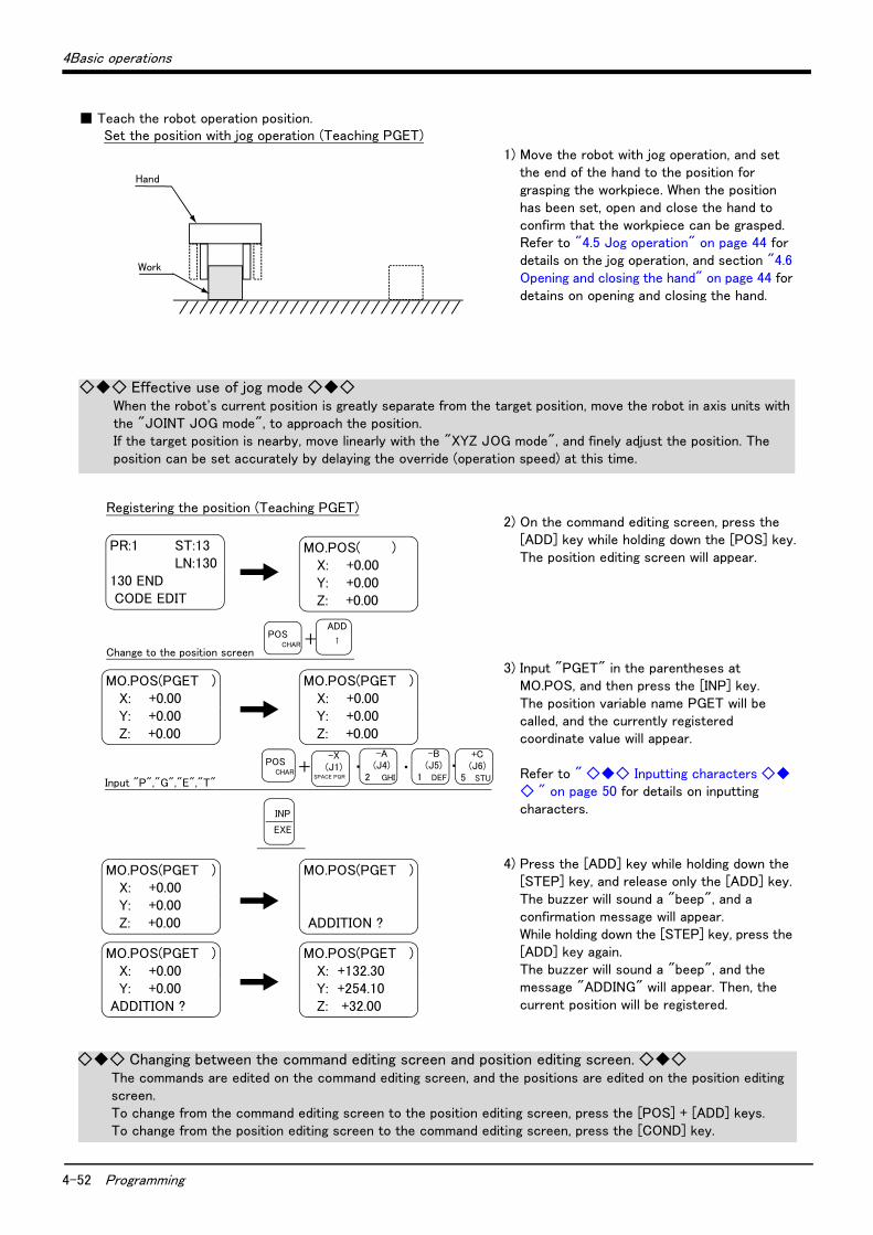
4-52 Programming
4Basic operations
■ Teach the robot operation position.
1) Move the robot with jog operation, and set the end of the hand to the position for grasping the workpiece. When the position has been set, open and close the hand to confirm that the workpiece can be grasped. Refer to "4.5 Jog operation" on page 44 for details on the jog operation, and section "4.6 Opening and closing the hand" on page 44 for detains on opening and closing the hand.
2) On the command editing screen, press the [ADD] key while holding down the [POS] key. The position editing screen will appear.
3) Input "PGET" in the parentheses at MO.POS, and then press the [INP] key. The position variable name PGET will be called, and the currently registered coordinate value will appear. Refer to " ◇◆◇ Inputting characters ◇◆◇ " on page 50 for details on inputting characters.
4) Press the [ADD] key while holding down the [STEP] key, and release only the [ADD] key. The buzzer will sound a "beep", and a confirmation message will appear. While holding down the [STEP] key, press the [ADD] key again. The buzzer will sound a "beep", and the message "ADDING" will appear. Then, the current position will be registered.
Set the position with jog operation (Teaching PGET)
Work
Hand
◇◆◇ Effective use of jog mode ◇◆◇When the robot's current position is greatly separate from the target position, move the robot in axis units with the "JOINT JOG mode", to approach the position.If the target position is nearby, move linearly with the "XYZ JOG mode", and finely adjust the position. The position can be set accurately by delaying the override (operation speed) at this time.
Registering the position (Teaching PGET)
PR:1 ST:13 LN:130
130 END CODE EDIT
MO.POS( ) X: +0.00 Y: +0.00 Z: +0.00
Change to the position screen +
MO.POS(PGET ) X: +0.00 Y: +0.00 Z: +0.00
MO.POS(PGET ) X: +0.00 Y: +0.00 Z: +0.00
+ ・ ・Input "P","G","E","T"
・
MO.POS(PGET ) X: +0.00 Y: +0.00 Z: +0.00
MO.POS(PGET ) ADDITION ?
MO.POS(PGET ) X: +0.00 Y: +0.00 ADDITION ?
MO.POS(PGET ) X: +132.30 Y: +254.10 Z: +32.00
ADD
↑POS
CHAR
-A(J4)
2 GHI
-X(J1)
SPACE PQR
+C(J6)
5 STU
POSCHAR
INP
EXE
-B(J5)
1 DEF
◇◆◇ Changing between the command editing screen and position editing screen. ◇◆◇The commands are edited on the command editing screen, and the positions are edited on the position editing screen.To change from the command editing screen to the position editing screen, press the [POS] + [ADD] keys.To change from the position editing screen to the command editing screen, press the [COND] key.
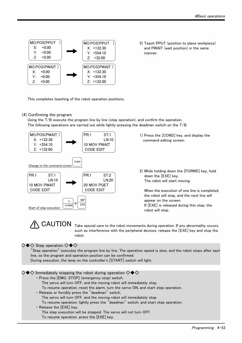
4Basic operations
Programming 4-53
5) Teach PPUT (position to place workpiece) and PWAIT (wait position) in the same manner.
This completes teaching of the robot operation positions.
(4) Confirming the programUsing the T/B execute the program line by line (step operation), and confirm the operation.
The following operations are carried out while lightly pressing the deadman switch on the T/B.
1) Press the [COND] key, and display the command editing screen.
2) While holding down the [FORWD] key, hold down the [EXE] key. The robot will start moving. When the execution of one line is completed, the robot will stop, and the next line will appear on the screen. If [EXE] is released during this step, the robot will stop.
Take special care to the robot movements during operation. If any abnormality occurs, such as interference with the peripheral devices, release the [EXE] key and stop the robot.
MO.POS(PPUT ) X: +0.00 Y: +0.00 Z: +0.00
MO.POS(PPUT ) X: +132.30 Y: +554.10 Z: +32.00
MO.POS(PWAIT ) X: +0.00 Y: +0.00 Z: +0.00
MO.POS(PWAIT ) X: +132.30 Y: +354.10 Z: +132.00
MO.POS(PWAIT ) X: +132.30 Y: +354.10 Z: +132.00
PR:1 ST:1 LN:10
10 MOV PWAIT CODE EDIT
Change to the command screen
PR:1 ST:1 LN:10
10 MOV PWAIT CODE EDIT
Start of step execution
+
PR:1 ST:2 LN:20
20 MOV PGET CODE EDIT
COND
INP
EXE+
FORWD
CAUTION
◇◆◇ Step operation ◇◆◇"Step operation" executes the program line by line. The operation speed is slow, and the robot stops after eachline, so the program and operation position can be confirmed.During execution, the lamp on the controller's [START] switch will light.
◇◆◇ Immediately stopping the robot during operation ◇◆◇・ Press the [EMG. STOP] (emergency stop) switch.
The servo will turn OFF, and the moving robot will immediately stop. To resume operation, reset the alarm, turn the servo ON, and start step operation.
・ Release or forcibly press the "deadman" switch.The servo will turn OFF, and the moving robot will immediately stop. To resume operation, lightly press the "deadman" switch, and start step operation.
・ Release the [EXE] key.The step execution will be stopped. The servo will not turn OFF.To resume operation, press the [EXE] key.
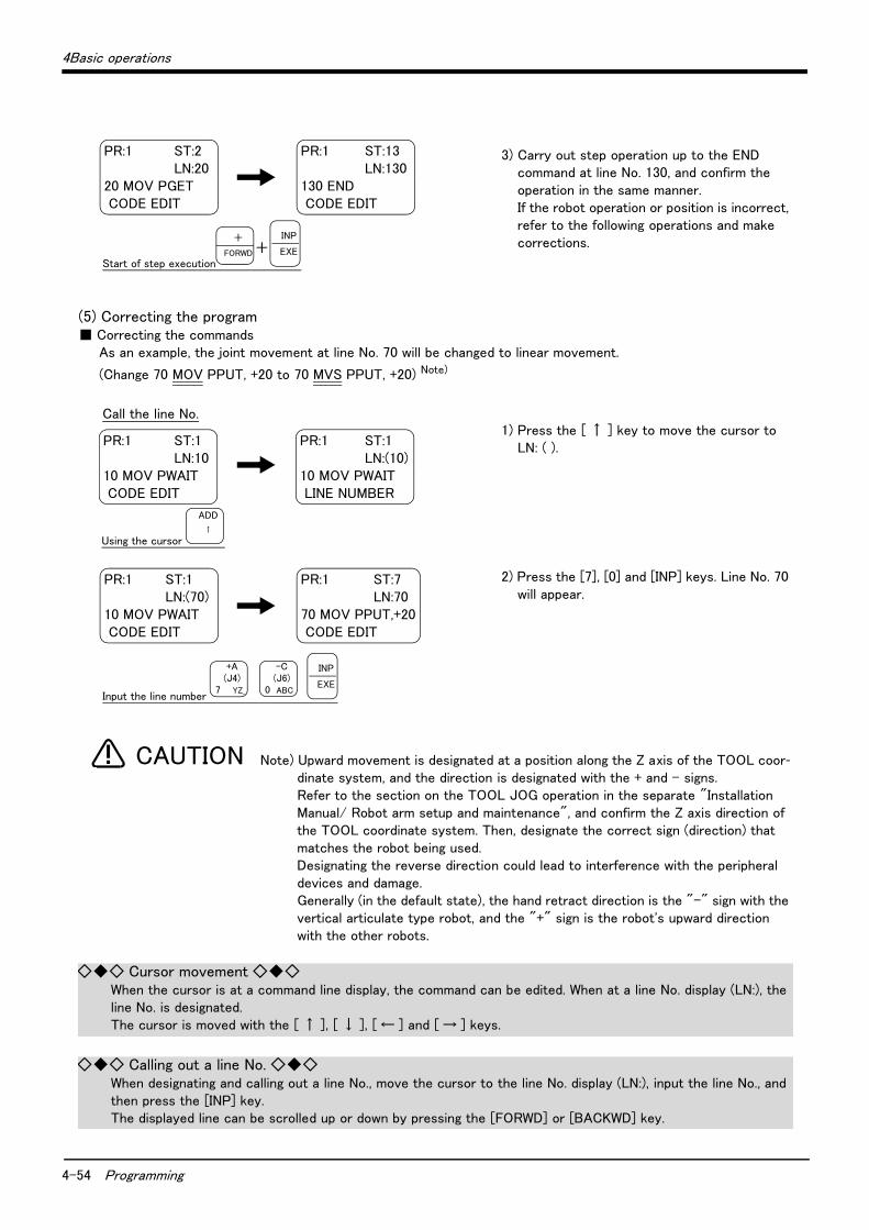
4-54 Programming
4Basic operations
3) Carry out step operation up to the END command at line No. 130, and confirm the operation in the same manner. If the robot operation or position is incorrect, refer to the following operations and make corrections.
(5) Correcting the program■ Correcting the commands
As an example, the joint movement at line No. 70 will be changed to linear movement.
(Change 70 MOV PPUT, +20 to 70 MVS PPUT, +20) Note)
1) Press the [ ↑ ] key to move the cursor to LN: ( ).
2) Press the [7], [0] and [INP] keys. Line No. 70 will appear.
Note) Upward movement is designated at a position along the Z axis of the TOOL coor-dinate system, and the direction is designated with the + and - signs. Refer to the section on the TOOL JOG operation in the separate "Installation Manual/ Robot arm setup and maintenance", and confirm the Z axis direction of the TOOL coordinate system. Then, designate the correct sign (direction) that matches the robot being used. Designating the reverse direction could lead to interference with the peripheral devices and damage. Generally (in the default state), the hand retract direction is the "-" sign with the vertical articulate type robot, and the "+" sign is the robot's upward direction with the other robots.
PR:1 ST:2 LN:20
20 MOV PGET CODE EDIT
Start of step execution
PR:1 ST:13 LN:130
130 END CODE EDIT
+INP
EXE
+
FORWD
PR:1 ST:1 LN:10
10 MOV PWAIT CODE EDIT
Using the cursor
PR:1 ST:1 LN:(10)
10 MOV PWAIT LINE NUMBER
Call the line No.
PR:1 ST:1 LN:(70)
10 MOV PWAIT CODE EDIT
Input the line number
PR:1 ST:7 LN:70
70 MOV PPUT,+20 CODE EDIT
ADD
↑
-C(J6)
0 ABC
+A(J4)
7 YZ_
INP
EXE
CAUTION
◇◆◇ Cursor movement ◇◆◇When the cursor is at a command line display, the command can be edited. When at a line No. display (LN:), the line No. is designated. The cursor is moved with the [ ↑ ], [ ↓ ], [ ← ] and [ → ] keys.
◇◆◇ Calling out a line No. ◇◆◇When designating and calling out a line No., move the cursor to the line No. display (LN:), input the line No., and then press the [INP] key.The displayed line can be scrolled up or down by pressing the [FORWD] or [BACKWD] key.
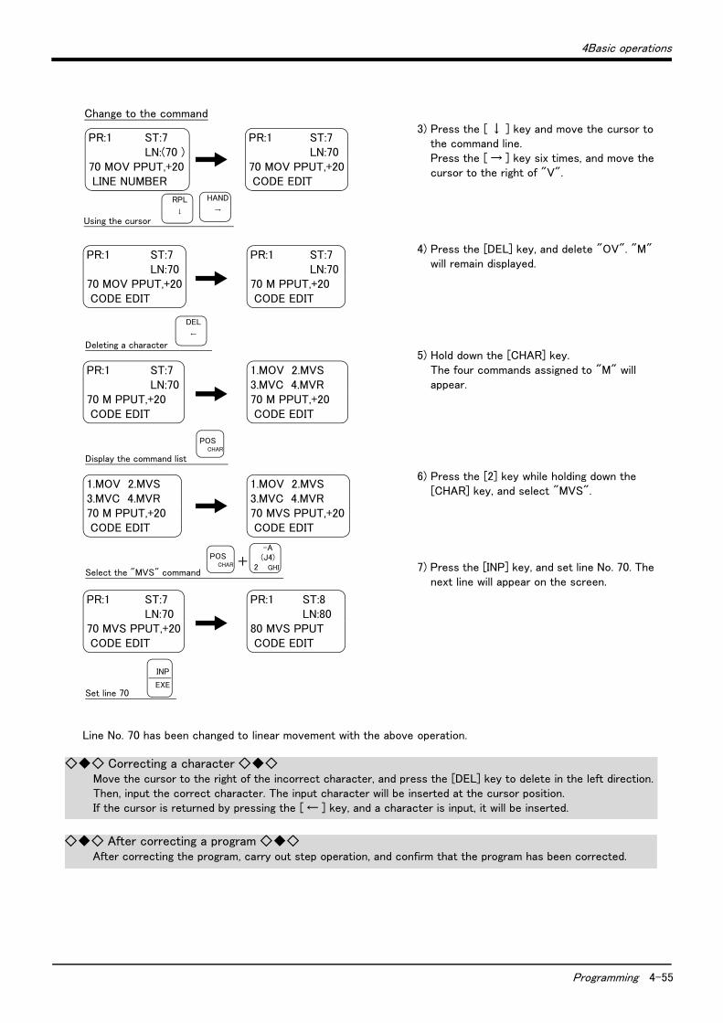
4Basic operations
Programming 4-55
3) Press the [ ↓ ] key and move the cursor to the command line. Press the [ → ] key six times, and move the cursor to the right of "V".
4) Press the [DEL] key, and delete "OV". "M" will remain displayed.
5) Hold down the [CHAR] key. The four commands assigned to "M" will appear.
6) Press the [2] key while holding down the [CHAR] key, and select "MVS".
7) Press the [INP] key, and set line No. 70. The next line will appear on the screen.
Line No. 70 has been changed to linear movement with the above operation.
PR:1 ST:7 LN:(70 )
70 MOV PPUT,+20 LINE NUMBER
Using the cursor
PR:1 ST:7 LN:70
70 MOV PPUT,+20 CODE EDIT
Change to the command
PR:1 ST:7 LN:70
70 MOV PPUT,+20 CODE EDIT
Deleting a character
PR:1 ST:7 LN:70
70 M PPUT,+20 CODE EDIT
PR:1 ST:7 LN:70
70 M PPUT,+20 CODE EDIT
Display the command list
1.MOV 2.MVS 3.MVC 4.MVR 70 M PPUT,+20 CODE EDIT
1.MOV 2.MVS 3.MVC 4.MVR 70 M PPUT,+20 CODE EDIT
Select the "MVS" command
1.MOV 2.MVS 3.MVC 4.MVR 70 MVS PPUT,+20 CODE EDIT
+
PR:1 ST:7 LN:70
70 MVS PPUT,+20 CODE EDIT
Set line 70
PR:1 ST:8 LN:80
80 MVS PPUT CODE EDIT
RPL
↓
HAND
→
DEL
←
POSCHAR
INP
EXE
-A(J4)
2 GHI
POSCHAR
◇◆◇ Correcting a character ◇◆◇Move the cursor to the right of the incorrect character, and press the [DEL] key to delete in the left direction. Then, input the correct character. The input character will be inserted at the cursor position.If the cursor is returned by pressing the [ ← ] key, and a character is input, it will be inserted.
◇◆◇ After correcting a program ◇◆◇After correcting the program, carry out step operation, and confirm that the program has been corrected.

4-56 Programming
4Basic operations
■ Correcting the taught positionAs an example, the wait position (PWAIT) will be corrected.
1) On the command editing screen, press the [ADD] key while holding down the [CHAR] key. The position editing screen will appear.
2) Input "PWAIT" in the parentheses at MO.POS, and then press the [INP] key. The position variable name PWAIT will be called out, and the currently registered coordinate value will appear.
New wait position
(PWAIT)Change
Change the movement position
PR:1 ST:8 LN:(80 )
80 MVS PPUT CODE EDIT
MO.POS( ) X: +0.00 Y: +0.00 Z: +0.00
Change to the position screen
+
MO.POS(PWAIT ) X: +0.00 Y: +0.00 Z: +0.00
MO.POS(PWAIT ) X: +132.30 Y: +354.10 Z: +132.00
+ ・・Input "P","W","A","I","T"
・
・
ADD
↑POS
CHAR
POSCHAR
-C(J6)
0 ABC
-A(J4)
2 GHI
-X(J1)
SPACE PQR
+C(J6)
5 STU
+B(J5)
6 VWX
INP
EXE
◇◆◇ Calling out a position variable ◇◆◇Input the name of the variable to be called out in the parentheses at MO. POS on the position editing screen. Then, press the [INP] key.The displayed position variable can be scrolled up or down by pressing the [FORWD] or [BACKWD] key.
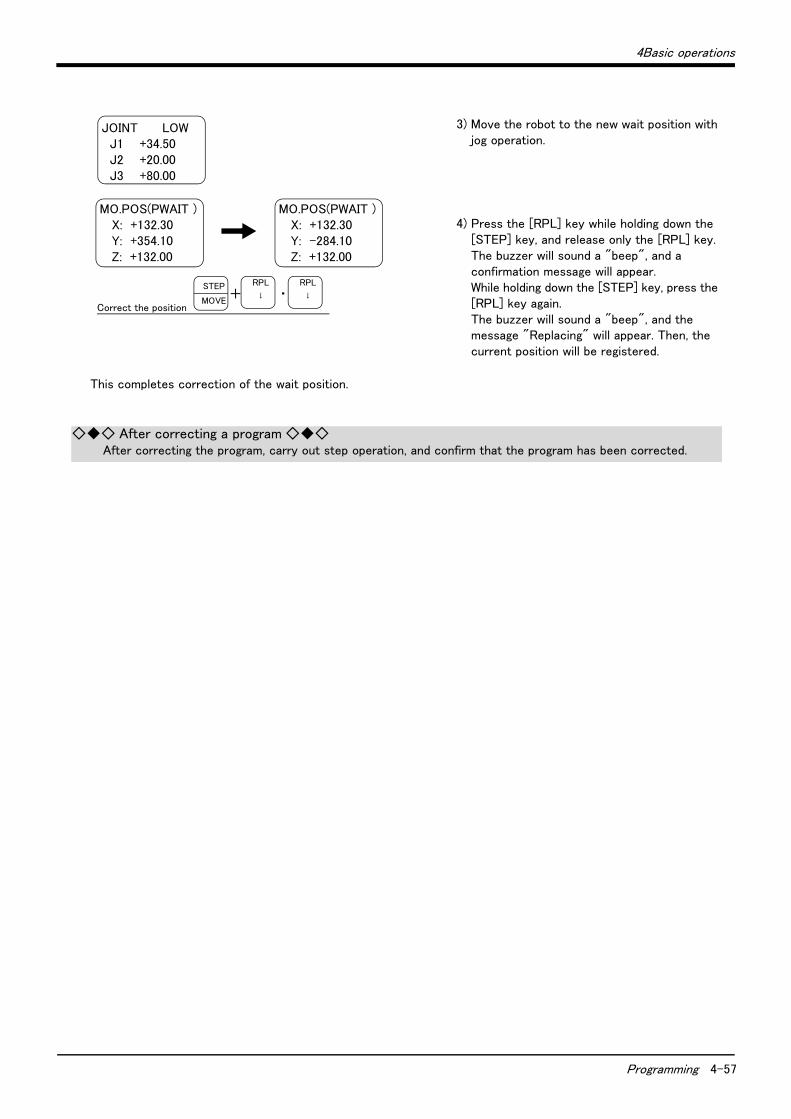
4Basic operations
Programming 4-57
3) Move the robot to the new wait position with jog operation.
4) Press the [RPL] key while holding down the [STEP] key, and release only the [RPL] key. The buzzer will sound a "beep", and a confirmation message will appear. While holding down the [STEP] key, press the [RPL] key again. The buzzer will sound a "beep", and the message "Replacing" will appear. Then, the current position will be registered.
This completes correction of the wait position.
JOINT LOW J1 +34.50 J2 +20.00 J3 +80.00
Correct the position
MO.POS(PWAIT ) X: +132.30 Y: +354.10 Z: +132.00
MO.POS(PWAIT ) X: +132.30 Y: -284.10 Z: +132.00
+ ・RPL
↓
STEP
MOVE
RPL
↓
◇◆◇ After correcting a program ◇◆◇After correcting the program, carry out step operation, and confirm that the program has been corrected.

4-58 Programming
4Basic operations
(6) Start automatic operation.
Before starting automatic operation, always confirm the following item. Starting automatic operation without confirming these items could lead to property damage or physical injury.
・ Make sure that there are no operators near the robot.
・ Make sure that the safety fence is locked, and operators cannot enter unintentionally.
・ Make sure that there are no unnecessary items, such as tools, inside the robot operation range.
・ Make sure that the workpiece is correctly placed at the designated position.
・ Confirm that the program operates correctly with step operation.
In the following explanation, automatic operation will be carried out with the controller.
1) Set the T/B [ENABLE/DISABLE] switch to "DISABLE".
2) Set the controller [MODE] switch to "AUTO (Op.)".
3) Press the controller [CHNG DISP] switch twice, and display the "OVERRIDE" on the STATUS NUMBER display panel. (A "(" will appear at the lower left.) Press the [DOWN] key several times, and display "10". The operation speed will be set to 10%.
The servo will turn OFF when the controller's [MODE] switch is changed. Note that axes not provided with brakes could drop with their own weight.
CAUTION
DISABLE ENABLE
STATUS NUMBER
STATUS NUMBER
TEACH
AUTO
(Ext.)AUTO (Op.)
MODE
CHNG DISP
Prepare the controller
Set the operation speed
T/B disable
Controller enable
Display the override
UP
DOWN
Set the override
CAUTION
◇◆◇ Operations to change [MODE] switch without turning servo OFF ◇◆◇(1) While holding down the deadman switch on the T/B, set the [ENABLE/DISABLE] switch to "DISABLE".(2) While holding down the deadman switch on the T/B, set the controller [MODE] switch to "AUTO (Op.)".(3) Release the T/B deadman switch.

4Basic operations
Programming 4-59
4) Press the [CHNG DISP] switch, and display the "program No." on the STATUS NUMBER display panel. (A "P" will appear at the head.) Confirm that the program No. targeted for automatic operation is displayed. With the previous operation, the program was created in program No. 1, so "P. 0001" will appear. If the correct program No. is not displayed, press the [UP] and [DOWN] keys to display the correct program No.
5) After pressing the controller [START] switch, press the [END] switch. The robot operation will start and will stop after one cycle.
When executing the work example given in "Fig. 4-6Example of work" on page 45, always press the [END] switch and end the program after one cycle. If the [END] switch is not pressed, the hand will interfere with the existing workpiece when it goes to pale the workpiece in the second cycle.
Before starting automatic operation, always confirm that the target program No. is selected.
Take special care to the robot movements during automatic operation. If any abnormality occurs, press the [EMG. STOP] switch and immediately stop the robot.
UP
DOWN
START END
Start automatic operation
Select the program number
Start End with one cycle
Display the program number
Select the program number
STATUS NUMBER
CHNG DISP STATUS NUMBER
CAUTION
CAUTION
CAUTION
◇◆◇ Operating from the controller ◇◆◇Set the T/B [ENABLE/DISABLE] switch to "DISABLE" and the controller [MODE] switch to "AUTO (Op.)". Operations from the controller are not possible unless the controller [MODE] switch is set to "AUTO (Op.)".
◇◆◇ Operation speed ◇◆◇The operation speed for automatic operation with the controller can be set.When the override is displayed on the STATUS NUMBER display panel (with a " □ " displayed on the lower left)the override display will increment or decrement each time the [UP] or [DOWN] key is pressed. The max. speedis 100%.Initially set a low speed, and gradually increase it.

5-60 Maintenance and inspection interval
5Maintenance and Inspection
5 Maintenance and Inspection
The maintenance and inspection procedures to be carried out to use the robot for a long time without trouble are described in this chapter. The types and replacement methods of consumable parts are also explained.
5.1 Maintenance and inspection interval
Maintenance and inspection are divided into the inspections carried out daily, and the periodic inspections carry out at set intervals. Always carry these out to prevent unforeseen trouble, to maintain the product for a long time, and to secure safety.
(1) Inspection schedule
Fig.5-1 : Inspection schedule
0 Hr
Dai
ly insp
ection
Monthly inspection
Monthly inspection
5 0 0 Hr Monthly inspection
Monthly inspection
Monthly inspection
1 0 0 0 Hr Monthly inspection
Monthly inspection
Monthly inspection
1 5 0 0 Hr Monthly inspection
Monthly inspection
Monthly inspection
2 0 0 0 Hr Monthly inspection Yearly inspection
Operating time
<Guideline for inspection period>
For one shift
8 Hr/day x 20 days/month x 12 months = approx. 1800 Hr
10 Hr/day x 20 days/month x 12 months = approx. 2400 Hr
For two shifts
15 Hr/day x 20 days/month x 12 months = approx. 3600 Hr
[Caution] According to the schedule on the above, when using the double shift, you should make the inspections at half the regular intervals.
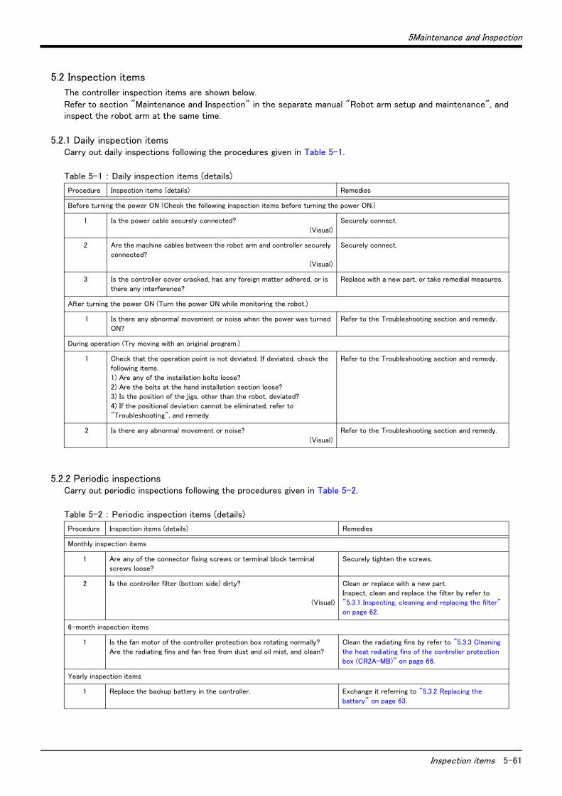
5Maintenance and Inspection
Inspection items 5-61
5.2 Inspection items
The controller inspection items are shown below.
Refer to section "Maintenance and Inspection" in the separate manual "Robot arm setup and maintenance", and inspect the robot arm at the same time.
5.2.1 Daily inspection itemsCarry out daily inspections following the procedures given in Table 5-1.
Table 5-1 : Daily inspection items (details)
5.2.2 Periodic inspectionsCarry out periodic inspections following the procedures given in Table 5-2.
Table 5-2 : Periodic inspection items (details)
Procedure Inspection items (details) Remedies
Before turning the power ON (Check the following inspection items before turning the power ON.)
1 Is the power cable securely connected?
(Visual)
Securely connect.
2 Are the machine cables between the robot arm and controller securely
connected?
(Visual)
Securely connect.
3 Is the controller cover cracked, has any foreign matter adhered, or is
there any interference?
Replace with a new part, or take remedial measures.
After turning the power ON (Turn the power ON while monitoring the robot.)
1 Is there any abnormal movement or noise when the power was turned
ON?
Refer to the Troubleshooting section and remedy.
During operation (Try moving with an original program.)
1 Check that the operation point is not deviated. If deviated, check the
following items.
1) Are any of the installation bolts loose?
2) Are the bolts at the hand installation section loose?
3) Is the position of the jigs, other than the robot, deviated?
4) If the positional deviation cannot be eliminated, refer to
"Troubleshooting", and remedy.
Refer to the Troubleshooting section and remedy.
2 Is there any abnormal movement or noise?
(Visual)
Refer to the Troubleshooting section and remedy.
Procedure Inspection items (details) Remedies
Monthly inspection items
1 Are any of the connector fixing screws or terminal block terminal
screws loose?
Securely tighten the screws.
2 Is the controller filter (bottom side) dirty?
(Visual)
Clean or replace with a new part.
Inspect, clean and replace the filter by refer to
"5.3.1 Inspecting, cleaning and replacing the filter"
on page 62.
6-month inspection items
1 Is the fan motor of the controller protection box rotating normally?
Are the radiating fins and fan free from dust and oil mist, and clean?
Clean the radiating fins by refer to "5.3.3 Cleaning
the heat radiating fins of the controller protection
box (CR2A-MB)" on page 66.
Yearly inspection items
1 Replace the backup battery in the controller. Exchange it referring to "5.3.2 Replacing the
battery" on page 63.

5-62 Maintenance and inspection procedures
5Maintenance and Inspection
5.3 Maintenance and inspection procedures
The procedures for carrying out periodic maintenance and inspection are described below. Thoroughly comprehend the procedures, and follow the instructions. This work can be commissioned to the Mitsubishi Service Dept. for a fee. (Never disassemble, etc., any of the parts not described in this section.)
The maintenance parts required for the maintenance and inspection are shown in section "5.4 Maintenance parts" on page 40. Contact your dealer for these parts when required.
5.3.1 Inspecting, cleaning and replacing the filterA filter has been installed in the front part of the controller's bottom surface. The following shows the procedure for inspecting, cleaning and replacing the filter:
Fig.5-2 : How to remove the filter
1) Remove the filter plate in the bottom of the front side of the controller by unscrewing the M3 screws (2 pcs.).
2) Remove the filter from the filter plate, and then remove dust and particles accumulated on the filter. If the filter is heavily soiled, rinse it well with water and similar solution and dry it completely, or replace it with a new one.
3) Attach the cleaned or new filter to the filter plate, and install it to the controller with the M3 screws (2 pcs.).
This completes the inspection, cleaning and replace of the filter for the CR2A-572/CR2B-574 controller.
CR2A-572/CR2B-574 controller
Filter
Filter plate
M3 screw (two pieces)
*The left figure shows the CR2A-572 controller for example. The RS-232C connector is installed vertically as the controller type is "CR2B-574".

5Maintenance and Inspection
Maintenance and inspection procedures 5-63
5.3.2 Replacing the battery
The procedures for replacing the battery are described below.
If the system is used after the battery cumulative time over error (Error No. 7520) occurs, the backup fault alarm will occur. If the backup fault alarm occurs, the con-tents of the memory cannot be guaranteed, so save important program and position data on a floppy disk using personal computer support software, etc.
Replace the batteries for the controller and robot arm at the same time. Replace the controller battery within 15 minutes after removing the old battery.
Note that the battery-change method differs, depending on the controller being used. When the CR2-532 controller is used, refer to "(1) For the CR2-532 Control-ler" on page 63. When the CR2A-572 controller is used, refer to "(2) For the CR2A-572/CR2B-574 Controller" on page 64. When the CR2-532M controller is used, refer to "(3) For the CR2-532M Controller" on page 65.
(1) For the CR2-532 Controller
1) Turn the controller power ON once. (For approx. one minute.)
2) Wait at least three minutes after turning the power OFF, and then remove the controller Chassis cover. To remove the cover, remove the one installa-tion screw A, and slide the cover approx. 100mm toward the back. Then, lift it up.
3) Remove the upper rear cover by removing the four installation screws B on the back. The battery is on the left R6x2CPU looking from the front of the controller.
4) Hold and pull out the old battery connector, and remove from the battery holder.
5) Install the new battery into the battery holder. Install so that the lead line come to the front.
6) Connect the new battery cable connector to the connector removed in step "4)". Connect so that the red lead line is at the top. Connect the new battery within 15 minutes of removing the old battery.
7) Return the upper rear cover, removed in step "3)" Sandwich the power cable and grounding cable with the rubber bushing installed on the lower rear cover and upper rear cover. After install-ing, securely fix with the four screws. Install the chassis cover, removed in step "2)", and fix securely with screws.
8) Initialize the battery consumption time. Always carry out this step after replacing the battery, and initialize the battery usage time. Refer to the separate "Instruction Manual/Detailed Explanation of Functions and Opera-tions" for details on the initialization methods.
This completes the replace the battery of the CR2-532 controller.
CAUTION
CAUTION
MODE
AUTO (Ext .)
R6x2CPU
Chassis cover
Screw A(One)
Screw B(Four)
Power cable
Lower rear cover
Rubber bush
Upper rear cover
On the left side looking from the front
Battery
R6x2CPU(Rear side)
Battery
Battery holder Battery connector
Black
Red
Battery connector direction
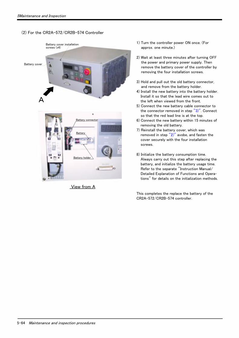
5-64 Maintenance and inspection procedures
5Maintenance and Inspection
(2) For the CR2A-572/CR2B-574 Controller
1) Turn the controller power ON once. (For approx. one minute.)
2) Wait at least three minutes after turning OFF the power and primary power supply. Then remove the battery cover of the controller by removing the four installation screws.
3) Hold and pull out the old battery connector, and remove from the battery holder.
4) Install the new battery into the battery holder. Install it so that the lead wire comes out to the left when viewed from the front.
5) Connect the new battery cable connector to the connector removed in step "3)". Connect so that the red lead line is at the top.
6) Connect the new battery within 15 minutes of removing the old battery.
7) Reinstall the battery cover, which was removed in step "2)" avobe, and fasten the cover securely with the four installation screws.
8) Initialize the battery consumption time. Always carry out this step after replacing the battery, and initialize the battery usage time. Refer to the separate "Instruction Manual/Detailed Explanation of Functions and Opera-tions" for details on the initialization methods.
This completes the replace the battery of the CR2A-572/CR2B-574 controller.
Battery holder
Battery
View from A
Battery connector
Battery cover
Battery cover installation screws (x4)
A

5Maintenance and Inspection
Maintenance and inspection procedures 5-65
(3) For the CR2-532M Controller
1) Turn the controller power ON once. (For approx. one minute.)
2) Wait at least three minutes after turning OFF the power and primary power supply, then loosen the fixing screws on the controller front door, and open the front door. The battery is on the R6x2CPU.
3) Hold and pull out the old battery connector, and remove from the battery holder.
4) Install the new battery into the battery holder. Install so that the lead line come to the front.
5) Connect the new battery cable connector to the connector removed in step "3)". Connect so that the red lead line is at the left. Connect the new battery within 15 minutes of removing the old battery.
6) Close the controller's front door, and fix with the fixing screws.
7) Initialize the battery consumption time. Always carry out this step after replacing the battery, and initialize the battery usage time. Refer to the separate "Instruction Manual/Detailed Explanation of Functions and Operations" for details on the initialization methods.
This completes the replace the battery of the CR2-532M controller.
Battery
Control unit(R6x2CPU)
Front door(Fixing screws x 2)
R6x2CPU
Battery Battery holder
Battery connector
BlackRed

5-66 Maintenance and inspection procedures
5Maintenance and Inspection
5.3.3 Cleaning the heat radiating fins of the controller protection box (CR2A-MB)The following shows the procedure for cleaning the radiating fins: Perform this cleaning by referring to Fig. 5-3.
(1) If the fins are soiled with dust and particles, blow them off using an air blower.1) Remove the power wire of the relay terminal box inside the panel.2) Remove the rear panel of the controller protection box from the main unit.3) Remove the heat exchanger from the rear panel.4) Remove the fan mounting plate from the rear panel, and then remove the fan.5) Remove the cable(2pair) and grounding wire connected to the fan.6) Blow off the exterior of the fins with an air blower.
(2) If dirt does not come off, clean the fins according to the following procedure:1) Pour a neutral detergent over the exterior of the fins to clean.2) Feed a dry cloth through the fins to remove dirt, and then air-dry them.3) After the fins are completely dry, install the heat exchanger to the controller protection box in the reverse
order of the steps for removing it.
When removing and/or installing the heat exchanger, pay extra attention as such operations may cause injury by sharp corners of metal plates.
Fig.5-3 : Cleaning the radiating fins (CR2A-MB)
CAUTION
Heat exchangerRadiating fin
Rear panel
Cable cover
Fan installation plate
Finger guard
Controller protection box
Grounding wire
Cable(2 pair)
AC fanM4 spring nut
Front cover
(CR2A-MB)
Installation screw(M4 x 10)
Relay terminal block f power supply
Installation screw(M4 x 10)
Corner type catch clip
Side cover
Air blow during cleaning.
Installation screw (M4 x 10)
Installation screw (M4 x 18)
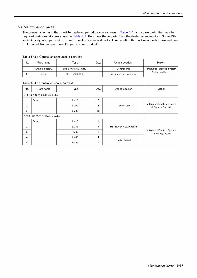
5Maintenance and Inspection
Maintenance parts 5-67
5.4 Maintenance parts
The consumable parts that must be replaced periodically are shown in Table 5-3, and spare parts that may be required during repairs are shown in Table 5-4. Purchase these parts from the dealer when required. Some Mit-subishi-designated parts differ from the maker's standard parts. Thus, confirm the part name, robot arm and con-troller serial No. and purchase the parts from the dealer.
Table 5-3 : Controller consumable part list
Table 5-4 : Controller spare part list
No. Part name Type Qty. Usage section Maker
1 Lithium battery ER6 BKO-NC2157H01 1 Control unit Mitsubishi Electric System
& Service;Co.,Ltd.2 Filter BKO-FA0688H01 1 Bottom of the controller
No. Part name Type Qty. Usage section Maker
CR2-532/CR2-532M controller
1 Fuse LM16 2
Control unitMitsubishi Electric System
& Service;Co.,Ltd.2 LM05 2
3 LM32 12
CR2A-572/CR2B-574 controller
1 Fuse LM16 1
RZ326A or RZ327 board
Mitsubishi Electric System
& Service;Co.,Ltd.
2 LM32 5
3 HM32 1
4 LM05 4RZ804 board
5 HM32 1

OCT..2003 MEE Printed in Japan on recycled paper. Specifications are subject to change without notice.
HEAD OFFICE : MITSUBISHI DENKI BLDG MARUNOUCHI TOKYO 100-8310 TELEX : J24532 CABLE MELCO TOKYO NAGOYA WORKS : 1-14, YADA-MINAMI 5, HIGASHI-KU, NAGOYA, JAPAN
Related Documents