MITSUBISHI Electronic Multi-Measuring Instrument Types ME96SSR-MB User's Manual: Detailed Edition ●Before operating the instrument, you should first read thoroughly this operation manual for safe operation and optimized performance of the product. Deliver this user's manual to the end user.

Welcome message from author
This document is posted to help you gain knowledge. Please leave a comment to let me know what you think about it! Share it to your friends and learn new things together.
Transcript
MITSUBISHI Electronic Multi-Measuring Instrument
Types
ME96SSR-MB
User's Manual: Detailed Edition
Before operating the instrument, you should first read thoroughly this operation manual for safe operation and optimized performance of the product. Deliver this user's manual to the end user.
Check on your delivery
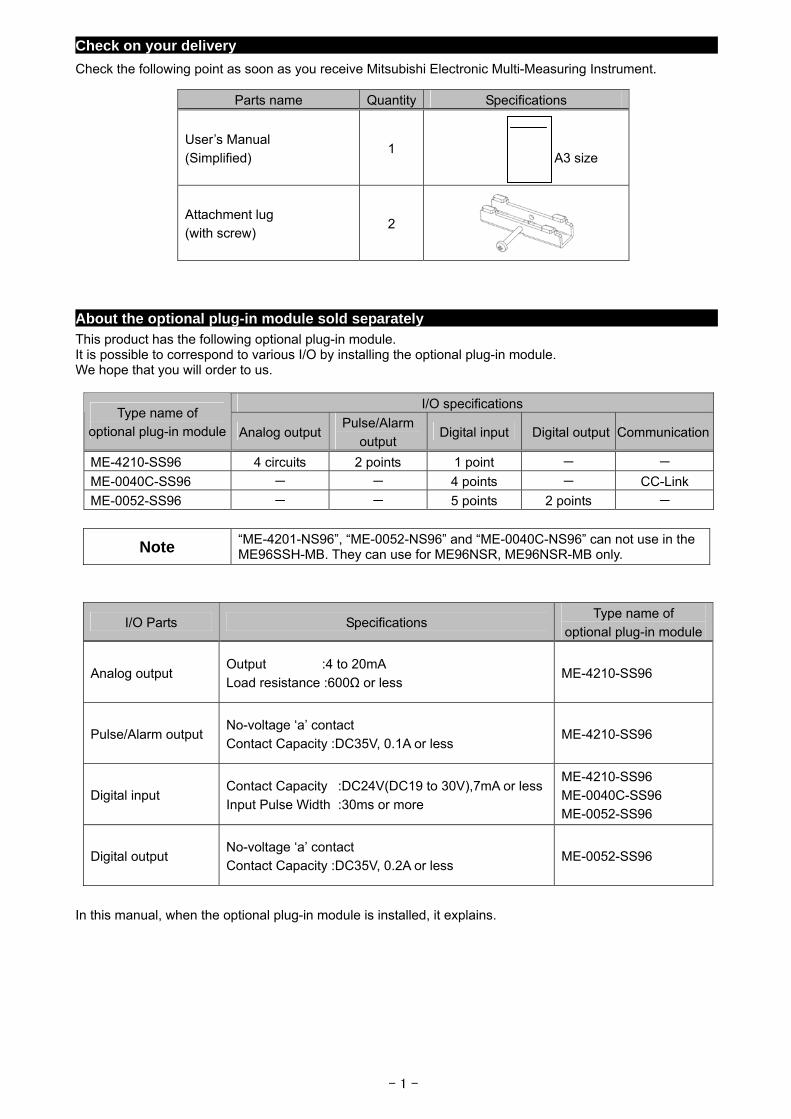
Check the following point as soon as you receive Mitsubishi Electronic Multi-Measuring Instrument.
Parts name Quantity Specifications
User’s Manual (Simplified)
1
A3 size
Attachment lug (with screw)
2
About the optional plug-in module sold separately
This product has the following optional plug-in module. It is possible to correspond to various I/O by installing the optional plug-in module. We hope that you will order to us.
I/O specifications Type name of
optional plug-in module Analog output Pulse/Alarm
output Digital input Digital output Communication
ME-4210-SS96 4 circuits 2 points 1 point - -
ME-0040C-SS96 - - 4 points - CC-Link
ME-0052-SS96 - - 5 points 2 points -
Note “ME-4201-NS96”, “ME-0052-NS96” and “ME-0040C-NS96” can not use in the ME96SSH-MB. They can use for ME96NSR, ME96NSR-MB only.
I/O Parts Specifications Type name of
optional plug-in module
Analog output Output :4 to 20mA
Load resistance :600Ω or less ME-4210-SS96
Pulse/Alarm output No-voltage ‘a’ contact
Contact Capacity :DC35V, 0.1A or less ME-4210-SS96
Digital input Contact Capacity :DC24V(DC19 to 30V),7mA or less
Input Pulse Width :30ms or more
ME-4210-SS96
ME-0040C-SS96 ME-0052-SS96
Digital output No-voltage ‘a’ contact Contact Capacity :DC35V, 0.2A or less
ME-0052-SS96
In this manual, when the optional plug-in module is installed, it explains.
- 1 -
- 2 -
Features
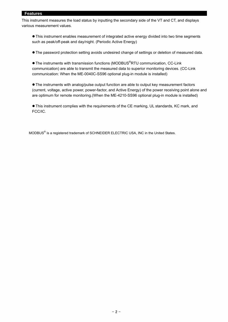
This instrument measures the load status by inputting the secondary side of the VT and CT, and displays various measurement values.
This instrument enables measurement of integrated active energy divided into two time segments such as peak/off-peak and day/night. (Periodic Active Energy)
The password protection setting avoids undesired change of settings or deletion of measured data.
The instruments with transmission functions (MODBUS®RTU communication, CC-Link communication) are able to transmit the measured data to superior monitoring devices. (CC-Link communication: When the ME-0040C-SS96 optional plug-in module is installed)
The instruments with analog/pulse output function are able to output key measurement factors (current, voltage, active power, power-factor, and Active Energy) of the power receiving point alone and
are optimum for remote monitoring.(When the ME-4210-SS96 optional plug-in module is installed)
This instrument complies with the requirements of the CE marking, UL standards, KC mark, and
FCC/IC.
MODBUS® is a registered trademark of SCHNEIDER ELECTRIC USA, INC in the United States.
- 3 -
Table of Contents
Check on your delivery ····················································································································1 About the optional plug-in module sold separately ·················································································1 Features·······································································································································2 Table of Contents ···························································································································3 Safety precaution ···························································································································5 Requirements for compliance with the EMC directive ·············································································8
Instructions for Handling
1. Display and Button Functions of Each Part ······················································································9
2. Function Modes ·························································································································12 3. Setting
3.1 Setting Flow························································································································13 3.2 Setting Menu 1: Basic Settings (Setting the Phase Wire System, Display Pattern, VT/Direct Voltage,
CT Primary Current, etc) ·······································································································15 3.3 Setting Menu 2: Communication Settings (Setting the MODBUS® RTU communication and CC-Link
communication) ···················································································································19 3.4 Setting Menu 3: Display Settings (Setting Maximum Scale, Active Energy Measurement, and
Harmonic Display, etc.) ·········································································································21 3.5 Setting Menu 4: LCD Settings (Setting Model Display, Version Display, Backlight, and Display Update
Time)·································································································································23 3.6 Setting Menu 5: Pulse and Alarm Settings (Setting Upper/Lower Limit Alarm, Motor Starting Current
Mask Function, Pulse Output, etc.) ··························································································24 3.7 Setting Menu 6: Setting the Analog Output ················································································29 3.8 Setting Menu 7: Setting Periodic Active Energy, Digital Input/Output ·············································32 3.9 Setting Menu 8: Special Settings (Setting Operating Time, Phase Display, IEC mode)························33 3.10Setting Value Confirmation Menus 1-9: Confirming the Settings in the Setting Menus 1-8 and Test
Mode in Setting Menu 9 ········································································································35 3.11Initializing Related Items by Changing Settings ··········································································36 3.12Initializing All Settings ···········································································································36 3.13Setting the Special Display Patten P00·····················································································37 3.14Examples of Simple Settings ··································································································39
4. Using Test Mode ························································································································41 4.1 Test Menu 1: Communication Test ···························································································42 4.2 Test Menu 2: Alarm Output/Digital Output Operation Test ·····························································43 4.3 Test Menu 3: Zero Span Adjustment for Analog Output ································································44 4.4 Test Menu 4: Analog Output Operation Test···············································································45 4.5 Test Menu 5: Pulse Output Operation Test ················································································46
5. Operation 5.1 Basic Operation Switch display·····················································································································47 Switch phase ······················································································································47 Bar graph display ················································································································48 Switching measurement factors displayed on bar graphs ·····························································48 Cyclic display······················································································································49 Harmonics display ···············································································································49 Maximum value and minimum value display··············································································51 Display of maximum value and minimum value ··········································································51 Clear the maximum/minimum value·························································································51 Active energy / reactive energy display ····················································································52 How to change the unit of Wh, varh·························································································52 Wh, varh zero reset··············································································································52 Reactive energy counting method (2 quadrant counting / 4 quadrant counting)·································53
Each measurement item display during power transmission·····················································53 Demand time and demand value of current demand ···································································54
- 4 -
Table of Content
5.2 Usage According to Purpose (Alarm, Periodic Active Energy, Operating Time, Password, etc.) Display and operation of the upper/lower limit alarm ···································································55 Canceling the upper/lower limit alarm ······················································································56 Stopping backlight flickering caused by upper/lower limit alarm generation ······································56 Upper/lower limit alarm items on the alarm contacts····································································56 Display of periodic active energy·····························································································56 Resetting periodic active energy to zero ···················································································56 Display of operation time·······································································································57 Resetting the operating time to zero ························································································57 Display and operation of digital input/output status ·····································································57 Releasing the digital input latch ······························································································57 Preventing maximum value update by motor starting current ························································58 Password protection setting ···································································································58
6. Other 6.1 Display Pattern Contents ·······································································································59 6.2 Maximum Scale Value ··········································································································61 6.3 Possible Setting Range for Maximum Scale ··············································································62 6.4 Measurement Items and Correspondence between Display and Output ··········································65 6.5 Measurement Characteristic···································································································66 6.6 Troubleshooting···················································································································67
Installation
1. Dimensions ·······························································································································68
2. Mounting ··································································································································70
3. Wiring ······································································································································71
4. Wiring Diagram ··························································································································73
Specifications
1.Specification ······························································································································79
2.Applicable Standards···················································································································80
3.Precautions for MODBUS® RTU Communication ···············································································80
4.Precautions for CC-Link Communication ·························································································80
5.Setting Table (Factory Settings and Customer Setting Note) ································································81
Safety Precaution
(Always read these instructions before using this equipment) For personnel and product safety please read the contents of these operating instructions carefully before using. Make sure that the end users read this manual and then keep the manual in a safe place for future reference. Make sure to deliver this manual to the end-user. If you are considering using this instrument for special purpose such as nuclear power plants, aerospace, medical care or passenger vehicles please refer to our sales representative.
HAZARD SYMBOLS
Read these instructions carefully and look at the equipment to become familiar with the device before trying to install, operate, service or maintain it. Terminal of control power (MA, MB) and voltage inputs (P1, P2, P3, PN) have hazards of electric shock, explosion, or arc flash. Turn off power supplying this device and the equipment in which it is installed before working on it.
Indicates that incorrect handling may cause hazardous conditions. Always follow the instructions because they are important to personal safety. Otherwise, it could result in electric shock, fire, erroneous operation, and damage of the instrument. If the equipment is used in a manner not specified by the manufacturer, the protection provided by the equipment may be impaired.
CAUTION
Normal service conditions
Use the instrument in an environment that meets the Normal service conditions as following points: Ambient temperature: -5 to +55°C Average day temperature: 35°C or less Humidity: 0~85%RH, non condensing. Altitude: 2000m or less Pollution Degree: 2 or less (Note 1) Atmosphere without corrosive gas, dust, salt, oil mist. Transient over voltage: 4000V or less (Note 1) A place without excessive shocks or vibration. Do not expose to rain and water drips. Do not expose to direct sunlight. An area in where no pieces of metal and an inductive substance disperse. Do not expose to strong electromagnetic field and ambient noises. Note 1.For the definition of the Pollution Degree and the Transient over voltage category, refer to
EN61010-1:2010.
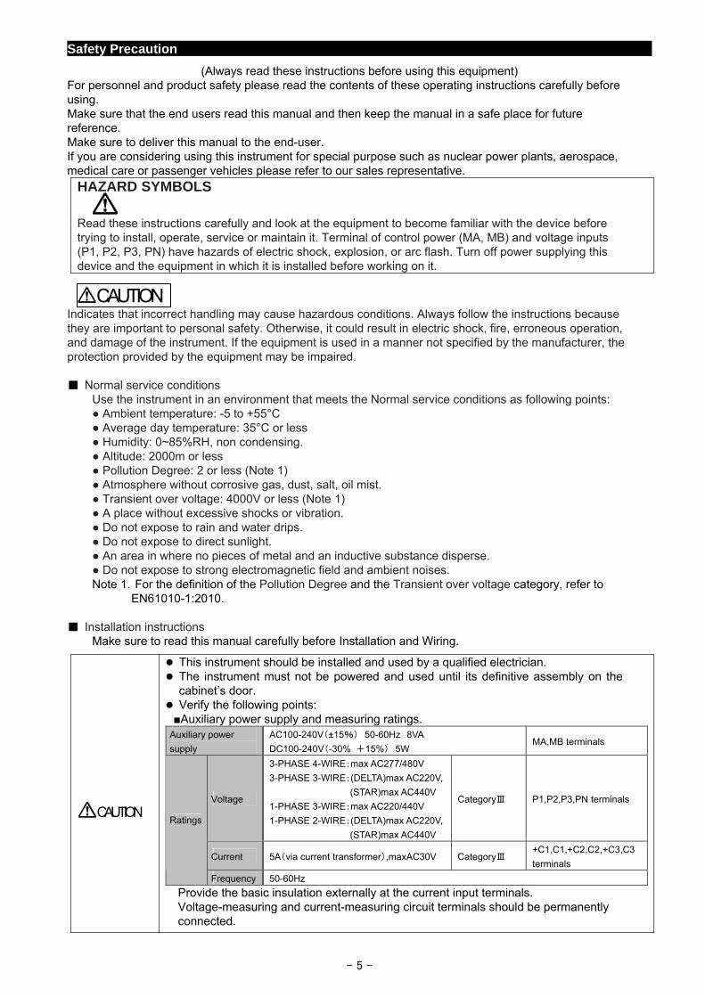
Installation instructions Make sure to read this manual carefully before Installation and Wiring.
This instrument should be installed and used by a qualified electrician. The instrument must not be powered and used until its definitive assembly on the
cabinet’s door. Verify the following points: Auxiliary power supply and measuring ratings. Auxiliary power
supply
AC100-240V(±15%) 50-60Hz 8VA
DC100-240V(-30% +15%) 5W MA,MB terminals
Voltage
3-PHASE 4-WIRE:max AC277/480V
3-PHASE 3-WIRE:(DELTA)max AC220V,
(STAR)max AC440V
1-PHASE 3-WIRE:max AC220/440V
1-PHASE 2-WIRE:(DELTA)max AC220V,
(STAR)max AC440V
CategoryⅢ P1,P2,P3,PN terminals
Current 5A(via current transformer),maxAC30V CategoryⅢ +C1,C1,+C2,C2,+C3,C3
terminals
Ratings
Frequency 50-60Hz
Provide the basic insulation externally at the current input terminals. Voltage-measuring and current-measuring circuit terminals should be permanently connected.
CAUTION
- 5 -
Safety Precaution
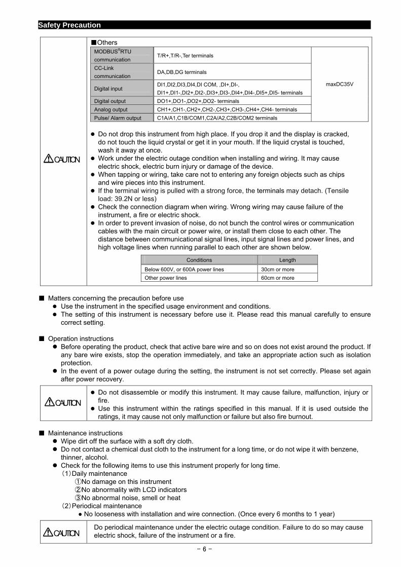
Others MODBUS®RTU
communication T/R+,T/R-,Ter terminals
CC-Link
communication DA,DB,DG terminals
Digital input DI1,DI2,DI3,DI4,DI COM, ,DI+,DI-,
DI1+,DI1-,DI2+,DI2-,DI3+,DI3-,DI4+,DI4-,DI5+,DI5- terminals
Digital output DO1+,DO1-,DO2+,DO2- terminals
Analog output CH1+,CH1-,CH2+,CH2-,CH3+,CH3-,CH4+,CH4- terminals
Pulse/ Alarm output C1A/A1,C1B/COM1,C2A/A2,C2B/COM2 terminals
maxDC35V
Do not drop this instrument from high place. If you drop it and the display is cracked,
do not touch the liquid crystal or get it in your mouth. If the liquid crystal is touched, wash it away at once.
Work under the electric outage condition when installing and wiring. It may cause electric shock, electric burn injury or damage of the device.
When tapping or wiring, take care not to entering any foreign objects such as chips and wire pieces into this instrument.
If the terminal wiring is pulled with a strong force, the terminals may detach. (Tensile load: 39.2N or less)
Check the connection diagram when wiring. Wrong wiring may cause failure of the instrument, a fire or electric shock.
In order to prevent invasion of noise, do not bunch the control wires or communication cables with the main circuit or power wire, or install them close to each other. The distance between communicational signal lines, input signal lines and power lines, and high voltage lines when running parallel to each other are shown below.
Conditions Length
Below 600V, or 600A power lines 30cm or more
Other power lines 60cm or more
CAUTION
Matters concerning the precaution before use
Use the instrument in the specified usage environment and conditions. The setting of this instrument is necessary before use it. Please read this manual carefully to ensure
correct setting.
Operation instructions Before operating the product, check that active bare wire and so on does not exist around the product. If
any bare wire exists, stop the operation immediately, and take an appropriate action such as isolation protection.
In the event of a power outage during the setting, the instrument is not set correctly. Please set again after power recovery.
Do not disassemble or modify this instrument. It may cause failure, malfunction, injury or fire.
Use this instrument within the ratings specified in this manual. If it is used outside the ratings, it may cause not only malfunction or failure but also fire burnout.
CAUTION
Maintenance instructions
Wipe dirt off the surface with a soft dry cloth. Do not contact a chemical dust cloth to the instrument for a long time, or do not wipe it with benzene,
thinner, alcohol. Check for the following items to use this instrument properly for long time. (1)Daily maintenance ①No damage on this instrument ②No abnormality with LCD indicators ③No abnormal noise, smell or heat (2)Periodical maintenance
No looseness with installation and wire connection. (Once every 6 months to 1 year)
Do periodical maintenance under the electric outage condition. Failure to do so may cause electric shock, failure of the instrument or a fire.
CAUTION
- 6 -
- 7 -
Safety Precaution
Storage conditions To store this instrument, turn off the power and remove wires, and put it in a plastic bag. For long-time storage, store at the following places. Failure to follow the instruction may cause a failure and reduced life of the instrument. Ambient temperature the: -25 to +75°C average day temperature: 35°C or less Humidity range 0 to 85%RH, non condensing. Atmosphere without corrosive gas, dust, salt, oil mist. A place without excessive shocks or vibration. Do not expose to rain and water drips. Do not expose to direct sunlight. An area in where no pieces of metal and an inductive substance disperse.
Guarantee
Gratis warranty is effective until the earlier of 1 year after the date of your purchase or 18 months after manufacturing.
The gratis warranty shall apply if the product fails even though it is being used properly in the conditions, with the methods and under the environments in accordance with the terms and precautions described in the catalogs, the instruction manual, caution label on the product, etc.
Repair shall be charged for the following cases even during the gratis warranty period.
① Failures occurring due to your improper storage or handling, carelessness or fault.
② Failures due to faulty workmanship
③ Failures due to faults in use and undue modification
④ Failures due to accidental force such as a fire, abnormal voltage, etc. and force majeure
such as an earthquake, wind, flood, etc.
⑤ Failures due to matters unpredictable based on the level of science technology at the time of
product.
Our company shall not be liable to compensate for any loss arising from events not attributable to our company, opportunity loss and lost earning of the customer due to failure of the product, and loss, secondary loss, accident compensation, damage to other products besides our products and other operations caused by a special reason regardless of our company’s predictability
Replacement Cycle
Although it depends on the status of use, 10 years is the guideline for renewal.
Disposal When disposing of this product, treat it as industrial waste. A battery is not used for this product.
About packaging materials and this manual For reduction of environment load, packaging materials are produced with cardboard, and this manual is printed on recycled paper.
EMC Directive Instruction
This section summarizes the precautions on conformance to the EMC Directive of the cabinet constructed using this instrument. However, the method of conformance to the EMC Directive and the judgment on whether or not the cabinet
conforms to the EMC Directive has to be determined finally by the manufacturer. This instrument complies with part 15 of the FCC Rules. Operation is subject to the following two conditions: (1)
This instrument may not cause harmful interference, and (2) this instrument must accept any interference received, including interference that may cause undesired operation.
1.EMC Standards
EN 61326-1
EN 61000-3-2
EN 61000-3-3
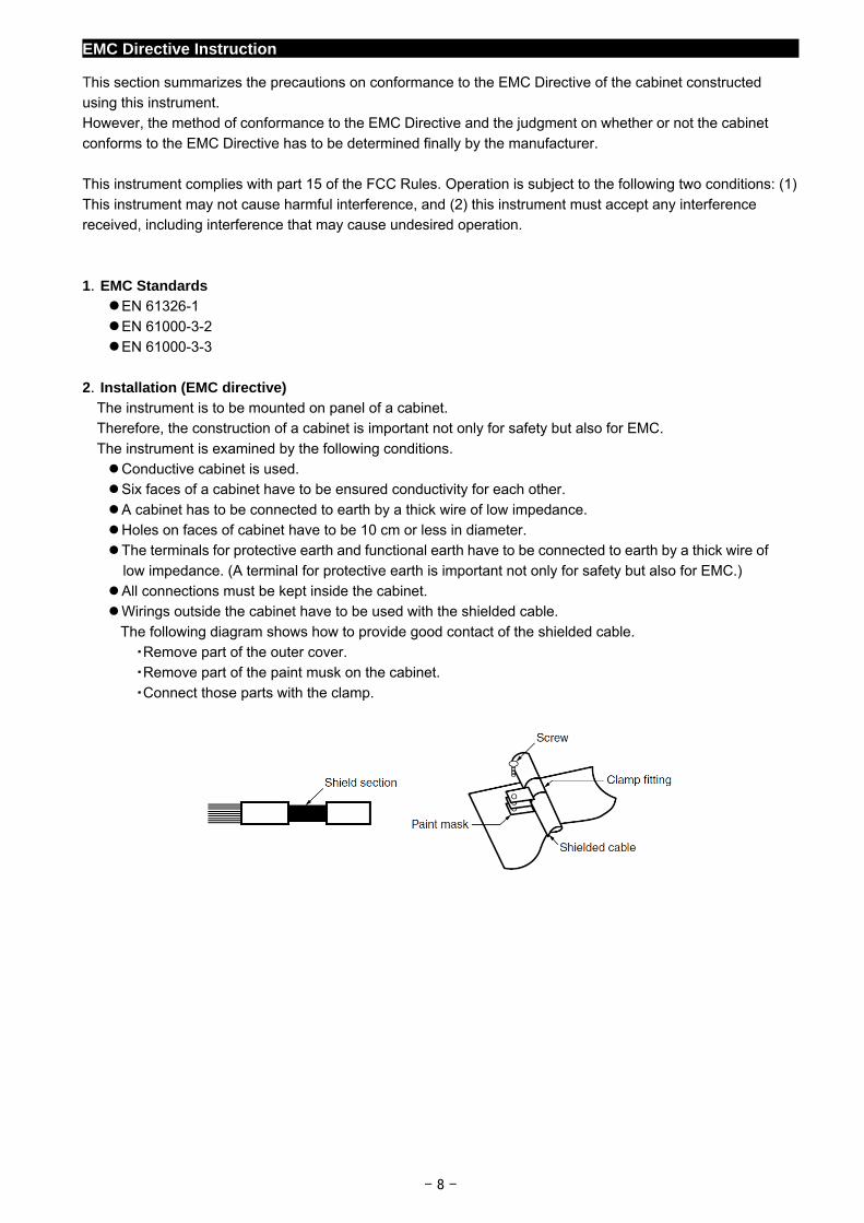
2.Installation (EMC directive) The instrument is to be mounted on panel of a cabinet. Therefore, the construction of a cabinet is important not only for safety but also for EMC.
The instrument is examined by the following conditions. Conductive cabinet is used. Six faces of a cabinet have to be ensured conductivity for each other.
A cabinet has to be connected to earth by a thick wire of low impedance. Holes on faces of cabinet have to be 10 cm or less in diameter. The terminals for protective earth and functional earth have to be connected to earth by a thick wire of
low impedance. (A terminal for protective earth is important not only for safety but also for EMC.) All connections must be kept inside the cabinet. Wirings outside the cabinet have to be used with the shielded cable.
The following diagram shows how to provide good contact of the shielded cable. ・Remove part of the outer cover. ・Remove part of the paint musk on the cabinet.
・Connect those parts with the clamp.
- 8 -
1. Display and Button Functions of Each Parts
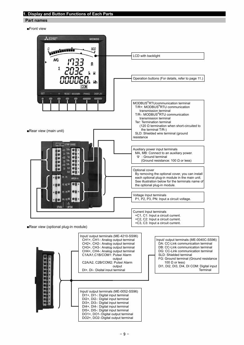
Part names
Front view
LCD with backlight
Rear view (main unit)
Rear view (optional plug-in module)
MODBUS®RTUcommunication terminal T/R+: MODBUS®RTU communication transmission terminal T/R-: MODBUS®RTU communication transmission terminal Ter: Termination terminal (120 Ω termination when short-circuited to the terminal T/R-) SLD: Shielded wire terminal (ground resistance
Optional cover By removing the optional cover, you can install each optional plug-in module in the main unit. See illustration below for the terminals name of the optional plug-in module.
Voltage Input terminals P1, P2, P3, PN: Input a circuit voltage.
Auxiliary power input terminals MA, MB: Connect to an auxiliary power. : Ground terminal (Ground resistance: 100 Ω or less)
Operation buttons (For details, refer to page 11.)
Current Input terminals +C1, C1: Input a circuit current. +C2, C2: Input a circuit current. +C3, C3: Input a circuit current.
Input/ output terminals (ME-4210-SS96) CH1+, CH1-: Analog output terminal CH2+, CH2-: Analog output terminal CH3+, CH3-: Analog output terminal CH4+, CH4-: Analog output terminal C1A/A1,C1B/COM1: Pulse/ Alarm output C2A/A2, C2B/COM2: Pulse/ Alarm output DI+, DI-: Digital input terminal
Input/ output terminals (ME-0040C-SS96) DA: CC-Link communication terminal DB: CC-Link communication terminal DG: CC-Link communication terminal SLD: Shielded terminal FG: Ground terminal (Ground resistance 100 Ω or less) DI1, DI2, DI3, DI4, DI COM: Digital input Terminal
Input/ output terminals (ME-0052-SS96) DI1+, DI1-: Digital input terminal DI2+, DI2-: Digital input terminal DI3+, DI3-: Digital input terminal DI4+, DI4-: Digital input terminal DI5+, DI5-: Digital input terminal DO1+, DO1-:Digital output terminal DO2+, DO2-:Digital output terminal
- 9 -
1. Display and Button Functions of Each Parts
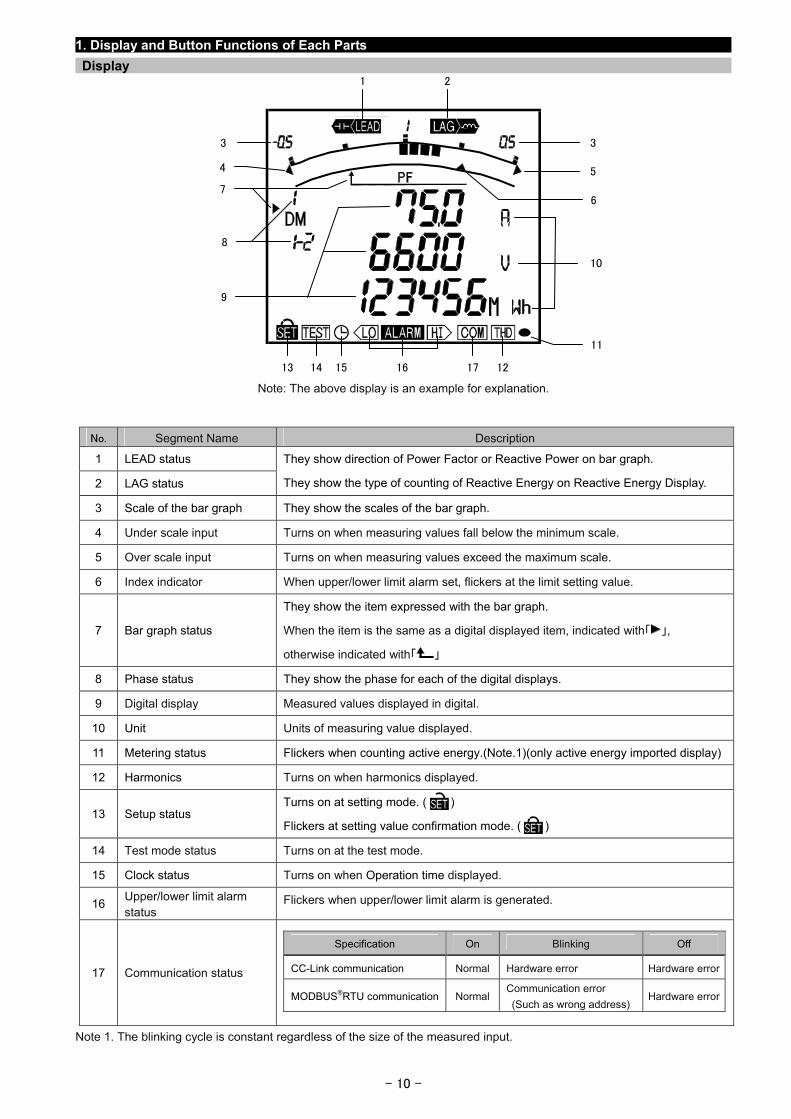
Display 1 2
- 10 -
Note: The above display is an example for explanation.
No. Segment Name Description
1 LEAD status
2 LAG status
They show direction of Power Factor or Reactive Power on bar graph.
They show the type of counting of Reactive Energy on Reactive Energy Display.
3 Scale of the bar graph They show the scales of the bar graph.
4 Under scale input Turns on when measuring values fall below the minimum scale.
5 Over scale input Turns on when measuring values exceed the maximum scale.
6 Index indicator When upper/lower limit alarm set, flickers at the limit setting value.
7 Bar graph status
They show the item expressed with the bar graph.
When the item is the same as a digital displayed item, indicated with「 」,
otherwise indicated with「 」
8 Phase status They show the phase for each of the digital displays.
9 Digital display Measured values displayed in digital.
10 Unit Units of measuring value displayed.
11 Metering status Flickers when counting active energy.(Note.1)(only active energy imported display)
12 Harmonics Turns on when harmonics displayed.
13 Setup status Turns on at setting mode. ( )
Flickers at setting value confirmation mode. ( )
14 Test mode status Turns on at the test mode.
15 Clock status Turns on when Operation time displayed.
16 Upper/lower limit alarm status
Flickers when upper/lower limit alarm is generated.
17 Communication status
Specification On Blinking Off
CC-Link communication Normal Hardware error Hardware error
MODBUS®RTU communication NormalCommunication error
(Such as wrong address) Hardware error
Note 1. The blinking cycle is constant regardless of the size of the measured input.
4
7
8
6
11
10
3
5
3
9
1613 14 15 17 12
1. Display and Button Functions of Each Parts
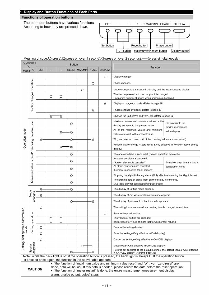
Functions of operation buttons
The operation buttons have various functions According to how they are pressed down.
- 11 -
Meaning of code:(press),(press on over 1 second),(press on over 2 seconds),―― (press simultaneously)
Button Operation
Mode SET - + RESET MAX/MIN PHASE DISPLAYFunction
Display changes.
Phase changes.
Mode changes to the max./min. display and the instantaneous display
The item expressed with the bar graph is changed. Harmonics number changes when harmonics displayed.
Displays change cyclically. (Refer to page 49)
Phases change cyclically. (Refer to page 49)
Dis
play
cha
nges
ope
ratio
n
Change the unit of Wh and varh, etc. (Refer to page 52)
Maximum values and minimum values on the
display are reset to the present value.
All of the Maximum values and minimum
values are reset to the present value.
Only available for
maximum/minimum
value display
Wh, varh are zero reset. (All of the counting values are zero reset.)
Periodic active energy is zero reset. (Only effective in Periodic active energy
display)
The operation time is zero reset (Screen operation time only)
An alarm condition is canceled.
(Screen element is canceled)
All alarm conditions are canceled.
(Element is canceled for all screens)
Available only when manual
cancelation is set
Stopping backlight flickering alarm. (Only effective in setting backlight flicker)
Mea
sure
d va
lue
is r
eset
/ C
ance
ling
the
alar
m, e
tc
The latching data of digital input on the display is canceled.
(Available only for contact point input screen)
The display of Setting mode appears.
The display of Set value confirmation mode appears.
Ope
ratio
n m
ode
Mod
e ch
ange
s
The display of password protection mode appears.
The setting items are saved, and setting item is changed to next item.
Back to the previous item.
The values of setting are changed.
(If it presses for 1 sec or more fast forward or fast return.)
Back to the setting display.
Save the settings(Only effective in End display) Set
ting
oper
atio
n
Cancel the settings(Only effective in CANCEL display)
Meter restart(Only effective in CANCEL display)
Set
ting/
Set
ting
valu
e co
nfirm
atio
n m
ode
Sp
eci
al
Ope
ratio
n
Returns set contents to the default settings (the default values, Only effective in CANCEL display) (Refer to page 36)
SET - + RESET MAX/MIN PHASE DISPLAY
Set button Reset button Phase button
+/-button Maximum/Minimum button Display button
Note: While the back light is off, if the operation button is pressed, the back light is always lit. If the operation button is pressed once again, the function in the above table appears.
CAUTION
If the function of “maximum value and minimum value reset” and “Wh, varh zero reset” are done, data will be lost. If this data is needed, please record the data before the reset operation. If the function of “meter restart” is done, the entire measurement(measure-ment display, alarm, analog output, pulse) stops.
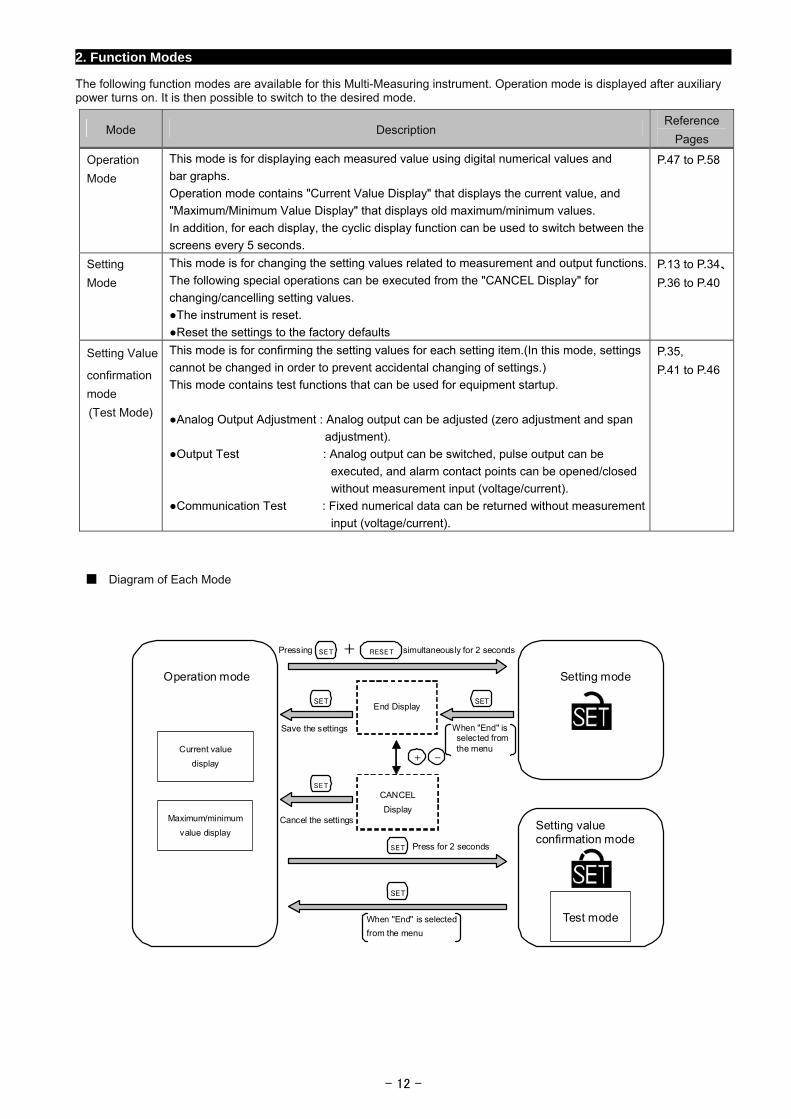
2. Function Modes
The following function modes are available for this Multi-Measuring instrument. Operation mode is displayed after auxiliary power turns on. It is then possible to switch to the desired mode.
Mode Description Reference
Pages
Operation
Mode
This mode is for displaying each measured value using digital numerical values and
bar graphs.
Operation mode contains "Current Value Display" that displays the current value, and
"Maximum/Minimum Value Display" that displays old maximum/minimum values.
In addition, for each display, the cyclic display function can be used to switch between the
screens every 5 seconds.
P.47 to P.58
Setting Mode
This mode is for changing the setting values related to measurement and output functions.
The following special operations can be executed from the "CANCEL Display" for
changing/cancelling setting values.
The instrument is reset.
Reset the settings to the factory defaults
P.13 to P.34、
P.36 to P.40
Setting Value
confirmation mode (Test Mode)
This mode is for confirming the setting values for each setting item.(In this mode, settings
cannot be changed in order to prevent accidental changing of settings.)
This mode contains test functions that can be used for equipment startup.
Analog Output Adjustment : Analog output can be adjusted (zero adjustment and span
adjustment).
Output Test : Analog output can be switched, pulse output can be
executed, and alarm contact points can be opened/closed
without measurement input (voltage/current).
Communication Test : Fixed numerical data can be returned without measurement
input (voltage/current).
P.35,
P.41 to P.46
Diagram of Each Mode
SET
+ -
Operation mode
Current value
display
Maximum/minimum
value display
Setting mode
Setting value confirmation mode
Test mode
SET
SET SET
SET
SET RESET
End Display
CANCEL Display
+
Save the settings
Cancel the settings
Pressing simultaneously for 2 seconds
When "End" is selected from the menu
When "End" is selected from the menu
Press for 2 seconds
- 12 -
- 13 -
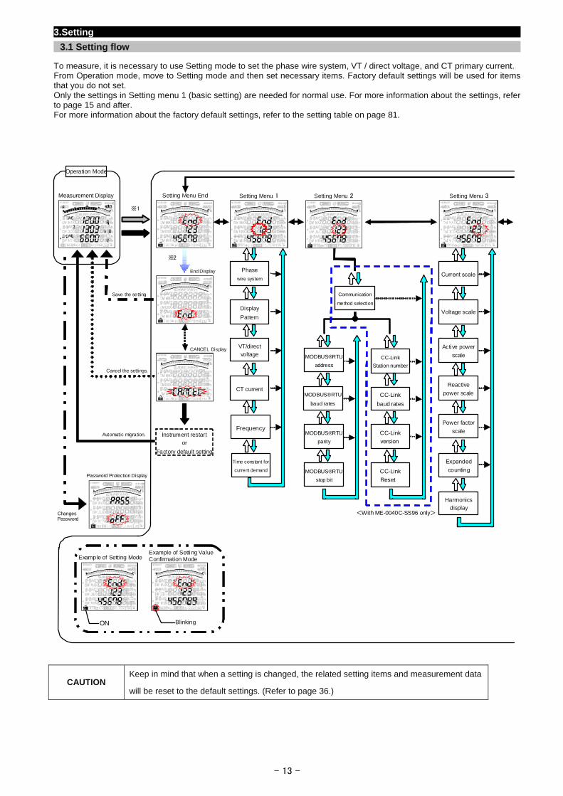
3.Setting
3.1 Setting flow
To measure, it is necessary to use Setting mode to set the phase wire system, VT / direct voltage, and CT primary current. From Operation mode, move to Setting mode and then set necessary items. Factory default settings will be used for items that you do not set. Only the settings in Setting menu 1 (basic setting) are needed for normal use. For more information about the settings, refer to page 15 and after. For more information about the factory default settings, refer to the setting table on page 81.
CAUTION Keep in mind that when a setting is changed, the related setting items and measurement data
will be reset to the default settings. (Refer to page 36.)
Frequency
Measurement Display Setting Menu End
End Display
CANCEL Display
Automatic migration.
Cancel the settings.
Save the setting
Instrument restart or
Factory default setting
Operation Mode
※2
※1
Changes Password
Password Protection Display
Time constant for
current demand
CT current
VT/directvoltage
Display
Pattern
Phase
wire system
Setting Menu 1 Setting Menu 2 Setting Menu 3
Harmonicsdisplay
Expandedcounting
Reactive
power scale
Active power
scale
Voltage scale
Current scale
Power factor
scale
MODBUS®RTU
address
MODBUS®RTU
baud rates
MODBUS®RTU
parity
MODBUS®RTU
stop bit
CC-Link
baud rates
CC-Link
version
CC-Link
Reset
CC-Link
Station number
<With ME-0040C-SS96 only>
Communication
method selection
ON Blinking
Example of Setting ModeExample of Setting Value Confirmation Mode
- 14 -
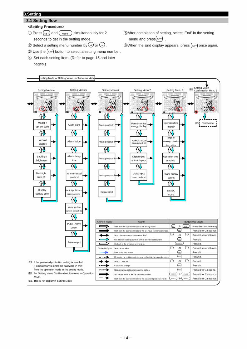
3.Setting
3.1 Setting flow
<Setting Procedure>
① Press and simultaneously for 2 ⑤After completion of setting, select ‘End’ in the setting
seconds to get in the setting mode. menu and press .
② Select a setting menu number by or . ⑥When the End display appears, press once again.
③ Use the button to select a setting menu number.
④ Set each setting item. (Refer to page 15 and later
pages.)
Setting Value Confirmation Menu 9Setting Menu 4 Setting Menu 5 Setting Menu 6 Setting Menu 7 Setting Menu 8
Setting Mode or Setting Value Confirmation Mode
Arrow in Figure Action Button operation
Shift from the operation mode to the setting mode. + Press them simultaneously
Shift from the operation mode to the set value confirmation mode. Press it for 2 seconds.
Select the menu number to set or “End”. or Press it several times.
Get into each setting screen. Shif t to the next setting item. Press it.
Go back to the previous setting item. Press it.
Omitted in figure Select a set value. or Press it several times.
Shift to the End screen. Press it.
Memorize the setting contents, and go back to the operation mode Press it.
Select "CANCEL." or Press it.
Cancel the settings. Press it.
Skip remaining setting items during setting. Press it for 1 second.
Set values return to the factory default value. + Press it for 2 seconds.
Shift from the operation mode to the password protection mode. + Press it for 2 seconds.
DISPLAY
RESE T
+ -
SET
PHASERESET
SET
SET
SET
SET
+ -
SET
SET
※1.If the password protection setting is enabled,
it is necessary to enter the password in shift
from the operation mode to the setting mode.
※2.For Setting Value Confirmation, it returns to Operation
Mode.
※3.This is not display in Setting Mode.
Test Mode※3
PHASERE SET
Model +
option code
Version
display
Backlight
brightness
Backlight
auto off
Display
update time
Alarm value
Alarm delay
time
Alarm cancel
method
Back light flickers
during alarms
Motor starting
current delay time
Alarm item
Pulse output
Pulse / Alarm
output
Analog output 1
Output Limit
Analog output 4
Analog output 3
Analog output 2
Phase display
setting
Operation time
threshold
Target for
counting operation
time setting
Operation time
display
Set IEC
mode
Periodic activeenergy setting
Periodic activeenergy display
Digital input
reset method
Digital input/
output display
+ -
※3
SET
+ -
SET
SET
SET
RESET
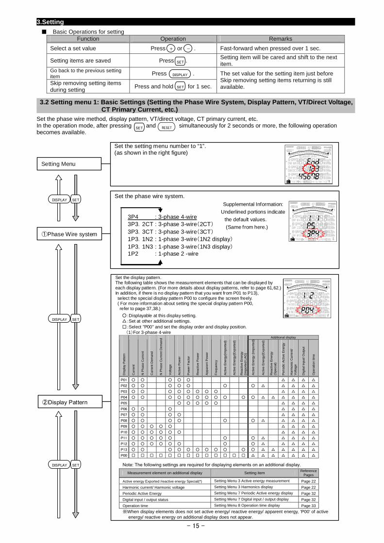
3.Setting
Basic Operations for setting Function Operation Remarks
Select a set value Press or . Fast-forward when pressed over 1 sec.
Setting items are saved Press . Setting item will be cared and shift to the next item.
Go back to the previous setting item Press .
Skip removing setting items during setting
Press and hold for 1 sec.
The set value for the setting item just before Skip removing setting items returning is still available.
-+
SET
DISPLAY
SET
3.2 Setting menu 1: Basic Settings (Setting the Phase Wire System, Display Pattern, VT/Direct Voltage, CT Primary Current, etc.)
Set the phase wire method, display pattern, VT/direct voltage, CT primary current, etc. In the operation mode, after pressing and simultaneously for 2 seconds or more, the following operation becomes available.
SET RESET
Set the phase wire system. Supplemental Information:
Underlined portions indicate
the default values.
(Same from here.)
①Phase Wire system
3P4 : 3-phase 4-wire 3P3.2CT : 3-phase 3-wire(2CT) 3P3.3CT : 3-phase 3-wire(3CT) 1P3.1N2 : 1-phase 3-wire(1N2 display) 1P3.1N3 : 1-phase 3-wire(1N3 display) 1P2 : 1-phase 2 -wire
Set the setting menu number to “1”. (as shown in the right figure)
Setting Menu
DISPLAY SET
Set the display pattern.The following table shows the measurement elements that can be displayed by each display pattern. (For more details about display patterns, refer to page 61,62.) In addition, if there is no display pattern that you want from P01 to P13), select the special display pattern P00 to configure the screen freely. ( For more information about setting the special display pattern P00,
refer to page 37,38.)
:Displayable at this display setting. :Set at other additional settings. :Select "P00" and set the display order and display position.
②Display Pattern
SETDISPLAY
(1)For 3-phase 4-wire Additional display
Dis
play
Pat
tern
Cur
rent
N P
has
e C
urre
nt
Cur
rent
Dem
and
N P
has
e C
urre
nt D
em
and
Vol
tag
e
Act
ive
Pow
er
Pow
er F
acto
r
Rea
ctiv
e P
ower
App
aren
t P
ower
Fre
quen
cy
Act
ive
Ene
rgy(
Impo
rte
d)
Act
ive
Ene
rgy(
Exp
orte
d)
Rea
ctiv
e E
ner
gy
(Im
port
ed
LA
G)
Act
ive
Ene
rgy
(Im
port
ed)
Act
ive
Ene
rgy(
Exp
orte
d)
Rea
ctiv
e E
ner
gy
(Spe
cial
)
Per
iodi
c A
ctiv
e E
ner
gy
Har
mon
ic C
urre
nt/
V
olta
ge
Dig
ital I
npu
t/ O
utpu
t
Ope
ratio
n tim
e
P01
P02
P03
P04
P05
P06
P07
P08
P09
P10
P11
P12
P13
P00
Note: The following settings are required for displaying elements on an additional display. Measurement element on additional display Setting item Reference
Pages
Active energy Exported /reactive energy Special(*) Setting Menu 3 Active energy measurement Page 22
Harmonic current/ Harmonic voltage Setting Menu 3 Harmonics display Page 22
Periodic Active Energy Setting Menu 7 Periodic Active energy display Page 32
Digital input / output status Setting Menu 7 Digital input / output display Page 32
Operation time Setting Menu 8 Operation time display Page 33
※When display elements does not set active energy/ reactive energy/ apparent energy, ’P00’ of active energy/ reactive energy on additional display does not appear.
SETDISPLAY
- 15 -
3.Setting
3.2 Setting menu 1: Basic Settings (Setting the Phase Wire System, Display Pattern, VT/Direct Voltage, CT Primary Current, etc.)
- 16 -
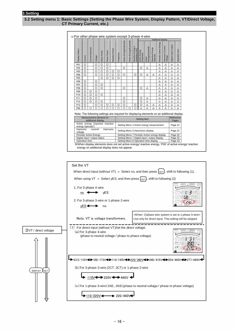
(2)For other phase wire system except 3-phase 4-wire
Additional display
Dis
play
Pat
tern
Cur
rent
Cur
rent
Dem
and
Vol
tag
e
Act
ive
Pow
er
Pow
er F
acto
r
Rea
ctiv
e P
ower
Fre
quen
cy
Act
ive
Ene
rgy(
Impo
rte
d)
Act
ive
Ene
rgy(
Exp
orte
d)
Rea
ctiv
e E
ner
gy y
(I
mpo
rte
d L
AG
)
Act
ive
Ene
rgy
(Im
port
ed)
Act
ive
Ene
rgy(
Exp
orte
d)
Rea
ctiv
e E
ner
gy
(Spe
cial
)
Per
iodi
c A
ctiv
e E
ner
gy
Har
mon
ic C
urre
nt/
V
olta
ge
Dig
ital I
npu
t/ O
utpu
t
Ope
ratio
n tim
e
P01
P02
P03
P04
P05
P06
P07
P08
P09
P10
P11
P12
P13
P00
Note: The following settings are required for displaying elements on an additional display.
Set the VT
When direct input (without VT) ⇒ Select no, and then press , shift to following (1).
When using VT ⇒ Select yES, and then press , shift to following (2)
1. For 3-phase 4-wire
2. For 3-phase 3-wire or 1-phase 2-wire
Note. VT is voltage transformers.
(1) For direct input (without VT)Set the direct voltage. (a)For 3-phase 4-wire (phase to neutral voltage / phase to phase voltage)
(b)For 3-phase 3-wire (2CT, 3CT) or 1-phase 2-wire
(c)For 1-phase 3-wire(1N2、1N3)(phase to neutral voltage / phase to phase voltage)
③VT / direct voltage
<When ①phase wire system is set to 1-phase 3-wire>
Use only for direct input. This setting will be skipped.
SET
SET
yES no
110V 220V 440V
110/220V 220/440V
no yES
63.5/110V 100/173V 110/190V 220/380V 240/415V 254/440V 277/480V
SETDISPLAY
Measurement element on Reference Setting item
additional display Pages
Active energy Exported /reactive energy Special(*)
Setting Menu 3 Active energy measurement Page 22
Harmonic current/ Harmonic voltage
Setting Menu 3 Harmonics display Page 22
Periodic Active Energy Setting Menu 7 Periodic Active energy display Page 32 Digital input / output status Setting Menu 7 Digital input / output display Page 32 Operation time Setting Menu 8 Operation time display Page 33
※When display elements does not set active energy/ reactive energy, ’P00’ of active energy/ reactive energy on additional display does not appear.
3.Setting
3.2 Setting menu 1: Basic Settings (Setting the Phase Wire System, Display Pattern, VT/Direct Voltage, CT Primary Current, etc.)
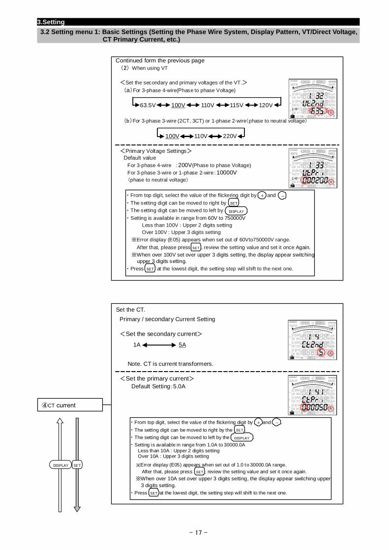
Continued form the previous page
(2) When using VT
<Set the secondary and primary voltages of the VT.>
(a)For 3-phase 4-wire(Phase to phase Voltage)
(b)For 3-phase 3-wire (2CT, 3CT) or 1-phase 2-wire(phase to neutral voltage)
<Primary Voltage Settings> Default value
For 3-phase 4-wire :200V(Phase to phase Voltage)
For 3-phase 3-wire or 1-phase 2-wire:10000V (phase to neutral voltage)
・ From top digit, select the value of the flickering digit by and
・ The setting digit can be moved to right by
・ The setting digit can be moved to left by
・ Setting is available in range from 60V to 750000V
Less than 100V : Upper 2 digits setting Over 100V : Upper 3 digits setting
※Error display (E05) appears when set out of 60Vto750000V range.
After that, please press , review the setting value and set it once Again.
※When over 100V set over upper 3 digits setting, the display appear switching upper 3 digits setting.
・ Press at the lowest digit, the setting step will shift to the next one.
63.5V 100V 110V 115V 120V
100V 110V 220V
+ -
SET
DISPLAY
SET
SET
Set the CT.
Primary / secondary Current Setting
<Set the secondary current>
Note. CT is current transformers.
<Set the primary current>
Default Setting:5.0A
④CT current
・ From top digit, select the value of the flickering digit by and .
・ The setting digit can be moved to right by the .
・ The setting digit can be moved to left by the .
・ Setting is available in range from 1.0A to 30000.0A Less than 10A : Upper 2 digits setting Over 10A : Upper 3 digits setting
※Error display (E05) appears when set out of 1.0 to 30000.0A range. After that, please press , review the setting value and set it once again.
※When over 10A set over upper 3 digits setting, the display appear switching upper 3 digits setting.
・ Press at the lowest digit, the setting step will shift to the next one.
1A 5A
+ -
DISPLAY
SET
SET
SET
SETDISPLAY
- 17 -
3.Setting
3.2 Setting menu 1: Basic Settings (Setting the Phase Wire System, Display Pattern, VT/Direct Voltage, CT Primary Current, etc.)
- 18 -
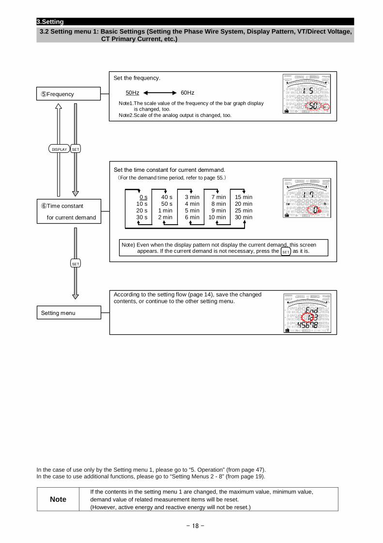
In the case of use only by the Setting menu 1, please go to “5. Operation” (from page 47). In the case to use additional functions, please go to “Setting Menus 2 - 8” (from page 19).
Note If the contents in the setting menu 1 are changed, the maximum value, minimum value, demand value of related measurement items will be reset. (However, active energy and reactive energy will not be reset.)
According to the setting flow (page 14), save the changed contents, or continue to the other setting menu.
Setting menu
Set the time constant for current demmand. (For the demand time period, refer to page 55.)
⑥Time constant
for current demand
0 s 10 s 20 s 30 s
40 s50 s
1 min2 min
3 min4 min5 min6 min
7 min8 min9 min
10 min
15 min20 min25 min30 min
Note) Even when the display pattern not display the current demand, this screen appears. If the current demand is not necessary, press the as it is. SET
Set the frequency.
⑤Frequency 50Hz 60Hz
Note1.The scale value of the frequency of the bar graph display is changed, too. Note2.Scale of the analog output is changed, too.
SETDISPLAY
SET
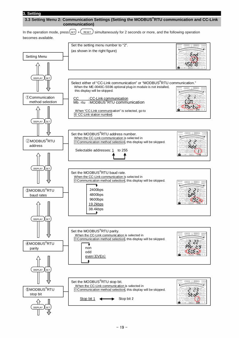
3. Setting
3.3 Setting Menu 2: Communication Settings (Setting the MODBUS®RTU communication and CC-Link communication)
In the operation mode, press + simultaneously for 2 seconds or more, and the following operation
- 19 -
becomes available.
Set the MODBUS®RTU parity. When the CC-Link communication is selected in Communication method selection, this display will be skipped.
④MODBUS®RTU parity non
odd even(EVEn)
Set the MODBUS®RTU baud rate. When the CC-Link communication is selected in Communication method selection, this display will be skipped.
③MODBUS®RTU baud rates
2400bps4800bps9600bps19.2kbps38.4kbps
Set the MODBUS®RTU address number. When the CC-Link communication is selected in Communication method selection, this display will be skipped.
Selectable addresses: 1 to 255
②MODBUS®RTU address
Select either of “CC-Link communication” or “MODBUS®RTU communication.” When the ME-0040C-SS96 optional plug-in module is not installed, this display will be skipped. CC :CC-Link communication Mb.rtu :MODBUS®RTU communication When “CC-Link communication” is selected, go to CC-Link station number.
①Communication method selection
Set the MODBUS®RTU stop bit. When the CC-Link communication is selected in Communication method selection, this display will be skipped.
⑤MODBUS®RTU stop bit
Stop bit 1 Stop bit 2
SETDISPLAY
SETDISPLAY
SETDISPLAY
SETDISPLAY
SETDISPLAY
SETDISPLAY
Set the setting menu number to “2”.
(as shown in the right figure)
SET RE TSE
Setting Menu
3. Setting
3.3 Setting Menu 2: Communication Settings (Setting the MODBUS®RTU communication and CC-Link communication)
- 20 -
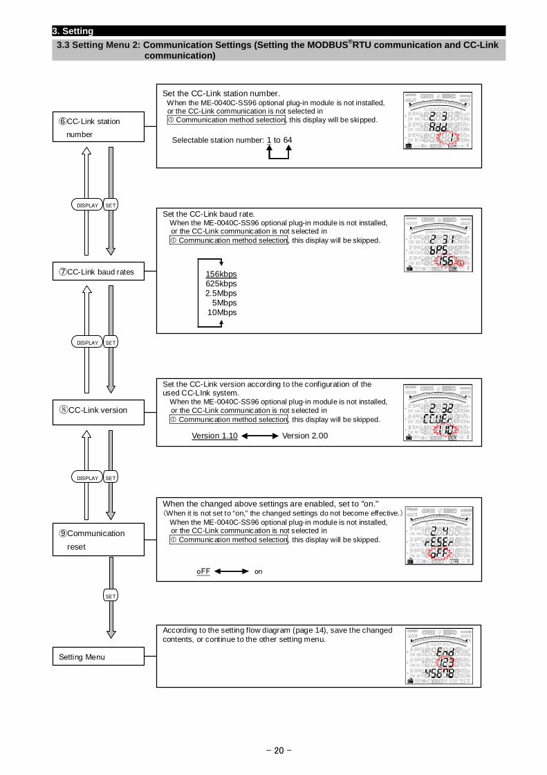
Set the CC-Link station number. When the ME-0040C-SS96 optional plug-in module is not installed, or the CC-Link communication is not selected in Communication method selection, this display will be skipped.
Selectable station number: 1 to 64
⑥CC-Link station
number
According to the setting flow diagram (page 14), save the changed contents, or continue to the other setting menu.
Setting Menu
When the changed above settings are enabled, set to "on." (When it is not set to “on,” the changed settings do not become effective.) When the ME-0040C-SS96 optional plug-in module is not installed, or the CC-Link communication is not selected in Communication method selection, this display will be skipped.
⑨Communication
reset
oFF on
Set the CC-Link version according to the configuration of the used CC-LInk system. When the ME-0040C-SS96 optional plug-in module is not installed, or the CC-Link communication is not selected in Communication method selection, this display will be skipped.
⑧CC-Link version
Version 1.10 Version 2.00
Set the CC-Link baud rate. When the ME-0040C-SS96 optional plug-in module is not installed, or the CC-Link communication is not selected in Communication method selection, this display will be skipped.
⑦CC-Link baud rates 156kbps625kbps2.5Mbps
5Mbps10Mbps
DISPLAY SET
SETDISPLAY
SETDISPLAY
SET
- 21 -
3. Setting
3.4 Setting Menu 3: Display Settings (Setting Maximum Scale, Active Energy Measurement, and Harmonic Display, etc.)
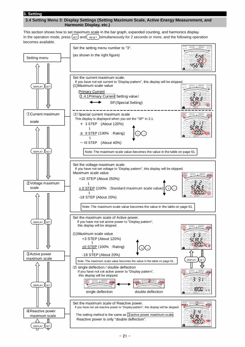
This section shows how to set maximum scale in the bar graph, expanded counting, and harmonics display. In the operation mode, press and simultaneously for 2 seconds or more, and the following operation becomes available.
Set the setting menu number to "3".
(as shown in the right figure) Setting menu
Set the maximum scale of Active power. If you have not set active power to “Display pattern”,
this display will be skipped.
(1)Maximum scale value
(2) single deflection / double deflection If you have not set active power to “Display pattern”, this display will be skipped.
③Active power maximum scale
Note:The maximum scale value becomes the value in the table on page 61.
single deflection double deflection
±0 STEP (100% :Rating) ~
~-18 STEP (About 20%)
+3 STEP (About 120%)
+ -
SETDISPLAY
Set the voltage maximum scale. If you have not set voltage to “Display pattern”, this display will be skipped. Maximum scale value
②Voltage maximum scale
Note:The maximum scale value becomes the value in the table on page 61.
± 0 STEP (100% :Standard maximum scale value)~
~-18 STEP (About 20%)
+10 STEP (About 250%)
+ -
Set the maximum scale of Reactive power. If you have not set reactive power to “Display pattern”, this display will be skipped.
The setting method is the same as ③active power maximum scale.
Reactive power is only “double deflection”.
④Reactive power maximum scale
Set the current maximum scale. If you have not set current to “Display pattern”, this display will be skipped. (1)Maximum scale value
(2)Special current maximum scale This display is displayed when you set the "SP" in 3.1.
①Current maximum
scale
Note:The maximum scale value becomes the value in the table on page 61.
± 0 STEP (100% :Rating) ~
~-10 STEP (About 40%)
+ 3 STEP (About 120%)
+ -
Primary Current
(1.4.1Primary Current Setting value)
SP.(Special Setting)
SETDISPLAY
SETDISPLAY
SETDISPLAY
SETDISPLAY
SETDISPLAY
SET RESET
3. Setting
3.4 Setting Menu 3: Display Settings (Setting Maximum Scale, Active Energy Measurement, and Harmonic Display, etc.)
- 22 -
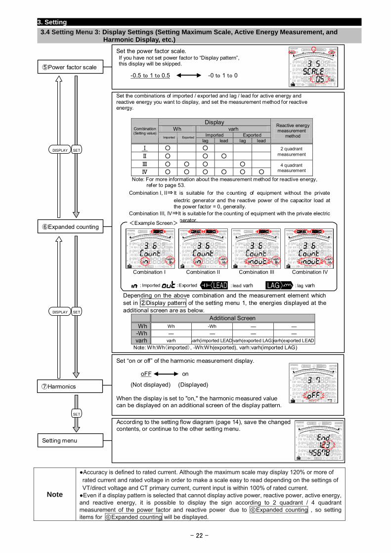
Set the power factor scale. If you have not set power factor to “Display pattern”, this display will be skipped.
Note
Accuracy is defined to rated current. Although the maximum scale may display 120% or more of rated current and rated voltage in order to make a scale easy to read depending on the settings of VT/direct voltage and CT primary current, current input is within 100% of rated current. Even if a display pattern is selected that cannot display active power, reactive power, active energy, and reactive energy, it is possible to display the sign according to 2 quadrant / 4 quadrant measurement of the power factor and reactive power due to ⑥Expanded counting , so setting items for ⑥Expanded counting will be displayed.
Set “on or off” of the harmonic measurement display.
When the display is set to "on," the harmonic measured value can be displayed on an additional screen of the display pattern.
⑦Harmonics
oFF on
(Not displayed) (Displayed)
According to the setting flow diagram (page 14), save the changed contents, or continue to the other setting menu.
Setting menu
Set the combinations of imported / exported and lag / lead for active energy and reactive energy you want to display, and set the measurement method for reactive energy.
Display Wh varh
Imported Exported Combination (Setting value)
Imported Exportedlag lead lag lead
Reactive energy measurement
method
Ⅰ
Ⅱ
2 quadrant measurement
Ⅲ
Ⅳ 4 quadrant
measurement
Note: For more information about the measurement method for reactive energy, refer to page 53.
Combination I, II⇒ It is suitable for the counting of equipment without the private
electric generator and the reactive power of the capacitor load at the power factor = 0, generally.
Combination III, IV⇒It is suitable for the counting of equipment with the private electric generator.
Depending on the above combination and the measurement element which set in ②Display pattern of the setting menu 1, the energies displayed at the additional screen are as below.
Additional Screen
Wh Wh -Wh ― ―
-Wh ― ― ― ―
varh varh varh(imported LEAD)varh(exported LAG)varh(exported LEAD)
Note: Wh:Wh(imported), -Wh:Wh(exported), varh:varh(imported LAG)
⑥Expanded counting <Example Screen>
Combination I Combination II Combination III Combination IV
:Imported :Exported :lead varh :lag varh
SETDISPLAY
SET
SETDISPLAY
⑤Power factor scale
-0.5 to 1 to 0.5 -0 to 1 to 0
3.Setting
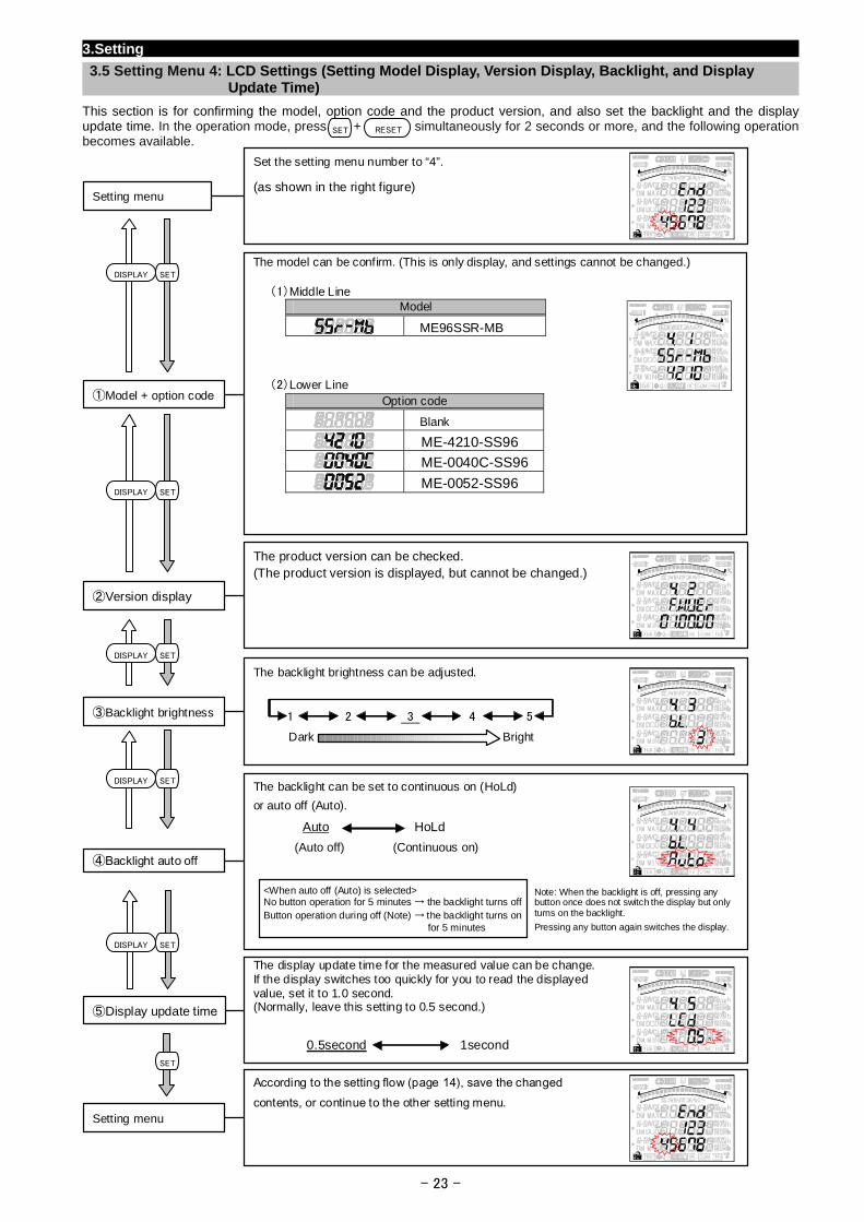
3.5 Setting Menu 4: LCD Settings (Setting Model Display, Version Display, Backlight, and Display Update Time)
This section is for confirming the model, option code and the product version, and also set the backlight and the display update time. In the operation mode, press + simultaneously for 2 seconds or more, and the following operation becomes available.
RESETSET
- 23 -
The model can be confirm. (This is only display, and settings cannot be changed.)
(1)Middle Line Model
ME96SSR-MB
(2)Lower Line
Option code
Blank
ME-4210-SS96
ME-0040C-SS96
ME-0052-SS96
①Model + option code
Set the setting menu number to “4”.
(as shown in the right figure) Setting menu
SETDISPLAY
According to the setting flow (page 14), save the changed contents, or continue to the other setting menu.
Setting menu
The display update time for the measured value can be change. If the display switches too quickly for you to read the displayed value, set it to 1.0 second. (Normally, leave this setting to 0.5 second.)
0.5second 1second
⑤Display update time
The backlight brightness can be adjusted.
③Backlight brightness 1 2 3 4 5
Dark Bright
The product version can be checked. (The product version is displayed, but cannot be changed.)
②Version display
SETDISPLAY
SETDISPLAY
SETDISPLAY The backlight can be set to continuous on (HoLd)
or auto off (Auto).
Auto HoLd
(Auto off) (Continuous on)④Backlight auto off
<When auto off (Auto) is selected> No button operation for 5 minutes → the backlight turns offButton operation during off (Note) → the backlight turns on
for 5 minutes
Note: When the backlight is off, pressing any button once does not switch the display but only turns on the backlight.
Pressing any button again switches the display.
SETDISPLAY
SET
3. Setting
3.6 Setting Menu 5: Pulse and Alarm Settings (Setting Upper/Lower Limit Alarm, Motor Starting Current Mask Function, Pulse Output, etc.)
This section shows how to set the upper/lower limit alarm, backlight flickering during alarm, motor starting current delay time, and
pulse output.
In the operation mode, press and simultaneously for 2 seconds or more, and the following operation becomes available. SET RESET
For more details about each function, refer to the corresponding pages. Upper/lower limit alarm → Pages 55 and 56, Motor startup current → Page 58
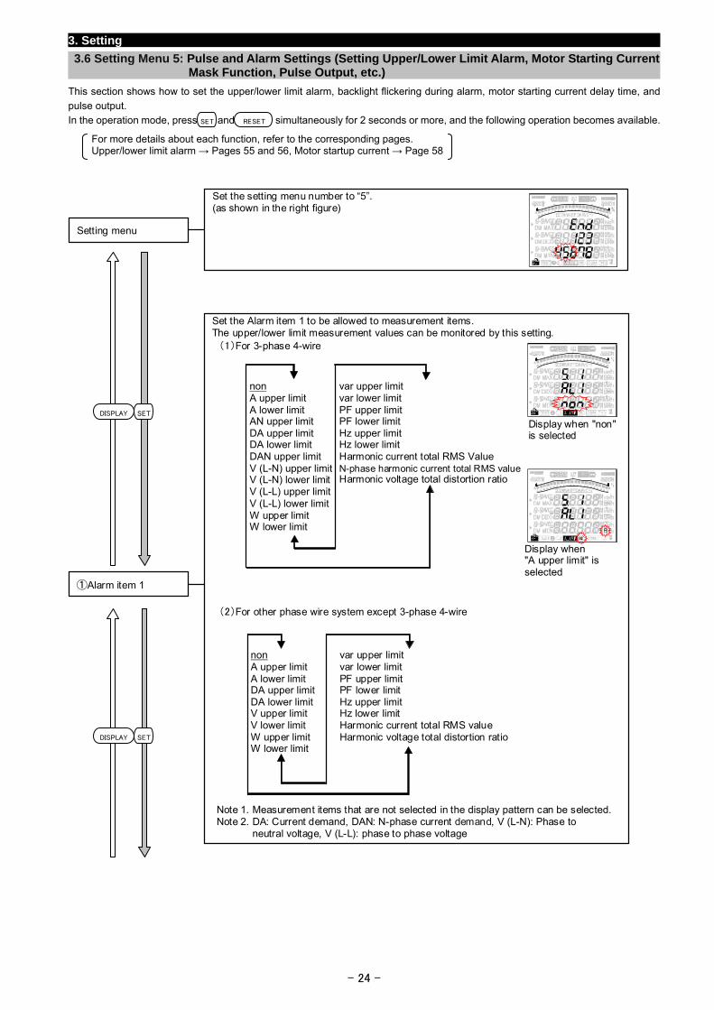
Set the setting menu number to “5”. (as shown in the right figure)
Setting menu
Set the Alarm item 1 to be allowed to measurement items.The upper/lower limit measurement values can be monitored by this setting. (1)For 3-phase 4-wire
(2)For other phase wire system except 3-phase 4-wire
①Alarm item 1
Note 1. Measurement items that are not selected in the display pattern can be selected.Note 2. DA: Current demand, DAN: N-phase current demand, V (L-N): Phase to
neutral voltage, V (L-L): phase to phase voltage
Display when "non"is selected
Display when "A upper limit" isselected
var upper limitvar lower limit PF upper limit PF lower limit Hz upper limit Hz lower limit Harmonic current total RMS Value N-phase harmonic current total RMS value Harmonic voltage total distortion ratio
non A upper limit A lower limit AN upper limit DA upper limit DA lower limit DAN upper limit V (L-N) upper limitV (L-N) lower limitV (L-L) upper limitV (L-L) lower limitW upper limit W lower limit
non A upper limitA lower limitDA upper limitDA lower limitV upper limitV lower limitW upper limitW lower limit
var upper limitvar lower limit PF upper limit PF lower limit Hz upper limit Hz lower limit Harmonic current total RMS value Harmonic voltage total distortion ratio
SETDISPLAY
SETDISPLAY
- 24 -
3. Setting
3.6 Setting Menu 5: Pulse and Alarm Settings (Setting Upper/Lower Limit Alarm, Motor Starting Current Mask Function, Pulse Output, etc.)
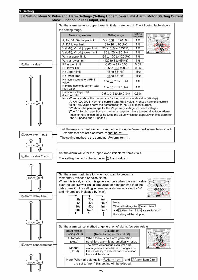
Set the alarm value for upper/lower limit alarm element 1. The following table shows
the setting range. Measuring element Setting range Setting
step(Note)
A, AN, DA, DAN upper limit 5 to 100 to 120(%) 1% A, DA lower limit 3 to 10 to 95(%) 1% V (L-N), V (L-L) upper limit 25 to 110 to 135(%) 1% V (L-N), V (L-L) lower limit 20 to 70 to 95(%) 1% W, var upper limit -95 to 100 to 120(%) 1% W, var lower limit -120 to 3 to 95(%) 1% PF upper limit -0.05 to 1 to 0.05 0.05 PF lower limit -0.05 to -0.5 to 0.05 0.05 Hz upper limit 45 to 65(Hz) 1Hz Hz lower limit 45 to 65(Hz) 1Hz Harmonic current total RMS value
1 to 35 to 120(%) 1%
N-phase harmonic current total RMS value
1 to 35 to 120(%) 1%
Harmonic voltage total distortion ratio
0.5 to 3.5 to 20.0(%) 0.5%
Note:W and var show the percentage for the maximum scale value (±0 step). A, AN, DA, DAN, Harmonic current total RMS value, N-phase harmonic current total RMS value shows the percentage for the CT primary current.
"V" shows the percentage for the VT primary voltage (or direct voltage). (The "V" for 1-phase 3-wire is the percentage for phase to neutral voltage. Alarm
monitoring is executed using twice the value which set upper/lower limit alarm for the 12-phase and 13-phase.)
②Alarm value 1
SETDISPLAY
Set the measurement element assigned to the upper/lower limit alarm items 2 to 4. Elements that are set elsewhere cannot be set.
The setting method is the same as ①Alarm item 1 . ③Alarm item 2 to 4
- 25 -
Set the alarm cancel method at generation of alarm. (screen, relay) Reset method(Setting value)
Description (Refer to pages 55 and 56)
Automatic (Auto)
When there is no alarm generation condition, alarm is automatically reset.
Manual (HoLd)
The alarm will continue even when the alarm generated conditions no longer exist.It is necessary to execute button operation to cancel the alarm.
⑥Alarm cancel method
Note: When all settings for ①Alarm item 1 and ③Alarm item 2 to 4 are set to "non," this setting will be skipped.
Set the alarm mask time for when you want to prevent amomentary overload or noise alarm. When this is set, an alarm is generated only when the alarm value over the upper/lower limit alarm value for a longer time than the delay time. On the setting screen, seconds are indicated by “s” and minutes are indicated by “min”.
⑤Alarm delay time
0s5s
10s20s
30s40s50s
1min
2min3min4min5min
Note:
When all settings for ①Alarm item 1
and ③Alarm item 2 to 4 are set to “non”,
this setting will be skipped.
Set the alarm value for the upper/lower limit alarm items 2 to 4.
The setting method is the same as ②Alarm value 1 . ④Alarm value 2 to 4
SETDISPLAY
SETDISPLAY
SETDISPLAY
SETDISPLAY
3.Setting
3.6 Setting Menu 5: Pulse and Alarm Settings (Setting Upper/Lower Limit Alarm, Motor Starting Current Mask Function, Pulse Output, etc.)
- 26 -
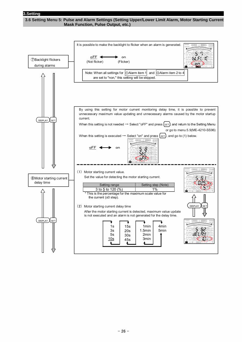
By using this setting for motor current monitoring delay time, it is possible to prevent unnecessary maximum value updating and unnecessary alarms caused by the motor startup current.
When this setting is not needed → Select "oFF" and press , and return to the Setting Menu
or go to menu 5.9(ME-4210-SS96)
When this setting is executed → Select "on" and press , and go to (1) below.
(1) Motor starting current value.
Set the value for detecting the motor starting current.
Setting range Setting step (Note) 3 to 5 to 120 (%) 1%
* This is the percentage for the maximum scale value for the current (±0 step).
(2) Motor starting current delay time
After the motor starting current is detected, maximum value update is not executed and an alarm is not generated for the delay time.
⑧Motor starting current delay time
oFF on
1s3s5s
10s
15s20s30s45s
1min1.5min
2min3min
4min5min
SET
SET
SETDISPLAY
It is possible to make the backlight to flicker when an alarm is generated.
⑦Backlight flickers
during alarms
oFF on
(Not flicker) (Flicker)
Note: When all settings for ①Alarm item 1 and ③Alarm item 2 to 4
are set to "non," this setting will be skipped.
DI SETSPLAY
SETDISPLAY
3.Setting
3.6 Setting Menu 5: Pulse and Alarm Settings (Setting Upper/Lower Limit Alarm, Motor Starting Current Mask Function, Pulse Output, etc.)
- 27 -
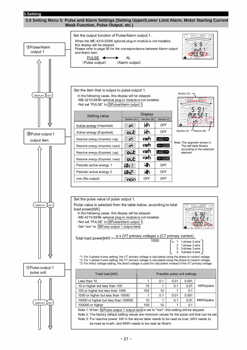
Set the output function of Pulse/Alarm output 1.
When the ME-4210-SS96 optional plug-in module is not installed, this display will be skipped. Please refer to page 56 for the correspondence between Alarm output and Alarm item.
⑨Pulse/Alarm output 1
PULSE AL(Pulse output) (Alarm output)
Set the item that is output to pulse output 1.
In the following cases, this display will be skipped. ・ME-4210-SS96 optional plug-in module is not installed. ・Not set “PULSE” to ⑨Pulse/Alarm output 1.
Display Setting value Section (A) Section (B) Section (C)
Active energy (Imported) OFF
Active energy (Exported) OFF
Reactive energy (Imported, Lag)
Reactive energy (Imported, Lead)
Reactive energy (Exported, Lag)
Reactive energy (Exported, Lead)
Periodic active energy 1 OFF
Periodic active energy 2 OFF
non (No output) OFF OFF
⑩Pulse output 1
output item Note: The segment shown in The left table flickers according to the selected element.
Section (A) Section (B)
Section (C) SETDISPLAY
Set the pulse value of pulse output 1.
Pulse value is selected from the table below, according to total load power[kW]. In the following cases, this display will be skipped. ・ME-4210-SS96 optional plug-in module is not installed. ・Not set “PULSE” to ⑨Pulse/Alarm output 1.
・Set “non” to ⑩Pulse output 1 output item.
α x (VT primary voltage) x (CT primary current)
Total load power[kW] =1000
*1: For 3-phase 4-wire setting, the VT primary voltage is calculated using the phase to neutral voltage. *2: For 1-phase 3-wire setting, the VT primary voltage is calculated using the phase to neutral voltage. *3: For direct voltage setting, the direct voltage is used for calculation instead of the VT primary voltage.
Total load [kW] Possible pulse unit settings
Less than 10 1 0.1 0.01 0.001
10 or higher but less than 100 10 1 0.1 0.01
100 or higher but less than 1000 100 10 1 0.1
kWh/pulse
1000 or higher but less than 10000 1 0.1 0.01 0.001
10000 or higher but less than 100000 10 1 0.1 0.01
100000 or higher 100 10 1 0.1
MWh/pulse
Note 1: When ⑩Pulse output 1 output item is set to "non", this setting will be skipped. Note 2: The factory default setting values are minimum values for the pulse unit that can be set.Note 3: For reactive power, kW in the above table needs to be read as kvar, kWh needs to
be read as kvarh, and MWh needs to be read as Mvarh.
⑪Pulse output 1 pulse unit
α: 1 1-phase 2-wire 2 1-phase 3-wire 3 3-phase 3-wire
3 3-phase 4-wire
DISPLAY SET
DISPLAY SET
3.Setting
3.6 Setting Menu 5: Pulse and Alarm Settings (Setting Upper/Lower Limit Alarm, Motor Starting Current Mask Function, Pulse Output, etc.)
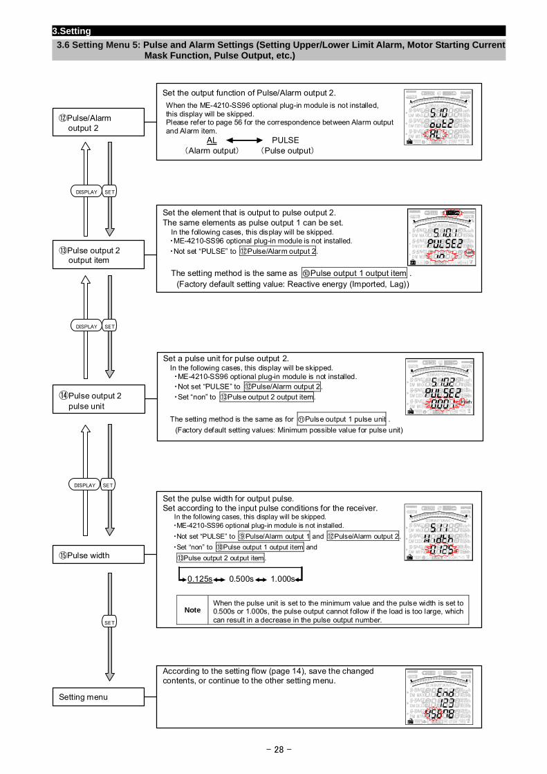
Set the output function of Pulse/Alarm output 2.
When the ME-4210-SS96 optional plug-in module is not installed, this display will be skipped. Please refer to page 56 for the correspondence between Alarm output and Alarm item.
⑫Pulse/Alarm output 2
AL PULSE(Alarm output) (Pulse output)
SETDISPLAY
Set the element that is output to pulse output 2.The same elements as pulse output 1 can be set. In the following cases, this display will be skipped. ・ME-4210-SS96 optional plug-in module is not installed.
・Not set “PULSE” to ⑫Pulse/Alarm output 2.
- 28 -
According to the setting flow (page 14), save the changed contents, or continue to the other setting menu.
Setting menu
Set the pulse width for output pulse. Set according to the input pulse conditions for the receiver.
In the following cases, this display will be skipped. ・ME-4210-SS96 optional plug-in module is not installed.
・Not set “PULSE” to ⑨Pulse/Alarm output 1 and ⑫Pulse/Alarm output 2.
・Set “non” to ⑩Pulse output 1 output item and
⑬Pulse output 2 output item.
Note When the pulse unit is set to the minimum value and the pulse width is set to 0.500s or 1.000s, the pulse output cannot follow if the load is too large, which can result in a decrease in the pulse output number.
⑮Pulse width
0.125s 0.500s 1.000s
Set a pulse unit for pulse output 2. In the following cases, this display will be skipped. ・ME-4210-SS96 optional plug-in module is not installed. ・Not set “PULSE” to ⑫Pulse/Alarm output 2.
・Set “non” to ⑬Pulse output 2 output item.
The setting method is the same as for ⑪Pulse output 1 pulse unit .
(Factory default setting values: Minimum possible value for pulse unit)
⑭Pulse output 2 pulse unit
The setting method is the same as ⑩Pulse output 1 output item .
⑬Pulse output 2 output item
(Factory default setting value: Reactive energy (Imported, Lag))
DISPLAY SET
SETDISPLAY
SET
3. Setting
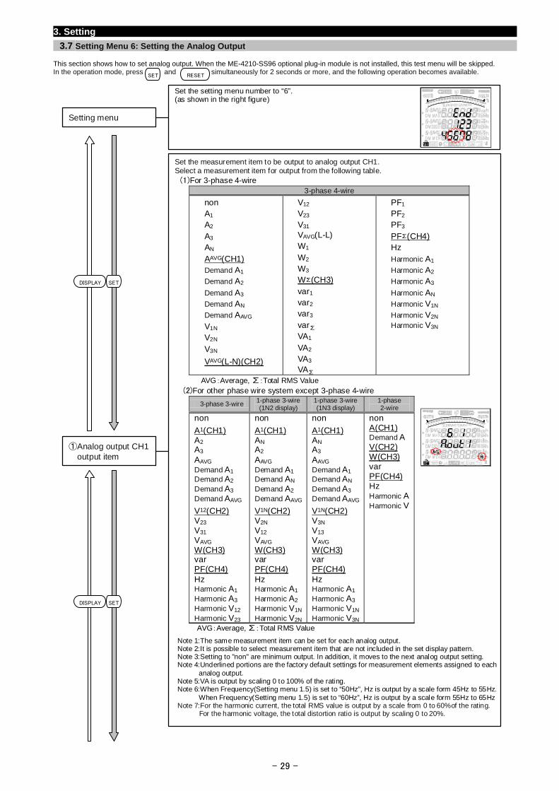
3.7 Setting Menu 6: Setting the Analog Output
This section shows how to set analog output. When the ME-4210-SS96 optional plug-in module is not installed, this test menu will be skipped. In the operation mode, press and simultaneously for 2 seconds or more, and the following operation becomes available.
SET RESET
Set the measurement item to be output to analog output CH1. Select a measurement item for output from the following table. (1)For 3-phase 4-wire
3-phase 4-wire
non A1 A2 A3 AN AAVG(CH1) Demand A1 Demand A2 Demand A3 Demand AN Demand AAVG V1N V2N V3N
VAVG(L-N)(CH2)
V12 V23 V31 VAVG(L-L) W1 W2 W3 W∑(CH3) var1 var2 var3 var∑ VA1 VA2 VA3 VA∑
PF1 PF2 PF3 PF∑(CH4) Hz Harmonic A1 Harmonic A2 Harmonic A3 Harmonic AN Harmonic V1N Harmonic V2N Harmonic V3N
AVG:Average, ∑:Total RMS Value (2)For other phase wire system except 3-phase 4-wire
3-phase 3-wire 1-phase 3-wire(1N2 display)
1-phase 3-wire(1N3 display)
1-phase 2-wire
non
A1(CH1) A2 A3 AAVG Demand A1 Demand A2 Demand A3 Demand AAVG
V12(CH2) V23 V31 VAVG W(CH3) var PF(CH4) Hz Harmonic A1 Harmonic A3 Harmonic V12 Harmonic V23
non
A1(CH1) AN A2 AAVG Demand A1 Demand AN Demand A2 Demand AAVG
V1N(CH2) V2N V12 VAVG W(CH3) var PF(CH4) Hz Harmonic A1 Harmonic A2 Harmonic V1N
Harmonic V2N
non
A1(CH1) AN A3 AAVG Demand A1 Demand AN Demand A3 Demand AAVG
V1N(CH2) V3N V13 VAVG W(CH3) var PF(CH4) Hz Harmonic A1 Harmonic A3 Harmonic V1N
Harmonic V3N
non A(CH1) Demand A V(CH2) W(CH3) var PF(CH4) Hz Harmonic A Harmonic V
AVG:Average, ∑:Total RMS Value
①Analog output CH1 output item
Note 1:The same measurement item can be set for each analog output. Note 2:It is possible to select measurement item that are not included in the set display pattern. Note 3:Setting to "non" are minimum output. In addition, it moves to the next analog output setting. Note 4:Underlined portions are the factory default settings for measurement elements assigned to each
analog output. Note 5:VA is output by scaling 0 to 100% of the rating. Note 6:When Frequency(Setting menu 1.5) is set to “50Hz”, Hz is output by a scale form 45Hz to 55Hz. When Frequency(Setting menu 1.5) is set to “60Hz”, Hz is output by a scale form 55Hz to 65HzNote 7:For the harmonic current, the total RMS value is output by a scale from 0 to 60%of the rating. For the harmonic voltage, the total distortion ratio is output by scaling 0 to 20%.
Set the setting menu number to “6”. (as shown in the right figure)
Setting menu
DISPLAY SET
SETDISPLAY
- 29 -
3. Setting
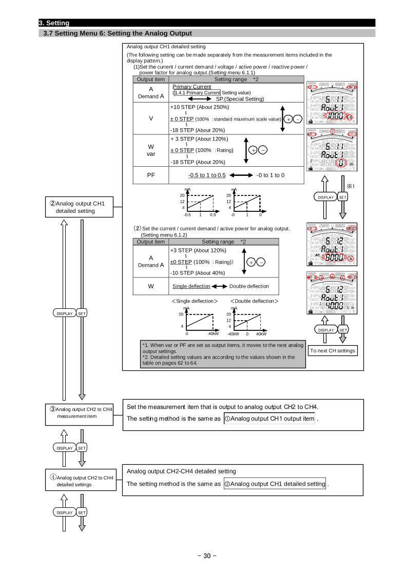
3.7 Setting Menu 6: Setting the Analog Output
Analog output CH1 detailed setting
(The following setting can be made separately from the measurement items included in the display pattern.) (1)Set the current / current demand / voltage / active power / reactive power /
power factor for analog output.(Setting menu 6.1.1) Output item Setting range *2
A Demand A
Primary Current (1.4.1 Primary Current Setting value) SP.(Special Setting)
V
W var
PF -0.5 to 1 to 0.5 -0 to 1 to 0
(2)Set the current / current demand / active power for analog output. (Setting menu 6.1.2)
Output item Setting range *2
A Demand A
W Single deflection Double deflection
②Analog output CH1 detailed setting
*1. When var or PF are set as output items, it moves to the next analog output settings. *2. Detailed setting values are according to the values shown in the table on pages 62 to 64.
±0 STEP (100% :Rating)) ~
~-10 STEP (About 40%)
+3 STEP (About 120%)
± 0 STEP (100% :Rating) ~
~-18 STEP (About 20%)
+ 3 STEP (About 120%)
mA
4
12
20
-40kW 40kW0
<Double deflection>
mA
4
20
40kW0
<Single deflection>
To next CH settings
※1mA
4
12
20
-0.5 0.51
mA
4
12
20
-0 01
+ -
± 0 STEP (100% :standard maximum scale value)~
~-18 STEP (About 20%)
+10 STEP (About 250%)
+ -
+ -
SETDISPLAY
SETDISPLAY
SETDISPLAY
Set the measurement item that is output to analog output CH2 to CH4.
The setting method is the same as ①Analog output CH1 output item . ③Analog output CH2 to CH4
measurement item
- 30 -
Analog output CH2-CH4 detailed setting
The setting method is the same as ②Analog output CH1 detailed setting . ④Analog output CH2 to CH4
detailed settings
DISPLAY SET
DISPLAY SET
3. Setting
3.7 Setting Menu 6: Setting the Analog Output
- 31 -
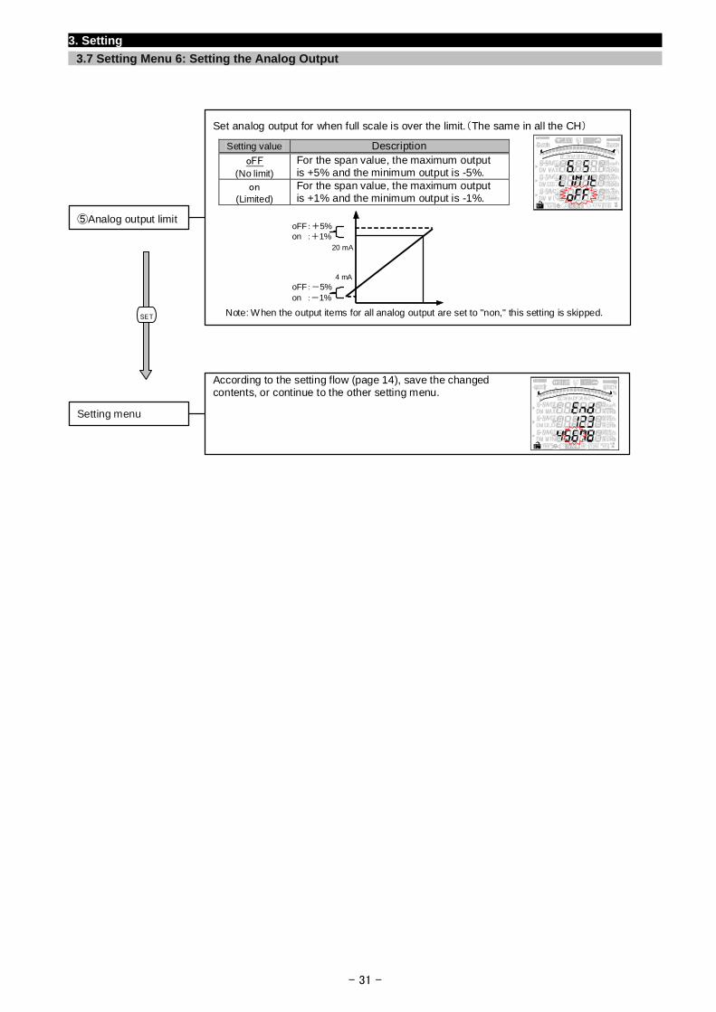
According to the setting flow (page 14), save the changed contents, or continue to the other setting menu.
Setting menu
SET
Set analog output for when full scale is over the limit.(The same in all the CH)
Setting value Description oFF
(No limit) For the span value, the maximum output is +5% and the minimum output is -5%.
on (Limited)
For the span value, the maximum output is +1% and the minimum output is -1%.
Note: When the output items for all analog output are set to "non," this setting is skipped.
⑤Analog output limit
20 mA
oFF:+5%on :+1%
oFF:-5%on :-1%
4 mA
- 32 -
3. Setting
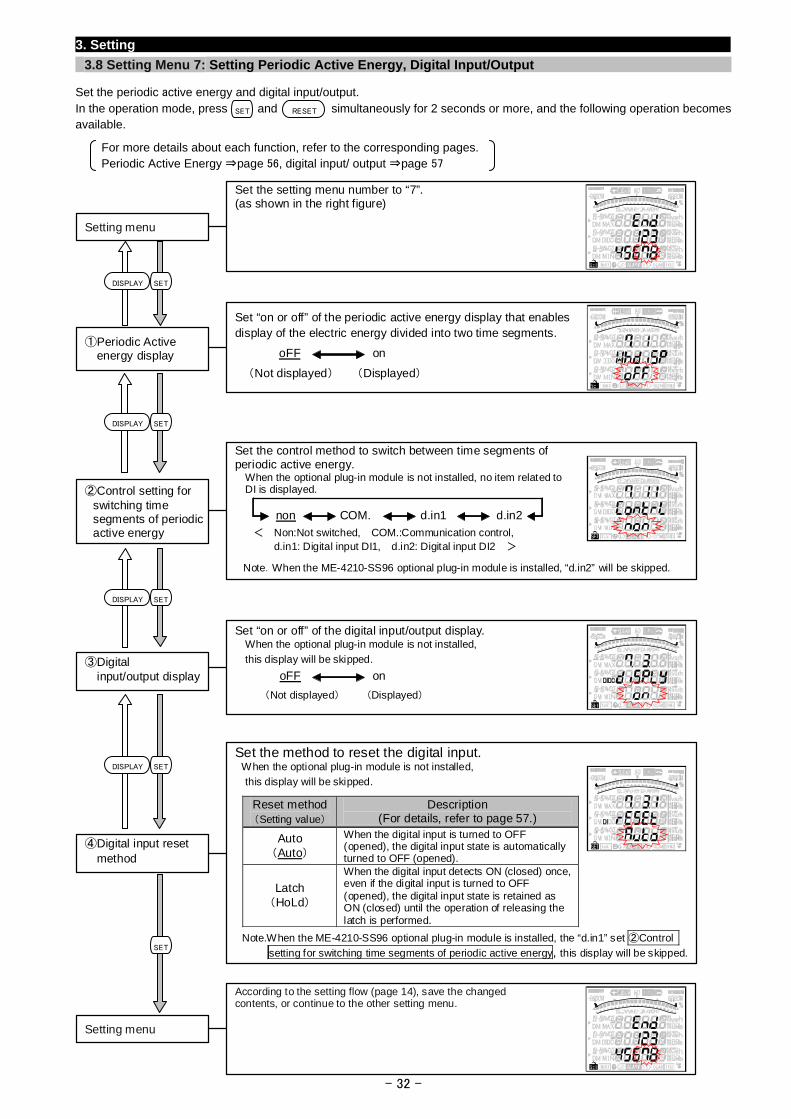
3.8 Setting Menu 7: Setting Periodic Active Energy, Digital Input/Output
Set the periodic active energy and digital input/output. In the operation mode, press and simultaneously for 2 seconds or more, and the following operation becomes available.
For more details about each function, refer to the corresponding pages. Periodic Active Energy ⇒page 56, digital input/ output ⇒page 57
According to the setting flow (page 14), save the changed contents, or continue to the other setting menu.
Setting menu
Set “on or off” of the periodic active energy display that enables display of the electric energy divided into two time segments.
oFF on
(Not displayed) (Displayed)
①Periodic Active energy display
Set the setting menu number to “7”. (as shown in the right figure)
Setting menu
SET RESET
Set the control method to switch between time segments ofperiodic active energy. When the optional plug-in module is not installed, no item related to DI is displayed. ②Control setting for
switching time segments of periodic active energy < Non:Not switched, COM.:Communication control,
d.in1: Digital input DI1, d.in2: Digital input DI2 >
non COM. d.in1 d.in2
Note.When the ME-4210-SS96 optional plug-in module is installed, “d.in2” will be skipped.
Set “on or off” of the digital input/output display. When the optional plug-in module is not installed,
this display will be skipped.
oFF on
(Not displayed) (Displayed)
③Digital input/output display
Set the method to reset the digital input. When the optional plug-in module is not installed,
this display will be skipped.
Reset method(Setting value)
Description (For details, refer to page 57.)
Auto (Auto)
When the digital input is turned to OFF (opened), the digital input state is automatically turned to OFF (opened).
Latch (HoLd)
When the digital input detects ON (closed) once, even if the digital input is turned to OFF (opened), the digital input state is retained as ON (closed) until the operation of releasing the latch is performed.
④Digital input reset method
Note.When the ME-4210-SS96 optional plug-in module is installed, the “d.in1” set ②Control
setting for switching time segments of periodic active energy, this display will be skipped.
SETDISPLAY
SETDISPLAY
SETDISPLAY
SETDISPLAY
SET
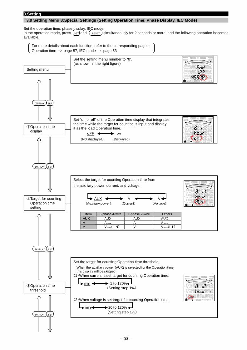
- 33 -
3.Setting
3.9 Setting Menu 8:Special Settings (Setting Operation Time, Phase Display, IEC Mode)
Set the operation time, phase display, IEC mode. In the operation mode, press and simultaneously for 2 seconds or more, and the following operation becomes available.
For more details about each function, refer to the corresponding pages. Operation time ⇒ page 57, IEC mode ⇒ page 53
Set “on or off” of the Operation time display that integrates the time while the target for counting is input and display it as the load Operation time.
①Operation time display
oFF on
(Not displayed) (Displayed)
Set the setting menu number to “8”. (as shown in the right figure)
Setting menu
SET RESET
SETDISPLAY
SETDISPLAY
SETDISPLAY
SETDISPLAY
Select the target for counting Operation time from
the auxiliary power, current, and voltage.
Item 3-phase 4-wire 1-phase 2-wire Others
AUX AUX AUX AUX A AAVG A AAVG V VAVG(L-N) V VAVG(L-L)
②Target for counting Operation time setting
(Auxiliary power) (Current) (Voltage)
AUX A V
Set the target for counting Operation time threshold.
When the auxiliary power (AUX) is selected for the Operation time, this display will be skipped. (1)When current is set target for counting Operation time.
(2)When voltage is set target for counting Operation time.
③Operation time threshold
min 1 to 120% (Setting step 1%)
min 20 to 120% (Setting step 1%)
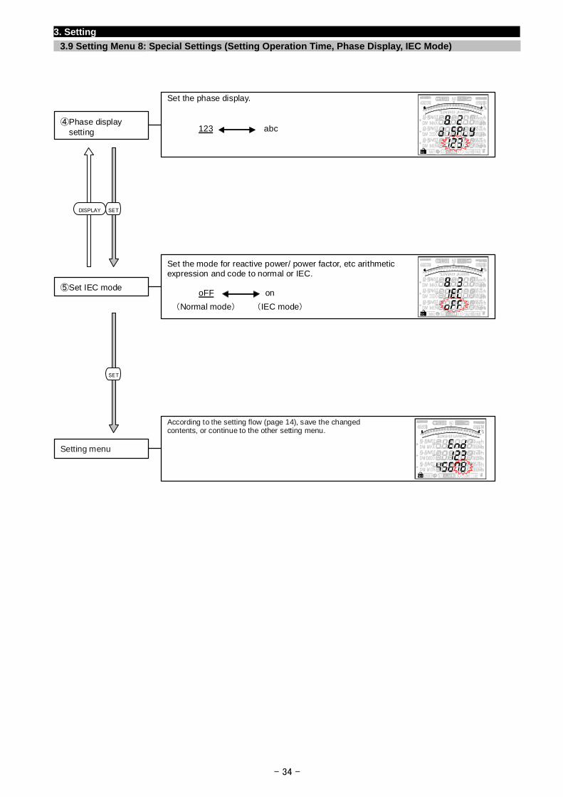
- 34 -
3. Setting
3.9 Setting Menu 8: Special Settings (Setting Operation Time, Phase Display, IEC Mode)
According to the setting flow (page 14), save the changed contents, or continue to the other setting menu.
Setting menu
SETDISPLAY
SET
Set the mode for reactive power/ power factor, etc arithmetic expression and code to normal or IEC.
oFF on
(Normal mode) (IEC mode)
⑤Set IEC mode
Set the phase display.
④Phase display setting 123 abc
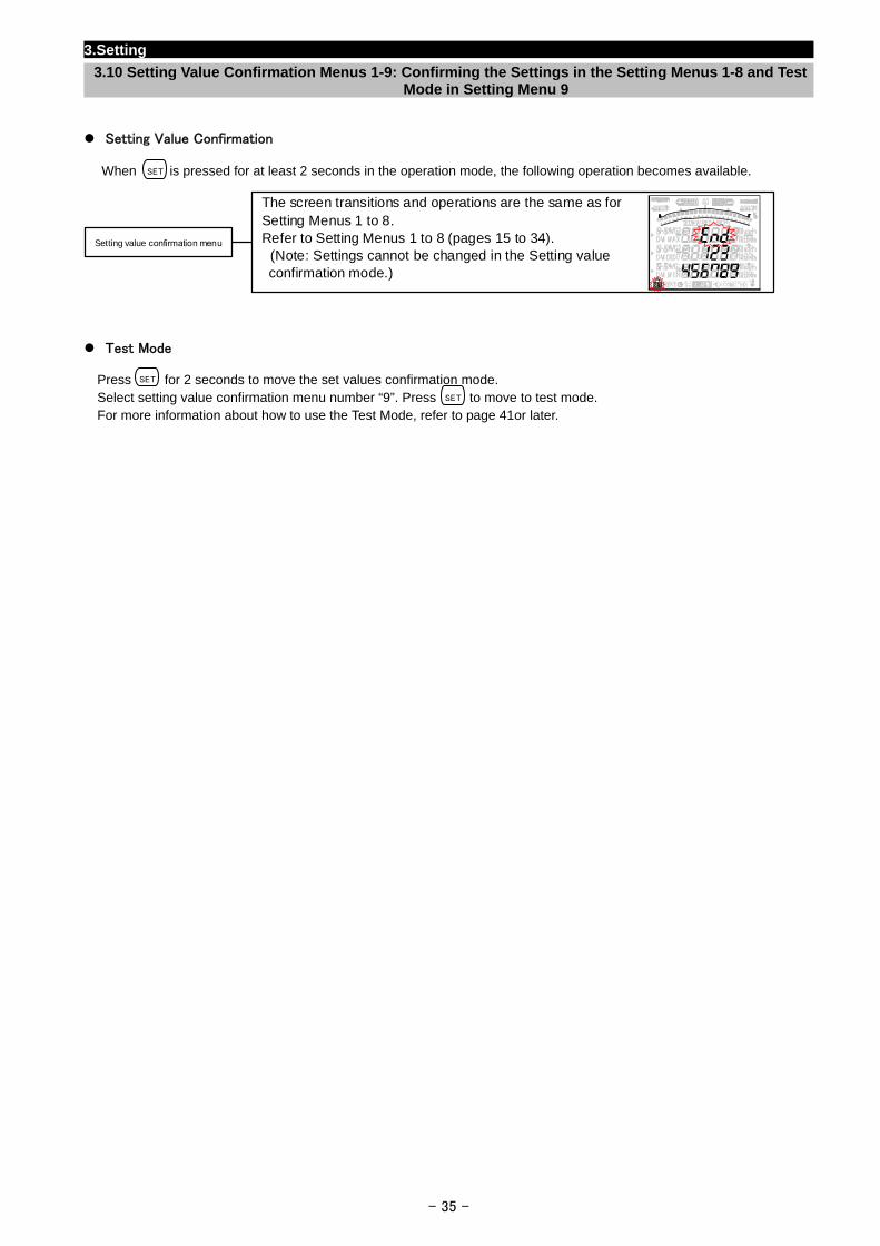
3.Setting
3.10 Setting Value Confirmation Menus 1-9: Confirming the Settings in the Setting Menus 1-8 and Test Mode in Setting Menu 9
Setting Value Confirmation
When is pressed for at least 2 seconds in the operation mode, the following operation becomes available. SET
The screen transitions and operations are the same as for Setting Menus 1 to 8. Refer to Setting Menus 1 to 8 (pages 15 to 34). (Note: Settings cannot be changed in the Setting value confirmation mode.)
Setting value confirmation menu
Test Mode
Press for 2 seconds to move the set values confirmation mode. SET
Select setting value confirmation menu number “9”. Press to move to test mode. SET
For more information about how to use the Test Mode, refer to page 41or later.
- 35 -
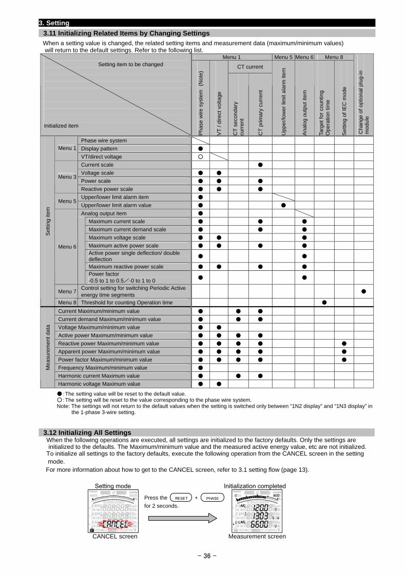
3. Setting
3.11 Initializing Related Items by Changing Settings
When a setting value is changed, the related setting items and measurement data (maximum/minimum values) will return to the default settings. Refer to the following list.
Menu 1 Menu 5 Menu 6 Menu 8
CT current
Setting item to be changed
Initialized item
Pha
se w
ire s
yste
m
(Not
e)
VT
/ di
rect
vol
tage
CT
sec
onda
ry
curr
ent
CT
prim
ary
cu
rre
nt
Upp
er/lo
we
r lim
it al
arm
item
Ana
log
outp
ut it
em
Targ
et fo
r co
untin
g O
pera
tion
time
Set
ting
of IE
C m
ode
Cha
nge
of o
ptio
nal
plu
g-in
m
odul
e
Phase wire system
Display pattern Menu 1
VT/direct voltage
Current scale
Voltage scale
Power scale Menu 3
Reactive power scale
Upper/lower limit alarm item Menu 5
Upper/lower limit alarm value
Analog output item
Maximum current scale
Maximum current demand scale
Maximum voltage scale
Maximum active power scale
Active power single deflection/ double deflection
Maximum reactive power scale
Menu 6
Power factor -0.5 to 1 to 0.5/-0 to 1 to 0
Menu 7 Control setting for switching Periodic Active energy time segments
Set
ting
item
Menu 8 Threshold for counting Operation time
Current Maximum/minimum value
Current demand Maximum/minimum value
Voltage Maximum/minimum value
Active power Maximum/minimum value
Reactive power Maximum/minimum value
Apparent power Maximum/minimum value
Power factor Maximum/minimum value
Frequency Maximum/minimum value
Harmonic current Maximum value
Mea
sure
men
t da
ta
Harmonic voltage Maximum value
:The setting value will be reset to the default value. :The setting will be reset to the value corresponding to the phase wire system. Note: The settings will not return to the default values when the setting is switched only between “1N2 display” and “1N3 display” in the 1-phase 3-wire setting.
3.12 Initializing All Settings When the following operations are executed, all settings are initialized to the factory defaults. Only the settings are
initialized to the defaults. The Maximum/minimum value and the measured active energy value, etc are not initialized. To initialize all settings to the factory defaults, execute the following operation from the CANCEL screen in the setting
mode. For more information about how to get to the CANCEL screen, refer to 3.1 setting flow (page 13).
Setting mode Initialization completed
- 36 -
CANCEL screen Measurement screen
RESET PHASEPress the +
for 2 seconds.
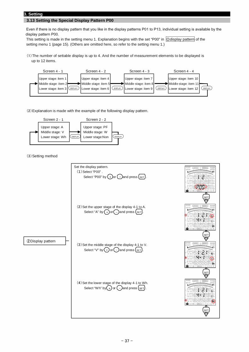
3. Setting
3.13 Setting the Special Display Pattern P00
Even if there is no display pattern that you like in the display patterns P01 to P13, individual setting is available by the display pattern P00.
This setting is made in the setting menu 1. Explanation begins with the set “P00” in ②display pattern of the setting menu 1 (page 15). (Others are omitted here, so refer to the setting menu 1.)
(1)The number of settable display is up to 4. And the number of measurement elements to be displayed is up to 12 items.
(2)Explanation is made with the example of the following display pattern.
(3)Setting method
DISPLAY
Upper stage: item 1
Middle stage: item 2
Lower stage: item 3
Upper stage: item 4
Middle stage: item 5
Lower stage: item 6
Upper stage: item 7
Middle stage: item 8
Lower stage: item 9
Upper stage: item 10
Middle stage: item 11
Lower stage: item 12 DISPLAY DISPLAYDISPLAY
Screen 4‐1 Screen 4‐4 Screen 4‐3Screen 4‐2
DISPLAY
Upper stage: A
Middle stage: V
Lower stage: Wh
Upper stage: PF
Middle stage: W
Lower stage:Non DISPLAY
Screen 2‐1 Screen 2‐2
Set the display pattern.
(1)Select “P00” . Select “P00” by or and press .
(2)Set the upper stage of the display 4-1 to A.
Select “A” by or and press .
(3)Set the middle stage of the display 4-1 to V.
Select “V” by or and press .
(4)Set the lower stage of the display 4-1 to Wh.
Select “Wh” by or and press .
②Display pattern
+ - SET
SET
SET
SET
SET
+ - SET
+ - SET
+ - SET
- 37 -
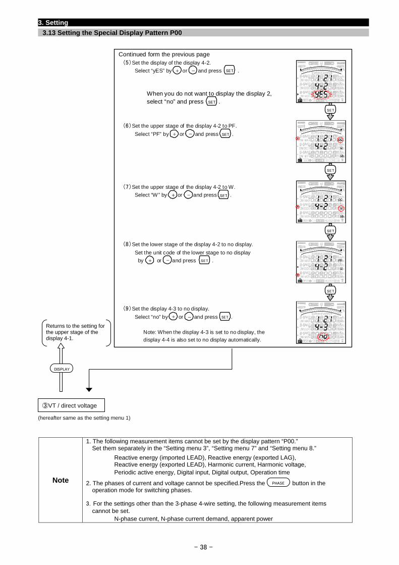
3. Setting
3.13 Setting the Special Display Pattern P00
- 38 -
Continued form the previous page
(5)Set the display of the display 4-2.
Select “yES” by or and press .
When you do not want to display the display 2, select “no” and press .
(6)Set the upper stage of the display 4-2 to PF.
Select “PF” by or and press .
(7)Set the upper stage of the display 4-2 to W.
Select “W” by or and press .
(8)Set the lower stage of the display 4-2 to no display. Set the unit code of the lower stage to no display
by or and press .
(9)Set the display 4-3 to no display.
Select “no” by or and press .
Note: When the display 4-3 is set to no display, the
display 4-4 is also set to no display automatically.
+ - SET
SET
SET
SET
SET
+ - SET
+ - SET
+ - SET
+ - SET
SET
Returns to the setting for the upper stage of the display 4-1.
DISPLAY
③VT / direct voltage
(hereafter same as the setting menu 1)
Note
1. The following measurement items cannot be set by the display pattern “P00.” Set them separately in the “Setting menu 3”, “Setting menu 7” and “Setting menu 8.”
Reactive energy (imported LEAD), Reactive energy (exported LAG), Reactive energy (exported LEAD), Harmonic current, Harmonic voltage, Periodic active energy, Digital input, Digital output, Operation time
2. The phases of current and voltage cannot be specified.Press the button in the operation mode for switching phases.
3.For the settings other than the 3-phase 4-wire setting, the following measurement items cannot be set.
N-phase current, N-phase current demand, apparent power
PHASE
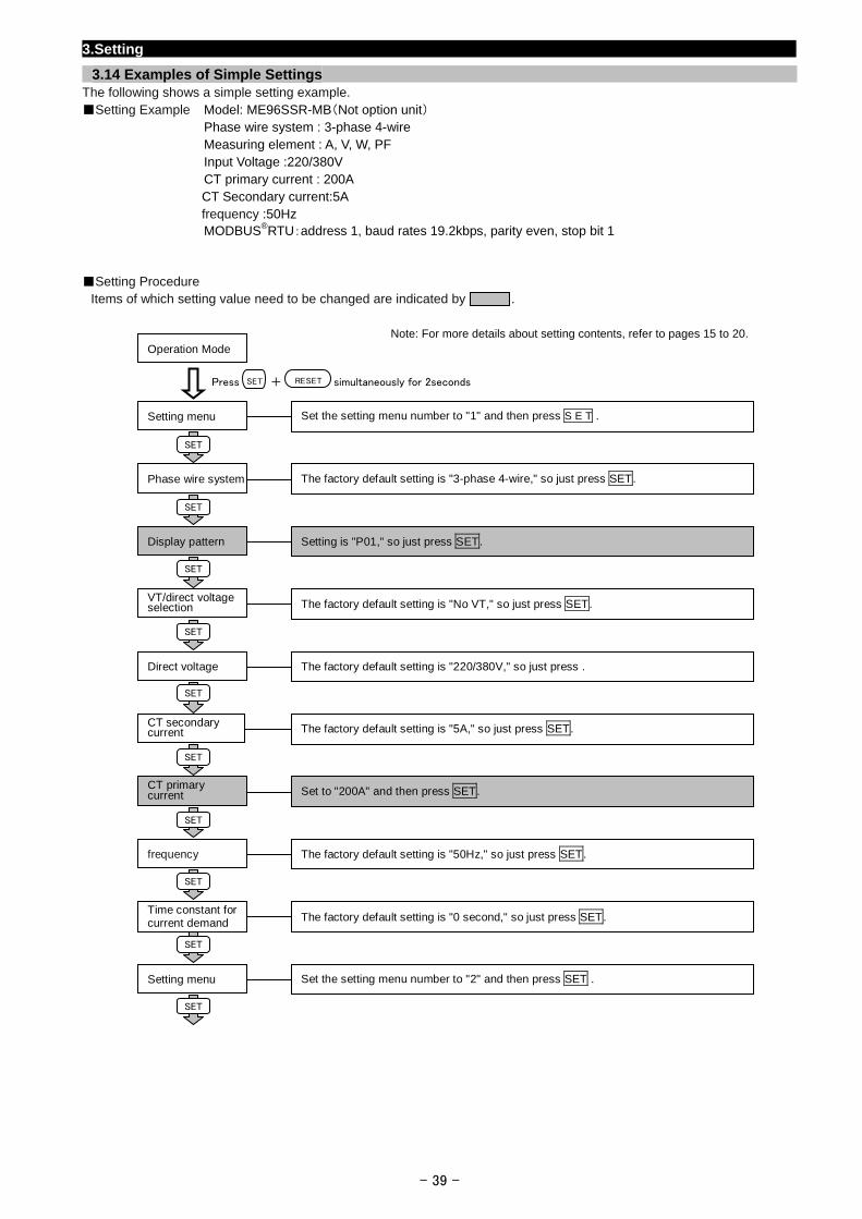
3.Setting
3.14 Examples of Simple Settings The following shows a simple setting example. Setting Example Model: ME96SSR-MB(Not option unit) Phase wire system : 3-phase 4-wire Measuring element : A, V, W, PF Input Voltage :220/380V CT primary current : 200A CT Secondary current:5A frequency :50Hz MODBUS®RTU:address 1, baud rates 19.2kbps, parity even, stop bit 1
Setting Procedure
Items of which setting value need to be changed are indicated by .
Operation Mode
Note: For more details about setting contents, refer to pages 15 to 20.
- 39 -
Set the setting menu number to "1" and then press S E T . Setting menu
Press + simultaneously for 2seconds RESET SET
The factory default setting is "3-phase 4-wire," so just press SET. Phase wire system
SET
Setting is "P01," so just press SET. Display pattern
SET
The factory default setting is "No VT," so just press SET. VT/direct voltage selection
SET
The factory default setting is "220/380V," so just press . Direct voltage
SET
The factory default setting is "5A," so just press SET. CT secondary current
SET
Set to "200A" and then press SET. CT primary current
SET
The factory default setting is "50Hz," so just press SET. frequency
SET
The factory default setting is "0 second," so just press SET . Time constant for current demand
SET
Set the setting menu number to "2" and then press SET . Setting menu
SET
SET
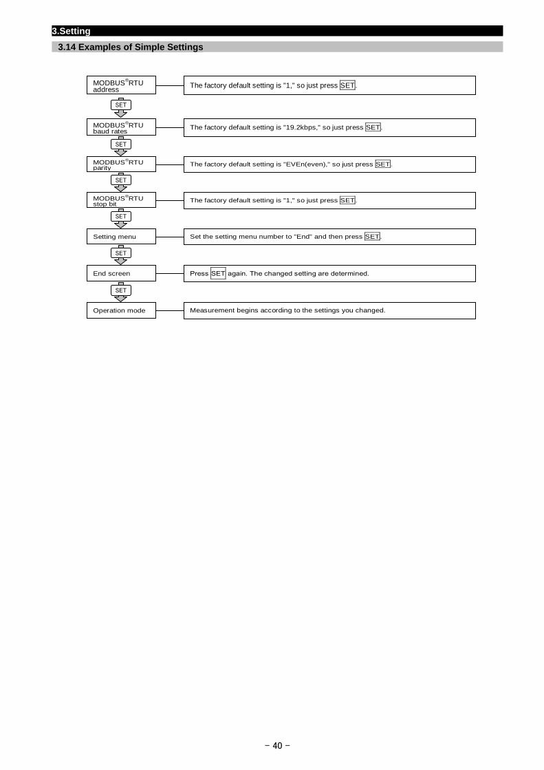
3.Setting
3.14 Examples of Simple Settings The factory default setting is "1," so just press SET. MODBUS®RTU
address SET
The factory default setting is "19.2kbps," so just press SET. MODBUS®RTU
baud rates
- 40 -
The factory default setting is "EVEn(even)," so just press SET. MODBUS®RTU parity
SET
The factory default setting is "1," so just press SET. MODBUS®RTU stop bit
SET
Set the setting menu number to "End" and then press SET. Setting menu
SET
Press SET again. The changed setting are determined. End screen
SET
Measurement begins according to the settings you changed. Operation mode
SET
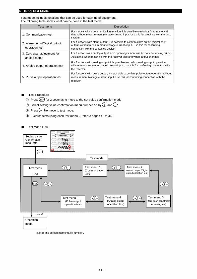
4. Using Test Mode
Test mode includes functions that can be used for start-up of equipment. The following table shows what can be done in the test mode.
Test menu Description
1.Communication test For models with a communication function, it is possible to monitor fixed numerical data without measurement (voltage/current) input. Use this for checking with the host system.
2.Alarm output/Digital output
operation test
For functions with alarm output, it is possible to confirm alarm output (digital point output) without measurement (voltage/current) input. Use this for confirming connection with the contacted device.
3.Zero span adjustment for
analog output
For functions with analog output, zero span adjustment can be done for analog output. Adjust this when matching with the receiver side and when output changes.
4.Analog output operation test For functions with analog output, it is possible to confirm analog output operation without measurement (voltage/current) input. Use this for confirming connection with the receiver.
5.Pulse output operation test For functions with pulse output, it is possible to confirm pulse output operation without measurement (voltage/current) input. Use this for confirming connection with the receiver.
Test Procedure
① Press for 2 seconds to move to the set value confirmation mode. SET
② Select setting value confirmation menu number "9" by and . -+
③ Press to move to test mode. SET
④ Execute tests using each test menu. (Refer to pages 42 to 46)
Test Mode Flow
- 41 -
(Note) The screen momentarily turns off.
Test menu 1 (Communication test)
Test menu 2 (Alarm output /Digital output operation test)
Test menu 3 (Zero span adjustment
for analog test)
Test menu 4 (Analog output operation test)
Test menu 5 (Pulse output operation test)
Setting value Confirmation menu "9"
SET
Test mode
Test menu
End
+ - + -
+ - + -SET
+ - + -
(Note)
Operation
mode

- 42 -
4. Using Test Mode
4.1 Test Menu 1: Communication Test
In the setting value confirmation mode, when the menu number is set to "9", you will enter the test mode.
<To continue other test mode> ⇒ Select other test menu number and then press .
<To close test mode>
⇒ Select "End" as the test menu number and then press . You will return to the operation mode.
Test menu
SET
SET
SETDISPLAY
SET
Set the test menu number to "1".
(as shown in the right figure)
Test menu
Execute communication test operation. (Values other than zero can be monitored even when the voltage and current are not input.)
Monitor value by communication ・ Values displayed on the screen, can be monitored.
Measurement elements not displayed on the screen are zero. ・ If you set the Alarm item with Setting Menu 5, the display will be the same as
the alarm is generating. (If you are using the ME-4210-SS96, alarm contact will remain open.)
・ It is possible to monitor the digital input status.
Display screen
Button operation
Operation Function
Press Switches the display screen.
Press Switches the phase.
Press Moves or returns to the maximum/minimum value screen.
Switches the analog bar graph element.
Press or Switches the harmonic degree (when
harmonics screen is displayed).
Press and together for at least 2 seconds.
Change the unit of Wh and varh.
Press Return to the test menu.
Note: When executing a communication test, please read the following manual in addition to this instruction manual. (For more information refer to page 80.)
・Electronic Multi-Measuring Instrument MODBUS®RTU communication I/F Specification
・Electronic Multi-Measuring Instrument Programming Manual (CC-Link communication)
①Communication test
・ As with the operation mode, it is displayed according to settings such as the display pattern.
・ The maximum/minimum value can be displayed. (Cyclic display cannot be executed.)
DISPLAY
SET
+ -
PHASE
MAX/MIN
+ -
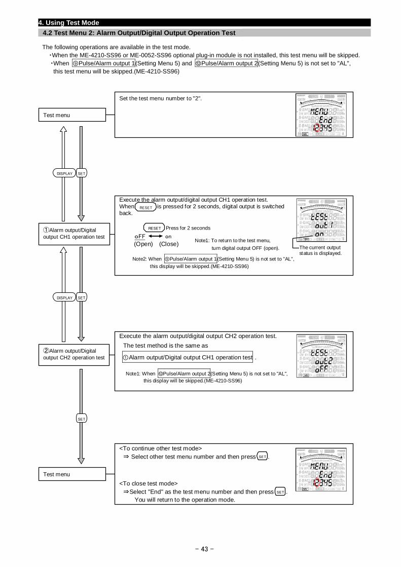
4. Using Test Mode
4.2 Test Menu 2: Alarm Output/Digital Output Operation Test
The following operations are available in the test mode. ・When the ME-4210-SS96 or ME-0052-SS96 optional plug-in module is not installed, this test menu will be skipped. ・When ⑨Pulse/Alarm output 1(Setting Menu 5) and ⑫Pulse/Alarm output 2(Setting Menu 5) is not set to "AL",
this test menu will be skipped.(ME-4210-SS96)
Set the test menu number to "2".
Test menu
- 43 -
<To continue other test mode> ⇒ Select other test menu number and then press .
<To close test mode>
⇒Select "End" as the test menu number and then press . You will return to the operation mode.
Test menu
SET
SET
Execute the alarm output/digital output CH2 operation test.
The test method is the same as
①Alarm output/Digital output CH1 operation test . ②Alarm output/Digital output CH2 operation test
Note1: When ⑫Pulse/Alarm output 2(Setting Menu 5) is not set to "AL", this display will be skipped.(ME-4210-SS96)
Execute the alarm output/digital output CH1 operation test.When is pressed for 2 seconds, digital output is switched back.
①Alarm output/Digital output CH1 operation test oFF on
The current outputstatus is displayed.
RESET
RESET Press for 2 seconds
Note1: To return to the test menu,
turn digital output OFF (open).
Note2: When ⑨Pulse/Alarm output 1(Setting Menu 5) is not set to "AL",
this display will be skipped.(ME-4210-SS96)
(Open) (Close)
SETDISPLAY
SETDISPLAY
SET
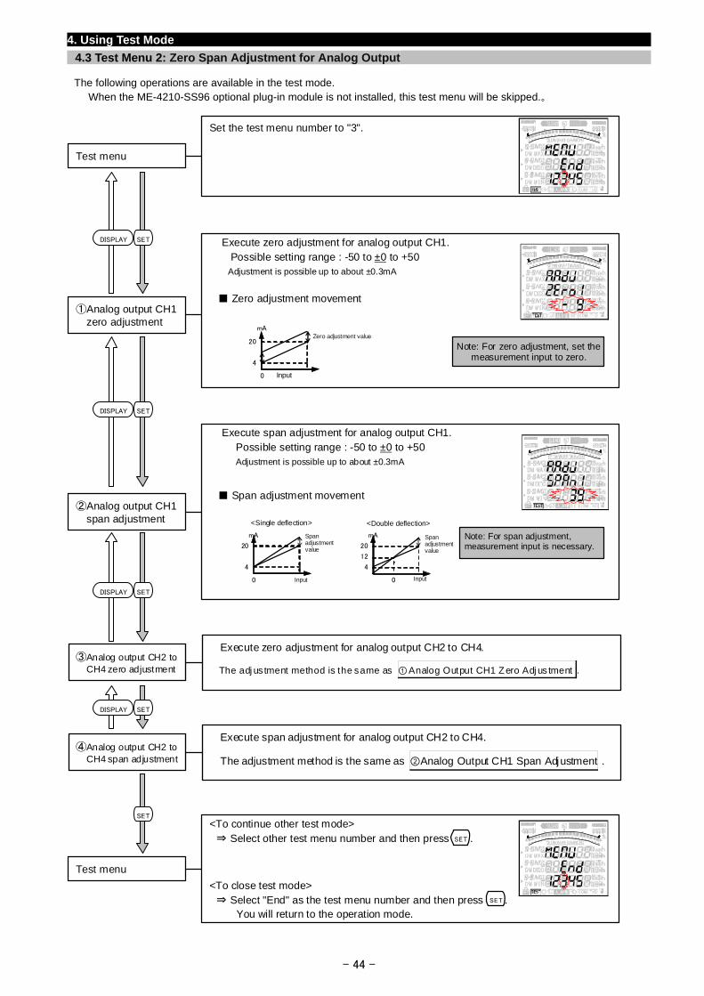
4. Using Test Mode
4.3 Test Menu 2: Zero Span Adjustment for Analog Output
The following operations are available in the test mode. When the ME-4210-SS96 optional plug-in module is not installed, this test menu will be skipped.。
- 44 -
Set the test menu number to "3".
Test menu
<To continue other test mode> ⇒ Select other test menu number and then press .
<To close test mode>
⇒ Select "End" as the test menu number and then press . You will return to the operation mode.
Test menu
SET
SET
Execute span adjustment for analog output CH2 to CH4.
The adjustment method is the same as ②Analog Output CH1 Span Adjustment . ④Analog output CH2 to
CH4 span adjustment
Execute zero adjustment for analog output CH2 to CH4.
The adj us tment method is the same as ①Analog Output CH1 Zero Adj us tment . ③Analog output CH2 to
CH4 zero adjustment
Execute span adjustment for analog output CH1. Possible setting range : -50 to ±0 to +50
Adjustment is possible up to about ±0.3mA
Span adjustment movement ②Analog output CH1
span adjustment
Note: For span adjustment, measurement input is necessary.
mA
4
20
Input0
<Single deflection>
Spanadjustmentvalue
mA
4
12
20
Input 0
<Double deflection>
Span adjustmentvalue
Execute zero adjustment for analog output CH1. Possible setting range : -50 to ±0 to +50
Adjustment is possible up to about ±0.3mA
Zero adjustment movement ①Analog output CH1
zero adjustment
Note: For zero adjustment, set the measurement input to zero.
mA
4
20
Input0
Zero adjustment value
SETDISPLAY
SETDISPLAY
SETDISPLAY
SETDISPLAY
SET
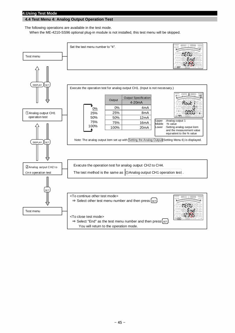
4.Using Test Mode
4.4 Test Menu 4: Analog Output Operation Test
The following operations are available in the test mode. When the ME-4210-SS96 optional plug-in module is not installed, this test menu will be skipped.
Set the test menu number to "4".
Test menu
Execute the operation test for analog output CH1. (Input is not necessary.)
Output SpecificationOutput
4-20mA
0% 4mA
25% 8mA50% 12mA
75% 16mA100% 20mA
①Analog output CH1 operation test
0%25%50%75%
100%
Note: The analog output item set up with Setting the Analog Output(Setting Menu 6) is displayed.
Upper :Analog output 1 Middle :% value Lower :Setting analog output item
and the measurement value equivalent to the % value
SETDISPLAY
- 45 -
<To continue other test mode> ⇒ Select other test menu number and then press .
<To close test mode> ⇒ Select "End" as the test menu number and then press . You will return to the operation mode.
Test menu
SET
SET
Execute the operation test for analog output CH2 to CH4.
The test method is the same as ①Analog output CH1 operation test .
②Analog out put CH2 t o
CH4 operat ion test
SETDISPLAY
SET
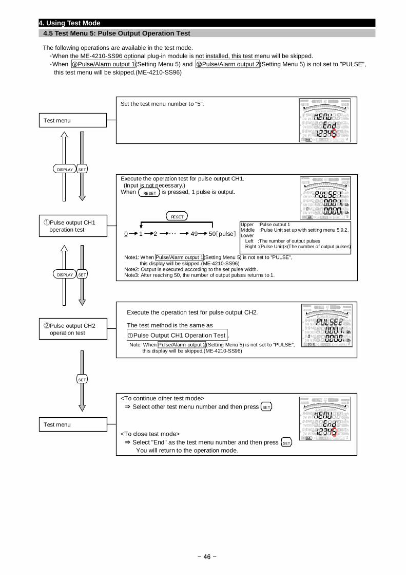
4. Using Test Mode
4.5 Test Menu 5: Pulse Output Operation Test
The following operations are available in the test mode. ・When the ME-4210-SS96 optional plug-in module is not installed, this test menu will be skipped. ・When ⑨Pulse/Alarm output 1(Setting Menu 5) and ⑫Pulse/Alarm output 2(Setting Menu 5) is not set to "PULSE",
this test menu will be skipped.(ME-4210-SS96)
Set the test menu number to "5".
Test menu
SETDISPLAY
Execute the operation test for pulse output CH1. (Input is not necessary.) When is pressed, 1 pulse is output.
- 46 -
<To continue other test mode> ⇒ Select other test menu number and then press .
<To close test mode> ⇒ Select "End" as the test menu number and then press . You will return to the operation mode.
Test menu
SET
SET
SET
SETDISPLAY
①Pulse output CH1 operation test
0 1 2 ・・・ 49 50[pulse]
RESET
RESET
Note1: When Pulse/Alarm output 1(Setting Menu 5) is not set to "PULSE",
Upper :Pulse output 1 Middle :Pulse Unit set up with setting menu 5.9.2.Lower
Left :The number of output pulses Right :(Pulse Unit)×(The number of output pulses)
this display will be skipped.(ME-4210-SS96) Note2: Output is executed according to the set pulse width. Note3: After reaching 50, the number of output pulses returns to 1.
Execute the operation test for pulse output CH2.
The test method is the same as
①Pulse Output CH1 Operation Test .
②Pulse output CH2 operation test
Note: When Pulse/Alarm output 2(Setting Menu 5) is not set to "PULSE", this display will be skipped.(ME-4210-SS96)
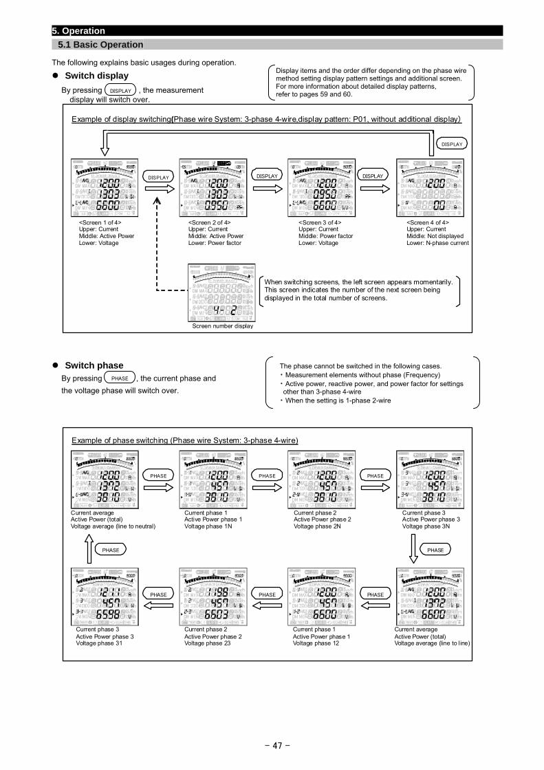
5. Operation
5.1 Basic Operation
The following explains basic usages during operation. Display items and the order differ depending on the phase wiremethod setting display pattern settings and additional screen.For more information about detailed display patterns, refer to pages 59 and 60.
Switch display
By pressing , the measurement display will switch over.
DISPLAY
Example of display switching(Phase wire System: 3-phase 4-wire,display pattern: P01, without additional display)
<Screen 1 of 4> Upper: Current Middle: Active Power Lower: Voltage
<Screen 2 of 4> Upper: Current Middle: Active Power Lower: Power factor
<Screen 3 of 4> Upper: Current Middle: Power factor Lower: Voltage
When switching screens, the left screen appears momentarily.This screen indicates the number of the next screen being displayed in the total number of screens.
Screen number display
DISPLAY
DISPLAYDISPLAYDISPLAY
<Screen 4 of 4> Upper: Current Middle: Not displayed Lower: N-phase current
- 47 -
Switch phase
By pressing , the current phase and
the voltage phase will switch over.
The phase cannot be switched in the following cases. ・ Measurement elements without phase (Frequency) ・ Active power, reactive power, and power factor for settings other than 3-phase 4-wire ・ When the setting is 1-phase 2-wire
PHASE
Example of phase switching (Phase wire System: 3-phase 4-wire)
Current average Active Power (total) Voltage average (line to neutral)
PHASE PHASEPHASE
PHASE PHASEPHASE
PHASE PHASE
Current phase 1 Active Power phase 1Voltage phase 1N
Current phase 2 Active Power phase 2Voltage phase 2N
Current phase 3 Active Power phase 3Voltage phase 3N
Current average Active Power (total) Voltage average (line to line)
Current phase 1Active Power phase 1Voltage phase 12
Current phase 2Active Power phase 2Voltage phase 23
Current phase 3 Active Power phase 3 Voltage phase 31
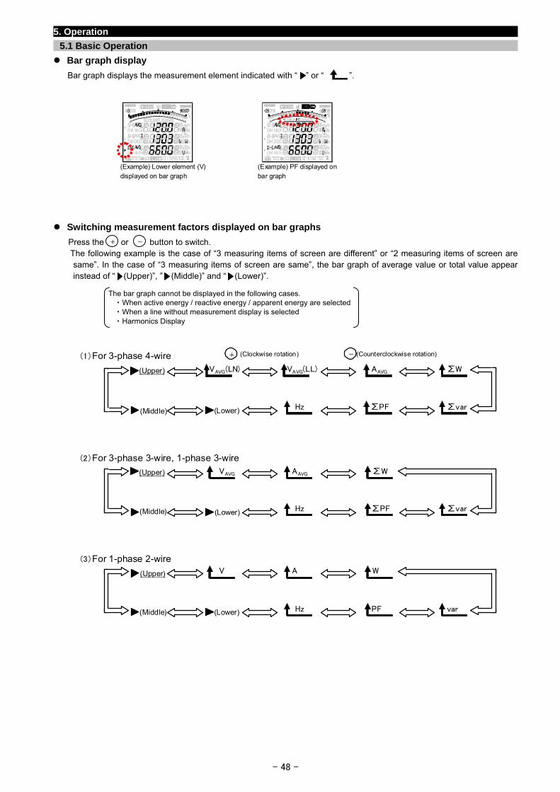
5. Operation
5.1 Basic Operation
Bar graph display
Bar graph displays the measurement element indicated with “ ” or “ ”.
(Example) Lower element (V)
displayed on bar graph
(Example) PF displayed on
bar graph
Switching measurement factors displayed on bar graphs
Press the or button to switch. -+
The following example is the case of “3 measuring items of screen are different” or “2 measuring items of screen are same”. In the case of “3 measuring items of screen are same”, the bar graph of average value or total value appear instead of “ (Upper)”, ” (Middle)” and “ (Lower)”.
The bar graph cannot be displayed in the following cases.
・ When active energy / reactive energy / apparent energy are selected・ When a line without measurement display is selected ・ Harmonics Display
(
1)For 3-phase 4-wire
(2)For 3-phase 3-wire, 1-phase 3-wire
(3)For 1-phase 2-wire
(Clockwise rotation) (Counterclockwise rotation) + -
(Upper) VAVG(LL) AAVG ∑W
∑var
VAVG(LN)
(Lower)(Middle) ∑PFHz
(Upper) AAVG ∑W
∑var
VAVG
(Lower)(Middle) ∑PFHz
(Upper) A W
var
V
(Lower)(Middle) PFHz
- 48 -
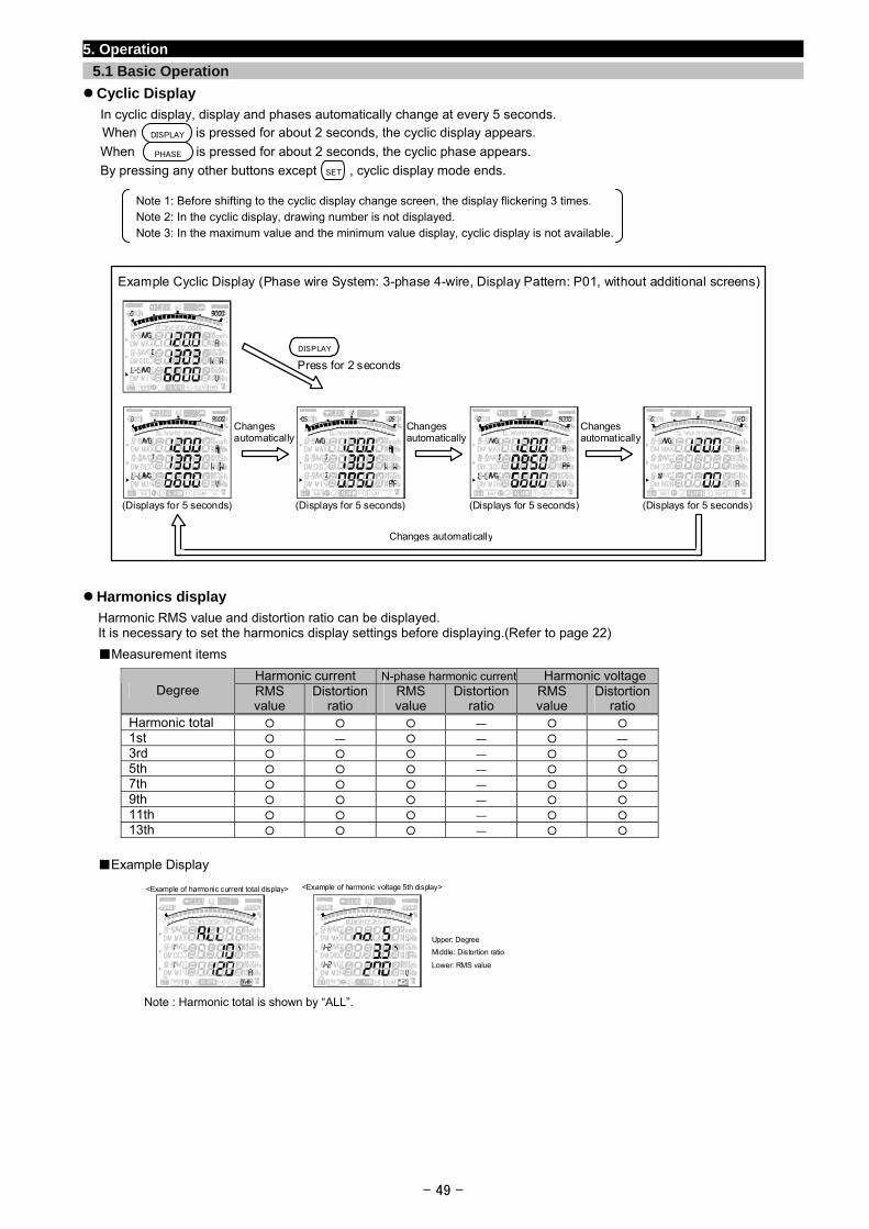
5. Operation
5.1 Basic Operation
Cyclic Display
In cyclic display, display and phases automatically change at every 5 seconds. When is pressed for about 2 seconds, the cyclic display appears. DISPLAY
When is pressed for about 2 seconds, the cyclic phase appears. PHASE
By pressing any other buttons except , cyclic display mode ends. SET
Note 1: Before shifting to the cyclic display change screen, the display flickering 3 times. Note 2: In the cyclic display, drawing number is not displayed. Note 3: In the maximum value and the minimum value display, cyclic display is not available.
Example Cyclic Display (Phase wire System: 3-phase 4-wire, Display Pattern: P01, without additional screens)
DISPLAY
Press for 2 seconds
Changes automatically
Changes automatically
Changes automatically
Changes automatically
(Displays for 5 seconds) (Displays for 5 seconds) (Displays for 5 seconds) (Displays for 5 seconds)
Harmonics display
Harmonic RMS value and distortion ratio can be displayed. It is necessary to set the harmonics display settings before displaying.(Refer to page 22)
Measurement items
Harmonic current N-phase harmonic current Harmonic voltage Degree RMS
value Distortion
ratio RMS value
Distortionratio
RMS value
Distortion ratio
Harmonic total ―
1st ― ― ―
3rd ―
5th ―
7th ―
9th ―
11th ―
13th ―
Example Display
<Example of harmonic current total display> <Example of harmonic voltage 5th display>
Upper: Degree
Middle: Distortion ratio
Lower: RMS value
Note : Harmonic total is shown by “ALL”.
- 49 -
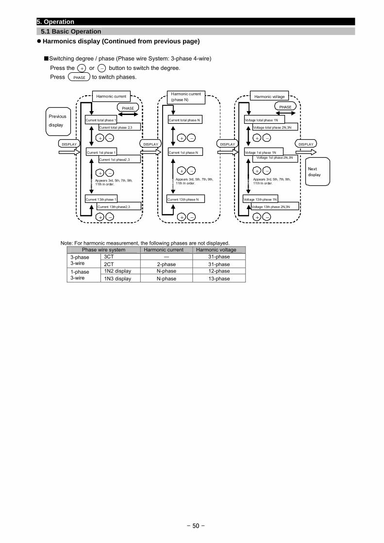
5. Operation
5.1 Basic Operation
Harmonics display (Continued from previous page)
Switching degree / phase (Phase wire System: 3-phase 4-wire)
Press the or button to switch the degree.
Press to switch phases.
-+
PHASE
+ -
Harmonic voltage
Voltage total phase 2N,3N
Voltage total phase 1N
Voltage 1st phase 2N,3N Voltage 1st phase 1N
Voltage 13th phase 2N,3N
Voltage 13th phase 1N
+ -
+ -
Appears 3rd, 5th, 7th, 9th, 11th In order.
PHASE
+ -
Harmonic current
Current total phase 2,3
Current total phase 1
Current 1st phase2,3
Current 1st phase 1
Current 13th phase2,3
Current 13th phase 1
+ -
+ -
Appears 3rd, 5th, 7th, 9th, 11th in order.
PHASE
DISPLAY
+ -
Harmonic current
(phase N)
Current total phase N
Current 1st phase N
Current 13th phase N
+ -
+ -
Appears 3rd, 5th, 7th, 9th,11th In order.
DISPLAYDISPLAYDISPLAY
Previous
display
Next
display
Note: For harmonic measurement, the following phases are not displayed. Phase wire system Harmonic current Harmonic voltage
3CT ― 31-phase 3-phase 3-wire 2CT 2-phase 31-phase
1N2 display N-phase 12-phase 1-phase 3-wire 1N3 display N-phase 13-phase
- 50 -
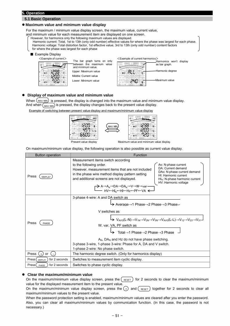
5. Operation
5.1 Basic Operation
Maximum value and minimum value display
For the maximum / minimum value display screen, the maximum value, current value, and minimum value for each measurement item are displayed on one screen.
However, for harmonics only the following maximum values are displayed. Harmonic current: Total, 1st to 13th (only odd number) effective values for where the phase was largest for each phase. Harmonic voltage: Total distortion factor, 1st effective value, 3rd to 13th (only odd number) content factors for where the phase was largest for each phase
Example Display
Upper: Maximum value
Middle: Current value
Lower: Minimum value
<Example of current> <Example of current harmonics>The bar graph turns on onlybetween the maximum valueand minimum value.
Harmonic degree
Harmonics won’t display as bar graph.
Maximum value
Display of maximum value and minimum value
When is pressed, the display is changed into the maximum value and minimum value display. And when is pressed, the display changes back to the present value display.
MAX/MIN
- 51 -
On maximum/minimum value display, the following operation is also possible as current value display.
Button operation Function
Press
Measurement items switch according to the following order. However, measurement items that are not included in the phase wire method display pattern setting and additional screens are not displayed.
Press
3-phase 4-wire: A and DA switch as V switches as W, var, VA, PF switch as AN, DAN and Hz do not have phase switching. 3-phase 3-wire, 1-phase 3-wire: Phase for A, DA and V switch. 1-phase 2-wire: No phase switch.
Press or The harmonic degree switch. (Only for harmonics display)
Press for 2 seconds Switches to measurement item cyclic display.
Press for 2 seconds Switches to phase cyclic display.
Clear the maximum/minimum value On the maximum/minimum value display screen, press the for 2 seconds to clear the maximum/minimum value for the displayed measurement item to the present value. On the maximum/minimum value display screen, press the and together for 2 seconds to clear all maximum/minimum values to the present value. When the password protection setting is enabled, maximum/minimum values are cleared after you enter the password. Also, you can clear all maximum/minimum values by communication function. (In this case, the password is not necessary.)
Example of switching between present value display and maximum/minimum value display
Present value display Maximum value and minimum value display
MAX/MIN
MAX/MIN
AN: N-phase current DA: Current demand DAN: N-phase current demandHI: Harmonic current HIN: N-phase harmonic currentHV: Harmonic voltage
A→AN→DA→DAN→V→W→var
HV←HIN←HI←Hz←PF←VA
DISPLAY
Average→1 Phase→2 Phase→3 Phase
VAVG(L-N)→V1N→V2N→V3N→VAVG(L-L)→V12→V23→V31PHASE
Total→1 Phase→2 Phase→3 Phase
-+
DISPLAY
PHASE
RESET
RESE+ T
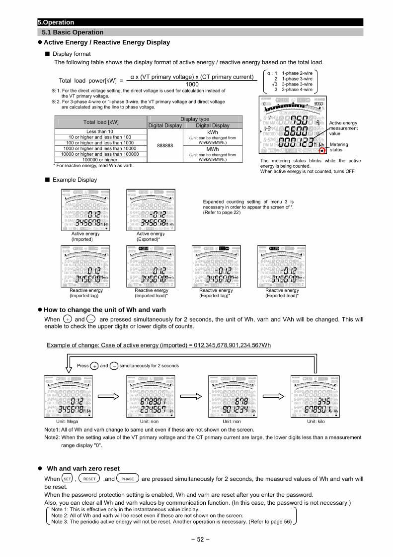
- 52 -
5.Operation
5.1 Basic Operation
Active Energy / Reactive Energy Display
Display format
The following table shows the display format of active energy / reactive energy based on the total load.
α x (VT primary voltage) x (CT primary current)Total load power[kW] =
1000 ※ 1. For the direct voltage setting, the direct voltage is used for calculation instead of
the VT primary voltage. ※ 2. For 3-phase 4-wire or 1-phase 3-wire, the VT primary voltage and direct voltage
are calculated using the line to phase voltage.
Display type Total load [kW]
Digital Display Digital Display Less than 10
10 or higher and less than 100 100 or higher and less than 1000
kWh (Unit can be changed from
Wh/kWh/MWh.)
1000 or higher and less than 10000 10000 or higher and less than 100000
100000 or higher
888888 MWh
(Unit can be changed from Wh/kWh/MWh.)
* For reactive energy, read Wh as varh.
Example Display
How to change the unit of Wh and varh
When and are pressed simultaneously for 2 seconds, the unit of Wh, varh and VAh will be changed. This will enable to check the upper digits or lower digits of counts.
Note1: All of Wh and varh change to same unit even if these are not shown on the screen.
Note2: When the setting value of the VT primary voltage and the CT primary current are large, the lower digits less than a measurement
range display "0".
Wh and varh zero reset
When , ,and are pressed simultaneously for 2 seconds, the measured values of Wh and varh will be reset. When the password protection setting is enabled, Wh and varh are reset after you enter the password. Also, you can clear all Wh and varh values by communication function. (In this case, the password is not necessary.)
Note 1: This is effective only in the instantaneous value display. Note 2: All of Wh and varh will be reset even if these are not shown on the screen. Note 3: The periodic active energy will not be reset. Another operation is necessary. (Refer to page 56)
PHASESET RESET
Example of change: Case of active energy (imported) = 012,345,678,901,234.567Wh
Unit:Mega Unit:non Unit:non Unit:kilo
Press and simultaneously for 2 seconds+ -
Active energy (Imported)
Active energy(Exported)*
Reactive energy (Imported lag)
Reactive energy(Imported lead)*
Reactive energy(Exported lag)*
Reactive energy(Exported lead)*
Expanded counting setting of menu 3 is necessary in order to appear the screen of *. (Refer to page 22)
α: 1 1-phase 2-wire 2 1-phase 3-wire 3 3-phase 3-wire 3 3-phase 4-wire
The metering status blinks while the active energy is being counted. When active energy is not counted, turns OFF.
Active energy measurement value
Metering status
+ -
√
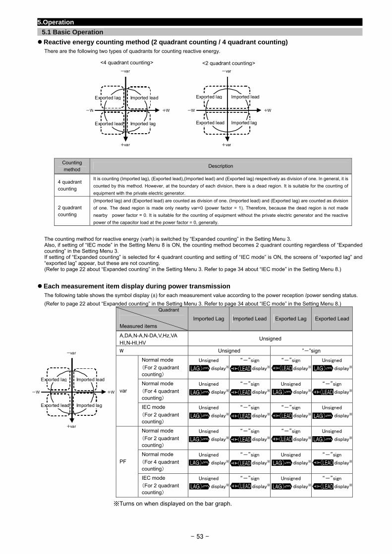
5.Operation
5.1 Basic Operation
Reactive energy counting method (2 quadrant counting / 4 quadrant counting) There are the following two types of quadrants for counting reactive energy.
+W-W
+var
-var
+W-W
+var
-var
<4 quadrant counting> <2 quadrant counting>
Exported lag Imported lead
Exported lead Imported lag
Exported lag Imported lead
Exported lead Imported lag
Counting method
Description
4 quadrant counting
It is counting (Imported lag), (Exported lead),(Imported lead) and (Exported lag) respectively as division of one. In general, it is
counted by this method. However, at the boundary of each division, there is a dead region. It is suitable for the counting of
equipment with the private electric generator.
2 quadrant counting
(Imported lag) and (Exported lead) are counted as division of one. (Imported lead) and (Exported lag) are counted as division
of one. The dead region is made only nearby var=0 (power factor = 1). Therefore, because the dead region is not made
nearby power factor = 0. It is suitable for the counting of equipment without the private electric generator and the reactive
power of the capacitor load at the power factor = 0, generally.
The counting method for reactive energy (varh) is switched by “Expanded counting” in the Setting Menu 3. Also, if setting of “IEC mode” in the Setting Menu 8 is ON, the counting method becomes 2 quadrant counting regardless of “Expanded counting” in the Setting Menu 3. If setting of “Expanded counting” is selected for 4 quadrant counting and setting of “IEC mode” is ON, the screens of “exported lag” and “exported lag” appear, but these are not counting. (Refer to page 22 about “Expanded counting” in the Setting Menu 3. Refer to page 34 about “IEC mode” in the Setting Menu 8.)
Each measurement item display during power transmission
The following table shows the symbol display (±) for each measurement value according to the power reception /power sending status.
(Refer to page 22 about “Expanded counting” in the Setting Menu 3. Refer to page 34 about “IEC mode” in the Setting Menu 8.) Quadrant
Measured items
Imported Lag Imported Lead Exported Lag Exported Lead
A,DA,N-A,N-DA,V,Hz,VA HI,N-HI,HV
Unsigned
W Unsigned ”-”sign
Normal mode
(For 2 quadrant counting)
Unsigned
display※
“-”sign
display※
“-”sign
display※
Unsigned
display※
Normal mode
(For 4 quadrant counting)
Unsigned
display※
“-”sign
display※
Unsigned
display※
“-”sign
display※var
IEC mode
(For 2 quadrant counting)
Unsigned
display※
“-”sign
display※
“-”sign
display※
Unsigned
display※
Normal mode
(For 2 quadrant counting)
Unsigned
display※
“-”sign
display※
“-”sign
display※
Unsigned
display※
Normal mode
(For 4 quadrant counting)
Unsigned
display※
“-”sign
display※
Unsigned
display※
“-”sign
display※PF
IEC mode
(For 2 quadrant counting)
Unsigned
display※
“-”sign
display※
Unsigned
display※
“-”sign
display※
- 53 -
※Turns on when displayed on the bar graph.
+W+W -W
+var
-var
Exported lag Imported lead
Exported lead Imported lag
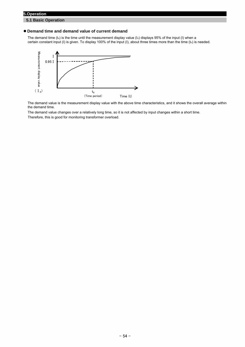
5.Operation
5.1 Basic Operation
Demand time and demand value of current demand
The demand time (to) is the time until the measurement display value (Io) displays 95% of the input (I) when a certain constant input (I) is given. To display 100% of the input (I), about three times more than the time (to) is needed.
The demand value is the measurement display value with the above time characteristics, and it shows the overall average within the demand time.
The demand value changes over a relatively long time, so it is not affected by input changes within a short time. Therefore, this is good for monitoring transformer overload.
Ⅰ
Measu
rem
ent disp
lay value
Time (t)
(Ⅰ0) t0 (Time period)
0.95Ⅰ
- 54 -
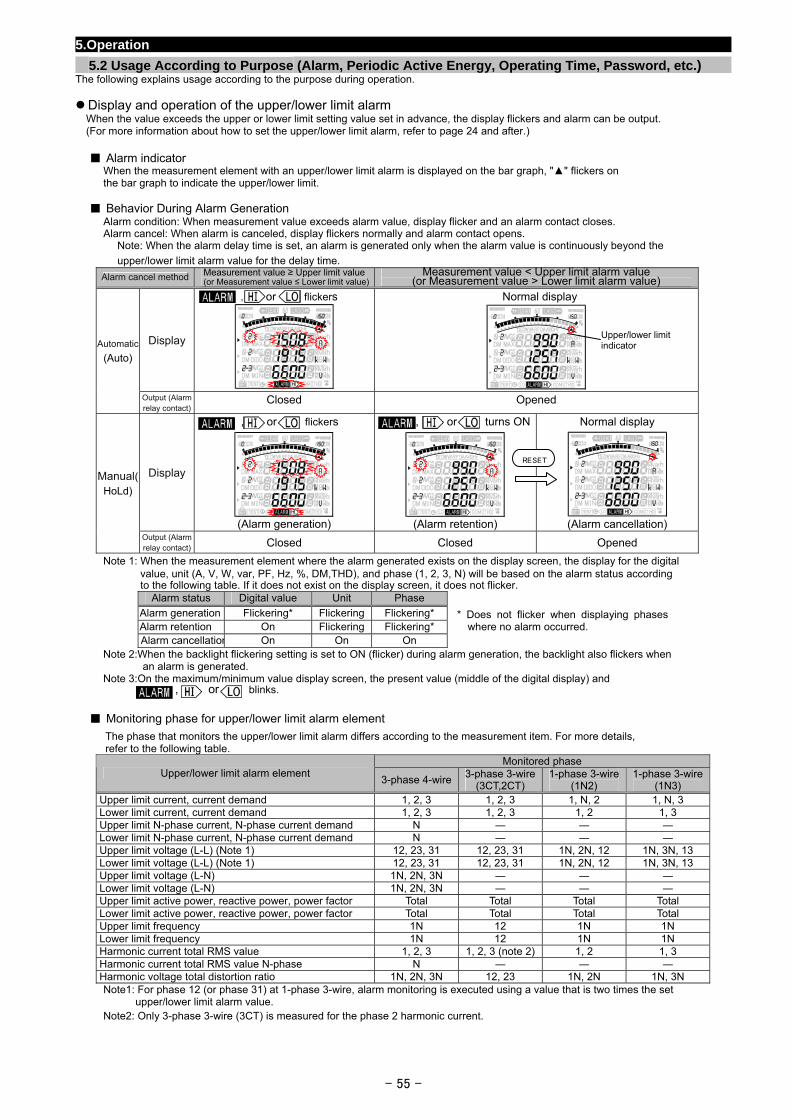
5.Operation
5.2 Usage According to Purpose (Alarm, Periodic Active Energy, Operating Time, Password, etc.) The following explains usage according to the purpose during operation.
Display and operation of the upper/lower limit alarm When the value exceeds the upper or lower limit setting value set in advance, the display flickers and alarm can be output. (For more information about how to set the upper/lower limit alarm, refer to page 24 and after.)
Alarm indicator
When the measurement element with an upper/lower limit alarm is displayed on the bar graph, "" flickers on the bar graph to indicate the upper/lower limit.
Behavior During Alarm Generation Alarm condition: When measurement value exceeds alarm value, display flicker and an alarm contact closes. Alarm cancel: When alarm is canceled, display flickers normally and alarm contact opens.
Note: When the alarm delay time is set, an alarm is generated only when the alarm value is continuously beyond the
upper/lower limit alarm value for the delay time.
Alarm cancel method Measurement value ≥ Upper limit value (or Measurement value ≤ Lower limit value)
Measurement value < Upper limit alarm value (or Measurement value > Lower limit alarm value)
Display
, or flickers Normal display
Automatic
(Auto)
Output (Alarm relay contact)
Closed Opened
Display
, or flickers
(Alarm generation)
, or turns ON
(Alarm retention)
Normal display
(Alarm cancellation)
Manual(HoLd)
Output (Alarm relay contact) Closed Closed Opened
Upper/lo er limitwindicator
RESET
Note 1: When the measurement element where the alarm generated exists on the display screen, the display for the digital value, unit (A, V, W, var, PF, Hz, %, DM,THD), and phase (1, 2, 3, N) will be based on the alarm status according to the following table. If it does not exist on the display screen, it does not flicker.
Alarm status Digital value Unit Phase
Alarm generation Flickering* Flickering Flickering* Alarm retention On Flickering Flickering* Alarm cancellation On On On
* Does not flicker when displaying phases where no alarm occurred.
Note 2:When the backlight flickering setting is set to ON (flicker) during alarm generation, the backlight also flickers when an alarm is generated.
Note 3:On the maximum/minimum value display screen, the present value (middle of the digital display) and , or blinks.
Monitoring phase for upper/lower limit alarm element
The phase that monitors the upper/lower limit alarm differs according to the measurement item. For more details, refer to the following table.
Monitored phase Upper/lower limit alarm element
3-phase 4-wire3-phase 3-wire
(3CT,2CT) 1-phase 3-wire
(1N2) 1-phase 3-wire
(1N3) Upper limit current, current demand 1, 2, 3 1, 2, 3 1, N, 2 1, N, 3 Lower limit current, current demand 1, 2, 3 1, 2, 3 1, 2 1, 3 Upper limit N-phase current, N-phase current demand N ― ― ― Lower limit N-phase current, N-phase current demand N ― ― ― Upper limit voltage (L-L) (Note 1) 12, 23, 31 12, 23, 31 1N, 2N, 12 1N, 3N, 13 Lower limit voltage (L-L) (Note 1) 12, 23, 31 12, 23, 31 1N, 2N, 12 1N, 3N, 13 Upper limit voltage (L-N) 1N, 2N, 3N ― ― ― Lower limit voltage (L-N) 1N, 2N, 3N ― ― ― Upper limit active power, reactive power, power factor Total Total Total Total Lower limit active power, reactive power, power factor Total Total Total Total Upper limit frequency 1N 12 1N 1N Lower limit frequency 1N 12 1N 1N Harmonic current total RMS value 1, 2, 3 1, 2, 3 (note 2) 1, 2 1, 3 Harmonic current total RMS value N-phase N ― ― ― Harmonic voltage total distortion ratio 1N, 2N, 3N 12, 23 1N, 2N 1N, 3N Note1: For phase 12 (or phase 31) at 1-phase 3-wire, alarm monitoring is executed using a value that is two times the set upper/lower limit alarm value. Note2: Only 3-phase 3-wire (3CT) is measured for the phase 2 harmonic current.
- 55 -
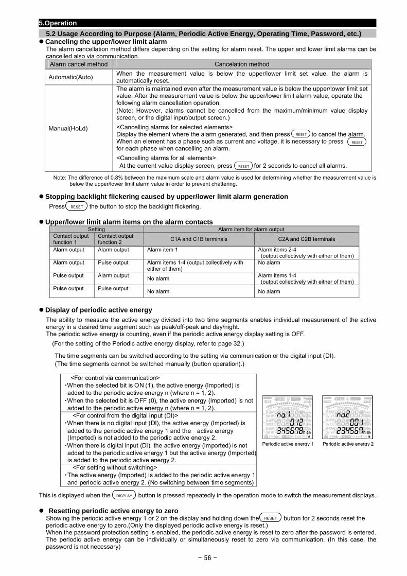
5.Operation
5.2 Usage According to Purpose (Alarm, Periodic Active Energy, Operating Time, Password, etc.) Canceling the upper/lower limit alarm
The alarm cancellation method differs depending on the setting for alarm reset. The upper and lower limit alarms can be cancelled also via communication.
Alarm cancel method Cancelation method
Automatic(Auto) When the measurement value is below the upper/lower limit set value, the alarm is automatically reset.
Manual(HoLd)
The alarm is maintained even after the measurement value is below the upper/lower limit set value. After the measurement value is below the upper/lower limit alarm value, operate the following alarm cancellation operation. (Note: However, alarms cannot be cancelled from the maximum/minimum value display screen, or the digital input/output screen.)
<Cancelling alarms for selected elements> Display the element where the alarm generated, and then press to cancel the alarm.When an element has a phase such as current and voltage, it is necessary to press for each phase when cancelling an alarm.
<Cancelling alarms for all elements>
At the current value display screen, press for 2 seconds to cancel all alarms.
RESET
RESET
RESET
Note: The difference of 0.8% between the maximum scale and alarm value is used for determining whether the measurement value is below the upper/lower limit alarm value in order to prevent chattering.
Stopping backlight flickering caused by upper/lower limit alarm generation
Press the button to stop the backlight flickering.
RESET
Upper/lower limit alarm items on the alarm contacts Setting Alarm item for alarm output
Contact output function 1
Contact output function 2
C1A and C1B terminals C2A and C2B terminals
Alarm output Alarm output Alarm item 1 Alarm items 2-4 (output collectively with either of them)
Alarm output Pulse output Alarm items 1-4 (output collectively with either of them)
No alarm
Pulse output Alarm output No alarm Alarm items 1-4 (output collectively with either of them)
Pulse output Pulse output No alarm No alarm
Display of periodic active energy
The ability to measure the active energy divided into two time segments enables individual measurement of the active energy in a desired time segment such as peak/off-peak and day/night. The periodic active energy is counting, even if the periodic active energy display setting is OFF.
(For the setting of the Periodic active energy display, refer to page 32.)
This is displayed when the button is pressed repeatedly in the operation mode to switch the measurement displays. DISPLAY
The time segments can be switched according to the setting via communication or the digital input (DI). (The time segments cannot be switched manually (button operation).)
<For control via communication> ・When the selected bit is ON (1), the active energy (Imported) is added to the periodic active energy n (where n = 1, 2).
・When the selected bit is OFF (0), the active energy (Imported) is not added to the periodic active energy n (where n = 1, 2).
<For control from the digital input (DI)> ・When there is no digital input (DI), the active energy (Imported) is added to the periodic active energy 1 and the active energy (Imported) is not added to the periodic active energy 2.
・When there is digital input (DI), the active energy (Imported) is not added to the periodic active energy 1 but the active energy (Imported) is added to the periodic active energy 2.
<For setting without switching> ・The active energy (Imported) is added to the periodic active energy 1 and periodic active energy 2. (No switching between time segments)
Periodic active energy 1 Periodic active energy 2
Resetting periodic active energy to zero Showing the periodic active energy 1 or 2 on the display and holding down the button for 2 seconds reset the periodic active energy to zero.(Only the displayed periodic active energy is reset.) When the password protection setting is enabled, the periodic active energy is reset to zero after the password is entered. The periodic active energy can be individually or simultaneously reset to zero via communication. (In this case, the password is not necessary)
RESET
- 56 -
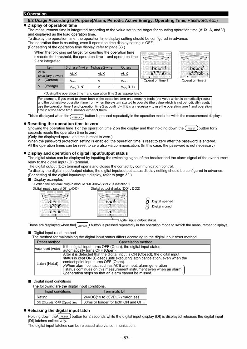
5.Operation
5.2 Usage According to Purpose(Alarm, Periodic Active Energy, Operating Time, Password, etc.) Display of operation time
The measurement time is integrated according to the value set to the target for counting operation time (AUX, A, and V) and displayed as the load operation time. To display the operation time, the operation time display setting should be configured in advance. The operation time is counting, even if operation time display setting is OFF. (For setting of the operation time display, refer to page 33.)
This is displayed when the button is pressed repeatedly in the operation mode to switch the measurement displays.
Operation time 1 Operation time 2
When the following set target for counting the operation time exceeds the threshold, the operation time 1 and operation time2 are integrated.
For example, if you want to check both of the operation time on a monthly basis (the value which is periodically reset) and the cumulative operation time from when the system started to operate (the value which is not periodically reset), use the operation time 1 and operation time 2 accordingly. If it is unnecessary to use the operation time 1 and operation time 2 at the same time, monitor either of them.
<Using the operation time 1 and operation time 2 as appropriate>
Item 3-phase 4-wire 1-phase 2-wire Others AUX (Auxiliary power)
AUX AUX AUX
A (Current) AAVG A AAVG
V (Voltage) VAVG(L-N) V VAVG(L-L)
DISPLAY
Resetting the operation time to zero Showing the operation time 1 or the operation time 2 on the display and then holding down the button for 2 seconds resets the operation time to zero. (Only the displayed operation time is reset to zero.) When the password protection setting is enabled, the operation time is reset to zero after the password is entered. All the operation times can be reset to zero also via communication. (In this case, the password is not necessary)
RESET
Display and operation of digital input/output status The digital status can be displayed by inputting the switching signal of the breaker and the alarm signal of the over current relay to the digital input (DI) terminal. The digital output (DO) terminal opens and closes the contact by communication control. To display the digital input/output status, the digital input/output status display setting should be configured in advance. (For setting of the digital input/output display, refer to page 32.) Display examples
These are displayed when the button is pressed repeatedly in the operation mode to switch the measurement displays.
<When the optional plug-in module “ME-0052-SS96” is installed> Digital input display(DI1 to DI5) Digital output display(DO1、DO2)
:Digital closed
:Digital opened
Digital input/ output status
DISPLAY
Digital input reset method The method for maintaining the digital input status differs according to the digital input reset method.
Reset method Cancelation method
Auto reset (Auto) If the digital input turns OFF (Open), the digital input status automatically turns OFF (Open).
Latch (HoLd)
After it is detected that the digital input is ON (Closed), the digital input status is kept ON (Closed) until executing latch cancelation, even when the contact point input turns OFF (Open).
When alarm contact such as ACB are input, alarm generation status continues on this measurement instrument even when an alarm generation stops so that an alarm cannot be missed.
Digital input conditions
The following are the digital input conditions. Input conditions Terminals DI
Rating 24VDC(19 to 30VDC),7mAor less ON (Closed) / OFF (Open) time 30ms or longer for both ON and OFF
Releasing the digital input latch
Holding down the button for 2 seconds while the digital input display (DI) is displayed releases the digital input (DI) latches collectively. The digital input latches can be released also via communication.
RESET
- 57 -
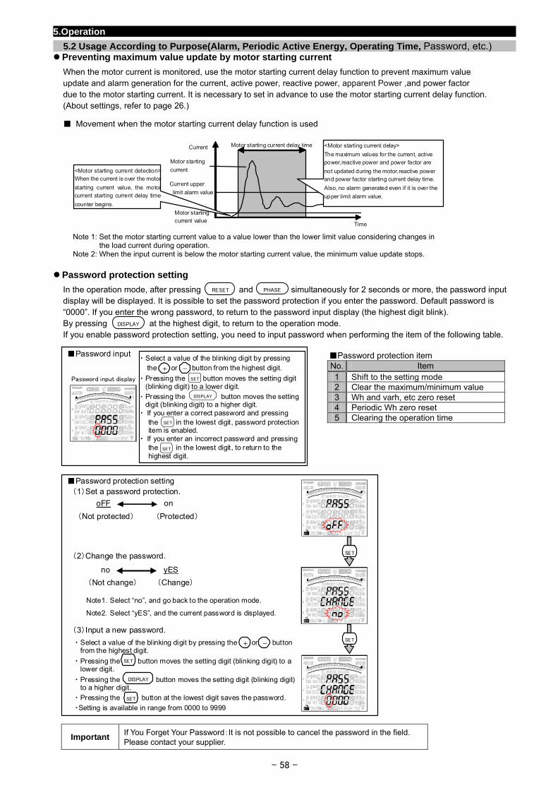
5.Operation
5.2 Usage According to Purpose(Alarm, Periodic Active Energy, Operating Time, Password, etc.) Preventing maximum value update by motor starting current
When the motor current is monitored, use the motor starting current delay function to prevent maximum value update and alarm generation for the current, active power, reactive power, apparent Power ,and power factor due to the motor starting current. It is necessary to set in advance to use the motor starting current delay function. (About settings, refer to page 26.) Movement when the motor starting current delay function is used
Note 1: Set the motor starting current value to a value lower than the lower limit value considering changes in the load current during operation. Note 2: When the input current is below the motor starting current value, the minimum value update stops.
<Motor starting current detection> When the current is over the motor
starting current value, the motor current starting current delay time
counter begins.
<Motor starting current delay>
The maximum values for the current, active power,reactive power and power factor are
not updated during the motor,reactive power and power factor starting current delay time.
Also, no alarm generated even if it is over the
upper limit alarm value.
Motor starting current delay time Current
Time
Motor starting current value
Current upper
limit alarm value
Motor starting
current
Password protection setting
In the operation mode, after pressing and simultaneously for 2 seconds or more, the password input display will be displayed. It is possible to set the password protection if you enter the password. Default password is “0000”. If you enter the wrong password, to return to the password input display (the highest digit blink). By pressing at the highest digit, to return to the operation mode. If you enable password protection setting, you need to input password when performing the item of the following table. Password protection item
PHASERESET
DISPLAY
- 58 -
No. Item 1 Shift to the setting mode 2 Clear the maximum/minimum value 3 Wh and varh, etc zero reset 4 Periodic Wh zero reset 5 Clearing the operation time
Password input ・ Select a value of the blinking digit by pressing
the or button from the highest digit.
・ Pressing the button moves the setting digit (blinking digit) to a lower digit.
・ Pressing the button moves the setting digit (blinking digit) to a higher digit.
・ If you enter a correct password and pressing the in the lowest digit, password protection item is enabled.
・ If you enter an incorrect password and pressing the in the lowest digit, to return to the highest digit.
+ -
DISPLAY
SETPassword input display
SET
SET
Password protection setting
(1)Set a password protection.
Important If You Forget Your Password:It is not possible to cancel the password in the field. Please contact your supplier.
(2)Change the password.
Note1.Select “no”, and go back to the operation mode.
Note2.Select “yES”, and the current password is displayed.
(3)Input a new password.
oFF on
(Not protected) (Protected)
no yES
SET
(Not change) (Change)
・ Select a value of the blinking digit by pressing the or button from the highest digit.
・ Pressing the button moves the setting digit (blinking digit) to a lower digit.
・ Pressing the button moves the setting digit (blinking digit) to a higher digit.
・ Pressing the button at the lowest digit saves the password
・Setting is available in range from 0000 to 9999
.
+SET
-
SET
DISPLAY
SET
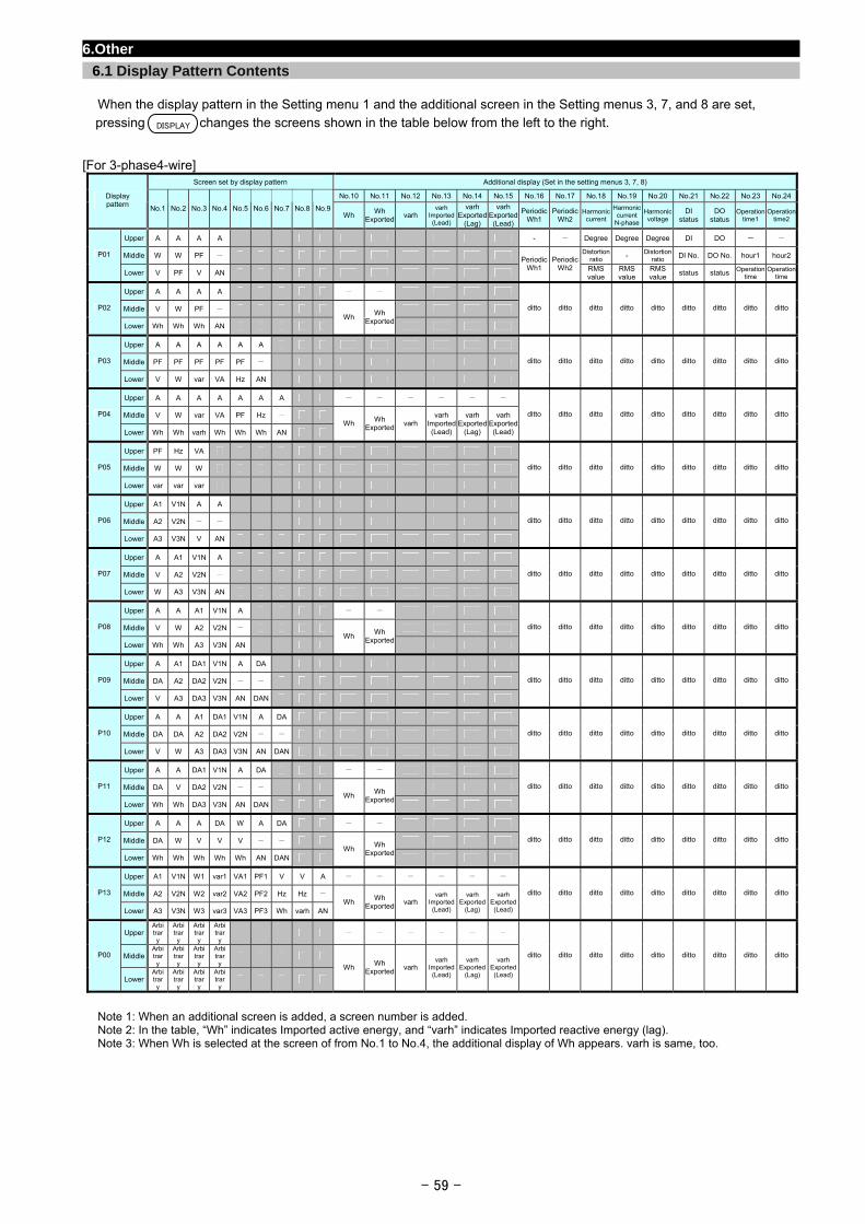
- 59 -
6.Other
6.1 Display Pattern Contents
When the display pattern in the Setting menu 1 and the additional screen in the Setting menus 3, 7, and 8 are set,
pressing changes the screens shown in the table below from the left to the right.
[For 3-phase4-wire] Screen set by display pattern Additional display (Set in the setting menus 3, 7, 8)
No.10 No.11 No.12 No.13 No.14 No.15 No.16 No.17 No.18 No.19 No.20 No.21 No.22 No.23 No.24Display pattern
No.1 No.2 No.3 No.4 No.5 No.6 No.7 No.8 No.9 Wh
Wh Exported
varh varh
Imported(Lead)
varh Exported
(Lag)
varh Exported(Lead)
PeriodicWh1
PeriodicWh2
Harmoniccurrent
Harmonic current
N-phase
Harmonic voltage
DI status
DO status
Operation time1
Operation time2
Upper A A A A - - Degree Degree Degree DI DO - -
Middle W W PF - Distortionratio - Distortion
ratio DI No. DO No. hour1 hour2P01
Lower V PF V AN
PeriodicWh1
PeriodicWh2 RMS
valueRMS value
RMS value
status status Operation time
Operation time
Upper A A A A - -
Middle V W PF - P02
Lower Wh Wh Wh AN Wh
Wh Exported
ditto ditto ditto ditto ditto ditto ditto ditto ditto
Upper A A A A A A
Middle PF PF PF PF PF - P03
Lower V W var VA Hz AN
ditto ditto ditto ditto ditto ditto ditto ditto ditto
Upper A A A A A A A - - - - - -
Middle V W var VA PF Hz - P04
Lower Wh Wh varh Wh Wh Wh AN Wh
Wh Exported
varh varh
Imported(Lead)
varh Exported
(Lag)
varh Exported(Lead)
ditto ditto ditto ditto ditto ditto ditto ditto ditto
Upper PF Hz VA
Middle W W W P05
Lower var var var
ditto ditto ditto ditto ditto ditto ditto ditto ditto
Upper A1 V1N A A
Middle A2 V2N - - P06
Lower A3 V3N V AN
ditto ditto ditto ditto ditto ditto ditto ditto ditto
Upper A A1 V1N A
Middle V A2 V2N - P07
Lower W A3 V3N AN
ditto ditto ditto ditto ditto ditto ditto ditto ditto
Upper A A A1 V1N A - -
Middle V W A2 V2N - P08
Lower Wh Wh A3 V3N AN Wh
Wh Exported
ditto ditto ditto ditto ditto ditto ditto ditto ditto
Upper A A1 DA1 V1N A DA
Middle DA A2 DA2 V2N - - P09
Lower V A3 DA3 V3N AN DAN
ditto ditto ditto ditto ditto ditto ditto ditto ditto
Upper A A A1 DA1 V1N A DA
Middle DA DA A2 DA2 V2N - - P10
Lower V W A3 DA3 V3N AN DAN
ditto ditto ditto ditto ditto ditto ditto ditto ditto
Upper A A DA1 V1N A DA - -
Middle DA V DA2 V2N - - P11
Lower Wh Wh DA3 V3N AN DAN Wh
Wh Exported
ditto ditto ditto ditto ditto ditto ditto ditto ditto
Upper A A A DA W A DA - -
Middle DA W V V V - - P12
Lower Wh Wh Wh Wh Wh AN DAN Wh
Wh Exported
ditto ditto ditto ditto ditto ditto ditto ditto ditto
Upper A1 V1N W1 var1 VA1 PF1 V V A - - - - - -
Middle A2 V2N W2 var2 VA2 PF2 Hz Hz - P13
Lower A3 V3N W3 var3 VA3 PF3 Wh varh AN Wh
Wh Exported
varh varh
Imported(Lead)
varh Exported
(Lag)
varh Exported(Lead)
ditto ditto ditto ditto ditto ditto ditto ditto ditto
Upper Arbitrary
Arbitrary
Arbitrary
Arbitrary
- - - - - -
Middle Arbitrary
Arbitrary
Arbitrary
Arbitrary
P00
Lower Arbitrary
Arbitrary
Arbitrary
Arbitrary
Wh Wh
Exportedvarh
varh Imported(Lead)
varh Exported
(Lag)
varh Exported(Lead)
ditto ditto ditto ditto ditto ditto ditto ditto ditto
Note 1: When an additional screen is added, a screen number is added. Note 2: In the table, “Wh” indicates Imported active energy, and “varh” indicates Imported reactive energy (lag). Note 3: When Wh is selected at the screen of from No.1 to No.4, the additional display of Wh appears. varh is same, too.
DISPLAY
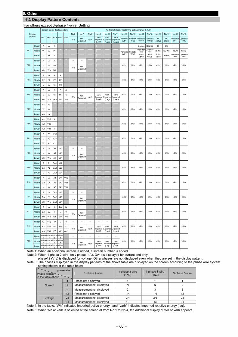
- 60 -
6. Other
6.1 Display Pattern Contents
[For others except 3-phase 4-wire] Setting Screen set by display pattern Additional display (Set in the setting menus 3, 7, 8)
No.6 No.7 No.8 No.9 No.10 No.11 No.12 No.13 No.14 No.15 No.16 No.17 No.18 No.19 Display pattern
No.1 No.2 No.3 No.4 No.5 Wh
Wh Exported
varh varh
Imported (Lead)
varhExported
(Lag)
varhExported (Lead)
PeriodicWh1
PeriodicWh2
Harmoniccurrent
Harmonicvoltage
DI status
DO status
Operation time1
Operation time2
Upper A A A - - Degree Degree DI DO - -
Middle W W PF Distortionratio
Distortionratio DI No. DO No. hour1 hour2 P01
Lower V PF V
PeriodicWh1
PeriodicWh2 RMS
valueRMS value
RMS value
status Operation time
Operation time
Upper A A A - -
Middle V W PF P02
Lower Wh Wh Wh Wh
Wh Exported
ditto ditto ditto ditto ditto ditto ditto ditto
Upper A A A A
Middle PF PF PF PF P03
Lower V W var Hz
ditto ditto ditto ditto ditto ditto ditto ditto
Upper A A A A A - - - - - -
Middle V W var PF Hz P04
Lower Wh Wh varh Wh Wh Wh
Wh Exported
varh varh
Imported (Lead)
varhExported
(Lag)
varhExported (Lead)
ditto ditto ditto ditto ditto ditto ditto ditto
Upper PF Hz
Middle W W P05
Lower var var
ditto ditto ditto ditto ditto ditto ditto ditto
Upper A1 V12 A
Middle A2 V23 - P06
Lower A3 V31 V
ditto ditto ditto ditto ditto ditto ditto ditto
Upper A A1 V12
Middle V A2 V23 P07
Lower W A3 V31
ditto ditto ditto ditto ditto ditto ditto ditto
Upper A A A1 V12 - -
Middle V W A2 V23 P08
Lower Wh Wh A3 V31 Wh
Wh Exported
ditto ditto ditto ditto ditto ditto ditto ditto
Upper A A1 DA1 V12
Middle DA A2 DA2 V23 P09
Lower V A3 DA3 V31
ditto ditto ditto ditto ditto ditto ditto ditto
Upper A A A1 DA1 V12
Middle DA DA A2 DA2 V23 P10
Lower V W A3 DA3 V31
ditto ditto ditto ditto ditto ditto ditto ditto
Upper A A DA1 V12 - -
Middle DA V DA2 V23 P11
Lower Wh Wh DA3 V31 Wh
Wh Exported
ditto ditto ditto ditto ditto ditto ditto ditto
Upper A A A DA W - -
Middle DA W V V V P12
Lower Wh Wh Wh Wh Wh Wh
Wh Exported
ditto ditto ditto ditto ditto ditto ditto ditto
Upper A1 V12 W V V - - - - - -
Middle A2 V23 var Hz Hz P13
Lower A3 V31 PF Wh varh Wh
Wh Exported
varh varh
Imported (Lead)
varhExported
(Lag)
varhExported (Lead)
ditto ditto ditto ditto ditto ditto ditto ditto
Upper Arbitrary
Arbitrary
Arbitrary
Arbitrary
- - - - - -
Middle Arbitrary
Arbitrary
Arbitrary
Arbitrary P00
Lower Arbitrary
Arbitrary
Arbitrary
Arbitrary
Wh
Wh Exported
varh varh
Imported (Lead)
varh Exported
(Lag)
varh Exported (Lead)
ditto ditto ditto ditto ditto ditto ditto ditto
Note 1: When an additional screen is added, a screen number is added. Note 2: When 1-phase 2-wire, only phase1 (A1, DA1) is displayed for current and only
phase12 (V12) is displayed for voltage. Other phases are not displayed even when they are set in the display pattern. Note 3: The phases displayed in the display patterns of the above table are displayed on the screen according to the phase wire system
setting shown in the table below. phase wire
Phase display in the table above
1-phase 2-wire 1-phase 3-wire
(1N2) 1-phase 3-wire
(1N3) 3-phase 3-wire
1 Phase not displayed 1 1 1
2 Measurement not displayed N N 2 Current
3 Measurement not displayed 2 3 3
12 Phase not displayed 1N 1N 12
23 Measurement not displayed 2N 3N 23 Voltage 31 Measurement not displayed 12 13 31
Note 4: In the table, “Wh” indicates Imported active energy , and “varh” indicates Imported reactive energy (lag). Note 5: When Wh or varh is selected at the screen of from No.1 to No.4, the additional display of Wh or varh appears.
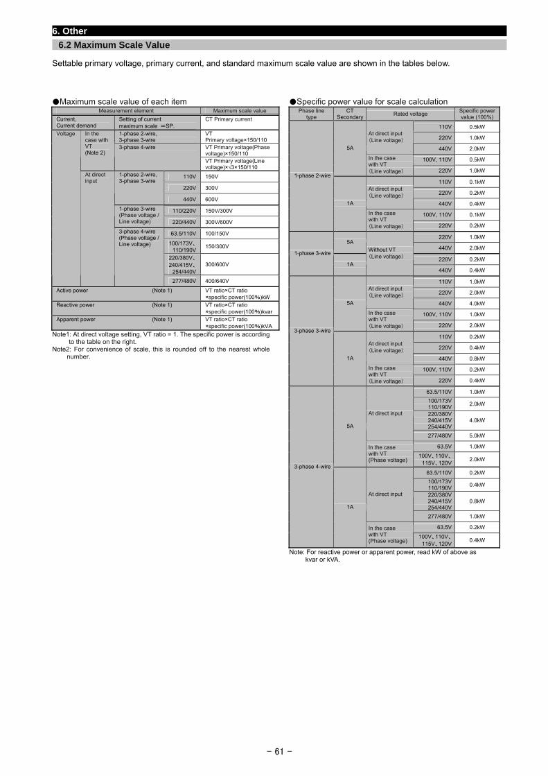
- 61 -
6. Other
6.2 Maximum Scale Value
Settable primary voltage, primary current, and standard maximum scale value are shown in the tables below.
Maximum scale value of each item Measurement element Maximum scale value
Current, Current demand
Setting of current maximum scale =SP.
CT Primary current
1-phase 2-wire, 3-phase 3-wire
VT Primary voltage×150/110 VT Primary voltage(Phase voltage)×150/110
In the case with VT (Note 2)
3-phase 4-wire
VT Primary voltage(Line voltage)×√3×150/110
110V 150V
220V 300V
1-phase 2-wire, 3-phase 3-wire
440V 600V
110/220V 150V/300V 1-phase 3-wire (Phase voltage / Line voltage) 220/440V 300V/600V
63.5/110V 100/150V
100/173V、 110/190V
150/300V
220/380V、 240/415V、
254/440V 300/600V
Voltage
At direct input
3-phase 4-wire (Phase voltage / Line voltage)
277/480V 400/640V
Active power (Note 1) VT ratio×CT ratio ×specific power(100%)kW
Reactive power (Note 1) VT ratio×CT ratio ×specific power(100%)kvar
Apparent power (Note 1) VT ratio×CT ratio ×specific power(100%)kVA
Note1: At direct voltage setting, VT ratio = 1. The specific power is according to the table on the right.
Note2: For convenience of scale, this is rounded off to the nearest whole number.
Specific power value for scale calculation Phase line
type CT
SecondaryRated voltage
Specific power value (100%)
110V 0.5kW
220V 1.0kW At direct input (Line voltage)
440V 2.0kW
100V, 110V 0.5kW
5A
In the case with VT (Line voltage) 220V 1.0kW
110V 0.1kW
220V 0.2kW At direct input (Line voltage)
440V 0.4kW
100V, 110V 0.1kW
1-phase 2-wire
1A
In the case with VT (Line voltage) 220V 0.2kW
220V 1.0kW 5A
440V 2.0kW
220V 0.2kW 1-phase 3-wire
1A
Without VT (Line voltage)
440V 0.4kW
110V 1.0kW
220V 2.0kW At direct input (Line voltage)
440V 4.0kW
100V, 110V 1.0kW
5A
In the case with VT (Line voltage) 220V 2.0kW
110V 0.2kW
220V 0.4kW At direct input (Line voltage)
440V 0.8kW
100V, 110V 0.2kW
3-phase 3-wire
1A
In the case with VT (Line voltage) 220V 0.4kW
63.5/110V 1.0kW
100/173V 110/190V
2.0kW
220/380V 240/415V 254/440V
4.0kW At direct input
277/480V 5.0kW
63.5V 1.0kW
5A
In the case with VT (Phase voltage)
100V、110V、 115V、120V
2.0kW
63.5/110V 0.2kW
100/173V 110/190V
0.4kW
220/380V 240/415V 254/440V
0.8kW At direct input
277/480V 1.0kW
63.5V 0.2kW
3-phase 4-wire
1A
In the case with VT (Phase voltage)
100V、110V、 115V、120V
0.4kW
Note: For reactive power or apparent power, read kW of above as kvar or kVA.
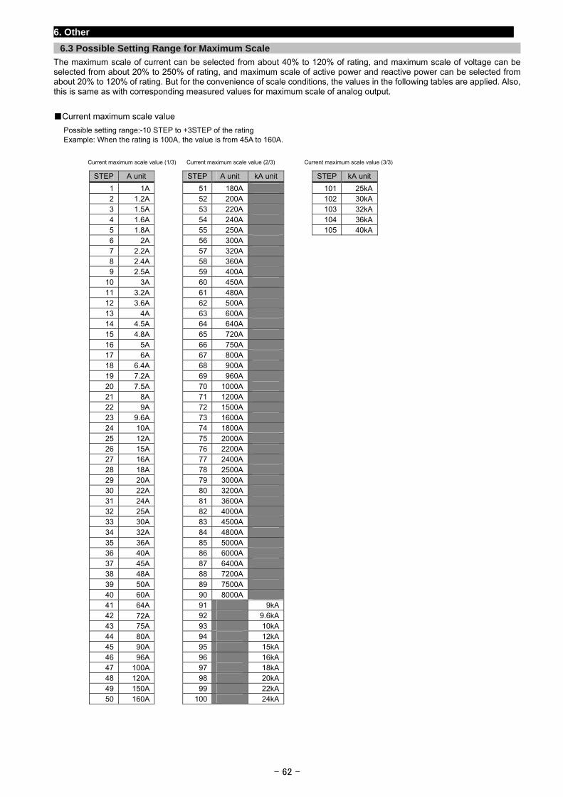
- 62 -
6. Other
6.3 Possible Setting Range for Maximum Scale
The maximum scale of current can be selected from about 40% to 120% of rating, and maximum scale of voltage can be selected from about 20% to 250% of rating, and maximum scale of active power and reactive power can be selected from about 20% to 120% of rating. But for the convenience of scale conditions, the values in the following tables are applied. Also, this is same as with corresponding measured values for maximum scale of analog output.
Current maximum scale value
Possible setting range:-10 STEP to +3STEP of the rating Example: When the rating is 100A, the value is from 45A to 160A.
Current maximum scale value (1/3) Current maximum scale value (2/3) Current maximum scale value (3/3)
STEP A unit STEP A unit kA unit STEP kA unit
1 1A 51 180A 101 25kA2 1.2A 52 200A 102 30kA3 1.5A 53 220A 103 32kA4 1.6A 54 240A 104 36kA5 1.8A 55 250A 105 40kA6 2A 56 300A
7 2.2A 57 320A
8 2.4A 58 360A
9 2.5A 59 400A
10 3A 60 450A
11 3.2A 61 480A
12 3.6A 62 500A
13 4A 63 600A
14 4.5A 64 640A
15 4.8A 65 720A
16 5A 66 750A
17 6A 67 800A
18 6.4A 68 900A
19 7.2A 69 960A
20 7.5A 70 1000A
21 8A 71 1200A
22 9A 72 1500A
23 9.6A 73 1600A
24 10A 74 1800A
25 12A 75 2000A
26 15A 76 2200A
27 16A 77 2400A
28 18A 78 2500A
29 20A 79 3000A
30 22A 80 3200A
31 24A 81 3600A
32 25A 82 4000A
33 30A 83 4500A
34 32A 84 4800A
35 36A 85 5000A
36 40A 86 6000A
37 45A 87 6400A
38 48A 88 7200A
39 50A 89 7500A
40 60A 90 8000A
41 64A 91 9kA
42 72A 92 9.6kA
43 75A 93 10kA
44 80A 94 12kA
45 90A 95 15kA
46 96A 96 16kA
47 100A 97 18kA
48 120A 98 20kA
49 150A 99 22kA
50 160A 100 24kA
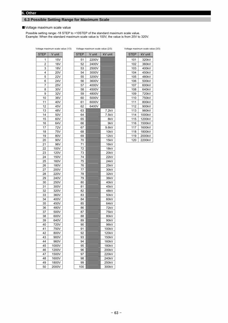
- 63 -
6. Other
6.3 Possible Setting Range for Maximum Scale
Voltage maximum scale value
Possible setting range:-18 STEP to +10STEP of the standard maximum scale value. Example: When the standard maximum scale value is 100V, the value is from 20V to 320V.
Voltage maximum scale value (1/3) Voltage maximum scale value (2/3) Voltage maximum scale value (3/3)
STEP V unit STEP V unit kV unit STEP kV unit
1 15V 51 2200V 101 320kV
2 16V 52 2400V 102 360kV3 18V 53 2500V 103 400kV4 20V 54 3000V 104 450kV5 22V 55 3200V 105 480kV6 24V 56 3600V 106 500kV7 25V 57 4000V 107 600kV8 30V 58 4500V 108 640kV9 32V 59 4800V 109 720kV
10 36V 60 5000V 110 750kV11 40V 61 6000V 111 800kV12 45V 62 6400V 112 900kV13 48V 63 7.2kV 113 960kV14 50V 64 7.5kV 114 1000kV15 60V 65 8kV 115 1200kV16 64V 66 9kV 116 1500kV17 72V 67 9.6kV 117 1600kV18 75V 68 10kV 118 1800kV19 80V 69 12kV 119 2000kV20 90V 70 15kV 120 2200kV21 96V 71 16kV
22 100V 72 18kV
23 120V 73 20kV
24 150V 74 22kV
25 160V 75 24kV
26 180V 76 25kV
27 200V 77 30kV
28 220V 78 32kV
29 240V 79 36kV
30 250V 80 40kV
31 300V 81 45kV
32 320V 82 48kV
33 360V 83 50kV
34 400V 84 60kV
35 450V 85 64kV
36 480V 86 72kV
37 500V 87 75kV
38 600V 88 80kV
39 640V 89 90kV
40 720V 90 96kV
41 750V 91 100kV
42 800V 92 120kV
43 900V 93 150kV
44 960V 94 160kV
45 1000V 95 180kV
46 1200V 96 200kV
47 1500V 97 220kV
48 1600V 98 240kV
49 1800V 99 250kV
50 2000V 100 300kV
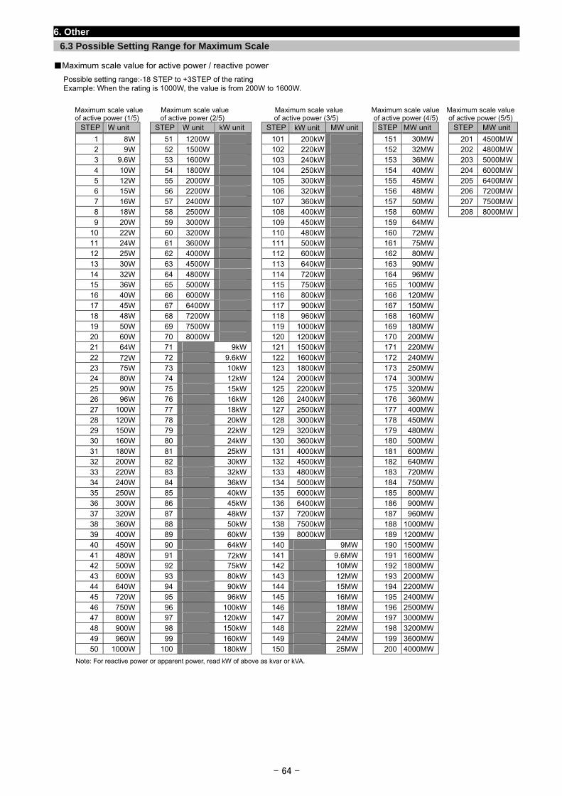
- 64 -
6. Other
6.3 Possible Setting Range for Maximum Scale
Maximum scale value for active power / reactive power
Possible setting range:-18 STEP to +3STEP of the rating Example: When the rating is 1000W, the value is from 200W to 1600W.
Maximum scale value Maximum scale value Maximum scale value Maximum scale value Maximum scale value of active power (1/5) of active power (2/5) of active power (3/5) of active power (4/5) of active power (5/5)
STEP W unit STEP W unit kW unit STEP kW unit MW unit STEP MW unit STEP MW unit
1 8W 51 1200W 101 200kW 151 30MW 201 4500MW2 9W 52 1500W 102 220kW 152 32MW 202 4800MW3 9.6W 53 1600W 103 240kW 153 36MW 203 5000MW4 10W 54 1800W 104 250kW 154 40MW 204 6000MW5 12W 55 2000W 105 300kW 155 45MW 205 6400MW6 15W 56 2200W 106 320kW 156 48MW 206 7200MW7 16W 57 2400W 107 360kW 157 50MW 207 7500MW8 18W 58 2500W 108 400kW 158 60MW 208 8000MW9 20W 59 3000W 109 450kW 159 64MW
10 22W 60 3200W 110 480kW 160 72MW
11 24W 61 3600W 111 500kW 161 75MW
12 25W 62 4000W 112 600kW 162 80MW
13 30W 63 4500W 113 640kW 163 90MW
14 32W 64 4800W 114 720kW 164 96MW
15 36W 65 5000W 115 750kW 165 100MW
16 40W 66 6000W 116 800kW 166 120MW
17 45W 67 6400W 117 900kW 167 150MW
18 48W 68 7200W 118 960kW 168 160MW
19 50W 69 7500W 119 1000kW 169 180MW
20 60W 70 8000W 120 1200kW 170 200MW
21 64W 71 9kW 121 1500kW 171 220MW
22 72W 72 9.6kW 122 1600kW 172 240MW
23 75W 73 10kW 123 1800kW 173 250MW
24 80W 74 12kW 124 2000kW 174 300MW
25 90W 75 15kW 125 2200kW 175 320MW
26 96W 76 16kW 126 2400kW 176 360MW
27 100W 77 18kW 127 2500kW 177 400MW
28 120W 78 20kW 128 3000kW 178 450MW
29 150W 79 22kW 129 3200kW 179 480MW
30 160W 80 24kW 130 3600kW 180 500MW
31 180W 81 25kW 131 4000kW 181 600MW
32 200W 82 30kW 132 4500kW 182 640MW
33 220W 83 32kW 133 4800kW 183 720MW
34 240W 84 36kW 134 5000kW 184 750MW
35 250W 85 40kW 135 6000kW 185 800MW
36 300W 86 45kW 136 6400kW 186 900MW
37 320W 87 48kW 137 7200kW 187 960MW
38 360W 88 50kW 138 7500kW 188 1000MW
39 400W 89 60kW 139 8000kW 189 1200MW
40 450W 90 64kW 140 9MW 190 1500MW
41 480W 91 72kW 141 9.6MW 191 1600MW
42 500W 92 75kW 142 10MW 192 1800MW
43 600W 93 80kW 143 12MW 193 2000MW
44 640W 94 90kW 144 15MW 194 2200MW
45 720W 95 96kW 145 16MW 195 2400MW
46 750W 96 100kW 146 18MW 196 2500MW
47 800W 97 120kW 147 20MW 197 3000MW
48 900W 98 150kW 148 22MW 198 3200MW
49 960W 99 160kW 149 24MW 199 3600MW
50 1000W 100 180kW 150 25MW 200 4000MW
Note: For reactive power or apparent power, read kW of above as kvar or kVA.
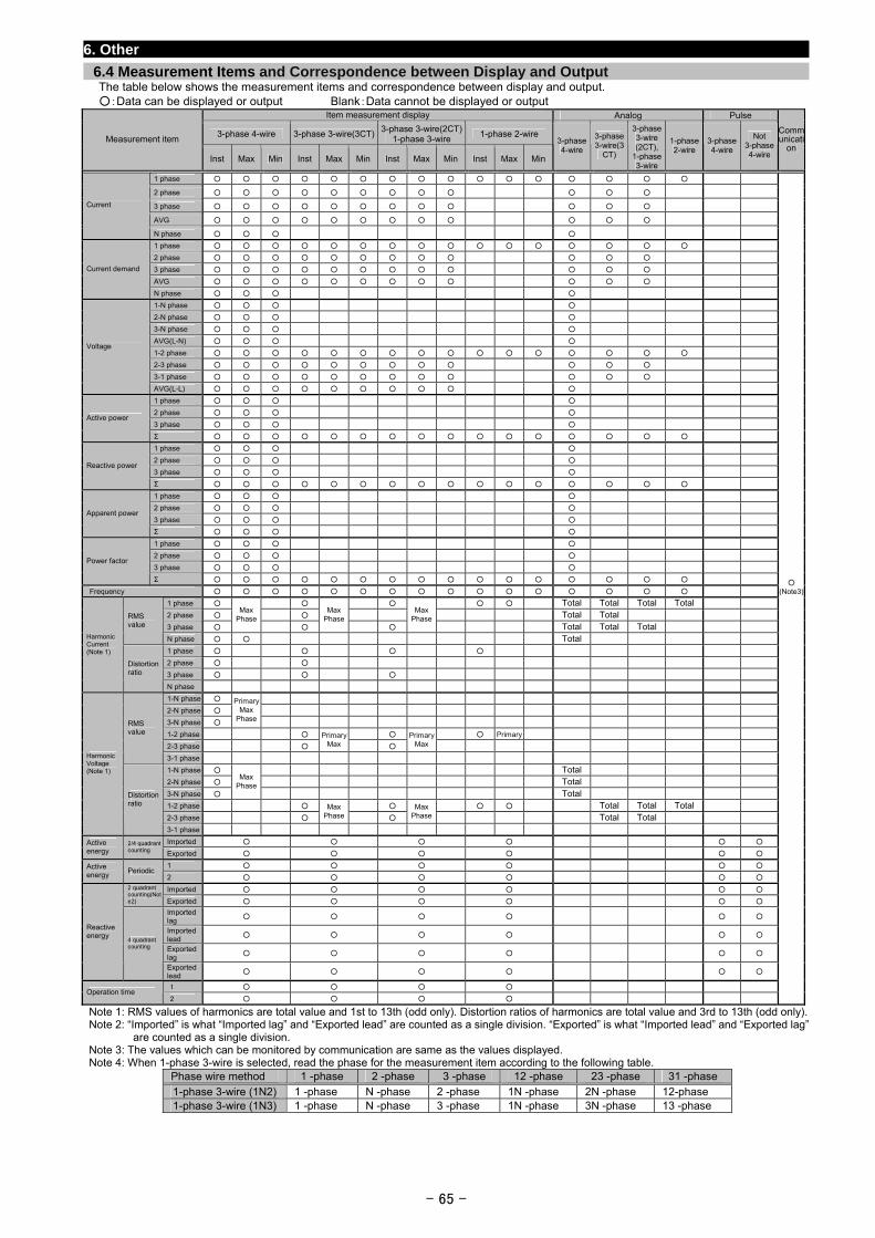
- 65 -
6. Other
6.4 Measurement Items and Correspondence between Display and Output The table below shows the measurement items and correspondence between display and output. :Data can be displayed or output Blank:Data cannot be displayed or output
Item measurement display Analog Pulse
3-phase 4-wire 3-phase 3-wire(3CT)3-phase 3-wire(2CT)
1-phase 3-wire 1-phase 2-wire
Measurement item
Inst Max Min Inst Max Min Inst Max Min Inst Max Min
3-phase 4-wire
3-phase 3-wire(3
CT)
3-phase 3-wire (2CT),
1-phase 3-wire
1-phase 2-wire
3-phase 4-wire
Not 3-phase 4-wire
Communicati
on
1 phase
2 phase
3 phase
AVG
Current
N phase
1 phase
2 phase
3 phase
AVG
Current demand
N phase
1-N phase
2-N phase
3-N phase
AVG(L-N)
1-2 phase
2-3 phase
3-1 phase
Voltage
AVG(L-L)
1 phase
2 phase
3 phase Active power
Σ
1 phase
2 phase
3 phase Reactive power
Σ
1 phase
2 phase
3 phase Apparent power
Σ
1 phase
2 phase
3 phase Power factor
Σ
Frequency
1 phase Total Total Total Total
2 phase Total Total
3 phase
Max Phase
Max Phase
MaxPhase
Total Total Total
RMS value
N phase Total
1 phase
2 phase
3 phase
Harmonic Current (Note 1)
Distortion ratio
N phase
1-N phase
2-N phase
3-N phase
PrimaryMax
Phase
1-2 phase Primary
2-3 phase
Primary Max
PrimaryMax
RMS value
3-1 phase
1-N phase Total
2-N phase Total
3-N phase
Max Phase
Total
1-2 phase Total Total Total
2-3 phase
Max Phase
MaxPhase Total Total
Harmonic Voltage (Note 1)
Distortion ratio
3-1 phase
Imported Active energy
2/4 quadrant counting Exported
1 Active energy
Periodic 2
Imported 2 quadrant counting(Note2) Exported
Imported lag
Imported lead
Exported lag
Reactive energy
4 quadrant counting
Exported lead
1 Operation time
2
(Note3)
Note 1: RMS values of harmonics are total value and 1st to 13th (odd only). Distortion ratios of harmonics are total value and 3rd to 13th (odd only). Note 2: “Imported” is what “Imported lag” and “Exported lead” are counted as a single division. “Exported” is what “Imported lead” and “Exported lag”
are counted as a single division. Note 3: The values which can be monitored by communication are same as the values displayed. Note 4: When 1-phase 3-wire is selected, read the phase for the measurement item according to the following table.
Phase wire method 1 -phase 2 -phase 3 -phase 12 -phase 23 -phase 31 -phase
1-phase 3-wire (1N2) 1 -phase N -phase 2 -phase 1N -phase 2N -phase 12-phase 1-phase 3-wire (1N3) 1 -phase N -phase 3 -phase 1N -phase 3N -phase 13 -phase
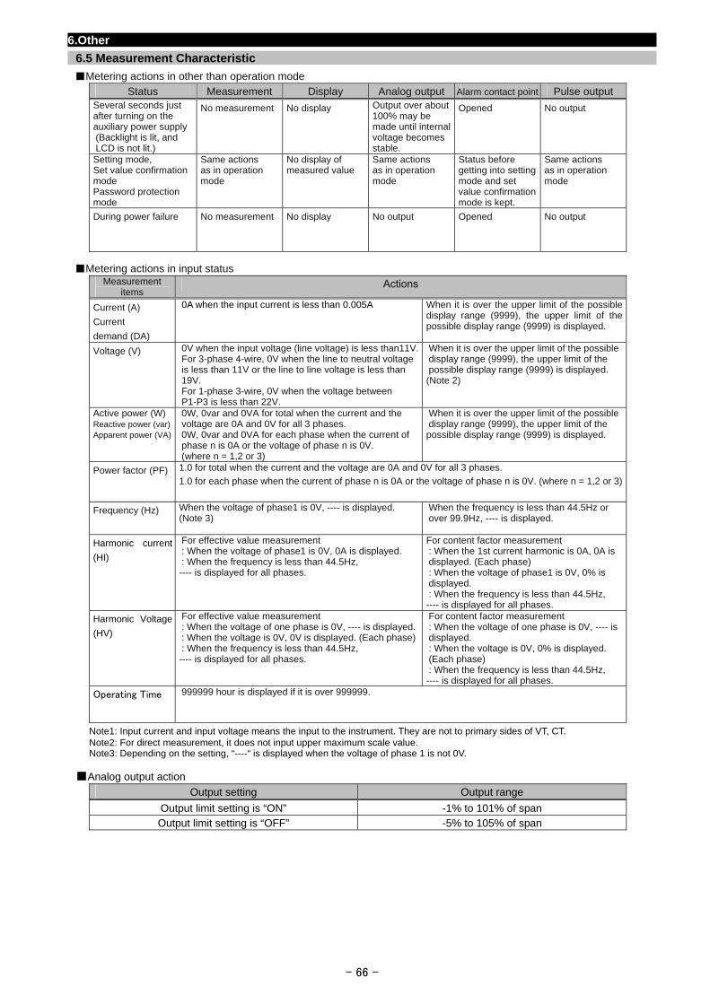
6.Other
6.5 Measurement Characteristic
Metering actions in other than operation mode
Status Measurement Display Analog output Alarm contact point Pulse output Several seconds just after turning on the auxiliary power supply (Backlight is lit, and LCD is not lit.)
No measurement No display Output over about 100% may be made until internal voltage becomes stable.
Opened No output
Setting mode, Set value confirmation mode Password protection mode
Same actions as in operation mode
No display of measured value
Same actions as in operation mode
Status before getting into setting mode and set value confirmation mode is kept.
Same actions as in operation mode
During power failure
No measurement No display No output Opened No output
Metering actions in input status
Measurement items
Actions
Current (A)
Current
demand (DA)
0A when the input current is less than 0.005A
When it is over the upper limit of the possible display range (9999), the upper limit of the possible display range (9999) is displayed.
Voltage (V) 0V when the input voltage (line voltage) is less than11V.For 3-phase 4-wire, 0V when the line to neutral voltage is less than 11V or the line to line voltage is less than 19V. For 1-phase 3-wire, 0V when the voltage between P1-P3 is less than 22V.
When it is over the upper limit of the possibledisplay range (9999), the upper limit of the possible display range (9999) is displayed. (Note 2)
Active power (W) Reactive power (var) Apparent power (VA)
0W, 0var and 0VA for total when the current and the voltage are 0A and 0V for all 3 phases. 0W, 0var and 0VA for each phase when the current of phase n is 0A or the voltage of phase n is 0V. (where n = 1,2 or 3)
When it is over the upper limit of the possibledisplay range (9999), the upper limit of the possible display range (9999) is displayed.
Power factor (PF) 1.0 for total when the current and the voltage are 0A and 0V for all 3 phases.
1.0 for each phase when the current of phase n is 0A or the voltage of phase n is 0V. (where n = 1,2 or 3)
Frequency (Hz) When the voltage of phase1 is 0V, ---- is displayed. (Note 3)
When the frequency is less than 44.5Hz or over 99.9Hz, ---- is displayed.
Harmonic current
(HI)
For effective value measurement : When the voltage of phase1 is 0V, 0A is displayed. : When the frequency is less than 44.5Hz, ---- is displayed for all phases.
For content factor measurement : When the 1st current harmonic is 0A, 0A is displayed. (Each phase) : When the voltage of phase1 is 0V, 0% is displayed. : When the frequency is less than 44.5Hz, ---- is displayed for all phases.
Harmonic Voltage
(HV)
For effective value measurement : When the voltage of one phase is 0V, ---- is displayed.: When the voltage is 0V, 0V is displayed. (Each phase): When the frequency is less than 44.5Hz, ---- is displayed for all phases.
For content factor measurement : When the voltage of one phase is 0V, ---- is displayed. : When the voltage is 0V, 0% is displayed. (Each phase) : When the frequency is less than 44.5Hz, ---- is displayed for all phases.
Operating Time 999999 hour is displayed if it is over 999999.
Note1: Input current and input voltage means the input to the instrument. They are not to primary sides of VT, CT. Note2: For direct measurement, it does not input upper maximum scale value. Note3: Depending on the setting, “----“ is displayed when the voltage of phase 1 is not 0V.
Analog output action
Output setting Output range
Output limit setting is “ON” -1% to 101% of span Output limit setting is “OFF” -5% to 105% of span
- 66 -
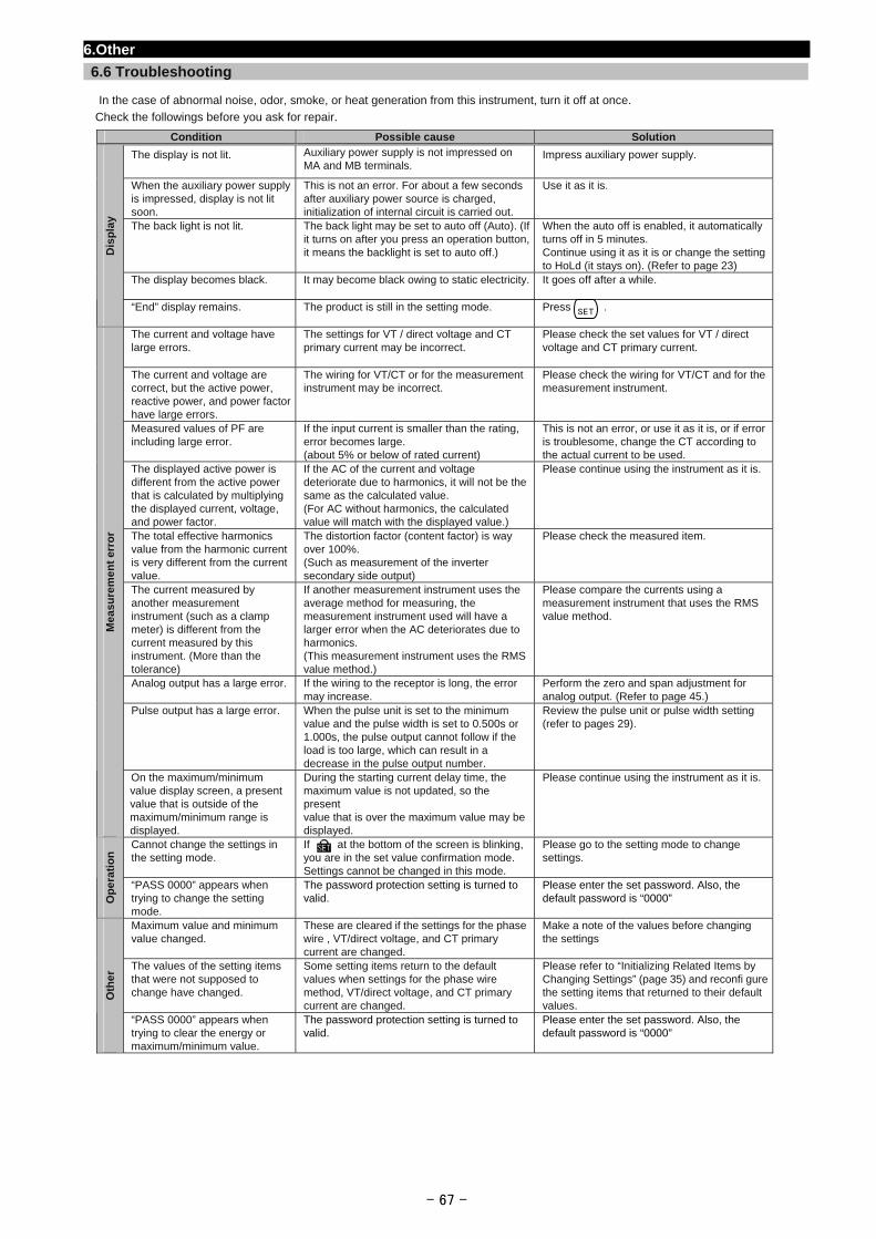
6.Other
6.6 Troubleshooting
In the case of abnormal noise, odor, smoke, or heat generation from this instrument, turn it off at once.
Check the followings before you ask for repair.
Condition Possible cause Solution
The display is not lit.
Auxiliary power supply is not impressed on MA and MB terminals.
Impress auxiliary power supply.
When the auxiliary power supply is impressed, display is not lit soon.
This is not an error. For about a few seconds after auxiliary power source is charged, initialization of internal circuit is carried out.
Use it as it is.
The back light is not lit. The back light may be set to auto off (Auto). (If it turns on after you press an operation button, it means the backlight is set to auto off.)
When the auto off is enabled, it automatically turns off in 5 minutes. Continue using it as it is or change the setting to HoLd (it stays on). (Refer to page 23)
The display becomes black.
It may become black owing to static electricity. It goes off after a while.
Dis
pla
y
“End” display remains.
The product is still in the setting mode. Press .
The current and voltage have large errors.
The settings for VT / direct voltage and CT primary current may be incorrect.
Please check the set values for VT / direct voltage and CT primary current.
The current and voltage are correct, but the active power, reactive power, and power factor have large errors.
The wiring for VT/CT or for the measurement instrument may be incorrect.
Please check the wiring for VT/CT and for the measurement instrument.
Measured values of PF are including large error.
If the input current is smaller than the rating, error becomes large. (about 5% or below of rated current)
This is not an error, or use it as it is, or if error is troublesome, change the CT according to the actual current to be used.
The displayed active power is different from the active power that is calculated by multiplying the displayed current, voltage, and power factor.
If the AC of the current and voltage deteriorate due to harmonics, it will not be the same as the calculated value. (For AC without harmonics, the calculated value will match with the displayed value.)
Please continue using the instrument as it is.
The total effective harmonics value from the harmonic current is very different from the current value.
The distortion factor (content factor) is way over 100%. (Such as measurement of the inverter secondary side output)
Please check the measured item.
The current measured by another measurement instrument (such as a clamp meter) is different from the current measured by this instrument. (More than the tolerance)
If another measurement instrument uses the average method for measuring, the measurement instrument used will have a larger error when the AC deteriorates due to harmonics. (This measurement instrument uses the RMS value method.)
Please compare the currents using a measurement instrument that uses the RMS value method.
Analog output has a large error.
If the wiring to the receptor is long, the error may increase.
Perform the zero and span adjustment for analog output. (Refer to page 45.)
Pulse output has a large error. When the pulse unit is set to the minimum value and the pulse width is set to 0.500s or 1.000s, the pulse output cannot follow if the load is too large, which can result in a decrease in the pulse output number.
Review the pulse unit or pulse width setting (refer to pages 29).
Me
as
ure
me
nt
err
or
On the maximum/minimum value display screen, a present value that is outside of the maximum/minimum range is displayed.
During the starting current delay time, the maximum value is not updated, so the present value that is over the maximum value may be displayed.
Please continue using the instrument as it is.
Cannot change the settings in the setting mode.
If at the bottom of the screen is blinking, you are in the set value confirmation mode. Settings cannot be changed in this mode.
Please go to the setting mode to change settings.
Op
era
tio
n
“PASS 0000” appears when trying to change the setting mode.
The password protection setting is turned to valid.
Please enter the set password. Also, the default password is “0000”
Maximum value and minimum value changed.
These are cleared if the settings for the phasewire , VT/direct voltage, and CT primary current are changed.
Make a note of the values before changing the settings
The values of the setting items that were not supposed to change have changed.
Some setting items return to the default values when settings for the phase wire method, VT/direct voltage, and CT primary current are changed.
Please refer to “Initializing Related Items by Changing Settings” (page 35) and reconfi gure the setting items that returned to their default values.
Oth
er
“PASS 0000” appears when trying to clear the energy or maximum/minimum value.
The password protection setting is turned to valid.
Please enter the set password. Also, the default password is “0000”
SET
- 67 -
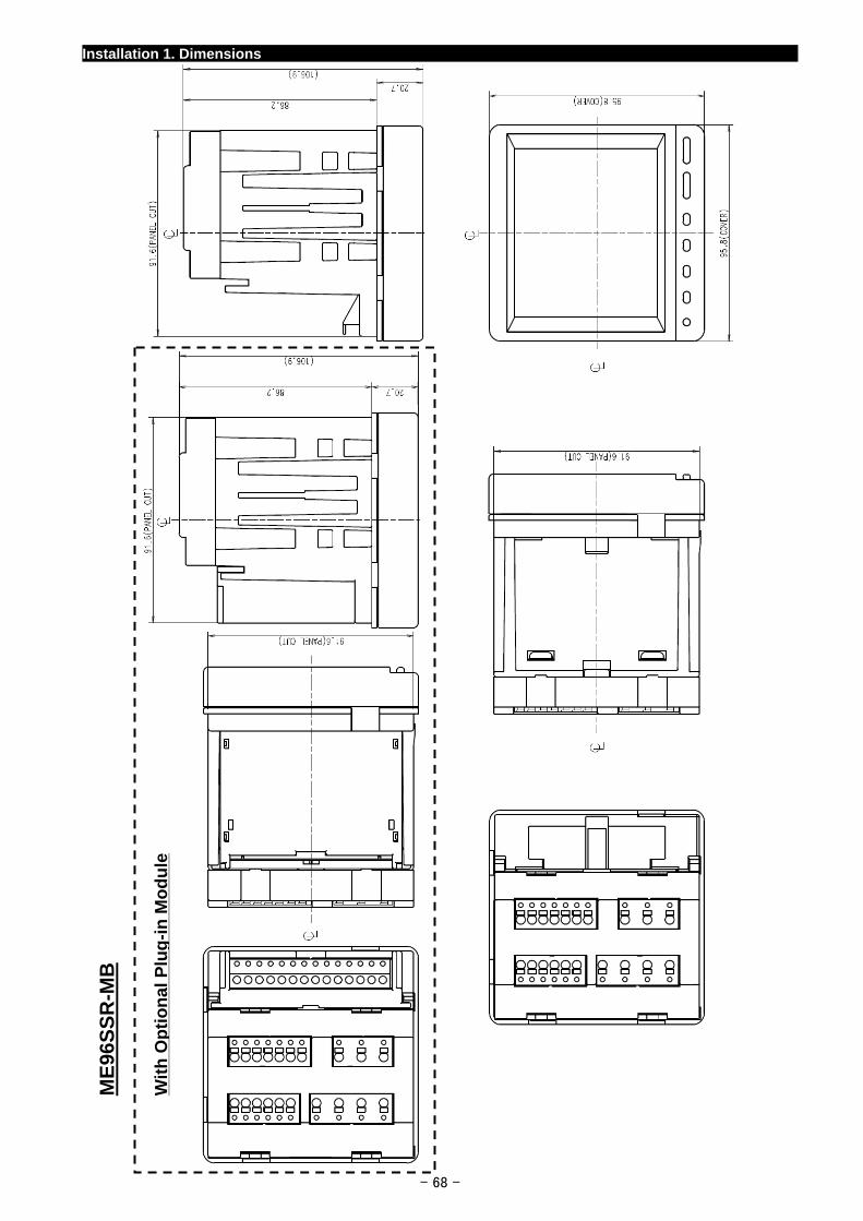
Installation 1. Dimensions
- 68 -
Wit
h O
pti
on
al P
lug
-in
Mo
du
le
ME
96S
SR
-MB
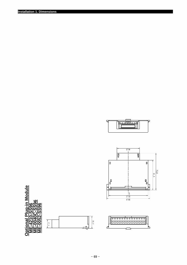
Installation 1. Dimensions
Op
tio
nal
Plu
g-i
n M
od
ule
ME
-421
0-S
S96
ME
-004
0C-S
S96
ME
-005
2-S
S96
- 69 -
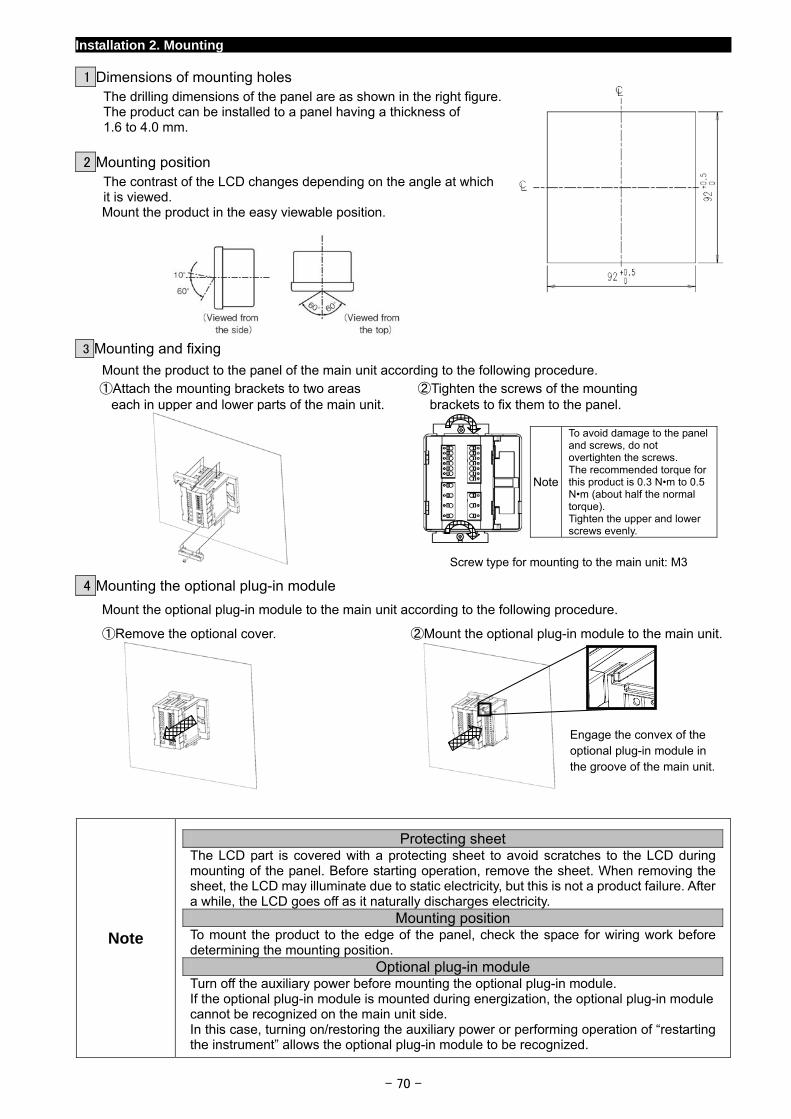
Installation 2. Mounting
1 Dimensions of mounting holes
The drilling dimensions of the panel are as shown in the right figure.
- 70 -
The product can be installed to a panel having a thickness of 1.6 to 4.0 mm.
2 Mounting position
The contrast of the LCD changes depending on the angle at which it is viewed. Mount the product in the easy viewable position.
3 Mounting and fixing
Mount the product to the panel of the main unit according to the following procedure. ①Attach the mounting brackets to two areas
each in upper and lower parts of the main unit.②Tighten the screws of the mounting
brackets to fix them to the panel.
4 Mounting the optional plug-in module
Mount the optional plug-in module to the main unit according to the following procedure.
①Remove the optional cover. ②Mount the optional plug-in module to the main unit.
Note
Protecting sheet The LCD part is covered with a protecting sheet to avoid scratches to the LCD during mounting of the panel. Before starting operation, remove the sheet. When removing the sheet, the LCD may illuminate due to static electricity, but this is not a product failure. After a while, the LCD goes off as it naturally discharges electricity.
Mounting position To mount the product to the edge of the panel, check the space for wiring work before determining the mounting position.
Optional plug-in module Turn off the auxiliary power before mounting the optional plug-in module. If the optional plug-in module is mounted during energization, the optional plug-in module cannot be recognized on the main unit side. In this case, turning on/restoring the auxiliary power or performing operation of “restarting the instrument” allows the optional plug-in module to be recognized.
Engage the convex of the optional plug-in module in the groove of the main unit.
Note
To avoid damage to the panel and screws, do not overtighten the screws. The recommended torque for this product is 0.3 N•m to 0.5 N•m (about half the normal torque). Tighten the upper and lower screws evenly.
Screw type for mounting to the main unit: M3
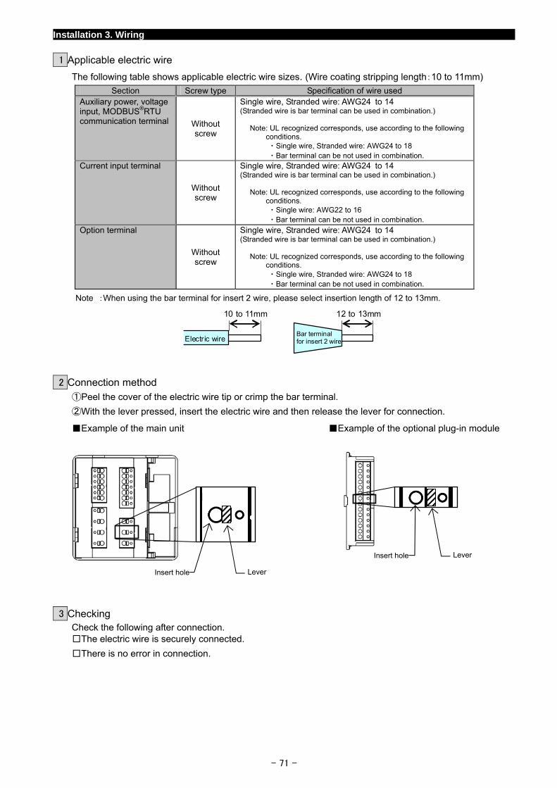
Installation 3. Wiring
1 Applicable electric wire
The following table shows applicable electric wire sizes. (Wire coating stripping length:10 to 11mm)
Section Screw type Specification of wire used Auxiliary power, voltage input, MODBUS®RTU communication terminal Without
screw
Single wire, Stranded wire: AWG24 to 14 (Stranded wire is bar terminal can be used in combination.)
Note: UL recognized corresponds, use according to the following conditions. ・Single wire, Stranded wire: AWG24 to 18 ・Bar terminal can be not used in combination.
Current input terminal
Without screw
Single wire, Stranded wire: AWG24 to 14 (Stranded wire is bar terminal can be used in combination.)
Note: UL recognized corresponds, use according to the following conditions. ・Single wire: AWG22 to 16 ・Bar terminal can be not used in combination.
Option terminal
Without screw
Single wire, Stranded wire: AWG24 to 14 (Stranded wire is bar terminal can be used in combination.)
Note: UL recognized corresponds, use according to the following conditions. ・Single wire, Stranded wire: AWG24 to 18 ・Bar terminal can be not used in combination.
Note :When using the bar terminal for insert 2 wire, please select insertion length of 12 to 13mm.
Electric wire
10 to 11mm
Bar terminal for insert 2 wire
12 to 13mm
2 Connection method
①Peel the cover of the electric wire tip or crimp the bar terminal.
②With the lever pressed, insert the electric wire and then release the lever for connection.
Example of the main unit Example of the optional plug-in module
- 71 -
Insert hole
LeverInsert hole
Lever
3 Checking
Check the following after connection. The electric wire is securely connected.
There is no error in connection.
Installation 3. Wiring
CAUTION
Do not work with hot-line jobs
Do not connect hot-line jobs. It may cause electric shock, burns, device burn out, or fire. It is recommended that a protection fuse be used for VT and the auxiliary power source.
Do not open the secondary side of the CT circuit
Connect the CT secondary side signal correctly to the terminal for CT connection. If the CT is not connected properly or if the secondary side of the CT is open, it may result in high voltage on the secondary side of the CT, the insulation of the secondary winding wire may be damaged, and burnout may be caused.
Do not short the secondary side of the VT circuit
Connect the VT secondary side signal correctly to the terminal for VT connection. If the VT is not connected properly or if the secondary side of the VT shorts, over current may flow to the secondary side of the VT, which can burn out the secondary winding wire. If the secondary winding wire burns out, it can damage the insulation of the primary winding wire, resulting in a short between phases.
Make sure connections to the connection terminals are tight
Electrical wires must be properly tightened to the connection terminal. Otherwise, heat and measurement errors may be caused.
Do not forget wiring of “C1”,”C2” and “C3” for pass.
When the L side of CT circuit is common wire, it is necessary to short-circuit “C1”,”C2”, and “C3” terminal of this device.
Do not use improper electrical wires
Make sure that the electrical wires have the proper rating for current and voltage. If inappropriate electrical wires are used, fire may be caused.
Do not pull the connection wires with force
If the terminal wiring is pulled with a strong force, the output portion may detach. (Tensile load: 39.2N or less)
Do not apply an abnormal voltage.
If a pressure test is given to a high-pressure device, a ground must be used in order to avoid damaging this measurement instrument. If a high voltage of AC2000V is applied for over one minute to the measurement instrument, damage may occur.
Do not connect to Non-Connection (NC) terminal.
Do not connect to Non-Connection (NC) terminals for the purpose of relay etc.
Use the proper voltage for the auxiliary power source.
Use the proper voltage for the auxiliary power source terminal. If an improper voltage is used, the instrument may be damaged or fire may be caused.
- 72 -
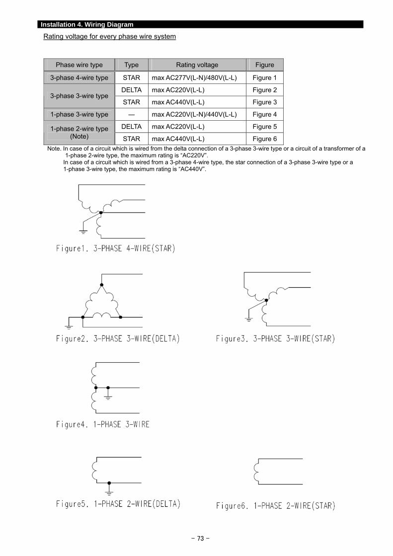
- 73 -
Installation 4. Wiring Diagram
Rating voltage for every phase wire system
Phase wire type Type Rating voltage Figure
3-phase 4-wire type STAR max AC277V(L-N)/480V(L-L) Figure 1
DELTA max AC220V(L-L) Figure 2 3-phase 3-wire type
STAR max AC440V(L-L) Figure 3
1-phase 3-wire type ― max AC220V(L-N)/440V(L-L) Figure 4
DELTA max AC220V(L-L) Figure 5 1-phase 2-wire type (Note) STAR max AC440V(L-L) Figure 6
Note. In case of a circuit which is wired from the delta connection of a 3-phase 3-wire type or a circuit of a transformer of a 1-phase 2-wire type, the maximum rating is “AC220V”.
In case of a circuit which is wired from a 3-phase 4-wire type, the star connection of a 3-phase 3-wire type or a 1-phase 3-wire type, the maximum rating is “AC440V”.
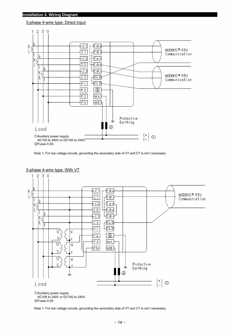
Installation 4. Wiring Diagram
3-phase 4-wire type: Direct input
①Auxiliary power supply AC100 to 240V or DC100 to 240V.
②Fuses 0.5A
Note 1: For low voltage circuits, grounding the secondary side of VT and CT is not t necessary.
3-phase 4-wire type: With VT
①Auxiliary power supply AC100 to 240V or DC100 to 240V.
②Fuses 0.5A Note 1: For low voltage circuits, grounding the secondary side of VT and CT is not t necessary.
- 74 -
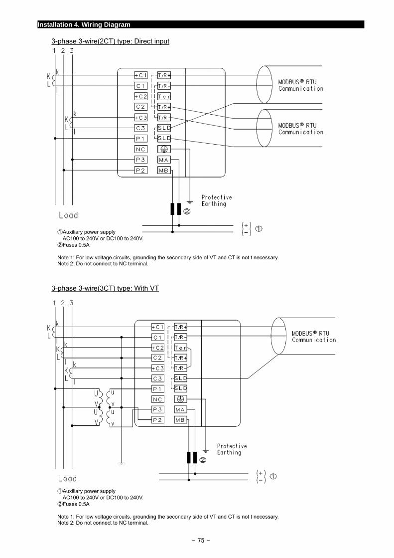
Installation 4. Wiring Diagram
3-phase 3-wire(2CT) type: Direct input
①Auxiliary power supply AC100 to 240V or DC100 to 240V.
②Fuses 0.5A Note 1: For low voltage circuits, grounding the secondary side of VT and CT is not t necessary. Note 2: Do not connect to NC terminal.
3-phase 3-wire(3CT) type: With VT
①Auxiliary power supply AC100 to 240V or DC100 to 240V.
②Fuses 0.5A Note 1: For low voltage circuits, grounding the secondary side of VT and CT is not t necessary. Note 2: Do not connect to NC terminal.
- 75 -
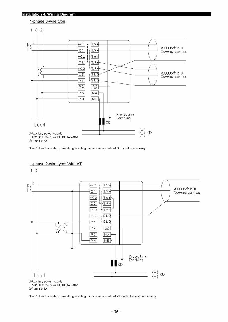
Installation 4. Wiring Diagram
1-phase 3-wire type
①Auxiliary power supply AC100 to 240V or DC100 to 240V.
②Fuses 0.5A Note 1: For low voltage circuits, grounding the secondary side of CT is not t necessary
1-phase 2-wire type: With VT
①Auxiliary power supply AC100 to 240V or DC100 to 240V.
②Fuses 0.5A Note 1: For low voltage circuits, grounding the secondary side of VT and CT is not t necessary.
- 76 -
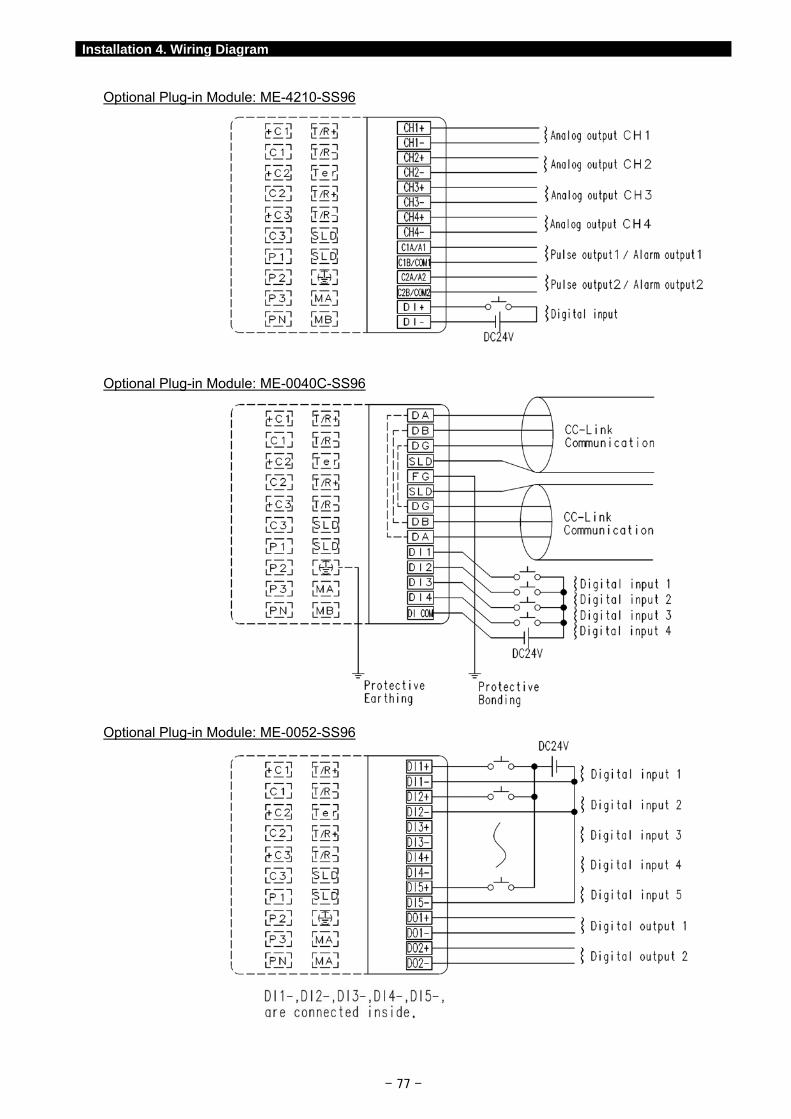
- 77 -
Installation 4. Wiring Diagram
Optional Plug-in Module: ME-4210-SS96
Optional Plug-in Module: ME-0040C-SS96
Optional Plug-in Module: ME-0052-SS96
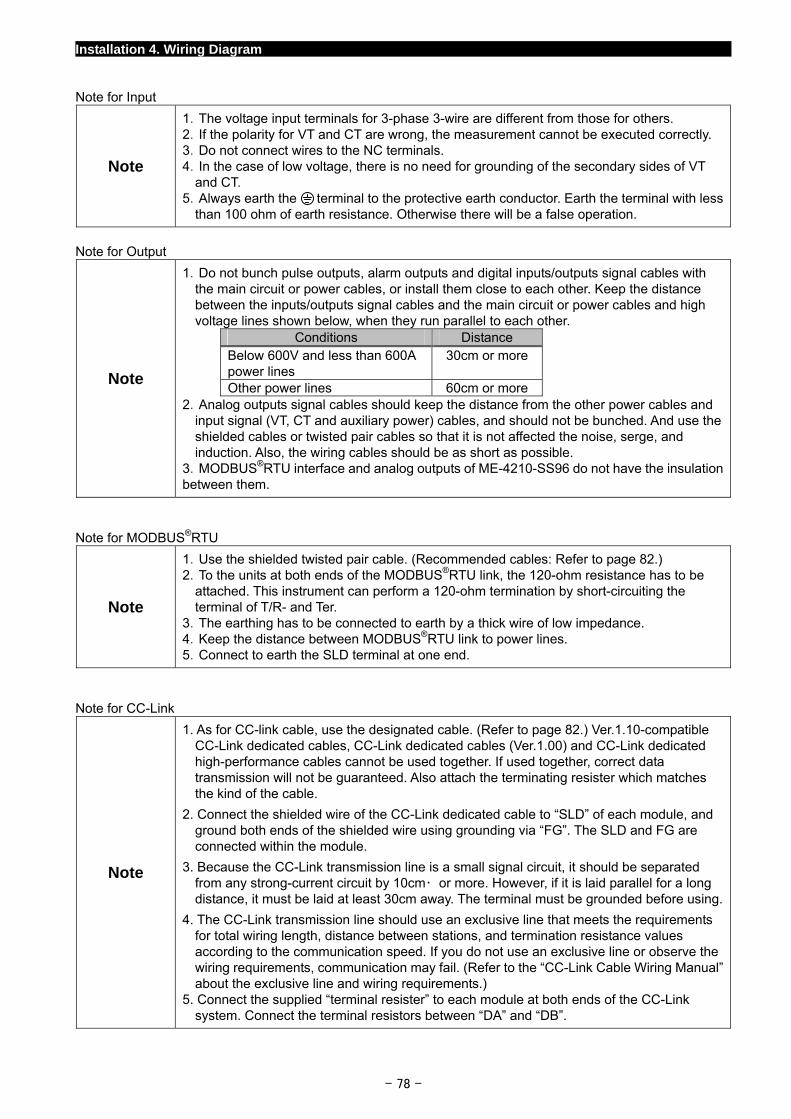
Installation 4. Wiring Diagram
Note for Input
Note
1.The voltage input terminals for 3-phase 3-wire are different from those for others. 2.If the polarity for VT and CT are wrong, the measurement cannot be executed correctly. 3.Do not connect wires to the NC terminals. 4.In the case of low voltage, there is no need for grounding of the secondary sides of VT
and CT. 5.Always earth the terminal to the protective earth conductor. Earth the terminal with less
than 100 ohm of earth resistance. Otherwise there will be a false operation.
Note for Output
Note
1.Do not bunch pulse outputs, alarm outputs and digital inputs/outputs signal cables with the main circuit or power cables, or install them close to each other. Keep the distance between the inputs/outputs signal cables and the main circuit or power cables and high voltage lines shown below, when they run parallel to each other.
Conditions Distance Below 600V and less than 600A power lines
30cm or more
Other power lines 60cm or more 2.Analog outputs signal cables should keep the distance from the other power cables and
input signal (VT, CT and auxiliary power) cables, and should not be bunched. And use the shielded cables or twisted pair cables so that it is not affected the noise, serge, and induction. Also, the wiring cables should be as short as possible.
3.MODBUS®RTU interface and analog outputs of ME-4210-SS96 do not have the insulation between them.
Note for MODBUS®RTU
Note
1.Use the shielded twisted pair cable. (Recommended cables: Refer to page 82.) 2.To the units at both ends of the MODBUS®RTU link, the 120-ohm resistance has to be
attached. This instrument can perform a 120-ohm termination by short-circuiting the terminal of T/R- and Ter.
3.The earthing has to be connected to earth by a thick wire of low impedance. 4.Keep the distance between MODBUS®RTU link to power lines. 5.Connect to earth the SLD terminal at one end.
Note for CC-Link
Note
1. As for CC-link cable, use the designated cable. (Refer to page 82.) Ver.1.10-compatible CC-Link dedicated cables, CC-Link dedicated cables (Ver.1.00) and CC-Link dedicated high-performance cables cannot be used together. If used together, correct data transmission will not be guaranteed. Also attach the terminating resister which matches the kind of the cable.
2. Connect the shielded wire of the CC-Link dedicated cable to “SLD” of each module, and ground both ends of the shielded wire using grounding via “FG”. The SLD and FG are connected within the module.
3. Because the CC-Link transmission line is a small signal circuit, it should be separated from any strong-current circuit by 10cm・ or more. However, if it is laid parallel for a long distance, it must be laid at least 30cm away. The terminal must be grounded before using.
4. The CC-Link transmission line should use an exclusive line that meets the requirements for total wiring length, distance between stations, and termination resistance values according to the communication speed. If you do not use an exclusive line or observe the wiring requirements, communication may fail. (Refer to the “CC-Link Cable Wiring Manual” about the exclusive line and wiring requirements.)
5. Connect the supplied “terminal resister” to each module at both ends of the CC-Link system. Connect the terminal resistors between “DA” and “DB”.
- 78 -
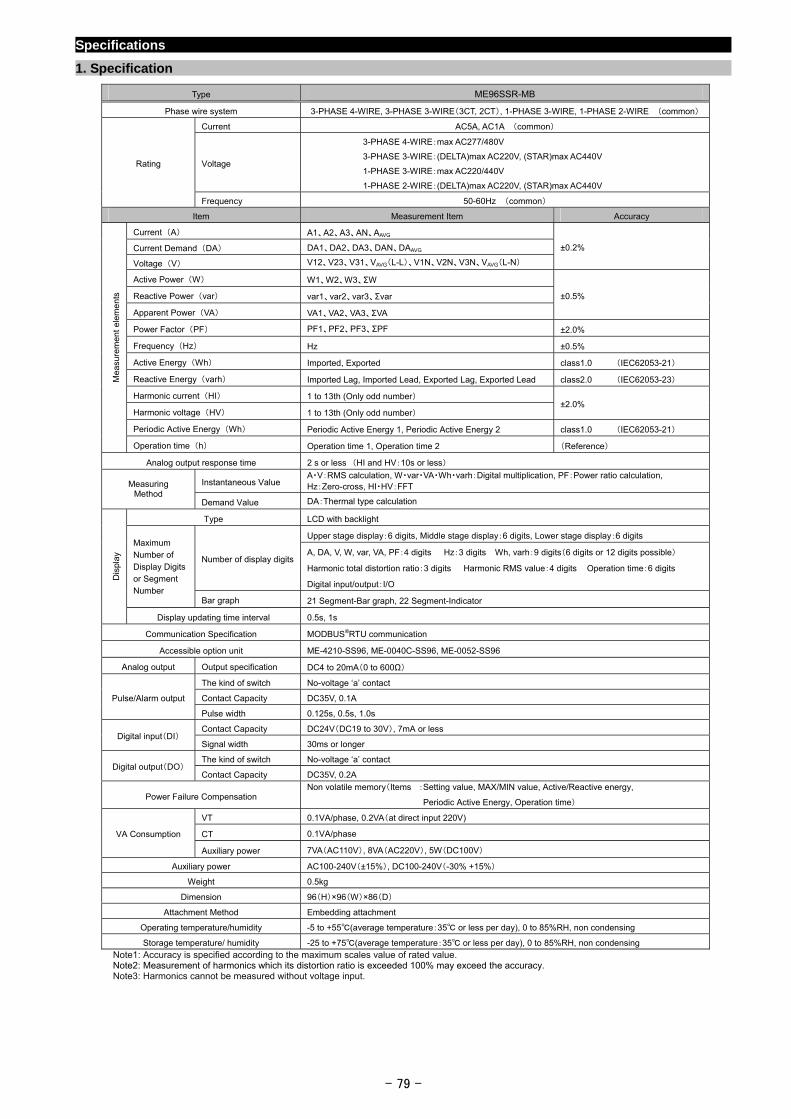
- 79 -
Specifications
1. Specification
Type ME96SSR-MB
Phase wire system 3-PHASE 4-WIRE, 3-PHASE 3-WIRE(3CT, 2CT), 1-PHASE 3-WIRE, 1-PHASE 2-WIRE (common)
Current AC5A, AC1A (common)
Voltage
3-PHASE 4-WIRE:max AC277/480V
3-PHASE 3-WIRE:(DELTA)max AC220V, (STAR)max AC440V
1-PHASE 3-WIRE:max AC220/440V
1-PHASE 2-WIRE:(DELTA)max AC220V, (STAR)max AC440V
Rating
Frequency 50-60Hz (common)
Item Measurement Item Accuracy
Current (A) A1、A2、A3、AN、AAVG
Current Demand (DA) DA1、DA2、DA3、DAN、DAAVG
Voltage (V) V12、V23、V31、VAVG(L-L)、V1N、V2N、V3N、VAVG(L-N)
±0.2%
Active Power (W) W1、W2、W3、ΣW
Reactive Power (var) var1、var2、var3、Σvar
Apparent Power (VA) VA1、VA2、VA3、ΣVA
±0.5%
Power Factor (PF) PF1、PF2、PF3、ΣPF ±2.0%
Frequency (Hz) Hz ±0.5%
Active Energy (Wh) Imported, Exported class1.0 (IEC62053-21)
Reactive Energy (varh) Imported Lag, Imported Lead, Exported Lag, Exported Lead class2.0 (IEC62053-23)
Harmonic current (HI) 1 to 13th (Only odd number)
Harmonic voltage (HV) 1 to 13th (Only odd number) ±2.0%
Periodic Active Energy (Wh) Periodic Active Energy 1, Periodic Active Energy 2 class1.0 (IEC62053-21)
Mea
sure
men
t el
eme
nts
Operation time (h) Operation time 1, Operation time 2 (Reference)
Analog output response time 2 s or less (HI and HV:10s or less)
Instantaneous Value A・V:RMS calculation, W・var・VA・Wh・varh:Digital multiplication, PF:Power ratio calculation, Hz:Zero-cross, HI・HV:FFT Measuring
Method Demand Value DA:Thermal type calculation
Type LCD with backlight
Upper stage display:6 digits, Middle stage display:6 digits, Lower stage display:6 digits
Number of display digits A, DA, V, W, var, VA, PF:4 digits Hz:3 digits Wh, varh:9 digits(6 digits or 12 digits possible)
Harmonic total distortion ratio:3 digits Harmonic RMS value:4 digits Operation time:6 digits
Digital input/output:I/O
Maximum Number of Display Digits or Segment Number
Bar graph 21 Segment-Bar graph, 22 Segment-Indicator
Dis
play
Display updating time interval 0.5s, 1s
Communication Specification MODBUS®RTU communication
Accessible option unit ME-4210-SS96, ME-0040C-SS96, ME-0052-SS96
Analog output Output specification DC4 to 20mA(0 to 600Ω)
The kind of switch No-voltage ‘a’ contact
Contact Capacity DC35V, 0.1A Pulse/Alarm output
Pulse width 0.125s, 0.5s, 1.0s
Contact Capacity DC24V(DC19 to 30V), 7mA or less Digital input(DI)
Signal width 30ms or longer
The kind of switch No-voltage ‘a’ contact Digital output(DO)
Contact Capacity DC35V, 0.2A
Power Failure Compensation Non volatile memory(Items :Setting value, MAX/MIN value, Active/Reactive energy,
Periodic Active Energy, Operation time)
VT 0.1VA/phase, 0.2VA(at direct input 220V)
CT 0.1VA/phase VA Consumption
Auxiliary power 7VA(AC110V), 8VA(AC220V), 5W(DC100V)
Auxiliary power AC100-240V(±15%), DC100-240V(-30% +15%)
Weight 0.5kg
Dimension 96(H)×96(W)×86(D)
Attachment Method Embedding attachment
Operating temperature/humidity -5 to +55(average temperature:35 or less per day), 0 to 85%RH, non condensing
Storage temperature/ humidity -25 to +75(average temperature:35 or less per day), 0 to 85%RH, non condensing
Note1: Accuracy is specified according to the maximum scales value of rated value. Note2: Measurement of harmonics which its distortion ratio is exceeded 100% may exceed the accuracy. Note3: Harmonics cannot be measured without voltage input.
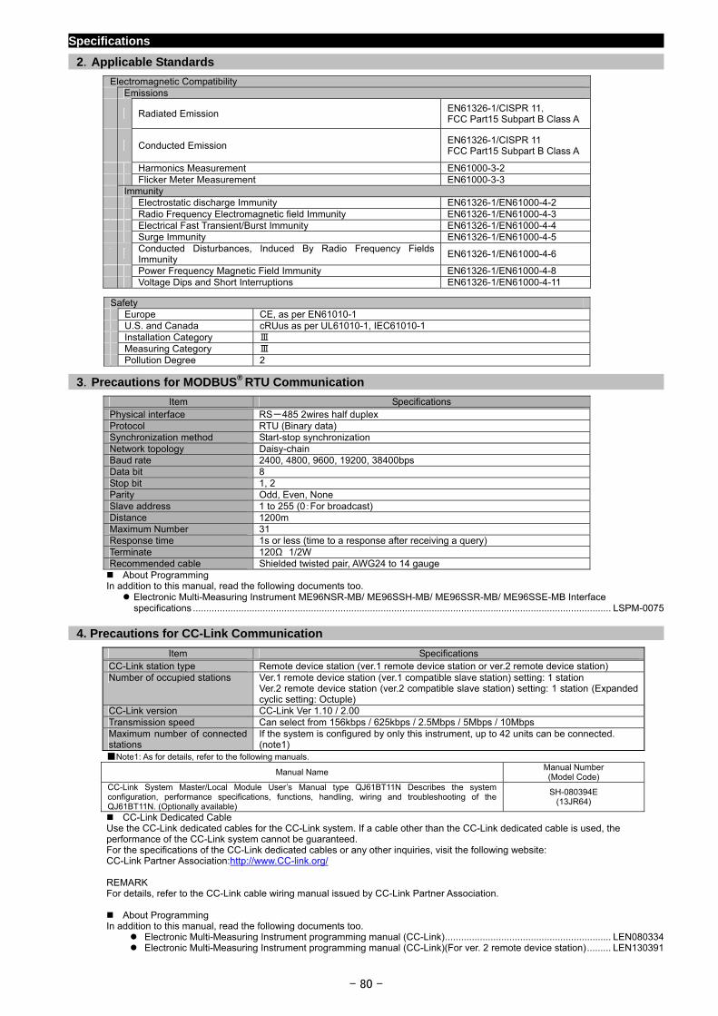
- 80 -
Specifications
2.Applicable Standards
Electromagnetic Compatibility Emissions
Radiated Emission EN61326-1/CISPR 11, FCC Part15 Subpart B Class A
Conducted Emission EN61326-1/CISPR 11 FCC Part15 Subpart B Class A
Harmonics Measurement EN61000-3-2 Flicker Meter Measurement EN61000-3-3 Immunity Electrostatic discharge Immunity EN61326-1/EN61000-4-2 Radio Frequency Electromagnetic field Immunity EN61326-1/EN61000-4-3 Electrical Fast Transient/Burst Immunity EN61326-1/EN61000-4-4 Surge Immunity EN61326-1/EN61000-4-5
Conducted Disturbances, Induced By Radio Frequency Fields Immunity
EN61326-1/EN61000-4-6
Power Frequency Magnetic Field Immunity EN61326-1/EN61000-4-8 Voltage Dips and Short Interruptions EN61326-1/EN61000-4-11
Safety Europe CE, as per EN61010-1 U.S. and Canada cRUus as per UL61010-1, IEC61010-1 Installation Category Ⅲ Measuring Category Ⅲ Pollution Degree 2
3.Precautions for MODBUS® RTU Communication
Item Specifications Physical interface RS-485 2wires half duplex Protocol RTU (Binary data) Synchronization method Start-stop synchronization Network topology Daisy-chain Baud rate 2400, 4800, 9600, 19200, 38400bps Data bit 8 Stop bit 1, 2 Parity Odd, Even, None Slave address 1 to 255 (0:For broadcast) Distance 1200m Maximum Number 31 Response time 1s or less (time to a response after receiving a query) Terminate 120Ω 1/2W Recommended cable Shielded twisted pair, AWG24 to 14 gauge About Programming In addition to this manual, read the following documents too. Electronic Multi-Measuring Instrument ME96NSR-MB/ ME96SSH-MB/ ME96SSR-MB/ ME96SSE-MB Interface
specifications ............................................................................................................................................................ LSPM-0075
4. Precautions for CC-Link Communication
Item Specifications CC-Link station type Remote device station (ver.1 remote device station or ver.2 remote device station) Number of occupied stations Ver.1 remote device station (ver.1 compatible slave station) setting: 1 station
Ver.2 remote device station (ver.2 compatible slave station) setting: 1 station (Expanded cyclic setting: Octuple)
CC-Link version CC-Link Ver 1.10 / 2.00 Transmission speed Can select from 156kbps / 625kbps / 2.5Mbps / 5Mbps / 10Mbps Maximum number of connected stations
If the system is configured by only this instrument, up to 42 units can be connected. (note1)
Note1: As for details, refer to the following manuals.
Manual Name Manual Number (Model Code)
CC-Link System Master/Local Module User’s Manual type QJ61BT11N Describes the system configuration, performance specifications, functions, handling, wiring and troubleshooting of the QJ61BT11N. (Optionally available)
SH-080394E (13JR64)
CC-Link Dedicated Cable Use the CC-Link dedicated cables for the CC-Link system. If a cable other than the CC-Link dedicated cable is used, the performance of the CC-Link system cannot be guaranteed. For the specifications of the CC-Link dedicated cables or any other inquiries, visit the following website: CC-Link Partner Association:http://www.CC-link.org/ REMARK For details, refer to the CC-Link cable wiring manual issued by CC-Link Partner Association. About Programming In addition to this manual, read the following documents too.
Electronic Multi-Measuring Instrument programming manual (CC-Link).............................................................. LEN080334 Electronic Multi-Measuring Instrument programming manual (CC-Link)(For ver. 2 remote device station)......... LEN130391
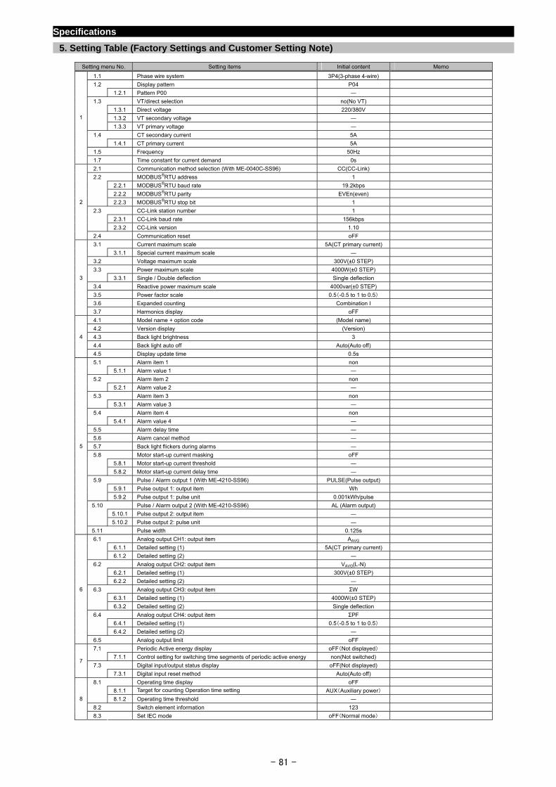
- 81 -
Specifications
5. Setting Table (Factory Settings and Customer Setting Note)
Setting menu No. Setting items Initial content Memo
1.1 Phase wire system 3P4(3-phase 4-wire)
1.2 Display pattern P04
1.2.1 Pattern P00 ―
1.3 VT/direct selection no(No VT)
1.3.1 Direct voltage 220/380V
1.3.2 VT secondary voltage ―
1.3.3 VT primary voltage ―
1.4 CT secondary current 5A
1.4.1 CT primary current 5A
1.5 Frequency 50Hz
1
1.7 Time constant for current demand 0s
2.1 Communication method selection (With ME-0040C-SS96) CC(CC-Link)
2.2 MODBUS®RTU address 1
2.2.1 MODBUS®RTU baud rate 19.2kbps
2.2.2 MODBUS®RTU parity EVEn(even)
2.2.3 MODBUS®RTU stop bit 1
2.3 CC-Link station number 1
2.3.1 CC-Link baud rate 156kbps
2.3.2 CC-Link version 1.10
2
2.4 Communication reset oFF
3.1 Current maximum scale 5A(CT primary current)
3.1.1 Special current maximum scale ―
3.2 Voltage maximum scale 300V(±0 STEP)
3.3 Power maximum scale 4000W(±0 STEP)
3.3.1 Single / Double deflection Single deflection
3.4 Reactive power maximum scale 4000var(±0 STEP)
3.5 Power factor scale 0.5(-0.5 to 1 to 0.5)
3.6 Expanded counting Combination I
3
3.7 Harmonics display oFF
4.1 Model name + option code (Model name)
4.2 Version display (Version)
4.3 Back light brightness 3
4.4 Back light auto off Auto(Auto off)
4
4.5 Display update time 0.5s
5.1 Alarm item 1 non
5.1.1 Alarm value 1 ―
5.2 Alarm item 2 non
5.2.1 Alarm value 2 ―
5.3 Alarm item 3 non
5.3.1 Alarm value 3 ―
5.4 Alarm item 4 non
5.4.1 Alarm value 4 ―
5.5 Alarm delay time ―
5.6 Alarm cancel method ―
5.7 Back light flickers during alarms ―
5.8 Motor start-up current masking oFF
5.8.1 Motor start-up current threshold ―
5.8.2 Motor start-up current delay time ―
5.9 Pulse / Alarm output 1 (With ME-4210-SS96) PULSE(Pulse output)
5.9.1 Pulse output 1: output item Wh
5.9.2 Pulse output 1: pulse unit 0.001kWh/pulse
5.10 Pulse / Alarm output 2 (With ME-4210-SS96) AL (Alarm output)
5.10.1 Pulse output 2: output item ―
5.10.2 Pulse output 2: pulse unit ―
5
5.11 Pulse width 0.125s
6.1 Analog output CH1: output item AAVG
6.1.1 Detailed setting (1) 5A(CT primary current)
6.1.2 Detailed setting (2) ―
6.2 Analog output CH2: output item VAVG(L-N)
6.2.1 Detailed setting (1) 300V(±0 STEP)
6.2.2 Detailed setting (2) ―
6.3 Analog output CH3: output item ΣW
6.3.1 Detailed setting (1) 4000W(±0 STEP)
6.3.2 Detailed setting (2) Single deflection
6.4 Analog output CH4: output item ΣPF
6.4.1 Detailed setting (1) 0.5(-0.5 to 1 to 0.5)
6.4.2 Detailed setting (2) ―
6
6.5 Analog output limit oFF
7.1 Periodic Active energy display oFF(Not displayed)
7.1.1 Control setting for switching time segments of periodic active energy non(Not switched)
7.3 Digital input/output status display oFF(Not displayed) 7
7.3.1 Digital input reset method Auto(Auto off)
8.1 Operating time display oFF
8.1.1 Target for counting Operation time setting AUX(Auxiliary power)
8.1.2 Operating time threshold ―
8.2 Switch element information 123
8
8.3 Set IEC mode oFF(Normal mode)
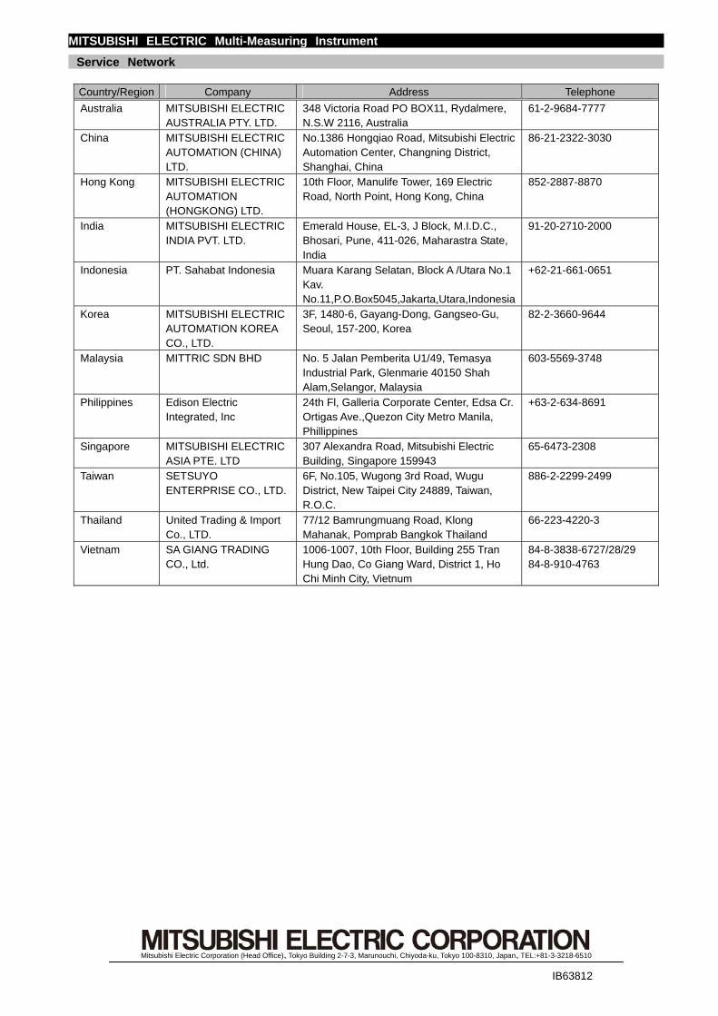
MITSUBISHI ELECTRIC Multi-Measuring Instrument
Service Network
Country/Region Company Address Telephone
Australia MITSUBISHI ELECTRIC AUSTRALIA PTY. LTD.
348 Victoria Road PO BOX11, Rydalmere, N.S.W 2116, Australia
61-2-9684-7777
China MITSUBISHI ELECTRIC AUTOMATION (CHINA) LTD.
No.1386 Hongqiao Road, Mitsubishi Electric Automation Center, Changning District, Shanghai, China
86-21-2322-3030
Hong Kong MITSUBISHI ELECTRIC AUTOMATION (HONGKONG) LTD.
10th Floor, Manulife Tower, 169 Electric Road, North Point, Hong Kong, China
852-2887-8870
India MITSUBISHI ELECTRIC INDIA PVT. LTD.
Emerald House, EL-3, J Block, M.I.D.C., Bhosari, Pune, 411-026, Maharastra State, India
91-20-2710-2000
Indonesia PT. Sahabat Indonesia Muara Karang Selatan, Block A /Utara No.1 Kav. No.11,P.O.Box5045,Jakarta,Utara,Indonesia
+62-21-661-0651
Korea MITSUBISHI ELECTRIC AUTOMATION KOREA CO., LTD.
3F, 1480-6, Gayang-Dong, Gangseo-Gu, Seoul, 157-200, Korea
82-2-3660-9644
Malaysia MITTRIC SDN BHD No. 5 Jalan Pemberita U1/49, Temasya Industrial Park, Glenmarie 40150 Shah Alam,Selangor, Malaysia
603-5569-3748
Philippines Edison Electric Integrated, Inc
24th Fl, Galleria Corporate Center, Edsa Cr. Ortigas Ave.,Quezon City Metro Manila, Phillippines
+63-2-634-8691
Singapore MITSUBISHI ELECTRIC ASIA PTE. LTD
307 Alexandra Road, Mitsubishi Electric Building, Singapore 159943
65-6473-2308
Taiwan SETSUYO ENTERPRISE CO., LTD.
6F, No.105, Wugong 3rd Road, Wugu District, New Taipei City 24889, Taiwan, R.O.C.
886-2-2299-2499
Thailand United Trading & Import Co., LTD.
77/12 Bamrungmuang Road, Klong Mahanak, Pomprab Bangkok Thailand
66-223-4220-3
Vietnam SA GIANG TRADING CO., Ltd.
1006-1007, 10th Floor, Building 255 Tran Hung Dao, Co Giang Ward, District 1, Ho Chi Minh City, Vietnum
84-8-3838-6727/28/29 84-8-910-4763
Mitsubishi Electric Corporation (Head Office)、Tokyo Building 2-7-3, Marunouchi, Chiyoda-ku, Tokyo 100-8310, Japan、TEL:+81-3-3218-6510
IB63812
Related Documents