Welcome message from author
This document is posted to help you gain knowledge. Please leave a comment to let me know what you think about it! Share it to your friends and learn new things together.
Transcript
ii
HWE10050 GB
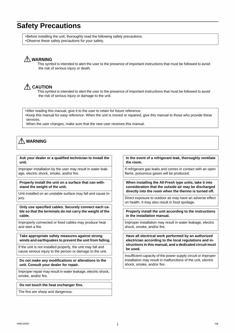
Safety PrecautionsBefore installing the unit, thoroughly read the following safety precautions.Observe these safety precautions for your safety.
WARNINGThis symbol is intended to alert the user to the presence of important instructions that must be followed to avoid the risk of serious injury or death.
CAUTIONThis symbol is intended to alert the user to the presence of important instructions that must be followed to avoid the risk of serious injury or damage to the unit.
After reading this manual, give it to the user to retain for future reference.Keep this manual for easy reference. When the unit is moved or repaired, give this manual to those who provide these services. When the user changes, make sure that the new user receives this manual.
WARNING
Ask your dealer or a qualified technician to install the unit.
Improper installation by the user may result in water leak-age, electric shock, smoke, and/or fire.
Properly install the unit on a surface that can with-stand the weight of the unit.
Unit installed on an unstable surface may fall and cause in-jury.
Only use specified cables. Securely connect each ca-ble so that the terminals do not carry the weight of the cable.
Improperly connected or fixed cables may produce heat and start a fire.
Take appropriate safety measures against strong winds and earthquakes to prevent the unit from falling.
If the unit is not installed properly, the unit may fall and cause serious injury to the person or damage to the unit.
Do not make any modifications or alterations to the unit. Consult your dealer for repair.
Improper repair may result in water leakage, electric shock, smoke, and/or fire.
Do not touch the heat exchanger fins.
The fins are sharp and dangerous.
In the event of a refrigerant leak, thoroughly ventilate the room.
If refrigerant gas leaks and comes in contact with an open flame, poisonous gases will be produced.
When installing the All-Fresh type units, take it into consideration that the outside air may be discharged directly into the room when the thermo is turned off.
Direct exposure to outdoor air may have an adverse effect on health. It may also result in food spoilage.
Properly install the unit according to the instructions in the installation manual.
Improper installation may result in water leakage, electric shock, smoke, and/or fire.
Have all electrical work performed by an authorized electrician according to the local regulations and in-structions in this manual, and a dedicated circuit must be used.
Insufficient capacity of the power supply circuit or improper installation may result in malfunctions of the unit, electric shock, smoke, and/or fire.
iiHWE10050 GB
WARNING
Securely attach the terminal block cover (panel) to the unit.
If the terminal block cover (panel) is not installed properly, dust and/or water may infiltrate and pose a risk of electric shock, smoke, and/or fire.
Only use the type of refrigerant that is indicated on the unit when installing or reinstalling the unit.
Infiltration of any other type of refrigerant or air into the unit may adversely affect the refrigerant cycle and may cause the pipes to burst or explode.
When installing the unit in a small room, exercise cau-tion and take measures against leaked refrigerant reaching the limiting concentration.
Consult your dealer with any questions regarding limiting concentrations and for precautionary measures before in-stalling the unit. Leaked refrigerant gas exceeding the lim-iting concentration causes oxygen deficiency.
Consult your dealer or a specialist when moving or re-installing the unit.
Improper installation may result in water leakage, electric shock, and/or fire.
After completing the service work, check for a gas leak.
If leaked refrigerant is exposed to a heat source, such as a fan heater, stove, or electric grill, poisonous gases may be produced.
Do not try to defeat the safety features of the unit.
Forced operation of the pressure switch or the temperature switch by defeating the safety features of these devices, or the use of accessories other than the ones that are recom-mended by MITSUBISHI may result in smoke, fire, and/or explosion.
Only use accessories recommended by MITSUBISHI.
Ask a qualified technician to install the unit. Improper instal-lation by the user may result in water leakage, electric shock, smoke, and/or fire.
Control box houses high-voltage parts.
When opening or closing the front panel of the control box, do not let it come into contact with any of the internal com-ponents. Before inspecting the inside of the control box, turn off the power, keep the unit off for at least 10 minutes, and confirm that the voltage between FT-P and FT-N on INV Board has dropped to DC20V or less. (It takes about 10 minutes to discharge electricity after the power supply is turned off.)
iiiiii
HWE10050 GB
Precautions for handling units for use with R410A
CAUTION
Do not use the existing refrigerant piping.
A large amount of chlorine that is contained in the residual refrigerant and refrigerator oil in the existing piping may cause the refrigerator oil in the new unit to deteriorate.R410A is a high-pressure refrigerant and can cause the existing pipes to burst.
Use refrigerant pipes made of phosphorus deoxidized copper. Keep the inner and outer surfaces of the pipes clean and free of such contaminants as sulfur, oxides, dust, dirt, shaving particles, oil, and water.
These types of contaminants inside the refrigerant pipes may cause the refrigerant oil to deteriorate.
Store the pipes to be installed indoors, and keep both ends of the pipes sealed until immediately before braz-ing. (Keep elbows and other joints wrapped in plastic.)
Infiltration of dust, dirt, or water into the refrigerant system may cause the refrigerating machine oil to deteriorate or cause the unit to malfunction.
Use a small amount of ester oil, ether oil, or alkylben-zene to coat flares and flanges.
Infiltration of a large amount of mineral oil may cause the re-frigerating machine oil to deteriorate.
Charge liquid refrigerant (as opposed to gaseous re-frigerant) into the system.
If gaseous refrigerant is charged into the system, the com-position of the refrigerant in the cylinder will change and may result in performance loss.
Use a vacuum pump with a reverse-flow check valve.
If a vacuum pump that is not equipped with a reverse-flow check valve is used, the vacuum pump oil may flow into the refrigerant cycle and cause the refrigerating machine oil to deteriorate.
Prepare tools for exclusive use with R410A. Do not use the following tools if they have been used with the con-ventional refrigerant (gauge manifold, charging hose, gas leak detector, reverse-flow check valve, refrigerant charge base, vacuum gauge, and refrigerant recovery equipment.).
If the refrigerant or the refrigerating machine oil left on these tools are mixed in with R410A, it may cause the re-frigerating machine oil to deteriorate.Infiltration of water may cause the refrigerating machine oil to deteriorate.Gas leak detectors for conventional refrigerants will not detect an R410A leak because R410A is free of chlorine.
Do not use a charging cylinder.
If a charging cylinder is used, the composition of the refrig-erant will change, and the unit may experience power loss.
Exercise special care when handling the tools for use with R410A.
Infiltration of dust, dirt, or water into the refrigerant system may cause the refrigerating machine oil to deteriorate.
Only use refrigerant R410A.
The use of other types of refrigerant that contain chlorine (i.e. R22) may cause the refrigerating machine oil to deteri-orate.
ivHWE10050 GB
Before installing the unit
WARNING
Do not install the unit where a gas leak may occur.
If gaseous refrigerant leaks and piles up around the unit, it may be ignited.
Do not use the unit to keep food items, animals, plants, artifacts, or for other special purposes.
The unit is not designed to preserve food products.
Do not use the unit in an unusual environment.
Do not install the unit where a large amount of oil or steam is present or where acidic or alkaline solutions or chemical sprays are used frequently. Doing so may lead to a re-markable drop in performance, electric shock, malfunc-tions, smoke, and/or fire.The presence of organic solvents or corrosive gas (i.e. ammonia, sulfur compounds, and acid) may cause gas leakage or water leakage.
When installing the unit in a hospital, take appropriate measures to reduce noise interference.
High-frequency medical equipment may interfere with the normal operation of the air conditioner or vice versa.
Do not install the unit on or over things that cannot get wet.
When the humidity level exceeds 80% or if the drainage system is clogged, the indoor unit may drip water. Drain wa-ter is also discharged from the outdoor unit. Install a central-ized drainage system if necessary.
vv
HWE10050 GB
Before installing the unit (moving and reinstalling the unit) and performing electrical work
CAUTION
Properly ground the unit.
Do not connect the grounding wire to a gas pipe, water pipe, lightning rod, or grounding wire from a telephone pole. Im-proper grounding may result in electric shock, smoke, fire, and/or malfunction due to noise interference.
Do not put tension on the power supply wires.
If tension is put on the wires, they may break and result in excessive heat, smoke, and/or fire.
Install an earth leakage breaker to avoid the risk of electric shock.
Failure to install an earth leakage breaker may result in electric shock, smoke, and/or fire.
Use the kind of power supply wires that are specified in the installation manual.
The use of wrong kind of power supply wires may result in current leak, electric shock, and/or fire.
Use breakers and fuses (current breaker, remote switch <switch + Type-B fuse>, moulded case circuit breaker) with the proper current capacity.
The use of wrong capacity fuses, steel wires, or copper wires may result in malfunctions, smoke, and/or fire.
Do not spray water on the air conditioner or immerse the air conditioner in water.
Otherwise, electric shock and/or fire may result.
When handling units, always wear protective gloves to protect your hands from metal parts and high-tempera-ture parts.
Periodically check the installation base for damage.
If the unit is left on a damaged platform, it may fall and cause injury.
Properly install the drain pipes according to the in-structions in the installation manual. Keep them insu-lated to avoid dew condensation.
Improper plumbing work may result in water leakage and damage to the furnishings.
Exercise caution when transporting products.
Products weighing more than 20 kg should not be carried alone.Do not carry the product by the PP bands that are used on some products.Do not touch the heat exchanger fins. They are sharp and dangerous.When lifting the unit with a crane, secure all four corners to prevent the unit from falling.
Properly dispose of the packing materials.
Nails and wood pieces in the package may pose a risk of injury.Plastic bags may pose a risk of choking hazard to chil-dren. Tear plastic bags into pieces before disposing of them.
viHWE10050 GB
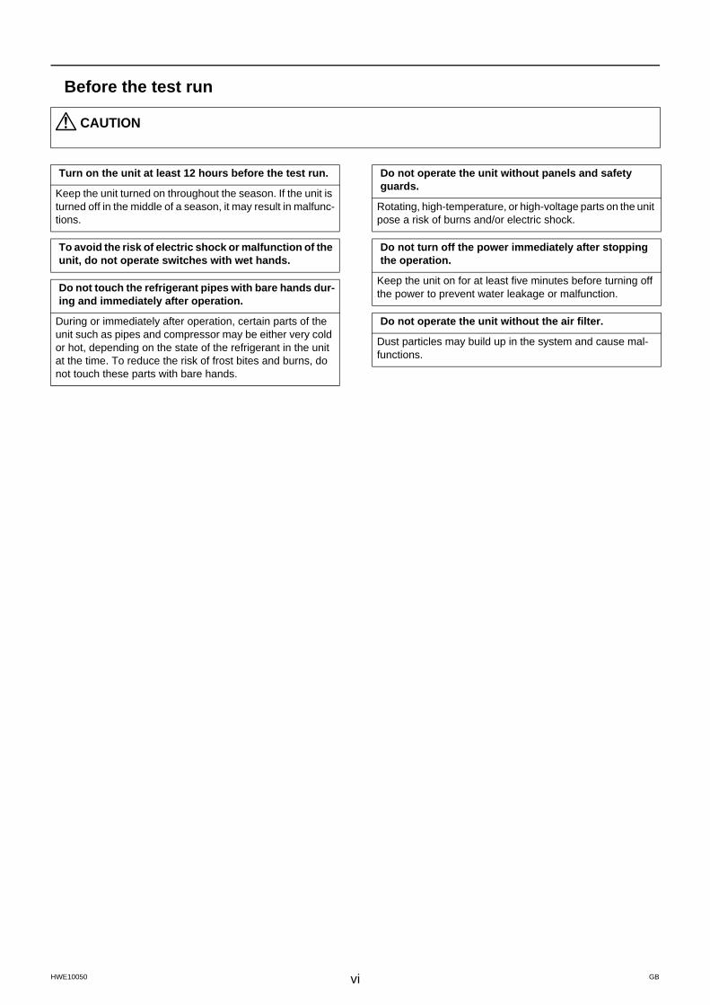
Before the test run
CAUTION
Turn on the unit at least 12 hours before the test run.
Keep the unit turned on throughout the season. If the unit is turned off in the middle of a season, it may result in malfunc-tions.
To avoid the risk of electric shock or malfunction of the unit, do not operate switches with wet hands.
Do not touch the refrigerant pipes with bare hands dur-ing and immediately after operation.
During or immediately after operation, certain parts of the unit such as pipes and compressor may be either very cold or hot, depending on the state of the refrigerant in the unit at the time. To reduce the risk of frost bites and burns, do not touch these parts with bare hands.
Do not operate the unit without panels and safety guards.
Rotating, high-temperature, or high-voltage parts on the unit pose a risk of burns and/or electric shock.
Do not turn off the power immediately after stopping the operation.
Keep the unit on for at least five minutes before turning off the power to prevent water leakage or malfunction.
Do not operate the unit without the air filter.
Dust particles may build up in the system and cause mal-functions.
CONTENTS
HWE10050 GB
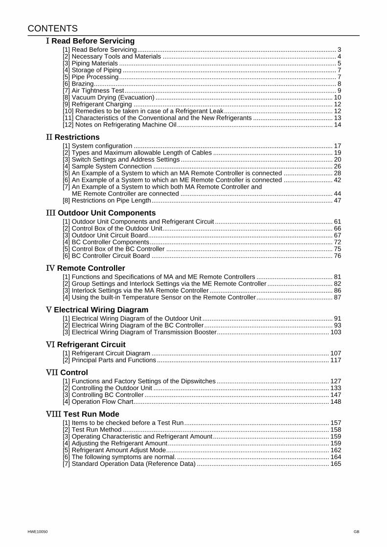
I Read Before Servicing[1] Read Before Servicing.............................................................................................................. 3[2] Necessary Tools and Materials ................................................................................................ 4[3] Piping Materials ........................................................................................................................ 5[4] Storage of Piping ...................................................................................................................... 7[5] Pipe Processing........................................................................................................................ 7[6] Brazing...................................................................................................................................... 8[7] Air Tightness Test..................................................................................................................... 9[8] Vacuum Drying (Evacuation) .................................................................................................. 10[9] Refrigerant Charging .............................................................................................................. 12[10] Remedies to be taken in case of a Refrigerant Leak............................................................ 12[11] Characteristics of the Conventional and the New Refrigerants ............................................ 13[12] Notes on Refrigerating Machine Oil ...................................................................................... 14
II Restrictions[1] System configuration .............................................................................................................. 17[2] Types and Maximum allowable Length of Cables .................................................................. 19[3] Switch Settings and Address Settings .................................................................................... 20[4] Sample System Connection ................................................................................................... 26[5] An Example of a System to which an MA Remote Controller is connected ........................... 28[6] An Example of a System to which an ME Remote Controller is connected ........................... 42[7] An Example of a System to which both MA Remote Controller and
ME Remote Controller are connected .................................................................................... 44[8] Restrictions on Pipe Length.................................................................................................... 47
III Outdoor Unit Components[1] Outdoor Unit Components and Refrigerant Circuit ................................................................. 61[2] Control Box of the Outdoor Unit.............................................................................................. 66[3] Outdoor Unit Circuit Board...................................................................................................... 67[4] BC Controller Components..................................................................................................... 72[5] Control Box of the BC Controller ............................................................................................ 75[6] BC Controller Circuit Board .................................................................................................... 76
IV Remote Controller[1] Functions and Specifications of MA and ME Remote Controllers .......................................... 81[2] Group Settings and Interlock Settings via the ME Remote Controller .................................... 82[3] Interlock Settings via the MA Remote Controller .................................................................... 86[4] Using the built-in Temperature Sensor on the Remote Controller.......................................... 87
V Electrical Wiring Diagram[1] Electrical Wiring Diagram of the Outdoor Unit ........................................................................ 91[2] Electrical Wiring Diagram of the BC Controller....................................................................... 93[3] Electrical Wiring Diagram of Transmission Booster.............................................................. 103
VI Refrigerant Circuit[1] Refrigerant Circuit Diagram .................................................................................................. 107[2] Principal Parts and Functions ............................................................................................... 117
VII Control[1] Functions and Factory Settings of the Dipswitches .............................................................. 127[2] Controlling the Outdoor Unit ................................................................................................. 133[3] Controlling BC Controller ...................................................................................................... 147[4] Operation Flow Chart............................................................................................................ 148
VIII Test Run Mode[1] Items to be checked before a Test Run................................................................................ 157[2] Test Run Method .................................................................................................................. 158[3] Operating Characteristic and Refrigerant Amount................................................................ 159[4] Adjusting the Refrigerant Amount......................................................................................... 159[5] Refrigerant Amount Adjust Mode.......................................................................................... 162[6] The following symptoms are normal. .................................................................................... 164[7] Standard Operation Data (Reference Data) ......................................................................... 165
CONTENTS
HWE10050 GB
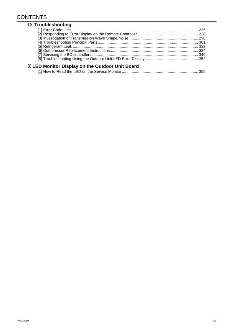
IX Troubleshooting[1] Error Code Lists.................................................................................................................... 225[2] Responding to Error Display on the Remote Controller........................................................ 228[3] Investigation of Transmission Wave Shape/Noise ............................................................... 298[4] Troubleshooting Principal Parts............................................................................................ 301[5] Refrigerant Leak ................................................................................................................... 332[6] Compressor Replacement Instructions................................................................................. 334[7] Servicing the BC controller ................................................................................................... 349[8] Troubleshooting Using the Outdoor Unit LED Error Display................................................. 352
X LED Monitor Display on the Outdoor Unit Board[1] How to Read the LED on the Service Monitor ...................................................................... 355
- 1 -HWE10050 GB
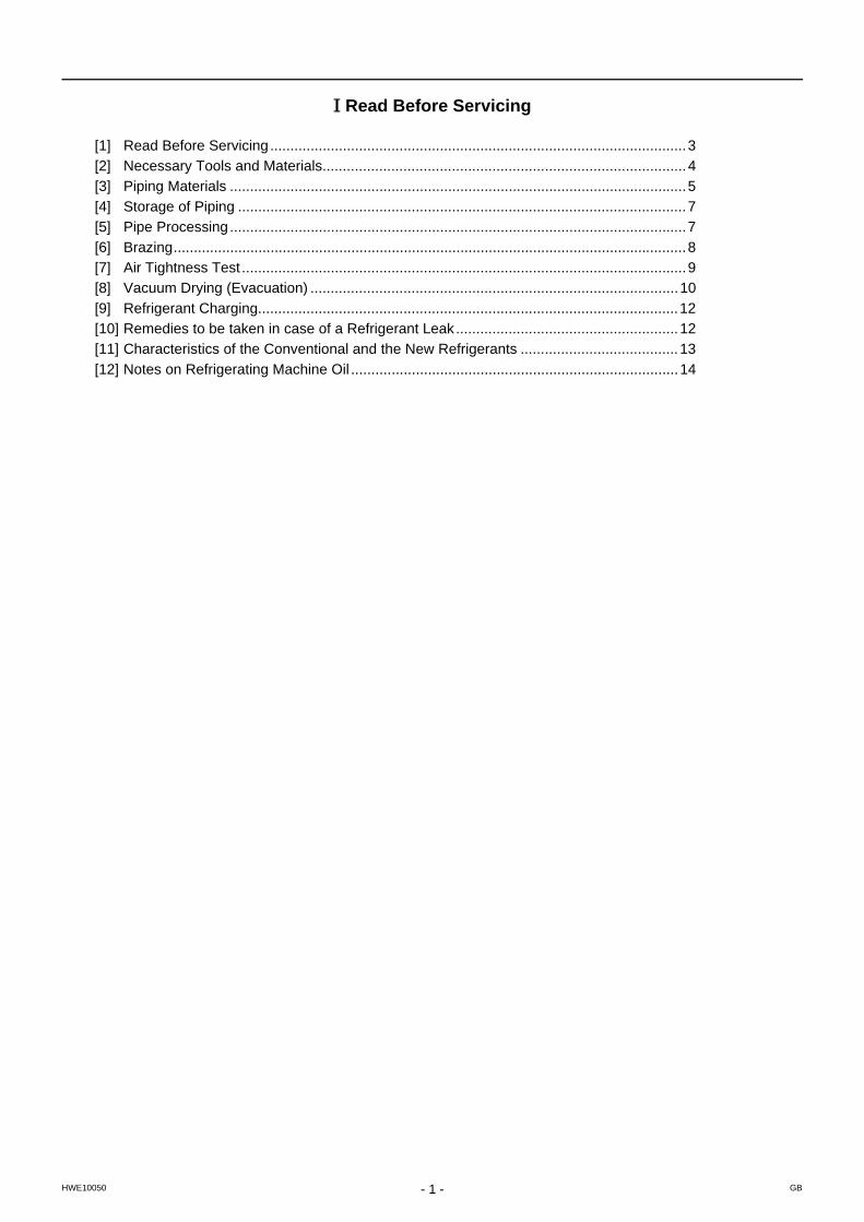
I Read Before Servicing
[1] Read Before Servicing.......................................................................................................3[2] Necessary Tools and Materials..........................................................................................4[3] Piping Materials .................................................................................................................5[4] Storage of Piping ...............................................................................................................7[5] Pipe Processing.................................................................................................................7[6] Brazing...............................................................................................................................8[7] Air Tightness Test ..............................................................................................................9[8] Vacuum Drying (Evacuation) ...........................................................................................10[9] Refrigerant Charging........................................................................................................12[10] Remedies to be taken in case of a Refrigerant Leak.......................................................12[11] Characteristics of the Conventional and the New Refrigerants .......................................13[12] Notes on Refrigerating Machine Oil .................................................................................14

- 2 -
[ I Read Before Servicing ]
- 3 -HWE10050 GB
I Read Before Servicing
[1] Read Before Servicing1. Check the type of refrigerant used in the system to be serviced.
Refrigerant TypeMulti air conditioner for building application CITY MULTI R2 YJM-A series R410A
2. Check the symptoms exhibited by the unit to be serviced.Refer to this service handbook for symptoms relating to the refrigerant cycle.
3. Thoroughly read the safety precautions at the beginning of this manual.
4. Preparing necessary tools: Prepare a set of tools to be used exclusively with each type of refrigerant.Refer to "Necessary Tools and Materials" for information on the use of tools.(page 4)
5. Verification of the connecting pipes: Verify the type of refrigerant used for the unit to be moved or replaced.Use refrigerant pipes made of phosphorus deoxidized copper. Keep the inner and outer surfaces of the pipes clean and free of such contaminants as sulfur, oxides, dust, dirt, shaving particles, oil, and water.These types of contaminants inside the refrigerant pipes may cause the refrigerant oil to deteriorate.
6. If there is a leak of gaseous refrigerant and the remaining refrigerant is exposed to an open flame, a poisonous gas hydrofluoric acid may form. Keep workplace well ventilated.
CAUTIONInstall new pipes immediately after removing old ones to keep moisture out of the refrigerant circuit.The use of refrigerant that contains chloride, such as R22, will cause the refrigerating machine oil to deteriorate.
[ I Read Before Servicing ]
- 4 -HWE10050 GB
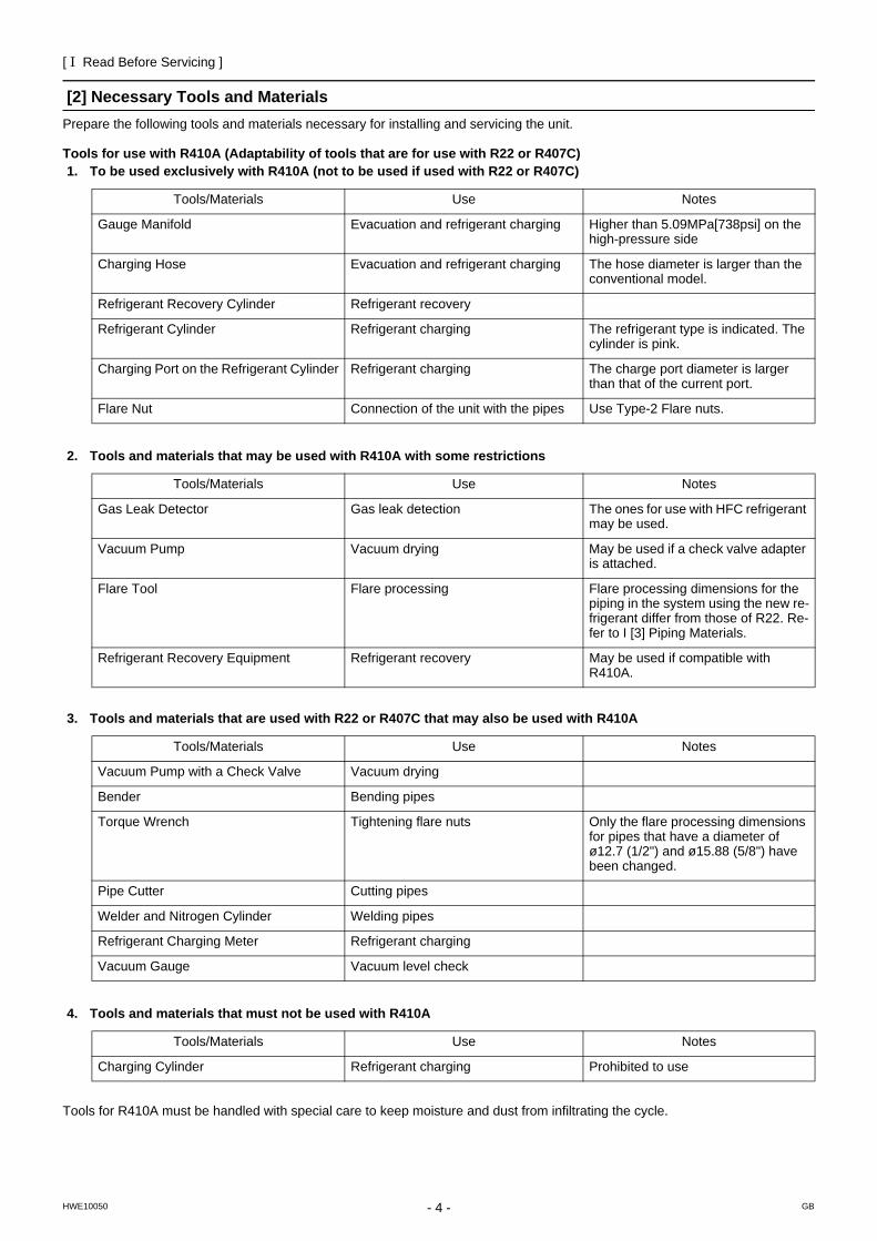
[2] Necessary Tools and MaterialsPrepare the following tools and materials necessary for installing and servicing the unit.
Tools for use with R410A (Adaptability of tools that are for use with R22 or R407C)1. To be used exclusively with R410A (not to be used if used with R22 or R407C)
2. Tools and materials that may be used with R410A with some restrictions
3. Tools and materials that are used with R22 or R407C that may also be used with R410A
4. Tools and materials that must not be used with R410A
Tools for R410A must be handled with special care to keep moisture and dust from infiltrating the cycle.
Tools/Materials Use Notes
Gauge Manifold Evacuation and refrigerant charging Higher than 5.09MPa[738psi] on the high-pressure side
Charging Hose Evacuation and refrigerant charging The hose diameter is larger than the conventional model.
Refrigerant Recovery Cylinder Refrigerant recovery
Refrigerant Cylinder Refrigerant charging The refrigerant type is indicated. The cylinder is pink.
Charging Port on the Refrigerant Cylinder Refrigerant charging The charge port diameter is larger than that of the current port.
Flare Nut Connection of the unit with the pipes Use Type-2 Flare nuts.
Tools/Materials Use Notes
Gas Leak Detector Gas leak detection The ones for use with HFC refrigerant may be used.
Vacuum Pump Vacuum drying May be used if a check valve adapter is attached.
Flare Tool Flare processing Flare processing dimensions for the piping in the system using the new re-frigerant differ from those of R22. Re-fer to I [3] Piping Materials.
Refrigerant Recovery Equipment Refrigerant recovery May be used if compatible with R410A.
Tools/Materials Use Notes
Vacuum Pump with a Check Valve Vacuum drying
Bender Bending pipes
Torque Wrench Tightening flare nuts Only the flare processing dimensions for pipes that have a diameter of ø12.7 (1/2") and ø15.88 (5/8") have been changed.
Pipe Cutter Cutting pipes
Welder and Nitrogen Cylinder Welding pipes
Refrigerant Charging Meter Refrigerant charging
Vacuum Gauge Vacuum level check
Tools/Materials Use Notes
Charging Cylinder Refrigerant charging Prohibited to use
[ I Read Before Servicing ]
- 5 -HWE10050 GB
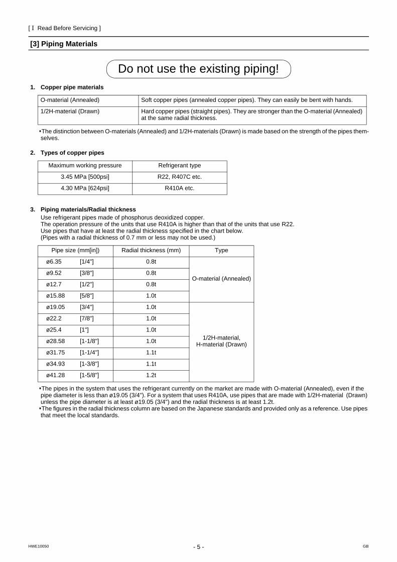
[3] Piping Materials
1. Copper pipe materials
The distinction between O-materials (Annealed) and 1/2H-materials (Drawn) is made based on the strength of the pipes them-selves.
2. Types of copper pipes
3. Piping materials/Radial thicknessUse refrigerant pipes made of phosphorus deoxidized copper.The operation pressure of the units that use R410A is higher than that of the units that use R22. Use pipes that have at least the radial thickness specified in the chart below. (Pipes with a radial thickness of 0.7 mm or less may not be used.)
The pipes in the system that uses the refrigerant currently on the market are made with O-material (Annealed), even if the pipe diameter is less than ø19.05 (3/4"). For a system that uses R410A, use pipes that are made with 1/2H-material (Drawn) unless the pipe diameter is at least ø19.05 (3/4") and the radial thickness is at least 1.2t.The figures in the radial thickness column are based on the Japanese standards and provided only as a reference. Use pipes that meet the local standards.
O-material (Annealed) Soft copper pipes (annealed copper pipes). They can easily be bent with hands.
1/2H-material (Drawn) Hard copper pipes (straight pipes). They are stronger than the O-material (Annealed) at the same radial thickness.
Maximum working pressure Refrigerant type
3.45 MPa [500psi] R22, R407C etc.
4.30 MPa [624psi] R410A etc.
Pipe size (mm[in]) Radial thickness (mm) Type
ø6.35 [1/4"] 0.8t
O-material (Annealed)ø9.52 [3/8"] 0.8t
ø12.7 [1/2"] 0.8t
ø15.88 [5/8"] 1.0t
ø19.05 [3/4"] 1.0t
1/2H-material, H-material (Drawn)
ø22.2 [7/8"] 1.0t
ø25.4 [1"] 1.0t
ø28.58 [1-1/8"] 1.0t
ø31.75 [1-1/4"] 1.1t
ø34.93 [1-3/8"] 1.1t
ø41.28 [1-5/8"] 1.2t
Do not use the existing piping!
[ I Read Before Servicing ]
- 6 -HWE10050 GB
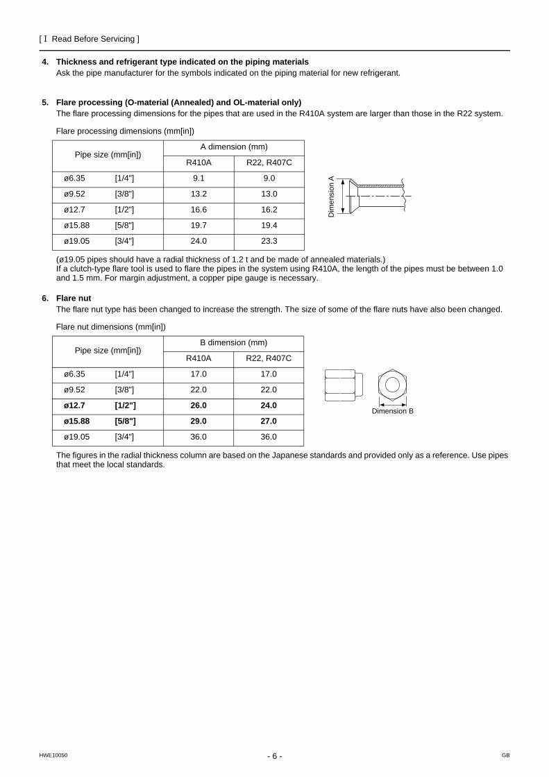
4. Thickness and refrigerant type indicated on the piping materialsAsk the pipe manufacturer for the symbols indicated on the piping material for new refrigerant.
5. Flare processing (O-material (Annealed) and OL-material only)The flare processing dimensions for the pipes that are used in the R410A system are larger than those in the R22 system.
(ø19.05 pipes should have a radial thickness of 1.2 t and be made of annealed materials.) If a clutch-type flare tool is used to flare the pipes in the system using R410A, the length of the pipes must be between 1.0 and 1.5 mm. For margin adjustment, a copper pipe gauge is necessary.
6. Flare nutThe flare nut type has been changed to increase the strength. The size of some of the flare nuts have also been changed.
The figures in the radial thickness column are based on the Japanese standards and provided only as a reference. Use pipes that meet the local standards.
Flare processing dimensions (mm[in])
Pipe size (mm[in])A dimension (mm)
R410A R22, R407C
ø6.35 [1/4"] 9.1 9.0
ø9.52 [3/8"] 13.2 13.0
ø12.7 [1/2"] 16.6 16.2
ø15.88 [5/8"] 19.7 19.4
ø19.05 [3/4"] 24.0 23.3
Flare nut dimensions (mm[in])
Pipe size (mm[in])B dimension (mm)
R410A R22, R407C
ø6.35 [1/4"] 17.0 17.0
ø9.52 [3/8"] 22.0 22.0
ø12.7 [1/2"] 26.0 24.0
ø15.88 [5/8"] 29.0 27.0
ø19.05 [3/4"] 36.0 36.0
Dim
ensi
on A
Dimension B
[ I Read Before Servicing ]
- 7 -HWE10050 GB
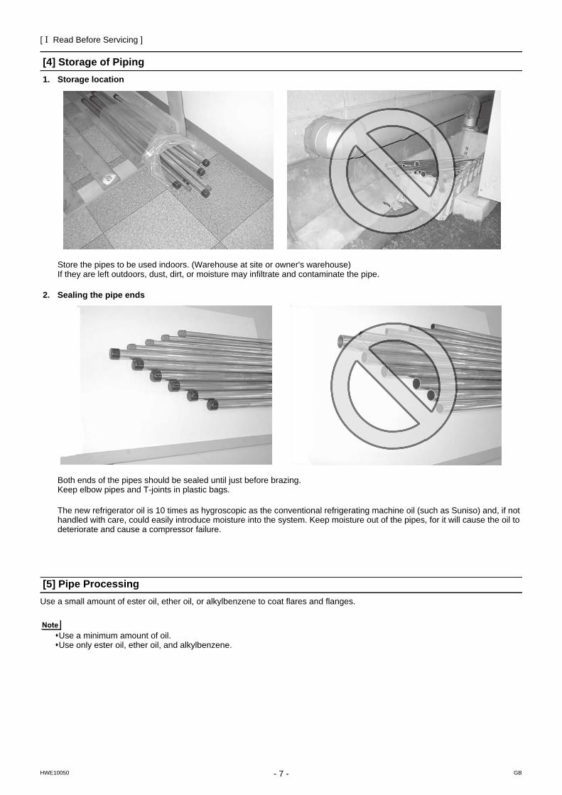
[4] Storage of Piping1. Storage location
Store the pipes to be used indoors. (Warehouse at site or owner's warehouse) If they are left outdoors, dust, dirt, or moisture may infiltrate and contaminate the pipe.
2. Sealing the pipe ends
Both ends of the pipes should be sealed until just before brazing.Keep elbow pipes and T-joints in plastic bags.
The new refrigerator oil is 10 times as hygroscopic as the conventional refrigerating machine oil (such as Suniso) and, if not handled with care, could easily introduce moisture into the system. Keep moisture out of the pipes, for it will cause the oil to deteriorate and cause a compressor failure.
[5] Pipe ProcessingUse a small amount of ester oil, ether oil, or alkylbenzene to coat flares and flanges.
Use a minimum amount of oil. Use only ester oil, ether oil, and alkylbenzene.
[ I Read Before Servicing ]
- 8 -HWE10050 GB
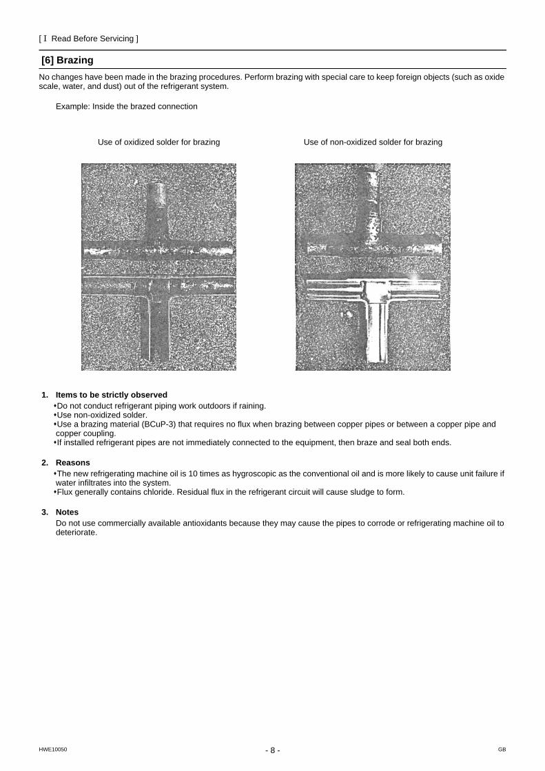
[6] BrazingNo changes have been made in the brazing procedures. Perform brazing with special care to keep foreign objects (such as oxide scale, water, and dust) out of the refrigerant system.
Example: Inside the brazed connection
1. Items to be strictly observedDo not conduct refrigerant piping work outdoors if raining.Use non-oxidized solder.Use a brazing material (BCuP-3) that requires no flux when brazing between copper pipes or between a copper pipe and copper coupling.If installed refrigerant pipes are not immediately connected to the equipment, then braze and seal both ends.
2. ReasonsThe new refrigerating machine oil is 10 times as hygroscopic as the conventional oil and is more likely to cause unit failure if water infiltrates into the system.Flux generally contains chloride. Residual flux in the refrigerant circuit will cause sludge to form.
3. NotesDo not use commercially available antioxidants because they may cause the pipes to corrode or refrigerating machine oil to deteriorate.
Use of oxidized solder for brazing Use of non-oxidized solder for brazing
[ I Read Before Servicing ]
- 9 -HWE10050 GB
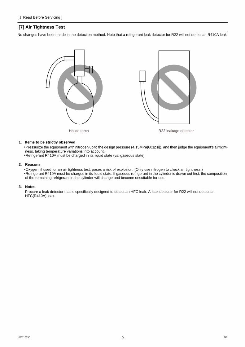
[7] Air Tightness TestNo changes have been made in the detection method. Note that a refrigerant leak detector for R22 will not detect an R410A leak.
1. Items to be strictly observedPressurize the equipment with nitrogen up to the design pressure (4.15MPa[601psi]), and then judge the equipment's air tight-ness, taking temperature variations into account.Refrigerant R410A must be charged in its liquid state (vs. gaseous state).
2. ReasonsOxygen, if used for an air tightness test, poses a risk of explosion. (Only use nitrogen to check air tightness.)Refrigerant R410A must be charged in its liquid state. If gaseous refrigerant in the cylinder is drawn out first, the composition of the remaining refrigerant in the cylinder will change and become unsuitable for use.
3. NotesProcure a leak detector that is specifically designed to detect an HFC leak. A leak detector for R22 will not detect an HFC(R410A) leak.
Halide torch R22 leakage detector
[ I Read Before Servicing ]
- 10 -HWE10050 GB
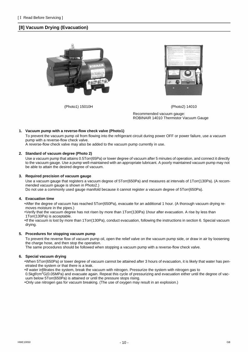
[8] Vacuum Drying (Evacuation)
1. Vacuum pump with a reverse-flow check valve (Photo1)To prevent the vacuum pump oil from flowing into the refrigerant circuit during power OFF or power failure, use a vacuum pump with a reverse-flow check valve.A reverse-flow check valve may also be added to the vacuum pump currently in use.
2. Standard of vacuum degree (Photo 2)Use a vacuum pump that attains 0.5Torr(65Pa) or lower degree of vacuum after 5 minutes of operation, and connect it directly to the vacuum gauge. Use a pump well-maintained with an appropriate lubricant. A poorly maintained vacuum pump may not be able to attain the desired degree of vacuum.
3. Required precision of vacuum gaugeUse a vacuum gauge that registers a vacuum degree of 5Torr(650Pa) and measures at intervals of 1Torr(130Pa). (A recom-mended vacuum gauge is shown in Photo2.)Do not use a commonly used gauge manifold because it cannot register a vacuum degree of 5Torr(650Pa).
4. Evacuation timeAfter the degree of vacuum has reached 5Torr(650Pa), evacuate for an additional 1 hour. (A thorough vacuum drying re-moves moisture in the pipes.)Verify that the vacuum degree has not risen by more than 1Torr(130Pa) 1hour after evacuation. A rise by less than 1Torr(130Pa) is acceptable.If the vacuum is lost by more than 1Torr(130Pa), conduct evacuation, following the instructions in section 6. Special vacuum drying.
5. Procedures for stopping vacuum pumpTo prevent the reverse flow of vacuum pump oil, open the relief valve on the vacuum pump side, or draw in air by loosening the charge hose, and then stop the operation.The same procedures should be followed when stopping a vacuum pump with a reverse-flow check valve.
6. Special vacuum dryingWhen 5Torr(650Pa) or lower degree of vacuum cannot be attained after 3 hours of evacuation, it is likely that water has pen-etrated the system or that there is a leak.If water infiltrates the system, break the vacuum with nitrogen. Pressurize the system with nitrogen gas to 0.5kgf/cm2G(0.05MPa) and evacuate again. Repeat this cycle of pressurizing and evacuation either until the degree of vac-uum below 5Torr(650Pa) is attained or until the pressure stops rising.Only use nitrogen gas for vacuum breaking. (The use of oxygen may result in an explosion.)
(Photo1) 15010H (Photo2) 14010
Recommended vacuum gauge: ROBINAIR 14010 Thermistor Vacuum Gauge
[ I Read Before Servicing ]
- 11 -HWE10050 GB
7. NotesTo evacuate air from the entire systemApplying a vacuum through the check joints at the refrigerant service valve on the high and low pressure sides (BV1 and 2) is not enough to attain the desired vacuum pressure.Be sure to apply a vacuum through the check joints at the refrigerant service valve on the high and low pressure sides (BV1 and 2) and also through the check joints on the high and low pressure sides (CJ1 and 2).To evacuate air only from the outdoor unitsApply a vacuum through the check joints on the high and low pressure sides (CJ1, and 2). To evacuate air from the indoor units and extension pipes Apply a vacuum through the check joints at the refrigerant service valve on the high and low pressure sides (BV1 and 2).
[ I Read Before Servicing ]
- 12 -HWE10050 GB
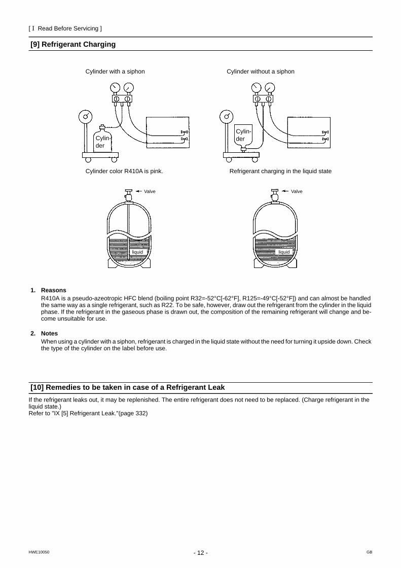
[9] Refrigerant Charging
1. ReasonsR410A is a pseudo-azeotropic HFC blend (boiling point R32=-52°C[-62°F], R125=-49°C[-52°F]) and can almost be handled the same way as a single refrigerant, such as R22. To be safe, however, draw out the refrigerant from the cylinder in the liquid phase. If the refrigerant in the gaseous phase is drawn out, the composition of the remaining refrigerant will change and be-come unsuitable for use.
2. NotesWhen using a cylinder with a siphon, refrigerant is charged in the liquid state without the need for turning it upside down. Check the type of the cylinder on the label before use.
[10] Remedies to be taken in case of a Refrigerant LeakIf the refrigerant leaks out, it may be replenished. The entire refrigerant does not need to be replaced. (Charge refrigerant in the liquid state.)Refer to "IX [5] Refrigerant Leak."(page 332)
Cylinder with a siphon
Cylinder color R410A is pink. Refrigerant charging in the liquid state
Cylin-der
liquid
Valve Valve
liquid
Cylin-der
Cylinder without a siphon
[ I Read Before Servicing ]
- 13 -HWE10050 GB
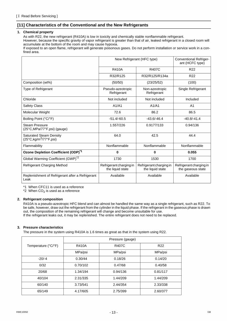
[11] Characteristics of the Conventional and the New Refrigerants1. Chemical property
As with R22, the new refrigerant (R410A) is low in toxicity and chemically stable nonflammable refrigerant.However, because the specific gravity of vapor refrigerant is greater than that of air, leaked refrigerant in a closed room will accumulate at the bottom of the room and may cause hypoxia.If exposed to an open flame, refrigerant will generate poisonous gases. Do not perform installation or service work in a con-fined area.
*1 When CFC11 is used as a reference*2 When CO2 is used as a reference
2. Refrigerant compositionR410A is a pseudo-azeotropic HFC blend and can almost be handled the same way as a single refrigerant, such as R22. To be safe, however, draw out the refrigerant from the cylinder in the liquid phase. If the refrigerant in the gaseous phase is drawn out, the composition of the remaining refrigerant will change and become unsuitable for use.If the refrigerant leaks out, it may be replenished. The entire refrigerant does not need to be replaced.
3. Pressure characteristicsThe pressure in the system using R410A is 1.6 times as great as that in the system using R22.
New Refrigerant (HFC type) Conventional Refriger-ant (HCFC type)
R410A R407C R22
R32/R125 R32/R125/R134a R22
Composition (wt%) (50/50) (23/25/52) (100)
Type of Refrigerant Pseudo-azeotropic Refrigerant
Non-azeotropic Refrigerant
Single Refrigerant
Chloride Not included Not included Included
Safety Class A1/A1 A1/A1 A1
Molecular Weight 72.6 86.2 86.5
Boiling Point (°C/°F) -51.4/-60.5 -43.6/-46.4 -40.8/-41.4
Steam Pressure(25°C,MPa/77°F,psi) (gauge)
1.557/226 0.9177/133 0.94/136
Saturated Steam Density(25°C,kg/m3/77°F,psi)
64.0 42.5 44.4
Flammability Nonflammable Nonflammable Nonflammable
Ozone Depletion Coefficient (ODP)*1 0 0 0.055
Global Warming Coefficient (GWP)*2 1730 1530 1700
Refrigerant Charging Method Refrigerant charging in the liquid state
Refrigerant charging in the liquid state
Refrigerant charging in the gaseous state
Replenishment of Refrigerant after a Refrigerant Leak
Available Available Available
Temperature (°C/°F)
Pressure (gauge)
R410A R407C R22
MPa/psi MPa/psi MPa/psi
-20/-4 0.30/44 0.18/26 0.14/20
0/32 0.70/102 0.47/68 0.40/58
20/68 1.34/194 0.94/136 0.81/117
40/104 2.31/335 1.44/209 1.44/209
60/140 3.73/541 2.44/354 2.33/338
65/149 4.17/605 2.75/399 2.60/377
[ I Read Before Servicing ]
- 14 -HWE10050 GB
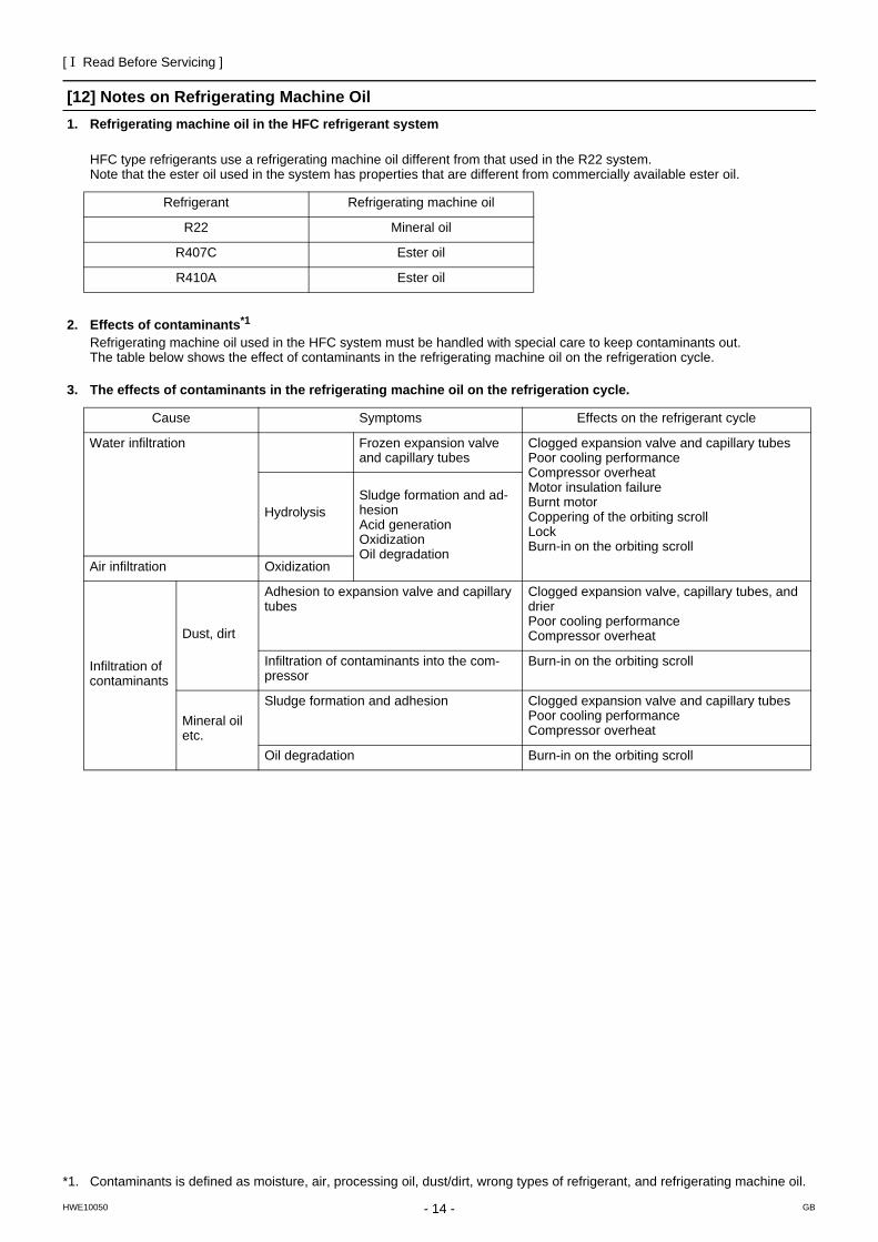
[12] Notes on Refrigerating Machine Oil1. Refrigerating machine oil in the HFC refrigerant system
HFC type refrigerants use a refrigerating machine oil different from that used in the R22 system.Note that the ester oil used in the system has properties that are different from commercially available ester oil.
2. Effects of contaminants*1
Refrigerating machine oil used in the HFC system must be handled with special care to keep contaminants out.The table below shows the effect of contaminants in the refrigerating machine oil on the refrigeration cycle.
3. The effects of contaminants in the refrigerating machine oil on the refrigeration cycle.
Refrigerant Refrigerating machine oil
R22 Mineral oil
R407C Ester oil
R410A Ester oil
*1. Contaminants is defined as moisture, air, processing oil, dust/dirt, wrong types of refrigerant, and refrigerating machine oil.
Cause Symptoms Effects on the refrigerant cycle
Water infiltration Frozen expansion valve and capillary tubes
Clogged expansion valve and capillary tubesPoor cooling performanceCompressor overheatMotor insulation failureBurnt motorCoppering of the orbiting scrollLockBurn-in on the orbiting scroll
HydrolysisSludge formation and ad-hesionAcid generationOxidizationOil degradation
Air infiltration Oxidization
Infiltration of contaminants
Dust, dirt
Adhesion to expansion valve and capillary tubes
Clogged expansion valve, capillary tubes, and drierPoor cooling performanceCompressor overheat
Infiltration of contaminants into the com-pressor
Burn-in on the orbiting scroll
Mineral oil etc.
Sludge formation and adhesion Clogged expansion valve and capillary tubesPoor cooling performanceCompressor overheat
Oil degradation Burn-in on the orbiting scroll
- 15 -HWE10050 GB
II Restrictions
[1] System configuration .......................................................................................................17[2] Types and Maximum allowable Length of Cables ...........................................................19[3] Switch Settings and Address Settings .............................................................................20[4] Sample System Connection.............................................................................................26[5] An Example of a System to which an MA Remote Controller is connected.....................28[6] An Example of a System to which an ME Remote Controller is connected.....................42[7] An Example of a System to which both MA Remote Controller and
ME Remote Controller are connected..............................................................................44[8] Restrictions on Pipe Length.............................................................................................47

- 16 -
[ II Restrictions ]
- 17 -HWE10050 GB
II Restrictions
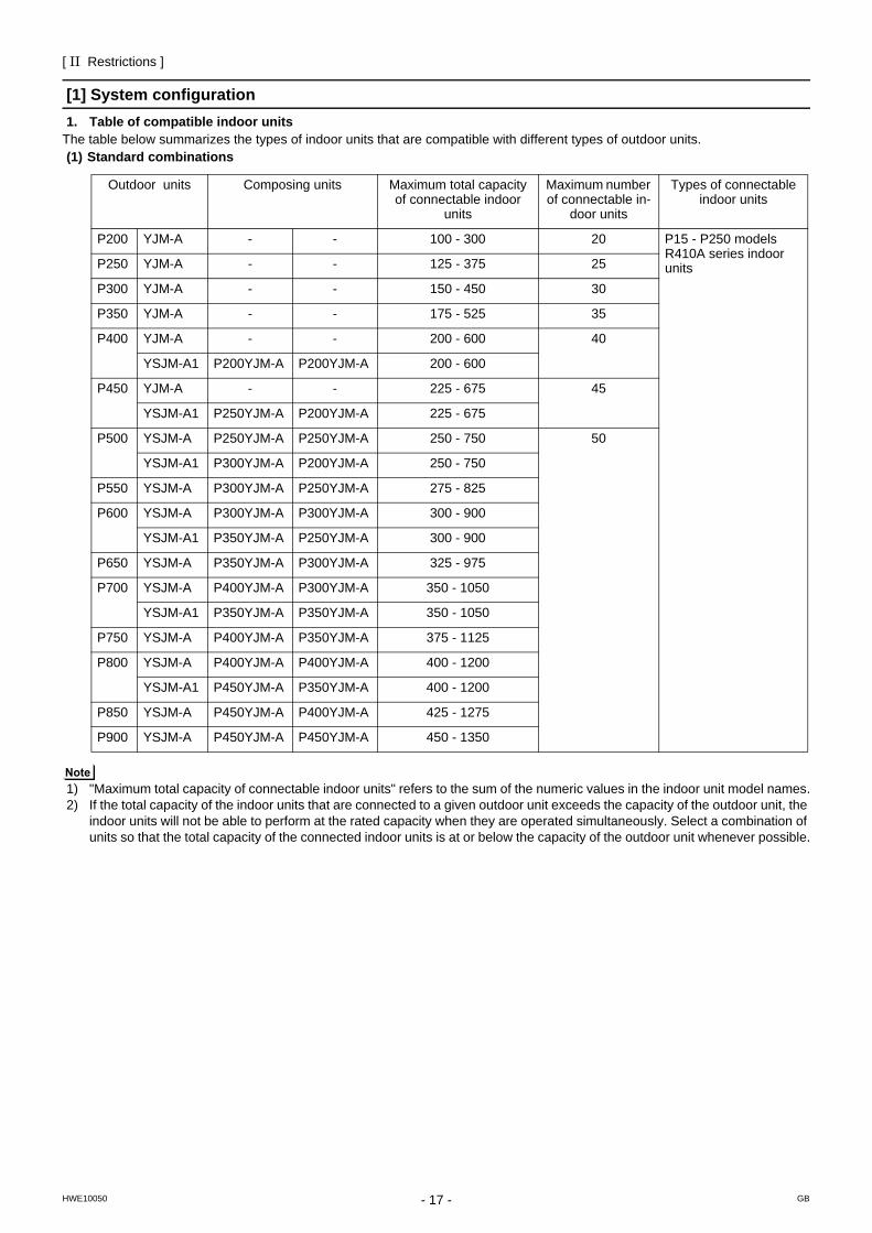
[1] System configuration1. Table of compatible indoor units
The table below summarizes the types of indoor units that are compatible with different types of outdoor units. (1) Standard combinations
1) "Maximum total capacity of connectable indoor units" refers to the sum of the numeric values in the indoor unit model names.2) If the total capacity of the indoor units that are connected to a given outdoor unit exceeds the capacity of the outdoor unit, the
indoor units will not be able to perform at the rated capacity when they are operated simultaneously. Select a combination of units so that the total capacity of the connected indoor units is at or below the capacity of the outdoor unit whenever possible.
Outdoor units Composing units Maximum total capacity of connectable indoor
units
Maximum number of connectable in-
door units
Types of connectable indoor units
P200 YJM-A - - 100 - 300 20 P15 - P250 modelsR410A series indoor unitsP250 YJM-A - - 125 - 375 25
P300 YJM-A - - 150 - 450 30
P350 YJM-A - - 175 - 525 35
P400 YJM-A - - 200 - 600 40
YSJM-A1 P200YJM-A P200YJM-A 200 - 600
P450 YJM-A - - 225 - 675 45
YSJM-A1 P250YJM-A P200YJM-A 225 - 675
P500 YSJM-A P250YJM-A P250YJM-A 250 - 750 50
YSJM-A1 P300YJM-A P200YJM-A 250 - 750
P550 YSJM-A P300YJM-A P250YJM-A 275 - 825
P600 YSJM-A P300YJM-A P300YJM-A 300 - 900
YSJM-A1 P350YJM-A P250YJM-A 300 - 900
P650 YSJM-A P350YJM-A P300YJM-A 325 - 975
P700 YSJM-A P400YJM-A P300YJM-A 350 - 1050
YSJM-A1 P350YJM-A P350YJM-A 350 - 1050
P750 YSJM-A P400YJM-A P350YJM-A 375 - 1125
P800 YSJM-A P400YJM-A P400YJM-A 400 - 1200
YSJM-A1 P450YJM-A P350YJM-A 400 - 1200
P850 YSJM-A P450YJM-A P400YJM-A 425 - 1275
P900 YSJM-A P450YJM-A P450YJM-A 450 - 1350
[ II Restrictions ]
- 18 -HWE10050 GB
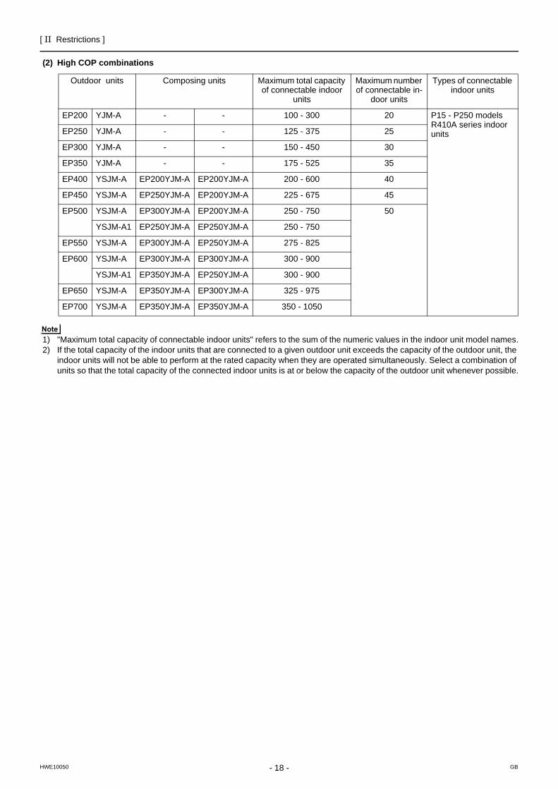
(2) High COP combinations
1) "Maximum total capacity of connectable indoor units" refers to the sum of the numeric values in the indoor unit model names.2) If the total capacity of the indoor units that are connected to a given outdoor unit exceeds the capacity of the outdoor unit, the
indoor units will not be able to perform at the rated capacity when they are operated simultaneously. Select a combination of units so that the total capacity of the connected indoor units is at or below the capacity of the outdoor unit whenever possible.
Outdoor units Composing units Maximum total capacity of connectable indoor
units
Maximum number of connectable in-
door units
Types of connectable indoor units
EP200 YJM-A - - 100 - 300 20 P15 - P250 modelsR410A series indoor unitsEP250 YJM-A - - 125 - 375 25
EP300 YJM-A - - 150 - 450 30
EP350 YJM-A - - 175 - 525 35
EP400 YSJM-A EP200YJM-A EP200YJM-A 200 - 600 40
EP450 YSJM-A EP250YJM-A EP200YJM-A 225 - 675 45
EP500 YSJM-A EP300YJM-A EP200YJM-A 250 - 750 50
YSJM-A1 EP250YJM-A EP250YJM-A 250 - 750
EP550 YSJM-A EP300YJM-A EP250YJM-A 275 - 825
EP600 YSJM-A EP300YJM-A EP300YJM-A 300 - 900
YSJM-A1 EP350YJM-A EP250YJM-A 300 - 900
EP650 YSJM-A EP350YJM-A EP300YJM-A 325 - 975
EP700 YSJM-A EP350YJM-A EP350YJM-A 350 - 1050
[ II Restrictions ]
- 19 -HWE10050 GB
[2] Types and Maximum allowable Length of Cables1. Wiring work (1) Notes1) Have all electrical work performed by an authorized electrician according to the local regulations and instructions in this man-
ual.2) Install external transmission cables at least 5cm [1-31/32"] away from the power supply cable to avoid noise interference.
(Do not put the control cable and power supply cable in the same conduit tube.) 3) Provide grounding for the outdoor unit as required.4) Run the cable from the electric box of the indoor or outdoor unit in such way that the box is accessible for servicing.5) Do not connect power supply wiring to the terminal block for transmission line. Doing so will damage the electronic compo-
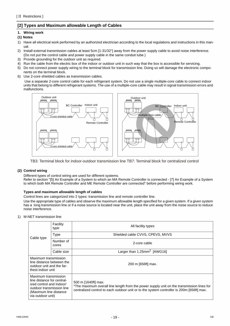
nents on the terminal block.6) Use 2-core shielded cables as transmission cables.
Use a separate 2-core control cable for each refrigerant system. Do not use a single multiple-core cable to connect indoor units that belong to different refrigerant systems. The use of a multiple-core cable may result in signal transmission errors and malfunctions.
(2) Control wiringDifferent types of control wiring are used for different systems. Refer to section "[5] An Example of a System to which an MA Remote Controller is connected - [7] An Example of a System to which both MA Remote Controller and ME Remote Controller are connected" before performing wiring work.
Types and maximum allowable length of cablesControl lines are categorized into 2 types: transmission line and remote controller line. Use the appropriate type of cables and observe the maximum allowable length specified for a given system. If a given system has a long transmission line or if a noise source is located near the unit, place the unit away from the noise source to reduce noise interference.
1) M-NET transmission line
Cable type
Facility type All facility types
Type Shielded cable CVVS, CPEVS, MVVS
Number of cores 2-core cable
Cable size Larger than 1.25mm2 [AWG16]
Maximum transmission line distance between the outdoor unit and the far-thest indoor unit
200 m [656ft] max.
Maximum transmission line distance for central-ized control and Indoor/outdoor transmission line(Maximum line distance via outdoor unit)
500 m [1640ft] max.*The maximum overall line length from the power supply unit on the transmission lines for centralized control to each outdoor unit or to the system controller is 200m [656ft] max.
TB3
TB7
TB3
TB7
TB3
TB7
TB3
TB7
TB3
TB7
TB3
TB7
TB3
TB7
TB3
TB7
TB3: Terminal block for indoor-outdoor transmission line TB7: Terminal block for centralized control
multiple-core cable
BC Controller Indoor unit
Remote ControllerRemote Controller
2-core shielded cable
2-core shielded cable
Outdoor unit
BC Controller Indoor unit
Outdoor unit
[ II Restrictions ]
- 20 -HWE10050 GB
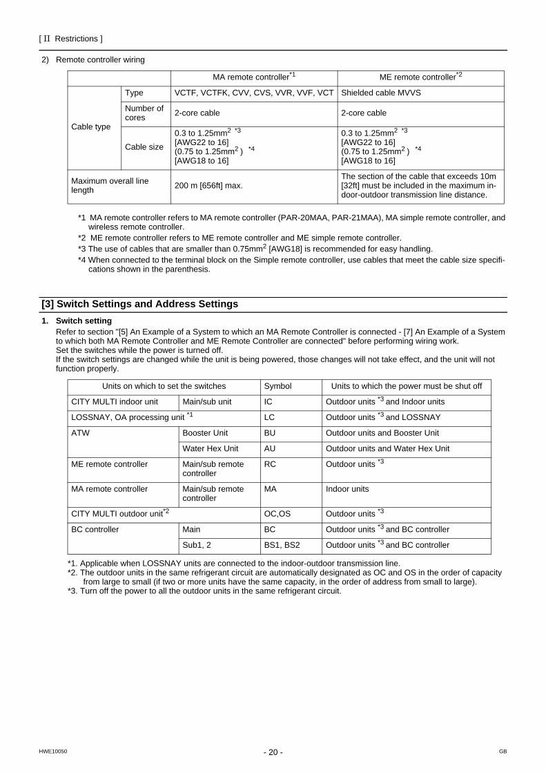
2) Remote controller wiring
*1 MA remote controller refers to MA remote controller (PAR-20MAA, PAR-21MAA), MA simple remote controller, and wireless remote controller.
*2 ME remote controller refers to ME remote controller and ME simple remote controller.*3 The use of cables that are smaller than 0.75mm2 [AWG18] is recommended for easy handling.*4 When connected to the terminal block on the Simple remote controller, use cables that meet the cable size specifi-
cations shown in the parenthesis.
[3] Switch Settings and Address Settings1. Switch setting
Refer to section "[5] An Example of a System to which an MA Remote Controller is connected - [7] An Example of a System to which both MA Remote Controller and ME Remote Controller are connected" before performing wiring work.Set the switches while the power is turned off.If the switch settings are changed while the unit is being powered, those changes will not take effect, and the unit will not function properly.
*1. Applicable when LOSSNAY units are connected to the indoor-outdoor transmission line.*2. The outdoor units in the same refrigerant circuit are automatically designated as OC and OS in the order of capacity
from large to small (if two or more units have the same capacity, in the order of address from small to large).*3. Turn off the power to all the outdoor units in the same refrigerant circuit.
MA remote controller*1 ME remote controller*2
Cable type
Type VCTF, VCTFK, CVV, CVS, VVR, VVF, VCT Shielded cable MVVS
Number of cores 2-core cable 2-core cable
Cable size
0.3 to 1.25mm2 *3 [AWG22 to 16] (0.75 to 1.25mm2 ) *4 [AWG18 to 16]
0.3 to 1.25mm2 *3 [AWG22 to 16] (0.75 to 1.25mm2 ) *4 [AWG18 to 16]
Maximum overall line length 200 m [656ft] max.
The section of the cable that exceeds 10m [32ft] must be included in the maximum in-door-outdoor transmission line distance.
Units on which to set the switches Symbol Units to which the power must be shut off
CITY MULTI indoor unit Main/sub unit IC Outdoor units *3 and Indoor units
LOSSNAY, OA processing unit *1 LC Outdoor units *3 and LOSSNAY
ATW Booster Unit BU Outdoor units and Booster Unit
Water Hex Unit AU Outdoor units and Water Hex Unit
ME remote controller Main/sub remote controller
RC Outdoor units *3
MA remote controller Main/sub remote controller
MA Indoor units
CITY MULTI outdoor unit*2 OC,OS Outdoor units *3
BC controller Main BC Outdoor units *3 and BC controller
Sub1, 2 BS1, BS2 Outdoor units *3 and BC controller
[ II Restrictions ]
- 21 -HWE10050 GB
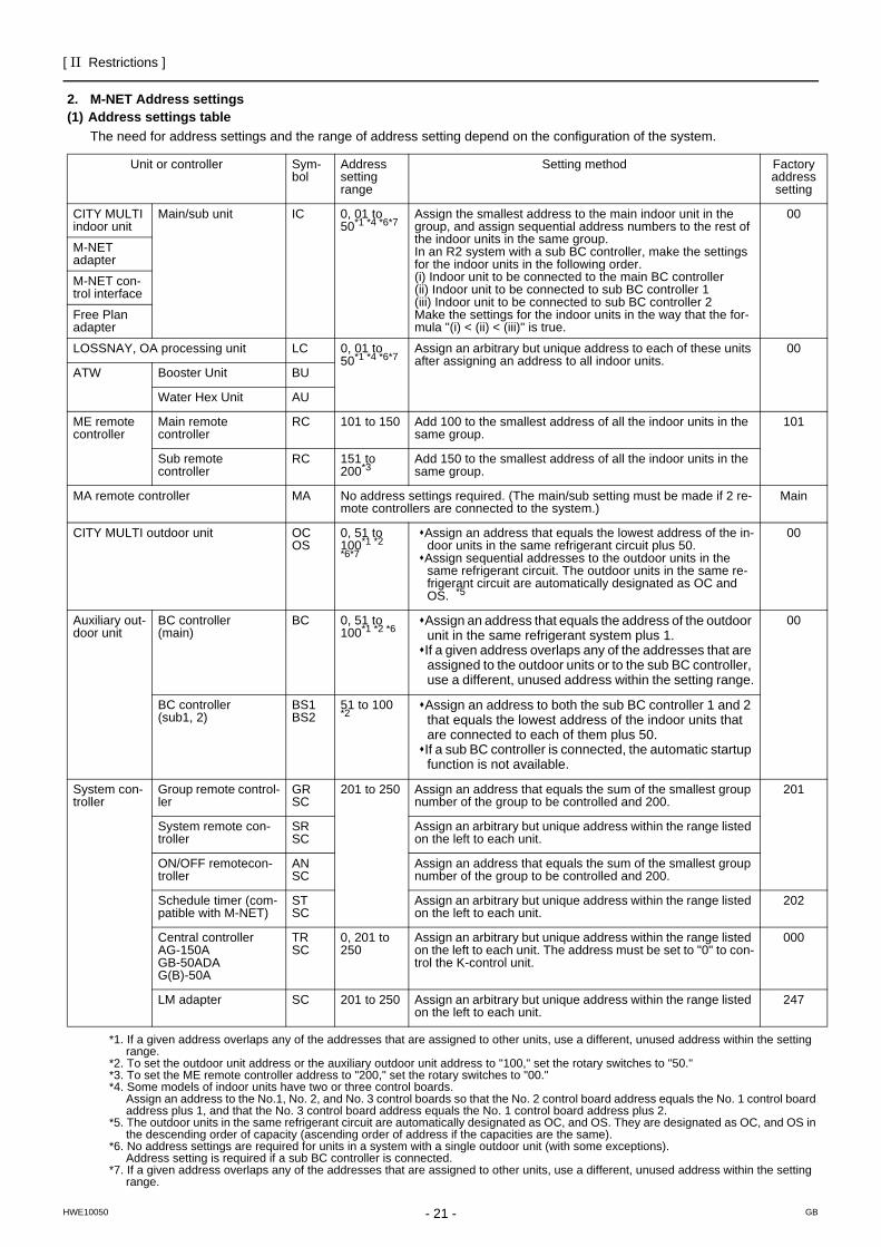
2. M-NET Address settings(1) Address settings table
The need for address settings and the range of address setting depend on the configuration of the system.
*1. If a given address overlaps any of the addresses that are assigned to other units, use a different, unused address within the setting range.
*2. To set the outdoor unit address or the auxiliary outdoor unit address to "100," set the rotary switches to "50."*3. To set the ME remote controller address to "200," set the rotary switches to "00."*4. Some models of indoor units have two or three control boards.
Assign an address to the No.1, No. 2, and No. 3 control boards so that the No. 2 control board address equals the No. 1 control board address plus 1, and that the No. 3 control board address equals the No. 1 control board address plus 2.
*5. The outdoor units in the same refrigerant circuit are automatically designated as OC, and OS. They are designated as OC, and OS in the descending order of capacity (ascending order of address if the capacities are the same).
*6. No address settings are required for units in a system with a single outdoor unit (with some exceptions). Address setting is required if a sub BC controller is connected.
*7. If a given address overlaps any of the addresses that are assigned to other units, use a different, unused address within the setting range.
Unit or controller Sym-bol
Address setting range
Setting method Factory address setting
CITY MULTI indoor unit
Main/sub unit IC 0, 01 to 50*1 *4 *6*7
Assign the smallest address to the main indoor unit in the group, and assign sequential address numbers to the rest of the indoor units in the same group. In an R2 system with a sub BC controller, make the settings for the indoor units in the following order. (i) Indoor unit to be connected to the main BC controller(ii) Indoor unit to be connected to sub BC controller 1(iii) Indoor unit to be connected to sub BC controller 2Make the settings for the indoor units in the way that the for-mula "(i) < (ii) < (iii)" is true.
00
M-NET adapter
M-NET con-trol interface
Free Plan adapter
LOSSNAY, OA processing unit LC 0, 01 to 50*1 *4 *6*7
Assign an arbitrary but unique address to each of these units after assigning an address to all indoor units.
00
ATW Booster Unit BU
Water Hex Unit AU
ME remote controller
Main remote controller
RC 101 to 150 Add 100 to the smallest address of all the indoor units in the same group.
101
Sub remote controller
RC 151 to 200*3
Add 150 to the smallest address of all the indoor units in the same group.
MA remote controller MA No address settings required. (The main/sub setting must be made if 2 re-mote controllers are connected to the system.)
Main
CITY MULTI outdoor unit OCOS
0, 51 to 100*1 *2 *6*7
Assign an address that equals the lowest address of the in-door units in the same refrigerant circuit plus 50.Assign sequential addresses to the outdoor units in the same refrigerant circuit. The outdoor units in the same re-frigerant circuit are automatically designated as OC and OS. *5
00
Auxiliary out-door unit
BC controller(main)
BC 0, 51 to 100*1 *2 *6
Assign an address that equals the address of the outdoor unit in the same refrigerant system plus 1.If a given address overlaps any of the addresses that are assigned to the outdoor units or to the sub BC controller, use a different, unused address within the setting range.
00
BC controller(sub1, 2)
BS1BS2
51 to 100 *2
Assign an address to both the sub BC controller 1 and 2 that equals the lowest address of the indoor units that are connected to each of them plus 50.If a sub BC controller is connected, the automatic startup function is not available.
System con-troller
Group remote control-ler
GRSC
201 to 250 Assign an address that equals the sum of the smallest group number of the group to be controlled and 200.
201
System remote con-troller
SRSC
Assign an arbitrary but unique address within the range listed on the left to each unit.
ON/OFF remotecon-troller
ANSC
Assign an address that equals the sum of the smallest group number of the group to be controlled and 200.
Schedule timer (com-patible with M-NET)
STSC
Assign an arbitrary but unique address within the range listed on the left to each unit.
202
Central controllerAG-150AGB-50ADAG(B)-50A
TRSC
0, 201 to 250
Assign an arbitrary but unique address within the range listed on the left to each unit. The address must be set to "0" to con-trol the K-control unit.
000
LM adapter SC 201 to 250 Assign an arbitrary but unique address within the range listed on the left to each unit.
247
[ II Restrictions ]
- 22 -HWE10050 GB
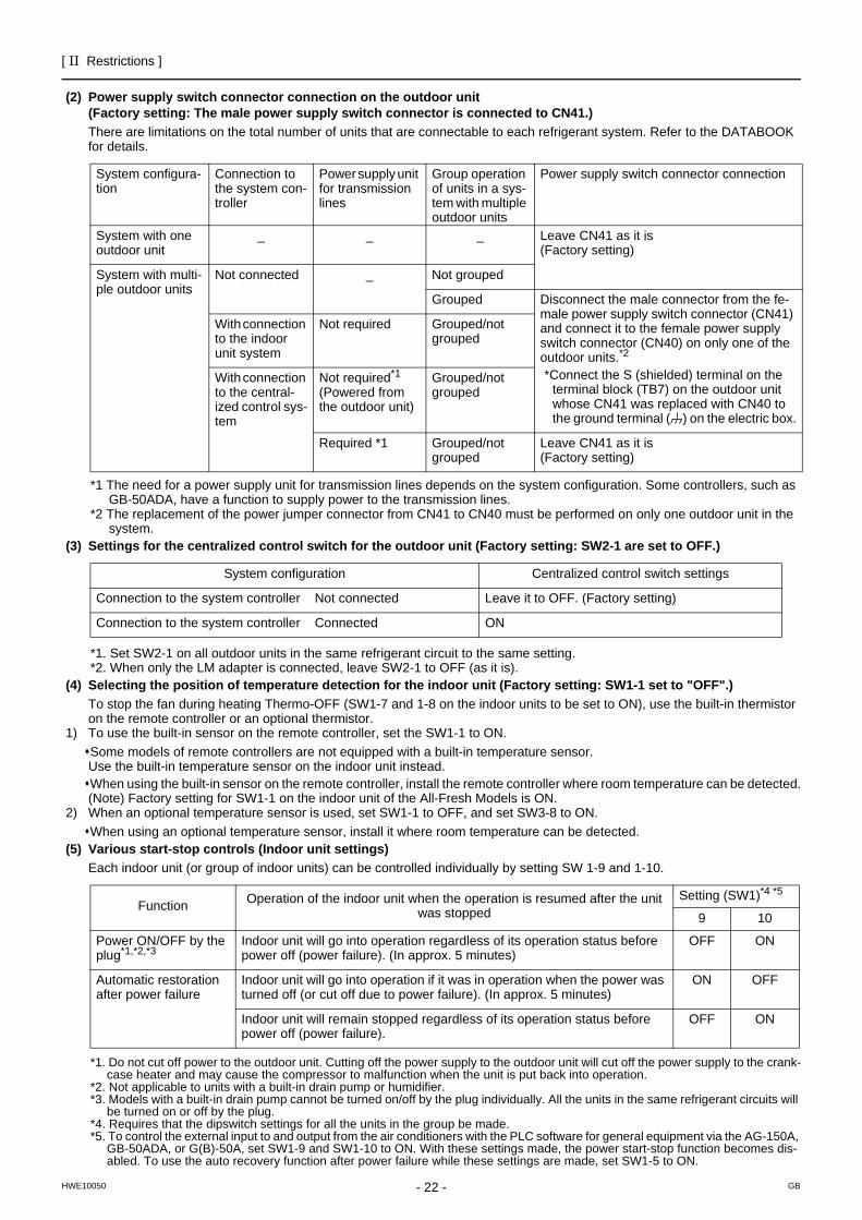
(2) Power supply switch connector connection on the outdoor unit(Factory setting: The male power supply switch connector is connected to CN41.)There are limitations on the total number of units that are connectable to each refrigerant system. Refer to the DATABOOK for details.
*1 The need for a power supply unit for transmission lines depends on the system configuration. Some controllers, such as GB-50ADA, have a function to supply power to the transmission lines.
*2 The replacement of the power jumper connector from CN41 to CN40 must be performed on only one outdoor unit in the system.
(3) Settings for the centralized control switch for the outdoor unit (Factory setting: SW2-1 are set to OFF.)
*1. Set SW2-1 on all outdoor units in the same refrigerant circuit to the same setting.*2. When only the LM adapter is connected, leave SW2-1 to OFF (as it is).
(4) Selecting the position of temperature detection for the indoor unit (Factory setting: SW1-1 set to "OFF".)To stop the fan during heating Thermo-OFF (SW1-7 and 1-8 on the indoor units to be set to ON), use the built-in thermistor on the remote controller or an optional thermistor.
1) To use the built-in sensor on the remote controller, set the SW1-1 to ON.Some models of remote controllers are not equipped with a built-in temperature sensor. Use the built-in temperature sensor on the indoor unit instead.When using the built-in sensor on the remote controller, install the remote controller where room temperature can be detected.(Note) Factory setting for SW1-1 on the indoor unit of the All-Fresh Models is ON.
2) When an optional temperature sensor is used, set SW1-1 to OFF, and set SW3-8 to ON.When using an optional temperature sensor, install it where room temperature can be detected.
(5) Various start-stop controls (Indoor unit settings)Each indoor unit (or group of indoor units) can be controlled individually by setting SW 1-9 and 1-10.
*1. Do not cut off power to the outdoor unit. Cutting off the power supply to the outdoor unit will cut off the power supply to the crank-case heater and may cause the compressor to malfunction when the unit is put back into operation.
*2. Not applicable to units with a built-in drain pump or humidifier.*3. Models with a built-in drain pump cannot be turned on/off by the plug individually. All the units in the same refrigerant circuits will
be turned on or off by the plug.*4. Requires that the dipswitch settings for all the units in the group be made.*5. To control the external input to and output from the air conditioners with the PLC software for general equipment via the AG-150A,
GB-50ADA, or G(B)-50A, set SW1-9 and SW1-10 to ON. With these settings made, the power start-stop function becomes dis-abled. To use the auto recovery function after power failure while these settings are made, set SW1-5 to ON.
System configura-tion
Connection to the system con-troller
Power supply unit for transmission lines
Group operation of units in a sys-tem with multiple outdoor units
Power supply switch connector connection
System with one outdoor unit
_ _ _ Leave CN41 as it is (Factory setting)
System with multi-ple outdoor units
Not connected _ Not grouped
Grouped Disconnect the male connector from the fe-male power supply switch connector (CN41) and connect it to the female power supply switch connector (CN40) on only one of the outdoor units.*2
*Connect the S (shielded) terminal on the terminal block (TB7) on the outdoor unit whose CN41 was replaced with CN40 to the ground terminal ( ) on the electric box.
With connection to the indoor unit system
Not required Grouped/not grouped
With connection to the central-ized control sys-tem
Not required*1 (Powered from the outdoor unit)
Grouped/not grouped
Required *1 Grouped/not grouped
Leave CN41 as it is (Factory setting)
System configuration Centralized control switch settings
Connection to the system controller Not connected Leave it to OFF. (Factory setting)
Connection to the system controller Connected ON
Function Operation of the indoor unit when the operation is resumed after the unit was stopped
Setting (SW1)*4 *5
9 10
Power ON/OFF by the plug*1,*2,*3
Indoor unit will go into operation regardless of its operation status before power off (power failure). (In approx. 5 minutes)
OFF ON
Automatic restoration after power failure
Indoor unit will go into operation if it was in operation when the power was turned off (or cut off due to power failure). (In approx. 5 minutes)
ON OFF
Indoor unit will remain stopped regardless of its operation status before power off (power failure).
OFF ON
[ II Restrictions ]
- 23 -HWE10050 GB
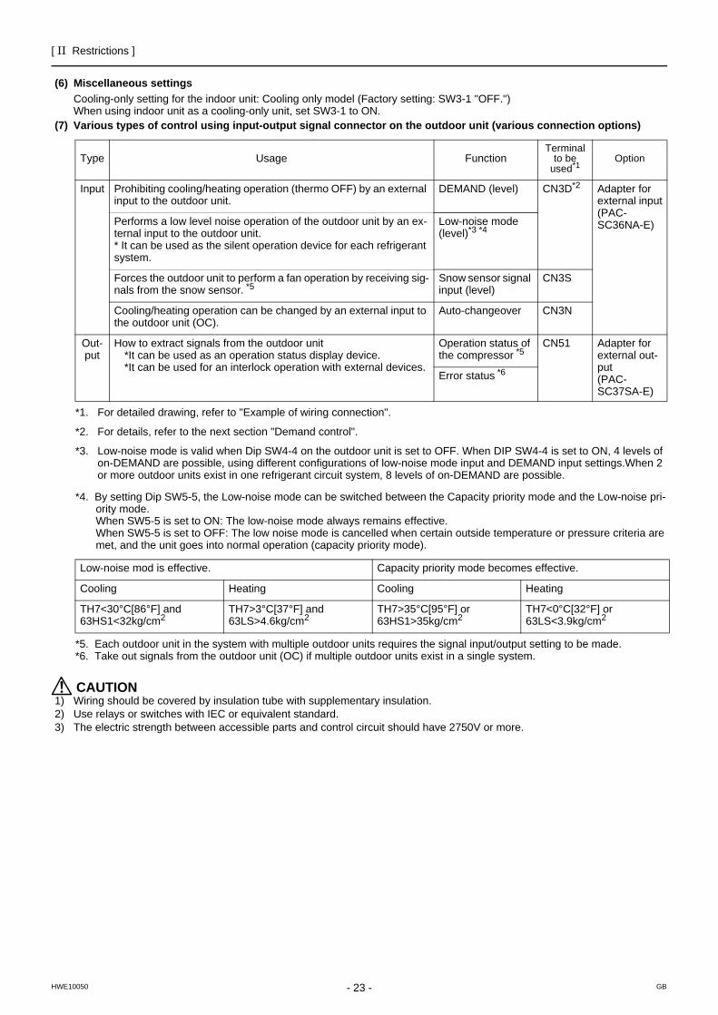
(6) Miscellaneous settingsCooling-only setting for the indoor unit: Cooling only model (Factory setting: SW3-1 "OFF.")When using indoor unit as a cooling-only unit, set SW3-1 to ON.
(7) Various types of control using input-output signal connector on the outdoor unit (various connection options)
*4. By setting Dip SW5-5, the Low-noise mode can be switched between the Capacity priority mode and the Low-noise pri-ority mode.When SW5-5 is set to ON: The low-noise mode always remains effective.When SW5-5 is set to OFF: The low noise mode is cancelled when certain outside temperature or pressure criteria are met, and the unit goes into normal operation (capacity priority mode).
*5. Each outdoor unit in the system with multiple outdoor units requires the signal input/output setting to be made.*6. Take out signals from the outdoor unit (OC) if multiple outdoor units exist in a single system.
CAUTION1) Wiring should be covered by insulation tube with supplementary insulation.2) Use relays or switches with IEC or equivalent standard.3) The electric strength between accessible parts and control circuit should have 2750V or more.
Type Usage FunctionTerminal
to be used*1
*1. For detailed drawing, refer to "Example of wiring connection".
Option
Input Prohibiting cooling/heating operation (thermo OFF) by an external input to the outdoor unit.
DEMAND (level) CN3D*2
*2. For details, refer to the next section "Demand control".
Adapter for external input(PAC-SC36NA-E)Performs a low level noise operation of the outdoor unit by an ex-
ternal input to the outdoor unit. * It can be used as the silent operation device for each refrigerant system.
Low-noise mode (level)*3 *4
*3. Low-noise mode is valid when Dip SW4-4 on the outdoor unit is set to OFF. When DIP SW4-4 is set to ON, 4 levels of on-DEMAND are possible, using different configurations of low-noise mode input and DEMAND input settings.When 2 or more outdoor units exist in one refrigerant circuit system, 8 levels of on-DEMAND are possible.
Forces the outdoor unit to perform a fan operation by receiving sig-nals from the snow sensor. *5
Snow sensor signal input (level)
CN3S
Cooling/heating operation can be changed by an external input to the outdoor unit (OC).
Auto-changeover CN3N
Out-put
How to extract signals from the outdoor unit *It can be used as an operation status display device.*It can be used for an interlock operation with external devices.
Operation status of the compressor *5
CN51 Adapter for external out-put(PAC-SC37SA-E)
Error status *6
Low-noise mod is effective. Capacity priority mode becomes effective.
Cooling Heating Cooling Heating
TH7<30°C[86°F] and 63HS1<32kg/cm2
TH7>3°C[37°F] and 63LS>4.6kg/cm2
TH7>35°C[95°F] or 63HS1>35kg/cm2
TH7<0°C[32°F] or 63LS<3.9kg/cm2
[ II Restrictions ]
- 24 -HWE10050 GB
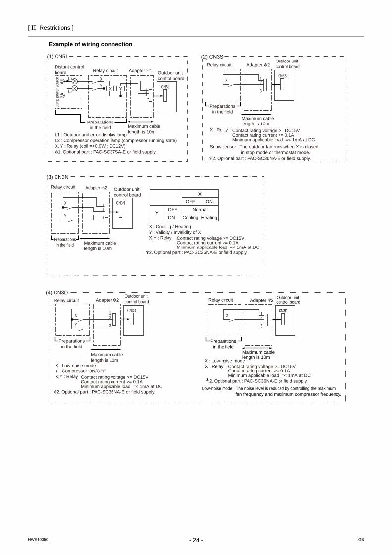
Example of wiring connection
(1) CN51 (2) CN3S
CN51
X
Y
L1
L2
ecruos rewop pmaL
Distant control board Relay circuit Adapter 1 Outdoor unit
control board
Preparationsin the field Maximum cable
length is 10m
543
X Y
L1 : Outdoor unit error display lampL2 : Compressor operation lamp (compressor running state)X, Y : Relay (coil =<0.9W : DC12V)
1. Optional part : PAC-SC37SA-E or field supply.2. Optional part : PAC-SC36NA-E or field supply.
X : Relay
Snow sensor : The outdoor fan runs when X is closed in stop mode or thermostat mode.
XCN3S
Preparationsin the field
Maximum cable length is 10m
Adapter 2Outdoor unitcontrol board
2
3
1
Contact rating voltage >= DC15VContact rating current >= 0.1AMinimum applicable load =< 1mA at DC
Relay circuit
(3) CN3N
2. Optional part : PAC-SC36NA-E or field supply.
Preparationsin the field
OFF
Cooling
ON
Heating
NormalY
OFF
ON
X
Contact rating voltage >= DC15VContact rating current >= 0.1AMinimum applicable load =< 1mA at DC
X : Cooling / HeatingY : Validity / Invalidity of XX,Y : Relay
CN3NX
Y
Relay circuit Adapter 2 Outdoor unitcontrol board
Maximum cable length is 10m
1
2
3
(4) CN3D
2. Optional part : PAC-SC36NA-E or field supply.
X : Low-noise modeX : Low-noise mode
Y : Compressor ON/OFFX,Y : Relay Contact rating voltage >= DC15V
Contact rating current >= 0.1AMinimum appicable load =< 1mA at DC
Y
XCN3D
Preparationsin the field
Maximum cable length is 10m
Adapter 2Outdoor unitcontrol board
3
21
Relay circuit
2. Optional part : PAC-SC36NA-E or field supply.
XCN3D
Preparationsin the field
Maximum cable length is 10m
Adapter 2Outdoor unitcontrol board
2
3
1
X : Relay
fan frequency and maximum compressor frequency.
Contact rating voltage >= DC15VContact rating current >= 0.1AMinimum applicable load =< 1mA at DC
Low-noise mode : The noise level is reduced by controlling the maximum
Relay circuit
[ II Restrictions ]
- 25 -HWE10050 GB
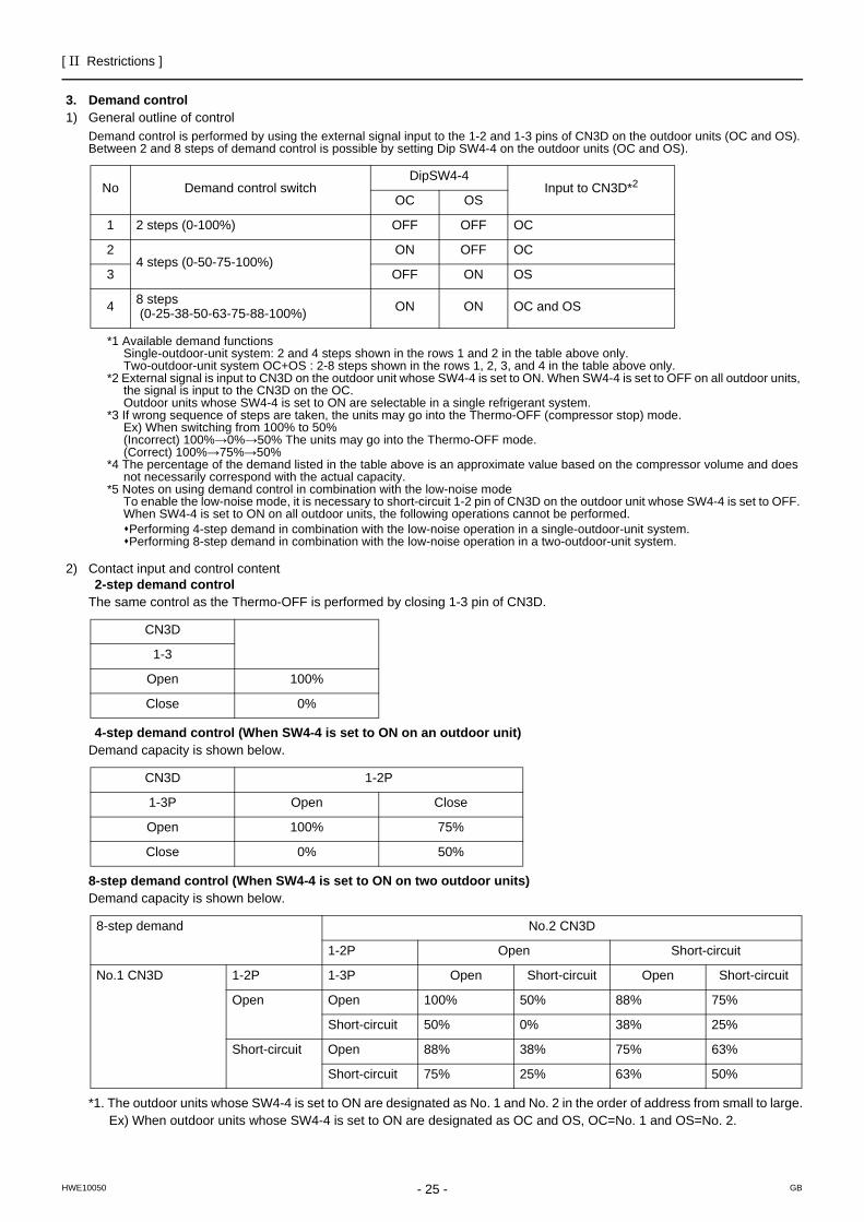
3. Demand control 1) General outline of control
Demand control is performed by using the external signal input to the 1-2 and 1-3 pins of CN3D on the outdoor units (OC and OS).Between 2 and 8 steps of demand control is possible by setting Dip SW4-4 on the outdoor units (OC and OS).
*1 Available demand functionsSingle-outdoor-unit system: 2 and 4 steps shown in the rows 1 and 2 in the table above only.Two-outdoor-unit system OC+OS : 2-8 steps shown in the rows 1, 2, 3, and 4 in the table above only.
*2 External signal is input to CN3D on the outdoor unit whose SW4-4 is set to ON. When SW4-4 is set to OFF on all outdoor units, the signal is input to the CN3D on the OC.Outdoor units whose SW4-4 is set to ON are selectable in a single refrigerant system.
*3 If wrong sequence of steps are taken, the units may go into the Thermo-OFF (compressor stop) mode.Ex) When switching from 100% to 50%(Incorrect) 100%→0%→50% The units may go into the Thermo-OFF mode.(Correct) 100%→75%→50%
*4 The percentage of the demand listed in the table above is an approximate value based on the compressor volume and does not necessarily correspond with the actual capacity.
*5 Notes on using demand control in combination with the low-noise mode To enable the low-noise mode, it is necessary to short-circuit 1-2 pin of CN3D on the outdoor unit whose SW4-4 is set to OFF. When SW4-4 is set to ON on all outdoor units, the following operations cannot be performed. Performing 4-step demand in combination with the low-noise operation in a single-outdoor-unit system.Performing 8-step demand in combination with the low-noise operation in a two-outdoor-unit system.
2) Contact input and control content2-step demand control
The same control as the Thermo-OFF is performed by closing 1-3 pin of CN3D.
4-step demand control (When SW4-4 is set to ON on an outdoor unit)Demand capacity is shown below.
8-step demand control (When SW4-4 is set to ON on two outdoor units)Demand capacity is shown below.
*1. The outdoor units whose SW4-4 is set to ON are designated as No. 1 and No. 2 in the order of address from small to large.Ex) When outdoor units whose SW4-4 is set to ON are designated as OC and OS, OC=No. 1 and OS=No. 2.
No Demand control switchDipSW4-4
Input to CN3D*2
OC OS
1 2 steps (0-100%) OFF OFF OC
24 steps (0-50-75-100%)
ON OFF OC
3 OFF ON OS
4 8 steps (0-25-38-50-63-75-88-100%) ON ON OC and OS
CN3D
1-3
Open 100%
Close 0%
CN3D 1-2P
1-3P Open Close
Open 100% 75%
Close 0% 50%
8-step demand No.2 CN3D
1-2P Open Short-circuit
No.1 CN3D 1-2P 1-3P Open Short-circuit Open Short-circuit
Open Open 100% 50% 88% 75%
Short-circuit 50% 0% 38% 25%
Short-circuit Open 88% 38% 75% 63%
Short-circuit 75% 25% 63% 50%
[ II Restrictions ]
- 26 -HWE10050 GB
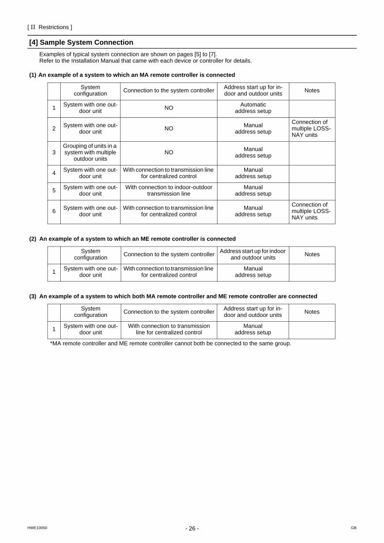
[4] Sample System ConnectionExamples of typical system connection are shown on pages [5] to [7]. Refer to the Installation Manual that came with each device or controller for details.
(1) An example of a system to which an MA remote controller is connected
(2) An example of a system to which an ME remote controller is connected
(3) An example of a system to which both MA remote controller and ME remote controller are connected
System configuration Connection to the system controller Address start up for in-
door and outdoor units Notes
1 System with one out-door unit NO Automatic
address setup
2 System with one out-door unit NO Manual
address setup
Connection of multiple LOSS-NAY units
3Grouping of units in a system with multiple
outdoor unitsNO Manual
address setup
4 System with one out-door unit
With connection to transmission line for centralized control
Manual address setup
5 System with one out-door unit
With connection to indoor-outdoortransmission line
Manual address setup
6 System with one out-door unit
With connection to transmission line for centralized control
Manual address setup
Connection of multiple LOSS-NAY units
System configuration Connection to the system controller Address start up for indoor
and outdoor units Notes
1 System with one out-door unit
With connection to transmission line for centralized control
Manual address setup
System configuration Connection to the system controller Address start up for in-
door and outdoor units Notes
1 System with one out-door unit
With connection to transmission line for centralized control
Manual address setup
*MA remote controller and ME remote controller cannot both be connected to the same group.

[ II Restrictions ]
- 27 -HWE10050 GB
- 28 -
[ II Restrictions ]
GBHWE10050
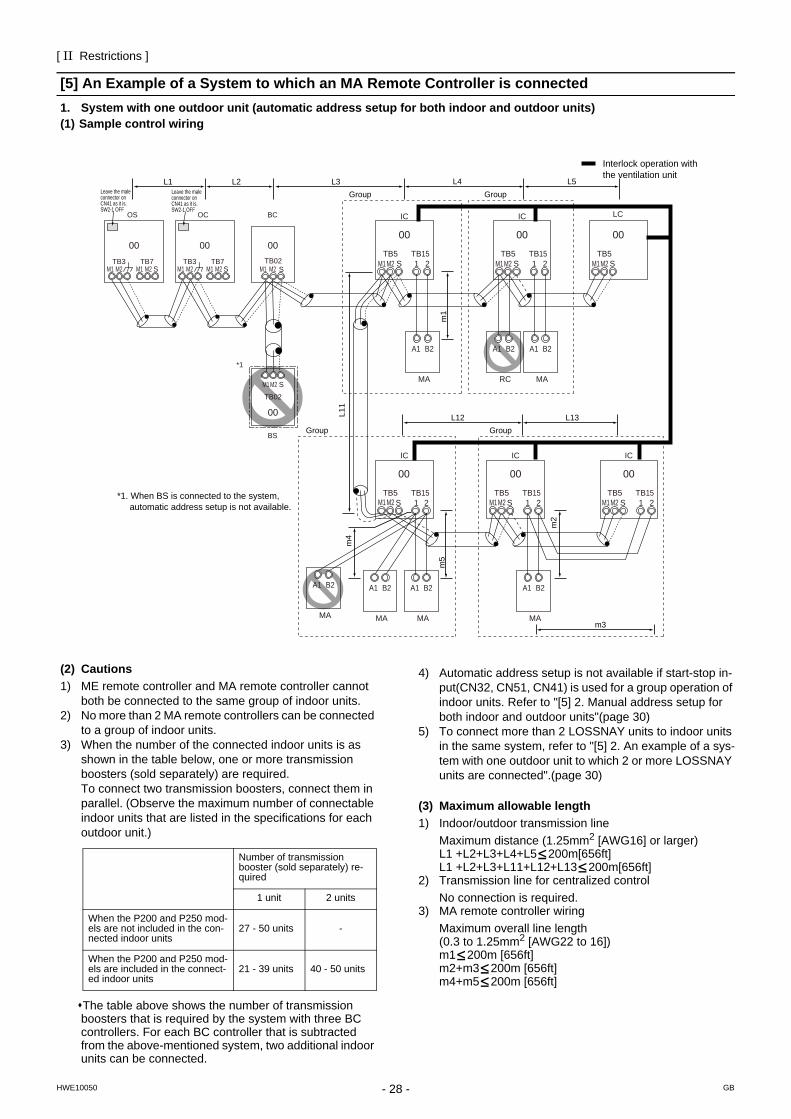
[5] An Example of a System to which an MA Remote Controller is connected1. System with one outdoor unit (automatic address setup for both indoor and outdoor units)(1) Sample control wiring
(2) Cautions1) ME remote controller and MA remote controller cannot
both be connected to the same group of indoor units.2) No more than 2 MA remote controllers can be connected
to a group of indoor units.3) When the number of the connected indoor units is as
shown in the table below, one or more transmission boosters (sold separately) are required.To connect two transmission boosters, connect them in parallel. (Observe the maximum number of connectable indoor units that are listed in the specifications for each outdoor unit.)
The table above shows the number of transmission boosters that is required by the system with three BC controllers. For each BC controller that is subtracted from the above-mentioned system, two additional indoor units can be connected.
4) Automatic address setup is not available if start-stop in-put(CN32, CN51, CN41) is used for a group operation of indoor units. Refer to "[5] 2. Manual address setup for both indoor and outdoor units"(page 30)
5) To connect more than 2 LOSSNAY units to indoor units in the same system, refer to "[5] 2. An example of a sys-tem with one outdoor unit to which 2 or more LOSSNAY units are connected".(page 30)
(3) Maximum allowable length1) Indoor/outdoor transmission line
Maximum distance (1.25mm2 [AWG16] or larger)L1 +L2+L3+L4+L5 200m[656ft]L1 +L2+L3+L11+L12+L13 200m[656ft]
2) Transmission line for centralized controlNo connection is required.
3) MA remote controller wiringMaximum overall line length (0.3 to 1.25mm2 [AWG22 to 16])m1 200m [656ft]m2+m3 200m [656ft]m4+m5 200m [656ft]
IC
TB5M1M2 M1M2 M1M2
M1M2M1M2M1M2
STB151 2
00
IC
TB5S
TB151 2
00
A1 B2
MA
A1 B2
MA
A1 B2
RC
LC
TB5S
00
IC
TB5S 1 2
TB15
IC
TB5S
TB151 2
0000
IC
TB5S
TB151 2
00
A1 B2
MA
A1 B2
MA
A1 B2
MA
GroupGroup
GroupGroup
A1 B2
MA
m1
L11
m2
L4 L5
L12 L13
m3
m5
m4
Interlock operation withthe ventilation unit
*1. When BS is connected to the system, automatic address setup is not available.
BC
00
OC
00TB7
M1 M2 STB3
OS
00TB7
M1 M2 M1 M2 M1 M2STB3 TB02
M1 M2 S
*1
BS
TB02
00
SM1M2
L3L1 L2Leave the maleconnector onCN41 as it is.SW2-1 OFF
Leave the maleconnector onCN41 as it is.SW2-1 OFF
Number of transmission booster (sold separately) re-quired
1 unit 2 units
When the P200 and P250 mod-els are not included in the con-nected indoor units
27 - 50 units -
When the P200 and P250 mod-els are included in the connect-ed indoor units
21 - 39 units 40 - 50 units
[ II Restrictions ]
29- 29 -HWE10050 GB
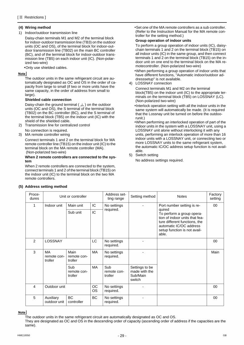
(4) Wiring method1) Indoor/outdoor transmission line
Daisy-chain terminals M1 and M2 of the terminal block for indoor-outdoor transmission line (TB3) on the outdoor units (OC and OS), of the terminal block for indoor-out-door transmission line (TB02) on the main BC controller (BC), and of the terminal block for indoor-outdoor trans-mission line (TB5) on each indoor unit (IC). (Non-polar-ized two-wire)Only use shielded cables.
The outdoor units in the same refrigerant circuit are au-tomatically designated as OC and OS in the order of ca-pacity from large to small (if two or more units have the same capacity, in the order of address from small to large).Shielded cable connectionDaisy-chain the ground terminal ( ) on the outdoor units (OC and OS), the S terminal of the terminal block (TB02) on the BC controller (BC), and the S terminal of the terminal block (TB5) on the indoor unit (IC) with the shield of the shielded cable.
2) Transmission line for centralized controlNo connection is required.
3) MA remote controller wiringConnect terminals 1 and 2 on the terminal block for MA remote controller line (TB15) on the indoor unit (IC) to the terminal block on the MA remote controller (MA). (Non-polarized two-wire)When 2 remote controllers are connected to the sys-temWhen 2 remote controllers are connected to the system, connect terminals 1 and 2 of the terminal block (TB15) on the indoor unit (IC) to the terminal block on the two MA remote controllers.
Set one of the MA remote controllers as a sub controller. (Refer to the Instruction Manual for the MA remote con-troller for the setting method.)Group operation of indoor unitsTo perform a group operation of indoor units (IC), daisy-chain terminals 1 and 2 on the terminal block (TB15) on all indoor units (IC) in the same group, and then connect terminals 1 and 2 on the terminal block (TB15) on the in-door unit on one end to the terminal block on the MA re-motecontroller. (Non-polarized two-wire)When performing a group operation of indoor units that have different functions, "Automatic indoor/outdoor ad-dresssetup" is not available.
4) LOSSNAY connectionConnect terminals M1 and M2 on the terminal block(TB5) on the indoor unit (IC) to the appropriate ter-minals on the terminal block (TB5) on LOSSNAY (LC). (Non-polarized two-wire)Interlock operation setting with all the indoor units in the same system will automatically be made. (It is required that the Lossnay unit be turned on before the outdoo-runit.)When performing an interlocked operation of part of the indoor units in the system with a LOSSNAY unit, using a LOSSNAY unit alone without interlocking it with any units, performing an interlock operation of more than 16 indoor units with a LOSSNAY unit, or connecting two or more LOSSNAY units to the same refrigerant system, the automatic IC/OC address setup function is not avail-able.
5) Switch settingNo address settings required.
(5) Address setting method
The outdoor units in the same refrigerant circuit are automatically designated as OC and OS.They are designated as OC and OS in the descending order of capacity (ascending order of address if the capacities are the same).
Proce-dures Unit or controller Address set-
ting range Setting method Notes Factory setting
1 Indoor unit Main unit IC No settings required.
- Port number setting is re-quiredTo perform a group opera-tion of indoor units that fea-ture different functions, the automatic IC/OC address setup function is not avail-able.
00
Sub unit IC
2 LOSSNAY LC No settings required.
- 00
3 MA remote con-troller
Main remote con-troller
MA No settings required.
- Main
Sub remote con-troller
MA Sub remote con-troller
Settings to be made with the Sub/Main switch
4 Outdoor unit OCOS
No settings required.
- 00
5 Auxiliary outdoor unit
BC controller
BC No settings required.
- 00
- 30 -
[ II Restrictions ]
GBHWE10050
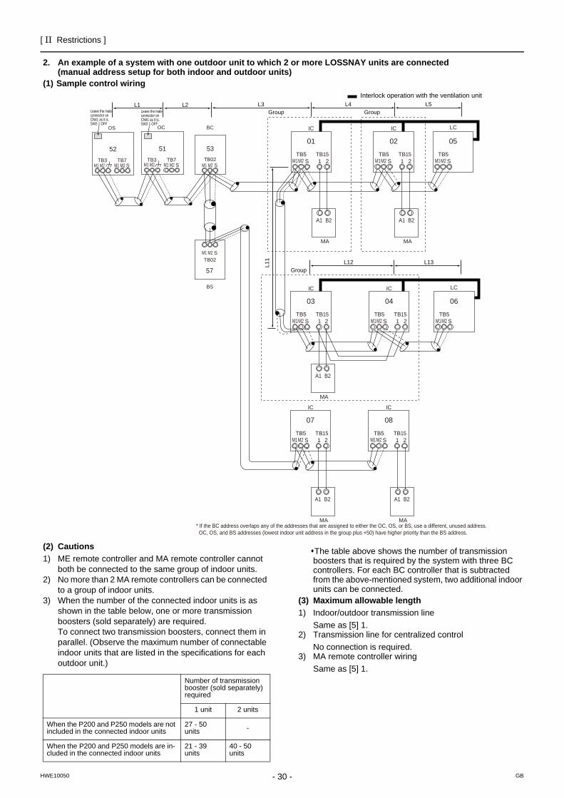
2. An example of a system with one outdoor unit to which 2 or more LOSSNAY units are connected (manual address setup for both indoor and outdoor units)
(1) Sample control wiring
(2) Cautions1) ME remote controller and MA remote controller cannot
both be connected to the same group of indoor units.2) No more than 2 MA remote controllers can be connected
to a group of indoor units.3) When the number of the connected indoor units is as
shown in the table below, one or more transmission boosters (sold separately) are required.To connect two transmission boosters, connect them in parallel. (Observe the maximum number of connectable indoor units that are listed in the specifications for each outdoor unit.)
The table above shows the number of transmission boosters that is required by the system with three BC controllers. For each BC controller that is subtracted from the above-mentioned system, two additional indoor units can be connected.
(3) Maximum allowable length1) Indoor/outdoor transmission line
Same as [5] 1.2) Transmission line for centralized control
No connection is required.3) MA remote controller wiring
Same as [5] 1.
L3
BC
53
OC
51TB7
STB3 TB02
S
IC
TB5S
TB151 2
01
IC
TB5S
TB151 2
02
A1 B2
MA
A1 B2
MA
LC
TB5S
05
IC
TB5S 1 2
TB15
IC
TB5S
TB151 2
0403
LC
TB5S
06
A1 B2
MA
* If the BC address overlaps any of the addresses that are assigned to either the OC, OS, or BS, use a different, unused address. OC, OS, and BS addresses (lowest indoor unit address in the group plus +50) have higher priority than the BS address.
IC
TB5S 1 2
TB15
IC
TB5S
TB151 2
0807
A1 B2
MA
A1 B2
MA
M1M2M1M2
L11
L4 L5
L12 L13
OS
52TB7
M1 M2 M1 M2M1 M2 M1 M2 M1 M2M1M2 M1M2 M1M2
M1M2M1M2M1M2
STB3
M1 M2TB02
S
57
BS
L1 L2GroupGroup
Group
Interlock operation with the ventilation unit
Leave the maleconnector onCN41 as it is.SW2-1 OFF
Leave the maleconnector onCN41 as it is.SW2-1 OFF
Number of transmission booster (sold separately) required
1 unit 2 units
When the P200 and P250 models are not included in the connected indoor units
27 - 50 units -
When the P200 and P250 models are in-cluded in the connected indoor units
21 - 39 units
40 - 50 units
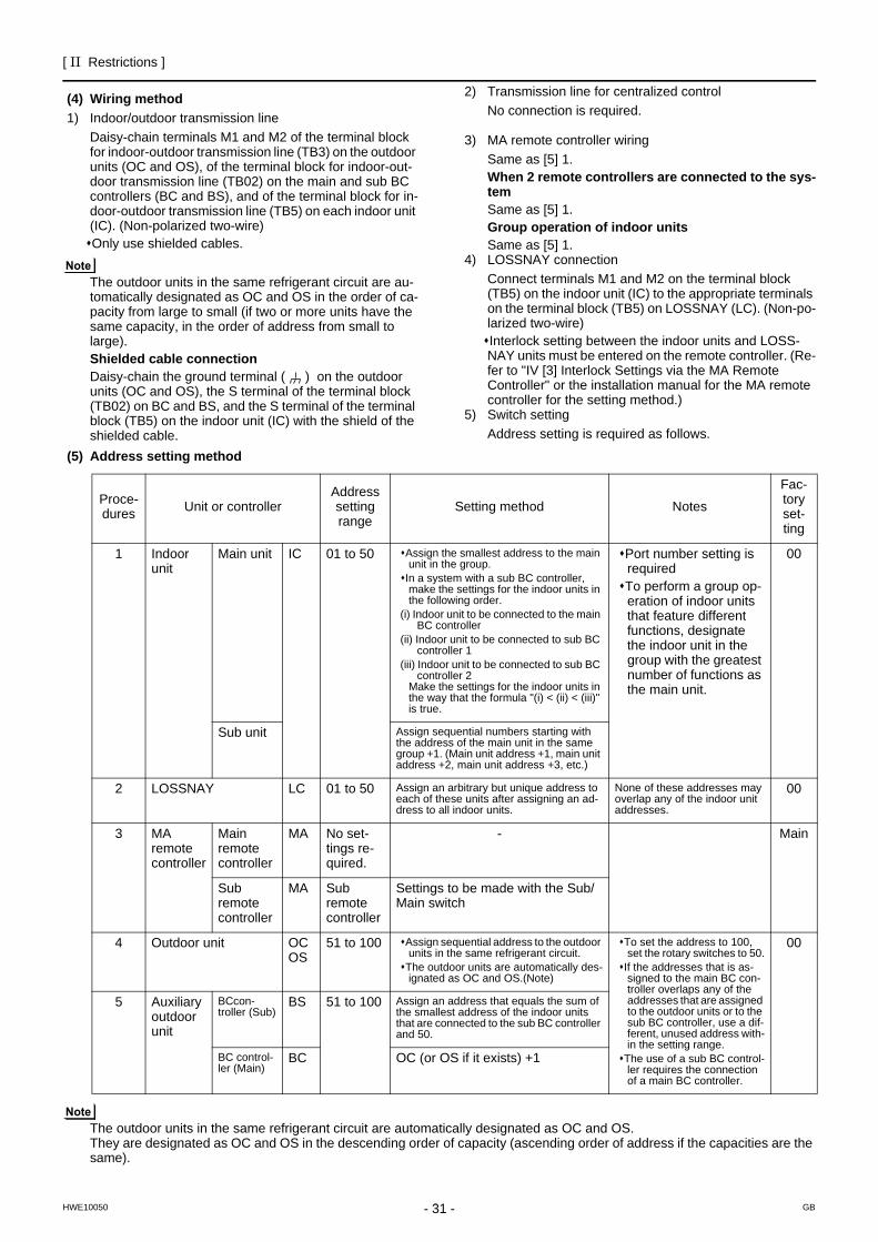
[ II Restrictions ]
31- 31 -HWE10050 GB
(4) Wiring method1) Indoor/outdoor transmission line
Daisy-chain terminals M1 and M2 of the terminal block for indoor-outdoor transmission line (TB3) on the outdoor units (OC and OS), of the terminal block for indoor-out-door transmission line (TB02) on the main and sub BC controllers (BC and BS), and of the terminal block for in-door-outdoor transmission line (TB5) on each indoor unit (IC). (Non-polarized two-wire)Only use shielded cables.
The outdoor units in the same refrigerant circuit are au-tomatically designated as OC and OS in the order of ca-pacity from large to small (if two or more units have the same capacity, in the order of address from small to large).Shielded cable connectionDaisy-chain the ground terminal ( ) on the outdoor units (OC and OS), the S terminal of the terminal block (TB02) on BC and BS, and the S terminal of the terminal block (TB5) on the indoor unit (IC) with the shield of the shielded cable.
2) Transmission line for centralized controlNo connection is required.
3) MA remote controller wiringSame as [5] 1.When 2 remote controllers are connected to the sys-temSame as [5] 1.Group operation of indoor unitsSame as [5] 1.
4) LOSSNAY connectionConnect terminals M1 and M2 on the terminal block (TB5) on the indoor unit (IC) to the appropriate terminals on the terminal block (TB5) on LOSSNAY (LC). (Non-po-larized two-wire)Interlock setting between the indoor units and LOSS-NAY units must be entered on the remote controller. (Re-fer to "IV [3] Interlock Settings via the MA Remote Controller" or the installation manual for the MA remote controller for the setting method.)
5) Switch settingAddress setting is required as follows.
(5) Address setting method
The outdoor units in the same refrigerant circuit are automatically designated as OC and OS.They are designated as OC and OS in the descending order of capacity (ascending order of address if the capacities are the same).
Proce-dures Unit or controller
Address setting range
Setting method Notes
Fac-tory set-ting
1 Indoor unit
Main unit IC 01 to 50 Assign the smallest address to the main unit in the group.
In a system with a sub BC controller, make the settings for the indoor units in the following order.
(i) Indoor unit to be connected to the main BC controller
(ii) Indoor unit to be connected to sub BC controller 1
(iii) Indoor unit to be connected to sub BC controller 2
Make the settings for the indoor units in the way that the formula "(i) < (ii) < (iii)" is true.
Port number setting is requiredTo perform a group op-eration of indoor units that feature different functions, designate the indoor unit in the group with the greatest number of functions as the main unit.
00
Sub unit Assign sequential numbers starting with the address of the main unit in the same group +1. (Main unit address +1, main unit address +2, main unit address +3, etc.)
2 LOSSNAY LC 01 to 50 Assign an arbitrary but unique address to each of these units after assigning an ad-dress to all indoor units.
None of these addresses may overlap any of the indoor unit addresses.
00
3 MA remote controller
Main remote controller
MA No set-tings re-quired.
- Main
Sub remote controller
MA Sub remote controller
Settings to be made with the Sub/Main switch
4 Outdoor unit OCOS
51 to 100 Assign sequential address to the outdoor units in the same refrigerant circuit.
The outdoor units are automatically des-ignated as OC and OS.(Note)
To set the address to 100, set the rotary switches to 50.
If the addresses that is as-signed to the main BC con-troller overlaps any of the addresses that are assigned to the outdoor units or to the sub BC controller, use a dif-ferent, unused address with-in the setting range.
The use of a sub BC control-ler requires the connection of a main BC controller.
00
5 Auxiliary outdoor unit
BCcon-troller (Sub)
BS 51 to 100 Assign an address that equals the sum of the smallest address of the indoor units that are connected to the sub BC controller and 50.
BC control-ler (Main)
BC OC (or OS if it exists) +1
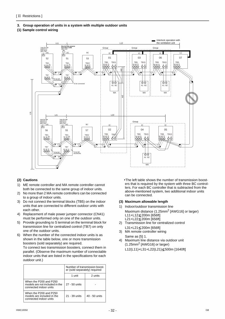
- 32 -
[ II Restrictions ]
GBHWE10050
3. Group operation of units in a system with multiple outdoor units(1) Sample control wiring
(2) Cautions1) ME remote controller and MA remote controller cannot
both be connected to the same group of indoor units.2) No more than 2 MA remote controllers can be connected
to a group of indoor units.3) Do not connect the terminal blocks (TB5) on the indoor
units that are connected to different outdoor units with each other.
4) Replacement of male power jumper connector (CN41) must be performed only on one of the outdoor units.
5) Provide grounding to S terminal on the terminal block for transmission line for centralized control (TB7) on only one of the outdoor units.
6) When the number of the connected indoor units is as shown in the table below, one or more transmission boosters (sold separately) are required.To connect two transmission boosters, connect them in parallel. (Observe the maximum number of connectable indoor units that are listed in the specifications for each outdoor unit.)
The left table shows the number of transmission boost-ers that is required by the system with three BC control-lers. For each BC controller that is subtracted from the above-mentioned system, two additional indoor units can be connected.
(3) Maximum allowable length1) Indoor/outdoor transmission line
Maximum distance (1.25mm2 [AWG16] or larger)L11+L12 200m [656ft]L21+L22 200m [656ft]
2) Transmission line for centralized controlL31+L21 200m [656ft]
3) MA remote controller wiringSame as [5] 1.
4) Maximum line distance via outdoor unit (1.25mm2 [AWG16] or larger)L12(L11)+L31+L22(L21) 500m [1640ft]
IC
TB5S
TB151 2
01
IC
TB5S
TB151 2
03
A1 B2
MA
A1 B2
MA
LC
TB5S
07
IC
TB5S 1 2
TB15
IC
TB5S
TB151 2 1 2
0402
IC
TB5 TB15S
05
A1 B2
MA
Group
IC
TB5S
TB151 2
06
A1 B2
MA
GroupGroup
Group
To be leftunconnected
m2
m3
Interlock operation withthe ventilation unitL12
L22
L11
L21
OC
Move the male connector from CN41 to CN40.SW2-1 OFF
Leave the maleconnector onCN41 as it is.SW2-1 OFF
Leave the maleconnector onCN41 as it is.SW2-1 OFF
Leave the maleconnector onCN41 as it is.SW2-1 OFF
TB3
TB7S
51
OS
TB3
TB7
M1 M2
M1 M2
M1 M2
M1 M2
M1 M2 M1 M2 M1 M2 M1 M2 M1 M2
M1 M2M1 M2M1 M2M1 M2M1 M2M1 M2
M1 M2 M1 M2
S
52
OC
TB3
TB7S
55
OS
TB3
TB7S
56
L31
To be leftunconnected
S
S
BC
TB02
53
BC
TB02
57
To be leftunconnected
To be connected
Number of transmission boost-er (sold separately) required
1 unit 2 units
When the P200 and P250 models are not included in the connected indoor units
27 - 50 units -
When the P200 and P250 models are included in the connected indoor units
21 - 39 units 40 - 50 units
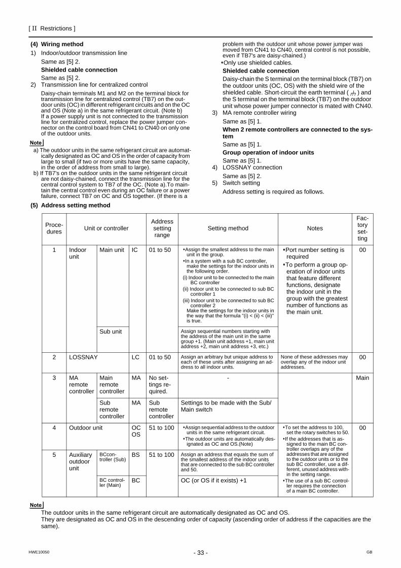
[ II Restrictions ]
33- 33 -HWE10050 GB
(4) Wiring method1) Indoor/outdoor transmission line
Same as [5] 2.Shielded cable connectionSame as [5] 2.
2) Transmission line for centralized controlDaisy-chain terminals M1 and M2 on the terminal block for transmission line for centralized control (TB7) on the out-door units (OC) in different refrigerant circuits and on the OC and OS (Note a) in the same refrigerant circuit. (Note b)If a power supply unit is not connected to the transmission line for centralized control, replace the power jumper con-nector on the control board from CN41 to CN40 on only one of the outdoor units.
a) The outdoor units in the same refrigerant circuit are automat-ically designated as OC and OS in the order of capacity from large to small (if two or more units have the same capacity, in the order of address from small to large).
b) If TB7's on the outdoor units in the same refrigerant circuit are not daisy-chained, connect the transmission line for the central control system to TB7 of the OC. (Note a).To main-tain the central control even during an OC failure or a power failure, connect TB7 on OC and OS together. (If there is a
problem with the outdoor unit whose power jumper was moved from CN41 to CN40, central control is not possible, even if TB7's are daisy-chained.)Only use shielded cables.Shielded cable connectionDaisy-chain the S terminal on the terminal block (TB7) on the outdoor units (OC, OS) with the shield wire of the shielded cable. Short-circuit the earth terminal ( ) and the S terminal on the terminal block (TB7) on the outdoor unit whose power jumper connector is mated with CN40.
3) MA remote controller wiringSame as [5] 1.When 2 remote controllers are connected to the sys-temSame as [5] 1.Group operation of indoor unitsSame as [5] 1.
4) LOSSNAY connectionSame as [5] 2.
5) Switch settingAddress setting is required as follows.
(5) Address setting method
The outdoor units in the same refrigerant circuit are automatically designated as OC and OS.They are designated as OC and OS in the descending order of capacity (ascending order of address if the capacities are the same).
Proce-dures Unit or controller
Address setting range
Setting method Notes
Fac-tory set-ting
1 Indoor unit
Main unit IC 01 to 50 Assign the smallest address to the main unit in the group.
In a system with a sub BC controller, make the settings for the indoor units in the following order.
(i) Indoor unit to be connected to the main BC controller
(ii) Indoor unit to be connected to sub BC controller 1
(iii) Indoor unit to be connected to sub BC controller 2
Make the settings for the indoor units in the way that the formula "(i) < (ii) < (iii)" is true.
Port number setting is requiredTo perform a group op-eration of indoor units that feature different functions, designate the indoor unit in the group with the greatest number of functions as the main unit.
00
Sub unit Assign sequential numbers starting with the address of the main unit in the same group +1. (Main unit address +1, main unit address +2, main unit address +3, etc.)
2 LOSSNAY LC 01 to 50 Assign an arbitrary but unique address to each of these units after assigning an ad-dress to all indoor units.
None of these addresses may overlap any of the indoor unit addresses.
00
3 MA remote controller
Main remote controller
MA No set-tings re-quired.
- Main
Sub remote controller
MA Sub remote controller
Settings to be made with the Sub/Main switch
4 Outdoor unit OCOS
51 to 100 Assign sequential address to the outdoor units in the same refrigerant circuit.
The outdoor units are automatically des-ignated as OC and OS.(Note)
To set the address to 100, set the rotary switches to 50.
If the addresses that is as-signed to the main BC con-troller overlaps any of the addresses that are assigned to the outdoor units or to the sub BC controller, use a dif-ferent, unused address with-in the setting range.
The use of a sub BC control-ler requires the connection of a main BC controller.
00
5 Auxiliary outdoor unit
BCcon-troller (Sub)
BS 51 to 100 Assign an address that equals the sum of the smallest address of the indoor units that are connected to the sub BC controller and 50.
BC control-ler (Main)
BC OC (or OS if it exists) +1
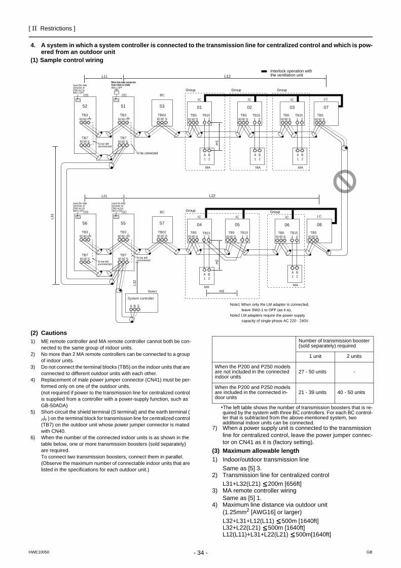
- 34 -
[ II Restrictions ]
GBHWE10050
4. A system in which a system controller is connected to the transmission line for centralized control and which is pow-ered from an outdoor unit
(1) Sample control wiring
(2) Cautions1) ME remote controller and MA remote controller cannot both be con-
nected to the same group of indoor units.2) No more than 2 MA remote controllers can be connected to a group
of indoor units.3) Do not connect the terminal blocks (TB5) on the indoor units that are
connected to different outdoor units with each other.4) Replacement of male power jumper connector (CN41) must be per-
formed only on one of the outdoor units.(not required if power to the transmission line for centralized control is supplied from a controller with a power-supply function, such as GB-50ADA)
5) Short-circuit the shield terminal (S terminal) and the earth terminal ( ) on the terminal block for transmission line for centralized control
(TB7) on the outdoor unit whose power jumper connector is mated with CN40.
6) When the number of the connected indoor units is as shown in the table below, one or more transmission boosters (sold separately) are required.To connect two transmission boosters, connect them in parallel. (Observe the maximum number of connectable indoor units that are listed in the specifications for each outdoor unit.)
The left table shows the number of transmission boosters that is re-quired by the system with three BC controllers. For each BC control-ler that is subtracted from the above-mentioned system, two additional indoor units can be connected.
7) When a power supply unit is connected to the transmission line for centralized control, leave the power jumper connec-tor on CN41 as it is (factory setting).
(3) Maximum allowable length1) Indoor/outdoor transmission line
Same as [5] 3.2) Transmission line for centralized control
L31+L32(L21) 200m [656ft]3) MA remote controller wiring
Same as [5] 1.4) Maximum line distance via outdoor unit
(1.25mm2 [AWG16] or larger)L32+L31+L12(L11) 500m [1640ft]L32+L22(L21) 500m [1640ft]L12(L11)+L31+L22(L21) 500m[1640ft]
IC
TB5S
TB151 2
01
IC
TB5S
TB151 2
02
A1
B2
MA
A1
B2
MA
LC
TB5S
07
IC
TB5S 1 2
TB15
IC
TB5S
TB151 2
0504
LC
TB5S
08
IC
TB5S
TB151 2
03
A1
B2
MA
IC
TB5S
TB151 2
06
A1
B2
MA
A1
B2
MAm3
L31
System controller
A B S
Note1
L32
OC
To be connected
m2
m1
Note1 When only the LM adapter is connected, leave SW2-1 to OFF (as it is).Note2 LM adapters require the power supply capacity of single-phase AC 220 - 240V.
TB3
TB7S
51
OS
TB3
TB7
M1 M2 M1 M2
M1 M2M1 M2
M1 M2 M1 M2 M1 M2 M1 M2 M1 M2
M1 M2M1 M2M1 M2M1 M2M1 M2M1 M2M1 M2
M1 M2 M1 M2
S
52
OC
TB3
TB7S
55
OS
TB3
TB7S
56
Group
Group Group
Group Group
Interlock operation withthe ventilation unit
Move the male connectorfrom CN41 to CN40.SW2-1 OFF
Leave the maleconnector onCN41 as it is.SW2-1 OFF
Leave the maleconnector onCN41 as it is.SW2-1 OFF
Leave the maleconnector onCN41 as it is.SW2-1 OFF
To be left unconnected
To be left unconnected
To be left unconnected
S
BC
TB02
53
S
BC
TB02
57
L22L21
L12L11
Number of transmission booster (sold separately) required
1 unit 2 units
When the P200 and P250 models are not included in the connected indoor units
27 - 50 units -
When the P200 and P250 models are included in the connected in-door units
21 - 39 units 40 - 50 units
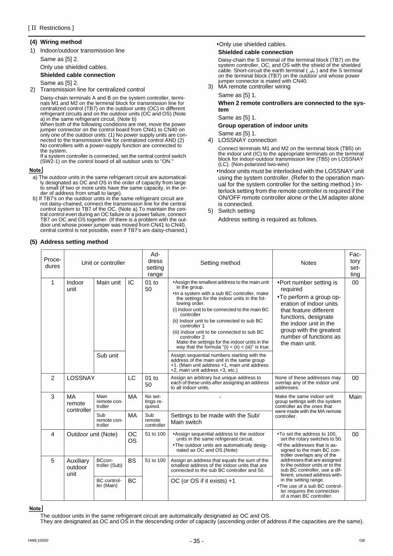
[ II Restrictions ]
35- 35 -HWE10050 GB
(4) Wiring method1) Indoor/outdoor transmission line
Same as [5] 2.Only use shielded cables.Shielded cable connectionSame as [5] 2.
2) Transmission line for centralized controlDaisy-chain terminals A and B on the system controller, termi-nals M1 and M2 on the terminal block for transmission line for centralized control (TB7) on the outdoor units (OC) in different refrigerant circuits and on the outdoor units (OC and OS) (Note a) in the same refrigerant circuit. (Note b)When both of the following conditions are met, move the power jumper connector on the control board from CN41 to CN40 on only one of the outdoor units: (1) No power supply units are con-nected to the transmission line for centralized control AND (2) No controllers with a power-supply function are connected to the system.If a system controller is connected, set the central control switch (SW2-1) on the control board of all outdoor units to "ON."
a) The outdoor units in the same refrigerant circuit are automatical-ly designated as OC and OS in the order of capacity from large to small (if two or more units have the same capacity, in the or-der of address from small to large).
b) If TB7's on the outdoor units in the same refrigerant circuit are not daisy-chained, connect the transmission line for the central control system to TB7 of the OC. (Note a).To maintain the cen-tral control even during an OC failure or a power failure, connect TB7 on OC and OS together. (If there is a problem with the out-door unit whose power jumper was moved from CN41 to CN40, central control is not possible, even if TB7's are daisy-chained.)
Only use shielded cables.Shielded cable connectionDaisy-chain the S terminal of the terminal block (TB7) on the system controller, OC, and OS with the shield of the shielded cable. Short-circuit the earth terminal ( ) and the S terminal on the terminal block (TB7) on the outdoor unit whose power jumper connector is mated with CN40.
3) MA remote controller wiringSame as [5] 1.When 2 remote controllers are connected to the sys-temSame as [5] 1.Group operation of indoor unitsSame as [5] 1.
4) LOSSNAY connectionConnect terminals M1 and M2 on the terminal block (TB5) on the indoor unit (IC) to the appropriate terminals on the terminal block for indoor-outdoor transmission line (TB5) on LOSSNAY (LC). (Non-polarized two-wire)Indoor units must be interlocked with the LOSSNAY unit using the system controller. (Refer to the operation man-ual for the system controller for the setting method.) In-terlock setting from the remote controller is required if the ON/OFF remote controller alone or the LM adapter alone is connected.
5) Switch settingAddress setting is required as follows.
(5) Address setting method
The outdoor units in the same refrigerant circuit are automatically designated as OC and OS.They are designated as OC and OS in the descending order of capacity (ascending order of address if the capacities are the same).
Proce-dures Unit or controller
Ad-dress setting range
Setting method NotesFac-tory set-ting
1 Indoor unit
Main unit IC 01 to 50
Assign the smallest address to the main unit in the group.
In a system with a sub BC controller, make the settings for the indoor units in the fol-lowing order.
(i) Indoor unit to be connected to the main BC controller
(ii) Indoor unit to be connected to sub BC controller 1
(iii) Indoor unit to be connected to sub BC controller 2
Make the settings for the indoor units in the way that the formula "(i) < (ii) < (iii)" is true.
Port number setting is requiredTo perform a group op-eration of indoor units that feature different functions, designate the indoor unit in the group with the greatest number of functions as the main unit.
00
Sub unit Assign sequential numbers starting with the address of the main unit in the same group +1. (Main unit address +1, main unit address +2, main unit address +3, etc.)
2 LOSSNAY LC 01 to 50
Assign an arbitrary but unique address to each of these units after assigning an address to all indoor units.
None of these addresses may overlap any of the indoor unit addresses.
00
3 MA remote controller
Main remote con-troller
MA No set-tings re-quired.
- Make the same indoor unit group settings with the system controller as the ones that were made with the MA remote controller.
Main
Sub remote con-troller
MA Sub remote controller
Settings to be made with the Sub/Main switch
4 Outdoor unit (Note) OCOS
51 to 100 Assign sequential address to the outdoor units in the same refrigerant circuit.
The outdoor units are automatically desig-nated as OC and OS.(Note)
To set the address to 100, set the rotary switches to 50.
If the addresses that is as-signed to the main BC con-troller overlaps any of the addresses that are assigned to the outdoor units or to the sub BC controller, use a dif-ferent, unused address with-in the setting range.
The use of a sub BC control-ler requires the connection of a main BC controller.
00
5 Auxiliary outdoor unit
BCcon-troller (Sub)
BS 51 to 100 Assign an address that equals the sum of the smallest address of the indoor units that are connected to the sub BC controller and 50.
BC control-ler (Main)
BC OC (or OS if it exists) +1
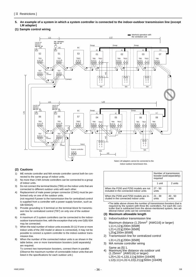
- 36 -
[ II Restrictions ]
GBHWE10050
5. An example of a system in which a system controller is connected to the indoor-outdoor transmission line (except LM adapter)
(1) Sample control wiring
(2) Cautions1) ME remote controller and MA remote controller cannot both be con-
nected to the same group of indoor units.2) No more than 2 MA remote controllers can be connected to a group
of indoor units.3) Do not connect the terminal blocks (TB5) on the indoor units that are
connected to different outdoor units with each other.4) Replacement of male power jumper connector (CN41) must be per-
formed only on one of the outdoor units.(not required if power to the transmission line for centralized control is supplied from a controller with a power-supply function, such as GB-50ADA)
5) Provide grounding to S terminal on the terminal block for transmis-sion line for centralized control (TB7) on only one of the outdoor units.
6) A maximum of 3 system controllers can be connected to the indoor-outdoor transmission line, with the exception that only one G(B)-50A may be connected.
7) When the total number of indoor units exceeds 20 (12 if one or more indoor units of the 200 model or above is connected), it may not be possible to connect a system controller to the indoor-outdoor trans-mission line.
8) When the number of the connected indoor units is as shown in the table below, one or more transmission boosters (sold separately) are required.To connect two transmission boosters, connect them in parallel. (Observe the maximum number of connectable indoor units that are listed in the specifications for each outdoor unit.)
The table above shows the number of transmission boosters that is required by the system with three BC controllers. For each BC con-troller that is subtracted from the above-mentioned system, two ad-ditional indoor units can be connected.
(3) Maximum allowable length1) Indoor/outdoor transmission line
Maximum distance (1.25mm2 [AWG16] or larger)L11+L12 200m [656ft]L21+L22 200m [656ft]L25 200m [656ft]
2) Transmission line for centralized controlL31+L21 200m [656ft]
3) MA remote controller wiringSame as [5] 1.
4) Maximum line distance via outdoor unit (1.25mm2 [AWG16] or larger)L25+L31+L12(L11) 500m [1640ft]L12(L11)+L31+L22(L21) 500m [1640ft]
IC
TB5S
TB151 2
01
IC
TB5S
TB151 2
02
A1
B2
MA
A1
B2
MA
LC
TB5S
07
IC
TB5S 1 2
TB15
IC
TB5S
TB151 2
0504
LC
TB5S
08
IC
TB5S
TB151 2
03
A1
B2
MA
IC
TB5S
TB151 2
06
A1
B2
MA
A1
B2
MA
GroupGroupGroup
Group Group
m3
Interlock operation withthe ventilation unit
OC
Connect
m2
m1
Note1 LM adapters cannot be connected to the indoor-outdoor transmission line.
TB3
TB7S
51
OS
TB3
TB7S
52
OC
TB3
TB7S
55
OS
TB3
TB7S
56
L31
A B S
L25
M2M1 M2M1
M2M1 M2M1
M2M1 M2M1 M2M1 M2M1 M2M1
M2M1M2M1M2M1M2M1M2M1M2M1
M2M1M2M1
M2M1
NotConnect
NotConnect
NotConnect
CN41 CN40 ReplaceSW2-1 OFF ON
SW2-1 OFF ON
Leave the maleconnector onCN41 as it is.
SW2-1 OFF ON
Leave the maleconnector onCN41 as it is.
SW2-1 OFF ON
Leave the maleconnector onCN41 as it is.
System controller
Note1
S
BC
TB02
53
S
BC
TB02
57
L22L21
L12L11
Number of transmission booster (sold separately) required
1 unit 2 units
When the P200 and P250 models are not included in the connected indoor units
27 - 50 units -
When the P200 and P250 models are in-cluded in the connected indoor units
21 - 39 units
40 - 50 units
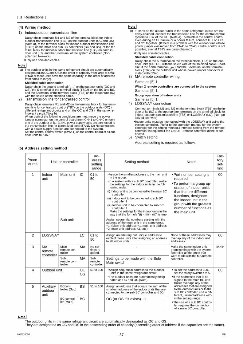
[ II Restrictions ]
37- 37 -HWE10050 GB
(4) Wiring method1) Indoor/outdoor transmission line
Daisy-chain terminals M1 and M2 of the terminal block for indoor-outdoor transmission line (TB3) on the outdoor units (OC and OS) (Note a), of the terminal block for indoor-outdoor transmission line (TB02) on the main and sub BC controllers (BC and BS), of the ter-minal block for indoor-outdoor transmission line (TB5) on each in-door unit (IC), and the S terminal of the system controller.(Non-polarized two-wire)Only use shielded cables.
a) The outdoor units in the same refrigerant circuit are automatically designated as OC and OS in the order of capacity from large to small (if two or more units have the same capacity, in the order of address from small to large).Shielded cable connectionDaisy-chain the ground terminal ( ) on the outdoor units (OC and OS), the S terminal of the terminal block (TB02) on the BC and BS, and the S terminal of the terminal block (TB5) on the indoor unit (IC) with the shield of the shielded cable.
2) Transmission line for centralized controlDaisy-chain terminals M1 and M2 on the terminal block for transmis-sion line for centralized control (TB7) on the outdoor units (OC) in different refrigerant circuits and on the OC and OS in the same re-frigerant circuit.(Note b)When both of the following conditions are met, move the power jumper connector on the control board from CN41 to CN40 on only one of the outdoor units: (1) No power supply units are connected to the transmission line for centralized control AND (2) No controllers with a power-supply function are connected to the system.Set the central control switch (SW2-1) on the control board of all out-door units to "ON."
b) If TB7's on the outdoor units in the same refrigerant circuit are not daisy-chained, connect the transmission line for the central control system to TB7 of the OC. (Note a).To maintain the central control even during an OC failure or a power failure, connect TB7 on OC and OS together. (If there is a problem with the outdoor unit whose power jumper was moved from CN41 to CN40, central control is not possible, even if TB7's are daisy-chained.)Only use shielded cables.Shielded cable connectionDaisy-chain the S terminal on the terminal block (TB7) on the out-door units (OC, OS) with the shield wire of the shielded cable. Short-circuit the earth terminal ( ) and the S terminal on the terminal block (TB7) on the outdoor unit whose power jumper connector is mated with CN40.
3) MA remote controller wiringSame as [5] 1.When 2 remote controllers are connected to the systemSame as [5] 1.Group operation of indoor unitsSame as [5] 1.
4) LOSSNAY connectionConnect terminals M1 and M2 on the terminal block (TB5) on the in-door units (IC) to the appropriate terminals on the terminal block for indoor-outdoor transmission line (TB5) on LOSSNAY (LC). (Non-po-larized two-wire)Indoor units must be interlocked with the LOSSNAY unit using the system controller. (Refer to the operation manual for the system controller for the setting method.) Interlock setting from the remote controller is required if the ON/OFF remote controller alone is con-nected.
5) Switch settingAddress setting is required as follows.
(5) Address setting method
The outdoor units in the same refrigerant circuit are automatically designated as OC and OS.They are designated as OC and OS in the descending order of capacity (ascending order of address if the capacities are the same).
Proce-dures Unit or controller
Ad-dress setting range
Setting method NotesFac-tory set-ting
1 Indoor unit
Main unit IC 01 to 50
Assign the smallest address to the main unit in the group.
In a system with a sub BC controller, make the settings for the indoor units in the fol-lowing order.
(i) Indoor unit to be connected to the main BC controller
(ii) Indoor unit to be connected to sub BC controller 1
(iii) Indoor unit to be connected to sub BC controller 2
Make the settings for the indoor units in the way that the formula "(i) < (ii) < (iii)" is true.
Port number setting is requiredTo perform a group op-eration of indoor units that feature different functions, designate the indoor unit in the group with the greatest number of functions as the main unit.
00
Sub unit Assign sequential numbers starting with the address of the main unit in the same group +1. (Main unit address +1, main unit address +2, main unit address +3, etc.)
2 LOSSNAY LC 01 to 50
Assign an arbitrary but unique address to each of these units after assigning an address to all indoor units.
None of these addresses may overlap any of the indoor unit addresses.
00
3 MA remote controller
Main remote con-troller
MA No set-tings re-quired.
- Make the same indoor unit group settings with the system controller as the ones that were made with the MA remote controller.
Main
Sub remote con-troller
MA Sub remote controller
Settings to be made with the Sub/Main switch
4 Outdoor unit OCOS
51 to 100 Assign sequential address to the outdoor units in the same refrigerant circuit.
The outdoor units are automatically desig-nated as OC and OS.(Note)
To set the address to 100, set the rotary switches to 50.
If the addresses that is as-signed to the main BC con-troller overlaps any of the addresses that are assigned to the outdoor units or to the sub BC controller, use a dif-ferent, unused address with-in the setting range.
The use of a sub BC control-ler requires the connection of a main BC controller.
00
5 Auxiliary outdoor unit
BCcon-troller (Sub)
BS 51 to 100 Assign an address that equals the sum of the smallest address of the indoor units that are connected to the sub BC controller and 50.
BC control-ler (Main)
BC OC (or OS if it exists) +1
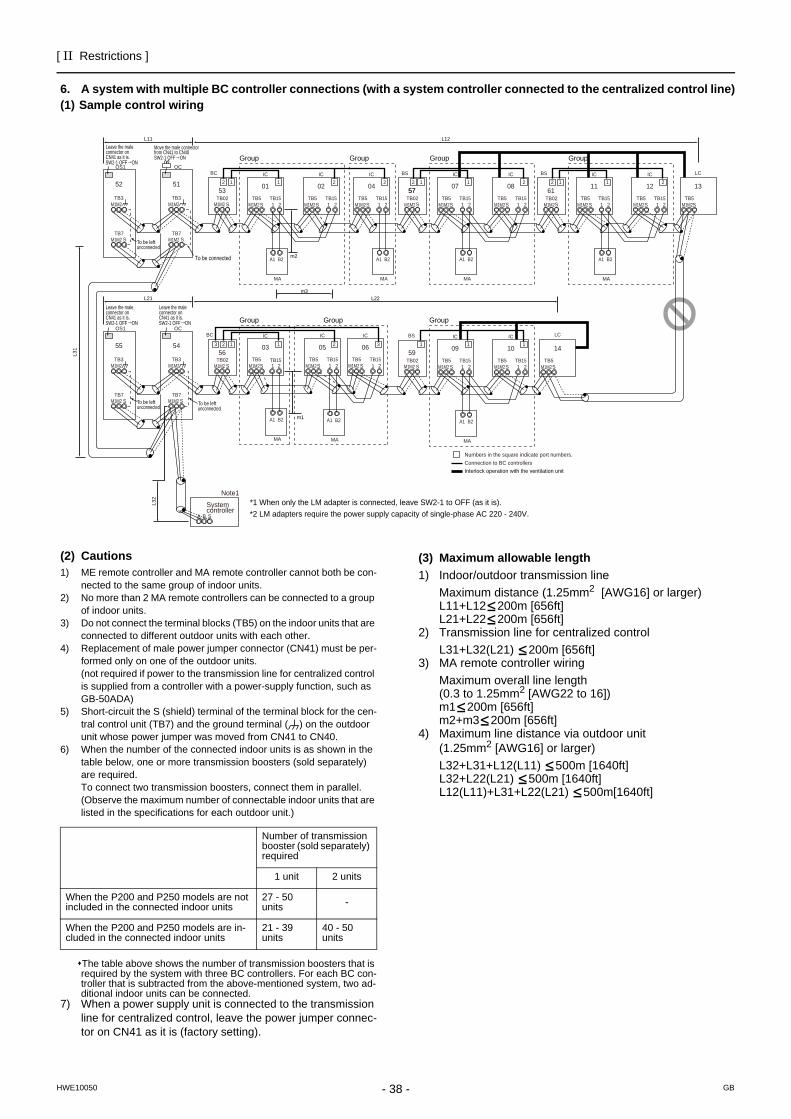
- 38 -
[ II Restrictions ]
GBHWE10050
6. A system with multiple BC controller connections (with a system controller connected to the centralized control line)(1) Sample control wiring
(2) Cautions1) ME remote controller and MA remote controller cannot both be con-
nected to the same group of indoor units.2) No more than 2 MA remote controllers can be connected to a group
of indoor units.3) Do not connect the terminal blocks (TB5) on the indoor units that are
connected to different outdoor units with each other.4) Replacement of male power jumper connector (CN41) must be per-
formed only on one of the outdoor units.(not required if power to the transmission line for centralized control is supplied from a controller with a power-supply function, such as GB-50ADA)
5) Short-circuit the S (shield) terminal of the terminal block for the cen-tral control unit (TB7) and the ground terminal ( ) on the outdoor unit whose power jumper was moved from CN41 to CN40.
6) When the number of the connected indoor units is as shown in the table below, one or more transmission boosters (sold separately) are required. To connect two transmission boosters, connect them in parallel. (Observe the maximum number of connectable indoor units that are listed in the specifications for each outdoor unit.)
The table above shows the number of transmission boosters that is required by the system with three BC controllers. For each BC con-troller that is subtracted from the above-mentioned system, two ad-ditional indoor units can be connected.
7) When a power supply unit is connected to the transmission line for centralized control, leave the power jumper connec-tor on CN41 as it is (factory setting).
(3) Maximum allowable length1) Indoor/outdoor transmission line
Maximum distance (1.25mm2 [AWG16] or larger)L11+L12 200m [656ft]L21+L22 200m [656ft]
2) Transmission line for centralized controlL31+L32(L21) 200m [656ft]
3) MA remote controller wiringMaximum overall line length (0.3 to 1.25mm2 [AWG22 to 16])m1 200m [656ft]m2+m3 200m [656ft]
4) Maximum line distance via outdoor unit(1.25mm2 [AWG16] or larger)L32+L31+L12(L11) 500m [1640ft]L32+L22(L21) 500m [1640ft]L12(L11)+L31+L22(L21) 500m[1640ft]
L11
L21
OC
TB3
TB7S
51
L31
A B S
L32
OS1
TB3
TB7
M1M2
S
52
OC
TB3
TB7S
54
OS1
TB3
TB7S
55
SW2-1 OFF ON
Move the male connector from CN41 to CN40
Group
Group Group Group
Group Group Group
To be left unconnected
To be left unconnected
To be left unconnected
To be connected
M1M2
M1M2 M1M2
M1M2
M1M2
M1M2 M1M2
M1M2
*1 When only the LM adapter is connected, leave SW2-1 to OFF (as it is).*2 LM adapters require the power supply capacity of single-phase AC 220 - 240V.
IC
TB5S
TB151 2
01
IC
TB5S
TB151 2
02
IC
TB5S
TB151 2
04
IC
TB5S
TB151 2
06
A1 B2
MA
A1 B2
MA
A1 B2
MA
IC
TB5S 1 2
TB15
IC
TB5S
TB151 2
0503
L12
L22
IC
TB5S
TB151 2
07
IC
TB5S
TB151 2
08
A1 B2
MA
IC
TB5S
TB151 2
09
IC
TB5S
TB151 2
10
A1 B2
MA
A1 B2
MA
BC
BC
TB02S
53 57
TB02M1M2 S
BS
TB02S
BS
TB02S
1 1 2 1 222 12
57
1 1 2 1 1
LC
TB5S
14323 1
Numbers in the square indicate port numbers.Connection to BC controllers
56 59
Interlock operation with the ventilation unit
IC
TB5S
TB151 2
11
IC
TB5S
TB151 2
12
A1 B2
MA
61
BS
TB02S
1 2
LC
TB5S
1312
m2
m3
m1
SW2-1 OFF ON
Leave the maleconnector onCN41 as it is.
SW2-1 OFF ON
Leave the maleconnector onCN41 as it is.
SW2-1 OFF ON
Leave the maleconnector onCN41 as it is.
System controller
Note1
M1M2 M1M2 M1M2 M1M2 M1M2 M1M2 M1M2 M1M2 M1M2 M1M2
M1M2 M1M2 M1M2 M1M2 M1M2 M1M2M1M2
Number of transmission booster (sold separately) required
1 unit 2 units
When the P200 and P250 models are not included in the connected indoor units
27 - 50 units -
When the P200 and P250 models are in-cluded in the connected indoor units
21 - 39 units
40 - 50 units
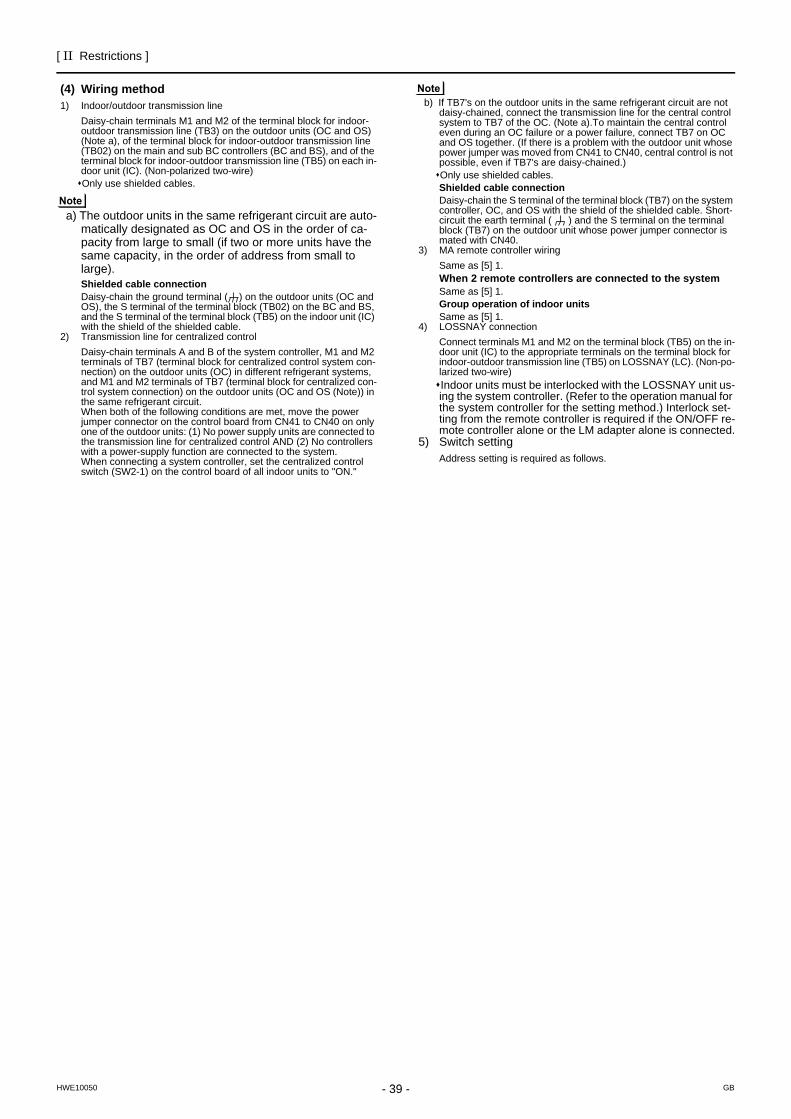
[ II Restrictions ]
39- 39 -HWE10050 GB
(4) Wiring method1) Indoor/outdoor transmission line
Daisy-chain terminals M1 and M2 of the terminal block for indoor-outdoor transmission line (TB3) on the outdoor units (OC and OS) (Note a), of the terminal block for indoor-outdoor transmission line (TB02) on the main and sub BC controllers (BC and BS), and of the terminal block for indoor-outdoor transmission line (TB5) on each in-door unit (IC). (Non-polarized two-wire)Only use shielded cables.
a) The outdoor units in the same refrigerant circuit are auto-matically designated as OC and OS in the order of ca-pacity from large to small (if two or more units have the same capacity, in the order of address from small to large).Shielded cable connectionDaisy-chain the ground terminal ( ) on the outdoor units (OC and OS), the S terminal of the terminal block (TB02) on the BC and BS, and the S terminal of the terminal block (TB5) on the indoor unit (IC) with the shield of the shielded cable.
2) Transmission line for centralized controlDaisy-chain terminals A and B of the system controller, M1 and M2 terminals of TB7 (terminal block for centralized control system con-nection) on the outdoor units (OC) in different refrigerant systems, and M1 and M2 terminals of TB7 (terminal block for centralized con-trol system connection) on the outdoor units (OC and OS (Note)) in the same refrigerant circuit.When both of the following conditions are met, move the power jumper connector on the control board from CN41 to CN40 on only one of the outdoor units: (1) No power supply units are connected to the transmission line for centralized control AND (2) No controllers with a power-supply function are connected to the system.When connecting a system controller, set the centralized control switch (SW2-1) on the control board of all indoor units to "ON."
b) If TB7's on the outdoor units in the same refrigerant circuit are not daisy-chained, connect the transmission line for the central control system to TB7 of the OC. (Note a).To maintain the central control even during an OC failure or a power failure, connect TB7 on OC and OS together. (If there is a problem with the outdoor unit whose power jumper was moved from CN41 to CN40, central control is not possible, even if TB7's are daisy-chained.)Only use shielded cables.Shielded cable connectionDaisy-chain the S terminal of the terminal block (TB7) on the system controller, OC, and OS with the shield of the shielded cable. Short-circuit the earth terminal ( ) and the S terminal on the terminal block (TB7) on the outdoor unit whose power jumper connector is mated with CN40.
3) MA remote controller wiringSame as [5] 1.When 2 remote controllers are connected to the systemSame as [5] 1.Group operation of indoor unitsSame as [5] 1.
4) LOSSNAY connectionConnect terminals M1 and M2 on the terminal block (TB5) on the in-door unit (IC) to the appropriate terminals on the terminal block for indoor-outdoor transmission line (TB5) on LOSSNAY (LC). (Non-po-larized two-wire)Indoor units must be interlocked with the LOSSNAY unit us-ing the system controller. (Refer to the operation manual for the system controller for the setting method.) Interlock set-ting from the remote controller is required if the ON/OFF re-mote controller alone or the LM adapter alone is connected.
5) Switch settingAddress setting is required as follows.
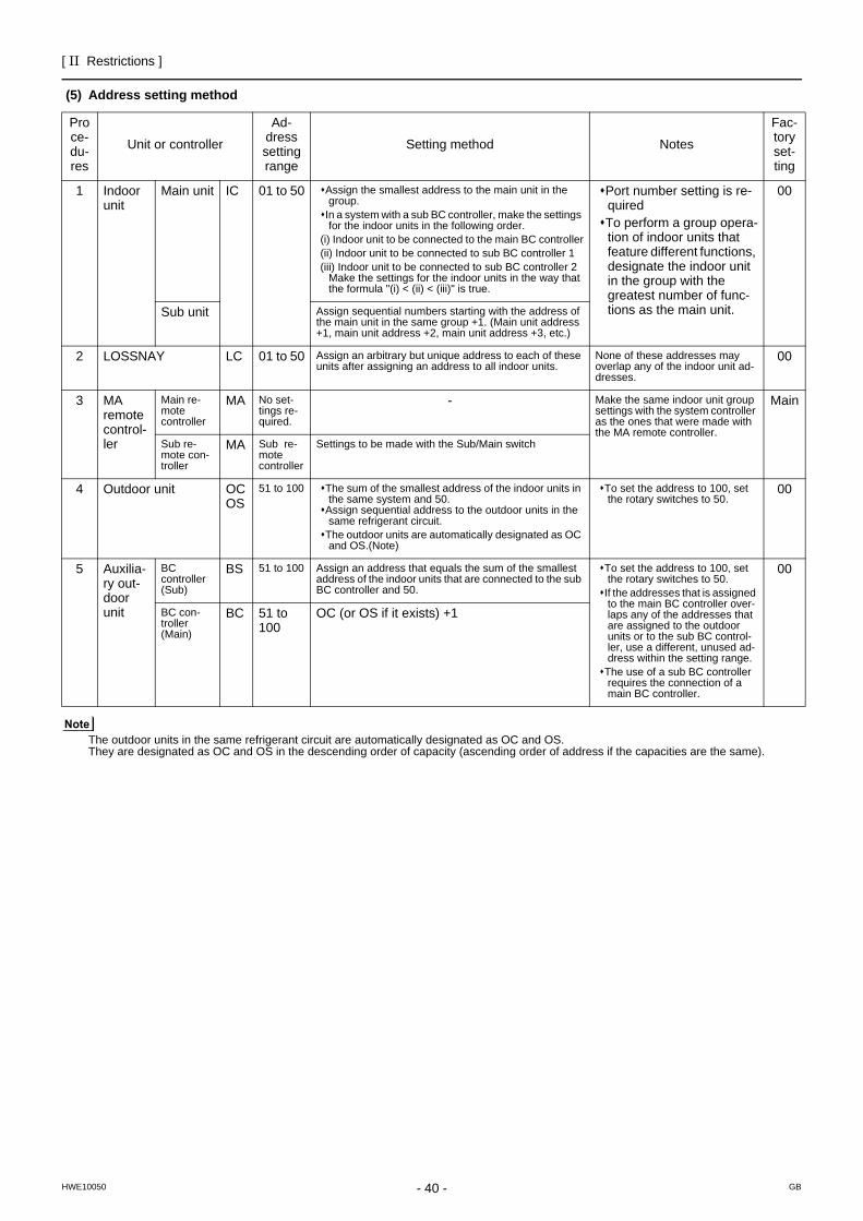
- 40 -
[ II Restrictions ]
GBHWE10050
(5) Address setting method
The outdoor units in the same refrigerant circuit are automatically designated as OC and OS.They are designated as OC and OS in the descending order of capacity (ascending order of address if the capacities are the same).
Proce-du-res
Unit or controller
Ad-dress setting range
Setting method Notes
Fac-tory set-ting
1 Indoor unit
Main unit IC 01 to 50 Assign the smallest address to the main unit in the group.
In a system with a sub BC controller, make the settings for the indoor units in the following order.
(i) Indoor unit to be connected to the main BC controller(ii) Indoor unit to be connected to sub BC controller 1(iii) Indoor unit to be connected to sub BC controller 2
Make the settings for the indoor units in the way that the formula "(i) < (ii) < (iii)" is true.
Port number setting is re-quiredTo perform a group opera-tion of indoor units that feature different functions, designate the indoor unit in the group with the greatest number of func-tions as the main unit.
00
Sub unit Assign sequential numbers starting with the address of the main unit in the same group +1. (Main unit address +1, main unit address +2, main unit address +3, etc.)
2 LOSSNAY LC 01 to 50 Assign an arbitrary but unique address to each of these units after assigning an address to all indoor units.
None of these addresses may overlap any of the indoor unit ad-dresses.
00
3 MA remote control-ler
Main re-mote controller
MA No set-tings re-quired.
- Make the same indoor unit group settings with the system controller as the ones that were made with the MA remote controller.
Main
Sub re-mote con-troller
MA Sub re-mote controller
Settings to be made with the Sub/Main switch
4 Outdoor unit OCOS
51 to 100 The sum of the smallest address of the indoor units in the same system and 50.
Assign sequential address to the outdoor units in the same refrigerant circuit.
The outdoor units are automatically designated as OC and OS.(Note)
To set the address to 100, set the rotary switches to 50.
00
5 Auxilia-ry out-door unit
BCcontroller (Sub)
BS 51 to 100 Assign an address that equals the sum of the smallest address of the indoor units that are connected to the sub BC controller and 50.
To set the address to 100, set the rotary switches to 50.
If the addresses that is assigned to the main BC controller over-laps any of the addresses that are assigned to the outdoor units or to the sub BC control-ler, use a different, unused ad-dress within the setting range.
The use of a sub BC controller requires the connection of a main BC controller.
00
BC con-troller (Main)
BC 51 to 100
OC (or OS if it exists) +1

[ II Restrictions ]
41- 41 -HWE10050 GB
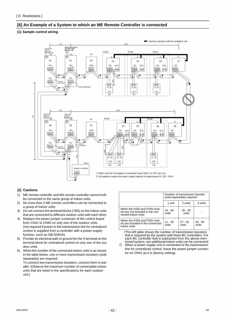
- 42 -
[ II Restrictions ]
GBHWE10050
[6] An Example of a System to which an ME Remote Controller is connected(1) Sample control wiring
(2) Cautions1) ME remote controller and MA remote controller cannot both
be connected to the same group of indoor units.2) No more than 2 ME remote controllers can be connected to
a group of indoor units.3) Do not connect the terminal blocks (TB5) on the indoor units
that are connected to different outdoor units with each other.4) Replace the power jumper connector of the control board
from CN41 to CN40 on only one of the outdoor units.(not required if power to the transmission line for centralized control is supplied from a controller with a power-supply function, such as GB-50ADA)
5) Provide an electrical path to ground for the S terminal on the terminal block for centralized control on only one of the out-door units.
6) When the number of the connected indoor units is as shown in the table below, one or more transmission boosters (sold separately) are required.To connect two transmission boosters, connect them in par-allel. (Observe the maximum number of connectable indoor units that are listed in the specifications for each outdoor unit.)
The left table shows the number of transmission boosters that is required by the system with three BC controllers. For each BC controller that is subtracted from the above-men-tioned system, two additional indoor units can be connected.
7) When a power supply unit is connected to the transmission line for centralized control, leave the power jumper connec-tor on CN41 as it is (factory setting).
IC
TB5S
TB151 2
01
IC
TB5S
TB151 2
02
LC
TB5S
07
IC
TB5S 1 2
TB15
IC
TB5S
TB151 2
0504
LC
TB5S
08
IC
TB5S
TB151 2
03
IC
TB5S
TB151 2
06
A1 B2
RC101
A1 B2
RC102
A1 B2
RC103
Group
Group Group
Group Group
To be connected
M1M2 M1M2M1M2
M1M2 M1M2 M1M2 M1M2
L31
A B S
L32
OC
m1
TB3
TB7M1 M2S
51
OS
TB3
TB7M1M2
M1M2 M1M2
S
52
OC
TB3
TB7S
55
OS
TB3
TB7S
56
To be left unconnected
Interlock operation with the ventilation unit
*1 When only the LM adapter is connected, leave SW2-1 to OFF (as it is).*2 LM adapters require the power supply capacity of single-phase AC 220 - 240V.
System controller
Note1
SW2-1 OFF ON
Leave the maleconnector onCN41 as it is.
SW2-1 OFF ON
Leave the maleconnector onCN41 as it is.
SW2-1 OFF ON
Move the male connector from CN41 to CN40.
SW2-1 OFF ON
Leave the maleconnector onCN41 as it is.
M1M2
M1M2 M1M2
M1M2 M1M2To be left unconnected
To be left unconnected
104
A1 B2
RC154
A1 B2
RC
m3
106
A1 B2
RC
m2
S
BC
TB02
53
S
BC
TB02
57
L12L11
L22L21
M1M2
M1M2
Number of transmission booster (sold separately) required
1 unit 2 units 3 units
When the P200 and P250 mod-els are not included in the con-nected indoor units
15 - 34 units
35 - 50 units -
When the P200 and P250 mod-els are included in the connected indoor units
11 - 26 units
27 - 42 units
43 - 50 units
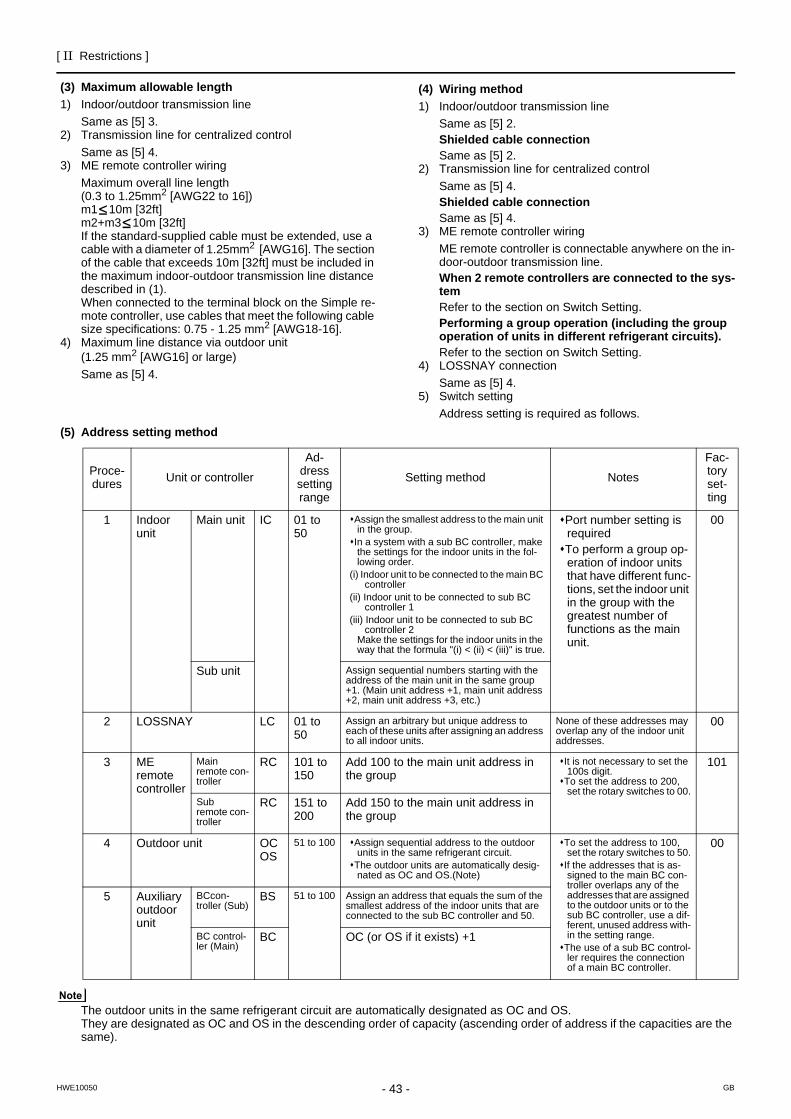
[ II Restrictions ]
43- 43 -HWE10050 GB
(3) Maximum allowable length1) Indoor/outdoor transmission line
Same as [5] 3.2) Transmission line for centralized control
Same as [5] 4.3) ME remote controller wiring
Maximum overall line length (0.3 to 1.25mm2 [AWG22 to 16])m1 10m [32ft]m2+m3 10m [32ft]If the standard-supplied cable must be extended, use a cable with a diameter of 1.25mm2 [AWG16]. The section of the cable that exceeds 10m [32ft] must be included in the maximum indoor-outdoor transmission line distance described in (1).When connected to the terminal block on the Simple re-mote controller, use cables that meet the following cable size specifications: 0.75 - 1.25 mm2 [AWG18-16].
4) Maximum line distance via outdoor unit(1.25 mm2 [AWG16] or large)Same as [5] 4.
(4) Wiring method1) Indoor/outdoor transmission line
Same as [5] 2.Shielded cable connectionSame as [5] 2.
2) Transmission line for centralized controlSame as [5] 4.Shielded cable connectionSame as [5] 4.
3) ME remote controller wiringME remote controller is connectable anywhere on the in-door-outdoor transmission line.When 2 remote controllers are connected to the sys-temRefer to the section on Switch Setting.Performing a group operation (including the group operation of units in different refrigerant circuits).Refer to the section on Switch Setting.
4) LOSSNAY connectionSame as [5] 4.
5) Switch settingAddress setting is required as follows.
(5) Address setting method
The outdoor units in the same refrigerant circuit are automatically designated as OC and OS.They are designated as OC and OS in the descending order of capacity (ascending order of address if the capacities are the same).
Proce-dures Unit or controller
Ad-dress setting range
Setting method Notes
Fac-tory set-ting
1 Indoor unit
Main unit IC 01 to 50
Assign the smallest address to the main unit in the group.
In a system with a sub BC controller, make the settings for the indoor units in the fol-lowing order.
(i) Indoor unit to be connected to the main BC controller
(ii) Indoor unit to be connected to sub BC controller 1
(iii) Indoor unit to be connected to sub BC controller 2
Make the settings for the indoor units in the way that the formula "(i) < (ii) < (iii)" is true.
Port number setting is requiredTo perform a group op-eration of indoor units that have different func-tions, set the indoor unit in the group with the greatest number of functions as the main unit.
00
Sub unit Assign sequential numbers starting with the address of the main unit in the same group +1. (Main unit address +1, main unit address +2, main unit address +3, etc.)
2 LOSSNAY LC 01 to 50
Assign an arbitrary but unique address to each of these units after assigning an address to all indoor units.
None of these addresses may overlap any of the indoor unit addresses.
00
3 ME remote controller
Main remote con-troller
RC 101 to 150
Add 100 to the main unit address in the group
It is not necessary to set the 100s digit.
To set the address to 200, set the rotary switches to 00.
101
Sub remote con-troller
RC 151 to 200
Add 150 to the main unit address in the group
4 Outdoor unit OCOS
51 to 100 Assign sequential address to the outdoor units in the same refrigerant circuit.
The outdoor units are automatically desig-nated as OC and OS.(Note)
To set the address to 100, set the rotary switches to 50.
If the addresses that is as-signed to the main BC con-troller overlaps any of the addresses that are assigned to the outdoor units or to the sub BC controller, use a dif-ferent, unused address with-in the setting range.
The use of a sub BC control-ler requires the connection of a main BC controller.
00
5 Auxiliary outdoor unit
BCcon-troller (Sub)
BS 51 to 100 Assign an address that equals the sum of the smallest address of the indoor units that are connected to the sub BC controller and 50.
BC control-ler (Main)
BC OC (or OS if it exists) +1
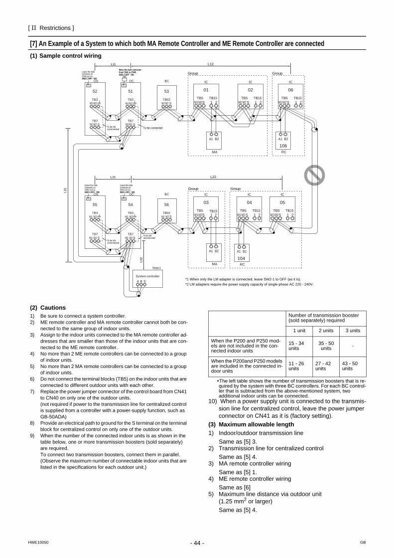
- 44 -
[ II Restrictions ]
GBHWE10050
[7] An Example of a System to which both MA Remote Controller and ME Remote Controller are connected(1) Sample control wiring
(2) Cautions1) Be sure to connect a system controller.2) ME remote controller and MA remote controller cannot both be con-
nected to the same group of indoor units.3) Assign to the indoor units connected to the MA remote controller ad-
dresses that are smaller than those of the indoor units that are con-nected to the ME remote controller.
4) No more than 2 ME remote controllers can be connected to a group of indoor units.
5) No more than 2 MA remote controllers can be connected to a group of indoor units.
6) Do not connect the terminal blocks (TB5) on the indoor units that are connected to different outdoor units with each other.
7) Replace the power jumper connector of the control board from CN41 to CN40 on only one of the outdoor units.(not required if power to the transmission line for centralized control is supplied from a controller with a power-supply function, such as GB-50ADA)
8) Provide an electrical path to ground for the S terminal on the terminal block for centralized control on only one of the outdoor units.
9) When the number of the connected indoor units is as shown in the table below, one or more transmission boosters (sold separately) are required.To connect two transmission boosters, connect them in parallel. (Observe the maximum number of connectable indoor units that are listed in the specifications for each outdoor unit.)
The left table shows the number of transmission boosters that is re-quired by the system with three BC controllers. For each BC control-ler that is subtracted from the above-mentioned system, two additional indoor units can be connected.
10) When a power supply unit is connected to the transmis-sion line for centralized control, leave the power jumper connector on CN41 as it is (factory setting).
(3) Maximum allowable length1) Indoor/outdoor transmission line
Same as [5] 3.2) Transmission line for centralized control
Same as [5] 4.3) MA remote controller wiring
Same as [5] 1.4) ME remote controller wiring
Same as [6]5) Maximum line distance via outdoor unit
(1.25 mm2 or larger)Same as [5] 4.
IC
TB5S
TB151 2
01
IC
TB5S
TB151 2
02
IC
TB5S
TB151 2
06
106
IC
TB5S
TB151 2
05
A1 B2
MA
A1 B2
RC
A1 B2
MA
IC
TB5S 1 2
TB15
IC
TB5S
TB151 2
0403
104A1 B2
RC
OC
TB3
TB7S
51
OS
TB3
TB7S
52
OC
TB3
TB7S
54
OS
TB3
TB7S
55
L31
A B S
L32
SW2-1 OFF ON
Leave the maleconnector onCN41 as it is.
SW2-1 OFF ON
Leave the maleconnector onCN41 as it is.
To be left unconnected
To be left unconnected
To be left unconnected
To be connected
System controller
Note1
*1 When only the LM adapter is connected, leave SW2-1 to OFF (as it is).*2 LM adapters require the power supply capacity of single-phase AC 220 - 240V.
M1M2
M1M2
M1M2
M1M2
M1M2 M1M2 M1M2
M1M2M1M2M1M2M1 M2M1 M2M1 M2
M1 M2M1 M2
S
BC
TB02
53
S
BC
TB02
56
L22L21
L12L11
SW2-1 OFF ON
Leave the maleconnector onCN41 as it is. SW2-1 OFF ON
Move the male connector from CN41 to CN40. Group Group
GroupGroup
M1M2
Number of transmission booster (sold separately) required
1 unit 2 units 3 units
When the P200 and P250 mod-els are not included in the con-nected indoor units
15 - 34 units
35 - 50 units -
When the P200and P250 models are included in the connected in-door units
11 - 26 units
27 - 42 units
43 - 50 units
[ II Restrictions ]
45- 45 -HWE10050 GB
(4) Wiring method1) Indoor/outdoor transmission line
Same as [5] 2.Shielded cable connectionSame as [5] 2.
2) Transmission line for centralized controlSame as [5] 4.Shielded cable connectionSame as [5] 4.
3) MA remote controller wiring(When 2 remote controllers are connected to the sys-tem
Group operation of indoor units)Same as [5] 1.
4) ME remote controller wiring(When 2 remote controllers are connected to the sys-temGroup operation of indoor units)Same as [6]
5) LOSSNAY connectionSame as [5] 4.
6) Switch settingAddress setting is required as follows.
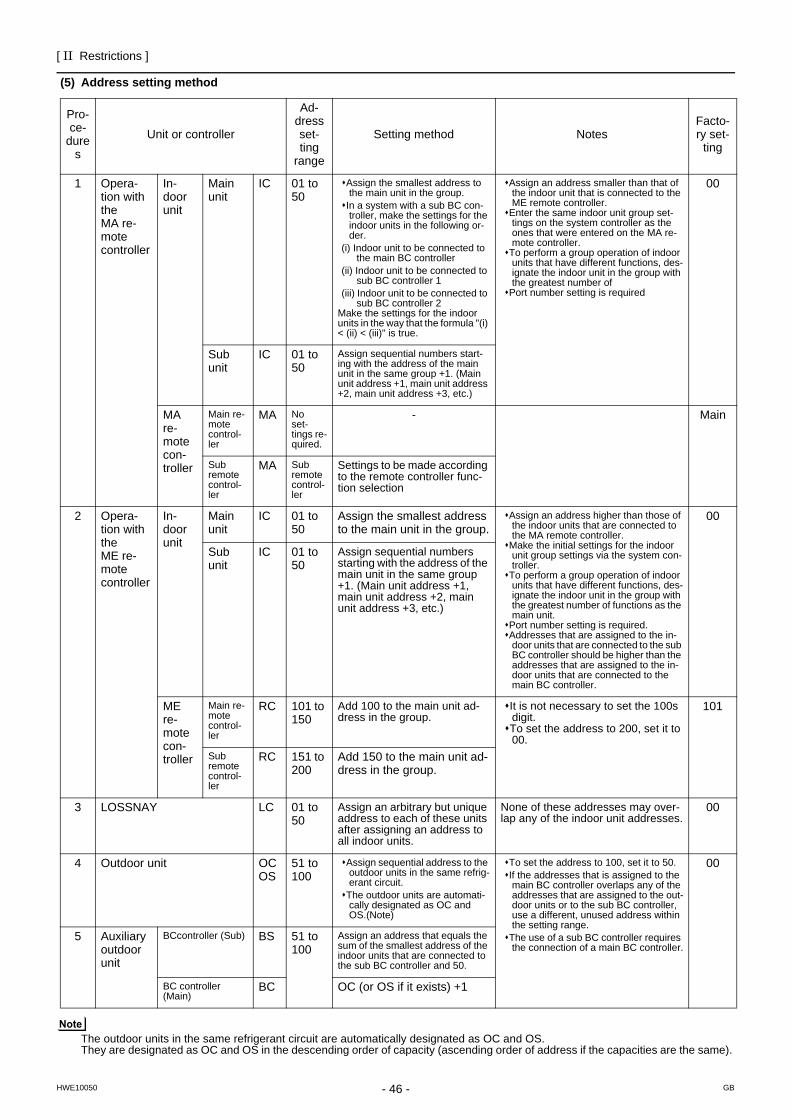
- 46 -
[ II Restrictions ]
GBHWE10050
(5) Address setting method
The outdoor units in the same refrigerant circuit are automatically designated as OC and OS. They are designated as OC and OS in the descending order of capacity (ascending order of address if the capacities are the same).
Pro-ce-
dures
Unit or controller
Ad-dress set-ting
range
Setting method NotesFacto-ry set-
ting
1 Opera-tion with the MA re-mote controller
In-door unit
Main unit
IC 01 to 50
Assign the smallest address to the main unit in the group.
In a system with a sub BC con-troller, make the settings for the indoor units in the following or-der.
(i) Indoor unit to be connected to the main BC controller
(ii) Indoor unit to be connected to sub BC controller 1
(iii) Indoor unit to be connected to sub BC controller 2
Make the settings for the indoor units in the way that the formula "(i) < (ii) < (iii)" is true.
Assign an address smaller than that of the indoor unit that is connected to the ME remote controller.
Enter the same indoor unit group set-tings on the system controller as the ones that were entered on the MA re-mote controller.
To perform a group operation of indoor units that have different functions, des-ignate the indoor unit in the group with the greatest number of
Port number setting is required
00
Sub unit
IC 01 to 50
Assign sequential numbers start-ing with the address of the main unit in the same group +1. (Main unit address +1, main unit address +2, main unit address +3, etc.)
MA re-mote con-troller
Main re-mote control-ler
MA No set-tings re-quired.
- Main
Sub remote control-ler
MA Sub remote control-ler
Settings to be made according to the remote controller func-tion selection
2 Opera-tion with the ME re-mote controller
In-door unit
Main unit
IC 01 to 50
Assign the smallest address to the main unit in the group.
Assign an address higher than those of the indoor units that are connected to the MA remote controller.
Make the initial settings for the indoor unit group settings via the system con-troller.
To perform a group operation of indoor units that have different functions, des-ignate the indoor unit in the group with the greatest number of functions as the main unit.
Port number setting is required. Addresses that are assigned to the in-door units that are connected to the sub BC controller should be higher than the addresses that are assigned to the in-door units that are connected to the main BC controller.
00
Sub unit
IC 01 to 50
Assign sequential numbers starting with the address of the main unit in the same group +1. (Main unit address +1, main unit address +2, main unit address +3, etc.)
ME re-mote con-troller
Main re-mote control-ler
RC 101 to 150
Add 100 to the main unit ad-dress in the group.
It is not necessary to set the 100s digit.To set the address to 200, set it to 00.
101
Sub remote control-ler
RC 151 to 200
Add 150 to the main unit ad-dress in the group.
3 LOSSNAY LC 01 to 50
Assign an arbitrary but unique address to each of these units after assigning an address to all indoor units.
None of these addresses may over-lap any of the indoor unit addresses.
00
4 Outdoor unit OCOS
51 to 100
Assign sequential address to the outdoor units in the same refrig-erant circuit.
The outdoor units are automati-cally designated as OC and OS.(Note)
To set the address to 100, set it to 50.If the addresses that is assigned to the main BC controller overlaps any of the addresses that are assigned to the out-door units or to the sub BC controller, use a different, unused address within the setting range.
The use of a sub BC controller requires the connection of a main BC controller.
00
5 Auxiliary outdoor unit
BCcontroller (Sub) BS 51 to 100
Assign an address that equals the sum of the smallest address of the indoor units that are connected to the sub BC controller and 50.
BC controller (Main)
BC OC (or OS if it exists) +1
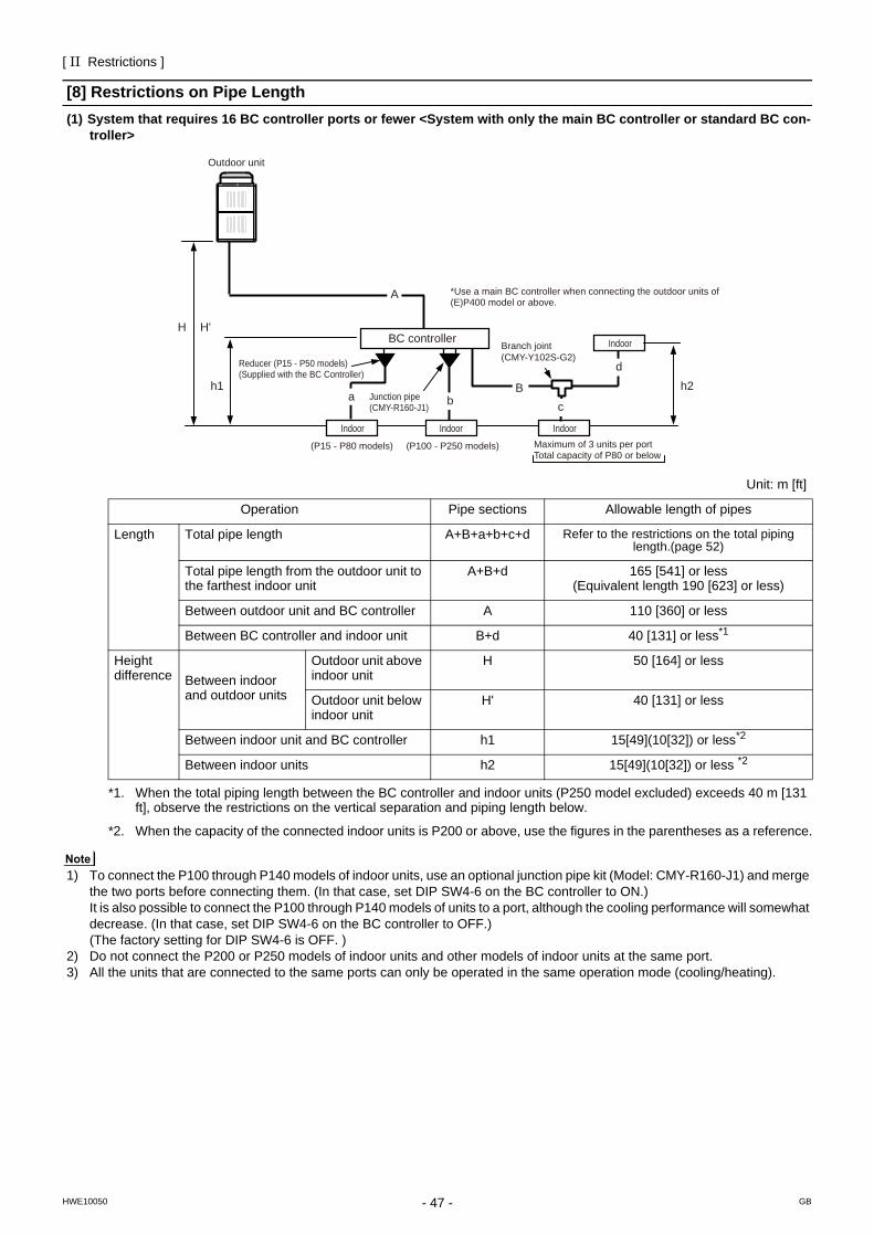
[ II Restrictions ]
- 47 -HWE10050 GB
[8] Restrictions on Pipe Length(1) System that requires 16 BC controller ports or fewer <System with only the main BC controller or standard BC con-
troller>
1) To connect the P100 through P140 models of indoor units, use an optional junction pipe kit (Model: CMY-R160-J1) and merge the two ports before connecting them. (In that case, set DIP SW4-6 on the BC controller to ON.) It is also possible to connect the P100 through P140 models of units to a port, although the cooling performance will somewhat decrease. (In that case, set DIP SW4-6 on the BC controller to OFF.)(The factory setting for DIP SW4-6 is OFF. )
2) Do not connect the P200 or P250 models of indoor units and other models of indoor units at the same port.3) All the units that are connected to the same ports can only be operated in the same operation mode (cooling/heating).
a b
H H'
h1
A
h2
Outdoor unit
BC controller
Reducer (P15 - P50 models)(Supplied with the BC Controller)
B
d
cJunction pipe(CMY-R160-J1)
*Use a main BC controller when connecting the outdoor units of (E)P400 model or above.
Branch joint(CMY-Y102S-G2)
Indoor Indoor Indoor
Indoor
(P15 - P80 models) (P100 - P250 models) Maximum of 3 units per portTotal capacity of P80 or below
Unit: m [ft]
Operation Pipe sections Allowable length of pipes
Length Total pipe length A+B+a+b+c+d Refer to the restrictions on the total piping length.(page 52)
Total pipe length from the outdoor unit to the farthest indoor unit
A+B+d 165 [541] or less (Equivalent length 190 [623] or less)
Between outdoor unit and BC controller A 110 [360] or less
Between BC controller and indoor unit B+d 40 [131] or less*1
Height difference Between indoor
and outdoor units
Outdoor unit above indoor unit
H 50 [164] or less
Outdoor unit below indoor unit
H' 40 [131] or less
Between indoor unit and BC controller h1 15[49](10[32]) or less*2
Between indoor units h2 15[49](10[32]) or less *2
*1. When the total piping length between the BC controller and indoor units (P250 model excluded) exceeds 40 m [131 ft], observe the restrictions on the vertical separation and piping length below.
*2. When the capacity of the connected indoor units is P200 or above, use the figures in the parentheses as a reference.
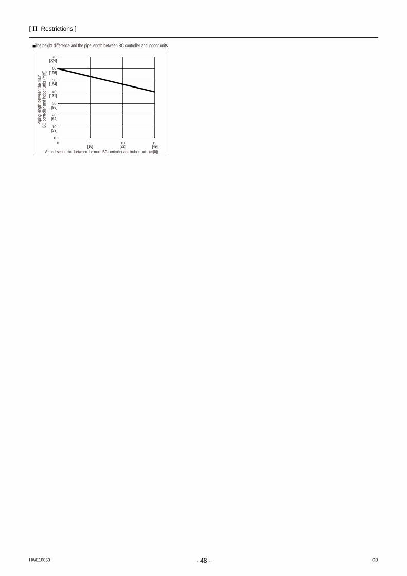
[ II Restrictions ]
- 48 -HWE10050 GB
0
10
20
30
40
50
60
70
0 5 10 15
Pipin
g len
gth
betw
een
the
main
BC
cont
rolle
r and
indo
or u
nits (
m[ft
])
Vertical separation between the main BC controller and indoor units (m[ft])
The height difference and the pipe length between BC controller and indoor units
[32]
[16] [32] [49]
[64]
[98]
[131]
[164]
[196]
[229]
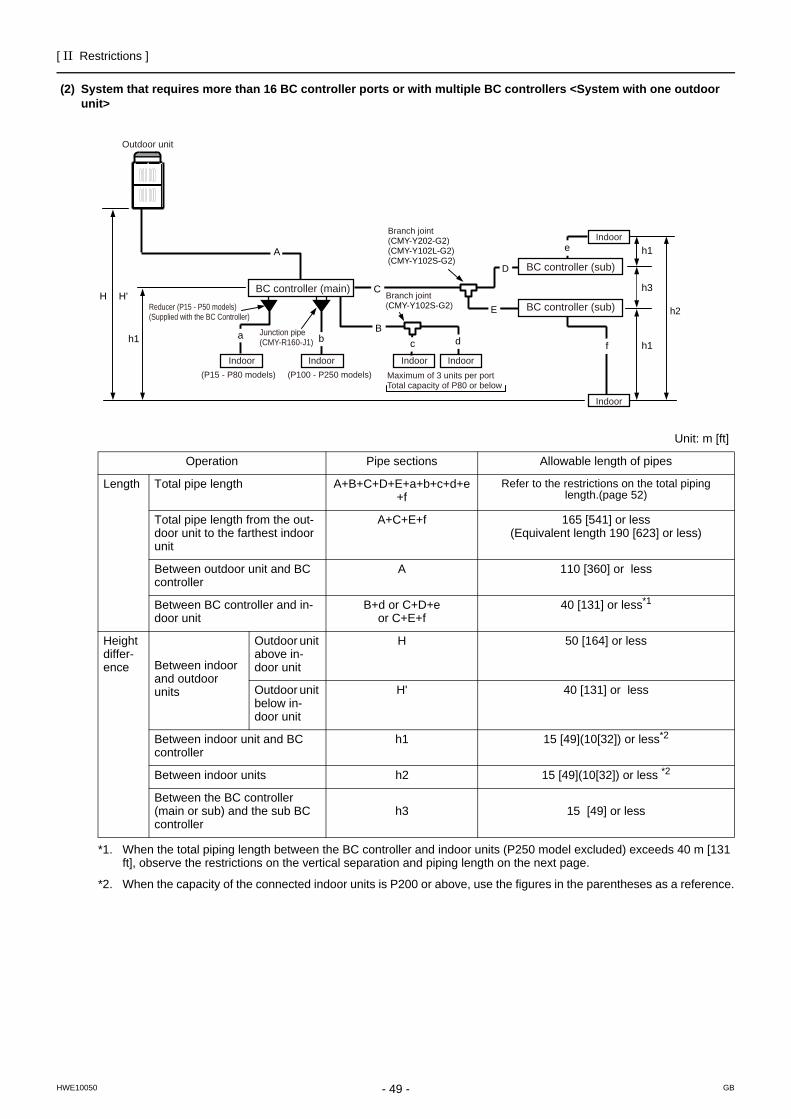
[ II Restrictions ]
- 49 -HWE10050 GB
(2) System that requires more than 16 BC controller ports or with multiple BC controllers <System with one outdoor unit>
Unit: m [ft]
Operation Pipe sections Allowable length of pipes
Length Total pipe length A+B+C+D+E+a+b+c+d+e+f
Refer to the restrictions on the total piping length.(page 52)
Total pipe length from the out-door unit to the farthest indoor unit
A+C+E+f 165 [541] or less (Equivalent length 190 [623] or less)
Between outdoor unit and BC controller
A 110 [360] or less
Between BC controller and in-door unit
B+d or C+D+eor C+E+f
40 [131] or less*1
*1. When the total piping length between the BC controller and indoor units (P250 model excluded) exceeds 40 m [131 ft], observe the restrictions on the vertical separation and piping length on the next page.
Height differ-ence Between indoor
and outdoor units
Outdoor unit above in-door unit
H 50 [164] or less
Outdoor unit below in-door unit
H' 40 [131] or less
Between indoor unit and BC controller
h1 15 [49](10[32]) or less*2
*2. When the capacity of the connected indoor units is P200 or above, use the figures in the parentheses as a reference.
Between indoor units h2 15 [49](10[32]) or less *2
Between the BC controller (main or sub) and the sub BC controller
h3 15 [49] or less
Branch joint(CMY-Y202-G2)(CMY-Y102L-G2)(CMY-Y102S-G2)
Branch joint(CMY-Y102S-G2)
a
C
b
H H'
h1h1
Bc d f
h3
D
E
A e h1
h2
Outdoor unit
BC controller (main)
BC controller (sub)
BC controller (sub)
Indoor Indoor Indoor Indoor
Indoor
Indoor
Reducer (P15 - P50 models)(Supplied with the BC Controller)
(P15 - P80 models) (P100 - P250 models) Maximum of 3 units per portTotal capacity of P80 or below
Junction pipe(CMY-R160-J1)
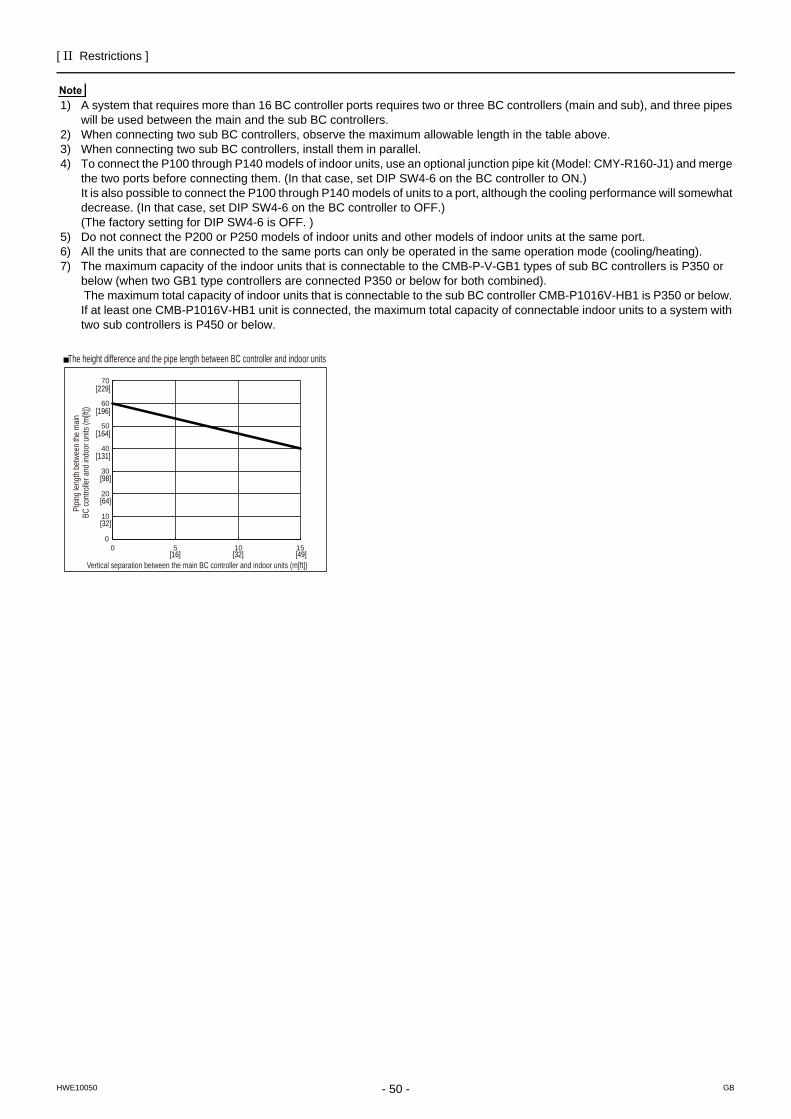
[ II Restrictions ]
- 50 -HWE10050 GB
1) A system that requires more than 16 BC controller ports requires two or three BC controllers (main and sub), and three pipes will be used between the main and the sub BC controllers.
2) When connecting two sub BC controllers, observe the maximum allowable length in the table above. 3) When connecting two sub BC controllers, install them in parallel.4) To connect the P100 through P140 models of indoor units, use an optional junction pipe kit (Model: CMY-R160-J1) and merge
the two ports before connecting them. (In that case, set DIP SW4-6 on the BC controller to ON.) It is also possible to connect the P100 through P140 models of units to a port, although the cooling performance will somewhat decrease. (In that case, set DIP SW4-6 on the BC controller to OFF.)(The factory setting for DIP SW4-6 is OFF. )
5) Do not connect the P200 or P250 models of indoor units and other models of indoor units at the same port.6) All the units that are connected to the same ports can only be operated in the same operation mode (cooling/heating). 7) The maximum capacity of the indoor units that is connectable to the CMB-P-V-GB1 types of sub BC controllers is P350 or
below (when two GB1 type controllers are connected P350 or below for both combined). The maximum total capacity of indoor units that is connectable to the sub BC controller CMB-P1016V-HB1 is P350 or below. If at least one CMB-P1016V-HB1 unit is connected, the maximum total capacity of connectable indoor units to a system with two sub controllers is P450 or below.
0
10
20
30
40
50
60
70
0 5 10 15
Pipin
g len
gth
betw
een
the
main
BC
cont
rolle
r and
indo
or u
nits (
m[ft
])
Vertical separation between the main BC controller and indoor units (m[ft])
The height difference and the pipe length between BC controller and indoor units
[32]
[16] [32] [49]
[64]
[98]
[131]
[164]
[196]
[229]
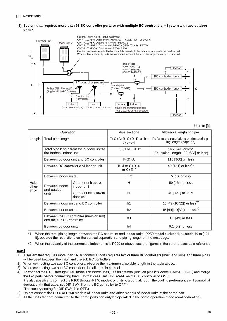
[ II Restrictions ]
- 51 -HWE10050 GB
(3) System that requires more than 16 BC controller ports or with multiple BC controllers <System with two outdoor units>
1) A system that requires more than 16 BC controller ports requires two or three BC controllers (main and sub), and three pipes will be used between the main and the sub BC controllers.
2) When connecting two sub BC controllers, observe the maximum allowable length in the table above. 3) When connecting two sub BC controllers, install them in parallel.4) To connect the P100 through P140 models of indoor units, use an optional junction pipe kit (Model: CMY-R160-J1) and merge
the two ports before connecting them. (In that case, set DIP SW4-6 on the BC controller to ON.) It is also possible to connect the P100 through P140 models of units to a port, although the cooling performance will somewhat decrease. (In that case, set DIP SW4-6 on the BC controller to OFF.)(The factory setting for DIP SW4-6 is OFF.)
5) Do not connect the P200 or P250 models of indoor units and other models of indoor units at the same port.6) All the units that are connected to the same ports can only be operated in the same operation mode (cooling/heating).
h1
h3
h1
h2
f
D
E
e
Outdoor Twinning kit (High/Low press.)CMY-R100VBK: Outdoor unit P400(-A1) - P650/EP400 - EP600(-A)CMY-R200VBK: Outdoor unit P700 - P800(-A)CMY-R100XLVBK: Outdoor unit P800(-A1)/EP600(-A1) - EP700CMY-R200XLVBK: Outdoor unit P850 - P900On the low-pressure side, the twinning kit connects to the pipes on site inside the outdoor unit.When different capacity units are combined, connect the kit to the larger capacity outdoor unit.
a
C
bB
c d
AGF
h4
Outdoor unit 1Outdoor unit 2
H H'
h1
BC controller (main)
Indoor Indoor Indoor Indoor
Indoor
Indoor
BC controller (sub)
BC controller (sub)
Branch joint(CMY-Y202-G2)(CMY-Y102L-G2)(CMY-Y102S-G2)
Branch joint(CMY-Y102S-G2)
(P15 - P80 models) (P100 - P250 models) Maximum of 3 units per portTotal capacity of P80 or below
Reducer (P15 - P50 models)(Supplied with the BC Controller)
Junction pipe(CMY-R160-J1)
Unit: m [ft]
Operation Pipe sections Allowable length of pipes
Length Total pipe length F+G+A+B+C+D+E+a+b+c+d+e+f
Refer to the restrictions on the total pip-ing length.(page 52)
Total pipe length from the outdoor unit to the farthest indoor unit
F(G)+A+C+E+f 165 [541] or less (Equivalent length 190 [623] or less)
Between outdoor unit and BC controller F(G)+A 110 [360] or less
Between BC controller and indoor unit B+d or C+D+eor C+E+f
40 [131] or less*1
Between indoor units F+G 5 [16] or less
Height differ-ence
Between indoor and outdoor units
Outdoor unit above indoor unit
H 50 [164] or less
Outdoor unit below in-door unit
H' 40 [131] or less
Between indoor unit and BC controller h1 15 [49](10[32]) or less*2
Between indoor units h2 15 [49](10[32]) or less *2
Between the BC controller (main or sub) and the sub BC controller h3 15 [49] or less
Between outdoor units h4 0.1 [0.3] or less
*1. When the total piping length between the BC controller and indoor units (P250 model excluded) exceeds 40 m [131 ft], observe the restrictions on the vertical separation and piping length on the next page.
*2. When the capacity of the connected indoor units is P200 or above, use the figures in the parentheses as a reference.
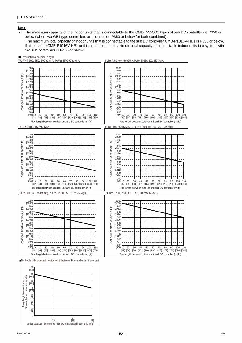
[ II Restrictions ]
- 52 -HWE10050 GB
7) The maximum capacity of the indoor units that is connectable to the CMB-P-V-GB1 types of sub BC controllers is P350 or below (when two GB1 type controllers are connected P350 or below for both combined) . The maximum total capacity of indoor units that is connectable to the sub BC controller CMB-P1016V-HB1 is P350 or below. If at least one CMB-P1016V-HB1 unit is connected, the maximum total capacity of connectable indoor units to a system with two sub controllers is P450 or below.
Restrictions on pipe length [PURY-P200, 250, 300YJM-A, PURY-EP200YJM-A] [PURY-P350, 400, 450YJM-A, PURY-EP250, 300, 350YJM-A]
[PURY-P400, 450YSJM-A1] [PURY-P500, 550YSJM-A(1), PURY-EP400, 450, 500, 550YSJM-A(1)]
[PURY-P600, 650YSJM-A(1), PURY-EP600, 650, 700YSJM-A(1)] [PURY-P700, 750, 800, 850, 900YSJM-A(1)]
1000
900
800
700
600
500
400
300
20010 20 30 40 50 60 70 80 90 100 110[32] [64] [98] [131] [164] [196] [229] [262] [295] [328] [360]
[3280]
[2952]
[2624]
[2296]
[1968]
[1640]
[1312]
[984]
[656]
1000
900
800
700
600
500
400
300
20010 20 30 40 50 60 70 80 90 100 110[32] [64] [98] [131] [164] [196] [229] [262] [295] [328] [360]
[3280]
[2952]
[2624]
[2296]
[1968]
[1640]
[1312]
[984]
[656]
1000
900
800
700
600
500
400
300
20010 20 30 40 50 60 70 80 90 100 110[32] [64] [98] [131] [164] [196] [229] [262] [295] [328] [360]
[3280]
[2952]
[2624]
[2296]
[1968]
[1640]
[1312]
[984]
[656]
1000
900
800
700
600
500
400
300
20010 20 30 40 50 60 70 80 90 100 110[32] [64] [98] [131] [164] [196] [229] [262] [295] [328] [360]
[3280]
[2952]
[2624]
[2296]
[1968]
[1640]
[1312]
[984]
[656]
1000
900
800
700
600
500
400
300
20010 20 30 40 50 60 70 80 90 100 110[32] [64] [98] [131] [164] [196] [229] [262] [295] [328] [360]
[3280]
[2952]
[2624]
[2296]
[1968]
[1640]
[1312]
[984]
[656]
1000
900
800
700
600
500
400
300
20010 20 30 40 50 60 70 80 90 100 110[32] [64] [98] [131] [164] [196] [229] [262] [295] [328] [360]
[3280]
[2952]
[2624]
[2296]
[1968]
[1640]
[1312]
[984]
[656]
Agg
rega
te le
ngth
of a
ll pi
pes(
m [f
t])
Pipe length between outdoor unit and BC controller (m [ft])
Agg
rega
te le
ngth
of a
ll pi
pes(
m [f
t])
Pipe length between outdoor unit and BC controller (m [ft])
Agg
rega
te le
ngth
of a
ll pi
pes(
m [f
t])
Pipe length between outdoor unit and BC controller (m [ft])
Agg
rega
te le
ngth
of a
ll pi
pes(
m [f
t])
Pipe length between outdoor unit and BC controller (m [ft])
Agg
rega
te le
ngth
of a
ll pi
pes(
m [f
t])
Pipe length between outdoor unit and BC controller (m [ft])
Agg
rega
te le
ngth
of a
ll pi
pes(
m [f
t])
Pipe length between outdoor unit and BC controller (m [ft])
0
10
20
30
40
50
60
70
0 5 10 15
Pipin
g len
gth
betw
een
the
main
BC
cont
rolle
r and
indo
or u
nits (
m[ft
])
Vertical separation between the main BC controller and indoor units (m[ft])
The height difference and the pipe length between BC controller and indoor units
[32]
[16] [32] [49]
[64]
[98]
[131]
[164]
[196]
[229]
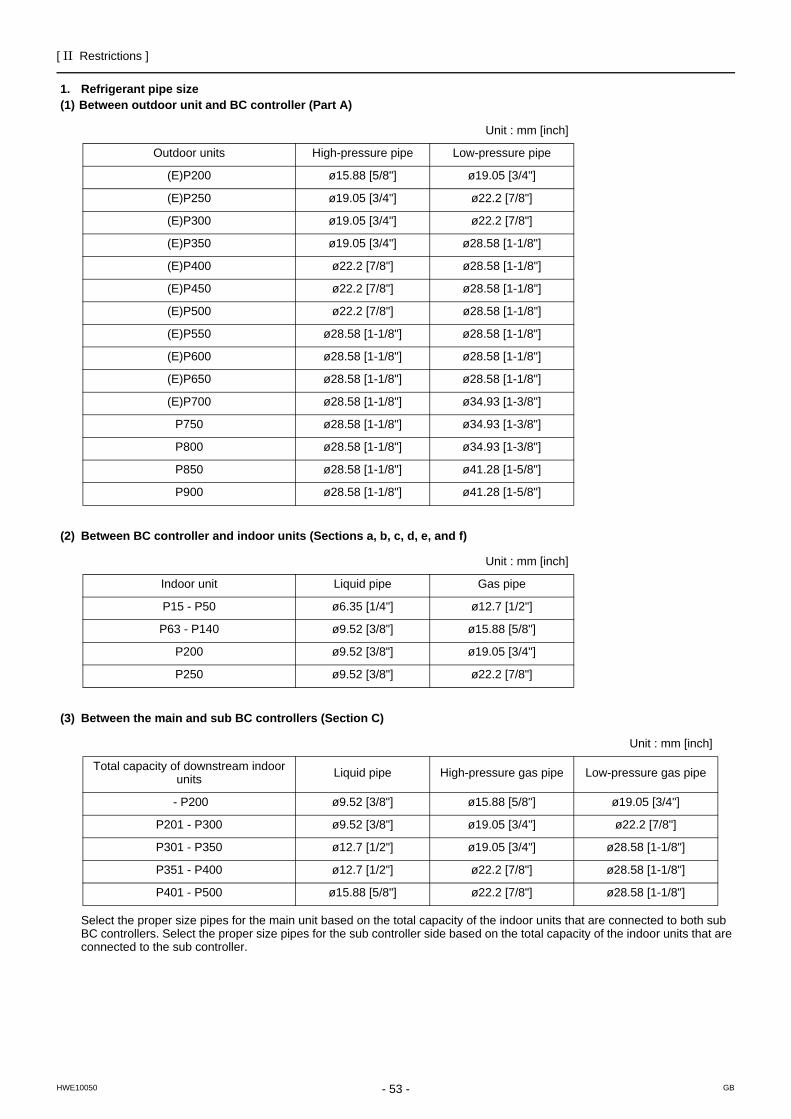
[ II Restrictions ]
- 53 -HWE10050 GB
1. Refrigerant pipe size(1) Between outdoor unit and BC controller (Part A)
(2) Between BC controller and indoor units (Sections a, b, c, d, e, and f)
(3) Between the main and sub BC controllers (Section C)
Select the proper size pipes for the main unit based on the total capacity of the indoor units that are connected to both sub BC controllers. Select the proper size pipes for the sub controller side based on the total capacity of the indoor units that are connected to the sub controller.
Unit : mm [inch]
Outdoor units High-pressure pipe Low-pressure pipe
(E)P200 ø15.88 [5/8"] ø19.05 [3/4"]
(E)P250 ø19.05 [3/4"] ø22.2 [7/8"]
(E)P300 ø19.05 [3/4"] ø22.2 [7/8"]
(E)P350 ø19.05 [3/4"] ø28.58 [1-1/8"]
(E)P400 ø22.2 [7/8"] ø28.58 [1-1/8"]
(E)P450 ø22.2 [7/8"] ø28.58 [1-1/8"]
(E)P500 ø22.2 [7/8"] ø28.58 [1-1/8"]
(E)P550 ø28.58 [1-1/8"] ø28.58 [1-1/8"]
(E)P600 ø28.58 [1-1/8"] ø28.58 [1-1/8"]
(E)P650 ø28.58 [1-1/8"] ø28.58 [1-1/8"]
(E)P700 ø28.58 [1-1/8"] ø34.93 [1-3/8"]
P750 ø28.58 [1-1/8"] ø34.93 [1-3/8"]
P800 ø28.58 [1-1/8"] ø34.93 [1-3/8"]
P850 ø28.58 [1-1/8"] ø41.28 [1-5/8"]
P900 ø28.58 [1-1/8"] ø41.28 [1-5/8"]
Unit : mm [inch]
Indoor unit Liquid pipe Gas pipe
P15 - P50 ø6.35 [1/4"] ø12.7 [1/2"]
P63 - P140 ø9.52 [3/8"] ø15.88 [5/8"]
P200 ø9.52 [3/8"] ø19.05 [3/4"]
P250 ø9.52 [3/8"] ø22.2 [7/8"]
Unit : mm [inch]
Total capacity of downstream indoor units Liquid pipe High-pressure gas pipe Low-pressure gas pipe
- P200 ø9.52 [3/8"] ø15.88 [5/8"] ø19.05 [3/4"]
P201 - P300 ø9.52 [3/8"] ø19.05 [3/4"] ø22.2 [7/8"]
P301 - P350 ø12.7 [1/2"] ø19.05 [3/4"] ø28.58 [1-1/8"]
P351 - P400 ø12.7 [1/2"] ø22.2 [7/8"] ø28.58 [1-1/8"]
P401 - P500 ø15.88 [5/8"] ø22.2 [7/8"] ø28.58 [1-1/8"]
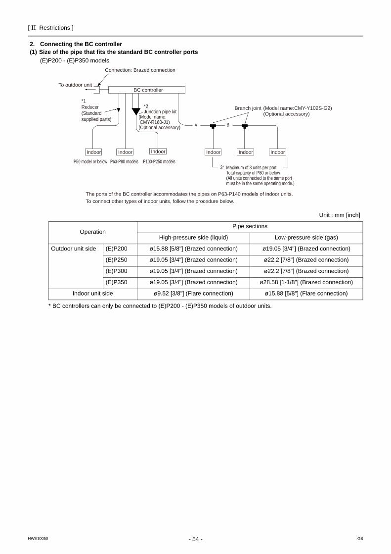
[ II Restrictions ]
- 54 -HWE10050 GB
2. Connecting the BC controller(1) Size of the pipe that fits the standard BC controller ports
(E)P200 - (E)P350 models
* BC controllers can only be connected to (E)P200 - (E)P350 models of outdoor units.
Unit : mm [inch]
OperationPipe sections
High-pressure side (liquid) Low-pressure side (gas)
Outdoor unit side (E)P200 ø15.88 [5/8"] (Brazed connection) ø19.05 [3/4"] (Brazed connection)
(E)P250 ø19.05 [3/4"] (Brazed connection) ø22.2 [7/8"] (Brazed connection)
(E)P300 ø19.05 [3/4"] (Brazed connection) ø22.2 [7/8"] (Brazed connection)
(E)P350 ø19.05 [3/4"] (Brazed connection) ø28.58 [1-1/8"] (Brazed connection)
Indoor unit side ø9.52 [3/8"] (Flare connection) ø15.88 [5/8"] (Flare connection)
IndoorIndoorIndoorIndoorIndoorIndoor
BC controller
Maximum of 3 units per portTotal capacity of P80 or below(All units connected to the same port must be in the same operating mode.)
Branch joint (Model name:CMY-Y102S-G2) (Optional accessory)
*2Junction pipe kit
(Model name: CMY-R160-J1)(Optional accessory)
P50 model or below P63-P80 models P100-P250 models3*
A B
*1Reducer(Standard supplied parts)
To outdoor unit
Connection: Brazed connection
The ports of the BC controller accommodates the pipes on P63-P140 models of indoor units.To connect other types of indoor units, follow the procedure below.
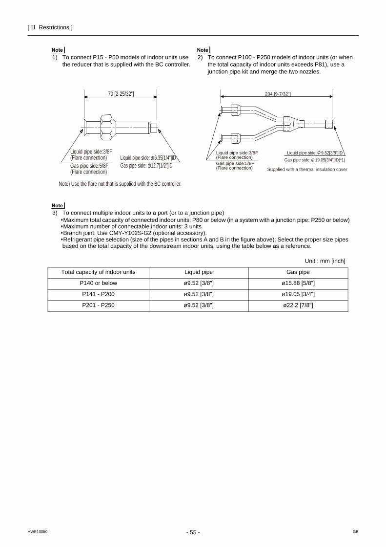
[ II Restrictions ]
- 55 -HWE10050 GB
1) To connect P15 - P50 models of indoor units use the reducer that is supplied with the BC controller.
2) To connect P100 - P250 models of indoor units (or when the total capacity of indoor units exceeds P81), use a junction pipe kit and merge the two nozzles.
3) To connect multiple indoor units to a port (or to a junction pipe)Maximum total capacity of connected indoor units: P80 or below (in a system with a junction pipe: P250 or below)Maximum number of connectable indoor units: 3 unitsBranch joint: Use CMY-Y102S-G2 (optional accessory).Refrigerant pipe selection (size of the pipes in sections A and B in the figure above): Select the proper size pipes based on the total capacity of the downstream indoor units, using the table below as a reference.
Unit : mm [inch]
Total capacity of indoor units Liquid pipe Gas pipe
P140 or below ø9.52 [3/8"] ø15.88 [5/8"]
P141 - P200 ø9.52 [3/8"] ø19.05 [3/4"]
P201 - P250 ø9.52 [3/8"] ø22.2 [7/8"]
Liquid pipe side: 6.35[1/4"]IDGas pipe side: 12.7[1/2"]ID
Liquid pipe side:3/8F(Flare connection)Gas pipe side:5/8F(Flare connection)
Note) Use the flare nut that is supplied with the BC controller.
70 [2-25/32"]
Liquid pipe side: 9.52[3/8”]IDGas pipe side: 19.05[3/4”]ID(*1)
234 [9-7/32"]
Supplied with a thermal insulation cover
Liquid pipe side:3/8F(Flare connection)Gas pipe side:5/8F(Flare connection)
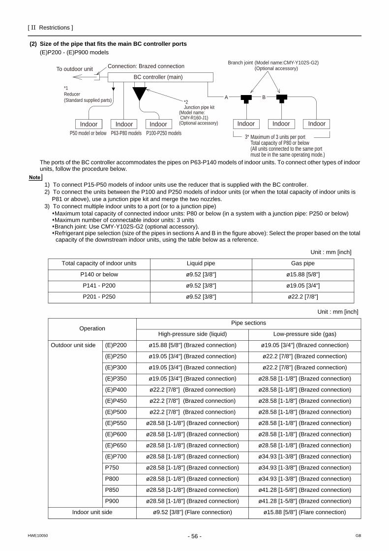
[ II Restrictions ]
- 56 -HWE10050 GB
(2) Size of the pipe that fits the main BC controller ports(E)P200 - (E)P900 models
The ports of the BC controller accommodates the pipes on P63-P140 models of indoor units. To connect other types of indoor units, follow the procedure below.
1) To connect P15-P50 models of indoor units use the reducer that is supplied with the BC controller.2) To connect the units between the P100 and P250 models of indoor units (or when the total capacity of indoor units is
P81 or above), use a junction pipe kit and merge the two nozzles.3) To connect multiple indoor units to a port (or to a junction pipe)
Maximum total capacity of connected indoor units: P80 or below (in a system with a junction pipe: P250 or below)Maximum number of connectable indoor units: 3 unitsBranch joint: Use CMY-Y102S-G2 (optional accessory).Refrigerant pipe selection (size of the pipes in sections A and B in the figure above): Select the proper based on the total capacity of the downstream indoor units, using the table below as a reference.
Unit : mm [inch]
Total capacity of indoor units Liquid pipe Gas pipe
P140 or below ø9.52 [3/8"] ø15.88 [5/8"]
P141 - P200 ø9.52 [3/8"] ø19.05 [3/4"]
P201 - P250 ø9.52 [3/8"] ø22.2 [7/8"]
Unit : mm [inch]
OperationPipe sections
High-pressure side (liquid) Low-pressure side (gas)
Outdoor unit side (E)P200 ø15.88 [5/8"] (Brazed connection) ø19.05 [3/4"] (Brazed connection)
(E)P250 ø19.05 [3/4"] (Brazed connection) ø22.2 [7/8"] (Brazed connection)
(E)P300 ø19.05 [3/4"] (Brazed connection) ø22.2 [7/8"] (Brazed connection)
(E)P350 ø19.05 [3/4"] (Brazed connection) ø28.58 [1-1/8"] (Brazed connection)
(E)P400 ø22.2 [7/8"] (Brazed connection) ø28.58 [1-1/8"] (Brazed connection)
(E)P450 ø22.2 [7/8"] (Brazed connection) ø28.58 [1-1/8"] (Brazed connection)
(E)P500 ø22.2 [7/8"] (Brazed connection) ø28.58 [1-1/8"] (Brazed connection)
(E)P550 ø28.58 [1-1/8"] (Brazed connection) ø28.58 [1-1/8"] (Brazed connection)
(E)P600 ø28.58 [1-1/8"] (Brazed connection) ø28.58 [1-1/8"] (Brazed connection)
(E)P650 ø28.58 [1-1/8"] (Brazed connection) ø28.58 [1-1/8"] (Brazed connection)
(E)P700 ø28.58 [1-1/8"] (Brazed connection) ø34.93 [1-3/8"] (Brazed connection)
P750 ø28.58 [1-1/8"] (Brazed connection) ø34.93 [1-3/8"] (Brazed connection)
P800 ø28.58 [1-1/8"] (Brazed connection) ø34.93 [1-3/8"] (Brazed connection)
P850 ø28.58 [1-1/8"] (Brazed connection) ø41.28 [1-5/8"] (Brazed connection)
P900 ø28.58 [1-1/8"] (Brazed connection) ø41.28 [1-5/8"] (Brazed connection)
Indoor unit side ø9.52 [3/8"] (Flare connection) ø15.88 [5/8"] (Flare connection)
A B
Indoor Indoor IndoorP50 model or below P63-P80 models P100-P250 models
*2Junction pipe kit
(Model name: CMY-R160-J1)(Optional accessory)
BC controller (main)To outdoor unit Connection: Brazed connection
*1Reducer(Standard supplied parts)
Maximum of 3 units per portTotal capacity of P80 or below(All units connected to the same port must be in the same operating mode.)
3*
Indoor Indoor Indoor
Branch joint (Model name:CMY-Y102S-G2) (Optional accessory)
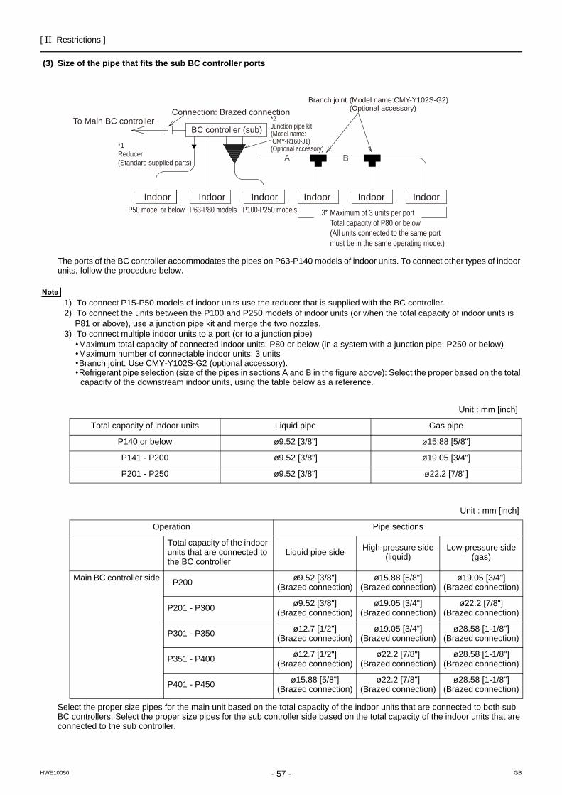
[ II Restrictions ]
- 57 -HWE10050 GB
(3) Size of the pipe that fits the sub BC controller ports
The ports of the BC controller accommodates the pipes on P63-P140 models of indoor units. To connect other types of indoor units, follow the procedure below.
1) To connect P15-P50 models of indoor units use the reducer that is supplied with the BC controller.2) To connect the units between the P100 and P250 models of indoor units (or when the total capacity of indoor units is
P81 or above), use a junction pipe kit and merge the two nozzles.3) To connect multiple indoor units to a port (or to a junction pipe)
Maximum total capacity of connected indoor units: P80 or below (in a system with a junction pipe: P250 or below)Maximum number of connectable indoor units: 3 unitsBranch joint: Use CMY-Y102S-G2 (optional accessory).Refrigerant pipe selection (size of the pipes in sections A and B in the figure above): Select the proper based on the total capacity of the downstream indoor units, using the table below as a reference.
Select the proper size pipes for the main unit based on the total capacity of the indoor units that are connected to both sub BC controllers. Select the proper size pipes for the sub controller side based on the total capacity of the indoor units that are connected to the sub controller.
Unit : mm [inch]
Total capacity of indoor units Liquid pipe Gas pipe
P140 or below ø9.52 [3/8"] ø15.88 [5/8"]
P141 - P200 ø9.52 [3/8"] ø19.05 [3/4"]
P201 - P250 ø9.52 [3/8"] ø22.2 [7/8"]
A B
Indoor Indoor IndoorP50 model or below P63-P80 models P100-P250 models
*2Junction pipe kit(Model name: CMY-R160-J1)(Optional accessory)
BC controller (sub)To Main BC controller
Connection: Brazed connection
*1Reducer(Standard supplied parts)
Maximum of 3 units per portTotal capacity of P80 or below(All units connected to the same port must be in the same operating mode.)
3*
Indoor Indoor Indoor
Branch joint (Model name:CMY-Y102S-G2) (Optional accessory)
Unit : mm [inch]
Operation Pipe sections
Total capacity of the indoor units that are connected to the BC controller
Liquid pipe side High-pressure side (liquid)
Low-pressure side (gas)
Main BC controller side - P200 ø9.52 [3/8"](Brazed connection)
ø15.88 [5/8"](Brazed connection)
ø19.05 [3/4"] (Brazed connection)
P201 - P300 ø9.52 [3/8"](Brazed connection)
ø19.05 [3/4"] (Brazed connection)
ø22.2 [7/8"] (Brazed connection)
P301 - P350 ø12.7 [1/2"](Brazed connection)
ø19.05 [3/4"] (Brazed connection)
ø28.58 [1-1/8"] (Brazed connection)
P351 - P400 ø12.7 [1/2"](Brazed connection)
ø22.2 [7/8"] (Brazed connection)
ø28.58 [1-1/8"] (Brazed connection)
P401 - P450 ø15.88 [5/8"](Brazed connection)
ø22.2 [7/8"] (Brazed connection)
ø28.58 [1-1/8"] (Brazed connection)

- 58 -
[ II Restrictions ]
GBHWE10050
- 59 -HWE10050 GB
III Outdoor Unit Components
[1] Outdoor Unit Components and Refrigerant Circuit ..........................................................61[2] Control Box of the Outdoor Unit.......................................................................................66[3] Outdoor Unit Circuit Board...............................................................................................67[4] BC Controller Components ..............................................................................................72[5] Control Box of the BC Controller......................................................................................75[6] BC Controller Circuit Board..............................................................................................76

- 60 -
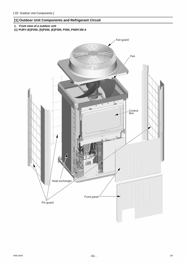
[ III Outdoor Unit Components ]
- 61 -HWE10050 GB
III Outdoor Unit Components
[1] Outdoor Unit Components and Refrigerant Circuit1. Front view of a outdoor unit(1) PURY-(E)P200, (E)P250, (E)P300, P350, P400YJM-A
Fan
Control Box
Fan guard
Fin guard
Front panel
Heat exchanger
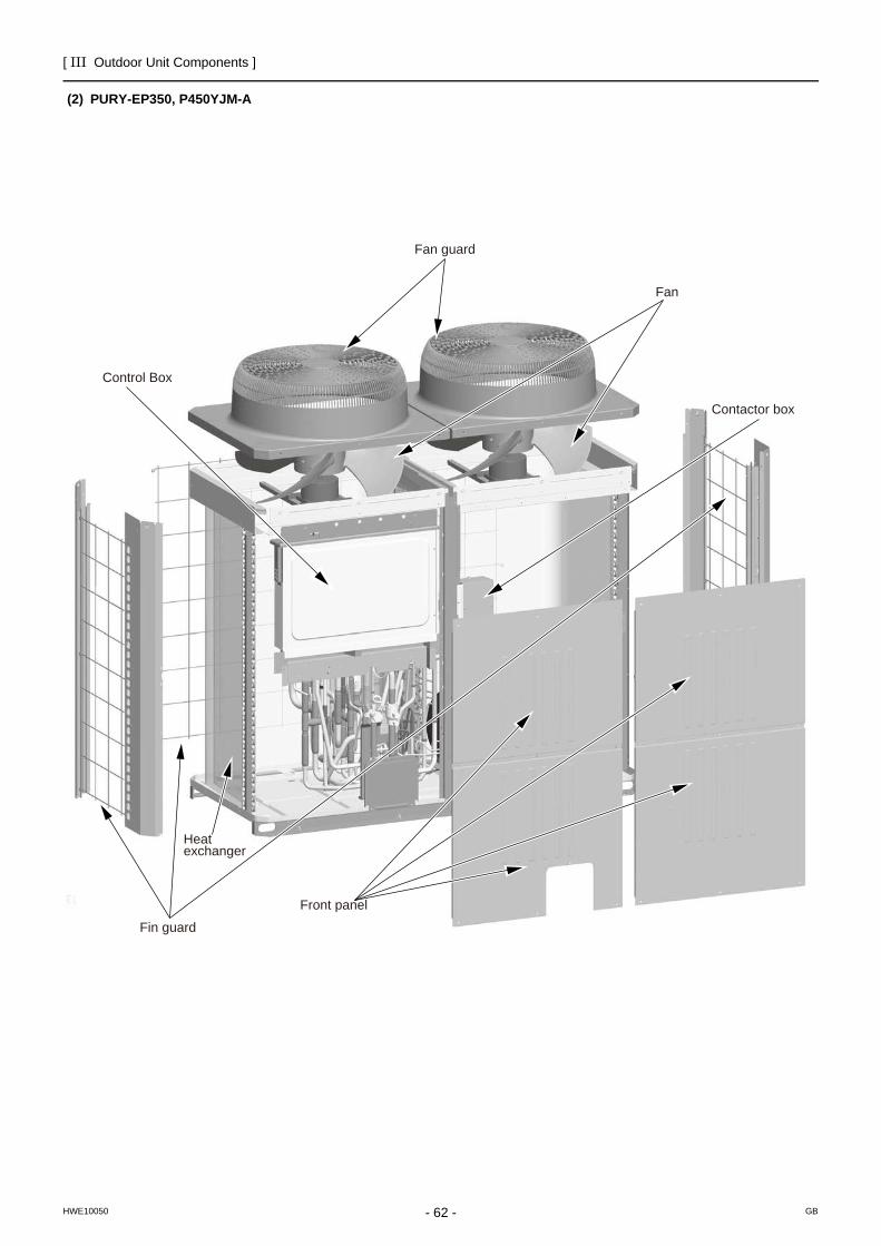
[ III Outdoor Unit Components ]
- 62 -HWE10050 GB
(2) PURY-EP350, P450YJM-A
Fan
Contactor box
Control Box
Fan guard
Fin guard
Front panel
Heat exchanger
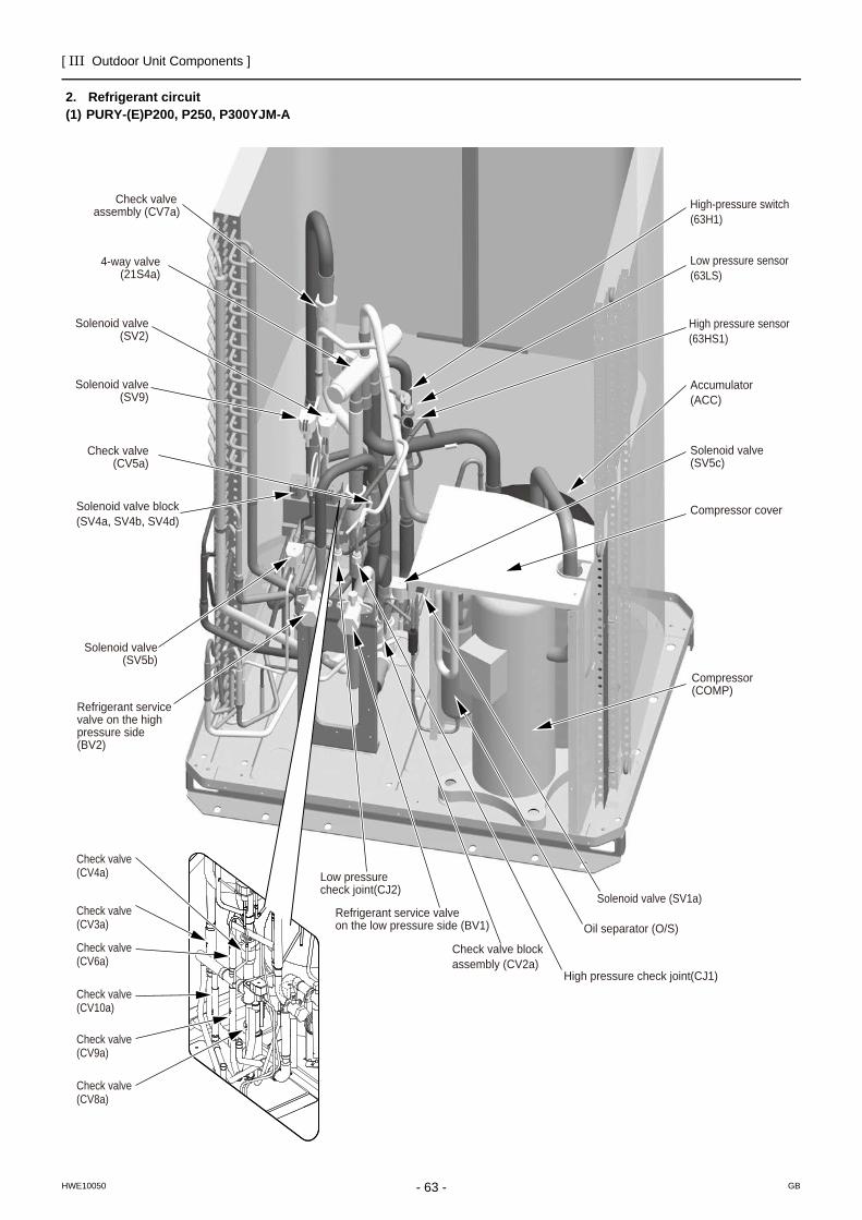
[ III Outdoor Unit Components ]
- 63 -HWE10050 GB
2. Refrigerant circuit(1) PURY-(E)P200, P250, P300YJM-A
High-pressure switch(63H1)
Low pressure sensor(63LS)
High pressure sensor(63HS1)
Accumulator(ACC)
Solenoid valve (SV1a)
Compressor cover
Compressor (COMP)
Oil separator (O/S)
High pressure check joint(CJ1)
Low pressure check joint(CJ2)
Refrigerant service valve on the low pressure side (BV1)
Refrigerant service valve on the high pressure side(BV2)
Check valve block assembly (CV2a)
Check valve(CV4a)
Check valve(CV3a)
Check valve(CV6a)
Check valve(CV10a)
Check valve(CV9a)
Check valve(CV8a)
Solenoid valve(SV5b)
Solenoid valve block(SV4a, SV4b, SV4d)
Check valve(CV5a)
Solenoid valve(SV9)
Solenoid valve(SV2)
4-way valve(21S4a)
Check valve assembly (CV7a)
Solenoid valve(SV5c)
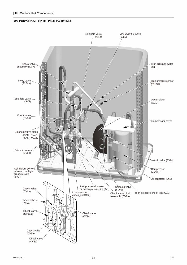
[ III Outdoor Unit Components ]
- 64 -HWE10050 GB
(2) PURY-EP250, EP300, P350, P400YJM-A
High-pressure switch(63H1)
Low pressure sensor(63LS)
High pressure sensor(63HS1)
Accumulator(ACC)
Solenoid valve (SV1a)
Compressor cover
Compressor (COMP)
Oil separator (O/S)
High pressure check joint(CJ1)Low pressure check joint(CJ2)
Refrigerant service valve on the low pressure side (BV1)
Refrigerant service valve on the high pressure side(BV2)
Check valve block assembly (CV2a)
Check valve(CV4a)
Check valve(CV3a)
Check valve(CV6a)
Check valve(CV10a)
Check valve(CV9a)
Check valve(CV8a)
Solenoid valve(SV5b)
Solenoid valve block(SV4a, SV4b,SV4c, SV4d)
Check valve(CV5a)
Solenoid valve(SV9)
Solenoid valve(SV2)
4-way valve(21S4a)
Check valve assembly (CV7a)
Solenoid valve(SV5c)
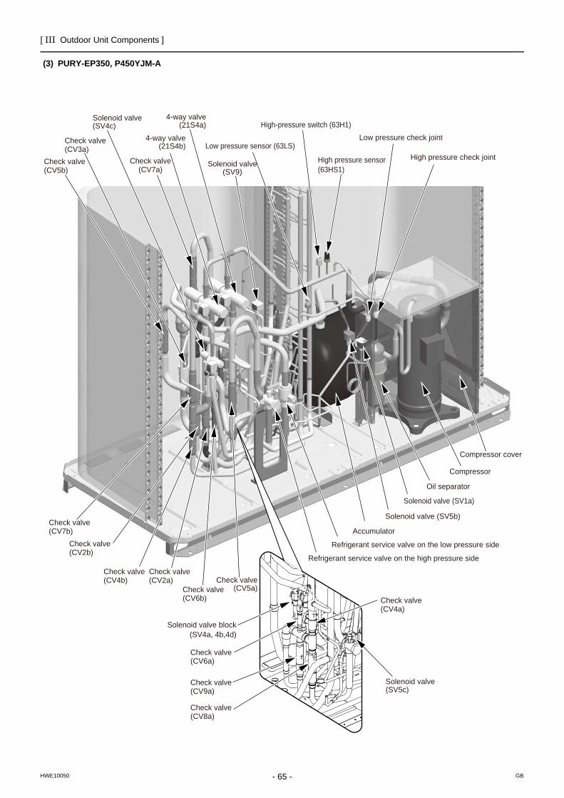
[ III Outdoor Unit Components ]
- 65 -HWE10050 GB
(3) PURY-EP350, P450YJM-A
High-pressure switch (63H1)
Low pressure sensor (63LS)
Accumulator
Solenoid valve (SV1a)
Compressor cover
Compressor
Oil separator
High pressure check joint
Low pressure check jointCheck valve(CV3a)
Check valve(CV5b)
Check valve(CV6a)
Check valve(CV4a)
Check valve(CV9a)
Check valve(CV8a)
Check valve(CV7b)
Check valve(CV6b)
Check valve(CV2a)
Check valve(CV4b)
Check valve(CV2b)
Check valve(CV7a)
Solenoid valve (SV5b)
Solenoid valve block(SV4a, 4b,4d)
Check valve(CV5a)
Refrigerant service valve on the low pressure side
Refrigerant service valve on the high pressure side
Solenoid valve(SV9)
4-way valve(21S4a)
4-way valve(21S4b)
Solenoid valve(SV4c)
Solenoid valve(SV5c)
High pressure sensor(63HS1)
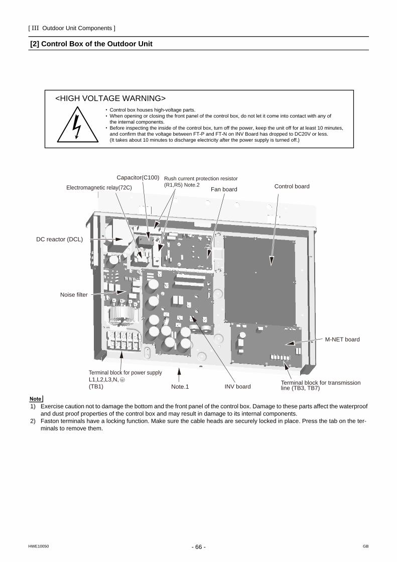
[ III Outdoor Unit Components ]
- 66 -HWE10050 GB
[2] Control Box of the Outdoor Unit
1) Exercise caution not to damage the bottom and the front panel of the control box. Damage to these parts affect the waterproof and dust proof properties of the control box and may result in damage to its internal components.
2) Faston terminals have a locking function. Make sure the cable heads are securely locked in place. Press the tab on the ter-minals to remove them.
<HIGH VOLTAGE WARNING>Control box houses high-voltage parts.When opening or closing the front panel of the control box, do not let it come into contact with any of the internal components.Before inspecting the inside of the control box, turn off the power, keep the unit off for at least 10 minutes, and confirm that the voltage between FT-P and FT-N on INV Board has dropped to DC20V or less.(It takes about 10 minutes to discharge electricity after the power supply is turned off.)
Control board
DC reactor (DCL)
Electromagnetic relay(72C)
Noise filter
Note.1 INV board
Fan board
Rush current protection resistor(R1,R5) Note.2
Terminal block for transmission line (TB3, TB7)
M-NET board
Terminal block for power supplyL1,L2,L3,N,(TB1)
Capacitor(C100)
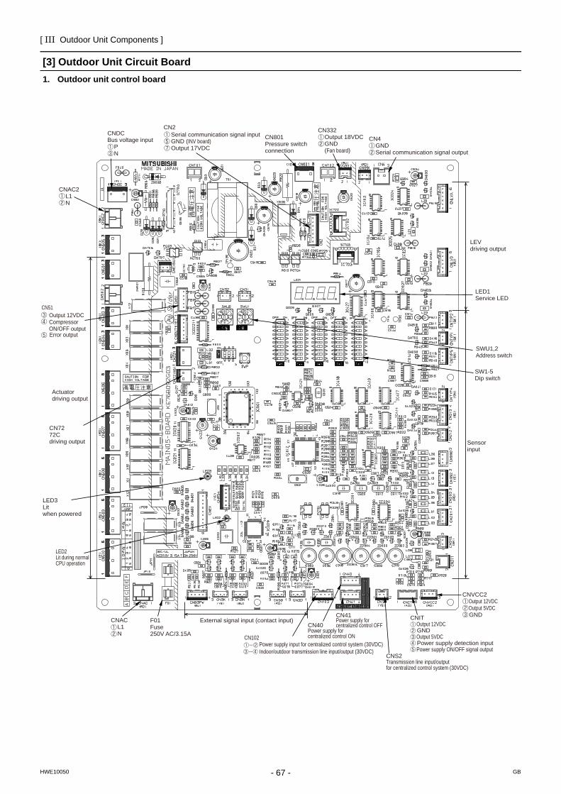
[ III Outdoor Unit Components ]
- 67 -HWE10050 GB
[3] Outdoor Unit Circuit Board1. Outdoor unit control board
LED2Lit during normal CPU operation
CN7272Cdriving output
Serial communication signal inputGND (INV board)Output 17VDC
CN801Pressure switch connection
CN4 GND Serial communication signal output
LEVdriving output
LED1Service LED
SWU1,2Address switch
SW1-5Dip switch
Sensor input
CNVCC2 Output 12VDC Output 5VDC GNDCNIT
Output 12VDC GND Output 5VDC Power supply detection input Power supply ON/OFF signal output
CNS2Transmission line input/outputfor centralized control system (30VDC)
CN41Power supply for centralized control OFFCN40
Power supply for centralized control ONCN102
Indoor/outdoor transmission line input/output (30VDC)Power supply input for centralized control system (30VDC)
External signal input (contact input)F01Fuse250V AC/3.15A
CNAC L1 N
LED3Litwhen powered
Actuatordriving output
Output 12VDCCompressor ON/OFF outputError output
CN51
CNAC2 L1 N
CNDCBus voltage input P N
CN2 CN332 Output 18VDC GND (Fan board)
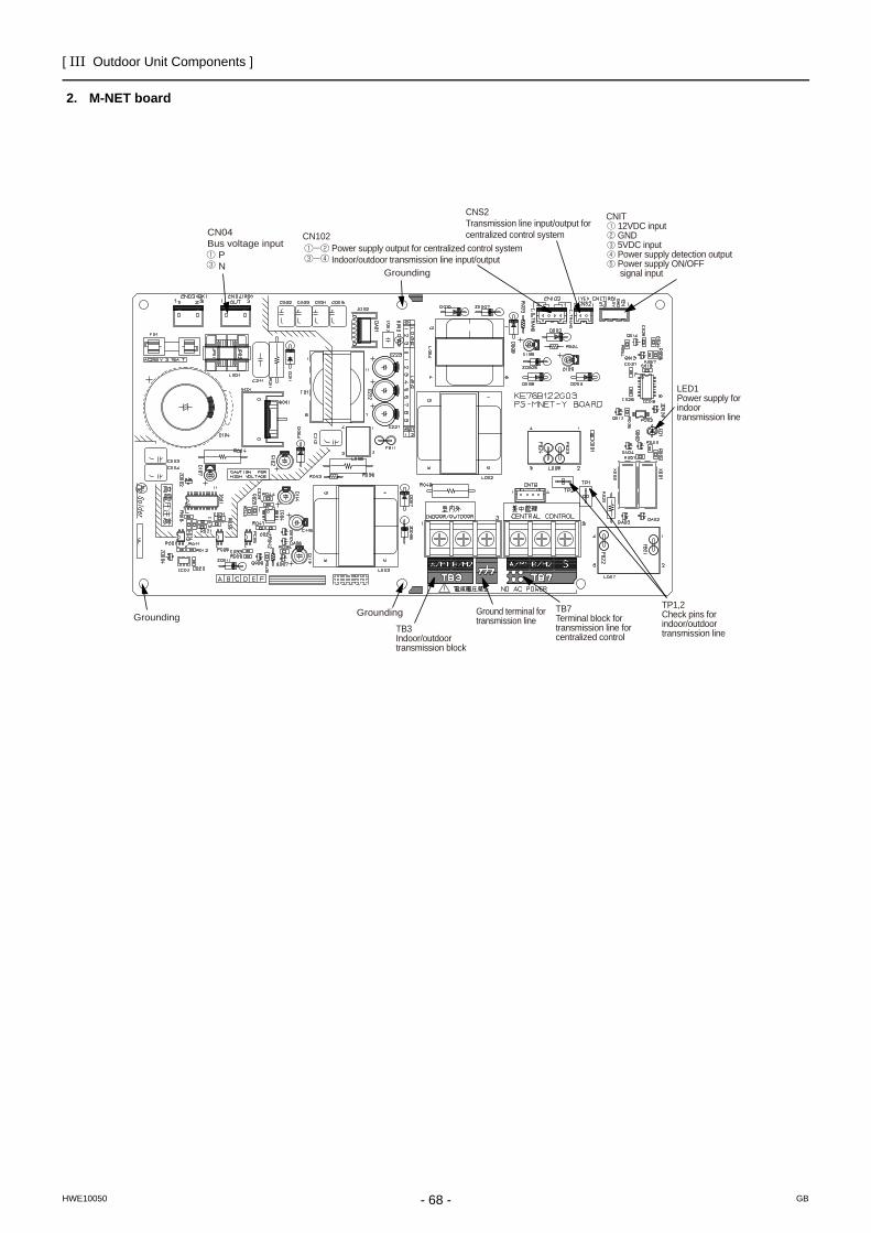
[ III Outdoor Unit Components ]
- 68 -HWE10050 GB
2. M-NET board
Power supply output for centralized control system Indoor/outdoor transmission line input/output
CN102
CNS2Transmission line input/output for centralized control system
CNIT 12VDC input GND 5VDC input Power supply detection output Power supply ON/OFF signal input
LED1Power supply for indoor transmission line
TP1,2Check pins for indoor/outdoortransmission line
TB7Terminal block for transmission line for centralized control
TB3Indoor/outdoor transmission block
Ground terminal for transmission line
GroundingGrounding
CN04Bus voltage input P N
Grounding
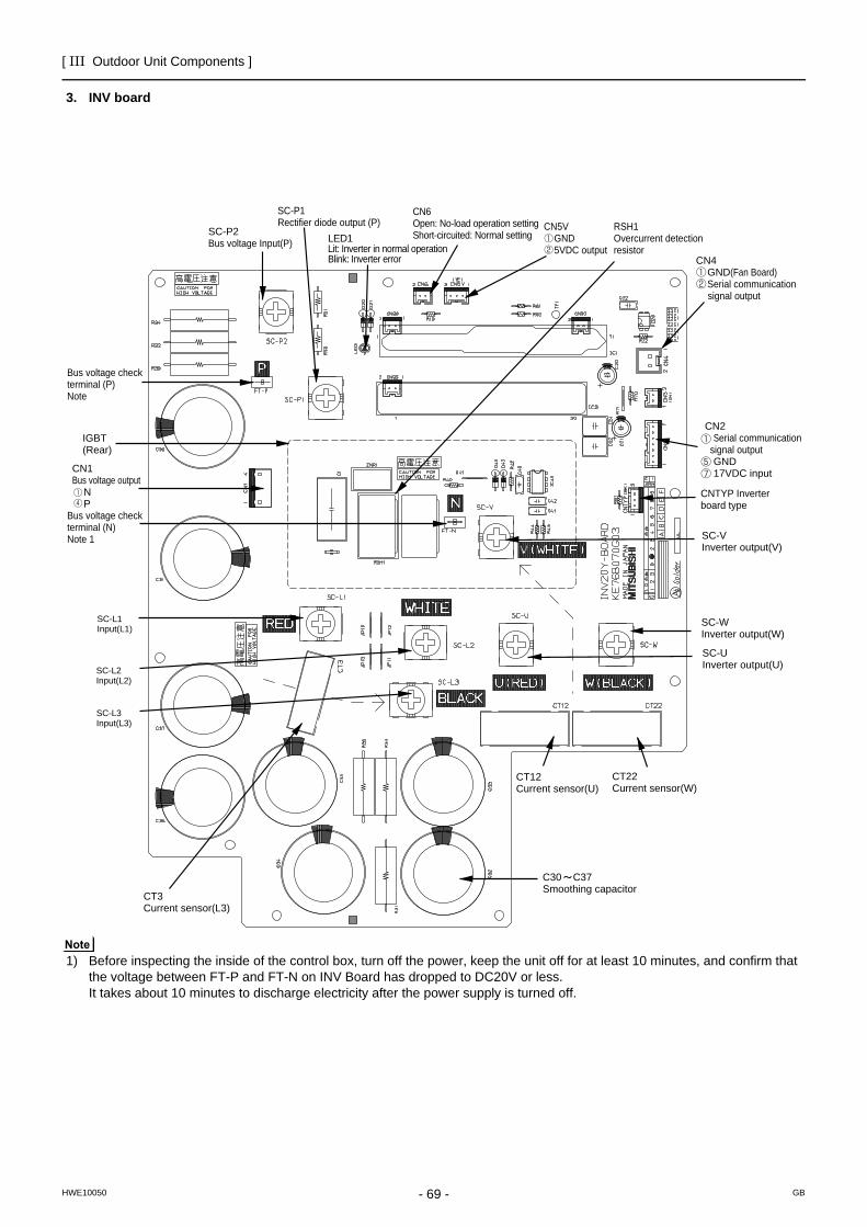
[ III Outdoor Unit Components ]
- 69 -HWE10050 GB
3. INV board
1) Before inspecting the inside of the control box, turn off the power, keep the unit off for at least 10 minutes, and confirm that the voltage between FT-P and FT-N on INV Board has dropped to DC20V or less. It takes about 10 minutes to discharge electricity after the power supply is turned off.
SC-L1Input(L1)
SC-L2Input(L2)
SC-L3Input(L3)
IGBT(Rear)
Bus voltage checkterminal (P)Note
Bus voltage check terminal (N)Note 1
SC-P2Bus voltage Input(P)
SC-P1Rectifier diode output (P)
LED1Lit: Inverter in normal operationBlink: Inverter error
CN6Open: No-load operation settingShort-circuited: Normal setting
CN5V GND 5VDC output
RSH1Overcurrent detection resistor
CN4 GND(Fan Board) Serial communication
signal output
CN2 Serial communication signal output GND 17VDC input
SC-VInverter output(V)
CNTYP Inverter board type
SC-WInverter output(W)
SC-UInverter output(U)
CT22Current sensor(W)
CT12Current sensor(U)
C30 C37Smoothing capacitor
CN1Bus voltage output N P
CT3Current sensor(L3)
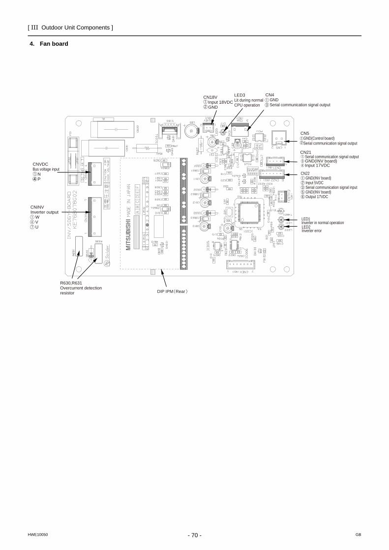
[ III Outdoor Unit Components ]
- 70 -HWE10050 GB
4. Fan board
CNVDCBus voltage input N P
CNINVInverter output W V U
CN18V Input 18VDC GND
LED3Lit during normal CPU operation
CN4 GND Serial communication signal output
CN5 GND(Control board) Serial communication signal output
CN21 Serial communication signal output GND(INV board) Input 17VDC
CN22 GND(INV board) Input 5VDC Serial communication signal input GND(INV board) Output 17VDC
LED1Inverter in normal operationLED2Inverter error
DIP IPM Rear
R630,R631Overcurrent detection resistor
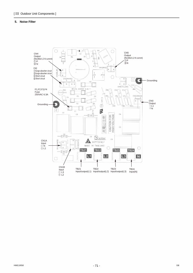
[ III Outdoor Unit Components ]
- 71 -HWE10050 GB
5. Noise Filter
CN4Output(Rectified L2-N current) P N
CN5Output(Rectified L2-N current) P N
TB21Input/output(L1)
TB22Input/output(L2)
TB23Input/output(L3)
TB24Input(N)
CN1BInput L3 L2
CN1AInput N L1
Grounding
F1,F2,F3,F4Fuse250VAC 6.3A
CN3Output L1 N
Grounding
CN2 Surge absorber circuit Surge absorber circuit Short circuit Short circuit
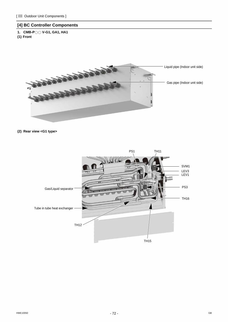
[ III Outdoor Unit Components ]
- 72 -HWE10050 GB
[4] BC Controller Components1. CMB-P V-G1, GA1, HA1(1) Front
(2) Rear view <G1 type>
Liquid pipe (Indoor unit side)
Gas pipe (Indoor unit side)
TH12
TH15
TH16
TH11
SVM1
LEV1LEV3
PS1
PS3
Tube in tube heat exchanger
Gas/Liquid separator
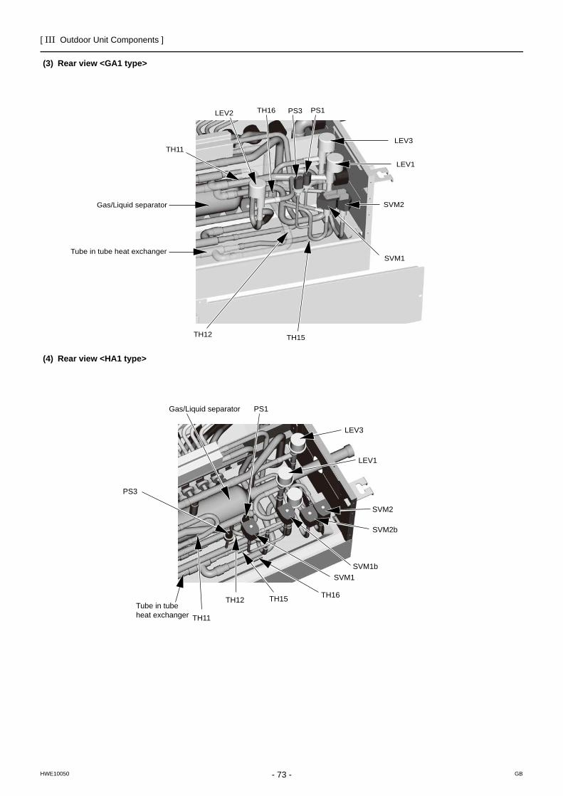
[ III Outdoor Unit Components ]
- 73 -HWE10050 GB
(3) Rear view <GA1 type>
(4) Rear view <HA1 type>
TH12 TH15
TH16
TH11
SVM2
SVM1
LEV1
LEV3
LEV2 PS1PS3
Tube in tube heat exchanger
Gas/Liquid separator
Gas/Liquid separator
LEV3
LEV1
SVM2
SVM2b
SVM1bSVM1
TH16TH15TH12
TH11
PS1
PS3
Tube in tube heat exchanger
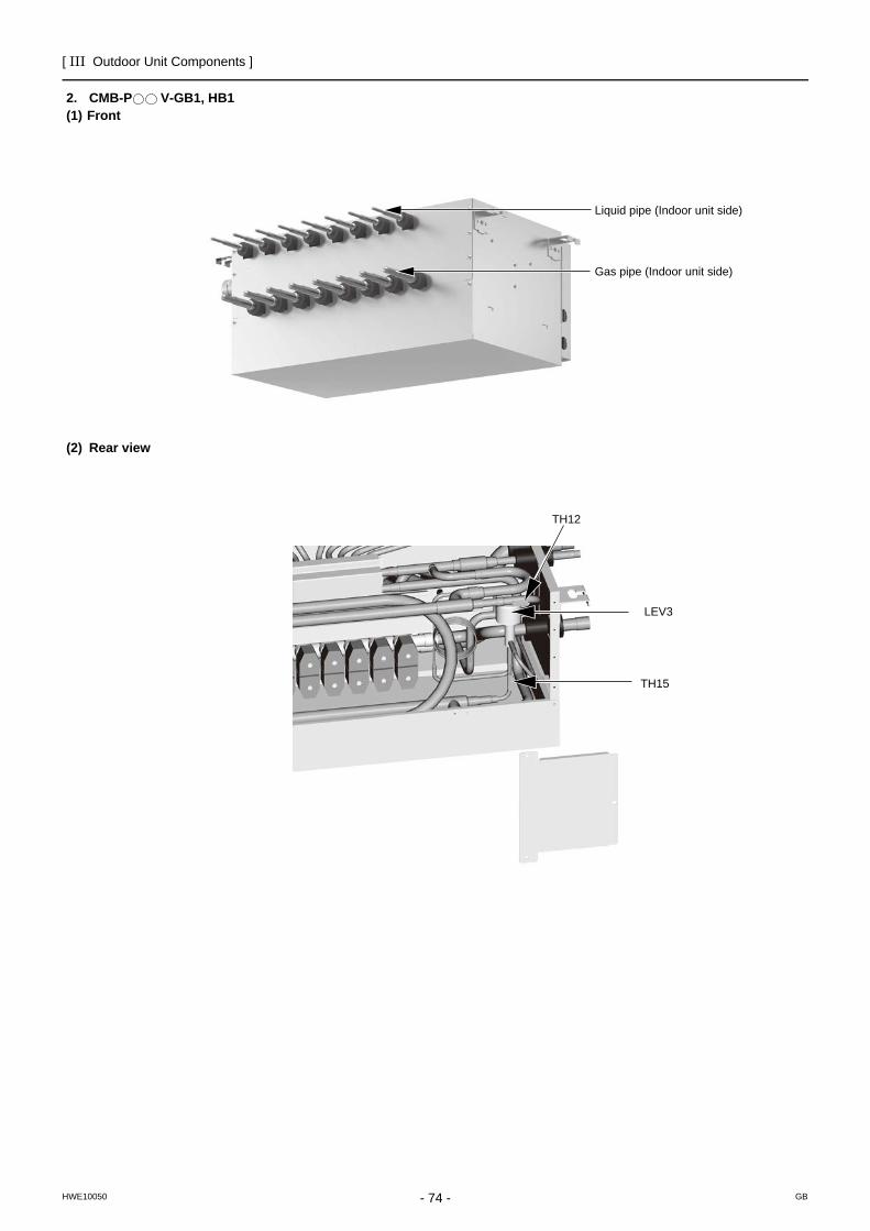
[ III Outdoor Unit Components ]
- 74 -HWE10050 GB
2. CMB-P V-GB1, HB1(1) Front
(2) Rear view
Liquid pipe (Indoor unit side)
Gas pipe (Indoor unit side)
TH15
TH12
LEV3
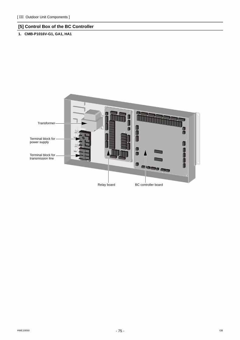
[ III Outdoor Unit Components ]
- 75 -HWE10050 GB
[5] Control Box of the BC Controller1. CMB-P1016V-G1, GA1, HA1
Relay board
Transformer
Terminal block fortransmission line
BC controller board
Terminal block forpower supply
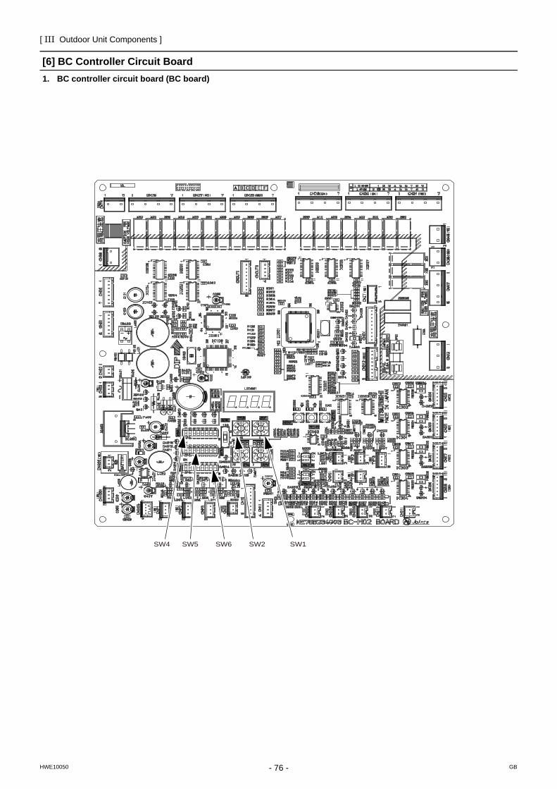
[ III Outdoor Unit Components ]
- 76 -HWE10050 GB
[6] BC Controller Circuit Board1. BC controller circuit board (BC board)
SW1SW2SW5 SW6SW4
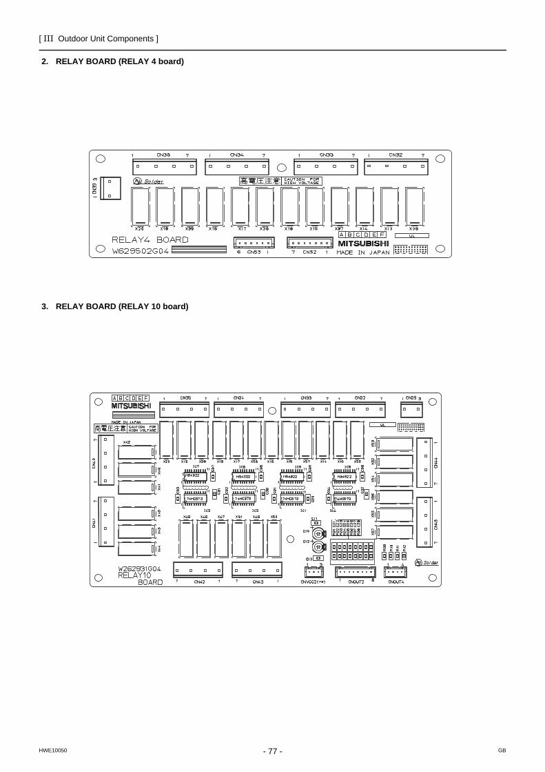
[ III Outdoor Unit Components ]
- 77 -HWE10050 GB
2. RELAY BOARD (RELAY 4 board)
3. RELAY BOARD (RELAY 10 board)
- 78 -
[ III Outdoor Unit Components ]
GBHWE10050
- 79 -HWE10050 GB
IV Remote Controller
[1] Functions and Specifications of MA and ME Remote Controllers ...................................81[2] Group Settings and Interlock Settings via the ME Remote Controller .............................82[3] Interlock Settings via the MA Remote Controller .............................................................86[4] Using the built-in Temperature Sensor on the Remote Controller ...................................87

- 80 -
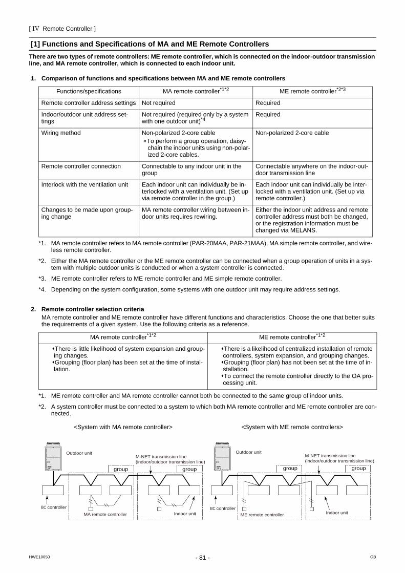
[ IV Remote Controller ]
- 81 -HWE10050 GB
IV Remote Controller
[1] Functions and Specifications of MA and ME Remote ControllersThere are two types of remote controllers: ME remote controller, which is connected on the indoor-outdoor transmission line, and MA remote controller, which is connected to each indoor unit.
1. Comparison of functions and specifications between MA and ME remote controllers
2. Remote controller selection criteriaMA remote controller and ME remote controller have different functions and characteristics. Choose the one that better suits the requirements of a given system. Use the following criteria as a reference.
Functions/specifications MA remote controller*1*2
*1. MA remote controller refers to MA remote controller (PAR-20MAA, PAR-21MAA), MA simple remote controller, and wire-less remote controller.
*2. Either the MA remote controller or the ME remote controller can be connected when a group operation of units in a sys-tem with multiple outdoor units is conducted or when a system controller is connected.
ME remote controller*2*3
*3. ME remote controller refers to ME remote controller and ME simple remote controller.
Remote controller address settings Not required Required
Indoor/outdoor unit address set-tings
Not required (required only by a system with one outdoor unit)*4
*4. Depending on the system configuration, some systems with one outdoor unit may require address settings.
Required
Wiring method Non-polarized 2-core cable∗To perform a group operation, daisy-
chain the indoor units using non-polar-ized 2-core cables.
Non-polarized 2-core cable
Remote controller connection Connectable to any indoor unit in the group
Connectable anywhere on the indoor-out-door transmission line
Interlock with the ventilation unit Each indoor unit can individually be in-terlocked with a ventilation unit. (Set up via remote controller in the group.)
Each indoor unit can individually be inter-locked with a ventilation unit. (Set up via remote controller.)
Changes to be made upon group-ing change
MA remote controller wiring between in-door units requires rewiring.
Either the indoor unit address and remote controller address must both be changed, or the registration information must be changed via MELANS.
MA remote controller*1*2 ME remote controller*1*2
There is little likelihood of system expansion and group-ing changes.Grouping (floor plan) has been set at the time of instal-lation.
There is a likelihood of centralized installation of remote controllers, system expansion, and grouping changes.Grouping (floor plan) has not been set at the time of in-stallation.To connect the remote controller directly to the OA pro-cessing unit.
*1. ME remote controller and MA remote controller cannot both be connected to the same group of indoor units.
*2. A system controller must be connected to a system to which both MA remote controller and ME remote controller are con-nected.
<System with MA remote controller> <System with ME remote controllers>
MA remote controller
Outdoor unit
Indoor unitBC controller
M-NET transmission line(indoor/outdoor transmission line)
groupgroup
ME remote controller
Outdoor unit
Indoor unitBC controller
M-NET transmission line(indoor/outdoor transmission line)
groupgroup
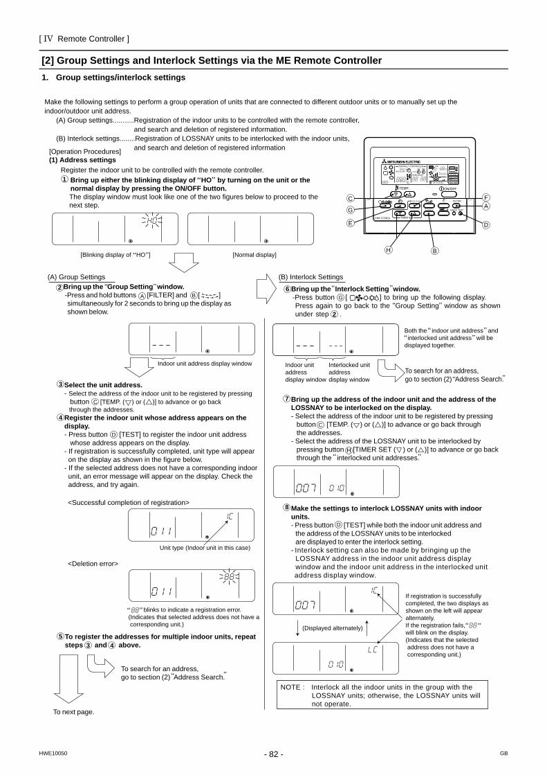
[ IV Remote Controller ]
- 82 -HWE10050 GB
[2] Group Settings and Interlock Settings via the ME Remote Controller1. Group settings/interlock settings
<Deletion error>
[Normal display]
(B) Interlock Settings (A) Group Settings
Indoor unit address display window Indoor unit address display window
Interlocked unit address display window
Make the following settings to perform a group operation of units that are connected to different outdoor units or to manually set up the indoor/outdoor unit address. (A) Group settings...........Registration of the indoor units to be controlled with the remote controller, and search and deletion of registered information. (B) Interlock settings........Registration of LOSSNAY units to be interlocked with the indoor units, and search and deletion of registered information[Operation Procedures]
(1) Address settings Register the indoor unit to be controlled with the remote controller. Bring up either the blinking display of HO by turning on the unit or the normal display by pressing the ON/OFF button. The display window must look like one of the two figures below to proceed to the next step.
1
2 Bring up the Group Setting window. -Press and hold buttons [FILTER] and [ ] simultaneously for 2 seconds to bring up the display as shown below.
3
A
C
D
B
Select the unit address. - Select the address of the indoor unit to be registered by pressing button [TEMP. ( ) or ( )] to advance or go back through the addresses. Register the indoor unit whose address appears on the display. - Press button [TEST] to register the indoor unit address whose address appears on the display. - If registration is successfully completed, unit type will appear on the display as shown in the figure below. - If the selected address does not have a corresponding indoor unit, an error message will appear on the display. Check the address, and try again.
5
<Successful completion of registration>
Unit type (Indoor unit in this case)
blinks to indicate a registration error.(Indicates that selected address does not have a corresponding unit.)
4
To register the addresses for multiple indoor units, repeat steps and above.3 4
To search for an address, go to section (2) Address Search.
To next page.
To search for an address, go to section (2) Address Search.
Bring up the Interlock Setting window. -Press button [ ] to bring up the following display. Press again to go back to the Group Setting window as shown under step .
6G
2
Both the indoor unit address and interlocked unit address will be displayed together.
Bring up the address of the indoor unit and the address of the LOSSNAY to be interlocked on the display.- Select the address of the indoor unit to be registered by pressing button [TEMP. ( ) or ( )] to advance or go back through the addresses. - Select the address of the LOSSNAY unit to be interlocked by pressing button [TIMER SET ( ) or ( )] to advance or go back through the interlocked unit addresses.
7
8
C
H
Make the settings to interlock LOSSNAY units with indoor units.- Press button [TEST] while both the indoor unit address and the address of the LOSSNAY units to be interlocked are displayed to enter the interlock setting.- Interlock setting can also be made by bringing up the LOSSNAY address in the indoor unit address display window and the indoor unit address in the interlocked unit address display window.
D
(Displayed alternately)
If registration is successfully completed, the two displays as shown on the left will appear alternately.If the registration fails, will blink on the display.(Indicates that the selected address does not have a corresponding unit.)
NOTE : Interlock all the indoor units in the group with the LOSSNAY units; otherwise, the LOSSNAY units will not operate.
[Blinking display of HO ]
?AF
D
BH
G
C
EPAR-F27MEA
ON/OFF
CENTRALLY CONTROLLEDDAILY
AUTO OFF
REMAINDER
CLOCK
ON OFF
˚C
CHECK MODEFILTER
TEST RUNLIMIT TEMP.
˚C1Hr.
NOT AVAILABLESTAND BY DEFROST
FILTER
CHECK TEST
TEMP.
TIMER SET
CLOCK→ON→OFF
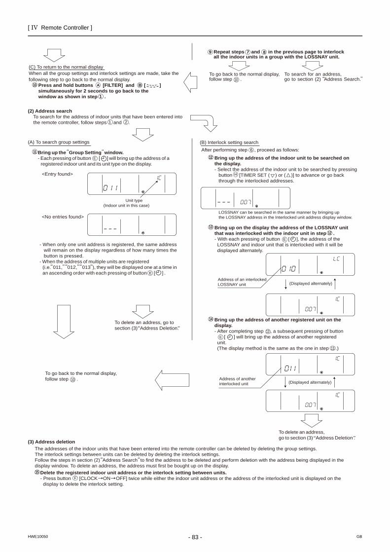
[ IV Remote Controller ]
- 83 -HWE10050 GB
<Entry found>
<No entries found>
(C) To return to the normal display When all the group settings and interlock settings are made, take the following step to go back to the normal display. Press and hold buttons [FILTER] and [ ] simultaneously for 2 seconds to go back to the window as shown in step .
(2) Address search To search for the address of indoor units that have been entered into the remote controller, follow steps and .
(A) To search group settings
Unit type (Indoor unit in this case)
- When only one unit address is registered, the same address will remain on the display regardless of how many times the button is pressed. - When the address of multiple units are registered (i.e. 011, 012, 013 ), they will be displayed one at a time in an ascending order with each pressing of button [ ] .
To delete an address, go to section (3) Address Deletion.
To go back to the normal display, follow step .
(Displayed alternately)
To delete an address, go to section (3) Address Deletion .
Bring up the address of another registered unit on the display. - After completing step , a subsequent pressing of button [ ] will bring up the address of another registered unit. (The display method is the same as the one in step .)
Address of an interlocked LOSSNAY unit
Address of another interlocked unit
Bring up on the display the address of the LOSSNAY unit that was interlocked with the indoor unit in step . - With each pressing of button [ ], the address of the LOSSNAY and indoor unit that is interlocked with it will be displayed alternately.
LOSSNAY can be searched in the same manner by bringing up the LOSSNAY address in the Interlocked unit address display window.
(B) Interlock setting search After performing step , proceed as follows:
Bring up the address of the indoor unit to be searched on the display. - Select the address of the indoor unit to be searched by pressing button [TIMER SET ( ) or ( )] to advance or go back through the interlocked addresses.
Repeat steps and in the previous page to interlock all the indoor units in a group with the LOSSNAY unit.
7 8
To go back to the normal display, follow step .
To search for an address, go to section (2) Address Search.
(3) Address deletion The addresses of the indoor units that have been entered into the remote controller can be deleted by deleting the group settings. The interlock settings between units can be deleted by deleting the interlock settings. Follow the steps in section (2) Address Search to find the address to be deleted and perform deletion with the address being displayed in the display window. To delete an address, the address must first be bought up on the display. Delete the registered indoor unit address or the interlock setting between units. - Press button ? [CLOCK ON OFF] twice while either the indoor unit address or the address of the interlocked unit is displayed on the display to delete the interlock setting.
(Displayed alternately)
10 A B
1
Bring up the Group Setting window. - Each pressing of button [ ] will bring up the address of a registered indoor unit and its unit type on the display.
11 E
1 2
E
10
E
13
13
13
12
14
12
6
E
H
9
10
F 15
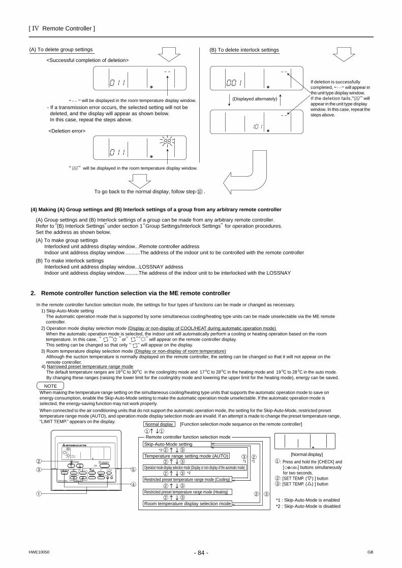
[ IV Remote Controller ]
- 84 -HWE10050 GB
2. Remote controller function selection via the ME remote controller
(A) To delete group settings (B) To delete interlock settings
<Successful completion of deletion>
will be displayed in the room temperature display window.- If a transmission error occurs, the selected setting will not be deleted, and the display will appear as shown below. In this case, repeat the steps above.
(Displayed alternately)
<Deletion error>
will be displayed in the room temperature display window.
(4) Making (A) Group settings and (B) Interlock settings of a group from any arbitrary remote controller
(A) Group settings and (B) Interlock settings of a group can be made from any arbitrary remote controller.Refer to (B) Interlock Settings under section 1 Group Settings/Interlock Settings for operation procedures.Set the address as shown below.(A) To make group settings Interlocked unit address display window...Remote controller address Indoor unit address display window...........The address of the indoor unit to be controlled with the remote controller(B) To make interlock settings Interlocked unit address display window...LOSSNAY address Indoor unit address display window..........The address of the indoor unit to be interlocked with the LOSSNAY
If deletion is successfully completed, will appear in the unit type display window.If the deletion fails, will appear in the unit type display window. In this case, repeat the steps above.
- -
To go back to the normal display, follow step .10
In the remote controller function selection mode, the settings for four types of functions can be made or changed as necessary.
4) Narrowed preset temperature range mode The default temperature ranges are 19 C to 30 C in the cooling/dry mode and 17 C to 28 C in the heating mode and 19 C to 28 C in the auto mode. By changing these ranges (raising the lower limit for the cooling/dry mode and lowering the upper limit for the heating mode), energy can be saved.
When making the temperature range setting on the simultaneous cooling/heating type units that supports the automatic operation mode to save on energy consumption, enable the Skip-Auto-Mode setting to make the automatic operation mode unselectable. If the automatic operation mode is selected, the energy-saving function may not work properly. When connected to the air conditioning units that do not support the automatic operation mode, the setting for the Skip-Auto-Mode, restricted preset temperature range mode (AUTO), and operation mode display selection mode are invalid. If an attempt is made to change the preset temperature range, “LIMIT TEMP.” appears on the display.
NOTE
[Normal display]
4
5
PAR-F27MEA
ON/OFF
FILTER
CHECK TEST
TEMP.
TIMER SET
CLOCK→ON→OFF
1
32
: Press and hold the [CHECK] and [ ] buttons simultaneously for two seconds.: [SET TEMP. ( ) ] button: [SET TEMP. ( ) ] button
3) Room temperature display selection mode (Display or non-display of room temperature) Although the suction temperature is normally displayed on the remote controller, the setting can be changed so that it will not appear on the remote controller.
2) Operation mode display selection mode (Display or non-display of COOL/HEAT during automatic operation mode) When the automatic operation mode is selected, the indoor unit will automatically perform a cooling or heating operation based on the room temperature. In this case, or will appear on the remote controller display. This setting can be changed so that only will appear on the display.
1) Skip-Auto-Mode setting The automatic operation mode that is supported by some simultaneous cooling/heating type units can be made unselectable via the ME remote controller.
[Function selection mode sequence on the remote controller]Normal display1 1
3
33
2
2
232
32
32
32
Skip-Auto-Mode setting
*1 *1
*2
*2
Temperature range setting mode (AUTO)
Room temperature display selection mode *1 : Skip-Auto-Mode is enabled*2 : Skip-Auto-Mode is disabled
Operation mode display selection mode (Display or non-display of the automatic mode)
Restricted preset temperature range mode (Heating)
Restricted preset temperature range mode (Cooling)
Remote controller function selection mode
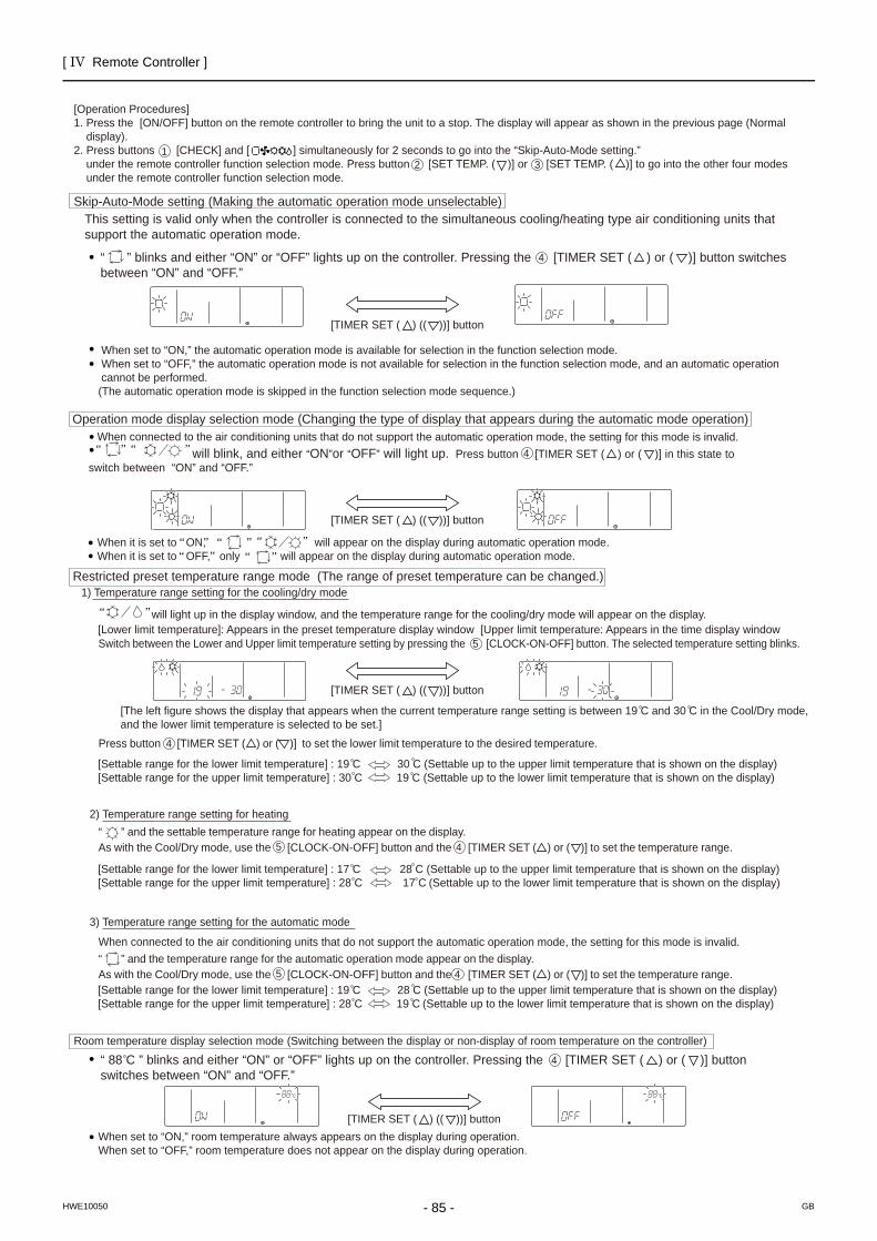
[ IV Remote Controller ]
- 85 -HWE10050 GB
[Lower limit temperature]: Appears in the preset temperature display window [Upper limit temperature: Appears in the time display window
[Settable range for the lower limit temperature] : 19 C 30 C (Settable up to the upper limit temperature that is shown on the display)[Settable range for the upper limit temperature] : 30 C 19 C (Settable up to the lower limit temperature that is shown on the display)
[Settable range for the lower limit temperature] : 17 C 28 C (Settable up to the upper limit temperature that is shown on the display) [Settable range for the upper limit temperature] : 28 C 17 C (Settable up to the lower limit temperature that is shown on the display)
[Settable range for the lower limit temperature] : 19 C 28 C (Settable up to the upper limit temperature that is shown on the display)[Settable range for the upper limit temperature] : 28 C 19 C (Settable up to the lower limit temperature that is shown on the display)
will light up in the display window, and the temperature range for the cooling/dry mode will appear on the display.
[Operation Procedures] 1. Press the [ON/OFF] button on the remote controller to bring the unit to a stop. The display will appear as shown in the previous page (Normal display). 2. Press buttons [CHECK] and [ ] simultaneously for 2 seconds to go into the “Skip-Auto-Mode setting.” under the remote controller function selection mode. Press button [SET TEMP. ( )] or [SET TEMP. ( )] to go into the other four modes under the remote controller function selection mode.
1 2 3
Skip-Auto-Mode setting (Making the automatic operation mode unselectable)
“ ” blinks and either “ON” or “OFF” lights up on the controller. Pressing the [TIMER SET ( ) or ( )] button switches between “ON” and “OFF.”
This setting is valid only when the controller is connected to the simultaneous cooling/heating type air conditioning units that support the automatic operation mode.
When set to “ON,” the automatic operation mode is available for selection in the function selection mode. When set to “OFF,” the automatic operation mode is not available for selection in the function selection mode, and an automatic operation cannot be performed. (The automatic operation mode is skipped in the function selection mode sequence.)
[The left figure shows the display that appears when the current temperature range setting is between 19 C and 30 C in the Cool/Dry mode, and the lower limit temperature is selected to be set.]
2) Temperature range setting for heating
4
Switch between the Lower and Upper limit temperature setting by pressing the [CLOCK-ON-OFF] button. The selected temperature setting blinks.
“ ” and the settable temperature range for heating appear on the display. As with the Cool/Dry mode, use the [CLOCK-ON-OFF] button and the [TIMER SET ( ) or ( )] to set the temperature range.
5
Room temperature display selection mode (Switching between the display or non-display of room temperature on the controller)
When set to “ON,” room temperature always appears on the display during operation. When set to “OFF,” room temperature does not appear on the display during operation.
5 4
“ ” and the temperature range for the automatic operation mode appear on the display. As with the Cool/Dry mode, use the [CLOCK-ON-OFF] button and the [TIMER SET ( ) or ( )] to set the temperature range. 5 4
3) Temperature range setting for the automatic mode
˚ C ˚ C
“ 88 C ” blinks and either “ON” or “OFF” lights up on the controller. Pressing the [TIMER SET ( ) or ( )] button switches between “ON” and “OFF.”
4
Operation mode display selection mode (Changing the type of display that appears during the automatic mode operation)
will blink, and either “ON”or “OFF” will light up. Press button [TIMER SET ( ) or ( )] in this state to switch between “ON” and “OFF.”
4
When it is set to ON, will appear on the display during automatic operation mode. When it is set to OFF, only will appear on the display during automatic operation mode.
When connected to the air conditioning units that do not support the automatic operation mode, the setting for this mode is invalid.
[TIMER SET ( ) (( ))] button
[TIMER SET ( ) (( ))] button
[TIMER SET ( ) (( ))] button
[TIMER SET ( ) (( ))] button
Restricted preset temperature range mode (The range of preset temperature can be changed.) 1) Temperature range setting for the cooling/dry mode
Press button [TIMER SET ( ) or ( )] to set the lower limit temperature to the desired temperature. 4
When connected to the air conditioning units that do not support the automatic operation mode, the setting for this mode is invalid.
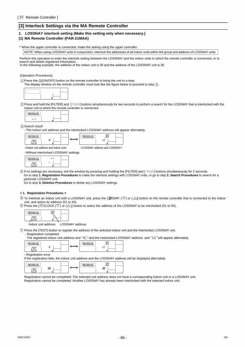
[ IV Remote Controller ]
- 86 -HWE10050 GB
[3] Interlock Settings via the MA Remote Controller1. LOSSNAY interlock setting (Make this setting only when necessary.)(1) MA Remote Controller (PAR-21MAA)
[Operation Procedures]
<Indoor unit address and indoor unit> <LOSSNAY address and LOSSNAY> - Without interlocked LOSSNAY settings
Search result - The indoor unit address and the interlocked LOSSNAY address will appear alternately.
Press the [ON/OFF] button on the remote controller to bring the unit to a stop. The display window on the remote controller must look like the figure below to proceed to step .
NOTE: When using LOSSNAY units in conjunction, interlock the addresses of all indoor units within the group and address of LOSSNAY units.
Perform this operation to enter the interlock setting between the LOSSNAY and the indoor units to which the remote controller is connected, or to search and delete registered information.
* When the upper controller is connected, make the setting using the upper controller.
In the following example, the address of the indoor unit is 05 and the address of the LOSSNAY unit is 30.
2
< 1. Registration Procedures >
Indoor unit address LOSSNAY address
Press the [TEST] button to register the address of the selected indoor unit and the interlocked LOSSNAY unit. - Registration completed The registered indoor unit address and IC, and the interlocked LOSSNAY address and LC will appear alternately.
- Registration error If the registration fails, the indoor unit address and the LOSSNAY address will be displayed alternately.
Registration cannot be completed: The selected unit address does not have a corresponding indoor unit or a LOSSNAY unit. Registration cannot be completed: Another LOSSNAY has already been interlocked with the selected indoor unit.
1
3
2
Press and hold the [FILTER] and [ ] buttons simultaneously for two seconds to perform a search for the LOSSNAY that is interlocked with the indoor unit to which the remote controller is connected.
If no settings are necessary, exit the window by pressing and holding the [FILTER] and [ ] buttons simultaneously for 2 seconds. Go to step 1. Registration Procedures to make the interlock settings with LOSSNAY units, or go to step 2. Search Procedures to search for a particular LOSSNAY unit. Go to step 3. Deletion Procedures to delete any LOSSNAY settings.
To interlock an indoor unit with a LOSSNAY unit, press the [ TEMP. ( ) or ( )] button on the remote controller that is connected to the indoor unit, and select its address (01 to 50). Press the [ CLOCK ( ) or ( )] button to select the address of the LOSSNAY to be interlocked (01 to 50).
5
4
7
6
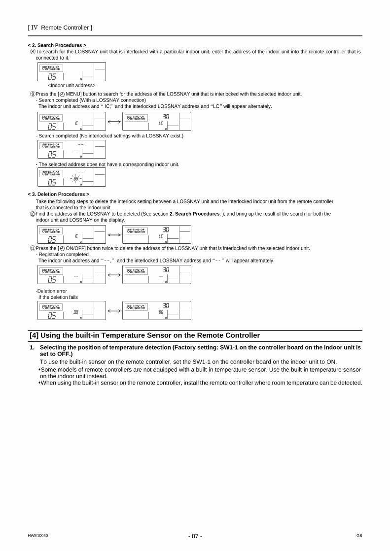
[ IV Remote Controller ]
- 87 -HWE10050 GB
[4] Using the built-in Temperature Sensor on the Remote Controller1. Selecting the position of temperature detection (Factory setting: SW1-1 on the controller board on the indoor unit is
set to OFF.)To use the built-in sensor on the remote controller, set the SW1-1 on the controller board on the indoor unit to ON.Some models of remote controllers are not equipped with a built-in temperature sensor. Use the built-in temperature sensor on the indoor unit instead.When using the built-in sensor on the remote controller, install the remote controller where room temperature can be detected.
<Indoor unit address>
- Search completed (No interlocked settings with a LOSSNAY exist.)
- The selected address does not have a corresponding indoor unit.
< 2. Search Procedures >
< 3. Deletion Procedures >
Press the [ MENU] button to search for the address of the LOSSNAY unit that is interlocked with the selected indoor unit.- Search completed (With a LOSSNAY connection) The indoor unit address and IC, and the interlocked LOSSNAY address and LC will appear alternately.
Take the following steps to delete the interlock setting between a LOSSNAY unit and the interlocked indoor unit from the remote controller that is connected to the indoor unit.Find the address of the LOSSNAY to be deleted (See section 2. Search Procedures. ), and bring up the result of the search for both the indoor unit and LOSSNAY on the display.
Press the [ ON/OFF] button twice to delete the address of the LOSSNAY unit that is interlocked with the selected indoor unit.- Registration completed The indoor unit address and , and the interlocked LOSSNAY address and will appear alternately.
-Deletion error If the deletion fails
8
9
10
11
To search for the LOSSNAY unit that is interlocked with a particular indoor unit, enter the address of the indoor unit into the remote controller that is connected to it.
- 88 -
[ IV Remote Controller ]
GBHWE10050
- 89 -HWE10050 GB
V Electrical Wiring Diagram
[1] Electrical Wiring Diagram of the Outdoor Unit .................................................................91[2] Electrical Wiring Diagram of the BC Controller ................................................................93[3] Electrical Wiring Diagram of Transmission Booster.......................................................103

- 90 -
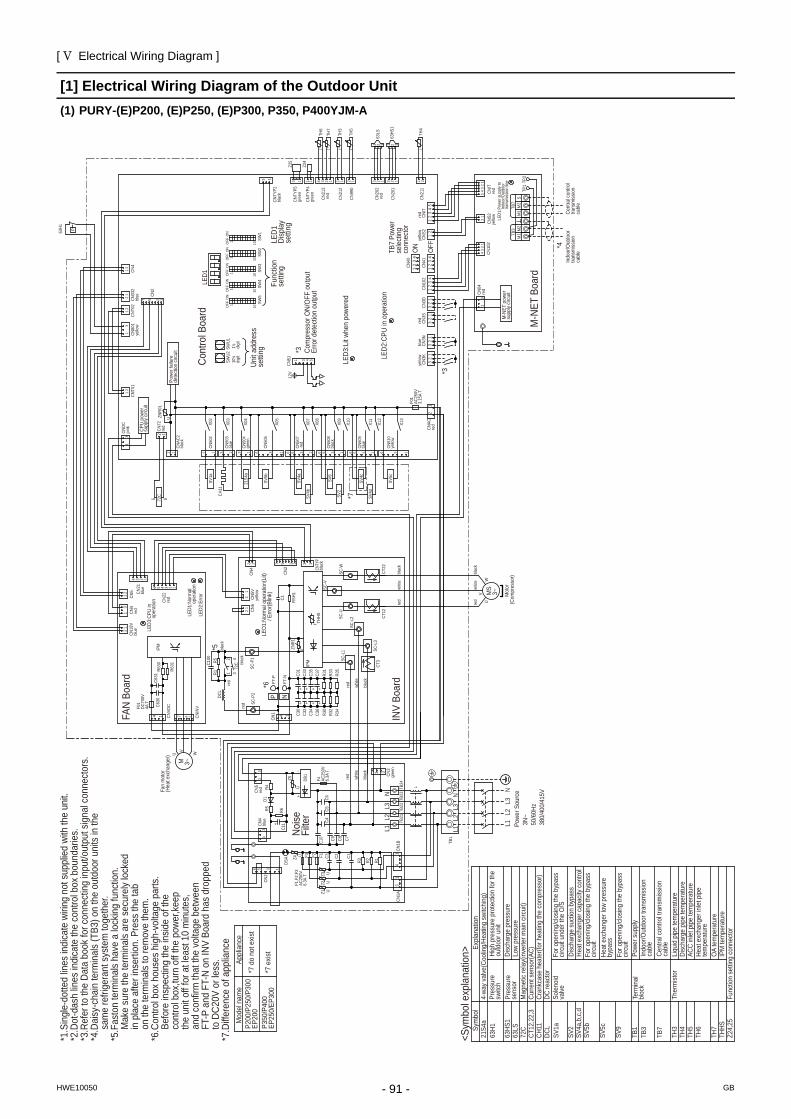
[ V Electrical Wiring Diagram ]
- 91 -HWE10050 GB
V Electrical Wiring Diagram
[1] Electrical Wiring Diagram of the Outdoor Unit(1) PURY-(E)P200, (E)P250, (E)P300, P350, P400YJM-A
+
-+
++
+
2 1
++
++
+
32
32
P350
/P40
0EP
250/
EP30
0
L3L2
L1Noise
Filte
r
C11
R6
3
TB22
DB1
UF1,F
2,F3
AC25
0V6.
3A T U
C5C9
C2
1
11
L1L2
TB23
5
C6
L3
U
3CN
1B TB1
R1
U
C7
6
CN2
CN1A
R3
C1
TB21
C3
33
1
blac
k
red
CN4
blue
C10
DSA
1
Z1
4
C4U
Z2Z3
F2
R2
Z4 F1F3
R5
F4 AC25
0V6.
3A T
C8
white
Z5
R4D1
CN5
red TB
24
N
L
N
1
CN3
gree
n
3
L3N
L1L2
Powe
r Sou
rce
3N~
50/
60Hz
380
/400
/415
V
Disc
harg
e su
ctio
n by
pass
SV2
SV2
SV9
CN50
8bl
ack
X10
5 1
*7 e
xist
*7 d
o no
t exis
tP2
00/P
250/
P300
EP20
0
Appl
ianc
eM
odel
nam
e
*1.S
ingl
e-do
tted
lines
indi
cate
wiri
ng n
ot s
uppl
ied
with
the
unit.
*2.D
ot-d
ash
lines
indi
cate
the
cont
rol b
ox b
ound
arie
s.*3
.Ref
er to
the
Data
boo
k fo
r con
nect
ing
inpu
t/out
put s
igna
l con
nect
ors.
*4.D
aisy
-cha
in te
rmin
als
(TB3
) on
the
outd
oor u
nits
in th
e
sam
e re
frige
rant
sys
tem
toge
ther
.*5
.Fas
ton
term
inal
s ha
ve a
lock
ing
func
tion.
M
ake
sure
the
term
inal
s ar
e se
cure
ly lo
cked
in
pla
ce a
fter i
nser
tion.
Pre
ss th
e ta
b
on th
e te
rmin
als
to re
mov
e th
em.
*6.C
ontro
l box
hou
ses
high
-vol
tage
par
ts.
Be
fore
insp
ectin
g th
e in
side
of th
e
cont
rol b
ox,tu
rn o
ff th
e po
wer,k
eep
th
e un
it of
f for
at l
east
10
min
utes
,
and
conf
irm th
at th
e vo
ltage
bet
ween
FT
-P a
nd F
T-N
on IN
V Bo
ard
has
drop
ped
to
DC2
0V o
r les
s.*7
.Diff
eren
ce o
f app
lianc
e
X11
X12
356 1
CN50
9bl
ue
1
CN51
0ye
llow
X09
36
Unit
addr
ess
setti
ng
CN50
4gr
een
CT12
C31
C33
SV4b
R631
X13
36
red
CNIT
yello
w C
NS2
t °
1
1
LED1
Disp
lay
setti
ngCN
5112
V
Func
tion
setti
ng
SW1
101
CN21
2
CNTY
P4gr
een
*3
32
Com
pres
sor O
N/O
FF o
utpu
tEr
ror d
etec
tion
outp
ut
CN20
1
Z25
1 4 1
1
1
TH3
3
ON
OFF
SW2
101SW
U2
LED1
C35
C37
R31
R33
R30
ON
SW3
10
Cont
rol B
oard
TH7
CN40
63HS
1
CN41
TH6
t °tTH
4
32 2
2
1
SW5
LED3
:Lit
when
pow
ered
13
R32
2
R34
R35
C36
3
C34
SC-V
CT22
SC-U
V1
1
1
1
t
LED3
:CPU
in
ope
ratio
n
4
CNTY
P2bl
ack
6
yello
w C
N3K
*3
3
5
U
blue
CN3N
54
4
CN21
blue
1
3TB
7 Po
wer
sele
ctin
gco
nnec
tor
CN10
2
CNVD
C
2
1
IPM
2
1
4
TP1
W
DCL
V
blac
k
72C
white
red
32
1
ON
OFF
1
M-N
ET p
ower
supp
ly cir
cuit
12
3
M-N
ET B
oard
12
1
Powe
r fai
lure
dete
ctio
n cir
cuit
1
CNAC
2bl
ack
CN50
2
Indo
or/O
utdo
ortra
nsm
issio
nca
ble
INV
Boar
dre
d
3
CNT0
1
U
4
ON
2
1's digi
t
THHS
1
CNIT
red
S
2
1
CN99
0
1
3 W
TB3
10's
digi
t
OFF
LED2
:CPU
in o
pera
tion
5
2
CNS
2ye
llow
TB7
1
CNDC
pink
M1
2
2
red
6
MS
3~
1
1
t
C100
*5
3
3
U1
4
LED1
:Pow
er s
uppl
y to
I
ndoo
r/Out
door
t
rans
miss
ion
line
SV4d
ZNR0
1
M2
32
M1
blac
k
Cent
ral c
ontro
ltra
nsm
issio
nca
ble
*6
SC-L
1
1
4
ON
OFF
FT-N
R5
M 3~
M
otor
(Com
pres
sor)
°
CN5
Vye
llow
5
2
3
3
3red
CN3S
11
CN04
red
1
CN2
2
3
CN4
X05
2
2
Fan
mot
or(H
eat e
xcha
nger
)
SC-P
2 P
1
CN21
1
CN20
2 re
d
TH5
°
N
CN1
M2
2
TP2
SV4c
LED1
:Nor
mal
ope
ratio
n(Li
t)
/ Er
ror(B
link)
2
CN50
3bl
ue
5
X04
4
*4
SC-W
C32
SC-L
3
CH11
CN50
6
12
CN72
red
3
P63H1
CN80
1ye
llow
1
2
CN33
2bl
ue
21
OFF
SW4
10
blac
k
1
CNT0
2
11
CN3D
43
2
1
21
CPU
powe
rsu
pply
circu
it
CNAC
red
2
1
F01
AC25
0V3.
15A
T
1
t
CN50
7 re
d
ON
OFF
10
SWU1
white
CN21
3 re
d
SC-L
2
3
Z24
7
4
°
32
11
22
7
12
CN5
1 CN4
red
CNIN
V
3
4
R630
1
1
C630
white
3
redCN
22re
d
C631
5
F01
DC70
0V4A
T
1
CNTY
P5gr
een
4
LED2
:Erro
r
21S4
a
1
LED1
:Nor
mal
o
pera
tion
2
3 2
X02
X03
CN18
Vbl
ue
5
1
7
CN4
3CN
6
2
°IP
M4
SC-P
1
FT-P
blac
k
C30re
d
CT3
72C
C1CN
2 CNTY
Pbl
ack
R1bl
ack
6
3
RSH1
CN10
2
1
1
1
FAN
Boar
d
63LS
ZNR1
U3
SV5b
X08
SV4a
X07
356
SV1a
*7
1
SV5c
SV5b
<Sym
bol e
xpla
natio
n>
DCL
SV1a
SV4a
,b,c
,d
CT12
,22,
3CH
11
72C
63LS
63HS
1
63H1Sy
mbo
l21
S4a
SV5c
Z24,
25TH
HSTH
7
TH6
TH5
TH4
TH3
TB7
TB3
TB1
SV9
DC re
acto
rSo
leno
idva
lve
Cran
kcas
e he
ater
(for h
eatin
g th
e co
mpr
esso
r)Cu
rrent
sen
sor(A
C)M
agne
tic re
lay(
inve
rter m
ain
circu
it)Lo
w pr
essu
reDi
scha
rge
pres
sure
High
pre
ssur
e pr
otec
tion
for t
heou
tdoo
r uni
tPr
essu
resw
itch
Pres
sure
sens
or
Expl
anat
ion
4-wa
y va
lve(C
oolin
g/He
atin
g sw
itchi
ng)
For o
peni
ng/c
losin
g th
e by
pass
circu
it un
der t
he O
/S
Heat
exc
hang
er c
apac
ity c
ontro
l
Liqu
id p
ipe
tem
pera
ture
Ther
mist
orDi
scha
rge
pipe
tem
pera
ture
ACC
inle
t pip
e te
mpe
ratu
re
OA
tem
pera
ture
IPM
tem
pera
ture
Func
tion
setti
ng c
onne
ctor
Powe
r sup
ply
Indo
or/O
utdo
or tr
ansm
issio
nca
ble
Cent
ral c
ontro
l tra
nsm
issio
nca
ble
Term
inal
bloc
k
Heat
exc
hang
er in
let p
ipe
tem
pera
ture
For o
peni
ng/c
losin
g th
e by
pass
circu
it
Heat
exc
hang
er lo
w pr
essu
reby
pass
For o
peni
ng/c
losin
g th
e by
pass
circu
it
PURY-EP200, 250, 300YJM-A(-BS)
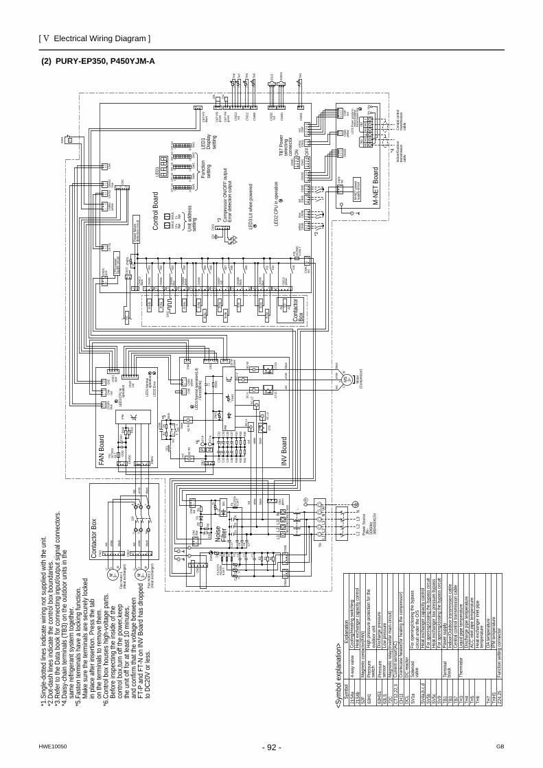
[ V Electrical Wiring Diagram ]
- 92 -HWE10050 GB
(2) PURY-EP350, P450YJM-A
+
-+
++
+
2 1
++
++
+
23
23
L3L2
L1
CN3
gree
n
1 3
Noise
Filte
r
C11
R6
3
TB22
DB1
UF1,F
2,F3
AC25
0V6.
3A T
UC5
C9
C2
1
11
L1L2
TB23
5
C6
L3
U
3CN
1B TB1
R1
U
C7
6
CN2
CN1A
R3
C1
TB21
C3
33
1
blac
k
red
CN4
blue
C10
DSA
1
Z1
4
C4U
Z2Z3
F2
R2
Z4 F1F3
R5
F4 AC25
0V6.
3A T
C8
white
Z5
R4D1
CN5
red
Powe
r Sou
rce
3N~
50/
60Hz
380
/400
/415
V
L2L1
L3
N
TB24 L
N
N
Cont
acto
rBo
x
12bl
ack
8 7 5
red
white
U
M 3~V W
4
8
Heat
exc
hang
er c
apac
ity c
ontro
lCo
olin
g/He
atin
g sw
itchi
ng21
S4b
A2A1
5
red
white
blac
k
7
CN12 2 1
CN11
M 3~
U V WFa
n m
otor
2(H
eat e
xcha
nger
)
Fan
mot
or 1
(Hea
t exc
hang
er)
U V W
red
white
blac
k
52F
TSR
Cont
acto
r Box
*1.S
ingl
e-do
tted
lines
indi
cate
wiri
ng n
ot s
uppl
ied
with
the
unit.
*2.D
ot-d
ash
lines
indi
cate
the
cont
rol b
ox b
ound
arie
s.*3
.Ref
er to
the
Data
boo
k fo
r con
nect
ing
inpu
t/out
put s
igna
l con
nect
ors.
*4.D
aisy
-cha
in te
rmin
als
(TB3
) on
the
outd
oor u
nits
in th
e
sam
e re
frige
rant
sys
tem
toge
ther
.*5
.Fas
ton
term
inal
s ha
ve a
lock
ing
func
tion.
M
ake
sure
the
term
inal
s ar
e se
cure
ly lo
cked
in
pla
ce a
fter i
nser
tion.
Pre
ss th
e ta
b
on th
e te
rmin
als
to re
mov
e th
em.
*6.C
ontro
l box
hou
ses
high
-vol
tage
par
ts.
Be
fore
insp
ectin
g th
e in
side
of th
e
cont
rol b
ox,tu
rn o
ff th
e po
wer,k
eep
th
e un
it of
f for
at l
east
10
min
utes
,
and
conf
irm th
at th
e vo
ltage
bet
ween
FT
-P a
nd F
T-N
on IN
V Bo
ard
has
drop
ped
to
DC2
0V o
r les
s.
Mag
netic
con
tact
or(F
AN)
52F
X11
X12
356 1
CN50
9bl
ue
X06
15
SV5b
SV5c
1
X01
CN51
0ye
llow
52F
X09
36 5 1
CN50
8bl
ack
Unit
addr
ess
setti
ng
CN50
4gr
een
CT12
C31
C33
SV4b
CN50
13
R631
1 1 6
red
CNIT
yello
w C
NS2
t °
1
1
LED1
Disp
lay
setti
ngCN
5112
V
Func
tion
setti
ng
SW1
101
CN21
2
CNTY
P4gr
een
*3
32
Com
pres
sor O
N/O
FF o
utpu
tEr
ror d
etec
tion
outp
ut
CN20
1
Z25
1 4 1
1
1
TH3
3
ON
OFF
SW2
101SW
U2
LED1
C35
C37
R31
R33
R30
ON
SW3
10
Cont
rol B
oard
TH7
CN40
63HS
1
CN41
TH6
t °tTH
4
32 2
2
1
SW5
LED3
:Lit
when
pow
ered
13
R32
2
R34
R35
C36
3
C34
SC-V
CT22
SC-U
V1
1
1
1
t
LED3
:CPU
in
ope
ratio
n
4
CNTY
P2bl
ack
6
yello
w C
N3K
*3
3
5
U
blue
CN3N
54
4
CN21
blue
1
3TB
7 Po
wer
sele
ctin
gco
nnec
tor
CN10
2
CNVD
C
2
1
IPM
2
1
4
TP1
DCL
blac
k
72C
white
red
32
1
ON
OFF
1
M-N
ET p
ower
supp
ly cir
cuit
12
3
M-N
ET B
oard
12
1
Powe
r fai
lure
dete
ctio
n cir
cuit
1
CNAC
2bl
ack
CN50
2
Indo
or/O
utdo
ortra
nsm
issio
nca
ble
INV
Boar
dre
d
3
CNT0
14
ON
2
1's digi
t
THHS
1
CNIT
red
S
2
1
CN99
0
1
3 W
TB3
10's
digi
t
OFF
LED2
:CPU
in o
pera
tion
5
2 C
NS2
yello
w
TB7
1
CNDC
pink
M1
2
2
red
6
MS 3~
1
1
t
C100
*5
3
3
U1
4
LED1
:Pow
er s
uppl
y to
I
ndoo
r/Out
door
t
rans
miss
ion
line
SV4d
ZNR0
1
M2
32
M1
blac
k
Cent
ral c
ontro
ltra
nsm
issio
nca
ble
*6
SC-L
1
1
4
ON
OFF
FT-N
R5
M
otor
(Com
pres
sor)
°
CN5
Vye
llow
5
2
3
3
3red
CN3S
1
CN04
red
1
CN2
2
3
CN4
X05
2
2
SC-P
2 P
1
CN21
1
CN20
2 re
d
TH5
°
N
CN1
M2
2
TP2
SV4c
LED1
:Nor
mal
ope
ratio
n(Li
t)
/ Er
ror(B
link)
2
CN50
3bl
ue
5
X04
4
*4
SC-W
C32
SC-L
3
CH11
CN50
6
12
CN72
red
3
P63H1
CN80
1ye
llow
1
2
CN33
2bl
ue
21
OFF
SW4
10
blac
k
1
CNT0
2
11
CN3D
43
2
1
21
CPU
powe
rsu
pply
circu
it
CNAC
red
2
1
F01
AC25
0V3.
15A
T
1
t
CN50
7 re
d
ON
OFF
10
SWU1
white
CN21
3 re
d
SC-L
2
3
Z24
7
4
°
32
11
22
7
12
CN5
1 CN4
red
CNIN
V
3
R630
1
1
C630
white
3
redCN
22re
d
C631
5
F01
DC70
0V4A
T
1
CNTY
P5gr
een
4
LED2
:Erro
r
21S4
a
1
LED1
:Nor
mal
o
pera
tion
2
3 2
X02
X03
CN18
Vbl
ue
5
1
7
CN4
3CN
6
2
°IP
M4
SC-P
1
FT-P
blac
k
C30re
d
CT3
72C
C1CN
2 CNTY
Pbl
ack
R1bl
ack
6
3
RSH1
CN10
2
1
1
1
FAN
Boar
d
63LS
ZNR1
U3
X08
SV4a
SV9
X07
356
SV1a
21S4
b
X14
DCL
SV1a
SV4a
,b,c
,d
CT12
,22,
3CH
11
72C
63LS
63HS
1
63H1Sy
mbo
l21
S4a
Z24,
25TH
HSTH
7
TH6
TH5
TH4
TH3
TB1
DC re
acto
rSo
leno
idva
lve
Cran
kcas
e he
ater
(for h
eatin
g th
e co
mpr
esso
r)Cu
rrent
sen
sor(A
C)M
agne
tic re
lay(
inve
rter m
ain
circu
it)Lo
w pr
essu
reDi
scha
rge
pres
sure
High
pre
ssur
e pr
otec
tion
for t
heou
tdoo
r uni
tPr
essu
resw
itch
Pres
sure
sens
or
Expl
anat
ion
4-wa
y va
lve
For o
peni
ng/c
losin
g th
e by
pass
circu
it un
der t
he O
/SHe
at e
xcha
nger
cap
acity
con
trol
Liqu
id p
ipe
tem
pera
ture
Ther
mist
orDi
scha
rge
pipe
tem
pera
ture
ACC
inle
t pip
e te
mpe
ratu
re
OA
tem
pera
ture
IPM
tem
pera
ture
Func
tion
setti
ng c
onne
ctor
Powe
r sup
ply
Term
inal
bloc
k
Heat
exc
hang
er in
let p
ipe
tem
pera
ture
For o
peni
ng/c
losin
g th
e by
pass
circ
uit
SV5b
Heat
exc
hang
er lo
w pr
essu
re b
ypas
sSV
5cFo
r ope
ning
/clo
sing
the
bypa
ss c
ircui
tSV
9
Indo
or/O
utdo
or tr
ansm
issio
n ca
ble
TB3
Cent
ral c
ontro
l tra
nsm
issio
n ca
ble
TB7
<Sym
bol e
xpla
natio
n>
PURY P450YJM A( BS)PURY-EP350YJM-A(-BS)
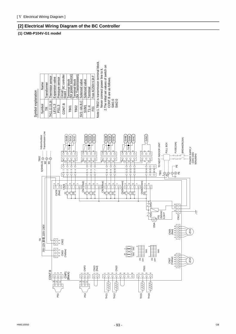
[ V Electrical Wiring Diagram ]
- 93 -HWE10050 GB
[2] Electrical Wiring Diagram of the BC Controller(1) CMB-P104V-G1 model
CO
NT.
BPr
essu
re s
enso
r
TRTH
11,12
,15,16
LEV1
,3PS
1,3
Sym
bol
Nam
eTr
ansf
orm
erTh
erm
istor
sen
sor
Expa
nsio
n va
lve
SV1~
4A,B
,CSo
leno
id v
alve
TB01
Term
inal
blo
ck(fo
r pow
er s
ourc
e)TB
02Te
rmin
al b
lock
(for T
rans
mis
sion
)
T1~4
Term
inal
F01
Fuse
AC2
50V
6.3A
F
Sole
noid
val
veSV
M1
TRTB
02
CN
26
31
CN
121
53
CN
05
65
43
21
CO
NT.
B1 2
CN
023
CN
P1 1 2 3C
NP3
21 1 2 3 4 5 6 7 8 4321
12
32
1C
N03
CN
13
CN
10
CN
11
CN
07
TH11
TH12
TH15
TH16
PS1
PS3
65
43
21
TB01
LEV3
LEV1
S(SH
IELD
)M
2M
1
220V
~240
V20
V~22
V
L
1 2 3 41098
42 3 10
21 43
SV3A
SV3B
SV2B
SV3C
SV2C
SV2A
2 43
75 6432
1 2 3 41 2 3 42 3 4
98765
SV1C
SV1A
SV1B
753175317531X2 X1 X3
0
X4 X3 X31
X6 X5 X32C
N27
(Red
)
CN
28(B
lue)
11
11
2 3 4131211
161514131211SV
4B
SV4C
SV4A
15 1614
1 2 3 4
1
7531X8 X7 X3
3
CN
29(G
reen
)
SVM
1
1 2 3
1 2 3
1 3
CN
36(G
reen
)X2
1
N
ZNR0
1ZN
R02
CN
TR(R
ed)
2 2
PE
3 1 3 1T2 T3T1 T4
PETO N
EXT
IND
OO
R U
NIT
PULL
BO
X
FUSE
(16A
)
BREA
KER
(16A
)
POW
ER S
UPP
LY~2
20V-
240V
50H
z/60
Hz
Indo
or/o
utdo
orTr
ansm
issi
on L
ine
ON
OFF
1
SW5
OFF
8
SW4
ON
1
8
BC co
ntroll
erCi
rcui
tbo
ard
SW2
SW1
110
F01
250V
AC6.
3A F
(Bla
ck) (R
ed)
(Yel
low
)(R
ed)
(Yel
low
)
DSA
Not
e:1.
TB02
is tr
ansm
issi
on te
rmin
al b
lock
. N
ever
con
nect
pow
er li
ne to
it.
2.Th
e in
itial
set
val
ues
of s
witc
h on
C
ON
T.B
are
as fo
llow
s.
SW1:
0SW
2:0
Sym
bol e
xpla
natio
n
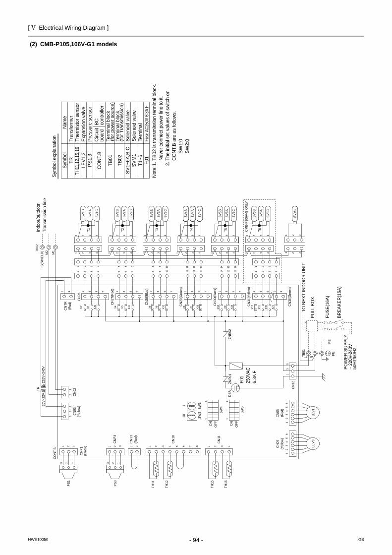
[ V Electrical Wiring Diagram ]
- 94 -HWE10050 GB
(2) CMB-P105,106V-G1 modelsSy
mbo
l exp
lana
tion Fuse
AC25
0V 6.
3A F
F01
Term
inal
T1~6
TB02
TB01
CO
NT.
BC
ircui
tbo
ard
BC
cont
rolle
r
Term
inal
blo
ck(fo
r Tra
nsm
issi
on)
Sole
noid
val
veSo
leno
id v
alve
Term
inal
blo
ck(fo
r pow
er s
ourc
e)
Pres
sure
sen
sor
Expa
nsio
n va
lve
Ther
mis
tor s
enso
rTr
ansf
orm
erN
ame
Sym
bol
SV1~
6A,B
,CSV
M1
TRTH
11,1
2,15
,16
LEV1
,3PS
1,3
Not
e: 1.
TB0
2 is
tran
smis
sion
term
inal
blo
ck.
Nev
er c
onne
ct p
ower
line
to it
.
2. T
he in
itial
set
val
ues
of s
witc
h on
C
ON
T.B
are
as fo
llow
s.
SW1:
0
SW2:
0
F01
250V
AC6.
3A F
CM
B-P1
06V-
G O
NLY
101
SW1
SW2
(Bla
ck)
(Red
)
(Yel
low
)(R
ed)
DSA
(Red
)
(Yel
low
)
8
1
ON
SW4
8
OFF
SW5
1
OFFON
T5T4 T6T1 T3T21313 22
Indo
or/o
utdo
orTr
ansm
issi
on li
ne
PEPE
50H
z/60
Hz
~ 22
0V-2
40V
POW
ER S
UPP
LYBR
EAKE
R(1
6A)
FUSE
(16A
)
PULL
BO
X
TO N
EXT
IND
OO
R U
NIT
CN
31(Y
ello
w)
CN
30(B
lack
)
X35
X11
X12
X34
X9X10
X33
X7X81 3 5 7 1 3 5 7 1 3 5
1 4321
4321 4321
SV6B
SV6A
SV6C
1 2 3 4
1 2 3 43 4
32 41
2114 1615
SV4A
SV4C
SV5B
SV4B
SV5C
SV5A
11 12 13 14 15 16
11 12 13432
11
11
X32
X5X6X31
X3X4X30
X1X21 3 5 7 1 3 5 7 1 3 5 7
SV1B
SV1A
SV1C
5 6 7 8 9
432 4321 4321
2 3 4 65 7
3 42
SV2A
SV2C
SV3C
SV2B
SV3B
SV3A
3 41 2
1032 4
8 9 104321
20V~
22V
220V
~240
V
LEV1
LEV3
TB01
12
34
56
PS3
PS1
TH16
TH15
TH12
TH11
CN
11
CN
10
CN
13
CN
031
23
21
1 2 3 4876543211 2
CN
P3321
CN
P1
3C
N02
21
CO
NT.
B
12
34
56
35
1
CN
12
1C
NTR
3
CN
26
TR
1 32
1 2 3
SVM
1
31X2
1
TB02
M2
M1
S(SH
IELD
)
CN
07C
N05
ZNR
01
CN
27(R
ed)
CN
28(B
lue)
CN
29(G
reen
)
ZNR
02
L N
CN
36(G
reen
)
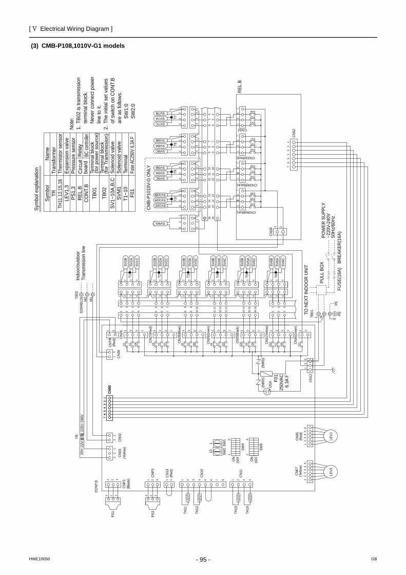
[ V Electrical Wiring Diagram ]
- 95 -HWE10050 GB
(3) CMB-P108,1010V-G1 modelsSy
mbo
l exp
lana
tion Fuse
AC25
0V 6.
3A F
F01
Term
inal
T1~1
0
TB02
TB01
REL
.BC
ON
T.B
Circ
uit
boar
dR
elay
BC co
ntroll
er
Term
inal
blo
ck(fo
r Tra
nsm
issi
on)
Sole
noid
val
veSo
leno
id v
alve
Term
inal
blo
ck(fo
r pow
er s
ourc
e)
Pres
sure
sen
sor
Expa
nsio
n va
lve
Ther
mis
tor s
enso
rTr
ansf
orm
erN
ame
Sym
bol
SV1~
10A,
B,C
SVM
1
TRTH
11,1
2,15
,16
LEV1
,3PS
1,3
Not
e:1.
TB0
2 is
tran
smis
sion
term
inal
blo
ck.
N
ever
con
nect
pow
er
lin
e to
it.
2. T
he in
itial
set
val
ues
of
sw
itch
on C
ON
T.B
ar
e as
follo
ws.
SW1:
0
SW
2:0
SW2
SW1
110
CM
B-P1
010V
-G O
NLY
F01
250V
AC6.
3A F
(Bla
ck)
(Red
)
(Yel
low
)(R
ed)
DSA
(Yel
low
)
81
OFFON
SW4
SW5
OFFON
81
213 2 3 1
T6T2 T3 T4 T5T1
T7T8
T9T1
0
Indo
or/o
utdo
orTr
ansm
issi
on li
ne
50H
z/60
Hz
~220
V-24
0VPO
WER
SU
PPLY
BREA
KER
(16A
)FU
SE(1
6A)
PULL
BO
X
TO N
EXT
IND
OO
R U
NIT
PEPE
REL
.B
SVM1
32
1
32
1
CN
TR1 3
CN
26C
N383
1
53
1
76
54
32
112
34
56
7
CN
50C
N50
PS3
PS1
TR
TH16
TH15
TH12
TH11
CN
11
CN
10
CN
02C
N03
12
32
1
1 2 3 4876543211 2
CN
P3321321
LEV1
LEV3
12
34
56
12
34
56
CO
NT.
B
CN
52
13C
N39
12
34
56
7
220V
~240
V20
V~22
V
SV6B
SV6A
SV6C
1 2 3 4
1 2 3 43
321
21161514765 1312111098
161514765 1098 131211
4 4 4 43 3 3 32 2 2 21 1 1 1
SV5C
SV5A
SV5B
SV4B
SV4A
SV4C
SV3B
SV3A
SV3C
SV2B
SV2A
SV2C
2 3 4 1 2 3 4 2 3 4 2 3 41 11
753175317531753175317
X4 X3 X31
X6 X5 X32
X8 X7 X33
X10
X9 X34
X12
X11
X35
1 42 3
1 42 34321
SV1C
SV1A
SV1B
1 2 3 4531
X2 X1 X30
12
34
12
34
12
34
12
34
12
34
12
34
12
34
12
34
SV7B
SV8B
SV9B
SV10B
SV7A
SV8A
SV9A
SV10A
SV7C
SV8C
SV9C
SV10C
1314
1510
1112
97
86
544
87
65
1211
109
1514
1316 16
CN35(Blue)
CN32
CN33(Red)
CN34(Black)
X14
X13
X36
X37
X15
X16
X18
X17
X38
X39
X19
X20
57
31
75
31
75
31
75
13
33
CN
12
CN36
(Gre
en)
1 3
X21
S(SH
IELD
)TB02
M2
M1
CN
P1
CN
13
CN
07C
N05
CN
27(R
ed)
CN
28(B
lue)
CN29
(Gre
en)
CN30
(Blac
k)
CN31
(Yell
ow)
NTB01
L
ZNR
02ZN
R01
(Red
)
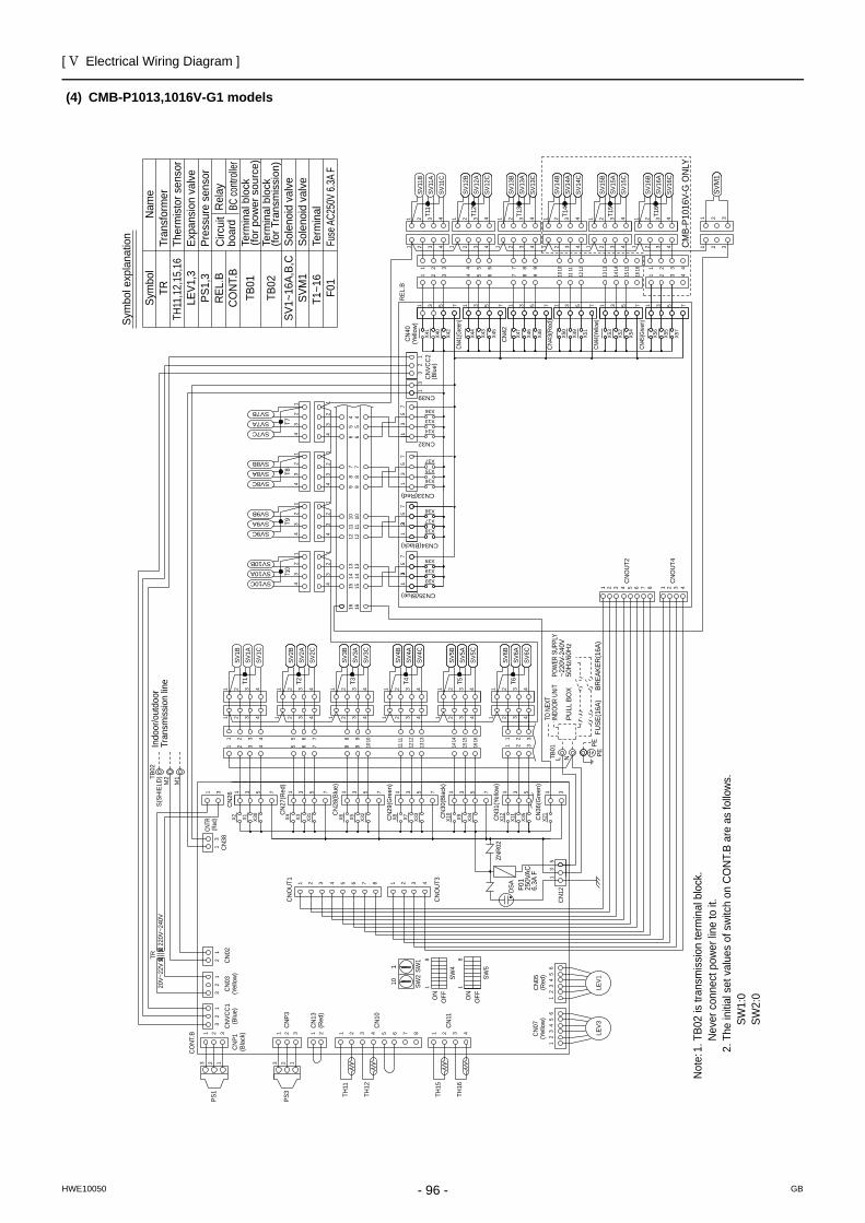
[ V Electrical Wiring Diagram ]
- 96 -HWE10050 GB
(4) CMB-P1013,1016V-G1 models
Sym
bol e
xpla
natio
n Fuse
AC25
0V 6.
3A F
F01
Term
inal
T1~1
6
TB02
TB01
REL
.BC
ON
T.B
Circ
uit
boar
dR
elay
BC co
ntroll
er
Term
inal
blo
ck(fo
r Tra
nsm
issi
on)
Sole
noid
val
veSo
leno
id v
alve
Term
inal
blo
ck(fo
r pow
er s
ourc
e)
Pres
sure
sen
sor
Expa
nsio
n va
lve
Ther
mis
tor s
enso
rTr
ansf
orm
erN
ame
Sym
bol
SV1~
16A,
B,C
SVM
1
TRTH
11,1
2,15
,16
LEV1
,3PS
1,3
Not
e: 1.
TB0
2 is
tran
smis
sion
term
inal
blo
ck.
Nev
er c
onne
ct p
ower
line
to it
.
2. T
he in
itial
set
val
ues
of s
witc
h on
CO
NT.
B ar
e as
follo
ws.
SW
1:0
SW
2:0
188
11
X41
3 1 3 51 3 5 71 3 5 775
X49
X50
X46
X47
X48
X44
X40
X43
X42
X45
1 3 5 71 3 5 77
X54
X57
X53
X52
X56
X55
X51
1 2 43
1 2 434321
4321
1 2 3 41 2 3 41 2 3 41 2 3 41 2 3 4
1 2 3 41 2 3 41 2 3 41 2 3 41 2 3 4
1615147651 42 3 13121110
16151413121110
98
2 31 7 98654
1 3
1 2 3
2SV
M1
13
57
13
57
13
57
X20
X18
X19
X17
X39
X38
X16
X15
X37
X36
X13
X14
33
13
57
43
21
43
21
43
21
43
21
43
21
43
21
43
21
43
21
1314
1510
1112
97
86
54 4
87
65
1211
109
1514
131616
11
11
1 3 5 7 1 3 5 7 1 3 5 7 1 3 5 7 1 3 5 7 1 3 5
X2 X1 X30
X4 X3 X31
X6 X5 X32
X8 X7 X33
X10
X9 X34
X12
X11
X35
1 2
1 2 33
4321
4321
1 2 3 41 2 3 41 2 3 41 2 3 42 3 4
1 2 3 41 2 3 41 2 3 41 2 3 42 3 4
16151476542 3 1312111098
42 3 1615141312111098765
1 2 387654321 4
1 31
23
21
1 2 3 4876543211 2321321
12
34
56
12
34
56
41 2 3 4 5 6 7 8 321
31
53
1
31
21
3
31
2
1 3
X21
CM
B-P1
016V
-G O
NLY
F01
250V
AC6.
3A F
SW2
SW1
110
(Bla
ck)
(Red
)
(Red
)(Y
ello
w)
(Blu
e)
DSA
ON
OFF
SW5
OFF
SW4
ON
T16
T12
T13
T14
T15
T11
T7T8
T9T1
0
T6T2 T3 T4 T5T1
3 13 1 22
Indo
or/o
utdo
orTr
ansm
issi
on li
ne
TO N
EXT
50H
z/60
Hz
~220
V-24
0VPO
WER
SUP
PLY
BREA
KER
(16A
)FU
SE(1
6A)
PULL
BO
X
PEPE
INDO
OR U
NIT
CN
42
SV16
CSV
16A
SV16
B
SV15
CSV
15A
SV15
B
SV14
BSV
14A
SV14
C
SV13
BSV
13A
SV13
C
SV12
BSV
12A
SV12
C
SV11
CSV
11A
SV11
B
REL
.BC
N40
CN32
SV10CSV10ASV10B
SV9CSV9ASV9B
SV8CSV8ASV8B
SV7C
SV7BSV7A
SV6C
SV6A
SV6B
SV5C
SV5A
SV5B
SV4B
SV4A
SV4C
SV3B
SV3A
SV3C
SV2B
SV2A
SV2C
SV1C
SV1A
SV1B
(Yel
low
)
CN
43(R
ed)
CN41
(Gree
n)
CN45
(Gree
n)
CN44
(Yell
ow)
20V~
22V
220V
~240
V
PS3
PS1
CNTR
CN
26C
N38
TR
TH16
TH15
TH12
TH11
CN
11
CN
10
CN
02C
N03
CN
P3
CN
P1
CN
OU
T4
CN
OU
T2
CN
OU
T1
CN
OU
T3
CN
12
CN39
CO
NT.
B
CN
VCC
2
CN
VCC
1
LEV3
LEV1
CN
13
CN
05C
N07
(Yel
low
)(B
lue)
(Red
)
CN
27(R
ed)
CN
28(B
lue)
CN
29(G
reen
)
CN
30(B
lack
)
CN
31(Y
ello
w)
CN
36(G
reen
)
CN35(Blue)
CN34(Black)
CN33(Red)
S(SH
IELD
)TB02
M2
M1
TB01
NL
ZNR
02
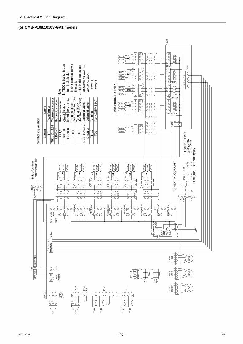
[ V Electrical Wiring Diagram ]
- 97 -HWE10050 GB
(5) CMB-P108,1010V-GA1 models
Sym
bol e
xpla
natio
n Fuse
AC25
0V 6.
3A F
F01
Term
inal
T1~1
0
TB02
TB01
REL
.BC
ON
T.B
Circ
uit
boar
dR
elay
BC co
ntroll
er
Term
inal
blo
ck(fo
r Tra
nsm
issi
on)
Sole
noid
val
veSo
leno
id v
alve
Term
inal
blo
ck(fo
r pow
er s
ourc
e)
Pres
sure
sen
sor
Expa
nsio
n va
lve
Ther
mis
tor s
enso
rTr
ansf
orm
erN
ame
Sym
bol
SV1~
10A,
B,C
SVM
1,2
TRTH
11,1
2,15
,16
LEV1
~3PS
1,3
Not
e:1.
TB0
2 is
tran
smis
sion
term
inal
blo
ck.
N
ever
con
nect
pow
er
lin
e to
it.
2. T
he in
itial
set
val
ues
of
sw
itch
on C
ON
T.B
ar
e as
follo
ws.
SW1:
0
SW
2:0
CM
B-P1
010V
-GA
ON
LY
F01
250V
AC6.
3A F
101 SW
1SW
2
(Bla
ck) (R
ed)
(Yel
low
)(R
ed)
(Blu
e)
DSA
18
ON
OFF
SW5
SW4
ON
OFF
18
T10
T9T8
T7
T1 T5T4T3T2 T6
1323 1 2
Indo
or/o
utdo
orTr
ansm
issi
on li
ne
PEPETO
NEX
T IN
DO
OR
UN
IT
FUSE
(16A
)
PULL
BO
X BREA
KER
(16A
)
POW
ER S
UPP
LY~2
20V-
240V
50H
z/60
Hz
SVM2SVM1
32
1
32
1
32
144
32
1
33
31
57
13
57
15
71
75
X20
X19
X39
X38
X17
X18
X16
X15
X37
X36
X13
X14
CN32
161613
1415
910
1112
56
78
4 45
68
79
1211
1015
1413
SV10C
SV9C
SV8C
SV7C
SV10A
SV9A
SV8A
SV7A
SV10B
SV9B
SV8B
SV7B
43
21
43
21
43
21
43
21
43
21
43
21
43
21
43
21
76
54
32
1
CN
52
REL
.B
CN
39
CN35(Blue)
CN34(Black)
CN33(Red)
13
1 3 1 3
CN
46(Y
ello
w)
X21
X60
X30
X1X21 3 5
4321
SV1B
SV1A
SV1C
1 2 3 432 41
X35
X11
X12
X34
X9X10
X33
X7X8X32
X5X6X31
X3X4
7 1 3 5 7 1 3 5 7 1 3 5 7 1 3 5 7 1 3 5 7
1 11 4324324321432
SV2C
SV2A
SV2B
SV3C
SV3A
SV3B
SV4C
SV4A
SV4B
SV5B
SV5A
SV5C
1111 2222 3333 4444
8 9 10 11 12 135 6 7 14 15 16 1 2 3
32 41 8 9 10 11 12 135 6 7 14 15 16 1 2 34321
4321
SV6C
SV6A
SV6B
20V~
22V
220V
~240
V
CO
NT.
B
65
43
21
65
43
21
LEV3
LEV1
1 2 3 1 2 3C
NP3
21 1 2 3 4 5 6 7 8 4321
12
32
1
CN
02
CN
10
CN
11
TH11
TH12
TH15
TH16
TR
PS1
PS3
CN
507
65
43
21
13
5
CN
12
13
CN
38C
N2631
65
43
21
LEV2
CN
P1
CN
13
CN
07C
N05
CN
06
S(SH
IELD
)TB02
M2
M1
ZNR0
2
ZNR
01
CN
TR(R
ed)
CN
27(R
ed)
CN
28(B
lue)
CN
29(G
reen
)
CN
31(Y
ello
w)
CN
30(B
lack
)
CN
36(G
reen
)
L NTB01
CN
03(Y
ello
w)
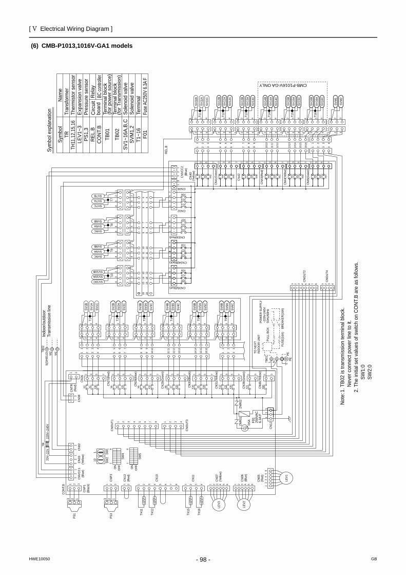
[ V Electrical Wiring Diagram ]
- 98 -HWE10050 GB
(6) CMB-P1013,1016V-GA1 modelsSy
mbo
l exp
lana
tion Fuse
AC25
0V 6.
3A F
F01
Term
inal
T1~1
6
TB02
TB01
REL
.BC
ON
T.B
Circ
uit
boar
dR
elay
BC co
ntroll
er
Term
inal
blo
ck(fo
r Tra
nsm
issi
on)
Sole
noid
val
veSo
leno
id v
alve
Term
inal
blo
ck(fo
r pow
er s
ourc
e)
Pres
sure
sen
sor
Expa
nsio
n va
lve
Ther
mis
tor s
enso
rTr
ansf
orm
erN
ame
Sym
bol
SV1~
16A,
B,C
SVM
1,2
TRTH
11,1
2,15
,16
LEV1
~3PS
1,3
Not
e: 1.
TB0
2 is
tran
smis
sion
term
inal
blo
ck.
Nev
er c
onne
ct p
ower
line
to it
.
2. T
he in
itial
set
val
ues
of s
witc
h on
CO
NT.
B ar
e as
follo
ws.
SW
1:0
SW
2:0
F01
250V
AC6.
3A F
(Red
)
CMB-P1016V-GA ONLY
SW2
SW1
110
(Bla
ck)
(Red
)
(Yel
low
)
(Blu
e)D
SA
(Blu
e)
18
ON
OFF
SW5
OFF
8
SW4
ON
1
PEPE
50H
z/60
Hz
~220
V-24
0VPO
WER
SU
PPLY
TO N
EXT
IND
OO
R U
NIT
BREA
KER
(16A
)FU
SE(1
6A)
PULL
BO
X
T16
T12
T13
T14
T15
T11
T7T8
T9T1
0
T6T2 T3 T4 T5T1
3 13 1 22
Indo
or/o
utdo
orTr
ansm
issi
on li
ne
X60
CN
46(Y
ello
w)
1 33
CN
OU
T4
CN
OU
T2
41 2 3 4 5 6 7 8 321
CN
125
31
TB01
L N
LEV1
12
34
56
CN
05
2
11
322 3
SVM
1
SVM
2
1 3 1 3 51 3 5 71 3 5 775
X49
X50
X48
1 3 5 71 3 5 77
X54
X57
X53
X52
X56
X55
X51
1 2 43431
4321
SV16
C
SV16
A
SV16
B
1 2 3 41 2 3 41 2 3 41 2 3 41 2 3 4
1 2 3 41 2 3 41 2 3 41 2 3 4
SV15
C
SV15
A
SV15
B
SV14
B
SV14
A
SV14
C
SV13
B
SV13
A
SV13
C
SV12
B
SV12
A
SV12
C
1 2 3 4
1615147651 42 3 1312111098
1 2 431615147651 42 3 1312111098
SV11
C
SV11
A
SV11
B
REL
.B
CN
43(R
ed)
CN44
(Yell
ow)
CN45
(Gre
en)
X21
CN
36(G
reen
)1
13
57
13
57
13
57
X20
X18
X19
X17
X39
X38
X16
X15
X37
X36
X13
X14
33
13
57
CN32
43
21
43
21
43
21
43
21
43
21
43
21
43
21
43
21
1314
1510
1112
97
86
544
87
65
1211
109
1514
131616
SV10C
SV10A
SV10B
SV9C
SV9A
SV9B
SV8C
SV8A
SV8B
SV7C
SV7B
SV7A
11
11
1 3 5 7 1 3 5 7 1 3 5 7 1 3 5 7 1 3 5 7 1 3 5 7
X2 X1 X30
X4 X3 X31
X6 X5 X32
X8 X7 X33
X10
X9 X34
X12
X11
X35
CN
26
CN
27(R
ed)
CN
28(B
lue)
CN
29(G
reen
)
CN
30(B
lack
)
CN
31(Y
ello
w)
1 2
1 2 33
4321
4321
SV6C
SV6A
SV6B
1 2 3 41 2 3 41 2 3 41 2 3 42 3 4
1 2 3 41 2 3 41 2 3 41 2 3 4
SV5C
SV5A
SV5B
SV4B
SV4A
SV4C
SV3B
SV3A
SV3C
SV2B
SV2A
SV2C
2 3 4
16151476542 3 1312111098
42 3 1615141312111098765
SV1C
SV1A
SV1B
X41
CN
42
X46
X47
X44
X40
X43
X42
X45
20V~
22V
220V
~240
V
PS3
PS1
1 2 387654321 4
1 3C
N38
TR
TH16
TH15
TH12
TH11
CN
11
CN
10
CN
0212
32
1
1 1 2 3 4 5 6 1 2 3 4 5 62 3 4876543211 2
CN
P3321321
31
CN
OU
T1
CN
OU
T3
31
CN39
CO
NT.
B
21
3 CN
VCC
2
31
2
LEV3
S(SH
IELD
)TB02
M2
M1
CN
03(Y
ello
w)
CN
VCC
1(B
lue)
CN
P1
CN
13
CN
07
LEV2
CN
06ZN
R02
ZNR
01
CN35(Blue)
CN33(Red)
CN34(Black)
(Yel
low
)C
N40
CN41
(Gre
en)
(Red
)C
NTR
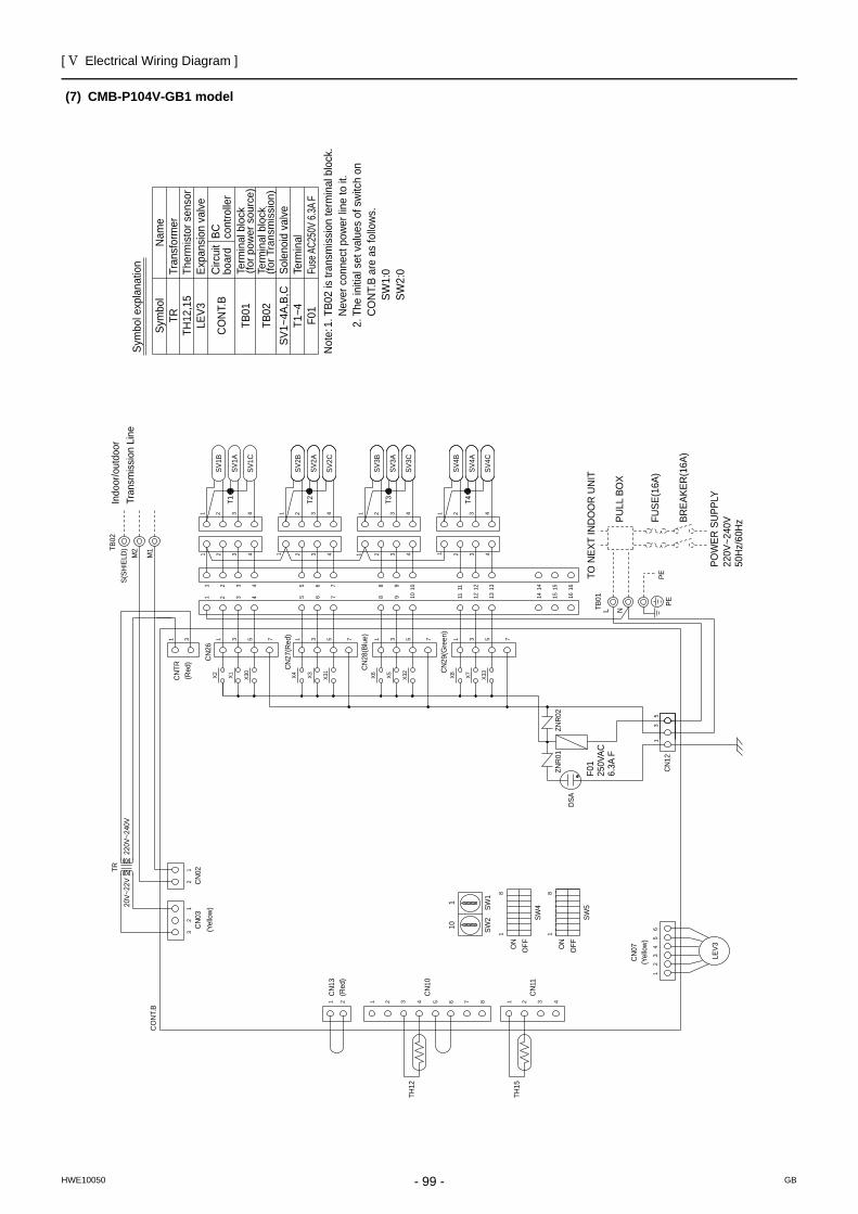
[ V Electrical Wiring Diagram ]
- 99 -HWE10050 GB
(7) CMB-P104V-GB1 model
Sym
bol e
xpla
natio
n Fuse
AC25
0V 6.
3A F
F01
Term
inal
T1~4
TB02
TB01
CO
NT.
BC
ircui
tbo
ard
BC
cont
rolle
r
Term
inal
blo
ck(fo
r Tra
nsm
issi
on)
Sole
noid
val
ve
Term
inal
blo
ck(fo
r pow
er s
ourc
e)
Expa
nsio
n va
lve
Ther
mis
tor s
enso
rTr
ansf
orm
erN
ame
Sym
bol
SV1~
4A,B
,C
TRTH
12,1
5LE
V3
Not
e: 1.
TB0
2 is
tran
smis
sion
term
inal
blo
ck.
Nev
er c
onne
ct p
ower
line
to it
.
2. T
he in
itial
set
val
ues
of s
witc
h on
C
ON
T.B
are
as fo
llow
s.
SW1:
0
SW2:
0
SW2
SW1
110
F01
250V
AC6.
3A F
(Yel
low
)
(Red
)
(Yel
low
)
DSA
ON
OFF
1
SW5
OFF
8
SW4
ON
1
8
T2 T3T1 T4Indo
or/o
utdo
orTr
ansm
issi
on L
ine
PULL
BO
X
TO N
EXT
IND
OO
R U
NIT
50H
z/60
Hz
220V
~240
VPO
WER
SU
PPLY
BREA
KER
(16A
)
FUSE
(16A
)PE
PE
TR
CN
26
31
CN
121
53
CO
NT.
B
CN
02
21 1 2 3 4 5 6 7 8 4321
12
32
1
CN
10
CN
11
TH12
TH15
65
43
21
LEV3
220V
~240
V20
V~22
V
1 2 3 41098
42 3 10
21 43
SV3A
SV3B
SV2B
SV3C
SV2C
SV2A
2 43
75 6432
1 2 3 41 2 3 42 3 4
98765
SV1C
SV1A
SV1B
753175317531X2 X1 X3
0
X4 X3 X31
X6 X5 X32
11
11
2 3 4131211
161514131211SV
4B
SV4C
SV4A
15 1614
1 2 3 4
1
7531X8 X7 X3
3
TB02
S(SH
IELD
)M
2
M1
CN
03
CN
13
TB01
NL
CN
07
(Red
)C
NTR C
N27
(Red
)
CN
28(B
lue)
CN
29(G
reen
)
ZNR
01ZN
R02
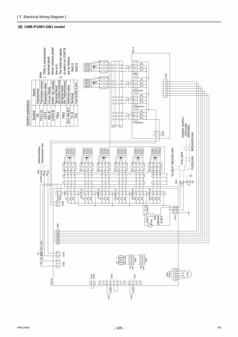
[ V Electrical Wiring Diagram ]
- 100 -HWE10050 GB
(8) CMB-P108V-GB1 modelSy
mbo
l exp
lana
tion Fuse
AC25
0V 6.
3A F
F01
Term
inal
T1~8
TB02
TB01
REL
.BC
ON
T.B
Circ
uit
boar
dR
elay
BC co
ntroll
er
Term
inal
blo
ck(fo
r Tra
nsm
issi
on)
Sole
noid
val
ve
Term
inal
blo
ck(fo
r pow
er s
ourc
e)
Expa
nsio
n va
lve
Ther
mis
tor s
enso
rTr
ansf
orm
erN
ame
Sym
bol
SV1~
8A,B
,C
TRTH
12,1
5LE
V3N
ote:
1. T
B02
is tr
ansm
issi
on
te
rmin
al b
lock
.
Nev
er c
onne
ct p
ower
line
to it
.2.
The
initi
al s
et v
alue
s
of s
witc
h on
CO
NT.
B
are
as fo
llow
s.
SW
1:0
SW2:
0
SW2
SW1
110
(Red
)
(Yel
low
)
DSA
F01
250V
AC6.
3A F
81
OFFON
SW4
SW5
OFFON
81
T6T2 T3 T4 T5T1
T7T8
Indo
or/o
utdo
orTr
ansm
issi
on li
ne
PETO N
EXT
IND
OO
R U
NIT
PULL
BO
X
FUSE
(16A
)BR
EAKE
R(1
6A)
POW
ER S
UPP
LY~2
20V-
240V
50H
z/60
Hz
PE
REL
.B
CN
TR1 3
CN
26C
N383
1
53
1
76
54
32
1
CN
50
TR
TH15
TH12
CN
11
CN
10
CN
02C
N03
12
32
1
1 2 3 4876543211 2
LEV3
12
34
56
CO
NT.
B
CN
52
13
CN
391
23
45
67
220V
~240
V20
V~22
V
SV6B
SV6A
SV6C
1 2 3 4
1 2 3 43
321
21161514765 1312111098
161514765 1098 131211
4 4 4 43 3 3 32 2 2 21 1 1 1
SV5C
SV5A
SV5B
SV4B
SV4A
SV4C
SV3B
SV3A
SV3C
SV2B
SV2A
SV2C
2 3 4 1 2 3 4 2 3 4 2 3 41 11
753175317531753175317
X4 X3 X31
X6 X5 X32
X8 X7 X33
X10
X9 X34
X12
X11
X35
1 42 3
1 42 34321
SV1C
SV1A
SV1B
1 2 3 4531
X2 X1 X30
12
34
12
34
12
34
12
34
SV7B
SV8B
SV7A
SV8A
SV7C
SV8C
1314
1510
1112
97
86
544
87
65
1211
109
1514
1316 16
CN32
X14
X13
X36
X37
X15
X16
X18
X17
X38
X39
X19
X20
57
31
75
31
75
31
75
13
33
CN
12
TB02
S(SH
IELD
)M
2M
1
(Red
)
CN
13 CN
07
ZNR
01ZN
R02
NLTB01
CN
27(R
ed)
CN
28(B
lue)
CN
29(G
reen
)
CN
30(B
lack
)
CN35(Blue)
CN34(Black)
CN33(Red)
CN
31(Y
ello
w)
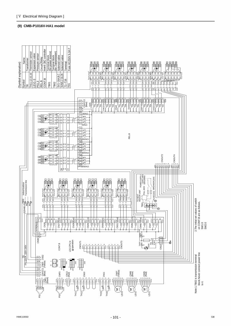
[ V Electrical Wiring Diagram ]
- 101 -HWE10050 GB
(9) CMB-P1016V-HA1 model
T1T1
0T9
T8T7
T2 T3 T4 T5 T6
T11
T12
T13
T14
T15
T16
(Blu
e)C
NVC
C1 (Y
ello
w)
CN
03C
N02
22
32
31
11
321
(Bla
ck)
CN
P1
123
220V
~240
VTR
20V~
22V
CN
381
3
CN
TR(R
ed)
31
CN
26X0
2
X01
X30
7531
CN
27(R
ed) 1 3 5 7
X31
X03
X04
CN
28(B
lue)
X06
X05
X32
1 3 5 7
CN29
(Gre
en)
X08
X07
X33
531 7
CN30
(Blac
k)
X10
1 3 5 7X3
4
X09
CN31
(Yell
ow)
X12
1 3X1
1
X35
5 7
CN36
(Gre
en)
X21
1 3
CN46
(Yell
ow)
X60
1 3
CN
47 X62
X61
1 3 65 65
31
CN
12
ZNR
02ZN
R01
F01
250V
AC6.
3A F
CN
OU
T3
2 3 4187654321
CN
OU
T1
110 SW
2SW
11
8
OFFO
N
81
SW4
OFFO
N
SW5
81
SW6
OFFO
N
87654C
N10
32
CN
13(R
ed)
2
CN
P332 111
3 2 1PS
3
PS1 TH
11
TH12
CN
11
4321TH
15
TH16
4 5 6321
(Yel
low
)C
N07
CN
05(R
ed)
4 5 63214 5 6321
(Blu
e)C
N06
Indo
or/o
utdo
orTr
ansm
issi
on li
ne
TB02
S(SH
IELD
) 16151476542 3 1312111098
42 3 1615141312111098765
11
1 2
1 2 33
~220
V-24
0VPO
WER
SUP
PLY
50H
z/60
Hz
BREA
KER
(16A
)FU
SE(1
6A)
PULL
BO
X
IND
OO
R U
NIT
TO N
EXT
1 2 3 44321 1 2 3 4
4321 1 2 3 44321
1 2 3 44321 4321
1 2 3 4
1 2 3 44321
CN
OU
T4
CN
OU
T2
41 2 3 4 5 6 7 8 32143
21 1
23
4
43
21 1
23
4
43
21 1
23
41
23
443
21
1314
1510
1112
97
86
87
612
1110
915
1413
16165
445
CN35(Blue)
X20
X19
X39
75
31
CN34(Black)
X18
X17
X38
75
31
CN33(Red)
X16
X15
X37
75
31
CN39
CN32
13
57
X36
X13
X14
CN
VCC
23
21
3 (Blu
e)
1
(Yel
low
)C
N40
X41
X40
X42
1 3 5 7
CN41
(Gre
en)
X44
X43
X45
CN
42 X47
X46
X48
CN43
(Red
)
X50
X49
X51
CN44
(Yell
ow)
X53
X52
3 5175317531 3 5 76542 3
2 3 654
7 12111098
11 12107 98
11
1 2 3 4 1 2
X54
CN45
(Gre
en)
X56
X55
X57
75317151413
1 2 431614 1513 5 6 87
16
543211 2 3 4 5
85 6 71 2 434321
1 2 3 443211 2 3 42 31
21 3 441 2 3 4
43 11 2 3 4
432
1 2 3 4
Term
inal
Fuse
AC
250V
6.3
A F
T1~T
16F0
1
SVM
1,2,
1b,2
bSo
leno
id v
alve
Sole
noid
val
veSV
1~16
A,B,
CTB
02Te
rmin
al b
lock
(for T
rans
mis
sion
)
Term
inal
blo
ck(fo
r pow
er s
ourc
e)TB
01
CO
NT.
BR
EL.B
TR
TH
11,1
2,15
,16
LE
V1~3
PS1,
3
Sym
bol
Nam
e(S
ymbo
l exp
lana
tion)
Tran
sfor
mer
Ther
mis
ter s
enso
rEx
pans
ion
valv
ePr
essu
re s
enso
rC
ircui
tbo
ard
Rel
ayBC
con
trolle
r
Not
e:1.
TB02
is tr
ansm
issi
on te
rmin
al
b
lock
.Nev
er c
onne
ct p
ower
line
to it
.
2
.The
initi
al s
et v
alue
s of
sw
itch
on
CO
NT.
B ar
e as
follo
ws.
SW
1:0
SW
2:0
66
CO
NT.
B
REL
.B
M2
M1
SV1B
SV1A
SV1C
SV2C
SV2A
SV2B
SV3C
SV3A
SV3B
SV4C
SV4A
SV4B
SV5C
SV5A
SV5B
SV6C
SV6A
SV6B
SV10C
SV10A
SV10B
SV9C
SV9A
SV9B
SV8C
SV8A
SV8B
SV7C
SV7A
SV7B
SV11
C
SV11
A
SV11
B
SV12
C
SV12
A
SV12
B
SV13
C
SV13
A
SV13
B
SV14
C
SV14
A
SV14
B
SV15
C
SV15
A
SV15
B
SV16
C
SV16
A
SV16
B
SVM
2b
SVM
2
SVM
1
SVM
1b
TB01
L N
MLE
V1
LEV2
M
LEV3
M
LD
1:C
PU in
o
pera
tion
UU
DSA
t°t°t°t°
1
1 3 5 7
33
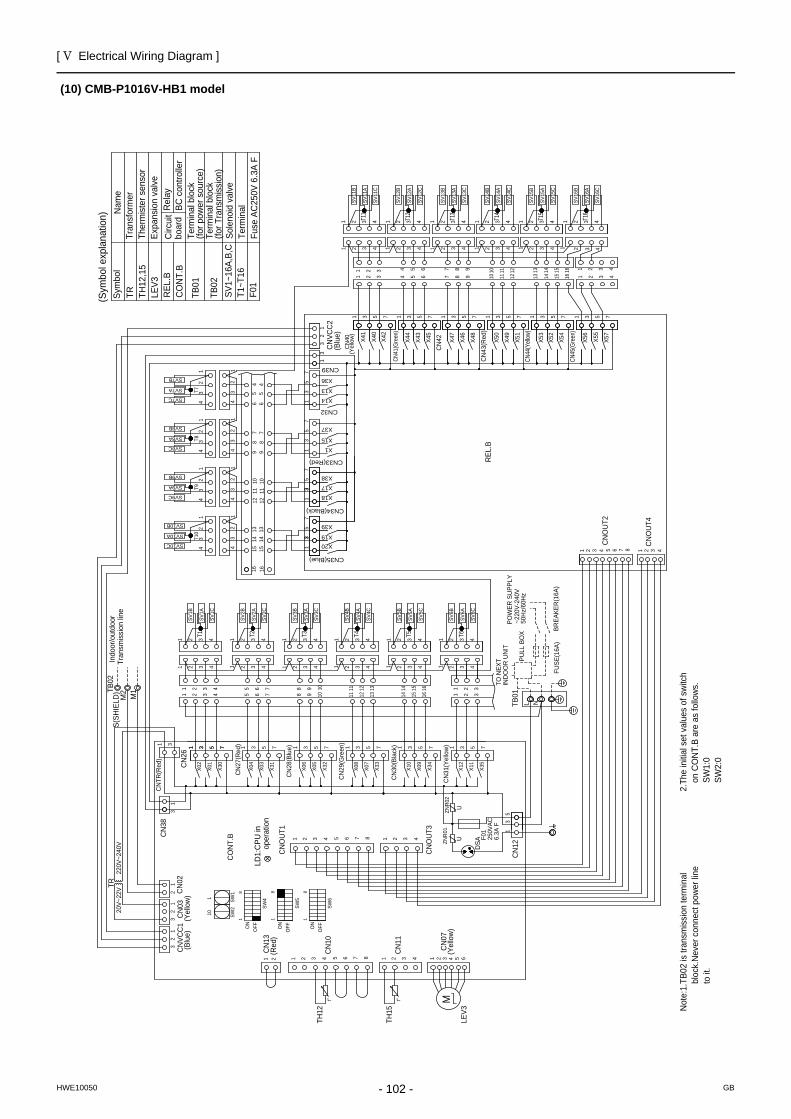
[ V Electrical Wiring Diagram ]
- 102 -HWE10050 GB
(10) CMB-P1016V-HB1 model
T1T1
0T9
T8T7
T2 T3 T4 T5 T6
T11
T12
T13
T14
T15
T16
BC c
ontro
ller
Rel
ayC
ircui
tbo
ard
Expa
nsio
n va
lve
Ther
mis
ter s
enso
rTr
ansf
orm
erN
ame
Sym
bol
TR
TH
12,1
5
LEV3
R
EL.B
CO
NT.
B
TB01
Term
inal
blo
ck(fo
r pow
er s
ourc
e)Te
rmin
al b
lock
(for T
rans
mis
sion
)TB
02SV
1~16
A,B,
CSo
leno
id v
alve
T1~T
16F0
1Te
rmin
alFu
se A
C25
0V 6
.3A
F
(Blu
e)C
NVC
C1
(Yel
low
)C
N03
CN
022
23
23
11
1
220V
~240
VTR
20V~
22V
CN
381
3
CN
TR(R
ed)
31
CN
26
X02
X01
X30
7531
CN
27(R
ed) 1 3 5 7
X31
X03
X04
CN
28(B
lue)
X06
X05
X32
1 3 5 7
CN
29(G
reen
)
X08
X07
X33
531 7
CN
30(B
lack
)
X10
1 3 5 7X3
4
X09
CN
31(Y
ello
w)
X12
1 3X1
1
X35
5 7
53
1C
N12
ZNR
02ZN
R01
F01
250V
AC6.
3A F
CN
OU
T3
2 3 4187654321
CN
OU
T1
110 SW
2SW
11
8
OFFO
N
81
SW4
OFFO
N
SW5
81
SW6
OFFO
N
87654C
N10
32
CN
13(R
ed)
2 11
TH12
CN
11
4321TH
15
4 5 6321
(Yel
low
)C
N07
Indo
or/o
utdo
orTr
ansm
issi
on li
ne
TB02
S(SH
IELD
) 16151476542 3 1312111098
42 3 1615141312111098765
11
1 2
1 2 33
~220
V-24
0VPO
WER
SU
PPLY
50H
z/60
Hz
BREA
KER
(16A
)FU
SE(1
6A)
PULL
BO
X
IND
OO
R U
NIT
TO N
EXT
1 2 3 44321 1 2 3 4
4321 1 2 3 44321
1 2 3 44321 4321
1 2 3 4
1 2 3 44321
CN
OU
T4
CN
OU
T2
41 2 3 4 5 6 7 8 32143
21 1
23
4
43
21 1
23
4
43
21 1
23
41
23
443
21
1314
1510
1112
97
86
87
612
1110
915
1413
16165
445
CN35(Blue)
X20X19
X39
75
31
CN34(Black)
X18
X17
X38
75
31
CN33(Red)
X1
X15
X37
75
31
CN39
CN32
13
57
X36
X13
X14
CN
VCC
23
21
3
(Blu
e)
1
(Yel
low
)C
N40 X4
1
X40
X42
1 3 5 7
CN41
(Gre
en)
X44
X43
X45
CN
42 X47
X46
X48
CN
43(R
ed)
X50
X49
X51
CN44
(Yell
ow)
X53
X52
3 5175317531 3 5 76542 3
2 3 654
7 12111098
11 12107 98
11
1 2 3 4 1 2
X54
CN45
(Gre
en)
X56
X55
X57
75317151413
1 2 431614 1513
16 1 2 434321
1 2 3 443211 2 3 42 31
21 3 441 2 3 4
43 11 2 3 4
432
1 2 3 4
CO
NT.
B
REL
.B
M2
M1
SV1B
SV1A
SV1C
SV2C
SV2A
SV2B
SV3C
SV3A
SV3B
SV4C
SV4A
SV4B
SV5C
SV5A
SV5B
SV6C
SV6A
SV6B
SV10C
SV10A
SV10B
SV9C
SV9A
SV9B
SV8C
SV8A
SV8B
SV7C
SV7A
SV7B
SV11
C
SV11
A
SV11
B
SV12
C
SV12
A
SV12
B
SV13
C
SV13
A
SV13
B
SV14
C
SV14
A
SV14
B
SV15
C
SV15
A
SV15
B
SV16
C
SV16
A
SV16
B
TB01
L N
2
.The
initi
al s
et v
alue
s of
sw
itch
on
CO
NT.
B ar
e as
follo
ws.
SW
1:0
SW
2:0
Not
e:1.
TB02
is tr
ansm
issi
on te
rmin
al
b
lock
.Nev
er c
onne
ct p
ower
line
to it
.
LEV3
M
LD
1:C
PU in
o
pera
tion
UU
DSA
t°t°
1
1 3 5 7
33
(Sym
bol e
xpla
natio
n)
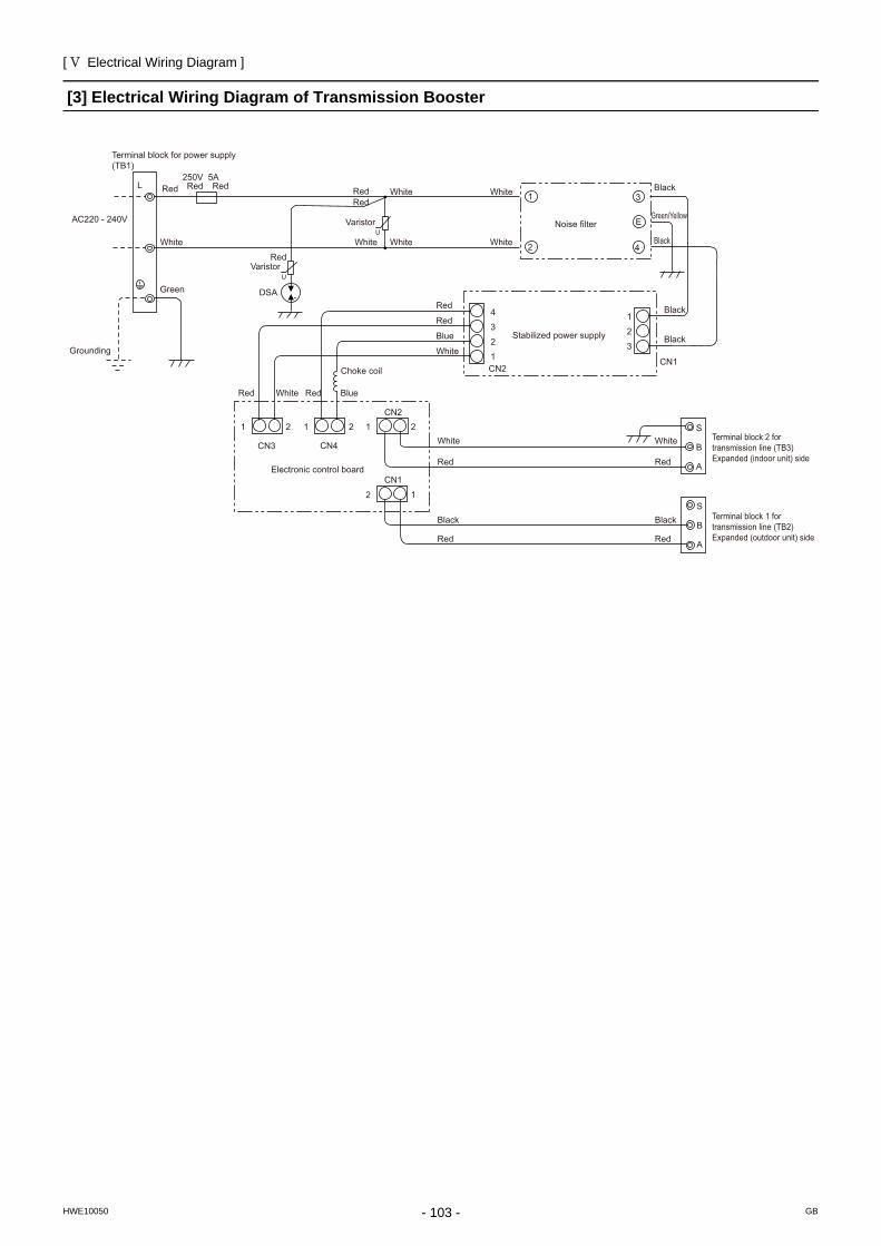
[ V Electrical Wiring Diagram ]
- 103 -HWE10050 GB
[3] Electrical Wiring Diagram of Transmission Booster
AC220 - 240V
Terminal block for power supply (TB1)
L Red Red Red
White
Green
250V 5A
Grounding
Red Red
Red
U
U
White
White White
White
White
White Blue Red Red
DSA
White
White
Blue
Red
Red
Red
Red
Varistor
Varistor
Noise filter
Stabilized power supply
4
3
2
1
1
2
3
CN2 CN1
Black
Black
Black
Black
Green/Yellow
1
2
3
E
4
Choke coil
1 2
CN3
1 2 1 2
CN4
CN2
1 2
CN1 Electronic control board
Black
White
Red
Red
Black
S
B
A
S
B
A
Terminal block 2 for transmission line (TB3) Expanded (indoor unit) side
Terminal block 1 for transmission line (TB2) Expanded (outdoor unit) side

- 104 -
[ V Electrical Wiring Diagram ]
GBHWE10050
- 105 -HWE10050 GB
VI Refrigerant Circuit
[1] Refrigerant Circuit Diagram ...........................................................................................107[2] Principal Parts and Functions ........................................................................................117

- 106 -
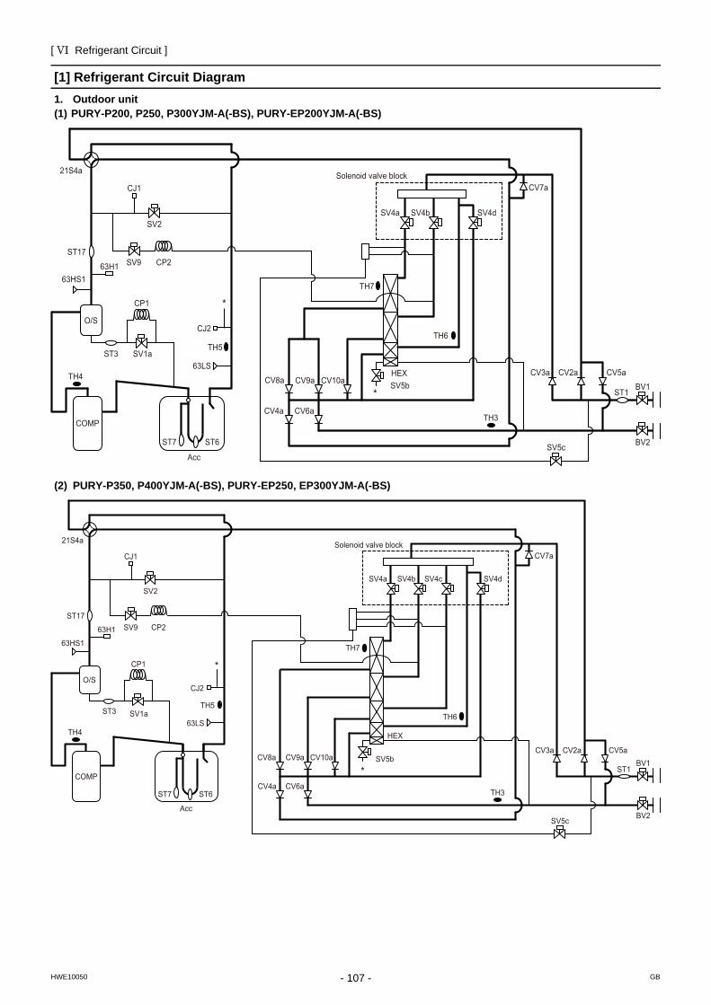
[ VI Refrigerant Circuit ]
- 107 -HWE10050 GB
VI Refrigerant Circuit
[1] Refrigerant Circuit Diagram1. Outdoor unit(1) PURY-P200, P250, P300YJM-A(-BS), PURY-EP200YJM-A(-BS)
(2) PURY-P350, P400YJM-A(-BS), PURY-EP250, EP300YJM-A(-BS)
HEXSV5bCV9a CV10aCV8a
CV4a CV6a
TH6
BV2
BV1
CV3a CV2a CV5a
SV5c
TH3
ST1
SV4b SV4d
CV7a
SV4a
Solenoid valve block
TH7
O/S
ST3 SV1a
CP1
TH4
63H163HS1
SV9 CP2
63LS
TH5
CJ2
*
*
ST17
CJ1
SV2
21S4a
COMP
ST7 ST6
Acc
COMP
O/S
ST3 SV1a
CP1
TH4
63H1
63HS1
ST17
CJ1
SV9 CP2
SV2
63LS
TH5
CJ2
21S4a
ST7 ST6
Acc
SV4dSV4cSV4bSV4a
HEX
SV5bCV9a CV10aCV8a
TH7
CV4a CV6a
CV7a
TH6
BV2
BV1CV2aCV3a CV5a
SV5c
TH3
ST1
*
*
Solenoid valve block
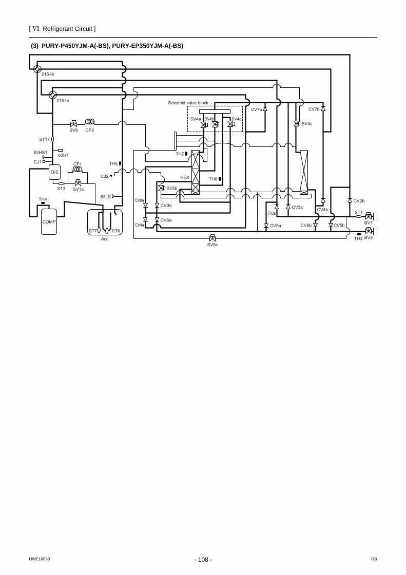
[ VI Refrigerant Circuit ]
- 108 -HWE10050 GB
(3) PURY-P450YJM-A(-BS), PURY-EP350YJM-A(-BS)
COMP
O/S
ST3 SV1a
CP1
TH4
63H163HS1
ST17
CJ1
SV9 CP2
63LS
TH5
CJ2
SV4bSV4a
HEX
CV9aCV8a
TH7
CV6a
CV7a
TH6
CV3a
CV5a
SV5cTH3
ST1
21S4a
ST7 ST6
Acc
SV4d
CV7b
CV4b
CV6b
CV2a
CV5b
CV2b
SV4c
SV5b
CV4a
21S4b
BV2
BV1
Solenoid valve block
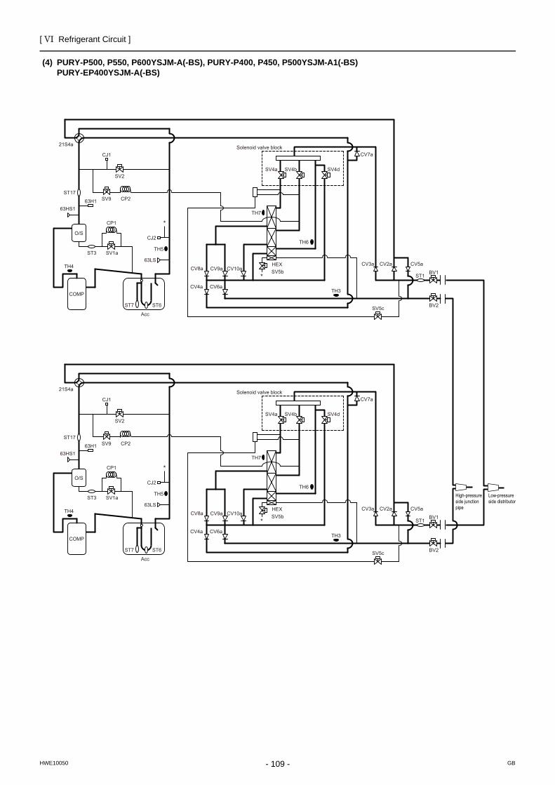
[ VI Refrigerant Circuit ]
- 109 -HWE10050 GB
(4) PURY-P500, P550, P600YSJM-A(-BS), PURY-P400, P450, P500YSJM-A1(-BS)PURY-EP400YSJM-A(-BS)
High-pressureside junction pipe
Low-pressureside distributor
HEXSV5bCV9a CV10aCV8a
CV4a CV6a
TH6
BV2
BV1
CV3a CV2a CV5a
SV5c
TH3
ST1
SV4b SV4d
CV7a
SV4a
Solenoid valve block
TH7
O/S
ST3 SV1a
CP1
TH4
63H163HS1
SV9 CP2
63LS
TH5
CJ2
*
*
ST17
CJ1
SV2
21S4a
COMP
ST7 ST6
Acc
HEXSV5bCV9a CV10aCV8a
CV4a CV6a
TH6
BV2
BV1
CV3a CV2a CV5a
SV5c
TH3
ST1
SV4b SV4d
CV7a
SV4a
Solenoid valve block
TH7
O/S
ST3 SV1a
CP1
TH4
63H163HS1
SV9 CP2
63LS
TH5
CJ2
*
*
ST17
CJ1
SV2
21S4a
COMP
ST7 ST6
Acc
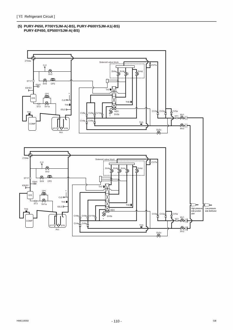
[ VI Refrigerant Circuit ]
- 110 -HWE10050 GB
(5) PURY-P650, P700YSJM-A(-BS), PURY-P600YSJM-A1(-BS)PURY-EP450, EP500YSJM-A(-BS)
High-pressureside junction pipe
Low-pressureside distributor
HEXSV5bCV9a CV10aCV8a
CV4a CV6a
TH6
BV2
BV1
CV3a CV2a CV5a
SV5c
TH3
ST1
SV4b SV4d
CV7a
SV4a
Solenoid valve block
TH7
O/S
ST3 SV1a
CP1
TH4
63H163HS1
SV9 CP2
63LS
TH5
CJ2
*
*
ST17
CJ1
SV2
21S4a
COMP
ST7 ST6
Acc
COMP
O/S
ST3 SV1a
CP1
TH4
63H1
63HS1
ST17
CJ1
SV9 CP2
SV2
63LS
TH5
CJ2
21S4a
ST7 ST6
Acc
SV4dSV4cSV4bSV4a
HEX
SV5bCV9a CV10aCV8a
TH7
CV4a CV6a
CV7a
TH6
BV2
BV1CV2aCV3a CV5a
SV5c
TH3
ST1
*
*
Solenoid valve block
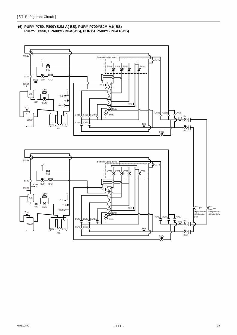
[ VI Refrigerant Circuit ]
- 111 -HWE10050 GB
(6) PURY-P750, P800YSJM-A(-BS), PURY-P700YSJM-A1(-BS)PURY-EP550, EP600YSJM-A(-BS), PURY-EP500YSJM-A1(-BS)
High-pressureside junction pipe
Low-pressureside distributor
COMP
O/S
ST3 SV1a
CP1
TH4
63H1
63HS1
ST17
CJ1
SV9 CP2
SV2
63LS
TH5
CJ2
21S4a
ST7 ST6
Acc
SV4dSV4cSV4bSV4a
HEX
SV5bCV9a CV10aCV8a
TH7
CV4a CV6a
CV7a
TH6
BV2
BV1CV2aCV3a CV5a
SV5c
TH3
ST1
*
*
Solenoid valve block
COMP
O/S
ST3 SV1a
CP1
TH4
63H1
63HS1
ST17
CJ1
SV9 CP2
SV2
63LS
TH5
CJ2
21S4a
ST7 ST6
Acc
SV4dSV4cSV4bSV4a
HEX
SV5bCV9a CV10aCV8a
TH7
CV4a CV6a
CV7a
TH6
BV2
BV1CV2aCV3a CV5a
SV5c
TH3
ST1
*
*
Solenoid valve block
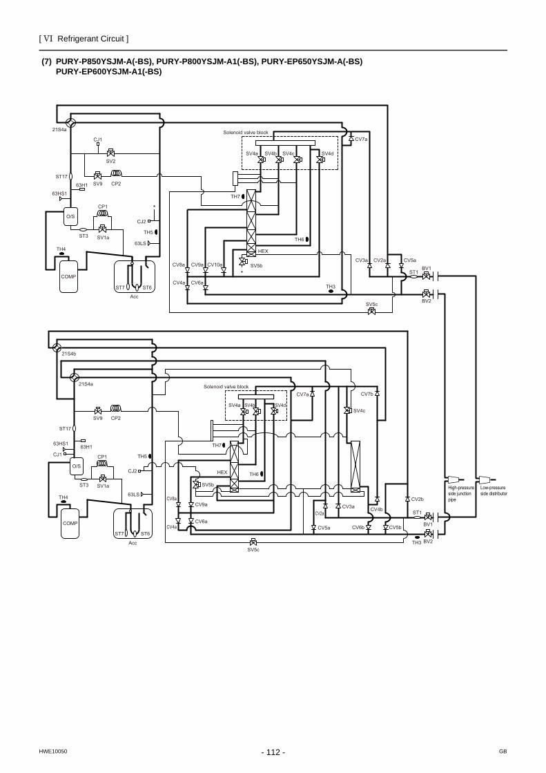
[ VI Refrigerant Circuit ]
- 112 -HWE10050 GB
(7) PURY-P850YSJM-A(-BS), PURY-P800YSJM-A1(-BS), PURY-EP650YSJM-A(-BS)PURY-EP600YSJM-A1(-BS)
High-pressureside junction pipe
Low-pressureside distributor
COMP
O/S
ST3 SV1a
CP1
TH4
63H1
63HS1
ST17
CJ1
SV9 CP2
SV2
63LS
TH5
CJ2
21S4a
ST7 ST6
Acc
SV4dSV4cSV4bSV4a
HEX
SV5bCV9a CV10aCV8a
TH7
CV4a CV6a
CV7a
TH6
BV2
BV1CV2aCV3a CV5a
SV5c
TH3
ST1
*
*
Solenoid valve block
COMP
O/S
ST3 SV1a
CP1
TH4
63H163HS1
ST17
CJ1
SV9 CP2
63LS
TH5
CJ2
SV4bSV4a
HEX
CV9aCV8a
TH7
CV6a
CV7a
TH6
CV3a
CV5a
SV5cTH3
ST1
21S4a
ST7 ST6
Acc
SV4d
CV7b
CV4b
CV6b
CV2a
CV5b
CV2b
SV4c
SV5b
CV4a
21S4b
BV2
BV1
Solenoid valve block
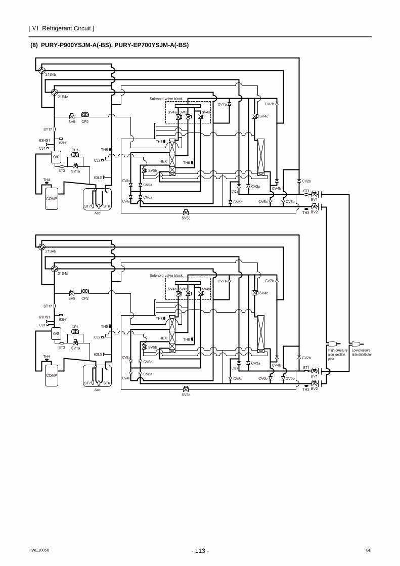
[ VI Refrigerant Circuit ]
- 113 -HWE10050 GB
(8) PURY-P900YSJM-A(-BS), PURY-EP700YSJM-A(-BS)
High-pressureside junction pipe
Low-pressureside distributor
COMP
O/S
ST3 SV1a
CP1
TH4
63H163HS1
ST17
CJ1
SV9 CP2
63LS
TH5
CJ2
SV4bSV4a
HEX
CV9aCV8a
TH7
CV6a
CV7a
TH6
CV3a
CV5a
SV5cTH3
ST1
21S4a
ST7 ST6
Acc
SV4d
CV7b
CV4b
CV6b
CV2a
CV5b
CV2b
SV4c
SV5b
CV4a
21S4b
BV2
BV1
Solenoid valve block
COMP
O/S
ST3 SV1a
CP1
TH4
63H163HS1
ST17
CJ1
SV9 CP2
63LS
TH5
CJ2
SV4bSV4a
HEX
CV9aCV8a
TH7
CV6a
CV7a
TH6
CV3a
CV5a
SV5cTH3
ST1
21S4a
ST7 ST6
Acc
SV4d
CV7b
CV4b
CV6b
CV2a
CV5b
CV2b
SV4c
SV5b
CV4a
21S4b
BV2
BV1
Solenoid valve block
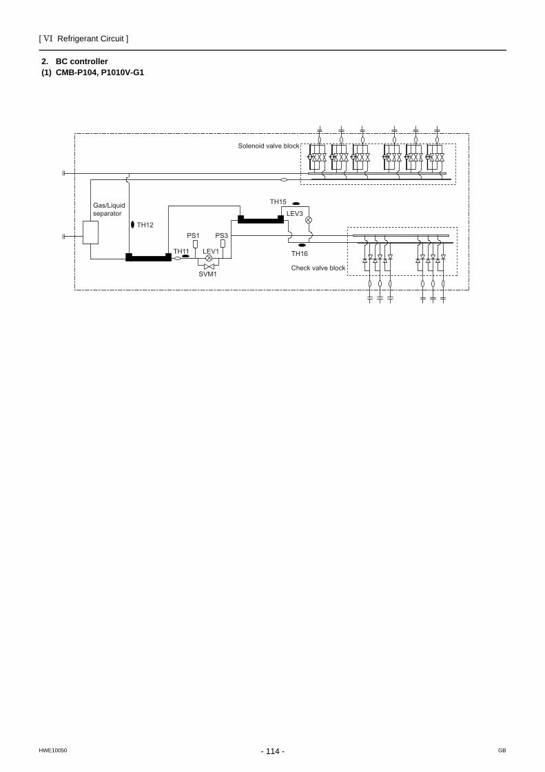
[ VI Refrigerant Circuit ]
- 114 -HWE10050 GB
2. BC controller(1) CMB-P104, P1010V-G1
TH15
TH12
LEV3
LEV1 TH16
PS3PS1
TH11
SVM1
Gas/Liquid separator
Check valve block
Solenoid valve block
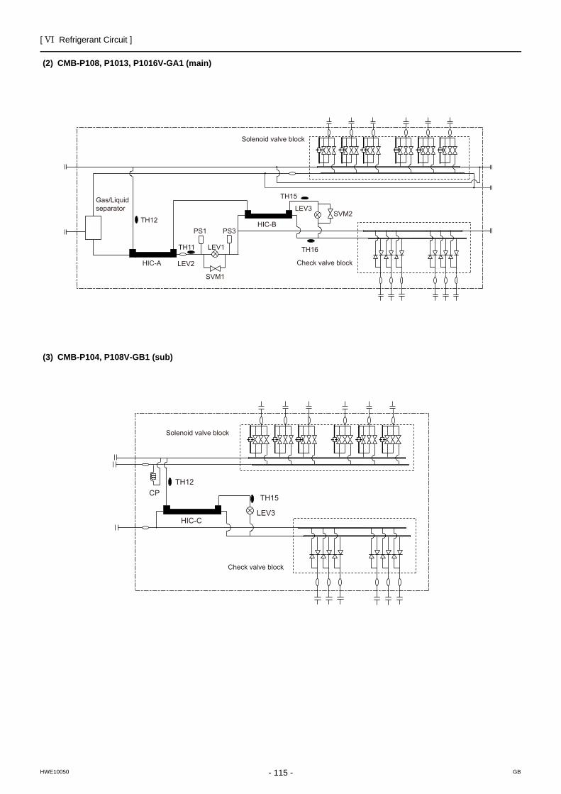
[ VI Refrigerant Circuit ]
- 115 -HWE10050 GB
(2) CMB-P108, P1013, P1016V-GA1 (main)
(3) CMB-P104, P108V-GB1 (sub)
TH15
HIC-B
HIC-A
TH12
LEV3SVM2
LEV1
LEV2
TH16
PS3PS1
TH11
SVM1
Solenoid valve block
Check valve block
Gas/Liquidseparator
TH15
TH12
HIC-C
CP
LEV3
Check valve block
Solenoid valve block
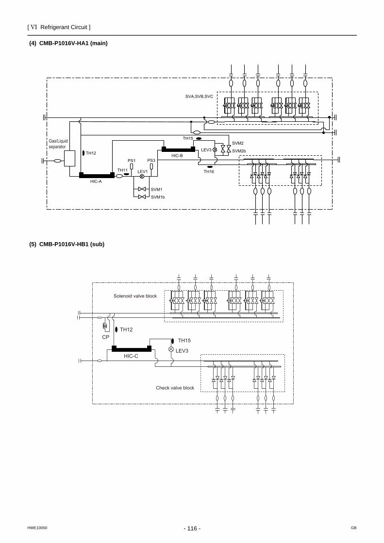
[ VI Refrigerant Circuit ]
- 116 -HWE10050 GB
(4) CMB-P1016V-HA1 (main)
(5) CMB-P1016V-HB1 (sub)
TH15
TH12LEV3
LEV1 TH16
PS1 PS3
TH11
SVA,SVB,SVC
SVM1
SVM2
HIC-A
HIC-B
SVM1b
SVM2b
Gas/Liquidseparator
TH15
TH12
HIC-C
CP
LEV3
Check valve block
Solenoid valve block
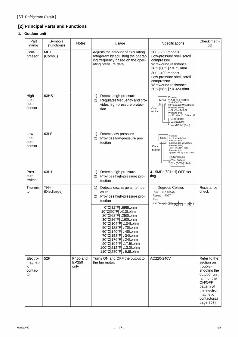
[ VI Refrigerant Circuit ]
- 117 -HWE10050 GB
[2] Principal Parts and Functions1. Outdoor unit
Part name
Symbols (functions) Notes Usage Specifications Check meth-
od
Com-pressor
MC1(Comp1)
Adjusts the amount of circulating refrigerant by adjusting the operat-ing frequency based on the oper-ating pressure data
200 - 250 modelsLow-pressure shell scroll compressorWirewound resistance20°C[68°F] : 0.71 ohm300 - 400 modelsLow-pressure shell scroll compressorWirewound resistance20°C[68°F] : 0.323 ohm
High pres-sure sensor
63HS1 1) Detects high pressure2) Regulates frequency and pro-
vides high-pressure protec-tion
Low pres-sure sensor
63LS 1) Detects low pressure2) Provides low-pressure pro-
tection
Pres-sure switch
63H1 1) Detects high pressure2) Provides high-pressure pro-
tection
4.15MPa[601psi] OFF set-ting
Thermis-tor
TH4(Discharge)
1) Detects discharge air temper-ature
2) Provides high-pressure pro-tection
Degrees Celsius Resistance check
0°C[32°F] :698kohm 10°C[50°F] :413kohm 20°C[68°F] :250kohm 30°C[86°F] :160kohm 40°C[104°F] :104kohm 50°C[122°F] : 70kohm 60°C[140°F] : 48kohm 70°C[158°F] : 34kohm 80°C[176°F] : 24kohm 90°C[194°F] :17.5kohm100°C[212°F] :13.0kohm110°C[230°F] : 9.8kohm
Electro-magnet-ic contac-tor
52F P450 and EP350 only
Turns ON and OFF the output to the fan motor.
AC220-240V Refer to the section on trouble-shooting the outdoor unit fan for the ON/OFF pattern of the electro-magnetic contactors.(page 307)
Pressure0~4.15 MPa [601psi]Vout 0.5~3.5V0.071V/0.098 MPa [14psi]Pressure [MPa]=1.38 x Vout [V]-0.69Pressure [psi]=(1.38 x Vout [V] - 0.69) x 145
GND (Black)Vout (White)Vcc (DC5V) (Red)
Con-nector
63HS1
1
1 2 3
23
Pressure0~1.7 MPa [247psi]Vout 0.5~3.5V0.173V/0.098 MPa [14psi]Pressure [MPa]=0.566 x Vout [V] - 0.283Pressure [psi]=(0.566 x Vout [V] - 0.283) x 145
GND (Black)Vout (White)Vcc (DC5V) (Red)
Con-nector
63LS
1
1 2 3
23
R = 7.465k120
R = 4057R =7.465
25/120
t
4057 273 t1
3931exp
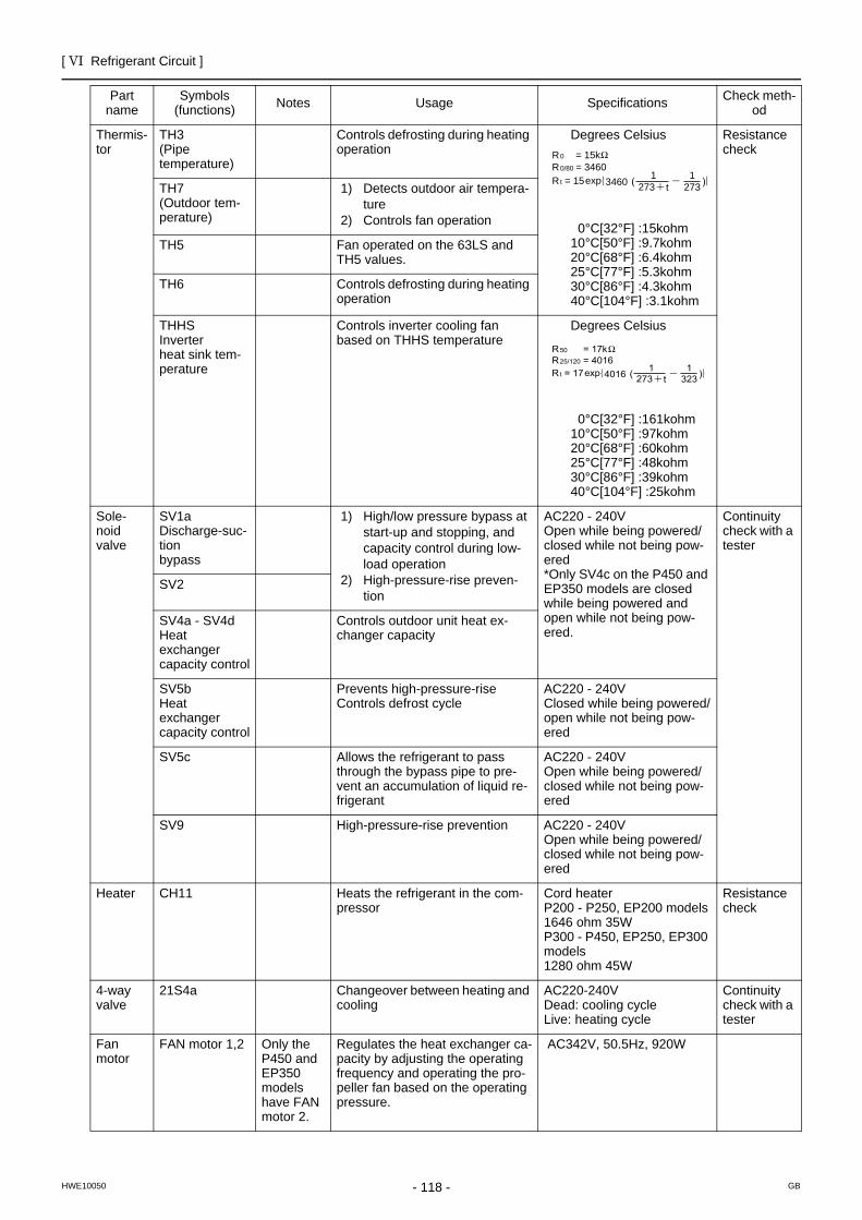
[ VI Refrigerant Circuit ]
- 118 -HWE10050 GB
Thermis-tor
TH3(Pipe temperature)
Controls defrosting during heating operation
Degrees Celsius
0°C[32°F] :15kohm10°C[50°F] :9.7kohm20°C[68°F] :6.4kohm25°C[77°F] :5.3kohm30°C[86°F] :4.3kohm40°C[104°F] :3.1kohm
Resistance check
TH7(Outdoor tem-perature)
1) Detects outdoor air tempera-ture
2) Controls fan operation
TH5 Fan operated on the 63LS and TH5 values.
TH6 Controls defrosting during heating operation
THHSInverter heat sink tem-perature
Controls inverter cooling fan based on THHS temperature
Degrees Celsius
0°C[32°F] :161kohm10°C[50°F] :97kohm20°C[68°F] :60kohm25°C[77°F] :48kohm30°C[86°F] :39kohm40°C[104°F] :25kohm
Sole-noid valve
SV1aDischarge-suc-tion bypass
1) High/low pressure bypass at start-up and stopping, and capacity control during low-load operation
2) High-pressure-rise preven-tion
AC220 - 240VOpen while being powered/closed while not being pow-ered*Only SV4c on the P450 and EP350 models are closed while being powered and open while not being pow-ered.
Continuity check with a tester
SV2
SV4a - SV4dHeat exchanger capacity control
Controls outdoor unit heat ex-changer capacity
SV5b Heat exchanger capacity control
Prevents high-pressure-riseControls defrost cycle
AC220 - 240VClosed while being powered/open while not being pow-ered
SV5c Allows the refrigerant to pass through the bypass pipe to pre-vent an accumulation of liquid re-frigerant
AC220 - 240VOpen while being powered/closed while not being pow-ered
SV9 High-pressure-rise prevention AC220 - 240VOpen while being powered/closed while not being pow-ered
Heater CH11 Heats the refrigerant in the com-pressor
Cord heater P200 - P250, EP200 models1646 ohm 35WP300 - P450, EP250, EP300 models1280 ohm 45W
Resistance check
4-way valve
21S4a Changeover between heating and cooling
AC220-240VDead: cooling cycle Live: heating cycle
Continuity check with a tester
Fanmotor
FAN motor 1,2 Only the P450 and EP350 models have FAN motor 2.
Regulates the heat exchanger ca-pacity by adjusting the operating frequency and operating the pro-peller fan based on the operating pressure.
AC342V, 50.5Hz, 920W
Part name
Symbols (functions) Notes Usage Specifications Check meth-
od
R = 15k0
R = 3460R = 15
0/80
t 3460 273 t1
2731exp
R = 17k50
R = 4016R = 17
25/120
t 4016 273 t1
3231exp
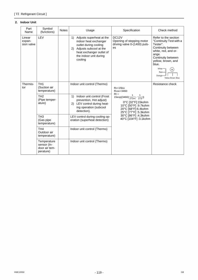
[ VI Refrigerant Circuit ]
- 119 -HWE10050 GB
2. Indoor Unit
Part Name
Symbol (functions) Notes Usage Specification Check method
Linear expan-sion valve
LEV 1) Adjusts superheat at the indoor heat exchanger outlet during cooling
2) Adjusts subcool at the heat exchanger outlet of the indoor unit during cooling
DC12VOpening of stepping motordriving valve 0-(1400) puls-es
Refer to the section "Continuity Test with a Tester". Continuity between white, red, and or-ange.Continuity between yellow, brown, and blue.
Thermis-tor
TH1 (Suction air temperature)
Indoor unit control (Thermo)
0°C [32°F]:15kohm 10°C [50°F] :9.7kohm 20°C [68°F]:6.4kohm 25°C [77°F] :5.3kohm 30°C [86°F] :4.3kohm 40°C [104°F] :3.1kohm
Resistance check
TH2 (Pipe temper-ature)
1) Indoor unit control (Frost prevention, Hot adjust)
2) LEV control during heat-ing operation (subcool detection).
TH3 (Gas pipe temperature)
LEV control during cooling op-eration (superheat detection)
TH4 Outdoor air temperature)
Indoor unit control (Thermo)
Temperature sensor (In-door air tem-perature)
Indoor unit control (Thermo)
Yellow
White
Red
Orange Brown Blue
M
1273+t
R0=15k R0/80=3460Rt =15exp{3460( - )}
1273
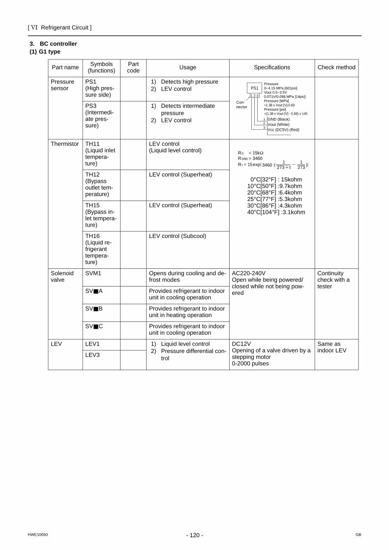
[ VI Refrigerant Circuit ]
- 120 -HWE10050 GB
3. BC controller(1) G1 type
Part name Symbols (functions)
Part code Usage Specifications Check method
Pressure sensor
PS1 (High pres-sure side)
1) Detects high pressure2) LEV control
PS3(Intermedi-ate pres-sure)
1) Detects intermediate pressure
2) LEV control
Thermistor TH11(Liquid inlet tempera-ture)
LEV control(Liquid level control)
0°C[32°F] : 15kohm 10°C[50°F] :9.7kohm 20°C[68°F] :6.4kohm 25°C[77°F] :5.3kohm 30°C[86°F] :4.3kohm 40°C[104°F] :3.1kohm
TH12(Bypass outlet tem-perature)
LEV control (Superheat)
TH15(Bypass in-let tempera-ture)
LEV control (Superheat)
TH16 (Liquid re-frigerant tempera-ture)
LEV control (Subcool)
Solenoid valve
SVM1 Opens during cooling and de-frost modes
AC220-240VOpen while being powered/closed while not being pow-ered
Continuity check with a tester
SV A Provides refrigerant to indoor unit in cooling operation
SV B Provides refrigerant to indoor unit in heating operation
SV C Provides refrigerant to indoor unit in cooling operation
LEV LEV1 1) Liquid level control2) Pressure differential con-
trol
DC12VOpening of a valve driven by a stepping motor 0-2000 pulses
Same as indoor LEV
LEV3
Pressure0~4.15 MPa [601psi]Vout 0.5~3.5V0.071V/0.098 MPa [14psi]Pressure [MPa]=1.38 x Vout [V]-0.69Pressure [psi]=(1.38 x Vout [V] - 0.69) x 145
GND (Black)Vout (White)Vcc (DC5V) (Red)
Con-nector
PS1
1
1 2 3
23
R = 15k0
R = 3460R = 15
0/80
t 3460 273 t1
2731exp
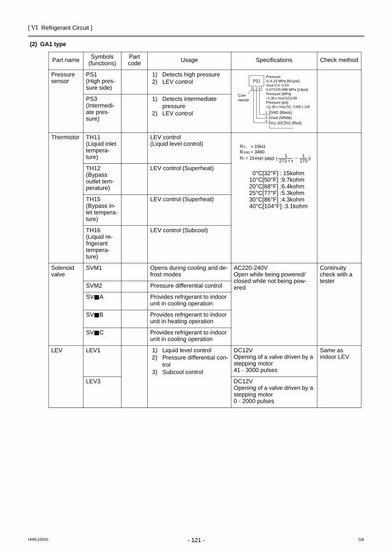
[ VI Refrigerant Circuit ]
- 121 -HWE10050 GB
(2) GA1 type
Part name Symbols (functions)
Part code Usage Specifications Check method
Pressure sensor
PS1 (High pres-sure side)
1) Detects high pressure2) LEV control
PS3(Intermedi-ate pres-sure)
1) Detects intermediate pressure
2) LEV control
Thermistor TH11(Liquid inlet tempera-ture)
LEV control(Liquid level control)
0°C[32°F] : 15kohm 10°C[50°F] :9.7kohm 20°C[68°F] :6.4kohm 25°C[77°F] :5.3kohm 30°C[86°F] :4.3kohm 40°C[104°F] :3.1kohm
TH12(Bypass outlet tem-perature)
LEV control (Superheat)
TH15(Bypass in-let tempera-ture)
LEV control (Superheat)
TH16 (Liquid re-frigerant tempera-ture)
LEV control (Subcool)
Solenoid valve
SVM1 Opens during cooling and de-frost modes
AC220-240VOpen while being powered/closed while not being pow-ered
Continuity check with a tester
SVM2 Pressure differential control
SV A Provides refrigerant to indoor unit in cooling operation
SV B Provides refrigerant to indoor unit in heating operation
SV C Provides refrigerant to indoor unit in cooling operation
LEV LEV1 1) Liquid level control2) Pressure differential con-
trol3) Subcool control
DC12VOpening of a valve driven by a stepping motor 41 - 3000 pulses
Same as indoor LEV
LEV3 DC12VOpening of a valve driven by a stepping motor 0 - 2000 pulses
Pressure0~4.15 MPa [601psi]Vout 0.5~3.5V0.071V/0.098 MPa [14psi]Pressure [MPa]=1.38 x Vout [V]-0.69Pressure [psi]=(1.38 x Vout [V] - 0.69) x 145
GND (Black)Vout (White)Vcc (DC5V) (Red)
Con-nector
PS1
1
1 2 3
23
R = 15k0
R = 3460R = 15
0/80
t 3460 273 t1
2731exp
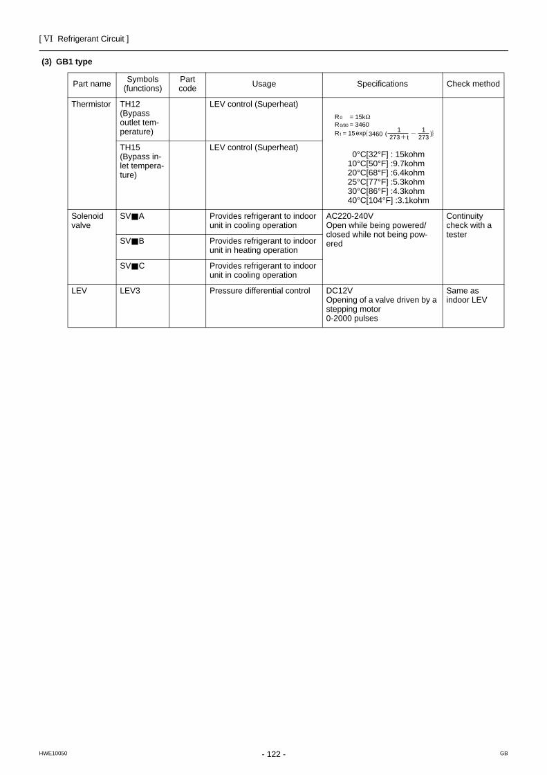
[ VI Refrigerant Circuit ]
- 122 -HWE10050 GB
(3) GB1 type
Part name Symbols (functions)
Part code Usage Specifications Check method
Thermistor TH12(Bypass outlet tem-perature)
LEV control (Superheat)
0°C[32°F] : 15kohm 10°C[50°F] :9.7kohm 20°C[68°F] :6.4kohm 25°C[77°F] :5.3kohm 30°C[86°F] :4.3kohm 40°C[104°F] :3.1kohm
TH15(Bypass in-let tempera-ture)
LEV control (Superheat)
Solenoid valve
SV A Provides refrigerant to indoor unit in cooling operation
AC220-240VOpen while being powered/closed while not being pow-ered
Continuity check with a tester
SV B Provides refrigerant to indoor unit in heating operation
SV C Provides refrigerant to indoor unit in cooling operation
LEV LEV3 Pressure differential control DC12VOpening of a valve driven by a stepping motor 0-2000 pulses
Same as indoor LEV
R = 15k0
R = 3460R = 15
0/80
t 3460 273 t1
2731exp
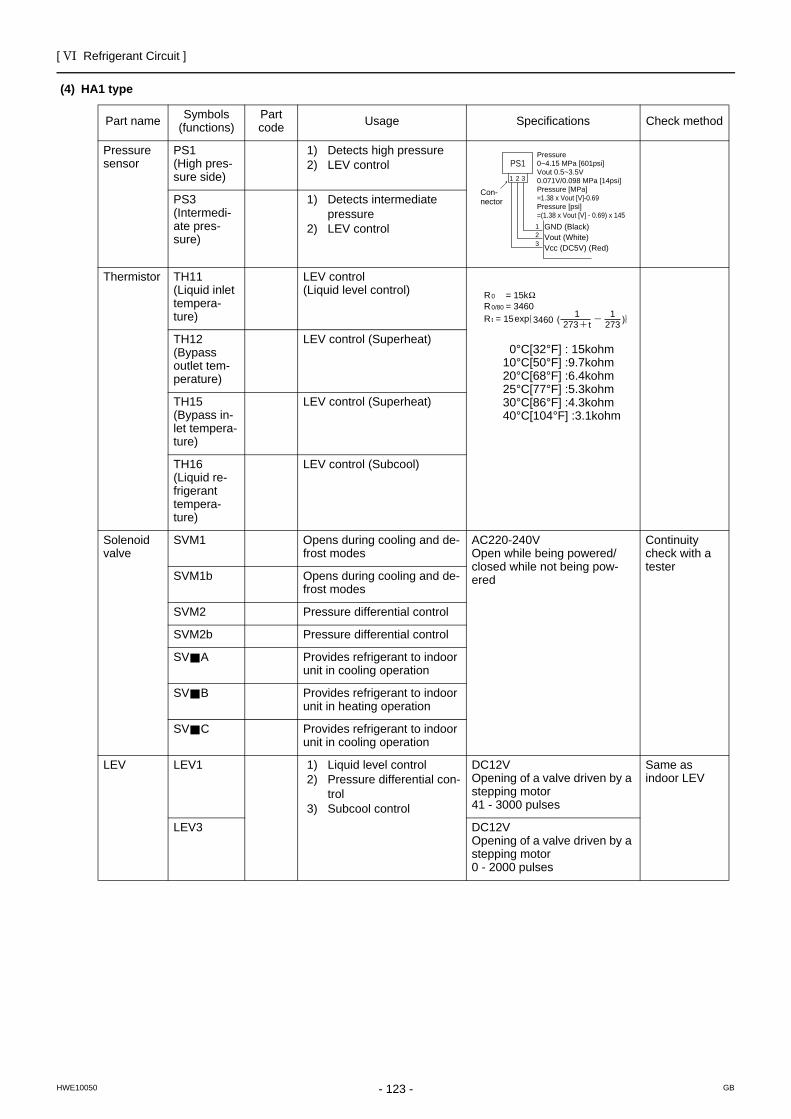
[ VI Refrigerant Circuit ]
- 123 -HWE10050 GB
(4) HA1 type
Part name Symbols (functions)
Part code Usage Specifications Check method
Pressure sensor
PS1 (High pres-sure side)
1) Detects high pressure2) LEV control
PS3(Intermedi-ate pres-sure)
1) Detects intermediate pressure
2) LEV control
Thermistor TH11(Liquid inlet tempera-ture)
LEV control(Liquid level control)
0°C[32°F] : 15kohm 10°C[50°F] :9.7kohm 20°C[68°F] :6.4kohm 25°C[77°F] :5.3kohm 30°C[86°F] :4.3kohm 40°C[104°F] :3.1kohm
TH12(Bypass outlet tem-perature)
LEV control (Superheat)
TH15(Bypass in-let tempera-ture)
LEV control (Superheat)
TH16 (Liquid re-frigerant tempera-ture)
LEV control (Subcool)
Solenoid valve
SVM1 Opens during cooling and de-frost modes
AC220-240VOpen while being powered/closed while not being pow-ered
Continuity check with a tester
SVM1b Opens during cooling and de-frost modes
SVM2 Pressure differential control
SVM2b Pressure differential control
SV A Provides refrigerant to indoor unit in cooling operation
SV B Provides refrigerant to indoor unit in heating operation
SV C Provides refrigerant to indoor unit in cooling operation
LEV LEV1 1) Liquid level control2) Pressure differential con-
trol3) Subcool control
DC12VOpening of a valve driven by a stepping motor 41 - 3000 pulses
Same as indoor LEV
LEV3 DC12VOpening of a valve driven by a stepping motor 0 - 2000 pulses
Pressure0~4.15 MPa [601psi]Vout 0.5~3.5V0.071V/0.098 MPa [14psi]Pressure [MPa]=1.38 x Vout [V]-0.69Pressure [psi]=(1.38 x Vout [V] - 0.69) x 145
GND (Black)Vout (White)Vcc (DC5V) (Red)
Con-nector
PS1
1
1 2 3
23
R = 15k0
R = 3460R = 15
0/80
t 3460 273 t1
2731exp

[ VI Refrigerant Circuit ]
- 124 -HWE10050 GB
(5) HB1 type
Part name Symbols (functions)
Part code Usage Specifications Check method
Thermistor TH12(Bypass outlet tem-perature)
LEV control (Superheat)
0°C[32°F] : 15kohm 10°C[50°F] :9.7kohm 20°C[68°F] :6.4kohm 25°C[77°F] :5.3kohm 30°C[86°F] :4.3kohm 40°C[104°F] :3.1kohm
TH15(Bypass in-let tempera-ture)
LEV control (Superheat)
Solenoid valve
SV A Provides refrigerant to indoor unit in cooling operation
AC220-240VOpen while being powered/closed while not being pow-ered
Continuity check with a tester
SV B Provides refrigerant to indoor unit in heating operation
SV C Provides refrigerant to indoor unit in cooling operation
LEV LEV3 Pressure differential control DC12VOpening of a valve driven by a stepping motor 0-2000 pulses
Same as indoor LEV
R = 15k0
R = 3460R = 15
0/80
t 3460 273 t1
2731exp
- 125 -HWE10050 GB
VII Control
[1] Functions and Factory Settings of the Dipswitches .......................................................127[2] Controlling the Outdoor Unit ..........................................................................................133[3] Controlling BC Controller ...............................................................................................147[4] Operation Flow Chart.....................................................................................................148

- 126 -
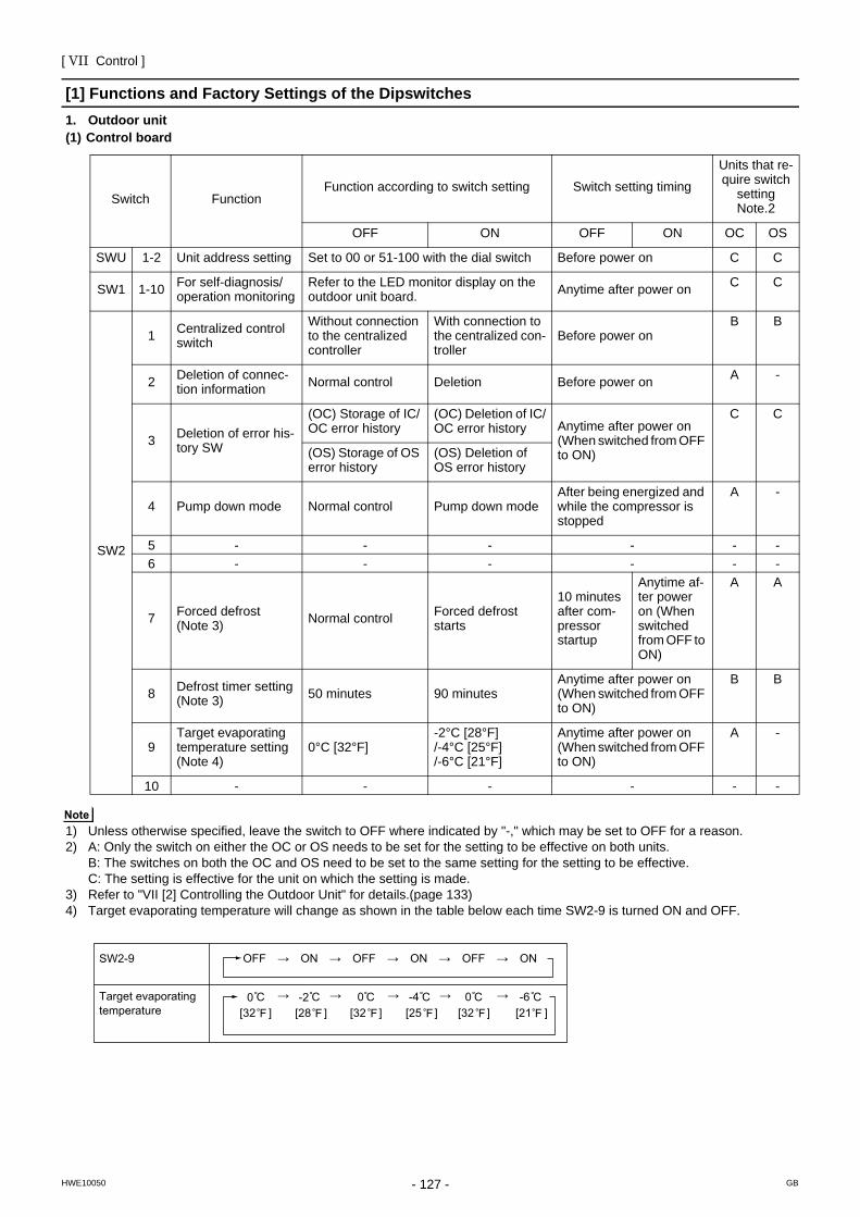
[ VII Control ]
- 127 -HWE10050 GB
VII Control
[1] Functions and Factory Settings of the Dipswitches1. Outdoor unit(1) Control board
1) Unless otherwise specified, leave the switch to OFF where indicated by "-," which may be set to OFF for a reason.2) A: Only the switch on either the OC or OS needs to be set for the setting to be effective on both units.
B: The switches on both the OC and OS need to be set to the same setting for the setting to be effective. C: The setting is effective for the unit on which the setting is made.
3) Refer to "VII [2] Controlling the Outdoor Unit" for details.(page 133)4) Target evaporating temperature will change as shown in the table below each time SW2-9 is turned ON and OFF.
Switch FunctionFunction according to switch setting Switch setting timing
Units that re-quire switch
setting Note.2
OFF ON OFF ON OC OS
SWU 1-2 Unit address setting Set to 00 or 51-100 with the dial switch Before power on C C
SW1 1-10 For self-diagnosis/operation monitoring
Refer to the LED monitor display on the outdoor unit board. Anytime after power on C C
SW2
1 Centralized control switch
Without connection to the centralized controller
With connection to the centralized con-troller
Before power onB B
2 Deletion of connec-tion information Normal control Deletion Before power on A -
3 Deletion of error his-tory SW
(OC) Storage of IC/OC error history
(OC) Deletion of IC/OC error history Anytime after power on
(When switched from OFF to ON)
C C
(OS) Storage of OS error history
(OS) Deletion of OS error history
4 Pump down mode Normal control Pump down modeAfter being energized and while the compressor is stopped
A -
5 - - - - - -6 - - - - - -
7 Forced defrost(Note 3) Normal control Forced defrost
starts
10 minutes after com-pressor startup
Anytime af-ter power on (When switched from OFF to ON)
A A
8 Defrost timer setting(Note 3) 50 minutes 90 minutes
Anytime after power on (When switched from OFF to ON)
B B
9Target evaporating temperature setting(Note 4)
0°C [32°F] -2°C [28°F] /-4°C [25°F] /-6°C [21°F]
Anytime after power on (When switched from OFF to ON)
A -
10 - - - - - -
SW2-9 OFF → ON → OFF → ON → OFF → ON
Target evaporatingtemperature
0 [32 ] [32 ] [32 ][25 ]
-2[28 ]
0 0-4[21 ]-6
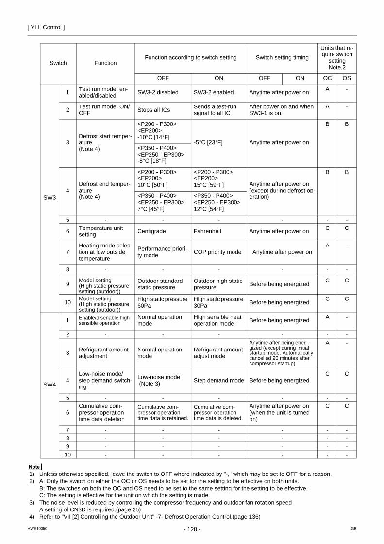
[ VII Control ]
- 128 -HWE10050 GB
1) Unless otherwise specified, leave the switch to OFF where indicated by "-," which may be set to OFF for a reason.2) A: Only the switch on either the OC or OS needs to be set for the setting to be effective on both units.
B: The switches on both the OC and OS need to be set to the same setting for the setting to be effective. C: The setting is effective for the unit on which the setting is made.
3) The noise level is reduced by controlling the compressor frequency and outdoor fan rotation speedA setting of CN3D is required.(page 25)
4) Refer to "VII [2] Controlling the Outdoor Unit" -7- Defrost Operation Control.(page 136)
Switch FunctionFunction according to switch setting Switch setting timing
Units that re-quire switch
setting Note.2
OFF ON OFF ON OC OS
SW3
1 Test run mode: en-abled/disabled SW3-2 disabled SW3-2 enabled Anytime after power on A -
2 Test run mode: ON/OFF Stops all ICs Sends a test-run
signal to all ICAfter power on and when SW3-1 is on.
A -
3Defrost start temper-ature (Note 4)
<P200 - P300><EP200>-10°C [14°F]
-5°C [23°F] Anytime after power on
B B
<P350 - P400><EP250 - EP300>-8°C [18°F]
4Defrost end temper-ature(Note 4)
<P200 - P300><EP200>10°C [50°F]
<P200 - P300><EP200>15°C [59°F] Anytime after power on
(except during defrost op-eration)
B B
<P350 - P400><EP250 - EP300>7°C [45°F]
<P350 - P400><EP250 - EP300>12°C [54°F]
5 - - - - - -
6 Temperature unitsetting Centigrade Fahrenheit Anytime after power on C C
7Heating mode selec-tion at low outside temperature
Performance priori-ty mode COP priority mode Anytime after power on
A -
8 - - - - - -
9Model setting(High static pressure setting (outdoor))
Outdoor standard static pressure
Outdoor high static pressure Before being energized C C
10Model setting(High static pressure setting (outdoor))
High static pressure 60Pa
High static pressure 30Pa Before being energized C C
SW4
1 Enable/disenable high sensible operation
Normal operation mode
High sensible heat operation mode Before being energized A -
2 - - - - - -
3 Refrigerant amount adjustment
Normal operation mode
Refrigerant amount adjust mode
Anytime after being ener-gized (except during initial startup mode. Automatically cancelled 90 minutes after compressor startup)
A -
4Low-noise mode/step demand switch-ing
Low-noise mode (Note 3) Step demand mode Before being energized
C C
5 - - - - - -
6Cumulative com-pressor operation time data deletion
Cumulative com-pressor operation time data is retained.
Cumulative com-pressor operation time data is deleted.
Anytime after power on (when the unit is turned on)
C C
7 - - - - - -8 - - - - - -9 - - - - - -10 - - - - - -
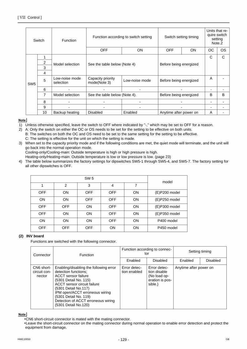
[ VII Control ]
- 129 -HWE10050 GB
1) Unless otherwise specified, leave the switch to OFF where indicated by "-," which may be set to OFF for a reason.2) A: Only the switch on either the OC or OS needs to be set for the setting to be effective on both units.
B: The switches on both the OC and OS need to be set to the same setting for the setting to be effective. C: The setting is effective for the unit on which the setting is made.
3) When set to the capacity priority mode and if the following conditions are met, the quiet mode will terminate, and the unit will go back into the normal operation mode. Cooling-only/Cooling-main: Outside temperature is high or high pressure is high.Heating-only/Heating-main: Outside temperature is low or low pressure is low. (page 23)
4) The table below summarizes the factory settings for dipswitches SW5-1 through SW5-4, and SW5-7. The factory setting for all other dipswitches is OFF.
(2) INV boardFunctions are switched with the following connector.
CN6 short-circuit connector is mated with the mating connector. Leave the short-circuit connector on the mating connector during normal operation to enable error detection and protect the equipment from damage.
Switch FunctionFunction according to switch setting Switch setting timing
Units that re-quire switch
setting Note.2
OFF ON OFF ON OC OS
SW5
1
Model selection See the table below (Note 4) Before being energized
C C234
5 Low-noise mode selection
Capacity priority mode(Note 3) Low-noise mode Before being energized A -
6 - - - - - -7 Model selection See the table below (Note 4). Before being energized B B
8 - - - - - -9 - - - - - -
10 Backup heating Disabled Enabled Anytime after power on A -
SW 5model
1 2 3 4 7
OFF ON OFF OFF ON (E)P200 model
ON ON OFF OFF ON (E)P250 model
OFF OFF ON OFF ON (E)P300 model
OFF ON ON OFF ON (E)P350 model
ON ON ON OFF ON P400 model
OFF OFF OFF ON ON P450 model
Connector FunctionFunction according to connec-
tor Setting timing
Enabled Disabled Enabled Disabled
CN6 short-circuit con-
nector
Enabling/disabling the following error detection functions;ACCT sensor failure(5301 Detail No. 115)ACCT sensor circuit failure(5301 Detail No.117)IPM open/ACCT erroneous wiring(5301 Detail No. 119)Detection of ACCT erroneous wiring(5301 Detail No.120)
Error detec-tion enabled
Error detec-tion disable(No load op-eration is pos-sible.)
Anytime after power on
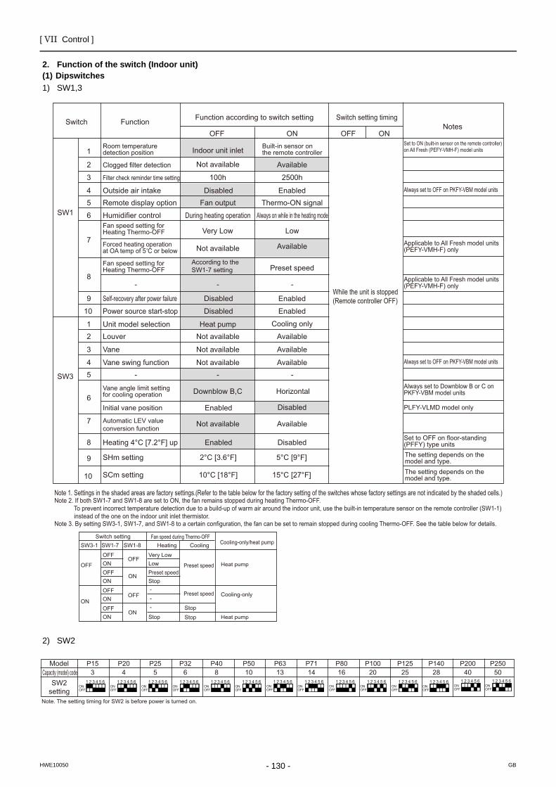
[ VII Control ]
- 130 -HWE10050 GB
2. Function of the switch (Indoor unit)(1) Dipswitches1) SW1,3
2) SW2
SW3-1
OFF
OFFOFF
ON
ON
ON
OFF
ON
OFFONOFFONOFFON
Very LowLowPreset speed
Preset speed
Preset speed
Stop
StopStopStop
Switch settingSW1-7 SW1-8 Heating Cooling Cooling-only/heat pump
Heat pump
Cooling-only
Heat pump
Fan speed during Thermo-OFF
Note 2. If both SW1-7 and SW1-8 are set to ON, the fan remains stopped during heating Thermo-OFF. To prevent incorrect temperature detection due to a build-up of warm air around the indoor unit, use the built-in temperature sensor on the remote controller (SW1-1) instead of the one on the indoor unit inlet thermistor.Note 3. By setting SW3-1, SW1-7, and SW1-8 to a certain configuration, the fan can be set to remain stopped during cooling Thermo-OFF. See the table below for details.
Switch Function Function according to switch setting
OFF ON
Switch setting timing
OFF ONNotes
SW1
SW3
1
2
3
45
6
7
8
9
10
9
10
12
3
45
6
7
8
Room temperature detection position
Clogged filter detection
Filter check reminder time setting
Outside air intakeRemote display option
Humidifier control
Self-recovery after power failure
Fan speed setting for Heating Thermo-OFF
Power source start-stop
Unit model selectionLouver
Vane
Vane swing function-
Vane angle limit setting for cooling operation
Initial vane position
Heating 4°C [7.2°F] up
Automatic LEV value conversion function
Indoor unit inlet
100h
DisabledFan output
2500h
EnabledThermo-ON signal
Built-in sensor on the remote controller
Available
During heating operation
According to the SW1-7 setting
Heat pump
Always on while in the heating modeFan speed setting for Heating Thermo-OFF Very Low Low
Preset speed
Cooling only
Enabled
Enabled
Disabled
Disabled Enabled
Enabled
Not available Available
Not available Available
Not available
Not available
AvailableNot available
Available
Not available Available
- -
- - -
Downblow B,C Horizontal
While the unit is stopped (Remote controller OFF)
Always set to OFF on PKFY-VBM model units
Set to ON (built-in sensor on the remote controller) on All Fresh (PEFY-VMH-F) model units
Applicable to All Fresh model units(PEFY-VMH-F) only
Applicable to All Fresh model units(PEFY-VMH-F) only
Always set to OFF on PKFY-VBM model units
PLFY-VLMD model only
Set to OFF on floor-standing (PFFY) type units
Always set to Downblow B or C on PKFY-VBM model units
Disabled
SHm setting 2°C [3.6°F]
10°C [18°F]
5°C [9°F]
15°C [27°F]
The setting depends on the model and type.The setting depends on the model and type.SCm setting
Disabled
Forced heating operation at OA temp of 5 C or below
---
Note 1. Settings in the shaded areas are factory settings.(Refer to the table below for the factory setting of the switches whose factory settings are not indicated by the shaded cells.)
ModelCapacity (model) code
SW2setting
Note. The setting timing for SW2 is before power is turned on.
1 2 3 4 5 6
P204
ONOFF
1 2 3 4 5 6
P153
ONOFF
P255
1 2 3 4 5 6ONOFF
P326
1 2 3 4 5 6ONOFF
P408
1 2 3 4 5 6ONOFF
P5010
1 2 3 4 5 6ONOFF
1 2 3 4 5 6
P6313
ONOFF
P7114
1 2 3 4 5 6ONOFF
P8016
1 2 3 4 5 6ONOFF
P10020
1 2 3 4 5 6ONOFF
P12525
1 2 3 4 5 6ONOFF
P20040
1 2 3 4 5 6ONOFF
P25050
1 2 3 4 5 6ONOFF
1 2 3 4 5 6
P14028
ONOFF
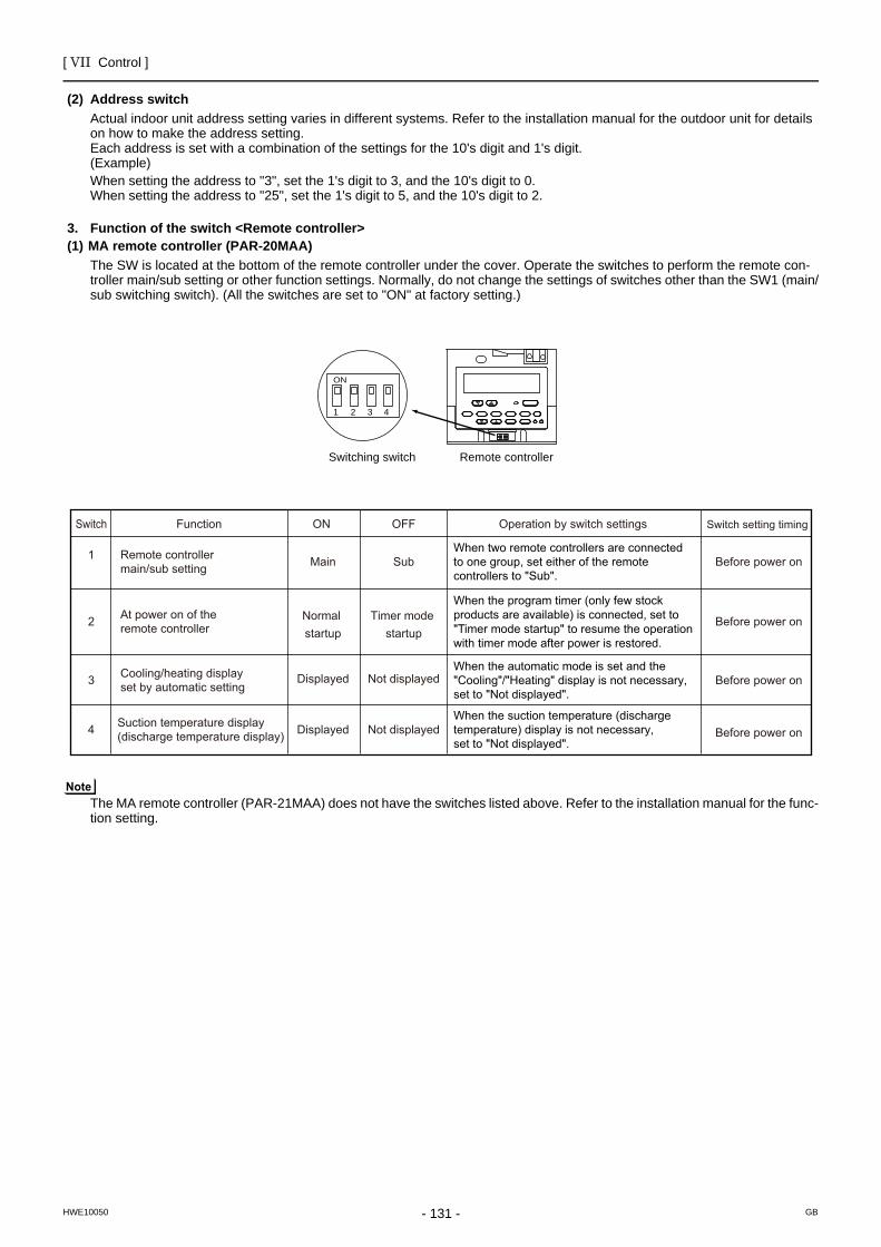
[ VII Control ]
- 131 -HWE10050 GB
(2) Address switchActual indoor unit address setting varies in different systems. Refer to the installation manual for the outdoor unit for details on how to make the address setting.Each address is set with a combination of the settings for the 10's digit and 1's digit.(Example)When setting the address to "3", set the 1's digit to 3, and the 10's digit to 0.When setting the address to "25", set the 1's digit to 5, and the 10's digit to 2.
3. Function of the switch <Remote controller>(1) MA remote controller (PAR-20MAA)
The SW is located at the bottom of the remote controller under the cover. Operate the switches to perform the remote con-troller main/sub setting or other function settings. Normally, do not change the settings of switches other than the SW1 (main/sub switching switch). (All the switches are set to "ON" at factory setting.)
The MA remote controller (PAR-21MAA) does not have the switches listed above. Refer to the installation manual for the func-tion setting.
Remote controllerSwitching switch
1
ON
2 3 4
Switch
2
1
Function
Remote controller main/sub setting
At power on of the remote controller
Normalstartup
Timer mode startup
3 Cooling/heating display set by automatic setting
Displayed Not displayed
4 Suction temperature display (discharge temperature display) Displayed Not displayed
Operation by switch settings Switch setting timingON OFF
Main Sub
Before power on
Before power on
Before power on
Before power onWhen two remote controllers are connected to one group, set either of the remote controllers to "Sub".
When the program timer (only few stockproducts are available) is connected, set to "Timer mode startup" to resume the operation with timer mode after power is restored.
When the automatic mode is set and the "Cooling"/"Heating" display is not necessary, set to "Not displayed".
When the suction temperature (discharge temperature) display is not necessary, set to "Not displayed".
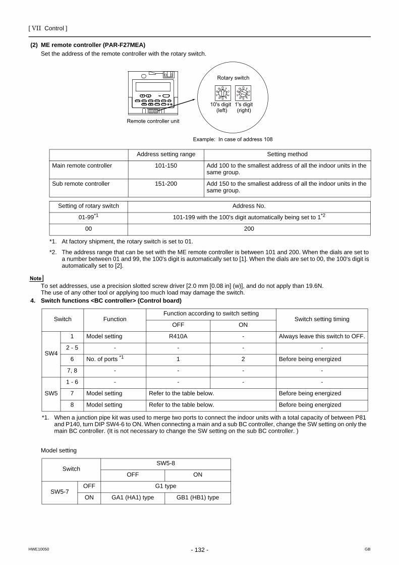
[ VII Control ]
- 132 -HWE10050 GB
(2) ME remote controller (PAR-F27MEA)Set the address of the remote controller with the rotary switch.
To set addresses, use a precision slotted screw driver [2.0 mm [0.08 in] (w)], and do not apply than 19.6N. The use of any other tool or applying too much load may damage the switch.
4. Switch functions <BC controller> (Control board)
Model setting
0123456789 0123456789
012345678901234567
8 9
10's digit 1's digit(left) (right)
Remote controller unit
Rotary switch
Example: In case of address 108
Address setting range Setting method
Main remote controller 101-150 Add 100 to the smallest address of all the indoor units in the same group.
Sub remote controller 151-200 Add 150 to the smallest address of all the indoor units in the same group.
Setting of rotary switch Address No.
01-99*1 101-199 with the 100's digit automatically being set to 1*2
00 200
*1. At factory shipment, the rotary switch is set to 01.
*2. The address range that can be set with the ME remote controller is between 101 and 200. When the dials are set to a number between 01 and 99, the 100's digit is automatically set to [1]. When the dials are set to 00, the 100's digit is automatically set to [2].
Switch FunctionFunction according to switch setting
Switch setting timingOFF ON
SW4
1 Model setting R410A - Always leave this switch to OFF.
2 - 5 - - - -
6 No. of ports *1
*1. When a junction pipe kit was used to merge two ports to connect the indoor units with a total capacity of between P81 and P140, turn DIP SW4-6 to ON. When connecting a main and a sub BC controller, change the SW setting on only the main BC controller. (It is not necessary to change the SW setting on the sub BC controller. )
1 2 Before being energized
7, 8 - - - -
SW5
1 - 6 - - - -
7 Model setting Refer to the table below. Before being energized
8 Model setting Refer to the table below. Before being energized
SwitchSW5-8
OFF ON
SW5-7OFF G1 type
ON GA1 (HA1) type GB1 (HB1) type
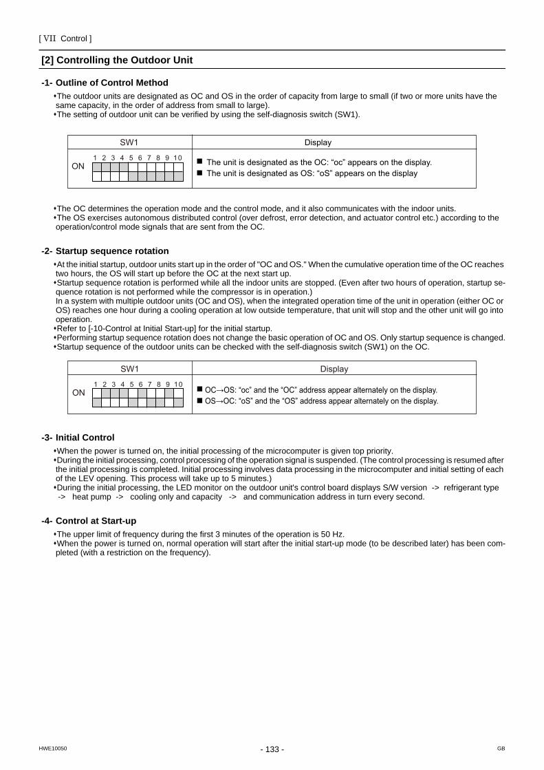
[ VII Control ]
- 133 -HWE10050 GB
[2] Controlling the Outdoor UnitOutline of Control Method
-1- Outline of Control MethodThe outdoor units are designated as OC and OS in the order of capacity from large to small (if two or more units have the same capacity, in the order of address from small to large).The setting of outdoor unit can be verified by using the self-diagnosis switch (SW1).
The OC determines the operation mode and the control mode, and it also communicates with the indoor units.The OS exercises autonomous distributed control (over defrost, error detection, and actuator control etc.) according to the operation/control mode signals that are sent from the OC.
Startup sequence rotation
-2- Startup sequence rotationAt the initial startup, outdoor units start up in the order of "OC and OS." When the cumulative operation time of the OC reaches two hours, the OS will start up before the OC at the next start up.Startup sequence rotation is performed while all the indoor units are stopped. (Even after two hours of operation, startup se-quence rotation is not performed while the compressor is in operation.)In a system with multiple outdoor units (OC and OS), when the integrated operation time of the unit in operation (either OC or OS) reaches one hour during a cooling operation at low outside temperature, that unit will stop and the other unit will go into operation.Refer to [-10-Control at Initial Start-up] for the initial startup.Performing startup sequence rotation does not change the basic operation of OC and OS. Only startup sequence is changed.Startup sequence of the outdoor units can be checked with the self-diagnosis switch (SW1) on the OC.
Initial Control
-3- Initial Control When the power is turned on, the initial processing of the microcomputer is given top priority.During the initial processing, control processing of the operation signal is suspended. (The control processing is resumed after the initial processing is completed. Initial processing involves data processing in the microcomputer and initial setting of each of the LEV opening. This process will take up to 5 minutes.)During the initial processing, the LED monitor on the outdoor unit's control board displays S/W version -> refrigerant type -> heat pump -> cooling only and capacity -> and communication address in turn every second.
Control at Start-up
-4- Control at Start-up The upper limit of frequency during the first 3 minutes of the operation is 50 Hz.When the power is turned on, normal operation will start after the initial start-up mode (to be described later) has been com-pleted (with a restriction on the frequency).
Display SW1
ON 1 2 3 5 4 6 7 8 9 10 The unit is designated as the OC: “oc” appears on the display.
The unit is designated as OS: “oS” appears on the display
Display SW1
OC→OS: “oc” and the “OC” address appear alternately on the display.OS→OC: “oS” and the “OS” address appear alternately on the display.
ON 1 2 3 5 4 6 7 8 9 10
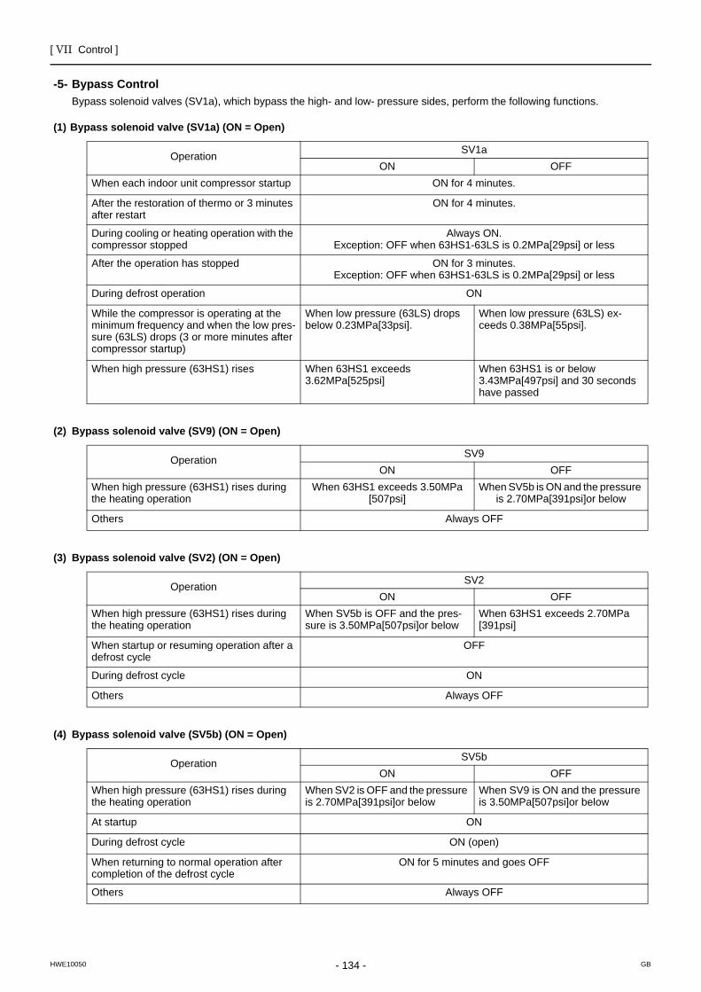
[ VII Control ]
- 134 -HWE10050 GB
Bypass Control
-5- Bypass ControlBypass solenoid valves (SV1a), which bypass the high- and low- pressure sides, perform the following functions.
(1) Bypass solenoid valve (SV1a) (ON = Open)
(2) Bypass solenoid valve (SV9) (ON = Open)
(3) Bypass solenoid valve (SV2) (ON = Open)
(4) Bypass solenoid valve (SV5b) (ON = Open)
Operation SV1aON OFF
When each indoor unit compressor startup ON for 4 minutes.
After the restoration of thermo or 3 minutes after restart
ON for 4 minutes.
During cooling or heating operation with the compressor stopped
Always ON. Exception: OFF when 63HS1-63LS is 0.2MPa[29psi] or less
After the operation has stopped ON for 3 minutes. Exception: OFF when 63HS1-63LS is 0.2MPa[29psi] or less
During defrost operation ON
While the compressor is operating at the minimum frequency and when the low pres-sure (63LS) drops (3 or more minutes after compressor startup)
When low pressure (63LS) drops below 0.23MPa[33psi].
When low pressure (63LS) ex-ceeds 0.38MPa[55psi].
When high pressure (63HS1) rises When 63HS1 exceeds 3.62MPa[525psi]
When 63HS1 is or below 3.43MPa[497psi] and 30 seconds have passed
Operation SV9ON OFF
When high pressure (63HS1) rises during the heating operation
When 63HS1 exceeds 3.50MPa [507psi]
When SV5b is ON and the pressure is 2.70MPa[391psi]or below
Others Always OFF
Operation SV2ON OFF
When high pressure (63HS1) rises during the heating operation
When SV5b is OFF and the pres-sure is 3.50MPa[507psi]or below
When 63HS1 exceeds 2.70MPa [391psi]
When startup or resuming operation after a defrost cycle
OFF
During defrost cycle ON
Others Always OFF
Operation SV5bON OFF
When high pressure (63HS1) rises during the heating operation
When SV2 is OFF and the pressure is 2.70MPa[391psi]or below
When SV9 is ON and the pressure is 3.50MPa[507psi]or below
At startup ON
During defrost cycle ON (open)
When returning to normal operation after completion of the defrost cycle
ON for 5 minutes and goes OFF
Others Always OFF
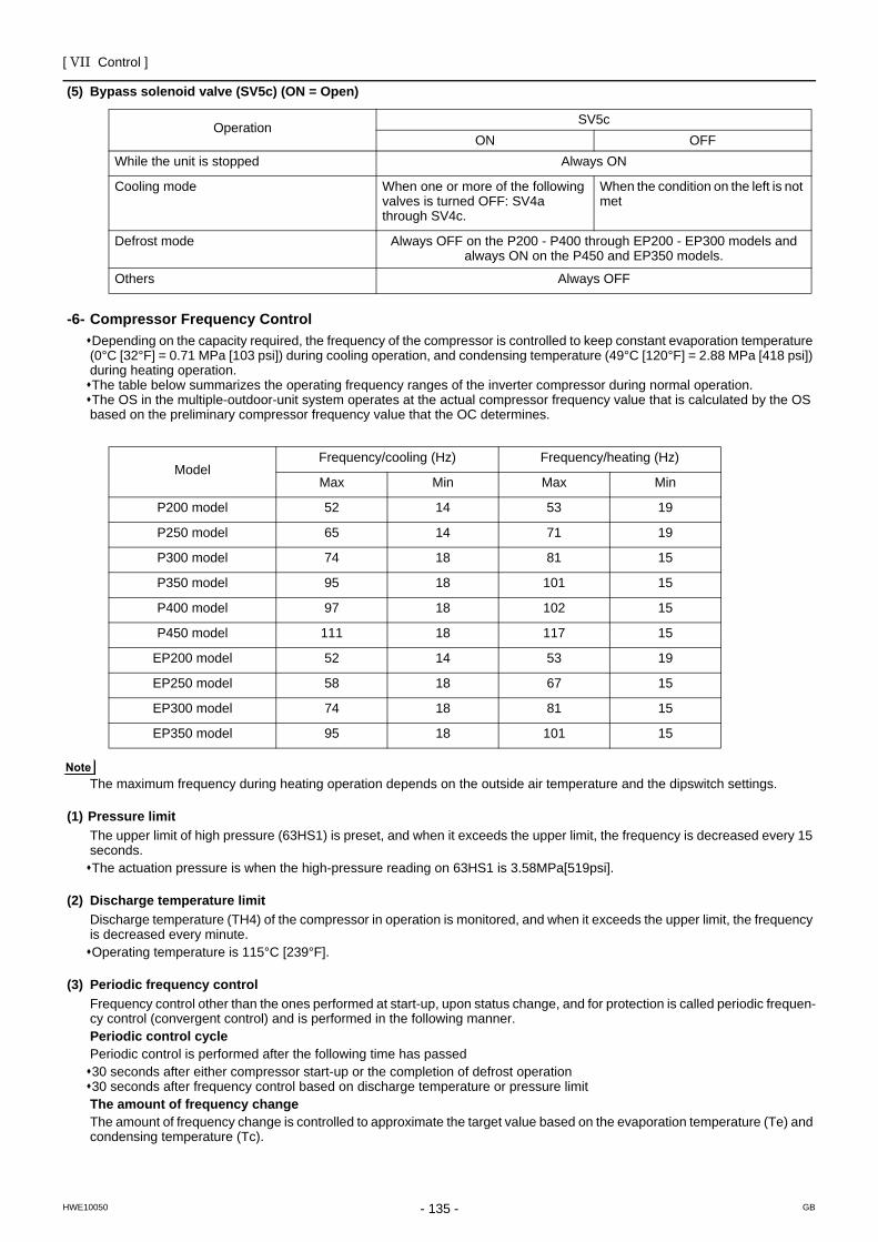
[ VII Control ]
- 135 -HWE10050 GB
(5) Bypass solenoid valve (SV5c) (ON = Open)
Compressor Frequency Control
-6- Compressor Frequency Control Depending on the capacity required, the frequency of the compressor is controlled to keep constant evaporation temperature (0°C [32°F] = 0.71 MPa [103 psi]) during cooling operation, and condensing temperature (49°C [120°F] = 2.88 MPa [418 psi]) during heating operation. The table below summarizes the operating frequency ranges of the inverter compressor during normal operation.The OS in the multiple-outdoor-unit system operates at the actual compressor frequency value that is calculated by the OS based on the preliminary compressor frequency value that the OC determines.
The maximum frequency during heating operation depends on the outside air temperature and the dipswitch settings.
(1) Pressure limitThe upper limit of high pressure (63HS1) is preset, and when it exceeds the upper limit, the frequency is decreased every 15 seconds.The actuation pressure is when the high-pressure reading on 63HS1 is 3.58MPa[519psi].
(2) Discharge temperature limitDischarge temperature (TH4) of the compressor in operation is monitored, and when it exceeds the upper limit, the frequency is decreased every minute.Operating temperature is 115°C [239°F].
(3) Periodic frequency controlFrequency control other than the ones performed at start-up, upon status change, and for protection is called periodic frequen-cy control (convergent control) and is performed in the following manner.Periodic control cyclePeriodic control is performed after the following time has passed30 seconds after either compressor start-up or the completion of defrost operation30 seconds after frequency control based on discharge temperature or pressure limitThe amount of frequency changeThe amount of frequency change is controlled to approximate the target value based on the evaporation temperature (Te) and condensing temperature (Tc).
Operation SV5cON OFF
While the unit is stopped Always ON
Cooling mode When one or more of the following valves is turned OFF: SV4a through SV4c.
When the condition on the left is not met
Defrost mode Always OFF on the P200 - P400 through EP200 - EP300 models and always ON on the P450 and EP350 models.
Others Always OFF
ModelFrequency/cooling (Hz) Frequency/heating (Hz)
Max Min Max Min
P200 model 52 14 53 19
P250 model 65 14 71 19
P300 model 74 18 81 15
P350 model 95 18 101 15
P400 model 97 18 102 15
P450 model 111 18 117 15
EP200 model 52 14 53 19
EP250 model 58 18 67 15
EP300 model 74 18 81 15
EP350 model 95 18 101 15
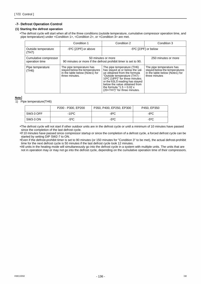
[ VII Control ]
- 136 -HWE10050 GB
Defrost Operation Control
-7- Defrost Operation Control(1) Starting the defrost operation
The defrost cycle will start when all of the three conditions (outside temperature, cumulative compressor operation time, and pipe temperature) under <Condition 1>, <Condition 2>, or <Condition 3> are met.
1) Pipe temperature(TH6)
The defrost cycle will not start if other outdoor units are in the defrost cycle or until a minimum of 10 minutes have passed since the completion of the last defrost cycle.If 10 minutes have passed since compressor startup or since the completion of a defrost cycle, a forced defrost cycle can be started by setting DIP SW2-7 to ON. Even if the defrost-prohibit timer is set to 90 minutes (or 150 minutes for "Condition 3" to be met), the actual defrost-prohibit time for the next defrost cycle is 50 minutes if the last defrost cycle took 12 minutes. All units in the heating mode will simultaneously go into the defrost cycle in a system with multiple units. The units that are not in operation may or may not go into the defrost cycle, depending on the cumulative operation time of their compressors.
Condition 1 Condition 2 Condition 3
Outside temperature (TH7)
-5ºC [23ºF] or above -5ºC [23ºF] or below
Cumulative compressor operation time
50 minutes or more 90 minutes or more if the defrost prohibit timer is set to 90.
250 minutes or more
Pipe temperature(TH6)
The pipe temperature has stayed below the temperatures in the table below (Note1) for three minutes.
The pipe temperature (TH6) has stayed at or below the val-ue obtained from the formula "Outside temperature (TH7) - 10ºC [18ºF]" for three minutes. or the 63LS reading has stayed below the value obtained from the formula "1.5 + 0.02 x (20+TH7)" for three minutes.
The pipe temperature has stayed below the temperatures in the table below (Note1) for three minutes
P200 - P300, EP200 P350, P400, EP250, EP300 P450, EP350
SW3-3 OFF -10ºC -8ºC -8ºC
SW3-3 ON -5ºC -5ºC -5ºC
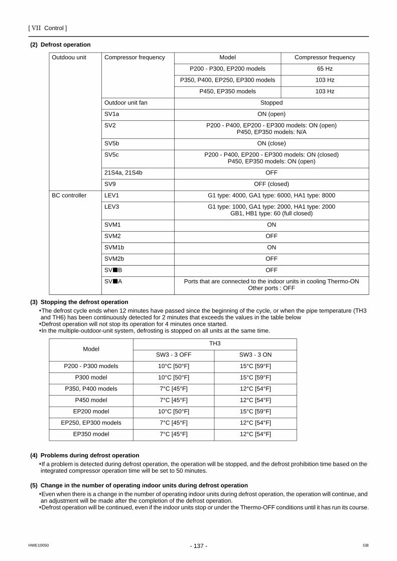
[ VII Control ]
- 137 -HWE10050 GB
(2) Defrost operation
(3) Stopping the defrost operationThe defrost cycle ends when 12 minutes have passed since the beginning of the cycle, or when the pipe temperature (TH3 and TH6) has been continuously detected for 2 minutes that exceeds the values in the table belowDefrost operation will not stop its operation for 4 minutes once started. In the multiple-outdoor-unit system, defrosting is stopped on all units at the same time.
(4) Problems during defrost operationIf a problem is detected during defrost operation, the operation will be stopped, and the defrost prohibition time based on the integrated compressor operation time will be set to 50 minutes.
(5) Change in the number of operating indoor units during defrost operationEven when there is a change in the number of operating indoor units during defrost operation, the operation will continue, and an adjustment will be made after the completion of the defrost operation.Defrost operation will be continued, even if the indoor units stop or under the Thermo-OFF conditions until it has run its course.
Outdoou unit Compressor frequency Model Compressor frequency
P200 - P300, EP200 models 65 Hz
P350, P400, EP250, EP300 models 103 Hz
P450, EP350 models 103 Hz
Outdoor unit fan Stopped
SV1a ON (open)
SV2 P200 - P400, EP200 - EP300 models: ON (open)P450, EP350 models: N/A
SV5b ON (close)
SV5c P200 - P400, EP200 - EP300 models: ON (closed)P450, EP350 models: ON (open)
21S4a, 21S4b OFF
SV9 OFF (closed)
BC controller LEV1 G1 type: 4000, GA1 type: 6000, HA1 type: 8000
LEV3 G1 type: 1000, GA1 type: 2000, HA1 type: 2000GB1, HB1 type: 60 (full closed)
SVM1 ON
SVM2 OFF
SVM1b ON
SVM2b OFF
SV B OFF
SV A Ports that are connected to the indoor units in cooling Thermo-ON Other ports : OFF
ModelTH3
SW3 - 3 OFF SW3 - 3 ON
P200 - P300 models 10°C [50°F] 15°C [59°F]
P300 model 10°C [50°F] 15°C [59°F]
P350, P400 models 7°C [45°F] 12°C [54°F]
P450 model 7°C [45°F] 12°C [54°F]
EP200 model 10°C [50°F] 15°C [59°F]
EP250, EP300 models 7°C [45°F] 12°C [54°F]
EP350 model 7°C [45°F] 12°C [54°F]
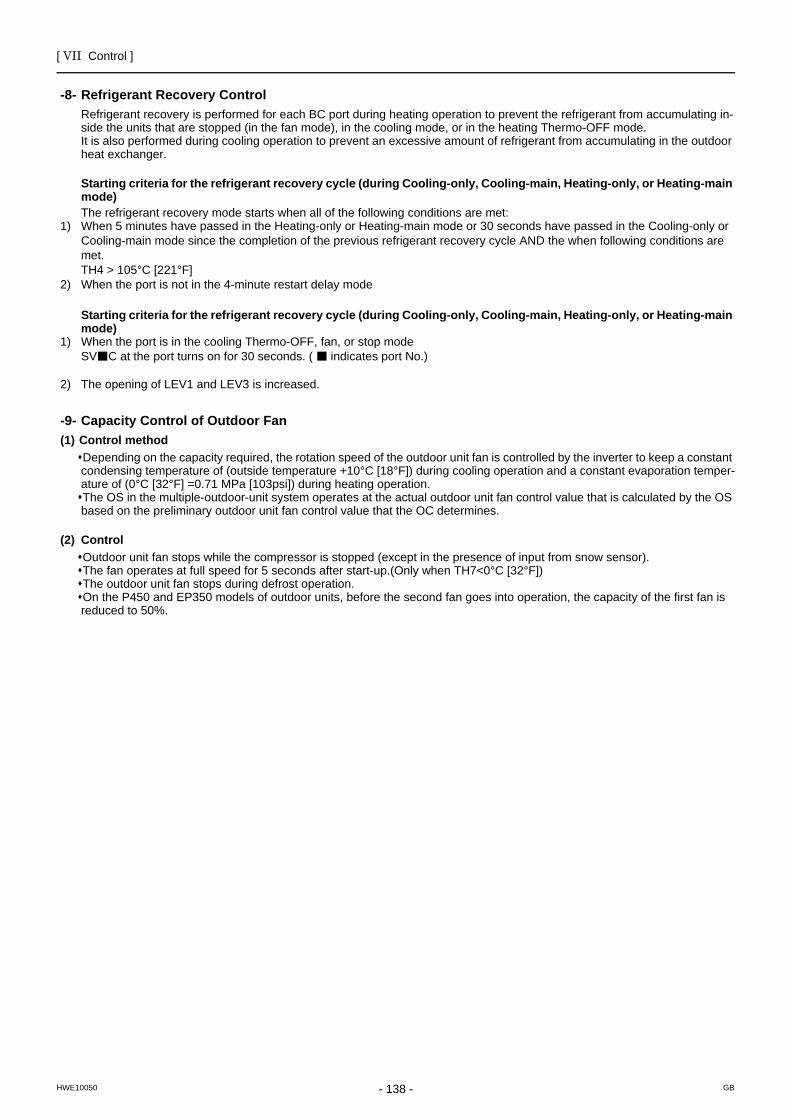
[ VII Control ]
- 138 -HWE10050 GB
Refrigerant Recovery Control
-8- Refrigerant Recovery Control Refrigerant recovery is performed for each BC port during heating operation to prevent the refrigerant from accumulating in-side the units that are stopped (in the fan mode), in the cooling mode, or in the heating Thermo-OFF mode.It is also performed during cooling operation to prevent an excessive amount of refrigerant from accumulating in the outdoor heat exchanger.
Starting criteria for the refrigerant recovery cycle (during Cooling-only, Cooling-main, Heating-only, or Heating-main mode)The refrigerant recovery mode starts when all of the following conditions are met:
1) When 5 minutes have passed in the Heating-only or Heating-main mode or 30 seconds have passed in the Cooling-only or Cooling-main mode since the completion of the previous refrigerant recovery cycle AND the when following conditions are met. TH4 > 105°C [221°F]
2) When the port is not in the 4-minute restart delay mode
Starting criteria for the refrigerant recovery cycle (during Cooling-only, Cooling-main, Heating-only, or Heating-main mode)
1) When the port is in the cooling Thermo-OFF, fan, or stop mode SV C at the port turns on for 30 seconds. ( indicates port No.)
2) The opening of LEV1 and LEV3 is increased.
Capacity Control of Outdoor Fan
-9- Capacity Control of Outdoor Fan(1) Control method
Depending on the capacity required, the rotation speed of the outdoor unit fan is controlled by the inverter to keep a constant condensing temperature of (outside temperature +10°C [18°F]) during cooling operation and a constant evaporation temper-ature of (0°C [32°F] =0.71 MPa [103psi]) during heating operation.The OS in the multiple-outdoor-unit system operates at the actual outdoor unit fan control value that is calculated by the OS based on the preliminary outdoor unit fan control value that the OC determines.
(2) ControlOutdoor unit fan stops while the compressor is stopped (except in the presence of input from snow sensor).The fan operates at full speed for 5 seconds after start-up.(Only when TH7<0°C [32°F])The outdoor unit fan stops during defrost operation.On the P450 and EP350 models of outdoor units, before the second fan goes into operation, the capacity of the first fan is reduced to 50%.
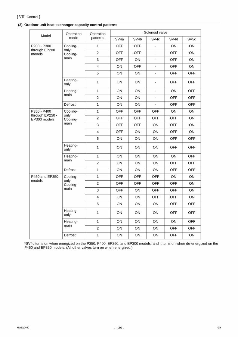
[ VII Control ]
- 139 -HWE10050 GB
(3) Outdoor unit heat exchanger capacity control patterns
*SV4c turns on when energized on the P350, P400, EP250, and EP300 models. and it turns on when de-energized on the P450 and EP350 models. (All other valves turn on when energized.)
Model Operation mode
Operation patterns
Solenoid valve
SV4a SV4b SV4c SV4d SV5c
P200 - P300 through EP200 models
Cooling-onlyCooling-main
1 OFF OFF - ON ON
2 OFF OFF - OFF ON
3 OFF ON - OFF ON
4 ON OFF - OFF ON
5 ON ON - OFF OFF
Heating-only 1 ON ON - OFF OFF
Heating-main
1 ON ON - ON OFF
2 ON ON - OFF OFF
Defrost 1 ON ON - OFF OFF
P350 - P400 through EP250 - EP300 models
Cooling-onlyCooling-main
1 OFF OFF OFF ON ON
2 OFF OFF OFF OFF ON
3 OFF OFF ON OFF ON
4 OFF ON ON OFF ON
5 ON ON ON OFF OFF
Heating-only 1 ON ON ON OFF OFF
Heating-main
1 ON ON ON ON OFF
2 ON ON ON OFF OFF
Defrost 1 ON ON ON OFF OFF
P450 and EP350 models
Cooling-onlyCooling-main
1 OFF OFF OFF ON ON
2 OFF OFF OFF OFF ON
3 OFF ON OFF OFF ON
4 ON ON OFF OFF ON
5 ON ON ON OFF OFF
Heating-only 1 ON ON ON OFF OFF
Heating-main
1 ON ON ON ON OFF
2 ON ON ON OFF OFF
Defrost 1 ON ON ON OFF ON
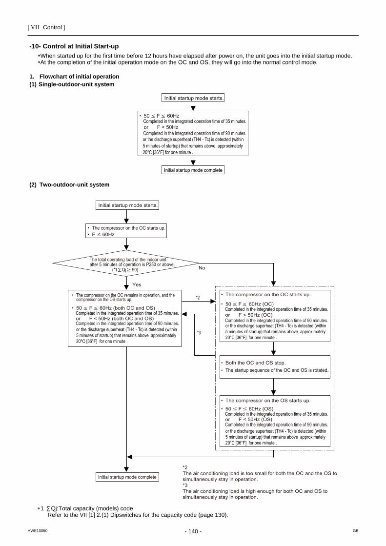
[ VII Control ]
- 140 -HWE10050 GB
Control at Initial Start-up
-10- Control at Initial Start-upWhen started up for the first time before 12 hours have elapsed after power on, the unit goes into the initial startup mode.At the completion of the initial operation mode on the OC and OS, they will go into the normal control mode.
1. Flowchart of initial operation(1) Single-outdoor-unit system
(2) Two-outdoor-unit system
∗1 Qj:Total capacity (models) code Refer to the VII [1] 2.(1) Dipswitches for the capacity code (page 130).
50 F 60Hz
or F < 50Hz
Initial startup mode starts.
Completed in the integrated operation time of 35 minutes.
Initial startup mode complete
or the discharge superheat (TH4 - Tc) is detected (within 5 minutes of startup) that remains above approximately 20°C [36°F] for one minute .
Completed in the integrated operation time of 90 minutes.
The compressor on the OC starts up.
The total operating load of the indoor unit after 5 minutes of operation is P250 or above.
(*1 Qj 50)
Initial startup mode starts.
F 60Hz
Yes
No
or F < 50Hz (both OC and OS)Completed in the integrated operation time of 90 minutes.
The compressor on the OC remains in operation, and the compressor on the OS starts up.
or F < 50Hz (OC)Completed in the integrated operation time of 90 minutes.
The compressor on the OC starts up.
Both the OC and OS stop.The startup sequence of the OC and OS is rotated.
or F < 50Hz (OS)Completed in the integrated operation time of 90 minutes.
The compressor on the OS starts up.
*2
*3
*2The air conditioning load is too small for both the OC and the OS tosimultaneously stay in operation.*3The air conditioning load is high enough for both OC and OS tosimultaneously stay in operation.
Initial startup mode complete
or the discharge superheat (TH4 - Tc) is detected (within 5 minutes of startup) that remains above approximately 20°C [36°F] for one minute .
or the discharge superheat (TH4 - Tc) is detected (within 5 minutes of startup) that remains above approximately 20°C [36°F] for one minute .
or the discharge superheat (TH4 - Tc) is detected (within 5 minutes of startup) that remains above approximately 20°C [36°F] for one minute .
50 F 60Hz (both OC and OS)Completed in the integrated operation time of 35 minutes.
50 F 60Hz (OC)Completed in the integrated operation time of 35 minutes.
50 F 60Hz (OS)Completed in the integrated operation time of 35 minutes.
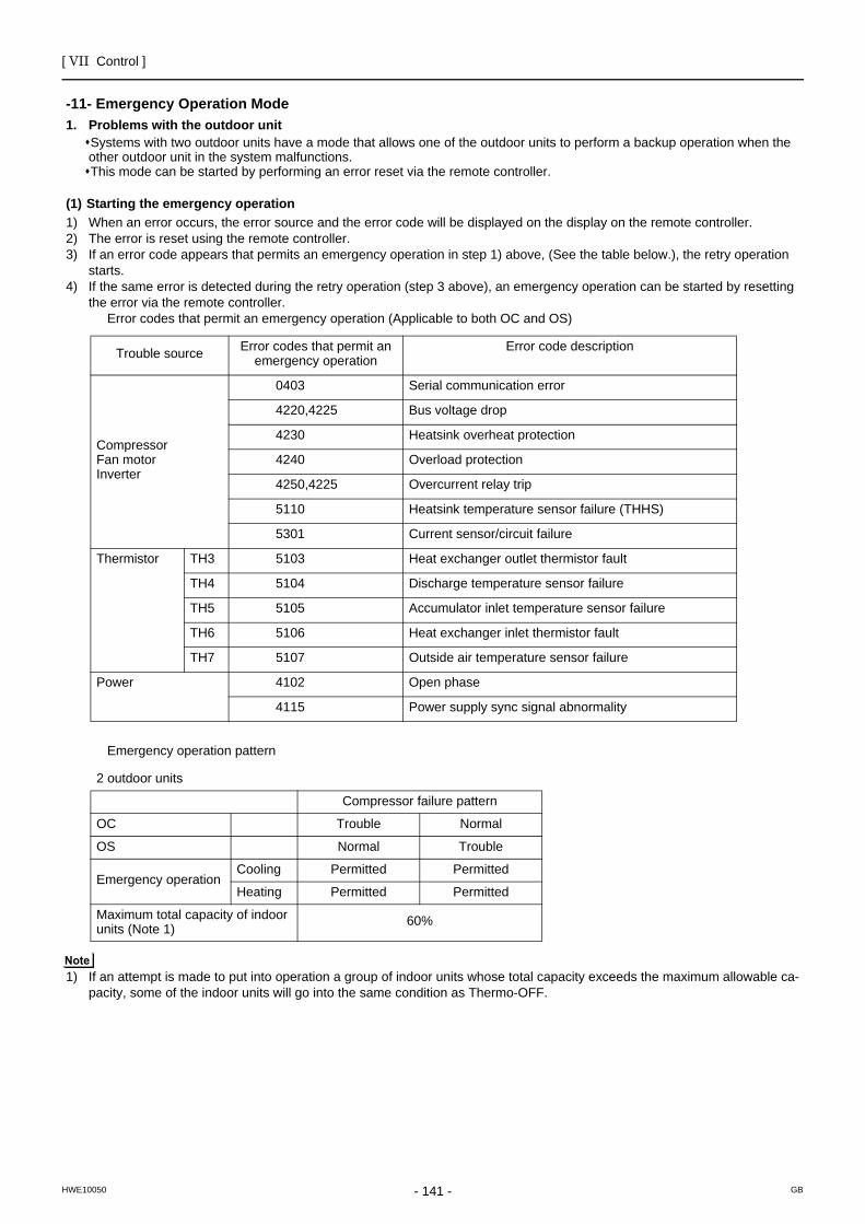
[ VII Control ]
- 141 -HWE10050 GB
Emergency Operation Mode
-11- Emergency Operation Mode1. Problems with the outdoor unit
Systems with two outdoor units have a mode that allows one of the outdoor units to perform a backup operation when the other outdoor unit in the system malfunctions.This mode can be started by performing an error reset via the remote controller.
(1) Starting the emergency operation1) When an error occurs, the error source and the error code will be displayed on the display on the remote controller.2) The error is reset using the remote controller.3) If an error code appears that permits an emergency operation in step 1) above, (See the table below.), the retry operation
starts.4) If the same error is detected during the retry operation (step 3 above), an emergency operation can be started by resetting
the error via the remote controller.Error codes that permit an emergency operation (Applicable to both OC and OS)
Emergency operation pattern
1) If an attempt is made to put into operation a group of indoor units whose total capacity exceeds the maximum allowable ca-pacity, some of the indoor units will go into the same condition as Thermo-OFF.
Trouble source Error codes that permit an emergency operation
Error code description
CompressorFan motorInverter
0403 Serial communication error
4220,4225 Bus voltage drop
4230 Heatsink overheat protection
4240 Overload protection
4250,4225 Overcurrent relay trip
5110 Heatsink temperature sensor failure (THHS)
5301 Current sensor/circuit failure
Thermistor TH3 5103 Heat exchanger outlet thermistor fault
TH4 5104 Discharge temperature sensor failure
TH5 5105 Accumulator inlet temperature sensor failure
TH6 5106 Heat exchanger inlet thermistor fault
TH7 5107 Outside air temperature sensor failure
Power 4102 Open phase
4115 Power supply sync signal abnormality
2 outdoor units
Compressor failure pattern
OC Trouble Normal
OS Normal Trouble
Emergency operationCooling Permitted Permitted
Heating Permitted Permitted
Maximum total capacity of indoor units (Note 1) 60%
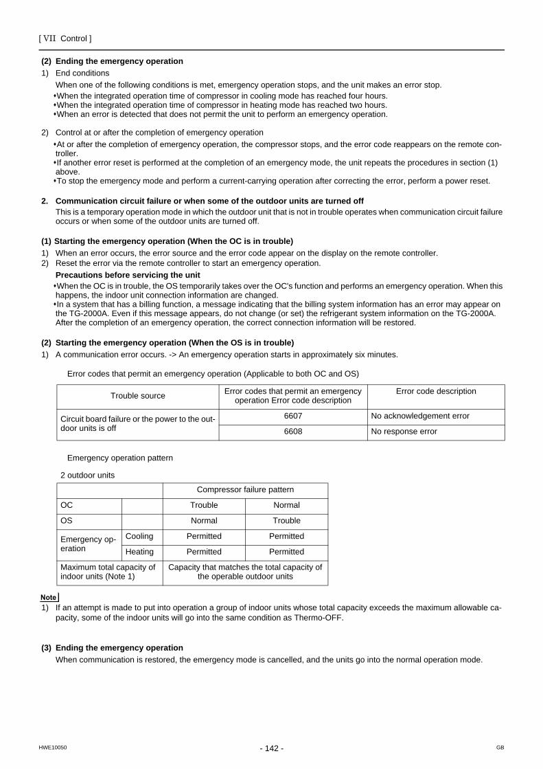
[ VII Control ]
- 142 -HWE10050 GB
(2) Ending the emergency operation1) End conditions
When one of the following conditions is met, emergency operation stops, and the unit makes an error stop.When the integrated operation time of compressor in cooling mode has reached four hours.When the integrated operation time of compressor in heating mode has reached two hours.When an error is detected that does not permit the unit to perform an emergency operation.
2) Control at or after the completion of emergency operationAt or after the completion of emergency operation, the compressor stops, and the error code reappears on the remote con-troller.If another error reset is performed at the completion of an emergency mode, the unit repeats the procedures in section (1) above.To stop the emergency mode and perform a current-carrying operation after correcting the error, perform a power reset.
2. Communication circuit failure or when some of the outdoor units are turned offThis is a temporary operation mode in which the outdoor unit that is not in trouble operates when communication circuit failure occurs or when some of the outdoor units are turned off.
(1) Starting the emergency operation (When the OC is in trouble)1) When an error occurs, the error source and the error code appear on the display on the remote controller.2) Reset the error via the remote controller to start an emergency operation.
Precautions before servicing the unitWhen the OC is in trouble, the OS temporarily takes over the OC's function and performs an emergency operation. When this happens, the indoor unit connection information are changed.In a system that has a billing function, a message indicating that the billing system information has an error may appear on the TG-2000A. Even if this message appears, do not change (or set) the refrigerant system information on the TG-2000A. After the completion of an emergency operation, the correct connection information will be restored.
(2) Starting the emergency operation (When the OS is in trouble)1) A communication error occurs. -> An emergency operation starts in approximately six minutes.
Error codes that permit an emergency operation (Applicable to both OC and OS)
Emergency operation pattern
1) If an attempt is made to put into operation a group of indoor units whose total capacity exceeds the maximum allowable ca-pacity, some of the indoor units will go into the same condition as Thermo-OFF.
(3) Ending the emergency operationWhen communication is restored, the emergency mode is cancelled, and the units go into the normal operation mode.
Trouble source Error codes that permit an emergency operation Error code description
Error code description
Circuit board failure or the power to the out-door units is off
6607 No acknowledgement error
6608 No response error
2 outdoor units
Compressor failure pattern
OC Trouble Normal
OS Normal Trouble
Emergency op-eration
Cooling Permitted Permitted
Heating Permitted Permitted
Maximum total capacity of indoor units (Note 1)
Capacity that matches the total capacity of the operable outdoor units
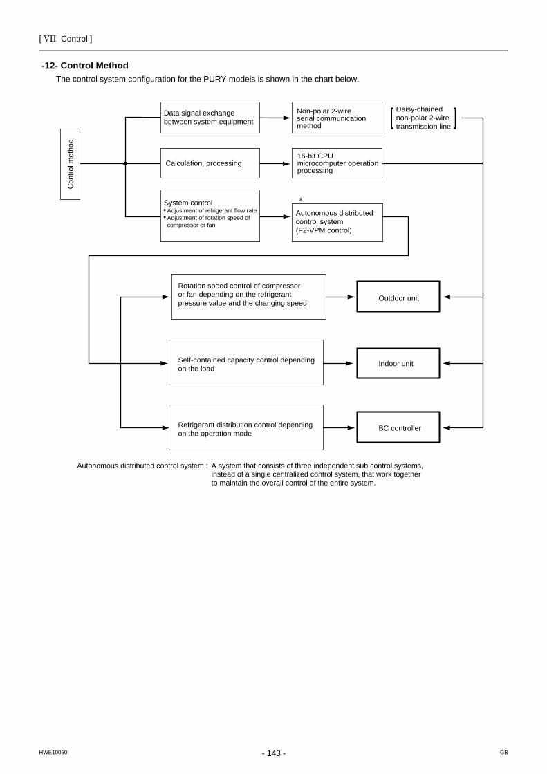
[ VII Control ]
- 143 -HWE10050 GB
Control Method
-12- Control Method The control system configuration for the PURY models is shown in the chart below.
Con
trol m
etho
d
Data signal exchange between system equipment
Calculation, processing
System control Adjustment of refrigerant flow rate Adjustment of rotation speed of compressor or fan
Non-polar 2-wireserial communication method
16-bit CPUmicrocomputer operation processing
Autonomous distributed control system (F2-VPM control)
Rotation speed control of compressor or fan depending on the refrigerant pressure value and the changing speed
Self-contained capacity control depending on the load
Refrigerant distribution control depending on the operation mode
Outdoor unit
Daisy-chained non-polar 2-wiretransmission line
Indoor unit
BC controller
*
Autonomous distributed control system : A system that consists of three independent sub control systems,instead of a single centralized control system, that work togetherto maintain the overall control of the entire system.
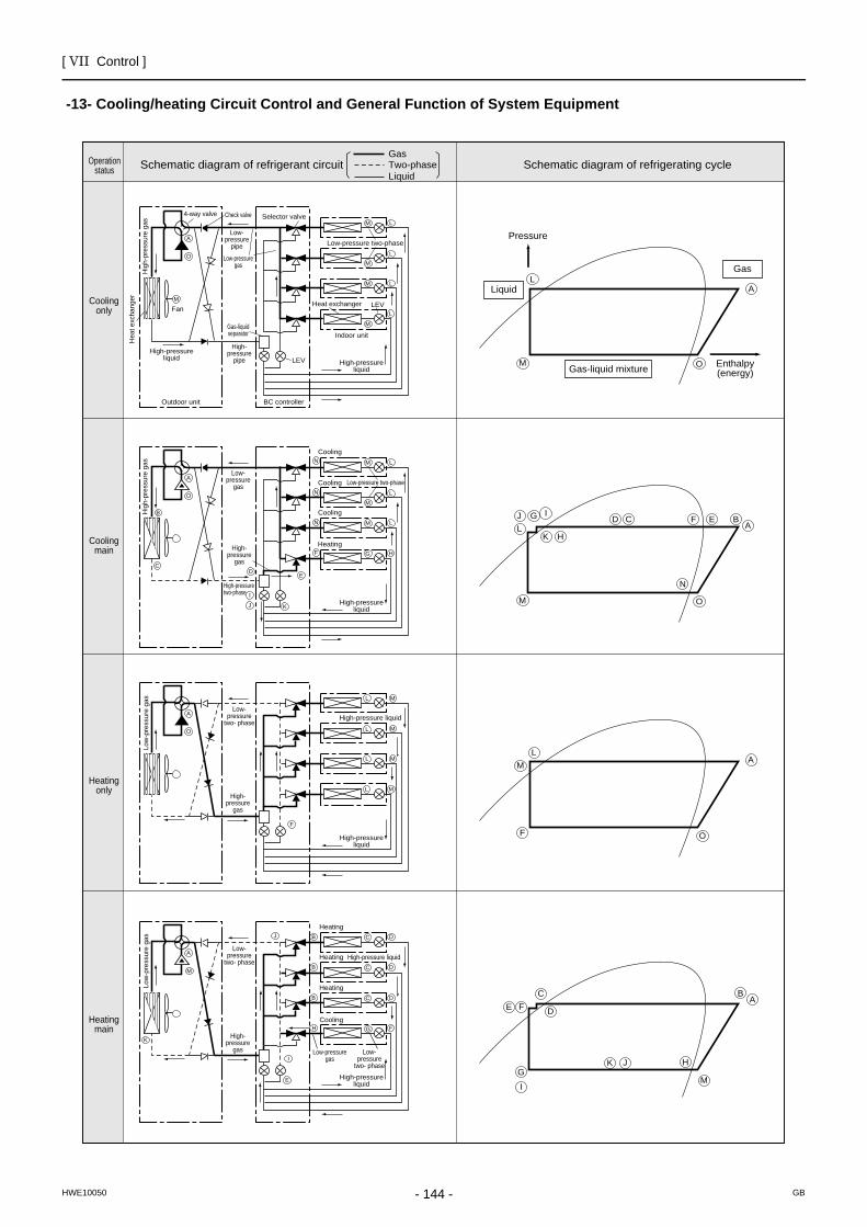
[ VII Control ]
- 144 -HWE10050 GB
Cooling/heating Circuit Control and General Function of System Equipment
-13- Cooling/heating Circuit Control and General Function of System Equipment
Hig
h-pr
essu
re g
asH
igh-
pres
sure
gas
Hea
t exc
hang
er
High-pressureliquid
Fan
4-way valve Check valve Selector valve
Low-pressure two-phase
Low-pressure two-phase
Low-pressure
two- phase
High-pressure liquid
Low-pressure
two- phase
Low-pressure
two- phase
Heat exchanger
High-pressureliquid
High-pressureliquid
High-pressureliquid
High-pressureliquid
High-pressure liquid
Cooling
Cooling
Cooling
Heating
Cooling
Heating
Heating
Heating
Low-pressure
pipe
High-pressure
pipe
High-pressure
gas
High-pressure
gas
High-pressure
gas
High-pressure two-phase
Low-pressuregas
Low-pressuregas
Low
-pre
ssur
e ga
sLo
w-p
ress
ure
gas
Low-pressure
gas
Gas-liquidseparator
Outdoor unit BC controller
Indoor unit
LEV
LEV
M
M L
M L
ML
M
L
A
O
ML
ML
ML
ML
A
O
B
CD
I
J
J
E
F
F
N
N
N
K
M L
M L
ML
G H
A
O
LJ G I
K H
D C F E B
N
A
M O
JG
I
K H
D
CFE
BA
M
L
F
M A
O
M
LA
O
M
A
I
E
K
B C D
B C D
B C D
FGH
Gas-liquid mixture
Pressure
Liquid
Gas
Enthalpy(energy)
Schematic diagram of refrigerant circuitGasTwo-phaseLiquid
Schematic diagram of refrigerating cycle
Coolingonly
Operationstatus
Coolingmain
Heatingonly
Heatingmain
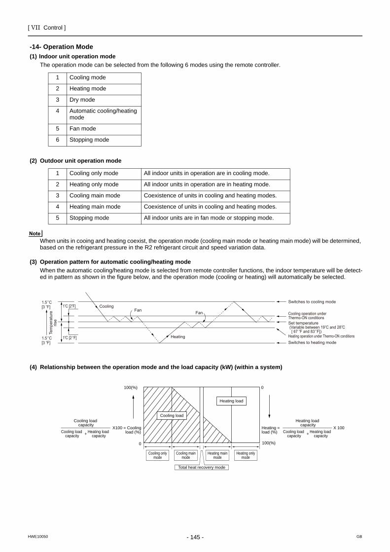
[ VII Control ]
- 145 -HWE10050 GB
Operation Mode
-14- Operation Mode(1) Indoor unit operation mode
The operation mode can be selected from the following 6 modes using the remote controller.
(2) Outdoor unit operation mode
When units in cooing and heating coexist, the operation mode (cooling main mode or heating main mode) will be determined, based on the refrigerant pressure in the R2 refrigerant circuit and speed variation data.
(3) Operation pattern for automatic cooling/heating modeWhen the automatic cooling/heating mode is selected from remote controller functions, the indoor temperature will be detect-ed in pattern as shown in the figure below, and the operation mode (cooling or heating) will automatically be selected.
(4) Relationship between the operation mode and the load capacity (kW) (within a system)
1 Cooling mode
2 Heating mode
3 Dry mode
4 Automatic cooling/heating mode
5 Fan mode
6 Stopping mode
1 Cooling only mode All indoor units in operation are in cooling mode.
2 Heating only mode All indoor units in operation are in heating mode.
3 Cooling main mode Coexistence of units in cooling and heating modes.
4 Heating main mode Coexistence of units in cooling and heating modes.
5 Stopping mode All indoor units are in fan mode or stopping mode.
CoolingFan
Heating
Switches to cooling mode
Cooling operation under Thermo-ON conditionsSet temperature (Variable between 19 C and 28 C [ 67 F and 83 F])Heating operation under Thermo-ON conditionsSwitches to heating mode
Fan
Tem
pera
ture
rise
1.5 C [3 F]
1.5 C [3 F]
1 C [2 F]
1 C [2 F]
Cooling load capacity
Heating load capacity+Cooling load
capacity
Heating load capacity
Heating load capacity+Cooling load
capacity
100(%)
Cooling onlymode
Cooling mainmode
Heating mainmode
Total heat recovery mode
Heating onlymode
100(%)
Heating load (%)
Heating load
X100 = Cooling load (%)
=
Cooling load
X 100
0
0
[ VII Control ]
- 146 -HWE10050 GB
DEMAND Control
-15- DEMAND ControlCooling/heating operation can be prohibited (Thermo-OFF) by an external input to the indoor units.
When DIP SW4-4 is set to ON, the 4-step DEMAND control is enabled. Eight-step demand control is possible in the system with two outdoor units.
Refer to Chapter II [3] 2.(7) "Various types of control using input-output signal connector on the outdoor unit (various connec-tion options)" for details.(page 23)
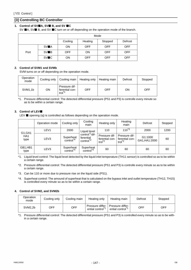
[ VII Control ]
- 147 -HWE10050 GB
[3] Controlling BC Controller1. Control of SV A, SV B, and SV C
SV A, SV B, and SV C turn on or off depending on the operation mode of the branch.
2. Control of SVM1 snd SVMbSVM turns on or off depending on the operation mode.
3. Control of LEVLEV opening (sj) is controlled as follows depending on the operation mode.
4. Control of SVM2, and SVM2b
Mode
Cooling Heating Stopped Defrost
Port
SV A ON OFF OFF OFF
SV B OFF ON OFF OFF
SV C ON OFF OFF OFF
Operation mode Cooling only Cooling main Heating only Heating main Defrost Stopped
SVM1,1b ONPressure dif-ferential con-trol*1
*1. Pressure differential control: The detected differential pressure (PS1 and P3) is controlle every minute so as to be within a certain range.
OFF OFF ON OFF
Operation mode Cooling only Cooling main Heating only Heating
main Defrost Stopped
G1,GA1HA1type
LEV1 2000 Liquid level control*1dif-ferential control*2
*1. Liquid level control: The liquid level detected by the liquid inlet temperature (TH11 sensor) is controlled so as to be within a certain range.
*2. Pressure differential control: The detected differential pressure (PS1 and P3) is controlle every minute so as to be within a certain range.
110 110*3
*3. Can be 110 or more due to pressure rise on the liquid side (PS1).
2000 1200
LEV3 Superheat control*4
*4. Superheat control: The amound of superheat that is calculated on the bypass inlet and outlet temperature (TH12, TH15) is controlled every minute so as to be within a certain range.
Pressure dif-ferential con-trol*2
Pressure dif-ferential con-trol*2
G1:1000GA1,HA1:2000 60
GB1,HB1type LEV3 Superheat
control*4Superheat control*4 60 60 60 60
Operation mode Cooling only Cooling main Heating only Heating main Defrost Stopped
SVM2,2b OFF OFF Pressure differ-ential control*1
*1. Pressure differential control: The detected differential pressure (PS1 and P3) is controlled every minute so as to be with-in a certain range.
Pressure differ-ential control*1 OFF OFF
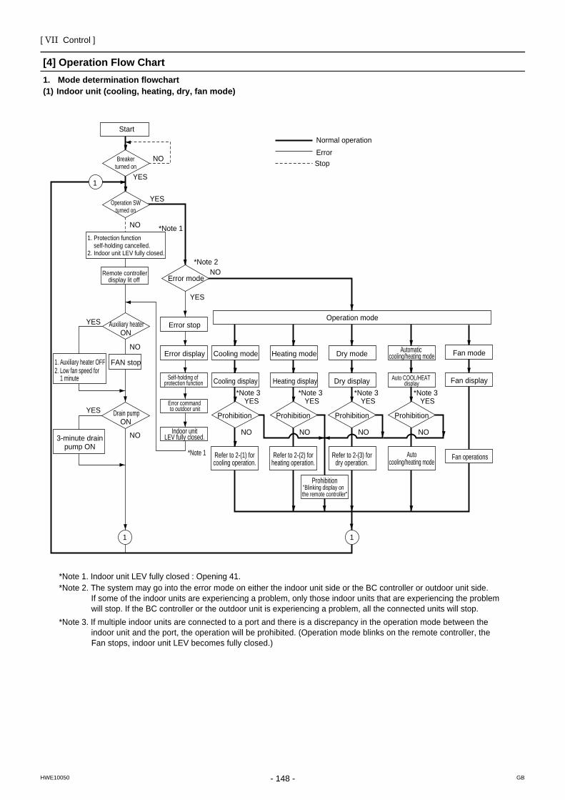
[ VII Control ]
- 148 -HWE10050 GB
[4] Operation Flow Chart1. Mode determination flowchart(1) Indoor unit (cooling, heating, dry, fan mode)
Start
Remote controller display lit off Error mode
Error stop
Error display
Self-holding of protection function
Error command to outdoor unit
Indoor unit LEV fully closed.
Refer to 2-(1) for cooling operation.
Refer to 2-(2) for heating operation.
Refer to 2-(3) for dry operation.
ProhibitionProhibitionProhibition
Dry display Heating display Cooling display
Dry mode Heating mode Fan mode
Fan display
Fan operations
Operation mode
Cooling mode
Prohibition"Blinking display on the remote controller"
FAN stop
Breaker turned on
Operation SW turned on
Auxiliary heaterON
Drain pumpON
3-minute drain pump ON
NO
NO
NO
NO
NO NO NO NO NO
*Note 1
*Note 1
*Note 2
*Note 3 *Note 3 *Note 3
1. Protection function self-holding cancelled.2. Indoor unit LEV fully closed.
1. Auxiliary heater OFF2. Low fan speed for 1 minute
YES
YES
YES
YESYES YES YES
YES
Normal operationErrorStop
1
Prohibition
Auto COOL/HEAT display
Automatic cooling/heating mode
*Note 3YES
Auto cooling/heating mode
11
*Note 1. Indoor unit LEV fully closed : Opening 41.*Note 2. The system may go into the error mode on either the indoor unit side or the BC controller or outdoor unit side. If some of the indoor units are experiencing a problem, only those indoor units that are experiencing the problem will stop. If the BC controller or the outdoor unit is experiencing a problem, all the connected units will stop.*Note 3. If multiple indoor units are connected to a port and there is a discrepancy in the operation mode between the indoor unit and the port, the operation will be prohibited. (Operation mode blinks on the remote controller, the Fan stops, indoor unit LEV becomes fully closed.)
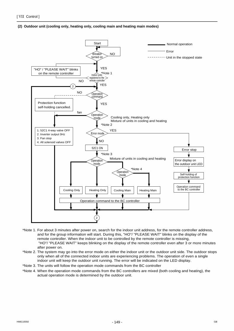
[ VII Control ]
- 149 -HWE10050 GB
(2) Outdoor unit (cooling only, heating only, cooling main and heating main modes)
Start
Breaker turned on
Operation command
Error stop
Error display on the outdoor unit LED
Self-holding of protection function
Operation command to the BC controller
Operation mode
Error mode
52C1 ON
*Note 1
*Note 2
*Note 3
*Note 4
YES
YES
YES
YES
NO
NO
NO
fan
NO
"HO" / "PLEASE WAIT" blinks on the remote controller
Operation command to the BC controller
Cooling only, Heating onlyMixture of units in cooling and heating
Mixture of units in cooling and heating
Protection function self-holding cancelled.
Normal operation
1. 52C1 4-way valve OFF2. Inverter output 0Hz3. Fan stop4. All solenoid valves OFF
Cooling Only Heating Only
2
2
Cooling Main
Operation mode
Operation mode
*Note 1. For about 3 minutes after power on, search for the indoor unit address, for the remote controller address, and for the group information will start. During this, "HO"/ "PLEASE WAIT" blinks on the display of the remote controller. When the indoor unit to be controlled by the remote controller is missing, "HO"/ "PLEASE WAIT" keeps blinking on the display of the remote controller even after 3 or more minutes after power on.
*Note 3. The units will follow the operation mode commands from the BC controller*Note 4. When the operation mode commands from the BC controllers are mixed (both cooling and heating), the actual operation mode is determined by the outdoor unit.
*Note 2. The system may go into the error mode on either the indoor unit or the outdoor unit side. The outdoor stops only when all of the connected indoor units are experiencing problems. The operation of even a single indoor unit will keep the outdoor unit running. The error will be indicated on the LED display.
Heating Main
Indoor units registered to the remote controller
Error
Unit in the stopped state
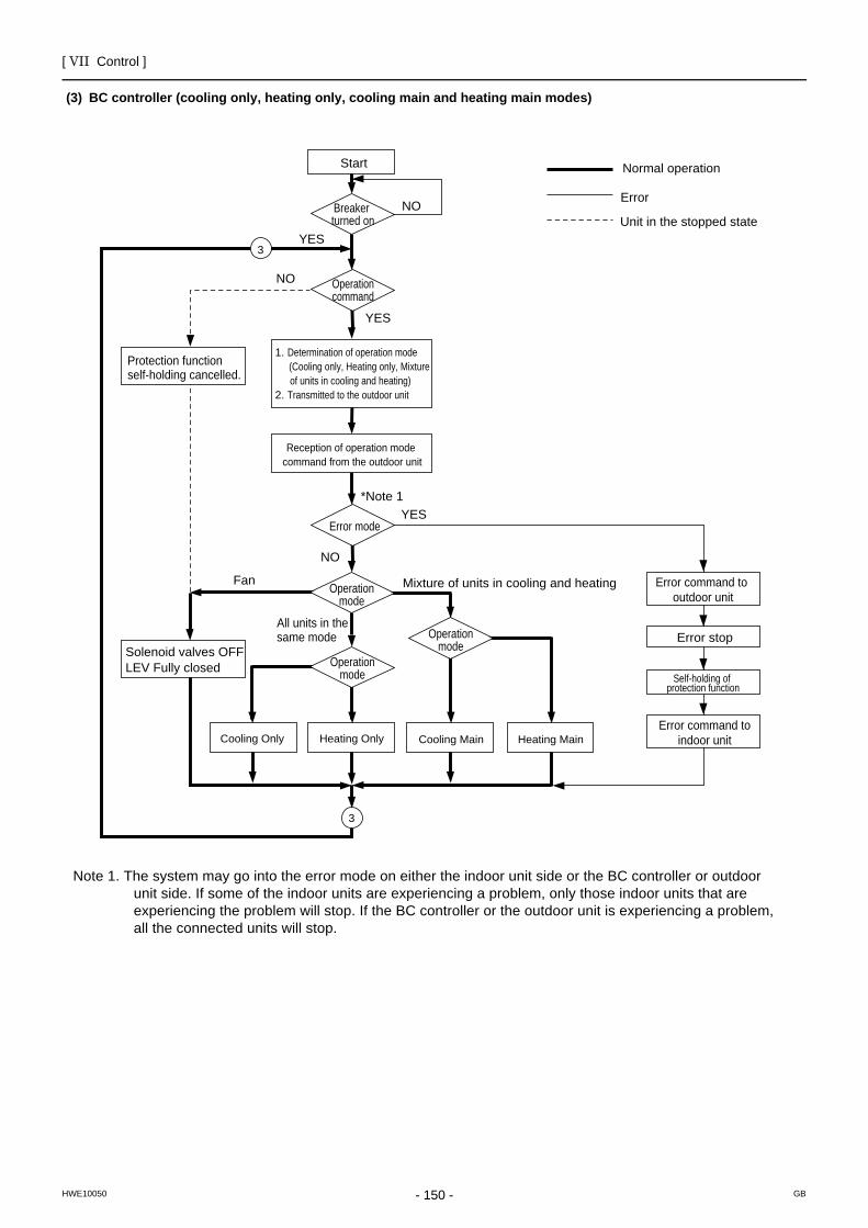
[ VII Control ]
- 150 -HWE10050 GB
(3) BC controller (cooling only, heating only, cooling main and heating main modes)
Start
Breaker turned on
Operation command
Error command to outdoor unit
Error stop
Self-holding of protection function
Error command to indoor unit
Error mode
*Note 1
YES
YES
YES
NO
NO
Fan
NO
All units in the same mode
Solenoid valves OFFLEV Fully closed
1. Determination of operation mode (Cooling only, Heating only, Mixture of units in cooling and heating)2. Transmitted to the outdoor unit
3
3
Operation mode
Note 1. The system may go into the error mode on either the indoor unit side or the BC controller or outdoor unit side. If some of the indoor units are experiencing a problem, only those indoor units that are experiencing the problem will stop. If the BC controller or the outdoor unit is experiencing a problem, all the connected units will stop.
Operation mode
Operation mode
Cooling Only Heating Only Cooling Main Heating Main
Mixture of units in cooling and heating
Reception of operation mode command from the outdoor unit
Protection function self-holding cancelled.
Normal operation
Error
Unit in the stopped state
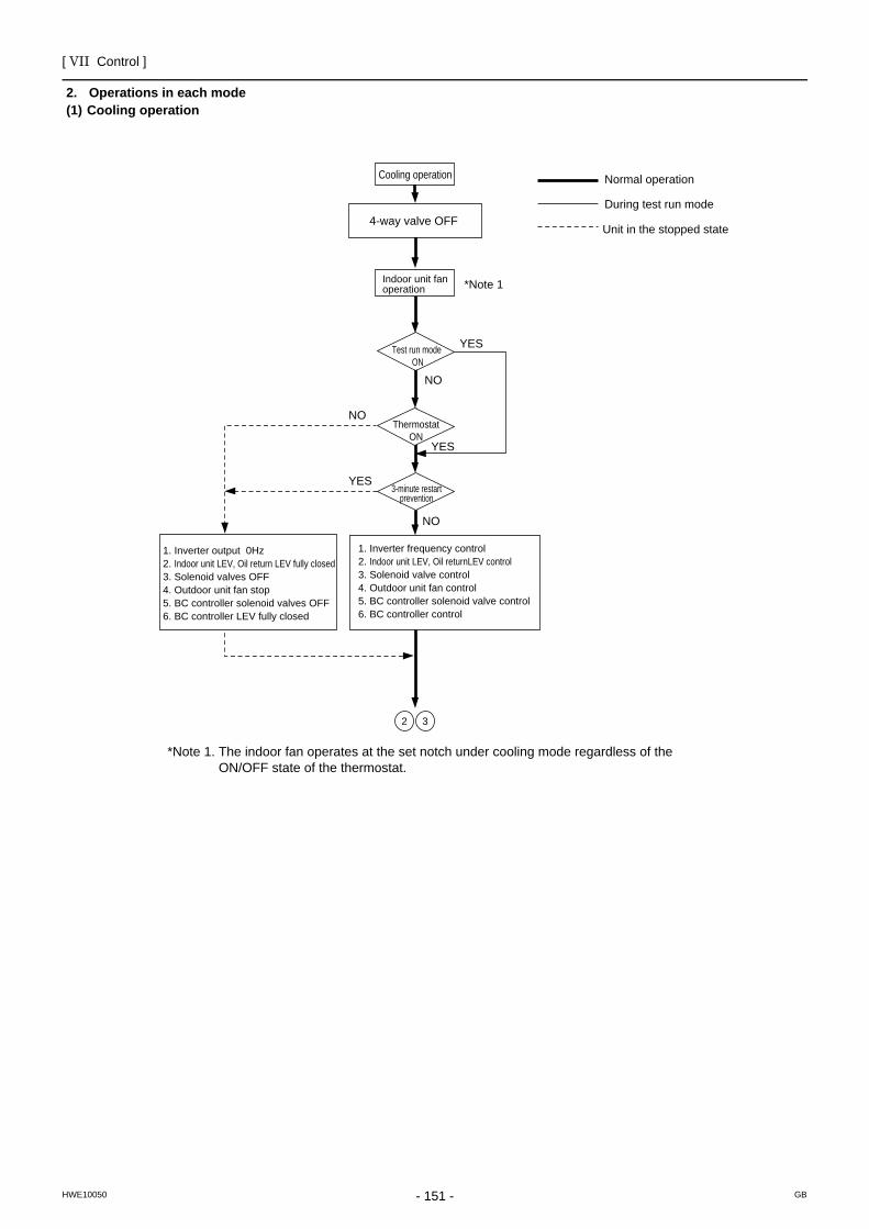
[ VII Control ]
- 151 -HWE10050 GB
2. Operations in each mode(1) Cooling operation
Cooling operation
Test run mode ON
Thermostat ON
3-minute restart prevention
*Note 1
YES
YES
YES
NO
NO
NO
4-way valve OFF
1. Inverter frequency control2. Indoor unit LEV, Oil returnLEV control3. Solenoid valve control4. Outdoor unit fan control5. BC controller solenoid valve control6. BC controller control
Normal operation
During test run mode
Indoor unit fan operation
1. Inverter output 0Hz2. Indoor unit LEV, Oil return LEV fully closed3. Solenoid valves OFF4. Outdoor unit fan stop5. BC controller solenoid valves OFF6. BC controller LEV fully closed
Unit in the stopped state
2 3
*Note 1. The indoor fan operates at the set notch under cooling mode regardless of the ON/OFF state of the thermostat.
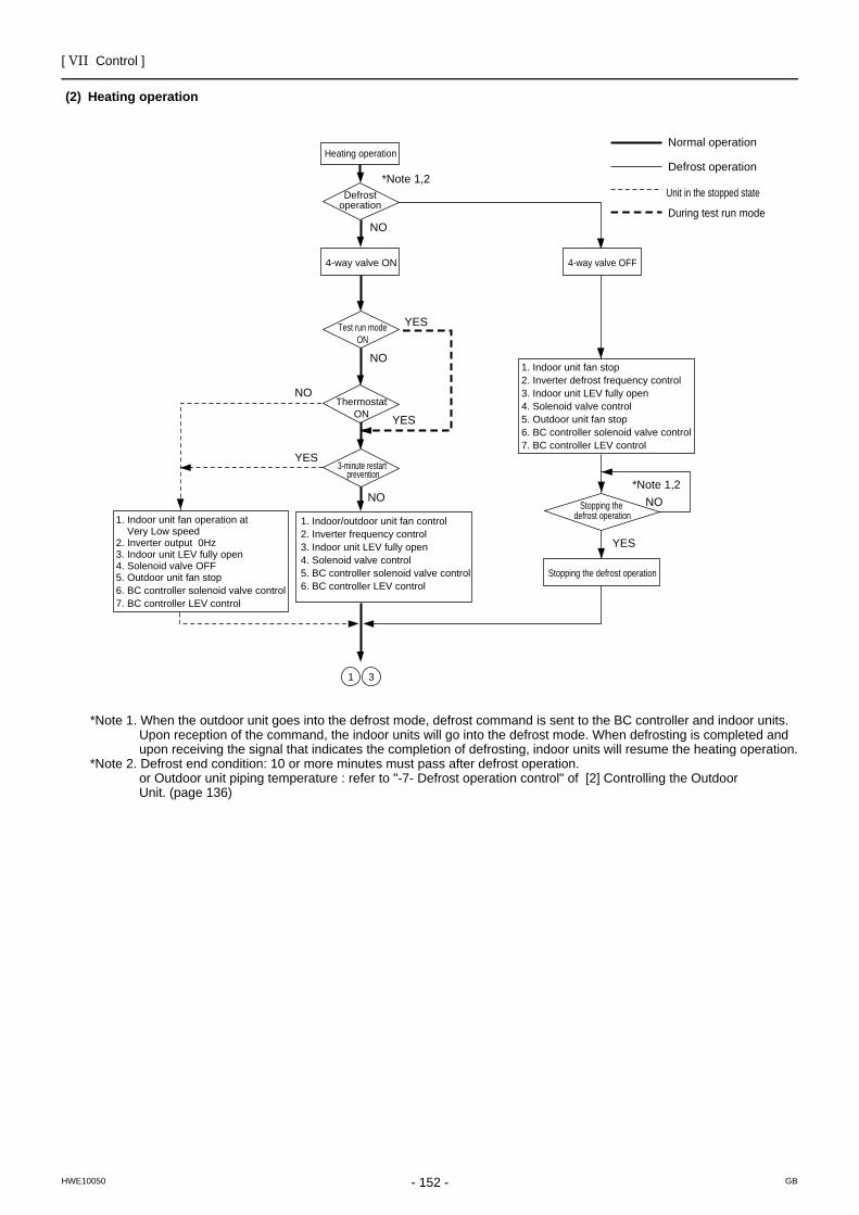
[ VII Control ]
- 152 -HWE10050 GB
(2) Heating operation
*Note 1. When the outdoor unit goes into the defrost mode, defrost command is sent to the BC controller and indoor units.Upon reception of the command, the indoor units will go into the defrost mode. When defrosting is completed and upon receiving the signal that indicates the completion of defrosting, indoor units will resume the heating operation.
*Note 2. Defrost end condition: 10 or more minutes must pass after defrost operation.or Outdoor unit piping temperature : refer to "-7- Defrost operation control" of [2] Controlling the Outdoor Unit. (page 136)
Heating operation
Test run mode ON
Thermostat ON
Defrost operation
3-minute restart prevention
*Note 1,2
*Note 1,2
YES
YES
YES
YES
NO
NO
NO
NO
NO
1. Indoor/outdoor unit fan control2. Inverter frequency control3. Indoor unit LEV fully open4. Solenoid valve control5. BC controller solenoid valve control6. BC controller LEV control
Normal operation
Defrost operation
4-way valve ON
During test run mode
1. Indoor unit fan operation at Very Low speed2. Inverter output 0Hz3. Indoor unit LEV fully open4. Solenoid valve OFF5. Outdoor unit fan stop6. BC controller solenoid valve control7. BC controller LEV control
Stopping the defrost operation
1. Indoor unit fan stop2. Inverter defrost frequency control3. Indoor unit LEV fully open4. Solenoid valve control5. Outdoor unit fan stop6. BC controller solenoid valve control7. BC controller LEV control
4-way valve OFF
1 3
Stopping the defrost operation
Unit in the stopped state
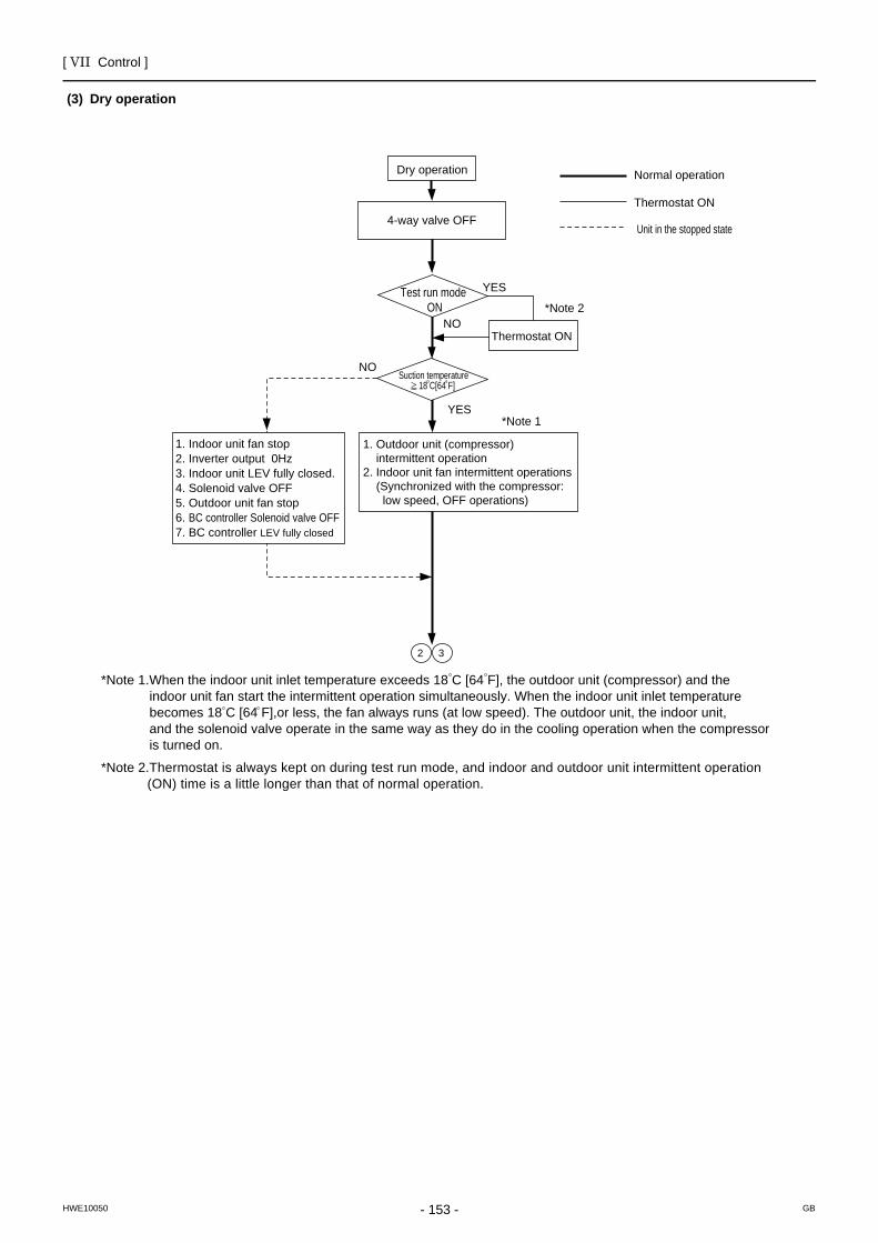
[ VII Control ]
- 153 -HWE10050 GB
(3) Dry operation
Dry operation
*Note 1
*Note 2
YES
YES
NO
NO
4-way valve OFF
1. Outdoor unit (compressor) intermittent operation2. Indoor unit fan intermittent operations (Synchronized with the compressor: low speed, OFF operations)
Normal operation
Thermostat ON
Thermostat ON
1. Indoor unit fan stop2. Inverter output 0Hz3. Indoor unit LEV fully closed.4. Solenoid valve OFF5. Outdoor unit fan stop6. BC controller Solenoid valve OFF7. BC controller LEV fully closed
2 3
*Note 1.When the indoor unit inlet temperature exceeds 18 C [64 F], the outdoor unit (compressor) and the indoor unit fan start the intermittent operation simultaneously. When the indoor unit inlet temperature becomes 18 C [64 F],or less, the fan always runs (at low speed). The outdoor unit, the indoor unit, and the solenoid valve operate in the same way as they do in the cooling operation when the compressor is turned on.
*Note 2.Thermostat is always kept on during test run mode, and indoor and outdoor unit intermittent operation (ON) time is a little longer than that of normal operation.
Test run mode ON
Suction temperature 18 C[64 F]
Unit in the stopped state

- 154 -
[ VII Control ]
GBHWE10050
- 155 -HWE10050 GB
VIII Test Run Mode
[1] Items to be checked before a Test Run.........................................................................157[2] Test Run Method ...........................................................................................................158[3] Operating Characteristic and Refrigerant Amount .........................................................159[4] Adjusting the Refrigerant Amount ..................................................................................159[5] Refrigerant Amount Adjust Mode...................................................................................162[6] The following symptoms are normal. .............................................................................164[7] Standard Operation Data (Reference Data) ..................................................................165

- 156 -
[ VIII Test Run Mode ]
- 157 -HWE10050 GB
VIII Test Run Mode
[1] Items to be checked before a Test Run(1) Check for refrigerant leak and loose cables and connectors.
(2) Measure the insulation resistance between the power supply terminal block and the ground with a 500V megger and make sure it reads at least 1.0Mohm.
Do not operate the unit if the insulation resistance is below 1.0Mohm.Do not apply megger voltage to the terminal block for transmission line. Doing so will damage the controller board.The insulation resistance between the power supply terminal block and the ground could go down to close to 1Mohm imme-diately after installation or when the power is kept off for an extended period of time because of the accumulation of refrigerant in the compressor.If insulation resistance reads at least 1Mohm, by turning on the main power and powering the belt heater for at least 12 hours, the refrigerant in the compressor will evaporate and the insulation resistance will go up.Do not measure the insulation resistance of the terminal block for transmission line for the unit remote controller.
(3) Make sure the valves on both the high-pressure and low-pressure sides are fully open.
Securely tighten the cap.
(4) Check the phase sequence and the voltage of the power supply.
(5) [When a transmission booster is connected]Turn on the transmission booster before turning on the outdoor units.
If the outdoor units are turned on first, the connection information for the refrigerant circuit may not be properly recognized.In case the outdoor units are turned on before the transmission booster is turned on, perform a power reset on the outdoor units after turning on the power booster.
(6) Turn on the main power to the unit at least 12 hours before test run to power the belt heater.
Insufficient powering time may result in compressor damage.
(7) When a power supply unit is connected to the transmission line for centralized control, perform a test run with the power supply unit being energized. Leave the power jumper connector on CN41 as it is (factory setting).
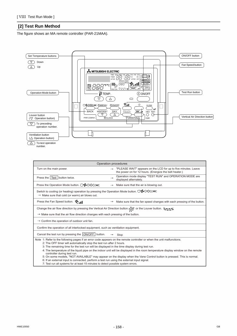
[ VIII Test Run Mode ]
- 158 -HWE10050 GB
[2] Test Run MethodThe figure shows an MA remote controller (PAR-21MAA).
PAR-21MAA
ON/OFF
FILTER
CHECK
OPERATION CLEAR
TEST
TEMP.
MENU
BACK DAYMONITOR/SET
CLOCK
ON/OFF
Set Temperature buttons
Down
Up
Operation Mode button
ON/OFF button
Fan Speed button
Test Run button
Vertical Air Direction buttonLouver button( Operation button)
To precedingoperation number.
Ventilation button( Operation button)
To next operation number.
F CF C
ERROR CODEAFTERTIMERTIME SUN MON TUE WED THU FRI SAT
ONOFF
HrAFTER
FILTERFUNCTION
ONLY1Hr.
WEEKLYSIMPLE
AUTO OFF
Operation procedures Turn on the main power. "PLEASE WAIT" appears on the LCD for up to five minutes. Leave
the power on for 12 hours. (Energize the belt heater.)
Press the Test button twice. Operation mode display "TEST RUN" and OPERATION MODE are displayed alternately.
Press the Operation Mode button.
Make sure that cold (or warm) air blows out.
Make sure that the air is blowing out.
Switch to cooling (or heating) operation by pressing the Operation Mode button.
Press the Fan Speed button.
Change the air flow direction by pressing the Vertical Air Direction button or the Louver button.
Confirm the operation of outdoor unit fan.
Confirm the operation of all interlocked equipment, such as ventilation equipment.
Note 1: Refer to the following pages if an error code appears on the remote controller or when the unit malfunctions. 2: The OFF timer will automatically stop the test run after 2 hours. 3: The remaining time for the test run will be displayed in the time display during test run. 4: The temperature of the liquid pipe on the indoor unit will be displayed in the room temperature display window on the remote controller during test run. 5: On some models, "NOT AVAILABLE" may appear on the display when the Vane Control button is pressed. This is normal. 6: If an external input is connected, perform a test run using the external input signal. 7: Test run all systems for at least 15 minutes to detect possible system errors.
Make sure that the fan speed changes with each pressing of the button.
Stop
Make sure that the air flow direction changes with each pressing of the button.
Cancel the test run by pressing the ON/OFF button.
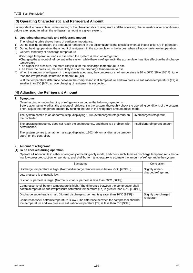
[ VIII Test Run Mode ]
- 159 -HWE10050 GB
[3] Operating Characteristic and Refrigerant AmountIt is important to have a clear understanding of the characteristics of refrigerant and the operating characteristics of air conditioners before attempting to adjust the refrigerant amount in a given system.
1. Operating characteristic and refrigerant amountThe following table shows items of particular importance.
1) During cooling operation, the amount of refrigerant in the accumulator is the smallest when all indoor units are in operation.2) During heating operation, the amount of refrigerant in the accumulator is the largest when all indoor units are in operation.3) General tendency of discharge temperature
Discharge temperature tends to rise when the system is short on refrigerant.Changing the amount of refrigerant in the system while there is refrigerant in the accumulator has little effect on the discharge temperature.The higher the pressure, the more likely it is for the discharge temperature to rise.The lower the pressure, the more likely it is for the discharge temperature to rise.
4) When the amount of refrigerant in the system is adequate, the compressor shell temperature is 10 to 60°C [18 to 108°F] higher than the low pressure saturation temperature (Te).-> If the temperature difference between the compressor shell temperature and low pressure saturation temperature (Te) is smaller than 5°C [9°F], an overcharging of refrigerant is suspected.
[4] Adjusting the Refrigerant Amount1. Symptoms
Overcharging or undercharging of refrigerant can cause the following symptoms: Before attempting to adjust the amount of refrigerant in the system, thoroughly check the operating conditions of the system. Then, adjust the refrigerant amount by running the unit in the refrigerant amount adjust mode.
2. Amount of refrigerant(1) To be checked during operation
Operate all indoor units in either cooling-only or heating-only mode, and check such items as discharge temperature, subcool-ing, low pressure, suction temperature, and shell bottom temperature to estimate the amount of refrigerant in the system.
The system comes to an abnormal stop, displaying 1500 (overcharged refrigerant) on the controller.
Overcharged refrigerant
The operating frequency does not reach the set frequency, and there is a problem with performance.
Insufficient refrigerant amount
The system comes to an abnormal stop, displaying 1102 (abnormal discharge temper-ature) on the controller.
Symptoms Conclusion
Discharge temperature is high. (Normal discharge temperature is below 95°C [203°F].) Slightly under-charged refrigerant
Low pressure is unusually low.
Suction superheat is large. (Normal suction superheat is less than 20°C [36°F].)
Compressor shell bottom temperature is high. (The difference between the compressor shell bottom temperature and low pressure saturation temperature (Te) is greater than 60°C [108°F].)
Discharge superheat is small. (Normal discharge superheat is greater than 10°C [18°F].) Slightly overcharged refrigerant
Compressor shell bottom temperature is low. (The difference between the compressor shell bot-tom temperature and low pressure saturation temperature (Te) is less than 5°C [9°F].)
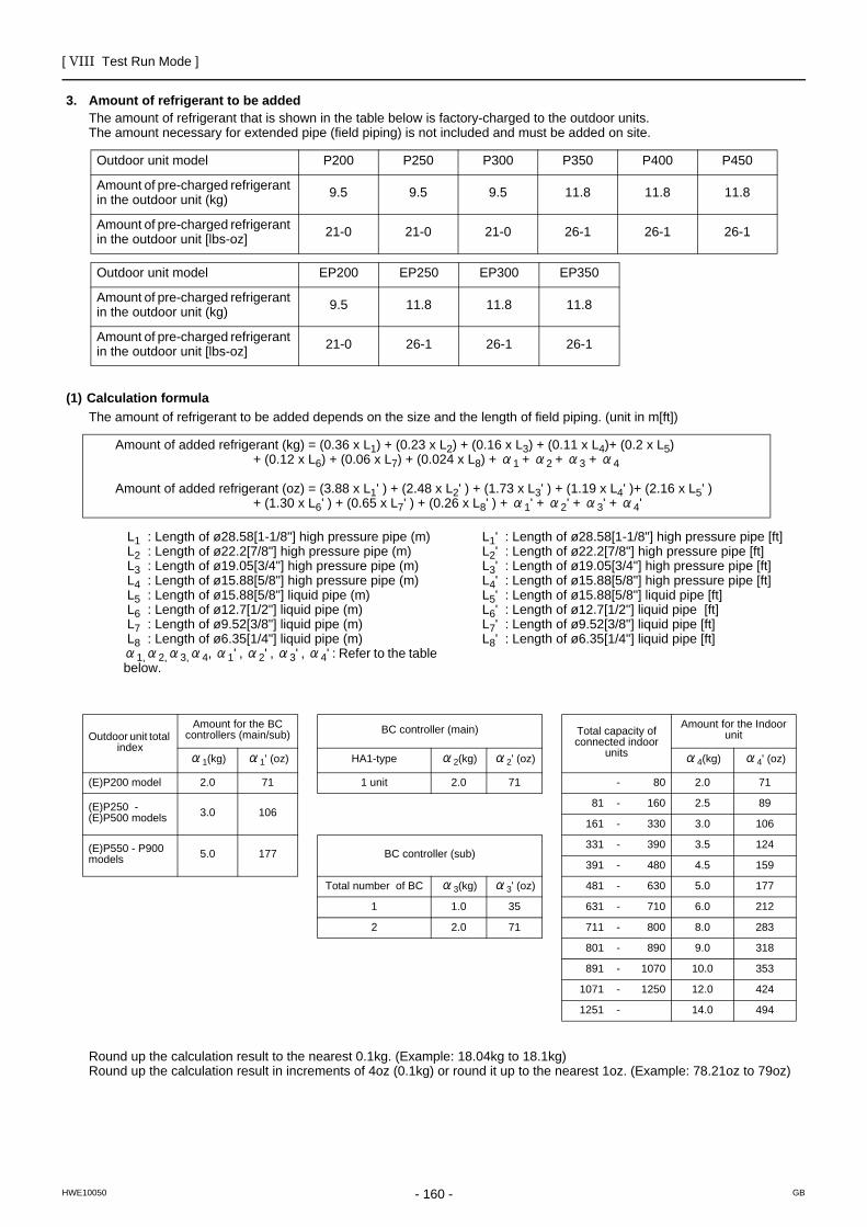
[ VIII Test Run Mode ]
- 160 -HWE10050 GB
3. Amount of refrigerant to be addedThe amount of refrigerant that is shown in the table below is factory-charged to the outdoor units.The amount necessary for extended pipe (field piping) is not included and must be added on site.
(1) Calculation formulaThe amount of refrigerant to be added depends on the size and the length of field piping. (unit in m[ft])
Round up the calculation result to the nearest 0.1kg. (Example: 18.04kg to 18.1kg)Round up the calculation result in increments of 4oz (0.1kg) or round it up to the nearest 1oz. (Example: 78.21oz to 79oz)
Outdoor unit model P200 P250 P300 P350 P400 P450
Amount of pre-charged refrigerant in the outdoor unit (kg) 9.5 9.5 9.5 11.8 11.8 11.8
Amount of pre-charged refrigerant in the outdoor unit [lbs-oz] 21-0 21-0 21-0 26-1 26-1 26-1
Outdoor unit model EP200 EP250 EP300 EP350
Amount of pre-charged refrigerant in the outdoor unit (kg) 9.5 11.8 11.8 11.8
Amount of pre-charged refrigerant in the outdoor unit [lbs-oz] 21-0 26-1 26-1 26-1
Amount of added refrigerant (kg) = (0.36 x L1) + (0.23 x L2) + (0.16 x L3) + (0.11 x L4)+ (0.2 x L5) + (0.12 x L6) + (0.06 x L7) + (0.024 x L8) + α1 + α2 + α3 + α4
Amount of added refrigerant (oz) = (3.88 x L1' ) + (2.48 x L2' ) + (1.73 x L3' ) + (1.19 x L4' )+ (2.16 x L5' ) + (1.30 x L6' ) + (0.65 x L7' ) + (0.26 x L8' ) + α1' + α2' + α3' + α4'
L1 : Length of ø28.58[1-1/8"] high pressure pipe (m) L2 : Length of ø22.2[7/8"] high pressure pipe (m) L3 : Length of ø19.05[3/4"] high pressure pipe (m) L4 : Length of ø15.88[5/8"] high pressure pipe (m) L5 : Length of ø15.88[5/8"] liquid pipe (m) L6 : Length of ø12.7[1/2"] liquid pipe (m) L7 : Length of ø9.52[3/8"] liquid pipe (m) L8 : Length of ø6.35[1/4"] liquid pipe (m)α1,α2,α3,α4, α1' , α2' , α3' , α4' : Refer to the table below.
L1' : Length of ø28.58[1-1/8"] high pressure pipe [ft] L2' : Length of ø22.2[7/8"] high pressure pipe [ft] L3' : Length of ø19.05[3/4"] high pressure pipe [ft] L4' : Length of ø15.88[5/8"] high pressure pipe [ft] L5' : Length of ø15.88[5/8"] liquid pipe [ft] L6' : Length of ø12.7[1/2"] liquid pipe [ft] L7' : Length of ø9.52[3/8"] liquid pipe [ft] L8' : Length of ø6.35[1/4"] liquid pipe [ft]
Outdoor unit total index
Amount for the BC controllers (main/sub) BC controller (main) Total capacity of
connected indoor units
Amount for the Indoor unit
α1(kg) α1' (oz) HA1-type α2(kg) α2' (oz) α4(kg) α4' (oz)
(E)P200 model 2.0 71 1 unit 2.0 71 - 80 2.0 71
(E)P250 - (E)P500 models 3.0 106
81 - 160 2.5 89
161 - 330 3.0 106
(E)P550 - P900 models 5.0 177 BC controller (sub)
331 - 390 3.5 124
391 - 480 4.5 159
Total number of BC α3(kg) α3' (oz) 481 - 630 5.0 177
1 1.0 35 631 - 710 6.0 212
2 2.0 71 711 - 800 8.0 283
801 - 890 9.0 318
891 - 1070 10.0 353
1071 - 1250 12.0 424
1251 - 14.0 494
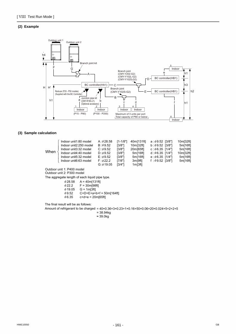
[ VIII Test Run Mode ]
- 161 -HWE10050 GB
(2) Example
(3) Sample calculation
BC controller(HA1)
BC controller(HB1)
BC controller(HB1)
Indoor
a
C
b
H H′
h1h1
(P15 - P80)
Junction pipe kit(CMY-R160-J1)(Optional accessory)
Branch joint(CMY-Y102S-G2)
Bc d f
h3
D
E
Branch joint(CMY-Y202-G2)(CMY-Y102L-G2)(CMY-Y102S-G2)
A e h1
F
h4
Branch joint kit
Outdoor unit 1Outdoor unit 2
Reducer (P20 - P50 models)(Supplied with the BC Controller)
G
h2
Indoor
Indoor
Maximum of 3 units per portTotal capacity of P80 or below
Indoor IndoorIndoor2
6
5
3 41
(P100 - P250)
Indoor unit1:80 modelIndoor unit2:250 modelIndoor unit3:32 modelIndoor unit4:40 modelIndoor unit5:32 modelIndoor unit6:63 model
A : 28.58B : 9.52C : 9.52D : 9.52E : 9.52F : 22.2G : 19.05
40m10m20m5m5m3m1m
[1-1/8"][3/8"][3/8"][3/8"][3/8"][7/8"][3/4"]
[3/8"][3/8"][1/4"][1/4"][1/4"][3/8"]
[131ft][32ft][65ft][16ft][16ft][9ft][3ft]
[32ft][16ft][16ft][32ft][16ft][16ft]
a : 9.52b : 9.52c : 6.35d : 6.35e : 6.35f : 9.52
10m5m5m
10m5m5m
28.58 A = 40m[131ft] 22.2 F = 30m[98ft] 19.05 G = 1m[3ft] 9.52 C+D+E+a+b+f = 50m[164ft] 6.35 c+d+e = 20m[65ft]
The aggregate length of each liquid pipe type.Outdoor unit 2: P300 modelOutdoor unit 1: P400 model
The final result will be as follows:Amount of refrigerant to be charged = 40×0.36+3×0.23+1×0.16+50×0.06+20×0.024+5+2+2+5
= 38.94kg≈ 39.0kg
When
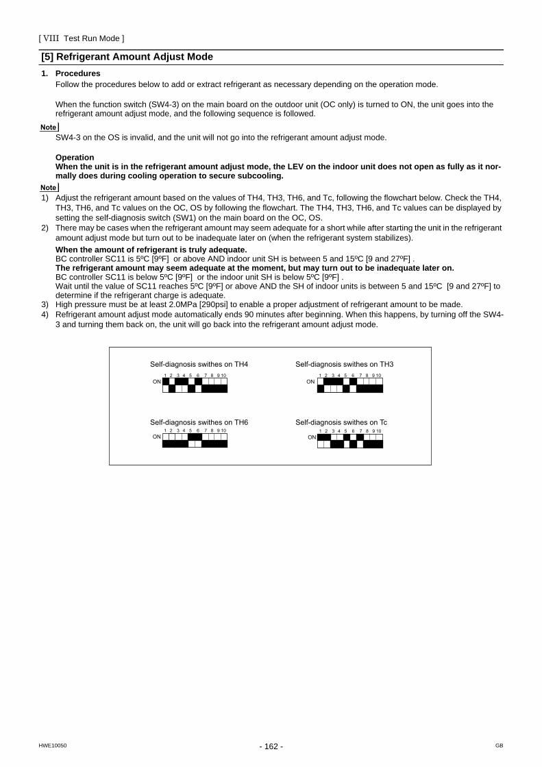
[ VIII Test Run Mode ]
- 162 -HWE10050 GB
[5] Refrigerant Amount Adjust Mode1. Procedures
Follow the procedures below to add or extract refrigerant as necessary depending on the operation mode.
When the function switch (SW4-3) on the main board on the outdoor unit (OC only) is turned to ON, the unit goes into the refrigerant amount adjust mode, and the following sequence is followed.
SW4-3 on the OS is invalid, and the unit will not go into the refrigerant amount adjust mode.
OperationWhen the unit is in the refrigerant amount adjust mode, the LEV on the indoor unit does not open as fully as it nor-mally does during cooling operation to secure subcooling.
1) Adjust the refrigerant amount based on the values of TH4, TH3, TH6, and Tc, following the flowchart below. Check the TH4, TH3, TH6, and Tc values on the OC, OS by following the flowchart. The TH4, TH3, TH6, and Tc values can be displayed by setting the self-diagnosis switch (SW1) on the main board on the OC, OS.
2) There may be cases when the refrigerant amount may seem adequate for a short while after starting the unit in the refrigerant amount adjust mode but turn out to be inadequate later on (when the refrigerant system stabilizes).When the amount of refrigerant is truly adequate.BC controller SC11 is 5ºC [9ºF] or above AND indoor unit SH is between 5 and 15ºC [9 and 27ºF] .The refrigerant amount may seem adequate at the moment, but may turn out to be inadequate later on.BC controller SC11 is below 5ºC [9ºF] or the indoor unit SH is below 5ºC [9ºF] .Wait until the value of SC11 reaches 5ºC [9ºF] or above AND the SH of indoor units is between 5 and 15ºC [9 and 27ºF] to determine if the refrigerant charge is adequate.
3) High pressure must be at least 2.0MPa [290psi] to enable a proper adjustment of refrigerant amount to be made. 4) Refrigerant amount adjust mode automatically ends 90 minutes after beginning. When this happens, by turning off the SW4-
3 and turning them back on, the unit will go back into the refrigerant amount adjust mode.
Self-diagnosis swithes on TH4
Self-diagnosis swithes on TH6
Self-diagnosis swithes on TH3
Self-diagnosis swithes on Tc
1 2 3 4 5 6 7 8 9 10ON
1 2 3 4 5 6 7 8 9 10ON
1 2 3 4 5 6 7 8 9 10ON
1 2 3 4 5 6 7 8 9 10ON
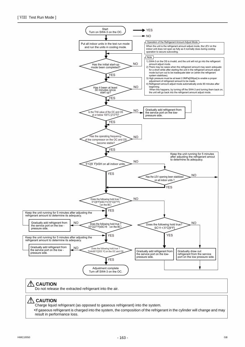
[ VIII Test Run Mode ]
- 163 -HWE10050 GB
CAUTIONDo not release the extracted refrigerant into the air.
CAUTIONCharge liquid refrigerant (as opposed to gaseous refrigerant) into the system.If gaseous refrigerant is charged into the system, the composition of the refrigerant in the cylinder will change and may result in performance loss.
YES
YES
YES
YES
YES
YES
YES
YES YES
YES
NO
NO
NO
NO
NO
NO
NO
NO
NO
Start
Put all indoor units in the test run mode and run the units in cooling mode.
Has it been at least 30 minutes since
start up?
5°C[9 F]≤SH on all indoor units.
Has the LEV opening been stabilizedon all indoor units ?
NODoes the following hold true? SC11 5°C[9°F]
YES
NODoes the following hold true ?5°C[9°F]≤SC11≤15°C[27°F]
on the BC
Gradually add refrigerant from the service port on the low- pressure side.
Keep the unit running for 5 minutes after adjusting the refrigerant amount to determine its adequacy.
Keep the unit running for 5 minutes after adjusting the refrigerant amount to determine its adequacy.
Turn on SW4-3 on the OC.
Adjustment completeTurn off SW4-3 on the OC.
Has the initial start-upmode been completed?
Gradually add refrigerant from the service port on the low -pressure side.
Gradually add refrigerant from the service port on the low -pressure side.
Keep the unit running for 5 minutes after adjusting the refrigerant amout to determine its adequacy.
Gradually add refrigerant from the service port on the low- pressure side.
Gradually draw out refrigerant from the service port on the low pressure side.
Is the TH4 value of the OC and OSat or below 100°C [212°F]?
Has the operating frequency of the compressor on the OC and OS
become stable?
Does the following hold true ?TH4≤95°C[203 F] on the OC and OS
Does the following hold true ?15°C[27°F]≤SC16 on the BC
Operation of the Refrigerant Amount Adjust Mode
When the unit is the refrigerant amount adjust mode, the LEV on the indoor unit does not open as fully as it normally does during cooling operation to secure subcooling.
Note
1) SW4-3 on the OS is invalid, and the unit will not go into the refrigerant amount adjust mode.
2) There may be cases when the refrigerant amount may seem adequate for a short while after starting the unit in the refrigerant amount adjust mode but turn out to be inadequate later on (when the refrigerant system stabilizes).
3) High pressure must be at least 2.0MPa[290psi] to enable a proper adjustment of refrigerant amount to be made.
4) Refrigerant amount adjust mode automatically ends 90 minutes after beginning.
When this happens, by turning off the SW4-3 and turning them back on, the unit will go back into the refrigerant amount adjust mode.
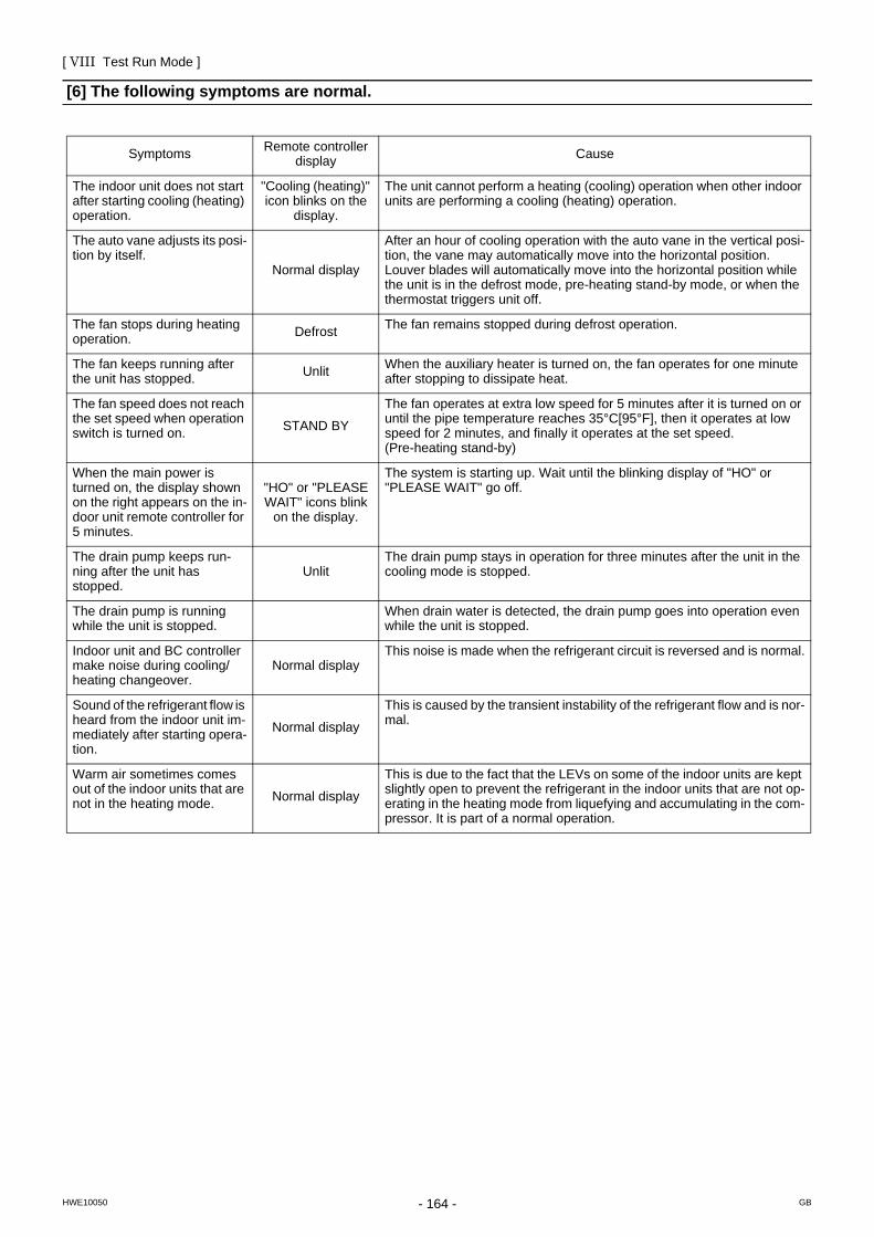
[ VIII Test Run Mode ]
- 164 -HWE10050 GB
[6] The following symptoms are normal.
Symptoms Remote controller display Cause
The indoor unit does not start after starting cooling (heating) operation.
"Cooling (heating)" icon blinks on the
display.
The unit cannot perform a heating (cooling) operation when other indoor units are performing a cooling (heating) operation.
The auto vane adjusts its posi-tion by itself.
Normal display
After an hour of cooling operation with the auto vane in the vertical posi-tion, the vane may automatically move into the horizontal position. Louver blades will automatically move into the horizontal position while the unit is in the defrost mode, pre-heating stand-by mode, or when the thermostat triggers unit off.
The fan stops during heating operation. Defrost The fan remains stopped during defrost operation.
The fan keeps running after the unit has stopped. Unlit When the auxiliary heater is turned on, the fan operates for one minute
after stopping to dissipate heat.
The fan speed does not reach the set speed when operation switch is turned on. STAND BY
The fan operates at extra low speed for 5 minutes after it is turned on or until the pipe temperature reaches 35°C[95°F], then it operates at low speed for 2 minutes, and finally it operates at the set speed. (Pre-heating stand-by)
When the main power is turned on, the display shown on the right appears on the in-door unit remote controller for 5 minutes.
"HO" or "PLEASE WAIT" icons blink
on the display.
The system is starting up. Wait until the blinking display of "HO" or "PLEASE WAIT" go off.
The drain pump keeps run-ning after the unit has stopped.
UnlitThe drain pump stays in operation for three minutes after the unit in the cooling mode is stopped.
The drain pump is running while the unit is stopped.
When drain water is detected, the drain pump goes into operation even while the unit is stopped.
Indoor unit and BC controller make noise during cooling/heating changeover.
Normal displayThis noise is made when the refrigerant circuit is reversed and is normal.
Sound of the refrigerant flow is heard from the indoor unit im-mediately after starting opera-tion.
Normal display
This is caused by the transient instability of the refrigerant flow and is nor-mal.
Warm air sometimes comes out of the indoor units that are not in the heating mode. Normal display
This is due to the fact that the LEVs on some of the indoor units are kept slightly open to prevent the refrigerant in the indoor units that are not op-erating in the heating mode from liquefying and accumulating in the com-pressor. It is part of a normal operation.
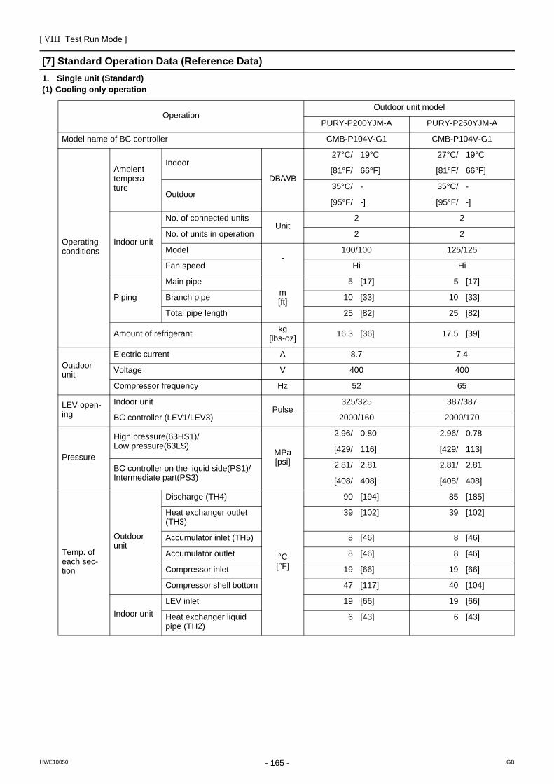
[ VIII Test Run Mode ]
- 165 -HWE10050 GB
[7] Standard Operation Data (Reference Data)1. Single unit (Standard)(1) Cooling only operation
OperationOutdoor unit model
PURY-P200YJM-A PURY-P250YJM-A
Model name of BC controller CMB-P104V-G1 CMB-P104V-G1
Operating conditions
Ambient tempera-ture
Indoor
DB/WB
27°C/ 19°C 27°C/ 19°C
[81°F/ 66°F] [81°F/ 66°F]
Outdoor35°C/ - 35°C/ -
[95°F/ -] [95°F/ -]
Indoor unit
No. of connected unitsUnit
2 2
No. of units in operation 2 2
Model-
100/100 125/125
Fan speed Hi Hi
Piping
Main pipem[ft]
5 [17] 5 [17]
Branch pipe 10 [33] 10 [33]
Total pipe length 25 [82] 25 [82]
Amount of refrigerant kg[lbs-oz] 16.3 [36] 17.5 [39]
Outdoor unit
Electric current A 8.7 7.4
Voltage V 400 400
Compressor frequency Hz 52 65
LEV open-ing
Indoor unitPulse
325/325 387/387
BC controller (LEV1/LEV3) 2000/160 2000/170
Pressure
High pressure(63HS1)/Low pressure(63LS)
MPa[psi]
2.96/ 0.80 2.96/ 0.78
[429/ 116] [429/ 113]
BC controller on the liquid side(PS1)/Intermediate part(PS3)
2.81/ 2.81 2.81/ 2.81
[408/ 408] [408/ 408]
Temp. of each sec-tion
Outdoor unit
Discharge (TH4)
°C[°F]
90 [194] 85 [185]
Heat exchanger outlet (TH3)
39 [102] 39 [102]
Accumulator inlet (TH5) 8 [46] 8 [46]
Accumulator outlet 8 [46] 8 [46]
Compressor inlet 19 [66] 19 [66]
Compressor shell bottom 47 [117] 40 [104]
Indoor unitLEV inlet 19 [66] 19 [66]
Heat exchanger liquid pipe (TH2)
6 [43] 6 [43]
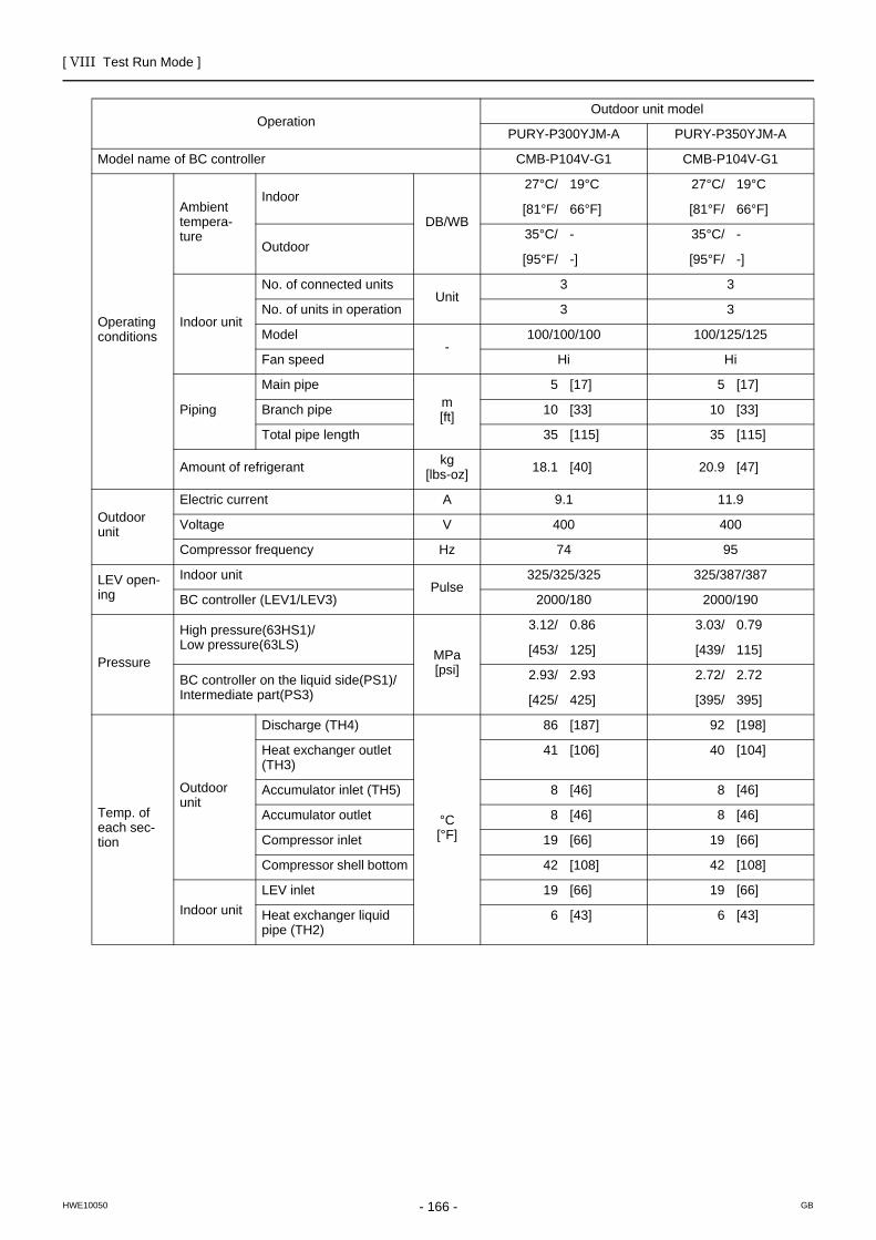
[ VIII Test Run Mode ]
- 166 -HWE10050 GB
OperationOutdoor unit model
PURY-P300YJM-A PURY-P350YJM-A
Model name of BC controller CMB-P104V-G1 CMB-P104V-G1
Operating conditions
Ambient tempera-ture
Indoor
DB/WB
27°C/ 19°C 27°C/ 19°C
[81°F/ 66°F] [81°F/ 66°F]
Outdoor35°C/ - 35°C/ -
[95°F/ -] [95°F/ -]
Indoor unit
No. of connected unitsUnit
3 3
No. of units in operation 3 3
Model-
100/100/100 100/125/125
Fan speed Hi Hi
Piping
Main pipem[ft]
5 [17] 5 [17]
Branch pipe 10 [33] 10 [33]
Total pipe length 35 [115] 35 [115]
Amount of refrigerant kg[lbs-oz] 18.1 [40] 20.9 [47]
Outdoor unit
Electric current A 9.1 11.9
Voltage V 400 400
Compressor frequency Hz 74 95
LEV open-ing
Indoor unitPulse
325/325/325 325/387/387
BC controller (LEV1/LEV3) 2000/180 2000/190
Pressure
High pressure(63HS1)/Low pressure(63LS)
MPa[psi]
3.12/ 0.86 3.03/ 0.79
[453/ 125] [439/ 115]
BC controller on the liquid side(PS1)/Intermediate part(PS3)
2.93/ 2.93 2.72/ 2.72
[425/ 425] [395/ 395]
Temp. of each sec-tion
Outdoor unit
Discharge (TH4)
°C[°F]
86 [187] 92 [198]
Heat exchanger outlet (TH3)
41 [106] 40 [104]
Accumulator inlet (TH5) 8 [46] 8 [46]
Accumulator outlet 8 [46] 8 [46]
Compressor inlet 19 [66] 19 [66]
Compressor shell bottom 42 [108] 42 [108]
Indoor unitLEV inlet 19 [66] 19 [66]
Heat exchanger liquid pipe (TH2)
6 [43] 6 [43]

[ VIII Test Run Mode ]
- 167 -HWE10050 GB
OperationOutdoor unit model
PURY-P400YJM-A PURY-P450YJM-A
Model name of BC controller CMB-P108V-GA1 CMB-P108V-GA1
Operating conditions
Ambient tempera-ture
Indoor
DB/WB
27°C/ 19°C 27°C/ 19°C
[81°F/ 66°F] [81°F/ 66°F]
Outdoor35°C/ - 35°C/ -
[95°F/ -] [95°F/ -]
Indoor unit
No. of connected unitsUnit
4 4
No. of units in operation 4 4
Model-
100/100/100/100 100/100/125/125
Fan speed Hi Hi
Piping
Main pipem[ft]
5 [17] 5 [17]
Branch pipe 10 [33] 10 [33]
Total pipe length 45 [148] 45 [148]
Amount of refrigerant kg[lbs-oz] 22.9 [51] 22.9 [51]
Outdoor unit
Electric current A 14.2 15.2
Voltage V 400 400
Compressor frequency Hz 97 111
LEV open-ing
Indoor unitPulse
325/325/325/325 325/325/387/387
BC controller (LEV1/LEV3) 2000/200 2000/210
Pressure
High pressure(63HS1)/Low pressure(63LS)
MPa[psi]
3.16/ 0.89 3.15/ 0.85
[458/ 129] [457/ 123]
BC controller on the liquid side(PS1)/Intermediate part(PS3)
2.75/ 2.75 2.70/ 2.70
[399/ 399] [392/ 392]
Temp. of each sec-tion
Outdoor unit
Discharge (TH4)
°C[°F]
91 [196] 90 [194]
Heat exchanger outlet (TH3)
42 [108] 40 [104]
Accumulator inlet (TH5) 8 [46] 8 [46]
Accumulator outlet 8 [46] 8 [46]
Compressor inlet 19 [66] 19 [66]
Compressor shell bottom 40 [104] 40 [104]
Indoor unitLEV inlet 17 [63] 17 [63]
Heat exchanger liquid pipe (TH2)
4 [39] 4 [39]
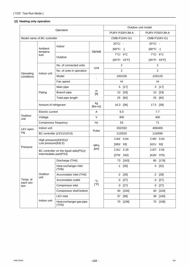
[ VIII Test Run Mode ]
- 168 -HWE10050 GB
(2) Heating only operation
OperationOutdoor unit model
PURY-P200YJM-A PURY-P250YJM-A
Model name of BC controller CMB-P104V-G1 CMB-P104V-G1
Operating conditions
Ambient tempera-ture
Indoor
DB/WB
20°C/ - 20°C/ -
[68°F/ -] [68°F/ -]
Outdoor7°C/ 6°C 7°C/ 6°C
[45°F/ 43°F] [45°F/ 43°F]
Indoor unit
No. of connected unitsUnit
2 2
No. of units in operation 2 2
Model-
100/100 125/125
Fan speed Hi Hi
Piping
Main pipem[ft]
5 [17] 5 [17]
Branch pipe 10 [33] 10 [33]
Total pipe length 25 [82] 25 [82]
Amount of refrigerant kg[lbs-oz] 16.3 [36] 17.5 [39]
Outdoor unit
Electric current A 6.0 7.7
Voltage V 400 400
Compressor frequency Hz 53 71
LEV open-ing
Indoor unitPulse
332/332 406/406
BC controller (LEV1/LEV3) 110/520 110/590
Pressure
High pressure(63HS1)/Low pressure(63LS)
MPa[psi]
2.64/ 0.64 2.90/ 0.64
[383/ 93] [421/ 93]
BC controller on the liquid side(PS1)/Intermediate part(PS3)
2.61/ 2.29 2.87/ 2.55
[379/ 332] [416/ 370]
Temp. of each sec-tion
Outdoor unit
Discharge (TH4)
°C[°F]
73 [163] 80 [176]
Heat exchanger inlet (TH6)
-1 [30] 0 [32]
Accumulator inlet (TH5) -2 [28] -2 [28]
Accumulator outlet -3 [27] -3 [27]
Compressor inlet -3 [27] -3 [27]
Compressor shell bottom 40 [104] 40 [104]
Indoor unitLEV inlet 37 [99] 38 [100]
Heat exchanger gas pipe (TH3)
70 [158] 70 [158]

[ VIII Test Run Mode ]
- 169 -HWE10050 GB
OperationOutdoor unit model
PURY-P300YJM-A PURY-P350YJM-A
Model name of BC controller CMB-P104V-G1 CMB-P104V-G1
Operating conditions
Ambient tempera-ture
Indoor
DB/WB
20°C/ - 20°C/ -
[68°F/ -] [68°F/ -]
Outdoor7°C/ 6°C 7°C/ 6°C
[45°F/ 43°F] [45°F/ 43°F]
Indoor unit
No. of connected unitsUnit
3 3
No. of units in operation 3 3
Model-
100/100/100 100/125/125
Fan speed Hi Hi
Piping
Main pipem[ft]
5 [17] 5 [17]
Branch pipe 10 [33] 10 [33]
Total pipe length 35 [115] 35 [115]
Amount of refrigerant kg[lbs-oz] 18.1 [40] 20.9 [47]
Outdoor unit
Electric current A 9.2 11.4
Voltage V 400 400
Compressor frequency Hz 81 101
LEV open-ing
Indoor unitPulse
332/332/332 332/406/406
BC controller (LEV1/LEV3) 110/660 110/730
Pressure
High pressure(63HS1)/Low pressure(63LS)
MPa[psi]
2.68/ 0.58 2.88/ 0.60
[389/ 84] [418/ 87]
BC controller on the liquid side(PS1)/Intermediate part(PS3)
2.64/ 2.32 2.84/ 2.52
[383/ 336] [412/ 365]
Temp. of each sec-tion
Outdoor unit
Discharge (TH4)
°C[°F]
81 [178] 84 [183]
Heat exchanger inlet (TH6)
0 [32] 1 [34]
Accumulator inlet (TH5) -3 [27] -4 [25]
Accumulator outlet -4 [25] -4 [25]
Compressor inlet -4 [25] -4 [25]
Compressor shell bottom 40 [104] 40 [104]
Indoor unitLEV inlet 39 [102] 39 [102]
Heat exchanger gas pipe (TH3)
70 [158] 70 [158]

[ VIII Test Run Mode ]
- 170 -HWE10050 GB
OperationOutdoor unit model
PURY-P400YJM-A PURY-P450YJM-A
Model name of BC controller CMB-P108V-GA1 CMB-P108V-GA1
Operating conditions
Ambient tempera-ture
Indoor
DB/WB
20°C/ - 20°C/ -
[68°F/ -] [68°F/ -]
Outdoor7°C/ 6°C 7°C/ 6°C
[45°F/ 43°F] [45°F/ 43°F]
Indoor unit
No. of connected unitsUnit
4 4
No. of units in operation 4 4
Model-
100/100/100/100 100/100/125/125
Fan speed Hi Hi
Piping
Main pipem[ft]
5 [17] 5 [17]
Branch pipe 10 [33] 10 [33]
Total pipe length 45 [148] 45 [148]
Amount of refrigerant kg[lbs-oz] 22.9 [51] 22.9 [51]
Outdoor unit
Electric current A 13.4 15.3
Voltage V 400 400
Compressor frequency Hz 102 117
LEV open-ing
Indoor unitPulse
332/332/332/332 332/332/406/406
BC controller (LEV1/LEV3) 110/800 110/870
Pressure
High pressure(63HS1)/Low pressure(63LS)
MPa[psi]
2.68/ 0.56 2.68/ 0.56
[389/ 81] [389/ 81]
BC controller on the liquid side(PS1)/Intermediate part(PS3)
2.64/ 2.32 2.64/ 2.32
[383/ 336] [383/ 336]
Temp. of each sec-tion
Outdoor unit
Discharge (TH4)
°C[°F]
82 [180] 82 [180]
Heat exchanger inlet (TH6)
1 [34] 1 [34]
Accumulator inlet (TH5) -4 [25] -4 [25]
Accumulator outlet -4 [25] -4 [25]
Compressor inlet -4 [25] -4 [25]
Compressor shell bottom 40 [104] 40 [104]
Indoor unitLEV inlet 37 [99] 37 [99]
Heat exchanger gas pipe (TH3)
70 [158] 70 [158]
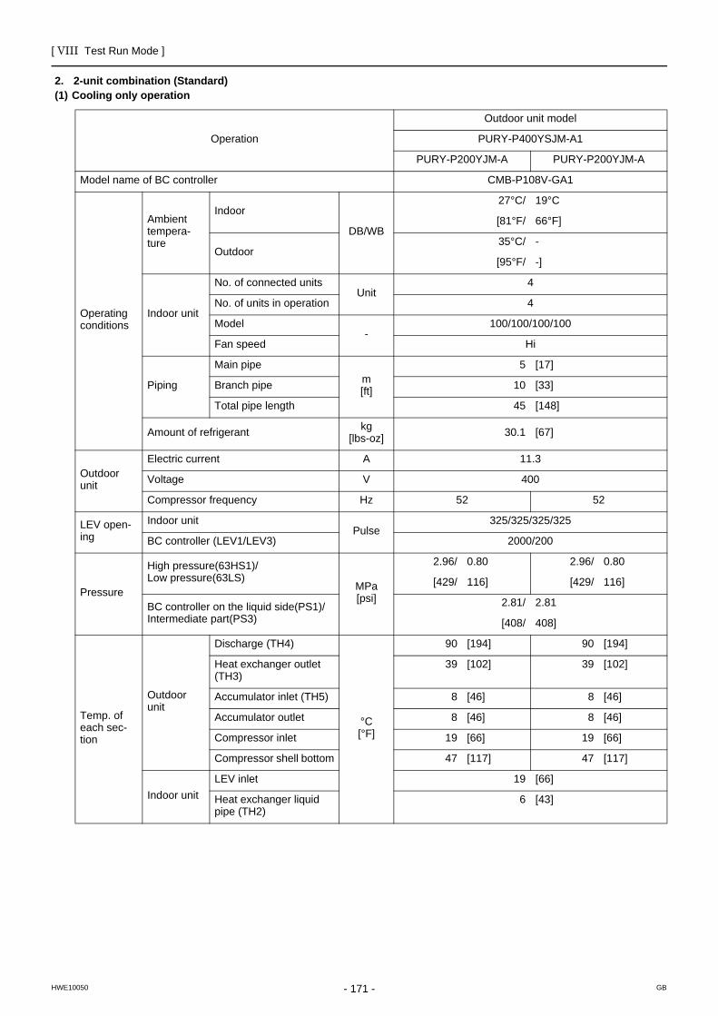
[ VIII Test Run Mode ]
- 171 -HWE10050 GB
2. 2-unit combination (Standard)(1) Cooling only operation
Operation
Outdoor unit model
PURY-P400YSJM-A1
PURY-P200YJM-A PURY-P200YJM-A
Model name of BC controller CMB-P108V-GA1
Operating conditions
Ambient tempera-ture
Indoor
DB/WB
27°C/ 19°C
[81°F/ 66°F]
Outdoor35°C/ -
[95°F/ -]
Indoor unit
No. of connected unitsUnit
4
No. of units in operation 4
Model-
100/100/100/100
Fan speed Hi
Piping
Main pipem[ft]
5 [17]
Branch pipe 10 [33]
Total pipe length 45 [148]
Amount of refrigerant kg[lbs-oz] 30.1 [67]
Outdoor unit
Electric current A 11.3
Voltage V 400
Compressor frequency Hz 52 52
LEV open-ing
Indoor unitPulse
325/325/325/325
BC controller (LEV1/LEV3) 2000/200
Pressure
High pressure(63HS1)/Low pressure(63LS)
MPa[psi]
2.96/ 0.80 2.96/ 0.80
[429/ 116] [429/ 116]
BC controller on the liquid side(PS1)/Intermediate part(PS3)
2.81/ 2.81
[408/ 408]
Temp. of each sec-tion
Outdoor unit
Discharge (TH4)
°C[°F]
90 [194] 90 [194]
Heat exchanger outlet (TH3)
39 [102] 39 [102]
Accumulator inlet (TH5) 8 [46] 8 [46]
Accumulator outlet 8 [46] 8 [46]
Compressor inlet 19 [66] 19 [66]
Compressor shell bottom 47 [117] 47 [117]
Indoor unitLEV inlet 19 [66]
Heat exchanger liquid pipe (TH2)
6 [43]

[ VIII Test Run Mode ]
- 172 -HWE10050 GB
Operation
Outdoor unit model
PURY-P450YSJM-A1
PURY-P250YJM-A PURY-P200YJM-A
Model name of BC controller CMB-P108V-GA1
Operating conditions
Ambient tempera-ture
Indoor
DB/WB
27°C/ 19°C
[81°F/ 66°F]
Outdoor35°C/ -
[95°F/ -]
Indoor unit
No. of connected unitsUnit
4
No. of units in operation 4
Model-
100/100/125/125
Fan speed Hi
Piping
Main pipem[ft]
5 [17]
Branch pipe 10 [33]
Total pipe length 45 [148]
Amount of refrigerant kg[lbs-oz] 30.1 [67]
Outdoor unit
Electric current A 13.1
Voltage V 400
Compressor frequency Hz 65 52
LEV open-ing
Indoor unitPulse
325/325/387/387
BC controller (LEV1/LEV3) 2000/210
Pressure
High pressure(63HS1)/Low pressure(63LS)
MPa[psi]
2.96/ 0.79 2.96/ 0.79
[429/ 115] [429/ 115]
BC controller on the liquid side(PS1)/Intermediate part(PS3)
2.81/ 2.81
[408/ 409]
Temp. of each sec-tion
Outdoor unit
Discharge (TH4)
°C[°F]
88 [190] 88 [190]
Heat exchanger outlet (TH3)
39 [102] 39 [102]
Accumulator inlet (TH5) 8 [46] 8 [46]
Accumulator outlet 8 [46] 8 [46]
Compressor inlet 19 [66] 19 [66]
Compressor shell bottom 43 [109] 43 [109]
Indoor unitLEV inlet 19 [66]
Heat exchanger liquid pipe (TH2)
6 [43]

[ VIII Test Run Mode ]
- 173 -HWE10050 GB
Operation
Outdoor unit model
PURY-P500YSJM-A
PURY-P250YJM-A PURY-P250YJM-A
Model name of BC controller CMB-P108V-GA1
Operating conditions
Ambient tempera-ture
Indoor
DB/WB
27°C/ 19°C
[81°F/ 66°F]
Outdoor35°C/ -
[95°F/ -]
Indoor unit
No. of connected unitsUnit
5
No. of units in operation 5
Model-
100/100/100/100/100
Fan speed Hi
Piping
Main pipem[ft]
5 [17]
Branch pipe 10 [33]
Total pipe length 55 [181]
Amount of refrigerant kg[lbs-oz] 31.2 [69]
Outdoor unit
Electric current A 15.6
Voltage V 400
Compressor frequency Hz 65 65
LEV open-ing
Indoor unitPulse
325/325/325/325/325
BC controller (LEV1/LEV3) 2000/220
Pressure
High pressure(63HS1)/Low pressure(63LS)
MPa[psi]
2.96/ 0.78 2.96/ 0.78
[429/ 113] [429/ 113]
BC controller on the liquid side(PS1)/Intermediate part(PS3)
2.81/ 2.81
[408/ 410]
Temp. of each sec-tion
Outdoor unit
Discharge (TH4)
°C[°F]
85 [185] 88 [194]
Heat exchanger outlet (TH3)
39 [102] 40 [104]
Accumulator inlet (TH5) 8 [46] 8 [46]
Accumulator outlet 8 [46] 8 [46]
Compressor inlet 19 [66] 19 [66]
Compressor shell bottom 40 [104] 40 [104]
Indoor unitLEV inlet 19 [66]
Heat exchanger liquid pipe (TH2)
6 [43]

[ VIII Test Run Mode ]
- 174 -HWE10050 GB
Operation
Outdoor unit model
PURY-P500YSJM-A1
PURY-P300YJM-A PURY-P200YJM-A
Model name of BC controller CMB-P108V-GA1
Operating conditions
Ambient tempera-ture
Indoor
DB/WB
27°C/ 19°C
[81°F/ 66°F]
Outdoor35°C/ -
[95°F/ -]
Indoor unit
No. of connected unitsUnit
5
No. of units in operation 5
Model-
100/100/100/100/100
Fan speed Hi
Piping
Main pipem[ft]
5 [17]
Branch pipe 10 [33]
Total pipe length 55 [181]
Amount of refrigerant kg[lbs-oz] 31.2 [69]
Outdoor unit
Electric current A 15.5
Voltage V 400
Compressor frequency Hz 74 52
LEV open-ing
Indoor unitPulse
325/325/325/325/325
BC controller (LEV1/LEV3) 2000/220
Pressure
High pressure(63HS1)/Low pressure(63LS)
MPa[psi]
3.04/ 0.83 3.04/ 0.83
[441/ 120] [441/ 120]
BC controller on the liquid side(PS1)/Intermediate part(PS3)
2.87/ 2.87
[416/ 416]
Temp. of each sec-tion
Outdoor unit
Discharge (TH4)
°C[°F]
88 [190] 88 [190]
Heat exchanger outlet (TH3)
40 [104] 40 [104]
Accumulator inlet (TH5) 8 [46] 8 [46]
Accumulator outlet 8 [46] 8 [46]
Compressor inlet 19 [66] 19 [66]
Compressor shell bottom 44 [111] 44 [111]
Indoor unitLEV inlet 19 [66]
Heat exchanger liquid pipe (TH2)
6 [43]

[ VIII Test Run Mode ]
- 175 -HWE10050 GB
Operation
Outdoor unit model
PURY-P550YSJM-A
PURY-P300YJM-A PURY-P250YJM-A
Model name of BC controller CMB-P108V-GA1
Operating conditions
Ambient tempera-ture
Indoor
DB/WB
27°C/ 19°C
[81°F/ 66°F]
Outdoor35°C/ -
[95°F/ -]
Indoor unit
No. of connected unitsUnit
5
No. of units in operation 5
Model-
100/100/100/125/125
Fan speed Hi
Piping
Main pipem[ft]
5 [17]
Branch pipe 10 [33]
Total pipe length 55 [181]
Amount of refrigerant kg[lbs-oz] 33.8 [75]
Outdoor unit
Electric current A 18.2
Voltage V 400
Compressor frequency Hz 74 65
LEV open-ing
Indoor unitPulse
325/325/325/387/387
BC controller (LEV1/LEV3) 2000/230
Pressure
High pressure(63HS1)/Low pressure(63LS)
MPa[psi]
3.04/ 0.82 3.04/ 0.82
[441/ 119] [441/ 119]
BC controller on the liquid side(PS1)/Intermediate part(PS3)
2.87/ 2.87
[416/ 416]
Temp. of each sec-tion
Outdoor unit
Discharge (TH4)
°C[°F]
86 [187] 86 [187]
Heat exchanger outlet (TH3)
40 [104] 40 [104]
Accumulator inlet (TH5) 8 [46] 8 [46]
Accumulator outlet 8 [46] 8 [46]
Compressor inlet 19 [66] 19 [66]
Compressor shell bottom 41 [106] 41 [106]
Indoor unitLEV inlet 19 [66]
Heat exchanger liquid pipe (TH2)
6 [43]

[ VIII Test Run Mode ]
- 176 -HWE10050 GB
Operation
Outdoor unit model
PURY-P600YSJM-A
PURY-P300YJM-A PURY-P300YJM-A
Model name of BC controller CMB-P108V-GA1
Operating conditions
Ambient tempera-ture
Indoor
DB/WB
27°C/ 19°C
[81°F/ 66°F]
Outdoor35°C/ -
[95°F/ -]
Indoor unit
No. of connected unitsUnit
6
No. of units in operation 6
Model-
100/100/100/100/100/100
Fan speed Hi
Piping
Main pipem[ft]
5 [17]
Branch pipe 10 [33]
Total pipe length 65 [214]
Amount of refrigerant kg[lbs-oz] 34.4 [76]
Outdoor unit
Electric current A 20.6
Voltage V 400
Compressor frequency Hz 74 74
LEV open-ing
Indoor unitPulse
325/325/325/325/325/325
BC controller (LEV1/LEV3) 2000/240
Pressure
High pressure(63HS1)/Low pressure(63LS)
MPa[psi]
3.12/ 0.86 3.12/ 0.86
[453/ 125] [453/ 125]
BC controller on the liquid side(PS1)/Intermediate part(PS3)
2.93/ 2.93
[425/ 425]
Temp. of each sec-tion
Outdoor unit
Discharge (TH4)
°C[°F]
86 [187] 86 [187]
Heat exchanger outlet (TH3)
41 [106] 41 [106]
Accumulator inlet (TH5) 8 [46] 8 [46]
Accumulator outlet 8 [46] 8 [46]
Compressor inlet 19 [66] 19 [66]
Compressor shell bottom 42 [108] 42 [108]
Indoor unitLEV inlet 19 [66]
Heat exchanger liquid pipe (TH2)
6 [43]

[ VIII Test Run Mode ]
- 177 -HWE10050 GB
Operation
Outdoor unit model
PURY-P600YSJM-A1
PURY-P350YJM-A PURY-P250YJM-A
Model name of BC controller CMB-P108V-GA1
Operating conditions
Ambient tempera-ture
Indoor
DB/WB
27°C/ 19°C
[81°F/ 66°F]
Outdoor35°C/ -
[95°F/ -]
Indoor unit
No. of connected unitsUnit
6
No. of units in operation 6
Model-
100/100/100/100/100/100
Fan speed Hi
Piping
Main pipem[ft]
5 [17]
Branch pipe 10 [33]
Total pipe length 65 [214]
Amount of refrigerant kg[lbs-oz] 36.7 [81]
Outdoor unit
Electric current A 20.1
Voltage V 400
Compressor frequency Hz 95 65
LEV open-ing
Indoor unitPulse
325/325/325/325/325/325
BC controller (LEV1/LEV3) 2000/240
Pressure
High pressure(63HS1)/Low pressure(63LS)
MPa[psi]
3.00/ 0.79 3.00/ 0.79
[435/ 115] [435/ 115]
BC controller on the liquid side(PS1)/Intermediate part(PS3)
2.77/ 2.77
[402/ 402]
Temp. of each sec-tion
Outdoor unit
Discharge (TH4)
°C[°F]
89 [192] 89 [192]
Heat exchanger outlet (TH3)
40 [104] 40 [104]
Accumulator inlet (TH5) 8 [46] 8 [46]
Accumulator outlet 8 [46] 8 [46]
Compressor inlet 19 [66] 19 [66]
Compressor shell bottom 41 [106] 41 [106]
Indoor unitLEV inlet 19 [66]
Heat exchanger liquid pipe (TH2)
6 [43]

[ VIII Test Run Mode ]
- 178 -HWE10050 GB
Operation
Outdoor unit model
PURY-P650YSJM-A
PURY-P350YJM-A PURY-P300YJM-A
Model name of BC controller CMB-P108V-GA1
Operating conditions
Ambient tempera-ture
Indoor
DB/WB
27°C/ 19°C
[81°F/ 66°F]
Outdoor35°C/ -
[95°F/ -]
Indoor unit
No. of connected unitsUnit
6
No. of units in operation 6
Model-
100/100/100/100/125/125
Fan speed Hi
Piping
Main pipem[ft]
5 [17]
Branch pipe 10 [33]
Total pipe length 65 [214]
Amount of refrigerant kg[lbs-oz] 37.7 [84]
Outdoor unit
Electric current A 22.6
Voltage V 400
Compressor frequency Hz 95 74
LEV open-ing
Indoor unitPulse
325/325/325/325/387/387
BC controller (LEV1/LEV3) 2000/250
Pressure
High pressure(63HS1)/Low pressure(63LS)
MPa[psi]
3.08/ 0.83 3.08/ 0.83
[447/ 120] [447/ 120]
BC controller on the liquid side(PS1)/Intermediate part(PS3)
2.83/ 2.83
[410/ 410]
Temp. of each sec-tion
Outdoor unit
Discharge (TH4)
°C[°F]
89 [192] 89 [192]
Heat exchanger outlet (TH3)
40 [104] 40 [104]
Accumulator inlet (TH5) 8 [46] 8 [46]
Accumulator outlet 8 [46] 8 [46]
Compressor inlet 19 [66] 19 [66]
Compressor shell bottom 42 [108] 42 [108]
Indoor unitLEV inlet 19 [66]
Heat exchanger liquid pipe (TH2)
6 [43]

[ VIII Test Run Mode ]
- 179 -HWE10050 GB
Operation
Outdoor unit model
PURY-P700YSJM-A
PURY-P400YJM-A PURY-P300YJM-A
Model name of BC controller CMB-P1016V-HA1
Operating conditions
Ambient tempera-ture
Indoor
DB/WB
27°C/ 19°C
[81°F/ 66°F]
Outdoor35°C/ -
[95°F/ -]
Indoor unit
No. of connected unitsUnit
7
No. of units in operation 7
Model-
100/100/100/100/100/100/100
Fan speed Hi
Piping
Main pipem[ft]
5 [17]
Branch pipe 10 [33]
Total pipe length 75 [247]
Amount of refrigerant kg[lbs-oz] 38.3 [85]
Outdoor unit
Electric current A 25.1
Voltage V 400
Compressor frequency Hz 97 74
LEV open-ing
Indoor unitPulse
325/325/325/325/325/325/325
BC controller (LEV1/LEV3) 2000/260
Pressure
High pressure(63HS1)/Low pressure(63LS)
MPa[psi]
3.14/ 0.88 3.14/ 0.88
[455/ 128] [455/ 128]
BC controller on the liquid side(PS1)/Intermediate part(PS3)
2.84/ 2.84
[412/ 412]
Temp. of each sec-tion
Outdoor unit
Discharge (TH4)
°C[°F]
89 [192] 89 [192]
Heat exchanger outlet (TH3)
42 [108] 42 [108]
Accumulator inlet (TH5) 8 [46] 8 [46]
Accumulator outlet 8 [46] 8 [46]
Compressor inlet 19 [66] 19 [66]
Compressor shell bottom 41 [106] 41 [106]
Indoor unitLEV inlet 18 [64]
Heat exchanger liquid pipe (TH2)
5 [41]

[ VIII Test Run Mode ]
- 180 -HWE10050 GB
Operation
Outdoor unit model
PURY-P700YSJM-A1
PURY-P350YJM-A PURY-P350YJM-A
Model name of BC controller CMB-P1016V-HA1
Operating conditions
Ambient tempera-ture
Indoor
DB/WB
27°C/ 19°C
[81°F/ 66°F]
Outdoor35°C/ -
[95°F/ -]
Indoor unit
No. of connected unitsUnit
7
No. of units in operation 7
Model-
100/100/100/100/100/100/100
Fan speed Hi
Piping
Main pipem[ft]
5 [17]
Branch pipe 10 [33]
Total pipe length 75 [247]
Amount of refrigerant kg[lbs-oz] 40.6 [90]
Outdoor unit
Electric current A 24.6
Voltage V 400
Compressor frequency Hz 95 95
LEV open-ing
Indoor unitPulse
325/325/325/325/325/325/325
BC controller (LEV1/LEV3) 2000/260
Pressure
High pressure(63HS1)/Low pressure(63LS)
MPa[psi]
3.03/ 0.79 3.03/ 0.79
[439/ 115] [439/ 115]
BC controller on the liquid side(PS1)/Intermediate part(PS3)
2.72/ 2.72
[395/ 395]
Temp. of each sec-tion
Outdoor unit
Discharge (TH4)
°C[°F]
92 [198] 92 [198]
Heat exchanger outlet (TH3)
40 [104] 40 [104]
Accumulator inlet (TH5) 8 [46] 8 [46]
Accumulator outlet 8 [46] 8 [46]
Compressor inlet 19 [66] 19 [66]
Compressor shell bottom 42 [108] 42 [108]
Indoor unitLEV inlet 19 [66]
Heat exchanger liquid pipe (TH2)
6 [43]

[ VIII Test Run Mode ]
- 181 -HWE10050 GB
Operation
Outdoor unit model
PURY-P750YSJM-A
PURY-P400YJM-A PURY-P350YJM-A
Model name of BC controller CMB-P1016V-HA1
Operating conditions
Ambient tempera-ture
Indoor
DB/WB
27°C/ 19°C
[81°F/ 66°F]
Outdoor35°C/ -
[95°F/ -]
Indoor unit
No. of connected unitsUnit
7
No. of units in operation 7
Model-
100/100/100/100/100/125/125
Fan speed Hi
Piping
Main pipem[ft]
5 [17]
Branch pipe 10 [33]
Total pipe length 75 [247]
Amount of refrigerant kg[lbs-oz] 42.6 [94]
Outdoor unit
Electric current A 27.8
Voltage V 400
Compressor frequency Hz 97 95
LEV open-ing
Indoor unitPulse
325/325/325/325/325/387/387
BC controller (LEV1/LEV3) 2000/270
Pressure
High pressure(63HS1)/Low pressure(63LS)
MPa[psi]
3.10/ 0.84 3.10/ 0.84
[450/ 122] [450/ 122]
BC controller on the liquid side(PS1)/Intermediate part(PS3)
2.74/ 2.74
[397/ 397]
Temp. of each sec-tion
Outdoor unit
Discharge (TH4)
°C[°F]
91 [196] 91 [196]
Heat exchanger outlet (TH3)
41 [106] 41 [106]
Accumulator inlet (TH5) 8 [46] 8 [46]
Accumulator outlet 8 [46] 8 [46]
Compressor inlet 19 [66] 19 [66]
Compressor shell bottom 41 [106] 41 [106]
Indoor unitLEV inlet 18 [64]
Heat exchanger liquid pipe (TH2)
5 [41]

[ VIII Test Run Mode ]
- 182 -HWE10050 GB
Operation
Outdoor unit model
PURY-P800YSJM-A
PURY-P400YJM-A PURY-P400YJM-A
Model name of BC controller CMB-P1016V-HA1
Operating conditions
Ambient tempera-ture
Indoor
DB/WB
27°C/ 19°C
[81°F/ 66°F]
Outdoor35°C/ -
[95°F/ -]
Indoor unit
No. of connected unitsUnit
8
No. of units in operation 8
Model-
100/100/100/100/100/100/100/100
Fan speed Hi
Piping
Main pipem[ft]
5 [17]
Branch pipe 10 [33]
Total pipe length 85 [279]
Amount of refrigerant kg[lbs-oz] 43.2 [96]
Outdoor unit
Electric current A 29.7
Voltage V 400
Compressor frequency Hz 97 97
LEV open-ing
Indoor unitPulse
325/325/325/325/325/325/325/325
BC controller (LEV1/LEV3) 2000/280
Pressure
High pressure(63HS1)/Low pressure(63LS)
MPa[psi]
3.16/ 0.89 3.16/ 0.89
[458/ 129] [458/ 129]
BC controller on the liquid side(PS1)/Intermediate part(PS3)
2.75/ 2.75
[399/ 399]
Temp. of each sec-tion
Outdoor unit
Discharge (TH4)
°C[°F]
91 [196] 91 [196]
Heat exchanger outlet (TH3)
42 [108] 42 [108]
Accumulator inlet (TH5) 8 [46] 8 [46]
Accumulator outlet 8 [46] 8 [46]
Compressor inlet 19 [66] 19 [66]
Compressor shell bottom 40 [104] 40 [104]
Indoor unitLEV inlet 17 [63]
Heat exchanger liquid pipe (TH2)
4 [39]
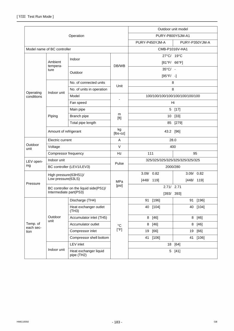
[ VIII Test Run Mode ]
- 183 -HWE10050 GB
Operation
Outdoor unit model
PURY-P800YSJM-A1
PURY-P450YJM-A PURY-P350YJM-A
Model name of BC controller CMB-P1016V-HA1
Operating conditions
Ambient tempera-ture
Indoor
DB/WB
27°C/ 19°C
[81°F/ 66°F]
Outdoor35°C/ -
[95°F/ -]
Indoor unit
No. of connected unitsUnit
8
No. of units in operation 8
Model-
100/100/100/100/100/100/100/100
Fan speed Hi
Piping
Main pipem[ft]
5 [17]
Branch pipe 10 [33]
Total pipe length 85 [279]
Amount of refrigerant kg[lbs-oz] 43.2 [96]
Outdoor unit
Electric current A 28.0
Voltage V 400
Compressor frequency Hz 111 95
LEV open-ing
Indoor unitPulse
325/325/325/325/325/325/325/325
BC controller (LEV1/LEV3) 2000/280
Pressure
High pressure(63HS1)/Low pressure(63LS)
MPa[psi]
3.09/ 0.82 3.09/ 0.82
[448/ 119] [448/ 119]
BC controller on the liquid side(PS1)/Intermediate part(PS3)
2.71/ 2.71
[393/ 393]
Temp. of each sec-tion
Outdoor unit
Discharge (TH4)
°C[°F]
91 [196] 91 [196]
Heat exchanger outlet (TH3)
40 [104] 40 [104]
Accumulator inlet (TH5) 8 [46] 8 [46]
Accumulator outlet 8 [46] 8 [46]
Compressor inlet 19 [66] 19 [66]
Compressor shell bottom 41 [106] 41 [106]
Indoor unitLEV inlet 18 [64]
Heat exchanger liquid pipe (TH2)
5 [41]

[ VIII Test Run Mode ]
- 184 -HWE10050 GB
Operation
Outdoor unit model
PURY-P850YSJM-A
PURY-P450YJM-A PURY-P400YJM-A
Model name of BC controller CMB-P1016V-HA1
Operating conditions
Ambient tempera-ture
Indoor
DB/WB
27°C/ 19°C
[81°F/ 66°F]
Outdoor35°C/ -
[95°F/ -]
Indoor unit
No. of connected unitsUnit
8
No. of units in operation 8
Model-
100/100/100/100/100/100/125/125
Fan speed Hi
Piping
Main pipem[ft]
5 [17]
Branch pipe 10 [33]
Total pipe length 85 [279]
Amount of refrigerant kg[lbs-oz] 44.2 [98]
Outdoor unit
Electric current A 30.7
Voltage V 400
Compressor frequency Hz 111 97
LEV open-ing
Indoor unitPulse
325/325/325/325/325/325/387/387
BC controller (LEV1/LEV3) 2000/290
Pressure
High pressure(63HS1)/Low pressure(63LS)
MPa[psi]
3.15/ 0.87 3.15/ 0.87
[457/ 126] [457/ 126]
BC controller on the liquid side(PS1)/Intermediate part(PS3)
2.72/ 2.72
[395/ 395]
Temp. of each sec-tion
Outdoor unit
Discharge (TH4)
°C[°F]
90 [194] 90 [194]
Heat exchanger outlet (TH3)
41 [106] 41 [106]
Accumulator inlet (TH5) 8 [46] 8 [46]
Accumulator outlet 8 [46] 8 [46]
Compressor inlet 19 [66] 19 [66]
Compressor shell bottom 40 [104] 40 [104]
Indoor unitLEV inlet 17 [63]
Heat exchanger liquid pipe (TH2)
4 [39]
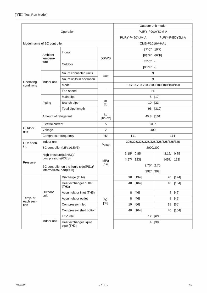
[ VIII Test Run Mode ]
- 185 -HWE10050 GB
Operation
Outdoor unit model
PURY-P900YSJM-A
PURY-P450YJM-A PURY-P450YJM-A
Model name of BC controller CMB-P1016V-HA1
Operating conditions
Ambient tempera-ture
Indoor
DB/WB
27°C/ 19°C
[81°F/ 66°F]
Outdoor35°C/ -
[95°F/ -]
Indoor unit
No. of connected unitsUnit
9
No. of units in operation 9
Model-
100/100/100/100/100/100/100/100/100
Fan speed Hi
Piping
Main pipem[ft]
5 [17]
Branch pipe 10 [33]
Total pipe length 95 [312]
Amount of refrigerant kg[lbs-oz] 45.8 [101]
Outdoor unit
Electric current A 31.7
Voltage V 400
Compressor frequency Hz 111 111
LEV open-ing
Indoor unitPulse
325/325/325/325/325/325/325/325/325
BC controller (LEV1/LEV3) 2000/300
Pressure
High pressure(63HS1)/Low pressure(63LS)
MPa[psi]
3.15/ 0.85 3.15/ 0.85
[457/ 123] [457/ 123]
BC controller on the liquid side(PS1)/Intermediate part(PS3)
2.70/ 2.70
[392/ 392]
Temp. of each sec-tion
Outdoor unit
Discharge (TH4)
°C[°F]
90 [194] 90 [194]
Heat exchanger outlet (TH3)
40 [104] 40 [104]
Accumulator inlet (TH5) 8 [46] 8 [46]
Accumulator outlet 8 [46] 8 [46]
Compressor inlet 19 [66] 19 [66]
Compressor shell bottom 40 [104] 40 [104]
Indoor unitLEV inlet 17 [63]
Heat exchanger liquid pipe (TH2)
4 [39]
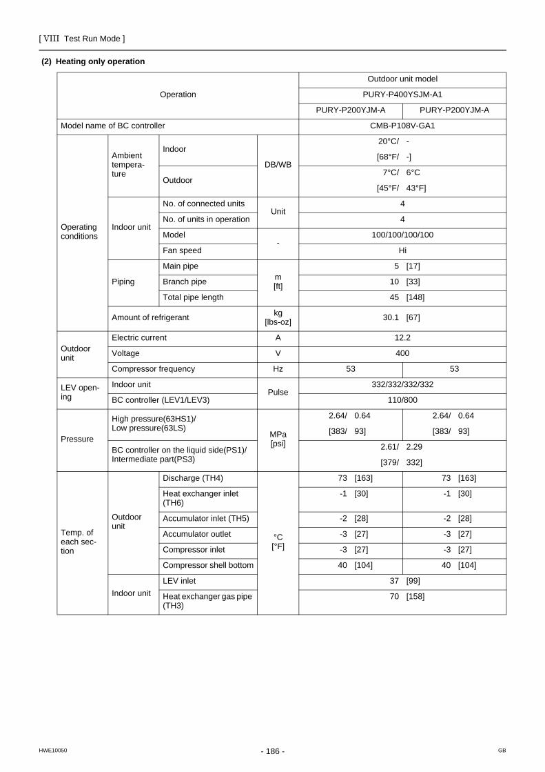
[ VIII Test Run Mode ]
- 186 -HWE10050 GB
(2) Heating only operation
Operation
Outdoor unit model
PURY-P400YSJM-A1
PURY-P200YJM-A PURY-P200YJM-A
Model name of BC controller CMB-P108V-GA1
Operating conditions
Ambient tempera-ture
Indoor
DB/WB
20°C/ -
[68°F/ -]
Outdoor7°C/ 6°C
[45°F/ 43°F]
Indoor unit
No. of connected unitsUnit
4
No. of units in operation 4
Model-
100/100/100/100
Fan speed Hi
Piping
Main pipem[ft]
5 [17]
Branch pipe 10 [33]
Total pipe length 45 [148]
Amount of refrigerant kg[lbs-oz] 30.1 [67]
Outdoor unit
Electric current A 12.2
Voltage V 400
Compressor frequency Hz 53 53
LEV open-ing
Indoor unitPulse
332/332/332/332
BC controller (LEV1/LEV3) 110/800
Pressure
High pressure(63HS1)/Low pressure(63LS)
MPa[psi]
2.64/ 0.64 2.64/ 0.64
[383/ 93] [383/ 93]
BC controller on the liquid side(PS1)/Intermediate part(PS3)
2.61/ 2.29
[379/ 332]
Temp. of each sec-tion
Outdoor unit
Discharge (TH4)
°C[°F]
73 [163] 73 [163]
Heat exchanger inlet (TH6)
-1 [30] -1 [30]
Accumulator inlet (TH5) -2 [28] -2 [28]
Accumulator outlet -3 [27] -3 [27]
Compressor inlet -3 [27] -3 [27]
Compressor shell bottom 40 [104] 40 [104]
Indoor unitLEV inlet 37 [99]
Heat exchanger gas pipe (TH3)
70 [158]

[ VIII Test Run Mode ]
- 187 -HWE10050 GB
Operation
Outdoor unit model
PURY-P450YSJM-A1
PURY-P250YJM-A PURY-P200YJM-A
Model name of BC controller CMB-P108V-GA1
Operating conditions
Ambient tempera-ture
Indoor
DB/WB
20°C/ -
[68°F/ -]
Outdoor7°C/ 6°C
[45°F/ 43°F]
Indoor unit
No. of connected unitsUnit
4
No. of units in operation 4
Model-
100/100/125/125
Fan speed Hi
Piping
Main pipem[ft]
5 [17]
Branch pipe 10 [33]
Total pipe length 45 [148]
Amount of refrigerant kg[lbs-oz] 30.1 [67]
Outdoor unit
Electric current A 14.0
Voltage V 400
Compressor frequency Hz 71 53
LEV open-ing
Indoor unitPulse
332/332/406/406
BC controller (LEV1/LEV3) 110/870
Pressure
High pressure(63HS1)/Low pressure(63LS)
MPa[psi]
2.77/ 0.64 2.77/ 0.64
[402/ 93] [402/ 93]
BC controller on the liquid side(PS1)/Intermediate part(PS3)
2.74/ 2.42
[397/ 351]
Temp. of each sec-tion
Outdoor unit
Discharge (TH4)
°C[°F]
77 [171] 77 [171]
Heat exchanger inlet (TH6)
0 [32] 0 [32]
Accumulator inlet (TH5) -2 [28] -2 [28]
Accumulator outlet -3 [27] -3 [27]
Compressor inlet -3 [27] -3 [27]
Compressor shell bottom 40 [104] 40 [104]
Indoor unitLEV inlet 38 [100]
Heat exchanger gas pipe (TH3)
70 [158]

[ VIII Test Run Mode ]
- 188 -HWE10050 GB
Operation
Outdoor unit model
PURY-P500YSJM-A
PURY-P250YJM-A PURY-P250YJM-A
Model name of BC controller CMB-P108V-GA1
Operating conditions
Ambient tempera-ture
Indoor
DB/WB
20°C/ -
[68°F/ -]
Outdoor7°C/ 6°C
[45°F/ 43°F]
Indoor unit
No. of connected unitsUnit
5
No. of units in operation 5
Model-
100/100/100/100/100
Fan speed Hi
Piping
Main pipem[ft]
5 [17]
Branch pipe 10 [33]
Total pipe length 55 [181]
Amount of refrigerant kg[lbs-oz] 31.2 [69]
Outdoor unit
Electric current A 15.9
Voltage V 400
Compressor frequency Hz 71 71
LEV open-ing
Indoor unitPulse
332/332/332/332/332
BC controller (LEV1/LEV3) 110/940
Pressure
High pressure(63HS1)/Low pressure(63LS)
MPa[psi]
2.90/ 0.64 2.90/ 0.64
[421/ 93] [421/ 93]
BC controller on the liquid side(PS1)/Intermediate part(PS3)
2.87/ 2.55
[416/ 370]
Temp. of each sec-tion
Outdoor unit
Discharge (TH4)
°C[°F]
80 [176] 80 [176]
Heat exchanger inlet (TH6)
0 [32] 0 [32]
Accumulator inlet (TH5) -2 [28] -2 [28]
Accumulator outlet -3 [27] -3 [27]
Compressor inlet -3 [27] -3 [27]
Compressor shell bottom 40 [104] 40 [104]
Indoor unitLEV inlet 38 [100]
Heat exchanger gas pipe (TH3)
70 [158]

[ VIII Test Run Mode ]
- 189 -HWE10050 GB
Operation
Outdoor unit model
PURY-P500YSJM-A1
PURY-P300YJM-A PURY-P200YJM-A
Model name of BC controller CMB-P108V-GA1
Operating conditions
Ambient tempera-ture
Indoor
DB/WB
20°C/ -
[68°F/ -]
Outdoor7°C/ 6°C
[45°F/ 43°F]
Indoor unit
No. of connected unitsUnit
5
No. of units in operation 5
Model-
100/100/100/100/100
Fan speed Hi
Piping
Main pipem[ft]
5 [17]
Branch pipe 10 [33]
Total pipe length 55 [181]
Amount of refrigerant kg[lbs-oz] 31.2 [69]
Outdoor unit
Electric current A 15.8
Voltage V 400
Compressor frequency Hz 81 53
LEV open-ing
Indoor unitPulse
332/332/332/332/332
BC controller (LEV1/LEV3) 110/940
Pressure
High pressure(63HS1)/Low pressure(63LS)
MPa[psi]
2.66/ 0.61 2.66/ 0.61
[386/ 88] [386/ 88]
BC controller on the liquid side(PS1)/Intermediate part(PS3)
2.63/ 2.31
[381/ 335]
Temp. of each sec-tion
Outdoor unit
Discharge (TH4)
°C[°F]
77 [171] 77 [171]
Heat exchanger inlet (TH6)
0 [32] 0 [32]
Accumulator inlet (TH5) -3 [27] -3 [27]
Accumulator outlet -4 [25] -4 [25]
Compressor inlet -4 [25] -4 [25]
Compressor shell bottom 40 [104] 40 [104]
Indoor unitLEV inlet 38 [100]
Heat exchanger gas pipe (TH3)
70 [158]

[ VIII Test Run Mode ]
- 190 -HWE10050 GB
Operation
Outdoor unit model
PURY-P550YSJM-A
PURY-P300YJM-A PURY-P250YJM-A
Model name of BC controller CMB-P108V-GA1
Operating conditions
Ambient tempera-ture
Indoor
DB/WB
20°C/ -
[68°F/ -]
Outdoor7°C/ 6°C
[45°F/ 43°F]
Indoor unit
No. of connected unitsUnit
5
No. of units in operation 5
Model-
100/100/100/125/125
Fan speed Hi
Piping
Main pipem[ft]
5 [17]
Branch pipe 10 [33]
Total pipe length 55 [181]
Amount of refrigerant kg[lbs-oz] 33.8 [75]
Outdoor unit
Electric current A 17.8
Voltage V 400
Compressor frequency Hz 81 71
LEV open-ing
Indoor unitPulse
332/332/332/406/406
BC controller (LEV1/LEV3) 110/1010
Pressure
High pressure(63HS1)/Low pressure(63LS)
MPa[psi]
2.79/ 0.61 2.79/ 0.61
[405/ 88] [405/ 88]
BC controller on the liquid side(PS1)/Intermediate part(PS3)
2.76/ 2.44
[400/ 354]
Temp. of each sec-tion
Outdoor unit
Discharge (TH4)
°C[°F]
81 [178] 81 [178]
Heat exchanger inlet (TH6)
0 [32] 0 [32]
Accumulator inlet (TH5) -3 [27] -3 [27]
Accumulator outlet -4 [25] -4 [25]
Compressor inlet -4 [25] -4 [25]
Compressor shell bottom 40 [104] 40 [104]
Indoor unitLEV inlet 39 [102]
Heat exchanger gas pipe (TH3)
70 [158]

[ VIII Test Run Mode ]
- 191 -HWE10050 GB
Operation
Outdoor unit model
PURY-P600YSJM-A
PURY-P300YJM-A PURY-P300YJM-A
Model name of BC controller CMB-P108V-GA1
Operating conditions
Ambient tempera-ture
Indoor
DB/WB
20°C/ -
[68°F/ -]
Outdoor7°C/ 6°C
[45°F/ 43°F]
Indoor unit
No. of connected unitsUnit
6
No. of units in operation 6
Model-
100/100/100/100/100/100
Fan speed Hi
Piping
Main pipem[ft]
5 [17]
Branch pipe 10 [33]
Total pipe length 65 [214]
Amount of refrigerant kg[lbs-oz] 34.4 [76]
Outdoor unit
Electric current A 20.0
Voltage V 400
Compressor frequency Hz 81 81
LEV open-ing
Indoor unitPulse
332/332/332/332/332/332
BC controller (LEV1/LEV3) 110/1080
Pressure
High pressure(63HS1)/Low pressure(63LS)
MPa[psi]
2.68/ 0.58 2.68/ 0.58
[389/ 84] [389/ 84]
BC controller on the liquid side(PS1)/Intermediate part(PS3)
2.64/ 2.32
[383/ 336]
Temp. of each sec-tion
Outdoor unit
Discharge (TH4)
°C[°F]
81 [178] 81 [178]
Heat exchanger inlet (TH6)
0 [32] 0 [32]
Accumulator inlet (TH5) -3 [27] -3 [27]
Accumulator outlet -4 [25] -4 [25]
Compressor inlet -4 [25] -4 [25]
Compressor shell bottom 40 [104] 40 [104]
Indoor unitLEV inlet 39 [102]
Heat exchanger gas pipe (TH3)
70 [158]

[ VIII Test Run Mode ]
- 192 -HWE10050 GB
Operation
Outdoor unit model
PURY-P600YSJM-A1
PURY-P350YJM-A PURY-P250YJM-A
Model name of BC controller CMB-P108V-GA1
Operating conditions
Ambient tempera-ture
Indoor
DB/WB
20°C/ -
[68°F/ -]
Outdoor7°C/ 6°C
[45°F/ 43°F]
Indoor unit
No. of connected unitsUnit
6
No. of units in operation 6
Model-
100/100/100/100/100/100
Fan speed Hi
Piping
Main pipem[ft]
5 [17]
Branch pipe 10 [33]
Total pipe length 65 [214]
Amount of refrigerant kg[lbs-oz] 36.7 [81]
Outdoor unit
Electric current A 19.5
Voltage V 400
Compressor frequency Hz 101 71
LEV open-ing
Indoor unitPulse
332/332/332/332/332/332
BC controller (LEV1/LEV3) 110/1080
Pressure
High pressure(63HS1)/Low pressure(63LS)
MPa[psi]
2.89/ 0.62 2.89/ 0.62
[419/ 90] [419/ 90]
BC controller on the liquid side(PS1)/Intermediate part(PS3)
2.85/ 2.53
[413/ 367]
Temp. of each sec-tion
Outdoor unit
Discharge (TH4)
°C[°F]
82 [180] 82 [180]
Heat exchanger inlet (TH6)
1 [34] 1 [34]
Accumulator inlet (TH5) -3 [27] -3 [27]
Accumulator outlet -4 [25] -4 [25]
Compressor inlet -4 [25] -4 [25]
Compressor shell bottom 40 [104] 40 [104]
Indoor unitLEV inlet 39 [102]
Heat exchanger gas pipe (TH3)
70 [158]

[ VIII Test Run Mode ]
- 193 -HWE10050 GB
Operation
Outdoor unit model
PURY-P650YSJM-A
PURY-P350YJM-A PURY-P300YJM-A
Model name of BC controller CMB-P108V-GA1
Operating conditions
Ambient tempera-ture
Indoor
DB/WB
20°C/ -
[68°F/ -]
Outdoor7°C/ 6°C
[45°F/ 43°F]
Indoor unit
No. of connected unitsUnit
6
No. of units in operation 6
Model-
100/100/100/100/125/125
Fan speed Hi
Piping
Main pipem[ft]
5 [17]
Branch pipe 10 [33]
Total pipe length 65 [214]
Amount of refrigerant kg[lbs-oz] 37.7 [84]
Outdoor unit
Electric current A 21.5
Voltage V 400
Compressor frequency Hz 101 81
LEV open-ing
Indoor unitPulse
332/332/332/332/406/406
BC controller (LEV1/LEV3) 110/1150
Pressure
High pressure(63HS1)/Low pressure(63LS)
MPa[psi]
2.78/ 0.58 2.78/ 0.58
[403/ 84] [403/ 84]
BC controller on the liquid side(PS1)/Intermediate part(PS3)
2.74/ 2.42
[397/ 351]
Temp. of each sec-tion
Outdoor unit
Discharge (TH4)
°C[°F]
83 [181] 83 [181]
Heat exchanger inlet (TH6)
1 [34] 1 [34]
Accumulator inlet (TH5) -3 [27] -3 [27]
Accumulator outlet -4 [25] -4 [25]
Compressor inlet -4 [25] -4 [25]
Compressor shell bottom 40 [104] 40 [104]
Indoor unitLEV inlet 38 [100]
Heat exchanger gas pipe (TH3)
70 [158]

[ VIII Test Run Mode ]
- 194 -HWE10050 GB
Operation
Outdoor unit model
PURY-P700YSJM-A
PURY-P400YJM-A PURY-P300YJM-A
Model name of BC controller CMB-P1016V-HA1
Operating conditions
Ambient tempera-ture
Indoor
DB/WB
20°C/ -
[68°F/ -]
Outdoor7°C/ 6°C
[45°F/ 43°F]
Indoor unit
No. of connected unitsUnit
7
No. of units in operation 7
Model-
100/100/100/100/100/100/100
Fan speed Hi
Piping
Main pipem[ft]
5 [17]
Branch pipe 10 [33]
Total pipe length 75 [247]
Amount of refrigerant kg[lbs-oz] 38.3 [85]
Outdoor unit
Electric current A 23.4
Voltage V 400
Compressor frequency Hz 102 81
LEV open-ing
Indoor unitPulse
332/332/332/332/332/332/332
BC controller (LEV1/LEV3) 110/1220
Pressure
High pressure(63HS1)/Low pressure(63LS)
MPa[psi]
2.68/ 0.57 2.68/ 0.57
[389/ 83] [389/ 83]
BC controller on the liquid side(PS1)/Intermediate part(PS3)
2.64/ 2.32
[383/ 336]
Temp. of each sec-tion
Outdoor unit
Discharge (TH4)
°C[°F]
82 [180] 82 [180]
Heat exchanger inlet (TH6)
1 [34] 1 [34]
Accumulator inlet (TH5) -4 [25] -4 [25]
Accumulator outlet -4 [25] -4 [25]
Compressor inlet -4 [25] -4 [25]
Compressor shell bottom 40 [104] 40 [104]
Indoor unitLEV inlet 38 [100]
Heat exchanger gas pipe (TH3)
70 [158]

[ VIII Test Run Mode ]
- 195 -HWE10050 GB
Operation
Outdoor unit model
PURY-P700YSJM-A1
PURY-P350YJM-A PURY-P350YJM-A
Model name of BC controller CMB-P1016V-HA1
Operating conditions
Ambient tempera-ture
Indoor
DB/WB
20°C/ -
[68°F/ -]
Outdoor7°C/ 6°C
[45°F/ 43°F]
Indoor unit
No. of connected unitsUnit
7
No. of units in operation 7
Model-
100/100/100/100/100/100/100
Fan speed Hi
Piping
Main pipem[ft]
5 [17]
Branch pipe 10 [33]
Total pipe length 75 [247]
Amount of refrigerant kg[lbs-oz] 40.6 [90]
Outdoor unit
Electric current A 22.9
Voltage V 400
Compressor frequency Hz 101 101
LEV open-ing
Indoor unitPulse
332/332/332/332/332/332/332
BC controller (LEV1/LEV3) 110/1220
Pressure
High pressure(63HS1)/Low pressure(63LS)
MPa[psi]
2.88/ 0.60 2.88/ 0.60
[418/ 87] [418/ 87]
BC controller on the liquid side(PS1)/Intermediate part(PS3)
2.84/ 2.52
[412/ 365]
Temp. of each sec-tion
Outdoor unit
Discharge (TH4)
°C[°F]
84 [183] 84 [183]
Heat exchanger inlet (TH6)
1 [34] 1 [34]
Accumulator inlet (TH5) -4 [25] -4 [25]
Accumulator outlet -4 [25] -4 [25]
Compressor inlet -4 [25] -4 [25]
Compressor shell bottom 40 [104] 40 [104]
Indoor unitLEV inlet 39 [102]
Heat exchanger gas pipe (TH3)
70 [158]

[ VIII Test Run Mode ]
- 196 -HWE10050 GB
Operation
Outdoor unit model
PURY-P750YSJM-A
PURY-P400YJM-A PURY-P350YJM-A
Model name of BC controller CMB-P1016V-HA1
Operating conditions
Ambient tempera-ture
Indoor
DB/WB
20°C/ -
[68°F/ -]
Outdoor7°C/ 6°C
[45°F/ 43°F]
Indoor unit
No. of connected unitsUnit
7
No. of units in operation 7
Model-
100/100/100/100/100/125/125
Fan speed Hi
Piping
Main pipem[ft]
5 [17]
Branch pipe 10 [33]
Total pipe length 75 [247]
Amount of refrigerant kg[lbs-oz] 42.6 [94]
Outdoor unit
Electric current A 25.3
Voltage V 400
Compressor frequency Hz 102 101
LEV open-ing
Indoor unitPulse
332/332/332/332/332/406/406
BC controller (LEV1/LEV3) 110/1290
Pressure
High pressure(63HS1)/Low pressure(63LS)
MPa[psi]
2.78/ 0.58 2.78/ 0.58
[403/ 84] [403/ 84]
BC controller on the liquid side(PS1)/Intermediate part(PS3)
2.74/ 2.42
[397/ 351]
Temp. of each sec-tion
Outdoor unit
Discharge (TH4)
°C[°F]
83 [181] 83 [181]
Heat exchanger inlet (TH6)
1 [34] 1 [34]
Accumulator inlet (TH5) -4 [25] -4 [25]
Accumulator outlet -4 [25] -4 [25]
Compressor inlet -4 [25] -4 [25]
Compressor shell bottom 40 [104] 40 [104]
Indoor unitLEV inlet 38 [100]
Heat exchanger gas pipe (TH3)
70 [158]

[ VIII Test Run Mode ]
- 197 -HWE10050 GB
Operation
Outdoor unit model
PURY-P800YSJM-A
PURY-P400YJM-A PURY-P400YJM-A
Model name of BC controller CMB-P1016V-HA1
Operating conditions
Ambient tempera-ture
Indoor
DB/WB
20°C/ -
[68°F/ -]
Outdoor7°C/ 6°C
[45°F/ 43°F]
Indoor unit
No. of connected unitsUnit
8
No. of units in operation 8
Model-
100/100/100/100/100/100/100/100
Fan speed Hi
Piping
Main pipem[ft]
5 [17]
Branch pipe 10 [33]
Total pipe length 85 [279]
Amount of refrigerant kg[lbs-oz] 43.2 [96]
Outdoor unit
Electric current A 27.3
Voltage V 400
Compressor frequency Hz 102 102
LEV open-ing
Indoor unitPulse
332/332/332/332/332/332/332/332
BC controller (LEV1/LEV3) 110/1360
Pressure
High pressure(63HS1)/Low pressure(63LS)
MPa[psi]
2.68/ 0.56 2.68/ 0.56
[389/ 81] [389/ 81]
BC controller on the liquid side(PS1)/Intermediate part(PS3)
2.64/ 2.32
[383/ 336]
Temp. of each sec-tion
Outdoor unit
Discharge (TH4)
°C[°F]
82 [180] 82 [180]
Heat exchanger inlet (TH6)
1 [34] 1 [34]
Accumulator inlet (TH5) -4 [25] -4 [25]
Accumulator outlet -4 [25] -4 [25]
Compressor inlet -4 [25] -4 [25]
Compressor shell bottom 40 [104] 40 [104]
Indoor unitLEV inlet 37 [99]
Heat exchanger gas pipe (TH3)
70 [158]

[ VIII Test Run Mode ]
- 198 -HWE10050 GB
Operation
Outdoor unit model
PURY-P800YSJM-A1
PURY-P450YJM-A PURY-P350YJM-A
Model name of BC controller CMB-P1016V-HA1
Operating conditions
Ambient tempera-ture
Indoor
DB/WB
20°C/ -
[68°F/ -]
Outdoor7°C/ 6°C
[45°F/ 43°F]
Indoor unit
No. of connected unitsUnit
8
No. of units in operation 8
Model-
100/100/100/100/100/100/100/100
Fan speed Hi
Piping
Main pipem[ft]
5 [17]
Branch pipe 10 [33]
Total pipe length 85 [279]
Amount of refrigerant kg[lbs-oz] 43.2 [96]
Outdoor unit
Electric current A 27.1
Voltage V 400
Compressor frequency Hz 117 101
LEV open-ing
Indoor unitPulse
332/332/332/332/332/332/332/332
BC controller (LEV1/LEV3) 110/1360
Pressure
High pressure(63HS1)/Low pressure(63LS)
MPa[psi]
2.78/ 0.58 2.78/ 0.58
[403/ 84] [403/ 84]
BC controller on the liquid side(PS1)/Intermediate part(PS3)
2.74/ 2.42
[397/ 351]
Temp. of each sec-tion
Outdoor unit
Discharge (TH4)
°C[°F]
83 [181] 83 [181]
Heat exchanger inlet (TH6)
1 [34] 1 [34]
Accumulator inlet (TH5) -4 [25] -4 [25]
Accumulator outlet -4 [25] -4 [25]
Compressor inlet -4 [25] -4 [25]
Compressor shell bottom 40 [104] 40 [104]
Indoor unitLEV inlet 38 [100]
Heat exchanger gas pipe (TH3)
70 [158]

[ VIII Test Run Mode ]
- 199 -HWE10050 GB
Operation
Outdoor unit model
PURY-P850YSJM-A
PURY-P450YJM-A PURY-P400YJM-A
Model name of BC controller CMB-P1016V-HA1
Operating conditions
Ambient tempera-ture
Indoor
DB/WB
20°C/ -
[68°F/ -]
Outdoor7°C/ 6°C
[45°F/ 43°F]
Indoor unit
No. of connected unitsUnit
8
No. of units in operation 8
Model-
100/100/100/100/100/100/125/125
Fan speed Hi
Piping
Main pipem[ft]
5 [17]
Branch pipe 10 [33]
Total pipe length 85 [279]
Amount of refrigerant kg[lbs-oz] 44.2 [98]
Outdoor unit
Electric current A 29.8
Voltage V 400
Compressor frequency Hz 117 102
LEV open-ing
Indoor unitPulse
332/332/332/332/332/332/406/406
BC controller (LEV1/LEV3) 110/1430
Pressure
High pressure(63HS1)/Low pressure(63LS)
MPa[psi]
2.68/ 0.56 2.68/ 0.56
[389/ 81] [389/ 81]
BC controller on the liquid side(PS1)/Intermediate part(PS3)
2.64/ 2.32
[383/ 336]
Temp. of each sec-tion
Outdoor unit
Discharge (TH4)
°C[°F]
82 [180] 82 [180]
Heat exchanger inlet (TH6)
1 [34] 1 [34]
Accumulator inlet (TH5) -4 [25] -4 [25]
Accumulator outlet -4 [25] -4 [25]
Compressor inlet -4 [25] -4 [25]
Compressor shell bottom 40 [104] 40 [104]
Indoor unitLEV inlet 37 [99]
Heat exchanger gas pipe (TH3)
70 [158]
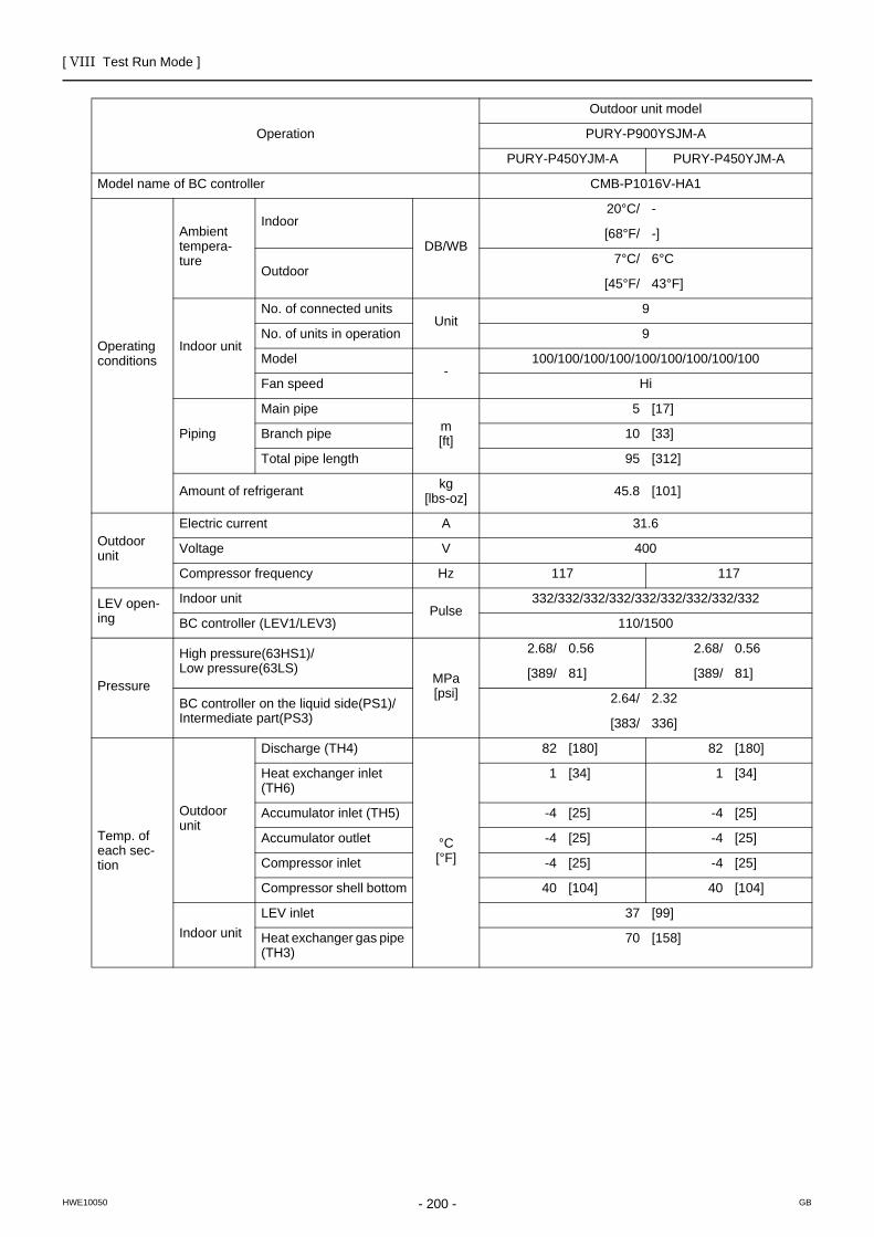
[ VIII Test Run Mode ]
- 200 -HWE10050 GB
Operation
Outdoor unit model
PURY-P900YSJM-A
PURY-P450YJM-A PURY-P450YJM-A
Model name of BC controller CMB-P1016V-HA1
Operating conditions
Ambient tempera-ture
Indoor
DB/WB
20°C/ -
[68°F/ -]
Outdoor7°C/ 6°C
[45°F/ 43°F]
Indoor unit
No. of connected unitsUnit
9
No. of units in operation 9
Model-
100/100/100/100/100/100/100/100/100
Fan speed Hi
Piping
Main pipem[ft]
5 [17]
Branch pipe 10 [33]
Total pipe length 95 [312]
Amount of refrigerant kg[lbs-oz] 45.8 [101]
Outdoor unit
Electric current A 31.6
Voltage V 400
Compressor frequency Hz 117 117
LEV open-ing
Indoor unitPulse
332/332/332/332/332/332/332/332/332
BC controller (LEV1/LEV3) 110/1500
Pressure
High pressure(63HS1)/Low pressure(63LS)
MPa[psi]
2.68/ 0.56 2.68/ 0.56
[389/ 81] [389/ 81]
BC controller on the liquid side(PS1)/Intermediate part(PS3)
2.64/ 2.32
[383/ 336]
Temp. of each sec-tion
Outdoor unit
Discharge (TH4)
°C[°F]
82 [180] 82 [180]
Heat exchanger inlet (TH6)
1 [34] 1 [34]
Accumulator inlet (TH5) -4 [25] -4 [25]
Accumulator outlet -4 [25] -4 [25]
Compressor inlet -4 [25] -4 [25]
Compressor shell bottom 40 [104] 40 [104]
Indoor unitLEV inlet 37 [99]
Heat exchanger gas pipe (TH3)
70 [158]
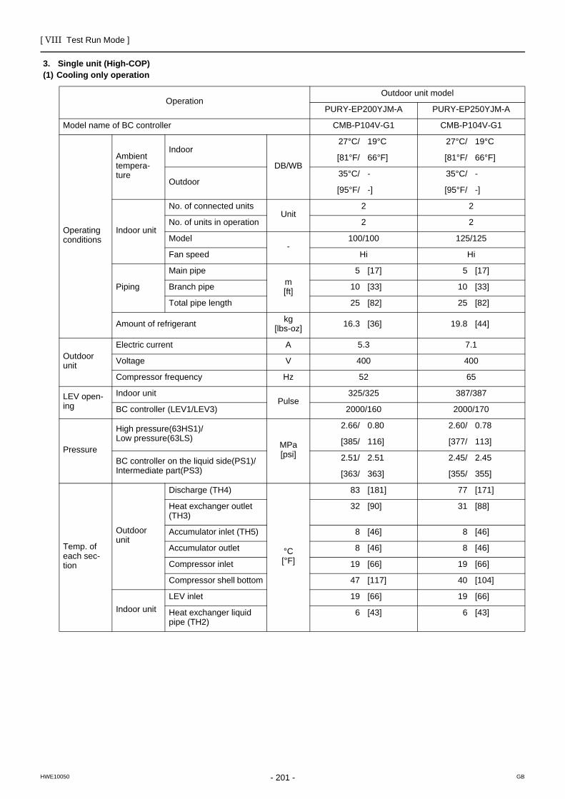
[ VIII Test Run Mode ]
- 201 -HWE10050 GB
3. Single unit (High-COP)(1) Cooling only operation
OperationOutdoor unit model
PURY-EP200YJM-A PURY-EP250YJM-A
Model name of BC controller CMB-P104V-G1 CMB-P104V-G1
Operating conditions
Ambient tempera-ture
Indoor
DB/WB
27°C/ 19°C 27°C/ 19°C
[81°F/ 66°F] [81°F/ 66°F]
Outdoor35°C/ - 35°C/ -
[95°F/ -] [95°F/ -]
Indoor unit
No. of connected unitsUnit
2 2
No. of units in operation 2 2
Model-
100/100 125/125
Fan speed Hi Hi
Piping
Main pipem[ft]
5 [17] 5 [17]
Branch pipe 10 [33] 10 [33]
Total pipe length 25 [82] 25 [82]
Amount of refrigerant kg[lbs-oz] 16.3 [36] 19.8 [44]
Outdoor unit
Electric current A 5.3 7.1
Voltage V 400 400
Compressor frequency Hz 52 65
LEV open-ing
Indoor unitPulse
325/325 387/387
BC controller (LEV1/LEV3) 2000/160 2000/170
Pressure
High pressure(63HS1)/Low pressure(63LS)
MPa[psi]
2.66/ 0.80 2.60/ 0.78
[385/ 116] [377/ 113]
BC controller on the liquid side(PS1)/Intermediate part(PS3)
2.51/ 2.51 2.45/ 2.45
[363/ 363] [355/ 355]
Temp. of each sec-tion
Outdoor unit
Discharge (TH4)
°C[°F]
83 [181] 77 [171]
Heat exchanger outlet (TH3)
32 [90] 31 [88]
Accumulator inlet (TH5) 8 [46] 8 [46]
Accumulator outlet 8 [46] 8 [46]
Compressor inlet 19 [66] 19 [66]
Compressor shell bottom 47 [117] 40 [104]
Indoor unitLEV inlet 19 [66] 19 [66]
Heat exchanger liquid pipe (TH2)
6 [43] 6 [43]

[ VIII Test Run Mode ]
- 202 -HWE10050 GB
OperationOutdoor unit model
PURY-EP300YJM-A PURY-EP350YJM-A
Model name of BC controller CMB-P104V-G1 CMB-P104V-G1
Operating conditions
Ambient tempera-ture
Indoor
DB/WB
27°C/ 19°C 27°C/ 19°C
[81°F/ 66°F] [81°F/ 66°F]
Outdoor35°C/ - 35°C/ -
[95°F/ -] [95°F/ -]
Indoor unit
No. of connected unitsUnit
3 3
No. of units in operation 3 3
Model-
100/100/100 100/125/125
Fan speed Hi Hi
Piping
Main pipem[ft]
5 [17] 5 [17]
Branch pipe 10 [33] 10 [33]
Total pipe length 35 [115] 35 [115]
Amount of refrigerant kg[lbs-oz] 20.4 [45] 20.9 [47]
Outdoor unit
Electric current A 8.7 10.8
Voltage V 400 400
Compressor frequency Hz 74 95
LEV open-ing
Indoor unitPulse
325/325/325 325/387/387
BC controller (LEV1/LEV3) 2000/180 2000/190
Pressure
High pressure(63HS1)/Low pressure(63LS)
MPa[psi]
2.78/ 0.86 2.75/ 0.79
[403/ 125] [399/ 115]
BC controller on the liquid side(PS1)/Intermediate part(PS3)
2.59/ 2.59 2.55/ 2.55
[375/ 375] [370/ 370]
Temp. of each sec-tion
Outdoor unit
Discharge (TH4)
°C[°F]
80 [176] 80 [176]
Heat exchanger outlet (TH3)
35 [95] 35 [95]
Accumulator inlet (TH5) 8 [46] 8 [46]
Accumulator outlet 8 [46] 8 [46]
Compressor inlet 19 [66] 19 [66]
Compressor shell bottom 42 [108] 40 [104]
Indoor unitLEV inlet 19 [108] 19 [66]
Heat exchanger liquid pipe (TH2)
6 [43] 6 [43]
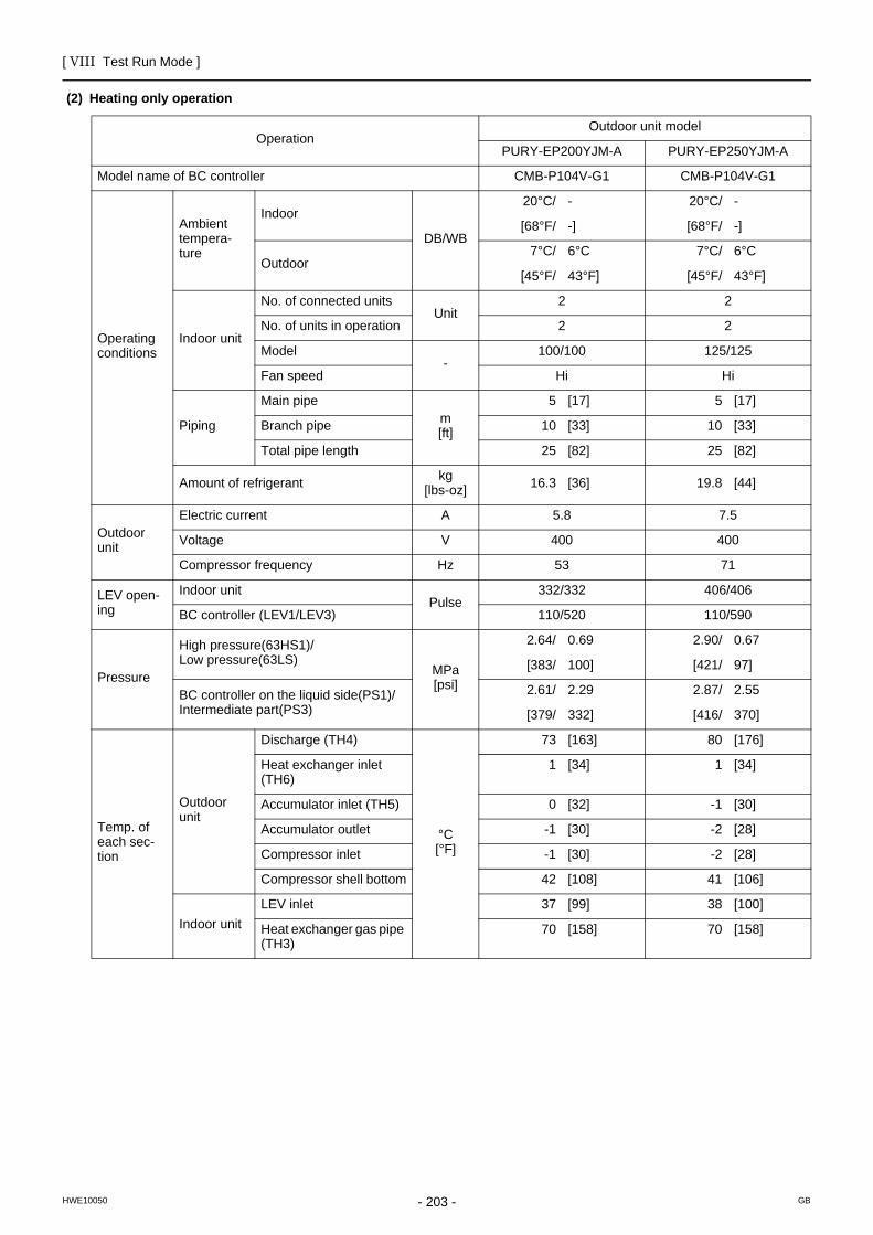
[ VIII Test Run Mode ]
- 203 -HWE10050 GB
(2) Heating only operation
OperationOutdoor unit model
PURY-EP200YJM-A PURY-EP250YJM-A
Model name of BC controller CMB-P104V-G1 CMB-P104V-G1
Operating conditions
Ambient tempera-ture
Indoor
DB/WB
20°C/ - 20°C/ -
[68°F/ -] [68°F/ -]
Outdoor7°C/ 6°C 7°C/ 6°C
[45°F/ 43°F] [45°F/ 43°F]
Indoor unit
No. of connected unitsUnit
2 2
No. of units in operation 2 2
Model-
100/100 125/125
Fan speed Hi Hi
Piping
Main pipem[ft]
5 [17] 5 [17]
Branch pipe 10 [33] 10 [33]
Total pipe length 25 [82] 25 [82]
Amount of refrigerant kg[lbs-oz] 16.3 [36] 19.8 [44]
Outdoor unit
Electric current A 5.8 7.5
Voltage V 400 400
Compressor frequency Hz 53 71
LEV open-ing
Indoor unitPulse
332/332 406/406
BC controller (LEV1/LEV3) 110/520 110/590
Pressure
High pressure(63HS1)/Low pressure(63LS)
MPa[psi]
2.64/ 0.69 2.90/ 0.67
[383/ 100] [421/ 97]
BC controller on the liquid side(PS1)/Intermediate part(PS3)
2.61/ 2.29 2.87/ 2.55
[379/ 332] [416/ 370]
Temp. of each sec-tion
Outdoor unit
Discharge (TH4)
°C[°F]
73 [163] 80 [176]
Heat exchanger inlet (TH6)
1 [34] 1 [34]
Accumulator inlet (TH5) 0 [32] -1 [30]
Accumulator outlet -1 [30] -2 [28]
Compressor inlet -1 [30] -2 [28]
Compressor shell bottom 42 [108] 41 [106]
Indoor unitLEV inlet 37 [99] 38 [100]
Heat exchanger gas pipe (TH3)
70 [158] 70 [158]

[ VIII Test Run Mode ]
- 204 -HWE10050 GB
OperationOutdoor unit model
PURY-EP300YJM-A PURY-EP350YJM-A
Model name of BC controller CMB-P104V-G1 CMB-P104V-G1
Operating conditions
Ambient tempera-ture
Indoor
DB/WB
20°C/ - 20°C/ -
[68°F/ -] [68°F/ -]
Outdoor7°C/ 6°C 7°C/ 6°C
[45°F/ 43°F] [45°F/ 43°F]
Indoor unit
No. of connected unitsUnit
3 3
No. of units in operation 3 3
Model-
100/100/100 100/125/125
Fan speed Hi Hi
Piping
Main pipem[ft]
5 [17] 5 [17]
Branch pipe 10 [33] 10 [33]
Total pipe length 35 [115] 35 [115]
Amount of refrigerant kg[lbs-oz] 20.4 [45] 20.9 [47]
Outdoor unit
Electric current A 9.0 11.1
Voltage V 400 400
Compressor frequency Hz 81 101
LEV open-ing
Indoor unitPulse
332/332/332 332/406/406
BC controller (LEV1/LEV3) 110/660 110/730
Pressure
High pressure(63HS1)/Low pressure(63LS)
MPa[psi]
2.68/ 0.60 2.88/ 0.65
[389/ 87] [418/ 94]
BC controller on the liquid side(PS1)/Intermediate part(PS3)
2.64/ 2.32 2.84/ 2.52
[383/ 336] [412/ 365]
Temp. of each sec-tion
Outdoor unit
Discharge (TH4)
°C[°F]
81 [178] 80 [176]
Heat exchanger inlet (TH6)
1 [34] 1 [34]
Accumulator inlet (TH5) -2 [28] -1 [30]
Accumulator outlet -3 [27] -2 [28]
Compressor inlet -3 [27] -2 [28]
Compressor shell bottom 41 [106] 41 [106]
Indoor unitLEV inlet 39 [102] 38 [100]
Heat exchanger gas pipe (TH3)
70 [158] 70 [158]

[ VIII Test Run Mode ]
- 205 -HWE10050 GB
4. 2-unit combination (High-COP)(1) Cooling only operation
Operation
Outdoor unit model
PURY-EP400YSJM-A
PURY-EP200YJM-A PURY-EP200YJM-A
Model name of BC controller CMB-P108V-GA1
Operating conditions
Ambient tempera-ture
Indoor
DB/WB
27°C/ 19°C
[81°F/ 66°F]
Outdoor35°C/ -
[95°F/ -]
Indoor unit
No. of connected unitsUnit
4
No. of units in operation 4
Model-
100/100/100/100
Fan speed Hi
Piping
Main pipem[ft]
5 [17]
Branch pipe 10 [33]
Total pipe length 45 [148]
Amount of refrigerant kg[lbs-oz] 30.1 [67]
Outdoor unit
Electric current A 10.9
Voltage V 400
Compressor frequency Hz 52 52
LEV open-ing
Indoor unitPulse
325/325/325/325
BC controller (LEV1/LEV3) 2000/200
Pressure
High pressure(63HS1)/Low pressure(63LS)
MPa[psi]
2.96/ 0.80 2.96/ 0.80
[429/ 116] [429/ 116]
BC controller on the liquid side(PS1)/Intermediate part(PS3)
2.81/ 2.81
[408/ 408]
Temp. of each sec-tion
Outdoor unit
Discharge (TH4)
°C[°F]
90 [194] 90 [194]
Heat exchanger outlet (TH3)
39 [102] 39 [102]
Accumulator inlet (TH5) 8 [46] 8 [46]
Accumulator outlet 8 [46] 8 [46]
Compressor inlet 19 [66] 19 [66]
Compressor shell bottom 47 [117] 47 [117]
Indoor unitLEV inlet 19 [66]
Heat exchanger liquid pipe (TH2)
6 [43]

[ VIII Test Run Mode ]
- 206 -HWE10050 GB
Operation
Outdoor unit model
PURY-EP450YSJM-A
PURY-EP250YJM-A PURY-EP200YJM-A
Model name of BC controller CMB-P108V-GA1
Operating conditions
Ambient tempera-ture
Indoor
DB/WB
27°C/ 19°C
[81°F/ 66°F]
Outdoor35°C/ -
[95°F/ -]
Indoor unit
No. of connected unitsUnit
4
No. of units in operation 4
Model-
100/100/125/125
Fan speed Hi
Piping
Main pipem[ft]
5 [17]
Branch pipe 10 [33]
Total pipe length 45 [148]
Amount of refrigerant kg[lbs-oz] 32.4 [72]
Outdoor unit
Electric current A 12.6
Voltage V 400
Compressor frequency Hz 65 52
LEV open-ing
Indoor unitPulse
325/325/387/387
BC controller (LEV1/LEV3) 2000/210
Pressure
High pressure(63HS1)/Low pressure(63LS)
MPa[psi]
2.96/ 0.79 2.96/ 0.79
[429/ 115] [429/ 115]
BC controller on the liquid side(PS1)/Intermediate part(PS3)
2.81/ 2.81
[408/ 409]
Temp. of each sec-tion
Outdoor unit
Discharge (TH4)
°C[°F]
88 [190] 88 [190]
Heat exchanger outlet (TH3)
39 [102] 39 [102]
Accumulator inlet (TH5) 8 [46] 8 [46]
Accumulator outlet 8 [46] 8 [46]
Compressor inlet 19 [66] 19 [66]
Compressor shell bottom 43 [109] 43 [109]
Indoor unitLEV inlet 19 [66]
Heat exchanger liquid pipe (TH2)
6 [43]

[ VIII Test Run Mode ]
- 207 -HWE10050 GB
Operation
Outdoor unit model
PURY-EP500YSJM-A
PURY-EP300YJM-A PURY-EP200YJM-A
Model name of BC controller CMB-P108V-GA1
Operating conditions
Ambient tempera-ture
Indoor
DB/WB
27°C/ 19°C
[81°F/ 66°F]
Outdoor35°C/ -
[95°F/ -]
Indoor unit
No. of connected unitsUnit
5
No. of units in operation 5
Model-
100/100/100/100/100
Fan speed Hi
Piping
Main pipem[ft]
5 [17]
Branch pipe 10 [33]
Total pipe length 55 [181]
Amount of refrigerant kg[lbs-oz] 33.5 [74]
Outdoor unit
Electric current A 14.3
Voltage V 400
Compressor frequency Hz 74 52
LEV open-ing
Indoor unitPulse
325/325/325/325/325
BC controller (LEV1/LEV3) 2000/220
Pressure
High pressure(63HS1)/Low pressure(63LS)
MPa[psi]
2.96/ 0.78 2.96/ 0.78
[429/ 113] [429/ 113]
BC controller on the liquid side(PS1)/Intermediate part(PS3)
2.81/ 2.81
[408/ 409]
Temp. of each sec-tion
Outdoor unit
Discharge (TH4)
°C[°F]
85 [185] 90 [194]
Heat exchanger outlet (TH3)
39 [102] 40 [104]
Accumulator inlet (TH5) 8 [46] 8 [46]
Accumulator outlet 8 [46] 8 [46]
Compressor inlet 19 [66] 19 [66]
Compressor shell bottom 40 [104] 40 [104]
Indoor unitLEV inlet 19 [66]
Heat exchanger liquid pipe (TH2)
6 [43]

[ VIII Test Run Mode ]
- 208 -HWE10050 GB
Operation
Outdoor unit model
PURY-EP500YSJM-A1
PURY-EP250YJM-A PURY-EP250YJM-A
Model name of BC controller CMB-P108V-GA1
Operating conditions
Ambient tempera-ture
Indoor
DB/WB
27°C/ 19°C
[81°F/ 66°F]
Outdoor35°C/ -
[95°F/ -]
Indoor unit
No. of connected unitsUnit
5
No. of units in operation 5
Model-
100/100/100/100/100
Fan speed Hi
Piping
Main pipem[ft]
5 [17]
Branch pipe 10 [33]
Total pipe length 55 [181]
Amount of refrigerant kg[lbs-oz] 35.8 [79]
Outdoor unit
Electric current A 14.7
Voltage V 400
Compressor frequency Hz 65 65
LEV open-ing
Indoor unitPulse
325/325/325/325/325
BC controller (LEV1/LEV3) 2000/220
Pressure
High pressure(63HS1)/Low pressure(63LS)
MPa[psi]
3.04/ 0.83 3.04/ 0.83
[441/ 120] [441/ 120]
BC controller on the liquid side(PS1)/Intermediate part(PS3)
2.87/ 2.87
[416/ 416]
Temp. of each sec-tion
Outdoor unit
Discharge (TH4)
°C[°F]
88 [190] 88 [190]
Heat exchanger outlet (TH3)
40 [104] 40 [104]
Accumulator inlet (TH5) 8 [46] 8 [46]
Accumulator outlet 8 [46] 8 [46]
Compressor inlet 19 [66] 19 [66]
Compressor shell bottom 44 [111] 44 [111]
Indoor unitLEV inlet 19 [66]
Heat exchanger liquid pipe (TH2)
6 [43]

[ VIII Test Run Mode ]
- 209 -HWE10050 GB
Operation
Outdoor unit model
PURY-EP550YSJM-A
PURY-EP300YJM-A PURY-EP250YJM-A
Model name of BC controller CMB-P108V-GA1
Operating conditions
Ambient tempera-ture
Indoor
DB/WB
27°C/ 19°C
[81°F/ 66°F]
Outdoor35°C/ -
[95°F/ -]
Indoor unit
No. of connected unitsUnit
5
No. of units in operation 5
Model-
100/100/100/125/125
Fan speed Hi
Piping
Main pipem[ft]
5 [17]
Branch pipe 10 [33]
Total pipe length 55 [181]
Amount of refrigerant kg[lbs-oz] 38.4 [85]
Outdoor unit
Electric current A 16.2
Voltage V 400
Compressor frequency Hz 74 65
LEV open-ing
Indoor unitPulse
325/325/325/387/387
BC controller (LEV1/LEV3) 2000/230
Pressure
High pressure(63HS1)/Low pressure(63LS)
MPa[psi]
3.04/ 0.82 3.04/ 0.82
[441/ 119] [441/ 119]
BC controller on the liquid side(PS1)/Intermediate part(PS3)
2.87/ 2.87
[416/ 416]
Temp. of each sec-tion
Outdoor unit
Discharge (TH4)
°C[°F]
86 [187] 86 [187]
Heat exchanger outlet (TH3)
40 [104] 40 [104]
Accumulator inlet (TH5) 8 [46] 8 [46]
Accumulator outlet 8 [46] 8 [46]
Compressor inlet 19 [66] 19 [66]
Compressor shell bottom 41 [106] 41 [106]
Indoor unitLEV inlet 19 [66]
Heat exchanger liquid pipe (TH2)
6 [43]

[ VIII Test Run Mode ]
- 210 -HWE10050 GB
Operation
Outdoor unit model
PURY-EP600YSJM-A
PURY-EP300YJM-A PURY-EP300YJM-A
Model name of BC controller CMB-P108V-GA1
Operating conditions
Ambient tempera-ture
Indoor
DB/WB
27°C/ 19°C
[81°F/ 66°F]
Outdoor35°C/ -
[95°F/ -]
Indoor unit
No. of connected unitsUnit
6
No. of units in operation 6
Model-
100/100/100/100/100/100
Fan speed Hi
Piping
Main pipem[ft]
5 [17]
Branch pipe 10 [33]
Total pipe length 65 [214]
Amount of refrigerant kg[lbs-oz] 39.0 [86]
Outdoor unit
Electric current A 17.7
Voltage V 400
Compressor frequency Hz 74 74
LEV open-ing
Indoor unitPulse
325/325/325/325/325/325
BC controller (LEV1/LEV3) 2000/240
Pressure
High pressure(63HS1)/Low pressure(63LS)
MPa[psi]
3.12/ 0.86 3.12/ 0.86
[453/ 125] [453/ 125]
BC controller on the liquid side(PS1)/Intermediate part(PS3)
2.93/ 2.93
[425/ 425]
Temp. of each sec-tion
Outdoor unit
Discharge (TH4)
°C[°F]
86 [187] 86 [187]
Heat exchanger outlet (TH3)
41 [106] 41 [106]
Accumulator inlet (TH5) 8 [46] 8 [46]
Accumulator outlet 8 [46] 8 [46]
Compressor inlet 19 [66] 19 [66]
Compressor shell bottom 42 [108] 42 [108]
Indoor unitLEV inlet 19 [66]
Heat exchanger liquid pipe (TH2)
6 [43]

[ VIII Test Run Mode ]
- 211 -HWE10050 GB
Operation
Outdoor unit model
PURY-EP600YSJM-A1
PURY-EP350YJM-A PURY-EP250YJM-A
Model name of BC controller CMB-P108V-GA1
Operating conditions
Ambient tempera-ture
Indoor
DB/WB
27°C/ 19°C
[81°F/ 66°F]
Outdoor35°C/ -
[95°F/ -]
Indoor unit
No. of connected unitsUnit
6
No. of units in operation 6
Model-
100/100/100/100/100/100
Fan speed Hi
Piping
Main pipem[ft]
5 [17]
Branch pipe 10 [33]
Total pipe length 65 [214]
Amount of refrigerant kg[lbs-oz] 39.0 [86]
Outdoor unit
Electric current A 18.7
Voltage V 400
Compressor frequency Hz 95 65
LEV open-ing
Indoor unitPulse
325/325/325/325/325/325
BC controller (LEV1/LEV3) 2000/240
Pressure
High pressure(63HS1)/Low pressure(63LS)
MPa[psi]
3.00/ 0.79 3.00/ 0.79
[435/ 115] [435/ 115]
BC controller on the liquid side(PS1)/Intermediate part(PS3)
2.77/ 2.77
[402/ 402]
Temp. of each sec-tion
Outdoor unit
Discharge (TH4)
°C[°F]
89 [192] 89 [192]
Heat exchanger outlet (TH3)
40 [104] 40 [104]
Accumulator inlet (TH5) 8 [46] 8 [46]
Accumulator outlet 8 [46] 8 [46]
Compressor inlet 19 [66] 19 [66]
Compressor shell bottom 41 [106] 41 [106]
Indoor unitLEV inlet 19 [66]
Heat exchanger liquid pipe (TH2)
6 [43]

[ VIII Test Run Mode ]
- 212 -HWE10050 GB
Operation
Outdoor unit model
PURY-EP650YSJM-A
PURY-EP350YJM-A PURY-EP300YJM-A
Model name of BC controller CMB-P108V-GA1
Operating conditions
Ambient tempera-ture
Indoor
DB/WB
27°C/ 19°C
[81°F/ 66°F]
Outdoor35°C/ -
[95°F/ -]
Indoor unit
No. of connected unitsUnit
6
No. of units in operation 6
Model-
100/100/100/100/125/125
Fan speed Hi
Piping
Main pipem[ft]
5 [17]
Branch pipe 10 [33]
Total pipe length 65 [214]
Amount of refrigerant kg[lbs-oz] 40.0 [89]
Outdoor unit
Electric current A 20.0
Voltage V 400
Compressor frequency Hz 95 74
LEV open-ing
Indoor unitPulse
325/325/325/325/387/387
BC controller (LEV1/LEV3) 2000/250
Pressure
High pressure(63HS1)/Low pressure(63LS)
MPa[psi]
3.08/ 0.83 3.08/ 0.83
[447/ 120] [447/ 120]
BC controller on the liquid side(PS1)/Intermediate part(PS3)
2.83/ 2.83
[410/ 410]
Temp. of each sec-tion
Outdoor unit
Discharge (TH4)
°C[°F]
89 [192] 89 [192]
Heat exchanger outlet (TH3)
40 [104] 40 [104]
Accumulator inlet (TH5) 8 [46] 8 [46]
Accumulator outlet 8 [46] 8 [46]
Compressor inlet 19 [66] 19 [66]
Compressor shell bottom 42 [108] 42 [108]
Indoor unitLEV inlet 19 [66]
Heat exchanger liquid pipe (TH2)
6 [43]

[ VIII Test Run Mode ]
- 213 -HWE10050 GB
Operation
Outdoor unit model
PURY-EP700YSJM-A
PURY-EP350YJM-A PURY-EP350YJM-A
Model name of BC controller CMB-P1016V-HA1
Operating conditions
Ambient tempera-ture
Indoor
DB/WB
27°C/ 19°C
[81°F/ 66°F]
Outdoor35°C/ -
[95°F/ -]
Indoor unit
No. of connected unitsUnit
7
No. of units in operation 7
Model-
100/100/100/100/100/100/100
Fan speed Hi
Piping
Main pipem[ft]
5 [17]
Branch pipe 10 [33]
Total pipe length 75 [247]
Amount of refrigerant kg[lbs-oz] 40.6 [90]
Outdoor unit
Electric current A 22.3
Voltage V 400
Compressor frequency Hz 95 95
LEV open-ing
Indoor unitPulse
325/325/325/325/325/325/325
BC controller (LEV1/LEV3) 2000/260
Pressure
High pressure(63HS1)/Low pressure(63LS)
MPa[psi]
3.14/ 0.88 3.14/ 0.88
[455/ 128] [455/ 128]
BC controller on the liquid side(PS1)/Intermediate part(PS3)
2.84/ 2.84
[412/ 412]
Temp. of each sec-tion
Outdoor unit
Discharge (TH4)
°C[°F]
89 [192] 89 [192]
Heat exchanger outlet (TH3)
42 [108] 42 [108]
Accumulator inlet (TH5) 8 [46] 8 [46]
Accumulator outlet 8 [46] 8 [46]
Compressor inlet 19 [66] 19 [66]
Compressor shell bottom 41 [106] 41 [106]
Indoor unitLEV inlet 18 [64]
Heat exchanger liquid pipe (TH2)
5 [41]

[ VIII Test Run Mode ]
- 214 -HWE10050 GB
(2) Heating only operation
Operation
Outdoor unit model
PURY-EP400YSJM-A
PURY-EP200YJM-A PURY-EP200YJM-A
Model name of BC controller CMB-P108V-GA1
Operating conditions
Ambient tempera-ture
Indoor
DB/WB
20°C/ -
[68°F/ -]
Outdoor7°C/ 6°C
[45°F/ 43°F]
Indoor unit
No. of connected unitsUnit
4
No. of units in operation 4
Model-
100/100/100/100
Fan speed Hi
Piping
Main pipem[ft]
5 [17]
Branch pipe 10 [33]
Total pipe length 45 [148]
Amount of refrigerant kg[lbs-oz] 30.1 [67]
Outdoor unit
Electric current A 11.9
Voltage V 400
Compressor frequency Hz 53 53
LEV open-ing
Indoor unitPulse
332/332/332/332
BC controller (LEV1/LEV3) 110/800
Pressure
High pressure(63HS1)/Low pressure(63LS)
MPa[psi]
2.64/ 0.69 2.64/ 0.69
[383/ 100] [383/ 100]
BC controller on the liquid side(PS1)/Intermediate part(PS3)
2.61/ 2.29
[379/ 332]
Temp. of each sec-tion
Outdoor unit
Discharge (TH4)
°C[°F]
73 [163] 73 [163]
Heat exchanger inlet (TH6)
1 [34] 1 [34]
Accumulator inlet (TH5) 0 [32] 0 [32]
Accumulator outlet -1 [30] -1 [30]
Compressor inlet -1 [30] -1 [30]
Compressor shell bottom 42 [108] 42 [108]
Indoor unitLEV inlet 37 [99]
Heat exchanger gas pipe (TH3)
70 [158]

[ VIII Test Run Mode ]
- 215 -HWE10050 GB
Operation
Outdoor unit model
PURY-EP450YSJM-A
PURY-EP250YJM-A PURY-EP200YJM-A
Model name of BC controller CMB-P108V-GA1
Operating conditions
Ambient tempera-ture
Indoor
DB/WB
20°C/ -
[68°F/ -]
Outdoor7°C/ 6°C
[45°F/ 43°F]
Indoor unit
No. of connected unitsUnit
4
No. of units in operation 4
Model-
100/100/125/125
Fan speed Hi
Piping
Main pipem[ft]
5 [17]
Branch pipe 10 [33]
Total pipe length 45 [148]
Amount of refrigerant kg[lbs-oz] 32.4 [72]
Outdoor unit
Electric current A 13.5
Voltage V 400
Compressor frequency Hz 71 53
LEV open-ing
Indoor unitPulse
332/332/406/406
BC controller (LEV1/LEV3) 110/870
Pressure
High pressure(63HS1)/Low pressure(63LS)
MPa[psi]
2.77/ 0.68 2.77/ 0.68
[402/ 99] [402/ 99]
BC controller on the liquid side(PS1)/Intermediate part(PS3)
2.74/ 2.42
[397/ 351]
Temp. of each sec-tion
Outdoor unit
Discharge (TH4)
°C[°F]
77 [171] 77 [171]
Heat exchanger inlet (TH6)
1 [34] 1 [34]
Accumulator inlet (TH5) -1 [30] -1 [30]
Accumulator outlet -2 [28] -2 [28]
Compressor inlet -2 [28] -2 [28]
Compressor shell bottom 41 [106] 41 [106]
Indoor unitLEV inlet 38 [100]
Heat exchanger gas pipe (TH3)
70 [158]

[ VIII Test Run Mode ]
- 216 -HWE10050 GB
Operation
Outdoor unit model
PURY-EP500YSJM-A
PURY-EP300YJM-A PURY-EP200YJM-A
Model name of BC controller CMB-P108V-GA1
Operating conditions
Ambient tempera-ture
Indoor
DB/WB
20°C/ -
[68°F/ -]
Outdoor7°C/ 6°C
[45°F/ 43°F]
Indoor unit
No. of connected unitsUnit
5
No. of units in operation 5
Model-
100/100/100/100/100
Fan speed Hi
Piping
Main pipem[ft]
5 [17]
Branch pipe 10 [33]
Total pipe length 55 [181]
Amount of refrigerant kg[lbs-oz] 33.5 [74]
Outdoor unit
Electric current A 15.1
Voltage V 400
Compressor frequency Hz 81 53
LEV open-ing
Indoor unitPulse
332/332/332/332/332
BC controller (LEV1/LEV3) 110/940
Pressure
High pressure(63HS1)/Low pressure(63LS)
MPa[psi]
2.66/ 0.65 2.66/ 0.65
[386/ 94] [386/ 94]
BC controller on the liquid side(PS1)/Intermediate part(PS3)
2.63/ 2.31
[381/ 335]
Temp. of each sec-tion
Outdoor unit
Discharge (TH4)
°C[°F]
77 [171] 77 [171]
Heat exchanger inlet (TH6)
1 [34] 1 [34]
Accumulator inlet (TH5) -1 [30] -1 [30]
Accumulator outlet -2 [28] -2 [28]
Compressor inlet -2 [28] -2 [28]
Compressor shell bottom 41 [106] 41 [106]
Indoor unitLEV inlet 38 [100]
Heat exchanger gas pipe (TH3)
70 [158]

[ VIII Test Run Mode ]
- 217 -HWE10050 GB
Operation
Outdoor unit model
PURY-EP500YSJM-A1
PURY-EP250YJM-A PURY-EP250YJM-A
Model name of BC controller CMB-P108V-GA1
Operating conditions
Ambient tempera-ture
Indoor
DB/WB
20°C/ -
[68°F/ -]
Outdoor7°C/ 6°C
[45°F/ 43°F]
Indoor unit
No. of connected unitsUnit
5
No. of units in operation 5
Model-
100/100/100/100/100
Fan speed Hi
Piping
Main pipem[ft]
5 [17]
Branch pipe 10 [33]
Total pipe length 55 [181]
Amount of refrigerant kg[lbs-oz] 35.8 [79]
Outdoor unit
Electric current A 15.5
Voltage V 400
Compressor frequency Hz 71 71
LEV open-ing
Indoor unitPulse
332/332/332/332/332
BC controller (LEV1/LEV3) 110/940
Pressure
High pressure(63HS1)/Low pressure(63LS)
MPa[psi]
2.90/ 0.67 2.90/ 0.67
[421/ 97] [421/ 97]
BC controller on the liquid side(PS1)/Intermediate part(PS3)
2.87/ 2.55
[416/ 370]
Temp. of each sec-tion
Outdoor unit
Discharge (TH4)
°C[°F]
80 [176] 80 [176]
Heat exchanger inlet (TH6)
1 [34] 1 [34]
Accumulator inlet (TH5) -1 [30] -1 [30]
Accumulator outlet -2 [28] -2 [28]
Compressor inlet -2 [28] -2 [28]
Compressor shell bottom 41 [106] 41 [106]
Indoor unitLEV inlet 38 [100]
Heat exchanger gas pipe (TH3)
70 [158]

[ VIII Test Run Mode ]
- 218 -HWE10050 GB
Operation
Outdoor unit model
PURY-EP550YSJM-A
PURY-EP300YJM-A PURY-EP250YJM-A
Model name of BC controller CMB-P108V-GA1
Operating conditions
Ambient tempera-ture
Indoor
DB/WB
20°C/ -
[68°F/ -]
Outdoor7°C/ 6°C
[45°F/ 43°F]
Indoor unit
No. of connected unitsUnit
5
No. of units in operation 5
Model-
100/100/100/125/125
Fan speed Hi
Piping
Main pipem[ft]
5 [17]
Branch pipe 10 [33]
Total pipe length 55 [181]
Amount of refrigerant kg[lbs-oz] 38.4 [85]
Outdoor unit
Electric current A 16.7
Voltage V 400
Compressor frequency Hz 81 71
LEV open-ing
Indoor unitPulse
332/332/332/406/406
BC controller (LEV1/LEV3) 110/1010
Pressure
High pressure(63HS1)/Low pressure(63LS)
MPa[psi]
2.79/ 0.64 2.79/ 0.64
[405/ 93] [405/ 93]
BC controller on the liquid side(PS1)/Intermediate part(PS3)
2.76/ 2.44
[400/ 354]
Temp. of each sec-tion
Outdoor unit
Discharge (TH4)
°C[°F]
81 [178] 81 [178]
Heat exchanger inlet (TH6)
1 [34] 1 [34]
Accumulator inlet (TH5) -2 [28] -2 [28]
Accumulator outlet -3 [27] -3 [27]
Compressor inlet -3 [27] -3 [27]
Compressor shell bottom 41 [106] 41 [106]
Indoor unitLEV inlet 39 [102]
Heat exchanger gas pipe (TH3)
70 [158]

[ VIII Test Run Mode ]
- 219 -HWE10050 GB
Operation
Outdoor unit model
PURY-EP600YSJM-A
PURY-EP300YJM-A PURY-EP300YJM-A
Model name of BC controller CMB-P108V-GA1
Operating conditions
Ambient tempera-ture
Indoor
DB/WB
20°C/ -
[68°F/ -]
Outdoor7°C/ 6°C
[45°F/ 43°F]
Indoor unit
No. of connected unitsUnit
6
No. of units in operation 6
Model-
100/100/100/100/100/100
Fan speed Hi
Piping
Main pipem[ft]
5 [17]
Branch pipe 10 [33]
Total pipe length 65 [214]
Amount of refrigerant kg[lbs-oz] 39.0 [86]
Outdoor unit
Electric current A 18.2
Voltage V 400
Compressor frequency Hz 81 81
LEV open-ing
Indoor unitPulse
332/332/332/332/332/332
BC controller (LEV1/LEV3) 110/1080
Pressure
High pressure(63HS1)/Low pressure(63LS)
MPa[psi]
2.68/ 0.60 2.68/ 0.60
[389/ 87] [389/ 87]
BC controller on the liquid side(PS1)/Intermediate part(PS3)
2.64/ 2.32
[383/ 336]
Temp. of each sec-tion
Outdoor unit
Discharge (TH4)
°C[°F]
81 [178] 81 [178]
Heat exchanger inlet (TH6)
1 [34] 1 [34]
Accumulator inlet (TH5) -2 [28] -2 [28]
Accumulator outlet -3 [27] -3 [27]
Compressor inlet -3 [27] -3 [27]
Compressor shell bottom 41 [106] 41 [106]
Indoor unitLEV inlet 39 [102]
Heat exchanger gas pipe (TH3)
70 [158]

[ VIII Test Run Mode ]
- 220 -HWE10050 GB
Operation
Outdoor unit model
PURY-EP600YSJM-A1
PURY-EP350YJM-A PURY-EP250YJM-A
Model name of BC controller CMB-P108V-GA1
Operating conditions
Ambient tempera-ture
Indoor
DB/WB
20°C/ -
[68°F/ -]
Outdoor7°C/ 6°C
[45°F/ 43°F]
Indoor unit
No. of connected unitsUnit
6
No. of units in operation 6
Model-
100/100/100/100/100/100
Fan speed Hi
Piping
Main pipem[ft]
5 [17]
Branch pipe 10 [33]
Total pipe length 65 [214]
Amount of refrigerant kg[lbs-oz] 39.0 [86]
Outdoor unit
Electric current A 19.2
Voltage V 400
Compressor frequency Hz 101 71
LEV open-ing
Indoor unitPulse
332/332/332/332/332/332
BC controller (LEV1/LEV3) 110/1080
Pressure
High pressure(63HS1)/Low pressure(63LS)
MPa[psi]
2.89/ 0.66 2.89/ 0.66
[419/ 96] [419/ 96]
BC controller on the liquid side(PS1)/Intermediate part(PS3)
2.85/ 2.53
[413/ 367]
Temp. of each sec-tion
Outdoor unit
Discharge (TH4)
°C[°F]
80 [176] 80 [176]
Heat exchanger inlet (TH6)
1 [34] 1 [34]
Accumulator inlet (TH5) -1 [30] -1 [30]
Accumulator outlet -2 [28] -2 [28]
Compressor inlet -2 [28] -2 [28]
Compressor shell bottom 41 [106] 41 [106]
Indoor unitLEV inlet 38 [100]
Heat exchanger gas pipe (TH3)
70 [158]

[ VIII Test Run Mode ]
- 221 -HWE10050 GB
Operation
Outdoor unit model
PURY-EP650YSJM-A
PURY-EP350YJM-A PURY-EP300YJM-A
Model name of BC controller CMB-P108V-GA1
Operating conditions
Ambient tempera-ture
Indoor
DB/WB
20°C/ -
[68°F/ -]
Outdoor7°C/ 6°C
[45°F/ 43°F]
Indoor unit
No. of connected unitsUnit
6
No. of units in operation 6
Model-
100/100/100/100/125/125
Fan speed Hi
Piping
Main pipem[ft]
5 [17]
Branch pipe 10 [33]
Total pipe length 65 [214]
Amount of refrigerant kg[lbs-oz] 40.0 [89]
Outdoor unit
Electric current A 20.7
Voltage V 400
Compressor frequency Hz 101 81
LEV open-ing
Indoor unitPulse
332/332/332/332/406/406
BC controller (LEV1/LEV3) 110/1150
Pressure
High pressure(63HS1)/Low pressure(63LS)
MPa[psi]
2.78/ 0.63 2.78/ 0.63
[403/ 91] [403/ 91]
BC controller on the liquid side(PS1)/Intermediate part(PS3)
2.74/ 2.42
[397/ 351]
Temp. of each sec-tion
Outdoor unit
Discharge (TH4)
°C[°F]
80 [176] 80 [176]
Heat exchanger inlet (TH6)
1 [34] 1 [34]
Accumulator inlet (TH5) -1 [30] -1 [30]
Accumulator outlet -2 [28] -2 [28]
Compressor inlet -2 [28] -2 [28]
Compressor shell bottom 41 [106] 41 [106]
Indoor unitLEV inlet 38 [100]
Heat exchanger gas pipe (TH3)
70 [158]

[ VIII Test Run Mode ]
- 222 -HWE10050 GB
Operation
Outdoor unit model
PURY-EP700YSJM-A
PURY-EP350YJM-A PURY-EP350YJM-A
Model name of BC controller CMB-P1016V-HA1
Operating conditions
Ambient tempera-ture
Indoor
DB/WB
20°C/ -
[68°F/ -]
Outdoor7°C/ 6°C
[45°F/ 43°F]
Indoor unit
No. of connected unitsUnit
7
No. of units in operation 7
Model-
100/100/100/100/100/100/100
Fan speed Hi
Piping
Main pipem[ft]
5 [17]
Branch pipe 10 [33]
Total pipe length 75 [247]
Amount of refrigerant kg[lbs-oz] 40.6 [90]
Outdoor unit
Electric current A 23.2
Voltage V 400
Compressor frequency Hz 101 101
LEV open-ing
Indoor unitPulse
332/332/332/332/332/332/332
BC controller (LEV1/LEV3) 110/1220
Pressure
High pressure(63HS1)/Low pressure(63LS)
MPa[psi]
2.88/ 0.65 2.88/ 0.65
[418/ 94] [418/ 94]
BC controller on the liquid side(PS1)/Intermediate part(PS3)
2.84/ 2.52
[412/ 365]
Temp. of each sec-tion
Outdoor unit
Discharge (TH4)
°C[°F]
80 [176] 80 [176]
Heat exchanger inlet (TH6)
1 [34] 1 [34]
Accumulator inlet (TH5) -1 [30] -1 [30]
Accumulator outlet -2 [28] -2 [28]
Compressor inlet -2 [28] -2 [28]
Compressor shell bottom 41 [106] 41 [106]
Indoor unitLEV inlet 38 [100]
Heat exchanger gas pipe (TH3)
70 [158]
- 223 -HWE10050 GB
IX Troubleshooting
[1] Error Code Lists .............................................................................................................225[2] Responding to Error Display on the Remote Controller.................................................228[3] Investigation of Transmission Wave Shape/Noise.........................................................298[4] Troubleshooting Principal Parts .....................................................................................301[5] Refrigerant Leak ............................................................................................................332[6] Compressor Replacement Instructions..........................................................................334[7] Servicing the BC controller ............................................................................................349[8] Troubleshooting Using the Outdoor Unit LED Error Display..........................................352

- 224 -
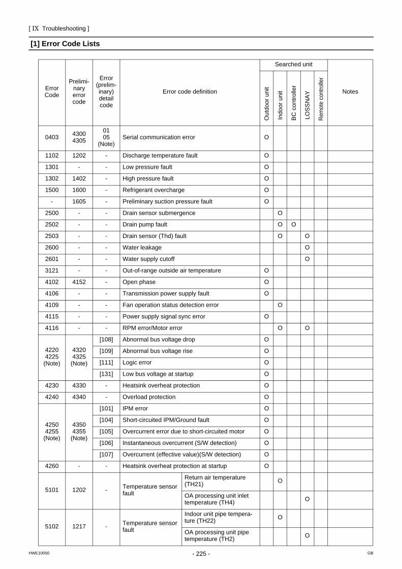
[ IX Troubleshooting ]
- 225 -HWE10050 GB
IX Troubleshooting
[1] Error Code Lists
Error Code
Prelimi-nary error code
Error (prelim-inary) detail code
Error code definition
Searched unit
Notes
0403 43004305
0105
(Note)Serial communication error O
1102 1202 - Discharge temperature fault O
1301 - - Low pressure fault O
1302 1402 - High pressure fault O
1500 1600 - Refrigerant overcharge O
- 1605 - Preliminary suction pressure fault O
2500 - - Drain sensor submergence O
2502 - - Drain pump fault O O
2503 - - Drain sensor (Thd) fault O O
2600 - - Water leakage O
2601 - - Water supply cutoff O
3121 - - Out-of-range outside air temperature O
4102 4152 - Open phase O
4106 - - Transmission power supply fault O
4109 - - Fan operation status detection error O
4115 - - Power supply signal sync error O
4116 - - RPM error/Motor error O O
42204225
(Note)
43204325
(Note)
[108] Abnormal bus voltage drop O
[109] Abnormal bus voltage rise O
[111] Logic error O
[131] Low bus voltage at startup O
4230 4330 - Heatsink overheat protection O
4240 4340 - Overload protection O
42504255
(Note)
43504355
(Note)
[101] IPM error O
[104] Short-circuited IPM/Ground fault O
[105] Overcurrent error due to short-circuited motor O
[106] Instantaneous overcurrent (S/W detection) O
[107] Overcurrent (effective value)(S/W detection) O
4260 - - Heatsink overheat protection at startup O
5101 1202 - Temperature sensor fault
Return air temperature (TH21) O
OA processing unit inlet temperature (TH4) O
5102 1217 - Temperature sensor fault
Indoor unit pipe tempera-ture (TH22) O
OA processing unit pipe temperature (TH2) O
Out
door
uni
t
Indo
or u
nit
BC
con
trolle
r
LOS
SN
AY
Rem
ote
cont
rolle
r
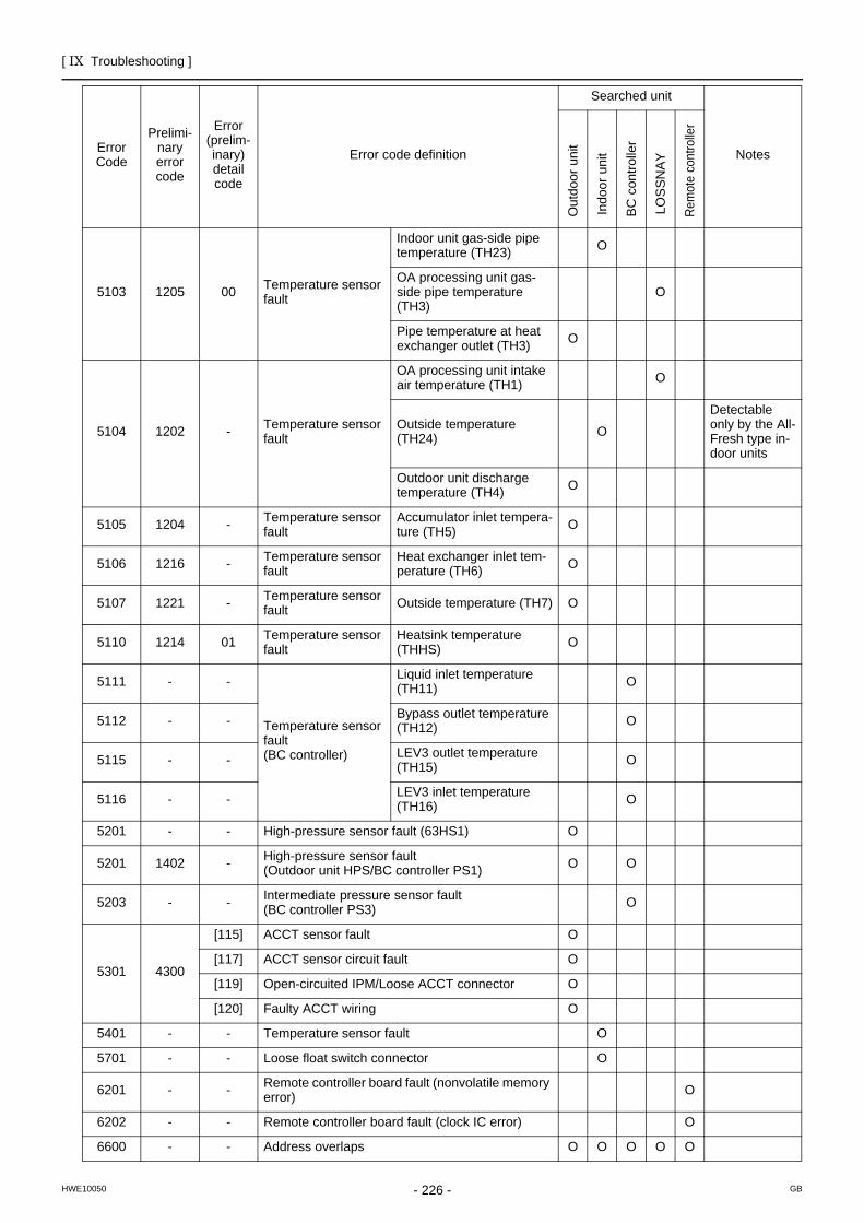
[ IX Troubleshooting ]
- 226 -HWE10050 GB
5103 1205 00 Temperature sensor fault
Indoor unit gas-side pipe temperature (TH23) O
OA processing unit gas-side pipe temperature (TH3)
O
Pipe temperature at heat exchanger outlet (TH3) O
5104 1202 - Temperature sensor fault
OA processing unit intake air temperature (TH1) O
Outside temperature (TH24) O
Detectable only by the All-Fresh type in-door units
Outdoor unit discharge temperature (TH4) O
5105 1204 - Temperature sensor fault
Accumulator inlet tempera-ture (TH5) O
5106 1216 - Temperature sensor fault
Heat exchanger inlet tem-perature (TH6) O
5107 1221 - Temperature sensor fault Outside temperature (TH7) O
5110 1214 01 Temperature sensor fault
Heatsink temperature (THHS) O
5111 - -
Temperature sensor fault(BC controller)
Liquid inlet temperature (TH11) O
5112 - - Bypass outlet temperature (TH12) O
5115 - - LEV3 outlet temperature (TH15) O
5116 - - LEV3 inlet temperature (TH16) O
5201 - - High-pressure sensor fault (63HS1) O
5201 1402 - High-pressure sensor fault (Outdoor unit HPS/BC controller PS1) O O
5203 - - Intermediate pressure sensor fault (BC controller PS3) O
5301 4300
[115] ACCT sensor fault O
[117] ACCT sensor circuit fault O
[119] Open-circuited IPM/Loose ACCT connector O
[120] Faulty ACCT wiring O
5401 - - Temperature sensor fault O
5701 - - Loose float switch connector O
6201 - - Remote controller board fault (nonvolatile memory error) O
6202 - - Remote controller board fault (clock IC error) O
6600 - - Address overlaps O O O O O
Error Code
Prelimi-nary error code
Error (prelim-inary) detail code
Error code definition
Searched unit
Notes
Out
door
uni
t
Indo
or u
nit
BC
con
trolle
r
LOS
SN
AY
Rem
ote
cont
rolle
r
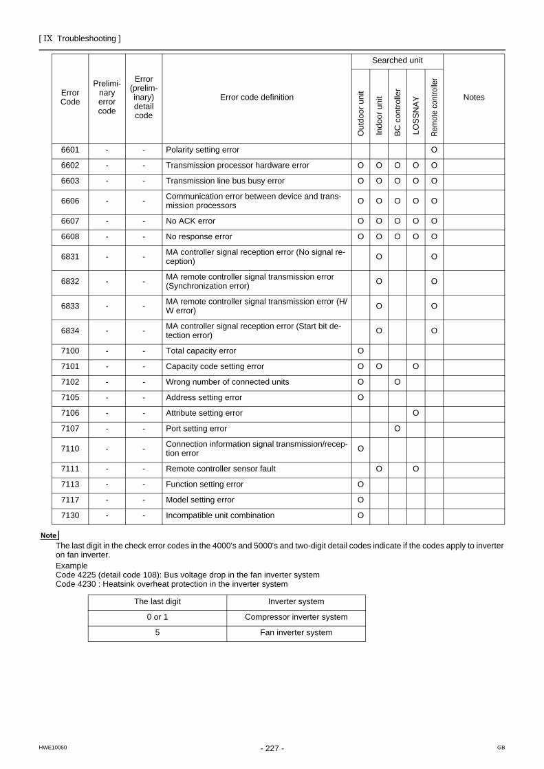
[ IX Troubleshooting ]
- 227 -HWE10050 GB
The last digit in the check error codes in the 4000's and 5000's and two-digit detail codes indicate if the codes apply to inverter on fan inverter.ExampleCode 4225 (detail code 108): Bus voltage drop in the fan inverter systemCode 4230 : Heatsink overheat protection in the inverter system
6601 - - Polarity setting error O
6602 - - Transmission processor hardware error O O O O O
6603 - - Transmission line bus busy error O O O O O
6606 - - Communication error between device and trans-mission processors O O O O O
6607 - - No ACK error O O O O O
6608 - - No response error O O O O O
6831 - - MA controller signal reception error (No signal re-ception) O O
6832 - - MA remote controller signal transmission error (Synchronization error) O O
6833 - - MA remote controller signal transmission error (H/W error) O O
6834 - - MA controller signal reception error (Start bit de-tection error) O O
7100 - - Total capacity error O
7101 - - Capacity code setting error O O O
7102 - - Wrong number of connected units O O
7105 - - Address setting error O
7106 - - Attribute setting error O
7107 - - Port setting error O
7110 - - Connection information signal transmission/recep-tion error O
7111 - - Remote controller sensor fault O O
7113 - - Function setting error O
7117 - - Model setting error O
7130 - - Incompatible unit combination O
The last digit Inverter system
0 or 1 Compressor inverter system
5 Fan inverter system
Error Code
Prelimi-nary error code
Error (prelim-inary) detail code
Error code definition
Searched unit
Notes
Out
door
uni
t
Indo
or u
nit
BC
con
trolle
r
LOS
SN
AY
Rem
ote
cont
rolle
r
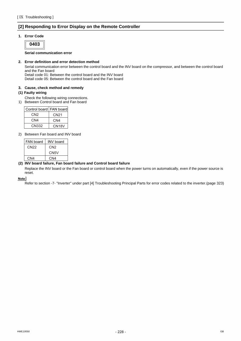
[ IX Troubleshooting ]
- 228 -HWE10050 GB
[2] Responding to Error Display on the Remote Controller0403
1. Error Code
Serial communication error
2. Error definition and error detection methodSerial communication error between the control board and the INV board on the compressor, and between the control board and the Fan boardDetail code 01: Between the control board and the INV board Detail code 05: Between the control board and the Fan board
3. Cause, check method and remedy(1) Faulty wiring
Check the following wiring connections.1) Between Control board and Fan board
2) Between Fan board and INV board
(2) INV board failure, Fan board failure and Control board failureReplace the INV board or the Fan board or control board when the power turns on automatically, even if the power source is reset.
Refer to section -7- "Inverter" under part [4] Troubleshooting Principal Parts for error codes related to the inverter.(page 323)
0403
CN2 CN21CN4 CN4CN332 CN18V
Control board FAN board
CN22 CN2CN5V
CN4 CN4
FAN board INV board
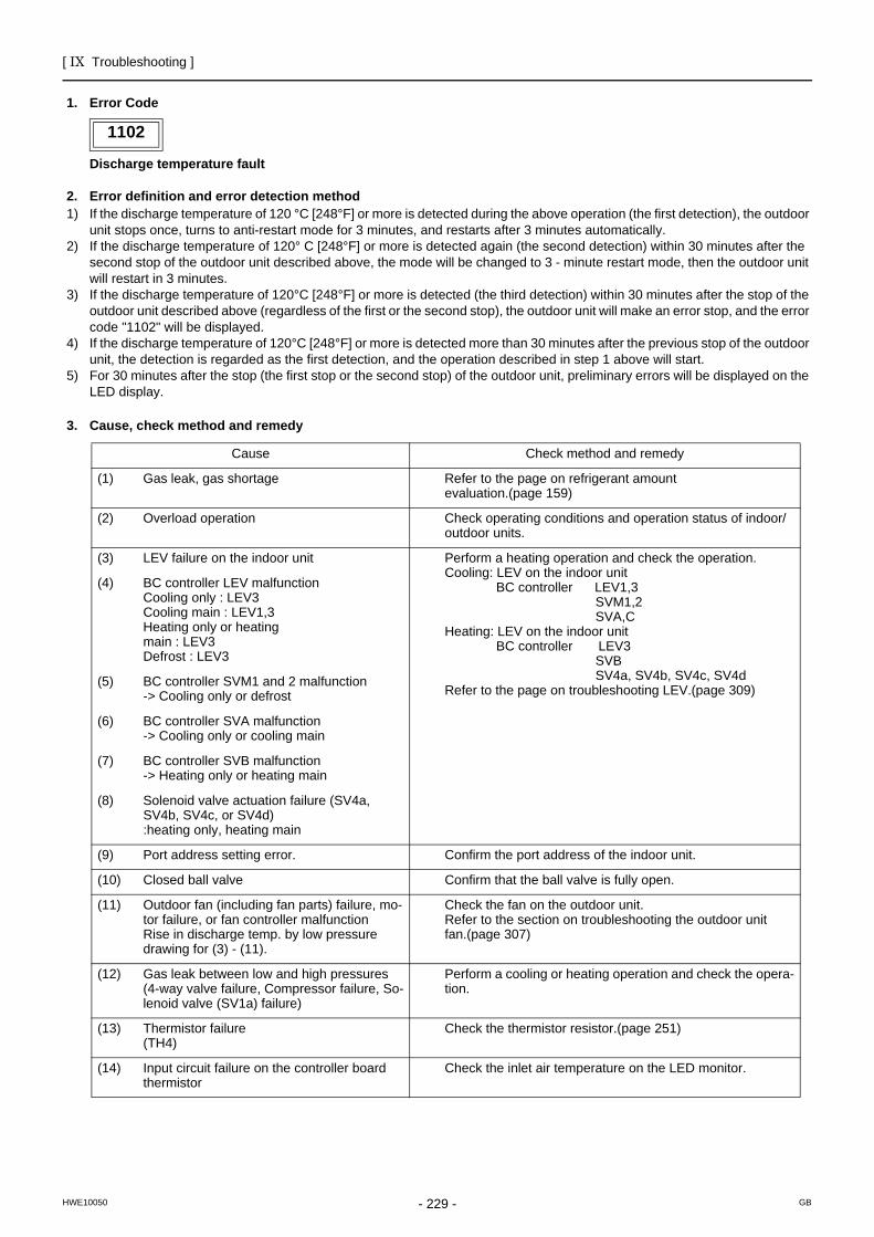
[ IX Troubleshooting ]
- 229 -HWE10050 GB
1102
1. Error Code
Discharge temperature fault
2. Error definition and error detection method1) If the discharge temperature of 120 °C [248°F] or more is detected during the above operation (the first detection), the outdoor
unit stops once, turns to anti-restart mode for 3 minutes, and restarts after 3 minutes automatically.2) If the discharge temperature of 120° C [248°F] or more is detected again (the second detection) within 30 minutes after the
second stop of the outdoor unit described above, the mode will be changed to 3 - minute restart mode, then the outdoor unit will restart in 3 minutes.
3) If the discharge temperature of 120°C [248°F] or more is detected (the third detection) within 30 minutes after the stop of the outdoor unit described above (regardless of the first or the second stop), the outdoor unit will make an error stop, and the error code "1102" will be displayed.
4) If the discharge temperature of 120°C [248°F] or more is detected more than 30 minutes after the previous stop of the outdoor unit, the detection is regarded as the first detection, and the operation described in step 1 above will start.
5) For 30 minutes after the stop (the first stop or the second stop) of the outdoor unit, preliminary errors will be displayed on the LED display.
3. Cause, check method and remedy
1102
Cause Check method and remedy
(1) Gas leak, gas shortage Refer to the page on refrigerant amount evaluation.(page 159)
(2) Overload operation Check operating conditions and operation status of indoor/outdoor units.
(3) LEV failure on the indoor unit Perform a heating operation and check the operation.Cooling: LEV on the indoor unit BC controller LEV1,3 SVM1,2 SVA,CHeating: LEV on the indoor unit BC controller LEV3 SVB SV4a, SV4b, SV4c, SV4dRefer to the page on troubleshooting LEV.(page 309)
(4) BC controller LEV malfunctionCooling only : LEV3Cooling main : LEV1,3Heating only or heatingmain : LEV3Defrost : LEV3
(5) BC controller SVM1 and 2 malfunction-> Cooling only or defrost
(6) BC controller SVA malfunction-> Cooling only or cooling main
(7) BC controller SVB malfunction-> Heating only or heating main
(8) Solenoid valve actuation failure (SV4a, SV4b, SV4c, or SV4d):heating only, heating main
(9) Port address setting error. Confirm the port address of the indoor unit.
(10) Closed ball valve Confirm that the ball valve is fully open.
(11) Outdoor fan (including fan parts) failure, mo-tor failure, or fan controller malfunctionRise in discharge temp. by low pressure drawing for (3) - (11).
Check the fan on the outdoor unit. Refer to the section on troubleshooting the outdoor unit fan.(page 307)
(12) Gas leak between low and high pressures(4-way valve failure, Compressor failure, So-lenoid valve (SV1a) failure)
Perform a cooling or heating operation and check the opera-tion.
(13) Thermistor failure(TH4)
Check the thermistor resistor.(page 251)
(14) Input circuit failure on the controller board thermistor
Check the inlet air temperature on the LED monitor.
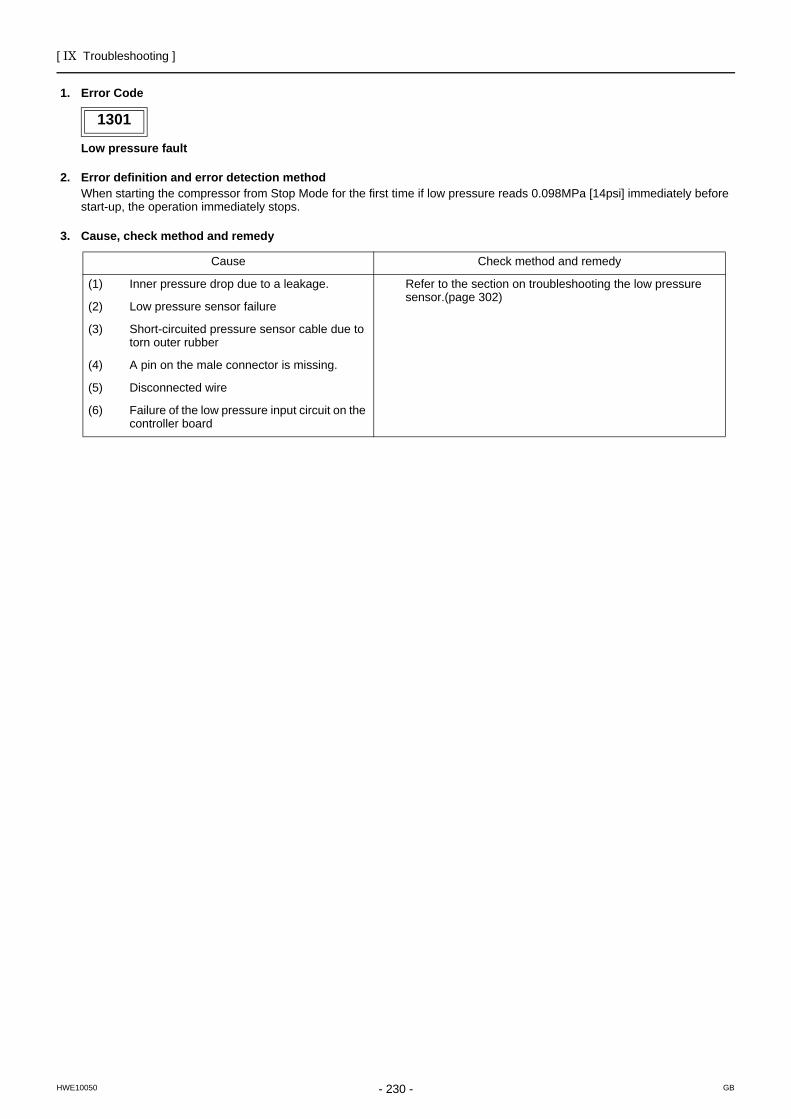
[ IX Troubleshooting ]
- 230 -HWE10050 GB
1301
1. Error Code
Low pressure fault
2. Error definition and error detection methodWhen starting the compressor from Stop Mode for the first time if low pressure reads 0.098MPa [14psi] immediately before start-up, the operation immediately stops.
3. Cause, check method and remedy
1301
Cause Check method and remedy
(1) Inner pressure drop due to a leakage. Refer to the section on troubleshooting the low pressure sensor.(page 302)
(2) Low pressure sensor failure
(3) Short-circuited pressure sensor cable due to torn outer rubber
(4) A pin on the male connector is missing.
(5) Disconnected wire
(6) Failure of the low pressure input circuit on the controller board
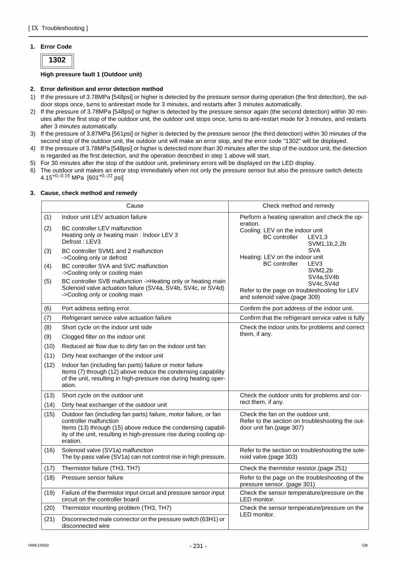
[ IX Troubleshooting ]
- 231 -HWE10050 GB
1302
1. Error Code
High pressure fault 1 (Outdoor unit)
2. Error definition and error detection method1) If the pressure of 3.78MPa [548psi] or higher is detected by the pressure sensor during operation (the first detection), the out-
door stops once, turns to antirestart mode for 3 minutes, and restarts after 3 minutes automatically.2) If the pressure of 3.78MPa [548psi] or higher is detected by the pressure sensor again (the second detection) within 30 min-
utes after the first stop of the outdoor unit, the outdoor unit stops once, turns to anti-restart mode for 3 minutes, and restarts after 3 minutes automatically.
3) If the pressure of 3.87MPa [561psi] or higher is detected by the pressure sensor (the third detection) within 30 minutes of the second stop of the outdoor unit, the outdoor unit will make an error stop, and the error code "1302" will be displayed.
4) If the pressure of 3.78MPa [548psi] or higher is detected more than 30 minutes after the stop of the outdoor unit, the detection is regarded as the first detection, and the operation described in step 1 above will start.
5) For 30 minutes after the stop of the outdoor unit, preliminary errors will be displayed on the LED display.6) The outdoor unit makes an error stop immediately when not only the pressure sensor but also the pressure switch detects
4.15+0,-0.15 MPa [601+0,-22 psi]
3. Cause, check method and remedy
1302
Cause Check method and remedy
(1) Indoor unit LEV actuation failure Perform a heating operation and check the op-eration.Cooling: LEV on the indoor unit BC controller LEV1,3 SVM1,1b,2,2b SVAHeating: LEV on the indoor unit BC controller LEV3 SVM2,2b SV4a,SV4b SV4c,SV4dRefer to the page on troubleshooting for LEV and solenoid valve.(page 309)
(2) BC controller LEV malfunction Heating only or heating main : Indoor LEV 3Defrost : LEV3
(3) BC controller SVM1 and 2 malfunction->Cooling only or defrost
(4) BC controller SVA and SVC malfunction->Cooling only or cooling main
(5) BC controller SVB malfunction ->Heating only or heating mainSolenoid valve actuation failure (SV4a, SV4b, SV4c, or SV4d) ->Cooling only or cooling main
(6) Port address setting error. Confirm the port address of the indoor unit.(7) Refrigerant service valve actuation failure Confirm that the refrigerant service valve is fully (8) Short cycle on the indoor unit side Check the indoor units for problems and correct
them, if any.(9) Clogged filter on the indoor unit(10) Reduced air flow due to dirty fan on the indoor unit fan(11) Dirty heat exchanger of the indoor unit(12) Indoor fan (including fan parts) failure or motor failure
Items (7) through (12) above reduce the condensing capability of the unit, resulting in high-pressure rise during heating oper-ation.
(13) Short cycle on the outdoor unit Check the outdoor units for problems and cor-rect them, if any.(14) Dirty heat exchanger of the outdoor unit
(15) Outdoor fan (including fan parts) failure, motor failure, or fan controller malfunctionItems (13) through (15) above reduce the condensing capabil-ity of the unit, resulting in high-pressure rise during cooling op-eration.
Check the fan on the outdoor unit.Refer to the section on troubleshooting the out-door unit fan.(page 307)
(16) Solenoid valve (SV1a) malfunction The by-pass valve (SV1a) can not control rise in high pressure.
Refer to the section on troubleshooting the sole-noid valve.(page 303)
(17) Thermistor failure (TH3, TH7) Check the thermistor resistor.(page 251)(18) Pressure sensor failure Refer to the page on the troubleshooting of the
pressure sensor. (page 301)(19) Failure of the thermistor input circuit and pressure sensor input
circuit on the controller boardCheck the sensor temperature/pressure on the LED monitor.
(20) Thermistor mounting problem (TH3, TH7) Check the sensor temperature/pressure on the LED monitor.
(21) Disconnected male connector on the pressure switch (63H1) or disconnected wire
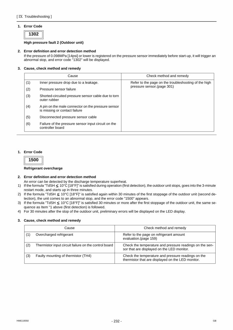
[ IX Troubleshooting ]
- 232 -HWE10050 GB
1. Error Code
High pressure fault 2 (Outdoor unit)
2. Error definition and error detection methodIf the pressure of 0.098MPa [14psi] or lower is registered on the pressure sensor immediately before start-up, it will trigger an abnormal stop, and error code "1302" will be displayed.
3. Cause, check method and remedy
1500
1. Error Code
Refrigerant overcharge
2. Error definition and error detection methodAn error can be detected by the discharge temperature superheat.
1) If the formula "TdSH 10°C [18°F]" is satisfied during operation (first detection), the outdoor unit stops, goes into the 3-minute restart mode, and starts up in three minutes.
2) If the formula "TdSH 10°C [18°F]" is satisfied again within 30 minutes of the first stoppage of the outdoor unit (second de-tection), the unit comes to an abnormal stop, and the error code "1500" appears.
3) If the formula "TdSH 10°C [18°F]" is satisfied 30 minutes or more after the first stoppage of the outdoor unit, the same se-quence as Item "1 above (first detection) is followed.
4) For 30 minutes after the stop of the outdoor unit, preliminary errors will be displayed on the LED display.
3. Cause, check method and remedy
1302
Cause Check method and remedy
(1) Inner pressure drop due to a leakage. Refer to the page on the troubleshooting of the high pressure sensor.(page 301)
(2) Pressure sensor failure
(3) Shorted-circuited pressure sensor cable due to torn outer rubber
(4) A pin on the male connector on the pressure sensor is missing or contact failure
(5) Disconnected pressure sensor cable
(6) Failure of the pressure sensor input circuit on the controller board
1500
Cause Check method and remedy
(1) Overcharged refrigerant Refer to the page on refrigerant amount evaluation.(page 159)
(2) Thermistor input circuit failure on the control board Check the temperature and pressure readings on the sen-sor that are displayed on the LED monitor.
(3) Faulty mounting of thermistor (TH4) Check the temperature and pressure readings on the thermistor that are displayed on the LED monitor.
[ IX Troubleshooting ]
- 233 -HWE10050 GB
2500
1. Error Code
Drain sensor submergence (Models with a drain sensor)
2. Error definition and error detection method1) If an immersion of the drain sensor in the water is detected while the unit is in any mode other than the Cool/Dry mode and
when the drain pump goes from OFF to ON, this condition is considered preliminary water leakage. While this error is being detected, humidifier output cannot be turned on.
2) If the immersion of the sensor in the water is detected four consecutive times at an hour interval, this is considered water leak-age, and "2500" appears on the monitor.
3) Detection of water leakage is also performed while the unit is stopped.4) Preliminary water leakage is cancelled when the following conditions are met:
One hour after the preliminary water leakage was detected, it is not detected that the drain pump goes from OFF to ON.The operation mode is changed to Cool/Dry.The liquid pipe temperature minus the inlet temperature is -10°C [-18°F] or less.
3. Cause, check method and remedy
2500
Cause Check method and remedy
(1) Drain water drainage problemClogged drain pumpClogged drain pipingBackflow of drain water from other units
Check for proper drainage.
(2) Adhesion of water drops to the drain sensorTrickling of water along the lead wireRippling of drain water caused by filter clogging
1) Check for proper lead wire installation.
2) Check for clogged filter.
(3) Failure of the relay circuit for the solenoid valve Replace the relay.
(4) Indoor unit control board failureDrain sensor circuit failure
If the above item checks out OK, replace the indoor unit control board.
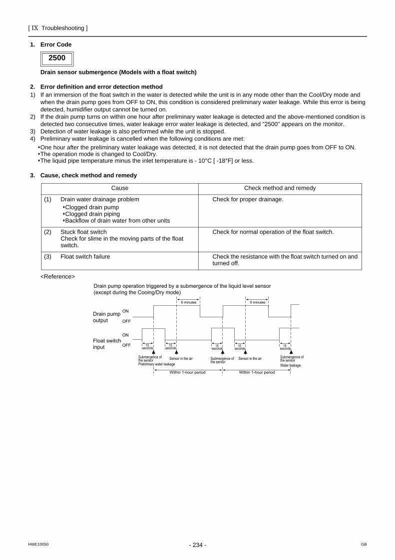
[ IX Troubleshooting ]
- 234 -HWE10050 GB
1. Error Code
Drain sensor submergence (Models with a float switch)
2. Error definition and error detection method1) If an immersion of the float switch in the water is detected while the unit is in any mode other than the Cool/Dry mode and
when the drain pump goes from OFF to ON, this condition is considered preliminary water leakage. While this error is being detected, humidifier output cannot be turned on.
2) If the drain pump turns on within one hour after preliminary water leakage is detected and the above-mentioned condition is detected two consecutive times, water leakage error water leakage is detected, and "2500" appears on the monitor.
3) Detection of water leakage is also performed while the unit is stopped.4) Preliminary water leakage is cancelled when the following conditions are met:
One hour after the preliminary water leakage was detected, it is not detected that the drain pump goes from OFF to ON.The operation mode is changed to Cool/Dry.The liquid pipe temperature minus the inlet temperature is - 10°C [ -18°F] or less.
3. Cause, check method and remedy
<Reference>
2500
Cause Check method and remedy
(1) Drain water drainage problemClogged drain pumpClogged drain pipingBackflow of drain water from other units
Check for proper drainage.
(2) Stuck float switchCheck for slime in the moving parts of the float switch.
Check for normal operation of the float switch.
(3) Float switch failure Check the resistance with the float switch turned on and turned off.
6 minutes6 minutes
15 seconds
15 seconds 15
seconds15
seconds15
seconds
ON
OFF
ON
OFF
Drain pump operation triggered by a submergence of the liquid level sensor (except during the Cooing/Dry mode)
Drain pump output
Float switch input
Submergence of the sensor
Submergence of the sensor Preliminary water leakage
Submergence of the sensor Water leakage
Sensor in the airSensor in the air
Within 1-hour periodWithin 1-hour period
[ IX Troubleshooting ]
- 235 -HWE10050 GB
2502
1. Error Code
Drain pump fault (Models with a drain sensor)
2. Error definition and error detection method1) Make the drain sensor thermistor self-heat. If the temperature rise is small, it is interpreted that the sensor is immersed in
water. This condition is considered to be a preliminary error, and the unit goes into the 3-minute restart delay mode.2) If another episode of the above condition is detected during the preliminary error, this is considered a drain pump error, and
"2502" appears on the monitor.3) This error is always detected while the drain pump is in operation.4) The following criteria are met when the criteria for the forced stoppage of outdoor unit (system stoppage) are met.
∗"Liquid pipe temperature - inlet temperature -10°C [ -18 °F] " has been detected for 30 minutes.∗The immersion of drain sensor is detected 10 consecutive times.∗The conditions that are listed under items 1) through 3) above are always met before the criteria for the forced stoppage
of the outdoor unit.5) The indoor unit that detected the conditions that are listed in item 4) above brings the outdoor unit in the same refrigerant
circuit to an error stop (compressor operation prohibited), and the outdoor unit brings all the indoor units in the same refrigerant circuit that are in any mode other than Fan or Stop to an error stop. "2502" appears on the monitor of the units that came to an error stop.
6) Forced stoppage of the outdoor unitDetection timing: The error is detected whether the unit is in operation or stopped.
7) Ending criteria for the forced stoppage of outdoor unitPower reset the indoor unit that was identified as the error source and the outdoor unit that is connected to the same refrig-erant circuit.Forced stoppage of the outdoor unit cannot be cancelled by stopping the unit via the remote controller.(Note) Items 1) - 3) and 4) - 7) are detected independently from each other.
The address and attribute that appear on the remote controller are those of the indoor unit (or OA processing unit) that caused the error.
3. Cause, check method and remedy
2502
Cause Check method and remedy
(1) Drain pump failure Check for proper functioning of the drain pump.
(2) Drain water drainage problemClogged drain pumpClogged drain piping
Check for proper drainage.
(3) Adhesion of water drops to the drain sensorTrickling of water along the lead wireRippling of drain water caused by filter clogging
1) Check for proper lead wire installation.
2) Check for clogged filter.
(4) Indoor unit control board failureDrain pump drive circuit failureDrain heater output circuit failure
If the above item checks out OK, replace the indoor unit control board.
(5) Items (1) through (4) above and an indoor unit elec-tronic valve closure failure (leaky valve) occurred si-multaneously.
Check the solenoid valves on the indoor unit for leaks.
[ IX Troubleshooting ]
- 236 -HWE10050 GB
1. Error Code
Drain pump fault (Models with a float switch)
2. Error definition and error detection method1) The immersion of sensor tip in water is detected by the ON/OFF signal from the float switch.
∗Submergence of the sensor When it is detected that the float switch has been ON for 15 seconds, it is interpreted that the sensor tip is immersed in water.
∗Sensor in the airWhen it is detected that the float switch has been OFF for 15 seconds, it is interpreted that the sensor tip is not immersed in water.
2) If it is detected that the float switch has been ON for 3 minutes after the immersion of the sensor tip was detected, this is con-sidered a drain pump failure, and "2502" appears on the monitor.∗The total time it takes for this error to be detected is 3 minutes and 15 seconds, including the time it takes for the first im-
mersion of the sensor tip to be detected.3) Detection of drain pump failure is performed while the unit is stopped.4) The following criteria are met when the criteria for the forced stoppage of outdoor unit (system stoppage) are met.
∗"Liquid pipe temperature - inlet temperature - 10°C [ -18°F] " has been detected for 30 minutes.∗It is detected by the float switch that the sensor tip has been immersed in water for 15 minutes or more.∗The conditions that are listed under items 1) through 3) above are always met before the criteria for the forced stoppage
of the outdoor unit.5) The indoor unit that detected the conditions that are listed in item 4) above brings the outdoor unit in the same refrigerant
circuit to an error stop (compressor operation prohibited), and the outdoor unit brings all the indoor units in the same refrigerant circuit that are in any mode other than Fan or Stop to an error stop.
6) Forced stoppage of the outdoor unitDetection timing: The error is detected whether the unit is in operation or stopped.This error is detected whether the unit is in operation or stopped.
7) Ending criteria for the forced stoppage of outdoor unitPower reset the indoor unit that was identified as the error source and the outdoor unit that is connected to the same refrig-erant circuit.Forced stoppage of the outdoor unit cannot be cancelled by stopping the unit via the remote controller.(Note) Items 1) - 3) and 4) - 7) are detected independently from each other.
The address and attribute that appear on the remote controller are those of the indoor unit (or OA processing unit) that caused the error.
3. Cause, check method and remedy
2502
Cause Check method and remedy
(1) Drain pump failure Check for proper functioning of the drain pump mechanism
(2) Drain water drainage problemClogged drain pumpClogged drain piping
Check for proper drainage.
(3) Stuck float switchCheck for slime in the moving parts of the float switch.
Check for normal operation of the float switch.
(4) Float switch failure Check the resistance with the float switch turned on and turned off.
(5) Indoor unit control board failureDrain pump drive circuit failureFloat switch input circuit failure
Replace indoor unit control board.
(6) Items (1) through (5) above and an indoor unit electronic valve closure failure (leaky valve) occurred simultane-ously.
Check the solenoid valves on the indoor unit for leaks.
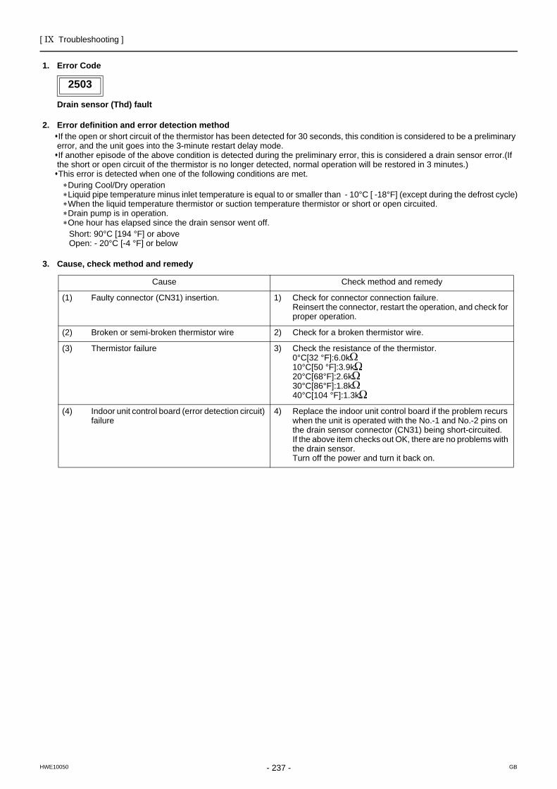
[ IX Troubleshooting ]
- 237 -HWE10050 GB
2503
1. Error Code
Drain sensor (Thd) fault
2. Error definition and error detection methodIf the open or short circuit of the thermistor has been detected for 30 seconds, this condition is considered to be a preliminary error, and the unit goes into the 3-minute restart delay mode.If another episode of the above condition is detected during the preliminary error, this is considered a drain sensor error.(If the short or open circuit of the thermistor is no longer detected, normal operation will be restored in 3 minutes.)This error is detected when one of the following conditions are met.∗During Cool/Dry operation∗Liquid pipe temperature minus inlet temperature is equal to or smaller than - 10°C [ -18°F] (except during the defrost cycle)∗When the liquid temperature thermistor or suction temperature thermistor or short or open circuited.∗Drain pump is in operation.∗One hour has elapsed since the drain sensor went off.
Short: 90°C [194 °F] or aboveOpen: - 20°C [-4 °F] or below
3. Cause, check method and remedy
2503
Cause Check method and remedy
(1) Faulty connector (CN31) insertion. 1) Check for connector connection failure.Reinsert the connector, restart the operation, and check for proper operation.
(2) Broken or semi-broken thermistor wire 2) Check for a broken thermistor wire.
(3) Thermistor failure 3) Check the resistance of the thermistor.0°C[32 °F]:6.0k 10°C[50 °F]:3.9k 20°C[68°F]:2.6k 30°C[86°F]:1.8k 40°C[104 °F]:1.3k
(4) Indoor unit control board (error detection circuit) failure
4) Replace the indoor unit control board if the problem recurs when the unit is operated with the No.-1 and No.-2 pins on the drain sensor connector (CN31) being short-circuited.If the above item checks out OK, there are no problems with the drain sensor.Turn off the power and turn it back on.
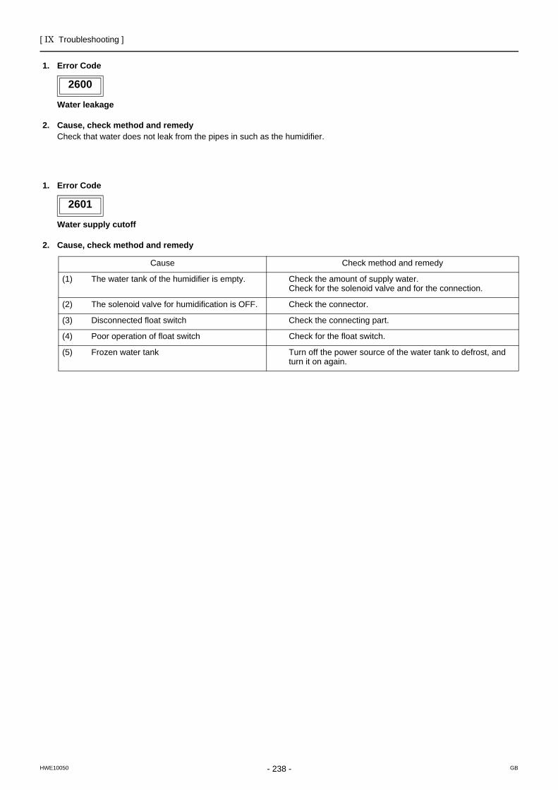
[ IX Troubleshooting ]
- 238 -HWE10050 GB
2600
1. Error Code
Water leakage
2. Cause, check method and remedyCheck that water does not leak from the pipes in such as the humidifier.
2601
1. Error Code
Water supply cutoff
2. Cause, check method and remedy
2600
2601
Cause Check method and remedy
(1) The water tank of the humidifier is empty. Check the amount of supply water. Check for the solenoid valve and for the connection.
(2) The solenoid valve for humidification is OFF. Check the connector.
(3) Disconnected float switch Check the connecting part.
(4) Poor operation of float switch Check for the float switch.
(5) Frozen water tank Turn off the power source of the water tank to defrost, and turn it on again.
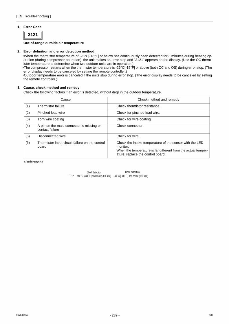
[ IX Troubleshooting ]
- 239 -HWE10050 GB
3121
1. Error Code
Out-of-range outside air temperature
2. Error definition and error detection methodWhen the thermistor temperature of -28°C[-18°F] or below has continuously been detected for 3 minutes during heating op-eration (during compressor operation), the unit makes an error stop and "3121" appears on the display. (Use the OC therm-istor temperature to determine when two outdoor units are in operation.)The compressor restarts when the thermistor temperature is -26°C[-15°F] or above (both OC and OS) during error stop. (The error display needs to be canceled by setting the remote controller.)Outdoor temperature error is canceled if the units stop during error stop. (The error display needs to be canceled by setting the remote controller.)
3. Cause, check method and remedyCheck the following factors if an error is detected, without drop in the outdoor temperature.
<Reference>
3121
Cause Check method and remedy
(1) Thermistor failure Check thermistor resistance.
(2) Pinched lead wire Check for pinched lead wire.
(3) Torn wire coating Check for wire coating.
(4) A pin on the male connector is missing or contact failure
Check connector.
(5) Disconnected wire Check for wire.
(6) Thermistor input circuit failure on the control board
Check the intake temperature of the sensor with the LED monitor.When the temperature is far different from the actual temper-ature, replace the control board.
TH7Open detection
-40 C [ -40 F ] and below (130 k )Short detection
110 C [230 F ] and above (0.4 k )
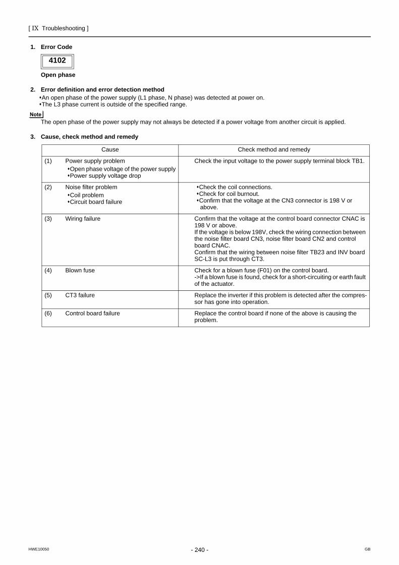
[ IX Troubleshooting ]
- 240 -HWE10050 GB
4102
1. Error Code
Open phase
2. Error definition and error detection methodAn open phase of the power supply (L1 phase, N phase) was detected at power on. The L3 phase current is outside of the specified range.
The open phase of the power supply may not always be detected if a power voltage from another circuit is applied.
3. Cause, check method and remedy
4102
Cause Check method and remedy
(1) Power supply problemOpen phase voltage of the power supplyPower supply voltage drop
Check the input voltage to the power supply terminal block TB1.
(2) Noise filter problemCoil problemCircuit board failure
Check the coil connections.Check for coil burnout.Confirm that the voltage at the CN3 connector is 198 V or above.
(3) Wiring failure Confirm that the voltage at the control board connector CNAC is 198 V or above.If the voltage is below 198V, check the wiring connection between the noise filter board CN3, noise filter board CN2 and control board CNAC. Confirm that the wiring between noise filter TB23 and INV board SC-L3 is put through CT3.
(4) Blown fuse Check for a blown fuse (F01) on the control board. ->If a blown fuse is found, check for a short-circuiting or earth fault of the actuator.
(5) CT3 failure Replace the inverter if this problem is detected after the compres-sor has gone into operation.
(6) Control board failure Replace the control board if none of the above is causing the problem.
[ IX Troubleshooting ]
- 241 -HWE10050 GB
4106
1. Error Code
<Transmission power supply fault Error detail code FF (Outdoor unit)>2. Error definition and error detection method
Transmission power output failure
3. Cause 1) Wiring failure2) Transmission power supply cannot output voltage because overcurrent was detected.3) Voltage cannot be output due to transmission power supply problem. 4) Transmission voltage detection circuit failure
4. Check method and remedyCheck the items in IX [4] -8- (2) Troubleshooting transmission power circuit of outdoor unit on all outdoor units in the same refrigerant circuit.(page 331)
<Transmission power supply fault other than error detail code FF (Outdoor unit)>2. Error definition and error detection method
Transmission power reception failure
3. CauseOne of the outdoor units stopped supplying power, but no other outdoor units start supplying power.
4. Check method and remedyCheck the items in IX [4] -8- (2) Troubleshooting transmission power circuit of outdoor unit on all outdoor units in the same refrigerant circuit.(page 331)
4109
1. Error Code
Indoor unit fan operation error
2. Error definition and error detection method1) Connector CN28 has remained open-circuited for 100 consecutive secondsduring operation.
3. Cause, check method and remedy
4106
4109
Cause Check method and remedy
(1) Auxiliary relay (X13) fault The coil or the wiring of the auxiliary relay connected to CN28 is faulty.
(2) Connector (CN28) is disconnected. Check the connector for proper connection.
(3) Blown fuse Check the fuse on the control circuit board.
(4) Motor error (thermistor error inside the motor) Check the unit fan for proper operation in the test run mode. If no problems are found with items 1 through 3 above and the fan does not operate, replace the motor.
[ IX Troubleshooting ]
- 242 -HWE10050 GB
4115
1. Error Code
Power supply signal sync error
2. Error definition and error detection methodThe frequency cannot be determined when the power is switched on.
3. Cause, check method and remedy
4116
1. Error Code
RPM error/Motor error
2. Error definition and error detection methodLOSSNAY∗The motor keep running even if the power is OFF.∗The thermal overload relay is ON. (Only for the three-phase model)
Indoor unitIf detected less than 180rpm or more than 2000rpm, the indoor unit will restart and keep running for 3 minutes.If detected again, the display will appear.
3. Cause, check method and remedy
4115
Cause Check method and remedy
(1) Power supply error Check the voltage of the power supply terminal block (TB1).
(2) Noise filter problemCoil problemCircuit board failure
Check the coil connections.Check for coil burnout.Confirm that the voltage at the CN3 connector is 198 V or above.
(3) Faulty wiring Check fuse F01 on the control board.
(4) Wiring failureBetween noise filter CN3 and noise filter CN2 and con-trol board CNAC
Confirm that the voltage at the control board con-nector CNAC is 198 V or above.
(5) Control board failure If none of the items described above is applicable, and if the trouble reappears even after the power is switched on again, replace the control board.
4116
Cause Check method and remedy
(1) Board failure Replace the board.
(2) Motor malfunction Check for the motor and the solenoid switch.
(3) Solenoid switch malfunction
[ IX Troubleshooting ]
- 243 -HWE10050 GB
4220?4225
1. Error Code
Abnormal bus voltage drop (Detail code 108)
2. Error definition and error detection methodIf Vdc 289V or less is detected during Inverter operation. (S/W detection)
3. Cause, check method and remedy(1) Power supply environment
Check whether the unit makes an instantaneous stop when the detection result is abnormal or a power failure occurs.Check whether the power voltage (Between L1 and L2, L2 and L3, and L1 and L3) is 342V or less across all phases.
(2) Voltage drop detected4220Check the voltage between the FT-P and FT-N terminals on the INV board while the inverter is stopped and if it is 420 V or above, check the following items.
1) Confirm on the LED monitor that the bus voltage is above 289V. Replace the INV board if it is below 289 V.
2) Check the voltage at CN72 on the control board. ->Go to (3).3) Check the noise filter coil connections and for coil burnout.4) Check the wiring connections between the following sections
Between the noise filter board and INV board. Between the INV board and DCL.Replace 72C if no problems are found.
5) Check the IGBT module resistance on the INV board (Refer to the Trouble shooting for IGBT module). (page 328)Check the voltage between the FT-P and FT-N terminals on the INV board while the inverter is stopped and if it is less than 420 V, check the following items.
1) Check the coil connections and for coil burnout on the noise filter.2) Check the wiring between the noise filter board and INV board.3) Check the connection to SCP1 and SC-P2 on the INV board. 4) Check the in-rush current resistor value.5) Check the 72C resistance value.6) Check the DCL resistance value.
Replace the INV board if no problems are found.
4225Check the voltage at CNVDC on the Fan board while the inverter is stopped and if it is 420 V or above, check the following items.
1) Check the voltage at CN72 on the control board. ->Go to 3). 2) Check the noise filter coil connections and for coil burnout.3) Check the wiring connections between the following sections
Between the INV board and the Fan board.4) Check contents 4220
Replace the Fan board if no problems are found.Check the voltage at CNVDC on the Fan board while the inverter is stopped and if it is less than 420 V, check the following items.
1) Check the state of the wiring connections between the INV board and the Fan board.2) Check contents 4220
Replace the Fan board if no problems are found.
(3) Control board failureConfirm that DC12V is applied to the connector CN72 on the control board while the inverter is operating. If not, replace the control board.
Refer to section -7- "Inverter" under part [4] Troubleshooting Principal Parts for error codes related to the inverter.(page 323)
42204225
[ IX Troubleshooting ]
- 244 -HWE10050 GB
1. Error Code
Abnormal bus voltage rise (Detail code 109)
2. Error definition and error detection methodIf Vdc 830V is detected during inverter operation.
3. Cause, check method and remedy(1) Different voltage connection
Check the power supply voltage on the power supply terminal block (TB1).(2) INV board failure
If the problem recurs, replace the INV board.In the case of 4220: INV boardIn the case of 4225: Fan board
Refer to section -7- "Inverter" under part [4] Troubleshooting Principal Parts for error codes related to the inverter.(page 323)
1. Error Code
Logic error (Detail code 111)
2. Error definition and error detection methodH/W errorIf only the H/W error logic circuit operates, and no identifiable error is detected.
3. Cause, Check method and remedyIn the case of 4220
In the case of 4225
Refer to section -7- "Inverter" under part [4] Troubleshooting Principal Parts for error codes related to the inverter.(page 323)
42204225
42204225
Cause Check method and remedy
(1) External noise
(2) INV board failure Refer to IX [4] -7- (2) [1].(page 325)
Cause Check method and remedy
(1) External noise
(2) Fan board failure Refer to IX [4] -7- (2) [6].(page 326)
[ IX Troubleshooting ]
- 245 -HWE10050 GB
1. Error Code
Low bus voltage at startup (Detail code 131)
2. Error definition and error detection methodWhen Vdc 160 V is detected just before the inverter operation.
3. Cause, check method and remedy(1) Inverter main circuit failure
Same as detail code 108 of 4220 error
Refer to section -7- "Inverter" under part [4] Troubleshooting Principal Parts for error codes related to the inverter.(page 323)
4230
1. Error Code
Heatsink overheat protection
2. Error definition and error detection methodWhen the heat sink temperature (THHS) remains at or above 100°C [212°F] is detected.
3. Cause, check method and remedy
Refer to section -7- "Inverter" under part [4] Troubleshooting Principal Parts for error codes related to the inverter.(page 323)
42204225
4230
Cause Check method and remedy
(1) Fan board failure Refer to IX [4] -7- (2) [6].(page 326)
(2) Outdoor unit fan failure Check the outdoor unit fan operation. If any problem is found with the fan operation, check the fan motor. ->Refer to IX [4] -7- (2) [5].(page 326)
(3) Air passage blockage Check that the heat sink cooling air passage is not blocked
(4) THHS failure 1) Check for proper installation of the INV board IGBT. (Check for proper instal-lation of the IGBT heatsink.)
2) Check the THHS sensor reading on the LED monitor.->If an abnormal value appears, replace the INV board.
[ IX Troubleshooting ]
- 246 -HWE10050 GB
4240
1. Error Code
Overload protection
2. Error definition and error detection methodIf the output current of "(Iac) >Imax (Arms)" or "THHS > 95°C[203°F] " is continuously detected for 10 minutes or more during inverter operation.
3. Cause, check method and remedy
Refer to section -7- "Inverter" under part [4] Troubleshooting Principal Parts for error codes related to the inverter.(page 323)
4240
Model Imax(Arms)
P200,P250EP200 19
P300-P450EP250-EP350 27
Cause Check method and remedy
(1) Air passage blockage Check that the heat sink cooling air passage is not blocked
(2) Power supply environment Power supply voltage is 342 V or above.
(3) Inverter failure Refer to IX [4] -7-.(page 323)
(4) Compressor failure Check that the compressor has not overheated during operation.-> Check the refrigerant circuit (oil return section).Refer to IX [4] -7- (2) [2].(page 325)
[ IX Troubleshooting ]
- 247 -HWE10050 GB
4250?4250 4255
1. Error Code
IPM error (Detail code 101)
2. Error definition and error detection methodIn the case of 4250Overcurrent is detected by the overcurrent detection resistor (RSH) on the INV board. In the case of 4255IPM error signal is detected.
3. Cause, check method and remedyIn the case of 4250
In the case of 4255
Refer to section -7- "Inverter" under part [4] Troubleshooting Principal Parts for error codes related to the inverter.(page 323)
42504255
Cause Check method and remedy
(1) Inverter output related Refer to IX [4] -7- (2) [1]-[4].(page 325)
Check the IGBT module resistance value of the INV board, if no problems are found. (Refer to the Trouble shooting for IGBT module)(page 328)
Cause Check method and remedy
(1) Fan motor abnormality Refer to IX [4] -7- (2) [5].(page 326)
(2) Fan board failure Refer to IX [4] -7- (2) [6].(page 326)
(3) Electromagnetic contactor (52F) actuation failure (P450, EP350 only)
Check the wiring between the FAN board, 52F, and fan motor. (page 307)
[ IX Troubleshooting ]
- 248 -HWE10050 GB
1. Error Code
Instantaneous overcurrent (Detail code 106)Overcurrent (effective value) (Detail code 107)
2. Error definition and error detection methodOvercurrent 94Apeak or 22Arm and above is detected (P200-P250, EP200 models) OR 94Apeak or 35Arm and above is de-tected (P300-P450, EP250-EP350 model and above) by the current sensor.
3. Cause, check method and remedy
Refer to section -7- "Inverter" under part [4] Troubleshooting Principal Parts for error codes related to the inverter.(page 323)
1. Error Code
Short-circuited IPM/Ground fault (Detail code 104)
2. Error definition and error detection methodWhen IPM/IGBT short damage or grounding on the load side is detected just before starting the inverter.
3. Cause, check method and remedyIn the case of 4250
In the case of 4255
Refer to section -7- "Inverter" under part [4] Troubleshooting Principal Parts for error codes related to the inverter.(page 323)
4250
Cause Check method and remedy
(1) Inverter output related Refer to IX [4] -7- (2) [1]-[4]. (page 325) Check the IGBT module resistance value of the in-verter board, if no problems are found. (Refer to the Trouble shooting for IGBT module)(page 328)
42504255
Cause Check method and remedy
(1) Grounding fault compressor Refer to IX [4] -7- (2) [2].(page 325)
(2) Inverter output related Refer to IX [4] -7- (2) [1]-[4].(page 325)
Cause Check method and remedy
(1) Grounding fault of fan motor Refer to IX [4] -7- (2) [5].(page 326)
(2) Fan board failure Refer to IX [4] -7- (2) [6].(page 326)
(3) Electromagnetic contactor (52F) actuation failure (P450, EP350 only)
Check the wiring between the FAN board, 52F, and fan motor. (page 307)
[ IX Troubleshooting ]
- 249 -HWE10050 GB
1. Error Code
Overcurrent error due to short-circuited motor (Detail code 105)
2. Error definition and error detection methodWhen a short is detected on the load side just before starting the inverter operation.
3. Cause, Check method and remedyIn the case of 4250
In the case of 4255
Refer to section -7- "Inverter" under part [4] Troubleshooting Principal Parts for error codes related to the inverter.(page 323)
4260
1. Error Code
Heatsink overheat protection at startup
2. Error definition and error detection methodThe heatsink temperature (THHS) remains at or above 100°C [212°F] for 10 minutes or more at inverter startup.
3. Cause, check method and remedySame as 4230 error
42504255
Cause Check method and remedy
(1) Short - circuited compressor Refer to IX [4] -7- (2) [2].(page 325)
(2) Output wiring Check for a short circuit.
Cause Check method and remedy
(1) Short - circuited fan motor Refer to IX [4] -7- (2) [5].(page 326)
(2) Output wiring Check for a short circuit.
(3) Electromagnetic contactor (52F) actuation failure (P450, EP350 only)
Check the wiring between the FAN board, 52F, and fan motor. (page 307)
4260
[ IX Troubleshooting ]
- 250 -HWE10050 GB
5101,5102,5103,5104
1. Error Code
Return air temperature sensor (TH21) fault (Indoor unit)Return air temperature sensor (TH4) fault (OA processing unit)
Pipe temperature sensor (TH22) fault (Indoor unit) Pipe temperature sensor (TH2) fault (OA processing unit)
Gas-side pipe temperature sensor (TH23) fault (Indoor unit)Gas-side pipe temperature sensor (TH3) fault (OA processing unit)
Intake air temperature sensor (TH1) fault (OA processing unit)Intake air temperature sensor (TH24) fault (All-fresh (100% outdoor air) type indoor unit)
2. Error definition and error detection methodIf a short or an open is detected during thermostat ON, the outdoor unit turns to anti-restart mode for 3 minutes. When the error is not restored after 3 minutes (if restored, the outdoor unit runs normally), the outdoor unit makes an error stop.Short: detectable at 90°C [194°F] or higherOpen: detectable at -40°C [-40°F] or lowerSensor error at gas-side cannot be detected under the following conditions.∗During heating operation∗During cooling operation for 3 minutes after the compressor turns on.
3. Cause, check method and remedy
5101
5102
5103
5104
Cause Check method and remedy
(1) Thermistor failure Check the thermistor resistor.0°C [32°F]: 15 kohm10°C [50°F]: 9.7 kohm20°C [68°F] : 6.4 kohm30°C [86°F] : 4.3 kohm40°C [104°F] : 3.1 kohm
(2) Connector contact failure
(3) Disconnected wire or partial disconnected thermistor wire
(4) Unattached thermistor or contact failure
(5) Indoor board (detection circuit) failure Check the connector contact.When no fault is found, the indoor board is a failure.
[ IX Troubleshooting ]
- 251 -HWE10050 GB
5102,5103,5104,5105,5106,5107?5103,5104,5105,5106,5107
1. Error Code
Heat exchanger outlet temperature sensor (TH3) fault (Outdoor unit)
Discharge temperature sensor (TH4) fault (Outdoor unit)
Accumulator inlet temperature sensor (TH5) fault (Outdoor unit)
Heat exchanger inlet temperature sensor (TH6) fault (Outdoor unit)
Outside temperature sensor (TH7) fault (Outdoor unit)
2. Error definition and error detection methodWhen a short (high temperature intake) or an open (low temperature intake) of the thermistor is detected (the first detection), the outdoor unit stops, turns to anti-restart mode for 3 minutes, and restarts when the detected temperature of the thermistor.When a short or an open is detected again (the second detection) after the first restart of the outdoor unit, the outdoor unit stops, turns to anti-restart mode for 3 minutes, and restarts in 3 minutes when the detected temperature is within the normal range.When a short or an open is detected again (the third detection) after the previous restart of the outdoor unit, the outdoor unit makes an error stop.When a short or an open of the thermistor is detected just before the restart of the outdoor unit, the outdoor unit makes an error stop, and the error code "5102", "5103", 5104", "5105", "5106"or "5107" will appear.During 3-minute antirestart mode, preliminary errors will be displayed on the LED display.A short or an open described above is not detected for 10 minutes after the compressor start, during defrost mode, or for 3 minutes after defrost mode.
3. Cause, check method and remedy
<Reference>
5103
5104
5105
5106
5107
Cause Check method and remedy
(1) Thermistor failure Check thermistor resistance.
(2) Pinched lead wire Check for pinched lead wire.
(3) Torn wire coating Check for wire coating.
(4) A pin on the male connector is missing or contact failure
Check connector.
(5) Disconnected wire Check for wire.
(6) Thermistor input circuit failure on the control board
Check the intake temperature of the sensor with the LED monitor.When the temperature is far different from the actual temper-ature, replace the control board.
TH3TH4TH5TH6TH7
Open detection
-40 C [ -40 F ] and below (130 k and above ) 0 C [ 32 F ] and below (698 k and above)-40 C [ -40 F ] and below (130 k and above)-40 C [ -40 F ] and below (130 k and above)-40 °C [ -40 °F ] and below (130 k and above )
Short detection 110 C [230 F ] and above (0.4 k and below )240 C [464 F ] and above (0.57 k and below ) 70 C [158 F ] and above (0.4 k and below ) 70 C [158 F ] and above (1.14 k and below )110 °C [230 °F ] and above (0.4 k and below )
[ IX Troubleshooting ]
- 252 -HWE10050 GB
5110
1. Error Code
Heatsink temperature sensor (THHS) fault (Detail code 01)
2. Error definition and error detection methodWhen a short or an open of THHS is detected just before or during the inverter operation.
3. Cause, check method and remedy
Refer to section -7- "Inverter" under part [4] Troubleshooting Principal Parts for error codes related to the inverter.(page 323)
5111,5112,5115,5116
1. Error Code
Liquid inlet temperature sensor (TH11) fault (BC controller)
Bypass outlet temperature sensor (TH12) fault (BC controller)
LEV3 outlet temperature sensor (TH15) fault (BC controller)
LEV3 inlet temperature sensor (TH16) fault (BC controller)
2. Error definition and error detection methodIf a shorted (high temperature intake) or open (low temperature intake) thermistor (TH11, TH12, TH15, or TH16) is detected during operation, the unit makes an error stop, and an error code "5111," "5112," "5115," or "5116" appears on the display. Detection of a short- or open-circuit as described above is suspended during the defrost cycle and for 3 minutes after the operation mode is changed.
3. Cause, check method and remedy
<Reference>
5110
Cause Check method and remedy
(1) INV board failure If the problem recurs when the unit is put into operation, replace the INV board.
5111
5112
5115
5116
Cause Check method and remedy
(1) Thermistor failure Check thermistor resistance.
(2) Pinched lead wire Check for pinched lead wire.
(3) Torn wire coating Check for wire coating.
(4) A pin on the male connector is missing or contact failure
Check connector.
(5) Disconnected wire Check for wire.
(6) Thermistor input circuit failure on the control board
Check the intake temperature of the sensor with the LED monitor.When the temperature is far different from the actual temperature, replace the control board.
TH11TH12TH15TH16
Open detection-40 C [ -40 F ] and below (130 k )-40 C [ -40 F ] and below (130 k )-40 C [ -40 F ] and below (130 k )-40 C [ -40 F ] and below (130 k )
Short detection110 C [230 F ] and above (0.4 k )110 C [230 F ] and above (0.4 k ) 70 C [158 F ] and above (0.4 k )110 C [230 F ] and above (0.4 k )
[ IX Troubleshooting ]
- 253 -HWE10050 GB
5201
1. Error Code
High-pressure sensor fault (63HS1)
2. Error definition and error detection methodIf the high pressure sensor detects 0.098MPa [14psi] or less during the operation, the outdoor unit stops once, turns to anti-restart mode for 3 minutes, and restarts after 3 minutes when the detected high pressure sensor is 0.098MPa [14psi] or more.If the high pressure sensor detects 0.098MPa [14psi] or less just before the restart, the outdoor unit makes an error stop, and the error code "5201" will appear.During 3-minute antirestart mode, preliminary errors will be displayed on the LED display.A error is not detected for 3 minutes after the compressor start, during defrost operation, or 3 minutes after defrost operation.
3. Cause, check method and remedy
5201
Cause Check method and remedy
(1) High pressure sensor failure Refer to the page on the troubleshooting of the high pressure sensor. (IX [4] -1-) (page 301)
(2) Pressure drop due to refrigerant leak
(3) Torn wire coating
(4) A pin on the male connector is missing or contact failure
(5) Disconnected wire
(6) High pressure sensor input circuit failure on the control board
[ IX Troubleshooting ]
- 254 -HWE10050 GB
1. Error Code
High-pressure sensor fault (Outdoor unit 63HS1/BC controller PS1)
Intermediate pressure sensor fault (BC controller PS3)
2. Error definition and error detection methodWhen a pressure sensor reading of 4.06 MPa [589 psi] or above is detected, error codes "5201" and "5203" will appear.The unit will continue its operation by using other sensors as a backup.
3. Cause, check method and remedy
5201
5203
Cause Check method and remedy
(1) High pressure sensor failure Refer to the page on the troubleshooting of the high pressure sensor. (IX [4] -1-)(page 301)
(2) Pressure drop due to refrigerant leak
(3) Torn wire coating
(4) A pin on the male connector is missing or contact failure
(5) Disconnected wire
(6) High pressure sensor input circuit failure on the control board
[ IX Troubleshooting ]
- 255 -HWE10050 GB
5301
1. Error Code
ACCT sensor fault (Detail code 115)
2. Error definition and error detection methodWhen the formula "output current < 1.5 Arms" remains satisfied for 10 seconds while the inverter is in operation.
3. Cause, check method and remedy
Refer to section -7-"Inverter" under part [4] Troubleshooting Principal Parts for error codes related to the inverter.(page 323)
1. Error Code
ACCT sensor circuit fault (Detail code 117)
2. Error definition and error detection methodWhen an error value is detected with the ACCT detection circuit just before the inverter starts
3. Cause, check method and remedy
Refer to section -7-"Inverter" under part [4] Troubleshooting Principal Parts for error codes related to the inverter.(page 323)
5301
Cause Check method and remedy
(1) Inverter open output phase Check the output wiring connections.
(2) Compressor failure Refer to IX [4] -7- (2) [2].(page 325)
(3) INV board failure Refer to IX [4] -7- (2) [1], [3], [4].(page 325)
5301
Cause Check method and remedy
(1) INV board failure Refer to IX [4] -7- (2) [1], [3], [4].(page 325)
(2) Compressor failure Refer to IX [4] -7- (2) [2].(page 325)
[ IX Troubleshooting ]
- 256 -HWE10050 GB
1. Error Code
Open-circuited IPM/Loose ACCT connector (Detail code 119)
2. Error definition and error detection methodPresence of enough current cannot be detected during the self-diagnostic operation immediately before inverter startup.
3. Cause, check method and remedy
Refer to section -7- "Inverter" under part [4] Troubleshooting Principal Parts for error codes related to the inverter.(page 323)
1. Error Code
Faulty ACCT wiring (Detail code 120)
2. Error definition and error detection methodPresence of target current cannot be detected during the self-diagnostic operation immediately before startup. (Detection of improperly mounted ACCT sensor)
3. Cause, check method and remedy
Refer to section -7- "Inverter" under part [4] Troubleshooting Principal Parts for error codes related to the inverter.(page 323)
5301
Cause Check method and remedy
(1) Inverter output wiring problem Check output wiring connections.Confirm that the U- and W-phase output cables are put through CT12 and CT22 on the INV board respectively.
(2) Inverter failure Refer to IX [4] -7- (2) [3], [4].(page 325)
(3) Compressor failure Refer to IX [4] -7- (2) [2].(page 325)
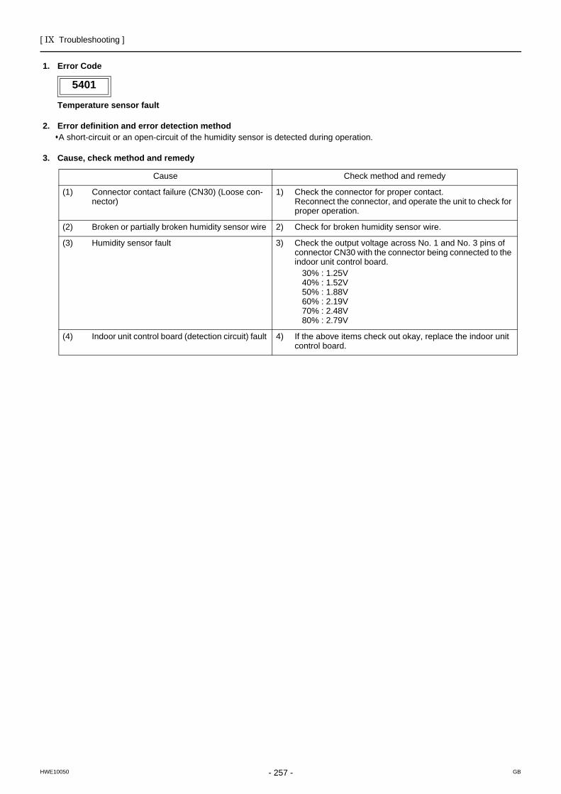
[ IX Troubleshooting ]
- 257 -HWE10050 GB
5401
1. Error Code
Temperature sensor fault
2. Error definition and error detection methodA short-circuit or an open-circuit of the humidity sensor is detected during operation.
3. Cause, check method and remedy
5401
Cause Check method and remedy
(1) Connector contact failure (CN30) (Loose con-nector)
1) Check the connector for proper contact. Reconnect the connector, and operate the unit to check for proper operation.
(2) Broken or partially broken humidity sensor wire 2) Check for broken humidity sensor wire.
(3) Humidity sensor fault 3) Check the output voltage across No. 1 and No. 3 pins of connector CN30 with the connector being connected to the indoor unit control board. 30% : 1.25V 40% : 1.52V 50% : 1.88V 60% : 2.19V 70% : 2.48V 80% : 2.79V
(4) Indoor unit control board (detection circuit) fault 4) If the above items check out okay, replace the indoor unit control board.
[ IX Troubleshooting ]
- 258 -HWE10050 GB
5701
1. Error Code
Loose float switch connector
2. Error definition and error detection methodDetection of the disconnected float switch (open-phase condition) during operation
3. Cause, check method and remedy(1) CN4F disconnection or contact failure
Check for disconnection of the connector (CN4F) on the indoor unit control board.
6201
1. Error Code
Remote controller board fault (nonvolatile memory error)
2. Error definition and error detection methodThis error is detected when the data cannot be read out from the built-in nonvolatile memory on the remote controller.
3. Cause, check method and remedy(1) Remote controller failure
Replace the remote controller.
6202
1. Error Code
Remote controller board fault (clock IC error)
2. Error definition and error detection methodThis error is detected when the built-in clock on the remote controller is not properly functioning.
3. Cause, check method and remedy(1) Remote controller failure
Replace the remote controller.
5701
6201
6202
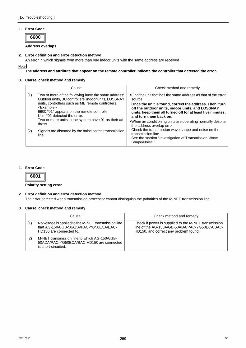
[ IX Troubleshooting ]
- 259 -HWE10050 GB
6600
1. Error Code
Address overlaps
2. Error definition and error detection methodAn error in which signals from more than one indoor units with the same address are received
The address and attribute that appear on the remote controller indicate the controller that detected the error.
3. Cause, check method and remedy
6601
1. Error Code
Polarity setting error
2. Error definition and error detection methodThe error detected when transmission processor cannot distinguish the polarities of the M-NET transmission line.
3. Cause, check method and remedy
6600
Cause Check method and remedy
(1) Two or more of the following have the same address: Outdoor units, BC controllers, indoor units, LOSSNAY units, controllers such as ME remote controllers. <Example>6600 "01" appears on the remote controllerUnit #01 detected the error. Two or more units in the system have 01 as their ad-dress.
Find the unit that has the same address as that of the error source.Once the unit is found, correct the address. Then, turn off the outdoor units, indoor units, and LOSSNAY units, keep them all turned off for at least five minutes, and turn them back on.When air conditioning units are operating normally despite the address overlap errorCheck the transmission wave shape and noise on the transmission line.See the section "Investigation of Transmission Wave Shape/Noise."
(2) Signals are distorted by the noise on the transmission line.
6601
Cause Check method and remedy
(1) No voltage is applied to the M-NET transmission line that AG-150A/GB-50ADA/PAC-YG50ECA/BAC-HD150 are connected to.
Check if power is supplied to the M-NET transmission line of the AG-150A/GB-50ADA/PAC-YG50ECA/BAC-HD150, and correct any problem found.
(2) M-NET transmission line to which AG-150A/GB-50ADA/PAC-YG50ECA/BAC-HD150 are connected is short-circuited.
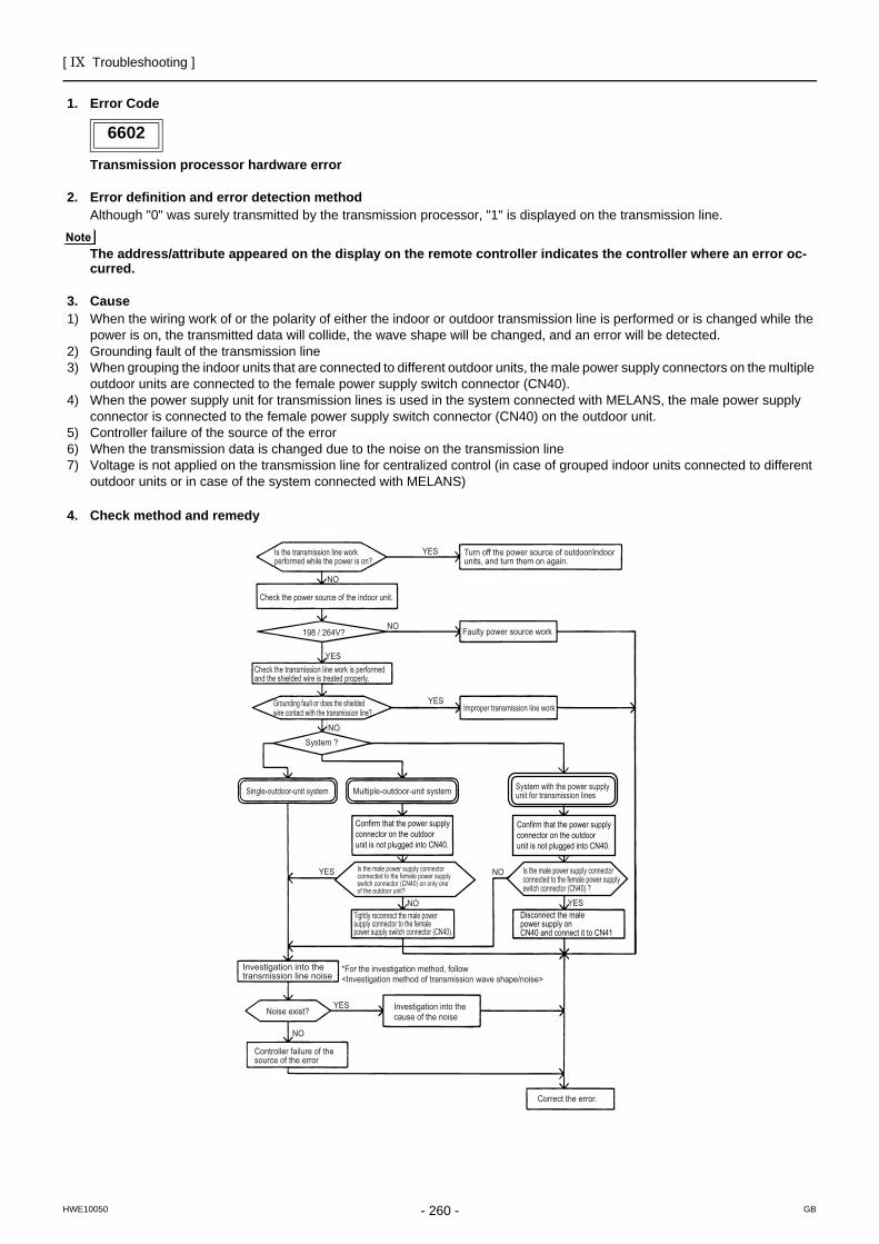
[ IX Troubleshooting ]
- 260 -HWE10050 GB
6602
1. Error Code
Transmission processor hardware error
2. Error definition and error detection methodAlthough "0" was surely transmitted by the transmission processor, "1" is displayed on the transmission line.
The address/attribute appeared on the display on the remote controller indicates the controller where an error oc-curred.
3. Cause1) When the wiring work of or the polarity of either the indoor or outdoor transmission line is performed or is changed while the
power is on, the transmitted data will collide, the wave shape will be changed, and an error will be detected.2) Grounding fault of the transmission line3) When grouping the indoor units that are connected to different outdoor units, the male power supply connectors on the multiple
outdoor units are connected to the female power supply switch connector (CN40).4) When the power supply unit for transmission lines is used in the system connected with MELANS, the male power supply
connector is connected to the female power supply switch connector (CN40) on the outdoor unit.5) Controller failure of the source of the error6) When the transmission data is changed due to the noise on the transmission line7) Voltage is not applied on the transmission line for centralized control (in case of grouped indoor units connected to different
outdoor units or in case of the system connected with MELANS)
4. Check method and remedy
6602
NO Tightly reconnect the male power supply connector to the female power supply switch connector (CN40).
YES
YES
YES
YES
YES
YES
NO
NO
NO
NO
Is the transmission line work performed while the power is on?
Check the power source of the indoor unit.
198 / 264V?
Check the transmission line work is performed and the shielded wire is treated properly.
Grounding fault or does the shielded wire contact with the transmission line?
System ?
Faulty power source work
Improper transmission line work
Turn off the power source of outdoor/indoor units, and turn them on again.
NO
Investigation into the transmission line noise
Noise exist?
Controller failure of the source of the error
*For the investigation method, follow <Investigation method of transmission wave shape/noise>
Investigation into the cause of the noise
Correct the error.
System with the power supply unit for transmission lines
Is the male power supply connector connected to the female power supply switch connector (CN40) on only one of the outdoor unit?
Is the male power supply connector connected to the female power supply switch connector (CN40) ?
Confirm that the power supply connector on the outdoor unit is not plugged into CN40.
Confirm that the power supply connector on the outdoor unit is not plugged into CN40.
Disconnect the male power supply on CN40 and connect it to CN41
Single-outdoor-unit system Multiple-outdoor-unit system
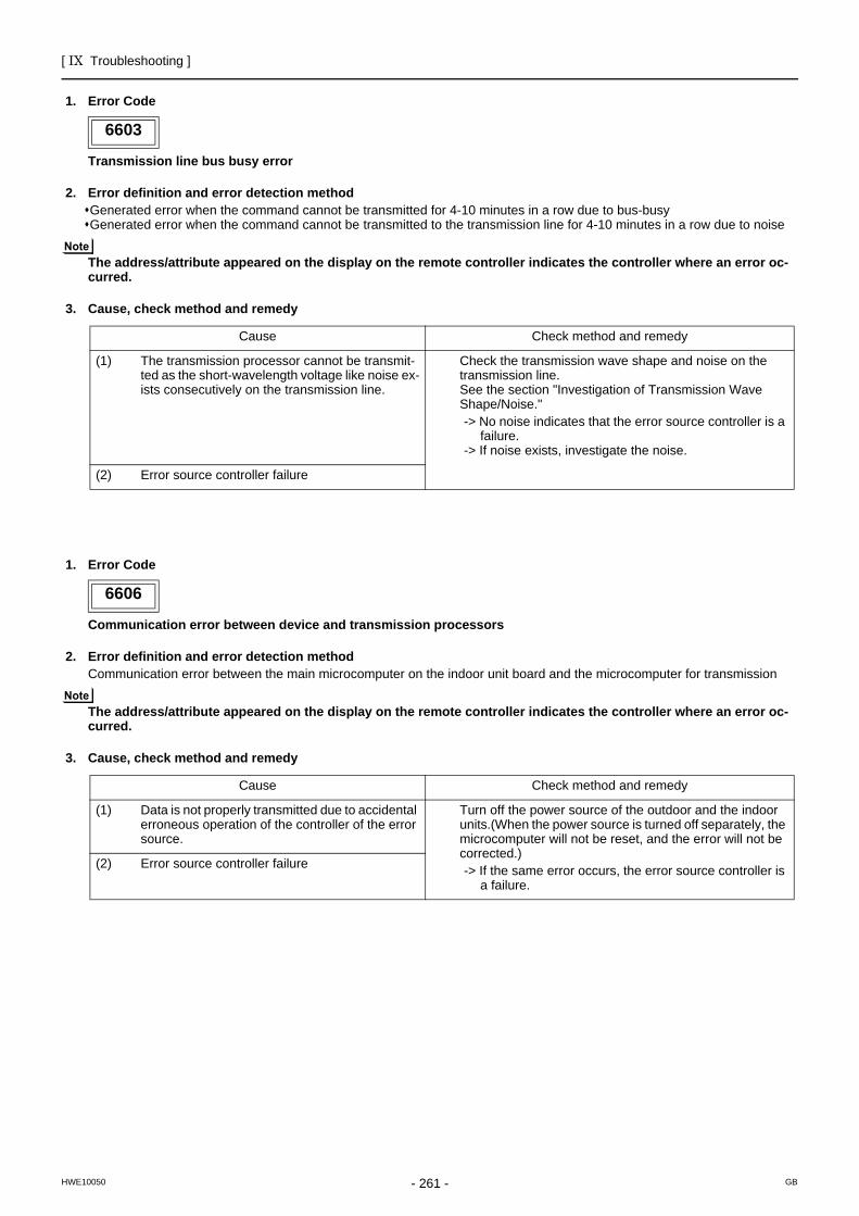
[ IX Troubleshooting ]
- 261 -HWE10050 GB
6603
1. Error Code
Transmission line bus busy error
2. Error definition and error detection methodGenerated error when the command cannot be transmitted for 4-10 minutes in a row due to bus-busyGenerated error when the command cannot be transmitted to the transmission line for 4-10 minutes in a row due to noise
The address/attribute appeared on the display on the remote controller indicates the controller where an error oc-curred.
3. Cause, check method and remedy
6606
1. Error Code
Communication error between device and transmission processors
2. Error definition and error detection methodCommunication error between the main microcomputer on the indoor unit board and the microcomputer for transmission
The address/attribute appeared on the display on the remote controller indicates the controller where an error oc-curred.
3. Cause, check method and remedy
6603
Cause Check method and remedy
(1) The transmission processor cannot be transmit-ted as the short-wavelength voltage like noise ex-ists consecutively on the transmission line.
Check the transmission wave shape and noise on the transmission line.See the section "Investigation of Transmission Wave Shape/Noise."-> No noise indicates that the error source controller is a
failure.-> If noise exists, investigate the noise.
(2) Error source controller failure
6606
Cause Check method and remedy
(1) Data is not properly transmitted due to accidental erroneous operation of the controller of the error source.
Turn off the power source of the outdoor and the indoor units.(When the power source is turned off separately, the microcomputer will not be reset, and the error will not be corrected.)-> If the same error occurs, the error source controller is
a failure.
(2) Error source controller failure
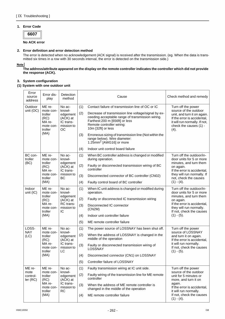
[ IX Troubleshooting ]
- 262 -HWE10050 GB
6607
1. Error Code
No ACK error
2. Error definition and error detection methodThe error is detected when no acknowledgement (ACK signal) is received after the transmission. (eg. When the data is trans-mitted six times in a row with 30 seconds interval, the error is detected on the transmission side.)
The address/attribute appeared on the display on the remote controller indicates the controller which did not provide the response (ACK).
3. System configuration(1) System with one outdoor unit
6607
Error source
address
Error dis-play
Detection method Cause Check method and remedy
Outdoor unit (OC)
ME re-mote con-troller (RC)MA re-mote con-troller (MA)
No ac-knowl-edgement (ACK) at IC trans-mission to OC
(1) Contact failure of transmission line of OC or IC Turn off the power source of the outdoor unit, and turn it on again.If the error is accidental, it will run normally. If not, check the causes (1) - (4).
(2) Decrease of transmission line voltage/signal by ex-ceeding acceptable range of transmission wiring.Farthest:200 m [656ft] or lessRemote controller wiring:10m [32ft] or less
(3) Erroneous sizing of transmission line (Not within the range below). Wire diameter:1.25mm2 [AWG16] or more
(4) Indoor unit control board failure
BC con-troller (BC)
ME re-mote con-troller (RC)MA re-mote con-troller (MA)
No ac-knowl-edgement (ACK) at IC trans-mission to BC
(1) When BC controller address is changed or modified during operation.
Turn off the outdoor/in-door units for 5 or more minutes, and turn them on again. If the error is accidental, they will run normally. If not, check the causes (1) - (4).
(2) Faulty or disconnected transmission wiring of BC controller
(3) Disconnected connector of BC controller (CN02)
(4) Faulty control board of BC controller
Indoor unit (IC)
ME re-mote con-troller (RC)MA re-mote con-troller (MA)
No ac-knowl-edgement (ACK) at RC trans-mission to IC
(1) When IC unit address is changed or modified during operation.
Turn off the outdoor/in-door units for 5 or more minutes, and turn them on again.If the error is accidental, they will run normally. If not, check the causes (1) - (5).
(2) Faulty or disconnected IC transmission wiring
(3) Disconnected IC connector(CN2M)
(4) Indoor unit controller failure
(5) ME remote controller failure
LOSS-NAY (LC)
ME re-mote con-troller (RC)MA re-mote con-troller (MA)
No ac-knowl-edgement (ACK) at IC trans-mission to LC
(1) The power source of LOSSNAY has been shut off. Turn off the power source of LOSSNAY and turn it on again.If the error is accidental, it will run normally.If not, check the causes (1) - (5).
(2) When the address of LOSSNAY is changed in the middle of the operation
(3) Faulty or disconnected transmission wiring of LOSSNAY
(4) Disconnected connector (CN1) on LOSSNAY
(5) Controller failure of LOSSNAY
ME re-mote control-ler (RC)
ME re-mote con-troller (RC)MA re-mote con-troller (MA)
No ac-knowl-edgement (ACK) at IC trans-mission to RC
(1) Faulty transmission wiring at IC unit side. Turn off the power source of the outdoor unit for 5 minutes or more, and turn it on again.If the error is accidental, it will run normally.If not, check the causes (1) - (4).
(2) Faulty wiring of the transmission line for ME remote controller
(3) When the address of ME remote controller is changed in the middle of the operation
(4) ME remote controller failure
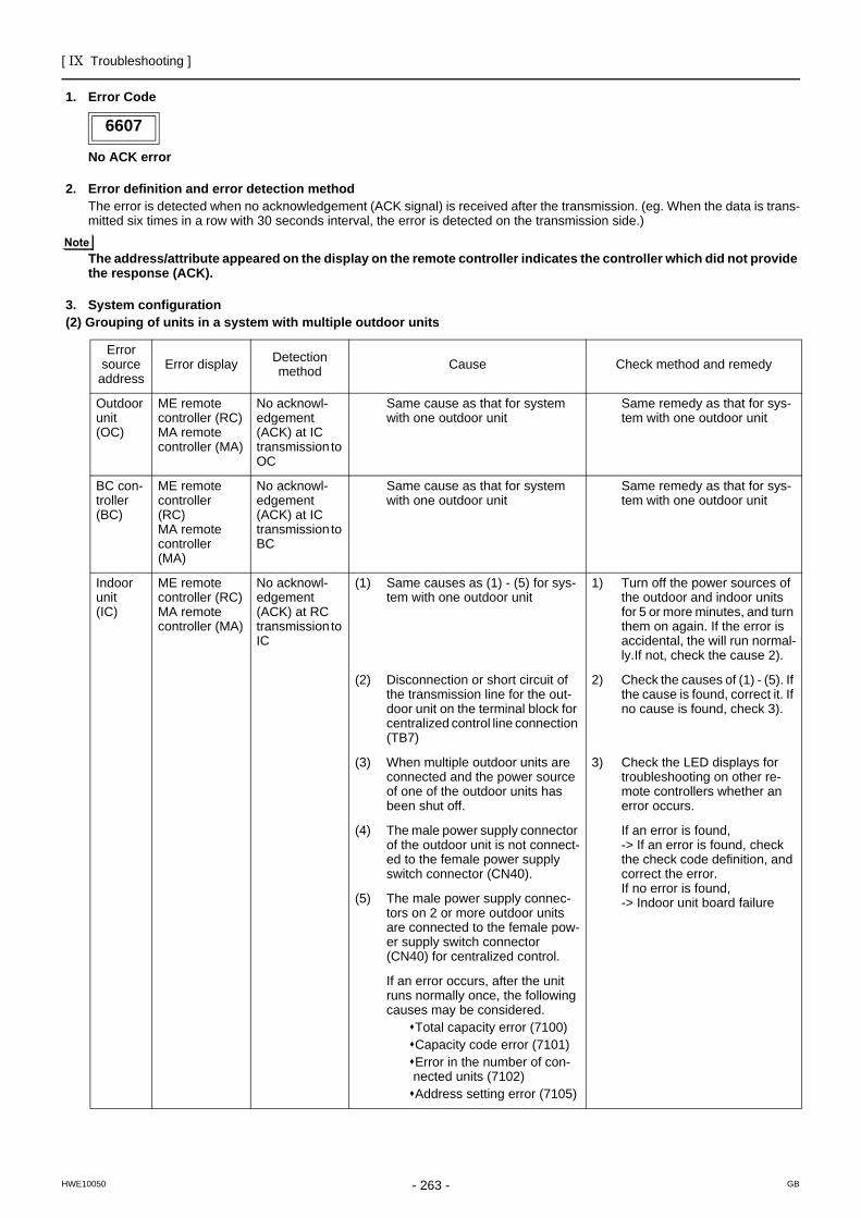
[ IX Troubleshooting ]
- 263 -HWE10050 GB
1. Error Code
No ACK error
2. Error definition and error detection methodThe error is detected when no acknowledgement (ACK signal) is received after the transmission. (eg. When the data is trans-mitted six times in a row with 30 seconds interval, the error is detected on the transmission side.)
The address/attribute appeared on the display on the remote controller indicates the controller which did not provide the response (ACK).
3. System configuration(2) Grouping of units in a system with multiple outdoor units
6607
Error source address
Error display Detection method Cause Check method and remedy
Outdoor unit(OC)
ME remote controller (RC)MA remote controller (MA)
No acknowl-edgement (ACK) at IC transmission to OC
Same cause as that for system with one outdoor unit
Same remedy as that for sys-tem with one outdoor unit
BC con-troller(BC)
ME remote controller(RC)MA remote controller(MA)
No acknowl-edgement (ACK) at IC transmission to BC
Same cause as that for system with one outdoor unit
Same remedy as that for sys-tem with one outdoor unit
Indoor unit(IC)
ME remote controller (RC)MA remote controller (MA)
No acknowl-edgement (ACK) at RC transmission to IC
(1) Same causes as (1) - (5) for sys-tem with one outdoor unit
1) Turn off the power sources of the outdoor and indoor units for 5 or more minutes, and turn them on again. If the error is accidental, the will run normal-ly.If not, check the cause 2).
(2) Disconnection or short circuit of the transmission line for the out-door unit on the terminal block for centralized control line connection (TB7)
2) Check the causes of (1) - (5). If the cause is found, correct it. If no cause is found, check 3).
(3) When multiple outdoor units are connected and the power source of one of the outdoor units has been shut off.
3) Check the LED displays for troubleshooting on other re-mote controllers whether an error occurs.
(4) The male power supply connector of the outdoor unit is not connect-ed to the female power supply switch connector (CN40).
If an error is found,-> If an error is found, check the check code definition, and correct the error.If no error is found,-> Indoor unit board failure(5) The male power supply connec-
tors on 2 or more outdoor units are connected to the female pow-er supply switch connector (CN40) for centralized control.
If an error occurs, after the unit runs normally once, the following causes may be considered.
Total capacity error (7100)Capacity code error (7101)Error in the number of con-nected units (7102)Address setting error (7105)
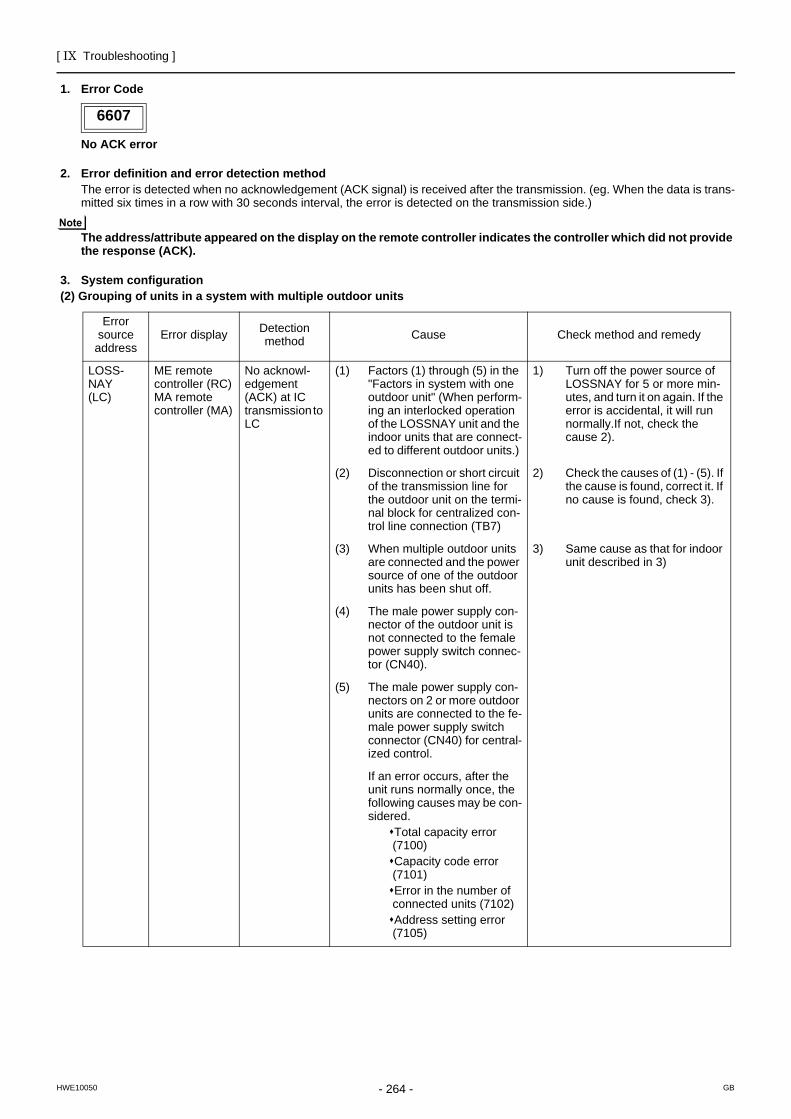
[ IX Troubleshooting ]
- 264 -HWE10050 GB
1. Error Code
No ACK error
2. Error definition and error detection methodThe error is detected when no acknowledgement (ACK signal) is received after the transmission. (eg. When the data is trans-mitted six times in a row with 30 seconds interval, the error is detected on the transmission side.)
The address/attribute appeared on the display on the remote controller indicates the controller which did not provide the response (ACK).
3. System configuration(2) Grouping of units in a system with multiple outdoor units
6607
Error source
addressError display Detection
method Cause Check method and remedy
LOSS-NAY(LC)
ME remote controller (RC)MA remote controller (MA)
No acknowl-edgement (ACK) at IC transmission to LC
(1) Factors (1) through (5) in the "Factors in system with one outdoor unit" (When perform-ing an interlocked operation of the LOSSNAY unit and the indoor units that are connect-ed to different outdoor units.)
1) Turn off the power source of LOSSNAY for 5 or more min-utes, and turn it on again. If the error is accidental, it will run normally.If not, check the cause 2).
(2) Disconnection or short circuit of the transmission line for the outdoor unit on the termi-nal block for centralized con-trol line connection (TB7)
2) Check the causes of (1) - (5). If the cause is found, correct it. If no cause is found, check 3).
(3) When multiple outdoor units are connected and the power source of one of the outdoor units has been shut off.
3) Same cause as that for indoor unit described in 3)
(4) The male power supply con-nector of the outdoor unit is not connected to the female power supply switch connec-tor (CN40).
(5) The male power supply con-nectors on 2 or more outdoor units are connected to the fe-male power supply switch connector (CN40) for central-ized control.
If an error occurs, after the unit runs normally once, the following causes may be con-sidered.
Total capacity error (7100)Capacity code error (7101)Error in the number of connected units (7102)Address setting error (7105)
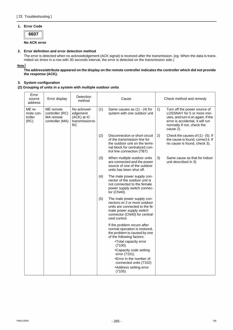
[ IX Troubleshooting ]
- 265 -HWE10050 GB
1. Error Code
No ACK error
2. Error definition and error detection methodThe error is detected when no acknowledgement (ACK signal) is received after the transmission. (eg. When the data is trans-mitted six times in a row with 30 seconds interval, the error is detected on the transmission side.)
The address/attribute appeared on the display on the remote controller indicates the controller which did not provide the response (ACK).
3. System configuration(2) Grouping of units in a system with multiple outdoor units
6607
Error source
addressError display Detection
method Cause Check method and remedy
ME re-mote con-troller (RC)
ME remote controller (RC)MA remote controller (MA)
No acknowl-edgement (ACK) at IC transmission to RC
(1) Same causes as (1) - (4) for system with one outdoor unit
1) Turn off the power source of LOSSNAY for 5 or more min-utes, and turn it on again. If the error is accidental, it will run normally.If not, check the cause 2).
(2) Disconnection or short circuit of the transmission line for the outdoor unit on the termi-nal block for centralized con-trol line connection (TB7)
2) Check the causes of (1) - (5). If the cause is found, correct it. If no cause is found, check 3).
(3) When multiple outdoor units are connected and the power source of one of the outdoor units has been shut off.
3) Same cause as that for indoor unit described in 3)
(4) The male power supply con-nector of the outdoor unit is not connected to the female power supply switch connec-tor (CN40).
(5) The male power supply con-nectors on 2 or more outdoor units are connected to the fe-male power supply switch connector (CN40) for central-ized control.
If the problem recurs after normal operation is restored, the problem is caused by one of the following factors:
Total capacity error (7100)Capacity code setting error (7101)Error in the number of connected units (7102)Address setting error (7105)
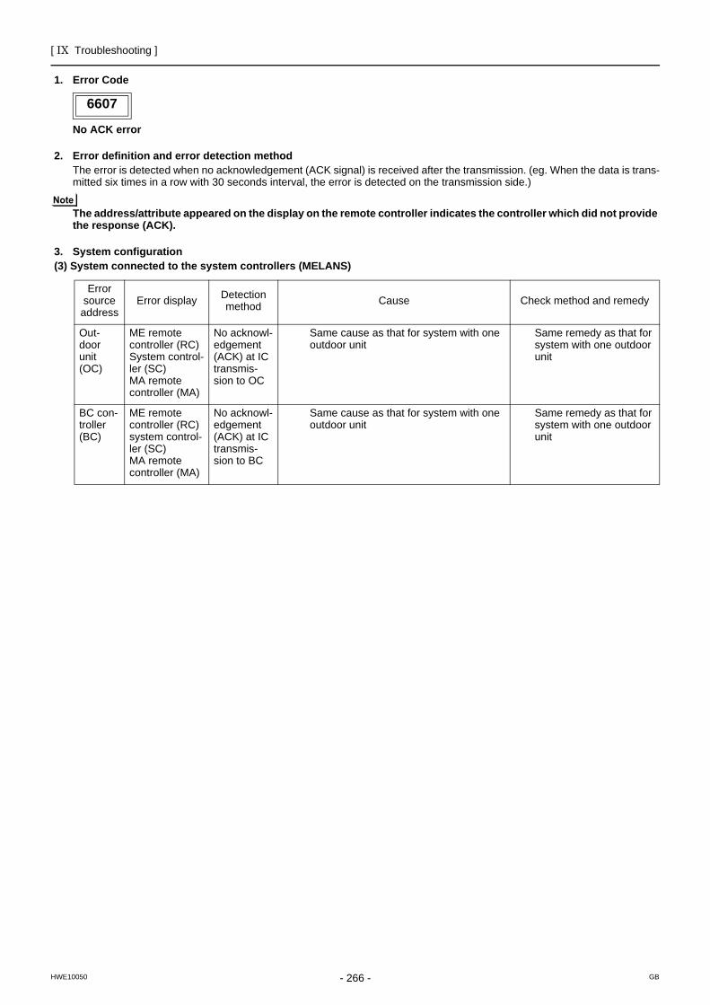
[ IX Troubleshooting ]
- 266 -HWE10050 GB
1. Error Code
No ACK error
2. Error definition and error detection methodThe error is detected when no acknowledgement (ACK signal) is received after the transmission. (eg. When the data is trans-mitted six times in a row with 30 seconds interval, the error is detected on the transmission side.)
The address/attribute appeared on the display on the remote controller indicates the controller which did not provide the response (ACK).
3. System configuration(3) System connected to the system controllers (MELANS)
6607
Error source address
Error display Detection method Cause Check method and remedy
Out-door unit(OC)
ME remote controller (RC)System control-ler (SC)MA remote controller (MA)
No acknowl-edgement (ACK) at IC transmis-sion to OC
Same cause as that for system with one outdoor unit
Same remedy as that for system with one outdoor unit
BC con-troller(BC)
ME remote controller (RC)system control-ler (SC)MA remote controller (MA)
No acknowl-edgement (ACK) at IC transmis-sion to BC
Same cause as that for system with one outdoor unit
Same remedy as that for system with one outdoor unit
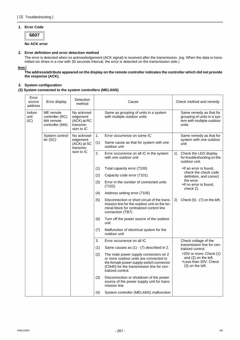
[ IX Troubleshooting ]
- 267 -HWE10050 GB
1. Error Code
No ACK error
2. Error definition and error detection methodThe error is detected when no acknowledgement (ACK signal) is received after the transmission. (eg. When the data is trans-mitted six times in a row with 30 seconds interval, the error is detected on the transmission side.)
The address/attribute appeared on the display on the remote controller indicates the controller which did not provide the response (ACK).
3. System configuration(3) System connected to the system controllers (MELANS)
6607
Error source address
Error display Detection method Cause Check method and remedy
Indoor unit(IC)
ME remote controller (RC)MA remote controller (MA)
No acknowl-edgement (ACK) at RC transmis-sion to IC
Same as grouping of units in a system with multiple outdoor units
Same remedy as that for grouping of units in a sys-tem with multiple outdoor units
System control-ler (SC)
No acknowl-edgement (ACK) at SC transmis-sion to IC
1. Error occurrence on some IC Same remedy as that for system with one outdoor unit(1) Same cause as that for system with one
outdoor unit
2. Error occurrence on all IC in the system with one outdoor unit
1) Check the LED display for troubleshooting on the outdoor unit.
(1) Total capacity error (7100) If an error is found, check the check code definition, and correct the error.If no error is found, check 2).
(2) Capacity code error (7101)
(3) Error in the number of connected units (7102)
(4) Address setting error (7105)
(5) Disconnection or short circuit of the trans-mission line for the outdoor unit on the ter-minal block for centralized control line connection (TB7)
2) Check (5) - (7) on the left.
(6) Turn off the power source of the outdoor unit
(7) Malfunction of electrical system for the outdoor unit
3. Error occurrence on all IC Check voltage of the transmission line for cen-tralized control.
20V or more: Check (1) and (2) on the left.Less than 20V: Check (3) on the left.
(1) Same causes as (1) - (7) described in 2.
(2) The male power supply connectors on 2 or more outdoor units are connected to the female power supply switch connector (CN40) for the transmission line for cen-tralized control.
(3) Disconnection or shutdown of the power source of the power supply unit for trans-mission line
(4) System controller (MELANS) malfunction
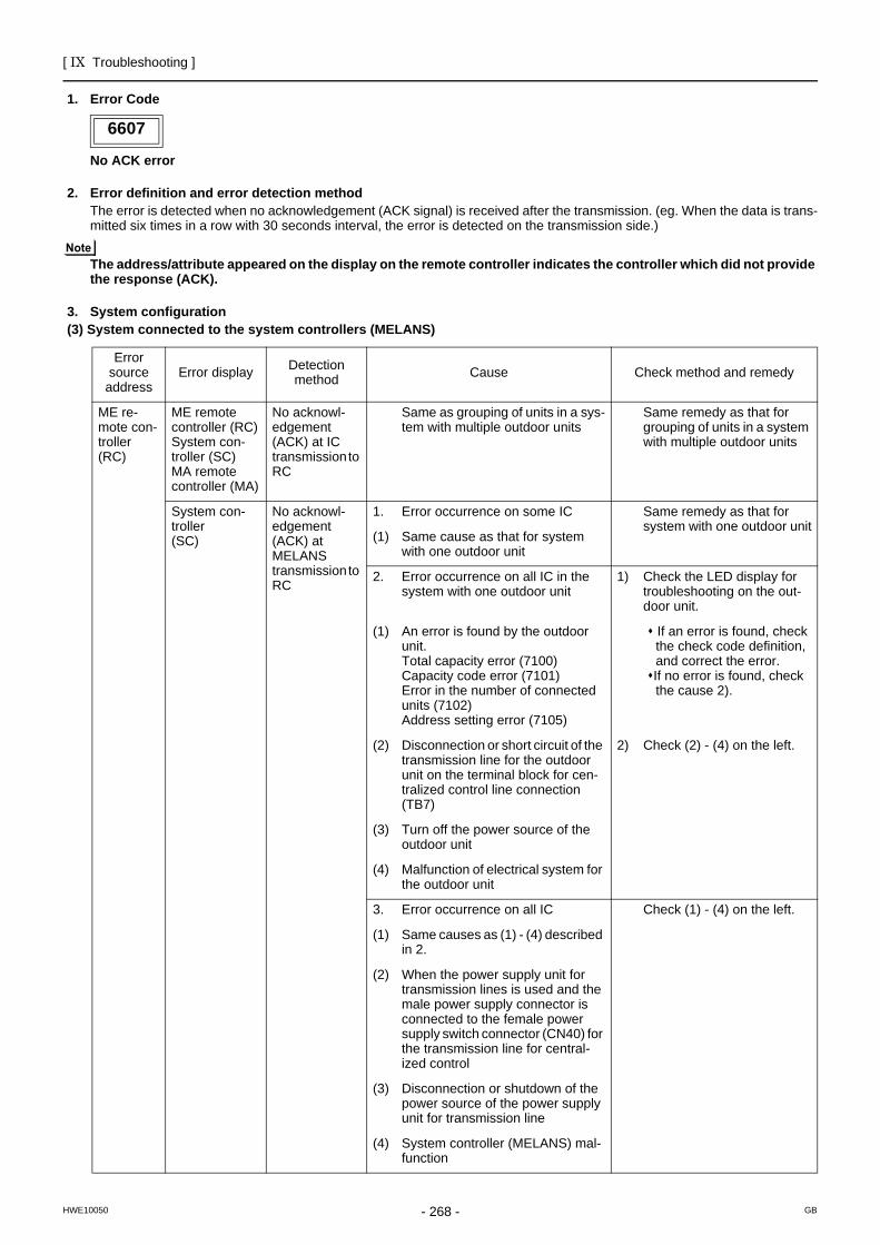
[ IX Troubleshooting ]
- 268 -HWE10050 GB
1. Error Code
No ACK error
2. Error definition and error detection methodThe error is detected when no acknowledgement (ACK signal) is received after the transmission. (eg. When the data is trans-mitted six times in a row with 30 seconds interval, the error is detected on the transmission side.)
The address/attribute appeared on the display on the remote controller indicates the controller which did not provide the response (ACK).
3. System configuration(3) System connected to the system controllers (MELANS)
6607
Error source
addressError display Detection
method Cause Check method and remedy
ME re-mote con-troller(RC)
ME remote controller (RC)System con-troller (SC)MA remote controller (MA)
No acknowl-edgement (ACK) at IC transmission to RC
Same as grouping of units in a sys-tem with multiple outdoor units
Same remedy as that for grouping of units in a system with multiple outdoor units
System con-troller(SC)
No acknowl-edgement (ACK) at MELANS transmission to RC
1. Error occurrence on some IC Same remedy as that for system with one outdoor unit
(1) Same cause as that for system with one outdoor unit
2. Error occurrence on all IC in the system with one outdoor unit
1) Check the LED display for troubleshooting on the out-door unit.
(1) An error is found by the outdoor unit.Total capacity error (7100)Capacity code error (7101)Error in the number of connected units (7102)Address setting error (7105)
If an error is found, check the check code definition, and correct the error.If no error is found, check the cause 2).
(2) Disconnection or short circuit of the transmission line for the outdoor unit on the terminal block for cen-tralized control line connection (TB7)
2) Check (2) - (4) on the left.
(3) Turn off the power source of the outdoor unit
(4) Malfunction of electrical system for the outdoor unit
3. Error occurrence on all IC Check (1) - (4) on the left.
(1) Same causes as (1) - (4) described in 2.
(2) When the power supply unit for transmission lines is used and the male power supply connector is connected to the female power supply switch connector (CN40) for the transmission line for central-ized control
(3) Disconnection or shutdown of the power source of the power supply unit for transmission line
(4) System controller (MELANS) mal-function
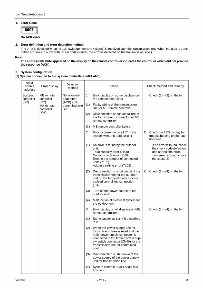
[ IX Troubleshooting ]
- 269 -HWE10050 GB
1. Error Code
No ACK error
2. Error definition and error detection methodThe error is detected when no acknowledgement (ACK signal) is received after the transmission. (eg. When the data is trans-mitted six times in a row with 30 seconds interval, the error is detected on the transmission side.)
The address/attribute appeared on the display on the remote controller indicates the controller which did not provide the response (ACK).
3. System configuration(3) System connected to the system controllers (MELANS)
6607
Error source
addressError display Detection
method Cause Check method and remedy
System controller(SC)
ME remote controller(RC)MA remote controller(MA)
No acknowl-edgement (ACK) at IC transmission to SC
1. Error display on some displays on ME remote controllers
Check (1) - (3) on the left.
(1) Faulty wiring of the transmission line for ME remote controller
(2) Disconnection or contact failure of the transmission connector for ME remote controller
(3) ME remote controller failure
2. Error occurrence on all IC in the system with one outdoor unit
1) Check the LED display for troubleshooting on the out-door unit.
(1) An error is found by the outdoor unit.Total capacity error (7100)Capacity code error (7101)Error in the number of connected units (7102)Address setting error (7105)
If an error is found, check the check code definition, and correct the error.If no error is found, check the cause 2)
(2) Disconnection or short circuit of the transmission line for the outdoor unit on the terminal block for cen-tralized control line connection (TB7)
2) Check (2) - (4) on the left.
(3) Turn off the power source of the outdoor unit
(4) Malfunction of electrical system for the outdoor unit
3. Error display on all displays on ME remote controllers
Check (1) - (4) on the left
(1) Same causes as (1) - (4) described in 2.
(2) When the power supply unit for transmission lines is used and the male power supply connector is connected to the female power sup-ply switch connector (CN40) for the transmission line for centralized control
(3) Disconnection or shutdown of the power source of the power supply unit for transmission line
(4) System controller (MELANS) mal-function
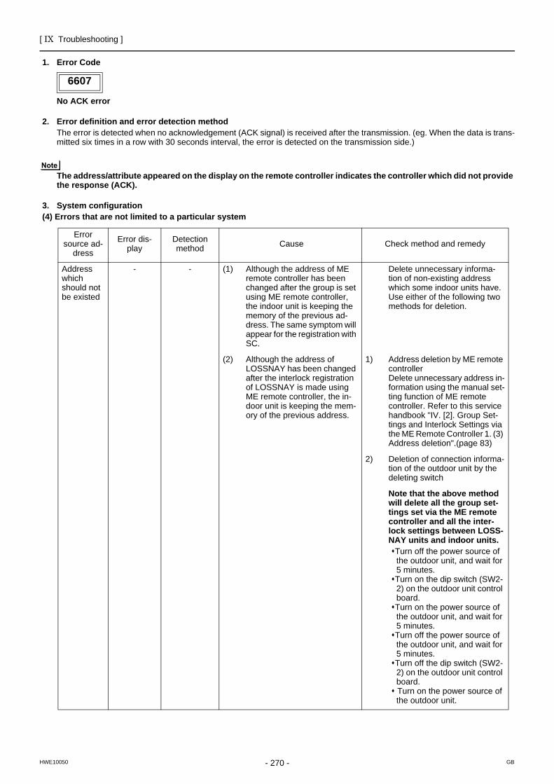
[ IX Troubleshooting ]
- 270 -HWE10050 GB
1. Error Code
No ACK error
2. Error definition and error detection methodThe error is detected when no acknowledgement (ACK signal) is received after the transmission. (eg. When the data is trans-mitted six times in a row with 30 seconds interval, the error is detected on the transmission side.)
The address/attribute appeared on the display on the remote controller indicates the controller which did not provide the response (ACK).
3. System configuration(4) Errors that are not limited to a particular system
6607
Error source ad-
dress
Error dis-play
Detection method Cause Check method and remedy
Address which should not be existed
- - (1) Although the address of ME remote controller has been changed after the group is set using ME remote controller, the indoor unit is keeping the memory of the previous ad-dress. The same symptom will appear for the registration with SC.
Delete unnecessary informa-tion of non-existing address which some indoor units have.Use either of the following two methods for deletion.
(2) Although the address of LOSSNAY has been changed after the interlock registration of LOSSNAY is made using ME remote controller, the in-door unit is keeping the mem-ory of the previous address.
1) Address deletion by ME remote controllerDelete unnecessary address in-formation using the manual set-ting function of ME remote controller. Refer to this service handbook "IV. [2]. Group Set-tings and Interlock Settings via the ME Remote Controller 1. (3) Address deletion".(page 83)
2) Deletion of connection informa-tion of the outdoor unit by the deleting switch
Note that the above method will delete all the group set-tings set via the ME remote controller and all the inter-lock settings between LOSS-NAY units and indoor units.
Turn off the power source of the outdoor unit, and wait for 5 minutes.Turn on the dip switch (SW2-2) on the outdoor unit control board. Turn on the power source of the outdoor unit, and wait for 5 minutes.Turn off the power source of the outdoor unit, and wait for 5 minutes.Turn off the dip switch (SW2-2) on the outdoor unit control board. Turn on the power source of the outdoor unit.
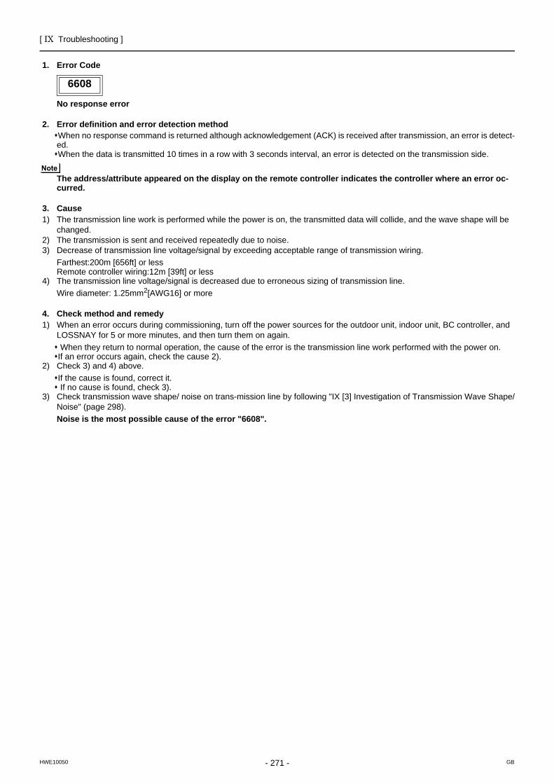
[ IX Troubleshooting ]
- 271 -HWE10050 GB
6608
1. Error Code
No response error
2. Error definition and error detection methodWhen no response command is returned although acknowledgement (ACK) is received after transmission, an error is detect-ed.When the data is transmitted 10 times in a row with 3 seconds interval, an error is detected on the transmission side.
The address/attribute appeared on the display on the remote controller indicates the controller where an error oc-curred.
3. Cause1) The transmission line work is performed while the power is on, the transmitted data will collide, and the wave shape will be
changed.2) The transmission is sent and received repeatedly due to noise.3) Decrease of transmission line voltage/signal by exceeding acceptable range of transmission wiring.
Farthest:200m [656ft] or lessRemote controller wiring:12m [39ft] or less
4) The transmission line voltage/signal is decreased due to erroneous sizing of transmission line.Wire diameter: 1.25mm2[AWG16] or more
4. Check method and remedy1) When an error occurs during commissioning, turn off the power sources for the outdoor unit, indoor unit, BC controller, and
LOSSNAY for 5 or more minutes, and then turn them on again. When they return to normal operation, the cause of the error is the transmission line work performed with the power on.If an error occurs again, check the cause 2).
2) Check 3) and 4) above.If the cause is found, correct it. If no cause is found, check 3).
3) Check transmission wave shape/ noise on trans-mission line by following "IX [3] Investigation of Transmission Wave Shape/Noise" (page 298).Noise is the most possible cause of the error "6608".
6608
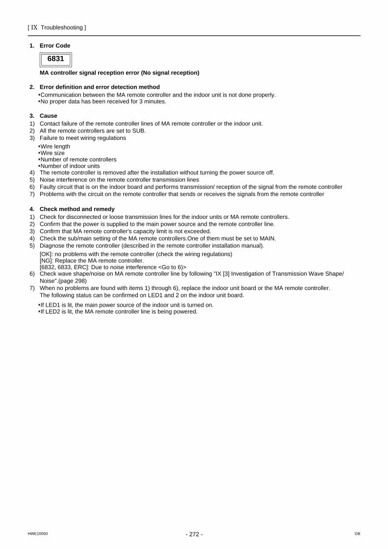
[ IX Troubleshooting ]
- 272 -HWE10050 GB
6831
1. Error Code
MA controller signal reception error (No signal reception)
2. Error definition and error detection methodCommunication between the MA remote controller and the indoor unit is not done properly. No proper data has been received for 3 minutes.
3. Cause1) Contact failure of the remote controller lines of MA remote controller or the indoor unit.2) All the remote controllers are set to SUB.3) Failure to meet wiring regulations
Wire lengthWire sizeNumber of remote controllersNumber of indoor units
4) The remote controller is removed after the installation without turning the power source off.5) Noise interference on the remote controller transmission lines6) Faulty circuit that is on the indoor board and performs transmission/ reception of the signal from the remote controller7) Problems with the circuit on the remote controller that sends or receives the signals from the remote controller
4. Check method and remedy1) Check for disconnected or loose transmission lines for the indoor units or MA remote controllers.2) Confirm that the power is supplied to the main power source and the remote controller line.3) Confirm that MA remote controller's capacity limit is not exceeded.4) Check the sub/main setting of the MA remote controllers.One of them must be set to MAIN.5) Diagnose the remote controller (described in the remote controller installation manual).
[OK]: no problems with the remote controller (check the wiring regulations)[NG]: Replace the MA remote controller.[6832, 6833, ERC]: Due to noise interference <Go to 6)>
6) Check wave shape/noise on MA remote controller line by following "IX [3] Investigation of Transmission Wave Shape/Noise".(page 298)
7) When no problems are found with items 1) through 6), replace the indoor unit board or the MA remote controller.The following status can be confirmed on LED1 and 2 on the indoor unit board.
If LED1 is lit, the main power source of the indoor unit is turned on.If LED2 is lit, the MA remote controller line is being powered.
6831
[ IX Troubleshooting ]
- 273 -HWE10050 GB
6832
1. Error Code
MA remote controller signal transmission error (Synchronization error)
2. Error definition and error detection methodMA remote controller and the indoor unit is not done properly.Failure to detect opening in the transmission path and unable to send signals∗Indoor unit : 3 minutes∗Remote controller : 6 seconds
3. Cause1) Contact failure of the remote controller lines of MA remote controller or the indoor unit2) 2 or more remote controllers are set to MAIN3) Overlapped indoor unit address4) Noise interference on the remote controller lines5) Failure to meet wiring regulations
Wire lengthWire sizeNumber of remote controllersNumber of indoor units
6) Problems with the circuit on the remote controller that sends or receives the signals from the remote controller
4. Check method and remedy1) Check for disconnected or loose transmission lines for the indoor units or MA remote controllers.2) Confirm that the power is supplied to the main power source and the remote controller line.3) Confirm that MA remote controller's capacity limit is not exceeded.4) Check the sub/main setting of the MA remote controllers.One of them must be set to MAIN.5) Diagnose the remote controller (described in the remote controller installation manual).
[OK]: no problems with the remote controller (check the wiring regulations)[NG]: Replace the MA remote controller.[6832, 6833, ERC]: Due to noise interference <Go to 6)>
6) Check wave shape/noise on MA remote controller line by following "IX [3] Investigation of Transmission Wave Shape/Noise".(page 298)
7) When no problems are found with items 1) through 6), replace the indoor unit board or the MA remote controller.The following status can be confirmed on LED1 and 2 on the indoor unit board.
If LED1 is lit, the main power source of the indoor unit is turned on.If LED2 is lit, the MA remote controller line is being powered.
6832
[ IX Troubleshooting ]
- 274 -HWE10050 GB
6833
1. Error Code
MA remote controller signal transmission error (Hardware error)
2. Error definition and error detection methodCommunication between the MA remote controller and the indoor unit is not done properly.An error occurs when the transmitted data and the received data differ for 30 times in a row.
3. Cause1) Contact failure of the remote controller lines of MA remote controller or the indoor unit2) 2 or more remote controllers are set to MAIN3) Overlapped indoor unit address4) Noise interference on the remote controller lines5) Failure to meet wiring regulations
Wire lengthWire sizeNumber of remote controllersNumber of indoor units
6) Problems with the circuit on the remote controller that sends or receives the signals from the remote controller
4. Check method and remedy1) Check for disconnected or loose transmission lines for the indoor units or MA remote controllers.2) Confirm that the power is supplied to the main power source and the remote controller line.3) Confirm that MA remote controller's capacity limit is not exceeded.4) Check the sub/main setting of the MA remote controllers.One of them must be set to MAIN.5) Diagnose the remote controller (described in the remote controller installation manual).
[OK]: no problems with the remote controller (check the wiring regulations)[NG]: Replace the MA remote controller.[6832, 6833, ERC]: Due to noise interference <Go to 6)>
6) Check wave shape/noise on MA remote controller line by following "IX [3] Investigation of Transmission Wave Shape/Noise".(page 298)
7) When no problems are found with items 1) through 6), replace the indoor unit board or the MA remote controller.The following status can be confirmed on LED1 and 2 on the indoor unit board.
If LED1 is lit, the main power source of the indoor unit is turned on.If LED2 is lit, the MA remote controller line is being powered.
6833

[ IX Troubleshooting ]
- 275 -HWE10050 GB
6834
1. Error Code
MA controller signal reception error (Start bit detection error)
2. Error definition and error detection methodCommunication between the MA remote controller and the indoor unit is not done properly.No proper data has been received for 2 minutes.
3. Cause1) Contact failure of the remote controller lines of MA remote controller or the indoor unit.2) All the remote controllers are set to SUB.3) Failure to meet wiring regulations
Wire lengthWire sizeNumber of remote controllersNumber of indoor units
4) The remote controller is removed after the installation without turning the power source off.5) Noise interference on the remote controller transmission lines6) Faulty circuit that is on the indoor board and performs transmission/ reception of the signal from the remote controller7) Problems with the circuit on the remote controller that sends or receives the signals from the remote controller
4. Check method and remedy1) Check for disconnected or loose transmission lines for the indoor units or MA remote controllers.2) Confirm that the power is supplied to the main power source and the remote controller line.3) Confirm that MA remote controller's capacity limit is not exceeded.4) Check the sub/main setting of the MA remote controllers.One of them must be set to MAIN.5) Diagnose the remote controller (described in the remote controller installation manual).
[OK]: no problems with the remote controller (check the wiring regulations)[NG]: Replace the MA remote controller.[6832, 6833, ERC]: Due to noise interference <Go to 6)>
6) Check wave shape/noise on MA remote controller line by following "IX [3] Investigation of Transmission Wave Shape/Noise".(page 298)
7) When no problems are found with items 1) through 6), replace the indoor unit board or the MA remote controller.The following status can be confirmed on LED1 and 2 on the indoor unit board.
If LED1 is lit, the main power source of the indoor unit is turned onIf LED2 is lit, the MA remote controller line is being powered.
6834
[ IX Troubleshooting ]
- 276 -HWE10050 GB
7100
1. Error Code
Total capacity error
2. Error definition and error detection methodThe model total of indoor units in the system with one outdoor unit exceeds limitations.
3. Error source, cause, check method and remedy,
7100
Error source Cause Check method and remedy
Outdoor unit (1) The model total of indoor units in the sys-tem with one outdoor unit exceeds the fol-lowing table.
1) Check the Qj total (capacity code total) of indoor units connected.
2) Check the Qj setting (capacity code) of the con-nected indoor unit set by the switch (SW2 on in-door unit board).
When the model name set by the switch is differ-ent from that of the unit connected, turn off the power source of the outdoor and the indoor units, and change the setting of the Qj (capacity code).
3) Indoor unit Qj table
(2) The model selection switches (SW5-1 - 5-4) on the outdoor unit are set incorrectly.
Check the setting for the model selection switch on the outdoor unit (Dipswitches SW5-1 - 5-4 on the outdoor unit control board).
(3) The outdoor unit and the auxiliary unit (OS) that is connected to the same system are not properly connected.
Confirm that the TB3 on the OC and OS are properly connected.
(E)P200 model(E)P250 model(E)P300 model(E)P350 model(E)P400 model(E)P450 model(E)P500 model(E)P550 model(E)P600 model(E)P650 model(E)P700 model
P750 modelP800 modelP850 modelP900 model
300375450525600675750825900975
10501125120012751350
Qj TotalModel
152025324050637180100125140200250
34568101314162025284050
Model Qj
(E)P200 model(E)P250 model(E)P300 model(E)P350 model
P400 modelP450 model
SW5
OFFONOFFOFF
OFF OFF OFFON
ONONOFFONON
OFFOFFONONON
ON
OFFOFFOFFOFFOFF
1 2 3 4Model
[ IX Troubleshooting ]
- 277 -HWE10050 GB
7101
1. Error Code
Capacity code setting error
2. Error definition and error detection method Connection of incompatible (wrong capacity code) indoor unit or outdoor unit
3. Error source, cause, check method and remedy
7101
Error source Cause Check method and remedy
Outdoor unitIndoor unit
(1) The model name (capacity code) set by the switch (SW2) is wrong.
1) Check the model name (capacity code) of the in-door unit which has the error source address set by the switch (SW2 on indoor unit board).When the model name set by the switch is different from that of the unit connected, turn off the power source of the outdoor and the indoor units, and change the setting of the capacity code.
*The capacity of the indoor unit can be confirmed by the self-diagnosis function (SW1 operation) of the outdoor unit.
Outdoor unit (2) The model selection switches (SW5-1 - 5-4) on the outdoor unit are set incor-rectly.
Check the setting for the model selection switch on the outdoor unit (Dipswitches SW5-1 - 5-4 on the outdoor unit control board).
(E)P200 model(E)P250 model(E)P300 model(E)P350 model
P400 modelP450 model
SW5
OFFONOFFOFF
OFF OFF OFFON
ONONOFFONON
OFFOFFONONON
ON
OFFOFFOFFOFFOFF
1 2 3 4Model
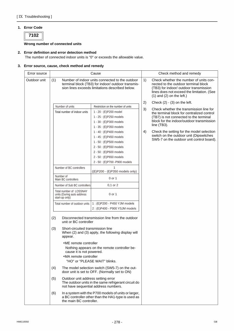
[ IX Troubleshooting ]
- 278 -HWE10050 GB
7102
1. Error Code
Wrong number of connected units
2. Error definition and error detection method The number of connected indoor units is "0" or exceeds the allowable value.
3. Error source, cause, check method and remedy
7102
Error source Cause Check method and remedy
Outdoor unit (1) Number of indoor units connected to the outdoor terminal block (TB3) for indoor/ outdoor transmis-sion lines exceeds limitations described below.
1) Check whether the number of units con-nected to the outdoor terminal block (TB3) for indoor/ outdoor transmission lines does not exceed the limitation. (See (1) and (2) on the left.)
2) Check (2) - (3) on the left.
3) Check whether the transmission line for the terminal block for centralized control (TB7) is not connected to the terminal block for the indoor/outdoor transmission line (TB3).
4) Check the setting for the model selection switch on the outdoor unit (Dipswitches SW5-7 on the outdoor unit control board).
(2) Disconnected transmission line from the outdoor unit or BC controller
(3) Short-circuited transmission lineWhen (2) and (3) apply, the following display will appear.
ME remote controllerNothing appears on the remote controller be-cause it is not powered.MA remote controller "HO" or "PLEASE WAIT" blinks.
(4) The model selection switch (SW5-7) on the out-door unit is set to OFF. (Normally set to ON)
(5) Outdoor unit address setting error The outdoor units in the same refrigerant circuit do not have sequential address numbers.
(6) In a system with the P700 models of units or larger, a BC controller other than the HA1-type is used as the main BC controller.
Restriction on the number of unitsNumber of units
0 or 1
0 or 1
1((E)P200 - (E)P350 models only)
0,1 or 2
1 - 20 : (E)P200 model1 - 25 : (E)P250 models1 - 30 : (E)P300 models1 - 35 : (E)P350 models1 - 40 : (E)P400 models1 - 45 : (E)P450 models1 - 50 : (E)P500 models2 - 50 : (E)P550 models2 - 50 : (E)P600 models2 - 50 : (E)P650 models2 - 50 : (E)P700 -P900 models
1 : (E)P200 - P450 YJM models2 : (E)P400 - P900 YSJM models
Total number of indoor units
Total number of LOSSNAY units (During auto address start-up only)
Number of Sub BC controllers
Number of Main BC controllers
Number of BC controllers
Total number of outdoor units
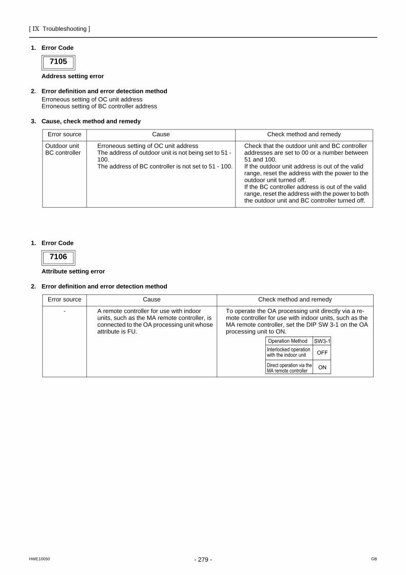
[ IX Troubleshooting ]
- 279 -HWE10050 GB
7105
1. Error Code
Address setting error
2. Error definition and error detection methodErroneous setting of OC unit addressErroneous setting of BC controller address
3. Cause, check method and remedy
7106
1. Error Code
Attribute setting error
2. Error definition and error detection method
7105
Error source Cause Check method and remedy
Outdoor unitBC controller
Erroneous setting of OC unit address The address of outdoor unit is not being set to 51 - 100.The address of BC controller is not set to 51 - 100.
Check that the outdoor unit and BC controller addresses are set to 00 or a number between 51 and 100.If the outdoor unit address is out of the valid range, reset the address with the power to the outdoor unit turned off.If the BC controller address is out of the valid range, reset the address with the power to both the outdoor unit and BC controller turned off.
7106
Error source Cause Check method and remedy
- A remote controller for use with indoor units, such as the MA remote controller, is connected to the OA processing unit whose attribute is FU.
To operate the OA processing unit directly via a re-mote controller for use with indoor units, such as the MA remote controller, set the DIP SW 3-1 on the OA processing unit to ON.
SW3-1
OFF
ON
Interlocked operation with the indoor unit
Operation Method
Direct operation via the MA remote controller
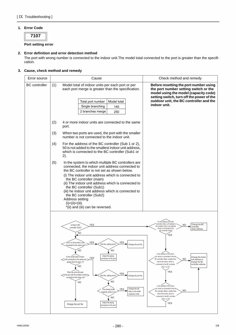
[ IX Troubleshooting ]
- 280 -HWE10050 GB
7107
1. Error Code
Port setting error
2. Error definition and error detection methodThe port with wrong number is connected to the indoor unit.The model total connected to the port is greater than the specifi-cation.
3. Cause, check method and remedy
7107
Error source Cause Check method and remedy
BC controller (1) Model total of indoor units per each port or per each port merge is greater than the specification.
Before resetting the port number using the port number setting switch or the model using the model (capacity code) setting switch, turn off the power of the outdoor unit, the BC controller and the indoor unit.
(2) 4 or more indoor units are connected to the same port.
(3) When two ports are used, the port with the smaller number is not connected to the indoor unit.
(4) For the address of the BC controller (Sub 1 or 2), 50 is not added to the smallest indoor unit address, which is connected to the BC controller (Sub1 or 2).
(5) In the system to which multiple BC controllers are connected, the indoor unit address connected to the BC controller is not set as shown below.(i) The indoor unit address which is connected to
the BC controller (main)(ii) The indoor unit address which is connected to
the BC controller (Sub1)(iii) he indoor unit address which is connected to
the BC controller (Sub2)Address setting
(i)<(ii)<(iii)*(ii) and (iii) can be reversed.
Model totalTotal port numberSingle branching
2 branches merge140250
Change the port No.
Is there a BC controller (Sub)?
Are 4 or more indoor units connected to the same port?
Is the model total of indoor units connected to the same port
greater than the item (1)?
When two ports are used, is the port with the smallest number
connected to the indoor unit?
YES
YES
NO
YES
YES
NO
For the address of the BC controller (Sub), is 50 added to
the smallest indoor unit address, which is connected to the
BC controller (Sub)?
Is the address of the indoor unit, which is connected to the the BC controller (Main) ,smaller than
that of the indoor, which is connected to the BC controller
(Sub 1 or 2)?
YES
YES
Is the address of the indoor unit, which is connected to the the BC controller (Main), smaller than
that of the indoor, which is connected to the BC controller
(Sub 1 or 2)?
YES
NO
NO
NO
NO
NO
Change the port No.
NO Change the BC controller (Sub) address.
NO
NO
Change the indoor unit address or change the BC controller address
YESChange the port No.
YES Change the set indoor unit model (capacity code).
Port No. setting error?
Port No. setting error?
The wrong model (capacity code) is set.
Adjust the piping connection to the port.
Adjust the piping connection to the port.
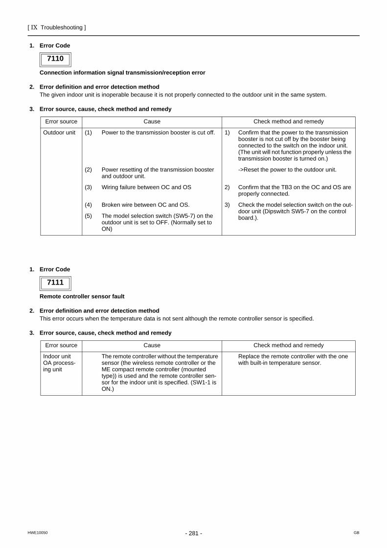
[ IX Troubleshooting ]
- 281 -HWE10050 GB
7110
1. Error Code
Connection information signal transmission/reception error
2. Error definition and error detection methodThe given indoor unit is inoperable because it is not properly connected to the outdoor unit in the same system.
3. Error source, cause, check method and remedy
7111
1. Error Code
Remote controller sensor fault
2. Error definition and error detection methodThis error occurs when the temperature data is not sent although the remote controller sensor is specified.
3. Error source, cause, check method and remedy
7110
Error source Cause Check method and remedy
Outdoor unit (1) Power to the transmission booster is cut off. 1) Confirm that the power to the transmission booster is not cut off by the booster being connected to the switch on the indoor unit. (The unit will not function properly unless the transmission booster is turned on.)
(2) Power resetting of the transmission booster and outdoor unit.
->Reset the power to the outdoor unit.
(3) Wiring failure between OC and OS 2) Confirm that the TB3 on the OC and OS are properly connected.
(4) Broken wire between OC and OS. 3) Check the model selection switch on the out-door unit (Dipswitch SW5-7 on the control board.). (5) The model selection switch (SW5-7) on the
outdoor unit is set to OFF. (Normally set to ON)
7111
Error source Cause Check method and remedy
Indoor unit OA process-ing unit
The remote controller without the temperature sensor (the wireless remote controller or the ME compact remote controller (mounted type)) is used and the remote controller sen-sor for the indoor unit is specified. (SW1-1 is ON.)
Replace the remote controller with the one with built-in temperature sensor.
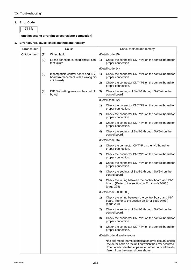
[ IX Troubleshooting ]
- 282 -HWE10050 GB
7113
1. Error Code
Function setting error (incorrect resistor connection)
2. Error source, cause, check method and remedy
7113
Error source Cause Check method and remedy
Outdoor unit (1) Wiring fault (Detail code 15)
(2) Loose connectors, short-circuit, con-tact failure
1) Check the connector CNTYP5 on the control board for proper connection.
(Detail code 14)
(3) Incompatible control board and INV board (replacement with a wrong cir-cuit board)
1) Check the connector CNTYP4 on the control board for proper connection.
2) Check the connector CNTYP5 on the control board for proper connection.
(4) DIP SW setting error on the control board
3) Check the settings of SW5-1 through SW5-4 on the control board.
(Detail code 12)
1) Check the connector CNTYP2 on the control board for proper connection.
2) Check the connector CNTYP5 on the control board for proper connection.
3) Check the connector CNTYP4 on the control board for proper connection.
4) Check the settings of SW5-1 through SW5-4 on the control board.
(Detail code 16)
1) Check the connector CNTYP on the INV board for proper connection.
2) Check the connector CNTYP5 on the control board for proper connection.
3) Check the connector CNTYP4 on the control board for proper connection.
4) Check the settings of SW5-1 through SW5-4 on the control board.
5) Check the wiring between the control board and INV board. (Refer to the section on Error code 0403.) (page 228)
(Detail code 00, 01, 05)
1) Check the wiring between the control board and INV board. (Refer to the section on Error code 0403.) (page 228)
2) Check the settings of SW5-1 through SW5-4 on the control board.
3) Check the connector CNTYP5 on the control board for proper connection.
4) Check the connector CNTYP4 on the control board for proper connection.
(Detail code Miscellaneous)
*If a set-model-name identification error occurs, check the detail code on the unit on which the error occurred. The detail code that appears on other units will be dif-ferent from the ones shown above.
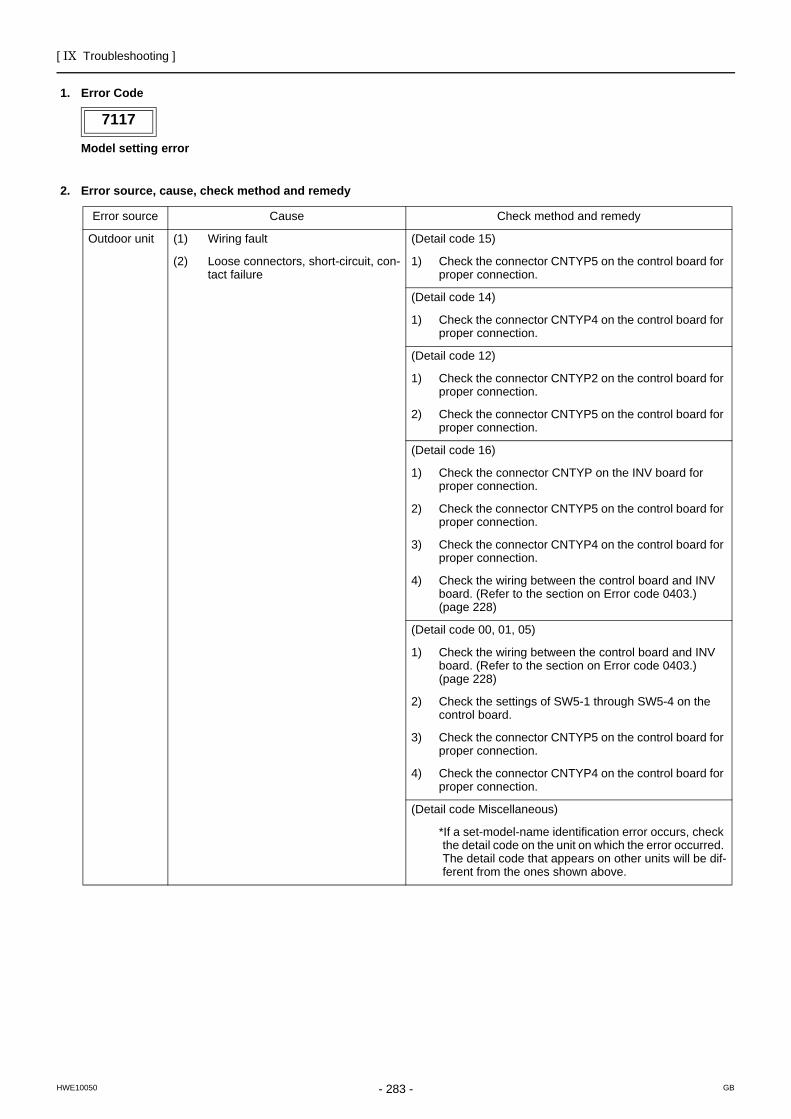
[ IX Troubleshooting ]
- 283 -HWE10050 GB
7117
1. Error Code
Model setting error
2. Error source, cause, check method and remedy
7117
Error source Cause Check method and remedy
Outdoor unit (1) Wiring fault (Detail code 15)
(2) Loose connectors, short-circuit, con-tact failure
1) Check the connector CNTYP5 on the control board for proper connection.
(Detail code 14)
1) Check the connector CNTYP4 on the control board for proper connection.
(Detail code 12)
1) Check the connector CNTYP2 on the control board for proper connection.
2) Check the connector CNTYP5 on the control board for proper connection.
(Detail code 16)
1) Check the connector CNTYP on the INV board for proper connection.
2) Check the connector CNTYP5 on the control board for proper connection.
3) Check the connector CNTYP4 on the control board for proper connection.
4) Check the wiring between the control board and INV board. (Refer to the section on Error code 0403.) (page 228)
(Detail code 00, 01, 05)
1) Check the wiring between the control board and INV board. (Refer to the section on Error code 0403.) (page 228)
2) Check the settings of SW5-1 through SW5-4 on the control board.
3) Check the connector CNTYP5 on the control board for proper connection.
4) Check the connector CNTYP4 on the control board for proper connection.
(Detail code Miscellaneous)
*If a set-model-name identification error occurs, check the detail code on the unit on which the error occurred. The detail code that appears on other units will be dif-ferent from the ones shown above.
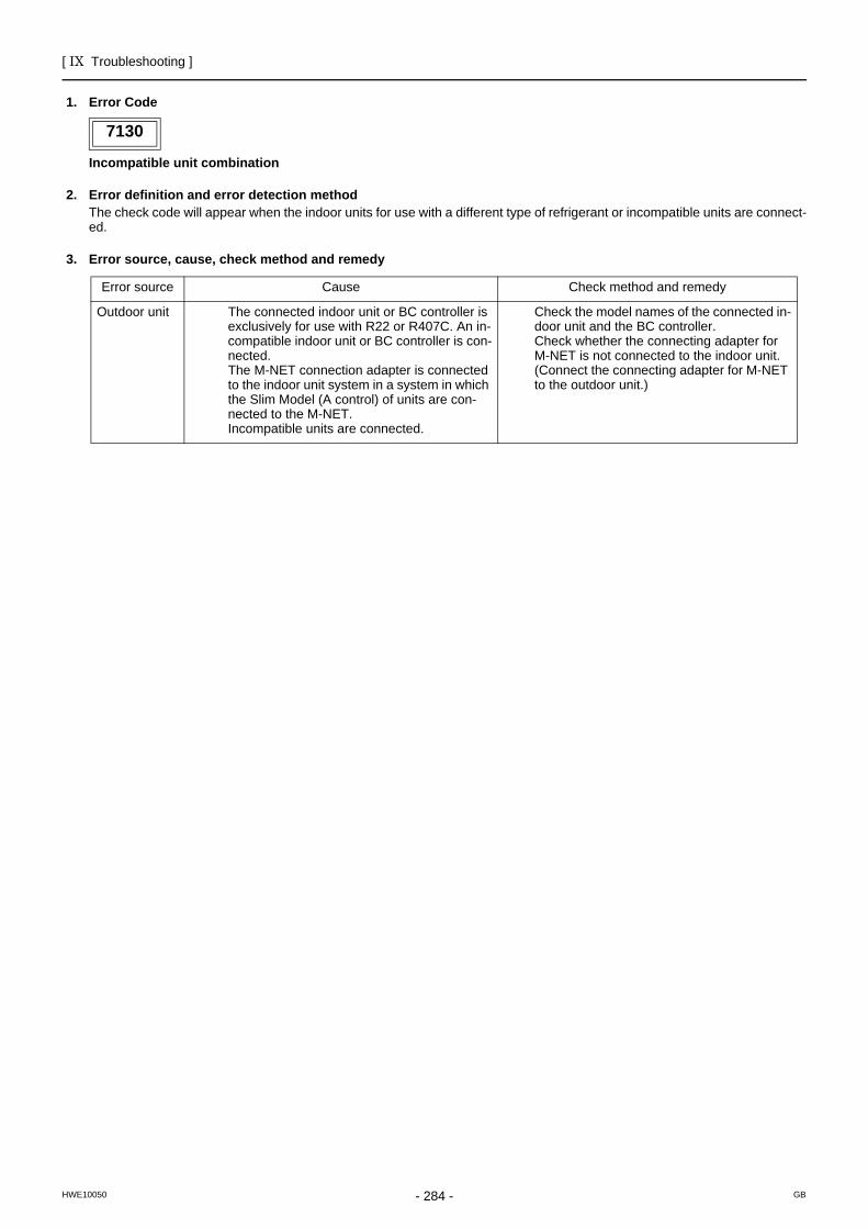
[ IX Troubleshooting ]
- 284 -HWE10050 GB
7130
1. Error Code
Incompatible unit combination
2. Error definition and error detection methodThe check code will appear when the indoor units for use with a different type of refrigerant or incompatible units are connect-ed.
3. Error source, cause, check method and remedy
7130
Error source Cause Check method and remedy
Outdoor unit The connected indoor unit or BC controller is exclusively for use with R22 or R407C. An in-compatible indoor unit or BC controller is con-nected.The M-NET connection adapter is connected to the indoor unit system in a system in which the Slim Model (A control) of units are con-nected to the M-NET. Incompatible units are connected.
Check the model names of the connected in-door unit and the BC controller.Check whether the connecting adapter for M-NET is not connected to the indoor unit. (Connect the connecting adapter for M-NET to the outdoor unit.)
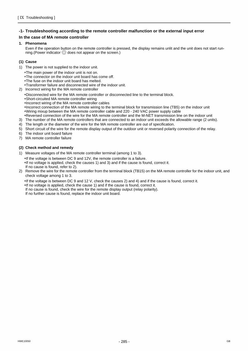
[ IX Troubleshooting ]
- 285 -HWE10050 GB
Troubleshooting according to the remote controller malfunction or the external input errorIn the case of MA remote controller
-1- Troubleshooting according to the remote controller malfunction or the external input errorIn the case of MA remote controller1. Phenomena
Even if the operation button on the remote controller is pressed, the display remains unlit and the unit does not start run-ning.(Power indicator does not appear on the screen.)
(1) Cause1) The power is not supplied to the indoor unit.
The main power of the indoor unit is not on.The connector on the indoor unit board has come off.The fuse on the indoor unit board has melted.Transformer failure and disconnected wire of the indoor unit.
2) Incorrect wiring for the MA remote controllerDisconnected wire for the MA remote controller or disconnected line to the terminal block.Short-circuited MA remote controller wiringIncorrect wiring of the MA remote controller cablesIncorrect connection of the MA remote wiring to the terminal block for transmission line (TB5) on the indoor unitWiring mixup between the MA remote controller cable and 220 - 240 VAC power supply cableReversed connection of the wire for the MA remote controller and the M-NET transmission line on the indoor unit
3) The number of the MA remote controllers that are connected to an indoor unit exceeds the allowable range (2 units).4) The length or the diameter of the wire for the MA remote controller are out of specification.5) Short circuit of the wire for the remote display output of the outdoor unit or reversed polarity connection of the relay.6) The indoor unit board failure7) MA remote controller failure
(2) Check method and remedy1) Measure voltages of the MA remote controller terminal (among 1 to 3).
If the voltage is between DC 9 and 12V, the remote controller is a failure.If no voltage is applied, check the causes 1) and 3) and if the cause is found, correct it.If no cause is found, refer to 2).
2) Remove the wire for the remote controller from the terminal block (TB15) on the MA remote controller for the indoor unit, and check voltage among 1 to 3.If the voltage is between DC 9 and 12 V, check the causes 2) and 4) and if the cause is found, correct it.If no voltage is applied, check the cause 1) and if the cause is found, correct it.If no cause is found, check the wire for the remote display output (relay polarity).If no further cause is found, replace the indoor unit board.
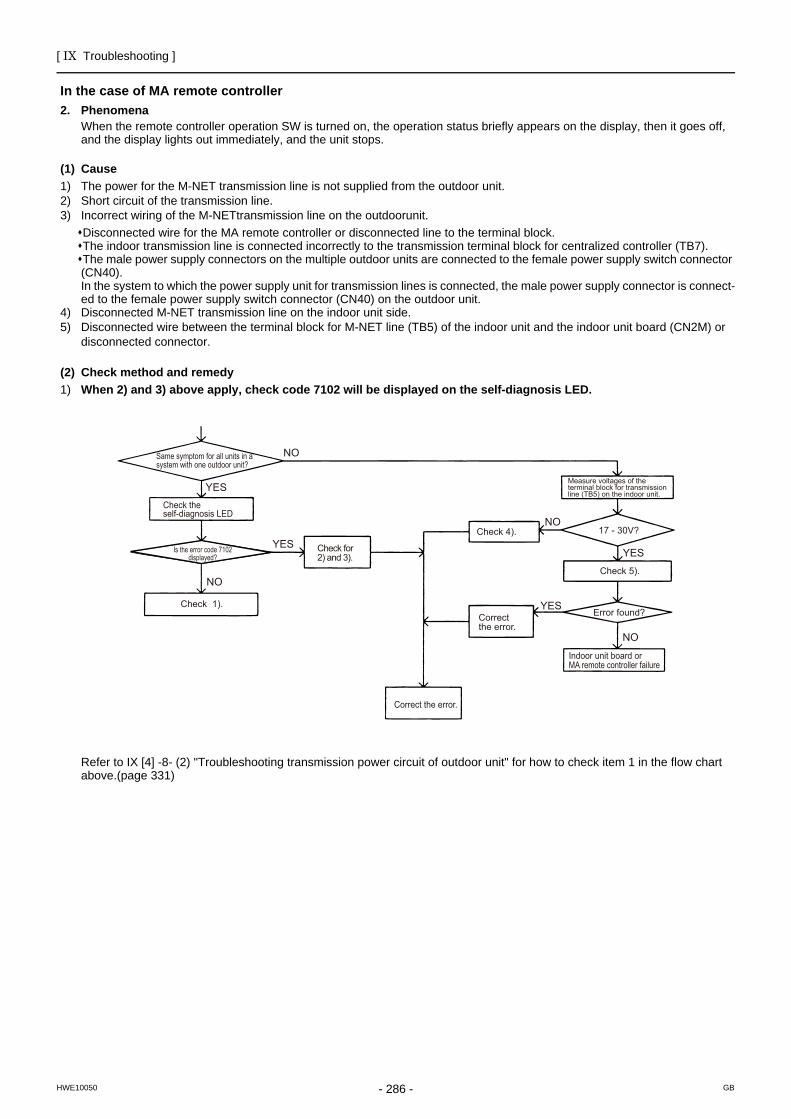
[ IX Troubleshooting ]
- 286 -HWE10050 GB
In the case of MA remote controller2. Phenomena
When the remote controller operation SW is turned on, the operation status briefly appears on the display, then it goes off, and the display lights out immediately, and the unit stops.
(1) Cause1) The power for the M-NET transmission line is not supplied from the outdoor unit.2) Short circuit of the transmission line.3) Incorrect wiring of the M-NETtransmission line on the outdoorunit.
Disconnected wire for the MA remote controller or disconnected line to the terminal block.The indoor transmission line is connected incorrectly to the transmission terminal block for centralized controller (TB7).The male power supply connectors on the multiple outdoor units are connected to the female power supply switch connector (CN40).In the system to which the power supply unit for transmission lines is connected, the male power supply connector is connect-ed to the female power supply switch connector (CN40) on the outdoor unit.
4) Disconnected M-NET transmission line on the indoor unit side.5) Disconnected wire between the terminal block for M-NET line (TB5) of the indoor unit and the indoor unit board (CN2M) or
disconnected connector.
(2) Check method and remedy1) When 2) and 3) above apply, check code 7102 will be displayed on the self-diagnosis LED.
Refer to IX [4] -8- (2) "Troubleshooting transmission power circuit of outdoor unit" for how to check item 1 in the flow chart above.(page 331)
YES
YES
YES
YES
NO
NO
NO
NO
Same symptom for all units in a system with one outdoor unit?
Check the self-diagnosis LED
Check 1).
Check for 2) and 3).
Check 4).
Measure voltages of the terminal block for transmission line (TB5) on the indoor unit.
17 - 30V?
Check 5).
Error found?
Indoor unit board or MA remote controller failure
Correct the error.
Correct the error.
Is the error code 7102 displayed?
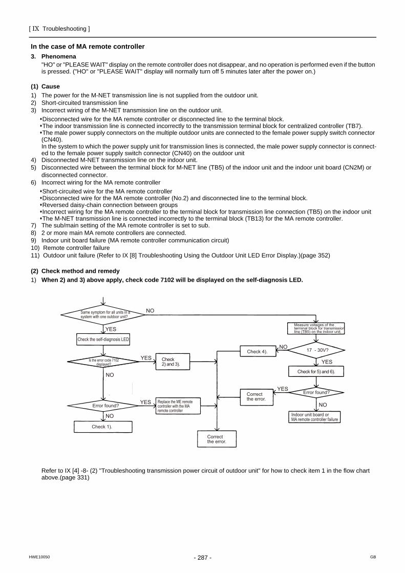
[ IX Troubleshooting ]
- 287 -HWE10050 GB
In the case of MA remote controller3. Phenomena
"HO" or "PLEASE WAIT" display on the remote controller does not disappear, and no operation is performed even if the button is pressed. ("HO" or "PLEASE WAIT" display will normally turn off 5 minutes later after the power on.)
(1) Cause1) The power for the M-NET transmission line is not supplied from the outdoor unit.2) Short-circuited transmission line3) Incorrect wiring of the M-NET transmission line on the outdoor unit.
Disconnected wire for the MA remote controller or disconnected line to the terminal block.The indoor transmission line is connected incorrectly to the transmission terminal block for centralized controller (TB7).The male power supply connectors on the multiple outdoor units are connected to the female power supply switch connector (CN40).In the system to which the power supply unit for transmission lines is connected, the male power supply connector is connect-ed to the female power supply switch connector (CN40) on the outdoor unit
4) Disconnected M-NET transmission line on the indoor unit.5) Disconnected wire between the terminal block for M-NET line (TB5) of the indoor unit and the indoor unit board (CN2M) or
disconnected connector.6) Incorrect wiring for the MA remote controller
Short-circuited wire for the MA remote controllerDisconnected wire for the MA remote controller (No.2) and disconnected line to the terminal block.Reversed daisy-chain connection between groupsIncorrect wiring for the MA remote controller to the terminal block for transmission line connection (TB5) on the indoor unitThe M-NET transmission line is connected incorrectly to the terminal block (TB13) for the MA remote controller.
7) The sub/main setting of the MA remote controller is set to sub.8) 2 or more main MA remote controllers are connected.9) Indoor unit board failure (MA remote controller communication circuit)10) Remote controller failure11) Outdoor unit failure (Refer to IX [8] Troubleshooting Using the Outdoor Unit LED Error Display.)(page 352)
(2) Check method and remedy1) When 2) and 3) above apply, check code 7102 will be displayed on the self-diagnosis LED.
Refer to IX [4] -8- (2) "Troubleshooting transmission power circuit of outdoor unit" for how to check item 1 in the flow chart above.(page 331)
YES
YES
YES
NO
NO
YES
YES
NO
NO
NO
Check the self-diagnosis LED
Error found?
Error found?
Replace the ME remote controller with the MA remote controller
Check for 5) and 6).
17 - 30V?
Same symptom for all units in a system with one outdoor unit?
Check 1).
Check 2) and 3).
Check 4).
Correct the error.
Correct the error.
Measure voltages of the terminal block for transmission line (TB5) on the indoor unit.
Is the error code 7102 displayed?
Indoor unit board or MA remote controller failure
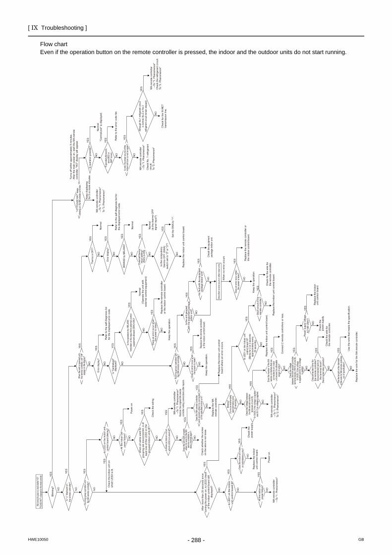
[ IX Troubleshooting ]
- 288 -HWE10050 GB
Flow chartEven if the operation button on the remote controller is pressed, the indoor and the outdoor units do not start running.
YE
S
Blin
king
?
Is "
" dis
playe
d on
th
e re
mot
e co
ntro
ller?
NO
NO
NO
YE
S
YE
S
Whe
n al
l wire
s us
ed fo
r gr
oupi
ng a
re d
isco
nnec
ted,
is a
t le
ast o
ne o
f the
LE
D2
on th
e
grou
ped
indo
or u
nits
lit?
YE
S
Che
ck th
e w
iring
Is th
ere
an in
door
unit
on
wh
ich L
ED2
is tu
rned
off?
If ope
rated
after
ward
s,
erro
r 660
2 or
6607
occu
rs.
Chec
k the
volta
ge be
twee
n the
MA
remo
te co
ntroll
er
termi
nals
(A an
d B).
9-13
VDC
if the
volta
ge is
appli
ed
and 0
V if n
o volt
age i
s app
lied.
Is L
ED1
on th
e in
door
uni
t co
ntro
l boa
rd lit
? (B
links
for 2
or 3
sec
onds
ap
prox
imat
ely
ever
y
20 s
econ
ds)
Does
the n
umbe
r of th
e MA
re
mote
contr
oller
s tha
t are
co
nnec
ted to
an in
door
un
it exc
eed t
he al
lowab
le
rang
e (2 u
nits)?
Blink
ing?
(Tur
ns on
mom
entar
ily
appr
oxim
ately
ever
y 20
seco
nds)
MA
rem
ote
cont
rolle
r →
To "1
. Phe
nom
enon
"
MA
rem
ote
cont
rolle
r →
To "1
. Phe
nom
enon
"
MA
rem
ote
cont
rolle
r →
To "1
. Phe
nom
enon
"To
"2. P
heno
men
on"
MA
rem
ote
cont
rolle
r →
To "1
. Phe
nom
enon
"To
"3. P
heno
men
on"
MA
rem
ote
cont
rolle
r →
To "1
. Phe
nom
enon
"C
heck
No.
1 re
frige
rant
ci
rcui
t.To
"2. P
heno
men
on"
MA
rem
ote
cont
rolle
r →
To "1
. Phe
nom
enon
"C
heck
the
refri
gera
nt c
ircui
t.To
"2. P
heno
men
on"
Che
ck fo
r the
M-N
ET
tra
nsm
issi
on li
ne.
Rep
lace
the
indo
or u
nit c
ontro
l boa
rd.
Con
nect
2 re
mot
e co
ntro
llers
or l
ess.
Resto
re th
e or
igina
l MA
rem
ote
cont
rolle
r wirin
g co
nnec
tions
afte
r rep
airs.
Che
ck w
heth
er th
e sc
rew
on
the
wire
is n
ot lo
ose.
Is L
ED2
on th
e in
door
uni
t co
ntro
l boa
rd b
linkin
g?
Whe
n the
unit i
s ope
rated
with
the
remo
te co
ntroll
er, w
ill "O
N"
appe
ar on
the d
isplay
?
Is "C
entra
lized
" di
spla
yed?
"HO"
/"PLE
ASE
WAI
T" ke
eps
blink
ing on
the M
A re
mote
contr
oller.
Is on
ly the
powe
r sou
rce of
the
indoo
r unit
turn
turn
ed on
again
? DE
MAN
D by
MEL
ANS?
Exte
rnal
ther
mo
in
put s
ettin
g?
(SW
3-3=
ON)
Does
an
erro
r occ
ur w
hen
th
e po
wer i
s re
set?
Does
the u
nit w
ork p
rope
rly
when
the w
ire fo
r the
MA
re
mote
contr
oller
is
daisy
-chain
ed ag
ain?
Is L
ED
1 on
the
indo
or
unit
cont
rol b
oard
lit?
Does
the M
A re
mote
contr
oller
wo
rk pr
oper
ly wh
en it
is co
nnec
ted
to the
spec
ified i
ndoo
r unit
?
Does
an
erro
r occ
ur w
hen
th
e po
wer i
s res
et?
Runn
ing g
roup
ope
ratio
n wi
th
the
MA
rem
ote
cont
rolle
r?
Is th
e un
it gr
oupe
d
with
the
equi
pmen
t pac
kage
in
door
uni
t?
No fa
ult w
ith th
e eq
uipm
ent
pack
age
indo
or u
nit?
Does
an
erro
r occ
ur w
hen
th
e po
wer i
s res
et?
Chec
k tha
t no e
rror o
ccurs
in ot
her in
door
units
.
Che
ck th
e in
door
uni
t on
w
hich
LE
D2
is li
t.
All t
he in
door
uni
t po
wer f
ailu
re?
All t
he in
door
uni
t p
ower
failu
re?
Erro
r disp
lay?
Erro
r disp
lay?
Ther
mo
is O
FF?
Is o
pera
tion
poss
ible
?
Shor
t circ
uit o
f the
re
mot
e co
ntro
ller?
After t
urning
the po
wer on
, check
wheth
er "HO
"/ "PL
EASE
WAIT"
is dis
played
on the
remote
contro
ller.
Afte
r mor
e th
an 2
0 se
cond
s si
nce
tu
rnin
g th
e po
wer
on,
is L
ED
2 ch
eck
of
the
indo
or c
ontro
l boa
rd s
till
disp
laye
d?
Is th
e op
erat
ion b
y MEL
ANS
fo
rbidd
en o
r the
inpu
t fro
m e
xtern
al co
ntro
l eq
uipm
ent a
llowe
d (S
WC=
ON)?
Is th
e co
mpu
lsor
y
ther
mo
OFF
(SW
A)
switc
h se
t to
"2" o
r "3"
?
Alth
ough
No.
1 re
frige
rant
circ
uit
is no
rmal,
No.
2 or
No.
3
refri
gera
nt ci
rcuit
rem
ain st
oppe
d.
Runn
ing gr
oup o
pera
tion w
ith
the M
A re
mote
contr
oller
?
Does
the i
ndoo
r unit
mak
e an
insta
ntane
ous s
top?
Powe
r sup
ply
volta
geAC
198~
264V
?
NO
YE
S
NO
NO
NO
NO
NO
N
O
NO
NO
Whe
n no
err
or o
ccur
s
NO
NO
NO
Kee
p di
spla
ying
fo
r 5 o
r mor
e m
inut
es.
NO
NO
NO
NO
NO
NO
NO
NO
NO
NO
NO
NO
Che
ck th
e
pow
er s
uppl
y.
Che
ck th
e w
ire fo
r th
e re
mot
e co
ntro
ller. NO
Rep
lace
the
indo
or u
nit c
ontro
l boa
rd.
NO
N
O
NO
NO
NO
Rep
lace
the
MA
re
mot
e co
ntro
ller.
NO
Repl
ace
the
rem
ote
cont
rolle
r or
the
indo
or c
ontro
l boa
rd.
YE
S
Rep
lace
the
indo
or u
nit c
ontro
l bo
ard
whe
re a
n er
ror o
ccur
s.
Kee
p th
e op
erat
ion.
NO
NO
NO
NO
Kee
p th
e op
erat
ion.
YE
S
YE
S
YE
S
YE
S
Pow
er o
n
YE
S
Ref
er to
the
self-
diag
nosi
s lis
t fo
r the
dis
play
ed e
rror
cod
e.
YE
S
Nor
mal
Turn
s of
f with
in a
ppro
xim
atel
y 5
min
utes
. A
fter t
he m
ain
pow
er o
n, s
tart
the
MA
rem
ote
co
ntro
ller.
"HO
" dis
play
will
app
ear. YE
S
Nor
mal
"C
entra
lized
" is
disp
laye
d.
YE
S
Ref
er to
the
erro
r cod
e lis
t.
YE
S
YE
S
YE
S
Nor
mal
YE
S
Nor
mal
(Is
the
ther
mo
OFF
si
gnal
inpu
t?)
YE
S
Set
the
SW
A to
"1".
YE
S
Ref
er to
the
self-
diag
nosi
s lis
t for
th
e di
spla
yed
erro
r cod
e.
YE
S
YE
S
YE
S
YE
S
Chec
k th
e eq
uipm
ent
pack
age
indo
or u
nit.
YE
S
Rep
lace
the
rem
ote
cont
rolle
r or
the
indo
or c
ontro
l boa
rd.
Rep
lace
the
indo
or u
nit c
ontro
l boa
rd.
YE
S
YE
S
YE
S
Rep
lace
the
rem
ote
cont
rolle
r or
the
indo
or c
ontro
l boa
rd.
Nor
mal
(O
pera
te th
e un
it w
ith
exte
rnal
con
trol e
quip
men
t)
YE
S
YE
S R
epla
ce th
e in
door
un
it co
ntro
l boa
rd.
Che
ck th
e
pow
er s
uppl
y.
YE
S
YE
S
YE
S
YE
S
Chec
k the
volta
ge
betw
een t
he M
A re
mote
contr
oller
ter
mina
l bloc
ks (T
B15)
(A an
d B).
9-13
VDC
if the
volta
ge
is ap
plied
and 0
V if n
o volt
age
is ap
plied
.
NO
Disc
onne
cted
wire
for
the
rem
ote
cont
rolle
r?
Disc
onne
cted
wire
to
the
term
inal
blo
ck?
Disc
onne
cted r
elay c
onne
ctor?
NO
Are t
he le
ngth
or th
e diam
eter
of the
wire
for M
A re
mote
contr
oller
ou
t of s
pecif
icatio
n?
NO
YE
S
YE
S
Use
the
wire
that
mee
ts th
e sp
ecifi
catio
n.
Rep
lace
the
wire
for t
he M
A re
mot
e co
ntro
ller.
YE
S
Che
ck fo
r the
wire
for
the
rem
ote
cont
rolle
r.
Kee
p th
e op
erat
ion.
YE
S
Rep
lace
the
indo
or
unit
cont
rol b
oard
.
YE
S
YE
S
YE
S
Pow
er o
n
[ IX Troubleshooting ]
- 289 -HWE10050 GB
Troubleshooting according to the remote controller malfunction or the external input errorIn case of ME remote controller
In case of ME remote controller1. Phenomena
Even if the operation button on the remote controller is pressed, the display remains unlit and the unit does not start running.(Power indicator does not appear on the screen.)
(1) Cause1) The power for the M-NET transmission line is not supplied from the indoor unit.2) Short circuit of the transmission line.3) Incorrect wiring of the M-NET transmission line on the outdoor unit.
Disconnected wire for the MA remote controller or disconnected line to the terminal block.The indoor transmission line is connected incorrectly to the transmission terminal block for centralized controller (TB7).
4) Disconnected transmission line on the remote controller.5) Remote controller failure6) Outdoor unit failure (Refer to IX [8] Troubleshooting Using the Outdoor Unit LED Error Display.)(page 352)
(2) Check method and remedy1) Check voltage of the transmission terminal block for of the ME remote controller.
If voltage between is 17V and 30V -> ME remote controller failure When voltage is 17V or less -> Refer to IX [4] -8- (2) "Troubleshooting transmission power curcuit of outdoor unit".(page 331)
2) When 2) and 3) above apply, check code 7102 will be displayed on the self-diagnosis LED.
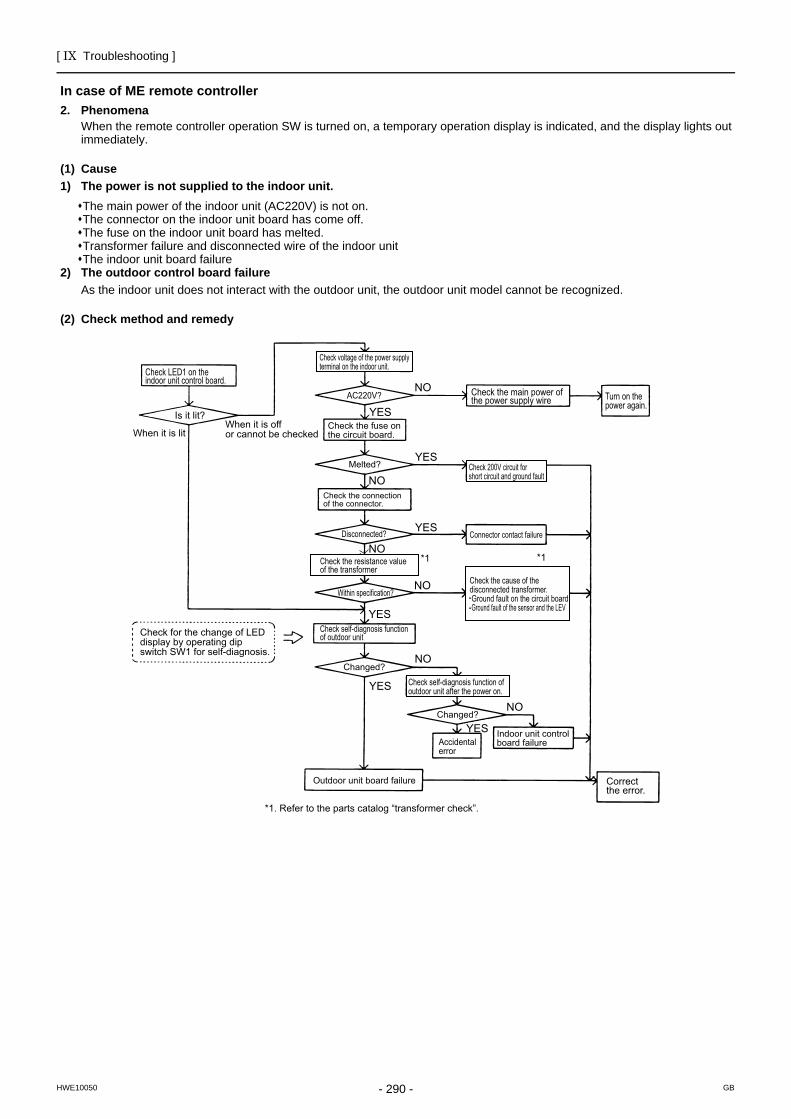
[ IX Troubleshooting ]
- 290 -HWE10050 GB
In case of ME remote controller2. Phenomena
When the remote controller operation SW is turned on, a temporary operation display is indicated, and the display lights out immediately.
(1) Cause1) The power is not supplied to the indoor unit.
The main power of the indoor unit (AC220V) is not on.The connector on the indoor unit board has come off.The fuse on the indoor unit board has melted.Transformer failure and disconnected wire of the indoor unitThe indoor unit board failure
2) The outdoor control board failureAs the indoor unit does not interact with the outdoor unit, the outdoor unit model cannot be recognized.
(2) Check method and remedy
YES
YES
YES
YES
YES
NO
NO
NO
NO
NO
NO
YES
*1 *1
Check LED1 on the indoor unit control board.
Is it lit?
When it is litWhen it is off or cannot be checked
Check for the change of LED display by operating dip switch SW1 for self-diagnosis.
Check voltage of the power supply terminal on the indoor unit.
AC220V?
Check the fuse on the circuit board.
Melted? Check 200V circuit for short circuit and ground fault
Check the connection of the connector.
Check the main power of the power supply wire Turn on the
power again.
Connector contact failureDisconnected?
Check the resistance value of the transformer
Within specification?Check the cause of the disconnected transformer. Ground fault on the circuit board Ground fault of the sensor and the LEV
Check self-diagnosis function of outdoor unit
Changed?
Changed?
Outdoor unit board failure
Check self-diagnosis function of outdoor unit after the power on.
Accidental error
Indoor unit control board failure
Correct the error.
*1. Refer to the parts catalog “transformer check”.
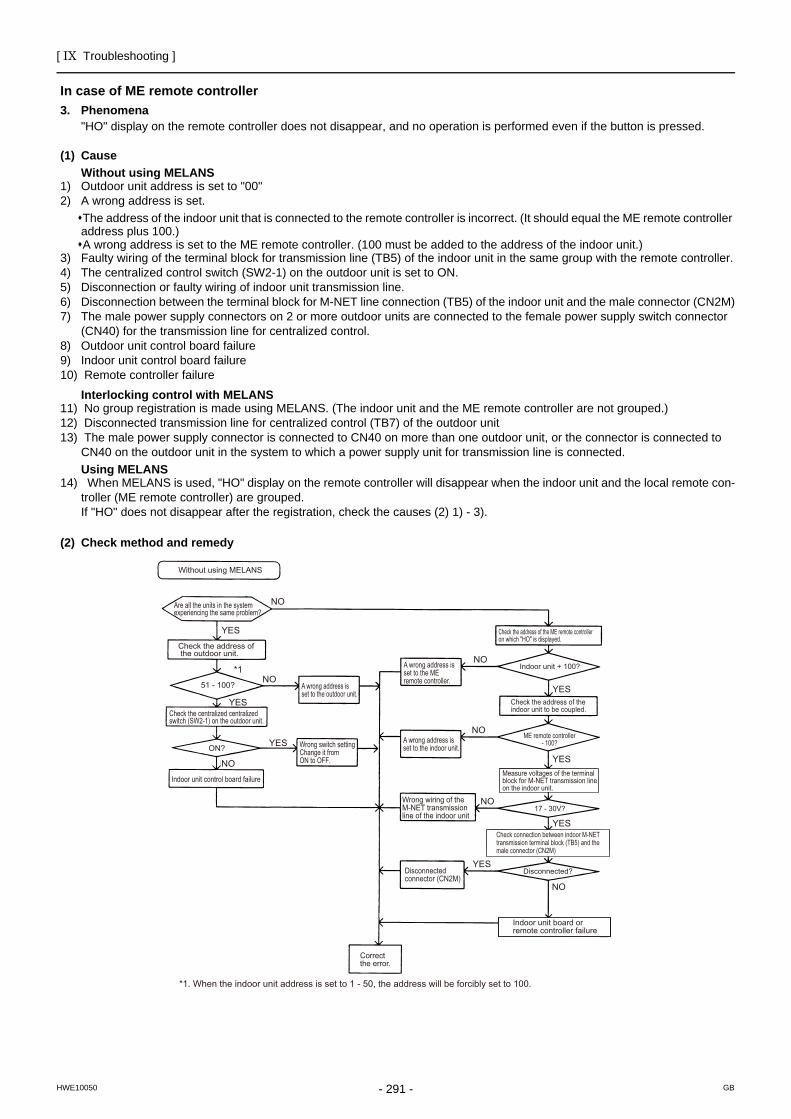
[ IX Troubleshooting ]
- 291 -HWE10050 GB
In case of ME remote controller3. Phenomena
"HO" display on the remote controller does not disappear, and no operation is performed even if the button is pressed.
(1) CauseWithout using MELANS
1) Outdoor unit address is set to "00"2) A wrong address is set.
The address of the indoor unit that is connected to the remote controller is incorrect. (It should equal the ME remote controller address plus 100.)A wrong address is set to the ME remote controller. (100 must be added to the address of the indoor unit.)
3) Faulty wiring of the terminal block for transmission line (TB5) of the indoor unit in the same group with the remote controller.4) The centralized control switch (SW2-1) on the outdoor unit is set to ON.5) Disconnection or faulty wiring of indoor unit transmission line.6) Disconnection between the terminal block for M-NET line connection (TB5) of the indoor unit and the male connector (CN2M)7) The male power supply connectors on 2 or more outdoor units are connected to the female power supply switch connector
(CN40) for the transmission line for centralized control.8) Outdoor unit control board failure9) Indoor unit control board failure10) Remote controller failure
Interlocking control with MELANS11) No group registration is made using MELANS. (The indoor unit and the ME remote controller are not grouped.)12) Disconnected transmission line for centralized control (TB7) of the outdoor unit13) The male power supply connector is connected to CN40 on more than one outdoor unit, or the connector is connected to
CN40 on the outdoor unit in the system to which a power supply unit for transmission line is connected.Using MELANS
14) When MELANS is used, "HO" display on the remote controller will disappear when the indoor unit and the local remote con-troller (ME remote controller) are grouped.If "HO" does not disappear after the registration, check the causes (2) 1) - 3).
(2) Check method and remedy
YES
YES
YES
YES
YES
YES
YES
NO
NO *1
*1. When the indoor unit address is set to 1 - 50, the address will be forcibly set to 100.
NO
NO
NO
NO
NO
Without using MELANS
Are all the units in the system experiencing the same problem?
Check the address of the outdoor unit.
51 - 100?
Check the centralized centralized switch (SW2-1) on the outdoor unit.
ON?
Indoor unit control board failure
A wrong address is set to the outdoor unit.
Wrong switch setting Change it from ON to OFF.
A wrong address is set to the ME remote controller.
A wrong address is set to the indoor unit.
Wrong wiring of the M-NET transmission line of the indoor unit
Disconnected connector (CN2M)
Correct the error.
Disconnected?
17 - 30V?
ME remote controller- 100?
Check the address of the indoor unit to be coupled.
Indoor unit + 100?
Check the address of the ME remote controller on which "HO" is displayed.
Check connection between indoor M-NET transmission terminal block (TB5) and the male connector (CN2M)
Measure voltages of the terminal block for M-NET transmission line on the indoor unit.
Indoor unit board or remote controller failure
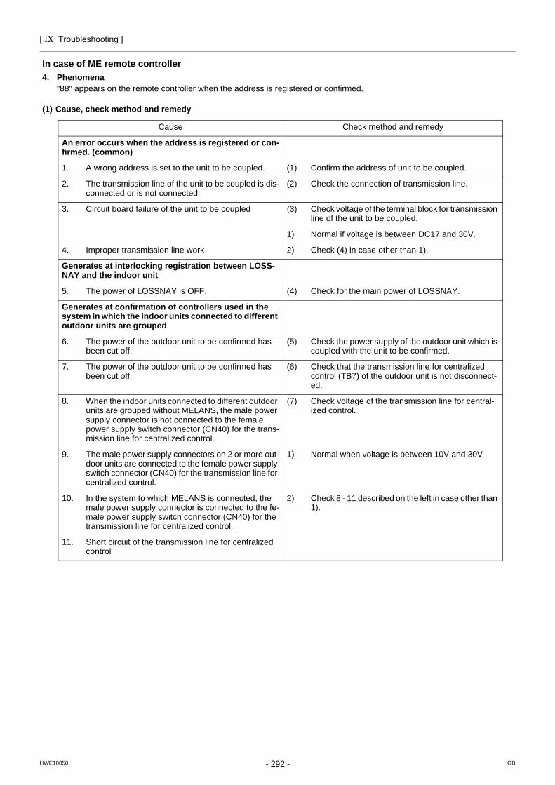
[ IX Troubleshooting ]
- 292 -HWE10050 GB
In case of ME remote controller4. Phenomena
"88" appears on the remote controller when the address is registered or confirmed.
(1) Cause, check method and remedy
Cause Check method and remedy
An error occurs when the address is registered or con-firmed. (common)
1. A wrong address is set to the unit to be coupled. (1) Confirm the address of unit to be coupled.
2. The transmission line of the unit to be coupled is dis-connected or is not connected.
(2) Check the connection of transmission line.
3. Circuit board failure of the unit to be coupled (3) Check voltage of the terminal block for transmission line of the unit to be coupled.
1) Normal if voltage is between DC17 and 30V.
4. Improper transmission line work 2) Check (4) in case other than 1).
Generates at interlocking registration between LOSS-NAY and the indoor unit
5. The power of LOSSNAY is OFF. (4) Check for the main power of LOSSNAY.
Generates at confirmation of controllers used in the system in which the indoor units connected to different outdoor units are grouped
6. The power of the outdoor unit to be confirmed has been cut off.
(5) Check the power supply of the outdoor unit which is coupled with the unit to be confirmed.
7. The power of the outdoor unit to be confirmed has been cut off.
(6) Check that the transmission line for centralized control (TB7) of the outdoor unit is not disconnect-ed.
8. When the indoor units connected to different outdoor units are grouped without MELANS, the male power supply connector is not connected to the female power supply switch connector (CN40) for the trans-mission line for centralized control.
(7) Check voltage of the transmission line for central-ized control.
9. The male power supply connectors on 2 or more out-door units are connected to the female power supply switch connector (CN40) for the transmission line for centralized control.
1) Normal when voltage is between 10V and 30V
10. In the system to which MELANS is connected, the male power supply connector is connected to the fe-male power supply switch connector (CN40) for the transmission line for centralized control.
2) Check 8 - 11 described on the left in case other than 1).
11. Short circuit of the transmission line for centralized control
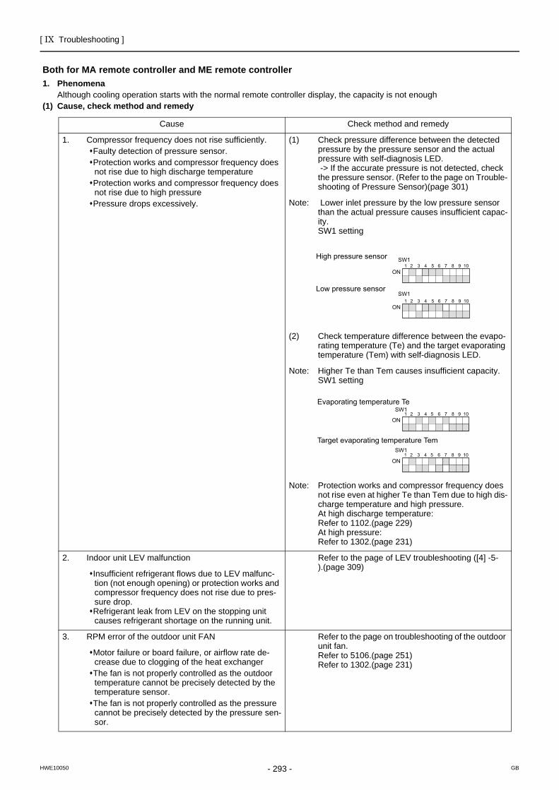
[ IX Troubleshooting ]
- 293 -HWE10050 GB
Troubleshooting according to the remote controller malfunction or the external input errorBoth for MA remote controller and ME remote controller
Both for MA remote controller and ME remote controller1. Phenomena
Although cooling operation starts with the normal remote controller display, the capacity is not enough(1) Cause, check method and remedy
Cause Check method and remedy
1. Compressor frequency does not rise sufficiently.Faulty detection of pressure sensor.Protection works and compressor frequency does not rise due to high discharge temperatureProtection works and compressor frequency does not rise due to high pressurePressure drops excessively.
(1) Check pressure difference between the detected pressure by the pressure sensor and the actual pressure with self-diagnosis LED. -> If the accurate pressure is not detected, check the pressure sensor. (Refer to the page on Trouble-shooting of Pressure Sensor)(page 301)
Note: Lower inlet pressure by the low pressure sensor than the actual pressure causes insufficient capac-ity.SW1 setting
(2) Check temperature difference between the evapo-rating temperature (Te) and the target evaporating temperature (Tem) with self-diagnosis LED.
Note: Higher Te than Tem causes insufficient capacity.SW1 setting
Note: Protection works and compressor frequency does not rise even at higher Te than Tem due to high dis-charge temperature and high pressure.At high discharge temperature:Refer to 1102.(page 229) At high pressure:Refer to 1302.(page 231)
2. Indoor unit LEV malfunction Refer to the page of LEV troubleshooting ([4] -5-).(page 309)
Insufficient refrigerant flows due to LEV malfunc-tion (not enough opening) or protection works and compressor frequency does not rise due to pres-sure drop.Refrigerant leak from LEV on the stopping unit causes refrigerant shortage on the running unit.
3. RPM error of the outdoor unit FAN Refer to the page on troubleshooting of the outdoor unit fan.Refer to 5106.(page 251) Refer to 1302.(page 231)
Motor failure or board failure, or airflow rate de-crease due to clogging of the heat exchangerThe fan is not properly controlled as the outdoor temperature cannot be precisely detected by the temperature sensor.The fan is not properly controlled as the pressure cannot be precisely detected by the pressure sen-sor.
High pressure sensor
Low pressure sensor
ON1 2 3 4 5 6 7 8 9 10
ON1 2 3 4 5 6 7 8 9 10
SW1
SW1
1 2 3 4 5 6 7 8 9 10
Evaporating temperature Te
Target evaporating temperature Tem
ON1 2 3 4 5 6 7 8 9 10
ON
SW1
SW1
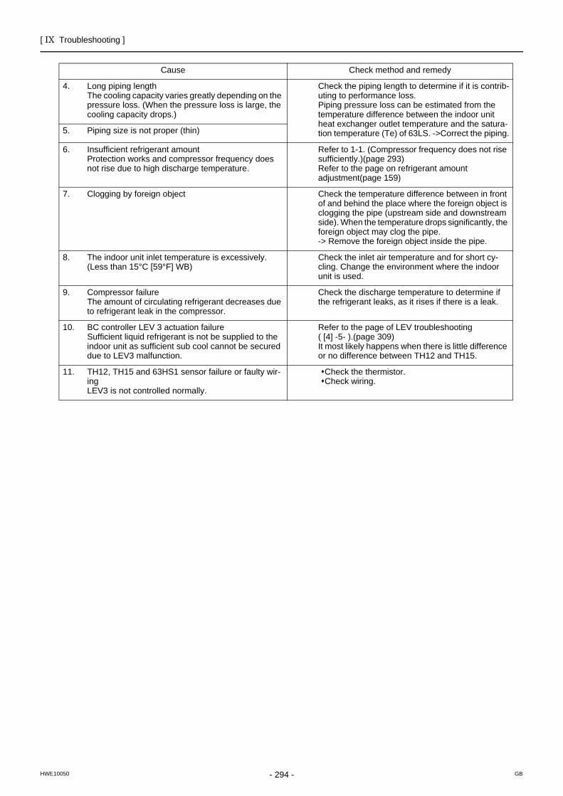
[ IX Troubleshooting ]
- 294 -HWE10050 GB
Cause Check method and remedy
4. Long piping lengthThe cooling capacity varies greatly depending on the pressure loss. (When the pressure loss is large, the cooling capacity drops.)
Check the piping length to determine if it is contrib-uting to performance loss.Piping pressure loss can be estimated from the temperature difference between the indoor unit heat exchanger outlet temperature and the satura-tion temperature (Te) of 63LS. ->Correct the piping.5. Piping size is not proper (thin)
6. Insufficient refrigerant amountProtection works and compressor frequency does not rise due to high discharge temperature.
Refer to 1-1. (Compressor frequency does not rise sufficiently.)(page 293) Refer to the page on refrigerant amount adjustment(page 159)
7. Clogging by foreign object Check the temperature difference between in front of and behind the place where the foreign object is clogging the pipe (upstream side and downstream side). When the temperature drops significantly, the foreign object may clog the pipe.-> Remove the foreign object inside the pipe.
8. The indoor unit inlet temperature is excessively. (Less than 15°C [59°F] WB)
Check the inlet air temperature and for short cy-cling. Change the environment where the indoor unit is used.
9. Compressor failureThe amount of circulating refrigerant decreases due to refrigerant leak in the compressor.
Check the discharge temperature to determine if the refrigerant leaks, as it rises if there is a leak.
10. BC controller LEV 3 actuation failure Sufficient liquid refrigerant is not be supplied to the indoor unit as sufficient sub cool cannot be secured due to LEV3 malfunction.
Refer to the page of LEV troubleshooting ( [4] -5- ).(page 309) It most likely happens when there is little difference or no difference between TH12 and TH15.
11. TH12, TH15 and 63HS1 sensor failure or faulty wir-ingLEV3 is not controlled normally.
Check the thermistor.Check wiring.
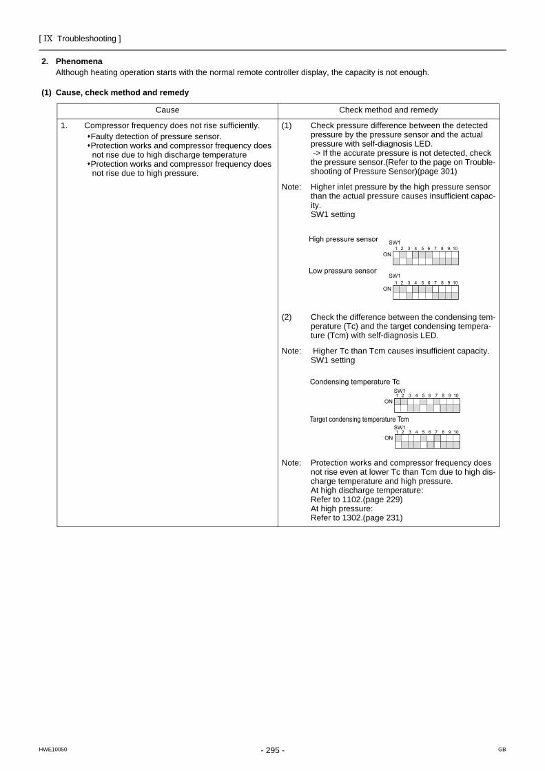
[ IX Troubleshooting ]
- 295 -HWE10050 GB
2. PhenomenaAlthough heating operation starts with the normal remote controller display, the capacity is not enough.
(1) Cause, check method and remedy
Cause Check method and remedy
1. Compressor frequency does not rise sufficiently.Faulty detection of pressure sensor.Protection works and compressor frequency does not rise due to high discharge temperatureProtection works and compressor frequency does not rise due to high pressure.
(1) Check pressure difference between the detected pressure by the pressure sensor and the actual pressure with self-diagnosis LED. -> If the accurate pressure is not detected, check the pressure sensor.(Refer to the page on Trouble-shooting of Pressure Sensor)(page 301)
Note: Higher inlet pressure by the high pressure sensor than the actual pressure causes insufficient capac-ity.SW1 setting
(2) Check the difference between the condensing tem-perature (Tc) and the target condensing tempera-ture (Tcm) with self-diagnosis LED.
Note: Higher Tc than Tcm causes insufficient capacity.SW1 setting
Note: Protection works and compressor frequency does not rise even at lower Tc than Tcm due to high dis-charge temperature and high pressure.At high discharge temperature:Refer to 1102.(page 229) At high pressure:Refer to 1302.(page 231)
High pressure sensor
Low pressure sensor
ON1 2 3 4 5 6 7 8 9 10
ON1 2 3 4 5 6 7 8 9 10
SW1
SW1
Condensing temperature Tc
Target condensing temperature Tcm
ON
ON1 2 3 4 5 6 7 8 9 10
1 2 3 4 5 6 7 8 9 10
SW1
SW1
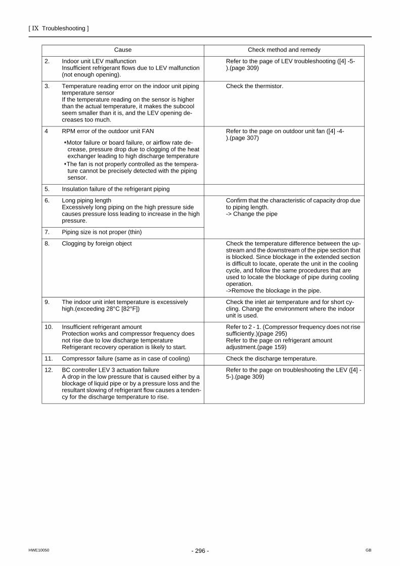
[ IX Troubleshooting ]
- 296 -HWE10050 GB
Cause Check method and remedy
2. Indoor unit LEV malfunctionInsufficient refrigerant flows due to LEV malfunction (not enough opening).
Refer to the page of LEV troubleshooting ([4] -5-).(page 309)
3. Temperature reading error on the indoor unit piping temperature sensor If the temperature reading on the sensor is higher than the actual temperature, it makes the subcool seem smaller than it is, and the LEV opening de-creases too much.
Check the thermistor.
4 RPM error of the outdoor unit FAN Refer to the page on outdoor unit fan ([4] -4-).(page 307)
Motor failure or board failure, or airflow rate de-crease, pressure drop due to clogging of the heat exchanger leading to high discharge temperatureThe fan is not properly controlled as the tempera-ture cannot be precisely detected with the piping sensor.
5. Insulation failure of the refrigerant piping
6. Long piping lengthExcessively long piping on the high pressure side causes pressure loss leading to increase in the high pressure.
Confirm that the characteristic of capacity drop due to piping length.-> Change the pipe
7. Piping size is not proper (thin)
8. Clogging by foreign object Check the temperature difference between the up-stream and the downstream of the pipe section that is blocked. Since blockage in the extended section is difficult to locate, operate the unit in the cooling cycle, and follow the same procedures that are used to locate the blockage of pipe during cooling operation.->Remove the blockage in the pipe.
9. The indoor unit inlet temperature is excessively high.(exceeding 28°C [82°F])
Check the inlet air temperature and for short cy-cling. Change the environment where the indoor unit is used.
10. Insufficient refrigerant amountProtection works and compressor frequency does not rise due to low discharge temperatureRefrigerant recovery operation is likely to start.
Refer to 2 - 1. (Compressor frequency does not rise sufficiently.)(page 295) Refer to the page on refrigerant amount adjustment.(page 159)
11. Compressor failure (same as in case of cooling) Check the discharge temperature.
12. BC controller LEV 3 actuation failure A drop in the low pressure that is caused either by a blockage of liquid pipe or by a pressure loss and the resultant slowing of refrigerant flow causes a tenden-cy for the discharge temperature to rise.
Refer to the page on troubleshooting the LEV ([4] -5-).(page 309)
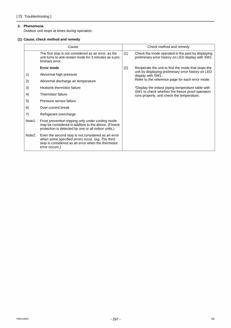
[ IX Troubleshooting ]
- 297 -HWE10050 GB
3. PhenomenaOutdoor unit stops at times during operation.
(1) Cause, check method and remedy
Cause Check method and remedy
The first stop is not considered as an error, as the unit turns to anti-restart mode for 3 minutes as a pre-liminary error.
(1) Check the mode operated in the past by displaying preliminary error history on LED display with SW1.
Error mode (2) Reoperate the unit to find the mode that stops the unit by displaying preliminary error history on LED display with SW1.Refer to the reference page for each error mode.
1) Abnormal high pressure
2) Abnormal discharge air temperature
3) Heatsink thermistor failure *Display the indoor piping temperature table with SW1 to check whether the freeze proof operation runs properly, and check the temperature.4) Thermistor failure
5) Pressure sensor failure
6) Over-current break
7) Refrigerant overcharge
Note1: Frost prevention tripping only under cooling mode may be considered in addition to the above. (Freeze protection is detected by one or all indoor units.)
Note2: Even the second stop is not considered as an error when some specified errors occur. (eg. The third stop is considered as an error when the thermistor error occurs.)
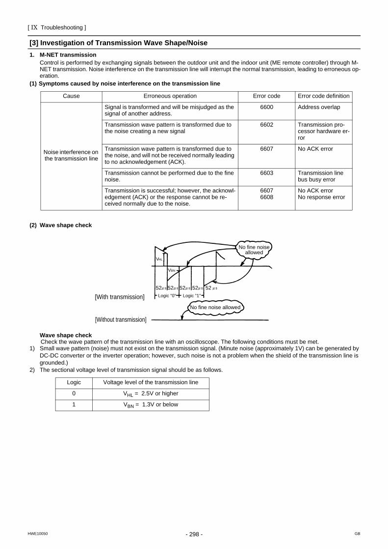
[ IX Troubleshooting ]
- 298 -HWE10050 GB
[3] Investigation of Transmission Wave Shape/Noise1. M-NET transmission
Control is performed by exchanging signals between the outdoor unit and the indoor unit (ME remote controller) through M-NET transmission. Noise interference on the transmission line will interrupt the normal transmission, leading to erroneous op-eration.
(1) Symptoms caused by noise interference on the transmission line
(2) Wave shape check
Wave shape checkCheck the wave pattern of the transmission line with an oscilloscope. The following conditions must be met.
1) Small wave pattern (noise) must not exist on the transmission signal. (Minute noise (approximately 1V) can be generated by DC-DC converter or the inverter operation; however, such noise is not a problem when the shield of the transmission line is grounded.)
2) The sectional voltage level of transmission signal should be as follows.
Cause Erroneous operation Error code Error code definition
Noise interference on the transmission line
Signal is transformed and will be misjudged as the signal of another address.
6600 Address overlap
Transmission wave pattern is transformed due to the noise creating a new signal
6602 Transmission pro-cessor hardware er-ror
Transmission wave pattern is transformed due to the noise, and will not be received normally leading to no acknowledgement (ACK).
6607 No ACK error
Transmission cannot be performed due to the fine noise.
6603 Transmission line bus busy error
Transmission is successful; however, the acknowl-edgement (ACK) or the response cannot be re-ceived normally due to the noise.
66076608
No ACK errorNo response error
Logic Voltage level of the transmission line
0 VHL = 2.5V or higher
1 VBN = 1.3V or below
[With transmission]
[Without transmission]
No fine noise allowed
No fine noise allowed
52 52 52 52 52
VBN
VHL
Logic "0" Logic "1"
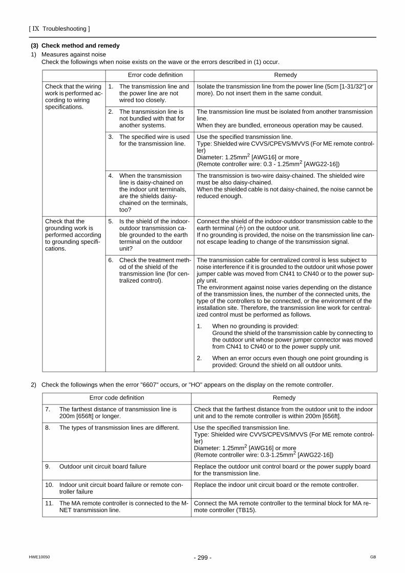
[ IX Troubleshooting ]
- 299 -HWE10050 GB
(3) Check method and remedy1) Measures against noise
Check the followings when noise exists on the wave or the errors described in (1) occur.
2) Check the followings when the error "6607" occurs, or "HO" appears on the display on the remote controller.
Error code definition Remedy
Check that the wiring work is performed ac-cording to wiring specifications.
1. The transmission line and the power line are not wired too closely.
Isolate the transmission line from the power line (5cm [1-31/32"] or more). Do not insert them in the same conduit.
2. The transmission line is not bundled with that for another systems.
The transmission line must be isolated from another transmission line.When they are bundled, erroneous operation may be caused.
3. The specified wire is used for the transmission line.
Use the specified transmission line.Type: Shielded wire CVVS/CPEVS/MVVS (For ME remote control-ler)Diameter: 1.25mm2 [AWG16] or more (Remote controller wire: 0.3 - 1.25mm2 [AWG22-16])
4. When the transmission line is daisy-chained on the indoor unit terminals, are the shields daisy-chained on the terminals, too?
The transmission is two-wire daisy-chained. The shielded wire must be also daisy-chained.When the shielded cable is not daisy-chained, the noise cannot be reduced enough.
Check that the grounding work is performed according to grounding specifi-cations.
5. Is the shield of the indoor-outdoor transmission ca-ble grounded to the earth terminal on the outdoor unit?
Connect the shield of the indoor-outdoor transmission cable to the earth terminal ( ) on the outdoor unit.If no grounding is provided, the noise on the transmission line can-not escape leading to change of the transmission signal.
6. Check the treatment meth-od of the shield of the transmission line (for cen-tralized control).
The transmission cable for centralized control is less subject to noise interference if it is grounded to the outdoor unit whose power jumper cable was moved from CN41 to CN40 or to the power sup-ply unit.The environment against noise varies depending on the distance of the transmission lines, the number of the connected units, the type of the controllers to be connected, or the environment of the installation site. Therefore, the transmission line work for central-ized control must be performed as follows.
1. When no grounding is provided: Ground the shield of the transmission cable by connecting to the outdoor unit whose power jumper connector was moved from CN41 to CN40 or to the power supply unit.
2. When an error occurs even though one point grounding is provided: Ground the shield on all outdoor units.
Error code definition Remedy
7. The farthest distance of transmission line is 200m [656ft] or longer.
Check that the farthest distance from the outdoor unit to the indoor unit and to the remote controller is within 200m [656ft].
8. The types of transmission lines are different. Use the specified transmission line.Type: Shielded wire CVVS/CPEVS/MVVS (For ME remote control-ler)Diameter: 1.25mm2 [AWG16] or more (Remote controller wire: 0.3-1.25mm2 [AWG22-16])
9. Outdoor unit circuit board failure Replace the outdoor unit control board or the power supply board for the transmission line.
10. Indoor unit circuit board failure or remote con-troller failure
Replace the indoor unit circuit board or the remote controller.
11. The MA remote controller is connected to the M-NET transmission line.
Connect the MA remote controller to the terminal block for MA re-mote controller (TB15).
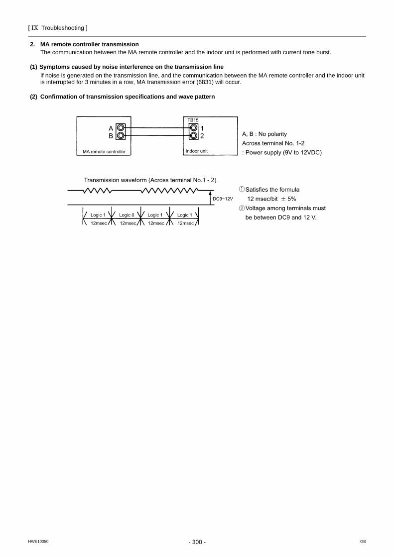
[ IX Troubleshooting ]
- 300 -HWE10050 GB
2. MA remote controller transmissionThe communication between the MA remote controller and the indoor unit is performed with current tone burst.
(1) Symptoms caused by noise interference on the transmission lineIf noise is generated on the transmission line, and the communication between the MA remote controller and the indoor unit is interrupted for 3 minutes in a row, MA transmission error (6831) will occur.
(2) Confirmation of transmission specifications and wave pattern
A, B : No polarityAcross terminal No. 1-2 : Power supply (9V to 12VDC)
Satisfies the formula 12 msec/bit 5% Voltage among terminals must be between DC9 and 12 V.
TB15
AB
12
MA remote controller
Transmission waveform (Across terminal No.1 - 2)
DC9~12V
Logic 1 Logic 0 Logic 1 Logic 1
12msec 12msec 12msec 12msec
Indoor unit
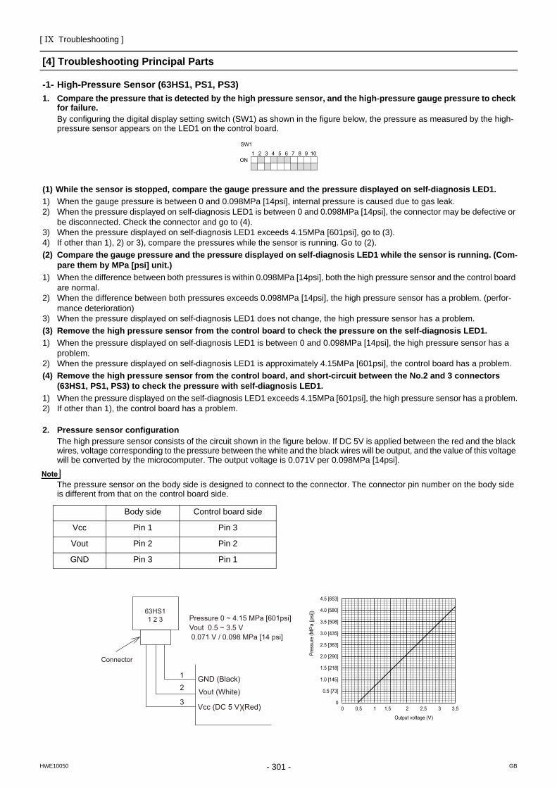
[ IX Troubleshooting ]
- 301 -HWE10050 GB
[4] Troubleshooting Principal PartsHigh-Pressure Sensor
-1- High-Pressure Sensor (63HS1, PS1, PS3)1. Compare the pressure that is detected by the high pressure sensor, and the high-pressure gauge pressure to check
for failure.By configuring the digital display setting switch (SW1) as shown in the figure below, the pressure as measured by the high-pressure sensor appears on the LED1 on the control board.
(1) While the sensor is stopped, compare the gauge pressure and the pressure displayed on self-diagnosis LED1.1) When the gauge pressure is between 0 and 0.098MPa [14psi], internal pressure is caused due to gas leak. 2) When the pressure displayed on self-diagnosis LED1 is between 0 and 0.098MPa [14psi], the connector may be defective or
be disconnected. Check the connector and go to (4). 3) When the pressure displayed on self-diagnosis LED1 exceeds 4.15MPa [601psi], go to (3).4) If other than 1), 2) or 3), compare the pressures while the sensor is running. Go to (2).(2) Compare the gauge pressure and the pressure displayed on self-diagnosis LED1 while the sensor is running. (Com-
pare them by MPa [psi] unit.)1) When the difference between both pressures is within 0.098MPa [14psi], both the high pressure sensor and the control board
are normal. 2) When the difference between both pressures exceeds 0.098MPa [14psi], the high pressure sensor has a problem. (perfor-
mance deterioration) 3) When the pressure displayed on self-diagnosis LED1 does not change, the high pressure sensor has a problem.(3) Remove the high pressure sensor from the control board to check the pressure on the self-diagnosis LED1.1) When the pressure displayed on self-diagnosis LED1 is between 0 and 0.098MPa [14psi], the high pressure sensor has a
problem.2) When the pressure displayed on self-diagnosis LED1 is approximately 4.15MPa [601psi], the control board has a problem. (4) Remove the high pressure sensor from the control board, and short-circuit between the No.2 and 3 connectors
(63HS1, PS1, PS3) to check the pressure with self-diagnosis LED1.1) When the pressure displayed on the self-diagnosis LED1 exceeds 4.15MPa [601psi], the high pressure sensor has a problem.2) If other than 1), the control board has a problem.
2. Pressure sensor configurationThe high pressure sensor consists of the circuit shown in the figure below. If DC 5V is applied between the red and the black wires, voltage corresponding to the pressure between the white and the black wires will be output, and the value of this voltage will be converted by the microcomputer. The output voltage is 0.071V per 0.098MPa [14psi].
The pressure sensor on the body side is designed to connect to the connector. The connector pin number on the body side is different from that on the control board side.
Body side Control board side
Vcc Pin 1 Pin 3
Vout Pin 2 Pin 2
GND Pin 3 Pin 1
1 2 3 4 5 6 7 8 9 10ON
SW1
0
0.5 [73]
1.0 [145]
1.5 [218]
2.0 [290]
2.5 [363]
3.0 [435]
3.5 [508]
4.0 [580]
4.5 [653]
0 0.5 1 1.5 2 2.5 3 3.5
Output voltage (V)
Pr
essu
re (M
Pa
[psi
])
Connector
63HS11 2 3
1 2
3
GND (Black)
Vout (White)
Vcc (DC 5 V)(Red)
Pressure 0 ~ 4.15 MPa [601psi] Vout 0.5 ~ 3.5 V 0.071 V / 0.098 MPa [14 psi]
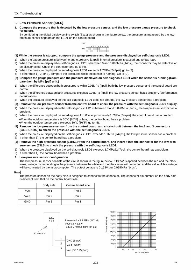
[ IX Troubleshooting ]
- 302 -HWE10050 GB
Low-Pressure Sensor
-2- Low-Pressure Sensor (63LS)1. Compare the pressure that is detected by the low pressure sensor, and the low pressure gauge pressure to check
for failure.By configuring the digital display setting switch (SW1) as shown in the figure below, the pressure as measured by the low-pressure sensor appears on the LED1 on the control board.
(1) While the sensor is stopped, compare the gauge pressure and the pressure displayed on self-diagnosis LED1.1) When the gauge pressure is between 0 and 0.098MPa [14psi], internal pressure is caused due to gas leak. 2) When the pressure displayed on self-diagnosis LED1 is between 0 and 0.098MPa [14psi], the connector may be defective or
be disconnected. Check the connector and go to (4). 3) When the pressure displayed on self-diagnosis LED1 exceeds 1.7MPa [247psi], go to (3).4) If other than 1), 2) or 3), compare the pressures while the sensor is running. Go to (2).(2) Compare the gauge pressure and the pressure displayed on self-diagnosis LED1 while the sensor is running.(Com-
pare them by MPa [psi] unit.)1) When the difference between both pressures is within 0.03MPa [4psi], both the low pressure sensor and the control board are
normal.2) When the difference between both pressures exceeds 0.03MPa [4psi], the low pressure sensor has a problem. (performance
deterioration) 3) When the pressure displayed on the self-diagnosis LED1 does not change, the low pressure sensor has a problem.(3) Remove the low pressure sensor from the control board to check the pressure with the self-diagnosis LED1 display.1) When the pressure displayed on the self-diagnosis LED1 is between 0 and 0.098MPa [14psi], the low pressure sensor has a
problem.2) When the pressure displayed on self-diagnosis LED1 is approximately 1.7MPa [247psi], the control board has a problem.
When the outdoor temperature is 30°C [86°F] or less, the control board has a problem. When the outdoor temperature exceeds 30°C [86°F], go to (5).
(4) Remove the low pressure sensor from the control board, and short-circuit between the No.2 and 3 connectors (63LS:CN202) to check the pressure with the self-diagnosis LED1.
1) When the pressure displayed on the self-diagnosis LED1 exceeds 1.7MPa [247psi], the low pressure sensor has a problem. 2) If other than 1), the control board has a problem.(5) Remove the high pressure sensor (63HS1) from the control board, and insert it into the connector for the low pres-
sure sensor (63LS) to check the pressure with the self-diagnosis LED1.1) When the pressure displayed on the self-diagnosis LED1 exceeds 1.7MPa [247psi], the control board has a problem. 2) If other than 1), the control board has a problem.2. Low-pressure sensor configuration
The low pressure sensor consists of the circuit shown in the figure below. If DC5V is applied between the red and the black wires, voltage corresponding to the pressure between the white and the black wires will be output, and the value of this voltage will be converted by the microcomputer. The output voltage is 0.173V per 0.098MPa [14psi].
The pressure sensor on the body side is designed to connect to the connector. The connector pin number on the body side is different from that on the control board side.
Body side Control board side
Vcc Pin 1 Pin 3
Vout Pin 2 Pin 2
GND Pin 3 Pin 1
1 2 3 4 5 6 7 8 9 10ON
SW1
0
0.2 [29]
0.4 [58]
0.6 [87]
0.8 [116]
1.0 [145]
1.2 [174]
1.4 [203]
1.6 [232]
1.8 [261]
0 0.5 1 1.5 2 2.5 3 3.5 Output voltage (V)
Pr
essu
re (M
Pa
[psi
])
Connector
63LS1 2 3
12
3
GND (Black)
Vout (White)
Vcc (DC 5 V)(Red)
Pressure 0 ~ 1.7 MPa [247psi]Vout 0.5 ~ 3.5 V 0.173 V / 0.098 MPa [14 psi]
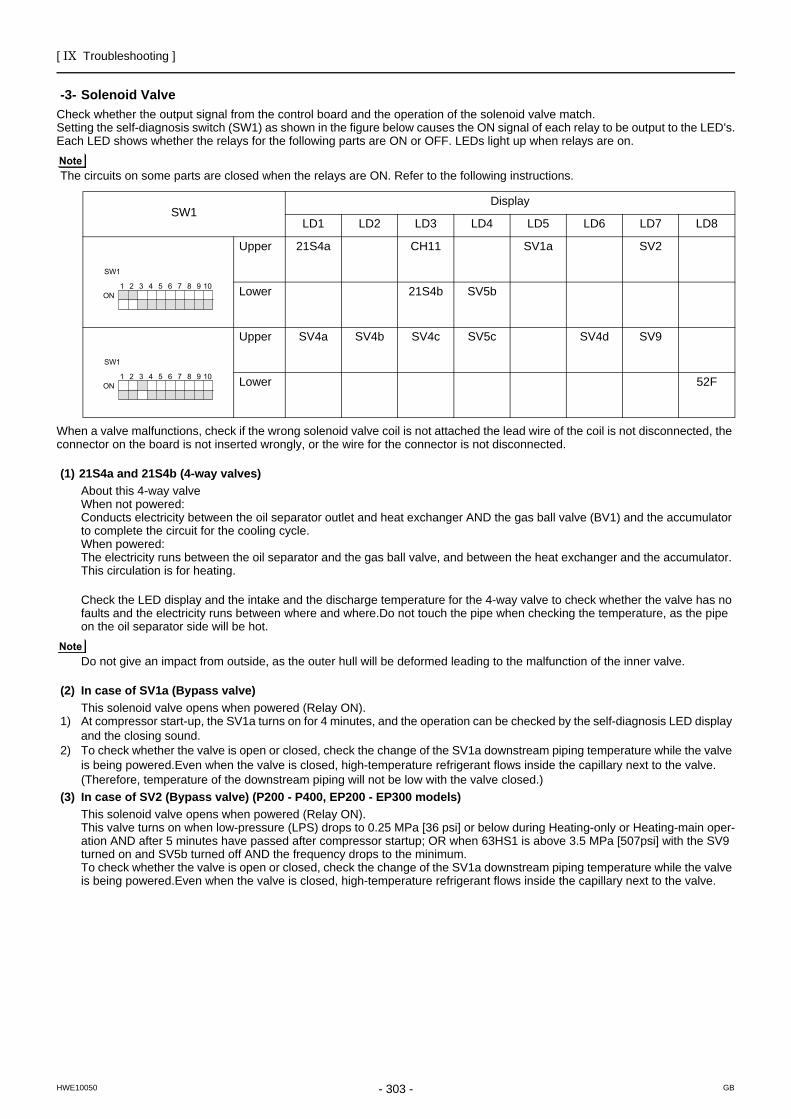
[ IX Troubleshooting ]
- 303 -HWE10050 GB
Solenoid Valve
-3- Solenoid ValveCheck whether the output signal from the control board and the operation of the solenoid valve match.Setting the self-diagnosis switch (SW1) as shown in the figure below causes the ON signal of each relay to be output to the LED's.Each LED shows whether the relays for the following parts are ON or OFF. LEDs light up when relays are on.
The circuits on some parts are closed when the relays are ON. Refer to the following instructions.
When a valve malfunctions, check if the wrong solenoid valve coil is not attached the lead wire of the coil is not disconnected, the connector on the board is not inserted wrongly, or the wire for the connector is not disconnected.
(1) 21S4a and 21S4b (4-way valves)About this 4-way valveWhen not powered: Conducts electricity between the oil separator outlet and heat exchanger AND the gas ball valve (BV1) and the accumulator to complete the circuit for the cooling cycle. When powered: The electricity runs between the oil separator and the gas ball valve, and between the heat exchanger and the accumulator. This circulation is for heating.
Check the LED display and the intake and the discharge temperature for the 4-way valve to check whether the valve has no faults and the electricity runs between where and where.Do not touch the pipe when checking the temperature, as the pipe on the oil separator side will be hot.
Do not give an impact from outside, as the outer hull will be deformed leading to the malfunction of the inner valve.
(2) In case of SV1a (Bypass valve)This solenoid valve opens when powered (Relay ON).
1) At compressor start-up, the SV1a turns on for 4 minutes, and the operation can be checked by the self-diagnosis LED display and the closing sound.
2) To check whether the valve is open or closed, check the change of the SV1a downstream piping temperature while the valve is being powered.Even when the valve is closed, high-temperature refrigerant flows inside the capillary next to the valve. (Therefore, temperature of the downstream piping will not be low with the valve closed.)
(3) In case of SV2 (Bypass valve) (P200 - P400, EP200 - EP300 models)This solenoid valve opens when powered (Relay ON).This valve turns on when low-pressure (LPS) drops to 0.25 MPa [36 psi] or below during Heating-only or Heating-main oper-ation AND after 5 minutes have passed after compressor startup; OR when 63HS1 is above 3.5 MPa [507psi] with the SV9 turned on and SV5b turned off AND the frequency drops to the minimum.To check whether the valve is open or closed, check the change of the SV1a downstream piping temperature while the valve is being powered.Even when the valve is closed, high-temperature refrigerant flows inside the capillary next to the valve.
SW1Display
LD1 LD2 LD3 LD4 LD5 LD6 LD7 LD8
Upper 21S4a CH11 SV1a SV2
Lower 21S4b SV5b
Upper SV4a SV4b SV4c SV5c SV4d SV9
Lower 52F
1 2 3 4 5 6 7 8 9 10ON
SW1
1 2 3 4 5 6 7 8 9 10 ON
SW1
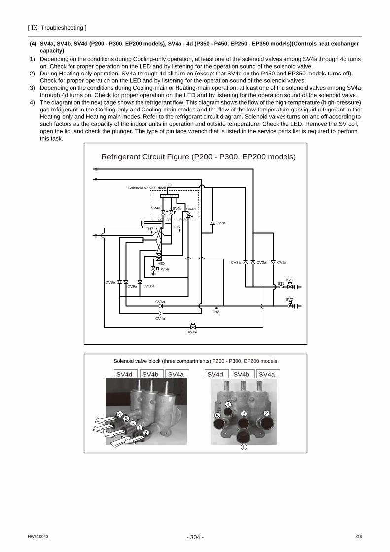
[ IX Troubleshooting ]
- 304 -HWE10050 GB
(4) SV4a, SV4b, SV4d (P200 - P300, EP200 models), SV4a - 4d (P350 - P450, EP250 - EP350 models)(Controls heat exchanger capacity)
1) Depending on the conditions during Cooling-only operation, at least one of the solenoid valves among SV4a through 4d turns on. Check for proper operation on the LED and by listening for the operation sound of the solenoid valve.
2) During Heating-only operation, SV4a through 4d all turn on (except that SV4c on the P450 and EP350 models turns off). Check for proper operation on the LED and by listening for the operation sound of the solenoid valves.
3) Depending on the conditions during Cooling-main or Heating-main operation, at least one of the solenoid valves among SV4a through 4d turns on. Check for proper operation on the LED and by listening for the operation sound of the solenoid valve.
4) The diagram on the next page shows the refrigerant flow. This diagram shows the flow of the high-temperature (high-pressure) gas refrigerant in the Cooling-only and Cooling-main modes and the flow of the low-temperature gas/liquid refrigerant in the Heating-only and Heating-main modes. Refer to the refrigerant circuit diagram. Solenoid valves turns on and off according to such factors as the capacity of the indoor units in operation and outside temperature. Check the LED. Remove the SV coil, open the lid, and check the plunger. The type of pin face wrench that is listed in the service parts list is required to perform this task.
ST1CV8a
CV6a
TH7
TH3
SV4a SV4b SV4d
TH6
CV9a CV10a
SV5b
CV4a
CV2a
CV7a
CV3a CV5aHEX
Solenoid Valves Block
BV1
BV2
SV5c
Refrigerant Circuit Figure (P200 - P300, EP200 models)
12
3
45
1
23
4
5
Solenoid valve block (three compartments) P200 - P300, EP200 models
SV4d SV4b SV4a SV4d SV4b SV4a
[ IX Troubleshooting ]
- 305 -HWE10050 GB
12
34
56
1
234
5
6
Pin-face tool
SV4d
SV4dSV4c
SV4bSV4a
Valve
Solenoid valve
Solenoid valve coil
Pin-face tool
Tightening torque : 150N.m [1500kg.cm]
SV4cSV4b
SV4a
ST1CV8a
CV6a
TH7
TH3
SV4a
SV4d
TH6
CV9a CV10a
SV5b
CV4a
CV2a
CV7a
CV3a CV5aHEX
BV1
BV2
SV5c
SV4b
SV4c
SV4d SV4c SV4b SV4a
Solenoid Valves Block
Refrigerant Circuit Figure (P350 - P400, EP250, EP300 models)
Solenoid valve block (four compartments) P350 - P400, EP250, EP300 models
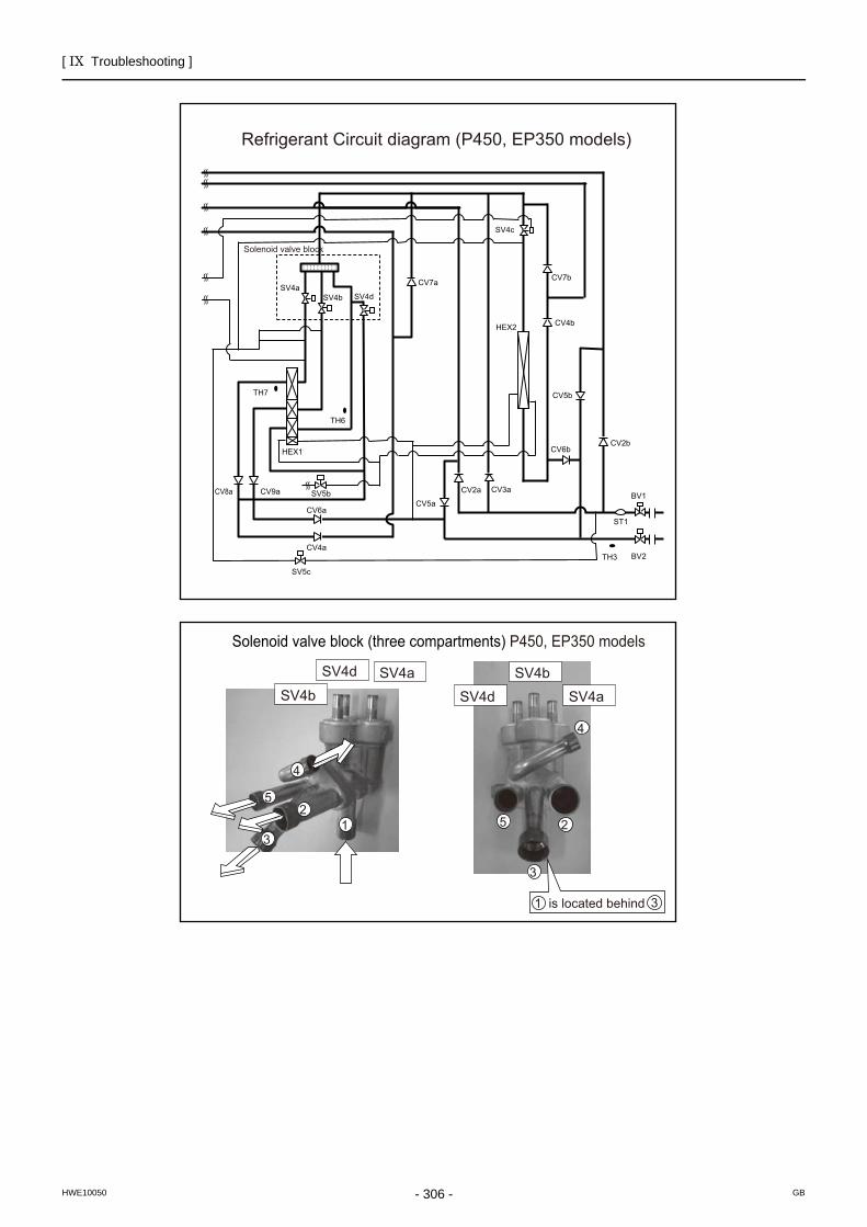
[ IX Troubleshooting ]
- 306 -HWE10050 GB
12
3
4
5
2
3
4
5
ST1
CV8a
CV6a
TH7
TH3
SV4aSV4b SV4d
TH6
CV9aCV5a
SV5b
CV4a
CV2a
CV7a
CV6b
CV5b
HEX1
SV4c
BV1
BV2
SV5c
CV3a
CV7b
CV2b
CV4bHEX2
Refrigerant Circuit diagram (P450, EP350 models)
1 is located behind 3
Solenoid valve block (three compartments) P450, EP350 models
Solenoid valve block
SV4d
SV4bSV4a
SV4dSV4b
SV4a
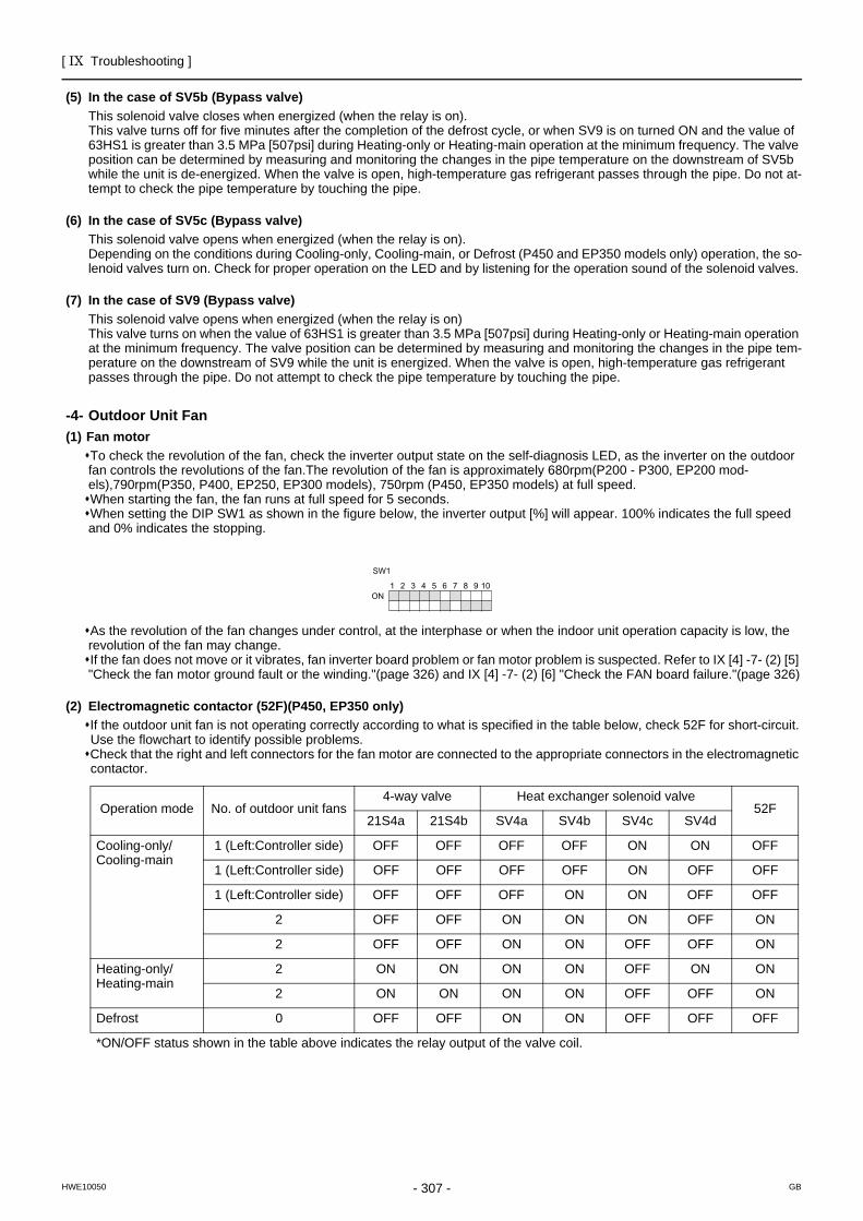
[ IX Troubleshooting ]
- 307 -HWE10050 GB
(5) In the case of SV5b (Bypass valve) This solenoid valve closes when energized (when the relay is on).This valve turns off for five minutes after the completion of the defrost cycle, or when SV9 is on turned ON and the value of 63HS1 is greater than 3.5 MPa [507psi] during Heating-only or Heating-main operation at the minimum frequency. The valve position can be determined by measuring and monitoring the changes in the pipe temperature on the downstream of SV5b while the unit is de-energized. When the valve is open, high-temperature gas refrigerant passes through the pipe. Do not at-tempt to check the pipe temperature by touching the pipe.
(6) In the case of SV5c (Bypass valve) This solenoid valve opens when energized (when the relay is on).Depending on the conditions during Cooling-only, Cooling-main, or Defrost (P450 and EP350 models only) operation, the so-lenoid valves turn on. Check for proper operation on the LED and by listening for the operation sound of the solenoid valves.
(7) In the case of SV9 (Bypass valve) This solenoid valve opens when energized (when the relay is on)This valve turns on when the value of 63HS1 is greater than 3.5 MPa [507psi] during Heating-only or Heating-main operation at the minimum frequency. The valve position can be determined by measuring and monitoring the changes in the pipe tem-perature on the downstream of SV9 while the unit is energized. When the valve is open, high-temperature gas refrigerant passes through the pipe. Do not attempt to check the pipe temperature by touching the pipe.
Outdoor Unit Fan
-4- Outdoor Unit Fan(1) Fan motor
To check the revolution of the fan, check the inverter output state on the self-diagnosis LED, as the inverter on the outdoor fan controls the revolutions of the fan.The revolution of the fan is approximately 680rpm(P200 - P300, EP200 mod-els),790rpm(P350, P400, EP250, EP300 models), 750rpm (P450, EP350 models) at full speed.When starting the fan, the fan runs at full speed for 5 seconds.When setting the DIP SW1 as shown in the figure below, the inverter output [%] will appear. 100% indicates the full speed and 0% indicates the stopping.
As the revolution of the fan changes under control, at the interphase or when the indoor unit operation capacity is low, the revolution of the fan may change.If the fan does not move or it vibrates, fan inverter board problem or fan motor problem is suspected. Refer to IX [4] -7- (2) [5] "Check the fan motor ground fault or the winding."(page 326) and IX [4] -7- (2) [6] "Check the FAN board failure."(page 326)
(2) Electromagnetic contactor (52F)(P450, EP350 only)If the outdoor unit fan is not operating correctly according to what is specified in the table below, check 52F for short-circuit.Use the flowchart to identify possible problems. Check that the right and left connectors for the fan motor are connected to the appropriate connectors in the electromagnetic contactor.
Operation mode No. of outdoor unit fans4-way valve Heat exchanger solenoid valve
52F21S4a 21S4b SV4a SV4b SV4c SV4d
Cooling-only/Cooling-main
1 (Left:Controller side) OFF OFF OFF OFF ON ON OFF
1 (Left:Controller side) OFF OFF OFF OFF ON OFF OFF
1 (Left:Controller side) OFF OFF OFF ON ON OFF OFF
2 OFF OFF ON ON ON OFF ON
2 OFF OFF ON ON OFF OFF ON
Heating-only/Heating-main
2 ON ON ON ON OFF ON ON
2 ON ON ON ON OFF OFF ON
Defrost 0 OFF OFF ON ON OFF OFF OFF
*ON/OFF status shown in the table above indicates the relay output of the valve coil.
1 2 3 4 5 6 7 8 9 10 ON
SW1
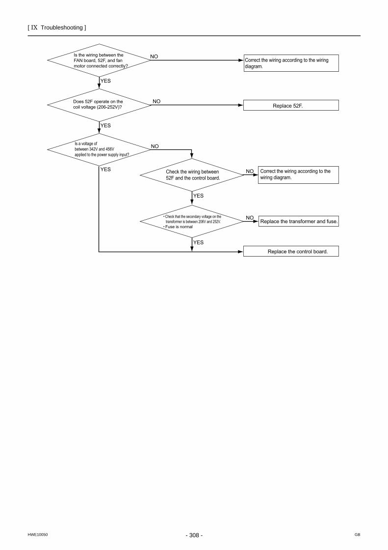
[ IX Troubleshooting ]
- 308 -HWE10050 GB
YES
YES
YES
YES
YES
NO
NO
NO
NO
Replace the control board.
Replace 52F.
Is the wiring between the FAN board, 52F, and fan motor connected correctly?
Does 52F operate on the coil voltage (206-252V)?
Check the wiring between 52F and the control board.
Check that the secondary voltage on the transformer is between 206V and 252V.Fuse is normal
Is a voltage ofbetween 342V and 456V applied to the power supply input?
Correct the wiring according to the wiring diagram.
Correct the wiring according to the wiring diagram.
NOReplace the transformer and fuse.
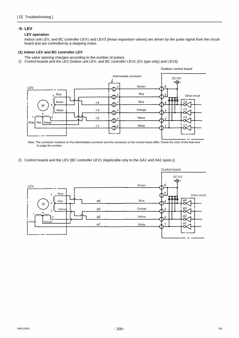
[ IX Troubleshooting ]
- 309 -HWE10050 GB
LEV
-5- LEVLEV operationIndoor unit LEV, and BC controller LEV1 and LEV3 (linear expansion valves) are driven by the pulse signal from the circuit board and are controlled by a stepping motor.
(1) Indoor LEV and BC controller LEV The valve opening changes according to the number of pulses.
1) Control boards and the LEV (Indoor unit LEV, and BC controller LEV1 (G1 type only) and LEV3)
2) Control boards and the LEV (BC controller LEV1 (Applicable only to the GA1 and HA1 types.))
Note. The connector numbers on the intermediate connector and the connector on the control board differ. Check the color of the lead wire to judge the number.
Outdoor control board
Drive circuit
LEV
M
5
5
2
2
1
1
3
3 4
4
6
6
DC12V
Red
Intermediate connector
Brown
Blue
Orange
Yellow
WhiteRed OrangeWhite
Brown
Blue
Yellow
6
5
4 4
3
2
1
3
2
1
4
3
2
1
ø4
ø3
ø2
ø1
ø4
ø3
ø2
ø1
Control board
Drive circuit
LEV
M
52
13
4
6
DC12V
Brown
Blue
Orange
Yellow
WhiteOrangeWhite
Blue
Yellow
Red
6
5
4
3
2
1
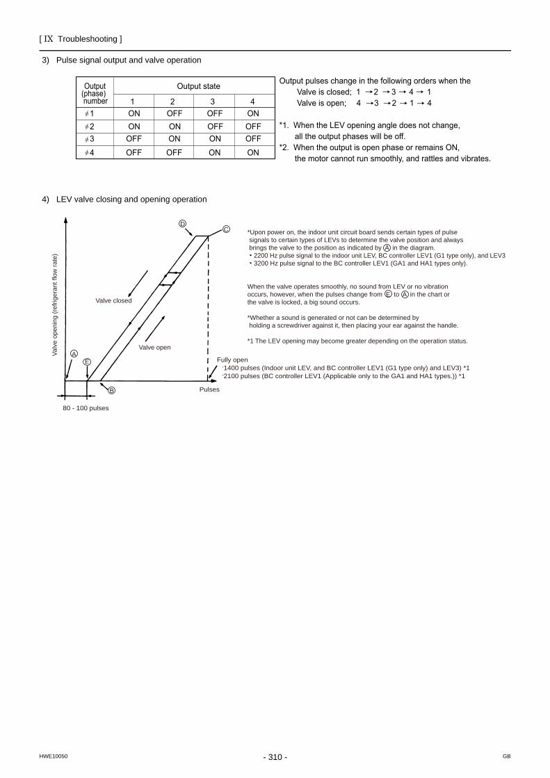
[ IX Troubleshooting ]
- 310 -HWE10050 GB
3) Pulse signal output and valve operation
4) LEV valve closing and opening operation
Output state Output (phase) number 1 2 3 4
1 ON OFF OFF ON2 ON ON OFF OFF3 OFF ON ON OFF
4 OFF OFF ON ON
Output pulses change in the following orders when the Valve is closed; 1 2 3 4 1 Valve is open; 4 3 2 1 4
*1. When the LEV opening angle does not change, all the output phases will be off.*2. When the output is open phase or remains ON, the motor cannot run smoothly, and rattles and vibrates.
*Upon power on, the indoor unit circuit board sends certain types of pulse signals to certain types of LEVs to determine the valve position and always brings the valve to the position as indicated by A in the diagram. ・2200 Hz pulse signal to the indoor unit LEV, BC controller LEV1 (G1 type only), and LEV3・3200 Hz pulse signal to the BC controller LEV1 (GA1 and HA1 types only).
When the valve operates smoothly, no sound from LEV or no vibration occurs, however, when the pulses change from E to A in the chart or the valve is locked, a big sound occurs.
*Whether a sound is generated or not can be determined by holding a screwdriver against it, then placing your ear against the handle.
*1 The LEV opening may become greater depending on the operation status.
.1400 pulses (Indoor unit LEV, and BC controller LEV1 (G1 type only) and LEV3) *1
.2100 pulses (BC controller LEV1 (Applicable only to the GA1 and HA1 types.)) *1
Valv
e op
enin
g (r
efrig
eran
t flo
w ra
te)
Valve closed
Valve open
E
B
80 - 100 pulses
Pulses
Fully openA
CD
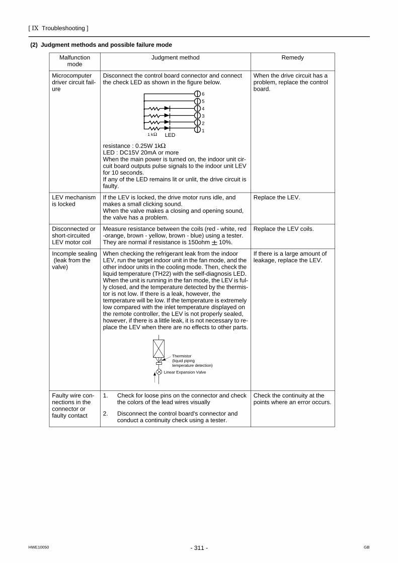
[ IX Troubleshooting ]
- 311 -HWE10050 GB
(2) Judgment methods and possible failure mode
Malfunction mode
Judgment method Remedy
Microcomputer driver circuit fail-ure
Disconnect the control board connector and connect the check LED as shown in the figure below.
resistance : 0.25W 1kLED : DC15V 20mA or moreWhen the main power is turned on, the indoor unit cir-cuit board outputs pulse signals to the indoor unit LEV for 10 seconds. If any of the LED remains lit or unlit, the drive circuit is faulty.
When the drive circuit has a problem, replace the control board.
LEV mechanism is locked
If the LEV is locked, the drive motor runs idle, and makes a small clicking sound.When the valve makes a closing and opening sound, the valve has a problem.
Replace the LEV.
Disconnected or short-circuited LEV motor coil
Measure resistance between the coils (red - white, red -orange, brown - yellow, brown - blue) using a tester. They are normal if resistance is 150ohm 10%.
Replace the LEV coils.
Incomple sealing (leak from the valve)
When checking the refrigerant leak from the indoor LEV, run the target indoor unit in the fan mode, and the other indoor units in the cooling mode. Then, check the liquid temperature (TH22) with the self-diagnosis LED. When the unit is running in the fan mode, the LEV is ful-ly closed, and the temperature detected by the thermis-tor is not low. If there is a leak, however, the temperature will be low. If the temperature is extremely low compared with the inlet temperature displayed on the remote controller, the LEV is not properly sealed, however, if there is a little leak, it is not necessary to re-place the LEV when there are no effects to other parts.
If there is a large amount of leakage, replace the LEV.
Faulty wire con-nections in the connector or faulty contact
1. Check for loose pins on the connector and check the colors of the lead wires visually
Check the continuity at the points where an error occurs.
2. Disconnect the control board's connector and conduct a continuity check using a tester.
654321
1 k LED
Thermistor(liquid piping temperature detection)
Linear Expansion Valve
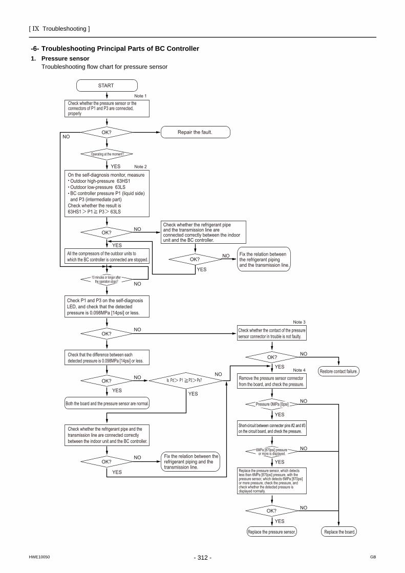
[ IX Troubleshooting ]
- 312 -HWE10050 GB
Troubleshooting Principal Parts of BC Controller
-6- Troubleshooting Principal Parts of BC Controller1. Pressure sensor
Troubleshooting flow chart for pressure sensor
Check whether the pressure sensor or the connectors of P1 and P3 are connected, properly
All the compressors of the outdoor units to which the BC controller is connected are stopped.
Check P1 and P3 on the self-diagnosis LED, and check that the detected pressure is 0.098MPa [14psi] or less.
On the self-diagnosis monitor, measure Outdoor high-pressure 63HS1 Outdoor low-pressure 63LS BC controller pressure P1 (liquid side) and P3 (intermediate part)Check whether the result is63HS1 P1 P3 63LS
START
Repair the fault.
Fix the relation between the refrigerant piping and the transmission line.
Fix the relation between the refrigerant piping and the transmission line.
Replace the pressure sensor. Replace the board.
Restore contact failure.
Check whether the contact of the pressure sensor connector in trouble is not faulty.
OK?
OK?
Check that the difference between each detected pressure is 0.098MPa [14psi] or less.
OK?
Both the board and the pressure sensor are normal.
OK? Is Pd P1 P3 Ps? Remove the pressure sensor connector from the board, and check the pressure.
OK?
OK?
Check whether the refrigerant pipe and the transmission line are connected correctly between the indoor unit and the BC controller.
OK?
Operating at the moment?
Check whether the refrigerant pipe and the transmission line are connected correctly between the indoor unit and the BC controller.
OK?
YES Note 2
Note 1
NO
YES
YES
YES
Note 3
Note 4
NO
NO
NO
NO
YES
NO
NO
YES
YES
YES
NO
NO
YES
NO
YES
NO
NO
Replace the pressure sensor, which detects less than 6MPa [870psi] pressure, with the pressure sensor, which detects 6MPa [870psi] or more pressure, check the pressure, and check whether the detected pressure is displayed normally.
10 minutes or longer after the operation stops?
Pressure 0MPa [0psi]
6MPa [870psi] pressure or more is displayed.
Short-circuit between connecter pins #2 and #3 on the circuit board, and check the pressure.
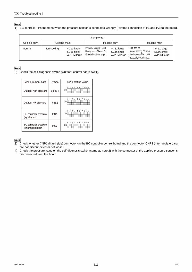
[ IX Troubleshooting ]
- 313 -HWE10050 GB
1) BC controller: Phenomena when the pressure sensor is connected wrongly (reverse connection of P1 and P3) to the board.
2) Check the self-diagnosis switch (Outdoor control board SW1).
3) Check whether CNP1 (liquid side) connector on the BC controller control board and the connector CNP2 (intermediate part) are not disconnected or not loose.
4) Check the pressure value on the self-diagnosis switch (same as note 2) with the connector of the applied pressure sensor is disconnected from the board.
Cooling-only Heating only
Heating main
Non-cooling Indoor heating SC small Heating indoor Thermo ON Especially noise is large.
Indoor heating SC smallHeating indoor Thermo ON Especially noise is large.
Cooling-main
Symptoms
SC11 large SC16 small PHM large
SC11 large SC16 small PHM large
Non-cooling Normal SC11 largeSC16 small PHM large
Measurement data SW1 setting value
Outdoor high pressure
Outdoor low pressure
BC controller pressure (liquid side)
BC controller pressure (intermediate part)
Symbol
63HS1
PS1
63LS
PS3
1 2 3 4 5 6 7 8 9 10ON
1 2 3 4 5 6 7 8 9 10ON
1 2 3 4 5 6 7 8 9 10ON
1 2 3 4 5 6 7 8 9 10ON
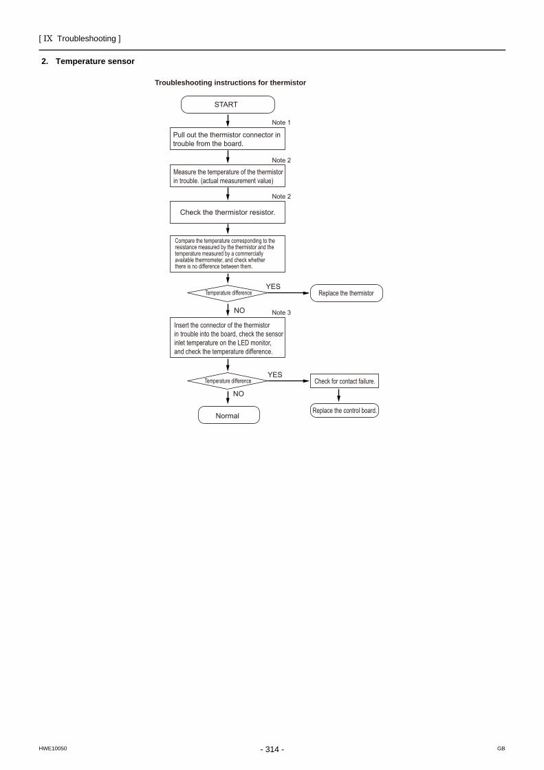
[ IX Troubleshooting ]
- 314 -HWE10050 GB
2. Temperature sensor
Pull out the thermistor connector in trouble from the board.
Measure the temperature of the thermistor in trouble. (actual measurement value)
Check the thermistor resistor.
Compare the temperature corresponding to the resistance measured by the thermistor and the temperature measured by a commercially available thermometer, and check whether there is no difference between them.
Insert the connector of the thermistor in trouble into the board, check the sensor inlet temperature on the LED monitor, and check the temperature difference.
START
Normal
Troubleshooting instructions for thermistor
Replace the thermistorTemperature difference
Temperature difference Check for contact failure.
Replace the control board.
Note 1
Note 2
Note 2
Note 3
YES
NO
YES
NO
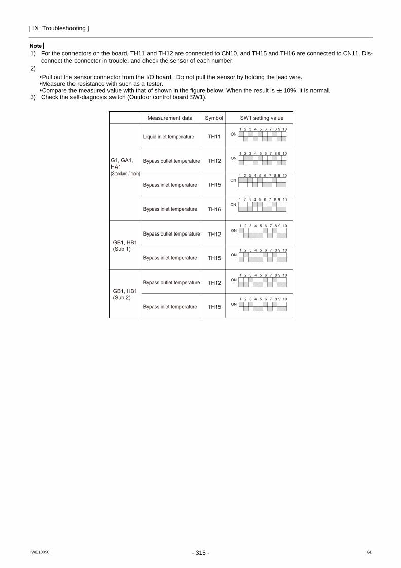
[ IX Troubleshooting ]
- 315 -HWE10050 GB
1) For the connectors on the board, TH11 and TH12 are connected to CN10, and TH15 and TH16 are connected to CN11. Dis-connect the connector in trouble, and check the sensor of each number.
2) Pull out the sensor connector from the I/O board, Do not pull the sensor by holding the lead wire.Measure the resistance with such as a tester.Compare the measured value with that of shown in the figure below. When the result is 10%, it is normal.
3) Check the self-diagnosis switch (Outdoor control board SW1).
1 2 3 4 5 6 7 8 9 10ON
1 2 3 4 5 6 7 8 9 10ON
1 2 3 4 5 6 7 8 9 10ON
1 2 3 4 5 6 7 8 9 10ON
1 2 3 4 5 6 7 8 9 10ON
1 2 3 4 5 6 7 8 9 10ON
1 2 3 4 5 6 7 8 9 10ON
1 2 3 4 5 6 7 8 9 10ON
TH12
TH15
TH12
TH15
Liquid inlet temperature
Bypass outlet temperature
Bypass outlet temperature
Bypass outlet temperature
TH11
TH12
Bypass inlet temperature
Bypass inlet temperature
Bypass inlet temperature
Bypass inlet temperature
TH15
TH16
Measurement data SW1 setting value Symbol
G1, GA1, HA1(Standard / main)
GB1, HB1(Sub 1)
GB1, HB1(Sub 2)
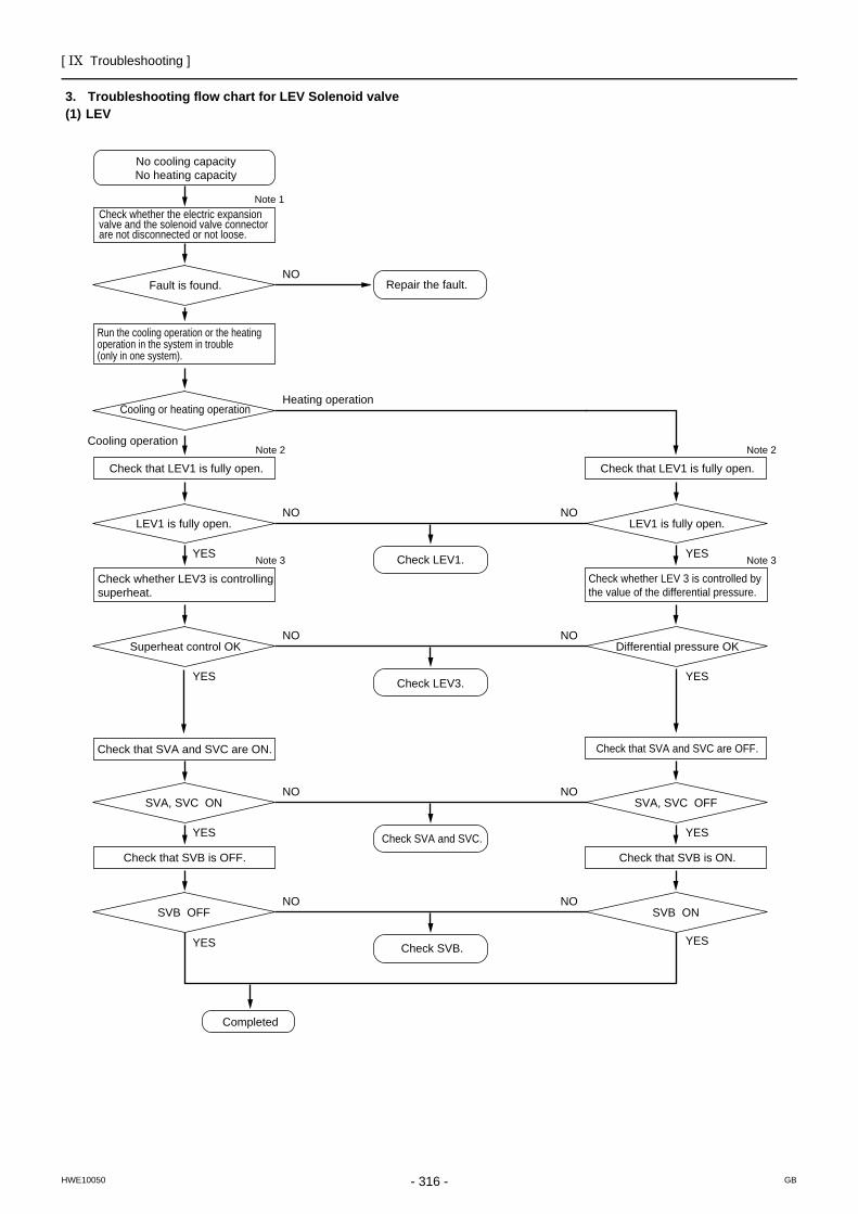
[ IX Troubleshooting ]
- 316 -HWE10050 GB
3. Troubleshooting flow chart for LEV Solenoid valve(1) LEV
Check whether the electric expansion valve and the solenoid valve connector are not disconnected or not loose.
Run the cooling operation or the heating operation in the system in trouble (only in one system).
No cooling capacity No heating capacity
Repair the fault. Fault is found.
Note 1
NO
Check that LEV1 is fully open. Check that LEV1 is fully open.
Check that SVA and SVC are ON. Check that SVA and SVC are OFF.
Cooling or heating operation
Note 2
Heating operation
Check whether LEV3 is controlling superheat.
Check LEV1.
Check LEV3.
Check SVA and SVC.
Check SVB.
LEV1 is fully open.
Check whether LEV 3 is controlled by the value of the differential pressure.
LEV1 is fully open.
Note 3
Note 2
Note 3YES
NO
Cooling operation
Superheat control OK Differential pressure OK
YES
NO
Check that SVB is OFF. Check that SVB is ON.
SVA, SVC ON SVA, SVC OFF
YES
YES
NO
Completed
SVB OFF SVB ON
YES
YES
YES
YES
NO
NO
NO
NO
NO
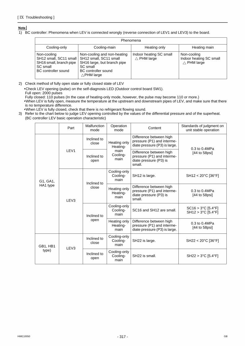
[ IX Troubleshooting ]
- 317 -HWE10050 GB
1) BC controller: Phenomena when LEV is connected wrongly (reverse connection of LEV1 and LEV3) to the board.
2) Check method of fully open state or fully closed state of LEVCheck LEV opening (pulse) on the self-diagnosis LED (Outdoor control board SW1).Full open: 2000 pulsesFully closed: 110 pulses (In the case of heating-only mode, however, the pulse may become 110 or more.)When LEV is fully open, measure the temperature at the upstream and downstream pipes of LEV, and make sure that there is no temperature difference.When LEV is fully closed, check that there is no refrigerant flowing sound.
3) Refer to the chart below to judge LEV opening controlled by the values of the differential pressure and of the superheat. (BC controller LEV basic operation characteristic)
Phenomena
Cooling-only Cooling-main Heating only Heating main
Non-coolingSH12 small, SC11 smallSH16 small, branch pipe SC smallBC controller sound
Non-cooling and non-heatingSH12 small, SC11 smallSH16 large, but branch pipe SC smallBC controller sound PHM large
Indoor heating SC small PHM large
Non-coolingIndoor heating SC small PHM large
Part Malfunction mode
Operation mode Content Standards of judgment on
unit stable operation
G1, GA1, HA1 type
LEV1
Inclined to close Heating only
Heating-main
Cooling-main
Difference between high pressure (P1) and interme-diate pressure (P3) is large.
0.3 to 0.4MPa[44 to 58psi]
Inclined to open
Difference between high pressure (P1) and interme-diate pressure (P3) is small.
LEV3
Inclined to close
Cooling-onlyCooling-
mainSH12 is large. SH12 < 20°C [36°F]
Heating onlyHeating-
main
Difference between high pressure (P1) and interme-diate pressure (P3) is small.
0.3 to 0.4MPa[44 to 58psi]
Inclined to open
Cooling-onlyCooling-
mainSC16 and SH12 are small. SC16 > 3°C [5.4°F]
SH12 > 3°C [5.4°F]
Heating onlyHeating-
main
Difference between high pressure (P1) and interme-diate pressure (P3) is large.
0.3 to 0.4MPa[44 to 58psi]
GB1, HB1 type) LEV3
Inclined to close
Cooling-onlyCooling-
mainSH22 is large. SH22 < 20°C [36°F]
Inclined to open
Cooling-onlyCooling-
mainSH22 is small. SH22 > 3°C [5.4°F]
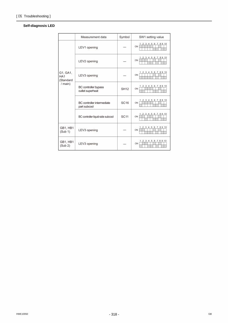
[ IX Troubleshooting ]
- 318 -HWE10050 GB
Self-diagnosis LED
1 2 3 4 5 6 7 8 9 10ON
1 2 3 4 5 6 7 8 9 10ON
1 2 3 4 5 6 7 8 9 10ON
1 2 3 4 5 6 7 8 9 10ON
1 2 3 4 5 6 7 8 9 10ON
1 2 3 4 5 6 7 8 9 10ON
1 2 3 4 5 6 7 8 9 10ON
1 2 3 4 5 6 7 8 9 10ON
LEV1 opening
LEV3 opening
LEV3 opening
BC controller bypass outlet superheat
BC controller intermediate part subcool
SH12
LEV2 opening
LEV3 opening
SC16
BC controller liquid-side subcool SC11
Measurement data SW1 setting value Symbol
G1, GA1, HA1(Standard / main)
GB1, HB1(Sub 1)
GB1, HB1(Sub 2)
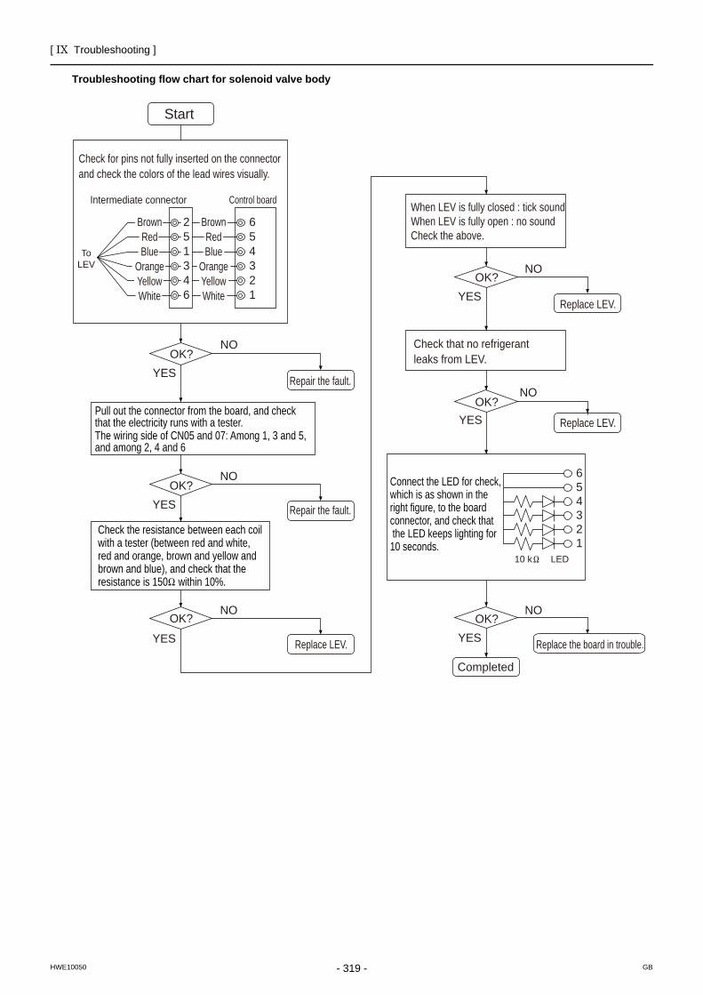
[ IX Troubleshooting ]
- 319 -HWE10050 GB
Troubleshooting flow chart for solenoid valve body
6
6
54321
54321
251346
ToLEV
LED10 k
Start
BrownRedBlue
OrangeYellowWhite
BrownRedBlue
OrangeYellowWhite
OK?NO
YES
OK?NO
YES
Repair the fault.
Repair the fault.
OK?NO
YES
OK?NO
YES Replace LEV.
OK?NO
YES Replace LEV.
Replace LEV.
OK?NO
YES Replace the board in trouble.
Completed
Check for pins not fully inserted on the connectorand check the colors of the lead wires visually.
Intermediate connector Control board
Check that no refrigerant leaks from LEV.
Pull out the connector from the board, and check that the electricity runs with a tester.The wiring side of CN05 and 07: Among 1, 3 and 5, and among 2, 4 and 6
Check the resistance between each coil with a tester (between red and white, red and orange, brown and yellow and brown and blue), and check that the resistance is 150 within 10%.
Connect the LED for check, which is as shown in the right figure, to the board connector, and check that the LED keeps lighting for 10 seconds.
When LEV is fully closed : tick soundWhen LEV is fully open : no soundCheck the above.
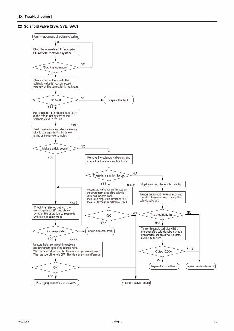
[ IX Troubleshooting ]
- 320 -HWE10050 GB
(2) Solenoid valve (SVA, SVB, SVC)
Stop the operation of the applied BC remote controller system.
Faulty judgment of solenoid valve
Faulty judgment of solenoid valve Solenoid valve failure
Replace the control board. Replace the solenoid valve coil.
Repair the fault.
Replace the control board.
Stop the operation
Note 1
Check whether the wire to the solenoid valve is not connected wrongly, or the connector is not loose.
No fault
Check the operation sound of the solenoid valve to be magnetized at the time of turning on the remote controller.
Makes a tick sound.
Check the relay output with the self-diagnosis LED, and check whether the operation corresponds with the operation mode.
Corresponds
Measure the temperature at the upstream and downstream pipes of the solenoid valve.When the solenoid valve is ON : There is no temperature difference.When the solenoid valve is OFF : There is a temperature difference.
OK
Remove the solenoid valve coil, and check that there is a suction force.
There is a suction force.
Note 2
Note 2
Note 2
Measure the temperature at the upstream and downstream pipes of the solenoid valve, and compare them.There is no temperature difference. : OKThere is a temperature difference. : NO
OK
Run the cooling or heating operation of the refrigerant system of the solenoid valve in trouble.
NO
NO
NO
Stop the unit with the remote controller.
Remove the solenoid valve connector, and check that the electricity runs through the solenoid valve coil.
The electricity runs.
Output 200V
NO
NO NO
NO
YES
YES
YES
YES
YES
YES
YES
YES
YES
Turn on the remote controller with the connector of the solenoid valve in troubledisconnected, and check that the control board outputs 200V.
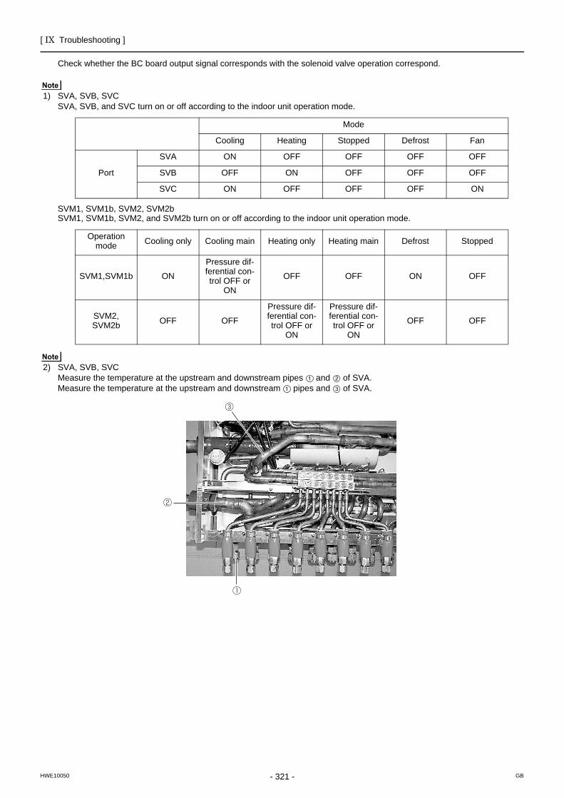
[ IX Troubleshooting ]
- 321 -HWE10050 GB
Check whether the BC board output signal corresponds with the solenoid valve operation correspond.
1) SVA, SVB, SVCSVA, SVB, and SVC turn on or off according to the indoor unit operation mode.
SVM1, SVM1b, SVM2, SVM2bSVM1, SVM1b, SVM2, and SVM2b turn on or off according to the indoor unit operation mode.
2) SVA, SVB, SVCMeasure the temperature at the upstream and downstream pipes and of SVA.Measure the temperature at the upstream and downstream pipes and of SVA.
Mode
Cooling Heating Stopped Defrost Fan
Port
SVA ON OFF OFF OFF OFF
SVB OFF ON OFF OFF OFF
SVC ON OFF OFF OFF ON
Operation mode Cooling only Cooling main Heating only Heating main Defrost Stopped
SVM1,SVM1b ON
Pressure dif-ferential con-trol OFF or
ON
OFF OFF ON OFF
SVM2, SVM2b OFF OFF
Pressure dif-ferential con-trol OFF or
ON
Pressure dif-ferential con-trol OFF or
ON
OFF OFF
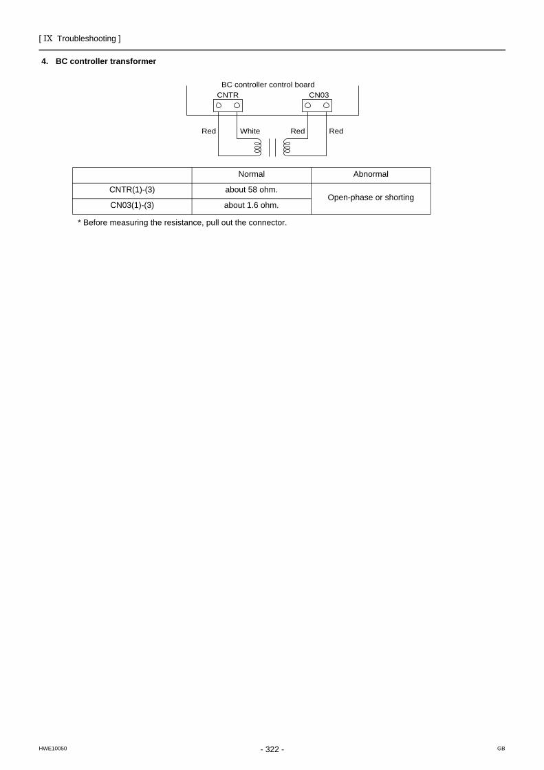
[ IX Troubleshooting ]
- 322 -HWE10050 GB
4. BC controller transformer
* Before measuring the resistance, pull out the connector.
Normal Abnormal
CNTR(1)-(3) about 58 ohm.Open-phase or shorting
CN03(1)-(3) about 1.6 ohm.
CNTR CN03BC controller control board
Red White Red Red
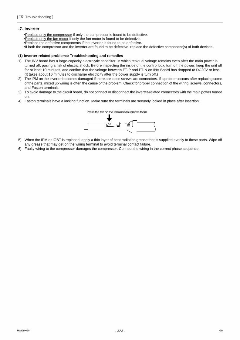
[ IX Troubleshooting ]
- 323 -HWE10050 GB
Inverter
-7- InverterReplace only the compressor if only the compressor is found to be defective. Replace only the fan motor if only the fan motor is found to be defective. Replace the defective components if the inverter is found to be defective.If both the compressor and the inverter are found to be defective, replace the defective component(s) of both devices.
(1) Inverter-related problems: Troubleshooting and remedies1) The INV board has a large-capacity electrolytic capacitor, in which residual voltage remains even after the main power is
turned off, posing a risk of electric shock. Before inspecting the inside of the control box, turn off the power, keep the unit off for at least 10 minutes, and confirm that the voltage between FT-P and FT-N on INV Board has dropped to DC20V or less.(It takes about 10 minutes to discharge electricity after the power supply is turn off.)
2) The IPM on the inverter becomes damaged if there are loose screws are connectors. If a problem occurs after replacing some of the parts, mixed up wiring is often the cause of the problem. Check for proper connection of the wiring, screws, connectors, and Faston terminals.
3) To avoid damage to the circuit board, do not connect or disconnect the inverter-related connectors with the main power turned on.
4) Faston terminals have a locking function. Make sure the terminals are securely locked in place after insertion.
5) When the IPM or IGBT is replaced, apply a thin layer of heat radiation grease that is supplied evenly to these parts. Wipe off any grease that may get on the wiring terminal to avoid terminal contact failure.
6) Faulty wiring to the compressor damages the compressor. Connect the wiring in the correct phase sequence.
Press the tab on the terminals to remove them.
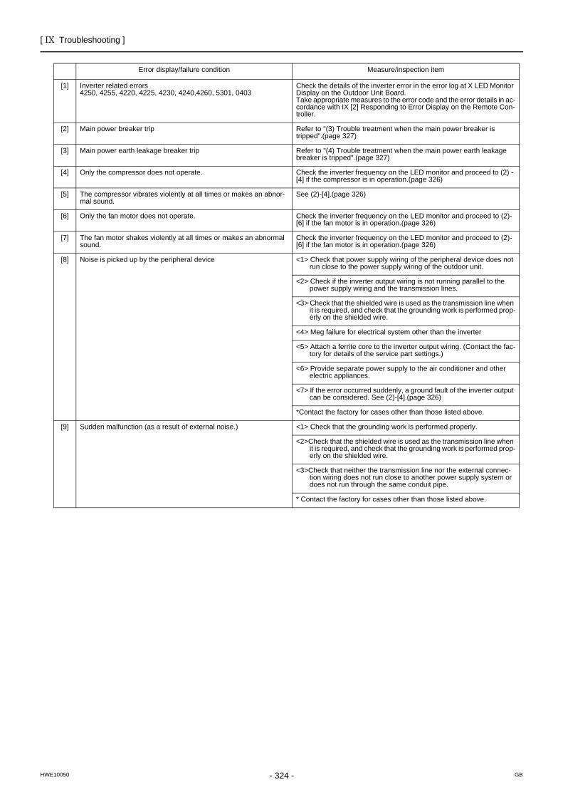
[ IX Troubleshooting ]
- 324 -HWE10050 GB
Error display/failure condition Measure/inspection item
[1] Inverter related errors4250, 4255, 4220, 4225, 4230, 4240,4260, 5301, 0403
Check the details of the inverter error in the error log at X LED Monitor Display on the Outdoor Unit Board.Take appropriate measures to the error code and the error details in ac-cordance with IX [2] Responding to Error Display on the Remote Con-troller.
[2] Main power breaker trip Refer to "(3) Trouble treatment when the main power breaker is tripped".(page 327)
[3] Main power earth leakage breaker trip Refer to "(4) Trouble treatment when the main power earth leakage breaker is tripped".(page 327)
[4] Only the compressor does not operate. Check the inverter frequency on the LED monitor and proceed to (2) - [4] if the compressor is in operation.(page 326)
[5] The compressor vibrates violently at all times or makes an abnor-mal sound.
See (2)-[4].(page 326)
[6] Only the fan motor does not operate. Check the inverter frequency on the LED monitor and proceed to (2)-[6] if the fan motor is in operation.(page 326)
[7] The fan motor shakes violently at all times or makes an abnormal sound.
Check the inverter frequency on the LED monitor and proceed to (2)-[6] if the fan motor is in operation.(page 326)
[8] Noise is picked up by the peripheral device <1> Check that power supply wiring of the peripheral device does not run close to the power supply wiring of the outdoor unit.
<2> Check if the inverter output wiring is not running parallel to the power supply wiring and the transmission lines.
<3> Check that the shielded wire is used as the transmission line when it is required, and check that the grounding work is performed prop-erly on the shielded wire.
<4> Meg failure for electrical system other than the inverter
<5> Attach a ferrite core to the inverter output wiring. (Contact the fac-tory for details of the service part settings.)
<6> Provide separate power supply to the air conditioner and other electric appliances.
<7> If the error occurred suddenly, a ground fault of the inverter output can be considered. See (2)-[4].(page 326)
*Contact the factory for cases other than those listed above.
[9] Sudden malfunction (as a result of external noise.) <1> Check that the grounding work is performed properly.
<2>Check that the shielded wire is used as the transmission line when it is required, and check that the grounding work is performed prop-erly on the shielded wire.
<3>Check that neither the transmission line nor the external connec-tion wiring does not run close to another power supply system or does not run through the same conduit pipe.
* Contact the factory for cases other than those listed above.
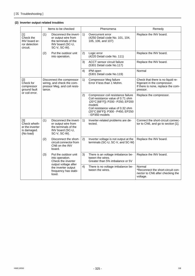
[ IX Troubleshooting ]
- 325 -HWE10050 GB
(2) Inverter output related troubles
Items to be checked Phenomena Remedy
[1]Check the INV board er-ror detection circuit.
(1) Disconnect the invert-er output wire from the terminals of the INV board (SC-U, SC-V, SC-W).
1) Overcurrent error (4250 Detail code No. 101, 104, 105, 106, and 107)
Replace the INV board.
(2) Put the outdoor unit into operation.
2) Logic error(4220 Detail code No. 111)
Replace the INV board.
3) ACCT sensor circuit failure (5301 Detail code No.117)
Replace the INV board.
4) IPM open (5301 Detail code No.119)
Normal
[2]Check for compressor ground fault or coil error.
Disconnect the compressor wiring, and check the com-pressor Meg, and coil resis-tance.
1) Compressor Meg failureError if less than 1 Mohm.
Check that there is no liquid re-frigerant in the compressor. If there is none, replace the com-pressor.
2) Compressor coil resistance failureCoil resistance value of 0.71 ohm (20°C [68°F]): P200 - P250, EP200 modelsCoil resistance value of 0.32 ohm(20°C [68°F]): P300 - P450, EP250 - EP350 models
Replace the compressor.
[3]Check wheth-er the inverter is damaged.(No load)
(1) Disconnect the invert-er output wire from the terminals of the INV board (SC-U, SC-V, SC-W).
1) Inverter-related problems are de-tected.
Connect the short-circuit connec-tor to CN6, and go to section [1].
(2) Disconnect the short-circuit connector from CN6 on the INV board.
2) Inverter voltage is not output at the terminals (SC-U, SC-V, and SC-W)
Replace the INV board.
(3) Put the outdoor unit into operation.Check the inverter output voltage after the inverter output frequency has stabi-lized.
3) There is an voltage imbalance be-tween the wires. Greater than 5% imbalance or 5V
Replace the INV board.
4) There is no voltage imbalance be-tween the wires.
Normal*Reconnect the short-circuit con-nector to CN6 after checking the voltage.
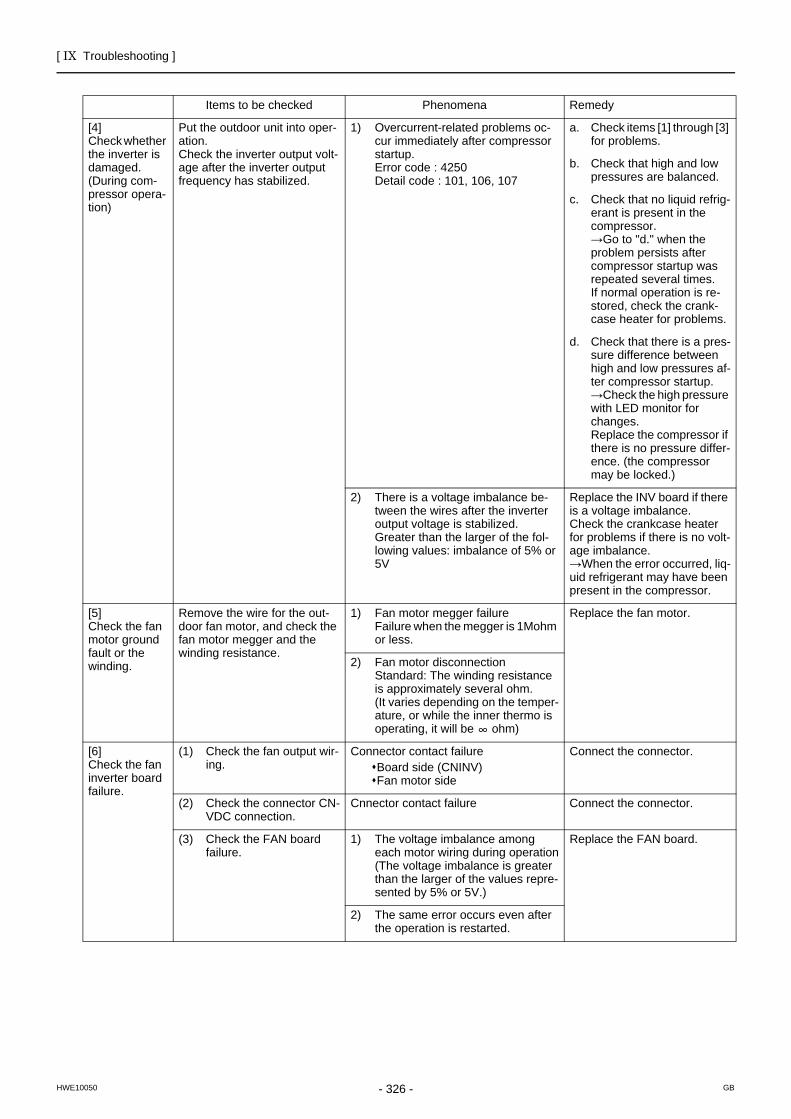
[ IX Troubleshooting ]
- 326 -HWE10050 GB
Items to be checked Phenomena Remedy
[4]Check whether the inverter is damaged.(During com-pressor opera-tion)
Put the outdoor unit into oper-ation.Check the inverter output volt-age after the inverter output frequency has stabilized.
1) Overcurrent-related problems oc-cur immediately after compressor startup.Error code : 4250Detail code : 101, 106, 107
a. Check items [1] through [3] for problems.
b. Check that high and low pressures are balanced.
c. Check that no liquid refrig-erant is present in the compressor.→Go to "d." when the problem persists after compressor startup was repeated several times.If normal operation is re-stored, check the crank-case heater for problems.
d. Check that there is a pres-sure difference between high and low pressures af-ter compressor startup.→Check the high pressure with LED monitor for changes.Replace the compressor if there is no pressure differ-ence. (the compressor may be locked.)
2) There is a voltage imbalance be-tween the wires after the inverter output voltage is stabilized. Greater than the larger of the fol-lowing values: imbalance of 5% or 5V
Replace the INV board if there is a voltage imbalance.Check the crankcase heater for problems if there is no volt-age imbalance.→When the error occurred, liq-uid refrigerant may have been present in the compressor.
[5]Check the fan motor ground fault or the winding.
Remove the wire for the out-door fan motor, and check the fan motor megger and the winding resistance.
1) Fan motor megger failure Failure when the megger is 1Mohm or less.
Replace the fan motor.
2) Fan motor disconnection Standard: The winding resistance is approximately several ohm.(It varies depending on the temper-ature, or while the inner thermo is operating, it will be ohm)
[6]Check the fan inverter board failure.
(1) Check the fan output wir-ing.
Connector contact failureBoard side (CNINV)Fan motor side
Connect the connector.
(2) Check the connector CN-VDC connection.
Cnnector contact failure Connect the connector.
(3) Check the FAN board failure.
1) The voltage imbalance among each motor wiring during operation(The voltage imbalance is greater than the larger of the values repre-sented by 5% or 5V.)
Replace the FAN board.
2) The same error occurs even after the operation is restarted.
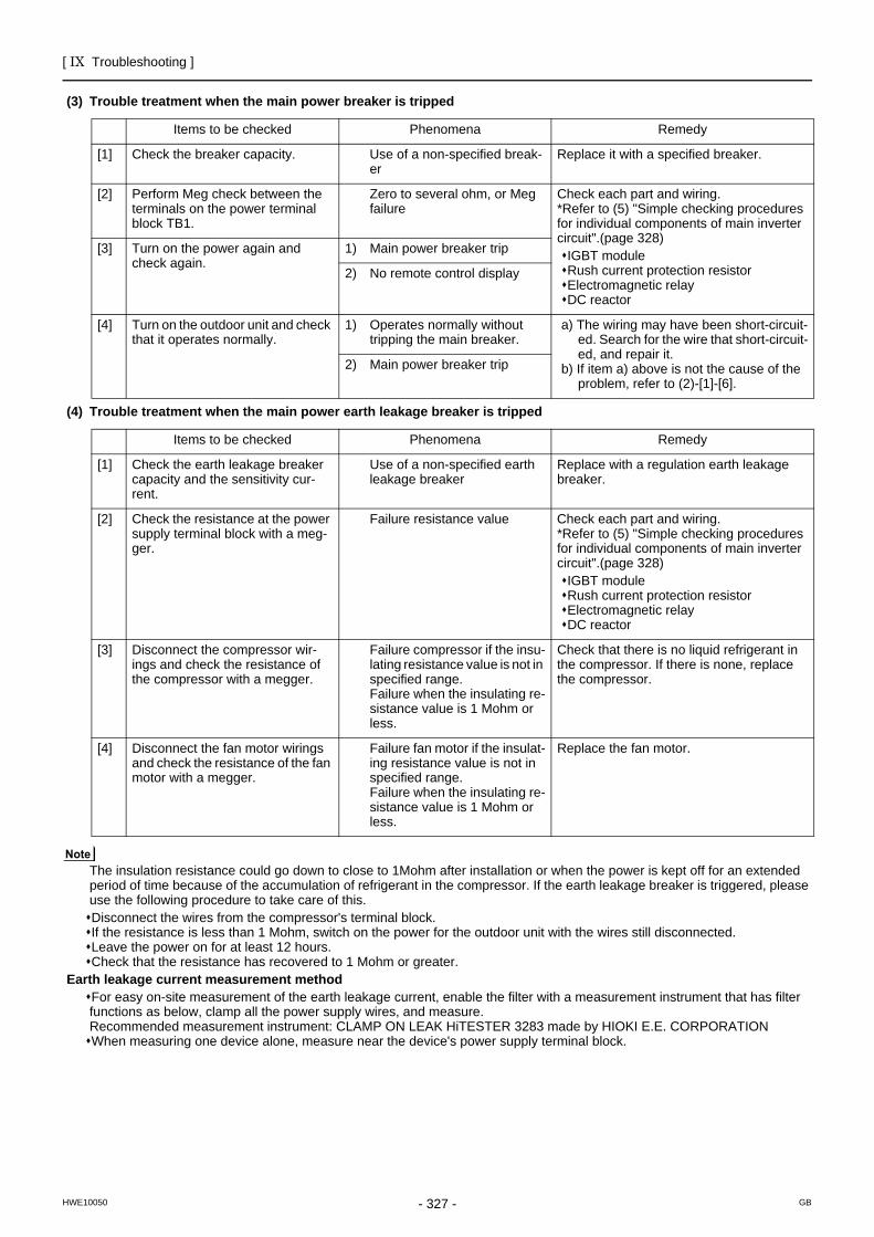
[ IX Troubleshooting ]
- 327 -HWE10050 GB
(3) Trouble treatment when the main power breaker is tripped
(4) Trouble treatment when the main power earth leakage breaker is tripped
The insulation resistance could go down to close to 1Mohm after installation or when the power is kept off for an extended period of time because of the accumulation of refrigerant in the compressor. If the earth leakage breaker is triggered, please use the following procedure to take care of this.Disconnect the wires from the compressor's terminal block.If the resistance is less than 1 Mohm, switch on the power for the outdoor unit with the wires still disconnected.Leave the power on for at least 12 hours.Check that the resistance has recovered to 1 Mohm or greater.
Earth leakage current measurement methodFor easy on-site measurement of the earth leakage current, enable the filter with a measurement instrument that has filter functions as below, clamp all the power supply wires, and measure.Recommended measurement instrument: CLAMP ON LEAK HiTESTER 3283 made by HIOKI E.E. CORPORATIONWhen measuring one device alone, measure near the device's power supply terminal block.
Items to be checked Phenomena Remedy
[1] Check the breaker capacity. Use of a non-specified break-er
Replace it with a specified breaker.
[2] Perform Meg check between the terminals on the power terminal block TB1.
Zero to several ohm, or Meg failure
Check each part and wiring.*Refer to (5) "Simple checking procedures for individual components of main inverter circuit".(page 328)
IGBT moduleRush current protection resistorElectromagnetic relayDC reactor
[3] Turn on the power again and check again.
1) Main power breaker trip
2) No remote control display
[4] Turn on the outdoor unit and check that it operates normally.
1) Operates normally without tripping the main breaker.
a) The wiring may have been short-circuit-ed. Search for the wire that short-circuit-ed, and repair it.
b) If item a) above is not the cause of the problem, refer to (2)-[1]-[6].
2) Main power breaker trip
Items to be checked Phenomena Remedy
[1] Check the earth leakage breaker capacity and the sensitivity cur-rent.
Use of a non-specified earth leakage breaker
Replace with a regulation earth leakage breaker.
[2] Check the resistance at the power supply terminal block with a meg-ger.
Failure resistance value Check each part and wiring.*Refer to (5) "Simple checking procedures for individual components of main inverter circuit".(page 328)
IGBT moduleRush current protection resistorElectromagnetic relayDC reactor
[3] Disconnect the compressor wir-ings and check the resistance of the compressor with a megger.
Failure compressor if the insu-lating resistance value is not in specified range.Failure when the insulating re-sistance value is 1 Mohm or less.
Check that there is no liquid refrigerant in the compressor. If there is none, replace the compressor.
[4] Disconnect the fan motor wirings and check the resistance of the fan motor with a megger.
Failure fan motor if the insulat-ing resistance value is not in specified range.Failure when the insulating re-sistance value is 1 Mohm or less.
Replace the fan motor.
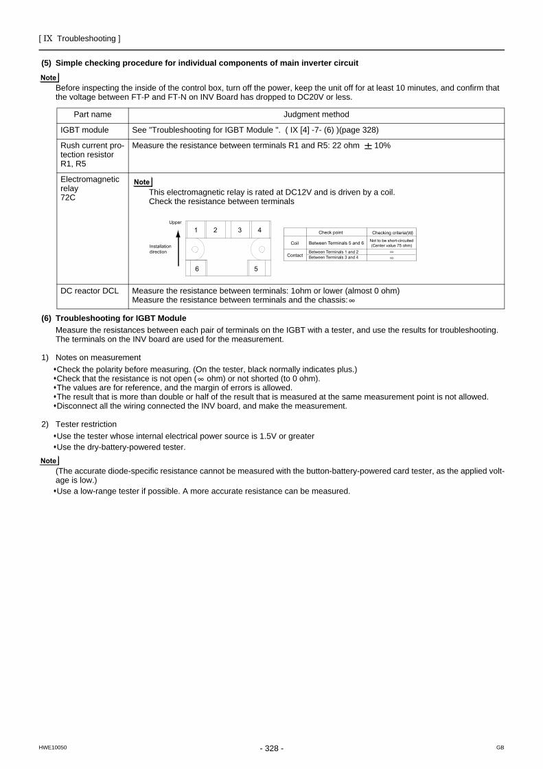
[ IX Troubleshooting ]
- 328 -HWE10050 GB
(5) Simple checking procedure for individual components of main inverter circuit
Before inspecting the inside of the control box, turn off the power, keep the unit off for at least 10 minutes, and confirm that the voltage between FT-P and FT-N on INV Board has dropped to DC20V or less.
(6) Troubleshooting for IGBT Module Measure the resistances between each pair of terminals on the IGBT with a tester, and use the results for troubleshooting.The terminals on the INV board are used for the measurement.
1) Notes on measurementCheck the polarity before measuring. (On the tester, black normally indicates plus.)Check that the resistance is not open ( ohm) or not shorted (to 0 ohm).The values are for reference, and the margin of errors is allowed.The result that is more than double or half of the result that is measured at the same measurement point is not allowed.Disconnect all the wiring connected the INV board, and make the measurement.
2) Tester restrictionUse the tester whose internal electrical power source is 1.5V or greaterUse the dry-battery-powered tester.
(The accurate diode-specific resistance cannot be measured with the button-battery-powered card tester, as the applied volt-age is low.)Use a low-range tester if possible. A more accurate resistance can be measured.
Part name Judgment method
IGBT module See "Troubleshooting for IGBT Module ". ( IX [4] -7- (6) )(page 328)
Rush current pro-tection resistorR1, R5
Measure the resistance between terminals R1 and R5: 22 ohm 10%
Electromagnetic relay72C This electromagnetic relay is rated at DC12V and is driven by a coil.
Check the resistance between terminals
DC reactor DCL Measure the resistance between terminals: 1ohm or lower (almost 0 ohm)Measure the resistance between terminals and the chassis:
1
6 5
2 3 4Upper
Installation direction
Check point Checking criteria( )W
Between Terminals 5 and 6
Between Terminals 1 and 2Between Terminals 3 and 4
Not to be short-circuited(Center value 75 ohm)Coil
Contact
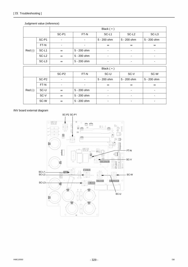
[ IX Troubleshooting ]
- 329 -HWE10050 GB
INV board external diagram
Judgment value (reference)
Black ( + )
SC-P1 FT-N SC-L1 SC-L2 SC-L3
Red (-)
SC-P1 - - 5 - 200 ohm 5 - 200 ohm 5 - 200 ohm
FT-N - -
SC-L1 5 - 200 ohm - - -
SC-L2 5 - 200 ohm - - -
SC-L3 5 - 200 ohm - - -
Black ( + )
SC-P2 FT-N SC-U SC-V SC-W
Red (-)
SC-P2 - - 5 - 200 ohm 5 - 200 ohm 5 - 200 ohm
FT-N - -
SC-U 5 - 200 ohm - - -
SC-V 5 - 200 ohm - - -
SC-W 5 - 200 ohm - - -
SC-U
SC-W
SC-V
FT-N
SC-P1SC-P2
SC-L1SC-L2
SC-L3
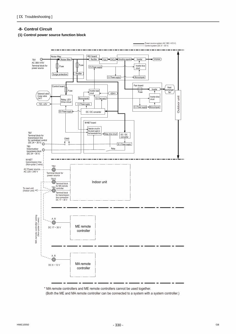
[ IX Troubleshooting ]
- 330 -HWE10050 GB
Control Circuit
-8- Control Circuit(1) Control power source function block
Out
door
uni
t
Power source system (AC 380 / 415 V)Control system (DC 5 ~ 30 V)
* MA remote controllers and ME remote controllers cannot be used together.(Both the ME and MA remote controller can be connected to a system with a system controller.)
A, B
A, B
M-NET transmission line (Non-polar 2 wire)
AC 220 / 240 VAC Power source
To next unit (Indoor unit)
MA
rem
ote
cont
rolle
r w
iring
(N
on-p
olar
2 w
ire)
DC 17 ~ 30 V
DC 9 ~ 12 V
ME remote controller
MA remote controller
Indoor unit
TB2
TB15
Terminal block for power source
TB5 Terminal block for MA remote controller
Terminal block for transmission line connection DC 17 ~ 30 V
AC 380/ 415VTerminal block for power source
TB1
Noise filterNoise filter
FuseFuse
Fuse
72C, LEV
Fuse
Surge protection
INV board
Control board Fan board
63H1
72C DCL
DC / DC converter
Detection circuit for the power supply to the transmission line
M-NET board
DC / DC converter
Microcomputer
Microcomputer
Microcomputer 5 V Power supply
18 V Power supply
12V Power supply
30 V Power supply
Relay drive circuit
Relay
5 V Power supply
5 V Power supply
17V Power supply
Smoothing capacitor Inverter
Inverter
Inverter drive circuit
Inverter drive circuit
Inverter reset circuit
Rectifier Compressor
Heat exchanger
fan
Relay, LEV Drive circuit
Solenoid valve4-way valveCH11
CN40 Terminal block for transmission line for centralized control (DC 24 ~ 30 V)
TB7
Indoor/outdoor transmission block (DC 24 ~ 30 V)
TB3
Rectifier
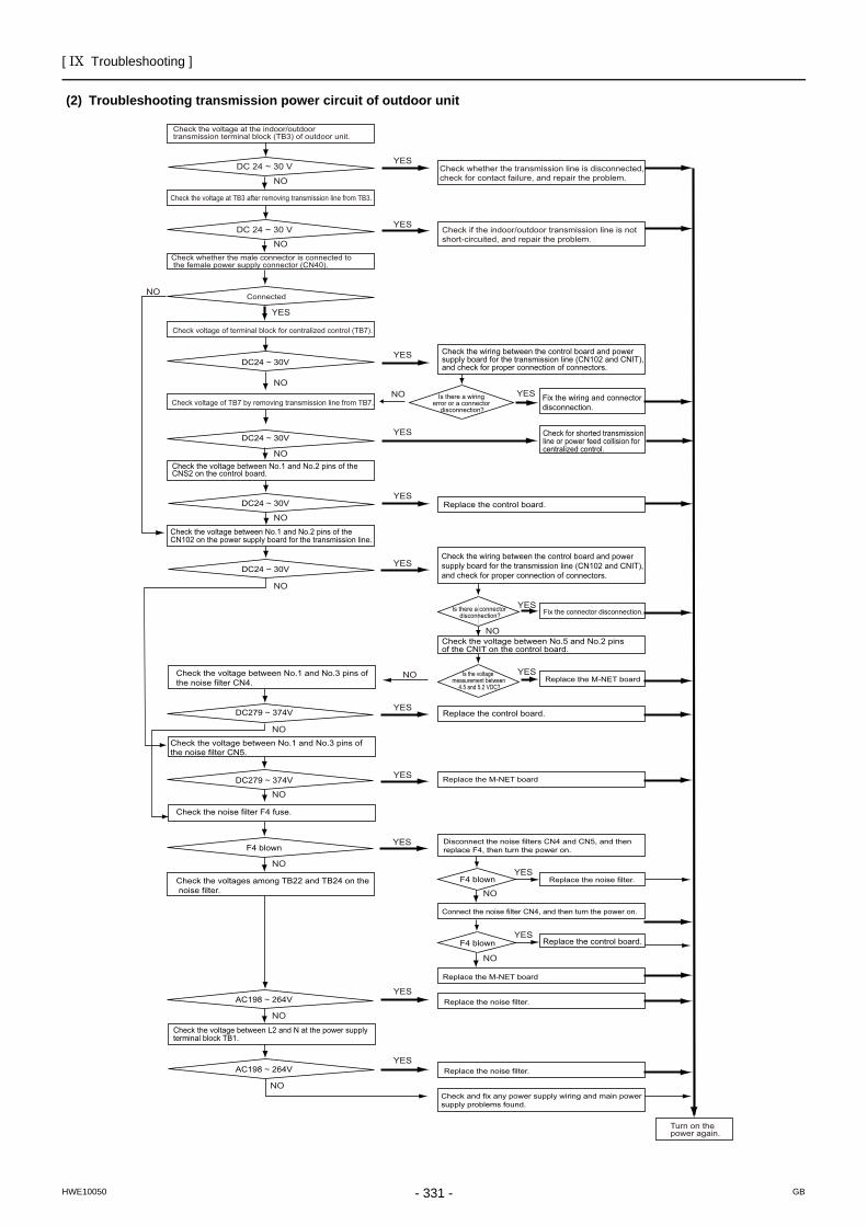
[ IX Troubleshooting ]
- 331 -HWE10050 GB
(2) Troubleshooting transmission power circuit of outdoor unit
Check the voltage between No.1 and No.2 pins of the CNS2 on the control board.
Check the wiring between the control board and power supply board for the transmission line (CN102 and CNIT), and check for proper connection of connectors.
Check the wiring between the control board and power supply board for the transmission line (CN102 and CNIT), and check for proper connection of connectors.
Is there a wiring error or a connector
disconnection?
Check the voltage between No.5 and No.2 pins of the CNIT on the control board.
Is the voltage measurement between
4.5 and 5.2 VDC?
Is there a connector disconnection? Fix the connector disconnection.
Replace the M-NET board
Replace the control board.
Replace the M-NET board
Replace the M-NET board
Replace the noise filter.
Connect the noise filter CN4, and then turn the power on.
Replace the noise filter.
Replace the noise filter.
Check and fix any power supply wiring and main power supply problems found.
Disconnect the noise filters CN4 and CN5, and then replace F4, then turn the power on.
Fix the wiring and connector disconnection.
Check for shorted transmission line or power feed collision for centralized control.
Replace the control board.
Check the voltage between No.1 and No.2 pins of the CN102 on the power supply board for the transmission line.
Check the voltage between No.1 and No.3 pins of the noise filter CN4.
Check the voltage between No.1 and No.3 pins of the noise filter CN5.
Check the noise filter F4 fuse.
Check the voltages among TB22 and TB24 on the noise filter.
Check the voltage between L2 and N at the power supply terminal block TB1.
DC24 ~ 30V
DC24 ~ 30V
DC24 ~ 30V
DC279 ~ 374V
DC279 ~ 374V
F4 blown
F4 blown
F4 blown
AC198 ~ 264V
AC198 ~ 264V
DC24 ~ 30V
Turn on the power again.
YES
YES
YES
YES
YES
YES
YES
YES
YES
YES
YES
YES
YES
YES
YES
YES
NONO
NO
NO
NO
NO
NO
NO
NO
NO
NO
NO
NO
NO
NO
NO
YES
NO
Check the voltage at the indoor/outdoor transmission terminal block (TB3) of outdoor unit.
DC 24 ~ 30 V
DC 24 ~ 30 V
Check the voltage at TB3 after removing transmission line from TB3.
Check whether the male connector is connected to the female power supply connector (CN40).
Connected
Check voltage of terminal block for centralized control (TB7).
Check voltage of TB7 by removing transmission line from TB7.
Check if the indoor/outdoor transmission line is notshort-circuited, and repair the problem.
Check whether the transmission line is disconnected, check for contact failure, and repair the problem.
Replace the control board.
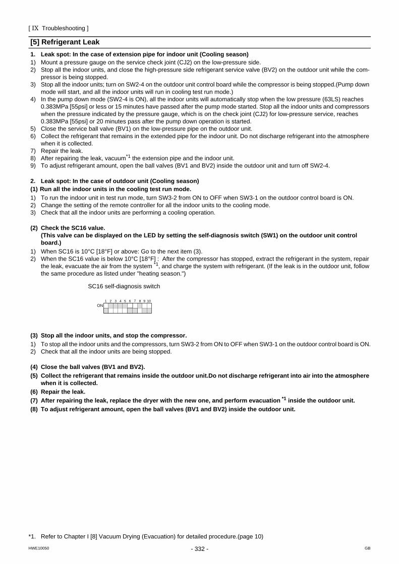
[ IX Troubleshooting ]
- 332 -HWE10050 GB
[5] Refrigerant Leak1. Leak spot: In the case of extension pipe for indoor unit (Cooling season)1) Mount a pressure gauge on the service check joint (CJ2) on the low-pressure side.2) Stop all the indoor units, and close the high-pressure side refrigerant service valve (BV2) on the outdoor unit while the com-
pressor is being stopped.3) Stop all the indoor units; turn on SW2-4 on the outdoor unit control board while the compressor is being stopped.(Pump down
mode will start, and all the indoor units will run in cooling test run mode.)4) In the pump down mode (SW2-4 is ON), all the indoor units will automatically stop when the low pressure (63LS) reaches
0.383MPa [55psi] or less or 15 minutes have passed after the pump mode started. Stop all the indoor units and compressors when the pressure indicated by the pressure gauge, which is on the check joint (CJ2) for low-pressure service, reaches 0.383MPa [55psi] or 20 minutes pass after the pump down operation is started.
5) Close the service ball valve (BV1) on the low-pressure pipe on the outdoor unit. 6) Collect the refrigerant that remains in the extended pipe for the indoor unit. Do not discharge refrigerant into the atmosphere
when it is collected.7) Repair the leak.8) After repairing the leak, vacuum*1 the extension pipe and the indoor unit.9) To adjust refrigerant amount, open the ball valves (BV1 and BV2) inside the outdoor unit and turn off SW2-4.
2. Leak spot: In the case of outdoor unit (Cooling season)(1) Run all the indoor units in the cooling test run mode.1) To run the indoor unit in test run mode, turn SW3-2 from ON to OFF when SW3-1 on the outdoor control board is ON.2) Change the setting of the remote controller for all the indoor units to the cooling mode.3) Check that all the indoor units are performing a cooling operation.
(2) Check the SC16 value.(This valve can be displayed on the LED by setting the self-diagnosis switch (SW1) on the outdoor unit control board.)
1) When SC16 is 10°C [18°F] or above: Go to the next item (3).2) When the SC16 value is below 10°C [18°F] : After the compressor has stopped, extract the refrigerant in the system, repair
the leak, evacuate the air from the system *1, and charge the system with refrigerant. (If the leak is in the outdoor unit, follow the same procedure as listed under "heating season.")
(3) Stop all the indoor units, and stop the compressor.1) To stop all the indoor units and the compressors, turn SW3-2 from ON to OFF when SW3-1 on the outdoor control board is ON.2) Check that all the indoor units are being stopped.
(4) Close the ball valves (BV1 and BV2).(5) Collect the refrigerant that remains inside the outdoor unit.Do not discharge refrigerant into air into the atmosphere
when it is collected.(6) Repair the leak.(7) After repairing the leak, replace the dryer with the new one, and perform evacuation *1 inside the outdoor unit.(8) To adjust refrigerant amount, open the ball valves (BV1 and BV2) inside the outdoor unit.
*1. Refer to Chapter I [8] Vacuum Drying (Evacuation) for detailed procedure.(page 10)
SC16 self-diagnosis switch
1 2 3 4 5 6 7 8 10 9ON
[ IX Troubleshooting ]
- 333 -HWE10050 GB
3. Leak spot: In the case of extension pipe for indoor unit (Heating season)(1) Run all the indoor units in heating test run mode.1) To run the indoor unit in test run mode, turn SW3-2 from ON to OFF when SW3-1 on the outdoor control board is ON.2) Change the setting of the remote controller for all the indoor units to the heating mode.3) Check that all the indoor units are performing a heating operation.
(2) Stop all the indoor units, and stop the compressor.1) To stop all the indoor units and the compressors, turn SW3-2 from ON to OFF when SW3-1 on the outdoor control board is ON.2) Check that all the indoor units are stopped.
(3) Close the ball valves (BV1 and BV2).(4) Collect the refrigerant that remains inside the indoor unit. Do not discharge refrigerant into air into the atmosphere
when it is collected.(5) Repair the leak.(6) After repairing the leak, perform evacuation of the extension pipe*1 for the indoor unit, and open the ball valves (BV1
and BV2) to adjust refrigerant.
4. Leak spot: In the case of outdoor unit (Heating season)1) Collect the refrigerant in the entire system (outdoor unit, extended pipe and indoor unit).Do not discharge refrigerant into the
atmosphere when it is collected.2) Repair the leak.3) Repair the leak, and evacuate the air from the entire system *1 . Then, calculate the proper amount of refrigerant to be added
(outdoor unit + extension pipe + indoor unit), and charge the system with that amount. Refer to Chapter VIII [4] 3. for the proper amount of refrigerant charge.(page 160)
*1. Refer to Chapter I [8] Vacuum Drying (Evacuation) for detailed procedure.(page 10)
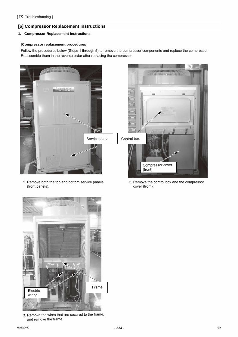
[ IX Troubleshooting ]
- 334 -HWE10050 GB
[6] Compressor Replacement Instructions1. Compressor Replacement Instructions
Follow the procedures below (Steps 1 through 5) to remove the compressor components and replace the compressor. Reassemble them in the reverse order after replacing the compressor.
[Compressor replacement procedures]
1. Remove both the top and bottom service panels (front panels).
3. Remove the wires that are secured to the frame, and remove the frame.
Electric wiring
Frame
Service panel Control box
Compressor cover (front)
2. Remove the control box and the compressor cover (front).
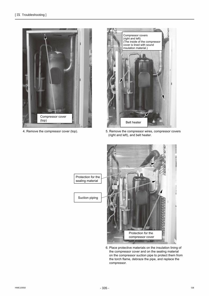
[ IX Troubleshooting ]
- 335 -HWE10050 GB
Compressor cover (top)
4. Remove the compressor cover (top). 5. Remove the compressor wires, compressor covers (right and left), and belt heater.
Protection for the sealing material
Suction piping
Protection for the compressor cover
6. Place protective materials on the insulation lining of the compressor cover and on the sealing material on the compressor suction pipe to protect them from the torch flame, debraze the pipe, and replace the compressor.
Belt heater
Compressor covers (right and left)(The inside of the compressor cover is lined with sound insulation material.)
[ IX Troubleshooting ]
- 336 -HWE10050 GB
NO. Parts to be serviced
1 Solenoid valve block ASSY (SV4a, SV4b, SV4d)
2 Check valve (CV4a)
3 Check valve (CV6a, CV8a, CV9a, CV10a)
1. Solenoid valve block ASSY (SV4a, SV4b, SV4d), Check valve (CV4a, CV6a, CV8a, CV9a, CV10a) replacement instruc-tions
* Following instructions show procedures for replacing service parts for Solenoid valve block ASSY (SV4a, SV4b, SV4d), Check valve (CV4a, CV6a, CV8a, CV9a, CV10a). Replace them properly according to the procedures.
1. Applicable models • PURY-P200, 250, 300YJM-A (-BS) • PURY-EP200YJM-A (-BS)
2. Parts to be serviced, Set-contentFollowing instructions are applicable to 1-3 service parts on the table below.
Things required for replacingItem
Solenoid valve block service parts set [Set-content] • Replacement instructions • Solenoid valve block ASSY • Connecting pipe (ø9.52 [3/8"])
Service parts replacement instructions set [Set-content] • Replacement instructions • Connecting pipe (ø9.52 [3/8"])
Numbers1
111
1
11
3. Procedures
* Precautions for starting replacement • Check that the main power supply is OFF. • Check that no refrigerant is in the outdoor unit.
Remove each part according to the 1)-3) procedures on the next page before replacing service parts.Mount the removed parts back in place in a reversed procedures of 1)-3) on the next page after replacing service parts.
(1) Solenoid valve block ASSY (SV4a, SV4b, SV4d) replacement procedures To remove Solenoid valve block ASSY
Remove the solenoid valve block coil cover, solenoid valve coil, and peripheral cables. Remove the screw (M5) that fixes the solenoid valve block and the supporting plate for solenoid valve block. Cut the pipe at the position indicated on the next page with a pipe cutter. Remove the pipe from the brazed A part. Debraze B-G parts (total 6 places). Do not damage heat exchanger fins and peripheral piping devices when removing the Solenoid valve block ASSY.
To install Solenoid valve block ASSY Mount the Solenoid valve block ASSY replacement to the unit with care not to damage heat exchanger fins and
peripheral piping devices. Fix the Solenoid valve block ASSY and the supporting plate with the fixing screw (M5). Braze B-G part (total 6 places), and connect the solenoid valve block and the heat exchanger header with the connect-
ing pipe (ø9.52 [3/8"]) that comes with the service parts set. Mount the solenoid valve block coil cover, solenoid valve coil, and peripheral cables back in place.
*Precautions for replacing Solenoid valve block ASSYBe sure to perform no-oxidation brazing when brazing.After brazing, check the condition around the brazing. After confirming no leakage, evacuate the air inside.*1Perform brazing with care of the flame direction so that it does not burn cables and plates etc. in the unit.Remove the brazing part protecting heat exchanger fins from burning, and replace the service parts.
*1. Refer to Chapter I [8] Vacuum Drying (Evacuation) for detailed procedure.(page 10)
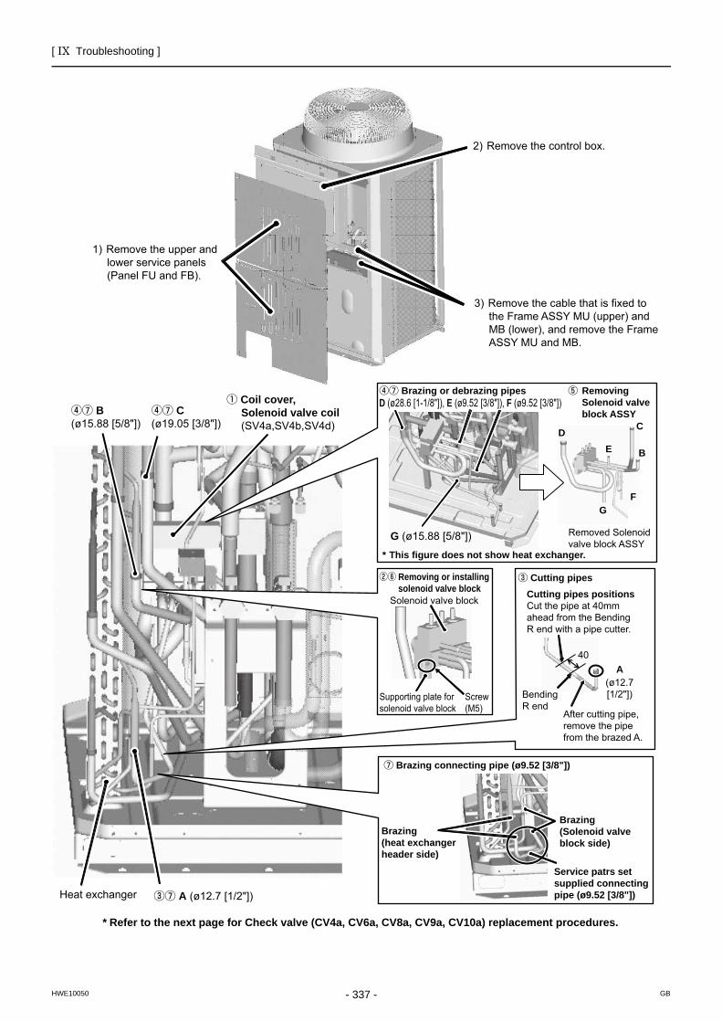
[ IX Troubleshooting ]
- 337 -HWE10050 GB
Heat exchanger ③⑦ A (ø12.7 [1/2"])
④⑦ B(ø15.88 [5/8"])
④⑦ C(ø19.05 [3/8"])
① Coil cover, Solenoid valve coil (SV4a,SV4b,SV4d)
1) Remove the upper and lower service panels (Panel FU and FB).
2) Remove the control box.
3) Remove the cable that is fixed to the Frame ASSY MU (upper) and MB (lower), and remove the Frame ASSY MU and MB.
* Refer to the next page for Check valve (CV4a, CV6a, CV8a, CV9a, CV10a) replacement procedures.
②⑥ Removing or installing solenoid valve block
Solenoid valve block
Supporting plate for solenoid valve block
Screw (M5)
⑦ Brazing connecting pipe (ø9.52 [3/8"])
Brazing(heat exchanger header side)
Brazing(Solenoid valve block side)
Service patrs setsupplied connecting pipe (ø9.52 [3/8"])
④⑦ Brazing or debrazing pipesD (ø28.6 [1-1/8"]), E (ø9.52 [3/8"]), F (ø9.52 [3/8"])
G (ø15.88 [5/8"])
* This figure does not show heat exchanger.
D C
BE
FG
Removed Solenoid valve block ASSY
⑤ Removing Solenoid valve block ASSY
③ Cutting pipesCutting pipes positionsCut the pipe at 40mm ahead from the Bending R end with a pipe cutter.
40A
(ø12.7 [1/2"])Bending
R endAfter cutting pipe, remove the pipe from the brazed A.
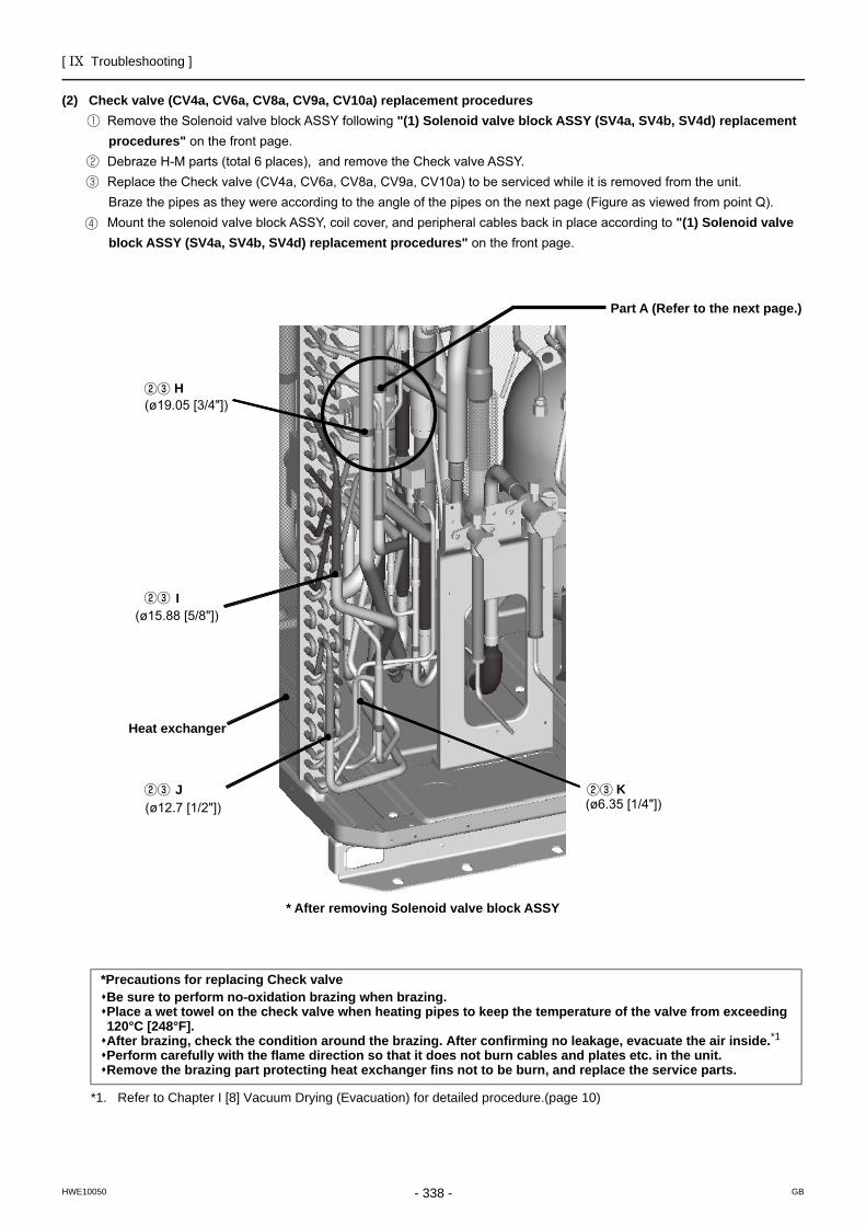
[ IX Troubleshooting ]
- 338 -HWE10050 GB
(2) Check valve (CV4a, CV6a, CV8a, CV9a, CV10a) replacement procedures Remove the Solenoid valve block ASSY following "(1) Solenoid valve block ASSY (SV4a, SV4b, SV4d) replacement
procedures" on the front page. Debraze H-M parts (total 6 places), and remove the Check valve ASSY. Replace the Check valve (CV4a, CV6a, CV8a, CV9a, CV10a) to be serviced while it is removed from the unit.
Braze the pipes as they were according to the angle of the pipes on the next page (Figure as viewed from point Q). Mount the solenoid valve block ASSY, coil cover, and peripheral cables back in place according to "(1) Solenoid valve
block ASSY (SV4a, SV4b, SV4d) replacement procedures" on the front page.
(ø19.05 [3/4"])
I
Heat exchanger
(ø12.7 [1/2"]) K
H
(ø15.88 [5/8"])
J(ø6.35 [1/4"])
* After removing Solenoid valve block ASSY
Part A (Refer to the next page.)
*Precautions for replacing Check valveBe sure to perform no-oxidation brazing when brazing.Place a wet towel on the check valve when heating pipes to keep the temperature of the valve from exceeding 120°C [248°F].After brazing, check the condition around the brazing. After confirming no leakage, evacuate the air inside.*1Perform carefully with the flame direction so that it does not burn cables and plates etc. in the unit.Remove the brazing part protecting heat exchanger fins not to be burn, and replace the service parts.
*1. Refer to Chapter I [8] Vacuum Drying (Evacuation) for detailed procedure.(page 10)
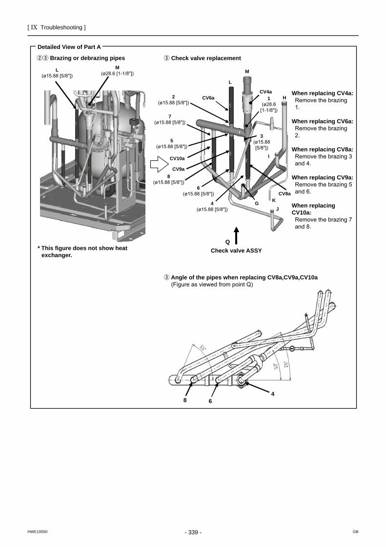
[ IX Troubleshooting ]
- 339 -HWE10050 GB
Detailed View of Part A
②③ Brazing or debrazing pipes
L(ø15.88 [5/8"])
M(ø28.6 [1-1/8"])
③ Check valve replacement
* This figure does not show heat exchanger.
M
L
CV6aCV4a
2(ø15.88 [5/8"])
7(ø15.88 [5/8"])
5(ø15.88 [5/8"])
CV10a
CV9a8
(ø15.88 [5/8"])6
(ø15.88 [5/8"])
4(ø15.88 [5/8"])
QCheck valve ASSY
H1(ø28.6
[1-1/8"])
3(ø15.88 [5/8"])
I
CV8aKG
J
③ Angle of the pipes when replacing CV8a,CV9a,CV10a (Figure as viewed from point Q)
When replacing CV4a:Remove the brazing 1.
When replacing CV6a:Remove the brazing 2.
When replacing CV8a:Remove the brazing 3 and 4.
When replacing CV9a:Remove the brazing 5 and 6.
When replacing CV10a:
Remove the brazing 7 and 8.
8 64
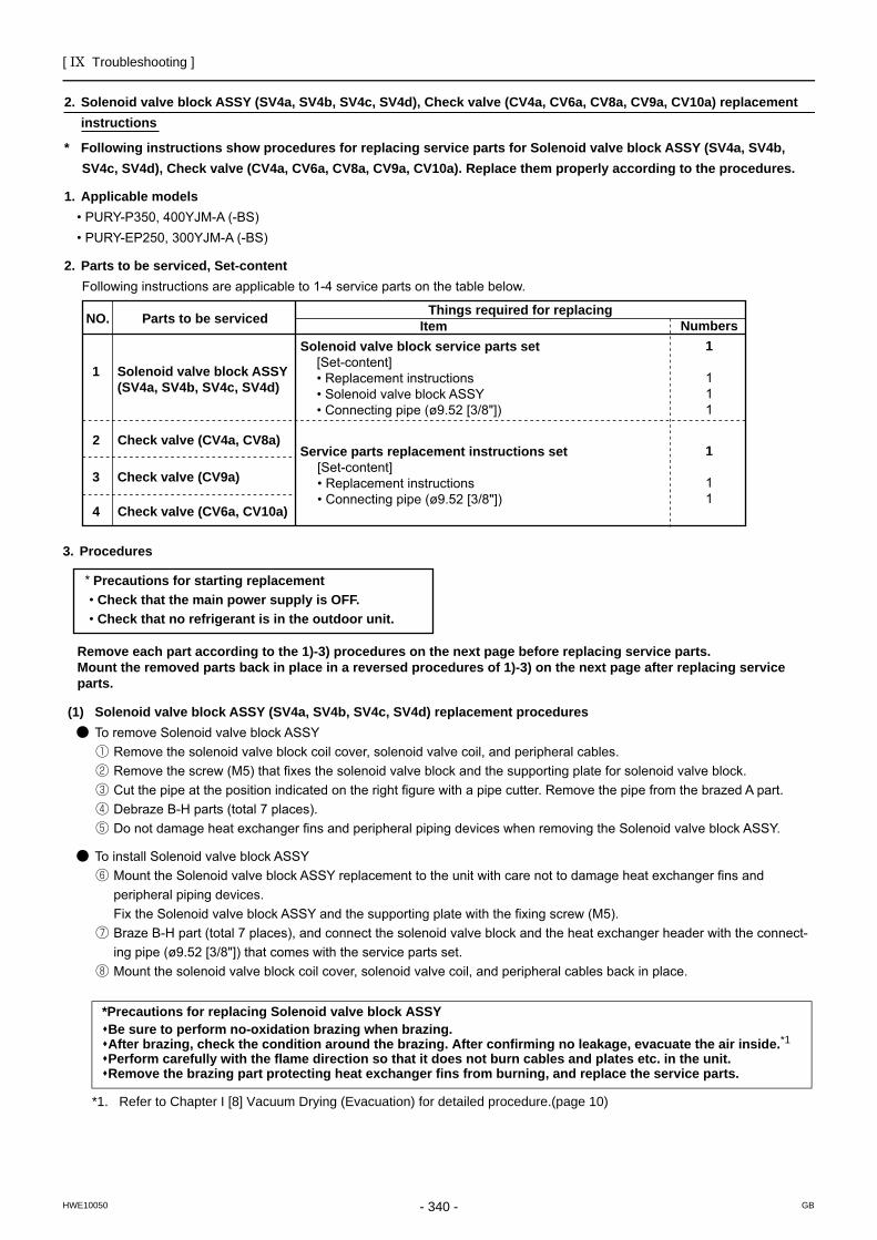
[ IX Troubleshooting ]
- 340 -HWE10050 GB
2. Solenoid valve block ASSY (SV4a, SV4b, SV4c, SV4d), Check valve (CV4a, CV6a, CV8a, CV9a, CV10a) replacement instructions
* Following instructions show procedures for replacing service parts for Solenoid valve block ASSY (SV4a, SV4b, SV4c, SV4d), Check valve (CV4a, CV6a, CV8a, CV9a, CV10a). Replace them properly according to the procedures.
1. Applicable models • PURY-P350, 400YJM-A (-BS) • PURY-EP250, 300YJM-A (-BS)
2. Parts to be serviced, Set-contentFollowing instructions are applicable to 1-4 service parts on the table below.
NO. Parts to be serviced
1 Solenoid valve block ASSY (SV4a, SV4b, SV4c, SV4d)
2 Check valve (CV4a, CV8a)
4 Check valve (CV6a, CV10a)
3 Check valve (CV9a)
Things required for replacingItem
Solenoid valve block service parts set [Set-content] • Replacement instructions • Solenoid valve block ASSY • Connecting pipe (ø9.52 [3/8"])
Numbers1
111
Service parts replacement instructions set [Set-content] • Replacement instructions • Connecting pipe (ø9.52 [3/8"])
1
11
3. Procedures
* Precautions for starting replacement • Check that the main power supply is OFF. • Check that no refrigerant is in the outdoor unit.
Remove each part according to the 1)-3) procedures on the next page before replacing service parts.Mount the removed parts back in place in a reversed procedures of 1)-3) on the next page after replacing service parts.
(1) Solenoid valve block ASSY (SV4a, SV4b, SV4c, SV4d) replacement procedures ● To remove Solenoid valve block ASSY
① Remove the solenoid valve block coil cover, solenoid valve coil, and peripheral cables.② Remove the screw (M5) that fixes the solenoid valve block and the supporting plate for solenoid valve block.③ Cut the pipe at the position indicated on the right figure with a pipe cutter. Remove the pipe from the brazed A part.④ Debraze B-H parts (total 7 places). ⑤ Do not damage heat exchanger fins and peripheral piping devices when removing the Solenoid valve block ASSY.
● To install Solenoid valve block ASSY⑥ Mount the Solenoid valve block ASSY replacement to the unit with care not to damage heat exchanger fins and
peripheral piping devices. Fix the Solenoid valve block ASSY and the supporting plate with the fixing screw (M5).
⑦ Braze B-H part (total 7 places), and connect the solenoid valve block and the heat exchanger header with the connect-ing pipe (ø9.52 [3/8"]) that comes with the service parts set.
⑧ Mount the solenoid valve block coil cover, solenoid valve coil, and peripheral cables back in place.
*Precautions for replacing Solenoid valve block ASSYBe sure to perform no-oxidation brazing when brazing.After brazing, check the condition around the brazing. After confirming no leakage, evacuate the air inside.*1Perform carefully with the flame direction so that it does not burn cables and plates etc. in the unit.Remove the brazing part protecting heat exchanger fins from burning, and replace the service parts.
*1. Refer to Chapter I [8] Vacuum Drying (Evacuation) for detailed procedure.(page 10)
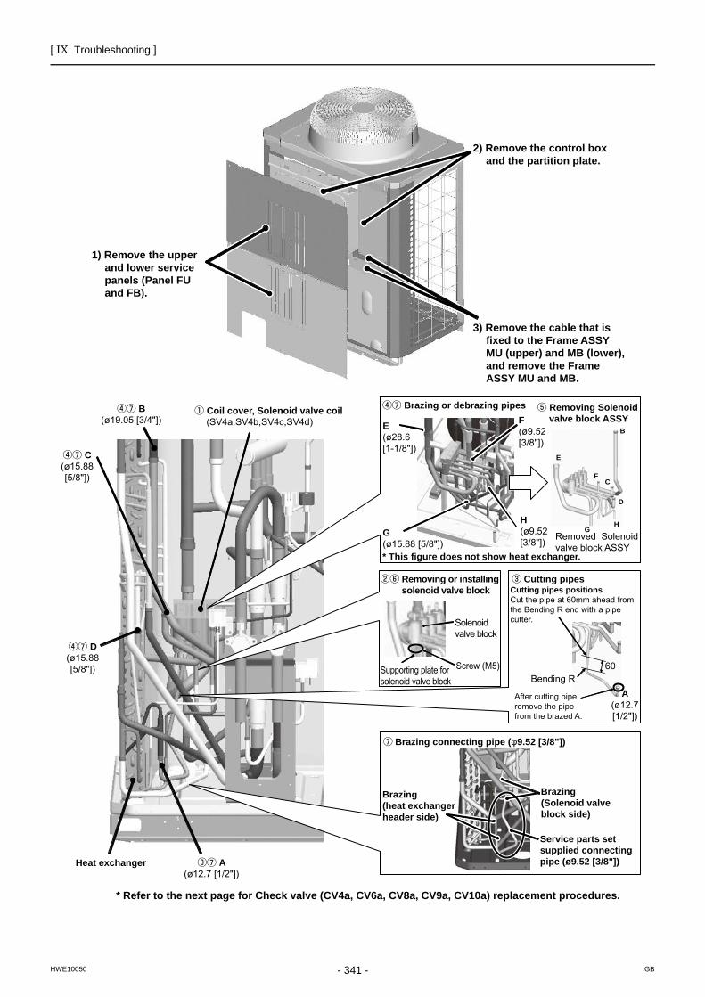
[ IX Troubleshooting ]
- 341 -HWE10050 GB
②⑥ Removing or installing solenoid valve block
Solenoid valve block
Supporting plate for solenoid valve block
Screw (M5)
③ Cutting pipesCutting pipes positionsCut the pipe at 60mm ahead from the Bending R end with a pipe cutter.
60Bending R
A(ø12.7 [1/2"])
After cutting pipe, remove the pipe from the brazed A.
④⑦ B(ø19.05 [3/4"])
④⑦ C(ø15.88 [5/8"])
① Coil cover, Solenoid valve coil (SV4a,SV4b,SV4c,SV4d)
④⑦ D(ø15.88 [5/8"])
Heat exchanger ③⑦ A(ø12.7 [1/2"])
⑦ Brazing connecting pipe (φ9.52 [3/8"])
Brazing(heat exchanger header side)
Brazing(Solenoid valve block side)
Service parts setsupplied connecting pipe (ø9.52 [3/8"])
④⑦ Brazing or debrazing pipes ⑤ Removing Solenoid valve block ASSY
E(ø28.6 [1-1/8"])
F(ø9.52 [3/8"])
G(ø15.88 [5/8"])* This figure does not show heat exchanger.
E
B
FC
D
HG
Removed Solenoid valve block ASSY
H(ø9.52 [3/8"])
* Refer to the next page for Check valve (CV4a, CV6a, CV8a, CV9a, CV10a) replacement procedures.
1) Remove the upper and lower service panels (Panel FU and FB).
2) Remove the control box and the partition plate.
3) Remove the cable that is fixed to the Frame ASSY MU (upper) and MB (lower), and remove the Frame ASSY MU and MB.
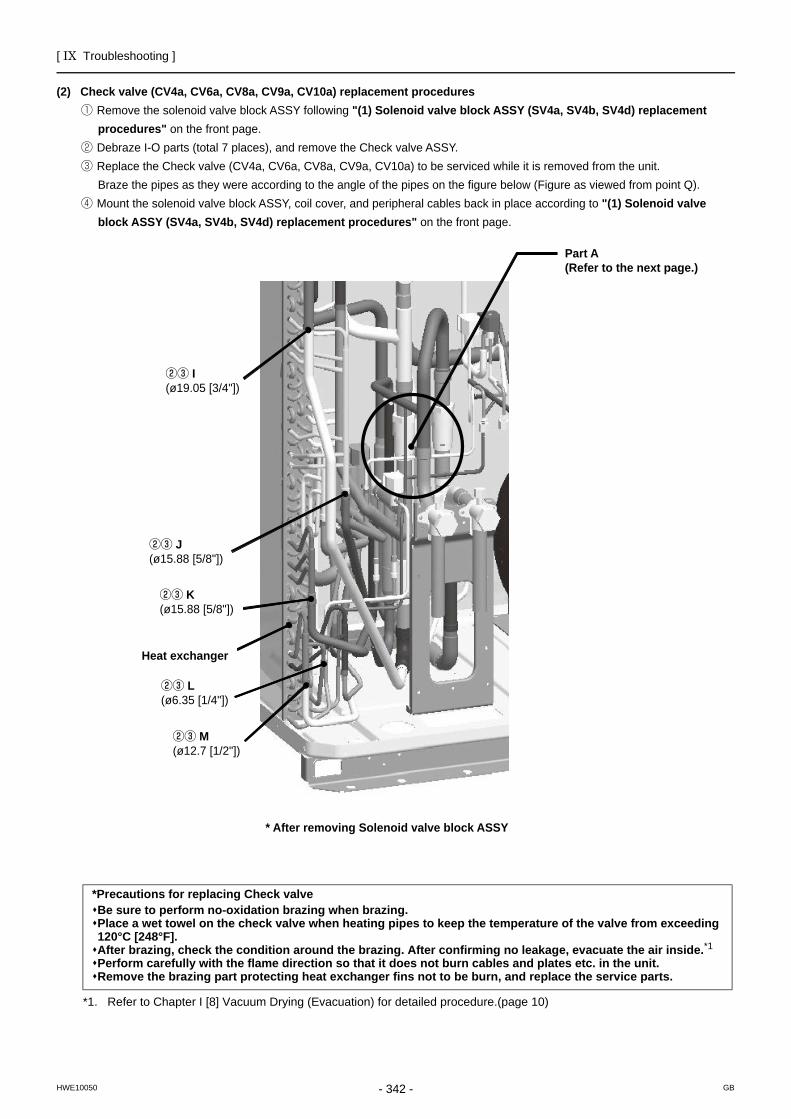
[ IX Troubleshooting ]
- 342 -HWE10050 GB
(2) Check valve (CV4a, CV6a, CV8a, CV9a, CV10a) replacement procedures① Remove the solenoid valve block ASSY following "(1) Solenoid valve block ASSY (SV4a, SV4b, SV4d) replacement
procedures" on the front page.② Debraze I-O parts (total 7 places), and remove the Check valve ASSY.③ Replace the Check valve (CV4a, CV6a, CV8a, CV9a, CV10a) to be serviced while it is removed from the unit.
Braze the pipes as they were according to the angle of the pipes on the figure below (Figure as viewed from point Q).④ Mount the solenoid valve block ASSY, coil cover, and peripheral cables back in place according to "(1) Solenoid valve
block ASSY (SV4a, SV4b, SV4d) replacement procedures" on the front page.
Part A (Refer to the next page.)
②③ I(ø19.05 [3/4"])
* After removing Solenoid valve block ASSY
②③ J(ø15.88 [5/8"])
②③ K(ø15.88 [5/8"])
Heat exchanger
②③ L(ø6.35 [1/4"])
②③ M(ø12.7 [1/2"])
*Precautions for replacing Check valveBe sure to perform no-oxidation brazing when brazing.Place a wet towel on the check valve when heating pipes to keep the temperature of the valve from exceeding 120°C [248°F].After brazing, check the condition around the brazing. After confirming no leakage, evacuate the air inside.*1Perform carefully with the flame direction so that it does not burn cables and plates etc. in the unit.Remove the brazing part protecting heat exchanger fins not to be burn, and replace the service parts.
*1. Refer to Chapter I [8] Vacuum Drying (Evacuation) for detailed procedure.(page 10)
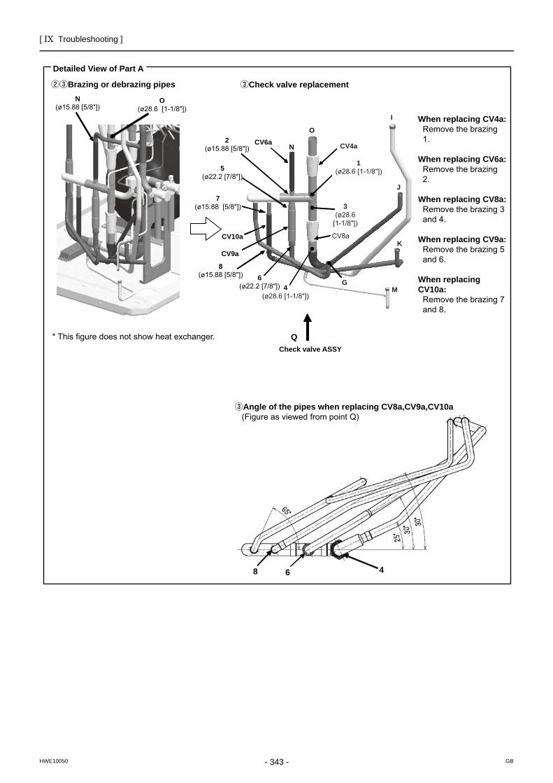
[ IX Troubleshooting ]
- 343 -HWE10050 GB
Detailed View of Part A
②③Brazing or debrazing pipesN
(ø15.88 [5/8"])O
(ø28.6 [1-1/8"])
③Check valve replacement
* This figure does not show heat exchanger.
③Angle of the pipes when replacing CV8a,CV9a,CV10a (Figure as viewed from point Q)
8 6 4
When replacing CV4a:Remove the brazing 1.
When replacing CV6a:Remove the brazing 2.
When replacing CV8a:Remove the brazing 3 and 4.
When replacing CV9a:Remove the brazing 5 and 6.
When replacing CV10a:
Remove the brazing 7 and 8.
O
NCV6a CV4a
2(ø15.88 [5/8"])
7(ø15.88 [5/8"])
5(ø22.2 [7/8"])
CV10a
CV9a
8(ø15.88 [5/8"]) 6
(ø22.2 [7/8"]) 4(ø28.6 [1-1/8"])
QCheck valve ASSY
1(ø28.6 [1-1/8"])
3(ø28.6
[1-1/8"])
J
CV8a
MG
K
I
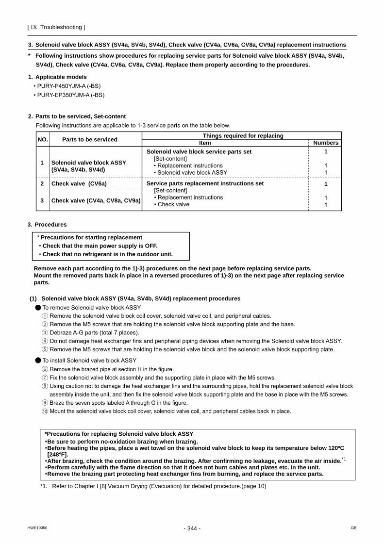
[ IX Troubleshooting ]
- 344 -HWE10050 GB
3. Solenoid valve block ASSY (SV4a, SV4b, SV4d), Check valve (CV4a, CV6a, CV8a, CV9a) replacement instructions
* Following instructions show procedures for replacing service parts for Solenoid valve block ASSY (SV4a, SV4b, SV4d), Check valve (CV4a, CV6a, CV8a, CV9a). Replace them properly according to the procedures.
1. Applicable models • PURY-P450YJM-A (-BS) • PURY-EP350YJM-A (-BS)
2. Parts to be serviced, Set-contentFollowing instructions are applicable to 1-3 service parts on the table below.
NO. Parts to be serviced
1 Solenoid valve block ASSY (SV4a, SV4b, SV4d)
2 Check valve (CV6a)
3 Check valve (CV4a, CV8a, CV9a)
Things required for replacingItem
Solenoid valve block service parts set [Set-content] • Replacement instructions • Solenoid valve block ASSY
Numbers1
11
Service parts replacement instructions set [Set-content] • Replacement instructions • Check valve
1
11
3. Procedures
* Precautions for starting replacement • Check that the main power supply is OFF. • Check that no refrigerant is in the outdoor unit.
Remove each part according to the 1)-3) procedures on the next page before replacing service parts.Mount the removed parts back in place in a reversed procedures of 1)-3) on the next page after replacing service parts.
(1) Solenoid valve block ASSY (SV4a, SV4b, SV4d) replacement procedures To remove Solenoid valve block ASSY
Remove the solenoid valve block coil cover, solenoid valve coil, and peripheral cables.Remove the M5 screws that are holding the solenoid valve block supporting plate and the base.Debraze A-G parts (total 7 places).Do not damage heat exchanger fins and peripheral piping devices when removing the Solenoid valve block ASSY.Remove the M5 screws that are holding the solenoid valve block and the solenoid valve block supporting plate.
To install Solenoid valve block ASSYRemove the brazed pipe at section H in the figure.Fix the solenoid valve block assembly and the supporting plate in place with the M5 screws.Using caution not to damage the heat exchanger fins and the surrounding pipes, hold the replacement solenoid valve block assembly inside the unit, and then fix the solenoid valve block supporting plate and the base in place with the M5 screws.Braze the seven spots labeled A through G in the figure.Mount the solenoid valve block coil cover, solenoid valve coil, and peripheral cables back in place.
2
1
3
4
5
6
7
8
9
10
*Precautions for replacing Solenoid valve block ASSYBe sure to perform no-oxidation brazing when brazing.Before heating the pipes, place a wet towel on the solenoid valve block to keep its temperature below 120ºC [248ºF].After brazing, check the condition around the brazing. After confirming no leakage, evacuate the air inside.*1Perform carefully with the flame direction so that it does not burn cables and plates etc. in the unit.Remove the brazing part protecting heat exchanger fins from burning, and replace the service parts.
*1. Refer to Chapter I [8] Vacuum Drying (Evacuation) for detailed procedure.(page 10)
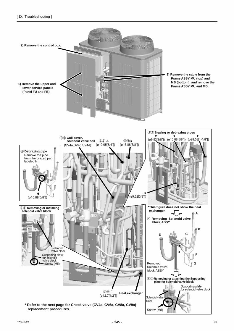
[ IX Troubleshooting ]
- 345 -HWE10050 GB
B(ø15.88[5/8"])
A(ø19.05[3/4"])(SV4a,SV4b,SV4d)
F(ø12.7[1/2"])
G
F
B
E
D
C
A
H(ø15.88[5/8"])
G(ø9.52[3/8"])
C(ø9.52[3/8"])
E(ø28.58[1-1/8"])
D(ø15.88[5/8"])
Heat exchanger
Screw (M5)
Supporting platefor solenoid valve block
Solenoidvalve block
Removing or installingsolenoid valve block
Brazing or debrazing pipes
Removed Solenoid valveblock ASSY
Removing Solenoid valve block ASSY
Screw (M5)
Supporting platefor solenoid valve block
Solenoid valve block
Debrazing pipe
Removing or attaching the Supportingplate for solenoid valve block
Remove the pipefrom the brazed pant labeled H.
3) Remove the cable from the Frame ASSY MU (top) and MB (bottom), and remove the Frame ASSY MU and MB.
*This figure does not show the heat exchanger.
2) Remove the control box.
1) Remove the upper and lower service panels (Panel FU and FB).
Coil cover, Solenoid valve coil
* Refer to the next page for Check valve (CV4a, CV6a, CV8a, CV9a) replacement procedures.
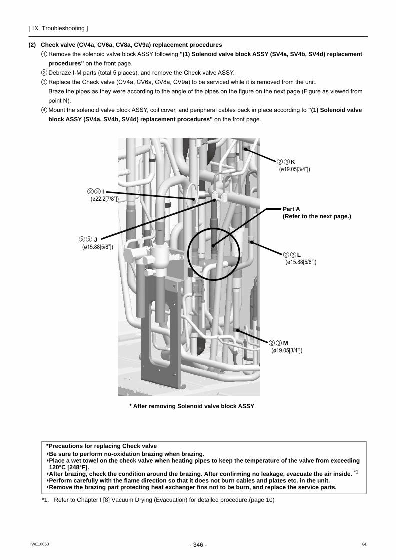
[ IX Troubleshooting ]
- 346 -HWE10050 GB
I(ø22.2[7/8”])
2 3
J(ø15.88[5/8”])
2 3
L(ø15.88[5/8”])2 3
K(ø19.05[3/4”])2 3
M(ø19.05[3/4”])2 3
(2) Check valve (CV4a, CV6a, CV8a, CV9a) replacement proceduresRemove the solenoid valve block ASSY following "(1) Solenoid valve block ASSY (SV4a, SV4b, SV4d) replacement procedures" on the front page.Debraze I-M parts (total 5 places), and remove the Check valve ASSY.Replace the Check valve (CV4a, CV6a, CV8a, CV9a) to be serviced while it is removed from the unit. Braze the pipes as they were according to the angle of the pipes on the figure on the next page (Figure as viewed from point N).Mount the solenoid valve block ASSY, coil cover, and peripheral cables back in place according to "(1) Solenoid valve block ASSY (SV4a, SV4b, SV4d) replacement procedures" on the front page.
Part A (Refer to the next page.)
* After removing Solenoid valve block ASSY
2
1
3
4
*Precautions for replacing Check valveBe sure to perform no-oxidation brazing when brazing.Place a wet towel on the check valve when heating pipes to keep the temperature of the valve from exceeding 120°C [248°F].After brazing, check the condition around the brazing. After confirming no leakage, evacuate the air inside. *1Perform carefully with the flame direction so that it does not burn cables and plates etc. in the unit.Remove the brazing part protecting heat exchanger fins not to be burn, and replace the service parts.
*1. Refer to Chapter I [8] Vacuum Drying (Evacuation) for detailed procedure.(page 10)
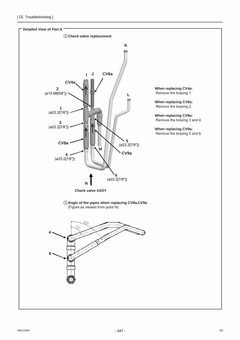
[ IX Troubleshooting ]
- 347 -HWE10050 GB
Detailed View of Part A
Angle of the pipes when replacing CV8a,CV9a (Figure as viewed from point N)
CV4a
CV8a
CV9a
CV6a
5
Check valve ASSY
6
6
3
4
4
1
N
M
L
I J
K
2 When replacing CV4a: Remove the brazing 1.
When replacing CV6a:Remove the brazing 2.
When replacing CV8a: Remove the brazing 3 and 4.
When replacing CV9a: Remove the brazing 5 and 6.
(ø22.2[7/8”])
(ø22.2[7/8”])
(ø22.2[7/8”])
(ø22.2[7/8”])
(ø22.2[7/8”])
(ø15.88[5/8”])
Check valve replacement3
3
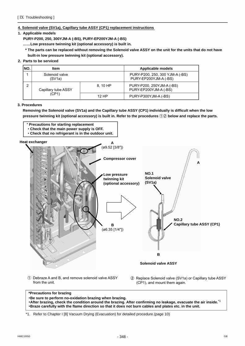
[ IX Troubleshooting ]
- 348 -HWE10050 GB
4. Solenoid valve (SV1a), Capillary tube ASSY (CP1) replacement instructions1. Applicable models
PURY-P200, 250, 300YJM-A (-BS), PURY-EP200YJM-A (-BS)
* The parts can be replaced without removing the Solenoid valve ASSY on the unit for the units that do not have built-in low pressure twinning kit (optional accessory).
2. Parts to be serviced
NO. Item Applicable models
2 Capillary tube ASSY
8, 10 HP PURY-P200, 250YJM-A (-BS)
(CP1) PURY-EP200YJM-A (-BS)
1 Solenoid valve PURY-P200, 250, 300 YJM-A (-BS) (SV1a) PURY-EP200YJM-A (-BS)
3. ProceduresRemoving the Solenoid valve (SV1a) and the Capillary tube ASSY (CP1) individually is difficult when the low pressure twinning kit (optional accessory) is built in. Refer to the procedures below and replace the parts.
……Low pressure twinning kit (optional accessory) is built in.
12 HP PURY-P300YJM-A (-BS)
* Precautions for starting replacement • Check that the main power supply is OFF. • Check that no refrigerant is in the outdoor unit.
Heat exchanger A(ø9.52 [3/8"])
Compressor cover
Low pressure twinning kit(optional accessory)
B(ø6.35 [1/4"])
NO.1Solenoid valve (SV1a)
A
NO.2Capillary tube ASSY (CP1)
B
Solenoid valve ASSY
Debraze A and B, and remove solenoid valve ASSYfrom the unit.
Replace Solenoid valve (SV1a) or Capillary tube ASSY(CP1), and mount them again.
*Precautions for brazingBe sure to perform no-oxidation brazing when brazing.After brazing, check the condition around the brazing. After confirming no leakage, evacuate the air inside.*1Braze carefully with the flame direction so that it does not burn cables and plates etc. in the unit.
*1. Refer to Chapter I [8] Vacuum Drying (Evacuation) for detailed procedure.(page 10)
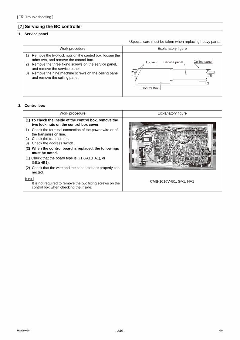
[ IX Troubleshooting ]
- 349 -HWE10050 GB
[7] Servicing the BC controller1. Service panel
2. Control box
*Special care must be taken when replacing heavy parts.
Work procedure Explanatory figure
1) Remove the two lock nuts on the control box, loosen the other two, and remove the control box.
2) Remove the three fixing screws on the service panel, and remove the service panel.
3) Remove the nine machine screws on the ceiling panel, and remove the ceiling panel.
Work procedure Explanatory figure
(1) To check the inside of the control box, remove the two lock nuts on the control box cover.
1) Check the terminal connection of the power wire or of the transmission line.
2) Check the transformer.3) Check the address switch.(2) When the control board is replaced, the followings
must be noted.(1) Check that the board type is G1,GA1(HA1), or
GB1(HB1).(2) Check that the wire and the connector are properly con-
nected.
It is not required to remove the two fixing screws on the control box when checking the inside.
CMB-1016V-G1, GA1, HA1
Loosen Service panel
Control Box
Ceiling panel
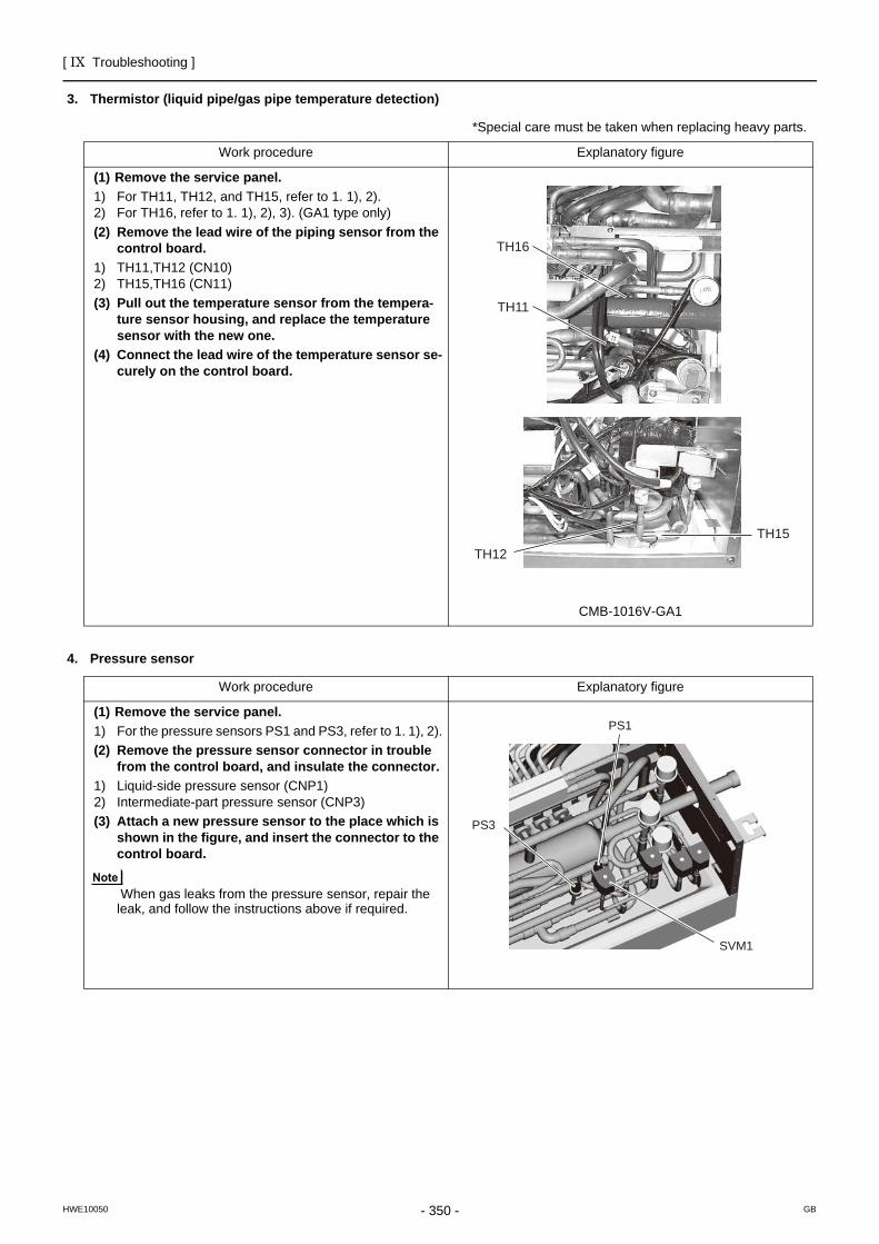
[ IX Troubleshooting ]
- 350 -HWE10050 GB
3. Thermistor (liquid pipe/gas pipe temperature detection)
4. Pressure sensor
*Special care must be taken when replacing heavy parts.
Work procedure Explanatory figure
(1) Remove the service panel.1) For TH11, TH12, and TH15, refer to 1. 1), 2).2) For TH16, refer to 1. 1), 2), 3). (GA1 type only)(2) Remove the lead wire of the piping sensor from the
control board.1) TH11,TH12 (CN10)2) TH15,TH16 (CN11)(3) Pull out the temperature sensor from the tempera-
ture sensor housing, and replace the temperature sensor with the new one.
(4) Connect the lead wire of the temperature sensor se-curely on the control board.
CMB-1016V-GA1
Work procedure Explanatory figure
(1) Remove the service panel.1) For the pressure sensors PS1 and PS3, refer to 1. 1), 2).(2) Remove the pressure sensor connector in trouble
from the control board, and insulate the connector.1) Liquid-side pressure sensor (CNP1)2) Intermediate-part pressure sensor (CNP3)(3) Attach a new pressure sensor to the place which is
shown in the figure, and insert the connector to the control board.
When gas leaks from the pressure sensor, repair the leak, and follow the instructions above if required.
TH15TH12
TH16
TH11
SVM1
PS1
PS3
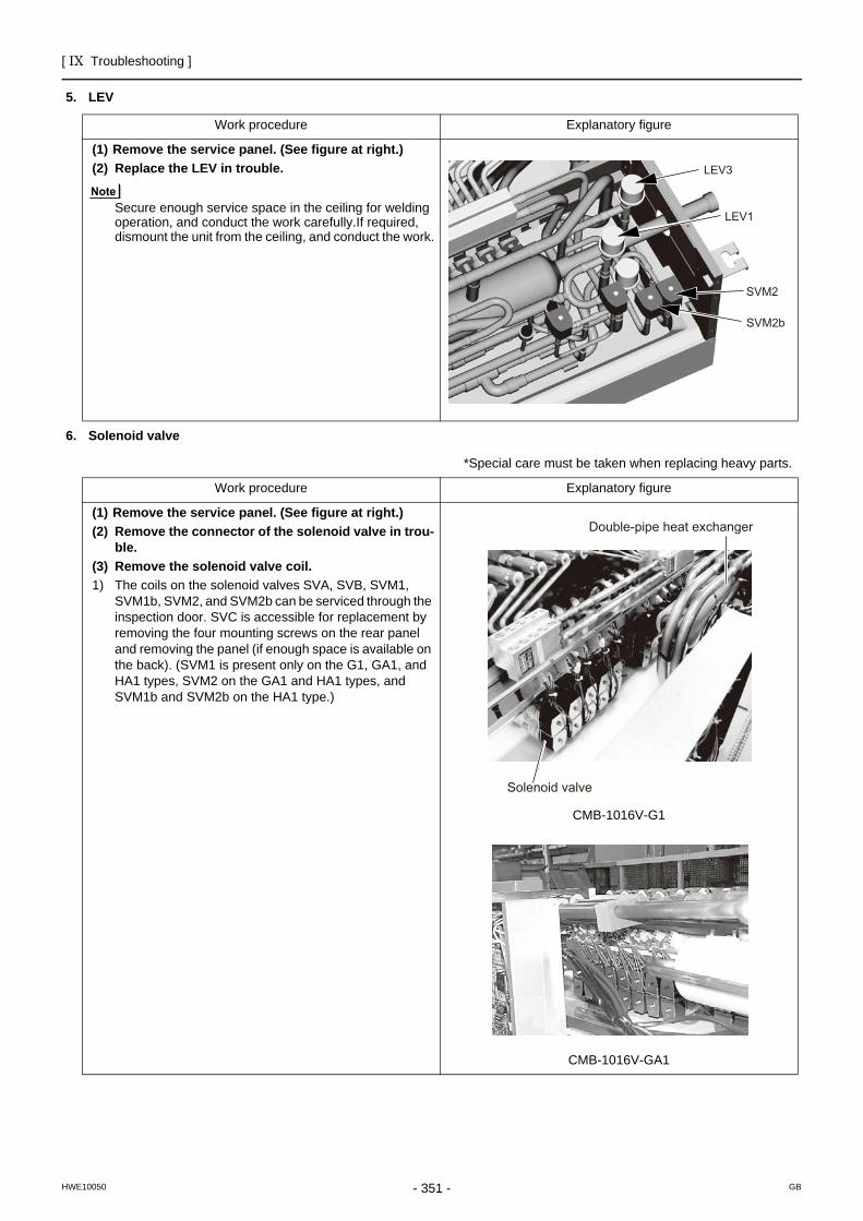
[ IX Troubleshooting ]
- 351 -HWE10050 GB
5. LEV
6. Solenoid valve
Work procedure Explanatory figure
(1) Remove the service panel. (See figure at right.)(2) Replace the LEV in trouble.
Secure enough service space in the ceiling for welding operation, and conduct the work carefully.If required, dismount the unit from the ceiling, and conduct the work.
*Special care must be taken when replacing heavy parts.
Work procedure Explanatory figure
(1) Remove the service panel. (See figure at right.)(2) Remove the connector of the solenoid valve in trou-
ble.(3) Remove the solenoid valve coil.1) The coils on the solenoid valves SVA, SVB, SVM1,
SVM1b, SVM2, and SVM2b can be serviced through the inspection door. SVC is accessible for replacement by removing the four mounting screws on the rear panel and removing the panel (if enough space is available on the back). (SVM1 is present only on the G1, GA1, and HA1 types, SVM2 on the GA1 and HA1 types, and SVM1b and SVM2b on the HA1 type.)
CMB-1016V-G1
CMB-1016V-GA1
LEV3
LEV1
SVM2
SVM2b
Double-pipe heat exchanger
Solenoid valve
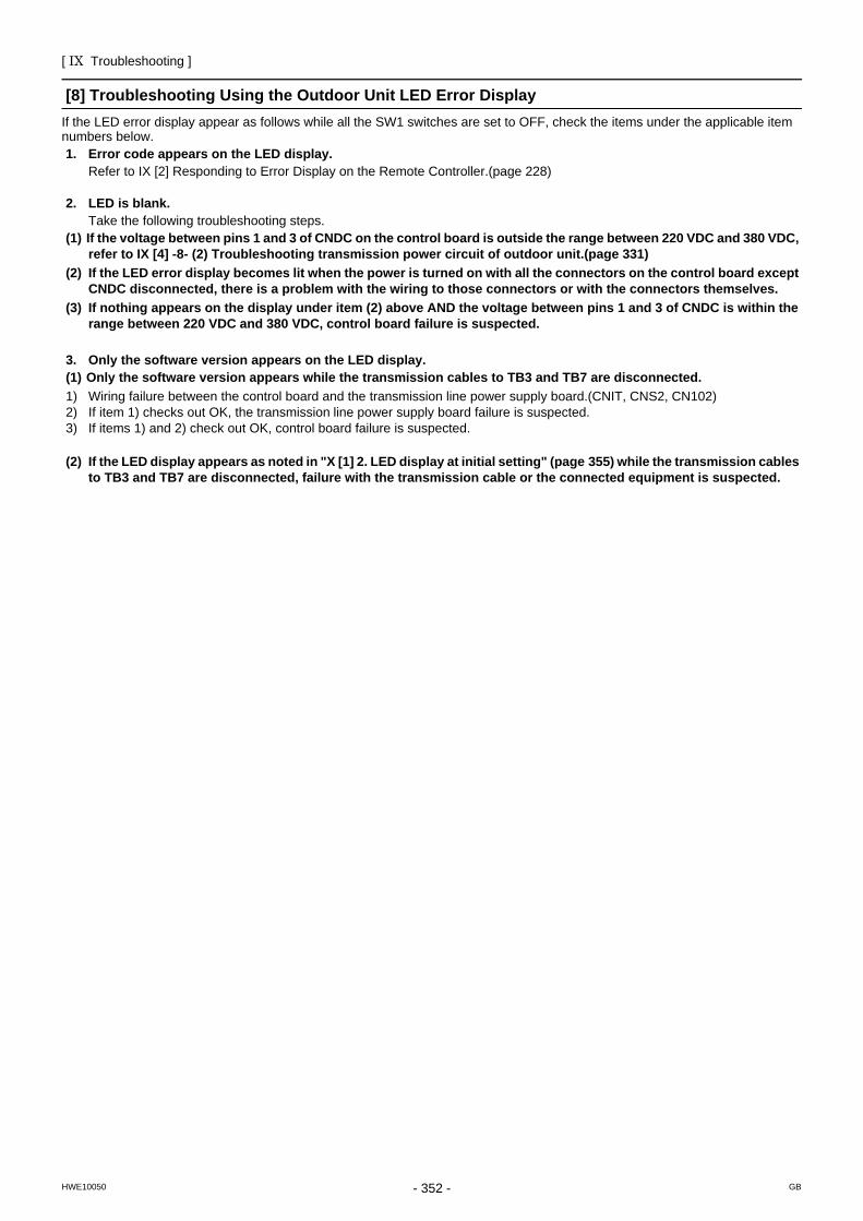
[ IX Troubleshooting ]
- 352 -HWE10050 GB
[8] Troubleshooting Using the Outdoor Unit LED Error DisplayIf the LED error display appear as follows while all the SW1 switches are set to OFF, check the items under the applicable item numbers below.1. Error code appears on the LED display.
Refer to IX [2] Responding to Error Display on the Remote Controller.(page 228)
2. LED is blank.Take the following troubleshooting steps.
(1) If the voltage between pins 1 and 3 of CNDC on the control board is outside the range between 220 VDC and 380 VDC, refer to IX [4] -8- (2) Troubleshooting transmission power circuit of outdoor unit.(page 331)
(2) If the LED error display becomes lit when the power is turned on with all the connectors on the control board except CNDC disconnected, there is a problem with the wiring to those connectors or with the connectors themselves.
(3) If nothing appears on the display under item (2) above AND the voltage between pins 1 and 3 of CNDC is within the range between 220 VDC and 380 VDC, control board failure is suspected.
3. Only the software version appears on the LED display.(1) Only the software version appears while the transmission cables to TB3 and TB7 are disconnected.1) Wiring failure between the control board and the transmission line power supply board.(CNIT, CNS2, CN102)2) If item 1) checks out OK, the transmission line power supply board failure is suspected.3) If items 1) and 2) check out OK, control board failure is suspected.
(2) If the LED display appears as noted in "X [1] 2. LED display at initial setting" (page 355) while the transmission cables to TB3 and TB7 are disconnected, failure with the transmission cable or the connected equipment is suspected.
- 353 -HWE10050 GB
X LED Monitor Display on the Outdoor Unit Board
[1] How to Read the LED on the Service Monitor ...............................................................355

- 354 -
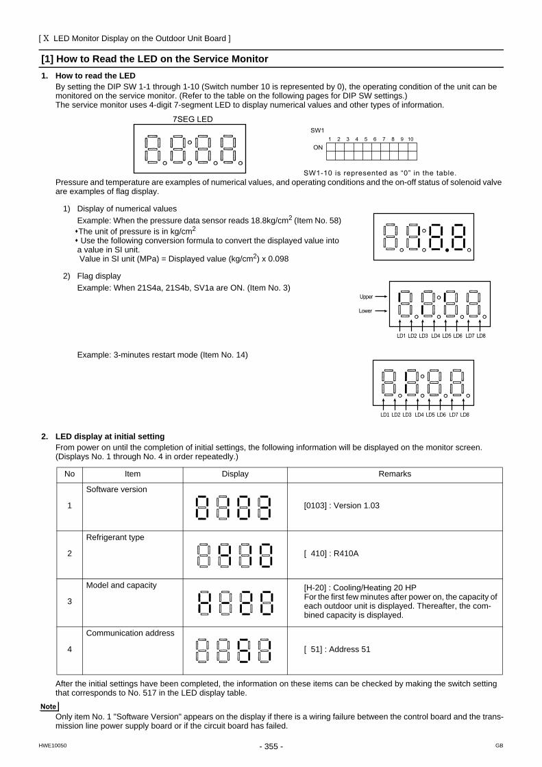
[ X LED Monitor Display on the Outdoor Unit Board ]
- 355 -HWE10050 GB
X LED Monitor Display on the Outdoor Unit Board
[1] How to Read the LED on the Service Monitor1. How to read the LED
By setting the DIP SW 1-1 through 1-10 (Switch number 10 is represented by 0), the operating condition of the unit can be monitored on the service monitor. (Refer to the table on the following pages for DIP SW settings.) The service monitor uses 4-digit 7-segment LED to display numerical values and other types of information.
Pressure and temperature are examples of numerical values, and operating conditions and the on-off status of solenoid valve are examples of flag display.
2. LED display at initial settingFrom power on until the completion of initial settings, the following information will be displayed on the monitor screen.(Displays No. 1 through No. 4 in order repeatedly.)
After the initial settings have been completed, the information on these items can be checked by making the switch setting that corresponds to No. 517 in the LED display table.
Only item No. 1 "Software Version" appears on the display if there is a wiring failure between the control board and the trans-mission line power supply board or if the circuit board has failed.
1) Display of numerical valuesExample: When the pressure data sensor reads 18.8kg/cm2 (Item No. 58)The unit of pressure is in kg/cm2
Use the following conversion formula to convert the displayed value into a value in SI unit. Value in SI unit (MPa) = Displayed value (kg/cm2) x 0.098
2) Flag display Example: When 21S4a, 21S4b, SV1a are ON. (Item No. 3)
Example: 3-minutes restart mode (Item No. 14)
No Item Display Remarks
1
Software version
[0103] : Version 1.03
2
Refrigerant type
[ 410] : R410A
3
Model and capacity [H-20] : Cooling/Heating 20 HPFor the first few minutes after power on, the capacity of each outdoor unit is displayed. Thereafter, the com-bined capacity is displayed.
4
Communication address
[ 51] : Address 51
SW1
ON1 2 3 4 5 6 7 8
SW1-10 is represented as “0” in the table.
9 10
7SEG LED
LD1 LD2 LD3 LD4 LD5 LD6 LD7 LD8
Upper
Lower
LD1 LD2 LD3 LD4 LD5 LD6 LD7 LD8
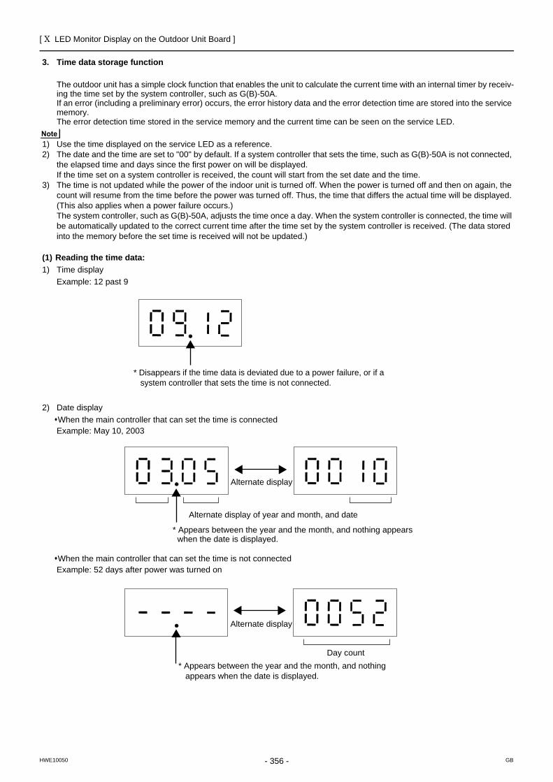
[ X LED Monitor Display on the Outdoor Unit Board ]
- 356 -HWE10050 GB
3. Time data storage function
The outdoor unit has a simple clock function that enables the unit to calculate the current time with an internal timer by receiv-ing the time set by the system controller, such as G(B)-50A.If an error (including a preliminary error) occurs, the error history data and the error detection time are stored into the service memory.The error detection time stored in the service memory and the current time can be seen on the service LED.
1) Use the time displayed on the service LED as a reference.2) The date and the time are set to "00" by default. If a system controller that sets the time, such as G(B)-50A is not connected,
the elapsed time and days since the first power on will be displayed.If the time set on a system controller is received, the count will start from the set date and the time.
3) The time is not updated while the power of the indoor unit is turned off. When the power is turned off and then on again, the count will resume from the time before the power was turned off. Thus, the time that differs the actual time will be displayed. (This also applies when a power failure occurs.)The system controller, such as G(B)-50A, adjusts the time once a day. When the system controller is connected, the time will be automatically updated to the correct current time after the time set by the system controller is received. (The data stored into the memory before the set time is received will not be updated.)
(1) Reading the time data:1) Time display
Example: 12 past 9
2) Date displayWhen the main controller that can set the time is connectedExample: May 10, 2003
When the main controller that can set the time is not connectedExample: 52 days after power was turned on
* Disappears if the time data is deviated due to a power failure, or if a system controller that sets the time is not connected.
Alternate display
Alternate display of year and month, and date
* Appears between the year and the month, and nothing appears when the date is displayed.
Alternate display
Day count
* Appears between the year and the month, and nothing appears when the date is displayed.
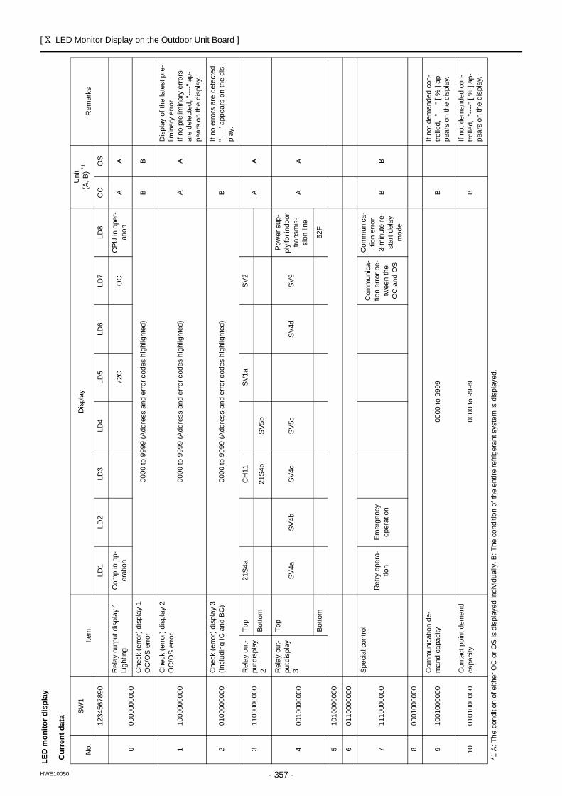
[ X LED Monitor Display on the Outdoor Unit Board ]
- 357 -HWE10050
ILE
D M
onito
r Dis
play
on
the
Out
door
Uni
t Boa
rd
LED
mon
itor d
ispl
ay
Cur
rent
dat
a
No.
SW
1Ite
mD
ispl
ayU
nit
(A, B
) *1R
emar
ks
1234
5678
90LD
1LD
2LD
3LD
4LD
5LD
6LD
7LD
8O
CO
S
000
0000
0000
Rel
ay o
utpu
t dis
play
1
Ligh
ting
Com
p in
op-
erat
ion
72C
OC
CPU
in o
per-
atio
nA
A
Che
ck (e
rror)
disp
lay
1 O
C/O
S e
rror
0000
to 9
999
(Add
ress
and
erro
r cod
es h
ighl
ight
ed)
BB
110
0000
0000
Che
ck (e
rror)
disp
lay
2 O
C/O
S e
rror
0000
to 9
999
(Add
ress
and
erro
r cod
es h
ighl
ight
ed)
AA
Dis
play
of t
he la
test
pre
-lim
inar
y er
ror
If no
pre
limin
ary
erro
rs
are
dete
cted
, "---
-" a
p-pe
ars
on th
e di
spla
y.
201
0000
0000
Che
ck (e
rror)
disp
lay
3 (In
clud
ing
IC a
nd B
C)
0000
to 9
999
(Add
ress
and
erro
r cod
es h
ighl
ight
ed)
BIf
no e
rrors
are
det
ecte
d,
"----
" app
ears
on
the
dis-
play
.
311
0000
0000
Rel
ay o
ut-
put d
ispl
ay
2
Top
21S4
aC
H11
SV1
aSV
2A
AB
otto
m21
S4b
SV5
b
400
1000
0000
Rel
ay o
ut-
put d
ispl
ay
3
Top
SV4a
SV4b
SV4c
SV5c
SV4d
SV9
Pow
er s
up-
ply
for i
ndoo
r tra
nsm
is-
sion
line
AA
Bot
tom
52F
510
1000
0000
601
1000
0000
711
1000
0000
Spec
ial c
ontro
l
Ret
ry o
pera
-tio
nEm
erge
ncy
oper
atio
n
Com
mun
ica-
tion
erro
r be-
twee
n th
e O
C a
nd O
S
Com
mun
ica-
tion
erro
r3-
min
ute
re-
star
t del
ay
mod
e
BB
800
0100
0000
910
0100
0000
Com
mun
icat
ion
de-
man
d ca
paci
ty00
00 to
999
9B
If no
t dem
ande
d co
n-tro
lled,
"---
-" [
% ]
ap-
pear
s on
the
disp
lay.
1001
0100
0000
Con
tact
poi
nt d
eman
d ca
paci
ty00
00 to
999
9B
If no
t dem
ande
d co
n-tro
lled,
"---
-" [
% ]
ap-
pear
s on
the
disp
lay.
*1 A
: The
con
ditio
n of
eith
er O
C o
r OS
is d
ispl
ayed
indi
vidu
ally
. B: T
he c
ondi
tion
of th
e en
tire
refri
gera
nt s
yste
m is
dis
play
ed.
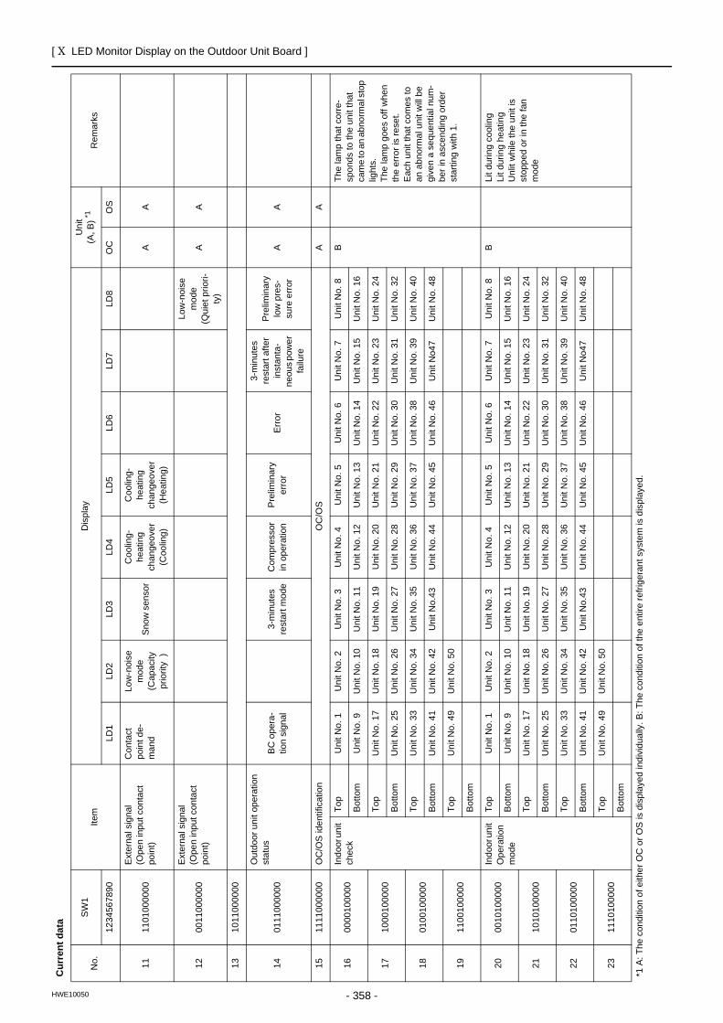
[ X LED Monitor Display on the Outdoor Unit Board ]
- 358 -HWE10050
1111
0100
0000
Exte
rnal
sig
nal
(Ope
n in
put c
onta
ct
poin
t)
Con
tact
po
int d
e-m
and
Low
-noi
se
mod
e(C
apac
ity
prio
rity
)
Snow
sen
sor
Coo
ling-
heat
ing
chan
geov
er(C
oolin
g)
Coo
ling-
heat
ing
chan
geov
er(H
eatin
g)
AA
1200
1100
0000
Exte
rnal
sig
nal
(Ope
n in
put c
onta
ct
poin
t)
Low
-noi
se
mod
e (Q
uiet
prio
ri-ty
)
AA
1310
1100
0000
1401
1100
0000
Out
door
uni
t ope
ratio
n st
atus
BC o
pera
-tio
n si
gnal
3-m
inut
es
rest
art m
ode
Com
pres
sor
in o
pera
tion
Pre
limin
ary
erro
rEr
ror
3-m
inut
es
rest
art a
fter
inst
anta
-ne
ous p
ower
fa
ilure
Pre
limin
ary
low
pre
s-su
re e
rror
AA
1511
1100
0000
OC
/OS
iden
tific
atio
nO
C/O
SA
A
1600
0010
0000
Indo
or u
nit
chec
kTo
pU
nit N
o. 1
Uni
t No.
2U
nit N
o. 3
Uni
t No.
4U
nit N
o. 5
Uni
t No.
6U
nit N
o. 7
Uni
t No.
8B
The
lam
p th
at c
orre
-sp
onds
to th
e un
it th
at
cam
e to
an
abno
rmal
sto
p lig
hts.
Th
e la
mp
goes
off
whe
n th
e er
ror i
s re
set.
Eac
h un
it th
at c
omes
to
an a
bnor
mal
uni
t will
be
give
n a
sequ
entia
l num
-be
r in
asce
ndin
g or
der
star
ting
with
1.
Bot
tom
Uni
t No.
9U
nit N
o. 1
0U
nit N
o. 1
1U
nit N
o. 1
2U
nit N
o. 1
3U
nit N
o. 1
4U
nit N
o. 1
5U
nit N
o. 1
6
1710
0010
0000
Top
Uni
t No.
17
Uni
t No.
18
Uni
t No.
19
Uni
t No.
20
Uni
t No.
21
Uni
t No.
22
Uni
t No.
23
Uni
t No.
24
Bot
tom
Uni
t No.
25
Uni
t No.
26
Uni
t No.
27
Uni
t No.
28
Uni
t No.
29
Uni
t No.
30
Uni
t No.
31
Uni
t No.
32
1801
0010
0000
Top
Uni
t No.
33
Uni
t No.
34
Uni
t No.
35
Uni
t No.
36
Uni
t No.
37
Uni
t No.
38
Uni
t No.
39
Uni
t No.
40
Bot
tom
Uni
t No.
41
Uni
t No.
42
Uni
t No.
43U
nit N
o. 4
4U
nit N
o. 4
5U
nit N
o. 4
6U
nit N
o47
Uni
t No.
48
1911
0010
0000
Top
Uni
t No.
49
Uni
t No.
50
Bot
tom
2000
1010
0000
Indo
or u
nit
Ope
ratio
n m
ode
Top
Uni
t No.
1U
nit N
o. 2
Uni
t No.
3U
nit N
o. 4
Uni
t No.
5U
nit N
o. 6
Uni
t No.
7U
nit N
o. 8
BLi
t dur
ing
cool
ing
Lit d
urin
g he
atin
g U
nlit
whi
le th
e un
it is
st
oppe
d or
in th
e fa
n m
ode
Bot
tom
Uni
t No.
9U
nit N
o. 1
0U
nit N
o. 1
1U
nit N
o. 1
2U
nit N
o. 1
3U
nit N
o. 1
4U
nit N
o. 1
5U
nit N
o. 1
6
2110
1010
0000
Top
Uni
t No.
17
Uni
t No.
18
Uni
t No.
19
Uni
t No.
20
Uni
t No.
21
Uni
t No.
22
Uni
t No.
23
Uni
t No.
24
Bot
tom
Uni
t No.
25
Uni
t No.
26
Uni
t No.
27
Uni
t No.
28
Uni
t No.
29
Uni
t No.
30
Uni
t No.
31
Uni
t No.
32
2201
1010
0000
Top
Uni
t No.
33
Uni
t No.
34
Uni
t No.
35
Uni
t No.
36
Uni
t No.
37
Uni
t No.
38
Uni
t No.
39
Uni
t No.
40
Bot
tom
Uni
t No.
41
Uni
t No.
42
Uni
t No.
43U
nit N
o. 4
4U
nit N
o. 4
5U
nit N
o. 4
6U
nit N
o47
Uni
t No.
48
2311
1010
0000
Top
Uni
t No.
49
Uni
t No.
50
Bot
tom
Cur
rent
dat
a
No.
SW
1Ite
mD
ispl
ayU
nit
(A, B
) *1R
emar
ks
1234
5678
90LD
1LD
2LD
3LD
4LD
5LD
6LD
7LD
8O
CO
S
*1 A
: The
con
ditio
n of
eith
er O
C o
r OS
is d
ispl
ayed
indi
vidu
ally
. B: T
he c
ondi
tion
of th
e en
tire
refri
gera
nt s
yste
m is
dis
play
ed.
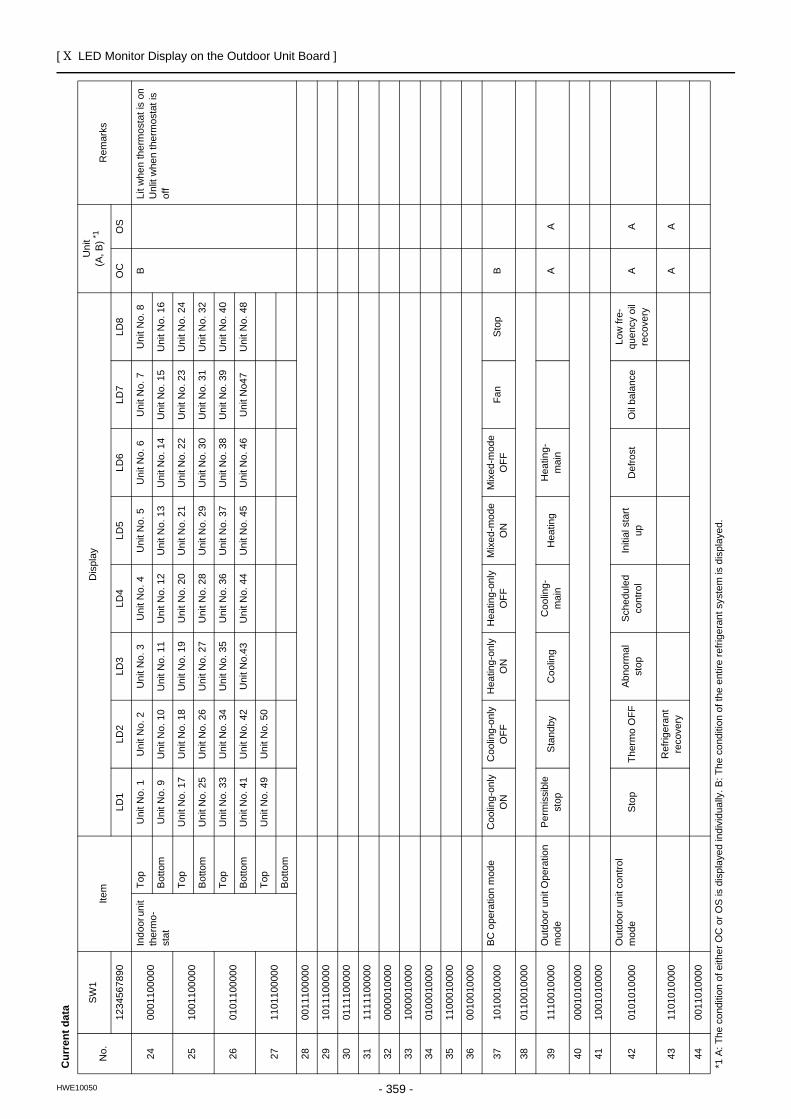
[ X LED Monitor Display on the Outdoor Unit Board ]
- 359 -HWE10050
2400
0110
0000
Indo
or u
nit
ther
mo-
stat
Top
Uni
t No.
1U
nit N
o. 2
Uni
t No.
3U
nit N
o. 4
Uni
t No.
5U
nit N
o. 6
Uni
t No.
7U
nit N
o. 8
BLi
t whe
n th
erm
osta
t is
onU
nlit
whe
n th
erm
osta
t is
off
Bot
tom
Uni
t No.
9U
nit N
o. 1
0U
nit N
o. 1
1U
nit N
o. 1
2U
nit N
o. 1
3U
nit N
o. 1
4U
nit N
o. 1
5U
nit N
o. 1
6
2510
0110
0000
Top
Uni
t No.
17
Uni
t No.
18
Uni
t No.
19
Uni
t No.
20
Uni
t No.
21
Uni
t No.
22
Uni
t No.
23
Uni
t No.
24
Bot
tom
Uni
t No.
25
Uni
t No.
26
Uni
t No.
27
Uni
t No.
28
Uni
t No.
29
Uni
t No.
30
Uni
t No.
31
Uni
t No.
32
2601
0110
0000
Top
Uni
t No.
33
Uni
t No.
34
Uni
t No.
35
Uni
t No.
36
Uni
t No.
37
Uni
t No.
38
Uni
t No.
39
Uni
t No.
40
Bot
tom
Uni
t No.
41
Uni
t No.
42
Uni
t No.
43U
nit N
o. 4
4U
nit N
o. 4
5U
nit N
o. 4
6U
nit N
o47
Uni
t No.
48
2711
0110
0000
Top
Uni
t No.
49
Uni
t No.
50
Bot
tom
2800
1110
0000
2910
1110
0000
3001
1110
0000
3111
1110
0000
3200
0001
0000
3310
0001
0000
3401
0001
0000
3511
0001
0000
3600
1001
0000
3710
1001
0000
BC o
pera
tion
mod
eC
oolin
g-on
ly
ON
Coo
ling-
only
O
FFH
eatin
g-on
ly
ON
Hea
ting-
only
O
FFM
ixed
-mod
e O
NM
ixed
-mod
e O
FFFa
nSt
opB
3801
1001
0000
3911
1001
0000
Out
door
uni
t Ope
ratio
n m
ode
Perm
issi
ble
stop
Sta
ndby
Coo
ling
Coo
ling-
mai
nH
eatin
gH
eatin
g-m
ain
AA
4000
0101
0000
4110
0101
0000
4201
0101
0000
Out
door
uni
t con
trol
mod
eS
top
Ther
mo
OFF
Abno
rmal
st
opSc
hedu
led
cont
rol
Initi
al s
tart
upD
efro
stO
il ba
lanc
eLo
w fr
e-qu
ency
oil
reco
very
AA
4311
0101
0000
Ref
riger
ant
reco
very
AA
4400
1101
0000
Cur
rent
dat
a
No.
SW
1Ite
mD
ispl
ayU
nit
(A, B
) *1R
emar
ks
1234
5678
90LD
1LD
2LD
3LD
4LD
5LD
6LD
7LD
8O
CO
S
*1 A
: The
con
ditio
n of
eith
er O
C o
r OS
is d
ispl
ayed
indi
vidu
ally
. B: T
he c
ondi
tion
of th
e en
tire
refri
gera
nt s
yste
m is
dis
play
ed.
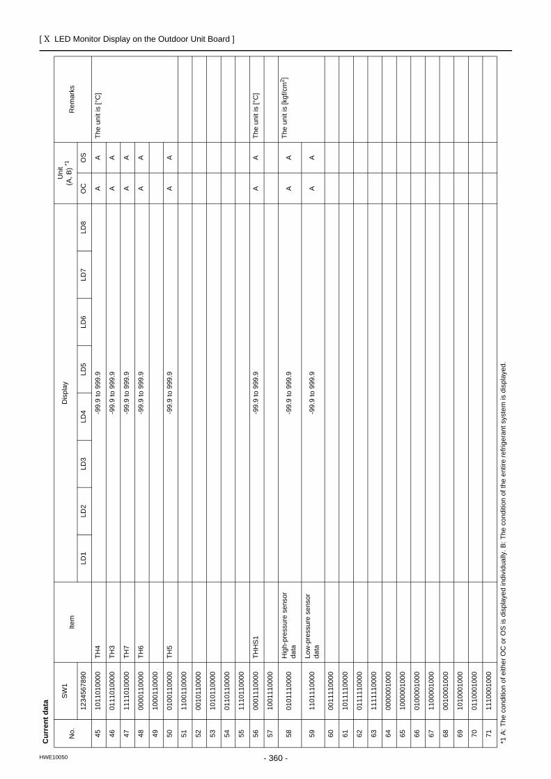
[ X LED Monitor Display on the Outdoor Unit Board ]
- 360 -HWE10050
4510
1101
0000
TH4
-99.
9 to
999
.9A
ATh
e un
it is
[°C
]
4601
1101
0000
TH3
-99.
9 to
999
.9A
A
4711
1101
0000
TH7
-99.
9 to
999
.9A
A
4800
0011
0000
TH6
-99.
9 to
999
.9A
A
4910
0011
0000
5001
0011
0000
TH5
-99.
9 to
999
.9A
A
5111
0011
0000
5200
1011
0000
5310
1011
0000
5401
1011
0000
5511
1011
0000
5600
0111
0000
THH
S1-9
9.9
to 9
99.9
AA
The
unit
is [°
C]
5710
0111
0000
5801
0111
0000
Hig
h-pr
essu
re s
enso
r da
ta-9
9.9
to 9
99.9
AA
The
unit
is [k
gf/c
m2 ]
5911
0111
0000
Low
-pre
ssur
e se
nsor
da
ta-9
9.9
to 9
99.9
AA
6000
1111
0000
6110
1111
0000
6201
1111
0000
6311
1111
0000
6400
0000
1000
6510
0000
1000
6601
0000
1000
6711
0000
1000
6800
1000
1000
6910
1000
1000
7001
1000
1000
7111
1000
1000
Cur
rent
dat
a
No.
SW
1Ite
mD
ispl
ayU
nit
(A, B
) *1R
emar
ks
1234
5678
90LD
1LD
2LD
3LD
4LD
5LD
6LD
7LD
8O
CO
S
*1 A
: The
con
ditio
n of
eith
er O
C o
r OS
is d
ispl
ayed
indi
vidu
ally
. B: T
he c
ondi
tion
of th
e en
tire
refri
gera
nt s
yste
m is
dis
play
ed.
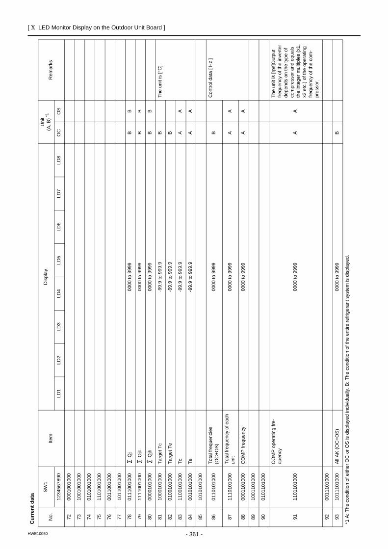
[ X LED Monitor Display on the Outdoor Unit Board ]
- 361 -HWE10050
7200
0100
1000
7310
0100
1000
7401
0100
1000
7511
0100
1000
7600
1100
1000
7710
1100
1000
7801
1100
1000
Qj
0000
to 9
999
BB
7911
1100
1000
Qjc
0000
to 9
999
BB
8000
0010
1000
Qjh
0000
to 9
999
BB
8110
0010
1000
Targ
et T
c-9
9.9
to 9
99.9
BTh
e un
it is
[°C
]
8201
0010
1000
Targ
et T
e-9
9.9
to 9
99.9
B
8311
0010
1000
Tc-9
9.9
to 9
99.9
AA
8400
1010
1000
Te-9
9.9
to 9
99.9
AA
8510
1010
1000
8601
1010
1000
Tota
l fre
quen
cies
(O
C+O
S)00
00 to
999
9B
Con
trol d
ata
[ Hz
]
8711
1010
1000
Tota
l fre
quen
cy o
f eac
h un
it00
00 to
999
9A
A
8800
0110
1000
CO
MP
freq
uenc
y00
00 to
999
9A
A
8910
0110
1000
9001
0110
1000
9111
0110
1000
CO
MP
ope
ratin
g fre
-qu
ency
0000
to 9
999
AA
The
unit
is [r
ps]O
utpu
tfre
quen
cy o
f the
inve
rter
depe
nds
on th
e ty
pe o
fco
mpr
esso
r and
equ
als
the
inte
ger m
ultip
les
(x1,
x2 e
tc.)
of th
e op
erat
ing
frequ
ency
of t
he c
om-
pres
sor.
9200
1110
1000
9310
1110
1000
All A
K (O
C+O
S)00
00 to
999
9B
Cur
rent
dat
a
No.
SW
1Ite
mD
ispl
ayU
nit
(A, B
) *1R
emar
ks
1234
5678
90LD
1LD
2LD
3LD
4LD
5LD
6LD
7LD
8O
CO
S
*1 A
: The
con
ditio
n of
eith
er O
C o
r OS
is d
ispl
ayed
indi
vidu
ally
. B: T
he c
ondi
tion
of th
e en
tire
refri
gera
nt s
yste
m is
dis
play
ed.
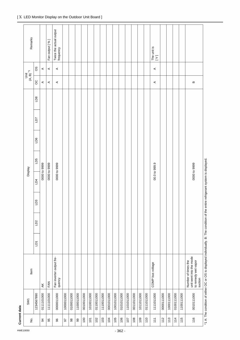
[ X LED Monitor Display on the Outdoor Unit Board ]
- 362 -HWE10050
9401
1110
1000
AK00
00 to
999
9A
A
9511
1110
1000
FAN
0000
to 9
999
AA
Fan
outp
ut [
% ]
9600
0001
1000
Fan
inve
rter o
utpu
t fre
-qu
ency
0000
to 9
999
AA
Twic
e th
e ac
tual
out
put
frequ
ency
9710
0001
1000
9801
0001
1000
9911
0001
1000
100
0010
0110
00
101
1010
0110
00
102
0110
0110
00
103
1110
0110
00
104
0001
0110
00
105
1001
0110
00
106
0101
0110
00
107
1101
0110
00
108
0011
0110
00
109
1011
0110
00
110
0111
0110
00
111
1111
0110
00C
OM
P b
us v
olta
ge00
.0 to
999
.9A
ATh
e un
it is
[ V ]
112
0000
1110
00
113
1000
1110
00
114
0100
1110
00
115
1100
1110
00
116
0010
1110
00
Num
ber o
f tim
es th
e un
it w
ent i
nto
the
mod
e to
rem
edy
wet
vap
or
suct
ion
0000
to 9
999
B
Cur
rent
dat
a
No.
SW
1Ite
mD
ispl
ayU
nit
(A, B
) *1R
emar
ks
1234
5678
90LD
1LD
2LD
3LD
4LD
5LD
6LD
7LD
8O
CO
S
*1 A
: The
con
ditio
n of
eith
er O
C o
r OS
is d
ispl
ayed
indi
vidu
ally
. B: T
he c
ondi
tion
of th
e en
tire
refri
gera
nt s
yste
m is
dis
play
ed.
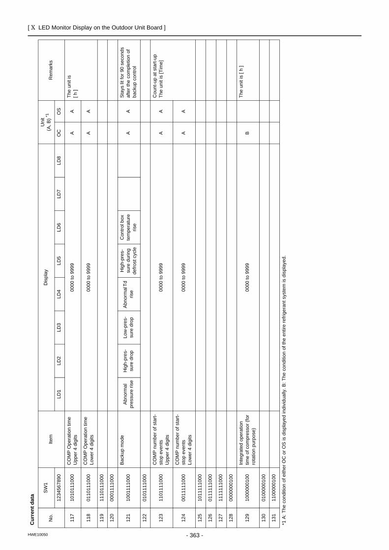
[ X LED Monitor Display on the Outdoor Unit Board ]
- 363 -HWE10050
117
1010
1110
00C
OM
P O
pera
tion
time
Upp
er 4
dig
its00
00 to
999
9A
ATh
e un
it is
[ h ]
118
0110
1110
00C
OM
P O
pera
tion
time
Low
er 4
dig
its00
00 to
999
9A
A
119
1110
1110
00
120
0001
1110
00
121
1001
1110
00Ba
ckup
mod
eA
bnor
mal
pr
essu
re ri
seH
igh-
pres
-su
re d
rop
Low
-pre
s-su
re d
rop
Abno
rmal
Td
rise
Hig
h-pr
es-
sure
dur
ing
defro
st c
ycle
Con
trol b
ox
tem
pera
ture
ris
eA
AS
tays
lit f
or 9
0 se
cond
s af
ter t
he c
ompl
etio
n of
ba
ckup
con
trol
122
0101
1110
00
123
1101
1110
00C
OM
P n
umbe
r of s
tart-
stop
eve
nts
Upp
er 4
dig
its00
00 to
999
9A
AC
ount
-up
at s
tart-
upTh
e un
it is
[Tim
e]
124
0011
1110
00C
OM
P n
umbe
r of s
tart-
stop
eve
nts
Low
er 4
dig
its00
00 to
999
9A
A
125
1011
1110
00
126
0111
1110
00
127
1111
1110
00
128
0000
0001
00
129
1000
0001
00In
tegr
ated
ope
ratio
n tim
e of
com
pres
sor (
for
rota
tion
purp
ose)
0000
to 9
999
BTh
e un
it is
[ h
]
130
0100
0001
00
131
1100
0001
00
Cur
rent
dat
a
No.
SW
1Ite
mD
ispl
ayU
nit
(A, B
) *1R
emar
ks
1234
5678
90LD
1LD
2LD
3LD
4LD
5LD
6LD
7LD
8O
CO
S
*1 A
: The
con
ditio
n of
eith
er O
C o
r OS
is d
ispl
ayed
indi
vidu
ally
. B: T
he c
ondi
tion
of th
e en
tire
refri
gera
nt s
yste
m is
dis
play
ed.
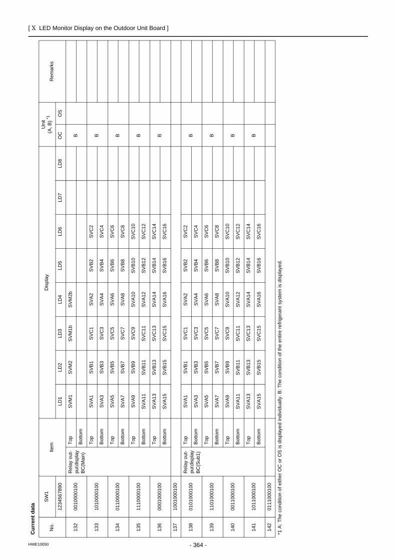
[ X LED Monitor Display on the Outdoor Unit Board ]
- 364 -HWE10050
132
0010
0001
00R
elay
out
-pu
t dis
play
BC
(Mai
n)
Top
SVM
1S
VM2
SVM
1bS
VM2b
BB
otto
m
133
1010
0001
00To
pSV
A1SV
B1
SVC
1S
VA2
SVB
2SV
C2
BB
otto
mSV
A3SV
B3
SVC
3S
VA4
SVB
4SV
C4
134
0110
0001
00To
pSV
A5SV
B5
SVC
5S
VA6
SVB
6SV
C6
BB
otto
mSV
A7SV
B7
SVC
7S
VA8
SVB
8SV
C8
135
1110
0001
00To
pSV
A9SV
B9
SVC
9SV
A10
SVB1
0SV
C10
BB
otto
mS
VA11
SVB1
1SV
C11
SVA
12SV
B12
SVC
12
136
0001
0001
00To
pS
VA13
SVB1
3SV
C13
SVA
14SV
B14
SVC
14B
Bot
tom
SVA
15SV
B15
SVC
15SV
A16
SVB1
6SV
C16
137
1001
0001
00
138
0101
0001
00R
elay
out
-pu
t dis
play
BC
(Sub
1)
Top
SVA1
SVB
1S
VC1
SVA
2S
VB2
SVC
2B
Bot
tom
SVA3
SVB
3S
VC3
SVA
4S
VB4
SVC
4
139
1101
0001
00To
pSV
A5SV
B5
SVC
5S
VA6
SVB
6SV
C6
BB
otto
mSV
A7SV
B7
SVC
7S
VA8
SVB
8SV
C8
140
0011
0001
00To
pSV
A9SV
B9
SVC
9SV
A10
SVB1
0SV
C10
BB
otto
mS
VA11
SVB1
1SV
C11
SVA
12SV
B12
SVC
12
141
1011
0001
00To
pS
VA13
SVB1
3SV
C13
SVA
14SV
B14
SVC
14B
Bot
tom
SVA
15SV
B15
SVC
15SV
A16
SVB1
6SV
C16
142
0111
0001
00
Cur
rent
dat
a
No.
SW
1Ite
mD
ispl
ayU
nit
(A, B
) *1R
emar
ks
1234
5678
90LD
1LD
2LD
3LD
4LD
5LD
6LD
7LD
8O
CO
S
*1 A
: The
con
ditio
n of
eith
er O
C o
r OS
is d
ispl
ayed
indi
vidu
ally
. B: T
he c
ondi
tion
of th
e en
tire
refri
gera
nt s
yste
m is
dis
play
ed.
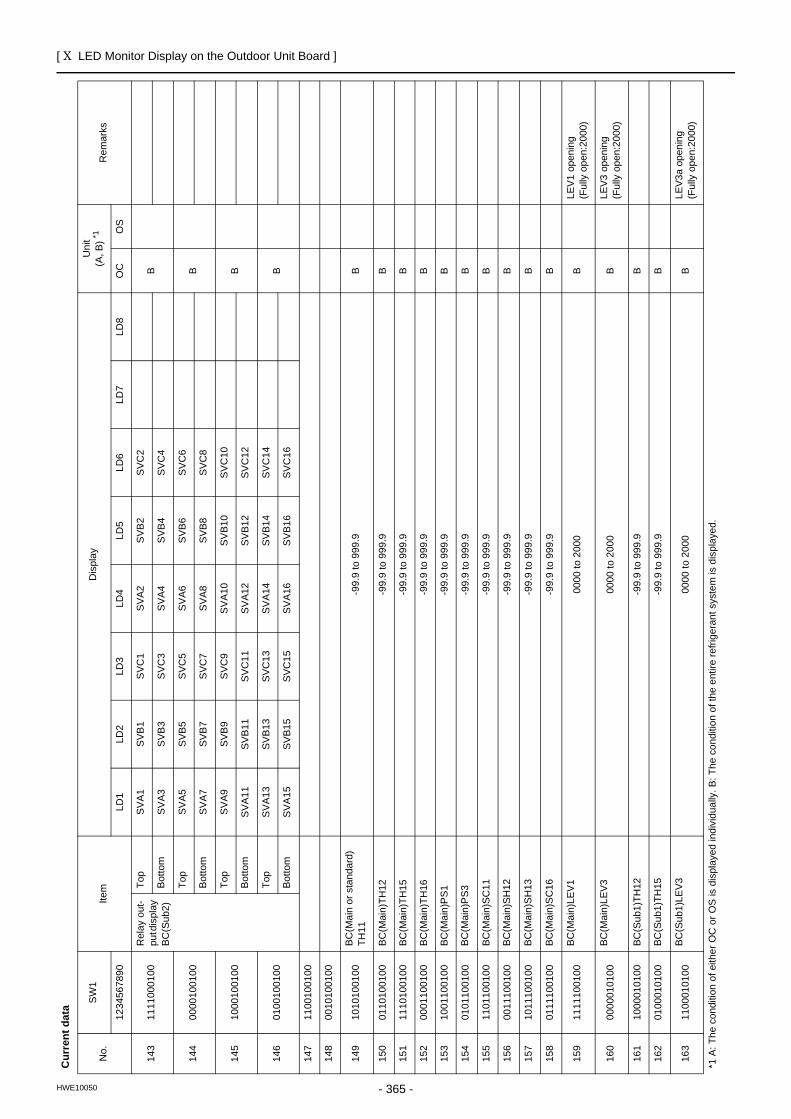
[ X LED Monitor Display on the Outdoor Unit Board ]
- 365 -HWE10050
143
1111
0001
00R
elay
out
-pu
t dis
play
BC
(Sub
2)
Top
SVA1
SVB
1S
VC1
SVA
2S
VB2
SVC
2B
Bot
tom
SVA3
SVB
3S
VC3
SVA
4S
VB4
SVC
4
144
0000
1001
00To
pSV
A5SV
B5
SVC
5S
VA6
SVB
6SV
C6
BB
otto
mSV
A7SV
B7
SVC
7S
VA8
SVB
8SV
C8
145
1000
1001
00To
pSV
A9SV
B9
SVC
9SV
A10
SVB1
0SV
C10
BB
otto
mS
VA11
SVB1
1SV
C11
SVA
12SV
B12
SVC
12
146
0100
1001
00To
pS
VA13
SVB1
3SV
C13
SVA
14SV
B14
SVC
14B
Bot
tom
SVA
15SV
B15
SVC
15SV
A16
SVB1
6SV
C16
147
1100
1001
00
148
0010
1001
00
149
1010
1001
00BC
(Mai
n or
sta
ndar
d)TH
11-9
9.9
to 9
99.9
B
150
0110
1001
00
BC(M
ain)
TH12
-99.
9 to
999
.9B
151
1110
1001
00
BC(M
ain)
TH15
-99.
9 to
999
.9B
152
0001
1001
00
BC(M
ain)
TH16
-99.
9 to
999
.9B
153
1001
1001
00
BC(M
ain)
PS1
-99.
9 to
999
.9B
154
0101
1001
00
BC(M
ain)
PS3
-99.
9 to
999
.9B
155
1101
1001
00
BC(M
ain)
SC
11-9
9.9
to 9
99.9
B
156
0011
1001
00
BC(M
ain)
SH
12-9
9.9
to 9
99.9
B
157
1011
1001
00
BC(M
ain)
SH
13-9
9.9
to 9
99.9
B
158
0111
1001
00
BC(M
ain)
SC
16-9
9.9
to 9
99.9
B
159
1111
1001
00
BC(M
ain)
LEV1
0000
to 2
000
BLE
V1 o
peni
ng(F
ully
ope
n:20
00)
160
0000
0101
00
BC(M
ain)
LEV3
0000
to 2
000
BLE
V3 o
peni
ng(F
ully
ope
n:20
00)
161
1000
0101
00
BC(S
ub1)
TH12
-99.
9 to
999
.9B
162
0100
0101
00
BC(S
ub1)
TH15
-99.
9 to
999
.9B
163
1100
0101
00
BC(S
ub1)
LEV3
0000
to 2
000
BLE
V3a
open
ing
(Ful
ly o
pen:
2000
)
Cur
rent
dat
a
No.
SW
1Ite
mD
ispl
ayU
nit
(A, B
) *1R
emar
ks
1234
5678
90LD
1LD
2LD
3LD
4LD
5LD
6LD
7LD
8O
CO
S
*1 A
: The
con
ditio
n of
eith
er O
C o
r OS
is d
ispl
ayed
indi
vidu
ally
. B: T
he c
ondi
tion
of th
e en
tire
refri
gera
nt s
yste
m is
dis
play
ed.
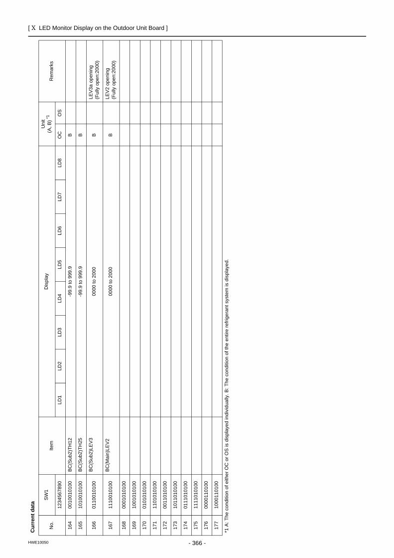
[ X LED Monitor Display on the Outdoor Unit Board ]
- 366 -HWE10050
164
0010
0101
00
BC(S
ub2)
TH12
-99.
9 to
999
.9B
165
1010
0101
00
BC(S
ub2)
TH25
-99.
9 to
999
.9B
166
0110
0101
00
BC(S
ub2)
LEV3
0000
to 2
000
BLE
V3a
open
ing
(Ful
ly o
pen:
2000
)
167
1110
0101
00
BC(M
ain)
LEV2
0000
to 2
000
BLE
V2 o
peni
ng(F
ully
ope
n:20
00)
168
0001
0101
00
169
1001
0101
00
170
0101
0101
00
171
1101
0101
00
172
0011
0101
00
173
1011
0101
00
174
0111
0101
00
175
1111
0101
00
176
0000
1101
00
177
1000
1101
00
Cur
rent
dat
a
No.
SW
1Ite
mD
ispl
ayU
nit
(A, B
) *1R
emar
ks
1234
5678
90LD
1LD
2LD
3LD
4LD
5LD
6LD
7LD
8O
CO
S
*1 A
: The
con
ditio
n of
eith
er O
C o
r OS
is d
ispl
ayed
indi
vidu
ally
. B: T
he c
ondi
tion
of th
e en
tire
refri
gera
nt s
yste
m is
dis
play
ed.
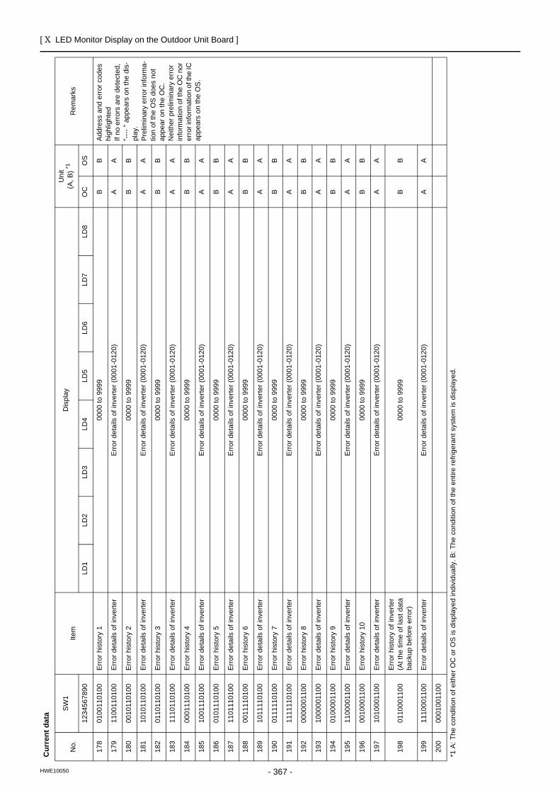
[ X LED Monitor Display on the Outdoor Unit Board ]
- 367 -HWE10050
178
0100
1101
00Er
ror h
isto
ry 1
0000
to 9
999
BB
Add
ress
and
erro
r cod
es
high
light
edIf
no e
rrors
are
det
ecte
d,
"----
" ap
pear
s on
the
dis-
play
.P
relim
inar
y er
ror i
nfor
ma-
tion
of th
e O
S do
es n
ot
appe
ar o
n th
e O
C.
Nei
ther
pre
limin
ary
erro
r in
form
atio
n of
the
OC
nor
er
ror i
nfor
mat
ion
of th
e IC
ap
pear
s on
the
OS
.
179
1100
1101
00
Erro
r det
ails
of i
nver
ter
Erro
r det
ails
of i
nver
ter (
0001
-012
0)A
A
180
0010
1101
00
Erro
r his
tory
200
00 to
999
9B
B
181
1010
1101
00
Erro
r det
ails
of i
nver
ter
Erro
r det
ails
of i
nver
ter (
0001
-012
0)A
A
182
0110
1101
00
Erro
r his
tory
300
00 to
999
9B
B
183
1110
1101
00
Erro
r det
ails
of i
nver
ter
Erro
r det
ails
of i
nver
ter (
0001
-012
0)A
A
184
0001
1101
00
Erro
r his
tory
400
00 to
999
9B
B
185
1001
1101
00
Erro
r det
ails
of i
nver
ter
Erro
r det
ails
of i
nver
ter (
0001
-012
0)A
A
186
0101
1101
00
Erro
r his
tory
500
00 to
999
9B
B
187
1101
1101
00
Erro
r det
ails
of i
nver
ter
Erro
r det
ails
of i
nver
ter (
0001
-012
0)A
A
188
0011
1101
00
Erro
r his
tory
600
00 to
999
9B
B
189
1011
1101
00
Erro
r det
ails
of i
nver
ter
Erro
r det
ails
of i
nver
ter (
0001
-012
0)A
A
190
0111
1101
00
Erro
r his
tory
700
00 to
999
9B
B
191
1111
1101
00
Erro
r det
ails
of i
nver
ter
Erro
r det
ails
of i
nver
ter (
0001
-012
0)A
A
192
0000
0011
00
Erro
r his
tory
800
00 to
999
9B
B
193
1000
0011
00
Erro
r det
ails
of i
nver
ter
Erro
r det
ails
of i
nver
ter (
0001
-012
0)A
A
194
0100
0011
00
Erro
r his
tory
900
00 to
999
9B
B
195
1100
0011
00
Erro
r det
ails
of i
nver
ter
Erro
r det
ails
of i
nver
ter (
0001
-012
0)A
A
196
0010
0011
00
Erro
r his
tory
10
0000
to 9
999
BB
197
1010
0011
00
Erro
r det
ails
of i
nver
ter
Erro
r det
ails
of i
nver
ter (
0001
-012
0)A
A
198
0110
0011
00Er
ror h
isto
ry o
f inv
erte
r(A
t the
tim
e of
last
dat
a ba
ckup
bef
ore
erro
r)00
00 to
999
9B
B
199
1110
0011
00Er
ror d
etai
ls o
f inv
erte
rEr
ror d
etai
ls o
f inv
erte
r (00
01-0
120)
AA
200
0001
0011
00
Cur
rent
dat
a
No.
SW
1Ite
mD
ispl
ayU
nit
(A, B
) *1R
emar
ks
1234
5678
90LD
1LD
2LD
3LD
4LD
5LD
6LD
7LD
8O
CO
S
*1 A
: The
con
ditio
n of
eith
er O
C o
r OS
is d
ispl
ayed
indi
vidu
ally
. B: T
he c
ondi
tion
of th
e en
tire
refri
gera
nt s
yste
m is
dis
play
ed.
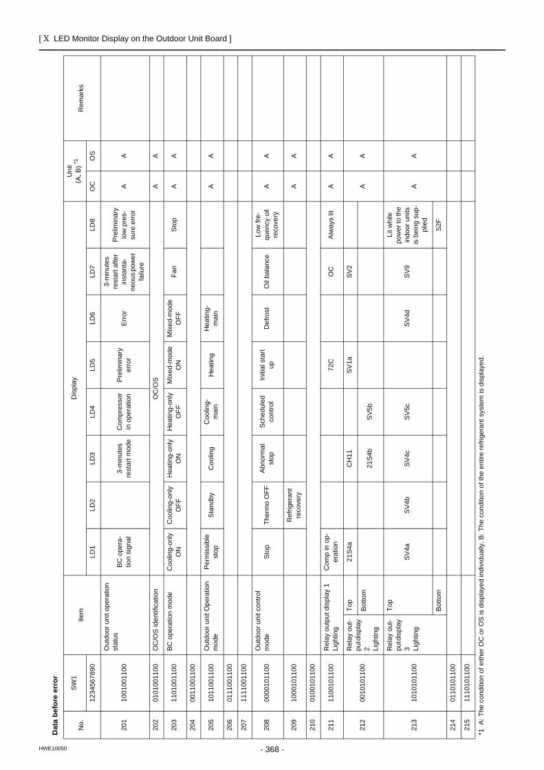
[ X LED Monitor Display on the Outdoor Unit Board ]
- 368 -HWE10050
Dat
a be
fore
err
or
No.
SW
1Ite
mD
ispl
ayU
nit
(A, B
) *1R
emar
ks
1234
5678
90LD
1LD
2LD
3LD
4LD
5LD
6LD
7LD
8O
CO
S
201
1001
0011
00
Out
door
uni
t ope
ratio
n st
atus
BC o
pera
-tio
n si
gnal
3-m
inut
es
rest
art m
ode
Com
pres
sor
in o
pera
tion
Pre
limin
ary
erro
rEr
ror
3-m
inut
es
rest
art a
fter
inst
anta
-ne
ous p
ower
fa
ilure
Pre
limin
ary
low
pre
s-su
re e
rror
AA
202
0101
0011
00O
C/O
S id
entif
icat
ion
OC
/OS
AA
203
1101
0011
00BC
ope
ratio
n m
ode
Coo
ling-
only
O
NC
oolin
g-on
ly
OFF
Hea
ting-
only
O
NH
eatin
g-on
ly
OFF
Mix
ed-m
ode
ON
Mix
ed-m
ode
OFF
Fan
Stop
AA
204
0011
0011
00
205
1011
0011
00O
utdo
or u
nit O
pera
tion
mod
ePe
rmis
sibl
e st
opS
tand
byC
oolin
gC
oolin
g-m
ain
Hea
ting
Hea
ting-
mai
nA
A
206
0111
0011
00
207
1111
0011
00
208
0000
1011
00O
utdo
or u
nit c
ontro
l m
ode
Sto
pTh
erm
o O
FFAb
norm
al
stop
Sche
dule
d co
ntro
lIn
itial
sta
rt up
Def
rost
Oil
bala
nce
Low
fre-
quen
cy o
il re
cove
ryA
A
209
1000
1011
00R
efrig
eran
t re
cove
ryA
A
210
0100
1011
00
211
1100
1011
00R
elay
out
put d
ispl
ay 1
Ligh
ting
Com
p in
op-
erat
ion
72C
OC
Alw
ays
litA
A
212
0010
1011
00
Rel
ay o
ut-
put d
ispl
ay
2 Ligh
ting
Top
21S4
aC
H11
SV1
aSV
2
AA
Bot
tom
21S4
bS
V5b
213
1010
1011
00
Rel
ay o
ut-
put d
ispl
ay
3 Ligh
ting
Top
SV4a
SV4b
SV4c
SV5c
SV4d
SV9
Lit w
hile
po
wer
to th
e in
door
uni
ts
is b
eing
sup
-pl
ied
AA
Bot
tom
52F
214
0110
1011
00
215
1110
1011
00
*1 A
: The
con
ditio
n of
eith
er O
C o
r OS
is d
ispl
ayed
indi
vidu
ally
. B: T
he c
ondi
tion
of th
e en
tire
refri
gera
nt s
yste
m is
dis
play
ed.
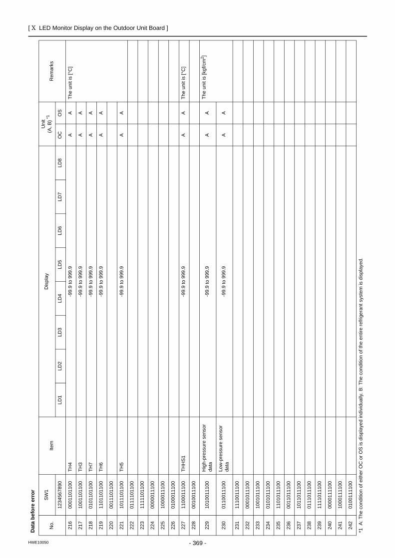
[ X LED Monitor Display on the Outdoor Unit Board ]
- 369 -HWE10050
216
0001
1011
00TH
4-9
9.9
to 9
99.9
AA
The
unit
is [°
C]
217
1001
1011
00TH
3-9
9.9
to 9
99.9
AA
218
0101
1011
00TH
7-9
9.9
to 9
99.9
AA
219
1101
1011
00TH
6-9
9.9
to 9
99.9
AA
220
0011
1011
00
221
1011
1011
00TH
5-9
9.9
to 9
99.9
AA
222
0111
1011
00
223
1111
1011
00
224
0000
0111
00
225
1000
0111
00
226
0100
0111
00
227
1100
0111
00TH
HS1
-99.
9 to
999
.9A
ATh
e un
it is
[°C
]
228
0010
0111
00
229
1010
0111
00H
igh-
pres
sure
sen
sor
data
-99.
9 to
999
.9A
ATh
e un
it is
[kgf
/cm
2 ]
230
0110
0111
00Lo
w-p
ress
ure
sens
or
data
-99.
9 to
999
.9A
A
231
1110
0111
00
232
0001
0111
00
233
1001
0111
00
234
0101
0111
00
235
1101
0111
00
236
0011
0111
00
237
1011
0111
00
238
0111
0111
00
239
1111
0111
00
240
0000
1111
00
241
1000
1111
00
242
0100
1111
00
Dat
a be
fore
err
or
No.
SW
1Ite
mD
ispl
ayU
nit
(A, B
) *1R
emar
ks
1234
5678
90LD
1LD
2LD
3LD
4LD
5LD
6LD
7LD
8O
CO
S
*1 A
: The
con
ditio
n of
eith
er O
C o
r OS
is d
ispl
ayed
indi
vidu
ally
. B: T
he c
ondi
tion
of th
e en
tire
refri
gera
nt s
yste
m is
dis
play
ed.
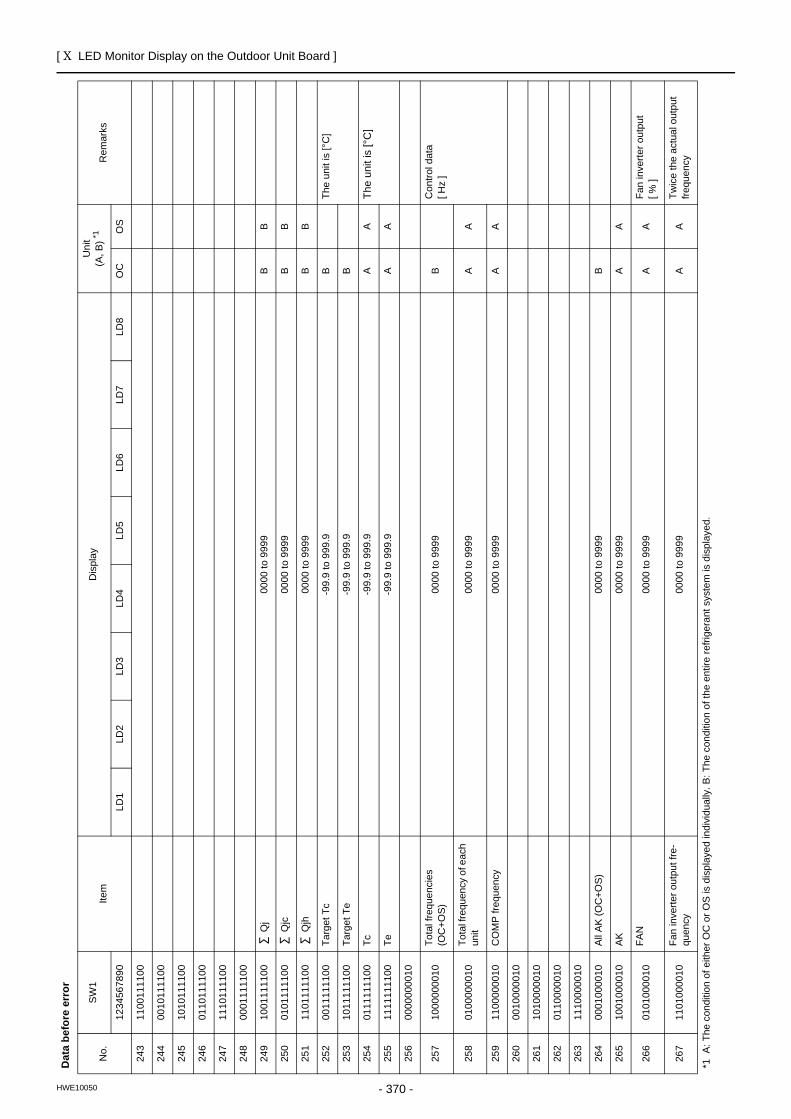
[ X LED Monitor Display on the Outdoor Unit Board ]
- 370 -HWE10050
243
1100
1111
00
244
0010
1111
00
245
1010
1111
00
246
0110
1111
00
247
1110
1111
00
248
0001
1111
00
249
1001
1111
00 Q
j 00
00 to
999
9B
B
250
0101
1111
00 Q
jc00
00 to
999
9B
B
251
1101
1111
00 Q
jh00
00 to
999
9B
B
252
0011
1111
00Ta
rget
Tc
-99.
9 to
999
.9B
The
unit
is [°
C]
253
1011
1111
00Ta
rget
Te
-99.
9 to
999
.9B
254
0111
1111
00Tc
-99.
9 to
999
.9A
ATh
e un
it is
[°C
]
255
1111
1111
00Te
-99.
9 to
999
.9A
A
256
0000
0000
10
257
1000
0000
10To
tal f
requ
enci
es
(OC
+OS)
0000
to 9
999
BC
ontro
l dat
a[ H
z ]
258
0100
0000
10To
tal f
requ
ency
of e
ach
unit
0000
to 9
999
AA
259
1100
0000
10C
OM
P fr
eque
ncy
0000
to 9
999
AA
260
0010
0000
10
261
1010
0000
10
262
0110
0000
10
263
1110
0000
10
264
0001
0000
10Al
l AK
(OC
+OS)
0000
to 9
999
B
265
1001
0000
10AK
0000
to 9
999
AA
266
0101
0000
10FA
N00
00 to
999
9A
AFa
n in
verte
r out
put
[ % ]
267
1101
0000
10Fa
n in
verte
r out
put f
re-
quen
cy00
00 to
999
9A
ATw
ice
the
actu
al o
utpu
t fre
quen
cy
Dat
a be
fore
err
or
No.
SW
1Ite
mD
ispl
ayU
nit
(A, B
) *1R
emar
ks
1234
5678
90LD
1LD
2LD
3LD
4LD
5LD
6LD
7LD
8O
CO
S
*1 A
: The
con
ditio
n of
eith
er O
C o
r OS
is d
ispl
ayed
indi
vidu
ally
. B: T
he c
ondi
tion
of th
e en
tire
refri
gera
nt s
yste
m is
dis
play
ed.
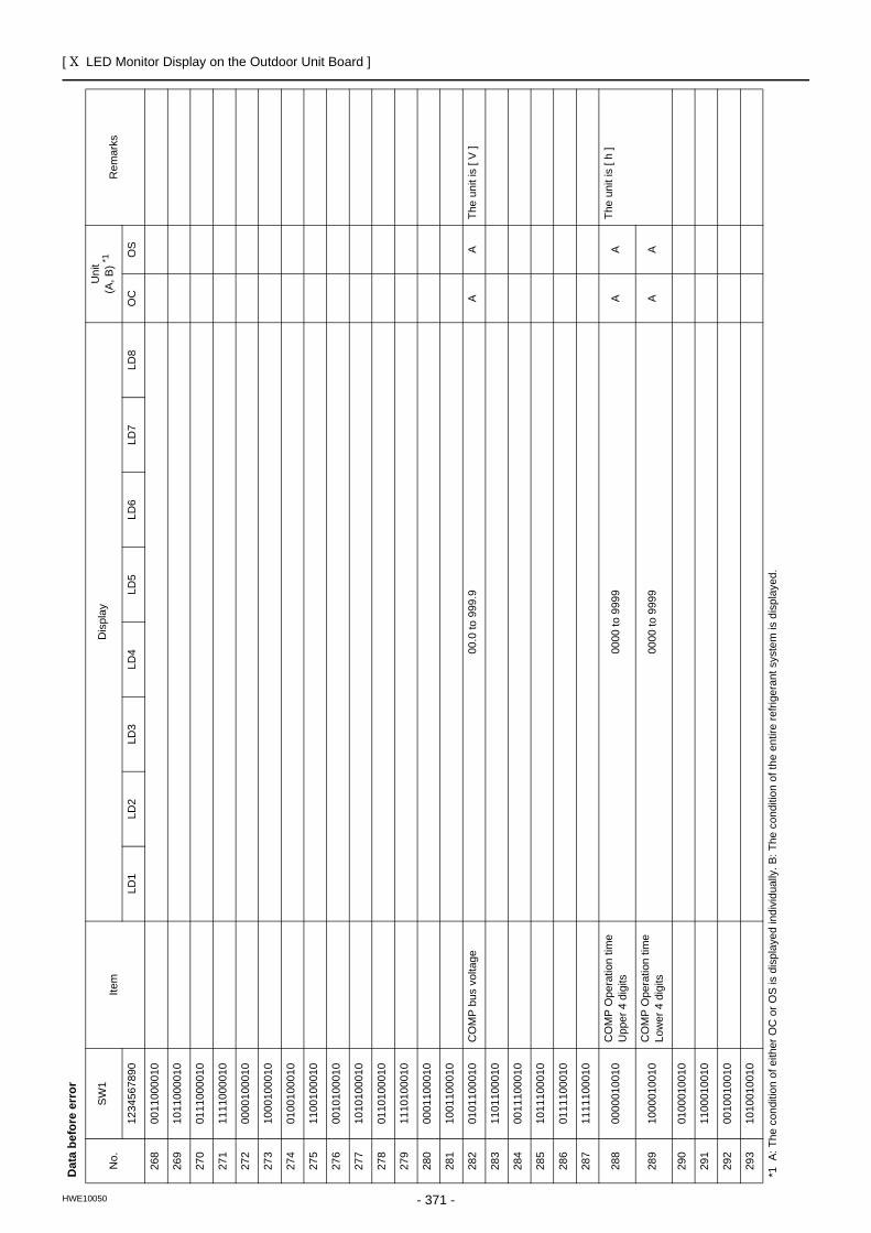
[ X LED Monitor Display on the Outdoor Unit Board ]
- 371 -HWE10050
268
0011
0000
10
269
1011
0000
10
270
0111
0000
10
271
1111
0000
10
272
0000
1000
10
273
1000
1000
10
274
0100
1000
10
275
1100
1000
10
276
0010
1000
10
277
1010
1000
10
278
0110
1000
10
279
1110
1000
10
280
0001
1000
10
281
1001
1000
10
282
0101
1000
10C
OM
P b
us v
olta
ge00
.0 to
999
.9A
ATh
e un
it is
[ V
]
283
1101
1000
10
284
0011
1000
10
285
1011
1000
10
286
0111
1000
10
287
1111
1000
10
288
0000
0100
10C
OM
P O
pera
tion
time
Upp
er 4
dig
its00
00 to
999
9A
ATh
e un
it is
[ h
]
289
1000
0100
10C
OM
P O
pera
tion
time
Low
er 4
dig
its00
00 to
999
9A
A
290
0100
0100
10
291
1100
0100
10
292
0010
0100
10
293
1010
0100
10
Dat
a be
fore
err
or
No.
SW
1Ite
mD
ispl
ayU
nit
(A, B
) *1R
emar
ks
1234
5678
90LD
1LD
2LD
3LD
4LD
5LD
6LD
7LD
8O
CO
S
*1 A
: The
con
ditio
n of
eith
er O
C o
r OS
is d
ispl
ayed
indi
vidu
ally
. B: T
he c
ondi
tion
of th
e en
tire
refri
gera
nt s
yste
m is
dis
play
ed.
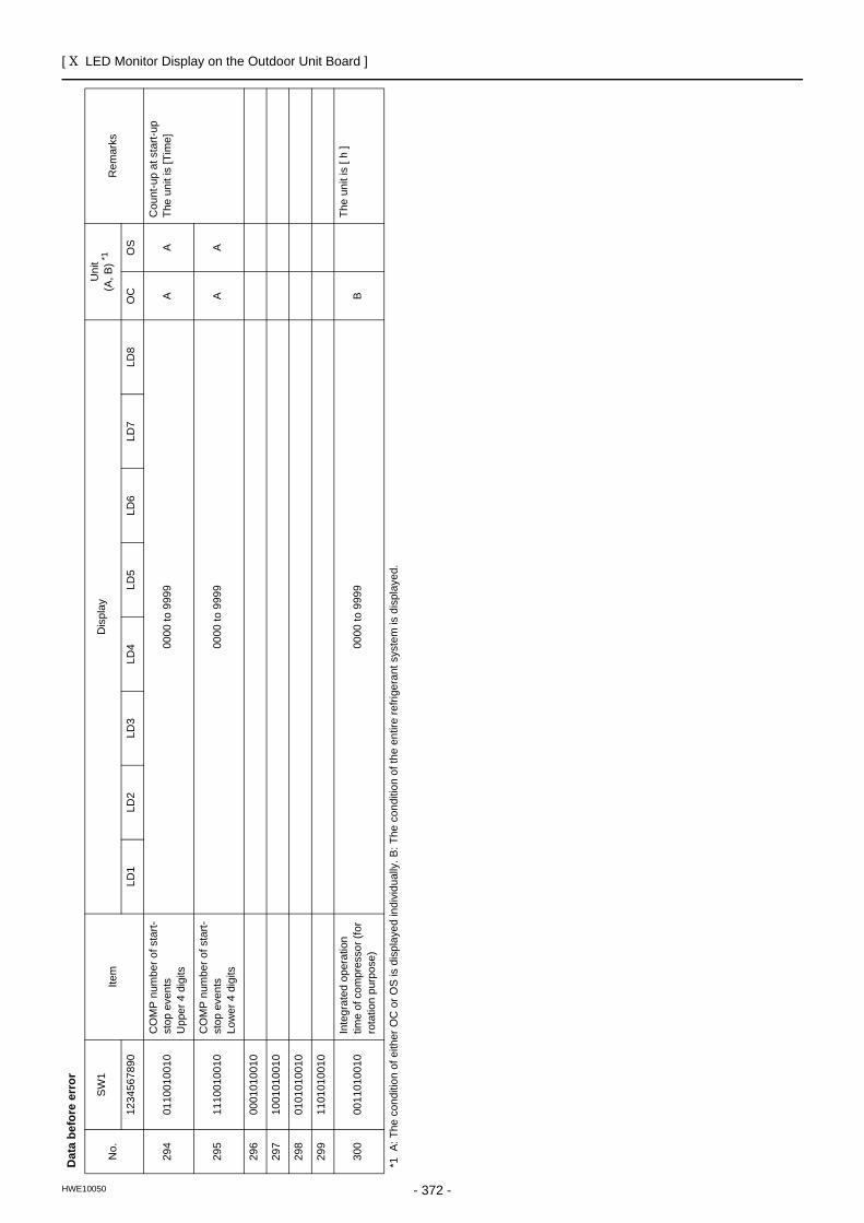
[ X LED Monitor Display on the Outdoor Unit Board ]
- 372 -HWE10050
294
0110
0100
10C
OM
P n
umbe
r of s
tart-
stop
eve
nts
Upp
er 4
dig
its00
00 to
999
9A
AC
ount
-up
at s
tart-
upTh
e un
it is
[Tim
e]
295
1110
0100
10C
OM
P n
umbe
r of s
tart-
stop
eve
nts
Low
er 4
dig
its00
00 to
999
9A
A
296
0001
0100
10
297
1001
0100
10
298
0101
0100
10
299
1101
0100
10
300
0011
0100
10In
tegr
ated
ope
ratio
n tim
e of
com
pres
sor (
for
rota
tion
purp
ose)
0000
to 9
999
BTh
e un
it is
[ h
]
Dat
a be
fore
err
or
No.
SW
1Ite
mD
ispl
ayU
nit
(A, B
) *1R
emar
ks
1234
5678
90LD
1LD
2LD
3LD
4LD
5LD
6LD
7LD
8O
CO
S
*1 A
: The
con
ditio
n of
eith
er O
C o
r OS
is d
ispl
ayed
indi
vidu
ally
. B: T
he c
ondi
tion
of th
e en
tire
refri
gera
nt s
yste
m is
dis
play
ed.
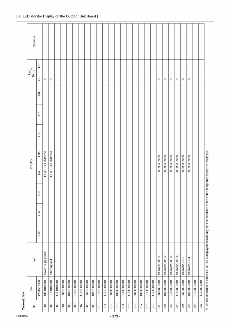
[ X LED Monitor Display on the Outdoor Unit Board ]
- 373 -HWE10050
Cur
rent
dat
a
No.
SW
1Ite
mD
ispl
ayU
nit
(A, B
)*1R
emar
ks
1234
5678
90LD
1LD
2LD
3LD
4LD
5LD
6LD
7LD
8O
CO
S
301
1011
0100
10Po
wer
sup
ply
unit
OC
/OS
<->
Add
ress
B
302
0111
0100
10St
art-u
p un
itO
C/O
S <-
> A
ddre
ssB
303
1111
0100
10
304
0000
1100
10
305
1000
1100
10
306
0100
1100
10
307
1100
1100
10
308
0010
1100
10
309
1010
1100
10
310
0110
1100
10
311
1110
1100
10
312
0001
1100
10
313
1001
1100
10
314
0101
1100
10
315
1101
1100
10
316
0011
1100
10
317
1011
1100
10
318
0111
1100
10
319
1111
1100
10
320
0000
0010
10
BC(M
ain)
TH11
-99.
9 to
999
.9B
321
1000
0010
10
BC(M
ain)
TH12
-99.
9 to
999
.9B
322
0100
0010
10
BC(M
ain)
TH15
-99.
9 to
999
.9B
323
1100
0010
10
BC(M
ain)
TH16
-99.
9 to
999
.9B
324
0010
0010
10
BC(M
ain)
PS1
-99.
9 to
999
.9B
325
1010
0010
10
BC(M
ain)
PS3
-99.
9 to
999
.9B
326
0110
0010
10
327
1110
0010
10
*1 A
: The
con
ditio
n of
eith
er O
C o
r OS
is d
ispl
ayed
indi
vidu
ally
. B: T
he c
ondi
tion
of th
e en
tire
refri
gera
nt s
yste
m is
dis
play
ed.
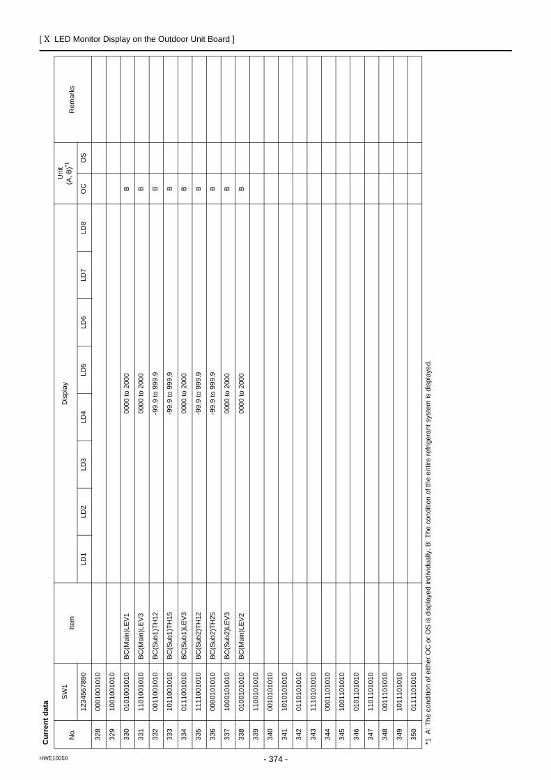
[ X LED Monitor Display on the Outdoor Unit Board ]
- 374 -HWE10050
328
0001
0010
10
329
1001
0010
10
330
0101
0010
10
BC(M
ain)
LEV1
0000
to 2
000
B
331
1101
0010
10
BC(M
ain)
LEV3
0000
to 2
000
B
332
0011
0010
10
BC(S
ub1)
TH12
-99.
9 to
999
.9B
333
1011
0010
10
BC(S
ub1)
TH15
-99.
9 to
999
.9B
334
0111
0010
10
BC(S
ub1)
LEV3
0000
to 2
000
B
335
1111
0010
10
BC(S
ub2)
TH12
-99.
9 to
999
.9B
336
0000
1010
10
BC(S
ub2)
TH25
-99.
9 to
999
.9B
337
1000
1010
10
BC(S
ub2)
LEV3
0000
to 2
000
B
338
0100
1010
10
BC(M
ain)
LEV2
0000
to 2
000
B
339
1100
1010
10
340
0010
1010
10
341
1010
1010
10
342
0110
1010
10
343
1110
1010
10
344
0001
1010
10
345
1001
1010
10
346
0101
1010
10
347
1101
1010
10
348
0011
1010
10
349
1011
1010
10
350
0111
1010
10
Cur
rent
dat
a
No.
SW
1Ite
mD
ispl
ayU
nit
(A, B
)*1R
emar
ks
1234
5678
90LD
1LD
2LD
3LD
4LD
5LD
6LD
7LD
8O
CO
S
*1 A
: The
con
ditio
n of
eith
er O
C o
r OS
is d
ispl
ayed
indi
vidu
ally
. B: T
he c
ondi
tion
of th
e en
tire
refri
gera
nt s
yste
m is
dis
play
ed.
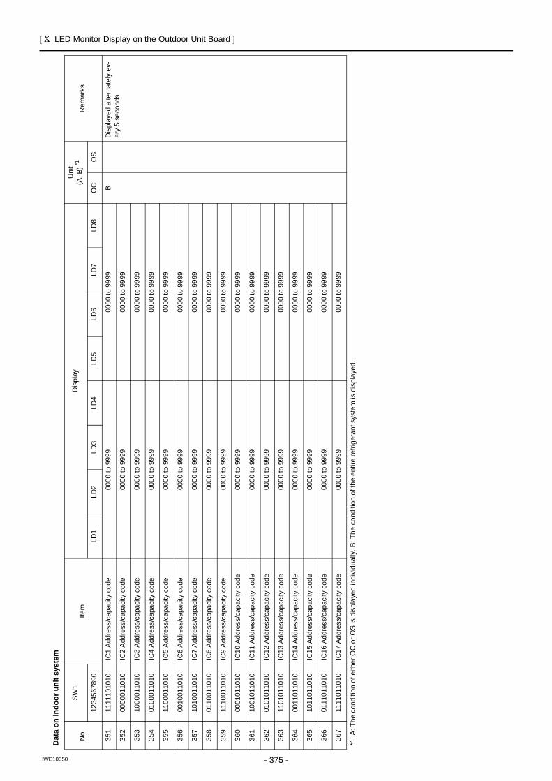
[ X LED Monitor Display on the Outdoor Unit Board ]
- 375 -HWE10050
Dat
a on
indo
or u
nit s
yste
m
No.
SW
1Ite
mD
ispl
ayU
nit
(A, B
) *1R
emar
ks
1234
5678
90LD
1LD
2LD
3LD
4LD
5LD
6LD
7LD
8O
CO
S
351
1111
1010
10
IC1
Addr
ess/
capa
city
cod
e00
00 to
999
900
00 to
999
9B
Dis
play
ed a
ltern
atel
y ev
-er
y 5
seco
nds
352
0000
0110
10IC
2 Ad
dres
s/ca
paci
ty c
ode
0000
to 9
999
0000
to 9
999
353
1000
0110
10IC
3 Ad
dres
s/ca
paci
ty c
ode
0000
to 9
999
0000
to 9
999
354
0100
0110
10IC
4 Ad
dres
s/ca
paci
ty c
ode
0000
to 9
999
0000
to 9
999
355
1100
0110
10IC
5 Ad
dres
s/ca
paci
ty c
ode
0000
to 9
999
0000
to 9
999
356
0010
0110
10IC
6 Ad
dres
s/ca
paci
ty c
ode
0000
to 9
999
0000
to 9
999
357
1010
0110
10IC
7 Ad
dres
s/ca
paci
ty c
ode
0000
to 9
999
0000
to 9
999
358
0110
0110
10IC
8 Ad
dres
s/ca
paci
ty c
ode
0000
to 9
999
0000
to 9
999
359
1110
0110
10IC
9 Ad
dres
s/ca
paci
ty c
ode
0000
to 9
999
0000
to 9
999
360
0001
0110
10IC
10 A
ddre
ss/c
apac
ity c
ode
0000
to 9
999
0000
to 9
999
361
1001
0110
10IC
11 A
ddre
ss/c
apac
ity c
ode
0000
to 9
999
0000
to 9
999
362
0101
0110
10IC
12 A
ddre
ss/c
apac
ity c
ode
0000
to 9
999
0000
to 9
999
363
1101
0110
10IC
13 A
ddre
ss/c
apac
ity c
ode
0000
to 9
999
0000
to 9
999
364
0011
0110
10IC
14 A
ddre
ss/c
apac
ity c
ode
0000
to 9
999
0000
to 9
999
365
1011
0110
10IC
15 A
ddre
ss/c
apac
ity c
ode
0000
to 9
999
0000
to 9
999
366
0111
0110
10IC
16 A
ddre
ss/c
apac
ity c
ode
0000
to 9
999
0000
to 9
999
367
1111
0110
10IC
17 A
ddre
ss/c
apac
ity c
ode
0000
to 9
999
0000
to 9
999
*1 A
: The
con
ditio
n of
eith
er O
C o
r OS
is d
ispl
ayed
indi
vidu
ally
. B: T
he c
ondi
tion
of th
e en
tire
refri
gera
nt s
yste
m is
dis
play
ed.
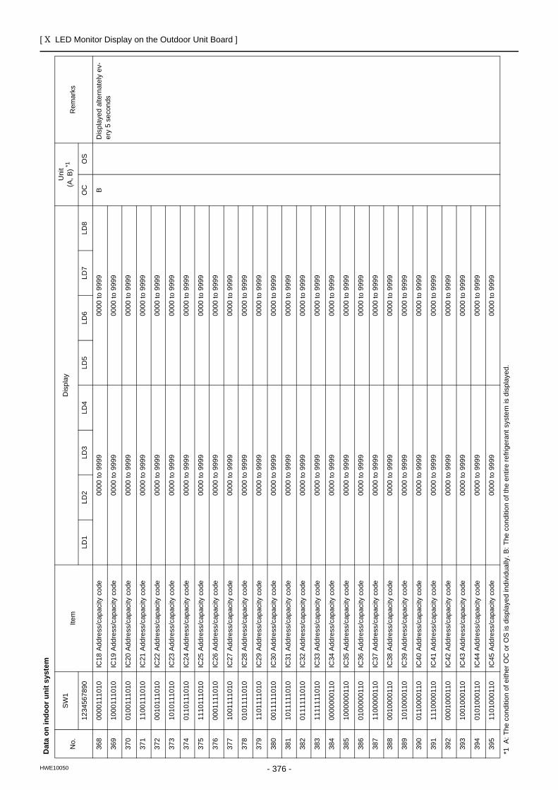
[ X LED Monitor Display on the Outdoor Unit Board ]
- 376 -HWE10050
368
0000
1110
10IC
18 A
ddre
ss/c
apac
ity c
ode
0000
to 9
999
0000
to 9
999
BD
ispl
ayed
alte
rnat
ely
ev-
ery
5 se
cond
s36
910
0011
1010
IC19
Add
ress
/cap
acity
cod
e00
00 to
999
900
00 to
999
9
370
0100
1110
10IC
20 A
ddre
ss/c
apac
ity c
ode
0000
to 9
999
0000
to 9
999
371
1100
1110
10IC
21 A
ddre
ss/c
apac
ity c
ode
0000
to 9
999
0000
to 9
999
372
0010
1110
10IC
22 A
ddre
ss/c
apac
ity c
ode
0000
to 9
999
0000
to 9
999
373
1010
1110
10IC
23 A
ddre
ss/c
apac
ity c
ode
0000
to 9
999
0000
to 9
999
374
0110
1110
10IC
24 A
ddre
ss/c
apac
ity c
ode
0000
to 9
999
0000
to 9
999
375
1110
1110
10IC
25 A
ddre
ss/c
apac
ity c
ode
0000
to 9
999
0000
to 9
999
376
0001
1110
10IC
26 A
ddre
ss/c
apac
ity c
ode
0000
to 9
999
0000
to 9
999
377
1001
1110
10IC
27 A
ddre
ss/c
apac
ity c
ode
0000
to 9
999
0000
to 9
999
378
0101
1110
10IC
28 A
ddre
ss/c
apac
ity c
ode
0000
to 9
999
0000
to 9
999
379
1101
1110
10IC
29 A
ddre
ss/c
apac
ity c
ode
0000
to 9
999
0000
to 9
999
380
0011
1110
10IC
30 A
ddre
ss/c
apac
ity c
ode
0000
to 9
999
0000
to 9
999
381
1011
1110
10IC
31 A
ddre
ss/c
apac
ity c
ode
0000
to 9
999
0000
to 9
999
382
0111
1110
10IC
32 A
ddre
ss/c
apac
ity c
ode
0000
to 9
999
0000
to 9
999
383
1111
1110
10IC
33 A
ddre
ss/c
apac
ity c
ode
0000
to 9
999
0000
to 9
999
384
0000
0001
10IC
34 A
ddre
ss/c
apac
ity c
ode
0000
to 9
999
0000
to 9
999
385
1000
0001
10IC
35 A
ddre
ss/c
apac
ity c
ode
0000
to 9
999
0000
to 9
999
386
0100
0001
10IC
36 A
ddre
ss/c
apac
ity c
ode
0000
to 9
999
0000
to 9
999
387
1100
0001
10IC
37 A
ddre
ss/c
apac
ity c
ode
0000
to 9
999
0000
to 9
999
388
0010
0001
10IC
38 A
ddre
ss/c
apac
ity c
ode
0000
to 9
999
0000
to 9
999
389
1010
0001
10IC
39 A
ddre
ss/c
apac
ity c
ode
0000
to 9
999
0000
to 9
999
390
0110
0001
10IC
40 A
ddre
ss/c
apac
ity c
ode
0000
to 9
999
0000
to 9
999
391
1110
0001
10IC
41 A
ddre
ss/c
apac
ity c
ode
0000
to 9
999
0000
to 9
999
392
0001
0001
10IC
42 A
ddre
ss/c
apac
ity c
ode
0000
to 9
999
0000
to 9
999
393
1001
0001
10IC
43 A
ddre
ss/c
apac
ity c
ode
0000
to 9
999
0000
to 9
999
394
0101
0001
10IC
44 A
ddre
ss/c
apac
ity c
ode
0000
to 9
999
0000
to 9
999
395
1101
0001
10IC
45 A
ddre
ss/c
apac
ity c
ode
0000
to 9
999
0000
to 9
999
Dat
a on
indo
or u
nit s
yste
m
No.
SW
1Ite
mD
ispl
ayU
nit
(A, B
) *1R
emar
ks
1234
5678
90LD
1LD
2LD
3LD
4LD
5LD
6LD
7LD
8O
CO
S
*1 A
: The
con
ditio
n of
eith
er O
C o
r OS
is d
ispl
ayed
indi
vidu
ally
. B: T
he c
ondi
tion
of th
e en
tire
refri
gera
nt s
yste
m is
dis
play
ed.
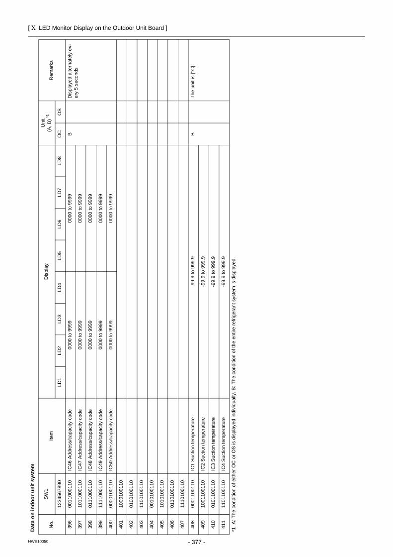
[ X LED Monitor Display on the Outdoor Unit Board ]
- 377 -HWE10050
396
0011
0001
10IC
46 A
ddre
ss/c
apac
ity c
ode
0000
to 9
999
0000
to 9
999
BD
ispl
ayed
alte
rnat
ely
ev-
ery
5 se
cond
s39
710
1100
0110
IC47
Add
ress
/cap
acity
cod
e00
00 to
999
900
00 to
999
9
398
0111
0001
10IC
48 A
ddre
ss/c
apac
ity c
ode
0000
to 9
999
0000
to 9
999
399
1111
0001
10IC
49 A
ddre
ss/c
apac
ity c
ode
0000
to 9
999
0000
to 9
999
400
0000
1001
10IC
50 A
ddre
ss/c
apac
ity c
ode
0000
to 9
999
0000
to 9
999
401
1000
1001
10
402
0100
1001
10
403
1100
1001
10
404
0010
1001
10
405
1010
1001
10
406
0110
1001
10
407
1110
1001
10
408
0001
1001
10IC
1 Su
ctio
n te
mpe
ratu
re-9
9.9
to 9
99.9
BTh
e un
it is
[°C
]
409
1001
1001
10IC
2 Su
ctio
n te
mpe
ratu
re-9
9.9
to 9
99.9
410
0101
1001
10IC
3 Su
ctio
n te
mpe
ratu
re-9
9.9
to 9
99.9
411
1101
1001
10IC
4 Su
ctio
n te
mpe
ratu
re-9
9.9
to 9
99.9
Dat
a on
indo
or u
nit s
yste
m
No.
SW
1Ite
mD
ispl
ayU
nit
(A, B
) *1R
emar
ks
1234
5678
90LD
1LD
2LD
3LD
4LD
5LD
6LD
7LD
8O
CO
S
*1 A
: The
con
ditio
n of
eith
er O
C o
r OS
is d
ispl
ayed
indi
vidu
ally
. B: T
he c
ondi
tion
of th
e en
tire
refri
gera
nt s
yste
m is
dis
play
ed.
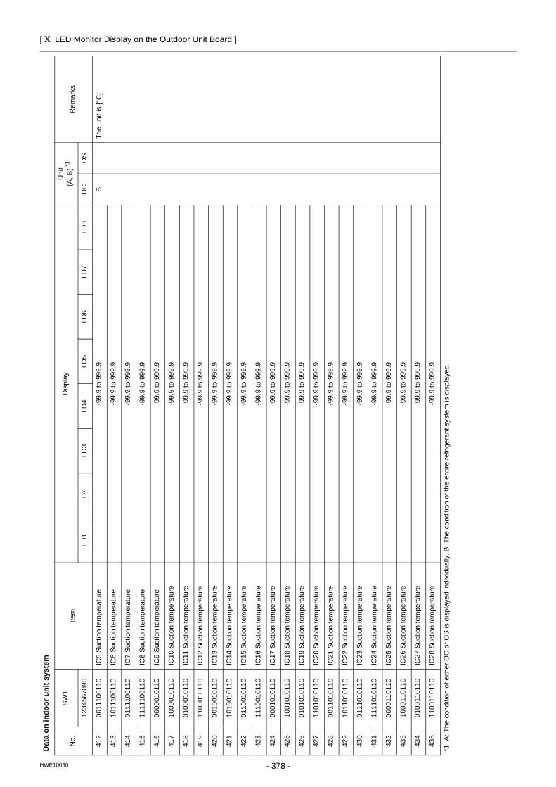
[ X LED Monitor Display on the Outdoor Unit Board ]
- 378 -HWE10050
412
0011
1001
10IC
5 Su
ctio
n te
mpe
ratu
re-9
9.9
to 9
99.9
BTh
e un
it is
[°C
]
413
1011
1001
10IC
6 Su
ctio
n te
mpe
ratu
re-9
9.9
to 9
99.9
414
0111
1001
10IC
7 Su
ctio
n te
mpe
ratu
re-9
9.9
to 9
99.9
415
1111
1001
10IC
8 Su
ctio
n te
mpe
ratu
re-9
9.9
to 9
99.9
416
0000
0101
10IC
9 Su
ctio
n te
mpe
ratu
re-9
9.9
to 9
99.9
417
1000
0101
10IC
10 S
uctio
n te
mpe
ratu
re-9
9.9
to 9
99.9
418
0100
0101
10IC
11 S
uctio
n te
mpe
ratu
re-9
9.9
to 9
99.9
419
1100
0101
10IC
12 S
uctio
n te
mpe
ratu
re-9
9.9
to 9
99.9
420
0010
0101
10IC
13 S
uctio
n te
mpe
ratu
re-9
9.9
to 9
99.9
421
1010
0101
10IC
14 S
uctio
n te
mpe
ratu
re-9
9.9
to 9
99.9
422
0110
0101
10IC
15 S
uctio
n te
mpe
ratu
re-9
9.9
to 9
99.9
423
1110
0101
10IC
16 S
uctio
n te
mpe
ratu
re-9
9.9
to 9
99.9
424
0001
0101
10IC
17 S
uctio
n te
mpe
ratu
re-9
9.9
to 9
99.9
425
1001
0101
10IC
18 S
uctio
n te
mpe
ratu
re-9
9.9
to 9
99.9
426
0101
0101
10IC
19 S
uctio
n te
mpe
ratu
re-9
9.9
to 9
99.9
427
1101
0101
10IC
20 S
uctio
n te
mpe
ratu
re-9
9.9
to 9
99.9
428
0011
0101
10IC
21 S
uctio
n te
mpe
ratu
re-9
9.9
to 9
99.9
429
1011
0101
10IC
22 S
uctio
n te
mpe
ratu
re-9
9.9
to 9
99.9
430
0111
0101
10IC
23 S
uctio
n te
mpe
ratu
re-9
9.9
to 9
99.9
431
1111
0101
10IC
24 S
uctio
n te
mpe
ratu
re-9
9.9
to 9
99.9
432
0000
1101
10IC
25 S
uctio
n te
mpe
ratu
re-9
9.9
to 9
99.9
433
1000
1101
10IC
26 S
uctio
n te
mpe
ratu
re-9
9.9
to 9
99.9
434
0100
1101
10IC
27 S
uctio
n te
mpe
ratu
re-9
9.9
to 9
99.9
435
1100
1101
10IC
28 S
uctio
n te
mpe
ratu
re-9
9.9
to 9
99.9
Dat
a on
indo
or u
nit s
yste
m
No.
SW
1Ite
mD
ispl
ayU
nit
(A, B
) *1R
emar
ks
1234
5678
90LD
1LD
2LD
3LD
4LD
5LD
6LD
7LD
8O
CO
S
*1 A
: The
con
ditio
n of
eith
er O
C o
r OS
is d
ispl
ayed
indi
vidu
ally
. B: T
he c
ondi
tion
of th
e en
tire
refri
gera
nt s
yste
m is
dis
play
ed.
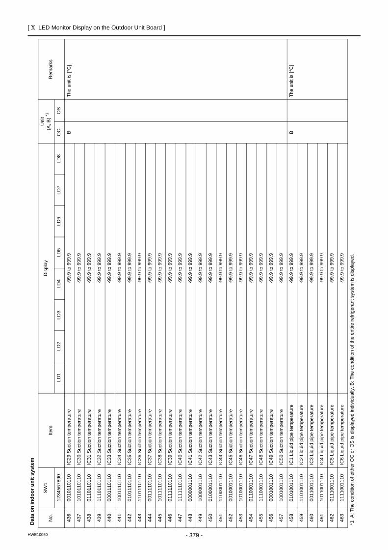
[ X LED Monitor Display on the Outdoor Unit Board ]
- 379 -HWE10050
436
0010
1101
10IC
29 S
uctio
n te
mpe
ratu
re-9
9.9
to 9
99.9
BTh
e un
it is
[°C
]
437
1010
1101
10IC
30 S
uctio
n te
mpe
ratu
re-9
9.9
to 9
99.9
438
0110
1101
10IC
31 S
uctio
n te
mpe
ratu
re-9
9.9
to 9
99.9
439
1110
1101
10IC
32 S
uctio
n te
mpe
ratu
re-9
9.9
to 9
99.9
440
0001
1101
10IC
33 S
uctio
n te
mpe
ratu
re-9
9.9
to 9
99.9
441
1001
1101
10IC
34 S
uctio
n te
mpe
ratu
re-9
9.9
to 9
99.9
442
0101
1101
10IC
35 S
uctio
n te
mpe
ratu
re-9
9.9
to 9
99.9
443
1101
1101
10IC
36 S
uctio
n te
mpe
ratu
re-9
9.9
to 9
99.9
444
0011
1101
10IC
37 S
uctio
n te
mpe
ratu
re-9
9.9
to 9
99.9
445
1011
1101
10IC
38 S
uctio
n te
mpe
ratu
re-9
9.9
to 9
99.9
446
0111
1101
10IC
39 S
uctio
n te
mpe
ratu
re-9
9.9
to 9
99.9
447
1111
1101
10IC
40 S
uctio
n te
mpe
ratu
re-9
9.9
to 9
99.9
448
0000
0011
10IC
41 S
uctio
n te
mpe
ratu
re-9
9.9
to 9
99.9
449
1000
0011
10IC
42 S
uctio
n te
mpe
ratu
re-9
9.9
to 9
99.9
450
0100
0011
10IC
43 S
uctio
n te
mpe
ratu
re-9
9.9
to 9
99.9
451
1100
0011
10IC
44 S
uctio
n te
mpe
ratu
re-9
9.9
to 9
99.9
452
0010
0011
10IC
45 S
uctio
n te
mpe
ratu
re-9
9.9
to 9
99.9
453
1010
0011
10IC
46 S
uctio
n te
mpe
ratu
re-9
9.9
to 9
99.9
454
0110
0011
10IC
47 S
uctio
n te
mpe
ratu
re-9
9.9
to 9
99.9
455
1110
0011
10IC
48 S
uctio
n te
mpe
ratu
re-9
9.9
to 9
99.9
456
0001
0011
10IC
49 S
uctio
n te
mpe
ratu
re-9
9.9
to 9
99.9
457
1001
0011
10IC
50 S
uctio
n te
mpe
ratu
re-9
9.9
to 9
99.9
458
0101
0011
10IC
1 Li
quid
pip
e te
mpe
ratu
re-9
9.9
to 9
99.9
BTh
e un
it is
[°C
]
459
1101
0011
10IC
2 Li
quid
pip
e te
mpe
ratu
re-9
9.9
to 9
99.9
460
0011
0011
10IC
3 Li
quid
pip
e te
mpe
ratu
re-9
9.9
to 9
99.9
461
1011
0011
10IC
4 Li
quid
pip
e te
mpe
ratu
re-9
9.9
to 9
99.9
462
0111
0011
10IC
5 Li
quid
pip
e te
mpe
ratu
re-9
9.9
to 9
99.9
463
1111
0011
10IC
6 Li
quid
pip
e te
mpe
ratu
re-9
9.9
to 9
99.9
Dat
a on
indo
or u
nit s
yste
m
No.
SW
1Ite
mD
ispl
ayU
nit
(A, B
) *1R
emar
ks
1234
5678
90LD
1LD
2LD
3LD
4LD
5LD
6LD
7LD
8O
CO
S
*1 A
: The
con
ditio
n of
eith
er O
C o
r OS
is d
ispl
ayed
indi
vidu
ally
. B: T
he c
ondi
tion
of th
e en
tire
refri
gera
nt s
yste
m is
dis
play
ed.
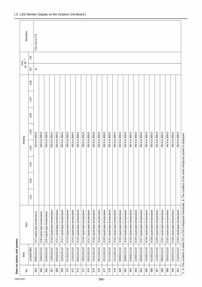
[ X LED Monitor Display on the Outdoor Unit Board ]
- 380 -HWE10050
464
0000
1011
10IC
7 Li
quid
pip
e te
mpe
ratu
re-9
9.9
to 9
99.9
BTh
e un
it is
[°C
]
465
1000
1011
10IC
8 Li
quid
pip
e te
mpe
ratu
re-9
9.9
to 9
99.9
466
0100
1011
10IC
9 Li
quid
pip
e te
mpe
ratu
re-9
9.9
to 9
99.9
467
1100
1011
10IC
10 L
iqui
d pi
pe te
mpe
ratu
re-9
9.9
to 9
99.9
468
0010
1011
10IC
11 L
iqui
d pi
pe te
mpe
ratu
re-9
9.9
to 9
99.9
469
1010
1011
10IC
12 L
iqui
d pi
pe te
mpe
ratu
re-9
9.9
to 9
99.9
470
0110
1011
10IC
13 L
iqui
d pi
pe te
mpe
ratu
re-9
9.9
to 9
99.9
471
1110
1011
10IC
14 L
iqui
d pi
pe te
mpe
ratu
re-9
9.9
to 9
99.9
472
0001
1011
10IC
15 L
iqui
d pi
pe te
mpe
ratu
re-9
9.9
to 9
99.9
473
1001
1011
10IC
16 L
iqui
d pi
pe te
mpe
ratu
re-9
9.9
to 9
99.9
474
0101
1011
10IC
17 L
iqui
d pi
pe te
mpe
ratu
re-9
9.9
to 9
99.9
475
1101
1011
10IC
18 L
iqui
d pi
pe te
mpe
ratu
re-9
9.9
to 9
99.9
476
0011
1011
10IC
19 L
iqui
d pi
pe te
mpe
ratu
re-9
9.9
to 9
99.9
477
1011
1011
10IC
20 L
iqui
d pi
pe te
mpe
ratu
re-9
9.9
to 9
99.9
478
0111
1011
10IC
21 L
iqui
d pi
pe te
mpe
ratu
re-9
9.9
to 9
99.9
479
1111
1011
10IC
22 L
iqui
d pi
pe te
mpe
ratu
re-9
9.9
to 9
99.9
480
0000
0111
10IC
23 L
iqui
d pi
pe te
mpe
ratu
re-9
9.9
to 9
99.9
481
1000
0111
10IC
24 L
iqui
d pi
pe te
mpe
ratu
re-9
9.9
to 9
99.9
482
0100
0111
10IC
25 L
iqui
d pi
pe te
mpe
ratu
re-9
9.9
to 9
99.9
483
1100
0111
10IC
26 L
iqui
d pi
pe te
mpe
ratu
re-9
9.9
to 9
99.9
484
0010
0111
10IC
27 L
iqui
d pi
pe te
mpe
ratu
re-9
9.9
to 9
99.9
485
1010
0111
10IC
28 L
iqui
d pi
pe te
mpe
ratu
re-9
9.9
to 9
99.9
486
0110
0111
10IC
29 L
iqui
d pi
pe te
mpe
ratu
re-9
9.9
to 9
99.9
487
1110
0111
10IC
30 L
iqui
d pi
pe te
mpe
ratu
re-9
9.9
to 9
99.9
488
0001
0111
10IC
31 L
iqui
d pi
pe te
mpe
ratu
re-9
9.9
to 9
99.9
489
1001
0111
10IC
32 L
iqui
d pi
pe te
mpe
ratu
re-9
9.9
to 9
99.9
490
0101
0111
10IC
33 L
iqui
d pi
pe te
mpe
ratu
re-9
9.9
to 9
99.9
491
1101
0111
10IC
34 L
iqui
d pi
pe te
mpe
ratu
re-9
9.9
to 9
99.9
Dat
a on
indo
or u
nit s
yste
m
No.
SW
1Ite
mD
ispl
ayU
nit
(A, B
) *1R
emar
ks
1234
5678
90LD
1LD
2LD
3LD
4LD
5LD
6LD
7LD
8O
CO
S
*1 A
: The
con
ditio
n of
eith
er O
C o
r OS
is d
ispl
ayed
indi
vidu
ally
. B: T
he c
ondi
tion
of th
e en
tire
refri
gera
nt s
yste
m is
dis
play
ed.
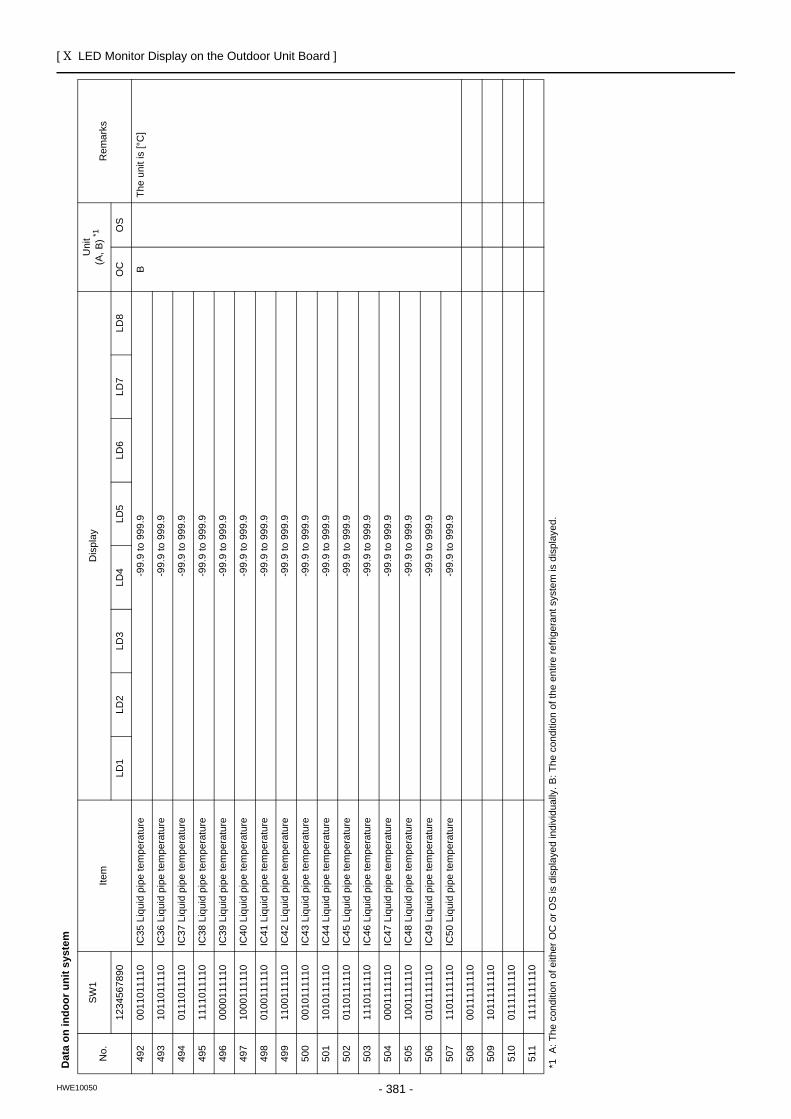
[ X LED Monitor Display on the Outdoor Unit Board ]
- 381 -HWE10050
492
0011
0111
10IC
35 L
iqui
d pi
pe te
mpe
ratu
re-9
9.9
to 9
99.9
BTh
e un
it is
[°C
]
493
1011
0111
10IC
36 L
iqui
d pi
pe te
mpe
ratu
re-9
9.9
to 9
99.9
494
0111
0111
10IC
37 L
iqui
d pi
pe te
mpe
ratu
re-9
9.9
to 9
99.9
495
1111
0111
10IC
38 L
iqui
d pi
pe te
mpe
ratu
re-9
9.9
to 9
99.9
496
0000
1111
10IC
39 L
iqui
d pi
pe te
mpe
ratu
re-9
9.9
to 9
99.9
497
1000
1111
10IC
40 L
iqui
d pi
pe te
mpe
ratu
re-9
9.9
to 9
99.9
498
0100
1111
10IC
41 L
iqui
d pi
pe te
mpe
ratu
re-9
9.9
to 9
99.9
499
1100
1111
10IC
42 L
iqui
d pi
pe te
mpe
ratu
re-9
9.9
to 9
99.9
500
0010
1111
10IC
43 L
iqui
d pi
pe te
mpe
ratu
re-9
9.9
to 9
99.9
501
1010
1111
10IC
44 L
iqui
d pi
pe te
mpe
ratu
re-9
9.9
to 9
99.9
502
0110
1111
10IC
45 L
iqui
d pi
pe te
mpe
ratu
re-9
9.9
to 9
99.9
503
1110
1111
10IC
46 L
iqui
d pi
pe te
mpe
ratu
re-9
9.9
to 9
99.9
504
0001
1111
10IC
47 L
iqui
d pi
pe te
mpe
ratu
re-9
9.9
to 9
99.9
505
1001
1111
10IC
48 L
iqui
d pi
pe te
mpe
ratu
re-9
9.9
to 9
99.9
506
0101
1111
10IC
49 L
iqui
d pi
pe te
mpe
ratu
re-9
9.9
to 9
99.9
507
1101
1111
10IC
50 L
iqui
d pi
pe te
mpe
ratu
re-9
9.9
to 9
99.9
508
0011
1111
10
509
1011
1111
10
510
0111
1111
10
511
1111
1111
10
Dat
a on
indo
or u
nit s
yste
m
No.
SW
1Ite
mD
ispl
ayU
nit
(A, B
) *1R
emar
ks
1234
5678
90LD
1LD
2LD
3LD
4LD
5LD
6LD
7LD
8O
CO
S
*1 A
: The
con
ditio
n of
eith
er O
C o
r OS
is d
ispl
ayed
indi
vidu
ally
. B: T
he c
ondi
tion
of th
e en
tire
refri
gera
nt s
yste
m is
dis
play
ed.
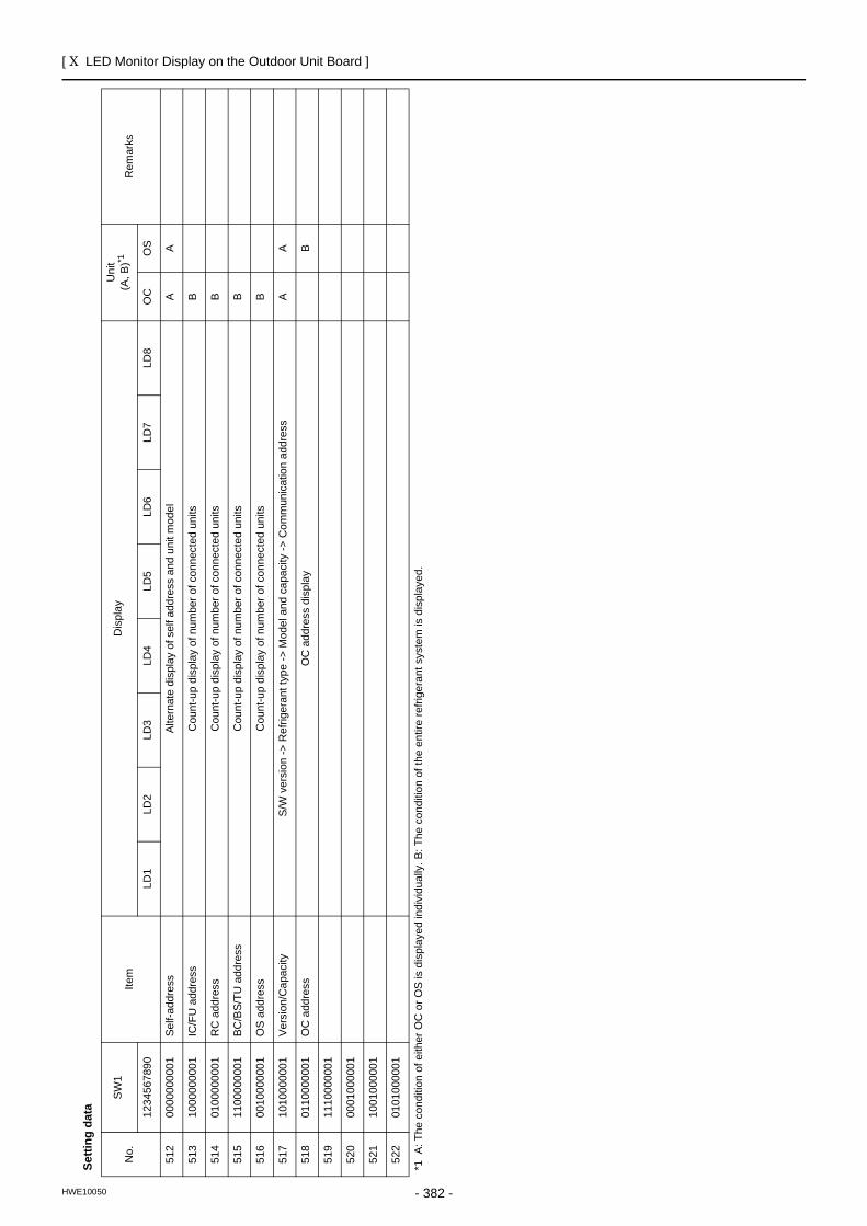
[ X LED Monitor Display on the Outdoor Unit Board ]
- 382 -HWE10050
Setti
ng d
ata
No.
SW
1Ite
mD
ispl
ayU
nit
(A, B
)*1R
emar
ks
1234
5678
90LD
1LD
2LD
3LD
4LD
5LD
6LD
7LD
8O
CO
S
512
0000
0000
01Se
lf-ad
dres
sAl
tern
ate
disp
lay
of s
elf a
ddre
ss a
nd u
nit m
odel
AA
513
1000
0000
01IC
/FU
add
ress
Cou
nt-u
p di
spla
y of
num
ber o
f con
nect
ed u
nits
B
514
0100
0000
01R
C a
ddre
ssC
ount
-up
disp
lay
of n
umbe
r of c
onne
cted
uni
tsB
515
1100
0000
01BC
/BS/
TU a
ddre
ssC
ount
-up
disp
lay
of n
umbe
r of c
onne
cted
uni
tsB
516
0010
0000
01O
S a
ddre
ssC
ount
-up
disp
lay
of n
umbe
r of c
onne
cted
uni
tsB
517
1010
0000
01Ve
rsio
n/C
apac
ityS/
W v
ersi
on ->
Ref
riger
ant t
ype
-> M
odel
and
cap
acity
-> C
omm
unic
atio
n ad
dres
sA
A
518
0110
0000
01O
C a
ddre
ssO
C a
ddre
ss d
ispl
ayB
519
1110
0000
01
520
0001
0000
01
521
1001
0000
01
522
0101
0000
01
*1 A
: The
con
ditio
n of
eith
er O
C o
r OS
is d
ispl
ayed
indi
vidu
ally
. B: T
he c
ondi
tion
of th
e en
tire
refri
gera
nt s
yste
m is
dis
play
ed.
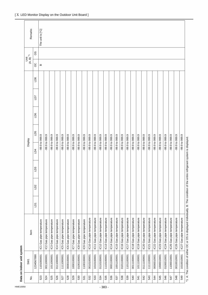
[ X LED Monitor Display on the Outdoor Unit Board ]
- 383 -HWE10050
Dat
a on
indo
or u
nit s
yste
m
No.
SW
1Ite
mD
ispl
ayU
nit
(A, B
) *1R
emar
ks
1234
5678
90LD
1LD
2LD
3LD
4LD
5LD
6LD
7LD
8O
CO
S
523
1101
0000
01IC
1 G
as p
ipe
tem
pera
ture
-99.
9 to
999
.9B
The
unit
is [°
C]
524
0011
0000
01IC
2 G
as p
ipe
tem
pera
ture
-99.
9 to
999
.9
525
1011
0000
01IC
3 G
as p
ipe
tem
pera
ture
-99.
9 to
999
.9
526
0111
0000
01IC
4 G
as p
ipe
tem
pera
ture
-99.
9 to
999
.9
527
1111
0000
01IC
5 G
as p
ipe
tem
pera
ture
-99.
9 to
999
.9
528
0000
1000
01
IC6
Gas
pip
e te
mpe
ratu
re-9
9.9
to 9
99.9
529
1000
1000
01
IC7
Gas
pip
e te
mpe
ratu
re-9
9.9
to 9
99.9
530
0100
1000
01
IC8
Gas
pip
e te
mpe
ratu
re-9
9.9
to 9
99.9
531
1100
1000
01
IC9
Gas
pip
e te
mpe
ratu
re-9
9.9
to 9
99.9
532
0010
1000
01
IC10
Gas
pip
e te
mpe
ratu
re-9
9.9
to 9
99.9
533
1010
1000
01
IC11
Gas
pip
e te
mpe
ratu
re-9
9.9
to 9
99.9
534
0110
1000
01
IC12
Gas
pip
e te
mpe
ratu
re-9
9.9
to 9
99.9
535
1110
1000
01
IC13
Gas
pip
e te
mpe
ratu
re-9
9.9
to 9
99.9
536
0001
1000
01
IC14
Gas
pip
e te
mpe
ratu
re-9
9.9
to 9
99.9
537
1001
1000
01
IC15
Gas
pip
e te
mpe
ratu
re-9
9.9
to 9
99.9
538
0101
1000
01
IC16
Gas
pip
e te
mpe
ratu
re-9
9.9
to 9
99.9
539
1101
1000
01
IC17
Gas
pip
e te
mpe
ratu
re-9
9.9
to 9
99.9
540
0011
1000
01
IC18
Gas
pip
e te
mpe
ratu
re-9
9.9
to 9
99.9
541
1011
1000
01
IC19
Gas
pip
e te
mpe
ratu
re-9
9.9
to 9
99.9
542
0111
1000
01
IC20
Gas
pip
e te
mpe
ratu
re-9
9.9
to 9
99.9
543
1111
1000
01
IC21
Gas
pip
e te
mpe
ratu
re-9
9.9
to 9
99.9
544
0000
0100
01
IC22
Gas
pip
e te
mpe
ratu
re-9
9.9
to 9
99.9
545
1000
0100
01
IC23
Gas
pip
e te
mpe
ratu
re-9
9.9
to 9
99.9
546
0100
0100
01
IC24
Gas
pip
e te
mpe
ratu
re-9
9.9
to 9
99.9
547
1100
0100
01
IC25
Gas
pip
e te
mpe
ratu
re-9
9.9
to 9
99.9
548
0010
0100
01
IC26
Gas
pip
e te
mpe
ratu
re-9
9.9
to 9
99.9
549
1010
0100
01
IC27
Gas
pip
e te
mpe
ratu
re-9
9.9
to 9
99.9
*1 A
: The
con
ditio
n of
eith
er O
C o
r OS
is d
ispl
ayed
indi
vidu
ally
. B: T
he c
ondi
tion
of th
e en
tire
refri
gera
nt s
yste
m is
dis
play
ed.
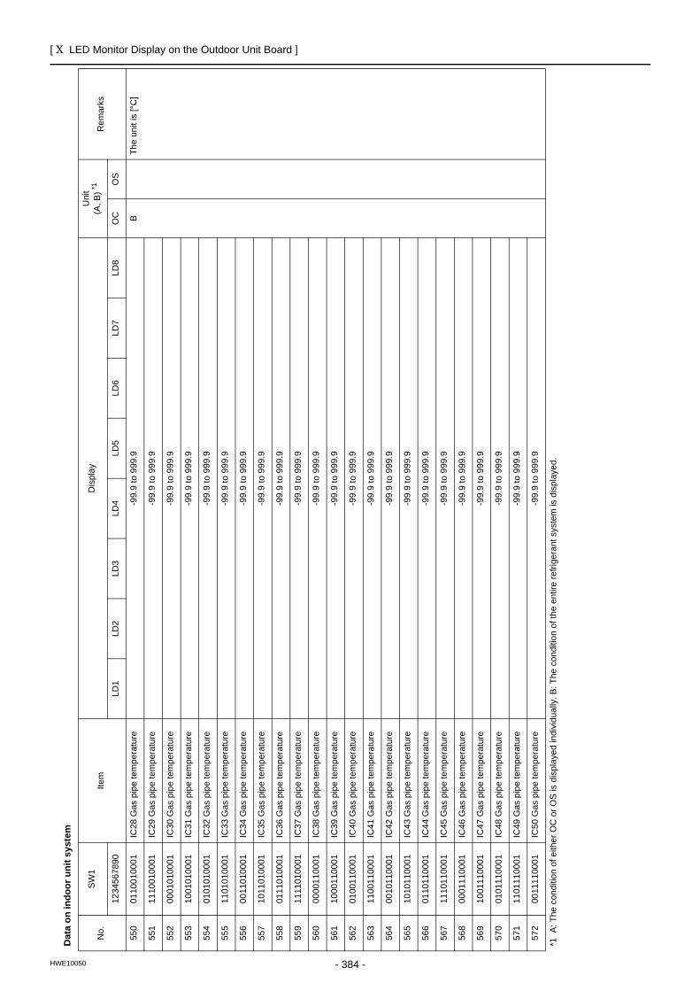
[ X LED Monitor Display on the Outdoor Unit Board ]
- 384 -HWE10050
Dat
a on
indo
or u
nit s
yste
m
No.
SW
1Ite
mD
ispl
ayU
nit
(A, B
) *1R
emar
ks
1234
5678
90LD
1LD
2LD
3LD
4LD
5LD
6LD
7LD
8O
CO
S
550
0110
0100
01
IC28
Gas
pip
e te
mpe
ratu
re-9
9.9
to 9
99.9
BTh
e un
it is
[°C
]
551
1110
0100
01
IC29
Gas
pip
e te
mpe
ratu
re-9
9.9
to 9
99.9
552
0001
0100
01
IC30
Gas
pip
e te
mpe
ratu
re-9
9.9
to 9
99.9
553
1001
0100
01
IC31
Gas
pip
e te
mpe
ratu
re-9
9.9
to 9
99.9
554
0101
0100
01
IC32
Gas
pip
e te
mpe
ratu
re-9
9.9
to 9
99.9
555
1101
0100
01
IC33
Gas
pip
e te
mpe
ratu
re-9
9.9
to 9
99.9
556
0011
0100
01
IC34
Gas
pip
e te
mpe
ratu
re-9
9.9
to 9
99.9
557
1011
0100
01
IC35
Gas
pip
e te
mpe
ratu
re-9
9.9
to 9
99.9
558
0111
0100
01
IC36
Gas
pip
e te
mpe
ratu
re-9
9.9
to 9
99.9
559
1111
0100
01
IC37
Gas
pip
e te
mpe
ratu
re-9
9.9
to 9
99.9
560
0000
1100
01
IC38
Gas
pip
e te
mpe
ratu
re-9
9.9
to 9
99.9
561
1000
1100
01
IC39
Gas
pip
e te
mpe
ratu
re-9
9.9
to 9
99.9
562
0100
1100
01
IC40
Gas
pip
e te
mpe
ratu
re-9
9.9
to 9
99.9
563
1100
1100
01
IC41
Gas
pip
e te
mpe
ratu
re-9
9.9
to 9
99.9
564
0010
1100
01
IC42
Gas
pip
e te
mpe
ratu
re-9
9.9
to 9
99.9
565
1010
1100
01
IC43
Gas
pip
e te
mpe
ratu
re-9
9.9
to 9
99.9
566
0110
1100
01
IC44
Gas
pip
e te
mpe
ratu
re-9
9.9
to 9
99.9
567
1110
1100
01IC
45 G
as p
ipe
tem
pera
ture
-99.
9 to
999
.9
568
0001
1100
01IC
46 G
as p
ipe
tem
pera
ture
-99.
9 to
999
.9
569
1001
1100
01IC
47 G
as p
ipe
tem
pera
ture
-99.
9 to
999
.9
570
0101
1100
01IC
48 G
as p
ipe
tem
pera
ture
-99.
9 to
999
.9
571
1101
1100
01IC
49 G
as p
ipe
tem
pera
ture
-99.
9 to
999
.9
572
0011
1100
01IC
50 G
as p
ipe
tem
pera
ture
-99.
9 to
999
.9
*1 A
: The
con
ditio
n of
eith
er O
C o
r OS
is d
ispl
ayed
indi
vidu
ally
. B: T
he c
ondi
tion
of th
e en
tire
refri
gera
nt s
yste
m is
dis
play
ed.
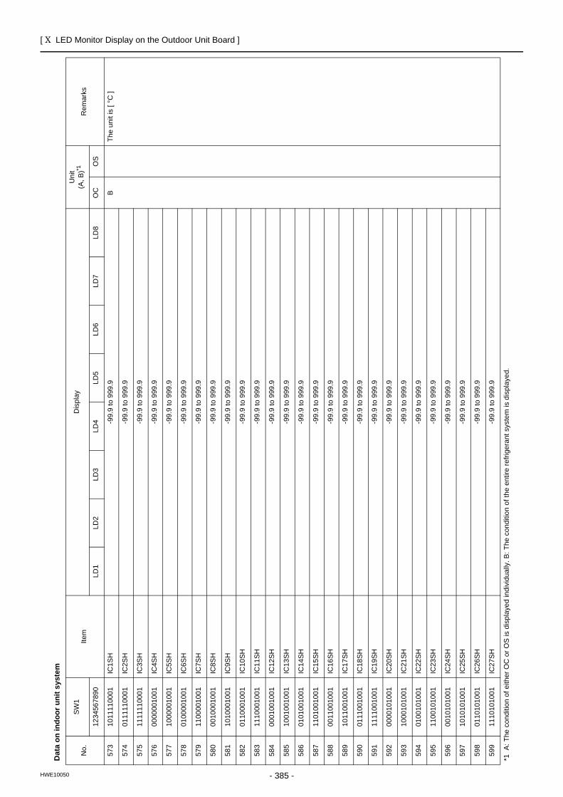
[ X LED Monitor Display on the Outdoor Unit Board ]
- 385 -HWE10050
Dat
a on
indo
or u
nit s
yste
m
No.
SW
1Ite
mD
ispl
ayU
nit
(A, B
)*1R
emar
ks
1234
5678
90LD
1LD
2LD
3LD
4LD
5LD
6LD
7LD
8O
CO
S
573
1011
1100
01IC
1SH
-99.
9 to
999
.9B
The
unit
is [
°C ]
574
0111
1100
01IC
2SH
-99.
9 to
999
.9
575
1111
1100
01IC
3SH
-99.
9 to
999
.9
576
0000
0010
01IC
4SH
-99.
9 to
999
.9
577
1000
0010
01IC
5SH
-99.
9 to
999
.9
578
0100
0010
01IC
6SH
-99.
9 to
999
.9
579
1100
0010
01IC
7SH
-99.
9 to
999
.9
580
0010
0010
01IC
8SH
-99.
9 to
999
.9
581
1010
0010
01IC
9SH
-99.
9 to
999
.9
582
0110
0010
01IC
10SH
-99.
9 to
999
.9
583
1110
0010
01IC
11SH
-99.
9 to
999
.9
584
0001
0010
01IC
12SH
-99.
9 to
999
.9
585
1001
0010
01IC
13SH
-99.
9 to
999
.9
586
0101
0010
01IC
14SH
-99.
9 to
999
.9
587
1101
0010
01IC
15SH
-99.
9 to
999
.9
588
0011
0010
01IC
16SH
-99.
9 to
999
.9
589
1011
0010
01IC
17SH
-99.
9 to
999
.9
590
0111
0010
01IC
18SH
-99.
9 to
999
.9
591
1111
0010
01IC
19SH
-99.
9 to
999
.9
592
0000
1010
01IC
20SH
-99.
9 to
999
.9
593
1000
1010
01IC
21SH
-99.
9 to
999
.9
594
0100
1010
01IC
22SH
-99.
9 to
999
.9
595
1100
1010
01IC
23SH
-99.
9 to
999
.9
596
0010
1010
01IC
24SH
-99.
9 to
999
.9
597
1010
1010
01IC
25SH
-99.
9 to
999
.9
598
0110
1010
01IC
26SH
-99.
9 to
999
.9
599
1110
1010
01IC
27SH
-99.
9 to
999
.9
*1 A
: The
con
ditio
n of
eith
er O
C o
r OS
is d
ispl
ayed
indi
vidu
ally
. B: T
he c
ondi
tion
of th
e en
tire
refri
gera
nt s
yste
m is
dis
play
ed.
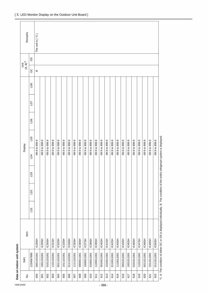
[ X LED Monitor Display on the Outdoor Unit Board ]
- 386 -HWE10050
600
0001
1010
01IC
28SH
-99.
9 to
999
.9B
The
unit
is [
°C ]
601
1001
1010
01IC
29SH
-99.
9 to
999
.9
602
0101
1010
01IC
30SH
-99.
9 to
999
.9
603
1101
1010
01IC
31SH
-99.
9 to
999
.9
604
0011
1010
01IC
32SH
-99.
9 to
999
.9
605
1011
1010
01IC
33SH
-99.
9 to
999
.9
606
0111
1010
01IC
34SH
-99.
9 to
999
.9
607
1111
1010
01IC
35SH
-99.
9 to
999
.9
608
0000
0110
01IC
36SH
-99.
9 to
999
.9
609
1000
0110
01IC
37SH
-99.
9 to
999
.9
610
0100
0110
01IC
38SH
-99.
9 to
999
.9
611
1100
0110
01
IC39
SH-9
9.9
to 9
99.9
612
0010
0110
01
IC40
SH-9
9.9
to 9
99.9
613
1010
0110
01
IC41
SH-9
9.9
to 9
99.9
614
0110
0110
01
IC42
SH-9
9.9
to 9
99.9
615
1110
0110
01
IC43
SH-9
9.9
to 9
99.9
616
0001
0110
01
IC44
SH-9
9.9
to 9
99.9
617
1001
0110
01
IC45
SH-9
9.9
to 9
99.9
618
0101
0110
01
IC46
SH-9
9.9
to 9
99.9
619
1101
0110
01
IC47
SH-9
9.9
to 9
99.9
620
0011
0110
01
IC48
SH-9
9.9
to 9
99.9
621
1011
0110
01
IC49
SH-9
9.9
to 9
99.9
622
0111
0110
01
IC50
SH-9
9.9
to 9
99.9
Dat
a on
indo
or u
nit s
yste
m
No.
SW
1Ite
mD
ispl
ayU
nit
(A, B
)*1R
emar
ks
1234
5678
90LD
1LD
2LD
3LD
4LD
5LD
6LD
7LD
8O
CO
S
*1 A
: The
con
ditio
n of
eith
er O
C o
r OS
is d
ispl
ayed
indi
vidu
ally
. B: T
he c
ondi
tion
of th
e en
tire
refri
gera
nt s
yste
m is
dis
play
ed.
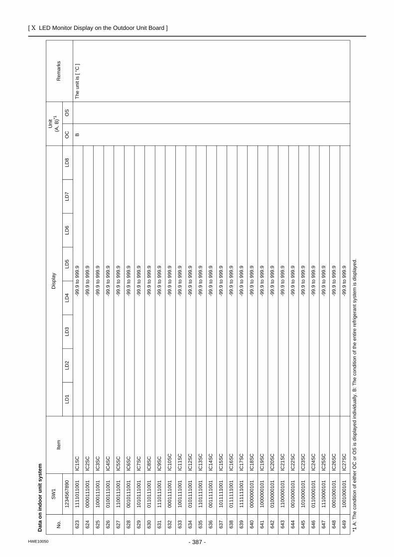
[ X LED Monitor Display on the Outdoor Unit Board ]
- 387 -HWE10050
Dat
a on
indo
or u
nit s
yste
m
No.
SW
1Ite
mD
ispl
ayU
nit
(A, B
)*1R
emar
ks
1234
5678
90LD
1LD
2LD
3LD
4LD
5LD
6LD
7LD
8O
CO
S
623
1111
0110
01
IC1S
C-9
9.9
to 9
99.9
BTh
e un
it is
[ °C
]
624
0000
1110
01
IC2S
C-9
9.9
to 9
99.9
625
1000
1110
01
IC3S
C-9
9.9
to 9
99.9
626
0100
1110
01
IC4S
C-9
9.9
to 9
99.9
627
1100
1110
01
IC5S
C-9
9.9
to 9
99.9
628
0010
1110
01
IC6S
C-9
9.9
to 9
99.9
629
1010
1110
01
IC7S
C-9
9.9
to 9
99.9
630
0110
1110
01
IC8S
C-9
9.9
to 9
99.9
631
1110
1110
01
IC9S
C-9
9.9
to 9
99.9
632
0001
1110
01
IC10
SC-9
9.9
to 9
99.9
633
1001
1110
01
IC11
SC-9
9.9
to 9
99.9
634
0101
1110
01
IC12
SC-9
9.9
to 9
99.9
635
1101
1110
01
IC13
SC-9
9.9
to 9
99.9
636
0011
1110
01
IC14
SC-9
9.9
to 9
99.9
637
1011
1110
01
IC15
SC-9
9.9
to 9
99.9
638
0111
1110
01
IC16
SC-9
9.9
to 9
99.9
639
1111
1110
01
IC17
SC-9
9.9
to 9
99.9
640
0000
0001
01
IC18
SC-9
9.9
to 9
99.9
641
1000
0001
01
IC19
SC-9
9.9
to 9
99.9
642
0100
0001
01
IC20
SC-9
9.9
to 9
99.9
643
1100
0001
01
IC21
SC-9
9.9
to 9
99.9
644
0010
0001
01
IC22
SC-9
9.9
to 9
99.9
645
1010
0001
01
IC23
SC-9
9.9
to 9
99.9
646
0110
0001
01
IC24
SC-9
9.9
to 9
99.9
647
1110
0001
01
IC25
SC-9
9.9
to 9
99.9
648
0001
0001
01
IC26
SC-9
9.9
to 9
99.9
649
1001
0001
01
IC27
SC-9
9.9
to 9
99.9
*1 A
: The
con
ditio
n of
eith
er O
C o
r OS
is d
ispl
ayed
indi
vidu
ally
. B: T
he c
ondi
tion
of th
e en
tire
refri
gera
nt s
yste
m is
dis
play
ed.
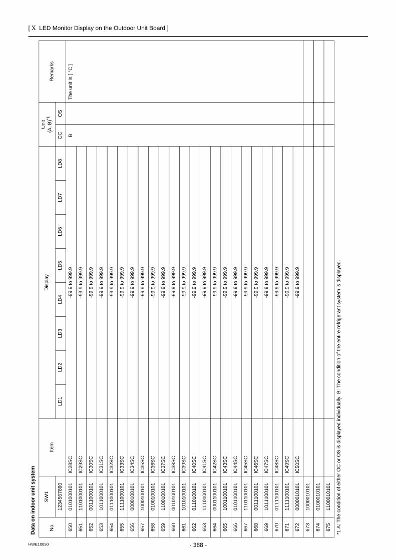
[ X LED Monitor Display on the Outdoor Unit Board ]
- 388 -HWE10050
650
0101
0001
01
IC28
SC-9
9.9
to 9
99.9
BTh
e un
it is
[ °C
]
651
1101
0001
01
IC29
SC-9
9.9
to 9
99.9
652
0011
0001
01
IC30
SC-9
9.9
to 9
99.9
653
1011
0001
01IC
31SC
-99.
9 to
999
.9
654
0111
0001
01
IC32
SC-9
9.9
to 9
99.9
655
1111
0001
01
IC33
SC-9
9.9
to 9
99.9
656
0000
1001
01
IC34
SC-9
9.9
to 9
99.9
657
1000
1001
01
IC35
SC-9
9.9
to 9
99.9
658
0100
1001
01
IC36
SC-9
9.9
to 9
99.9
659
1100
1001
01
IC37
SC-9
9.9
to 9
99.9
660
0010
1001
01
IC38
SC-9
9.9
to 9
99.9
661
1010
1001
01
IC39
SC-9
9.9
to 9
99.9
662
0110
1001
01
IC40
SC-9
9.9
to 9
99.9
663
1110
1001
01
IC41
SC-9
9.9
to 9
99.9
664
0001
1001
01
IC42
SC-9
9.9
to 9
99.9
665
1001
1001
01
IC43
SC-9
9.9
to 9
99.9
666
0101
1001
01
IC44
SC-9
9.9
to 9
99.9
667
1101
1001
01
IC45
SC-9
9.9
to 9
99.9
668
0011
1001
01
IC46
SC-9
9.9
to 9
99.9
669
1011
1001
01
IC47
SC-9
9.9
to 9
99.9
670
0111
1001
01
IC48
SC-9
9.9
to 9
99.9
671
1111
1001
01
IC49
SC-9
9.9
to 9
99.9
672
0000
0101
01
IC50
SC-9
9.9
to 9
99.9
673
1000
0101
01
674
0100
0101
01
675
1100
0101
01
Dat
a on
indo
or u
nit s
yste
m
No.
SW
1Ite
mD
ispl
ayU
nit
(A, B
)*1R
emar
ks
1234
5678
90LD
1LD
2LD
3LD
4LD
5LD
6LD
7LD
8O
CO
S
*1 A
: The
con
ditio
n of
eith
er O
C o
r OS
is d
ispl
ayed
indi
vidu
ally
. B: T
he c
ondi
tion
of th
e en
tire
refri
gera
nt s
yste
m is
dis
play
ed.
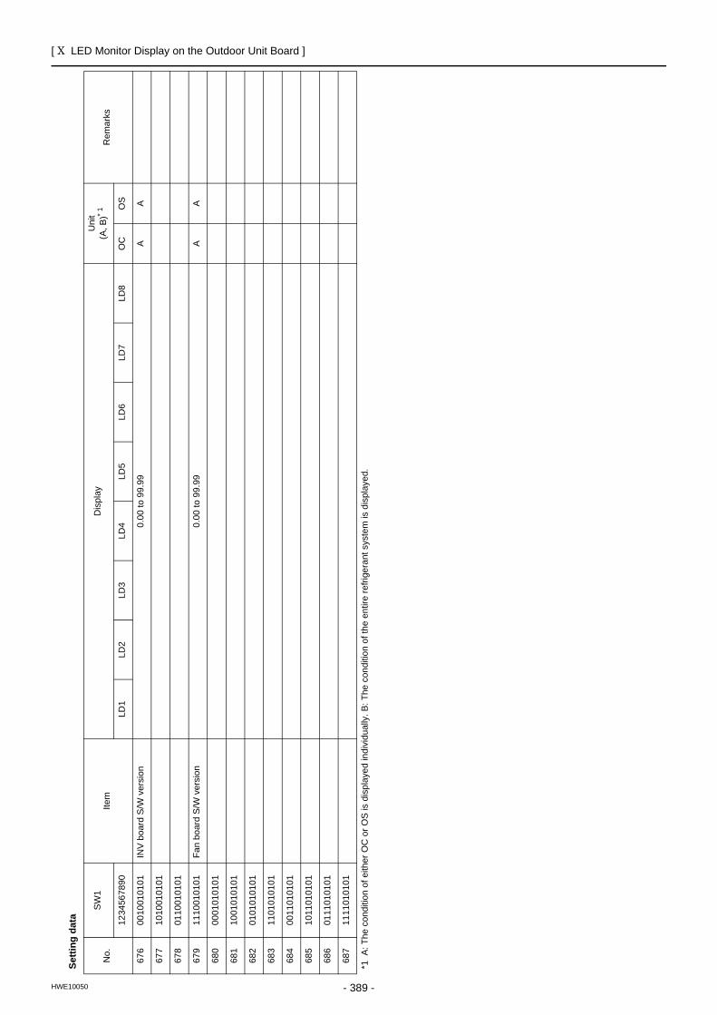
[ X LED Monitor Display on the Outdoor Unit Board ]
- 389 -HWE10050
Setti
ng d
ata
No.
SW
1Ite
mD
ispl
ayU
nit
(A, B
)* 1
Rem
arks
1234
5678
90LD
1LD
2LD
3LD
4LD
5LD
6LD
7LD
8O
CO
S
676
0010
0101
01
INV
boar
d S/
W v
ersi
on0.
00 to
99.
99A
A
677
1010
0101
01
678
0110
0101
01
679
1110
0101
01
Fan
boar
d S/
W v
ersi
on0.
00 to
99.
99A
A
680
0001
0101
01
681
1001
0101
01
682
0101
0101
01
683
1101
0101
01
684
0011
0101
01
685
1011
0101
01
686
0111
0101
01
687
1111
0101
01
*1 A
: The
con
ditio
n of
eith
er O
C o
r OS
is d
ispl
ayed
indi
vidu
ally
. B: T
he c
ondi
tion
of th
e en
tire
refri
gera
nt s
yste
m is
dis
play
ed.
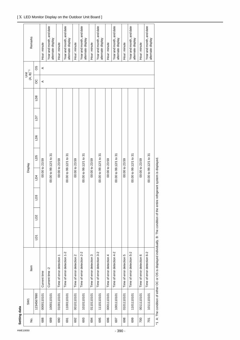
[ X LED Monitor Display on the Outdoor Unit Board ]
- 390 -HWE10050
688
0000
1101
01
Cur
rent
tim
e00
:00
to 2
3:59
AA
Hou
r: m
inut
e
689
1000
1101
01
Cur
rent
tim
e -2
00.0
0 to
99.
12/1
to 3
1Ye
ar a
nd m
onth
, and
dat
e al
tern
ate
disp
lay
690
0100
1101
01
Tim
e of
erro
r det
ectio
n 1
00:0
0 to
23:
59H
our:
min
ute
691
1100
1101
01
Tim
e of
erro
r det
ectio
n 1-
200
.00
to 9
9.12
/1 to
31
Year
and
mon
th, a
nd d
ate
alte
rnat
e di
spla
y
692
0010
1101
01
Tim
e of
erro
r det
ectio
n 2
00:0
0 to
23:
59H
our:
min
ute
693
1010
1101
01
Tim
e of
erro
r det
ectio
n 2-
200
.00
to 9
9.12
/1 to
31
Year
and
mon
th, a
nd d
ate
alte
rnat
e di
spla
y
694
0110
1101
01
Tim
e of
erro
r det
ectio
n 3
00:0
0 to
23:
59H
our:
min
ute
695
1110
1101
01Ti
me
of e
rror d
etec
tion
3-2
00.0
0 to
99.
12/1
to 3
1Ye
ar a
nd m
onth
, and
dat
e al
tern
ate
disp
lay
696
0001
1101
01
Tim
e of
erro
r det
ectio
n 4
00:0
0 to
23:
59H
our:
min
ute
697
1001
1101
01
Tim
e of
erro
r det
ectio
n 4-
200
.00
to 9
9.12
/1 to
31
Year
and
mon
th, a
nd d
ate
alte
rnat
e di
spla
y
698
0101
1101
01
Tim
e of
erro
r det
ectio
n 5
00:0
0 to
23:
59H
our:
min
ute
699
1101
1101
01
Tim
e of
erro
r det
ectio
n 5-
200
.00
to 9
9.12
/1 to
31
Year
and
mon
th, a
nd d
ate
alte
rnat
e di
spla
y
700
0011
1101
01
Tim
e of
erro
r det
ectio
n 6
00:0
0 to
23:
59H
our:
min
ute
701
1011
1101
01
Tim
e of
erro
r det
ectio
n 6-
200
.00
to 9
9.12
/1 to
31
Year
and
mon
th, a
nd d
ate
alte
rnat
e di
spla
y
Setti
ng d
ata
No.
SW
1Ite
mD
ispl
ayU
nit
(A, B
)* 1
Rem
arks
1234
5678
90LD
1LD
2LD
3LD
4LD
5LD
6LD
7LD
8O
CO
S
*1 A
: The
con
ditio
n of
eith
er O
C o
r OS
is d
ispl
ayed
indi
vidu
ally
. B: T
he c
ondi
tion
of th
e en
tire
refri
gera
nt s
yste
m is
dis
play
ed.
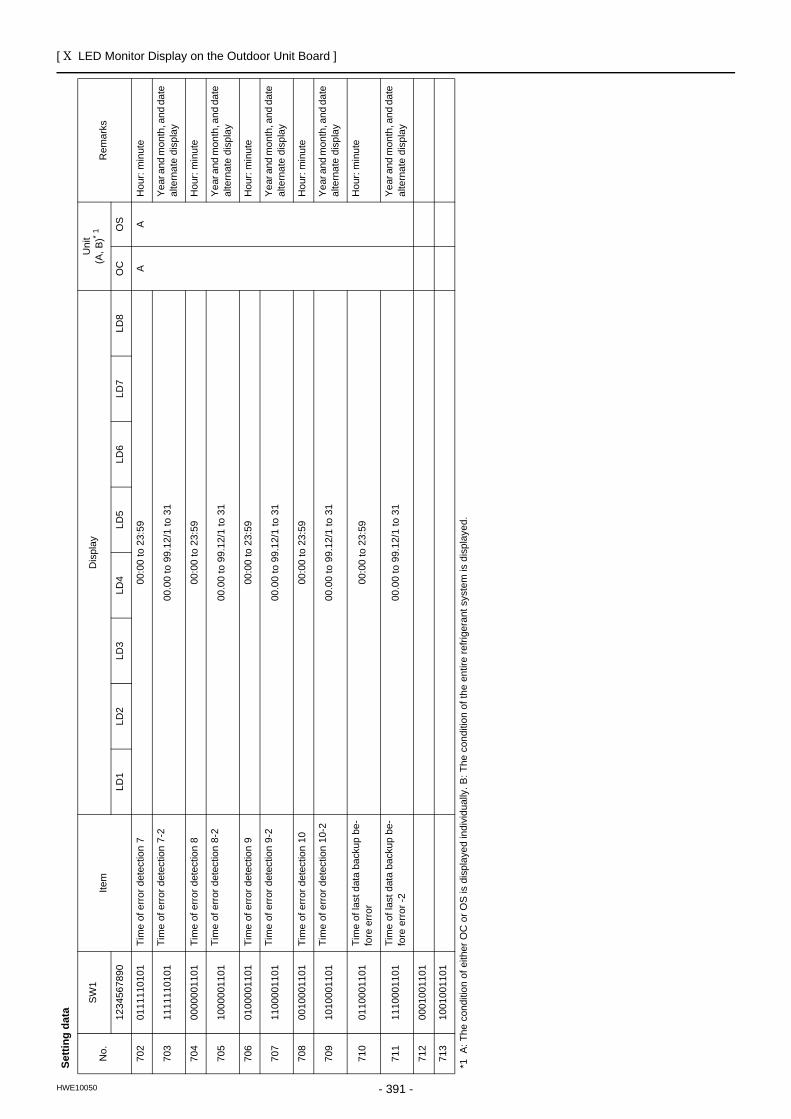
[ X LED Monitor Display on the Outdoor Unit Board ]
- 391 -HWE10050
702
0111
1101
01
Tim
e of
erro
r det
ectio
n 7
00:0
0 to
23:
59A
AH
our:
min
ute
703
1111
1101
01
Tim
e of
erro
r det
ectio
n 7-
200
.00
to 9
9.12
/1 to
31
Year
and
mon
th, a
nd d
ate
alte
rnat
e di
spla
y
704
0000
0011
01
Tim
e of
erro
r det
ectio
n 8
00:0
0 to
23:
59H
our:
min
ute
705
1000
0011
01
Tim
e of
erro
r det
ectio
n 8-
200
.00
to 9
9.12
/1 to
31
Year
and
mon
th, a
nd d
ate
alte
rnat
e di
spla
y
706
0100
0011
01
Tim
e of
erro
r det
ectio
n 9
00:0
0 to
23:
59H
our:
min
ute
707
1100
0011
01
Tim
e of
erro
r det
ectio
n 9-
200
.00
to 9
9.12
/1 to
31
Year
and
mon
th, a
nd d
ate
alte
rnat
e di
spla
y
708
0010
0011
01
Tim
e of
erro
r det
ectio
n 10
00:0
0 to
23:
59H
our:
min
ute
709
1010
0011
01
Tim
e of
erro
r det
ectio
n 10
-200
.00
to 9
9.12
/1 to
31
Year
and
mon
th, a
nd d
ate
alte
rnat
e di
spla
y
710
0110
0011
01
Tim
e of
last
dat
a ba
ckup
be-
fore
err
or00
:00
to 2
3:59
Hou
r: m
inut
e
711
1110
0011
01
Tim
e of
last
dat
a ba
ckup
be-
fore
err
or -2
00.0
0 to
99.
12/1
to 3
1Ye
ar a
nd m
onth
, and
dat
e al
tern
ate
disp
lay
712
0001
0011
01
713
1001
0011
01
Setti
ng d
ata
No.
SW
1Ite
mD
ispl
ayU
nit
(A, B
)* 1
Rem
arks
1234
5678
90LD
1LD
2LD
3LD
4LD
5LD
6LD
7LD
8O
CO
S
*1 A
: The
con
ditio
n of
eith
er O
C o
r OS
is d
ispl
ayed
indi
vidu
ally
. B: T
he c
ondi
tion
of th
e en
tire
refri
gera
nt s
yste
m is
dis
play
ed.

[ X LED Monitor Display on the Outdoor Unit Board ]
- 392 -HWE10050
Dat
a on
indo
or u
nit s
yste
m
No.
SW
1Ite
mD
ispl
ayU
nit
(A, B
)* 1R
emar
ks
1234
5678
90LD
1LD
2LD
3LD
4LD
5LD
6LD
7LD
8O
CO
S
714
0101
0011
01
IC1
LEV
open
ing
0000
to 9
999
BFu
lly o
pen:
200
0
715
1101
0011
01
IC2
LEV
open
ing
0000
to 9
999
716
0011
0011
01
IC3
LEV
open
ing
0000
to 9
999
717
1011
0011
01
IC4
LEV
open
ing
0000
to 9
999
718
0111
0011
01
IC5
LEV
open
ing
0000
to 9
999
719
1111
0011
01
IC6
LEV
open
ing
0000
to 9
999
720
0000
1011
01
IC7
LEV
open
ing
0000
to 9
999
721
1000
1011
01
IC8
LEV
open
ing
0000
to 9
999
722
0100
1011
01
IC9
LEV
open
ing
0000
to 9
999
723
1100
1011
01
IC10
LEV
ope
ning
0000
to 9
999
724
0010
1011
01
IC11
LEV
ope
ning
0000
to 9
999
725
1010
1011
01
IC12
LEV
ope
ning
0000
to 9
999
726
0110
1011
01
IC13
LEV
ope
ning
0000
to 9
999
727
1110
1011
01
IC14
LEV
ope
ning
0000
to 9
999
728
0001
1011
01
IC15
LEV
ope
ning
0000
to 9
999
729
1001
1011
01
IC16
LEV
ope
ning
0000
to 9
999
730
0101
1011
01
IC17
LEV
ope
ning
0000
to 9
999
731
1101
1011
01
IC18
LEV
ope
ning
0000
to 9
999
732
0011
1011
01
IC19
LEV
ope
ning
0000
to 9
999
733
1011
1011
01
IC20
LEV
ope
ning
0000
to 9
999
734
0111
1011
01
IC21
LEV
ope
ning
0000
to 9
999
735
1111
1011
01
IC22
LEV
ope
ning
0000
to 9
999
736
0000
0111
01
IC23
LEV
ope
ning
0000
to 9
999
737
1000
0111
01
IC24
LEV
ope
ning
0000
to 9
999
738
0100
0111
01
IC25
LEV
ope
ning
0000
to 9
999
739
1100
0111
01
IC26
LEV
ope
ning
0000
to 9
999
740
0010
0111
01
IC27
LEV
ope
ning
0000
to 9
999
*1 A
: The
con
ditio
n of
eith
er O
C o
r OS
is d
ispl
ayed
indi
vidu
ally
. B: T
he c
ondi
tion
of th
e en
tire
refri
gera
nt s
yste
m is
dis
play
ed.
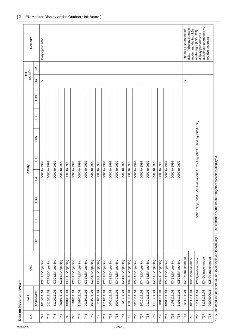
[ X LED Monitor Display on the Outdoor Unit Board ]
- 393 -HWE10050
741
1010
0111
01
IC28
LEV
ope
ning
0000
to 9
999
BFu
lly o
pen:
200
0
742
0110
0111
01
IC29
LEV
ope
ning
0000
to 9
999
743
1110
0111
01
IC30
LEV
ope
ning
0000
to 9
999
744
0001
0111
01
IC31
LEV
ope
ning
0000
to 9
999
745
1001
0111
01
IC32
LEV
ope
ning
0000
to 9
999
746
0101
0111
01
IC33
LEV
ope
ning
0000
to 9
999
747
1101
0111
01
IC34
LEV
ope
ning
0000
to 9
999
748
0011
0111
01
IC35
LEV
ope
ning
0000
to 9
999
749
1011
0111
01
IC36
LEV
ope
ning
0000
to 9
999
750
0111
0111
01
IC37
LEV
ope
ning
0000
to 9
999
751
1111
0111
01
IC38
LEV
ope
ning
0000
to 9
999
752
0000
1111
01
IC39
LEV
ope
ning
0000
to 9
999
753
1000
1111
01
IC40
LEV
ope
ning
0000
to 9
999
754
0100
1111
01
IC41
LEV
ope
ning
0000
to 9
999
755
1100
1111
01
IC42
LEV
ope
ning
0000
to 9
999
756
0010
1111
01
IC43
LEV
ope
ning
0000
to 9
999
757
1010
1111
01
IC44
LEV
ope
ning
0000
to 9
999
758
0110
1111
01
IC45
LEV
ope
ning
0000
to 9
999
759
1110
1111
01
IC46
LEV
ope
ning
0000
to 9
999
760
0001
1111
01
IC47
LEV
ope
ning
0000
to 9
999
761
1001
1111
01
IC48
LEV
ope
ning
0000
to 9
999
762
0101
1111
01
IC49
LEV
ope
ning
0000
to 9
999
763
1101
1111
01
IC50
LEV
ope
ning
0000
to 9
999
764
0011
1111
01
IC1
Ope
ratio
n m
ode
0000
: St
op 0
001
: Ven
tilat
ion
000
2 : C
oolin
g 0
003
: Hea
ting
000
4 : D
ry
BTh
e fo
ur L
Ds
on th
e le
ft (L
D1-
4) d
ispl
ay o
pera
tion
mod
e, a
nd th
e fo
ur L
Ds
on th
e rig
ht (L
D5-
LD8)
di
spla
y po
rt ad
dres
s.(D
ispl
ayed
alte
rnat
ely
ev-
ery
five
seco
nds)
765
1011
1111
01
IC2
Ope
ratio
n m
ode
766
0111
1111
01
IC3O
pera
tion
mod
e
767
1111
1111
01
IC4
Ope
ratio
n m
ode
768
0000
0000
11
IC5
Ope
ratio
n m
ode
Dat
a on
indo
or u
nit s
yste
m
No.
SW
1Ite
mD
ispl
ayU
nit
(A, B
)* 1R
emar
ks
1234
5678
90LD
1LD
2LD
3LD
4LD
5LD
6LD
7LD
8O
CO
S
*1 A
: The
con
ditio
n of
eith
er O
C o
r OS
is d
ispl
ayed
indi
vidu
ally
. B: T
he c
ondi
tion
of th
e en
tire
refri
gera
nt s
yste
m is
dis
play
ed.
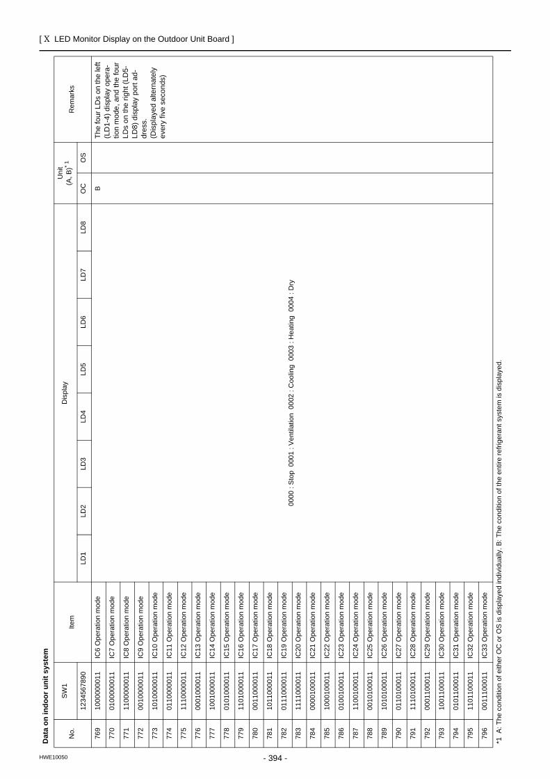
[ X LED Monitor Display on the Outdoor Unit Board ]
- 394 -HWE10050
769
1000
0000
11
IC6
Ope
ratio
n m
ode
0000
: St
op 0
001
: Ven
tilat
ion
000
2 : C
oolin
g 0
003
: Hea
ting
000
4 : D
ry
BTh
e fo
ur L
Ds
on th
e le
ft (L
D1-
4) d
ispl
ay o
pera
-tio
n m
ode,
and
the
four
LD
s on
the
right
(LD
5-LD
8) d
ispl
ay p
ort a
d-dr
ess.
(Dis
play
ed a
ltern
atel
y ev
ery
five
seco
nds)
770
0100
0000
11
IC7
Ope
ratio
n m
ode
771
1100
0000
11
IC8
Ope
ratio
n m
ode
772
0010
0000
11
IC9
Ope
ratio
n m
ode
773
1010
0000
11
IC10
Ope
ratio
n m
ode
774
0110
0000
11
IC11
Ope
ratio
n m
ode
775
1110
0000
11
IC12
Ope
ratio
n m
ode
776
0001
0000
11
IC13
Ope
ratio
n m
ode
777
1001
0000
11
IC14
Ope
ratio
n m
ode
778
0101
0000
11
IC15
Ope
ratio
n m
ode
779
1101
0000
11
IC16
Ope
ratio
n m
ode
780
0011
0000
11
IC17
Ope
ratio
n m
ode
781
1011
0000
11
IC18
Ope
ratio
n m
ode
782
0111
0000
11
IC19
Ope
ratio
n m
ode
783
1111
0000
11
IC20
Ope
ratio
n m
ode
784
0000
1000
11
IC21
Ope
ratio
n m
ode
785
1000
1000
11
IC22
Ope
ratio
n m
ode
786
0100
1000
11
IC23
Ope
ratio
n m
ode
787
1100
1000
11
IC24
Ope
ratio
n m
ode
788
0010
1000
11
IC25
Ope
ratio
n m
ode
789
1010
1000
11
IC26
Ope
ratio
n m
ode
790
0110
1000
11
IC27
Ope
ratio
n m
ode
791
1110
1000
11
IC28
Ope
ratio
n m
ode
792
0001
1000
11
IC29
Ope
ratio
n m
ode
793
1001
1000
11
IC30
Ope
ratio
n m
ode
794
0101
1000
11
IC31
Ope
ratio
n m
ode
795
1101
1000
11
IC32
Ope
ratio
n m
ode
796
0011
1000
11
IC33
Ope
ratio
n m
ode
Dat
a on
indo
or u
nit s
yste
m
No.
SW
1Ite
mD
ispl
ayU
nit
(A, B
)* 1R
emar
ks
1234
5678
90LD
1LD
2LD
3LD
4LD
5LD
6LD
7LD
8O
CO
S
*1 A
: The
con
ditio
n of
eith
er O
C o
r OS
is d
ispl
ayed
indi
vidu
ally
. B: T
he c
ondi
tion
of th
e en
tire
refri
gera
nt s
yste
m is
dis
play
ed.
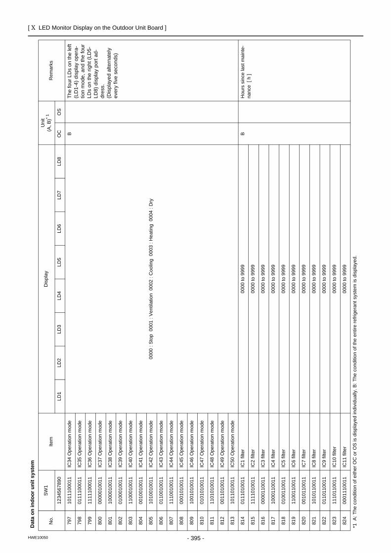
[ X LED Monitor Display on the Outdoor Unit Board ]
- 395 -HWE10050
797
1011
1000
11
IC34
Ope
ratio
n m
ode
0000
: St
op 0
001
: Ven
tilat
ion
000
2 : C
oolin
g 0
003
: Hea
ting
000
4 : D
ry
BTh
e fo
ur L
Ds
on th
e le
ft (L
D1-
4) d
ispl
ay o
pera
-tio
n m
ode,
and
the
four
LD
s on
the
right
(LD
5-LD
8) d
ispl
ay p
ort a
d-dr
ess.
(Dis
play
ed a
ltern
atel
y ev
ery
five
seco
nds)
798
0111
1000
11
IC35
Ope
ratio
n m
ode
799
1111
1000
11
IC36
Ope
ratio
n m
ode
800
0000
0100
11
IC37
Ope
ratio
n m
ode
801
1000
0100
11
IC38
Ope
ratio
n m
ode
802
0100
0100
11
IC39
Ope
ratio
n m
ode
803
1100
0100
11
IC40
Ope
ratio
n m
ode
804
0010
0100
11
IC41
Ope
ratio
n m
ode
805
1010
0100
11
IC42
Ope
ratio
n m
ode
806
0110
0100
11
IC43
Ope
ratio
n m
ode
807
1110
0100
11
IC44
Ope
ratio
n m
ode
808
0001
0100
11
IC45
Ope
ratio
n m
ode
809
1001
0100
11
IC46
Ope
ratio
n m
ode
810
0101
0100
11
IC47
Ope
ratio
n m
ode
811
1101
0100
11
IC48
Ope
ratio
n m
ode
812
0011
0100
11
IC49
Ope
ratio
n m
ode
813
1011
0100
11
IC50
Ope
ratio
n m
ode
814
0111
0100
11
IC1
filte
r00
00 to
999
9B
Hou
rs s
ince
last
mai
nte-
nanc
e [
h ]
815
1111
0100
11IC
2 fil
ter
0000
to 9
999
816
0000
1100
11IC
3 fil
ter
0000
to 9
999
817
1000
1100
11IC
4 fil
ter
0000
to 9
999
818
0100
1100
11IC
5 fil
ter
0000
to 9
999
819
1100
1100
11IC
6 fil
ter
0000
to 9
999
820
0010
1100
11IC
7 fil
ter
0000
to 9
999
821
1010
1100
11IC
8 fil
ter
0000
to 9
999
822
0110
1100
11IC
9 fil
ter
0000
to 9
999
823
1110
1100
11IC
10 fi
lter
0000
to 9
999
824
0001
1100
11IC
11 fi
lter
0000
to 9
999
Dat
a on
indo
or u
nit s
yste
m
No.
SW
1Ite
mD
ispl
ayU
nit
(A, B
)* 1R
emar
ks
1234
5678
90LD
1LD
2LD
3LD
4LD
5LD
6LD
7LD
8O
CO
S
*1 A
: The
con
ditio
n of
eith
er O
C o
r OS
is d
ispl
ayed
indi
vidu
ally
. B: T
he c
ondi
tion
of th
e en
tire
refri
gera
nt s
yste
m is
dis
play
ed.
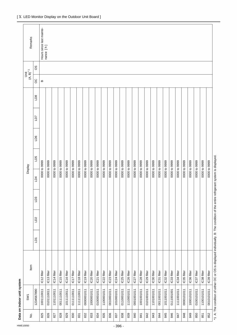
[ X LED Monitor Display on the Outdoor Unit Board ]
- 396 -HWE10050
825
1001
1100
11IC
12 fi
lter
0000
to 9
999
BH
ours
sin
ce la
st m
aint
e-na
nce
[ h
]82
601
0111
0011
IC13
filte
r00
00 to
999
9
827
1101
1100
11IC
14 fi
lter
0000
to 9
999
828
0011
1100
11IC
15 fi
lter
0000
to 9
999
829
1011
1100
11IC
16 fi
lter
0000
to 9
999
830
0111
1100
11IC
17 fi
lter
0000
to 9
999
831
1111
1100
11IC
18 fi
lter
0000
to 9
999
832
0000
0010
11IC
19 fi
lter
0000
to 9
999
833
1000
0010
11IC
20 fi
lter
0000
to 9
999
834
0100
0010
11IC
21 fi
lter
0000
to 9
999
835
1100
0010
11IC
22 fi
lter
0000
to 9
999
836
0010
0010
11IC
23 fi
lter
0000
to 9
999
837
1010
0010
11IC
24 fi
lter
0000
to 9
999
838
0110
0010
11IC
25 fi
lter
0000
to 9
999
839
1110
0010
11IC
26 fi
lter
0000
to 9
999
840
0001
0010
11IC
27 fi
lter
0000
to 9
999
841
1001
0010
11IC
28 fi
lter
0000
to 9
999
842
0101
0010
11IC
29 fi
lter
0000
to 9
999
843
1101
0010
11IC
30 fi
lter
0000
to 9
999
844
0011
0010
11IC
31 fi
lter
0000
to 9
999
845
1011
0010
11IC
32 fi
lter
0000
to 9
999
846
0111
0010
01
IC33
filte
r00
00 to
999
9
847
1111
0010
11
IC34
filte
r00
00 to
999
9
848
0000
1010
11
IC35
filte
r00
00 to
999
9
849
1000
1010
11
IC36
filte
r00
00 to
999
9
850
0100
1010
11
IC37
filte
r00
00 to
999
9
851
1100
1010
11
IC38
filte
r00
00 to
999
9
852
0010
1010
11
IC39
filte
r00
00 to
999
9
Dat
a on
indo
or u
nit s
yste
m
No.
SW
1Ite
mD
ispl
ayU
nit
(A, B
)* 1R
emar
ks
1234
5678
90LD
1LD
2LD
3LD
4LD
5LD
6LD
7LD
8O
CO
S
*1 A
: The
con
ditio
n of
eith
er O
C o
r OS
is d
ispl
ayed
indi
vidu
ally
. B: T
he c
ondi
tion
of th
e en
tire
refri
gera
nt s
yste
m is
dis
play
ed.
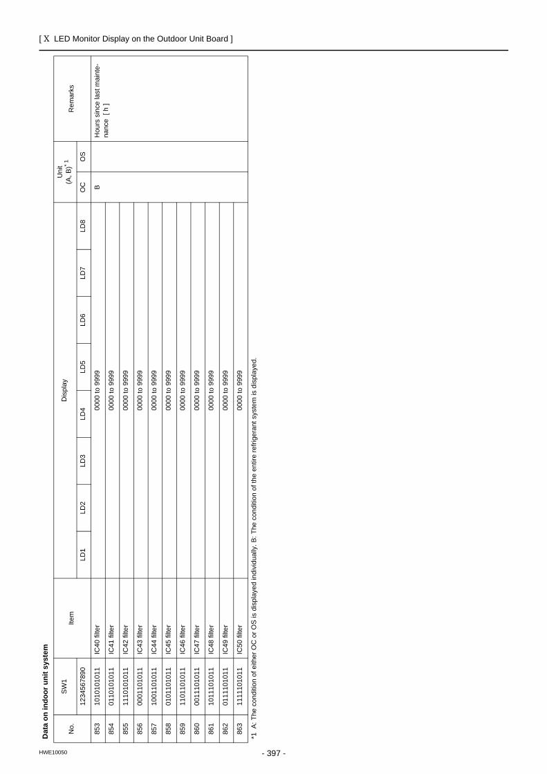
[ X LED Monitor Display on the Outdoor Unit Board ]
- 397 -HWE10050
853
1010
1010
11
IC40
filte
r00
00 to
999
9B
Hou
rs s
ince
last
mai
nte-
nanc
e [
h ]
854
0110
1010
11
IC41
filte
r00
00 to
999
9
855
1110
1010
11
IC42
filte
r00
00 to
999
9
856
0001
1010
11
IC43
filte
r00
00 to
999
9
857
1001
1010
11
IC44
filte
r00
00 to
999
9
858
0101
1010
11
IC45
filte
r00
00 to
999
9
859
1101
1010
11
IC46
filte
r00
00 to
999
9
860
0011
1010
11
IC47
filte
r00
00 to
999
9
861
1011
1010
11
IC48
filte
r00
00 to
999
9
862
0111
1010
11
IC49
filte
r00
00 to
999
9
863
1111
1010
11
IC50
filte
r00
00 to
999
9
Dat
a on
indo
or u
nit s
yste
m
No.
SW
1Ite
mD
ispl
ayU
nit
(A, B
)* 1R
emar
ks
1234
5678
90LD
1LD
2LD
3LD
4LD
5LD
6LD
7LD
8O
CO
S
*1 A
: The
con
ditio
n of
eith
er O
C o
r OS
is d
ispl
ayed
indi
vidu
ally
. B: T
he c
ondi
tion
of th
e en
tire
refri
gera
nt s
yste
m is
dis
play
ed.
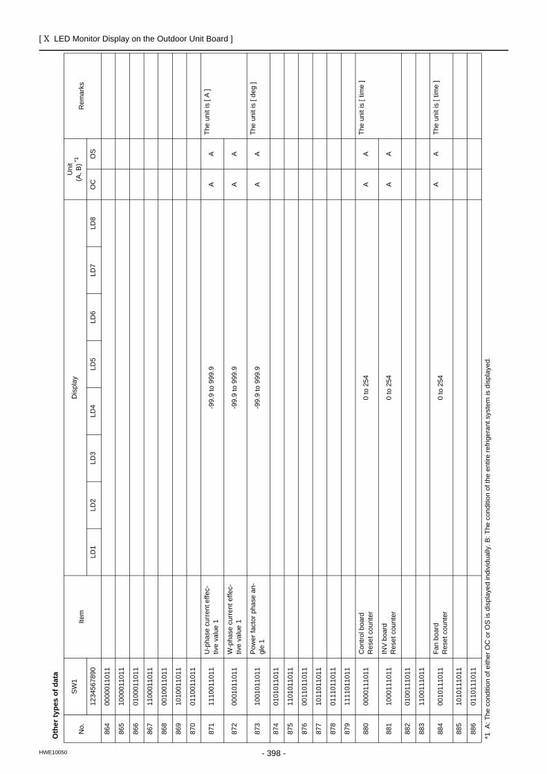
[ X LED Monitor Display on the Outdoor Unit Board ]
- 398 -HWE10050
Oth
er ty
pes
of d
ata
No.
SW
1Ite
mD
ispl
ayU
nit
(A, B
) *1
Rem
arks
1234
5678
90LD
1LD
2LD
3LD
4LD
5LD
6LD
7LD
8O
CO
S
864
0000
0110
11
865
1000
0110
11
866
0100
0110
11
867
1100
0110
11
868
0010
0110
11
869
1010
0110
11
870
0110
0110
11
871
1110
0110
11
U-p
hase
cur
rent
effe
c-tiv
e va
lue
1-9
9.9
to 9
99.9
AA
The
unit
is [
A ]
872
0001
0110
11
W-p
hase
cur
rent
effe
c-tiv
e va
lue
1-9
9.9
to 9
99.9
AA
873
1001
0110
11
Pow
er fa
ctor
pha
se a
n-gl
e 1
-99.
9 to
999
.9A
ATh
e un
it is
[ de
g ]
874
0101
0110
11
875
1101
0110
11
876
0011
0110
11
877
1011
0110
11
878
0111
0110
11
879
1111
0110
11
880
0000
1110
11
Con
trol b
oard
Res
et c
ount
er0
to 2
54A
ATh
e un
it is
[ tim
e ]
881
1000
1110
11
INV
boar
dR
eset
cou
nter
0 to
254
AA
882
0100
1110
11
883
1100
1110
11
884
0010
1110
11
Fan
boar
dR
eset
cou
nter
0 to
254
AA
The
unit
is [
time
]
885
1010
1110
11
886
0110
1110
11
*1 A
: The
con
ditio
n of
eith
er O
C o
r OS
is d
ispl
ayed
indi
vidu
ally
. B: T
he c
ondi
tion
of th
e en
tire
refri
gera
nt s
yste
m is
dis
play
ed.
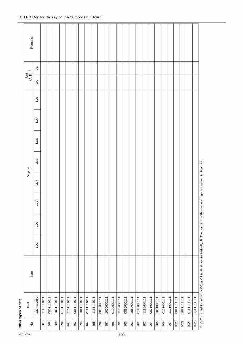
[ X LED Monitor Display on the Outdoor Unit Board ]
- 399 -HWE10050
887
1110
1110
11
888
0001
1110
11
889
1001
1110
11
890
0101
1110
11
891
1101
1110
11
892
0011
1110
11
893
1011
1110
11
894
0111
1110
11
895
1111
1110
11
896
0000
0001
11
897
1000
0001
11
898
0100
0001
11
899
1100
0001
11
900
0010
0001
11
901
1010
0001
11
902
0110
0001
11
903
1110
0001
11
904
0001
0001
11
905
1001
0001
11
906
0101
0001
11
907
1101
0001
11
1020
0011
1111
11
1021
1011
1111
11
1022
0111
1111
11
1023
1111
1111
11
Oth
er ty
pes
of d
ata
No.
SW
1Ite
mD
ispl
ayU
nit
(A, B
) *1
Rem
arks
1234
5678
90LD
1LD
2LD
3LD
4LD
5LD
6LD
7LD
8O
CO
S
*1 A
: The
con
ditio
n of
eith
er O
C o
r OS
is d
ispl
ayed
indi
vidu
ally
. B: T
he c
ondi
tion
of th
e en
tire
refri
gera
nt s
yste
m is
dis
play
ed.

Related Documents