Welcome message from author
This document is posted to help you gain knowledge. Please leave a comment to let me know what you think about it! Share it to your friends and learn new things together.
Transcript


i
Safety PrecautionsPlease read the following safety precautions carefully before installing the unit to ensure safety.
Make sure that this manual is passed on to the end user to retain for future reference.Retain this manual for future reference. When the unit is reinstalled or repaired, have this manual available to those who pro-
vide these services. Make sure that this manual is passed on to any future users.
All electric work must be performed by qualified personnel.
Air tightness test must be performed by qualified personnel.
[1] General Precautions
Indicates a risk of death or serious injury.
Indicates a risk of serious injury or structural damage.
General Precautions
Do not use refrigerant other than the type in-dicated in the manuals provided with the unit and on the nameplate. Doing so may cause the unit or pipes to burst, or result in explosion or fire during use, during repair, or at the time of disposal of the unit. It may also be in violation of applicable laws. MIT-SUBISHI ELECTRIC CORPORATION cannot be held responsible for malfunctions or ac-cidents resulting from the use of the wrong type of refrigerant.
Do not install the unit in a place where large amounts of oil, steam, organic solvents, or corrosive gases, such as sulfuric gas, are present or where acidic/alkaline solutions or sprays containing sulfur are used fre-quently. These substances can compro-mise the performance of the unit or cause certain components of the unit to corrode, which can result in refrigerant leakage, wa-ter leakage, injury, electric shock, malfunc-tions, smoke, or fire.
Do not try to defeat the safety features of the unit or make unauthorized setting changes. Forcing the unit to operate the unit by de-feating the safety features of the devices such as the pressure switch or the tempera-ture switch, making unauthorized changes to the switch settings, or using accessories other than the ones recommended by Mit-subishi Electric may result in smoke, fire, or explosion.
To reduce the risk of shorting, current leak-age, electric shock, malfunctions, smoke, or fire, do not splash water on electric parts.
To reduce the risk of electric shock, mal-functions, smoke or fire, do not operate the switches/buttons or touch other electrical parts with wet hands.
To reduce the risk of pipe burst and explo-sion, do not allow gas refrigerant and refrig-erant oil to be trapped in the refrigerant circuit.
To reduce the risk of burns or frost bites, do not touch the refrigerant pipes or refrigerant circuit components with bare hands during and immediately after operation.
To reduce the risk of burns, do not touch any electrical parts with bare hands during or immediately after stopping operation.
To reduce the risk of injury from falling tools, keep children away while installing, inspecting, or repairing the unit.
Keep the space well ventilated. Refrigerant can displace air and cause oxygen starva-tion. If leaked refrigerant comes in contact with a heat source, toxic gas may be gener-ated.

ii
[2] Transportation and Installation
Always replace a fuse with one with the cor-rect current rating. The use of improperly rated fuses or a substitution of fuses with steel or copper wire may result in bursting, fire or explosion.
To reduce the risk of electric shock, smoke, and fire due to infiltration of dust and water, properly install all required covers and pan-els on the terminal box and control box.
To reduce the risk of injury from units falling or falling over, periodically check the instal-lation base for damage.
Consult an authorized agency for the proper disposal of the unit. Refrigerant oil and re-frigerant that may be left in the unit pose a risk of fire, explosion, or environmental pol-lution.
To reduce the risk of being caught in rotat-ing parts, electric shock, and burns, do not operate the unit without all required panels and guards being installed.
To reduce the risk of injury, do not sit, stand, or place objects on the unit.
To reduce the risk of water leakage and mal-functions, do not turn off the power immedi-ately after stopping operation. Leave the unit turned on for at least 5 minutes before turning off the power.
Do not install the unit over things that are vulnerable to water damage from condensa-tion dripping.
To reduce the risk of injury, electric shock, and malfunctions, do not touch or allow ca-bles to come in contact with the edges of components.
To reduce the risk of injury, do not touch the heat exchanger fins or sharp edges of com-ponents with bare hands.
Always wear protective gears when touch-ing electrical components on the unit. Sev-eral minutes after the power is switched off, residual voltage may still cause electric shock.
To reduce the risk of electric shock and burns, always wear protective gear when working on units.
To reduce the risk of injury, do not insert fin-gers or foreign objects into air inlet/outlet grills. If the unit is left on a damaged base, it may fall and cause injury.
To reduce the risk of injury, always wear protective gear when working on units.
Do not release refrigerant into the atmo-sphere. Collect and reuse the refrigerant, or have it properly disposed of by an autho-rized agency. Refrigerant poses environ-mental hazards if released into the air.
Transportation and Installation
Lift the unit by placing the slings at desig-nated locations. Support the outdoor unit securely at four points to keep it from slip-ping and sliding. If the unit is not properly supported, it may fall and cause personal injury.
To reduce the risk of injury, do not carry the product by the PP bands that are used on some packages.
To reduce the risk of injury, products weigh-ing 20 kg or more should be carried by two or more people.

iii
[3] Installation
[4] Piping Work
Installation
Do not install the unit where there is a risk of leaking flammable gas.If flammable gas accumulates around the unit, it may ignite and cause a fire or explo-sion.
To reduce the risk of injury from coming in contact with units, install units where they are not accessible to people other than maintenance personnel.
To reduce the risk of injury, properly dis-pose of the packing materials so that chil-dren will not play with them.
Properly dispose of the packing materials. Plastic bags pose suffocation hazard to children.
All drainage work should be performed by the dealer or qualified personnel according to the instructions detailed in the Installa-tion Manual. Improper drainage work may cause water leakage and resultant damage to the furnishings.
Remove packing materials from the unit be-fore operating the unit. Note that some ac-cessories may be taped to the unit. Properly install all accessories that are required. Fail-ing to remove the packing materials or fail-ing to install required accessories may result in refrigerant leakage, oxygen depri-vation, smoke, or fire.
Consult your dealer and take appropriate measures to safeguard against refrigerant leakage and resultant oxygen starvation. An installation of a refrigerant gas detector is recommended.
Any additional parts must be installed by the dealer or qualified personnel. Only use the parts specified by Mitsubishi Electric. Installation by unauthorized personnel or use of unauthorized parts or accessories may result in water leakage, electric shock, or fire.
Take appropriate safety measures against wind gusts and earthquakes to prevent the unit from toppling over and causing injury.
To reduce the risk of injury from units falling or falling over, install the unit on a surface that is strong enough to support its weight.
Do not install the unit over things that are vulnerable to water damage. Provide an ad-equate collective drainage system for the drain water from unit as necessary.
To reduce the risk of damage to the unit and resultant electric leak and electric shock, keep small animals, snow, and rain water from entering the unit by closing the gap in the pipe and wire access holes.
To reduce the risk of rain water or drain wa-ter from entering the room and damaging the interior, drainage work must be per-formed by your dealer or qualified person-nel according to the instructions detailed in the Installation Manual.
Piping Work
To reduce the risk of injury, including frost bites, that may result from being blasted with refrigerant, use caution when operat-ing the refrigerant service valve. If refriger-ant leaks out and comes in contact with an open flame, toxic gases may be generated.
To reduce the risk of refrigerant catching fire and causing burns, remove the refriger-ant gas and the residual refrigerant oil in the pipes before heating them.
iv
[5] Wiring Work
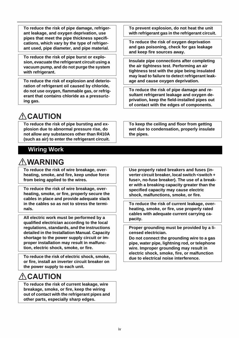
To reduce the risk of pipe damage, refriger-ant leakage, and oxygen deprivation, use pipes that meet the pipe thickness specifi-cations, which vary by the type of refriger-ant used, pipe diameter, and pipe material.
To reduce the risk of pipe burst or explo-sion, evacuate the refrigerant circuit using a vacuum pump, and do not purge the system with refrigerant.
To reduce the risk of explosion and deterio-ration of refrigerant oil caused by chloride, do not use oxygen, flammable gas, or refrig-erant that contains chloride as a pressuriz-ing gas.
To prevent explosion, do not heat the unit with refrigerant gas in the refrigerant circuit.
To reduce the risk of oxygen deprivation and gas poisoning, check for gas leakage and keep fire sources away.
Insulate pipe connections after completing the air tightness test. Performing an air tightness test with the pipe being insulated may lead to failure to detect refrigerant leak-age and cause oxygen deprivation.
To reduce the risk of pipe damage and re-sultant refrigerant leakage and oxygen de-privation, keep the field-installed pipes out of contact with the edges of components.
To reduce the risk of pipe bursting and ex-plosion due to abnormal pressure rise, do not allow any substances other than R410A (such as air) to enter the refrigerant circuit.
To keep the ceiling and floor from getting wet due to condensation, properly insulate the pipes.
Wiring Work
To reduce the risk of wire breakage, over-heating, smoke, and fire, keep undue force from being applied to the wires.
To reduce the risk of wire breakage, over-heating, smoke, or fire, properly secure the cables in place and provide adequate slack in the cables so as not to stress the termi-nals.
All electric work must be performed by a qualified electrician according to the local regulations, standards, and the instructions detailed in the Installation Manual. Capacity shortage to the power supply circuit or im-proper installation may result in malfunc-tion, electric shock, smoke, or fire.
To reduce the risk of electric shock, smoke, or fire, install an inverter circuit breaker on the power supply to each unit.
Use properly rated breakers and fuses (in-verter circuit breaker, local switch <switch + fuse>, no-fuse breaker). The use of a break-er with a breaking capacity greater than the specified capacity may cause electric shock, malfunctions, smoke, or fire.
To reduce the risk of current leakage, over-heating, smoke, or fire, use properly rated cables with adequate current carrying ca-pacity.
Proper grounding must be provided by a li-censed electrician.Do not connect the grounding wire to a gas pipe, water pipe, lightning rod, or telephone wire. Improper grounding may result in electric shock, smoke, fire, or malfunction due to electrical noise interference.
To reduce the risk of current leakage, wire breakage, smoke, or fire, keep the wiring out of contact with the refrigerant pipes and other parts, especially sharp edges.

v
[6] Relocation and Repairs
[7] Additional Precautions
Relocation and Repairs
To reduce the risk of refrigerant leakage, water leakage, injury, electric shock, and fire, units should only be moved or repaired by your dealer or qualified personnel.
To reduce the risk of wire shorting, electric leak, electric shock, smoke, or fire, do not perform maintenance work in the rain.
To reduce the risk of injury, electric shock, and fire, properly reinstall all removed com-ponents after completing repair work.
To reduce the risk of wire shorting, electric shock, malfunctions, or fire, keep circuit boards dust free, and do not touch them with your hands or tools.
To reduce the risk of refrigerant and water leakage, check the pipe supports and insu-lation for damage during inspection or re-pair, and replace or repair the ones that are found to be deteriorated.
Additional Precautions
To avoid damage to the unit, use appropri-ate tools to install, inspect, or repair the unit.
To reduce the risk or malfunction, turn on the power at least 12 hours before starting operation, and leave the power turned on throughout the operating season.
Recover all refrigerant in the units, and dis-pose of it properly according to any applica-ble laws and regulations.
Provide a maintenance access to allow for the inspection of pipes above the ceiling or the buried pipes.
Take appropriate measures against electri-cal noise interference when installing the air conditioners in hospitals or facilities with radio communication capabilities. Inverter, high-frequency medical, or wireless com-munication equipment as well as power generators may cause the air conditioning system to malfunction. Air conditioning system may also adversely affect the opera-tion of these types of equipment by creating electrical noise.
To reduce the risk of damage to the unit, leave the valves on the unit closed until re-frigerant charging is completed.
Place a wet towel on the refrigerant service valve before brazing the pipes to keep its temperature from rising above 120ºC and damaging the surrounding equipment.
Direct the blazing torch flame away from the adjacent cables and sheet metal to keep them from being overheated and damaged.
Prepare tools for exclusive use with R410A. Do not use the following tools if they have been used with the conventional refrigerant (R22): gauge manifold, charging hose, re-frigerant leak detector, check valve, refrig-erant charge spout, vacuum gauge, and refrigerant recovery equipment. R410A does not contain chloride, so leak detectors for use with older types of refrigerants will not detect an R410A leak. Infiltration of the residual refrigerant, refrigerant oil, or water on these tools may cause the refrigerant oil in the new system to deteriorate or damage the compressor.
To reduce the risk of the vacuum pump oil backflowing into the refrigerant cycle and causing the refrigerant oil to deteriorate, use a vacuum pump with a check valve.
Have a set of tools for exclusive use with R410A. Consult your nearest Mitsubishi Electric Dealer.
Keep dust, dirt, and water off charging hose and flare tool. Infiltration of dust, dirt, or wa-ter into the refrigerant circuit may cause the refrigerant oil to deteriorate or damage the compressor.

vi
Use refrigerant piping and couplings that meet the applicable standards. For refriger-ant pipes, use pipes made of phosphorus deoxidized copper. Keep the inner and out-er surfaces of pipes and couplings clean and free of such contaminants as sulfur, ox-ides, dust, dirt, shaving particles, oil, and moisture. Failure to follow these directions may result in the deterioration of refrigerant oil or compressor damage.
Store the piping materials indoors, and keep both ends of the pipes sealed until im-mediately before brazing. Keep elbows and other joints in plastic bags. Infiltration of dust, dirt, or water into the refrigerant cir-cuit may cause the refrigerant oil to deterio-rate or damage the compressor.
Apply ester oil, ether oil, or a small amount of alkyl benzene to flares and flanges. The use and accidental infiltration of mineral oil into the system may cause the refrigerant oil to deteriorate or damage the compres-sor.
To reduce the risk of oxidized film from en-tering the refrigerant pipe and causing the refrigerant oil to deteriorate or damaging the compressor, braze pipes under nitrogen purge.
Do not use the existing refrigerant piping. A large amount of chloride that is contained in the residual refrigerant and refrigerant oil in the existing piping may cause the refriger-ant oil in the new unit to deteriorate or dam-age the compressor.
Charge refrigerant in the liquid state. If re-frigerant is charged in the gas phase, the composition of the refrigerant in the cylin-der will change, compromising the unit's performance.
Do not use a charging cylinder. The use of a charging cylinder will change the composi-tion of the refrigerant, compromising the unit's performance.
Charge the system with an appropriate amount of refrigerant in the liquid phase. Refer to the relevant sections in the manu-als to calculate the appropriate amount of refrigerant to be charged. Refrigerant over-charge or undercharge may result in perfor-mance drop or abnormal stop of operation.
To reduce the risk of power capacity short-age, always use a dedicated power supply circuit.
To reduce the risk of both the breaker on the product side and the upstream breaker from tripping and causing problems, split the power supply system or provide protection coordination between the earth leakage breaker and no-fuse breaker.
Have a backup system, if failure of the unit has a potential for causing significant prob-lems or damages.

CONTENTS
Chapter 1 Check Before Servicing1-1 Preparation for Piping Work.................................................................................................................. 31-2 Handling and Characteristics of Piping Materials, Refrigerant, and Refrigerant Oil ....................... 51-3 Working with Refrigerant Piping......................................................................................................... 101-4 Precautions for Wiring......................................................................................................................... 141-5 Cautionary notes on installation environment and maintenance.................................................... 16
Chapter 2 Restrictions2-1 System Configurations ........................................................................................................................ 192-2 Types and Maximum Allowable Length of Cables ............................................................................ 202-3 Switch Settings..................................................................................................................................... 212-4 M-NET Address Settings ..................................................................................................................... 222-5 Demand Control Overview .................................................................................................................. 282-6 System Connection Example .............................................................................................................. 302-7 Example System with an MA Remote Controller .............................................................................. 322-8 Example System with an ME Remote Controller............................................................................... 422-9 Example System with an MA and an ME Remote Controller............................................................ 442-10 Restrictions on Refrigerant Pipes ...................................................................................................... 46
Chapter 3 Major Components, Their Functions and Refrigerant Circuits3-1 External Appearance and Refrigerant Circuit Components of Outdoor Unit ................................. 533-2 Outdoor Unit Refrigerant Circuit Diagrams ....................................................................................... 593-3 Functions of the Major Components of Outdoor Unit ...................................................................... 613-4 Functions of the Major Components of Indoor Unit ......................................................................... 64
Chapter 4 Electrical Components and Wiring Diagrams4-1 Outdoor Unit Circuit Board Arrangement .......................................................................................... 674-2 Outdoor Unit Circuit Board Components .......................................................................................... 714-3 Outdoor Unit Electrical Wiring Diagrams........................................................................................... 804-4 Transmission Booster Electrical Wiring Diagrams........................................................................... 82
Chapter 5 Control5-1 Dipswitch Functions and Factory Settings........................................................................................ 855-2 Outdoor Unit Control ........................................................................................................................... 935-3 Operation Flowcharts ........................................................................................................................ 106
Chapter 6 Test Run6-1 Read before Test Run ........................................................................................................................ 1136-2 MA and ME Remote Controller Functions and Specifications....................................................... 1146-3 Making the Group and Interlock Settings from an ME Remote Controller ................................... 1156-4 Selecting Remote Controller Functions from an ME Remote Controller ...................................... 1196-5 Making Interlock Settings from an MA Remote Controller............................................................. 1216-6 Changing the Room Temperature Detection Position.................................................................... 1276-7 Test Run Method ................................................................................................................................ 1286-8 Operation Characteristics and Refrigerant Charge ........................................................................ 1316-9 Evaluating and Adjusting Refrigerant Charge.................................................................................1316-10 The Following Symptoms Are Normal ............................................................................................. 1376-11 Standard Operation Data (Reference Data) ..................................................................................... 138
Chapter 7 Troubleshooting Using Error Codes7-1 Error Code and Preliminary Error Code Lists ................................................................................. 1657-2 Error Code Definitions and Solutions: Codes [0 - 999]................................................................... 1697-3 Error Code Definitions and Solutions: Codes [1000 - 1999]........................................................... 1717-4 Error Code Definitions and Solutions: Codes [2000 - 2999]........................................................... 1757-5 Error Code Definitions and Solutions: Codes [3000 - 3999]........................................................... 1817-6 Error Code Definitions and Solutions: Codes [4000 - 4999]........................................................... 1827-7 Error Code Definitions and Solutions: Codes [5000 - 5999]........................................................... 1987-8 Error Code Definitions and Solutions: Codes [6000 - 6999]........................................................... 206
HWE14040 GB

CONTENTS
7-9 Error Code Definitions and Solutions: Codes [7000 - 7999]........................................................... 226
Chapter 8 Troubleshooting Based on Observed Symptoms8-1 MA Remote Controller Problems ...................................................................................................... 2378-2 ME remote Controller Problems ....................................................................................................... 2418-3 Refrigerant Control Problems ........................................................................................................... 2458-4 Checking Transmission Waveform and for Electrical Noise Interference.................................... 2508-5 Pressure Sensor Circuit Configuration and Troubleshooting Pressure Sensor Problems ........ 2538-6 Troubleshooting Solenoid Valve Problems ..................................................................................... 2558-7 Troubleshooting Outdoor Unit Fan Problems ................................................................................. 2578-8 Troubleshooting LEV Problems........................................................................................................ 2588-9 Troubleshooting Inverter Problems ................................................................................................. 2648-10 Control Circuit .................................................................................................................................... 2768-11 Measures for Refrigerant Leakage ................................................................................................... 2818-12 Compressor Replacement Instructions ........................................................................................... 2838-13 Troubleshooting Problems Using the LED Status Indicators on the Outdoor Unit ..................... 285
Chapter 9 LED Status Indicators on the Outdoor Unit Circuit Board9-1 LED Status Indicators ........................................................................................................................ 2899-2 LED Status Indicators Table ............................................................................................................. 292
HWE14040 GB

- 1 -HWE14040 GB
Chapter 1 Check Before Servicing
1-1 Preparation for Piping Work ................................................................................................................ 3
1-1-1 Read before Servicing ............................................................................................................................ 3
1-1-2 Tool Preparation ..................................................................................................................................... 4
1-2 Handling and Characteristics of Piping Materials, Refrigerant, and Refrigerant Oil...................... 5
1-2-1 Piping Materials ...................................................................................................................................... 5
1-2-2 Storage of Piping Materials..................................................................................................................... 7
1-2-3 Pipe Processing ...................................................................................................................................... 7
1-2-4 Characteristics of the New and Conventional Refrigerants .................................................................... 8
1-2-5 Refrigerant Oil......................................................................................................................................... 9
1-3 Working with Refrigerant Piping ....................................................................................................... 10
1-3-1 Pipe Brazing.......................................................................................................................................... 10
1-3-2 Air Tightness Test ................................................................................................................................. 11
1-3-3 Vacuum Drying ..................................................................................................................................... 12
1-3-4 Refrigerant Charging............................................................................................................................. 13
1-4 Precautions for Wiring ....................................................................................................................... 14
1-5 Cautionary notes on installation environment and maintenance .................................................. 16

- 2 -HWE14040 GB

[1-1 Preparation for Piping Work ]
1 C
hec
k B
efo
re S
ervi
cin
g
1 Check Before Servicing
1-1 Preparation for Piping Work
1-1-1 Read before Servicing
1. Check the type of refrigerant used in the system to be serviced.Refrigerant TypeMulti air conditioner for building application CITY MULTI YKB-A1 series:R410A
2. Check the symptoms exhibited by the unit to be serviced.Refer to this service handbook for symptoms relating to the refrigerant cycle.
3. Thoroughly read the safety precautions at the beginning of this manual.
4. Preparing necessary tools: Prepare a set of tools to be used exclusively with each type of refrigerant.For information about the correct use of tools, refer to the following page(s). [1-1-2 Tool Preparation](page 4)
5. Verification of the connecting pipes: Verify the type of refrigerant used for the unit to be moved or replaced.Use refrigerant pipes made of phosphorus deoxidized copper. Keep the inner and outer surfaces of the pipes clean and free of such contaminants as sulfur, oxides, dust, dirt, shaving particles, oil, and water.These types of contaminants inside the refrigerant pipes may cause the refrigerant oil to deteriorate.
6. If there is a leak of gaseous refrigerant and the remaining refrigerant is exposed to an open flame, a poisonous gas hydrofluoric acid may form. Keep workplace well ventilated.
CAUTIONInstall new pipes immediately after removing old ones to keep moisture out of the refrigerant circuit.The use of refrigerant that contains chloride, such as R22, will cause the refrigerating machine oil to deteriorate.
- 3 -HWE14040 GB

[1-1 Preparation for Piping Work ]
1-1-2 Tool Preparation
Prepare the following tools and materials necessary for installing and servicing the unit.
Tools for use with R410A (Adaptability of tools that are for use with R22 or R407C)1. To be used exclusively with R410A (not to be used if used with R22 or R407C)
2. Tools and materials that may be used with R410A with some restrictions
3. Tools and materials that are used with R22 or R407C that may also be used with R410A
4. Tools and materials that must not be used with R410A
Tools for R410A must be handled with special care to keep moisture and dust from infiltrating the cycle.
Tools/Materials Use Notes
Gauge Manifold Evacuation and refrigerant charging Higher than 5.09MPa[738psi] on the high-pressure side
Charging Hose Evacuation and refrigerant charging The hose diameter is larger than the conventional model.
Refrigerant Recovery Cylinder Refrigerant recovery
Refrigerant Cylinder Refrigerant charging The refrigerant type is indicated. The cylinder is pink.
Charging Port on the Refrigerant Cylinder Refrigerant charging The charge port diameter is larger than that of the current port.
Flare Nut Connection of the unit with the pipes Use Type-2 Flare nuts.
Tools/Materials Use Notes
Gas Leak Detector Gas leak detection The ones for use with HFC refrigerant may be used.
Vacuum Pump Vacuum drying May be used if a check valve adapter is attached.
Flare Tool Flare processing Flare processing dimensions for the piping in the system using the new re-frigerant differ from those of R22. Re-fer to the following page(s). [1-2-1 Piping Materials](page 5)
Refrigerant Recovery Equipment Refrigerant recovery May be used if compatible with R410A.
Tools/Materials Use Notes
Vacuum Pump with a Check Valve Vacuum drying
Bender Bending pipes
Torque Wrench Tightening flare nuts Only the flare processing dimensions for pipes that have a diameter of ø12.7 (1/2") and ø15.88 (5/8") have been changed.
Pipe Cutter Cutting pipes
Welder and Nitrogen Cylinder Welding pipes
Refrigerant Charging Meter Refrigerant charging
Vacuum Gauge Vacuum level check
Tools/Materials Use Notes
Charging Cylinder Refrigerant charging Prohibited to use
- 4 -HWE14040 GB

[1-2 Handling and Characteristics of Piping Materials, Refrigerant, and Refrigerant Oil ]
1 C
hec
k B
efo
re S
ervi
cin
g
1-2 Handling and Characteristics of Piping Materials, Refrigerant, and Refrigerant Oil
1-2-1 Piping Materials
1. Copper pipe materials
The distinction between O-materials (Annealed) and 1/2H-materials (Drawn) is made based on the strength of the pipes them-selves.O-materials (Annealed) can easily be bent with hands. 1/2H-materials (Drawn) are considerably stronger than O-material (Annealed) at the same thickness.
2. Types of copper pipes
3. Piping materials/Radial thicknessUse refrigerant pipes made of phosphorus deoxidized copper.The operation pressure of the units that use R410A is higher than that of the units that use R22. Use pipes that have at least the radial thickness specified in the chart below. (Pipes with a radial thickness of 0.7 mm or less may not be used.)
Annealed pipes have been used for older model units when a diameter of the pipe is up to φ19.05 (3/4"). For a system that uses R410A, use pipes that are made with 1/2H-material (Drawn). (Annealed pipes may be used for pipes with a diameter of φ19.05 (3/4") and a radial thickness of 1.2 t).The figures in the radial thickness column are based on the Japanese standards and provided only as a reference. Use pipes that meet the local standards.
O-material (Annealed) Soft copper pipes (annealed copper pipes). They can easily be bent with hands.
1/2H-material (Drawn) Hard copper pipes (straight pipes). They are stronger than the O-material (Annealed) at the same radial thickness.
Maximum working pressure Refrigerant type
3.45 MPa [500psi] R22, R407C etc.
4.30 MPa [624psi] R410A etc.
Pipe size (mm[in]) Radial thickness (mm) Type
ø6.35 [1/4"] 0.8t
O-material (Annealed)ø9.52 [3/8"] 0.8t
ø12.7 [1/2"] 0.8t
ø15.88 [5/8"] 1.0t
ø19.05 [3/4"] 1.0t
1/2H-material, H-material (Drawn)
ø22.2 [7/8"] 1.0t
ø25.4 [1"] 1.0t
ø28.58 [1-1/8"] 1.0t
ø31.75 [1-1/4"] 1.1t
ø34.93 [1-3/8"] 1.2t
ø41.28 [1-5/8"] 1.4t
Do not use the existing piping!
- 5 -HWE14040 GB

[1-2 Handling and Characteristics of Piping Materials, Refrigerant, and Refrigerant Oil ]
4. Thickness and refrigerant type indicated on the piping materialsAsk the pipe manufacturer for the symbols indicated on the piping material for new refrigerant.
5. Flare processing (O-material (Annealed) and OL-material only)The flare processing dimensions for the pipes that are used in the R410A system are larger than those in the R22 system.
If a clutch-type flare tool is used to flare the pipes in the system using R410A, the length of the pipes must be between 1.0 and 1.5 mm. For margin adjustment, a copper pipe gauge is necessary.
6. Flare nutThe flare nut type has been changed to increase the strength. The size of some of the flare nuts have also been changed.
The figures in the radial thickness column are based on the Japanese standards and provided only as a reference. Use pipes that meet the local standards.
Flare processing dimensions (mm[in])
Pipe size (mm[in])A dimension (mm)
R410A R22, R407C
ø6.35 [1/4"] 9.1 9.0
ø9.52 [3/8"] 13.2 13.0
ø12.7 [1/2"] 16.6 16.2
ø15.88 [5/8"] 19.7 19.4
ø19.05 [3/4"] 24.0 23.3
Flare nut dimensions (mm[in])
Pipe size (mm[in])B dimension (mm)
R410A R22, R407C
ø6.35 [1/4"] 17.0 17.0
ø9.52 [3/8"] 22.0 22.0
ø12.7 [1/2"] 26.0 24.0
ø15.88 [5/8"] 29.0 27.0
ø19.05 [3/4"] 36.0 36.0
Dim
ensi
on A
Dimension B
- 6 -HWE14040 GB
[1-2 Handling and Characteristics of Piping Materials, Refrigerant, and Refrigerant Oil ]
1 C
hec
k B
efo
re S
ervi
cin
g
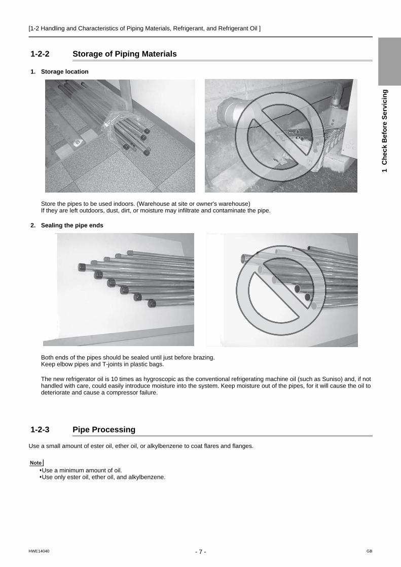
1-2-2 Storage of Piping Materials
1. Storage location
Store the pipes to be used indoors. (Warehouse at site or owner's warehouse) If they are left outdoors, dust, dirt, or moisture may infiltrate and contaminate the pipe.
2. Sealing the pipe ends
Both ends of the pipes should be sealed until just before brazing.Keep elbow pipes and T-joints in plastic bags.
The new refrigerator oil is 10 times as hygroscopic as the conventional refrigerating machine oil (such as Suniso) and, if not handled with care, could easily introduce moisture into the system. Keep moisture out of the pipes, for it will cause the oil to deteriorate and cause a compressor failure.
1-2-3 Pipe Processing
Use a small amount of ester oil, ether oil, or alkylbenzene to coat flares and flanges.
Use a minimum amount of oil. Use only ester oil, ether oil, and alkylbenzene.
- 7 -HWE14040 GB

[1-2 Handling and Characteristics of Piping Materials, Refrigerant, and Refrigerant Oil ]
1-2-4 Characteristics of the New and Conventional Refrigerants
1. Chemical propertyAs with R22, the new refrigerant (R410A) is low in toxicity and chemically stable nonflammable refrigerant.However, because the specific gravity of vapor refrigerant is greater than that of air, leaked refrigerant in a closed room will accumulate at the bottom of the room and may cause hypoxia.If exposed to an open flame, refrigerant will generate poisonous gases. Do not perform installation or service work in a con-fined area.
*1 When CFC11 is used as a reference*2 When CO2 is used as a reference
2. Refrigerant compositionR410A is a pseudo-azeotropic HFC blend and can almost be handled the same way as a single refrigerant, such as R22. To be safe, however, draw out the refrigerant from the cylinder in the liquid phase. If the refrigerant in the gaseous phase is drawn out, the composition of the remaining refrigerant will change and become unsuitable for use.If the refrigerant leaks out, it may be replenished. The entire refrigerant does not need to be replaced.
3. Pressure characteristicsThe pressure in the system using R410A is 1.6 times as great as that in the system using R22.
New Refrigerant (HFC type) Conventional Refriger-ant (HCFC type)
R410A R407C R22
R32/R125 R32/R125/R134a R22
Composition (wt%) (50/50) (23/25/52) (100)
Type of Refrigerant Pseudo-azeotropicRefrigerant
Non-azeotropic Refrigerant
Single Refrigerant
Chloride Not included Not included Included
Safety Class A1/A1 A1/A1 A1
Molecular Weight 72.6 86.2 86.5
Boiling Point (°C/°F) -51.4/-60.5 -43.6/-46.4 -40.8/-41.4
Steam Pressure(25°C,MPa/77°F,psi) (gauge)
1.557/226 0.9177/133 0.94/136
Saturated Steam Density(25°C,kg/m3/77°F,psi)
64.0 42.5 44.4
Flammability Nonflammable Nonflammable Nonflammable
Ozone Depletion Coefficient (ODP)*1 0 0 0.055
Global Warming Coefficient (GWP)*2 2090 1774 1700
Refrigerant Charging Method Refrigerant charging in the liquid state
Refrigerant charging in the liquid state
Refrigerant charging in the gaseous state
Replenishment of Refrigerant after a Refrigerant Leak
Available Available Available
Temperature (°C/°F)
Pressure (gauge)
R410A R407C R22
MPa/psi MPa/psi MPa/psi
-20/-4 0.30/44 0.18/26 0.14/20
0/32 0.70/102 0.47/68 0.40/58
20/68 1.34/194 0.94/136 0.81/117
40/104 2.31/335 1.44/209 1.44/209
60/140 3.73/541 2.44/354 2.33/338
65/149 4.17/605 2.75/399 2.60/377
- 8 -HWE14040 GB

[1-2 Handling and Characteristics of Piping Materials, Refrigerant, and Refrigerant Oil ]
1 C
hec
k B
efo
re S
ervi
cin
g
1-2-5 Refrigerant Oil
1. Refrigerating machine oil in the HFC refrigerant system
HFC type refrigerants use a refrigerating machine oil different from that used in the R22 system.Note that the ester oil used in the system has properties that are different from commercially available ester oil.
2. Effects of contaminants*1
Refrigerating machine oil used in the HFC system must be handled with special care to keep contaminants out.The table below shows the effect of contaminants in the refrigerating machine oil on the refrigeration cycle.
3. The effects of contaminants in the refrigerating machine oil on the refrigeration cycle.
Refrigerant Refrigerating machine oil
R22 Mineral oil
R407C Ester oil
R410A Ester oil
*1. Contaminants is defined as moisture, air, processing oil, dust/dirt, wrong types of refrigerant, and refrigerating machine oil.
Cause Symptoms Effects on the refrigerant cycle
Water infiltration Frozen expansion valve and capillary tubes
Clogged expansion valve and capillary tubesPoor cooling performanceCompressor overheatMotor insulation failureBurnt motorCoppering of the orbiting scrollLockBurn-in on the orbiting scroll
HydrolysisSludge formation and ad-hesionAcid generationOxidizationOil degradation
Air infiltration Oxidization
Infiltration of contaminants
Dust, dirt
Adhesion to expansion valve and capillary tubes
Clogged expansion valve, capillary tubes, and drierPoor cooling performanceCompressor overheat
Infiltration of contaminants into the com-pressor
Burn-in on the orbiting scroll
Mineral oil etc.
Sludge formation and adhesion Clogged expansion valve and capillary tubesPoor cooling performanceCompressor overheat
Oil degradation Burn-in on the orbiting scroll
- 9 -HWE14040 GB

[1-3 Working with Refrigerant Piping ]
1-3 Working with Refrigerant Piping
1-3-1 Pipe Brazing
No changes have been made in the brazing procedures. Perform brazing with special care to keep foreign objects (such as oxide scale, water, and dust) out of the refrigerant system.
Example: Inside the brazed connection
1. Items to be strictly observedDo not conduct refrigerant piping work outdoors if raining.Use inert gas during brazing.Use a brazing material (BCuP-3) that requires no flux when brazing between copper pipes or between a copper pipe and copper coupling.If installed refrigerant pipes are not immediately connected to the equipment, then braze and seal both ends.
2. ReasonsThe new refrigerating machine oil is 10 times as hygroscopic as the conventional oil and is more likely to cause unit failure if water infiltrates into the system.Flux generally contains chloride. Residual flux in the refrigerant circuit will cause sludge to form.
3. NotesDo not use commercially available antioxidants because they may cause the pipes to corrode or refrigerating machine oil to deteriorate.
Use of no inert gas during brazing Use of inert gas during brazing
- 10 -HWE14040 GB
[1-3 Working with Refrigerant Piping ]
1 C
hec
k B
efo
re S
ervi
cin
g
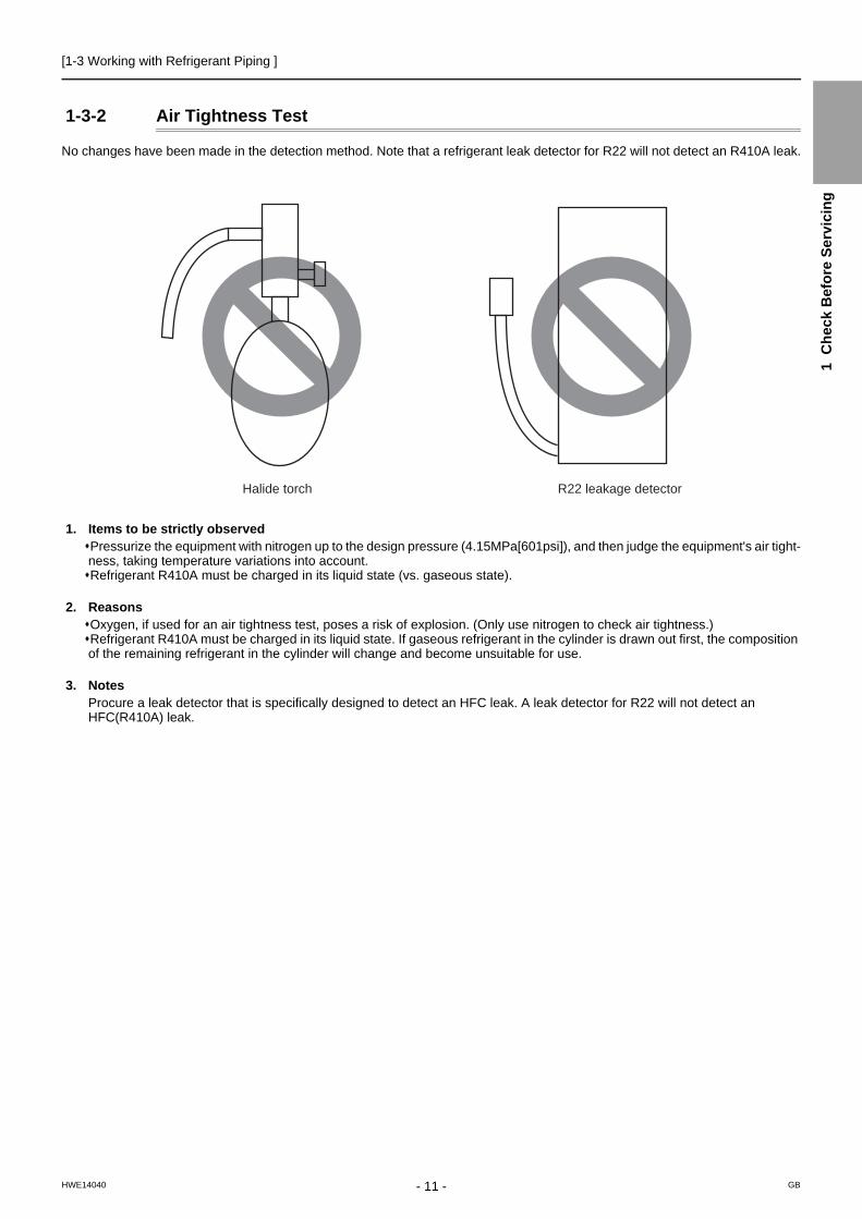
1-3-2 Air Tightness Test
No changes have been made in the detection method. Note that a refrigerant leak detector for R22 will not detect an R410A leak.
1. Items to be strictly observedPressurize the equipment with nitrogen up to the design pressure (4.15MPa[601psi]), and then judge the equipment's air tight-ness, taking temperature variations into account.Refrigerant R410A must be charged in its liquid state (vs. gaseous state).
2. ReasonsOxygen, if used for an air tightness test, poses a risk of explosion. (Only use nitrogen to check air tightness.)Refrigerant R410A must be charged in its liquid state. If gaseous refrigerant in the cylinder is drawn out first, the composition of the remaining refrigerant in the cylinder will change and become unsuitable for use.
3. NotesProcure a leak detector that is specifically designed to detect an HFC leak. A leak detector for R22 will not detect an HFC(R410A) leak.
Halide torch R22 leakage detector
- 11 -HWE14040 GB

[1-3 Working with Refrigerant Piping ]
1-3-3 Vacuum Drying
1. Vacuum pump with a reverse-flow check valve (Photo1)To prevent the vacuum pump oil from flowing into the refrigerant circuit during power OFF or power failure, use a vacuum pump with a reverse-flow check valve.A reverse-flow check valve may also be added to the vacuum pump currently in use.
2. Standard of vacuum degree (Photo 2)Use a vacuum pump that attains 0.5Torr(65Pa) or lower degree of vacuum after 5 minutes of operation, and connect it directly to the vacuum gauge. Use a pump well-maintained with an appropriate lubricant. A poorly maintained vacuum pump may not be able to attain the desired degree of vacuum.
3. Required precision of vacuum gaugeUse a vacuum gauge that registers a vacuum degree of 5Torr(650Pa) and measures at intervals of 1Torr(130Pa). (A recom-mended vacuum gauge is shown in Photo2.)Do not use a commonly used gauge manifold because it cannot register a vacuum degree of 5Torr(650Pa).
4. Evacuation timeAfter the degree of vacuum has reached 5Torr(650Pa), evacuate for an additional 1 hour. (A thorough vacuum drying re-moves moisture in the pipes.)Verify that the vacuum degree has not risen by more than 1Torr(130Pa) 1hour after evacuation. A rise by less than 1Torr(130Pa) is acceptable.If the vacuum is lost by more than 1Torr(130Pa), conduct evacuation, following the instructions in section 6. Special vacuum drying.
5. Procedures for stopping vacuum pumpTo prevent the reverse flow of vacuum pump oil, open the relief valve on the vacuum pump side, or draw in air by loosening the charge hose, and then stop the operation.The same procedures should be followed when stopping a vacuum pump with a reverse-flow check valve.
6. Special vacuum dryingWhen 5Torr(650Pa) or lower degree of vacuum cannot be attained after 3 hours of evacuation, it is likely that water has pen-etrated the system or that there is a leak.If water infiltrates the system, break the vacuum with nitrogen. Pressurize the system with nitrogen gas to 0.5kgf/cm2G(0.05MPa) and evacuate again. Repeat this cycle of pressurizing and evacuation either until the degree of vac-uum below 5Torr(650Pa) is attained or until the pressure stops rising.Only use nitrogen gas for vacuum breaking. (The use of oxygen may result in an explosion.)
(Photo1) 15010H (Photo2) 14010
Recommended vacuum gauge: ROBINAIR 14010 Thermistor Vacuum Gauge
- 12 -HWE14040 GB

[1-3 Working with Refrigerant Piping ]
1 C
hec
k B
efo
re S
ervi
cin
g
1-3-4 Refrigerant Charging
1. ReasonsR410A is a pseudo-azeotropic HFC blend (boiling point R32=-52°C[-62°F], R125=-49°C[-52°F]) and can almost be handled the same way as a single refrigerant, such as R22. To be safe, however, draw out the refrigerant from the cylinder in the liquid phase. If the refrigerant in the gaseous phase is drawn out, the composition of the remaining refrigerant will change and be-come unsuitable for use.
2. NotesWhen using a cylinder with a siphon, refrigerant is charged in the liquid state without the need for turning it upside down. Check the type of the cylinder on the label before use.If the refrigerant leaks out, it may be replenished. The entire refrigerant does not need to be replaced. (Charge refrigerant in the liquid state.)Refer to the following page(s).[8-11 Measures for Refrigerant Leakage](page 281)
Cylinder with a siphon
Cylinder color R410A is pink. Refrigerant charging in the liquid state
Cylin-der
liquid
Valve Valve
liquid
Cylin-der
Cylinder without a siphon
- 13 -HWE14040 GB
[1-4 Precautions for Wiring ]
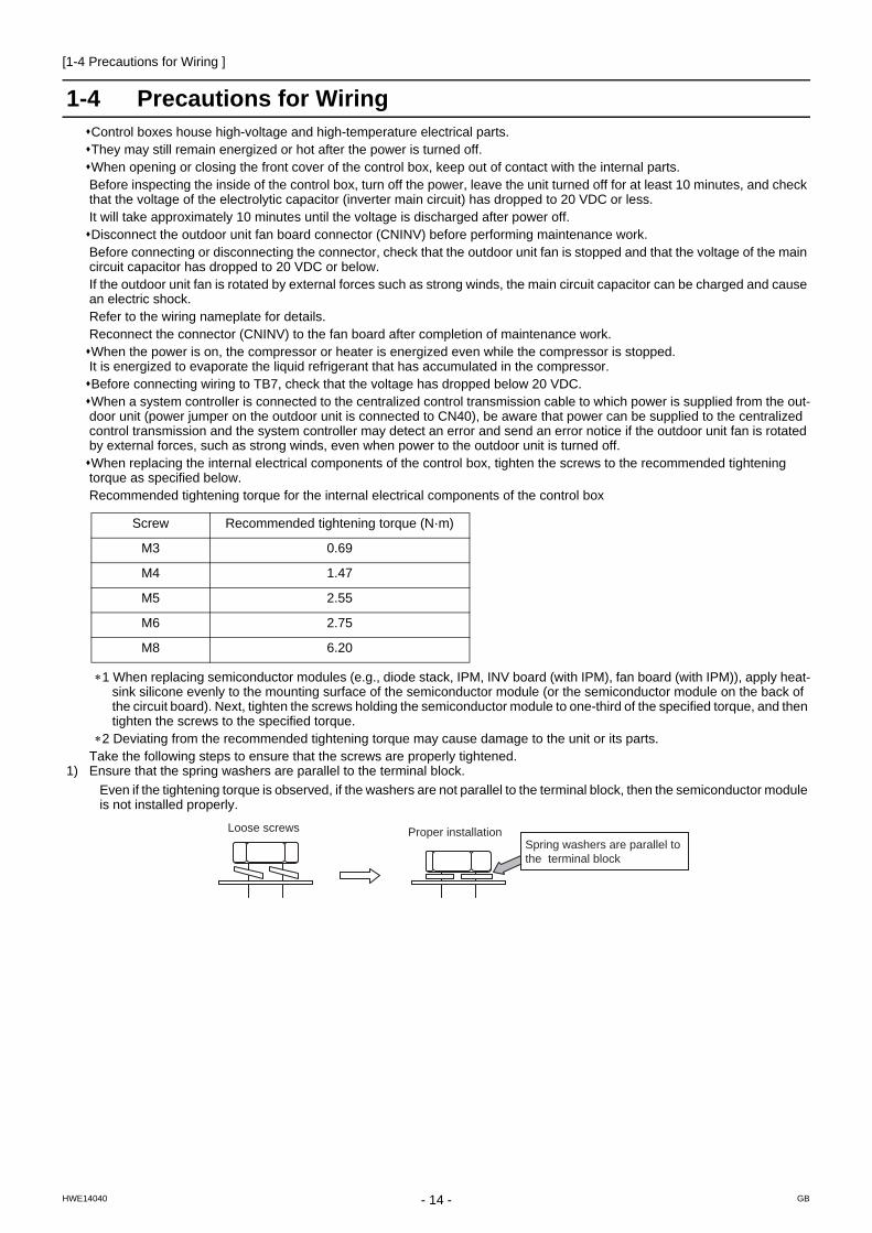
1-4 Precautions for WiringControl boxes house high-voltage and high-temperature electrical parts.They may still remain energized or hot after the power is turned off. When opening or closing the front cover of the control box, keep out of contact with the internal parts.Before inspecting the inside of the control box, turn off the power, leave the unit turned off for at least 10 minutes, and check that the voltage of the electrolytic capacitor (inverter main circuit) has dropped to 20 VDC or less.It will take approximately 10 minutes until the voltage is discharged after power off.Disconnect the outdoor unit fan board connector (CNINV) before performing maintenance work. Before connecting or disconnecting the connector, check that the outdoor unit fan is stopped and that the voltage of the main circuit capacitor has dropped to 20 VDC or below.If the outdoor unit fan is rotated by external forces such as strong winds, the main circuit capacitor can be charged and cause an electric shock. Refer to the wiring nameplate for details.Reconnect the connector (CNINV) to the fan board after completion of maintenance work. When the power is on, the compressor or heater is energized even while the compressor is stopped.It is energized to evaporate the liquid refrigerant that has accumulated in the compressor. Before connecting wiring to TB7, check that the voltage has dropped below 20 VDC.When a system controller is connected to the centralized control transmission cable to which power is supplied from the out-door unit (power jumper on the outdoor unit is connected to CN40), be aware that power can be supplied to the centralized control transmission and the system controller may detect an error and send an error notice if the outdoor unit fan is rotated by external forces, such as strong winds, even when power to the outdoor unit is turned off.When replacing the internal electrical components of the control box, tighten the screws to the recommended tightening torque as specified below.Recommended tightening torque for the internal electrical components of the control box
1 When replacing semiconductor modules (e.g., diode stack, IPM, INV board (with IPM), fan board (with IPM)), apply heat-sink silicone evenly to the mounting surface of the semiconductor module (or the semiconductor module on the back of the circuit board). Next, tighten the screws holding the semiconductor module to one-third of the specified torque, and then tighten the screws to the specified torque.
2 Deviating from the recommended tightening torque may cause damage to the unit or its parts.Take the following steps to ensure that the screws are properly tightened.
1) Ensure that the spring washers are parallel to the terminal block.
Even if the tightening torque is observed, if the washers are not parallel to the terminal block, then the semiconductor module is not installed properly.
Screw Recommended tightening torque (N·m)
M3 0.69
M4 1.47
M5 2.55
M6 2.75
M8 6.20
Proper installationLoose screwsSpring washers are parallel tothe terminal block
- 14 -HWE14040 GB

[1-4 Precautions for Wiring ]
1 C
hec
k B
efo
re S
ervi
cin
g
2) Check the wires are securely fastened to the screw terminals.
Screw the screws straight down so as not to damage the screw threads.Hold the two round terminals back to back to ensure that the screw will screw down straight. After tightening the screw, mark a line through the screw head, washer, and terminals with a permanent marker.
Example
Poor contact caused by loose screws may result in overheating and fire.Continued use of the damaged circuit board may cause overheating and fire.
Daisy-chain
Power supply terminal block, indoor-outdoor transmission line terminal block, and centralized controller transmission line
Mark a line.
Place the round terminals back to back.
Power wires, transmission lines, centralized transmission lines
- 15 -HWE14040 GB

[1-5 Cautionary notes on installation environment and maintenance ]
1-5 Cautionary notes on installation environment and maintenance
Salt-resistant unit is resistant to salt corrosion, but not salt-proof. Please note the following when installing and main-taining outdoor units in marine atmosphere.
1) Install the salt-resistant unit out of direct exposure to sea breeze, and minimize the exposure to salt water mist.2) Avoid installing a sun shade over the outdoor unit, so that rain will wash away salt deposits off the unit.3) Install the unit horizontally to ensure proper water drainage from the base of the unit. Accumulation of water in the base of the
outdoor unit will significantly accelerate corrosion.4) Periodically wash salt deposits off the unit, especially when the unit is installed in a coastal area.5) Repair all noticeable scratches after installation and during maintenance.6) Periodically check the unit, and apply anti-rust agent and replace corroded parts as necessary.
- 16 -HWE14040 GB

- 17 -HWE14040 GB
Chapter 2 Restrictions
2-1 System Configurations....................................................................................................................... 19
2-2 Types and Maximum Allowable Length of Cables........................................................................... 20
2-3 Switch Settings ................................................................................................................................... 21
2-4 M-NET Address Settings .................................................................................................................... 22
2-4-1 Address Settings List ............................................................................................................................ 22
2-4-2 Outdoor Unit Power Jumper Connector Connection............................................................................. 23
2-4-3 Outdoor Unit Centralized Controller Switch Setting .............................................................................. 23
2-4-4 Room Temperature Detection Position Selection ................................................................................. 23
2-4-5 Start/Stop Control of Indoor Units ......................................................................................................... 24
2-4-6 Miscellaneous Settings ......................................................................................................................... 24
2-4-7 Various Control Methods Using the Signal Input/Output Connector on Outdoor Unit .......................... 25
2-5 Demand Control Overview ................................................................................................................. 28
2-6 System Connection Example............................................................................................................. 30
2-7 Example System with an MA Remote Controller ............................................................................. 32
2-7-1 Single Refrigerant System (Automatic Indoor/Outdoor Address Startup)............................................. 32
2-7-2 Single Refrigerant System with Two or More LOSSNAY Units ............................................................ 34
2-7-3 Grouped Operation of Units in Separate Refrigerant Circuits............................................................... 36
2-7-4 System with a Connection of System Controller to Centralized Control Transmission Line................. 38
2-7-5 System with a Connection of System Controller to Indoor-Outdoor Transmission Line ....................... 40
2-8 Example System with an ME Remote Controller ............................................................................. 42
2-8-1 System with a Connection of System Controller to Centralized Control Transmission Line................. 42
2-9 Example System with an MA and an ME Remote Controller .......................................................... 44
2-9-1 System with a Connection of System Controller to Centralized Control Transmission Line................. 44
2-10 Restrictions on Refrigerant Pipes ..................................................................................................... 46
2-10-1 Restrictions on Refrigerant Pipe Length ............................................................................................... 46
2-10-2 Restrictions on Refrigerant Pipe Size ................................................................................................... 49

- 18 -HWE14040 GB

[2-1 System Configurations ]
2 R
es
tric
tio
ns
2 Restrictions
2-1 System Configurations1. Table of compatible indoor units(1) High COP combinations
The table below summarizes the types of indoor units that are compatible with different types of outdoor units.
1) "Maximum total capacity of connectable indoor units" refers to the sum of the numeric values in the indoor unit model names.2) If the total capacity of the indoor units that are connected to a given outdoor unit exceeds the capacity of the outdoor unit, the
indoor units will not be able to perform at the rated capacity when they are operated simultaneously. Select a combination of units so that the total capacity of the connected indoor units is at or below the capacity of the outdoor unit whenever possible.
Outdoor units Composing units Maximum total capacity of con-nectable indoor
units
Maximum number of connect-
able indoor units
Types of connectableindoor units
P200 YKB-A1 - - - 100 - 260 17 P15 - P250 modelsR410A series indoor units
P250 YKB-A1 - - - 125 - 325 21
P300 YKB-A1 - - - 150 - 390 26
P350 YKB-A1 - - - 175 - 455 30
P400 YKB-A1 - - - 200 - 520 34
P450 YKB-A1 - - - 225 - 585 39
P500 YKB-A1 - - - 250 - 650 43
P400 YSKB-A1 P200 P200 - 200 - 520 34
P450 YSKB-A1 P250 P200 - 225 - 585 39
P500 YSKB-A1 P250 P250 - 250 - 650 43
P550 YSKB-A1 P300 P250 - 275 - 715 47
P600 YSKB-A1 P350 P250 - 300 - 780 50
P650 YSKB-A1 P350 P300 - 325 - 845
P700 YSKB-A1 P350 P350 - 350 - 910
P750 YSKB-A1 P400 P350 - 375 - 975
P800 YSKB-A1 P450 P350 - 400 - 1040
P850 YSKB-A1 P450 P400 - 425 - 1105
P900 YSKB-A1 P450 P450 - 450 - 1170
P950 YSKB-A1 P400 P300 P250 475 - 1235
P1000 YSKB-A1 P400 P300 P300 500 - 1300
P1050 YSKB-A1 P400 P350 P300 525 - 1365
P1100 YSKB-A1 P400 P350 P350 550 - 1430
P1150 YSKB-A1 P450 P350 P350 575 - 1495
P1200 YSKB-A1 P450 P400 P350 600 - 1560
P1250 YSKB-A1 P450 P450 P350 625 - 1625
P1300 YSKB-A1 P450 P450 P400 650 - 1690
P1350 YSKB-A1 P450 P450 P450 675 - 1755
- 19 -HWE14040 GB

[2-2 Types and Maximum Allowable Length of Cables ]
2-2 Types and Maximum Allowable Length of Cables1. Wiring work (1) Notes
1) Have all electrical work performed by an authorized electrician according to the local regulations and instructions in this man-ual.
2) Install external transmission cables at least 5cm [1-31/32"] away from the power supply cable to avoid noise interference. (Do not put the control cable and power supply cable in the same conduit tube.)
3) Provide grounding for the outdoor unit as required.4) Run the cable from the electric box of the indoor or outdoor unit in such way that the box is accessible for servicing.5) Do not connect power supply wiring to the terminal block for transmission cable. Doing so will damage the electronic compo-
nents on the terminal block.6) Use 2-core shielded cables as transmission cables.
Do not use a single multiple-core cable to connect indoor units that belong to different refrigerant systems. Doing so may result in signal transmission errors and malfunctions..
7) When extending the transmission cable, be sure to extend the shield wire.
(2) Control wiring
Different types of control wiring are used for different systems. Before performing wiring work, refer to the following page(s).[2-7 Example System with an MA Remote Controller](page 32)[2-8 Example System with an ME Remote Controller](page 42)[2-9 Example System with an MA and an ME Remote Controller](page 44)Types and maximum allowable length of cablesControl lines are categorized into 2 types: transmission line and remote controller line. Use the appropriate type of cables and observe the maximum allowable length specified for a given system. If a given system has a long transmission line or if a noise source is located near the unit, place the unit away from the noise source to reduce noise interference.
1) M-NET transmission line
Cable type
Facility type
All facility types
Type Shielded cable CVVS, CPEVS, MVVS
Number of cores 2-core cable
Cable size Larger than 1.25mm2 [AWG16]
Maximum transmission line distance between the outdoor unit and the far-thest indoor unit
200 m [656ft] max.
Maximum transmission line distance for central-ized control and Indoor/outdoor transmission line(Maximum line distance via outdoor unit)
500 m [1640ft] max.*The maximum overall line length from the power supply unit on the transmission lines for centralized control to each outdoor unit or to the system controller is 200m [656ft] max.
TB 3
TB 7
TB 3
TB 7
TB 3
TB 3
TB 7
TB 7
TB 3
TB 7
TB 3
TB 7
TB 3
TB 7
TB 3
TB 7
TB 3
TB 3
TB 7
TB 7
TB 3
TB 7
TB 3
TB 7
2-core shielded cable
2-core shielded cable
Indoor unit
Outdoor unit
TB3: Terminal block for indoor-outdoor transmission line TB7: Terminal block for centralized control
Remote Controller
Indoor unit
Outdoor unit
Remote Controller
multiple-core cable
- 20 -HWE14040 GB

[2-3 Switch Settings ]
2 R
es
tric
tio
ns
2) Remote controller wiring
*1 MA remote controller refers to MA remote controller (PAR-31MAA, PAR-21MAA), MA simple remote controller, and wireless remote controller.
*2 ME remote controller refers to ME remote controller, Compact ME remote controller, and LOSSNAY remote control-ler.
*3 The use of cables that are smaller than 0.75mm2 (AWG18) is recommended for easy handling.*4 When connected to the terminal block on the Simple remote controller, use cables that meet the cable size specifi-
cations shown in the parenthesis.*5 When connecting PAR-31MAA or MA Simple remote controller, use sheathed cables with a minimum thickness of
0.3 mm2.
2-3 Switch Settings1. Switch setting
The necessary switch settings depend on system configuration. Before performing wiring work, refer to the following page(s).[2-7 Example System with an MA Remote Controller](page 32)[2-8 Example System with an ME Remote Controller](page 42)[2-9 Example System with an MA and an ME Remote Controller](page 44)If the switch settings are changed while the unit is being powered, those changes will not take effect, and the unit will not function properly.
*1. Applicable when LOSSNAY units are connected to the indoor-outdoor transmission line.*2. The outdoor units in the same refrigerant circuit are automatically designated as OC, OS1, and OS2 in the order of
capacity from large to small (if two or more units have the same capacity, in the order of address from small to large).*3. Turn off the power to all the outdoor units in the same refrigerant circuit.*4. When setting the switch SW4 of the control board, set it with the outdoor unit power on. Refer to the following page(s).
[5-1-1 Outdoor Unit Switch Functions and Factory Settings](page 85)
MA remote controller*1 ME remote controller*2
Cable type
Type VCTF, VCTFK, CVV, CVS, VVR, VVF, VCT Shielded cables CVVS, CPEVS, and MVVS
Number of cores
2-core cable 2-core cable
Cable size0.3 to 1.25mm2 *3 *5 [AWG22 to 16]
0.3 to 1.25mm2 *3 [AWG22 to 16] (0.75 to 1.25mm2 ) *4 [AWG18 to 16]
Maximum overall line length
200 m [656ft] max.The section of the cable that exceeds 10m [32ft] must be included in the maximum in-door-outdoor transmission line distance.
Units on which to set the switches Symbol Units to which the power must be shut off
CITY MULTI indoor unit Main/sub unit IC Outdoor units *3 and Indoor units
LOSSNAY, OA processing unit *1 LC Outdoor units *3 and LOSSNAY
ATW Booster Unit BU Outdoor units and Booster Unit
Water Hex Unit AU Outdoor units and Water Hex Unit
Air handling kit IC Outdoor units *3 or field supplied air handling unit
ME remote controller Main/sub remote controller
RC Outdoor units *3
MA remote controller*4 Main/sub remote controller
MA Indoor units
CITY MULTI outdoor unit*2 OC,OS1,OS2 Outdoor units *3 *5
- 21 -HWE14040 GB

[2-4 M-NET Address Settings ]
2-4 M-NET Address Settings
2-4-1 Address Settings List
1. M-NET Address settings(1) Address settings table
The need for address settings and the range of address setting depend on the configuration of the system.
*1. Address setting is not required for a City Multi system that consists of a single refrigerant circuit (with some exceptions).*2. To set the ME remote controller address to "200", set the rotary switches to "00".*3. To set the outdoor unit address to "100," set the rotary switches to "50."*4. Some indoor units have 2 or 3 controller boards that require address settings.
No. 2 controller board address must be equal to the sum of the No. 1 controller board address and 1, and the No.3 controller board address must equal to the No. 1 controller address and 2.
*5. The outdoor units in the same refrigerant circuit are automatically designated as OC, OS1, and OS2 in the order of capacity from large to small (if two or more units have the same capacity, in the order of address from small to large).
*6. If a given address overlaps any of the addresses that are assigned to other units, use a different, unused address within the setting range.
Unit or controller Address setting range
Setting method Facto-ry set-
ting
CITY MULTI in-door unit
Main/sub unit 00, 01 to 50*1*6
Assign the smallest address to the main indoor unit in the group, and assign sequential address numbers to the rest of the indoor units in the same group. *4
00
M-NET adapter
M-NET control in-terface
Free Plan adapt-er
LOSSNAY, OA processing unitAir handling kit
00, 01 to 50*1*6
Assign an arbitrary but unique address to each of these units after assigning an address to all indoor units.
00
ATW Booster Unit
Water Hex Unit
ME remote con-troller
Main remote controller
101 to 150 Add 100 to the smallest address of all the indoor units in the same group.
101
Sub remote controller
151 to 200*2 Add 150 to the smallest address of all the indoor units in the same group.
MA remote controller No address settings required. (The main/sub setting must be made if 2 remote controllers are connected to the system.)
Main
CITY MULTI outdoor unit 00, 51 to 100*1,*3,*6
Assign sequential addresses to the outdoor units in the same refrigerant circuit. The outdoor units in the same refrigerant circuit are automatically designated as OC and OS. *5
00
System controller Group remote controller
201 to 250 Assign an address that equals the sum of the smallest group number of the group to be controlled and 200.
201
System remote controller
Assign an arbitrary but unique address within the range listed on the left to each unit.
ON/OFF re-mote controller
Assign an address that equals the sum of the smallest group number of the group to be controlled and 200.
Schedule timer (compatible with M-NET)
Assign an arbitrary but unique address within the range listed on the left to each unit.
202
Central con-trollerAE-200AG-150AGB-50ADAG(B)-50A
000, 201 to 250
Assign an arbitrary but unique address within the range listed on the left to each unit. The address must be set to "000" to control the K-control unit.
000
LM adapter 201 to 250 Assign an arbitrary but unique address within the range listed on the left to each unit.
247
- 22 -HWE14040 GB

[2-4 M-NET Address Settings ]
2 R
es
tric
tio
ns
2-4-2 Outdoor Unit Power Jumper Connector Connection
There are limitations on the total number of units that are connectable to each refrigerant system. Refer to the DATABOOK for details.
*1 The need for a power supply unit for transmission lines depends on the system configuration. Some controllers, such as GB-50ADA, have a function to supply power to the transmission lines.
*2 The replacement of the power jumper connector from CN41 to CN40 must be performed on only one outdoor unit in the system.
2-4-3 Outdoor Unit Centralized Controller Switch Setting
*1 Set SW5-1 on all outdoor units in the same refrigerant circuit to the same setting.*2 When only the LM adapter is connected, leave SW5-1 to OFF (as it is).
2-4-4 Room Temperature Detection Position Selection
To stop the fan during heating Thermo-OFF (SW1-7 and 1-8 on the indoor units to be set to ON), use the built-in thermistor on the remote controller or an optional thermistor.
1) To use the built-in sensor on the remote controller, set the SW1-1 to ON.(Factory setting: SW1-1 set to "OFF".)
Some models of remote controllers are not equipped with a built-in temperature sensor. Use the built-in temperature sensor on the indoor unit instead.When using the built-in sensor on the remote controller, install the remote controller where room temperature can be detected.(Note) Factory setting for SW1-1 on the indoor unit of the All-Fresh Models is ON.
2) When an optional temperature sensor is used, set SW1-1 to OFF, and set SW3-8 to ON.
When using an optional temperature sensor, install it where room temperature can be detected.
System configu-ration
Connection to the system con-troller
Power supply unit for transmission lines
Group operation of units in a sys-tem with multiple outdoor units
Power supply switch connector connection
System with one outdoor unit
_ _ _ Leave CN41 as it is (Factory setting)
System with multiple outdoor units
Not connected _ Not grouped
Not required Grouped Disconnect the male connector from the fe-male power supply switch connector (CN41) and connect it to the female power supply switch connector (CN40) on only one of the outdoor units.*2
*Connect the S (shielded) terminal on the ter-minal block (TB7) on the outdoor unit whose CN41 was replaced with CN40 to the ground terminal ( ) on the electric box.
With connection to the indoor unit system
Not required Grouped/not grouped
With connection to the central-ized control system
Not required*1 (Powered from the outdoor unit)
Grouped/not grouped
Required *1 Grouped/not grouped
Leave CN41 as it is (Factory setting)
System configuration Centralized control switch (SW5-1) settings *1
Connection to the system controller Not connected Leave it to OFF. (Factory setting)
Connection to the system controller Connected *2 ON
- 23 -HWE14040 GB

[2-4 M-NET Address Settings ]
2-4-5 Start/Stop Control of Indoor Units
Each indoor unit (or group of indoor units) can be controlled individually by setting SW 1-9 and 1-10.
*1. Do not shut off power to the outdoor units. Doing so will cut off the power supply to the compressors and the heater on the outdoor units and may result in compressor malfunction when operation is restored after a power failure.
*2. Not applicable to units with a built-in drain pump or humidifier.*3. Models with a built-in drain pump cannot be turned on/off by the plug individually. All the units in the same refrigerant cir-
cuits will be turned on or off by the plug.*4. Requires that the dipswitch settings for all the units in the group be made.*5. To control the external input to and output from the air conditioners with the PLC software for general equipment via the
AE-200,AG-150A, GB-50ADA, or G(B)-50A, set SW1-9 and SW1-10 to ON. With these settings made, the power start-stop function becomes disabled. To use the auto recovery function after power failure while these settings are made, set SW1-5 to ON.
2-4-6 Miscellaneous Settings
Cooling-only setting for the indoor unit: Cooling only model (Factory setting: SW3-1 "OFF.")When using indoor unit as a cooling-only unit, set SW3-1 to ON.
Function Operation of the indoor unit when the operation is resumed after the unit was stopped
Setting (SW1)*4 *5
9 10
Power ON/OFF by the plug*1,*2,*3
Indoor unit will go into operation regardless of its operation status before power off (power failure). (In approx. 5 minutes)
OFF ON
Automatic restoration after power failure
Indoor unit will go into operation if it was in operation when the power was turned off (or cut off due to power failure). (In approx. 5 minutes)
ON OFF
Indoor unit will remain stopped regardless of its operation status before power off (power failure).
OFF OFF
- 24 -HWE14040 GB

[2-4 M-NET Address Settings ]
2 R
es
tric
tio
ns
2-4-7 Various Control Methods Using the Signal Input/Output Connector on Outdoor Unit
(1) Various connection options
*1 For details, refer to section (2) Example of wiring connection. *2 For details, refer to section (2) Example of wiring connection and other relevant sections in the manual. [2-5 Demand Control
Overview](page 28)*3 Low-noise mode is valid when Dip SW6-8 on the outdoor unit is set to OFF. When DIP SW6-8 is set to ON, 4 levels of on-
DEMAND are possible, using different configurations of low-noise mode input and DEMAND input settings.When 2 or more outdoor units exist in one refrigerant circuit system, 8 levels of on-DEMAND are possible. When 3 outdoor units exist in one refrigerant circuitsystem, 12 levels of on-DEMAND are possible.
*4 By setting Dip SW6-7, the Low-noise mode can be switched between the Capacity priority mode and the Low-noise priority mode.When SW6-7 is set to ON: The Low-noise mode always remains effective.When SW6-7 is set to OFF: The Low-noise mode is cancelled when certain outside temperature or pressure criteria are met, and the unit goes into normal operation (capacity priority mode).
*5 If multiple outdoor units are connected to the same refrigerant circuit, signal input/output settings need to be made for each outdoor unit.
*6 Take out signals from the outdoor unit that is designated as OC if multiple outdoor units in the same system. *7 If the formula TH7>5 holds true, the fan will not go into operation when the contact receives signal input. *8 When using a base heater, change the setting using SW4. When using a base heater, error output will not be available.
Type Usage FunctionTerminal
to be used*1
Option
Input Prohibiting cooling/heating operation (thermo OFF) by an external input to the outdoor unit.
*It can be used as the DEMAND control device for each system.
DEMAND (level) CN3D*2 Adapter for external input(PAC-SC36NA-E)
Performs a low level noise operation of the outdoor unit by an ex-ternal input to the outdoor unit. * It can be used as the silent operation device for each refrigerant system.
Low-noise mode (level) *3*4
Forces the outdoor unit to perform a fan operation by receiving sig-nals from the snow sensor.*5*7
Snow sensor signal input (level)
CN3S
Cooling/heating operation can be changed by an external input to the outdoor unit.
Auto-changeover CN3N
The operation mode of the unit can be changed from normal cool-ing operation (performance priority) to energy-saving cooling mode by an external signal input.
Energy-saving mode
CN3K
Out-put
How to extract signals from the outdoor unit *It can be used as an operation status display device.*It can be used for an interlock operation with external devices.
Operation status of the compressor*5
CN51 Adapter for external out-put(PAC-SC37SA-E)
Error status*6*8
Low-noise mode is effective Capacity priority mode becomes effective
Cooling Heating Cooling Heating
TH7 < 30°C [86°F]and63HS1 < 32kg/cm2
TH7 > 3°C [37°F]and63LS > 4.6kg/cm2
TH7 > 35°C [95°F]or63HS1 > 35kg/cm2
TH7 < 0°C [32°F]or63LS < 3.9kg/cm2
- 25 -HWE14040 GB
[2-4 M-NET Address Settings ]
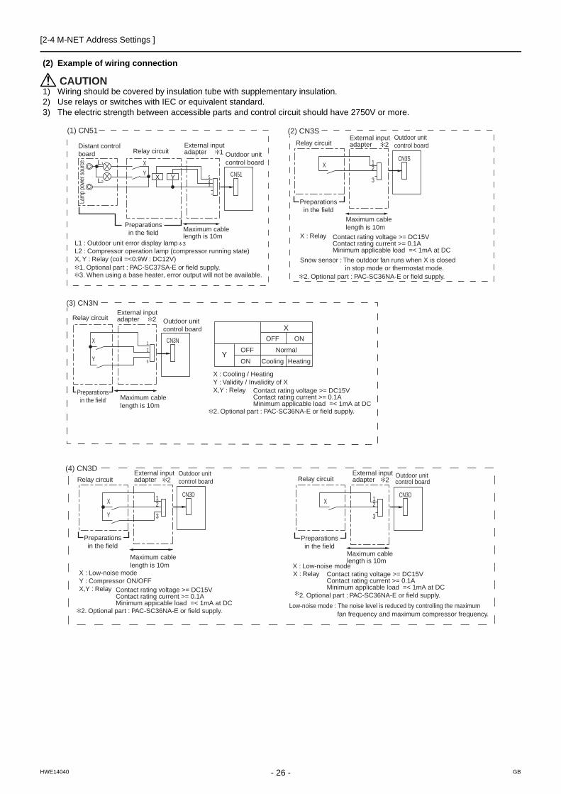
(2) Example of wiring connection
CAUTION1) Wiring should be covered by insulation tube with supplementary insulation.2) Use relays or switches with IEC or equivalent standard.3) The electric strength between accessible parts and control circuit should have 2750V or more.
(1) CN51 (2) CN3S
CN51
X
Y
L1
L2
ecruos rewop pmaL
Distant control board Relay circuit 1 Outdoor unit
control board
Preparationsin the field Maximum cable
length is 10m
543
X Y
L1 : Outdoor unit error display lampL2 : Compressor operation lamp (compressor running state)X, Y : Relay (coil =<0.9W : DC12V)
1. Optional part : PAC-SC37SA-E or field supply.3. When using a base heater, error output will not be available.
3
2. Optional part : PAC-SC36NA-E or field supply.
X : Relay
Snow sensor : The outdoor fan runs when X is closed in stop mode or thermostat mode.
XCN3S
Preparationsin the field
Maximum cable length is 10m
External input adapter
Outdoor unitcontrol board
2
3
1
Contact rating voltage >= DC15VContact rating current >= 0.1AMinimum applicable load =< 1mA at DC
Relay circuit
(3) CN3N
2. Optional part : PAC-SC36NA-E or field supply.
Preparationsin the field
OFF
Cooling
ON
Heating
NormalY
OFF
ON
X
Contact rating voltage >= DC15VContact rating current >= 0.1AMinimum applicable load =< 1mA at DC
X : Cooling / HeatingY : Validity / Invalidity of XX,Y : Relay
CN3NX
Y
Relay circuit Outdoor unitcontrol board
Maximum cable length is 10m
1
2
3
2External input adapter
2External input adapter
(4) CN3D
2. Optional part : PAC-SC36NA-E or field supply.
X : Low-noise modeX : Low-noise mode
Y : Compressor ON/OFFX,Y : Relay Contact rating voltage >= DC15V
Contact rating current >= 0.1AMinimum appicable load =< 1mA at DC
Y
XCN3D
Preparationsin the field
Maximum cable length is 10m
External input adapter 2
Outdoor unitcontrol board
3
21
Relay circuit
2. Optional part : PAC-SC36NA-E or field supply.
XCN3D
Preparationsin the field
Maximum cable length is 10m
Outdoor unitcontrol board
2
3
1
X : Relay
fan frequency and maximum compressor frequency.
Contact rating voltage >= DC15VContact rating current >= 0.1AMinimum applicable load =< 1mA at DC
Low-noise mode : The noise level is reduced by controlling the maximum
Relay circuitExternal input adapter 2
- 26 -HWE14040 GB

[2-4 M-NET Address Settings ]
2 R
es
tric
tio
ns
(5) CN3K
2. Optional part : PAC-SC36NA-E or field supply.
X : Energy-saving mode commandX : Relay Contact rating voltage >= DC15V
Contact rating current >= 0.1AMinimum appicable load =< 1mA at DC
X
CN3K
Preparationsin the field
Maximum cable length is 10m
Outdoor unitcontrol board
3
21
Relay circuitExternal input adapter 2
- 27 -HWE14040 GB

[2-5 Demand Control Overview ]
2-5 Demand Control Overview(1) General outline of control
Demand control is performed by using the external signal input to the 1-2 and 1-3 pins of CN3D on the outdoor units (OC, OS1, and OS2).Between 2 and 12 steps of demand control is possible by setting DIP SW6-8 on the outdoor units (OC, OS1, and OS2).
*1. Available demand functionsP200-P500YKB models (single-outdoor-unit system): 2 and 4 steps shown in the rows (a) and (b) in the table above only.P400-P900YSKB models (two-outdoor-unit system OC+OS1): 2-8 steps shown in the rows (a), (b), (c), and (e) in the table above only.P950-P1350YSKB models (three-outdoor-unit system OC+OS1+OS2): 2-12 steps shown in the rows (a)-(h) in the table above.
*2. External signal is input to CN3D on the outdoor unit whose SW6-8 is set to ON. When SW6-8 is set to OFF on all outdoor units, the signal is input to the CN3D on the OC.Outdoor units whose SW6-8 is set to ON are selectable in a single refrigerant system.
*3. If wrong sequence of steps are taken, the units may go into the Thermo-OFF (compressor stop) mode.Ex) When switching from 100% to 50%
(Incorrect) 100% to 0% to 50% : The units may go into the Thermo-OFF mode.(Correct) 100% to 75% to 50%
*4. The percentage of the demand listed in the table above is an approximate value based on the compressor volume and does not necessarily correspond with the actual capacity.
*5. Notes on using demand control in combination with the low-noise modeTo enable the low-noise mode, it is necessary to short-circuit 1-2 pin of CN3D on the outdoor unit whose SW6-8 is set to OFF.When SW6-8 is set to ON on all outdoor units, the following operations cannot be performed. Performing 4-step demand in combination with the low-noise operation in a single-outdoor-unit system.Performing 8-step demand in combination with the low-noise operation in a two-outdoor-unit system.Performing 12-step demand in combination with the low-noise operation in a three-outdoor-unit system.
(2) Contact input and control content
1) SW6-8: OFF (Compressor ON/OFF, Low-noise mode)
*1. When SW6-8 on the outdoor unit in one refrigerant circuit system is set to ON , this function cannot be used.*2. This function and the 4 levels or 8 levels on-DEMAND function can be used together. Input the order to CN3D 1-2P on
the outdoor unit whose SW6-8 is set to OFF.
No Demand control switchDipSW6-8
Input to CN3D *2OC OS1 OS2
(a) 2 steps(0-100%) OFF OFF OFF OC
(b) 4 steps(0-50-75-100%) ON OFF OFF OC
(c) OFF ON OFF OS1
(d) OFF OFF ON OS2
(e) 8 steps(0-25-38-50-63-75-88-100%) ON ON OFF OC and OS1
(f) ON OFF ON OC and OS2
(g) OFF ON ON OS1 and OS2
(h) 12 steps(0-17-25-34-42-50-59-67-75-84-92-100%)
ON ON ON OC, OS1, and OS2
CN3D 1-3P Compressor ON/OFF *1
Open Compressor ON
Close Compressor OFF
CN3D 1-2P Low-noise mode*2
Open OFF
Close ON
- 28 -HWE14040 GB

[2-5 Demand Control Overview ]
2 R
es
tric
tio
ns
2) When SW6-8 on one outdoor unit in one refrigerant circuit system is set to ON (4 levels of on-DEMAND) (*3)
*3. Input the order to CN3D on the outdoor unit whose SW6-8 is set to ON.
3) When SW6-8 on the two outdoor units in one refrigerant circuit system is set to ON (8 levels of on-DEMAND) (*4, *5)
*4. Input the order to CN3D on the outdoor unit whose SW6-8 is set to ON.*5. CN3D of No. 1, 2, 3 can be selected arbitrary with the outdoor unit whose SW6-8 is set to ON.
4) When SW6-8 on the all outdoor units in one refrigerant circuit system is set to ON (12 levels of on-DEMAND) (*4)
*3. Input the order to CN3D on the outdoor unit whose SW6-8 is set to ON.*4. CN3D of No. 1, 2, 3 can be selected arbitrary with the outdoor unit whose SW6-8 is set to ON.
CN3D 1-2P
CN3D 1-3P Open Short-circuit
Open 100% (No DEMAND) 75%
Short-circuit 0% (Compressor OFF) 50%
8 levels of on-DEMAND No.2 CN3D
1-2P Open Short-circuit
No.1 CN3D 1-2P 1-3P Open Short-circuit Open Short-circuit
Open Open 100% 50% 88% 75%
Short-circuit 50% 0% 38% 25%
Short-circuit Open 88% 38% 75% 63%
Short-circuit 75% 25% 63% 50%
12 levels of on-DE-MAND
No.2 CN3D 1-2P Open
1-3P Open Short-circuit
No.3 CN3D 1-2P Open Short-circuit Open Short-circuit
No.1 CN3D
1-2P 1-3P Open Short-circuit
Open Short-circuit
Open Short-circuit
Open Short-circuit
Open Open 100% 67% 92% 84% 67% 34% 59% 50%
Short-circuit
67% 34% 59% 50% 34% 0% 25% 17%
Short-circuit Open 92% 59% 84% 75% 59% 25% 50% 42%
Short-circuit
84% 50% 75% 67% 50% 17% 42% 34%
12 levels of on-DE-MAND
No.2 CN3D 1-2P Short-circuit
1-3P Open Short-circuit
No.3 CN3D 1-2P Open Short-circuit Open Short-circuit
No.1 CN3D
1-2P 1-3P Open Short-circuit
Open Short-circuit
Open Short-circuit
Open Short-circuit
Open Open 92% 59% 84% 75% 84% 50% 75% 67%
Short-circuit
59% 25% 50% 42% 50% 17% 42% 34%
Short-circuit Open 84% 50% 75% 67% 75% 42% 67% 59%
Short-circuit
75% 42% 67% 59% 67% 34% 59% 50%
If the step listed as the wrong example above is taken, thermo may go off.The percentage of the demand listed in the table above is an approximate value based on the compressor volume and does not necessarily correspond with the capacity.When this function is enabled, the night mode cannot be enabled.
(Wrong)
(Correct)
100%
100%
0%
75%
50%
50%
Demand control steps
Note the following steps to be taken when using the STEP DEMAND (Example) When switching from 100% to 50%
- 29 -HWE14040 GB

[2-6 System Connection Example ]
2-6 System Connection ExampleExamples of typical system connection are shown below.Refer to the Installation Manual that came with each device or controller for details.
(1) An example of a system to which an MA remote controller is connected
(2) An example of a system to which an ME remote controller is connected
(3) An example of a system to which both MA remote controller and ME remote controller are connected
System configuration Connection to the system controller
Address start up for in-door and outdoor units Notes
1System with one out-
door unit NOAutomatic
address setup
2 System with one out-door unit NO Manual
address setup
Connection of multiple LOSS-NAY units
3Grouping of units in a system with multiple
outdoor unitsNO
Manual address setup
4 System with one out-door unit
With connection to transmission line for centralized control
Manual address setup
5 System with one out-door unit
With connection to indoor-outdoortransmission line
Manual address setup
System configuration Connection to the system controller
Address start up for indoor and outdoor units Notes
1System with one out-
door unitWith connection to transmission line
for centralized controlManual
address setup
System configuration Connection to the system controller Address start up for in-
door and outdoor units Notes
1 System with one out-door unit
With connection to transmission line for centralized control
Manual address setup
*MA remote controller and ME remote controller cannot both be connected to the same group.
- 30 -HWE14040 GB
[2-6 System Connection Example ]
2 R
es
tric
tio
ns
- 31 -HWE14040 GB

[2-7 Example System with an MA Remote Controller ]
2-7 Example System with an MA Remote Controller
2-7-1 Single Refrigerant System (Automatic Indoor/Outdoor Address Startup)
(1) Sample control wiring
(2) Cautions
1) ME remote controller and MA remote controller cannot both be connected to the same group of indoor units.
2) No more than 2 MA remote controllers can be connected to a group of indoor units.
3) A transmission booster is required in a system to which more than 32 indoor units (26 units if one or more indoor units of the 200 model or above is connected) are con-nected.
4) Automatic address setup is not available if start-stop in-put (CN32, CN51, CN41) is used for a group operation of indoor units or when multiple indoor units with different functions are grouped in the same group. Refer to the fol-lowing page(s). [2-7-2 Single Refrigerant System with Two or More LOSSNAY Units](page 34)
5) For information about connecting two or more LOSSNAY units to a system, refer to the following page(s). [2-7-2 Single Refrigerant System with Two or More LOSSNAY Units](page 34)
(3) Maximum allowable length
1) Indoor/outdoor transmission line
Maximum distance (1.25mm2 [AWG16] or larger)L1 +L2+L3+L4 200m[656ft]L1 +L2+L11+L12+L13 200m[656ft]
2) Transmission line for centralized control
No connection is required.3) MA remote controller wiring
Maximum overall line length (0.3 to 1.25mm2 [AWG22 to 16])m1 200m [656ft]m2+m3 200m [656ft]m4+m5 200m [656ft]*When connecting PAR-31MAA or MA Simple remote controller, use sheathed cables with a minimum thick-ness of 0.3 mm2.
IC
TB5 S
TB15 1 2
00
IC
TB5 S
TB15 1 2
00
A B
MA
A B
MA
A B
RC
LC
TB5 S
00
IC
TB5 M1 M2 M1 M2 M1 M2
M1 M2 M1 M2 M1 M2
S 1 2 TB15
IC
TB5 S
TB15 1 2
00 00
IC
TB5 S
TB15 1 2
00
A B
MA
A B
MA
A B
MA
A B
MA
m1
L11
m2
L3 L4
L12 L13
m3
m5
m4
Interlock operation with the ventilation unit
TB3
00 00 TB7
S TB3
00 TB7
M1 M2 M1 M2 M1 M2 M1 M2 M1 M2 M1 M2 S TB3 TB7
S
OC OS1 OS2
Leave the maleconnector onCN41 as it is.SW5-1 OFF
Leave the maleconnector onCN41 as it is.SW5-1 OFF
Leave the maleconnector onCN41 as it is.SW5-1 OFF
Group Group
Group Group
L2 L1
- 32 - GBHWE14040

[2-7 Example System with an MA Remote Controller ]
2 R
es
tric
tio
ns
(4) Wiring method
1) Indoor/outdoor transmission line
Daisy-chain terminals M1 and M2 on the terminal block for indoor-outdoor transmission line (TB3) on the outdoor units (OC, OS1, OS2) (Note), and terminals M1 and M2 on the terminal block for indoor-outdoor transmission line (TB5) on each indoor unit (IC). (Non-polarized two-wire)Only use shielded cables.
The outdoor units in the same refrigerant circuit are au-tomatically designated as OC, OS1, and OS2 in the or-der of capacity from large to small (if two or more units have the same capacity, in the order of address from small to large).Shielded cable connectionDaisy-chain the ground terminal ( ) on the outdoor units (OC, OS1, OS2), and the S terminal on the terminal block (TB5) on the indoor unit (IC) with the shield wire of the shielded cable.
2) Transmission line for centralized control
No connection is required.3) MA remote controller wiring
Connect terminals 1 and 2 on the terminal block for MA remote controller line (TB15) on the indoor unit (IC) to the terminal block on the MA remote controller (MA). (Non-polarized two-wire)When 2 remote controllers are connected to the sys-temWhen 2 remote controllers are connected to the system, connect terminals 1 and 2 of the terminal block (TB15) on the indoor unit (IC) to the terminal block on the two MA remote controllers.Set one of the MA remote controllers to sub. (Refer to
MA remote controller function selection or the installation manual for the MA remote controller for the setting meth-od.)Group operation of indoor unitsTo perform a group operation of indoor units (IC), daisy-chain terminals 1 and 2 on the terminal block (TB15) on all indoor units (IC) in the same group, and then connect terminals 1 and 2 on the terminal block (TB15) on the in-door unit on one end to the terminal block on the MA re-mote controller. (Non-polarized two-wire)When performing a group operation of indoor units that have different functions, "Automatic indoor/outdoor ad-dress setup" is not available.
4) LOSSNAY connection
Connect terminals M1 and M2 on the terminal block (TB5) on the indoor unit (IC) to the appropriate terminals on the terminal block (TB5) on LOSSNAY (LC). (Non-po-larized two-wire)Interlock operation setting with all the indoor units in the same system will automatically be made. (It is required that the Lossnay unit be turned on before the outdoor unit.)For information about certain types of systems (1. Sys-tems in which the LOSSNAY unit is interlocked with only part of the indoor units, 2. Systems in which the LOSS-NAY unit is operated independently from the indoor units, 3. Systems in which more than 16 indoor units are interlocked with the LOSSNAY unit, and 4. Systems to which two ore more LOSSNAY units are connected), re-fer to the following page(s). [2-7-2 Single Refrigerant System with Two or More LOSSNAY Units](page 34)
5) Switch setting
No address settings required.
(5) Address setting method
The outdoor units in the same refrigerant circuit are automatically designated as OC, OS1, and OS2.The outdoor units are designated as OC, OS1, and OS2 in the order of capacity from large to small (if two or more units have the same capacity, in the order of address from small to large).
Proce-dures
Unit or controller Address setting range
Setting method
Notes Factory setting
1 Indoor unit Main unit IC No settings re-quired.
- For information about how to perform a group opera-tion of indoor units that feature different functions, refer to the following page(s). [2-7-2 Single Re-frigerant System with Two or More LOSSNAY Units](page 34)
00
Sub unit IC
2 LOSSNAY LC No settings re-quired.
- 00
3 MA remote con-troller
Main remote con-troller
MA No settings re-quired.
- Main
Sub remote con-troller
MA Sub remote controller
Settings to be made ac-cording to the remote controller function se-lection
4 Outdoor unit (Note) OCOS1OS2
No settings re-quired.
- 00
33- 33 -HWE14040 GB

[2-7 Example System with an MA Remote Controller ]
2-7-2 Single Refrigerant System with Two or More LOSSNAY Units
(1) Sample control wiring
(2) Cautions
1) ME remote controller and MA remote controller cannot both be connected to the same group of indoor units.
2) No more than 2 MA remote controllers can be connected to a group of indoor units.
3) A transmission booster is required in a system to which more than 32 indoor units (26 units if one or more indoor units of the 200 model or above is connected) are con-nected.
Refer to the DATABOOK for further information about how many booster units are required for a given system.
(3) Maximum allowable length
1) Indoor/outdoor transmission line
Same as 2-7-12) Transmission line for centralized control
No connection is required.3) MA remote controller wiring
Same as 2-7-1
L2
TB3
51 52 TB7
S TB3 TB7
S
IC
TB5 S
TB15 1 2
01
IC
TB5 S
TB15 1 2
02
A B
MA
A B
MA
LC
TB5 S
05
IC
TB5 S 1 2
TB15
IC
TB5 S
TB15 1 2
04 03
LC
TB5 S
06
A B
MA
Group Group
Group
M1 M2 M1 M2 M1 M2
M1 M2 M1 M2 M1 M2
L11
L3 L4
L12 L13
53 TB7
M1 M2 M1 M2 M1 M2 M1 M2 M1 M2 M1 M2 S TB3
L1
OC OS1 OS2
Leave the maleconnector onCN41 as it is.SW5-1 OFF
Leave the maleconnector onCN41 as it is.SW5-1 OFF
Leave the maleconnector onCN41 as it is.SW5-1 OFF
Interlock operation with the ventilation unit
m1
m2
m3
- 34 - GBHWE14040

[2-7 Example System with an MA Remote Controller ]
2 R
es
tric
tio
ns
(4) Wiring method
1) Indoor/outdoor transmission line
Same as 2-7-1Shielded cable connectionSame as 2-7-1
2) Transmission line for centralized control
No connection is required.3) MA remote controller wiring
Same as 2-7-1When 2 remote controllers are connected to the sys-temSame as 2-7-1Group operation of indoor unitsSame as 2-7-1
4) LOSSNAY connection
Connect terminals M1 and M2 on the terminal block (TB5) on the indoor unit (IC) to the appropriate terminals on the terminal block (TB5) on LOSSNAY (LC). (Non-po-larized two-wire)Interlock setting between the indoor units and LOSS-NAY units must be entered on the remote controller. For information about how to interlock the operation of indoor and LOSSNAY units, refer to the remote controller Instal-lation Manual and the following page(s) in this Service Handbook.[6-5 Making Interlock Settings from an MA Remote Con-troller](page 121)
5) Switch setting
Address setting is required as follows.
(5) Address setting method
The outdoor units in the same refrigerant circuit are automatically designated as OC, OS1, and OS2.The outdoor units are designated as OC, OS1, and OS2 in the order of capacity from large to small (if two or more units have the same capacity, in the order of address from small to large).
Proce-dures Unit or controller
Address setting range
Setting method Notes Factory setting
1 Indoor unit Main unit
IC 01 to 50 Assign the smallest ad-dress to the main unit in the group.
To perform a group opera-tion of indoor units that have different functions, designate the indoor unit in the group with the great-est number of functions as the main unit.
00
Sub unit Assign sequential numbers starting with the address of the main unit in the same group +1. (Main unit ad-dress +1, main unit ad-dress +2, main unit address +3, etc.)
2 LOSSNAY LC 01 to 50 Assign an arbitrary but unique address to each of these units after assigning an address to all indoor units.
None of these addresses may overlap any of the in-door unit addresses.
00
3 MA remote con-troller
Main remote control-ler
MA No settings re-quired.
- Main
Sub remote control-ler
MA Sub remote controller
Settings to be made ac-cording to the remote con-troller function selection
4 Outdoor unit OCOS1OS2
51 to 100 Assign sequential address to the outdoor units in the same refrigerant circuit. The outdoor units are auto-matically designated as OC, OS1, and OS2.(Note)
To set the address to 100, set the rotary switches to 50.
00
35- 35 -HWE14040 GB
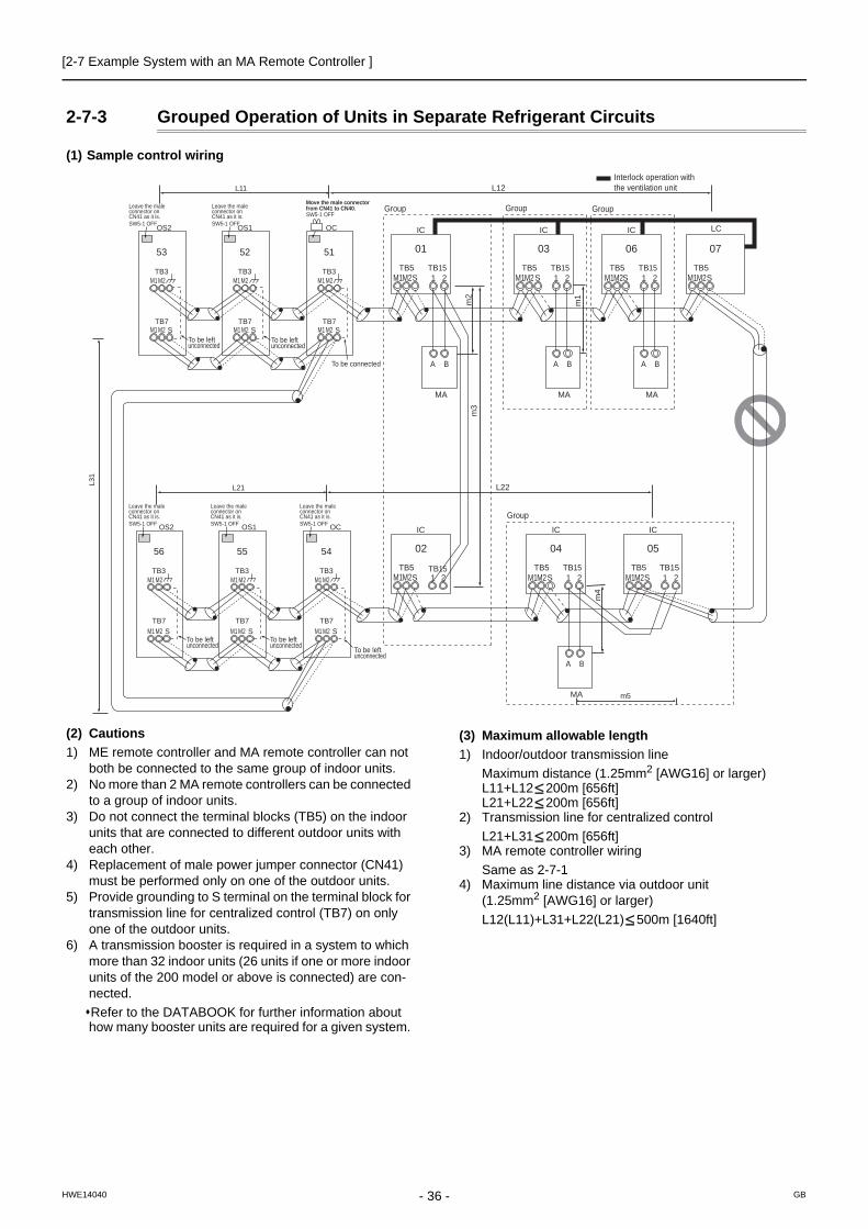
[2-7 Example System with an MA Remote Controller ]
2-7-3 Grouped Operation of Units in Separate Refrigerant Circuits
(1) Sample control wiring
(2) Cautions
1) ME remote controller and MA remote controller can not both be connected to the same group of indoor units.
2) No more than 2 MA remote controllers can be connected to a group of indoor units.
3) Do not connect the terminal blocks (TB5) on the indoor units that are connected to different outdoor units with each other.
4) Replacement of male power jumper connector (CN41) must be performed only on one of the outdoor units.
5) Provide grounding to S terminal on the terminal block for transmission line for centralized control (TB7) on only one of the outdoor units.
6) A transmission booster is required in a system to which more than 32 indoor units (26 units if one or more indoor units of the 200 model or above is connected) are con-nected.
Refer to the DATABOOK for further information about how many booster units are required for a given system.
(3) Maximum allowable length
1) Indoor/outdoor transmission line
Maximum distance (1.25mm2 [AWG16] or larger)L11+L12 200m [656ft]L21+L22 200m [656ft]
2) Transmission line for centralized control
L21+L31 200m [656ft]3) MA remote controller wiring
Same as 2-7-14) Maximum line distance via outdoor unit
(1.25mm2 [AWG16] or larger)
L12(L11)+L31+L22(L21) 500m [1640ft]
IC
TB5 S
TB15 1 2
01
IC
TB5 S
TB15 1 2
03
A B
MA
A B
MA
LC
TB5 S
07
IC
TB5 S 1 2
TB15
IC
TB5 S
TB15 1 2 1 2
04 02
IC
TB5 TB15 S
05
A B
MA
IC
TB5 S
TB15 1 2
06
A B
MA
Group
Group Group Group
M1 M2 M1 M2 M1 M2 M1 M2
M1 M2 M1 M2 M1 M2
m2
m3
m1
m4
Interlock operation with the ventilation unit L12
L22
L11
L21
OC
TB3
TB7 S
51
To be connected
To be left unconnected
To be left unconnected
OS1
TB3
TB7 S
52
OS2
TB3
TB7
M1 M2 M1 M2 M1 M2
M1 M2 M1 M2 M1 M2 S
53
OC
TB3
TB7 S
54
OS1
TB3
TB7 S
55
OS2
TB3
TB7
M1 M2 M1 M2 M1 M2
M1 M2 M1 M2 M1 M2 S
56
L31
Leave the male connector on CN41 as it is. SW5-1 OFF
Leave the male connector on CN41 as it is. SW5-1 OFF
Leave the male connector on CN41 as it is. SW5-1 OFF
Leave the male connector on CN41 as it is. SW5-1 OFF
Leave the male connector on CN41 as it is. SW5-1 OFF
SW5-1 OFF
Move the male connector from CN41 to CN40.
To be left unconnected
To be left unconnected To be left
unconnected
m5
- 36 - GBHWE14040

[2-7 Example System with an MA Remote Controller ]
2 R
es
tric
tio
ns
(4) Wiring method
1) Indoor/outdoor transmission line
Same as 2-7-1Only use shielded cables.Shielded cable connectionSame as 2-7-1
2) Transmission line for centralized control
Daisy-chain terminals M1 and M2 on the terminal block for transmission line for centralized control (TB7) on the outdoor units (OC) in different refrigerant circuits and on the OC, OS1, and OS2 (Note a) in the same refrigerant circuitIf a power supply unit is not connected to the transmis-sion line for centralized control, replace the power jump-er connector on the control board from CN41 to CN40 on only one of the outdoor units.
a) The outdoor units in the same refrigerant circuit are auto-matically designated as OC, OS1, and OS2 in the order of capacity from large to small (if two or more units have the same capacity, in the order of address from small to large).
b) When not daisy-chaining TB7's on the outdoor units in the same refrigerant circuit, connect the transmission line for centralized control to TB7 on the OC (Note a). To maintain centralized control even during an OC failure or
a power failure, daisy-chain TB7 of OC, OS1, and OS2. (If there is a problem with the outdoor unit whose power jumper was moved from CN41 to CN40, centralized con-trol is not possible, even if TB7's are daisy-chained).
c) When connecting TB7, only commence after checking that the voltage is below 20 VDC.Only use shielded cables.Shielded cable connectionDaisy-chain the S terminal on the terminal block (TB7) on the outdoor units (OC, OS1, OS2) with the shield wire of the shielded cable. Short-circuit the earth terminal ( ) and the S terminal on the terminal block (TB7) on the out-door unit whose power jumper connector is mated with CN40.
3) MA remote controller wiring
Same as 2-7-1When 2 remote controllers are connected to the sys-temSame as 2-7-1Group operation of indoor unitsSame as 2-7-1
4) LOSSNAY connection
Same as 2-7-25) Switch setting
Address setting is required as follows.
(5) Address setting method
The outdoor units in the same refrigerant circuit are automatically designated as OC, OS1, and OS2.The outdoor units are designated as OC, OS1, and OS2 in the order of capacity from large to small (if two or more units have the same capacity, in the order of address from small to large).
Proce-dures Unit or controller Address setting
range Setting method Notes Factory setting
1 Indoor unit
Main unit IC 01 to 50 Assign the smallest ad-dress to the main unit in the group.
To perform a group operation of indoor units that have differ-ent functions, desig-nate the indoor unit in the group with the greatest number of functions as the main unit.
00
Sub unit Assign sequential num-bers starting with the ad-dress of the main unit in the same group +1. (Main unit address +1, main unit address +2, main unit ad-dress +3, etc.)
2 LOSSNAY LC 01 to 50 Assign an arbitrary but unique address to each of these units after assigning an address to all indoor units.
None of these ad-dresses may overlap any of the indoor unit addresses.
00
3 MA re-mote con-troller
Main remote controller
MA No settings required.
- Main
Sub remote controller
MA Sub remote controller
Settings to be made ac-cording to the remote con-troller function selection
4 Outdoor unit OCOS1OS2
51 to 100 Assign sequential address to the outdoor units in the same refrigerant circuit. The outdoor units are au-tomatically designated as OC, OS1, and OS2. (Note)
To set the address to 100, set the rotary switches to 50.
00
37- 37 -HWE14040 GB

[2-7 Example System with an MA Remote Controller ]
2-7-4 System with a Connection of System Controller to Centralized Control Transmission Line
(1) Sample control wiring
An example of a system in which a system controller is connected to the transmission cable for the centralized control system and the power is supplied from the outdoor unit
(2) Cautions1) ME remote controller and MA remote controller cannot both be
connected to the same group of indoor units.2) No more than 2 MA remote controllers can be connected to a
group of indoor units.3) Do not connect the terminal blocks (TB5) on the indoor units that
are connected to different outdoor units with each other.4) Replacement of male power jumper connector (CN41) must be
performed only on one of the outdoor units (not required if power to the transmission line for centralized control is supplied from a controller with a power supply function, such as GB-50ADA).
5) Short-circuit the shield terminal (S terminal) and the earth termi-nal ( ) on the terminal block for transmission line for central-ized control (TB7) on the outdoor unit whose power jumper connector is mated with CN40.
6) A transmission booster is required in a system to which more than 32 indoor units (26 units if one or more indoor units of the 200 model or above is connected) are connected.
Refer to the DATABOOK for further information about how
many booster units are required for a given system. 7) When a power supply unit is connected to the transmission line
for centralized control, leave the power jumper connector on CN41 as it is (factory setting).
(3) Maximum allowable length
1) Indoor/outdoor transmission line
Same as 2-7-32) Transmission line for centralized control
L31+L32(L21) 200m [656ft]3) MA remote controller wiring
Same as 2-7-14) Maximum line distance via outdoor unit
(1.25mm2 [AWG16] or larger)
L32+L31+L12(L11) 500m [1640ft]L32+L22(L21) 500m [1640ft]L12(L11)+L31+L22(L21) 500m[1640ft]
IC
TB5 S
TB15 1 2
01
IC
TB5 S
TB15 1 2
02
A B
MA
A B
MA
LC
TB5 S
07
IC
TB5 S 1 2
TB15
IC
TB5 S
TB15 1 2
05 04
LC
TB5 S
08
IC
TB5 S
TB15 1 2
03
A B
MA
IC
TB5 S
TB15 1 2
06
A B
MA
A B
MA
M1 M2 M1 M2 M1 M2 M1 M2
M1 M2 M1 M2 M1 M2 M1 M2
L12 L11
L22 L21
m3
L31
A B S
L32
Note1
System controller
OC
TB3
TB7 S
51
To be connected
To be left unconnected To be left
unconnected
m2
m1
OS1
TB3
TB7 S
52
OS2
TB3
TB7
M1 M2 M1 M2 M1 M2
M1 M2 M1 M2 M1 M2 S
53
OC
TB3
TB7 S
54
OS1
TB3
TB7 S
55
OS2
TB3
TB7
M1 M2 M1 M2 M1 M2
M1 M2 M1 M2 M1 M2 S
56
Leave the male connector on CN41 as it is. SW5-1 OFF ON
Leave the male connector on CN41 as it is. SW5-1 OFF ON
Leave the male connector on CN41 as it is. SW5-1 OFF ON
Leave the male connector on CN41 as it is. SW5-1 OFF ON
Leave the male connector on CN41 as it is. SW5-1 OFF ON
SW5-1 OFF ON Group Group Group
Group Group
Interlock operation with the ventilation unit
Note1 When only the LM adapter is connected, leave SW5-1 to OFF (as it is).Note2 LM adapters require the power supply capacity of single-phase AC 220/240V.
To be left unconnected
To be left unconnected
To be left unconnected
Move the male connectorfrom CN41 to CN40.
- 38 - GBHWE14040

[2-7 Example System with an MA Remote Controller ]
2 R
es
tric
tio
ns
(4) Wiring method
1) Indoor/outdoor transmission line
Same as 2-7-1Shielded cable connectionSame as 2-7-1
2) Transmission line for centralized control
Daisy-chain terminals A and B on the system controller, terminals M1 and M2 on the terminal block for transmis-sion line for centralized control (TB7) on the outdoor units (OC) in different refrigerant circuits and on the out-door units (OC, OS1, and OS2) in the same refrigerant circuit. (Note b)If a power supply unit is not connected to the transmis-sion line for centralized control, replace the power jump-er connector on the control board from CN41 to CN40 on only one of the outdoor units.If a system controller is connected, set the central control switch (SW5-1) on the control board of all outdoor units to "ON."
a) The outdoor units in the same refrigerant circuit are auto-matically designated as OC, OS1, and OS2 in the order of capacity from large to small (if two or more units have the same capacity, in the order of address from small to large).
b) When not daisy-chaining TB7's on the outdoor units in the same refrigerant circuit, connect the transmission line for centralized control to TB7 on the OC (Note a). To maintain centralized control even during an OC failure or a power failure, daisy-chain TB7 of OC, OS1, and OS2. (If there is a problem with the outdoor unit whose power jumper was moved from CN41 to CN40, centralized con-
trol is not possible, even if TB7's are daisy-chained).c) When connecting TB7, only commence after checking
that the voltage is below 20 VDC.Only use shielded cables.Shielded cable connectionDaisy-chain the S terminal on the terminal block (TB7) on the outdoor units (OC, OS1, OS2) with the shield wire of the shielded cable. Short-circuit the earth terminal ( ) and the S terminal on the terminal block (TB7) on the out-door unit whose power jumper connector is mated with CN40.
3) MA remote controller wiring
Same as 2-7-1When 2 remote controllers are connected to the sys-temSame as 2-7-1Group operation of indoor unitsSame as 2-7-1
4) LOSSNAY connection
Connect terminals M1 and M2 on the terminal block (TB5) on the indoor unit (IC) to the appropriate terminals on the terminal block for indoor-outdoor transmission line (TB5) on LOSSNAY (LC). (Non-polarized 2-core cable)Indoor units must be interlocked with the LOSSNAY unit using the system controller. (Refer to the operation man-ual for the system controller for the setting method.) In-terlock setting from the remote controller is required if the ON/OFF remote controller alone or the LM adapter alone is connected.
5) Switch setting
Address setting is required as follows.
(5) Address setting method
The outdoor units in the same refrigerant circuit are automatically designated as OC, OS1, and OS2.The outdoor units are designated as OC, OS1, and OS2 in the order of capacity from large to small (if two or more units have the same capacity, in the order of address from small to large).
Proce-dures Unit or controller
Address setting range
Setting method NotesFactory setting
1 Indoor unit Main unit IC 01 to 50 Assign the smallest address to the main unit in the group.
To perform a group oper-ation of indoor units that have different functions, designate the indoor unit in the group with the greatest number of func-tions as the main unit.
00
Sub unit Assign sequential numbers starting with the address of the main unit in the same group +1. (Main unit address +1, main unit address +2, main unit address +3, etc.)
2 LOSSNAY LC 01 to 50 Assign an arbitrary but unique address to each of these units after assigning an address to all indoor units.
None of these addresses may overlap any of the in-door unit addresses.
00
3 MA remote controller
Main remote control-ler
MA No settings re-quired.
- Enter the same indoor unit group settings on the system controller as the ones that were entered on the MA remote controller.
Main
Sub remote control-ler
MA Sub remote con-troller
Settings to be made accord-ing to the remote controller function selection
4 Outdoor unit OCOS1OS2
51 to 100 Assign sequential address to the outdoor units in the same refrigerant circuit.The outdoor units are auto-matically designated as OC, OS1, and OS2. (Note)
To set the address to 100, set the rotary switches to 50.
00
39- 39 -HWE14040 GB

[2-7 Example System with an MA Remote Controller ]
2-7-5 System with a Connection of System Controller to Indoor-Outdoor Transmission Line
(1) Sample control wiring
(2) Cautions
1) ME remote controller and MA remote controller cannot both be connected to the same group of indoor units.
2) No more than 2 MA remote controllers can be connected to a group of indoor units.
3) Do not connect the terminal blocks (TB5) on the indoor units that are connected to different outdoor units with each other.
4) Replacement of male power jumper connector (CN41) must be performed only on one of the outdoor units (not required if power to the transmission line for centralized control is supplied from a controller with a power supply function, such as GB-50ADA).
5) Provide grounding to S terminal on the terminal block for transmission line for centralized control (TB7) on only one of the outdoor units.
6) A maximum of three system controllers can be connected to the indoor-outdoor transmission line. (AE-200, AG-150A, GB-50ADA, or G(B)-50A are not connectable.)
7) When the total number of indoor units exceeds 26, it may not be possible to connect a system controller on the indoor-outdoor transmission line.
In a system to which more than 18 indoor units including one or more indoor units of 200 model or above are connected, there may be cases in which the system controller cannot be
connected to the indoor-outdoor transmission line.Refer to the DATABOOK for further information about how many booster units are required for a given system.
(3) Maximum allowable length
1) Indoor/outdoor transmission line
Maximum distance (1.25mm2 [AWG16] or larger)L11+L12 200m [656ft]L21+L22 200m [656ft]L25 200m [656ft]
2) Transmission line for centralized control
L31+L21 200m [656ft]3) MA remote controller wiring
Same as 2-7-14) Maximum line distance via outdoor unit
(1.25mm2 [AWG16] or larger)
L25+L31+L12(L11) 500m [1640ft]L12(L11)+L31+L22(L21) 500m [1640ft]
IC
TB5 S
TB15 1 2
01
IC
TB5 S
TB15 1 2
02
A B
MA
A B
MA
LC
TB5 S
07
IC
TB5 S 1 2
TB15
IC
TB5 S
TB15 1 2
05 04
LC
TB5 S
08
IC
TB5 S
TB15 1 2
03
A B
MA
IC
TB5 S
TB15 1 2
06
A B
MA
A B
MA
M1 M2 M1 M2 M1 M2 M1 M2
M1 M2 M1 M2 M1 M2 M1 M2
L12 L11
L22 L21
m3
OC
TB3
TB7 S
51
m2
m1
OS1
TB3
TB7 S
52
OS2
TB3
TB7
M1 M2 M1 M2 M1 M2
M1 M2 M1 M2 M1 M2 S
53
OC
TB3
TB7 S
54
OS1
TB3
TB7 S
55
OS2
TB3
TB7
M1 M2 M1 M2 M1 M2
M1 M2 M1 M2 M1 M2 S
56
L31
A B S
L25
Note1 LM adapters cannot be connected to the indoor-outdoor transmission line.
Note1
System controller
SW5-1 OFF ONSW5-1 OFF ON
Leave the male connector on CN41 as it is.
SW5-1 OFF ON
Leave the male connector on CN41 as it is.
Move the male connector from CN41 to CN40.
SW5-1 OFF ON
Leave the male connector on CN41 as it is.
SW5-1 OFF ON
Leave the male connector on CN41 as it is.
SW5-1 OFF ON
Leave the male connector on CN41 as it is.
Group Group Group
Group Group
Interlock operation with the ventilation unit
To be left unconnected
To be left unconnected
To be left unconnected
To be left unconnected
To be left unconnected
To be connected
- 40 - GBHWE14040

[2-7 Example System with an MA Remote Controller ]
2 R
es
tric
tio
ns
(4) Wiring method
1) Indoor/outdoor transmission line
Daisy-chain terminals M1 and M2 on the terminal block for indoor-outdoor transmission line (TB3) on the outdoor units (OC, OS1, OS2) (Note a), terminals M1 and M2 on the terminal block for indoor-outdoor transmission line (TB5) on each indoor unit (IC), and the S terminal on the system controller. (Non-polarized two-wire)Only use shielded cables.
a) The outdoor units in the same refrigerant circuit are auto-matically designated as OC, OS1, and OS2. The outdoor units are designated as OC, OS1, and OS2 in the order of capacity from large to small (if two or more units have the same capacity, in the order of address from small to large).Shielded cable connectionDaisy-chain the ground terminal ( ) on the outdoor units (OC, OS1, OS2), the S terminal on the terminal block (TB5) on the indoor unit (IC), and the S terminal on the system controller with the shield wire of the shielded cable.
2) Transmission line for centralized control
Daisy-chain terminals M1 and M2 on the terminal block for transmission line for centralized control (TB7) on the outdoor units (OC) in different refrigerant circuits and on the OC, OS1, and OS2 in the same refrigerant circuit. (Note b)If a power supply unit is not connected to the transmis-sion line for centralized control, replace the power jump-er connector on the control board from CN41 to CN40 on only one of the outdoor units.Set the central control switch (SW5-1) on the control board of all outdoor units to "ON."
b) When not daisy-chaining TB7's on the outdoor units in the
same refrigerant circuit, connect the transmission line for centralized control to TB7 on the OC (Note a). To maintain centralized control even during an OC failure or a power fail-ure, daisy-chain TB7 of OC, OS1, and OS2. (If there is a problem with the outdoor unit whose power jumper was moved from CN41 to CN40, centralized control is not possi-ble, even if TB7's are daisy-chained).
c) When connecting TB7, only commence after checking that the voltage is below 20 VDC.Only use shielded cables.Shielded cable connectionDaisy-chain the S terminal on the terminal block (TB7) on the outdoor units (OC, OS1, OS2) with the shield wire of the shielded cable. Short-circuit the earth terminal ( ) and the S terminal on the terminal block (TB7) on the out-door unit whose power jumper connector is mated with CN40.
3) MA remote controller wiring
Same as 2-7-1When 2 remote controllers are connected to the sys-temSame as 2-7-1Group operation of indoor unitsSame as 2-7-1
4) LOSSNAY connection
Connect terminals M1 and M2 on the terminal block (TB5) on the indoor units (IC) to the appropriate termi-nals on the terminal block for indoor-outdoor transmis-sion line (TB5) on LOSSNAY (LC). (Non-polarized two-wire)Indoor units must be interlocked with the LOSSNAY unit using the system controller. (Refer to the operation man-ual for the system controller for the setting method.) In-terlock setting from the remote controller is required if the ON/OFF remote controller alone is connected.
5) Switch setting
Address setting is required as follows.
(5) Address setting method
The outdoor units in the same refrigerant circuit are automatically designated as OC, OS1, and OS2.The outdoor units are designated as OC, OS1, and OS2 in the order of capacity from large to small (if two or more units have the same capacity, in the order of address from small to large).
Proce-dures
Unit or controller Address set-ting range
Setting method Notes Factory setting
1 Indoor unit
Main unit IC 01 to 50 Assign the smallest address to the main unit in the group.
To perform a group operation of indoor units that have different functions, designate the indoor unit in the group with the great-est number of functions as the main unit.
00
Sub unit Assign sequential numbers start-ing with the address of the main unit in the same group +1. (Main unit address +1, main unit ad-dress +2, main unit address +3, etc.)
2 LOSSNAY LC 01 to 50 Assign an arbitrary but unique address to each of these units af-ter assigning an address to all in-door units.
None of these addresses may overlap any of the indoor unit addresses.
00
3 MA remote control-ler
Main remote controller
MA No settings re-quired.
- Enter the same indoor unit group settings on the system controller as the ones that were entered on the MA remote con-troller.
Main
Sub remote controller
MA Sub remote con-troller
Settings to be made accord-ing to the remote controller function selection
4 Outdoor unit OCOS1OS2
51 to 100 Assign sequential address to the outdoor units in the same refrigerant circuit. The outdoor units are auto-matically designated as OC, OS1, and OS2. (Note)
To set the address to 100, set the rotary switches to 50.
00
41- 41 -HWE14040 GB

[2-8 Example System with an ME Remote Controller ]
2-8 Example System with an ME Remote Controller
2-8-1 System with a Connection of System Controller to Centralized Control Transmission Line
(1) Sample control wiring
(2) Cautions1) ME remote controller and MA remote controller cannot both be
connected to the same group of indoor units.2) No more than 3 ME remote controllers can be connected to a
group of indoor units.3) Do not connect the terminal blocks (TB5) on the indoor units that
are connected to different outdoor units with each other.4) Replacement of male power jumper connector (CN41) must be
performed only on one of the outdoor units (not required if power to the transmission line for centralized control is supplied from a controller with a power supply function, such as GB-50ADA).
5) Provide an electrical path to ground for the S terminal on the ter-minal block for centralized control on only one of the outdoor units.
6) A transmission booster must be connected to a system in which the total number of connected indoor units exceeds 20.
7) A transmission booster is required in a system to which more than 16 indoor including one or more indoor units of the 200 model or above are connected.
Refer to the DATABOOK for further information about how many booster units are required for a given system.
8) When a power supply unit is connected to the transmission line
for centralized control, leave the power jumper connector on CN41 as it is (factory setting).
(3) Maximum allowable length1) Indoor/outdoor transmission line
Same as 2-7-32) Transmission line for centralized control
Same as 2-7-43) M-NET remote controller wiring
Maximum overall line length (0.3 to 1.25mm2 [AWG22 to 16])m1 10m [32ft]m2+m3 10m [32ft]If the standard-supplied cable must be extended, use a cable with a diameter of 1.25mm2 [AWG16]. The section of the cable that exceeds 10m [32ft] must be included in the maximum in-door-outdoor transmission line distance described in 1).*When connected to the terminal block on the Simple remote controller, use cables that meet the following cable size specifi-cations: 0.75 - 1.25 mm2 [AWG18-14].
4) Maximum line distance via outdoor unit (1.25 mm2 [AWG16] min.) Same as 2-7-4
IC
TB5 S
TB15 1 2
01
IC
TB5 S
TB15 1 2
02
LC
TB5 S
07
IC
TB5 S 1 2
TB15
IC
TB5 S
TB15 1 2
05 04
LC
TB5 S
08
IC
TB5 S
TB15 1 2
03
IC
TB5 S
TB15 1 2
06
A B
RC 101
A B
RC 102
A B
RC 103
Group Group
Group Group Group
M1 M2 M1 M2 M1 M2 M1 M2
M1 M2 M1 M2 M1 M2 M1 M2
L12 L11
L22 L21
L31
A B S
L32
Note1
System controller
Interlock operation with the ventilation unit
OC
TB3
TB7 S
51
m1
OS1
TB3
TB7 S
52
OS2
TB3
TB7
M1 M2 M1 M2 M1 M2
M1 M2 M1 M2 M1 M2 S
53
OC
TB3
TB7 S
54
OS1
TB3
TB7 S
55
OS2
TB3
TB7
M1 M2 M1 M2 M1 M2
M1 M2 M1 M2 M1 M2 S
56
Leave the male connector on CN41 as it is. SW5-1 OFF ON
Leave the male connector on CN41 as it is. SW5-1 OFF ON
Leave the male connector on CN41 as it is. SW5-1 OFF ON
Leave the male connector on CN41 as it is. SW5-1 OFF ON
Leave the male connector on CN41 as it is. SW5-1 OFF ON
SW5-1 OFF ON
Move the male connector from CN41 to CN40.
To be connected
To be left unconnected
To be left unconnected
To be left unconnected
To be left unconnected
To be left unconnected
104
A B
RC 154
A B
RC
m3
106
A B
RC
m2
Note1 When only the LM adapter is connected, leave SW5-1 to OFF (as it is).Note2 LM adapters require the power supply capacity of single-phase AC 220/240V.
- 42 - GBHWE14040

[2-8 Example System with an ME Remote Controller ]
2 R
es
tric
tio
ns
(4) Wiring method
1) Indoor/outdoor transmission line
Same as 2-7-1Shielded cable connectionSame as 2-7-1
2) Transmission line for centralized control
Same as 2-7-4Shielded cable connectionSame as 2-7-4
3) ME remote controller wiring
ME remote controller is connectable anywhere on the in-door-outdoor transmission line.
When 2 remote controllers are connected to the sys-temRefer to the section on Switch Setting.Performing a group operation (including the group operation of units in different refrigerant circuits).Refer to the section on Switch Setting.
4) LOSSNAY connection
Same as 2-7-45) Switch setting
Address setting is required as follows.
(5) Address setting method
The outdoor units in the same refrigerant circuit are automatically designated as OC, OS1, and OS2.The outdoor units are designated as OC, OS1, and OS2 in the order of capacity from large to small (if two or more units have the same capacity, in the order of address from small to large).
Proce-dures Unit or controller
Address setting range Setting method Notes
Factory setting
1 Indoor unit
Main unit IC 01 to 50 Assign the smallest ad-dress to the main unit in the group.
To perform a group operation of indoor units that have differ-ent functions, desig-nate the indoor unit in the group with the greatest number of functions as the main unit.
00
Sub unit Assign sequential num-bers starting with the ad-dress of the main unit in the same group +1. (Main unit address +1, main unit address +2, main unit address +3, etc.)
2 LOSSNAY LC 01 to 50 Assign an arbitrary but unique address to each of these units after as-signing an address to all indoor units.
None of these ad-dresses may overlap any of the indoor unit addresses.
00
3 ME re-mote controller
Main remote controller
RC 101 to 150 Add 100 to the main unit address in the group
It is not necessary to set the 100s digit.To set the address
to 200, set the rota-ry switches to 00.
101
Sub remote controller
RC 151 to 200 Add 150 to the main unit address in the group
4 Outdoor unit OCOS1OS2
51 to 100 Assign sequential ad-dress to the outdoor units in the same refrig-erant circuit. The out-door units are automatically designat-ed as OC, OS1, and OS2. (Note)
To set the address to 100, set the rotary switches to 50.
00
43- 43 -HWE14040 GB

[2-9 Example System with an MA and an ME Remote Controller ]
2-9 Example System with an MA and an ME Remote Controller
2-9-1 System with a Connection of System Controller to Centralized Control Transmission Line
(1) Sample control wiring
(2) Cautions
1) Be sure to connect a system controller.2) ME remote controller and MA remote controller cannot
both be connected to the same group of indoor units.3) Assign to the indoor units connected to the MA remote
controller addresses that are smaller than those of the in-door units that are connected to the ME remote control-ler.
4) No more than 2 ME remote controllers can be connected to a group of indoor units.
5) No more than 2 MA remote controllers can be connected to a group of indoor units.
6) Do not connect the terminal blocks (TB5) on the indoor units that are connected to different outdoor units with each other.
7) Replacement of male power jumper connector (CN41) must be performed only on one of the outdoor units (not required if power to the transmission line for centralized control is supplied from a controller with a power supply function, such as GB-50ADA).
8) Provide an electrical path to ground for the S terminal on the terminal block for centralized control on only one of the outdoor units.
9) A transmission booster must be connected to a system
in which the total number of connected indoor units ex-ceeds 20.
10) A transmission booster is required in a system to which more than 16 indoor including one or more indoor units of the 200 model or above are connected.
Refer to the DATABOOK for further information about how many booster units are required for a given system.
11) When a power supply unit is connected to the transmis-sion line for centralized control, leave the power jumper connector on CN41 as it is (factory setting).
(3) Maximum allowable length
1) Indoor/outdoor transmission line
Same as 2-7-32) Transmission line for centralized control
Same as 2-7-43) MA remote controller wiring
Same as 2-7-14) M-NET remote controller wiring
Same as 2-7-15) Maximum line distance via outdoor unit
(1.25 mm2 [AWG16] min. )
Same as 2-7-4
IC
TB5 TB15 1 2
01
IC
TB5 TB15 1 2
02
IC
TB5 TB15 1 2
06
106
IC
TB5 TB15 1 2
05
A B
MA
A B
RC
A B
MA
IC
TB5 1 2
TB15
IC
TB5 TB15 1 2
04 03
104 A B
RC
L11 L12
L21 L22
TB3
TB7 S
TB3
TB7 S
TB3
TB7
M1 M2 M1 M2 M1 M2
M1 M2 M1 M2 M1 M2 S
OC
TB3
TB7 S
54
OS1
TB3
TB7 S
55
OS2
TB3
TB7
M1 M2 M1 M2 M1 M2
M1 M2 M1 M2 M1 M2 S
56
L31
A B S
L32
S M1 M2 S M1 M2 S M1 M2
SW5-1 OFF ON
Leave the male connector on CN41 as it is.
SW5-1 OFF ON
Leave the male connector on CN41 as it is.
OC OS1 OS2
51 52 53
Move the male connector from CN41 to CN40.SW5-1 OFF ON
Group Group
Group Group SW5-1 OFF ON
Leave the male connector on CN41 as it is.
SW5-1 OFF ON
Leave the male connector on CN41 as it is.
SW5-1 OFF ON
Leave the male connector on CN41 as it is.
Note1
System controller
Note1 When only the LM adapter is connected, leave SW5-1 to OFF (as it is).Note2 LM adapters require the power supply capacity of single-phase AC 220/240V.
To be connected
To be left unconnected
To be left unconnected
To be left unconnected
To be left unconnected
To be left unconnected
S M1 M2 S M1 M2 S M1 M2
- 44 - GBHWE14040

[2-9 Example System with an MA and an ME Remote Controller ]
2 R
es
tric
tio
ns
(4) Wiring method
1) Indoor/outdoor transmission line
Same as 2-7-1Shielded cable connectionSame as 2-7-1
2) Transmission line for centralized control
Same as 2-7-4Shielded cable connectionSame as 2-7-4
3) MA remote controller wiring
Same as 2-7-1When 2 remote controllers are connected to the sys-tem
Same as 2-7-1Group operation of indoor unitsSame as 2-7-1
4) M-NET remote controller wiring
Same as 2-7-1When 2 remote controllers are connected to the sys-temSame as 2-7-1Group operation of indoor unitsSame as 2-7-1
5) LOSSNAY connection
Same as 2-7-46) Switch setting
Address setting is required as follows.
(5) Address setting method
The outdoor units in the same refrigerant circuit are automatically designated as OC, OS1, and OS2. The outdoor units are designated as OC, OS1, and OS2 in the order of capacity from large to small (if two or more units have the same capacity, in the order of address from small to large).
Proce-dures Unit or controller
Address setting range
Setting method Notes Factory setting
1 Opera-tion with the MA re-mote control-ler
In-door unit
Main unit IC 01 to 50 Assign the smallest address to the main unit in the group.
Assign an address smaller than that of the indoor unit that is connected to the ME remote controller.Enter the same indoor unit
group settings on the system controller as the ones that were entered on the MA re-mote controller.To perform a group operation
of indoor units that have dif-ferent functions, designate the indoor unit in the group with the greatest number of functions as the main unit.
00
Sub unit Assign sequential num-bers starting with the ad-dress of the main unit in the same group +1. (Main unit address +1, main unit address +2, main unit ad-dress +3, etc.)
MA re-mote con-troller
Main re-mote con-troller
MA No settings required.
- Main
Sub remote controller
MA Sub remote controller
Settings to be made ac-cording to the remote con-troller function selection
2 Opera-tion with the ME re-mote control-ler
In-door unit
Main unit IC 01 to 50 Assign the smallest ad-dress to the main unit in the group.
Enter the indoor unit group settings on the system con-troller (MELANS).Assign an address larger than
those of the indoor units that are connected to the MA re-mote controller.To perform a group operation
of indoor units that have dif-ferent functions, designate the indoor unit in the group with the greatest number of functions as the main unit.
00
Sub unit Assign sequential num-bers starting with the ad-dress of the main unit in the same group +1. (Main unit address +1, main unit address +2, main unit ad-dress +3, etc.)
ME re-mote con-troller
Main re-mote con-troller
RC 101 to 150
Add 100 to the main unit address in the group.
It is not necessary to set the 100s digit.To set the address to 200,
set the rotary switches to 00.
101
Sub remote controller
RC 151 to 200
Add 150 to the main unit address in the group.
3 LOSSNAY LC 01 to 50 Assign an arbitrary but unique address to each of these units after assigning an address to all indoor units.
None of these addresses may overlap any of the in-door unit addresses.
00
4 Outdoor unit OCOS1OS2
51 to 100 Assign sequential address to the outdoor units in the same refrigerantcircuit. The outdoor units are au-tomatically designated as OC, OS1, and OS2. (Note)
To set the address to 100, set the rotary switches to 50.
00
45- 45 -HWE14040 GB
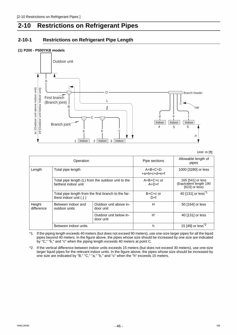
[2-10 Restrictions on Refrigerant Pipes ]
2-10 Restrictions on Refrigerant Pipes
2-10-1 Restrictions on Refrigerant Pipe Length
(1) P200 - P500YKB models
L
B
e
h
f
6
1
a c b
3 2
5
A
D
C d
4
H H '
Branch joint
Indoor Indoor Indoor
Indoor Indoor Indoor
cap
Branch header
(Out
door
uni
t abo
ve in
door
uni
t) (O
utdo
or u
nit b
elow
indo
or u
nit)
Outdoor unit
First branch (Branch joint)
Unit: m [ft]
Operation Pipe sections Allowable length of pipes
Length Total pipe length A+B+C+D +a+b+c+d+e+f
1000 [3280] or less
Total pipe length (L) from the outdoor unit to the farthest indoor unit
A+B+C+c orA+D+f
165 [541] or less(Equivalent length 190
[623] or less)
Total pipe length from the first branch to the far-thest indoor unit ( )
B+C+c orD+f
40 [131] or less*1
Height difference
Between indoor and outdoor units
Outdoor unit above in-door unit
H 50 [164] or less
Outdoor unit below in-door unit
H' 40 [131] or less
Between indoor units h 15 [49] or less*2
*1. If the piping length exceeds 40 meters (but does not exceed 90 meters), use one-size larger pipes for all the liquid pipes beyond 40 meters. In the figure above, the pipes whose size should be increased by one size are indicated by "C," "b," and "c" when the piping length exceeds 40 meters at point C.
*2. If the vertical difference between indoor units exceeds 15 meters (but does not exceed 30 meters), use one-size larger liquid pipes for the relevant indoor units. In the figure above, the pipes whose size should be increased by one size are indicated by "B," "C," "a," "b," and "c" when the "h" exceeds 15 meters.
- 46 - GBHWE14040

[2-10 Restrictions on Refrigerant Pipes ]
2 R
es
tric
tio
ns
(2) P400 - P1350YSKB models
See the next page for the detailed description of the sample application above.
Unit: m [ft]
Operation Pipe sections Allowable length of pipes
Length Between outdoor units A+B+C+D 10 [32] or less
Total pipe length A+B+C+D+E+F+G+I+J+K+M+a+b+c+d+e+f+g
+i
1000 [3280] or less
Total pipe length (L) from the outdoor unit to the farthest indoor unit
A(B)+C+E+J+K+M+i 165 [541] or less(Equivalent length 190
[623] or less)
Total pipe length from the first branch to the far-thest indoor unit ( )
G+I+J+i 40 [131] or less*1
*1. If the piping length exceeds 40 meters (but does not exceed 90 meters), use one-size larger pipes for all the liquid pipes beyond 40 meters. In the figure above, the pipes whose size should be increased by one size are indicated by "I," "c," and "d" when the piping length exceeds 40 meters at point I.
Height difference
Between indoor and outdoor units H 50 [164] or less(40 [131] or below if
outdoor unit is below in-door unit)
Between indoor units h1 15 [49] or less*2
*2. If the vertical difference between indoor units exceeds 15 meters (but does not exceed 30 meters), use one-size larger liquid pipes for the relevant indoor units. In the figure above, the pipes whose size should be increased by one size are indicated by "J," "K," "M," "e," "f," "g,"and "i" when the "h1" exceeds 15 meters.
Between outdoor units h2 0.1[0.3] or less
Indoor Indoor Indoor Indoor
Indoor Indoor Indoor Indoor
E
L
H a
h1
h2
b
2
1
c
3
d
4
e
5
f
6
g
7
i
8
C
E F G I
J K M
B D A
First branch
(Note)
To downstream units
Note : "Total sum of downstream unit model numbers" in the table is the sum of the model numbers of the units after point E in the figure.
Note1 Install the pipe that connects the branch pipe and the outdoor units in the way that it has a downward inclination toward the branch pipe.
Provide a trap on the pipe (gas pipe only) within 2 m from the joint pipe if the total length of the pipe that connects the joint pipe and the outdoor unit exceeds 2 m.
Downward inclination To indoor unit
To indoor unit
To indoor unit Joint pipe
Joint pipe
Trap (gas pipe only)
To indoor unit Upward inclination
First liquid refrigerant distributor First gas refrigerant distributor
Second gas refrigerant distributor Second liquid refrigerant distributor
2m [6ft]
2m [6ft] Max.
Outdoor unit Outdoor unitOutdoor unit
- 47 -HWE14040 GB

[2-10 Restrictions on Refrigerant Pipes ]
When the vertical separation between indoor units exceeds 15 m
Outdoor unit above indoor unit
example 1 example 2
When the distance from the first branch to the farthest indoor unit exceeds 40 m
Outdoor unit below indoor unit
example 3 example 4
When the distance from the first branch to the farthest indoor unit exceeds 40 m and the vertical separation between indoor units exceeds 15 m
example 5
Outdoor unit
Increase the size of the pipe indicated by
"A, a1, and a2" by one size.
H:exceeds 15 mA
H
B
a1a2
b1
Indoor unit Indoor unit
Indoor unit Indoor unit
Increase the size of the pipe indicated by
"A, B, b1 and e1" by one size.
H1:exceeds 15 mH2:15 m or less
C D
c
A
B H2
H1
d e2
e1
E
a b2b1
Outdoor unit
Outdoor unit
Indoor unit Indoor unit Indoor unit
Indoor unit Indoor unit
Indoor unit Indoor unit
Outdoor unit
Increase the size of the pipe indicated by "A, a1, and a2" by one size.
H:exceeds 15 m
BH
A a1a2
b
Indoor unit Indoor unit
Indoor unit Indoor unit
Indoor unit Indoor unit Indoor unit
Indoor unit Indoor unit Indoor unit Indoor unit
L1
C D
c
A
B
L2
d e2 e1
E
a b2 b1
Increase the size of the pipe indicated by "E, e1, e2 and b1" by one size.
H:15 m or lessL1, L2:40m
Outdoor unit
Outdoor unit
Indoor unit Indoor unit
Indoor unit
Outdoor unit
Outdoor unit
Indoor unit Indoor unit Indoor unit
Indoor unit
L1
C D
c
A
BL2
d e2
H2
H1
e1
E
a b2
b1 e1
Increase the size of the pipe indicated by
"E, e1, e2 and b1" by one size.
H1:exceeds 15 mH2:15 m or lessL1, L2:40m
- 48 -HWE14040 GB

[2-10 Restrictions on Refrigerant Pipes ]
2 R
es
tric
tio
ns
2-10-2 Restrictions on Refrigerant Pipe Size
(1) Diameter of the refrigerant pipe between the outdoor unit and the first branch (outdoor unit pipe size)
(2) Size of the refrigerant pipe between the first branch and the indoor unit (indoor unit pipe size)
Outdoor unit set name (total capacity)
Liquid pipe size (mm) [inch] Gas pipe size (mm) [inch]
200 model ø9.52 [3/8"] ø22.2 [7/8"]
250 model ø9.52 [3/8"]*1
*1. Use ø12.7 [1/2"] pipes if the piping length to the farthest indoor unit exceeds 90 m [295 ft].
ø22.2 [7/8"]
300 model ø9.52 [3/8"]*2
*2. Use ø12.7 [1/2"] pipes if the piping length to the farthest indoor unit exceeds 40 m [131 ft].
ø28.58 [1-1/8"]
350 model ø12.7 [1/2"] ø28.58 [1-1/8"]
400 model ø12.7 [1/2"] ø28.58 [1-1/8"]
450 model ø15.88 [5/8"] ø28.58 [1-1/8"]
500 model ø15.88 [5/8"] ø28.58 [1-1/8"]
550 model ø15.88 [5/8"] ø28.58 [1-1/8"]
600 model ø15.88 [5/8"] ø28.58 [1-1/8"]
650 model ø15.88 [5/8"] ø28.58 [1-1/8"]
700 - 800 model ø19.05 [3/4"] ø34.93 [1-3/8"]
850 - 1350 model ø19.05 [3/4"] ø41.28 [1-5/8"]
model Pipe diameter (mm) [inch]
20 - 50 models Liquid pipe ø6.35 [1/4"]
Gas pipe ø12.7 [1/2"]
63 - 140 models Liquid pipe ø9.52 [3/8"]
Gas pipe ø15.88 [5/8"]
200 model Liquid pipe ø9.52 [3/8"]
Gas pipe ø19.05 [3/4"]
250 model Liquid pipe ø9.52 [3/8"]
Gas pipe ø22.2 [7/8"]
400 model Liquid pipe ø12.7 [1/2"]
Gas pipe ø28.58 [1-1/8"]
500 model Liquid pipe ø15.88 [5/8"]
Gas pipe ø28.58 [1-1/8"]
- 49 -HWE14040 GB

[2-10 Restrictions on Refrigerant Pipes ]
(3) Size of the refrigerant pipe between the branches for connection to indoor units
(4) Size of the refrigerant pipe between the first distributor and the second distributor
(5) Size of the refrigerant pipe between the first distributor or the second distributor and outdoor units
Total capacity of the downstream units
Liquid pipe size (mm) [inch] Gas pipe size (mm) [inch]
- 140 ø9.52 [3/8"] ø15.88 [5/8"]
P141 - P200 ø9.52 [3/8"] ø19.05 [3/4"]
P201 - P300 ø9.52 [3/8"] ø22.2 [7/8"]
P301 - P400 ø12.7 [1/2"] ø28.58 [1-1/8"]
P401 - P650 ø15.88 [5/8"] ø28.58 [1-1/8"]
P651 - P800 ø19.05 [3/4"] ø34.93 [1-3/8"]
P801 - ø19.05 [3/4"] ø41.28 [1-5/8"]
Liquid pipe size (mm) [inch] Gas pipe size (mm) [inch]
ø19.05 [3/4"] ø34.93 [1-3/8"]
Liquid pipe size (mm) [inch] Gas pipe size (mm) [inch]
200 model ø9.52 [3/8"] ø22.2 [7/8"]
250 model
300 model ø12.7 [1/2"] ø28.58 [1-1/8"]
350 model
400 model
450 model ø15.88 [5/8"]
- 50 -HWE14040 GB

- 51 -HWE14040 GB
Chapter 3 Major Components, Their Functions and Refrigerant Circuits
3-1 External Appearance and Refrigerant Circuit Components of Outdoor Unit................................ 53
3-1-1 External Appearance of Outdoor Unit ................................................................................................... 53
3-1-2 Outdoor Unit Refrigerant Circuits.......................................................................................................... 56
3-2 Outdoor Unit Refrigerant Circuit Diagrams...................................................................................... 59
3-3 Functions of the Major Components of Outdoor Unit ..................................................................... 61
3-4 Functions of the Major Components of Indoor Unit ........................................................................ 64

- 52 -HWE14040 GB

[3-1 External Appearance and Refrigerant Circuit Components of Outdoor Unit ]
3 M
ajo
r C
om
po
ne
nts
, T
hei
r F
un
cti
on
s a
nd
Re
frig
era
nt
Cir
cuit
s
3 Major Components, Their Functions and Refrigerant Circuits
3-1 External Appearance and Refrigerant Circuit Components of Outdoor Unit
3-1-1 External Appearance of Outdoor Unit
(1) PUHY-P200, P250YKB-A1
Fan guardFan guard
FanFan
Control boxControl box
HeatexchangerHeatexchanger
Front panelsFront panels
Fin guardFin guard
Side panelSide panel
- 53 -HWE14040 GB

[3-1 External Appearance and Refrigerant Circuit Components of Outdoor Unit ]
(2) PUHY-P300, P350, P400YKB-A1
Fan guardFan guard
FanFan
Control boxControl box
HeatexchangerHeatexchanger
Front panelsFront panels
Fin guardFin guard
Side panelSide panel
- 54 -HWE14040 GB

[3-1 External Appearance and Refrigerant Circuit Components of Outdoor Unit ]
3 M
ajo
r C
om
po
ne
nts
, T
hei
r F
un
cti
on
s a
nd
Re
frig
era
nt
Cir
cuit
s
(3) PUHY-P450, P500YKB-A1
Fan boxFan box
Fan guardsFan guards
FansFans
Control boxControl box
HeatexchangerHeatexchanger
Front panelsFront panels
Fin guardFin guard
Side panelSide panel
- 55 -HWE14040 GB
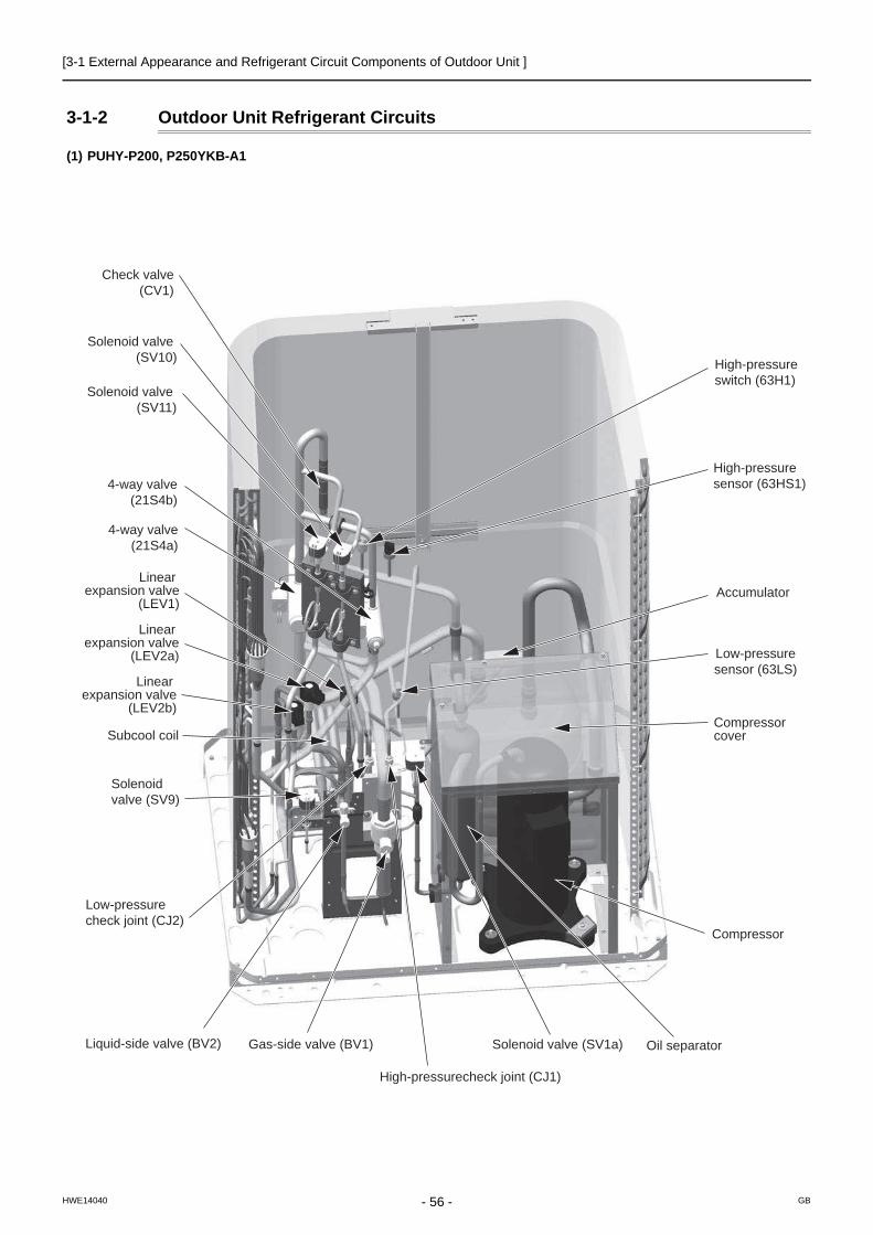
[3-1 External Appearance and Refrigerant Circuit Components of Outdoor Unit ]
3-1-2 Outdoor Unit Refrigerant Circuits
(1) PUHY-P200, P250YKB-A1
4-way valve(21S4b)
4-way valve(21S4a)
Solenoid valve (SV11)
Solenoid valve (SV10)
Subcool coil
Linear expansion valve
(LEV2a)
Linear expansion valve
(LEV2b)
Linear expansion valve
(LEV1)
Liquid-side valve (BV2) Gas-side valve (BV1) Oil separator
Compressor
Solenoidvalve (SV9)
Solenoid valve (SV1a)
Low-pressurecheck joint (CJ2)
Compressorcover
Accumulator
High-pressurecheck joint (CJ1)
High-pressuresensor (63HS1)
High-pressureswitch (63H1)
Low-pressuresensor (63LS)
Check valve(CV1)
- 56 -HWE14040 GB

[3-1 External Appearance and Refrigerant Circuit Components of Outdoor Unit ]
3 M
ajo
r C
om
po
ne
nts
, T
hei
r F
un
cti
on
s a
nd
Re
frig
era
nt
Cir
cuit
s
(2) PUHY-P300, P350, P400YKB-A1
4-way valve(21S4b)
4-way valve(21S4a)
Solenoid valve (SV11)
Solenoid valve (SV10)
Subcool coil
Linear expansionvalve (LEV2a)
Linear expansionvalve (LEV2b)
Linear expansionvalve (LEV1)
Liquid-side valve (BV2) Gas-side valve (BV1)
Oil separator
Compressor
Solenoidvalve (SV1a)
Low-pressurecheck joint (CJ2)
Compressorcover
Accumulator
High-pressurecheck joint (CJ1)
High-pressuresensor (63HS1)
High-pressureswitch (63H1)
Low-pressuresensor (63LS)
Check valve(CV1)
Solenoid valve(SV9)
- 57 -HWE14040 GB

[3-1 External Appearance and Refrigerant Circuit Components of Outdoor Unit ]
(3) PUHY-P450, P500YKB-A1
4-way valve(21S4b)
2-way valve (SV5b)
4-way valve(21S4a)
4-way valve(21S4c)
Solenoid valve (SV11)
Solenoid valve (SV10)
Subcool coil
Linear expansionvalve (LEV2a)
Linear expansionvalve (LEV2b)
Linear expansionvalve (LEV1)
Liquid-side valve (BV2)
Gas-side valve (BV1)
Oil separator
Compressor
Solenoidvalve(SV1a)
Low-pressure check joint (CJ2)
Compressorcover
Accumulator
High-pressurecheck joint (CJ1)
High-pressuresensor (63HS1)
High-pressureswitch (63H1)
Low-pressure sensor (63LS)
Check valve(CV1)
Solenoid valve(SV9)
- 58 -HWE14040 GB

[3-2 Outdoor Unit Refrigerant Circuit Diagrams ]
3 M
ajo
r C
om
po
ne
nts
, T
hei
r F
un
cti
on
s a
nd
Re
frig
era
nt
Cir
cuit
s
3-2 Outdoor Unit Refrigerant Circuit Diagrams(1) PUHY-P200, P250 models
(2) PUHY-P300, P350, P400 models
SCC LEV1
SV1aSV11 SV10
CP5CP4
63H1
ST3
ST6
63HS1
CJ1
CJ2
ST7
21S4b
21S4a
CP1CV1
ST1
ST2 BV2
BV1
SV9
ACC
Comp
O/S
HEX
FAN
MOTOR
LEV2b LEV2a
*
*
TH4
TH2
TH9
TH3
TH7TH11
63LS
TH6
TH5
SCC LEV1
SV1aSV11 SV10
CP5CP4
63H1
ST3
ST6
63HS1
CJ1
CJ2
ST7
21S4b
21S4a
CP1CV1
ST1
ST2 BV2
BV1
SV9
ACC
Comp
O/S
HEX
FAN
MOTOR
LEV2b LEV2a
*
*
TH4
TH2
TH9
TH3
TH7TH11
63LS
TH6
TH5
- 59 -HWE14040 GB
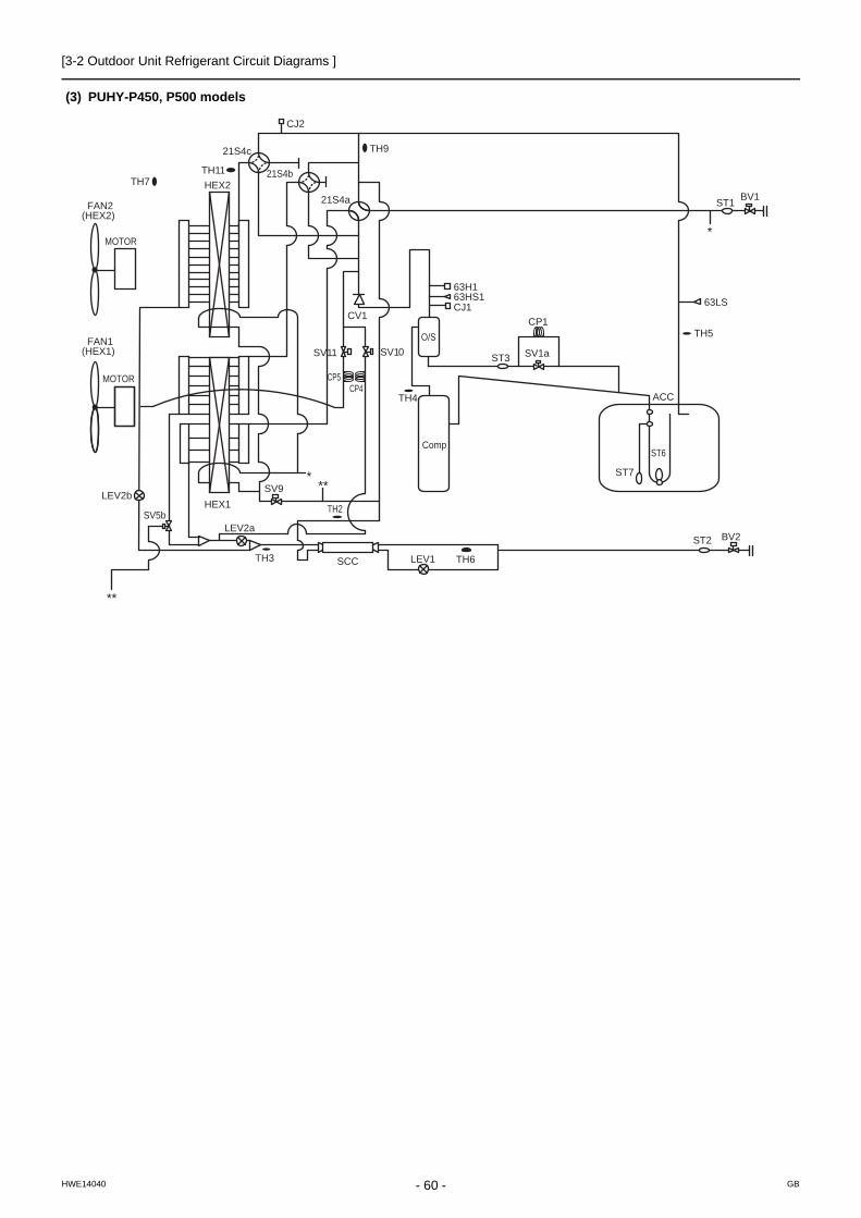
[3-2 Outdoor Unit Refrigerant Circuit Diagrams ]
(3) PUHY-P450, P500 models
SCC LEV1
ACC
63H1
21S4a
ST6
63HS1
ST7
21S4c
CJ1
Comp
O/S
LEV2a
LEV2b
ST2 BV2
BV1
21S4b
SV5b
SV9
SV10SV11
*
*
**
**
ST1
63LS
FAN2(HEX2)
FAN1(HEX1) SV1a
CP1CV1
HEX2TH7
MOTOR
MOTOR
TH9
CJ2
TH11
TH2HEX1
TH3 TH6
TH4
TH5
ST3
CP5CP4
- 60 -HWE14040 GB

[3-3 Functions of the Major Components of Outdoor Unit ]
3 M
ajo
r C
om
po
ne
nts
, T
hei
r F
un
cti
on
s a
nd
Re
frig
era
nt
Cir
cuit
s
3-3 Functions of the Major Components of Outdoor Unit
Part name
Symbols (functions) Notes Usage Specifications Check method
Com-pressor
MC1(Comp1)
Adjusts the amount of circulating refrigerant by adjusting the operat-ing frequency based on the oper-ating pressure data
P200, P250 modelsLow-pressure shell scroll compressorwirewound resistance20°C [68°F] : 0.72 ΩP300, P350 modelsLow-pressure shell scroll compressorwirewound resistance20°C [68°F] : 0.32 ΩP400 modelLow-pressure shell scroll compressorwirewound resistance20°C [68°F] : 0.30 ΩP450, P500 modelsLow-pressure shell scroll compressorwirewound resistance20°C [68°F] : 0.43 Ω
High pres-sure sensor
63HS1 1) Detects high pressure2) Regulates frequency and pro-
vides high-pressure protec-tion
Low pres-sure sensor
63LS 1) Detects low pressure2) Provides low-pressure pro-
tection3) Defrost control during heating
operation
Pres-sure switch
63H1 1) Detects high pressure2) Provides high-pressure pro-
tection
4.15MPa[601psi] OFF setting
Pressure0~4.15 MPa [601psi]Vout 0.5~3.5V0.071V/0.098 MPa [14psi]Pressure [MPa]=1.38 x Vout [V]-0.69Pressure [psi]=(1.38 x Vout [V] - 0.69) x 145
GND (Black)Vout (White)Vcc (DC5V) (Red)
Con-nector
63HS1
1
1 2 3
23
Pressure0~1.7 MPa [247psi]Vout 0.5~3.5V0.173V/0.098 MPa [14psi]Pressure [MPa]=0.566 x Vout [V] - 0.283Pressure [psi]=(0.566 x Vout [V] - 0.283) x 145
GND (Black)Vout (White)Vcc (DC5V) (Red)
Con-nector
63LS
1
1 2 3
23
- 61 -HWE14040 GB

[3-3 Functions of the Major Components of Outdoor Unit ]
Thermis-tor
TH4(Discharge)
1) Detects discharge air temper-ature
2) Provides high-pressure pro-tection
Degrees Celsius Resistance check
0°C[32°F] :698 kΩ10°C[50°F] :413 kΩ 20°C[68°F] :250 kΩ 30°C[86°F] :160 kΩ 40°C[104°F] :104 kΩ 50°C[122°F] : 70 kΩ 60°C[140°F] : 48 kΩ 70°C[158°F] : 34 kΩ 80°C[176°F] : 24 kΩ 90°C[194°F] :17.5 kΩ100°C[212°F] :13.0 kΩ110°C[230°F] : 9.8 kΩ
TH2 LEV 1 is controlled based on the TH2, TH3, and TH6 values.
Degrees Celsius
0°C[32°F] :15 kΩ10°C[50°F] :9.7 kΩ20°C[68°F] :6.4 kΩ25°C[77°F] :5.3 kΩ30°C[86°F] :4.3 kΩ40°C[104°F] :3.1 kΩ
Resistance check
TH3(Pipe temperature)
1) Controls frequency2) Controls defrosting during
heating operation
TH7(Outdoor temperature)
1) Detects outdoor air tempera-ture
2) Controls fan operation
TH5 LEV2 are controlled based on the 63LS and TH5 values.
TH6 Controls LEV1 based on TH2, TH3, and TH6 data.
TH9,11 Determines the completion of Continuous heating cycle mode.
THHSInverter heat sink temperature
Controls inverter cooling fan based on THHS temperature
Degrees Celsius
0°C[32°F] :161 kΩ10°C[50°F] :97 kΩ20°C[68°F] :60 kΩ25°C[77°F] :48 kΩ30°C[86°F] :39 kΩ40°C[104°F] :25 kΩ
THL DCL temperature
DCL overheat protection Degrees Celsius
0°C[32°F] :162.2 kΩ10°C[50°F] :98.3 kΩ25°C[77°F] :49.1 kΩ50°C[122°F] :17.6 kΩ100°C[212°F] :3.3 kΩ
Part name
Symbols (functions) Notes Usage Specifications Check method
R = 7.465k120
R = 4057R =7.465
25/120
t
4057 273 t1
3931exp
R = 15k0
R = 3460R = 15
0/80
t 3460 273 t1
2731exp
R = 17k50
R = 4016R = 17
25/120
t 4016 273 t1
3231exp
R = 3.3k100
B = 3970R = 3.3
0/100
t 3970 273 t1
3731exp
- 62 -HWE14040 GB

[3-3 Functions of the Major Components of Outdoor Unit ]
3 M
ajo
r C
om
po
ne
nts
, T
hei
r F
un
cti
on
s a
nd
Re
frig
era
nt
Cir
cuit
s
Sole-noid valve
SV1aDischarge-suction bypass
1) High/low pressure bypass at start-up and stopping, and capacity control during low-load operation
2) High-pressure-rise preven-tion
AC220-240VOpen while being powered/closed while not being pow-ered
Continuity check with a tester
SV5b Heat exchanger capacity con-trol
P450, P500 models only
Controls outdoor unit heat ex-changer capacity
AC220-240VClosed while being powered/open while not being powered
SV9 High-pressure-rise prevention Open while being powered/closed while not being pow-ered
SV10 Continuous heating cycle mode Open while being powered/closed while not being pow-ered
SV11 Continuous heating cycle mode Open while being powered/closed while not being pow-ered
Linear expan-sion valve
LEV1(SC control)
Adjusts the amount of bypass flow from the liquid pipe on the outdoor unit during cooling
DC12VOpening of a valve driven by a stepping motor 0-480 pulses (direct driven type)
Same as indoor LEVThe resistance val-ue differs from that of the indoor LEV.Refer to the follow-ing page(s). [8-8 Troubleshooting LEV Prob-lems](page 258)
LEV2a(Refrigerant flow adjust-ment)
Adjusts refrigerant flow during heatingCut off the refrigerant flow during continuous heating cycle
DC12VOpening of a valve driven by a stepping motor 2100 pulses(Max. 3000 pulses)
Refer to the section "Continuity Test with a Tester". Continuity between white and orange.Continuity between yellow, red, and blue.
LEV2b(Refrigerant flow adjust-ment)
4-way valve
21S4a Changeover between heating and cooling
AC220-240VDead: cooling cycle Live: heating cycle
Continuity check with a tester
21S4b 1) Changeover between heating and cooling
2) Controls outdoor unit heat ex-changer capacity
AC220-240VDead: cooling cycle Outdoor unit heat exchanger capacity at 100%Live: heating cycleOutdoor unit heat exchanger capacity at 25%, 50%or heating cycle
21S4c P450, P500 models only
Fanmotor
FAN motor 1,2
FAN mo-tor 2 is only on the P450, P500 models.
Regulates the heat exchanger ca-pacity by adjusting the operating frequency and operating the pro-peller fan based on the operating pressure.
AC380-400V, 920W*The P200-P400 models and the P450 model are equipped with different types of fan mo-tors.
Part name
Symbols (functions) Notes Usage Specifications Check method
Yellow
White Orange
red Blue
M
- 63 -HWE14040 GB

[3-4 Functions of the Major Components of Indoor Unit ]
3-4 Functions of the Major Components of Indoor Unit
Part Name
Symbol (functions) Notes Usage Specification Check method
Linear expan-sion valve
LEV 1) Adjusts superheat at the indoor heat exchanger outlet during cooling
2) Adjusts subcool at the in-door unit heat exchanger outlet during heating
DC12VOpening of stepping motordriving valve 0-(1800) pulses
Refer to the section "Continuity Test with a Tester". Continuity between white, red, and or-ange.Continuity between yellow, brown, and blue.
Thermis-tor
TH1 (Suction air tem-perature)
Indoor unit control (Thermo)
0°C [32°F]:15 kΩ 10°C [50°F] :9.7 kΩ 20°C [68°F]:6.4 kΩ 25°C [77°F] :5.3 kΩ 30°C [86°F] :4.3 kΩ 40°C [104°F] :3.1 kΩ
Resistance check
TH2 (Pipe tempera-ture)
1) Indoor unit control (Frost prevention, Hot adjust)
2) LEV control during heat-ing operation (subcool detection).
TH3 (Gas pipe tem-perature)
LEV control during cooling op-eration (superheat detection)
TH4 Outdoor air tem-perature)*1
Indoor unit control (Thermo)
Temperature sensor (Indoor air temperature)
Indoor unit control (Thermo)
*1. Indicates gas pipe temperature on the PKFY-P VHM-E and PKFY-P VKM-E models.
Yellow
White
Red
Orange Brown Blue
M
1
273+t
R0=15k R0/80=3460Rt =15exp3460( - )
1
273
- 64 -HWE14040 GB

- 65 -HWE14040 GB
Chapter 4 Electrical Components and Wiring Diagrams
4-1 Outdoor Unit Circuit Board Arrangement......................................................................................... 67
4-1-1 Outdoor Unit Control Box...................................................................................................................... 67
4-1-2 Fan Box................................................................................................................................................. 70
4-2 Outdoor Unit Circuit Board Components ......................................................................................... 71
4-2-1 Control Board........................................................................................................................................ 71
4-2-2 M-NET Board (Transmission Power Supply Board) ............................................................................. 72
4-2-3 INV Board ............................................................................................................................................. 73
4-2-4 Fan Board ............................................................................................................................................. 75
4-2-5 Noise Filter............................................................................................................................................ 76
4-2-6 Capacitor Board .................................................................................................................................... 78
4-2-7 Connect Board ...................................................................................................................................... 79
4-3 Outdoor Unit Electrical Wiring Diagrams ......................................................................................... 80
4-4 Transmission Booster Electrical Wiring Diagrams ......................................................................... 82

- 66 -HWE14040 GB

[4-1 Outdoor Unit Circuit Board Arrangement ]
4 E
lec
tric
al C
om
po
nen
ts a
nd
Wir
ing
Dia
gra
ms
4 Electrical Components and Wiring Diagrams
4-1 Outdoor Unit Circuit Board Arrangement
4-1-1 Outdoor Unit Control Box
(1) PUHY-P200, P250, P300, P350, P400YKB-A1
1) Exercise caution not to damage the bottom and the front panel of the control box. Damage to these parts affect the water-proof and dust proof properties of the control box and may result in damage to its internal components.
2) Faston terminals have a locking function. Make sure the cable heads are securely locked in place. Press the tab on the ter-minals to remove them.
3) Control box houses high temperature parts. Be well careful even after turning off the power source.4) Perform the service after disconnecting the outdoor unit fan board connector (CNINV) and the inverter board con-
nector (CN1). Before plugging in or unplugging connectors, check that the outdoor unit fan is not rotating and that the voltage between FT-P and FT-N on the INV board is 20 VDC or less. The capacitor may collect a charge and cause an electric shock when the outdoor unit fan rotates in windy conditions. Refer to the wiring nameplate for details.
5) To connect wiring to TB7, check that the voltage is 20 VDC or below.6) Reconnect the connector (CNINV) back to the fan board and reconnect the connector (CN1) back to the inverter board after
servicing.7) When opening or closing the front panel of the control box, do not let it come into contact with any of the internal components.
Before plugging in or unplugging connectors, check that the outdoor unit fan is not rotating and that the voltage between FT-P and FT-N on the INV board is 20 VDC or less. It takes about 10 minutes to discharge electricity after the power supply is turned off.
8) When the power is on, the compressor or heater is energized even while the compressor is stopped. Before turning on the power, disconnect all power supply wires from the compressor terminal block, and measure the insulation resistance of the compressor. Check the compressor for a ground fault. If the insulation resistance is 1.0 MΩ or below, connect all power supply wires to the compressor and turn on the power to the outdoor unit. It is energized to evaporate the liquid refrigerant that has accumulated in the compressor.
<HIGH VOLTAGE WARNING>Control box houses high-voltage parts.When opening or closing the front panel of the control box, do not let it come into contact with any of the internal components.Before inspecting the inside of the control box, turn off the power, keep the unit off for at least 10 minutes,and confirm that the voltage of the capacitor in the main circuit has dropped to 20 VDC or less.
FAN board Control boardElectromagnetic relay(DCL)
Rush current protection resistor(R1, R5) Note 2)
M-NET boardINV board Note 1)Ground terminal
Terminal block for power supply (TB1)
Terminal block for transmission line (TB3, TB7)
Capacitor(C100)
Electromagneticcontactor (72C)
Noise filter
- 67 -HWE14040 GB
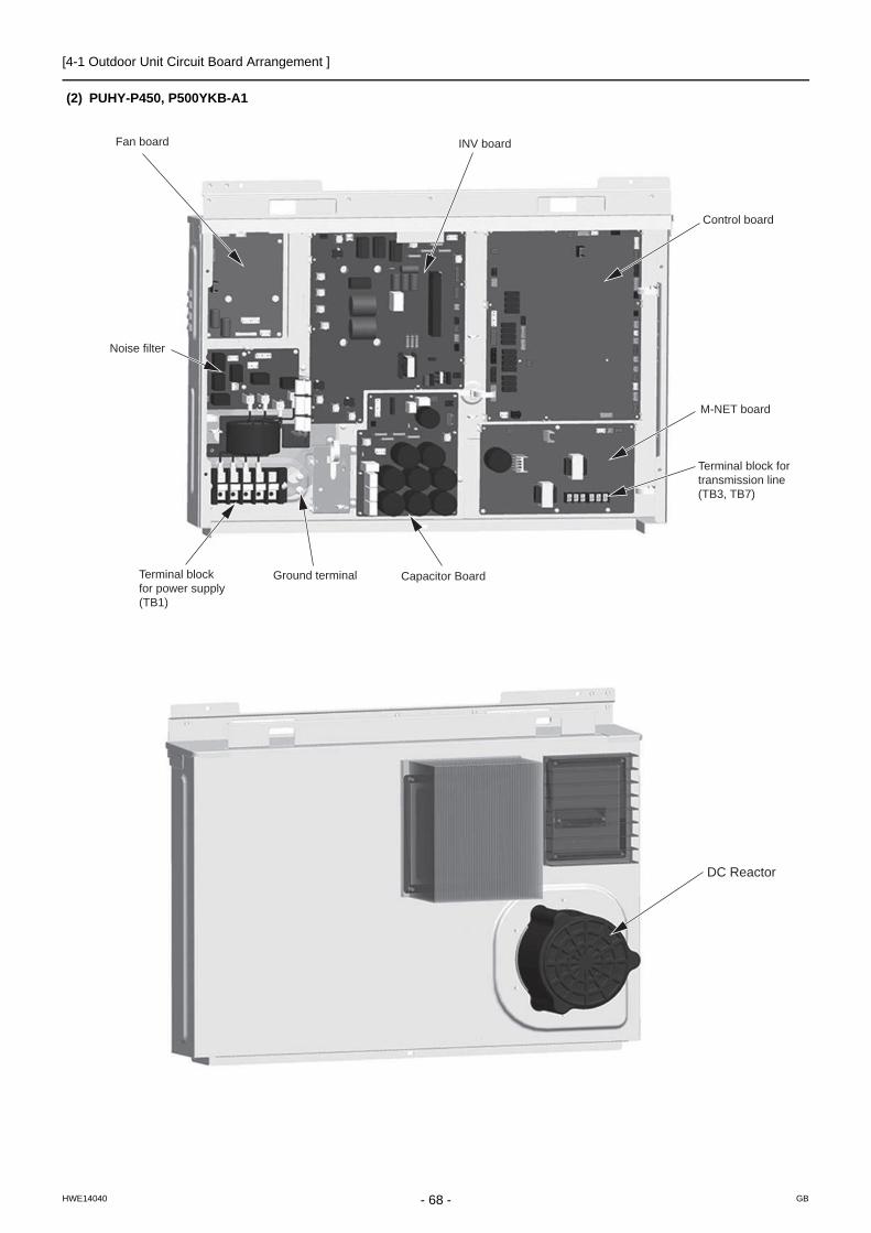
[4-1 Outdoor Unit Circuit Board Arrangement ]
(2) PUHY-P450, P500YKB-A1
Capacitor Board
INV board
Control board
M-NET board
Terminal block for transmission line (TB3, TB7)
Terminal block for power supply (TB1)
Noise filter
Fan board
Ground terminal
DC Reactor
- 68 -HWE14040 GB

[4-1 Outdoor Unit Circuit Board Arrangement ]
4 E
lec
tric
al C
om
po
nen
ts a
nd
Wir
ing
Dia
gra
ms
1) Exercise caution not to damage the bottom and the front panel of the control box. Damage to these parts affect the water-proof and dust proof properties of the control box and may result in damage to its internal components.
2) Faston terminals have a locking function. Make sure the cable heads are securely locked in place. Press the tab on the ter-minals to remove them.
3) Control box houses high temperature parts. Be well careful even after turning off the power source.4) Perform the service after disconnecting the outdoor unit fan board connector (CNINV) and the inverter board con-
nector (CN1). Before plugging in or unplugging connectors, check that the outdoor unit fan is not rotating and that the voltage between SC-P and SC-N on the capacitor board is 20 VDC or less. The capacitor may collect a charge and cause an electric shock when the outdoor unit fan rotates in windy conditions. Refer to the wiring nameplate for details.
5) To connect wiring to TB7, check that the voltage is 20 VDC or below.6) Reconnect the connector (CNINV) back to the fan board and reconnect the connector (CN1) back to the inverter board after
servicing.7) When opening or closing the front panel of the control box, do not let it come into contact with any of the internal components.
Before inspecting the inside of the control box, turn off the power, keep the unit off for at least 10 minutes, and confirm that the capacitor voltage (inverter main circuit) has dropped to 20 V DC or less. It takes about 10 minutes to discharge electricity after the power supply is turned off.
8) When the power is on, the compressor or heater is energized even while the compressor is stopped. Before turning on the power, disconnect all power supply wires from the compressor terminal block, and measure the insulation resistance of the compressor. Check the compressor for a ground fault. If the insulation resistance is 1.0 MΩ or below, connect all power supply wires to the compressor and turn on the power to the outdoor unit. It is energized to evaporate the liquid refrigerant that has accumulated in the compressor.
- 69 -HWE14040 GB

[4-1 Outdoor Unit Circuit Board Arrangement ]
4-1-2 Fan Box
(1) PUHY-P450, P500YKB-A1
1. Handle the fan box with care. If the front or the bottom panel becomes damaged, water or dust may enter the fan box, dam-aging its internal parts.
2. Perform the service after disconnecting the fan board connector (CNINV) and the connect board connector (CN103). Before plugging in or unplugging connectors, check that the outdoor unit fan is not rotating and that the voltage be-tween FT-P and FT-N on the INV board or between SC-P and SC-N on the capacitor board is 20 VDC or less. The ca-pacitor may collect a charge and cause an electric shock when the outdoor unit fan rotates in windy conditions.
3. Reconnect the connector (CNINV) back to the fan board and reconnect the connector (CN103) back to the connect board after servicing.
FAN board
Connect board
Note 1)
- 70 -HWE14040 GB

[4-2 Outdoor Unit Circuit Board Components ]
4 E
lec
tric
al C
om
po
nen
ts a
nd
Wir
ing
Dia
gra
ms
4-2 Outdoor Unit Circuit Board Components
4-2-1 Control Board
*For information about the display of SW4 function settings, refer to the following page(s). [5-1-1 Outdoor Unit Switch Func-tions and Factory Settings](page 85)
CN801Pressure switch connection
Actuator drivesignal output LEV
drive signal output
SWU1,2Address switch
LED1Service LED
LED3Function settingdisplayLit :ONUnlit:OFF
LED2Normal/Errorindicator
SWP1SW4 setting(SW6-10:OFF)Effective/Ineffectiveswitching
SW4~6Dip switches
CN40Centralized controlpower supply ONCN51
12 VDC output Compressor ON/OFF signal output Error signal output CN41
Centralized controlpower supply OFF
External signal input (contact input)
F01250 VAC3.15A T
CNRYB72 drive signaloutput
Sensor input
CN2/2A Serial communication signal input GND
CN4/4A 5 VDC output GND Serial communication GND
16 VDCGND(FAN INV board 1)17 VDC17 VDCGND(INV board)
CN33218 VDC outputGND(FAN INV board 2)
CNVCC2 12 VDC output 5 VDC output GND
CNAC2 L1 phase L2 phase
CNPS 12 VDC output GND 5 VDC output Power supply detection input Power supply ON/OFF signal outputCentralized control
transmission signal input/output (30 VDC)Power input signal for the centralizedcontrol system (30 VDC)Indoor-outdoortransmission line signal input/output (30 VDC)
CNAC L1 phase N phase
CNDC Bus voltage input P N
CN110 Power supply detection signal input GND
CN62
- 71 -HWE14040 GB

[4-2 Outdoor Unit Circuit Board Components ]
4-2-2 M-NET Board (Transmission Power Supply Board)
Power supply output for centralized control system Indoor/outdoor transmission line input/output
CN102
CNS2Transmission line input/output for centralized control system
CNIT 12VDC input GND 5VDC input Power supply detection output Power supply ON/OFF signal input
LED1Power supply for indoor transmission line
TP1,2Check pins for indoor/outdoortransmission line
TB7Terminal block for transmission line for centralized control
TB3Indoor/outdoor transmission block
Ground terminal for transmission line
GroundingGrounding
CN04Bus voltage input P N
Grounding
- 72 -HWE14040 GB

[4-2 Outdoor Unit Circuit Board Components ]
4 E
lec
tric
al C
om
po
nen
ts a
nd
Wir
ing
Dia
gra
ms
4-2-3 INV Board
(1) PUHY-P200, P250, P300, P350, P400YKB-A1
1) When opening or closing the front panel of the control box, do not let it come into contact with any of the internal components. Before inspecting the inside of the control box, turn off the power, keep the unit off for at least 10 minutes, and confirm that the capacitor voltage (inverter main circuit) has dropped to 20 VDC or less. It takes about 10 minutes to discharge electricity after the power supply is turned off.
2) Faston terminals have a locking function. Make sure the cable heads are securely locked in place. Press the tab on the ter-minals to remove them.
3) Control box houses high temperature parts. Be well careful even after turning off the power source.4) Perform the service after disconnecting the outdoor unit fan board connector (CNINV) and the inverter board con-
nector (CN1). Before plugging in or unplugging connectors, check that the outdoor unit fan is not rotating and that the voltage between FT-P and FT-N on the INV board is 20 VDC or less. The capacitor may collect a charge and cause an electric shock when the outdoor unit fan rotates in windy conditions. Refer to the wiring nameplate for details.
5) To connect wiring to TB7, check that the voltage is 20 VDC or below.6) Reconnect the connector (CNINV) back to the fan board and reconnect the connector (CN1) back to the inverter board after
servicing.7) When the power is turned on, the compressor is energized even while it is not operating. Before turning on the power, discon-
nect all power supply wires from the compressor terminal block, and measure the insulation resistance of the compressor.Check the compressor for a ground fault. If the insulation resistance is 1.0 MΩ or below, connect all power supply wires to the compressor and turn on the power to the outdoor unit. The liquid refrigerant in the compressor will evaporate by energizing the compressor.
- 73 -HWE14040 GB

[4-2 Outdoor Unit Circuit Board Components ]
(2) PUHY-P450, P500YKB-A1
1) When opening or closing the front panel of the control box, do not let it come into contact with any of the internal components. Before inspecting the inside of the control box, turn off the power, keep the unit off for at least 10 minutes, and confirm that the capacitor voltage (inverter main circuit) has dropped to 20 VDC or less. It takes about 10 minutes to discharge electricity after the power supply is turned off.
2) Faston terminals have a locking function. Make sure the cable heads are securely locked in place. Press the tab on the ter-minals to remove them.
3) Control box houses high temperature parts. Be well careful even after turning off the power source.4) Perform the service after disconnecting the outdoor unit fan board connector (CNINV) and the inverter board con-
nector (CN1). Before plugging in or unplugging connectors, check that the outdoor unit fan is not rotating and that the voltage between SC-P and SC-N on the capacitor board is 20 VDC or less. The capacitor may collect a charge and cause an electric shock when the outdoor unit fan rotates in windy conditions. Refer to the wiring nameplate for details.
5) To connect wiring to TB7, check that the voltage is 20 VDC or below.6) Reconnect the connector (CNINV) back to the fan board and reconnect the connector (CN1) back to the inverter board after
servicing.7) When the power is on, the compressor or heater is energized even while the compressor is stopped. Before turning on the
power, disconnect all power supply wires from the compressor terminal block, and measure the insulation resistance of the compressor. Check the compressor for a ground fault. If the insulation resistance is 1.0 MΩ or below, connect all power supply wires to the compressor and turn on the power to the outdoor unit. It is energized to evaporate the liquid refrigerant that has accumulated in the compressor.
CNCT4AElectric current sensor(DC) output(CT3)
CT-3Electric current sensor(DC bus current)
SC-L1input(L1)
SC-L2input(L2)
SC-L3input(L3)
SC-BDC bus current input
IGBT(Rear)
CT-1Electric current sensor(U)
CT-2Electric current sensor(W)
F1Fuse 250 VAC3.15A
CN10Gate power supply input
+-
SW001ON: No-load operationOFF: Normal operationOFF: Fixed
CNTYPINV board Type
CN5VGND5 VDC output
CNTHDCL thermistor input
CNCT4BElectric current sensor(DC) input(CT-3)
CN43GND(Fan board)Serial communicationsignal input
SC-NBus voltage output(N)
FT001Neutral point output(P)
CNRYInrush current limitingrelay input
SC-LDC bus current input
SC-PBus voltage output(P)
R001Oversurrentdetection resistor
FT-R21Bus voltage output(P)
LED5Lit: Power is supplied to the relay driveUnlit: Power is not supplied to the relay drive
LED4Microcomputer in operationLED1Lit: Inverter operationBlinking: Inverter error
CN1Bus voltage output
NP
CN2Serial communicationsignal outputGND17 VDC input17 VDC inputGND
SC-UInverter output(U)
SC-VInverter output(V)
SC-WInverter output(W)
- 74 -HWE14040 GB

[4-2 Outdoor Unit Circuit Board Components ]
4 E
lec
tric
al C
om
po
nen
ts a
nd
Wir
ing
Dia
gra
ms
4-2-4 Fan Board
1) When opening or closing the front panel of the control box, do not let it come into contact with any of the internal components. Before inspecting the inside of the control box, turn off the power, keep the unit off for at least 10 minutes, and confirm that the capacitor voltage (inverter main circuit) has dropped to 20 VDC or less. It takes about 10 minutes to discharge electricity after the power supply is turned off.
2) Control box houses high temperature parts. Be well careful even after turning off the power source.3) Perform the service after disconnecting the outdoor unit fan board connector (CNINV) and the inverter board con-
nector (CN1). Before plugging in or unplugging connectors, check that the outdoor unit fan is not rotating and that the voltage between FT-P and FT-N on the INV board or between SC-P and SC-N on the capacitor board is 20 VDC or less. The capacitor may collect a charge and cause an electric shock when the outdoor unit fan rotates in windy con-ditions. Refer to the wiring nameplate for details.
4) To connect wiring to TB7, check that the voltage is 20 VDC or below.5) Reconnect the connector (CNINV) back to the fan board and reconnect the connector (CN1) back to the inverter board after
servicing.
LED1Lit: Inverter operationBlinking: Inverter error
LED4Microcomputer in operation (Lit)
RSH02
- 75 -HWE14040 GB

[4-2 Outdoor Unit Circuit Board Components ]
4-2-5 Noise Filter
(1) PUHY-P200, P250, P300, P350, P400YKB-A1
CN4Output(Rectified L2-N current) P N
CN5Output(Rectified L2-N current) P N
TB21Input/output(L1)
TB22Input/output(L2)
TB23Input/output(L3)
TB24Input(N)
CN1BInput L3 L2
CN1AInput N L1
Grounding
F1,F2,F3,F4Fuse250VAC 6.3A
CN3Output L1 N
Grounding
CN2 Surge absorber circuit Surge absorber circuit Short circuit Short circuit
- 76 -HWE14040 GB

[4-2 Outdoor Unit Circuit Board Components ]
4 E
lec
tric
al C
om
po
nen
ts a
nd
Wir
ing
Dia
gra
ms
(2) PUHY-P450, P500YKB-A1
CN1AInput N L1
CN1B L3 L2
1
1
4
3
CN3Output L1 N
13
CN4Output L2 N L3
13
135
5 6
CN2 Surge absorber circuit Surge absorber circuit Short circuit Short circuit
Grounding
Grounding
Grounding
F3Fuse250VAC 6.3A
F1Fuse250VAC 6.3A
F2Fuse250VAC 6.3A
TB24Input/outputN
TB23Input/outputL3TB22
Input/outputL2
TB21Input/outputL1
CA
UTI
ON
FO
RH
IGH
VO
LTA
GE
CAUTION FORHIGH VOLTAGE
- 77 -HWE14040 GB

[4-2 Outdoor Unit Circuit Board Components ]
4-2-6 Capacitor Board
(1) PUHY-P450, P500YKB-A1
1) When opening or closing the front panel of the control box, do not let it come into contact with any of the internal components. Before inspecting the inside of the control box, turn off the power, keep the unit off for at least 10 minutes, and confirm that the capacitor voltage (inverter main circuit) has dropped to 20 VDC or less. It takes about 10 minutes to discharge electricity after the power supply is turned off.
2) Control box houses high temperature parts. Be well careful even after turning off the power source.3) Perform the service after disconnecting the fan board connector (CNINV) and the connector board connector
(CN103). Before plugging in or unplugging connectors, check that the outdoor unit fan is not rotating and that the voltage between SC-P and SC-N on the capacitor board is 20 VDC or less. The capacitor may collect a charge and cause an electric shock when the outdoor unit fan rotates in windy conditions. Refer to the wiring nameplate for details.
4) To connect wiring to TB7, check that the voltage is 20 VDC or below.5) Reconnect the connector (CNINV) back to the fan board and reconnect the connector (CN103) back to the connector board
after servicing.
CN106Bus voltage input N P
CN103Output(Rectified L3-N current) P N
CN107Output(L3-N rectifier) P N
CN104Output(L3-N rectifier) P N
SC-NBus voltage input(N)
SC-PBus voltage input(P)
note.1
note.1
C101~C108Smoothing capacitor
R301~R304Rush current protection resistor
CN102 Power supply detection signal output GND
CN101 Input(L2) Input(N) Input(L3)
- 78 -HWE14040 GB
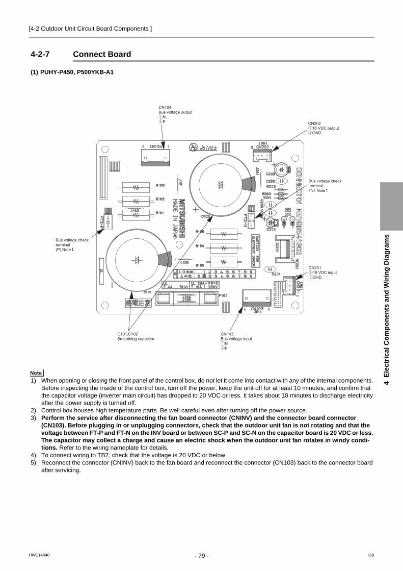
[4-2 Outdoor Unit Circuit Board Components ]
4 E
lec
tric
al C
om
po
nen
ts a
nd
Wir
ing
Dia
gra
ms
4-2-7 Connect Board
(1) PUHY-P450, P500YKB-A1
1) When opening or closing the front panel of the control box, do not let it come into contact with any of the internal components. Before inspecting the inside of the control box, turn off the power, keep the unit off for at least 10 minutes, and confirm that the capacitor voltage (inverter main circuit) has dropped to 20 VDC or less. It takes about 10 minutes to discharge electricity after the power supply is turned off.
2) Control box houses high temperature parts. Be well careful even after turning off the power source.3) Perform the service after disconnecting the fan board connector (CNINV) and the connector board connector
(CN103). Before plugging in or unplugging connectors, check that the outdoor unit fan is not rotating and that the voltage between FT-P and FT-N on the INV board or between SC-P and SC-N on the capacitor board is 20 VDC or less. The capacitor may collect a charge and cause an electric shock when the outdoor unit fan rotates in windy condi-tions. Refer to the wiring nameplate for details.
4) To connect wiring to TB7, check that the voltage is 20 VDC or below.5) Reconnect the connector (CNINV) back to the fan board and reconnect the connector (CN103) back to the connector board
after servicing.
1
- 79 -HWE14040 GB

[4-3 Outdoor Unit Electrical Wiring Diagrams ]
4-3 Outdoor Unit Electrical Wiring Diagrams(1) PUHY-P200, P250, P300, P350, P400 models
RSH0
1/02,R
SH1
For c
urre
nt d
etec
tion
Cen
tral c
ontro
l tra
nsm
issi
on c
able
Indo
or/O
utdo
or tr
ansm
issi
on c
able
C30
~C37
Cap
acito
r (in
verte
r mai
n ci
rcui
t)
LC
hoke
coi
l (fo
r hig
h fre
quen
cy n
oise
redu
ctio
n)
For i
nrus
h cu
rren
t pre
vent
ion
Res
isto
rR
1,5
HIC
byp
ass,
Con
trols
refri
gera
ntflo
w in
HIC
circ
uit
Sub
cool
ed li
quid
refri
gera
ntte
mpe
ratu
re
Pip
e te
mpe
ratu
re
SV
1a
LEV
2a,b
21S
4aS
ymbo
l
<Sym
bol e
xpla
natio
n>
63H
1
63H
S1
63LS
72C
21S
4b
CT12
,CT22
,CT3
LEV
1
DC
L
Pre
ssur
e co
ntro
l,Ref
riger
ant f
low
rate
con
trol
Sol
enoi
dva
lve
For o
peni
ng/c
losi
ng th
e by
pass
circ
uit u
nder
the
O/S
Hea
t exc
hang
er c
apac
ity c
ontro
l4-
way
val
veE
xpla
natio
n
Pre
ssur
ese
nsor
Coo
ling/
Hea
ting
switc
hing
Pre
ssur
esw
itch
Hig
h pr
essu
re p
rote
ctio
n fo
r the
outd
oor u
nit
Dis
char
ge p
ress
ure
Low
pre
ssur
eM
agne
tic re
lay(
inve
rter m
ain
circ
uit)
Cur
rent
sen
sor(
AC
)
Line
arex
pans
ion
valv
e
DC
reac
tor
Sub
cool
byp
ass
outle
tte
mpe
ratu
reTH
2
Z25
THH
S
TH7
TH6
TH5
TH4
TH3
TB7
TB3
TB1
SV
9
Ther
mis
tor
Dis
char
ge p
ipe
tem
pera
ture
AC
C in
let p
ipe
tem
pera
ture
OA
tem
pera
ture
IPM
tem
pera
ture
Func
tion
setti
ng c
onne
ctor
Pow
er s
uppl
yTe
rmin
albl
ock
For o
peni
ng/c
losi
ng th
e by
pass
circ
uit
C15
1,C
152
F121
DC
700V
4A T
RSH0
1/02
12
L3N
red
CN
PS
1 321 TP
1TP
2
TB3
23
TB7
M1
M2
M1
M2
S
1
51
23
4
12
t°
LEV
2a
M
1234612
13
2
3456
36
1
53
1
2 213 4
CN
83bl
ack
L1L2
31
Fan
mot
or(H
eat e
xcha
nger
)
U V W
7 14
34
CN
4bl
ack
1
13
23
1
t3
SW
001
14
°
CN
2
1
12
1
3
31
43
2
23
1
1
CN
SN
R
TH2
TH4
t
4
° t
1
1
1
CN
211
gree
n
23
12
33
21
U
5
°
2
54321
1
32
1
23
123
1
CN
6
21
2
yello
wCN
POW
tt °°
1
65
4
X10
ON
X07
Uni
t add
ress
setti
ng
CT1
2
CN
5re
dD
1R
4
-Z5
1
+
5 1 1
whi
te
12
34
3gr
een
CN
62
CN
990
gree
n
CN
213
gree
n
CNTY
P4
F4 AC25
0V6.
3A T
R5
CN
201
Z25
TH5
TH6
SWU2
LED
1
SW6
10
Con
trol B
oard
TH3
CN
40
63H
S1
CN
41
TH7
15
234
1
SW4
LED
3
5LE
V1
3
3
SE
T U
P(S
W6-
10)
SC
-V
CT2
2
SC
-U
V
CN
4bl
ue
red
M
OFF
t
blac
k
CN
506
red
CNTY
P2bl
ack
6
yello
wC
N3K
*3
Com
pres
sor O
N/O
FF o
utpu
tE
rror
det
ectio
n ou
tput
TB21
DC12
VCN
51
CN1A
U
CN
2
blue
CN
3N
1 3
+
3
21S
4b
4
TB1
CN
1B
TB7
Pow
erse
lect
ing
conn
ecto
r
1
IPM
2
5
6
L3N
DC
L
blac
k
72C
whi
te
red
26
ON OFF
M-N
ET
pow
ersu
pply
circ
uit
12
M-N
ET
Boa
rd
Pow
er fa
ilure
dete
ctio
n ci
rcui
t
Indo
or/O
utdo
ortra
nsm
issi
onca
ble
INV
Boa
rdre
dTB
23TB
24
L2L1
+
ON1'
sdi
git
THHS
CN
102
C31
,C33
,C
35,C
37
14
11
W
10's
digi
t
OFF
LED
2:N
orm
al o
pera
tion(
Lit)
/
Err
or(B
link)
CN
S2
yello
w
CN
DC
red
red
MS 3~
22
C10
0*5
U
LED
1:P
ower
sup
ply
to
Ind
oor/O
utdo
or
tra
nsm
issi
on li
ne
ZNR
400
+
blac
k
Cen
tral c
ontro
ltra
nsm
issi
onca
ble
*6
SC
-L1
ONOF
F
FT-N
R30,
R32,
R34
Mot
or(C
ompr
esso
r)
red
CN
3S
1
CN
04re
d
CN
43ye
llow
1
SC
-P2
P
CN
61gr
een
CN
202
red
C30
,C32
,C
34,C
36
6
N
CN
1LE
D1:
Nor
mal
ope
ratio
n(Li
t) /
Err
or(B
link)
*4
SC
-W
SC
-L3
2
CN
RY
B
P
63H
1
4
1
SW5
10
5
CN
3D
1
CP
U p
ower
supp
ly c
ircui
t
blac
kC
NA
C2
1 *3
ONOF
F
10
SWU1
whi
te
CN
212
red
SC
-L2
6
2
CN
80
CNTY
P5gr
een
LED4
:CPU
in o
pera
tion
LED1
:Nor
mal
ope
ratio
n(Li
t) /
Erro
r(Blin
k)
CN
801
red
5
°IP
M4
SC
-P1
FT-P
blac
kre
d
DB
1
CT3
C1
CNTY
Pbl
ack
blac
k
TB22
SW
P1
RS
H1
R6
C11
FAN
Boa
rd
63LS
ZNR
1U
L
Noi
seFi
lter
2
CN
507
blac
k3
3
6
4
CN
3gr
een
SV
9
Func
tion
setti
ng
LED
1D
ispl
ayse
tting
/Fu
nctio
nse
tting
72C
Noi
se fi
lter
Noi
se fi
lter
67
red
Sur
geab
sorb
er
12
CN
LVA
CN
LVB
red
1
F01
AC25
0V3.1
5A T
MS 3~
whi
tebl
ack
1
CN
ITre
dL1
L2L3
N
R31,
R33,
R35
*1.S
ingl
e-do
tted
lines
indi
cate
wiri
ng n
ot s
uppl
ied
with
the
unit.
*2.D
ot-d
ash
lines
indi
cate
the
cont
rol b
ox b
ound
arie
s.*3
.Ref
er to
the
Dat
a bo
ok fo
r con
nect
ing
inpu
t/out
put
si
gnal
con
nect
ors.
*4.D
aisy
-cha
in te
rmin
als
(TB
3) o
n th
e ou
tdoo
r uni
ts in
the
sa
me
refri
gera
nt s
yste
m to
geth
er.
*5.F
asto
n te
rmin
als
have
a lo
ckin
g fu
nctio
n.
Mak
e su
re th
e te
rmin
als
are
secu
rely
lock
ed in
pla
ce
afte
r ins
ertio
n. P
ress
the
tab
on th
e te
rmin
als
to
rem
oved
them
.*6
.Con
trol b
ox h
ouse
s hi
gh-v
olta
ge p
arts
.
Bef
ore
insp
ectin
g th
e in
side
of t
he c
ontro
l box
,turn
off
th
e po
wer
,kee
p th
e un
it of
f for
at l
east
10
min
utes
, and
co
nfirm
that
the
volta
ge b
etw
een
FT-P
and
FT-
N o
n
INV
Boa
rd h
as d
ropp
ed to
DC
20V
or l
ess.
3
4 1
R1,
R5
X05
X06
35 16
CN
505
13
CN
AC
CN
81gr
een
12
51234
4
4
CN
2
SV
1a
21S
4a
Pow
er S
ourc
e3N
~50
/60H
z38
0/40
0/41
5V
TH9,
TH11
Hea
t exc
hang
er o
utle
t pip
e te
mpe
ratu
re
SV
10,S
V11
For o
peni
ng/c
losi
ng th
e de
frost
circ
uit
CN
82bl
ue
LEV
2b
M
12346
CN
LVD
5
t°TH
11
CNTY
P1bl
ack
12t°
TH9
CN
INV
CN
VD
C
X04
3 1C
N50
4S
V11
X03
3 1C
N50
3S
V10
5
gree
n
yello
w
blue
CN
110
blac
k
12
6
- 80 -HWE14040 GB

[4-3 Outdoor Unit Electrical Wiring Diagrams ]
4 E
lec
tric
al C
om
po
nen
ts a
nd
Wir
ing
Dia
gra
ms
(2) PUHY-P450, P500 models
FT2-
N
F101
DC
400V
10A
T
FT2-
P
C10
2
R104
~R10
6R1
01~R
103
C10
1+
+
R30
1~R
304
Res
isto
rFo
r inr
ush
curr
ent p
reve
ntio
nRS
H01,
RSH0
2Fo
r cur
rent
det
ectio
n
Indo
or/O
utdo
or tr
ansm
issi
on c
able
Line
arex
pans
ion
Cen
tral c
ontro
l tra
nsm
issi
on c
able
Sub
cool
ed li
quid
refri
gera
ntte
mpe
ratu
re
Pip
e te
mpe
ratu
re
Out
door
uni
t hea
t exc
hang
erca
paci
ty c
ontro
lS
V5b
LC
hoke
coi
l (fo
r hig
h fre
quen
cy n
oise
redu
ctio
n)
SV
1a
21S
4aSym
bol
<Sym
bol e
xpla
natio
n>
63H
1
63H
S1
63LS
RY
1
21S
4b,c
CT-
1,C
T-2
LEV
1
DC
L
Sol
enoi
dva
lve
For o
peni
ng/c
losi
ng th
e by
pass
circ
uit u
nder
the
O/S
Hea
t exc
hang
er c
apac
ity c
ontro
l4-
way
val
veE
xpla
natio
n
Pre
ssur
ese
nsor
Coo
ling/
Hea
ting
switc
hing
Pre
ssur
esw
itch
Hig
h pr
essu
re p
rote
ctio
n fo
r the
outd
oor u
nit
Dis
char
ge p
ress
ure
Low
pre
ssur
eM
agne
tic
Cur
rent
DC
reac
tor
Z25
THH
S
TH7
TH6
TH5
TH4
TH3
TB7
TB3
TB1
SV
9
Ther
mis
tor
Dis
char
ge p
ipe
tem
pera
ture
AC
C in
let p
ipe
tem
pera
ture
OA
tem
pera
ture
IPM
tem
pera
ture
Func
tion
setti
ng c
onne
ctor
Pow
er s
uppl
yTe
rmin
albl
ock
For o
peni
ng/c
losi
ng th
e by
pass
circ
uit
F121
DC
700V
4A T
C151
,C15
2
RSH0
1,
F121
DC70
0V4A
TC1
51,C
152
RSH0
1,
FAN
Boa
rd
CONN
ECT
Boar
d54321
11
23
CN
2A1
23
CN
2
M2
CP
U p
ower
supp
ly c
ircui
t
M1
CN
332
blue
12
12
X05
X06
35 16
CN
505
13
WVU
Fan
mot
or(H
eat e
xcha
nger
)
CN
4bl
ack
M1
LED1
:Nor
mal
oper
ation
(Lit)
/
Erro
r(Blin
k)LE
D4:C
PU in
ope
ratio
n
3
IPM
CN
VD
C
1
CN
81
CN
80
SW
001
42
23
1 2 3 4 5 6 211 6OF
FON
4 1 4 17
CN
INV
14
red
CN
PS
1 321
TP1
TP2
TB3
23
CN
201
CN4A
black
TB7
S
CN
AC
512
34
CN
81
5431
t °
LEV
2a
M
1234612341 2
6C
N20
23
31
3 4
CN
103
Fan
mot
or(H
eat e
xcha
nger
)
U V WC
NIN
V
7 14
t
SW
001
14
12
°
5
1
134
12
1
3
31
432
23
1
1
CNSN
R
M2
TH4
4
t
4
°
1
1
CN
211
gree
n
23
123
32
1
SV
1a
CN
83
21S4
a
CN
104
4 4
1 1
32
23
MS 3~
2
123
1
1
21
MS 3~
3
2
CN
82
yello
wCN
POW
tt °°
65
4
X10
ON
X08
X07
X11
Unit a
ddre
ssse
tting
6
35 51 16 6
12
34
3gr
een
CN
62
SE
T U
P(S
W6-
10)
LED
1D
ispl
ayse
tting
/Fu
nctio
nse
tting
CN51
DC12
V
Func
tion
setti
ng
CN
990
gree
n
CN
213
gree
n
CNTY
P4
*3 Com
pres
sor O
N/O
FF o
utpu
tE
rror
det
ectio
n ou
tput
CN
201
Z25
TH5
TH6
SWU2
LED
1
SW6
10
Con
trol B
oard
TH3
CN
40
63H
S1
CN
41
TH7
15
543
1
SW4
LED3
2
LEV
1
3
V
MOF
F
CN
506
red
CN
508
blue
CNTY
P2bl
ack
yello
wC
N3K
*3
TB21
SV
5b
21S4
c
U
blue
CN
3N3
21S4
b
TB7
Pow
erse
lect
ing
conn
ecto
r
CN
VD
CIP
M
1
L3
N
26
ON
OFF
M-N
ET
pow
ersu
pply
circ
uit
12
M-N
ET
Boa
rd
Pow
er fa
ilure
dete
ctio
n ci
rcui
t
Indo
or/O
utdo
ortra
nsm
issi
onca
ble
TB23
TB24
L2
L1
ON1'
sdi
git
CN10
2
14
11
W
10's
digi
t
OFF
LED2
:Nor
mal
oper
ation
(Lit)
/
Erro
r(Blin
k)
CN
S2
yello
w
CNDC
red
MS 3~
22
U
LED
1:P
ower
sup
ply
to
Ind
oor/O
utdo
or
tra
nsm
issi
on li
ne
ZNR
400
6
Cen
tral c
ontro
ltra
nsm
issi
onca
ble
ONOF
F
Mot
or(C
ompr
esso
r)
red
CN
3S
CN
04re
d
CN
61gr
een
CN
202
red
6
1 2
*4
4
1
SW5
10
5
CN
3D
1
black
CNAC
2
1ON
OFF
10
SWU1
CN
212
red
3
6
CN
80
4
CNTY
P5gr
een
LED4
:CPU
in o
pera
tion
LED1
:Nor
mal
oper
ation
(Lit)
/
Erro
r(Blin
k)
5
CN
SN
R
TB22
SW
P01
FAN
Boar
d
63LS
2
CN
507
blac
k3
3
6
4
SV
9
Noi
se fi
lter
red
12
1
CNLV
A
CNLV
Bre
d
1
F01
AC25
0V3.
15A
T
white
blac
k
1
CN
ITre
d
*1.S
ingl
e-do
tted
lines
indi
cate
wiri
ng n
ot s
uppl
ied
w
ith th
e un
it.*2
.Dot
-das
h lin
es in
dica
te th
e co
ntro
l box
bou
ndar
ies.
*3.R
efer
to th
e D
ata
book
for c
onne
ctin
g in
put/o
utpu
t
sign
al c
onne
ctor
s.*4
.Dai
sy-c
hain
term
inal
s (T
B3)
on
the
outd
oor u
nits
in
the
sam
e re
frige
rant
sys
tem
toge
ther
.*5
.Fas
ton
term
inal
s ha
ve a
lock
ing
func
tion.
M
ake
sure
the
term
inal
s ar
e se
cure
ly lo
cked
in p
lace
af
ter i
nser
tion.
Pre
ss th
e ta
b on
the
term
inal
s to
re
mov
ed th
em.
*6.C
ontro
l box
hou
ses
high
-vol
tage
par
ts. B
efor
e
insp
ectin
g th
e in
side
of t
he c
ontro
l box
,turn
off
th
e po
wer
, kee
p th
e un
it of
f for
at l
east
10 m
inut
es, a
nd c
onfir
m th
at th
e vo
ltage
bet
wee
n
SC
-P a
nd S
C-N
on
Cap
acito
r Boa
rd h
as d
ropp
ed to
13 CN
CT4A
CN
RY
12
CN
11
4S
C-P
FT-0
01SC
-N
t°
R02
9,R
030
R03
1,R
032
RY
3R
Y4
ZNR
001U
C001
,C0
02
CT-
3
P N
FT-R
21
SC
-L
SC
-L1
SC
-L2
SC
-L3
SC
-B
12 315 134 2 3 1 1 32
CN2
CN43
CNCT
4B
CNTY
P CN10
DCL
1C
NTH
2
t°
CT-1
CT-2
INV
Boa
rd
LED4
:CPU
in o
pera
tion
LED1
:Nor
mal
oper
ation
(Lit)
/
Erro
r(Blin
k)
1 4
CN10
4
31
CN10
7
+R2
04C
202
D103
R203
31
CN10
3
DB
ZNR
U00
1-+
1 74
CN10
1
1 2
SC
-PFT
001
R103
,R1
04
SC
-N
+
C101
~C10
8
41
CN
106
R101
,R1
02
R301
~ R
304
FT00
2PN
Cap
acito
rB
oard
3 1C
N50
4S
V11
3 1C
N50
3S
V10
yello
w
gree
n
3 1C
N50
1C
H11
blue
CN11
01
2CN
RYB
12
t °CN
TYP1
blac
kTH
912
t °TH
11
2TH
2t °
L3N
L1L2
Pow
er S
ourc
e 3
N~
50/
60H
z 3
80/4
00/4
15V
TB1
L1L2
L3N
F1 AC25
0V6.
3A T
F2 AC25
0V6.
3A T
F3 AC25
0V6.
3A T
15 3 CN
4
3 1
CN
3
Surg
eab
sorb
er61 3 CN
2
5
Noi
sefil
ter
Noi
se fi
lter
34
11
CN1B
CN1A
L
CN10
2
2
SC
-U
SC
-V
SC
-WRY1
R205
5
RSH0
2gr
een
blac
k
gree
n
blue
RSH0
2
gree
n
blac
k
blue
gree
n
blue
THL
red
gree
n
blue blac
k
black
blac
kre
d
black
black
black
12P
63H
1
CN80
1re
d
Pow
er fa
ilure
dete
ctio
n ci
rcui
t
C10
1~C
108
C00
1,C
002
Cap
acito
rIn
verte
r mai
n ci
rcui
tFi
lter c
ircui
t
LED
5: R
elay
pow
er s
uppl
y
RY
1,3,
4 THH
S
IPM gate drivecircuitSW
001
ON
OFF
F1 AC25
0V3.
15A
T
LEV
2b
M
12346
CNLV
Dbl
ue
X04
X03
X01
RY
3,R
Y4
rela
yFi
lter c
ircui
tIn
verte
r mai
n ci
rcui
t
CT-
3se
nsor
AC
DC
CH
11C
rank
case
hea
ter (
for h
eatin
g th
e co
mpr
esor
)
valv
e LE
V2a
,b
HIC
byp
ass,
Con
trols
refri
gera
ntflo
w in
HIC
circ
uit
Pre
ssur
e co
ntro
l, R
efrig
eran
t flo
wra
te c
ontro
l
SV
10,S
V11
For o
peni
ng/c
losi
ng th
e de
frost
circ
uit
Sub
cool
byp
ass
outle
t tem
pera
ture
TH2
TH9,
TH11
Hea
t exc
hang
er o
utle
t pip
e te
mpe
ratu
re
R00
1
C020
~C02
3
red
THL
DC
reac
tor t
empe
ratu
re
red
whi
tebl
ack
blue
red
whi
tew
hite
red
red
whi
te
blac
k
red
white
blac
k
red
redw
hite
whi
te
D
C20
V o
r les
s.
red
whi
te
blac
kDB
101
- 81 -HWE14040 GB

[4-4 Transmission Booster Electrical Wiring Diagrams ]
4-4 Transmission Booster Electrical Wiring Diagrams
220 - 240VAC
Terminal block for power supply (TB1)
L Red Red Red
White
Green
250V 5A
Grounding
Red Red
Red
U
U
White
White White
White
White
White Blue Red Red
DSA
White
White
Blue
Red
Red
Red
Red
Varistor
Varistor
Noise filter
Stabilized power supply
4
3
2
1
1
2
3
CN2 CN1
Black
Black
Black
Black
Green/Yellow
1
2
3
E
4
Choke coil
1 2
CN3
1 2 1 2
CN4
CN2
1 2
CN1 Electronic control board
Black
White
Red
Red
Black
S
B
A
S
B
A
Terminal block 2 for transmission line (TB3) Expanded (indoor unit) side
Terminal block 1 for transmission line (TB2) Expanded (outdoor unit) side
- 82 -HWE14040 GB

- 83 -HWE14040 GB
Chapter 5 Control
5-1 Dipswitch Functions and Factory Settings ...................................................................................... 85
5-1-1 Outdoor Unit Switch Functions and Factory Settings ........................................................................... 85
5-1-2 Indoor Unit Switch Functions and Factory Settings .............................................................................. 89
5-1-3 Remote Controller Switch Functions and Factory Settings................................................................... 91
5-2 Outdoor Unit Control .......................................................................................................................... 93
5-2-1 Overview ............................................................................................................................................... 93
5-2-2 Rotation Control .................................................................................................................................... 93
5-2-3 Initial Control ......................................................................................................................................... 93
5-2-4 Startup Control...................................................................................................................................... 93
5-2-5 Refrigerant Bypass Control................................................................................................................... 94
5-2-6 Frequency Control ................................................................................................................................ 95
5-2-7 Defrost Operation Control ..................................................................................................................... 96
5-2-8 Continuous heating mode control ......................................................................................................... 97
5-2-9 Refrigerant Recovery Control ............................................................................................................... 98
5-2-10 Outdoor Unit Fan Control...................................................................................................................... 99
5-2-11 Subcool Coil Control (Linear Expansion Valve 1) ................................................................................. 99
5-2-12 Refrigerant Flow Control (Linear Expansion Valves 2a and 2b) ........................................................... 99
5-2-13 Control at Initial Startup ........................................................................................................................ 99
5-2-14 Emergency Operation Mode ............................................................................................................... 102
5-2-15 Operation Mode .................................................................................................................................. 105
5-2-16 Demand Control.................................................................................................................................. 105
5-2-17 Control of IH energization without the compressor in operation (not applicable to the P450 and P500 models) ..105
5-2-18 Compressor heater control (P450 and P500 models)......................................................................... 105
5-3 Operation Flowcharts ....................................................................................................................... 106
5-3-1 Operation Sequence Flowchart .......................................................................................................... 106
5-3-2 Actions Performed in Different Modes ................................................................................................ 108

- 84 -HWE14040 GB

[5-1 Dipswitch Functions and Factory Settings ]
5 C
on
tro
l
5 Control
5-1 Dipswitch Functions and Factory Settings
5-1-1 Outdoor Unit Switch Functions and Factory Settings
(1) Control board
1) Unless otherwise specified, leave the switch to OFF where indicated by "-," which may be set to OFF for a reason.2) A: Only the switch on OC needs to be set for the setting to be effective.
B: The switches on both the OC and OS need to be set to the same seeing for the setting to be effective.C: The switches on both the OC and OS need to be set.
3) When set to the performance-priority mode, the low-noise mode will be terminated, and the units will operate in the normal mode.Cooling: Ambient temperature or the high pressure is high.Heating: When the outside air temperature is low or when the low pressure is low. Refer to the following page(s). [2-4-7 Var-ious Control Methods Using the Signal Input/Output Connector on Outdoor Unit](page 25)
4) Operation noise is reduced by controlling the compressor frequencies and the rotation speed of the outdoor unit fans.CN3D needs to be set. Refer to the following page(s). [2-4-7 Various Control Methods Using the Signal Input/Output Connec-tor on Outdoor Unit](page 25)
5) Operation noise is reduced by limiting the frequency of the compressor and rotation speed of the outdoor unit fan.
Switch FunctionFunction according to switch setting
Switch setting timingUnits that require
switch setting (Note 2)OFF ON
SWU 1-2 Unit address setting Set to 00 or 51-100 with the dial switch Before power on C
SW5
1Centralized control switch
Without connec-tion to the central-ized controller
With connection to the centralized con-troller
Before power onB
2 Deletion of connection information
Normal control Deletion Before power on A
3 -
Preset before shipment
-
4 - -
5 - -
6 - -
7 - -
8 - -
SW6
1 - - - - -
2COP priority setting (at low outside tempera-ture)
Heating capacity priority control mode
Heating COP priori-ty mode
Before power onA
3 - - - - -
4Model setting (outdoor unit/high static pres-sure setting)
Normal static pres-sure
High static pres-sure
Before power onC
5Model setting (outdoor unit/high static pres-sure setting)
High (60 Pa) High (30 Pa) Before power onC
6 - - - - -
7Performance-priority/low-noise mode setting
Performance-pri-ority mode (Note 3)
Quiet-priority mode(Note 5)
Anytime after power on
A
8Low-noise mode/step demand switching
Low-noise mode (Note 4) Step demand mode Before power on
C
9 - - - - -
10Self-diagnosis monitor display / SW4 function setting mode switching
Self-diagnosis monitor display
SW4 function set-ting mode
Anytime after power on
C
- 85 -HWE14040 GB

[5-1 Dipswitch Functions and Factory Settings ]
(2) Additional dipswitch settings at time of shipment
Switch Function
Function according to switch setting
Switch setting timing
Units that require switch setting
(Note 2)OFF (LED3 Unlit) ON (LED3 Lit)
SW4SW6-10: OFF
1-101:ON, 0:OFF
Self-diagnosis/operation monitor
Refer to the following page(s). [9 LED Status Indicators on the Outdoor Unit Circuit Board](page 289)
Anytime after power on C
SW41-10 [0:OFF, 1:ON](Note 1)SW6-10:ON
No.769 1000000011 Test run mode: ON/OFF Stops all ICs Sends a test-run sig-nal to all IC Anytime after power on A
No.832 0000001011 Cumulative compressor operation time deletion Retained Cleared Any time after being energized (When
changed from OFF to ON) C
No.848 0000101011 Continuous heating cycle function Disabled Enabled After being energized and while the com-
pressor is stopped B
No.896 0000000111 Clearance of error history
OC Retained (IC/OC) Deleted (IC/OC)Anytime after power on (OFF→ON) C
OS Retained (OS) Deleted (OS)
No.897 1000000111 High sensible heat opera-tion setting
Depends on the combined setting with No. 900 (Note 4)
After being energized and while the com-pressor is stopped A
No.900 0010000111 High sensible heat opera-tion setting
Depends on the combined setting with No. 897 (Note 4)
After being energized and while the com-pressor is stopped A
No.912 0000100111 Pump down function Normal control Pump down opera-tion
After being energized and while the com-pressor is stopped A
No.913 1000100111 Forced defrost (Note 3) Normal control Forced defrost starts10 minutes after the completion of de-frost operation (OFF→ON) or 10 minutes after compressor start-up (OFF→ON)
D
No.915 1100100111 Defrost start temperature (Note 3)
P200 - P300:-13°C [9°F]P350 - P450:-11°C [12°F]
-8°C [18°F] Anytime after power on B
No.916 0010100111 Defrost end temperature (Note 3)
P200, P250:10°C [50°F]P300 - P450:7°C [45°F]
5°C [41°F] Anytime after power on B
No.918 0110100111 Changes the defrost timer setting (Note 3) 50 minutes 90 minutes Anytime after power on (OFF→ON) B
No.921 1001100111 Temperature unit display °C °F Anytime after power on C
No.922 0101100111 Refrigerant amount adjust-ment Normal control Refrigerant amount
adjust mode
When the compressor is in operation (ex-cept during initial startup/becomes inef-fective 90 minutes after compressor started up.)
A
No.932 0010010111 Heating backup Disabled Enabled Anytime after power on A
No.933 1010010111 Snow sensor setting
Effective only when TH7 ≤ 5 is true or the snow sensor contact input is on.
Effective when TH7 ≤ 5 is true Anytime after power on C
No.934 0110010111 Snow sensor setting Continuous fan op-eration (FAN=50%)
Intermittent fan op-eration (The fan op-erates in the cycle of being in operation at 100% capacity for 5 minutes and then stops and remains stopped for 30 min-utes.)
Anytime after power on C
No.964 0010001111 Target evaporation tem-perature setting
Depends on the setting combination with No. 982 (Note 5) Anytime after power on A
No.972 0011001111Automatic cooling/heating mode (IC with the smallest address)
Normal control Automatic cooling/heating mode
Before power on (After configuring the setting, perform a power reset.) A
No.982 0110101111 Target evaporation tem-perature setting
Depends on the setting combination with No. 964 (Note 5) Anytime after power on A
No.988 0011101111Refrigerant recovery/Evac-uation (two-way valve/LEV1 open)
Disabled Enabled After being energized and when units are stopped C
- 86 -HWE14040 GB

[5-1 Dipswitch Functions and Factory Settings ]
5 C
on
tro
l
1) To change the settings, set SW6-10 to ON, set SW4, and press and hold SWP01 for 2 seconds or longer (OFF↔ON).LED3 will light up when the switch setting is ON, and lights off when OFF.Use the LED3 display to confirm that the settings are properly made.The settings will need to be set again when the control board is replaced. Write down the settings on the electrical wiring drawing label.
2) A: OC: Only the switch on OC needs to be set for the setting to be effective.B: OC: The switches on both the OC and OS need to be set to the same seeing for the setting to be effective.C: OC: The switches on both the OC and OS need to be set. D: OC: The switch on either the OC or OS needs to be set.
3) For details, refer to the following page(s).[5-2-7 Defrost Operation Control](page 96)4) The table below shows the combinations of the settings for items No. 897 and No. 900 and the target evaporating temperature setting that corresponds
to each combination.
5) The table below shows the combinations of the settings for items No. 964 and No. 982 and the target evaporating temperature setting that corresponds to each combination.
6) Unless otherwise specified, leave the switch to OFF where indicated by "-," which may be set to OFF for a reason.7) The settings that are configured with SW4 (SW6-10: ON) will automatically be stored on the indoor units that support the new function*. The stored
settings will automatically be restored when the outdoor unit control board is replaced.
If none of the connected indoor units supports the new function, no configuration information will be saved. If this is the case, manually record the settings configuration on the control box panel.*The new function is supported on most units that are manufactured in December of 2012 and later. Depending on the model, this function may be
added on later date. Ask your dealer for further details.
(3) INV board
Functions are switched with the following connector.1) PUHY-P200, P250, P300, P350, P400YKB-A1
CN6 short-circuit connector is mated with the mating connector. Leave the short-circuit connector on the mating connector during normal operation to enable error detection and protect the equipment from damage.
SwitchNo.900
OFF ON
No.897 OFF 0°C [32°F] 9°C [48°F]
ON 4°C [39°F] 14°C [57°F]
SwitchNo.982
OFF ON
No.964 OFF 0°C [32°F] -4°C [25°F]
ON -2°C [28°F] -6°C [21°F]
Connector Function
Function according to connec-tor Setting timing
Enabled Disabled
CN6 short-circuit con-
nector
Detects or ignores the following errorsACCT sensor failure(5301 Detail No. 115)ACCT sensor circuit failure(5301 Detail No.117)IPM open/ACCT erroneous wiring(5301 Detail No. 119)Detection of ACCT erroneous wiring(5301 Detail No.120)
Error detec-tion enabled
Error detec-tion disable(No load op-eration is pos-sible.)
Anytime after power on
- 87 -HWE14040 GB

[5-1 Dipswitch Functions and Factory Settings ]
2) PUHY-P450, P500YKB-A1
The default settings for all switches are OFF. Unless otherwise specified, leave the switch that are indicated by "-" to OFF, which may be set to OFF for a reason. Leave SW001-1 to OFF during normal operation. Setting this switch to ON disables the error detection function and may result in equipment damage.
(4) Fan board (Control box side, Fan box side)
Only the addresses are preset before shipment (All other switches are set to OFF.) Unless otherwise specified, leave the switch to OFF where indicated by "-," which may be set to OFF for a reason.Set SW1-5 on the control-box-side fan board to ON (address = 5). Set SW1-6 on the fan-box-side fan board to ON (address = 6).Leave SW1-1 to OFF during normal operation. Setting this switch to ON will disable the error detection function and may result in equipment damage.
Switch Function
Function according to switch setting Switch setting timing
OFF ON
SW001
1
Detects or ignores the following errorsACCT/DCCT sensor fault (5301 Detail No. 115 and 116)ACCT/DCCT sensor circuit fault (5301 Detail No. 117 and 118)Open-circuited IPM/Loose CNCT2 connector (5301 Detail No. 119)Detection of faulty wiring (5301 Detail No. 120)
Error detec-tion enabled
Error detec-tion disable(No load op-eration is pos-sible.)
Anytime after power on
2 - - - -
Switch Function
Function according to switch setting Switch setting timing
OFF ON
SW1 1 Enabling/Disabling no-load opera-tionNo-load operation will continue for approximately 30 seconds, and then the unit will come to an abnor-mal stop. For details, refer to the following page(s). [8-9-9 Checking the Fan Inverter for Damage at No Load](page 270)
No-load oper-ation disabled
No-load oper-ation enabled
Anytime after power on
2 - - - -
3 - - - -
4 - - - -
5 Address setting (Control box side) 0 5 Before power on
6 Address setting (Fan box side) 0 6 Before power on
- 88 -HWE14040 GB

[5-1 Dipswitch Functions and Factory Settings ]
5 C
on
tro
l
5-1-2 Indoor Unit Switch Functions and Factory Settings
(1) Dipswitches
1) SW1,3
2) SW2
The setting timing for SW2 is before power is turned on.For how to read the SW settings, refer to the following page(s). [9-1-1 How to Read the LED](page 289)
SW3-1
OFF
OFFOFF
ON
ON
ON
OFF
ON
OFFONOFFONOFFON
Very LowLowPreset speed
Preset speed
Preset speed
Stop
StopStopStop
Switch settingSW1-7 SW1-8 Heating Cooling Cooling-only/heat pump
Heat pump
Cooling-only
Heat pump
Fan speed during Thermo-OFF
Note 2. If both SW1-7 and SW1-8 are set to ON, the fan remains stopped during heating Thermo-OFF. To prevent incorrect temperature detection due to a build-up of warm air around the indoor unit, use the built-in temperature sensor on the remote controller (SW1-1) instead of the one on the indoor unit inlet thermistor.Note 3. By setting SW3-1, SW1-7, and SW1-8 to a certain configuration, the fan can be set to remain stopped during cooling Thermo-OFF. See the table below for details.
Switch Function Function according to switch setting
OFF ON
Switch setting timingNotes
SW1
SW3
1
2
3
45
6
7
8
9
10
9
10
12
3
45
6
7
8
Room temperature detection position
Clogged filter detection
Filter check reminder time setting
Outside air intakeRemote display option
Humidifier control
Self-recovery after power failure
Fan speed setting for Heating Thermo-OFF
Power source start-stop
Unit model selectionLouver
Vane
Vane swing function-
Vane angle limit setting for cooling operation
Initial vane position
Heating 4°C [7.2°F] up
Automatic LEV value conversion function
Indoor unit inlet
100h
DisabledFan output
2500h
EnabledThermo-ON signal
Built-in sensor on the remote controller
Available
During heating operation
According to the SW1-7 setting
Heat pump
Always on while in the heating modeFan speed setting for Heating Thermo-OFF Very Low Low
Preset speed
Cooling only
Enabled
Enabled
Disabled
Disabled Enabled
Enabled
Not available Available
Not available Available
Not available
Not available
AvailableNot available
Available
Not available Available
- -
- - -
Downblow B,C Horizontal
While the unit is stopped (Remote controller OFF)
Always set to OFF on PKFY-VBM model units
Set to ON (built-in sensor on the remote controller) on All Fresh (PEFY-VMH-F) model units
Applicable to All Fresh model units(PEFY-VMH-F) only
Applicable to All Fresh model units(PEFY-VMH-F) only
Always set to OFF on PKFY-VBM model units
PLFY-VLMD model only
Set to OFF on floor-standing (PFFY) type units
Always set to Downblow B or C on PKFY-VBM model units
Disabled
SHm setting 2°C [3.6°F]
10°C [18°F]
5°C [9°F]
15°C [27°F]
The setting depends on the model and type.The setting depends on the model and type.SCm setting
Disabled
Forced heating operation at OA temp of 5 C or below
---
Note 1. Settings in the shaded areas are factory settings.(Refer to the table below for the factory setting of the switches whose factory settings are not indicated by the shaded cells.)
P204
P153
P255
P326
P408
P5010
P6313
P7114
P8016
P10020
P12525
P20040
P25050
P14028
ModelCapacity (model) code
SW2setting 1 2 3 4 5 6
ONOF
F1 2 3 4 5 6
ONOF
F1 2 3 4 5 6
ONOF
F1 2 3 4 5 6
ONOF
F
1 2 3 4 5 6ON
OFF
1 2 3 4 5 6ON
OFF
1 2 3 4 5 6ON
OFF
1 2 3 4 5 6ON
OFF
1 2 3 4 5 6ON
OFF
1 2 3 4 5 6ON
OFF
1 2 3 4 5 6ON
OFF
1 2 3 4 5 6ON
OFF
1 2 3 4 5 6ON
OFF
1 2 3 4 5 6ON
OFF
- 89 -HWE14040 GB

[5-1 Dipswitch Functions and Factory Settings ]
(2) Address switch
Actual indoor unit address setting varies in different systems. Refer to the installation manual for the outdoor unit for details on how to make the address setting.Each address is set with a combination of the settings for the 10's digit and 1's digit.(Example)When setting the address to "3", set the 1's digit to 3, and the 10's digit to 0.When setting the address to "25", set the 1's digit to 5, and the 10's digit to 2.
- 90 -HWE14040 GB

[5-1 Dipswitch Functions and Factory Settings ]
5 C
on
tro
l
5-1-3 Remote Controller Switch Functions and Factory Settings
(1) MA simple remote controller (PAC-YT52CRA)
There are switches on the back of the top case. Remote controller Main/Sub and other function settings are performed using these switches. Ordinarily, only change the Main/Sub setting of SW1. (The factory settings are ON for SW1, 2, and 3 and OFF for SW4.)
The MA remote controllers (PAR-31MAA and PAR-21MAA) do not have the switches listed above. Refer to the installation manual for the function setting.
ON
OFF1 2 3 4
Comment Switch setting timing
Before power on
Before power on
Before power on
Before power on
OFFONSW contents MainSW No.
1Remote controller Main/Sub setting Main Set one of the two remote controllers at one
group to “ON”.
2Temperature displayunits setting Celsius When the temperature is displayed in
[Fahrenheit], set to “OFF”.
3Cooling/heating display in AUTO mode Yes When you do not want to display “Cooling” and
“Heating” in the AUTO mode, set to “OFF”.
4Indoor temperature display Yes
Sub
Fahrenheit
No
No When you want to display the indoor temperature, set to “ON”.
- 91 -HWE14040 GB

[5-1 Dipswitch Functions and Factory Settings ]
(2) ME remote controller (PAR-F27MEA)
Set the address of the remote controller with the rotary switch.
To set addresses, use a precision slotted screw driver [2.0 mm [0.08 in] (w)], and do not apply than 19.6N. The use of any other tool or applying too much load may damage the switch.
0123456789 0123456789
012345678901234567
8 9
10's digit 1's digit(left) (right)
Remote controller unit
Rotary switch
Example: In case of address 108
Address setting range Setting method
Main remote controller 101-150 Add 100 to the smallest address of all the indoor units in the same group.
Sub remote controller 151-200 Add 150 to the smallest address of all the indoor units in the same group.
Setting of rotary switch Address No.
01-99*1 101-199 with the 100's digit automatically being set to 1*2
00 200
*1. At factory shipment, the rotary switch is set to 01.
*2. The address range that can be set with the ME remote controller is between 101 and 200. When the dials are set to a number between 01 and 99, the 100's digit is automatically set to [1]. When the dials are set to 00, the 100's digit is automatically set to [2].
- 92 -HWE14040 GB

[5-2 Outdoor Unit Control ]
5 C
on
tro
l
5-2 Outdoor Unit Control
5-2-1 Overview
The outdoor units are designated as OC, OS1 and OS2 in the order of capacity from large to small (if two or more units have the same capacity, in the order of address from small to large).The setting of outdoor unit can be verified by using the self-diagnosis switch (SW4).
The OC determines the operation mode and the control mode, and it also communicates with the indoor units.The OS exercises autonomous distributed control (over defrost, error detection, and actuator control etc.) according to the operation/control mode signals that are sent from the OC.
5-2-2 Rotation Control
At the initial startup, outdoor units start up in the order of "OC, OS1 and OS2." After two or more hours of operation, the startup sequence changes to "OS1, OS2 and OC" or "OS2, OC and OS1".Startup sequence rotation is performed while all the indoor units are stopped. (Even after two hours of operation, startup se-quence rotation is not performed while the compressor is in operation.)For information about rotation control at initial startup, refer to the following page(s). [5-2-13 Control at Initial Startup](page 99)Performing startup sequence rotation does not change the basic operation of OC and OS. Only startup sequence is changed.Startup sequence of the outdoor units can be checked with the self-diagnosis switch (SW4) on the OC.
5-2-3 Initial Control
When the power is turned on, the initial processing of the microcomputer is given top priority.During the initial processing, control processing of the operation signal is suspended. (The control processing is resumed after the initial processing is completed. Initial processing involves data processing in the microcomputer and initial setting of each of the LEV opening. This process will take up to 5 minutes.)During the initial processing, the LED monitor on the outdoor unit's control board displays S/W version → refrigerant type → Model and capacity → and communication address in turn every second.
5-2-4 Startup Control
The upper limit of frequency during the first 3 minutes of the operation is 50 Hz.When the power is turned on, normal operation will start after the initial start-up mode (to be described later) has been com-pleted (with a restriction on the frequency).
SW4 (SW6-10:OFF) Display
The unit is designated as the OC: "oc" appears on the display.The unit is designated as OS1: "oS-1" appears on the displayThe unit is designated as OS2: "oS-2" appears on the display.For how to read the SW settings, refer to the following page(s). [9-1-1 How
to Read the LED](page 289)
ON
1 2 3 4 5 6 7 8 9 10 OFF
SW4 (SW6-10:OFF) Display
OC→OS1→OS2: "OC" and the OC address appear alternately on the display.OS1→OS2→OC: "OS-1" and the OS1 address appear alternately on the display.OS2→OC→OS1: "OS-2" and the OS2 address appear alternately on the display.For how to read the SW settings, refer to the following page(s). [9-1-1 How to Read
the LED](page 289)
ON
1 2 3 4 5 6 7 8 9 10 OFF
- 93 -HWE14040 GB

[5-2 Outdoor Unit Control ]
5-2-5 Refrigerant Bypass Control
Bypass solenoid valves (SV1a), which bypass the high- and low- pressure sides, perform the following functions.
(1) Bypass solenoid valve (SV1a) (ON = Open), (SV9) (ON = Open)
OperationSV1a
ON OFF
When starting-up the compressor of each outdoor unit
ON for 4 minutes.
After the restoration of thermo or 3 minutes after restart
ON for 4 minutes.
During cooling or heating operation with the compressor stopped
Always ON. Exception: OFF when 63HS1-63LS is 0.2 MPa [29 psi] or less
After the operation has stopped ON for 3 minutes. Exception: OFF when 63HS1-63LS is 0.2 MPa [29 psi] or less
During defrost operation ON
During compressor operation at Fmin fre-quency in the cooling mode and when the low pressure (63LS) drops (three or more minutes after compressor startup)
When low pressure (63LS) drops below 0.23 MPa [33 psi].
When low pressure (63LS) ex-ceeds 0.38 MPa [55 psi].
The following conditions are met during the heating mode: Compressor frequency after power on is greater than 0. The low pressure (63LS) drops (One or more minutes after compressor startup if the cumulative compressor operation time is one hour or less; three or more minutes if the cumulative compressor operation time is one hour or more)
When the low pressure (63LS) drops below 0.12 MPa [17 psi]
When the low pressure (63LS) ris-es above 0.16 MPa [23 psi]
When high pressure (63HS1) rises When 63HS1 exceeds 3.62 MPa [525 psi]
When 63HS1 is or below 3.43 MPa [497 psi] and 30 seconds have passed
OperationSV9
ON OFF
When high pressure (63HS1) rises during the heating operation
When 63HS1 exceeds 3.50MPa [507psi]
When 63HS1 is or below 2.70Mpa [391psi]
When returning to normal operation after completion of the defrost cycle
If TH7>-15°C, stays ON for five minutes, then turns off If TH7< = -15°C, stays ON for 25 minutes,
or stays ON until 63HS's reading is below 1.96 MPa [284 psi], then turns off
Others Always OFF
OperationSV10
ON OFF
When Continuous heating mode
P200-P400: Lower part of heat exchanger is being defrosted.P450-P500: Left part of heat exchanger is being defrosted.
Other than on the left
- 94 -HWE14040 GB

[5-2 Outdoor Unit Control ]
5 C
on
tro
l
5-2-6 Frequency Control
Depending on the capacity required, the frequency of the compressor is controlled to keep constant evaporation temperature (0°C [32°F] = 0.71 MPa [103 psi]) during cooling operation, and condensing temperature (49°C [120°F] = 2.88 MPa [418 psi]) during heating operation. The table below summarizes the operating frequency ranges of the inverter compressor during normal operation.The OS in the multiple-outdoor-unit system operates at the actual compressor frequency value that is calculated by the OS based on the preliminary compressor frequency value that the OC determines.
The maximum frequency during heating operation is affected by the outdoor air temperature to a certain extent.
(1) Pressure limit
The upper limit of high pressure (63HS1) is preset, and when it exceeds the upper limit, the frequency is decreased every 15 seconds.The actuation pressure is when the high-pressure reading on 63HS1 is 3.58MPa[519psi].
(2) Discharge temperature limit
Discharge temperature (TH4) of the compressor in operation is monitored, and when it exceeds the upper limit, the frequency is decreased every minute.Operating temperature is 115°C [239°F].
(3) Periodic frequency control
Frequency control other than the ones performed at start-up, upon status change, and for protection is called periodic frequen-cy control (convergent control) and is performed in the following manner.Periodic control cyclePeriodic control is performed after the following time has passed30 seconds after either compressor start-up or the completion of defrost operation30 seconds after frequency control based on discharge temperature or pressure limitThe amount of frequency changeThe amount of frequency change is controlled to approximate the target value based on the evaporation temperature (Te) and condensing temperature (Tc).
OperationSV11
ON OFF
When Continuous heating mode
P200-P400: Top part of heat exchanger is being defrosted.P450-P500: Right part of heat exchanger is being defrosted.
Other than on the left
ModelFrequency/cooling (Hz) Frequency/heating (Hz)
Max Min Max Min
200 model 52 10 56 10
250 model 65 10 71 10
300 model 74 16 88 16
350 model 91 16 105 16
400 model 97 16 110 16
450 model 111 16 122 16
500 model 123 16 129 16
- 95 -HWE14040 GB

[5-2 Outdoor Unit Control ]
5-2-7 Defrost Operation Control
(1) Starting the defrost operation
The defrost cycle will start when all of the three conditions (outside temperature, cumulative compressor operation time, and pipe temperature) under <Condition 1>, <Condition 2>, or <Condition 3> are met.
1) Evaporating temperature (Te)
The defrost cycle will not start if other outdoor units are in the defrost cycle or until a minimum of 10 minutes have passed since the completion of the last defrost cycle.If 10 minutes have passed since compressor startup or since the completion of a defrost cycle, a forced defrost cycle can be started by setting DIP SW4(913) to ON. Even if the defrost-prohibit timer is set to 90 minutes, the actual defrost-prohibit time for the next defrost cycle is 50 minutes if the last defrost cycle took 12 minutes.All units in the heating mode will simultaneously go into the defrost cycle in a system with multiple units. The units that are not in operation may or may not go into the defrost cycle, depending on the cumulative operation time of their compressors.
(2) Defrost operation
Condition 1 Condition 2 Condition 3
Outside temperature (TH7)
-5ºC [23ºF] or above -5ºC [23ºF] or below
Cumulative compressor operation time
50 minutes or more 90 minutes or more if the defrost prohibit timer is set to 90.
250 minutes or more
Evaporating tempera-ture (Te)
The evaporating temperature has stayed below the tempera-ture in the table below (Note1) for 3 minutes
(Te ≤ 1.1 × TH7 - 7.5) continued for 3 minutes or [1.5 + 0.02 x (20+TH7) > 63LS] continued for 3 minutes
The evaporating temperature has stayed below the tempera-ture in the table below (Note1) for 3 minutes
P200 - P400 P450- P500
SW4 (915) OFF -13 ºC -11 ºC
SW4 (915) ON -8 ºC -8 ºC
Compressor frequency Model Compressor frequency
P200 - P250 models 79 Hz
P300 - P400 models 107Hz
P450 - P500 models 129Hz
Outdoor unit fan Stopped
SV1a ON
SV5b OFF (open)
21S4a OFF
21S4b, 21S4c OFF
SV9 OFF
SV10,SV11 OFF (Closed)
LEV1 0 pulses*1
*1. This value may be greater than 0 pulse depending on the 63LS and TH4 status.
LEV2 2000 pulses
- 96 -HWE14040 GB
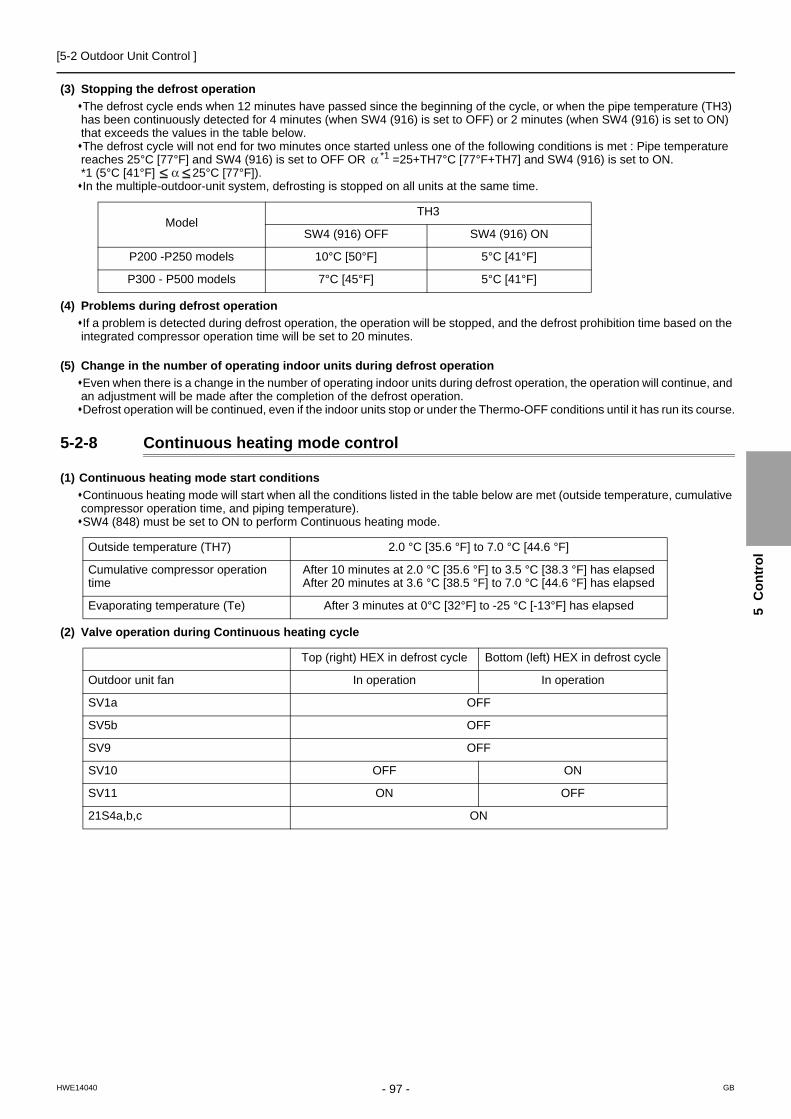
[5-2 Outdoor Unit Control ]
5 C
on
tro
l
(3) Stopping the defrost operation
The defrost cycle ends when 12 minutes have passed since the beginning of the cycle, or when the pipe temperature (TH3) has been continuously detected for 4 minutes (when SW4 (916) is set to OFF) or 2 minutes (when SW4 (916) is set to ON) that exceeds the values in the table below.The defrost cycle will not end for two minutes once started unless one of the following conditions is met : Pipe temperature reaches 25°C [77°F] and SW4 (916) is set to OFF OR *1 =25+TH7°C [77°F+TH7] and SW4 (916) is set to ON.*1 (5°C [41°F] 25°C [77°F]).In the multiple-outdoor-unit system, defrosting is stopped on all units at the same time.
(4) Problems during defrost operation
If a problem is detected during defrost operation, the operation will be stopped, and the defrost prohibition time based on the integrated compressor operation time will be set to 20 minutes.
(5) Change in the number of operating indoor units during defrost operation
Even when there is a change in the number of operating indoor units during defrost operation, the operation will continue, and an adjustment will be made after the completion of the defrost operation.Defrost operation will be continued, even if the indoor units stop or under the Thermo-OFF conditions until it has run its course.
5-2-8 Continuous heating mode control
(1) Continuous heating mode start conditions
Continuous heating mode will start when all the conditions listed in the table below are met (outside temperature, cumulative compressor operation time, and piping temperature).SW4 (848) must be set to ON to perform Continuous heating mode.
(2) Valve operation during Continuous heating cycle
ModelTH3
SW4 (916) OFF SW4 (916) ON
P200 -P250 models 10°C [50°F] 5°C [41°F]
P300 - P500 models 7°C [45°F] 5°C [41°F]
Outside temperature (TH7) 2.0 °C [35.6 °F] to 7.0 °C [44.6 °F]
Cumulative compressor operation time
After 10 minutes at 2.0 °C [35.6 °F] to 3.5 °C [38.3 °F] has elapsedAfter 20 minutes at 3.6 °C [38.5 °F] to 7.0 °C [44.6 °F] has elapsed
Evaporating temperature (Te) After 3 minutes at 0°C [32°F] to -25 °C [-13°F] has elapsed
Top (right) HEX in defrost cycle Bottom (left) HEX in defrost cycle
Outdoor unit fan In operation In operation
SV1a OFF
SV5b OFF
SV9 OFF
SV10 OFF ON
SV11 ON OFF
21S4a,b,c ON
- 97 -HWE14040 GB

[5-2 Outdoor Unit Control ]
5-2-9 Refrigerant Recovery Control
Recovery of refrigerant is performed during heating operation to prevent the refrigerant from accumulating inside the unit while it is stopped (unit in fan mode), or inside the indoor unit that is in cooling mode or in heating mode with thermo off. It is also performed during cooling operation to prevent an excessive amount of refrigerant from accumulating in the outdoor heat ex-changer. It is also performed during cooling operation to prevent an excessive amount of refrigerant from accumulating in the outdoor heat exchanger.
(1) During heating operation
Starting refrigerant recovery modeThe refrigerant recovery mode in heating starts when all of the following three conditions are met:15 minutes have passed since the completion of previous refrigerant recovery.TH4 > 115°C [239°F]Frequencies below 50 Hz
Refrigerant recovery1) Refrigerant is recovered with the LEV on the applicable indoor unit (unit under stopping mode, fan mode, cooling, heating with
thermo off) being opened for 30 seconds.
2) Periodic capacity control of the outdoor units and periodic LEV control of the indoor units will be suspended during refrigerant recovery operation; they will be performed after the recovery has been completed.
(2) During cooling operation
Starting refrigerant recovery modeThe refrigerant recovery mode starts when all the following conditions are met:30 minutes have passed since the completion of previous refrigerant recovery.When the unit keeps running for 3 minutes in a row or more with high discharge temperatureTH4 > 105°C [221°F] or 63HS1 > 3.43 MPa [497 psi] (35 kg/cm2G) and SC0 > 10°C [18°F]
Refrigerant recoveryThe opening of LEV1 is increased and periodic control begins again.
Opening of LEV during refrigerant recoveryOpening of indoor unit LEV: 400 pulses
Initial opening of LEVStart Finish
30 seconds
- 98 -HWE14040 GB

[5-2 Outdoor Unit Control ]
5 C
on
tro
l
5-2-10 Outdoor Unit Fan Control
(1) Control method
Depending on the capacity required, the rotation speed of the outdoor unit fan is controlled by the inverter, targeting a constant evaporation temperature of (0°C [32°F]= 0.71 MPa [103 psi]) during cooling operation and constant condensing temperature of (49°C [120°F]= 2.88 MPa [418 psi]) during heating operation. The OS in the multiple-outdoor-unit system operates at the actual outdoor unit fan control value that is calculated by the OS based on the preliminary outdoor unit fan control value that the OC determines.
(2) Control
Outdoor unit fan stops while the compressor is stopped (except in the presence of input from snow sensor).The fan operates at full speed for 5 seconds after start-up.(Only when TH7<0°C [32°F])The outdoor unit fan stops during defrost operation.
5-2-11 Subcool Coil Control (Linear Expansion Valve 1)
The OC, OS1, and OS2 controls the subcool coil individually.The LEV is controlled every 30 seconds to maintain constant the subcool at the outdoor unit heat exchanger outlet that is calculated from the values of high pressure (63HS1) and liquid piping temperature (TH3), or the superheat that is calculated from the values of low pressure (63LS) and the bypass outlet temperature (TH2) of the subcool coil.LEV opening is controlled based on the values of the inlet (TH6) and the outlet (TH3) temperatures of the subcool coil, high pressure (63HS1), and discharge temperature (TH4). In a single-outdoor-unit system, the LEV is closed (0) in the heating mode, while the compressor is stopped, and during cooling Thermo-OFF. In a multiple-outdoor-unit system, the LEV closes (0) during heating operation, while the compressor is stopped, or during cooling Thermo-OFF. The LEV opens to a specified position when 15 minutes have passed after Thermo-OFF. (65 pulses)During the defrost cycle, normally, the valve initially operates at 0 pulses, although it may operate at higher pulses depending on the 63LS and TH4 status.
5-2-12 Refrigerant Flow Control (Linear Expansion Valves 2a and 2b)
Refrigerant flow is controlled by each unit in the combined models during heating. Refrigerant flow control is performed by the OC, OS1, and OS2 individually. The valve opens to a specified angle during cooling (Opening: 2100 pulses)Valve opening is controlled based on the values of high pressure (63HS1), discharge temperature (TH4), low pressure( 63LS), and piping temperature (TH5). The valve moves to the predetermined position while the unit is stopped.The valve opening may increase to 3000 pulses during the defrost cycle or when the units are operated in unusual operating conditions.
5-2-13 Control at Initial Startup
When started up for the first time before 12 hours have elapsed after power on, the unit goes into the initial startup mode.At the completion of the initial operation mode on the OC, OS1, and OS2, they will go into the normal control mode.
(1) P200 - P500YKB models
50 F 60Hz
or F < 50Hz
Initial startup mode starts.
Completed in the integrated operation time of 35 minutes.
Initial startup mode complete
or the discharge superheat (TH4 - Tc) is detected (within 5 minutes of startup) that remains above approximately 25 degrees for one minute .
Completed in the integrated operation time of 90 minutes.
- 99 -HWE14040 GB

[5-2 Outdoor Unit Control ]
(2) P400 - P900YSKB models
1 Qj:Total capacity (models) codeFor information about capacity codes, refer to the following page(s).[5-1-2 Indoor Unit Switch Functions and Factory Set-tings](page 89)
The compressor on the OC starts up.
The total operating load of the indoor unit after 5 minutes of operation is P250 or above.
(*1 Qj 50)
Initial startup mode starts.
F 60Hz
Yes
No
or F < 50Hz (both OC and OS)Completed in the integrated operation time of 90 minutes.
The compressor on the OC remains in operation, and the compressor on the OS starts up.
or F < 50Hz (OC)Completed in the integrated operation time of 90 minutes.
The compressor on the OC starts up.
Both the OC and OS stop.The startup sequence of the OC and OS is rotated.
or F < 50Hz (OS)Completed in the integrated operation time of 90 minutes.
The compressor on the OS starts up.
*2
*3
*2The air conditioning load is too small for both the OC and the OS tosimultaneously stay in operation.*3The air conditioning load is high enough for both OC and OS tosimultaneously stay in operation.
Initial startup mode complete
or the discharge superheat (TH4 - Tc) is detected (within 5 minutes of startup) that remains above approximately 25 degrees for one minute .
or the discharge superheat (TH4 - Tc) is detected (within 5 minutes of startup) that remains above approximately 25 degrees for one minute .
or the discharge superheat (TH4 - Tc) is detected (within 5 minutes of startup) that remains above approximately 25 degrees for one minute .
50 F 60Hz (both OC and OS)Completed in the integrated operation time of 35 minutes.
50 F 60Hz (OC)Completed in the integrated operation time of 35 minutes.
50 F 60Hz (OS)Completed in the integrated operation time of 35 minutes.
- 100 -HWE14040 GB
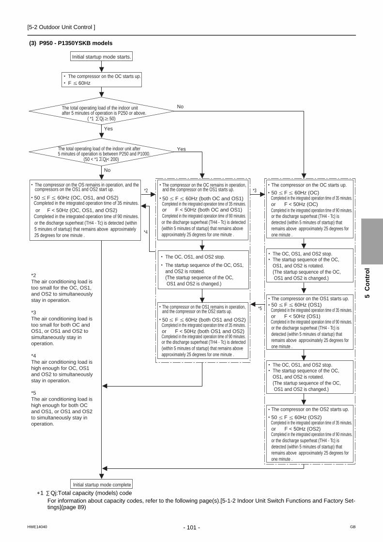
[5-2 Outdoor Unit Control ]
5 C
on
tro
l
(3) P950 - P1350YSKB models
1 Qj:Total capacity (models) codeFor information about capacity codes, refer to the following page(s).[5-1-2 Indoor Unit Switch Functions and Factory Set-tings](page 89)
Initial startup mode starts.
The compressor on the OC starts up. F 60Hz
The total operating load of the indoor unit after 5 minutes of operation is P250 or above.
( *1 Qj 50)
The total operating load of the indoor unit after 5 minutes of operation is between P250 and P1000.
(50 < *1 Qj< 200)
50 F 60Hz (OC, OS1, and OS2)
or F < 50Hz (OC, OS1, and OS2)Completed in the integrated operation time of 35 minutes.
Completed in the integrated operation time of 90 minutes.
The compressor on the OS remains in operation, and the compressors on the OS1 and OS2 start up.
50 F 60Hz (both OC and OS1)
or F < 50Hz (both OC and OS1)Completed in the integrated operation time of 35 minutes.
Completed in the integrated operation time of 90 minutes.
The compressor on the OC remains in operation, and the compressor on the OS1 starts up. 50 F 60Hz (OC)
or F < 50Hz (OC)Completed in the integrated operation time of 35 minutes.
Completed in the integrated operation time of 90 minutes.
The compressor on the OC starts up.
The OC, OS1, and OS2 stop.The startup sequence of the OC, OS1, and OS2 is rotated.(The startup sequence of the OC, OS1 and OS2 is changed.)
The OC, OS1, and OS2 stop.The startup sequence of the OC, OS1, and OS2 is rotated.(The startup sequence of the OC, OS1 and OS2 is changed.)
The OC, OS1, and OS2 stop.The startup sequence of the OC, OS1, and OS2 is rotated.(The startup sequence of the OC, OS1 and OS2 is changed.)
50 F 60Hz (OS1)
or F < 50Hz (OS1)Completed in the integrated operation time of 35 minutes.
Completed in the integrated operation time of 90 minutes.
The compressor on the OS1 starts up.
50 F 60Hz (OS2)
or F < 50Hz (OS2)Completed in the integrated operation time of 35 minutes.
Completed in the integrated operation time of 90 minutes.
The compressor on the OS2 starts up.
*2 *3
*4
*5
Yes
No
No
Yes
Initial startup mode complete
50 F 60Hz (both OS1 and OS2)Completed in the integrated operation time of 35 minutes.
Completed in the integrated operation time of 90 minutes.
The compressor on the OS1 remains in operation, and the compressor on the OS2 starts up.
or F < 50Hz (both OS1 and OS2)
*2The air conditioning load is too small for the OC, OS1, and OS2 to simultaneously stay in operation.
*3The air conditioning load is too small for both OC and OS1, or OS1 and OS2 to simultaneously stay in operation.
*4The air conditioning load is high enough for OC, OS1 and OS2 to simultaneously stay in operation.
*5The air conditioning load is high enough for both OC and OS1, or OS1 and OS2 to simultaneously stay in operation.
or the discharge superheat (TH4 - Tc) is detected (within 5 minutes of startup) that remains above approximately 25 degrees for one minute .
or the discharge superheat (TH4 - Tc) is detected (within 5 minutes of startup) that remains above approximately 25 degrees for one minute .
or the discharge superheat (TH4 - Tc) is detected (within 5 minutes of startup) that remains above approximately 25 degrees for one minute .
or the discharge superheat (TH4 - Tc) is detected (within 5 minutes of startup) that remains above approximately 25 degrees for one minute .
or the discharge superheat (TH4 - Tc) is detected (within 5 minutes of startup) that remains above approximately 25 degrees for one minute .
or the discharge superheat (TH4 - Tc) is detected (within 5 minutes of startup) that remains above approximately 25 degrees for one minute .
- 101 -HWE14040 GB

[5-2 Outdoor Unit Control ]
5-2-14 Emergency Operation Mode
1. Problems with the outdoor unitEmergency operation mode is a mode in which outdoor units that are operating normally take over the operation of the out-door units that are experiencing problems. (P400-P900YSKB models go into an emergency operation mode when one out-door unit is in trouble, and P950-P1350YSKB models go into an emergency operation mode when one or two outdoor units are in trouble.)This mode can be started by performing an error reset via the remote controller.
(1) Starting the emergency operation
1) When an error occurs, the error source and the error code will be displayed on the display on the remote controller.2) The error is reset using the remote controller.3) If an error code appears that permits an emergency operation in step 1) above, (See the table below.), the retry operation
starts.4) If the same error is detected during the retry operation (step 3 above), an emergency operation can be started by resetting
the error via the remote controller.Error codes that permit an emergency operation (Applicable to both OC and OS)
Emergency operation pattern (2 outdoor units)
Trouble source Error codes that permit an emergency operation
Error code description
CompressorFan motorInverter
0403 Serial communication error
4220,4225,4226 Bus voltage drop
4230,4235 Heatsink overheat protection
4240,4245 Overload protection
4250,4255,4256 Overcurrent relay trip
5110 Heatsink temperature sensor failure (THHS)
5120 DCL temperature sensor circuit fault
5301 Current sensor/circuit failure
5305,5306 Position error
Thermistor TH2 5102 Subcool heat exchanger bypass outlet temperature sensor failure
TH3 5103 Pipe temperature sensor failure
TH4 5104 Discharge temperature sensor failure
TH5 5105 Accumulator inlet temperature sensor failure
TH6 5106 Subcool heat exchanger liquid outlet sensor failure
TH7 5107 Outside air temperature sensor failure
TH9 5109 Continuous heating temperature sensor fault
TH11 5111 Continuous heating temperature sensor fault
Power 4102 Open phase
4115 Power supply sync signal abnormality
OC
OC failure patternTroubleNormalPermitted PermittedPermitted Permitted
60%
CoolingHeating
NormalTrouble
OS failure pattern
OSEmergency operation
Maximum total capacity of indoor units (Note 1)
- 102 -HWE14040 GB

[5-2 Outdoor Unit Control ]
5 C
on
tro
l
Emergency operation pattern (3 outdoor units)
(2) Ending the emergency operation
1) End conditions
When one of the following conditions is met, emergency operation stops, and the unit makes an error stop.When the integrated operation time of compressor in cooling mode has reached four hours.When the integrated operation time of compressor in heating mode has reached two hours.When an error is detected that does not permit the unit to perform an emergency operation.
2) Control at or after the completion of emergency operation
At or after the completion of emergency operation, the compressor stops, and the error code reappears on the remote con-troller.If another error reset is performed at the completion of an emergency mode, the unit repeats the procedures in section (1) above.To stop the emergency mode and perform a current-carrying operation after correcting the error, perform a power reset.
2. Communication circuit failure or when some of the outdoor units are turned offThis is a temporary operation mode in which the outdoor unit that is not in trouble operates when communication circuit failure occurs or when some of the outdoor units are turned off.
(1) Starting the emergency operation (When the OC is in trouble)
1) When an error occurs, the error source and the error code appear on the display on the remote controller.2) Reset the error via the remote controller to start an emergency operation.
Precautions before servicing the unitWhen the OC is in trouble, the OS temporarily takes over the OC's function and performs an emergency operation. When this happens, the indoor unit connection information are changed.In a system that has a billing function, a message indicating that the billing system information has an error may appear on the TG-2000A. Even if this message appears, do not change (or set) the refrigerant system information on the TG-2000A. After the completion of an emergency operation, the correct connection information will be restored.
OC
OC failure pattern
Trouble Trouble TroubleNormalNormal NormalNormal
Normal Normal
60% 40%
CoolingHeating
Normal Normal NormalTrouble
Trouble Trouble TroubleTrouble Trouble
OS1 failure pattern
OS2 failure pattern
OC, OS1 failure pattern
OC, OS2 failure pattern
OS1, OS2 failure pattern
OS1OS2Emergency operationMaximum total capacity of indoor units (Note 1)
(Note 1) If an attempt is made to put into operation a group of indoor units whose total capacity exceeds the maximum allowable capacity, some of the indoor units will go into the same condition as Thermo-OFF.
PermittedPermitted
PermittedPermitted
PermittedPermitted
PermittedPermitted
PermittedPermitted
PermittedPermitted
- 103 -HWE14040 GB

[5-2 Outdoor Unit Control ]
(2) Starting the emergency operation (When the OS is in trouble)
1) A communication error occurs. → An emergency operation starts in approximately six minutes.
Error codes that permit an emergency operation (Applicable to both OC and OS)
Emergency operation pattern (2 outdoor units)
Emergency operation pattern (3 outdoor units)
(3) Ending the emergency operation
When communication is restored, the emergency mode is cancelled, and the units go into the normal operation mode.
Trouble source
Circuit board failure or the power to the outdoor units is off
66076608
No acknowledgement errorNo response error
Error codes that permit an emergency operation Error code description
OC
CoolingHeating
OC failure patternTroubleNormalPermitted PermittedPermitted Permitted
NormalTrouble
OS failure pattern
OSEmergency operation
Maximum total capacity of indoor units (Note 1)
Capacity that matches the total capacity of the operable outdoor units
OC
OC failure pattern
Trouble Trouble TroubleNormalNormal NormalNormal
Normal Normal
CoolingHeating
Normal Normal NormalTrouble
Trouble Trouble TroubleTrouble Trouble
OS1 failure pattern
OS2 failure pattern
OC, OS1 failure pattern
OS1OS2Emergency operationMaximum total capacity of indoor units (Note 1) Capacity that matches the total capacity of the operable outdoor units
(Note 1) If an attempt is made to put into operation a group of indoor units whose total capacity exceeds the maximum allowable capacity, some of the indoor units will go into the same condition as Thermo-OFF.
PermittedPermitted
PermittedPermitted
PermittedPermitted
PermittedPermitted
PermittedPermitted
PermittedPermitted
OC, OS2 failure pattern
OS1, OS2 failure pattern
- 104 -HWE14040 GB

[5-2 Outdoor Unit Control ]
5 C
on
tro
l
5-2-15 Operation Mode
(1) Indoor unit operation mode
The operation mode can be selected from the following 5 modes using the remote controller.
(2) Outdoor unit operation mode
When the outdoor unit is performing a cooling operation, the operation mode of the connected indoor units that are not in the cooling mode (Stopped, Fan, Thermo-OFF) cannot be changed to heating from the remote controller. If this attempt is mode, "Heating" will flash on the remote controller. The opposite is true when the outdoor unit is performing a heating operation. (The first selection has the priority.)
5-2-16 Demand Control
Cooling/heating operation can be prohibited (Thermo-OFF) by an external input to the indoor units.
When DIP SW6-8 is set to ON, the 4-step DEMAND control is enabled.Eight-step demand control is possible in the system with two outdoor units.Twelve-step demand control is possible in the system with three outdoor units.
For details, refer to the following page(s). [2-4-7 Various Control Methods Using the Signal Input/Output Connector on Outdoor Unit](page 25)
5-2-17 Control of IH energization without the compressor in operation (not applicable to the P450 and P500 models)
IH is used to heat the compressor motor on the stopped outdoor unit to make liquid refrigerant in the compressor evaporate or to keep liquid refrigerant from flooding the compressor.
Initial power on after power is turned on: Stays on for 12 hours, and then transitions to the operation that is performed while the compressor is stoppedWhen the compressor is stopped: Stays off for 30 minutes after the compressor stopped, and then repeats the on-off cycle at 30-minute intervalsLit LED1 on the INV board indicates that the INV board is energized by an IH.
5-2-18 Compressor heater control (P450 and P500 models)
When the outdoor unit is stopped, the heater wrapped around the compressor heats up the compressor to evaporate the ac-cumulated liquid refrigerant and prevent liquid refrigerant accumulating in the compressor.
It is always energized when the compressor is stopped.
1 Cooling mode
2 Heating mode
3 Dry mode
4 Fan mode
5 Stopping mode
1 Cooling mode All indoor units in operation are in cooling mode.
2 Heating mode All indoor units in operation are in heating mode.
3 Stopping mode All indoor units are in fan mode or stopping mode.
- 105 -HWE14040 GB

[5-3 Operation Flowcharts ]
5-3 Operation Flowcharts
5-3-1 Operation Sequence Flowchart
(1) Indoor unit (cooling, heating, dry, fan mode)
*Note 1. Indoor unit LEV fully closed : Opening 41.*Note 2. The system may go into the error mode on either the indoor unit or the outdoor unit side. If some of the indoor units are experiencing a problem (except water leakage), only those indoor units that are experiencing the problems will stop. If the outdoor unit is experiencing a problem, all connected indoor units will stop.*Note 3. The operation will be prohibited when the set cooling/heating mode is different from that of the outdoor unit.
Start
Remote controller display lit off
Error mode
Error stop
Error display
Self-holding of protection function
Error command to outdoor unit
Indoor unit LEV fully closed.
Refer to 5-3-2 (1)Cooling operation.
Refer to 5-3-2 (2)Heating operation.
Refer to 5-3-2 (3) for dry operation.
ProhibitionProhibitionProhibition
Dry displayHeating displayCooling display
Dry modeHeating mode Fan mode
Fan display
Fan operations
Operation mode
Cooling mode
Operation command to outdoor unit (to 2 )
Prohibition"Blinking display on
the remote controller"
FAN stop
Breaker turned on
Operation SW turned on
Auxiliary heaterON
Drain pumpON
3-minute drain pump ON
NO
NO
NO
NO
NONO NO NO
*Note 1
*Note 2
*Note 1
*Note 3 *Note 3 *Note 3
1. Protection function self-holding cancelled.2. Indoor unit LEV fully closed.
1. Auxiliary heater OFF2. Low fan speed for 1 minute
YES
YES
YES
YESYES YES YES
YES
Normal operation
ErrorUnit in the stopped state
From outdoor unit1
- 106 -HWE14040 GB

[5-3 Operation Flowcharts ]
5 C
on
tro
l
(2) Outdoor unit (cooling and heating modes)
*Note 1. For about 3 minutes after power on, search for the indoor unit address, for the remote controller address, and for the group information will start. During this, "HO" / "PLEASE WAIT" blinks on the display of the remote controller. When the indoor unit to be controlled by the remote controller is missing, "HO" / "PLEASE WAIT" keeps blinking on the display of the remote controller even after 3 or more minutes after power on. *Note 2. The system may go into the error mode on either the indoor unit or the outdoor unit side. The outdoor stops only when all of the connected indoor units are experiencing problems. The operation of even a single indoor unit will keep the outdoor unit running. The error will be indicated on the LED display. *Note 3. The outdoor unit operates according to the operation mode commanded by the indoor unit. However, when the outdoor unit is running a cooling operation, come of the operating indoor units will stop, or the operation of these indoor units will be prohibited even when the indoor unit mode is switched from fan mode to heating mode. This also applies when the outdoor unit is running a heating operation.
Start
Breaker turned on
Operation command
Error stop
Error display on the outdoor unit LED
Error command to indoor unit
Operation mode
Operation mode
Error mode
72C ON
*Note 1
*Note 3
*Note 2
YES
YES
YES
YES
NO
NO
NO
NO
"HO" / "PLEASE WAIT" blinks on the remote controller
Operation command to indoor unit To 1 .
Cooling / Heating
1. Protection function self-holding cancelled. 2. LEV1 fully closed.
Normal operation
1. 72C OFF 2. Inverter output 0Hz 3. Fan stop 4. All solenoid valves OFF
Refer to Cooling/Dry Operation 5-3-2 (1) and 5-3-2 (3).
Refer to heating Operation 5-3-2 (2).
2 From indoor unit
Error
Unit in the stopped state
Self-holding of protection function
Indoor units registered to the remote controller
- 107 -HWE14040 GB

[5-3 Operation Flowcharts ]
5-3-2 Actions Performed in Different Modes
(1) Cooling operation
*Note 1. The indoor fan operates at the set notch under cooling mode regardless of the ON/OFF state of the thermostat.
Cooling operation
Test run mode ON
Thermostat ON
3-minute restart prevention
*Note 1
YES
YES
YES
NO
NO
NO
4-way valve OFF
1. Inverter frequency control2. Indoor unit LEV, LEV1 control LEV2 fully opened3. Solenoid valve control4. Outdoor unit fan control5. 72C control
Normal operation
During test run mode
Unit in the stopped state
Indoor unit fan operation
1. Inverter output 0Hz2. Indoor unit LEV, LEV1 LEV2 rated opening3. All solenoid valves OFF4. Outdoor unit fan stop5. 72C OFF6. Compressor motor becomes energized. Crankcase heater energized for P450 and P500 models.
- 108 -HWE14040 GB

[5-3 Operation Flowcharts ]
5 C
on
tro
l
(2) Heating operation
1) When outdoor unit starts defrosting, it transmits defrost operations command to indoor unit, and the indoor unit start defrosting operations. Similarly when defrosting operation stops, indoor unit returns to heating operation after receiving defrost end com-mand of outdoor unit.
2) Defrost end condition: 12 minutes have passed since defrost operation started.Outdoor unit pipe temperature: Refer to the following page(s).[5-2-7 Defrost Operation Control](page 96)
Heating operation
Test run mode ON
Thermostat ON
Defrost operation
3-minute restart prevention
*Note 1,2
*Note 1,2
YES
YES
YES
YES
YES
NO
NO
NO
NO
NO
1. Indoor/outdoor unit fan control2. Inverter frequency control3. Indoor unit LEV, LEV1,LEV2 control4. Solenoid valve control5. 72C control
Normal operation
Defrost operation
4-way valve ON
During test run mode
1. Indoor unit fan operation at Very Low speed2. Inverter output 0Hz3. Indoor unit LEV, LEV1 Fully closed LEV2 rated opening4. All solenoid valves OFF5. Outdoor unit fan stop6. 72C OFF7. Compressor motor becomes energized. Crankcase heater energized for P450 and P500 models.
4-way valve OFF
Stopping the defrost operation
Stopping the defrost operation
Return to heating operation
1. Indoor unit fan stops2. Inverter defrost frequency control3. Indoor unit LEV fully closed.4. Solenoid valve control5. Outdoor unit fan stop6. LEV1 control7. LEV2 fully opened.8. 72C control
Unit in the stopped state
- 109 -HWE14040 GB

[5-3 Operation Flowcharts ]
(3) Dry operation
Dry operation
*Note 1
*Note 2
YES
YES
NO
NO
4-way valve OFF
1. Outdoor unit (compressor) intermittent operation 2. Indoor unit fan intermittent operations (Synchronized with the compressor: low speed, OFF operations)
Normal operation
Thermostat ON
Thermostat ON
1. Indoor unit fan stop2. Inverter output 0Hz3. Indoor unit LEV, LEV1 fully closed. LEV2 rated opening.4. Solenoid valve OFF5. Outdoor unit fan stop6. 72C OFF7. Compressor motor becomes energized. Crankcase heater energized for P450 and P500 models.
1 or 2
*Note 1.When the indoor unit inlet temperature exceeds 18°C [64°F], the outdoor unit (compressor) and the indoor unit fan start the intermittent operation simultaneously. When the indoor unit inlet temperature becomes 18°C [64°F],or less, the fan always runs (at low speed). The outdoor unit, the indoor unit, and the solenoid valve operate in the same way as they do in the cooling operation when the compressor is turned on.
*Note 2.Thermostat is always kept on during test run mode, and indoor and outdoor unit intermittent operation (ON) time is a little longer than that of normal operation.
Test run mode ON
Suction temperature 18°C[64°F]
Unit in the stopped state
- 110 -HWE14040 GB

- 111 -HWE14040 GB
Chapter 6 Test Run
6-1 Read before Test Run....................................................................................................................... 113
6-2 MA and ME Remote Controller Functions and Specifications ..................................................... 114
6-2-1 Function/Specification Comparison .................................................................................................... 114
6-2-2 Local Remote Controller Selection Tips.............................................................................................. 114
6-3 Making the Group and Interlock Settings from an ME Remote Controller.................................. 115
6-3-1 Overview ............................................................................................................................................. 115
6-3-2 Address Registration........................................................................................................................... 115
6-3-3 Address Search .................................................................................................................................. 117
6-3-4 Address Deletion................................................................................................................................. 118
6-3-5 Making Group and Interlock Settings from Another Remote Controller.............................................. 118
6-4 Selecting Remote Controller Functions from an ME Remote Controller .................................... 119
6-5 Making Interlock Settings from an MA Remote Controller ........................................................... 121
6-5-1 MA Remote Controller (PAR-31MAA)................................................................................................. 121
6-5-2 MA Remote Controller (PAR-21MAA)................................................................................................. 122
6-5-3 MA Simple Remote Controller ............................................................................................................ 124
6-6 Changing the Room Temperature Detection Position .................................................................. 127
6-7 Test Run Method............................................................................................................................... 128
6-7-1 MA Remote Controller (PAR-31MAA)................................................................................................. 128
6-7-2 MA Remote Controller (PAR-21MAA)................................................................................................. 130
6-8 Operation Characteristics and Refrigerant Charge ....................................................................... 131
6-9 Evaluating and Adjusting Refrigerant Charge ............................................................................... 131
6-9-1 Refrigerant Overcharge and undercharge .......................................................................................... 131
6-9-2 Checking the Refrigerant Charge during Operation............................................................................ 131
6-9-3 The Amount of Refrigerant to Be Added............................................................................................. 132
6-9-4 Refrigerant Charge Adjustment Mode ................................................................................................ 135
6-10 The Following Symptoms Are Normal ............................................................................................ 137
6-11 Standard Operation Data (Reference Data) .................................................................................... 138
6-11-1 Single Unit (Standard)......................................................................................................................... 138
6-11-2 Dual Unit Combination (Standard) ...................................................................................................... 142
6-11-3 Triple Unit Combination (Standard) .................................................................................................... 153

- 112 -HWE14040 GB
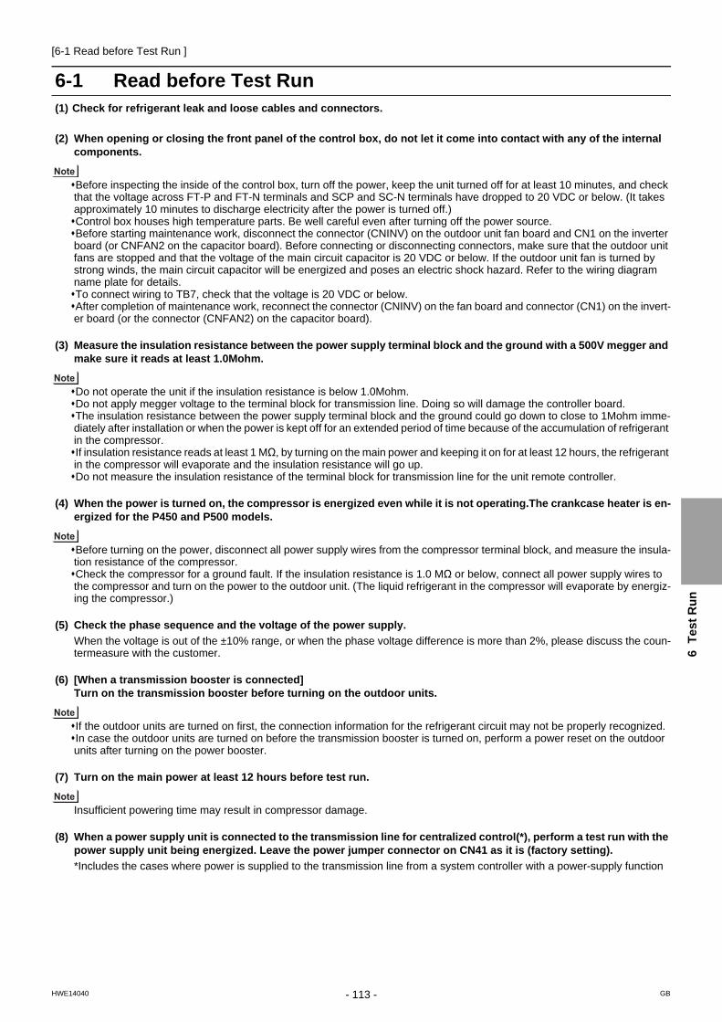
[6-1 Read before Test Run ]
6
Te
st
Ru
n
6 Test Run
6-1 Read before Test Run(1) Check for refrigerant leak and loose cables and connectors.
(2) When opening or closing the front panel of the control box, do not let it come into contact with any of the internal components.
Before inspecting the inside of the control box, turn off the power, keep the unit turned off for at least 10 minutes, and check that the voltage across FT-P and FT-N terminals and SCP and SC-N terminals have dropped to 20 VDC or below. (It takes approximately 10 minutes to discharge electricity after the power is turned off.)Control box houses high temperature parts. Be well careful even after turning off the power source.Before starting maintenance work, disconnect the connector (CNINV) on the outdoor unit fan board and CN1 on the inverter board (or CNFAN2 on the capacitor board). Before connecting or disconnecting connectors, make sure that the outdoor unit fans are stopped and that the voltage of the main circuit capacitor is 20 VDC or below. If the outdoor unit fan is turned by strong winds, the main circuit capacitor will be energized and poses an electric shock hazard. Refer to the wiring diagram name plate for details.To connect wiring to TB7, check that the voltage is 20 VDC or below.After completion of maintenance work, reconnect the connector (CNINV) on the fan board and connector (CN1) on the invert-er board (or the connector (CNFAN2) on the capacitor board).
(3) Measure the insulation resistance between the power supply terminal block and the ground with a 500V megger and make sure it reads at least 1.0Mohm.
Do not operate the unit if the insulation resistance is below 1.0Mohm.Do not apply megger voltage to the terminal block for transmission line. Doing so will damage the controller board.The insulation resistance between the power supply terminal block and the ground could go down to close to 1Mohm imme-diately after installation or when the power is kept off for an extended period of time because of the accumulation of refrigerant in the compressor.If insulation resistance reads at least 1 MΩ, by turning on the main power and keeping it on for at least 12 hours, the refrigerant in the compressor will evaporate and the insulation resistance will go up.Do not measure the insulation resistance of the terminal block for transmission line for the unit remote controller.
(4) When the power is turned on, the compressor is energized even while it is not operating.The crankcase heater is en-ergized for the P450 and P500 models.
Before turning on the power, disconnect all power supply wires from the compressor terminal block, and measure the insula-tion resistance of the compressor.Check the compressor for a ground fault. If the insulation resistance is 1.0 MΩ or below, connect all power supply wires to the compressor and turn on the power to the outdoor unit. (The liquid refrigerant in the compressor will evaporate by energiz-ing the compressor.)
(5) Check the phase sequence and the voltage of the power supply.
When the voltage is out of the ±10% range, or when the phase voltage difference is more than 2%, please discuss the coun-termeasure with the customer.
(6) [When a transmission booster is connected]Turn on the transmission booster before turning on the outdoor units.
If the outdoor units are turned on first, the connection information for the refrigerant circuit may not be properly recognized.In case the outdoor units are turned on before the transmission booster is turned on, perform a power reset on the outdoor units after turning on the power booster.
(7) Turn on the main power at least 12 hours before test run.
Insufficient powering time may result in compressor damage.
(8) When a power supply unit is connected to the transmission line for centralized control(*), perform a test run with the power supply unit being energized. Leave the power jumper connector on CN41 as it is (factory setting).
*Includes the cases where power is supplied to the transmission line from a system controller with a power-supply function
- 113 -HWE14040 GB

[6-2 MA and ME Remote Controller Functions and Specifications ]
6-2 MA and ME Remote Controller Functions and SpecificationsThere are two types of remote controllers: ME remote controller, which is connected on the indoor-outdoor transmission line, and MA remote controller, which is connected to each indoor unit.
6-2-1 Function/Specification Comparison
6-2-2 Local Remote Controller Selection Tips
MA remote controller and ME remote controller have different functions and characteristics. Choose the one that better suits the requirements of a given system. Use the following criteria as a reference.
Functions/specifications MA remote controller*1*2
*1. MA remote controller refers to MA remote controller (PAR-31MAA, PAR-21MAA), MA simple remote controller, and wire-less remote controller.
*2. Either the MA remote controller or the ME remote controller can be connected when a group operation of units in a sys-tem with multiple outdoor units is conducted or when a system controller is connected.
ME remote controller*2*3
*3. ME remote controller refers to ME remote controller and ME simple remote controller.
Remote controller address settings Not required Required
Indoor/outdoor unit address set-tings
Not required (required only by a system with one outdoor unit)*4
*4. Depending on the system configuration, some systems with one outdoor unit may require address settings.
Required
Wiring method Non-polarized 2-core cableTo perform a group operation, daisy-
chain the indoor units using non-polar-ized 2-core cables.
Non-polarized 2-core cable
Remote controller connection Connectable to any indoor unit in the group
Connectable anywhere on the indoor-out-door transmission line
Interlock with the ventilation unit Each indoor unit can individually be in-terlocked with a ventilation unit. (Set up via remote controller in the group.)
Each indoor unit can individually be inter-locked with a ventilation unit. (Set up via remote controller.)
Changes to be made upon group-ing change
MA remote controller wiring between in-door units requires rewiring.
Either the indoor unit address and remote controller address must both be changed, or the registration information must be changed via MELANS.
MA remote controller*1*2
*1. ME remote controller and MA remote controller cannot both be connected to the same group of indoor units.
*2. A system controller must be connected to a system to which both MA remote controller and ME remote controller are con-nected.
ME remote controller*1*2
There is little likelihood of system expansion and grouping changes.Grouping (floor plan) has been set at the time of in-stallation.
There is a likelihood of centralized installation of remote control-lers, system expansion, and grouping changes.Grouping (floor plan) has not been set at the time of installation.To connect the remote controller directly to the OA processing
unit.
<System with MA remote controller> <System with ME remote controllers>
MA remote controller
Outdoor unit
Indoor unit
M-NET transmission line (indoor/outdoor transmission line)
groupgroup
ME remote controller
Outdoor unit
Indoor unit
M-NET transmission line(indoor/outdoor transmission line)
groupgroup
- 114 -HWE14040 GB

[6-3 Making the Group and Interlock Settings from an ME Remote Controller ]
6
Te
st
Ru
n
6-3 Making the Group and Interlock Settings from an ME Remote Controller
6-3-1 Overview
6-3-2 Address Registration
Make the following settings to perform a group operation of units that are connected to different outdoor units or to manually set up the indoor/outdoor unit address. (A) Group settings...........Registration of the indoor units to be controlled with the remote controller, and search and deletion of registered information. (B) Interlock settings........Registration of LOSSNAY units to be interlocked with the indoor units, and search and deletion of registered information
[Normal display]
Register the indoor unit to be controlled with the remote controller. Bring up either the blinking display of HO by turning on the unit or the normal display by pressing the ON/OFF button. The display window must look like one of the two figures below to proceed to the next step.
1
[Blinking display of HO ]
? A F
D
B H
G
C
EPAR-F27MEA
ON/OFF
CENTRALLY CONTROLLEDDAILY
AUTO OFF
REMAINDERCLOCK
ON OFF
˚C
CHECK MODEFILTER
TEST RUNLIMIT TEMP.
˚C1Hr.
NOT AVAILABLESTAND BY DEFROST
FILTER
CHECK TEST
TEMP.
TIMER SET
CLOCK ON OFF
- 115 -HWE14040 GB

[6-3 Making the Group and Interlock Settings from an ME Remote Controller ]
<Deletion error>
(B) Interlock Settings (A) Group Settings
Indoor unit address display window Indoor unit address display window
Interlocked unit address display window
2 Bring up the Group Setting window. -Press and hold buttons [FILTER] and [ ] simultaneously for 2 seconds to bring up the display as shown below.
3
A
C
D
B
Select the unit address. - Select the address of the indoor unit to be registered by pressing button [TEMP. ( ) or ( )] to advance or go back through the addresses. Register the indoor unit whose address appears on the display. - Press button [TEST] to register the indoor unit address whose address appears on the display. - If registration is successfully completed, unit type will appear on the display as shown in the figure below. - If the selected address does not have a corresponding indoor unit, an error message will appear on the display. Check the address, and try again.
5
<Successful completion of registration>
Unit type (Indoor unit in this case)
blinks to indicate a registration error.(Indicates that selected address does not have a corresponding unit.)
4
To register the addresses for multiple indoor units, repeat steps and above.3 4
Go to section 6-3-3 "Address Search" for how to search for an address.
Bring up the Interlock Setting window. -Press button [ ] to bring up the following display. Press again to go back to the Group Setting window as shown under step .
6G
2
Both the indoor unit address and interlocked unit address will be displayed together.
Bring up the address of the indoor unit and the address of the LOSSNAY to be interlocked on the display.- Select the address of the indoor unit to be registered by pressing button [TEMP. ( ) or ( )] to advance or go back through the addresses. - Select the address of the LOSSNAY unit to be interlocked by pressing button [TIMER SET ( ) or ( )] to advance or go back through the interlocked unit addresses.
7
8
C
H
Make the settings to interlock LOSSNAY units with indoor units.- Press button [TEST] while both the indoor unit address and the address of the LOSSNAY units to be interlocked are displayed to enter the interlock setting.- Interlock setting can also be made by bringing up the LOSSNAY address in the indoor unit address display window and the indoor unit address in the interlocked unit address display window.
D
(Displayed alternately)
If registration is successfully completed, the two displays as shown on the left will appear alternately.If the registration fails, will blink on the display.(Indicates that the selected address does not have a corresponding unit.)
NOTE : Interlock all the indoor units in the group with the LOSSNAY units; otherwise, the LOSSNAY units will not operate.
(C) To return to the normal displayWhen all the group settings and interlock settings are made, take the following step to go back to the normal display. Press and hold buttons [FILTER] and [ ] simultaneously for 2 seconds to go back to the window as shown in step .
Repeat steps 7 and 8 above until all the indoor units in the group are interlocked with the LOSSNAY unit.
To go back to the normal display, follow step .
10 A B
1
9
10
Go to section 6-3-3 "Address Search" for how to search for an address.
Go to section 6-3-3 "Address Search" for how to search for an address.
- 116 -HWE14040 GB

[6-3 Making the Group and Interlock Settings from an ME Remote Controller ]
6
Te
st
Ru
n
6-3-3 Address Search
<Entry found>
<No entries found>
To search for the address of indoor units that have been entered into the remote controller, follow steps and .
(A) To search group settings
Unit type (Indoor unit in this case)
- When only one unit address is registered, the same address will remain on the display regardless of how many times the button is pressed. - When the address of multiple units are registered (i.e. 011, 012, 013 ), they will be displayed one at a time in an ascending order with each pressing of button [ ] .
To go back to the normal display, follow step .
(Displayed alternately)
Bring up the address of another registered unit on the display. - After completing step , a subsequent pressing of button [ ] will bring up the address of another registered unit. (The display method is the same as the one in step .)
Address of an interlocked LOSSNAY unit
Address of another interlocked unit
Bring up on the display the address of the LOSSNAY unit that was interlocked with the indoor unit in step . - With each pressing of button [ ], the address of the LOSSNAY and indoor unit that is interlocked with it will be displayed alternately.
LOSSNAY can be searched in the same manner by bringing up the LOSSNAY address in the Interlocked unit address display window.
(B) Interlock setting search After performing step , proceed as follows:
Bring up the address of the indoor unit to be searched on the display. - Select the address of the indoor unit to be searched by pressing button [TIMER SET ( ) or ( )] to advance or go back through the interlocked addresses.
(Displayed alternately)
Refer to section 6-3-4 "Address Deletion" for how to delete an address.
Bring up the Group Setting window. - Each pressing of button [ ] will bring up the address of a registered indoor unit and its unit type on the display.
11 E
1 2
E
10
E
13
13
13
12
14
12
6
E
H
Refer to section 6-3-4 "Address Deletion" for how to delete an address.
- 117 -HWE14040 GB

[6-3 Making the Group and Interlock Settings from an ME Remote Controller ]
6-3-4 Address Deletion
6-3-5 Making Group and Interlock Settings from Another Remote Controller
The addresses of the indoor units that have been entered into the remote controller can be deleted by deleting the group settings.The interlock settings between units can be deleted by deleting the interlock settings.Follow the steps in section 6-3-3 Address Search to find the address to be deleted and perform deletion with the address being displayed in the display window. To delete an address, the address must first be bought up on the display. Delete the registered indoor unit address or the interlock setting between units. - Press button ? [CLOCK ON OFF] twice while either the indoor unit address or the address of the interlocked unit is displayed on the display to delete the interlock setting.
F15
(A) To delete group settings (B) To delete interlock settings
<Successful completion of deletion>
will be displayed in the room temperature display window.
- If a transmission error occurs, the selected setting will not be deleted, and the display will appear as shown below. In this case, repeat the steps above.
(Displayed alternately)
<Deletion error>
will be displayed in the room temperature display window.
If deletion is successfully completed, will appear in the unit type display window.If the deletion fails, will appear in the unit type display window. In this case, repeat the steps above.
- -
To go back to the normal display, follow step .10
(A) Group settings and (B) Interlock settings of a group can be made from any arbitrary remote controller.Refer to "(B) Interlock Settings" under section 6-3-1 "Overview" for operation procedures.Set the address as shown below.
(A) To make group settings Interlocked unit address display window...Remote controller address Indoor unit address display window...........The address of the indoor unit to be controlled with the remote controller
(B) To make interlock settings Interlocked unit address display window...LOSSNAY address Indoor unit address display window..........The address of the indoor unit to be interlocked with the LOSSNAY
- 118 -HWE14040 GB

[6-4 Selecting Remote Controller Functions from an ME Remote Controller ]
6
Te
st
Ru
n
6-4 Selecting Remote Controller Functions from an ME Remote Controller
In the remote controller function selection mode, the settings for four types of functions can be made or changed as necessary.
4) Narrowed preset temperature range mode The default temperature ranges are 19 C to 30 C in the cooling/dry mode and 17 C to 28 C in the heating mode and 19 C to 28 C in the auto mode. By changing these ranges (raising the lower limit for the cooling/dry mode and lowering the upper limit for the heating mode), energy can be saved.
When making the temperature range setting on the simultaneous cooling/heating type units that supports the automatic operation mode to save on energy consumption, enable the Skip-Auto-Mode setting to make the automatic operation mode unselectable. If the automatic operation mode is selected, the energy-saving function may not work properly.
When connected to the air conditioning units that do not support the automatic operation mode, the setting for the Skip-Auto-Mode, restricted preset temperature range mode (AUTO), and operation mode display selection mode are invalid. If an attempt is made to change the preset temperature range, “LIMIT TEMP.” appears on the display.
NOTE
[Normal display]
4
5
PAR-F27MEA
ON/OFF
FILTER
CHECK TEST
TEMP.
TIMER SET
CLOCK→ON→OFF
1
32
: Press and hold the [CHECK] and [ ] buttons simultaneously for two seconds.: [SET TEMP. ( ) ] button: [SET TEMP. ( ) ] button
3) Room temperature display selection mode (Display or non-display of room temperature) Although the suction temperature is normally displayed on the remote controller, the setting can be changed so that it will not appear on the remote controller.
2) Operation mode display selection mode (Display or non-display of COOL/HEAT during automatic operation mode) When the automatic operation mode is selected, the indoor unit will automatically perform a cooling or heating operation based on the room temperature. In this case, or will appear on the remote controller display. This setting can be changed so that only will appear on the display.
1) Skip-Auto-Mode setting The automatic operation mode that is supported by some simultaneous cooling/heating type units can be made unselectable via the ME remote controller.
[Function selection mode sequence on the remote controller]Normal display
1 1
3
3
3
2
2
232
32
32
32
Skip-Auto-Mode setting
*1 *1
*2
*2
Temperature range setting mode (AUTO)
Room temperature display selection mode *1 : Skip-Auto-Mode is enabled*2 : Skip-Auto-Mode is disabled
Operation mode display selection mode (Display or non-display of the automatic mode)
Restricted preset temperature range mode (Heating)
Restricted preset temperature range mode (Cooling)
Remote controller function selection mode
- 119 -HWE14040 GB

[6-4 Selecting Remote Controller Functions from an ME Remote Controller ]
[Lower limit temperature]: Appears in the preset temperature display window [Upper limit temperature: Appears in the time display window
[Settable range for the lower limit temperature] : 19 C 30 C (Settable up to the upper limit temperature that is shown on the display)[Settable range for the upper limit temperature] : 30 C 19 C (Settable up to the lower limit temperature that is shown on the display)
[Settable range for the lower limit temperature] : 17 C 28 C (Settable up to the upper limit temperature that is shown on the display) [Settable range for the upper limit temperature] : 28 C 17 C (Settable up to the lower limit temperature that is shown on the display)
[Settable range for the lower limit temperature] : 19 C 28 C (Settable up to the upper limit temperature that is shown on the display)[Settable range for the upper limit temperature] : 28 C 19 C (Settable up to the lower limit temperature that is shown on the display)
will light up in the display window, and the temperature range for the cooling/dry mode will appear on the display.
[Operation Procedures] 1. Press the [ON/OFF] button on the remote controller to bring the unit to a stop. The display will appear as shown in the previous page (Normal display). 2. Press buttons [CHECK] and [ ] simultaneously for 2 seconds to go into the “Skip-Auto-Mode setting.” under the remote controller function selection mode. Press button [SET TEMP. ( )] or [SET TEMP. ( )] to go into the other four modes under the remote controller function selection mode.
1 2 3
Skip-Auto-Mode setting (Making the automatic operation mode unselectable)
“ ” blinks and either “ON” or “OFF” lights up on the controller. Pressing the [TIMER SET ( ) or ( )] button switches between “ON” and “OFF.”
This setting is valid only when the controller is connected to the simultaneous cooling/heating type air conditioning units that support the automatic operation mode.
When set to “ON,” the automatic operation mode is available for selection in the function selection mode. When set to “OFF,” the automatic operation mode is not available for selection in the function selection mode, and an automatic operation cannot be performed. (The automatic operation mode is skipped in the function selection mode sequence.)
[The left figure shows the display that appears when the current temperature range setting is between 19 C and 30 C in the Cool/Dry mode, and the lower limit temperature is selected to be set.]
2) Temperature range setting for heating
4
Switch between the Lower and Upper limit temperature setting by pressing the [CLOCK-ON-OFF] button. The selected temperature setting blinks.
“ ” and the settable temperature range for heating appear on the display. As with the Cool/Dry mode, use the [CLOCK-ON-OFF] button and the [TIMER SET ( ) or ( )] to set the temperature range.
5
Room temperature display selection mode (Switching between the display or non-display of room temperature on the controller)
When set to “ON,” room temperature always appears on the display during operation. When set to “OFF,” room temperature does not appear on the display during operation.
5 4
“ ” and the temperature range for the automatic operation mode appear on the display. As with the Cool/Dry mode, use the [CLOCK-ON-OFF] button and the [TIMER SET ( ) or ( )] to set the temperature range. 5 4
3) Temperature range setting for the automatic mode
˚ C ˚ C
“ 88 C ” blinks and either “ON” or “OFF” lights up on the controller. Pressing the [TIMER SET ( ) or ( )] button switches between “ON” and “OFF.”
4
Operation mode display selection mode (Changing the type of display that appears during the automatic mode operation)
will blink, and either “ON”or “OFF” will light up. Press button [TIMER SET ( ) or ( )] in this state to switch between “ON” and “OFF.”
4
When it is set to ON, will appear on the display during automatic operation mode. When it is set to OFF, only will appear on the display during automatic operation mode.
When connected to the air conditioning units that do not support the automatic operation mode, the setting for this mode is invalid.
[TIMER SET ( ) (( ))] button
[TIMER SET ( ) (( ))] button
[TIMER SET ( ) (( ))] button
[TIMER SET ( ) (( ))] button
Restricted preset temperature range mode (The range of preset temperature can be changed.) 1) Temperature range setting for the cooling/dry mode
Press button [TIMER SET ( ) or ( )] to set the lower limit temperature to the desired temperature. 4
When connected to the air conditioning units that do not support the automatic operation mode, the setting for this mode is invalid.
- 120 -HWE14040 GB

[6-5 Making Interlock Settings from an MA Remote Controller ]
6
Te
st
Ru
n
6-5 Making Interlock Settings from an MA Remote ControllerLOSSNAY interlock setting (Make this setting only when necessary.)
6-5-1 MA Remote Controller (PAR-31MAA)
This setting is required only when the operation of City Multi units is interlocked with LOSSNAY units. This setting is not available for the Mr. Slim units. Interlock settings can be made for the indoor unit to which the remote controller is connected. (They can also be confirmed or deleted.)
Note: Use the centralized controller to make the settings if it is connected.To interlock the operation of the indoor units with the LOSSNAY units, be sure to interlock the addresses of ALL indoor units in the group and that of the LOSSNAY unit.
[Button operation][1] When "Lossnay" on the Service
menu is selected, the remote controller will automatically begin searching for the registered LOSSNAY addresses of the currently connected indoor unit.
[2] When the search is completed, the smallest address of the indoor units that are connected to the remote controller and the address of the interlocked LOSSNAY unit will appear. "--" will appear if no LOSSNAY unit is interlocked with the indoor units.
If no settings need to be made, press the RETURN button to go back to the Service menu.
To make LOSSNAY interlock setting
[3] Enter the addresses of the indoor unit and the LOSSNAY unit to be interlocked, with the F1 through F4 buttons, select "Set" in the "Function", and press the SELECT button to save the settings. "Sending data" will appear on the screen. If the setting is successfully completed, "Setting completed" will appear.
LossnayIU addressLossnay address
Collecting data
Lossnay
Cursor AddressSelect:
IU addressLossnay addressFunction Set/Conf/Del.
LossnayLossnay
Return:
IU addressLossnay address
IU addressLossnay address
Sending data Setting completed
To search for the LOSSNAY address
[4] Enter the address of the indoor unit to which the remote controller is connected, select "Conf" in the "Function", and press the SELECT button. "Collecting data" will appear on the screen. If the signal is received correctly, the indoor unit address and LOSSNAY address will appear. "--" will appear when no LOSSNAY unit is found. "Unit not exist" will appear if no indoor units that are correspond to the entered address are found.
To delete the interlock setting
[5] To delete the interlocked setting between LOSSNAY unit and the indoor units to which the remote controller is connected, enter the indoor unit address and LOSSNAY address with the F1 through F4 buttons, select "Del." in the "Function", and press the SELECT button. "Deleting" will appear. The screen will return to the search result screen if the deletion is successfully completed. "Unit not exist" will appear if no indoor units that are correspond to the entered address are found. If deletion fails, "Request rejected" will appear on the screen.
LossnayLossnay
Return:
IU addressLossnay address
IU addressLossnay address
Collecting data Unit not exist
LossnayLossnay
Return:
IU addressLossnay address
IU addressLossnay address
Deleting Request rejected
- 121 -HWE14040 GB

[6-5 Making Interlock Settings from an MA Remote Controller ]
6-5-2 MA Remote Controller (PAR-21MAA)
[Operation Procedures]
<Indoor unit address and indoor unit> <LOSSNAY address and LOSSNAY> - Without interlocked LOSSNAY settings
Search result - The indoor unit address and the interlocked LOSSNAY address will appear alternately.
Press the [ON/OFF] button on the remote controller to bring the unit to a stop. The display window on the remote controller must look like the figure below to proceed to step .
NOTE: When using LOSSNAY units in conjunction, interlock the addresses of all indoor units within the group and address of LOSSNAY units.
Perform this operation to enter the interlock setting between the LOSSNAY and the indoor units to which the remote controller is connected, or to search and delete registered information.
* When the upper controller is connected, make the setting using the upper controller.
In the following example, the address of the indoor unit is 05 and the address of the LOSSNAY unit is 30.
2
< 1. Registration Procedures >
Indoor unit address LOSSNAY address
Press the [TEST] button to register the address of the selected indoor unit and the interlocked LOSSNAY unit. - Registration completed The registered indoor unit address and IC, and the interlocked LOSSNAY address and LC will appear alternately.
- Registration error If the registration fails, the indoor unit address and the LOSSNAY address will be displayed alternately.
Registration cannot be completed: The selected unit address does not have a corresponding indoor unit or a LOSSNAY unit. Registration cannot be completed: Another LOSSNAY has already been interlocked with the selected indoor unit.
1
3
2
Press and hold the [FILTER] and [ ] buttons simultaneously for two seconds to perform a search for the LOSSNAY that is interlocked with the indoor unit to which the remote controller is connected.
If no settings are necessary, exit the window by pressing and holding the [FILTER] and [ ] buttons simultaneously for 2 seconds. Go to step 1. Registration Procedures to make the interlock settings with LOSSNAY units, or go to step 2. Search Procedures to search for a particular LOSSNAY unit. Go to step 3. Deletion Procedures to delete any LOSSNAY settings.
To interlock an indoor unit with a LOSSNAY unit, press the [ TEMP. ( ) or ( )] button on the remote controller that is connected to the indoor unit, and select its address (01 to 50). Press the [ CLOCK ( ) or ( )] button to select the address of the LOSSNAY to be interlocked (01 to 50).
5
4
7
6
- 122 -HWE14040 GB

[6-5 Making Interlock Settings from an MA Remote Controller ]
6
Te
st
Ru
n
<Indoor unit address>
- Search completed (No interlocked settings with a LOSSNAY exist.)
- The selected address does not have a corresponding indoor unit.
< 2. Search Procedures >
< 3. Deletion Procedures >
Press the [ MENU] button to search for the address of the LOSSNAY unit that is interlocked with the selected indoor unit.- Search completed (With a LOSSNAY connection) The indoor unit address and IC, and the interlocked LOSSNAY address and LC will appear alternately.
Take the following steps to delete the interlock setting between a LOSSNAY unit and the interlocked indoor unit from the remote controller that is connected to the indoor unit.Find the address of the LOSSNAY to be deleted (See section 2. Search Procedures. ), and bring up the result of the search for both the indoor unit and LOSSNAY on the display.
Press the [ ON/OFF] button twice to delete the address of the LOSSNAY unit that is interlocked with the selected indoor unit.- Registration completed The indoor unit address and , and the interlocked LOSSNAY address and will appear alternately.
-Deletion error If the deletion fails
8
9
10
11
To search for the LOSSNAY unit that is interlocked with a particular indoor unit, enter the address of the indoor unit into the remote controller that is connected to it.
- 123 -HWE14040 GB

[6-5 Making Interlock Settings from an MA Remote Controller ]
6-5-3 MA Simple Remote Controller
Perform this operation when you want to register the LOSSNAY, confirm the registered units,or delete the registered units controlled by the remote controller.The following uses indoor unit address 05 and LOSSNAY address 30 as an example to describethe setting procedure.
[Setting Procedure]Stop the air conditioner using the remote controller button.Press and hold down the and buttons at the same time for two seconds. The display shown below appears. The remote controller confirms the registered LOSSNAYaddresses of the currently connected indoor units.
Registration confirmation result- The indoor unit address and registered LOSSNAY address are displayed alternately.
Make this setting only when interlocked operation with LOSSNAY is necessary withCITY MULTI models.
ONOFF
.
<Indoor unit address and indoor unit display> <LOSSNAY address display and LOSSNAY display>
1
2
3
- When LOSSNAY is not registered.
If registration is unnecessary, end registration by pressing and holding down the and buttons at the same time for two seconds.
If a new LOSSNAY must be registered, go to step 1. Registration procedure.If you want to confirm another LOSSNAY, go to step 2. Confirmation procedure.To delete a registered LOSSNAY, go to step 3. Deletion procedure.
.4
- 124 -HWE14040 GB

[6-5 Making Interlock Settings from an MA Remote Controller ]
6
Te
st
Ru
n
<1. Registration procedure>Set the address of the indoor unit to be interlocked with the LOSSNAY unit using the and
buttons. (01 to 50)After setting, press the button and set the Lossnay address you want to register by operating the and buttons. (01~50)
Press the button, and register the set indoor unit address and LOSSNAY address.- Registration end display
The indoor unit address and “IC” and LOSSNAY address and “LC” are alternately displayed.
- Registration error displayIf the address is not registered correctly, the indoor unit address and [ ], and the registered LOSSNAY and [ ] are alternately displayed.
Cannot be registered because the registered indoor unit or LOSSNAY does not exist.Cannot be registered because another LOSSNAY was registered at the registered indoor unit.
...
. .
Indoor unit address LOSSNAY or OA processing unit address
ONOFF
5
6
7
- 125 -HWE14040 GB

[6-5 Making Interlock Settings from an MA Remote Controller ]
8
9
10
11
<2. Confirmation procedure>Set the address of the indoor unit connected by the remote controller whose LOSSNAY youwant to confirm using the and buttons. (01 to 50)Press the button and button simultaneously for 2 seconds, and check the LOSSNAY address registered at the set indoor unit address.- Confirmation end display (When LOSSNAY is connected.)
The indoor unit address and “IC” and registered LOSSNAY address and “LC” are alternately displayed.
- Confirmation end display (When LOSSNAY is not connected.)
- Registered indoor unit address does not exist.
<3. Deletion procedure>Use this procedure when you want to delete registration of indoor units connected by the remote controller and LOSSNAY.
Confirm (see 2. Confirmation procedure) the LOSSNAY you want to delete and display theindoor units and LOSSNAY confirmation results. Press the and buttons simultaneously for 2 seconds, and delete registrationof the LOSSNAY address registered at the set indoor unit.- Deletion end display
Indoor unit address and “– –” and registered LOSSNAY address and “– –” are alternatelydisplayed.
- Deletion error displayWhen deletion was not performed properly.
. .ONOFF
. .
- 126 -HWE14040 GB

[6-6 Changing the Room Temperature Detection Position ]
6
Te
st
Ru
n
6-6 Changing the Room Temperature Detection Position1. Selecting the position of temperature detection (Factory setting: SW1-1 on the controller board on the indoor unit is
set to OFF.)To use the built-in sensor on the remote controller, set the SW1-1 on the controller board on the indoor unit to ON.Some models of remote controllers are not equipped with a built-in temperature sensor. Use the built-in temperature sensor on the indoor unit instead.When using the built-in sensor on the remote controller, install the remote controller where room temperature can be detected.
- 127 -HWE14040 GB

[6-7 Test Run Method ]
6-7 Test Run Method
6-7-1 MA Remote Controller (PAR-31MAA)
(1) Remote controller button functions
(2) Operation procedures
F1 button
F1 F2 F3 F4
F2 button
The assignment of the function buttons varies depending on the screen.Follow the guide screen that will appear at the bottom of the screen (from the left, F1, F2, F3, and F4).
On the Main screen: Changes the operation mode.On the Main Menu screen: Scrolls the cursor down.
On the Main screen: Decreases the set temperature.On the Main Menu screen: Scrolls the cursor up.
F3 buttonOn the Main screen: Increases the set temperature.On the Main Menu screen: Returns to the previous page.
F4 buttonOn the Main menu screen: Changes the fan speed.On the Main Menu screen: Jumps to the next page.
Displays the Main Menu. Turns on and off the controller.Returns to the previous page. Confirms the selection.
“Menu” button “Return” button “Select” button “On/Off” button
Function button
Press the F1 button to change the operation mode.Cooling: Check that the supply air is cold.Heating: Check that the supply air is warm.
Press the button to bring up the screen to change the airflow direction, and check the auto vane with the F1 and F2 buttons.Press the button to return to the "Test run" screen.
Outdoor units control the fan rotation to adjust the operation performance. Depending on the outside air conditions, the fan will rotate at low speed and maintains its rotation speed unless capacity shortage occurs. The fan may stop or rotate in the reverse direction, depending on the outside airflow; this is normal.
Press the button to end the test run. (The screen will return to the Test run menu.)
Step 1: Turn on the main power at least 12 hours before starting operation.
Step 2: Set the remote controller to the "Test run" mode.
Step 3: Check the supply air temperatures and the auto vane functions.
Step 4: Check the outdoor unit fan for proper operation.
Step 5: Ending the test run
On the Service Menu screen, select "Test run" and press the button.The test run menu will appear. Select "Test run" and press the button.Test run will begin, and the test run screen will appear.It may take up to 15 minutes to detect a system error. (*Keep all the systems simultaneously operating for a minimum of 15 minutes.)
1
2
1
1
2
3
The green power indicator and "Please Wait" will blink on the remote controller for up to five minutes. While they are blinking, remote controller will not respond to button pressing. Wait until "Please Wait" goes off the screen.
F1 F2 F3 F4 F1 F2 F3 F4 F1 F2 F3 F4
F1 F2 F3 F4 F1 F2 F3 F4
1 2 3
1 2??
Service menu Test run menu Test run
Switch disp.
RemainTest run Test run
Cool AutoPipeDrain pump test run
Service menu:
Input maintenance info.
CheckSelf check
Main menu:Cursor Cursor Mode Fan
Test run
Switch disp.
Remain Remain
Cool AutoPipe
Mode Fan Vane
- 128 -HWE14040 GB

[6-7 Test Run Method ]
6
Te
st
Ru
n
(3) Entering the maintenance information
F1 F2 F3 F4
Step 1: Switching the remote controller screen to "Maintenance information" (Requires the maintenance password. This screen is not accessible while the controller is under centralized control.)
On the Service Menu screen, select "Input maintenance info." and press the button.Select "Model name input" and press the button.
Model name, serial number, and dealer's phone number can be registered to the remote controller to be displayed on the screen when an error occurs.
1 1
2
2
1
1
1 2
1 2
Step 2: Selecting the outdoor unit address and indoor unit address information to be resisteredSelect the address to be registered, using the F1 and F2 buttons, and then press the button.Address: 0-255
1
Step 3: Registering the model nameEnter the model name. The character string can be up to 18 characters in length.Move the cursor left with the F1 button, and right with the F2 button.Select a character with the F3 and F4 buttons.Press the button when done entering characters. The screen will return to the one shown in Step 2.
Repeat Steps 2 and 3 until all the model names of the units at the selected addresses have been entered. To change the address, press the button on the screen shown in Step 3 to return to the screen shown in Step 2, and then change the address. After changing the address, enter the model name.
Tips: the model name information of the unit at a given address can be copied and pasted to another unit at a different address.Press the F3 button in Step 2 to copy the model name information of the unit at the selected address.Press the F4 button in Step 2 to overwrite the model name information of the unit at the selected address.
1
Step 4: Registering the serial numberSelect "Serial No. input" in Step 1-2 above, and then press thebutton.Register the serial number by following steps 2 and 3 above.The serial number can be up to 8 characters in length.
1
2
Step 5: Entering your dealer's phone numberSelect "Dealer information input" on the Maintenance information screen, and press the button.
Press the button when "Dealer information" appears.
1
2
Enter your dealer's telephone number.Telephone number can be up to 13 characters.Move the cursor left with the F1 button, and right with the F2 button.Select a character with the F3 and F4 buttons.Press the button when done entering characters.
3 3
Cursor
Cursor
F1 F2 F3 F4
Service menu Maintenance information
Model information
Model registration
Test runInput maintenance info.
Check
Model name input
Add.
Add.
Input:
Input:
End:
Select:
Serial No. inputDealer information inputInitialize maintenance info.
Self checkMain menu: Service menu:
Cursor Cursor
Cursor Letter
Cursor Letter
Address Copy
Serial No. registration
Dealer information
Dealer information
Add.
DealerTel
DealerTel
Select: Address Copy
Maintenance informationModel name inputSerial No. inputDealer information inputInitialize maintenance info.
Service menu:Cursor
Maintenance informationModel name inputSerial No. inputDealer information inputInitialize maintenance info.
Service menu:Cursor
- 129 -HWE14040 GB
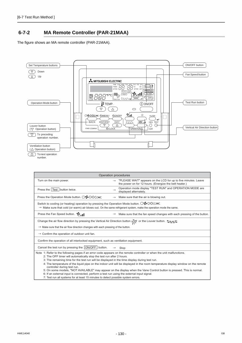
[6-7 Test Run Method ]
6-7-2 MA Remote Controller (PAR-21MAA)
The figure shows an MA remote controller (PAR-21MAA).
PAR-21MAA
ON/OFF
FILTER
CHECK
OPERATION CLEAR
TEST
TEMP.
MENU
BACK DAYMONITOR/SET
CLOCK
ON/OFF
Set Temperature buttons
Down
Up
Operation Mode button
ON/OFF button
Fan Speed button
Test Run button
Vertical Air Direction buttonLouver button( Operation button)
To precedingoperation number.
Ventilation button( Operation button)
To next operation number.
F CF C
ERROR CODEAFTERTIMERTIME SUN MON TUE WED THU FRI SAT
ONOFF
HrAFTER
FILTERFUNCTION
ONLY1Hr.
WEEKLYSIMPLE
AUTO OFF
Operation procedures Turn on the main power. "PLEASE WAIT" appears on the LCD for up to five minutes. Leave
the power on for 12 hours. (Energize the belt heater.)
Press the Test button twice. Operation mode display "TEST RUN" and OPERATION MODE are displayed alternately.
Press the Operation Mode button.
Make sure that cold (or warm) air blows out. On the same refrigerant system, make the operation mode the same.
Make sure that the air is blowing out.
Switch to cooling (or heating) operation by pressing the Operation Mode button.
Press the Fan Speed button.
Change the air flow direction by pressing the Vertical Air Direction button or the Louver button.
Confirm the operation of outdoor unit fan.
Confirm the operation of all interlocked equipment, such as ventilation equipment.
Note 1: Refer to the following pages if an error code appears on the remote controller or when the unit malfunctions. 2: The OFF timer will automatically stop the test run after 2 hours. 3: The remaining time for the test run will be displayed in the time display during test run. 4: The temperature of the liquid pipe on the indoor unit will be displayed in the room temperature display window on the remote controller during test run. 5: On some models, "NOT AVAILABLE" may appear on the display when the Vane Control button is pressed. This is normal. 6: If an external input is connected, perform a test run using the external input signal. 7: Test run all systems for at least 15 minutes to detect possible system errors.
Make sure that the fan speed changes with each pressing of the button.
Stop
Make sure that the air flow direction changes with each pressing of the button.
Cancel the test run by pressing the ON/OFF button.
- 130 -HWE14040 GB
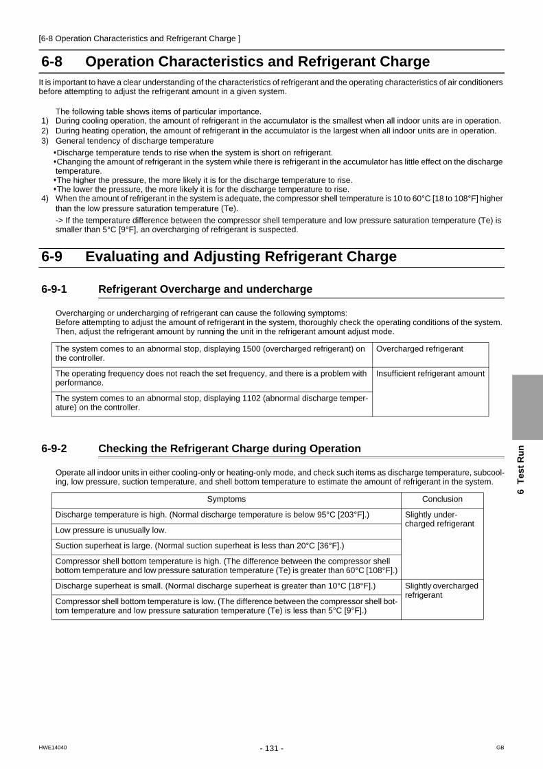
[6-8 Operation Characteristics and Refrigerant Charge ]
6
Te
st
Ru
n
6-8 Operation Characteristics and Refrigerant ChargeIt is important to have a clear understanding of the characteristics of refrigerant and the operating characteristics of air conditioners before attempting to adjust the refrigerant amount in a given system.
The following table shows items of particular importance.1) During cooling operation, the amount of refrigerant in the accumulator is the smallest when all indoor units are in operation.2) During heating operation, the amount of refrigerant in the accumulator is the largest when all indoor units are in operation.3) General tendency of discharge temperature
Discharge temperature tends to rise when the system is short on refrigerant.Changing the amount of refrigerant in the system while there is refrigerant in the accumulator has little effect on the discharge temperature.The higher the pressure, the more likely it is for the discharge temperature to rise.The lower the pressure, the more likely it is for the discharge temperature to rise.
4) When the amount of refrigerant in the system is adequate, the compressor shell temperature is 10 to 60°C [18 to 108°F] higher than the low pressure saturation temperature (Te).
-> If the temperature difference between the compressor shell temperature and low pressure saturation temperature (Te) is smaller than 5°C [9°F], an overcharging of refrigerant is suspected.
6-9 Evaluating and Adjusting Refrigerant Charge
6-9-1 Refrigerant Overcharge and undercharge
Overcharging or undercharging of refrigerant can cause the following symptoms: Before attempting to adjust the amount of refrigerant in the system, thoroughly check the operating conditions of the system. Then, adjust the refrigerant amount by running the unit in the refrigerant amount adjust mode.
6-9-2 Checking the Refrigerant Charge during Operation
Operate all indoor units in either cooling-only or heating-only mode, and check such items as discharge temperature, subcool-ing, low pressure, suction temperature, and shell bottom temperature to estimate the amount of refrigerant in the system.
The system comes to an abnormal stop, displaying 1500 (overcharged refrigerant) on the controller.
Overcharged refrigerant
The operating frequency does not reach the set frequency, and there is a problem with performance.
Insufficient refrigerant amount
The system comes to an abnormal stop, displaying 1102 (abnormal discharge temper-ature) on the controller.
Symptoms Conclusion
Discharge temperature is high. (Normal discharge temperature is below 95°C [203°F].) Slightly under-charged refrigerant
Low pressure is unusually low.
Suction superheat is large. (Normal suction superheat is less than 20°C [36°F].)
Compressor shell bottom temperature is high. (The difference between the compressor shell bottom temperature and low pressure saturation temperature (Te) is greater than 60°C [108°F].)
Discharge superheat is small. (Normal discharge superheat is greater than 10°C [18°F].) Slightly overcharged refrigerant
Compressor shell bottom temperature is low. (The difference between the compressor shell bot-tom temperature and low pressure saturation temperature (Te) is less than 5°C [9°F].)
- 131 -HWE14040 GB

[6-9 Evaluating and Adjusting Refrigerant Charge ]
6-9-3 The Amount of Refrigerant to Be Added
The amount of refrigerant that is shown in the table below is factory-charged to the outdoor units. The amount necessary for extended pipe (field piping) is not included and must be added on site.
(1) Calculation formula
The amount of refrigerant to be added depends on the size and the length of field piping. (unit in m[ft])When the piping length to the farthest indoor unit is shorter than 30.5 meters (100 feet)
When the piping length to the farthest indoor unit is 30.5 meters (100 feet) or longer
Round up the calculation result to the nearest 0.1kg. (Example: 18.04kg to 18.1kg)Round up the calculation result in increments of 4oz (0.1kg) or round it up to the nearest 1oz. (Example: 178.21oz to 179oz)When connecting PEFY-P20VMA3-E, add 0.54 kg of refrigerant per indoor unit.
Outdoor unit model P200 P250 P300 P350 P400 P450 P500
Amount of pre-charged refrigerant in the outdoor unit (kg)
6.5 8.0 11.5 11.5 11.5 11.8 11.8
Amount of pre-charged refrigerant in the outdoor unit [lbs-oz]
14-6 17-11 25-6 25-6 25-6 26-1 26-1
Amount of added refrigerant (kg) = (0.29x L1) + (0.2 x L2) + (0.12 x L3) + (0.06 x L4) + (0.024 x L5) +αAmount of added refrigerant (oz) = (3.1x L1' ) +(2.15 x L2' ) + (1.29 x L3' ) + (0.65 x L4' ) + (0.26 x L5' ) + α'
Amount of added refrigerant (kg) = (0.26x L1) + (0.18 x L2) + (0.11 x L3) + (0.054 x L4) + (0.021 x L5) +αAmount of added refrigerant (oz) = (2.80x L1' ) +(1.94 x L2' ) + (1.19 x L3' ) + (0.58 x L4' ) + (0.23 x L5' ) + α'
L1: Length of ø19.05 [3/4"] liquid pipe (m) L2: Length of ø15.88 [5/8"] liquid pipe (m) L3: Length of ø12.7 [1/2"] liquid pipe (m) L4: Length of ø9.52 [3/8"] liquid pipe (m) L5: Length of ø6.35 [1/4"] liquid pipe (m)α, α': Refer to the table below.
L1': Length of ø19.05 [3/4"] liquid pipe [ft] L2': Length of ø15.88 [5/8"] liquid pipe [ft] L3': Length of ø12.7 [1/2"] liquid pipe [ft] L4': Length of ø9.52 [3/8"] liquid pipe [ft] L5': Length of ø6.35 [1/4"] liquid pipe [ft]
Total capacity of connected indoor units
α (kg) α' (oz)
- 80 2.0 71
81 - 160 2.5 89
161 - 330 3.0 106
331 - 390 3.5 124
391 - 480 4.5 159
481 - 630 5.0 177
631 - 710 6.0 212
711 - 800 8.0 283
801 - 890 9.0 318
891 - 1070 10.0 353
1071 - 1250 12.0 424
1251 - 14.0 494
- 132 -HWE14040 GB

[6-9 Evaluating and Adjusting Refrigerant Charge ]
6
Te
st
Ru
n
1) Maximum refrigerant charge
There is a limit to the amount of refrigerant that can be charged into a unit. Regardless of the amount yielded by the formula above, observe the maximum refrigerant charge in the table below.
*1 Maximum refrigerant charge: the amount of factory-charged refrigerant and the amount of refrigerant to be added on site.
Total index of the outdoor units P200 P250 P300 P350 P400 P450
Maximum refrigerant charge *1 (kg) 22.3 29.7 32.7 33.6 37.2 45.0
Maximum refrigerant charge *1 [lbs-oz] 49-3 65-8 72-2 74-2 82-1 99-4
Total index of the outdoor units P500 P400S P450S P500S P550S P600S
Maximum refrigerant charge *1 (kg) 45.9 45.0 45.9 47.0 51.3 53.9
Maximum refrigerant charge *1 [lbs-oz] 101-4 99-4 101-4 103-10 113-2 118-14
Total index of the outdoor units P650S P700S P750S P800S P850S P900S
Maximum refrigerant charge *1 (kg) 56.5 68.9 68.9 71.4 73.2 75.7
Maximum refrigerant charge *1 [lbs-oz] 124-9 151-15 151-15 157-7 161-7 166-15
Total index of the outdoor units P950S P1000S P1050S P1100S P1150S P1200S
Maximum refrigerant charge *1 (kg) 96.9 99.9 102.9 106 109 112
Maximum refrigerant charge *1 [lbs-oz] 213-10 220-4 226-14 233-11 240-5 246-15
Total index of the outdoor units P1250S P1300S P1350S
Maximum refrigerant charge *1 (kg) 112 112 112
Maximum refrigerant charge *1 [lbs-oz] 246-15 246-15 246-15
- 133 -HWE14040 GB

[6-9 Evaluating and Adjusting Refrigerant Charge ]
(2) Example: PUHY-P350YKB-A1
(3) Sample calculation
A
B C D e
a b c d
Indoor 1: P125 40 m 10 m2: P100 10 m 5 m3: P40 15 m 10 m4: P32 10 m 10 m5: P63 10 m
The total length of liquid pipe of each size is as follows:ø12.7: A + e = 40 + 10 = 50 m
A: ø12.7 a: ø9.52b: ø9.52c: ø6.35d: ø9.52e: ø12.7
B: ø9.52C: ø9.52D: ø9.52
ø9.52: B + C + D + a + b + d = 10 + 15 + 10 + 10 + 5 + 10 = 60 mø6.35: c = 10 = 10 m
P40P100P125 P32 P63
= + + + + + 3.5
+ + + + + 3.5
+ 0
+ 0
(kg) 0 (m) x 0.26 (kg/m)
Additional refrigerant charge
= 0 0 50 x 0.11 60 x 0.054 10 x 0.021= 12.5 (12.45) kg
Total length of liquid
x 0.26 (kg/m)
0 (m) x 0.18 (kg/m)
Total length of liquid
x 0.18 (kg/m)
50 (m) x 0.11 (kg/m)
Total length of liquid
x 0.11 (kg/m)
60 (m) x 0.054 (kg/m)
Total length of liquid
x 0.054 (kg/m)
10 (m) x 0.021 (kg/m)
Total length of liquid
x 0.021 (kg/m)
CAUTIONCharge liquid refrigerant (as opposed to gaseous refrigerant) into the system.If gaseous refrigerant is charged into the system, the composition of the refrigerant in the cylinder will change and may result in performance loss.
- 134 -HWE14040 GB

[6-9 Evaluating and Adjusting Refrigerant Charge ]
6
Te
st
Ru
n
6-9-4 Refrigerant Charge Adjustment Mode
Follow the procedures below to add or extract refrigerant as necessary depending on the operation mode.
When the function switch (SW4 (922)) on the main board on the outdoor unit (OC only) is turned to ON, the unit goes into the refrigerant amount adjust mode, and the following sequence is followed.
The unit will not go into the refrigerant amount adjust mode when the switch on the OS is set to ON.
OperationWhen the unit is in the refrigerant amount adjust mode, the LEV on the indoor unit does not open as fully as it nor-mally does during cooling operation to secure subcooling.
1) Using the flowchart on the next page, adjust the refrigerant charge. Check the TH4, TH3, TH2, TH6, Te, and Tc values of OC, OS1, and OS2 by setting the diagnostic switch (SW4 (SW6-10: OFF) first, and use these values to diagnose the refrigerant charge.
2) There may be cases when the refrigerant amount may seem adequate for a short while after starting the unit in the refrigerant amount adjust mode but turn out to be inadequate later on (when the refrigerant system stabilizes).
When the amount of refrigerant is truly adequate.TH3-TH6 on the outdoor unit is 5°C [9°F] or above and SH on the indoor unit is between 5 and 15°C [9 and 27°F].The refrigerant amount may seem adequate at the moment, but may turn out to be inadequate later on.TH3-TH6 on the outdoor unit is 5°C [9°F] or less and SH on the indoor unit is 5°C [9°F] or less. Wait until the TH3-TH6 reaches 5°C [9°F] or above and the SH of the indoor unit is between 5 and 15°C [9 and 27°F] to de-termine that the refrigerant amount is adequate.
3) If the high pressure is not at least 2.0 MPa [290 psi], a correct judgment will not be possible for refrigerant adjustment. Perform the adjustment when the outdoor air temperature is at least 20°C.
4) Refrigerant amount adjust mode automatically ends 90 minutes after beginning. When this happens, by turning off the SW4 (922) and turning them back on, the unit will go back into the refrigerant amount adjust mode.
SW4 settings
For how to read the SW settings, refer to the following page(s). [9-1-1 How to Read the LED](page 289)
Self-diagnosis swithes on TH4
Self-diagnosis swithes on TH2 Self-diagnosis swithes on TH6
Self-diagnosis swithes on TH3
Self-diagnosis swithes on TcSelf-diagnosis swithes on Te
ON
1 2 3 4 5 6 7 8 9 10 OFF
ON
1 2 3 4 5 6 7 8 9 10 OFF
ON
1 2 3 4 5 6 7 8 9 10 OFF
ON
1 2 3 4 5 6 7 8 9 10 OFF
ON
1 2 3 4 5 6 7 8 9 10 OFF
ON
1 2 3 4 5 6 7 8 9 10 OFF
- 135 -HWE14040 GB

[6-9 Evaluating and Adjusting Refrigerant Charge ]
For information about Notes 1 through 4 in the flowchart, refer to items 1) through 4) on the previous page. [6-9-4 Refrigerant Charge Adjustment Mode](page 135)
CAUTIONDo not release the extracted refrigerant into the air.
CAUTIONCharge liquid refrigerant (as opposed to gaseous refrigerant) into the system.If gaseous refrigerant is charged into the system, the composition of the refrigerant in the cylinder will change and may result in performance loss.
YES
YES
YES
YES
YES
YES
YES
YES
YES
NO
NO
NO
NO
NO
NO
NO
NO
NO
Start
Put all indoor units in the test run mode and run the units in cooling mode.
Has it been at least 30 minutes since
start up?
Note 3
Note 1
Does 8°C [14.4°F] Tc-TH3 12°C [21.6°F] hold true?(Use the largest “Tc - TH3” value of the
OC, OS1, and OS2.)
Does the following hold true? Tc-TH3 8°C [14.4°F]
*Refer to the previous page for *Notes 1-4 in the chart.
Note 2
Note 2
Note 2
Note 1
Gradually add refrigerant from the service port on the low- pressure side.
Keep the unit running for 5 minutes after adjusting the refrigerant amount to determine its adequacy.
Keep the unit running for 5 minutes after adjusting the refrigerant amount to determine its adequacy.
Turn off SW4 (922) on the OC.
Turn on SW4 (922) on the OC.
Adjustment complete
Note 4
Has the initial start-upmode been completed?
Gradually add refrigerant from the service port on the low pressure side.
Gradually add refrigerant from the service port on the low pressure side.
Keep the unit running for 5 minutes after adjusting the refrigerant amount and check(Tc-TH3)
Gradually add refrigerant from the service port on the low pressure side.
Gradually draw out refrigerant from the service port on the low pressure side.
Does Tc-TH6 20°C [36°F] hold true?
Is the TH4 value of the OC, OS1, OS2 at or below 100°C [212°F]?
Has the operating frequency of the compressor on the OC, OS1,
and OS2 become stable?
Note 1
Is the TH4 value of the OC, OS1, OS2 at or below 95°C [203°F]
(Check this item on the unit whose “Tc – TH3” value was used in the step above.)
- 136 -HWE14040 GB

[6-10 The Following Symptoms Are Normal ]
6
Te
st
Ru
n
6-10 The Following Symptoms Are Normal
Symptoms Remote controller display
Cause
The indoor unit does not start after starting cooling (heating) operation.
"Cooling (heating)" icon blinks on the
display.
The unit cannot perform a heating (cooling) operation when other indoor units on the same refrigerant system, are performing a cooling (heating) operation.
The auto vane adjusts its posi-tion by itself.
Normal display
After an hour of cooling operation with the auto vane in the vertical posi-tion, the vane may automatically move into the horizontal position. Louver blades will automatically move into the horizontal position while the unit is in the defrost mode, pre-heating stand-by mode, or when the thermostat triggers unit off.
The fan speed changes dur-ing heating. Normal display Very Low fan speed when "Thermo-OFF.' Changes from Very Low to pre-
set fan speed when "Thermo-ON" depending on pipe temperature.
The fan stops during heating operation.
Defrost The fan remains stopped during defrost operation.
The fan keeps running after the unit has stopped.
Unlit When the auxiliary heater is turned on, the fan operates for one minute after stopping to dissipate heat.
The fan speed does not reach the set speed when operation switch is turned on. STAND BY
The fan operates at extra low speed for 5 minutes after it is turned on or until the pipe temperature reaches 35°C[95°F], then it operates at low speed for 2 minutes, and finally it operates at the set speed. (Pre-heating stand-by)
When the main power is turned on, the display shown on the right appears on the in-door unit remote controller for 5 minutes.
"HO" or "PLEASE WAIT" icons blink
on the display.
The system is starting up. Wait until the blinking display of "HO" or "PLEASE WAIT" go off.
The drain pump keeps run-ning after the unit has stopped.
UnlitThe drain pump stays in operation for three minutes after the unit in the cooling mode is stopped.
The drain pump is running while the unit is stopped.
Unlit When drain water is detected, the drain pump goes into operation even while the unit is stopped.
Indoor unit and BC controller make noise during cooling/heating changeover.
Normal displayThis noise is made when the refrigerant circuit is reversed and is normal.
Sound of the refrigerant flow is heard from the indoor unit im-mediately after starting opera-tion.
Normal display
This is caused by the transient instability of the refrigerant flow and is nor-mal.
Warm air sometimes comes out of the indoor units that are not in the heating mode. Normal display
This is due to the fact that the LEVs on some of the indoor units are kept slightly open to prevent the refrigerant in the indoor units that are not op-erating in the heating mode from liquefying and accumulating in the com-pressor. It is part of a normal operation.
- 137 -HWE14040 GB

[6-11 Standard Operation Data (Reference Data) ]
6-11 Standard Operation Data (Reference Data)
6-11-1 Single Unit (Standard)
Outdoor unit model PUHY-P200YKB-A1 PUHY-P250YKB-A1
Conditions
Ambient temperature (cooling)
Indoor DB/WB
26.7°C/19.4°C [80°F/67°F] 26.7°C/19.4°C [80°F/67°F]
Outdoor 35°C/- [95°F/-] 35°C/- [95°F/-]
Ambient temperature (heating)
Indoor DB/WB
21.1°C/- [70°F/-] 21.1°C/- [70°F/-]
Outdoor 8.3°C/6.1°C [47°F/43°F] 8.3°C/6.1°C [47°F43°F]
Indoor unit
Number of units connectedUnit
2 2
Number of units in operation 2 2
Model - 100/100 125/125
Piping
Main pipe
m [ft]
5 [16-3/8] 5 [16-3/8]
Branch pipe 10 [32-3/4] 10 [32-3/4]
Total pipe length 25 [82] 25 [82]
Fan speed - Hi Hi
Refrigerant charge kg [lbs-oz] 11 [25] 13 [29]
Outdoor unit Voltage V 400 400
Cooling operation
Outdoor unitElectric current A 10.8 14.2
Compressor frequency Hz 52 65
LEV open-ing
Indoor unit
Pulse
325/325 325/325
SC (LEV1) 80 100
LEV2 2100 2100
Pressure High pressure (after O/S)/Low pressure (before accumulator) MPa [psi] 2.59/0.96 [376/139] 2.83/0.84 [410/122]
Section tempera-
tures
Outdoor unit
Discharge (TH4)
°C [°F]
69 [156] 74 [165]
Heat exchanger outlet (TH3) 44 [111] 46 [115]
Accumulator inlet 10 [50] 10 [50]
Accumulator outlet 10 [50] 10 [50]
SCC outlet (TH6) 24 [75] 26 [79]
Compressor inlet 17 [63] 14 [57]
Compressor shell bottom 47 [117] 38 [100]
Indoor unitLEV inlet 23 [73] 25 [77]
Heat exchanger outlet 10 [50] 10 [50]
Heating operation
Outdoor unitElectric current A 10.8 14.6
Compressor frequency Hz 53 71
LEV open-ing
Indoor unit
Pulse
332/332 332/332
SC (LEV1) 0 0
LEV2 2100 2100
Pressure High pressure (after O/S)/Low pressure (before accumulator) MPa [psi] 2.59/0.67 [376/97] 2.85/0.64 [413/93]
Section tempera-
tures
Outdoor unit
Discharge (TH4)
°C [°F]
72 [162] 75 [167]
Heat exchanger outlet (TH3) 0 [32] -2 [28]
Accumulator inlet 0 [32] -2 [28]
Accumulator outlet 0 [32] -2 [28]
Compressor inlet 0 [32] -2 [28]
Compressor shell bottom 40 [104] 40 [104]
Indoor unitLEV inlet 36 [97] 37 [99]
Heat exchanger inlet 70 [158] 73 [163]
- 138 -HWE14040 GB

[6-11 Standard Operation Data (Reference Data) ]
6
Te
st
Ru
n
Outdoor unit model PUHY-P300YKB-A1 PUHY-P350YKB-A1
Conditions
Ambient temperature (cooling)
Indoor DB/WB
26.7°C/19.4°C [80°F/67°F] 26.7°C/19.4°C [80°F/67°F]
Outdoor 35°C/- [95°F/-] 35°C/- [95°F/-]
Ambient temperature (heating)
Indoor DB/WB
21.1°C/- [70vF/?] 21.1°C/- [70°F/-]
Outdoor 8.3°C/6.1°C [47°F/43°F] 8.3°C/6.1°C [47°F/43°F]
Indoor unit
Number of units connectedUnit
3 3
Number of units in operation 3 3
Model - 100/100/100 100/125/125
Piping
Main pipe
m [ft]
5 [16-3/8] 5 [16-3/8]
Branch pipe 10 [32-3/4] 10 [32-3/4]
Total pipe length 35 [114-13/16] 35 [114-13/16]
Fan speed - Hi Hi
Refrigerant charge kg [lbs-oz] 17 [38] 18 [40]
Outdoor unit Voltage V 400 400
Cooling operation
Outdoor unitElectric current A 16.7 20.8
Compressor frequency Hz 74 95
LEV open-ing
Indoor unit
Pulse
325/325/325 325/325/325
SC (LEV1) 100 190
LEV2 2100 2100
Pressure High pressure (after O/S)/Low pressure (before accumulator) MPa [psi] 2.92/0.90 [424/131] 3.05/0.84 [442/122]
Section tempera-
tures
Outdoor unit
Discharge (TH4)
°C [°F]
73 [163] 82 [180]
Heat exchanger outlet (TH3) 40 [104] 45 [113]
Accumulator inlet 10 [50] 7 [45]
Accumulator outlet 10 [50] 7 [45]
SCC outlet (TH6) 20 [68] 25 [77]
Compressor inlet 15 [59] 19 [66]
Compressor shell bottom 42 [108] 38 [100]
Indoor unitLEV inlet 19 [66] 17 [63]
Heat exchanger outlet 10 [50] 10 [50]
Heating operation
Outdoor unitElectric current A 17.4 23.3
Compressor frequency Hz 81 102
LEV open-ing
Indoor unit
Pulse
332/332/332 332/332/332
SC (LEV1) 0 0
LEV2 2100 2100
Pressure High pressure (after O/S)/Low pressure (before accumulator) MPa [psi] 2.70/0.65 [392/94] 2.74/0.61 [397/88]
Section tempera-
tures
Outdoor unit
Discharge (TH4)
°C [°F]
70 [158] 89 [192]
Heat exchanger outlet (TH3) -1 [30] -3 [27]
Accumulator inlet -1 [30] -3 [27]
Accumulator outlet -1 [30] -3 [27]
Compressor inlet -1 [30] -3 [27]
Compressor shell bottom 40 [104] 40 [104]
Indoor unitLEV inlet 36 [97] 37 [99]
Heat exchanger inlet 69 [156] 80 [176]
- 139 -HWE14040 GB

[6-11 Standard Operation Data (Reference Data) ]
Outdoor unit model PUHY-P400YKB-A1 PUHY-P450YKB-A1
Conditions
Ambient temperature (cooling)
Indoor DB/WB
26.7°C/19.4°C [80°F/67°F] 26.7°C/19.4°C [80°F/67°F]
Outdoor 35°C/- [95°F/-] 35°C/- [95°F/-]
Ambient temperature (heating)
Indoor DB/WB
21.1°C/- [70°F/-] 21.1°C/- [70°F/-]
Outdoor 8.3°C/6.1°C [47°F/43°F] 8.3°C/6.1°C [47°F/43°F]
Indoor unit
Number of units connectedUnit
4 4
Number of units in operation 4 4
Model - 100/100/100/100 100/100/125/125
Piping
Main pipe
m [ft]
5 [16-3/8] 5 [16-3/8]
Branch pipe 10 [32-3/4] 10 [32-3/4]
Total pipe length 45 [147-5/8] 45 [147-5/8]
Fan speed - Hi Hi
Refrigerant charge kg [lbs-oz] 28 [62] 28 [62]
Outdoor unit Voltage V 400 400
Cooling operation
Outdoor unitElectric current A 27.6 34.6
Compressor frequency Hz 97 111
LEV open-ing
Indoor unit
Pulse
325/325/325 325/325/325/325
SC (LEV1) 100 190
LEV2 2100 2100
Pressure High pressure (after O/S)/Low pressure (before accumulator) MPa [psi] 3.18/0.84 [461/122] 3.31/0.84 [480/122]
Section tempera-
tures
Outdoor unit
Discharge (TH4)
°C [°F]
84 [183] 86 [187]
Heat exchanger outlet (TH3) 45 [113] 45 [113]
Accumulator inlet 7 [45] 7 [45]
Accumulator outlet 7 [45] 7 [45]
SCC outlet (TH6) 25 [77] 25 [77]
Compressor inlet 19 [66] 19 [66]
Compressor shell bottom 38 [100] 38 [100]
Indoor unitLEV inlet 17 [63] 17 [63]
Heat exchanger outlet 10 [50] 10 [50]
Heating operation
Outdoor unitElectric current A 29.0 36.4
Compressor frequency Hz 108 120
LEV open-ing
Indoor unit
Pulse
332/332/332/332 332/332/406/406
SC (LEV1) 0 0
LEV2 2100 2100
Pressure High pressure (after O/S)/Low pressure (before accumulator) MPa [psi] 2.78/0.61 [403/88] 2.82/0.61 [409/88]
Section tempera-
tures
Outdoor unit
Discharge (TH4)
°C [°F]
90 [194] 90 [194]
Heat exchanger outlet (TH3) -3 [27] -3 [27]
Accumulator inlet -3 [27] -3 [27]
Accumulator outlet -3 [27] -3 [27]
Compressor inlet -3 [27] -3 [27]
Compressor shell bottom 40 [104] 40 [104]
Indoor unitLEV inlet 37 [99] 37 [99]
Heat exchanger inlet 80 [176] 80 [176]
- 140 -HWE14040 GB

[6-11 Standard Operation Data (Reference Data) ]
6
Te
st
Ru
n
Outdoor unit model PUHY-P500YKB-A1
Conditions
Ambient temperature (cooling)
Indoor DB/WB
26.7°C/19.4°C [80°F/67°F]
Outdoor 35°C/- [95°F/-]
Ambient temperature (heating)
Indoor DB/WB
21.1°C/- [70°F/-]
Outdoor 8.3°C/6.1°C [47°F/43°F]
Indoor unit
Number of units connectedUnit
4
Number of units in operation 4
Model - 125/125/125/125
Piping
Main pipe
m [ft]
5 [16-3/8]
Branch pipe 10 [32-3/4]
Total pipe length 45 [147-5/8]
Fan speed - Hi
Refrigerant charge kg [lbs-oz] 38 [84]
Outdoor unit Voltage V 400
Cooling operation
Outdoor unitElectric current A 43.5
Compressor frequency Hz 120
LEV open-ing
Indoor unit
Pulse
387/387/387/387
SC (LEV1) 100
LEV2 2100
Pressure High pressure (after O/S)/Low pressure (before accumulator) MPa [psi] 2.76/0.93 [400/135]
Section tempera-
tures
Outdoor unit
Discharge (TH4)
°C [°F]
73 [163]
Heat exchanger outlet (TH3) 40 [104]
Accumulator inlet 10 [50]
Accumulator outlet 10 [50]
SCC outlet (TH6) 20 [68]
Compressor inlet 15 [59]
Compressor shell bottom 42 [108]
Indoor unitLEV inlet 21 [70]
Heat exchanger outlet 10 [50]
Heating operation
Outdoor unitElectric current A 46.2
Compressor frequency Hz 129
LEV open-ing
Indoor unit
Pulse
406/406/406/406
SC (LEV1) 0
LEV2 2100
Pressure High pressure (after O/S)/Low pressure (before accumulator) MPa [psi] 2.65/0.66 [384/96]
Section tempera-
tures
Outdoor unit
Discharge (TH4)
°C [°F]
70 [158]
Heat exchanger outlet (TH3) -1 [30]
Accumulator inlet -1 [30]
Accumulator outlet -1 [30]
Compressor inlet -1 [30]
Compressor shell bottom 40 [104]
Indoor unitLEV inlet 36 [97]
Heat exchanger inlet 70 [157]
- 141 -HWE14040 GB

[6-11 Standard Operation Data (Reference Data) ]
6-11-2 Dual Unit Combination (Standard)
Packaged unit model PUHY-P400YSKB-A1
Outdoor unit model PUHY-P200YKB-A1 PUHY-P200YKB-A1
Conditions
Ambient temperature (cooling)
Indoor DB/WB
26.7°C/19.4°C [80°F/67°F]
Outdoor 35°C/- [95°F/-]
Ambient temperature (heating)
Indoor DB/WB
21.1°C/- [70°F/-]
Outdoor 8.3°C/6.1°C [47°F/43°F]
Indoor unit
Number of units connectedUnit
4
Number of units in operation 4
Model - 100/100/100/100
Piping
Main pipe
m [ft]
5 [16-3/8]
Branch pipe 10 [32-3/4]
Total pipe length 45 [147-5/8]
Fan speed - Hi
Refrigerant charge kg [lbs-oz] 21 [47]
Outdoor unit Voltage V 400
Cooling operation
Outdoor unitElectric current A 21.6
Compressor frequency Hz 52 52
LEV open-ing
Indoor unit
Pulse
325/325/325/325
SC (LEV1) 80 80
LEV2 2100 2100
Pressure High pressure (after O/S)/Low pressure (before accumula-tor) MPa [psi] 2.59/0.96 [376/139] 2.59/0.96 [376/139]
Section tempera-
tures
Outdoor unit
Discharge (TH4)
°C [°F]
69 [156] 69 [156]
Heat exchanger outlet (TH3) 44 [111] 44 [111]
Accumulator inlet 10 [50] 10 [50]
Accumulator outlet 10 [50] 10 [50]
SCC outlet (TH6) 24 [75] 24 [75]
Compressor inlet 17 [63] 17 [63]
Compressor shell bottom 47 [117] 47 [117]
Indoor unitLEV inlet 23 [73] 23 [73]
Heat exchanger outlet 10 [50] 10 [50]
Heating operation
Outdoor unitElectric current A 21.6
Compressor frequency Hz 53 53
LEV open-ing
Indoor unit
Pulse
332/332/332/332
SC (LEV1) 0
LEV2 2100 2100
Pressure High pressure (after O/S)/Low pressure (before accumula-tor) MPa [psi] 2.59/0.67 [376/97] 2.59/0.67 [376/97]
Section tempera-
tures
Outdoor unit
Discharge (TH4)
°C [°F]
72 [162] 72 [162]
Heat exchanger outlet (TH3) 0 [32] 0 [32]
Accumulator inlet 0 [32] 0 [32]
Accumulator outlet 0 [32] 0 [32]
Compressor inlet 0 [32] 0 [32]
Compressor shell bottom 40 [104] 40 [104]
Indoor unitLEV inlet 36 [97] 36 [97]
Heat exchanger inlet 70 [158] 70 [158]
- 142 -HWE14040 GB

[6-11 Standard Operation Data (Reference Data) ]
6
Te
st
Ru
n
Packaged unit model PUHY-P450YSKB-A1
Outdoor unit model PUHY-P200YKB-A1 PUHY-P250YKB-A1
Conditions
Ambient temperature (cooling)
Indoor DB/WB
26.7°C/19.4°C [80°F/67°F]
Outdoor 35°C/- [95°F/-]
Ambient temperature (heating)
Indoor DB/WB
21.1°C/- [70°F/-]
Outdoor 8.3°C/6.1°C [47°F/43°F]
Indoor unit
Number of units connectedUnit
4
Number of units in operation 4
Model - 100/100/125/125
Piping
Main pipe
m [ft]
5 [16-3/8]
Branch pipe 10 [32-3/4]
Total pipe length 45 [147-5/8]
Fan speed - Hi
Refrigerant charge kg [lbs-oz] 23 [51]
Outdoor unit Voltage V 400
Cooling operation
Outdoor unitElectric current A 25.0
Compressor frequency Hz 52 65
LEV open-ing
Indoor unit
Pulse
325/325/325/325
SC (LEV1) 80 100
LEV2 2100 2100
Pressure High pressure (after O/S)/Low pressure (before accumula-tor) MPa [psi] 2.59/0.96 [376/139] 2.83/0.84 [410/122]
Section tempera-
tures
Outdoor unit
Discharge (TH4)
°C [°F]
69 [156] 74 [165]
Heat exchanger outlet (TH3) 44 [111] 46 [115]
Accumulator inlet 10 [50] 10 [50]
Accumulator outlet 10 [50] 10 [50]
SCC outlet (TH6) 24 [75] 26 [79]
Compressor inlet 17 [63] 14 [57]
Compressor shell bottom 47 [117] 38 [100]
Indoor unitLEV inlet 23 [73] 25 [77]
Heat exchanger outlet 10 [50] 10 [50]
Heating operation
Outdoor unitElectric current A 25.4
Compressor frequency Hz 53 71
LEV open-ing
Indoor unit
Pulse
332/332/332/332
SC (LEV1) 0
LEV2 2100 2100
Pressure High pressure (after O/S)/Low pressure (before accumula-tor) MPa [psi] 2.59/0.67 [376/97] 2.85/0.64 [413/93]
Section tempera-
tures
Outdoor unit
Discharge (TH4)
°C [°F]
72 [162] 75 [167]
Heat exchanger outlet (TH3) 0 [32] -2 [28]
Accumulator inlet 0 [32] -2 [28]
Accumulator outlet 0 [32] -2 [28]
Compressor inlet 0 [32] -2 [28]
Compressor shell bottom 40 [104] 40 [104]
Indoor unitLEV inlet 36 [97] 37 [99]
Heat exchanger inlet 70 [158] 73 [163]
- 143 -HWE14040 GB

[6-11 Standard Operation Data (Reference Data) ]
Packaged unit model PUHY-P500YSKB-A1
Outdoor unit model PUHY-P250YKB-A1 PUHY-P250YKB-A1
Conditions
Ambient temperature (cooling)
Indoor DB/WB
26.7°C/19.4°C [80°F/67°F]
Outdoor 35°C/- [95°F/-]
Ambient temperature (heating)
Indoor DB/WB
21.1°C/- [70°F/-]
Outdoor 8.3°C/6.1°C [47°F/43°F]
Indoor unit
Number of units connectedUnit
4
Number of units in operation 4
Model - 125/125/125/125
Piping
Main pipe
m [ft]
5 [16-3/8]
Branch pipe 10 [32-3/4]
Total pipe length 45 [147-5/8]
Fan speed - Hi
Refrigerant charge kg [lbs-oz] 25 [56]
Outdoor unit Voltage V 400
Cooling operation
Outdoor unitElectric current A 28.4
Compressor frequency Hz 65 65
LEV open-ing
Indoor unit
Pulse
325/325/325/325
SC (LEV1) 100 100
LEV2 2100 2100
Pressure High pressure (after O/S)/Low pressure (before accumula-tor) MPa [psi] 2.83/0.84 [410/122] 2.83/0.84 [410/122]
Section tempera-
tures
Outdoor unit
Discharge (TH4)
°C [°F]
74 [165] 74 [165]
Heat exchanger outlet (TH3) 46 [115] 46 [115]
Accumulator inlet 10 [50] 10 [50]
Accumulator outlet 10 [50] 10 [50]
SCC outlet (TH6) 26 [79] 26 [79]
Compressor inlet 14 [57] 14 [57]
Compressor shell bottom 38 [100] 38 [100]
Indoor unitLEV inlet 25 [77] 25 [77]
Heat exchanger outlet 10 [50] 10 [50]
Heating operation
Outdoor unitElectric current A 29.3
Compressor frequency Hz 71 71
LEV open-ing
Indoor unit
Pulse
332/332/332/332
SC (LEV1) 0
LEV2 2100 2100
Pressure High pressure (after O/S)/Low pressure (before accumula-tor) MPa [psi] 2.85/0.64 [413/93] 2.85/0.64 [413/93]
Section tempera-
tures
Outdoor unit
Discharge (TH4)
°C [°F]
75 [167] 75 [167]
Heat exchanger outlet (TH3) -2 [28] -2 [28]
Accumulator inlet -2 [28] -2 [28]
Accumulator outlet -2 [28] -2 [28]
Compressor inlet -2 [28] -2 [28]
Compressor shell bottom 40 [104] 40 [104]
Indoor unitLEV inlet 37 [99] 37 [99]
Heat exchanger inlet 73 [163] 73 [163]
- 144 -HWE14040 GB

[6-11 Standard Operation Data (Reference Data) ]
6
Te
st
Ru
n
Packaged unit model PUHY-P550YSKB-A1
Outdoor unit model PUHY-P250YKB-A1 PUHY-P300YKB-A1
Conditions
Ambient temperature (cooling)
Indoor DB/WB
26.7°C/19.4°C [80°F/67°F]
Outdoor 35°C/- [95°F/-]
Ambient temperature (heating)
Indoor DB/WB
21.1°C/- [70°F/-]
Outdoor 8.3°C/6.1°C [47°F/43°F]
Indoor unit
Number of units connectedUnit
5
Number of units in operation 5
Model - 100/100/100/125/125
Piping
Main pipe
m [ft]
5 [16-3/8]
Branch pipe 10 [32-3/4]
Total pipe length 55 [180-7/16]
Fan speed - Hi
Refrigerant charge kg [lbs-oz] 29 [64]
Outdoor unit Voltage V 400
Cooling operation
Outdoor unitElectric current A 30.9
Compressor frequency Hz 65 74
LEV open-ing
Indoor unit
Pulse
325/325/325/325/325
SC (LEV1) 100 100
LEV2 2100 2100
Pressure High pressure (after O/S)/Low pressure (before accumula-tor) MPa [psi] 2.83/0.84 [410/122] 2.92/0.90 [424/131]
Section tempera-
tures
Outdoor unit
Discharge (TH4)
°C [°F]
74 [165] 73 [163]
Heat exchanger outlet (TH3) 46 [115] 40 [104]
Accumulator inlet 10 [50] 10 [50]
Accumulator outlet 10 [50] 10 [50]
SCC outlet (TH6) 26 [79] 20 [68]
Compressor inlet 14 [57] 15 [59]
Compressor shell bottom 38 [100] 42 [108]
Indoor unitLEV inlet 25 [77] 19 [66]
Heat exchanger outlet 10 [50] 10 [50]
Heating operation
Outdoor unitElectric current A 32.0
Compressor frequency Hz 71 81
LEV open-ing
Indoor unit
Pulse
332/332/332/332/332
SC (LEV1) 0
LEV2 2100 2100
Pressure High pressure (after O/S)/Low pressure (before accumula-tor) MPa [psi] 2.85/0.64 [413/93] 2.70/0.65 [392/94]
Section tempera-
tures
Outdoor unit
Discharge (TH4)
°C [°F]
75 [167] 70 [158]
Heat exchanger outlet (TH3) -2 [28] -1 [30]
Accumulator inlet -2 [28] -1 [30]
Accumulator outlet -2 [28] -1 [30]
Compressor inlet -2 [28] -1 [30]
Compressor shell bottom 40 [104] 40 [104]
Indoor unitLEV inlet 37 [99] 36 [97]
Heat exchanger inlet 73 [163] 69 [156]
- 145 -HWE14040 GB

[6-11 Standard Operation Data (Reference Data) ]
Packaged unit model PUHY-P600YSKB-A1
Outdoor unit model PUHY-P250YKB-A1 PUHY-P350YKB-A1
Conditions
Ambient temperature (cooling)
Indoor DB/WB
26.7°C/19.4°C [80°F/67°F]
Outdoor 35°C/- [95°F/-]
Ambient temperature (heating)
Indoor DB/WB
21.1°C/- [70°F/-]
Outdoor 8.3°C/6.1°C [47°F/43°F]
Indoor unit
Number of units connectedUnit
5
Number of units in operation 5
Model - 100/125/125/125/125
Piping
Main pipe
m [ft]
5 [16-3/8]
Branch pipe 10 [32-3/4]
Total pipe length 55 [180-7/16]
Fan speed - Hi
Refrigerant charge kg [lbs-oz] 29 [64]
Outdoor unit Voltage V 400
Cooling operation
Outdoor unitElectric current A 35.0
Compressor frequency Hz 65 95
LEV open-ing
Indoor unit
Pulse
325/325/325/325/325
SC (LEV1) 100 190
LEV2 2100 2100
Pressure High pressure (after O/S)/Low pressure (before accumula-tor) MPa [psi] 2.83/0.84 [410/122] 3.05/0.84 [442/122]
Section tempera-
tures
Outdoor unit
Discharge (TH4)
°C [°F]
74 [165] 82 [180]
Heat exchanger outlet (TH3) 46 [115] 45 [113]
Accumulator inlet 10 [50] 7 [45]
Accumulator outlet 10 [50] 7 [45]
SCC outlet (TH6) 26 [79] 25 [77]
Compressor inlet 14 [57] 19 [66]
Compressor shell bottom 38 [100] 38 [100]
Indoor unitLEV inlet 25 [77] 17 [63]
Heat exchanger outlet 10 [50] 10 [50]
Heating operation
Outdoor unitElectric current A 38.0
Compressor frequency Hz 71 102
LEV open-ing
Indoor unit
Pulse
332/332/332/332/332
SC (LEV1) 0
LEV2 2100 2100
Pressure High pressure (after O/S)/Low pressure (before accumula-tor) MPa [psi] 2.85/0.64 [413/93] 2.74/0.61 [397/88]
Section tempera-
tures
Outdoor unit
Discharge (TH4)
°C [°F]
75 [167] 89 [192]
Heat exchanger outlet (TH3) -2 [28] -3 [27]
Accumulator inlet -2 [28] -3 [27]
Accumulator outlet -2 [28] -3 [27]
Compressor inlet -2 [28] -3 [27]
Compressor shell bottom 40 [104] 40 [104]
Indoor unitLEV inlet 37 [99] 37 [99]
Heat exchanger inlet 73 [163] 80 [176]
- 146 -HWE14040 GB

[6-11 Standard Operation Data (Reference Data) ]
6
Te
st
Ru
n
Packaged unit model PUHY-P650YSKB-A1
Outdoor unit model PUHY-P300YKB-A1 PUHY-P350YKB-A1
Conditions
Ambient temperature (cooling)
Indoor DB/WB
26.7°C/19.4°C [80°F/67°F]
Outdoor 35°C/- [95°F/-]
Ambient temperature (heating)
Indoor DB/WB
21.1°C/- [70°F/-]
Outdoor 8.3°C/6.1°C [47°F/43°F]
Indoor unit
Number of units connectedUnit
6
Number of units in operation 6
Model - 100/100/100/100/125/125
Piping
Main pipe
m [ft]
5 [16-3/8]
Branch pipe 10 [32-3/4]
Total pipe length 65 [213-1/4]
Fan speed - Hi
Refrigerant charge kg [lbs-oz] 34 [75]
Outdoor unit Voltage V 400
Cooling operation
Outdoor unitElectric current A 37.5
Compressor frequency Hz 74 95
LEV open-ing
Indoor unit
Pulse
325/325/325/325/325/325
SC (LEV1) 100 190
LEV2 2100 2100
Pressure High pressure (after O/S)/Low pressure (before accumula-tor) MPa [psi] 2.92/0.90 [424/131] 3.05/0.84 [442/122]
Section tempera-
tures
Outdoor unit
Discharge (TH4)
°C [°F]
73 [163] 82 [180]
Heat exchanger outlet (TH3) 40 [104] 45 [113]
Accumulator inlet 10 [50] 7 [45]
Accumulator outlet 10 [50] 7 [45]
SCC outlet (TH6) 20 [68] 25 [77]
Compressor inlet 15 [59] 19 [66]
Compressor shell bottom 42 [108] 38 [100]
Indoor unitLEV inlet 19 [66] 17 [63]
Heat exchanger outlet 10 [50] 10 [50]
Heating operation
Outdoor unitElectric current A 40.7
Compressor frequency Hz 81 102
LEV open-ing
Indoor unit
Pulse
332/332/332/332/332/332
SC (LEV1) 0
LEV2 2100 2100
Pressure High pressure (after O/S)/Low pressure (before accumula-tor) MPa [psi] 2.70/0.65 [392/94] 2.74/0.61 [397/88]
Section tempera-
tures
Outdoor unit
Discharge (TH4)
°C [°F]
70 [158] 89 [192]
Heat exchanger outlet (TH3) -1 [30] -3 [27]
Accumulator inlet -1 [30] -3 [27]
Accumulator outlet -1 [30] -3 [27]
Compressor inlet -1 [30] -3 [27]
Compressor shell bottom 40 [104] 40 [104]
Indoor unitLEV inlet 36 [97] 37 [99]
Heat exchanger inlet 69 [156] 80 [176]
- 147 -HWE14040 GB

[6-11 Standard Operation Data (Reference Data) ]
Packaged unit model PUHY-P700YSKB-A1
Outdoor unit model PUHY-P350YKB-A1 PUHY-P350YKB-A1
Conditions
Ambient temperature (cooling)
Indoor DB/WB
26.7°C/19.4°C [80°F/67°F]
Outdoor 35°C/- [95°F/-]
Ambient temperature (heating)
Indoor DB/WB
21.1°C/- [70°F/-]
Outdoor 8.3°C/6.1°C [47°F/43°F]
Indoor unit
Number of units connectedUnit
6
Number of units in operation 6
Model - 100/100/125/125/125/125
Piping
Main pipe
m [ft]
5 [16-3/8]
Branch pipe 10 [32-3/4]
Total pipe length 65 [213-1/4]
Fan speed - Hi
Refrigerant charge kg [lbs-oz] 35 [78]
Outdoor unit Voltage V 400
Cooling operation
Outdoor unitElectric current A 41.6
Compressor frequency Hz 95 95
LEV open-ing
Indoor unit
Pulse
325/325/325/325/325/325
SC (LEV1) 190 190
LEV2 2100 2100
Pressure High pressure (after O/S)/Low pressure (before accumula-tor) MPa [psi] 3.05/0.84 [442/122] 3.05/0.84 [442/122]
Section tempera-
tures
Outdoor unit
Discharge (TH4)
°C [°F]
82 [180] 82 [180]
Heat exchanger outlet (TH3) 45 [113] 45 [113]
Accumulator inlet 7 [45] 7 [45]
Accumulator outlet 7 [45] 7 [45]
SCC outlet (TH6) 25 [77] 25 [77]
Compressor inlet 19 [66] 19 [66]
Compressor shell bottom 38 [100] 38 [100]
Indoor unitLEV inlet 17 [63] 17 [63]
Heat exchanger outlet 10 [50] 10 [50]
Heating operation
Outdoor unitElectric current A 46.6
Compressor frequency Hz 102 102
LEV open-ing
Indoor unit
Pulse
332/332/332/332/332/332
SC (LEV1) 0
LEV2 2100 2100
Pressure High pressure (after O/S)/Low pressure (before accumula-tor) MPa [psi] 2.74/0.61 [397/88] 2.74/0.61 [397/88]
Section tempera-
tures
Outdoor unit
Discharge (TH4)
°C [°F]
89 [192] 89 [192]
Heat exchanger outlet (TH3) -3 [27] -3 [27]
Accumulator inlet -3 [27] -3 [27]
Accumulator outlet -3 [27] -3 [27]
Compressor inlet -3 [27] -3 [27]
Compressor shell bottom 40 [104] 40 [104]
Indoor unitLEV inlet 37 [99] 37 [99]
Heat exchanger inlet 80 [176] 80 [176]
- 148 -HWE14040 GB

[6-11 Standard Operation Data (Reference Data) ]
6
Te
st
Ru
n
Packaged unit model PUHY-P750YSKB-A1
Outdoor unit model PUHY-P350YKB-A1 PUHY-P400YKB-A1
Conditions
Ambient temperature (cooling)
Indoor DB/WB
26.7°C/19.4°C [80°F/67°F]
Outdoor 35°C/- [95°F/-]
Ambient temperature (heating)
Indoor DB/WB
21.1°C/- [70°F/-]
Outdoor 8.3°C/6.1°C [47°F/43°F]
Indoor unit
Number of units connectedUnit
7
Number of units in operation 7
Model - 100/100/100/100/100/125/125
Piping
Main pipe
m [ft]
5 [16-3/8]
Branch pipe 10 [32-3/4]
Total pipe length 75 [246-1/16]
Fan speed - Hi
Refrigerant charge kg [lbs-oz] 37 [82]
Outdoor unit Voltage V 400
Cooling operation
Outdoor unitElectric current A 46.5
Compressor frequency Hz 95 97
LEV open-ing
Indoor unit
Pulse
325/325/325/325/325/325/325
SC (LEV1) 190 100
LEV2 2100 2100
Pressure High pressure (after O/S)/Low pressure (before accumula-tor) MPa [psi] 3.05/0.84 [442/122] 3.18/0.84 [461/122]
Section tempera-
tures
Outdoor unit
Discharge (TH4)
°C [°F]
82 [180] 84 [183]
Heat exchanger outlet (TH3) 45 [113] 45 [113]
Accumulator inlet 7 [45] 7 [45]
Accumulator outlet 7 [45] 7 [45]
SCC outlet (TH6) 25 [77] 25 [77]
Compressor inlet 19 [66] 19 [66]
Compressor shell bottom 38 [100] 38 [100]
Indoor unitLEV inlet 17 [63] 17 [63]
Heat exchanger outlet 10 [50] 10 [50]
Heating operation
Outdoor unitElectric current A 49.6
Compressor frequency Hz 102 108
LEV open-ing
Indoor unit
Pulse
332/332/332/332/332/332/332
SC (LEV1) 0
LEV2 2100 2100
Pressure High pressure (after O/S)/Low pressure (before accumula-tor) MPa [psi] 2.74/0.61 [397/88] 2.78/0.61 [403/88]
Section tempera-
tures
Outdoor unit
Discharge (TH4)
°C [°F]
89 [192] 90 [194]
Heat exchanger outlet (TH3) -3 [27] -3 [27]
Accumulator inlet -3 [27] -3 [27]
Accumulator outlet -3 [27] -3 [27]
Compressor inlet -3 [27] -3 [27]
Compressor shell bottom 40 [104] 40 [104]
Indoor unitLEV inlet 37 [99] 37 [99]
Heat exchanger inlet 80 [176] 80 [176]
- 149 -HWE14040 GB

[6-11 Standard Operation Data (Reference Data) ]
Packaged unit model PUHY-P800YSKB-A1
Outdoor unit model PUHY-P350YKB-A1 PUHY-P450YKB-A1
Conditions
Ambient temperature (cooling)
Indoor DB/WB
26.7°C/19.4°C [80°F/67°F]
Outdoor 35°C/- [95°F/-]
Ambient temperature (heating)
Indoor DB/WB
21.1°C/- [70°F/-]
Outdoor 8.3°C/6.1°C [47°F/43°F]
Indoor unit
Number of units connectedUnit
7
Number of units in operation 7
Model - 100/100/100/125/125/125/125
Piping
Main pipe
m [ft]
5 [16-3/8]
Branch pipe 10 [32-3/4]
Total pipe length 75 [246-1/16]
Fan speed - Hi
Refrigerant charge kg [lbs-oz] 37 [82]
Outdoor unit Voltage V 400
Cooling operation
Outdoor unitElectric current A 49.7
Compressor frequency Hz 95 111
LEV open-ing
Indoor unit
Pulse
325/325/325/325/325/325/325
SC (LEV1) 190 190
LEV2 2100 2100
Pressure High pressure (after O/S)/Low pressure (before accumula-tor) MPa [psi] 3.05/0.84 [442/122] 3.31/0.84 [480/122]
Section tempera-
tures
Outdoor unit
Discharge (TH4)
°C [°F]
82 [180] 86 [187]
Heat exchanger outlet (TH3) 45 [113] 45 [113]
Accumulator inlet 7 [45] 7 [45]
Accumulator outlet 7 [45] 7 [45]
SCC outlet (TH6) 25 [77] 25 [77]
Compressor inlet 19 [66] 19 [66]
Compressor shell bottom 38 [100] 38 [100]
Indoor unitLEV inlet 17 [63] 17 [63]
Heat exchanger outlet 10 [50] 10 [50]
Heating operation
Outdoor unitElectric current A 53.2
Compressor frequency Hz 102 120
LEV open-ing
Indoor unit
Pulse
332/332/332/332/332/332/332
SC (LEV1) 0
LEV2 2100 2100
Pressure High pressure (after O/S)/Low pressure (before accumula-tor) MPa [psi] 2.74/0.61 [397/88] 2.82/0.61 [409/88]
Section tempera-
tures
Outdoor unit
Discharge (TH4)
°C [°F]
89 [192] 90 [194]
Heat exchanger outlet (TH3) -3 [27] -3 [27]
Accumulator inlet -3 [27] -3 [27]
Accumulator outlet -3 [27] -3 [27]
Compressor inlet -3 [27] -3 [27]
Compressor shell bottom 40 [104] 40 [104]
Indoor unitLEV inlet 37 [99] 37 [99]
Heat exchanger inlet 80 [176] 80 [176]
- 150 -HWE14040 GB

[6-11 Standard Operation Data (Reference Data) ]
6
Te
st
Ru
n
Packaged unit model PUHY-P850YSKB-A1
Outdoor unit model PUHY-P400YKB-A1 PUHY-P450YKB-A1
Conditions
Ambient temperature (cooling)
Indoor DB/WB
26.7°C/19.4°C [80°F/67°F]
Outdoor 35°C/- [95°F/-]
Ambient temperature (heating)
Indoor DB/WB
21.1°C/- [70°F/-]
Outdoor 8.3°C/6.1°C [47°F/43°F]
Indoor unit
Number of units connectedUnit
8
Number of units in operation 8
Model - 100/100/100/100/100/100/125/125
Piping
Main pipe
m [ft]
5 [16-3/8]
Branch pipe 10 [32-3/4]
Total pipe length 85 [278-13/16]
Fan speed - Hi
Refrigerant charge kg [lbs-oz] 39 [86]
Outdoor unit Voltage V 400
Cooling operation
Outdoor unitElectric current A 54.7
Compressor frequency Hz 97 111
LEV open-ing
Indoor unit
Pulse
325/325/325/325/325/325/325/325
SC (LEV1) 100 190
LEV2 2100 2100
Pressure High pressure (after O/S)/Low pressure (before accumula-tor) MPa [psi] 3.18/0.84 [461/122] 3.31/0.84 [480/122]
Section tempera-
tures
Outdoor unit
Discharge (TH4)
°C [°F]
84 [183] 86 [187]
Heat exchanger outlet (TH3) 45 [113] 45 [113]
Accumulator inlet 7 [45] 7 [45]
Accumulator outlet 7 [45] 7 [45]
SCC outlet (TH6) 25 [77] 25 [77]
Compressor inlet 19 [66] 19 [66]
Compressor shell bottom 38 [100] 38 [100]
Indoor unitLEV inlet 17 [63] 17 [63]
Heat exchanger outlet 10 [50] 10 [50]
Heating operation
Outdoor unitElectric current A 56.2
Compressor frequency Hz 108 120
LEV open-ing
Indoor unit
Pulse
332/332/332/332/332/332/332/332
SC (LEV1) 0
LEV2 2100 2100
Pressure High pressure (after O/S)/Low pressure (before accumula-tor) MPa [psi] 2.78/0.61 [403/88] 2.82/0.61 [409/88]
Section tempera-
tures
Outdoor unit
Discharge (TH4)
°C [°F]
90 [194] 90 [194]
Heat exchanger outlet (TH3) -3 [27] -3 [27]
Accumulator inlet -3 [27] -3 [27]
Accumulator outlet -3 [27] -3 [27]
Compressor inlet -3 [27] -3 [27]
Compressor shell bottom 40 [104] 40 [104]
Indoor unitLEV inlet 37 [99] 37 [99]
Heat exchanger inlet 80 [176] 80 [176]
- 151 -HWE14040 GB

[6-11 Standard Operation Data (Reference Data) ]
Packaged unit model PUHY-P900YSKB-A1
Outdoor unit model PUHY-P450YKB-A1 PUHY-P450YKB-A1
Conditions
Ambient temperature (cooling)
Indoor DB/WB
26.7°C/19.4°C [80°F/67°F]
Outdoor 35°C/- [95°F/-]
Ambient temperature (heating)
Indoor DB/WB
21.1°C/- [70°F/-]
Outdoor 8.3°C/6.1°C [47°F/43°F]
Indoor unit
Number of units connectedUnit
8
Number of units in operation 8
Model - 100/100/100/100/125/125/125/125
Piping
Main pipe
m [ft]
5 [16-3/8]
Branch pipe 10 [32-3/4]
Total pipe length 85 [278-13/16]
Fan speed - Hi
Refrigerant charge kg [lbs-oz] 40 [89]
Outdoor unit Voltage V 400
Cooling operation
Outdoor unitElectric current A 57.9
Compressor frequency Hz 111 111
LEV open-ing
Indoor unit
Pulse
325/325/325/325/325/325/325/325
SC (LEV1) 190 190
LEV2 2100 2100
Pressure High pressure (after O/S)/Low pressure (before accumula-tor) MPa [psi] 3.31/0.84 [480/122] 3.31/0.84 [480/122]
Section tempera-
tures
Outdoor unit
Discharge (TH4)
°C [°F]
86 [187] 86 [187]
Heat exchanger outlet (TH3) 45 [113] 45 [113]
Accumulator inlet 7 [45] 7 [45]
Accumulator outlet 7 [45] 7 [45]
SCC outlet (TH6) 25 [77] 25 [77]
Compressor inlet 19 [66] 19 [66]
Compressor shell bottom 38 [100] 38 [100]
Indoor unitLEV inlet 17 [63] 17 [63]
Heat exchanger outlet 10 [50] 10 [50]
Heating operation
Outdoor unitElectric current A 59.8
Compressor frequency Hz 120 120
LEV open-ing
Indoor unit
Pulse
332/332/332/332/332/332/332/332
SC (LEV1) 0
LEV2 2100 2100
Pressure High pressure (after O/S)/Low pressure (before accumula-tor) MPa [psi] 2.82/0.61 [409/88] 2.82/0.61 [409/88]
Section tempera-
tures
Outdoor unit
Discharge (TH4)
°C [°F]
90 [194] 90 [194]
Heat exchanger outlet (TH3) -3 [27] -3 [27]
Accumulator inlet -3 [27] -3 [27]
Accumulator outlet -3 [27] -3 [27]
Compressor inlet -3 [27] -3 [27]
Compressor shell bottom 40 [104] 40 [104]
Indoor unitLEV inlet 37 [99] 37 [99]
Heat exchanger inlet 80 [176] 80 [176]
- 152 -HWE14040 GB

[6-11 Standard Operation Data (Reference Data) ]
6
Te
st
Ru
n
6-11-3 Triple Unit Combination (Standard)
Packaged unit model PUHY-P950YSKB-A1
Outdoor unit model PUHY-P250YKB-A1 PUHY-P300YKB-A1 PUHY-P400YKB-A1
Conditions
Ambient temperature (cooling)
Indoor DB/WB
26.7°C/19.4°C [80°F/67°F]
Outdoor 35°C/- [95°F/-]
Ambient temperature (heating)
Indoor DB/WB
21.1°C/- [70°F/-]
Outdoor 8.3°C/6.1°C [47°F/43°F]
Indoor unit
Number of units connectedUnit
9
Number of units in operation 9
Model - 100/100/100/100/100/100/100/125/125
Piping
Main pipe
m [ft]
5 [16-3/8]
Branch pipe 10 [32-3/4]
Total pipe length 95 [311-5/8]
Fan speed - Hi
Refrigerant charge kg [lbs-oz] 48 [106]
Outdoor unit Voltage V 400
Cooling operation
Outdoor unitElectric current A 56.7
Compressor frequency Hz 65 74 97
LEV open-ing
Indoor unit
Pulse
325/325/325/325/325/325/325/325/325
SC (LEV1) 100 100 100
LEV2 2100 2100 2100
Pressure High pressure (after O/S)/Low pressure (before accumulator) MPa [psi]2.83/0.84 2.92/0.90 3.18/0.84
[410/122] [424/131] [461/122]
Section tempera-
tures
Outdoor unit
Discharge (TH4)
°C [°F]
74 [165] 73 [163] 84 [183]
Heat exchanger outlet (TH3) 46 [115] 40 [104] 45 [113]
Accumulator inlet 10 [50] 10 [50] 7 [45]
Accumulator outlet 10 [50] 10 [50] 7 [45]
SCC outlet (TH6) 26 [79] 20 [68] 25 [77]
Compressor inlet 14 [57] 15 [59] 19 [66]
Compressor shell bottom 38 [100] 42 [108] 38 [100]
Indoor unitLEV inlet 25 [77] 19 [66] 17 [63]
Heat exchanger outlet 10 [50] 10 [50] 10 [50]
Heating operation
Outdoor unitElectric current A 58.3
Compressor frequency Hz 71 81 108
LEV open-ing
Indoor unit
Pulse
332/332/332/332/332/332/332/332/332
SC (LEV1) 0
LEV2 2100 2100 2100
Pressure High pressure (after O/S)/Low pressure (before accumulator) MPa [psi]2.85/0.64 2.70/0.65 2.78/0.61
[413/93] [392/94] [403/88]
Section tempera-
tures
Outdoor unit
Discharge (TH4)
°C [°F]
75 [167] 70 [158] 90 [194]
Heat exchanger outlet (TH3) -2 [28] -1 [30] -3 [27]
Accumulator inlet -2 [28] -1 [30] -3 [27]
Accumulator outlet -2 [28] -1 [30] -3 [27]
Compressor inlet -2 [28] -1 [30] -3 [27]
Compressor shell bottom 40 [104] 40 [104] 40 [104]
Indoor unitLEV inlet 37 [99] 36 [97] 37 [99]
Heat exchanger inlet 73 [163] 69 [156] 80 [176]
- 153 -HWE14040 GB

[6-11 Standard Operation Data (Reference Data) ]
Packaged unit model PUHY-P1000YSKB-A1
Outdoor unit model PUHY-P300YKB-A1 PUHY-P300YKB-A1 PUHY-P400YKB-A1
Conditions
Ambient temperature (cooling)
Indoor DB/WB
26.7°C/19.4°C [80°F/67°F]
Outdoor 35°C/- [95°F/-]
Ambient temperature (heating)
Indoor DB/WB
21.1°C/- [70°F/-]
Outdoor 8.3°C/6.1°C [47°F/43°F]
Indoor unit
Number of units connectedUnit
10
Number of units in operation 10
Model - 100/100/100/100/100/100/100/100/100/100
Piping
Main pipe
m [ft]
5 [16-3/8]
Branch pipe 10 [32-3/4]
Total pipe length 105 [344-7/16]
Fan speed - Hi
Refrigerant charge kg [lbs-oz] 52 [115]
Outdoor unit Voltage V 400
Cooling operation
Outdoor unitElectric current A 59.2
Compressor frequency Hz 74 74 97
LEV open-ing
Indoor unit
Pulse
325/325/325/325/325/325/325/325/325/325
SC (LEV1) 100 100 100
LEV2 2100 2100 2100
Pressure High pressure (after O/S)/Low pressure (before accumulator) MPa [psi]2.92/0.90 2.92/0.90 3.18/0.84
[424/131] [424/131] [461/122]
Section tempera-
tures
Outdoor unit
Discharge (TH4)
°C [°F]
73 [163] 73 [163] 84 [183]
Heat exchanger outlet (TH3) 40 [104] 40 [104] 45 [113]
Accumulator inlet 10 [50] 10 [50] 7 [45]
Accumulator outlet 10 [50] 10 [50] 7 [45]
SCC outlet (TH6) 20 [68] 20 [68] 25 [77]
Compressor inlet 15 [59] 15 [59] 19 [66]
Compressor shell bottom 42 [108] 42 [108] 38 [100]
Indoor unitLEV inlet 19 [66] 19 [66] 17 [63]
Heat exchanger outlet 10 [50] 10 [50] 10 [50]
Heating operation
Outdoor unitElectric current A 61.1
Compressor frequency Hz 81 81 108
LEV open-ing
Indoor unit
Pulse
332/332/332/332/332/332/332/332/332/332
SC (LEV1) 0
LEV2 2100 2100 2100
Pressure High pressure (after O/S)/Low pressure (before accumulator) MPa [psi]2.70/0.65 2.70/0.65 2.78/0.61
[392/94] [392/94] [403/88]
Section tempera-
tures
Outdoor unit
Discharge (TH4)
°C [°F]
70 [158] 70 [158] 90 [194]
Heat exchanger outlet (TH3) -1 [30] -1 [30] -3 [27]
Accumulator inlet -1 [30] -1 [30] -3 [27]
Accumulator outlet -1 [30] -1 [30] -3 [27]
Compressor inlet -1 [30] -1 [30] -3 [27]
Compressor shell bottom 40 [104] 40 [104] 40 [104]
Indoor unitLEV inlet 36 [97] 36 [97] 37 [99]
Heat exchanger inlet 69 [156] 69 [156] 80 [176]
- 154 -HWE14040 GB

[6-11 Standard Operation Data (Reference Data) ]
6
Te
st
Ru
n
Packaged unit model PUHY-P1050YSKB-A1
Outdoor unit model PUHY-P300YKB-A1 PUHY-P350YKB-A1 PUHY-P400YKB-A1
Conditions
Ambient temperature (cooling)
Indoor DB/WB
26.7°C/19.4°C [80°F/67°F]
Outdoor 35°C/- [95°F/-]
Ambient temperature (heating)
Indoor DB/WB
21.1°C/- [70°F/-]
Outdoor 8.3°C/6.1°C [47°F/43°F]
Indoor unit
Number of units connectedUnit
10
Number of units in operation 10
Model - 100/100/100/100/100/100/100/100/125/125
Piping
Main pipe
m [ft]
5 [16-3/8]
Branch pipe 10 [32-3/4]
Total pipe length 105 [344-7/16]
Fan speed - Hi
Refrigerant charge kg [lbs-oz] 52 [115]
Outdoor unit Voltage V 400
Cooling operation
Outdoor unitElectric current A 63.3
Compressor frequency Hz 74 95 97
LEV open-ing
Indoor unit
Pulse
325/325/325/325/325/325/325/325/325/325
SC (LEV1) 100 190 100
LEV2 2100 2100 2100
Pressure High pressure (after O/S)/Low pressure (before accumulator) MPa [psi]2.92/0.90 3.05/0.84 3.18/0.84
[424/131] [442/122] [461/122]
Section tempera-
tures
Outdoor unit
Discharge (TH4)
°C [°F]
73 [163] 82 [180] 84 [183]
Heat exchanger outlet (TH3) 40 [104] 45 [113] 45 [113]
Accumulator inlet 10 [50] 7 [45] 7 [45]
Accumulator outlet 10 [50] 7 [45] 7 [45]
SCC outlet (TH6) 20 [68] 25 [77] 25 [77]
Compressor inlet 15 [59] 19 [66] 19 [66]
Compressor shell bottom 42 [108] 38 [100] 38 [100]
Indoor unitLEV inlet 19 [66] 17 [63] 17 [63]
Heat exchanger outlet 10 [50] 10 [50] 10 [50]
Heating operation
Outdoor unitElectric current A 67.0
Compressor frequency Hz 81 102 108
LEV open-ing
Indoor unit
Pulse
332/332/332/332/332/332/332/332/332/332
SC (LEV1) 0
LEV2 2100 2100 2100
Pressure High pressure (after O/S)/Low pressure (before accumulator) MPa [psi]2.70/0.65 2.74/0.61 2.78/0.61
[392/94] [397/88] [403/88]
Section tempera-
tures
Outdoor unit
Discharge (TH4)
°C [°F]
70 [158] 89 [192] 90 [194]
Heat exchanger outlet (TH3) -1 [30] -3 [27] -3 [27]
Accumulator inlet -1 [30] -3 [27] -3 [27]
Accumulator outlet -1 [30] -3 [27] -3 [27]
Compressor inlet -1 [30] -3 [27] -3 [27]
Compressor shell bottom 40 [104] 40 [104] 40 [104]
Indoor unitLEV inlet 36 [97] 37 [99] 37 [99]
Heat exchanger inlet 69 [156] 80 [176] 80 [176]
- 155 -HWE14040 GB

[6-11 Standard Operation Data (Reference Data) ]
Packaged unit model PUHY-P1100YSKB-A1
Outdoor unit model PUHY-P350YKB-A1 PUHY-P350YKB-A1 PUHY-P400YKB-A1
Conditions
Ambient temperature (cooling)
Indoor DB/WB
26.7°C/19.4°C [80°F/67°F]
Outdoor 35°C/- [95°F/-]
Ambient temperature (heating)
Indoor DB/WB
21.1°C/- [70°F/-]
Outdoor 8.3°C/6.1°C [47°F/43°F]
Indoor unit
Number of units connectedUnit
10
Number of units in operation 10
Model - 100/100/100/100/100/100/125/125/125/125
Piping
Main pipe
m [ft]
5 [16-3/8]
Branch pipe 10 [32-3/4]
Total pipe length 105 [344-7/16]
Fan speed - Hi
Refrigerant charge kg [lbs-oz] 54 [120]
Outdoor unit Voltage V 400
Cooling operation
Outdoor unitElectric current A 67.3
Compressor frequency Hz 95 95 97
LEV open-ing
Indoor unit
Pulse
325/325/325/325/325/325/325/325/325/325
SC (LEV1) 190 190 100
LEV2 2100 2100 2100
Pressure High pressure (after O/S)/Low pressure (before accumulator) MPa [psi]3.05/0.84 3.05/0.84 3.18/0.84
[442/122] [442/122] [461/122]
Section tempera-
tures
Outdoor unit
Discharge (TH4)
°C [°F]
82 [180] 82 [180] 84 [183]
Heat exchanger outlet (TH3) 45 [113] 45 [113] 45 [113]
Accumulator inlet 7 [45] 7 [45] 7 [45]
Accumulator outlet 7 [45] 7 [45] 7 [45]
SCC outlet (TH6) 25 [77] 25 [77] 25 [77]
Compressor inlet 19 [66] 19 [66] 19 [66]
Compressor shell bottom 38 [100] 38 [100] 38 [100]
Indoor unitLEV inlet 17 [63] 17 [63] 17 [63]
Heat exchanger outlet 10 [50] 10 [50] 10 [50]
Heating operation
Outdoor unitElectric current A 72.9
Compressor frequency Hz 102 102 108
LEV open-ing
Indoor unit
Pulse
332/332/332/332/332/332/332/332/332/332
SC (LEV1) 0
LEV2 2100 2100 2100
Pressure High pressure (after O/S)/Low pressure (before accumulator) MPa [psi]2.74/0.61 2.74/0.61 2.78/0.61
[397/88] [397/88] [403/88]
Section tempera-
tures
Outdoor unit
Discharge (TH4)
°C [°F]
89 [192] 89 [192] 90 [194]
Heat exchanger outlet (TH3) -3 [27] -3 [27] -3 [27]
Accumulator inlet -3 [27] -3 [27] -3 [27]
Accumulator outlet -3 [27] -3 [27] -3 [27]
Compressor inlet -3 [27] -3 [27] -3 [27]
Compressor shell bottom 40 [104] 40 [104] 40 [104]
Indoor unitLEV inlet 37 [99] 37 [99] 37 [99]
Heat exchanger inlet 80 [176] 80 [176] 80 [176]
- 156 -HWE14040 GB
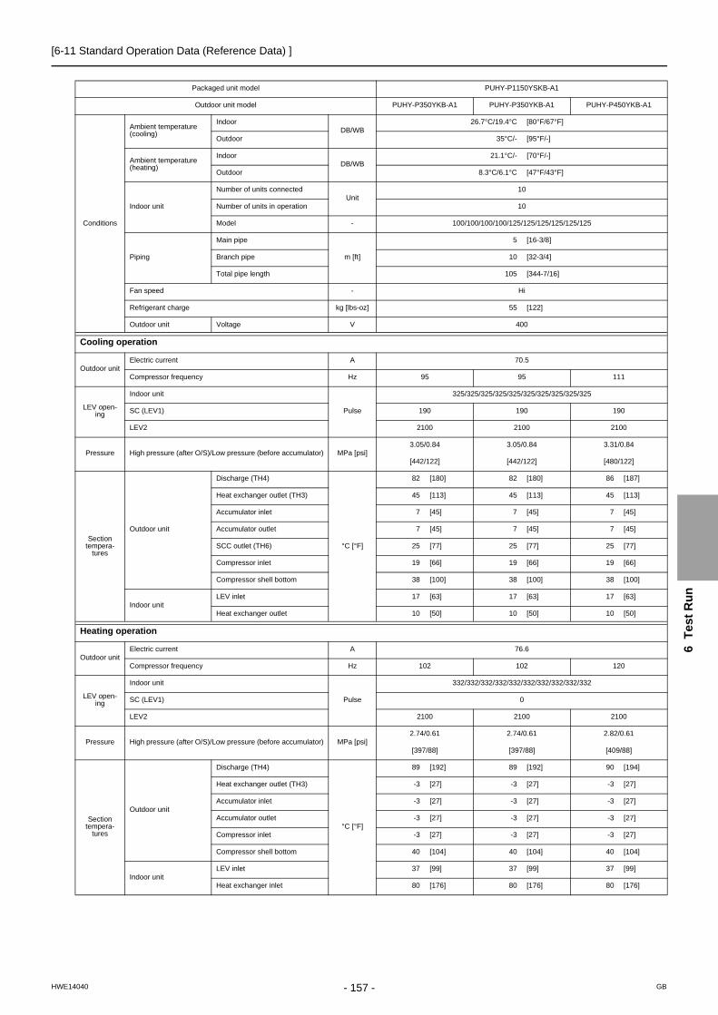
[6-11 Standard Operation Data (Reference Data) ]
6
Te
st
Ru
n
Packaged unit model PUHY-P1150YSKB-A1
Outdoor unit model PUHY-P350YKB-A1 PUHY-P350YKB-A1 PUHY-P450YKB-A1
Conditions
Ambient temperature (cooling)
Indoor DB/WB
26.7°C/19.4°C [80°F/67°F]
Outdoor 35°C/- [95°F/-]
Ambient temperature (heating)
Indoor DB/WB
21.1°C/- [70°F/-]
Outdoor 8.3°C/6.1°C [47°F/43°F]
Indoor unit
Number of units connectedUnit
10
Number of units in operation 10
Model - 100/100/100/100/125/125/125/125/125/125
Piping
Main pipe
m [ft]
5 [16-3/8]
Branch pipe 10 [32-3/4]
Total pipe length 105 [344-7/16]
Fan speed - Hi
Refrigerant charge kg [lbs-oz] 55 [122]
Outdoor unit Voltage V 400
Cooling operation
Outdoor unitElectric current A 70.5
Compressor frequency Hz 95 95 111
LEV open-ing
Indoor unit
Pulse
325/325/325/325/325/325/325/325/325/325
SC (LEV1) 190 190 190
LEV2 2100 2100 2100
Pressure High pressure (after O/S)/Low pressure (before accumulator) MPa [psi]3.05/0.84 3.05/0.84 3.31/0.84
[442/122] [442/122] [480/122]
Section tempera-
tures
Outdoor unit
Discharge (TH4)
°C [°F]
82 [180] 82 [180] 86 [187]
Heat exchanger outlet (TH3) 45 [113] 45 [113] 45 [113]
Accumulator inlet 7 [45] 7 [45] 7 [45]
Accumulator outlet 7 [45] 7 [45] 7 [45]
SCC outlet (TH6) 25 [77] 25 [77] 25 [77]
Compressor inlet 19 [66] 19 [66] 19 [66]
Compressor shell bottom 38 [100] 38 [100] 38 [100]
Indoor unitLEV inlet 17 [63] 17 [63] 17 [63]
Heat exchanger outlet 10 [50] 10 [50] 10 [50]
Heating operation
Outdoor unitElectric current A 76.6
Compressor frequency Hz 102 102 120
LEV open-ing
Indoor unit
Pulse
332/332/332/332/332/332/332/332/332/332
SC (LEV1) 0
LEV2 2100 2100 2100
Pressure High pressure (after O/S)/Low pressure (before accumulator) MPa [psi]2.74/0.61 2.74/0.61 2.82/0.61
[397/88] [397/88] [409/88]
Section tempera-
tures
Outdoor unit
Discharge (TH4)
°C [°F]
89 [192] 89 [192] 90 [194]
Heat exchanger outlet (TH3) -3 [27] -3 [27] -3 [27]
Accumulator inlet -3 [27] -3 [27] -3 [27]
Accumulator outlet -3 [27] -3 [27] -3 [27]
Compressor inlet -3 [27] -3 [27] -3 [27]
Compressor shell bottom 40 [104] 40 [104] 40 [104]
Indoor unitLEV inlet 37 [99] 37 [99] 37 [99]
Heat exchanger inlet 80 [176] 80 [176] 80 [176]
- 157 -HWE14040 GB
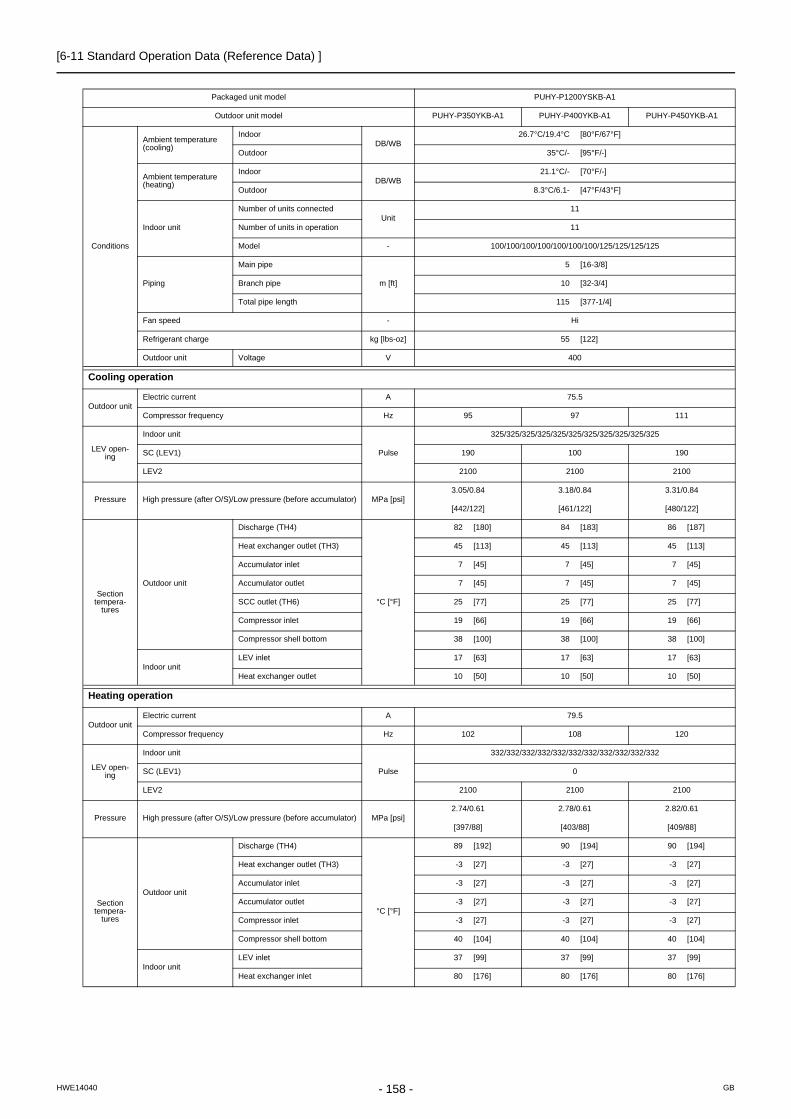
[6-11 Standard Operation Data (Reference Data) ]
Packaged unit model PUHY-P1200YSKB-A1
Outdoor unit model PUHY-P350YKB-A1 PUHY-P400YKB-A1 PUHY-P450YKB-A1
Conditions
Ambient temperature (cooling)
Indoor DB/WB
26.7°C/19.4°C [80°F/67°F]
Outdoor 35°C/- [95°F/-]
Ambient temperature (heating)
Indoor DB/WB
21.1°C/- [70°F/-]
Outdoor 8.3°C/6.1- [47°F/43°F]
Indoor unit
Number of units connectedUnit
11
Number of units in operation 11
Model - 100/100/100/100/100/100/100/125/125/125/125
Piping
Main pipe
m [ft]
5 [16-3/8]
Branch pipe 10 [32-3/4]
Total pipe length 115 [377-1/4]
Fan speed - Hi
Refrigerant charge kg [lbs-oz] 55 [122]
Outdoor unit Voltage V 400
Cooling operation
Outdoor unitElectric current A 75.5
Compressor frequency Hz 95 97 111
LEV open-ing
Indoor unit
Pulse
325/325/325/325/325/325/325/325/325/325/325
SC (LEV1) 190 100 190
LEV2 2100 2100 2100
Pressure High pressure (after O/S)/Low pressure (before accumulator) MPa [psi]3.05/0.84 3.18/0.84 3.31/0.84
[442/122] [461/122] [480/122]
Section tempera-
tures
Outdoor unit
Discharge (TH4)
°C [°F]
82 [180] 84 [183] 86 [187]
Heat exchanger outlet (TH3) 45 [113] 45 [113] 45 [113]
Accumulator inlet 7 [45] 7 [45] 7 [45]
Accumulator outlet 7 [45] 7 [45] 7 [45]
SCC outlet (TH6) 25 [77] 25 [77] 25 [77]
Compressor inlet 19 [66] 19 [66] 19 [66]
Compressor shell bottom 38 [100] 38 [100] 38 [100]
Indoor unitLEV inlet 17 [63] 17 [63] 17 [63]
Heat exchanger outlet 10 [50] 10 [50] 10 [50]
Heating operation
Outdoor unitElectric current A 79.5
Compressor frequency Hz 102 108 120
LEV open-ing
Indoor unit
Pulse
332/332/332/332/332/332/332/332/332/332/332
SC (LEV1) 0
LEV2 2100 2100 2100
Pressure High pressure (after O/S)/Low pressure (before accumulator) MPa [psi]2.74/0.61 2.78/0.61 2.82/0.61
[397/88] [403/88] [409/88]
Section tempera-
tures
Outdoor unit
Discharge (TH4)
°C [°F]
89 [192] 90 [194] 90 [194]
Heat exchanger outlet (TH3) -3 [27] -3 [27] -3 [27]
Accumulator inlet -3 [27] -3 [27] -3 [27]
Accumulator outlet -3 [27] -3 [27] -3 [27]
Compressor inlet -3 [27] -3 [27] -3 [27]
Compressor shell bottom 40 [104] 40 [104] 40 [104]
Indoor unitLEV inlet 37 [99] 37 [99] 37 [99]
Heat exchanger inlet 80 [176] 80 [176] 80 [176]
- 158 -HWE14040 GB

[6-11 Standard Operation Data (Reference Data) ]
6
Te
st
Ru
n
Packaged unit model PUHY-P1250YSKB-A1
Outdoor unit model PUHY-P350YKB-A1 PUHY-P450YKB-A1 PUHY-P450YKB-A1
Conditions
Ambient temperature (cooling)
Indoor DB/WB
26.7°C/19.4°C [80°F/67°F]
Outdoor 35°C/- [95°F/-]
Ambient temperature (heating)
Indoor DB/WB
21.1°C/- [70°F/-]
Outdoor 8.3°C/6.1°C [47°F/43°F]
Indoor unit
Number of units connectedUnit
11
Number of units in operation 11
Model - 100/100/100/100/100/125/125/125/125/125/125
Piping
Main pipe
m [ft]
5 [16-3/8]
Branch pipe 10 [32-3/4]
Total pipe length 115 [377-1/4]
Fan speed - Hi
Refrigerant charge kg [lbs-oz] 56 [124]
Outdoor unit Voltage V 400
Cooling operation
Outdoor unitElectric current A 78.7
Compressor frequency Hz 95 111 111
LEV open-ing
Indoor unit
Pulse
325/325/325/325/325/325/325/325/325/325/325
SC (LEV1) 190 190 190
LEV2 2100 2100 2100
Pressure High pressure (after O/S)/Low pressure (before accumulator) MPa [psi]3.05/0.84 3.31/0.84 3.31/0.84
[442/122] [480/122] [480/122]
Section tempera-
tures
Outdoor unit
Discharge (TH4)
°C [°F]
82 [180] 86 [187] 86 [187]
Heat exchanger outlet (TH3) 45 [113] 45 [113] 45 [113]
Accumulator inlet 7 [45] 7 [45] 7 [45]
Accumulator outlet 7 [45] 7 [45] 7 [45]
SCC outlet (TH6) 25 [77] 25 [77] 25 [77]
Compressor inlet 19 [66] 19 [66] 19 [66]
Compressor shell bottom 38 [100] 38 [100] 38 [100]
Indoor unitLEV inlet 17 [63] 17 [63] 17 [63]
Heat exchanger outlet 10 [50] 10 [50] 10 [50]
Heating operation
Outdoor unitElectric current A 83.2
Compressor frequency Hz 102 120 120
LEV open-ing
Indoor unit
Pulse
332/332/332/332/332/332/332/332/332/332/332
SC (LEV1) 0
LEV2 2100 2100 2100
Pressure High pressure (after O/S)/Low pressure (before accumulator) MPa [psi]2.74/0.61 2.82/0.61 2.82/0.61
[397/88] [409/88] [409/88]
Section tempera-
tures
Outdoor unit
Discharge (TH4)
°C [°F]
89 [192] 90 [194] 90 [194]
Heat exchanger outlet (TH3) -3 [27] -3 [27] -3 [27]
Accumulator inlet -3 [27] -3 [27] -3 [27]
Accumulator outlet -3 [27] -3 [27] -3 [27]
Compressor inlet -3 [27] -3 [27] -3 [27]
Compressor shell bottom 40 [104] 40 [104] 40 [104]
Indoor unitLEV inlet 37 [99] 37 [99] 37 [99]
Heat exchanger inlet 80 [176] 80 [176] 80 [176]
- 159 -HWE14040 GB

[6-11 Standard Operation Data (Reference Data) ]
Packaged unit model PUHY-P1300YSKB-A1
Outdoor unit model PUHY-P400YKB-A1 PUHY-P450YKB-A1 PUHY-P450YKB-A1
Conditions
Ambient temperature (cooling)
Indoor DB/WB
26.7°C/19.4°C [80°F/67°F]
Outdoor 35°C/- [95°F/-]
Ambient temperature (heating)
Indoor DB/WB
21.1°C/- [70°F/-]
Outdoor 8.3°C/6.1°C [47°F/43°F]
Indoor unit
Number of units connectedUnit
12
Number of units in operation 12
Model - 100/100/100/100/100/100/100/100/125/125/125/125
Piping
Main pipe
m [ft]
5 [16-3/8]
Branch pipe 10 [32-3/4]
Total pipe length 125 [410-1/16]
Fan speed - Hi
Refrigerant charge kg [lbs-oz] 58 [128]
Outdoor unit Voltage V 400
Cooling operation
Outdoor unitElectric current A 83.6
Compressor frequency Hz 97 111 111
LEV open-ing
Indoor unit
Pulse
325/325/325/325/325/325/325/325/325/325/325/325
SC (LEV1) 100 190 190
LEV2 2100 2100 2100
Pressure High pressure (after O/S)/Low pressure (before accumulator) MPa [psi]3.18/0.84 3.31/0.84 3.31/0.84
[461/122] [480/122] [480/122]
Section tempera-
tures
Outdoor unit
Discharge (TH4)
°C [°F]
84 [183] 86 [187] 86 [187]
Heat exchanger outlet (TH3) 45 [113] 45 [113] 45 [113]
Accumulator inlet 7 [45] 7 [45] 7 [45]
Accumulator outlet 7 [45] 7 [45] 7 [45]
SCC outlet (TH6) 25 [77] 25 [77] 25 [77]
Compressor inlet 19 [66] 19 [66] 19 [66]
Compressor shell bottom 38 [100] 38 [100] 38 [100]
Indoor unitLEV inlet 17 [63] 17 [63] 17 [63]
Heat exchanger outlet 10 [50] 10 [50] 10 [50]
Heating operation
Outdoor unitElectric current A 86.1
Compressor frequency Hz 108 120 120
LEV open-ing
Indoor unit
Pulse
332/332/332/332/332/332/332/332/332/332/332/332
SC (LEV1) 0
LEV2 2100 2100 2100
Pressure High pressure (after O/S)/Low pressure (before accumulator) MPa [psi]2.78/0.61 2.82/0.61 2.82/0.61
[403/88] [409/88] [409/88]
Section tempera-
tures
Outdoor unit
Discharge (TH4)
°C [°F]
90 [194] 90 [194] 90 [194]
Heat exchanger outlet (TH3) -3 [27] -3 [27] -3 [27]
Accumulator inlet -3 [27] -3 [27] -3 [27]
Accumulator outlet -3 [27] -3 [27] -3 [27]
Compressor inlet -3 [27] -3 [27] -3 [27]
Compressor shell bottom 40 [104] 40 [104] 40 [104]
Indoor unitLEV inlet 37 [99] 37 [99] 37 [99]
Heat exchanger inlet 80 [176] 80 [176] 80 [176]
- 160 -HWE14040 GB

[6-11 Standard Operation Data (Reference Data) ]
6
Te
st
Ru
n
Packaged unit model PUHY-P1350YSKB-A1
Outdoor unit model PUHY-P450YKB-A1 PUHY-P450YKB-A1 PUHY-P450YKB-A1
Conditions
Ambient temperature (cooling)
Indoor DB/WB
26.7°C/19.4°C [80°F/67°F]
Outdoor 35°C/- [95°F/-]
Ambient temperature (heating)
Indoor DB/WB
21.1°C/- [70°F/-]
Outdoor 8.3°C/6.1°C [47°F/43°F]
Indoor unit
Number of units connectedUnit
12
Number of units in operation 12
Model - 100/100/100/100/100/100/125/125/125/125/125/125
Piping
Main pipe
m [ft]
5 [16-3/8]
Branch pipe 10 [32-3/4]
Total pipe length 125 [410-1/16]
Fan speed - Hi
Refrigerant charge kg [lbs-oz] 59 [131]
Outdoor unit Voltage V 400
Cooling operation
Outdoor unitElectric current A 86.8
Compressor frequency Hz 111 111 111
LEV open-ing
Indoor unit
Pulse
325/325/325/325/325/325/325/325/325/325/325/325
SC (LEV1) 190 190 190
LEV2 2100 2100 2100
Pressure High pressure (after O/S)/Low pressure (before accumulator) MPa [psi]3.31/0.84 3.31/0.84 3.31/0.84
[480/122] [480/122] [480/122]
Section tempera-
tures
Outdoor unit
Discharge (TH4)
°C [°F]
86 [187] 86 [187] 86 [187]
Heat exchanger outlet (TH3) 45 [113] 45 [113] 45 [113]
Accumulator inlet 7 [45] 7 [45] 7 [45]
Accumulator outlet 7 [45] 7 [45] 7 [45]
SCC outlet (TH6) 25 [77] 25 [77] 25 [77]
Compressor inlet 19 [66] 19 [66] 19 [66]
Compressor shell bottom 38 [100] 38 [100] 38 [100]
Indoor unitLEV inlet 17 [63] 17 [63] 17 [63]
Heat exchanger outlet 10 [50] 10 [50] 10 [50]
Heating operation
Outdoor unitElectric current A 89.8
Compressor frequency Hz 120 120 120
LEV open-ing
Indoor unit
Pulse
332/332/332/332/332/332/332/332/332/332/332/332
SC (LEV1) 0
LEV2 2100 2100 2100
Pressure High pressure (after O/S)/Low pressure (before accumulator) MPa [psi]2.82/0.61 2.82/0.61 2.82/0.61
[409/88] [409/88] [409/88]
Section tempera-
tures
Outdoor unit
Discharge (TH4)
°C [°F]
90 [194] 90 [194] 90 [194]
Heat exchanger outlet (TH3) -3 [27] -3 [27] -3 [27]
Accumulator inlet -3 [27] -3 [27] -3 [27]
Accumulator outlet -3 [27] -3 [27] -3 [27]
Compressor inlet -3 [27] -3 [27] -3 [27]
Compressor shell bottom 40 [104] 40 [104] 40 [104]
Indoor unitLEV inlet 37 [99] 37 [99] 37 [99]
Heat exchanger inlet 80 [176] 80 [176] 80 [176]
- 161 -HWE14040 GB

[6-11 Standard Operation Data (Reference Data) ]
- 162 -HWE14040 GB

- 163 -HWE14040 GB
Chapter 7 Troubleshooting Using Error Codes
7-1 Error Code and Preliminary Error Code Lists ................................................................................ 165
7-2 Error Code Definitions and Solutions: Codes [0 - 999] ................................................................. 169
7-2-1 Error Code [0403] ............................................................................................................................... 169
7-2-2 Error Code [0404] ............................................................................................................................... 170
7-3 Error Code Definitions and Solutions: Codes [1000 - 1999] ......................................................... 171
7-3-1 Error Code [1102] ............................................................................................................................... 171
7-3-2 Error Code [1301] ............................................................................................................................... 172
7-3-3 Error Code [1302] (during operation) .................................................................................................. 173
7-3-4 Error Code [1302] (at startup) ............................................................................................................. 174
7-3-5 Error Code [1500] ............................................................................................................................... 174
7-4 Error Code Definitions and Solutions: Codes [2000 - 2999] ......................................................... 175
7-4-1 Error Code [2500] (Models with a drain sensor) ................................................................................. 175
7-4-2 Error Code [2500] (Models with a float switch) ................................................................................... 176
7-4-3 Error Code [2502] (Models with a drain sensor) ................................................................................. 177
7-4-4 Error Code [2502] (Models with a float switch) ................................................................................... 178
7-4-5 Error Code [2503] ............................................................................................................................... 179
7-4-6 Error Code [2600] ............................................................................................................................... 180
7-4-7 Error Code [2601] ............................................................................................................................... 180
7-5 Error Code Definitions and Solutions: Codes [3000 - 3999] ......................................................... 181
7-5-1 Error Code [3121] ............................................................................................................................... 181
7-6 Error Code Definitions and Solutions: Codes [4000 - 4999] ......................................................... 182
7-6-1 Error Code [4102] ............................................................................................................................... 182
7-6-2 Error Code [4106] ............................................................................................................................... 183
7-6-3 Error Code [4109] ............................................................................................................................... 183
7-6-4 Error Code [4115] ............................................................................................................................... 184
7-6-5 Error Code [4116] ............................................................................................................................... 184
7-6-6 Error Code [4121] ............................................................................................................................... 185
7-6-7 Error Code [4124] ............................................................................................................................... 186
7-6-8 Error Codes [4220, 4225, 4226] Detail Code 108............................................................................... 187
7-6-9 Error Codes [4220, 4225, 4226] Detail Code 109............................................................................... 188
7-6-10 Error Code [4220] Detail Code 110..................................................................................................... 189
7-6-11 Error Codes [4220, 4225, 4226] Detail Code 111, 112....................................................................... 189
7-6-12 Error Code [4220] Detail Code 123..................................................................................................... 190
7-6-13 Error Code [4220] Detail Code 124..................................................................................................... 190
7-6-14 Error Codes [4220, 4225, 4226] Detail Code 131............................................................................... 191
7-6-15 Error Code [4230] Detail Code 125..................................................................................................... 191
7-6-16 Error Code [4230] Detail Code 126..................................................................................................... 192
7-6-17 Error Code [4240] ............................................................................................................................... 193
7-6-18 Error Codes [4250, 4255, 4256] Detail Code 101............................................................................... 194
7-6-19 Error Codes [4250, 4255, 4256] Detail Code 104............................................................................... 195
7-6-20 Error Codes [4250, 4255, 4256] Detail Code 105............................................................................... 196
7-6-21 Error Code [4250] Detail Codes 106 and 107..................................................................................... 196
7-6-22 Error Code [4250] Detail Codes 121, 128, and 122............................................................................ 197
7-6-23 Error Code [4260] ............................................................................................................................... 197
7-7 Error Code Definitions and Solutions: Codes [5000 - 5999] ......................................................... 198
7-7-1 Error Codes [5101, 5102, 5103, 5104]................................................................................................ 198
7-7-2 Error Codes [5102,5103,5104,5105,5106,5107,5109,5111]............................................................... 199

- 164 -HWE14040 GB
7-7-3 Error Code [5110] ............................................................................................................................... 200
7-7-4 Error Code [5120] ............................................................................................................................... 201
7-7-5 Error Code [5201] ............................................................................................................................... 201
7-7-6 Error Code [5301] Detail Code 115..................................................................................................... 202
7-7-7 Error Code [5301] Detail Code 117..................................................................................................... 202
7-7-8 Error Code [5301] Detail Code 119..................................................................................................... 203
7-7-9 Error Code [5301] Detail Code 120..................................................................................................... 203
7-7-10 Error Code [5301] Detail Code 127..................................................................................................... 204
7-7-11 Error Codes [5305, 5306] Detail Code 132......................................................................................... 204
7-7-12 Error Codes [5305, 5306] Detail Code 133......................................................................................... 205
7-7-13 Error Codes [5305, 5306] Detail Code 134......................................................................................... 205
7-7-14 Error Code [5701] ............................................................................................................................... 205
7-8 Error Code Definitions and Solutions: Codes [6000 - 6999] ......................................................... 206
7-8-1 Error Code [6201] ............................................................................................................................... 206
7-8-2 Error Code [6202] ............................................................................................................................... 206
7-8-3 Error Code [6600] ............................................................................................................................... 207
7-8-4 Error Code [6601] ............................................................................................................................... 207
7-8-5 Error Code [6602] ............................................................................................................................... 208
7-8-6 Error Code [6603] ............................................................................................................................... 209
7-8-7 Error Code [6606] ............................................................................................................................... 209
7-8-8 Error Code [6607] Error Source Address = Outdoor Unit (OC)........................................................... 210
7-8-9 Error Code [6607] Error Source Address = Indoor Unit (IC) ............................................................... 211
7-8-10 Error Code [6607] Error Source Address = LOSSNAY (LC)............................................................... 212
7-8-11 Error Code [6607] Error Source Address = ME Remote Controller .................................................... 213
7-8-12 Error Code [6607] Error Source Address = System Controller ........................................................... 214
7-8-13 Error Code [6607] All Error Source Addresses ................................................................................... 215
7-8-14 Error Code [6607] No Error Source Address ...................................................................................... 216
7-8-15 Error Code [6608] ............................................................................................................................... 217
7-8-16 Error Code [6831] ............................................................................................................................... 218
7-8-17 Error Code [6832] ............................................................................................................................... 219
7-8-18 Error Code [6833] ............................................................................................................................... 220
7-8-19 Error Code [6834] ............................................................................................................................... 221
7-8-20 Error Code [6840] ............................................................................................................................... 222
7-8-21 Error Code [6841] ............................................................................................................................... 222
7-8-22 Error Code [6842] ............................................................................................................................... 223
7-8-23 Error Code [6843] ............................................................................................................................... 224
7-8-24 Error Code [6846] ............................................................................................................................... 225
7-9 Error Code Definitions and Solutions: Codes [7000 - 7999] ......................................................... 226
7-9-1 Error Code [7100] ............................................................................................................................... 226
7-9-2 Error Code [7101] ............................................................................................................................... 227
7-9-3 Error Code [7102] ............................................................................................................................... 228
7-9-4 Error Code [7105] ............................................................................................................................... 229
7-9-5 Error Code [7106] ............................................................................................................................... 229
7-9-6 Error Code [7110] ............................................................................................................................... 230
7-9-7 Error Code [7111] ............................................................................................................................... 230
7-9-8 Error Code [7113] ............................................................................................................................... 231
7-9-9 Error Code [7117] ............................................................................................................................... 232
7-9-10 Error Code [7130] ............................................................................................................................... 233

[7-1 Error Code and Preliminary Error Code Lists ]
7 T
rou
ble
sh
oo
tin
g U
sin
g E
rro
r C
od
es
7 Troubleshooting Using Error Codes
7-1 Error Code and Preliminary Error Code Lists
Error Code
Prelimi-nary error code
Error (prelim-inary) detail code
Error code definition
Searched unit
Notes
0403430043054306
156
(Note)
Serial communication error/Panel communication error O O (page 169)
0404 - - Indoor unit EEPROM abnormality O (page 170)
0900 - - Test run O
1102 1202 - Discharge temperature fault O (page 171)
1301 - - Low pressure fault O (page 172)
1302 1402 - High pressure fault O (page 173)
1500 1600 - Refrigerant overcharge O (page 174)
- 1605 - Preliminary suction pressure fault O
2500 - - Drain sensor submergence O (page 175)
2502 - - Drain pump fault O (page 177)
2503 - - Drain sensor (Thd) fault O O (page 179)
2600 - - Water leakage O (page 180)
2601 - - Water supply cutoff O (page 180)
3121 - - Out-of-range outside air temperature O (page 181)
4102 4152 - Open phase O (page 182)
4106 - - Transmission power supply fault O (page 183)
4109 - - Fan operation status detection error O (page 183)
4115 - - Power supply signal sync error O (page 184)
4116 - - RPM error/Motor error O O (page 184)
4121 4171 − Function setting error O (page 185)
4124 - − Electric system not operate due to damper abnormality O (page 186)
422042254226
(Note)
432043254326
(Note)
[0] Backup operation O
[108] Abnormal bus voltage drop (Software detection) O (page 187)
[109] Abnormal bus voltage rise (Software detection) O (page 188)
[110] BUS voltage error (Hardware detection) O (page 189)
[111] Logic error O (page 189)
[112] Logic error O (page 189)
[123] Voltage boost control error O (page 190)
[124] BUS circuit fault O (page 190)
[131] Low bus voltage at startup O (page 191)
4230 4330[125] Heatsink overheat protection O (page 191)
[126] DCL temperature fault O (page 192)
4240 4340 - Overload protection O (page 193)
Out
door
uni
t
Indo
or u
nit
LOS
SN
AY
Rem
ote
cont
rolle
r
- 165 -HWE14040 GB

[7-1 Error Code and Preliminary Error Code Lists ]
425042554256
(Note)
435043554356
(Note)
[0] Backup operation O
[101] IPM error O (page 194)
[104] Short-circuited IPM/Ground fault O (page 195)
[105] Overcurrent error due to short-circuited motor O (page 196)
[106] Instantaneous overcurrent (S/W detection) O (page 196)
[107] Overcurrent (effective value)(S/W detection) O (page 196)
[121] DCL overcurrent breaker error (hardware detection) O (page 197)
[122] DCL overcurrent breaker error (software detection) O (page 197)
[128] DCL overcurrent breaker error (hardware detection) O (page 197)
4260 - - Heatsink overheat protection at startup O (page 197)
5101 1202 - Temperature sensor fault
Return air temperature (TH21) O (page 198)
OA processing unit inlet temperature (TH4) O (page 198)
5102 1217 - Temperature sensor fault
Indoor unit pipe tempera-ture (TH22) O (page 198)
OA processing unit pipe temperature (TH2) O (page 198)
HIC bypass circuit outlet temperature (TH2) O (page 199)
5103 1205 00 Temperature sensor fault
Indoor unit gas-side pipe temperature (TH23) O (page 198)
OA processing unit gas-side pipe temperature (TH3) O (page 198)
Pipe temperature at heatex-changer outlet (TH3) O (page 199)
5104 1202 - Temperature sensor fault
OA processing unit intake air temperature (TH1) O (page 198)
Outside temperature (TH24) O
(page 198) Detectable only by the All-Fresh type in-door units
Outdoor unit discharge tem-perature (TH4) O (page 199)
5105 1204 - Temperature sensor fault Accumulator inlet tempera-ture (TH5)
O (page 199)
5106 1216 - Temperature sensor fault HIC circuit outlet tempera-ture (TH6)
O (page 199)
5107 1221 - Temperature sensor fault Outside temperature (TH7) O (page 199)
5109 1273 - Temperature sensor faultHeat exchanger outlet pipe temperature (TH9) O
(page 199)
5110 1214
[0] Backup operation O
01 Temperature sensor fault Heatsink temperature (THHS) O (page 200)
Error Code
Prelimi-nary error code
Error (prelim-inary) detail code
Error code definition
Searched unit
Notes
Out
door
uni
t
Indo
or u
nit
LOS
SN
AY
Rem
ote
cont
rolle
r
- 166 -HWE14040 GB

[7-1 Error Code and Preliminary Error Code Lists ]
7 T
rou
ble
sh
oo
tin
g U
sin
g E
rro
r C
od
es
5111 1274 - Temperature sensor faultHeat exchanger outlet pipe temperature (TH11) O
(page 199)
5120 1248[0] Backup operation O
01 Temperature sensor fault DCL(THL) O
5201 - - High-pressure sensor fault (63HS1) O (page 201)
5301 4300
[0] Backup operation O
[115] ACCT sensor fault O (page 202)
[117] ACCT sensor circuit fault O (page 202)
[119] Open-circuited IPM/Loose ACCT connector O (page 203)
[120] Faulty ACCT wiring O (page 203)
[127] DCL electric current circuit error O (page 204)
53055306
43054306
[0] Backup operation O
[132] Position detection error at startup O (page 204)
[133] Position detection error during operation O (page 205)
[134] RPM error before startup O (page 205)
5701 - - Loose float switch connector O (page 205)
6201 - - Remote controller board fault (nonvolatile memory error) O (page 206)
6202 - - Remote controller board fault (clock IC error) O (page 206)
6600 - - Address overlap O O O O (page 207)
6601 - - Polarity setting error O (page 207)
6602 - - Transmission processor hardware error O O O O (page 208)
6603 - - Transmission line bus busy error O O O O (page 209)
6606 - - Communication error between device and transmission processors
O O O O (page 209)
6607 - - No ACK error O O O O (page 210)
6608 - - No response error O O O O (page 217)
6831 - - MA controller signal reception error (No signal reception) O O (page 218)
6832 - - MA remote controller signal transmission error (Synchro-nization error)
O O (page 219)
6833 - - MA remote controller signal transmission error (Hard-ware error)
O O (page 220)
6834 - -MA controller signal reception error (Start bit detection error) O O (page 221)
6840 - - A control communication reception error O (page 222)
6841 - - A control communication synchronism not recover O (page 222)
6842 - - A control communication transmission/reception hard-ware trouble
O (page 223)
6843 - - A control communication start bit detection error O (page 224)
6846 - - Start-up time over O (page 225)
7100 - - Total capacity error O (page 226)
Error Code
Prelimi-nary error code
Error (prelim-inary) detail code
Error code definition
Searched unit
Notes
Out
door
uni
t
Indo
or u
nit
LOS
SN
AY
Rem
ote
cont
rolle
r
- 167 -HWE14040 GB

[7-1 Error Code and Preliminary Error Code Lists ]
The last digit in the check error codes in the 4000's and 5000's and two-digit detail codes indicate if the codes apply to com-pressor inverter on fan inverter.ExampleCode 4225 (detail code 108): Bus voltage drop in the fan inverter systemCode 4230 : Heatsink overheat protection in the compressor inverter system
7101 - - Capacity code setting error O O O (page 227)
7102 - - Wrong number of connected units O (page 228)
7105 - - Address setting error O (page 229)
7106 - - Attribute setting error O (page 229)
7110 - - Connection information signal transmission/reception er-ror O (page 230)
7111 - - Remote controller sensor fault O O (page 230)
7113 - - Function setting error (improper connection of CNTYP) O (page 231)
7117 - - Model setting error O (page 232)
7130 - - Incompatible unit combination O (page 233)
Error Code
Prelimi-nary error code
Error (prelim-inary) detail code
Error code definition
Searched unit
Notes
Out
door
uni
t
Indo
or u
nit
LOS
SN
AY
Rem
ote
cont
rolle
r
The last digit Inverter system
0 or 1 Compressor inverter system
5 or 6 Fan inverter system
INV board Series name
Outdoor unitsOverload protection
Imax (Arms)
Current effective value error
(Arms)
Current peak value error (Apeak)
Temper-ature
protec-tion TOL
(°C)
INV20Y
Standard
PUHY-P200YKB-A1 15 23 38 100
PUHY-P250YKB-A1 15 23 38 100
PUHY-P300YKB-A1 27 33 56 100
PUHY-P350YKB-A1 27 33 56 100
PUHY-P400YKB-A1 27 33 56 100
INV30YCPUHY-P450YKB-A1 22 26 44 89
PUHY-P500YKB-A1 22 26 44 89
- 168 -HWE14040 GB
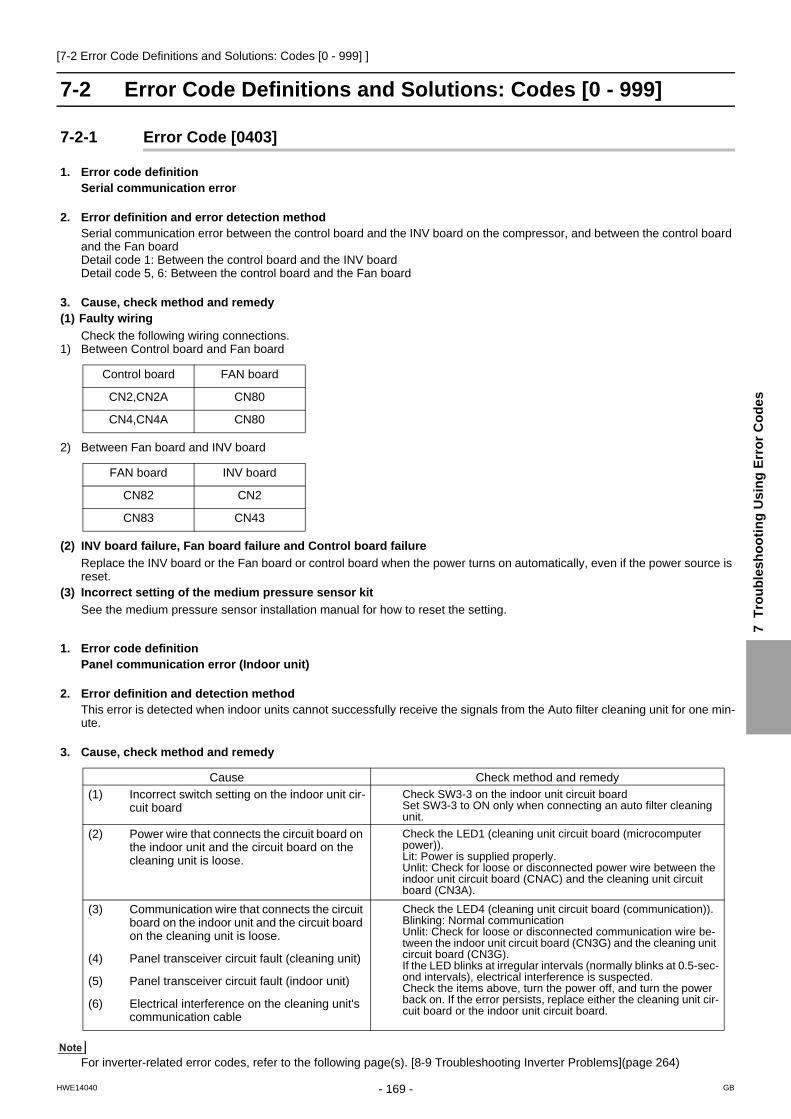
[7-2 Error Code Definitions and Solutions: Codes [0 - 999] ]
7 T
rou
ble
sh
oo
tin
g U
sin
g E
rro
r C
od
es
7-2 Error Code Definitions and Solutions: Codes [0 - 999]
7-2-1 Error Code [0403]
1. Error code definitionSerial communication error
2. Error definition and error detection methodSerial communication error between the control board and the INV board on the compressor, and between the control board and the Fan boardDetail code 1: Between the control board and the INV board Detail code 5, 6: Between the control board and the Fan board
3. Cause, check method and remedy(1) Faulty wiring
Check the following wiring connections.1) Between Control board and Fan board
2) Between Fan board and INV board
(2) INV board failure, Fan board failure and Control board failure
Replace the INV board or the Fan board or control board when the power turns on automatically, even if the power source is reset.
(3) Incorrect setting of the medium pressure sensor kit
See the medium pressure sensor installation manual for how to reset the setting.
1. Error code definitionPanel communication error (Indoor unit)
2. Error definition and detection methodThis error is detected when indoor units cannot successfully receive the signals from the Auto filter cleaning unit for one min-ute.
3. Cause, check method and remedy
For inverter-related error codes, refer to the following page(s). [8-9 Troubleshooting Inverter Problems](page 264)
Control board FAN board
CN2,CN2A CN80
CN4,CN4A CN80
FAN board INV board
CN82 CN2
CN83 CN43
Cause Check method and remedy
(1) Incorrect switch setting on the indoor unit cir-cuit board
Check SW3-3 on the indoor unit circuit board Set SW3-3 to ON only when connecting an auto filter cleaning unit.
(2) Power wire that connects the circuit board on the indoor unit and the circuit board on the cleaning unit is loose.
Check the LED1 (cleaning unit circuit board (microcomputer power)). Lit: Power is supplied properly. Unlit: Check for loose or disconnected power wire between the indoor unit circuit board (CNAC) and the cleaning unit circuit board (CN3A).
(3) Communication wire that connects the circuit board on the indoor unit and the circuit board on the cleaning unit is loose.
Check the LED4 (cleaning unit circuit board (communication)).Blinking: Normal communication Unlit: Check for loose or disconnected communication wire be-tween the indoor unit circuit board (CN3G) and the cleaning unit circuit board (CN3G). If the LED blinks at irregular intervals (normally blinks at 0.5-sec-ond intervals), electrical interference is suspected. Check the items above, turn the power off, and turn the power back on. If the error persists, replace either the cleaning unit cir-cuit board or the indoor unit circuit board.
(4) Panel transceiver circuit fault (cleaning unit)
(5) Panel transceiver circuit fault (indoor unit)
(6) Electrical interference on the cleaning unit's communication cable
- 169 -HWE14040 GB

[7-2 Error Code Definitions and Solutions: Codes [0 - 999] ]
7-2-2 Error Code [0404]
1. Error code definitionA control communication reception error
2. Error definition and error detection methodIndoor controller boardAbnormal if data cannot be read normally from the nonvolatile memory of the indoor controller board.
3. Cause, check method and remedy
Cause Check method and remedy
Defective indoor controller board Replace indoor controller board.
- 170 -HWE14040 GB

[7-3 Error Code Definitions and Solutions: Codes [1000 - 1999] ]
7 T
rou
ble
sh
oo
tin
g U
sin
g E
rro
r C
od
es
7-3 Error Code Definitions and Solutions: Codes [1000 - 1999]
7-3-1 Error Code [1102]
1. Error code definitionDischarge temperature fault
2. Error definition and error detection method1) If the discharge temperature of 120 °C [248°F] or more is detected during the above operation (the first detection), the outdoor
unit stops once, turns to anti-restart mode for 3 minutes, and restarts after 3 minutes automatically.2) If the discharge temperature of 120° C [248°F] or more is detected again (the second detection) within 30 minutes after the
second stop of the outdoor unit described above, the mode will be changed to 3 - minute restart mode, then the outdoor unit will restart in 3 minutes.
3) If the discharge temperature of 120°C [248°F] or more is detected (the 30th detection) within 30 minutes after the stop of the outdoor unit described above (regardless of the first or the 29th stop), the outdoor unit will make an error stop, and the error code "1102" will be displayed.
4) If the discharge temperature of 120°C [248°F] or more is detected more than 30 minutes after the previous stop of the outdoor unit, the detection is regarded as the first detection, and the operation described in step 1 above will start.
5) For 30 minutes after the stop (the first stop or the second stop) of the outdoor unit, preliminary errors will be displayed on the LED display.
3. Cause, check method and remedy
Cause Check method and remedy
(1) Gas leak, gas shortage Refer to the following page(s).[6-9 Evaluating and Adjusting Refrigerant Charge](page 131)
(2) Overload operation Check operating conditions and operation status of indoor/outdoor units.
(3) LEV failure on the indoor unit Perform a cooling or heating operation to check the opera-tion.Cooling: Indoor unit LEV, LEV1, LEV2Heating: Indoor unit LEV, LEV2Refer to the following page(s). [8-8 Troubleshooting LEV Problems](page 258)
(4) Outdoor unit LEV1 actuation failureOutdoor unit LEV2 actuation failure
(5) Closed refrigerant service valve Confirm that the refrigerant service valve is fully open.
(6) Outdoor fan (including fan parts) failure, mo-tor failure, or fan controller malfunctionRise in discharge temp. by low pressure drawing for (3) - (6).
Check the fan on the outdoor unit. Refer to the following page(s). [8-7 Troubleshooting Outdoor Unit Fan Problems](page 257)
(7) Gas leak between low and high pressures(4-way valve failure, Compressor failure, So-lenoid valve (SV1a) failure)
Perform a cooling or heating operation and check the opera-tion.
(8) Thermistor failure(TH4)
Refer to the following page(s).
(9) Input circuit failure on the controller board thermistor
Check the inlet air temperature on the LED monitor.
- 171 -HWE14040 GB

[7-3 Error Code Definitions and Solutions: Codes [1000 - 1999] ]
7-3-2 Error Code [1301]
1. Error code definitionLow pressure fault
2. Error definition and error detection methodWhen starting the compressor from Stop Mode for the first time if low pressure reads 0.098MPa [14psi] immediately before start-up, the operation immediately stops.
3. Cause, check method and remedy
Cause Check method and remedy
(1) Inner pressure drop due to a leakage. Refer to the following page(s). [8-5-3 Comparing the Low-Pressure Sensor Measurement and Gauge Pressure](page 254)(2) Low pressure sensor failure
(3) Short-circuited pressure sensor cable due to torn outer rubber
(4) A pin on the male connector is missing.
(5) Disconnected wire
(6) Failure of the low pressure input circuit on the controller board
- 172 -HWE14040 GB

[7-3 Error Code Definitions and Solutions: Codes [1000 - 1999] ]
7 T
rou
ble
sh
oo
tin
g U
sin
g E
rro
r C
od
es
7-3-3 Error Code [1302] (during operation)
1. Error code definitionHigh pressure fault 1 (Outdoor unit)
2. Error definition and error detection method1) If the pressure of 3.78MPa [548psi] or higher is detected by the pressure sensor during operation (the first detection), the out-
door stops once, turns to antirestart mode for 3 minutes, and restarts after 3 minutes automatically.2) If the pressure of 3.78MPa [548psi] or higher is detected by the pressure sensor again (the second detection) within 30 min-
utes after the first stop of the outdoor unit, the outdoor unit stops once, turns to anti-restart mode for 3 minutes, and restarts after 3 minutes automatically.
3) If the pressure of 3.87MPa [561psi] or higher is detected by the pressure sensor (the third detection) within 30 minutes of the second stop of the outdoor unit, the outdoor unit will make an error stop, and the error code "1302" will be displayed.
4) If the pressure of 3.78MPa [548psi] or higher is detected more than 30 minutes after the stop of the outdoor unit, the detection is regarded as the first detection, and the operation described in step 1 above will start.
5) For 30 minutes after the stop of the outdoor unit, preliminary errors will be displayed on the LED display.6) The outdoor unit makes an error stop immediately when not only the pressure sensor but also the pressure switch detects
4.15+0,-0.15 MPa [601+0,-22 psi]7) Open phase due to unstable power supply voltage may cause the pressure switch to malfunction or cause the units to come
to an abnormal stop.
3. Cause, check method and remedy
Cause Check method and remedy
(1) Indoor unit LEV2 actuation failure -> CoolingIndoor unit LEV actuation failure -> Heating
Perform a cooling or heating operation to check the oper-ation.Cooling: Indoor unit LEV2Heating: Indoor unit LEVRefer to the following page(s). [8-8 Troubleshooting LEV Problems](page 258)
(2) Closed refrigerant service valve Confirm that the refrigerant service valve is fully open.
(3) Short cycle on the indoor unit side Check the indoor units for problems and correct them, if any.(4) Clogged filter on the indoor unit
(5) Reduced air flow due to dirty fan on the indoor unit fan
(6) Dirty heat exchanger of the indoor unit
(7) Indoor fan (including fan parts) failure or motor failureRise in high pressure caused by lowered con-densing capacity in heating operation for (2) - (7).
(8) Short cycle on the outdoor unit Check the outdoor units for problems and correct them, if any.(9) Dirty heat exchanger of the outdoor unit
(10) Outdoor fan (including fan parts) failure, motor failure, or fan controller malfunctionRise in discharge temp. by low pressure drawing for (8) - (10).
Check the fan on the outdoor unit.Refer to the following page(s). [8-7 Troubleshooting Out-door Unit Fan Problems](page 257)
(11) Solenoid valve (SV1a) malfunction (The by-pass valve (SV1a) can not control rise in high pres-sure).
Refer to the following page(s). [8-6 Troubleshooting Sole-noid Valve Problems](page 255)
(12) Thermistor failure (TH3, TH7) Refer to the following page(s).
(13) Pressure sensor failure Refer to the following page(s). [8-5-1 Comparing the High-Pressure Sensor Measurement and Gauge Pres-sure](page 253)
(14) Failure of the thermistor input circuit and pressure sensor input circuit on the controller board
Check the temperature and the pressure of the sensor with LED monitor.
(15) Thermistor mounting problem (TH3, TH7) Check the temperature and the pressure of the sensor with LED monitor.
(16) Disconnected male connector on the pressure switch (63H1) or disconnected wire
(17) Voltage drop caused by unstable power supply voltage
Check the input voltage at the power supply terminal block (TB1).
- 173 -HWE14040 GB

[7-3 Error Code Definitions and Solutions: Codes [1000 - 1999] ]
7-3-4 Error Code [1302] (at startup)
1. Error code definitionHigh pressure fault 2 (Outdoor unit)
2. Error definition and error detection methodIf the pressure of 0.098MPa [14psi] or lower is registered on the pressure sensor immediately before start-up, it will trigger an abnormal stop, and error code "1302" will be displayed.
3. Cause, check method and remedy
7-3-5 Error Code [1500]
1. Error code definitionRefrigerant overcharge
2. Error definition and error detection methodAn error can be detected by the discharge temperature superheat.
1) If the formula "TdSH 10°C [18°F]" is satisfied during operation (first detection), the outdoor unit stops, goes into the 3-minute restart mode, and starts up in three minutes.
2) If the formula "TdSH 10°C [18°F]" is satisfied again within 30 minutes of the fifth stoppage of the outdoor unit (sixth detec-tion), the unit comes to an abnormal stop, and the error code "1500" appears.
3) If the formula "TdSH 10°C [18°F]" is satisfied 30 minutes or more after the first stoppage of the outdoor unit, the same se-quence as Item "1 above (first detection) is followed.
4) For 30 minutes after the stop of the outdoor unit, preliminary errors will be displayed on the LED display.
3. Cause, check method and remedy
Cause Check method and remedy
(1) Inner pressure drop due to a leakage. Refer to the following page(s). [8-5-1 Comparing the High-Pressure Sensor Measurement and Gauge Pressure](page 253)(2) Pressure sensor failure
(3) Shorted-circuited pressure sensor cable due to torn outer rubber
(4) A pin on the male connector on the pressure sensor is missing or contact failure
(5) Disconnected pressure sensor cable
(6) Failure of the pressure sensor input circuit on the controller board
Cause Check method and remedy
(1) Overcharged refrigerant Refer to the following page(s). [6-9 Evaluating and Adjust-ing Refrigerant Charge](page 131)
(2) Thermistor input circuit failure on the control board Check the temperature and pressure readings on the sen-sor that are displayed on the LED monitor.
(3) Faulty mounting of thermistor (TH4) Check the temperature and pressure readings on the thermistor that are displayed on the LED monitor.
(4) Outdoor unit LEV2 actuation failure -> Heating Refer to the following page(s). [8-8 Troubleshooting LEV Problems](page 258)
- 174 -HWE14040 GB

[7-4 Error Code Definitions and Solutions: Codes [2000 - 2999] ]
7 T
rou
ble
sh
oo
tin
g U
sin
g E
rro
r C
od
es
7-4 Error Code Definitions and Solutions: Codes [2000 - 2999]
7-4-1 Error Code [2500] (Models with a drain sensor)
1. Error code definitionDrain sensor submergence
2. Error definition and error detection method1) If an immersion of the drain sensor in the water is detected while the unit is in any mode other than the Cool/Dry mode and
when the drain pump goes from OFF to ON, this condition is considered preliminary water leakage. While this error is being detected, humidifier output cannot be turned on.
2) If the immersion of the sensor in the water is detected four consecutive times at an hour interval, this is considered water leak-age, and "2500" appears on the monitor.
3) Detection of water leakage is also performed while the unit is stopped.4) Preliminary water leakage is cancelled when the following conditions are met:
One hour after the preliminary water leakage was detected, it is not detected that the drain pump goes from OFF to ON.The operation mode is changed to Cool/Dry.The liquid pipe temperature minus the inlet temperature is -10°C [-18°F] or less.
3. Cause, check method and remedy
Cause Check method and remedy
(1) Drain water drainage problemClogged drain pumpClogged drain pipingBackflow of drain water from other units
Check for proper drainage.
(2) Adhesion of water drops to the drain sensorTrickling of water along the lead wireRippling of drain water caused by filter clogging
1) Check for proper lead wire installation.
2) Check for clogged filter.
(3) Failure of the relay circuit for the solenoid valve Replace the relay.
(4) Indoor unit control board failureDrain sensor circuit failure
If the above item checks out OK, replace the indoor unit control board.
- 175 -HWE14040 GB

[7-4 Error Code Definitions and Solutions: Codes [2000 - 2999] ]
7-4-2 Error Code [2500] (Models with a float switch)
1. Error code definitionDrain sensor submergence
2. Error definition and error detection method1) If an immersion of the float switch in the water is detected while the unit is in any mode other than the Cool/Dry mode and
when the drain pump goes from OFF to ON, this condition is considered preliminary water leakage. While this error is being detected, humidifier output cannot be turned on.
2) If the drain pump turns on within one hour after preliminary water leakage is detected and the above-mentioned condition is detected two consecutive times, water leakage error water leakage is detected, and "2500" appears on the monitor.
3) Detection of water leakage is also performed while the unit is stopped.4) Preliminary water leakage is cancelled when the following conditions are met:
One hour after the preliminary water leakage was detected, it is not detected that the drain pump goes from OFF to ON.The operation mode is changed to Cool/Dry.The liquid pipe temperature minus the inlet temperature is - 10°C [ -18°F] or less.
3. Cause, check method and remedy
<Reference>
Cause Check method and remedy
(1) Drain water drainage problemClogged drain pumpClogged drain pipingBackflow of drain water from other units
Check for proper drainage.
(2) Stuck float switchCheck for slime in the moving parts of the float switch.
Check for normal operation of the float switch.
(3) Float switch failure Check the resistance with the float switch turned on and turned off.
6 minutes6 minutes
15 seconds
15 seconds 15
seconds15
seconds15
seconds
ON
OFF
ON
OFF
Drain pump operation triggered by a submergence of the liquid level sensor (except during the Cooing/Dry mode)
Drain pump output
Float switch input
Submergence of the sensor
Submergence of the sensor Preliminary water leakage
Submergence of the sensor Water leakage
Sensor in the airSensor in the air
Within 1-hour periodWithin 1-hour period
- 176 -HWE14040 GB

[7-4 Error Code Definitions and Solutions: Codes [2000 - 2999] ]
7 T
rou
ble
sh
oo
tin
g U
sin
g E
rro
r C
od
es
7-4-3 Error Code [2502] (Models with a drain sensor)
1. Error code definitionDrain pump fault
2. Error definition and error detection method1) Make the drain sensor thermistor self-heat. If the temperature rise is small, it is interpreted that the sensor is immersed in
water. This condition is considered to be a preliminary error, and the unit goes into the 3-minute restart delay mode.2) If another episode of the above condition is detected during the preliminary error, this is considered a drain pump error, and
"2502" appears on the monitor.3) This error is always detected while the drain pump is in operation.4) The following criteria are met when the criteria for the forced stoppage of outdoor unit (system stoppage) are met.
"Liquid pipe temperature - inlet temperature -10°C [ -18 °F] " has been detected for 30 minutes.The immersion of drain sensor is detected 10 consecutive times.The conditions that are listed under items 1) through 3) above are always met before the criteria for the forced stoppage
of the outdoor unit.5) The indoor unit that detected the conditions that are listed in item 4) above brings the outdoor unit in the same refrigerant
circuit to an error stop (compressor operation prohibited), and the outdoor unit brings all the indoor units in the same refrigerant circuit that are in any mode other than Fan or Stop to an error stop. "2502" appears on the monitor of the units that came to an error stop.
6) Forced stoppage of the outdoor unitDetection timing: The error is detected whether the unit is in operation or stopped.
7) Ending criteria for the forced stoppage of outdoor unitPower reset the indoor unit that was identified as the error source and the outdoor unit that is connected to the same refrig-erant circuit.Forced stoppage of the outdoor unit cannot be cancelled by stopping the unit via the remote controller.(Note) Items 1) - 3) and 4) - 7) are detected independently from each other.
The address and attribute that appear on the remote controller are those of the indoor unit (or OA processing unit) that caused the error.
3. Cause, check method and remedy
Cause Check method and remedy
(1) Drain pump failure Check for proper functioning of the drain pump.
(2) Drain water drainage problemClogged drain pumpClogged drain piping
Check for proper drainage.
(3) Adhesion of water drops to the drain sensorTrickling of water along the lead wireRippling of drain water caused by filter clogging
1) Check for proper lead wire installation.
2) Check for clogged filter.
(4) Indoor unit control board failureDrain pump drive circuit failureDrain heater output circuit failure
If the above item checks out OK, replace the indoor unit control board.
(5) Items (1) through (4) above and an indoor unit elec-tronic valve closure failure (leaky valve) occurred si-multaneously.
Check the solenoid valves on the indoor unit for leaks.
- 177 -HWE14040 GB

[7-4 Error Code Definitions and Solutions: Codes [2000 - 2999] ]
7-4-4 Error Code [2502] (Models with a float switch)
1. Error code definitionDrain pump fault
2. Error definition and error detection method1) The immersion of sensor tip in water is detected by the ON/OFF signal from the float switch.
Submergence of the sensor When it is detected that the float switch has been ON for 15 seconds, it is interpreted that the sensor tip is immersed in water.
Sensor in the airWhen it is detected that the float switch has been OFF for 15 seconds, it is interpreted that the sensor tip is not immersed in water.
2) If it is detected that the float switch has been ON for 3 minutes after the immersion of the sensor tip was detected, this is con-sidered a drain pump failure, and "2502" appears on the monitor.
The total time it takes for this error to be detected is 3 minutes and 15 seconds, including the time it takes for the first im-mersion of the sensor tip to be detected.
3) Detection of drain pump failure is performed while the unit is stopped.4) The following criteria are met when the criteria for the forced stoppage of outdoor unit (system stoppage) are met.
"Liquid pipe temperature - inlet temperature - 10°C [ -18°F] " has been detected for 30 minutes.It is detected by the float switch that the sensor tip has been immersed in water for 15 minutes or more.The conditions that are listed under items 1) through 3) above are always met before the criteria for the forced stoppage
of the outdoor unit.5) The indoor unit that detected the conditions that are listed in item 4) above brings the outdoor unit in the same refrigerant
circuit to an error stop (compressor operation prohibited), and the outdoor unit brings all the indoor units in the same refrigerant circuit that are in any mode other than Fan or Stop to an error stop.
6) Forced stoppage of the outdoor unitDetection timing: The error is detected whether the unit is in operation or stopped.This error is detected whether the unit is in operation or stopped.
7) Ending criteria for the forced stoppage of outdoor unitPower reset the indoor unit that was identified as the error source and the outdoor unit that is connected to the same refrig-erant circuit.Forced stoppage of the outdoor unit cannot be cancelled by stopping the unit via the remote controller.(Note) Items 1) - 3) and 4) - 7) are detected independently from each other.
The address and attribute that appear on the remote controller are those of the indoor unit (or OA processing unit) that caused the error.
3. Cause, check method and remedy
Cause Check method and remedy
(1) Drain pump failure Check for proper functioning of the drain pump mechanism
(2) Drain water drainage problemClogged drain pumpClogged drain piping
Check for proper drainage.
(3) Stuck float switchCheck for slime in the moving parts of the float switch.
Check for normal operation of the float switch.
(4) Float switch failure Check the resistance with the float switch turned on and turned off.
(5) Indoor unit control board failureDrain pump drive circuit failureFloat switch input circuit failure
Replace indoor unit control board.
(6) Items (1) through (5) above and an indoor unit electronic valve closure failure (leaky valve) occurred simultane-ously.
Check the solenoid valves on the indoor unit for leaks.
- 178 -HWE14040 GB

[7-4 Error Code Definitions and Solutions: Codes [2000 - 2999] ]
7 T
rou
ble
sh
oo
tin
g U
sin
g E
rro
r C
od
es
7-4-5 Error Code [2503]
1. Error code definitionDrain sensor (Thd) fault
2. Error definition and error detection methodIf the open or short circuit of the thermistor has been detected for 30 seconds, this condition is considered to be a preliminary error, and the unit goes into the 3-minute restart delay mode.If another episode of the above condition is detected during the preliminary error, this is considered a drain sensor error.(If the short or open circuit of the thermistor is no longer detected, normal operation will be restored in 3 minutes.)This error is detected when one of the following conditions are met.
During Cool/Dry operationLiquid pipe temperature minus inlet temperature is equal to or smaller than - 10°C [ -18°F] (except during the defrost cycle)When the liquid temperature thermistor or suction temperature thermistor or short or open circuited.Drain pump is in operation.One hour has elapsed since the drain sensor went off.
Short: 90°C [194 °F] or aboveOpen: - 20°C [-4 °F] or below
3. Cause, check method and remedy
Cause Check method and remedy
(1) Faulty connector (CN31) insertion. 1) Check for connector connection failure.Reinsert the connector, restart the operation, and check for proper operation.
(2) Broken or semi-broken thermistor wire 2) Check for a broken thermistor wire.
(3) Thermistor failure 3) Check the resistance of the thermistor.0°C[32 °F]:6.0 kΩ 10°C[50 °F]:3.9 kΩ 20°C[68°F]:2.6 kΩ 30°C[86°F]:1.8 kΩ 40°C[104 °F]:1.3 kΩ
(4) Indoor unit control board (error detection circuit) failure
4) Replace the indoor unit control board if the problem recurs when the unit is operated with the No.-1 and No.-2 pins on the drain sensor connector (CN31) being short-circuited.If the above item checks out OK, there are no problems with the drain sensor.Turn off the power and turn it back on.
- 179 -HWE14040 GB

[7-4 Error Code Definitions and Solutions: Codes [2000 - 2999] ]
7-4-6 Error Code [2600]
1. Error code definitionWater leakage
2. Cause, check method and remedyCheck that water does not leak from the pipes in such as the humidifier.
7-4-7 Error Code [2601]
1. Error code definitionWater supply cutoff
2. Cause, check method and remedy
Cause Check method and remedy
(1) The water tank of the humidifier is empty. Check the amount of supply water. Check for the solenoid valve and for the connection.
(2) The solenoid valve for humidification is OFF. Check the connector.
(3) Disconnected float switch Check the connecting part.
(4) Poor operation of float switch Check for the float switch.
(5) Frozen water tank Turn off the power source of the water tank to defrost, and turn it on again.
- 180 -HWE14040 GB

[7-5 Error Code Definitions and Solutions: Codes [3000 - 3999] ]
7 T
rou
ble
sh
oo
tin
g U
sin
g E
rro
r C
od
es
7-5 Error Code Definitions and Solutions: Codes [3000 - 3999]
7-5-1 Error Code [3121]
1. Error code definitionOut-of-range outside air temperature
2. Error definition and error detection methodWhen the thermistor temperature of -28°C[-18°F] or below has continuously been detected for 3 minutes during heating op-eration (during compressor operation), the unit makes an error stop and "3121" appears on the display. (Use the OC therm-istor temperature to determine when two outdoor units are in operation.)The compressor restarts when the thermistor temperature is -26°C[-15°F] or above (both OC and OS) during error stop. (The error display needs to be canceled by setting the remote controller.)Outdoor temperature error is canceled if the units stop during error stop. (The error display needs to be canceled by setting the remote controller.)
3. Cause, check method and remedyCheck the following factors if an error is detected, without drop in the outdoor temperature.
<Reference>
Cause Check method and remedy
(1) Thermistor failure Check thermistor resistance.
(2) Pinched lead wire Check for pinched lead wire.
(3) Torn wire coating Check for wire coating.
(4) A pin on the male connector is missing or contact failure
Check connector.
(5) Disconnected wire Check for wire.
(6) Thermistor input circuit failure on the control board
Check the intake temperature of the sensor with the LED monitor.When the temperature is far different from the actual temper-ature, replace the control board.
TH7Open detection
-40 C [ -40 F ] and below (130 k )Short detection
110 C [230 F ] and above (0.4 k )
- 181 -HWE14040 GB

[7-6 Error Code Definitions and Solutions: Codes [4000 - 4999] ]
7-6 Error Code Definitions and Solutions: Codes [4000 - 4999]
7-6-1 Error Code [4102]
1. Error code definitionOpen phase
2. Error definition and error detection methodAn open phase of the power supply (L1 phase, N phase) was detected at power on. The L3 phase current is outside of the specified range. When an open phase is detected (L2-phase or N-phase in the power supply) is detected at the start of operation.
The open phase of the power supply may not always be detected if a power voltage from another circuit is applied.
3. Cause, check method and remedy
Cause Check method and remedy
(1) Power supply problemOpen phase voltage of the power supplyPower supply voltage drop
Check the input voltage to the power supply terminal block TB1.
(2) Noise filter problemCoil problemCircuit board failure
Check the coil connections.Check for coil burnout.Confirm that the voltage at the CN3 connector is 198 V or
above.Check that the voltage across pins 3 and 5 on the noise filter
CN4 connector is equal to or greater than 198 volts.
(3) Wiring failure Confirm that the voltage at the control board connector CNAC is 198 V or above.If the voltage is below 198V, check the wiring connection between the noise filter board CN3, noise filter board CN2 and control board CNAC. Confirm that the wiring between noise filter TB23 and INV board SC-L3 is put through CT3. Check the connections of the wire between capacitor board con-nector CN102 and control board connector CN110.
(4) Blown fuse Check for a blown fuse (F01) on the control board. →If a blown fuse is found, check for a short-circuiting or earth fault of the actuator.Check that F1 and F2 on the noise filter are not blown.→If a blown fuse is found, check for a short-circuiting or earth fault of the actuator.
(5) CT3 failure Replace the inverter board if this problem is detected after the compressor has gone into operation.
(6) Control board failure Replace the control board if none of the above is causing the problem.
- 182 -HWE14040 GB

[7-6 Error Code Definitions and Solutions: Codes [4000 - 4999] ]
7 T
rou
ble
sh
oo
tin
g U
sin
g E
rro
r C
od
es
7-6-2 Error Code [4106]
1. Error code definition<Transmission power supply fault Error detail code FF (Outdoor unit)>2. Error definition and error detection method
Transmission power output failure
3. Cause 1) Wiring failure2) Transmission power supply cannot output voltage because overcurrent was detected.3) Voltage cannot be output due to transmission power supply problem. 4) Transmission voltage detection circuit failure
4. Check method and remedyCheck the transmission power supply circuit on all outdoor units in a given refrigerant circuit for problems. [8-10-2 Trouble-shooting Problems with Outdoor Unit Transmission Power Supply Circuit](page 278)
1. Error code definition<Transmission power supply fault other than error detail code FF (Outdoor unit)>2.Error definition and error detection method
Transmission power reception failure
3.CauseOne of the outdoor units stopped supplying power, but no other outdoor units start supplying power.
4.Check method and remedyCheck the transmission power supply circuit on all outdoor units in a given refrigerant circuit for problems. [8-10-2 Trouble-shooting Problems with Outdoor Unit Transmission Power Supply Circuit](page 278)
7-6-3 Error Code [4109]
1. Error code definitionIndoor unit fan operation error
2. Error definition and error detection method1) Connector CN28 has remained open-circuited for 100 consecutive secondsduring operation.
3. Cause, check method and remedy
Cause Check method and remedy
(1) Auxiliary relay (X13) fault The coil or the wiring of the auxiliary relay connected to CN28 is faulty.
(2) Connector (CN28) is disconnected. Check the connector for proper connection.
(3) Blown fuse Check the fuse on the control circuit board.
(4) Motor error (thermistor error inside the motor) Check the unit fan for proper operation in the test run mode. If no problems are found with items 1 through 3 above and the fan does not operate, replace the motor.
- 183 -HWE14040 GB

[7-6 Error Code Definitions and Solutions: Codes [4000 - 4999] ]
7-6-4 Error Code [4115]
1. Error code definitionPower supply signal sync error
2. Error definition and error detection methodThe frequency cannot be determined when the power is switched on.
3. Cause, check method and remedy
7-6-5 Error Code [4116]
1. Error code definitionRPM error/Motor error
2. Error definition and error detection methodLOSSNAY
The motor keep running even if the power is OFF.The thermal overload relay is ON. (Only for the three-phase model)
Indoor unitIf detected less than 180rpm or more than 2000rpm, the indoor unit will restart and keep running for 3 minutes.If detected again, the display will appear.
3. Cause, check method and remedy
Cause Check method and remedy
(1) Power supply error Check the voltage of the power supply terminal block (TB1).
(2) Noise filter problemCoil problemCircuit board failure
Check the coil connections.Check for coil burnout.Confirm that the voltage at the CN3 connector is
198 V or above.
(3) Faulty wiring Check fuse F01 on the control board.
(4) Wiring failureBetween noise filter CN3 and noise filter CN2 and con-trol board CNAC
Confirm that the voltage at the control board con-nector CNAC is 198 V or above.
(5) Control board failure If none of the items described above is applicable, and if the trouble reappears even after the power is switched on again, replace the control board.
Cause Check method and remedy
(1) Board failure Replace the board.
(2) Motor malfunction Check for the motor and the solenoid switch.
(3) Solenoid switch malfunction
- 184 -HWE14040 GB

[7-6 Error Code Definitions and Solutions: Codes [4000 - 4999] ]
7 T
rou
ble
sh
oo
tin
g U
sin
g E
rro
r C
od
es
7-6-6 Error Code [4121]
1. Error code definitionFunction setting error
2. Error source, cause, check method and remedy
Error source Cause Check method and remedy
Outdoor unit (1) Dip switch setting error on the control board Check the SW6-1 setting on the control board
(2) Connector connection error on the control board
Check that nothing is connected to the connector CNAF on the control board.
(3) Control board failure Replace the control board if no problems are found with the two items above.
- 185 -HWE14040 GB

[7-6 Error Code Definitions and Solutions: Codes [4000 - 4999] ]
7-6-7 Error Code [4124]
1. Error code definitionElectric system not operate due to damper abnormality
2. Error definition and error detection methodWhen the damper is not located at the designated position.
3. Cause, check method and remedy When the damper is not located at the designated position.
1) Check there is something that interferes the opening or closing movement of the damper.2) If damper does not open or close, turn OFF the power supply and measure the resistance of the damper lock motors (ML1,
ML2) and the damper motor (MV2).The resistance value is normal each. →Replace the indoor electronic control P.C. board.The resistance value is not normal each. →Replace the motor that indicates the abnormal value.
3) If damper opens or closes, measure the voltage between CN1X1 (+) and (-) and the voltage between CN1Y1 (+) and (-) during the damper open by pressing VANE CONTROL button.There is not 0V DC between CN1X1 (+) and (-). →Replace the damper limit switch (open)There is not 5V DC between CN1X1 (+) and (-). →Replace the damper limit switch (close)
4) If damper opens or closes and voltages in 3) are normal, measure the voltage between CN1X1 (+) and (-) and the voltage between CN1Y1 (+) and (-) during the damper close by pressing VANE CONTROL button.There is not 5V DC between CN1X1 (+) and (-). →Replace the damper limit switch (open)There is not 0V DC between CN1X1 (+) and (-). →Replace the damper limit switch (close)There is 5V DC between CN1X1 (+) and (-) and 0V DC between CN1X1 (+) and (-). →Replace the indoor electronic control P.C. board.
Part name Check method and criteria Figure
Damper lock motorRight(ML1)
Measure the resistance between the terminals with a tester.(Part temperature: 10°C ~ 30°C)
Color of the lead wire NormalBRN-other one 235Ω~255Ω
Damper lock motorLeft(ML2)
Damper motor(MV2)
Measure the resistance between the terminals with a tester.(Part temperature: 10°C ~ 30°C)
Color of the lead wire NormalBRN-other one 282Ω~306Ω
RED
YLWBRN
ORN
ROTOR
GRN
CN151
Indoor electroniccontrol P.C. Board
JR06JR05IC101
CN1X1 CN1Y1
CN152CN211CN212
Fuse(F11)VARISTOR(NR11)
R111 C111 T11
- 186 -HWE14040 GB

[7-6 Error Code Definitions and Solutions: Codes [4000 - 4999] ]
7 T
rou
ble
sh
oo
tin
g U
sin
g E
rro
r C
od
es
7-6-8 Error Codes [4220, 4225, 4226] Detail Code 108
1. Error code definitionAbnormal bus voltage drop (Detail code 108)
2. Error definition and error detection methodIf Vdc 289V or less is detected during Inverter operation. (S/W detection)
3. Cause, check method and remedy(1) Power supply environment
Find out if there was a (momentary) power failure.Check whether the power voltage (Between L1 and L2, L2 and L3, and L1 and L3) is 342V or less across all phases.
(2) Voltage drop detected
4220INV20YCheck the voltage between the FT-P and FT-N terminals on the INV board while the inverter is stopped and if it is 420 V or above, check the following items.
1) Confirm on the LED monitor that the bus voltage is above 289V.
Replace the INV board if it is below 289 V. 2) Check the voltage at CN72 on the control board. →Go to (3).3) Check the noise filter coil connections and for coil burnout.4) Check the wiring connections between the following sections
Between the noise filter board and INV board. Between the INV board and DCL.Replace 72C if no problems are found.
5) Check the IGBT module resistance on the INV board. Refer to the following page(s). [8-9-15 Troubleshooting Problems with IGBT Module](page 273)
Check the voltage between the FT-P and FT-N terminals on the INV board while the inverter is stopped and if it is less than 420 V, check the following items.
1) Check the coil connections and for coil burnout on the noise filter.2) Check the wiring between the noise filter board and INV board.3) Check the connection to SCP1 and SC-P2 on the INV board. 4) Check the in-rush current resistor value.5) Check the 72C resistance value.6) Check the DCL resistance value.
Replace the INV board if no problems are found.
INV30YCCheck the voltage across SC-P and SC-N on the inverter board while the inverter is stopped.If the voltage is 420 volts or above, check the following.
1) Check on the LED monitor that the BUS voltage is greater than 289 volts. If it is equal to or below 289 volts, replace the inverter board.
2) Check the coli (L) for proper connection, and check for broken wiring.3) Check the wiring between the following parts.
Between the noise filter board and inverter board, and between the inverter board and the capacitor board.4) If the problem persists after restart, replace the inverter board.
If the voltage is below 420 volts, check the following.1) Check the coli (L) for proper connection, and check for broken wiring.2) Check the wiring between the following parts.
Between the noise filter board and inverter board, and between the inverter board and the capacitor board.3) Check the inrush current resistor value. Refer to section [8-9-14 Simple Check on Inverter Circuit Components](page
273)4) If the problem persists after restart, replace the inverter board.
- 187 -HWE14040 GB

[7-6 Error Code Definitions and Solutions: Codes [4000 - 4999] ]
4225Check the voltage at CNVDC on the Fan board while the inverter is stopped and if it is 420 V or above, check the following items.
1) Check the voltage at CN72 on the control board. →Go to 3). 2) Check the noise filter coil connections and for coil burnout.3) Check the wiring connections between the following sections
Between the noise filter board INV board and the Fan board.4) Check contents 4220
Replace the Fan board if no problems are found.Check the voltage at CNVDC on the Fan board while the inverter is stopped and if it is less than 420 V, check the following items.
1) Check the state of the wiring connections between the INV board and the Fan board.2) Check contents 4220
Replace the Fan board if no problems are found.In case of 4226 (On the P450 and P500 models, this error code relates to the fan board in the fan box.)Check the voltage at CNVDC on the Fan board while the inverter is stopped and if it is 420 V or above, check the following items.
1) Check the voltage at CN72 on the control board. →Go to 3). 2) Check the noise filter coil connections and for coil burnout.3) Check the wiring connections between the following sections
Between the noise filter board INV board and the Fan board.4) Check contents 4220
Replace the Fan board if no problems are found.Check the voltage at CNVDC on the Fan board while the inverter is stopped and if it is less than 420 V, check the following items.
1) Check between noise filter board, inverter board, connector board, and fan board.2) Check contents 4220
Replace the Fan board if no problems are found.
(3) Control board failure
Check that 12VDC is applied to connector CN72 on the control board while the inverter is operating. If voltage is absent or the wrong voltage is applied, check the fuse F01. Replace the control board if no problems are found with the fuse.
For inverter-related error codes, refer to the following page(s). [8-9 Troubleshooting Inverter Problems](page 264)
7-6-9 Error Codes [4220, 4225, 4226] Detail Code 109
1. Error code definitionAbnormal bus voltage rise (Detail code 109)
2. Error definition and error detection methodIf Vdc 830V is detected during inverter operation.
3. Cause, check method and remedy(1) Different voltage connection
Check the power supply voltage on the power supply terminal block (TB1).(2) INV board failure
If the problem recurs, replace the INV board or fan board.In the case of 4220: INV boardIn the case of 4225: Fan boardIn the case of 4226: Fan board (Fan box side)
For inverter-related error codes, refer to the following page(s). [8-9 Troubleshooting Inverter Problems](page 264)
- 188 -HWE14040 GB

[7-6 Error Code Definitions and Solutions: Codes [4000 - 4999] ]
7 T
rou
ble
sh
oo
tin
g U
sin
g E
rro
r C
od
es
7-6-10 Error Code [4220] Detail Code 110
1. Error code definitionVDC error (Detail code 110)
2. Error definition and error detection methodBUS voltage error When Vdc is equal to or greater than 814 volts (hardware detection)If a voltage drop of the 12 V power supply (CNRY) of the relay on the INV board is detected (INV30YC only)
3. Cause, check method and remedyDetails of 4220 error: See No. 108 and 109.Also see error details No. 124 of 4220 error (applicable to INV30YC only).
For inverter-related error codes, refer to the following page(s). [8-9 Troubleshooting Inverter Problems](page 264)
7-6-11 Error Codes [4220, 4225, 4226] Detail Code 111, 112
1. Error code definitionLogic error (Detail code 111, 112)
2. Error definition and error detection methodH/W errorIf only the H/W error logic circuit operates, and no identifiable error is detected.
3. Cause, Check method and remedyIn the case of 4220
In the case of 4225 and 4226
For inverter-related error codes, refer to the following page(s). [8-9 Troubleshooting Inverter Problems](page 264)
Cause Check method and remedy
(1) External noise Refer to the following page(s). [8-9-2 Checking the Inverter Board Error Detection Circuit](page 266)
(2) INV board failure
Cause Check method and remedy
(1) External noise Refer to the following page(s). [8-9-8 Checking the Fan Board Error Detection Circuit at No Load](page 269)[8-9-9 Checking the Fan Inverter for Damage at No Load](page 270)[8-9-10 Checking the Fan Inverter for Damage with Load](page 271)
(2) Fan board failure
- 189 -HWE14040 GB

[7-6 Error Code Definitions and Solutions: Codes [4000 - 4999] ]
7-6-12 Error Code [4220] Detail Code 123
1. Error code definitionVoltage boost control error (Detail code 123)(outdoor unit)
2. Error definition and error detection methodWhen a drop in power supply voltage or a malfunction in the booster circuit is detected
3. Cause, check method and remedy
For inverter-related error codes, refer to the following page(s). [8-9 Troubleshooting Inverter Problems](page 264)
7-6-13 Error Code [4220] Detail Code 124
1. Error code definitionBUS circuit fault (Detail code 124)(outdoor unit)
2. Error definition and error detection methodWhen a malfunction of the relay (RY 2, 3, or 4) on the inverter board is detected
3. Cause, check method and remedy
For inverter-related error codes, refer to the following page(s). [8-9 Troubleshooting Inverter Problems](page 264)
Cause Check method and remedy
(1) Inverter-output-related items
Refer to the following page(s). [8-9-2 Checking the Inverter Board Error Detection Circuit](page 266)
Refer to the following page(s). [8-9-3 Checking the Compressor for Ground Fault and Coil Resistance Problems](page 266)
Refer to the following page(s). [8-9-4 Checking the Inverter for Damage at No-Load](page 266)
Refer to the following page(s). [8-9-5 Checking the Inverter for Damage during Com-pressor Operation](page 267)
Refer to the following page(s). [8-9-11 Checking the Installation Conditions](page 271)
Cause Check method and remedy
(1) Contact failure Refer to the following page(s). [8-9-4 Checking the Inverter for Damage at No-Load](page 266)
Refer to the following page(s). [8-9-5 Checking the Inverter for Damage during Com-pressor Operation](page 267)
(2) Inverter-output-related items
Refer to the following page(s). [8-9-2 Checking the Inverter Board Error Detection Circuit](page 266)
Refer to the following page(s). [8-9-3 Checking the Compressor for Ground Fault and Coil Resistance Problems](page 266)
Refer to the following page(s). [8-9-4 Checking the Inverter for Damage at No-Load](page 266)
Refer to the following page(s). [8-9-5 Checking the Inverter for Damage during Com-pressor Operation](page 267)
Refer to the following page(s). [8-9-11 Checking the Installation Conditions](page 271)
- 190 -HWE14040 GB

[7-6 Error Code Definitions and Solutions: Codes [4000 - 4999] ]
7 T
rou
ble
sh
oo
tin
g U
sin
g E
rro
r C
od
es
7-6-14 Error Codes [4220, 4225, 4226] Detail Code 131
1. Error code definitionLow bus voltage at startup (Detail code 131)
2. Error definition and error detection methodWhen Vdc 160 V is detected just before the inverter operation.
3. Cause, check method and remedy(1) Inverter main circuit failure
Same as detail code 108 of 4220 error
For inverter-related error codes, refer to the following page(s). [8-9 Troubleshooting Inverter Problems](page 264)
7-6-15 Error Code [4230] Detail Code 125
1. Error code definitionHeatsink overheat protection (Detail code 125)
2. Error definition and error detection method
3. Cause, check method and remedy
For inverter-related error codes, refer to the following page(s). [8-9 Troubleshooting Inverter Problems](page 264)
models TOH
INV20Y 105°C
INV30YC 94°C
Cause Check method and remedy
(1) Fan board failure Refer to the following page(s). [8-9-8 Checking the Fan Board Error Detection Circuit at No Load](page 269)[8-9-9 Checking the Fan Inverter for Damage at No Load](page 270)[8-9-10 Checking the Fan Inverter for Damage with Load](page 271)
(2) Outdoor unit fan failure Check the outdoor unit fan operation. If any problem is found with the fan operation, check the fan motor. Refer to the following page(s). [8-9-7 Checking the Fan Motor for Ground Fault and Coil Resistance Problems](page 269)
(3) Air passage blockage Check that the heat sink cooling air passage is not blocked
(4) THHS failure 1) Check for proper installation of the INV board IGBT. (Check for proper instal-lation of the IGBT heatsink.)
2) Check the THHS sensor reading on the LED monitor.→If an abnormal value appears, replace the INV board.
- 191 -HWE14040 GB

[7-6 Error Code Definitions and Solutions: Codes [4000 - 4999] ]
7-6-16 Error Code [4230] Detail Code 126
1. Error code definitionDCL temperature fault (Detail code 126)(outdoor unit)
2. Error definition and error detection methodWhen DCL temperature that equals or exceeds 170˚C is detected (applicable to INV30YC only)
3. Cause, check method and remedy
For inverter-related error codes, refer to the following page(s). [8-9 Troubleshooting Inverter Problems](page 264)
Cause Check method and remedy
(1) Fan inverter board fault Refer to the following page(s). [8-9-8 Checking the Fan Board Error Detection Circuit at No Load](page 269)
Refer to the following page(s). [8-9-9 Checking the Fan Inverter for Damage at No Load](page 270)
Refer to the following page(s). [8-9-10 Checking the Fan Inverter for Damage with Load](page 271)
(2) Outdoor unit fan fault Check the outdoor unit fan for proper operation.If there is a problem with fan operation, check the fan motor. Refer to the following page(s). [8-9-7 Checking the Fan Motor for Ground Fault and Coil Resistance Prob-lems](page 269)
(3) DCL temperature sen-sor connector contact failure
Check the connector (CNTH) on the inverter board for proper connection.
(4) DCL error If the problem persists after restart, replace the DCL.
- 192 -HWE14040 GB

[7-6 Error Code Definitions and Solutions: Codes [4000 - 4999] ]
7 T
rou
ble
sh
oo
tin
g U
sin
g E
rro
r C
od
es
7-6-17 Error Code [4240]
1. Error code definitionOverload protection
2. Error definition and error detection methodIf the output current of "(Iac) >Imax (Arms)" or "THHS > TOL" is continuously detected for 10 minutes during inverter operation. refer to the following page(s). [7-1 Error Code and Preliminary Error Code Lists](page 168)
3. Cause, check method and remedy
For inverter-related error codes, refer to the following page(s). [8-9 Troubleshooting Inverter Problems](page 264)
Cause Check method and remedy
(1) Air passage blockage Check that the heat sink cooling air passage is not blocked
(2) Power supply environment Power supply voltage is 342 V or above.
(3) Inverter failure Refer to the following page(s). [8-9 Troubleshooting Inverter Problems](page 264)
(4) Compressor failure Check that the compressor has not overheated during operation.→ Check the refrigerant circuit (oil return section).Refer to the following page(s). [8-9-3 Checking the Compressor for Ground Fault and Coil Resistance Problems](page 266)
(5) The model selection switches (SW5-3 - 5-8) on the outdoor unit are set incorrectly.
Check the setting for the model selection switch on the outdoor unit (Dipswitches SW5-3 - 5-8 on the outdoor unit control board).For switch settings, refer to the following page(s). [7-9-2 Error Code [7101]](page 227)
- 193 -HWE14040 GB

[7-6 Error Code Definitions and Solutions: Codes [4000 - 4999] ]
7-6-18 Error Codes [4250, 4255, 4256] Detail Code 101
1. Error code definitionIPM error (Detail code 101)
2. Error definition and error detection methodIn the case of 4250If an overcurrent is detected by the overcurrent detection resistor RSH (R001 when INV30YC) on the INV board. In the case of 4255 and 4256IPM error signal is detected.
3. Cause, check method and remedyIn the case of 4250
In the case of 4255 and 4256
For inverter-related error codes, refer to the following page(s). [8-9 Troubleshooting Inverter Problems](page 264)
Cause Check method and remedy
(1) Inverter output related Refer to the following page(s). [8-9-2 Checking the Inverter Board Error Detection Circuit](page 266)[8-9-3 Checking the Compressor for Ground Fault and Coil Resistance Prob-lems](page 266)[8-9-4 Checking the Inverter for Damage at No-Load](page 266)[8-9-5 Checking the Inverter for Damage during Compressor Operation](page 267)[8-9-11 Checking the Installation Conditions](page 271)Check the IGBT module resistance value of the INV board, if no problems are found. [8-9-15 Troubleshooting Problems with IGBT Module](page 273)
(2) The model selection switches (SW5-3 - 5-8) on the outdoor unit are set incorrectly.
Check the setting for the model selection switch on the outdoor unit (Dipswitches SW5-3 - 5-8 on the outdoor unit control board).For switch settings, refer to the following page(s). [7-9-2 Error Code [7101]](page 227)
Cause Check method and remedy
(1) Fan motor abnormality Refer to the following page(s). [8-9-7 Checking the Fan Motor for Ground Fault and Coil Resistance Problems](page 269)
(2) Fan board failure Refer to the following page(s). [8-9-8 Checking the Fan Board Error Detection Circuit at No Load](page 269)[8-9-9 Checking the Fan Inverter for Damage at No Load](page 270)[8-9-10 Checking the Fan Inverter for Damage with Load](page 271)
- 194 -HWE14040 GB

[7-6 Error Code Definitions and Solutions: Codes [4000 - 4999] ]
7 T
rou
ble
sh
oo
tin
g U
sin
g E
rro
r C
od
es
7-6-19 Error Codes [4250, 4255, 4256] Detail Code 104
1. Error code definitionShort-circuited IPM/Ground fault (Detail code 104)
2. Error definition and error detection methodWhen IPM/IGBT short damage or grounding on the load side is detected just before starting the inverter.
3. Cause, check method and remedyIn the case of 4250
In the case of 4255 and 4256
For inverter-related error codes, refer to the following page(s). [8-9 Troubleshooting Inverter Problems](page 264)
Cause Check method and remedy
(1) Grounding fault compressor Refer to the following page(s). [8-9-3 Checking the Compressor for Ground Fault and Coil Resistance Problems](page 266)
(2) Inverter output related Refer to the following page(s). [8-9-2 Checking the Inverter Board Error Detection Circuit](page 266)[8-9-3 Checking the Compressor for Ground Fault and Coil Resistance Problems](page 266)[8-9-4 Checking the Inverter for Damage at No-Load](page 266)[8-9-5 Checking the Inverter for Damage during Compressor Opera-tion](page 267)[8-9-11 Checking the Installation Conditions](page 271)
Cause Check method and remedy
(1) Grounding fault of fan motor Refer to the following page(s). [8-9-7 Checking the Fan Motor for Ground Fault and Coil Resistance Problems](page 269)
(2) Fan board failure Refer to the following page(s). [8-9-8 Checking the Fan Board Error Detection Circuit at No Load](page 269)[8-9-9 Checking the Fan Inverter for Damage at No Load](page 270)[8-9-10 Checking the Fan Inverter for Damage with Load](page 271)
- 195 -HWE14040 GB

[7-6 Error Code Definitions and Solutions: Codes [4000 - 4999] ]
7-6-20 Error Codes [4250, 4255, 4256] Detail Code 105
1. Error code definitionOvercurrent error due to short-circuited motor (Detail code 105)
2. Error definition and error detection methodWhen a short is detected on the load side just before starting the inverter operation.
3. Cause, Check method and remedyIn the case of 4250
In the case of 4255 and 4256
For inverter-related error codes, refer to the following page(s). [8-9 Troubleshooting Inverter Problems](page 264)
7-6-21 Error Code [4250] Detail Codes 106 and 107
1. Error code definitionInstantaneous overcurrent (Detail code 106)Overcurrent (effective value) (Detail code 107)
2. Error definition and error detection methodWhen a current above the specified value is detected by the electric current sensor.Refer to the relevant pages for the details of model names and the specified values.
3. Cause, check method and remedy
For inverter-related error codes, refer to the following page(s). [8-9 Troubleshooting Inverter Problems](page 264)
Cause Check method and remedy
(1) Short - circuited compressor Refer to the following page(s). [8-9-3 Checking the Compressor for Ground Fault and Coil Resistance Problems](page 266)
(2) Output wiring Check for a short circuit.
Cause Check method and remedy
(1) Short - circuited fan motor Refer to the following page(s). [8-9-7 Checking the Fan Motor for Ground Fault and Coil Resistance Problems](page 269)
(2) Output wiring Check for a short circuit.
Cause Check method and remedy
(1) Inverter output related Refer to the following page(s). [8-9-2 Checking the Inverter Board Error Detection Circuit](page 266)[8-9-3 Checking the Compressor for Ground Fault and Coil Resistance Prob-lems](page 266)[8-9-4 Checking the Inverter for Damage at No-Load](page 266)[8-9-5 Checking the Inverter for Damage during Compressor Operation](page 267)[8-9-11 Checking the Installation Conditions](page 271)Check the IGBT module resistance value of the INV board, if no problems are found. [8-9-15 Troubleshooting Problems with IGBT Module](page 273)
(2) The model selection switches (SW5-3 - 5-8) on the outdoor unit are set in-correctly.
Check the setting for the model selection switch on the outdoor unit (Dipswitches SW5-3 - 5-8 on the outdoor unit control board).For switch settings, refer to the following page(s). [7-9-2 Error Code [7101]](page 227)
- 196 -HWE14040 GB

[7-6 Error Code Definitions and Solutions: Codes [4000 - 4999] ]
7 T
rou
ble
sh
oo
tin
g U
sin
g E
rro
r C
od
es
7-6-22 Error Code [4250] Detail Codes 121, 128, and 122
1. Error code definitionDCL overcurrent error (H/W) (Detail code 121 and 128)(outdoor unit) DCL overcurrent error (S/W) (Detail code 122) (outdoor unit)
2. Error definition and error detection methodWhen a DCL overcurrent is detected by the electric current sensor
3. Cause, check method and remedy
For inverter-related error codes, refer to the following page(s). [8-9 Troubleshooting Inverter Problems](page 264)
7-6-23 Error Code [4260]
1. Error code definitionHeatsink overheat protection at startup
2. Error definition and error detection methodWhen heatsink temperature (THHS) remains at or above TOH for 10 minutes or longer after inverter startup
3. Cause, check method and remedySame as 4230 error
Cause Check method and remedy
(1) Inverter-output-related items
Refer to the following page(s). [8-9-2 Checking the Inverter Board Error Detection Circuit](page 266)
Refer to the following page(s). [8-9-3 Checking the Compressor for Ground Fault and Coil Resistance Problems](page 266)
Refer to the following page(s). [8-9-4 Checking the Inverter for Damage at No-Load](page 266)
Refer to the following page(s). [8-9-5 Checking the Inverter for Damage during Com-pressor Operation](page 267)
Refer to the following page(s). [8-9-11 Checking the Installation Conditions](page 271)
models TOH
INV20Y 105˚C
INV30YC 94˚C
- 197 -HWE14040 GB

[7-7 Error Code Definitions and Solutions: Codes [5000 - 5999] ]
7-7 Error Code Definitions and Solutions: Codes [5000 - 5999]
7-7-1 Error Codes [5101, 5102, 5103, 5104]
1. Error code definition5101Return air temperature sensor (TH21) fault (Indoor unit)Return air temperature sensor (TH4) fault (OA processing unit)
5102Pipe temperature sensor (TH22) fault (Indoor unit) Pipe temperature sensor (TH2) fault (OA processing unit)
5103Gas-side pipe temperature sensor (TH23) fault (Indoor unit)Gas-side pipe temperature sensor (TH3) fault (OA processing unit)
5104Intake air temperature sensor (TH1) fault (OA processing unit)Intake air temperature sensor (TH24) fault (All-fresh (100% outdoor air) type indoor unit)
2. Error definition and error detection methodIf a short or an open is detected during thermostat ON, the outdoor unit turns to anti-restart mode for 3 minutes. When the error is not restored after 3 minutes (if restored, the outdoor unit runs normally), the outdoor unit makes an error stop.Short: detectable at 90°C [194°F] or higherOpen: detectable at -40°C [-40°F] or lowerSensor error at gas-side cannot be detected under the following conditions.
During heating operationDuring cooling operation for 3 minutes after the compressor turns on.
3. Cause, check method and remedy
Cause Check method and remedy
(1) Thermistor failure Check the thermistor resistor.0°C [32°F]: 15 kΩ10°C [50°F]: 9.7 kΩ20°C [68°F] : 6.4 kΩ30°C [86°F] : 4.3 kΩ40°C [104°F] : 3.1 kΩ
(2) Connector contact failure
(3) Disconnected wire or partial disconnected thermistor wire
(4) Unattached thermistor or contact failure
(5) Indoor board (detection circuit) failure Check the connector contact.When no fault is found, the indoor board is a failure.
- 198 -HWE14040 GB

[7-7 Error Code Definitions and Solutions: Codes [5000 - 5999] ]
7 T
rou
ble
sh
oo
tin
g U
sin
g E
rro
r C
od
es
7-7-2 Error Codes [5102,5103,5104,5105,5106,5107,5109,5111]
1. Error code definition5102HIC bypass circuit outlet temperature sensor (TH2) fault (Outdoor unit)
5103Heat exchanger outlet temperature sensor (TH3) fault (Outdoor unit)
5104Discharge temperature sensor (TH4) fault (Outdoor unit)
5105Accumulator inlet temperature sensor (TH5) fault (Outdoor unit)
5106HIC circuit outlet temperature sensor (TH6) fault (Outdoor unit)
5107Outside temperature sensor (TH7) fault (Outdoor unit)
5109Continuous heating temperature sensor (TH9) fault (outdoor unit)
5111Continuous heating temperature sensor (TH11) fault (outdoor unit)
2. Error definition and error detection methodWhen a short (high temperature intake) or an open (low temperature intake) of the thermistor is detected (the first detection), the outdoor unit stops, turns to anti-restart mode for 3 minutes, and restarts when the detected temperature of the thermistor.When a short or an open is detected again (the second detection) after the first restart of the outdoor unit, the outdoor unit stops, turns to anti-restart mode for 3 minutes, and restarts in 3 minutes when the detected temperature is within the normal range.When a short or an open is detected again (the third detection) after the previous restart of the outdoor unit, the outdoor unit makes an error stop.When a short or an open of the thermistor is detected just before the restart of the outdoor unit, the outdoor unit makes an error stop, and the error code "5102", "5103", 5104", "5105", "5106"or "5107" will appear.During 3-minute antirestart mode, preliminary errors will be displayed on the LED display.A short or an open described above is not detected for 10 minutes after the compressor start, during defrost mode, or for 3 minutes after defrost mode.
- 199 -HWE14040 GB

[7-7 Error Code Definitions and Solutions: Codes [5000 - 5999] ]
3. Cause, check method and remedy
<Reference>
7-7-3 Error Code [5110]
1. Error code definitionHeatsink temperature sensor (THHS) fault (Detail code 01)
2. Error definition and error detection methodWhen a short or an open of THHS is detected just before or during the inverter operation.
3. Cause, check method and remedy
For inverter-related error codes, refer to the following page(s). [8-9 Troubleshooting Inverter Problems](page 264)
Cause Check method and remedy
(1) Thermistor failure Check thermistor resistance.
(2) Pinched lead wire Check for pinched lead wire.
(3) Torn wire coating Check for wire coating.
(4) A pin on the male connector is missing or contact failure
Check connector.
(5) Disconnected wire Check for wire.
(6) Thermistor input circuit failure on the control board
Check the intake temperature of the sensor with the LED monitor.When the temperature is far different from the actual temper-ature, replace the control board.
Short detection Open detection
TH2 70°C [158°F] and above (0.4kΩ) -40°C [-40°F] and below (130kΩ)
TH3 110°C [230°F] and above (0.4kΩ) -40°C [-40°F] and below (130kΩ)
TH4 240°C [464°F] and above (0.57kΩ) 0°C [32°F] and below (698kΩ)
TH5 70°C [158°F] and above (0.4kΩ) -40°C [-40°F] and below (130kΩ)
TH6 70°C [158°F] and above (1.14kΩ) -40°C [-40°F] and below (130kΩ)
TH7 110°C [230°F] and above (0.4kΩ) -40°C [-40°F] and below (130kΩ)
TH9 160°C [320°F] and above (0.18kΩ) -40°C [-40°F] and below (130kΩ)
TH11 160°C [320°F] and above (0.18kΩ) -40°C [-40°F] and below (130kΩ)
Cause Check method and remedy
(1) INV board failure If the problem recurs when the unit is put into operation, replace the INV board.
- 200 -HWE14040 GB

[7-7 Error Code Definitions and Solutions: Codes [5000 - 5999] ]
7 T
rou
ble
sh
oo
tin
g U
sin
g E
rro
r C
od
es
7-7-4 Error Code [5120]
1. Error code definitionDCL temperature sensor circuit fault (Detail code 01)(outdoor unit)
2. Error definition and error detection methodWhen an open phase or a short circuit of the temperature sensor is detected immediately before inverter startup or during operation (applicable to INV30YC only)
3. Cause, check method and remedyINV30YC
For inverter-related error codes, refer to the following page(s). [8-9 Troubleshooting Inverter Problems](page 264)
7-7-5 Error Code [5201]
1. Error code definitionHigh-pressure sensor fault (63HS1)
2. Error definition and error detection methodIf the high pressure sensor detects 0.098MPa [14psi] or less during the operation, the outdoor unit stops once, turns to anti-restart mode for 3 minutes, and restarts after 3 minutes when the detected high pressure sensor is 0.098MPa [14psi] or more.If the high pressure sensor detects 0.098MPa [14psi] or less just before the restart, the outdoor unit makes an error stop, and the error code "5201" will appear.During 3-minute antirestart mode, preliminary errors will be displayed on the LED display.A error is not detected for 3 minutes after the compressor start, during defrost operation, or 3 minutes after defrost operation.
3. Cause, check method and remedy
Cause Check method and remedy
(1) Contact failure Check the connector (CNTH) on the inverter board for proper connection.
(2) DCL temperature sensor Disconnect the connector (CNTH), check the resistance val-ue of the DCL temperature sensor, and replace the DCL if the difference is significant.[3-3 Functions of the Major Com-ponents of Outdoor Unit](page 61)
(3) INV board failure If the problem persists after restart operation, replace the in-verter board.
Cause Check method and remedy
(1) High pressure sensor failure Refer to the following page(s). [8-5-1 Com-paring the High-Pressure Sensor Measure-ment and Gauge Pressure](page 253)
(2) Pressure drop due to refrigerant leak
(3) Torn wire coating
(4) A pin on the male connector is missing or contact failure
(5) Disconnected wire
(6) High pressure sensor input circuit failure on the control board
- 201 -HWE14040 GB

[7-7 Error Code Definitions and Solutions: Codes [5000 - 5999] ]
7-7-6 Error Code [5301] Detail Code 115
1. Error code definitionACCT sensor fault (Detail code 115)
2. Error definition and error detection methodWhen the formula "output current < 1.5 Arms" remains satisfied for 10 seconds while the inverter is in operation.
3. Cause, check method and remedy
For inverter-related error codes, refer to the following page(s). [8-9 Troubleshooting Inverter Problems](page 264)
7-7-7 Error Code [5301] Detail Code 117
1. Error code definitionACCT sensor circuit fault (Detail code 117)
2. Error definition and error detection methodWhen an error value is detected with the ACCT detection circuit just before the inverter starts
3. Cause, check method and remedy
For inverter-related error codes, refer to the following page(s). [8-9 Troubleshooting Inverter Problems](page 264)
Cause Check method and remedy
(1) Inverter open output phase Check the output wiring connections.
(2) Compressor failure Refer to the following page(s). [8-9-3 Checking the Compressor for Ground Fault and Coil Resistance Prob-lems](page 266)
(3) INV board failure Refer to the following page(s). [8-9-2 Checking the Inverter Board Error Detection Circuit](page 266)[8-9-4 Checking the Inverter for Damage at No-Load](page 266)[8-9-5 Checking the Inverter for Damage during Compressor Operation](page 267)
Cause Check method and remedy
(1) INV board failure Refer to the following page(s). [8-9-2 Checking the Inverter Board Error Detection Circuit](page 266)[8-9-4 Checking the Inverter for Damage at No-Load](page 266)[8-9-5 Checking the Inverter for Damage during Compressor Operation](page 267)
(2) Compressor failure Refer to the following page(s). [8-9-3 Checking the Compressor for Ground Fault and Coil Resistance Problems](page 266)
- 202 -HWE14040 GB
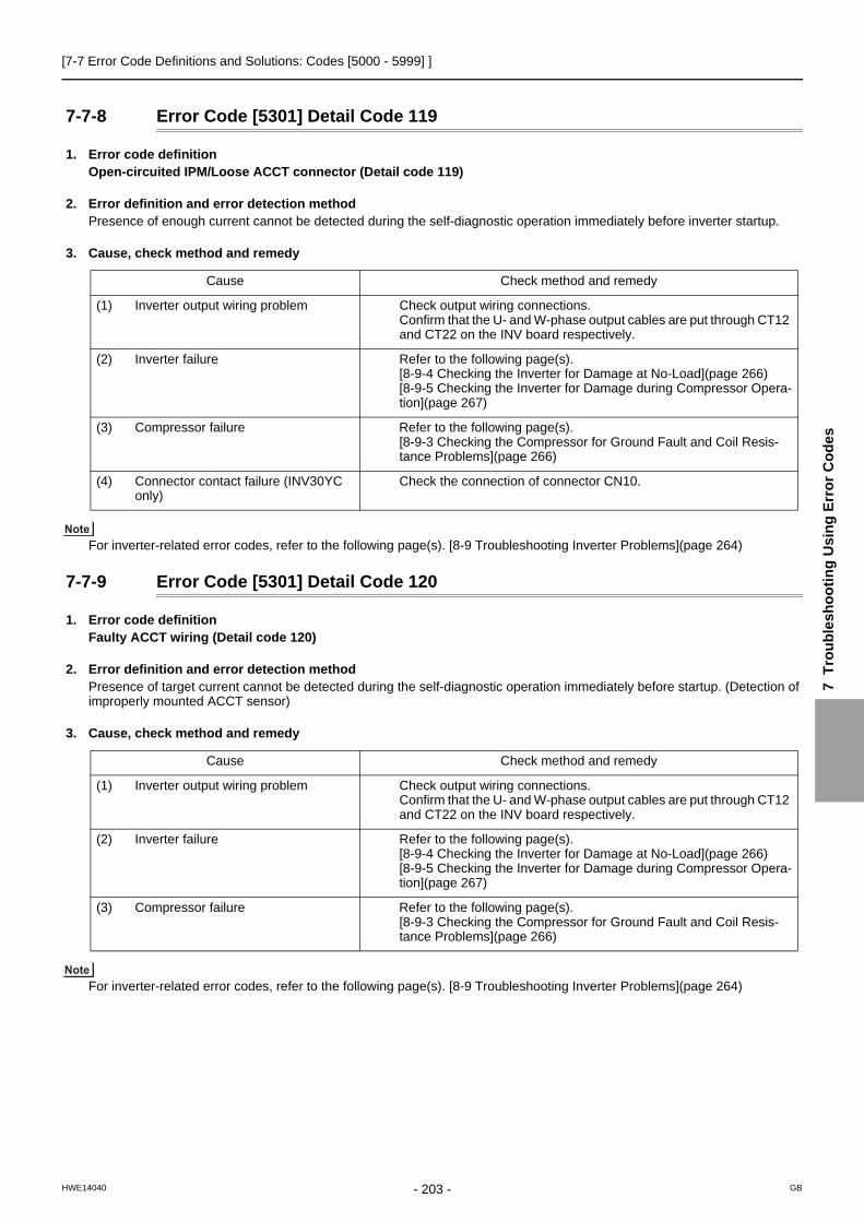
[7-7 Error Code Definitions and Solutions: Codes [5000 - 5999] ]
7 T
rou
ble
sh
oo
tin
g U
sin
g E
rro
r C
od
es
7-7-8 Error Code [5301] Detail Code 119
1. Error code definitionOpen-circuited IPM/Loose ACCT connector (Detail code 119)
2. Error definition and error detection methodPresence of enough current cannot be detected during the self-diagnostic operation immediately before inverter startup.
3. Cause, check method and remedy
For inverter-related error codes, refer to the following page(s). [8-9 Troubleshooting Inverter Problems](page 264)
7-7-9 Error Code [5301] Detail Code 120
1. Error code definitionFaulty ACCT wiring (Detail code 120)
2. Error definition and error detection methodPresence of target current cannot be detected during the self-diagnostic operation immediately before startup. (Detection of improperly mounted ACCT sensor)
3. Cause, check method and remedy
For inverter-related error codes, refer to the following page(s). [8-9 Troubleshooting Inverter Problems](page 264)
Cause Check method and remedy
(1) Inverter output wiring problem Check output wiring connections.Confirm that the U- and W-phase output cables are put through CT12 and CT22 on the INV board respectively.
(2) Inverter failure Refer to the following page(s). [8-9-4 Checking the Inverter for Damage at No-Load](page 266)[8-9-5 Checking the Inverter for Damage during Compressor Opera-tion](page 267)
(3) Compressor failure Refer to the following page(s). [8-9-3 Checking the Compressor for Ground Fault and Coil Resis-tance Problems](page 266)
(4) Connector contact failure (INV30YC only)
Check the connection of connector CN10.
Cause Check method and remedy
(1) Inverter output wiring problem Check output wiring connections.Confirm that the U- and W-phase output cables are put through CT12 and CT22 on the INV board respectively.
(2) Inverter failure Refer to the following page(s). [8-9-4 Checking the Inverter for Damage at No-Load](page 266)[8-9-5 Checking the Inverter for Damage during Compressor Opera-tion](page 267)
(3) Compressor failure Refer to the following page(s). [8-9-3 Checking the Compressor for Ground Fault and Coil Resis-tance Problems](page 266)
- 203 -HWE14040 GB

[7-7 Error Code Definitions and Solutions: Codes [5000 - 5999] ]
7-7-10 Error Code [5301] Detail Code 127
1. Error code definitionDCL electric current circuit error (Detail code 127)(outdoor unit)
2. Error definition and error detection methodWhen an abnormal value in the DCL electric current sensor detection circuit is detected
3. Cause, check method and remedy
For inverter-related error codes, refer to the following page(s). [8-9 Troubleshooting Inverter Problems](page 264)
7-7-11 Error Codes [5305, 5306] Detail Code 132
1. Error code definitionPosition detection error at startup (Detail code 132)
2. Error definition and error detection methodWhen a motor sensor has detected an error within 10 seconds after the fan motor has gone into operation.
3. Cause, check method and remedy
For inverter-related error codes, refer to the following page(s). [8-9 Troubleshooting Inverter Problems](page 264)
Cause Check method and remedy
(1) Contact failure Check the wiring between CNCT4A and CNCT4B.
(2) Incorrect installation Check the wiring on the SC-L terminal.
(3) INV board failure If the problem persists after restart operation, replace the in-verter board.
Cause Check method and remedy
(1) Contact failure and faulty fan motor wiring
Check the fan board connector CNINV and CNSNR for proper con-tacts.Check the wirign betweem the fan motor and fan board.
(2) Fan board failure Refer to the following page(s). [8-9-10 Checking the Fan Inverter for Damage with Load](page 271)
(3) Fan motor error Refer to the following page(s). [8-9-7 Checking the Fan Motor for Ground Fault and Coil Resistance Problems](page 269)
- 204 -HWE14040 GB

[7-7 Error Code Definitions and Solutions: Codes [5000 - 5999] ]
7 T
rou
ble
sh
oo
tin
g U
sin
g E
rro
r C
od
es
7-7-12 Error Codes [5305, 5306] Detail Code 133
1. Error code definitionPosition detection error during operation (Detail code 133)
2. Error definition and error detection methodAn error from a motor sensor is detected during fan moter operation.
3. Cause, check method and remedy
For inverter-related error codes, refer to the following page(s). [8-9 Troubleshooting Inverter Problems](page 264)
7-7-13 Error Codes [5305, 5306] Detail Code 134
1. Error code definitionRPM error before start up (Detail code 134)
2. Error definition and error detection methodThe fan RPM will not drop to the set RPM.
3. Cause, check method and remedy
For inverter-related error codes, refer to the following page(s). [8-9 Troubleshooting Inverter Problems](page 264)
7-7-14 Error Code [5701]
1. Error code definitionLoose float switch connector
2. Error definition and error detection methodDetection of the disconnected float switch (open-phase condition) during operation
3. Cause, check method and remedy(1) CN4F disconnection or contact failure
Check for disconnection of the connector (CN4F) on the indoor unit control board.
Cause Check method and remedy
(1) Outdoor factors Check that there is no wind (gust or strong wind).
(2) Contact failure and faulty fan motor wiring
Check the fan board connector CNINV and CNSNR for proper contacts.Check the wirign betweem the fan motor and fan board.
(3) Fan board failure Refer to the following page(s). [8-9-9 Checking the Fan Inverter for Damage at No Load](page 270)[8-9-10 Checking the Fan Inverter for Damage with Load](page 271)
(4) Fan motor error Refer to the following page(s). [8-9-7 Checking the Fan Motor for Ground Fault and Coil Resistance Problems](page 269)
Cause Check method and remedy
(1) Outdoor factors Check that there is no wind (gust or strong wind).
(2) Fan board failure Refer to the following page(s). [8-9-9 Checking the Fan Inverter for Damage at No Load](page 270)[8-9-10 Checking the Fan Inverter for Damage with Load](page 271)
(3) Fan motor error Refer to the following page(s). [8-9-7 Checking the Fan Motor for Ground Fault and Coil Resistance Problems](page 269)
- 205 -HWE14040 GB
[7-8 Error Code Definitions and Solutions: Codes [6000 - 6999] ]
7-8 Error Code Definitions and Solutions: Codes [6000 - 6999]
7-8-1 Error Code [6201]
1. Error code definitionRemote controller board fault (nonvolatile memory error)
2. Error definition and error detection methodThis error is detected when the data cannot be read out from the built-in nonvolatile memory on the remote controller.
3. Cause, check method and remedy(1) Remote controller failure
Replace the remote controller.
7-8-2 Error Code [6202]
1. Error code definitionRemote controller board fault (clock IC error)
2. Error definition and error detection methodThis error is detected when the built-in clock on the remote controller is not properly functioning.
3. Cause, check method and remedy(1) Remote controller failure
Replace the remote controller.
- 206 -HWE14040 GB

[7-8 Error Code Definitions and Solutions: Codes [6000 - 6999] ]
7 T
rou
ble
sh
oo
tin
g U
sin
g E
rro
r C
od
es
7-8-3 Error Code [6600]
1. Error code definitionAddress overlap
2. Error definition and error detection methodAn error in which signals from more than one indoor units with the same address are received
The address and attribute that appear on the remote controller indicate the controller that detected the error.
3. Cause, check method and remedy
7-8-4 Error Code [6601]
1. Error code definitionPolarity setting error
2. Error definition and error detection methodThe error detected when transmission processor cannot distinguish the polarities of the M-NET transmission line.
3. Cause, check method and remedy
Cause Check method and remedy
(1) Two or more of the following have the same address: Outdoor units, indoor units, LOSSNAY units, control-lers such as ME remote controllers. <Example>6600 "01" appears on the remote controllerUnit #01 detected the error. Two or more units in the system have 01 as their ad-dress.
Find the unit that has the same address as that of the error source.Once the unit is found, correct the address. Then, turn off the outdoor units, indoor units, and LOSSNAY units, keep them all turned off for at least five minutes, and turn them back on.When air conditioning units are operating normally despite the address overlap errorCheck the transmission wave shape and noise on the transmission line.See the section "Investigation of Transmission Wave Shape/Noise."
(2) Signals are distorted by the noise on the transmission line.
Cause Check method and remedy
(1) No voltage is applied to the M-NET transmission line that AG-150A/GB-50ADA/PAC-YG50ECA/BAC-HD150 are connected to.
Check if power is supplied to the M-NET transmission line of the AG-150A/GB-50ADA/PAC-YG50ECA/BAC-HD150, and correct any problem found.
(2) M-NET transmission line to which AG-150A/GB-50ADA/PAC-YG50ECA/BAC-HD150 are connected is short-circuited.
(3) When two or more power supplies are connected to the M-NET
- 207 -HWE14040 GB

[7-8 Error Code Definitions and Solutions: Codes [6000 - 6999] ]
7-8-5 Error Code [6602]
1. Error code definitionTransmission processor hardware error
2. Error definition and error detection methodAlthough "0" was surely transmitted by the transmission processor, "1" is displayed on the transmission line.
The address/attribute appeared on the display on the remote controller indicates the controller where an error oc-curred.
3. Cause1) When the wiring work of or the polarity of either the indoor or outdoor transmission line is performed or is changed while the
power is on, the transmitted data will collide, the wave shape will be changed, and an error will be detected.2) Grounding fault of the transmission line3) When grouping the indoor units that are connected to different outdoor units, the male power supply connectors on the multiple
outdoor units are connected to the female power supply switch connector (CN40).4) When the power supply unit for transmission lines is used in the system connected with MELANS, the male power supply
connector is connected to the female power supply switch connector (CN40) on the outdoor unit.5) Controller failure of the source of the error6) When the transmission data is changed due to the noise on the transmission line7) Voltage is not applied on the transmission line for centralized control (in case of grouped indoor units connected to different
outdoor units or in case of the system connected with MELANS)
4. Check method and remedy
NO Tightly reconnect the male power supply connector to the female power supply switch connector (CN40).
YES
YES
YES
YES
YES
YES
NO
NO
NO
NO
Is the transmission line work performed while the power is on?
Check the power source of the indoor unit.
198 / 264V?
Check the transmission line work is performed and the shielded wire is treated properly.
Grounding fault or does the shielded wire contact with the transmission line?
System ?
Faulty power source work
Improper transmission line work
Turn off the power source of outdoor/indoor units, and turn them on again.
NO
Investigation into the transmission line noise
Noise exist?
Controller failure of the source of the error
*For the investigation method, follow <Investigation method of transmission wave shape/noise>
Investigation into the cause of the noise
Correct the error.
System with the power supply unit for transmission lines
Is the male power supply connector connected to the female power supply switch connector (CN40) on only one of the outdoor unit?
Is the male power supply connector connected to the female power supply switch connector (CN40) ?
Confirm that the power supply connector on the outdoor unit is not plugged into CN40.
Confirm that the power supply connector on the outdoor unit is not plugged into CN40.
Disconnect the male power supply on CN40 and connect it to CN41
Single-outdoor-unit system Multiple-outdoor-unit system
- 208 -HWE14040 GB
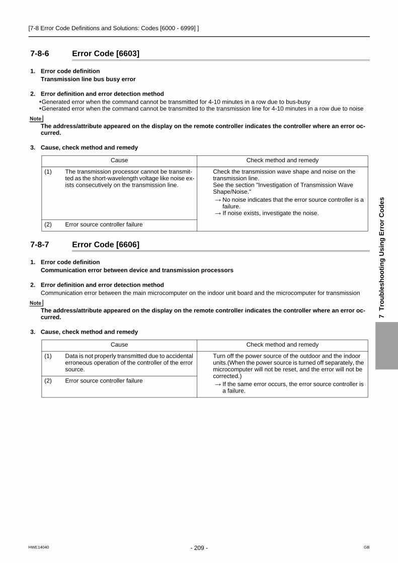
[7-8 Error Code Definitions and Solutions: Codes [6000 - 6999] ]
7 T
rou
ble
sh
oo
tin
g U
sin
g E
rro
r C
od
es
7-8-6 Error Code [6603]
1. Error code definitionTransmission line bus busy error
2. Error definition and error detection methodGenerated error when the command cannot be transmitted for 4-10 minutes in a row due to bus-busyGenerated error when the command cannot be transmitted to the transmission line for 4-10 minutes in a row due to noise
The address/attribute appeared on the display on the remote controller indicates the controller where an error oc-curred.
3. Cause, check method and remedy
7-8-7 Error Code [6606]
1. Error code definitionCommunication error between device and transmission processors
2. Error definition and error detection methodCommunication error between the main microcomputer on the indoor unit board and the microcomputer for transmission
The address/attribute appeared on the display on the remote controller indicates the controller where an error oc-curred.
3. Cause, check method and remedy
Cause Check method and remedy
(1) The transmission processor cannot be transmit-ted as the short-wavelength voltage like noise ex-ists consecutively on the transmission line.
Check the transmission wave shape and noise on the transmission line.See the section "Investigation of Transmission Wave Shape/Noise."→ No noise indicates that the error source controller is a
failure.→ If noise exists, investigate the noise.
(2) Error source controller failure
Cause Check method and remedy
(1) Data is not properly transmitted due to accidental erroneous operation of the controller of the error source.
Turn off the power source of the outdoor and the indoor units.(When the power source is turned off separately, the microcomputer will not be reset, and the error will not be corrected.)→ If the same error occurs, the error source controller is
a failure.
(2) Error source controller failure
- 209 -HWE14040 GB

[7-8 Error Code Definitions and Solutions: Codes [6000 - 6999] ]
7-8-8 Error Code [6607] Error Source Address = Outdoor Unit (OC)
1. Error code definitionNo ACK error
2. Error definition and error detection methodThe error is detected when no acknowledgement (ACK signal) is received after the transmission. (eg. When the data is trans-mitted six times in a row with 30 seconds interval, the error is detected on the transmission side.)
The address/attribute appeared on the display on the remote controller indicates the controller which did not provide the response (ACK).
3. Cause, check method and remedy
Cause Check method and remedy
(1) Incidental cause 1) Turn off the power source of the outdoor unit, and turn it on again.
(2) Contact failure of transmission line of OC or IC 2) If the error is accidental, it will run normally. If not, check the causes (2) - (5).
(3) Decrease of transmission line voltage/signal by exceed-ing acceptable range of transmission wiring.Farthest: 200 m [656ft] or lessRemote controller wiring:10m [32ft] or less
(4) Erroneous sizing of transmission line (Not within the range below). Wire diameter:1.25mm2 [AWG16] or more
(5) Outdoor unit control board failure
- 210 -HWE14040 GB

[7-8 Error Code Definitions and Solutions: Codes [6000 - 6999] ]
7 T
rou
ble
sh
oo
tin
g U
sin
g E
rro
r C
od
es
7-8-9 Error Code [6607] Error Source Address = Indoor Unit (IC)
1. Error code definitionNo ACK error
2. Error definition and error detection methodThe error is detected when no acknowledgement (ACK signal) is received after the transmission. (eg. When the data is trans-mitted six times in a row with 30 seconds interval, the error is detected on the transmission side.)
The address/attribute appeared on the display on the remote controller indicates the controller which did not provide the response (ACK).
3. Cause, check method and remedy
(1) Troubleshooting problems for indoor units (A)
(2) Troubleshooting problems for indoor units (B)
Error display
ME remote controller (RC), MA remote controller (MA) System controller (SC)
Types of refrigerant systems
Single refrigerant system Grouped operation of multi-ple refrigerant systems
Types of indoor units experiencing problems
Part of the indoor units (IC) are experiencing
problems.
All indoor units (IC) in the same system are
experiencing problems.
All indoor units (IC) are experiencing problems.
Troubleshooting prob-lems for indoor units (A)
Troubleshooting problems for indoor units (A)
Troubleshooting prob-lems for indoor units (A)
Troubleshooting prob-lems for indoor units (B)
Troubleshooting prob-lems for indoor units (B)
& &
Troubleshooting problems for all units (A)
Troubleshooting prob-lems for all units (A)
Cause Check method and remedy
(1) Incidental cause 1) Turn off the outdoor/indoor units for 5 or more min-utes, and turn them on again.
(2) When IC unit address is changed or modified during op-eration.
2) If the error is accidental, it will run normally. If not, check the causes (2) - (6).
(3) Faulty or disconnected IC transmission wiring
(4) Disconnected IC connector(CN2M)
(5) Indoor unit controller failure
(6) ME remote controller failure
Cause Check method and remedy
(1) When the power supply unit for transmission lines is used and the male power supply connector is connected to the female power supply switch connector (CN40) for the transmission line for centralized control
Check voltage of the transmission line for central-ized control.20 V or more: Check (1) on the left.Less than 20 V: Check (2) on the left.
(2) Disconnection or shutdown of the power source of the power supply unit for transmission line
(3) System controller (MELANS) malfunction
- 211 -HWE14040 GB
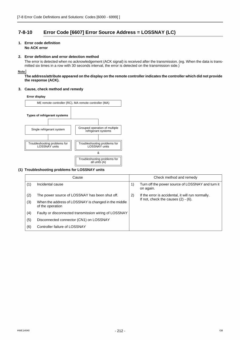
[7-8 Error Code Definitions and Solutions: Codes [6000 - 6999] ]
7-8-10 Error Code [6607] Error Source Address = LOSSNAY (LC)
1. Error code definitionNo ACK error
2. Error definition and error detection methodThe error is detected when no acknowledgement (ACK signal) is received after the transmission. (eg. When the data is trans-mitted six times in a row with 30 seconds interval, the error is detected on the transmission side.)
The address/attribute appeared on the display on the remote controller indicates the controller which did not provide the response (ACK).
3. Cause, check method and remedy
(1) Troubleshooting problems for LOSSNAY units
Error display
ME remote controller (RC), MA remote controller (MA)
Types of refrigerant systems
Single refrigerant system Grouped operation of multiple refrigerant systems
Troubleshooting problems for LOSSNAY units
Troubleshooting problems for LOSSNAY units
&
Troubleshooting problems for all units (A)
Cause Check method and remedy
(1) Incidental cause 1) Turn off the power source of LOSSNAY and turn it on again.
(2) The power source of LOSSNAY has been shut off. 2) If the error is accidental, it will run normally.If not, check the causes (2) - (6).
(3) When the address of LOSSNAY is changed in the middle of the operation
(4) Faulty or disconnected transmission wiring of LOSSNAY
(5) Disconnected connector (CN1) on LOSSNAY
(6) Controller failure of LOSSNAY
- 212 -HWE14040 GB

[7-8 Error Code Definitions and Solutions: Codes [6000 - 6999] ]
7 T
rou
ble
sh
oo
tin
g U
sin
g E
rro
r C
od
es
7-8-11 Error Code [6607] Error Source Address = ME Remote Controller
1. Error code definitionNo ACK error
2. Error definition and error detection methodThe error is detected when no acknowledgement (ACK signal) is received after the transmission. (eg. When the data is trans-mitted six times in a row with 30 seconds interval, the error is detected on the transmission side.)
The address/attribute appeared on the display on the remote controller indicates the controller which did not provide the response (ACK).
3. Cause, check method and remedy
(1) Troubleshooting problems for ME remote controllers
Error display
ME remote controller (RC), MA remote controller (MA) System controller (SC)
Types of refrigerant sys-tems
Single refrigerant system Grouped operation of mul-tiple refrigerant systems
Types of indoor units experiencing problems
Part of the indoor units (IC) are experiencing
problems.
All indoor units (IC) in the same system are experi-
encing problems.
All indoor units (IC) are experiencing problems.
Troubleshooting problems for ME remote controllers
Troubleshooting prob-lems for ME remote con-
trollers
Troubleshooting prob-lems for ME remote con-
trollers
Troubleshooting prob-lems for all units (B)
Troubleshooting prob-lems for all units (B)
& &
Troubleshooting prob-lems for all units (A)
Troubleshooting prob-lems for all units (C)
Cause Check method and remedy
(1) Incidental cause 1) Turn off the power source of the outdoor unit for 5 minutes or more, and turn it on again.
(2) Faulty transmission wiring at IC unit side. 2) If not, check the causes (2) - (5).
(3) Faulty wiring of the transmission line for ME remote con-troller
(4) When the address of ME remote controller is changed in the middle of the operation
(5) ME remote controller failure
- 213 -HWE14040 GB

[7-8 Error Code Definitions and Solutions: Codes [6000 - 6999] ]
7-8-12 Error Code [6607] Error Source Address = System Controller
1. Error code definitionNo ACK error
2. Error definition and error detection methodThe error is detected when no acknowledgement (ACK signal) is received after the transmission. (eg. When the data is trans-mitted six times in a row with 30 seconds interval, the error is detected on the transmission side.)
The address/attribute appeared on the display on the remote controller indicates the controller which did not provide the response (ACK).
3. Cause, check method and remedy
(1) Troubleshooting problems for system controllers
Error display
ME remote controller (RC), MA remote controller (MA)
Type of unit/controller in error
Part of the ME remote con-trollers (RC) are experi-
encing problems.
All indoor units (IC) in the same system are experi-
encing problems.
All ME remote controllers (RC) are experiencing
problems.
Troubleshooting problems for system controllers
Troubleshooting prob-lems for all units (B)
Troubleshooting prob-lems for all units (B)
&
Troubleshooting prob-lems for all units (C)
Cause Check method and remedy
(1) Incidental cause 1) Turn off the power source of the outdoor unit for 5 minutes or more, and turn it on again.
(2) Faulty wiring of the transmission line for ME remote con-troller
2) If not, check the causes (2) - (4).
(3) When the address of ME remote controller is changed in the middle of the operation
(4) ME remote controller failure
- 214 -HWE14040 GB

[7-8 Error Code Definitions and Solutions: Codes [6000 - 6999] ]
7 T
rou
ble
sh
oo
tin
g U
sin
g E
rro
r C
od
es
7-8-13 Error Code [6607] All Error Source Addresses
1. Error code definitionNo ACK error
2. Error definition and error detection methodThe error is detected when no acknowledgement (ACK signal) is received after the transmission. (eg. When the data is trans-mitted six times in a row with 30 seconds interval, the error is detected on the transmission side.)
The address/attribute appeared on the display on the remote controller indicates the controller which did not provide the response (ACK).
3. Cause, check method and remedy(1) Troubleshooting problems for all units (A)
(2) Troubleshooting problems for all units (B)
(3) Troubleshooting problems for all units (C)
Cause Check method and remedy
(1) Disconnection or short circuit of the transmission line for the outdoor unit on the terminal block for centralized con-trol line connection (TB7)
1) Check the causes of (1) - (4). If the cause is found, correct it. If no cause is found, check 2).
(2) When multiple outdoor units are connected and the pow-er source of one of the outdoor units has been shut off.
2) Check the LED displays for troubleshooting on oth-er remote controllers whether an error occurs.
(3) The male power supply connector of the outdoor unit is not connected to the female power supply switch connec-tor (CN40).
When an error is presentCheck the causes of the error indicated by the error codes listed in item (4) in the "Cause" col-umn. When no errors are present
Indoor unit circuit board failure
(4) The male power supply connectors on 2 or more outdoor units are connected to the female power supply switch connector (CN40) for centralized control.
If an error occurs, after the unit runs normally once, the following causes may be considered.Total capacity error (7100)Capacity code error (7101)Error in the number of connected units (7102)Address setting error (7105)
Cause Check method and remedy
(1) Total capacity error (7100) 1) Check the LED display for troubleshooting on the outdoor unit.When an error is present
Check the causes of the error indicated by the error codes listed in items (1) through (4) in the "Cause" column. When no errors are present
Check the causes of the error indicated by the error codes listed in items (5) through (7) in the "Cause" column.
(2) Capacity code error (7101)
(3) Error in the number of connected units (7102)
(4) Address setting error (7105)
(5) Disconnection or short circuit of the transmission line for the outdoor unit on the terminal block for centralized con-trol line connection (TB7)
(6) Turn off the power source of the outdoor unit
(7) Malfunction of electrical system for the outdoor unit
Cause Check method and remedy
(1) When the power supply unit for transmission lines is used and the male power supply connector is connected to the female power supply switch connector (CN40) for the transmission line for centralized control
Check the causes of the error indicated by the error codes listed in items (1) through (3) in the "Cause" column.
(2) Disconnection or shutdown of the power source of the power supply unit for transmission line
(3) System controller (MELANS) malfunction
- 215 -HWE14040 GB

[7-8 Error Code Definitions and Solutions: Codes [6000 - 6999] ]
7-8-14 Error Code [6607] No Error Source Address
1. Error code definitionNo ACK error
2. Error definition and error detection methodThe error is detected when no acknowledgement (ACK signal) is received after the transmission. (eg. When the data is trans-mitted six times in a row with 30 seconds interval, the error is detected on the transmission side.)
The address/attribute appeared on the display on the remote controller indicates the controller which did not provide the response (ACK).
3. Cause, check method and remedy
Cause Check method and remedy
(1) Although the address of ME remote controller has been changed after the group is set using ME remote control-ler, the indoor unit is keeping the memory of the previous address. The same symptom will appear for the registra-tion with SC.
Delete unnecessary information of non-existing address which some indoor units have.Use either of the following two methods for dele-tion.
(2) Although the address of LOSSNAY has been changed af-ter the interlock registration of LOSSNAY is made using ME remote controller, the indoor unit is keeping the mem-ory of the previous address.
1) Address deletion by ME remote controllerDelete unnecessary address information using the manual setting function of ME remote controller. For details, refer to the following page(s). [6-3-4 Address Deletion](page 118)
2) Deletion of connection information of the outdoor unit by the deleting switch
Note that the above method will delete all the group settings set via the ME remote controller and all the interlock settings between LOSSNAY units and indoor units.
Procedures1) Turn off the power source of the outdoor unit,
and wait for 5 minutes.2) Turn on the dip switch (SW5-2) on the outdoor
unit control board. 3) Turn on the power source of the outdoor unit,
and wait for 5 minutes.4) Turn off the power source of the outdoor unit,
and wait for 5 minutes.5) Turn off the dip switch (SW5-2) on the outdoor
unit control board.6) Turn on the power source of the outdoor unit.
- 216 -HWE14040 GB

[7-8 Error Code Definitions and Solutions: Codes [6000 - 6999] ]
7 T
rou
ble
sh
oo
tin
g U
sin
g E
rro
r C
od
es
7-8-15 Error Code [6608]
1. Error code definitionNo response error
2. Error definition and error detection methodWhen no response command is returned although acknowledgement (ACK) is received after transmission, an error is detect-ed.When the data is transmitted 10 times in a row with 3 seconds interval, an error is detected on the transmission side.
The address/attribute appeared on the display on the remote controller indicates the controller where an error oc-curred.
3. Cause1) The transmission line work is performed while the power is on, the transmitted data will collide, and the wave shape will be
changed.2) The transmission is sent and received repeatedly due to noise.3) Decrease of transmission line voltage/signal by exceeding acceptable range of transmission wiring.
Farthest: 200m [656ft] or lessRemote controller wiring: 12m [39ft] or less
4) The transmission line voltage/signal is decreased due to erroneous sizing of transmission line.
Wire diameter: 1.25mm2[AWG16] or more
4. Check method and remedy1) When an error occurs during commissioning, turn off the power sources for the outdoor unit, indoor unit, and LOSSNAY for 5
or more minutes, and then turn them on again.
When they return to normal operation, the cause of the error is the transmission line work performed with the power on.If an error occurs again, check the cause 2).
2) Check 3) and 4) above.
If the cause is found, correct it. If no cause is found, check 3).
3) Check the transmission waveform, and check the transmission line for electrical noise. For details, refer to the following page(s). [8-4 Checking Transmission Waveform and for Electrical Noise Interference](page 250)
Noise is the most possible cause of the error "6608".
- 217 -HWE14040 GB

[7-8 Error Code Definitions and Solutions: Codes [6000 - 6999] ]
7-8-16 Error Code [6831]
1. Error code definitionMA controller signal reception error (No signal reception)
2. Error definition and error detection methodCommunication between the MA remote controller and the indoor unit is not done properly. No proper data has been received for 3 minutes.
3. Cause1) Contact failure of the remote controller lines of MA remote controller or the indoor unit.2) All the remote controllers are set to SUB.3) Failure to meet wiring regulations
Wire lengthWire sizeNumber of remote controllersNumber of indoor units
4) The remote controller is removed after the installation without turning the power source off.5) Noise interference on the remote controller transmission lines6) Faulty circuit that is on the indoor board and performs transmission/ reception of the signal from the remote controller7) Problems with the circuit on the remote controller that sends or receives the signals from the remote controller
4. Check method and remedy1) Check for disconnected or loose transmission lines for the indoor units or MA remote controllers.2) Confirm that the power is supplied to the main power source and the remote controller line.3) Confirm that MA remote controller's capacity limit is not exceeded.4) Check the sub/main setting of the MA remote controllers.One of them must be set to MAIN.5) Diagnose the remote controller (described in the remote controller installation manual).
[OK]: no problems with the remote controller (check the wiring regulations)[NG]: Replace the MA remote controller.[6832, 6833, ERC]: Due to noise interference <Go to 6)>
6) Check the transmission waveform, and check the MA remote controller line for electrical noise. For details, refer to the follow-ing page(s). [8-4 Checking Transmission Waveform and for Electrical Noise Interference](page 250)
7) When no problems are found with items 1) through 6), replace the indoor unit board or the MA remote controller.The following status can be confirmed on LED1 and 2 on the indoor unit board.
If LED1 is lit, the main power source of the indoor unit is turned on.If LED2 is lit, the MA remote controller line is being powered.
- 218 -HWE14040 GB

[7-8 Error Code Definitions and Solutions: Codes [6000 - 6999] ]
7 T
rou
ble
sh
oo
tin
g U
sin
g E
rro
r C
od
es
7-8-17 Error Code [6832]
1. Error code definitionMA remote controller signal transmission error (Synchronization error)
2. Error definition and error detection methodMA remote controller and the indoor unit is not done properly.Failure to detect opening in the transmission path and unable to send signals
Indoor unit: 3 minutesRemote controller: 6 seconds
3. Cause1) Contact failure of the remote controller lines of MA remote controller or the indoor unit2) 2 or more remote controllers are set to MAIN3) Overlapped indoor unit address4) Noise interference on the remote controller lines5) Failure to meet wiring regulations
Wire lengthWire sizeNumber of remote controllersNumber of indoor units
6) Problems with the circuit on the remote controller that sends or receives the signals from the remote controller
4. Check method and remedy1) Check for disconnected or loose transmission lines for the indoor units or MA remote controllers.2) Confirm that the power is supplied to the main power source and the remote controller line.3) Confirm that MA remote controller's capacity limit is not exceeded.4) Check the sub/main setting of the MA remote controllers.One of them must be set to MAIN.5) Diagnose the remote controller (described in the remote controller installation manual).
[OK]: no problems with the remote controller (check the wiring regulations)[NG]: Replace the MA remote controller.[6832, 6833, ERC]: Due to noise interference <Go to 6)>
6) Check the transmission waveform, and check the MA remote controller line for electrical noise. For details, refer to the follow-ing page(s). [8-4 Checking Transmission Waveform and for Electrical Noise Interference](page 250)
7) When no problems are found with items 1) through 6), replace the indoor unit board or the MA remote controller.The following status can be confirmed on LED1 and 2 on the indoor unit board.
If LED1 is lit, the main power source of the indoor unit is turned on.If LED2 is lit, the MA remote controller line is being powered.
- 219 -HWE14040 GB
[7-8 Error Code Definitions and Solutions: Codes [6000 - 6999] ]
7-8-18 Error Code [6833]
1. Error code definitionMA remote controller signal transmission error (Hardware error)
2. Error definition and error detection methodCommunication between the MA remote controller and the indoor unit is not done properly.An error occurs when the transmitted data and the received data differ for 30 times in a row.
3. Cause1) Contact failure of the remote controller lines of MA remote controller or the indoor unit2) 2 or more remote controllers are set to MAIN3) Overlapped indoor unit address4) Noise interference on the remote controller lines5) Failure to meet wiring regulations
Wire lengthWire sizeNumber of remote controllersNumber of indoor units
6) Problems with the circuit on the remote controller that sends or receives the signals from the remote controller
4. Check method and remedy1) Check for disconnected or loose transmission lines for the indoor units or MA remote controllers.2) Confirm that the power is supplied to the main power source and the remote controller line.3) Confirm that MA remote controller's capacity limit is not exceeded.4) Check the sub/main setting of the MA remote controllers.One of them must be set to MAIN.5) Diagnose the remote controller (described in the remote controller installation manual).
[OK]: no problems with the remote controller (check the wiring regulations)[NG]: Replace the MA remote controller.[6832, 6833, ERC]: Due to noise interference <Go to 6)>
6) Check the transmission waveform, and check the MA remote controller line for electrical noise. For details, refer to the follow-ing page(s). [8-4 Checking Transmission Waveform and for Electrical Noise Interference](page 250)
7) When no problems are found with items 1) through 6), replace the indoor unit board or the MA remote controller.The following status can be confirmed on LED1 and 2 on the indoor unit board.
If LED1 is lit, the main power source of the indoor unit is turned on.If LED2 is lit, the MA remote controller line is being powered.
- 220 -HWE14040 GB

[7-8 Error Code Definitions and Solutions: Codes [6000 - 6999] ]
7 T
rou
ble
sh
oo
tin
g U
sin
g E
rro
r C
od
es
7-8-19 Error Code [6834]
1. Error code definitionMA controller signal reception error (Start bit detection error)
2. Error definition and error detection methodCommunication between the MA remote controller and the indoor unit is not done properly.No proper data has been received for 2 minutes.
3. Cause1) Contact failure of the remote controller lines of MA remote controller or the indoor unit.2) All the remote controllers are set to SUB.3) Failure to meet wiring regulations
Wire lengthWire sizeNumber of remote controllersNumber of indoor units
4) The remote controller is removed after the installation without turning the power source off.5) Noise interference on the remote controller transmission lines6) Faulty circuit that is on the indoor board and performs transmission/ reception of the signal from the remote controller7) Problems with the circuit on the remote controller that sends or receives the signals from the remote controller
4. Check method and remedy1) Check for disconnected or loose transmission lines for the indoor units or MA remote controllers.2) Confirm that the power is supplied to the main power source and the remote controller line.3) Confirm that MA remote controller's capacity limit is not exceeded.4) Check the sub/main setting of the MA remote controllers.One of them must be set to MAIN.5) Diagnose the remote controller (described in the remote controller installation manual).
[OK]: no problems with the remote controller (check the wiring regulations)[NG]: Replace the MA remote controller.[6832, 6833, ERC]: Due to noise interference <Go to 6)>
6) Check the transmission waveform, and check the MA remote controller line for electrical noise. For details, refer to the follow-ing page(s). [8-4 Checking Transmission Waveform and for Electrical Noise Interference](page 250)
7) When no problems are found with items 1) through 6), replace the indoor unit board or the MA remote controller.The following status can be confirmed on LED1 and 2 on the indoor unit board.
If LED1 is lit, the main power source of the indoor unit is turned onIf LED2 is lit, the MA remote controller line is being powered.
- 221 -HWE14040 GB

[7-8 Error Code Definitions and Solutions: Codes [6000 - 6999] ]
7-8-20 Error Code [6840]
1. Error code definitionA control communication reception error
2. Error definition and error detection methodIndoor/outdoor unit communication error (Signal receiving error)Abnormal if indoor controller board could not receive any signal normally for 6 minutes after turning the power onAbnormal if indoor controller board could not receive any signal normally for 3 minutes.Consider the unit as abnormal under the following condition. When 2 or more indoor units are connected to an outdoor unit, indoor controller board could not receive a signal for 3 minutes from outdoor controller circuit board, a signal which allows outdoor controller circuit board to transmit signals.
3. Cause, check method and remedy
7-8-21 Error Code [6841]
1. Error code definitionA control communication synchronism not recover
2. Error definition and error detection methodIndoor/outdoor unit communication error (Transmitting error) (Outdoor unit)Abnormal if "0" receiving is detected 30 times continuously though outdoor controller circuit board has transmitted "1".Abnormal if outdoor controller circuit board could not find blank of transmission path for 3 minutes.
3. Cause, check method and remedy
Cause Check method and remedy
(1) Contact failure, short circuit or miswiring (converse wiring) of in-door/outdoor unit connecting wire.
Check disconnecting or looseness of indoor /outdoor unit connecting wire of indoor unit or outdoor unit. Check all the units in case of twin/triple/quadruple indoor unit system.
(2) Defective transmitting receiving circuit of outdoor controller cir-cuit board.
Turn the power off, and on again to check. If abnormality generates again, replace indoor controller board or outdoor controller circuit board.(3) Defective transmitting receiving circuit of indoor controller board.
(4) Noise has entered into indoor/outdoor unit connecting wire.
(5) Defective fan motor Turn the power off, and detach fan motor from connector (CNF1, 2). Then turn the power on again. If abnormality is not dis-played, replace fan motor. If abnormality is displayed, replace outdoor controller circuit board.
(6) Defective rush current resistor of outdoor power circuit board Check the rush current resistor on outdoor power circuit board with tester. If open is de-tected, replace the power circuit board.
Cause Check method and remedy
(1) Indoor/outdoor unit connecting wire has contact failure. Check disconnection or looseness of indoor/outdoor unit connecting wire.
(2) Defective communication circuit of outdoor controller circuit board.
Turn the power off, and on again to check. Replace outdoor controller circuit board if ab-normality is displayed again.
(3) Noise has entered power supply.
(4) Noise has entered indoor/outdoor unit connecting wire.
- 222 -HWE14040 GB

[7-8 Error Code Definitions and Solutions: Codes [6000 - 6999] ]
7 T
rou
ble
sh
oo
tin
g U
sin
g E
rro
r C
od
es
7-8-22 Error Code [6842]
1. Error code definitionA control communication transmission/reception hardware trouble
2. Error definition and error detection methodIndoor/outdoor unit communication error (Transmitting error)Abnormal if "1" receiving is detected 30 times continuously though indoor controller board has transmitted "0".
3. Cause, check method and remedy
Cause Check method and remedy
(1) Defective transmitting receiving circuit of indoor controller board Turn the power off, and on again to check. If abnormality generates again, replace indoor controller board.(2) Noise has entered into power supply.
(3) Noise has entered into outdoor control wire.
- 223 -HWE14040 GB

[7-8 Error Code Definitions and Solutions: Codes [6000 - 6999] ]
7-8-23 Error Code [6843]
1. Error code definitionA control communication start bit detection error
2. Error definition and error detection methodIndoor/outdoor unit communication error (Signal receiving error)Abnormal if indoor controller board could not receive any signal normally for 6 minutes after turning the power on.Abnormal if indoor controller board could not receive any signal normally for 3 minutes.Consider the unit as abnormal under the following condition. When 2 or more indoor units are connected to an outdoor unit, indoor controller board could not receive a signal for 3 minutes from outdoor controller circuit board, a signal which allows outdoor controller circuit board to transmit signals.
3. Cause, check method and remedy
1. Error code definitionA control communication start bit detection error
2. Error definition and error detection methodIndoor/outdoor unit communication error (Signal receiving error)(Outdoor unit)Abnormal if outdoor controller circuit board could not receive anything normally for 3 minutes.
3. Cause, check method and remedy
Cause Check method and remedy
(1) Contact failure, short circuit or miswiring (converse wiring) of in-door/outdoor unit connecting wire
Check disconnecting or looseness of indoor /outdoor unit connecting wire of all indoor units or outdoor units.
(2) Defective transmitting receiving circuit of outdoor controller cir-cuit board.
Turn the power off, and on again to check. If abnormality generates again, replace indoor controller board or outdoor controller circuit board.Note: ther indoor controller board may have defect.
(3) Defective transmitting receiving circuit of indoor controller board.
(4) Noise has entered into indoor/outdoor unit connecting wire.
(5) Defective fan motor Turn the power off, and detach fan motor from connector (CNF1, 2). Then turn the power on again. If abnormality is not dis-played, replace fan motor. If abnormality is displayed, replace outdoor controller circuit board.
(6) Defective rush current resistor of outdoor power circuit board Check the rush current resistor on outdoor power circuit board with tester. If open is de-tected, replace the power circuit board.
Cause Check method and remedy
(1) Contact failure of indoor/outdoor unit connecting wire Check disconnection or looseness of indoor/outdoor unit connecting wire of indoor or out-door units.
(2) Defective communication circuit of outdoor controller circuit board
Turn the power off, and on again to check. Replace indoor controller board or outdoor controller circuit board if abnormality is dis-played again.(3) Defective communication circuit of indoor controller board
(4) Noise has entered into indoor/outdoor unit connecting wire.
- 224 -HWE14040 GB

[7-8 Error Code Definitions and Solutions: Codes [6000 - 6999] ]
7 T
rou
ble
sh
oo
tin
g U
sin
g E
rro
r C
od
es
7-8-24 Error Code [6846]
1. Error code definitionStart-up time over
2. Error definition and error detection methodStart-up time over The unit cannot finish start-up process within 4 minutes after power on.
3. Cause, check method and remedy
Cause Check method and remedy
(1) Contact failure of indoor/outdoor unit connecting wire Check disconnection or looseness or polarity of indoor/outdoor unit connecting wire of in-door and outdoor units.
(2) Diameter or length of indoor/outdoor unit connecting wire is out of specified capacity.
Check diameter and length of indoor/outdoor unit connecting wire. Total wiring length: 80 m (including wiring connecting each indoor unit and between indoor and outdoor unit) Also check if the connection order of flat ca-ble is S1, S2, S3.
(3) 2 or more outdoor units have refrigerant address "0". (In case of group control)
Check if refrigerant addresses are overlap-ping in case of group control system.
(4) Noise has entered into power supply or indoor/outdoor unit con-necting wire.
Check transmission path, and remove the cause.Note: The descriptions above, 1)-4), are for EA, Eb and EC.*The check code in the parenthesis indicates PAR-30MAA model.
- 225 -HWE14040 GB

[7-9 Error Code Definitions and Solutions: Codes [7000 - 7999] ]
7-9 Error Code Definitions and Solutions: Codes [7000 - 7999]
7-9-1 Error Code [7100]
1. Error code definitionTotal capacity error
2. Error definition and error detection methodThe model total of indoor units in the system with one outdoor unit exceeds limitations.
3. Error source, cause, check method and remedy,
Error source Cause Check method and remedy
Outdoor unit (1) The model total of indoor units in the system with one outdoor unit exceeds the following table.
1) Check the Qj total (capacity code total) of in-door units connected.
2) Check the Qj setting (capacity code) of the connected indoor unit set by the switch (SW2 on indoor unit board).
When the model name set by the switch is dif-ferent from that of the unit connected, turn off the power source of the outdoor and the indoor units, and change the setting of the Qj (capac-ity code).
3) Indoor unit Qj table
(2) The model selection switches (SW5-3 - 5-8) on the outdoor unit are set incorrectly.
Check the setting for the model selection switch on the outdoor unit (Dipswitches SW5-3 - 5-8 on the outdoor unit control board).
(3) The outdoor unit and the auxiliary unit (OS) that is connected to the same system are not proper-ly connected.
Confirm that the TB3 on the OC and OS are properly connected.
Qj TotalModel200 model250 model300 model350 model400 model450 model500 model550 model600 model650 model700 model750 model800 model850 model900 model950 model
1000 model1050 model1100 model1150 model1200 model1250 model1300 model1350 model
53698696108121138155172177190207224241248254270284296312324338351365
152025324050637180100125140200250
34568101314162025284050
Model Qj
P200 modelP250 modelP300 modelP350 modelP400 modelP450 modelP500 model
Model SW5
OFF ON OFF OFFON ON OFF OFFOFF OFF ON OFFOFF ON ON OFFON ON ON OFFOFF OFF OFF ON
3 4 5 6ONONONONONON
OFFOFFOFFOFFOFFOFF
ON OFF OFF ON ON OFF
7 8
- 226 -HWE14040 GB

[7-9 Error Code Definitions and Solutions: Codes [7000 - 7999] ]
7 T
rou
ble
sh
oo
tin
g U
sin
g E
rro
r C
od
es
7-9-2 Error Code [7101]
1. Error code definitionCapacity code setting error
2. Error definition and error detection method Connection of incompatible (wrong capacity code) indoor unit or outdoor unit
3. Error source, cause, check method and remedy
Error source Cause Check method and remedy
Outdoor unitIndoor unit
(1) The model name (capacity code) set by the switch (SW2) is wrong.
1) Check the model name (capacity code) of the in-door unit which has the error source address set by the switch (SW2 on indoor unit board).When the model name set by the switch is differ-ent from that of the unit connected, turn off the power source of the outdoor and the indoor units, and change the setting of the capacity code.
*The capacity of the indoor unit can be con-firmed by the self-diagnosis function (SW1 operation) of the outdoor unit.
Outdoor unit (2) The model selection switches (SW5-3 - 5-8) on the outdoor unit are set incorrectly.
Check the setting for the model selection switch on the outdoor unit (Dipswitches SW5-3 - 5-8 on the outdoor unit control board).
P200 modelP250 modelP300 modelP350 modelP400 modelP450 modelP500 model
Model SW5
OFF ON OFF OFFON ON OFF OFFOFF OFF ON OFFOFF ON ON OFFON ON ON OFFOFF OFF OFF ON
3 4 5 6ONONONONONON
OFFOFFOFFOFFOFFOFF
ON OFF OFF ON ON OFF
7 8
- 227 -HWE14040 GB

[7-9 Error Code Definitions and Solutions: Codes [7000 - 7999] ]
7-9-3 Error Code [7102]
1. Error code definitionWrong number of connected units
2. Error definition and error detection method The number of connected indoor units is "0" or exceeds the allowable value.
3. Error source, cause, check method and remedy
Error source Cause Check method and remedy
Outdoor unit (1) Number of indoor units connected to the outdoor terminal block (TB3) for indoor/ outdoor transmis-sion lines exceeds limitations described below.
1) Check whether the number of units connected to the outdoor terminal block (TB3) for indoor/ outdoor transmission lines does not exceed the limitation. (See (1) and (2) on the left.)
(2) Disconnected transmission line of the outdoor unit 2) Check (2) - (3) on the left.
(3) Short-circuited transmission lineWhen (2) and (3) apply, the following display will appear.
3) Check whether the transmission line for the terminal block for cen-tralized control (TB7) is not con-nected to the terminal block for the indoor/outdoor transmission line (TB3).
ME remote controllerNothing appears on the remote controller be-cause it is not powered.MA remote controller
"HO" or "PLEASE WAIT" blinks.
(4) The model selection switch (SW5-7) on the out-door unit is set to OFF. (Normally set to ON)
4) Check the setting for the model se-lection switch on the outdoor unit (Dipswitches SW5-7 on the outdoor unit control board).(5) Outdoor unit address setting error
The outdoor units in the same refrigerant circuit do not have sequential address numbers.
Restriction on the number of unitsNumber of units
0 or 1
17 : 200 model21 : 250 models26 : 300 models30 : 350 models34 : 400 models39 : 450 models43 : 500 models47 : 550 models50 : 600 - 1350 models
1 : P200 - P500YKB models2 : P400 - P900 YSKB models3 : P950 - P1350 YSKB models
Total number of indoor units
Total number of LOSSNAY units(During auto address start-up only)
Total number of outdoor units
- 228 -HWE14040 GB

[7-9 Error Code Definitions and Solutions: Codes [7000 - 7999] ]
7 T
rou
ble
sh
oo
tin
g U
sin
g E
rro
r C
od
es
7-9-4 Error Code [7105]
1. Error code definitionAddress setting error
2. Error definition and error detection methodErroneous setting of OC unit address
3. Cause, check method and remedy
7-9-5 Error Code [7106]
1. Error code definitionAttribute setting error
2. Error definition and error detection method
Error source Cause Check method and remedy
Outdoor unit Erroneous setting of OC unit address The address of outdoor unit is not being set to 51 - 100.
Check that the address of OC unit is set to 51- 100.Reset the address if it stays out of the range, while shutting the power source off.
Error source Cause Check method and remedy
- A remote controller for use with indoor units, such as the MA remote controller, is connected to the OA processing unit whose attribute is FU.
To operate the OA processing unit directly via a re-mote controller for use with indoor units, such as the MA remote controller, set the DIP SW 3-1 on the OA processing unit to ON.
SW3-1
OFF
ON
Interlocked operation with the indoor unit
Operation Method
Direct operation via the MA remote controller
- 229 -HWE14040 GB

[7-9 Error Code Definitions and Solutions: Codes [7000 - 7999] ]
7-9-6 Error Code [7110]
1. Error code definitionConnection information signal transmission/reception error
2. Error definition and error detection methodThe given indoor unit is inoperable because it is not properly connected to the outdoor unit in the same system.
3. Error source, cause, check method and remedy
7-9-7 Error Code [7111]
1. Error code definitionRemote controller sensor fault
2. Error definition and error detection methodThis error occurs when the temperature data is not sent although the remote controller sensor is specified.
3. Error source, cause, check method and remedy
Error source Cause Check method and remedy
Outdoor unit (1) Power to the transmission booster is cut off. 1) Confirm that the power to the transmission booster is not cut off by the booster being connected to the switch on the indoor unit. (The unit will not function properly unless the transmission booster is turned on.)
(2) Power resetting of the transmission booster and outdoor unit.
->Reset the power to the outdoor unit.
(3) Wiring failure between OC and OS 2) Confirm that the TB3 on the OC and OS are properly connected.
(4) Broken wire between OC and OS. 3) Check the model selection switch on the out-door unit (Dipswitch SW5-7 on the control board.). (5) The model selection switch (SW5-7) on the
outdoor unit is set to OFF. (Normally set to ON)
Error source Cause Check method and remedy
Indoor unit OA process-ing unit
The remote controller without the temperature sensor (the wireless remote controller or the ME compact remote controller (mounted type)) is used and the remote controller sen-sor for the indoor unit is specified. (SW1-1 is ON.)
Replace the remote controller with the one with built-in temperature sensor.
- 230 -HWE14040 GB

[7-9 Error Code Definitions and Solutions: Codes [7000 - 7999] ]
7 T
rou
ble
sh
oo
tin
g U
sin
g E
rro
r C
od
es
7-9-8 Error Code [7113]
1. Error code definitionFunction setting error (improper connection of CNTYP)
2. Error source, cause, check method and remedy
Error source Cause Check method and remedy
Outdoor unit (1) Wiring fault (Detail code 15)
(2) Loose connectors, short-cir-cuit, contact failure
1) Check the connector CNTYP5 on the control board for proper con-nection.
(Detail code 14)
(3) Incompatible control board and INV board (replacement with a wrong circuit board)
1) Check the connector CNTYP5 on the control board for proper con-nection.
(4) DIP SW setting error on the control board
2) Check the settings of SW5-3 through SW5-6 on the control board.
(Detail code 12)
1) Check the connector CNTYP2 on the control board for proper con-nection.
2) Check the connector CNTYP5 on the control board for proper con-nection.
3) Check the settings of SW5-3 through SW5-6 on the control board.
(Detail code 16)
1) Check the connector CNTYP on the INV board for proper connec-tion.
2) Check the connector CNTYP5 on the control board for proper con-nection.
3) Check the settings of SW5-3 through SW5-6 on the control board.
4) Check the wiring between the control board and INV board.Refer to the following page(s). [7-2-1 Error Code [0403]](page 169)
(Detail code 0, 1, 5, 6)
1) Check the wiring between the control board and INV board.Refer to the following page(s). [7-2-1 Error Code [0403]](page 169)
2) Check the settings of SW5-3 through SW5-6 on the control board.
3) Check the connector CNTYP5 on the control board for proper con-nection.
(Detail code Miscellaneous)
*If a set-model-name identification error occurs, check the detail code on the unit on which the error occurred. The detail code that appears on other units will be different from the ones shown above.
- 231 -HWE14040 GB

[7-9 Error Code Definitions and Solutions: Codes [7000 - 7999] ]
7-9-9 Error Code [7117]
1. Error code definitionModel setting error
2. Error source, cause, check method and remedy
Error source Cause Check method and remedy
Outdoor unit (1) Wiring fault (Detail code 15)
(2) Loose connectors, short-circuit, con-tact failure
1) Check the connector CNTYP5 on the control board for proper connection.
(Detail code 12)
1) Check the connector CNTYP2 on the control board for proper connection.
2) Check the connector CNTYP5 on the control board for proper connection.
(Detail code 16)
1) Check the connector CNTYP on the INV board for proper connection.
2) Check the connector CNTYP5 on the control board for proper connection.
3) Check the wiring between the control board and INV board.Refer to the following page(s). [7-2-1 Error Code [0403]](page 169)
(Detail code 0, 1, 5, 6)
1) Check the wiring between the control board and INV board.Refer to the following page(s). [7-2-1 Error Code [0403]](page 169)
2) Check the settings of SW5-3 through SW5-6 on the control board.
3) Check the connector CNTYP5 on the control board for proper connection.
(Detail code Miscellaneous)
*If a set-model-name identification error occurs, check the detail code on the unit on which the error occurred. The detail code that appears on other units will be dif-ferent from the ones shown above.
- 232 -HWE14040 GB

[7-9 Error Code Definitions and Solutions: Codes [7000 - 7999] ]
7 T
rou
ble
sh
oo
tin
g U
sin
g E
rro
r C
od
es
7-9-10 Error Code [7130]
1. Error code definitionIncompatible unit combination
2. Error definition and error detection methodThe check code will appear when the indoor units with different refrigerant systems are connected.
3. Error source, cause, check method and remedy
Error source Cause Check method and remedy
Outdoor unit The connected indoor unit is for use with R22 or R407C. Incorrect type of indoor units are connected. The M-NET connection adapter is connected to the indoor unit system in a system in which the Slim Model (A control) of units are con-nected to the M-NET.
Check the connected indoor unit model.Check whether the connecting adapter for M-NET is not connected to the indoor unit.(Connect the connecting adapter for M-NET to the outdoor unit.)
- 233 -HWE14040 GB

[7-9 Error Code Definitions and Solutions: Codes [7000 - 7999] ]
- 234 -HWE14040 GB

- 235 -HWE14040 GB
Chapter 8 Troubleshooting Based on Observed Symptoms
8-1 MA Remote Controller Problems..................................................................................................... 237
8-1-1 The LCD Does Not Light Up. .............................................................................................................. 237
8-1-2 The LCD Momentarily Lights Up and Then Goes Off. ........................................................................ 238
8-1-3 "HO" and "PLEASE WAIT" Do Not Go Off the Screen. ...................................................................... 239
8-1-4 Air Conditioning Units Do Not Operate When the ON Button Is Pressed. .......................................... 240
8-2 ME remote Controller Problems ...................................................................................................... 241
8-2-1 The LCD Does Not Light Up. .............................................................................................................. 241
8-2-2 The LCD Momentarily Lights Up and Then Goes Off. ........................................................................ 242
8-2-3 "HO" Does Not Go Off the Screen. ..................................................................................................... 243
8-2-4 "88" Appears on the LCD.................................................................................................................... 244
8-3 Refrigerant Control Problems.......................................................................................................... 245
8-3-1 Units in the Cooling Mode Do Not Operate at Expected Capacity...................................................... 245
8-3-2 Units in the Heating Mode Do Not Operate at Expected Capacity. .................................................... 247
8-3-3 Outdoor Units Stop at Irregular Times. ............................................................................................... 249
8-4 Checking Transmission Waveform and for Electrical Noise Interference .................................. 250
8-4-1 M-NET................................................................................................................................................. 250
8-4-2 MA Remote Controller ........................................................................................................................ 252
8-5 Pressure Sensor Circuit Configuration and Troubleshooting Pressure Sensor Problems....... 253
8-5-1 Comparing the High-Pressure Sensor Measurement and Gauge Pressure....................................... 253
8-5-2 High-Pressure Sensor Configuration (63HS1).................................................................................... 253
8-5-3 Comparing the Low-Pressure Sensor Measurement and Gauge Pressure........................................ 254
8-5-4 Low-Pressure Sensor Configuration (63LS) ....................................................................................... 254
8-6 Troubleshooting Solenoid Valve Problems.................................................................................... 255
8-7 Troubleshooting Outdoor Unit Fan Problems................................................................................ 257
8-8 Troubleshooting LEV Problems ...................................................................................................... 258
8-8-1 General Overview on LEV Operation.................................................................................................. 258
8-8-2 Possible Problems and Solutions ....................................................................................................... 261
8-8-3 Coil Removal Instructions ................................................................................................................... 262
8-9 Troubleshooting Inverter Problems ................................................................................................ 264
8-9-1 Inverter-Related Problems and Solutions ........................................................................................... 264
8-9-2 Checking the Inverter Board Error Detection Circuit ........................................................................... 266
8-9-3 Checking the Compressor for Ground Fault and Coil Resistance Problems ...................................... 266
8-9-4 Checking the Inverter for Damage at No-Load ................................................................................... 266
8-9-5 Checking the Inverter for Damage during Compressor Operation...................................................... 267
8-9-6 Checking the Converter for Damage during Compressor Operation .................................................. 269
8-9-7 Checking the Fan Motor for Ground Fault and Coil Resistance Problems ......................................... 269
8-9-8 Checking the Fan Board Error Detection Circuit at No Load .............................................................. 269
8-9-9 Checking the Fan Inverter for Damage at No Load ............................................................................ 270
8-9-10 Checking the Fan Inverter for Damage with Load .............................................................................. 271
8-9-11 Checking the Installation Conditions................................................................................................... 271
8-9-12 Solutions for the Main No-Fuse Breaker Trip...................................................................................... 272
8-9-13 Solutions for the Main Earth Leakage Breaker Trip ............................................................................ 272
8-9-14 Simple Check on Inverter Circuit Components ................................................................................... 273
8-9-15 Troubleshooting Problems with IGBT Module .................................................................................... 273
8-10 Control Circuit................................................................................................................................... 276
8-10-1 Control Power Supply Function Block................................................................................................. 276
8-10-2 Troubleshooting Problems with Outdoor Unit Transmission Power Supply Circuit ............................ 278
- 236 -HWE14040 GB
8-11 Measures for Refrigerant Leakage .................................................................................................. 281
8-12 Compressor Replacement Instructions.......................................................................................... 283
8-13 Troubleshooting Problems Using the LED Status Indicators on the Outdoor Unit ................... 285

[8-1 MA Remote Controller Problems ]
8 T
rou
ble
sh
oo
tin
g B
ase
d o
n O
bs
erv
ed
Sym
pto
ms
8 Troubleshooting Based on Observed Symptoms
8-1 MA Remote Controller Problems
8-1-1 The LCD Does Not Light Up.
1. PhenomenaEven if the operation button on the remote controller is pressed, the display remains unlit and the unit does not start run-ning.(Power indicator ( ) is unlit and no lines appear on the remote controller.)
2. Cause1) The power is not supplied to the indoor unit.
The main power of the indoor unit is not on.The connector on the indoor unit board has come off.The fuse on the indoor unit board has melted.Transformer failure and disconnected wire of the indoor unit.
2) Incorrect wiring for the MA remote controller
Disconnected wire for the MA remote controller or disconnected line to the terminal block.Short-circuited MA remote controller wiringIncorrect wiring of the MA remote controller cablesIncorrect connection of the MA remote wiring to the terminal block for transmission line (TB5) on the indoor unitWiring mixup between the MA remote controller cable and 220-240 VAC power supply cableReversed connection of the wire for the MA remote controller and the M-NET transmission line on the indoor unit
3) The number of the MA remote controllers that are connected to an indoor unit exceeds the allowable range (2 units). Two PAR-31MAA controllers are connected.
4) The length or the diameter of the wire for the MA remote controller are out of specification.5) Short circuit of the wire for the remote display output of the outdoor unit or reversed polarity connection of the relay.6) The indoor unit board failure7) MA remote controller failure
3. Check method and remedy1) Check the voltage at the MA remote controller terminals.
If the voltage is between DC 9 and 12V, the remote controller is a failure.If no voltage is applied, check the causes 1) and 3) and if the cause is found, correct it.If no cause is found, refer to 2).
2) Disconnect the remote controller cable from TB15 (MA remote controller terminal) on the indoor unit, and check the voltage across the terminals on TB15.
If the voltage is between DC 9 and 12 V, check the causes 2) and 4) and if the cause is found, correct it.If no voltage is applied, check the cause 1) and if the cause is found, correct it.If no cause is found, check the wire for the remote display output (relay polarity).If no further cause is found, replace the indoor unit board.
- 237 -HWE14040 GB

[8-1 MA Remote Controller Problems ]
8-1-2 The LCD Momentarily Lights Up and Then Goes Off.
1. PhenomenaWhen the remote controller operation SW is turned on, the operation status briefly appears on the display, then it goes off, and the display lights out immediately, and the unit stops.
2. Cause1) The power for the M-NET transmission line is not supplied from the outdoor unit. For details, refer to the following page(s).[8-
10-2 Troubleshooting Problems with Outdoor Unit Transmission Power Supply Circuit](page 278)2) Short circuit of the transmission line.3) Incorrect wiring of the M-NETtransmission line on the outdoorunit.
Disconnected wire for the MA remote controller or disconnected line to the terminal block.The indoor transmission line is connected incorrectly to the transmission terminal block for centralized controller (TB7).The male power supply connectors on the multiple outdoor units are connected to the female power supply switch connector (CN40).In the system to which the power supply unit for transmission lines is connected, the male power supply connector is connect-ed to the female power supply switch connector (CN40) on the outdoor unit.
4) Disconnected M-NET transmission line on the indoor unit side.5) Disconnected wire between the terminal block for M-NET line (TB5) of the indoor unit and the indoor unit board (CN2M) or
disconnected connector.
3. Check method and remedyWhen 2) and 3) above apply, check code 7102 will be displayed on the self-diagnosis LED.
YES
YES
YES
YES
NO
NO
NO
NO
Same symptom for all units in a system with one outdoor unit?
Check the self-diagnosis LED
Check item 1) in the "Cause" column.
Check items 2) and 3) in the "Cause" column.
Check item 4) in the "Cause" column.
Measure voltages of the terminal block for transmission line (TB5) on the indoor unit.
17 - 30V?
Check item 5) in the "Cause" column.
Error found?
Indoor unit board or MA remote controller failure
Correct the error.
Is the error code 7102 displayed?
- 238 -HWE14040 GB

[8-1 MA Remote Controller Problems ]
8 T
rou
ble
sh
oo
tin
g B
ase
d o
n O
bs
erv
ed
Sym
pto
ms
8-1-3 "HO" and "PLEASE WAIT" Do Not Go Off the Screen.
1. Phenomena"HO" or "PLEASE WAIT" display on the remote controller does not disappear, and no operation is performed even if the button is pressed. ("HO" or "PLEASE WAIT" display will normally turn off 5 minutes later after the power on.)
2. Cause1) The power for the M-NET transmission line is not supplied from the outdoor unit. For details, refer to the following page(s).[8-
10-2 Troubleshooting Problems with Outdoor Unit Transmission Power Supply Circuit](page 278)2) Short-circuited transmission line3) Incorrect wiring of the M-NET transmission line on the outdoor unit.
Disconnected wire for the MA remote controller or disconnected line to the terminal block.The indoor transmission line is connected incorrectly to the transmission terminal block for centralized controller (TB7).The male power supply connectors on the multiple outdoor units are connected to the female power supply switch connector (CN40).In the system to which the power supply unit for transmission lines is connected, the male power supply connector is connect-ed to the female power supply switch connector (CN40) on the outdoor unit
4) Disconnected M-NET transmission line on the indoor unit.5) Disconnected wire between the terminal block for M-NET line (TB5) of the indoor unit and the indoor unit board (CN2M) or
disconnected connector.6) Incorrect wiring for the MA remote controller
Short-circuited wire for the MA remote controllerDisconnected wire for the MA remote controller (No.2) and disconnected line to the terminal block.Reversed daisy-chain connection between groupsIncorrect wiring for the MA remote controller to the terminal block for transmission line connection (TB5) on the indoor unitThe M-NET transmission line is connected incorrectly to the terminal block (TB15) for the MA remote controller.
7) The sub/main setting of the MA remote controller is set to sub. Two PAR-31MAA controllers are connected.8) 2 or more main MA remote controllers are connected.9) Indoor unit board failure (MA remote controller communication circuit)10) Remote controller failure11) Outdoor unit failure (Refer to the following page(s). [8-13 Troubleshooting Problems Using the LED Status Indicators on the
Outdoor Unit](page 285))
3. Check method and remedyWhen 2) and 3) above apply, check code 7102 will be displayed on the self-diagnosis LED.
YES
YES
YES
NO
NO
YES
YES
NO
NO
NO
Check the self-diagnosis LED
Error found?
Error found?
Replace the ME remote controller with the MA remote controller
17 - 30V?
Same symptom for all units in a system with one outdoor unit?
Correct the error.
Measure voltages of the terminal block for transmission line (TB5) on the indoor unit.
Is the error code 7102 displayed?
Indoor unit board or MA remote controller failure
Check item 1) in the "Cause" column.
Check items 2) and 3) in the "Cause" column.
Check item 4) in the "Cause" column.
Check items 5) and 6) in the "Cause" column.
- 239 -HWE14040 GB

[8-1 MA Remote Controller Problems ]
8-1-4 Air Conditioning Units Do Not Operate When the ON Button Is Pressed.
1. PhenomenaEven if the operation button on the remote controller is pressed, the indoor and the outdoor units do not start running.
2. Check method and remedy
YES
Blin
king
?
Is "
" dis
playe
d on
the re
mote
contr
oller
?
NO
NO
NO
YES
YES
Whe
n al
l wire
s us
ed fo
r gr
oupi
ng a
re d
isco
nnec
ted,
is a
t le
ast o
ne o
f the
LED
2 on
the
grou
ped
indo
or u
nits
lit?
YES
Che
ck th
e da
isy-
chai
ned
cabl
es fo
r pro
blem
s.
Is the
re an
indo
or un
it on
which
LED2
is tu
rned
off?
If ope
rated
after
wards
, err
or 66
02 or
66
07 oc
curs.
Chec
k the
volta
ge be
twee
n the
MA r
emote
contr
oller
termi
nals
(A an
d B).
9-13V
DC if
the vo
ltage
is ap
plied
an
d 0V
if no v
oltag
e is a
pplie
d.
Is L
ED1
on th
e in
door
uni
t co
ntro
l boa
rd lit
?(B
links
for 2
or 3
sec
onds
ap
prox
imat
ely
ever
y 20
sec
onds
)
Does
the n
umbe
r of th
e MA
remote
contr
ollers
that
are
conn
ected
to an
indo
or un
it exc
eed t
he al
lowab
le ran
ge (2
units
)?Ar
en't t
wo PA
R-31
MAA c
onne
cted?
Blink
ing?
(Turn
s on m
omen
tarily
ap
proxim
ately
every
20
seco
nds)
*Afte
r cor
rect
ing
the
erro
r, da
isy-c
hain
th
e wi
re fo
r the
MA
rem
ote
cont
rolle
r aga
in.
See
sect
ion
8-1-
1 Th
e LC
D Do
es N
ot L
ight
Up.
See
sec
tion
8-1-
1 Th
e LC
D
Doe
s N
ot L
ight
Up.
See
sect
ions
8-
1-1
The
LCD
Does
Not
Lig
ht U
p an
d 8-
1-2
The
LCD
Mom
enta
rily
Ligh
ts
Up a
nd T
hen
Goe
s O
ff.
See
sec
tion
8-1-
3 "H
O"a
nd
"PLE
AS
E W
AIT
" D
o N
ot G
o O
ff th
e S
cree
n.
See
sec
tion
8-1-
2 Th
e LC
D
Mom
enta
rily
Ligh
ts U
p an
d Th
en G
oes
Off.
No.
1 R
efrig
eran
t circ
uit c
heck
See
sec
tion
8-1-
2 Th
e LC
D
Mom
enta
rily
Ligh
ts U
p an
d Th
en G
oes
Off.
Che
ck th
e m
alfu
nctio
ning
re
frige
rant
circ
uit.
Che
ck fo
r the
M-N
ET
trans
mis
sion
line
.
Rep
lace
the
indo
or u
nit c
ontro
l boa
rd.
Con
nect
onl
y tw
o re
mot
e co
ntro
llers
to a
sys
tem
. D
o no
t con
nect
two
PAR
-31M
AA to
a s
yste
m.
Che
ck w
heth
er th
e sc
rew
on
the
wire
is n
ot lo
ose.
Is L
ED2
on th
e in
door
uni
t co
ntro
l boa
rd b
linkin
g?
Whe
n the
unit i
s ope
rated
with
the
remo
te co
ntroll
er, w
ill "O
N"
appe
ar on
the d
isplay
?
Is "C
entra
lized
" di
spla
yed?
"HO"
/"PLE
ASE
WAI
T" ke
eps
blink
ing on
the M
A rem
ote co
ntroll
er.
Is on
ly the
powe
r sou
rce of
the
indoo
r unit
turn
turne
d on a
gain?
DEM
AND
by M
ELAN
S?
Exte
rnal
ther
mo
inpu
t set
ting?
(SW
3-3=
ON)
Does
an
erro
r occ
ur w
hen
the
powe
r is
rese
t?
Does
the u
nit w
ork p
rope
rly
when
the w
ire fo
r the
MA
remo
te co
ntroll
er is
da
isy-ch
ained
again
?
Is L
ED1
on th
e in
door
un
it co
ntro
l boa
rd li
t?
Does
the M
A re
mote
contr
oller
wo
rk pr
oper
ly wh
en it
is co
nnec
ted
to the
spec
ified i
ndoo
r unit
?
Does
an er
ror o
ccur
whe
n the
powe
r is re
set?
Runn
ing gr
oup o
pera
tion w
ith
the M
A re
mote
contr
oller
?
Is th
e un
it gr
oupe
d wi
th th
e eq
uipm
ent p
acka
ge
indo
or u
nit?
No fa
ult w
ith th
e eq
uipm
ent
pack
age
indo
or u
nit?
Does
an er
ror o
ccur
whe
n the
powe
r is re
set?
Chec
k tha
t no e
rror o
ccurs
in ot
her in
door
units
.
Che
ck th
e in
door
uni
t on
whi
ch L
ED2
is li
t.
All t
he in
door
uni
t po
wer f
ailu
re?
All t
he in
door
uni
t p
ower
failu
re?
Erro
r disp
lay?
Erro
r disp
lay?
Ther
mo
is O
FF?
Is o
pera
tion
poss
ible
?
Shor
t circ
uit o
f the
re
mot
e co
ntro
ller?
After t
urning
the po
wer on
, check
wheth
er "HO
"/"PL
EASE
WAIT"
is dis
played
on the
remote
contro
ller.
Afte
r mor
e th
an 2
0 se
cond
s si
nce
turn
ing
the
pow
er o
n, is
LED
2 ch
eck
of th
e in
door
con
trol b
oard
stil
l di
spla
yed?
Is the
oper
ation
by M
ELAN
S for
bidde
n or t
he in
put fr
om ex
terna
l con
trol
equip
ment
allow
ed (S
WC=
ON)?
Is th
e co
mpu
lsor
y th
erm
o O
FF (S
WA)
sw
itch
set t
o "2
" or "
3"?
Alth
ough
No.
1 re
frige
rant
circ
uit
is no
rmal,
No.
2 or
No.
3 re
frige
rant
circ
uit re
main
stop
ped.
Runn
ing gr
oup o
perat
ion w
ith
the M
A rem
ote co
ntroll
er?
Does
the i
ndoo
r unit
mak
e an
insta
ntane
ous s
top?
Powe
r sup
ply
volta
geAC
198~
264V
?
NO
YES
NO
NO
NO
NO
NO
NO
NO
NOWhe
n no
erro
r occ
urs
NO
NO
NO
Keep
dis
play
ing
for 5
or m
ore
min
utes
.
NO
NO
NO
NO
NO
NO
NO
NO
NO
NO
NO
NO
Che
ck th
e po
wer
sup
ply.
Che
ck th
e w
ire fo
r th
e re
mot
e co
ntro
ller.NO
Rep
lace
the
indo
or u
nit c
ontro
l boa
rd.
NO
NO
NO
NO
NO
Rep
lace
the
MA
rem
ote
cont
rolle
r.
NO
Repl
ace
the
rem
ote
cont
rolle
r or
the
indo
or c
ontro
l boa
rd.
YES
Rep
lace
the
indo
or u
nit c
ontro
l bo
ard
whe
re a
n er
ror o
ccur
s.
Keep
the
oper
atio
n.
NO
NO
NO
NO
Keep
the
oper
atio
n.
YES
YES
YES
YES
Pow
er o
n
YES
Ref
er to
the
self-
diag
nosi
s lis
t fo
r the
dis
play
ed e
rror c
ode.
YES
Nor
mal
Turn
s of
f with
in a
ppro
xim
atel
y 5
min
utes
.Af
ter t
he m
ain
pow
er o
n, s
tart
the
MA
rem
ote
cont
rolle
r. "H
O" d
ispl
ay w
ill ap
pear
. YES
Nor
mal
"C
entra
lized
" is
disp
laye
d.
YES Ref
er to
the
erro
r cod
e lis
t.
YES
YES
YES
Nor
mal
YES
Nor
mal
(Is th
e th
erm
o O
FF
sign
al in
put?
)
YES
Set t
he S
WA
to "1
".
YES
Ref
er to
the
self-
diag
nosi
s lis
t for
th
e di
spla
yed
erro
r cod
e.
YES
YES
YES
YES
Chec
k th
e eq
uipm
ent
pack
age
indo
or u
nit.
YES Rep
lace
the
rem
ote
cont
rolle
r or
the
indo
or c
ontro
l boa
rd.
Rep
lace
the
indo
or u
nit c
ontro
l boa
rd.
YES
YES
YES
Rep
lace
the
rem
ote
cont
rolle
r or
the
indo
or c
ontro
l boa
rd.
Nor
mal
(O
pera
te th
e un
it w
ith
exte
rnal
con
trol e
quip
men
t)
YES
YES R
epla
ce th
e in
door
un
it co
ntro
l boa
rd.
Che
ck th
e po
wer
sup
ply.
YES
YES
YES
YES
Chec
k the
volta
ge be
twee
n the
MA
remote
contr
oller
termi
nal b
locks
(TB1
5) (A
and B
).9-1
3VDC
if the
volta
ge
is ap
plied
and 0
V if n
o volt
age
is ap
plied
.
NO
Disc
onne
cted
wire
for
the
rem
ote
cont
rolle
r?Di
scon
nect
ed w
ire to
th
e te
rmin
al b
lock
?Di
scon
necte
d rela
y con
necto
r?
NO
Are t
he le
ngth
or the
diam
eter
of the
wire
for M
A rem
ote co
ntroll
er ou
t of s
pecif
icatio
n?
NO
YES
YES Use
the
wire
that
mee
ts th
e sp
ecifi
catio
n.
Rep
lace
the
wire
for t
he M
A re
mot
e co
ntro
ller.
YES
Che
ck fo
r the
wire
for
the
rem
ote
cont
rolle
r.
Keep
the
oper
atio
n.
YES
Rep
lace
the
indo
or
unit
cont
rol b
oard
.
YES
YES
YES
Pow
er o
n
- 240 -HWE14040 GB

[8-2 ME remote Controller Problems ]
8 T
rou
ble
sh
oo
tin
g B
ase
d o
n O
bs
erv
ed
Sym
pto
ms
8-2 ME remote Controller Problems
8-2-1 The LCD Does Not Light Up.
1. PhenomenaEven if the operation button on the remote controller is pressed, the display remains unlit and the unit does not start running.(Power indicator does not appear on the screen.)
2. Cause1) The power for the M-NET transmission line is not supplied from the outdoor unit.2) Short circuit of the transmission line.3) Incorrect wiring of the M-NET transmission line on the outdoor unit.
Disconnected wire for the MA remote controller or disconnected line to the terminal block.The indoor transmission line is connected incorrectly to the transmission terminal block for centralized controller (TB7).
4) Disconnected transmission line on the remote controller.5) Remote controller failure6) Outdoor unit failure (For details, refer to the following page(s). [8-13 Troubleshooting Problems Using the LED Status Indica-
tors on the Outdoor Unit](page 285))
3. Check method and remedy1) Check voltage of the transmission terminal block for of the ME remote controller.
If voltage between is 17V and 30V → ME remote controller failure When voltage is 17V or less → For details, refer to the following page(s). [8-10-2 Troubleshooting Problems with Outdoor Unit Transmission Power Supply Circuit](page 278)
2) When 2) and 3) above apply, check code 7102 will be displayed on the self-diagnosis LED.
- 241 -HWE14040 GB

[8-2 ME remote Controller Problems ]
8-2-2 The LCD Momentarily Lights Up and Then Goes Off.
1. PhenomenaWhen the remote controller operation SW is turned on, a temporary operation display is indicated, and the display lights out immediately.
2. Cause1) The power is not supplied to the indoor unit.
The main power of the indoor unit (AC220V) is not on.The connector on the indoor unit board has come off.The fuse on the indoor unit board has melted.Transformer failure and disconnected wire of the indoor unitThe indoor unit board failure
2) The outdoor control board failure
As the indoor unit does not interact with the outdoor unit, the outdoor unit model cannot be recognized.
3. Check method and remedy
YES
YES
YES
YES
YES
NO
NO
NO
NO
NO
NO
YES
*1 *1
Check LED1 on the indoor unit control board.
Is it lit?
When it is lit When it is off or cannot be checked
Check for the change of LED display by operating dip switch for self-diagnosis.
Check voltage of the power supply terminal on the indoor unit.
AC220V?
Check the fuse on the circuit board.
Melted? Check 200V circuit for short circuit and ground fault
Check the connection of the connector.
Check the main power of the power supply wire Turn on the
power again.
Connector contact failure Disconnected?
Check the resistance value of the transformer
Within specification? Check the cause of the disconnected transformer. Ground fault on the circuit board Ground fault of the sensor and the LEV
Check self-diagnosis function of outdoor unit
Changed?
Changed?
Outdoor unit board failure
Check self-diagnosis function of outdoor unit after the power on.
Accidental error
Indoor unit control board failure
Correct the error.
*1. Refer to the parts catalog “transformer check”.
- 242 -HWE14040 GB

[8-2 ME remote Controller Problems ]
8 T
rou
ble
sh
oo
tin
g B
ase
d o
n O
bs
erv
ed
Sym
pto
ms
8-2-3 "HO" Does Not Go Off the Screen.
1. Phenomena"HO" display on the remote controller does not disappear, and no operation is performed even if the button is pressed.
2. CauseWithout using MELANS1) Outdoor unit address is set to "00"2) A wrong address is set.
The address of the indoor unit that is connected to the remote controller is incorrect. (It should equal the ME remote controller address plus 100.)A wrong address is set to the ME remote controller. (100 must be added to the address of the indoor unit.)
3) Faulty wiring of the terminal block for transmission line (TB5) of the indoor unit in the same group with the remote controller.4) The centralized control switch (SW5-1) on the outdoor unit is set to ON.5) Disconnection or faulty wiring of indoor unit transmission line.6) Disconnection between the terminal block for M-NET line connection (TB5) of the indoor unit and the male connector (CN2M)7) The male power supply connectors on 2 or more outdoor units are connected to the female power supply switch connector
(CN40) for the transmission line for centralized control.8) Outdoor unit control board failure9) Indoor unit control board failure10) Remote controller failure
Interlocking control with MELANS1) No group registration is made using MELANS. (The indoor unit and the ME remote controller are not grouped.)2) Disconnected transmission line for centralized control (TB7) of the outdoor unit3) The male power supply connector is connected to CN40 on more than one outdoor unit, or the connector is connected to CN40
on the outdoor unit in the system to which a power supply unit for transmission line is connected.Using MELANS1) When MELANS is used, "HO" display on the remote controller will disappear when the indoor unit and the local remote con-
troller (ME remote controller) are grouped.If "HO" does not disappear after the registration, check items 1) through 3) in the "Cause" column of the section on interlocked control with MELANS.
3. Check method and remedy
YES
YES
YES
YES
YES
YES
YES
NO
NO *1
*1. When the indoor unit address is set to 1 - 50, the address will be forcibly set to 100.
NO
NO
NO
NO
NO
Without using MELANS
Are all the units in the system experiencing the same problem?
Check the address of the outdoor unit.
51 - 100?
Check the centralized centralizedswitch (SW5-1) on the outdoor unit.
ON?
Indoor unit control board failure
A wrong address is set to the outdoor unit.
Wrong switch setting Change it from ON to OFF.
A wrong address is set to the ME remote controller.
A wrong address is set to the indoor unit.
Wrong wiring of the M-NET transmission line of the indoor unit
Disconnected connector (CN2M)
Correct the error.
Disconnected?
17 - 30V?
ME remote controller- 100?
Check the address of the indoor unit to be coupled.
Indoor unit + 100?
Check the address of the ME remote controller on which "HO" is displayed.
Check connection between indoor M-NET transmission terminal block (TB5) and the male connector (CN2M)
Measure voltages of the terminal block for M-NET transmission line on the indoor unit.
Indoor unit board or remote controller failure
- 243 -HWE14040 GB
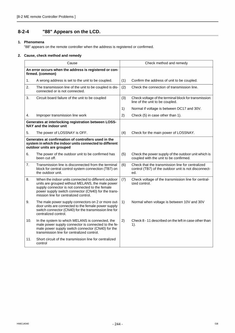
[8-2 ME remote Controller Problems ]
8-2-4 "88" Appears on the LCD.
1. Phenomena"88" appears on the remote controller when the address is registered or confirmed.
2. Cause, check method and remedy
Cause Check method and remedy
An error occurs when the address is registered or con-firmed. (common)
1. A wrong address is set to the unit to be coupled. (1) Confirm the address of unit to be coupled.
2. The transmission line of the unit to be coupled is dis-connected or is not connected.
(2) Check the connection of transmission line.
3. Circuit board failure of the unit to be coupled (3) Check voltage of the terminal block for transmission line of the unit to be coupled.
1) Normal if voltage is between DC17 and 30V.
4. Improper transmission line work 2) Check (5) in case other than 1).
Generates at interlocking registration between LOSS-NAY and the indoor unit
5. The power of LOSSNAY is OFF. (4) Check for the main power of LOSSNAY.
Generates at confirmation of controllers used in the system in which the indoor units connected to different outdoor units are grouped
6. The power of the outdoor unit to be confirmed has been cut off.
(5) Check the power supply of the outdoor unit which is coupled with the unit to be confirmed.
7. Transmission line is disconnected from the terminal block for central control system connection (TB7) on the outdoor unit.
(6) Check that the transmission line for centralized control (TB7) of the outdoor unit is not disconnect-ed.
8. When the indoor units connected to different outdoor units are grouped without MELANS, the male power supply connector is not connected to the female power supply switch connector (CN40) for the trans-mission line for centralized control.
(7) Check voltage of the transmission line for central-ized control.
9. The male power supply connectors on 2 or more out-door units are connected to the female power supply switch connector (CN40) for the transmission line for centralized control.
1) Normal when voltage is between 10V and 30V
10. In the system to which MELANS is connected, the male power supply connector is connected to the fe-male power supply switch connector (CN40) for the transmission line for centralized control.
2) Check 8 - 11 described on the left in case other than 1).
11. Short circuit of the transmission line for centralized control
- 244 -HWE14040 GB

[8-3 Refrigerant Control Problems ]
8 T
rou
ble
sh
oo
tin
g B
ase
d o
n O
bs
erv
ed
Sym
pto
ms
8-3 Refrigerant Control Problems
8-3-1 Units in the Cooling Mode Do Not Operate at Expected Capacity.
1. PhenomenaAlthough cooling operation starts with the normal remote controller display, the capacity is not enough
2. Cause, check method and remedy
Cause Check method and remedy
1. Compressor frequency does not rise sufficiently.Faulty detection of pressure sensor.Protection works and compressor frequency does
not rise due to high discharge temperatureProtection works and compressor frequency does
not rise due to high pressurePressure drops excessively.
(1) Check pressure difference between the detected pressure by the pressure sensor and the actual pres-sure with self-diagnosis LED.→ If the accurate pressure is not detected, check the pressure sensor. Refer to the following page(s). [8-5-1 Comparing the High-Pressure Sensor Measurement and Gauge Pressure](page 253)
Note: Lower inlet pressure by the low pressure sensor than the actual pressure causes insufficient capacity.SW4 setting (SW6-10: OFF)
For how to read the SW settings, refer to the follow-ing page(s). [9-1-1 How to Read the LED](page 289)
(2) Check temperature difference between the evaporat-ing temperature (Te) and the target evaporating tem-perature (Tem) with self-diagnosis LED.
Note: Higher Te than Tem causes insufficient capacity.SW4 setting (SW6-10: OFF)
For how to read the SW settings, refer to the follow-ing page(s). [9-1-1 How to Read the LED](page 289)
Note: Protection works and compressor frequency does not rise even at higher Te than Tem due to high discharge temperature and high pressure.At high discharge temperature:Refer to the following page(s).[7-3-1 Error Code [1102]](page 171)At high pressure:Refer to the following page(s). [7-3-3 Error Code [1302] (during operation)](page 173)
2. Indoor unit LEV malfunction Refer to the following page(s).[8-8 Troubleshooting LEV Problems](page 258)
Insufficient refrigerant flows due to LEV malfunc-tion (not enough opening) or protection works and compressor frequency does not rise due to pres-sure drop.Refrigerant leak from LEV on the stopping unit
causes refrigerant shortage on the running unit.
High pressure sensor
Low pressure sensor
ON
SW4
1 2 3 4 5 6 7 8 9 10 OFF
ON
SW4
1 2 3 4 5 6 7 8 9 10 OFF
Evaporating temperature Te
Target evaporating temperature Tem
ON
SW4
1 2 3 4 5 6 7 8 9 10 OFF
ON
SW4
1 2 3 4 5 6 7 8 9 10 OFF
- 245 -HWE14040 GB

[8-3 Refrigerant Control Problems ]
Cause Check method and remedy
3. RPM error of the outdoor unit FAN Refer to the following page(s).[8-7 Troubleshooting Outdoor Unit Fan Prob-lems](page 257)
[7-3-3 Error Code [1302] (during operation)](page 173)
Motor failure or board failure, or airflow rate de-crease due to clogging of the heat exchangerThe fan is not properly controlled as the outdoor
temperature cannot be precisely detected by the temperature sensor.The fan is not properly controlled as the pressure
cannot be precisely detected by the pressure sen-sor.
4. Long piping lengthThe cooling capacity varies greatly depending on the pressure loss. (When the pressure loss is large, the cooling capacity drops.)
Check the piping length to determine if it is contrib-uting to performance loss.Piping pressure loss can be estimated from the temperature difference between the indoor unit heat exchanger outlet temperature and the satura-tion temperature (Te) of 63LS. →Correct the piping.5. Piping size is not proper (thin)
6. Insufficient refrigerant amountProtection works and compressor frequency does not rise due to high discharge temperature.
Refer to item 1 (Compressor frequency does not rise sufficiently.) on the previous page. (page 245)Refer to the following page(s).[6-9 Evaluating and Adjusting Refrigerant Charge](page 131)
7. Clogging by foreign object Check the temperature difference between in front of and behind the place where the foreign object is clogging the pipe (upstream side and downstream side). When the temperature drops significantly, the foreign object may clog the pipe.→ Remove the foreign object inside the pipe.
8. The indoor unit inlet temperature is excessively. (Less than 15°C [59°F] WB)
Check the inlet air temperature and for short cy-cling. Change the environment where the indoor unit is used.
9. Compressor failureThe amount of circulating refrigerant decreases due to refrigerant leak in the compressor.
Check the discharge temperature to determine if the refrigerant leaks, as it rises if there is a leak.
10. LEV1 malfunctionSufficient liquid refrigerant is not be supplied to the indoor unit as sufficient sub cool cannot be secured due to LEV1 malfunction.
Refer to the following page(s).[8-8 Troubleshooting LEV Problems](page 258)It most likely happens when there is little difference or no difference between TH3 and TH6.
11. TH3, TH6 and 63HS1 sensor failure or faulty wiringLEV1 is not controlled normally.
Check the thermistor.Check wiring.
12. LEV2 actuation failure A drop in the low pressure that is caused either by a blockage of liquid pipe or by a pressure loss and the resultant slowing of refrigerant flow causes a tenden-cy for the discharge temperature to rise.
Refer to the following page(s).[8-8 Troubleshooting LEV Problems](page 258)
- 246 -HWE14040 GB

[8-3 Refrigerant Control Problems ]
8 T
rou
ble
sh
oo
tin
g B
ase
d o
n O
bs
erv
ed
Sym
pto
ms
8-3-2 Units in the Heating Mode Do Not Operate at Expected Capacity.
1. PhenomenaAlthough heating operation starts with the normal remote controller display, the capacity is not enough.
2. Cause, check method and remedy
Cause Check method and remedy
1. Compressor frequency does not rise sufficiently.Faulty detection of pressure sensor.Protection works and compressor frequency does
not rise due to high discharge temperatureProtection works and compressor frequency does
not rise due to high pressure.
(1) Check pressure difference between the detected pressure by the pressure sensor and the actual pressure with self-diagnosis LED.→ If the accurate pressure is not detected, check the pressure sensor. Refer to the following page(s). [8-5-1 Comparing the High-Pressure Sensor Measurement and Gauge Pressure](page 253)
Note: Higher inlet pressure by the high pressure sensor than the actual pressure causes insufficient capac-ity.SW4 setting (SW6-10: OFF)
For how to read the SW settings, refer to the fol-lowing page(s). [9-1-1 How to Read the LED](page 289)
(2) Check the difference between the condensing tem-perature (Tc) and the target condensing tempera-ture (Tcm) with self-diagnosis LED.
Note: Higher Tc than Tcm causes insufficient capacity.SW4 setting (SW6-10: OFF)
For how to read the SW settings, refer to the fol-lowing page(s). [9-1-1 How to Read the LED](page 289)
Note: Protection works and compressor frequency does not rise even at lower Tc than Tcm due to high dis-charge temperature and high pressure.At high discharge temperature:Refer to the following page(s).[7-3-1 Error Code [1102]](page 171)At high pressure:Refer to the following page(s).[7-3-3 Error Code [1302] (during operation)](page 173)
High pressure sensor
Low pressure sensor
ON
SW4
1 2 3 4 5 6 7 8 9 10 OFF
ON
SW4
1 2 3 4 5 6 7 8 9 10 OFF
Condensing temperature Tc
Target condensing temperature Tcm
ON
SW4
1 2 3 4 5 6 7 8 9 10 OFF
ON
SW4
1 2 3 4 5 6 7 8 9 10 OFF
- 247 -HWE14040 GB

[8-3 Refrigerant Control Problems ]
Cause Check method and remedy
2. Indoor unit LEV malfunctionInsufficient refrigerant flows due to LEV malfunction (not enough opening).
Refer to the following page(s).[8-8 Troubleshooting LEV Problems](page 258)
3. Temperature reading error on the indoor unit piping temperature sensor If the temperature reading on the sensor is higher than the actual temperature, it makes the subcool seem smaller than it is, and the LEV opening de-creases too much.
Check the thermistor.
4 RPM error of the outdoor unit FAN Refer to the following page(s).[8-7 Troubleshooting Outdoor Unit Fan Prob-lems](page 257)Motor failure or board failure, or airflow rate de-
crease, pressure drop due to clogging of the heat exchanger leading to high discharge temperatureThe fan is not properly controlled as the tempera-
ture cannot be precisely detected with the piping sensor.
5. Insulation failure of the refrigerant piping
6. Long piping lengthExcessively long piping on the high pressure side causes pressure loss leading to increase in the high pressure.
Confirm that the characteristic of capacity drop due to piping length.→ Change the pipe
7. Piping size is not proper (thin)
8. Clogging by foreign object Check the temperature difference between the up-stream and the downstream of the pipe section that is blocked. Since blockage in the extended section is difficult to locate, operate the unit in the cooling cycle, and follow the same procedures that are used to locate the blockage of pipe during cooling operation.→ Remove the blockage in the pipe.
9. The indoor unit inlet temperature is excessively high.(exceeding 28°C [82°F])
Check the inlet air temperature and for short cy-cling. Change the environment where the indoor unit is used.
10. Insufficient refrigerant amountProtection works and compressor frequency does not rise due to low discharge temperatureRefrigerant recovery operation is likely to start.
Refer to item 1 (Compressor frequency does not rise sufficiently.) on the previous page. (page 247)Refer to the following page(s).[6-9 Evaluating and Adjusting Refrigerant Charge](page 131)
11. Compressor failure (same as in case of cooling) Check the discharge temperature.
12. LEV2 actuation failureA drop in the low pressure that is caused either by a blockage of liquid pipe or by a pressure loss and the resultant slowing of refrigerant flow causes a tenden-cy for the discharge temperature to rise.
Refer to the following page(s).[8-8 Troubleshooting LEV Problems](page 258)
- 248 -HWE14040 GB

[8-3 Refrigerant Control Problems ]
8 T
rou
ble
sh
oo
tin
g B
ase
d o
n O
bs
erv
ed
Sym
pto
ms
8-3-3 Outdoor Units Stop at Irregular Times.
1. PhenomenaOutdoor unit stops at times during operation.
2. Cause, check method and remedy
Cause Check method and remedy
The first stop is not considered as an error, as the unit turns to anti-restart mode for 3 minutes as a pre-liminary error.
(1) Check the mode operated in the past by displaying preliminary error history on LED display with SW4.
Error mode (2) Reoperate the unit to find the mode that stops the unit by displaying preliminary error history on LED display with SW4.Refer to the reference page for each error mode.
1) Abnormal high pressure
2) Abnormal discharge air temperature
3) Heatsink thermistor failure *Display the indoor piping temperature table with SW4 to check whether the freeze proof operation runs properly, and check the temperature.
4) Thermistor failure Refer to the following page(s).9 LED Status Indica-tors on the Outdoor Unit Circuit Board(page 289)
5) Pressure sensor failure
6) Over-current break
7) Refrigerant overcharge
Note1: Frost prevention tripping only under cooling mode may be considered in addition to the above. (Freeze protection is detected by one or all indoor units.)
Note2: Even the second stop is not considered as an error when some specified errors occur. (eg. The third stop is considered as an error when the thermistor error occurs.)
- 249 -HWE14040 GB

[8-4 Checking Transmission Waveform and for Electrical Noise Interference ]
8-4 Checking Transmission Waveform and for Electrical Noise Interference
8-4-1 M-NET
Control is performed by exchanging signals between the outdoor unit and the indoor unit (ME remote controller) through M-NET transmission. Noise interference on the transmission line will interrupt the normal transmission, leading to erroneous op-eration.
(1) Symptoms caused by noise interference on the transmission line
(2) Wave shape check
Wave shape checkCheck the wave pattern of the transmission line with an oscilloscope. The following conditions must be met.
1) Small wave pattern (noise) must not exist on the transmission signal. (Minute noise (approximately 1V) can be generated by DC-DC converter or the inverter operation; however, such noise is not a problem when the shield of the transmission line is grounded.)
2) The sectional voltage level of transmission signal should be as follows.
Cause Erroneous operation Error code Error code definition
Noise interference on the transmission line
Signal is transformed and will be misjudged as the signal of another address.
6600 Address overlap
Transmission wave pattern is transformed due to the noise creating a new signal
6602 Transmission pro-cessor hardware er-ror
Transmission wave pattern is transformed due to the noise, and will not be received normally leading to no acknowledgement (ACK).
6607 No ACK error
Transmission cannot be performed due to the fine noise.
6603 Transmission line bus busy error
Transmission is successful; however, the acknowl-edgement (ACK) or the response cannot be re-ceived normally due to the noise.
66076608
No ACK errorNo response error
Logic Voltage level of the transmission line
0 VHL = 2.5V or higher
1 VBN = 1.3V or below
[With transmission]
[Without transmission]
No fine noise allowed
No fine noise allowed
52 52 52 52 52
VBN
VHL
Logic "0" Logic "1"
- 250 -HWE14040 GB

[8-4 Checking Transmission Waveform and for Electrical Noise Interference ]
8 T
rou
ble
sh
oo
tin
g B
ase
d o
n O
bs
erv
ed
Sym
pto
ms
(3) Check method and remedy
1) Measures against noiseCheck the followings when noise exists on the wave or the errors described in (1) occur.
2) Check the followings when the error "6607" occurs, or "HO" appears on the display on the remote controller.
Error code definition Remedy
Check that the wiring work is performed ac-cording to wiring specifications.
1. The transmission line and the power line are not wired too closely.
Isolate the transmission line from the power line (5cm [1-31/32"] or more). Do not insert them in the same conduit.
2. The transmission line is not bundled with that for another systems.
The transmission line must be isolated from another transmission line.When they are bundled, erroneous operation may be caused.
3. The specified wire is used for the transmission line.
Use the specified transmission line.Type: Shielded wire CVVS/CPEVS/MVVS (For ME remote control-ler)Diameter: 1.25mm2 [AWG16] or more (Remote controller wire: 0.3 - 1.25mm2 [AWG22-16])
4. When the transmission line is daisy-chained on the indoor unit terminals, are the shields daisy-chained on the terminals, too?
The transmission is two-wire daisy-chained. The shielded wire must be also daisy-chained.When the shielded cable is not daisy-chained, the noise cannot be reduced enough.
Check that the grounding work is performed according to grounding specifi-cations.
5. Is the shield of the indoor-outdoor transmission ca-ble grounded to the earth terminal on the outdoor unit?
Connect the shield of the indoor-outdoor transmission cable to the earth terminal ( ) on the outdoor unit.If no grounding is provided, the noise on the transmission line can-not escape leading to change of the transmission signal.
6. Check the treatment meth-od of the shield of the transmission line (for cen-tralized control).
The transmission cable for centralized control is less subject to noise interference if it is grounded to the outdoor unit whose power jumper cable was moved from CN41 to CN40 or to the power sup-ply unit.The environment against noise varies depending on the distance of the transmission lines, the number of the connected units, the type of the controllers to be connected, or the environment of the installation site. Therefore, the transmission line work for central-ized control must be performed as follows.
1. When no grounding is provided: Ground the shield of the transmission cable by connecting to the outdoor unit whose power jumper connector was moved from CN41 to CN40 or to the power supply unit.
2. When an error occurs even though one point grounding is provided: Ground the shield on all outdoor units.
Error code definition Remedy
7. The farthest distance of transmission line is 200m [656ft] or longer.
Check that the farthest distance from the outdoor unit to the indoor unit and to the remote controller is within 200m [656ft].
8. The types of transmission lines are different. Use the specified transmission line.Type: Shielded wire CVVS/CPEVS/MVVS (For ME remote control-ler)Diameter: 1.25mm2 [AWG16] or more (Remote controller wire: 0.3-1.25mm2 [AWG22-16])
9. Outdoor unit circuit board failure Replace the outdoor unit control board or the power supply board for the transmission line.
10. Indoor unit circuit board failure or remote con-troller failure
Replace the indoor unit circuit board or the remote controller.
11. The MA remote controller is connected to the M-NET transmission line.
Connect the MA remote controller to the terminal block for MA re-mote controller (TB15).
- 251 -HWE14040 GB

[8-4 Checking Transmission Waveform and for Electrical Noise Interference ]
8-4-2 MA Remote Controller
The communication between the MA remote controller and the indoor unit is performed with current tone burst.
(1) Symptoms caused by noise interference on the transmission line
If noise is generated on the transmission line, and the communication between the MA remote controller and the indoor unit is interrupted for 3 minutes in a row, MA transmission error (6831) will occur.
(2) Confirmation of transmission specifications and wave pattern
A, B : No polarityAcross terminal No. 1-2 : Power supply (9V to 12VDC)
Satisfies the formula 12 msec/bit 5% Voltage among terminals must be between DC9 and 12 V.
TB15
AB
12
MA remote controller
Transmission waveform (Across terminal No.1 - 2)
DC9~12V
Logic 1 Logic 0 Logic 1 Logic 1
12msec 12msec 12msec 12msec
Indoor unit
- 252 -HWE14040 GB

[8-5 Pressure Sensor Circuit Configuration and Troubleshooting Pressure Sensor Problems ]
8 T
rou
ble
sh
oo
tin
g B
ase
d o
n O
bs
erv
ed
Sym
pto
ms
8-5 Pressure Sensor Circuit Configuration and Troubleshooting Pressure Sensor Problems
8-5-1 Comparing the High-Pressure Sensor Measurement and Gauge Pressure
By configuring the digital display setting switch (SW4 (when SW6-10 is set to OFF)) as shown in the figure below, the pressure as measured by the high-pressure sensor appears on the LED1 on the control board.
(1) While the sensor is stopped, compare the gauge pressure and the pressure displayed on self-diagnosis LED1.
1) When the gauge pressure is between 0 and 0.098MPa [14psi], internal pressure is caused due to gas leak. 2) When the pressure displayed on self-diagnosis LED1 is between 0 and 0.098MPa [14psi], the connector may be defective or
be disconnected. Check the connector and go to (4). 3) When the pressure displayed on self-diagnosis LED1 exceeds 4.15MPa [601psi], go to (3).4) If other than 1), 2) or 3), compare the pressures while the sensor is running. Go to (2).
(2) Compare the gauge pressure and the pressure displayed on self-diagnosis LED1 while the sensor is running. (Com-pare them by MPa [psi] unit.)
1) When the difference between both pressures is within 0.098MPa [14psi], both the high pressure sensor and the control board are normal.
2) When the difference between both pressures exceeds 0.098MPa [14psi], the high pressure sensor has a problem. (perfor-mance deterioration)
3) When the pressure displayed on self-diagnosis LED1 does not change, the high pressure sensor has a problem.
(3) Remove the high pressure sensor from the control board to check the pressure on the self-diagnosis LED1.
1) When the pressure displayed on self-diagnosis LED1 is between 0 and 0.098MPa [14psi], the high pressure sensor has a problem.
2) When the pressure displayed on self-diagnosis LED1 is approximately 4.15MPa [601psi], the control board has a problem.
(4) Remove the high pressure sensor from the control board, and short-circuit between the No.2 and 3 connectors (63HS1) to check the pressure with self-diagnosis LED1.
1) When the pressure displayed on the self-diagnosis LED1 exceeds 4.15MPa [601psi], the high pressure sensor has a problem.2) If other than 1), the control board has a problem.
8-5-2 High-Pressure Sensor Configuration (63HS1)
The high pressure sensor consists of the circuit shown in the figure below. If DC 5V is applied between the red and the black wires, voltage corresponding to the pressure between the white and the black wires will be output, and the value of this voltage will be converted by the microcomputer. The output voltage is 0.071V per 0.098MPa [14psi].
The pressure sensor on the body side is designed to connect to the connector. The connector pin number on the body side is different from that on the control board side.
For how to read the SW settings, refer to the following page(s). [9-1-1 How to Read the LED](page 289)
ON
SW4
1 2 3 4 5 6 7 8 9 10 OFF
Body side Control board side
Vcc Pin 1 Pin 3
Vout Pin 2 Pin 2
GND Pin 3 Pin 1
0
0.5 [73]
1.0 [145]
1.5 [218]
2.0 [290]
2.5 [363]
3.0 [435]
3.5 [508]
4.0 [580]
4.5 [653]
0 0.5 1 1.5 2 2.5 3 3.5
Output voltage (V)
Pr
essu
re (M
Pa [p
si])
Connector
63HS11 2 3
1 2
3
GND (Black)
Vout (White)
Vcc (DC 5 V)(Red)
Pressure 0 ~ 4.15 MPa [601psi] Vout 0.5 ~ 3.5 V 0.071 V / 0.098 MPa [14 psi]
- 253 -HWE14040 GB

[8-5 Pressure Sensor Circuit Configuration and Troubleshooting Pressure Sensor Problems ]
8-5-3 Comparing the Low-Pressure Sensor Measurement and Gauge Pressure
By configuring the digital display setting switch (SW4 (when SW6-10 is set to OFF)) as shown in the figure below, the pressure as measured by the low-pressure sensor appears on the LED1 on the control board.
(1) While the sensor is stopped, compare the gauge pressure and the pressure displayed on self-diagnosis LED1.
1) When the gauge pressure is between 0 and 0.098MPa [14psi], internal pressure is caused due to gas leak. 2) When the pressure displayed on self-diagnosis LED1 is between 0 and 0.098MPa [14psi], the connector may be defective or
be disconnected. Check the connector and go to (4). 3) When the pressure displayed on self-diagnosis LED1 exceeds 1.7MPa [247psi], go to (3).4) If other than 1), 2) or 3), compare the pressures while the sensor is running. Go to (2).
(2) Compare the gauge pressure and the pressure displayed on self-diagnosis LED1 while the sensor is running.(Com-pare them by MPa [psi] unit.)
1) When the difference between both pressures is within 0.03MPa [4psi], both the low pressure sensor and the control board are normal.2) When the difference between both pressures exceeds 0.03MPa [4psi], the low pressure sensor has a problem. (performance dete-
rioration) 3) When the pressure displayed on the self-diagnosis LED1 does not change, the low pressure sensor has a problem.
(3) Remove the low pressure sensor from the control board to check the pressure with the self-diagnosis LED1 display.
1) When the pressure displayed on the self-diagnosis LED1 is between 0 and 0.098MPa [14psi], the low pressure sensor has a problem.
2) When the pressure displayed on self-diagnosis LED1 is approximately 1.7MPa [247psi], the control board has a problem.
When the outdoor temperature is 30°C [86°F] or less, the control board has a problem. When the outdoor temperature exceeds 30°C [86°F], go to (5).
(4) Remove the low pressure sensor from the control board, and short-circuit between the No.2 and 3 connectors (63LS:CN202) to check the pressure with the self-diagnosis LED1.
1) When the pressure displayed on the self-diagnosis LED1 exceeds 1.7MPa [247psi], the low pressure sensor has a problem. 2) If other than 1), the control board has a problem.
(5) Remove the high pressure sensor (63HS1) from the control board, and insert it into the connector for the low pres-sure sensor (63LS) to check the pressure with the self-diagnosis LED1.
1) When the pressure displayed on the self-diagnosis LED1 exceeds 1.7MPa [247psi], the control board has a problem. 2) If other than 1), the control board has a problem.
8-5-4 Low-Pressure Sensor Configuration (63LS)
The low pressure sensor consists of the circuit shown in the figure below. If DC5V is applied between the red and the black wires, voltage corresponding to the pressure between the white and the black wires will be output, and the value of this voltage will be converted by the microcomputer. The output voltage is 0.173V per 0.098MPa [14psi].
The pressure sensor on the body side is designed to connect to the connector. The connector pin number on the body side is different from that on the control board side.
For how to read the SW settings, refer to the following page(s). [9-1-1 How to Read the LED](page 289)
ON
SW4
1 2 3 4 5 6 7 8 9 10 OFF
Body side Control board side
Vcc Pin 1 Pin 3
Vout Pin 2 Pin 2
GND Pin 3 Pin 1
0
0.2 [29]
0.4 [58]
0.6 [87]
0.8 [116]
1.0 [145]
1.2 [174]
1.4 [203]
1.6 [232]
1.8 [261]
0 0.5 1 1.5 2 2.5 3 3.5 Output voltage (V)
Pr
essu
re (M
Pa
[psi
])
Connector
63LS1 2 3
12
3
GND (Black)
Vout (White)
Vcc (DC 5 V)(Red)
Pressure 0 ~ 1.7 MPa [247psi]Vout 0.5 ~ 3.5 V 0.173 V / 0.098 MPa [14 psi]
- 254 -HWE14040 GB
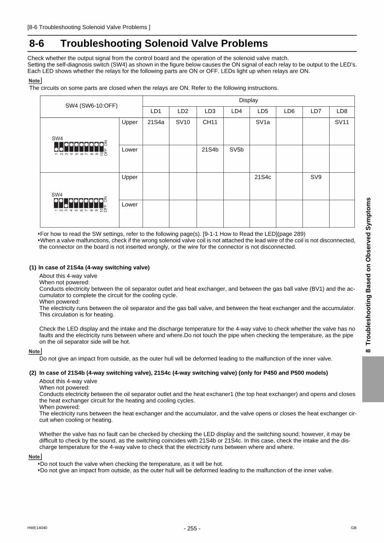
[8-6 Troubleshooting Solenoid Valve Problems ]
8 T
rou
ble
sh
oo
tin
g B
ase
d o
n O
bs
erv
ed
Sym
pto
ms
8-6 Troubleshooting Solenoid Valve ProblemsCheck whether the output signal from the control board and the operation of the solenoid valve match.Setting the self-diagnosis switch (SW4) as shown in the figure below causes the ON signal of each relay to be output to the LED's.Each LED shows whether the relays for the following parts are ON or OFF. LEDs light up when relays are ON.
The circuits on some parts are closed when the relays are ON. Refer to the following instructions.
For how to read the SW settings, refer to the following page(s). [9-1-1 How to Read the LED](page 289)When a valve malfunctions, check if the wrong solenoid valve coil is not attached the lead wire of the coil is not disconnected, the connector on the board is not inserted wrongly, or the wire for the connector is not disconnected.
(1) In case of 21S4a (4-way switching valve)
About this 4-way valveWhen not powered: Conducts electricity between the oil separator outlet and heat exchanger, and between the gas ball valve (BV1) and the ac-cumulator to complete the circuit for the cooling cycle. When powered: The electricity runs between the oil separator and the gas ball valve, and between the heat exchanger and the accumulator. This circulation is for heating.
Check the LED display and the intake and the discharge temperature for the 4-way valve to check whether the valve has no faults and the electricity runs between where and where.Do not touch the pipe when checking the temperature, as the pipe on the oil separator side will be hot.
Do not give an impact from outside, as the outer hull will be deformed leading to the malfunction of the inner valve.
(2) In case of 21S4b (4-way switching valve), 21S4c (4-way switching valve) (only for P450 and P500 models)
About this 4-way valveWhen not powered: Conducts electricity between the oil separator outlet and the heat exchaner1 (the top heat exchanger) and opens and closes the heat exchanger circuit for the heating and cooling cycles. When powered: The electricity runs between the heat exchanger and the accumulator, and the valve opens or closes the heat exchanger cir-cuit when cooling or heating.
Whether the valve has no fault can be checked by checking the LED display and the switching sound; however, it may be difficult to check by the sound, as the switching coincides with 21S4b or 21S4c. In this case, check the intake and the dis-charge temperature for the 4-way valve to check that the electricity runs between where and where.
Do not touch the valve when checking the temperature, as it will be hot.Do not give an impact from outside, as the outer hull will be deformed leading to the malfunction of the inner valve.
SW4 (SW6-10:OFF)Display
LD1 LD2 LD3 LD4 LD5 LD6 LD7 LD8
Upper 21S4a SV10 CH11 SV1a SV11
Lower 21S4b SV5b
Upper 21S4c SV9
Lower
ON
SW4
1 2 3 4 5 6 7 8 9 10 OFF
ON
SW4
1 2 3 4 5 6 7 8 9 10 OFF
- 255 -HWE14040 GB

[8-6 Troubleshooting Solenoid Valve Problems ]
(3) In case of SV1a (Bypass valve)
This solenoid valve opens when powered (Relay ON).1) At compressor start-up, the SV1a turns on for 4 minutes, and the operation can be checked by the self-diagnosis LED display
and the closing sound.2) To check whether the valve is open or closed, check the change of the SV1a downstream piping temperature while the valve
is being powered.Even when the valve is closed, high-temperature refrigerant flows inside the capillary next to the valve. (Therefore, temperature of the downstream piping will not be low with the valve closed.)
(4) In the case of SV5b (2-way valve) , SV5c (2-way valve) (only for P450 and P500 models)
This solenoid valve is a switching valve that closes when energized. Proper operation of this valve can be checked on the LED and by the switching sound. During the cooling mode, SV5b and 21S4b, SV5c and 21S4c, are switched simultaneously, which may make it difficult to check for proper operation of the SV5b or SV5c by listening for the switching sound. If this is the case, the temperature before and after SV5b or SV5c can be used to determine if the refrigerant is the pipe.
(5) In the case of SV9 (Solenoid valve)
This solenoid valve is a switching valve that opens when energized. Proper operation of this valve can be checked on the LED display and by the switching sound.
(6) In the case of SV10 (Solenoid valve)
This solenoid valve is a switching valve that opens when energized. Proper operation of this valve can be checked on the LED display and by the switching sound.
(7) In the case of SV11 (Solenoid valve)
This solenoid valve is a switching valve that opens when energized. Proper operation of this valve can be checked on the LED display and by the switching sound.
Do not give an impact from outside, as the outer hull will be deformed leading to the malfunction of the inner valve.
- 256 -HWE14040 GB

[8-7 Troubleshooting Outdoor Unit Fan Problems ]
8 T
rou
ble
sh
oo
tin
g B
ase
d o
n O
bs
erv
ed
Sym
pto
ms
8-7 Troubleshooting Outdoor Unit Fan Problems(1) Fan motor (common items)
To check the revolution of the fan, check the inverter output state on the self-diagnosis LED, as the inverter on the outdoor fan controls the revolutions of the fan.When starting the fan, the fan runs at full speed for 5 seconds.When setting the DIP SW4 (when SW6-10 is set to OFF) as shown in the figure below, the inverter output [%] will appear. 100% indicates the full speed and 0% indicates the stopping. (Fan #2 is only on the P450 and P500 models.)
As the revolution of the fan changes under control, at the interphase or when the indoor unit operation capacity is low, the revolution of the fan may change.If the fan does not move or it vibrates, Fan board problem or fan motor problem is suspected. When checking the fan motor for problems by shutting down the power, be sure to disconnect the motor wire from the fan board. If a short-circuited fan board malfunctions, it will keep the fan motor from rotating smoothly. For details, refer to the following page(s).[8-9-7 Checking the Fan Motor for Ground Fault and Coil Resistance Problems](page 269)[8-9-8 Checking the Fan Board Error Detection Circuit at No Load](page 269)[8-9-9 Checking the Fan Inverter for Damage at No Load](page 270)[8-9-10 Checking the Fan Inverter for Damage with Load](page 271)
For how to read the SW settings, refer to the following page(s). [9-1-1 How to Read the LED](page 289)
Fan 1 Fan 2
ON
SW4
1 2 3 4 5 6 7 8 9 10 OFF
ON
SW4
1 2 3 4 5 6 7 8 9 10 OFF
- 257 -HWE14040 GB

[8-8 Troubleshooting LEV Problems ]
8-8 Troubleshooting LEV Problems
8-8-1 General Overview on LEV Operation
LEV (Indoor unit: Linear expansion valve) and LEV2 (Outdoor unit: Linear expansion valve) are stepping-motor-driven valves that operate by receiving the pulse signals from the indoor and outdoor unit control boards.
(1) Indoor LEV and Outdoor LEV (LEV2)
The valve opening changes according to the number of pulses.1) Indoor unit control board and the LEV (Indoor unit: Linear expansion valve)
2) Outdoor unit control board and the LEV (Outdoor unit: Linear expansion valve)
Note. The connector numbers on the intermediate connector and the connector on the control board differ. Check the color of the lead wire to judge the number.
Control board
Drive circuit
LEV
M
5
5
2
2
1
1
3
3 4
4
6
6
DC12V
Red
Intermediate connector
Brown
Blue
Orange
Yellow
White Red Orange White
Brown
Blue
Yellow
6
5
4 4
3
2
1
3
2
1
4
3
2
1
ø4
ø3
ø2
ø1
ø4
ø3
ø2
ø1
Control board
Drive circuit
LEV
M
52
13
4
6
DC12V
Red
Blue
Orange
Yellow
WhiteOrangeWhite
Blue
Yellow
Red
6
5
4
3
2
1
- 258 -HWE14040 GB

[8-8 Troubleshooting LEV Problems ]
8 T
rou
ble
sh
oo
tin
g B
ase
d o
n O
bs
erv
ed
Sym
pto
ms
3) Pulse signal output and valve operation
4) LEV closing and opening operation
Output state Output (phase) number 1 2 3 4
1 ON OFF OFF ON2 ON ON OFF OFF3 OFF ON ON OFF
4 OFF OFF ON ON
Output pulses change in the following orders when the Valve is closed; 1 2 3 4 1 Valve is open; 4 3 2 1 4
*1. When the LEV opening angle does not change, all the output phases will be off.*2. When the output is open phase or remains ON, the motor cannot run smoothly, and rattles and vibrates.
*Upon power on, the indoor unit circuit board sends a 2200 pulse signal to the indoor unit LEV and a 3200 pulse signal to the outdoor unit LEV to determine the valve position and always brings the valve to the position as indicated by " A " in the diagram.
When the valve operates smoothly, no sound from LEV or no vibration occurs, however, when the pulses change from E to A in the chart or the valve is locked, a big sound occurs.
*Whether a sound is generated or not can be determined by holding a screwdriver against it, then placing your ear against the handle.
*1 The LEV opening may become greater depending on the operation status.
Valv
e op
enin
g (r
efrig
eran
t flo
w ra
te)
Valve closed
Valve open
E
B
80 - 100 pulses
Pulses
Fully open.1400 pulses (indoor unit LEV) *1.2100 pulses (outdoor unit LEV) *1
A
CD
- 259 -HWE14040 GB

[8-8 Troubleshooting LEV Problems ]
(2) Outdoor LEV (LEV1)
The valve opening changes according to the number of pulses.1) Connections between the outdoor control board and LEV1 (outdoor expansion valve)
2) Pulse signal output and valve operation
3) LEV valve closing and opening operation
LEV
DC 12V
Outdoor control board
M
4
6
2
35
1
4
5
6
3
2
1
4
5
6
3
2
1
4
3
2
1
Red
Brown
Blue
Orange
Yellow
White
Drive circuit
1 2 3 4 5 6 7 8
1 ON OFF OFF OFF OFF OFF ON ON
2 ON ON ON OFF OFF OFF OFF OFF
3 OFF OFF ON ON ON OFF OFF OFF
4 OFF OFF OFF OFF ON ON ON OFF
Output pulses change in the following orders when the Valve is open; 1 2 3 4 5 6 7 8 1 Valve is closed; 8 7 6 5 4 3 2 1 8
*1. When the LEV opening angle does not change, all the output phases will be off.*2. When the output is open phase or remains ON, the motor cannot run smoothly, and rattles and vibrates.
Output (phase) number
Output state
*When the power is turned on, the valve closing signal of 520 pulses will be output from the indoor board to LEV to fix the valve position. It must be fixed at point A.(Pulse signal is output for approximately 17 seconds.)
When the valve operates smoothly, there is no sound from the LEV and no vibration occurs, but when the valve is locked, noise is generated.
*Whether a sound is generated or not can be determined by holding a screwdriver against it, then placing your ear against the handle.
*If liquid refrigerant flows inside the LEV, the sound may become smaller.
B
A
Fully open: 480 pulses
Pulses
Val
ve o
peni
ng (
refr
iger
ant f
low
rat
e)
Valve closed
Valve open
- 260 -HWE14040 GB

[8-8 Troubleshooting LEV Problems ]
8 T
rou
ble
sh
oo
tin
g B
ase
d o
n O
bs
erv
ed
Sym
pto
ms
8-8-2 Possible Problems and Solutions
The specifications of the outdoor unit (outdoor LEV) and the indoor unit (indoor LEV) differ.Therefore, remedies for each failure may vary. Check the remedy specified for the appropriate LEV as indicated in the right column.
Malfunction mode
Judgment method Remedy Target LEV
Microcomputer driver circuit fail-ure
Disconnect the control board connector and connect the check LED as shown in the figure below.
resistance : 0.25W 1kΩLED : DC15V 20mA or moreWhen the main power is turned on, the indoor unit circuit board outputs pulse signals to the indoor unit LEV for 10 seconds, and the outdoor unit circuit board outputs pulse signals to the outdoor unit LEV for 17 seconds.If any of the LED remains lit or unlit, the drive circuit is faulty.
When the drive circuit has a problem, replace the control board.
IndoorOutdoor
LEV mechanism is locked
If the LEV is locked, the drive motor runs idle, and makes a small clicking sound.When the valve makes a closing and opening sound, the valve has a problem.
Replace the LEV. IndoorOutdoor
Disconnected or short-circuited LEV motor coil
Measure the resistance between coils (red-white, red-orange, brown-yellow, brown-blue) with a tester. When the resistance is in the range of 150Ω ± 10%, the LEV is normal.
Replace the LEV coils. Indoor
Measure the resistance between coils (red-white, red-orange, red-yellow, red-blue) with a tester. When the resistance is in the range of 100Ω ± 10%, the LEV is normal.
Replace the LEV coils. Outdoor(LEV2a, LEV2b)
Measure resistance between the coils (red - white, red -orange, brown - yellow, brown - blue) using a tester. They are normal if resistance is 46Ω ± 3%.
Replace the LEV coils. Outdoor(LEV1)
Incomple sealing(leak from the valve)
When checking the refrigerant leak from the indoor LEV, run the target indoor unit in the fan mode, and the other indoor units in the cooling mode. Then, check the liquid temperature (TH22) with the self-diagnosis LED. When the unit is running in the fan mode, the LEV is fully closed, and the temperature detected by the thermistor is not low. If there is a leak, however, the temper-ature will be low. If the temperature is extremely low compared with the inlet temperature displayed on the remote controller, the LEV is not properly sealed, however, if there is a little leak, it is not necessary to replace the LEV when there are no effects to other parts.
If there is a large amount of leakage, replace the LEV.
Indoor
Faulty wire con-nections in the connector or faulty contact
1. Check for loose pins on the connector and check the col-ors of the lead wires visually
Check the continuity at the points where an error occurs.
IndoorOutdoor
2. Disconnect the control board's connector and conduct a continuity check using a tester.
6
5
4
3
2
11 k LED
Thermistor(liquid piping temperature detection)
Linear Expansion Valve
- 261 -HWE14040 GB

[8-8 Troubleshooting LEV Problems ]
8-8-3 Coil Removal Instructions
(1) Outdoor unit LEV (LEV1)
1) LEV component
As shown in the figure, the outdoor LEV is made in such a way that the coils and the body can be separated.
2) Removing the coils
Fasten the body tightly at the bottom (Part A in the figure) so that the body will not move, then pull out the coils toward the top.If the coils are pulled out without the body gripped, undue force will be applied and the pipe will be bent.
3) Installing the coils
Fix the body tightly at the bottom (Part A in the figure) so that the body will not move, then insert the coils from the top, and insert the coil stopper securely in the pipe on the body. Hold the body when pulling out the coils to prevent so that the pipe will not be bent. If the coils are pushed without the body gripped, undue force will be applied and the pipe will be bent. Hold the body when pulling out the coils to prevent so that the pipe will not be bent.
CoilsStopper
Lead wire
Body
Part A
Part A
- 262 -HWE14040 GB

[8-8 Troubleshooting LEV Problems ]
8 T
rou
ble
sh
oo
tin
g B
ase
d o
n O
bs
erv
ed
Sym
pto
ms
(2) Outdoor unit LEV (LEV2a, LEV2b)
1) Components
The outdoor unit LEV consists of a coil and a valve body that can be separated from each other.
2) Removing the coil
Securely hold the LEV at the bottom (as indicated by A in the figure), and turn the coil. After checking that the stopper is re-moved, pull up and out the coil.When removing the coil, hold the LEV body securely to prevent undue force from being placed on the pipe and bending the pipe.
3) Installing the coil
Securely hold the bottom of the LEV (section A in the figure), insert the coil from above, and turn the coil until the coil stopper is properly installed on the LEV body.When removing the coil, hold the LEV body securely to prevent undue force from being placed on the pipe and bending the pipe.
Stopper
Lead wire
CoilBody
Part A
Stopper
Stopper
Part A
- 263 -HWE14040 GB

[8-9 Troubleshooting Inverter Problems ]
8-9 Troubleshooting Inverter Problems
8-9-1 Inverter-Related Problems and Solutions
Replace only the compressor if only the compressor is found to be defective. (Overcurrent will flow through the inverter if the compressor is damaged, however, the power supply is automatically cut when overcurrent is detected, protecting the inverter from damage. Make sure that the model selection switches on the outdoor unit (Dip switches SW5-3 through 5-8 on the out-door unit control board) are set correctly. For switch settings, refer to the following page(s). [7-9-2 Error Code [7101]](page 227))Replace only the fan motor if only the fan motor is found to be defective. (Overcurrent will flow through the inverter if the fan motor is damaged, however, the power supply is automatically cut when overcurrrent is detected, protecting the inverter from damage.)Replace the defective components if the inverter is found to be defective.If both the compressor and the inverter are found to be defective, replace the defective component(s) of both devices.
(1) Inverter-related problems: Troubleshooting and remedies
1) Inside the inverter is a large capacity electrolytic capacitor, and the residual voltage that remains after the main power is turned off presents a risk of electric shock. Before inspecting the inside of the control box, turn off the power, leave the unit turned off for at least 10 minutes, and check that the voltage across FT-P and FT-N terminals or SC-P and SC-N terminals on the inverter board has dropped to 20 VDC or less. (It takes approximately 10 minutes to discharge electricity after the power is turned off.)
2) Before starting maintenance work, disconnect the connector (CNINV) on the outdoor unit fan board and CN1 on the inverter board (or CNFAN2 on the capacitor board). Before connecting or disconnecting connectors, make sure that the outdoor unit fans are stopped and that the voltage of the main circuit capacitor is 20 VDC or below. If the outdoor unit fan is turned by strong winds, the main circuit capacitor will be energized and poses an electric shock hazard. Refer to the wiring diagram name plate for details.
3) To connect wiring to TB7, check that the voltage is 20 VDC or below.4) After completion of maintenance work, reconnect the connector (CNINV) on the fan board and connector (CN1) on the inverter
board (or the connector (CNFAN2) on the capacitor board).5) The IPM on the inverter becomes damaged if there are loose screws are connectors. If a problem occurs after replacing some
of the parts, mixed up wiring is often the cause of the problem. Check for proper connection of the wiring, screws, connectors, and Faston terminals.
6) To avoid damage to the circuit board, do not connect or disconnect the inverter-related connectors with the main power turned on.
7) Faston terminals have a locking function. Make sure the terminals are securely locked in place after insertion.
8) When the IPM or IGBT is replaced, apply a thin layer of heat radiation grease that is supplied evenly to these parts. Wipe off any grease that may get on the wiring terminal to avoid terminal contact failure.
9) Faulty wiring to the compressor damages the compressor. Connect the wiring in the correct phase sequence.10) When the power is turned on, the compressor and the heater are energized even while they are not operating. Before turning
on the power, disconnect all power supply wires from the compressor terminal block, and measure the insulation resistance of the compressor. Check the compressor for a ground fault. If the insulation resistance is 1.0 MΩ or below, connect all power supply wires to the compressor or the heater, and turn on the power to the outdoor unit. (The liquid refrigerant in the compres-sor will evaporate by energizing the compressor.)
Press the tab on the terminals to remove them.
- 264 -HWE14040 GB

[8-9 Troubleshooting Inverter Problems ]
8 T
rou
ble
sh
oo
tin
g B
ase
d o
n O
bs
erv
ed
Sym
pto
ms
Error display/failure condition Measure/inspection item
[1] Inverter related errors4250, 4255, 4256, 4220, 4225, 4226, 4230, 4240, 4260, 5301, 5305, 5306, 0403
Implement solutions that correspond to the error codes or preliminary error codes.[7-1 Error Code and Preliminary Error Code Lists](page 165)
[2] Main power breaker trip Refer to the following page(s). [8-9-12 Solutions for the Main No-Fuse Breaker Trip](page 272)
[3] Main power earth leakage breaker trip Refer to the following page(s). [8-9-13 Solutions for the Main Earth Leakage Breaker Trip](page 272)
[4] Only the compressor does not operate. Check the inverter frequency on the LED monitor. If the frequency indi-cates that the units are in operation, refer to the following page(s). [8-9-5 Checking the Inverter for Damage during Compressor Opera-tion](page 267)
[5] The compressor vibrates violently at all times or makes an abnor-mal sound.
Refer to the following page(s). [8-9-5 Checking the Inverter for Damage during Compressor Operation](page 267)
[6] Compressor rotation speed does not reach the specified speed. <1> Check for problems with compressor current and heatsink temper-ature.
<2> Check for imbalance in power supply voltage. *Approximate target: 3% or less.
[7] Only the fan motor does not operate. Check the inverter frequency on the LED monitor. If the frequency indi-cates that the units are in operation, refer to the following page(s). [8-9-8 Checking the Fan Board Error Detection Circuit at No Load](page 269)[8-9-9 Checking the Fan Inverter for Damage at No Load](page 270)[8-9-10 Checking the Fan Inverter for Damage with Load](page 271)
[8] The fan motor shakes violently at all times or makes an abnormal sound.
Check the inverter frequency on the LED monitor. If the frequency indi-cates that the units are in operation, refer to the following page(s). [8-9-8 Checking the Fan Board Error Detection Circuit at No Load](page 269)[8-9-9 Checking the Fan Inverter for Damage at No Load](page 270)[8-9-10 Checking the Fan Inverter for Damage with Load](page 271)
[9] Noise is picked up by the peripheral device <1> Check that power supply wiring of the peripheral device does not run close to the power supply wiring of the outdoor unit.
<2> Check if the inverter output wiring is not running parallel to the power supply wiring and the transmission lines.
<3> Check that the shielded wire is used as the transmission line when it is required, and check that the grounding work is performed prop-erly on the shielded wire.
<4> Meg failure for electrical system other than the inverter
<5> Attach a ferrite core to the inverter output wiring. (Contact the fac-tory for details of the service part settings.)
<6> Provide separate power supply to the air conditioner and other electric appliances.
<7> If the problem suddenly appeared, inverter output may have had a ground fault. For details, refer to the following page(s). [8-9-5 Checking the Inverter for Damage during Compressor Opera-tion](page 267)
*Contact the factory for cases other than those listed above.
[10] Sudden malfunction (as a result of external noise.) <1> Check that the grounding work is performed properly.
<2>Check that the shielded wire is used as the transmission line when it is required, and check that the grounding work is performed prop-erly on the shielded wire.
<3>Check that neither the transmission line nor the external connec-tion wiring does not run close to another power supply system or does not run through the same conduit pipe.
* Contact the factory for cases other than those listed above.
- 265 -HWE14040 GB

[8-9 Troubleshooting Inverter Problems ]
8-9-2 Checking the Inverter Board Error Detection Circuit
8-9-3 Checking the Compressor for Ground Fault and Coil Resistance Problems
8-9-4 Checking the Inverter for Damage at No-Load
Items to be checked Phenomena Remedy
(1) Remove power supply. 1) Overcurrent error Error code: 4250Detail code: No. 101, 104, 105, 106, and 107
Replace the INV board.
(2) Disconnect the inverter output wire from the ter-minals of the INV board (SC-U, SC-V, SC-W).
2) Logic errorError code: 4220Detail code: No. 111
Replace the INV board.
(3) Apply power supply. 3) ACCT sensor circuit failure Error code: 5301Detail code: No.117
Replace the INV board.
(4) Put the outdoor unit into operation.
4) IPM open Error code: 5301Detail code: No.119
Normal
Items to be checked Phenomena Remedy
Disconnect the compressor wir-ing, and check the compressor Meg, and coil resistance.
1) Compressor Meg failureError if less than 1 MΩ.
Check that there is no liquid refrigerant in the compressor. If there is none, replace the compres-sor.
2) Compressor coil resistance failureCoil resistance value of 0.72 Ω(20°C [68°F]): P200, P250 modelsCoil resistance value of 0.32 Ω(20°C [68°F]): P300, P350 modelsCoil resistance value of 0.30 Ω(20°C [68°F]): P400, modelCoil resistance value of 0.43 Ω(20°C [68°F]): P450, P500 models
Replace the compressor.
Items to be checked Phenomena Remedy
(1) Remove power supply. 1) Inverter-related problems are detected. Connect the short-circuit connector to CN6 or set SW001-1 to ON, and go to 8-9-2.
(2) Disconnect the inverter output wire from the ter-minals of the INV board (SC-U, SC-V, SC-W).
2) Inverter voltage is not output at the termi-nals (SC-U, SC-V, and SC-W)
Replace the INV board.
(3) Disconnect the short-cir-cuit connector from CN6 on the INV board.
3) There is an voltage imbalance between the wires. Greater than 5% imbalance or 5V
Replace the INV board.
(4) Apply power supply.
(5) Put the outdoor unit into operation.Check the inverter output voltage after the inverter output frequency has sta-bilized.
4) There is no voltage imbalance between the wires.
Normal* Reconnect the short-circuit connec-tor to CN6 or restore SW001 to its orig-inal setting after checking the voltage.
- 266 -HWE14040 GB

[8-9 Troubleshooting Inverter Problems ]
8 T
rou
ble
sh
oo
tin
g B
ase
d o
n O
bs
erv
ed
Sym
pto
ms
8-9-5 Checking the Inverter for Damage during Compressor Operation
Items to be checked Phenomena Remedy
Put the outdoor unit into opera-tion.Check the inverter output volt-age after the inverter output fre-quency has stabilized.<INV20Y>
1) Overcurrent-related problems occur im-mediately after compressor startup.Error code : 4250Detail code : 101, 102, 106, 107
a. Check items 8-9-2 through 8-9-4 for problems.
b. Check that high and low pressures are balanced.
c. Check that no liquid refrigerant is present in the compressor and that there is no liquid backflow.→Go to "d." when the problem per-sists after compressor startup was repeated several times.
d. Check that there is a pressure dif-ference between high and low pressures after compressor start-up.→Check the high pressure with LED monitor for changes.Replace the compressor if there is no pressure difference. (the com-pressor may be locked.)
2) There is a voltage imbalance between the wires after the inverter output voltage is stabilized. Greater than the larger of the following values: imbalance of 5% or 5V
Replace the INV board if there is a volt-age imbalance.Check the belt heater for problems if there is no voltage imbalance.→When the error occurred, liquid refrig-erant may have been present in the compressor.
- 267 -HWE14040 GB

[8-9 Troubleshooting Inverter Problems ]
<INV30YC> 3) A BUS circuit error occurs immediately after compressor startup.Error code : 4220Detail code : 124
a. Check that 12 VDC is supplied to the relay at startup (Check that LED5 lights up.)Between pins 1 (+) and 2 (-) on the CNRY connector
b. Replace the inverter board if no problems were found with item a.
4) An overcurrent error occurs during oper-ation.Error code : 4250Detail code : 121,122
[8-9-6 Checking the Converter for Damage during Compressor Oper-ation](page 269)
5) An overcurrent error occurs immediately after compressor startup.Error code : 4250Detail code :101,106,107,128
a. Check for refrigerant flooding.→When the problem persists after compressor startup was repeated several times, go to "d" after a cer-tain time after energizing the com-pressor or the heater.If normal operation is restored, check the belt heater for problems.
b. Check that there is a pressure dif-ference between high and low pressures after compressor start-up.→Check the high pressure with LED monitor for changes.Replace the compressor if there is no pressure difference. (the com-pressor may be locked.)
c. Check for interphase voltage im-balance.
d. Replace the INV board if no prob-lems were found with the items a or c.
e. If the problem persists after replac-ing the inverter board,[8-9-3 Checking the Compressor for Ground Fault and Coil Resistance Problems](page 266)
6) An overvoltage error occurs during oper-ation.Error code : 4220Detail code :109,110,112
[8-9-6 Checking the Converter for Damage during Compressor Oper-ation](page 269)
7) No problems were found with items 1) through 6).
Normal[8-9-6 Checking the Con-verter for Damage during Com-pressor Operation](page 269)
Items to be checked Phenomena Remedy
- 268 -HWE14040 GB

[8-9 Troubleshooting Inverter Problems ]
8 T
rou
ble
sh
oo
tin
g B
ase
d o
n O
bs
erv
ed
Sym
pto
ms
8-9-6 Checking the Converter for Damage during Compressor Operation
8-9-7 Checking the Fan Motor for Ground Fault and Coil Resistance Problems
8-9-8 Checking the Fan Board Error Detection Circuit at No Load
Items to be checked Phenomena Remedy
(1) Operate the outdoor unit. 1) BUS voltage does not boost (does not change)BUS voltage does not boost to approximately between 650 and 750 VDC, or the following errors are detected.Error code : 4220Detail code : 123
Replace the inverter board.
(2) Check the BUS voltage after the converter circuit went into oper-ation and the BUS voltage has boost. *The voltage generally boost at or above 60 rps, de-pending on the power source voltage.
2) An overcurrent error occurs after converter circuit goes into opera-tion.Error code : 4250Detail code : 121,122
a.If the problem persists after startup, re-place the inverter board.
b.If the problem persists after replacing the inverter board, replace the DCL.
3) An overvoltage error occurs after converter circuit goes into opera-tion.Error code : 4220Detail code : 109,110,112
a.If the problem persists after startup, re-place the inverter board.
b.If the problem persists after replacing the inverter board, replace the DCL.
4) No problems were found with items 1) through 3).
Normal
Items to be checked Phenomena Remedy
Remove fan motor winding. Check insulation resistance and coil resis-tance.
1) Fan motor insulation failure.If < 1 MΩ, Defect.
Change fan motor.
2) Fan motor wire failure.Target coil resistance: Approx. 10 Ω.(Changes with temperature)
Change fan motor.
Items to be checked Phenomena Remedy
(1) Turn off breaker.*Turn power off without fail.
1) Electrical current over load error.Check code: 4255, 4256 Detail code: 101, 104
Change fan board.
(2) Remove fan board CNINV and CNSNR connectors.
2) Logic error Check code: 4225, 4256Detail code:111
Change fan board.
(3) Turn on breaker. 3) Position error on start up Check code: 5305, 5306Detail code: 132
Normal*After checking, return connector CNINV & CNSNR.(4) Operate unit.
- 269 -HWE14040 GB

[8-9 Troubleshooting Inverter Problems ]
8-9-9 Checking the Fan Inverter for Damage at No Load
Items to be checked Phenomena Remedy
(1) Turn off breaker.*Turn power off without fail.
1) Within 30 seconds from the start of operation, an error other than a posi-tion error (5305, 5306) (detail code 132) is detected.
Change fan board.
(2) Disconnect the connector CNINV from the fan board.
2) Less than 5V unbalance in the wir-ing.
Change fan board.
(3) Set fan board switch SW1-1 to ON.
3) No unbalanced voltage in the wiring.After 30 second, detail code 132 is produced and the system stops.
Normal*After checking, return SW1&CNINV.
(4) Turn on breaker.
(5) Operate unit.After about 30 seconds under no load with constant voltage output, the code below will be displayed indicating a position error (5305, 5306).Detail code: 132Also, running with no load pro-duces constant voltage of about 160V.
- 270 -HWE14040 GB

[8-9 Troubleshooting Inverter Problems ]
8 T
rou
ble
sh
oo
tin
g B
ase
d o
n O
bs
erv
ed
Sym
pto
ms
8-9-10 Checking the Fan Inverter for Damage with Load
8-9-11 Checking the Installation Conditions
Items to be checked Phenomena Remedy
(1) Turn off breaker. 1) After operation, electrical overload error or position detection error and unit stops within 10 seconds.Check code: 4255, 4256, 5305, 5306Detail code: 101, 132
Check for fan motor lock.→If locked, change for fan motor.If the same error is still present after changing fan motor, change Fan board. →If not locked, refer to 3) & 4).
(2) Turn on breaker. 2) RPM error before stat-up Check code: 5305, 5306Detail code: 134
Change Fan board if the same error occurs after restart.
(3) Operate unit. 3) Electrical current overload error during operation Check code: 4255, 4256Detail code: 101
a. Check for gusts or windy conditions.b. Go to 8-9-6 if not windy.c. After checking 8-9-6, and there is no
problem, change Fan board.d. If replacing Fan board doesn't re-
solve issue, change fan motor.
4) Sensor error during operation Check code: 5305, 5306Detail code: 132, 133
a. Check for gusts or windy conditions.b. If no issues with wind, but the error
is still present, change Fan board.c. Change fan motor if Fan board
change doesn't resolve issue.
5) Voltage overload error Check code: 4225, 4226Detail code: 109
a. Check for gusts or windy conditions.b. Change Fan board if it is not windy.
6) Load short circuit Check code: 4255, 4256.Detail code: 105
a. Check 8-9-7 and 8-9-8. If no prob-lem, then check wiring forshort cir-cuit.
b. If there is no problem with item a. above, change fan motor.
c. If same error after motor change, change Fan board.
7) After RPM has stabilized, voltage unbal-ance of 5%, or 5V.
a. If voltage is unbalanced, go to 8-9-6b. After checking 8-9-6, and there is no
problem, change Fan board.c. If replacing Fan board doesn't re-
solve issue, change fan motor.
Items to be checked Phenomena Remedy
(1) Check refrigerant charge. Overcharge of refrigerant Return to correct refrigerant charge.
(2) Check outdoor unit branch in-stallation.
The branch approach <500 mm. Make branch approach >500mm
Is the branch angle < ±15° to horizontal? Make branch angle < ±15°
- 271 -HWE14040 GB

[8-9 Troubleshooting Inverter Problems ]
8-9-12 Solutions for the Main No-Fuse Breaker Trip
8-9-13 Solutions for the Main Earth Leakage Breaker Trip
The insulation resistance could go down to close to 1 MΩ after installation or when the power is kept off for an extended period of time because of the accumulation of refrigerant in the compressor. If the earth leakage breaker is triggered, please use the following procedure to take care of this.Disconnect the wires from the compressor's terminal block.If the resistance is less than 1 MΩ, switch on the power for the outdoor unit with the wires still disconnected.Leave the power on for at least 12 hours.Check that the resistance has recovered to 1 MΩ or greater.
Earth leakage current measurement methodFor easy on-site measurement of the earth leakage current, enable the filter with a measurement instrument that has filter functions as below, clamp all the power supply wires, and measure.Recommended measurement instrument: CLAMP ON LEAK HiTESTER 3283 made by HIOKI E.E. CORPORATIONWhen measuring one device alone, measure near the device's power supply terminal block.
Items to be checked Phenomena Remedy
[1] Check the breaker capacity. Use of a non-specified break-er
Replace it with a specified breaker.
[2] Perform Meg check between the terminals on the power terminal block TB1.
Zero to several ohm, or Meg failure
Check each part and wiring.Refer to the following page(s).[8-9-14 Sim-ple Check on Inverter Circuit Compo-nents](page 273)IGBT moduleRush current protection resistorElectromagnetic relayDC reactor
[3] Turn on the power again and check again.
1) Main power breaker trip
2) No remote control display
[4] Turn on the outdoor unit and check that it operates normally.
1) Operates normally without tripping the main breaker.
a) The wiring may have been short-circuit-ed. Search for the wire that short-circuit-ed, and repair it.
b) If item a) above is not the cause of the problem, refer to 8-9-2 - 8-9-10
2) Main power breaker trip
Items to be checked Phenomena Remedy
[1] Check the earth leakage breaker capacity and the sensitivity cur-rent.
Use of a non-specified earth leakage breaker
Replace with a regulation earth leakage breaker.
[2] Check the resistance at the power supply terminal block with a meg-ger.
Failure resistance value Check each part and wiring.Refer to the following page(s).[8-9-14 Sim-ple Check on Inverter Circuit Compo-nents](page 273)IGBT moduleRush current protection resistorElectromagnetic relayDC reactor
[3] Disconnect the compressor wir-ings and check the resistance of the compressor with a megger.
Failure compressor if the insu-lating resistance value is not in specified range.Failure when the insulating re-sistance value is 1 MΩ or less.
Check that there is no liquid refrigerant in the compressor. If there is none, replace the compressor.
[4] Disconnect the fan motor wirings and check the resistance of the fan motor with a megger.
Failure fan motor if the insulat-ing resistance value is not in specified range.Failure when the insulating re-sistance value is 1 MΩ or less.
Replace the fan motor.
- 272 -HWE14040 GB

[8-9 Troubleshooting Inverter Problems ]
8 T
rou
ble
sh
oo
tin
g B
ase
d o
n O
bs
erv
ed
Sym
pto
ms
8-9-14 Simple Check on Inverter Circuit Components
Turn off the power of the unit and wait at least 10 minutes, check that the voltage between the FT-P and FT-N terminals on the INV board or between the SC-P and SC-N terminals is 20 VDC or less, and then remove the applicable parts from the control box.
8-9-15 Troubleshooting Problems with IGBT Module
Measure the resistances between each pair of terminals on the IGBT with a tester, and use the results for troubleshooting.The terminals on the INV board are used for the measurement.
1) Notes on measurement
Check the polarity before measuring. (On the tester, black normally indicates plus.)Check that the resistance is not open (∞ Ω) or not shorted (to 0 Ω).The values are for reference, and the margin of errors is allowed.The result that is more than double or half of the result that is measured at the same measurement point is not allowed.Disconnect all the wiring connected the INV board, and make the measurement.
2) Tester restriction
Use the tester whose internal electrical power source is 1.5V or greaterUse the dry-battery-powered tester.
(The accurate diode-specific resistance cannot be measured with the button-battery-powered card tester, as the applied volt-age is low.)Use a low-range tester if possible. A more accurate resistance can be measured.
Part name Judgment method
IGBT module Refer to the following page(s). [8-9-15 Troubleshooting Problems with IGBT Module](page 273)
Rush current pro-tection resistorR1, R5
Measure the resistance between terminals R1 and R5: 22 Ω±10%
Electromagnetic relay72C
This electromagnetic relay is rated at DC12V and is driven by a coil. Check the resistance between terminals
P200-P400
P450-P500
DC reactor DCL Measure the resistance between terminals: 1Ω or lower (almost 0 Ω)Measure the resistance between terminals and the chassis: ∞
1
6 5
2 3 4Upper
Installation direction
Check point Checking criteria( )W
Between Terminals 5 and 6
Between Terminals 1 and 2Between Terminals 3 and 4
Not to be short-circuited(Center value 75 ohm)Coil
Contact
CoilRY3-RY4
ContactRY3-RY4
Between 1-2 pins and inverter boards RY3 and RY4
Inverter board FT-R21 and SC-P*Faston terminal and SC-P wiring removed
160Ω±10%
Inverter board CNRYOpen: ∞Inverter board CNRYWhen 12 VDC is being input: 0Ω
Check point Checking criteria4 3
21
- 273 -HWE14040 GB

[8-9 Troubleshooting Inverter Problems ]
INV board external diagram
<INV20Y>
Judgment value (reference)
Black ( + )
SC-P1 FT-N SC-L1 SC-L2 SC-L3
Red (-)
SC-P1 - - 5 - 200 Ω 5 - 200 Ω 5 - 200 Ω
FT-N - - ∞ ∞ ∞
SC-L1 ∞ 5 - 200 Ω - - -
SC-L2 ∞ 5 - 200 Ω - - -
SC-L3 ∞ 5 - 200 Ω - - -
Black ( + )
SC-P2 FT-N SC-U SC-V SC-W
Red (-)
SC-P2 - - 5 - 200 Ω 5 - 200 Ω 5 - 200 Ω
FT-N - - ∞ ∞ ∞
SC-U ∞ 5 - 200 Ω - - -
SC-V ∞ 5 - 200 Ω - - -
SC-W ∞ 5 - 200 Ω - - -
SC-U
SC-W
SC-V
FT-N
SC-P1SC-P2
SC-L1SC-L2
SC-L3
- 274 -HWE14040 GB
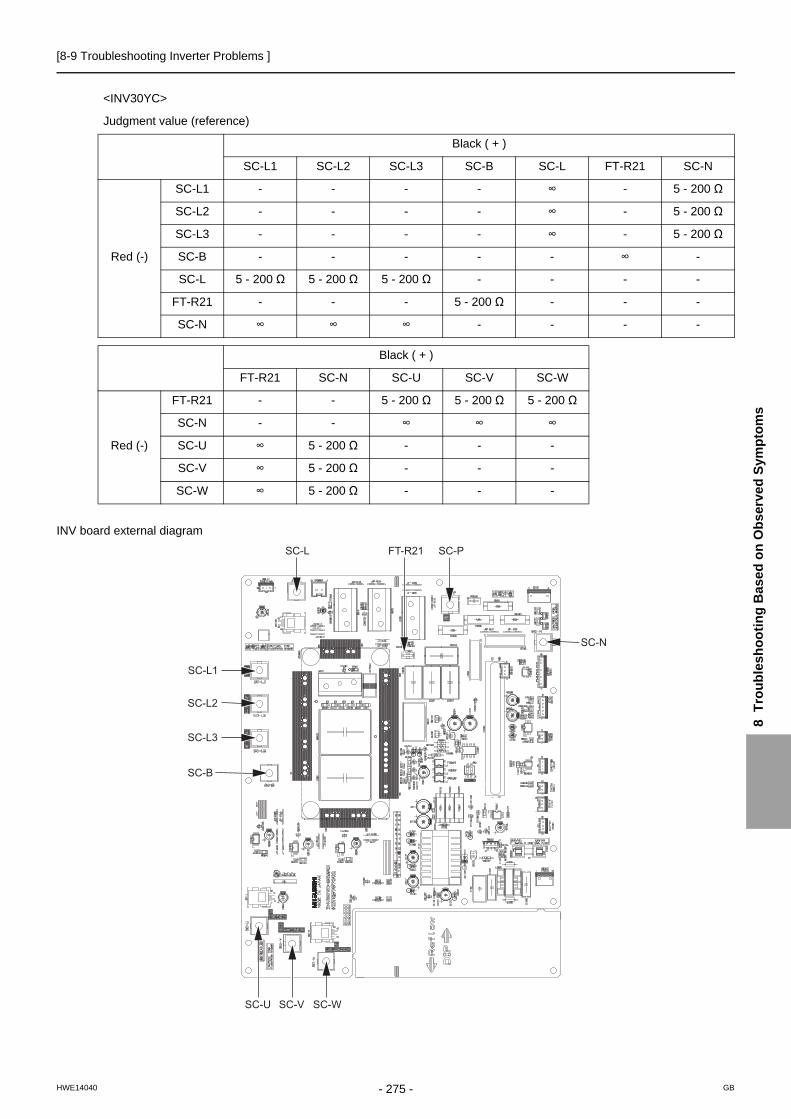
[8-9 Troubleshooting Inverter Problems ]
8 T
rou
ble
sh
oo
tin
g B
ase
d o
n O
bs
erv
ed
Sym
pto
ms
INV board external diagram
<INV30YC>
Judgment value (reference)
Black ( + )
SC-L1 SC-L2 SC-L3 SC-B SC-L FT-R21 SC-N
Red (-)
SC-L1 - - - - ∞ - 5 - 200 Ω
SC-L2 - - - - ∞ - 5 - 200 Ω
SC-L3 - - - - ∞ - 5 - 200 Ω
SC-B - - - - - ∞ -
SC-L 5 - 200 Ω 5 - 200 Ω 5 - 200 Ω - - - -
FT-R21 - - - 5 - 200 Ω - - -
SC-N ∞ ∞ ∞ - - - -
Black ( + )
FT-R21 SC-N SC-U SC-V SC-W
Red (-)
FT-R21 - - 5 - 200 Ω 5 - 200 Ω 5 - 200 Ω
SC-N - - ∞ ∞ ∞
SC-U ∞ 5 - 200 Ω - - -
SC-V ∞ 5 - 200 Ω - - -
SC-W ∞ 5 - 200 Ω - - -
SC-L1
SC-L
SC-U
SC-L2
SC-L3
SC-V SC-W
SC-P
SC-N
FT-R21
SC-B
- 275 -HWE14040 GB

[8-10 Control Circuit ]
8-10 Control Circuit
8-10-1 Control Power Supply Function Block
1) PUHY-P200 - P400YKB-A1
Out
door
uni
t
Power source system (380 ~ 415 VAC)Control system (5 ~ 30 VDC)
* MA remote controllers and ME remote controllers cannot be used together.(Both the ME and MA remote controller can be connected to a system with a system controller.)
A, B
A, B
M-NET transmission line (Non-polar 2 wire)
220 ~ 240 VACAC Power source
To next unit (Indoor unit)
MA
rem
ote
cont
rolle
r wiri
ng
(Non
-pol
ar 2
wire
)
17 ~ 30 VDC
9 ~ 12 VDC
ME remote controller
MA remote controller
Indoor unit
TB2
TB15
Terminal block for power source
TB5 Terminal block for MA remote controller
Terminal block for transmission line connection17 ~ 30 VDC
380 ~ 415 VAC Terminal block for power source
TB1
Noise filterNoise filter
FuseFuse
Fuse
72C, LEV
Fuse
Surge protection
INV board
Control board Fan board
63H1
72C DCL
DC / DC converter
Detection circuit for the power supply to the transmission line
M-NET board
DC / DC converter
Microcomputer
Microcomputer
Microcomputer 5 V Power supply
16 V Power supply
12V Power supply
30 V Power supply
Relay drive circuit
Relay
5 V Power supply
5 V Power supply
17V Power supply
Smoothing capacitor Inverter
Inverter
Inverter drive circuit
Inverter drive circuit
Inverter reset circuit
Rectifier Compressor
Heat exchanger
fan
Relay, LEV Drive circuit
Solenoid valve4-way valve
CN40 Terminal block for transmission line for centralized control(24 ~ 30 VDC)
TB7
Indoor/outdoor transmission block(24 ~ 30 VDC)
TB3
Rectifier
- 276 -HWE14040 GB

[8-10 Control Circuit ]
8 T
rou
ble
sh
oo
tin
g B
ase
d o
n O
bs
erv
ed
Sym
pto
ms
2) PUHY-P450 - P500YKB-A1
TB2
TB15
TB5
TB1AC Power Source(380VAC~415)Terminal block for power source
63H1
LEV
CN40
72CDCL
* MA remote controllers and ME remote controllers cannot be used together.(Both the ME and MA remote controller can be connected to a system with a system controller.)
Power source system (380 ~ 415 VAC)Control system (5 ~ 30 VDC)
A, B
A, B
220~240 VAC AC Power source
To next unit(Indoor unit)
MA
rem
ote
cont
rolle
r wiri
ng(N
on-p
olar
2 w
ire) 17 ~ 30 VDC
9 ~ 12 VDC
Terminal block for power source
Terminal block for MA remote controller
Terminal block for transmission line connection17 ~ 30 VDC
Noise filterNoise filter
Fuse
Fuse
Fuse
Fuse
Surge protection
Fan INV board
Fan INV boardControlboard
DC / DC converter
DC / DCconverter
DC / DCconverter
Detection circuit for the power supply to the transmission line
Detection circuit for the powersupply to the transmission line
M-NET board
Microcomputer
Microcomputer
Microcomputer
Microcomputer
30V Power supply
Relay drive circuit
Relay
5V Power supply
5V Power supply
5V Power supply
5V Power supply
12V Power supply
16V Power supply
16V Power supply
17V Power supply15V Power supply
Smoothing capacitor
Inverter
Inverter
Inverter
Inverter drive circuit
Inverter drive circuit
Inverter drive circuit
Converterdrive circuit
Inverter resetcircuit
Rectifier
Rectifier
Compressor
Heat exchanger
fan 1
Heat exchanger
fan 2
Relay, LEVDrive circuit
72CSolenoid valve
4-way valveCH11
Terminal block for transmission line for centralized control(24 ~ 30 VDC)
TB7
Indoor/outdoor transmission block(24 ~ 30 VDC)
TB3
ME remote controller
MA remote controller
Indoor unit
Out
door
uni
t
Connect board
Smoothing capacitor
- 277 -HWE14040 GB
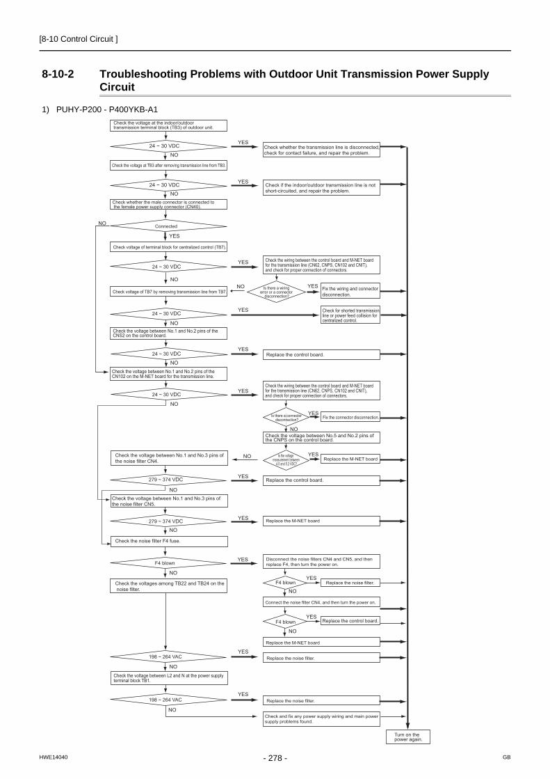
[8-10 Control Circuit ]
8-10-2 Troubleshooting Problems with Outdoor Unit Transmission Power Supply Circuit
1) PUHY-P200 - P400YKB-A1
Check the voltage between No.1 and No.2 pins of the CNS2 on the control board.
Check the wiring between the control board and M-NET board for the transmission line (CN62, CNPS, CN102 and CNIT), and check for proper connection of connectors.
Check the wiring between the control board and M-NET board for the transmission line (CN62, CNPS, CN102 and CNIT), and check for proper connection of connectors.
Is there a wiring error or a connector
disconnection?
Check the voltage between No.5 and No.2 pins of the CNPS on the control board.
Is the voltage measurement between
4.5 and 5.2 VDC?
Is there a connector disconnection? Fix the connector disconnection.
Replace the M-NET board
Replace the control board.
Replace the M-NET board
Replace the M-NET board
Replace the noise filter.
Connect the noise filter CN4, and then turn the power on.
Replace the noise filter.
Replace the noise filter.
Check and fix any power supply wiring and main power supply problems found.
Disconnect the noise filters CN4 and CN5, and then replace F4, then turn the power on.
Fix the wiring and connector disconnection.
Check for shorted transmission line or power feed collision for centralized control.
Replace the control board.
Check the voltage between No.1 and No.2 pins of the CN102 on the M-NET board for the transmission line.
Check the voltage between No.1 and No.3 pins of the noise filter CN4.
Check the voltage between No.1 and No.3 pins of the noise filter CN5.
Check the noise filter F4 fuse.
Check the voltages among TB22 and TB24 on the noise filter.
Check the voltage between L2 and N at the power supply terminal block TB1.
24 ~ 30 VDC
24 ~ 30 VDC
24 ~ 30 VDC
279 ~ 374 VDC
279 ~ 374 VDC
F4 blown
F4 blown
F4 blown
198 ~ 264 VAC
198 ~ 264 VAC
24 ~ 30 VDC
Turn on the power again.
YES
YES
YES
YES
YES
YES
YES
YES
YES
YES
YES
YES
YES
YES
YES
YES
NONO
NO
NO
NO
NO
NO
NO
NO
NO
NO
NO
NO
NO
NO
NO
YES
NO
Check the voltage at the indoor/outdoor transmission terminal block (TB3) of outdoor unit.
24 ~ 30 VDC
24 ~ 30 VDC
Check the voltage at TB3 after removing transmission line from TB3.
Check whether the male connector is connected to the female power supply connector (CN40).
Connected
Check voltage of terminal block for centralized control (TB7).
Check voltage of TB7 by removing transmission line from TB7.
Check if the indoor/outdoor transmission line is notshort-circuited, and repair the problem.
Check whether the transmission line is disconnected, check for contact failure, and repair the problem.
Replace the control board.
- 278 -HWE14040 GB
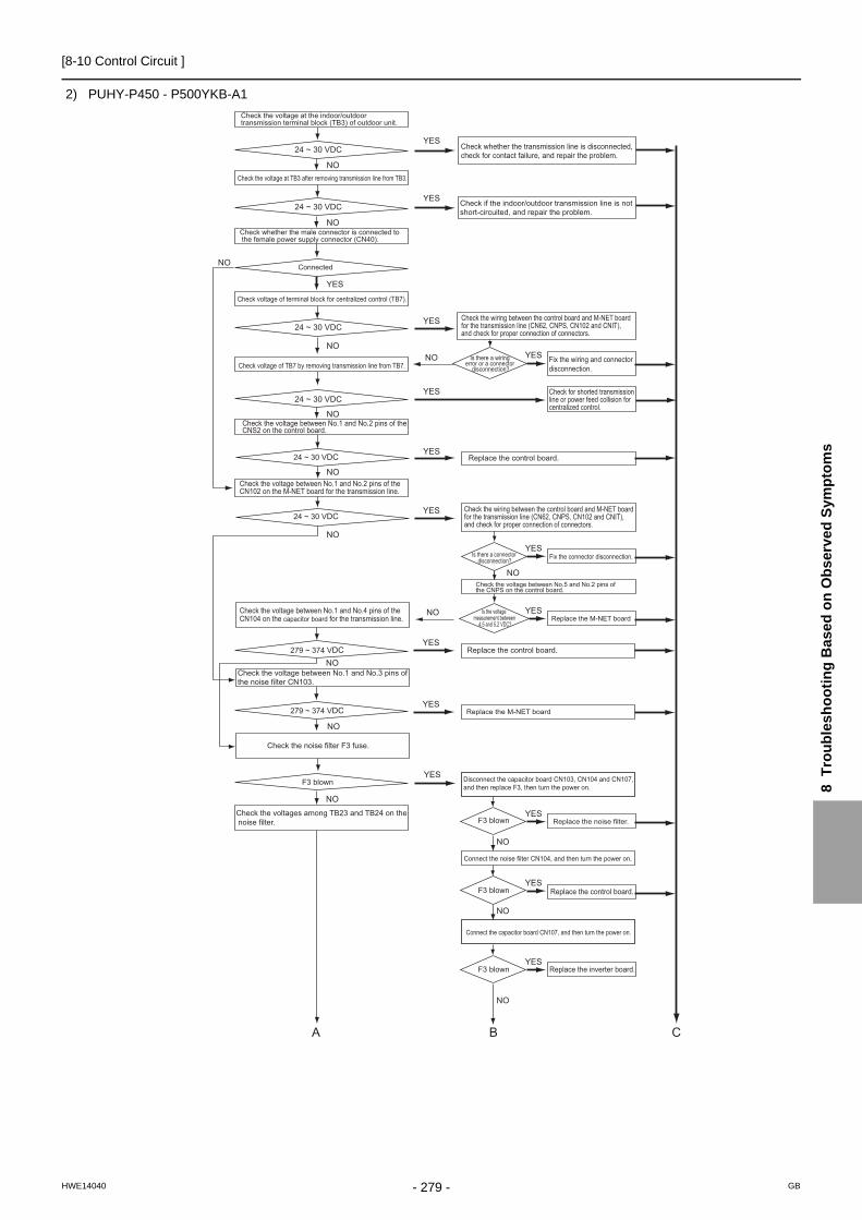
[8-10 Control Circuit ]
8 T
rou
ble
sh
oo
tin
g B
ase
d o
n O
bs
erv
ed
Sym
pto
ms
2) PUHY-P450 - P500YKB-A1
YES
YES
YES
NO
NO
NO
NO
YES
YES
YES
YES
YES
NO
NO
NO
NO
NO
NO
YES
NO
YES
YES
NO
NO
NO
YES
YES
YES
NO
YES
NO
A B C
YES
Check the voltage between No.1 and No.2 pins of the CNS2 on the control board.
Check the wiring between the control board and M-NET board for the transmission line (CN62, CNPS, CN102 and CNIT), and check for proper connection of connectors.
Check the wiring between the control board and M-NET board for the transmission line (CN62, CNPS, CN102 and CNIT), and check for proper connection of connectors.
Is there a wiring error or a connector
disconnection?
Check the voltage between No.5 and No.2 pins of the CNPS on the control board.
Is the voltage measurement between
4.5 and 5.2 VDC?
Is there a connector disconnection? Fix the connector disconnection.
Replace the M-NET board
Replace the control board.
Replace the M-NET board
Replace the noise filter.
Connect the noise filter CN104, and then turn the power on.
Connect the capacitor board CN107, and then turn the power on.
Disconnect the capacitor board CN103, CN104 and CN107, and then replace F3, then turn the power on.
Fix the wiring and connector disconnection.
Check for shorted transmission line or power feed collision for centralized control.
Replace the control board.
Check the voltage between No.1 and No.2 pins of the CN102 on the M-NET board for the transmission line.
Check the voltage between No.1 and No.4 pins of the CN104 on the capacitor board for the transmission line.
Check the voltage between No.1 and No.3 pins of the noise filter CN103.
Check the noise filter F3 fuse.
Check the voltages among TB23 and TB24 on the noise filter.
24 ~ 30 VDC
24 ~ 30 VDC
279 ~ 374 VDC
279 ~ 374 VDC
F3 blown
F3 blown
F3 blown
F3 blown
Check the voltage at the indoor/outdoor transmission terminal block (TB3) of outdoor unit.
24 ~ 30 VDC
24 ~ 30 VDC
24 ~ 30 VDC
24 ~ 30 VDC
Check the voltage at TB3 after removing transmission line from TB3.
Check whether the male connector is connected to the female power supply connector (CN40).
Connected
Check voltage of terminal block for centralized control (TB7).
Check voltage of TB7 by removing transmission line from TB7.
Check if the indoor/outdoor transmission line is notshort-circuited, and repair the problem.
Check whether the transmission line is disconnected, check for contact failure, and repair the problem.
Replace the control board.
Replace the inverter board.
- 279 -HWE14040 GB

[8-10 Control Circuit ]
A B C
YES
YES
NO
NO
198 ~ 264 VAC
198 ~ 264 VAC
Check the voltage between L3 and N at the power supply terminal block TB1.
Replace the M-NET board
Replace the noise filter.
Replace the noise filter.
Check and fix any power supply wiring and main power supply problems found.
Turn on the power again.
- 280 -HWE14040 GB

[8-11 Measures for Refrigerant Leakage ]
8 T
rou
ble
sh
oo
tin
g B
ase
d o
n O
bs
erv
ed
Sym
pto
ms
8-11 Measures for Refrigerant Leakage1. Leak spot: In the case of extension pipe for indoor unit or optional unit (Cooling season)1) Mount a pressure gauge on the service check joint (CJ2) on the low-pressure side.2) Stop all the indoor units, and close the liquid service valve (BV2) inside the outdoor unit while the compressor is stopped.3) Stop all the indoor units; turn on SW4 (912) on the outdoor unit control board while the compressor is being stopped.(Pump
down mode will start, and all the indoor units will run in cooling test run mode.)4) In the pump down mode (SW4 (912) is ON), all the indoor units will automatically stop when the low pressure (63LS) reaches
0.383MPa [55psi] or less or 15 minutes have passed after the pump mode started. Stop all the indoor units and compressors when the pressure indicated by the pressure gauge, which is on the check joint (CJ2) for low-pressure service, reaches 0.383MPa [55psi] or 20 minutes pass after the pump down operation is started.
5) Close the gas service valve (BV1) inside the outdoor unit.6) Collect the refrigerant that remains in the extended pipe for the indoor unit or optional unit. Do not discharge refrigerant into
the atmosphere when it is collected.7) Repair the leak.8) After repairing the leak, vacuum the extension pipe and the indoor unit or optional unit.9) To adjust refrigerant amount, open the service valves (BV1 and BV2) inside the outdoor unit and turn off SW4 (912).
2. Leak spot: In the case of outdoor unit (Cooling season)(1) Run all the indoor units in the cooling test run mode.
1) To run the indoor unit in test run mode, turn SW4 (769) from ON to OFF when SW3-1 on the outdoor control board is ON.2) Change the setting of the remote controller for all the indoor units to the cooling mode.3) Check that all the indoor units are performing a cooling operation.
(2) Check the values of Tc and TH6.(To display the values on the LED screen, use the self-diagnosis switch (SW4 (when SW6-10 is set to OFF)) on the outdoor unit control board.)
1) When Tc-TH6 is 10°C [18°F] or more : See the next item (3).2) When Tc-TH6 is less than 10°C [18°F] : After the compressor stops, collect the refrigerant inside the system, repair the leak,
perform evacuation, and recharge new refrigerant. (Leak spot: 4. In the case of outdoor unit, handle in the same way as heat-ing season.)
(3) Stop all the indoor units, and stop the compressor.
1) To stop all the indoor units and the compressors, turn SW4 (769) from ON to OFF when SW3-1 on the outdoor control board is ON.
2) Check that all the indoor units are being stopped.
(4) Close the service valves (BV1 and BV2).
(5) To prevent the liquid seal, extract small amount of refrigerant from the check joint of the liquid service valve (BV2), as the liquid seal may cause a malfunction of the unit.In the cooling cycle, the section between check valve CV1 and LEV2 will form a closed circuit. Before recovering the refrigerant or evacuating the system, leave the unit in a stopped state for at least 30 minutes and then open LEV2 and switch SW4 (988) from OFF to ON so that LEV1 and SV5b are in an open state. If this work is not performed, recovering the refrigerant or evacuating the system may not be possible. (After completion of work, set SW4 (988) from ON to OFF.)
(6) Collect the refrigerant that remains inside the outdoor unit.Do not discharge refrigerant into air into the atmosphere when it is collected.
(7) Repair the leak.
(8) After repairing the leak, replace the dryer with the new one, and perform evacuation inside the outdoor unit and op-tional unit.
(9) To adjust refrigerant amount, open the service valves (BV1 and BV2, or BV3 and BV4 when optional unit is installed) inside the outdoor unit.
Tc self-diagnosis switch TH6 self-diagnosis switch
For how to read the SW settings, refer to the following page(s). [9-1-1 How to Read the LED](page 289)
ON
SW4
1 2 3 4 5 6 7 8 9 10 OFF
ON
SW4
1 2 3 4 5 6 7 8 9 10 OFF
- 281 -HWE14040 GB

[8-11 Measures for Refrigerant Leakage ]
When the power to the outdoor/indoor unit must be turned off to repair the leak after closing the service valves specified in the item 4, turn the power off in approximately one hour after the outdoor/indoor units stop.
1) When 30 minutes have passed after the item 4 above, the indoor unit lev turns from fully closed to slightly open to prevent the refrigerant seal.LEV2 open when the outdoor unit remains stopped for 15 minutes to allow for the collection of refrigerant in the outdoor unit heat exchanger and to enable the evacuation of the outdoor unit heat exchanger.If the power is turned of in less than 5 minutes, LEV2 may close, trapping high-pressure refrigerant in the outdoor unit heat exchanger and creating a highly dangerous situation.
2) Therefore, if the power source is turned off within 30 minutes, the lev remains fully closed and the refrigerant remains sealed.When only the power for the indoor unit is turned off, the indoor unit LEV turns from faintly open to fully closed.
3. Leak spot: In the case of extension pipe for indoor unit or optional unit (Heating season)(1) Run all the indoor units in heating test run mode.
1) To run the indoor unit in test run mode, turn SW4 (769) from ON to OFF when SW3-1 on the outdoor control board is ON.2) Change the setting of the remote controller for all the indoor units to the heating mode.3) Check that all the indoor units are performing a heating operation.
(2) Stop all the indoor units, and stop the compressor.
1) To stop all the indoor units and the compressors, turn SW4 (769) from ON to OFF when SW3-1 on the outdoor control board is ON.
2) Check that all the indoor units are stopped.
(3) Close the service valves (BV1 and BV2).
(4) Collect the refrigerant that remains inside the indoor unit and optional unit. Do not discharge refrigerant into the at-mosphere when it is collected.
(5) Repair the leak.
(6) After repairing the leak, perform evacuation of the extension pipe for the indoor unit and optional unit, and open the service valves (BV1 and BV2) to adjust refrigerant.
4. Leak spot: In the case of outdoor unit (Heating season)1) Collect the refrigerant in the entire system (outdoor unit, extended pipe and indoor unit).Do not discharge refrigerant into the
atmosphere when it is collected. In the cooling cycle, the section between check valve CV1 and LEV2 will form a closed circuit. Before recovering the refrigerant or evacuating the system, leave the unit in a stopped state for at least 15 minutes and then open LEV2 and switch SW4 (988) from OFF to ON so that LEV1 and SV5b are in an open state. If this work is not performed, recovering the refrigerant or evacuating the system may not be possible. (After comple-tion of work, set SW4 (988) from ON to OFF.)
2) Repair the leak.3) After repairing the leak, perform evacuation of the entire system, and calculate the standard amount of refrigerant to be added
(for the outdoor unit, extension pipe, and indoor unit), and charge the refrigerant. For details, refer to the following page(s). [6-9-3 The Amount of Refrigerant to Be Added](page 132)
If the indoor or outdoor units need to be turned off for repairing leaks during Step 1) above, turn off the power approximately 1 hour after the units came to a stop.If the power is turned off in less than 15 minutes, LEV2 may close, trapping high-pressure refrigerant in the outdoor unit heat exchanger and creating a highly dangerous situation.
- 282 -HWE14040 GB

[8-12 Compressor Replacement Instructions ]
8 T
rou
ble
sh
oo
tin
g B
ase
d o
n O
bs
erv
ed
Sym
pto
ms
8-12 Compressor Replacement Instructions
Follow the procedures below (Steps 1 through 6) to remove the compressor components and replace the compressor. Reassemble them in the reverse order after replacing the compressor.
1. Remove both the top and bottom service panels (front panels).
3. Remove the wires that are secured to the frame, and remove the frame.
Electric wiring
Frame
Service panel
Control box
Compressor cover (front)
2. Remove the control box and the compressor cover (front).
- 283 -HWE14040 GB
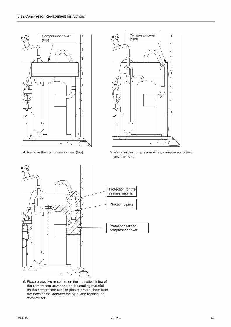
[8-12 Compressor Replacement Instructions ]
5. Remove the compressor wires, compressor cover, and the right.
Compressor cover (top)
4. Remove the compressor cover (top).
Compressor cover (right)
Protection for the sealing material
Suction piping
Protection for the compressor cover
6. Place protective materials on the insulation lining of the compressor cover and on the sealing material on the compressor suction pipe to protect them from the torch flame, debraze the pipe, and replace the compressor.
- 284 -HWE14040 GB

[8-13 Troubleshooting Problems Using the LED Status Indicators on the Outdoor Unit ]
8 T
rou
ble
sh
oo
tin
g B
ase
d o
n O
bs
erv
ed
Sym
pto
ms
8-13 Troubleshooting Problems Using the LED Status Indicators on the Outdoor Unit
If the LED error display appear as follows while all the SW4 switches and SW6-10 are set to OFF, check the items under the ap-plicable item numbers below.1. Error code appears on the LED display.
Refer to the following page(s). [7-1 Error Code and Preliminary Error Code Lists](page 165)
2. LED is blank.Take the following troubleshooting steps.
(1) Refer to the section on troubleshooting the transmission power supply circuit, if the voltage across pins 1 through 3 of CNDC on the control panel is outside the range between 220 VDC and 380 VDC. [8-10-2 Troubleshooting Problems with Outdoor Unit Transmission Power Supply Circuit](page 278)
(2) If the LED error display becomes lit when the power is turned on with all the connectors on the control board except CNDC disconnected, there is a problem with the wiring to those connectors or with the connectors themselves.
(3) If nothing appears on the display under item (2) above AND the voltage between pins 1 and 3 of CNDC is within the range between 220 VDC and 380 VDC, control board failure is suspected.
3. Only the software version appears on the LED display.(1) Only the software version appears while the transmission cables to TB3 and TB7 are disconnected.
1) Wiring failure between the control board and the transmission line power supply board.(CN62, CNPS, CNIT, CNS2, CN102)2) If item 1) checks out OK, the transmission line power supply board failure is suspected.3) If items 1) and 2) check out OK, control board failure is suspected.
(2) If the LED shows the same display as the initial display upon disconnection of transmission lines (TB3, TB7), there is a problem with the transmission lines or with the connected devices. [9-1-2 Initial LED Display](page 290)
- 285 -HWE14040 GB

[8-13 Troubleshooting Problems Using the LED Status Indicators on the Outdoor Unit ]
- 286 -HWE14040 GB

- 287 -HWE14040 GB
Chapter 9 LED Status Indicators on the Outdoor Unit Circuit Board
9-1 LED Status Indicators....................................................................................................................... 289
9-1-1 How to Read the LED ......................................................................................................................... 289
9-1-2 Initial LED Display............................................................................................................................... 290
9-1-3 Clock Memory Function ...................................................................................................................... 291
9-2 LED Status Indicators Table ............................................................................................................ 292

- 288 -HWE14040 GB

[9-1 LED Status Indicators ]
9 L
ED
Sta
tus
Ind
icat
ors
on
th
e O
utd
oo
r U
nit
Cir
cu
it B
oar
d
9 LED Status Indicators on the Outdoor Unit Circuit Board
9-1 LED Status Indicators
9-1-1 How to Read the LED
By setting the DIP SW 4-1 through 4-10 (Set SW6-10 to OFF.)(Switch number 10 is represented by 0), the operating condition of the unit can be monitored on the service monitor. (Refer to the table on the following pages for DIP SW settings.) The service monitor uses 4-digit 7-segment LED to display numerical values and other types of information.
Pressure and temperature are examples of numerical values, and operating conditions and the on-off status of solenoid valve are examples of flag display.
SW4-10 is set to "0" on the LED Status Indicators Table. In the example above, 1 through 9 are set to OFF, and 10 is set to ON.
1) Display of numerical values
Example: When the pressure data sensor reads 18.8kg/cm2 (Item No. 58)The unit of pressure is in kg/cm2
Use the following conversion formula to convert the displayed value into a value in SI unit.Value in SI unit (MPa) = Displayed value (kg/cm2) x 0.098
2) Flag display
Example: When 21S4a, 21S4b, SV1a are ON. (Item No. 3)
Example: 3-minutes restart mode (Item No. 14)
ON
SW4
1 2 3 4 5 6 7 8 9 10 OFF
7SEG LED
LD1 LD2 LD3 LD4 LD5 LD6 LD7 LD8
Upper
Lower
LD1 LD2 LD3 LD4 LD5 LD6 LD7 LD8
- 289 -HWE14040 GB

[9-1 LED Status Indicators ]
9-1-2 Initial LED Display
From power on until the completion of initial settings, the following information will be displayed on the monitor screen.(Displays No. 1 through No. 4 in order repeatedly.)
After the initial settings have been completed, the information on these items can be checked by making the switch setting that corresponds to No. 517 in the LED display table.
Only item No. 1 "Software Version" appears on the display if there is a wiring failure between the control board and the trans-mission line power supply board or if the circuit board has failed.
How to convert HP capacity to Model nameHP capacity is the capacity of outdoor unit that is shown on LED display at initial setting.Please refer to the following table to covert from HP capacity to Model name.
No Item Display Remarks
1
Software version
[0103] : Version 1.03
2
Refrigerant type
[ 410] : R410A
3
Model and capacity [H-20] : Cooling/Heating 20 HPFor the first few minutes after power on, the capacity of each outdoor unit is displayed. Thereafter, the com-bined capacity is displayed.
4
Communication address
[ 51] : Address 51
HP Model HP Model
8 P200 32 P800
10 P250 34 P850
12 P300 36 P900
14 P350 38 P950
16 P400 40 P1000
18 P450 42 P1050
20 P500 44 P1100
22 P550 46 P1150
24 P600 48 P1200
26 P650 50 P1250
28 P700 52 P1300
30 P750 54 P1350
- 290 -HWE14040 GB

[9-1 LED Status Indicators ]
9 L
ED
Sta
tus
Ind
icat
ors
on
th
e O
utd
oo
r U
nit
Cir
cu
it B
oar
d
9-1-3 Clock Memory Function
The outdoor unit has a simple clock function that enables the unit to calculate the current time with an internal timer by receiv-ing the time set by the system controller, such as AG-150A.If an error (including a preliminary error) occurs, the error history data and the error detection time are stored into the service memory.The error detection time stored in the service memory and the current time can be seen on the service LED.
1) Use the time displayed on the service LED as a reference.2) The date and the time are set to "00" by default. If a system controller that sets the time, such as AG-150A is not connected,
the elapsed time and days since the first power on will be displayed.If the time set on a system controller is received, the count will start from the set date and the time.
3) The time is not updated while the power of the indoor unit is turned off. When the power is turned off and then on again, the count will resume from the time before the power was turned off. Thus, the time that differs the actual time will be displayed. (This also applies when a power failure occurs.)The system controller, such as AG-150A, adjusts the time once a day. When the system controller is connected, the time will be automatically updated to the correct current time after the time set by the system controller is received. (The data stored into the memory before the set time is received will not be updated.)
(1) Reading the time data:
1) Time display
Example: 12 past 9
2) Date display
When the main controller that can set the time is connectedExample: May 10, 2003
When the main controller that can set the time is not connectedExample: 52 days after power was turned on
* Disappears if the time data is deviated due to a power failure, or if a system controller that sets the time is not connected.
Alternate display
Alternate display of year and month, and date
* Appears between the year and the month, and nothing appears when the date is displayed.
Alternate display
Day count
* Appears between the year and the month, and nothing appears when the date is displayed.
- 291 -HWE14040 GB

[9-2 LED Status Indicators Table]
10LED
Sta
tus
Ind
icat
ors
on
the
Ou
tdo
or U
nit C
ircu
it B
oar
d
9-2
LE
D S
tatu
s In
dic
ato
rs T
able
Cu
rren
t d
ata
No
.
SW
4 (W
hen
SW
6 -
10 is
set
to O
FF
)It
emD
isp
lay
Un
it(A
, B)
*1R
emar
ks
1234
567
890
LD
1LD
2LD
3LD
4L
D5
LD
6L
D7
LD8
OC
OS
000
0000
000
0
Re
lay
outp
ut d
isp
lay
1
Lig
htin
gC
omp
in o
p-er
atio
n7
2CO
CC
PU
in o
per
-a
tion
AA
Ch
eck
(err
or)
dis
play
1
OC
/OS
err
or0
000
to 9
999
(Add
ress
and
err
or c
odes
hig
hlig
hte
d)B
B
110
0000
000
0
Ch
eck
(err
or)
dis
play
2
OC
/OS
err
or0
000
to 9
999
(Add
ress
and
err
or c
odes
hig
hlig
hte
d)A
A
Dis
play
of t
he la
test
pre
-lim
inar
y e
rror
If n
o p
relim
ina
ry e
rror
s a
re d
ete
cted
, "--
--"
ap-
pea
rs o
n th
e d
ispl
ay.
201
0000
000
0C
hec
k (e
rror
) d
ispl
ay 3
(I
ncl
udin
g IC
an
d B
C)
000
0 to
999
9 (A
ddre
ss a
nd e
rror
cod
es h
ighl
igh
ted)
BIf
no
err
ors
are
dete
cte
d,
"---
-" a
ppe
ars
on th
e di
s-p
lay.
311
0000
000
0R
ela
y ou
t-pu
t dis
play
2
Top
21S
4a
SV
10
CH
11S
V1a
SV
11
AA
Bot
tom
21S
4bS
V5b
400
1000
000
0
Re
lay
out-
put d
ispl
ay
3
Top
21S
4c
SV
9
Pow
er s
up-
ply
for i
ndo
or
tra
nsm
is-
sion
line
AA
Bot
tom
711
1000
000
0
Sp
ecia
l con
trol
Ret
ry o
per
a-tio
nE
mer
genc
y o
pera
tion
Com
mun
ica-
tion
err
or b
e-tw
een
the
OC
an
d O
S
Com
mun
ica-
tion
erro
r3-
min
ute
re-
star
t de
lay
mod
e
BB
910
0100
000
0C
om
mun
icat
ion
de-
ma
nd c
apa
city
0000
to 9
999
BB
If n
ot d
em
ande
d c
on-
trol
led,
"---
-" [
% ]
app
ears
o
n th
e d
ispl
ay.
1001
0100
000
0C
ont
act p
oint
dem
and
ca
paci
ty00
00 to
999
9B
If n
ot d
em
ande
d c
on-
trol
led,
"---
-" [
% ]
app
ears
o
n th
e d
ispl
ay.
*1 A
: T
he
cond
ition
of e
ithe
r O
C o
r O
S is
dis
pla
yed
ind
ivid
ually
. B:
Th
e co
nditi
on o
f the
ent
ire r
efrig
eran
t sys
tem
is d
ispl
aye
d.
- 292 -HWE14040

[9-2 LED Status Indicators Table]
9 L
ED
Sta
tus
In
dic
ato
rs o
n t
he
Ou
tdo
or
Un
it C
ircu
it B
oa
rd
1111
0100
000
0
Ext
erna
l sig
nal
(Ope
n in
put c
onta
ct
poin
t)
Con
tact
po
int d
e-m
and
Low
-noi
se
mod
e(C
apa
city
pr
iorit
y )
Sno
w s
enso
r
Coo
ling-
hea
ting
chan
geo
ver
(Coo
ling
)
Coo
ling
-h
eatin
g
chan
geo
ver
(Hea
ting)
AA
1200
1100
000
0
Ext
erna
l sig
nal
(Ope
n in
put c
onta
ct
poin
t)
Low
-noi
se
mod
e (Q
uie
t prio
ri-
ty)
AA
1310
1100
000
0
1401
1100
000
0
Ou
tdoo
r un
it op
erat
ion
st
atu
sW
arm
-up
mod
e3
-min
ute
s re
star
t mo
deC
om
pres
sor
in o
per
atio
nP
relim
inar
y e
rror
Err
or
3-m
inut
es
rest
art a
fter
in
stan
ta-
neo
us
pow
er
failu
re
Pre
limin
ary
lo
w p
res-
sure
err
orA
A
1511
1100
000
0O
C/O
S id
ent
ifica
tion
OC
/OS
-1/O
S-2
AA
1600
0010
000
0In
doo
r un
it ch
eck
Top
Uni
t N
o. 1
Uni
t N
o. 2
Uni
t No.
3U
nit N
o. 4
Uni
t No.
5U
nit N
o. 6
Uni
t N
o. 7
Uni
t N
o. 8
BT
he la
mp
that
cor
re-
spo
nds
to th
e un
it th
at
cam
e to
an
abno
rma
l sto
p lig
hts
. T
he la
mp
goe
s of
f w
hen
the
erro
r is
re
set.
Eac
h un
it th
at c
om
es t
o a
n ab
norm
al u
nit w
ill b
e g
iven
a s
equ
ent
ial n
um-
ber
in a
scen
ding
ord
er
star
ting
with
1.
Bot
tom
Uni
t N
o. 9
Uni
t N
o. 1
0U
nit
No.
11
Uni
t N
o. 1
2U
nit N
o. 1
3U
nit N
o. 1
4U
nit
No
. 15
Un
it N
o. 1
6
1710
0010
000
0T
opU
nit
No
. 17
Un
it N
o. 1
8U
nit
No.
19
Uni
t No.
20
Uni
t No.
21
Uni
t No
. 22
Un
it N
o. 2
3U
nit
No
. 24
Bot
tom
Un
it N
o. 2
5U
nit
No.
26
Un
it N
o. 2
7U
nit N
o. 2
8U
nit N
o. 2
9U
nit N
o. 3
0U
nit
No
. 31
Un
it N
o. 3
2
1801
0010
000
0T
opU
nit
No
. 33
Un
it N
o. 3
4U
nit
No.
35
Uni
t No.
36
Uni
t No.
37
Uni
t No
. 38
Un
it N
o. 3
9U
nit
No
. 40
Bot
tom
Un
it N
o. 4
1U
nit
No.
42
Uni
t No
.43
Uni
t No.
44
Uni
t No.
45
Uni
t No
. 46
Un
it N
o. 4
7U
nit
No
. 48
1911
0010
000
0T
opU
nit
No
. 49
Un
it N
o. 5
0
Bot
tom
2000
1010
000
0In
doo
r un
it O
per
atio
n m
ode
Top
Uni
t N
o. 1
Uni
t N
o. 2
Uni
t No.
3U
nit N
o. 4
Uni
t No.
5U
nit N
o. 6
Uni
t N
o. 7
Uni
t N
o. 8
BLi
t du
ring
cool
ing
Blin
king
dur
ing
heat
ing
U
nlit
whi
le t
he u
nit i
s st
opp
ed o
r in
the
fan
m
ode
Bot
tom
Uni
t N
o. 9
Uni
t N
o. 1
0U
nit
No.
11
Uni
t N
o. 1
2U
nit N
o. 1
3U
nit N
o. 1
4U
nit
No
. 15
Un
it N
o. 1
6
2110
1010
000
0T
opU
nit
No
. 17
Un
it N
o. 1
8U
nit
No.
19
Uni
t No.
20
Uni
t No.
21
Uni
t No
. 22
Un
it N
o. 2
3U
nit
No
. 24
Bot
tom
Un
it N
o. 2
5U
nit
No.
26
Un
it N
o. 2
7U
nit N
o. 2
8U
nit N
o. 2
9U
nit N
o. 3
0U
nit
No
. 31
Un
it N
o. 3
2
2201
1010
000
0T
opU
nit
No
. 33
Un
it N
o. 3
4U
nit
No.
35
Uni
t No.
36
Uni
t No.
37
Uni
t No
. 38
Un
it N
o. 3
9U
nit
No
. 40
Bot
tom
Un
it N
o. 4
1U
nit
No.
42
Uni
t No
.43
Uni
t No.
44
Uni
t No.
45
Uni
t No
. 46
Un
it N
o. 4
7U
nit
No
. 48
2311
1010
000
0T
opU
nit
No
. 49
Un
it N
o. 5
0
Bot
tom
Cu
rren
t d
ata
No
.
SW
4 (W
hen
SW
6 -
10 is
set
to O
FF
)It
emD
isp
lay
Un
it(A
, B)
*1R
emar
ks
1234
567
890
LD
1LD
2LD
3LD
4L
D5
LD
6L
D7
LD8
OC
OS
*1 A
: T
he
cond
ition
of e
ithe
r O
C o
r O
S is
dis
pla
yed
ind
ivid
ually
. B:
Th
e co
nditi
on o
f the
ent
ire r
efrig
eran
t sys
tem
is d
ispl
aye
d.
- 293 -HWE14040
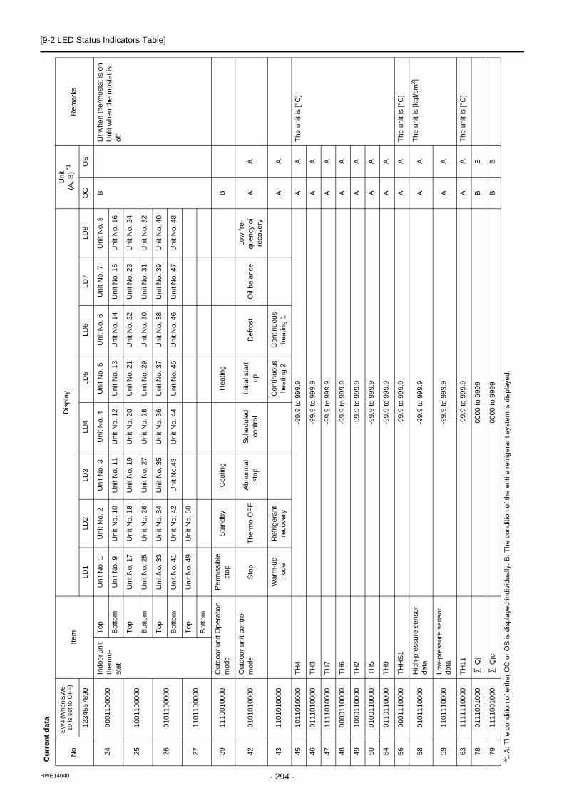
[9-2 LED Status Indicators Table]
2400
0110
000
0In
doo
r un
it th
erm
o-
sta
t
Top
Uni
t N
o. 1
Uni
t N
o. 2
Uni
t No.
3U
nit N
o. 4
Uni
t No.
5U
nit N
o. 6
Uni
t N
o. 7
Uni
t N
o. 8
BLi
t whe
n th
erm
osta
t is
on
Unl
it w
hen
the
rmo
stat
is
off
Bot
tom
Uni
t N
o. 9
Uni
t N
o. 1
0U
nit
No.
11
Uni
t N
o. 1
2U
nit N
o. 1
3U
nit N
o. 1
4U
nit
No
. 15
Un
it N
o. 1
6
2510
0110
000
0T
opU
nit
No
. 17
Un
it N
o. 1
8U
nit
No.
19
Uni
t No.
20
Uni
t No.
21
Uni
t No
. 22
Un
it N
o. 2
3U
nit
No
. 24
Bot
tom
Un
it N
o. 2
5U
nit
No.
26
Un
it N
o. 2
7U
nit N
o. 2
8U
nit N
o. 2
9U
nit N
o. 3
0U
nit
No
. 31
Un
it N
o. 3
2
2601
0110
000
0T
opU
nit
No
. 33
Un
it N
o. 3
4U
nit
No.
35
Uni
t No.
36
Uni
t No.
37
Uni
t No
. 38
Un
it N
o. 3
9U
nit
No
. 40
Bot
tom
Un
it N
o. 4
1U
nit
No.
42
Uni
t No
.43
Uni
t No.
44
Uni
t No.
45
Uni
t No
. 46
Un
it N
o. 4
7U
nit
No
. 48
2711
0110
000
0T
opU
nit
No
. 49
Un
it N
o. 5
0
Bot
tom
3911
1001
000
0O
utd
oor
unit
Op
erat
ion
mod
eP
erm
issi
ble
stop
Sta
ndby
Coo
ling
Hea
ting
B
4201
0101
000
0O
utd
oor
unit
cont
rol
mo
deS
top
Th
erm
o O
FF
Ab
norm
al
sto
pS
che
dule
d co
ntro
lIn
itial
sta
rt
upD
efro
stO
il ba
lanc
eLo
w fr
e-q
uenc
y oi
l re
cove
ryA
A
4311
0101
000
0W
arm
-up
mod
eR
efrig
eran
t re
cove
ryC
ont
inuo
us
hea
ting
2C
ont
inuo
us
heat
ing
1A
A
4510
1101
000
0T
H4
-99
.9 to
999
.9A
AT
he u
nit i
s [°
C]
4601
1101
000
0T
H3
-99
.9 to
999
.9A
A
4711
1101
000
0T
H7
-99
.9 to
999
.9A
A
4800
0011
000
0T
H6
-99
.9 to
999
.9A
A
4910
0011
000
0T
H2
-99
.9 to
999
.9A
A
5001
0011
000
0T
H5
-99
.9 to
999
.9A
A
5401
1011
000
0T
H9
-99
.9 to
999
.9A
A
5600
0111
000
0T
HH
S1
-99
.9 to
999
.9A
AT
he u
nit i
s [°
C]
5801
0111
000
0H
igh
-pre
ssur
e se
nsor
da
ta-9
9.9
to 9
99.9
AA
The
uni
t is
[kg
f/cm
2]
5911
0111
000
0Lo
w-p
ress
ure
sens
or
data
-99
.9 to
999
.9A
A
6311
1111
000
0T
H11
-99
.9 to
999
.9A
AT
he u
nit i
s [°
C]
7801
1100
100
0 Q
j00
00 to
999
9B
B
7911
1100
100
0 Q
jc00
00 to
999
9B
B
Cu
rren
t d
ata
No
.
SW
4 (W
hen
SW
6 -
10 is
set
to O
FF
)It
emD
isp
lay
Un
it(A
, B)
*1R
emar
ks
1234
567
890
LD
1LD
2LD
3LD
4L
D5
LD
6L
D7
LD8
OC
OS
*1 A
: T
he
cond
ition
of e
ithe
r O
C o
r O
S is
dis
pla
yed
ind
ivid
ually
. B:
Th
e co
nditi
on o
f the
ent
ire r
efrig
eran
t sys
tem
is d
ispl
aye
d.
- 294 -HWE14040

[9-2 LED Status Indicators Table]
9 L
ED
Sta
tus
In
dic
ato
rs o
n t
he
Ou
tdo
or
Un
it C
ircu
it B
oa
rd
8000
0010
100
0 Q
jh00
00 to
999
9B
B
8110
0010
100
0T
arg
et T
c-9
9.9
to 9
99.9
BT
he u
nit i
s [°
C]
8201
0010
100
0T
arg
et T
e-9
9.9
to 9
99.9
B
8311
0010
100
0T
c-9
9.9
to 9
99.9
AA
8400
1010
100
0T
e-9
9.9
to 9
99.9
AA
8601
1010
100
0T
ota
l fre
que
nci
es
(OC
+O
S)
0000
to 9
999
BC
ontr
ol d
ata
[ H
z ]
8711
1010
100
0T
ota
l fre
quen
cy o
f eac
h
unit
0000
to 9
999
AA
8800
0110
100
0C
OM
P fr
eque
ncy
0000
to 9
999
AA
9111
0110
100
0
CO
MP
ope
ratin
g fr
e-qu
ency
0000
to 9
999
AA
The
uni
t is
[rp
s]O
utpu
t fre
quen
cy o
f th
e in
vert
er d
epen
ds o
n th
e ty
pe o
f co
mpr
esso
r an
d e
qual
s th
e in
tege
r m
ulti-
ple
s (x
1, x
2 e
tc.)
of t
he
ope
ratin
g fr
eque
ncy
of
the
com
pres
sor
9200
1110
100
0
Nu
mbe
r of
tim
es
erro
r oc
curr
ed d
urin
g c
rank
-ca
se h
eatin
g by
com
-pr
ess
or
mo
tor
0000
to 9
999
AA
Num
ber
of t
ime
s IN
V e
r-ro
r oc
curr
ed d
urin
g IH
cr
ank
case
hea
ting
by
com
pre
ssor
mo
tor
9310
1110
100
0A
ll A
K (
OC
+O
S)
0000
to 9
999
B
9401
1110
100
0A
K00
00 to
999
9A
A
9511
1110
100
0F
AN
100
00 to
999
9A
AF
an o
utpu
t [ %
]
9600
0001
100
0F
an
inve
rter
out
put r
pm
(FA
N1
)00
00 to
999
9A
A[r
pm]
9710
0001
100
0F
AN
200
00 to
999
9A
AF
an o
utpu
t [ %
]
9801
0001
100
0F
an
inve
rter
out
put r
pm
(FA
N2
)00
00 to
999
9A
A[r
pm]
103
1110
011
000
LEV
100
00 to
999
9A
AO
utdo
or L
EV
op
enin
g (F
ully
ope
n: 4
80)
104
0001
011
000
LEV
2a
0000
to 9
999
AA
Out
door
LE
V o
pen
ing
(Fu
lly o
pen:
300
0)
Cu
rren
t d
ata
No
.
SW
4 (W
hen
SW
6 -
10 is
set
to O
FF
)It
emD
isp
lay
Un
it(A
, B)
*1R
emar
ks
1234
567
890
LD
1LD
2LD
3LD
4L
D5
LD
6L
D7
LD8
OC
OS
*1 A
: T
he
cond
ition
of e
ithe
r O
C o
r O
S is
dis
pla
yed
ind
ivid
ually
. B:
Th
e co
nditi
on o
f the
ent
ire r
efrig
eran
t sys
tem
is d
ispl
aye
d.
- 295 -HWE14040

[9-2 LED Status Indicators Table]
109
1011
011
000
LEV
2b
0000
to 9
999
AA
Out
door
LE
V o
pen
ing
(Fu
lly o
pen:
300
0)
108
0011
011
000
CO
MP
ope
ratin
g cu
r-re
nt (
DC
) 00
.0 to
999
.9A
AP
eak
valu
e [A
]
111
1111
011
000
CO
MP
bus
vol
tag
e00
.0 to
999
.9A
AT
he u
nit i
s [
V ]
116
0010
111
000
Nu
mbe
r of
tim
es
the
unit
we
nt in
to th
e m
ode
to
rem
edy
wet
va
por
suct
ion
0000
to 9
999
B
117
1010
111
000
CO
MP
Ope
ratio
n ti
me
Up
per
4 di
gits
0000
to 9
999
AA
The
uni
t is
[ h
]
118
0110
111
000
CO
MP
Ope
ratio
n ti
me
Low
er
4 di
gits
0000
to 9
999
AA
121
1001
111
000
Ba
ckup
mo
deA
bnor
mal
pr
essu
re r
ise
Hig
h-p
res-
sure
dro
pLo
w-p
res-
sure
dro
pA
bnor
mal
Td
ris
eA
AS
tays
lit f
or 9
0 s
econ
ds
afte
r th
e c
omp
letio
n of
b
acku
p co
ntro
l
123
1101
111
000
CO
MP
num
ber
of s
tart
-st
op
even
tsU
ppe
r 4
dig
its00
00 to
999
9A
AC
oun
t-u
p at
sta
rt-u
pT
he u
nit i
s [T
ime]
124
0011
111
000
CO
MP
num
ber
of s
tart
-st
op
even
tsLo
we
r 4
dig
its00
00 to
999
9A
A
129
1000
000
100
Inte
gra
ted
ope
ratio
n
time
of c
om
pres
sor
(for
ro
tatio
n p
urpo
se)
0000
to 9
999
BT
he u
nit i
s [
h ]
Cu
rren
t d
ata
No
.
SW
4 (W
hen
SW
6 -
10 is
set
to O
FF
)It
emD
isp
lay
Un
it(A
, B)
*1R
emar
ks
1234
567
890
LD
1LD
2LD
3LD
4L
D5
LD
6L
D7
LD8
OC
OS
*1 A
: T
he
cond
ition
of e
ithe
r O
C o
r O
S is
dis
pla
yed
ind
ivid
ually
. B:
Th
e co
nditi
on o
f the
ent
ire r
efrig
eran
t sys
tem
is d
ispl
aye
d.
- 296 -HWE14040

[9-2 LED Status Indicators Table]
9 L
ED
Sta
tus
In
dic
ato
rs o
n t
he
Ou
tdo
or
Un
it C
ircu
it B
oa
rd
178
0100
110
100
Err
or h
isto
ry 1
0000
to 9
999
BB
Add
ress
and
err
or c
odes
h
ighl
igh
ted
If n
o e
rror
s ar
e de
tect
ed,
"-
---
" ap
pear
s on
the
dis
-p
lay.
Pre
limin
ary
err
or
info
rma-
tion
of t
he O
S d
oes
not
a
ppea
r on
the
OC
.N
eith
er p
relim
inar
y er
ror
info
rma
tion
of t
he O
C n
or
err
or in
form
atio
n o
f th
e IC
a
ppea
rs o
n th
e O
S.
179
1100
110
100
Err
or d
etai
ls o
f in
vert
erE
rro
r de
tails
of i
nver
ter
(00
01-0
120
)A
A
180
0010
110
100
Err
or h
isto
ry 2
0000
to 9
999
BB
181
1010
110
100
Err
or d
etai
ls o
f in
vert
erE
rro
r de
tails
of i
nver
ter
(00
01-0
120
)A
A
182
0110
110
100
Err
or h
isto
ry 3
0000
to 9
999
BB
183
1110
110
100
Err
or d
etai
ls o
f in
vert
erE
rro
r de
tails
of i
nver
ter
(00
01-0
120
)A
A
184
0001
110
100
Err
or h
isto
ry 4
0000
to 9
999
BB
185
1001
110
100
Err
or d
etai
ls o
f in
vert
erE
rro
r de
tails
of i
nver
ter
(00
01-0
120
)A
A
186
0101
110
100
Err
or h
isto
ry 5
0000
to 9
999
BB
187
1101
110
100
Err
or d
etai
ls o
f in
vert
erE
rro
r de
tails
of i
nver
ter
(00
01-0
120
)A
A
188
0011
110
100
Err
or h
isto
ry 6
0000
to 9
999
BB
189
1011
110
100
Err
or d
etai
ls o
f in
vert
erE
rro
r de
tails
of i
nver
ter
(00
01-0
120
)A
A
190
0111
110
100
Err
or h
isto
ry 7
0000
to 9
999
BB
191
1111
110
100
Err
or d
etai
ls o
f in
vert
erE
rro
r de
tails
of i
nver
ter
(00
01-0
120
)A
A
192
0000
001
100
Err
or h
isto
ry 8
0000
to 9
999
BB
193
1000
001
100
Err
or d
etai
ls o
f in
vert
erE
rro
r de
tails
of i
nver
ter
(00
01-0
120
)A
A
194
0100
001
100
Err
or h
isto
ry 9
0000
to 9
999
BB
195
1100
001
100
Err
or d
etai
ls o
f in
vert
erE
rro
r de
tails
of i
nver
ter
(00
01-0
120
)A
A
196
0010
001
100
Err
or h
isto
ry 1
000
00 to
999
9B
B
197
1010
001
100
Err
or d
etai
ls o
f in
vert
erE
rro
r de
tails
of i
nver
ter
(00
01-0
120
)A
A
198
0110
001
100
Err
or h
isto
ry o
f in
vert
er(A
t the
tim
e of
last
da
ta
back
up b
efor
e e
rror
)00
00 to
999
9B
B
199
1110
001
100
Err
or d
etai
ls o
f in
vert
erE
rro
r de
tails
of i
nver
ter
(00
01-0
120
)A
A
Cu
rren
t d
ata
No
.
SW
4 (W
hen
SW
6 -
10 is
set
to O
FF
)It
emD
isp
lay
Un
it(A
, B)
*1R
emar
ks
1234
567
890
LD
1LD
2LD
3LD
4L
D5
LD
6L
D7
LD8
OC
OS
*1 A
: T
he
cond
ition
of e
ithe
r O
C o
r O
S is
dis
pla
yed
ind
ivid
ually
. B:
Th
e co
nditi
on o
f the
ent
ire r
efrig
eran
t sys
tem
is d
ispl
aye
d.
- 297 -HWE14040

[9-2 LED Status Indicators Table]
Err
or
his
tory
No
.
SW
4 (W
hen
SW
6 -
10 is
set
to O
FF
)It
emD
isp
lay
Un
it(A
, B)
*1R
emar
ks
1234
567
890
LD
1LD
2LD
3LD
4L
D5
LD
6L
D7
LD8
OC
OS
201
1001
001
100
Ou
tdoo
r un
it op
erat
ion
st
atu
sW
arm
-up
mod
e3
-min
ute
s re
star
t mo
deC
om
pres
sor
in o
per
atio
nP
relim
inar
y e
rror
Err
or
3-m
inut
es
rest
art a
fter
in
stan
ta-
neo
us
pow
er
failu
re
Pre
limin
ary
lo
w p
res-
sure
err
orA
A
202
0101
001
100
OC
/OS
ide
ntifi
catio
nO
C/O
S-1
/OS
-2A
A
205
1011
001
100
Ou
tdoo
r un
it O
per
atio
n m
ode
Pe
rmis
sibl
e st
opS
tand
byC
oolin
gH
eatin
gA
A
208
0000
101
100
Ou
tdoo
r un
it co
ntro
l m
ode
Sto
pT
her
mo
OF
FA
bno
rma
l st
op
Sch
edu
led
cont
rol
Initi
al s
tart
up
Def
rost
Oil
bala
nce
Low
fre-
que
ncy
oil
reco
very
AA
209
1000
101
100
War
m-u
p m
ode
Ref
riger
ant
reco
very
Co
ntin
uous
h
eatin
g 2
Co
ntin
uous
he
atin
g 1
AA
211
1100
101
100
Re
lay
outp
ut d
isp
lay
1Li
ght
ing
Com
p in
op-
erat
ion
72C
OC
Alw
ays
lit
AA
212
0010
101
100
Re
lay
out-
put d
ispl
ay
2 Lig
htin
g
Top
21S
4a
SV
10
CH
11S
V1a
SV
11
AA
Bot
tom
21S
4bS
V5b
213
1010
101
100
Re
lay
out-
put d
ispl
ay
3 Lig
htin
g
Top
21S
4c
SV
9
Lit
whi
le
pow
er to
the
indo
or u
nits
is
bei
ng s
up-
plie
d
AA
Bot
tom
216
0001
101
100
TH
4-9
9.9
to 9
99.9
AA
The
uni
t is
[°C
]
217
1001
101
100
TH
3-9
9.9
to 9
99.9
AA
218
0101
101
100
TH
7-9
9.9
to 9
99.9
AA
219
1101
101
100
TH
6-9
9.9
to 9
99.9
AA
220
0011
101
100
TH
2-9
9.9
to 9
99.9
AA
221
1011
101
100
TH
5-9
9.9
to 9
99.9
AA
225
1000
011
100
TH
9-9
9.9
to 9
99.9
AA
227
1100
011
100
TH
HS
1-9
9.9
to 9
99.9
AA
The
uni
t is
[°C
]
*1 A
: T
he
cond
ition
of e
ithe
r O
C o
r O
S is
dis
pla
yed
ind
ivid
ually
. B:
Th
e co
nditi
on o
f the
ent
ire r
efrig
eran
t sys
tem
is d
ispl
aye
d.
- 298 -HWE14040

[9-2 LED Status Indicators Table]
9 L
ED
Sta
tus
In
dic
ato
rs o
n t
he
Ou
tdo
or
Un
it C
ircu
it B
oa
rd
229
1010
011
100
Hig
h-p
ress
ure
sens
or
data
-99
.9 to
999
.9A
AT
he u
nit i
s [k
gf/c
m2]
230
0110
011
100
Low
-pre
ssur
e se
nsor
da
ta-9
9.9
to 9
99.9
AA
234
0101
011
100
TH
11-9
9.9
to 9
99.9
AA
The
uni
t is
[°C
]
249
1001
111
100
Qj
0000
to 9
999
BB
250
0101
111
100
Qjc
0000
to 9
999
BB
251
1101
111
100
Qjh
0000
to 9
999
BB
252
0011
111
100
Ta
rget
Tc
-99
.9 to
999
.9B
The
uni
t is
[°C
]
253
1011
111
100
Ta
rget
Te
-99
.9 to
999
.9B
254
0111
111
100
Tc
-99
.9 to
999
.9A
AT
he u
nit i
s [°
C]
255
1111
111
100
Te
-99
.9 to
999
.9A
A
257
1000
000
010
To
tal f
req
uen
cies
(O
C+
OS
)00
00 to
999
9B
Con
trol
dat
a [
Hz
]
258
0100
000
010
To
tal f
requ
ency
of e
ach
un
it00
00 to
999
9A
A
259
1100
000
010
CO
MP
freq
uen
cy00
00 to
999
9A
A
262
0110
000
010
CO
MP
ope
ratin
g fr
e-qu
ency
0000
to 9
999
AA
The
uni
t is
[rp
s]
264
0001
000
010
All
AK
(O
C+
OS
)00
00 to
999
9B
265
1001
000
010
AK
0000
to 9
999
AA
266
0101
000
010
FA
N1
0000
to 9
999
AA
Fan
inve
rter
out
put [
% ]
267
1101
000
010
Fa
n in
vert
er o
utpu
t rpm
(F
AN
1)
0000
to 9
999
AA
[rpm
]
268
0011
000
010
FA
N2
0000
to 9
999
AA
Fan
inve
rter
out
put [
% ]
269
1011
000
010
Fa
n in
vert
er o
utpu
t rpm
(F
AN
2)
0000
to 9
999
AA
[rpm
]
274
0100
100
010
LEV
100
00 to
999
9A
AO
utdo
or L
EV
op
enin
g (F
ully
ope
n: 4
80)
275
1100
100
010
LEV
2a
0000
to 9
999
AA
Out
door
LE
V o
pen
ing
(Fu
lly o
pen:
300
0)
Err
or
his
tory
No
.
SW
4 (W
hen
SW
6 -
10 is
set
to O
FF
)It
emD
isp
lay
Un
it(A
, B)
*1R
emar
ks
1234
567
890
LD
1LD
2LD
3LD
4L
D5
LD
6L
D7
LD8
OC
OS
*1 A
: T
he
cond
ition
of e
ithe
r O
C o
r O
S is
dis
pla
yed
ind
ivid
ually
. B:
Th
e co
nditi
on o
f the
ent
ire r
efrig
eran
t sys
tem
is d
ispl
aye
d.
- 299 -HWE14040

[9-2 LED Status Indicators Table]
279
1110
100
010
CO
MP
ope
ratin
g cu
r-re
nt (
DC
) 00
.0 to
999
.9A
A
282
0101
100
010
CO
MP
bus
vol
tag
e00
.0 to
999
.9A
AT
he u
nit i
s [
V ]
283
1101
100
010
LEV
2b
0000
to 9
999
AA
Out
door
LE
V o
pen
ing
(Fu
lly o
pen:
300
0)
288
0000
010
010
CO
MP
Ope
ratio
n ti
me
Up
per
4 di
gits
0000
to 9
999
AA
The
uni
t is
[ h
]
289
1000
010
010
CO
MP
Ope
ratio
n ti
me
Low
er
4 di
gits
0000
to 9
999
AA
294
0110
010
010
CO
MP
num
ber
of s
tart
-st
op
even
tsU
ppe
r 4
dig
its00
00 to
999
9A
AC
oun
t-u
p at
sta
rt-u
pT
he u
nit i
s [T
ime]
295
1110
010
010
CO
MP
num
ber
of s
tart
-st
op
even
tsLo
we
r 4
dig
its00
00 to
999
9A
A
300
0011
010
010
Inte
gra
ted
ope
ratio
n
time
of c
om
pres
sor
(for
ro
tatio
n p
urpo
se)
0000
to 9
999
BT
he u
nit i
s [
h ]
Err
or
his
tory
No
.
SW
4 (W
hen
SW
6 -
10 is
set
to O
FF
)It
emD
isp
lay
Un
it(A
, B)
*1R
emar
ks
1234
567
890
LD
1LD
2LD
3LD
4L
D5
LD
6L
D7
LD8
OC
OS
*1 A
: T
he
cond
ition
of e
ithe
r O
C o
r O
S is
dis
pla
yed
ind
ivid
ually
. B:
Th
e co
nditi
on o
f the
ent
ire r
efrig
eran
t sys
tem
is d
ispl
aye
d.
- 300 -HWE14040

[9-2 LED Status Indicators Table]
9 L
ED
Sta
tus
In
dic
ato
rs o
n t
he
Ou
tdo
or
Un
it C
ircu
it B
oa
rd
Cu
rren
t d
ata
No
.
SW
4 (W
hen
SW
6 -
10 is
set
to O
FF
)It
emD
isp
lay
Un
it(A
, B
)*1R
emar
ks
1234
567
890
LD
1LD
2LD
3LD
4L
D5
LD
6L
D7
LD8
OC
OS
301
1011
010
010
Po
wer
su
pply
uni
tO
C/O
S-1
/OS
-2 ↔
Add
ress
B
302
0111
010
010
Sta
rt-u
p un
itO
C/O
S-1
/OS
-2 ↔
Add
ress
B
*1 A
: T
he
cond
ition
of e
ithe
r O
C o
r O
S is
dis
pla
yed
ind
ivid
ually
. B:
Th
e co
nditi
on o
f the
ent
ire r
efrig
eran
t sys
tem
is d
ispl
aye
d.
- 301 -HWE14040

[9-2 LED Status Indicators Table]
Dat
a o
n in
do
or
un
it s
yste
m
No
.
SW
4 (W
hen
SW
6 -
10 is
set
to O
FF
)Ite
mD
isp
lay
Uni
t(A
, B
) *1
Rem
ark
s
1234
567
890
LD
1L
D2
LD3
LD4
LD5
LD
6L
D7
LD8
OC
OS
351
1111
101
010
IC1
Ad
dres
s/ca
paci
ty c
ode
000
0 to
99
9900
00 to
999
9B
Dis
play
ed a
ltern
atel
y e
v-e
ry 5
se
cond
s35
200
0001
101
0IC
2 A
ddr
ess/
capa
city
cod
e00
00
to 9
999
0000
to 9
999
353
1000
011
010
IC3
Ad
dres
s/ca
paci
ty c
ode
000
0 to
99
9900
00 to
999
9
354
0100
011
010
IC4
Ad
dres
s/ca
paci
ty c
ode
000
0 to
99
9900
00 to
999
9
355
1100
011
010
IC5
Ad
dres
s/ca
paci
ty c
ode
000
0 to
99
9900
00 to
999
9
356
0010
011
010
IC6
Ad
dres
s/ca
paci
ty c
ode
000
0 to
99
9900
00 to
999
9
357
1010
011
010
IC7
Ad
dres
s/ca
paci
ty c
ode
000
0 to
99
9900
00 to
999
9
358
0110
011
010
IC8
Ad
dres
s/ca
paci
ty c
ode
000
0 to
99
9900
00 to
999
9
359
1110
011
010
IC9
Ad
dres
s/ca
paci
ty c
ode
000
0 to
99
9900
00 to
999
9
360
0001
011
010
IC10
Add
ress
/cap
acity
co
de00
00
to 9
999
0000
to 9
999
361
1001
011
010
IC11
Add
ress
/cap
acity
co
de00
00
to 9
999
0000
to 9
999
362
0101
011
010
IC12
Add
ress
/cap
acity
co
de00
00
to 9
999
0000
to 9
999
363
1101
011
010
IC13
Add
ress
/cap
acity
co
de00
00
to 9
999
0000
to 9
999
364
0011
011
010
IC14
Add
ress
/cap
acity
co
de00
00
to 9
999
0000
to 9
999
365
1011
011
010
IC15
Add
ress
/cap
acity
co
de00
00
to 9
999
0000
to 9
999
366
0111
011
010
IC16
Add
ress
/cap
acity
co
de00
00
to 9
999
0000
to 9
999
367
1111
011
010
IC17
Add
ress
/cap
acity
co
de00
00
to 9
999
0000
to 9
999
*1 A
: T
he
cond
ition
of e
ithe
r O
C o
r O
S is
dis
pla
yed
ind
ivid
ually
. B:
Th
e co
nditi
on o
f the
ent
ire r
efrig
eran
t sys
tem
is d
ispl
aye
d.
- 302 -HWE14040

[9-2 LED Status Indicators Table]
9 L
ED
Sta
tus
In
dic
ato
rs o
n t
he
Ou
tdo
or
Un
it C
ircu
it B
oa
rd
368
0000
111
010
IC18
Add
ress
/cap
acity
co
de00
00
to 9
999
0000
to 9
999
BD
ispl
ayed
alte
rnat
ely
ev-
ery
5 s
eco
nds
369
1000
111
010
IC19
Add
ress
/cap
acity
co
de00
00
to 9
999
0000
to 9
999
370
0100
111
010
IC20
Add
ress
/cap
acity
co
de00
00
to 9
999
0000
to 9
999
371
1100
111
010
IC21
Add
ress
/cap
acity
co
de00
00
to 9
999
0000
to 9
999
372
0010
111
010
IC22
Add
ress
/cap
acity
co
de00
00
to 9
999
0000
to 9
999
373
1010
111
010
IC23
Add
ress
/cap
acity
co
de00
00
to 9
999
0000
to 9
999
374
0110
111
010
IC24
Add
ress
/cap
acity
co
de00
00
to 9
999
0000
to 9
999
375
1110
111
010
IC25
Add
ress
/cap
acity
co
de00
00
to 9
999
0000
to 9
999
376
0001
111
010
IC26
Add
ress
/cap
acity
co
de00
00
to 9
999
0000
to 9
999
377
1001
111
010
IC27
Add
ress
/cap
acity
co
de00
00
to 9
999
0000
to 9
999
378
0101
111
010
IC28
Add
ress
/cap
acity
co
de00
00
to 9
999
0000
to 9
999
379
1101
111
010
IC29
Add
ress
/cap
acity
co
de00
00
to 9
999
0000
to 9
999
380
0011
111
010
IC30
Add
ress
/cap
acity
co
de00
00
to 9
999
0000
to 9
999
381
1011
111
010
IC31
Add
ress
/cap
acity
co
de00
00
to 9
999
0000
to 9
999
382
0111
111
010
IC32
Add
ress
/cap
acity
co
de00
00
to 9
999
0000
to 9
999
383
1111
111
010
IC33
Add
ress
/cap
acity
co
de00
00
to 9
999
0000
to 9
999
384
0000
000
110
IC34
Add
ress
/cap
acity
co
de00
00
to 9
999
0000
to 9
999
385
1000
000
110
IC35
Add
ress
/cap
acity
co
de00
00
to 9
999
0000
to 9
999
386
0100
000
110
IC36
Add
ress
/cap
acity
co
de00
00
to 9
999
0000
to 9
999
387
1100
000
110
IC37
Add
ress
/cap
acity
co
de00
00
to 9
999
0000
to 9
999
388
0010
000
110
IC38
Add
ress
/cap
acity
co
de00
00
to 9
999
0000
to 9
999
389
1010
000
110
IC39
Add
ress
/cap
acity
co
de00
00
to 9
999
0000
to 9
999
390
0110
000
110
IC40
Add
ress
/cap
acity
co
de00
00
to 9
999
0000
to 9
999
391
1110
000
110
IC41
Add
ress
/cap
acity
co
de00
00
to 9
999
0000
to 9
999
392
0001
000
110
IC42
Add
ress
/cap
acity
co
de00
00
to 9
999
0000
to 9
999
393
1001
000
110
IC43
Add
ress
/cap
acity
co
de00
00
to 9
999
0000
to 9
999
394
0101
000
110
IC44
Add
ress
/cap
acity
co
de00
00
to 9
999
0000
to 9
999
395
1101
000
110
IC45
Add
ress
/cap
acity
co
de00
00
to 9
999
0000
to 9
999
Dat
a o
n in
do
or
un
it s
yste
m
No
.
SW
4 (W
hen
SW
6 -
10 is
set
to O
FF
)Ite
mD
isp
lay
Uni
t(A
, B
) *1
Rem
ark
s
1234
567
890
LD
1L
D2
LD3
LD4
LD5
LD
6L
D7
LD8
OC
OS
*1 A
: T
he
cond
ition
of e
ithe
r O
C o
r O
S is
dis
pla
yed
ind
ivid
ually
. B:
Th
e co
nditi
on o
f the
ent
ire r
efrig
eran
t sys
tem
is d
ispl
aye
d.
- 303 -HWE14040

[9-2 LED Status Indicators Table]
396
0011
000
110
IC46
Add
ress
/cap
acity
co
de00
00
to 9
999
0000
to 9
999
BD
ispl
ayed
alte
rnat
ely
ev-
ery
5 s
eco
nds
397
1011
000
110
IC47
Add
ress
/cap
acity
co
de00
00
to 9
999
0000
to 9
999
398
0111
000
110
IC48
Add
ress
/cap
acity
co
de00
00
to 9
999
0000
to 9
999
399
1111
000
110
IC49
Add
ress
/cap
acity
co
de00
00
to 9
999
0000
to 9
999
400
0000
100
110
IC50
Add
ress
/cap
acity
co
de00
00
to 9
999
0000
to 9
999
408
0001
100
110
IC1
Su
ctio
n te
mp
erat
ure
-99
.9 to
999
.9B
The
uni
t is
[°C
]
409
1001
100
110
IC2
Su
ctio
n te
mp
erat
ure
-99
.9 to
999
.9
410
0101
100
110
IC3
Su
ctio
n te
mp
erat
ure
-99
.9 to
999
.9
411
1101
100
110
IC4
Su
ctio
n te
mp
erat
ure
-99
.9 to
999
.9
Dat
a o
n in
do
or
un
it s
yste
m
No
.
SW
4 (W
hen
SW
6 -
10 is
set
to O
FF
)Ite
mD
isp
lay
Uni
t(A
, B
) *1
Rem
ark
s
1234
567
890
LD
1L
D2
LD3
LD4
LD5
LD
6L
D7
LD8
OC
OS
*1 A
: T
he
cond
ition
of e
ithe
r O
C o
r O
S is
dis
pla
yed
ind
ivid
ually
. B:
Th
e co
nditi
on o
f the
ent
ire r
efrig
eran
t sys
tem
is d
ispl
aye
d.
- 304 -HWE14040

[9-2 LED Status Indicators Table]
9 L
ED
Sta
tus
In
dic
ato
rs o
n t
he
Ou
tdo
or
Un
it C
ircu
it B
oa
rd
412
0011
100
110
IC5
Su
ctio
n te
mp
erat
ure
-99
.9 to
999
.9B
The
uni
t is
[°C
]
413
1011
100
110
IC6
Su
ctio
n te
mp
erat
ure
-99
.9 to
999
.9
414
0111
100
110
IC7
Su
ctio
n te
mp
erat
ure
-99
.9 to
999
.9
415
1111
100
110
IC8
Su
ctio
n te
mp
erat
ure
-99
.9 to
999
.9
416
0000
010
110
IC9
Su
ctio
n te
mp
erat
ure
-99
.9 to
999
.9
417
1000
010
110
IC10
Suc
tion
tem
pera
ture
-99
.9 to
999
.9
418
0100
010
110
IC11
Suc
tion
tem
pera
ture
-99
.9 to
999
.9
419
1100
010
110
IC12
Suc
tion
tem
pera
ture
-99
.9 to
999
.9
420
0010
010
110
IC13
Suc
tion
tem
pera
ture
-99
.9 to
999
.9
421
1010
010
110
IC14
Suc
tion
tem
pera
ture
-99
.9 to
999
.9
422
0110
010
110
IC15
Suc
tion
tem
pera
ture
-99
.9 to
999
.9
423
1110
010
110
IC16
Suc
tion
tem
pera
ture
-99
.9 to
999
.9
424
0001
010
110
IC17
Suc
tion
tem
pera
ture
-99
.9 to
999
.9
425
1001
010
110
IC18
Suc
tion
tem
pera
ture
-99
.9 to
999
.9
426
0101
010
110
IC19
Suc
tion
tem
pera
ture
-99
.9 to
999
.9
427
1101
010
110
IC20
Suc
tion
tem
pera
ture
-99
.9 to
999
.9
428
0011
010
110
IC21
Suc
tion
tem
pera
ture
-99
.9 to
999
.9
429
1011
010
110
IC22
Suc
tion
tem
pera
ture
-99
.9 to
999
.9
430
0111
010
110
IC23
Suc
tion
tem
pera
ture
-99
.9 to
999
.9
431
1111
010
110
IC24
Suc
tion
tem
pera
ture
-99
.9 to
999
.9
432
0000
110
110
IC25
Suc
tion
tem
pera
ture
-99
.9 to
999
.9
433
1000
110
110
IC26
Suc
tion
tem
pera
ture
-99
.9 to
999
.9
434
0100
110
110
IC27
Suc
tion
tem
pera
ture
-99
.9 to
999
.9
435
1100
110
110
IC28
Suc
tion
tem
pera
ture
-99
.9 to
999
.9
Dat
a o
n in
do
or
un
it s
yste
m
No
.
SW
4 (W
hen
SW
6 -
10 is
set
to O
FF
)Ite
mD
isp
lay
Uni
t(A
, B
) *1
Rem
ark
s
1234
567
890
LD
1L
D2
LD3
LD4
LD5
LD
6L
D7
LD8
OC
OS
*1 A
: T
he
cond
ition
of e
ithe
r O
C o
r O
S is
dis
pla
yed
ind
ivid
ually
. B:
Th
e co
nditi
on o
f the
ent
ire r
efrig
eran
t sys
tem
is d
ispl
aye
d.
- 305 -HWE14040

[9-2 LED Status Indicators Table]
436
0010
110
110
IC29
Suc
tion
tem
pera
ture
-99
.9 to
999
.9B
The
uni
t is
[°C
]
437
1010
110
110
IC30
Suc
tion
tem
pera
ture
-99
.9 to
999
.9
438
0110
110
110
IC31
Suc
tion
tem
pera
ture
-99
.9 to
999
.9
439
1110
110
110
IC32
Suc
tion
tem
pera
ture
-99
.9 to
999
.9
440
0001
110
110
IC33
Suc
tion
tem
pera
ture
-99
.9 to
999
.9
441
1001
110
110
IC34
Suc
tion
tem
pera
ture
-99
.9 to
999
.9
442
0101
110
110
IC35
Suc
tion
tem
pera
ture
-99
.9 to
999
.9
443
1101
110
110
IC36
Suc
tion
tem
pera
ture
-99
.9 to
999
.9
444
0011
110
110
IC37
Suc
tion
tem
pera
ture
-99
.9 to
999
.9
445
1011
110
110
IC38
Suc
tion
tem
pera
ture
-99
.9 to
999
.9
446
0111
110
110
IC39
Suc
tion
tem
pera
ture
-99
.9 to
999
.9
447
1111
110
110
IC40
Suc
tion
tem
pera
ture
-99
.9 to
999
.9
448
0000
001
110
IC41
Suc
tion
tem
pera
ture
-99
.9 to
999
.9
449
1000
001
110
IC42
Suc
tion
tem
pera
ture
-99
.9 to
999
.9
450
0100
001
110
IC43
Suc
tion
tem
pera
ture
-99
.9 to
999
.9
451
1100
001
110
IC44
Suc
tion
tem
pera
ture
-99
.9 to
999
.9
452
0010
001
110
IC45
Suc
tion
tem
pera
ture
-99
.9 to
999
.9
453
1010
001
110
IC46
Suc
tion
tem
pera
ture
-99
.9 to
999
.9
454
0110
001
110
IC47
Suc
tion
tem
pera
ture
-99
.9 to
999
.9
455
1110
001
110
IC48
Suc
tion
tem
pera
ture
-99
.9 to
999
.9
456
0001
001
110
IC49
Su
ctio
n te
mp
erat
ure
-99
.9 to
999
.9
457
1001
001
110
IC50
Suc
tion
tem
pera
ture
-99
.9 to
999
.9
458
0101
001
110
IC1
Liq
uid
pip
e te
mpe
ratu
re-9
9.9
to 9
99.9
BT
he u
nit i
s [°
C]
459
1101
001
110
IC2
Liq
uid
pip
e te
mpe
ratu
re-9
9.9
to 9
99.9
460
0011
001
110
IC3
Liq
uid
pip
e te
mpe
ratu
re-9
9.9
to 9
99.9
461
1011
001
110
IC4
Liq
uid
pip
e te
mpe
ratu
re-9
9.9
to 9
99.9
462
0111
001
110
IC5
Liq
uid
pip
e te
mpe
ratu
re-9
9.9
to 9
99.9
463
1111
001
110
IC6
Liq
uid
pip
e te
mpe
ratu
re-9
9.9
to 9
99.9
Dat
a o
n in
do
or
un
it s
yste
m
No
.
SW
4 (W
hen
SW
6 -
10 is
set
to O
FF
)Ite
mD
isp
lay
Uni
t(A
, B
) *1
Rem
ark
s
1234
567
890
LD
1L
D2
LD3
LD4
LD5
LD
6L
D7
LD8
OC
OS
*1 A
: T
he
cond
ition
of e
ithe
r O
C o
r O
S is
dis
pla
yed
ind
ivid
ually
. B:
Th
e co
nditi
on o
f the
ent
ire r
efrig
eran
t sys
tem
is d
ispl
aye
d.
- 306 -HWE14040

[9-2 LED Status Indicators Table]
9 L
ED
Sta
tus
In
dic
ato
rs o
n t
he
Ou
tdo
or
Un
it C
ircu
it B
oa
rd
464
0000
101
110
IC7
Liq
uid
pip
e te
mpe
ratu
re-9
9.9
to 9
99.9
BT
he u
nit i
s [°
C]
465
1000
101
110
IC8
Liq
uid
pip
e te
mpe
ratu
re-9
9.9
to 9
99.9
466
0100
101
110
IC9
Liq
uid
pip
e te
mpe
ratu
re-9
9.9
to 9
99.9
467
1100
101
110
IC10
Liq
uid
pip
e te
mp
erat
ure
-99
.9 to
999
.9
468
0010
101
110
IC11
Liq
uid
pip
e te
mp
erat
ure
-99
.9 to
999
.9
469
1010
101
110
IC12
Liq
uid
pip
e te
mp
erat
ure
-99
.9 to
999
.9
470
0110
101
110
IC13
Liq
uid
pip
e te
mp
erat
ure
-99
.9 to
999
.9
471
1110
101
110
IC14
Liq
uid
pip
e te
mp
erat
ure
-99
.9 to
999
.9
472
0001
101
110
IC15
Liq
uid
pip
e te
mp
erat
ure
-99
.9 to
999
.9
473
1001
101
110
IC16
Liq
uid
pip
e te
mp
erat
ure
-99
.9 to
999
.9
474
0101
101
110
IC17
Liq
uid
pip
e te
mp
erat
ure
-99
.9 to
999
.9
475
1101
101
110
IC18
Liq
uid
pip
e te
mp
erat
ure
-99
.9 to
999
.9
476
0011
101
110
IC19
Liq
uid
pip
e te
mp
erat
ure
-99
.9 to
999
.9
477
1011
101
110
IC20
Liq
uid
pip
e te
mp
erat
ure
-99
.9 to
999
.9
478
0111
101
110
IC21
Liq
uid
pip
e te
mp
erat
ure
-99
.9 to
999
.9
479
1111
101
110
IC22
Liq
uid
pip
e te
mp
erat
ure
-99
.9 to
999
.9
480
0000
011
110
IC23
Liq
uid
pip
e te
mp
erat
ure
-99
.9 to
999
.9
481
1000
011
110
IC24
Liq
uid
pip
e te
mp
erat
ure
-99
.9 to
999
.9
482
0100
011
110
IC25
Liq
uid
pip
e te
mp
erat
ure
-99
.9 to
999
.9
483
1100
011
110
IC26
Liq
uid
pip
e te
mp
erat
ure
-99
.9 to
999
.9
484
0010
011
110
IC27
Liq
uid
pip
e te
mp
erat
ure
-99
.9 to
999
.9
485
1010
011
110
IC28
Liq
uid
pip
e te
mp
erat
ure
-99
.9 to
999
.9
486
0110
011
110
IC29
Liq
uid
pip
e te
mp
erat
ure
-99
.9 to
999
.9
487
1110
011
110
IC30
Liq
uid
pip
e te
mp
erat
ure
-99
.9 to
999
.9
488
0001
011
110
IC31
Liq
uid
pip
e te
mp
erat
ure
-99
.9 to
999
.9
489
1001
011
110
IC32
Liq
uid
pip
e te
mp
erat
ure
-99
.9 to
999
.9
490
0101
011
110
IC33
Liq
uid
pip
e te
mp
erat
ure
-99
.9 to
999
.9
491
1101
011
110
IC34
Liq
uid
pip
e te
mp
erat
ure
-99
.9 to
999
.9
Dat
a o
n in
do
or
un
it s
yste
m
No
.
SW
4 (W
hen
SW
6 -
10 is
set
to O
FF
)Ite
mD
isp
lay
Uni
t(A
, B
) *1
Rem
ark
s
1234
567
890
LD
1L
D2
LD3
LD4
LD5
LD
6L
D7
LD8
OC
OS
*1 A
: T
he
cond
ition
of e
ithe
r O
C o
r O
S is
dis
pla
yed
ind
ivid
ually
. B:
Th
e co
nditi
on o
f the
ent
ire r
efrig
eran
t sys
tem
is d
ispl
aye
d.
- 307 -HWE14040

[9-2 LED Status Indicators Table]
492
0011
011
110
IC35
Liq
uid
pip
e te
mp
erat
ure
-99
.9 to
999
.9B
The
uni
t is
[°C
]
493
1011
011
110
IC36
Liq
uid
pip
e te
mp
erat
ure
-99
.9 to
999
.9
494
0111
011
110
IC37
Liq
uid
pip
e te
mp
erat
ure
-99
.9 to
999
.9
495
1111
011
110
IC38
Liq
uid
pip
e te
mp
erat
ure
-99
.9 to
999
.9
496
0000
111
110
IC39
Liq
uid
pip
e te
mp
erat
ure
-99
.9 to
999
.9
497
1000
111
110
IC40
Liq
uid
pip
e te
mp
erat
ure
-99
.9 to
999
.9
498
0100
111
110
IC41
Liq
uid
pip
e te
mp
erat
ure
-99
.9 to
999
.9
499
1100
111
110
IC42
Liq
uid
pip
e te
mp
erat
ure
-99
.9 to
999
.9
500
0010
111
110
IC43
Liq
uid
pip
e te
mp
erat
ure
-99
.9 to
999
.9
501
1010
111
110
IC44
Liq
uid
pip
e te
mp
erat
ure
-99
.9 to
999
.9
502
0110
111
110
IC45
Liq
uid
pip
e te
mp
erat
ure
-99
.9 to
999
.9
503
1110
111
110
IC46
Liq
uid
pip
e te
mp
erat
ure
-99
.9 to
999
.9
504
0001
111
110
IC47
Liq
uid
pip
e te
mp
erat
ure
-99
.9 to
999
.9
505
1001
111
110
IC48
Liq
uid
pip
e te
mp
erat
ure
-99
.9 to
999
.9
506
0101
111
110
IC49
Liq
uid
pip
e te
mp
erat
ure
-99
.9 to
999
.9
507
1101
111
110
IC50
Liq
uid
pip
e te
mp
erat
ure
-99
.9 to
999
.9
Dat
a o
n in
do
or
un
it s
yste
m
No
.
SW
4 (W
hen
SW
6 -
10 is
set
to O
FF
)Ite
mD
isp
lay
Uni
t(A
, B
) *1
Rem
ark
s
1234
567
890
LD
1L
D2
LD3
LD4
LD5
LD
6L
D7
LD8
OC
OS
*1 A
: T
he
cond
ition
of e
ithe
r O
C o
r O
S is
dis
pla
yed
ind
ivid
ually
. B:
Th
e co
nditi
on o
f the
ent
ire r
efrig
eran
t sys
tem
is d
ispl
aye
d.
- 308 -HWE14040

[9-2 LED Status Indicators Table]
9 L
ED
Sta
tus
In
dic
ato
rs o
n t
he
Ou
tdo
or
Un
it C
ircu
it B
oa
rd
Set
tin
g d
ata
No
.
SW
4 (W
hen
SW
6 -
10 is
set
to O
FF
)It
emD
isp
lay
Un
it(A
, B
)*1R
emar
ks
1234
567
890
LD
1LD
2LD
3LD
4L
D5
LD
6L
D7
LD8
OC
OS
512
0000
000
001
Se
lf-ad
dres
sA
ltern
ate
dis
play
of s
elf a
ddre
ss a
nd u
nit m
ode
lA
A
513
1000
000
001
IC/F
U a
ddr
ess
Cou
nt-u
p di
spla
y o
f nu
mbe
r o
f co
nnec
ted
units
B
514
0100
000
001
RC
add
ress
Cou
nt-u
p di
spla
y o
f nu
mbe
r o
f co
nnec
ted
units
B
516
0010
000
001
OS
add
ress
Cou
nt-u
p di
spla
y o
f nu
mbe
r o
f co
nnec
ted
units
B
517
1010
000
001
Ve
rsio
n/C
apa
city
S/W
ve
rsio
n →
Ref
riger
ant t
ype →
Mo
del a
nd c
apa
city
→ C
omm
uni
catio
n a
ddre
ssA
A
518
0110
000
001
OC
add
ress
OC
ad
dres
s di
spla
yB
*1 A
: T
he
cond
ition
of e
ithe
r O
C o
r O
S is
dis
pla
yed
ind
ivid
ually
. B:
Th
e co
nditi
on o
f the
ent
ire r
efrig
eran
t sys
tem
is d
ispl
ayed
.
- 309 -HWE14040

[9-2 LED Status Indicators Table]
Dat
a o
n in
do
or
un
it s
yste
m
No
.
SW
4 (W
hen
SW
6 -
10
is s
et to
OF
F)
Item
Dis
pla
yU
nit
(A, B
) *1
Rem
ark
s
1234
567
890
LD1
LD2
LD3
LD
4L
D5
LD6
LD7
LD8
OC
OS
523
1101
000
001
IC1
Ga
s pi
pe te
mpe
ratu
re-9
9.9
to 9
99.9
BT
he
unit
is [
°C]
524
0011
000
001
IC2
Ga
s pi
pe te
mpe
ratu
re-9
9.9
to 9
99.9
525
1011
000
001
IC3
Ga
s pi
pe te
mpe
ratu
re-9
9.9
to 9
99.9
526
0111
000
001
IC4
Ga
s pi
pe te
mpe
ratu
re-9
9.9
to 9
99.9
527
1111
000
001
IC5
Ga
s pi
pe te
mpe
ratu
re-9
9.9
to 9
99.9
528
0000
100
001
IC6
Ga
s pi
pe te
mpe
ratu
re-9
9.9
to 9
99.9
529
1000
100
001
IC7
Ga
s pi
pe te
mpe
ratu
re-9
9.9
to 9
99.9
530
0100
100
001
IC8
Ga
s pi
pe te
mpe
ratu
re-9
9.9
to 9
99.9
531
1100
100
001
IC9
Ga
s pi
pe te
mpe
ratu
re-9
9.9
to 9
99.9
532
0010
100
001
IC10
Gas
pip
e te
mp
erat
ure
-99.
9 to
999
.9
533
1010
100
001
IC11
Gas
pip
e te
mp
erat
ure
-99.
9 to
999
.9
534
0110
100
001
IC12
Gas
pip
e te
mp
erat
ure
-99.
9 to
999
.9
535
1110
100
001
IC13
Gas
pip
e te
mp
erat
ure
-99.
9 to
999
.9
536
0001
100
001
IC14
Gas
pip
e te
mp
erat
ure
-99.
9 to
999
.9
537
1001
100
001
IC15
Gas
pip
e te
mp
erat
ure
-99.
9 to
999
.9
538
0101
100
001
IC16
Gas
pip
e te
mp
erat
ure
-99.
9 to
999
.9
539
1101
100
001
IC17
Gas
pip
e te
mp
erat
ure
-99.
9 to
999
.9
540
0011
100
001
IC18
Gas
pip
e te
mp
erat
ure
-99.
9 to
999
.9
541
1011
100
001
IC19
Gas
pip
e te
mp
erat
ure
-99.
9 to
999
.9
542
0111
100
001
IC20
Gas
pip
e te
mp
erat
ure
-99.
9 to
999
.9
543
1111
100
001
IC21
Gas
pip
e te
mp
erat
ure
-99.
9 to
999
.9
544
0000
010
001
IC22
Gas
pip
e te
mp
erat
ure
-99.
9 to
999
.9
545
1000
010
001
IC23
Gas
pip
e te
mp
erat
ure
-99.
9 to
999
.9
546
0100
010
001
IC24
Gas
pip
e te
mp
erat
ure
-99.
9 to
999
.9
547
1100
010
001
IC25
Gas
pip
e te
mp
erat
ure
-99.
9 to
999
.9
548
0010
010
001
IC26
Gas
pip
e te
mp
erat
ure
-99.
9 to
999
.9
549
1010
010
001
IC27
Gas
pip
e te
mp
erat
ure
-99.
9 to
999
.9
*1 A
: T
he
cond
ition
of e
ithe
r O
C o
r O
S is
dis
pla
yed
ind
ivid
ually
. B:
The
con
ditio
n o
f the
ent
ire r
efrig
eran
t sys
tem
is d
ispl
aye
d.
- 310 -HWE14040
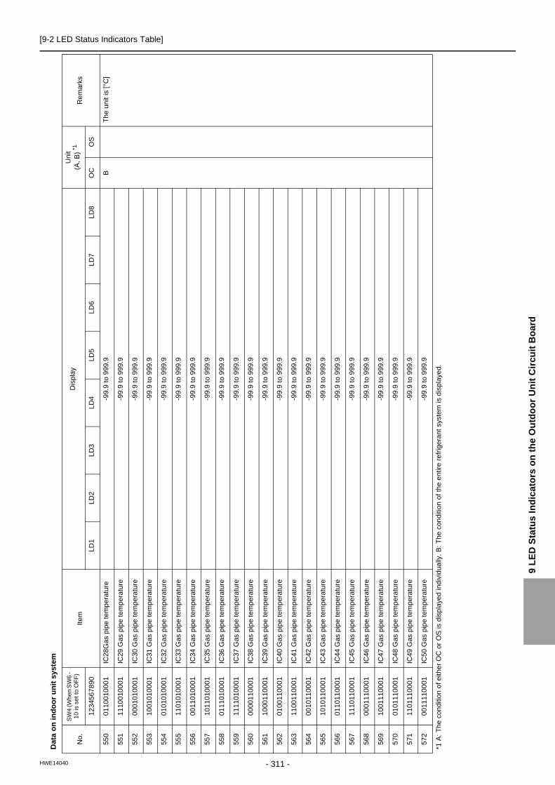
[9-2 LED Status Indicators Table]
9 L
ED
Sta
tus
In
dic
ato
rs o
n t
he
Ou
tdo
or
Un
it C
ircu
it B
oa
rd
Dat
a o
n in
do
or
un
it s
yste
m
No
.
SW
4 (W
hen
SW
6 -
10
is s
et to
OF
F)
Item
Dis
pla
yU
nit
(A, B
) *1
Rem
ark
s
1234
567
890
LD1
LD2
LD3
LD
4L
D5
LD6
LD7
LD8
OC
OS
550
0110
010
001
IC28
Gas
pip
e te
mp
erat
ure
-99.
9 to
999
.9B
Th
e un
it is
[°C
]
551
1110
010
001
IC29
Gas
pip
e te
mp
erat
ure
-99.
9 to
999
.9
552
0001
010
001
IC30
Gas
pip
e te
mp
erat
ure
-99.
9 to
999
.9
553
1001
010
001
IC31
Gas
pip
e te
mp
erat
ure
-99.
9 to
999
.9
554
0101
010
001
IC32
Gas
pip
e te
mp
erat
ure
-99.
9 to
999
.9
555
1101
010
001
IC33
Gas
pip
e te
mp
erat
ure
-99.
9 to
999
.9
556
0011
010
001
IC34
Gas
pip
e te
mp
erat
ure
-99.
9 to
999
.9
557
1011
010
001
IC35
Gas
pip
e te
mp
erat
ure
-99.
9 to
999
.9
558
0111
010
001
IC36
Gas
pip
e te
mp
erat
ure
-99.
9 to
999
.9
559
1111
010
001
IC37
Gas
pip
e te
mp
erat
ure
-99.
9 to
999
.9
560
0000
110
001
IC38
Gas
pip
e te
mp
erat
ure
-99.
9 to
999
.9
561
1000
110
001
IC39
Gas
pip
e te
mp
erat
ure
-99.
9 to
999
.9
562
0100
110
001
IC40
Gas
pip
e te
mp
erat
ure
-99.
9 to
999
.9
563
1100
110
001
IC41
Gas
pip
e te
mp
erat
ure
-99.
9 to
999
.9
564
0010
110
001
IC42
Gas
pip
e te
mp
erat
ure
-99.
9 to
999
.9
565
1010
110
001
IC43
Gas
pip
e te
mp
erat
ure
-99.
9 to
999
.9
566
0110
110
001
IC44
Gas
pip
e te
mp
erat
ure
-99.
9 to
999
.9
567
1110
110
001
IC45
Gas
pip
e te
mp
erat
ure
-99.
9 to
999
.9
568
0001
110
001
IC46
Gas
pip
e te
mp
erat
ure
-99.
9 to
999
.9
569
1001
110
001
IC47
Gas
pip
e te
mp
erat
ure
-99.
9 to
999
.9
570
0101
110
001
IC48
Gas
pip
e te
mp
erat
ure
-99.
9 to
999
.9
571
1101
110
001
IC49
Gas
pip
e te
mp
erat
ure
-99.
9 to
999
.9
572
0011
110
001
IC50
Gas
pip
e te
mp
erat
ure
-99.
9 to
999
.9
*1 A
: T
he
cond
ition
of e
ithe
r O
C o
r O
S is
dis
pla
yed
ind
ivid
ually
. B:
The
con
ditio
n o
f the
ent
ire r
efrig
eran
t sys
tem
is d
ispl
aye
d.
- 311 -HWE14040

[9-2 LED Status Indicators Table]
Dat
a o
n in
do
or
un
it s
yste
m
No
.
SW
4 (W
hen
SW
6 -
10 is
set
to O
FF
)It
emD
isp
lay
Un
it(A
, B
)*1R
emar
ks
1234
567
890
LD
1LD
2LD
3LD
4L
D5
LD
6L
D7
LD8
OC
OS
573
1011
110
001
IC1S
H-9
9.9
to 9
99.9
BT
he u
nit i
s [
°C ]
574
0111
110
001
IC2S
H-9
9.9
to 9
99.9
575
1111
110
001
IC3S
H-9
9.9
to 9
99.9
576
0000
001
001
IC4S
H-9
9.9
to 9
99.9
577
1000
001
001
IC5S
H-9
9.9
to 9
99.9
578
0100
001
001
IC6S
H-9
9.9
to 9
99.9
579
1100
001
001
IC7S
H-9
9.9
to 9
99.9
580
0010
001
001
IC8S
H-9
9.9
to 9
99.9
581
1010
001
001
IC9S
H-9
9.9
to 9
99.9
582
0110
001
001
IC10
SH
-99
.9 to
999
.9
583
1110
001
001
IC11
SH
-99
.9 to
999
.9
584
0001
001
001
IC12
SH
-99
.9 to
999
.9
585
1001
001
001
IC13
SH
-99
.9 to
999
.9
586
0101
001
001
IC14
SH
-99
.9 to
999
.9
587
1101
001
001
IC15
SH
-99
.9 to
999
.9
588
0011
001
001
IC16
SH
-99
.9 to
999
.9
589
1011
001
001
IC17
SH
-99
.9 to
999
.9
590
0111
001
001
IC18
SH
-99
.9 to
999
.9
591
1111
001
001
IC19
SH
-99
.9 to
999
.9
592
0000
101
001
IC20
SH
-99
.9 to
999
.9
593
1000
101
001
IC21
SH
-99
.9 to
999
.9
594
0100
101
001
IC22
SH
-99
.9 to
999
.9
595
1100
101
001
IC23
SH
-99
.9 to
999
.9
596
0010
101
001
IC24
SH
-99
.9 to
999
.9
597
1010
101
001
IC25
SH
-99
.9 to
999
.9
598
0110
101
001
IC26
SH
-99
.9 to
999
.9
599
1110
101
001
IC27
SH
-99
.9 to
999
.9
*1 A
: T
he
cond
ition
of e
ithe
r O
C o
r O
S is
dis
pla
yed
ind
ivid
ually
. B:
Th
e co
nditi
on o
f the
ent
ire r
efrig
eran
t sys
tem
is d
ispl
aye
d.
- 312 -HWE14040
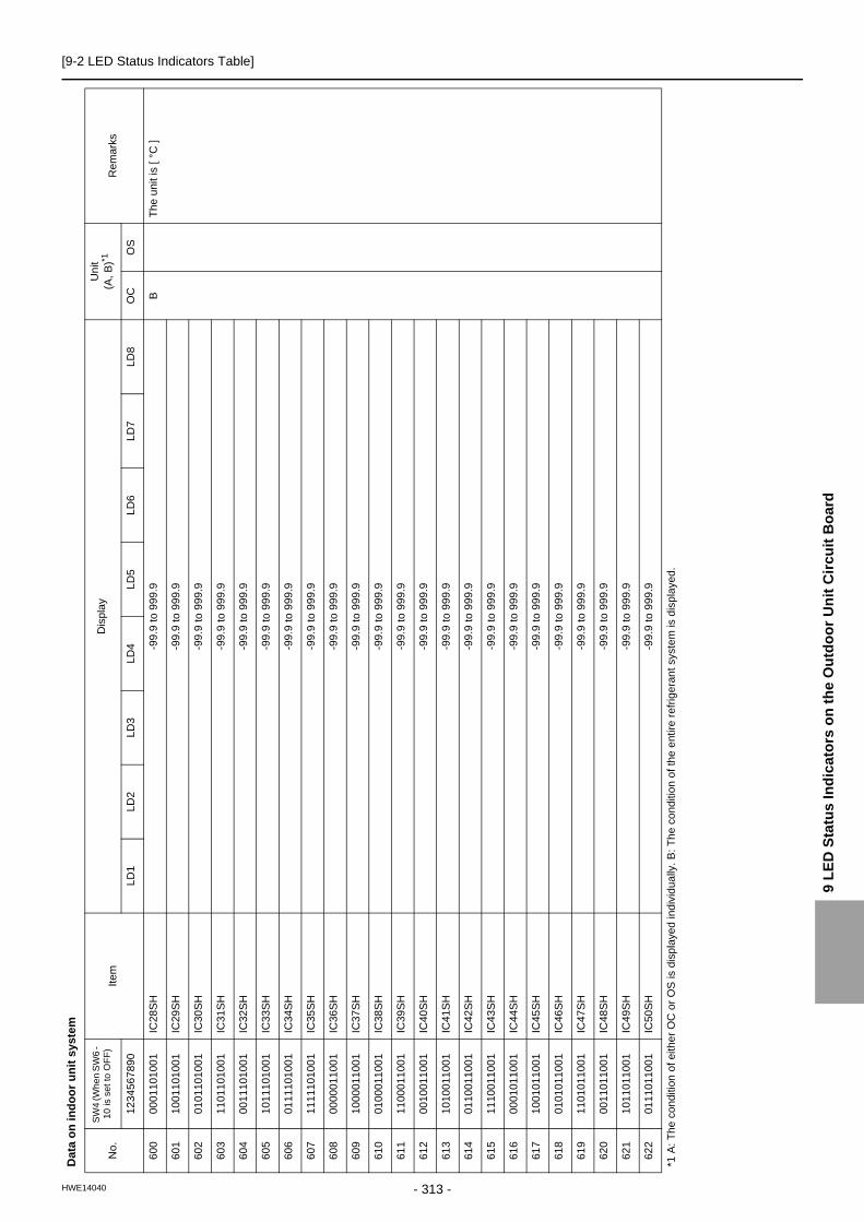
[9-2 LED Status Indicators Table]
9 L
ED
Sta
tus
In
dic
ato
rs o
n t
he
Ou
tdo
or
Un
it C
ircu
it B
oa
rd
600
0001
101
001
IC28
SH
-99
.9 to
999
.9B
The
uni
t is
[ °C
]
601
1001
101
001
IC29
SH
-99
.9 to
999
.9
602
0101
101
001
IC30
SH
-99
.9 to
999
.9
603
1101
101
001
IC31
SH
-99
.9 to
999
.9
604
0011
101
001
IC32
SH
-99
.9 to
999
.9
605
1011
101
001
IC33
SH
-99
.9 to
999
.9
606
0111
101
001
IC34
SH
-99
.9 to
999
.9
607
1111
101
001
IC35
SH
-99
.9 to
999
.9
608
0000
011
001
IC36
SH
-99
.9 to
999
.9
609
1000
011
001
IC37
SH
-99
.9 to
999
.9
610
0100
011
001
IC38
SH
-99
.9 to
999
.9
611
1100
011
001
IC39
SH
-99
.9 to
999
.9
612
0010
011
001
IC40
SH
-99
.9 to
999
.9
613
1010
011
001
IC41
SH
-99
.9 to
999
.9
614
0110
011
001
IC42
SH
-99
.9 to
999
.9
615
1110
011
001
IC43
SH
-99
.9 to
999
.9
616
0001
011
001
IC44
SH
-99
.9 to
999
.9
617
1001
011
001
IC45
SH
-99
.9 to
999
.9
618
0101
011
001
IC46
SH
-99
.9 to
999
.9
619
1101
011
001
IC47
SH
-99
.9 to
999
.9
620
0011
011
001
IC48
SH
-99
.9 to
999
.9
621
1011
011
001
IC49
SH
-99
.9 to
999
.9
622
0111
011
001
IC50
SH
-99
.9 to
999
.9
Dat
a o
n in
do
or
un
it s
yste
m
No
.
SW
4 (W
hen
SW
6 -
10 is
set
to O
FF
)It
emD
isp
lay
Un
it(A
, B
)*1R
emar
ks
1234
567
890
LD
1LD
2LD
3LD
4L
D5
LD
6L
D7
LD8
OC
OS
*1 A
: T
he
cond
ition
of e
ithe
r O
C o
r O
S is
dis
pla
yed
ind
ivid
ually
. B:
Th
e co
nditi
on o
f the
ent
ire r
efrig
eran
t sys
tem
is d
ispl
aye
d.
- 313 -HWE14040

[9-2 LED Status Indicators Table]
Dat
a o
n in
do
or
un
it s
yste
m
No
.
SW
4 (W
hen
SW
6 -
10 is
set
to O
FF
)It
emD
isp
lay
Un
it(A
, B
)*1R
emar
ks
1234
567
890
LD
1LD
2LD
3LD
4L
D5
LD
6L
D7
LD8
OC
OS
623
1111
011
001
IC1S
C-9
9.9
to 9
99.9
BT
he u
nit i
s [
°C ]
624
0000
111
001
IC2S
C-9
9.9
to 9
99.9
625
1000
111
001
IC3S
C-9
9.9
to 9
99.9
626
0100
111
001
IC4S
C-9
9.9
to 9
99.9
627
1100
111
001
IC5S
C-9
9.9
to 9
99.9
628
0010
111
001
IC6S
C-9
9.9
to 9
99.9
629
1010
111
001
IC7S
C-9
9.9
to 9
99.9
630
0110
111
001
IC8S
C-9
9.9
to 9
99.9
631
1110
111
001
IC9S
C-9
9.9
to 9
99.9
632
0001
111
001
IC10
SC
-99
.9 to
999
.9
633
1001
111
001
IC11
SC
-99
.9 to
999
.9
634
0101
111
001
IC12
SC
-99
.9 to
999
.9
635
1101
111
001
IC13
SC
-99
.9 to
999
.9
636
0011
111
001
IC14
SC
-99
.9 to
999
.9
637
1011
111
001
IC15
SC
-99
.9 to
999
.9
638
0111
111
001
IC16
SC
-99
.9 to
999
.9
639
1111
111
001
IC17
SC
-99
.9 to
999
.9
640
0000
000
101
IC18
SC
-99
.9 to
999
.9
641
1000
000
101
IC19
SC
-99
.9 to
999
.9
642
0100
000
101
IC20
SC
-99
.9 to
999
.9
643
1100
000
101
IC21
SC
-99
.9 to
999
.9
644
0010
000
101
IC22
SC
-99
.9 to
999
.9
645
1010
000
101
IC23
SC
-99
.9 to
999
.9
646
0110
000
101
IC24
SC
-99
.9 to
999
.9
647
1110
000
101
IC25
SC
-99
.9 to
999
.9
648
0001
000
101
IC26
SC
-99
.9 to
999
.9
649
1001
000
101
IC27
SC
-99
.9 to
999
.9
*1 A
: T
he
cond
ition
of e
ithe
r O
C o
r O
S is
dis
pla
yed
ind
ivid
ually
. B:
Th
e co
nditi
on o
f the
ent
ire r
efrig
eran
t sys
tem
is d
ispl
aye
d.
- 314 -HWE14040

[9-2 LED Status Indicators Table]
9 L
ED
Sta
tus
In
dic
ato
rs o
n t
he
Ou
tdo
or
Un
it C
ircu
it B
oa
rd
650
0101
000
101
IC28
SC
-99
.9 to
999
.9B
The
uni
t is
[ °C
]
651
1101
000
101
IC29
SC
-99
.9 to
999
.9
652
0011
000
101
IC30
SC
-99
.9 to
999
.9
653
1011
000
101
IC31
SC
-99
.9 to
999
.9
654
0111
000
101
IC32
SC
-99
.9 to
999
.9
655
1111
000
101
IC33
SC
-99
.9 to
999
.9
656
0000
100
101
IC34
SC
-99
.9 to
999
.9
657
1000
100
101
IC35
SC
-99
.9 to
999
.9
658
0100
100
101
IC36
SC
-99
.9 to
999
.9
659
1100
100
101
IC37
SC
-99
.9 to
999
.9
660
0010
100
101
IC38
SC
-99
.9 to
999
.9
661
1010
100
101
IC39
SC
-99
.9 to
999
.9
662
0110
100
101
IC40
SC
-99
.9 to
999
.9
663
1110
100
101
IC41
SC
-99
.9 to
999
.9
664
0001
100
101
IC42
SC
-99
.9 to
999
.9
665
1001
100
101
IC43
SC
-99
.9 to
999
.9
666
0101
100
101
IC44
SC
-99
.9 to
999
.9
667
1101
100
101
IC45
SC
-99
.9 to
999
.9
668
0011
100
101
IC46
SC
-99
.9 to
999
.9
669
1011
100
101
IC47
SC
-99
.9 to
999
.9
670
0111
100
101
IC48
SC
-99
.9 to
999
.9
671
1111
100
101
IC49
SC
-99
.9 to
999
.9
672
0000
010
101
IC50
SC
-99
.9 to
999
.9
Dat
a o
n in
do
or
un
it s
yste
m
No
.
SW
4 (W
hen
SW
6 -
10 is
set
to O
FF
)It
emD
isp
lay
Un
it(A
, B
)*1R
emar
ks
1234
567
890
LD
1LD
2LD
3LD
4L
D5
LD
6L
D7
LD8
OC
OS
*1 A
: T
he
cond
ition
of e
ithe
r O
C o
r O
S is
dis
pla
yed
ind
ivid
ually
. B:
Th
e co
nditi
on o
f the
ent
ire r
efrig
eran
t sys
tem
is d
ispl
aye
d.
- 315 -HWE14040

[9-2 LED Status Indicators Table]
Set
tin
g d
ata
No
.
SW
4 (W
hen
SW
6 -
10 is
set
to O
FF
)Ite
mD
ispl
ay
Un
it(A
, B
)* 1
Re
mar
ks
1234
567
890
LD1
LD2
LD3
LD
4L
D5
LD6
LD7
LD8
OC
OS
676
0010
010
101
INV
bo
ard
S/W
ver
sio
n0.
00 to
99.
99A
A
679
1110
010
101
Fa
n bo
ard
(add
ress
5)
S/W
ve
rsio
n0.
00 to
99.
99A
A
680
0001
010
101
Fa
n bo
ard
(add
ress
6)
S/W
ve
rsio
n0.
00 to
99.
99A
A
688
0000
110
101
Cu
rren
t tim
e0
0:00
to 2
3:59
AA
Ho
ur: m
inu
te
689
1000
110
101
Cu
rren
t tim
e -2
00.0
0 to
99
.12/
1 to
31
Ye
ar a
nd m
onth
, an
d da
te
alte
rna
te d
isp
lay
690
0100
110
101
Tim
e o
f err
or d
etec
tion
10
0:00
to 2
3:59
Ho
ur: m
inu
te
691
1100
110
101
Tim
e o
f err
or d
etec
tion
1-2
00.0
0 to
99
.12/
1 to
31
Ye
ar a
nd m
onth
, an
d da
te
alte
rna
te d
isp
lay
692
0010
110
101
Tim
e o
f err
or d
etec
tion
20
0:00
to 2
3:59
Ho
ur: m
inu
te
693
1010
110
101
Tim
e o
f err
or d
etec
tion
2-2
00.0
0 to
99
.12/
1 to
31
Ye
ar a
nd m
onth
, an
d da
te
alte
rna
te d
isp
lay
694
0110
110
101
Tim
e o
f err
or d
etec
tion
30
0:00
to 2
3:59
Ho
ur: m
inu
te
695
1110
110
101
Tim
e o
f err
or d
etec
tion
3-2
00.0
0 to
99
.12/
1 to
31
Ye
ar a
nd m
onth
, an
d da
te
alte
rna
te d
isp
lay
696
0001
110
101
Tim
e o
f err
or d
etec
tion
40
0:00
to 2
3:59
Ho
ur: m
inu
te
697
1001
110
101
Tim
e o
f err
or d
etec
tion
4-2
00.0
0 to
99
.12/
1 to
31
Ye
ar a
nd m
onth
, an
d da
te
alte
rna
te d
isp
lay
698
0101
110
101
Tim
e o
f err
or d
etec
tion
50
0:00
to 2
3:59
Ho
ur: m
inu
te
699
1101
110
101
Tim
e o
f err
or d
etec
tion
5-2
00.0
0 to
99
.12/
1 to
31
Ye
ar a
nd m
onth
, an
d da
te
alte
rna
te d
isp
lay
700
0011
110
101
Tim
e o
f err
or d
etec
tion
60
0:00
to 2
3:59
Ho
ur: m
inu
te
701
1011
110
101
Tim
e o
f err
or d
etec
tion
6-2
00.0
0 to
99
.12/
1 to
31
Ye
ar a
nd m
onth
, an
d da
te
alte
rna
te d
isp
lay
*1 A
: T
he
cond
ition
of e
ithe
r O
C o
r O
S is
dis
pla
yed
ind
ivid
ually
. B:
Th
e co
nditi
on o
f the
ent
ire r
efrig
eran
t sys
tem
is d
ispl
aye
d.
- 316 -HWE14040
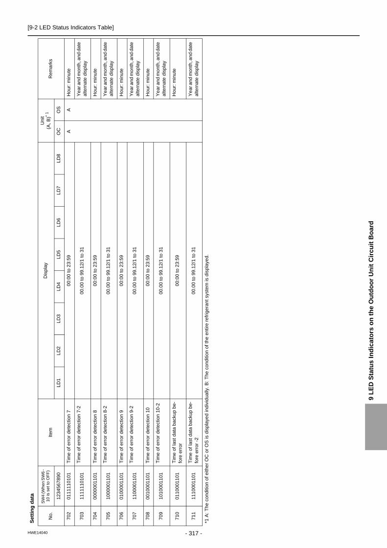
[9-2 LED Status Indicators Table]
9 L
ED
Sta
tus
In
dic
ato
rs o
n t
he
Ou
tdo
or
Un
it C
ircu
it B
oa
rd
702
0111
110
101
Tim
e o
f err
or d
etec
tion
70
0:00
to 2
3:59
AA
Ho
ur: m
inu
te
703
1111
110
101
Tim
e o
f err
or d
etec
tion
7-2
00.0
0 to
99
.12/
1 to
31
Ye
ar a
nd m
onth
, an
d da
te
alte
rna
te d
isp
lay
704
0000
001
101
Tim
e o
f err
or d
etec
tion
80
0:00
to 2
3:59
Ho
ur: m
inu
te
705
1000
001
101
Tim
e o
f err
or d
etec
tion
8-2
00.0
0 to
99
.12/
1 to
31
Ye
ar a
nd m
onth
, an
d da
te
alte
rna
te d
isp
lay
706
0100
001
101
Tim
e o
f err
or d
etec
tion
90
0:00
to 2
3:59
Ho
ur: m
inu
te
707
1100
001
101
Tim
e o
f err
or d
etec
tion
9-2
00.0
0 to
99
.12/
1 to
31
Ye
ar a
nd m
onth
, an
d da
te
alte
rna
te d
isp
lay
708
0010
001
101
Tim
e o
f err
or d
etec
tion
100
0:00
to 2
3:59
Ho
ur: m
inu
te
709
1010
001
101
Tim
e o
f err
or d
etec
tion
10-2
00.0
0 to
99
.12/
1 to
31
Ye
ar a
nd m
onth
, an
d da
te
alte
rna
te d
isp
lay
710
0110
001
101
Tim
e o
f las
t dat
a ba
ckup
be-
fore
err
or0
0:00
to 2
3:59
Ho
ur: m
inu
te
711
1110
001
101
Tim
e o
f las
t dat
a ba
ckup
be-
fore
err
or -
200
.00
to 9
9.1
2/1
to 3
1Y
ear
and
mon
th, a
nd
date
a
ltern
ate
dis
pla
y
Set
tin
g d
ata
No
.
SW
4 (W
hen
SW
6 -
10 is
set
to O
FF
)Ite
mD
ispl
ay
Un
it(A
, B
)* 1
Re
mar
ks
1234
567
890
LD1
LD2
LD3
LD
4L
D5
LD6
LD7
LD8
OC
OS
*1 A
: T
he
cond
ition
of e
ithe
r O
C o
r O
S is
dis
pla
yed
ind
ivid
ually
. B:
Th
e co
nditi
on o
f the
ent
ire r
efrig
eran
t sys
tem
is d
ispl
aye
d.
- 317 -HWE14040

[9-2 LED Status Indicators Table]
Dat
a o
n in
do
or
un
it s
yste
m
No
.
SW
4 (W
hen
SW
6 -
10 is
set
to O
FF
)It
emD
isp
lay
Un
it(A
, B
)* 1
Rem
arks
1234
567
890
LD
1LD
2LD
3LD
4L
D5
LD
6L
D7
LD8
OC
OS
714
0101
001
101
IC1
LE
V o
pen
ing
0000
to 9
999
BF
ully
op
en:
2000
715
1101
001
101
IC2
LE
V o
pen
ing
0000
to 9
999
716
0011
001
101
IC3
LE
V o
pen
ing
0000
to 9
999
717
1011
001
101
IC4
LE
V o
pen
ing
0000
to 9
999
718
0111
001
101
IC5
LE
V o
pen
ing
0000
to 9
999
719
1111
001
101
IC6
LE
V o
pen
ing
0000
to 9
999
720
0000
101
101
IC7
LE
V o
pen
ing
0000
to 9
999
721
1000
101
101
IC8
LE
V o
pen
ing
0000
to 9
999
722
0100
101
101
IC9
LE
V o
pen
ing
0000
to 9
999
723
1100
101
101
IC10
LE
V o
peni
ng00
00 to
999
9
724
0010
101
101
IC11
LE
V o
peni
ng00
00 to
999
9
725
1010
101
101
IC12
LE
V o
peni
ng00
00 to
999
9
726
0110
101
101
IC13
LE
V o
peni
ng00
00 to
999
9
727
1110
101
101
IC14
LE
V o
peni
ng00
00 to
999
9
728
0001
101
101
IC15
LE
V o
peni
ng00
00 to
999
9
729
1001
101
101
IC16
LE
V o
peni
ng00
00 to
999
9
730
0101
101
101
IC17
LE
V o
peni
ng00
00 to
999
9
731
1101
101
101
IC18
LE
V o
peni
ng00
00 to
999
9
732
0011
101
101
IC19
LE
V o
peni
ng00
00 to
999
9
733
1011
101
101
IC20
LE
V o
peni
ng00
00 to
999
9
734
0111
101
101
IC21
LE
V o
peni
ng00
00 to
999
9
735
1111
101
101
IC22
LE
V o
peni
ng00
00 to
999
9
736
0000
011
101
IC23
LE
V o
peni
ng00
00 to
999
9
737
1000
011
101
IC24
LE
V o
peni
ng00
00 to
999
9
738
0100
011
101
IC25
LE
V o
peni
ng00
00 to
999
9
739
1100
011
101
IC26
LE
V o
peni
ng00
00 to
999
9
740
0010
011
101
IC27
LE
V o
peni
ng00
00 to
999
9
*1 A
: T
he
cond
ition
of e
ithe
r O
C o
r O
S is
dis
pla
yed
ind
ivid
ually
. B:
Th
e co
nditi
on o
f the
ent
ire r
efrig
eran
t sys
tem
is d
ispl
aye
d.
- 318 -HWE14040

[9-2 LED Status Indicators Table]
9 L
ED
Sta
tus
In
dic
ato
rs o
n t
he
Ou
tdo
or
Un
it C
ircu
it B
oa
rd
741
1010
011
101
IC28
LE
V o
peni
ng00
00 to
999
9B
Ful
ly o
pen
: 20
00
742
0110
011
101
IC29
LE
V o
peni
ng00
00 to
999
9
743
1110
011
101
IC30
LE
V o
peni
ng00
00 to
999
9
744
0001
011
101
IC31
LE
V o
peni
ng00
00 to
999
9
745
1001
011
101
IC32
LE
V o
peni
ng00
00 to
999
9
746
0101
011
101
IC33
LE
V o
peni
ng00
00 to
999
9
747
1101
011
101
IC34
LE
V o
peni
ng00
00 to
999
9
748
0011
011
101
IC35
LE
V o
peni
ng00
00 to
999
9
749
1011
011
101
IC36
LE
V o
peni
ng00
00 to
999
9
750
0111
011
101
IC37
LE
V o
peni
ng00
00 to
999
9
751
1111
011
101
IC38
LE
V o
peni
ng00
00 to
999
9
752
0000
111
101
IC39
LE
V o
peni
ng00
00 to
999
9
753
1000
111
101
IC40
LE
V o
peni
ng00
00 to
999
9
754
0100
111
101
IC41
LE
V o
peni
ng00
00 to
999
9
755
1100
111
101
IC42
LE
V o
peni
ng00
00 to
999
9
756
0010
111
101
IC43
LE
V o
peni
ng00
00 to
999
9
757
1010
111
101
IC44
LE
V o
peni
ng00
00 to
999
9
758
0110
111
101
IC45
LE
V o
peni
ng00
00 to
999
9
759
1110
111
101
IC46
LE
V o
peni
ng00
00 to
999
9
760
0001
111
101
IC47
LE
V o
peni
ng00
00 to
999
9
761
1001
111
101
IC48
LE
V o
peni
ng00
00 to
999
9
762
0101
111
101
IC49
LE
V o
peni
ng00
00 to
999
9
763
1101
111
101
IC50
LE
V o
peni
ng00
00 to
999
9
764
0011
111
101
IC1
Op
erat
ion
mo
de
000
0 : S
top
0001
: V
ent
ilatio
n 00
02 :
Coo
ling
000
3 : H
eatin
g 0
004
: Dry
B
765
1011
111
101
IC2
Op
erat
ion
mo
de
766
0111
111
101
IC3O
pera
tion
mo
de
767
1111
111
101
IC4
Op
erat
ion
mo
de
768
0000
000
011
IC5
Op
erat
ion
mo
de
Dat
a o
n in
do
or
un
it s
yste
m
No
.
SW
4 (W
hen
SW
6 -
10 is
set
to O
FF
)It
emD
isp
lay
Un
it(A
, B
)* 1
Rem
arks
1234
567
890
LD
1LD
2LD
3LD
4L
D5
LD
6L
D7
LD8
OC
OS
*1 A
: T
he
cond
ition
of e
ithe
r O
C o
r O
S is
dis
pla
yed
ind
ivid
ually
. B:
Th
e co
nditi
on o
f the
ent
ire r
efrig
eran
t sys
tem
is d
ispl
aye
d.
- 319 -HWE14040

[9-2 LED Status Indicators Table]
769
1000
000
011
IC6
Op
erat
ion
mo
de
000
0 : S
top
0001
: V
ent
ilatio
n 00
02 :
Coo
ling
000
3 : H
eatin
g 0
004
: Dry
B
770
0100
000
011
IC7
Op
erat
ion
mo
de
771
1100
000
011
IC8
Op
erat
ion
mo
de
772
0010
000
011
IC9
Op
erat
ion
mo
de
773
1010
000
011
IC10
Ope
ratio
n m
ode
774
0110
000
011
IC11
Ope
ratio
n m
ode
775
1110
000
011
IC12
Ope
ratio
n m
ode
776
0001
000
011
IC13
Ope
ratio
n m
ode
777
1001
000
011
IC14
Ope
ratio
n m
ode
778
0101
000
011
IC15
Ope
ratio
n m
ode
779
1101
000
011
IC16
Ope
ratio
n m
ode
780
0011
000
011
IC17
Ope
ratio
n m
ode
781
1011
000
011
IC18
Ope
ratio
n m
ode
782
0111
000
011
IC19
Ope
ratio
n m
ode
783
1111
000
011
IC20
Ope
ratio
n m
ode
784
0000
100
011
IC21
Ope
ratio
n m
ode
785
1000
100
011
IC22
Ope
ratio
n m
ode
786
0100
100
011
IC23
Ope
ratio
n m
ode
787
1100
100
011
IC24
Ope
ratio
n m
ode
788
0010
100
011
IC25
Ope
ratio
n m
ode
789
1010
100
011
IC26
Ope
ratio
n m
ode
790
0110
100
011
IC27
Ope
ratio
n m
ode
791
1110
100
011
IC28
Ope
ratio
n m
ode
792
0001
100
011
IC29
Ope
ratio
n m
ode
793
1001
100
011
IC30
Ope
ratio
n m
ode
794
0101
100
011
IC31
Ope
ratio
n m
ode
795
1101
100
011
IC32
Ope
ratio
n m
ode
796
0011
100
011
IC33
Ope
ratio
n m
ode
Dat
a o
n in
do
or
un
it s
yste
m
No
.
SW
4 (W
hen
SW
6 -
10 is
set
to O
FF
)It
emD
isp
lay
Un
it(A
, B
)* 1
Rem
arks
1234
567
890
LD
1LD
2LD
3LD
4L
D5
LD
6L
D7
LD8
OC
OS
*1 A
: T
he
cond
ition
of e
ithe
r O
C o
r O
S is
dis
pla
yed
ind
ivid
ually
. B:
Th
e co
nditi
on o
f the
ent
ire r
efrig
eran
t sys
tem
is d
ispl
aye
d.
- 320 -HWE14040

[9-2 LED Status Indicators Table]
9 L
ED
Sta
tus
In
dic
ato
rs o
n t
he
Ou
tdo
or
Un
it C
ircu
it B
oa
rd
797
1011
100
011
IC34
Ope
ratio
n m
ode
000
0 : S
top
0001
: V
ent
ilatio
n 00
02 :
Coo
ling
000
3 : H
eatin
g 0
004
: Dry
B
798
0111
100
011
IC35
Ope
ratio
n m
ode
799
1111
100
011
IC36
Ope
ratio
n m
ode
800
0000
010
011
IC37
Ope
ratio
n m
ode
801
1000
010
011
IC38
Ope
ratio
n m
ode
802
0100
010
011
IC39
Ope
ratio
n m
ode
803
1100
010
011
IC40
Ope
ratio
n m
ode
804
0010
010
011
IC41
Ope
ratio
n m
ode
805
1010
010
011
IC42
Ope
ratio
n m
ode
806
0110
010
011
IC43
Ope
ratio
n m
ode
807
1110
010
011
IC44
Ope
ratio
n m
ode
808
0001
010
011
IC45
Ope
ratio
n m
ode
809
1001
010
011
IC46
Ope
ratio
n m
ode
810
0101
010
011
IC47
Ope
ratio
n m
ode
811
1101
010
011
IC48
Ope
ratio
n m
ode
812
0011
010
011
IC49
Ope
ratio
n m
ode
813
1011
010
011
IC50
Ope
ratio
n m
ode
814
0111
010
011
IC1
filte
r00
00 to
999
9B
Hou
rs s
ince
last
ma
inte
-n
ance
[ h
]81
511
1101
001
1IC
2 fil
ter
0000
to 9
999
816
0000
110
011
IC3
filte
r00
00 to
999
9
817
1000
110
011
IC4
filte
r00
00 to
999
9
818
0100
110
011
IC5
filte
r00
00 to
999
9
819
1100
110
011
IC6
filte
r00
00 to
999
9
820
0010
110
011
IC7
filte
r00
00 to
999
9
821
1010
110
011
IC8
filte
r00
00 to
999
9
822
0110
110
011
IC9
filte
r00
00 to
999
9
823
1110
110
011
IC10
filte
r00
00 to
999
9
824
0001
110
011
IC11
filte
r00
00 to
999
9
Dat
a o
n in
do
or
un
it s
yste
m
No
.
SW
4 (W
hen
SW
6 -
10 is
set
to O
FF
)It
emD
isp
lay
Un
it(A
, B
)* 1
Rem
arks
1234
567
890
LD
1LD
2LD
3LD
4L
D5
LD
6L
D7
LD8
OC
OS
*1 A
: T
he
cond
ition
of e
ithe
r O
C o
r O
S is
dis
pla
yed
ind
ivid
ually
. B:
Th
e co
nditi
on o
f the
ent
ire r
efrig
eran
t sys
tem
is d
ispl
aye
d.
- 321 -HWE14040

[9-2 LED Status Indicators Table]
825
1001
110
011
IC12
filte
r00
00 to
999
9B
Hou
rs s
ince
last
ma
inte
-n
ance
[ h
]82
601
0111
001
1IC
13 fi
lter
0000
to 9
999
827
1101
110
011
IC14
filte
r00
00 to
999
9
828
0011
110
011
IC15
filte
r00
00 to
999
9
829
1011
110
011
IC16
filte
r00
00 to
999
9
830
0111
110
011
IC17
filte
r00
00 to
999
9
831
1111
110
011
IC18
filte
r00
00 to
999
9
832
0000
001
011
IC19
filte
r00
00 to
999
9
833
1000
001
011
IC20
filte
r00
00 to
999
9
834
0100
001
011
IC21
filte
r00
00 to
999
9
835
1100
001
011
IC22
filte
r00
00 to
999
9
836
0010
001
011
IC23
filte
r00
00 to
999
9
837
1010
001
011
IC24
filte
r00
00 to
999
9
838
0110
001
011
IC25
filte
r00
00 to
999
9
839
1110
001
011
IC26
filte
r00
00 to
999
9
840
0001
001
011
IC27
filte
r00
00 to
999
9
841
1001
001
011
IC28
filte
r00
00 to
999
9
842
0101
001
011
IC29
filte
r00
00 to
999
9
843
1101
001
011
IC30
filte
r00
00 to
999
9
844
0011
001
011
IC31
filte
r00
00 to
999
9
845
1011
001
011
IC32
filte
r00
00 to
999
9
846
0111
001
001
IC33
filte
r00
00 to
999
9
847
1111
001
011
IC34
filte
r00
00 to
999
9
848
0000
101
011
IC35
filte
r00
00 to
999
9
849
1000
101
011
IC36
filte
r00
00 to
999
9
850
0100
101
011
IC37
filte
r00
00 to
999
9
851
1100
101
011
IC38
filte
r00
00 to
999
9
852
0010
101
011
IC39
filte
r00
00 to
999
9
Dat
a o
n in
do
or
un
it s
yste
m
No
.
SW
4 (W
hen
SW
6 -
10 is
set
to O
FF
)It
emD
isp
lay
Un
it(A
, B
)* 1
Rem
arks
1234
567
890
LD
1LD
2LD
3LD
4L
D5
LD
6L
D7
LD8
OC
OS
*1 A
: T
he
cond
ition
of e
ithe
r O
C o
r O
S is
dis
pla
yed
ind
ivid
ually
. B:
Th
e co
nditi
on o
f the
ent
ire r
efrig
eran
t sys
tem
is d
ispl
aye
d.
- 322 -HWE14040

[9-2 LED Status Indicators Table]
9 L
ED
Sta
tus
In
dic
ato
rs o
n t
he
Ou
tdo
or
Un
it C
ircu
it B
oa
rd
853
1010
101
011
IC40
filte
r00
00 to
999
9B
Hou
rs s
ince
last
ma
inte
-n
ance
[ h
]85
401
1010
101
1 IC
41 fi
lter
0000
to 9
999
855
1110
101
011
IC42
filte
r00
00 to
999
9
856
0001
101
011
IC43
filte
r00
00 to
999
9
857
1001
101
011
IC44
filte
r00
00 to
999
9
858
0101
101
011
IC45
filte
r00
00 to
999
9
859
1101
101
011
IC46
filte
r00
00 to
999
9
860
0011
101
011
IC47
filte
r00
00 to
999
9
861
1011
101
011
IC48
filte
r00
00 to
999
9
862
0111
101
011
IC49
filte
r00
00 to
999
9
863
1111
101
011
IC50
filte
r00
00 to
999
9
Dat
a o
n in
do
or
un
it s
yste
m
No
.
SW
4 (W
hen
SW
6 -
10 is
set
to O
FF
)It
emD
isp
lay
Un
it(A
, B
)* 1
Rem
arks
1234
567
890
LD
1LD
2LD
3LD
4L
D5
LD
6L
D7
LD8
OC
OS
*1 A
: T
he
cond
ition
of e
ithe
r O
C o
r O
S is
dis
pla
yed
ind
ivid
ually
. B:
Th
e co
nditi
on o
f the
ent
ire r
efrig
eran
t sys
tem
is d
ispl
aye
d.
- 323 -HWE14040

[9-2 LED Status Indicators Table]
Oth
er t
ypes
of
dat
a
No
.
SW
4 (W
hen
SW
6 -
10
is s
et to
OF
F)
Item
Dis
play
Uni
t(A
, B) *
1R
ema
rks
1234
567
890
LD
1L
D2
LD
3LD
4LD
5LD
6L
D7
LD
8O
CO
S
871
1110
011
011
U-p
has
e c
urre
nt e
ffec
-tiv
e va
lue
1-9
9.9
to 9
99.
9A
AT
he u
nit
is [
A ]
872
0001
011
011
W-p
hase
cur
rent
eff
ec-
tive
valu
e 1
-99.
9 to
99
9.9
AA
873
1001
011
011
Po
wer
fact
or p
hase
an-
gle
1-9
9.9
to 9
99.
9A
AT
he u
nit
is [
deg
]
880
0000
111
011
Co
ntro
l boa
rdR
ese
t co
unte
r0
to 2
54A
AT
he u
nit
is [
time
]
881
1000
111
011
INV
bo
ard
Re
set
coun
ter
0 to
254
AA
884
0010
111
011
Fa
n bo
ard
(add
ress
5)
rese
t cou
nter
0 to
254
AA
The
uni
t is
[ tim
e ]
885
1010
111
011
Fa
n bo
ard
(add
ress
6)
rese
t cou
nter
0 to
254
AA
*1 A
: T
he
cond
ition
of e
ithe
r O
C o
r O
S is
dis
pla
yed
ind
ivid
ually
. B:
The
con
ditio
n o
f the
ent
ire r
efrig
eran
t sys
tem
is d
ispl
aye
d.
- 324 -HWE14040

Related Documents