www.mita-teknik.com © 2011 Mita-Teknik. All rights reserved MT_MDS 031A (400V)_DataSheet_R2_0 MITA DRIVE SYSTEM - MDS 031A (400V) Description The MDS module is designed for pitch control on wind turbine rotor blades Integrated hardware and software solution Integrated safety software Compact and user-friendly design Quick and easy installation In General: The Mita Drive System- MDS - is used for pitch control of wind turbine rotor blades. The MDS is suitable for all types of turbine con- trollers. Features: The MDS is a hard- and software solution for pitching rotor blades. The MDS has a detachable, remote-operation seven-seg- ment LCD keypad. It is used to communicate with the drive, set parameters and for monitoring. The design allows a quick and easy installation. The very sturdy Drive Sys- tem is placed in the wind turbine hub, and is able to resist severe vibrations and rotations. Function: The MDS is supplied by the grid for normal operation. A DC back-up system allows emergency operation during grid loss. The MDS controls the motor brake of the pitch motors. Configuration: Mita-Teknik supplies com- plete pitch solutions includ- ing pitch motors, brake resis- tor encoders, position gauges, and limit switches. There are 2 principal con- figurations: a) with hub controller con- trolling the MDS by analog and digital signals. b) control of the MDS through Modbus communication. (other bus systems can be delivered upon request). Generally, each MDS drive works independently and is controlled individually. This allows full interchangeability and requires no individual programming. Mita-Teknik offers several MDS solutions. Configuration

Welcome message from author
This document is posted to help you gain knowledge. Please leave a comment to let me know what you think about it! Share it to your friends and learn new things together.
Transcript

www.mita-teknik.com © 2011 Mita-Teknik. All rights reservedMT_MDS 031A (400V)_DataSheet_R2_0
MITA DRIVE SYSTEM - MDS 031A (400V)
Description
The MDS module is designed for pitch control on wind turbine rotor blades
Integrated hardware and software solution
Integrated safety software
Compact and user-friendly design
Quick and easy installation
In General:The Mita Drive System- MDS - is used for pitch control of wind turbine rotor blades. The MDS is suitable for all types of turbine con-trollers.
Features:The MDS is a hard- and software solution for pitching rotor blades.
The MDS has a detachable, remote-operation seven-seg-ment LCD keypad. It is used to communicate with the drive, set parameters and for monitoring.
The design allows a quick and easy installation.
The very sturdy Drive Sys- tem is placed in the wind turbine hub, and is able to resist severe vibrations and rotations.
Function:The MDS is supplied by the grid for normal operation. A DC back-up system allows emergency operation during grid loss. The MDS controls the motor brake of the pitch motors.
Configuration:Mita-Teknik supplies com-plete pitch solutions includ-ing pitch motors, brake resis-tor encoders, position gauges, and limit switches.
There are 2 principal con- figurations:
a) with hub controller con-trolling the MDS by analog and digital signals.
b) control of the MDS through Modbus communication. (other bus systems can be delivered upon request).
Generally, each MDS drive works independently and is controlled individually. This allows full interchangeability and requires no individual programming.
Mita-Teknik offers several MDS solutions.
Configuration
www.mita-teknik.com © 2011 Mita-Teknik. All rights reservedMT_MDS 031A (400V)_DataSheet_R2_0
MITA DRIVE SYSTEM - MDS 031A (400V)
Supply Voltage Mains Nominal 3 x 400 V ACAllowed range 3 x 380 ...500V AC +/- 10%Connection Terminals 3 screw terminals + 1 ground terminalSupply Voltage Nominal 24 VDC Allowed range 24 VDC +/-15%Backup Power Nominal 500 VDCAllowed range 420 - 560 VDC-15%...+ 10%
Frequency Main supply 45 ... 66Hz
Frequency converterGeneral output Output voltage 3*0 ...U VAC (Mains)Output frequency 0 ...320 HzOutput frequency resolution 0.01 HzSwitching frequency 1 ...16 KHzSwitching frequency, default 10 KHzConnection to mains 1 or less/min.Starting delay 2 sec.Control method Frequency control U/F, Open loop sensorless Control, closed loop Frequency control, closed Loop vector controlAcceleration time 0 ... 3000 sec.Deceleration 0 ... 3000 sec.
Motor Connection MDS 031APower output 15 kW, 400 V 8,6 kW, 230 V
Current, continous (I load) 31 [A]Temperature, 10% overload 50 C°
Time, 10 % overload 1 min./10 min.Current, overload (I high) 47 [A]50 % overload 1.5*I high [A]Temperature, 50% overload + 50 C°Time, 50 % overload 1 min./10 min.
Current, max. (I short) 62 [A]Current, Peak 2 sec./20 sec.Starting torque I short for 2 sec. Braking Brake chopper Yes, internalBrake resistor Yes, external Connection terminals 2 screw terminals
Basic I/O CardDigital IntputNo. of points 6 Number of groups 2Basic I/O CardDigital Intput (cont.)Points per group 3Isolation noneNominal voltage 24 VDCSignal “1” >=18 VDC Signal “0” <=10 VDC Input current / signal “1” 5 mA max.Input impedance 5 KΩ
Anlog Input No. of points 2 Number of groups 1Points per group 2Isolation noneInput configurator jumpersInput voltage 0 ...10V (-10V ... + 10V) joystick control Input impedance ( V in) 200 KΩ Input current 0(4) ... 20mAInput impedance ( I in) 250 Ω Resolution 10 bit, 0.1% Accuracy +/- 1%
Digital Output Output type Open collector outputVoltage, max 48 VDC Current, max 50 mA
Analog OutputNo. of points 1 Number of groups 1Points per group 1Isolation noneOutput configurator jumpersVoltage 0 ...10VDCLoad ( V out ) R load >1 KΩCurrent 0(4) ...20mALoad ( I out) R load >500KΩ Resolution 0.1 % (10bit) Accuracy +/- 2%
Voltage Supply Voltage supply 24Vout +/- 15% (bidirectional)Current 150 mAProtection Short circuit protectionExternal voltage supply 24 VDCConnection terminals 2 x 10 screw terminals, coded
Technical data
www.mita-teknik.com © 2011 Mita-Teknik. All rights reservedMT_MDS 031A (400V)_DataSheet_R2_0
MITA DRIVE SYSTEM - MDS 031A (400V)
Relay Card with Termistor inputRelay Relay 1 output NO/NC Switching capacity 24 VDC/8A, 250 VAC/ 8A, 125 VDC/0.4A Switching capacity, min. 5V/10mA Relay 2 output NOSwitching capacity 24VDC/8A, 250 VAC/ 8A, 125 VDC/0.4ASwitching capacity, min. 5V/10mA
Thermistor Input No. of points 1Number of groups 1Points per group 1 Isolation noneSignal “1” >4.7KΩ (PTC) Signal “0” <4.7KΩ (PTC) Connection terminals 1 x 3, 2 x 2 screw terminals, no codingEncoder Card Digital input 3 Voltage input A 10...24 VDC (differential)Voltage input B 10 ...24 VDC differential, phase shift 90 ° compared to input AVoltage input Z 10 ...24 VDC (differential), 1 pulse/rev.Frequency < 150 KHz
Voltage Supply Voltage supply 15/24 VDC Current 150mAShort circuit protection YesExternal voltage supply 24 VDCVoltage configurator jumperConnection terminals 1 x 10 screw terminals, codedPorts for Optional Cards No. of slots 2 Interfaces: Analog/digitalIsolation None, Optocoupler, Relay ContactCommunication interfaces RS232, RS485, CAN open (preliminary)Encoder Different encoder boards. Contact us. Ports for Optional Serial Communication Cards No. of ports 1
Technical data
RS232 CommunicationPort Communication interfaces: RS232Communication speed 9600 ...57600 BAUDConnection 9 pin D-sub or terminals
RS485 Communication Port Communication interfaces: RS485
Modbus RTU Communication speed 300 ...38400 BAUDAddresses 1 ...247Connection 9 pin D-sub or terminalsData transfer method Half duplexTransfer cable Twisted pair (1 pair and shielded)Profibus DP Communication speed 9.6 k ...12M BAUDAddresses 2 ...126Connection 9 pin D-sub or terminalsData transfer method Half duplexTransfer cable Twisted pair (1 pair and shielded)
CAN Open Contact Mita-Teknik
Permissible Ambient ConditionsOperation temperature -10 to 50°CTransportation/Storage temp. -40 to +70°CMax. relative humidity 95% no condensationMax. operating height 2000 m. above sea level (Higher levels only by spe- cial agreement with Mita- Teknik)Derating 1% for each 1000 m. above 1000m.; max. 3000m.
Air QualityChemical vapours IEC 721-3-3, unit in operation, class 3C2Mechanical particles IEC 721-3-3, unit in operation, class 3S2

www.mita-teknik.com © 2011 Mita-Teknik. All rights reservedMT_MDS 031A (400V)_DataSheet_R2_0
MITA DRIVE SYSTEM - MDS 031A (400V)
Technical data
Vibration EN50178, EN60068-2-6 5 .... 150 Hz Displacement amplitude 1 mm. (peak) at 3....15.8 Hz. Max. accelleration amplitude 1 G at 15.8 ...150 HzShock EN50178, EN60068-2-27 UPS drop test (for applicable UPS weights)Storage and shipping max.: 15G, 11ms (in package)
ConstructionDimensions (WxHxD) 195 x 519 x 237 mmWeight KgDegree of protection IP21Standards EN61000-6-1 EN61000-6-2 EN61000-3+11A
MDS 031 400 V/Varnished P/N.: 979752XXX
Ordering data

www.mita-teknik.com © 2011 Mita-Teknik. All rights reservedMT_MDS 038A (400V)_DataSheet_R2_0
MITA DRIVE SYSTEM - MDS 038A (400V)
Description
The MDS module is designed for pitch control on wind turbine rotor blades
Integrated hardware and software solution
Integrated safety software
Compact and user-friendly design
Quick and easy installation
Configuration
In General:The Mita Drive System- MDS - is used for pitch control of wind turbine rotor blades. The MDS is suitable for all types of turbine con-trollers.
Features:The MDS is a hard- and software solution for pitching rotor blades.
The MDS has a detachable, remote-operation seven-seg-ment LCD keypad. It is used to communicate with the drive, set parameters and for monitoring.
The design allows a quick and easy installation.
The very sturdy Drive Sys- tem is placed in the wind turbine hub, and is able to resist severe vibrations and rotations.
Function:The MDS is supplied by the grid for normal operation. A DC back-up system allows emergency operation during grid loss. The MDS controls the motor brake of the pitch motors.
Configuration:Mita-Teknik supplies com-plete pitch solutions includ-ing pitch motors, brake resis-tor encoders, position gauges, and limit switches.
There are 2 principal con- figurations:
a) with hub controller con-trolling the MDS by analog and digital signals.
b) control of the MDS through Modbus communication. (other bus systems can be delivered upon request).
Generally, each MDS drive works independently and is controlled individually. This allows full interchangeability and requires no individual programming.
Mita-Teknik offers several MDS solutions.

www.mita-teknik.com © 2011 Mita-Teknik. All rights reservedMT_MDS 038A (400V)_DataSheet_R2_0
MITA DRIVE SYSTEM - MDS 038A (400V)
Supply Voltage Mains Nominal 3 x 400 V ACAllowed range 3 x 380 ...500V AC +/- 10%Connection Terminals 3 screw terminals + 1 ground terminalSupply Voltage Nominal 24 VDC Allowed range 24 VDC +/-15%Backup Power Nominal 500 VDCAllowed range 420 - 560 VDC-15%...+ 10%
Frequency Main supply 45 ... 66Hz
Frequency converterGeneral output Output voltage 3*0 ...U VAC (Mains)Output frequency 0 ...320 HzOutput frequency resolution 0.01 HzSwitching frequency 1 ...16 KHzSwitching frequency, default 10 KHzConnection to mains 1 or less/min.Starting delay 2 sec.Control method Frequency control U/F, Open loop sensorless Control, closed loop Frequency control, closed Loop vector controlAcceleration time 0 ... 3000 sec.Deceleration 0 ... 3000 sec.
Motor Connection MDS 038APower output 18,5 kW, 400 V 11 kW, 230 V
Current, continous (I load) 38 [A]Temperature, 10% overload 50 C°
Time, 10 % overload 1 min./10 min.Current, overload (I high) 57 [A]50 % overload 1.5*I high [A]Temperature, 50% overload + 50 C°Time, 50 % overload 1 min./10 min.
Current, max. (I short) 76 [A]Current, Peak 2 sec./20 sec.Starting torque I short for 2 sec. Braking Brake chopper Yes, internalBrake resistor Yes, external Connection terminals 2 screw terminals
Basic I/O CardDigital IntputNo. of points 6 Number of groups 2Basic I/O CardDigital Intput (cont.)Points per group 3Isolation noneNominal voltage 24 VDCSignal “1” >=18 VDC Signal “0” <=10 VDC Input current / signal “1” 5 mA max.Input impedance 5 KΩ
Anlog Input No. of points 2 Number of groups 1Points per group 2Isolation noneInput configurator jumpersInput voltage 0 ...10V (-10V ... + 10V) joystick control Input impedance ( V in) 200 KΩ Input current 0(4) ... 20mAInput impedance ( I in) 250 Ω Resolution 10 bit, 0.1% Accuracy +/- 1%
Digital Output Output type Open collector outputVoltage, max 48 VDC Current, max 50 mA
Analog OutputNo. of points 1 Number of groups 1Points per group 1Isolation noneOutput configurator jumpersVoltage 0 ...10VDCLoad ( V out ) R load >1 KΩCurrent 0(4) ...20mALoad ( I out) R load >500KΩ Resolution 0.1 % (10bit) Accuracy +/- 2%
Voltage Supply Voltage supply 24Vout +/- 15% (bidirectional)Current 150 mAProtection Short circuit protectionExternal voltage supply 24 VDCConnection terminals 2 x 10 screw terminals, coded
Technical data

www.mita-teknik.com © 2011 Mita-Teknik. All rights reservedMT_MDS 038A (400V)_DataSheet_R2_0
MITA DRIVE SYSTEM - MDS 038A (400V)
Relay Card with Termistor inputRelay Relay 1 output NO/NC Switching capacity 24 VDC/8A, 250 VAC/ 8A, 125 VDC/0.4A Switching capacity, min. 5V/10mA Relay 2 output NOSwitching capacity 24VDC/8A, 250 VAC/ 8A, 125 VDC/0.4ASwitching capacity, min. 5V/10mA
Thermistor Input No. of points 1Number of groups 1Points per group 1 Isolation noneSignal “1” >4.7KΩ (PTC) Signal “0” <4.7KΩ (PTC) Connection terminals 1 x 3, 2 x 2 screw terminals, no codingEncoder Card Digital input 3 Voltage input A 10...24 VDC (differential)Voltage input B 10 ...24 VDC differential, phase shift 90 ° compared to input AVoltage input Z 10 ...24 VDC (differential), 1 pulse/rev.Frequency < 150 KHz
Voltage Supply Voltage supply 15/24 VDC Current 150mAShort circuit protection YesExternal voltage supply 24 VDCVoltage configurator jumperConnection terminals 1 x 10 screw terminals, codedPorts for Optional Cards No. of slots 2 Interfaces: Analog/digitalIsolation None, Optocoupler, Relay ContactCommunication interfaces RS232, RS485, CAN open (preliminary)Encoder Different encoder boards. Contact us. Ports for Optional Serial Communication Cards No. of ports 1
Technical data
RS232 CommunicationPort Communication interfaces: RS232Communication speed 9600 ...57600 BAUDConnection 9 pin D-sub or terminals
RS485 Communication Port Communication interfaces: RS485
Modbus RTU Communication speed 300 ...38400 BAUDAddresses 1 ...247Connection 9 pin D-sub or terminalsData transfer method Half duplexTransfer cable Twisted pair (1 pair and shielded)Profibus DP Communication speed 9.6 k ...12M BAUDAddresses 2 ...126Connection 9 pin D-sub or terminalsData transfer method Half duplexTransfer cable Twisted pair (1 pair and shielded)
CAN Open Contact Mita-Teknik
Permissible Ambient ConditionsOperation temperature -10 to 50°CTransportation/Storage temp. -40 to +70°CMax. relative humidity 95% no condensationMax. operating height 2000 m. above sea level (Higher levels only by spe- cial agreement with Mita- Teknik)Derating 1% for each 1000 m. above 1000m.; max. 3000m.
Air QualityChemical vapours IEC 721-3-3, unit in operation, class 3C2Mechanical particles IEC 721-3-3, unit in operation, class 3S2

www.mita-teknik.com © 2011 Mita-Teknik. All rights reservedMT_MDS 038A (400V)_DataSheet_R2_0
MITA DRIVE SYSTEM - MDS 038A (400V)
Technical data
Vibration EN50178, EN60068-2-6 5 .... 150 Hz Displacement amplitude 1 mm. (peak) at 3....15.8 Hz. Max. accelleration amplitude 1 G at 15.8 ...150 HzShock EN50178, EN60068-2-27 UPS drop test (for applicable UPS weights)Storage and shipping max.: 15G, 11ms (in package)
ConstructionDimensions (WxHxD) 195 x 519 x 237 mmWeight KgDegree of protection IP21Standards EN61000-6-1 EN61000-6-2 EN61000-3+11A
MDS 038 400 V/Varnished P/N.: 979753XXX
Ordering data
www.mita-teknik.com © 2011 Mita-Teknik. All rights reservedMT_MDS 046A (400V)_DataSheet_R2_0
MITA DRIVE SYSTEM - MDS 046A (400V)
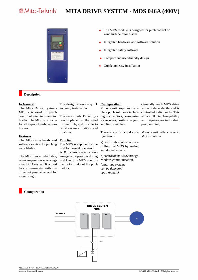
Description
The MDS module is designed for pitch control on wind turbine rotor blades
Integrated hardware and software solution
Integrated safety software
Compact and user-friendly design
Quick and easy installation
Configuration
In General:The Mita Drive System- MDS - is used for pitch control of wind turbine rotor blades. The MDS is suitable for all types of turbine con-trollers.
Features:The MDS is a hard- and software solution for pitching rotor blades.
The MDS has a detachable, remote-operation seven-seg-ment LCD keypad. It is used to communicate with the drive, set parameters and for monitoring.
The design allows a quick and easy installation.
The very sturdy Drive Sys- tem is placed in the wind turbine hub, and is able to resist severe vibrations and rotations.
Function:The MDS is supplied by the grid for normal operation. A DC back-up system allows emergency operation during grid loss. The MDS controls the motor brake of the pitch motors.
Configuration:Mita-Teknik supplies com-plete pitch solutions includ-ing pitch motors, brake resis-tor encoders, position gauges, and limit switches.
There are 2 principal con- figurations:
a) with hub controller con-trolling the MDS by analog and digital signals.
b) control of the MDS through Modbus communication. (other bus systems can be delivered upon request).
Generally, each MDS drive works independently and is controlled individually. This allows full interchangeability and requires no individual programming.
Mita-Teknik offers several MDS solutions.
www.mita-teknik.com © 2011 Mita-Teknik. All rights reservedMT_MDS 046A (400V)_DataSheet_R2_0
MITA DRIVE SYSTEM - MDS 046A (400V)
Supply Voltage Mains Nominal 3 x 400 V ACAllowed range 3 x 380 ...500V AC +/- 10%Connection Terminals 3 screw terminals + 1 ground terminalSupply Voltage Nominal 24 VDC Allowed range 24 VDC +/-15%Backup Power Nominal 500 VDCAllowed range 420 - 560 VDC-15%...+ 10%
Frequency Main supply 45 ... 66Hz
Frequency converterGeneral output Output voltage 3*0 ...U VAC (Mains)Output frequency 0 ...320 HzOutput frequency resolution 0.01 HzSwitching frequency 1 ...16 KHzSwitching frequency, default 10 KHzConnection to mains 1 or less/min.Starting delay 2 sec.Control method Frequency control U/F, Open loop sensorless Control, closed loop Frequency control, closed Loop vector controlAcceleration time 0 ... 3000 sec.Deceleration 0 ... 3000 sec.
Motor Connection MDS 046APower output 23.5 kW, 400 V 13,3 kW, 230 V
Current, continous (I load) 46 [A]Temperature, 10% overload 50 C°
Time, 10 % overload 1 min./10 min.Current, overload (I high) 69 [A]50 % overload 1.5*I high [A]Temperature, 50% overload + 50 C°Time, 50 % overload 1 min./10 min.
Current, max. (I short) 92 [A]Current, Peak 2 sec./20 sec.Starting torque I short for 2 sec. Braking Brake chopper Yes, internalBrake resistor Yes, external Connection terminals 2 screw terminals
Basic I/O CardDigital IntputNo. of points 6 Number of groups 2Basic I/O CardDigital Intput (cont.)Points per group 3Isolation noneNominal voltage 24 VDCSignal “1” >=18 VDC Signal “0” <=10 VDC Input current / signal “1” 5 mA max.Input impedance 5 KΩ
Anlog Input No. of points 2 Number of groups 1Points per group 2Isolation noneInput configurator jumpersInput voltage 0 ...10V (-10V ... + 10V) joystick control Input impedance ( V in) 200 KΩ Input current 0(4) ... 20mAInput impedance ( I in) 250 Ω Resolution 10 bit, 0.1% Accuracy +/- 1%
Digital Output Output type Open collector outputVoltage, max 48 VDC Current, max 50 mA
Analog OutputNo. of points 1 Number of groups 1Points per group 1Isolation noneOutput configurator jumpersVoltage 0 ...10VDCLoad ( V out ) R load >1 KΩCurrent 0(4) ...20mALoad ( I out) R load >500KΩ Resolution 0.1 % (10bit) Accuracy +/- 2%
Voltage Supply Voltage supply 24Vout +/- 15% (bidirectional)Current 150 mAProtection Short circuit protectionExternal voltage supply 24 VDCConnection terminals 2 x 10 screw terminals, coded
Technical data

www.mita-teknik.com © 2011 Mita-Teknik. All rights reservedMT_MDS 046A (400V)_DataSheet_R2_0
MITA DRIVE SYSTEM - MDS 046A (400V)
Relay Card with Termistor inputRelay Relay 1 output NO/NC Switching capacity 24 VDC/8A, 250 VAC/ 8A, 125 VDC/0.4A Switching capacity, min. 5V/10mA Relay 2 output NOSwitching capacity 24VDC/8A, 250 VAC/ 8A, 125 VDC/0.4ASwitching capacity, min. 5V/10mA
Thermistor Input No. of points 1Number of groups 1Points per group 1 Isolation noneSignal “1” >4.7KΩ (PTC) Signal “0” <4.7KΩ (PTC) Connection terminals 1 x 3, 2 x 2 screw terminals, no codingEncoder Card Digital input 3 Voltage input A 10...24 VDC (differential)Voltage input B 10 ...24 VDC differential, phase shift 90 ° compared to input AVoltage input Z 10 ...24 VDC (differential), 1 pulse/rev.Frequency < 150 KHz
Voltage Supply Voltage supply 15/24 VDC Current 150mAShort circuit protection YesExternal voltage supply 24 VDCVoltage configurator jumperConnection terminals 1 x 10 screw terminals, codedPorts for Optional Cards No. of slots 2 Interfaces: Analog/digitalIsolation None, Optocoupler, Relay ContactCommunication interfaces RS232, RS485, CAN open (preliminary)Encoder Different encoder boards. Contact us. Ports for Optional Serial Communication Cards No. of ports 1
Technical data
RS232 CommunicationPort Communication interfaces: RS232Communication speed 9600 ...57600 BAUDConnection 9 pin D-sub or terminals
RS485 Communication Port Communication interfaces: RS485
Modbus RTU Communication speed 300 ...38400 BAUDAddresses 1 ...247Connection 9 pin D-sub or terminalsData transfer method Half duplexTransfer cable Twisted pair (1 pair and shielded)Profibus DP Communication speed 9.6 k ...12M BAUDAddresses 2 ...126Connection 9 pin D-sub or terminalsData transfer method Half duplexTransfer cable Twisted pair (1 pair and shielded)
CAN Open Contact Mita-Teknik
Permissible Ambient ConditionsOperation temperature -10 to 50°CTransportation/Storage temp. -40 to +70°CMax. relative humidity 95% no condensationMax. operating height 2000 m. above sea level (Higher levels only by spe- cial agreement with Mita- Teknik)Derating 1% for each 1000 m. above 1000m.; max. 3000m.
Air QualityChemical vapours IEC 721-3-3, unit in operation, class 3C2Mechanical particles IEC 721-3-3, unit in operation, class 3S2
www.mita-teknik.com © 2011 Mita-Teknik. All rights reservedMT_MDS 046A (400V)_DataSheet_R2_0
MITA DRIVE SYSTEM - MDS 046A (400V)
Technical data
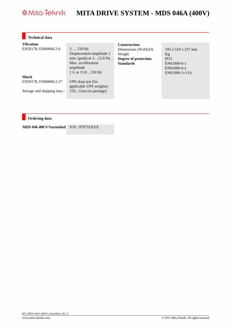
Vibration EN50178, EN60068-2-6 5 .... 150 Hz Displacement amplitude 1 mm. (peak) at 3....15.8 Hz. Max. accelleration amplitude 1 G at 15.8 ...150 HzShock EN50178, EN60068-2-27 UPS drop test (for applicable UPS weights)Storage and shipping max.: 15G, 11ms (in package)
ConstructionDimensions (WxHxD) 195 x 519 x 237 mmWeight KgDegree of protection IP21Standards EN61000-6-1 EN61000-6-2 EN61000-3+11A
MDS 046 400 V/Varnished P/N.: 979755XXX
Ordering data

www.mita-teknik.com © 2011 Mita-Teknik. All rights reservedMT_MDS 061A (400V)_DataSheet_R2_0
MITA DRIVE SYSTEM - MDS 061A (400V)
Description
The MDS module is designed for pitch control on wind turbine rotor blades
Integrated hardware and software solution
Integrated safety software
Compact and user-friendly design
Quick and easy installation
In General:The Mita Drive System- MDS - is used for pitch control of wind turbine rotor blades. The MDS is suitable for all types of turbine con-trollers.
Features:The MDS is a hard- and software solution for pitching rotor blades.
The MDS has a detachable, remote-operation seven-seg-ment LCD keypad. It is used to communicate with the drive, set parameters and for monitoring.
The design allows a quick and easy installation.
The very sturdy Drive Sys- tem is placed in the wind turbine hub, and is able to resist severe vibrations and rotations.
Function:The MDS is supplied by the grid for normal operation. A DC back-up system allows emergency operation during grid loss. The MDS controls the motor brake of the pitch motors.
Configuration:Mita-Teknik supplies com-plete pitch solutions includ-ing pitch motors, brake resis-tor encoders, position gauges, and limit switches.
There are 2 principal con- figurations:
a) with hub controller con-trolling the MDS by analog and digital signals.
b) control of the MDS through Modbus communication. (other bus systems can be delivered upon request).
Generally, each MDS drive works independently and is controlled individually. This allows full interchangeability and requires no individual programming.
Mita-Teknik offers several MDS solutions.
Configuration

www.mita-teknik.com © 2011 Mita-Teknik. All rights reservedMT_MDS 061A (400V)_DataSheet_R2_0
MITA DRIVE SYSTEM - MDS 061A (400V)
Supply Voltage Mains Nominal 3 x 400 V ACAllowed range 3 x 380 ...500V AC +/- 10%Connection Terminals 3 screw terminals + 1 ground terminalSupply Voltage Nominal 24 VDC Allowed range 24 VDC +/-15%Backup Power Nominal 500 VDCAllowed range 420 - 560 VDC-15%...+ 10%
Frequency Main supply 45 ... 66Hz
Frequency converterGeneral output Output voltage 3*0 ...U VAC (Mains)Output frequency 0 ...320 HzOutput frequency resolution 0.01 HzSwitching frequency 1 ...16 KHzSwitching frequency, default 10 KHzConnection to mains 1 or less/min.Starting delay 2 sec.Control method Frequency control U/F, Open loop sensorless Control, closed loop Frequency control, closed Loop vector controlAcceleration time 0 ... 3000 sec.Deceleration 0 ... 3000 sec.
Motor Connection MDS 061APower output 30 kW, 400 V 18,5 kW, 230 V
Current, continous (I load) 61 [A]Temperature, 10% overload 50 C°
Time, 10 % overload 1 min./10 min.Current, overload (I high) 96 [A]50 % overload 1.5*I high [A]Temperature, 50% overload + 50 C°Time, 50 % overload 1 min./10 min.
Current, max. (I short) 122 [A]Current, Peak 2 sec./20 sec.Starting torque I short for 2 sec. Braking Brake chopper Yes, internalBrake resistor Yes, external Connection terminals 2 screw terminals
Basic I/O CardDigital IntputNo. of points 6 Number of groups 2Basic I/O CardDigital Intput (cont.)Points per group 3Isolation noneNominal voltage 24 VDCSignal “1” >=18 VDC Signal “0” <=10 VDC Input current / signal “1” 5 mA max.Input impedance 5 KΩ
Anlog Input No. of points 2 Number of groups 1Points per group 2Isolation noneInput configurator jumpersInput voltage 0 ...10V (-10V ... + 10V) joystick control Input impedance ( V in) 200 KΩ Input current 0(4) ... 20mAInput impedance ( I in) 250 Ω Resolution 10 bit, 0.1% Accuracy +/- 1%
Digital Output Output type Open collector outputVoltage, max 48 VDC Current, max 50 mA
Analog OutputNo. of points 1 Number of groups 1Points per group 1Isolation noneOutput configurator jumpersVoltage 0 ...10VDCLoad ( V out ) R load >1 KΩCurrent 0(4) ...20mALoad ( I out) R load >500KΩ Resolution 0.1 % (10bit) Accuracy +/- 2%
Voltage Supply Voltage supply 24Vout +/- 15% (bidirectional)Current 150 mAProtection Short circuit protectionExternal voltage supply 24 VDCConnection terminals 2 x 10 screw terminals, coded
Technical data

www.mita-teknik.com © 2011 Mita-Teknik. All rights reservedMT_MDS 061A (400V)_DataSheet_R2_0
MITA DRIVE SYSTEM - MDS 061A (400V)
Relay Card with Termistor inputRelay Relay 1 output NO/NC Switching capacity 24 VDC/8A, 250 VAC/ 8A, 125 VDC/0.4A Switching capacity, min. 5V/10mA Relay 2 output NOSwitching capacity 24VDC/8A, 250 VAC/ 8A, 125 VDC/0.4ASwitching capacity, min. 5V/10mA
Thermistor Input No. of points 1Number of groups 1Points per group 1 Isolation noneSignal “1” >4.7KΩ (PTC) Signal “0” <4.7KΩ (PTC) Connection terminals 1 x 3, 2 x 2 screw terminals, no codingEncoder Card Digital input 3 Voltage input A 10...24 VDC (differential)Voltage input B 10 ...24 VDC differential, phase shift 90 ° compared to input AVoltage input Z 10 ...24 VDC (differential), 1 pulse/rev.Frequency < 150 KHz
Voltage Supply Voltage supply 15/24 VDC Current 150mAShort circuit protection YesExternal voltage supply 24 VDCVoltage configurator jumperConnection terminals 1 x 10 screw terminals, codedPorts for Optional Cards No. of slots 2 Interfaces: Analog/digitalIsolation None, Optocoupler, Relay ContactCommunication interfaces RS232, RS485, CAN open (preliminary)Encoder Different encoder boards. Contact us. Ports for Optional Serial Communication Cards No. of ports 1
Technical data
RS232 CommunicationPort Communication interfaces: RS232Communication speed 9600 ...57600 BAUDConnection 9 pin D-sub or terminals
RS485 Communication Port Communication interfaces: RS485
Modbus RTU Communication speed 300 ...38400 BAUDAddresses 1 ...247Connection 9 pin D-sub or terminalsData transfer method Half duplexTransfer cable Twisted pair (1 pair and shielded)Profibus DP Communication speed 9.6 k ...12M BAUDAddresses 2 ...126Connection 9 pin D-sub or terminalsData transfer method Half duplexTransfer cable Twisted pair (1 pair and shielded)
CAN Open Contact Mita-Teknik
Permissible Ambient ConditionsOperation temperature -10 to 50°CTransportation/Storage temp. -40 to +70°CMax. relative humidity 95% no condensationMax. operating height 2000 m. above sea level (Higher levels only by spe- cial agreement with Mita- Teknik)Derating 1% for each 1000 m. above 1000m.; max. 3000m.
Air QualityChemical vapours IEC 721-3-3, unit in operation, class 3C2Mechanical particles IEC 721-3-3, unit in operation, class 3S2

www.mita-teknik.com © 2011 Mita-Teknik. All rights reservedMT_MDS 061A (400V)_DataSheet_R2_0
MITA DRIVE SYSTEM - MDS 061A (400V)
Technical data
Vibration EN50178, EN60068-2-6 5 .... 150 Hz Displacement amplitude 1 mm. (peak) at 3....15.8 Hz. Max. accelleration amplitude 1 G at 15.8 ...150 HzShock EN50178, EN60068-2-27 UPS drop test (for applicable UPS weights)Storage and shipping max.: 15G, 11ms (in package)
ConstructionDimensions (WxHxD) 195 x 519 x 237 mmWeight KgDegree of protection IP21Standards EN61000-6-1 EN61000-6-2 EN61000-3+11A
MDS 061 400 V/Varnished P/N.: 979756XXX
Ordering data
electrical pitch systemsMDS Pitch Motors
Mt_MDS Pitch Motors_DataSheet_R3_4
© 2012 Mita-teknik. all rights reserved
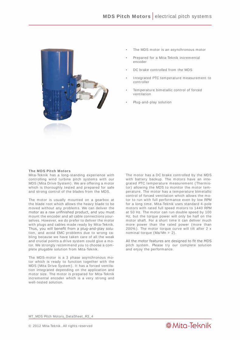
the MDS motor is an asynchronous motor•
Prepared for a Mita-teknik incremental • encoder
DC brake controlled from the MDS•
integrated PtC temperature measurement to • controller
temperature bimetallic control of forced • ventilation
Plug-and-play solution•
The MDS Pitch MotorsMita-teknik has a long-standing experience with controlling wind turbine pitch systems with our MDS (Mita Drive System). We are offering a motor which is thoroughly tested and prepared for safe and strong control of the blades from the MDS.
the motor is usually mounted on a gearbox at the blade root which allows the heavy blade to be moved without any problems. We can deliver the motor as a raw unfinished product, and you must mount the encoder and all cable connections your-selves. However, we do prefer to deliver the motor with plugs and cables made ready by Mita-teknik. Thus, you will benefit from a plug-and-play solu-tion, and avoid eMC problems due to wrong ca-bling because we have taken care of all the weak and crucial points a drive system could give a mo-tor. We strongly recommend you to choose a com-plete plugable solution from Mita-teknik.
the MDS-motor is a 3 phase asynchronous mo-tor which is ready to function together with the MDS (Mita Drive System). it has a forced ventila-tion integrated depending on the application and motor size. the motor is prepared for Mita-teknik incremental encoder which is a very strong and well-tested solution.
the motor has a DC brake controlled by the MDS with battery backup. the motors have an inte-grated PtC temperature measurement (thermis-tor) allowing the MDS to monitor the motor tem-perature. the motor has a temperature bimetallic control of forced ventilation which allows the mo-tor to run with full performance even by low RPM for a long time. Mita-teknik uses standard 4-pole motors with rated full speed motors to 1440 RPM at 50 Hz. the motor can run double speed by 100 Hz, but the torque power will only be half on the motor shaft. For a short time it can deliver much more power than the rated power (more than 200%). the motor torque curve will tilt after 2 x nominal torque (Ma/Mn > 2).
All the motor features are designed to fit the MDS pitch system. Please try our complete solution and enjoy the performance.
electrical pitch systemsMDS Pitch Motors
Mt_MDS Pitch Motors_DataSheet_R3_4
© 2012 Mita-teknik. all rights reserved
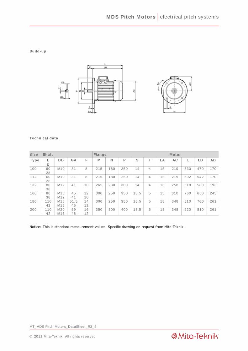
Build-up
Notice: This is standard measurement values. Specific drawing on request from Mita-Teknik.
Technical data
SizeType E DB GA F M N P S T LA AC L LB AD
D100 60 M10 31 8 215 180 250 14 4 15 219 530 470 170
28112 60 M10 31 8 215 180 250 14 4 15 219 602 542 170
28132 80 M12 41 10 265 230 300 14 4 16 258 618 580 193
38160 80 M16 45 12 300 250 350 18.5 5 15 310 760 650 245
38 M12 41 10180 110 M16 51.5 14 300 250 350 18.5 5 18 348 810 700 261
42 M16 45 12200 110 M20 59 16 350 300 400 18.5 5 18 348 920 810 261
42 M16 45 12
Shaft Flange Motor
electrical pitch systemsMDS Pitch Motors
Mt_MDS Pitch Motors_DataSheet_R3_4
© 2012 Mita-teknik. all rights reserved
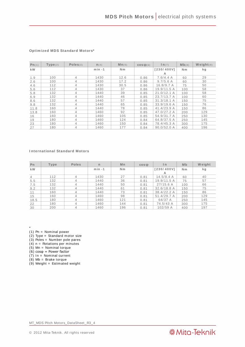
*(1) Pn = nominal power(2) type = Standard motor size(3) Poles = number pole pares(4) n = Rotations per minutes(5) Mn = nominal torque(6) cosφ = Power factor(7) in = nominal current(8) Mb = Brake torque(9) Weight = estimated weight
International Standard Motors
Optimized MDS Standard Motors*
Pn(1) cos φ(6) Mb(8)
kW Nm
1.9 0.86 602.6 0.86 604.6 0.86 755.6 0.86 1005.8 0.85 1006.9 0.85 1008.6 0.85 1509.8 0.85 15011.8 0.85 15013.8 0.85 20016 0.85 25019 0.84 25023 0.84 30027 0.84 400
n(4) In(7)
75132 4 1440 65
132 4132 4 1440 57 31.3/18.1 a
1440 46 23.7/13.7 a 60132 4 1440 39 21.0/12.1 a 58112 4 1430 37 19.9/11.5 a 58112 4 1430 30.5 16.8/9.7 a 50100 4 1430 17.2 9.7/5.6 a 30100 4 1430 12.6 7.6/4.4 a 29
A
Mn(5) Weight(9)
min -1 Nm [230/400V] kgType(2) Poles(3)
33.9/19.6 a 76160 4 1440 78 41.4/23.9 a 86160 4 1460 92 47.0/27.2 a 129160 4 1460 105 54.9/31.7 a 130180 4 1460 124 64.8/37.5 a 145180 4 1460 150 78.4/45.3 a 175180 4 1460 177 90.0/52.0 a 196
Pn cos φ MbkW Nm
4 0.81 605.5 0.81 757.5 0.81 1009.2 0.81 15011 0.81 15015 0.81 20018.5 0.81 25022 0.81 30030 0.81 400
Type Poles n Mn In Weightmin -1 Nm [230/400V] kg
A112 4 1430 27 14.5/8.4 a 40132 4 1440 36 19.9/11.5 a 57
32.6/18.8 a 75132 4 1440 50 27/15.6 a 66
160 4
132 4 1440 61160 4 1440 73 38.4/22.2 a 86
1460 98 51.4/29.7 a 129180 4 1460 121 64/37 a 145180 4 1460 144 74.5/43 a 175200 4 1460 196 102/59 a 197
electrical pitch systemsMDS Pitch Motors
Mt_MDS Pitch Motors_DataSheet_R3_4
© 2012 Mita-teknik. all rights reserved
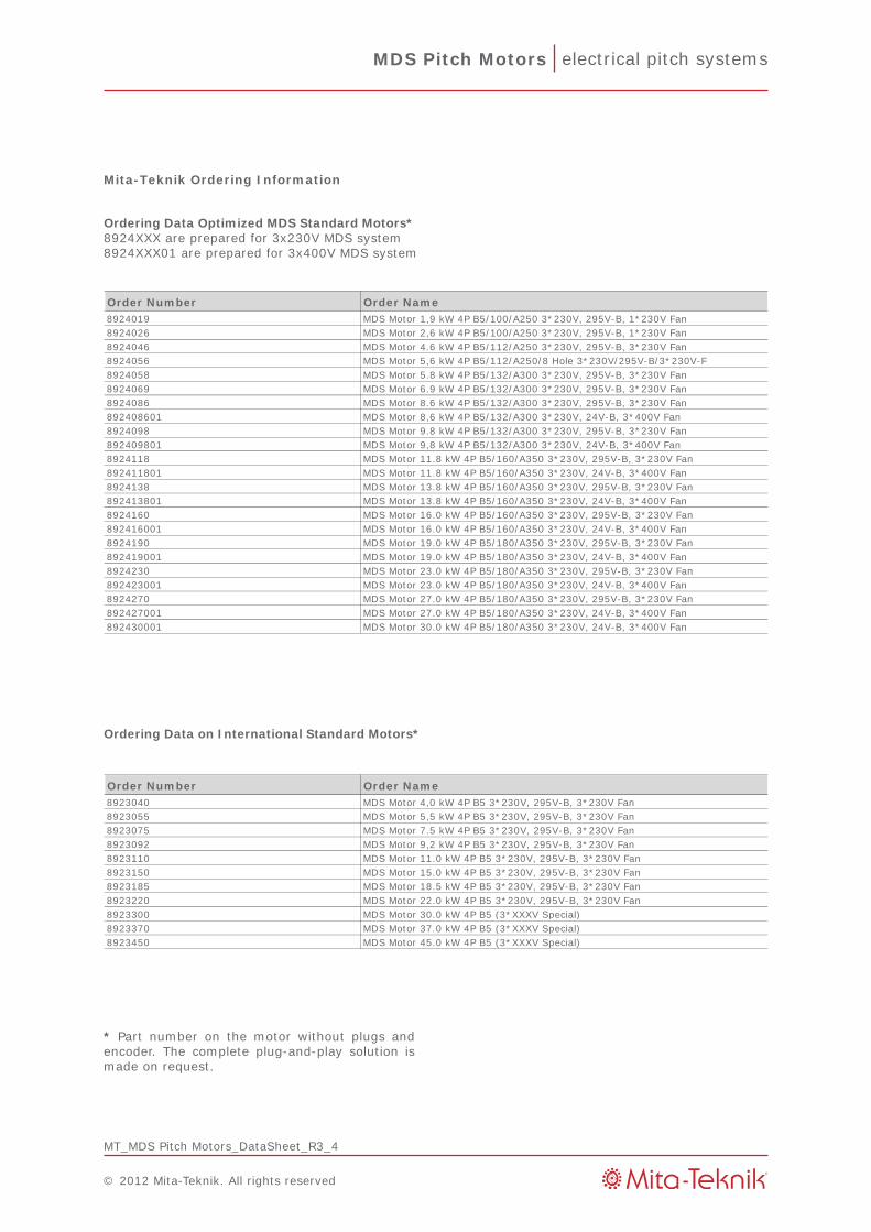
Mita-Teknik Ordering Information
Ordering Data Optimized MDS Standard Motors*8924XXX are prepared for 3x230V MDS system8924XXX01 are prepared for 3x400V MDS system
Ordering Data on International Standard Motors*
* Part number on the motor without plugs and encoder. the complete plug-and-play solution is made on request.
Order Number Order Name8923040 MDS Motor 4,0 kW 4P B5 3*230V, 295V-B, 3*230V Fan8923055 MDS Motor 5,5 kW 4P B5 3*230V, 295V-B, 3*230V Fan8923075 MDS Motor 7.5 kW 4P B5 3*230V, 295V-B, 3*230V Fan8923092 MDS Motor 9,2 kW 4P B5 3*230V, 295V-B, 3*230V Fan8923110 MDS Motor 11.0 kW 4P B5 3*230V, 295V-B, 3*230V Fan8923150 MDS Motor 15.0 kW 4P B5 3*230V, 295V-B, 3*230V Fan8923185 MDS Motor 18.5 kW 4P B5 3*230V, 295V-B, 3*230V Fan8923220 MDS Motor 22.0 kW 4P B5 3*230V, 295V-B, 3*230V Fan8923300 MDS Motor 30.0 kW 4P B5 (3*XXXV Special)8923370 MDS Motor 37.0 kW 4P B5 (3*XXXV Special)8923450 MDS Motor 45.0 kW 4P B5 (3*XXXV Special)
Order Number Order Name8924019 MDS Motor 1,9 kW 4P B5/100/a250 3*230V, 295V-B, 1*230V Fan8924026 MDS Motor 2,6 kW 4P B5/100/a250 3*230V, 295V-B, 1*230V Fan8924046 MDS Motor 4.6 kW 4P B5/112/a250 3*230V, 295V-B, 3*230V Fan8924056 MDS Motor 5,6 kW 4P B5/112/a250/8 Hole 3*230V/295V-B/3*230V-F8924058 MDS Motor 5.8 kW 4P B5/132/a300 3*230V, 295V-B, 3*230V Fan8924069 MDS Motor 6.9 kW 4P B5/132/a300 3*230V, 295V-B, 3*230V Fan8924086 MDS Motor 8.6 kW 4P B5/132/a300 3*230V, 295V-B, 3*230V Fan892408601 MDS Motor 8,6 kW 4P B5/132/a300 3*230V, 24V-B, 3*400V Fan8924098 MDS Motor 9.8 kW 4P B5/132/a300 3*230V, 295V-B, 3*230V Fan892409801 MDS Motor 9,8 kW 4P B5/132/a300 3*230V, 24V-B, 3*400V Fan8924118 MDS Motor 11.8 kW 4P B5/160/a350 3*230V, 295V-B, 3*230V Fan892411801 MDS Motor 11.8 kW 4P B5/160/a350 3*230V, 24V-B, 3*400V Fan8924138 MDS Motor 13.8 kW 4P B5/160/a350 3*230V, 295V-B, 3*230V Fan892413801 MDS Motor 13.8 kW 4P B5/160/a350 3*230V, 24V-B, 3*400V Fan8924160 MDS Motor 16.0 kW 4P B5/160/a350 3*230V, 295V-B, 3*230V Fan892416001 MDS Motor 16.0 kW 4P B5/160/a350 3*230V, 24V-B, 3*400V Fan8924190 MDS Motor 19.0 kW 4P B5/180/a350 3*230V, 295V-B, 3*230V Fan892419001 MDS Motor 19.0 kW 4P B5/180/a350 3*230V, 24V-B, 3*400V Fan8924230 MDS Motor 23.0 kW 4P B5/180/a350 3*230V, 295V-B, 3*230V Fan892423001 MDS Motor 23.0 kW 4P B5/180/a350 3*230V, 24V-B, 3*400V Fan8924270 MDS Motor 27.0 kW 4P B5/180/a350 3*230V, 295V-B, 3*230V Fan892427001 MDS Motor 27.0 kW 4P B5/180/a350 3*230V, 24V-B, 3*400V Fan892430001 MDS Motor 30.0 kW 4P B5/180/a350 3*230V, 24V-B, 3*400V Fan
Related Documents