MISUMI EtherDevice Switch MISUMI EtherDevice スイッチ IESH-MB205-R Hardware Installation Guide IESH-MB205-R ハードウェア・インストール・ガイド Third Edition, July 2013 第 3 版、2013 年 7 月 P/N: 1802002050212 2013 Misumi, all rights reserved. Reproduction without permission is prohibited. 許可なく複製することを禁止します。 根据《CCC 认证目录及国家认监委 2007 年 9 号公告》第 11 项,此产品 不属于 CCC 对象范围

Welcome message from author
This document is posted to help you gain knowledge. Please leave a comment to let me know what you think about it! Share it to your friends and learn new things together.
Transcript

MISUMI EtherDevice Switch
MISUMI EtherDevice スイッチ
IESH-MB205-R Hardware Installation Guide
IESH-MB205-R ハードウェア・インストール・ガイド
Third Edition, July 2013
第 3版、2013年 7月
P/N: 1802002050212
2013 Misumi, all rights reserved. Reproduction without permission is prohibited.
許可なく複製することを禁止します。
根据《CCC 认证目录及国家认监委 2007 年 9 号公告》第 11 项,此产品
不属于 CCC 对象范围

- 2 -
Overview
The IESH-MB205-R switches are entry-level 5- port Ethernet switches that
provide a cost-effective solution for your industrial Ethernet connection.
You could choose either a DC power input from 12 to 48 V or AC power input
from 18 to 30 V. These switches can operate from -10 to 60oC, and the rugged hardware design makes the IESH-MB205-R switches perfect for ensuring that
your Ethernet equipment can be used for demanding industrial applications.
This device complies with part 15 of the FCC Rules. Operation
is subject to the following two conditions: (1) This device may
not cause harmful interference, and (2) this device must accept
any interference received, including interference that may cause
undesired operation.
Package Checklist
The IESH-MB205-R is shipped with the following items. If any of these items
is missing or damaged, please contact your customer service representative for assistance.
IESH-MB205-R Switch
Hardware Installation Guide

- 3 -
Panel Layout of the IESH-MB205-R Series
1. Heat dissipation orifices
2. Terminal block for power input
and grounding
3. Misumi logo
4. Power input LED
5. 10/100BaseT(X) Port
6. TP port’s 100 Mbps LED
7. TP port’s 10 Mbps LED
8. DIN-Rail kit

- 4 -
Mounting Dimensions
- 5 -
DIN-Rail Mounting The plastic DIN-Rail attachment plate should already be fixed to the rear panel
of the IESH-MB205-R when you take it out of the box. If you need to reattach the DIN-Rail attachment plate, make sure the DIN-Rail kit is situated towards
the top, as shown in the figures below.
STEP 1: Insert the top of the DIN-Rail into the slot.
STEP 2: The DIN-Rail attachment unit will snap into place as shown below.
To remove the IESH-MB205-R from the DIN-Rail, insert a flat-blade screw
driver horizontally into the DIN-Rail kit under the IESH-MB205-R, and
then pull it upwards and release the
switch towards you and away from the DIN-Rail.
Wiring Requirements
Safety First!
Be sure to disconnect the power cord before installing and/or
wiring your EtherDevice Switch.
Calculate the maximum possible current in each power wire and common wire. Observe all electrical codes dictating the
maximum current allowable for each wire size.
If the current goes above the maximum ratings, the wiring could
overheat, causing serious damage to your equipment.
- 6 -
You should also pay attention to the following points:
Use separate paths to route wiring for power and devices. If power wiring
and device wiring paths must cross, make sure the wires are perpendicular
at the intersection point.
NOTE: Do not run signal or communications wiring and power wiring in
the same wire conduit. To avoid interference, wires with different signal
characteristics should be routed separately.
You can use the type of signal transmitted through a wire to determine
which wires should be kept separate. The rule of thumb is that wiring that
shares similar electrical characteristics can be bundled together.
Keep input wiring and output wiring separated.
It is strongly advised that you label wiring to all devices in the system when
necessary.
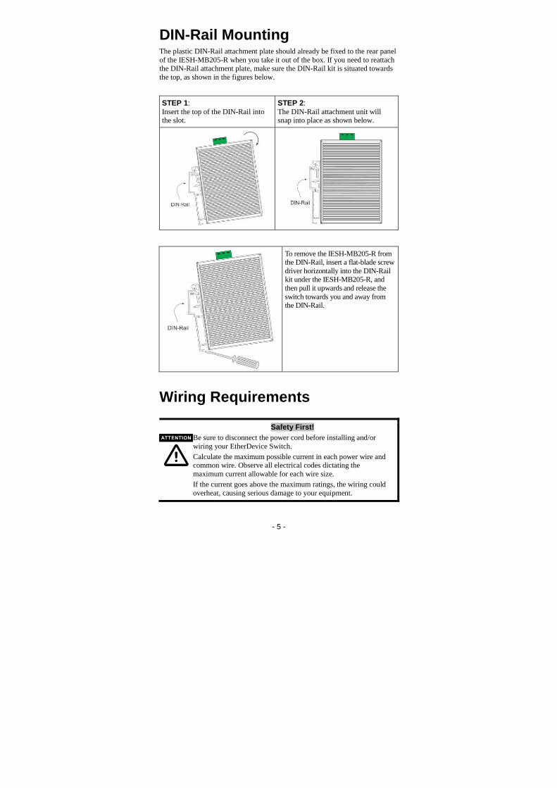
Grounding the EtherDevice Switch
Grounding and wire routing help limit the effects of noise due to electromagnetic interference
(EMI). Run the ground connection from the right most contact of the 3-contact terminal block to the
grounding surface prior to connecting devices.
This product is intended to be mounted to a well-grounded
mounting surface such as a metal panel.

- 7 -
Wiring the Power Inputs The two left-most contacts of the 3-contact terminal block connector on the top panel are used for the DC and AC inputs. Top and front views of one of the
terminal block connectors are shown here.
STEP 1: Insert the negative/positive DC wires into the V-/V+ terminals.
STEP 2: To keep the DC wires from pulling loose, use a small flat-blade screwdriver to tighten
the wire-clamp screws on the front of the terminal
block connector.
STEP 3: Insert the plastic terminal block
connector prongs into the terminal block receptor, which is located on the top panel.
Only connect to a class 2 power supply.
Only use 60/75°C copper (CU) wire, 28-12 AWG.
Use a maximum torque of 4.5 in-lb.

- 8 -
Communication Connections The IESH-MB205-R has five10/100BaseT(X) Ethernet ports.
10/100BaseT(X) Ethernet Port Connection The 10/100BaseT(X) ports located on the switch’s front panel are used to connect to Ethernet-enabled devices.
Below we show pinouts for both MDI (NIC-type) ports and MDI-X
(HUB/Switch-type) ports, and also show cable wiring diagrams for straight-through and cross-over Ethernet cables.
RJ45 (8-pin, MDI) Port Pinouts RJ45 (8-pin, MDI-X) Port Pinouts
RJ45 (8-pin) to RJ45 (8-pin) Straight-Through Cable Wiring
RJ45 (8-pin) to RJ45 (8-pin) Cross-Over Cable Wiring

- 9 -
LED Indicators The front panel of the Switch contains several LED indicators. The function of
each LED is described in the table below.
LED Color State Description
P AMBER
On Power is being supplied to the power input.
Off Power is not being supplied to the power input.
10M (TP) GREEN
On The TP port’s 10 Mbps link is active.
Blinking Data is being transmitted at 10 Mbps.
Off The TP port’s 10 Mbps link is inactive
100M (TP) GREEN
On The TP port’s 100 Mbps link is active.
Blinking Data is being transmitted at 100 Mbps.
Off The 100BaseTX port’s link is inactive.
Auto MDI/MDI-X Connection The Auto MDI/MDI-X function allows users to connect the switch’s 10/100BaseTX ports to any kind of Ethernet device, regardless of the type of
Ethernet cable being used for the connection. This means that you can use
either a straight-through or cross-over cable to connect the switch to your Ethernet devices.
Dual Speed Functionality and Switching The switch’s 10/100 Mbps switched RJ45 port auto negotiates with the
connected device for the fastest data transmission rate supported by both devices. All models of EtherDevice Switch are plug-and-play devices; software
configuration is not required at installation, or during maintenance. The half/full duplex mode for the switched RJ45 ports is user dependent and
changes (by auto-negotiation) to full or half duplex, depending on which
transmission speed is supported by the attached device.
Switching, Filtering, and Forwarding Each time a packet arrives at one of the switched ports, a decision is made to
either filter or forward the packet. Packets with source and destination
addresses belonging to the same port segment will be filtered, constraining those packets to one port, and relieving the rest of the network from the need to
process them. A packet with destination address on another port segment will be forwarded to the appropriate port, and will not be sent to the other ports
where it is not needed. Packets that are used to maintain the operation of the
network (such as the occasional multi-cast packet) are forwarded to all ports. The switch operates in the store-and-forward switching mode, which eliminates
bad packets and enables peak performance to be achieved when there is heavy traffic on the network.
- 10 -
Switching and Address Learning The EtherDevice switch has an address table that can hold up to 1K node
addresses, making it suitable for use with large networks. The address tables
are self-learning, so that as nodes are added or removed, or moved from one segment to another, the switch automatically adds new node locations to the
tables. An address-aging algorithm causes the least-used addresses to be deleted in favor of newer, more frequently used addresses. To reset the address
buffer, power down the unit and then power it back up.
Auto-Negotiation and Speed Sensing All of the switch’s RJ45 Ethernet ports independently support auto-negotiation for speeds in the 10BaseT and 100BaseTX modes, with operation according to
the IEEE 802.3u standard. This means that some nodes could be operating at
10 Mbps, while at the same time, other nodes are operating at 100 Mbps.
Auto-negotiation takes place when an RJ45 cable connection is made, and then
each time a LINK is enabled. The EtherDevice switch advertises its capability for using either 10 Mbps or 100 Mbps transmission speeds, with the device at
the other end of the cable expected to similarly advertise. The two devices will
agree to operate at either 10 Mbps or 100 Mbps.
If a EtherDevice switch’s RJ45 Ethernet port is connected to a non-negotiating
device, it will default to 10 Mbps speed and half-duplex mode, as required by the IEEE 802.3u standard.
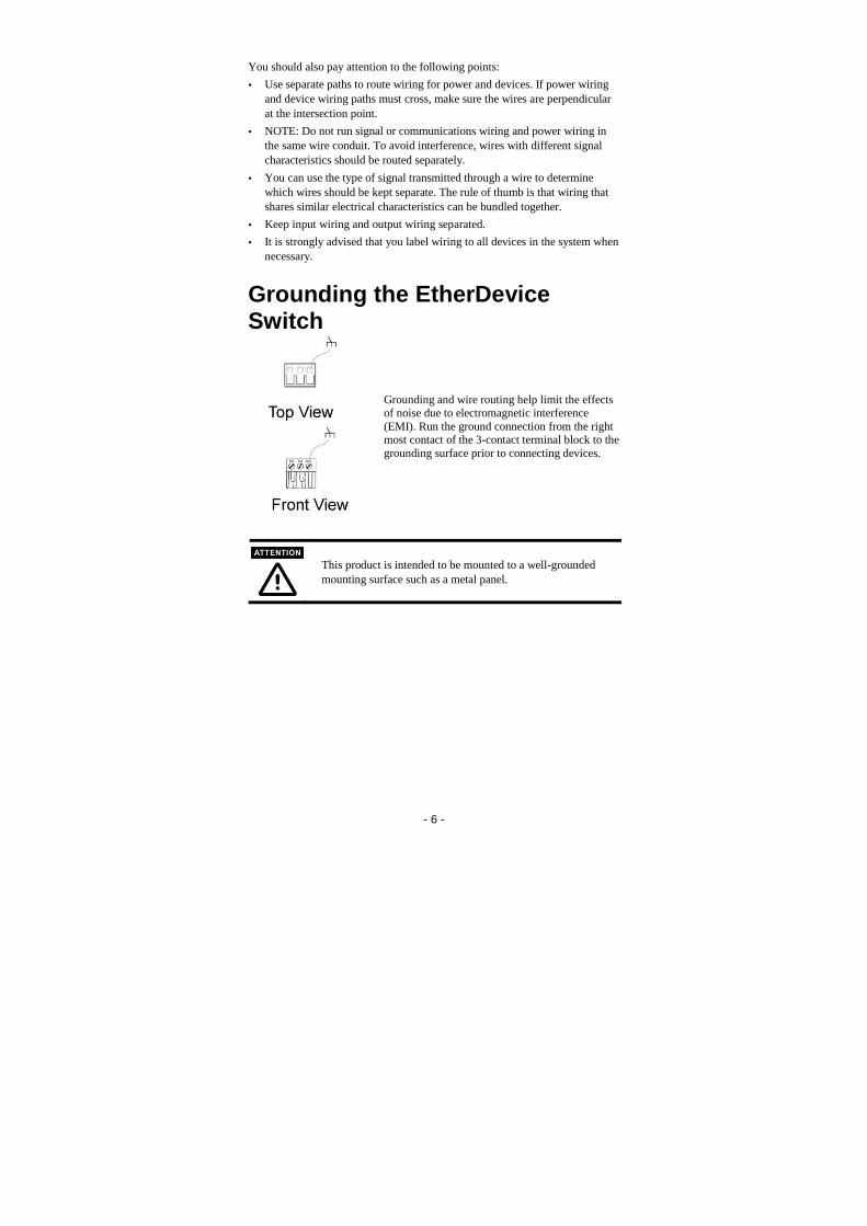
Specifications
Technology
Standards IEEE802.3, 802.3u, 802.3x
Processing Type Store and Forward, with IEEE802.3x full duplex,
non-blocking flow control
Address Table Size 1K uni-cast addresses
Interface
RJ45 Ports 10/100BaseT(X) auto negotiation speed, F/H duplex mode, and auto MDI/MDI-X connection
LED Indicators Power, 10/100 M
Power
Input Voltage 12 to 48 VDC, 18 to 30 VAC (47 to 63 Hz)
Input Current 0.12 A @ 24 V
Power Consumption 5 W
Connection Removable 3-contact terminal block
Overload Current
Protection
1.1 A
Reverse Polarity Protection
Present
Mechanical
Casing IP30 protection, plastic housing
Dimensions 25 x 109 x 88 mm
Weight 135 g
Installation DIN-Rail
- 11 -
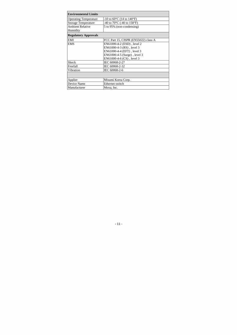
Environmental Limits
Operating Temperature -10 to 60°C (14 to 140°F)
Storage Temperature -40 to 70°C (-40 to 158°F)
Ambient Relative
Humidity
5 to 95% (non-condensing)
Regulatory Approvals
EMI FCC Part 15, CISPR (EN55022) class A
EMS EN61000-4-2 (ESD) , level 2
EN61000-4-3 (RS) , level 3 EN61000-4-4 (EFT) , level 3
EN61000-4-5 (Surge) , level 3 EN61000-4-6 (CS) , level 3
Shock IEC 60068-2-27
Freefall IEC 60068-2-32
Vibration IEC 60068-2-6
Applier Misumi Korea Corp.
Device Name Ethernet switch
Manufacturer Moxa, Inc.

- 12 -
概要
IESH-MB205-Rシリーズの MISUMI EtherDevice™ スイッチはエントリ・レベルの 5
ポート・イーサネット・スイッチで、産業用イーサネット接続のための費用対効果に優
れたソリューションを提供します。
IESH-MB205-Rでは、12~48 Vの DC電源入力または 18~30Vの AC電源入
力のいずれかを選択できます。IESH-MB205-R シリーズは-10℃から 60℃の稼動
時温度に対応し、堅牢なハードウェア設計を採用しているので、要求の多い産業
条件でもイーサネット装置を確実に使用できます。
梱包品確認リスト
MISUMI IESH-MB205-Rには以下のアイテムが同梱されています。不足しているも
のや損傷しているものがあれば、カスタマ・サービス代理店にお知らせください。
IESH-MB205-R 1台
ハードウェア・インストール・ガイド
特徴
高性能ネットワーク・スイッチング技術
10/100M、全/半二重、MDI/MDIX オートセンシングに対応
IEEE 802.3/802.3u/802.3x に対応
ストア・アンド・フォワード・スイッチングのプロセス・タイプ(アドレス・エントリ 1024)をサポート
10/100M、全/半二重、MDI/MDIX オートセンシングに対応
産業用設計
稼働時温度: -10~60℃
電源入力 DC: 12~48 V、AC: 18~30 V(47~63 Hz)
IP 30 適合プラスチック・ケース
DIN レール・マウント可能
IEEE 802.3/802.3u/802.3x に対応
ストア・アンド・フォワード・スイッチングのプロセス・タイプ(アドレス・エントリ 1024)をサポート

- 13 -
IESH-MB205-Rシリーズのパネル・レイアウト
1. 散熱口
2. 電源入力およびアース用端子台
3. MISUMI のロゴ
4. 電源入力 LED
5. 10/100BaseT(X) ポート
6. TP ポートの 100 Mbps LED
7. TP ポートの 10 Mbps LED
8. DIN レール・キット

- 14 -
取り付け寸法
側面
単位: mm
前面 背面
DIN レール・マウント IESH-MB205-R をボックスから取り出すと、リア・パネルにプラスチックの DIN レール
装着用プレートが固定されています。DIN レール・キットを再装着する必要がある場
合は、以下の図ように、必ず DIN レール・キットを上にして装着してください。
ステップ 1:
DINレールの上部をスロットに挿入しま
す。
ステップ 2:
下図のように、DIN レール装着ユニットを
所定の場所にしっかり取り付けます。
DINレール
DINレール
- 15 -
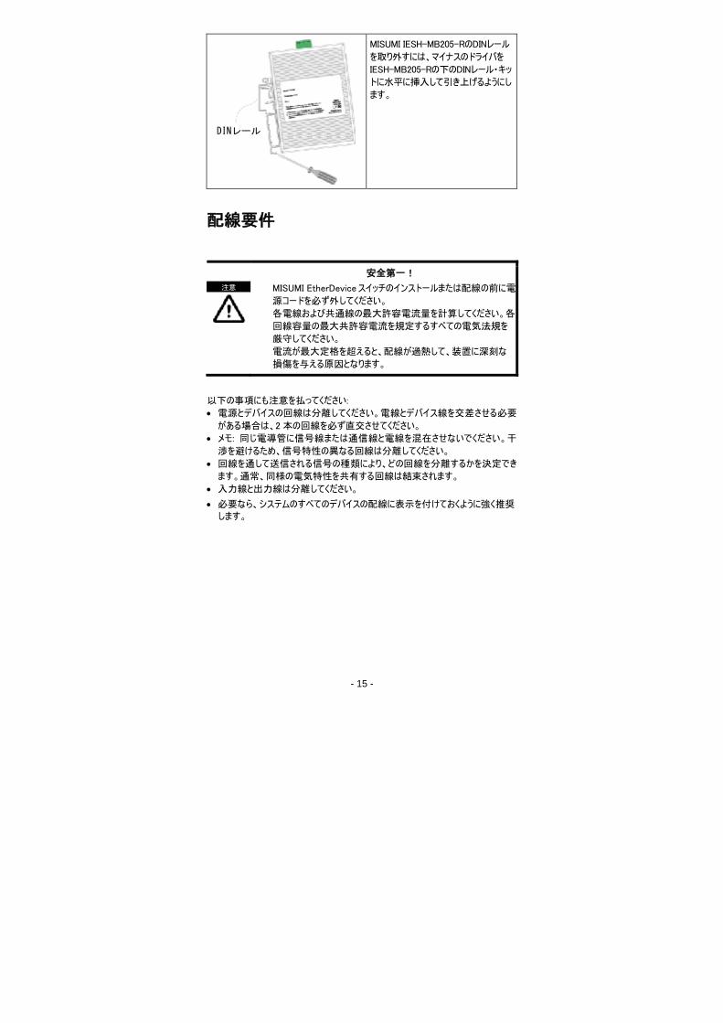
DINレール
MISUMI IESH-MB205-RのDINレール
を取り外すには、マイナスのドライバを
IESH-MB205-Rの下のDINレール・キッ
トに水平に挿入して引き上げるようにし
ます。
配線要件
安全第一!
MISUMI EtherDeviceスイッチのインストールまたは配線の前に電
源コードを必ず外してください。
各電線および共通線の最大許容電流量を計算してください。各
回線容量の最大共許容電流を規定するすべての電気法規を
厳守してください。
電流が最大定格を超えると、配線が過熱して、装置に深刻な
損傷を与える原因となります。
以下の事項にも注意を払ってください:
電源とデバイスの回線は分離してください。電線とデバイス線を交差させる必要
がある場合は、2本の回線を必ず直交させてください。
メモ: 同じ電導管に信号線または通信線と電線を混在させないでください。干
渉を避けるため、信号特性の異なる回線は分離してください。
回線を通して送信される信号の種類により、どの回線を分離するかを決定でき
ます。通常、同様の電気特性を共有する回線は結束されます。
入力線と出力線は分離してください。
必要なら、システムのすべてのデバイスの配線に表示を付けておくように強く推奨します。
注意
- 16 -
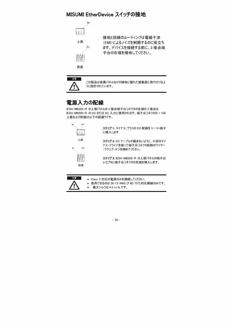
MISUMI EtherDevice スイッチの接地
接地と回線のルーティングは電磁干渉
(EMI)によるノイズを制限するのに役立ち
ます。デバイスを接続する前に、3接点端
子台の右端を接地してください。
この製品は金属パネルなどの接地に優れた搭載面に取り付けるよ
うに設計されています。
電源入力の配線 IESH-MB205-R の上部パネルの 3接点端子台コネクタの左端の 2接点は
IESH-MB205-R の DC または AC入力に使用されます。端子台コネクタの 1 つの
上面および前面は以下の図通りです。
ステップ 1: マイナス/プラスの DC配線を V-/V+端子
に挿入します
ステップ 2: DC ケーブルが緩まないように、小型のマイ
ナス・ドライバを使って端子台コネクタ前部のワイヤー
・クランプ・ネジを締めてください。
ステップ 3: IESH-MB205-R の上部パネルの端子台
レセプタに端子台コネクタの先端を挿入します。
Class 2対応の電源のみを接続してください。
使用できるのは 28-12 AWGび 60/75℃対応銅線のみです。
最大トルクは 4.5 in-lbです。
上面
前面
上面
前面
- 17 -
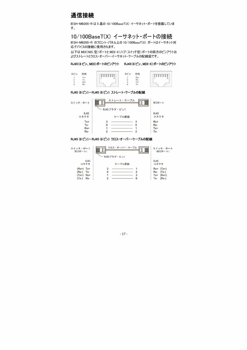
通信接続
IESH-MB205-Rは 5基の 10/100BaseT(X) イーサネット・ポートを搭載していま
す。
10/100BaseT(X) イーサネット・ポートの接続 IESH-MB205-R のフロント・パネル上の 10/100BaseT(X) ポートはイーサネット対
応デバイスの接続に使用されます。
以下は MDI(NIC型)ポートと MDI-X(ハブ/スイッチ型)ポートの両方のピンアウトお
よびストレートとクロス・オーバー・イーサネット・ケーブルの配線図です。
RJ45(8 ピン、MDI)ポートのピンアウト RJ45(8 ピン、MDI-X)ポートのピンアウト
RJ45 (8 ピン)-RJ45 (8 ピン) ストレート・ケーブルの配線
RJ45 (8 ピン)-RJ45 (8 ピン) クロス・オーバー・ケーブルの配線

- 18 -
LED インジケータ
MISUMI EtherDevice スイッチのフロント・パネルには複数の LED インジケータが用
意されています。各 LEDの機能は以下の通りです。
LED 色 状態 説明
P オレンジ 点灯 電源入力に電源が供給されています。
消灯 電源入力に電源が供給されていません。
10M (TP) 緑
点灯 TP ポートが 10 Mbps リンクを使用
点滅 10 Mbpsでデータを送信中
消灯 TP ポートの 10 Mbps リンクが使用されてい
ない
100M (TP) 緑
点灯 TP ポートが 100 Mbps リンクを使用
点滅 100 Mbps でデータを送信中
消灯 100Base TXポートのリンクが使用されてい
ない
自動 MDI/MDI-X接続
自動MDI/MDI-X機能を使えば、接続に使用されているイーサネット・ケーブルの種
類を気にせずに、MISUMI EtherDeviceスイッチの10/100BaseTXポートをあらゆる
種類のイーサネット・デバイスに接続できます。したがって、ストレート・ケーブルやクロ
ス・オーバー・ケーブルを使って IESH-MB205-R をイーサネット・デバイスに接続でき
ます。
デュアル・スピード機能とスイッチング
MISUMI EtherDevice スイッチの 10/100 Mbps スイッチド RJ45 ポートは両者が対
応している最大データ通信速度で自動ネゴシエートします。MISUMI EtherDevice
スイッチの全製品はインストールおよびメンテナンス時にソフトウェア設定が不要な
Plug & Playデバイスです。スイッチド RJ45 ポートの半/全二重モードはユーザーに
従属しており、接続デバイスが対応する通信測度により、(自動ネゴシエーション
で)全二重または半二重に変更されます。
スイッチング、フィルタリング、フォワーディング
パケットがスイッチド・ポートの 1 つに到達するたびに、パケットをフィルタリングするか、
フォワーディングするか決定されます。同じポ―ト・セグメントに属するソース・アドレス
とデスティネーション・アドレスを有するパケットはフィルタリングされて、1 つのポートに
強制送信されるので、それらのパケットを処理する必要からネットワークの残りを解
放します。他のポートのデスティネーション・アドレスを有するパケットは当該ポートに
フォワーディングされるので、必要のない他のポートには送信されません。ネットワーク
の動作を維持するのに使用される(特別なマルチ・キャスト・パケットなどの)パケット
はすべてのポートにフォワーディングされます。MISUMI EtherDevice スイッチはストア
・アンド・フォワード・スイッチング・モードで動作し、不良パケットを除去して、ネットワ
ークのトラフィック渋滞時に最高のパフォーマンスが得られるようにします。.
- 19 -
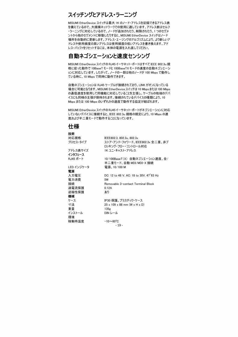
スイッチングとアドレス・ラーニング
MISUMI EtherDevice スイッチは最大 1K のノード・アドレスを記録できるアドレス表
を備えているので、大規模ネットワークでの使用に適しています。アドレス表はセルフ
・ラーニングに対応しているので、ノードが追加されたり、削除されたり、1 つのセグメ
ントから他のセグメントに移動したりすると、MISUMI EtherDevice スイッチはノード
場所を自動的に更新します。アドレス・エージングのアルゴリズムにより、より新しいア
ドレスや使用頻度の高いアドレスは使用頻度の低いアドレスを書き換えます。アド
レス・バッファをリセットするには、本体の電源を入れ直してください。
自動ネゴシエーションと速度センシング
MISUMI EtherDeviceスイッチのRJ45イーサネット・ポートはすべて IEEE 802.3u規
格に従った動作で 10BaseTモードと 100BaseTXモードの速度の自動ネゴシエーシ
ョンに対応しています。したがって、ノードの一部は他のノードが 100 Mbpsで動作し
ている時に、10 Mbpsで同時に動作できます。
自動ネゴシエーションは RJ45 ケーブルが接続されており、LINKがオンになっている
場合に可能となります。MISUMI EtherDeviceスイッチは10 Mbpsまたは100 Mbps
の通信速度を使用して同機能に対応していることを主張し、ケーブルの他端のデバ
イスにも同様の主張が期待されます。接続されているデバイスの種類により、10
Mbps または 100 Mbpsのいずれかの速度で動作する協定が結ばれます。
MISUMI EtherDeviceスイッチのRJ45イーサネット・ポートがネゴシエーションに対応
していないデバイスに接続すると、IEEE 802.3u 規格の規定により、10 Mbpsの速
度および半二重モードで動作することになっています。
仕様 技術
対応規格 IEEE802.3, 802.3u, 802.3x
プロセス・タイプ ストア・アンド・フォワード、IEEE802.3x全二重、非ブ
ロッキング・フロー・コントロール対応
アドレス表サイズ 1Kユニ・キャスト・アドレス
インタフェース
RJ45 ポート 10/100BaseT(X) 自動ネゴシエーション速度、全/
半二重モード、自動 MDI/MDI-X接続
LED インジケータ 電源、10/100 M
電源
入力電圧 DC: 12 to 48 V, AC: 18 to 30V, 47~63 Hz
電力消費 5W
接続 Removable 3-contact Terminal Block
過電流保護 0.12A
逆極性保護 あり
機械
ケース IP30保護、プラスチック・ケース
寸法 25 x 109 x 88 mm (W x H x D)
重量 135g
インストール DIN レール
環境
稼働時温度 -10~60℃

- 20 -
保存時温度 -40~70℃
環境相対湿度 5~95%(結露なきこと)
対応認証
EMI FCC Part 15, CISPR (EN55022) class A
EMS EN61000-4-2 (ESD),
EN61000-4-3 (RS),
EN61000-4-4 (EFT),
EN61000-4-5 (Surge),
EN61000-4-6 (CS),
衝撃 IEC 60068-2-27
自由落下 IEC 60068-2-32
振動 IEC 60068-2-6
保証 1年
Applier Misumi Korea Corp.
Device Name Ethernet switch
Manufacturer Moxa, Inc
Related Documents