Verification of Mobile SOC Design (UFS) Mohamed Samy Mentor Graphics

Welcome message from author
This document is posted to help you gain knowledge. Please leave a comment to let me know what you think about it! Share it to your friends and learn new things together.
Transcript

Verification of Mobile SOC
Design (UFS)
Mohamed Samy Mentor Graphics

Outline • Overview • SW/HW design
• Interface • Considerations
• Verification • UniPro level • System level
• Debugging • Protocol Analyzer
2

Overview • Verification Platforms • Emulation / Simulation • UFS2 and MIPI CSI-3
• Application layer (SW) • UniPro core (HW/SW) • M-PHY (HW)
• GUI tool “Protocol Analyzer” is used to trace and monitor • RMMI traffic • UniPro SAPs • UFS2 commands
3
UniPro
UFS2SWstack
M-PHY M-PHY
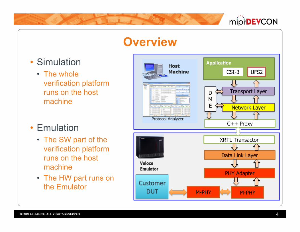
Overview • Simulation
• The whole verification platform runs on the host machine
• Emulation • The SW part of the
verification platform runs on the host machine
• The HW part runs on the Emulator
4
Transport Layer
Network Layer
Data Link Layer
PHY Adapter
D M E
Applica'on
C++ Proxy
XRTL Transactor
CSI-3 UFS2
M-PHY M-PHY

Co-Design • Network, DME, Transport, MIPI
CSI-3 and UFS2 layers are native C++ software layers
• Communication between SW and HW is through a transaction-based methodology based on SCE-MI 2.0 • C++ Proxy • XRTL transactor
• Middle-out methodology • Started with Data link layer and Network
layer first.
5
Transport Layer
Network Layer
Data Link Layer
PHY Adapter
D M E
Applica'on
C++ Proxy
XRTL Transactor
CSI-3 UFS2
M-PHY

Co-Design int UniProMemoryXactor_sc::WriteTransaction(u_int8_t *pBuf, u_int16_t wBytesCount, bool IsBlocking)
{ …
UniProMemoryWrite((svBitVecVal *)pTxBuf,(int)wBytesCount, (IsBlocking)?1:0); if (IsBlocking) { wait(Done);
}; … }
6
function void UniProMemoryWrite(input bit [COMODEL_BUF_SIZE-1:0] Buf, int BytesCount, int IsBlocking); WrIsBlock = IsBlocking; WrDataWordsCounts = ((BytesCount/(DATA_WIDTH/8)) + ((BytesCount%(DATA_WIDTH/8))?1:0));
WrBytesOfLastWord = BytesCount - (WrDataWordsCounts-1)*(DATA_WIDTH/8); WrLastBe = (WrBytesOfLastWord == 8 ) ? 8'hFF: (WrBytesOfLastWord == 7 ) ? 8'h7F: (WrBytesOfLastWord == 6 ) ? 8'h3F: (WrBytesOfLastWord == 5 ) ? 8'h1F: (WrBytesOfLastWord == 4 ) ? 8'h0F: (WrBytesOfLastWord == 3 ) ? 8'h07: (WrBytesOfLastWord == 2 ) ? 8'h03: (WrBytesOfLastWord == 1 ) ? 8'h01:
8'hFF;
for(int i =0 ; i< WrDataWordsCounts; i = i + 1 ) begin WrBuf[i] = Buf[(DATA_WIDTH)*i +: DATA_WIDTH]; end ->e_StartWr; endfunction;
C++proxyun;medso?waremodel
XRTLcounterpart

SW/HW Interface
7
• DME <-> DLL • DME <-> PAL • NL <-> DLL
NL
DME
DLL
PAL

SW/HW Interface (DME/NL SAPs)
8
DataSymbol# Bitfields
0
[15:0] DME_SAPopcode [31:16] GenSelectorIndexorSelectorIndex [47:32] MIBaUributeorGenMIBaUribute [55:48] ResultCode:usedforGenericErrorCode,ConfigResultCodeandPowerChangeResultCode,
DLErrorCode [56] AUrSetType [57] ResetLevel [58] PAResult [59] PHYDirec;on
1 [31:0] MIBvalue 2,3,4 PAPowerModeUserData

SW/HW Interface (NL SAPs)
9

UFS/CSI <-> UniPro Interface
10

Design Considerations • Implementing DME/NL/TL/UFS/CSI in SW
• flexibility • faster implementation
• Implementing PAL/DLL in RTL • Better overall performance (Minimize communication overhead)
• Bulks of data are grouped in DL and sent once to NL so better be in HW for performance
• Timers are in DL and PAL, can’t be done accurately in SW
• XRTL tasks have timeout mechanism to avoid blocking the calling SW side
11

HW Design Considerations • Full separation of data and control buses. Full
separation of TX and RX data buses • All layer attributes are implemented in a memory
module • Allows fast initialization of UniPro IP • Serves well in monitoring the layer attributes using the Protocol
Analyzer
• Abstract number of active lanes from the internal data bus through the use of lane distribution/merging logic
• 64 bits fixed Internal data bus (4 lanes of 16-bits each) • Merge PA_DATA and PA_ESCDATA into one SAP with
control flag
12

System Verification • UniPro level
• MIPI M-PHY already tested in a separate testing env (UVM based) • Block/Layer (UVM verification env.)
• PAL vs TLM models • DLL vs TLM models
• Integration • DLL/PAL/PHY vs TLM models in UVM env (HW) • UniPro (NL, TL, DLL, PAL, M-PHY) back to back (SW&HW)
• System level • UFS device vs UFS host UVM test env • UFS device vs UFS Host invoking guest OS
13

Layer testing (PAL, DLL)
14
DMEAgent
ULAgent
Layer X DUT
DME i/f
ULi/f
LL i/fDMEAgent
ULAgentTLM Refmodel
SB
seq
seq
seq
seq
Virtualseq
- UVM Based - Same architecture for PAL/DLL testing env
- X Agent represents the layer completely and reused as TLM ref model
- Ref model should be in sync with the DUT
monitor
driversqr
sqr
XAgent

PAL Verification Env.
15
PALDUT
DME i/f
DLL i/f
M-M
PALTLM
Model
monitor
driversqr
sqr
RMMI
RMMI IF
PALAgent

HW Integration Env. • Connect PAL and DLL UVM env back to back • In PAL env:
• Replace UL agent (dummy DLL) with a connection to the DLL verification env
• Direct all DLL communications to the PAL agent • Dummy DLL agent at the DUT side is passive and only monitors
PAL-DLL interface

HW Verification Challenges • Reference model should be in sync with the DUT
• Pause/Resume operations, Timers, Retransmission • Take care of resources shared between tx and rx
• DLL timers, PAL timers • Layer verification to be reused in integration testing
• Use a unique transaction format between PAL & DLL that is converted into RTL pin wiggles on each layer
• TB performance, processing of symbols vs preemption in the TX • Data delivered from DLL to PAL in terms of transaction (multiple
symbols). In case of preemption the transaction contains two or more SAPs
• In the RX we should process symbol by symbol to act immediately on different frames
• M-PHY representation within UniPro test env • Develop M-PHY TLM model or use HW model (which was already test)
17

SW testing
18
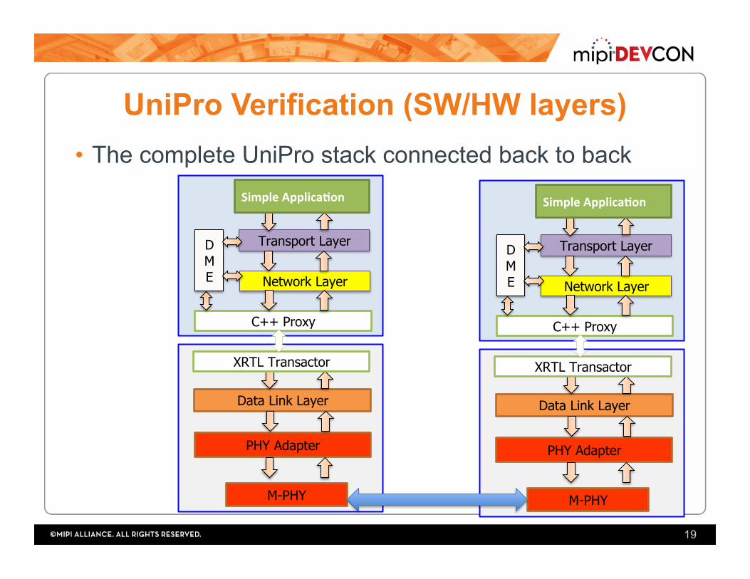
UniPro Verification (SW/HW layers) • The complete UniPro stack connected back to back
19
Transport Layer
Network Layer
Data Link Layer
PHY Adapter
D M E
SimpleApplica'on
C++ Proxy
XRTL Transactor
M-PHY
Transport Layer
Network Layer
Data Link Layer
PHY Adapter
D M E
SimpleApplica'on
C++ Proxy
XRTL Transactor
M-PHY

System Verification (UVM Env)
20
UFSAPPBFM+AXI
DriverVC
STIM
ULUS
UFSHost
M-PHY
DeviceUniPro
M-PHY
RMMI
DeviceUniProSW
UFSAppl.
(SC)TestbenchIPC
DPI
UNIPRO
HostCPortMonitor
MS
SMRx
Tx
ufs_host_core_top
ProtocolAnalyzer(UniPro/UFS)

VM-QEMU/Host Based Solution + UFS Driver
21
SwDriverSetup
HWSetup
UFSHC

DEBUGGING Protocol Analyzer
22
Debugging • Complex protocol layers (hard to spot bugs) • Specific attributes for each layer • Should trace HW/SW parts to spot issues
• Developed an in-house debugging tool “Protocol Analyzer” • Traces and Monitors:
• RMMI traffic • UniPro SAPs • UFS2 commands
23

Virtual UFS2: Snapshot
24
UFS device received a NOP OUT command from the host(32 bytes)
UFS replies with a NOP IN command to the host(32 bytes)

Virtual UFS2: SAP Tracing • Selecting the PACP_* SAP, the decoder window
shows the fields contents of PACP frames

Virtual UFS2: SAP Tracing • Selecting the DL_DATA_IND SAP, the
decoder window shows the raw data of the UniPro packet received by host

Virtual UFS2: SAP Tracing • Selecting the UFS_* SAP, the decoder
window shows the fields contents of the ULPI, each ULPI has a decoder

Virtual UFS2: Snapshot
s, Presentation Title, Month Year 28
SAP Tracing
M-PHY tracing
SAP Decoding
sessions
Session Info.

Overview
29
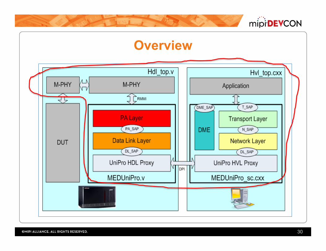
Overview
30

HW Integration Env.
PALDUT
DME i/f
DLL i/f
M-M
PALTLM
Model
RMMI IF
RMMI DLLDUT
DME i/f
NL i/f
PAL i/f
DMEAgent DME
Agent
ToDMESB
ToDMESB
DMEreq
DLLTLM
Model DMEreq
DummyNLAgent
req/res
conf/ind
DummyDLLAgent(passive)
DLLAgent
DummyNLAgent
DMEAgent
mon
drvsqr
sqr
DMEAgent
PALAgentmon
drvsqr
sqr
PA->DLSAPs
DL->PASB
DL->PASAPs
DL->PASAPs
DMESB(PA)
DME
DMESB(DL)
NLSB
ToNLSB
DLControlSB

Virtual UFS2: Multi-View
• Multi-View allows the user to open two sessions side by side to compare.

Virtual UFS2: SAP Tracing
PeerM-PHYRx
Peer M-PHY
Tx
Local M-PHY
Tx
Local M-PHY
Rx
Mentor UFS Device
DUT (UFS Host)
• M-PHY tracer windows monitors the RMMI interface of the local(Device) M-PHY and the RMMI interface of the Peer(Host) M-PHY
• Controls Symbols, Get, Set, Hibernate and Line Reset are monitored

Virtual UFS2: Session Configurations • Control/configure the Virtual UFS2
device before running the emulation
Data Link Layer
PHY Adapter
Transport Layer Network Layer
UFS Application
soc_tracerenables/disablesverilogModules(DL/PAStatemachinesMonitor.v)usingDPIexportcallat;me0ns
SM Monitor.v
SMMonitor.v
Related Documents