Table of Contents Content Page no. Abstract…………………………………………………… I List of Figures…………………………………………….. II Chapter 1 Introduction 1.1 About 1 1.2 Development Methods 1 Chapter 2 Literature Review 2.1 Optical flow or image subtraction in human detection from infrared camera on mobile robot 2 2.1.1 Abstract 2 2.1.2 Research Highlights 2 Chapter 3 Problem Identification 3.1 Statement of Problem 3 3.2 Advanced Technology 3 Chapter 4 Methodology 4.1 Design & Development of Hardware 4.1.1 Total Circuit Internal Working Explantion 4 4.2 Regulated Power Supply 5 4.3 Encoder HT12E 7 4.4 Decoder HT12D

Welcome message from author
This document is posted to help you gain knowledge. Please leave a comment to let me know what you think about it! Share it to your friends and learn new things together.
Transcript
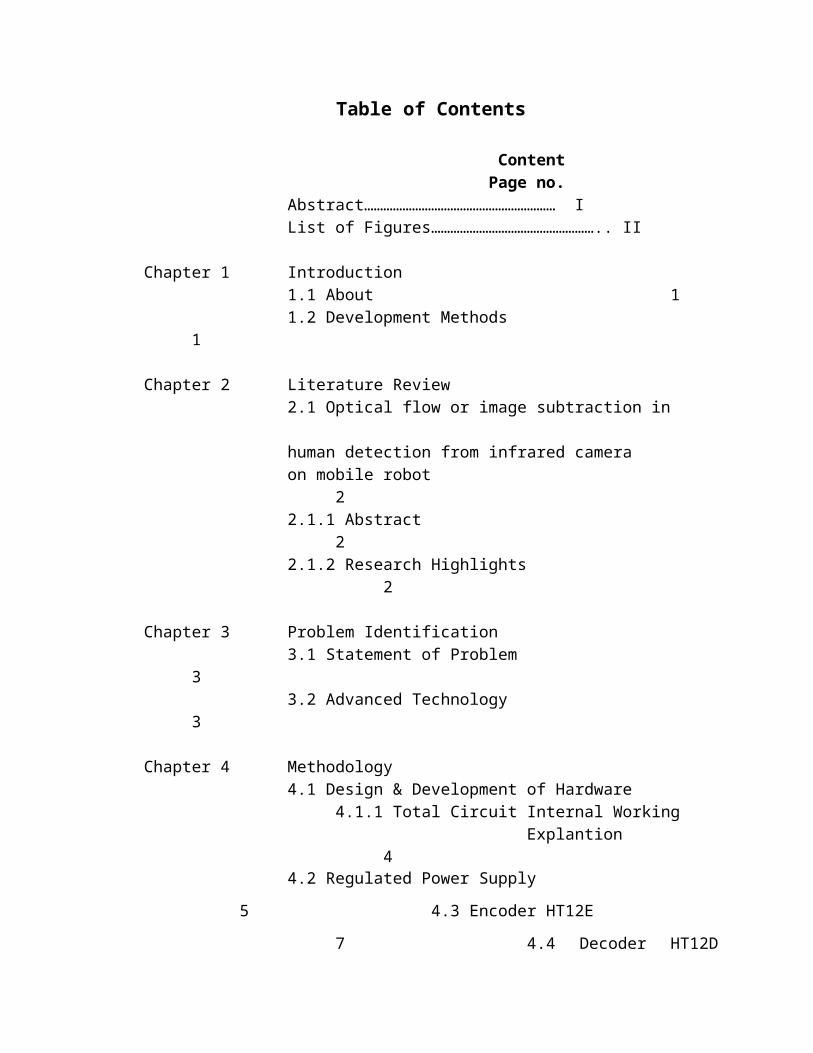
Table of Contents
Content Page no.
Abstract…………………………………………………… I
List of Figures…………………………………………….. II
Chapter 1 Introduction
1.1 About 1
1.2 Development Methods 1
Chapter 2 Literature Review
2.1 Optical flow or image subtraction in
human detection from infrared camera
on mobile robot 2
2.1.1 Abstract 2
2.1.2 Research Highlights 2
Chapter 3 Problem Identification
3.1 Statement of Problem 3
3.2 Advanced Technology 3
Chapter 4 Methodology
4.1 Design & Development of Hardware
4.1.1 Total Circuit Internal Working
Explantion
44.2 Regulated Power Supply 5
4.3 Encoder HT12E
7 4.4 Decoder HT12D
8 4.5Encoding & Decoding Process
8 4.5.1 What is encoding &
decoding 8 4.5.2 HT12D
&HT12E 9 4.6 DPDT Switch
Connection with Encoder 15 4.7 RF
Transmitter & Receiver 16

Chapter 5 Result & Discussion
5.1 Result
17
Chapter 6 Conclusion & Future Scope
6.1 Conclusion
18 6.2 Future Scope
18
Bibliography 19
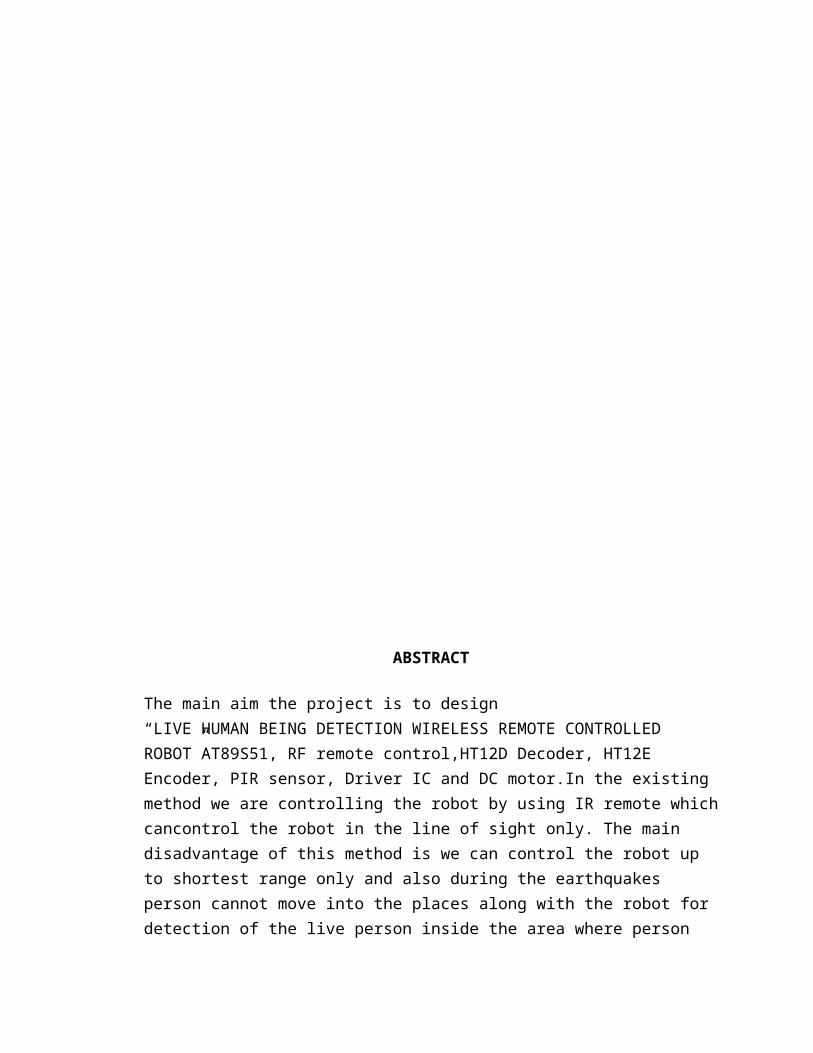
ABSTRACT
The main aim the project is to design “LIVE HUMAN BEING DETECTION WIRELESS REMOTE CONTROLLED ROBOT”AT89S51, RF remote control,HT12D Decoder, HT12E Encoder, PIR sensor, Driver IC and DC motor.In the existing method we are controlling the robot by using IR remote which cancontrol the robot in the line of sight only. The main disadvantage of this method is we can control the robot up to shortest range only and also during the earthquakes person cannot move into the places along with the robot for detection of the live person inside the area where person movement is not possible.In the proposed method we are using RF remote control which can be used to control the robot at any range. To detect the live person we are using PIR sensorcalledas passive infrared sensor which is used to detect the persons whether they are alive or not. The remote uses certain range of Radio frequencies which is used to transfer the commands from the remote to the robot. By using this we can change the directions of the robot. Programs are developed in Embedded C. Flash magic is used for loading programs into Microcontroller.Used to detect the live persons where earthquakes are generated.Low cost, easy to use for rural areas, automated operation, and low power consumption.
I
LIST OF FIGURES
Name of Figure Page no.
4.1.1 Transmitter & power Supply Circuit 8
4.3.1.1 LM7805 Regulator Pin Diagram 12
4.3.2.1 HT12E Pin Diagram 13
4.4.2.1 HT12E (Tx Side) 16
4.4.2.2 HT12E Parallel Input & Serial Output 17
4.4.2.3 HT12D(Rx Side) 18
4.4.2.4 HT12D Serial Input & Parallel Output 19
4.5.1 DPDT Switch Connection with Encoder 20

II
Chapter 1
INTRODUCTION

1.1 About
Live Human Being Detection Wireless Remote Control Robot is used to detectthe
live persons. This robot is very helpful in detecting live persons under the buried
and pillars etc., whenever there is any earthquake occurred, tsunami or any other building
collapse. At the time of these effects people may fell down and buried under the
bridgesand under the pillars etc., in some cases we can’t get into that felled contacts and
we can’thelp them. In such cases to save them immediately we use this robot. This robots
job is todetect the live person and indicate the signal to the helpers.
1.2 Development Methods
To implement this mechanism we used discrete components to control the
robot ,movement, and indicating signal purpose. We used ARM7 microcontroller to
control theentire robot function it has vast advantages, and PIR sensor to detect live
persons. DCmotors are used to for robot movement and it can be controlled by user.
When we send this robot to such places where man movement is not possible, It willtry to
find out the live persons. The user will control the robot movement with the remote.The
live person can be detected by the body temperature radiation. Normally human body will
have 96.8 to 105’c temperature range. The PIR (passive infrared) sensor will bedesigned
like that it will activate when it will detect that much temperature. This project
issophisticated in the market since it is a real time embedded project.
In the advanced market these robots are further implemented using the new technologies
like GSM, GPS and LCD displays. Using theseGSM technologies we can operate
the robot from the far distances and we can identify thelocation using GPS. Using
Camera at the Robot and LCD display at the user section we canoperate the device
accurately and it provides live section. Gear wheels can provide theaccurate movement in
all areas.

1
Chapter 2
LITERATURE
REVIEW

2.1 Optical flow or image subtraction in human detection from infrared camera on
mobile robot
2.1.1 Abstract
Perceiving the environment is crucial in any application related to mobile robotics
research. In this paper, a new approach to real-time human detection through
processing video captured by a thermal infrared camera mounted on the
autonomous mobile platform mSecuritT M is introduced. The approach starts with
a phase of static analysis for the detection of human candidates through some
classical image processing techniques such as image normalization and
thresholding. Then, the proposal starts a dynamic image analysis phase based in
optical flow or image difference. Optical flow is used when the robot is moving,
whilst image difference is the preferred method when the mobile platform is still.
The results of both phases are compared to enhance the human segmentation by
infrared camera. Indeed, optical flow or image difference will emphasize the
foreground hot spot areas obtained at the initial human candidates’ detection.
2.1.2 Research highlights
► Use of infrared camera on mobile robot.
►Comparison of performance of optical flow vs. image subtraction in motion
detection.
► Introduction of the mSecurit mobile robot.

Chapter 3
PROBLEM
IDENTIFICATION
3.1 Statement of Problem
There is many different kind of catastrophe in natural and man-
made disaster :earthquake, flooding, hurricane and they cause different disaster area like
collapsed building, landslide or crater. During these emergency situations, and specially i
n urban disaster, many different people are deployed (policeman, fire fighters and
medical assistance).They need to cooperate to save lives, protect structural infrastructure,
and evacuate victims to safety. In these situations, human rescuers must make quick
decisions under stress, and try to get victims to safety often at their own risk. They must
gather determine the location and status of victims and the stability of the structures
as quickly as possible so that medics and firefighters can enter the disaster area and save
victims. All of these tasks are performed mostly by human and trained dogs, often in very
dangerous and risky situations. This is why since some years, mobile robots have been
proposed to help them and to perform tasks that neither humans dogs nor existing tools
can do. For this project, we will focused only on robots which will work
in a disaster environment of manmade structure, like collapsed buildings.
3.2 Advanced Technology
The advent of new highspeed technology and the growing computer capacity provided o
pportunity for new robot controls and realization of new methods of control theory. This
technical improvement together with the need for high performance robots created faster,
more accurate and more intelligent robots using new robots control devices, new drives
and advanced control algorithms. This Project deals with live personal detection robot is
based on 8 bit Microcontroller. This Robot follows which is drawn over the surface. Here
we are using PIR sensor for detect the which are detect human. The project is mainly
used in the DEBRIS for Earth quake rescue. Internally it consists of IR sensors. The
infrared sensors are used to sense the live persons. All the above systems are controlled
by the Microcontroller. In our project we are using the popular 8 bit
microcontroller .The Microcontroller is used to control the motors. It gets
the signals from the PIR sensors and it drives the motors according to the sensor inputs.
Two DC gear motors are used to drive the robot.
6
Chapter 4
METHODOLOGY

4.1 DESIGN AND DEVELOPMENT OF HARDWARE
MAIN CIRCUIT DIAGRAM AND ITS OVERALL OPERATION

Fig 4.1: Transmitter and power supply circuit
8
4.2 INTERNAL WORKING EXPLANATION:
Mainly the block diagram consists of following parts:
Power supply circuit
RF transmitter
HT12E Encoder IC
The devices that act as input are
Power supply
Switch box
The devices that act as output are
RF transmitter
4.3 Total circuit internal working explanation:
The main aim is to design “LIVE PERSON DETECTION ROBOT USING RF
WIRELESS COMMUNICATION”.
This robot is developed by using LPC2148 micro controller to it RF receiver is connected
and driver IC and DC motors are used. The robot movement is controlled by using RF
remote control. This remote consists of RF transmitter through this remote robot
movement is controlled by sending commands to robot through RF transmitter which
receives data through RF receiver connected to controller and then based on commands
received by controller for changing direction of robot. To change the position of robot RF
transmitter is used which is used to change to particular direction. Consider To
move robot in forward direction then particular command is send to controller through
RF remote this remote internally contains RF encoder, The RF encoder to transmit the
position change wirelessly to robot. HT12E is RF encoder which receives the parallel
data from the controller and converts this parallel data into serial data and to transmit the
serial data to RF transmitter through “Dout” pin in RF encoder TE pin should always be
kept high to transmit it to data pin of RF transmitter. Then serial data is received by the
data pin of transmitter and is send out wirelessly by the antenna to RF receiver present at
robot. The RF receiver connected to robot receives the data through antenna and sends to
controller. The sent data by the RF transmitter is received by the RF receiver and send
that data RF decoder which decodes the signal ie., serial data into parallel by using

HT12D. Thesignal is received by “DIN” pin and sends out using data pins and through
data pins data issend to controller. Then controller sends received data to Driver IC which
is used to changethe direction of robot.
4.3.1 REGULATED POWER SUPPLY
A variable regulated power supply, also called a variable bench power supply ,is one
where you can continuously adjust the output voltage to your requirements. Varying the
output of the power supply is the recommended way to test a project after having double
checked parts placement against circuit drawings and the parts placement guide. This
type of regulation is ideal for having a simple variable bench power supply. Actually this
is quite important because one of the first projects a hobbyist should undertake is the
construction of a variable regulated power supply. While a dedicated supply is quite
handy, it's much handier to have a variable supply on hand, especially for testing.
Regulator:
The filter output is not a pure d.c and it is not a constant d.c voltage it varies with the
fluctuations in the main power supply. But our requirement is to get constant d.c power
supply. The regulator can give constant d.c power supply. These are two types –ve power
supply and +ve power supply. The 78xx series gives+ve power supply (78 indicates +ve
and xx indicates any voltage value). TheLM79xx series gives –ve power supply ( 79
indicates –ve and xx indicates anyvoltage value). In our project AT89c51, HT12E and
HT12D needs +5v power.LM7805 gives +5v constant power supply.
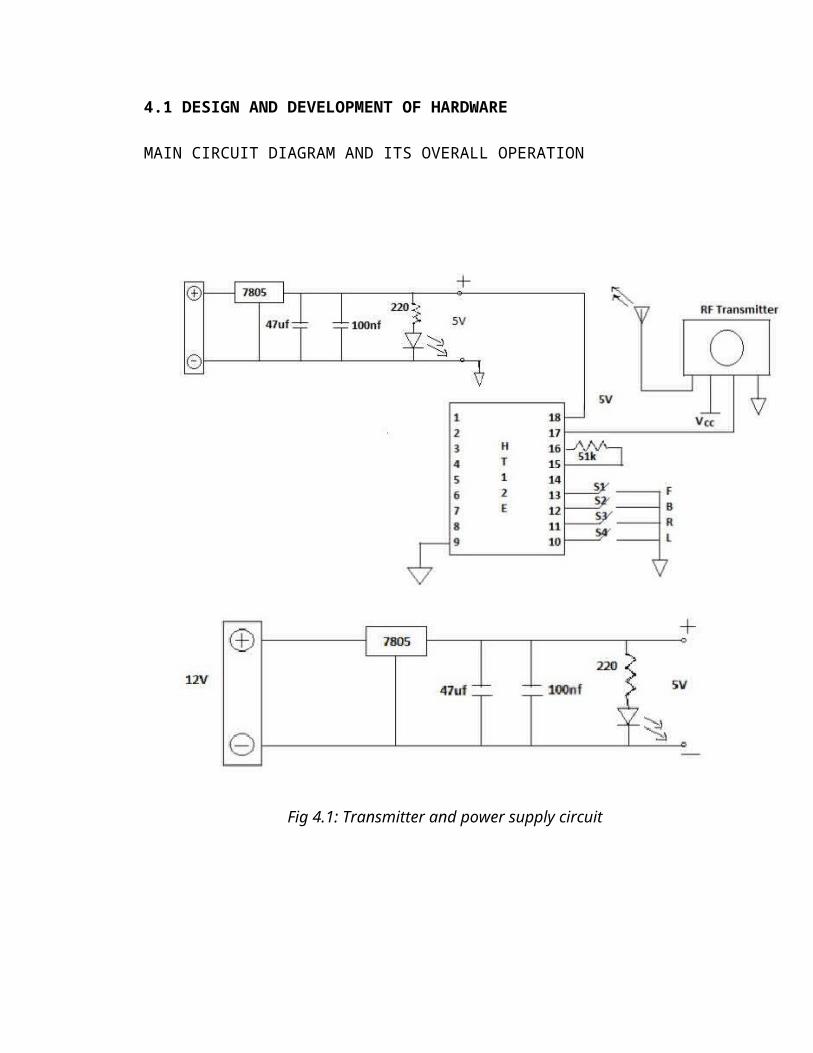
Fig.4.3.1.1 LM7805 regulator pin diagram
LM7805 Features
Output Current up to 1A
Output Voltages of 5, 6, 8, 9, 10, 12, 15, 18, 24V
Thermal Overload Protection
Short Circuit Protection
Output Transistor Safe Operating Area Protection
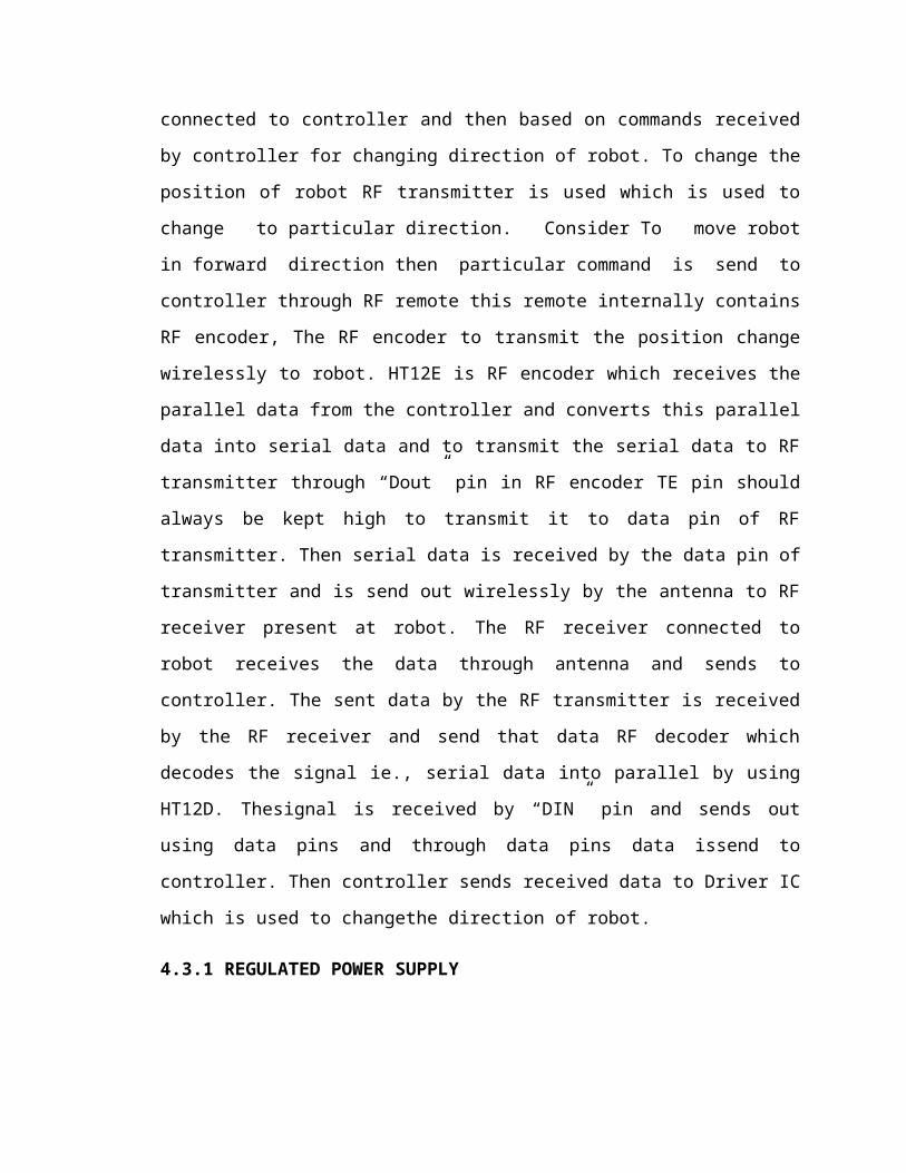
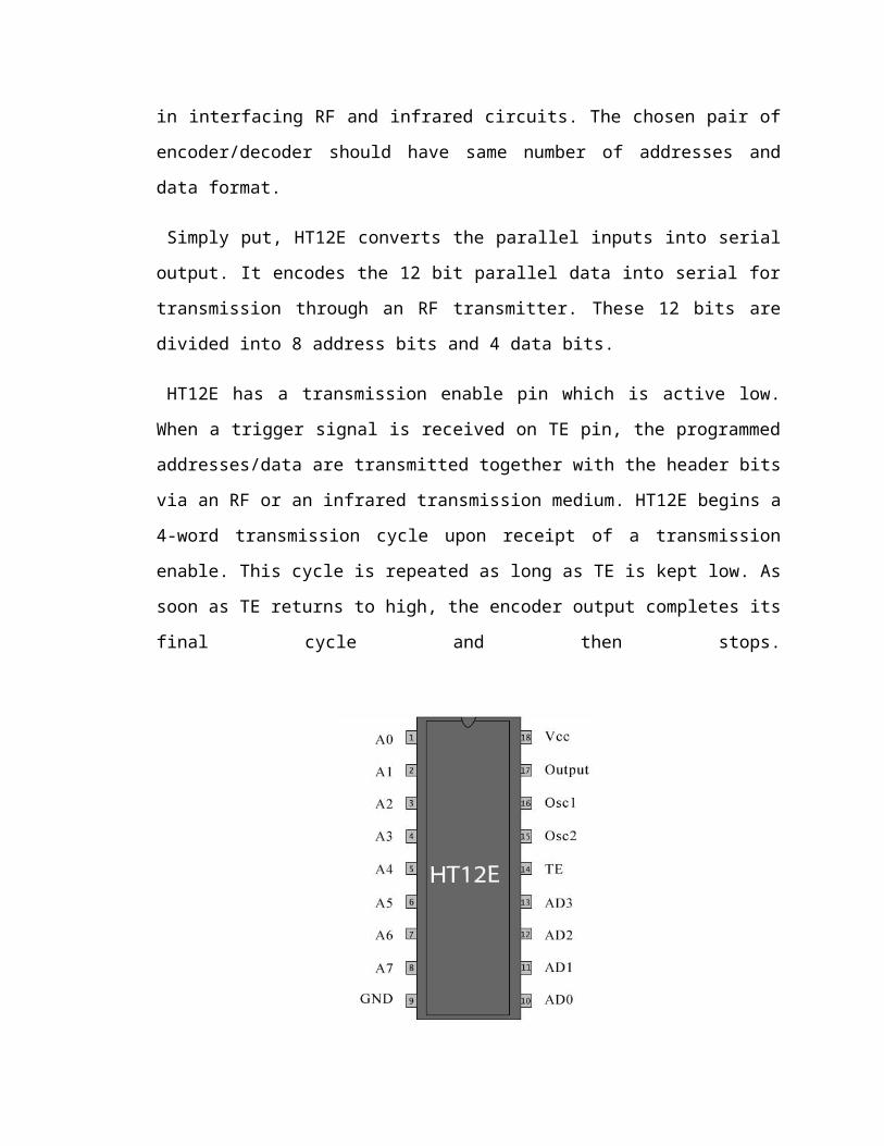
4.3.2 ENCODER HT12E
HT12E is an encoder integrated circuit of 212 series of encoders. They are paired with
212 series of decoders for use in remote control system applications. It is mainly used in
interfacing RF and infrared circuits. The chosen pair of encoder/decoder should have
same number of addresses and data format.
Simply put, HT12E converts the parallel inputs into serial output. It encodes the 12 bit
parallel data into serial for transmission through an RF transmitter. These 12 bits are
divided into 8 address bits and 4 data bits.

HT12E has a transmission enable pin which is active low. When a trigger signal is
received on TE pin, the programmed addresses/data are transmitted together with the
header bits via an RF or an infrared transmission medium. HT12E begins a 4-word
transmission cycle upon receipt of a transmission enable. This cycle is repeated as long as
TE is kept low. As soon as TE returns to high, the encoder output completes its final
cycle and then stops.
Fig 4.3.2.1: Pin Diagram- HT12E
4.3.3 DECODER HT12D
HT12D is a decoder integrated circuit that belongs to 212 series of decoders. This series
of decoders are mainly used for remote control system applications, like burglar alarm,
car door controller, security system etc. It is mainly provided to interface RF and infrared
circuits. They are paired with 212 series of encoders. The chosen pair of encoder/decoder
should have same number of addresses and data format.
In simple terms, HT12D converts the serial input into parallel outputs. It decodes the
serial addresses and data received by, say, an RF receiver, into parallel data and sends
them to output data pins. The serial input data is compared with the local addresses three
times continuously. The input data code is decoded when no error or unmatched codes
are found. A valid transmission in indicated by a high signal at VT pin.
HT12D is capable of decoding 12 bits, of which 8 are address bits and 4 are data bits.
The data on 4 bit latch type output pins remain unchanged until new is received.
4.4 ENCODING AND DECODING PROCESS
4.4.1 What is Encoding and Decoding:
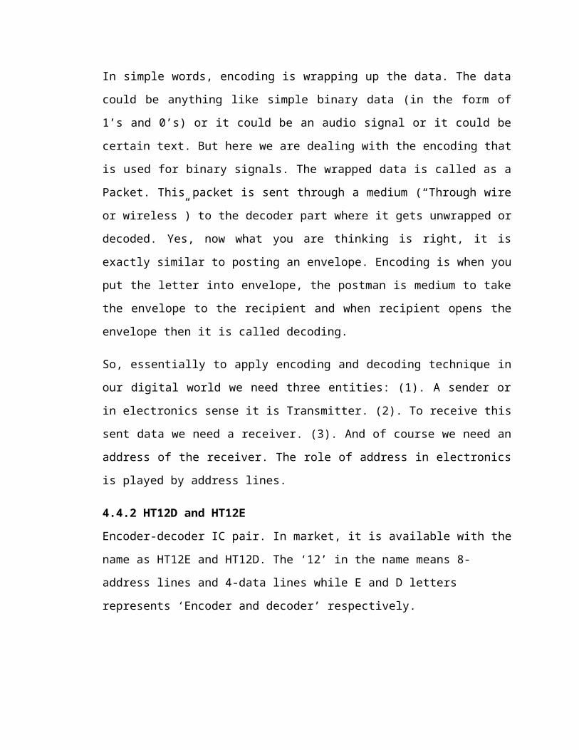
In simple words, encoding is wrapping up the data. The data could be anything like
simple binary data (in the form of 1’s and 0’s) or it could be an audio signal or it could be
certain text. But here we are dealing with the encoding that is used for binary signals. The
wrapped data is called as a Packet. This packet is sent through a medium (“Through wire
or wireless”) to the decoder part where it gets unwrapped or decoded. Yes, now what you
are thinking is right, it is exactly similar to posting an envelope. Encoding is when you
put the letter into envelope, the postman is medium to take the envelope to the recipient
and when recipient opens the envelope then it is called decoding.
So, essentially to apply encoding and decoding technique in our digital world we need
three entities: (1). A sender or in electronics sense it is Transmitter. (2). To receive this
sent data we need a receiver. (3). And of course we need an address of the receiver. The
role of address in electronics is played by address lines.
4.4.2 HT12D and HT12E
Encoder-decoder IC pair. In market, it is available with the name as HT12E and HT12D.
The ‘12’ in the name means 8-address lines and 4-data lines while E and D letters
represents ‘Encoder and decoder’ respectively.

HT12E(Transmitter side)
Fig4.4.2.1: HT12E(Tx Side)
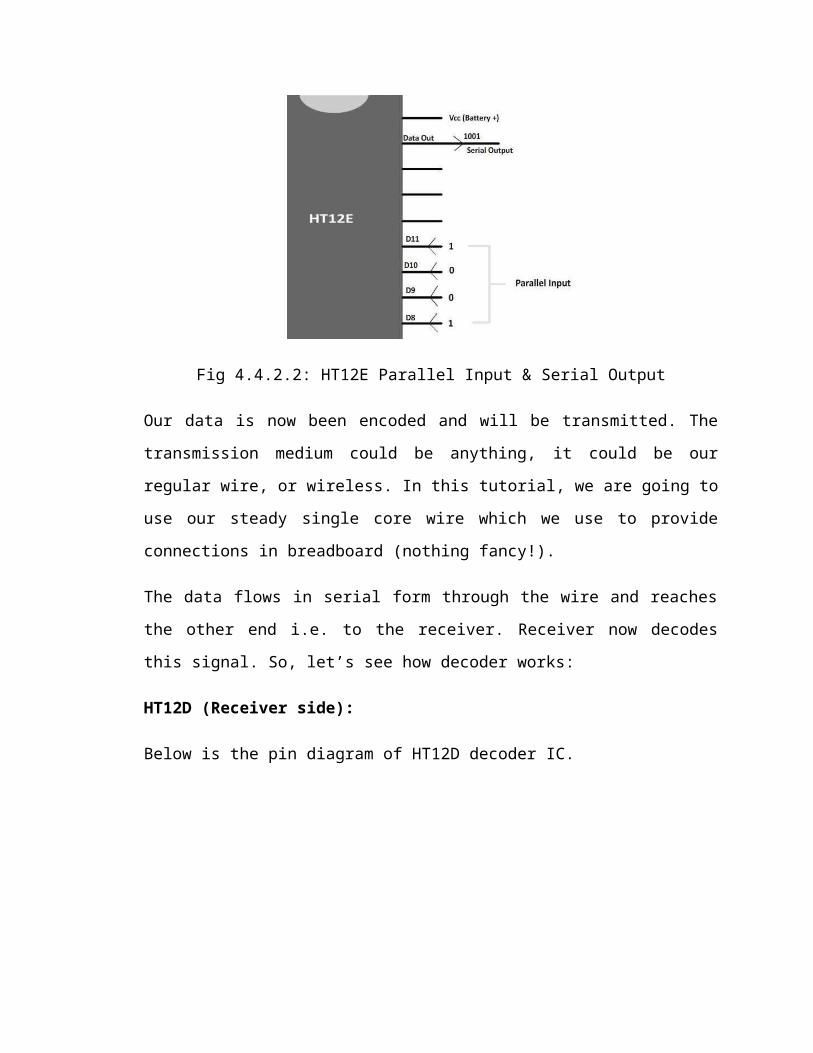
Let’s first take the Encoding side. The encoder has four input lines. Theses lines are used
to give input which we want to encode. In encoding, we are wrapping up the data which
means if we want to send a binary signal ‘1001’ to other end, we have to make data pins
as ‘1001’. Now, to make data pin like this, what we need to do is to give high or 5 volts
(which in digital means ‘1’) to pins ‘D0’ and ‘D3’ while we have to provide pins ‘D1’
and ‘D2’ with 0 volt. (Ground). This altogether gives us ‘1001’ which is transmitted out
from the ‘Data out’ pin of the HT12E. The input given to data pin is in parallel form
which is being transmitted into serial form from the data output pin. The figure below
will clear this:
Fig 4.4.2.2: HT12E Parallel Input & Serial Output

Our data is now been encoded and will be transmitted. The transmission medium could
be anything, it could be our regular wire, or wireless. In this tutorial, we are going to use
our steady single core wire which we use to provide connections in breadboard (nothing
fancy!).
The data flows in serial form through the wire and reaches the other end i.e. to the
receiver. Receiver now decodes this signal. So, let’s see how decoder works:
HT12D (Receiver side):
Below is the pin diagram of HT12D decoder IC.
Fig 4.4.2.3: HT12D(Rx Side)
Now neglect all the pins for this moment and just concentrate on Din (Data in) pin and
the for Data lines pin. The encoded data which is coming from the transmitter side goes
into the Data in (Din) pin. The data which was in serial order gets decoded and the output
is generated at the for data line pins in same order as that on transmitter pin.
When there is no input at the data in pin, the output pins i.e. data lines remains high.
The figure below shows the decoding taking place in HT12D
Fig 4.4.2.4: HT12D Serial Input & Parallel Output
Role of Address Lines:
When using a single pair of encoder-decoder IC, we generally leave the address pins as it
is i.e. we do not connect them to either ground or VCC. But what if there is more than
one decoder but only single encoder. In that case we need to give an address to the data
that it might travel to specific decoder only and our data should not leak at unnecessary
decoders. This is very useful in wireless communication.
To define an address, what we need to do is to connect specific address pins to the ground
on both encoder and decoder side; remember that the order of connecting the address pins
to the ground must be same. See the animation below for; it will remove all the twists in
your mind:
Oscillator Pins:
When we first hear the word oscillations, the first thing that comes in our mind is the to
and fro waving motion, yup as always you are correct. The role of oscillator in digital
electronics is to produce waves which are in Sine wave form or rectangular wave form.
The device used to generate this waveform is called ‘Oscillator’. The waveform
generated by the oscillator is called as ‘Pulses’ (like our heart beat). So, in digital world
the oscillator works identical to our Heart. Unfortunately, we will not be able to see the
oscillator device itself because in HT12D and HT12E, the oscillator comes inbuilt, what
we have to do is to put a resistor between the oscillators pins. But, in our coming tutorial
over microcontrollers, the need of oscillator is must, so we will learn about it in that
tutorials only.
VT Pin (Valid Transmission):
The valid transmission pin in decoder shows that the transmitter address and the receiver
address are same and is ready to receive the data from the encoder side.
During implementation of the circuit, we will see how to get notification about the valid
transmission through this pin.
So, now we are loaded with all the essentials needed to implement Encoder-Decoder
circuit. Let’s start implementing one:
Components Required:
1. IC- HT12E/HT12D (generally comes in pair).
2. Breadboard with complete Power supply.
3. LEDs (5)
4. Resistors (Four 125 ohm for LEDs)
(750k ohm for oscillator of Encoder)
(27k ohm for oscillator of Decoder).
5. Reset Switch (4).
6. Battery (6-24 volts)
Step1.
Take the power supply circuit and insert the encoder and decoder IC’s at some distance.
Also provide the VCC and ground to the pins (Pin number 9 ground and pin number 18
VCC for both the IC’s). See the figure below:
Step2.
Now, we will first make the encoder part. Insert the 750k ohm resistor in pin number 15
and 16 i.e. you have to short both the pins using this resistor. Connect the ‘Transmission
Enable pin’ (TE) to ground. This action will enable the IC to transmit the data through
data out pin. Now connect four reset switches in data line. Remember, reset switch has
two legs. One will go into the data line and the other one will go to ground. So, whenever
you will press the switch, the pin will get connected to the ground. See the figure below
which how actually you have to connect the switches:

Step3.
Yup, our encoder part is completed. You are ready to encode your secret data. But there
should be something which shows the reception of data at data output lines. We are using
LEDs for that purpose. The LED will glow when data is received. So, let’s put down
hands over decoder circuit.
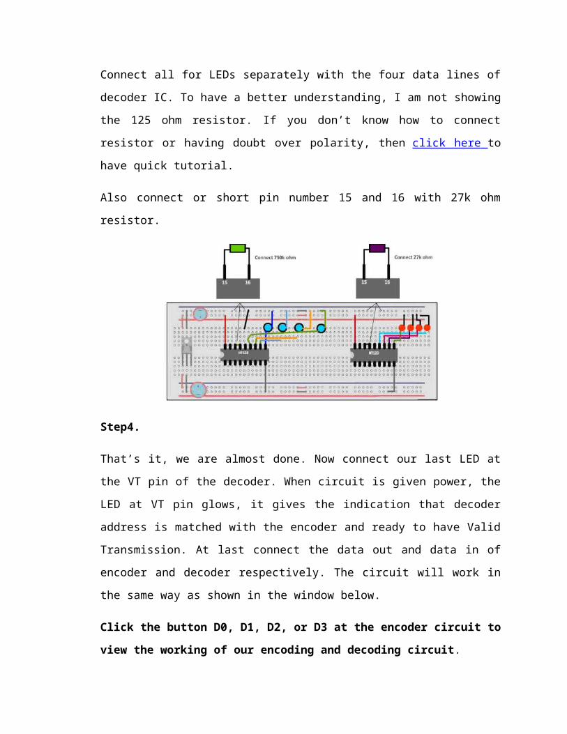
Connect all for LEDs separately with the four data lines of decoder IC. To have a better
understanding, I am not showing the 125 ohm resistor. If you don’t know how to connect
resistor or having doubt over polarity, then click here to have quick tutorial.
Also connect or short pin number 15 and 16 with 27k ohm resistor.
Step4.
That’s it, we are almost done. Now connect our last LED at the VT pin of the decoder.
When circuit is given power, the LED at VT pin glows, it gives the indication that
decoder address is matched with the encoder and ready to have Valid Transmission. At
last connect the data out and data in of encoder and decoder respectively. The circuit will
work in the same way as shown in the window below.
Click the button D0, D1, D2, or D3 at the encoder circuit to view the working of our
encoding and decoding circuit.
The complete circuit on breadboard will look like this. The bold blue line in centre of the
breadboard connects the data in and data out pins. You can also do this with real
breadboard by taking the wire through the slot provided in centre of breadboard. This
makes the circuit look less messy:
4.5 DPDT SWITCH CONNECTION WITH ENCODER
Fig 4.5.1: DPDT Switch Connection with Encoder

4.6 RF TRANSMITTER & RECEIVER
RF TRANSMITTER:
General Description:
The ST-TX01-ASK is an ASK Hybrid transmitter module.ST-TX01-ASK is designed by
the Saw Resonator, with an effective low cost, small size,and simple-to-use for
designing.Frequency Range:315 / 433.92 MHZ.Supply Voltage: 3~12V.Output Power :
4~16dBmCircuit Shape: Saw
Applications
*Wireless security systems
*Car Alarm systems
*Remote controls.
*Sensor reporting
*Automation systems

Chapter 5
RESULT AND DISCUSSION

5.1 RESULT
The project “LIVE PERSON DETECTION ROBOT USING RF WIRELESSTECHNOLOGY—TRANSMITTER SECTION” has been successfully designed and tested. It has been developed by integrating features of all the hardware components used. Presence of every module has been reasoned out and placed carefully thus contributing to the best working of the unit. Secondly, using highly advanced IC’s and with the help of growing technology the project has been successfully implemented.

Chapter 6
CONCLUSION & FUTURE SCOPE

6.1 CONCLUSION
The project “LIVE PERSON DETECTION ROBOT USING RF WIRELESSTECH
NOLOGY—TRANSMITTER SECTION” has been successfully designed and
tested. It has been developed by integrating features of all the hardware components used.
Presence of every module has been reasoned out and placed carefully thus contributing to
the best working of the unit. Secondly, using highly advanced IC’s and with the help of
growing technology the project has been successfully implemented.
BIBLIOGRAPHY

BIBLIOGRAPHY
1. Citation from book –
Electronic Components- D.V.Prasad
Wireless Communications - Theodore S. Rappaport
Mobile Tele Communications- William C.Y. Lee
2. Citation from website –
www.alldatasheet.com

33
Related Documents