MINOR LOSSES IN PIPES • Losses caused by fittings, bends, valves, etc. 1

Welcome message from author
This document is posted to help you gain knowledge. Please leave a comment to let me know what you think about it! Share it to your friends and learn new things together.
Transcript
MINOR LOSSES IN PIPES • Losses caused by fittings, bends, valves, etc.
1
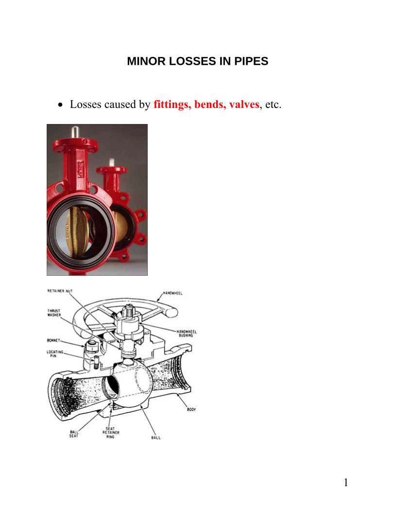
• Minor in comparison to friction losses which are
considered major. • Losses are proportional to – velocity of flow, geometry of
device.
)2/( 2 gvKhL = • The value of K is typically provided for various devices.
• Energy lost – units – N.m/N or lb-ft/lb
2
• K - loss factor - has no units (dimensionless)
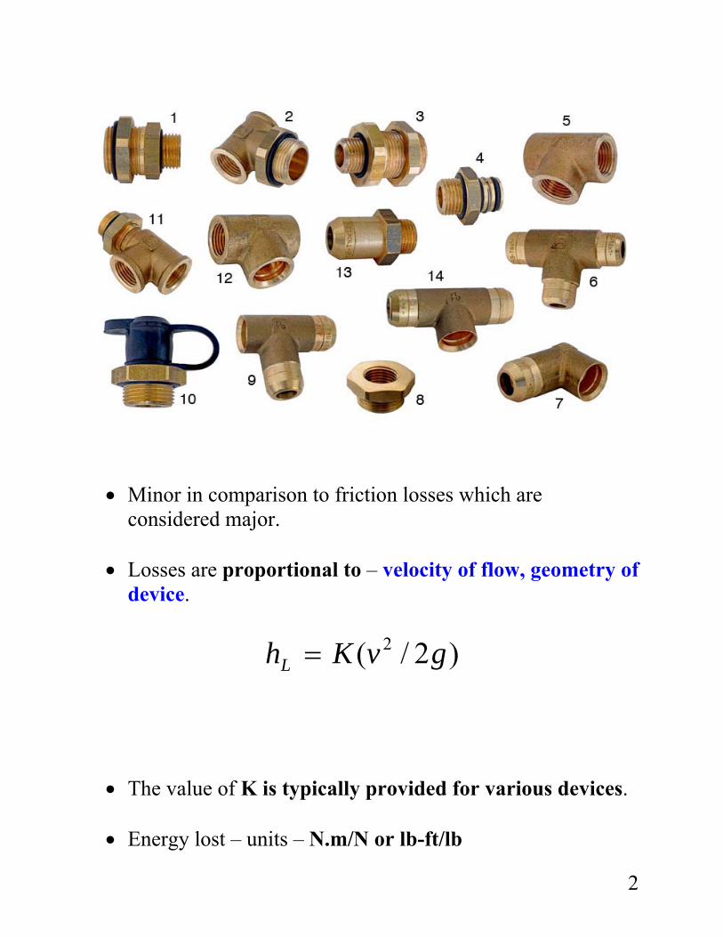
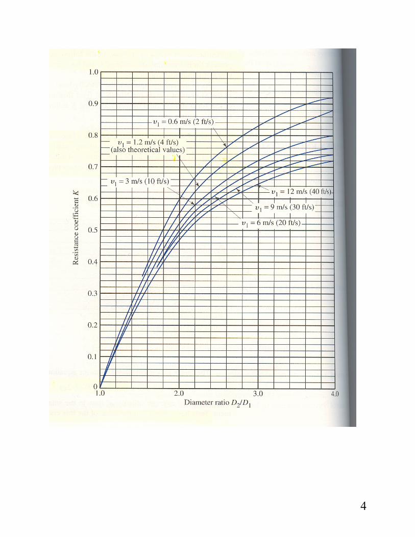
Sudden enlargement
Energy lost is because of turbulence. Amount of turbulence depends on the differences in pipe diameters
)2/( 21 gvKhL =
The values of K have been experimentally determined and provided in Figure 10.2 and Table 10.1.
3
4
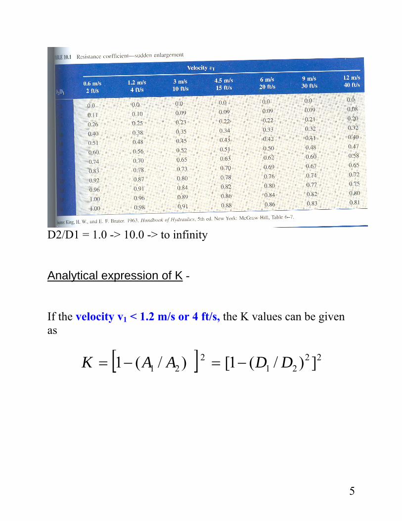
D2/D1 = 1.0 -> 10.0 -> to infinity Analytical expression of K - If the velocity v1 < 1.2 m/s or 4 ft/s, the K values can be given as
[ ] 2221
221 ])/(1[)/(1 DDAAK −=−=
5
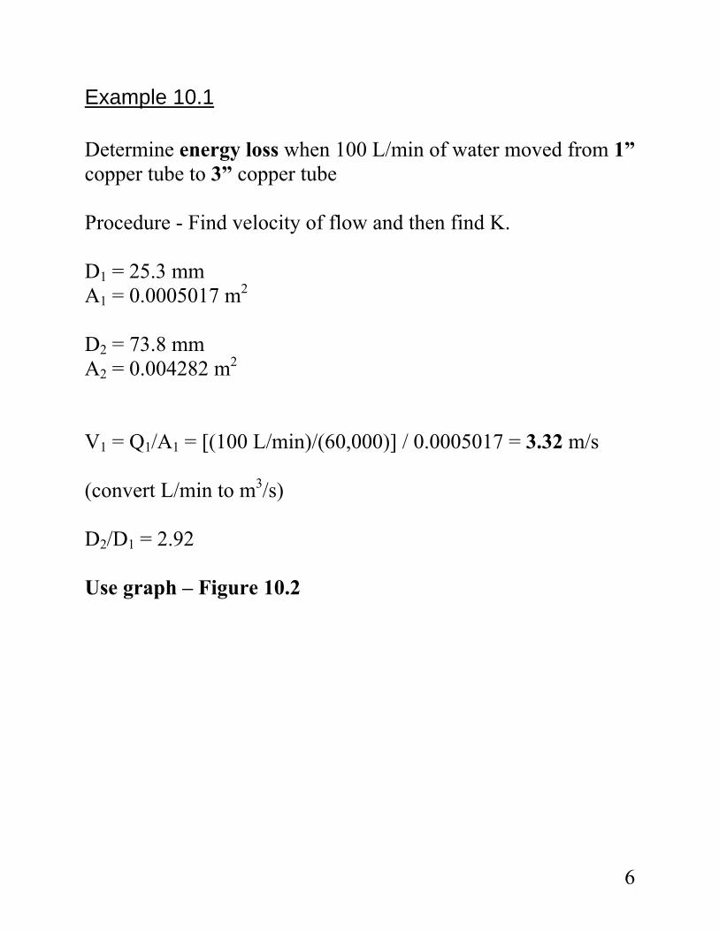
Example 10.1 Determine energy loss when 100 L/min of water moved from 1” copper tube to 3” copper tube Procedure - Find velocity of flow and then find K. D1 = 25.3 mm A1 = 0.0005017 m2 D2 = 73.8 mm A2 = 0.004282 m2 V1 = Q1/A1 = [(100 L/min)/(60,000)] / 0.0005017 = 3.32 m/s (convert L/min to m3/s) D2/D1 = 2.92 Use graph – Figure 10.2
6
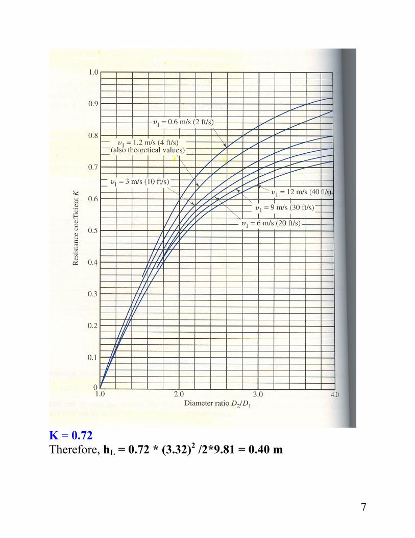
K = 0.72 Therefore, hL = 0.72 * (3.32)2 /2*9.81 = 0.40 m
7
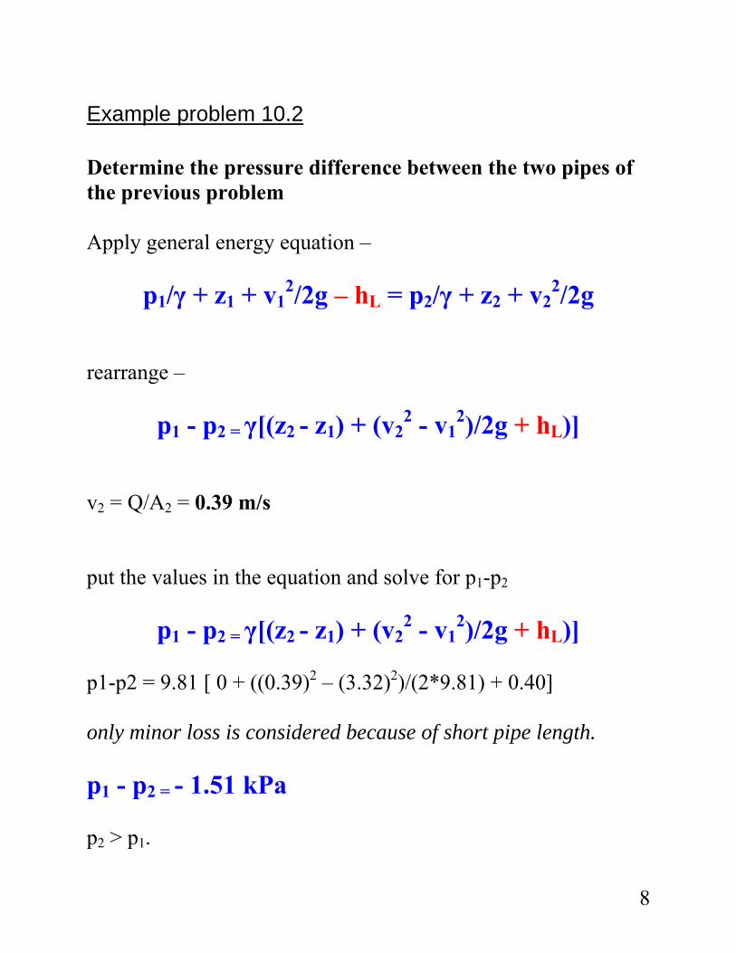
Example problem 10.2 Determine the pressure difference between the two pipes of the previous problem Apply general energy equation –
p1/γ + z1 + v12/2g – hL = p2/γ + z2 + v2
2/2g rearrange –
p1 - p2 = γ[(z2 - z1) + (v22 - v1
2)/2g + hL)] v2 = Q/A2 = 0.39 m/s put the values in the equation and solve for p1-p2
p1 - p2 = γ[(z2 - z1) + (v22 - v1
2)/2g + hL)] p1-p2 = 9.81 [ 0 + ((0.39)2 – (3.32)2)/(2*9.81) + 0.40] only minor loss is considered because of short pipe length. p1 - p2 = - 1.51 kPa p2 > p1.
8
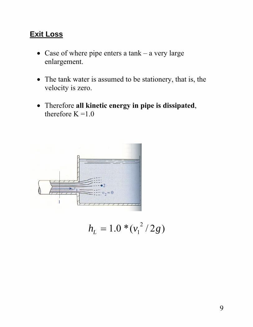
Exit Loss • Case of where pipe enters a tank – a very large
enlargement. • The tank water is assumed to be stationery, that is, the
velocity is zero. • Therefore all kinetic energy in pipe is dissipated,
therefore K =1.0
)2/(*0.1 21 gvhL =
9
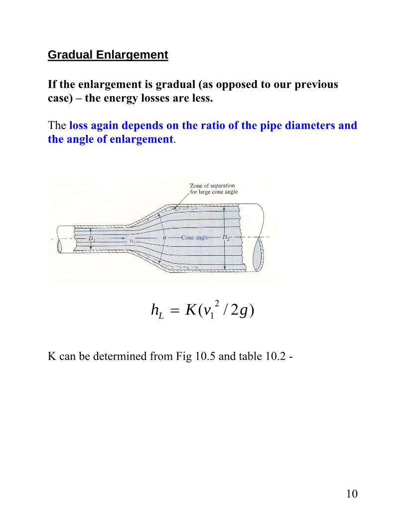
Gradual Enlargement If the enlargement is gradual (as opposed to our previous case) – the energy losses are less. The loss again depends on the ratio of the pipe diameters and the angle of enlargement.
)2/( 21 gvKhL =
K can be determined from Fig 10.5 and table 10.2 -
10
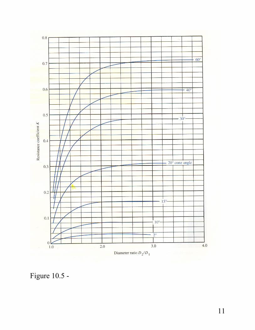
Figure 10.5 -
11
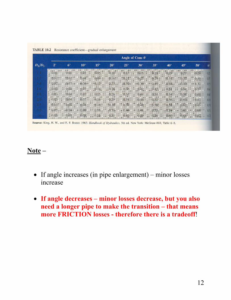
Note – • If angle increases (in pipe enlargement) – minor losses
increase • If angle decreases – minor losses decrease, but you also
need a longer pipe to make the transition – that means more FRICTION losses - therefore there is a tradeoff!
12
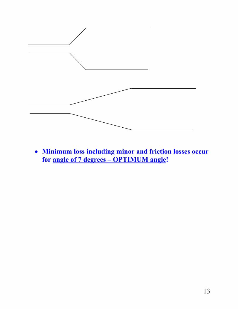
• Minimum loss including minor and friction losses occur
for angle of 7 degrees – OPTIMUM angle!
13
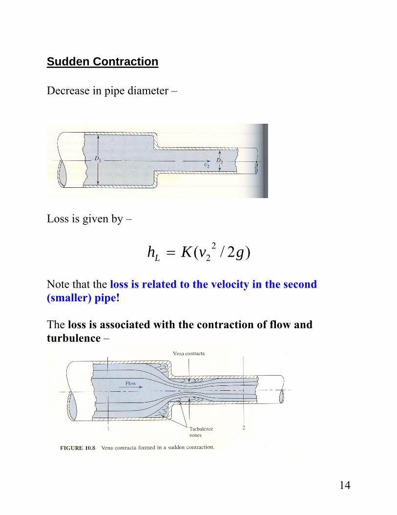
Sudden Contraction Decrease in pipe diameter –
Loss is given by –
)2/( 22 gvKhL =
Note that the loss is related to the velocity in the second (smaller) pipe! The loss is associated with the contraction of flow and turbulence –
14
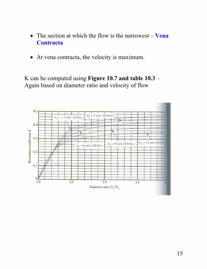
• The section at which the flow is the narrowest – Vena
Contracta • At vena contracta, the velocity is maximum.
K can be computed using Figure 10.7 and table 10.3 – Again based on diameter ratio and velocity of flow
15
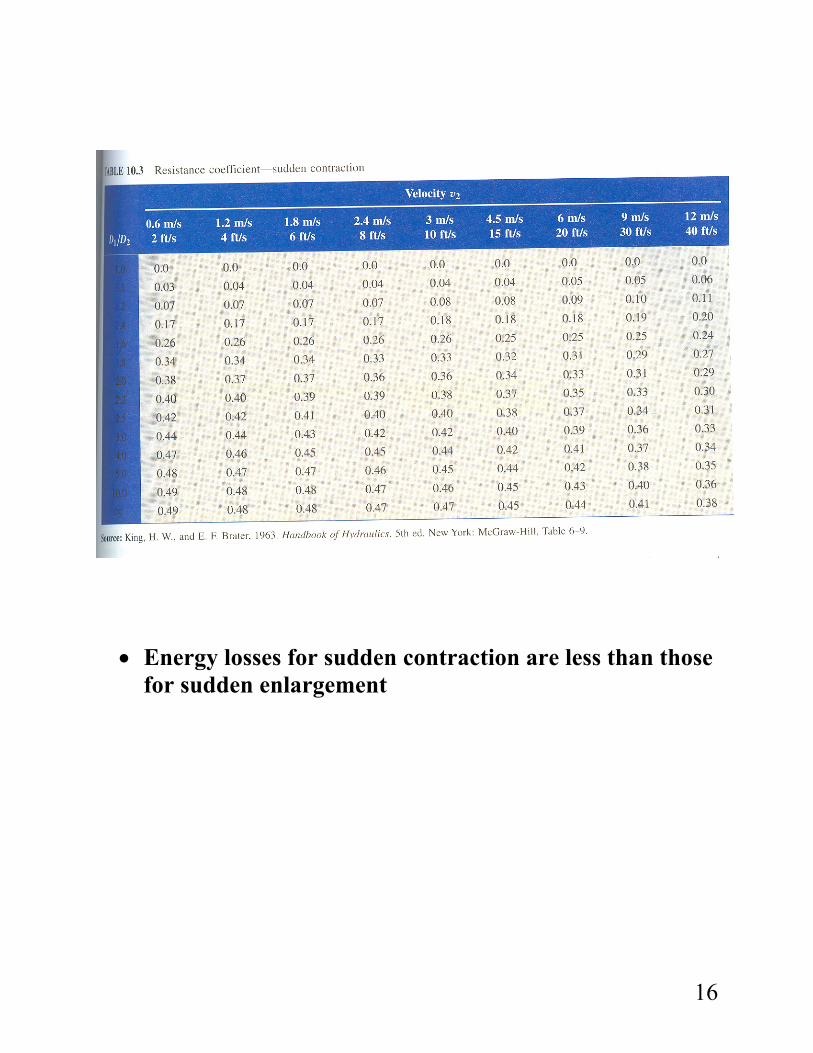
• Energy losses for sudden contraction are less than those
for sudden enlargement
16
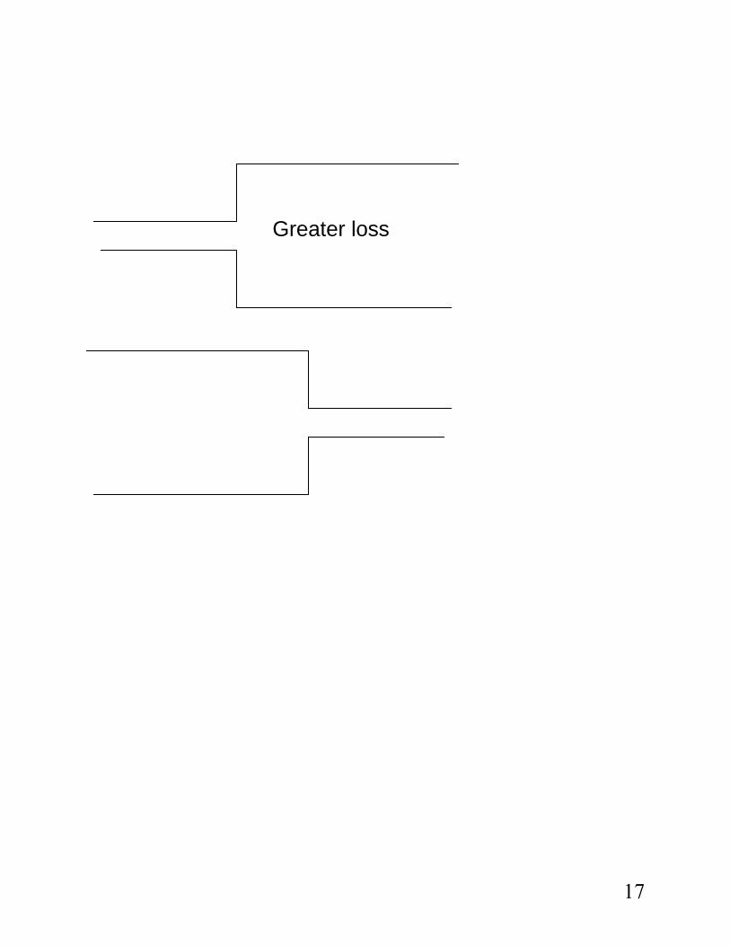
Greater loss
17
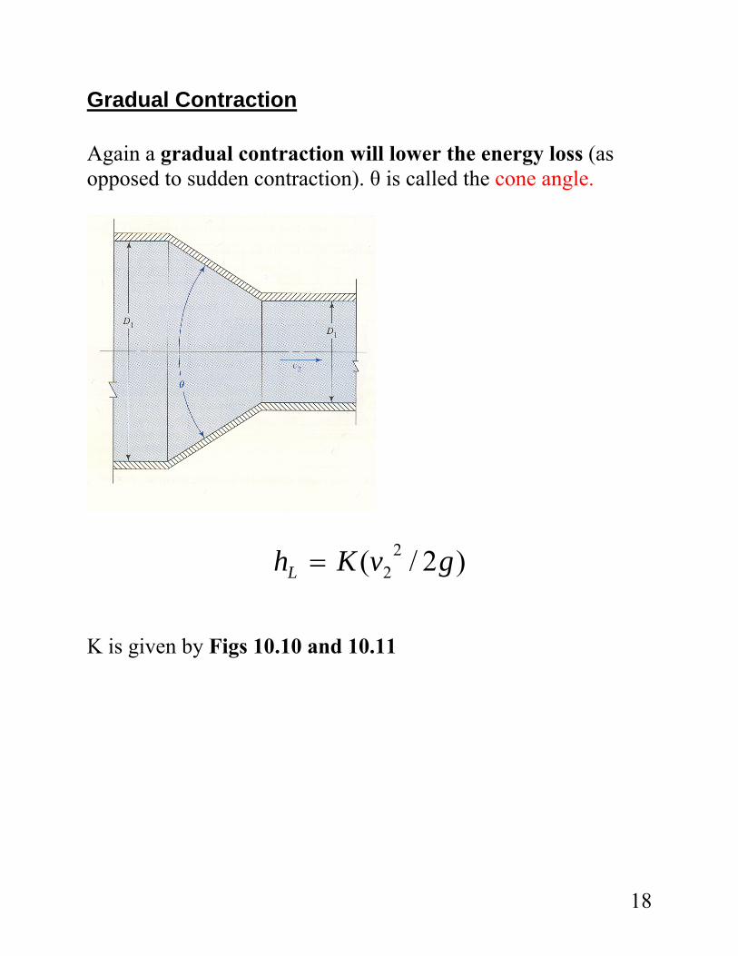
Gradual Contraction Again a gradual contraction will lower the energy loss (as opposed to sudden contraction). θ is called the cone angle.
)2/( 22 gvKhL =
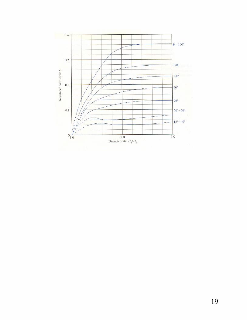
K is given by Figs 10.10 and 10.11
18
19
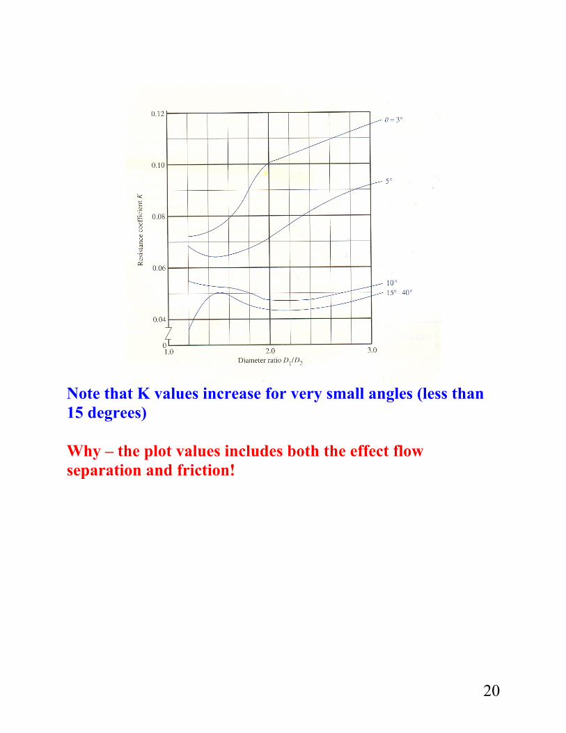
Note that K values increase for very small angles (less than 15 degrees) Why – the plot values includes both the effect flow separation and friction!
20
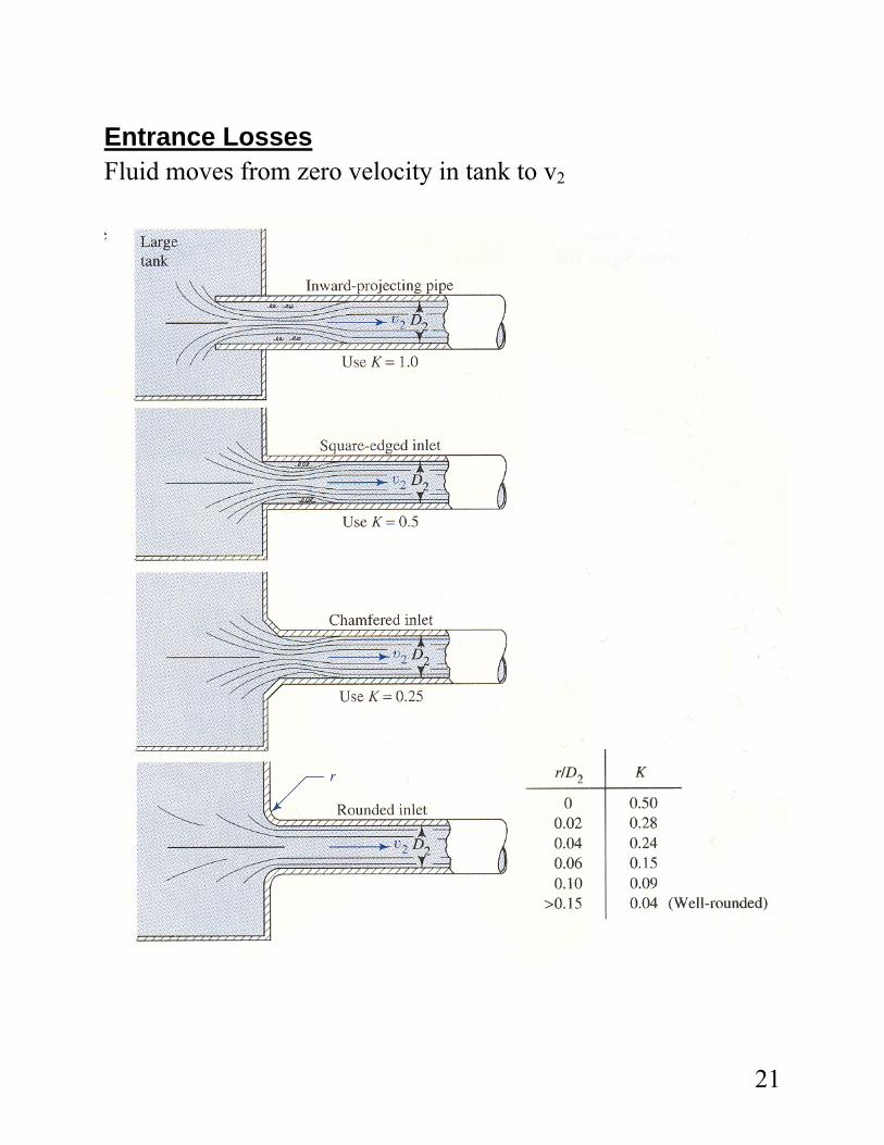
Entrance Losses Fluid moves from zero velocity in tank to v2
21
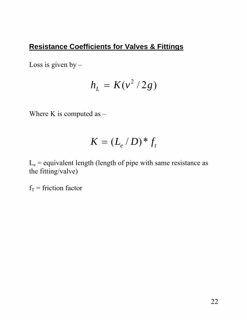
Resistance Coefficients for Valves & Fittings Loss is given by –
)2/( 2 gvKhL = Where K is computed as –
te fDLK *)/(= Le = equivalent length (length of pipe with same resistance as the fitting/valve) fT = friction factor
22
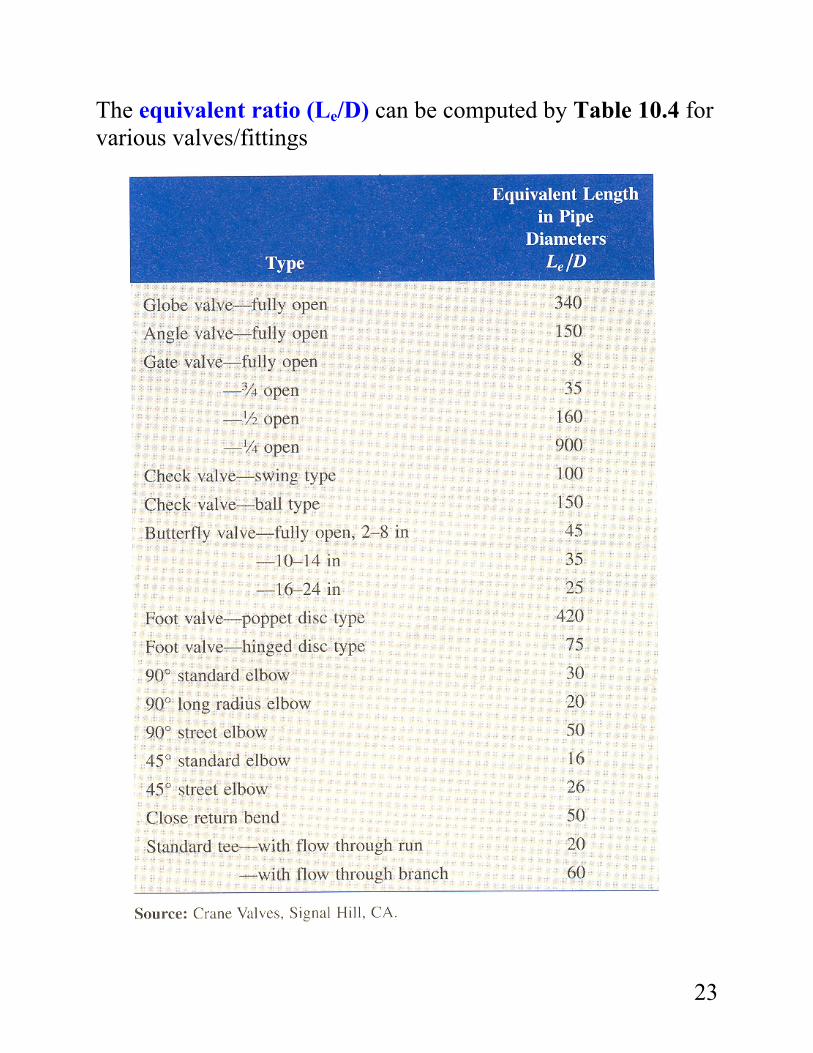
The equivalent ratio (Le/D) can be computed by Table 10.4 for various valves/fittings
23
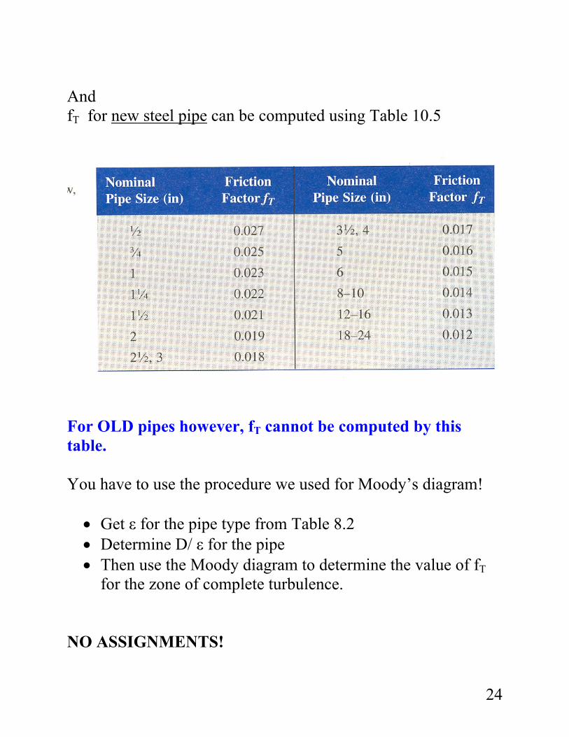
And fT for new steel pipe can be computed using Table 10.5
For OLD pipes however, fT cannot be computed by this table. You have to use the procedure we used for Moody’s diagram! • Get ε for the pipe type from Table 8.2 • Determine D/ ε for the pipe • Then use the Moody diagram to determine the value of fT
for the zone of complete turbulence. NO ASSIGNMENTS!
24
Related Documents