520 Lafayette Rd. N.; St. Paul, MN 55155-4194; 651-296-6300 (voice); 651-282-5332 (TTY) Regional Offices: Duluth • Brainerd • Detroit Lakes • Marshall • Rochester Equal Opportunity Employer • Printed on recycled paper containing at least 10% fibers from paper recycled by consumers STATE OF MINNESOTA Industrial Division National Pollutant Discharge Elimination System (NPDES)/ State Disposal System (SDS) Permit MN0057207 PERMITTEE: US Steel Corp - Minntac FACILITY NAME: US Steel - Minntac Tailings Basin Area RECEIVING WATER: Dark River CITY OR TOWNSHIP: Mountain Iron COUNTY: St. Louis ISSUANCE DATE: September 30, 1987 EXPIRATION DATE: July 31, 1992 MODIFICATION DATE: April 13, 2010 The state of Minnesota, on behalf of its citizens through the Minnesota Pollution Control Agency (MPCA), authorizes the Permittee to construct, install and operate a disposal system at the facility named above and to discharge from this facility to the receiving water named above, in accordance with the requirements of this permit. The goal of this permit is to protect water quality in accordance with Minnesota and U.S. statutes and rules, including Minn. Stat. chs. 115 and 116, Minn. R. chs. 7001, 7049, 7050, 7053, 7060 , 7090.3000 through 7090.3080, and the U.S. Clean Water Act. This permit is effective on the issuance date identified above, as modified on September 13, 2007. This permit expires at midnight on the expiration date identified above. Signature: Jeff Udd, P.E., Acting Supervisor for The Minnesota Pollution Control Agency Water Quality Permits Unit Land and Water Quality Permits Section Industrial Division Submit DMRs to: Questions on this permit? Attention: Discharge Monitoring Reports • For DMR and other permit reporting issues, contact: Minnesota Pollution Control Agency Belinda Nicholas, 651-757-2613. 520 Lafayette Rd N St Paul, MN 55155-4194 • For specific permit requirements or permit compliance status, contact: Submit Other WQ Reports to: John Thomas, 218-302-6616. Attention: WQ Submittals Center Minnesota Pollution Control Agency • General permit or NPDES program questions, contact: 520 Lafayette Rd N MPCA, 651-282-6143 or 1-800-657-3938. St Paul, MN 55155-4194 Minnesota Pollution Control Agency

Welcome message from author
This document is posted to help you gain knowledge. Please leave a comment to let me know what you think about it! Share it to your friends and learn new things together.
Transcript
520 Lafayette Rd. N.; St. Paul, MN 55155-4194; 651-296-6300 (voice); 651-282-5332 (TTY) Regional Offices: Duluth • Brainerd • Detroit Lakes • Marshall • Rochester
Equal Opportunity Employer • Printed on recycled paper containing at least 10% fibers from paper recycled by consumers
STATE OF MINNESOTA
Industrial Division
National Pollutant Discharge Elimination System (NPDES)/ State Disposal System (SDS) Permit MN0057207
PERMITTEE: US Steel Corp - Minntac FACILITY NAME: US Steel - Minntac Tailings Basin Area RECEIVING WATER: Dark River CITY OR TOWNSHIP: Mountain Iron COUNTY: St. Louis ISSUANCE DATE: September 30, 1987 EXPIRATION DATE: July 31, 1992 MODIFICATION DATE: April 13, 2010 The state of Minnesota, on behalf of its citizens through the Minnesota Pollution Control Agency (MPCA), authorizes the Permittee to construct, install and operate a disposal system at the facility named above and to discharge from this facility to the receiving water named above, in accordance with the requirements of this permit. The goal of this permit is to protect water quality in accordance with Minnesota and U.S. statutes and rules, including Minn. Stat. chs. 115 and 116, Minn. R. chs. 7001, 7049, 7050, 7053, 7060 , 7090.3000 through 7090.3080, and the U.S. Clean Water Act. This permit is effective on the issuance date identified above, as modified on September 13, 2007. This permit expires at midnight on the expiration date identified above. Signature:
Jeff Udd, P.E., Acting Supervisor for The Minnesota Pollution Control Agency Water Quality Permits Unit Land and Water Quality Permits Section Industrial Division
Submit DMRs to: Questions on this permit? Attention: Discharge Monitoring Reports • For DMR and other permit reporting issues, contact: Minnesota Pollution Control Agency Belinda Nicholas, 651-757-2613. 520 Lafayette Rd N St Paul, MN 55155-4194 • For specific permit requirements or permit compliance status, contact: Submit Other WQ Reports to: John Thomas, 218-302-6616. Attention: WQ Submittals Center Minnesota Pollution Control Agency • General permit or NPDES program questions, contact: 520 Lafayette Rd N MPCA, 651-282-6143 or 1-800-657-3938. St Paul, MN 55155-4194
Minnesota Pollution Control Agency
Page 2 Permit MN0057207
Table of Contents Page Permitted Facility Description 3-6 Map of Permitted Facility 7 Summary of Stations and Station Locations 8 Limits and Monitoring Requirements 9-11 Chapter 1: Ground Water Station Requirements – General 12 Chapter 2: Surface Discharge Station Requirements – General 12-13 Chapter 3: Surface Water Station Requirements – General 13 Chapter 4: Waste Stream Station Requirements – General 13-16 Chapter 5: Station Requirements – Specific 17 Chapter 6: Industrial Process Wastewater, NPDES/SDS 17-21 Chapter 7: Total Facility Requirements 22-33
Page 3 Permit MN0057207
Facility Description The US Steel - Minntac Tailings Basin Area facility (Facility) is located at Section 21, Township 59 North, Range 18 West, Mountain Iron, St. Louis County, Minnesota. The principal activity at this facility is taconite processing. At the maximum operating rate, the facility will generate 16.5 million long tons of taconite pellets per year. The facility consists of the Minntac tailings basin, the drainage area contributing surface runoff to the basin, and all wastewater disposal systems within the area designated on the map on page 5. The contributing drainage area includes part of an overburden/rock stockpile area to the southwest of the basin, as well as part of the Minntac plant area. That portion of the plant area which drains to the basin includes the concentrator, the agglomerator, the sewage treatment plant, the lube storage area, a substation, the plant area reservoir, and part of the crushing facilities. The Minntac plant consists of a series of crushers and screens, a crusher thickener, a concentrator, an agglomerator, and various auxiliary facilities. The concentrator utilizes a series of mills, magnetic separators, classifiers, hydroclones, hydroseparators, screens and thickeners, as well as a flotation process. Chemical additives include flocculants and various flotation reagents. The flocculants comprise Calgon M-5729, added to the crushing plant dust collector slurry at a rate of one pound per hour (lb/hr), and Calgon M-5372 or equivalent cationic homopolymers added to the concentrator tailings slurry prior to the thickening stage, at a rate of 170 lb/hr. The flotation reagents comprise: (a) an alkyl ether primary amine acetate or alkyl ether diamine acetate collector, Arosurf MG-83, Arosurf MG-83A, Tomah DA-17-5% Acetate, or equivalent (alkyl chain R no greater than C14), added at a maximum rate of 295 lb/hr; (b) an alcohol frother, methyl isobutyl carbinol, Arosurf 2057, Nalflote 8848, or equivalent (mixed C4 to C9 aliphatic alcohols only), added at a maximum rate of 101 lb/hr; and (c) anti-foaming agents Oreprep D-202 or Nalco 7810 Antifoam, added at a maximum rate of 162 lb/hr. The agglomerator receives the concentrate, which is then dewatered by disc filters. The filter cake is then mixed with bentonite and formed into pellets in balling drums. The pellets are dried, heated, and fired in a grate kiln, and then loaded for rail transport. The wastewater discharges to the tailings basin comprise the following, with their estimated average rates: Fine tailings slurry/concentrator process water 15,700 gpm Agglomerator process water 1,700 gpm Sewage plant discharge, covered under 40 gpm
NPDES/SDS Permit MN0050504 Laboratory wastewater (neutralized) 3,650 gal/yr Plant non-process water (wet scrubber discharge, floor unknown wash, roof runoff, non-contact cooling water) Runoff from plant area, stockpile areas and adjacent unknown
upland areas The agglomerator process water, sewage plant discharge, laboratory wastewater, plant non-process water and surface runoff from the plant area enter the south side of the basin through a series of pipes and ditches to the north of the concentrator and agglomerator buildings, in Section 28. Surface runoff from the upland area to the southeast of the basin enters through a series of four culverts through the perimeter dam. Runoff from the stockpile area and upland area to the southwest of the basin enters by seepage through the perimeter dam.
Page 4 Permit MN0057207
An average of 15 million long tons of dry fine tailings and 7 million long tons of dry coarse tailings are disposed of each year in the tailings basin. The coarse tailings are generated from the classifier, following the first stage of milling and magnetic separation. The fine tailings are generated from the crusher thickener overflow and the tailings thickener underflow. The fine tailings slurry and concentrator process water is discharged by gravity flow through pipes from the Step I, II, and III thickeners to a series of open ditches to the Minntac tailings basin. The discharge from the flotation process is restricted to Step I thickeners. The fine tailings slurry and flotation discharge is routed to the tailings basin via one of two discharge routes (east or west). Internal waste stream WS006 is representative of the fine tailings slurry discharge to the east while WS007 is representative of the discharge to the west. The basin is segmented into several cells, and the fine tailings discharge line is periodically moved from one cell to another. A permanent pumping station located on the basin returns water to the plant site reservoir. The station is located on the east side of Cell 1 (SE ¼, Section 15). Calcium chloride is occasionally used as a chemical dust suppressant on the basin and haul roads in the facility. Some coarse tailings are used for sanding on roads in the facility during the winter, and others are sold as aggregate product. The various basin cells are separated by dikes, each constructed of a single berm of coarse tailings placed by truck and various pieces of auxiliary equipment. Most of the perimeter dam for the tailings basin is constructed by spigotting a fine tailings slurry into the core between parallel inner and outer coarse tailings dikes; that part of the perimeter dam on the southwest side of the basin is constructed in the same manner as the interior basin dikes. The coarse tailings dikes are constructed by truck in ten foot lifts. The perimeter dam spigot lines are located on the dry side of the core; this creates a surface slope from the dry side down to the wet side, thus causing the water from the slurry to pond on the wet side of the core and seep through the wet side dike to the retained water within the disposal facility. Peat was removed from the original ground area to be occupied by the perimeter dam, and a ten foot deep key-way was dug in the core portion of this area. A demolition debris landfill (Solid Waste Permit SW-240) is located on the southeast corner of Cell A-2. The abandoned Minntac dump site (Agency Landfill Inventory Number SL-183) is located in the southwest corner of Cell 1 (SW ¼, SE ¼, Section 21 and NW ¼, NE ¼, Section 28). Paper, lunch wastes, wood scrapes, scrap metal, mill grease, and waste oil were disposed of at this dump during its period of operation. The basin is sited on an area of shallow (10 to 55 feet deep to bedrock) glacial and glaciofluvial deposits which are principally sand and gravel. Discreet seepage points have been identified along the toe of the perimeter dam on the west side (NW ¼, Section 18) and east side (Sections 10 and 15) of the tailings basin. Flows at the individual seepage points have been estimated at 0.02 to 0.32 million gallons per day (mgd). Two of the largest seepage points are outfall SD001 (formerly 020) on the west toe in the SE ¼, NE ¼, NW ¼, Section 18 and outfall SD002 (formerly 030) on the east toe in the NE ¼, SW ¼, NE ¼, Section 15. Drainage from the facility flows to the groundwater, the Dark River, and the Sandy River to the Little Sandy Lake and Sandy Lake. The Sandy River, Little Sandy Lake, and Sandy Lake are Class 2B, 3B, 4A, 4B, 5, and 6 waters. The Dark River is Class 2B, 3B, 4A, 4B, 5 and 6 waters in its upper reaches, and becomes Class 1B, 2A, 3B, 3C, 4A, 4B, 5 and 6 waters approximately 7 miles downstream, below Dark Lake. Ten monitoring wells, installed to depths of 14.5 to 28.0 feet below the ground surface, are located around the tailings basin. Monitoring occurs at seven of these monitoring wells, GW003, GW004, GW006, GW007, GW008, GW009, and GW010 (formerly 603, 604, 606, 607, 608, 609, and 610).
Page 5 Permit MN0057207
Monitoring station SW001 (formerly 701) is located on the Sandy River at Highway 53 (USGS Station 05128400). Monitoring station SW002 (formerly 702) is located on McNiven Creek at Highway 25. The facility also includes a wastewater treatment system for the blowdown from the Agglomerator Line wet scrubber. The wastewater treatment system includes: a scrubber water recirculation tank, a equalization/precipitation tank, lime slurry make-up and feed system, 1st stage thickener, polymer make-up and feed system, scrubber solids settling/storage pond, and all related piping and equipment. Scrubber blowdown water from the recirculation tank is sent to the equalization/precipitation tank at an average rate of 50 gallons per minute (gpm). Lime is added at the equalization/precipitation tank to increase calcium concentrations and promote calcium sulfate (gypsum) precipitation. Settling of the precipitated solids occurs in the 1st Stage Thickener. Polymer may be added to the 1st Stage Thickener to enhance solids settling. The solids are sent to a 25 acre-foot, composite lined settling/storage pond located on-site for the dewatering, and possible ultimate disposal, of the solids generated from the treatment system. The overflow from the 1st Stage Thickener is sent to either the Concentrate Thickener or Slurry Mix Tank. Available alkalinity in the concentrate slurry converts from bicarbonate to carbonate and allows calcium carbonate precipitation. The calcium carbonate precipitate is then removed in the disc filters along with the concentrate and made into pellets. The filtrate from the disc filters is then used as process water and eventually sent to the tailings basin. The treatment system is specifically designed to achieve a “no net increase” in mass loading of sulfate and calcium to the tailings basin. Fluoride removal also occurs due to the reactive nature of fluoride with excess calcium. Waste stream monitoring stations WS002, WS003, and WS004 are included for the scrubber wastewater treatment system. WS002 is located at the plant water make-up to the scrubber system, WS003 is located at the overflow from the 1st Stage Thickener, and WS004 is located on the concentrate slurry to the Concentrate Thickener or Slurry Mix Tank. A minor modification was done in 2007 to include the addition of waste stream monitoring station WS005, and the revision of the requirement for “no net increase” in calcium mass loading to the tailings basin to more appropriately require a “no net increase” in hardness (calcium + magnesium) mass loading to the tailings basin. WS005 is located at the influent to the Step I Reclaim Thickener. Monitoring at WS005 is required since the Step I Reclaim Thickener can receive overflow from the 1st Stage Thickener in order to comply with the “no net increase” in hardness requirement as described in Chapter 4 of this permit. This minor permit modification is to permit the construction of a Seep Collection and Return System (SC&R) as required by a Schedule of Compliance originally entered into by the Company and the MPCA on November 14, 2007, and as amended by Amendment No. 1 on February 25, 2010. U. S. Steel will implement a system of year-round collection and return of tailings basin surface seepage currently reporting to the Sandy River Watershed from the toe of the Minntac tailings basin perimeter dike. An evaluation of surface seepage to the Sandy River Watershed was conducted by U. S. Steel and Barr Engineering, in March 2008 to determine the locations and estimate the rate of surface seepage. The survey revealed that surface seepage to the Sandy River is being discharged in 13 discrete locations along the east side of the tailings basin perimeter dike. The SC&R system will consist of catch basins located in each of the 13 identified seepage locations, hydraulically connected by subsurface HDPE piping to pump stations. Each of the seepage areas will be shaped and graded to promote seepage flow to the catch basins. Sheet pile cut-off walls will be installed

Page 6 Permit MN0057207
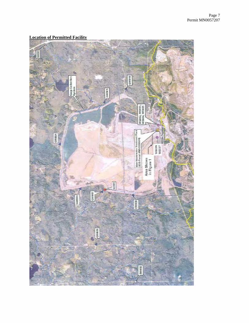
downgradient of each catch basin, connecting areas of higher elevation on either side of each discrete seepage location, to a depth of approximately 15 feet below existing ground level to ensure that surrounding wetlands are minimally impacted. The system will consist of two subsystems, one collecting seepage from the northern section and the other from the southern section. Each subsystem will terminate in a pump station consisting of a concrete vault containing a duplex pump system capable of returning the collected seepage back to the tailings basin clear pool reservoir. Upon completion of construction of the SC&R system and commencement of its operation, all water formerly reporting to SD002 (previously designated as Seep 030) will be captured and pumped back into the tailings basin clear pool, effectively eliminating the discharge through the currently permitted outfall. Due to safety issues at the current internal monitoring station, WS001, the minor permit modification also includes the relocation of monitoring station WS001 to two separate monitoring stations to be identified as WS006 and WS007. The new internal monitoring stations are representative of the entire fine tailings discharge from the Concentrator which also includes discharge from the flotation process. The fine tailings slurry is discharged through one of two routes at any given time, either to the east portion of the tailings basin past WS006 or to the west portion of the tailings basin past WS007, for uniform tailings distribution and disposal. The location of designated monitoring stations is specified on the attached "Summary of Stations and Station Locations" report. The location of the facility is shown on the attached aerial photograph.
Page 7 Permit MN0057207
Location of Permitted Facility
Permit Modified: April 13, 2010
Permit Expires: July 31, 1992US Steel - Minntac Tailings Basin Area
Summary of StationsPage 8
Permit #: MN0057207
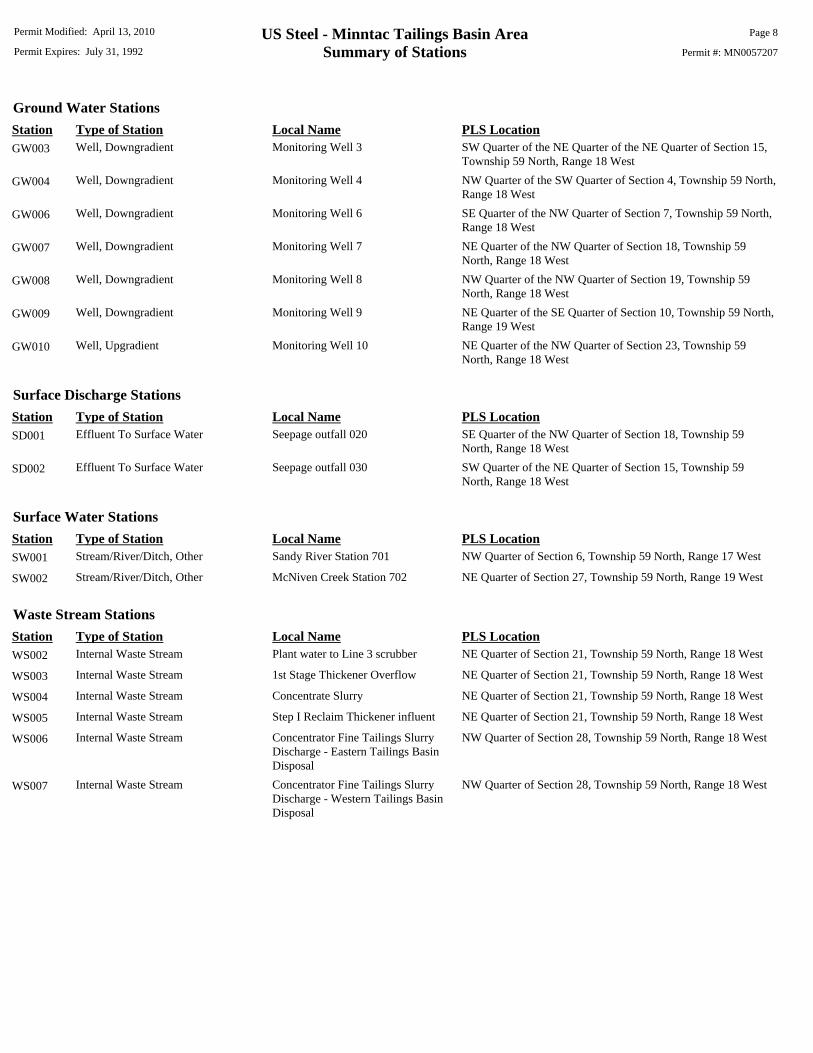
Ground Water StationsStation Type of Station Local Name PLS LocationGW003 Well, Downgradient Monitoring Well 3 SW Quarter of the NE Quarter of the NE Quarter of Section 15,
Township 59 North, Range 18 West
GW004 Well, Downgradient Monitoring Well 4 NW Quarter of the SW Quarter of Section 4, Township 59 North,Range 18 West
GW006 Well, Downgradient Monitoring Well 6 SE Quarter of the NW Quarter of Section 7, Township 59 North,Range 18 West
GW007 Well, Downgradient Monitoring Well 7 NE Quarter of the NW Quarter of Section 18, Township 59North, Range 18 West
GW008 Well, Downgradient Monitoring Well 8 NW Quarter of the NW Quarter of Section 19, Township 59North, Range 18 West
GW009 Well, Downgradient Monitoring Well 9 NE Quarter of the SE Quarter of Section 10, Township 59 North,Range 19 West
GW010 Well, Upgradient Monitoring Well 10 NE Quarter of the NW Quarter of Section 23, Township 59North, Range 18 West
Surface Discharge StationsStation Type of Station Local Name PLS LocationSD001 Effluent To Surface Water Seepage outfall 020 SE Quarter of the NW Quarter of Section 18, Township 59
North, Range 18 West
SD002 Effluent To Surface Water Seepage outfall 030 SW Quarter of the NE Quarter of Section 15, Township 59North, Range 18 West
Surface Water StationsStation Type of Station Local Name PLS LocationSW001 Stream/River/Ditch, Other Sandy River Station 701 NW Quarter of Section 6, Township 59 North, Range 17 West
SW002 Stream/River/Ditch, Other McNiven Creek Station 702 NE Quarter of Section 27, Township 59 North, Range 19 West
Waste Stream StationsStation Type of Station Local Name PLS LocationWS002 Internal Waste Stream Plant water to Line 3 scrubber NE Quarter of Section 21, Township 59 North, Range 18 West
WS003 Internal Waste Stream 1st Stage Thickener Overflow NE Quarter of Section 21, Township 59 North, Range 18 West
WS004 Internal Waste Stream Concentrate Slurry NE Quarter of Section 21, Township 59 North, Range 18 West
WS005 Internal Waste Stream Step I Reclaim Thickener influent NE Quarter of Section 21, Township 59 North, Range 18 West
WS006 Internal Waste Stream Concentrator Fine Tailings SlurryDischarge - Eastern Tailings BasinDisposal
NW Quarter of Section 28, Township 59 North, Range 18 West
WS007 Internal Waste Stream Concentrator Fine Tailings SlurryDischarge - Western Tailings BasinDisposal
NW Quarter of Section 28, Township 59 North, Range 18 West
US Steel - Minntac Tailings Basin AreaLimits and Monitoring Requirements
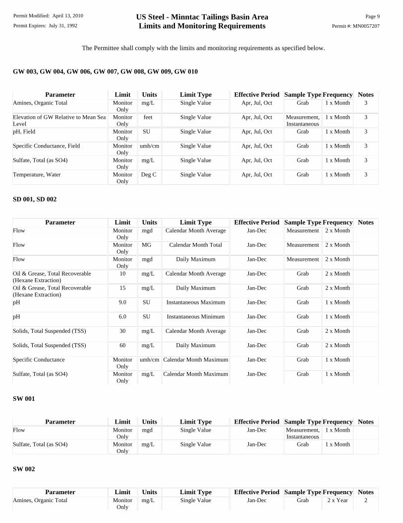
The Permittee shall comply with the limits and monitoring requirements as specified below.
Permit Modified: April 13, 2010
Permit Expires: July 31, 1992 Permit #: MN0057207
Page 9
GW 003, GW 004, GW 006, GW 007, GW 008, GW 009, GW 010
Parameter Limit Units Limit Type Effective Period Sample Type Frequency NotesAmines, Organic Total Monitor
Onlymg/L Single Value Apr, Jul, Oct Grab 1 x Month 3
Elevation of GW Relative to Mean SeaLevel
MonitorOnly
feet Single Value Apr, Jul, Oct Measurement,Instantaneous
1 x Month 3
pH, Field MonitorOnly
SU Single Value Apr, Jul, Oct Grab 1 x Month 3
Specific Conductance, Field MonitorOnly
umh/cm Single Value Apr, Jul, Oct Grab 1 x Month 3
Sulfate, Total (as SO4) MonitorOnly
mg/L Single Value Apr, Jul, Oct Grab 1 x Month 3
Temperature, Water MonitorOnly
Deg C Single Value Apr, Jul, Oct Grab 1 x Month 3
SD 001, SD 002
Parameter Limit Units Limit Type Effective Period Sample Type Frequency NotesFlow Monitor
Onlymgd Calendar Month Average Jan-Dec Measurement 2 x Month
Flow MonitorOnly
MG Calendar Month Total Jan-Dec Measurement 2 x Month
Flow MonitorOnly
mgd Daily Maximum Jan-Dec Measurement 2 x Month
Oil & Grease, Total Recoverable (Hexane Extraction)
10 mg/L Calendar Month Average Jan-Dec Grab 2 x Month
Oil & Grease, Total Recoverable (Hexane Extraction)
15 mg/L Daily Maximum Jan-Dec Grab 2 x Month
pH 9.0 SU Instantaneous Maximum Jan-Dec Grab 1 x Month
pH 6.0 SU Instantaneous Minimum Jan-Dec Grab 1 x Month
Solids, Total Suspended (TSS) 30 mg/L Calendar Month Average Jan-Dec Grab 2 x Month
Solids, Total Suspended (TSS) 60 mg/L Daily Maximum Jan-Dec Grab 2 x Month
Specific Conductance MonitorOnly
umh/cm Calendar Month Maximum Jan-Dec Grab 1 x Month
Sulfate, Total (as SO4) MonitorOnly
mg/L Calendar Month Maximum Jan-Dec Grab 1 x Month
SW 001
Parameter Limit Units Limit Type Effective Period Sample Type Frequency NotesFlow Monitor
Onlymgd Single Value Jan-Dec Measurement,
Instantaneous1 x Month
Sulfate, Total (as SO4) MonitorOnly
mg/L Single Value Jan-Dec Grab 1 x Month
SW 002
Parameter Limit Units Limit Type Effective Period Sample Type Frequency NotesAmines, Organic Total Monitor
Onlymg/L Single Value Jan-Dec Grab 2 x Year 2
US Steel - Minntac Tailings Basin AreaLimits and Monitoring Requirements
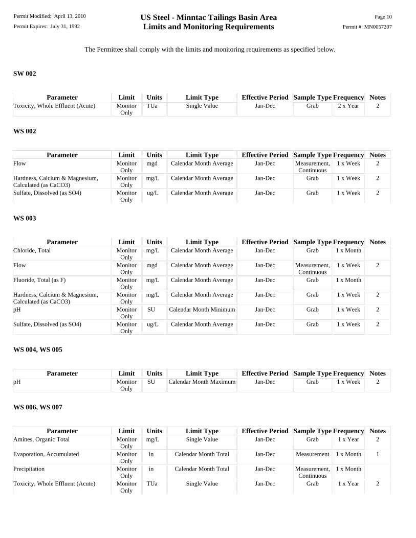
The Permittee shall comply with the limits and monitoring requirements as specified below.
Permit Modified: April 13, 2010
Permit Expires: July 31, 1992 Permit #: MN0057207
Page 10
SW 002
Parameter Limit Units Limit Type Effective Period Sample Type Frequency NotesToxicity, Whole Effluent (Acute) Monitor
OnlyTUa Single Value Jan-Dec Grab 2 x Year 2
WS 002
Parameter Limit Units Limit Type Effective Period Sample Type Frequency NotesFlow Monitor
Onlymgd Calendar Month Average Jan-Dec Measurement,
Continuous1 x Week 2
Hardness, Calcium & Magnesium, Calculated (as CaCO3)
MonitorOnly
mg/L Calendar Month Average Jan-Dec Grab 1 x Week 2
Sulfate, Dissolved (as SO4) MonitorOnly
ug/L Calendar Month Average Jan-Dec Grab 1 x Week 2
WS 003
Parameter Limit Units Limit Type Effective Period Sample Type Frequency NotesChloride, Total Monitor
Onlymg/L Calendar Month Average Jan-Dec Grab 1 x Month
Flow MonitorOnly
mgd Calendar Month Average Jan-Dec Measurement,Continuous
1 x Week 2
Fluoride, Total (as F) MonitorOnly
mg/L Calendar Month Average Jan-Dec Grab 1 x Month
Hardness, Calcium & Magnesium, Calculated (as CaCO3)
MonitorOnly
mg/L Calendar Month Average Jan-Dec Grab 1 x Week 2
pH MonitorOnly
SU Calendar Month Minimum Jan-Dec Grab 1 x Week 2
Sulfate, Dissolved (as SO4) MonitorOnly
ug/L Calendar Month Average Jan-Dec Grab 1 x Week 2
WS 004, WS 005
Parameter Limit Units Limit Type Effective Period Sample Type Frequency NotespH Monitor
OnlySU Calendar Month Maximum Jan-Dec Grab 1 x Week 2
WS 006, WS 007
Parameter Limit Units Limit Type Effective Period Sample Type Frequency NotesAmines, Organic Total Monitor
Onlymg/L Single Value Jan-Dec Grab 1 x Year 2
Evaporation, Accumulated MonitorOnly
in Calendar Month Total Jan-Dec Measurement 1 x Month 1
Precipitation MonitorOnly
in Calendar Month Total Jan-Dec Measurement,Continuous
1 x Month
Toxicity, Whole Effluent (Acute) MonitorOnly
TUa Single Value Jan-Dec Grab 1 x Year 2

US Steel - Minntac Tailings Basin AreaLimits and Monitoring Requirements
The Permittee shall comply with the limits and monitoring requirements as specified below.
Permit Modified: April 13, 2010
Permit Expires: July 31, 1992 Permit #: MN0057207
Page 11
Notes:1 -- May be estimated from data at measurement stations near the facility.2 -- See Chapter 4 Special Requirements.3 -- Three times annually: between March 28 and May 14; between July 1 and July 31; and between October 1 and October 31.
Permit Modified:
Permit Expires: July 31, 1992
April 13, 2010 Page 1
Permit #: MN0057207
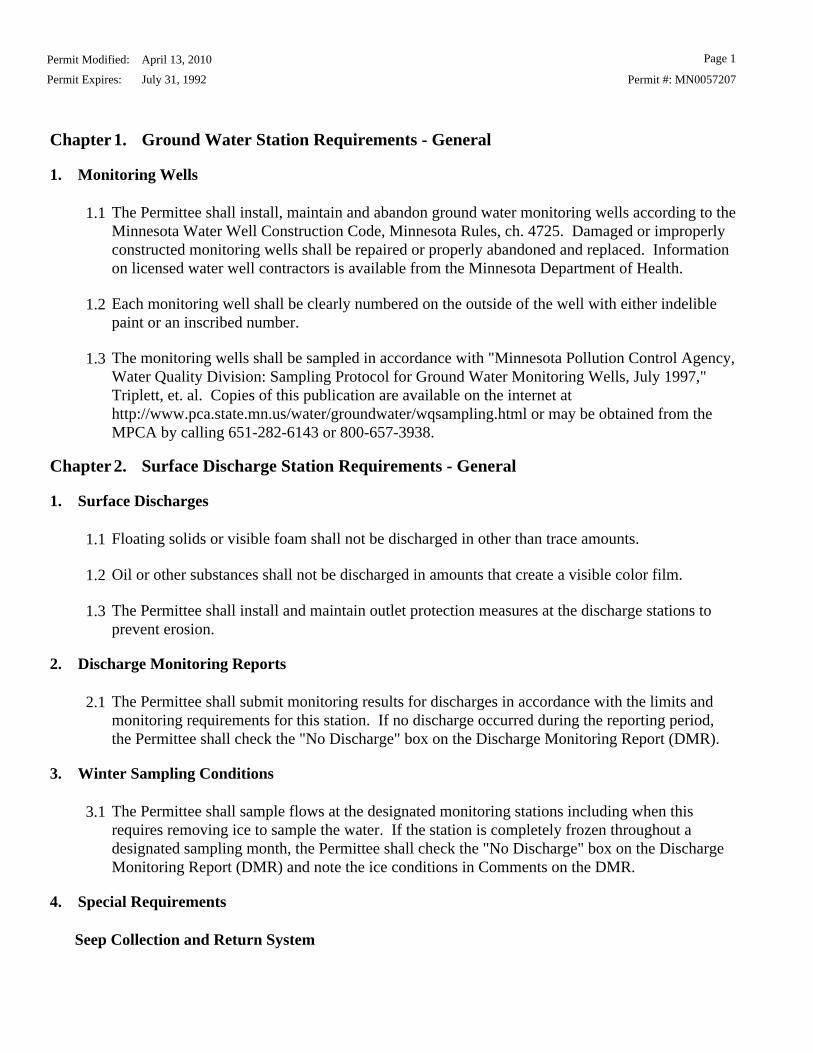
Chapter 1. Ground Water Station Requirements - General
1. Monitoring Wells
1.1 The Permittee shall install, maintain and abandon ground water monitoring wells according to theMinnesota Water Well Construction Code, Minnesota Rules, ch. 4725. Damaged or improperlyconstructed monitoring wells shall be repaired or properly abandoned and replaced. Informationon licensed water well contractors is available from the Minnesota Department of Health.
1.2 Each monitoring well shall be clearly numbered on the outside of the well with either indeliblepaint or an inscribed number.
1.3 The monitoring wells shall be sampled in accordance with "Minnesota Pollution Control Agency,Water Quality Division: Sampling Protocol for Ground Water Monitoring Wells, July 1997,"Triplett, et. al. Copies of this publication are available on the internet athttp://www.pca.state.mn.us/water/groundwater/wqsampling.html or may be obtained from theMPCA by calling 651-282-6143 or 800-657-3938.
Chapter 2. Surface Discharge Station Requirements - General
1. Surface Discharges
1.1 Floating solids or visible foam shall not be discharged in other than trace amounts.
1.2 Oil or other substances shall not be discharged in amounts that create a visible color film.
1.3 The Permittee shall install and maintain outlet protection measures at the discharge stations toprevent erosion.
2. Discharge Monitoring Reports
2.1 The Permittee shall submit monitoring results for discharges in accordance with the limits andmonitoring requirements for this station. If no discharge occurred during the reporting period,the Permittee shall check the "No Discharge" box on the Discharge Monitoring Report (DMR).
3. Winter Sampling Conditions
3.1 The Permittee shall sample flows at the designated monitoring stations including when thisrequires removing ice to sample the water. If the station is completely frozen throughout adesignated sampling month, the Permittee shall check the "No Discharge" box on the DischargeMonitoring Report (DMR) and note the ice conditions in Comments on the DMR.
4. Special Requirements
Seep Collection and Return System
Permit Modified:
Permit Expires: July 31, 1992
April 13, 2010 Page 2
Permit #: MN0057207
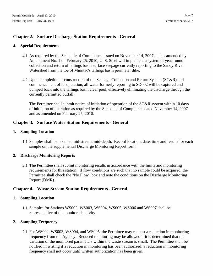
Chapter 2. Surface Discharge Station Requirements - General
4. Special Requirements
4.1 As required by the Schedule of Compliance issued on November 14, 2007 and as amended byAmendment No. 1 on February 25, 2010, U. S. Steel will implement a system of year-roundcollection and return of tailings basin surface seepage currently reporting to the Sandy RiverWatershed from the toe of Minntac's tailings basin perimeter dike.
4.2 Upon completion of construction of the Seepage Collection and Return System (SC&R) andcommencement of its operation, all water formerly reporting to SD002 will be captured andpumped back into the tailings basin clear pool, effectively eliminating the discharge through thecurrently permitted outfall.
The Permittee shall submit notice of initiation of operation of the SC&R system within 10 daysof initiation of operation as required by the Schedule of Compliance dated November 14, 2007and as amended on February 25, 2010.
Chapter 3. Surface Water Station Requirements - General
1. Sampling Location
1.1 Samples shall be taken at mid-stream, mid-depth. Record location, date, time and results for eachsample on the supplemental Discharge Monitoring Report form.
2. Discharge Monitoring Reports
2.1 The Permittee shall submit monitoring results in accordance with the limits and monitoringrequirements for this station. If flow conditions are such that no sample could be acquired, thePermittee shall check the "No Flow" box and note the conditions on the Discharge MonitoringReport (DMR).
Chapter 4. Waste Stream Station Requirements - General
1. Sampling Location
1.1 Samples for Stations WS002, WS003, WS004, WS005, WS006 and WS007 shall berepresentative of the monitored activity.
2. Sampling Frequency
2.1 For WS002, WS003, WS004, and WS005, the Permittee may request a reduction in monitoringfrequency from the Agency. Reduced monitoring may be allowed if it is determined that thevariation of the monitored parameters within the waste stream is small. The Permittee shall benotified in writing if a reduction in monitoring has been authorized; a reduction in monitoringfrequency shall not occur until written authorization has been given.
Permit Modified:
Permit Expires: July 31, 1992
April 13, 2010 Page 3
Permit #: MN0057207
Chapter 4. Waste Stream Station Requirements - General
3. Special Requirements
Determination of no net increase in sulfate mass loading to the tailings basin
3.1 Sampling and analysis shall be done in accordance with the Limits and Monitoring requirementssection of this permit. The following steps shall be completed during each sample event:
Step 1: Measure the dissolved sulfate concentration and flow rate of water in the scrubbermakeup stream (WS002). Calculate the mass of sulfate in the makeup stream. This is the massloading of sulfate entering the scrubber system.
Step 2: Measure the dissolved sulfate concentration and flow rate of the overflow from thecalcium sulfate thickener (WS003). Calculate the mass of sulfate in the thickener overflow. Thisis the mass loading of sulfate leaving the scrubber system.
The calculations described above shall be compiled for each calendar year. On an annual basis,the mass of sulfate leaving the scrubber system shall be less than or equal to the mass of sulfateentering the scrubber system.
Determination of no net increase in hardness mass loading to the tailings basin
Permit Modified:
Permit Expires: July 31, 1992
April 13, 2010 Page 4
Permit #: MN0057207
Chapter 4. Waste Stream Station Requirements - General
3. Special Requirements
3.2 Sampling and analysis shall be done in accordance with the Limits and Monitoring requirementssection of this permit. The following steps shall be completed during each sample event:
Step 1: Measure the hardness (calcium + magnesium) concentration and flow rate of water in thescrubber makeup stream (WS002). Calculate the mass of hardness in the makeup stream. This isthe mass loading of hardness entering the scrubber system.
Step 2: Measure the hardness concentration and flow rate of the overflow from the calciumsulfate thickener (WS003). Calculate the mass of hardness in the thickener overflow.
Step 3: Subtract the mass of hardness in the makeup stream (Step 1) from the mass of hardnessin the thickener overflow (Step 2). This is the mass of hardness that must be removed to satisfythe no net increase requirement. Convert the calculated mass of hardness to the appropriate molesof calcium and magnesium.
Step 4: Measure the pH of the thickener overflow (WS003) and the pH of the concentrate slurrystream (WS004) and/or the influent to the Step I Reclaim Thickener (WS005). Using thedifference between the pH of the thickener overflow and the appropriate slurry stream(s) and theflow rate of the thickener overflow, calculate the mass of excess hydroxide ions that are presentin the thickener overflow (which will convert bicarbonate in the concentrate stream to carbonate).Convert the mass to moles of hydroxide ions.
The calculations described above shall be compiled for each calendar year. On an annual basis,the number of moles of excess hydroxide ion (Step 4) must be equal to or greater than the numberof moles of excess calcium and magnesium (Step 3) in the thickener overflow stream.
3.3 If the oveflow from the calcium sulfate thickener is sent to both the Concentrate Thickener (orSlurry Mix Tank) and the Step I Reclaim Thickener in the same reporting period, the mass ofexcess hydroxide ions present in the thickener overflow (Step 4 above) shall be total of theindividual calculations based on the pH of the each slurry stream and the average flow rate of thethickener overflow to each location during the reporting period.
3.4 As part of the Annual Pollution Control Report, as required in Chapter 6, Requirement 1.3, to besubmitted by February 14 of each year, submit a summary of the Line 3 scrubber wastewatertreatment system monitoring activities and calculations for the preceding calendar year. Thesubmittal shall include the determination of compliance with the no net increase in mass loadingfrom the Line 3 scrubber wastewater treatment system. If compliance with the no net increase inthe mass loading of sulfate and hardness to the tailings basin has not been achieved, the submittalshall include a discussion of why compliance was not achieved, as well as a work plan andschedule, for MPCA review and approval, to achieve compliance.
Toxicity Testing Requirements
Permit Modified:
Permit Expires: July 31, 1992
April 13, 2010 Page 5
Permit #: MN0057207
Chapter 4. Waste Stream Station Requirements - General
3. Special Requirements
3.5 The Permittee shall conduct acute toxicity testing of the waste stream from WS006 or WS007(formerly WS001), depending upon which route of fine tailings slurry discharge is being used.Acute toxicity testing shall be conducted at least two times per year from WS006 or WS007 torepresent the fine tailings slurry discharge stream. The test organisms shall be the fatheadminnow (Pimephales promelas). The acute tests shall consist of a screen of 100 percent of thewaste stream once every six months, beginning on the effective date of this permit.
3.6 Based upon review by the Commissioner of the toxicity test results, the permit may be reopenedand subject to modification under requirements specified in Minnesota Rules Parts 7001.0170 to7001.0190. The modified permit may include new requirements for toxicity testing, toxicitylimitations, and a toxicity reduction evaluation (TRE) program.
Procedural Requirements for Toxicity Testing
3.7 1) Tests shall be conducted in accordance with procedures outlined in EPA-600/4-85-013entitled "Methods for Measuring the Acute Toxicity of Effluents to Aquatic Organisms." Anycircumstances not covered by this procedural manual, or that require deviation from that which isspecified in the manual shall first be approved by the Commissioner.
2) The waste stream sample shall be allowed to settle for 24 hours. The sample supernatant shallthen be filtered through a 0.45 um filter. The filtrate shall serve as the sample for toxicity testing.
3) The control water shall be taken from SW002 (formerly 702), and shall undergo settling andfiltering as in item 2 above.
4) Analysis for amine shall be conducted on each waste stream sample and control for which atoxicity test is conducted.
5) Submittal of the toxicity testing results shall include the date of sample collection, date of thetoxicity tests, enumeration of mortality in samples, and the raw data used in making thecalculations. Submittal of the amine results shall include the date of sample collection, date ofamine analysis, and the concentrations detected.
3.8 If acute toxicity testing at WS006 and/or WS007 or in the Minntac tailings basin indicates thatthe waste stream is acutely toxic, the Commissioner may require acute toxicity testing at outfallsSD001, SD002, stations GW001-GW008, or other locations designated by the Commissioner.No discharge from the facility to waters of the state shall be acutely toxic to humans or otheranimals or plant life, directly damaging to real property, or such as to actually or potentiallypreclude or limit the use of underground waters as a potable water supply.
Permit Modified:
Permit Expires: July 31, 1992
April 13, 2010 Page 6
Permit #: MN0057207
Chapter 5. Station Requirements - Specific
1. Ground Water Stations
1.1 GW 003: Submit a monthly DMR monthly: due 21 days after end of each calendar monthfollowing permit issuance.
1.2 GW 004: Submit a monthly DMR monthly: due 21 days after end of each calendar monthfollowing permit issuance.
1.3 GW 006: Submit a monthly DMR monthly: due 21 days after end of each calendar monthfollowing permit issuance.
1.4 GW 007: Submit a monthly DMR monthly: due 21 days after end of each calendar monthfollowing permit issuance.
1.5 GW 008: Submit a monthly DMR monthly: due 21 days after end of each calendar monthfollowing permit issuance.
1.6 GW 009: Submit a monthly DMR monthly: due 21 days after end of each calendar monthfollowing permit issuance.
1.7 GW 010: Submit a monthly DMR monthly: due 21 days after end of each calendar monthfollowing permit issuance.
2. Surface Discharge Stations
2.1 SD 001: Submit a monthly DMR monthly: due 21 days after end of each calendar monthfollowing permit issuance.
2.2 SD 002: Submit a monthly DMR monthly: due 21 days after end of each calendar monthfollowing permit issuance.
3. Surface Water Stations
3.1 SW 001: Submit a monthly DMR monthly: due 21 days after end of each calendar monthfollowing permit issuance.
3.2 SW 002: Submit a monthly DMR monthly: due 21 days after end of each calendar monthfollowing permit issuance.
4. Waste Stream Stations
4.1 WS 002: Submit a monthly DMR monthly by 21 days after the end of each calendar monthfollowing issuance of major permit modification.
4.2 WS 003: Submit a monthly DMR monthly by 21 days after the end of each calendar monthfollowing issuance of major permit modification.
Permit Modified:
Permit Expires: July 31, 1992
April 13, 2010 Page 7
Permit #: MN0057207
Chapter 5. Station Requirements - Specific
4. Waste Stream Stations
4.3 WS 004: Submit a monthly DMR monthly by 21 days after the end of each calendar monthfollowing issuance of major permit modification.
4.4 WS 005: Submit a monthly DMR monthly by 21 days after the end of each calendar monthfollowing issuance of minor permit modification.
4.5 WS 006: Submit an annual DMR annually by February 14 of each year following permitissuance.
4.6 WS 007: Submit an annual DMR annually by February 14 of each year following permitissuance.
Chapter 6. Industrial Process Wastewater, NPDES/SDS
1. Mine Tailings Basin
1.1 The Permitee shall notify the Commissioner in writing at least 180 days in advance of anyexpansion of the area covered by mining waste beyond that area contained within the perimeterdam for the tailings basin on the date of issuance of this permit.
1.2 The Permittee shall control surface runoff from mining waste disposal areas when such runoffhas caused or is likely to cause the limits specified in the water quality standards, including butnot limited to those for turbidity, to be exceeded in the following receiving waters: the SandyRiver.
1.3 The Permittee shall submit an Annual Pollution Control Report to the Commissioner. The annualreport shall be due on February 14 of each year, and shall detail for the previous year:
a. changes in plant processing from that shown on the flow sheets submitted with the applicationfor this permit, including rates of reagent addition;
b. changes in water balance flow from those flow data submitted with the application for thispermit;
c. a current map of the tailings basin, showing all dikes, dams, and cells, and current topographicand water level elevations in the basin;
d. changes in the tailings basin operation from that described in the facility description; and
e. Line 3 scrubber wastewater treatment system submittal required in Chapter 4.
Permit Modified:
Permit Expires: July 31, 1992
April 13, 2010 Page 8
Permit #: MN0057207
Chapter 6. Industrial Process Wastewater, NPDES/SDS
1. Mine Tailings Basin
1.4 The Permittee shall summarize the following water input and output data on a monthly basis, andshall include these data with the Discharge Monitoring Reports required by this permit:
a. Precipitation depth (this may be estimated from data at measurement stations near the facility);
b. Sources and volumes of non-precipitation water inputs to the facility;
c. Lake evaporation (this may be estimated from data at measurement stations near the facility);
d. Volume discharged from outfall SD001; and
e. Volume discharged from outfall SD002.
2. Toxic Substance Reporting
2.1 The Permittee shall notify the MPCA immediately of any knowledge or reason to believe that anactivity has occurred that would result in the discharge of a toxic pollutant listed in MinnesotaRules, pt. 7001.1060, subp. 4 to 10 or listed below that is not limited in the permit, if thedischarge of this toxic pollutant has exceeded or is expected to exceed the following levels:
a. for acrolein and acrylonitrile, 200 ug/L;
b. for 2,4-dinitrophenol and 2-methyl-4,6-dinitrophenol, 500 ug/L;
c. for antimony, 1mg/L;
d. for any other toxic pollutant listed in Minnesota Rules, pt. 7001.1060, subp. 4 to 10, 100 ug/L;or
e. five times the maximum concentration value identified and reported for that pollutant in thepermit application. (Minnesota Rules, pt. 7001.1090, subp. 2.A)
2.2 The Permittee shall notify the MPCA immediately if the Permittee has begun or expects to beginto use or manufacture as an intermediate or final by-product a toxic pollutant that was notreported in the permit application under Minnesota Rules, pt. 7001.1050, subp. 2.J. (MinnesotaRules, pt. 7001.1090, subp. 2.B)
Permit Modified:
Permit Expires: July 31, 1992
April 13, 2010 Page 9
Permit #: MN0057207
Chapter 6. Industrial Process Wastewater, NPDES/SDS
3. Mobile and Rail Equipment Service Areas
3.1 Mobile equipment and rail equipment service areas in the facility shall be operated in compliancewith the following:
a. The Permittee shall collect and dispose of locomotive traction sand, degreasing wastes, motoroil, oil filters, oil sorbent pads and booms, transmission fluids, power steering fluids, brakefluids, coolant/antifreeze, radiator flush wastewater and spent solvents in accordance withapplicable solid and hazardous waste management rules. These materials shall not be dischargedto surface or ground waters of the state.
b. The steam-cleaning of mobile equipment and rail equipment, except for limited outdoorcleaning of large drills and shovels, shall be conducted in wash bays that drain to wastewatertreatment systems that include the removal of suspended solids and flammable liquids. The onlywashing of mobile equipment done in outside areas shall be to remove mud and dirt that hasaccumulated during outside work.
c. The Permittee shall not use solvent-based cleaners, such as those available for brake cleaningand degreasing, to wash mobile and rail equipment unless the cleaning fluids are completelycontained and not allowed to flow to surface or ground waters of the state. Soaps and detergentsused in washing shall be biodegradable.
d. Mobile and rail equipment maintenance and repairs shall not be conducted in wash bays.
e. Hazardous materials shall not be stored or handled in wash bays.
f. The Permittee shall inspect wastewater containment systems regularly, and repair any leaksthat are detected immediately.
g. If the Permittee discovers that recoverable amounts of petroleum products have enteredwastewater containment systems, they shall be recovered immediately and reported to the MPCA.
h. Spill cleanup procedures shall be posted in mobile and rail equipment maintenance and repairareas.
4. Polychlorinated Biphenyls (PCBs)
4.1 PCBs, including but not limited to those used in electrical transformers and capacitors, shall notbe discharged or released to the environment.
5. New Proposed Dewatering
5.1 The Permittee shall obtain a permit modification before discharging from a new dewateringoutfall.
Permit Modified:
Permit Expires: July 31, 1992
April 13, 2010 Page 10
Permit #: MN0057207
Chapter 6. Industrial Process Wastewater, NPDES/SDS
6. Application for Permit Reissuance
6.1 The Permittee shall include, as part of the application for reissuance of this permit, an updatedoperating plan for the basin for the next five years.
7. Special Requirements
7.1 The Permittee will be constructing a new scrubber solids settling/storage pond located in the SW1/4 of the NW 1/4 of the NW 1/4, Section 27, T59N, R18W. The scrubber solids pond mayeventually serve as a disposal pond for scrubber solids. The scrubber pond is designed inaccordance with MPCA pond design and solid waste design criteria and will include a compositeliner and a dewatering system to accommodate dewatering of the pond contents. At closure thepond will be capped with a liner system in accordance with MPCA solid waste capping designcriteria.
The scrubber solids pond shall be constructed in accordance with the pond design plans andspecifications submitted for the project and in accordance with MPCA approval conditions of theengineering plans and specifications for the pond. The final cover/cap for the pond shall beinstalled in accordance with the submitted plans, as described in Requirement 7.2 below, and anyadditional MPCA design specifications required by the MPCA at the time of pond closure.
The scrubber pond is expected to have a useful life of approximately 20 years. Dewatering ofpond wastewater will occur periodically using the approved dewatering system. Water removedfrom the pond shall be returned to the head of the Line 3 scrubber wastewater treatment system.If not returned to the treatment system, collected pond water shall be treated in accordance withMPCA requirements at that time and discharged to the tailings basin or otherwise treated off site.Discharge of pond dewatering to the tailings basin may require a permit modification.
7.2 The Permittee shall submit for MPCA approval, at least 120 days prior to the closure of anyscrubber solids pond at the plant, a plan to provide a clay or geosynthetic cap, or other method tominimize erosion and infiltration from the former pond. The plan shall conform to MPCA designcriteria in effect at that time, and shall include provisions for perpetual maintenance. ThePermittee shall implement the plan upon closure of the disposal pond.
Upon completion of the disposal pond closure project, a detailed description, including a plat,shall be recorded with the county register of deeds. The description shall include general typesand location of wastes, depth of fill, and other information of interest to future land owners.
7.3 The Permittee shall submit for MPCA review and approval, plans and specifications, as well asany additional information required by the MPCA, for any additional scrubber solidssettling/storage ponds. The scrubber pond(s) shall be designed in accordance with MPCA ponddesign criteria and include a dewatering system to accommodate dewatering of the pondcontents. No construction shall begin until the Permittee has received written approval of plansand specifications for the construction from the MPCA.
Permit Modified:
Permit Expires: July 31, 1992
April 13, 2010 Page 11
Permit #: MN0057207
Chapter 7. Total Facility Requirements
1. Sampling and Analyses
1.1 Sample preservation and test procedures for the analysis of pollutants shall conform to 40 CFRPart 136 and Minnesota Rules, part 7041.3200.
1.2 Volatile organics shall be analyzed using Minnesota Department of Health Method 465E orequivalent method.
1.3 All monitoring and analytical instruments used to monitor as required by this permit shall becalibrated and maintained at a frequency necessary to ensure accuracy. The Permittee shallmeasure flows to ensure accuracy within plus or minus ten percent of the true flow values. ThePermittee shall maintain written records of all calibrations and maintenance.
1.4 Samples and measurements required by this permit shall be representative of the monitoredactivity and shall be analyzed by a laboratory certified by the Minnesota Department of Healthfor the applicable permitted parameters. Analyses of dissolved oxygen, pH, temperature andtotal residual chlorine do not need to be completed by a certified laboratory.
1.5 The "sample type", "sampling frequency" and "effective period" identified in the Limits andMonitoring section of this permit together designate the minimum required monitoringfrequency.
1.6 If a Permittee monitors more frequently than required by this permit, the results and thefrequency of monitoring shall be reported on the Discharge Monitoring Report (DMR) or otherform for that reporting period.
1.7 For bypasses, upsets, spills or any other discharge that may cause pollution of the waters of thestate, the Permittee shall take at least one (1) grab sample for permitted effluent parameters two(2) times per week. If the Permittee believes that measuring these parameters is inappropriate dueto known information about the discharge, the monitoring may be modified in consultation withthe MPCA. Where there is reason to believe a pollutant other than those limited in the permit ispresent, the Permittee shall sample for that pollutant. Appropriate sampling shall be determinedin consultation with the MPCA.
2. Facility Closure
2.1 The Permittee is responsible for closure and postclosure care of the facility. The Permittee shallnotify the MPCA of a significant reduction or cessation of operations described in this permit.
2.2 Facility closure that could result in a potential long-term water quality concern, such as theongoing discharge of wastewater to surface or ground water, may require a permit modification.An application for permit modification shall be submitted to the MPCA for approval before theproposed change is implemented.
Permit Modified:
Permit Expires: July 31, 1992
April 13, 2010 Page 12
Permit #: MN0057207
Chapter 7. Total Facility Requirements
2. Facility Closure
2.3 The MPCA may require the Permittee to establish financial assurance for closure, postclosurecare and remedial action at the facility.
2.4 The Commissioner may require the Permittee to submit a Pollution Control Deactivation Plan forapproval. The Permittee shall notify the Commissioner of any significant reduction or cessationof the operations described in the Facility Description. If a plan is required, the Commissionerwill inform the Permittee in writing of this request, and will state the site-specific concerns thatthe plan shall address and the date by which the plan shall be submitted. The plan shall providefor the implementation, including continued maintenance if necessary, of best managementpractices and best available technology and shall assure compliance with all applicable laws andAgency regulations which apply to air quality, water quality, and the disposal of hazardoussubstances.
3. Reporting
3.1 The Permittee shall report monitoring results for the completed reporting period in the unitsspecified by this permit on a Discharge Monitoring Report (DMR) form or other report formprovided by the MPCA.
3.2 The Permittee shall report ground water monitoring results on the Discharge Monitoring Report.
3.3 The Permittee shall report monitoring results below the reporting limit (RL) of a particularinstrument as "<" the value of the RL. For example, if an instrument has a RL of 0.1 mg/L and aparameter is not detected at a value of 0.1 mg/L or greater, the concentration shall be reported as"<0.1 mg/L." "Non-detected", "undetected", "below detection limit" and "zero" are unacceptablereporting results, and are permit reporting violations.
3.4 A Discharge Monitoring Report (DMR) shall be submitted for each station even if no dischargeoccurred during the reporting period. The Permittee shall report 'No Discharge', 'No Flow' or 'NoMaterials Generated' on a DMR or other monitoring report form only if no discharge, flow ormaterials are generated during the entire reporting period. The schedule for reporting can befound on the Submittals Summary section of this permit.
3.5 Individual values for each sample and measurement must be reported on the SupplementalReport Form provided by the MPCA and submitted with the Discharge Monitoring Report(DMR).
Permit Modified:
Permit Expires: July 31, 1992
April 13, 2010 Page 13
Permit #: MN0057207
Chapter 7. Total Facility Requirements
3. Reporting
3.6 The Permittee shall report the following information on the Discharge Monitoring Report (DMR):
a. any substantial changes in operational procedures;
b. activities which alter the nature or frequency of the discharge; and
c. material factors affecting compliance with the conditions of this permit.
3.7 The Permittee shall report monitoring results of bypass events on its Discharge MonitoringReport (DMR). If no bypass events occurred, check the "No Discharge" box on the DMR.
3.8 The Permittee or the duly authorized representative of the Permittee shall sign the reports anddocuments submitted to the MPCA by the Permittee. (Minnesota Rules, pt. 7001.0150, subp.2.D)
3.9 A person who falsifies, tampers with, or knowingly renders inaccurate a monitoring device ormethod required to be maintained under this permit is subject to penalties provided by federaland state law. (Minnesota Rules, pt. 7001.1090, subp. 1.G)
3.10 The Permittee shall report noncompliance with the permit not reported under Minnesota Rules,part 7001.0150, subpart 3, item K as a part of the next report which the Permittee is required tosubmit under this permit. If no reports are required within 30 days of the discovery of thenoncompliance, the Permittee shall submit the information listed in Minnesota Rules, part7001.0150, subpart 3, item K within 30 days of the discovery of the noncompliance. (MinnesotaRules, pt. 7001.1090, subp. 1.H)
3.11 A person who knowingly makes a false statement, representation, or certification in a record orother document submitted or required to be maintained under this permit, including monitoringreports or reports of compliance or noncompliance is subject to penalties provided by federal andstate law set forth. (Minnesota Rules, pt. 7001.0150, subp. 3.L)
Permit Modified:
Permit Expires: July 31, 1992
April 13, 2010 Page 14
Permit #: MN0057207
Chapter 7. Total Facility Requirements
4. Records
4.1 The Permittee shall maintain records for each sample and measurement. The records shallinclude the following information:
a. the exact place, date and time of the sample or measurement;
b. the date of analysis;
c. the name of the person who performed the sample collection, measurement, analysis, orcalculation;
d. the analytical techniques, procedures and methods used; and,
e. the results of the analysis.
4.2 The Permittee shall keep the records required by this permit for at least three (3) years, includingany calculations, original recordings from automatic monitoring instruments, and laboratorysheets. The Permittee shall extend these record retention periods upon request of the MPCAand/or during the course of an unresolved enforcement action. (Minnesota Rules, pt. 7001.0150,subp. 2.C.)
4.3 Except for data determined to be confidential according to Minnesota Statutes, ch. 116.075, subd.2, all reports required by this permit shall be available for public inspection at the MPCA St. Pauloffice. Effluent data shall not be considered confidential. Confidential material shall besubmitted according to Minnesota Rules, pt. 7000.1300.
4.4 The Permittee shall, when requested by the commissioner, submit within a reasonable time theinformation and reports that are relevant to the control of pollution regarding the construction,modification, or operation of the facility covered by the permit or regarding the conduct of theactivity covered by the permit. (Minnesota Rules, pt. 7001.0150, subp. 3.H.)
5. Compliance Responsibility
5.1 The Permittee shall perform the actions or conduct the activity authorized by the permit inaccordance with the plans and specifications approved by the agency and in compliance with theconditions of the permit. (Minnesota Rules, pt. 7001.0150, subp. 3.E.)
6. Noncompliance
6.1 Noncompliance with the requirements of this permit subjects the Permittee to penalties providedby federal and state law including monetary penalties, imprisonment, or both. (Minnesota Rules,pt. 7001.1090, subp. 1.B.; U.S.C. title 33, sect. 1319; Minn. Stat. sect. 115.071)
Permit Modified:
Permit Expires: July 31, 1992
April 13, 2010 Page 15
Permit #: MN0057207
Chapter 7. Total Facility Requirements
6. Noncompliance
6.2 If the Permittee discovers that noncompliance with a condition of the permit has occurred, thePermittee shall:
a. take all reasonable steps to minimize the adverse impacts to human health, public drinkingwater supplies, or the environment resulting from a permit violation.
b. notify the Minnesota Department of Public Safety Duty Officer at 1(800)422-0798 or(651)649-5451 within 24 hours of becoming aware of a permit violation that may endangerhuman health, public drinking water supplies or the environment. The Permittee shall submit awritten description of the exceedance to the MPCA within five (5) days of discovery of theexceedance.
Nothing in this requirement relieves the Permittee from immediately notifying the MPCA of anyrelease to surface waters of the state. (Minnesota Rules, pt. 7001.0150, subp. 3. J, K)
6.3 The Permittee shall submit a written description of any bypass, spill, upset or permit violationduring the reporting period to the MPCA with its Discharge Monitoring Report (DMR). If noDMR is required within 30 days, the Permittee shall submit a written report within 30 days of thediscovery of the noncompliance. This description shall include the following information:
a. a description of the event including volume, duration, monitoring results and receiving waters;
b. the cause of the event;
c. the steps taken to reduce, eliminate and prevent reoccurrence of the event;
d. the exact dates and times of the event; and
e. steps taken to reduce any adverse impact resulting from the event. (Minnesota Rules, pt.7001.0150, subp. 3.K)
Permit Modified:
Permit Expires: July 31, 1992
April 13, 2010 Page 16
Permit #: MN0057207
Chapter 7. Total Facility Requirements
7. Upset Defense
7.1 In the event of temporary noncompliance by the Permittee with an applicable effluent limitationresulting from an upset at the Permittee's facility due to factors beyond the control of thePermittee, the Permittee has an affirmative defense to an enforcement action brought by theagency as a result of the noncompliance if the Permittee demonstrates by a preponderance ofcompetent evidence:
a. the specific cause of the upset;
b. that the upset was unintentional;
c. that the upset resulted from factors beyond the control of the Permittee and did not result fromoperational error, improperly designed treatment facilities, inadequate treatment facilities, lack ofpreventative maintenance, or increases in production which are beyond the design capability ofthe treatment facilities;
d. that at the time of the upset the facility was being properly operated;
e. that the Permittee properly notified the commissioner of the upset in accordance withMinnesota Rules, part 7001.0150, subpart 3, items K and L; and
f. that the Permittee implemented the remedial measures required by Minnesota Rules, part7001.0150, subpart 3, item J. (Minnesota Rules, pt. 7001.1090, subp. 1.L)
8. Duty to Notify and Avoid Water Pollution
8.1 The Permittee shall notify the Minnesota Department of Public Safety Duty Officer at(800)422-0798 or (651)649-5451 immediately of the discharge, accidental or otherwise, of anysubstance or material under its control which, if not recovered, may cause pollution of waters ofthe state. Notification is not required for a discharge of five (5) gallons or less of petroleum.(Minnesota Statutes, section 115.061)
8.2 The Permittee shall report to the Duty Officer all pertinent information regarding the discharge.Refer to the MPCA "Emergency Notification Guidance for Wastewater Treatment Systems" forfurther information.
8.3 The Permittee shall take all reasonable steps to minimize the adverse impacts to human health,public drinking water supplies or to the environment resulting from the discharge. This mayinclude restricting or preventing untreated or partially treated wastewater, plant chemicals orfeedlot materials from entering waterways, containing spilled materials, recycling by-passedwastewater through the plant, or using auxiliary treatment methods. (Minnesota Statutes, section115.061)
Permit Modified:
Permit Expires: July 31, 1992
April 13, 2010 Page 17
Permit #: MN0057207
Chapter 7. Total Facility Requirements
9. Anticipated Bypasses
9.1 The Permittee may allow a bypass to occur if the bypass will not cause the exceedance of aneffluent limitation but only if the bypass is necessary for essential maintenance to assure efficientoperation of the facility. The permittee shall submit notice of the need for the bypass at least tendays before the date of the bypass. (Minnesota Rules, pt. 7001.1090, subp. 1.J)
9.2 The notice of the need for a bypass shall include the following information:
a. The proposed date and estimated duration of the bypass.
b. The alternatives to bypassing.
c. The proposed measures to mitigate environmental harm caused by the bypass.
d. A proposal for bypass monitoring.
9.3 The Permittee shall not allow an anticipated bypass to occur that will cause an exceedance of anapplicable effluent limitation unless the following conditions are met:
a. The bypass is unavoidable to prevent loss of life, personal injury, or severe property damage.For the purposes of this paragraph, "severe property damage" means substantial damage toproperty of the Permittee or of others; damage to the wastewater treatment facilities that maycause them to become inoperable; or substantial and permanent loss of natural resources that canbe reasonably expected to occur in the absence of a bypass. "Severe property damage" does notmean economic loss as a result of a delay in production.
b. There is no feasible alternative to the bypass, such as the use of auxiliary treatment facilities,retention of untreated wastes, or performance of maintenance during normal periods ofequipment downtime. This condition is not satisfied if adequate backup equipment should havebeen installed in the exercise of reasonable engineering judgment to prevent a bypass whichoccurred during normal periods of equipment downtime or preventative maintenance.
c. The Permittee has notified the commissioner of the anticipated bypass and the commissionerhas approved the bypass. The commissioner shall approve the bypass if the commissioner findsthat the conditions set forth in Minnesota Statutes, part 7001.1090, subpart 1, items A and B aremet. (Minnesota Rules, pt. 7001.1090, subp. 1.K)
10. Facilities Operation
10.1 The Permittee shall properly operate and maintain the systems used to achieve permitcompliance. Proper operation and maintenance includes effective performance, adequatefunding, adequate staffing and training, and adequate process and laboratory controls, includingappropriate quality assurance procedures. (Minnesota Rules, pt. 7001.0150, subp. 3.F)
Permit Modified:
Permit Expires: July 31, 1992
April 13, 2010 Page 18
Permit #: MN0057207
Chapter 7. Total Facility Requirements
10. Facilities Operation
10.2 The Permittee is responsible for insuring system reliability and shall install adequate backup orsupport systems to achieve permit compliance and prevent the discharge of untreated orinadequately treated waste. These systems may include alternative power sources, auxiliarytreatment works and sufficient storage volume for untreated wastes. (Minnesota Rules, pt.7001.0150, subp. 3.F)
10.3 The Permittee shall store, transport and dispose of biosolids, sediments, residual solids, filterbackwash, screenings, oil, grease and other substances so that pollutants do not enter surfacewaters or ground waters of the state.
10.4 The Permittee's discharge shall not cause any nuisance conditions, acutely toxic conditions toaquatic life or other adverse impact on the receiving water.
10.5 The Permittee shall comply with all applicable water quality, air quality, solid waste andhazardous waste statutes and rules in the operation and maintenance of the facility.
10.6 The Permittee shall schedule maintenance of the treatment works during non-critical waterquality periods to prevent degradation of water quality.
10.7 In-plant control tests shall be conducted at a frequency adequate to ensure continuous efficientoperation of the treatment facility.
11. Chemical Additives
11.1 The Permittee shall receive prior written approval from the MPCA before increasing the use of achemical additive authorized by this permit, or using a chemical additive not authorized by thispermit. "Chemical additive" includes processing reagents, water treatment products, coolingwater additives, freeze conditioning agents, chemical dust suppressants, detergents and solventcleaners used for equipment and maintenance cleaning, among other materials.
11.2 The Permittee shall request approval for an increased or new use of a chemical additive 60 daysbefore the proposed increased or new use.
Permit Modified:
Permit Expires: July 31, 1992
April 13, 2010 Page 19
Permit #: MN0057207
Chapter 7. Total Facility Requirements
11. Chemical Additives
11.3 This written request shall include the following information for the proposed additive:
a. Material Safety Data Sheet.
b. A complete product use and instruction label.
c. The commercial and chemical names of all ingredients.
d. Aquatic toxicity and human health or mammalian toxicity data including a carcinogenic,mutagenic or teratogenic concern or rating.
e. Environmental fate information including, but not limited to, persistence, half-life,intermediate breakdown products, and bioaccumulation data.
f. The proposed method, concentration, and average and maximum rates of use.
g. If applicable, the number of cycles before wastewater bleedoff.
h. If applicable, the ratio of makeup flow to discharge flow.
11.4 This permit may be modified to restrict the use or discharge of a chemical additive.
12. Inspection And Entry
12.1 The Permittee shall allow a representative of the MPCA, in accordance with Section 308 of theAct and Minnesota Statutes, section 115.04, and upon presentation of proper credentials, to:
a. enter the premises where the facility is located or activity conducted;
b. review and copy the records required by this permit;
c. inspect the facilities, systems, equipment, practices or operations regulated or required by thispermit;
d. sample or monitor to determine compliance; and
e. bring equipment upon the Permittee's premises necessary to conduct surveys andinvestigations. (Minnesota Rules, pt. 7001.0150, subp. 3.I)
Permit Modified:
Permit Expires: July 31, 1992
April 13, 2010 Page 20
Permit #: MN0057207
Chapter 7. Total Facility Requirements
13. Permit Modifications
13.1 Changes to the facility or operation of the facility may require a permit modification. ThePermittee shall submit an application describing the changes to the facility or operation to theMPCA and receive a permit modification prior to implementing the changes. The Permittee mustsubmit the permit modification application fee in accordance with Minnesota Rules, part7002.0250 with the application.
13.2 The following changes may require a permit modification:
a. Increased use or new use of a chemical additive.
b. Changes in the characteristics, concentrations or frequency of the wastewater flow, which mayinclude new significant industrial discharges to a sanitary sewage treatment system, significantchanges in existing industrial discharges to a sanitary system, significant rerouting of wastewaterfor reuse or for land disposal or significant changes in the levels of indicator characteristics.
c. Changes in biosolids or residual solids use and disposal practices.
13.3 The procedures as set forth in Minnesota Rules, pt. 7001.0100 through 7001.0130, includingpublic notice, apply to applications for permit modifications, with the following exceptions:
a. Modifications solely as to ownership or control as described in Minnesota Rules, pt.7001.0190, subp. 2.
b. Minor modifications as described in Minnesota Rules, pt. 7001.0190, subp. 3.
13.4 No permit may be assigned or transferred by the holder without the approval of the MPCA. Aperson to whom the permit has been transferred shall comply with the conditions of the permit.(Minnesota Rules, pt. 7001.0150, subp. 3.N)
14. Construction
14.1 Construction related to facility modifications, additions or expansions that is not expresslyauthorized by this permit requires a permit modification. If the construction project requires anEnvironmental Assessment Worksheet under Minnesota Rules, ch. 4410, no construction shallbegin until a negative declaration has been issued and all approvals have been received orimplemented. (Minnesota Rules, pt. 7001.0030)
14.2 No construction shall begin until the Permittee has received written approval of plans andspecifications for the construction from the MPCA.
Permit Modified:
Permit Expires: July 31, 1992
April 13, 2010 Page 21
Permit #: MN0057207
Chapter 7. Total Facility Requirements
15. Permit Modification, Suspension or Revocation
15.1 This permit may be modified, suspended, or revoked for the following reasons:
a. A violation of permit requirements.
b. Misrepresentation or failure to disclose fully all relevant information to obtain the permit.
c. A change in a condition that alters the discharge.
d. The establishment of a new or amended pollution standard, limitation or effluent guidelinethat is applicable to the permitted facility or activity.
e. Failure to pay permit fees.
f. Other reasons listed in Minnesota Rules, pt. 7001.0170.
16. Permit Reissuance
16.1 The Permittee shall submit an application for permit reissuance at least 180 days before permitexpiration. (Minnesota Rules, pt. 7001.0040, subp. 3)
16.2 If the Permittee has submitted a timely application for permit reissuance, the Permittee maycontinue to conduct the activities authorized by this permit, in compliance with the requirementsof this permit, until the MPCA takes final action on the application, unless the MPCA determinesone of the following:
a. The Permittee is not in substantial compliance with the requirements of this permit, or with astipulation agreement or compliance schedule designed to bring the Permittee into compliancewith this permit.
b. The MPCA, as a result of an action or failure to act by the Permittee, has been unable to takefinal action on the application on or before the expiration date of the permit.
c. The Permittee has submitted an application with major deficiencies or has failed to properlysupplement the application in a timely manner after being informed of deficiencies. (MinnesotaRules, pt. 7001.0160)
16.3 If the Permittee does not intend to continue the activities authorized by this permit after theexpiration date of this permit, the Permittee shall notify the MPCA. The MPCA may require thePermittee to apply for reissuance or a major modification of this permit to authorize facilityclosure.
Permit Modified:
Permit Expires: July 31, 1992
April 13, 2010 Page 22
Permit #: MN0057207
Chapter 7. Total Facility Requirements
17. Property Rights
17.1 The permit does not convey a property right or an exclusive privilege. (Minnesota Rules, pt.7001.0150, subp. 3.C)
18. Liability Exemption
18.1 In issuing this permit, the state and the MPCA assume no responsibility for damage to persons,property, or the environment caused by the activities of the Permittee in the conduct of actions,including those activities authorized, directed, or undertaken to achieve compliance with thispermit. To the extent the state and MPCA may be liable for the activities of its employees, thatliability is explicitly limited to that provided in the Tort Claims Act, Minnesota Statutes, section3.736. (Minnesota Rules, pt. 7001.0150, subp. 3.O)
18.2 The MPCA's issuance of this permit does not obligate the MPCA to enforce local laws, rules orplans beyond what is authorized by Minnesota Statutes. (Minnesota Rules, pt. 7001.0150, subp.3.D)
19. Liabilities
19.1 The MPCA's issuance of this permit does not release the Permittee from any liability, penalty orduty imposed by Minnesota or federal statutes or rules or local ordinances, except the obligationto obtain the permit. (Minnesota Rules, pt. 7001.0150, subp. 3.A)
19.2 The issuance of a permit does not prevent the future adoption by the MPCA of pollution controlrules, standards or orders more stringent than those now in existence and does not prevent theenforcement of these rules, standards or orders against the Permittee. (Minnesota Rules, pt.7001.0150, subp. 3.B)
20. Severability
20.1 The provisions of this permit are severable, and if any provisions of this permit, or theapplication of any provision of this permit to any circumstance, is held invalid, the application ofsuch provision to other circumstances and the remainder of this permit shall not be affectedthereby.
21. Incorporation By Reference
21.1 The Permittee shall comply with the provisions of 40 CFR Parts 122.41 and 122.42, MinnesotaRules, pt. 7001.0150, subp. 3, and pt. 7001.1090, which are incorporated into this permit byreference, and are enforceable parts of this permit.
STATE OF MINNESOTAMINNESOTA POLLUTION CONTROL AGENCY
IN TIlE MATTER OF: United States SteelCorporation
SCHEDULE OF COMPLIANCEMulti-Media Pollutant Reduction
Part 1. PARTIES. This Schedule of Compliance for Multi-media Pollutant Reductions
a ("Agreement" or "Schedule") applies to and is binding upon the following parties:
a. United States Steel Corporation ("Regulated Party")
b. Minnesota Pollution Control Agency ("MPCA ")
Unless specified otherwise in this Agreement, where this Agreement identifies actions to
be taken by the MPCA, the Commissioner or the Commissioner's designees shall act on
the MPCA's behalf.
Part 2. PURPOSE AND SCOPE OF SCHEDULE OF COMPLIANCE. The purpose
of this Agreement is to enact a multi-pollutant multi-media strategy at the Regulated
Party's Minnesota Ore Operations Minntac and Keetac facilities to reduce air quality
emissions, water quality pollutant discharges and resolve outstanding water quality non-
compliance at the Minntac tailings basin.
This Agreement amends the following agreements between the Regulated Party
and the MPCA so that that each of the following agreements are terminated and
superseded by this Agreement:
a. The termination language, Part 27, in the September 8, 2008, Stipulation
Agreement is hereby amended to allow that that agreement may be terminated when its
requirements are incorporated into another compliance document. As a result, the
September 8, 2008, Stipulation Agreement is hereby terminated upon the effective date of
this Agreement.
b. The termination language, Part 24, in the November 14, 2007, Schedule of
Compliance is hereby amended to allow that that agreement may be terminated when its
requirements are incorporated into another compliance document. As a result, the
November 14, 2007, Schedule of Compliance and the February 25,201.0 Amendment No.
to the November 14, 2007 Schedule of Compliance are hereby terminated upon the
effective date of this Agreement.
c. The termination language, Part 18, in the August 11,2010, Mercury Air
Emission Reductions Schedule of Compliance is hereby amended to allow that that
agreement may be terminated when its requirements are incorporated into another
compliance document. As a result, the November 14,2007, Schedule of Compliance is
hereby terminated upon the effective date of this Agreement.
Part 7 of this Agreement specifies what actions the Regulated Party agrees to
undertake to resolve alleged violations set out in Part 6 as well as water quality issues
associated with the Minntac tailings basin seep discharges and air quality issues. By
entering into this Schedule, the Regulated Party is settling a disputed matter between
itself and the MPCA and does not admit that the alleged violations set out in Part 6 of this
Agreement occurred. However, solely for the purposes of implementing Part 10 of this
Agreement, the Regulated Party agrees that the MPCA may rely upon the alleged
violations set out in Part 6 as provided in Part 10 of this Agreement. Except for the
purposes of implementing and enforcing this Agreement, nothing in this Agreement
constitutes an admission by either Party, or creates rights, substantive or procedural, that
can be asserted or enforced with respect to any claim of or legal action brought by a
person who is not a party to this Agreement.
Part 3. A UTHORITY. This Agreement is entered under the authority vested in the
MPCA by Minnesota Statutes Chapters 115 and 116.
Part 4. DEFINITIONS. Unless otherwise explicitly stated, the definitions in Minnesota
Statutes Chapters 115, 115A, 115B, 115C, 116, 116B and in Minnesota Rules Chapters
7000 to 7151 apply, as appropriate, to the terms used in this Agreement.
Part 5. BACKGROUND. The following is the background of this Agreement:
a. The Regulated Party operates two taconite mining and processing facilities in
Minnesota; Minnesota Ore Operations Minntac and Keetac. The Regulated Party and the
MPCA have agreements in place to resolve alleged water quality non-compliance at the
Minntac tailings basin and an agreement detailing how it will adhere to the
"Implementation Plan for Minnesota's Statewide Mercury Total Maximum Daily Load"
(Mercury TMDL Implementation Plan) dated October 2009, including Appendix 6
2
"Guidelines for New and Modified Mercury Air Emission Sources" for the proposed new
taconite indurating furnace (Phase III) at the Keetac facility and existing Keetac and
Minntac operations. The Regulated Party holds an air emissions permit for the Minntac
facility which contains a schedule for pilot testing and installing technically feasible
Nitrogen oxide control technologies. As provided herein, this Agreement incorporates
the requirements of these agreements, references the air emissions permit and contains
additional requirements to reduce the air quality and water quality impacts from the
Minntac and Keetac facilities. This Agreement details (1) installation of a surface water
seepage collection system on the Dark River side of the Minntac tailings basin, (2)
decreasing sulfate and hardness levels in the Minntac tailings basin and reducing
particulate air emissions by replacing Minntac's wet scrubbers with higher performing
control equipment, (3) reducing mercury emissions from the Minntac and Keetac
facilities by installing activated carbon injection or equivalent mercury control equipment
and evaluating mercury control technologies, (4) reducing sulfur dioxide emissions from
Minntac by installing a gas suspension absorber or equivalent dry control equipment, and
(5) continuing work to reduce nitrogen oxide emissions by complying with its air
emissions permit conditions.
Air QualitY Background
b. The MPCA does not allege and this Schedule is not intended to imply that
there currently exists air emissions noncompliance at either the Minntac or Keetac
facilities
c. The Clean Air Act requires U.S. EP A to set National Ambient Air Quality
Standards (NAAQS) for pollutants considered harmful to public health and the
environment. The Clean Air Act requires periodic review of the NAAQS and the science
upon which the NAAQS are based and the standards themselves. U.S. EPA has recently
promulgated more stringent standards for sulfur dioxide (S02)' nitrogen dioxide (N02)
and particulate matter less than 2.5 microns in diameter (PM 2.5). This agreement will
assist in the demonstration of compliance with the recently adopted standards for those
pollutants.
d. In 1999, u.s. EPA announced an effort to improve air quality in national
parks and wilderness areas such as Voyageurs National Park, the Boundary Waters
3
Canoe Area Wilderness and Isle Royale National Park. This agreement will reduce
impacts on visibility that are important to the Regional Haze program.
e. In 2008, the MPCA issued an air emissions permit for the Minntac facility
to resolve alleged PSD violations concerning alleged modifications to the facility. The
permit requires NOx control equipment pilot testing and increasingly more stringent NOx
emission limits.
Mercury Background£ The MPCA does not allege and this Schedule is not intended to imply that
there exists mercury reduction noncompliance at either the Minntac or Keetac facilities
g. One purpose of this Schedule is to detail the MPCA and Regulated Party's
activities related to conducting mercury control research, reporting results to the MPCA,
and installing feasible mercury control technologies on existing USS' facilities operating
taconite indurating furnace Lines 3, 4, 5, 6 and 7 at the Regulated Party's Minntac facility
and Phase II at the Keetac facility. These activities will be conducted to adhere to the
"Implementation Plan for Minnesota's Statewide Mercury Total Maximum Daily Load"
(Mercury TMDL Implementation Plan) dated October 2009, including Appendix 6
"Guidelines for New and Modified Mercury Air Emissi,!n Sources" for the proposed new
taconite indurating furnace (Phase III) at the Keetac facility. The Mercury Th1DL
Implementation Plan calls for statewide mercury reductions from existing mercury
emitting facilities by 2025.
h. The Regulated Party will reduce mercury emissions from its Minntac and
Keetac facilities consistent with the Mercury Th1DL Implementation Plan, however,
USS' proposed taconite indurating furnace, Phase III, at Keetac, will add new mercury
emissions to the statewide emission inventory of mercury emitting sources. The actions
described in this agreement are intended to ensure that the Regulated Party will reduce
emissions from its Minntac and Keetac facilities consistent with the Mercury TMDL
Implementation Plan and will do so before the 2025 goal date. The early reductions will
achieve the same or lower cumulative mercury emissions for the years 2008-2025 as
would occur without the new contribution from the proposed new taconite indurating
furnace, Phase III, at Keetac. To achieve this, the Regulated Party has a goal of installing
mercury controls at Minntac and Keetac to ensure that the increase in mercury emissions
4
from Phase III at Keetac is completely offset by these reductions and to achieve the 2025
target total mercury emission goal from Minntac and Keetac together of72.8 lbs/yr. See
Appendix A for a graphical representation of emission reductions.
i. The MPCA adopted a Statewide TMDL for mercury in 2007. By its terms,
Minnesota established that mercury air emissions should be reduced to a statewide total
of789 pounds of mercury per year by 2025. To reach the total reductions, the MPCA
developed a Mercury TMDL Implementation Plan in consultation with representatives of
mercury-emitting sources. The Plan establishes industry sector-specific mercury
reductions that must be met in order to achieve the final, state-wide reductions.
The Mercury TMDL Implementation Plan establishes mercury emission reduction
commitments for the Ferrous Mining and Processing Industry: U. S. Steel Minntac, U. S.
Steel Keetac, Ribbing Taconite, United Taconite, ArcelorMittal, Northshore Mines, Essar
Steel and Mesabi Nugget, to reach a target of21 0 lb/yr of emissions by 2025 and
establishes related interim goals and implementation guidelines. Achievement of that
target requires a 75 percent reduction from the baseline of 8411bs/yr for the Ferrous
Mining and Processing Industry.
j. The State of Minnesota, through its MPCA, will implement the Mercury
TMDL Implementation Plan. This effort includes the MPCA's continued application of
the "Guidelines for New and Modified Mercury Air Emission Sources" and rulemaking
to require certain mercury-emitting facilities to develop enforceable mercury emission
reduction plans to meet the sector and source reduction targets and timeframes listed in
the Mercury TMDL Implementation Plan. The MPCA recognizes the mercury control
technology testing and installation that the Regulated Party has committed to at Keetac
and Minntac. To the extent possible, the MPCA's continuing implementation of the Plan
will account for mercury emission reductions that the Regulated Party achieves at Keetac
and Minntac.
k. As provided in the Mercury TMDL Implementation Plan, by June 30, 2016, or
a date established by the MPCA rule, the MPCA will require submittal of a schedule for
reducing mercury emissions from the ferrous mining and processing industry by 2025.
I. As its contribution to achieving the TMDL Implementation Plan target of210
Ib/yr of emissions for the ferrous mining and processing industry by 2025, the Regulated
5
Party has committed to a goal of reducing total emissions to 72.8Ib/yr by 2025, a 75
percent reduction from the baseline of291.1Ib/yr from Regulated Party taconite
indurating furnace lines at Minntac and Keetac.
m. Once the Major Amendment to Air Emissions Permit (13700063-004) is
issued and in effect for the Regulated Party's Keetac facility, the Regulated Party will
commit to installing and operating mercury control technology on the new taconite
indurating furnace at Keetac (Phase I.II). The Air Emissions Permit will include
associated monitoring, recordkeeping and reporting requirements. Projected emissions
from this new furnace are up to 54.0 lb/yr.
n. To date, no mercury control technologies have been tested long term or
installed on a taconite indurating furnace. The majority of the published information and
research on mercury control technologies is based on coal-fired utility boilers.
o. The results of the research to be conducted by the Regulated Party are likely
to be applicable to other mining operations on the Iron Range, which may accelerate
achievement of the sector wide ferrous mining and processing industry Mercury TMDL
'Implementation Plan mercury emission reduction goal.
Water OualitY Background
p. On March 20, 2009, the Regulated Party submitted a National Pollutant
Discharge Elimination System (NPDES)/State Disposal System (SDS) permit application
as required by the November 14, 2007 Agreement between Regulated Party and the
MPCA. In that application, the Regulat~d Party proposed a water management strategy
based in part on installatio.n of a Process Water Treatment System (PWTS) to treat up to
7,000 gallons/minute of recirculating process water, as well as installation of a tailings
basin seep collection and return system to capture surface seepage that discharges to the
Sand River watershed. After submittal of the application the Regulated Party requested
the MPCA to not act upon the application while the Regulated Party investigated
refmements to the PWTS proposed in the permit. application.
q. The Regulated Party proposed instead to implement a Dry Controls Project to
eliminate or reduce pollutants in the tailings basin at their source. The Regulated Party
has determined that instead of installing a PWTS to treat process water while continuing
to transfer air pollutants from the wet scrubbers to the recirculating process water, it will~
6
instead eliminate the substantial source of pollutants entering the recirculating process
water through installation of dry emission controls.
r. The Dry Controls Project consists of the following control equipment
installations, in lieu of the existing wet scrubber on Line 6. Due to the size of the
equipment it cannot be located within existing structures; therefore construction timing
will be critical to the project timeline.
1. A dry electrostatic precipitator (ESP) or equivalent dry control
equipment to reduce air emissions of particulate matter (PM), particulate matter less than
10 microns in diameter (PMIO), and particulate matter less than 2.5 microns in diameter
(PM2.S)'
2. A gas suspension absorber or equivalent dry control equipment to
reduce air emissions of Sulfur dioxide (S02).
3. Activated carbon injection or equivalent control equipment to control
mercury (Hg) to reduce air emissions of Mercury (Hg).
s. By replacing wet scrubbers with dry emi~sion controls, a very significant
reduction in the mass of pollutants transferred to the recirculating process water and
passing through the tailings basin will be accomplished. In addition, the Dry Controls
Project is expected to achieve emissions reductions for PM, PM1o, PM2.s, Sulfur dioxide
(S02), and Mercury (Hg) greater than the existing control equipment.
t. On September 8, 2008 a Stipulation Agreement between the Regulated Party
and the MPCA became effective. The Stipulation Agreement required, among other
things, that the Regulated Party hire a consultant, identify corrective actions necessary to
ensure compliance with the NPDES/SDS permit requirement that there be no net increase
in sulfate and hardness to the tailings basin as a result of operation of the Line 3 scrubber,
and propose a schedule for implementing the recommended corrective actions, for MPCA
review and approval. As required by the Stipulation Agreement, the Regulated Party
submitted an Implementation Plan to the MPCA dated January 21, 2009. The
Implementation Plan indicated that the Regulated Party intended to rely upon the PWTS
to accomplish the permit requirement of no net sulfate and hard,ness increase to the
tailings basin. As indicated in Part 5.p. above, the Regulated Party is no longer
considering installation of a PWTS and so the Regulated Party, per the requirements of
7
the Stipulation Agreement, must identify and implement other corrective actions that
ensure compliance with the no net sulfate and hardness increase requirements of the
permit.
Part 6. ALLEGED VIOLATIONS
a. NPDES/SDS Permit No. MNOO57207 Chapter 4, Part 3.1 states, in-part:
On an annual basis, the mass of sulfate leaving the scrubber systemshall be less than or equal to the mass of sulfate entering the scrubbersystem.
The NPDES/SDS permit prohibits any increase in the mass of sulfate leaving thescrubber system as a result of the line 3 scrubber operation. The following table indicatesthe total pounds of sulfate that were added to the process wastewater as a result of thetreatment system operation between 2006 -2010:
Excess Pounds ofSulfate
Year ofOperation
20062007200820092010
80,847~~
5~Qi1~
fl-,~
b. NPDES/SDS Permit No. MNOO57207 Chapter 4, Part 3.2 (April 21,2006, permit modification) states, in-part:
On an annual basis, the number of moles of excess hydroxideion.. .must be equal to or greater than the number of moles of excesscalcium.. .in the thickener overflow stream.
The NPDES/SDS permit prohibits any increase in calcium in wastewater leaving thescrubber system as a result of the line 3 scrubber operation. In 2006,141,312 pounds ofcalcium was added to the process wastewater as a result of the line 3 scrubber operation.
NPDES/SDS Permit No. MNOO57207 Chapter 4, Part 3.2(September 13,2007, permit modification) states, in-part:
On an annual basis, the number of moles of excess hydroxideion.. .must be equal to or greater than the number of moles of excesscalcium and magnesium. ..in the thickener overflow stream.
The NPDES/SDS permit prohibits any increase in hardness in wastewater leaving thescrubber system as a result of the line 3 scrubber operation. The following table indicates
8
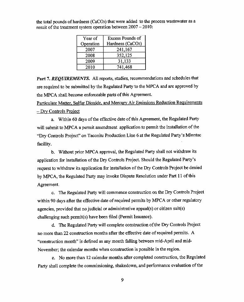
the total pounds of hardness (CaCO3) that were added to the process wastewater as aresult of the treatment system operation between 2007 -2010:
Excess Pounds ofHardness (~-
Year ofOperation
2007200820092010
241,167352,12531,133741,468
Part 7. REQUIREMENTS. All reports, studies, recommendations and schedules that
are required to be submitted by the Regulated Party to the MPCA and are approved by
the MPCA shall become enforceable parts of this Agreement.
Particulate Matter. Sulfur Dioxide. and Mercurv Air Emissions Reduction Reauirements
-Dry Controls Project
a. Within 60 days of the effective date of this Agreement, the Regulated Party
will submit to MPCA a permit amendment application to permit the installation of the
"Dry Controls Project" on Taconite Production Line 6 at the Regulated Party's Minntac
facility .
b. Without prior MPCA approval, the Regulated Party shall not withdraw its
application for installation of the Dry Controls Project. Should the Regulated Party's
request to withdraw its application for installation of the Dry Controls Project be denied
by MPCA, the Regulated Party may invoke Dispute Resolution under Part 11 of this
Agreement.c. The Regulated Party will commence construction on the Dry Controls Project
within 90 days after the effective date of required permits by MPCA or other regulatory
agencIes, provided that no judicial or administrative appeal(s) or citizen suit(s)
challenging such permit(s) have been filed (permit Issuance).
d. The Regulated Party will complete construction of the Dry Controls Project
no more than 22 construction months after the effective date of required permits. A
"construction month" is defined as any month falling between mid-April and mid.
November; the calendar months when construction is possible in the region.
e. No more than 12 calendar months after completed construction, the Regulated
Party shall complete the commissioning, shakedown, and performance evaluation of the
9
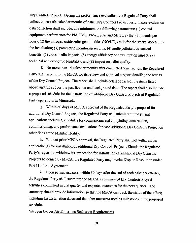
Dry Controls Project. During the performance evaluation, the Regulated Party shall
collect at least six calendar months of data. Dry Controls Project performance evaluation
data collection shall include, at a minimum, the following parameters: (1) control
equipment performance for PM, PM1o, PM2.s, S02, and Mercury (Hg) (in pounds per
hour); (2) the nitrogen oxides/nitrogen dioxides (NO/N02) ratio for the stacks affected by
the installation; (3) parametric monitoring records; (4) multi-pollutant co-control
benefits; (5) cross media impacts; (6) energy efficiency or consumption impact; (7)
technical and economic feasibility; and (8) impact on pellet quality.
f. No more than 14 calendar months after completed construction, the Regulated
Party shall submit to the MPCA for its review and approval a report detailing the results
of the Dry Control Project. The report shall include detail of each of the items listed
above and the supporting justification and background data. The report shall also include
a proposed schedule for the installation of additional Dry Control Projects at Regulated
Party operations in Minnesota.
g. Within 60 days ofMPCA approval of the Regulated Party's proposal for
additional Dry Control Projects, the Regulated Party will submit required permit
applications including schedules for commencing and completing construction,
commissioning, and performance evaluations for each additional Dry Controls Project on
other lines at the Minntac facility.
h. Without prior MPCA approval, the Regulated Party shall not withdraw its
application(s) for installation of additional Dry Controls Projects. Should the Regulated
Party's request to withdraw its application for installation of additional Dry Controls
Projects be denied by MPCA, the Regulated Party may invoke Dispute Resolution under
Part 11 of this Agreement.
i. Upon permit issuance, within 30 days after the end of each calendar quarter,
the Regulated Party shall submit to the MPCA a summary of Dry Controls Project
activities completed in that quarter and expected outcomes for the next quarter. The
summary should provide information so that the MPCA can track the status of the effort;
including the installation dates and the other measures used as milestones in the proposed
schedule.
Nitrogen Oxides Air Emissions Reduction ReQuirements
10
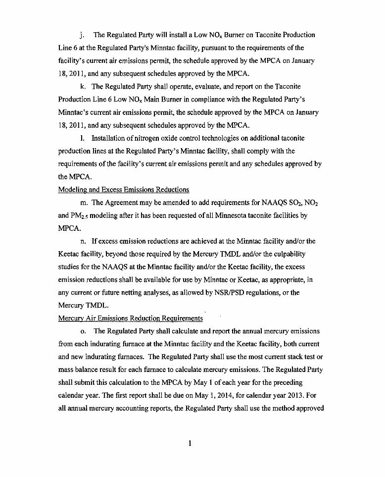
j. The Regulated Party will install a Low NOx Burner on Taconite Production
Line 6 at the Regulated Party's Minntac facility, pursuant to the requirements of the
facility's current air emissions permit, the schedule approved by the MPCA on January
18, 2011, and any subsequent schedules approved by the MPCA.
k. The Regulated Party shall operate, evaluate, and report on the Taconite
Production Line 6 Low NOx Main Burner in compliance with the Regulated Party's
Minntac's current air emissions permit, the schedule approved by the MPCA on January
18,2011, and any subsequent schedules approved by the MPCA.
1. Installation of nitrogen oxide control technologies on additional taconite
production lines at the Regulated Party's Minntac facility, shall comply with the
requirements of the facility's current air emissions permit and any schedules approved by
the MPCA.
Modeling and Excess Emissions Reductions
m. The Agreement may be amended to add requirements for NAAQS S02, N02
and PM2.5 modeling after it has been requested of all Minnesota taconite facilities by
MPCA.
n. If excess emission reductions are achieved at the Minntac facility and/or the
Keetac facility, beyond those required by the Mercury TMDL and/or the culpability
studies for the NAAQS at the Minntac facility and/or the Keetac facility, the excess
emission reductions shall be available for use by Minntac or Keetac, as appropriate, in
any current or future netting analyses, as allowed by NSR/PSD regulations, or the
Mercury TMDL.
Mercury Air Emissions Reduction ReQuirements
o. The Regulated Party shall calculate and report the annual mercury emissions
from each indurating furnace at the Minntac facility and the Keetac facility, both current
and new indurating furnaces. The Regulated Party shall use the most current stack test or
mass balance result for each furnace to calculate mercury emissions. The Regulated Party
shall submit this calculation to the MPCA by May 1 of each year for the preceding
calendar year. The first report shall be due on May 1,2014, for calendar year 2013. For
all annual mercury accounting reports, the Regulated Party shall use the method approved
1
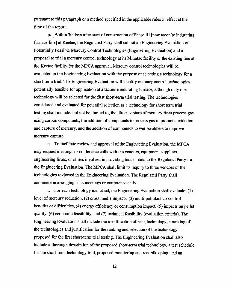
pursuant to this paragraph or a method specified in the applicable rules in effect at the
time of the report.
p. Within 30 days after start of construction of Phase III [new taconite indurating
furnace line] at Keetac, the Regulated Party shall submit an Engineering Evaluation of
Potentially Feasible Mercury Control Technologies (Engineering Evaluation) and a
proposal to trial a_mercury control technology at its Minntac facility or the existing line at
the Keetac facility for the MPCA approval. Mercury control technologies will be
evaluated in the Engineering Evaluation with the purpose of selecting a technology for a
short-term trial. The Engineering Evaluation will identify mercury control technologies
potentially feasible for application at a taconite indurating furnace, although only one
technology will be selected for the first short-term trial testing. The technologies
considered and evaluated for potential selection as a technology for short term trial
testing shall include, but not be limited to, the direct capture of mercury from process gas
using carbon compounds, the addition of compounds to process gas to promote oxidation
and capture of mercury, and the addition of compounds to wet scrubbers to improve
mercury capture.
q. To facilitate review and approval of the Engineering Evaluation, the MPCA
may request meetings or conference calls with the vendors, equipment suppliers,
engineering firms, or others involved in providing bids or data to the Regulated Party for
the Engineering Evaluation. The MPCA shall limit its inquiry to three vendors of the
technologies reviewed in the Engineering Evaluation. The Regulated Party shall
cooperate in arranging such meetings or conference calls.
r. For each technology identified, the Engineering Evaluation shall evaluate: (1)
level of mercury reduction, (2) cross media impacts, (3) multi-pollutant co-control
benefits or difficulties, (4) energy efficiency or consumption impact, (5) impacts on pellet
quality, (6) economic feasibility, and (7) technical feasibility (evaluation criteria). The
Engineering Evaluation shall include the identification of each technology "a ranking of
the technologies and justification for the ranking and selection of the technology
proposed for the first short-term trial testing. The Engineering Evaluation shall also
include a thorough description of the proposed short-term trial technology, a test schedule
for the short-term technology trial, proposed monitoring and recordkeeping, and an
12
evaluation of whether the proposed short-term trial technology requires any MPCA
permits prior to implementation.
s. Within 30 days of the MPCA approval of the Engineering Evaluation, the
Regulated Party shall submit a test plan in accordance with Minn. R. 7017.2001 to 7017.
2060 to conduct a short-term trial of mercury control technology at Minntac or the
existing line at Keetac (Phase II indurating furnace) in accordance with the approved
short-term trial proposal.
t. The Regulated Party shall commence implementation of the short-term trial
no later than 90 days following the later of the MPCA approval of the Regulated Party's
test plan or, if a permit(s) are necessary for the short-t~rm trial the effective date of the
permit(s), and shall complete the short term trial in accordance with the schedule
approved by the MPCA.
u. The Regulated Party shall submit a short-term trial report to the MPCA within
60 days after completion of the short-term trial. The short-term trial report shall include,
at a minimum, fuel Hg content(s) (ppm dry and Ib/MMBtu), fuel input rate for all fuels
(MMBtu/hr), dry greenball Hg content (ppm dry), fired pellet Hg content (ppm dry),
pellet production rate (L T/hr), air pollution control device captured solids Hg content
(ppm dry), mass rate (lb/hr) and flue gas concentration (ppm dry) ofHg entering and
exiting the mercury control technology, control efficiencies (percent reduction), and
control equipment parameter(s) identified in the short-term trial proposal. The Regulated
Party will describe if the technology tested is sufficiently promising to warrant long term
testing and justification for the conclusion reached in the report. The Regulated Party
shall include in its report a proposal of either a long term trial or a short term trial for the
next highest ranked technology.
v. The next short term trial shall proceed as described in Parts 7.s, 7.t and 7.u. If
the Regulated Party concludes in the report on the second short term trial that the
technology is not sufficiently promising to warrant long term testing, the Regulated Party
shall submit to the MPCA for approval an updated Engineering Evaluation identifying
the mercury reduction strategies/technologies that have been developed since the
preparation of the original Engineering Evaluation and update the information in the
original Engineering Evaluation in this short term trial report. A third short term trial
13
shall proceed as described in Parts 7.s, 7.t, and 7.u unless the revised Engineering
Evaluation concludes no further trials are justified and the MPCA approves. The MPCA
may request meetings or conference calls with the vendors, equipment suppliers,
engineering firms, or others involved in providing bids or data to the Regulated Party for
the revised Engineering Evaluation. The Regulated Party shall cooperate in arranging
such meetings or conference calls.
w. If the revised Engineering Evaluation concludes no further trials are justified,
evaluation of mercury control technologies will recommence if the MPCA identifies any
potentially feasible mercury control technologies not previously reviewed in the
Engineering Evaluation and notifies the Regulated Party that additional evaluation of a
technology is required. Within 90 days of the MPCA notifying the Regulated Party, the
Regulated Party will submit an evaluation of the technology and a schedule for short-
term trial if the technology meets the evaluation criteria identified in Part 7.s. If the
Regulated Party concludes that the technology is not suitable for a short-term trial, it will
provide copies of all relevant documents and a complete justification for rejecting the
technology for short-term trial.
x. If the Regulated Party becomes aware of a new technology, which the
Regulated Party prefers to test in lieu of the previously identified technologies, the
Regulated Party will notify the MPCA of the technology as soon as practicable. Within
60 days of initial notification to the MPCA of the technology, the Regulated Party will
s:ubmit to the MPCA information supporting testing of the new technology including a
permit applicability determination and a trial schedule for the MPCA approval. The
information shall include consideration of the evaluation criteria in Part 7.s, and
justification for selection of the new technology for short-term trial testing. the Regulated
Party will commence testing based on the MPCA approved schedule and after permit
issuance, if a permit is required.
y. If the short term trial concludes that the tested technology is potentially
feasible based on the evaluation criteria, the Regulated Party shall submit a proposal for a.long-term trial to MPCA for approval within 60 days after completion of the short-term
trial. The proposal shall describe the goals for the trial, the criteria to be used to
determine the success of the mercury control technology application, a schedule for
14
construction, startup, operation, conclusion of the trial and final report submittal. The
Regulated Party shall evaluate its proposed long-term trial technology to determine
whether it must apply for the MPCA permits prior to implementation of the long-term
trial.
z. Upon the MPCA approval of the Regulated Party's proposal for long-term
trial of a selected technology, the Regulated Party shall conduct a long-term trial of a
mercury control technology on one existing line. The Regulated Party shall commence
implementation of the long term trial within 90 days of the later of the MPCA approval of
the long-term trial report or, if a permit(s) is necessary for the long-term trial, from the
effective date of the permit(s), and has a goal of completing the long term trials within 18
calendar months after startup of the long term mercury control technology trial.
aa. Within 60 days after completion of the long-term trial, the Regulated Party
shall submit a report on the results of the long-term trial. The report shall include an
evaluation of mercury controls for installation on the Regulated Party operating taconite
indurating furnace lines, addressing the evaluation criteria established in the trial proposal
as well as describing what changes to mercury control(s) design or operation were
identified from the trial that will be needed to achieve or improve mercury control
performance. The report shall also propose a technology or technologies and a schedule
for installation on existing operating taconite indurating furnace lines to meet the
emission goal.
bb. If the long-term trial report proposes a technology for installation, within 60
days after the MPCA approval of the long-term trial report and technology proposal, the
Regulated Party shall submit permit application(s) and a schedule for installation of the
selected technology on necessary the Regulated Party operating taconite indurating
furnace lines to reach the 2025 goal.
cc. If the long-term trial report proposes no technology for installation and the
MPCA agrees, the Regulated Party shall proceed with another short term trial as
described in Parts 7. s, 7.t, 7.u, 7.y, 7.z, and 7.aa.
dd. Upon submitting permit application(s) for installation of the selected
technology on remaining necessary the Regulated Party operating taconite indurating
5
furnace lines to meet the reduction goal, the Regulated Party may submit a request to
terminate this Schedule.
ee. If by June 30, 2016, the Regulated Party and the MPCA agree that short term
and long term testing have not identified technologies for installation and no additional
technologies have been identified for testing, the Regulated Party 's testing obligations
will be fulfilled by cooperating with the Mercury- Emissions -Reduction Research and
Implementation Council established pursuant to the Mercury TMDL Implementation
Plan the Regulated Party's cooperation will continue until mercury technologies have
been installed or other mercury reduction actions have been taken that meet the
Regulated Party's mercury emission reduction goal.
Mercury Air Emissions Reduction Contin!!encv Conditions
ff. The following conditions describe actions the Regulated Party will implement
to minimize mercury emissions in the event that long term trial testing is not initiated. By
no later than January 1, 2016, the Regulated Party shall submit a plan and schedule for
MPCA approval, that is consistent with the Guidelines for New and Modified Mercury
Air Em~ssion Sources to offset cumulative mercury emissions from the operation of
Phase III from startup of Phase III through January 1,2025. The plan will include an
evaluation of the modification of the particulate matter scrubber operation at Minntac to
route mercury-containing scrubber solids from the front of the taconite process to the
tailings basin ("wasting scrubber solids").
gg. By no later than June 30, 2016, or within 60 days of approval by the MPCA,
the Regulated Party shall implement the plan and schedule if long term trial testing of
mercury controls has not been initiated.
Line 3 Scrubber Blowdown Treatment System ReQuirements
hh. The Regulated Party shall implement corrective measures necessary to resolve
the alleged violations indicated in Part 6 of this Agreement by October 31, 2011. If the
Regulated Party believes it cannot comply with this deadline for reasons beyond its
control the Regulated Party shall follow the procedures described in Part 13 of this
Agreement to request an extension. In addition to the requirements of Part 13, the
extension request must include a detailed chronology of the Regulated Party's actions to
address the alleged violations since submittal of the MPCA approved Implementation~
16
Plan, dated January 21,2009. Specifically, the request must provide details of actions
taken by the Regulated Party to address the alleged violations as expeditiously as possible
after the Regulated Party determined that the process water treatment system proposed in
the March, 2009 NPDES/SDS permit application would not be implemented, and indicate
why, for reasons beyond the contrC!1 of the Regulated Party, implementation of corrective
measures to resolve the alleged violations by October 31, 2011 are not feasible
ii. Within 30 days of the effective date of this Agreement, the Regulated Party
shall submit a Management Alternatives Report to MPCA. The Management Alternatives
Report shall include evaluations of reuse of LIne 3 scrubber blowdown and alternate
makeup sources to offset the increase of sulfate and hardness generated by the Line 3
scrubber system.
lj. If the Regulated Party determines that the alternatives identified in the
Management Alternatives Report are not feasible, within 60 days of the effective date of
this Agreement the Regulated Party shall submit to the MPCA a Line 3 Scrubber
Blowdown Treatment System Evaluation Report (Treatment Evaluation Report) that
summarizes the Regulated Party's consultants' proposals for modifications to or
replacement of the existing Line 3 scrubber blowdown treatment system. The Treatment
Evaluation Report shall identify recommendations to ensure compliance with the Permit
requirement for no net increase in total sulfate and hardness as a result of operation of the
Line 3 scrubber.
kk. Within 90 days of the effective date of this Agreement the Regulated Party
shall provide written notification to the MPCA indicating which recommendations within
the Management Alternatives Report or the Treatment Evaluation Report shall be
implemented.1. If the Regulated Party proposes to implement the recommendations of the
Management Alternatives Report, a schedule for completing activities necessary to
implement the water management alternatives shall be included, for MPCA review and
approval. The Regulated Party shall submit an application for modification of the
NPDES/SDS permit to the MPCA within 30 days of receiving MPCA approval of the
schedule for implementing recommendations of the Management Alternatives Report.
17
2. If the Regulated Party proposes to implement the recommendations of the
Treatment Evaluation Report, a schedule for implementation, including a schedule for
process demonstration and treatment optimization of at least two technologies, shall be
included for MPCA review and approval.
i. The Regulated Party shall submit a Process Optimization Study
(Optimization Study) that provides results of process demonstration and treatment
optimization of two technologies within 90 days ofMPCA approval of the schedule for
implementing the Treatment Evaluation Report recommendations. If the conclusions of
the Optimization Study indicate that at least one technology can be successfully
implemented, the Optimization Study shall include a schedule for completion of
construction necessary to implement full scale treatment, for MPCA approval.
ii. If the conclusions of the Optimization Study indicate that no
technology can be successfully implemented, the Optimization Study shall recommend
other approaches for meeting the permit-required no net increase in sulfate and hardness
to the tailings basin as a result of operation of the Line 3 scrubber system, with a schedule
for implementation of alternatives, for MPCA approval.
iii. Within 30 days ofMPCA approval of an Optimization Study that
concludes at least one technology can be successfully implemented, the Regulated Party
shall submit an application for permit modification.
ll. Following commissioning of the Line 6 Dry Controls Project, as specified in
Part 7..d, the Regulated Party shall complete an analysis of the monthly mass of sulfate
diverted from Minntac's recirculating process water system by the Line 6 Dry Controls
Project. When the cumulative mass of sulfate and hardness diverted from the
recirculating process water system exceeds the overall net increase in sulfate which had
resulted from operation of the Line 3 scrubber, the Regulated Party may submit a
notification to MPCA to discontinue any treatment technology or management alternative
that may have been included in the Line 3 Project, for MPCA consideration.
mm. Should any submittal or request pursuant to paragraphs ii through mm be
rejected or denied by MPCA, the Regulated Party may invoke Dispute Resolution under
Part 11 of this Agreement.
Dark River Monitorine: Reauirements
18
nn. Within 20 days of the effective date of this Agreement the Regulated Party
shall contact the Minnesota Department of Natural Resources (DNR) to discuss DNR
recommendations for flow validation monitoring of the Dark River downstream of the
Minntac Tailings Basin.
00. Within 30 days of contacting DNR the Regulated Party shall submit a Dark
River Monitoring Plan (Monitoring Plan) for establishing flow validation and water
chemistry monitoring stations as identified in the Monitoring Plan, for MPCA review and
approval. The Monitoring Plan shall include a description of flow validation
methodology as well as specific location information for each site and a schedule for
startup of flow monitoring stations. In no case shall startup of the stations occur more
than 60 days after receipt of approval to access the sites or MPCA approval of the plan,
whichever occurs later.
pp. Upon startup of operation of the monitoring stations established on the Dark
River, the Regulated Party shall conduct monitoring of all parameters indicated in the
MPCA approved Monitoring Plan, according to the schedule indicated in the Monitoring
Plan. Analysis of all parameters except field parameters as identified in the Monitoring
Plan must be conducted by a laboratory certified by the Minnesota Department of Health
for those analyses.
qq. The Regulated Party, beginning with the first month after startup of flow
validation monitoring, shall submit the results of flow validation and water chemistry
monitoring as a supplement to the next monthly Discharge Monitoring ~eports (DMRs)
submitted for NPDES/SDS Permit No. MNOO57207. The DMRs shall continue to be
submitted electronically to MPCA and are not required to be submitted to the MPCA case
contact.
rr. The Regulated Party shall conduct baseline monitoring prior to installation of
any seep collection infrastructure on the west side of the Minntac tailings basin. If
installation of a seep collection system on the west side of the Minntac tailings basin
proceeds, monitoring shall continue in accordance with the terms specified by the
NPDES / SDS Permit that was modified or reissued to authorize construction of the
collection system. If installation of a seep collection system does not proceed, the
Regulated Party may submit to the MPCA, for review and approval, a request to end
19
monitoring of the Dark River. Should the Regulated Party's request to end monitoring of
the Dark River be denied by MPCA, the Regulated Party may invoke Dispute Resolution
under Part 11 of this Agreement.
ss. By February 1 of each year the Regulated Party shall submit an Annual Dark
River Monitoring Report (Monitoring Report) that summarizes monitoring results for the
previous calendar year at each monitoring location identified in the Monitoring Plan. The
Annual Monitoring Report shall include tables of results of monthly constituent
monitoring, as well as a flow validation monitoring results. The annual report shall
continue in accordance with the terms specified by the NPDES / SDS Permit that was
modified or reissued to authorize construction of the collection system
Dark River Seepage Collection and Return System Reguirements
tt. Within 60 days of the effective date of this Agreement the Regulated Party
will retain a professional consultant to evaluate and report on the feasibility of collecting
surface seepage from the west side of the Minntac tailings basin for return to the
recirculating process water system (Feasibility Report) to eliminate the discharge of
surface seepage to the Dark River Watershed (Dark River Seep Collection and Return
System -SCRS).
uu. Within 60 days of the effective date of this Agreement the Regulated Party
shall contact appropriate federal, state and local wetland permitting authorities to discuss
the potentialSCRS and introduce wetland permitting authorities to the project in an
attempt to facilitate the wetland permitting process, if it is determined that the SCRS is
feasible. By December 31, 2011, the Regulated Party shall complete delineation of
wetlands that, based upon best available information, would likely be impacted by
construction of the SCRS, should the SCRS project proceed.
vv. Within 180 days of the effective qate of this Agreement the Regulated Party
shall submit to the MPCA for approval their consultant's completed Feasibility Report
for the SCRS. The Feasibility Report shall identify specific recommendations for
construction aQd operation ofa SCRS and provide estimates of the volume per unit time
of seepage water that would be collected through elimination of surface seeps or shall
identify specific reasons why the project is infeasible.
20
ww. Jfthe Feasibility Report concludes that a SCRS is feasible, the Regulated
Party shall submit an application to the MPCA for modification or reissuance of the
NPDES/SDS permit within 30 days ofMPCA approval of the Feasibility Report.
xx. Within 90 days of permit application submittal the Regulated Party shall
submit Plans and Specifications for the SCRS to the MPCA for review and approval.
yy. The Regulated Party shall commence construction of the SCRS following the
latter of either MPCA approval of the SCRS Plans and Specifications or the expiration of
any appeal period for the permit issued by MPCA or other appropriate regulatory
agencies pursuant to the application(s) submitted to such agencies and provided that no
judicial or administrative appeal(s) or citizen suit(s) challenging such permit(s) have been
filed. If these conditions are satisfied during the period of April 15 through September,
30,2011, initiation of construction of the SCRS within 30 days is required, otherwise
initiation of construction shall be delayed until the next construction season. A
construction season is defined as April 15 through December 15. Ifweather and/or site
conditions prohibit construction, the Regulated Party shall follow the procedures
described in Part 13 of this Ag!eement to request an extension.
zz. The Regulated Party shall notify the MPCA of SCRS construction
commencement within 10 days of construction initiation.
aaa. The Regulated Party shall complete construction of the SCRS within eight
consecutive construction season months during one or more construction season(s).
bbb. The Regulated Party must initiate operation of the SCRS within 30-days
of completion of the SCRS and notify the MPCA of SCRS initiation within 10 days of
initiation.
Dark River Mitigation Contingencx Plan ReQuirements
ccc. Within 60 days of the effective date of this Agreement the Regulated Party
shall retain a consultant to investigate Dark River flow augmentation strategies. The
Regulated Party shall notify the MPCA within 10 days that it has retained a consultant.
ddd. Within 210 days of the effective date of this Agreement the Regulated
Party shall provide a Dark River Flow Augmentation Report (Augmentation Report)
which was developed by the Regulated Party's consultant. The Augmentation Report
shall: (1) identify the maximum flow rate which the identified augmentation options
21
could provide, (2) identify whether the concentrations of any pollutants in the source
water used for augmentation may exceed Dark River water quality standards, including,
at minimum total hardness, specific conductance, total sulfate, and total dissolved solids,
and 3) identify potential locations for discharging augmentation water into surface waters
within the Dark River watershed. If augmentation water quality does not meet the water
quality standards of the proposed receiving water the Augmentation Report shall include
a literature review of treatment technologies that may provide adequate treatment of
augmentation water to ensure compliance with the applicable water quality standards.
eee. Within 240 days of the effective date of this Agreement the Regulated
Party shall meet with DNR and MPCA staff to evaluate whether or not operation of the
SCRS would have the potential to have an adverse impact on the Dark River. An adverse
impact is defined as operation of the SCRS causing (1) a significant decrease in critical
low flow quantity or (2) a significant increase in the duration of the critical low flow
period at the monitoring stations identified by monitoring as required by Part 7. pp of the
Agreement that would not have occurred had the SCRS not been in operation.
fff. If MPCA staff determine that the SCRS does not have the potential to
adversely impact the Dark River, the Regulated Party may request of the MPCA that
monitoring of the Dark River be terminated. Should the Regulated Party's request to
terminate the monitoring of the Dark River be denied by MPCA, the Regulated Party
may invoke Dispute Resolution under Part 11 of this Agreement.
ggg. IfMPCA staff determine that the SCRS has the potential to adversely
impact the Dark River and that flow augmentation options appear feasible based on the
Augmentation Report, the MPCA shall notify the Regulated Party of such determination
in writing. Within 30 days of such determination, the Regulated Party shall submit a
schedule for either implementing construction activities necessary to initiate
augmentation or a schedule for ~onducting bench and pilot scale testing of treatment
technologies to ensure that augmentation water meets applicable receiving water
standards, for MPCA review and approval. The Regulated Party shall implement the
approved schedules upon receipt of written notification from the MPCAthat the SCRS
has caused adverse impacts to the Dark River.
22
hhh. If MPCA staff determine that the SCRS has the potential to adversely
impact the Dark River and that no augmentation options appear feasible based on the
Augmentation Report, the MPCA shall notify the Regulated Party of such determination,
in writing. Within 90 days of such determination the Regulated Party shall submit a
summary of mitigation project options with implementation schedules that would offset
possible adverse impacts to the Dark River by operation of the SCRS, for MPCAreview
and approval. The Regulated Party shall implement the approved mitigation project and
schedule upon receipt of written notification from the MPCA that the SCRS has caused
adverse impacts to the Dark River.
iii. The Regulated Party may, after one or more years of operation of the SCRS,
request a meeting with DNR and MPCA staff to discuss the available Dark River
monitoring data and SCRS seepage collection data. The purpose of the meeting will be to
reassess whether or not the SCRS has adversely impacted the Dark River. If a
reassessment by MPCA staff determines there has not been an adverse impact to the Dark
River resulting from operation of the SCRS, then implementation of the approved
augmentation or mitigation options shall not be required and monitoring of the Dark
River shall be terminated upon written notification of such by the MPCA.
Tailings Basin Water Quali!y
jjj. Within 60 days of the effective date of this Agreement, the Regulated Party
shall submit a Monitoring Well Installation Plan (Installation Plan) and schedule for
installation for MPCA review and approval. The Installation Plan shall identify
monitoring wells that will be installed to: I) refine a groundwater model for sulfate
transport, and 2) monitor compliance with the sulfate groundwater standard at the current
property boundary. Current property boundary means the Regulated Party's property
boundary around the tailings basin that is present on the effective date of this Agreement.
The Installation Plan shall also identify the chemical parameters that will be monitored
and the frequency of monitoring ground water elevation and chemical parameters. Within
30 days ofMPCA review and approval of the Installation Plan the Regulated Party shall
install the additional monitoring wells, if field conditions permit. If field conditions do
not allow installation within 30 days ofMPCA approval of the Installation Plan, the
Regulated Party shall notify MPCA and provide an estimated schedule for installation of
23
monitoring wells at the earliest practical opportunity that field conditions permit, for
MPCA approval.
kkk. Within 60 days of the effective date of this Agreement, the Regulated
Party shall submit a conceptual groundwater model (Conceptual Model), for MPCA
review and approval. The Conceptual Model shall contain a discussion of the
characteristics of the aquifer and the overall objectives and underlying assumptions of the
groundwater model that will be used to predict sulfate transport from the tailings basin
and further described in Part 7.nnn.
Ill. Within 30 days of installation of the monitoring wells, the Regulated Party
shall submit a Monitoring Well Installation Report (Installation Report). The Installation
Report shall include, but is not limited to, a detailed monitoring well log for each
monitoring well installed, unique well number for each well, surveyed top of casing
elevations for each well, and a digital image (e.g., aerial photograph) identifying the
location of the wells in relation to the tailings basin and property boundary.
mmm. Within 90 days of submission of the Installation Report, the Regulated
Party shall begin to provide written updates to MPCA regarding the status of the
groundwater modeling efforts every six calendar months, at a minimum. The updates
shall include all groundwater monitoring information available since installation of the
monitoring wells,
nnn. The Regulated Party will incorporate the data gathered from installed
monitoring wells into the ground water model of sulfate transport and revise the
modeling assumptions in order to accurately model the monitored data. Within 210 days
of submission of the InstaUation Report, the Regulated Party will determine what sulfate
concentrations are necessary in the tailings basin to ensure compliance with the
groundwater standard at the current property boundary (target concentration). If the
Regulated Party is unable to provide a target concentration MPCA staff shall develop a
target concentration based on a model of sulfate transport, using available monitoring
information and well logs provided by the Regulated P~rty. If the Regulated Party
disputes that the MPCA model does not adequately predict the quality of groundwater
outside of the Regulated Party's tailings basin, the Regulated Party may pursue resolution
of this dispute through the steps described in Part 11 of this Agreement.
24
000. If ground water monitoring results show non-compliance with the
groundwater sulfate standard at the property boundary, the Regulated Party shall, within.five days of this determination notify the MPCA. In response, the, MPCA may take
action in accordance with Part 23 of the Agreement.
ppp. Within 180 days after the effective date of this Agreement the Regulated
Party shall provide an Alternate Makeup Water Report (Makeup Water Report) to the
MPCA, for review and approval. The Makeup Water Report shall: (1) provide an
evaluation of possible sources of makeup water that would have a lower sulfate
concentration than the present makeup water supply, (2) evaluate whether the alternative
source would be used instead of or in combination with the present makeup water supply
for facility operation to reduce sulfate loading to the tailings basin, and (3) provide a
schedule for the construction necessary to utilize the alternate makeup water source.
Implementation of the sc.hedule would be triggered upon detection of a violation of the
sulfate standard at the property boundary.
qqq. Within 210 days of this Agreement, the Regulated Party shall submit to
MPCA a Dry Controls Effectiveness Report (Effectiveness Report) that indicates
projections of sulfate concentration in the tailings basin from the date of the report
extending to five years after completion of the final dry control project, for MPCA
review and approval. The Effectiveness Report shall also include the target concentration,
if available, as determined by any finalized modeling as described in Part 7. nnn of the
Agreement. If at the time of submittal of the initial Effectiveness Report a target
concentration is unavailable, the Regulated Party shall provide to the MPCA an updated
Effectiveness Report within 30 days of establishment of the target concentration. If the
sulfate concentration projected for the tailings basin five years after completion of the
final dry control project is greater than the target concentration, the Effectiveness Report
must describe what additional sulfate reduction measures shall be taken, with a schedule,
to ensure the sulfate concentration projection is less than the target concentration within
five years of completion of the dry air control project. The Effectiveness Report may
include the use of alternative makeup water as identified in Part 7.ppp of the Agreement.
The Regulated Party shall provide annual updates of the Effectiveness Report by
February 1 of each year, subsequent to submission of the first Effectiveness Report. The
25
annual Effectiveness Reports shall provide revised projections or target concentrations
based on new information, as necessary.
Part 8. PENALTIES FOR VIOLATIONS OF THIS AGREEMENT.
a. If the Regulated Party fails to comply with Parts 7.d and 7.g of this
Agreement, the Regulated Party shall pay to the MPCA a penalty in the amount of$l,OOO
per requirement for each day of failure.
b. If the Regulated Party fails to comply with requirements of Part 7.ii -Part
7.qqq of this Agreement, the Regulated Party shall be subject to penalties for each failure,
as follows:
1. $500/day for failure to provide timely submittals and notifications to
the MPCA, as applicable.
2. $500/day for failure to retain consultants in a timely manner, as
applicable.3. $500/day for failure to initiate construction according to schedules
submitted by the Regulated Party and approved by the MPCA, as applicable.
4. $500/day for failure to initiat~ and complete bench and pilot scaletesting
according to schedules submitted by the Regulated Party and approved by the
MPCA, as applicable.
5. $l,OOO/day for failure to complete construction and initiate operation
according to schedules submitted by the Regulated Party and approved by the MPCA, as
applicable.
6.. Penalties for failure to comply with requirements of Part 7 of this
Agreement shall accrue from the date the Regulated Party was to have fulfilled the
requirement until the Regulated Party fulfills the requirement. Penalties shall not accrue
while the MPCA considers a timely extension request under Part 13 or during dispute
res~lution under Part 11, unless the MPCA det~rmines that the Regulated Party filed the
request or initiated dispute resolution solely for purposes of delay. If the Regulated Party
does not pursue dispute resolution under Part 11 for deniatof a timely extension request,
penalties shall accrue from the date the extension request is denied by the MPCA Case
Contact. If the Regulated Party pursues dispute resolution for denial of an extension
request and does not file a timely challenge in a court of competent jurisdiction as
26
provided by Part 11, penalties shall accrue from the date of a Commissioner's dispute
resolution decision against the Regulated Party until the Regulated Party fulfills the
requirement that is the subject of the extension request.
c. The Regulated Party shall pay a penalty under this Part within 30 days after
receiving written notice from the MPCA that the penalty is due. The written notice shall
specify the provision of the Agreement that the Regulated Party has not fulfilled and
indicate the date penalties began to accrue. If the Regulated Party fails to make timely
payment, the MPCA may assess and the Regulated Party agrees to pay a late payment
charge, in addition to the stipulated penalty, to be assessed as follows. Forty-five days
after receipt of written notice, the Regulated Party shall be obligated to pay a late charge
in an amount equal to ten percent of the unpaid stipulated penalty. Sixty days after receipt
of written notice, the Regulated Party shall be obligated to pay an additional late charge
in an amount equal to twenty percent of the unpaid stipulated penalty.
d. In dispute resplution before the Commissioner under Part 11, the Regulated
Party can contest the factual basis for the MPCA's determination that the Regulated Party
has not fulfilled a requirement of this Agreement covered by this Part. However, the
Regulated Party waives its right to challenge, on legal grounds, the requirement that it
pay penalties under this Part.
e. The Regulated Party shall not be liable for payment of penalties for failure to
comply with requirements of Part 7 of~his Agreement covered by this Part if it has
submitted to the MPCA a timely request for an extension of Agreement under Part 13 and
the MPCA has granted the request. The MPCA' s grant of an extension of schedule
waives the payment of penalties covered by this Part only on the requirements for which
the MPCA granted an extension of schedule and only for the time period specified by the
MPCA in the grant of an extension. An extension of schedule for one requirement of Part
7 does not extend the schedule for any other requirement of Part 7.
L Any requirement of this Agreement may be enforced as provided in Minn.
Stat.§ 115.071 (2004). Payment of a stipulated penalty does not relieve the Regulated
Party of its obligation to fulfill and complete requirements under the Agreement and to
otherwise comply with the terms and conditions of the Agreement.
27
Part 9. COVENANT NOT TO SUE AND RESERVATION OF REMEDIES. With
respect to the Regulated Party, the MPCA agrees not to exercise any administrative, legal
or equitable remedies available to the MPCA to address the violations alleged and
described in Part 6 as long as the Regulated Party performs according to and has
complied with the terms and conditions contained in this Agreement. The MPCA,
reserves the right to enforce this Agreement or take any action authorized by law, if the
Regulated Party fails to comply with the terms and conditions of this Agreement.
Further, the MPCA reserves the right to seek to enjoin violations of this
Agreement and to exercise its emergency powers pursuant to Minn. Stat. § 116.11 (2004)
in the event conditions or the Regulated Party's conduct warrant such action. Nothing in
this Agreement shall prevent the MPCA from exercising these rights and nothing in this
Agreement constitutes a waiver of these rights.
The Regulated Party agrees to waive all claims it may now have, as of the
effective date of this Agreement, under Minn. Stat. § 15.472 for fees and expenses arising
out of matters leading up to and addressed in this Agreement.
Part 10. REPEAT VIOLATIONS. Federal and state environmental programs establish
harsher penalties for violations of environmental laws or rules that constitute repeat
violations. In a proceeding to resolve alleged violations by the Regulated Party, ifany,
occurring after the date of the alleged violations set out in Part 6 of this Agreement, the
Regulated Party may argue about the extent to which the violations alleged in Part 6 of
this Agreement should affect the penalty amount for the later violations, but waives the
right: (1) to contend that the violations alleged in Part 6 of this Agreement did not occur
as alleged and (2) to require the MPCA to prove the violations alleged in Part 6 of this
Agreement.
Part 11. RESOLUTION OF DISPUTES. The parties to this Agreement shall resolve
disputes that arise as to any part of the Agreement as follows:
a. Either party, acting through its Case Contact (as defmed in Part 14 below),
may initiate dispute resolution by providing to the Case Contact of the other party an
initial written statement setting forth the matter in dispute, the position of the party, and
the information the party is relying upon to support its position.
28
The other party, acting through its Case Contact, shall provide a written statement
of its position and supporting information to the case contact of the initiating party within
14 calendar days after receipt of the initial written statement.
b. If the parties, acting through their Case Contacts, do not reach a resolution of
the dispute and reduce such resolution to writing in a form agreed upon by the parties
within 21 calendar days after the initiating party receives the statement of position from
the responding party, the Commissioner shall issue a written decision resolving the
dispute. The written decision may address stipulated penalties assessed pursuant to Part 8.
The Commissioner's decision shall be considered a final decision of the MPCA for
purposes of judicial review.
c. The Commissioner's decision shall become an integral and enforceable part of
this Agreement unless the Regulated Party timely challenges the decision in a court of
competent jurisdiction. Failure to timely challenge means the Regulated Party agrees to
comply with the MPCA Commissioner's decision on the matter in dispute and to pay any
penalties that accrue pursuant to Part 8 for failure to fulfill requirements of this
Agreement that are the subject of the dispute resolution. Further, if the Commissioner's
decision assesses penalties pursuant to Part 8 of this Agreement, the Regulated Party
agrees to and shall pay the amount of penalty determined by the Commissioner within 60
days after receiving the Commissioner's decision.
d. Throughout any dispute resolution, the Regulated Party shall comply with all
portions of the Agreement that the MPCA determines are not in dispute.
e. Should any request, report, study, recommendation, modification, schedule or
other submittal of the Regulated Party be rejected, disapproved, or otherwise denied by
MPCA, the Regulated Party may invoke Dispute Resolution under this Part.
Part 12. VENUE. Actions brought by the MPCA to enforce requirements and terms of
this Agreement shall be venued in Ramsey County District Court.
Part 13. EXTENSION OF SCHEDULES. If the Regulated Party wants an extension of
a deadline included in a schedule set out in Part 7, the Regulated Party must request the
extension in writing at least ten days before the scheduled deadline, or as soon as possible
before that date if the reason for the extension request arises less than ten days before the
deadline.
29
Each deadline extension request shall separately specify the reason why the
extension is needed. No requested extension shall be effective until approved in writing
by the MPCA, acting through the MPCA Case Contact or the Commissioner.
The MPCA shall grant an extension only for the period of time the MPCA
determines is reasonable under the circumstances. The written approval or grant of an
extension request shall be considered an enforceable part of the Agreement.
The Regulated Party has the burden of demonstrating to the satisfaction of the
MPCA that the request for the extension is timely, and that good cause exists for granting
the extension. Good cause can include, but is not limited to, the following:
a. Circumstances beyond the reasonable control of the Regulated Party.
b. Delays caused by the MPCA in reviewing timely submittals required by this
Agreement, the Regulated Party submitted in complete and approvable form, which make
it not feasible for the Regulated Party to meet the required schedules.
Good cause does not include unanticipated costs, increases in the cost of control
equipment, or delays in MPCA review of submittals when the submittals are not in
complete and approvable form.
The Regulated Party may c~allenge a decision by the MPCA to deny a request for
an extension under Part 11.
Part 14. CASE CONTAC7: The MPCA and the Regulated Party shall each designate a
Case Contact for the purpose of overseeing the implementation of this Agreement. The
MPCA Case Contact for air quality issues is Suzanne Bauman; the MPCA Case Contact
for water quality issues is John Thomas. The Regu)ated Party's Case Contact is Chrissy
Bartovich. Either party may change its designated Case Contact by notifying the other
party in writing, within five days of the change. To the extent possible, communications
between the Regulated Party and the MPCA concerning the terms and conditions of this
Agreement shall be directed through the Case Contacts. The address and telephone
number for Suzanne Bauman is MPCA, Industrial Division-5, 520 Lafaye;tte Rd N, St
Paul MN 55155, and (651)757-2798. The address and telephone number for John
Thomas is MPCA, 525 S. Lake Avenue, Suite 400, Duluth, MN 55802 and (218)302-
6616.
30
Part 15. REGULATED PARTY INFORMATION. The Regulated Party shall not
knowingly make any false statement, representation or certification in any record, report,
plan or other document filed or required to be submitted to the MPCA under this
Agreement. The Regulated Party shall immediately upon discovery report to the MPCA
any errors in such record, report, plan or other document.
Part 16. REVIEW OF SUBMITTALS. The MPCA, acting through its Commissioner,
Case Contact, or other designated MPCA staff, shall review all submittals made by the
Regulated Party as required by this Agreement and shall notify the Regulated Party in
writing of the approval or disapproval of each submittal, if applicable. The MPCA and
the Regulated Party shall consult with each other upon the request of either party during
the review of submittals or modifications. If any submittal is disapproved in whole or in
part, the MPCA Commissioner or designated MPCA staff shall notify the Regulated
Party of the specific inadequacies and shall indicate the necessary amendments or
reviews. Within 15 calendar days after receipt of any notice of disapproval, the Regulated
Party shall submit revisions and take actions to correct the inadequacies.
Part 17. ACCESS. During the term of this Agreement, the Regulated Party agrees to
provide the MPCA and its staff access to the Keetac and Minntac facilities and its records
and documents related to the implementation of this Agreement to the extent provided
under Minn. Stat. § 116.091 (2004) or other law, conditioned only upon the presentation
of credentials. The Regulated Party and MPCA shall comply with Minn. Stat. § 116.075
and Minnesota Rule 7000.1300 regarding any such information that is confidential and
not public.
Part 18. SAMPLING AND DA TA A V AlLARILIT¥: The Regulated Party shall make
available to the MPCA the results of any sampling, tests, or other data generated by the
Regulated Party, or on its behalf, to implement the requirements of this Agreement.
Part 19. RETENTION OF RECORDS. The Regulated Party shall retain in its
possession all records, documents, reports and data related to this Agreement.
The Regulated Party shall preserve these records, documents, reports and data for
a minimum of three years after the termination of this Agreement despite any document
retention policy of the Regulated Party to the contrary, and shall promptly make all such
documentation available for review upon request by the MPCA.
31
Part 20. APPLICABLE LAWS AND PERMITS. The Regulated Party shall undertake
all actions required to be taken pursuant to this Agreement in accordance with the
requirements of all applicable state and federal laws and regulations. Except when the
MPCA has specified and authorized a different compliance method in Part 7, the
Regulated Party must also comply with all applicable permits, orders, stipulation
Schedules and schedules of compliance. Nothing in this Schedule exempts or relieves the
Regulated Party of its obligation to comply wIth local governmental requirements.
Part 21. LIABILITIES. Each party agrees that it will be responsible for its own acts and
the results thereof to the extent authorized by law and shall not be responsible for the acts
of the other party and the results thereof. The State's liability shall be governed by the
provisions of the Minnesota Tort Claims Act, Minn. Stat, §§ 3.732, et seq., and other
applicable law.
Part 22. OTHER CLAIMS. Nothing herein shall release the Regulated Party from any
claims, causes of action or demands in law or equity by any person, firm, partnership or
corporation not a signatory to this Agreement for any liability it may have arising out of
or relating to th~ release of any pollutant or contaminant from its operations or from a
facility. Neither the Regulated Party nor the MPCA shall be held as a party to any
contract entered into by the other party to implement the requirements of this Schedule.
Part 23. RESERVATION OF REMEDIES. Nothing in this Schedule shall prevent the
MPCA from taking action to enforce the requirements of this Schedule;including
issuance of administrative orders, or from requiring additional action by the Regulated
Party if necessary to ensure compliance with this Schedule. In addition, the issuance of
this Schedule is not an exclusive action oiremedy by the MPCA, and except as provided
in Part 9 of this Agreement, it does not limit in anyway the MPCA's authority to bring
an enforcement action against or to seek and collect penalties from the Regulated Party
for violations of state and federal environmental laws, rules and permits. Further, the
MPCA reserves the right to exercise its emergency powers pursuant to Minn. Stat.. §
116.1.1 (2008) in the event conditions or the Regulated Party's conduct warrants such
action.
Part 24. SUCCESSORS, AGENTS AND CONTRACTORS. This Agreement shall be
binding upon the Regulated Party and its successors and assigns and upon the MPCA, its
32
successors and assigns. If the Regulated Party sells or otherwise conveys or assigns any
of its right, title or interest in the Facility, the conveyance shall not release the Regulated
Party from any obligation imposed by this Schedule, unless the party to whom the right,
title or interest has been transferred or assigned agrees in writing to fulfill the obligations
of this Agreement and the MPCA approves the transfer or assignment. The Regulated
Party shall ensure that the Regulated Party's agents, contractors and subsidiaries comply
with the terms and conditions of this Agreement.
Part 25. AMENDMENTS. Except with respect to extensions of schedules granted
under Part 13 and approved submittals under Part 16, this Agreement may be amended
only by written agreement between the parties.
Part 26. EFFECTIVE DATE. Except with respect to Parts 7.0 through 7.gg, the
Mercury Air Emissions Reduction Requirements and the Mercury Air Emissions
Reduction Contingency Conditions, this Agreement shall be effective on the date it is
signed by the MPCA.
The Mercury Air Emissions Reduction Requirements and the Mercury Air
Emissions Reduction Contingency Conditions are effective upon issuance of an effective
Keetac Permit No. 13700063-004 or the last party signature, whichever is later. In no
event will these parts of the Agreement be effective unless the MPCA has issued the
Keetac Permit No. 13700063-004 and such Permit is in effect.
Part 27. TERMINATION.
a. Each requirement of this Agreement shall terminate, in whole or in part, if
each of the following are met:
1. The Regulated Party has completed and complied with the provisions
contained in the Agreement for the Requirement for which termination is sought;
2. The Regulated Party has paid any stipulated penalties due and owing
to MCP A associated with the Requirement for which termination is sought.
3. The Regulated Party submits a written request to MPCA indicating
that it has completed and complied with the Requirement for which termination is sought;
and
4. MPCA, within 60-days of receiving a request from the Regulated
Party, has not contested in writing that such compliance with the Requirement has been
33
achieved. IfMPCA disputes the Regulated Party's compliance and completion with the
Requirement for which termination is sought, MPCA shall provide written notice to the
Regulated Party within 60-days of the date of receipt of the request and the Dispute
Resolution Provisions of Part 11 of this Agreement shall be invoked and the Requirement
shall remain in effect for that Requirement for which termination is sought pending the
resolution of the dispute by the parties, Commissioner or Court.
b. If by December 31, 2018, the State of Minnesota has not initiated action to
establish an enforceable schedule for installing mercury control technology at the six
existing taconite facilities, Parts 7.0 through 7.gg of the Agreement shall be terminated if
such Parts have not already been terminated pursuant to Part 27.a, above.
c. IfMPCA determines that termination of any provision of this Agreement is
appropriate without receiving a written notification by the Regulated Party pursuant to
paragraph (a) above, such provision of this Agreement shall be deemed satisfied and
terminated when the Regulated Party receives written notification from the MPCA that
the Regulated Party has demonstrated, to the satisfaction ofMPCA, that the term(s) of the
Agreement have been completed. Should the Regulated Party dispute MPCA's
determination that such provision is terminated, the Regulated Party may invoke Dispute
Resolution under Part .1.1 of this Agreement.
Part 28. SURVIVAL. The provisions of Parts 2,9, 10, 15, 18, 19,20,21,22,24, and 28
of this Agreement and the rights, duties and obligations of the MPCA and the Regulated
Party created in those provisions shall survive termination of this Agreement.
34
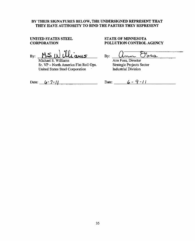
BY THEm SIGNATURES BELOW, THE UNDERSIGNED REPRESENT THATTHEY HAVE AUTHORITY TO BIND THE PARTIES THEY REPRESENT
STATE OF MINNESOTAPOLLUTION CONTROL AGENCY
UNITED STATES STEELCORPORATION
By: By:1"\.$ lJ M "QMASMichael S. WilliamsSr. VP -North America Flat Roll Ops.United States Steel Corporation
O;~:==b o-4.a-Ann Foss, DirectorStrategic Projects SectorIndustrial Division
Date: Cot. 7 -il Date: ~ -q -I I
35

APPENDIX A
Graphical Representation of Mercury Emission Reductions
36
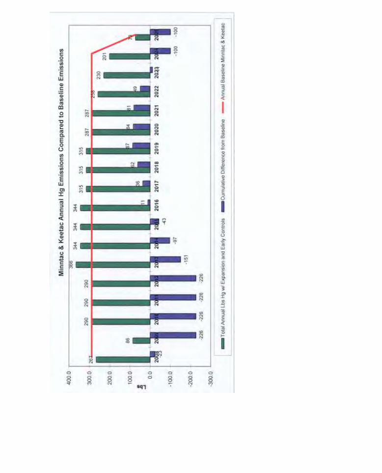

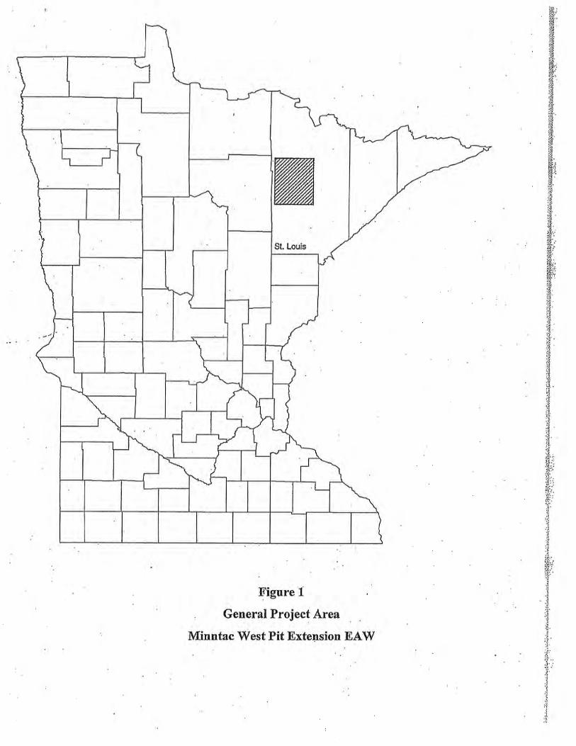
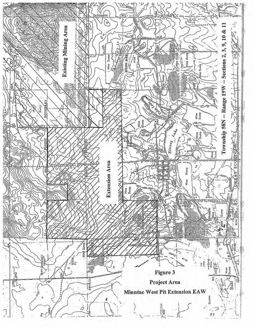
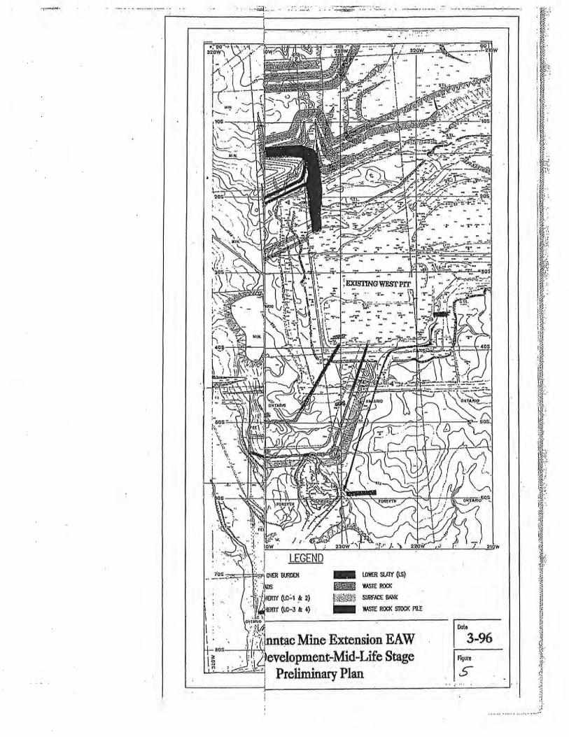
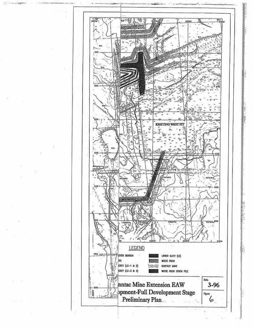
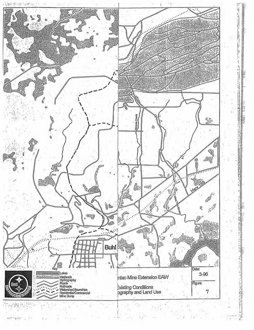
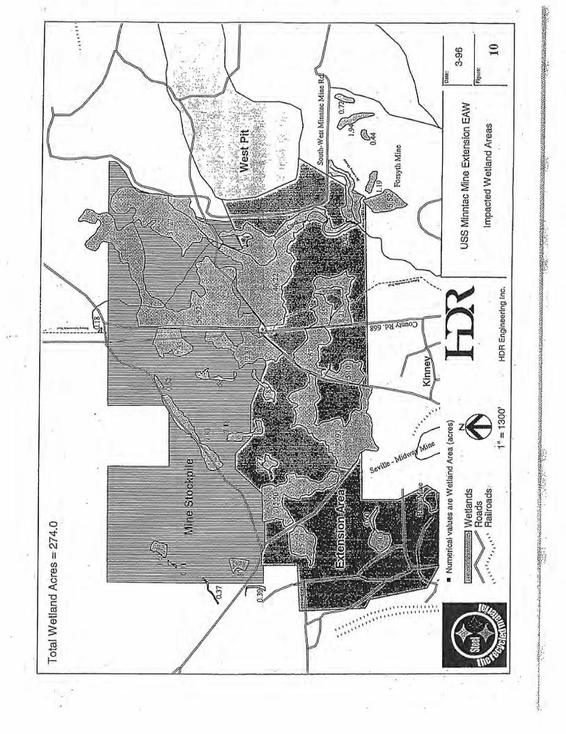
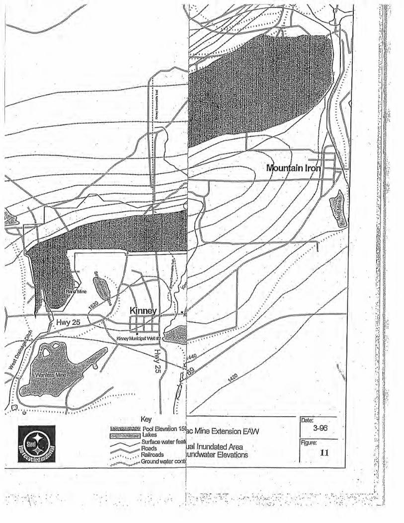
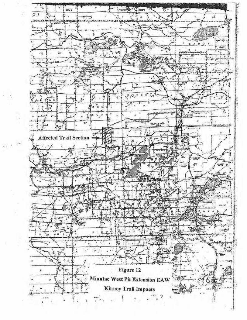
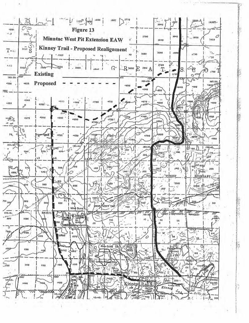
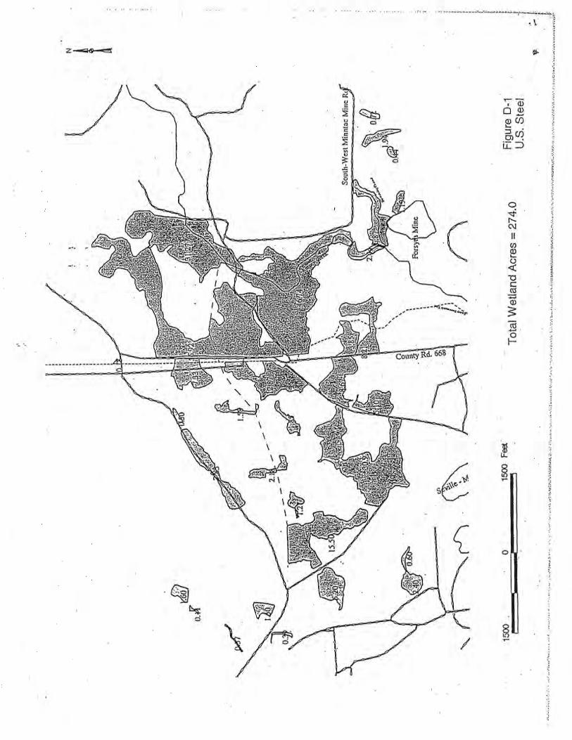
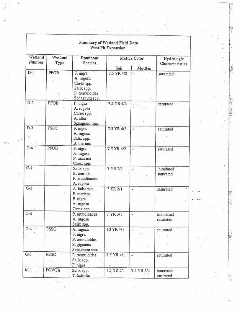
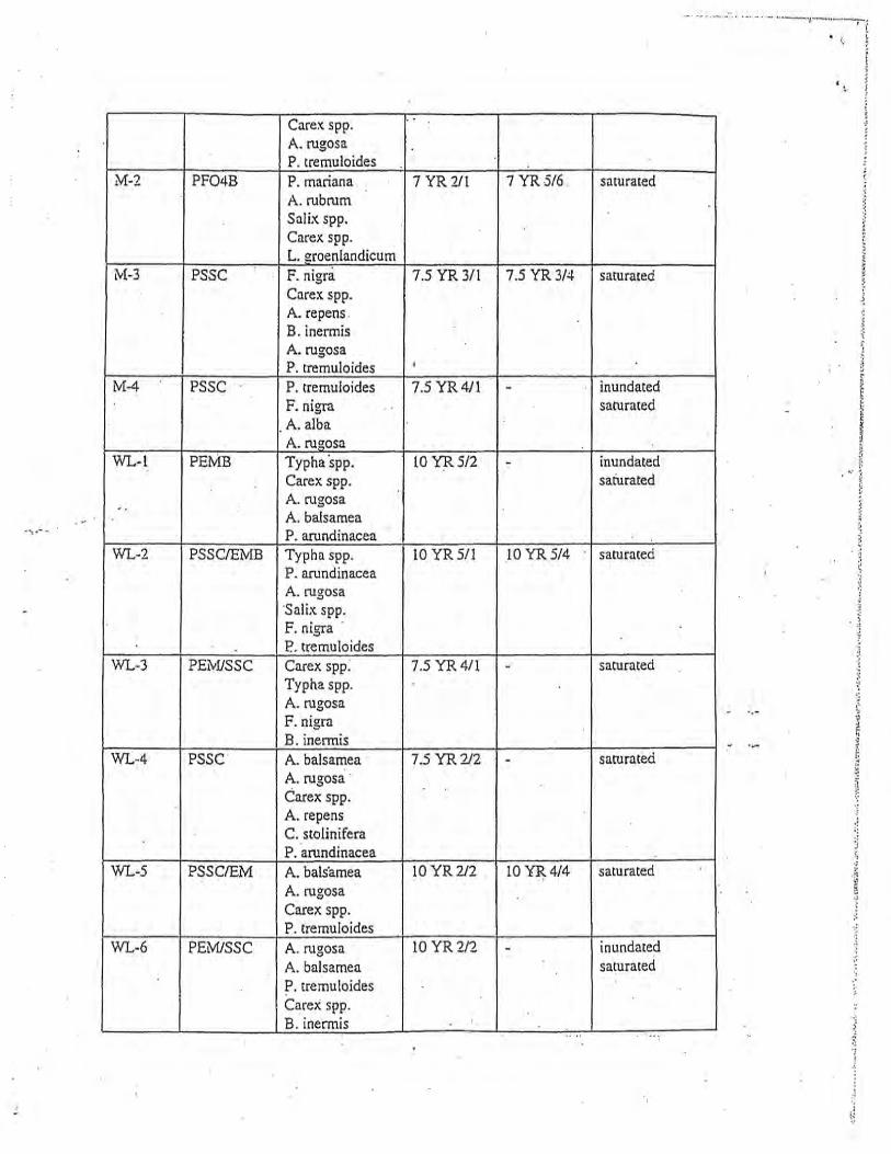
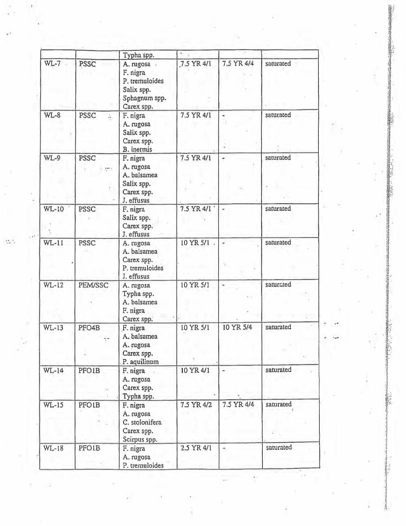
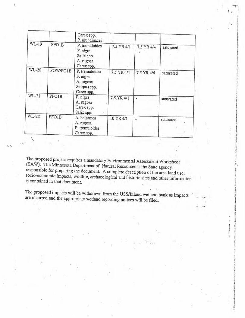
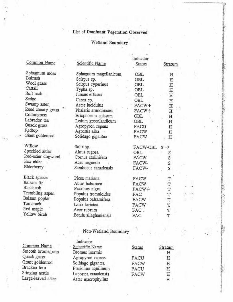
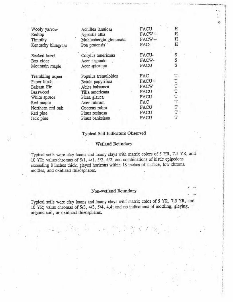
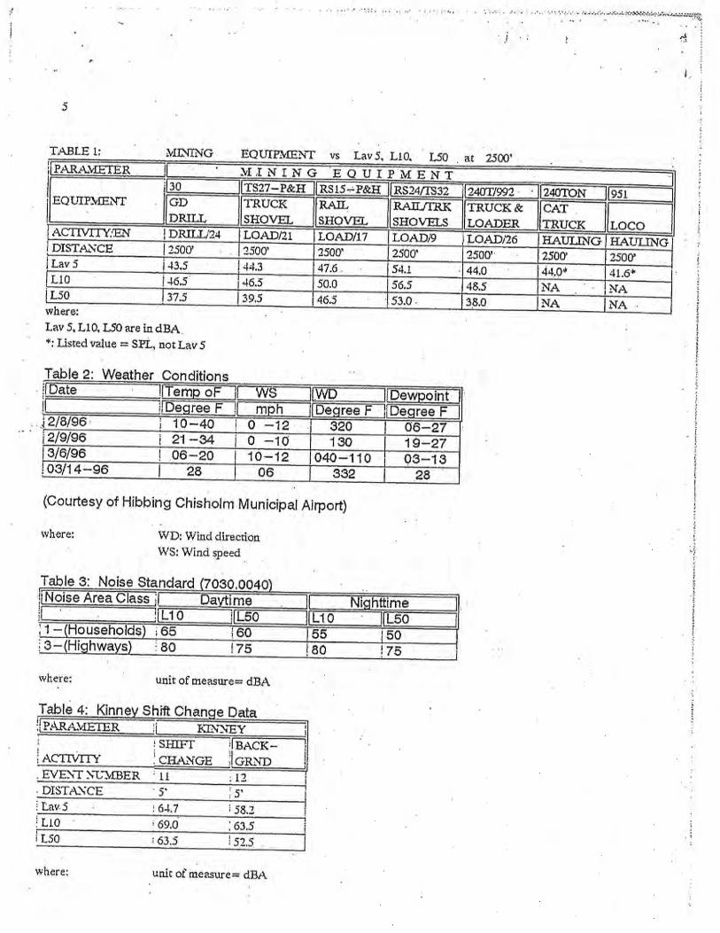
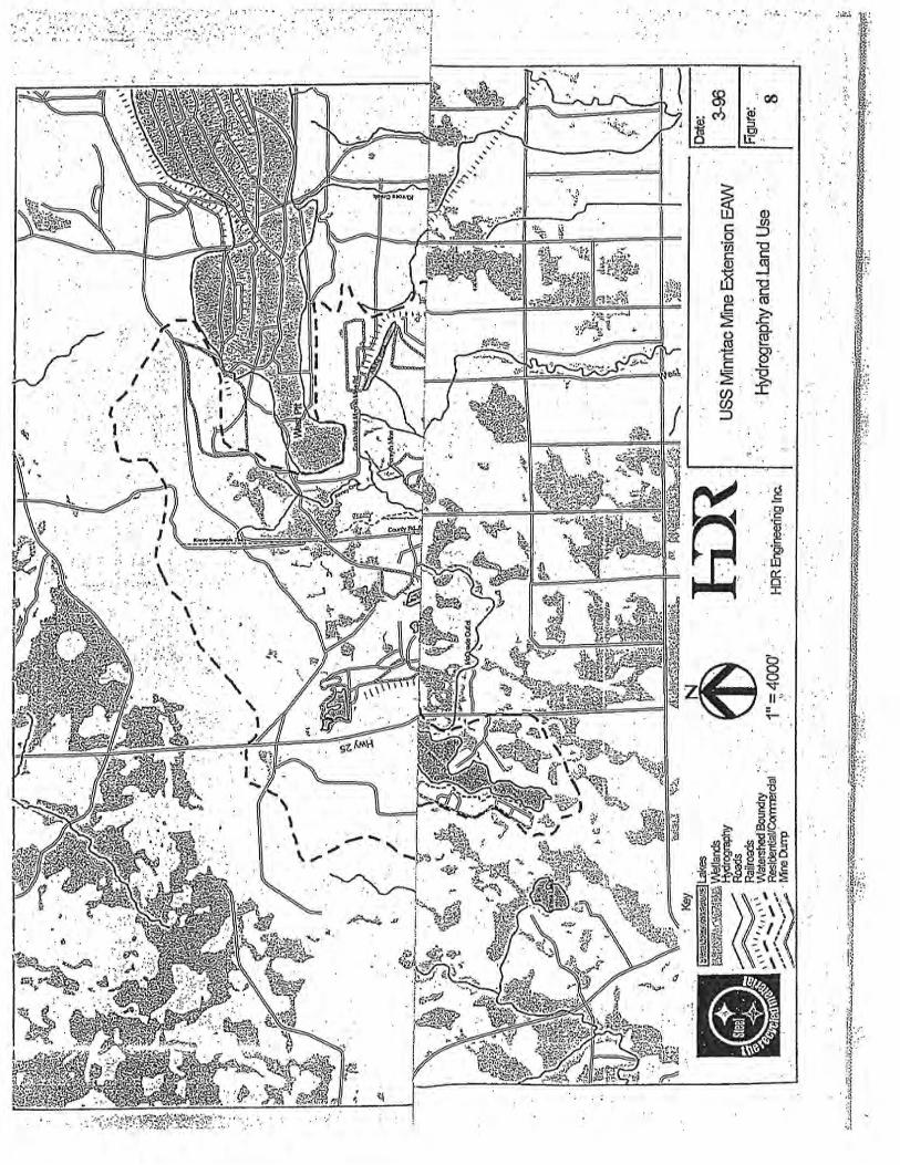
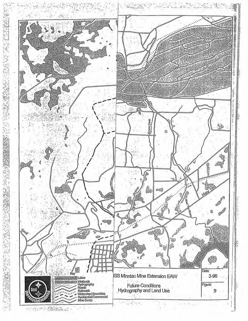
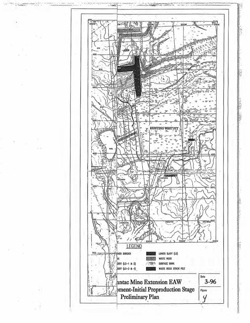
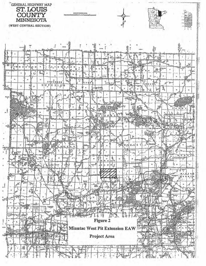
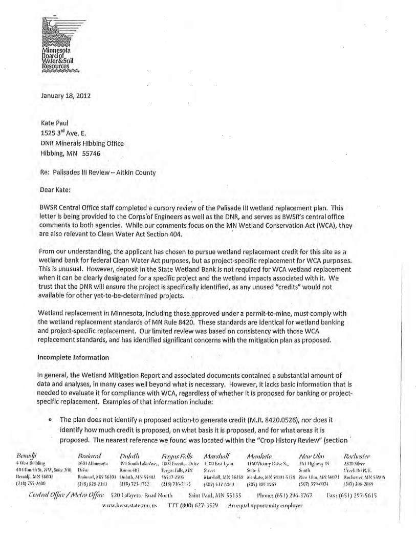
Palisade III Wetland Mitigation
Bank Site Report
United States Steel Corporation,
Minnesota Ore Operations
Palisade Wetland Mitigation Project
Aitkin County, Minnesota
March 2012
Palisade III Wetland Mitigation Bank Site Report United States Steel Corporation
i
Executive SummaryExecutive SummaryExecutive SummaryExecutive Summary
The Palisade III Wetland Mitigation Bank Site (Bank Site) is located approximately 2 miles southeast of the City
of Palisade in Aitkin County, Minnesota. United States Steel Corporation (U. S. Steel) in 2009 purchased a
4,393-acre property for wetland mitigation purposes. The Bank Site project involves the restoration of
approximately 480 acres of agricultural fields. U. S. Steel proposes to compensate for project specific
unavoidable wetland impacts for future operations at the two Minnesota Ore Operations facilities (Keetac and
Minntac).
The NRCS Custom Soil Resource Report for Aitkin County, Minnesota, indicates that a predominance of hydric
soil exists on approximately 98 percent of the Bank Site, indicating existing and/or historical wetland conditions.
Approximately 4.9 miles of drainage ditches flow around the property, but it can be anticipated that the Aitkin
County Ditch Authority would not authorize the abandonment of any regulated ditches. Therefore, this Bank Site
project will involve implementing low profile earthen embankments with minor grading to restore sustaining
hydrology. Please refer to Appendix C for the Bank Site Wetland Grading Plan.
Preliminary analysis indicates that sustaining hydrology can be achieved by designing wide, low profile earthen
embankments with minor grading. Two minor private ditches representing 1.47 acres of man-made ditches that
originate onsite would be abandoned as part of the grading process. These small private ditch abandonments shall
have no consequences to upstream properties. The Bank Site design resulted from a systematic investigation of
the site hydrology and hydraulics. The investigation necessitated the establishment of water level monitoring
points, including deep and shallow piezometers in the aquifer, and staff gauges in the ditches. Hydraulic testing
was also performed during data collection. In the end, through a complicated modeling program, it was shown
that by just minimizing surface drainage into the peripheral ditches and thereby increasing hydraulic resistance on
the Bank Site, the hydrology necessary to sustain wetlands would be achieved.
A watershed approach was employed in the analysis, involving a landscape view of the local watershed and
studying the surface and groundwater flows from higher elevations to northeast and southwest, and then draining
into the Mississippi and Sandy Rivers. The Bank Site analysis included review of several other local and regional
wetlands and their drainage systems. This assessment identified the following conditions within the watershed:
1. Impaired waters draining into the Mississippi River;
2. Sediment loading from past and present farming operations;
Palisade III Wetland Mitigation Bank Site Report United States Steel Corporation
ii
3. Reed canary grass and other invasive plant species impacting native vegetation;
4. Hydrology being altered by drainage ditches used for agricultural purposes; and
5. Wetland soil degradation by agricultural activities:
• Ditching and draining;
• Soil compaction;
• Organic soil desiccation and subsidence; and
• Erosion by wind and water.
The Bank Site project would also include wetland monitoring and maintenance for a minimum of five years.
U. S. Steel is also providing financial assurance for future monitoring, maintenance, contingency, proactive and
adaptive management to assure that the proposed Bank Site is successful in perpetuity.
Palisade III Wetland Mitigation Bank Site Report United States Steel Corporation
iii
Table of Contents
Executive Summary Executive Summary Executive Summary Executive Summary
1.0 Proposed Project .............................................................................................. 7
1.1 Introduction .................................................................................................................................. 7
1.2 Project Location ........................................................................................................................... 7
1.3 Project Purpose and Description .................................................................................................. 9
1.4 Project Status, Schedules and Permits.......................................................................................... 9
2.0 Existing Conditions ........................................................................................ 11
2.1 Landscape Setting ...................................................................................................................... 11
2.2 On-site Soils ............................................................................................................................... 11
2.3 Land Use History ....................................................................................................................... 13
2.4 Crop History Review .................................................................................................................. 13
2.5 Watershed ................................................................................................................................... 18
2.6 Local and Regional Airport Review........................................................................................... 18
2.7 Cultural and Historical Site Review ........................................................................................... 19
3.0 Wetland Impacts ............................................................................................ 20
3.1 Wetland Functional Losses ........................................................................................................ 20
3.2 Wetland Functional Gains at Bank Site ..................................................................................... 21
4.0 Wetland Delineation ....................................................................................... 21
5.0 Mitigation Strategy and Site Selection ............................................................. 23
5.1 Compensatory Mitigation ........................................................................................................... 23
5.2 Vegetation Establishment ........................................................................................................... 25
5.2.1 Site Conditions for Vegetation Establishment .................................................................... 25
5.2.2 Proposed Wetland Compensation Plantings ....................................................................... 27
5.2.3 Fresh (wet) Meadow and Sedge Meadow Seed Mixes ....................................................... 28
5.2.4 Upland Seeding ................................................................................................................... 29
5.2.5 Vegetation Management Schedule ..................................................................................... 32
6.0 Wetland Hydrology Assessment ...................................................................... 33
6.1 Water Budget.............................................................................................................................. 34
6.1.1 Precipitation and Evapotranspiration .................................................................................. 35
6.1.2 Surface Water Outflow ....................................................................................................... 36
6.1.3 Surface Water Inflow .......................................................................................................... 37
6.1.4 Ground-Water Outflow ....................................................................................................... 38
6.1.5 Ground-Water Inflow.......................................................................................................... 39
6.1.6 Water-Budget Evaluation and Summary ............................................................................ 39
6.2 Hydrologic Assessment .............................................................................................................. 40
6.2.1 On-Site Hydrologic Data Base ............................................................................................ 41
6.2.2 Aquifer Hydraulic Testing .................................................................................................. 43
Palisade III Wetland Mitigation Bank Site Report United States Steel Corporation
iv
6.2.3 Ditch Flow Analysis ........................................................................................................... 43
6.2.4 Ground-Water Flow Modeling ........................................................................................... 47
6.3 Conclusions and Recommendations........................................................................................... 52
7.0 Wetland Mitigation Goals, Objectives, and Performance Criteria .................................... 54
7.1 Goals........................................................................................................................................... 54
7.2 Objectives ................................................................................................................................... 54
7.2.1 Performance Standards ....................................................................................................... 54
7.2.2 Hydrological Performance Criteria ..................................................................................... 57
7.2.3 Wetland Vegetation Performance Criteria .......................................................................... 57
7.2.4 Final Performance Standards (5th
year of monitoring) ....................................................... 58
7.4 Monitoring .................................................................................................................................. 58
7.4.1 Monitoring Process ............................................................................................................. 59
7.4.2 Mitigation Banking Instrument ........................................................................................... 60
7.5 Contingency Plan ....................................................................................................................... 61
7.5.1 Drought ............................................................................................................................... 62
7.5.2 Large Storm Events............................................................................................................. 62
7.5.3 Invasive Plant Species......................................................................................................... 66
7.5.4 Wetland Vegetation Failure ................................................................................................ 68
7.5.5 Woody Wetland Vegetation Encroachment........................................................................ 68
7.5.6 Upland Earthen Embankment Management ....................................................................... 69
8.0 References ....................................................................................................... 70
List of Figures
Figure 1.1 – USGS Site Location Map
Figure 1.2– Aerial Map
Figure 2.1 – USDA Soils Map
Figure 2.2 – Sub-Parcel Crop Mapping
Figure 2.3– Watershed Map
Figure 6.1 – Water Budget Parcel Location Map
Figure 6.2 – Ditch Flow Diagram on Aerial Image
Figure 6.3 – Adjacent Property Owners Map
Palisade III Wetland Mitigation Bank Site Report United States Steel Corporation
v
Figures 7.1 to 7.3 – Knife Gate Valve Details
List of Tables
Table 2.1 – Credit Ranges Based on Proposed Action and Regulatory Agency
Table 3.1 – Keetac Wetland Impacts
Table 3.2 – Minntac Wetland Impacts
Table 5.1 – Wet Meadow/Sedge Meadow Wetland Seed Mix
Table 5.2 – Sedge Meadow Wetland Seed Mix
Table 5.3 – Upland Seed Mix
Table 6.1 – Effects of Proposed Changes on the Water Table
List of Appendices
Appendix A – Invasive Plant Species Map
Appendix B – Wetland Delineation Map and Soil Borings
Appendix C – Wetland Grading, Seeding and Woody Vegetation Plans
Appendix D – Water Budget Calculations and Charts
Appendix E – Water Table Level Contour Maps
Appendix F – Numerical Modeling Results

Palisade III Wetland Mitigation Bank Site Report United States Steel Corporation
vi
List of Acronyms and Technical Terms
BWSR- Minnesota Board of Water and Soil Resources
CIR - color infra-red
CFR - Code of Federal Regulations
DNR - Minnesota Department of Natural Resources
FQA - Floristic Quality Assessment
GIS - Geographic Information System
IBI - Index of Biological Integrity
IRT - Interagency Review Team
LGU - local governmental unit
MDA - Minnesota Department of Agriculture
MNDNR - Minnesota Department of Natural Resources
MNRAM - Minnesota Routine Assessment Methodology
MOU - Memorandum of Understanding
MPCA - Minnesota Pollution Control Agency
NRCS - Natural Resource Conservation Service
NWI- National Wetland Inventory
Section 404 - Clean Water Act
SWCD - Aitkin County Soil and Water Conservation District
TEP - Technical Evaluation Panel (WCA provisions)
USACE - United States Army Corps
USEPA - United States Environmental Protection Agency
USFWS - United States Fish and Wildlife Service
USGS - U. S. Geological Survey
WCA - Minnesota Wetland Conservation Act of 1991

Palisade III Wetland Mitigation Bank Site Report United States Steel Corporation
7
1.01.01.01.0 Proposed ProjectProposed ProjectProposed ProjectProposed Project
1.1 Introduction
United States Steel Corporation (U. S. Steel) is an integrated steel producer with operations in United States
Canada, and Central Europe. With two mining operations in Minnesota, U. S. Steel’s Minnesota Ore Operations
consist of the Keetac Mine (Keetac) in Keewatin, Itasca County, and the Minntac Mine (Minntac) in Mt. Iron, St.
Louis County. Both Keetac and Minntac mining operations are proposing to implement future mining expansions
and extensions that would require wetland compensatory mitigation. Unavoidable future wetland impacts at
Keetac and Minntac would require replacement credits over the next five or more years.
In 2009, U. S. Steel purchased 4,393 acres of agricultural land southeast of the City of Palisade, in Aitkin County,
Minnesota, with the intention of restoring the agricultural land to obtain replacement credits necessary to support
future Keetac and Minntac mining operations. To obtain replacement credits for operations over the next five
years or more, U. S. Steel is implementing this 480-acre project specific Bank Site wetland restoration project.
This Bank Site is also known as Palisade III. Palisade I and II are project specific wetland mitigation sites for
Keetac and Minntac, respectively, and are located on adjacent parcels. They would be constructed concurrently
with this Bank Site.
Based upon the review of historical aerial photographs and observations of hydric soils, it is evident that 98% of
the approximately 480-acre Bank Site was once a wetland habitat that had been drained and then farmed since the
1980s. The historic wetlands were drained through the construction of a system of ditches in the 1970s that was
followed in the early 1980s, by farming operations to the present day.
1.2 Project Location
The Bank Site is located in Aitkin County, Minnesota, approximately 2 to 3 miles southeast of the City of
Palisade. Specifically, the Bank Site is located in the E ½ of the NW ¼, S ½ of the NE ¼, E ½ of the SW ¼, and
the SE ¼ of Section 34 and the S ½ of the SW ¼ of Section 27, of Workman Township (T.49N., R.24W.), Aitkin
County, Minnesota. A 1973 USGS and 2009 Aerial Map of the Bank Site are presented in Figure 1.1 and Figure
1.2, respectively.
The Bank Site is located in the Mississippi River Headwaters, specifically Mississippi River-Grand Rapids major
watershed. The Bank Site is within Bank Service Area #5 and lies within the Laurentian Mixed Forest province.
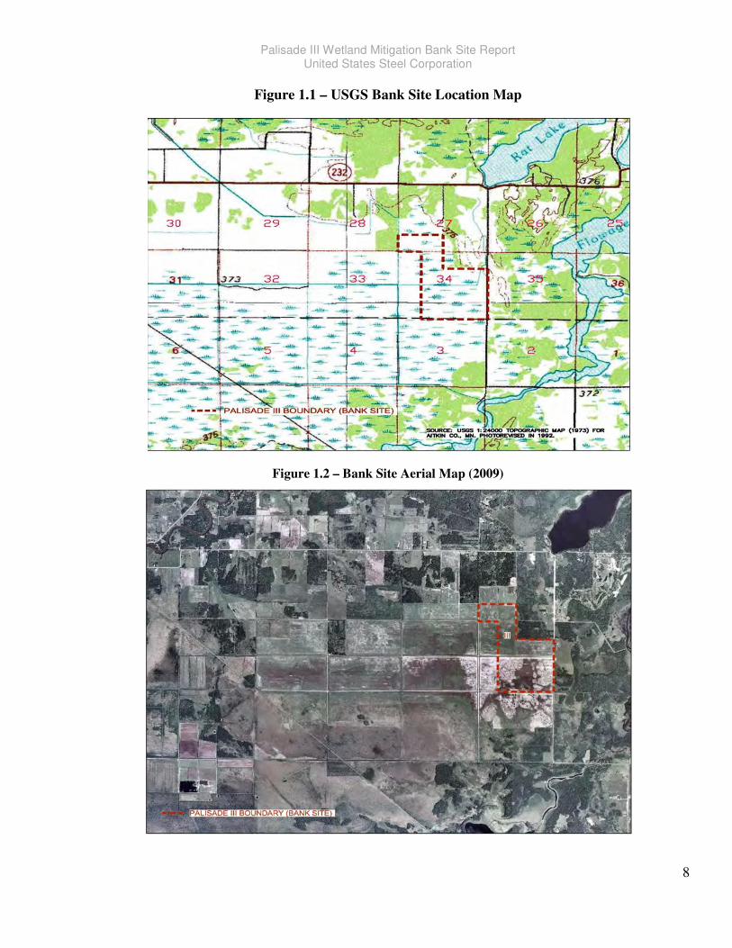
Palisade III Wetland Mitigation Bank Site Report United States Steel Corporation
8
Figure 1.1 – USGS Bank Site Location Map
Figure 1.2 – Bank Site Aerial Map (2009)
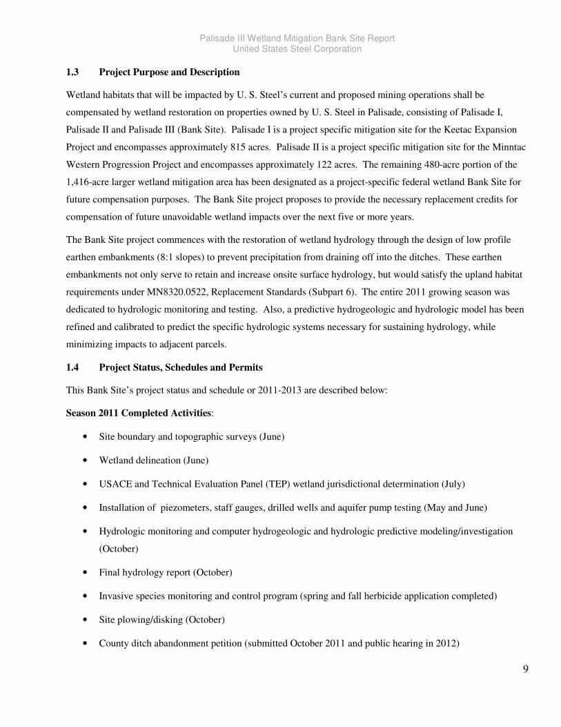
Palisade III Wetland Mitigation Bank Site Report United States Steel Corporation
9
1.3 Project Purpose and Description
Wetland habitats that will be impacted by U. S. Steel’s current and proposed mining operations shall be
compensated by wetland restoration on properties owned by U. S. Steel in Palisade, consisting of Palisade I,
Palisade II and Palisade III (Bank Site). Palisade I is a project specific mitigation site for the Keetac Expansion
Project and encompasses approximately 815 acres. Palisade II is a project specific mitigation site for the Minntac
Western Progression Project and encompasses approximately 122 acres. The remaining 480-acre portion of the
1,416-acre larger wetland mitigation area has been designated as a project-specific federal wetland Bank Site for
future compensation purposes. The Bank Site project proposes to provide the necessary replacement credits for
compensation of future unavoidable wetland impacts over the next five or more years.
The Bank Site project commences with the restoration of wetland hydrology through the design of low profile
earthen embankments (8:1 slopes) to prevent precipitation from draining off into the ditches. These earthen
embankments not only serve to retain and increase onsite surface hydrology, but would satisfy the upland habitat
requirements under MN8320.0522, Replacement Standards (Subpart 6). The entire 2011 growing season was
dedicated to hydrologic monitoring and testing. Also, a predictive hydrogeologic and hydrologic model has been
refined and calibrated to predict the specific hydrologic systems necessary for sustaining hydrology, while
minimizing impacts to adjacent parcels.
1.4 Project Status, Schedules and Permits
This Bank Site’s project status and schedule or 2011-2013 are described below:
Season 2011 Completed Activities:
• Site boundary and topographic surveys (June)
• Wetland delineation (June)
• USACE and Technical Evaluation Panel (TEP) wetland jurisdictional determination (July)
• Installation of piezometers, staff gauges, drilled wells and aquifer pump testing (May and June)
• Hydrologic monitoring and computer hydrogeologic and hydrologic predictive modeling/investigation
(October)
• Final hydrology report (October)
• Invasive species monitoring and control program (spring and fall herbicide application completed)
• Site plowing/disking (October)
• County ditch abandonment petition (submitted October 2011 and public hearing in 2012)
Palisade III Wetland Mitigation Bank Site Report United States Steel Corporation
10
2012/2013 Construction and Monitoring Schedule:
• Obtain USACE/MNDNR/TEP approval of the Palisade Wetland Mitigation Bank Site Report and Bank
Site Plans (early 2012)
• Bank Site to be farmed over the growing season
• Minor hydrologic and site monitoring during the growing season (including a several water level
collection events)
• Invasive species monitoring and control throughout the growing season along and within ditches (first
spraying would begin in April)
• Down payment of 25% required for seeds by May 2012 (payable to Prairie Moon Nursery) with balance
paid within 30 days after delivery (~November 15, 2012)
• Grading contractor to be retained (June/July)
• Seeding contractor to be retained (July/August)
• Construction to begin around October 15 and would continue until soil is frozen
• *Fall seeding would begin as soon as possible concurrently or directly after earthen embankment and
grading is completed in each parcel (seeds would be picked up by contractors)
• Woody plant supplier and contractor to be obtained by December for 2013 spring planting season
• Trees and shrubs (final species chosen would be based on availability) delivered for planting in March
2013
• Site monitoring within 3 weeks of the start of the growing season
• Invasive species and hydrology monitoring throughout the growing season
• Implementation of contingencies and/or adaptive management if necessary
*Dormant seeding would occur immediately after construction and continue until the soil is frozen. If seeding
cannot be completed in the dormant fall season before the soil is frozen, then snow seeding may occur in February
or March 2013 to complete the seeding phase of work. Currently, the proposed construction sequence would
begin at Palisade II (Minntac), then Palisade I (Keetac), and then Palisade III (Bank Site). Palisade II consists of
120 acres and is the smallest parcel that can be finished quickly. Palisade I is the largest parcel of about 815
acres.
Palisade III Wetland Mitigation Bank Site Report United States Steel Corporation
11
List of Federal, State and Local Permits
U. S. Steel will obtain all appropriate permits or other authorizations to construct and maintain the Bank Site,
prior to debiting any credits. U. S. Steel will also submit to the USACE a draft General Stormwater Permit
(Permit No: MN R100001) prior to construction. This would include a completed application to Minnesota
Pollution Control Agency located at 520 Lafayette Road North, St. Paul. MN 55155-4194. The permit will
require the development and implementation of a Stormwater Pollution Prevention Plan (SWPPP) and the
SWPPP is likely to be completed by the chosen contractor.
2.02.02.02.0 Existing ConditionsExisting ConditionsExisting ConditionsExisting Conditions
2.1 Landscape Setting
The topography around the Bank Site is best described as gently rolling with no visible hills or valleys. The
property is currently farmed and zoned for agriculture with about 4.9 miles of drainage ditches. The drainage
ditches are man-made and run north/south and east/west throughout the property. The vegetation in the ditches
includes various herbaceous grasses and invasive plant species (primarily reed canary grass and cattails), with a
few scattered small trees and shrubs along the banks. Non-disturbed properties around the Bank Site consist
predominantly of native hardwood swamps, shrub-carr and wet meadows.
2.2 On-site Soils
Approximately 62% (299 acres) of the Bank Site consists of muck soils likely to have formed from closed
depression topography that impeded surface drainage, and over time filled with organic material, forming peat.
Approximately 35% (170 acres) of sandy loam are poorly drained. The remaining 11 acres are moderately drained
upland soils. The United States Department of Agriculture (USDA), Natural Resources Conservation Service
(NRCS), Soil Survey of Aitkin County, Minnesota, has mapped the following project soils (grouped by Section
below):
Soils on 82-acre parcel in Section 27 Area on Parcel Hydrogeologic Group
1983 – Cathro muck, stratified substratum ~ 27 acres A/D (Very poorly drained)
1150 – Jevne fine sandy loam ~ 26 acres C (Poorly drained)
563 – Northwood muck ~ 29 acres B/D (Very poorly drained) Soils on 398-acre parcel in Section 34 Area on Parcel Hydrogeologic Group
1150 – Jevne fine sandy loam ~ 137 acres C (Poorly drained)
1983 – Cathro muck, stratified substratum ~ 110 acres A/D (Very poorly drained)
532 – Sago muck ~ 131 acres D (Very poorly drained)
563 – Northwood muck ~ 2 acres B/D (Very poorly drained)
625 – Sandwick loamy sand ~ 9 acres B (Moderately well drained)
346 – Talmoon fine sandy loam ~ 7 acres C (Poorly drained) 1353B – Cutaway loamy fine sand ~ 2 acres B (Moderately well drained)
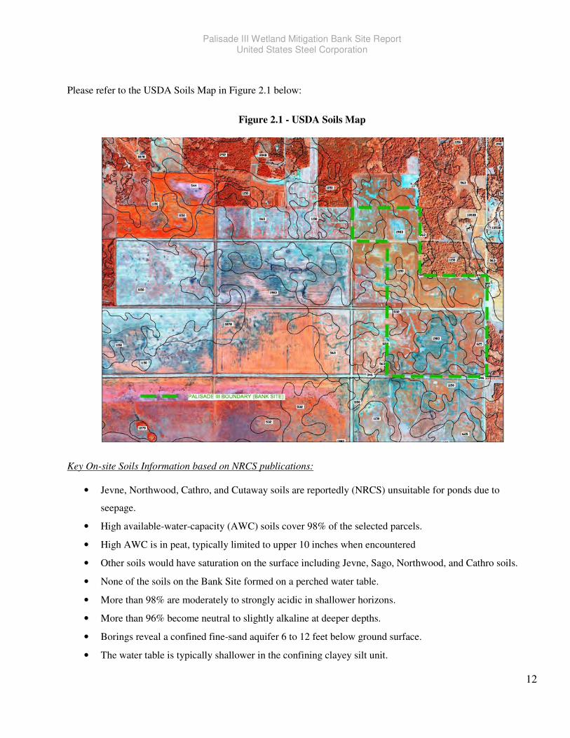
Palisade III Wetland Mitigation Bank Site Report United States Steel Corporation
12
Please refer to the USDA Soils Map in Figure 2.1 below:
Figure 2.1 - USDA Soils Map
Key On-site Soils Information based on NRCS publications:
• Jevne, Northwood, Cathro, and Cutaway soils are reportedly (NRCS) unsuitable for ponds due to
seepage.
• High available-water-capacity (AWC) soils cover 98% of the selected parcels.
• High AWC is in peat, typically limited to upper 10 inches when encountered
• Other soils would have saturation on the surface including Jevne, Sago, Northwood, and Cathro soils.
• None of the soils on the Bank Site formed on a perched water table.
• More than 98% are moderately to strongly acidic in shallower horizons.
• More than 96% become neutral to slightly alkaline at deeper depths.
• Borings reveal a confined fine-sand aquifer 6 to 12 feet below ground surface.
• The water table is typically shallower in the confining clayey silt unit.
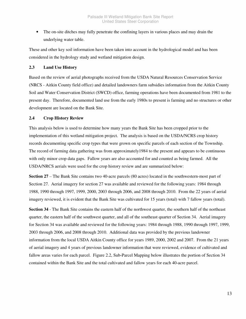
Palisade III Wetland Mitigation Bank Site Report United States Steel Corporation
13
• The on-site ditches may fully penetrate the confining layers in various places and may drain the
underlying water table.
These and other key soil information have been taken into account in the hydrological model and has been
considered in the hydrology study and wetland mitigation design.
2.3 Land Use History
Based on the review of aerial photographs received from the USDA Natural Resources Conservation Service
(NRCS - Aitkin County field office) and detailed landowners farm subsidies information from the Aitkin County
Soil and Water Conservation District (SWCD) office, farming operations have been documented from 1981 to the
present day. Therefore, documented land use from the early 1980s to present is farming and no structures or other
development are located on the Bank Site.
2.4 Crop History Review
This analysis below is used to determine how many years the Bank Site has been cropped prior to the
implementation of this wetland mitigation project. The analysis is based on the USDA/NCRS crop history
records documenting specific crop types that were grown on specific parcels of each section of the Township.
The record of farming data gathering was from approximately1984 to the present and appears to be continuous
with only minor crop data gaps. Fallow years are also accounted for and counted as being farmed. All the
USDA/NRCS aerials were used for the crop history review and are summarized below:
Section 27 – The Bank Site contains two 40-acre parcels (80 acres) located in the southwestern-most part of
Section 27. Aerial imagery for section 27 was available and reviewed for the following years: 1984 through
1988, 1990 through 1997, 1999, 2000, 2003 through 2006, and 2008 through 2010. From the 22 years of aerial
imagery reviewed, it is evident that the Bank Site was cultivated for 15 years (total) with 7 fallow years (total).
Section 34 - The Bank Site contains the eastern half of the northwest quarter, the southern half of the northeast
quarter, the eastern half of the southwest quarter, and all of the southeast quarter of Section 34. Aerial imagery
for Section 34 was available and reviewed for the following years: 1984 through 1988, 1990 through 1997, 1999,
2003 through 2006, and 2008 through 2010. Additional data was provided by the previous landowner
information from the local USDA Aitkin County office for years 1989, 2000, 2002 and 2007. From the 21 years
of aerial imagery and 4 years of previous landowner information that were reviewed, evidence of cultivated and
fallow areas varies for each parcel. Figure 2.2, Sub-Parcel Mapping below illustrates the portion of Section 34
contained within the Bank Site and the total cultivated and fallow years for each 40-acre parcel.
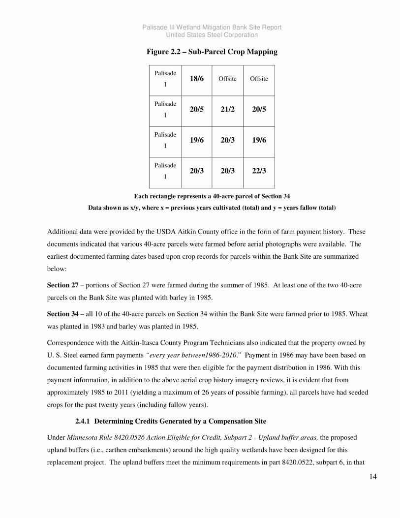
Palisade III Wetland Mitigation Bank Site Report United States Steel Corporation
14
Figure 2.2 – Sub-Parcel Crop Mapping
Palisade
I 18/6 Offsite Offsite
Palisade
I 20/5 21/2 20/5
Palisade
I 19/6 20/3 19/6
Palisade
I 20/3 20/3 22/3
Each rectangle represents a 40-acre parcel of Section 34
Data shown as x/y, where x = previous years cultivated (total) and y = years fallow (total)
Additional data were provided by the USDA Aitkin County office in the form of farm payment history. These
documents indicated that various 40-acre parcels were farmed before aerial photographs were available. The
earliest documented farming dates based upon crop records for parcels within the Bank Site are summarized
below:
Section 27 – portions of Section 27 were farmed during the summer of 1985. At least one of the two 40-acre
parcels on the Bank Site was planted with barley in 1985.
Section 34 – all 10 of the 40-acre parcels on Section 34 within the Bank Site were farmed prior to 1985. Wheat
was planted in 1983 and barley was planted in 1985.
Correspondence with the Aitkin-Itasca County Program Technicians also indicated that the property owned by
U. S. Steel earned farm payments “every year between1986-2010.” Payment in 1986 may have been based on
documented farming activities in 1985 that were then eligible for the payment distribution in 1986. With this
payment information, in addition to the above aerial crop history imagery reviews, it is evident that from
approximately 1985 to 2011 (yielding a maximum of 26 years of possible farming), all parcels have had seeded
crops for the past twenty years (including fallow years).
2.4.1 Determining Credits Generated by a Compensation Site
Under Minnesota Rule 8420.0526 Action Eligible for Credit, Subpart 2 - Upland buffer areas, the proposed
upland buffers (i.e., earthen embankments) around the high quality wetlands have been designed for this
replacement project. The upland buffers meet the minimum requirements in part 8420.0522, subpart 6, in that
Palisade III Wetland Mitigation Bank Site Report United States Steel Corporation
15
the minimum upland width would be no less than 25 feet and the average width is 50 feet or greater. Our low
profile upland earthen embankments are also designed with mosaic shaping such that it would blend into the
natural setting when constructed and planted. The upland buffers also serve to maximize the hydrology, taking
into account that the County most likely will not approve any ditch abandonment request. The Bank Site will
consist of approximately 60.5 acres (~12.6% of the property) of upland buffers. Of the 60.5 acres of upland
earthen embankments, only 36.68 acres can be used for the 25% upland crediting under Subpart 2, as 26.53
acres of the proposed earthen embankments consist of delineated wetlands where no credit will be considered.
Under Subpart 3, Restoration of completely drained or filled wetland areas - the completely drained or filled
Bank Site areas consist of approximately 161 acres of drained or filled farmland and approximately 23 acres
unpaved roads (which shall remain). The net restoration portion under Subpart 3 consists of approximately 124
acres (161 acres of upland minus 37 acres of that are needed for the earthen embankment construction).
The Bank Site project plan does not involve the restoration of historic native wetland plant communities, but of
in-kind native fresh (wet) meadow, sedge meadow, shrub-carr, and hardwood swamp communities appropriate
for Aitkin County.
Under Subpart 4, Restoration of partially drained or filled wetland areas, U. S. Steel anticipates that
approximate 256.67 acres of farmed wetlands would be eligible for up to 100 percent of the wetland area
restored, as these wetland areas have been farmed over the past 20 years and consist of degraded wetlands with
minimal existing functions. The approximate 256.67 net acres are derived from the total delineated farmed
wetlands of 283.2 acres minus 26.53 acres of those wetlands to be filled by earthen embankment construction.
Based on the partially drained wetlands delineated (283.2 acres – 26.53 = 256.67 net acres) plus the drained
wetlands (124 upland acres) and 25% for upland buffer (.25 x 36.7 acres = 9.17 acres), the Bank Site would
have a maximum of approximately 390 eligible credits at the Bank Site before applying replacement ratios.
For agricultural lands, the ratio is 1.5:1 for being located outside of the major watershed and 1:1 for projects
located within the major watershed. Using a 1.5:1 ratio would result in a maximum of approximately 260
replacement credits and using a 1:1 ratio would result in approximately 390 replacement credits.
Both Keetac and Minntac mining sites are located in a part of Minnesota with greater than 80% of pre-
settlement wetlands. The USACE under this scenario would start with a 1.5:1 replacement ratio and apply a .25
reduction to projects being in-place and another .25 reduction for project s having in-kind mitigation. Keetac
projects would get a .5 reduction and have 1:1 compensatory replacement ratio. Therefore, Keetac mitigation
projects could obtain a maximum of 390 replacement credits. Minntac would get a .25 reduction for having only
in-kind mitigation and at a 1.25:1 compensatory replacement ratio, Minntac could obtain a maximum of
approximately 312 replacement credits. Since the project specific acres have not yet been determined at the
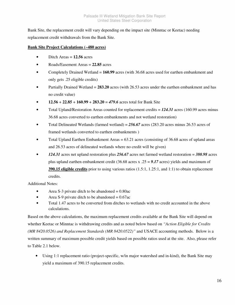
Palisade III Wetland Mitigation Bank Site Report United States Steel Corporation
16
Bank Site, the replacement credit will vary depending on the impact site (Minntac or Keetac) needing
replacement credit withdrawals from the Bank Site.
Bank Site Project Calculations (~480 acres)
• Ditch Areas = 12.56 acres
• Roads/Easement Areas = 22.85 acres
• Completely Drained Wetland = 160.99 acres (with 36.68 acres used for earthen embankment and
only gets .25 eligible credits)
• Partially Drained Wetland = 283.20 acres (with 26.53 acres under the earthen embankment and has
no credit value)
• 12.56 + 22.85 + 160.99 + 283.20 = 479.6 acres total for Bank Site
• Total Upland/Restoration Areas counted for replacement credits = 124.31 acres (160.99 acres minus
36.68 acres converted to earthen embankments and not wetland restoration)
• Total Delineated Wetlands (farmed wetland) = 256.67 acres (283.20 acres minus 26.53 acres of
framed wetlands converted to earthen embankments )
• Total Upland Earthen Embankment Areas = 63.21 acres (consisting of 36.68 acres of upland areas
and 26.53 acres of delineated wetlands where no credit will be given)
• 124.31 acres net upland restoration plus 256.67 acres net farmed wetland restoration = 380.98 acres
plus upland earthen embankment credit (36.68 acres x .25 = 9.17 acres) yields and maximum of
390.15 eligible credits prior to using various ratios (1.5:1, 1.25:1, and 1:1) to obtain replacement
credits.
Additional Notes:
• Area S-3 private ditch to be abandoned = 0.80ac
• Area S-9 private ditch to be abandoned = 0.67ac
• Total 1.47 acres to be converted from ditches to wetlands with no credit accounted in the above
calculations.
Based on the above calculations, the maximum replacement credits available at the Bank Site will depend on
whether Keetac or Minntac is withdrawing credits and as noted below based on “Action Eligible for Credits
(MR 8420.0526) and Replacement Standards (MR 8420.0522)” and USACE accounting methods. Below is a
written summary of maximum possible credit yields based on possible ratios used at the site. Also, please refer
to Table 2.1 below.
• Using 1:1 replacement ratio (project-specific, w/in major watershed and in-kind), the Bank Site may
yield a maximum of 390.15 replacement credits.
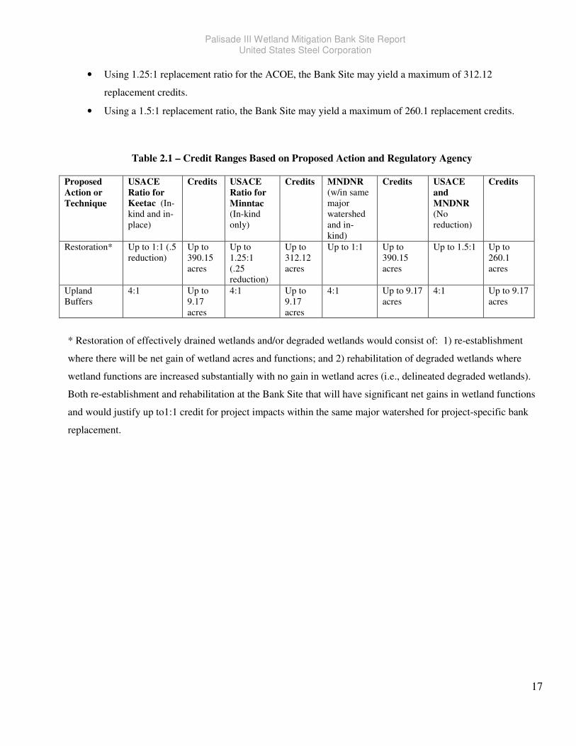
Palisade III Wetland Mitigation Bank Site Report United States Steel Corporation
17
• Using 1.25:1 replacement ratio for the ACOE, the Bank Site may yield a maximum of 312.12
replacement credits.
• Using a 1.5:1 replacement ratio, the Bank Site may yield a maximum of 260.1 replacement credits.
Table 2.1 – Credit Ranges Based on Proposed Action and Regulatory Agency
Proposed
Action or
Technique
USACE
Ratio for
Keetac (In-
kind and in-
place)
Credits USACE
Ratio for
Minntac (In-kind
only)
Credits MNDNR
(w/in same
major
watershed
and in-
kind)
Credits USACE
and
MNDNR (No
reduction)
Credits
Restoration* Up to 1:1 (.5
reduction)
Up to
390.15
acres
Up to
1.25:1
(.25
reduction)
Up to
312.12
acres
Up to 1:1 Up to
390.15
acres
Up to 1.5:1
Up to
260.1
acres
Upland
Buffers
4:1 Up to
9.17
acres
4:1 Up to
9.17
acres
4:1 Up to 9.17
acres
4:1 Up to 9.17
acres
* Restoration of effectively drained wetlands and/or degraded wetlands would consist of: 1) re-establishment
where there will be net gain of wetland acres and functions; and 2) rehabilitation of degraded wetlands where
wetland functions are increased substantially with no gain in wetland acres (i.e., delineated degraded wetlands).
Both re-establishment and rehabilitation at the Bank Site that will have significant net gains in wetland functions
and would justify up to1:1 credit for project impacts within the same major watershed for project-specific bank
replacement.
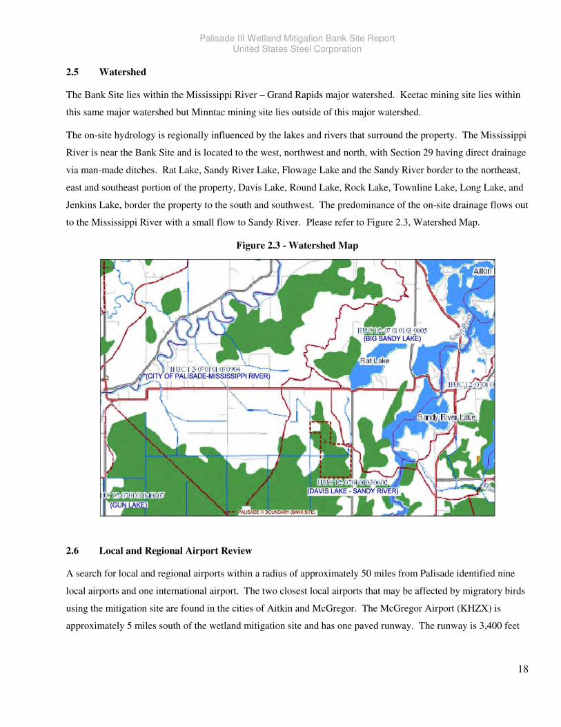
Palisade III Wetland Mitigation Bank Site Report United States Steel Corporation
18
2.5 Watershed
The Bank Site lies within the Mississippi River – Grand Rapids major watershed. Keetac mining site lies within
this same major watershed but Minntac mining site lies outside of this major watershed.
The on-site hydrology is regionally influenced by the lakes and rivers that surround the property. The Mississippi
River is near the Bank Site and is located to the west, northwest and north, with Section 29 having direct drainage
via man-made ditches. Rat Lake, Sandy River Lake, Flowage Lake and the Sandy River border to the northeast,
east and southeast portion of the property, Davis Lake, Round Lake, Rock Lake, Townline Lake, Long Lake, and
Jenkins Lake, border the property to the south and southwest. The predominance of the on-site drainage flows out
to the Mississippi River with a small flow to Sandy River. Please refer to Figure 2.3, Watershed Map.
Figure 2.3 - Watershed Map
2.6 Local and Regional Airport Review
A search for local and regional airports within a radius of approximately 50 miles from Palisade identified nine
local airports and one international airport. The two closest local airports that may be affected by migratory birds
using the mitigation site are found in the cities of Aitkin and McGregor. The McGregor Airport (KHZX) is
approximately 5 miles south of the wetland mitigation site and has one paved runway. The runway is 3,400 feet

Palisade III Wetland Mitigation Bank Site Report United States Steel Corporation
19
long by 75 feet wide. It is an “unattended” airport with no control tower and the airport manager is Mike Zebro.
This airport reports a local traffic of only 3 transient and 2 local airplane flights per day.
The Aitkin Airport (KAIT) is approximately 18 miles southwest of the wetland mitigation site and has two paved
runways. The runways are 3,123 feet long by 140 feet wide and 4,000 feet long by 75 feet wide. The airport is
publicly owned by the County and City of Aitkin and the airport manager is Kathy Brophy. The airport has onsite
attendance from November through April, 7 days a week between 0900-1600 hours and from May through
October, 7 days a week between 0900-1700 hours. This airport reports a local traffic of only 8 transient and 36
local airplane flights per day.
The remaining 7 local airports are about 30 or more miles away from the Bank Site. Most of these local airports
report 25 or fewer flights per day average with Brainerd Lake Regional (KBRD) airport having the most flights
with 25 transient and 60 local average flights per day. It is not expected that any of the local airports would be
impacted by the development of the wetland mitigation site.
The Duluth International Airport is the only international airport within approximately 60 miles due east of the
Bank Site. All flights appear to head southeast or southwest with most flights heading due south/southeast
towards Detroit, Chicago-O’Hare, New York and Orlando, Florida. Other flights head west to Las Vegas. Based
on the general flight path of the three major airlines out of Duluth International Airport (Delta, United, and
Allegiant), the proposed wetland mitigation is not located in the airport’s flight line and would not have any
impacts to large aircrafts.
The above information was obtained from the flight plan website: http://www.fltplan.com/.
2.7 Cultural and Historical Site Review
A table top review for cultural and historical resources was performed by utilizing the Minnesota Historical
Society website resources. A search for “National Register of Historic Places,” listed by county, confirmed that
the following ten places of cultural and historical interest exist within Aitkin County:
1. Aitkin Carnegie Library (1911)
2. Aitkin County Courthouse (1929) and Jail (1915)
3. Arthyde Stone House (World War I Era)
4. Bethlehem Lutheran Church (1897)
5. Casey, Patrick, House (1901)
6. Malmo Mounds and Village Sites (ca. 200 B.C. to A.D. 400)
7. National Woodenware Company Superintendent’s House (1910)
8. Northern Pacific Depot (1916)
9. Potter-Casey Company Building (1902)
Palisade III Wetland Mitigation Bank Site Report United States Steel Corporation
20
10. Savanna Portage (Transportation route between Upper Mississippi Valley and Great Lakes)
The properties listed above are located in or near the City of Aitkin and none of the structures or properties are on
or near the Bank Site. Therefore, none of the listed National Register properties would be impacted by the
proposed wetland mitigation project.
3.03.03.03.0 Wetland ImpactsWetland ImpactsWetland ImpactsWetland Impacts
U. S. Steel’s mining operations at Keetac and Minntac have the potential of impacting the following wetland
types: seasonally flooded basin; fresh (wet) meadow; shallow mash; deep marsh; shallow open water; shrub-carr,
alder thicket, and hardwood swamp. These wetlands provide many hydrological, ecological, and water quality
functions that may be impacted in future operations. Unavoidable impacts will be compensated for at the Bank
Site.
3.1 Wetland Functional Losses
Minntac and Keetac mining sites have many wetland types found throughout their properties. The nature of
mining creates unavoidable impacts to wetland habitats. Future wetland impacts and functional losses at Minntac
and Keetac may consist of the following:
• Loss of wildlife habitat (direct, indirect and cumulative impacts) for various game and non-game species,
such as white-tailed deer, black bear, ruffed grouse, various small mammals and migratory songbirds.
• Loss of linear feet of waterways that would impact many species of fishes and their habitats.
• Loss of benthic macro invertebrates such mayflies, stoneflies, and caddisflies are expected in the streams
and that support upper tropic levels.
• Loss of riparian habitats and reduction within the watersheds.
• The mining sites are within the range of Canada lynx (Lynx canadensis – federally threatened), gray wolf
(Canis lupis – federally threatened; state status, Special Concern) and the breeding range of bald eagle
(Haliaeetus leucocephalus – state status, Special Concern).
• The mining sites are within the range of seven state-listed botanical species that have been found in
association with historic mine stockpiles and three species of Botrychium (moonwort ferns) and one
colonial waterbird nest within one mile of the mine extension limits.
• Losses of wetlands detention, retention, recharge and discharge areas, water quality functions.
• Impacts to water quality.
• Loss of soils and water conservation.
• Increase invasive plant species due to site disturbances.
Palisade III Wetland Mitigation Bank Site Report United States Steel Corporation
21
3.2 Wetland Functional Gains at Bank Site
Wetland functions are the natural process or series of processes that take place within a wetland. These include
storage of water, transformation of nutrients, growth of living matter, and diversity of wetland plants, and they
have value for the wetland itself, and for the ecosystem, including wildlife. Functions can be grouped generally as
habitat, hydrologic, or water quality. But wetland values are also important locally, such as for recreation
activities (e.g., hunting and bird watching). The Bank Site will be a product of all the beneficial processes that
work together in a successful wetland.
It is expected that many wetland functions would be improved from such a large scale Bank Site. Such functions
include but not limited to:
• Local and regional floodwater retention and detention.
• Removal/reduction of downstream flows, sediments and nutrient removal (i.e., phosphorus and nitrogen).
• Watershed wide improvement to water quality due to the size of the mitigation area.
• Production and export of organic matter.
• Soil and water conservation.
• Increase wetland and upland wildlife habitats (food, water and shelter) for amphibians, mammals and
birds.
• Improved native plant ecology through increasing diversity and abundance and hereby maximizing
wetland and upland plant communities.
• Reduction of invasive plant species and their seed sources.
4444.0.0.0.0 Wetland DelineationWetland DelineationWetland DelineationWetland Delineation
Wetland delineation was performed in late 2010 and early 2011 on the 480 acres of agricultural land. The
wetland delineation included the entire project area of Palisade I, II, and III that began in September 2010, and
continued into early 2011. Wetland field work performed in 2011 involved re-evaluating the delineated basins
from the 2010 season as well as delineating the new basins on the additional 880 acres. Several basins that were
delineated in 2010 were expanded and/or combined with nearby delineated basins due to the observed spring
hydrology (i.e., ponding) being present in 2011. The extensions of the 2010 delineated wetlands included areas
where there was no evidence of crop stress in the field during 2010 or on historical photos covering a period of
2000 to the present.
Palisade III Wetland Mitigation Bank Site Report United States Steel Corporation
22
The land within the U. S. Steel property consists primarily of soybean fields, wheat fields, and seventy-nine (79)
wetland and thirteen (13) ditch boundaries. The wetland and ditch boundary delineations followed the methods
and criteria from the U. S. Army Corps of Engineers (COE) Wetlands Delineation Manual (1987) and the
“Regional Supplement to the COE Wetland Delineation Manual: Northcentral and Northeast Region”. The
boundaries of the wetlands were flagged in the field and were then located with land survey instrumentation.
Typical wetlands on-site were classified a seasonally flooded basins, ditched shallow marsh and not ditched fresh
(wet) meadows in temporarily and saturated flooded water regime. Ditches that were delineated were classified
as being either a fresh (wet) meadow (mostly reed canary grass) or excavated shallow marsh. Areas that bordered
the delineated wetland basins and ditches both on and off-site throughout the property consisted of soybean fields,
wheat fields, hardwood swamps, and shrub-carr wetlands.
Many of the delineated wetlands and ditches, with the exception of a few basins, were determined to be wetland
based only on primary and secondary wetland hydrology indicators. Since each investigated wetland and ditch
area was located within a hydric soil unit and the vegetation that was present during the spring consisted mainly
of common FAC to FACU agricultural weeds, the determinations were based primarily on the hydrology
parameter and as directed by the TEP members. Typical vegetation observed within these basins during the fall
of 2010 included soybean and wheat with a few hydrophytic grasses and forbs while observations during the
spring of 2011 was mainly soybean and wheat stubble and a few common agricultural weeds.
Field hydrology observations during 2011 indicated a range of standing water levels from a few to several inches
within many of the basins to the ditches having 1-5 feet plus of flowing water. Water table levels also ranged
widely from being present just below the surface in most basins to no evidence of a high water table. Typically
saturation levels in the wetlands and ditches ranged from being at or just below the surface to depths of 10-12”.
During the time of the spring delineation much of the site’s wetland hydrology was determined by primary
indicators like the presence of surface water (A1), high water table (A2), saturation of the soil in the upper 12”
(A3), sediment deposits (B2), and drift deposits (B3). Secondary indicators of wetland hydrology that were
common throughout the delineation include: drainage patterns (B10), saturation visible on aerial imagery (C9),
geomorphic position (D2), and shallow aquitard (D3).
The MNDNR Protected Waters Map did not indicate any protected water under MNDNR jurisdiction within the
subject property but located within one mile of the site within Sections 27, 28, and 34 of Workman Township are
two protected waters; Flowage Lake and Rat Lake. The Mississippi River is located approximately 1.5 miles to
the northwest of the subject property in Section 18 of Workman Township.
In a correspondence with MNDNR, Division of Ecological and Water Resources, correspondence #20110551
dated June 21, 2011, MNDNR indicated that “Based on this query, there are no known occurrences of rare
features in the area searched.”

Palisade III Wetland Mitigation Bank Site Report United States Steel Corporation
23
Please refer the Wetland Delineation Report (previously submitted and approved by USACE and TEP) for
specific wetland delineation details or Appendix B for the Wetland Delineation Map and Soil Boring information
(includes USACE Data Forms).
5555.0.0.0.0 Mitigation Strategy and Site SelectionMitigation Strategy and Site SelectionMitigation Strategy and Site SelectionMitigation Strategy and Site Selection
5.1 Compensatory Mitigation
The chosen wetland mitigation property is appropriate for wetland restoration and “restoration is the preferred
compensatory mitigation technique (§332.3(a))”.
Newly created wetland habitats require many years to become functionally established, even under favorable
conditions. Even simple wetland marshes are quite complex and their interdependent interactions are presently
not clearly understood. Developments of large wetland restoration projects will always involve some uncertainty
but to maximize the success rate of any large bank site, a key principle that should be followed is that one should
not attempt to create or restore difficult, unique and/or rare wetland types.
In general, sustaining hydrology is the key to a successful wetland mitigation project and the failure to do so
would likely result in failure to sustain hydric soils and hydrophytic vegetation. The following items were
evaluated to increase the wetland mitigation project success:
1. Minimize landscape manipulation while restoring hydrology:
• Grading would not require soil movement offsite or brought onto the site (zero net fill design).
• Development of wide low (8:1 slope) profile earthen embankments to maximize hydrology retention
through the minimization of surface water and shallow groundwater losses to the ditch system.
• Minimize landscape contouring with elevation adjustments as needed to acquire, distribute, and retain
wetland hydrology. This would include developing the low areas away from the ditches.
• If greater than 6 inches of topsoil is to be disturbed in the grading process, the topsoil would be
scraped off and stored appropriately nearby; then placed back over the graded areas.
2. Creating micro-topography through disking to maximize seed contact with soil during seeding activities.
3. The Palisade I and II is located in a favorable landscape position:
• Regionally surrounded by water sources and water bodies and site is topographically in a valley.
• Located at approximate topographic elevations as adjacent benchmark/reference wetlands.
• Project location would restore local and regional wetland habitat fragmentation.
• Existing onsite and adjacent invasive plant species are minimal annual farming and recent herbicide
spraying.

Palisade III Wetland Mitigation Bank Site Report United States Steel Corporation
24
4. The subject parcels exhibits hydric soils:
• 98% of the on-site soils are hydric and favorable for hydric soil function re-establishment.
• Approximately 62% of the soils were muck soils with historical water tables within 1 foot above and
below surface elevations.
• Remaining mineral soils exhibit hydric conditions with historical water tables within 1.5 feet below
surface elevations.
Because of the project’s lower landscape topography, presence of onsite and benchmark wetlands and favorable
hydrological conditions, and with U. S. Steel financial assurance and commitment, this project would avoid
common wetland mitigation pitfalls, such as:
• The inability to accurately estimate or model the following site features:
� Hydroperiods
� Water depths
� Water supply
� Shallow and deep groundwater tables
� Substrate (soil variability and types)
• Inability to implement contingency for:
� Controlling invasive plant species establishment
� Minimizing grazing of plantings (deer and/or geese)
� Reacting to catastrophic events (droughts, storms, and droughts)
� Replanting of herbaceous and woody vegetation should failure occur
• Insufficient follow-through:
� Inadequate monitoring
� Inadequate maintenance
� Inadequate resources for pro-active adaptive management
Palisade III Wetland Mitigation Bank Site Report United States Steel Corporation
25
5.2 Vegetation Establishment
5.2.1 Site Conditions for Vegetation Establishment
Vegetation establishment is based on hydrological information and evaluated data collected from the placement of
staff gauges, nested piezometers, paired wells (shallow and deep), cased well (to allow observation of hydraulic
testing below the shallow confining unit), and the analysis of aquifer pumping tests.
The analyzed data and flow modeling showed potential depths to shallow groundwater and surface water flows
for the growing season during dry, wet and average precipitation years. This modeling integrated topographic
data, ditch flow options (including various ditch abandonment scenarios) and associated soil types to calculate
potential hydrology levels under various circumstances. Hydrology was found not to be uniform throughout the
480 acres and varied from parcel to parcel depending on the ditch drainage flow and underlying soils. Each soil
type was evaluated for parameters including hydraulic conductivity that would provide estimated capillary fringes
from the predicted groundwater depths, providing a zone of expected saturation during the growing season as
based on the modeled groundwater elevations. Restrictive layers were also evaluated in this process, as clay
layers have been identified throughout the property.
After assessing the various existing condition data, alternatives to increase sustaining hydrology were evaluated.
Each alternative evaluated had to consider dilemmas such as regulated ditches would not be abandoned and
considerations for many offsite private properties that may have elevated groundwater tables from the
implementation of this project. Also certain roads could not be modified or removed since they are within utility
easements. Correspondence with the Great River Energy Land Rights Department was completed for this project
and easement roads would remain open for future maintenance by Great River Energy.
A ditch abandonment petition was submitted to Aitkin County in October 2011 but it is anticipated that
abandonment of any County regulated ditches would not be permitted. The 2011 hydrology model and water
budget analysis illustrates that if the ditches remained flowing (existing conditions), other site manipulations
would be required to obtain adequate sustaining hydrology. Using earthen embankments only was investigated
and could capture hydrology for some parcels. However, earthen embankments alone may not maximize or
capture adequate precipitation under normal circumstances on some areas of the Bank Site. In addition, using
only earthen embankments would create pooling conditions along the earthen embankments after every rainfall.
Water pooling during heavy rain events could erode embankment areas and create internal mote scenarios that
could short circuit the hydrological restoration by draining directly into the ditches through seepages. To prevent
earthen embankment erosion and leakage through the earthen embankments into the ditches, minor grading was
designed into the project.
Palisade III Wetland Mitigation Bank Site Report United States Steel Corporation
26
The current Bank Site plan has been modeled to demonstrate sustaining hydrology and increases water onsite to
the maximum possible extent without ditch abandonment. Therefore, in anticipation that none of the regulated
ditches would be abandoned, minor grading and earthen embankments would be implemented. The heights of the
upland earthen embankments are the minimal heights necessary to maximize surface water retention and are about
2 feet higher that the existing grades along most of the parcel perimeters. To construct portions of these perimeter
earthen embankments, some delineated wetlands would have to be raised to minimize water loss into the ditches.
After grading, some areas would become have shallow pools during heavy precipitation, but these pools are not
expected to remain long enough to become shallow marshes.
The proposed contour lines shown on the mitigation plan sheets are a representation of the approximate earthwork
required to establish the necessary perimeter earthen embankments and pooling basins. In developing the
mitigation plan drawings, the method of construction was a critical component to what is seen on these drawings.
The project will required the use of GPS machine controlled (laser guided) construction methods to grade the
proposed low profile earthen embankments. This type of specialized equipment have the ability of fine grading
(1/2” or better) and are capable of analyzing CAD drawings such that micro-adjustments on blade heights would
match the grades shown on the site plan. Therefore, these GPS guided machines must recognize the ground
elevations at all times when grading. This means that various contour lines that may typically not be shown are
shown to smooth over ground surfaces of the approximate same elevations. This is done for several reasons. The
first, reason as just mentioned above, is to assist and guide the construction equipment as it maneuvers over the
site. The equipment must know where they are located by reading smoothed out contour elevations as shown on
mitigation plan sheets. The second reason for using smoothed out contour lines is based on the limitation of the
CAD program to determine accurate cut and fill calculations. The accuracy of net fill calculations is increased by
these contour lines and also needed for bid purposes. As such, the proposed project is shown to results in a no net
loss of soil and therefore no soil to be removed from any parcel.
Overall, the wetland Bank Site plan is designed to mound up as much overland flow and precipitation as possible.
The proposed grades are establish at elevations for obtaining sustaining hydrology throughout the growing season
based on average annual precipitation, depth to water table, zones of saturation, soil types, and as compared to
adjacent reference wetlands. The wetland mitigation plan also considers the various types of wetlands to be
restored and provides elevation grades for the proposed plantings.
Reference wetlands from adjacent forested, shrub-carr and herbaceous wetlands provided some benchmark
comparisons during the 2011 growing season. Observations by June 2011 demonstrated that farmed wetlands
exhibited a noticeable drawdown and many soil borings no longer exhibited standing water in the soil pits. The
adjacent reference wetlands still exhibited water in their pits or still had saturated soil within the top 12-18 inches
at the same sampling dates. By late August, much of the farmed wetland areas exhibited dry soils within 18” but
Palisade III Wetland Mitigation Bank Site Report United States Steel Corporation
27
adjacent natural wetlands still remained saturated within 18 inches. During heavy rain events, both areas recover
quickly but the farmed wetland areas became dryer quickly after a storm event as storage was evidently less in the
farm fields and the ditches were working. These were general observations made by digging paired soil borings at
seven locations every month. These paired soil borings were not necessarily at the same boring locations each
time, but in the same general area for qualitative observations for soil saturation within 18 inches from the
surface.
5.2.2 Proposed Wetland Compensation Plantings
The Bank Site is planned to be seeded in 2012 with high quality native (locally collected) fresh (wet) meadow and
sedge meadow seed mixes. These wetland types are the most appropriate for the given site elevations as the
lower topographic areas would consist of near shallow marsh conditions and the highest restoration elevations
would be optimal for fresh (wet) meadow conditions. The two meadow seed mixes developed by Prairie Moon
Nursery will not contain any invasive plant species and all herbaceous species are native and local to Aitkin
County. The seed mixes have been collected within 100 miles of the Bank Site.
Woody species will also be planted on 80 acres within the Bank Site and needs to be planted in the spring season
(as noted by the Aitkin County Program Forester). Approximately 42 acres of hardwood swamps and 34 acres of
shrub-carr wetlands would be planted in the spring of 2013.
5.2.3 Shrub-Carr and Hardwood Swamp Wetland Planting
For shrub-carr and hardwood swamp woody vegetation, the likely species to be planted in the spring of 2013are
noted below. Telephone and email consultations were initiated in October 2011 with Craig VanSickle of the
Minnesota DNR State Nursery and Daren Wysocki, Timber Program Forester from Minnesota DNR. The
discussions entailed appropriate woody vegetation for the wetland Bank Site. As a result of these discussions, the
woody species noted below would be planted based on MNDNR availability and their likelihood of survival in
this geographic location.
Typical shrub-carr wetland would consist of red-osier dogwood (Cornus sericea), nannyberry (Viburnum
lentago), and highbush cranberry (Viburnum trilobum). Other species of shrubs may be available such as willows
(e.g., bebb, pussy, and sandbar) and alders and may have to be collected by private nurseries. It was indicated by
Craig VanSickle of MNDNR that alder plants are not likely to survive in any nursery environment and would not
be adequately available for planting. It was also noted that natural recruitment of willows and alders would be
expected take place and would not need to be planted on this site. Shrub-carr seeding may also be an option and
that may supplement the woody planting plan. However this method may require more mowing to help small
seeding compete as they could be easily shaded out in the first few years of growth.
Palisade III Wetland Mitigation Bank Site Report United States Steel Corporation
28
Hardwood swamp species may consist of balsam fir (Abies balsamea), silver maple (Acer saccharinum),
tamarack (Larix laricina), and northern white cedar (Thuja occidentalis). Yellow birch (Betula alleghaniensis),
red maple (Acer rubrum) and black spruce (Picea mariana) may also be alternate species.
The proposed planting locations for trees and shrubs are shown on the Wetland Woody Vegetation Plan in
Appendix C. The planting areas based on higher topographic wetland areas to optimize tree growth leading into a
more saturated shrub-carr area. The areas shown locations may be revised as post construction observation may
indicate better locations for the tree and shrub plantings. The proposed woody planting rate is 600 trees and
shrubs per acres and this estimate may also be revised based on species availability and size of plant material.
5.2.3 Fresh (wet) Meadow and Sedge Meadow Seed Mixes
Fresh (wet) meadow and sedge meadow seed mixes are dominated by facultative wet and obligate plant species.
Both communities have similar hydrology needs but the provided seed mixes have different species dominance.
The sedge meadow mix is more diversified and leans toward a wetter area of the mitigation site. Based on the
hydrology study, the approximate 1226-foot design pool elevation was selected as the predominant elevation that
would separate the fresh (wet) meadow and sedge meadow seeding areas. Even though the proposed seeding
elevations are not expected to have uniform hydrological distribution in the fields due to soil types, ditch
influence and subsurface drainage, the chosen diversified seed mixes would still germinate throughout the
designed wetland areas. In reality, the final micro topography and sustaining hydrology in each parcel will dictate
the vegetation establishment, to include species in the native seed bank.
For example, the 1227’ elevation would generally be dryer on most parcels, but in some areas, the 1227’ elevation
would be wetter than some 1226’ areas. It is anticipated that fresh (wet) meadow/sedge meadow wetlands would
be seeded above the approximate 1226’ elevation and the more diverse sedge meadow wetland would be seeded
below the 1226’ elevation. Upland seeding would occur on the earthen embankments at around 1227.5’ and
higher elevations.
Based on this scenario, fresh (wet) meadow/sedge meadow wetland would be approximately 27.65% (149.7
acres) of the seeded areas and the more diverse sedge meadow wetland would be approximately 52% (233.79
acres) of the seeded areas. The upland seed mix is expected cover the earthen embankments and would be
approximately 16% of the seeded areas (60.54 acres), resulting in approximately 444 acres of total seeding. The
remaining acres would consist of roads (22.35 acres) and open ditches (12.56 acres), totaling approximately 479
acres. Please refer to Table 5.1, 5.2 and 5.3 below for the proposed meadow seed mixes.
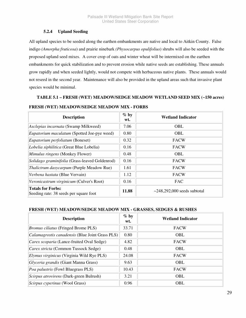
Palisade III Wetland Mitigation Bank Site Report United States Steel Corporation
29
5.2.4 Upland Seeding
All upland species to be seeded along the earthen embankments are native and local to Aitkin County. False
indigo (Amorpha fruticosa) and prairie ninebark (Physocarpus opulifolius) shrubs will also be seeded with the
proposed upland seed mixes. A cover crop of oats and winter wheat will be intermixed on the earthen
embankments for quick stabilization and to prevent erosion while native seeds are establishing. These annuals
grow rapidly and when seeded lightly, would not compete with herbaceous native plants. These annuals would
not reseed in the second year. Maintenance will also be provided in the upland areas such that invasive plant
species would be minimal.
TABLE 5.1 – FRESH (WET) MEADOW/SEDGE MEADOW WETLAND SEED MIX (~150 acres) FRESH (WET) MEADOW/SEDGE MEADOW MIX - FORBS
FRESH (WET) MEADOW/SEDGE MEADOW MIX - GRASSES, SEDGES & RUSHES
Description % by
wt. Wetland Indicator
Bromus ciliatus (Fringed Brome PLS) 33.71 FACW
Calamagrostis canadensis (Blue Joint Grass PLS) 0.80 OBL
Carex scoparia (Lance-fruited Oval Sedge) 4.82 FACW
Carex stricta (Common Tussock Sedge) 0.48 OBL
Elymus virginicus (Virginia Wild Rye PLS) 24.08 FACW
Glyceria grandis (Giant Manna Grass) 9.63 OBL
Poa palustris (Fowl Bluegrass PLS) 10.43 FACW
Scirpus atrovirens (Dark-green Bulrush) 3.21 OBL
Scirpus cyperinus (Wool Grass) 0.96 OBL
Description % by wt.
Wetland Indicator
Asclepias incarnata (Swamp Milkweed) 7.06 OBL
Eupatorium maculatum (Spotted Joe-pye weed) 0.80 OBL
Eupatorium perfoliatum (Boneset) 0.32 FACW
Lobelia siphilitica (Great Blue Lobelia) 0.16 FACW
Mimulus ringens (Monkey Flower) 0.48 OBL
Solidago graminifolia (Grass-leaved Goldenrod) 0.16 FACW
Thalictrum dasycarpum (Purple Meadow Rue) 1.61 FACW
Verbena hastata (Blue Vervain) 1.12 FACW
Veronicastrum virginicum (Culver's Root) 0.16 FAC
Totals for Forbs: Seeding rate: 38 seeds per square foot
11.88 ~248,292,000 seeds subtotal
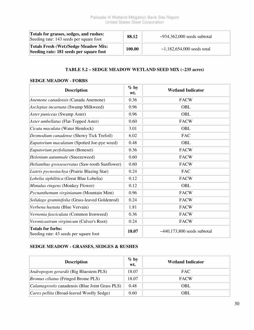
Palisade III Wetland Mitigation Bank Site Report United States Steel Corporation
30
Totals for grasses, sedges, and rushes: Seeding rate: 143 seeds per square foot
88.12 ~934,362,000 seeds subtotal
Totals Fresh (Wet)/Sedge Meadow Mix: Seeding rate: 181 seeds per square foot
100.00 ~1,182,654,000 seeds total
TABLE 5.2 – SEDGE MEADOW WETLAND SEED MIX (~235 acres)
SEDGE MEADOW - FORBS
Description % by
wt. Wetland Indicator
Anemone canadensis (Canada Anemone) 0.36 FACW
Asclepias incarnata (Swamp Milkweed) 0.96 OBL
Aster puniceus (Swamp Aster) 0.96 OBL
Aster umbellatus (Flat-Topped Aster) 0.60 FACW
Cicuta maculata (Water Hemlock) 3.01 OBL
Desmodium canadense (Showy Tick Trefoil) 6.02 FAC
Eupatorium maculatum (Spotted Joe-pye weed) 0.48 OBL
Eupatorium perfoliatum (Boneset) 0.36 FACW
Helenium autumnale (Sneezeweed) 0.60 FACW
Helianthus grosseserratus (Saw-tooth Sunflower) 0.60 FACW
Liatris pycnostachya (Prairie Blazing Star) 0.24 FAC
Lobelia siphilitica (Great Blue Lobelia) 0.12 FACW
Mimulus ringens (Monkey Flower) 0.12 OBL
Pycnanthemum virginianum (Mountain Mint) 0.96 FACW
Solidago graminifolia (Grass-leaved Goldenrod) 0.24 FACW
Verbena hastata (Blue Vervain) 1.81 FACW
Vernonia fasciculata (Common Ironweed) 0.36 FACW
Veronicastrum virginicum (Culver's Root) 0.24 FACW
Totals for forbs: Seeding rate: 43 seeds per square foot
18.07 ~440,173,800 seeds subtotal
SEDGE MEADOW - GRASSES, SEDGES & RUSHES
Description % by
wt. Wetland Indicator
Andropogon gerardii (Big Bluestem PLS) 18.07 FAC
Bromus ciliatus (Fringed Brome PLS) 18.07 FACW
Calamagrostis canadensis (Blue Joint Grass PLS) 0.48 OBL
Carex pellita (Broad-leaved Woolly Sedge) 0.60 OBL
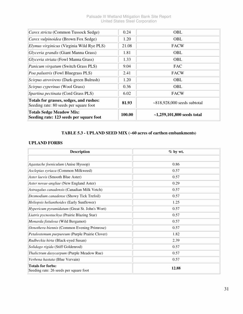
Palisade III Wetland Mitigation Bank Site Report United States Steel Corporation
31
Carex stricta (Common Tussock Sedge) 0.24 OBL
Carex vulpinoidea (Brown Fox Sedge) 1.20 OBL
Elymus virginicus (Virginia Wild Rye PLS) 21.08 FACW
Glyceria grandis (Giant Manna Grass) 1.81 OBL
Glyceria striata (Fowl Manna Grass) 1.33 OBL
Panicum virgatum (Switch Grass PLS) 9.04 FAC
Poa palustris (Fowl Bluegrass PLS) 2.41 FACW
Scirpus atrovirens (Dark-green Bulrush) 1.20 OBL
Scirpus cyperinus (Wool Grass) 0.36 OBL
Spartina pectinata (Cord Grass PLS) 6.02 FACW
Totals for grasses, sedges, and rushes: Seeding rate: 80 seeds per square foot
81.93 ~818,928,000 seeds subtotal
Totals Sedge Meadow Mix: Seeding rate: 123 seeds per square foot
100.00 ~1,259,101,800 seeds total
TABLE 5.3 - UPLAND SEED MIX (~60 acres of earthen embankments)
UPLAND FORBS
Description % by wt.
Agastache foeniculum (Anise Hyssop) 0.86
Asclepias syriaca (Common Milkweed) 0.57
Aster laevis (Smooth Blue Aster) 0.57
Aster novae-angliae (New England Aster) 0.29
Astragalus canadensis (Canadian Milk Vetch) 0.57
Desmodium canadense (Showy Tick Trefoil) 0.57
Heliopsis helianthoides (Early Sunflower) 1.25
Hypericum pyramidatum (Great St. John's Wort) 0.57
Liatris pycnostachya (Prairie Blazing Star) 0.57
Monarda fistulosa (Wild Bergamot) 0.57
Oenothera biennis (Common Evening Primrose) 0.57
Petalostemum purpureum (Purple Prairie Clover) 1.82
Rudbeckia hirta (Black-eyed Susan) 2.39
Solidago rigida (Stiff Goldenrod) 0.57
Thalictrum dasycarpum (Purple Meadow Rue) 0.57
Verbena hastata (Blue Vervain) 0.57
Totals for forbs: Seeding rate: 26 seeds per square foot
12.88
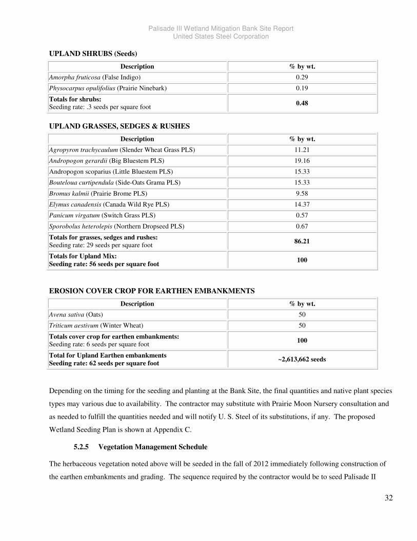
Palisade III Wetland Mitigation Bank Site Report United States Steel Corporation
32
UPLAND SHRUBS (Seeds)
Description % by wt.
Amorpha fruticosa (False Indigo) 0.29
Physocarpus opulifolius (Prairie Ninebark) 0.19
Totals for shrubs: Seeding rate: .3 seeds per square foot
0.48
UPLAND GRASSES, SEDGES & RUSHES
Description % by wt.
Agropyron trachycaulum (Slender Wheat Grass PLS) 11.21
Andropogon gerardii (Big Bluestem PLS) 19.16
Andropogon scoparius (Little Bluestem PLS) 15.33
Bouteloua curtipendula (Side-Oats Grama PLS) 15.33
Bromus kalmii (Prairie Brome PLS) 9.58
Elymus canadensis (Canada Wild Rye PLS) 14.37
Panicum virgatum (Switch Grass PLS) 0.57
Sporobolus heterolepis (Northern Dropseed PLS) 0.67
Totals for grasses, sedges and rushes:
Seeding rate: 29 seeds per square foot 86.21
Totals for Upland Mix:
Seeding rate: 56 seeds per square foot 100
EROSION COVER CROP FOR EARTHEN EMBANKMENTS
Description % by wt.
Avena sativa (Oats) 50
Triticum aestivum (Winter Wheat) 50
Totals cover crop for earthen embankments: Seeding rate: 6 seeds per square foot
100
Total for Upland Earthen embankments
Seeding rate: 62 seeds per square foot ~2,613,662 seeds
Depending on the timing for the seeding and planting at the Bank Site, the final quantities and native plant species
types may various due to availability. The contractor may substitute with Prairie Moon Nursery consultation and
as needed to fulfill the quantities needed and will notify U. S. Steel of its substitutions, if any. The proposed
Wetland Seeding Plan is shown at Appendix C.
5.2.5 Vegetation Management Schedule
The herbaceous vegetation noted above will be seeded in the fall of 2012 immediately following construction of
the earthen embankments and grading. The sequence required by the contractor would be to seed Palisade II
Palisade III Wetland Mitigation Bank Site Report United States Steel Corporation
33
(Minntac -113 seeded acres) first, followed by Palisade I (Keetac - 747 seeded acres) and then the Bank Site (444
seeded acres). Should weather delay construction during the work schedule, contractors would be asked to
complete the current site to the best of their abilities and continue at the next appropriate date. This may mean that
Palisade I and II are completed in the fall and the Bank Site may be completed the following spring with snow
seeding. A total of approximately 444 acres shall be seeded and later woody species planted at the Bank Site as
the remaining land consists of roads and ditches. The contractor will be required to till the land so that the seeds
will have maximum contact with the soil when broadcasted.
Post seeding maintenance will involve monitoring and maintenance. The vegetation management plan involves
monthly inspection of the overall plant growth and invasive species control as needed. Adaptive management will
be initiated if and when needed. All proposed adaptive management will be put into a plan explain the problems
with recommended methods to correct the problem. The plan would be submitted to the Interagency Review
Team for review. It is anticipated that within the first 2-3 weeks of the first growing season, staff will be onsite
evaluating the plant growth and assessing site hydrology.
Herbivore control, mid-summer and/or end of summer mowing, and invasive plant species control may all be
necessary during the first few years. Re-seeding may also be implemented if necessary.
6666.0.0.0.0 Wetland Hydrology AssessmentWetland Hydrology AssessmentWetland Hydrology AssessmentWetland Hydrology Assessment
This section presents a synopsis of the work performed to characterize the hydrology of the Bank Site. It provides
the basis for the use of earthen embankments to retain runoff and thereby increase the elevation of the water table
to restore wetland hydrology to the Bank Site. The following sections recapitulate the climate and hydrologic
data, the computations completed to estimate the various components of the water budget, the site work
performed to characterize the aquifer hydraulics and to establish a ground-water and surface water database, and
the efforts expended to frame and calibrate a ground-water model to predict the effects of proposed modifications
on the phreatic surface during normal and drought conditions.
The information provided herein is primarily an abstraction from U. S. Steel’s draft Wetland Mitigation Report
submitted to the USACE in December 2011. That earlier report related the work performed on U. S. Steel’s
wetland remediation activities on U. S. Steel’s contiguous 1,416-acre wetlands mitigation site, of which the Bank
Site comprises of approximately 480 acres. The present Bank Site reportreferences information contained in the
December 2011 draft Wetland Mitigation Report and readers may go to that report or request for a more detailed
report/methods if required.
In that sense, the present Bank Site report is intended to be an update of the December 2011 draft Wetland
Mitigation Report. The modeling performed for the 2011 wetland mitigation study indicated that a significant
amount of runoff from Bank Site could be retained by earthen embankments and be used to raise the water table,
Palisade III Wetland Mitigation Bank Site Report United States Steel Corporation
34
even without ditch abandonment. Thus, when the difficulties involved in ditch closure arose, the decision was
made to propose the installation of earthen embankments to retain as much water on the site as possible and to
grade the parcels in order to: (1) provide a more uniform distribution of recharge; and (2) to enhance diversity in
the depth to ground water and the depths of ponds that will develop, where closed surface depressions intersect
the water table. Other than the effects of the closure of two minor, internal private ditches, the present document
will consider the ditches only as they relate to the determination of aquifer properties.
Prior to gathering hydraulic data in the field, a preliminary water budget was performed to facilitate the orderly
development of the conceptual site hydrologic model that would guide the data-gathering efforts and, after being
adjusted to incorporate those data, form the basis of the predictive finite-difference model. The size of the Bank
Site and the complexity necessitated the use of a numerical model in order to predict the efficacy of using earthen
embankments and grading to restore wetland hydrology, in lieu of closing ditches. The following sections relate:
how the preliminary water budget was developed (Section 6.1); and a recapitulation of the site hydrologic analysis
(Section 6.2), through the establishment of a site hydrologic monitoring network and potentiometric database,
hydraulic testing, ditch-flow analysis, and computer modeling. Please refer to Appendix F for the Numerical
Modeling Results.
6.1 Water Budget
A water budget assessment was initially conducted for the larger 1,416-acre wetland mitigation site in 2011. This
involved an examination of the various parcels that make up that larger site and includes information, specific to
parcels on the Bank Site. The Regional Water Budget Manual published (in 2009) by the New Jersey Department
of Environmental Protection was used in lieu of a comparable document supplied by MNDNR. Computation
sheets for the whole 1,416-acre project site were included in the December 2011 draft Wetland Mitigation Report.
Because there are several soil series present with different hydrologic properties and the acreage surrounded by
peripheral ditches varied, it was best for predictive modeling to break up the water budget into several parcels
rectangular parcels (of between 40 and 320 acres) mostly bounded by peripheral drainage ditches, and estimate
the various water budget components for each parcel separately rather than to lump them together and try to
model the entire site. Figure 6-1 shows the locations of these parcels just for the Bank Site boundary. The
portions of these parcels that make up the site include the southern half (40 acres) of Parcel 2, which is the
western half of the southwest quadrant of Section 27 of Workman Township; all (40 acres) of Parcel 3, which is
the southeast quarter of the southwest quadrant of Section 27; the east half (80 acres) of Parcel 6, which is the
northwest quadrant of Section 34; all (80 acres) of Parcel 7, which comprises the south half of the northeast
quadrant of Section 34; and the eastern three-quarters (240 acres) of Parcel 8, which is the southern half of
Section 34. Consequently, the water-budget assessments in the December 2011 draft Wetland Mitigation Report

Palisade III Wetland Mitigation Bank Site Report United States Steel Corporation
35
for Parcels 2, 3, 6, 7, and 8 are pertinent to the present document and summary tables for the area-specific water-
budget components are presented in Table 6-1.
Each water-budget component is briefly discussed in its own section below. Traditionally, the water budget of
any hydrologic system would contain several components, including precipitation, evapotranspiration, surface
water outflow (run-off), surface water inflow (run-on), ground-water inflow and ground-water outflow. The
relative magnitudes of these components vary considerably among the parcels and one or more may be negligible
or become negligible seasonally. For example, all or nearly all of the water contributed to the system comes from
precipitation. As the site is continuously drained by peripheral and internal ditches, a significant portion of the
water leaves the site via the ditch system. Water reaches the ditches predominantly by surface run-off and as
baseflow through the shallow aquifer. In the warmer months, evapotranspiration becomes significant. The
shallow sand aquifer is the most significant aquifer hydraulically, and local well logs indicate that there is at least
one deeper sand aquifer beneath the glacial lake silts and clays that begin 15 to 25 feet below the ground surface.
Although the proportion of the shallow groundwater outflow to deeper units is distinct from baseflow discharge to
ditches, both are simply treated as ground-water outflows from the perspective of a conventional water budget.
Nevertheless, any leakage through the confining unit to the deep aquifer system may be important since water
stored in the ditches may be necessary for diversion and adaptive management in dry years. The magnitude of the
leakage could not be estimated without developing an alternate numerical model that can iteratively find a water
table elevation that balances the on-site recharge with the relative hydraulic resistances, both horizontally to the
ditches and vertically, through the confining unit, to the deep aquifer. The current model, making conservative
assumptions where data is lacking, facilitates the estimate of water-table elevation changes in response to
proposed site changes for retaining water. The model results have been used to better inform the estimates of
ground-water outflow in the water budget. These modeling efforts are discussed further in Section 6.2.4. Under
current conditions, it is expected that the water levels in the shallow aquifer and soils are controlled primarily by
precipitation recharge and discharge through the ditch system. The following sections describe how each of the
water budget components was calculated.
6.1.1 Precipitation and Evapotranspiration
Data used consisted of published temperature and precipitation data compiled by the National Oceanic and
Atmospheric Administration (NOAA), ground-water data collected by sets of shallow and deep piezometers
installed throughout the site, topographic data published by the United States Geological Survey (USGS), and soil
survey data published by the United States Department of Agriculture (USDA).
Historic precipitation, temperature, and weather data was available for the project site from 1892 to present for the
Sandy Lake Dam station located 5.2 miles northeast of the project site. To determine daily precipitation and
temperature for the wettest and driest years, the Palmer Hydrological Drought Index (PHDI) was used. The PHDI
Palisade III Wetland Mitigation Bank Site Report United States Steel Corporation
36
considers the hydrological impacts of precipitation, ground-water levels, reservoir levels, and temperature of the
surrounding area. Data sets for only the last 50 years were considered because older data sets were incomplete. It
was determined that the wettest and driest years, beginning with the start of the growing season, were April 1986
through March 1987 and April 1988 through March 1989, respectively. In addition, the year with the median
PHDI (April 1990 through March 1991) was selected for use in multi-year simulations in order to prepare the
model’s starting heads to simulate a wet or dry year that was preceded by a number of “average” years. In
addition, a water budget was completed for the first eight months of 2011, which uses daily precipitation and
temperature data collected at meteorological stations at Aitkin, Minnesota (approximately 25 miles to the
southwest of the mitigation site) and the local airport at McGregor, Minnesota, approximately 6 miles to the
south-southeast. These data sets were compared with periodic on-site rain gauge measurements. The entire data
were presented in the December 2011 draft Wetland Mitigation Report. The area-specific precipitation for each
month of the perspective for wet, dry, normal, and 2011 are presented (along with the other water-balance
components) for each parcel included in the Bank Site for the current and proposed site topography in the charts
provided in Appendix E.
Because the ground is normally expected to be frozen from December through March, no recharge is assumed
during those months and all precipitation falling (as snow) was expected to accumulate until April. For the month
of April, the snow is expected to melt at a more or less uniform rate throughout the month and infiltrate
continuously. This average rate of snow melt was added to daily precipitation recorded during April for the years
of interest. The daily precipitations were used in the surface water inflow and outflow computations, which are
discussed below.
The evapotranspiration rates were estimated using the Thornthwaite (1948) method, which utilizes temperature
and solar-radiation inputs for the project site. Temperature and insolation data were obtained from the airport
weather station at McGregor. The area-specific potential evapotranspiration for each month of the respective for
wet, dry, and normal years, as well as 2011, are presented for each parcel included in the Bank Site for the current
and proposed site topography in Appendix F. From the charts, it can be seen that evapotranspiration is greater in
the warmer months and represents the principal annual outflow, although it is exceeded by groundwater flow and
occasionally by runoff during the cooler months.
6.1.2 Surface Water Outflow
Currently, a considerable portion of the precipitation applied to the surface is lost through run-off to the ditch
system. The proposed modifications to the site to restore wetlands hydrology include the construction of wide,
low earthen embankments to minimize loss to the ditches. As explained above, one of the purposes of dividing
the Bank Site into parcels was to break the site into areas that would better represent the differences in local soil
hydrologic properties and thus improve the predictive value of the ground-water flow model.
Palisade III Wetland Mitigation Bank Site Report United States Steel Corporation
37
The hydrologic soil classes (HSCs) were identified for each parcel (as related in Section 2.2). For the purpose of
calculating the monthly runoff rates for the representative years in each parcel, TR-55 run-off curve numbers
(CN) were determined for each of the HSCs present on the parcel, for respective land cover types. For each day
in the year and each combination of hydrologic soil class and land cover, the potential maximum retention and the
initial abstraction were calculated. On days when the precipitation was less than the initial abstraction, the entire
daily recharge was retained on the site, either to be recharged or undergo evapotranspiration. Otherwise, the run-
off was calculated using the equation provided in TR-55.
Expected run-off quantities were calculated for the wettest, driest, the year with the median PHDI, and for the first
eight months of 2011, based upon the recorded daily precipitation for those respective years. For each parcel, a
weighted average run-off was calculated based on the proportion of each soil type therein for each of the selected
years. In order to compare the magnitude of the monthly run-off component from each parcel to the
corresponding rates of precipitation and evapotranspiration, the combined run-off from all of the soil series in the
parcel was divided by the area of the parcel and then converted to inches per month. The parcels identified for the
water budget are indicated and numbered in Figure 6.1. The results are shown on the charts provided in
Appendix D.
6.1.3 Surface Water Inflow
With the current peripheral ditch configuration, the majority of the run-on would be intercepted before it could
enter the U. S. Steel wetlands Bank Site. The eastern half of the north side of Parcel 7 is not bounded by a ditch,
but the area is a topographic high and the divide has an approximately north-south orientation, with a drainage
ditch to the west and a wetland and stream to the east. Consequently, little surface-water flow is expected to
move southward into the parcel.
Parcels 2, 6, and 8 are divided between the Bank Site and U. S. Steel’s Palisade I (Keetac) wetland mitigation
parcels. There is an east-west oriented divide immediately south of the boundary between the Bank Site portion
of Parcel 2 and the northern half, which is part of the Palisade I wetland mitigation site. Therefore, very little
overland flow is expected to runoff northward from the Bank Site to Palisade I, and virtually none is expected to
flow southward. Similarly, portions of Parcels 6 and 8 are shared between Palisade I on the west and the Bank
Site on the east and drainage swales on both parcels that cross the boundary between the wetland mitigation site
and Bank Sites divert surface water to the west, away from the Bank Site.
With the proposed site and ditch modifications, no run-on would be diverted onto the Bank Site. The water-
budget charts in Appendix D provide a column for surface water inflow, which being nil, is manifested as a gap
between the evapotranspiration and the proposed ground-water outflow columns.
Palisade III Wetland Mitigation Bank Site Report United States Steel Corporation
38
6.1.4 Ground-Water Outflow
Flow through the shallow aquifer underlying the Bank Site is controlled primarily by discharge to the ditch
system. Precipitation (minus runoff and evapotranspiration) infiltrates as recharge to the shallow aquifer. The
recharge causes an increase in hydraulic head. However, not all of the ground water under the parcels discharges
to the peripheral ditch system. There is a shallow aquifer, which is mostly unconfined, that facilitates flow of
groundwater from the interior of the parcels to the ditches. However, hydraulic testing of shallow aquifers and
measurement of flow in the ditches both confirm that a large portion of the site ground water leaves the site,
especially in the centers of the parcels, far from the ditches, by flowing downward through a lower-permeability
interval, to a regional, deep sand aquifer that sustains local water supply wells. Quantifying the relative
proportions of these two outflows was critical to the determination of whether the nullification of selected ditches
would have been effective in restoring wetlands hydrology to the site. Given the large areas and variable
hydraulic properties and recharge pattern, a finite-difference computer model was needed to perform the
computations, the results of which are described in Section 6.2.4.
In order to calculate estimates of monthly ground-water outflow from the parcels to the ditches, initial (i.e. prior to the
start of the growing season) average hydraulic gradients adjacent to the peripheral ditch for each parcel were based
upon piezometric data (contained in the on-site hydrologic database, which is described in Section 6.2.1) and
calculated hydraulic distances derived from the pumping test analyses (which are described further in Section 6.2.2).
This was done assuming that the wettest and driest years would be preceded by a normal year. It was reasoned that
the hydraulic gradient at this time of the year would be very low as recharge would have been zero for four months by
this time. In addition, the starting gradient for a normal year would be such that, by the end of the year, the water in
storage would be approximately equal to what it was at the beginning. The initial hydraulic gradient was then found
by an iterative procedure using the goal-seeking tool resident in the spreadsheet application for the analysis.
The initial hydraulic gradient in each parcel was multiplied by a representative hydraulic conductivity and aquifer
thickness for each parcel, and by the length of the parcel’s ditch, to calculate the ground-water outflow for a given
month. The change in storage was then divided by the aquifer specific yield to obtain a change in head and aquifer
thickness. These head and aquifer-thickness changes were used to calculate the ground-water outflow and storage
changes going into each successive month. These parcel-wide estimates of ground-water outflow are
underestimates since they do not consider losses via downward flow, through the confining unit, to the aquifer
below. They were used to guide the development of the finite-difference model used for the computer simulation
and are plotted on for representative wet, dry, normal years, as well as 2011, for each of the respective parcels in
the charts in Appendix D. Each chart shows the ground-water outflows for both current and proposed site
conditions. It can be seen that ground-water outflow is expected to increase when storage is increased during
months with greater precipitation and when, in the proposed condition, where more water is retained on the
Palisade III Wetland Mitigation Bank Site Report United States Steel Corporation
39
parcels through the use of earthen embankments. Groundwater outflow is analyzed in Section 6.2.4, when the
distribution of ground-water outflows is discussed, in preparation for predicting the efficacy of constructing
earthen embankments for the purpose of restoring wetlands hydrology to the parcels.
6.1.5 Ground-Water Inflow
A strong hydraulic connection between the drainage ditches and the aquifer was observed during pump testing
conducted across the site. Currently, the drainage ditches represent powerful hydraulic boundaries that generally
would preclude ground-water inflow to the mitigation parcels. Because the currently proposed site modifications
are intended to reduce run off on the mitigation parcels and not capture any off-site runoff, the hydrostatic head is
expected to increase on the parcels and thereby increase the rate of ground-water outflow, either to the ditches or
to the underlying deep aquifer, which has a mostly regional discharge. Consequently, for the evaluation of the
water budget for the Bank Site the ground-water inflow into the parcels is considered to be zero and is therefore
not represented in the charts in Appendix D.
6.1.6 Water-Budget Evaluation and Summary
The inputs and summary of monthly estimates for each of the monthly water-budget components are tabulated for
each parcel in Table 6.1 for the existing site conditions and proposed changes for a repetition of the wettest and
driest years in the 50-year period of record, as well as for the year (1990-1991), which was selected to represent
an average year and the most recent year (2011-2012). Individual graphs for the separate parcels comprising the
Bank Site are included in Appendix D. Each figure shows the values computed for:
1. The monthly precipitation and evapotranspiration, which are assumed to be unaffected by the proposed
changes;
2. The surface-water outflow, which is subtracted from the precipitation only for the current site condition,
but because of the proposed earthen embankments was retained for the proposed site condition water
budget and not subtracted;
3. The monthly ground-water outflow for the existing condition and the expected monthly changes in
storage and head; and
4. The monthly ground-water outflow for the proposed condition with the consequent changes in monthly
storage and head.
Each graph also shows two curves, representing the cumulative monthly changes in storage, for the existing and
proposed site conditions. The curve for the current condition shows the cumulative changes relative to a starting
storage that would be maintained in a series of average years. Thus, the cumulative storage at the end of the
selected average year is zero and the year ends where it began, with no net change. By zeroing out the average
Palisade III Wetland Mitigation Bank Site Report United States Steel Corporation
40
year, the final cumulative storage for the wettest and driest years are greater and less than zero, respectively
(though it may not be obvious because of the chart’s scale).
The curve for the proposed condition also shows the cumulative changes relative to a starting storage that would
be maintained in the current condition in a series of average years. Consequently, the curve shows both the
proposed difference in the monthly accommodation of the various inflows and outflows as well as the predicted
difference in the overall storage throughout the year between the proposed and current configurations for the
individual parcels for a repetition of the wettest, driest, representative average, and most recent years. The
predicted differences in storage between the current and proposed parcel configurations are also presented in
Table 6.1.
To summarize, the storage changes for the existing condition were computed by subtracting the
evapotranspiration, surface-water outflow, and existing-condition ground-water outflow from the precipitation.
Precipitation and snow melt are major components during the spring, summer, and fall, but are practically non-
existent during the winter. Evapotranspiration is a major component in the late spring and summer, but is minor
in the fall and early spring and zero during the winter. Consequently, the determination of which year is wetter or
drier depends not so much on the amount of precipitation, but when the precipitation falls.
In the present condition, surface-water outflow would be a contributing component of the water budget during the
spring, summer, and fall, except during major precipitation events and snow melt events, when it would be a
principal component. Because of expected normal freezing conditions, it is not considered during the winter.
The results of these analyses show that the retention of run-off (the current surface-water outflow) would result in
a substantial increase in the ground-water recharge for each individual parcel, consequently increasing the storage,
and by extension, increasing the amount of saturation within the mitigation areas. And as expected, with the
increase in storage, there would also be an increase in ground-water outflow due to head differences. One of the
benefits of the numerical modeling in Section 6.2.4 will be to quantify the effect of the proposed changes on the
distribution of ground-water outflow via the shallow aquifer to the ditches and via downward flow to the deep,
regional aquifer on the extent of areas with near-surface saturation. Even with a model that predicts an increase in
the amount of ground-water outflow, the amount of saturation would increase significantly after the proposed
changes relative to the current condition. Please refer to Appendix F for the Numerical Modeling Results.
6.2 Hydrologic Assessment
The hydrologic regime is the most important controlling factor of wetland species composition and ecosystem
processes. Many species, particularly hydrophytic plants, respond primarily to the depth, duration, and timing of
inundation. Concentrations of dissolved oxygen, soil development, nutrient cycling, and carbon fluxes are among
Palisade III Wetland Mitigation Bank Site Report United States Steel Corporation
41
the processes influenced by spatial or temporal fluctuations in the depth of the water table. The hydrological
assessment involved four components:
1. The establishment of a site-specific hydrological database, which includes meteorological data, water
level data from ditch staff gauges and piezometers, and ditch flow measurements;
2. Aquifer hydraulic testing;
3. A systematic analysis of the site’s surface water drainage system; and
4. A numerical hydrogeologic model.
Regional Hydrologic Setting
The Bank Site is within the drainage basin of the Mississippi River, which meanders southwestward
approximately 2.2 miles northwest of Section 32 of Workman Township. It is the ultimate discharge area for
surface water drainage on the mitigation site and for a portion of the aquifer system as well. Also, the Sandy
River, which flows southward approximately one mile east of Section 34, is significant in determining the
positions of hydraulic divides. Prior to the installation of the ditch drainage system, the easternmost portions of
the site, including those parcels in Sections 27 and 34, and the eastern two-thirds of parcels in Sections 28 and 33,
probably drained ultimately to the Sandy River. The remainder of Sections 28 and 33 and all of Section 32
drained to the Mississippi River. The present system of ditches and culverts (see Section 6.2.1), installed in the
1970s, channels the flow of Sections 27, 28, 32, 33, and 34 through neighboring sections to the west to a minor
tributary of the Mississippi River. The only exception is a ditch on the east side of the northeast quadrant of
Section 34 (along the west side of 240th Avenue), which flows north, joins a south-southeast-flowing stream, and
turns east entering a culvert (C33 on Figure 6.2), and ultimately discharges into the Sandy River.
The portion of flow in the aquifer system that underlies the parcels that comprise the Bank Site that is diverted to
the Mississippi River is dependent on the amount of hydraulic connection between the aquifer and the ditch
system. The following sections briefly describe the on-site monitoring network and database (Section 6.2.1),
hydraulic testing (Section 6.2.2), the ditch drainage system (Section 6.2.3), and hydraulic modeling in order to
determine the optimal means of restoring site hydrology while minimizing impacts to neighboring parcels
(Section 6.2.4).
6.2.1 On-Site Hydrologic Data Base
Monitoring wetland hydrology was necessary to establish baseline conditions and to calculate/measure the
response of a wetland to hydrologic alterations in the surrounding watershed. It was necessary to install
piezometers to monitor the water table during periods when it drops below the soil surface. Piezometers were
installed at U. S. Steel’s wetlands mitigation site in the fall of 2010 and spring of 2011, measured on several
Palisade III Wetland Mitigation Bank Site Report United States Steel Corporation
42
occasions over the course of the late 2010 and 2011 growing season. Ditch gauges were also installed in ditches,
near clusters of piezometers where possible, to monitor synoptic surface water levels.
Water levels have been measured and recorded periodically since September 2010. However, the monitoring
network was largely incomplete until May 2011. To date, 18 rounds of water levels have been taken (including
seven in September 2010). All water level measurements are tabulated in the December 2011 draft Wetland
Mitigation Report.
The water level measurements were used to interpolate the contours of the potentiometric surface for each of the
sampling dates, compute the vertical and horizontal components of the hydraulic gradient, serve as observation
points for aquifer pumping tests, and provide targets for the calibration of the numerical ground-water flow
model.
The water level data taken in mid spring through late summer of 2011 clearly show the effects of temperature and
evapotranspiration on water levels. Water table contour maps were constructed for selected dates to illustrate
these data. After reviewing the on-site precipitation gauge record, to avoid dates that might have had biased water
levels caused by taking readings too soon after thunderstorms, three dates were chosen for contouring: May 20,
June 30-July 1, and August 31-September 1, 2011. The Water Table Level Contour Maps are included in
Appendix E.
The water level data exhibit an increase in the number of well/ditch gauge clusters that exhibit losing-ditch
hydrology as the 2011 growing season progressed. In spring, the ditch gauges indicate that water levels in all but
a few of the ditches were lower than in adjacent wells and piezometers. As such, the hydraulic gradient appears to
drive flow toward the ditches and much of the flow in the ditches would be more or less continuously
accumulated baseflow. By the summer, the trend reverses in many clusters. This hydraulic gradient reversal
may be observed in greater detail where continuous data were recorded.
As the water table fell toward the end of spring and continuing through the summer, the number of clusters where
the water table drops below the water level in the adjacent ditch sections increases from 11 (On May 20th) to 23
(on September 1st) of the 41 well/piezometer/ditch clusters. The water level in the ditch is maintained by the flow
in upstream ditch sections, which continue to received baseflow (as well as runoff). The reason appears to be that
the aquifer was losing water through the underlying confining unit to the aquifer below. There were no other
possible sinks for ground-water outflow except where parallel ditches on either side of the farm road maintain
much different surface water elevations. But this exception cannot be used to explain the behavior observed,
because the mere transfer of flow from one ditch to another would retain the mass balance in the ditch system as a
whole and the final total would equal the sum of the component ditches, which was not the case. The ditches
appear to be losing water to the aquifer at some downstream point. This is confirmed by ditch flow
measurements, which will be discussed further in Section 6.2.3.
Palisade III Wetland Mitigation Bank Site Report United States Steel Corporation
43
As the water levels fall, the downward loss would continue as long as the shallow aquifer heads remain greater
than those in the deep aquifer. During years with normal precipitation, recharge in less well-drained off-site areas
and in the centers of the parcels would pass through the confining unit. This would raise the potentiometric
surface in the deeper aquifer to a point where it is greater than the water level maintained in the ditches creating a
situation with upward discharge, through the confining unit, to the ditches around the periphery of the parcels. It
is clear from precipitation records through September 2011 that 2011 was drier than a normal year. It is expected
that the losing-ditch configuration measured in the field represents a condition where the potentiometric surfaces
are equilibrating downward (from the long-term average level built up over many years) to a level that would
eventually reflect the lower recharge observed in 2011. If this is correct, then the trend would reverse when the
recharge rate increases to a more normal level.
6.2.2 Aquifer Hydraulic Testing
Constant-rate aquifer pumping tests were conducted throughout the U. S. Steel wetland mitigation site (including
the Bank Site parcels) to determine the properties of the shallow aquifer that exists across the site, the degree of
vertical heterogeneity and permeability within the substratum, and the extent of hydraulic connectivity of the
aquifer with the ditch system. Pumping rates averaged 1.1 gpm for all of the wells. The dataloggers were
monitored via computer throughout the drawdown phase of testing to determine when drawdown had reached a
steady-state. At that point, the pump was turned off and the piezometers were allowed to recover. Water levels
continued to be recorded during the recovery phase. The duration of pumping ranged between 25.8 minutes (due
to a pump failure) and 185 minutes, averaging 96.8 minutes for all wells.
For the hydrographs that were not affected by partial penetration, the image well and law of times methods were
used to calculate the distance to the image well. By comparing this calculated radius with the radius under ideal
hydraulic connection with ditch, the amount of hydraulic resistance added by the ditch bottom materials was
estimated. The protocols followed, methods of analysis, and tabulated results are presented in the December 2011
draft Wetland Mitigation Report. The hydraulic parameter values obtained from these tests varied across the
U. S. Steel property and were input to the finite-difference model used to predict the distribution of ground-water
outflow between the ditches and the deep confined aquifer that underlies the region.
6.2.3 Ditch Flow Analysis
The Ditch Flow Diagram, Figure 6.2, shows the drainage pattern of the ditches and channels along the fields of
the 1,416-acre wetland mitigation project, which includes the Bank Site. In Figure 6.2, the ditch drainage system
is superimposed upon a color infrared aerial photograph that can be used to identify the locations of the ditches
with respect to other physical features of the site. In order to facilitate the use of this figure, individual
streamlines carried by the system are given a letter or number designation (A-Z, 1-9) and grouped (shown by
color coding) according to the shared confluences. The official locations of county, state, and Fire Relief
Palisade III Wetland Mitigation Bank Site Report United States Steel Corporation
44
Commission (FRC) ditches are highlighted to facilitate comparison with existing ditches. It should be noted that
the observed directions of flow and actual positions of ditches are not always as shown on the official Aitkin
County ditch mapping. In addition the locations of county ditches often fall along roads where there are two
ditches on either side of the road, flowing in opposite directions. Where this occurs, both ditches are assumed to
be included in the county ditch system.
County Ditch Analysis
There are segments of four county ditches designated on the 1,416-acre U. S. Steel property. These are CD-4,
CD-38, FRC-A, and FRC-B. In three locations, there are overlaps between CD-4 and FRC-B. Following the
convention shown on maps available on-line from Aitkin County, these areas of overlap have been designated
“CD-4 & FRC-B”. There is no location on the site where FRC-B exists independently of CD-4.
The county ditch system is intended to drain the properties of individuals that may benefit from the drainage.
Ditches that are not designated either CD-4, CD-38, FRC-A, or CD-4 & FRC-B are considered private ditches.
All ditches on the designated wetlands mitigation site, whether county ditches or private, ultimately drain through
CD-38, either by discharging directly to one of its branches or indirectly through sections of FRC-A, CD-4, or
“CD-4 & FRC-B”. With the exception of CD-38, which throughout the U. S. Steel property, seems to be a
simply-branched system of Strahler (1952) first- and second-order tributaries and a single third-order stem, the
county ditch designations do not appear to reflect any common discharge point. In contrast to the county maps,
portions of CD-4 ultimately drain out through FRC-A or CD-38. County mapping indicates that the diagonal
ditch in the northwest quadrant of Section 29 is part of CD-4. The northwest half of the diagonal ditch appears to
drain to the ditches along Route 232. The southeast half of the diagonal ditch drains, via a circuitous route (which
involves flow through two private reaches), to FRC-A, which eventually joins the most downstream portion of
CD-38 before the latter reaches the Route 232 culvert (C11 on Figure 6.2). The one ditch that drains to the Sandy
River may be considered to be part of CD-4, although its position does not coincide with that mapped location of
CD-4 until it flows off site.
All of the ditch flow through the Bank Site originates on the U. S. Steel property. Since the wetlands mitigation
site includes some of the most up-stream portions of the 4,393-acre U. S. Steel property, most of the drainage
originates on site. However, as discussed in Section 6.1, a significant portion of the drainage that flows through
the mitigation site originates off site. Most of the drainage that originates off site enters through private ditches
that are probably not recognized by Aitkin County. Please refer to the Adjacent Property Owners Map in Figure
6.3.
State Ditch Summary
The state ditches, SD-66 and SD-86, have northern branches that extend into the southernmost parts of the U. S.
Steel property. Like the county ditches, their designated locations and apparent connections are not completely
Palisade III Wetland Mitigation Bank Site Report United States Steel Corporation
45
confirmed by field study or observations. Portions of the traces shown on the county ditch map do coincide with
the locations of several north-flowing ditches which drain through the U. S. Steel property (Ditches 1 through 7)
and ultimately discharge to CD-38, downstream of the drainage from the designated wetlands mitigation site, at
the point where the CD-38 leaves the property.
Some drainage from off-site properties to the south does enter the site through Ditches 5 and 6, which are
considered to be part of SD-86, although they do not drain southward to the east/west-oriented main stem of SD-
86. However, neither of these ditches is hydrologically significant with regard to the ditches surrounding the
current 1,416-acre wetland mitigation site. Consequently, off-site drainage in state ditches would not be affected
by any of the current proposed designs on any part of the 1,416-acre mitigation area, including the Bank Site.
Evaluation of Proposed Ditch Abandonment Effects
The current wetlands mitigation plan proposes to remove two internal ditches in the Bank Site. One of these
(Ditch C on Figure 6.2) is located between the southeast and southwest quarters of the southwest quarter of
Section 27. The other (Ditch F) lies between the northwest and the southwest quarters of the northeast quarter of
Section 34. Ditch abandonment would be accomplished by either partly or completely abandoning a ditch with
low-permeability clay or clay loam derived from landscaping in the interior of site. Abandoning these ditches
will have an effect on the surface-water outflow from adjacent and upstream sources, which does not appear to
include any significant off-site drainage. There may be a small contribution from the southern edge of the
northwest quarter of the northeast quarter of Section 34, but the USGS 7.5-minute topographic quadrangle map
for the Minnewawa quadrangle indicates that the land slopes toward the west in this area, except perhaps for a
narrow band immediately adjacent to the ditch.
Abandonment of these ditch sections will result in a slight rise of the water table in the adjacent parcels, but it is
expected to have less local impact than that of adding earthen embankments to retain surface runoff and no
measureable regional impact. Nevertheless, it was decided to include the removal of these segments in the
numerical model of the site hydrology. Please refer to Appendix F for the Numerical Modeling Results.
Ditch Flow Measurements
In order to better understand the relationship between recharge and the amount of flow in the ditches on the
wetlands mitigation site, the response of baseflow to hydraulic heads on the parcels, and to provide baseflow
estimates for use in aquifer modeling, the rates of surface-water flow were measured at specific times at sixteen
selected points in the ditch system, mostly downstream of the Bank Site. The base map for the potentiometric
Water Table Level Contour Maps (presented in Appendix E) shows the locations of these ditch-flow measuring
points. A measured ditch cross section was made at each point and the cross-sectional areas were computed for
several reference water levels at each location. In addition, the width of the wetted portion of the channel was
Palisade III Wetland Mitigation Bank Site Report United States Steel Corporation
46
also computed from the section to represent successive cross-sectional areas for various elevations. This is
because the width of the water surface perpendicular to the direction of flow could be measured with greater
certainty than the channel depth and more quickly than the water level elevation. A more detailed account,
including tables for use in interpolation of cross-sectional area from channel width for each section, is presented
in the December 2011 draft Wetland Mitigation Report.
The rates of surface-water flow and channel widths were measured on four occurrences: June 1-3, June 17, July
13, and September 1-2, 2011. The results of the measurements and calculated surface-water discharges at each
point are presented in the December 2011 draft Wetland Mitigation Report. The data exhibit considerable
uncertainty, due in part to the effects of strong winds stirring sluggish waters. There may also be a large
hyporheic component in the fast, shallow gravelly channel at ditch-flow measuring point DF-15. The following
information was obtained:
1. Based upon observations made at ditch gauges in the mitigation site ditches, the upstream ditches are
seasonally losing or gaining, with the number of losing locations increasing throughout the growing
season.
2. In general, the measuring points that are more downstream do not indicate a systematic accumulation of
flow, even in spring.
3. The rate of discharge measured between points in the main channel, in many cases, appears to decrease in
the downstream direction (some consistently), even with inflow from tributaries entering between them,
which strongly indicates that the ditches themselves are losing flow either continuously or at least in
many locations.
4. Based upon field observations, flow increases quickly after recharge events and appears to recede slowly,
but there are insufficient data/measurements to quantify this observation across the site.
5. Based upon field observations, certain first order channels appear to be stagnant most of the time, even
when channels draining only a few times more area are flowing quickly. This may be an indication that a
significant amount of the recharge leaves as ground water, which bypasses the drainage system by
draining downward toward the deeper aquifer and not leaving as baseflow to ditches. The flow records
for DF-6 and DF-7 consistently indicate stagnant or very slow flowing.
The resolution of some of these uncertainties can be at least partly addressed through numerical ground-water
flow modeling. The computer model was used to simulate a conceptual model of the site hydrology and indicates
whether the conceptual model is mathematically sound and determine whether the measured surface-water
outflow is sufficient, without requiring loss to underlying aquifers (given the measured precipitation, hydraulic
Palisade III Wetland Mitigation Bank Site Report United States Steel Corporation
47
conductivities, and aquifer thicknesses), or whether inclusion of a large ground-water loss to the underlying
aquifer is needed in order to explain field observations. The following section attempts to address these issues.
6.2.4 Ground-Water Flow Modeling
The primary purpose of the ground-water flow modeling, using a computer application, was to:
1. Provide a means of confirming the conceptual model of the complex hydrogeologic system present at the
mitigation site and surrounding U. S. Steel property;
2. Demonstrate that the water budget is conservative;
3. Provide a means of estimating the changes in hydraulic head that the proposed site modifications may be
expected to cause; and
4. Provide insights that might inform recommendations for adaptive management of the mitigation site.
Pre-calibration calculations have shown that the horizontal hydraulic conductivities of the mapped soils are
insufficient to convey the estimated average annual recharge to local ditch tributaries without a significant
hydraulic head to drive them. Even the shallow, fine sand aquifer, has insufficient permeability. The permeability
of the fine sand unit was subjected to constant-rate pumping tests, which resulted in hydraulic conductivities
ranging from 2.8 to 61.9 feet/day, which is within the typical range for fine sand. However, it is difficult to accept
that a 10-foot layer of this material is sufficient to convey even a few inches of annual recharge to the nearest
drainage ditch without a hydraulic gradient that is at least 50 percent greater than has been observed on the Bank
Site. In some places, the water table reaches the surface and runs off, developing the wetland areas that were
observed and delineated across the wetland mitigation site.
However, run-off cannot entirely explain drainage on this site. Despite the intervening, low-permeability strata,
the areas between ditches are very large; it appears that even a small amount of seepage through the silty and
sandy clay units to the more productive aquifer at depth has become significant a pathway for site drainage. This
hypothesis was tested by constructing and calibrating a ground-water flow model of the region, using USGS
MODFLOW (McDonald and Harbaugh 1988).
The model was framed based upon the known stratigraphy and hydrogeologic boundaries of the region, using the
hydraulic testing results and water-level and ditch-flow observations related above. In hydrogeologic modeling,
both local and regional data are critical. This is because the local system necessarily operates within a continuum
and the boundary conditions that define the larger system constrain all of its components. The area of interest of
the hydrologic model was the entire U. S. Steel property southeast of Palisade, Minnesota, with specific detail in
Palisade III Wetland Mitigation Bank Site Report United States Steel Corporation
48
the area of the 1,416-acre wetland mitigation site. However, the results presented in this document relate only to
the Bank Site. A more comprehensive description of the model results is presented in the December 2011 draft
Wetland Mitigation Report.
The model was framed to represent the geometry of the local and regional hydrogeologic units and discharge
areas, based upon USGS topographic maps, published glacial geology maps, local water-supply well records, and
the logs of borings drilled on site for this project. The available mapping of overburden geology indicates that
glacial lake sand, silt and clay, up to about 120 feet thick, overlie Precambrian bedrock. There is a laterally
extensive sand layer that supplies water to wells in the area. The site boring program has documented variability
in the distribution of sand and fine materials in the uppermost 25 feet across the site. In all of the site borings,
there is a fine sand or fine-to-medium sand unit, typically extending from 10 to 20 feet below the ground surface.
The sand overlies a silty clay interval, which is part of a composite confining unit that overlies the deep sand
aquifer. Above the shallow sand, the soils vary and are as described in Section 2.2. In the areas on the project site
mapped by the NRCS as Northwood, Cathro, and Sago muck, there may be a thickness of peat between 0.5 and 6
feet.
It had been observed from the ditch flow measurements collected in 2011 that drainage discharging into ditches
sustain losses as it flows westward across the property. The losses are noticeable in that the flow rate is less than
the sum of flows measured in the tributaries. The on-site ditch gauge and piezometers couplets manifest
seasonality in the gradient direction between the ditch and the aquifer. The only possible mechanism that can
explain these losses is discharge to ground-water. However, given the geometry of the regional hydrogeology, it is
very difficult to explain this observation other than as a transient phenomenon related to the potentiometric
surfaces of the multiple aquifer system slowly falling in response to less than normal recharge. This is supported
by the fact that even where the ditches appear to be losing water to the aquifer, the water levels in piezometer
clusters nearer the centers of the parcels are always higher than those near the ditches. If the parcel were the
recipient of water from ditches for an extended period of time and the only outflow were downward through the
confining unit, the water levels in the center would ultimately be the lowest on the parcel. Since this is not the
case in any parcel, the condition of losing ditches observed in 2011 must be a recent and temporary phenomenon,
which would be consistent with the recent meteorological data.
On a site with fully-established hydrology, the water level elevations observed are generally reflective of the long-
term average recharge. Other head-independent boundaries also must represent long-term average values. Since
the potentiometric data collected on the site were obtained during a dry year, 2010-2011, we needed to consider
the possibility that the water tables would be generally falling throughout the year, with a progressive
accumulation of storage losses relative to the series of more normal years that preceded it. This was accomplished
by preceding the simulation of the calibration year by a long period with recharge rates estimated for the selected
Palisade III Wetland Mitigation Bank Site Report United States Steel Corporation
49
average year and then calibrating the hydraulic parameters at various points during a simulation of recharges for
2010-2011. The recharge rates for each parcel during the selected average and most recent years were based upon
the monthly precipitation and calculated evapotranspiration rates discussed in Section 6.1.1 and surface-water
outflow (runoff) rates discussed in Section 6.1.2, all of which are presented by parcel in Appendix D.
Additional calibration to observed site water levels required splitting some of the shallower layers to
accommodate: places where the shallow aquifer was closer to the surface (in the vicinity of the southwest corner
of the northern half of Section 33); the lower elevation of the drainage ditch in the western portion of the
property; and the presence of open water on the ground surface in the proposed site modification alternatives
(along with the earthen embankments needed to control its movement). A tabulation of the hydraulic parameters
applied to each layer in the calibrated model is provided in the December 2011 draft Wetland Mitigation Report.
Different recharge rates were applied to each parcel of the model, owing to the different surface-water inflow and
outflow characteristics calculated in the water budget. These monthly estimates of the parameters for each parcel
are shown along with recharge, evapotranspiration, ground-water inflow and outflow, and changes in storage for
average driest, wettest, and most recent years in the form of bar charts in Appendix D. Monthly recharge rates for
each parcel were calculated by subtracting the monthly site-wide evapotranspiration rates for the selected average
year (1990-1991) from the monthly precipitation rates for the same year and further subtracting the calculated run
off for the current condition or adding the surface water inflow (if any) for the proposed-condition alternatives.
Model input parameters are tabulated in the December 2011 draft Wetland Mitigation Report.
The model required minor changes in the hydraulic conductivities in order to obtain a close match between the
model’s predicted water table elevations and the potentiometric Water Table Level Contour Maps in Appendix E.
The only place where horizontal hydraulic conductivity deviated from the single value applied universally to the
shallow aquifer was in the vicinity of well W4, in the southwest corner of Section 27 and southeast corner of
Section 28, where the measured water levels were locally very high and the aquifer transmissivity from the
pumping test was much lower than average.
There are two places where the recharge rates deviated from the parcel-specific values that were computed for the
water balance. One is in the southeast quadrant of Section 28, where run-off from the forested eastern half of the
northeast quadrant does not appear to be able to drain into Ditch 8, immediately to the west. Instead, it flows
south and pools in the northeast quadrant of the southeast quadrant of Section 28. The other area is the eastern
half of the northeast quadrant of Section 34, where a stream flowing southward through the eastern half of Section
27 flows south-southwest into the northeast quadrant of the northeast quadrant of Section 34 and turns east to
flow through a culvert under County Road 240, but sustains some back up, which causes sustained wet conditions
that extend into the portion of the wetlands mitigation area that occupies the southeast quadrant of the north east
quadrant of Section 34. The pooled run off in these two areas is assumed to be the cause of the localized elevated
Palisade III Wetland Mitigation Bank Site Report United States Steel Corporation
50
water levels measured in the associated well clusters. The recharge rates in the immediate areas of observed
pooling was increased during calibration until the simulated water levels were comparable to those measured in
the respective clusters.
Inspection of the calibrated model indicated that when the simulated potentiometric surface approximated those
interpolated between measurements taken on the site in 2011, the vertical component of the hydraulic gradients in
each parcel were always downward in the centers of the parcels, but always reversed to upward in the vicinity of a
drainage ditch. This matches the conceptual model for long-term average recharge, but does not simulate the
observed losing segments in the ditch system, which are attributed to the gradual loss of storage during the dry
year during which water-level and ditch-flow data were collected, as explained above. The principal difficulty
was that of simulating ditches that could re-wet after going dry, which would have been required activating a
MODFLOW feature that had been causing failure to converge errors in earlier versions of the model. However,
simulations of dry-year flow under existing conditions that were run for the present report after the submission of
the 2011Wetland Mitigation Report definitely show water levels in down-stream ditch sections falling below the
ditch bottoms while the water level in the ditches further upstream remain above their respective bottoms.
Being satisfied that the level of calibration was adequate, the model was tested to determine whether the water
budget was sufficiently conservative in preparation for using it to simulate the effects of the proposed changes.
Two alternative water-retention scenarios were simulated. Both involved the placement of earthen embankments
around the parcels in the Bank Site and the removal of the Ditch C in Section 27 and Ditch F in Section 34. The
difference between the two scenarios involves the use of re-grading: (1) earthen embankments (berms) only, with
no re-grading; and (2) earthen embankments plus re-grading. The simulations for both scenarios include
predictions of the depth of the water table below the ground surface and the depths of inundation above the
ground surface for the average annual and late summer (i.e. 60 days without recharge) of average years.
Simulations also were run for a repetition of the driest year for the earthen embankments s plus and re-grading
scenario. These indicated that wet conditions would not persist through the spring over most of the Bank Site and
none would persist anywhere in the site through the summer of the driest year. Consequently, while simulations
for the driest year were also run for the earthen embankments only and current conditions, their maps were not
completed for submission.
Interpretation of Modeling Results as They Relate to the Currently Proposed Project
The results of the two simulated scenarios indicate that the earthen embankments and limited ditch abandonment
would cause the water table to rise to the point where certain parcels would be partly inundated, with some areas
exceeding water levels greater than two feet above the water table throughout the year, during average years.
Palisade III Wetland Mitigation Bank Site Report United States Steel Corporation
51
As described above, the use of 2011 water levels to calibrate the model would result in the model having a
tendency to overestimate the amount of ground-water outflow. However, despite this, the average simulated
water level rises on individual parcels appear to be comparable to those predicted by the water budget.
In some cases, the water budget may have overestimated the groundwater outflow because the water levels in
some parcels rise to the spillway elevation. This means that the water levels would be amenable to adaptive
management. This is important because the amount of inundation, both on the site and on upstream properties,
can be controlled by adjusting the elevations of earthen embankments spillways. The implementation of selective
ditch abandonment in future years would be supportive, considering the potential of increased evapotranspiration
after the first few years of wetland development.
In summary, the site’s former wet conditions can be restored in the Bank Site by the addition of earthen
embankments, grading, and supplemented by the removal of two privet internal ditches C and F.
Additional Information on Possible Adverse Impacts on Adjacent Properties
The decision to eliminate the closure of peripheral ditches from the proposed modifications to the U. S. Steel
wetland mitigation site precludes the possibility of causing an increase in the frequency and intensity of flooding
on adjacent properties. The unimpeded drainage of the unmodified ditch system would be able to carry
stormwater away from upstream properties as well as at present. In fact, with the introduction of earthen
embankments around the Bank Site, for the purpose of retaining runoff, would reduce stormflow into the ditches
and thereby decrease the frequency and intensity of future flood events.
The induced water-table rise will be significant on the Bank Site under normal conditions and may cause a
decrease in the depth to water on adjacent sites of two feet or more. However, more accurate depths to water that
could be used to determine whether there would be any adverse affects on the current uses of those properties is
dependent upon the ground-surface elevations of those properties, which are not known with sufficient accuracy
to make definitive conclusions. However, based upon current aerial photographs, it appears that the areas that
would be the most affected are existing wetlands, woodlots and agricultural fields. The nearest domiciles and
farm structures are outside of the areas that are likely to undergo significant water table rises. Should it become
evident that the rise in water table does impact significant use of adjacent properties, U. S. Steel will implement
adaptive manage to ameliorate the impact and/or offer reasonable compensation for valid claims.
How Ditch Maintenance Would Affect the Hydrology (Proposed Earthen Embankments)
As described earlier, the shallow sand aquifer generally extends from 10 to 20 feet below the ground surface
across the U. S. Steel wetland mitigation site. In a few places, it is shallow enough be intersected by ditch
bottoms of the ditches. The aquifer is an important component of the drainage system in that it facilitates the flow
of groundwater from the interior of the parcels to the peripheral ditch. The vertical distance between the bottoms
Palisade III Wetland Mitigation Bank Site Report United States Steel Corporation
52
of the ditches and the top of the aquifer confers some hydraulic resistance that will help keep the water levels high
in the wetlands. Consequently, it is important to maintain as much of this hydraulic separation as possible and it
could be imperiled by excessive ditch maintenance. It is expected that the Aitkin County Ditch Authority would
only dredge to a depth that previously existed. Normal maintenance dredging would not be expected to have
significant hydrologic impacts to the mitigation site because: (1) digging deeper than original ditch depths would
not be likely since pipe invert elevations are already established at the outflow; (2) in most of the area, the ditches
would have to be deepened more than a foot to significantly reduce the hydraulic resistance above the sand layer
there; and (3) the stratification of the sand and overlying materials probably results in most of the ditches
receiving water through their sides as well as their bottoms, so that the hydraulic resistance is not limited to the
bottoms of the ditches, impacted by maintenance dredging.
Based upon our inspection of the ditches, it does not appear that they have ever undergone maintenance dredging.
Certain ditch culverts are obviously blocked and drainage is sustained only by interstitial flow through the soil
around them. Maintenance may involve dredging the bottoms and sides of the ditches and discharging the spoils
onto the adjacent land surface. The proposed earthen embankments will be approximately 50 feet wide (and
wider) and average about two feet in height. Therefore, it is very unlikely that the stability of the earthen
embankments will be compromised by dredge spoils. Depending upon the throwing power of the dredging
machine, the spoils may be deposited on the ditch side of the earthen embankments, the land side of the earthen
embankments, or into the wetlands areas. The last named would not alter the function of the earthen
embankments in any way. Deposition in a continuous ridge on the berm itself has the potential to raise the
effective berm height, which could alter its expected function during times of extreme inundation. Even then, the
function of the upland embankment will not be affected, except at the spillways, which could become partly or
completely blocked. To address that contingency, the adaptive management plan would include requesting the
County Ditch Authority to announce ditch maintenance before it would be performed, discuss dredge spoil
management plan prior to any ditch maintenance, and inspection of the berms following a maintenance event.
Should any damage (physical or causing invasive plant species) occur to any part of the earthen embankments, U.
S. Steel shall make any repairs necessary to restore original conditions.
6.3 Conclusions and Recommendations
1. Most of the standing water that occurs on the Bank Site arrives as precipitation in the form of either
rainfall or snowmelt.
2. Evapotranspiration is greatest during the months of July and August. Therefore, rainfall that occurs during
the middle of the growing season is a very important factor in distinguishing a “wet” year from a “dry”
year.
Palisade III Wetland Mitigation Bank Site Report United States Steel Corporation
53
3. Many of the drainage ditches on the Bank Site are under the jurisdiction of the County Ditch Authority, as
they have authority on most of the drainage that flows through the site. But vital ditch sections that
control much of the site hydrology are private and under U. S. Steel’s ultimate control.
4. On most parcels, a significant amount of water is currently lost from surface run-off into the ditches.
Adding berms to retain this run-off will significantly increase water storage and increase hydraulic
resistance on the mitigation site. This will restore year-round wet conditions to most of the Bank Site and
they will persist throughout the year.
5. Capturing upstream run-off from off-site areas would provide an important amount of water storage to
downstream parcels on the mitigation site, but this is not part of the proposed modifications for the Bank
Site.
6. Abandoning Ditches C and E on the Bank Site would increase hydraulic resistance to cause the water
table to rise in their immediate vicinities.
7. The nature of the aquifer on the U. S. Steel wetlands mitigation site is complex. Based on ditch flow
measurements, downstream ditches in the drainage system appear to be losing water through the bottom,
which is probably due to 2011 being a year with lower than average recharge. Of equal importance, the
mitigation site water-level measurements indicate that water is primarily lost as base-flow to ditches
during the springtime and other high water level events when hydraulic head is greatest.
8. The addition of earthen embankments to the Bank Site will decrease the frequency and intensity of
flooding on adjacent properties because it will not involve the modification of the ditch system that drains
those properties and it will cause the retention of stormwater that would otherwise runoff into the ditches
and possibly contribute to hydraulic back-up.
9. The only part of the berms that are vulnerable to ditch maintenance activities is the spillway, which can
be addressed by inspection after maintenance event and simple repairs, if needed.
Palisade III Wetland Mitigation Bank Site Report United States Steel Corporation
54
7.0 Wetland Mitigation Goals, Objectives, and Performance Criteria
7.1 Goals
The goal of the wetland mitigation is to provide a no net loss of wetland functions as a result of potential future
unavoidable wetland impacts at Keetac and Minntac mining operations. This goal will be attained through the
restoration of hydrology, wetland soil functions, and high quality wetland plant abundance and diversity. This
wetland restoration and enhancement project would be expected to improve wildlife habitats and connectivity.
Secondarily, there would be wildlife habitat and water quality improvements with increased plant diversity.
7.2 Objectives
The project objectives are listed below:
• Provide compensatory wetland mitigation for future unavoidable wetland impacts at United States Steel
Corporation, Minnesota Ore Operations (Keetac and Minntac);
• Restore approximately 480 acres of farmland that has been impacted by miles of man-made ditches;
• Improve hydrological functions by increasing wetland area, floodwater storage capacity, and extending
wetland hydroperiods, increasing habitat connectivity and repairing wetland fragmentation;
• Improve biological functions, to include increasing wildlife abundance and diversity;
• Improve water filtration function by increasing wetland acreage and planting wetland vegetation to
increase diversity of ecological communities;
• Reduce and control invasive species; and
• Improve regional flood capacity and riparian functions.
7.2.1 Performance Standards
This mitigation project contains performance standards based on 33CFR Part 332.5 and Minnesota Rule
8420.0522. These performance standards will ensure that the project is evaluated objectively and establishing as
expected. The performance standards should be based on most or all of the following:
• Final wetland acres achieved shall consist of native wetland vegetation where greater than 50% of the
native vegetation shall be facultative (FAC), facultative wet (FACW), and/or obligate (OBL) wetland
species with dominance of FACW and OBL species;
• Sustaining hydrology necessary to support hydrophytic vegetation;
• Invasive and non-native plant species minimized (e.g., no more than approximately 15% aerial cover) by
the end of the third year growing season for herbaceous wetland communities, excluding narrow-leaf
Palisade III Wetland Mitigation Bank Site Report United States Steel Corporation
55
cattail (Typha angustifolia). For shrub and woody species, this aerial coverage standard would apply at
the end of the fifth year growing season;
• Minimal bare ground exposure (e.g., no more than approximately 5% aerial cover) and overall adequate
density;
• Wetland vegetation diversity; and
• Wildlife recruitment.
Performance standards must be reasonably achievable and measurable. They should also be based on the best
available science and assessed in a practicable manner. They should be based on wetland characteristics and not
on specific wetland acreage targets; instead they should be based on overall success of established functioning
wetland acreages.
The following sections describe performance standards specific to fresh (wet) and sedge meadow wetlands,
hardwood swamps/shrub-carr wetlands and upland buffers to be grown on the Bank Site. The wetland hydrology
(elevations) described below is anticipated under normal circumstances and many wetland communities will
thrive when the target hydrology described below is restored.
Fresh (Wet) Meadow and Sedge Meadow
• The fresh (wet) and sedge meadow wetland hydrology would consist of saturation at or within 12 inches
of the ground surface for a minimum of 30 consecutive days, or two periods of 15 consecutive days,
during the growing season under normal to wetter than normal conditions. Inundation during the growing
season is not expected to occur except following the 10-year frequency or greater storm/flood event. The
depth of inundation shall be approximately 6 inches or less and the duration of any inundation event shall
be less than 15 days.
• The fresh (wet)/sedge meadow herbaceous vegetation would typically not be dominant after the first year
of seeding and as many weed species are expected after site disturbances. Mowing once or twice during
the first year only would be required to keep weed species from shading out the seeded species and to
minimize weed seed production at the end of the summer. The fresh (wet)/sedge meadow herbaceous
vegetation shall cumulatively comprise of at least 60 percent areal cover by the end of the second full
growing season and 75 percent by the end of the third growing season. At least 85% aerial cover of
native species shall be obtained by the end of the fifth year.
• The fresh (wet) meadow herbaceous layer shall be dominated by a minimum of six native, non-invasive
species of grasses, sedges, rushes, forbs, or ferns by the end of the fifth growing season.
Palisade III Wetland Mitigation Bank Site Report United States Steel Corporation
56
• Although monitoring is planned for approximately five years, if after three years of maintenance and
monitoring it is determined that a fresh (wet) meadow and sedge meadow communities have met the
performance standards described above, U. S. Steel may negotiate with the wetland regulatory authorities
to determine if monitoring may be then suspended for this community so that the Bank Site can be
approved and mitigation credit allocations can be finalized.
Hardwood Swamp and Shrub-Carr Wetlands
• Hardwood swamp and shrub-carr hydrology (woody species) would consist of saturation (water table)
near the ground surface, and often as much as 1 foot of water over the site after heavy precipitation.
• Hardwood swamp species after planting are expected to have some mortality after the first year and
survival estimate should not be used to document woody species planting efforts for the first three years
after planting. Woody species survival may be used as a performance measure in later years if natural
colonization does not confound survival estimates. However, plant density should provide for a more
reliable estimate of tree and shrub performance for the first three years after planting. The proposed
planting rate is 600 stems per acre and performance measures should be measured against that number.
• Native woody species that naturally colonize on the mitigation site will be included in plant density
estimates as natural recruitment (just as in native seed bank germination) would be part of the site
ecological success.
• Although monitoring is planned for approximately five years, woody species maintenance and monitoring
may be required from 5 to 10 years after planting and as growth typically is slow over the first 3 or more
years with minimal quantitative measurements. Survival of 50 percent or greater after the 5th years is an
acceptable performance standard. This may include 50 percent aerial cover by the end of the fifth year.
Upland Buffer
• Upland buffers are expected to develop within the Bank Site to meet the Wetland Conservation Act and
MNDNR requirements under Subpart 6 – Required Upland Buffer. These upland buffers will be in
primarily grassland habitats adjacent to the wetlands. Minor shrub seeding will also be implemented
during the seeding process. It is expected that portions of the earthen embankments would become
wetland habitats, depending on the draw down from the ditches and the location of the earthen
embankments relative to restored hydrology. Using a 1-foot linear length along the earthen embankments
yields less than 10 acres of wetlands, and this minor amount has not been accounted for in the
replacement crediting and as the actual amount may be much after the first year of seeding. These
grassland areas will be seeded with native species and will be managed so that no more than 15 percent
areal cover of exotic or non-native invasive vegetation is present after 5 years.
Palisade III Wetland Mitigation Bank Site Report United States Steel Corporation
57
• The herbaceous plant coverage may comprise at least 70 percent areal cover by the end of the third full
growing season, including at least 4 characteristic grass and forbs species at the end of the third full
growing season.
• The herbaceous plant coverage would comprise at least 85 percent areal cover by the end of the fifth (5)
full growing seasons.
• Tree or shrub species that volunteer within the adjacent upland buffer areas will be allowed to remain so
long as the species are native, non-invasive species, and do not threaten the integrity of the proposed
wetland mitigation areas. Some minor upland shrub seeding is planned.
It is recognized that the wetland development process (full function) cannot be established within a few years but
will take several seasons to develop. Therefore, short-term, interim performance standards are proposed but
would not be representative of potential performance until after the 3rd full growing season, at which time it is
expected visually, the wetland habitats as planned have established under normal circumstances. The monitoring
report completed after the 3rd
or 5th growing seasons will be critically assessed and a determination of whether or
not the restored wetland are in conformance with these performance standards, including a final delineation of the
wetland areas. Also, after the first two years of a more intensive monitoring program, the following years should
only require site visits early in the growing season and late in the growing season unless adaptive management
had been implemented. The following sections list examples of performance criteria expected for the Bank Site.
7.2.2 Hydrological Performance Criteria
For years 2 through 5 – The soil in the restored and enhanced wetland will be saturated to within 12-18 inches of
the surface or standing water will be present within 6-18 inches of the surface for at least two consecutive weeks
of the growing season. The two weeks are based on the wetland definition and approximately 10% of the growing
season and approximately the same criteria used to delineation the farmland. Measurements using existing staff
gauges and wells throughout the site will also help determine if hydrology has been restored.
7.2.3 Wetland Vegetation Performance Criteria
Woody Species: For years 2 through 5 – native wetland (facultative and wetter) woody species (planted and
volunteer) shall achieve an average density of at least 1-4 plants per 100 square feet, or a minimum of 300
seedlings per acre, or greater than 5%, 10%, 20% and 30% aerial cover, respectively, in shrub-carr and forested
communities of the restored or enhanced wetlands. At maturity (after 5 years to approximately 10 years after
planting), at least 300 trees per acre would be considered success woody species development as 600 trees per
acre will be planted.
Palisade III Wetland Mitigation Bank Site Report United States Steel Corporation
58
Sampling for tree species may include 10 meter plots measuring both survival and aerial cover for statistical
purposes. Aerial cover (and vigor) measurements after the fifth years would be the best measurement of success.
Sampling for shrubs species would include 5 meter plots measuring survival and aerial cover.
Herbaceous Species: For years 2 through 5– Aerial cover of native, wetland (facultative and wetter) herbaceous
plants species will be at least 30%, 40%, 60% and 85%, respectively for fresh (wet) and sedge meadows of the
restored wetlands.
7.2.4 Final Performance Standards (5th
year of monitoring)
The Bank Site shall be delineated after the fifth year using the current method to assure that the mitigation site
contains at least 85% restored wetland by definition.
The above proposed performance standards are developed based on the wetland mitigation Bank Site report and
site plan design. Since these standards are developed on a case-by-case basis, they are subject to change as
determined by the regulatory agencies after review and approval. All performance standards must be reasonably
achievable as based on wetland characteristics and based on best available science that can be measures and
assessed in a practicable manner. In general the Final Performance Standards are based on:
• Final wetland acres achieved
• Hydrology similar to adjacent wetland sites and/or within regulatory definitions
• Native herbaceous wetland plants dominant to at least 80% coverage or more
• Invasive plant species minimized to 15% coverage or less
• Vegetation diversity (determined by species stem counts)
• Wildlife recruitment (by observation)
• Final wetland delineation
• High functional wetland – including flora and fauna diversity
• Achieve wetland functionality assessment
7.4 Monitoring
Wetland monitoring shall be based on USACE Regulatory Guidance Letter, No. 08-03, dated 10 October 2008 –
“Minimum Monitoring Requirements for Compensatory Mitigation Projects Involving the Restoration,
Establishment, and/or Enhancement of Aquatic Resources.” Based on the “Final St. Paul District Policy For
Wetland Compensatory Mitigation in Minnesota”, the standard length of monitoring is 5 years and may be
extended to 10 years for establishment of certain wetland types (e.g., forested wetland), or may be shortened if all
performance standards are met earlier than five years. Monitoring reports can be submitted less frequently than
one year for bank sites requiring more than five years of monitoring.
Palisade III Wetland Mitigation Bank Site Report United States Steel Corporation
59
An annual monitoring report will be prepared during the first five years of monitoring for all actively developing
mitigation areas. The report will describe the status of the wetland mitigation, summarize the results of the
vegetative and hydrologic monitoring, and discuss management activities, corrective actions conducted during the
previous year, and activities planned for the following year. The report will be submitted to the MNDNR and
USACE by January 31st of the following year. The monitoring report will include the following information at a
minimum:
• Project Overview (page 1) - A brief description of the wetland mitigation area, including dates, location,
size, vegetative and hydrologic monitoring data and performance standards, current wetland types and
desired wetland types.
• A summary of water level measurements taken to date and a determination of whether the hydrology in
the wetland meets the design elevations and wetland hydrology criteria as defined in the performance
standards.
• Vegetation survey information, including species and percent areal coverage within each wetland
community and the reference wetland and a determination of whether the vegetation meets the
performance criteria.
• A map of the various plant communities present within the restoration areas (will be prepared when
distinctly different communities have developed).
• Color photographs (from fixed locations) and maps of the wetland mitigation areas, reference wetland,
and sample plots taken in late August to early September of each year at designated photo-reference
points.
• A summary data section and conclusion noting management activities, recommendations and/or
corrective actions conducted in the wetland during the previous year and activities planned for the
following year.
7.4.1 Monitoring Process
Monitoring will begin the first spring after the 480-acre Bank Site is seeded with native vegetation and would
continue for a minimum of 5 years. The Bank Site may be monitored beyond the designated period to track the
development of the mitigation project and until such time that U. S. Steel relinquishes site responsibility.
Routine monitoring standards will be used and will require annual estimates of cover, species diversity, and
density of woody vegetation for shrub-dominated and forested wetlands. Monitoring activities are driven by site-
specific performance criteria as noted in this document or as specified in the permit conditions. Field data would
be collected on a variety of environmental parameters including vegetation, soils, hydrology, and wildlife
Palisade III Wetland Mitigation Bank Site Report United States Steel Corporation
60
recruitment. When data analysis is completed, information on site development will be provided in an annual
monitoring plan with adaptive management recommendations if necessary. It is proposed that the site will be
inspected at least four (4) times during the first two growing season with the last site monitoring inspection
completed in September of each year prior to provide the required annual report.
A fixed baseline transect design would be used to sample habitat classes and/or sample units and there would be
enough plots to meet the sample size requirements for each habitat class. Each annual report will include a
quantitative visual observation for percent aerial cover and survival of woody plants. Use of small plot sizes,
frames (e.g., 1-meter square) with smaller grid squares of known area or other appropriate visual devices that will
represent known cover values to reduce measurement errors and provide year to year data consistency.
The sampling event will include establishment of baseline locations during the first year with staked transects for
all future monitoring visits. Alternatively, a grid transect system can be developed using a GPS unit and an aerial
photo-map. These transects may be modified as needed but will need to continue representing all the cover/habitat
classes and/or sample sizes for the entire project area. The method of data collection and the number and type of
sample units will be specified as a condition of the permit or determined during the end of the first year of
monitoring.
Depending on the initial sampling and site characteristics at the end of the 2012 growing season, transects may
vary in number, length, and separation distance to be determined. Sampling transect locations are determined by
using either a simple, systematic, stratified, or restricted random sampling method. It is expected that 1 to 2
square meter plots for herbaceous plant communities and possibly 65 to 265 square meter plots be used to collect
shrub/sapling layer information. In general, the correct sample size and number of samples will need to be
developed to accurately describe the existing conditions of habitat class and/or stratum. This number presently
cannot be determined until a planting plan and as-built survey are completed. For example, if 70 percent of the
mitigation site is shallow marsh, the method and number of transects will be different than if the site has 5-7
habitat classes which represent and greater diversified plan. Finally, a USACE data form will be completed
throughout the various transect so that all parameters are evaluated using the most updated 1987 Corps Manual
methods, such as the prevalence index (being <3.0).
7.4.2 Mitigation Banking Instrument
The approximate 480-acre mitigation Bank Site will be utilized for future project specific Keetac and Minntac
unavoidable wetland impacts. A final draft mitigation instrument is required by the USACE in 2012 and U. S.
Steel is current working with the USACE on the items listed below:
• Completing the mitigation bank instrument (MBI);

Palisade III Wetland Mitigation Bank Site Report United States Steel Corporation
61
• Financial assurance for construction, maintenance, monitoring, adaptive management, and overall project
success (e.g., performance bonds, irrevocable trusts, escrow accounts, casualty insurance, or letters of
credit);
• A provision stating that legal responsibility for providing the compensatory mitigation lies with U. S.
Steel;
• Default and closure provisions (if necessary);
• Draft permanent conservation easement (and designated grantee if known);
• Finalizing designated land uses such as passive recreation and/or hunting by the public;
• Signage plan identifying the location, size, material of the signs, wording on the signs (e.g., site
description, site boundaries, prohibited use, public access and etc.), and a sign maintenance plan.
A MBI will serve as the contractual agreement between the USACE and U. S. Steel. In particular, it will
definitively address objectives, long-term management, contingency plan, financial assurances, and protection of
the site in perpetuity. This is essential for the USACE’s ability to enforce the provisions of the banking
instrument should problems or failures occur.
7.5 Contingency Plan
In any wetland mitigation project, the single most important component is water. To have a successful project,
detailed knowledge assessments of local water sources (i.e., precipitation, surface and ground water) is the key to
a wetland mitigation success. Acquiring and retaining water in adequate amounts, at the proper time, and with the
correct duration are critical components of a mitigation project. However, the weather pattern from year to year is
unpredictable and contingency planning is necessary. Even though a mitigation contingency plan usually entails
the development of a back-up plan to address risks that jeopardize the original plan to restore the wetland, this
contingency plan also considers offsite inundation to private properties during extreme precipitations. A key
aspect of contingency planning is the ability to identify potential risks before they arise and plan contingency
strategies accordingly, or be aware of them beforehand so that they can be recognized and addressed quickly
during the monitoring phase of work. Potential wetland mitigation project risks normally include, but not limited
to, insufficient hydrology, predation (e.g., by geese or deer), vandalism (e.g., off road vehicles), and invasive
plant species.
As a part of this wetland restoration contingency plan, the need to address potential extreme weather conditions
has become apparent. Not only does the mitigation project need to have adequate water distributed to newly
planted wetlands, but that same water may have to be monitored and potentially controlled during critical high
water events (i.e., large storm and/or successive large storm events). One cannot predict or control the weather,
Palisade III Wetland Mitigation Bank Site Report United States Steel Corporation
62
but the project design would allow for contingency planning to minimize unfavorable impacts due to extreme
weather.
The contingency plan addresses potential issues that may occur after the mitigation site is constructed. The plan
addresses potential risks that may compromise any one or more of the performance standards/criteria (i.e.,
hydrology, hydrophytes and soil conditions). In considering a project contingency plan, one would have to
anticipate what may occur and be pro-active. The contingency plan would be implemented if and when a project
concern is identified during the site monitoring phase.
7.5.1 Drought
The scenario would be a response to a drought early in the mitigation process. Under this scenario, the
contingency plan may include irrigation by pumping water from adjacent ditches to the driest areas. In the
extreme case, this may require the establishment of eight pumping stations, each capable of discharging up to
1,000 gallons per minute and water taken from existing or newly drilled deep wells (with permits). In the event
that the entire site would require irrigation simultaneously (worst case scenario), it is estimated that eight trailer-
mounted 3kW generators would also be required. This contingency would be designed to flow approximately 0.5
inches of water to surface of the site in 40 hours of continuous pumping. The cost and implementation of this
pump system would be considered only should such a severe drought condition arise. Other alternatives may be
available depending on the severity and potential duration of drought conditions. At a certain point and if a severe
drought persist, this pumping option would no longer be possible. Another response is to simply maintain the
most viable areas and allow some of the other higher elevation wetlands to dry out. It is expected that most
wetland areas on the site could survive minor drought conditions and planned re-seeding in areas that don’t revive
would be considered.
7.5.2 Large Storm Events
Normal to moderate storm events are not expected to impact adjacent properties under normal circumstances. This
section addresses large and severe storm events or in some cases where 2 to 3 moderate to large storm events in a
row that may create usually severe storm situations. During severely large rain events or repeated rain events in
short succession, water table increases to the surfaces in lower topographic areas on adjacent properties may
occur. In such severe weather conditions, all of these local areas are expected to be inundated and fully saturated
even exclusive of the construction of this mitigation project. In general it is not expected that this project in itself
would cause flooding to adjacent properties as functioning ditches would carry off floodwaters and as no
regulated ditches would be abandoned as part of this mitigation project. The earthen embankments intended to
retain run off may prolong drainage and mound water tables on neighboring properties, possibly unfavorably
impacting their potential land use (e.g., farming) for some durations but only temporarily. Depending on the
duration of storm events, minor impacts of short duration may be expected during severe weather conditions. A
Palisade III Wetland Mitigation Bank Site Report United States Steel Corporation
63
contingency plan to address possible extreme precipitation events and to minimize impacts to adjacent properties
is outlined below.
To minimize the potential of off-site water table impacts and still allow the wetland project to be successful, two
water control structures will be constructed. One water control structure is passive using spillways and the second
is active, using manually operated valve gates. The proposed 2-foot earthen embankments within the 480-acre
Bank Site will consist of three overflow spillways located at the lower sections of the embankments. The second
water control structure consist of six 12-inch pipes with six manual valve gates that when opened, would rapidly
drain water from the lower areas of the interior parcels should weather conditions be so severe that warrants such
action.
These earthen embankments are designed to capture as much rainfall as possible to adequately saturate soils
during the spring growing season and to minimize upslope impacts. The elevations of the earthen embankment
spillway points are designed to promote the maximum inundation on the mitigation Bank Site while limiting the
amount of impacts to neighboring properties. It is not anticipated that the spillway elevations would be reached
under normal circumstances, except possibly during spring thaws and other severely wet conditions, when site
storage is at its fullest. However, in the event of a very wet season and/or with repeated storms, the duration of
inundation may be more than is needed on-site. During these severe conditions, a period of submergence or
saturation on off-site properties may be extended.
If the current spillway elevations are observed to be not working, adjustment to spillway release elevations can be
accomplished by simple backhoe excavations, thereby lowering the embankment height to allow overflow into the
ditches. The spillway can be protected by placement of erosion mats or stones if deemed necessary or if the
spillway is compromised by drainage. Should spillway elevation adjustments be completed and later observed to
still not provide sufficient site drainage, then manual water releases using the valve gates shall be implemented.
The inlets will have rocks stabilizing the inlet side with debris screens to prevent large objects from blocking flow
through the pipes. Inspection of these inlets during wetland monitoring events will assure that the inlets are kept
clean of debris. This manual drain system would require monitoring of weather local forecasts and onsite water
levels so that the individual charged with operating the system would be able to open the valves if needed in
anticipation of a potential high-water event and/or in relief of protracted inundation. The release of water into the
ditches is not expected to be a normal operational occurrence and would be implemented only if a severe storm
event occurs.
In the event of sudden, extensive flooding, where the water level in the lower parcels prevents accessing the
valves on the upper parcels, the more downstream valves would be opened first and the rate of fall of the water
surface monitored. When the waters have receded sufficiently to allow embankment access, the flood-relief
Palisade III Wetland Mitigation Bank Site Report United States Steel Corporation
64
valves on the upper basins would be opened to relieve the pressure difference on the opposite sides of the earthen
embankment and thereby limit seepage and piping.
The individual operating the outlet system would have to be able to access the Bank Site and monitor the levels
on the parcels and the local weather forecasts. Ideally, the individual would be a local resident who would be able
to operate the pumps.
The Bank Site initial objective is to provide sufficient hydrology for developing wetlands so premature pipe
drainage is not expected to occur unless extreme weather conditions warrant such action. During the first two
years, it will also be important to document the frequency of the opening of valves if ever implemented. If it
becomes apparent that the amount of water retained is more than needed to establish wetlands hydrology, the spill
points on any appropriate earthen embankment can first be lowered permanently, thus reducing the amount and
frequency of potential off-site inundation and the need for more frequent monitoring. It is expected that the fully-
established wetlands will need little or no flood-avoidance/relief monitoring and that the monitoring program
during the first three years will be sufficient to optimize the final spill point elevations.
The proposed 12” valve gate outlets are constructed of thick PVC and stainless steel paddles and stems. The gate
valves would not require long term maintenance and should any pipe become clogged, U. S. Steel shall clean the
pipe and replace the screen at the inlet side. Please refer below for details of the knife gate valve design:
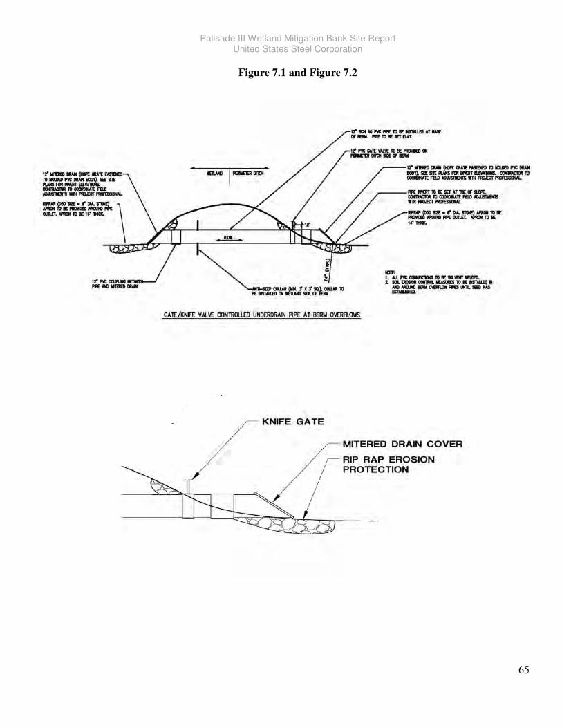
Palisade III Wetland Mitigation Bank Site Report United States Steel Corporation
65
Figure 7.1 and Figure 7.2
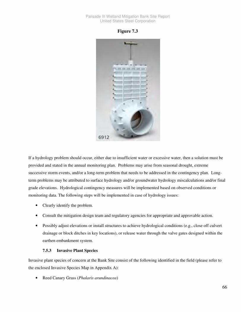
Palisade III Wetland Mitigation Bank Site Report United States Steel Corporation
66
Figure 7.3
If a hydrology problem should occur, either due to insufficient water or excessive water, then a solution must be
provided and stated in the annual monitoring plan. Problems may arise from seasonal drought, extreme
successive storm events, and/or a long-term problem that needs to be addressed in the contingency plan. Long-
term problems may be attributed to surface hydrology and/or groundwater hydrology miscalculations and/or final
grade elevations. Hydrological contingency measures will be implemented based on observed conditions or
monitoring data. The following steps will be implemented in case of hydrology issues:
• Clearly identify the problem.
• Consult the mitigation design team and regulatory agencies for appropriate and approvable action.
• Possibly adjust elevations or install structures to achieve hydrological conditions (e.g., close off culvert
drainage or block ditches in key locations), or release water through the valve gates designed within the
earthen embankment system.
7.5.3 Invasive Plant Species
Invasive plant species of concern at the Bank Site consist of the following identified in the field (please refer to
the enclosed Invasive Species Map in Appendix A):
• Reed Canary Grass (Phalaris arundinacea)
Palisade III Wetland Mitigation Bank Site Report United States Steel Corporation
67
• Hybrid Cattail (Typha x glauca)
• Canada Thistle (Cirsium arvense)
• Pigweed (Amarantgus spp.)
Reed canary grass and cattail are located strictly around the ditch areas as the farm is sprayed annually and
farmed. Canada thistle and pigweed species are also found adjacent to the ditches but were also found in colonies
away from the ditches in year 2011 when the fields were fallow. Most areas with Canada thistle and pigweed
species were sprayed last fall.
Research has demonstrated that an effective way to control reed canary grass (Phalaris arundinacea) is a
combination of late season herbicide application to maximize rhizome mortality and control burning to reduce the
seed bank density. Late season herbicide application is more effective in controlling reed canary grass and
burning (in conjunction with subsequent herbicide applications) would reduces the density of the seed bank,
limiting reed canary grass’s ability to re-colonize from seed. Control burning may not be feasibly/practicable but
if deemed necessary, a control burn plan may be implemented as part of the adaptive management plan. A 3-5
year process may be necessary to allow native vegetation to establish and dominate effectively. Repeated
applications would be needed and as part of this adaptive management strategy. Currently, 2011 spring and fall
herbicide applications of Roundup have been implemented using a 150 gallon skid mounted applicator with a
150’ hose. It is planned that applications of Roundup will continue every year and as needed. The annual spring
inundation on the site would also control the initial germination of reed canary grass. As the site draws down,
reed canary grass begins to germinate and herbicide applications would be utilized to control reed canary grass.
Hybrid cattails are limited to inside of the existing ditches. They were monitored and sprayed in 2011and should
they become too abundant in any one location that may jeopardize the seeded areas, they will be sprayed again.
For Canada thistle, consistent saturation along with shading by wetland plants would suppress their growth.
Canada thistle is shade intolerant and roots do not develop well in areas with a high water table. Therefore,
Canada thistle would need to be managed mostly in dryer disturbed areas along transition areas of the wetland
site. Once established, Canada thistle would require a vigilant spray program. One properly timed application of
glyphosate (RoundUp) may provide 50 to 90 percent control on shoot re-growth 6 months to a year later. At least
one additional application, made to the re-growth, may be needed 3 to 12 months later, to provide adequate stand
reductions for long term control. Conditions needed for good performance of foliar herbicides on Canada thistle is
specified below:
1. Adequate soil moisture from the soil surface well into the subsoil.
2. Green leaves, not wilted and generally free from extensive damage caused by insects, disease, drought,
hard freeze, dormancy etc.
Palisade III Wetland Mitigation Bank Site Report United States Steel Corporation
68
3. Shoot height is at least 10 inches tall in the early June and 8 inches or more in the fall.
4. Flowers not fully opened.
5. The thistle has not been disturbed recently (within 2 months) by tillage.
6. No mowing or cultivation should be done for 10 days after application.
Also biological control using stem weevil, bud weevil or stem gall fly have been known to be successful. These
are all commercially available and approved for use in MNDNR.
There are many species of pigweed with about 70 known species. Pigweed is considered a noxious weed in
Minnesota but provides food and cover for upland game birds. Some amount of pigweed should not be considered
damaging but if deemed necessary, the use of glyphosate (RoundUp) would control pigweed should a large area
be invaded by pigweed.
Vegetation problems can also include mortality and/or poor or stunted growth resulting in low ground coverage.
These problems can be highly varied and may include animal browsing (i.e., deer and/or geese), and other site
issues including vandalism. The following steps may be implemented in case of vegetation issues:
Plant replacement – Evaluate species and quantities necessary to establish aerial density.
Grazing control – Installation of fences, overhead string netting and/or use repellents. Predator decoys and
scarecrows, motion sensor noise (bang) devices and other motion device such as balloons may also be evaluated
and used. Wildlife grazing and damage should be expected to occur but can be minimized with the installation of
early protection devices (e.g., trunk collars) and/or scare devices or strategies.
7.5.4 Wetland Vegetation Failure
For this wetland mitigation project to be successful there must be at least an eighty-five percent aerial coverage of
wetland plants over a five year monitoring period. At any time during the monitoring period, should any large
areas of any planted vegetation (herbaceous and woody) appear to be compromised or deemed a failure, a re-
planting plan will be implemented once the cause of failure has been determined. This may mean increasing
hydrology through grading or plugging surficial or sub-surface leaks into the ditches. Also failure could be from
grazing and even vandalism by recreational vehicles.
7.5.5 Woody Wetland Vegetation Encroachment
Woody wetland vegetation encroachment shall be allowed and considered part of the natural succession process.
However, should woody encroachment from offsite areas appear excessive over the first 3 years of herbaceous
plant development, those selected areas may be mowed until the herbaceous layer has established. Once an area
has established herbaceous growth, natural woody plant encroachment would be allowed with further
interference. Areas planted with woody vegetation would not be disturbed as these areas designated for woody
Palisade III Wetland Mitigation Bank Site Report United States Steel Corporation
69
plant growth has a primary goal as a hardwood swamp, where herbaceous growth may be more limited upon
maturity.
7.5.6 Upland Earthen Embankment Management
The earthen embankments will be seeded with native non-invasive species and would not be mowed. Should a
large patch of invasive plant growth be observed, spraying would be implemented immediately. Re-seeding
would also be implemented if needed.
The ditches adjacent to the earthen embankments may be subject to cleaning by the Aitkin County Ditch
Authority at the request of upstream landowners. Should the Ditch Authority decide to dredge any adjacent
ditches, U. S. Steel will attempt to work with the Ditch Authority such that the earthen embankments are not
impacted by dredge spoils. This may include providing offsite disposal should appropriate open areas not be
available near the mitigation site. Effort by U. S. Steel shall be made (via letter to the Ditch Authority ) to ask the
Ditch Authority for notification prior to any ditch work at the mitigation site so that U. S. Steel can negotiate with
the Ditch Authority in regards to the placement of dredge spoils. Should the Ditch Authority perform work
without notification to U. S. Steel, and areas of the mitigation site that are impacted by dredge spoils would be
clean-up by U. S. Steel and reseeded.
Earthen embankments may also become overgrown with invasive plant species, especially if the embankment was
disturbed by the Ditch Authority. U. S. Steel would implement an invasive plant species spray plan and re-seed
so that the upland earthen embankment will continue to serve its purpose without compromises.
Palisade III Wetland Mitigation Bank Site Report United States Steel Corporation
70
8.0 References
Apfelbaum, Stephen I. and Charles E. Sams, 1987. Ecology and Control of Reed Canary Grass (Phalaris
arundinacea L.). Natural Areas Journal 7(2):69-74
Best Management Practices for the Invasive Phalaris arundinacea L. (Reed canary grass) in Wetland
Restorations. May 2004 and authored by Carrie H. Reinhardt and Susan M. Galatowitsch from the
University of Minnesota and sponsored by the Minnesota Department of Transportation
Comprehensive Wetland Assessment, Monitoring and Mapping Strategy for Minnesota. Minnesota Pollution
Control Agency, 520 Lafayette Rd. N., Saint Paul, MN 55155-4194, for the Minnesota Comprehensive
Wetland Assessment, Monitoring and Mapping Strategy Steering Committee.
Cowardin, L.M., V. Carter, F.C. Golet, and E.T. LaRoe. 1979. Classification of wetlands and deep-water habitats
of the United States. U. S. Fish and Wildlife Service FWS/OBS-79/31.
Daniels, W. Lee and Whittecar, G. Richard. Assessing Soil and Hydrologic Properties for the Successful Creation
of Non-Tidal Wetlands. Dept. Of Crop and Soil Environmental Sciences
Eggers, Steve D., and Donald M. Reed. 1997. Wetland plants and communities of Minnesota and Wisconsin.
Elzinga, C. L, D.W. Salzer, and J.W.Willoughby. 1998. Measuring and Monitoring Plant Populations. Bureau of
Land Management, Technical Reference 1730–1, Denver, Colorado, USA.
Environmental Laboratory. 11987. Corps of Engineers Wetland Delineation Manual. Environmental Laboratory,
Wetland Research Program Technical Report Y-87-1, Vicksburg, MS.
Final St. Paul District Policy for Wetland Compensatory Mitigation in Minnesota. Public Notice issued on
January 23, 2009, Referred to 2007-1101-SDE.
ITRC (Interstate Technology & Regulatory Council). 2005. Characterization, Design, Construction, and
Monitoring of Mitigation Wetlands. WTLND-2. Washington, D.C.: Interstate Technology & Regulatory
Council, Mitigation Wetlands Team.
Jacobson, Robert L. January 2006. Restoring & Managing Native Wetland & Upland Vegetation, Minnesota
Manual produced by Board of Soil & Water Resources in conjunction with the Minnesota Department of
Transportation.
McDonald, M.G. and A.W. Harbaugh, 1988. A modular three-dimensional finite-difference ground-water flow
model. Chapter A1 of Book 6 of Techniques of Water-Resources Investigations of the United States
Geological Survey. Reston, Virginia. x + 586 p.Mitsch, W.J. and J.G. Gosselink. 2007. Wetlands, 4th ed.,
John Wiley & Sons, Inc., New York.
Mitsch, W.J. (ed.). 2006. Wetland Creation, Restoration, and Conservation: The State of the Science. Elsevier,
Amsterdam, 175 pp.
Strahler, A.N. 1952. Dynamic basis of geomorphology. Geological Society of America Bulletin. 63(9): 923-938.
Palisade III Wetland Mitigation Bank Site Report United States Steel Corporation
71
Streever, B. 1999. Examples of performance standards for wetland creation and restoration in Section 404
permits and an approach to developing performance standards. U. S. Army Engineer Research and
Development Center, Vicksburg, MS, USA. WRP Technical Notes Collection (TN WRP WG-RS-3.3).
Theis, C.V. 1935. The relation between the lowering of the piezometric surface and the rate and duration of
discharge of a well using ground water storage. Transactions of the American Geophysical Union, 16th
Annual Meeting. Washington, D.C., part 2, pp. 518-524.
Tiner, R. W. 1999. Wetland indicators: A guide to wetland delineation, classification, and mapping. Lewis
Publishers, Boca Raton, FL.
United States Army Corps of Engineers, Environmental Laboratory. 1987. Corps of Engineers Wetlands
Delineation Manual. Waterways Experiment Station Technical Report Y-87-1, Vicksburg, MS.
United States Department of Agriculture, Natural Resources Conservation Service, Soil Survey of Aitkin County,
Minnesota, Part 1 and 2. 1999.
United States Department of Agriculture, Natural Resources Conservation Service, Custom Soil Resource Report
for Aitkin County, Minnesota. September 3, 2010.
U. S. Army Corps of Engineers, St. Paul District. Jamestown, ND: Northern Prairie Wildlife Research Center
(online).
Virginia Tech, Blacksburg, VA 24061-0404 and Dept. of Ocean, Earth and Atmospheric Sciences Old Dominion
University Norfolk, VA 23529-0276.
Warne, A. G. and J. S. Wakeley. 2000. Guidelines for conducting and reporting hydrologic assessments of
potential wetland sites. WRAP Technical Notes Collection (ERDC TN-WRAP-00-01), U. S. Army
Research and Development Center, Vicksburg, MS:
Winter, T.C., J. W. Harvey, O. L. Franke, and W. M. Alley. 1998. Ground Water and Surface Water: A Single
Resource. U. S. Geological Survey Circular 1139.

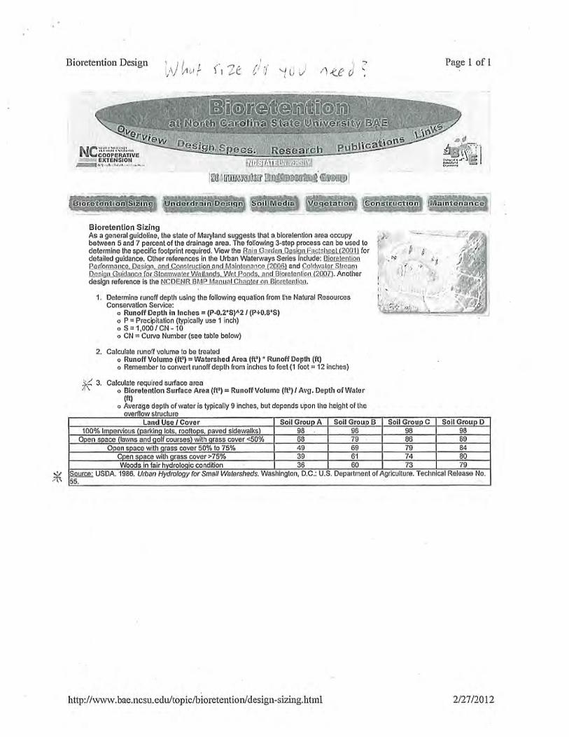

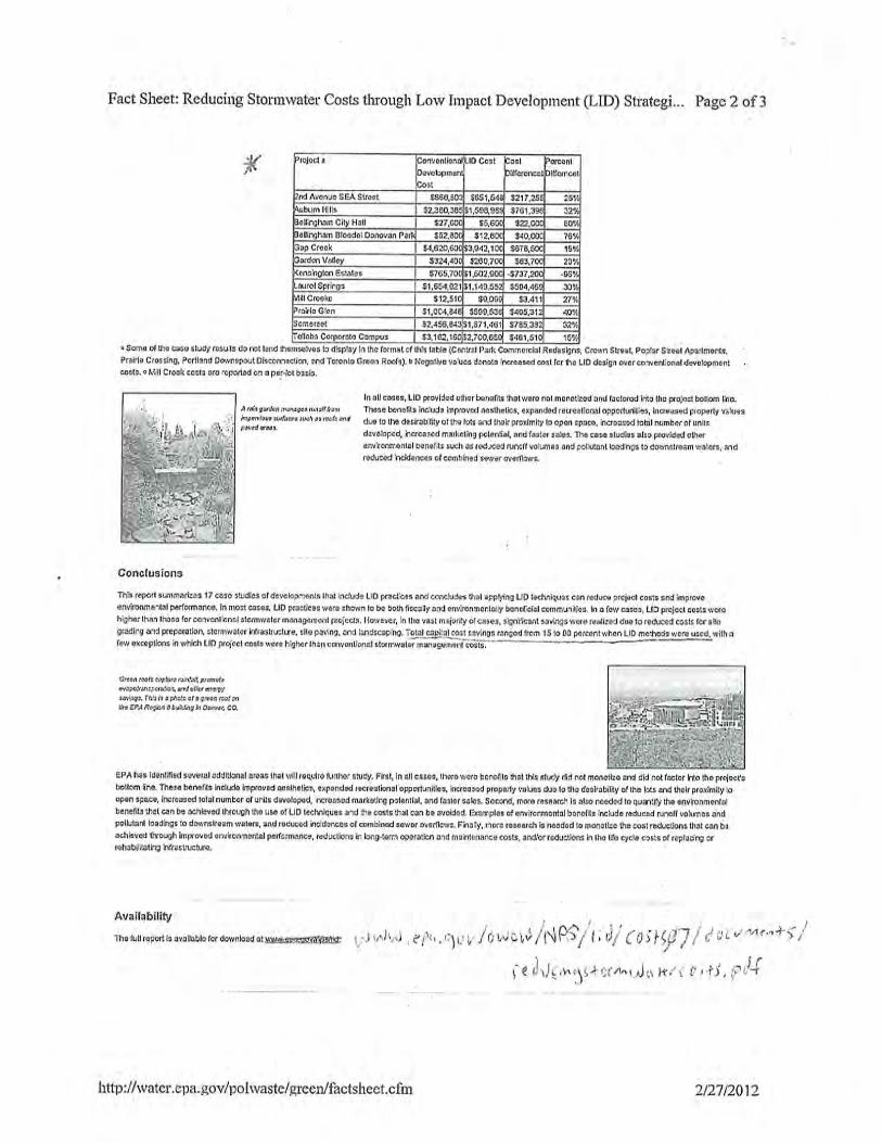
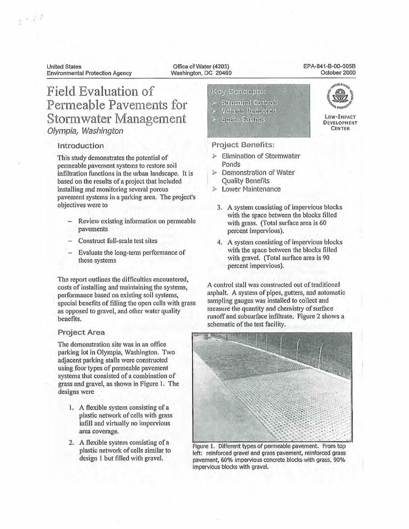
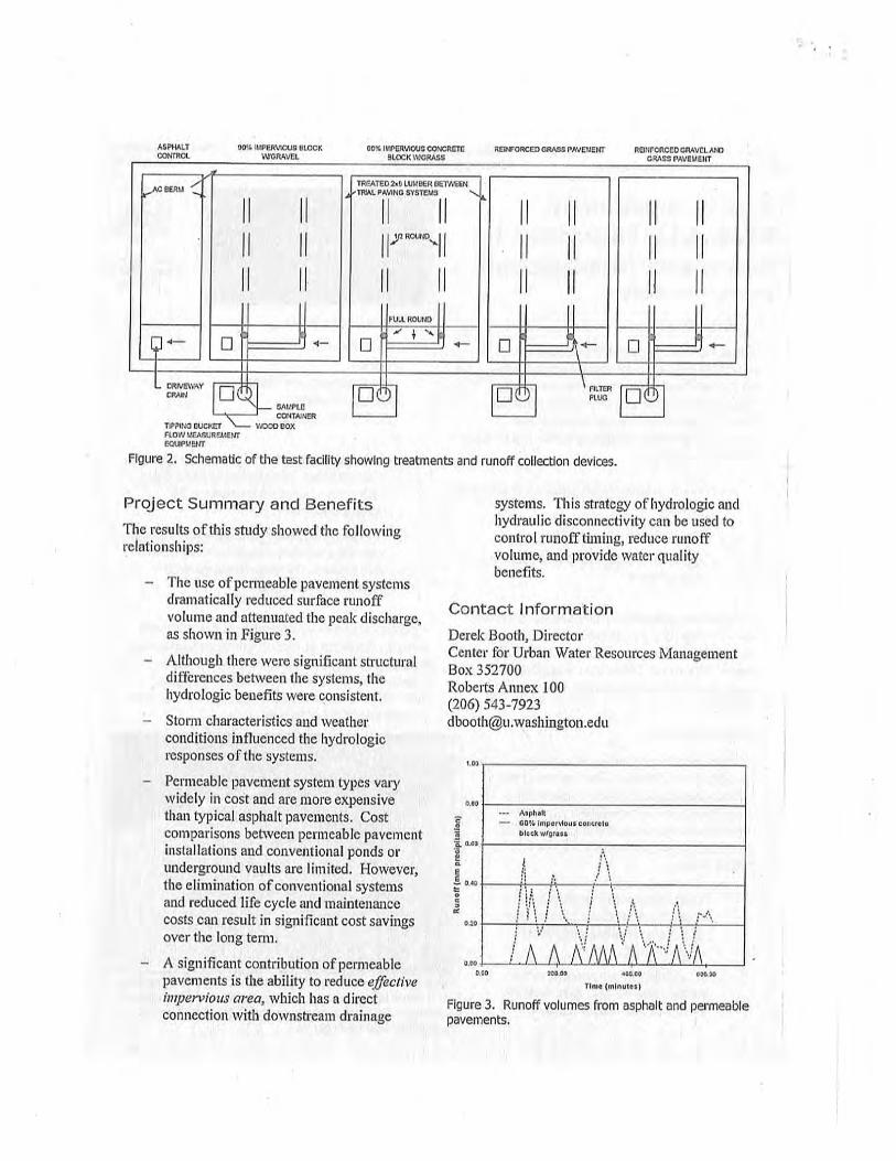
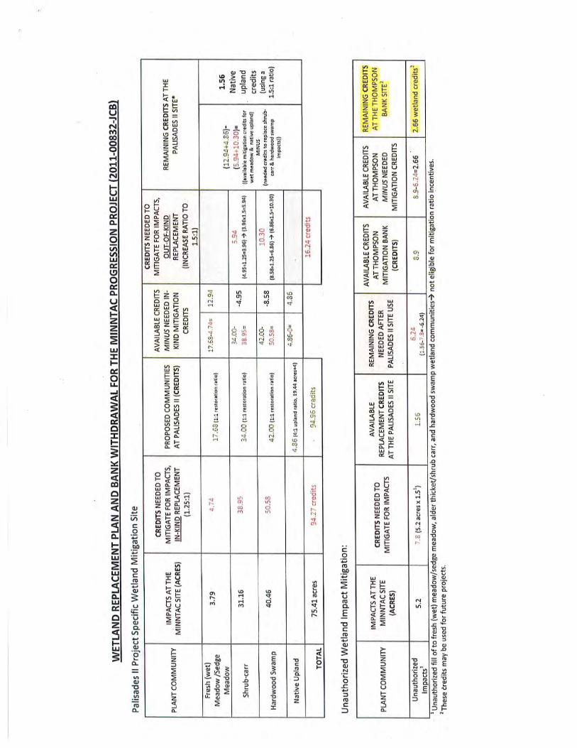
Related Documents