43-TV-25-10 GLO Issue 2 11/00 UK Minitrend Multitrend Plus Service Manual

Welcome message from author
This document is posted to help you gain knowledge. Please leave a comment to let me know what you think about it! Share it to your friends and learn new things together.
Transcript

43-TV-25-10 GLO Issue 2 11/00 UK
MinitrendMultitrend Plus
Service Manual

43-TV-25-10 GLO Issue 2 11/00 UK
Table of Contents
Table of Contents iii
Chapter 1: Introduction 1
Chapter 2: Minitrend V5 Analogue Card Installation 3
Removing the Rear Panel ........................................................................................ 3
Inside the Unit ........................................................................................................... 4
Standard and Universal Analogue Cards .............................................................. 4
Removing the Analogue Card ................................................................................ 4
Inserting the Analogue Card ................................................................................... 5
Re-assembling the Unit ........................................................................................... 5
Chapter 3: Minitrend V5 Alarm Card Installation 7
Removing the Rear Panel ........................................................................................ 7
Inside the Unit ........................................................................................................... 8
Alarm Cards .............................................................................................................. 8
Removing the Alarm Card ...................................................................................... 8
Inserting the Alarm Card ........................................................................................ 9
Re-assembling the Unit ......................................................................................... 10
Chapter 4: Minitrend V5 Power Supply Card &Transmitter Power Supply Card Installation 11
Removing the Rear Panel ...................................................................................... 11
Inside the Unit ......................................................................................................... 12
Power Supply and Transmitter Power Supply Cards ....................................... 12
Removing the Power Supply Card ...................................................................... 12
Inserting the Power Supply Card ......................................................................... 13
Re-assembling the Unit ......................................................................................... 13
43-TV-25-10 GLO Issue 2 11/00 UK ii i
Chapter 5: Minitrend V5Retransmission Card Installation 15
Removing the Rear Panel ......................................................................................15
Inside the Unit .........................................................................................................16
Retransmission Card ..............................................................................................16
Removing the Retransmission Card ....................................................................16
Inserting the Retransmission Card .......................................................................16
Re-assembling the Unit. .........................................................................................17
Chapter 6: Minitrend V5Communications Card Installation 19
Removing the Rear Panel ......................................................................................19
Inside the Unit .........................................................................................................20
Communications and RS485 Cards .....................................................................20
Removing the Comms Cards ................................................................................20
Inserting the Comms Cards ...................................................................................21
Re-assembling the Unit ..........................................................................................21
Connection Details .................................................................................................22Ethernet Interface .................................................................................................22RS232 Interface (Comm2) ....................................................................................22RS485 Interface (Comm3 Trendbus) ....................................................................22
Chapter 7: Minitrend V5Processor Card Installation 23
Removing the Rear Panel ......................................................................................23
Inside the Unit .........................................................................................................24
Processor Card .........................................................................................................24
Removing the Processor Card. .............................................................................24
Inserting the Processor Card .................................................................................25
Re-assembling the Unit ..........................................................................................25
Chapter 8: Minitrend V5 PCMCIA Card Installation 27
Removing the Rear Panel ......................................................................................27
Inside the Unit .........................................................................................................28
PCMCIA Card .........................................................................................................28
Removing the PCMCIA Card. ..............................................................................28
Inserting the PCMCIA Card .................................................................................29
Re-assembling the Unit ..........................................................................................29
i v 43-TV-25-10 GLO Issue 2 11/00 UK

Chapter 9: Minitrend V5 Rear Panel Assembly 31
Removing the Rear Panel ...................................................................................... 31
Replacing the Rear Panel Assembly ................................................................... 32
Re-assembling the Unit ......................................................................................... 32
Chapter 10: Minitrend V5 Disk Drive Replacement 33
Removing the Rear Panel ...................................................................................... 33
Inside the Unit ......................................................................................................... 34
Disk Drive Replacement ....................................................................................... 34
Disk Drive Installation .......................................................................................... 34
Re-assembling the Unit ......................................................................................... 35
Chapter 11: Minitrend V5 Display Assembly 37
Display Assembly Replacement .......................................................................... 37
Chapter 12: Multitrend Plus V5Analogue Card Installation 39
Removing the Rear Panel ...................................................................................... 39
Inside the Unit ......................................................................................................... 40
Standard and Universal Analogue Cards ............................................................ 40
Removing the Analogue Card .............................................................................. 41
Inserting the Analogue Card ................................................................................. 41
Re-assembling the Unit ......................................................................................... 41
Chapter 13: Multitrend Plus V5Alarm Card Installation 43
Removing the Rear Panel ...................................................................................... 43
Inside the Unit ......................................................................................................... 44
Alarm Cards ............................................................................................................ 44
Removing the Primary Alarm Card in slot D .................................................... 45
Inserting the Primary Alarm Card in slot D ....................................................... 45
Inserting a Second Alarm Card in slot D1 ......................................................... 47
Re-assembling the Unit ......................................................................................... 47
43-TV-25-10 GLO Issue 2 11/00 UK v
Chapter 14: Multitrend Plus V5Power Supply Card &Transmitter Power Supply Card Installation 49
Removing the Rear Panel ......................................................................................49
Inside the Unit .........................................................................................................50
Power Supply and Transmitter Power Supply Card ..........................................50
Installing the Power Supply ..................................................................................51
Removing the Transmitter Power Supply Card .................................................51
Inserting the Transmitter Power Supply Card ....................................................52
Re-assembling the Unit ..........................................................................................52
Chapter 15: Multitrend Plus V5Retransmission Card Installation 53
Removing the Rear Panel ......................................................................................53
Inside the Unit .........................................................................................................54
Retransmission Card ..............................................................................................54
Removing the Retransmission Card ....................................................................55
Inserting the Retransmission Card .......................................................................55
Re-assembling the Unit ..........................................................................................55
Chapter 16: Multitrend Plus V5Communications Card Installation 57
Removing the Rear Panel ......................................................................................57
Inside the Unit .........................................................................................................58
Communications and RS485 Cards .....................................................................59
Removing the Comms Cards ................................................................................59
Inserting the Comms Cards ...................................................................................60
Re-assembling the Unit ..........................................................................................60
Connection Details .................................................................................................61Ethernet Interface .................................................................................................61RS232 Interface (Comm2) ....................................................................................61RS485 Interface (Comm3 Trendbus) ....................................................................61
Chapter 17: Multitrend Plus V5Processor Card Installation 63
Removing the Rear Panel ......................................................................................63
Inside the Unit .........................................................................................................64
Processor Card .........................................................................................................65
Removing the Processor Card. .............................................................................65
Inserting the Processor Card .................................................................................66
vi 43-TV-25-10 GLO Issue 2 11/00 UK
Chapter 18: Multitrend Plus V5PCMCIA Card Installation 67
Removing the Rear Panel ...................................................................................... 67
Inside the Unit ......................................................................................................... 68
PCMCIA Card ........................................................................................................ 69
Removing the PCMCIA Card. ............................................................................. 69
Inserting the PCMCIA Card ................................................................................. 70
Re-assembling the Unit ......................................................................................... 70
Chapter 19: Multitrend Plus V5Rear Panel Assembly 71
Removing the Rear Panel ...................................................................................... 71
Replacing the Rear Panel Assembly ................................................................... 72
Re-assembling the Unit ......................................................................................... 72
Chapter 20: Multitrend Plus V5Disk Drive Replacement 73
Removing the Rear Panel ...................................................................................... 73
Disk Drive Replacement ....................................................................................... 74
Inside the Unit ......................................................................................................... 74
Disk Drive Installation .......................................................................................... 75
Re-assembling the Unit ......................................................................................... 75
Index 77
43-TV-25-10 GLO Issue 2 11/00 UK vi i

vi i i 43-TV-25-10 GLO Issue 2 11/00 UK
Chapter 1: Introduction
This manual is intended as a guide for the purposes of replacing or installing hardware.
Honeywell Recorders are designed for ease of assembly with minimal disturbance tothe rest of the unit.
There are, however, very few user-serviceable components - removing the rear paneland opening the back of the recorder should only be performed under the following cir-cumstances:
• When an item of hardware requires individual replacement.
• When an item of hardware is to be retrospectively fitted.
In all other instances it is recommended that the complete unit be returned for service toan authorised agent or service centre.
Before attempting to strip down a Honeywell recorder, it is advisable to clear a suffi-cient work space so components such as the front panel can be rested on the work sur-face without getting scratched or damaged.
This document is divided into two halves with separate instructions for the Minitrend V5 and the Multitrend Plus V5
CAUTIONOBSERVE ANTI-STATIC PRECAUTIONS
Refer to BS EN1000151:1992. Basic specification. Protection of electrostatic sensi-tive devices.
Ensure all power to the recorder is disconnected before attempting all maintenanceprocedures.
Full anti-static precautions MUST be observed when in contact with the electronicsof your recorder.
Removal of PCBs and battery back-up will result in the loss of all non-volatile data.Ensure all data and set-ups are saved.
Upon completion of service procedures detailed in this manual two basic safety testsshould be performed in order to ensure continued safe operation of the instrument.
1. Earth Resistance; 25 Adc applied between case and protective earth, bondingresistance should be < 0.1 Ohm.
2. Insulation Resistance; 500Vdc applied between the earth terminal, and the liveand neutral terminal shorted together, insulation resistance to be >2.0 MOhm.
(Mega Ohm, NOT milli Ohm)
Failure to comply with these instructions may result in product damage.
43-TV-25-10 GLO Issue 2 11/00 UK 1

2 43-TV-25-10 GLO Issue 2 11/00 UK
Chapter 2: Minitrend V5 Analogue Card Installation
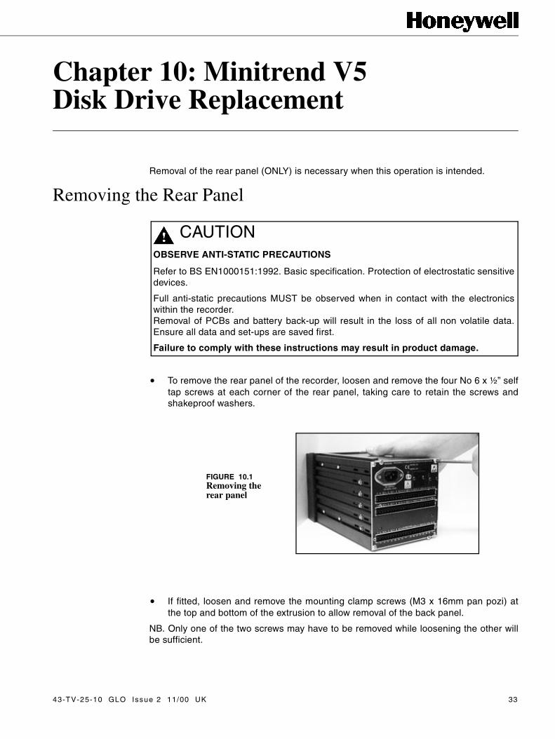
Removal of the rear panel (ONLY) is necessary when this operation is intended.
Removing the Rear Panel
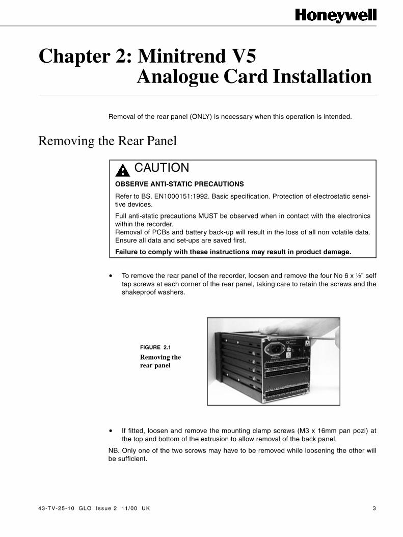
• To remove the rear panel of the recorder, loosen and remove the four No 6 x ½” selftap screws at each corner of the rear panel, taking care to retain the screws and theshakeproof washers.
• If fitted, loosen and remove the mounting clamp screws (M3 x 16mm pan pozi) atthe top and bottom of the extrusion to allow removal of the back panel.
NB. Only one of the two screws may have to be removed while loosening the other willbe sufficient.
CAUTIONOBSERVE ANTI-STATIC PRECAUTIONS
Refer to BS. EN1000151:1992. Basic specification. Protection of electrostatic sensi-tive devices.
Full anti-static precautions MUST be observed when in contact with the electronicswithin the recorder.Removal of PCBs and battery back-up will result in the loss of all non volatile data.Ensure all data and set-ups are saved first.
Failure to comply with these instructions may result in product damage.
FIGURE 2.1
Removing the rear panel
43-TV-25-10 GLO Issue 2 11/00 UK 3

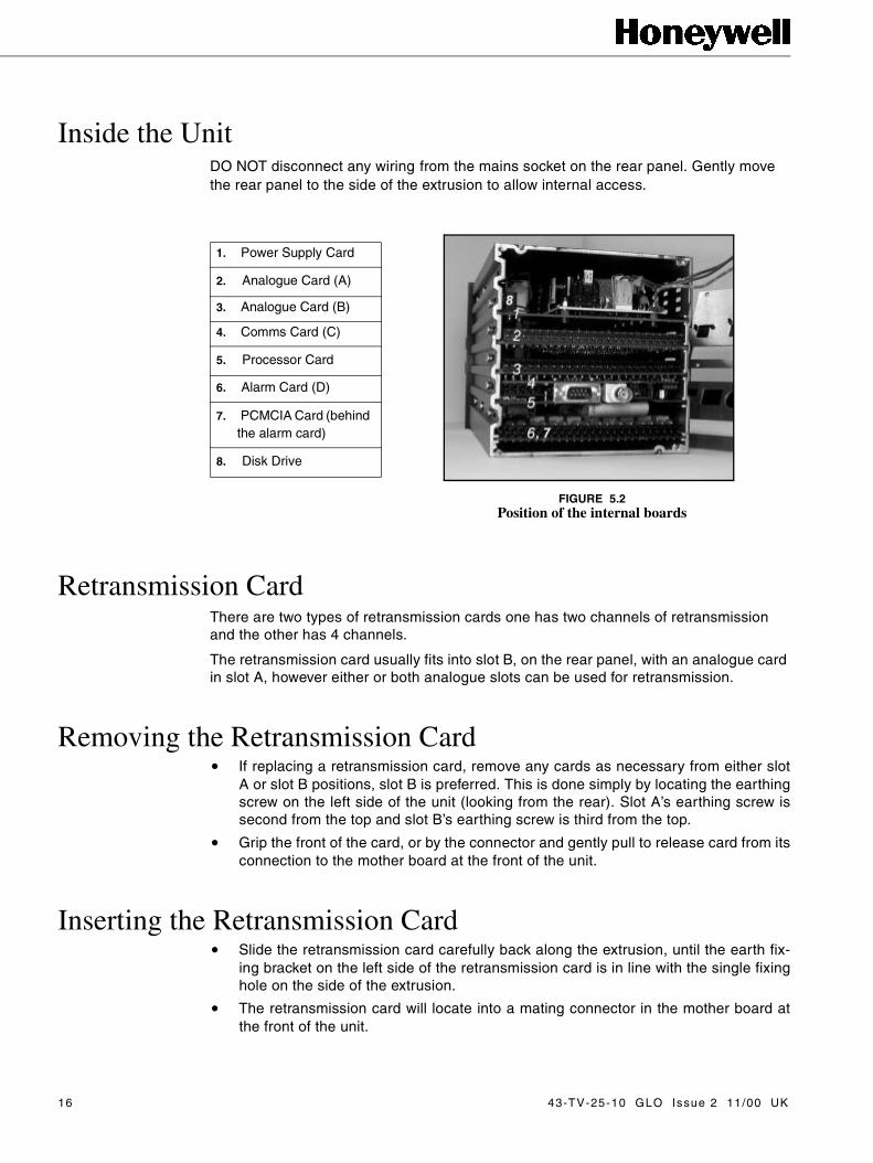
Inside the UnitDO NOT disconnect any wiring from the mains socket on the rear panel. Gently movethe rear panel to the side of the extrusion to allow internal access.
Standard and Universal Analogue CardsThe mechanical constraints for the standard analogue card and the universal analoguecard are the same.
The installation for either of the analogue cards in slot A or slot B positions, follows thesame procedure.
The analogue slot A, on the rear panel, is primarily for the standard analogue card andslot B for the universal analogue card. However, either slot can be used for both types ofanalogue card.
Removing the Analogue Card• If replacing an analogue card, remove any cards as necessary from slot A or slot B
positions. This is done simply by locating the earthing screw on the left side of theunit (looking from the rear). Slot A’s earthing screw is second from the top and slotB’s earthing screw is third from the top. Remove and retain the screws and washers.
• Grip the front of the card, or by the connector and gently pull to release the cardfrom its connection to the mother board at the front of the unit.
�
���
FIGURE 2.2
Position of the internal boards
1. Power Supply Card
2. Analogue Card (A)
3. Analogue Card (B)
4. Comms Card (C)
5. Processor Card
6. Alarm Card (D)
7. PCMCIA Card (behindthe alarm card)
8. Disk Drive
4 43-TV-25-10 GLO Issue 2 11/00 UK

Inserting the Analogue Card• Slide the new analogue card carefully back along the extrusion, until the earth fixing
bracket on the left side of the analogue card is in line with the single fixing hole onthe side of the extrusion.
• The analogue card will locate into a mating connector in the mother board at thefront of the unit.
• Ensure the card is pushed fully home and that no internal wiring is damaged as theanalogue card is returned.
• Replace/fit the earth screw and shakeproof washer, on the side of the extrusion,torque to 120cNm or 10.62lbf-in.
Re-assembling the Unit• Remove the plastic blanking plate safety cover
for the appropriate slot on the rear panel, ifnecessary, by pushing out the push rivets frombehind.
• Replace the rear panel, reposition the shake-proof washers and replace and tighten the fourNo. 6 x ½” self tap screws at each corner of therear panel.
• Replace and/or tighten the mounting clampscrews at the top and bottom of the extrusion. FIGURE 2.3 The Earthing Screws
43-TV-25-10 GLO Issue 2 11/00 UK 5

6 43-TV-25-10 GLO Issue 2 11/00 UK

Chapter 3: Minitrend V5 Alarm Card Installation
Removal of the rear panel (ONLY) is necessary when this operation is intended.
Removing the Rear Panel
• To remove the rear panel of the recorder, loosen and remove the four No 6 x ½” selftap screws at each corner of the rear panel, taking care to retain both the shake-proof washer and the screw.
• If fitted, loosen and remove the mounting clamp screws (M3 x 16mm pan pozi) atthe top and bottom of the extrusion to allow removal of the back panel.
NB. Only one of the two screws may have to be removed while loosening the other willbe sufficient.
CAUTIONOBSERVE ANTI-STATIC PRECAUTIONS
Refer to BS EN1000151:1992. Basic specification. Protection of electrostatic sensitivedevices.
Full anti-static precautions MUST be observed when in contact with the electronicswithin the recorder.Removal of PCBs and battery back-up will result in the loss of all non volatile data.Ensure all data and set-ups are saved first.
Failure to comply with these instructions may result in product damage.
FIGURE 3.1
Removing the rear panel
43-TV-25-10 GLO Issue 2 11/00 UK 7

Inside the UnitDO NOT disconnect any wiring from the mains socket on the rear panel. Gently movethe rear panel to the side of the extrusion to allow internal access.
Alarm CardsThere are two main types of alarm cards, the relay alarm card and the input/output card.
For the Minitrend V5, the relay alarm card is available with 4 or 8 channels of relay output, the 8 channel having two channels of digital input as standard.
The input/output cards for the Minitrend V5 are available with 8 or 16 channels, allchannels may be used as digital inputs.
All alarm cards take up position in slot D on the rear panel of the Minitrend V5.If the unit is not fitted with a PCMCIA card in the alarm slot D, a snubber card will berequired.
Removing the Alarm CardIt is necessary to access the processor card to connect one end of the alarm ribboncable to the socket on the under side of the card.
• Locate the earth bracket screw, for the processor card, on the left side of the unit(from the rear), second position from the bottom of the unit (Slot C). Remove andretain the screw and shakeproof washer.
• If the alarm card is being replaced, locate and remove the earthing screw from thebottom position of the unit (Slot D). Remove the card and retain both the screw andthe shakeproof washer.
• Grip the front of the processor card, or by the connector and gently pull to releasethe card from its connection to the mother board at the front of the unit.
�
���
FIGURE 3.2Position of the internal boards
1. Power Supply Card
2. Analogue Card (A)
3. Analogue Card (B)
4. Comms Card (C)
5. Processor Card
6. Alarm Card (D)
7. PCMCIA Card (behind the alarm card)
8. Disk Drive
8 43-TV-25-10 GLO Issue 2 11/00 UK

• Remove the alarm card at the same time.
• Slide the processor board out to reveal a 34-way connector on the under side of thecard.
• Remove the connector if replacing an alarm card.
• Plug one end of the new alarm ribbon cable into the connector on the processorcard. NB. Both ends of the ribbon cable are identical. The connector will only fit inone way round, identified by a location tab at one side of the connector. Push theconnectors fully into the socket on the card.
• Connect the other end of the ribbon cable in to the 34-way connector on the alarmcard.
Inserting the Alarm Card• Fit a snubber card into alarm slot D, if a PCMCIA card is not fitted.
• Begin to slide the processor card back into its slot holding the alarm card parallelbelow, allowing the ribbon cable to bend into a comfortable ‘S’ shape.See Figure 3.4 on page 9.
• Both the cards need to be insertedsimultaneously to keep the ribbon cablein its folded ‘S’ shape position.
• Slide the cards carefully back into theextrusion, until the fixing bracket on theleft side of both cards are in line withthe single fixing hole on the side of theextrusion.
• Ensure that no internal wiring is dam-aged as the alarm card is returned.
• The processor card will locate into amating connector in the mother board atthe front of the unit.
• Ensure the card is pushed fully home.
FIGURE 3.3Alarm card
FIGURE 3.4 Alarm Ribbon Cable
43-TV-25-10 GLO Issue 2 11/00 UK 9

• Replace/fit the earth screws andshakeproof washers, on the side of theextrusion, to secure both cards. Torque to 120cNm or 10.62lbf-in.
Re-assembling the Unit• Remove the plastic blanking plate safety cover on the bottom of the rear panel by
pushing out the push rivets (if adding the alarm card as a new option card).
• Replace the rear panel, reposition the shakeproof washers and replace and tightenthe four No 6 x ½” self tap screws at each corner of the rear panel.
• Replace and/or tighten the mounting clamp screws at the top and bottom of theextrusion.
FIGURE 3.5 The Earthing Screws
10 43-TV-25-10 GLO Issue 2 11/00 UK

Chapter 4: Minitrend V5 Power Supply Card &Transmitter Power Supply Card Installation
Removal of the rear panel (ONLY) is necessary when this operation is intended.
Removing the Rear Panel
• To remove the rear panel of the recorder, loosen and remove the four No 6 x ½” selftap screws at each corner of the rear panel, taking care to retain the screws andshakeproof washers.
• If fitted, loosen and remove the mounting clamp screws (M3 x 16mm pan pozi) atthe top and bottom of the extrusion to allow removal of the back panel.
NB Only one of the two screws may have to be removed while loosening the other will be sufficient.
CAUTIONOBSERVE ANTI-STATIC PRECAUTIONS
Refer to BS EN1000151:1992. Basic specification. Protection of electrostatic sensitivedevices.
Full anti-static precautions MUST be observed when in contact with the electronicswithin the recorder.Removal of PCBs and battery back-up will result in the loss of all non volatile data.Ensure all data and set-ups are saved first.
Failure to comply with these instructions may result in product damage.
FIGURE 4.1.Removing the rear panel
43-TV-25-10 GLO Issue 2 11/00 UK 11

Inside the UnitDO NOT disconnect any wiring from the mains socket on the rear panel. Gently move the rear panel to the side of the extrusion to allow internal access.
Power Supply and Transmitter Power Supply CardsThe power supply card is available as 240 Vac, 24 Vdc or 48 Vdc.
The installation for either of the power supply or the transmitter power supply cards in the top slot position, follows the same procedure.
The transmitter power supply card requires the top right blanking plate on the rear panel to be removed to allow for connection.
Removing the Power Supply Card• If replacing the power supply card, remove the existing card by locating the earthing
screw on the left side of the unit (looking from the rear). The top earthing screw isfor the power supply card.
• Grip the front of the card and gently pull to release the card from its connection tothe mother board at the front of the unit. Slide the power supply card out about30mm.
• Disconnect the 2-way disk drive loom on the left side of the card (one red and oneblack wire).
• From the piggy-back board mounted on the power supply card, disconnect the 3-way mains loom going to the live and neutral connections (only two wires, blue andbrown).
• Finally disconnect the earth lead from the mains filter on the rear panel (green/yel-low wire).
• The card can now be removed from the unit. See Figure 4.3 on page 13.
�
���
FIGURE 4.2Position of the internal boards
1. Power Supply Card
2. Analogue Card (A)
3. Analogue Card (B)
4. Comms Card (C)
5. Processor Card
6. Alarm Card (D)
7. PCMCIA Card (behind the alarm card)
8. Disk Drive
12 43-TV-25-10 GLO Issue 2 11/00 UK
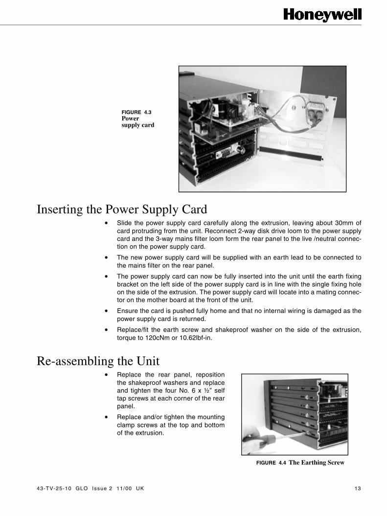
Inserting the Power Supply Card • Slide the power supply card carefully along the extrusion, leaving about 30mm of
card protruding from the unit. Reconnect 2-way disk drive loom to the power supplycard and the 3-way mains filter loom form the rear panel to the live /neutral connec-tion on the power supply card.
• The new power supply card will be supplied with an earth lead to be connected tothe mains filter on the rear panel.
• The power supply card can now be fully inserted into the unit until the earth fixingbracket on the left side of the power supply card is in line with the single fixing holeon the side of the extrusion. The power supply card will locate into a mating connec-tor on the mother board at the front of the unit.
• Ensure the card is pushed fully home and that no internal wiring is damaged as thepower supply card is returned.
• Replace/fit the earth screw and shakeproof washer on the side of the extrusion,torque to 120cNm or 10.62lbf-in.
Re-assembling the Unit• Replace the rear panel, reposition
the shakeproof washers and replaceand tighten the four No. 6 x ½” selftap screws at each corner of the rearpanel.
• Replace and/or tighten the mountingclamp screws at the top and bottomof the extrusion.
FIGURE 4.3Power supply card
FIGURE 4.4 The Earthing Screw
43-TV-25-10 GLO Issue 2 11/00 UK 13

14 43-TV-25-10 GLO Issue 2 11/00 UK
Chapter 5: Minitrend V5Retransmission Card Installation
Removal of the rear panel (ONLY) is necessary when this operation is intended.
Removing the Rear Panel
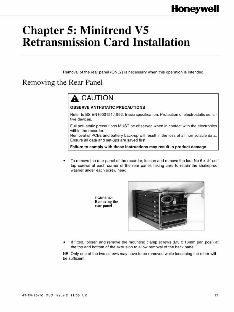
• To remove the rear panel of the recorder, loosen and remove the four No 6 x ½” selftap screws at each corner of the rear panel, taking care to retain the shakeproofwasher under each screw head.
• If fitted, loosen and remove the mounting clamp screws (M3 x 16mm pan pozi) atthe top and bottom of the extrusion to allow removal of the back panel.
NB. Only one of the two screws may have to be removed while loosening the other will be sufficient.
CAUTIONOBSERVE ANTI-STATIC PRECAUTIONS
Refer to BS EN1000151:1992. Basic specification. Protection of electrostatic sensi-tive devices.
Full anti-static precautions MUST be observed when in contact with the electronicswithin the recorder.Removal of PCBs and battery back-up will result in the loss of all non volatile data.Ensure all data and set-ups are saved first.
Failure to comply with these instructions may result in product damage.
FIGURE 5.1Removing the rear panel
43-TV-25-10 GLO Issue 2 11/00 UK 15
Inside the UnitDO NOT disconnect any wiring from the mains socket on the rear panel. Gently move the rear panel to the side of the extrusion to allow internal access.
Retransmission CardThere are two types of retransmission cards one has two channels of retransmission and the other has 4 channels.
The retransmission card usually fits into slot B, on the rear panel, with an analogue card in slot A, however either or both analogue slots can be used for retransmission.
Removing the Retransmission Card• If replacing a retransmission card, remove any cards as necessary from either slot
A or slot B positions, slot B is preferred. This is done simply by locating the earthingscrew on the left side of the unit (looking from the rear). Slot A’s earthing screw issecond from the top and slot B’s earthing screw is third from the top.
• Grip the front of the card, or by the connector and gently pull to release card from itsconnection to the mother board at the front of the unit.
Inserting the Retransmission Card• Slide the retransmission card carefully back along the extrusion, until the earth fix-
ing bracket on the left side of the retransmission card is in line with the single fixinghole on the side of the extrusion.
• The retransmission card will locate into a mating connector in the mother board atthe front of the unit.
�
���
FIGURE 5.2Position of the internal boards
1. Power Supply Card
2. Analogue Card (A)
3. Analogue Card (B)
4. Comms Card (C)
5. Processor Card
6. Alarm Card (D)
7. PCMCIA Card (behind the alarm card)
8. Disk Drive
16 43-TV-25-10 GLO Issue 2 11/00 UK

• Ensure the card is pushed fully home and that no internal wiring is damaged as theretransmission card is returned.
• Replace/fit the earth screw and shakeproof washer on the side of the extrusion,torque to 120cNm or 10.62lbf-in.
Re-assembling the Unit.• Remove the plastic blanking plate safety
cover for the appropriate slot on the rearpanel, if necessary, by pushing out thepush rivets from behind.
• Replace the rear panel, reposition theshakeproof washers and replace andtighten the four No. 6 x ½” self tap screwsat each corner of the rear panel.
• Replace and/or tighten the mountingclamp screws at the top and bottom of theextrusion.
FIGURE 5.3 The Earthing Screw
43-TV-25-10 GLO Issue 2 11/00 UK 17

18 43-TV-25-10 GLO Issue 2 11/00 UK

Chapter 6: Minitrend V5Communications Card Installation
Removal of the rear panel (ONLY) is necessary when this operation is intended.
Removing the Rear Panel
• To remove the rear panel of the recorder, loosen and remove the four No 6 x ½” selftap screws at each corner of the rear panel, taking care to retain the screws andshakeproof washers.
• If fitted, loosen and remove the mounting clamp screws (M3 x 16mm pan pozi) atthe top and bottom of the extrusion to allow removal of the back panel.
NB. Only one of the two screws may have to be removed while loosening the other will be sufficient.
CAUTIONOBSERVE ANTI-STATIC PRECAUTIONS
Refer to BS EN1000151:1992. Basic specification. Protection of electrostatic sensi-tive devices.
Full anti-static precautions MUST be observed when in contact with the electronicswithin the recorder.Removal of PCBs and battery back-up will result in the loss of all non volatile data.Ensure all data and set-ups are saved first.
Failure to comply with these instructions may result in product damage.
FIGURE 6.1Removing the rear panel
43-TV-25-10 GLO Issue 2 11/00 UK 19

Inside the UnitDO NOT disconnect any wiring from the mains socket on the rear panel. Gently move the rear panel to the side of the extrusion to allow internal access.
Communications and RS485 CardsThe mechanical constraints for the communications card and the RS485 comms cardare the same.
The comms cards plugs in on top of the processor card, like a piggy back board, whichoccupies slot C.
Removing the Comms Cards• If replacing a comms card, it is necessary to partially slide out the processor card to
unplug the comms card. This is done simply by locating the earthing screw on theleft side of the unit (looking from the rear). Slot C earthing screw is second from thebottom, remove and retain screw and shakeproof washer.
• Grip the front of the processor card, or by the connector, and gently pull to releasethe card from its connection to the mother board.
• Begin to slide the card out. If an alarm card is also fitted, a 34-way connector on theunderside of the processor card will have to be disconnected in order to slide theprocessor card out further.
• Pull out the processor card, with the comms card attached, and turn it over to showthe underside of the processor card. Remove the two screws and shakeproof wash-ers from the two pillars connecting the two cards together, from the underside of theprocessor card.
• Carefully separate the comms card from the processor card. TIP Pull the cardsapart evenly from each side. There are three double row headers in different orien-tations resulting in quite a tight fit. See Figure 6.3 on page 21.
�
���
FIGURE 6.2Position of the internal boards
1. Power Supply Card
2. Analogue Card (A)
3. Analogue Card (B)
4. Comms Card (C)
5. Processor Card
6. Alarm Card (D)
7. PCMCIA Card (behind the alarm card)
8. Disk Drive
20 43-TV-25-10 GLO Issue 2 11/00 UK

Inserting the Comms Cards• Plug in the new comms card to the processor card and replace the two screws and
shakeproof washers on the underside of the processor card to secure the pillars,locking the two cards together.
• Begin to slide the processor card back into the extrusion. If an alarm card is fitted,ensure the ribbon cable is reconnected to the underside of the processor card andkept flat to the alarm card.
• Insert the processor card fully until the earth fixing bracket on the left side of theprocessor card is in line with the single fixing hole on the side of the extrusion.
• The processor card will locate into a mating connector in the mother board at thefront of the unit.
• Ensure the card is pushed fully home and that no internal wiring is damaged as thealarm card is returned.
• Replace/fit the earth screw and shakeproof washer on the side of the extrusion,torque to 120cNm or 10.62lbf-in.
Re-assembling the Unit• Remove the plastic blanking plate safety
cover for the appropriate slot on the rearpanel, if necessary, by pushing out thepush rivets from behind.
• Replace the rear panel, reposition theshakeproof washers and replace andtighten the four No. 6 x ½” self tapscrews at each corner of the rear panel.
• Replace and/or tighten the mountingclamp screws at the top and bottom ofthe extrusion.
• If fitted, replace and tighten the mount-ing clamp screws at the top and bottom of the extrusion.
FIGURE 6.3The comms card plugs in on top of the processor card
FIGURE 6.4 The Earthing Screw
43-TV-25-10 GLO Issue 2 11/00 UK 21

C on n ection D eta ilsEthernet InterfaceThis is an 8-way RL45 socket Molex 95040-288‘‘ used for Ethernet connection, pcbposition J5. Standard Ethernet connection.
RS232 Interface (Comm2)This is a 9-way D-type connector (mating half not supplied), pcb position P1.
RS485 Interface (Comm3 Trendbus)This is a 5-way socket (mating half supplied), pcb position J1.
TD+
TD-RD+
RD-
1
2345678
locating pins(not connected)
2 4 6 8
7531
A B
1627
38495
-DTR2-R12
-CTS2TXD2-RTS2RXD2-DSR2-DCD2
1
2
3
4
5
TXA
-TXB
-RXB
RXA
22 43-TV-25-10 GLO Issue 2 11/00 UK

Chapter 7: Minitrend V5Processor Card Installation
Removal of the rear panel (ONLY) is necessary when this operation is intended.
Removing the Rear Panel
• To remove the rear panel of the recorder, loosen and remove the four No 6 x ½” selftap screws at each corner of the rear panel, taking care to retain the screws andshakeproof washers.
• If fitted, loosen and remove the mounting clamp screws (M3 x 16mm pan pozi) atthe top and bottom of the extrusion to allow removal of the back panel.
NB. Only one of the two screws may have to be removed while loosening the other will be sufficient.
CAUTIONOBSERVE ANTI-STATIC PRECAUTIONS
Refer to BS EN1000151:1992. Basic specification. Protection of electrostatic sensitivedevices.
Full anti-static precautions MUST be observed when in contact with the electronicswithin the recorder.Removal of PCBs and battery back-up will result in the loss of all non volatile data.Ensure all data and set-ups are saved first.
Failure to comply with these instructions may result in product damage.
FIGURE 7.1Removing the rear panel
43-TV-25-10 GLO Issue 2 11/00 UK 23

Inside the UnitDO NOT disconnect any wiring from the mains socket on the rear panel. Gently move the rear panel to the side of the extrusion to allow internal access.
Processor CardThe processor card is not an options card and is fitted in all units.
The processor card occupies slot C on the back of the unit.
Removing the Processor Card.• If replacing a processor card, remove any cards as necessary from the slot C posi-
tion. This is done by locating the earthing screw on the left side of the unit (lookingfrom the rear). Slot C’s earthing screw is second from the bottom. Remove andretain the screws and shakeproof washers.
• Grip the front of the card, or by the connector, and gently pull to release the cardfrom its connection to the mother board at the front of the unit.
• If there is an alarm card fitted in the slot below (slot D), there will be a 34-way con-nector attached to the underside of the processor card, this must be disconnectedbefore the processor card can be removed.
• If there is a comms card fitted, this will be a separate card plugged into the top ofthe processor card, it will need to be removed from the processor card. To do thispull the cards out and turn them over to show the underside of the processor card.Remove the two screws and shakeproof washers from the two pillars connecting thetwo cards together, from the underside of the processor card.
• Carefully separate the comms card from the processor card. Begin to pull the twoboards apart rotating them 90° each time. There are three double row headers indifferent orientations, therefore pulling from alternate side will ease the process.See Figure 7.3 on page 25.
�
���
FIGURE 7.2Position of the internal boards
1. Power Supply Card
2. Analogue Card (A)
3. Analogue Card (B)
4. Comms Card (C)
5. Processor Card
6. Alarm Card (D)
7. PCMCIA Card (behind the alarm card)
8. Disk Drive
24 43-TV-25-10 GLO Issue 2 11/00 UK

.
Inserting the Processor Card • Plug in the comms card, if fitted, to the processor card and replace the two screws
and shakeproof washers on the underside of the processor card to secure the pil-lars, locking the two cards together.
• Begin to slide the processor card carefully back into the extrusion. If an alarm cardis fitted, ensure the ribbon cable is kept flat to the alarm card. Slide the processorcard in and reconnect the ribbon cable to the connector on the underside of theprocessor card.
• Insert the processor card fully until the earth fixing bracket on the left side of theprocessor card is in line with the single fixing hole on the side of the extrusion.
• The processor card will locate into a mating connector on the mother board at thefront of the unit.
• Ensure the card is pushed fully home and that no internal wiring is damaged as thealarm card is returned.
• Replace/fit the earth screw and shakeproof washer on the side of the extrusion,torque to 120cNm or 10.62lbf-in.
Re-assembling the Unit• Remove the plastic blanking plate
safety cover for the appropriate slot onthe rear panel, if necessary, by push-ing out the push rivets from behind.
• Replace the rear panel, reposition theshakeproof washers and replace andtighten the four No. 6 x ½” self tapscrews at each corner of the rearpanel.
• Replace and/or tighten the mountingclamp screws at the top and bottom ofthe extrusion.
FIGURE 7.3The comms card plugs in on top of the processor card
FIGURE 7.4 The Earthing Screw
43-TV-25-10 GLO Issue 2 11/00 UK 25

26 43-TV-25-10 GLO Issue 2 11/00 UK
Chapter 8: Minitrend V5 PCMCIA Card Installation
Removal of the rear panel (ONLY) is necessary when this operation is intended.
Removing the Rear Panel
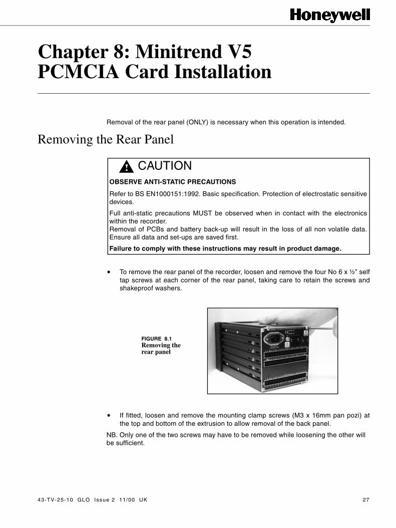
• To remove the rear panel of the recorder, loosen and remove the four No 6 x ½” selftap screws at each corner of the rear panel, taking care to retain the screws andshakeproof washers.
• If fitted, loosen and remove the mounting clamp screws (M3 x 16mm pan pozi) atthe top and bottom of the extrusion to allow removal of the back panel.
NB. Only one of the two screws may have to be removed while loosening the other will be sufficient.
CAUTIONOBSERVE ANTI-STATIC PRECAUTIONS
Refer to BS EN1000151:1992. Basic specification. Protection of electrostatic sensitivedevices.
Full anti-static precautions MUST be observed when in contact with the electronicswithin the recorder.Removal of PCBs and battery back-up will result in the loss of all non volatile data.Ensure all data and set-ups are saved first.
Failure to comply with these instructions may result in product damage.
FIGURE 8.1Removing the rear panel
43-TV-25-10 GLO Issue 2 11/00 UK 27
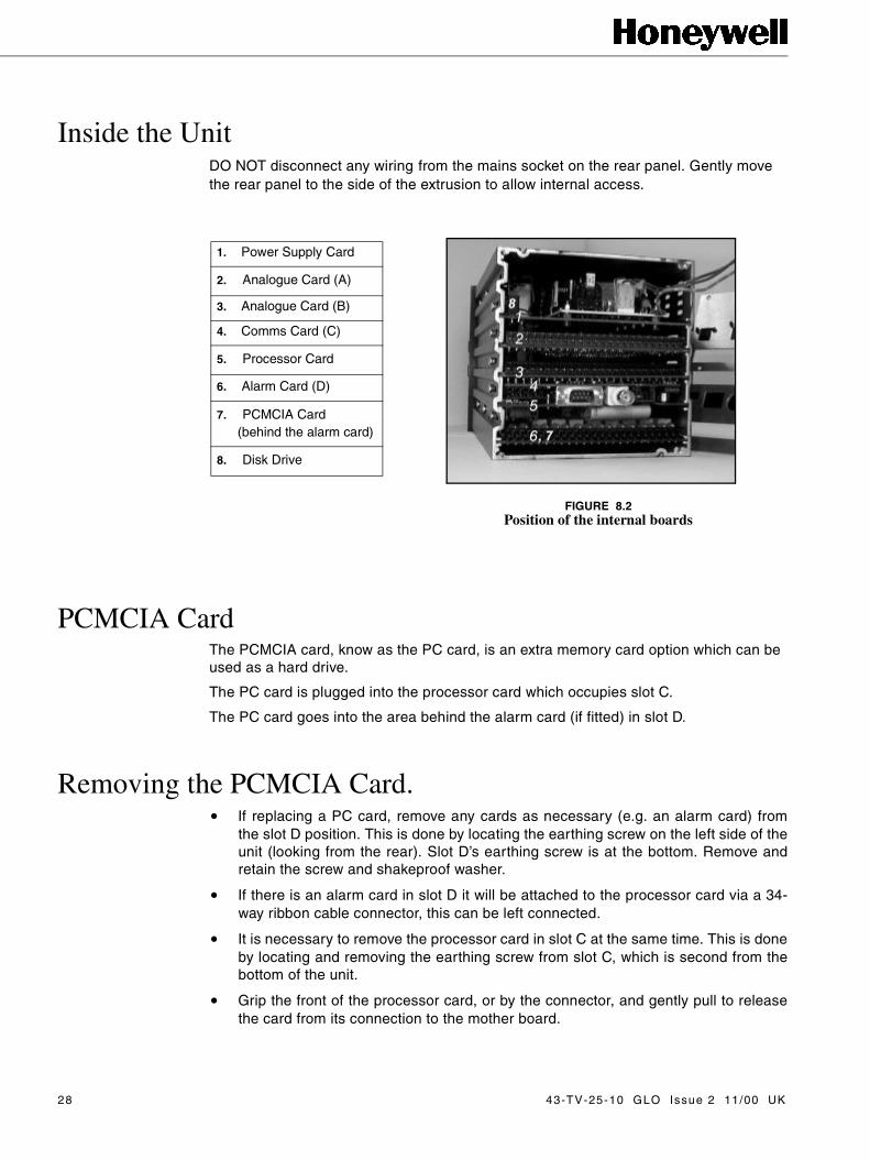
Inside the UnitDO NOT disconnect any wiring from the mains socket on the rear panel. Gently move the rear panel to the side of the extrusion to allow internal access.
PCMCIA CardThe PCMCIA card, know as the PC card, is an extra memory card option which can be used as a hard drive.
The PC card is plugged into the processor card which occupies slot C.
The PC card goes into the area behind the alarm card (if fitted) in slot D.
Removing the PCMCIA Card.• If replacing a PC card, remove any cards as necessary (e.g. an alarm card) from
the slot D position. This is done by locating the earthing screw on the left side of theunit (looking from the rear). Slot D’s earthing screw is at the bottom. Remove andretain the screw and shakeproof washer.
• If there is an alarm card in slot D it will be attached to the processor card via a 34-way ribbon cable connector, this can be left connected.
• It is necessary to remove the processor card in slot C at the same time. This is doneby locating and removing the earthing screw from slot C, which is second from thebottom of the unit.
• Grip the front of the processor card, or by the connector, and gently pull to releasethe card from its connection to the mother board.
�
���
FIGURE 8.2Position of the internal boards
1. Power Supply Card
2. Analogue Card (A)
3. Analogue Card (B)
4. Comms Card (C)
5. Processor Card
6. Alarm Card (D)
7. PCMCIA Card (behind the alarm card)
8. Disk Drive
28 43-TV-25-10 GLO Issue 2 11/00 UK
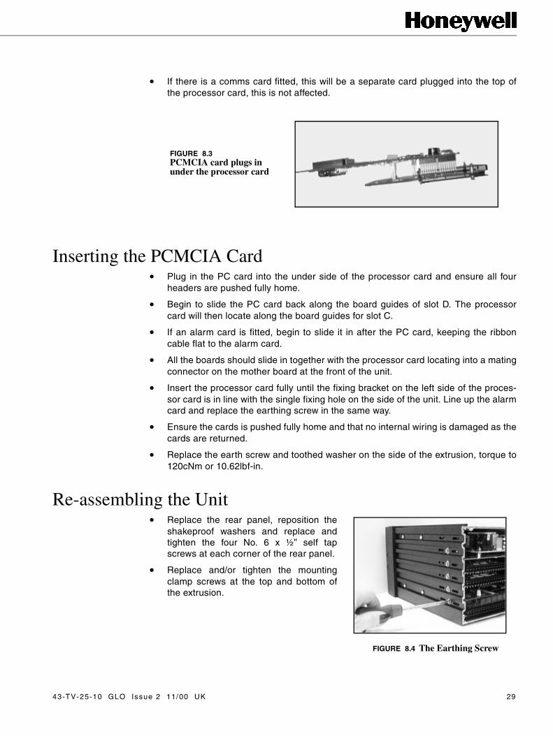
• If there is a comms card fitted, this will be a separate card plugged into the top ofthe processor card, this is not affected.
Inserting the PCMCIA Card • Plug in the PC card into the under side of the processor card and ensure all four
headers are pushed fully home.
• Begin to slide the PC card back along the board guides of slot D. The processorcard will then locate along the board guides for slot C.
• If an alarm card is fitted, begin to slide it in after the PC card, keeping the ribboncable flat to the alarm card.
• All the boards should slide in together with the processor card locating into a matingconnector on the mother board at the front of the unit.
• Insert the processor card fully until the fixing bracket on the left side of the proces-sor card is in line with the single fixing hole on the side of the unit. Line up the alarmcard and replace the earthing screw in the same way.
• Ensure the cards is pushed fully home and that no internal wiring is damaged as thecards are returned.
• Replace the earth screw and toothed washer on the side of the extrusion, torque to120cNm or 10.62lbf-in.
Re-assembling the Unit• Replace the rear panel, reposition the
shakeproof washers and replace andtighten the four No. 6 x ½” self tapscrews at each corner of the rear panel.
• Replace and/or tighten the mountingclamp screws at the top and bottom ofthe extrusion.
FIGURE 8.3PCMCIA card plugs in under the processor card
FIGURE 8.4 The Earthing Screw
43-TV-25-10 GLO Issue 2 11/00 UK 29

30 43-TV-25-10 GLO Issue 2 11/00 UK

Chapter 9: Minitrend V5 Rear Panel Assembly
Removing the Rear PanelRemoval of the rear panel is necessary for replacement or fitting any of the PC cards.
• To remove the rear panel of the recorder, loosen and remove the four No 6 x ½” selftap screws at each corner of the rear panel, taking care to retain the screws andshakeproof washers.
• If fitted, loosen and remove the mounting clamp screws (M3 x 16mm pan pozi) atthe top and bottom of the extrusion to allow removal of the back panel.
NB. Only one of the two screws may have to be removed while loosening the other will be sufficient.
CAUTIONOBSERVE ANTI-STATIC PRECAUTIONS
Refer to BS EN1000151:1992. Basic specification. Protection of electrostatic sensitivedevices.
Full anti-static precautions MUST be observed when in contact with the electronicswithin the recorder.Removal of PCBs and battery back-up will result in the loss of all non volatile data.Ensure all data and set-ups are saved first.
Failure to comply with these instructions may result in product damage.
FIGURE 9.1Removing the rear panel
43-TV-25-10 GLO Issue 2 11/00 UK 31

.
Replacing the Rear Panel Assembly• Remove, from the power supply card, the 3-way mains filter loom connecting the
live and neutral wires from the rear panel assembly (two wire, one brown and oneblue).
• Disconnect the earth lead from the mains filter on the rear panel assembly (green/yellow wire).
• Connect the 3-way mains filter loom from the new rear panel assembly to the powersupply card.
• Connect the earth lead from the power supply card on to the new rear panel assem-bly.
Re-assembling the Unit• Remove any plastic blanking plate safety covers for the appropriate slots on the rear
panel, if necessary, by pushing out the push rivets from behind.
• Replace the rear panel, reposition the toothed washers and replace and tighten thefour No6 x ½” self tap screws at each corner of the rear panel.
• Replace and/or tighten the mounting clamp screws at the top and bottom of theextrusion.
FIGURE 9.2Power supply card and rear panel assembly connections
earth lead
mains filter loom
32 43-TV-25-10 GLO Issue 2 11/00 UK
Chapter 10: Minitrend V5 Disk Drive Replacement
Removal of the rear panel (ONLY) is necessary when this operation is intended.
Removing the Rear Panel
• To remove the rear panel of the recorder, loosen and remove the four No 6 x ½” selftap screws at each corner of the rear panel, taking care to retain the screws andshakeproof washers.
• If fitted, loosen and remove the mounting clamp screws (M3 x 16mm pan pozi) atthe top and bottom of the extrusion to allow removal of the back panel.
NB. Only one of the two screws may have to be removed while loosening the other willbe sufficient.
CAUTIONOBSERVE ANTI-STATIC PRECAUTIONS
Refer to BS EN1000151:1992. Basic specification. Protection of electrostatic sensitivedevices.
Full anti-static precautions MUST be observed when in contact with the electronicswithin the recorder.Removal of PCBs and battery back-up will result in the loss of all non volatile data.Ensure all data and set-ups are saved first.
Failure to comply with these instructions may result in product damage.
FIGURE 10.1Removing the rear panel
43-TV-25-10 GLO Issue 2 11/00 UK 33

Inside the UnitDO NOT disconnect any wiring from the mains socket on the rear panel. Gently movethe rear panel to the side of the extrusion to allow internal access.
Disk Drive ReplacementBefore the disk drive can be accessed it is necessary to remove all the cards from theunit.
The top card is the power supply card, this is attached to the rear panel and can beremoved and replaced. See “Minitrend V5 Power Supply Card & Transmitter PowerSupply Card Installation” on page 11.
Slots A and B are for the analogue cards, standard or universal, these can be removedand replaced following the instructions on “Minitrend V5 Analogue Card Installation”on page 3.
Slot C is occupied by the processor card and possibly a comms card. For removal andreplacement of these cards see “Minitrend V5 Processor Card Installation” onpage 23. See also “Minitrend V5 Communications Card Installation” on page 19.
Remove any cards from slot D, these may be an alarm card and/or a PCMCIA memorycard. See “Minitrend V5 Alarm Card Installation” on page 7 and “Minitrend V5PCMCIA Card Installation” on page 27.
Disk Drive Installation• Remove all the cards from slots A, B, C, D, and the power supply card from the top
slot. Disconnect the 2-way disk drive power lead (red and black) from the powersupply card.
• Remove power supply and signal loom from disk drive.
• Unscrew the four fixing screws from the left side of the unit, remove and retain thescrews and remove the disk drive.
�
���
FIGURE 10.2Position of the internal boards
1. Power Supply Card
2. Analogue Card (A)
3. Analogue Card (B)
4. Comms Card (C)
5. Processor Card
6. Alarm Card (D)
7. PCMCIA Card (behind the alarm card)
8. Disk Drive
34 43-TV-25-10 GLO Issue 2 11/00 UK

• Position the new disk drive over the mounting holes and replace using the originalscrews.
• Fit power supply and signal leads to new disk drive.
• Reconnect the disk drive power lead to the power supply card.
• Replace the power supply card in to the top slot.
• Replace the analogue cards in slot A or B or both.
• Replace the processor card in slot C.
• Replace any cards in slot D.
Re-assembling the Unit• Replace the rear panel, reposition the shakeproof washers and replace and tighten
the four No 6 x ½” self tap screws at each corner of the rear panel.
• Replace and/or tighten the mounting clamp screws at the top and bottom of theextrusion.
43-TV-25-10 GLO Issue 2 11/00 UK 35

36 43-TV-25-10 GLO Issue 2 11/00 UK
Chapter 11: Minitrend V5 Display Assembly
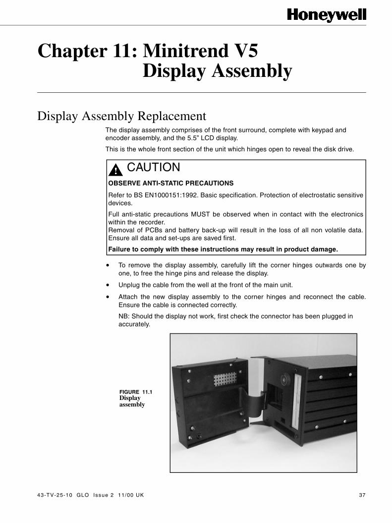
Display Assembly ReplacementThe display assembly comprises of the front surround, complete with keypad and encoder assembly, and the 5.5” LCD display.
This is the whole front section of the unit which hinges open to reveal the disk drive.
• To remove the display assembly, carefully lift the corner hinges outwards one byone, to free the hinge pins and release the display.
• Unplug the cable from the well at the front of the main unit.
• Attach the new display assembly to the corner hinges and reconnect the cable.Ensure the cable is connected correctly.
NB: Should the display not work, first check the connector has been plugged in accurately.
CAUTIONOBSERVE ANTI-STATIC PRECAUTIONS
Refer to BS EN1000151:1992. Basic specification. Protection of electrostatic sensitivedevices.
Full anti-static precautions MUST be observed when in contact with the electronicswithin the recorder.Removal of PCBs and battery back-up will result in the loss of all non volatile data.Ensure all data and set-ups are saved first.
Failure to comply with these instructions may result in product damage.
FIGURE 11.1Display assembly
43-TV-25-10 GLO Issue 2 11/00 UK 37

38 43-TV-25-10 GLO Issue 2 11/00 UK

Chapter 12: Multitrend Plus V5Analogue Card Installation
Removal of the rear panel (ONLY) is necessary when this operation is intended.
Removing the Rear Panel
• To remove the rear panel of the recorder, loosen and remove the four M4 x 8mmself tap screws at each corner of the rear panel, taking care to retain the screws andshakeproof washers.
CAUTIONOBSERVE ANTI-STATIC PRECAUTIONS
Refer to BS EN1000151:1992. Basic specification. Protection of electrostatic sensitivedevices.
Full anti-static precautions MUST be observed when in contact with the electronicswithin the recorder.Removal of PCBs and battery back-up will result in the loss of all non volatile data.Ensure all data and set-ups are saved first.
Failure to comply with these instructions may result in product damage.
FIGURE 12.1 Removing the rear panel
43-TV-25-10 GLO Issue 2 11/00 UK 39

Inside the UnitDO NOT disconnect any wiring from the mains socket on the rear panel. Gently movethe rear panel to the side of the extrusion to allow internal access.
Standard and Universal Analogue CardsThe mechanical constraints for the standard analogue card and the universal analoguecard are the same.
The Multitrend Plus V5 has four positions for analogue input cards. Slots A and A1, onthe rear panel, are primarily for the standard analogue card with slots B and B1 for theuniversal analogue card. However, either slot can be used for both types of analoguecard. Maximum of 32 channels of input.
Installation for either of the analogue cards in slot A, A1, B or B1 positions, follows thesame procedure.
�
���
�1. Analogue Card (A)
2. Analogue Card (B)
3. Analogue Card (A1)
4. Analogue Card (B1)
5. Comms Card (C)
6. Processor Card (C)
7. PCMCIA Card (D)(behind the alarm card)
8. Alarm Card
9. Transmitter Power SupplyCard
10. Mother Board
11. Power Supply
12. Disk Drive
FIGURE 12.2 Position of the internal boards
40 43-TV-25-10 GLO Issue 2 11/00 UK
Removing the Analogue Card• If replacing any of the analogue cards, first remove any cards as necessary from
slots A, A1 or slots B, B1 positions. This is done by locating the earthing screw on theleft side of the dividing panel in the middle of the unit (looking from the rear). Slot A’searthing screw is at the top, slot B is second from the top, slot A1 is third and slot B1is fourth from the top.
• Remove and retain the screws and shakeproof washers using a short reach screw-driver.
• Grip the front of the card, or by the connector, and gently pull to release the card fromits connection to the mother board at the front of the unit.
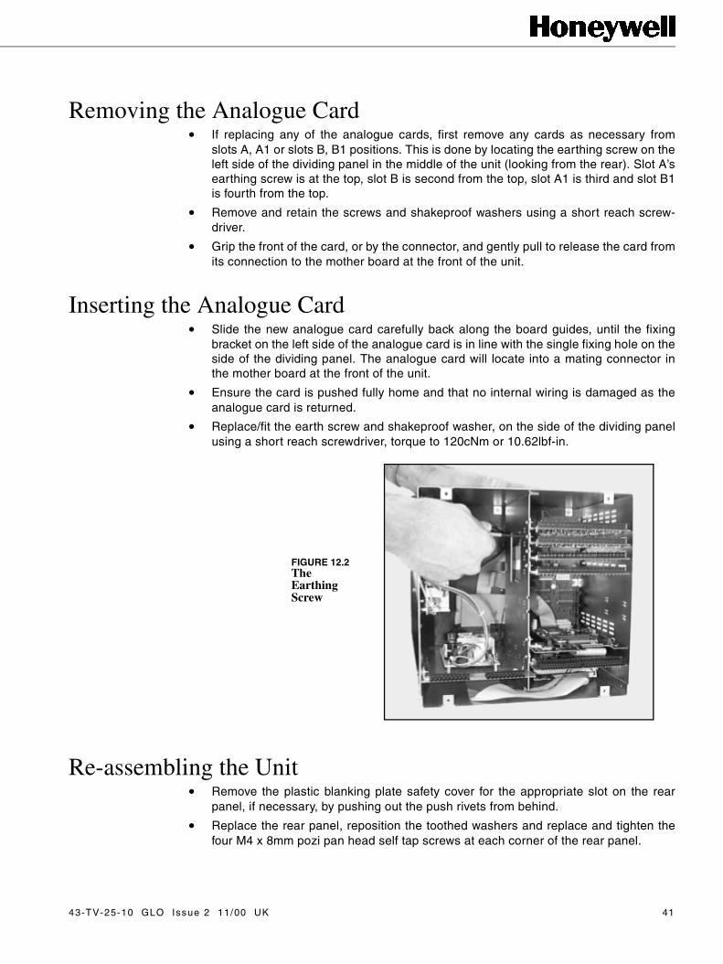
Inserting the Analogue Card• Slide the new analogue card carefully back along the board guides, until the fixing
bracket on the left side of the analogue card is in line with the single fixing hole on theside of the dividing panel. The analogue card will locate into a mating connector inthe mother board at the front of the unit.
• Ensure the card is pushed fully home and that no internal wiring is damaged as theanalogue card is returned.
• Replace/fit the earth screw and shakeproof washer, on the side of the dividing panelusing a short reach screwdriver, torque to 120cNm or 10.62lbf-in.
Re-assembling the Unit• Remove the plastic blanking plate safety cover for the appropriate slot on the rear
panel, if necessary, by pushing out the push rivets from behind.
• Replace the rear panel, reposition the toothed washers and replace and tighten thefour M4 x 8mm pozi pan head self tap screws at each corner of the rear panel.
FIGURE 12.2The Earthing Screw
43-TV-25-10 GLO Issue 2 11/00 UK 41

42 43-TV-25-10 GLO Issue 2 11/00 UK

Chapter 13: Multitrend Plus V5Alarm Card Installation
Removal of the rear panel (ONLY) is necessary when this operation is intended.
Removing the Rear Panel
• To remove the rear panel of the recorder, loosen and remove the four M4 x 8mmself tap screws at each corner of the rear panel, taking care to retain both theshakeproof washer and the screw.
CAUTIONOBSERVE ANTI-STATIC PRECAUTIONS
Refer to BS EN1000151:1992. Basic specification. Protection of electrostatic sensitivedevices.
Full anti-static precautions MUST be observed when in contact with the electronicswithin the recorder.Removal of PCBs and battery back-up will result in the loss of all non volatile data.Ensure all data and set-ups are saved first.
Failure to comply with these instructions may result in product damage.
FIGURE 13.1 Removing the rear panel
43-TV-25-10 GLO Issue 2 11/00 UK 43

Inside the UnitDO NOT disconnect any wiring from the mains socket on the rear panel. Gently movethe rear panel to the side of the case to allow internal access.
Alarm CardsThere are two main types of alarm cards, the relay alarm card and the input/output card.
For the Multitrend Plus V5, the relay alarm card is available with 4 or 8 channels ofrelay output, the 8 channel having two channels of digital input as standard.
The input/output cards for the Multitrend Plus V5 are available with 8, 16 or 32 chan-nels, all channels may be used as digital inputs.
All alarm cards take up position primarily in slot D and an extra alarm card can be fittedin slot D1, shown on the rear panel of the Multitrend Plus V5.
If the unit is fitted with a PCMCIA card in alarm slot D, a snubber card will be required. Ifthe unit is fitted with a PCMCIA card in alarm slot D, the snubber card is not required.
For a second alarm to be fitted in slot D1, an alarm interface card is required, whichplugs into the mother board.
Up to a total of 32 alarm channels are available.
�
���
�
FIGURE 13.2 Position of the internal boards
1. Analogue Card (A)
2. Analogue Card (B)
3. Analogue Card (A1)
4. Analogue Card (B1)
5. Comms Card (C)
6. Processor Card (C)
7. PCMCIA Card (D)(behind the alarm card)
8. Alarm Card
9. Transmitter Power Supply Card
10. Mother Board
11. Power Supply
12. Disk Drive
44 43-TV-25-10 GLO Issue 2 11/00 UK

Removing the Primary Alarm Card in slot DIt is necessary to access the processor card to connect one end of the alarm ribboncable to the socket on the under side of the card.
• Locate the earth screw for the processor card, on the left side of the dividing panelin the middle of the unit (from the rear). The processor card earth screw is secondfrom the bottom of the unit (C).
• Remove and retain both screw and shakeproof washer using a short reach screw-driver.
• Remove the earth screw and washer for the alarm card in the same way. The pri-mary alarm card occupies the bottom position (D). Retain both the screw and theshakeproof washer.
• Slide the processor board out to reveal a 34-way connector on the under side of theprocessor card. Remove the existing ribbon cable connector, if necessary. Plug innew alarm ribbon cable to the under side of the processor card. NB. Both ends ofthe ribbon cable are identical. The connector will only fit in one way round. Connectthe other end of the ribbon cable in to the 34-way connector on the alarm card.
• This is identified by a location tab on one side of the connector. Push the connec-tors fully into the socket on the card.
• Connect the other end of the alarm ribbon cable into the 34-way connector on thealarm card.
Inserting the Primary Alarm Card in slot D• Fit snubber card into alarm slot D, if a PCMCIA card is not fitted.
• Begin to slide the processor card back into its slot holding the alarm card parallelbelow, allowing the ribbon cable to bend into a comfortable ‘S’ shape. Both thecards need to be inserted simultaneously to keep the ribbon cable in its folded ‘S’shape position.
Comms Card (if fitted)
Processor Card
Alarm Card
PCMCIA Card (if fitted)
34-way alarm ribbon cable connector
FIGURE 13.3 The alarm card plugs in underneath the processor card
43-TV-25-10 GLO Issue 2 11/00 UK 45
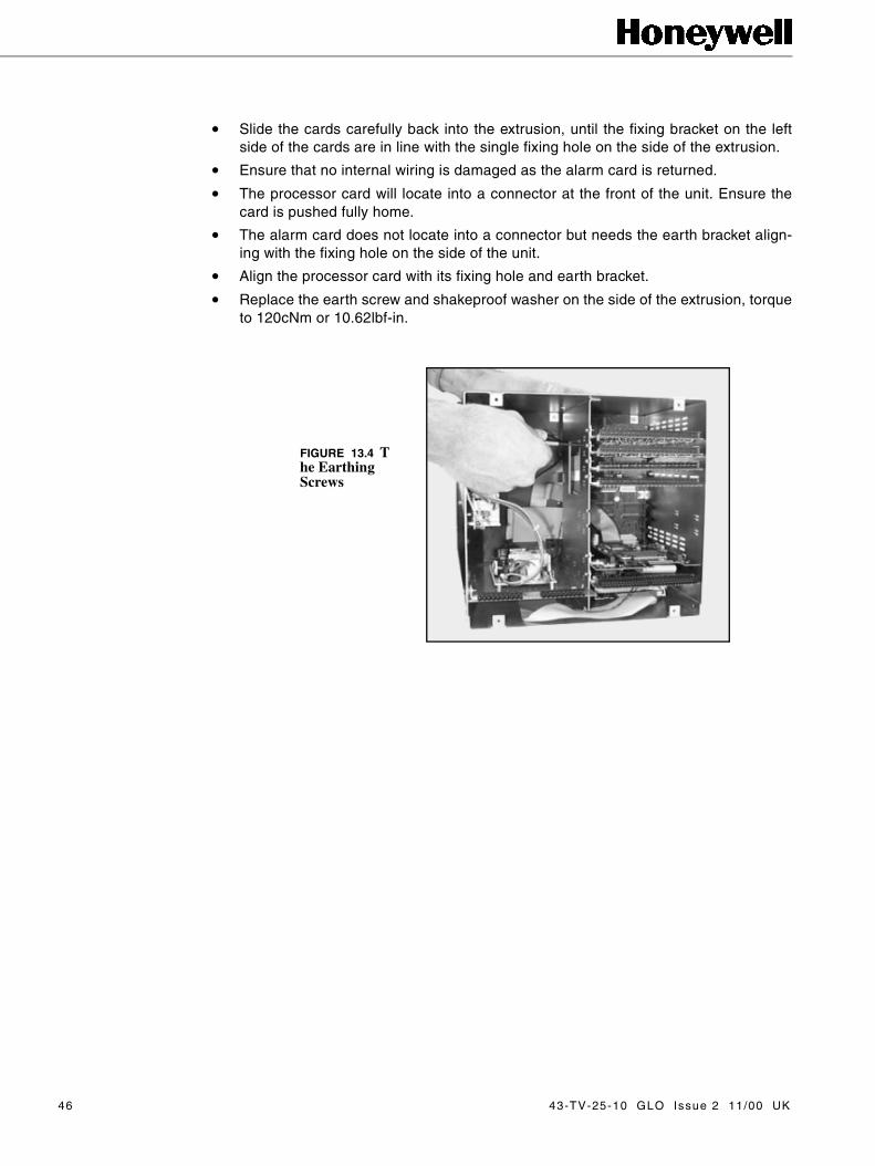
• Slide the cards carefully back into the extrusion, until the fixing bracket on the leftside of the cards are in line with the single fixing hole on the side of the extrusion.
• Ensure that no internal wiring is damaged as the alarm card is returned.
• The processor card will locate into a connector at the front of the unit. Ensure thecard is pushed fully home.
• The alarm card does not locate into a connector but needs the earth bracket align-ing with the fixing hole on the side of the unit.
• Align the processor card with its fixing hole and earth bracket.
• Replace the earth screw and shakeproof washer on the side of the extrusion, torqueto 120cNm or 10.62lbf-in.
FIGURE 13.4 The Earthing Screws
46 43-TV-25-10 GLO Issue 2 11/00 UK
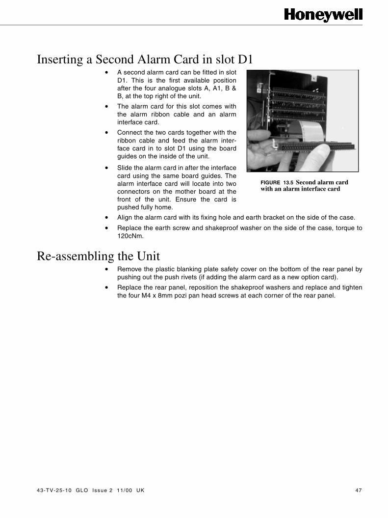
Inserting a Second Alarm Card in slot D1• A second alarm card can be fitted in slot
D1. This is the first available positionafter the four analogue slots A, A1, B &B, at the top right of the unit.
• The alarm card for this slot comes withthe alarm ribbon cable and an alarminterface card.
• Connect the two cards together with theribbon cable and feed the alarm inter-face card in to slot D1 using the boardguides on the inside of the unit.
• Slide the alarm card in after the interfacecard using the same board guides. Thealarm interface card will locate into twoconnectors on the mother board at thefront of the unit. Ensure the card ispushed fully home.
• Align the alarm card with its fixing hole and earth bracket on the side of the case.
• Replace the earth screw and shakeproof washer on the side of the case, torque to120cNm.
Re-assembling the Unit• Remove the plastic blanking plate safety cover on the bottom of the rear panel by
pushing out the push rivets (if adding the alarm card as a new option card).
• Replace the rear panel, reposition the shakeproof washers and replace and tightenthe four M4 x 8mm pozi pan head screws at each corner of the rear panel.
FIGURE 13.5 Second alarm card with an alarm interface card
43-TV-25-10 GLO Issue 2 11/00 UK 47

48 43-TV-25-10 GLO Issue 2 11/00 UK

Chapter 14: Multitrend Plus V5Power Supply Card &Transmitter Power Supply Card Installation
Removing the Rear Panel Removal of the rear panel (ONLY) is necessary when this operation is intended.
• To remove the rear panel of the recorder, loosen and remove the four M4 x 8mmself tap screws at each corner of the rear panel, taking care to retain the screws andshakeproof washers.
CAUTIONOBSERVE ANTI-STATIC PRECAUTIONS
Refer to BS EN1000151:1992. Basic specification. Protection of electrostatic sensitivedevices.
Full anti-static precautions MUST be observed when in contact with the electronicswithin the recorder.Removal of PCBs and battery back-up will result in the loss of all non volatile data.Ensure all data and set-ups are saved first.
Failure to comply with these instructions may result in product damage.
FIGURE 14.1 Removing the rear panel
43-TV-25-10 GLO Issue 2 11/00 UK 49

Inside the UnitDO NOT disconnect any wiring from the mains socket on the rear panel. Gently movethe rear panel to the side of the extrusion to allow internal access.
Power Supply and Transmitter Power Supply CardThe power supply is available as 240 Vac, 24 Vdc or 48 Vdc.
The power supply for either ac or dc units is screwed to the inside of the left panel asyou look from the back of the unit
Transmitter power supply card is only available on ac units.
The transmitter power supply card requires the bottom left blanking plate, slot F, on therear panel to be removed to allow for connection.
�
���
�
FIGURE 14.2 Position of the internal boards
1. Analogue Card (A)
2. Analogue Card (B)
3. Analogue Card (A1)
4. Analogue Card (B1)
5. Comms Card (C)
6. Processor Card (C)
7. PCMCIA Card (D)(behind the alarmcard)
8. Alarm Card
9. Transmitter Power Supply Card
10. Mother Board
11. Power Supply
12. Disk Drive
50 43-TV-25-10 GLO Issue 2 11/00 UK
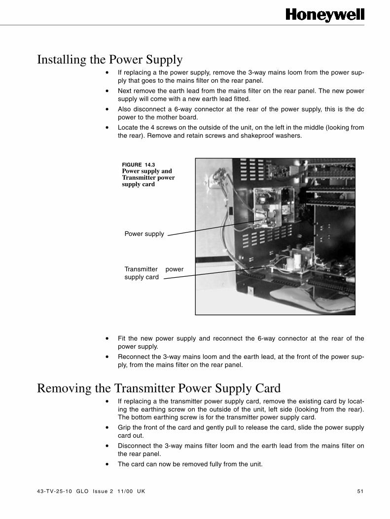
Installing the Power Supply• If replacing a the power supply, remove the 3-way mains loom from the power sup-
ply that goes to the mains filter on the rear panel.
• Next remove the earth lead from the mains filter on the rear panel. The new powersupply will come with a new earth lead fitted.
• Also disconnect a 6-way connector at the rear of the power supply, this is the dcpower to the mother board.
• Locate the 4 screws on the outside of the unit, on the left in the middle (looking fromthe rear). Remove and retain screws and shakeproof washers.
• Fit the new power supply and reconnect the 6-way connector at the rear of thepower supply.
• Reconnect the 3-way mains loom and the earth lead, at the front of the power sup-ply, from the mains filter on the rear panel.
Removing the Transmitter Power Supply Card• If replacing a the transmitter power supply card, remove the existing card by locat-
ing the earthing screw on the outside of the unit, left side (looking from the rear).The bottom earthing screw is for the transmitter power supply card.
• Grip the front of the card and gently pull to release the card, slide the power supplycard out.
• Disconnect the 3-way mains filter loom and the earth lead from the mains filter onthe rear panel.
• The card can now be removed fully from the unit.
Power supply
Transmitter powersupply card
FIGURE 14.3Power supply and Transmitter power supply card
43-TV-25-10 GLO Issue 2 11/00 UK 51
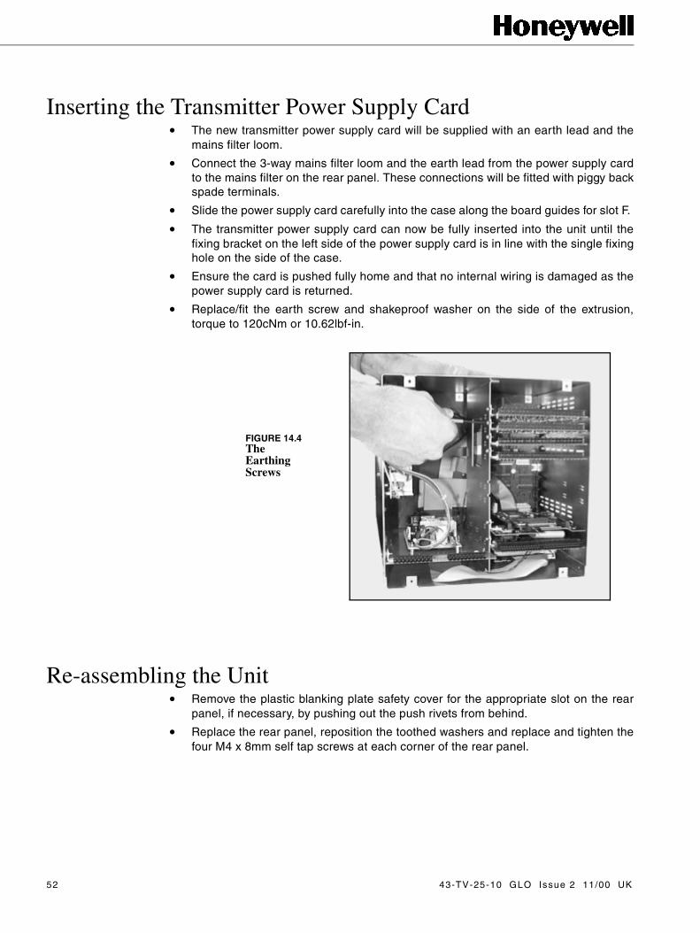
Inserting the Transmitter Power Supply Card • The new transmitter power supply card will be supplied with an earth lead and the
mains filter loom.
• Connect the 3-way mains filter loom and the earth lead from the power supply cardto the mains filter on the rear panel. These connections will be fitted with piggy backspade terminals.
• Slide the power supply card carefully into the case along the board guides for slot F.
• The transmitter power supply card can now be fully inserted into the unit until thefixing bracket on the left side of the power supply card is in line with the single fixinghole on the side of the case.
• Ensure the card is pushed fully home and that no internal wiring is damaged as thepower supply card is returned.
• Replace/fit the earth screw and shakeproof washer on the side of the extrusion,torque to 120cNm or 10.62lbf-in.
Re-assembling the Unit• Remove the plastic blanking plate safety cover for the appropriate slot on the rear
panel, if necessary, by pushing out the push rivets from behind.
• Replace the rear panel, reposition the toothed washers and replace and tighten thefour M4 x 8mm self tap screws at each corner of the rear panel.
FIGURE 14.4The Earthing Screws
52 43-TV-25-10 GLO Issue 2 11/00 UK
Chapter 15: Multitrend Plus V5Retransmission Card Installation
Removal of the rear panel (ONLY) is necessary when this operation is intended.
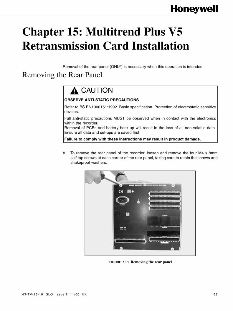
Removing the Rear Panel
• To remove the rear panel of the recorder, loosen and remove the four M4 x 8mmself tap screws at each corner of the rear panel, taking care to retain the screws andshakeproof washers.
CAUTIONOBSERVE ANTI-STATIC PRECAUTIONS
Refer to BS EN1000151:1992. Basic specification. Protection of electrostatic sensitivedevices.
Full anti-static precautions MUST be observed when in contact with the electronicswithin the recorder.Removal of PCBs and battery back-up will result in the loss of all non volatile data.Ensure all data and set-ups are saved first.
Failure to comply with these instructions may result in product damage.
FIGURE 15.1 Removing the rear panel
43-TV-25-10 GLO Issue 2 11/00 UK 53

Inside the UnitDO NOT disconnect any wiring from the mains socket on the rear panel. Gently movethe rear panel to the side of the case to allow internal access.
Retransmission CardThere are two types of retransmission cards, one has two channels of retransmissionand the other has 4 channels.
As analogue cards take the positions of slot A and slot B, the preferred slot for theretransmission card is A1. B1 is used if two retransmission cards are fitted and if threeanalogue cards are fitted B, A1 and B1 are used.
�
���
�
FIGURE 15.2 Position of the internal boards
1. Analogue Card (A)
2. Analogue Card (B)
3. Analogue Card (A1)
4. Analogue Card (B1)
5. Comms Card (C)
6. Processor Card (C)
7. PCMCIA Card (D)(behind the alarmcard)
8. Alarm Card
9. Transmitter Power Supply Card
10. Mother Board
11. Power Supply
12. Disk Drive
54 43-TV-25-10 GLO Issue 2 11/00 UK

Removing the Retransmission Card• If replacing a retransmission card, remove any cards as necessary from either slot
A1 or slot B1 positions, slot A1 is preferred. This is done simply by locating theearthing screw on the left side of the dividing panel in the middle of the unit (lookingfrom the rear). Slot A1’s earthing screw is third from the top and slot B1’s earthingscrew is fourth from the top.
• Grip the card by its connector and gently pull to release the card from its connectionto the mother board.
Inserting the Retransmission Card• Slide the retransmission card carefully back into the extrusion, until the fixing
bracket on the left side of the retransmission card is in line with the single fixing holeon the side of the case.
• The retransmission card will locate into a mating connector in the mother board atthe front of the unit.
• Ensure the card is pushed fully home and that no internal wiring is damaged as theretransmission card is returned.
• Replace/fit the earth screw and shakeproof washer on the side of the case, torqueto 120cNm or 10.62lbf-in.
Re-assembling the Unit• Remove the plastic blanking plate safety cover for the appropriate slot on the rear
panel, if necessary, by pushing out the push rivets from behind.
• Replace the rear panel, reposition the toothed washers and replace and tighten thefour M4 x 8mm self tap screws at each corner of the rear panel.
FIGURE 15.3The Earthing Screws
43-TV-25-10 GLO Issue 2 11/00 UK 55

56 43-TV-25-10 GLO Issue 2 11/00 UK

Chapter 16: Multitrend Plus V5Communications Card Installation
Removal of the rear panel (ONLY) is necessary when this operation is intended.
Removing the Rear Panel • To remove the rear panel of the recorder, loosen and remove the four M4 x 8mm
self tap screws at each corner of the rear panel, taking care to retain the screws andshakeproof washers.
CAUTIONOBSERVE ANTI-STATIC PRECAUTIONS
Refer to BS EN1000151:1992. Basic specification. Protection of electrostatic sensitivedevices.
Full anti-static precautions MUST be observed when in contact with the electronicswithin the recorder.Removal of PCBs and battery back-up will result in the loss of all non volatile data.Ensure all data and set-ups are saved first.
Failure to comply with these instructions may result in product damage.
FIGURE 16.1 Removing the rear panel
43-TV-25-10 GLO Issue 2 11/00 UK 57

Inside the UnitDO NOT disconnect any wiring from the mains socket on the rear panel. Gently movethe rear panel to the side of the case to allow internal access.
�
���
�
FIGURE 16.2 Position of the internal boards
1. Analogue Card (A)
2. Analogue Card (B)
3. Analogue Card (A1)
4. Analogue Card (B1)
5. Comms Card (C)
6. Processor Card (C)
7. PCMCIA Card (D)(behind the alarm card)
8. Alarm Card
9. Transmitter Power Supply Card
10. Mother Board
11. Power Supply
12. Disk Drive
58 43-TV-25-10 GLO Issue 2 11/00 UK

Communications and RS485 CardsThe mechanical constraints for the comms card and the RS485 card are the same.
The comms cards plugs onto the processor card, like a piggy back board, which occupiesslot C.
Removing the Comms Cards• If replacing a comms card, it is necessary to partially slide out the processor card.
This is done by locating the earthing screw on the left side of the dividing panel in themiddle of the unit (looking from the rear). Slot C earthing screw is second from thebottom, remove and retain screw and shakeproof washer.
• Grip the front of the card, or by the connector, and gently pull to release the card fromits connection to the mother board.
• Begin to slide the card out. If an alarm card is also fitted a 34-way connector on theunderside of the processor card will have to be disconnected in order to slide theprocessor card out further.
• Pull out the processor card and turn it over to show the underside of the card.
• Remove the two screws and shakeproof washers from the two pillars connecting thecomms and processor cards together, from the underside of the processor card.
• Carefully separate the comms card from the processor card. TIP Pull the cards apartevenly from each side. There are three double row headers in different orientationsresulting in quite a tight fit.
FIGURE 16.3The comms card plugs in on top of the processor card
43-TV-25-10 GLO Issue 2 11/00 UK 59
Inserting the Comms Cards• Plug in the new comms card to the processor card and replace the two screws and
shakeproof washers on the underside of the processor card to secure the pillars,locking the two cards together.
• Begin to slide the processor card carefully back into the extrusion. If an alarm card isfitted keep the ribbon cable flat to the alarm card, slide the processor card in andreconnect the ribbon cable to the connector on the underside of the processor card.
• Insert the processor card fully until the fixing bracket on the left side of the processorcard is in line with the single fixing hole on the side of the dividing panel.
• The processor card will locate into a mating connector in the mother board at thefront of the unit.
• Ensure the card is pushed fully home and that no internal wiring is damaged as thealarm card is returned.
• Replace the earth screw and shakeproof washer on the side of the case, torque to120cNm or 10.62lbf-in.
.
Re-assembling the Unit• Remove the plastic blanking plate safety cover for the appropriate slot on the rear
panel, if necessary, by pushing out the push rivets from behind.
• Replace the rear panel, reposition the shakeproof washers and replace and tightenthe four M4 x 8mm self tap screws at each corner of the rear panel.
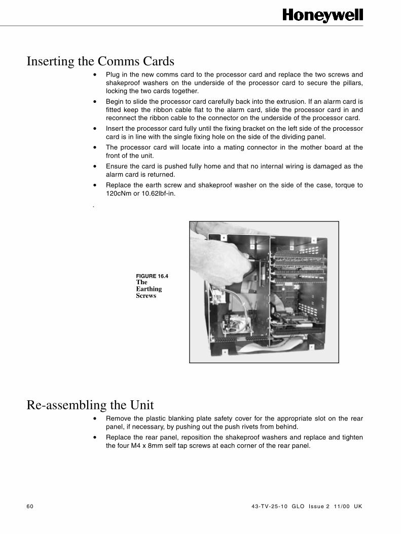
FIGURE 16.4The Earthing Screws
60 43-TV-25-10 GLO Issue 2 11/00 UK

C onn ection D eta ilsEthernet InterfaceThis is an 8-way RL45 socket Molex 95040-288‘‘ used for Ethernet connection, pcbposition J5. Standard Ethernet connection.
RS232 Interface (Comm2)This is a 9-way D-type connector (mating half not supplied), pcb position P1.
RS485 Interface (Comm3 Trendbus)This is a 5-way socket (mating half supplied), pcb position J1.
TD+
TD-RD+
RD-
1
2345678
locating pins(not connected)
2 4 6 8
7531
A B
1627
38495
-DTR2-R12
-CTS2TXD2-RTS2RXD2-DSR2-DCD2
1
2
3
4
5
TXA
-TXB
-RXB
RXA
43-TV-25-10 GLO Issue 2 11/00 UK 61

62 43-TV-25-10 GLO Issue 2 11/00 UK
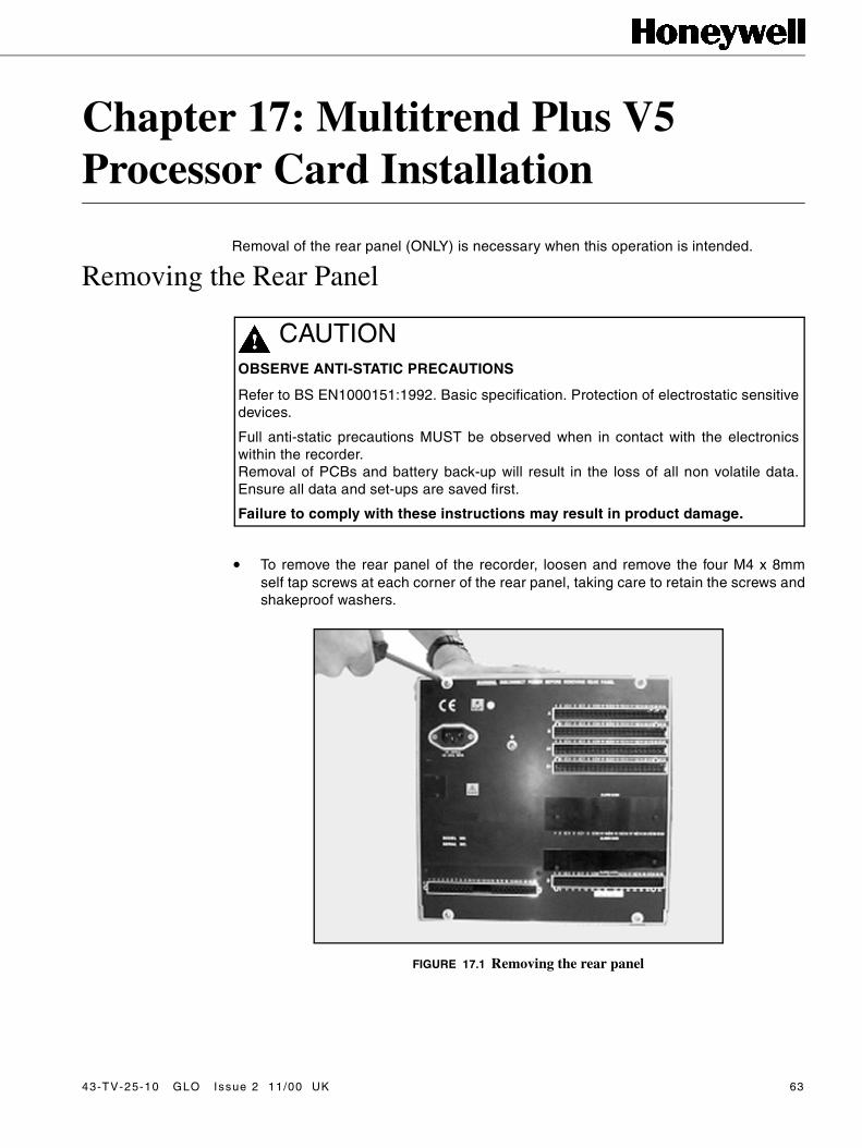
Chapter 17: Multitrend Plus V5Processor Card Installation
Removal of the rear panel (ONLY) is necessary when this operation is intended.
Removing the Rear Panel
• To remove the rear panel of the recorder, loosen and remove the four M4 x 8mmself tap screws at each corner of the rear panel, taking care to retain the screws andshakeproof washers.
CAUTIONOBSERVE ANTI-STATIC PRECAUTIONS
Refer to BS EN1000151:1992. Basic specification. Protection of electrostatic sensitivedevices.
Full anti-static precautions MUST be observed when in contact with the electronicswithin the recorder.Removal of PCBs and battery back-up will result in the loss of all non volatile data.Ensure all data and set-ups are saved first.
Failure to comply with these instructions may result in product damage.
FIGURE 17.1 Removing the rear panel
43-TV-25-10 GLO Issue 2 11/00 UK 63
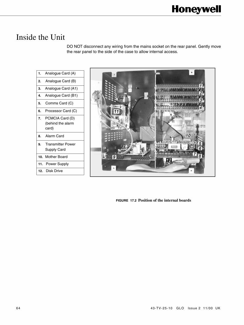
Inside the UnitDO NOT disconnect any wiring from the mains socket on the rear panel. Gently movethe rear panel to the side of the case to allow internal access.
�
���
�
FIGURE 17.2 Position of the internal boards
1. Analogue Card (A)
2. Analogue Card (B)
3. Analogue Card (A1)
4. Analogue Card (B1)
5. Comms Card (C)
6. Processor Card (C)
7. PCMCIA Card (D)(behind the alarm card)
8. Alarm Card
9. Transmitter Power Supply Card
10. Mother Board
11. Power Supply
12. Disk Drive
64 43-TV-25-10 GLO Issue 2 11/00 UK
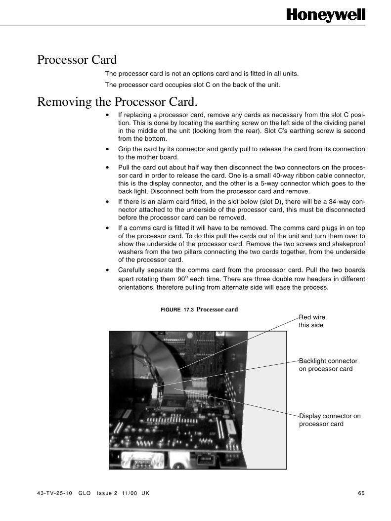
Processor CardThe processor card is not an options card and is fitted in all units.
The processor card occupies slot C on the back of the unit.
Removing the Processor Card.• If replacing a processor card, remove any cards as necessary from the slot C posi-
tion. This is done by locating the earthing screw on the left side of the dividing panelin the middle of the unit (looking from the rear). Slot C’s earthing screw is secondfrom the bottom.
• Grip the card by its connector and gently pull to release the card from its connectionto the mother board.
• Pull the card out about half way then disconnect the two connectors on the proces-sor card in order to release the card. One is a small 40-way ribbon cable connector,this is the display connector, and the other is a 5-way connector which goes to theback light. Disconnect both from the processor card and remove.
• If there is an alarm card fitted, in the slot below (slot D), there will be a 34-way con-nector attached to the underside of the processor card, this must be disconnectedbefore the processor card can be removed.
• If a comms card is fitted it will have to be removed. The comms card plugs in on topof the processor card. To do this pull the cards out of the unit and turn them over toshow the underside of the processor card. Remove the two screws and shakeproofwashers from the two pillars connecting the two cards together, from the undersideof the processor card.
• Carefully separate the comms card from the processor card. Pull the two boardsapart rotating them 90° each time. There are three double row headers in differentorientations, therefore pulling from alternate side will ease the process.
Backlight connector on processor card
Display connector on processor card
FIGURE 17.3 Processor cardRed wire this side
43-TV-25-10 GLO Issue 2 11/00 UK 65

Inserting the Processor Card • Plug in the PCMCIA card, if fitted, into the under side of the processor card and
ensure all four headers are pushed fully home.
• Plug in the comms card, if fitted, to the processor card and replace the two screwsand shakeproof washers on the underside of the processor card to secure the pil-lars, locking the two cards together.
• Begin to slide the PC card back along the board guides of slot D. The processorcard will then locate along the board guides for slot C.
• When the processor card is half way in, reconnect the ribbon cable display connec-tor and the 5-way connector for the backlight.
• If an alarm card is fitted, connect via the 34-way alarm ribbon cable and begin toslide it in along the board guides, keeping the ribbon cable flat to the alarm card.
• All the boards will slide in together with the processor card locating into a matingconnector on the mother board at the front of the unit.
• Insert the processor card fully until the fixing bracket on the left side of the proces-sor card is in line with the single fixing hole on the side of the dividing panel in themiddle of the unit.
• Line up the alarm card and replace the earthing screw in the same way.
• Ensure the card is pushed fully home and that no internal wiring is damaged as thealarm card is returned.
• Replace the earth screw and toothed washer on the side of the case, torque to120cNm or 10.62lbf-in.
• Re-assembling the Unit
• Remove the plastic blanking plate safety cover for the appropriate slot on the rearpanel, if necessary, by pushing out the push rivets from behind.
• Replace the rear panel, reposition the toothed washers and replace and tighten thefour M4 x 8mm self tap screws at each corner of the rear panel.
FIGURE 17.4The Earthing Screws
66 43-TV-25-10 GLO Issue 2 11/00 UK
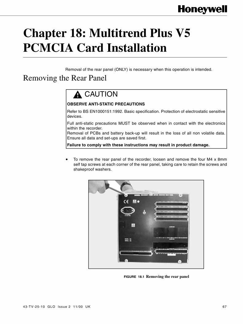
Chapter 18: Multitrend Plus V5PCMCIA Card Installation
Removal of the rear panel (ONLY) is necessary when this operation is intended.
Removing the Rear Panel
• To remove the rear panel of the recorder, loosen and remove the four M4 x 8mmself tap screws at each corner of the rear panel, taking care to retain the screws andshakeproof washers.
CAUTIONOBSERVE ANTI-STATIC PRECAUTIONS
Refer to BS EN1000151:1992. Basic specification. Protection of electrostatic sensitivedevices.
Full anti-static precautions MUST be observed when in contact with the electronicswithin the recorder.Removal of PCBs and battery back-up will result in the loss of all non volatile data.Ensure all data and set-ups are saved first.
Failure to comply with these instructions may result in product damage.
FIGURE 18.1 Removing the rear panel
43-TV-25-10 GLO Issue 2 11/00 UK 67
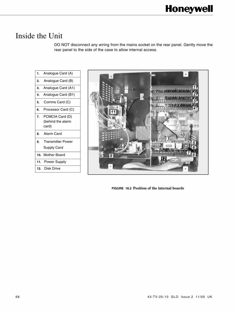
Inside the UnitDO NOT disconnect any wiring from the mains socket on the rear panel. Gently move therear panel to the side of the case to allow internal access.
�
���
�
FIGURE 18.2 Position of the internal boards
1. Analogue Card (A)
2. Analogue Card (B)
3. Analogue Card (A1)
4. Analogue Card (B1)
5. Comms Card (C)
6. Processor Card (C)
7. PCMCIA Card (D)(behind the alarm card)
8. Alarm Card
9. Transmitter Power
Supply Card
10. Mother Board
11. Power Supply
12. Disk Drive
68 43-TV-25-10 GLO Issue 2 11/00 UK

PCMCIA CardThe PCMCIA card, know as the PC card, is an extra memory card option which can beused as a hard drive.
The PC card is plugged into the processor card which occupies slot C.
The PC card goes into the area behind the alarm card (if fitted) in slot D.
Removing the PCMCIA Card.• If replacing a PC card, remove any cards as necessary from the slot D position.
This is done by locating the earthing screw on the left side of the dividing panel inthe middle of the unit (looking from the rear). Slot D’s earthing screw is at the bot-tom.
• If there is an alarm card in slot D it will be attached to the processor card via a 34-way ribbon cable connector, this can be left connected.
• It is necessary to remove the processor card in slot C. This is done by locating andremoving the earthing screw from slot C, which is second from the bottom of thedividing panel in the middle of the unit.
• There are two connectors on the processor card which need to be disconnected inorder to release the card. One is a small 40-way ribbon cable connector, which goesto the display, and the other is a 5-way connector which goes to the back light. Dis-connect both from the processor card and remove.
• Grip the processor card by its connector and gently pull to release the card from itsconnection to the mother board.
• If there is a comms card fitted, this will be a separate card plugged into the top ofthe processor card, this is not affected.
FIGURE 18.3PCMCIA card plugs in underneath the processor card
43-TV-25-10 GLO Issue 2 11/00 UK 69
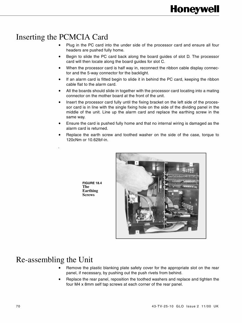
Inserting the PCMCIA Card • Plug in the PC card into the under side of the processor card and ensure all four
headers are pushed fully home.
• Begin to slide the PC card back along the board guides of slot D. The processorcard will then locate along the board guides for slot C.
• When the processor card is half way in, reconnect the ribbon cable display connec-tor and the 5-way connector for the backlight.
• If an alarm card is fitted begin to slide it in behind the PC card, keeping the ribboncable flat to the alarm card.
• All the boards should slide in together with the processor card locating into a matingconnector on the mother board at the front of the unit.
• Insert the processor card fully until the fixing bracket on the left side of the proces-sor card is in line with the single fixing hole on the side of the dividing panel in themiddle of the unit. Line up the alarm card and replace the earthing screw in thesame way.
• Ensure the card is pushed fully home and that no internal wiring is damaged as thealarm card is returned.
• Replace the earth screw and toothed washer on the side of the case, torque to120cNm or 10.62lbf-in.
.
Re-assembling the Unit• Remove the plastic blanking plate safety cover for the appropriate slot on the rear
panel, if necessary, by pushing out the push rivets from behind.
• Replace the rear panel, reposition the toothed washers and replace and tighten thefour M4 x 8mm self tap screws at each corner of the rear panel.
FIGURE 18.4The Earthing Screws
70 43-TV-25-10 GLO Issue 2 11/00 UK

Chapter 19: Multitrend Plus V5Rear Panel Assembly
Removing the Rear Panel
• To remove the rear panel of the recorder, loosen and remove the four M4 x 8mmself tap screws at each corner of the rear panel, taking care to retain the screws andshakeproof washers.
CAUTIONOBSERVE ANTI-STATIC PRECAUTIONS
Refer to BS EN1000151:1992. Basic specification. Protection of electrostatic sensitivedevices.
Full anti-static precautions MUST be observed when in contact with the electronicswithin the recorder.Removal of PCBs and battery back-up will result in the loss of all non volatile data.Ensure all data and set-ups are saved first.
Failure to comply with these instructions may result in product damage.
FIGURE 19.1 Removing the rear panel
43-TV-25-10 GLO Issue 2 11/00 UK 71

Replacing the Rear Panel Assembly• Remove, from the power supply, the 3-way mains filter loom connecting the live and
neutral wires from the rear panel assembly (blue and brown wires).
• Disconnect the earth lead from the mains filter on the rear panel assembly (green/yellow).
• If a transmitter power supply card is fitted, remove the 3-way mains filter loom con-necting the live and neutral wires from the rear panel assembly (blue and brownwires) and disconnect the earth lead from the mains filter on the rear panel assem-bly (green/yellow). These connections will be fitted with piggy back spade terminalson the mains filter.
• Connect the 3-way mains filter loom from the new rear panel assembly to the powersupply.
• Connect the earth lead from the power supply on to the new rear panel assembly.
Re-assembling the Unit• Replace the rear panel, reposition the toothed washers and replace and tighten the
four M4 x 8mm pozi pan head self tap screws at each corner of the rear panel.
Mains filter loom
Power supply
Earth lead
Main filter loom
Earth lead
Transmitter power supply card
FIGURE 19.2Rear panel connections
72 43-TV-25-10 GLO Issue 2 11/00 UK
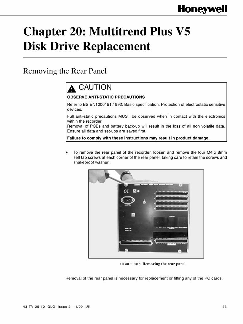
Chapter 20: Multitrend Plus V5Disk Drive Replacement
Removing the Rear Panel
• To remove the rear panel of the recorder, loosen and remove the four M4 x 8mmself tap screws at each corner of the rear panel, taking care to retain the screws andshakeproof washer.
Removal of the rear panel is necessary for replacement or fitting any of the PC cards.
CAUTIONOBSERVE ANTI-STATIC PRECAUTIONS
Refer to BS EN1000151:1992. Basic specification. Protection of electrostatic sensitivedevices.
Full anti-static precautions MUST be observed when in contact with the electronicswithin the recorder.Removal of PCBs and battery back-up will result in the loss of all non volatile data.Ensure all data and set-ups are saved first.
Failure to comply with these instructions may result in product damage.
FIGURE 20.1 Removing the rear panel
43-TV-25-10 GLO Issue 2 11/00 UK 73
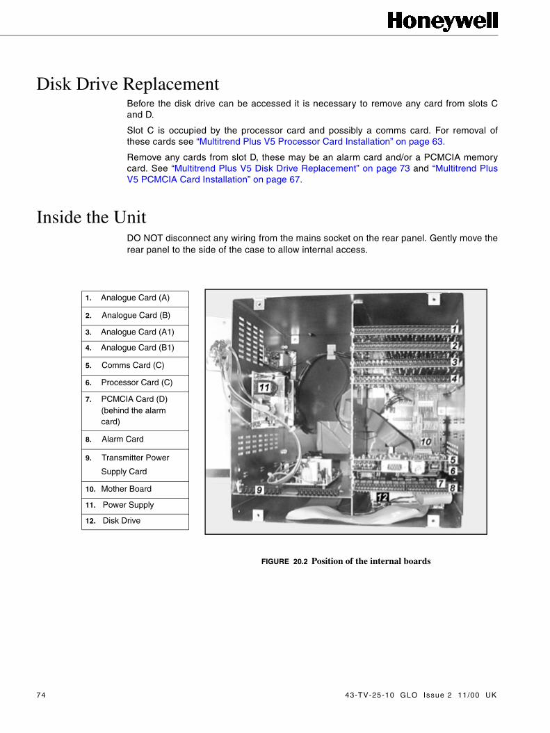
Disk Drive ReplacementBefore the disk drive can be accessed it is necessary to remove any card from slots Cand D.
Slot C is occupied by the processor card and possibly a comms card. For removal ofthese cards see “Multitrend Plus V5 Processor Card Installation” on page 63.
Remove any cards from slot D, these may be an alarm card and/or a PCMCIA memorycard. See “Multitrend Plus V5 Disk Drive Replacement” on page 73 and “Multitrend PlusV5 PCMCIA Card Installation” on page 67.
Inside the UnitDO NOT disconnect any wiring from the mains socket on the rear panel. Gently move therear panel to the side of the case to allow internal access.
�
���
�
FIGURE 20.2 Position of the internal boards
1. Analogue Card (A)
2. Analogue Card (B)
3. Analogue Card (A1)
4. Analogue Card (B1)
5. Comms Card (C)
6. Processor Card (C)
7. PCMCIA Card (D)(behind the alarm card)
8. Alarm Card
9. Transmitter Power
Supply Card
10. Mother Board
11. Power Supply
12. Disk Drive
74 43-TV-25-10 GLO Issue 2 11/00 UK

Disk Drive Installation• After all the cards have been removed from slots C and D, unscrew the four fixing
screws from the underside of the unit. The four screws are recessed into dimples,remove and retain the screws.
• Disconnect the two connectors on the end of the disk drive and re connect to the newdisk drive.
• Position the new disk drive over the mounting holes and replace using the originalscrews.
• Replace the processor card in slot C. See “Multitrend Plus V5 Processor Card Instal-lation” on page 63.
• Replace any cards in slot D. See “Multitrend Plus V5 Disk Drive Replacement” onpage 73 and “Multitrend Plus V5 PCMCIA Card Installation” on page 67.
Re-assembling the Unit• Replace the rear panel, reposition the shakeproof washers and replace and tighten
the four M4 x 8mm pozi pan head self tap screws at each corner of the rear panel.
FIGURE 20.3The Earthing Screw
43-TV-25-10 GLO Issue 2 11/00 UK 75

76 43-TV-25-10 GLO Issue 2 11/00 UK
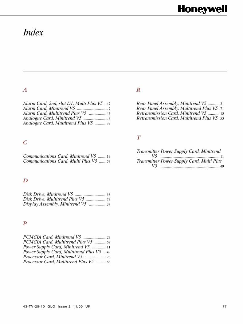
Index
A
Alarm Card, 2nd, slot D1, Multi Plus V5 ..47Alarm Card, Minitrend V5 ..................................7Alarm Card, Multitrend Plus V5 ...................43Analogue Card, Minitrend V5 ...........................3Analogue Card, Multitrend Plus V5 ............39
C
Communications Card, Minitrend V5 .........19Communications Card, Multi Plus V5 ........57
D
Disk Drive, Minitrend V5 ..................................33Disk Drive, Multitrend Plus V5 ......................73Display Assembly, Minitrend V5 ...................37
P
PCMCIA Card, Minitrend V5 .........................27PCMCIA Card, Multitrend Plus V5 .............67Power Supply Card, Minitrend V5 ................11Power Supply Card, Multitrend Plus V5 ...49Processor Card, Minitrend V5 ........................23Processor Card, Multitrend Plus V5 ...........63
43-TV-25-10 GLO Issue 2 11/00 UK
R
Rear Panel Assembly, Minitrend V5 .............31Rear Panel Assembly, Multitrend Plus V5 71Retransmission Card, Minitrend V5 .............15Retransmission Card, Multitrend Plus V5 53
T
Transmitter Power Supply Card, Minitrend V5 ..................................................................11
Transmitter Power Supply Card, Multi Plus V5 ..................................................................49
77

78 43-TV-25-10 GLO Issue 2 11/00 UK

43-TV-25-10 GLO Issue 2 11/00 UK 79
How would you rate the reputation of Honeywell Tick as appropriate A very reputable, successful company
A reputable company
A disreputable company
No views either way
Reputation
Service2
How do you rate or perceive the following servicelevels provided by our sales staff?
Tick as appropriate Excellent Good Fair
Response speed
Quality of response
Follow up response
Overall level of service
How do you rate or perceive the following service levels provided by our Technical Support Ser-vice?
Tick as appropriate Excellent Good Fair
Response speed
Quality of response
Follow up response
Overall level of service
How could our service be improved upon ....................................................................................................................................................
How many times do you receive a visit from one of our Sales representatives? Visits every:
1-3 months 3-6 months 6-12 months
How does that compare to our competitors?
More Less The same
Score on a level of 1-10, with 10 being the best
Quality of manuals / sales literature
Administration / documentation and letters
Technical expertise of our sales staff
Sales staff ability to give informed advice
The quality of the Honeywell sales team.
Pricing
Honeywell understanding of your industry.
How do you perceive our range of products?
Tick as appropriate
Products offered are better than those of competitors
Products offered are worse than those of competitors
Products offered are the same as those of competitors
Any other comments ..........................................................................................................................................................................................................................................Are there any products that we do not provide that you would like us to provide - or any we could improve on?..........................................................................................................................................................................................................................................Improvements to existing products....................................................................................................................................................................................................................................................................
Products3
4 General
If you are an existing or new customer, what made
you choose Honeywell.
Only on price
Price plus a combination of factors
Prefer to deal with a reputable company
Honeywell offers more than the competition in terms of ’added value’ over and above the product itself
Thank you for completing this questionnaire.
Please fill out your name and address below. Photo copy this form and Fax to us on
+44 (0)1202 476501Name .....................................................
Company name ......................................
Address .................................................
...............................................................
...............................................................
County................. Postcode...................
Tel:........................ Fax..........................
Company business ................................
...............................................................
1
Please take a moment to complete this questionnaire
Warranty/RemedyHoneywell warrants goods of its manufacture as being free of
defective material and faulty workmanship. Contact your local salesoffice for warranty information. If warranted goods are returned toHoneywell during that period of coverage, Honeywell will repair orreplace without charge those items it finds defective. The foregoingis Buyer’s sole remedy and is in lieu of all other warranties,expressed or implied, including those of merchantability andfitness for a particular purpose.
While we provide application assistance, personally, through ourliterature and the Honeywell web site, it is up to the customer todetermine the suitability of the product in the application.
Specifications may change at any time without notice. The infor-mation we supply is believed to be accurate and reliable as of thisprinting. However, we assume no responsibility for its use.
Sales and ServiceHoneywell serves its customers through a worldwide network of
sales offices and distributors. For application assistance, currentspecifications, pricing or name of the nearest Authorised Distributor,contact your local sales office or:INTERNET:www.honeywell.com/sensing
ARGENTINAHONEYWELL S.A.I.C.BELGRANO 1156BUENOS AIRESARGENTINATel. : 54 1 383 9290
ASIA PACIFIC HONEYWELL ASIA PACIFIC Inc.Room 3213-3225Sun Kung Kai CentreN° 30 Harbour RoadWANCHAIHONG KONGTel. : 852 829 82 98
AUSTRALIAHONEYWELL LIMITED5 Thomas Holt DriveNorth Ryde SydneyNSW AUSTRALIA 2113Tel. : 61 2 353 7000
AUSTRIA HONEYWELL AUSTRIA G.m.b.H.Handelskai 388A1020 VIENNAAUSTRIATel. : 43 1 727 800
BELGIUMHONEYWELL S.A.3 Avenue de BourgetB-1140 BRUSSELSBELGIUMTel. : 32 2 728 27 11
BRAZIL HONEYWELL DO BRA-ZIL AND CIARua Jose Alves Da ChunhaLima 172BUTANTA05360.050 SAO PAULO SPBRAZILTel. : 55 11 819 3755
BULGARIA HONEYWELL EOOD14, Iskarsko ChaussePOB 79BG- 1592 SofiaBULGARIATel : 359-791512/ 794027/ 792198
CANADA HONEYWELL LIMITEDTHE HONEYWELL CENTRE529 Mc Nicoll AvenueM2H 2C9 NORTH YORK,ONTARIOCANADATel. : 416 502 5200
CZECH REPUBLIC HONEYWELL, Spol.s.r.o.Budejovicka 1140 21 Prague 4Czech RepublicTel. : 42 2 6112 3434
DENMARKHONEYWELL A/SAutomatikvej 1DK 2860 SoeborgDENMARKTel. : 45 39 55 56 58
FINLANDHONEYWELL OYRuukintie 8FIN-02320 ESPOO 32FINLANDTel. : 358 0 3480101
FRANCE HONEYWELL S.A.Bâtiment « le Mercury »Parc Technologique de St AubinRoute de l’Orme (CD 128)91190 SAINT-AUBINFRANCETel. from France: 01 60 19 80 00From other countries: 33 1 60 19 80 00
GERMANYHONEYWELL AGKaiserleistrasse 39D-63067 OFFENBACHGERMANYTel. : 49 69 80 64444
HUNGARYHONEYWELL KftGogol u 13H-1133 BUDAPESTHUNGARYTel. : 36 1 451 43 00
ICELANDHONEYWELLHataekni .hfArmuli 26PO Box 8336128 reykjavikIcelandTel : 354 588 5000
ITALYHONEYWELL S.p.A.Via P. Gobetti, 2/b20063 Cernusco Sul NaviglioITALYTel. : 39 02 92146 1
MEXICOHONEYWELL S.A. DE CVAV. CONSTITUYENTES 900COL. LOMAS ALTAS11950 MEXICO CITYMEXICOTel : 52 5 259 1966
THE NETHERLANDSHONEYWELL BVLaaderhoogtweg 181101 EA AMSTERDAM ZOTHE NETHERLANDSTel : 31 20 56 56 911
NORWAYHONEYWELL A/SAskerveien 61PO Box 263N-1371 ASKERNORWAYTel. : 47 66 76 20 00
POLAND HONEYWELL Sp.z.o.oUI Domainewksa 4102-672 WARSAWPOLANDTel. : 48 22 606 09 00
PORTUGAL HONEYWELL PORTUGAL LDAEdificio Suecia IIAv. do Forte nr 3 - Piso 32795 CARNAXIDEPORTUGALTel. : 351 1 424 50 00
REPUBLIC OFIRELAND HONEYWELLUnit 1Robinhood Business ParkRobinhood RoadDUBLIN 22Republic of IrelandTel. : 353 1 4565944
REPUBLIC OF SINGAPORE HONEYWELL PTE LTDBLOCK 750E CHAI CHEE ROAD06-01 CHAI CHEE IND. PARK1646 SINGAPOREREP. OF SINGAPORETel. : 65 2490 100
REPUBLIC OF SOUTH AFRICAHONEYWELLSouthern AfricaPO BOX 138Milnerton 7435REPUBLIC OF SOUTH AFRICATel. : 27 11 805 12 01
ROMANIA HONEYWELL OfficeBucharest147 Aurel Vlaicu Str., Sc.Z.,Apt 61/62R-72921 BucharestROMANIATel : 40-1 211 00 76/ 211 79
RUSSIA HONEYWELL INC4 th Floor AdministrativeBuiliding of AO "Luzhniki"Management24 Luzhniki119048 MoscowRUSSIATel : 7 095 796 98 00/01
SLOVAKIA HONEYWELL LtdMlynske nivy 73PO Box 75820 07 BRATISLAVA 27SLOVAKIATel. : 421 7 52 47 400/425
SPAIN HONEYWELL S.AFactoryJosefa Valcarcel, 2428027 MADRIDSPAINTel. : 34 91 31 3 61 00
SWEDENHONEYWELL A.B.S-127 86 SkarholmenSTOCKHOLMSWEDENTel. : 46 8 775 55 00
SWITZERLANDHONEYWELL A.G.Hertistrasse 28304 WALLISELLENSWITZERLANDTel. : 41 1 831 02 71
TURKEYHONEYWELL Otomasyon ve KontrolSistemlen San ve Tic A.S.(Honeywell Turkey A.S.)Emirhan Cad No 144Barbaros Plaza C. Blok Kat 18Dikilitas 80700 IstanbulTURKEYTel : 90-212 258 18 30
UNITED KINGDOMHONEYWELLUnit 1,2 &4 Zodiac HouseCalleva ParkAldermastonBerkshire RG7 8HWUNITED KINGDOMTel : 44 118 906 2600
U.S.A.HONEYWELL INC.INDUSTRIAL CONTROLS DIV.1100 VIRGINIA DRIVEPA 19034-3260 FT. WASHINGTONU.S.A.Tel. : 1-800-343-0228
VENEZUELAHONEYWELL CAAPARTADO 613141060 CARACASVENEZUELA
Tel. : 58 2 239 0211
This publication does not constitute a contract between Honeywell and its customers. The contents may be changed at any time without notice. It is the cus-tomer’s responsibility to ensure safe installation and operation of the products. Detailed mounting drawings of all products illustrated are available on request. Honeywell 2000. All rights reserved.
43-TV-25-10 GLO Issue 2 11/00 UKSensing and Controlwww.honeywell.com/sensingHoneywell4 Airfield WayChristchurch, BH23 3TSDorset, U.K.
Related Documents