MINITOR VI SELECTIVE CALL ALERT MONITOR RECEIVER BASIC SERVICE MANUAL

Welcome message from author
This document is posted to help you gain knowledge. Please leave a comment to let me know what you think about it! Share it to your friends and learn new things together.
Transcript
MINITOR VISELECTIVE CALL ALERTMONITOR RECEIVERBASIC SERVICE MANUAL
Foreword
Computer Software Copyrights
The Motorola products described in this manual may include copyrighted Motorola computer programs stored in semiconductor memories or other media. Laws in the United States and other countries preserve for Motorola certain exclusive rights for copyrighted computer programs, including, but not limited to, the exclusive right to copy or reproduce in any form the copyrighted computer program. Accordingly, any copyrighted Motorola computer programs contained in the Motorola products described in this manual may not be copied, reproduced, modified, reverse-engineered, or distributed in any manner without the express written permission of Motorola. Furthermore, the purchase of Motorola products shall not be deemed to grant either directly or by implication, estoppel, or otherwise, any license under the copyrights, patents or patent applications of Motorola, except for the normal non-exclusive license to use that arises by operation of law in the sale of a product.
Document Copyrights
No duplication or distribution of this document or any portion thereof shall take place without the express written permission of Motorola. No part of this manual may be reproduced, distributed, or transmitted in any form or by any means, electronic or mechanical, for any purpose without the express written permission of Motorola.
Disclaimer
The information in this document is carefully examined, and is believed to be entirely reliable. However, no responsibility is assumed for inaccuracies. Furthermore, Motorola reserves the right to make changes to any products herein to improve readability, function, or design. Motorola does not assume any liability arising out of the applications or use of any product or circuit described herein; nor does it cover any license under its patent rights nor the rights of others.
Trademarks
MOTOROLA, MOTO, MOTOROLA SOLUTIONS and the Stylized M logo are trademarks or registered trademarks of Motorola Trademark Holdings, LLC and are used under license. All other trademarks are the property of their respective owners.
© 2014 Motorola Solutions, Inc.
All rights reserved.

iii
Document History
The following major changes have been implemented in this manual since the previous edition:
Edition Description Date
68009688001-A Initial Release Oct 2014
iv Table of Contents
Table of Contents
Foreword.........................................................................................................ii
Computer Software Copyrights....................................................................................................................iiDocument Copyrights ..................................................................................................................................iiDisclaimer ....................................................................................................................................................iiTrademarks..................................................................................................................................................ii
Document History ........................................................................................ iii
Table of Contents..........................................................................................iv
List of Figures ..............................................................................................vii
List of Tables ...............................................................................................viii
Commercial Warranty ...................................................................................ix
Limited Warranty.........................................................................................................................................ixMOTOROLA COMMUNICATION PRODUCTS ..............................................................................ix
I. What This Warranty Covers And For How Long .....................................................................ixII. General Provisions .................................................................................................................ixIII. State Law Rights (Applicable Only in U.S.A)......................................................................... xIV. How To Get Warranty Service .............................................................................................. xV. What This Warranty Does Not Cover..................................................................................... xVI. Patent And Software Provisions............................................................................................xiVII. Governing Law.....................................................................................................................xi
Battery and Charger Warranty ....................................................................xii
Workmanship Warranty .............................................................................................................................xiiCapacity Warranty .....................................................................................................................................xii
Chapter 1 Introduction ......................................................................... 1-1
1.1 Notations Used in This Manual .................................................................................................... 1-11.2 Pager Description ........................................................................................................................ 1-1
1.2.1 MINITOR VI ..................................................................................................................... 1-21.3 Summary of Bands Available....................................................................................................... 1-31.4 Model Charts................................................................................................................................ 1-3
1.4.1 VHF Tanapa Chart........................................................................................................... 1-31.4.2 UHF Tanapa Chart ..........................................................................................................1-4
1.5 Specifications............................................................................................................................... 1-51.5.1 VHF.................................................................................................................................. 1-5
Table of Contents v
1.5.2 UHF ................................................................................................................................. 1-7
Chapter 2 Test Equipment and Service Aids ..................................... 2-1
2.1 Recommended Test Equipment .................................................................................................. 2-12.2 Service Aids................................................................................................................................. 2-2
Chapter 3 Receive Performance Check.............................................. 3-1
3.1 General ........................................................................................................................................ 3-13.2 Tone Sensitivity ........................................................................................................................... 3-2
3.2.1 HP8920 Encoder ............................................................................................................. 3-33.2.2 HP8920 RX Test Window................................................................................................ 3-33.2.3 Tone Sensitivity Specification.......................................................................................... 3-4
3.3 Test Mode.................................................................................................................................... 3-4
Chapter 4 Disassembly/Reassembly Procedures ............................. 4-1
4.1 Disassembling and Reassembling the Pager – General ............................................................. 4-14.2 Maintenance ................................................................................................................................ 4-14.3 Pager Disassembly – Detailed..................................................................................................... 4-2
4.3.1 Removing Back Cover..................................................................................................... 4-24.3.1.1 Removing Belt Clip ........................................................................................... 4-24.3.1.2 Removing Back Housing .................................................................................. 4-24.3.1.3 Back Housing Disassembly .............................................................................. 4-5
4.3.2 Front Housing Disassembly............................................................................................. 4-54.3.2.1 Switch PCB Asssembly Disassembly............................................................... 4-54.3.2.2 Main Circuit Board Disassembly....................................................................... 4-64.3.2.3 IO Connector Assembly Disassembly .............................................................. 4-74.3.2.4 Speaker & Front Key Disassembly................................................................... 4-74.3.2.5 Reset Button Disassembly ............................................................................... 4-8
4.4 Pager Reassembly – Detailed ..................................................................................................... 4-94.4.1 Front Housing Reassembly ............................................................................................. 4-9
4.4.1.1 Reset Button Reasassembly ............................................................................ 4-94.4.1.2 Speaker and Front Key Reasassembly ............................................................ 4-94.4.1.3 IO Terminal Reasassembly .............................................................................. 4-94.4.1.4 Main Circuit Board Reasassembly ................................................................... 4-94.4.1.5 Switch PCB Assembly Reasassembly ........................................................... 4-10
4.4.2 Pager Reassembly ........................................................................................................ 4-114.4.2.1 Back Housing Reasassembly......................................................................... 4-114.4.2.2 Front Housing and Back Housing Reasassembly .......................................... 4-11
4.5 Pager Exploded Mechanical View and Parts Lists .................................................................... 4-144.5.1 MINITOR VI Exploded View and Parts List ................................................................... 4-14
Chapter 5 Accessories ......................................................................... 5-1
5.1 Introduction .................................................................................................................................. 5-15.1.1 Batteries .......................................................................................................................... 5-15.1.2 Chargers.......................................................................................................................... 5-15.1.3 Carrying Accessories....................................................................................................... 5-1

vi Table of Contents
5.1.4 Programming ................................................................................................................... 5-1
Appendix A Replacement Parts & Kits ..................................................A-1
A.1 Level 1 and 2 Maintenance..........................................................................................................A-1A.1.1 Replacement Parts Ordering ...........................................................................................A-1
A.2 Accessories and Aftermarket Division (AAD)...............................................................................A-1
List of Figures vii
List of Figures
Figure 1-1. MINITOR VI.......................................................................................................................... 1-2Figure 3-1. Tone Sense Check Setup .................................................................................................... 3-2Figure 4-1. Removing Belt Clip. ............................................................................................................. 4-2Figure 4-2. Unlocking Battery Latch ....................................................................................................... 4-3Figure 4-3. Removing Battery ................................................................................................................ 4-3Figure 4-4. Removing Screws and Protective Rubber Caps from Back Housing................................... 4-4Figure 4-5. Seperate Back Housing Assembly from Front Housing Assembly ...................................... 4-4Figure 4-6. Back Housing Disassembly.................................................................................................. 4-5Figure 4-7. Removing Knobs.................................................................................................................. 4-6Figure 4-8. Removing Switch PCB Assembly ........................................................................................ 4-6Figure 4-9. Removing Main PCB............................................................................................................ 4-7Figure 4-10. Removing IO Connector Assembly ...................................................................................... 4-7Figure 4-11. Removing Speaker and Front Key ....................................................................................... 4-8Figure 4-12. Removing Reset Button ....................................................................................................... 4-8Figure 4-13. Speaker and Front Key Assembly........................................................................................ 4-9Figure 4-14. Main PCB Assembly .......................................................................................................... 4-10Figure 4-15. Assembling Switch PCB Assembly .................................................................................... 4-10Figure 4-16. Thread of Switches ............................................................................................................ 4-11Figure 4-17. Assembling Knobs ............................................................................................................. 4-11Figure 4-18. Applying Grease ................................................................................................................ 4-12Figure 4-19. Assembling the Back Housing Kit to the Front Housing Kit ............................................... 4-13Figure 4-20. MINITOR VI Exploded View............................................................................................... 4-14
viii List of Tables
List of Tables
Table 2-1. Recommended Test Equipment ...........................................................................................2-1Table 2-2. Service Aids ......................................................................................................................... 2-2Table 3-1. Initial Equipment Control Settings ........................................................................................ 3-3Table 4-1. MINITOR VI Exploded View Parts List ............................................................................... 4-15
Related PublicationsMINITOR VI User Guide .............................................................................................................. 6800969001

Commercial Warranty ix
Commercial Warranty
Limited Warranty
MOTOROLA COMMUNICATION PRODUCTS
I. What This Warranty Covers And For How Long
MOTOROLA SOLUTIONS INC. (“MOTOROLA”) warrants the MOTOROLA manufactured Communication Products listed below (“Product”) against defects in material and workmanship under normal use and service for a period of time from the date of purchase as scheduled below:
Motorola, at its option, will at no charge either repair the Product (with new or reconditioned parts), replace it (with a new or reconditioned Product), or refund the purchase price of the Product during the warranty period provided it is returned in accordance with the terms of this warranty. Replaced parts or boards are warranted for the balance of the original applicable warranty period. All replaced parts of Product shall become the property of MOTOROLA.
This express limited warranty is extended by MOTOROLA to the original end user purchaser only and is not assignable or transferable to any other party. This is the complete warranty for the Product manufactured by MOTOROLA. MOTOROLA assumes no obligations or liability for additions or modifications to this warranty unless made in writing and signed by an officer of MOTOROLA.
Unless made in a separate agreement between MOTOROLA and the original end user purchaser, MOTOROLA does not warrant the installation, maintenance or service of the Product.
MOTOROLA cannot be responsible in any way for any ancillary equipment not furnished by MOTOROLA which is attached to or used in connection with the Product, or for operation of the Product with any ancillary equipment, and all such equipment is expressly excluded from this warranty. Because each system which may use the Product is unique, MOTOROLA disclaims liability for range, coverage, or operation of the system as a whole under this warranty.
II. General Provisions
This warranty sets forth the full extent of MOTOROLA'S responsibilities regarding the Product. Repair, replacement or refund of the purchase price, at MOTOROLA's option, is the exclusive remedy. THIS WARRANTY IS GIVEN IN LIEU OF ALL OTHER EXPRESS WARRANTIES. IMPLIED WARRANTIES, INCLUDING WITHOUT LIMITATION, IMPLIED WARRANTIES OF MERCHANTABILITY AND FITNESS FOR A PARTICULAR PURPOSE, ARE LIMITED TO THE DURATION OF THIS LIMITED WARRANTY. IN NO EVENT SHALL MOTOROLA BE LIABLE FOR DAMAGES IN EXCESS OF THE PURCHASE PRICE OF THE PRODUCT, FOR ANY LOSS OF USE, LOSS OF TIME, INCONVENIENCE, COMMERCIAL LOSS, LOST PROFITS OR SAVINGS OR OTHER INCIDENTAL, SPECIAL OR CONSEQUENTIAL DAMAGES ARISING OUT OF THE USE OR INABILITY TO USE SUCH PRODUCT, TO THE FULL EXTENT SUCH MAY BE DISCLAIMED BY LAW.
MINITOR VI Pager Two (2) Years
Product Accessories (Excluding Batteries and Chargers) One (1) Year
x Commercial Warranty
III. State Law Rights (Applicable Only in U.S.A)
SOME STATES DO NOT ALLOW THE EXCLUSION OR LIMITATION OF INCIDENTAL OR CONSEQUENTIAL DAMAGES OR LIMITATION ON HOW LONG AN IMPLIED WARRANTY LASTS, SO THE ABOVE LIMITATION OR EXCLUSIONS MAY NOT APPLY.
This warranty gives specific legal rights, and there may be other rights which may vary from state to state.
IV. How To Get Warranty Service
You must provide proof of purchase (bearing the date of purchase and Product item serial number) in order to receive warranty service and, also, deliver or send the Product item, transportation and insurance prepaid, to an authorized warranty service location. Warranty service will be provided by Motorola through one of its authorized warranty service locations. If you first contact the company which sold you the Product (e.g., dealer or communication service provider), it can facilitate your obtaining warranty service. You can also call Motorola at 1-800-927-2744 US/Canada or open a Contact Us case on Motorola Online (https://businessonline.motorolasolutions.com).
V. What This Warranty Does Not Cover
A. Defects or damage resulting from use of the Product in other than its normal and customary manner.
B. Defects or damage from misuse, accident, water, or neglect.
C. Defects or damage from improper testing, operation, maintenance, installation, alteration, modification, or adjustment.
D. Breakage or damage to antennas unless caused directly by defects in material workmanship.
E. A Product subjected to unauthorized Product modifications, disassemblies or repairs (including, without limitation, the addition to the Product of non-Motorola supplied equipment) which adversely affect performance of the Product or interfere with Motorola's normal warranty inspection and testing of the Product to verify any warranty claim.
F. Product which has had the serial number removed or made illegible.
G. Rechargeable batteries if:
- any of the seals on the battery enclosure of cells are broken or show evidence of tampering.
- the damage or defect is caused by charging or using the battery in equipment or service other than the Product for which it is specified.
H. Freight costs to the repair depot.
I. A Product which, due to illegal or unauthorized alteration of the software/firmware in the Product, does not function in accordance with MOTOROLA’s published specifications or the FCC type acceptance labeling in effect for the Product at the time the Product was initially distributed from MOTOROLA.
J. Scratches or other cosmetic damage to Product surfaces that does not affect the operation of the Product.
K. Normal and customary wear and tear.
Commercial Warranty xi
VI. Patent And Software Provisions
MOTOROLA will defend, at its own expense, any suit brought against the end user purchaser to the extent that it is based on a claim that the Product or parts infringe a United States patent, and MOTOROLA will pay those costs and damages finally awarded against the end user purchaser in any such suit which are attributable to any such claim, but such defense and payments are conditioned on the following:
A. that MOTOROLA will be notified promptly in writing by such purchaser of any notice of such claim;
B. that MOTOROLA will have sole control of the defense of such suit and all negotiations for its settlement or compromise; and
C. should the Product or parts become, or in MOTOROLA's opinion be likely to become, the subject of a claim of infringement of a United States patent, that such purchaser will permit MOTOROLA, at its option and expense, either to procure for such purchaser the right to continue using the Product or parts or to replace or modify the same so that it becomes noninfringing or to grant such purchaser a credit for the Product or parts as depreciated and accept its return. The depreciation will be an equal amount per year over the lifetime of the Product or parts as established by MOTOROLA.
MOTOROLA will have no liability with respect to any claim of patent infringement which is based upon the combination of the Product or parts furnished hereunder with software, apparatus or devices not furnished by MOTOROLA, nor will MOTOROLA have any liability for the use of ancillary equipment or software not furnished by MOTOROLA which is attached to or used in connection with the Product. The foregoing states the entire liability of MOTOROLA with respect to infringement of patents by the Product or any parts thereof.
Laws in the United States and other countries preserve for MOTOROLA certain exclusive rights for copyrighted MOTOROLA software such as the exclusive rights to reproduce in copies and distribute copies of such Motorola software. MOTOROLA software may be used in only the Product in which the software was originally embodied and such software in such Product may not be replaced, copied, distributed, modified in any way, or used to produce any derivative thereof. No other use including, without limitation, alteration, modification, reproduction, distribution, or reverse engineering of such MOTOROLA software or exercise of rights in such MOTOROLA software is permitted. No license is granted by implication, estoppel or otherwise under MOTOROLA patent rights or copyrights.
VII. Governing Law
This Warranty is governed by the laws of the State of Illinois, USA.
xii Battery and Charger Warranty
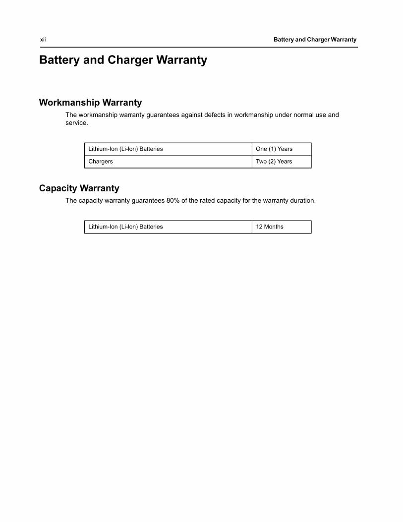
Battery and Charger Warranty
Workmanship WarrantyThe workmanship warranty guarantees against defects in workmanship under normal use and service.
Capacity WarrantyThe capacity warranty guarantees 80% of the rated capacity for the warranty duration.
Lithium-Ion (Li-lon) Batteries One (1) Years
Chargers Two (2) Years
Lithium-Ion (Li-lon) Batteries 12 Months
Chapter 1 Introduction
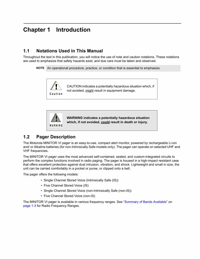
1.1 Notations Used in This ManualThroughout the text in this publication, you will notice the use of note and caution notations. These notations are used to emphasize that safety hazards exist, and due care must be taken and observed.
1.2 Pager DescriptionThe Motorola MINITOR VI pager is an easy-to-use, compact alert monitor, powered by rechargeable Li-ion and/ or Alkaline batteries (for non-Intrinsically Safe models only). The pager can operate on selected UHF and VHF frequencies.
The MINITOR VI pager uses the most advanced self-contained, sealed, and custom-integrated circuits to perform the complex functions involved in radio paging. The pager is housed in a high-impact resistant case that offers excellent protection against dust intrusion, vibration, and shock. Lightweight and small in size, the unit can be carried comfortably in a pocket or purse, or clipped onto a belt.
The pager offers the following models:
• Single Channel Stored Voice (Intrinsically Safe (IS))
• Five Channel Stored Voice (IS)
• Single Channel Stored Voice (non-Intrinsically Safe (non-IS))
• Five Channel Stored Voice (non-IS)
The MINITOR VI pager is available in various frequency ranges. See “Summary of Bands Available” on page 1-3 for Radio Frequency Ranges.
NOTE An operational procedure, practice, or condition that is essential to emphasize.
CAUTION indicates a potentially hazardous situation which, if not avoided, might result in equipment damage.
WARNING indicates a potentially hazardous situation which, if not avoided, could result in death or injury.
!C a u t i o n
!W A R N I N G
!

1-2 Introduction: Pager Description
1.2.1 MINITOR VI
Figure 1-1. MINITOR VI
• ON/ OFF/ VOLUME Control Knob – Rotate clockwise until click is heard to turn on pager; rotate counter-clockwise until click is heard to turn off pager. Rotate clockwise to increase volume level; rotate counter-clockwise to decrease volume level.
• LED INDICATORS – Red (Message Indicator) and yellow (Call Indicator) light-emitting diodes indicate operating status.
• BATTERY INDICATOR – Red, green and yellow light-emitting diodes indicate status of battery.
- Solid Green – indicates battery level is high.
- Solid Yellow – indicates battery level is medium.
- Solid Red – indicates battery level is low.
- Blinking Red – indicates battery level is critically low.
• RESET BUTTON – TURN OFF audio, alert, battery status indicators.
• FUNCTION SELECTOR KNOB – Rotate clockwise and counter clockwise to select preprogram function modes.
• PLAY BUTTON – Play message stored in memory.
• NEXT/ FASTFORWARD BUTTON – Skip to next message or fastforward current message.
• REWIND BUTTON – Skip to previous message or rewind current message.
• SPEAKER – Outputs all tones and audio generated by the pager.
Function Selector Knob
Reset Button
Message Indicator
Rewind Button
Play Button
On/Off Volume Control Knob
Speaker
Next/ Fastforward Button
Battery Indicator
Call Indicator
Introduction: Summary of Bands Available 1-3
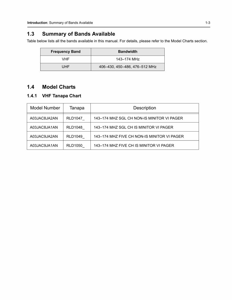
1.3 Summary of Bands AvailableTable below lists all the bands available in this manual. For details, please refer to the Model Charts section.
1.4 Model Charts
1.4.1 VHF Tanapa Chart
Frequency Band Bandwidth
VHF 143–174 MHz
UHF 406–430, 450–486, 476–512 MHz
Model Number Tanapa Description
A03JAC8JA2AN RLD1047_ 143–174 MHZ SGL CH NON-IS MINITOR VI PAGER
A03JAC8JA1AN RLD1048_ 143–174 MHZ SGL CH IS MINITOR VI PAGER
A03JAC9JA2AN RLD1049_ 143–174 MHZ FIVE CH NON-IS MINITOR VI PAGER
A03JAC9JA1AN RLD1050_ 143–174 MHZ FIVE CH IS MINITOR VI PAGER

1-4 Introduction: Model Charts
1.4.2 UHF Tanapa Chart
Model Number Tanapa Description
A04QAC8JA2AN RLE1125_ 406–430 MHZ SGL CH NON-IS MINITOR VI PAGER
A04QAC8JA1AN RLE1124_ 406–430 MHZ SGL CH IS MINITOR VI PAGER
A04QAC9JA2AN RLE1123_ 406–430 MHZ FIVE CH NON-IS MINITOR VI PAGER
A04QAC9JA1AN RLE1122_ 406–430 MHZ FIVE CH IS MINITOR VI PAGER
A04RAC8JA2AN RLE1121_ 450–486 MHZ SGL CH NON-IS MINITOR VI PAGER
A04RAC8JA1AN RLE1120_ 450–486 MHZ SGL CH IS MINITOR VI PAGER
A04RAC9JA2AN RLE1119_ 450–486 MHZ FIVE CH NON-IS MINITOR VI PAGER
A04RAC9JA1AN RLE1118_ 450–486 MHZ FIVE CH IS MINITOR VI PAGER
A04SAC8JA2AN RLE1117_ 476–512 MHZ SGL CH NON-IS MINITOR VI PAGER
A04SAC8JA1AN RLE1116_ 476–512 MHZ SGL CH IS MINITOR VI PAGER
A04SAC9JA2AN RLE1115_ 476–512 MHZ FIVE CH NON-IS MINITOR VI PAGER
A04SAC9JA1AN RLE1114_ 476–512 MHZ FIVE CH IS MINITOR VI PAGER

Introduction: Specifications 1-5
1.5 Specifications
1.5.1 VHF
Specification Remarks
Model Series1 Channel5 Channel
A03JAC8JA2AN, A03JAC8JA1ANA03JAC9JA2AN, A03JAC9JA1AN
Frequency 143.0 – 174.0 MHz
Channel Spacing 12.5 kHz/ 25 kHz per frequency Programmable feature
Max. Freq. Separation 31 MHz
Sensitivity Alerting (On body1)
*On Body (typ) 3.5 μV/m @ 25kHz
*On Body (typ) 4.5 μV/m @ 12.5kHz
*On Body (max) 4.5 μV/m @ 25kHz
*On Body (max) 5.5 μV/m @ 12.5kHz
Free Field 10.0 μV/m
8-position avg. <13.0 μV/m (on body)
Selectivity >65 dB TIA603-D
Spurious & Image >70 dB TIA603-D
Intermodulation >65 dB TIA603-D
Spurious Emissions (all bands)
Conducted >55 dB TIA603-D
Radiated >55 dB TIA603-D
Co-channel rejection > - 8 dB
First Oscillator Stability + / - 10 ppm
High level blocking >84 dB ETSI
>90 dB Motorola Procedure
Audio SPL @ 12”
Alert Tone 96 dB Anechoic chamber
Voice average 94 dB Anechoic chamber
Audio Distortion: Real Time Audio
Electrical < 4% TIA603-D
1-6 Introduction: Specifications
All Specifications are subject to change without notice.
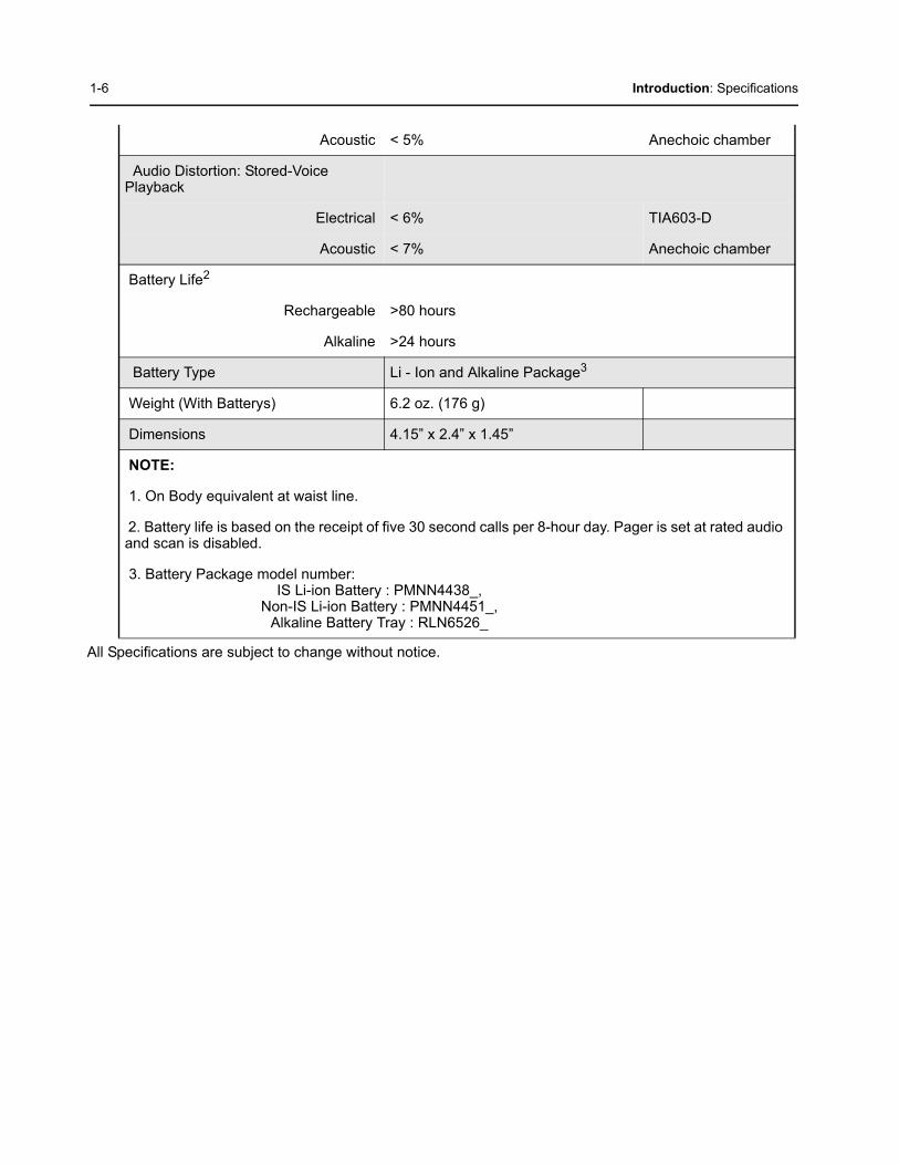
Acoustic < 5% Anechoic chamber
Audio Distortion: Stored-Voice Playback
Electrical < 6% TIA603-D
Acoustic < 7% Anechoic chamber
Battery Life2
Rechargeable >80 hours
Alkaline >24 hours
Battery Type Li - Ion and Alkaline Package3
Weight (With Batterys) 6.2 oz. (176 g)
Dimensions 4.15” x 2.4” x 1.45”
NOTE:
1. On Body equivalent at waist line.
2. Battery life is based on the receipt of five 30 second calls per 8-hour day. Pager is set at rated audio and scan is disabled.
3. Battery Package model number:IS Li-ion Battery : PMNN4438_,
Non-IS Li-ion Battery : PMNN4451_,Alkaline Battery Tray : RLN6526_

Introduction: Specifications 1-7
1.5.2 UHF
Specification Remarks
Model SeriesUHF1: 1 Channel
5 Channel
UHF2: 1 Channel5 Channel
UHF3: 1 Channel5 Channel
A04QAC8JA2AN, A04QAC8JA1ANA04QAC9JA2AN, A04QAC9JA1AN
A04RAC8JA2AN, A04RAC8JA1ANA04RAC9JA2AN, A04RAC9JA1AN
A04SAC8JA2AN, A04SAC8JA1ANA04SAC9JA2AN, A04SAC9JA1AN
Frequency UHF1UHF2UHF3
406.0 – 430.0 MHz450.0 – 486.0 MHz476.0 – 512.0 MHz
Channel Spacing 12.5 kHz/ 25 kHz per frequency Programmable feature
Max. Freq. SeparationUHF1UHF2UHF3
24 MHz36 MHz36 MHz
Sensitivity Alerting (On body1)
*On Body (typ) 3.0 μV/m @ 25kHz
*On Body (typ) 4.0 μV/m @ 12.5kHz
*On Body (max) 4.0 μV/m @ 25kHz
*On Body (max) 5.0 μV/m @ 12.5kHz
Free Field 12.0 μV/m
8-position avg. <14.0 μV/m (on body)
Selectivity >65 dB TIA603-D
Spurious & Image >70 dB TIA603-D
Intermodulation >65 dB TIA603-D
Spurious Emissions (all bands)
Conducted >55 dB TIA603-D
Radiated >55 dB TIA603-D
Co-channel rejection > - 8 dB
First Oscillator Stability + / - 5 ppm
High level blocking >84 dB ETSI
>90 dB Motorola Procedure
1-8 Introduction: Specifications
All Specifications are subject to change without notice.
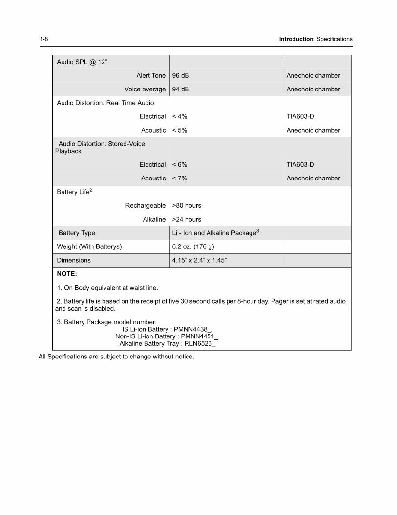
Audio SPL @ 12”
Alert Tone 96 dB Anechoic chamber
Voice average 94 dB Anechoic chamber
Audio Distortion: Real Time Audio
Electrical < 4% TIA603-D
Acoustic < 5% Anechoic chamber
Audio Distortion: Stored-Voice Playback
Electrical < 6% TIA603-D
Acoustic < 7% Anechoic chamber
Battery Life2
Rechargeable >80 hours
Alkaline >24 hours
Battery Type Li - Ion and Alkaline Package3
Weight (With Batterys) 6.2 oz. (176 g)
Dimensions 4.15” x 2.4” x 1.45”
NOTE:
1. On Body equivalent at waist line.
2. Battery life is based on the receipt of five 30 second calls per 8-hour day. Pager is set at rated audio and scan is disabled.
3. Battery Package model number:IS Li-ion Battery : PMNN4438_,
Non-IS Li-ion Battery : PMNN4451_,Alkaline Battery Tray : RLN6526_

Chapter 2 Test Equipment and Service Aids
2.1 Recommended Test EquipmentThe list of equipment contained in Table 2-1 includes most of the standard test equipment required for servicing MINITOR VI. Use equivalent whenever possible.
Table 2-1. Recommended Test Equipment
Equipment Example Application
RF Communications Test Set HP8920 or equivalent Tone Sensitivity test
2-2 Test Equipment and Service Aids: Service Aids
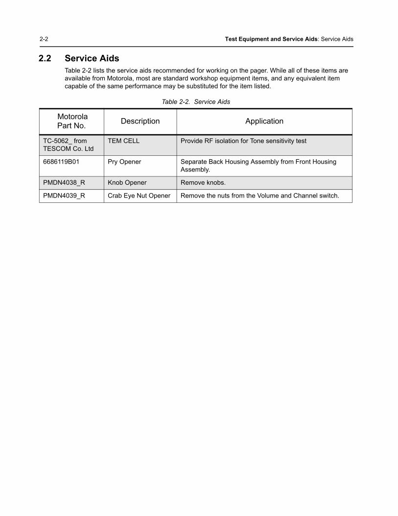
2.2 Service AidsTable 2-2 lists the service aids recommended for working on the pager. While all of these items are available from Motorola, most are standard workshop equipment items, and any equivalent item capable of the same performance may be substituted for the item listed.
Table 2-2. Service Aids
Motorola Part No.
Description Application
TC-5062_ from TESCOM Co. Ltd
TEM CELL Provide RF isolation for Tone sensitivity test
6686119B01 Pry Opener Separate Back Housing Assembly from Front Housing Assembly.
PMDN4038_R Knob Opener Remove knobs.
PMDN4039_R Crab Eye Nut Opener Remove the nuts from the Volume and Channel switch.
Chapter 3 Receive Performance Check
3.1 GeneralThe pagers meet published specifications through their manufacturing process by utilizing high- accuracy laboratory-quality test equipment. The recommended field service equipment approaches the accuracy of the manufacturing equipment with few exceptions. This accuracy must be maintained in compliance with the manufacturer’s recommended calibration schedule.

3-2 Receive Performance Check: Tone Sensitivity
3.2 Tone Sensitivity1. Connect the TEM cell and HP8920 or equivalent equipment as shown in Figure 3-1. below.
2. Put the pager into a TEM Cell, set up the the function switch to test frequency.
3. Set up the amplitude of the signal generator according to a known signal.
4. In this state, the HP8920 (or equivalent equipment) should be set up as follows.
a. QC2 signal should be sent to the pager by clicking “Send”, and make sure that the Alert tone is OK.
b. Repeat step 4a., lowering the amplitude each time until 4 out of 5 Alerts are received.
Figure 3-1. Tone Sense Check Setup
NOTE: Tone Sensitivity results may vary based on pager position and orientation in TEM cell.
Receive Performance Check: Tone Sensitivity 3-3
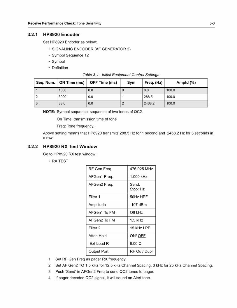
3.2.1 HP8920 Encoder
Set HP8920 Encoder as below:
• SIGNALING ENCODER (AF GENERATOR 2)
• Symbol Sequence:12
• Symbol
• Definition
NOTE: Symbol sequence: sequence of two tones of QC2.
On Time: transmission time of tone
Freq: Tone frequency.
Above setting means that HP8920 transmits 288.5 Hz for 1 second and 2468.2 Hz for 3 seconds in a row.
3.2.2 HP8920 RX Test Window
Go to HP8920 RX test window:
• RX TEST
1. Set RF Gen Freq as pager RX frequency.
2. Set AF Gen2 TO 1.5 kHz for 12.5 kHz Channel Spacing, 3 kHz for 25 kHz Channel Spacing.
3. Push ‘Send’ in AFGen2 Freq to send QC2 tones to pager.
4. If pager decoded QC2 signal, it will sound an Alert tone.
Table 3-1. Initial Equipment Control Settings
Seq. Num. ON Time (ms) OFF Time (ms) Sym Freq. (Hz) Amptd (%)
1 1000 0.0 0 0.0 100.0
2 3000 0.0 1 288.5 100.0
3 33.0 0.0 2 2468.2 100.0
RF Gen Freq. 476.025 MHz
AFGen1 Freq. 1.000 kHz
AFGen2 Freq. Send:Stop: Hz
Filter 1 50Hz HPF
Amplitude -107 dBm
AFGen1 To FM Off kHz
AFGen2 To FM 1.5 kHz
Filter 2 15 kHz LPF
Atten Hold ON/ OFF
Ext Load R 8.00 Ω
Output Port RF Out/ Dupl

3-4 Receive Performance Check: Test Mode
3.2.3 Tone Sensitivity Specification
Tone sensitivity is dependent on various test conditions such as path losses, orientation of the unit, type of source antenna, test equipment etc. A user may compare measurements to a known good unit. +-2 dB variation in Tone sensitivity measurement is expected from unit to unit measured.
3.3 Test Mode1. Rotate the Function Switch to position D.
2. Press and hold the Reset Button while powering on the unit.
3. An audible alert and red LED will indicate that you have entered to the I/O Test Mode. Release the Reset Button.
4. Press the Reset Button, the red LED turns off and the amber LED turns on.
5. Press the Reset Button, the amber LED turns off and the Battery Indicator LED turns on red.
6. Press the Reset Button, the Battery Indicator LED turns green.
7. Press the Reset Button, all LEDs turn on, the Battery Indicator LED is amber.
8. Press the Reset Button, all LEDs turn off and unit enters Pulsed Vibrate Mode.
9. Press the Reset Button, the unit enters Constant Vibrate Mode.
10. Press the Reset Button, a high pitched tone is heard.
11. Press the Reset Button, a louder high pitched tone is heard.
12. Press the Reset Button, a high pitch tone is heard and unit enters Constant Vibrate Mode.
13. Press the Reset Button, the unit enters Open Squelch Mode.
14. To exit Test Mode, power off the unit.

Chapter 4 Disassembly/Reassembly Procedures
4.1 Disassembling and Reassembling the Pager – GeneralWhen disassembling and reassembling the pager, it is important to pay particular attention to the snaps and tabs, and how parts align with each other.
The following tools are required for disassembling the radio:
• TORX™ T6 and screwdriver
• Pry Opener (6686119B01)
• Crab Eye Nut Tool (PMDN4039_R)
• Knob Remover (PMDN4038_R)
The following item and tools are required for reassembling the radio:
• Screw fastener: 3 bond (TB1401B)
• Crab Eye Nut Opener (PMDN4039_R)
• Grease (1180369B40)
• TORX™ T6 and screwdriver
If a unit requires further testing or service than is customarily performed at the basic level, please send the radio to a Motorola Service Center listed in Appendix A.
4.2 Maintenance
The procedures in this section provide instructions for the disassembly of the MINITOR VI pager.
This product contains static-sensitive devices. Use anti-static handling procedures to prevent electrostatic discharge and component damage.
Only Motorola Service Centers or Authorized Motorola Service Dealers can perform this function.
Only use TB1401B (Manufacturer; Threebond) paint. Do not to use other lock paint as they might harm the PC resin of the pager.
!C a u t i o n
!W A R N I N G
!

4-2 Disassembly/Reassembly Procedures: Pager Disassembly – Detailed
4.3 Pager Disassembly – Detailed
4.3.1 Removing Back Cover
4.3.1.1 Removing Belt Clip
1. Press the belt clip tab away from the back housing.
2. Gently pull the belt clip out.
Figure 4-1. Removing Belt Clip.
4.3.1.2 Removing Back Housing
1. Turn the pager off.
2. Unlock the battery latch.
Once the front housing and back cover are disassembled, the IS Intrinsic Safety Rating is voided. Any warranty or repair work must be done by a IS approved repair facility. The unit must be resealed during re-assembly in order for the unit to maintain the IS Intrinsic Safety Rating for Hazardous Locations.
!W A R N I N G
!

Disassembly/Reassembly Procedures: Pager Disassembly – Detailed 4-3
Figure 4-2. Unlocking Battery Latch
3. Remove the battery pack.
Figure 4-3. Removing Battery
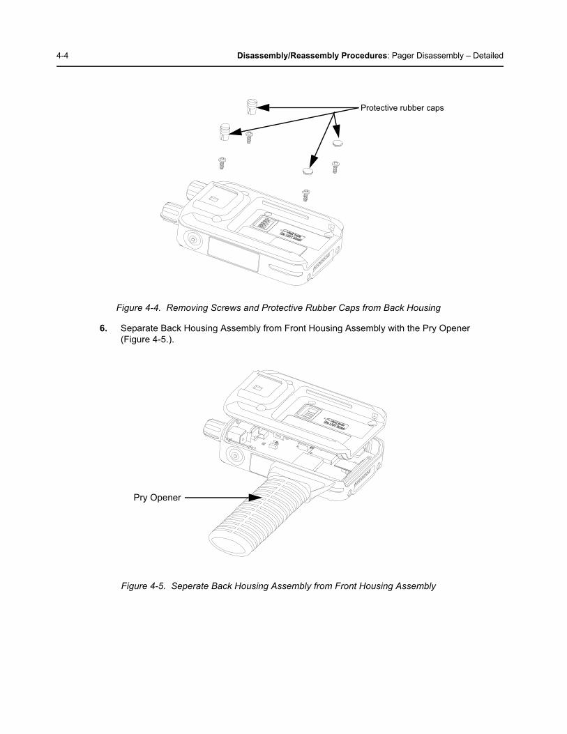
4. Remove the four protective rubber caps (32,33,34) from the Back Housing.
5. Remove the four screws (31) with a TORX™ T6 screwdriver.
4-4 Disassembly/Reassembly Procedures: Pager Disassembly – Detailed
Figure 4-4. Removing Screws and Protective Rubber Caps from Back Housing
6. Separate Back Housing Assembly from Front Housing Assembly with the Pry Opener (Figure 4-5.).
Figure 4-5. Seperate Back Housing Assembly from Front Housing Assembly
Protective rubber caps
Pry Opener
Disassembly/Reassembly Procedures: Pager Disassembly – Detailed 4-5
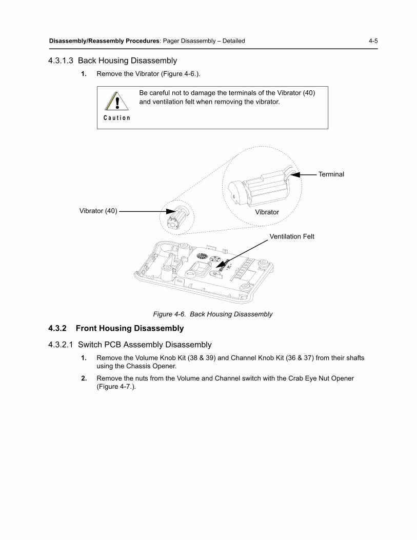
4.3.1.3 Back Housing Disassembly
1. Remove the Vibrator (Figure 4-6.).
Figure 4-6. Back Housing Disassembly
4.3.2 Front Housing Disassembly
4.3.2.1 Switch PCB Asssembly Disassembly
1. Remove the Volume Knob Kit (38 & 39) and Channel Knob Kit (36 & 37) from their shafts using the Chassis Opener.
2. Remove the nuts from the Volume and Channel switch with the Crab Eye Nut Opener(Figure 4-7.).
Be careful not to damage the terminals of the Vibrator (40) and ventilation felt when removing the vibrator.!
C a u t i o n
Vibrator (40)
Ventilation Felt
Terminal
Vibrator
4-6 Disassembly/Reassembly Procedures: Pager Disassembly – Detailed
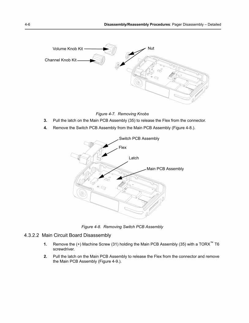
Figure 4-7. Removing Knobs
3. Pull the latch on the Main PCB Assembly (35) to release the Flex from the connector.
4. Remove the Switch PCB Assembly from the Main PCB Assembly (Figure 4-8.).
Figure 4-8. Removing Switch PCB Assembly
4.3.2.2 Main Circuit Board Disassembly
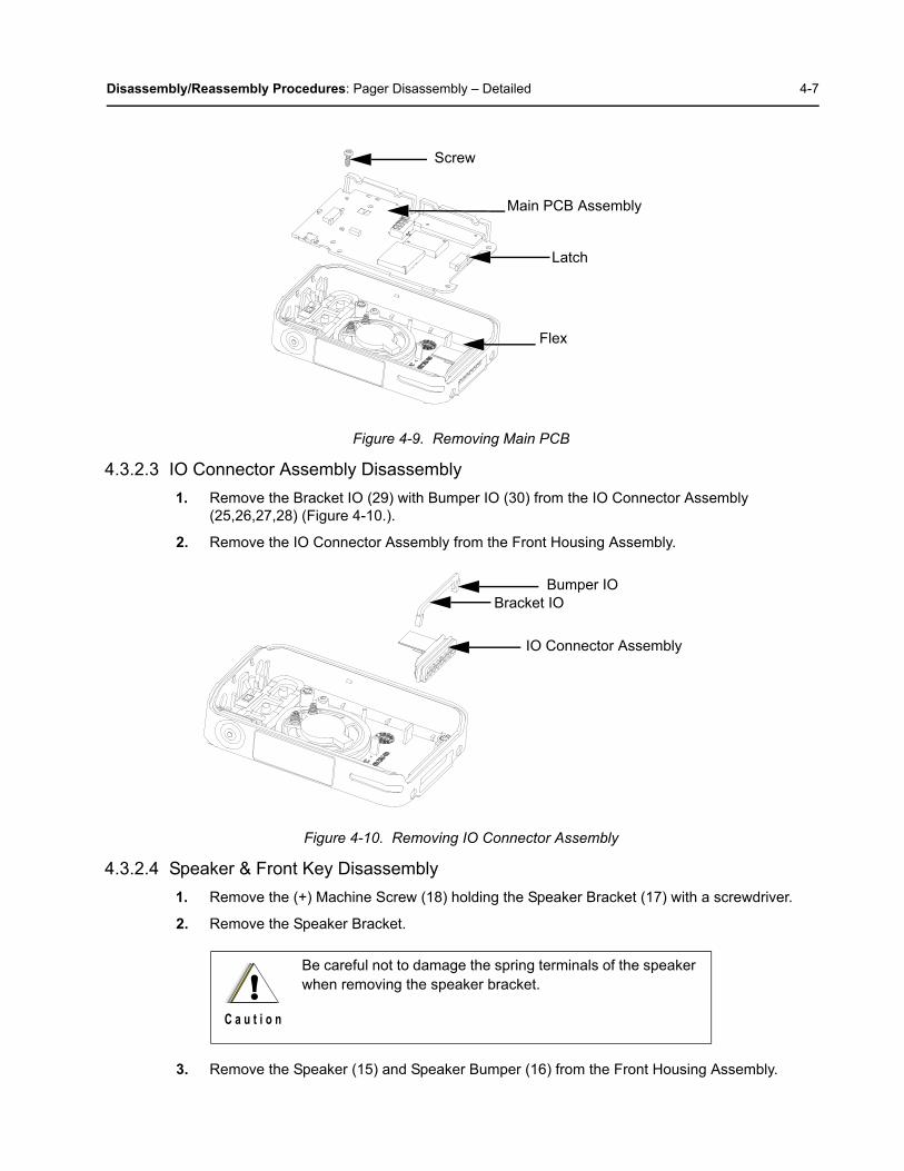
1. Remove the (+) Machine Screw (31) holding the Main PCB Assembly (35) with a TORX™ T6 screwdriver.
2. Pull the latch on the Main PCB Assembly to release the Flex from the connector and remove the Main PCB Assembly (Figure 4-9.).
Volume Knob Kit Nut
Channel Knob Kit
Switch PCB Assembly
Main PCB Assembly
Flex
Latch
Disassembly/Reassembly Procedures: Pager Disassembly – Detailed 4-7
Figure 4-9. Removing Main PCB
4.3.2.3 IO Connector Assembly Disassembly
1. Remove the Bracket IO (29) with Bumper IO (30) from the IO Connector Assembly (25,26,27,28) (Figure 4-10.).
2. Remove the IO Connector Assembly from the Front Housing Assembly.
Figure 4-10. Removing IO Connector Assembly
4.3.2.4 Speaker & Front Key Disassembly
1. Remove the (+) Machine Screw (18) holding the Speaker Bracket (17) with a screwdriver.
2. Remove the Speaker Bracket.
3. Remove the Speaker (15) and Speaker Bumper (16) from the Front Housing Assembly.
Be careful not to damage the spring terminals of the speaker when removing the speaker bracket.
Screw
Main PCB Assembly
Latch
Flex
Bumper IO
IO Connector Assembly
Bracket IO
!C a u t i o n
4-8 Disassembly/Reassembly Procedures: Pager Disassembly – Detailed
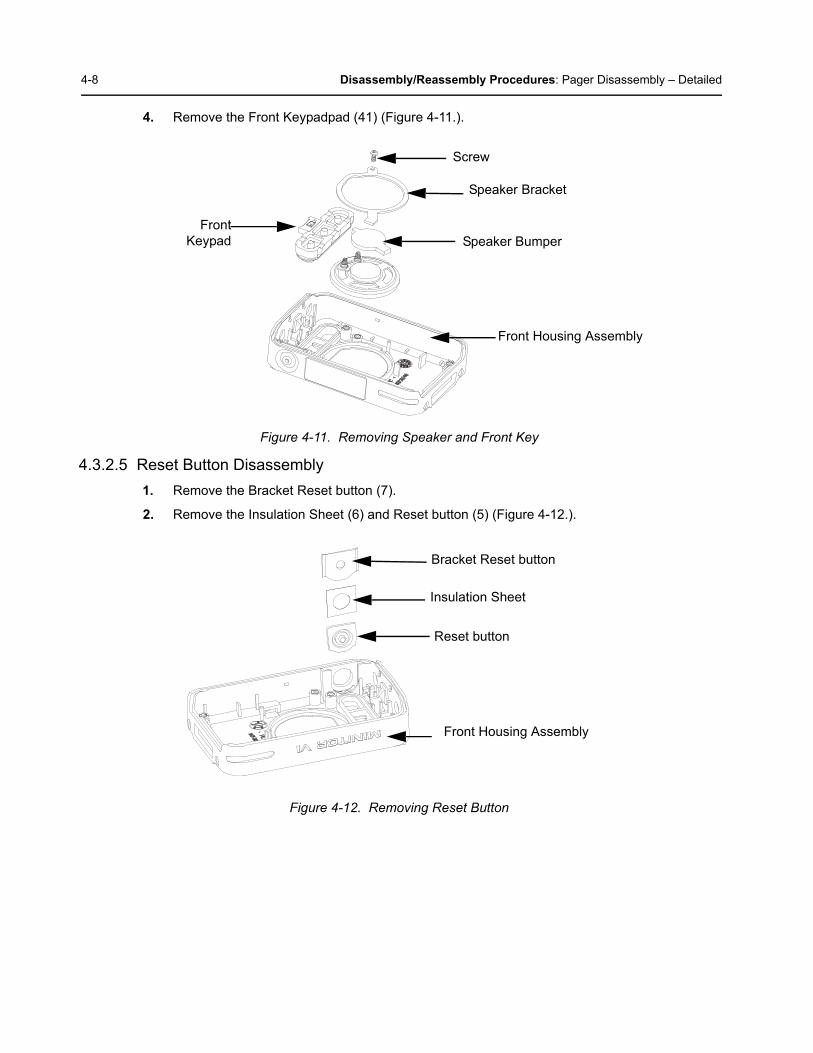
4. Remove the Front Keypadpad (41) (Figure 4-11.).
Figure 4-11. Removing Speaker and Front Key
4.3.2.5 Reset Button Disassembly
1. Remove the Bracket Reset button (7).
2. Remove the Insulation Sheet (6) and Reset button (5) (Figure 4-12.).
Figure 4-12. Removing Reset Button
Screw
Speaker Bracket
Speaker Bumper
Front Housing Assembly
FrontKeypad
Bracket Reset button
Reset button
Front Housing Assembly
Insulation Sheet

Disassembly/Reassembly Procedures: Pager Reassembly – Detailed 4-9
4.4 Pager Reassembly – Detailed
4.4.1 Front Housing Reassembly
4.4.1.1 Reset Button Reasassembly
Follow the reverse of Section 4.3.2.5 "Reset Button Disassembly" on page 4-8.
4.4.1.2 Speaker and Front Key Reasassembly
1. Align the guide rib of the Speaker (15) to the guide slot of the Front Housing Assembly.
2. Install the Speaker Bracket (17) and Speaker Bumper (16).
3. Tighten the (+) Machine Screw (18) holding Speaker Bracket to the housing to a torque of 2.0 kgf~2.5kgf.
4. Align the Front Keypad (41) onto the key slot. Apply force around the Front Keypad and ensure the Front Key sealing rib is perfectly set onto the key slot (Figure 4-13.).
.
Figure 4-13. Speaker and Front Key Assembly
4.4.1.3 IO Terminal Reasassembly
Follow the reverse of Section 4.3.2.3 "IO Connector Assembly Disassembly" on page 4-7.
4.4.1.4 Main Circuit Board Reasassembly
1. Insert the Flexible cable into the respective connector on the Main PCB Assembly (35).
2. Push both latches into the connector.
3. Tighten the (+) Machine Screw (31) holding th Main PCB Assembly to the housing with a torque of 3.0 kgf~3.5 kgf (Figure 4-14.).
Screw
Speaker Bracket
Speaker Bumper
Front Housing Assembly
Front Keypad-pad
Guide Rib
Guide Slot
4-10 Disassembly/Reassembly Procedures: Pager Reassembly – Detailed
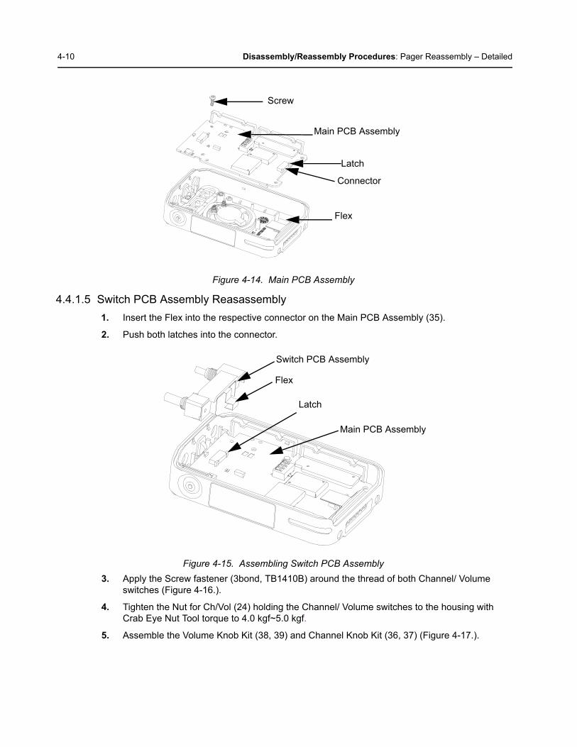
Figure 4-14. Main PCB Assembly
4.4.1.5 Switch PCB Assembly Reasassembly
1. Insert the Flex into the respective connector on the Main PCB Assembly (35).
2. Push both latches into the connector.
Figure 4-15. Assembling Switch PCB Assembly
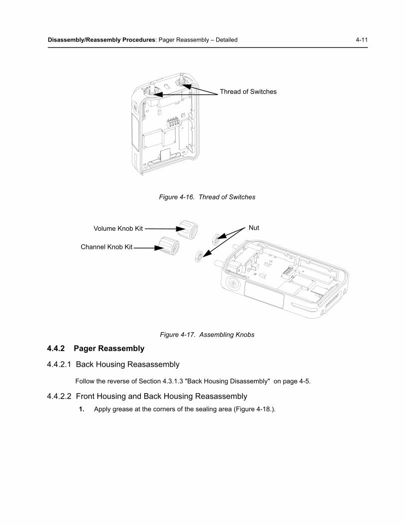
3. Apply the Screw fastener (3bond, TB1410B) around the thread of both Channel/ Volume switches (Figure 4-16.).
4. Tighten the Nut for Ch/Vol (24) holding the Channel/ Volume switches to the housing with Crab Eye Nut Tool torque to 4.0 kgf~5.0 kgf.
5. Assemble the Volume Knob Kit (38, 39) and Channel Knob Kit (36, 37) (Figure 4-17.).
Screw
Main PCB Assembly
Latch
Flex
Connector
Switch PCB Assembly
Main PCB Assembly
Flex
Latch
Disassembly/Reassembly Procedures: Pager Reassembly – Detailed 4-11
Figure 4-16. Thread of Switches
Figure 4-17. Assembling Knobs
4.4.2 Pager Reassembly
4.4.2.1 Back Housing Reasassembly
Follow the reverse of Section 4.3.1.3 "Back Housing Disassembly" on page 4-5.
4.4.2.2 Front Housing and Back Housing Reasassembly
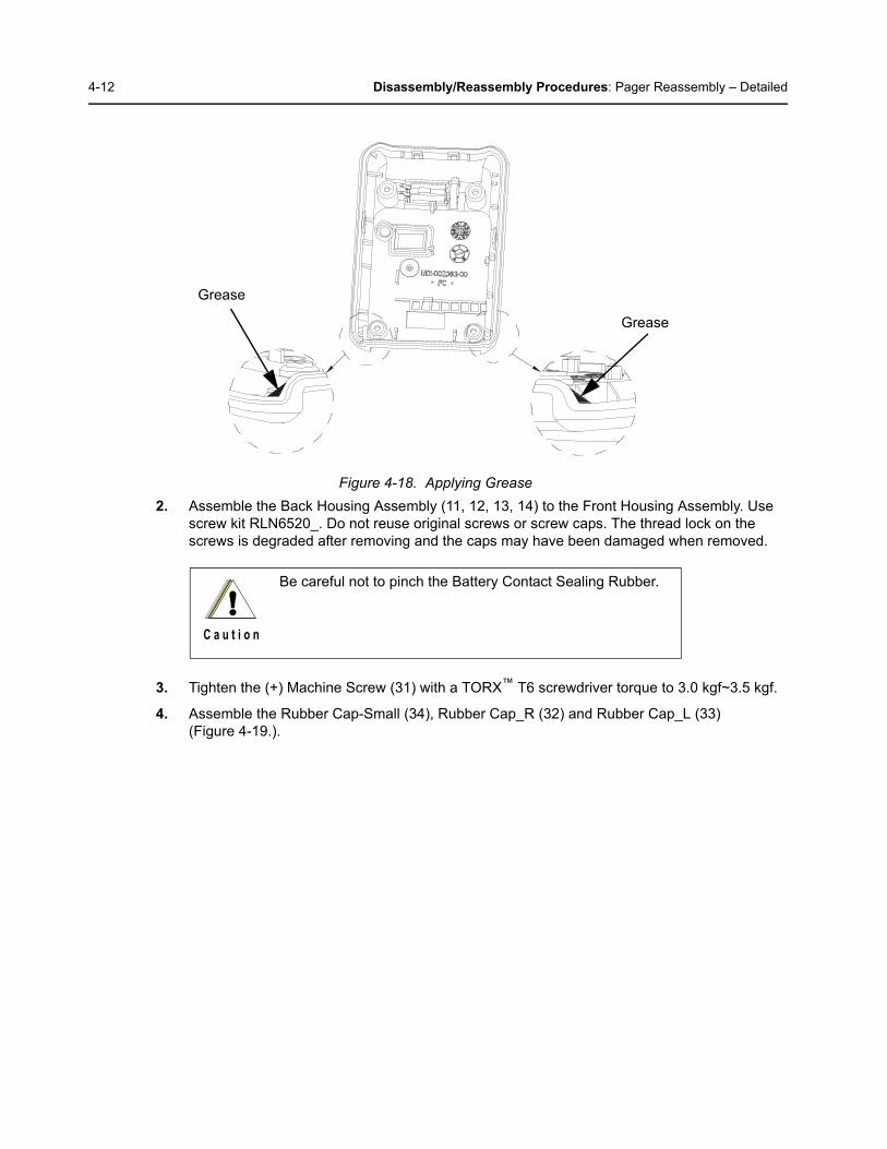
1. Apply grease at the corners of the sealing area (Figure 4-18.).
Thread of Switches
Volume Knob Kit Nut
Channel Knob Kit
4-12 Disassembly/Reassembly Procedures: Pager Reassembly – Detailed
Figure 4-18. Applying Grease
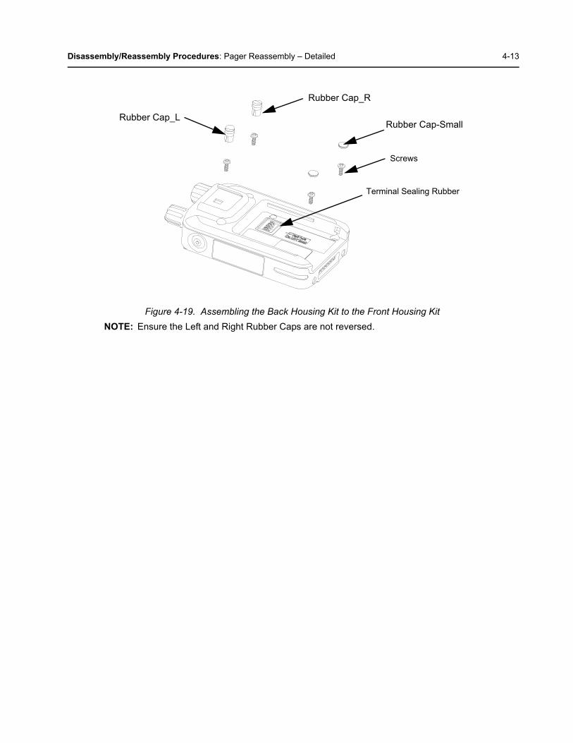
2. Assemble the Back Housing Assembly (11, 12, 13, 14) to the Front Housing Assembly. Use screw kit RLN6520_. Do not reuse original screws or screw caps. The thread lock on the screws is degraded after removing and the caps may have been damaged when removed.
3. Tighten the (+) Machine Screw (31) with a TORX™ T6 screwdriver torque to 3.0 kgf~3.5 kgf.
4. Assemble the Rubber Cap-Small (34), Rubber Cap_R (32) and Rubber Cap_L (33)(Figure 4-19.).
Be careful not to pinch the Battery Contact Sealing Rubber.
Grease
Grease
!C a u t i o n
Disassembly/Reassembly Procedures: Pager Reassembly – Detailed 4-13
Figure 4-19. Assembling the Back Housing Kit to the Front Housing Kit
NOTE: Ensure the Left and Right Rubber Caps are not reversed.
Rubber Cap-Small
Rubber Cap_R
Rubber Cap_L
Screws
Terminal Sealing Rubber
4-14 Disassembly/Reassembly Procedures: Pager Exploded Mechanical View and Parts Lists
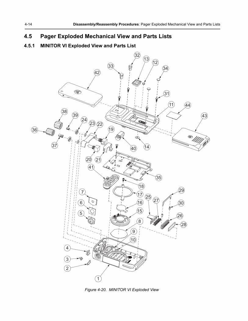
4.5 Pager Exploded Mechanical View and Parts Lists
4.5.1 MINITOR VI Exploded View and Parts List
Figure 4-20. MINITOR VI Exploded View
1
2
3
4
5
6
7
412120
37
36
3839
2423
4233
3213
1234
31
11
43
44
2219
40 14
35
18
17
16
15
8
9
10
2527
29
30
26
28

Disassembly/Reassembly Procedures: Pager Exploded Mechanical View and Parts Lists 4-15
Table 4-1. MINITOR VI Exploded View Parts List
Part Number Description Part Description Item No. Quantity
RHN1006_ COVER KIT, FRONT HOUSING
Front Housing 1 1
Light Pipe Message 2 1
Light Pipe Receive 3 1
Light Pipe Batt 4 1
Reset button 5 1
Insulation Sheet 6 1
Bracket Reset button 7 1
Felt (SPK) 8 1
Insert Screw 1 9 5
Insert Screw 2 10 1
RHN1007_ BACK HOUSING KIT Back Housing 11 1
Connector Cap 12 1
Sealing Batt. Terminal 13 1
Ventilation Felt 14 1
RSN4006_ REPAIR, KIT, SPEAKER Speaker 15 1
Speaker Bumper 16 1
Speaker Bracket 17 1
(+) Machine Screw for Speaker 18 1
RLN6518_ SWITCH, KIT, SWITCH, VOL/CHN
Switch Volume 19 1
CH Switch 20 1
Flexible PCB 21 1
Bracket Switch 22 1
O-ring Switch 23 2
Nut for Ch/Vol 24 2

4-16 Disassembly/Reassembly Procedures: Pager Exploded Mechanical View and Parts Lists
RLN6519_ CONNECTOR STANDARD-AUDIO, MM, KIT, CONNECTOR, IO
Flexible PCB 25 1
Housing IO 26 1
Pin Terminal 27 15
Sealing IO 28 1
Bracket IO 29 1
Bumper IO 30 2
RLN6520_ SCREW, KIT (+) Machine Screw 31 5
Rubber Cap_R 32 1
Rubber Cap_L 33 1
Rubber Cap-Small 34 2
Connector Cap 12 1
Table 4-1. MINITOR VI Exploded View Parts List (Continued)
Part Number Description Part Description Item No. Quantity
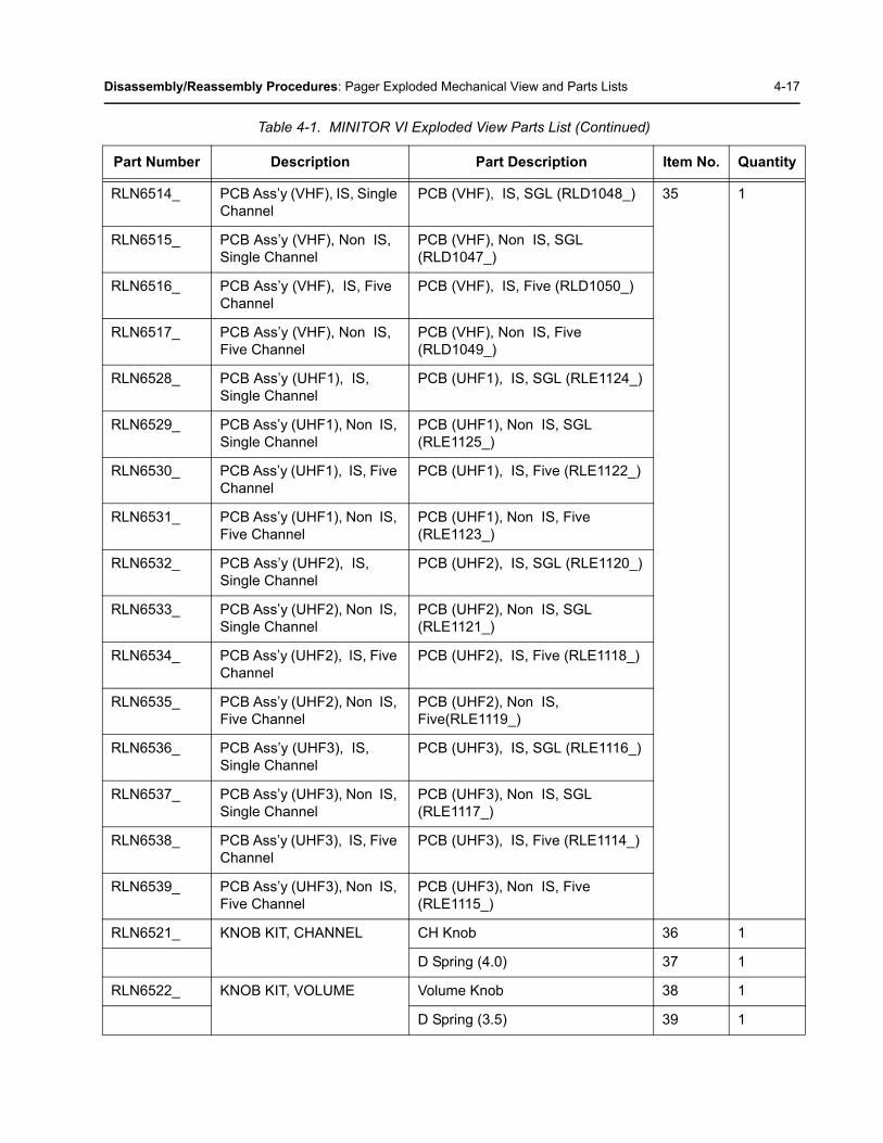
Disassembly/Reassembly Procedures: Pager Exploded Mechanical View and Parts Lists 4-17
RLN6514_ PCB Ass’y (VHF), IS, Single Channel
PCB (VHF), IS, SGL (RLD1048_) 35 1
RLN6515_ PCB Ass’y (VHF), Non IS, Single Channel
PCB (VHF), Non IS, SGL (RLD1047_)
RLN6516_ PCB Ass’y (VHF), IS, Five Channel
PCB (VHF), IS, Five (RLD1050_)
RLN6517_ PCB Ass’y (VHF), Non IS, Five Channel
PCB (VHF), Non IS, Five (RLD1049_)
RLN6528_ PCB Ass’y (UHF1), IS, Single Channel
PCB (UHF1), IS, SGL (RLE1124_)
RLN6529_ PCB Ass’y (UHF1), Non IS, Single Channel
PCB (UHF1), Non IS, SGL (RLE1125_)
RLN6530_ PCB Ass’y (UHF1), IS, Five Channel
PCB (UHF1), IS, Five (RLE1122_)
RLN6531_ PCB Ass’y (UHF1), Non IS, Five Channel
PCB (UHF1), Non IS, Five (RLE1123_)
RLN6532_ PCB Ass’y (UHF2), IS, Single Channel
PCB (UHF2), IS, SGL (RLE1120_)
RLN6533_ PCB Ass’y (UHF2), Non IS, Single Channel
PCB (UHF2), Non IS, SGL (RLE1121_)
RLN6534_ PCB Ass’y (UHF2), IS, Five Channel
PCB (UHF2), IS, Five (RLE1118_)
RLN6535_ PCB Ass’y (UHF2), Non IS, Five Channel
PCB (UHF2), Non IS, Five(RLE1119_)
RLN6536_ PCB Ass’y (UHF3), IS, Single Channel
PCB (UHF3), IS, SGL (RLE1116_)
RLN6537_ PCB Ass’y (UHF3), Non IS, Single Channel
PCB (UHF3), Non IS, SGL (RLE1117_)
RLN6538_ PCB Ass’y (UHF3), IS, Five Channel
PCB (UHF3), IS, Five (RLE1114_)
RLN6539_ PCB Ass’y (UHF3), Non IS, Five Channel
PCB (UHF3), Non IS, Five (RLE1115_)
RLN6521_ KNOB KIT, CHANNEL CH Knob 36 1
D Spring (4.0) 37 1
RLN6522_ KNOB KIT, VOLUME Volume Knob 38 1
D Spring (3.5) 39 1
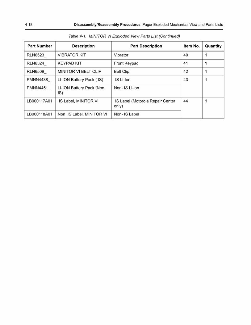
Table 4-1. MINITOR VI Exploded View Parts List (Continued)
Part Number Description Part Description Item No. Quantity
4-18 Disassembly/Reassembly Procedures: Pager Exploded Mechanical View and Parts Lists
RLN6523_ VIBRATOR KIT Vibrator 40 1
RLN6524_ KEYPAD KIT Front Keypad 41 1
RLN6509_ MINITOR VI BELT CLIP Belt Clip 42 1
PMNN4438_ LI-ION Battery Pack ( IS) IS Li-Ion 43 1
PMNN4451_ LI-ION Battery Pack (Non IS)
Non- IS Li-ion
LB000117A01 IS Label, MINITOR VI IS Label (Motorola Repair Center only)
44 1
LB000118A01 Non IS Label, MINITOR VI Non- IS Label
Table 4-1. MINITOR VI Exploded View Parts List (Continued)
Part Number Description Part Description Item No. Quantity
Chapter 5 Accessories
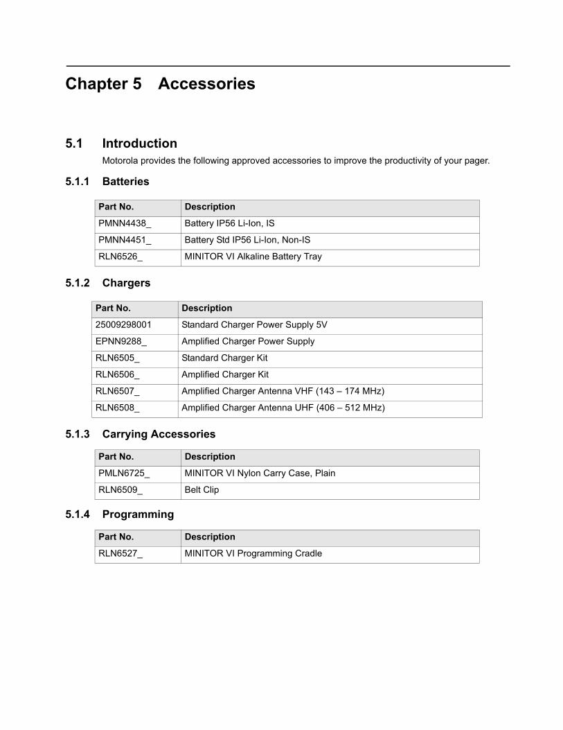
5.1 IntroductionMotorola provides the following approved accessories to improve the productivity of your pager.
5.1.1 Batteries
5.1.2 Chargers
5.1.3 Carrying Accessories
5.1.4 Programming
Part No. Description
PMNN4438_ Battery IP56 Li-Ion, IS
PMNN4451_ Battery Std IP56 Li-Ion, Non-IS
RLN6526_ MINITOR VI Alkaline Battery Tray
Part No. Description
25009298001 Standard Charger Power Supply 5V
EPNN9288_ Amplified Charger Power Supply
RLN6505_ Standard Charger Kit
RLN6506_ Amplified Charger Kit
RLN6507_ Amplified Charger Antenna VHF (143 – 174 MHz)
RLN6508_ Amplified Charger Antenna UHF (406 – 512 MHz)
Part No. Description
PMLN6725_ MINITOR VI Nylon Carry Case, Plain
RLN6509_ Belt Clip
Part No. Description
RLN6527_ MINITOR VI Programming Cradle

5-2 Accessories: Introduction
Notes
Appendix A Replacement Parts & Kits
A.1 Level 1 and 2 Maintenance
This manual covers Level 1 and 2 Maintenance:
Level 1 maintenance is the assessment and/or repair of fault in terms of faulty accessory or physical aspect of product; not including opening of the unit. Limited to replacement of battery, external knobs, all related frequency programming to customers’ and in some cases alignment/tuning, by Pager Programming software (PPS).
Level 2 maintenance includes all Level I activities plus: Assessment that require opening the Subscriber Product and rectifying a fault by replacement of a board or module, or replacement of major mechanical parts (like Front Housing Kit or Control Head Board), followed by alignment/tuning to ensure the replacement of board/module/major mechanical parts are within Subscriber Product’s specifications as per the service manual. It does not incorporate discrete component replacement.
A.1.1 Replacement Parts Ordering
When ordering replacement parts or equipment, include the Motorola part number and description used in the service manual or supplement.
When ordering crystals or channel elements, specify the Motorola part number, description, crystal frequency, and operating frequency desired.
When the Motorola part number of a component is not known, use the product model number or other related major assembly along with a description of the related major assembly and of the component in question.
In the U.S.A., to contact Motorola Solutions, Inc. on your TTY, call: 800-793-7834.
A.2 Accessories and Aftermarket Division (AAD)Replacement parts, test equipment, and manuals can be ordered from AAD.
U.S.A Outside U.S.A.
Phone: 800-422-4210 Phone: 847-538-8023
FAX: 800-622-6210 FAX: 847-576-3023

A-2 Replacement Parts & Kits‘ Accessories and Aftermarket Division (AAD)
Notes

Motorola Solutions, Inc.1303 East Algonquin RoadSchaumburg, Illinois 60196 U.S.A.
MOTOROLA, MOTO, MOTOROLA SOLUTIONS and the Stylized M logo are trademarks or registered trademarks of Motorola Trademark Holdings, LLC and are used under license.All other trademarks are the property of their respective owners. © 2014 Motorola Solutions, Inc. All rights reserved.November 2014.
*68009688001*68009688001-A
Related Documents


