Departamento de Inteligencia Artificial Escuela T´ ecnica Superior de Ingenieros Inform´ aticos PhD Thesis Mining Abstractions in Scientific Workflows Author: Daniel Garijo Verdejo Supervisors: Prof. Dr. Oscar Corcho Prof. Dra. Yolanda Gil December, 2015

Welcome message from author
This document is posted to help you gain knowledge. Please leave a comment to let me know what you think about it! Share it to your friends and learn new things together.
Transcript
Departamento de Inteligencia Artificial
Escuela Tecnica Superior de Ingenieros Informaticos
PhD Thesis
Mining Abstractions in Scientific
Workflows
Author: Daniel Garijo Verdejo
Supervisors: Prof. Dr. Oscar Corcho
Prof. Dra. Yolanda Gil
December, 2015

ii
Tribunal nombrado por el Sr. Rector Magfco. de la Universidad Politecnica de Madrid,
el dıa 30 de octubre de 2015
Presidente: Dra. Asuncion Gomez Perez
Vocal: Dr. Jose Manuel Gomez Perez
Vocal: Dr. Malcolm Atkinson
Vocal: Dr. Rafael Tolosana
Secretario: Dr. Mark Wilkinson
Suplente: Dr. Mariano Fernandez Lopez
Suplente: Dra. Belen Dıaz Agudo
Realizado el acto de defensa y lectura de la Tesis el dıa 3 de diciembre de 2015 en la
Facultad de Informatica
Calificacıon:
EL PRESIDENTE VOCAL 1 VOCAL 2
VOCAL 3 EL SECRETARIO
iii

iv

A mis padres
v

vi
Acknowledgements
Finally, after five years, I can finally say that I see light at the end of the
tunnel. Maybe the other side is still a bit cloudy at the moment, but the
important thing is to have arrived here. And, honestly, I think I wouldn’t
have made it to this point without all the people who have been by my side
during these years.
First, I would like to thank my supervisors Oscar Corcho and Yolanda Gil
for guiding me whenever I got stuck and for having the patience to answer
all my questions. Furthermore, thanks to their help, together with Asuncion
Gomez Perez’s advice, I was granted the FPU (Formacion de Profesorado
Universitario) scholarship from the Ministerio de Ciencia e Innovacion. This
scholarship has funded the internships and the research described on this
document, and I am very grateful for having had the opportunity to enjoy
it.
I would also like to thank my family, specially my parents (Francisco Javier
and Marıa Felisa) and my sister Elisa for all their support, advice and
suggestions during this period. Even from the distance!
Next up are my lab mates, who have helped me with the figures (Marıa
Poveda, I really think you could write a thesis just by doing cool figures),
logos (Idafen Santana, also responsible for our soccer team), technical sup-
port (Miguel Angel Garcıa and Raul Alcazar), advice for the thesis (Andres
Garcıa and Esther Lozano) or just cheering me up when hanging out with
them (Dani, Freddy, Carlos, Pablo, Julia, Boris, Alejandro, Olga and Vic-
tor). In this regard, I am also very grateful to my friends Sergio, Paloma,
David, Cristina and Javier for being always available to have a chat with a
beer and discuss things totally unrelated to this thesis.
I also owe special thanks to Paolo Missier and Khalid Belhajjame, who have
provided very valuable feedback with very little time for doing the review.
Next, Varun Ratnakar has always been crucial for some of the technical
parts described in this thesis. Varun is one of the best working colleagues
one could ever ask for.
And finally, I want to thank all the collaborators and projects pals I have
interacted with during these years, from the w4Ever team (with Carole,
Jun, Graham, Raul, Piotr, Stian, Khalid, Kristina, Lourdes, Susana, Pique)
to the people I have met during my internships at the ISI (Dirk, John,
Matheus, Felix, Zori).
Abstract
Scientific workflows have been adopted in the last decade to represent the
computational methods used in in silico scientific experiments and their
associated research products. Scientific workflows have demonstrated to be
useful for sharing and reproducing scientific experiments, allowing scientists
to visualize, debug and save time when re-executing previous work. How-
ever, scientific workflows may be difficult to understand and reuse. The
large amount of available workflows in repositories, together with their het-
erogeneity and lack of documentation and usage examples may become an
obstacle for a scientist aiming to reuse the work from other scientists. Fur-
thermore, given that it is often possible to implement a method using differ-
ent algorithms or techniques, seemingly disparate workflows may be related
at a higher level of abstraction, based on their common functionality. In
this thesis we address the issue of reusability and abstraction by exploring
how workflows relate to one another in a workflow repository, mining ab-
stractions that may be helpful for workflow reuse. In order to do so, we
propose a simple model for representing and relating workflows and their
executions, we analyze the typical common abstractions that can be found
in workflow repositories, we explore the current practices of users regarding
workflow reuse and we describe a method for discovering useful abstractions
for workflows based on existing graph mining techniques. Our results ex-
pose the common abstractions and practices of users in terms of workflow
reuse, and show how our proposed abstractions have potential to become
useful for users designing new workflows.
ix

x
Resumen
Los flujos de trabajo cientıficos han sido adoptados durante la ultima decada
para representar los metodos computacionales utilizados en experimentos in
silico, ası como para dar soporte a sus publicaciones asociadas. Dichos flujos
de trabajo han demostrado ser utiles para compartir y reproducir experi-
mentos cientıficos, permitiendo a investigadores visualizar, depurar y aho-
rrar tiempo a la hora de re-ejecutar un trabajo realizado con anterioridad.
Sin embargo, los flujos de trabajo cientıficos pueden ser en ocasiones difıciles
de entender y reutilizar. Esto es debido a impedimentos como el gran
numero de flujos de trabajo existentes en repositorios, su heterogeneidad
o la falta generalizada de documentacion y ejemplos de uso. Ademas, dado
que normalmente es posible implementar un mismo metodo utilizando algo-
ritmos o tecnicas distintas, flujos de trabajo aparentemente distintos pueden
estar relacionados a un determinado nivel de abstraccion, basadandose, por
ejemplo, en su funcionalidad comun. Esta tesis se centra en la reutilizacion
de flujos de trabajo y su abstraccion mediante la exploracion de relaciones
entre los flujos de trabajo de un repositorio y la extraccion de abstracciones
que podrıan ayudar a la hora de reutilizar otros flujos de trabajo existentes.
Para ello, se propone un modelo simple de representacion de flujos de tra-
bajo y sus ejecuciones, se analizan las abstracciones tıpicas que se pueden
encontrar en los repositorios de flujos de trabajo, se exploran las practicas
habituales de los usuarios a la hora de reutilizar flujos de trabajo existentes
y se describe un metodo para descubrir abstracciones utiles para usuarios,
basadas en tecnicas existentes de teorıa de grafos. Los resultados obtenidos
exponen las abstracciones y practicas comunes de usuarios en terminos de
reutilizacion de flujos de trabajo, y muestran como las abstracciones que se
extraen automaticamente tienen potencial para ser reutilizadas por usuarios
que buscan disenar nuevos flujos de trabajo.
xi

xii

Contents
1 Introduction 1
1.1 Contributions . . . . . . . . . . . . . . . . . . . . . . . . . . . . . . . . . 3
1.2 Thesis Structure . . . . . . . . . . . . . . . . . . . . . . . . . . . . . . . 4
1.3 Publications . . . . . . . . . . . . . . . . . . . . . . . . . . . . . . . . . . 5
1.4 External Contributions . . . . . . . . . . . . . . . . . . . . . . . . . . . . 6
2 Related Work 9
2.1 Scientific Workflow Representation . . . . . . . . . . . . . . . . . . . . . 11
2.1.1 Scientific Workflow Management Systems . . . . . . . . . . . . . 14
2.1.2 Scientific Workflow Life Cycle . . . . . . . . . . . . . . . . . . . . 17
2.1.3 Scientific Workflow Models . . . . . . . . . . . . . . . . . . . . . 19
2.1.4 Scientific Workflow Publication . . . . . . . . . . . . . . . . . . . 26
2.2 Workflow Abstraction . . . . . . . . . . . . . . . . . . . . . . . . . . . . 28
2.2.1 Types of Abstractions in Scientific Workflows . . . . . . . . . . . 28
2.2.2 Workflow Patterns . . . . . . . . . . . . . . . . . . . . . . . . . . 33
2.3 Workflow Reuse . . . . . . . . . . . . . . . . . . . . . . . . . . . . . . . . 34
2.3.1 Measuring Workflow Reuse . . . . . . . . . . . . . . . . . . . . . 35
2.3.2 Workflow Mining for Reuse . . . . . . . . . . . . . . . . . . . . . 36
2.4 Summary . . . . . . . . . . . . . . . . . . . . . . . . . . . . . . . . . . . 40
3 Research Objectives 43
3.1 Research Hypotheses . . . . . . . . . . . . . . . . . . . . . . . . . . . . . 44
3.2 Open Research Challenges . . . . . . . . . . . . . . . . . . . . . . . . . . 44
3.2.1 Workflow Representation Heterogeneity . . . . . . . . . . . . . . 45
3.2.2 Inadequate Level of Workflow Abstraction . . . . . . . . . . . . . 45
xiii
3.2.3 Difficulties of Workflow Reuse . . . . . . . . . . . . . . . . . . . . 46
3.2.4 Lack of Support for Workflow Annotation . . . . . . . . . . . . . 46
3.3 Research Methodology . . . . . . . . . . . . . . . . . . . . . . . . . . . . 47
4 Scientific Workflow Representation and Publication 51
4.1 Scientific Workflow Model . . . . . . . . . . . . . . . . . . . . . . . . . . 51
4.1.1 Representing the Provenance of Workflow Executions: The Open
Provenance Model and W3C PROV . . . . . . . . . . . . . . . . 52
4.1.2 Representing Workflow Templates and Instances: P-Plan . . . . 56
4.1.3 OPMW . . . . . . . . . . . . . . . . . . . . . . . . . . . . . . . . 58
4.2 Scientific Workflow Publication . . . . . . . . . . . . . . . . . . . . . . . 63
4.2.1 Workflows as Linked Data Resources . . . . . . . . . . . . . . . . 65
4.2.2 A Methodology for Publishing Scientific Workflows as Linked Data 66
4.2.3 Linked Data Workflows: An Example . . . . . . . . . . . . . . . 68
4.3 Summary . . . . . . . . . . . . . . . . . . . . . . . . . . . . . . . . . . . 70
5 Workflow Abstraction and Reuse 73
5.1 Workflow Motifs . . . . . . . . . . . . . . . . . . . . . . . . . . . . . . . 74
5.1.1 Experimental Setup . . . . . . . . . . . . . . . . . . . . . . . . . 74
5.1.2 Workflow Corpus Description . . . . . . . . . . . . . . . . . . . . 75
5.1.3 Methodology for Workflow Analysis . . . . . . . . . . . . . . . . 78
5.1.4 A Motif Catalogue for Abstracting Scientific Workflows . . . . . 79
5.1.5 Workflow Analysis Results . . . . . . . . . . . . . . . . . . . . . . 85
5.1.6 Summary . . . . . . . . . . . . . . . . . . . . . . . . . . . . . . . 92
5.2 Analysis of Workflow and Workflow Fragment Reuse . . . . . . . . . . . 93
5.2.1 Experimental Setup . . . . . . . . . . . . . . . . . . . . . . . . . 94
5.2.2 Workflow Reuse Analysis Results . . . . . . . . . . . . . . . . . . 98
5.3 Workflow and Workflow Fragment Reuse: User Survey . . . . . . . . . . 100
5.3.1 Experimental Setup . . . . . . . . . . . . . . . . . . . . . . . . . 100
5.3.2 User Survey Report . . . . . . . . . . . . . . . . . . . . . . . . . 101
5.4 Summary . . . . . . . . . . . . . . . . . . . . . . . . . . . . . . . . . . . 108
xiv

6 Workflow Fragment Mining 109
6.1 Data Preparation . . . . . . . . . . . . . . . . . . . . . . . . . . . . . . . 111
6.2 Common Workflow Fragment Extraction . . . . . . . . . . . . . . . . . . 111
6.2.1 Frequent Sub-graph Mining . . . . . . . . . . . . . . . . . . . . . 112
6.2.2 Frequent Sub-graph Mining in FragFlow . . . . . . . . . . . . . . 116
6.3 Fragment Filtering and Splitting . . . . . . . . . . . . . . . . . . . . . . 120
6.4 Fragment Linking . . . . . . . . . . . . . . . . . . . . . . . . . . . . . . . 122
6.4.1 Workflow Fragment Representation . . . . . . . . . . . . . . . . . 122
6.4.2 Finding Fragments in Workflows . . . . . . . . . . . . . . . . . . 124
6.5 Fragment Statistics and Visualization . . . . . . . . . . . . . . . . . . . 128
6.6 Summary . . . . . . . . . . . . . . . . . . . . . . . . . . . . . . . . . . . 128
7 Evaluation 131
7.1 Evaluation Metrics . . . . . . . . . . . . . . . . . . . . . . . . . . . . . . 131
7.1.1 Occurrence and Generalization Evaluation Metrics . . . . . . . . 132
7.1.2 Usefulness Evaluation Metrics . . . . . . . . . . . . . . . . . . . . 132
7.2 Workflow Motif Detection and Workflow Generalization . . . . . . . . . 135
7.2.1 Experimental Setup . . . . . . . . . . . . . . . . . . . . . . . . . 135
7.2.2 Evaluation of the Application of Inexact FSM techniques . . . . 137
7.2.3 Evaluation of the Application of Exact FSM Techniques . . . . . 142
7.2.4 Summary . . . . . . . . . . . . . . . . . . . . . . . . . . . . . . . 143
7.3 Workflow Fragment Assessment . . . . . . . . . . . . . . . . . . . . . . . 144
7.3.1 Experimental Setup . . . . . . . . . . . . . . . . . . . . . . . . . 144
7.3.2 FragFlow Fragments versus User Defined Groupings . . . . . . . 145
7.3.3 User Evaluation . . . . . . . . . . . . . . . . . . . . . . . . . . . 155
7.3.4 Summary . . . . . . . . . . . . . . . . . . . . . . . . . . . . . . . 157
7.4 Evaluation Conclusions . . . . . . . . . . . . . . . . . . . . . . . . . . . 157
7.4.1 Commonly Used Workflow Patterns and Abstractions . . . . . . 158
7.4.2 Workflow Fragment Usefulness . . . . . . . . . . . . . . . . . . . 159
8 Conclusions and Future Work 161
8.1 Assumptions and Restrictions . . . . . . . . . . . . . . . . . . . . . . . . 162
8.2 Contributions . . . . . . . . . . . . . . . . . . . . . . . . . . . . . . . . . 162
8.2.1 Workflow Representation Heterogeneity . . . . . . . . . . . . . . 162
xv

8.2.2 Addressing the Inadequate Level of Workflow Abstraction . . . . 164
8.2.3 Difficulty of Workflow Reuse . . . . . . . . . . . . . . . . . . . . 165
8.2.4 Lack of Support for Workflow Annotation . . . . . . . . . . . . . 167
8.3 Impact . . . . . . . . . . . . . . . . . . . . . . . . . . . . . . . . . . . . . 168
8.4 Limitations . . . . . . . . . . . . . . . . . . . . . . . . . . . . . . . . . . 169
8.4.1 Workflow Representation and Publication . . . . . . . . . . . . . 169
8.4.2 Common Workflow Motifs . . . . . . . . . . . . . . . . . . . . . . 170
8.4.3 Workflow Fragment Mining . . . . . . . . . . . . . . . . . . . . . 170
8.4.4 Workflow Generalization . . . . . . . . . . . . . . . . . . . . . . . 171
8.5 Future Work . . . . . . . . . . . . . . . . . . . . . . . . . . . . . . . . . 171
8.5.1 Towards Workflow Ecosystem Interoperability . . . . . . . . . . . 172
8.5.2 Automating Detection of Workflow Abstractions . . . . . . . . . 172
8.5.3 Improving Workflow Reuse . . . . . . . . . . . . . . . . . . . . . 174
A Competency questions for OPMW 177
B Reuse Questionnaire 183
C Evaluation Details 187
C.1 Motifs found in the Wings Corpus . . . . . . . . . . . . . . . . . . . . . 187
C.2 Details on the evaluation of the Application of Inexact FSM techniques 187
C.3 Details on the evaluation of the Application of Exact FSM techniques . 187
C.4 Usefulness Questionnaire . . . . . . . . . . . . . . . . . . . . . . . . . . . 188
D Additional FSM Algorithms for Mining Useful Fragments 191
Glossary 193
Bibliography 207
xvi
List of Figures
2.1 Two sample workflows from two different workflow systems. The one on
the left is from the text analytics domain, while the one on the right is
for neuro-image analysis. . . . . . . . . . . . . . . . . . . . . . . . . . . . 10
2.2 Example of a workflow represented as a Petri Net. The initial state
is represented with an “I”. Circles represent states of the workflow,
and boxes represent the actions executed between states. The arrows
represent data dependencies. . . . . . . . . . . . . . . . . . . . . . . . . 12
2.3 Example of a workflow represented in UML. The initial state is repre-
sented with a single black circle, while the final state has two circles.
Workflow steps are represented as ellipses, and their data dependencies
with arcs. Vertical bars represent fork and join nodes. . . . . . . . . . . 12
2.4 Example of a workflow represented in BPMN. The initial event is repre-
sented with a single circle, while the final event is depicted with a circle
with a wider line. Workflow steps (tasks) are represented with rounded
boxes. The flow is represented by arrows. Diamond boxes represent
gateways, which indicate when two activities are performed in parallel. . 13
2.5 Different types of graph, as introduced in Definition 1. . . . . . . . . . . 14
2.6 A workflow template (left), a workflow instance (center), and a successful
workflow execution (right). . . . . . . . . . . . . . . . . . . . . . . . . . 18
2.7 A workflow template (left), a workflow instance (center), and a failed
workflow execution (right). . . . . . . . . . . . . . . . . . . . . . . . . . 19
2.8 RDF example: a file is described with its creator. . . . . . . . . . . . . . 22
xvii
2.9 Skeletal planning abstraction based on a taxonomy. Two different tem-
plates (at the bottom) are two possible specializations of the template
on the top, based on the taxonomy of components presented on the top
right of the figure. Computational steps are represented with rectangles,
while inputs, intermediate results and outputs are represented with ovals. 29
2.10 Predicate abstraction example: the workflow on the left is an abstraction
of the workflow of the right. Two predicates (inputs Dictionary and
Clusters) are omitted in creating the abstraction. . . . . . . . . . . . . . 30
2.11 Macro abstraction example: two steps on the right are simplified as a
single step on the workflow in the left. . . . . . . . . . . . . . . . . . . . 31
2.12 Layered abstraction example: the workflow of the left is an abstraction
of the workflow of the right, which results when a workflow execution
engine enacts it. Therefore the user’s view of the workflow (left) is
different form the system’s view of the workflow (right). . . . . . . . . . 32
2.13 Difference in output: while process mining returns a network of probabil-
ities, a graph mining approach focuses on the possible fragments found
in the dataset. In the figure, the three workflows on the top lead to the
probability network on the bottom left and to the two fragments on the
bottom right. Inputs and outputs of each step have been omitted for
simplicity. . . . . . . . . . . . . . . . . . . . . . . . . . . . . . . . . . . . 41
3.1 Roadmap of the thesis work, organized by the different problems, the
approach followed to tackle each one and its proposed evaluation. . . . . 48
4.1 OPMV overview, extracted from its specification. . . . . . . . . . . . . . 54
4.2 PROV overview, extracted from its specification. . . . . . . . . . . . . . 55
4.3 The commonalities between PROV (left) and OPM (right) facilitate
mappings across both representations. . . . . . . . . . . . . . . . . . . . 56
4.4 Overview of P-Plan as an extension of PROV. . . . . . . . . . . . . . . . 57
4.5 Sub-plan representation in P-Plan: A plan (P2) with two steps is con-
tained as the third step of another plan (P1) with 3 steps. . . . . . . . . 58
4.6 OPMW and its relationship to the OPM, PROV, and P-Plan vocabularies. 59
xviii

4.7 Example of OPMW as an extension of PROV, OPM and P-Plan. A
workflow execution (bottom right) is linked to its workflow template
(top right). Other details like attribution metadata have been omitted
to simplify the figure. . . . . . . . . . . . . . . . . . . . . . . . . . . . . 60
4.8 Example of roles: an executed workflow step used two datasets of genes
(Dataset A, Dataset B) and produced two datasets of genes (Dataset C,
Dataset D). Each dataset played a different role in the process. . . . . . 61
4.9 Qualifying a usage relationship in PROV (on the left of the figure) and
OPM (on the right). Both models use an n-ary pattern (Usage and Used)
to link datasetA with the removeDuplicates step and the knownGenes role. 62
4.10 Role capture in OPMW: the roles of the inputs and outputs used and
generated by the activity removeDuplicates extend the OPM and PROV
usage and generation properties. . . . . . . . . . . . . . . . . . . . . . . 63
4.11 Example showing attribution metadata capture in OPMW. . . . . . . . 64
4.12 Different approaches for accessing workflow resources: a user may re-
quest to resolve a URI of a workflow by browsing a web page (HTML
representation). Instead, a machine would request a machine readable
format like RDF/XML or Turtle. For both machines and human users,
more complex queries about resources may be issued through the public
endpoint. . . . . . . . . . . . . . . . . . . . . . . . . . . . . . . . . . . . 70
5.1 Sample motifs in a Wings workflow fragment for drug discovery. A com-
parison analysis is performed on two different input datasets (SMAPV2).
The results are then sorted (SMAPResultSorter) and finally merged
(Merger, SMAPAlignementResultMerger). . . . . . . . . . . . . . . . . . 84
5.2 Sample motifs in a Taverna workflow for functional genomics. The work-
flow transfers data files containing proteomics data to a remote server
and augments several parameters for the invocation request. Then the
workflow waits for job completion and inquires about the state of the
submitted job. Once the inquiry call is returned the results are down-
loaded from the remote server. . . . . . . . . . . . . . . . . . . . . . . . 86
5.3 Distribution of the data-operation and data preparation motifs by domain. 87
5.4 Distribution of the data preparation motifs in the life sciences workflows. 89
xix
5.5 Distribution of motifs in the life sciences workflows. . . . . . . . . . . . . 90
5.6 Distribution of workflow-oriented motifs grouped by domain. . . . . . . 92
5.7 An example of a workflow in the LONI Pipeline, with workflow steps
(components) shown as circles. Outputs are shown as triangles while
the input (linearly registered) is a smaller circle. The connections among
steps represent the dataflow. Users can select sub-workflows to create
groupings of components (shown with dashed lines), which can be reused
in the same workflow and in others (shown as rectangular components). 95
5.8 Distribution of the answers regarding the utility of writing and sharing
code and the utility of the workflow system. . . . . . . . . . . . . . . . . 102
5.9 Preferred size of created workflows. . . . . . . . . . . . . . . . . . . . . . 103
5.10 Utility of workflows and groupings. . . . . . . . . . . . . . . . . . . . . . 106
6.1 An overview of our approach for common workflow fragment mining.
The rectangles represent major steps, while the ellipses are the inputs
and results from each step. Arrows represent where an input is used or
produced by a step. . . . . . . . . . . . . . . . . . . . . . . . . . . . . . 110
6.2 Simplifying workflows: by removing the data dependencies on the input
graph of the left, we reduce the overhead for graph mining algorithms
(middle and right). . . . . . . . . . . . . . . . . . . . . . . . . . . . . . . 112
6.3 Example of an inexact graph mining technique applied to three different
workflows (on top of the figure). The results can be seen in the lower
part of the figure. . . . . . . . . . . . . . . . . . . . . . . . . . . . . . . . 114
6.4 Example of an exact match graph mining technique applied to three
different workflows (on top of the figure). The results can be seen in the
lower part of the figure. . . . . . . . . . . . . . . . . . . . . . . . . . . . 115
6.5 Example of a support-based approach versus a frequency-based approach.
In a support-based approach, the occurrences of the fragment A → B
are two (one occurrence in the first workflow and another one on the
second workflow), while in a frequency-based approach the occurrences
would be three (two times in the first workflow and one in the second). . 117
6.6 Types of fragments for filtering FSM results. . . . . . . . . . . . . . . . 121
6.7 Wf-fd overview, extending the P-Plan ontology. . . . . . . . . . . . . . . 123
xx

6.8 Wf-fd example. Two fragments (resultF1 and resultF2 ) are found twice
on the workflows Workflow1 and Workflow2. Their respective tied work-
flow fragments indicate where in each of the workflows the fragments
were found. Also, resultF2 is part of resultF1, being recorded appropri-
ately. . . . . . . . . . . . . . . . . . . . . . . . . . . . . . . . . . . . . . . 124
6.9 Three sample fragments. Arrows represent the dependencies among the
steps. . . . . . . . . . . . . . . . . . . . . . . . . . . . . . . . . . . . . . 125
6.10 Inconsistent and consistent modeling of the fragments depicted in Figure
6.9. . . . . . . . . . . . . . . . . . . . . . . . . . . . . . . . . . . . . . . . 126
6.11 Transforming fragments obtained with exact FSM techniques (left) and
inexact FSM techniques (right). . . . . . . . . . . . . . . . . . . . . . . . 127
7.1 Overlap example: two fragments are compared against the same group-
ing. Fragment1 is exactly the same as Grouping1, while only two out of
three steps of Fragment2 are equal to Grouping1 (hence 66,6% overlap). 134
7.2 Example of an internal macro, annotated with a dashed line. The in-
ternal macro consists on the sequence of steps that are included on each
branch, ignoring all the possible 2, 3, 4 and 5 sub-workflows included on
it. . . . . . . . . . . . . . . . . . . . . . . . . . . . . . . . . . . . . . . . 136
7.3 Workflow where the internal macro annotated could not be detected.
When transforming the workflow to its reduced form, the internal macro
is just a one-step fragment, which is ignored. . . . . . . . . . . . . . . . 139
7.4 Fragment inclusion: The workflow on the left is included in the workflow
on the middle which itself is included on the one on the right. If maximal
patterns are chosen by the applied FSM technique, Workflow 1 may not
be detected as a common workflow fragment. . . . . . . . . . . . . . . . 141
7.5 Fragment overlap in SUBDUE: three workflows overlap without being
included on each other (their common parts have been highlighted with
a dotted line). If the FSM technique selects the bigger fragment, the
smaller one (step D followed by B) would not be detected. . . . . . . . 142
7.6 Number of fragments found and precision results for WC1 with the MDL
and Size evaluations. For the precision, only multi-step filtered fragments
are shown. . . . . . . . . . . . . . . . . . . . . . . . . . . . . . . . . . . . 146
xxi
7.7 Number of fragments found and precision results for WC2 with the MDL
and Size evaluations. For the precision, only multi-step filtered fragments
are shown. . . . . . . . . . . . . . . . . . . . . . . . . . . . . . . . . . . . 147
7.8 Number of fragments found and precision results for WC3 with the MDL
and Size evaluations. For the precision, only multi-step filtered fragments
are shown. . . . . . . . . . . . . . . . . . . . . . . . . . . . . . . . . . . . 148
7.9 Number of fragments found and precision results for WC4 with the MDL
and Size evaluations. For the precision, only multi-step filtered fragments
are shown. The asterisk indicates an execution failure for WC4. . . . . . 149
7.10 Groupings defined by user versus a fragment found. If a user defines
connected sub-groupings that co-occur with the same frequency, then
the fragment found will merge them. . . . . . . . . . . . . . . . . . . . . 150
7.11 Exact FSM results for corpus WC1 to WC4 using the gSpan algorithm. 154
xxii
List of Tables
2.1 Summary of the different approaches for representing WT, WI, WET,
their metadata and their connections. The asterisk (*) on the WT col-
umn indicates that the model makes no distinction when representing
WT and WI. . . . . . . . . . . . . . . . . . . . . . . . . . . . . . . . . . 25
3.1 Hypotheses and their respective addressed workflow research areas. . . . 45
3.2 Open research challenges and their related hypotheses. . . . . . . . . . . 47
3.3 Research and technical objectives and their related challenges. . . . . . 50
4.1 Comparison between OPMW and other scientific workflow vocabular-
ies for representing workflow templates, instances and execution traces.
The asterisk (*) on the WT column indicates that the model makes no
distinction when representing WT and WI. . . . . . . . . . . . . . . . . 72
5.1 Summary of the main differences in the features of each workflow system:
explicit support for control constructs (i.e., conditional, loops), whether
the user interface is web-based or not, whether the environment is open
or controlled, and the execution engine used. . . . . . . . . . . . . . . . 76
5.2 Number of workflows analyzed from Taverna (T), Wings (W), Galaxy
(G) and VisTrails (V). . . . . . . . . . . . . . . . . . . . . . . . . . . . . 77
5.3 Maximum, minimum and average size in terms of the number of steps
within workflows per domain. . . . . . . . . . . . . . . . . . . . . . . . . 78
5.4 Overview of our catalog of workflow motifs. . . . . . . . . . . . . . . . . 80
5.5 Distribution of the workflows from Taverna (T), Wings (W), Galaxy (G)
and VisTrails (V) in the life sciences domain. . . . . . . . . . . . . . . . 89
5.6 Corpus overview. . . . . . . . . . . . . . . . . . . . . . . . . . . . . . . . 96
xxiii
5.7 Reuse of workflows (wfs) for each corpus. . . . . . . . . . . . . . . . . . 98
5.8 Statistics and distribution of groupings in the corpora. . . . . . . . . . . 99
5.9 Reuse of groupings (group) for each corpus. . . . . . . . . . . . . . . . . 99
5.10 Survey results concerning why it is useful to create workflows. . . . . . . 104
5.11 Survey results with multiple choice answers concerning benefits of shar-
ing workflows. . . . . . . . . . . . . . . . . . . . . . . . . . . . . . . . . . 105
5.12 Survey results with multiple choice answers concerning benefits of shar-
ing groupings. . . . . . . . . . . . . . . . . . . . . . . . . . . . . . . . . . 107
6.1 Frequent sub-graph mining algorithms integrated in FragFlow. . . . . . 118
7.1 Proposed metrics with their requirements for evaluation. . . . . . . . . . 134
7.2 Summary of the manual analysis on the Wings corpus. . . . . . . . . . . 137
7.3 Inexact FSM techniques for the detection of internal macro motifs, using
the templates without and with generalization of their steps. . . . . . . 138
7.4 Inexact FSM techniques for the detection of workflows in composite
workflow motifs, using the templates as they are and with generaliza-
tion and the SUBDUE MDL evaluation. The asterisk represents the
results when a target workflow is included as part of a bigger detected
fragment. . . . . . . . . . . . . . . . . . . . . . . . . . . . . . . . . . . . 139
7.5 Inexact FSM techniques for the detection of composite workflow motifs,
using the templates as they are and with generalization and the SUB-
DUE Size evaluation. The asterisk represents the results when a target
workflow is included as part of a bigger detected fragment. . . . . . . . . 140
7.6 Exact FSM techniques for the detection of workflows included in compos-
ite workflow motifs, using the templates with and without generalization. 143
7.7 Unique workflows, groupings and their reuse. These numbers will be
later used to calculate the precision and recall of the proposed fragments. 145
7.8 Recall result summary: for each corpus (WC1 to WC4) and inexact FSM
technique, the table displays the lowest and highest recall obtained, along
with the frequency at which it was obtained. . . . . . . . . . . . . . . . 152
xxiv
7.9 Number of multi-step filtered fragments found by corpus at different sup-
port percentages. The number of workflows that the support corresponds
to is indicated in brackets. Due to memory problems, some executions
(indicated with an asterisk) at lower frequencies had to be limited to a
maximum size of fragment (around 10-15). . . . . . . . . . . . . . . . . . 153
7.10 Inexact FSM technique results versus exact FSM techniques in terms of
precision, considering exact comparison and overlap. . . . . . . . . . . . 154
7.11 Recall results summary obtained for the gSpan algorithm on each corpus.
The support percentage at which each result was obtained is highlighted
in brackets. . . . . . . . . . . . . . . . . . . . . . . . . . . . . . . . . . . 155
7.12 User evaluation of FragFlow fragments. . . . . . . . . . . . . . . . . . . 157
8.1 Assumptions considered in this thesis. . . . . . . . . . . . . . . . . . . . 163
8.2 Restrictions considered in this thesis. . . . . . . . . . . . . . . . . . . . . 163
A.1 Competency questions for OPMW (1). . . . . . . . . . . . . . . . . . . . 177
A.2 Competency questions for OPMW (2). . . . . . . . . . . . . . . . . . . . 178
A.3 Competency questions for OPMW (3). . . . . . . . . . . . . . . . . . . . 179
A.4 Competency questions for OPMW (4). . . . . . . . . . . . . . . . . . . . 180
A.5 Competency questions for OPMW (5). . . . . . . . . . . . . . . . . . . . 181
B.1 List of the questions included in the user survey (1). . . . . . . . . . . . 183
B.2 List of the questions included in the user survey (2). . . . . . . . . . . . 184
B.3 List of the questions included in the user survey (3). . . . . . . . . . . . 185
C.1 Motifs found in the Wings corpus. Templates with one step are omitted. 188
C.2 Details on precision and recall of inexact FSM techniques on corpora
WC1-WC4, used in the LONI Pipeline evaluation. The frequency in-
dicates the minimum number of occurrences for a fragment to appear
in the corpus. The precision and recall are shown only for multi-step
filtered fragments (Mff) for simplicity. . . . . . . . . . . . . . . . . . . . 189
xxv
C.3 Details on precision and recall of exact FSM techniques on corpora WC1-
WC4, used in the LONI Pipeline evaluation. The support indicates the
minimum number of templates in which to appear in the corpus. The
precision and recall are shown only for multi-step filtered fragments (Mff)
for simplicity. The asterisk (*) means that the execution was limited by
setting a maximum fragment size, in order to avoid out of memory errors.190
C.4 User questionnaire for assessing the usefulness of the proposed fragments. 190
xxvi
Chapter 1
Introduction
In the last decade, the research output produced by the scientific community has almost
doubled, from 1.3 million articles in 2003 to 2.4 million in 2013 (Ware and Mabe, 2015).
The productivity of scientists is heavily influenced by their number of publications in
high impact journals and conferences. Scientists are pressured to publish (Fanelli, 2010),
but they are not always required to grant access to the digital outputs associated with
their scientific publications. As a consequence, there is a general lack of transparency
when communicating the computational methods used to obtain publication results.
In order to improve transparency, several initiatives for open science are under-
way. The European Comission includes funding for open publication of research results
obtained in project grants1. The National Science Foundation requires a data manage-
ment plan to ensure access and preserve the outputs of a project grant2. Publishers
have promoted the notion of data and software journals3 to store and preserve datasets
as publications. Data repositories like FigShare4 or Dryad5 provide the means to share
and cite any piece of a scientific investigation. Similarly, code repositories like GitHub6
and Zenodo7 allow sharing and documenting software for the community.
Although these initiatives are valuable efforts to address the access to the resources
of an experiment, they do not focus on improving the communication of the meth-
1http://ec.europa.eu/research/science-society/open_access2http://www.nsf.gov/pubs/policydocs/pappguide/nsf11001/gpg_2.jsp#dmp3http://www.journals.elsevier.com/data-in-brief/4http://figshare.com/5http://datadryad.org/6http://github.com/7https://zenodo.org/
1
ods used in a scientific publication. Scientific articles usually describe computational
methods informally, often requiring a significant effort from others to reproduce and
to reuse. The reproducibility process can be very costly, even when the software and
datasets used in the publication are available online (Garijo et al., 2013b). Retractions
of publications have occurred in several disciplines (Marcus and Oransky, 2014; Rock-
off, 2015). Some initiatives have started tracking and documenting the retracted papers
of scientific journals8, in order to alert the community about problematic papers. The
repercussions of these bad practices can be seen beyond scientific circles. The public
shows neutral to low trust for science on topics like pesticides, depression drugs or flu
pandemics (American, 2010). Even publishers themselves have demanded researchers
to submit detailed descriptions of the materials and methods used in a publication
(Editorial, 2006).
Scientific workflows were proposed in the last decade in order to represent the
computational methods used in scientific publications (Taylor et al., 2006). Scientific
workflows define the set of computational tasks and dependencies needed to carry out
in silico experiments (therefore improving their reproducibility), and have been increas-
ingly adopted in domains like astronomy (Ruiz et al., 2014), brain image analysis (Di-
nov et al., 2009) and bioinformatics (Wolstencroft et al., 2013) among others. Besides
execution and reproducibility, there are several benefits of using scientific workflows
(Goderis, 2008) (Garijo et al., 2014b):
• Time savings: Individual users save a lot of time by copying and pasting whole
previous working pipelines in new experiments. Other users save time as well
when they reuse a workflow created by someone else, since they do not have to
re-implement every single step.
• Teaching: Workflows can be used as an effective way to teach students about the
sequence of steps and methods involved for processing an input. Breakpoints are
often placed throughout the workflow to serve as checkpoints and make sure that
execution was performed correctly.
• Visualization: With workflows, it is easier to understand how the overall method
is structured, as well as the algorithms used in each step.
8http://retractionwatch.com/
2
• Design for modularity: Workflows provide a high-level view of the major steps
involved in an analysis, and exposing those major steps drives the design of the
code in a modular fashion.
• Design for standardization: Using a common workflow system allows researchers
to see how others process certain kinds of data, what software packages they use,
and what formats are more common among a group of collaborators. This leads
to workflows that effectively capture emerging standards in the ways that data is
formatted and processed, based on common practices adopted by a community
of users.
• Debugging and inspectability: A workflow execution might fail due to incorrect
setup, problems in the underlying code, missing files, incompatible file types,
or server-related issues. Researchers use the workflow system’s environment to
debug errors in workflows.
Scientific workflows are relevant products of research, and “key enablers for repro-
ducibility of experiments involving large-scope computations” (Gil et al., 2007). How-
ever, reusing a workflow or any of its parts may become a daunting task. Scientific
workflows can become large and complex heterogeneous structures, and the lack of
documentation and examples often increases the difficulty in understanding their main
goals (Belhajjame et al., 2012b). In addition, there are large amounts of workflows
in existing workflow repositories. A repository may contain hundreds or thousands
of different workflows (Roure et al., 2009), and determining which ones are relevant
to the problem at hand might become a hurdle for a researcher. In this regard, the
creation of abstractions that group different workflows by certain criteria (e.g., com-
mon general functionality, shared workflow steps, etc.) is needed to improve workflow
understandability.
In this work we address the issue of reusability and abstraction in scientific work-
flows. We propose to do so by exploring common relationships among groups of work-
flows in a workflow repository, mining abstractions that are useful for reuse.
1.1 Contributions
The work presented in this thesis makes the following contributions:
3
• Workflow representation and publication: We propose a model to repre-
sent scientific workflows in the different stages of their life cycle, as well as a
methodology designed to publish scientific workflows and their resources in an
open architecture in the Web.
• A catalog of common workflow abstractions: We define a catalog of work-
flow motifs, which aim to capture the most common steps in scientific workflows
based on their functionality.
• Automatic detection of commonly used workflow fragments. We present
an approach to automatically mine commonly used workflow fragments that are
helpful for workflow reuse. Our approach exploits domain knowledge for gen-
eralizing workflows, which leads to the discovery of common abstract workflow
fragments. We also define metrics for assessing the usefulness of our results.
• Support for workflow annotation. In addition to our workflow representation
model, we define two models for semi-automatically annotating scientific work-
flows. The first model is a serialization of our catalog of workflow abstractions,
along with the means to annotate workflow steps and groups of steps. The sec-
ond model describes how workflow fragments are represented and linked to those
workflows where they appear.
1.2 Thesis Structure
The thesis is structured as follows:
Chapter 2 introduces the state of the art, along with the main concepts that we
will be handling throughout the thesis.
Based on the gaps identified in the state of the art, Chapter 3 describes the work
objectives and research hypotheses of this work.
Chapter 4 describes the model and methodology proposed to represent and publish
scientific workflows in their different stages of their life cycle.
Chapter 5 presents the catalog of common domain independent workflow abstrac-
tions, as well as two analyses of workflow reuse (one from an automatic perspective
and another one from a user community perspective) that help understand the current
practices of workflow users.
4
Chapter 6 explains the method to mine commonly used workflow fragments in
repositories of workflows, including how to filter and link the results. This approach is
evaluated in Chapter 7, where the results are explained in detail.
Finally, Chapter 8 describes conclusions and future lines of work.
1.3 Publications
The following publications have been accepted (in chronological order) during the re-
search work presented in this thesis:
1. Daniel Garijo and Yolanda Gil. A new Approach for Publishing workflows:
Abstractions, Standards, and Linked Data. Proceedings of the 6th Workshop on
Workflows in support of large-scale science, pages 47-56, Seattle, USA. 2011.
2. Daniel Garijo, Pinar Alper, Khalid Belhajjame, Oscar Corcho, Yolanda Gil, and
Carole Goble. Common Motifs in Scientific Workflows: An Empirical Analysis.
8th IEEE International Conference on eScience 2012, pages 1-8 Chicago, USA.
2012.
3. Daniel Garijo and Yolanda Gil. Augmenting PROV with Plans in P-Plan:
Scientific processes as Linked Data. Second International Workshop on Linked
Science: Tackling Big Data (LISC), held in conjunction with the International
Semantic Web Conference (ISWC), Boston, USA, 2012.
4. Daniel Garijo, Oscar Corcho, and Yolanda Gil. Detecting Common Scien-
tific Workflow Fragments Using Templates and Execution Provenance. Seventh
International Conference on Knowledge Capture (K-CAP), pages 33-40, Banff,
Alberta, Canada. 2013.
5. Khalid Belhajjame, Jun Zhao, Daniel Garijo, Aleix Garrido, Stian Soiland-
Reyes, Pinar Alper and Oscar Corcho. A Workflow PROV-Corpus Based on
Taverna and Wings. Proceedings of the Joint EDBT/ICDT 2013 Workshops,
pages 331-332. Genova, Italy 2013.
5
6. Daniel Garijo, Pinar Alper, Khalid Belhajjame, Oscar Corcho, Yolanda Gil,
Carole Goble. Common Motifs in Scientific Workflows: An Empirical Analy-
sis (Extension of the 2012 conference paper for a journal). Future Generation
Computer Systems, volume 36, pages 338-351. 2014.
7. Daniel Garijo, Oscar Corcho, Yolanda Gil, Boris A. Gutman, Ivo D. Dinov, Paul
Thompson, and Arthur W. Toga. Fragflow: Automated Fragment Detection in
Scientific Workflows. 10th IEEE International Conference on eScience 2014, pages
281-289, Guaruja, Brasil. 2014.
8. Daniel Garijo, Oscar Corcho, Yolanda Gil, Meredith N. Braskie, Derrek Hibar,
Xue Hua, Neda Jahanshad, Paul Thompson, and Arthur W. Toga. Workflow
Reuse in Practice: A Study of Neuroimaging Pipeline Users. 10th IEEE Interna-
tional Conference on eScience 2014, pages 90-99. Guaruja, Brasil. 2014.
9. Daniel Garijo and Yolanda Gil. Towards Workflow Ecosystems Through Stan-
dard Representations. 9th Workshop on Workflows in Support of Large-Scale
Science (WORKS 14), pages 94-104. New Orleans, USA. 2014.
1.4 External Contributions
The main work presented in this thesis is an original contribution by the author of the
manuscript. However, there are chapters which have been developed in collaboration
with other researchers. This section summarizes their names and contributions to this
thesis.
1. In Chapter 5.1 Pinar Alper and Khalid Belhajjame contributed by manually
inspecting many of the Taverna and VisTrails workflows. Together with Carole
Goble, they were also key to the discussions and development of the workflow
motif catalog, the associated ontology and the resulting publications.
2. In Section 5.3, Neda Jahanshad, Xue Hua, Meredith N.Braskie, Derrek Hibar
and Yolanda Gil contributed to the discussions used to create the online survey.
3. In Section 7.3, Samuel Hobel, Ivo D. Dinov and Boris A. Gutman participated in
evaluating the usefulness of the fragments produced by our approach. In addition,
6

some of the workflows of Boris A. Gutman have been used in the explanations of
this thesis.
4. Zhizhong Liu helped to retrieve the multi-user corpus of workflows of the LONI
Pipeline (WC3). This corpus was used in Chapters 5 and 7.
7

8
Chapter 2
Related Work
A scientific workflow is defined as a template specifying the tasks needed to carry
out a computational scientific experiment (Taylor et al., 2006). Each task, also known
as a workflow step, uses none or more inputs and produces one or more outputs.
The dataflow among the tasks, which we refer to as workflow step dependencies is
captured by recording the relationship between each output and input of any step of
the workflow. A workflow input is an input that has not been produced by any other
workflow step. Similarly, a workflow output is an output that is not used by any
other workflow step. An intermediate result is an output of a workflow step that
has been used as an input by another workflow step in the workflow.
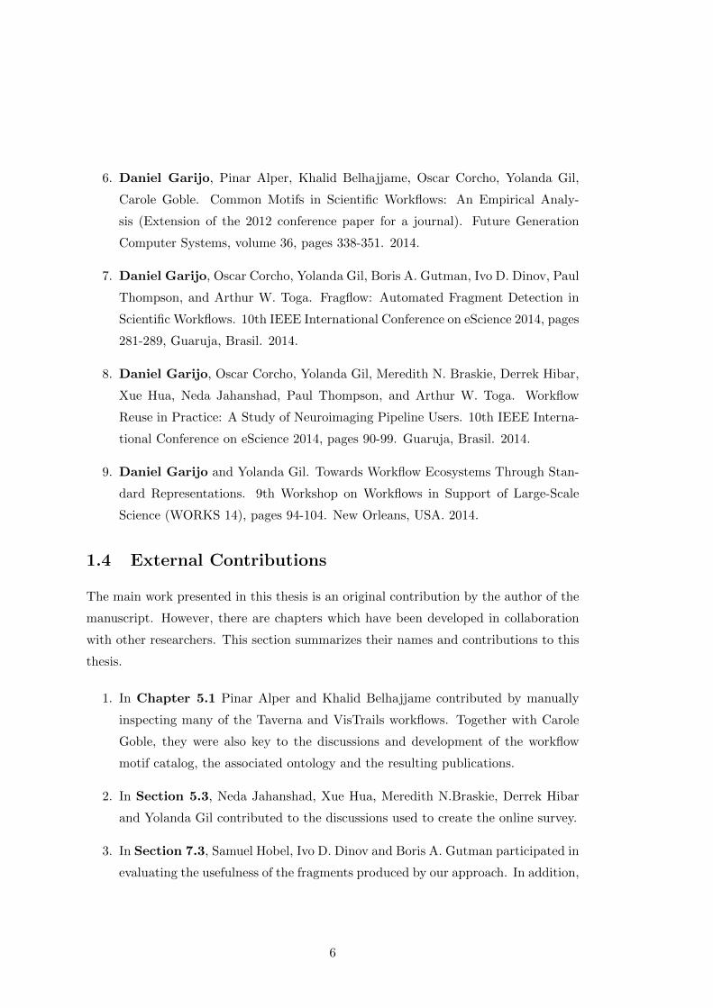
Scientific workflows have been used successfully in a wide range of domains, ranging
from life sciences to geology or astronomy. Figure 2.1 shows an example of two scientific
workflows from two different workflow systems. In both samples, we can see the most
typical elements of a scientific workflow: their inputs (textFile1, textfile2, threshold1
and threshold2 for the workflow on the left and projected landmarks, average curve
landmarks and skulpted for the workflow on the right), intermediate results (only shown
on the workflow of the left) and outputs (LikelihoodFile on the left and the upside
triangle at the bottom of the MINC obj 2 mesh step on the right). Inputs of a scientific
workflow may have been produced by other scientific workflows. Thus, an end-to-end
experiment can be seen as a puzzle composed of different scientific workflows performing
different aspects of it.
The main objective of this thesis is to mine repositories of workflows to find common
abstractions that are helpful for workflow reuse. There are several areas of ongoing
9
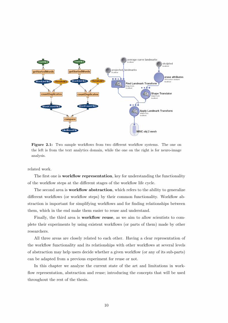
Figure 2.1: Two sample workflows from two different workflow systems. The one on
the left is from the text analytics domain, while the one on the right is for neuro-image
analysis.
related work.
The first one is workflow representation, key for understanding the functionality
of the workflow steps at the different stages of the workflow life cycle.
The second area is workflow abstraction, which refers to the ability to generalize
different workflows (or workflow steps) by their common functionality. Workflow ab-
straction is important for simplifying workflows and for finding relationships between
them, which in the end make them easier to reuse and understand.
Finally, the third area is workflow reuse, as we aim to allow scientists to com-
plete their experiments by using existent workflows (or parts of them) made by other
researchers.
All three areas are closely related to each other. Having a clear representation of
the workflow functionality and its relationships with other workflows at several levels
of abstraction may help users decide whether a given workflow (or any of its sub-parts)
can be adapted from a previous experiment for reuse or not.
In this chapter we analyze the current state of the art and limitations in work-
flow representation, abstraction and reuse; introducing the concepts that will be used
throughout the rest of the thesis.
10

2.1 Scientific Workflow Representation
Scientific workflows have been often compared to business workflows1, which are used
to represent business processes in the corporate world (Cerezo et al., 2013). As stated
in (Cerezo et al., 2013), “nothing prevents a user from using a business workflow frame-
work to model and perform a scientific experiment or a scientific workflow framework
to capture and automate a business process” and, in fact, there are examples of ap-
proaches for business workflows being adapted for scientific workflows (Mayer et al.,
2012) (Slominski, 2007).
However, there are some important differences between scientific workflows and
business workflows (Cerezo et al., 2013)(Tan et al., 2009)(Barga and Gannon, 2007).
On the one hand, business workflows are generally robust, secure, reliable and control-
driven (i.e., they often include control constructs like conditional branches and loops).
Business workflows are designed to perform services rather than exploring whether an
experiment can be successful or not. They also include policy and privacy concerns
for their usage, as this is typical in the corporate world. On the other hand, scientific
workflows represent in silico experiments that tend to be data driven, more dynamic
and evolving, with an aim for shareability and reusability of the exposed scientific
methods and with a flexible design for being extended by other researchers.
In our work we focus on scientific workflows. There have been several proposals for
their representation, and all of them use a graph-based approach. We introduce the
most relevant approaches in this section. Examples of workflow systems adopting each
representation are further described in (Deelman et al., 2009).
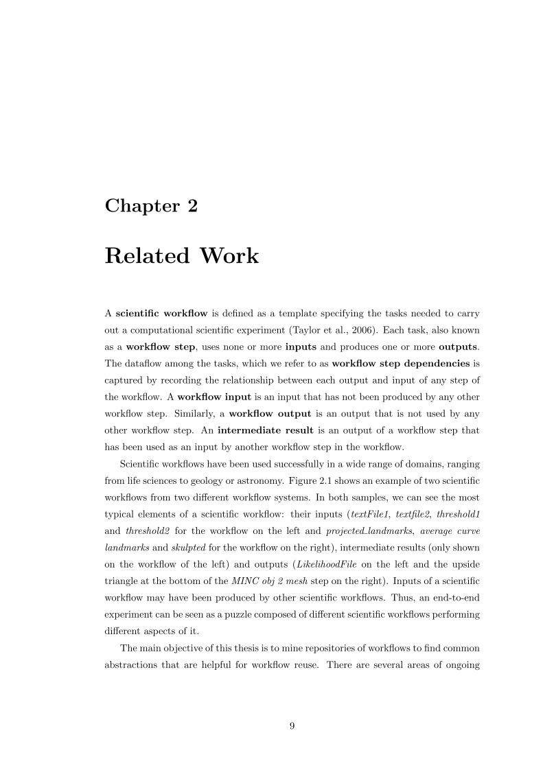
Petri Nets (Reisig and Rozenberg, 1998) represent workflow steps as actions, which
connect states of the workflow through directed arcs. Each state represents the status
of the workflow after the execution of an action. The workflow always starts with an
initial neutral state and reaches its final state only after the execution is completed.
Figure 2.2 shows an example of a workflow represented as a Petri Net. The workflow
retrieves a list of terms from a file (Read), adds annotations in parallel consulting
two different data sources (Annot1 and Annot2 ) and plots the results (Plot). Two
additional steps (Split and Merge) distribute the data and merge it later in order to
create the annotations in parallel.
1http://www.wfmc.org/what-is-bpm
11
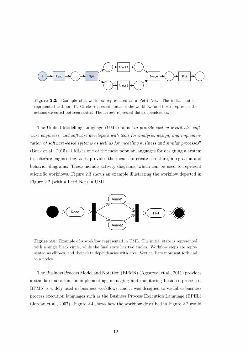
Figure 2.2: Example of a workflow represented as a Petri Net. The initial state is
represented with an “I”. Circles represent states of the workflow, and boxes represent the
actions executed between states. The arrows represent data dependencies.
The Unified Modelling Language (UML) aims “to provide system architects, soft-
ware engineers, and software developers with tools for analysis, design, and implemen-
tation of software-based systems as well as for modeling business and similar processes”
(Bock et al., 2015). UML is one of the most popular languages for designing a system
in software engineering, as it provides the means to create structure, integration and
behavior diagrams. These include activity diagrams, which can be used to represent
scientific workflows. Figure 2.3 shows an example illustrating the workflow depicted in
Figure 2.2 (with a Petri Net) in UML.
Figure 2.3: Example of a workflow represented in UML. The initial state is represented
with a single black circle, while the final state has two circles. Workflow steps are repre-
sented as ellipses, and their data dependencies with arcs. Vertical bars represent fork and
join nodes.
The Business Process Model and Notation (BPMN) (Aggarwal et al., 2011) provides
a standard notation for implementing, managing and monitoring business processes.
BPMN is widely used in business workflows, and it was designed to visualize business
process execution languages such as the Business Process Execution Language (BPEL)
(Jordan et al., 2007). Figure 2.4 shows how the workflow described in Figure 2.2 would
12

be represented in BPMN.
Figure 2.4: Example of a workflow represented in BPMN. The initial event is represented
with a single circle, while the final event is depicted with a circle with a wider line. Workflow
steps (tasks) are represented with rounded boxes. The flow is represented by arrows.
Diamond boxes represent gateways, which indicate when two activities are performed in
parallel.
However, the most typical representation for scientific workflows are graph-based
models. In them, the nodes of the graph represent workflow steps and the edges capture
their dataflow dependencies (e.g, (Gil et al., 2011) (Wolstencroft et al., 2013) (Goecks
et al., 2010) (Fahringer et al., 2007) (Berthold et al., 2008) (Callahan et al., 2006)
(Ludascher et al., 2006)). Figure 2.1, shows two workflow examples from two different
systems. It is worth mentioning that despite sharing the model, some systems represent
differently the inputs, outputs and intermediate results. In this case, ellipses are used
in the workflow of the left to refer to inputs, outputs and intermediate results, while
small circles and a triangle represent inputs and outputs for the workflow on the right.
Graph-based models are usually based on the definitions proposed in (Bondy and
Murty, 1976). Definition 1 summarizes the main concepts, which we use as basis for
the rest of the thesis.
Definition 1 A graph G = (V,E) is defined as a non empty set of vertices (nodes)
V = (v1, ..., vn) which are interconnected by an empty or non empty set of edges (links)
E = (e1, ..., em) with E ⊆ V × V and V disjoint from E (V ∩ E = ∅). Graphs are
directed when an edge e = (u, v) ∈ E means that the edge goes from u to v (having
(u, v) ∈ V ), u being the tail of the edge while v being its head. A walk W is a sequence
of consecutive vertices (v1, ..., vn) ∈ V such that for each pair of vertices (vi, vi+1) with
i ∈ (1, ..., n−1) there exists an edge e ∈ E that connects them. If ∀ (vi, vj) ∈W vi 6= vj
with i 6= j, W is denoted as a path. Two vertices of a graph G are connected if there is
a path between them. Connection is an equivalence relation on the vertex set V. Hence,
13

a graph G (V,E) can be divided into sets of connected vertices, called components.
When G (V,E) has only one component, the graph is connected. Otherwise the graph
is disconnected. A cycle C is a walk with (v1, ..., vn), where v1 = vn and where the
edges (e1, ..., ek) ∈ C are distinct. A graph without cycles is acyclic. Finally, a graph
G = (V,E,LV , LE , ϕV , ϕE) is labeled if LV and LE are sets of labels for the vertices
and edges respectively; and ϕV and ϕE are functions that define how each vertex or
edge is mapped to a label: V → LV and E → LE respectively. An illustrative example
of each type of graph can be seen in Figure 2.5, according to its definition.
Figure 2.5: Different types of graph, as introduced in Definition 1.
Scientific workflows are typically data intensive, and they are often represented as
directed acyclic graphs (DAGs). However, there are systems which allow for control
flow constructs and use, when necessary, directed cyclic graphs (DCGs) like Kepler
(Ludascher et al., 2006), VisTrails (Callahan et al., 2006) or Moteur (Glatard et al.,
2007). In the next section we introduce the main workflow management systems used
in this work.
2.1.1 Scientific Workflow Management Systems
In order to design, monitor, execute and debug scientific workflows the community has
created workflow management systems in different domains. Some examples are Wings
(Gil et al., 2011), Taverna (Wolstencroft et al., 2013), GenePattern (Reich et al., 2006),
the LONI Pipeline (Dinov et al., 2009), Galaxy (Goecks et al., 2010), VisTrails (Deel-
man et al., 2004), ASKALON (Fahringer et al., 2007), Knime (Berthold et al., 2008),
Kepler (Ludascher et al., 2006), Pegasus (Deelman et al., 2005) or Moteur (Glatard
et al., 2007). These and other systems have already been described and compared in
14
detail in related work (Goderis, 2008) (Cerezo, 2013) (Deelman et al., 2009) (Yu and
Buyya, 2005). Here we introduce the workflow systems that have been used for the
experiments of this thesis. The rationale behind using each of these workflow systems
is explained on Chapter 5.
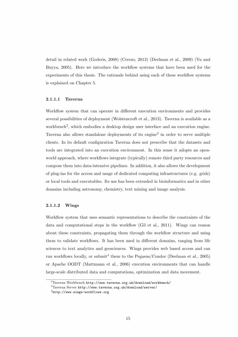
2.1.1.1 Taverna
Workflow system that can operate in different execution environments and provides
several possibilities of deployment (Wolstencroft et al., 2013). Taverna is available as a
workbench2, which embodies a desktop design user interface and an execution engine.
Taverna also allows standalone deployments of its engine3 in order to serve multiple
clients. In its default configuration Taverna does not prescribe that the datasets and
tools are integrated into an execution environment. In this sense it adopts an open-
world approach, where workflows integrate (typically) remote third party resources and
compose them into data-intensive pipelines. In addition, it also allows the development
of plug-ins for the access and usage of dedicated computing infrastructures (e.g. grids)
or local tools and executables. Its use has been extended in bioinformatics and in other
domains including astronomy, chemistry, text mining and image analysis.
2.1.1.2 Wings
Workflow system that uses semantic representations to describe the constraints of the
data and computational steps in the workflow (Gil et al., 2011). Wings can reason
about these constraints, propagating them through the workflow structure and using
them to validate workflows. It has been used in different domains, ranging from life
sciences to text analytics and geosciences. Wings provides web based access and can
run workflows locally, or submit4 them to the Pegasus/Condor (Deelman et al., 2005)
or Apache OODT (Mattmann et al., 2006) execution environments that can handle
large-scale distributed data and computations, optimization and data movement.
2Taverna Workbench http://www.taverna.org.uk/download/workbench/3Taverna Server http://www.taverna.org.uk/download/server/4http://www.wings-workflows.org
15
2.1.1.3 Galaxy
Web-based platform for data intensive biomedical research (Giardine et al., 2005)
(Blankenberg et al., 2007). One of the main features of Galaxy is its cloud back-
end, which provides support for its extensive catalogue of tools. These tools allow
performing different types of analysis of data from widely used existing datasets in the
biomedical domain. Galaxy uses its own engine for managing the workflow execution,
compatible with batch systems or Sun Grid Engine (SGE)5. Galaxy workflows can be
run online6 or by setting up a local instance7.
2.1.1.4 VisTrails
System that tracks the change-based provenance in workflow specifications in order
to facilitate reuse (Callahan et al., 2006). It has been used in different domains of
life sciences like medical informatics and biomedicine, but also in other domains like
image processing, climatology and physics. VisTrails uses its own engine to manage the
execution and allows for the combination of specialized libraries, grid and web services.
Its workflows can be run online8 or locally9.
2.1.1.5 The LONI Pipeline
Workflow system developed by the Laboratory of Neuro Imaging (LONI)10 mainly
for neuro-imaging applications (Dinov et al., 2011) (Dinov et al., 2009). It provides an
efficient distributed computing solution to address common challenges in neuro-imaging
research, enabling investigators to share, integrate, collaborate and expand resources
including data, computing platforms, and analytic algorithms. The LONI Pipeline
is mostly used for complex neuro-imaging analysis, which often requires knowledge
about the input/output requirements of algorithms, data format conversions, optimal
parameter settings, and a unique running environment since imaging studies tend to
produce large amounts of data.
5http://star.mit.edu/cluster/docs/0.93.3/guides/sge.html6https://main.g2.bx.psu.edu/root7http://wiki.galaxyproject.org/Admin/Get%20Galaxy8http://www.crowdlabs.org/vistrails/9http://www.vistrails.org/index.php/Downloads
10http://loni.usc.edu/
16
2.1.2 Scientific Workflow Life Cycle
There are four main stages in the life cycle of a workflow (van der Aalst et al., 2003b):
workflow design, workflow configuration, workflow enactment and workflow diagnosis.
Rather than focusing on the phases themselves, here we describe the main workflow
structures that are interchanged within a workflow management system during the
workflow life cycle. We distinguish three major types of workflow structures:
1. Workflow Template (WT): A generic reusable workflow specification that in-
dicates the types of steps in the workflow and their dataflow dependencies. Work-
flow templates have also been referred to as “Workflow Orchestration” (Deelman
et al., 2009). A workflow generation tool can take types of steps specified in the
workflow template (e.g., “Sort”) and specialize them to implemented algorithms
and codes (e.g., “Quicksort in Python”) to create a workflow instance.
2. Workflow Instance (WI): A workflow that specifies the application algorithms
to be executed and the data to be used (Deelman et al., 2009). Workflow instances
are created from workflow templates when datasets are identified and are some-
times called abstract workflows because they do not specify execution resources
(Cerezo et al., 2013). Since a type of step can have different implementations,
the same workflow template could be used to generate very different workflow
instances. A workflow instance can be submitted to a workflow mapping and
execution system, which will identify and assign available resources at run-time,
submit it for execution, oversee its execution, and return a workflow execution
trace. Because different resources may be available at different times or in dif-
ferent execution environments, the same workflow instance may result in very
different workflow execution traces.
3. Workflow Execution Trace (WET): Also known as provenance trace, a work-
flow execution trace contains the details of what happened during the execution
of a workflow, including what resources it was executed on, execution time for
each step, links to the intermediate results, and possibly other execution details
such as steps for data movements. When workflow steps fail to execute, a work-
flow execution contains annotations of what failed and in this way its dataflow
structure may be different from the dataflow in a workflow instance.
17
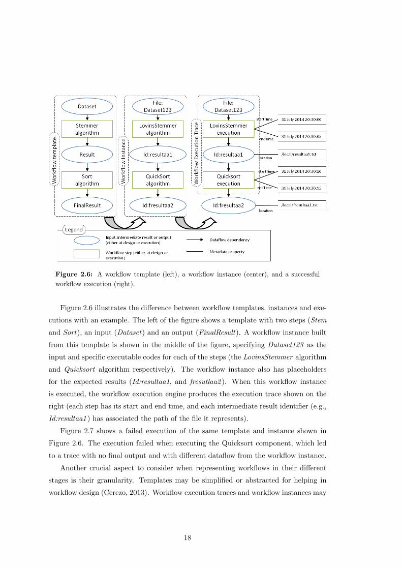
Figure 2.6: A workflow template (left), a workflow instance (center), and a successful
workflow execution (right).
Figure 2.6 illustrates the difference between workflow templates, instances and exe-
cutions with an example. The left of the figure shows a template with two steps (Stem
and Sort), an input (Dataset) and an output (FinalResult). A workflow instance built
from this template is shown in the middle of the figure, specifying Dataset123 as the
input and specific executable codes for each of the steps (the LovinsStemmer algorithm
and Quicksort algorithm respectively). The workflow instance also has placeholders
for the expected results (Id:resultaa1, and fresutlaa2 ). When this workflow instance
is executed, the workflow execution engine produces the execution trace shown on the
right (each step has its start and end time, and each intermediate result identifier (e.g.,
Id:resultaa1 ) has associated the path of the file it represents).
Figure 2.7 shows a failed execution of the same template and instance shown in
Figure 2.6. The execution failed when executing the Quicksort component, which led
to a trace with no final output and with different dataflow from the workflow instance.
Another crucial aspect to consider when representing workflows in their different
stages is their granularity. Templates may be simplified or abstracted for helping in
workflow design (Cerezo, 2013). Workflow execution traces and workflow instances may
18
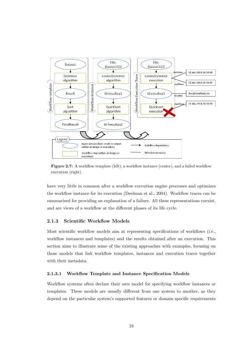
Figure 2.7: A workflow template (left), a workflow instance (center), and a failed workflow
execution (right).
have very little in common after a workflow execution engine processes and optimizes
the workflow instance for its execution (Deelman et al., 2004). Workflow traces can be
summarized for providing an explanation of a failure. All these representations coexist,
and are views of a workflow at the different phases of its life cycle.
2.1.3 Scientific Workflow Models
Most scientific workflow models aim at representing specifications of workflows (i.e.,
workflow instances and templates) and the results obtained after an execution. This
section aims to illustrate some of the existing approaches with examples, focusing on
those models that link workflow templates, instances and execution traces together
with their metadata.
2.1.3.1 Workflow Template and Instance Specification Models
Workflow systems often declare their own model for specifying workflow instances or
templates. These models are usually different from one system to another, as they
depend on the particular system’s supported features or domain specific requirements
19

(e.g., control-oriented constructs, enabling easy access to external web services, etc.).
For example, Taverna has Scufl (Oinn et al., 2004), Pegasus uses DAX11, Kepler uses
MOML (Lee and Neuendorffer, 2000), Askalon uses AGWL (Fahringer et al., 2005),
etc. Some additional examples can be seen in (Deelman et al., 2009).
There have been efforts towards creating a common workflow language. In the
business workflow domain, Web Services BPEL (WS-BPEL) (Jordan et al., 2007)
(Barga and Gannon, 2007) was designed for specifying business processes using web
services. In the scientific workflow domain, the Data-Intensive Systems Process Engi-
neering Language (DISPEL) was created to “describe abstract workflows for distributed
data-intensive applications” (Atkinson et al., 2013). Another significant effort to de-
velop a common workflow language was lead by the SHIWA project (Krefting et al.,
2011), which developed the IWIR language (Plankensteiner et al., 2011) for represent-
ing workflows in a system-independent manner. Workflows represented in IWIR can be
partitioned so that each partition is executed in a different workflow execution engine.
2.1.3.2 Workflow Execution Trace Models
These are the models designed to represent the provenance trace of a workflow. Accord-
ing to the recent W3C standard, provenance can be defined as “a record that describes
the people, institutions, entities, and activities involved in producing, influencing, or
delivering a piece of data or a thing” (Moreau et al., 2013).
The notion of provenance has been widely discussed in related work for a variety
of domains, ranging from digital humanities12 to e-science (Simmhan et al., 2005). In
fact, several models have been proposed throughout the years to manage and repre-
sent generic provenance (Moreau, 2010). In an attempt to propose a common prove-
nance standard, the workflow community started the Provenance Challenges13, which
focused on discussing different approaches for representing the same provenance prob-
lem and testing their interoperability. After the Third Provenance Challenge14, the
Open Provenance Model (OPM) (Moreau et al., 2011) consolidated itself as a de facto
provenance standard and was adopted by a reasonable part of the community15. The
11http://pegasus.isi.edu/wms/docs/schemas/dax-3.4/dax-3.4.html12http://www.getty.edu/research/tools/provenance/13http://twiki.ipaw.info/bin/view/Challenge14http://twiki.ipaw.info/bin/view/Challenge/ThirdProvenanceChallenge15http://openprovenance.org/
20
interest in having a standard for provenance interchange vocabulary led to the creation
of the W3C Provenance Incubator Group16, which gathered the provenance require-
ments proposed by the scientific community in different domains (Groth et al., 2012)
and set the first steps towards the creation of a standard (Gil et al., 2010). It was
followed by the Provenance Working Group17, whose effort finally materialized in the
family of PROV specifications18, a set of W3C recommendations on how to model and
interchange provenance on the Web (Groth and Moreau, 2013).
Some workflow systems have started capturing their workflow executions by extend-
ing OPM and PROV models (most of them during the development of this thesis). Swift
was perhaps one of the first workflow systems to export to OPM (Gadelha Jr. et al.,
2011). The Taverna team followed with an experimental workflow export to OPM19,
but more recently they have moved to the Research Object model (Belhajjame et al.,
2012a) to represent workflow descriptions and provenance according to PROV. Wings
exports workflow executions following both OPM (Garijo and Gil, 2011) and PROV20.
Some other approaches have used VisTrails to capture provenance traces according to
PROV, using a more generic model (Missier et al., 2013). Systems like Pegasus or
Kepler have been integrated with provenance management stores like PASOA (Miles
et al., 2007) or Prov Manager (Marinho et al., 2012) to generically store provenance
traces according to OPM and PROV respectively. To this date, there is no standard
extension of OPM or PROV for representing scientific workflow execution traces.
Finally, other workflow systems like Galaxy, GenePattern or the LONI Pipeline
create logs of workflow execution following their own conventions.
2.1.3.3 Linking workflow templates, instances and executions
The models shown in the previous sections tackle the representation of workflow tem-
plates, instances and executions separately. However, they depend on each other. For
example, let’s consider a scientist who wants to create a scientific workflow for the
experiment he has been working on. The first step would be to complete a sketch of
the workflow, which would be used to complete a workflow template. The workflow
16http://www.w3.org/2005/Incubator/prov/wiki/W3C_Provenance_Incubator_Group_Wiki17http://www.w3.org/2011/prov/wiki/Main_Page18https://dvcs.w3.org/hg/prov/raw-file/tip/namespace/landing-page.html19http://dev.mygrid.org.uk/wiki/display/tav250/Provenance+export+to+OPM+and+Janus20http://www.opmw.org/ontology/
21

template can then be implemented with specific algorithms using the input datasets se-
lected for the experiment, creating one or several workflow instances. Then, a workflow
instance may be executed one or several times, producing workflow execution traces
that may be successful or not.
The relationships among workflow templates, instances and executions are often
represented by different models with ontologies21. An ontology is defined as a “formal
specification of a shared conceptualization”, where conceptualization refers to “an ab-
stract model of some phenomenon in the world by having identified the relevant concepts
of that phenomenon”, formal means that “it should be machine-readable” and shared
means that “the ontology captures consensual knowledge” (Studer et al., 1998). Ontolo-
gies are usually implemented in RDFS (McBride et al., 2014) and OWL (McGuinness
and van Harmelen, 2004), which are represented using the Resource Description Frame-
work data model (RDF) (Klyne et al., 2004). RDF is a W3C recommendation that
specifies the relationships between resources using a labeled graph with RDF state-
ments. Each RDF statement consists on a triple with a subject node and an object
node, connected by a predicate. Figure 2.8 shows an example, in which a file (File1,
subject) is described with its creator (Bob, object) with the “createdBy” predicate.
Figure 2.8: RDF example: a file is described with its creator.
Since graphs are a common representation for scientific workflows, several models
have adopted RDF to represent their main concepts (Belhajjame et al., 2015; Cerezo,
2013; Missier et al., 2013). In addition, RDF provides a machine readable representation
of the workflow, making it easier to process. During the development of this thesis, some
models have been proposed to describe the links between scientific workflow templates,
instances or executions:
The Research Object ontologies consist of a family of specifications for de-
scribing aggregations of resources related to a scientific experiment (Belhajjame et al.,
21Ontologies are commonly referred to as vocabularies when they are not complex. See http://www.
w3.org/standards/semanticweb/ontology
22
2015). Scientific workflows play an important role, having two vocabularies for describ-
ing them. The workflow description vocabulary (wfdesc)22 defines workflow instances
and templates; and the workflow provenance vocabulary (wfprov)23 defines workflow
execution traces and how they link to the instances or templates. The vocabularies ex-
tend the PROV standard and support the definition of sub-workflows, but don’t make
a distinction between workflow instances and templates.
ProvONE is a recent PROV extension for capturing the “most important informa-
tion concerning scientific workflow computational processes”24. ProvONE is based on
D-PROV, another PROV extension that aims at representing the retrospective prove-
nance (workflow execution traces) and prospective provenance (workflow instances) of
scientific workflows (Missier et al., 2013). The model is similar to the Research Object
ontologies, but tries to be more generic by representing dependencies among processes
as links between ports or as channels.
Conceptual workflows have been designed to facilitate workflow abstraction and
design (Cerezo, 2013). The model proposes a conceptual level (what we refer to as
workflow template) which is then specified to an abstract level (workflow instance). A
similar effort has been described in the Wings system, defining generic and concrete
templates (Gil et al., 2009), but conceptual workflows are more generic by defining
constructs to represent and link loops and conditional branches in workflow templates
and instances. In both cases, the representation of workflow executions traces are out
of the scope of the model.
P-Plan is designed to capture “the plans that guided the execution of scientific
processes”25 (Garijo and Gil, 2012). Hence, it is a simple high level model extending
the PROV standard. P-Plan captures the main dataflow constructs and links them
to the workflow execution. Since it is a general purpose vocabulary, P-Plan has been
used for the description of laboratory protocols (Giraldo et al., 2014), description of
infrastructure of workflow steps26, scientific workflow invocation27 or social science
modeling(Markovic et al., 2014).
22http://purl.org/wf4ever/wfdesc23http://purl.org/wf4ever/wfprov24http://purl.org/provone25http://purl.org/net/p-plan26http://purl.org/net/wicus-stack27http://purl.org/net/wf-invocation
23
Other vocabularies aim to be more generic, in order to provide context to the whole
experiment that led to the scientific workflow. These vocabularies do not necessarily
attempt to describe any execution details, but rather a general purpose description that
serves as documentation of the steps of the workflow. They include:
The Investigation, Study, Assay Model (ISA) differentiates between three
concepts to describe biomedical research (Rocca et al., 2008). An assay represents the
most specific part of an experiment, i.e., measurements performed on subjects. A study
contains the experimental steps or sequence of steps and the investigation contains the
overall goals and means used for an experiment. An investigation may have one or
more studies, which themselves may consist of one or several assays. For each of these
concepts, the model aims to capture metadata such as references, names, protocols or
equipment.
The Ontology for Biomedical Investigations (OBI) defines a common frame-
work for representing experimental descriptions and methods in biomedical research
(Brinkman et al., 2010). OBI has been widely adopted and extended in the biomedical
domain, and although its main focus relies on identifying the different types of inputs,
outputs, roles and methods used by the community, it also defines basic relationships
for specifying the inputs and outputs of a certain step or protocol.
The EXPO Ontology presents an ontology for scientific experiments. Although
it is aimed at representing the scientific method (hypothesis, evaluation, interpretation
of results, etc.), the ontology has also specific steps for modeling scientific tasks like
those happening in a workflow along with their basic metadata (Soldatova and King,
2006).
Table 2.1 summarizes the scope and main features of the different approaches de-
scribed above.
2.1.3.4 Scientific Workflow Metadata
The final aspect for representing scientific workflows is their metadata. Workflow meta-
data often captures basic attribution and other aspects that are typical of scientific
workflows and their resources, such as the file size of the experiments, restrictions and
descriptions of the workflow steps, license, start and end time of the workflow execution,
whether an execution was successful or not, etc.
24
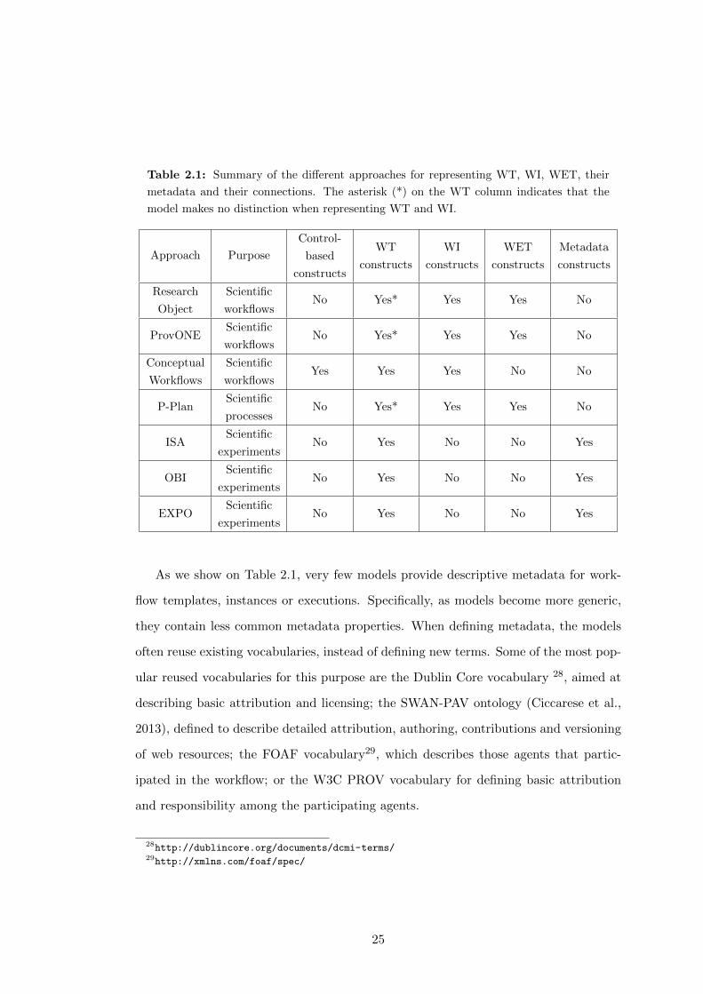
Table 2.1: Summary of the different approaches for representing WT, WI, WET, their
metadata and their connections. The asterisk (*) on the WT column indicates that the
model makes no distinction when representing WT and WI.
Approach Purpose
Control-
based
constructs
WT
constructs
WI
constructs
WET
constructs
Metadata
constructs
Research
Object
Scientific
workflowsNo Yes* Yes Yes No
ProvONEScientific
workflowsNo Yes* Yes Yes No
Conceptual
Workflows
Scientific
workflowsYes Yes Yes No No
P-PlanScientific
processesNo Yes* Yes Yes No
ISAScientific
experimentsNo Yes No No Yes
OBIScientific
experimentsNo Yes No No Yes
EXPOScientific
experimentsNo Yes No No Yes
As we show on Table 2.1, very few models provide descriptive metadata for work-
flow templates, instances or executions. Specifically, as models become more generic,
they contain less common metadata properties. When defining metadata, the models
often reuse existing vocabularies, instead of defining new terms. Some of the most pop-
ular reused vocabularies for this purpose are the Dublin Core vocabulary 28, aimed at
describing basic attribution and licensing; the SWAN-PAV ontology (Ciccarese et al.,
2013), defined to describe detailed attribution, authoring, contributions and versioning
of web resources; the FOAF vocabulary29, which describes those agents that partic-
ipated in the workflow; or the W3C PROV vocabulary for defining basic attribution
and responsibility among the participating agents.
28http://dublincore.org/documents/dcmi-terms/29http://xmlns.com/foaf/spec/
25

2.1.4 Scientific Workflow Publication
The ability to share workflows among scientists is critical for proper repurpose and
reuse of existing workflows; as well as a means to provide attribution and feedback to
other scientists for their work. In this section we review the current approaches for
making a scientific workflow public.
2.1.4.1 Data Repositories
The simplest option for sharing scientific workflows is through data repositories and
digital archives. In fact, general-purpose data repositories are gaining popularity for
sharing the resources associated to a paper: input datasets, specific results, etc.
In this kind of repositories, workflows (and optionally, their associated resources)
are compressed in a single file and stored or archived. The advantage of this approach
is that the stored file becomes citable, as data repositories often provide a Digital
Object Identifier (DOI)30 for referring to them. The downside is that workflow bundles
can be created in very heterogeneous ways, and without concrete guidelines, users may
omit important information for proper workflow reusability. Some popular general data
repositories are FigShare31 and Dryad32.
2.1.4.2 Workflow Repositories
In order to facilitate workflow reuse and to provide use examples, some workflow sys-
tems have created repositories for publishing workflow templates and instances. Galaxy
has a catalog of public workflows33 that can be downloaded and imported to one’s
workspace. VisTrails can push workflow specifications to CrowdLabs (Mates et al.,
2011) in order to further document them. The LONI Pipeline also has a curated
catalog of public workflows 34 and components. The most well known repository of
workflows is probably myExperiment (Goderis et al., 2009), initially developed to store
Taverna workflows, but currently containing more than 2000 workflows from systems
like Kepler, the LONI Pipeline or RapidMiner35.
30http://www.doi.org/31http://figshare.com32http://datadryad.org/33https://usegalaxy.org/workflow/list_published34http://pipeline.loni.usc.edu/explore/library-navigator/35https://rapidminer.com/
26
Most public repositories store only workflow templates, although myExperiment has
started moving towards capturing the context of experiments with Research Objects
(called “packs”). Packs are collections of aggregated resources relevant to a particular
experiment (e.g., executions, conclusions, hypothesis, diagrams, etc.).
The methodology for uploading a workflow into these repositories is usually through
their workflow management systems or by manual submission through their publicly
available APIs.
2.1.4.3 Science Gateways
Science gateways are applications, libraries of components, workflows and tools that
are shared and integrated through a portal. Most workflow systems often choose this
option for sharing workflows, as it can usually be combined with domain specific re-
sources like models and software libraries. Examples of science gateways can be seen
in (Filgueira et al., 2014) for the volcanology domain, in (Danovaro et al., 2014) for
hydro-meteorology research or in the LONI Pipeline36 for the neuro-image analysis
domain.
The main difference between a science gateway and a workflow repository is that
the former may provide the infrastructure to execute some of the shared components
through community portals.
2.1.4.4 Virtual Machines and Web Services
Finally, another solution adopted by scientists is to encapsulate their workflows as part
of virtual machines or web services that can be downloaded (or invoked) and then
executed. For example, (Chirigati et al., 2013) tracks the provenance of experiments
and then exposes the results and workflow specifications with a virtual machine. The
advantage of this approach is that anyone can easily reproduce the results claimed
by the scientist, since all the software dependencies are included as part of the virtual
machine. However, there are two main disadvantages. The first one is that the workflow
becomes a black box, hence very difficult to repurpose for other goals. The second one
is that this approach cannot always be considered, specifically when the datasets used
or produced by the experiment are large in size, or when the software uses non open
36http://pipeline.loni.usc.edu/explore/library-navigator/
27
source licenses, etc. Workflow reproducibility is a whole area of research, and is out of
the scope of this thesis.
2.2 Workflow Abstraction
There are several approaches for creating abstractions from scientific workflows (i.e.,
creating generalizations of steps by some of their common features). As we have shown
in the previous section, one possible way is based on the different stages of the workflow:
workflow templates are more abstract than workflow instances, which themselves may
be seen as representatives of a group of executions. Another possibility is based on the
granularity at which each stage can be presented to the user. For example, a workflow
execution trace may be simplified in part to facilitate understanding. In this section we
describe the most common types of workflow abstractions based on their granularity,
and give an overview on research developed to detect common workflow patterns.
2.2.1 Types of Abstractions in Scientific Workflows
Workflow templates and instances represent plans executed by a workflow engine.
Hence, some of the abstractions defined for planning tasks can also be applied to sci-
entific workflows. In this section we briefly define each of them with examples.
2.2.1.1 Skeletal planning
As stated in (Bergmann, 1992), a skeletal plan can be defined as a “sequence of ab-
stract and only partially specified steps which, when specialized to specific executable
operations, will solve a given problem in a specific problem context”. In this type of
abstraction, the number of steps in the abstract plan is the same as in the concrete
plan.
A particular case of this abstraction happens when only some of the steps of the
plan are abstract, in which case we refer to it as step abstraction. In step abstraction,
steps may be abstract classes of steps. These classes may be organized in a taxonomy
designed by domain experts, for example if the steps share similar constraints on the
conditions or effects. Figure 2.9 shows an example, where a generic workflow on the
top is specialized as two different workflows on the bottom of the figure, based on the
taxonomy of components depicted on the top right.
28
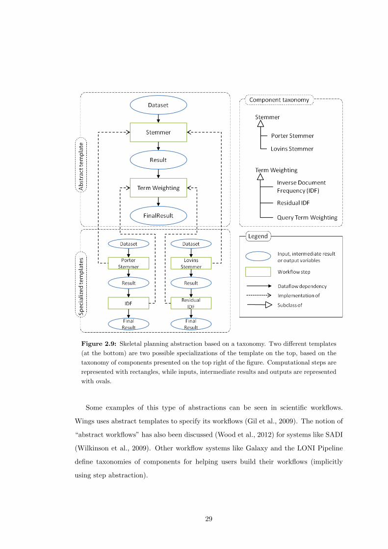
Figure 2.9: Skeletal planning abstraction based on a taxonomy. Two different templates
(at the bottom) are two possible specializations of the template on the top, based on the
taxonomy of components presented on the top right of the figure. Computational steps are
represented with rectangles, while inputs, intermediate results and outputs are represented
with ovals.
Some examples of this type of abstractions can be seen in scientific workflows.
Wings uses abstract templates to specify its workflows (Gil et al., 2009). The notion of
“abstract workflows” has also been discussed (Wood et al., 2012) for systems like SADI
(Wilkinson et al., 2009). Other workflow systems like Galaxy and the LONI Pipeline
define taxonomies of components for helping users build their workflows (implicitly
using step abstraction).
29

2.2.1.2 Predicate abstraction
In this type of abstraction, entire predicates are dropped at any given abstraction level
(Graf and Saidi, 1997). The intuition is that if a predicate requires less steps to be
accomplished then it can be placed in a lower abstraction level so that adding actions
to accomplish it will cause minimal disruption to the plan at higher levels. Ideally, the
abstraction layers are designed to preserve downward monotonicity, which implies that
any steps and orderings at higher layers of abstraction are unchanged as the plan is
elaborated at lower abstraction levels. In workflows, this would be akin to dropping
constraints or even inputs of steps at higher levels of abstraction. An example can be
seen in Figure 2.10, where the workflow on the right is abstracted as the workflow of the
left, dropping the optional inputs Dictionary (used to train the stemmer component)
and Clusters (which sets the number of clusters for the clustering algorithm).
Figure 2.10: Predicate abstraction example: the workflow on the left is an abstraction
of the workflow of the right. Two predicates (inputs Dictionary and Clusters) are omitted
in creating the abstraction.
30
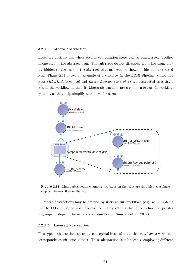
2.2.1.3 Macro abstraction
These are abstractions where several computation steps can be compressed together
as one step in the abstract plan. The sub-steps do not disappear from the plan, they
are hidden to the user in the abstract plan and can be shown inside the abstracted
step. Figure 2.11 shows an example of a workflow in the LONI Pipeline, where two
steps (KL MI deform field and Interp Average pairs of 3 ) are abstracted as a single
step in the workflow on the left. Macro abstractions are a common feature in workflow
systems, as they help simplify workflows for users.
Figure 2.11: Macro abstraction example: two steps on the right are simplified as a single
step on the workflow in the left.
Macro abstractions may be created by users as sub-workflows (e.g., as in systems
like the LONI Pipeline and Taverna), or via algorithms that mine behavioral profiles
of groups of steps of the workflow automatically (Smirnov et al., 2012).
2.2.1.4 Layered abstraction
This type of abstraction represents conceptual levels of detail that may have a very loose
correspondence with one another. These abstractions can be seen as employing different
31
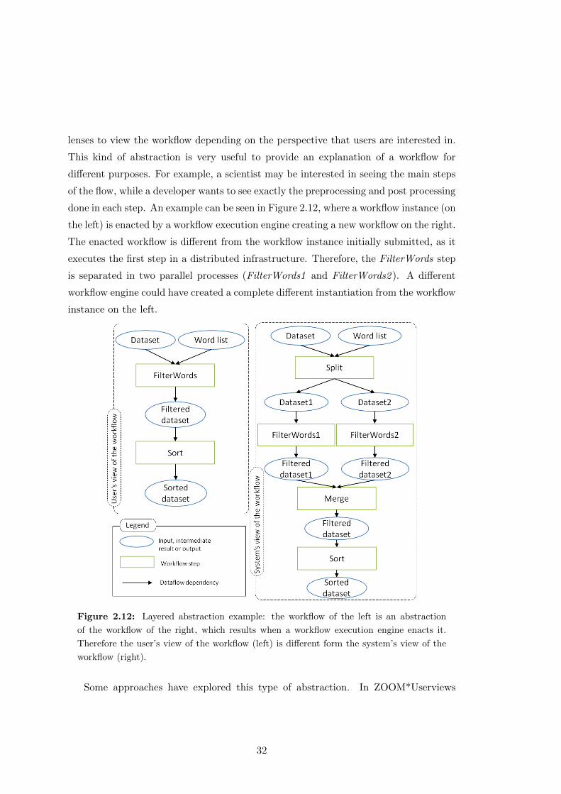
lenses to view the workflow depending on the perspective that users are interested in.
This kind of abstraction is very useful to provide an explanation of a workflow for
different purposes. For example, a scientist may be interested in seeing the main steps
of the flow, while a developer wants to see exactly the preprocessing and post processing
done in each step. An example can be seen in Figure 2.12, where a workflow instance (on
the left) is enacted by a workflow execution engine creating a new workflow on the right.
The enacted workflow is different from the workflow instance initially submitted, as it
executes the first step in a distributed infrastructure. Therefore, the FilterWords step
is separated in two parallel processes (FilterWords1 and FilterWords2 ). A different
workflow engine could have created a complete different instantiation from the workflow
instance on the left.
Figure 2.12: Layered abstraction example: the workflow of the left is an abstraction
of the workflow of the right, which results when a workflow execution engine enacts it.
Therefore the user’s view of the workflow (left) is different form the system’s view of the
workflow (right).
Some approaches have explored this type of abstraction. In ZOOM*Userviews
32

(Biton et al., 2007), the authors proposed to exploit workflow execution traces to show
different views to users according to their preferences. Conceptual workflows (Cerezo
et al., 2013) define a mapping to convert workflows defined in a conceptual level into
an intermediate representation that can be mapped itself to several target workflow
systems. Workflow systems such as Pegasus (Deelman et al., 2004) or ASKALON
(Wieczorek et al., 2005) often make use of this abstraction when mapping the workflow
instance to their distributed infrastructure.
2.2.2 Workflow Patterns
In Software Development, a pattern is defined as “the abstraction from a concrete
form which keeps recurring in specific non-arbitrary contexts” (Riehle and Zullighoven,
1996). This type of abstraction does not belong to any of the categories described in
the previous section, but has been studied extensively in related work.
Repositories of workflow patterns have been developed based on different prop-
erties of workflows. The most popular approach is based on the workflow structure
and constructs that are possible in different languages37 (van der Aalst et al., 2003a).
Other workflow patterns have been studied in terms of workflow resources (creation,
distribution, allocation, etc.) (Russell et al., 2004b) and workflow data (e.g., visibility,
interaction, transference, integration) (Russell et al., 2004a), including generic data
intensive usage patterns (Corcho, 2013). Additional classifications are based on the
intrinsic properties of the workflows (size, structure, branching factor, resource usage,
etc.) (Ramakrishnan and Plale, 2010) (Ostermann et al., 2008) and their environmental
characteristics (makespan, speedup, success rate, etc.) (Ostermann et al., 2008). The
viability of some of these workflow patterns has even been studied and discussed for
scientific workflows (Yildiz et al., 2009).
Workflow patterns represent common practices by the community, but do not al-
ways imply good practices for workflow design. For example, in (Cohen-Boulakia et al.,
2014) authors outline anti-patterns in scientific workflows, which basically consist of
redundancy and structural conflicts. Similarly, in (Velasco-Elizondo et al., 2013) the
authors use architectural abstractions (i.e., workflow patterns) to deal with data mis-
match issues between workflow steps (by suggesting the appropriate converters).
37http://www.workflowpatterns.com/
33

Generic workflow patterns based on the functionality of workflow steps have been
explored superficially. In (Wassink et al., 2009), the authors perform an automated
analysis of workflow scripts from life sciences, in order to obtain the frequency of
different types of technical ways of instantiating workflow steps (e.g. service invocations,
local scientist-developed scripting, local ready-madescripts, etc.). The authors also
refine the category of local ready-made scripts with activity categories depending on
their functionality (e.g., data access or data transformation). (Starlinger et al., 2012)
extends the categories defined in (Wassink et al., 2009), identifying sub-categories at a
workflow step level by analyzing 898 Taverna workflows in myExperiment.
Problem Solving Methods (PSMs) are other types of generic patterns that explore
the functionality of the workflow steps in them. PSMs describe strategies to achieve
the goal of a task in an implementation and domain-independent manner (Gomez-Perez
and Benjamins, 1999). PSMs are generic recipes, and some libraries have adapted them
to model the common processes in scientific domains (Gomez-Perez et al., 2010).
Other efforts aim at developing patterns based on workflow step functionality. Their
goal is to categorize and group common functionality in a specific domain, and, in
this regard, they may be used for generalizing workflows. For example, the Software
Ontology (SWO)38 models some of the typical operations in research regarding software
functionality like data annotation, data visualization, image compression, etc. Other
systems like Galaxy and the LONI Pipeline follow a similar approach. They have
defined generic categories under which they group workflow libraries, such as “get
data”, “statistics”, “structural analysis”, etc.
2.3 Workflow Reuse
Scientific contributions are often built on previous existing work, and this also applies to
scientists designing and creating scientific workflows. A proper workflow representation
and abstraction enables better understanding of workflows created by other researchers,
but it is difficult for scientists to explore whole datasets of workflows by themselves.
In order to facilitate this task, several approaches have been developed through
the years for mining workflows for different purposes, ranging from workflow design
to workflow discovery. In this section we first describe previous analyses on scientific
38http://sourceforge.net/projects/theswo/
34

workflow reuse, and then we summarize existing techniques that help users to reuse
workflows.
2.3.1 Measuring Workflow Reuse
Scientific workflows can be considered as software artifacts that connect software com-
ponents together (workflow steps). The barriers for software reuse have been analyzed
in the literature (Boldyreff, 1989). Software engineering technologies have been com-
pared and contrasted in terms of abstraction, selection, specialization and integration
(Krueger, 1992), which, as we have shown in this the chapter, are common problems in
scientific workflows as well. When focusing in the scientific domain, the incentives for
software development in terms of reuse, collaboration and productivity (e.g., getting
credit for software) have been discussed in (Howison and Herbsleb, 2011).
Regarding scientific workflows, some requirements for their reuse are defined in
(Goderis, 2008). The main requirements consist on having a community open to work-
flow reuse, availability of reusable workflows (e.g., through a publishing and sharing
infrastructure that manages interoperable workflows) and efficient workflow discovery.
The benefits of workflow reuse have been discussed in (Goderis et al., 2005), but (to
our knowledge) there are not many studies on how users perceive workflow reuse. One
of the few user surveys in the state of the art is (Goderis et al., 2005), which consisted
on a questionnaire to 24 scientists from different institutions. According to the survey
there are three main types of workflow reuse. These are “for one’s own purposes”,
“from a group of collaborators” and “from third parties”. The third type of workflow
reuse was not reported by any of the participants in the survey. In (Sethi et al., 2012),
the authors further defend the significance of reusing workflow fragments as well, by
showing how certain parts of text analytics and image analysis workflows may be used
for video activity recognition (and viceversa).
Automatic analyses of workflow repositories have also attempted to classify and
quantify workflow reuse, with a special focus on the myExperiment repository and Tav-
erna workflows. In (Tan et al., 2010), the authors use 280 Taverna workflows and 118
services of the BioCatalogue portal to find the connections among them (shared invo-
cations and components). Furthermore, they apply social network analysis techniques
to derive the centrality and betweenness of the nodes in the network. Unfortunately,
the results show that “services are currently reused in an ad hoc style instead of a
35
federated manner”. The work presented in (Wassink et al., 2009) also performs auto-
matic analyses on Taverna workflows available in myExperiment, but with a corpus of
415 workflows. In this case, the authors divide the corpus on different categories of
components (beanshells, scripts, etc.), and analyze their reuse. The work described in
(Littauer et al., 2012) builds on (Wassink et al., 2009) to further analyze other char-
acteristics of workflows (e.g., versioning, complexity, downloads) and proposes good
practices for workflow reuse.
However, the most complete analysis of myExperiment is (Starlinger et al., 2012),
which details how workflows, sub-workflows defined by users and steps (divided in
different categories) are reused. The corpus consists of 898 workflows, and reuse is
differentiated regarding the authors who contributed to the creation of a particular
workflow. Reuse is common, and may happen in three main different manners: a
workflow is reused as a new workflow (duplication), a sub-workflow is reused as a sub-
workflow in another workflow, and workflows are reused as sub-workflows (or viceversa).
Although current approaches have analyzed reuse in a significant amount of work-
flows, the majority of the corpora have been designed in the same workflow system
(Taverna) and leave out of the scope of their analysis groups of commonly occurring
workflow steps that may not have been annotated as sub-workflows by users.
2.3.2 Workflow Mining for Reuse
There are several areas where mining approaches have been applied for different pur-
poses, ranging from planning (Yang et al., 2005) (e.g., use previous plans to optimize
a future execution) to database query pattern extraction (Lawrynowicz and Potoniec,
2014) (in order to obtain common queries that might help to optimize access to the
dataset). In this section we introduce an overview on the efforts that are related to
mining workflows, in particular to those that are data intensive (scientific workflows).
These efforts are focused on three main goals: mining for the exploration of workflow
repositories, mining for recommending or discovering existent workflows and mining to
extract new workflows from existent ones.
2.3.2.1 Exploration of repositories
Repositories of workflows tend to be large, and it is difficult for users to analyze each
entry individually. In order to address this issue, there are several efforts that try to
36
organize repositories for enabling better understanding. These efforts are based on
machine learning techniques, namely clustering and topic modeling.
Clustering techniques are used to group sets of workflows together according to
a given similarity metric. The main difference among the existing approaches is the
similarity metric between workflows, the clustering technique being used and the num-
ber of clusters to which a workflow may belong. If we follow a chronological order,
(Santos et al., 2008) started proposing two different metrics to define similarity among
two given workflows: the maximum common sub-graph shared among them and the
euclidean distance that separates both workflows when represented as vectors (consid-
ering the union of the names of the workflow steps in the workflow as the features of
the vectors). In (Silva et al., 2011) the authors followed the previous approach by con-
sidering the structure of the workflow (e.g., connection between input ports and output
ports) on its similarity measure. Both efforts use the K-means algorithm (MacQueen,
1967), commonly used for clustering on the information retrieval domain. Finally, in
(Montani and Leonardi, 2012) the authors propose to use an edit distance in business
workflows, taking also into account the temporal similarity of the workflow steps. In
this case, the clustering technique is based on an unweighed pair group method with
arithmetic mean, which allows for hierarchical clustering.
Topic modeling techniques are common in text mining to determine the probability
of a document belonging to a certain topic. A topic is not a single word, but a set of
words which have a high probability of appearing together. (Stoyanovich et al., 2010)
applies this paradigm to the workflow domain, using 2075 workflows from VisTrails
and 861 from Taverna. The “words” in this case are the tags used to describe the
workflow and the names of the workflow steps. As a result, a set of topics are derived,
and workflows are organized around them.
A key difference between clustering techniques and topic modeling techniques is that
clustering techniques are deterministic, while topic modeling techniques are probabilis-
tic. This means that, when re-executed, a probabilistic technique may provide similar
results but not necessarily the same ones obtained on a previous execution. The main
disadvantage of both techniques is that a manual adjustment of the algorithm is needed
in order to find the optimal number of topics or clusters depending on the similarity
threshold set for the experiments.
37
2.3.2.2 Recommendation and discovery of existing workflows
The second goal for workflow mining focuses on suggesting workflows to users. This
can be done in two different phases of the workflow life cycle (van der Aalst et al.,
2003b): during workflow design, by suggesting the next workflow steps to the user, or
during workflow diagnosis, when aiming to discover workflows similar to a particular
one.
There are several approaches for next step suggestion while designing workflows,
based on previous executions or templates. The most straightforward approach can
be seen in (Oliveira et al., 2008), where the authors propose a probabilistic method by
computing the relationships between components in pairs and suggesting the next most
probable component. The approach proposed in (Koop, 2008) is more refined, by using
paths in previous workflows to recommend the most likely next step. The suggestion
may be either upstream or downstream the current fragment. Finally, (Leake and
Kendall-Morwick, 2008) relies on case-based reasoning approaches to mine provenance
traces in order to suggest users the next (single) step when editing new workflows. This
technique uses a similarity metric, based on an edit distance combined with a structural
comparison of the workflows.
Regarding workflow discovery, most approaches aim to deliver similar workflows
to a given one. The similarity metric is once again critical, and there has been work
that demonstrates that structural based approaches can outperform annotational ones
(Starlinger et al., 2014a). In (Goderis, 2008), the authors perform several experiments
comparing label-based approaches and sub-graph isomorphism techniques and perform
benchmarks for workflow discovery on that basis (Goderis et al., 2009). In (Bergmann
and Gil, 2014) the authors focus on structure according to a set of constraints set by
the user (e.g., having a specific input or output type). In this regard, this approach
is able to add specific requirements to the workflow the user is looking for. Finally, in
(Starlinger et al., 2014b), the similarity metric is based on a direct comparison of the
workflows by decomposing them into different layers, which provides fast results. It is
worth mentioning that some of the similarity metrics used for clustering repositories
may also be used for suggesting new workflows as well.
38

2.3.2.3 Deriving new workflows from existent corpora
The third goal for workflow mining aims to extract workflows from previous executions
or templates. In prior work this has been explored in two different ways: by deriving
an abstract workflow from a set of execution logs or by proposing new workflows from
a repository of workflow templates (based on, for example, commonly used structures).
Log mining has been explored in both business and scientific workflows. In the
business domain, (Herbst and Karagiannis, 1998) proposed to use hidden Markov mod-
els to find an approximation of a workflow from a set of execution traces. Other work
aims at obtaining workflow patterns through process mining. In fact, the term pro-
cess mining “refers to methods for distilling a structured process description from a
set of real executions” (van der Aalst et al., 2003b). A detailed analysis of different
approaches for process mining and research challenges can be read in (van der Aalst
et al., 2003b). Some exemplar approaches can be found in (van der Aalst et al., 2005),
where the resultant workflows are represented as Petri Nets, and (Rozinat and van der
Aalst, 2006), which introduces a whole framework for process mining. In the scientific
workflow domain (Gomez-Perez and Corcho, 2008) mines provenance traces to map
them against a problem solving method library. The goal of the work is similar to the
aforementioned approaches in business workflows, but in this case the authors aim to
generalize the provenance and to help understand the traces.
Case-based reasoning is often used to find substitute workflows for a given one. In
(Muller and Bergmann, 2014) the authors discuss the adaptability of workflows and
look for substitutes according to user needs. Another approach presents an algorithm
that combines control flow and dataflow of workflow traces, reasoning to generalize
and approximate a given workflow (Yaman et al., 2009). This is part of the POIROT
project (Burstein et al., 2009) for creating an architecture for reasoning and learning
components for workflows. Finally, (Smirnov et al., 2012) also generalizes workflows to
group common sets of components based on existing behaviors in the business domain.
During the development of this thesis, graph mining techniques have started to be
used to extract common patterns using the myExperiment repository. An overview of
the problem by extracting patterns with different metrics has been proposed in (Kamg-
nia Wonkap, 2014). 258 Taverna workflows were analyzed in (Diamantini et al., 2012),
39
as a first approximation using inexact graph mining techniques. Recently, (Garcıa-
Jimenez and Wilkinson, 2014a) has followed up by enriching 530 workflows with domain
specific knowledge in the biomedical domain. However, the lack of a gold standard to
measure precision and recall makes these approaches difficult to validate at the moment.
As happened with the approaches designed for exploring repositories, the main
difference between case-based reasoning, graph mining and process mining is that while
process mining is based on a network of probabilities, the other two approaches always
produce patterns that are found in the input workflow corpus. Figure 2.13 illustrates
the difference between the results of a process mining and a graph mining approach,
using as input the three workflows depicted on top. The fragments produced by a graph
mining technique can be seen on the right, while the network of probabilities extracted
from the workflows can be seen on the left. Although both approaches mine patterns,
they are used for different purposes.
2.4 Summary
In this chapter we have described the most relevant related work in the areas of workflow
representation, abstraction and reuse. On each of the areas, we have also introduced the
main concepts that will be used throughout the thesis along with the general limitations
of each approach.
Most of the described approaches focus on either representation, abstraction or
reuse, but none of them tackles the three areas as part of the same problem. Very
few models consider linking abstractions and patterns to the templates or execution
traces themselves; even in those approaches developed in parallel to this thesis. For
example (Cerezo, 2013) links conceptual workflows to the workflow instances, but does
not tackle the execution trace representation. Models like the Research Object and
ProvONE address the template and execution representation and linking, but avoid
dealing with abstractions of processes. To date, there are barely any approaches that
use domain knowledge to extract abstract patterns that may help reusing and exploring
workflows on a given repository. There is also a lack of a common simple model that
can be used to represent the basic workflow functionality of all workflow systems for
mining purposes, or that represents workflows based on their step functionality.
40
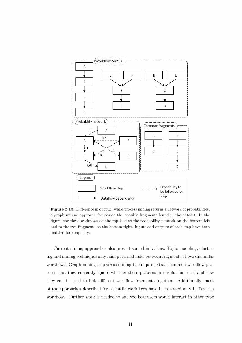
Figure 2.13: Difference in output: while process mining returns a network of probabilities,
a graph mining approach focuses on the possible fragments found in the dataset. In the
figure, the three workflows on the top lead to the probability network on the bottom left
and to the two fragments on the bottom right. Inputs and outputs of each step have been
omitted for simplicity.
Current mining approaches also present some limitations. Topic modeling, cluster-
ing and mining techniques may miss potential links between fragments of two dissimilar
workflows. Graph mining or process mining techniques extract common workflow pat-
terns, but they currently ignore whether these patterns are useful for reuse and how
they can be used to link different workflow fragments together. Additionally, most
of the approaches described for scientific workflows have been tested only in Taverna
workflows. Further work is needed to analyze how users would interact in other type
41

of environments, e.g., smaller communities like a research lab, students of a university
or a company.
In the next chapter we present our work objectives and hypothesis, relating them
to some of the limitations that we have identified in the current state of the art.
42
Chapter 3
Research Objectives
The main goal of the research presented in this thesis is to facilitate workflow un-
derstanding and reuse by analyzing and abstracting an existent corpus of scientific
workflows. This translates into three lines of work regarding scientific workflows. The
first one is workflow abstraction, which refers to the ability of a system to generalize
workflows (or workflow steps) by their common functionality. Workflow abstraction is
key for simplifying workflows and for finding relations between them.
The second line, workflow understanding, relates to the ability of users to clearly
determine the functionality of each of the steps (or group of steps) of the workflow.
Workflow understanding benefits from workflow abstraction, as it helps simplifying
the workflow at hand, and can be enhanced by including proper knowledge structure
to documentation and examples on the target workflow. Workflow understanding is
crucial to disseminate someone’s work within the scientific community.
The third line is workflow reuse, closely related with the previous two. Having
a clear understanding of the workflow functionality and its relationships with other
workflows may help users decide whether a given workflow (or any of its sub-parts) can
be adapted from a previous experiment or not.
This chapter introduces our main hypothesis (Section 3.1), its associated research
challenges (Section 3.2) and defines our research methodology, research and technical
goals (Section 3.3).
43
3.1 Research Hypotheses
We define our main hypothesis as follows:
Hypothesis 1 Scientific workflow repositories can be automatically analyzed to extract
commonly occurring patterns and abstractions that are useful for workflow developers
aiming to reuse existing workflows.
Our hypothesis can be divided into three different sub-parts, which overlap with the
workflow understanding, reuse and abstraction aspects respectively. First, by creating
a catalogue of the most typical domain-independent scientific workflow patterns based
on the functionality of workflow steps we can help users understand workflows better,
independently of the workflow system where they were defined (H1.1).
Second, by detecting commonly occurring patterns and abstractions automatically
we can find the implicit relationships between the workflows of a repository (H1.2).
Furthermore, for this purpose we hypothesize that the use of graph mining techniques
(H1.2.1) and the exploitation of domain specific metadata (H1.2.2) are good ap-
proaches for detecting and generalizing (or abstracting) common fragments automat-
ically.
Finally, by highlighting those patterns that are potentially useful for users designing
workflows we believe that we can help users reuse workflows (H1.3).
A summary of the hypotheses and how they deal with workflow abstraction, under-
standing and reuse can be found in table 3.1
3.2 Open Research Challenges
Our hypotheses can be related to several research challenges. First, in order to deter-
mine a common format to deal with templates and provenance of workflows, we need
to address the workflow representation heterogeneity in scientific workflows. Second, in
order to find common reusable patterns, we must handle the different levels of work-
flow abstraction and the difficulties for workflow reuse of a given corpus. Finally, by
detecting the common reusable patterns automatically we tackle the lack of support
for workflow annotation. Each of these research challenges are further described below,
and tackled throughout the thesis.
44
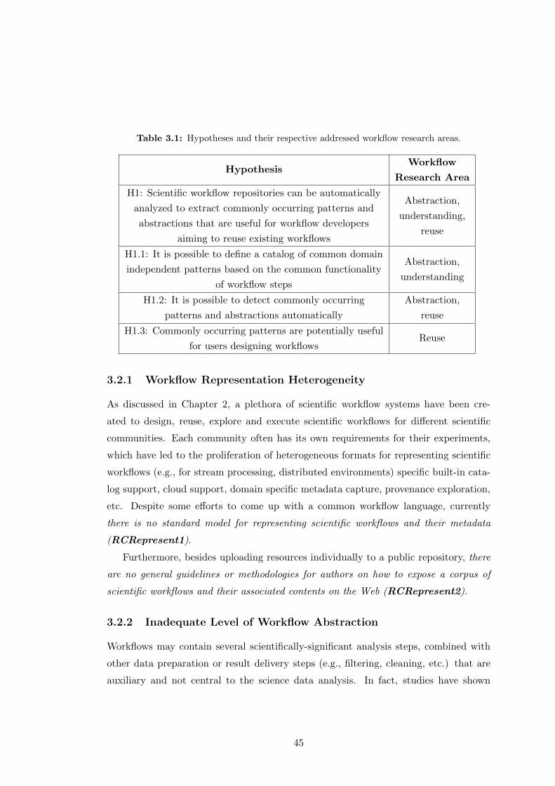
Table 3.1: Hypotheses and their respective addressed workflow research areas.
HypothesisWorkflow
Research Area
H1: Scientific workflow repositories can be automatically
analyzed to extract commonly occurring patterns and
abstractions that are useful for workflow developers
aiming to reuse existing workflows
Abstraction,
understanding,
reuse
H1.1: It is possible to define a catalog of common domain
independent patterns based on the common functionality
of workflow steps
Abstraction,
understanding
H1.2: It is possible to detect commonly occurring
patterns and abstractions automatically
Abstraction,
reuse
H1.3: Commonly occurring patterns are potentially useful
for users designing workflowsReuse
3.2.1 Workflow Representation Heterogeneity
As discussed in Chapter 2, a plethora of scientific workflow systems have been cre-
ated to design, reuse, explore and execute scientific workflows for different scientific
communities. Each community often has its own requirements for their experiments,
which have led to the proliferation of heterogeneous formats for representing scientific
workflows (e.g., for stream processing, distributed environments) specific built-in cata-
log support, cloud support, domain specific metadata capture, provenance exploration,
etc. Despite some efforts to come up with a common workflow language, currently
there is no standard model for representing scientific workflows and their metadata
(RCRepresent1).
Furthermore, besides uploading resources individually to a public repository, there
are no general guidelines or methodologies for authors on how to expose a corpus of
scientific workflows and their associated contents on the Web (RCRepresent2).
3.2.2 Inadequate Level of Workflow Abstraction
Workflows may contain several scientifically-significant analysis steps, combined with
other data preparation or result delivery steps (e.g., filtering, cleaning, etc.) that are
auxiliary and not central to the science data analysis. In fact, studies have shown
45
that over half of the steps of workflows consist on data preparation steps that increase
their complexity and obfuscate their main functionality (Garijo et al., 2012). There-
fore in many cases it is difficult to determine which are the main significant processing
steps of the workflow (RCAbstract1), even when a textual description of the workflow
functionality exists in a publication or other documentation. In this regard, patterns
have been defined in other work to capture typical control flow properties on workflows
(van der Aalst et al., 2003a). However, there are no catalogs on the typical abstrac-
tions that can be found in scientific workflows based on their basic step functionality
(RCAbstract2).
3.2.3 Difficulties of Workflow Reuse
One of the key aspects of workflows is their potential shareability. Scientists often
include workflows as sub-workflows (Starlinger et al., 2012) when the workflow sys-
tem supports them. Several repositories of workflows like myExperiment, the LONI
Pipeline, Crowdlabs or Galaxy store templates, metadata and sometimes even execu-
tions of past experiments. However, it is difficult to determine the relation between dif-
ferent workflows regarding their functionality (RCReuse1) and unless common reused
workflow fragments are explicitly exposed by users as sub-workflows, it is not easy to de-
tect which workflows or workflow fragments are potentially useful for reuse (RCReuse-
2).
3.2.4 Lack of Support for Workflow Annotation
Workflow authors have to describe manually the functionality of their workflows, their
relationships to other workflows, their metadata and their inputs and outputs. There
are currently no approaches for facilitating these annotations in a semi-automatic way
(RCAnnot1), even for the typical operations in workflows (e.g., formatting and merg-
ing inputs). Therefore, the textual annotations on workflows (besides basic metadata
like creator, date and main purpose) are very few, and no standard is followed for
describing workflow functionality and metadata.
A summary of the challenges tackled in this work and how they map to the hy-
potheses is presented in table 3.2.
46

Table 3.2: Open research challenges and their related hypotheses.
Research Challenge Hypotheses
RCRepresent-1: There is no standard model for representing
scientific workflows and their metadataH1.1, H1.2
RCRepresent-2: There are no standard methodologies for
publishing a corpus of scientific workflows and their
associated resources in the Web
H1.1
RCAbstract-1: It is difficult to determine which steps
perform the main significant processing steps
in a scientific worflow
H1.1
RCAbstract-2: There are no catalogs of the typical
abstractions that can be found in scientfic workflows
based on their basic step functionality
H1.1
RCReuse-1: It is difficult to determine the
relationship between different workflows
regarding their functionality
H1.2
RCReuse-2: It is not easy to detect which workflows
or workflow fragments are potentially useful for reuseH1.3
RCAnnot-1: There are currently no approaches for
assisting scientists with workflow annotationH1.2
3.3 Research Methodology
The work presented on this thesis has been performed in an exploratory manner, fol-
lowing a layered approach motivated by the hypotheses. On each layer, the work has
been validated experimentally, helping to refine the results obtained in previous layers.
Figure 3.1 shows a roadmap of the thesis work, where each layer represented on the
left corresponds to a general problem. On the center and right of the figure we have
specified our approach to tackle each of the layers and the evaluation followed to vali-
date such approach. From top left to bottom right, the layers stand for the models we
need for providing workflow descriptions reusing existing standards, validated through
competency questions (Gruninger and Fox, 1994); the workflow abstraction effort for
defining a catalog of typical abstractions in workflows (validated by comparing our pro-
posal with workflow corpora from different systems); and the mechanisms developed to
47
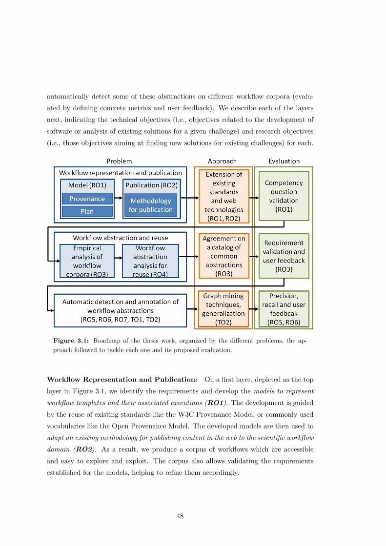
automatically detect some of these abstractions on different workflow corpora (evalu-
ated by defining concrete metrics and user feedback). We describe each of the layers
next, indicating the technical objectives (i.e., objectives related to the development of
software or analysis of existing solutions for a given challenge) and research objectives
(i.e., those objectives aiming at finding new solutions for existing challenges) for each.
Figure 3.1: Roadmap of the thesis work, organized by the different problems, the ap-
proach followed to tackle each one and its proposed evaluation.
Workflow Representation and Publication: On a first layer, depicted as the top
layer in Figure 3.1, we identify the requirements and develop the models to represent
workflow templates and their associated executions (RO1). The development is guided
by the reuse of existing standards like the W3C Provenance Model, or commonly used
vocabularies like the Open Provenance Model. The developed models are then used to
adapt an existing methodology for publishing content in the web to the scientific workflow
domain (RO2). As a result, we produce a corpus of workflows which are accessible
and easy to explore and exploit. The corpus also allows validating the requirements
established for the models, helping to refine them accordingly.
48
Workflow Abstraction and Reuse: In our second layer we first perform a manual
analysis on the published workflow corpus expanding it with the workflows available
in other online repositories like myExperiment, CrowdLabs and Galaxy. The analyses
aim at determining whether workflows in different domains and workflow systems share
common functionality among their steps, producing as an outcome a catalog of common
workflow abstractions (RO3). The catalog is validated and refined with each new
analyzed workflow, until no further abstractions can be obtained.
We then analyze the current practices of users in workflows (and their fragments)
in terms of workflow reuse, and we relate the results to the abstractions obtained in the
catalog (RO4). This allows us to focus on the automatic detection of those abstractions
that are relevant for workflow reuse.
Automatic Detection and Annotation of Workflow Abstractions: On our
bottom layer we bridge the gap between a corpus of workflows and the catalog of
abstractions defined on our second layer. We apply graph mining techniques to detect
potential abstractions automatically (TO1), define filtering techniques for refining the
obtained results (RO5) and propose metrics to validate our results against a corpus
of annotated workflows (RO6). As a result, we develop a system capable of finding
common patterns automatically (TO2), and we validate it with further feedback from
the users. Additionally, we propose a model for describing workflow fragments and
relate them to the workflows where they were found (RO7).
Table 3.3 summarizes the research objectives (ROs), technical objectives (TOs) and
the research challenges from Table 3.2 that they tackle.
49
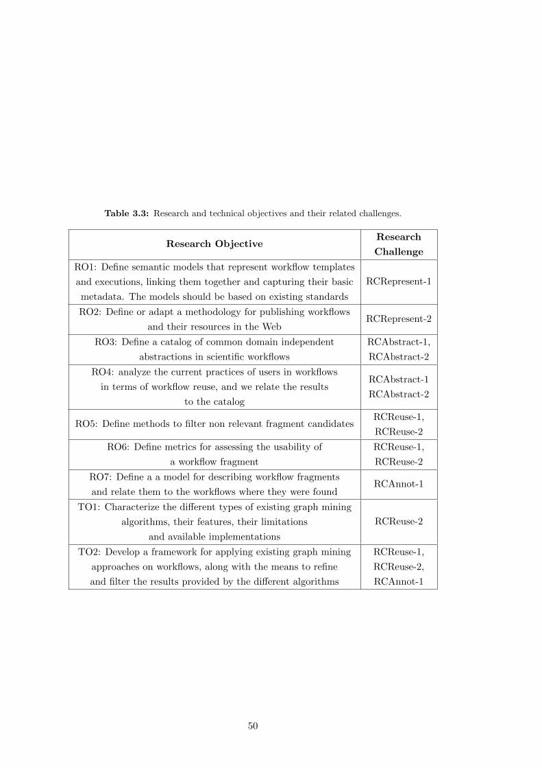
Table 3.3: Research and technical objectives and their related challenges.
Research ObjectiveResearch
Challenge
RO1: Define semantic models that represent workflow templates
and executions, linking them together and capturing their basic
metadata. The models should be based on existing standards
RCRepresent-1
RO2: Define or adapt a methodology for publishing workflows
and their resources in the WebRCRepresent-2
RO3: Define a catalog of common domain independent
abstractions in scientific workflows
RCAbstract-1,
RCAbstract-2
RO4: analyze the current practices of users in workflows
in terms of workflow reuse, and we relate the results
to the catalog
RCAbstract-1
RCAbstract-2
RO5: Define methods to filter non relevant fragment candidatesRCReuse-1,
RCReuse-2
RO6: Define metrics for assessing the usability of
a workflow fragment
RCReuse-1,
RCReuse-2
RO7: Define a a model for describing workflow fragments
and relate them to the workflows where they were foundRCAnnot-1
TO1: Characterize the different types of existing graph mining
algorithms, their features, their limitations
and available implementations
RCReuse-2
TO2: Develop a framework for applying existing graph mining
approaches on workflows, along with the means to refine
and filter the results provided by the different algorithms
RCReuse-1,
RCReuse-2,
RCAnnot-1
50

Chapter 4
Scientific Workflow
Representation and Publication
This chapter presents the Open Provenance Model for Workflows1 (OPMW), our model
to describe scientific workflows by capturing all their dataflow and dependencies, to-
gether with our approach for their publication. In doing so, we reuse existing standards
and methodologies, which aim to make our results reusable and interoperable with other
alternative approaches.
4.1 Scientific Workflow Model
We represent scientific workflows as labeled directed acyclic graphs (LDAGs). The
nodes of the graph represent the steps, inputs, outputs and intermediate results and
the edges represent the usage and generation dependencies among them. This choice
of model is motivated by the amount of scientific workflow systems using this or very
similar notation (as described on Chapter 2, some examples are Wings, the LONI
Pipeline, Taverna, Galaxy, VisTrails, etc.). In addition, a graph based model enables
the possibility of extending Semantic Web standards and reusing existing technologies
to model and expose workflow information. In order to create a simple model, we focus
on capturing data intensive workflow representations from a bottom up perspective,
i.e., the most simple common constructs shared among all workflow systems. Therefore,
1http://www.opmw.org/ontology/
51
control constructs like loops and optional branches have been left out of the scope of
the model.
Our model requirements, which have guided our development process, can be orga-
nized under three main categories:
• Workflow template representation requirements, which tackle the model-
ing of the workflow plan and its metadata. This includes the workflow template
and workflow instance stages, introduced in Section 2.1.2.
• Workflow provenance representation requirements, which refer to the
modeling of the execution of the workflow, its inputs, intermediate and final
results. Provenance is crucial to determine the chain of events that led to a result
of a scientific workflow, and which were the sources that influenced it.
• Workflow attribution representation requirements, which capture who
created and collaborated in the creation of the workflow, its execution and doc-
umentation. Attribution is key for acknowledging the authors appropriately be-
cause it allows them to get credit for the work they have done. For example, the
scientist responsible for designing the workflow (or a fragment of the workflow)
may be different from the scientist who is responsible for its execution on a certain
experiment.
The rest of the section describes how we have extended or reused existing vocabu-
laries and standards to create OPMW and address each of the requirement categories
described above. An Ontology Requirement Specification Document (ORSD) (Suarez-
Figueroa, 2010) has been created for each of our proposed vocabularies, containing the
competency questions (Gruninger and Fox, 1994) and the terms used to address them.
The ORSD can be seen in the Annex A.
4.1.1 Representing the Provenance of Workflow Executions: The Open
Provenance Model and W3C PROV
We use the W3C PROV standard and OPM (mentioned in Section 2.1.3.2) as founda-
tional vocabularies and extend them to represent workflow executions as provenance
records. In this section we briefly describe the core concepts of OPM and PROV that
are relevant to our work, along with their main similarities.
52
4.1.1.1 The Open Provenance Model
OPM models the resources for which we want to obtain the provenance (e.g., an input
of a workflow, an intermediate result, an output, etc.) as artifacts, which represent
immutable pieces of state. The steps that use and produce artifacts are known as
processes (action or series of actions performed on artifacts), and the entities that
control those processes are agents. The relationships between artifacts, processes
and agents are modeled in a provenance graph with five main causal edges: used
(a process used some artifact), wasControlledBy (an agent controlled some process),
wasGeneratedBy (a process generated an artifact), wasDerivedFrom (an artifact was
derived from another artifact) and wasTriggeredBy (a process was triggered by another
process). OPM also introduces the concept of roles to assign the type of activity that
artifacts, processes or agents played when interacting with one another, and the notion
of accounts and provenance graphs. An account represents a particular view on the
provenance of an artifact based on what was executed. A provenance graph groups
sets of related OPM assertions. OPM does not specify any concept for the modeling of
plans, so it can only be used to describe workflow executions and it cannot be used to
describe workflow instances or workflow templates.
OPM is available as two different ontologies that are built on top of each other.
One is the OPM Vocabulary (OPMV)2, a lightweight RDF vocabulary implementation
of the OPM model that only has a subset of the concepts in OPM but facilitates
modeling and query formulation. Figure 4.1 (from the online specification3) shows an
overview of the main OPMV concepts, i.e., agents, processes and artifacts and their
joint relationships. The other ontology is the OPM Ontology (OPMO)4, which covers
the full functionality of the OPM model, and can be used to represent OPM concepts
that are not in OPMV, such as Account or Role. OPMO also includes the possibility
of adding metadata to the relationships themselves (e.g., time of usage of an artifact
in an activity) through a n-ary relationship pattern (Noy et al., 2006).
2http://purl.org/net/opmv/ns3http://open-biomed.sourceforge.net/opmv/img/opmv_main_classes_properties_3.png4http://openprovenance.org/model/opmo
53

Figure 4.1: OPMV overview, extracted from its specification.
4.1.1.2 The W3C PROV Standard
The PROV model (with prefix prov) is heavily influenced by OPM. PROV models
the resources as entities (which can be mutable or immutable), the steps using and
generating entities as activities, and the individuals responsible for those activities
as agents. As shown in Figure 4.2 (from the online specification5), the relationships
are also modeled in a provenance graph with seven main types of edges: used (an ac-
tivity used some entity), wasAssociatedWith (an agent participated in some activity),
wasGeneratedBy (an activity generated an entity), wasDerivedFrom (an entity was de-
rived from another entity), wasAttributedTo (an entity was attributed to an agent),
actedOnBehalfOf (an agent acted on behalf of another agent) and wasInformedBy (an
activity used the entity produced by another activity).
PROV also keeps the notion of roles to describe how entities, activities and agents
behaved in a particular event (usage, generation, etc.); and provides the means to
qualify each of those roles using an n-ary pattern. Unlike OPM, PROV allows stating
the plan associated to a certain activity, although the plan definition itself is out of the
scope of the model (since it is not something that necessarily happened, for example,
if a step of a plan failed).
5http://www.w3.org/TR/prov-o/#starting-points-figure
54
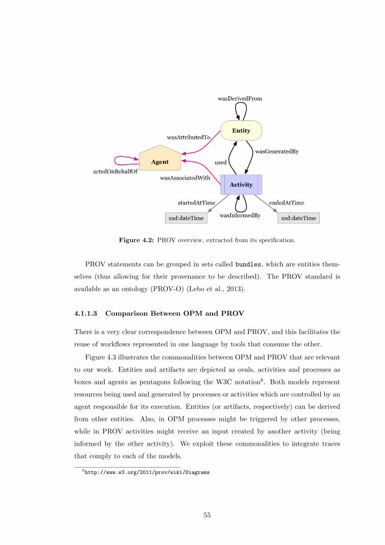
Figure 4.2: PROV overview, extracted from its specification.
PROV statements can be grouped in sets called bundles, which are entities them-
selves (thus allowing for their provenance to be described). The PROV standard is
available as an ontology (PROV-O) (Lebo et al., 2013).
4.1.1.3 Comparison Between OPM and PROV
There is a very clear correspondence between OPM and PROV, and this facilitates the
reuse of workflows represented in one language by tools that consume the other.
Figure 4.3 illustrates the commonalities between OPM and PROV that are relevant
to our work. Entities and artifacts are depicted as ovals, activities and processes as
boxes and agents as pentagons following the W3C notation6. Both models represent
resources being used and generated by processes or activities which are controlled by an
agent responsible for its execution. Entities (or artifacts, respectively) can be derived
from other entities. Also, in OPM processes might be triggered by other processes,
while in PROV activities might receive an input created by another activity (being
informed by the other activity). We exploit these commonalities to integrate traces
that comply to each of the models.
6http://www.w3.org/2011/prov/wiki/Diagrams
55
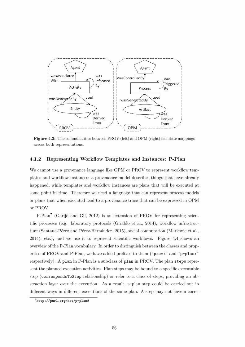
Figure 4.3: The commonalities between PROV (left) and OPM (right) facilitate mappings
across both representations.
4.1.2 Representing Workflow Templates and Instances: P-Plan
We cannot use a provenance language like OPM or PROV to represent workflow tem-
plates and workflow instances: a provenance model describes things that have already
happened, while templates and workflow instances are plans that will be executed at
some point in time. Therefore we need a language that can represent process models
or plans that when executed lead to a provenance trace that can be expressed in OPM
or PROV.
P-Plan7 (Garijo and Gil, 2012) is an extension of PROV for representing scien-
tific processes (e.g. laboratory protocols (Giraldo et al., 2014), workflow infrastruc-
ture (Santana-Perez and Perez-Hernandez, 2015), social computation (Markovic et al.,
2014), etc.), and we use it to represent scientific workflows. Figure 4.4 shows an
overview of the P-Plan vocabulary. In order to distinguish between the classes and prop-
erties of PROV and P-Plan, we have added prefixes to them (“prov:” and “p-plan:”
respectively). A plan in P-Plan is a subclass of plan in PROV. The plan steps repre-
sent the planned execution activities. Plan steps may be bound to a specific executable
step (correspondsToStep relationship) or refer to a class of steps, providing an ab-
straction layer over the execution. As a result, a plan step could be carried out in
different ways in different executions of the same plan. A step may not have a corre-
7http://purl.org/net/p-plan#
56
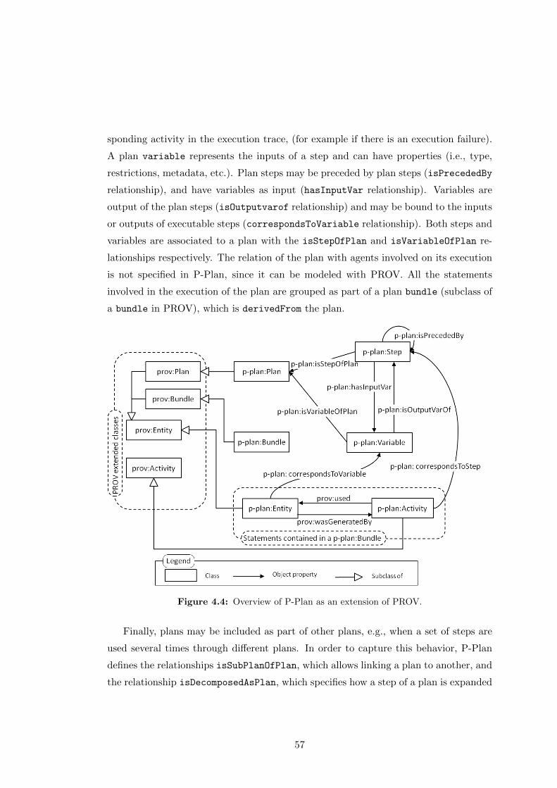
sponding activity in the execution trace, (for example if there is an execution failure).
A plan variable represents the inputs of a step and can have properties (i.e., type,
restrictions, metadata, etc.). Plan steps may be preceded by plan steps (isPrecededBy
relationship), and have variables as input (hasInputVar relationship). Variables are
output of the plan steps (isOutputvarof relationship) and may be bound to the inputs
or outputs of executable steps (correspondsToVariable relationship). Both steps and
variables are associated to a plan with the isStepOfPlan and isVariableOfPlan re-
lationships respectively. The relation of the plan with agents involved on its execution
is not specified in P-Plan, since it can be modeled with PROV. All the statements
involved in the execution of the plan are grouped as part of a plan bundle (subclass of
a bundle in PROV), which is derivedFrom the plan.
Figure 4.4: Overview of P-Plan as an extension of PROV.
Finally, plans may be included as part of other plans, e.g., when a set of steps are
used several times through different plans. In order to capture this behavior, P-Plan
defines the relationships isSubPlanOfPlan, which allows linking a plan to another, and
the relationship isDecomposedAsPlan, which specifies how a step of a plan is expanded
57

itself as another plan. When this happens, the step representing the sub-plan becomes
a multiStep. An example is shown in Figure 4.5, where a plan with two steps is as
part of another plan.
Figure 4.5: Sub-plan representation in P-Plan: A plan (P2) with two steps is contained
as the third step of another plan (P1) with 3 steps.
4.1.3 OPMW
Workflow templates, instances, and executions can be represented with the OPMW
model8 (Garijo and Gil, 2011). OPMW extends P-Plan for addressing the template
representation requirements, and PROV and OPM for the provenance representation
requirements. OPMW supports the representations of workflows at a fine granularity
with a lot of details pertaining to workflows that are not covered in those more generic
languages. OPMW also allows the representation of links between a workflow template,
a workflow instance created from it, and a workflow execution that resulted from an
instance. Finally, OPMW also supports the representation of roles and attribution
8http://www.opmw.org/ontology/
58
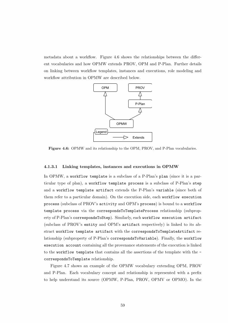
metadata about a workflow. Figure 4.6 shows the relationships between the differ-
ent vocabularies and how OPMW extends PROV, OPM and P-Plan. Further details
on linking between workflow templates, instances and executions, role modeling and
workflow attribution in OPMW are described below.
Figure 4.6: OPMW and its relationship to the OPM, PROV, and P-Plan vocabularies.
4.1.3.1 Linking templates, instances and executions in OPMW
In OPMW, a workflow template is a subclass of a P-Plan’s plan (since it is a par-
ticular type of plan), a workflow template process is a subclass of P-Plan’s step
and a workflow template artifact extends the P-Plan’s variable (since both of
them refer to a particular domain). On the execution side, each workflow execution
process (subclass of PROV’s activity and OPM’s process) is bound to a workflow
template process via the correspondsToTemplateProcess relationship (subprop-
erty of P-Plan’s correspondsToStep). Similarly, each workflow execution artifact
(subclass of PROV’s entity and OPM’s artifact respectively) is linked to its ab-
stract workflow template artifact with the correspondsToTemplateArtifact re-
lationship (subproperty of P-Plan’s correspondsToVariable). Finally, the workflow
execution account containing all the provenance statements of the execution is linked
to the workflow template that contains all the assertions of the template with the -
correspondsToTemplate relationship.
Figure 4.7 shows an example of the OPMW vocabulary extending OPM, PROV
and P-Plan. Each vocabulary concept and relationship is represented with a prefix
to help understand its source (OPMW, P-Plan, PROV, OPMV or OPMO). In the
59
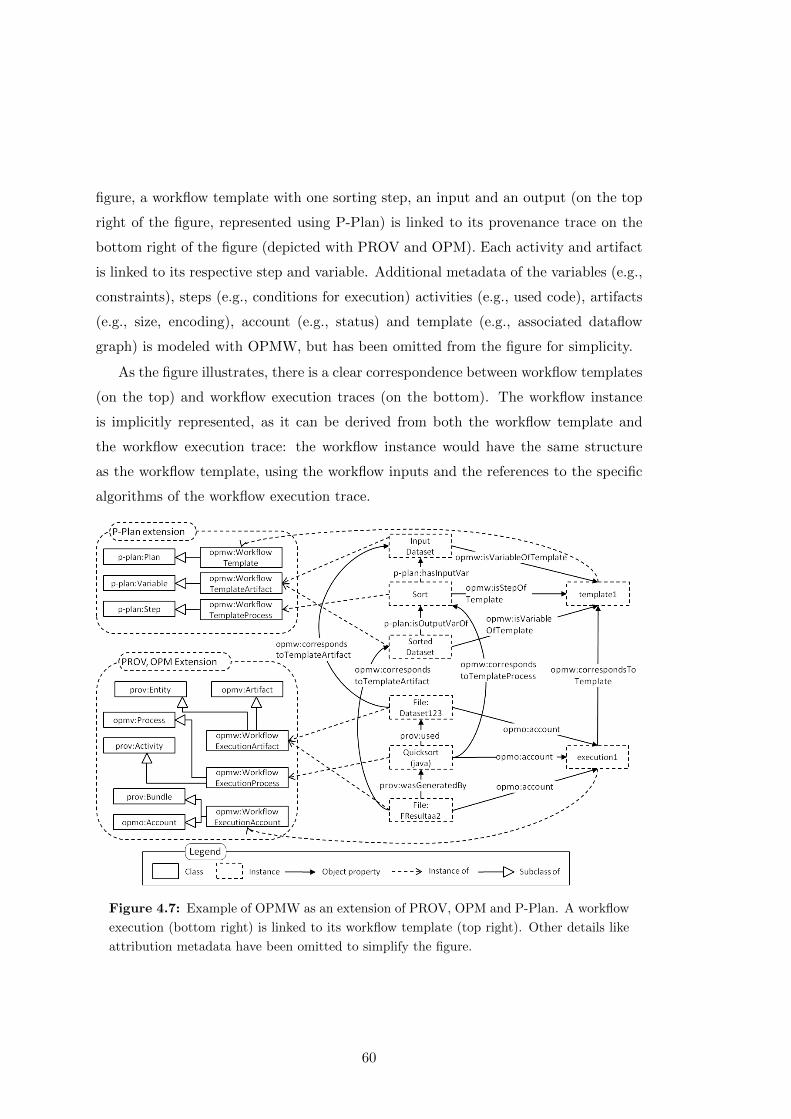
figure, a workflow template with one sorting step, an input and an output (on the top
right of the figure, represented using P-Plan) is linked to its provenance trace on the
bottom right of the figure (depicted with PROV and OPM). Each activity and artifact
is linked to its respective step and variable. Additional metadata of the variables (e.g.,
constraints), steps (e.g., conditions for execution) activities (e.g., used code), artifacts
(e.g., size, encoding), account (e.g., status) and template (e.g., associated dataflow
graph) is modeled with OPMW, but has been omitted from the figure for simplicity.
As the figure illustrates, there is a clear correspondence between workflow templates
(on the top) and workflow execution traces (on the bottom). The workflow instance
is implicitly represented, as it can be derived from both the workflow template and
the workflow execution trace: the workflow instance would have the same structure
as the workflow template, using the workflow inputs and the references to the specific
algorithms of the workflow execution trace.
Figure 4.7: Example of OPMW as an extension of PROV, OPM and P-Plan. A workflow
execution (bottom right) is linked to its workflow template (top right). Other details like
attribution metadata have been omitted to simplify the figure.
60
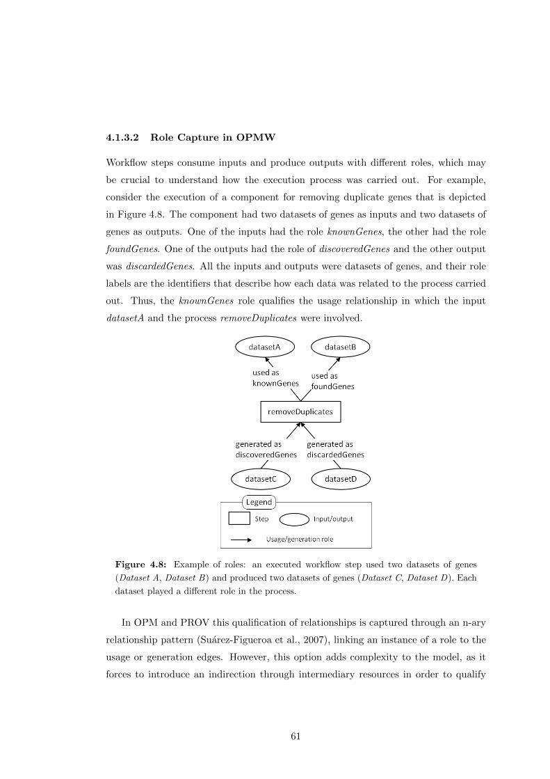
4.1.3.2 Role Capture in OPMW
Workflow steps consume inputs and produce outputs with different roles, which may
be crucial to understand how the execution process was carried out. For example,
consider the execution of a component for removing duplicate genes that is depicted
in Figure 4.8. The component had two datasets of genes as inputs and two datasets of
genes as outputs. One of the inputs had the role knownGenes, the other had the role
foundGenes. One of the outputs had the role of discoveredGenes and the other output
was discardedGenes. All the inputs and outputs were datasets of genes, and their role
labels are the identifiers that describe how each data was related to the process carried
out. Thus, the knownGenes role qualifies the usage relationship in which the input
datasetA and the process removeDuplicates were involved.
Figure 4.8: Example of roles: an executed workflow step used two datasets of genes
(Dataset A, Dataset B) and produced two datasets of genes (Dataset C, Dataset D). Each
dataset played a different role in the process.
In OPM and PROV this qualification of relationships is captured through an n-ary
relationship pattern (Suarez-Figueroa et al., 2007), linking an instance of a role to the
usage or generation edges. However, this option adds complexity to the model, as it
forces to introduce an indirection through intermediary resources in order to qualify
61
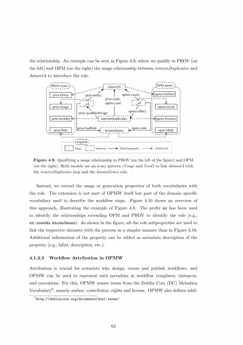
the relationship. An example can be seen in Figure 4.9, where we qualify in PROV (on
the left) and OPM (on the right) the usage relationship between removeDuplicates and
datasetA to introduce the role.
Figure 4.9: Qualifying a usage relationship in PROV (on the left of the figure) and OPM
(on the right). Both models use an n-ary pattern (Usage and Used) to link datasetA with
the removeDuplicates step and the knownGenes role.
Instead, we extend the usage or generation properties of both vocabularies with
the role. The extension is not part of OPMW itself but part of the domain specific
vocabulary used to describe the workflow steps. Figure 4.10 shows an overview of
this approach, illustrating the example of Figure 4.8. The prefix ex has been used
to identify the relationships extending OPM and PROV to identify the role (e.g.,
ex:usedAs knownGenes). As shown in the figure, all the role subproperties are used to
link the respective datasets with the process in a simpler manner than in Figure 4.10.
Additional information of the property can be added as metadata description of the
property (e.g., label, description, etc.).
4.1.3.3 Workflow Attribution in OPMW
Attribution is crucial for scientists who design, create and publish workflows, and
OPMW can be used to represent such metadata in workflow templates, instances,
and executions. For this, OPMW reuses terms from the Dublin Core (DC) Metadata
Vocabulary9, namely author, contributor, rights and license. OPMW also defines addi-
9http://dublincore.org/documents/dcmi-terms/
62
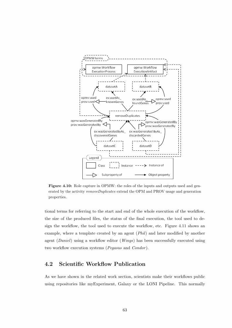
Figure 4.10: Role capture in OPMW: the roles of the inputs and outputs used and gen-
erated by the activity removeDuplicates extend the OPM and PROV usage and generation
properties.
tional terms for referring to the start and end of the whole execution of the workflow,
the size of the produced files, the status of the final execution, the tool used to de-
sign the workflow, the tool used to execute the workflow, etc. Figure 4.11 shows an
example, where a template created by an agent (Phil) and later modified by another
agent (Daniel) using a workflow editor (Wings) has been successfully executed using
two workflow execution systems (Pegasus and Condor).
4.2 Scientific Workflow Publication
As we have shown in the related work section, scientists make their workflows public
using repositories like myExperiment, Galaxy or the LONI Pipeline. This normally
63

Figure 4.11: Example showing attribution metadata capture in OPMW.
follows a manual process, which relies on the users to describe the workflow and pro-
vide additional metadata. Furthermore, this only makes accessible the workflow itself,
and to explore each workflow step it is necessary to download it locally. In this sec-
tion we describe our approach for publishing workflows and their executions as linked
web resources, along with its benefits and showing a functional example in the Wings
workflow system (Gil et al., 2011).
64
4.2.1 Workflows as Linked Data Resources
Publishing the templates and execution traces of scientific workflows is a crucial step
for reuse, reproducibility and understanding. In order to be able to reference all the
resources of a workflow template and its associated workflow executions properly, we use
Universal Resource Identifiers (URIs) (Berners-Lee et al., 2005) following the Linked
Data principles10 (Bizer et al., 2009). URIs provide the mechanism to refer to the
different resources of a workflow unambiguously, while the principles consist on a set
of rules or expectations which indicate how the URIs should behave when someone
(human or machine) accesses them.
The Linked Data principles state (Bizer et al., 2009): 1) that we should “use URIs
as names for things”, 2) that we should “use HTTP URIs so that people can look up
those names” (making those URIs resolvable and available in any browser), 3) that we
should “provide useful information when someone looks up a URI ” (by showing the
resources that are related to the URI) and 4) that we should “include links to other
URIs”, so that whoever is exploring the data can discover other resources. When a
URI complies with the four principles, it becomes a Linked Data URI.
Using Linked Data URIs enables several important advantages to the publication
of scientific workflows:
• Linking to third party web resources, which could be used for the input of
scientific workflows. For instance, referring to proteins in the Protein Data Bank
by using their published URI;
• Get linked from other applications by pointing to the URIs that we publish,
which include both the workflows and the data generated by them;
• Produce interoperable results within different systems without having to
define particular catalog structures and access interfaces;
However, publishing Linked Data is not straightforward. There are several decisions
and naming conventions to take into consideration when making the URIs accessible.
In the following section we present a Linked Data publication methodology adapted to
publish scientific workflows.
10http://www.w3.org/DesignIssues/LinkedData.html
65
4.2.2 A Methodology for Publishing Scientific Workflows as Linked
Data
Although there are publications that introduce and explain the Linked Data generation
and publication process (Heath and Bizer, 2011), there are no methodologies that indi-
cate the steps to follow in the scientific workflow domain. Therefore, we have adapted an
existing methodology used in the publication of governmental data (Villazon-Terrazas
et al., 2012, 2011) and other domains like energy consumption (Radulovic et al., 2015)
to achieve our purpose.
The methodology consists on five main steps that are described as follows:
• Specification, which consists on an effort to identify the set of data sources to
use, decide on their URI design and agree on a license for the resulting dataset.
• Modelling, where the users decide which vocabularies should be used to expose
the data.
• Generation, which summarizes the process of transforming the data from their
heterogeneous formats to RDF with the help of existing tools; cleaning the data
and linking it with other existent sources.
• Publication, where the resulting dataset and its metadata is made available by
using a triplestore (i.e., a database for the storage and retrieval of RDF (Villazon-
Terrazas et al., 2011)).
• Exploitation, which consists on the usage of the published data through browsers
for enabling their consumption manually or automatically.
Many of the steps of the methodology can be easily adapted to scientific workflows.
For the specification step, the set of data sources to use is reduced to deciding the
workflow management systems we want to integrate. From each workflow management
system it is necessary to identify how they specify workflow templates, workflow in-
stances and execution traces, as those are the files that will have to be transformed and
linked to each other when publishing the data.
The URI design is almost the same as in the original methodology. The base URI
should be a URL under a domain of our control, the URIs for the ontology terms
should have the word “ontology” on their schema and the URIs for the assertions or
66
instances should have the word “resource” followed by the class name of the instance.
In the scientific workflow domain we may want to distinguish different releases of the
execution traces. Therefore we have included an optional parameter indicating the
dataset name under which the data is made public:
Base URI = http://mydomain.org
Ontology URI = http://mydomain.org/ontology
Assertion URI = http://mydomain.org/[dataset/]resource/ClassName/instanceNa-
me
Regarding the appropriate license, publishers should first discuss the privacy issues
and requirements of the data about to be released. In some domains privacy is a concern
(e.g., for some workflows processing genomic data), in those cases an open license would
not be appropriate. However, there are many areas of science where privacy is not an
issue and that would benefit tremendously of an open license for sharing both data and
workflows as Linked Data. Since the goal of publishing a scientific workflow is to make
it available for others to reuse and repurpose, we recommend to use an open license.
Several catalogs of licenses are already available on the Web11 12 13, and can be used
for selecting the most appropriate one.
For the modeling step, we propose to use and adapt the OPMW vocabulary intro-
duced in Section 4.1.3, although other more recent PROV based vocabularies like the
Research Object ontologies (Belhajjame et al., 2015) or ProvONE14 could be used as
well.
The generation step may be considered the most complex step in the whole process,
as it depends on the features of the workflow system. Normally the templates, instances
and execution traces can be exported from the workflow system and have to be mapped
to the representation model chosen in the modeling step. Although several tools are
proposed in the methodology to help in the conversion (Villazon-Terrazas et al., 2011),
it is often necessary to develop a script that performs the transformation. The script
should create the appropriate URIs to refer to the resources, instead of relying on the
local IDs proposed by the workflow system. A very important aspect of this step is
that templates, instances and traces have to be linked to each other according the
11http://datahub.io/es/dataset/rdflicense12http://creativecommons.org/13http://opendatacommons.org/licenses/14http://purl.org/provone
67
representation model in order to be able to exploit these relationships later. In our
methodology we exclude linking workflow inputs to other datasets of the Linked Open
Data cloud, as we focus on making public the workflow contents for their reusability.
Finally, the publication step and exploitation step are followed as in the original
methodology by using the set of tools proposed in (Villazon-Terrazas et al., 2011). We
illustrate the whole methodology with an example in the next section.
4.2.3 Linked Data Workflows: An Example
In order to describe how each of the steps can be applied in practice, we have applied
our methodology successfully to the Wings workflow system (Gil et al., 2011).
For the specification step, we chose to export and link workflow templates and
execution traces out of the logs produced by the system. All the URIs generated by
our system are “Cool URIs”15, following the W3C recommendations. This means that
they are produced under a domain under our control, they are unique, and they are
not going to change. Each URI identifies a different resource that can be individually
accessed and dereferenced with content negotiation (i.e., the same URI can handle
requests for users (returning HTML) and machines (returning RDF)). By following our
methodology, we decided to apply the following URI naming scheme:
Base URI = http://www.opmw.org/
Ontology URI = http://www.opmw.org/ontology/
Assertion URI = http://www.opmw.org/export/resource/ClassName/instanceName
As for the license, we chose the Creative Commons Attribution-ShareAlike 3.016,
which allows anyone to reuse the published data if proper attribution is provided.
The modeling step is performed with the OPMW vocabulary. Then, in the genera-
tion step, Wings execution traces and instances are converted automatically to OPMW
with a transformation script17. Camel case notation is used for composing the identi-
fiers of classes and instances, and a MD5 encoding (Rivest, 1992) is used to generate a
unique identifier for each resource when necessary (e.g., a used file, an execution step,
etc.).
15http://www.w3.org/TR/cooluris/16http://creativecommons.org/licenses/by-sa/3.0/17https://github.com/dgarijo/WingsProvenanceExport
68

For the publication step, the RDF files are loaded into a triple store and made public
through a public endpoint (i.e., an access point for both human users and machines).
We have selected Openlink Virtuoso18 as our triple store because of its robustness,
support from the community and mechanisms to create a public access. An additional
file store is needed to store the files referred to in the links available in the triple store
(inputs, intermediate results and outputs of the workflows). The file store is available
in our local servers (http://www.opmw.org).
Now the endpoint can be exploited through generic visualizing tools like the linked
data browser Pubby19 or the workflow explorer WExp20 (which we developed to explore
the available data easily), but it can also be accessed programmatically from other
applications. The access point for a workflow is simply a URI (of a workflow template
or an execution), and all the components and datasets in the workflow can be accessed
from it.
For example, a template called “Aquaflow edm” would have the URI “http://www-
.opmw.org/export/resource/WorkflowTemplate/AQUAFLOW EDM” (template names are
unique in Wings) and type WorkflowTemplate, (i.e. http://www.opmw.org/ontology/-
WorkflowTemplate). As shown in Figure 4.12, by simply resolving the URI in a browser,
a user would see an HTML page21 with the descriptions involving that URI, i.e., the
provenance of the template (contributor, license, primary source, documentation, etc.),
the steps and variables that belong to the template, the executions associated to the
template and the rest of its metadata. If we edit the request headers to ask for a
machine-readable representation, we would receive the same information in the appro-
priate syntax (e.g., Turtle22 or RDF/XML23, depending on the request). This approach
can be used to access any resource (by resolving its URI) from any template or exe-
cution stored in the repository. If a user or program aims to perform a more complex
query (e.g., returning all the stored templates with at least two executions), they may
issue it to the public SPARQL endpoint24, which will check and return the results in
18http://virtuoso.openlinksw.com/19http://wifo5-03.informatik.uni-mannheim.de/pubby/20http://purl.org/net/wexp21http://www.opmw.org/export/page/resource/WorkflowTemplate/AQUAFLOW_EDM22http://www.w3.org/TR/turtle/23http://www.w3.org/TR/rdf-syntax-grammar/24http://opmw.org/sparql
69
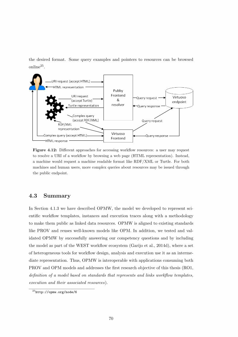
the desired format. Some query examples and pointers to resources can be browsed
online25.
Figure 4.12: Different approaches for accessing workflow resources: a user may request
to resolve a URI of a workflow by browsing a web page (HTML representation). Instead,
a machine would request a machine readable format like RDF/XML or Turtle. For both
machines and human users, more complex queries about resources may be issued through
the public endpoint.
4.3 Summary
In Section 4.1.3 we have described OPMW, the model we developed to represent sci-
entific workflow templates, instances and execution traces along with a methodology
to make them public as linked data resources. OPMW is aligned to existing standards
like PROV and reuses well-known models like OPM. In addition, we tested and val-
idated OPMW by successfully answering our competency questions and by including
the model as part of the WEST workflow ecosystem (Garijo et al., 2014d), where a set
of heterogeneous tools for workflow design, analysis and execution use it as an interme-
diate representation. Thus, OPMW is interoperable with applications consuming both
PROV and OPM models and addresses the first research objective of this thesis (RO1,
definition of a model based on standards that represents and links workflow templates,
execution and their associated resources).
25http://opmw.org/node/6
70
OPMW was designed to represent the most simple workflow constructs that are
common to most scientific workflow systems (i.e., the relation between workflow tem-
plates, instance and executions, usage and generation of inputs, intermediate results
and outputs and their key metadata), leaving more complex constructs like conditional
branches or loops out of scope of the model. The rationale behind this decision is that a
simpler representation may enable a better understanding (and hence, adoption) among
the community, facilitating retrieving key metadata of each input and workflow step
of the workflow and helping to understand the dataflow. In this regard, OPMW was
designed to expose workflow information on the Web in a simple manner. As described
in Section 2.1.3, there are more complex models for workflow interchange between dif-
ferent workflow systems (e.g., BPEL, SHIWA) to which OPMW can be mapped for
exploiting this information.
Table 4.1 shows a comparison between OPMW and other recent approaches for
representing scientific workflows and their relationships. On the one hand, the most
similar approaches are the Research Object (Belhajjame et al., 2015) and ProvONE26
models, which aim to provide a simple representation of workflows. In essence, the
difference among the models is small, and part of the reason for the overlap is that
they have been developed in parallel. Some of the differences are that the RO and
ProvONE models have support for explicitly modeling sub-workflows and use data
links to specify the connections between components of workflows. Instead, OPMW
connects input data and output data to the workflow steps directly, in order to simplify
the overall representation. Additionally, OPMW has explicit relationships for capturing
workflow metadata. Since all these vocabularies extend the PROV standard, their
representations are compatible at a higher level of abstraction.
On the other hand, the Conceptual Workflow model (Cerezo, 2013) is a top-down
approach, with a different scope than OPMW. Rather than providing a simple repre-
sentation between workflow templates and execution traces, the Conceptual Workflow
model studies how an abstract process can be transformed into a specific workflow.
The scope is therefore in modeling and representing the relationship between abstract
workflow templates and instances, which may follow a layered abstraction.
In section 4.2.2 we described a methodology that addresses the second research
objective of this thesis (RO2, definition of a methodology for publishing workflows and
26http://purl.org/provone
71
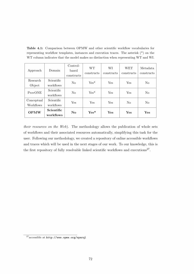
Table 4.1: Comparison between OPMW and other scientific workflow vocabularies for
representing workflow templates, instances and execution traces. The asterisk (*) on the
WT column indicates that the model makes no distinction when representing WT and WI.
Approach Domain
Control-
based
constructs
WT
constructs
WI
constructs
WET
constructs
Metadata
constructs
Research
Object
Scientific
workflowsNo Yes* Yes Yes No
ProvONEScientific
workflowsNo Yes* Yes Yes No
Conceptual
Workflows
Scientific
workflowsYes Yes Yes No No
OPMWScientific
workflowsNo Yes* Yes Yes Yes
their resources on the Web). The methodology allows the publication of whole sets
of workflows and their associated resources automatically, simplifying this task for the
user. Following our methodology, we created a repository of online accessible workflows
and traces which will be used in the next stages of our work. To our knowledge, this is
the first repository of fully resolvable linked scientific workflows and executions27.
27accessible at http://www.opmw.org/sparql
72
Chapter 5
Workflow Abstraction and Reuse
As stated in Chapter 3, one of our hypotheses aims to determine whether patterns and
abstractions can be obtained from a repository of workflows (H1.1). In particular, our
goal is to find those abstractions that capture generic features of groups of workflows
(or workflow fragments) independently from their contexts. For example, one way of
achieving abstraction is by publishing workflow templates and linking them to their
provenance executions traces. The templates act as a high level abstraction of a set of
executions, grouping them as entities with the same original plan. Other types of ab-
stractions may be obtained with the different types of workflow abstractions introduced
on Chapter 2.2, such as macro abstraction, skeletal planning or layered abstraction.
However, even after defining these abstractions, workflows may be difficult to under-
stand due to their their complex nature. A workflow may contain several scientifically-
significant analysis steps, combined with auxiliary data preparation or result deliv-
ery activities, and in different implementation styles. This difficulty in understanding
stands in the way of reusing workflows by potential adopters. In this chapter we aim
to address this issue by performing several analyses, from both abstraction and reuse
perspectives.
In Section 5.1, we characterize the domain independent conceptual abstractions for
workflow steps that can be found in scientific workflows upon manual inspection. We
refer to these abstractions as workflow motifs, and we have defined them after analyzing
workflows manually from several workflow systems. Motifs are provided through (i) a
characterization of the kinds of data-operation activities that are carried out within
workflows, which we refer to as data-operation motifs, and (ii) a characterization of
73
the different manners in which those activity motifs are realized/implemented within
workflows, which we refer to as workflow-oriented motifs.
In Sections 5.2 and 5.3 we explore how users reuse workflows and workflow frag-
ments, analyzing whether those motifs related to workflow reuse are relevant for users
or not. The analyses were performed from different perspectives. One analysis con-
sists on an automatic processing of workflows, while the other one surveys users on the
usefulness of reusing workflows and workflow fragments.
5.1 Workflow Motifs
In order to define a catalog of common domain independent abstractions in scientific
workflows (objective RO3 of this thesis) we performed a manual analysis of the current
practices in scientific workflow development. The objectives of the analysis were the
following:
1. To reverse-engineer the set of current practices in workflow development through
an empirical analysis.
2. To identify workflow abstractions that would facilitate understandability and
therefore effective reuse.
In this section we present the results of the empirical analysis, performed manu-
ally over 260 workflow descriptions from four different workflow management systems.
Based on this analysis, we propose a catalog of common workflow motifs.
5.1.1 Experimental Setup
We used workflows from Taverna (Wolstencroft et al., 2013), Wings (Gil et al., 2011),
Galaxy (Goecks et al., 2010) and VisTrails (Scheidegger et al., 2008). The choice of
these systems was due to the availability of workflow corpora through repositories (as
introduced in Section 2.1.4.2, myExperiment (Roure et al., 2009) for Taverna, Crowd-
labs (Mates et al., 2011) for VisTrails and the public endpoint we created in Section
4.2.2 (Garijo and Gil, 2011) for Wings) and portals (for Galaxy1), but also because of
their core similarities:
1https://main.g2.bx.psu.edu/
74

• They provide similar workflow modeling constructs. The selected workflow sys-
tems are data flow oriented, which is consistent with our models, and they operate
on large and heterogeneous data.
• All of them are open-source scientific workflow systems, initially focused on per-
forming in-silico experimentation on the life sciences (Taverna, Galaxy, VisTrails)
and geosciences (Wings) domains. Taverna, Wings and VisTrails now also have
workflows across other different domains like astronomy, machine learning, mete-
orology, etc.
• All of these systems can interact with third party tools and services, and they
include a catalog of components for performing different operations with data.
Despite being similar, we can still find some differences among the selected systems.
In particular, VisTrails has explicit mechanisms for the basic control constructs (e.g.,
conditionals and looping), while Taverna, Wings and Galaxy are observers of the pure
data flow paradigm (although there are implicit ways of implementing such control
structures).
The variety of environments in which these systems operate highlights some other
differences as well. While Taverna allows users to specify workflows that make use of
third party services (i.e., an open environment), Wings requires that the resources and
the analysis operations are made part of its environment prior to be used in experiments
(i.e. controlled environment). However, the differences between these systems are not
a significant differentiating factor, as Taverna allows more control to be added to the
environment through the addition of plug-ins, and Wings can establish connection to
third party services via custom components. VisTrails and Galaxy may be positioned
at an intermediate point, since they provide access to external web-services but also
build on a comprehensive library of components.
A summary of the commonalities and differences among the workflow systems in-
cluded in the analysis can be seen in Table 5.1.
5.1.2 Workflow Corpus Description
For our analysis, we have chosen 260 heterogeneous workflows in a variety of domains.
We analyzed a set of public Wings workflows (89 out of 132 workflows), part of the
75
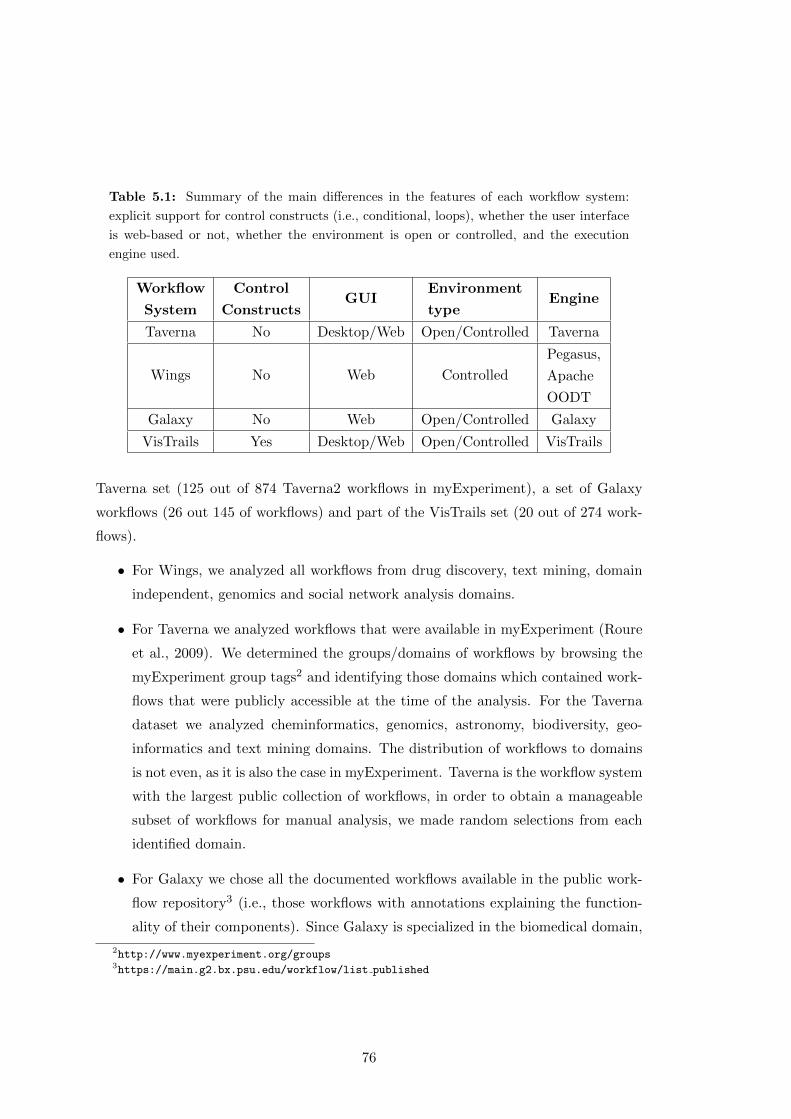
Table 5.1: Summary of the main differences in the features of each workflow system:
explicit support for control constructs (i.e., conditional, loops), whether the user interface
is web-based or not, whether the environment is open or controlled, and the execution
engine used.
Workflow
System
Control
ConstructsGUI
Environment
typeEngine
Taverna No Desktop/Web Open/Controlled Taverna
Wings No Web Controlled
Pegasus,
Apache
OODT
Galaxy No Web Open/Controlled Galaxy
VisTrails Yes Desktop/Web Open/Controlled VisTrails
Taverna set (125 out of 874 Taverna2 workflows in myExperiment), a set of Galaxy
workflows (26 out 145 of workflows) and part of the VisTrails set (20 out of 274 work-
flows).
• For Wings, we analyzed all workflows from drug discovery, text mining, domain
independent, genomics and social network analysis domains.
• For Taverna we analyzed workflows that were available in myExperiment (Roure
et al., 2009). We determined the groups/domains of workflows by browsing the
myExperiment group tags2 and identifying those domains which contained work-
flows that were publicly accessible at the time of the analysis. For the Taverna
dataset we analyzed cheminformatics, genomics, astronomy, biodiversity, geo-
informatics and text mining domains. The distribution of workflows to domains
is not even, as it is also the case in myExperiment. Taverna is the workflow system
with the largest public collection of workflows, in order to obtain a manageable
subset of workflows for manual analysis, we made random selections from each
identified domain.
• For Galaxy we chose all the documented workflows available in the public work-
flow repository3 (i.e., those workflows with annotations explaining the function-
ality of their components). Since Galaxy is specialized in the biomedical domain,
2http://www.myexperiment.org/groups3https://main.g2.bx.psu.edu/workflow/list published
76
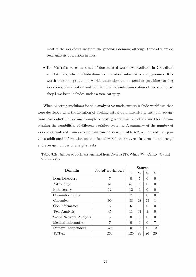
most of the workflows are from the genomics domain, although three of them do
text analysis operations in files.
• For VisTrails we chose a set of documented workflows available in Crowdlabs
and tutorials, which include domains in medical informatics and genomics. It is
worth mentioning that some workflows are domain independent (machine learning
workflows, visualization and rendering of datasets, annotation of texts, etc.), so
they have been included under a new category.
When selecting workflows for this analysis we made sure to include workflows that
were developed with the intention of backing actual data-intensive scientific investiga-
tions. We didn’t include any example or testing workflows, which are used for demon-
strating the capabilities of different workflow systems. A summary of the number of
workflows analyzed from each domain can be seen in Table 5.2, while Table 5.3 pro-
vides additional information on the size of workflows analyzed in terms of the range
and average number of analysis tasks.
Table 5.2: Number of workflows analyzed from Taverna (T), Wings (W), Galaxy (G) and
VisTrails (V).
Domain No of workflowsSource
T W G V
Drug Discovery 7 0 7 0 0
Astronomy 51 51 0 0 0
Biodiversity 12 12 0 0 0
Cheminformatics 7 7 0 0 0
Genomics 90 38 28 23 1
Geo-Informatics 6 6 0 0 0
Text Analysis 45 11 31 3 0
Social Network Analysis 5 0 5 0 0
Medical Informatics 7 0 0 0 7
Domain Independent 30 0 18 0 12
TOTAL 260 125 89 26 20
77
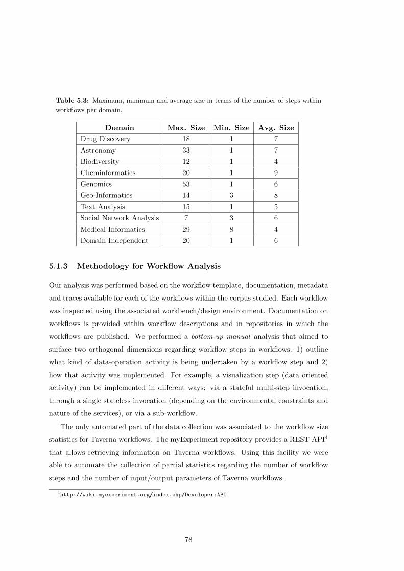
Table 5.3: Maximum, minimum and average size in terms of the number of steps within
workflows per domain.
Domain Max. Size Min. Size Avg. Size
Drug Discovery 18 1 7
Astronomy 33 1 7
Biodiversity 12 1 4
Cheminformatics 20 1 9
Genomics 53 1 6
Geo-Informatics 14 3 8
Text Analysis 15 1 5
Social Network Analysis 7 3 6
Medical Informatics 29 8 4
Domain Independent 20 1 6
5.1.3 Methodology for Workflow Analysis
Our analysis was performed based on the workflow template, documentation, metadata
and traces available for each of the workflows within the corpus studied. Each workflow
was inspected using the associated workbench/design environment. Documentation on
workflows is provided within workflow descriptions and in repositories in which the
workflows are published. We performed a bottom-up manual analysis that aimed to
surface two orthogonal dimensions regarding workflow steps in workflows: 1) outline
what kind of data-operation activity is being undertaken by a workflow step and 2)
how that activity was implemented. For example, a visualization step (data oriented
activity) can be implemented in different ways: via a stateful multi-step invocation,
through a single stateless invocation (depending on the environmental constraints and
nature of the services), or via a sub-workflow.
The only automated part of the data collection was associated to the workflow size
statistics for Taverna workflows. The myExperiment repository provides a REST API4
that allows retrieving information on Taverna workflows. Using this facility we were
able to automate the collection of partial statistics regarding the number of workflow
steps and the number of input/output parameters of Taverna workflows.
4http://wiki.myexperiment.org/index.php/Developer:API
78

Rather than hypothesizing possible motifs up front, we built up a set of motifs as we
progressed with the analysis. For each workflow we recorded the number of occurrences
of each motif according to the documentation, and metadata descriptions provided by
the original authors (independently of the workflow system it belonged to). In order to
minimize misinterpretation and human error, the motif occurrences identified for each
workflow were cross-validated by at least another colleague. Whenever there was a
conflict in the annotation, the metadata and documentation associated to the workflow
was reviewed again, discussing the possible interpretations until agreement.
5.1.4 A Motif Catalogue for Abstracting Scientific Workflows
We divided motifs into two categories: data-operation motifs (i.e., the motifs related
to the main functionality undertaken by the steps of the workflow), and workflow-
oriented motifs (i.e., how the data-operation motifs are undertaken in the workflow).
An overview of the motif catalog is provided in Table 5.4. In this section we describe
each type of motif in detail.
5.1.4.1 Data-Operation Motifs
Data Preparation
Data, once it is retrieved, may need several transformations before being able to be
used in a workflow step. The most common activities that we have detected in our
analysis are described below.
Combine: Data merging or joining steps are commonly found across workflows. The
combine motif refers to the step or group of steps in the workflow aggregating informa-
tion from different inputs. An example can be seen in Figure 5.1, where the results of
two branches are merged for presenting a single output result.
Filter: The datasets brought into a pipeline may not be subject to analysis in their
entirety. Data could further be distilled, sampled or could be subject to extraction of
various subsets.
79
Table 5.4: Overview of our catalog of workflow motifs.
Data-Operation Motifs
Data Preparation
Combine
Filter
Format Transformation
Input Augmentation
Output Extraction
Group
Sort
Split
Data Analysis
Data Cleaning
Data Movement
Data Retrieval
Data Visualization
Workflow-Oriented Motifs
Inter-Workflow Motifs
Atomic Workflows
Composite Workflows
Workflow Overloading
Intra-Workflow Motifs
Internal Macros
Human Interactions
Stateful (Asynchronous) Invocations
Format Transformation: Heterogeneity of formats in data representation is a known
issue in many scientific disciplines. Workflows that bring together multiple access or
analysis activities usually contain steps for format transformations, sometimes called
“Shims” (Hull et al., 2004), that typically preserve the contents of data while converting
its representation format.
80
Input Augmentation: Data access and analysis steps that are handled by external
services or tools typically require well formed query strings or structured requests as
input parameters. Certain tasks in workflows are dedicated to the generation of these
queries through an aggregation of multiple parameters. An example of this is provided
in the workflow of Figure 5.2: For each service invocation (e.g. getJobState) there are
steps (e.g. getJobState Input) that are responsible for creating the correctly formatted
inputs for the service.
Output Extraction: Outputs of data access or analysis steps could be subject to
data extraction to allow the conversion of data from the service format to the workflow
internal data carrying structures. This motif is similar to the format transformation
and filter motifs, and is associated with steps that perform the inverse operation of
input augmentation. An example is given in Figure 5.2, where output extraction steps
(e.g. getJobState output) are responsible for parsing the XML message resulting from
the service (getJobState) to return a singleton value containing solely the job state.
Group: Some steps of the workflow reorganize the input into different groups or
classify the inputs on a given collection of data items. For example, grouping a table
by a certain category or executing a SQL GROUP-BY clause on an input dataset.
Group is different from combine, as the former may reorganize the information in an
input without the need to aggregate it from several sources.
Sort: In certain cases datasets containing multiple data items/records are to be sorted
(with respect to a parameter) prior to further processing. The sort motif refers to those
steps. Figure 5.1 shows an example where the inputs resulting from the data analy-
sis (comparisonResults) are sorted (ComparisonResultsV2 component) before being
merged in a subsequent step.
Split: Our analysis has shown that many steps in the workflows separate an input
(or group of inputs) into different outputs. For example, the splitting of a dataset into
different subsets to be processed in parallel in a workflow.
81
Data Analysis
This motif refers to a broad category of tasks in diverse domains, and it is relevant be-
cause it often represents the main functionality of the workflow. An important number
of workflows are designed with the purpose of analyzing or evaluating different fea-
tures of input data, ranging from simple comparisons between the datasets to complex
protein analysis to see whether two molecules can be docked successfully or not. An
example is given in the workflow of Figure 5.2 with a processing step named warp2D,
and the steps named SMAPV2 in Figure 5.1 with a ligand binding sites comparison of
the inputs. These steps carry on the main functionality of the workflow, but they are
surrounded by other data preparation and filtering steps.
Data Cleaning/Curation
We have observed the steps for cleaning and curating data as a separate category from
data preparation and filtering. Typically these steps are undertaken by sophisticated
tooling/services, or by specialized users. A cleaning/curation step essentially preserves
and enriches the content of data (e.g., by a user’s annotation of a result with additional
information, detecting and removing inconsistencies on the data, etc.).
Data Movement
Certain analysis activities that are performed via external tools or services require the
submission of data to a location accessible by the service/tool (i.e., a web or a local
directory respectively). In such cases the workflow contains dedicated step(s) for the
upload/transfer of data to these locations. The same applies to the outputs, in which
case a data download step is used to chain the data to the next steps of the workflow.
The data deposition of the workflow results to a specific server would also be included
in this category. In Figure 5.2, the DataUpload step ships data to the server on which
the analysis will be done.
Data Retrieval
Workflows exploit heterogeneous data sources, remote databases, repositories or other
web resources exposed via SOAP or REST services. Scientific data stored in these repos-
itories are retrieved through query and retrieval steps inside workflows. Certain tasks
within the workflow are responsible for retrieving data from such external sources into
82
the workflow environment. We also observed that certain data integration workflows
contain multiple linked retrieval steps, being essentially parametrized data integration
chains. Data retrieval is different from data movement, as it refers to those steps of the
workflow selecting particular data to be consumed by the workflow (through a query,
REST API, etc.) instead of performing a bulk upload of the workflow resources.
Data Visualization
Being able to show the results is as important as producing them in some workflows.
Scientists use visualizations to show the conclusions of their experiments and to take
important decisions in the pipeline itself. Therefore, certain steps in workflows are
dedicated to generation of plots, graphs, tables and XMLs or CSV file outputs from
input data. This category is essentially for result delivery of the experiment results.
5.1.4.2 Workflow-Oriented Motifs
We divide this category into two different groups, depending on whether motifs are
observed among workflows, by analyzing the relations of the workflow with other work-
flows (inter workflow motifs); or within workflows, by exploring the workflow itself
(intra workflow motifs).
Inter Workflow Motifs
Atomic Workflows: A significant number of workflows perform an atomic unit of
functionality, which does not require to be decomposed in smaller workflow fragments.
Typically, these workflows are designed to be included in other workflows as sub-
workflows, part of a larger experiment. Atomic workflows are the main mechanism
of modularizing functionality within scientific workflows.
Composite Workflows: This motif refers to those workflows including one or more
workflows as a sub-workflow. The usage of sub-workflows appears as a common practice
for reusing modular functionality from multiple workflows. It is important to note
that there are two ways in which this motif may appear in a collection of workflows:
highlighted explicitly by the creator of the workflow (i.e., the user deliberately included
other workflows as part of the one being designed) or detected implicitly by the analysis
83
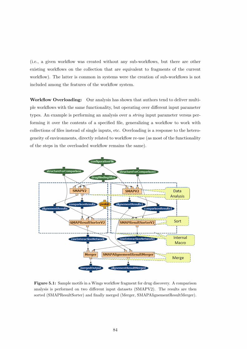
(i.e., a given workflow was created without any sub-workflows, but there are other
existing workflows on the collection that are equivalent to fragments of the current
workflow). The latter is common in systems were the creation of sub-workflows is not
included among the features of the workflow system.
Workflow Overloading: Our analysis has shown that authors tend to deliver multi-
ple workflows with the same functionality, but operating over different input parameter
types. An example is performing an analysis over a string input parameter versus per-
forming it over the contents of a specified file, generalizing a workflow to work with
collections of files instead of single inputs, etc. Overloading is a response to the hetero-
geneity of environments, directly related to workflow re-use (as most of the functionality
of the steps in the overloaded workflow remains the same).
Figure 5.1: Sample motifs in a Wings workflow fragment for drug discovery. A comparison
analysis is performed on two different input datasets (SMAPV2). The results are then
sorted (SMAPResultSorter) and finally merged (Merger, SMAPAlignementResultMerger).
84
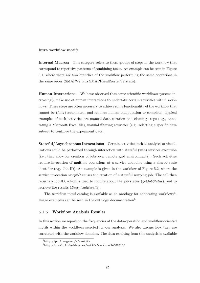
Intra workflow motifs
Internal Macros: This category refers to those groups of steps in the workflow that
correspond to repetitive patterns of combining tasks. An example can be seen in Figure
5.1, where there are two branches of the workflow performing the same operations in
the same order (SMAPV2 plus SMAPResultSorterV2 steps).
Human Interactions: We have observed that some scientific workflows systems in-
creasingly make use of human interactions to undertake certain activities within work-
flows. These steps are often necessary to achieve some functionality of the workflow that
cannot be (fully) automated, and requires human computation to complete. Typical
examples of such activities are manual data curation and cleaning steps (e.g., anno-
tating a Microsoft Excel file), manual filtering activities (e.g., selecting a specific data
sub-set to continue the experiment), etc.
Stateful/Asynchronous Invocations: Certain activities such as analyses or visual-
izations could be performed through interaction with stateful (web) services execution
(i.e., that allow for creation of jobs over remote grid environments). Such activities
require invocation of multiple operations at a service endpoint using a shared state
identifier (e.g. Job ID). An example is given in the workflow of Figure 5.2, where the
service invocation warp2D causes the creation of a stateful warping job. The call then
returns a job ID, which is used to inquire about the job status (getJobStatus), and to
retrieve the results (DownloadResults).
The workflow motif catalog is available as an ontology for annotating workflows5.
Usage examples can be seen in the ontology documentation6.
5.1.5 Workflow Analysis Results
In this section we report on the frequencies of the data-operation and workflow-oriented
motifs within the workflows selected for our analysis. We also discuss how they are
correlated with the workflow domains. The data resulting from this analysis is available
5http://purl.org/net/wf-motifs6http://vocab.linkeddata.es/motifs/version/14062013/
85
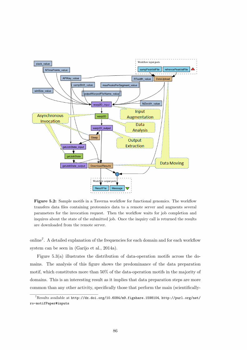
Figure 5.2: Sample motifs in a Taverna workflow for functional genomics. The workflow
transfers data files containing proteomics data to a remote server and augments several
parameters for the invocation request. Then the workflow waits for job completion and
inquires about the state of the submitted job. Once the inquiry call is returned the results
are downloaded from the remote server.
online7. A detailed explanation of the frequencies for each domain and for each workflow
system can be seen in (Garijo et al., 2014a).
Figure 5.3(a) illustrates the distribution of data-operation motifs across the do-
mains. The analysis of this figure shows the predominance of the data preparation
motif, which constitutes more than 50% of the data-operation motifs in the majority of
domains. This is an interesting result as it implies that data preparation steps are more
common than any other activity, specifically those that perform the main (scientifically-
7Results available at http://dx.doi.org/10.6084/m9.figshare.1598104, http://purl.org/net/
ro-motifPaper#inputs
86
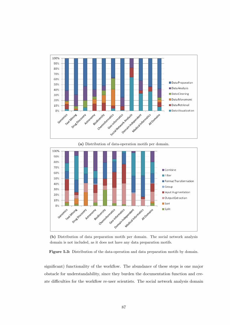
(a) Distribution of data-operation motifs per domain.
(b) Distribution of data preparation motifs per domain. The social network analysis
domain is not included, as it does not have any data preparation motifs.
Figure 5.3: Distribution of the data-operation and data preparation motifs by domain.
significant) functionality of the workflow. The abundance of these steps is one major
obstacle for understandability, since they burden the documentation function and cre-
ate difficulties for the workflow re-user scientists. The social network analysis domain
87
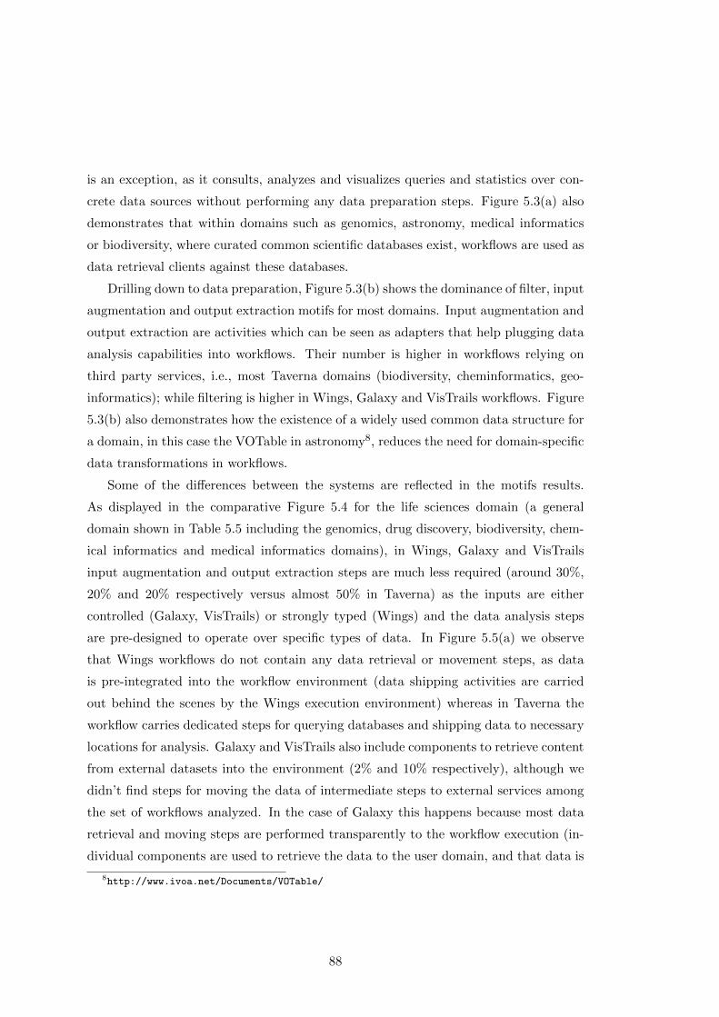
is an exception, as it consults, analyzes and visualizes queries and statistics over con-
crete data sources without performing any data preparation steps. Figure 5.3(a) also
demonstrates that within domains such as genomics, astronomy, medical informatics
or biodiversity, where curated common scientific databases exist, workflows are used as
data retrieval clients against these databases.
Drilling down to data preparation, Figure 5.3(b) shows the dominance of filter, input
augmentation and output extraction motifs for most domains. Input augmentation and
output extraction are activities which can be seen as adapters that help plugging data
analysis capabilities into workflows. Their number is higher in workflows relying on
third party services, i.e., most Taverna domains (biodiversity, cheminformatics, geo-
informatics); while filtering is higher in Wings, Galaxy and VisTrails workflows. Figure
5.3(b) also demonstrates how the existence of a widely used common data structure for
a domain, in this case the VOTable in astronomy8, reduces the need for domain-specific
data transformations in workflows.
Some of the differences between the systems are reflected in the motifs results.
As displayed in the comparative Figure 5.4 for the life sciences domain (a general
domain shown in Table 5.5 including the genomics, drug discovery, biodiversity, chem-
ical informatics and medical informatics domains), in Wings, Galaxy and VisTrails
input augmentation and output extraction steps are much less required (around 30%,
20% and 20% respectively versus almost 50% in Taverna) as the inputs are either
controlled (Galaxy, VisTrails) or strongly typed (Wings) and the data analysis steps
are pre-designed to operate over specific types of data. In Figure 5.5(a) we observe
that Wings workflows do not contain any data retrieval or movement steps, as data
is pre-integrated into the workflow environment (data shipping activities are carried
out behind the scenes by the Wings execution environment) whereas in Taverna the
workflow carries dedicated steps for querying databases and shipping data to necessary
locations for analysis. Galaxy and VisTrails also include components to retrieve content
from external datasets into the environment (2% and 10% respectively), although we
didn’t find steps for moving the data of intermediate steps to external services among
the set of workflows analyzed. In the case of Galaxy this happens because most data
retrieval and moving steps are performed transparently to the workflow execution (in-
dividual components are used to retrieve the data to the user domain, and that data is
8http://www.ivoa.net/Documents/VOTable/
88
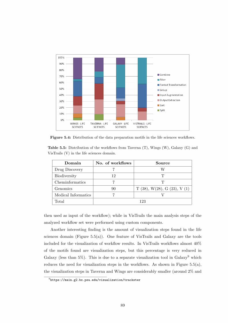
Figure 5.4: Distribution of the data preparation motifs in the life sciences workflows.
Table 5.5: Distribution of the workflows from Taverna (T), Wings (W), Galaxy (G) and
VisTrails (V) in the life sciences domain.
Domain No. of workflows Source
Drug Discovery 7 W
Biodiversity 12 T
Cheminformatics 7 T
Genomics 90 T (38), W(28), G (23), V (1)
Medical Informatics 7 V
Total 123
then used as input of the workflow); while in VisTrails the main analysis steps of the
analyzed workflow set were performed using custom components.
Another interesting finding is the amount of visualization steps found in the life
sciences domain (Figure 5.5(a)). One feature of VisTrails and Galaxy are the tools
included for the visualization of workflow results. In VisTrails workflows almost 40%
of the motifs found are visualization steps, but this percentage is very reduced in
Galaxy (less than 5%). This is due to a separate visualization tool in Galaxy9 which
reduces the need for visualization steps in the workflows. As shown in Figure 5.5(a),
the visualization steps in Taverna and Wings are considerably smaller (around 2% and
9https://main.g2.bx.psu.edu/visualization/trackster
89
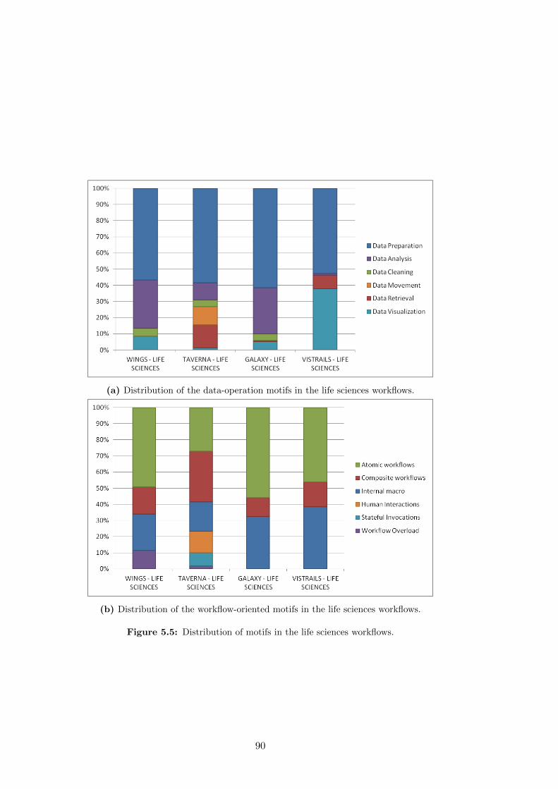
(a) Distribution of the data-operation motifs in the life sciences workflows.
(b) Distribution of the workflow-oriented motifs in the life sciences workflows.
Figure 5.5: Distribution of motifs in the life sciences workflows.
90

10% respectively).
The impact of the difference in the execution environments of the analyzed workflow
systems is also observed on the workflow-oriented motifs, as can be seen in Figure 5.5(b).
Stateful invocations motifs are not present in Wings, Galaxy and VisTrails workflows,
as all steps are handled by a dedicated workflow scheduling framework/pipeline system
and the details are hidden from the workflow developers. In Taverna’s default configu-
ration, there are no execution environments or scheduling frameworks prescribed to the
users. Therefore the workflow developers are 1) either responsible for catering for vari-
ous different invocation requirements of external resources, which may include stateful
invocations requiring execution of multiple consecutive steps in order to undertake a
single function 2) they can develop specific plug-ins that wrap-up stateful interactions
and boiler plate steps.
Regarding workflow-oriented motifs, Figure 5.6 shows that human interaction steps
are increasingly used in scientific workflows, especially in the biodiversity and chemin-
formatics domains. Human interaction steps in Taverna workflows are handled either
through external tools (e.g., Google Refine10), facilitated via a human-interaction plug-
in, or through local scripts (e.g., selection of configuration values from multi-choice
lists). However, we observed that several boiler-plate set-up steps are required for the
deployment and configuration of external tooling to support the human tasks. These
boiler plate steps result in very large and complex workflows. Wings and VisTrails
workflows do not contain human interaction steps. Galaxy is an environment that is
heavily based on user-driven configuration and invocation of analysis tools (some pa-
rameters and inputs of the workflows can even be changed after the execution of the
workflow has started). However, based on our definition of Human Interactions, i.e.
analytical data processing undertaken by a human, the Galaxy workflows that we have
analyzed do not contain any human computation steps either.
The workflow overload motif also plays a relevant role, appearing in almost 10% of
the analyzed workflows. Workflows containing this motif are considered advanced forms
of sub-workflow development. By executing workflows in different settings, authors
provide overloaded versions of the same functionality in different workflows to increase
the coverage on target uses.
10https://code.google.com/p/google-refine/
91

Figure 5.6: Distribution of workflow-oriented motifs grouped by domain.
Finally, Figure 5.6 shows a large proportion of the composite workflows and internal
macro motifs, up to more than 60% in some domains. This confirms that the use of sub-
workflows (or repetitions of sets of steps among a group of workflows) is an established
best practice for modularizing functionality and reuse. Sub-workflows can also be
used to encapsulate the preparation steps and multi-step service invocations within
“components” (Davies, 2011), in order to reduce obfuscation. However, users usually
have to identify these sub-workflows with common functionality by hand. Ideally, a
workflow system would suggest ways to simplify a workflow based on other published
workflows, instead of relying on users to do so. We will address this point in Chapter
6.
5.1.6 Summary
The main findings of our analysis can be summarized as follows:
• We identified 6 major types of data-operation motifs and 6 types of workflow-
oriented motifs that are used across different domains. From the former group,
the most common motif is the data preparation, highlighting that an important
effort in the creation of the workflow is dedicated to tool integration and data
92
operation activities. Regarding workflow-oriented motifs, the amount of internal
macro motifs and composite workflows indicate that reuse is a common practice
among scientists publishing their workflows.
• Some differences in the motif distribution are caused due to the features of the
workflow systems. The frequency by which the motifs appear depends on the
differences among the workflow environments and differences in domains. For
instance, data preparation motifs are correlated with the type of execution en-
vironment for which the workflow is designed. In a workflow system such as
Taverna, many steps in the workflow can be dedicated to the moving and re-
trieval of heterogeneous datasets, and stateful resource access protocols. On the
contrary, in a workflow system such as Wings, VisTrails and Galaxy we notice
that some data preparation motifs, such as data moving, are minimal and in
certain domains absent.
According to the analysis, common workflow fragments seem to be crucial for under-
standing how different workflows relate to each other and for creating different types of
abstractions, which should have an impact on workflow reuse. Here we hypothesize that
it is possible to detect commonly occurring workflow fragments automatically (H1.2),
and that they can be useful for potential reusers (H1.3). Thus, in an effort to un-
derstand in depth the relation between workflows, workflow fragments and their reuse
among the workflow corpora, the following sections perform two types of analysis. The
first one, on Section 5.2, details an automatic analysis exploring over more than 850
unique workflows in order to confirm the findings found manually. The second analysis,
in Section 5.3, aims to explore the user perspective on workflow fragment reuse and
usefulness, highlighting the common practices of a community of users.
5.2 Analysis of Workflow and Workflow Fragment Reuse
Given the results obtained in the manual analysis presented in Section 5.1, we explore
in this section how workflows are reused among a collection of workflows. Furthermore,
we analyze how workflow fragments defined by users (as sub-workflows) are reused in
other workflows. In order to do so, we first introduce the corpus used in the analysis,
and then we analyze how many of the workflow fragments (and workflows) defined by
93
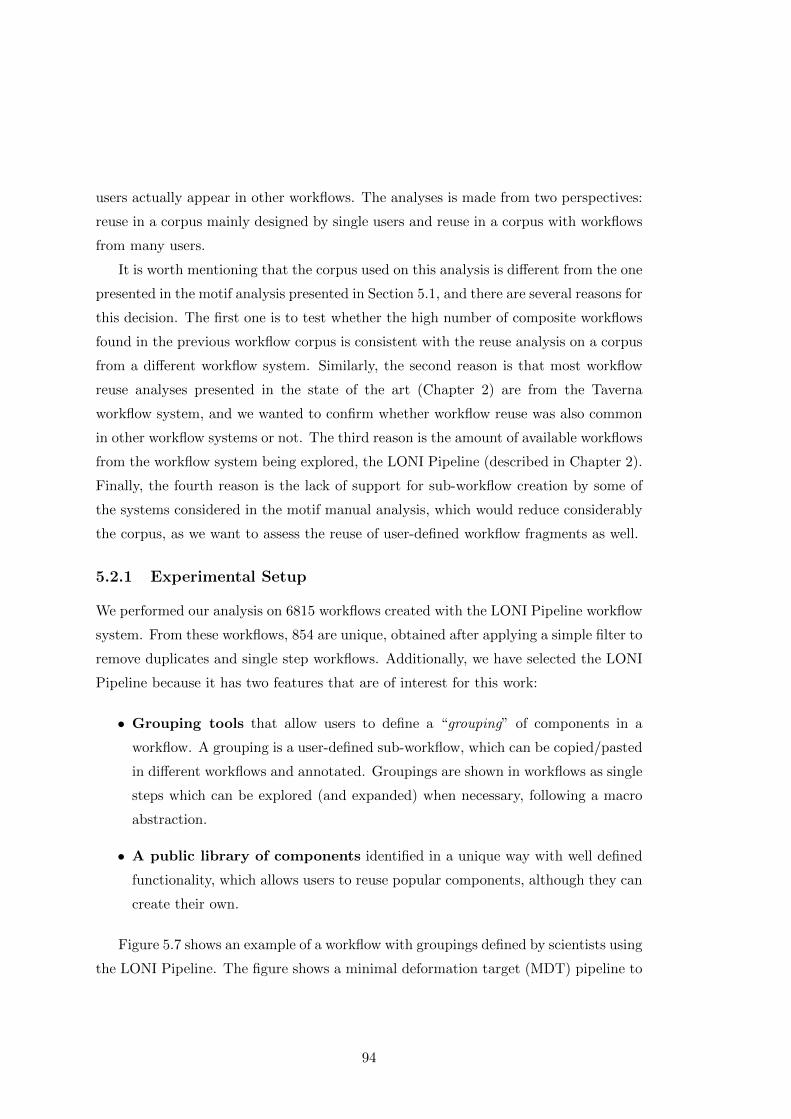
users actually appear in other workflows. The analyses is made from two perspectives:
reuse in a corpus mainly designed by single users and reuse in a corpus with workflows
from many users.
It is worth mentioning that the corpus used on this analysis is different from the one
presented in the motif analysis presented in Section 5.1, and there are several reasons for
this decision. The first one is to test whether the high number of composite workflows
found in the previous workflow corpus is consistent with the reuse analysis on a corpus
from a different workflow system. Similarly, the second reason is that most workflow
reuse analyses presented in the state of the art (Chapter 2) are from the Taverna
workflow system, and we wanted to confirm whether workflow reuse was also common
in other workflow systems or not. The third reason is the amount of available workflows
from the workflow system being explored, the LONI Pipeline (described in Chapter 2).
Finally, the fourth reason is the lack of support for sub-workflow creation by some of
the systems considered in the motif manual analysis, which would reduce considerably
the corpus, as we want to assess the reuse of user-defined workflow fragments as well.
5.2.1 Experimental Setup
We performed our analysis on 6815 workflows created with the LONI Pipeline workflow
system. From these workflows, 854 are unique, obtained after applying a simple filter to
remove duplicates and single step workflows. Additionally, we have selected the LONI
Pipeline because it has two features that are of interest for this work:
• Grouping tools that allow users to define a “grouping” of components in a
workflow. A grouping is a user-defined sub-workflow, which can be copied/pasted
in different workflows and annotated. Groupings are shown in workflows as single
steps which can be explored (and expanded) when necessary, following a macro
abstraction.
• A public library of components identified in a unique way with well defined
functionality, which allows users to reuse popular components, although they can
create their own.
Figure 5.7 shows an example of a workflow with groupings defined by scientists using
the LONI Pipeline. The figure shows a minimal deformation target (MDT) pipeline to
94

Figure 5.7: An example of a workflow in the LONI Pipeline, with workflow steps (compo-
nents) shown as circles. Outputs are shown as triangles while the input (linearly registered)
is a smaller circle. The connections among steps represent the dataflow. Users can select
sub-workflows to create groupings of components (shown with dashed lines), which can be
reused in the same workflow and in others (shown as rectangular components).
serve as an unbiased average brain template for neuro-imaging studies. The grouping,
which has been expanded in the figure (on top right) contains three steps and another
grouping (compose vector fields).
5.2.1.1 Workflow Corpus
The workflows are distributed among four different corpora. Originally, we obtained
two corpora from two different users, containing all the workflows created by them or
in collaboration with other people. A third corpus contains the runs of 62 unique users
submitted to the LONI Pipeline servers during January 2014. Finally, on a second
iteration of our analysis, another user incorporated more workflows to the experiment.
The main features of each corpus are described below:
1. User Corpus 1 (WC1) A set of 790 workflows (441 workflows after filtering du-
95
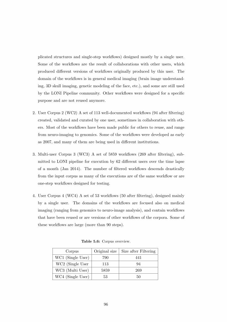
plicated structures and single-step workflows) designed mostly by a single user.
Some of the workflows are the result of collaborations with other users, which
produced different versions of workflows originally produced by this user. The
domain of the workflows is in general medical imaging (brain image understand-
ing, 3D skull imaging, genetic modeling of the face, etc.), and some are still used
by the LONI Pipeline community. Other workflows were designed for a specific
purpose and are not reused anymore.
2. User Corpus 2 (WC2) A set of 113 well-documented workflows (94 after filtering)
created, validated and curated by one user, sometimes in collaboration with oth-
ers. Most of the workflows have been made public for others to reuse, and range
from neuro-imaging to genomics. Some of the workflows were developed as early
as 2007, and many of them are being used in different institutions.
3. Multi-user Corpus 3 (WC3) A set of 5859 workflows (269 after filtering), sub-
mitted to LONI pipeline for execution by 62 different users over the time lapse
of a month (Jan 2014). The number of filtered workflows descends drastically
from the input corpus as many of the executions are of the same workflow or are
one-step workflows designed for testing.
4. User Corpus 4 (WC4) A set of 53 workflows (50 after filtering), designed mainly
by a single user. The domains of the workflows are focused also on medical
imaging (ranging from genomics to neuro-image analysis), and contain workflows
that have been reused or are versions of other workflows of the corpora. Some of
these workflows are large (more than 90 steps).
Table 5.6: Corpus overview.
Corpus Original size Size after Filtering
WC1 (Single User) 790 441
WC2 (Single User 113 94
WC3 (Multi User) 5859 269
WC4 (Single User) 53 50
96
In all four corpora, workflows are likely to reuse components from the public library,
what allows groupings to be reused across different workflows. Table 5.6 provides an
overview of the size of each corpus before and after filtering.
5.2.1.2 Analysis Methodology
The analysis was performed in an automated way for each corpus, once duplicate work-
flows and single-step workflows had been removed. In order to have a full notion on
how workflows and groupings are reused, we performed two independent sub-analysis
respectively.
In both analyses, each workflow or grouping was transformed to a labeled graph
(according to P-Plan) and compared against another in terms of its steps. Since in the
LONI Pipeline each component has a unique identifier, we use them to label the nodes
of the graph (the label becomes the type of the workflow step). Therefore, two nodes
are the same if they have the same label (i.e., the same type). Both analyses follow a
similar approach. First, an initial pass over the dataset gathers the different workflows
or groupings to compare. Then, a second iteration compares each graph (workflow or
grouping) against all the workflows of the corpus, annotating those workflows where
the graph is found. The method to do this comparison is by transforming each graph
to a SPARQL query (i.e., the standard language for querying RDF data (Harris et al.,
2013)) and issue it against the target workflow. Further details of this approach are
described in Chapter 6, where we use it to find workflow fragments in workflows.
It is worth mentioning that with our approach we compare whether a workflow or a
grouping is included in another workflow regardless of the grouping annotations made
by users in the target workflow. That is, if a grouping consists on three steps A, B and
C where C consumes the output of B and B consumes the output of A; and we find
these steps in a workflow with the same dependencies among them, we consider that the
grouping is found in that workflow (even if the steps A, B and C of the workflow have
not been annotated as a grouping by a user). This is a key difference with other related
work, where reuse is measured just in terms of the explicit workflows and sub-workflows
created by users.
Similarly to what happens with workflows, if a grouping is duplicated we will only
consider it once, and single-step and empty groupings are not considered for reuse.
Groupings are not further compared against groupings, just against workflows.
97
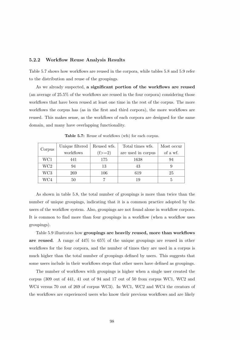
5.2.2 Workflow Reuse Analysis Results
Table 5.7 shows how workflows are reused in the corpora, while tables 5.8 and 5.9 refer
to the distribution and reuse of the groupings.
As we already suspected, a significant portion of the workflows are reused
(an average of 25.5% of the workflows are reused in the four corpora) considering those
workflows that have been reused at least one time in the rest of the corpus. The more
workflows the corpus has (as in the first and third corpora), the more workflows are
reused. This makes sense, as the workflows of each corpora are designed for the same
domain, and many have overlapping functionality.
Table 5.7: Reuse of workflows (wfs) for each corpus.
CorpusUnique filtered
workflows
Reused wfs.
(f>=2)
Total times wfs.
are used in corpus
Most occur
of a wf.
WC1 441 175 1638 94
WC2 94 13 43 9
WC3 269 106 619 25
WC4 50 7 19 5
As shown in table 5.8, the total number of groupings is more than twice than the
number of unique groupings, indicating that it is a common practice adopted by the
users of the workflow system. Also, groupings are not found alone in workflow corpora.
It is common to find more than four groupings in a workflow (when a workflow uses
groupings).
Table 5.9 illustrates how groupings are heavily reused, more than workflows
are reused. A range of 44% to 65% of the unique groupings are reused in other
workflows for the four corpora, and the number of times they are used in a corpus is
much higher than the total number of groupings defined by users. This suggests that
some users include in their workflows steps that other users have defined as groupings.
The number of workflows with groupings is higher when a single user created the
corpus (309 out of 441, 41 out of 94 and 17 out of 50 from corpus WC1, WC2 and
WC4 versus 70 out of 269 of corpus WC3). In WC1, WC2 and WC4 the creators of
the workflows are experienced users who know their previous workflows and are likely
98

to reuse them, while the high number of users contributing to WC3 makes it difficult
for all of them to be aware of the workflows from other colleagues.
Another interesting fact is the size of the groupings, being up to 92 in corpus
WC4 and down to 0 in corpora WC2 and WC4. After exploring several workflows
showing this practice, we have realized that the high number of steps for some groupings
happens because users sometimes declare a whole workflow as a grouping. A possible
explanation is that this would either facilitate copying and pasting the grouping into
other templates, or help organizing the workflow for the creator: when workflows are
too complex, users often separate their functionality in several smaller workflows. Then,
each smaller workflow is declared a grouping and copied and linked in a bigger workflow.
Regarding the minimum size of groupings, we have discovered that sometimes work-
flow creators group unused inputs or outputs in workflows, leading to groupings of 0
steps. A possible explanation to groupings of size 1 is that the workflow creators anno-
tate extra instructions when using a specific component in a workflow (in our analysis
only groupings of size bigger than one are considered, shown in the unique multi-step
grouping column of Table 5.8).
Table 5.8: Statistics and distribution of groupings in the corpora.
CorpusTotal
qroup.
Unique
multi-step
qroup.
Wf with
qroup.
Avg.
group.
per wf
Max nof
steps in
qroup.
Min n of
steps in
qroup.
WC1 1379 146 309 4 56 1
WC2 294 87 41 7 39 0
WC3 277 79 70 4 60 1
WC4 245 40 17 14 92 0
Table 5.9: Reuse of groupings (group) for each corpus.
CorpusUnique filtered
groupings
Reused group.
(f>=2)
Total times group.
are used in corpus
Most occurrences
of a grouping
WC1 146 65 1842 176
WC2 87 40 227 29
WC3 79 47 246 24
WC4 40 26 103 7
99
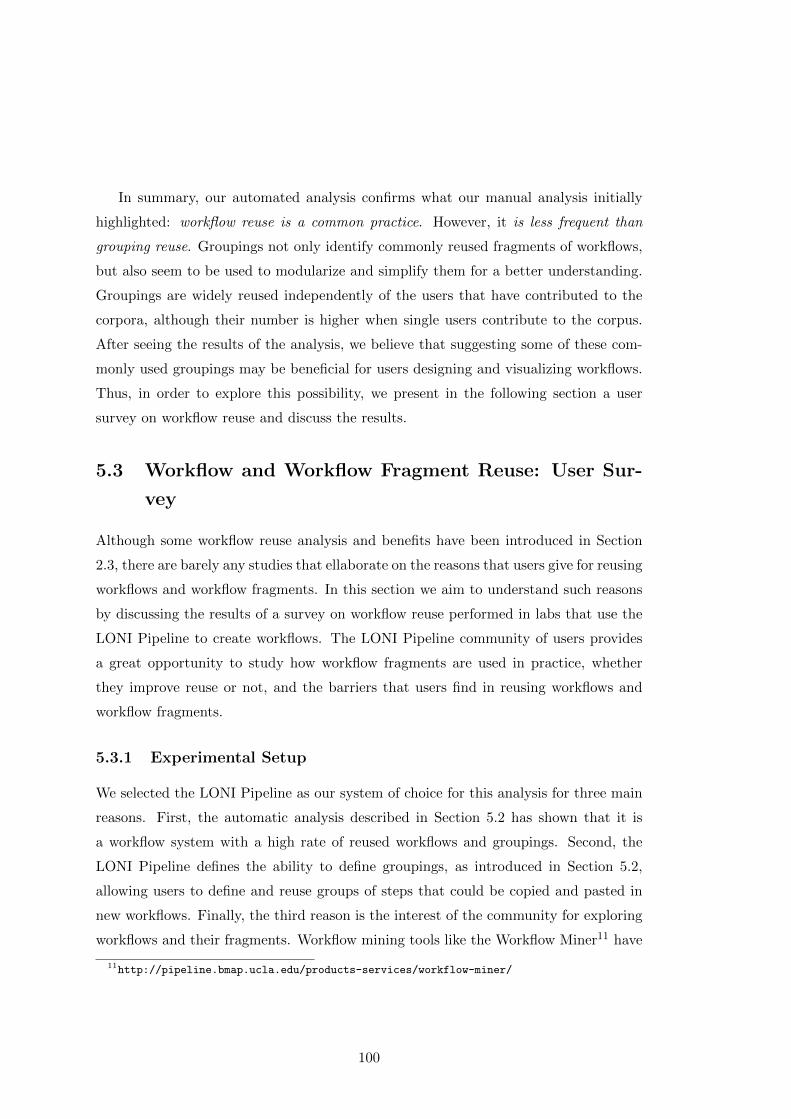
In summary, our automated analysis confirms what our manual analysis initially
highlighted: workflow reuse is a common practice. However, it is less frequent than
grouping reuse. Groupings not only identify commonly reused fragments of workflows,
but also seem to be used to modularize and simplify them for a better understanding.
Groupings are widely reused independently of the users that have contributed to the
corpora, although their number is higher when single users contribute to the corpus.
After seeing the results of the analysis, we believe that suggesting some of these com-
monly used groupings may be beneficial for users designing and visualizing workflows.
Thus, in order to explore this possibility, we present in the following section a user
survey on workflow reuse and discuss the results.
5.3 Workflow and Workflow Fragment Reuse: User Sur-
vey
Although some workflow reuse analysis and benefits have been introduced in Section
2.3, there are barely any studies that ellaborate on the reasons that users give for reusing
workflows and workflow fragments. In this section we aim to understand such reasons
by discussing the results of a survey on workflow reuse performed in labs that use the
LONI Pipeline to create workflows. The LONI Pipeline community of users provides
a great opportunity to study how workflow fragments are used in practice, whether
they improve reuse or not, and the barriers that users find in reusing workflows and
workflow fragments.
5.3.1 Experimental Setup
We selected the LONI Pipeline as our system of choice for this analysis for three main
reasons. First, the automatic analysis described in Section 5.2 has shown that it is
a workflow system with a high rate of reused workflows and groupings. Second, the
LONI Pipeline defines the ability to define groupings, as introduced in Section 5.2,
allowing users to define and reuse groups of steps that could be copied and pasted in
new workflows. Finally, the third reason is the interest of the community for exploring
workflows and their fragments. Workflow mining tools like the Workflow Miner11 have
11http://pipeline.bmap.ucla.edu/products-services/workflow-miner/
100

been developed for helping users browsing how different workflow components depend
on each other in a catalog of workflows.
The fact that the LONI Pipeline includes tools to create, mine and view workflow
groupings is an indication that users and/or developers have found a need for reusing
workflow fragments. In our analysis, we set out to understand the current level of
adoption, the perceived benefits, and the barriers regarding reuse of workflows and
workflow fragments.
We created a survey and sent it to the mailing list of users of the LONI Pipeline.
We included users who use the LONI Pipeline system installed at the University of
Souther California (USC), but due to time limitations we did not include many other
users that have downloaded the system and run it themselves in their own servers.
The survey was conducted on-line, and the responses were anonymous. The complete
survey can be found in Annex B, while the the responses are available online12.
The survey included two kinds of questions. Some questions presented a choice of
answers using a five-level Likert scale (Likert, 1932). For example, for the question
“Is reusing workflows from others useful?” we offered five answers: very often, often,
sometimes, occasionally, and never. Other questions offered a list of possible answers
and allowed users to provide their own answers. For example, for the question “Why
is reusing previously created workflows useful?” the list of possible answers included
“It saves time”, “Workflows give a high-level diagram that helps remember what was
done”, and “Other”. If the latter was chosen, respondents could provide text with their
own reasons. Respondents could do more than one selection.
It is worth mentioning that the survey tackles the issue of workflow reuse gradually.
First, it issues questions regarding the reusability of software. Then it asks for the
reusability of methods (i.e., workflows) and ends up prompting questions regarding the
reusability of fragments of those workflows. This way we ensure that we cover all the
possible aspects of workflow reuse.
5.3.2 User Survey Report
We received a total of 21 responses from the users in the lab, ranging from students
to experienced users and programmers. In this section we discuss the results of the
survey, highlighting in boldface our findings.
12http://dx.doi.org/10.6084/m9.figshare.1572327
101
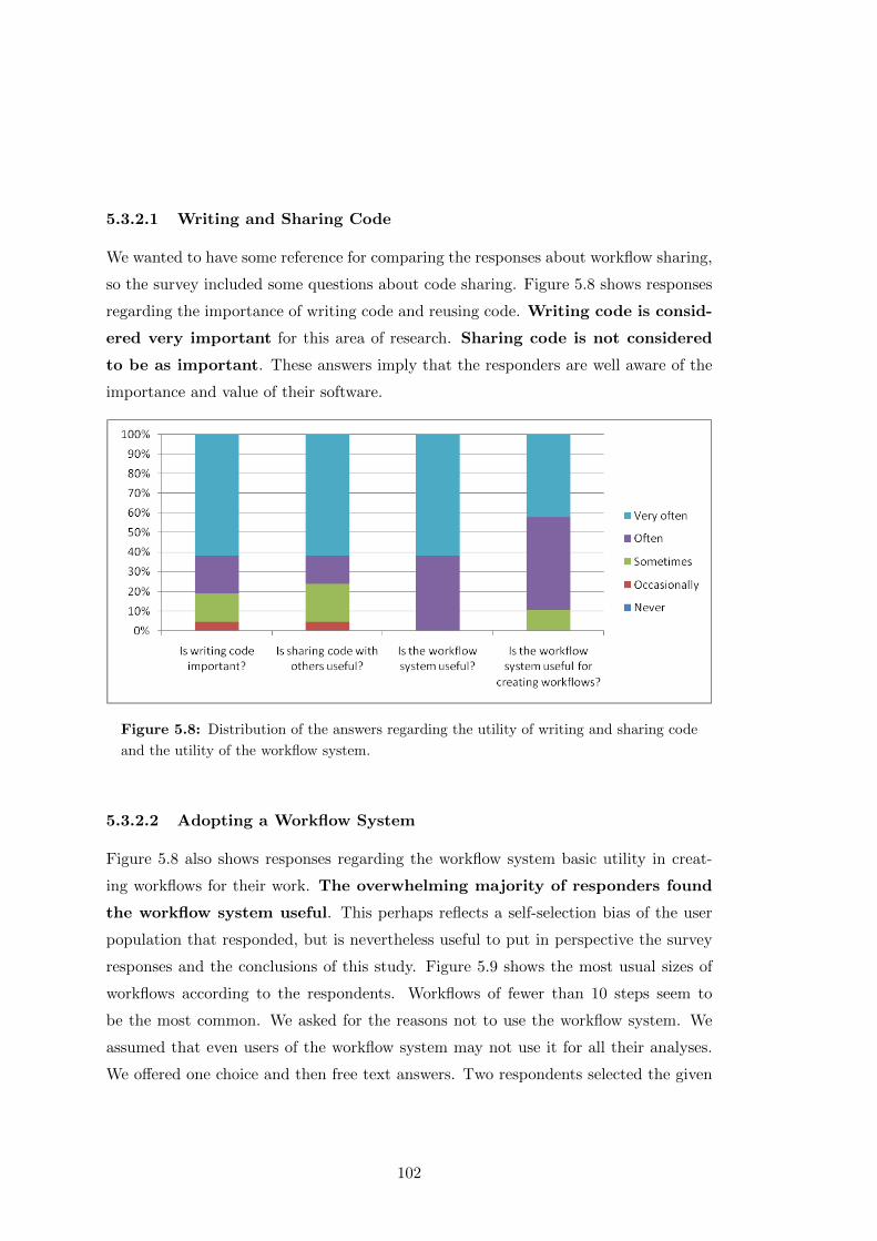
5.3.2.1 Writing and Sharing Code
We wanted to have some reference for comparing the responses about workflow sharing,
so the survey included some questions about code sharing. Figure 5.8 shows responses
regarding the importance of writing code and reusing code. Writing code is consid-
ered very important for this area of research. Sharing code is not considered
to be as important. These answers imply that the responders are well aware of the
importance and value of their software.
Figure 5.8: Distribution of the answers regarding the utility of writing and sharing code
and the utility of the workflow system.
5.3.2.2 Adopting a Workflow System
Figure 5.8 also shows responses regarding the workflow system basic utility in creat-
ing workflows for their work. The overwhelming majority of responders found
the workflow system useful. This perhaps reflects a self-selection bias of the user
population that responded, but is nevertheless useful to put in perspective the survey
responses and the conclusions of this study. Figure 5.9 shows the most usual sizes of
workflows according to the respondents. Workflows of fewer than 10 steps seem to
be the most common. We asked for the reasons not to use the workflow system. We
assumed that even users of the workflow system may not use it for all their analyses.
We offered one choice and then free text answers. Two respondents selected the given
102
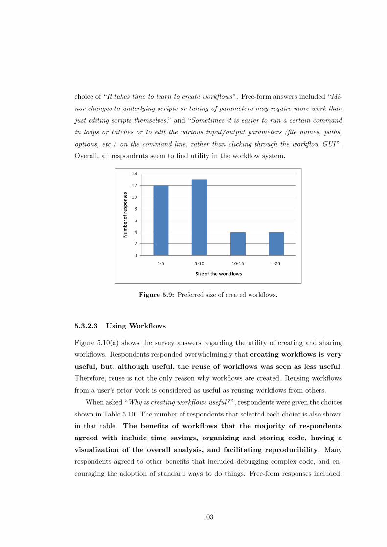
choice of “It takes time to learn to create workflows”. Free-form answers included “Mi-
nor changes to underlying scripts or tuning of parameters may require more work than
just editing scripts themselves,” and “Sometimes it is easier to run a certain command
in loops or batches or to edit the various input/output parameters (file names, paths,
options, etc.) on the command line, rather than clicking through the workflow GUI ”.
Overall, all respondents seem to find utility in the workflow system.
Figure 5.9: Preferred size of created workflows.
5.3.2.3 Using Workflows
Figure 5.10(a) shows the survey answers regarding the utility of creating and sharing
workflows. Respondents responded overwhelmingly that creating workflows is very
useful, but, although useful, the reuse of workflows was seen as less useful.
Therefore, reuse is not the only reason why workflows are created. Reusing workflows
from a user’s prior work is considered as useful as reusing workflows from others.
When asked “Why is creating workflows useful?”, respondents were given the choices
shown in Table 5.10. The number of respondents that selected each choice is also shown
in that table. The benefits of workflows that the majority of respondents
agreed with include time savings, organizing and storing code, having a
visualization of the overall analysis, and facilitating reproducibility. Many
respondents agreed to other benefits that included debugging complex code, and en-
couraging the adoption of standard ways to do things. Free-form responses included:
103
“Workflows are mainly used for population studies so that you can run many subjects in
the same time, and it is easy to pass around to someone who doesn’t know how to code”,
“The main reason is that it is easy to send a prepared pipeline to another researcher and
they can usually figure out how to use it, regardless of their programming knowledge”,
“It’s a really intuitive visualization of the underlying code. Sort of brings the code ’to
life’ !” and “Parallelizing without having to use the Sun Grid Engine script”.
Table 5.10: Survey results concerning why it is useful to create workflows.
Workflows save time 13
Easier to track and debug complex code 9
Convenient way to organize/store code 11
Help write more organized code 6
Help make code more modular/reusable 4
Help make methods more understandable 8
Visualization of overall analysis 11
Workflows facilitate reproducibility 10
Table 5.11a shows responses for the question of why it is useful to reuse workflows
in new analyses. Overwhelmingly, users found that using workflows saves them
time. They also found the visualization of the workflow useful. Free form answers
included: “We often re-run the exact same or very similar analysis steps on our data
(e.g., pre-processing, statistical tests), so often we only need to change the inputs and
outputs (and maybe some parameters)”.
Table 5.11b shows responses for why it is useful to share workflows with others.
The overwhelming majority of respondents said workflows are useful for both non-
programmers and for teaching new students. It also saves them time because
they do not need to re-implement code. No free form answers were specified.
Table 5.11c shows answers for why are workflows not shared. Respondents did not
offer very overwhelming reasons for not sharing workflows. Free form answers included
“The best pipelines to share are the ones that have all the kinks worked out, so we can
explain how to edit the input and output file names and then the person can just run
it”.
Table 5.11d shows responses for why it is not useful to reuse workflows from oth-
ers. Respondents did not offer very overwhelming reasons for not reusing workflows
104
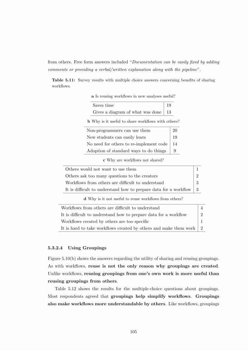
from others. Free form answers included “Documentation can be easily fixed by adding
comments or providing a verbal/written explanation along with the pipeline”.
Table 5.11: Survey results with multiple choice answers concerning benefits of sharing
workflows.
a Is reusing workflows in new analyses useful?
Saves time 19
Gives a diagram of what was done 13
b Why is it useful to share workflows with others?
Non-programmers can use them 20
New students can easily learn 19
No need for others to re-implement code 14
Adoption of standard ways to do things 9
c Why are workflows not shared?
Others would not want to use them 1
Others ask too many questions to the creators 2
Workflows from others are difficult to understand 3
It is difficult to understand how to prepare data for a workflow 3
d Why is it not useful to reuse workflows from others?
Workflows from others are difficult to understand 4
It is difficult to understand how to prepare data for a workflow 2
Workflows created by others are too specific 1
It is hard to take workflows created by others and make them work 2
5.3.2.4 Using Groupings
Figure 5.10(b) shows the answers regarding the utility of sharing and reusing groupings.
As with workflows, reuse is not the only reason why groupings are created.
Unlike workflows, reusing groupings from one’s own work is more useful than
reusing groupings from others.
Table 5.12 shows the results for the multiple-choice questions about groupings.
Most respondents agreed that groupings help simplify workflows. Groupings
also make workflows more understandable by others. Like workflows, groupings
105
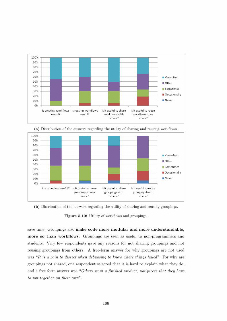
(a) Distribution of the answers regarding the utility of sharing and reusing workflows.
(b) Distribution of the answers regarding the utility of sharing and reusing groupings.
Figure 5.10: Utility of workflows and groupings.
save time. Groupings also make code more modular and more understandable,
more so than workflows. Groupings are seen as useful to non-programmers and
students. Very few respondents gave any reasons for not sharing groupings and not
reusing groupings from others. A free-form answer for why groupings are not used
was “It is a pain to dissect when debugging to know where things failed”. For why are
groupings not shared, one respondent selected that it is hard to explain what they do,
and a free form answer was “Others want a finished product, not pieces that they have
to put together on their own”.
106
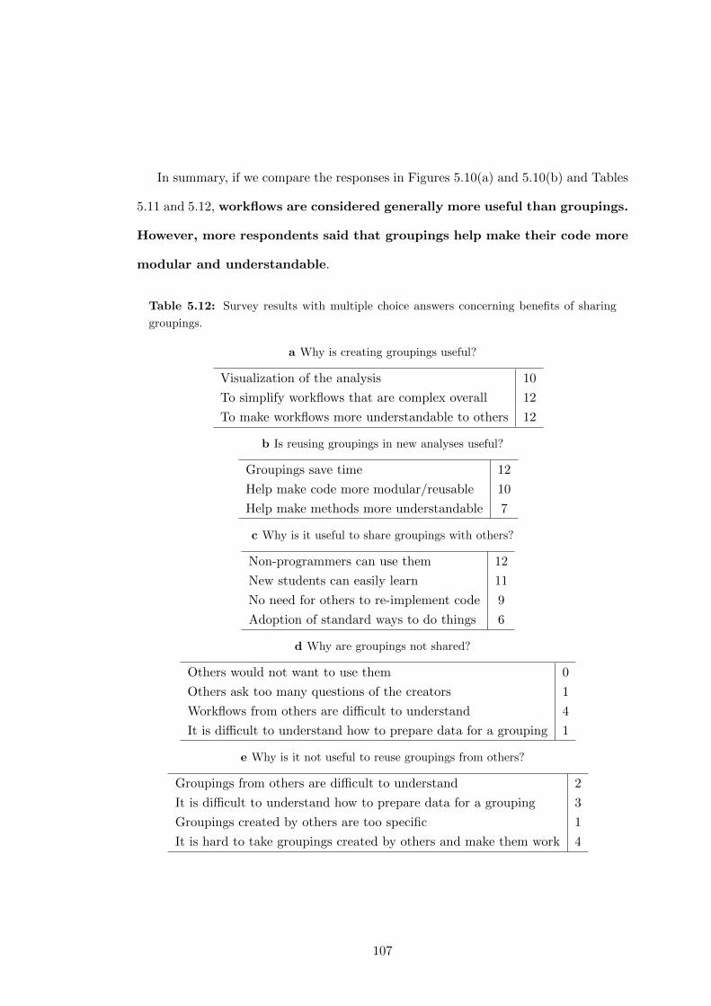
In summary, if we compare the responses in Figures 5.10(a) and 5.10(b) and Tables
5.11 and 5.12, workflows are considered generally more useful than groupings.
However, more respondents said that groupings help make their code more
modular and understandable.
Table 5.12: Survey results with multiple choice answers concerning benefits of sharing
groupings.
a Why is creating groupings useful?
Visualization of the analysis 10
To simplify workflows that are complex overall 12
To make workflows more understandable to others 12
b Is reusing groupings in new analyses useful?
Groupings save time 12
Help make code more modular/reusable 10
Help make methods more understandable 7
c Why is it useful to share groupings with others?
Non-programmers can use them 12
New students can easily learn 11
No need for others to re-implement code 9
Adoption of standard ways to do things 6
d Why are groupings not shared?
Others would not want to use them 0
Others ask too many questions of the creators 1
Workflows from others are difficult to understand 4
It is difficult to understand how to prepare data for a grouping 1
e Why is it not useful to reuse groupings from others?
Groupings from others are difficult to understand 2
It is difficult to understand how to prepare data for a grouping 3
Groupings created by others are too specific 1
It is hard to take groupings created by others and make them work 4
107
5.4 Summary
In this chapter we defined the scope of the workflow abstractions tackled in our work,
focusing on those related to workflow reuse. We defined a catalog of common workflow
motifs, which are domain independent conceptual abstractions of workflow steps, by
doing an empirical analysis on a corpus from four different workflows systems. This ad-
dresses the third research objective of this thesis (RO3, define a catalog of domain inde-
pendent abstractions in scientific workflows) and contributes to the research challenges
RCAbstract-1 (difficulty on determining which are the significant steps of a workflow),
RCAbstract-2 (absence of catalog of abstractions based on workflow step functionality)
and RCAnnot-1 (facilitate workflow annotation). The results of the analysis highlight
that three motifs in particular are widely used among the corpora: atomic workflows,
composite workflows and internal macros, which indicate that workflow reuse is a com-
mon practice among scientists of different domains.
We have attempted to confirm and understand further two aspects of workflows
and workflow fragments: reuse and usefulness. Therefore we have performed analyses
on another workflow system (the LONI Pipeline), different from the ones explored in
the manual analysis, with an active community of users and a significant corpus of
workflows.
We first performed an automated analysis of workflows to measure reuse, based on
the sets of steps users have defined in the corpora (user groupings). We also performed
a user survey on 21 users to find out their opinion with respect of workflow and sub-
workflow sharing and reuse. The results speak for themselves: the workflow reuse rate
is high (with a minimum of 12% and increasing up to 30% in cases where the size of the
collection is more than 200 workflows), and the grouping reuse rate is even higher (44%
to 65% of the groupings are reused). It is interesting that users consider workflows
more useful than groupings from the point of view of reuse, although they recognize
that groupings help modularizing and understanding their code better.
Given that users tend to reuse groupings and workflows, our hypothesis is that
by mining commonly used fragments of workflows we can discover new groupings or
even workflows that are useful for them when designing workflows. Hence, in the
next chapter we describe our approach for detecting these common workflow fragments
automatically.
108
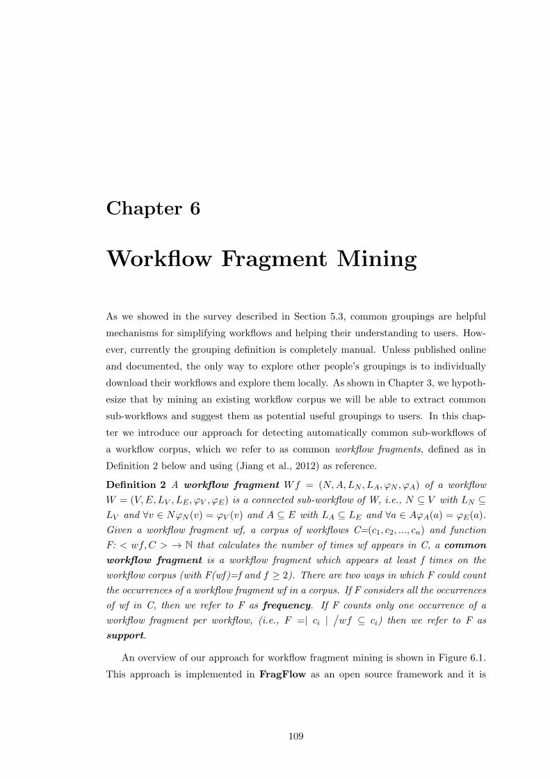
Chapter 6
Workflow Fragment Mining
As we showed in the survey described in Section 5.3, common groupings are helpful
mechanisms for simplifying workflows and helping their understanding to users. How-
ever, currently the grouping definition is completely manual. Unless published online
and documented, the only way to explore other people’s groupings is to individually
download their workflows and explore them locally. As shown in Chapter 3, we hypoth-
esize that by mining an existing workflow corpus we will be able to extract common
sub-workflows and suggest them as potential useful groupings to users. In this chap-
ter we introduce our approach for detecting automatically common sub-workflows of
a workflow corpus, which we refer to as common workflow fragments, defined as in
Definition 2 below and using (Jiang et al., 2012) as reference.
Definition 2 A workflow fragment Wf = (N,A,LN , LA, ϕN , ϕA) of a workflow
W = (V,E,LV , LE , ϕV , ϕE) is a connected sub-workflow of W, i.e., N ⊆ V with LN ⊆LV and ∀v ∈ NϕN (v) = ϕV (v) and A ⊆ E with LA ⊆ LE and ∀a ∈ AϕA(a) = ϕE(a).
Given a workflow fragment wf, a corpus of workflows C=(c1, c2, ..., cn) and function
F: < wf,C > → N that calculates the number of times wf appears in C, a common
workflow fragment is a workflow fragment which appears at least f times on the
workflow corpus (with F(wf)=f and f ≥ 2). There are two ways in which F could count
the occurrences of a workflow fragment wf in a corpus. If F considers all the occurrences
of wf in C, then we refer to F as frequency. If F counts only one occurrence of a
workflow fragment per workflow, (i.e., F =| ci |/wf ⊆ ci) then we refer to F as
support.
An overview of our approach for workflow fragment mining is shown in Figure 6.1.
This approach is implemented in FragFlow as an open source framework and it is
109
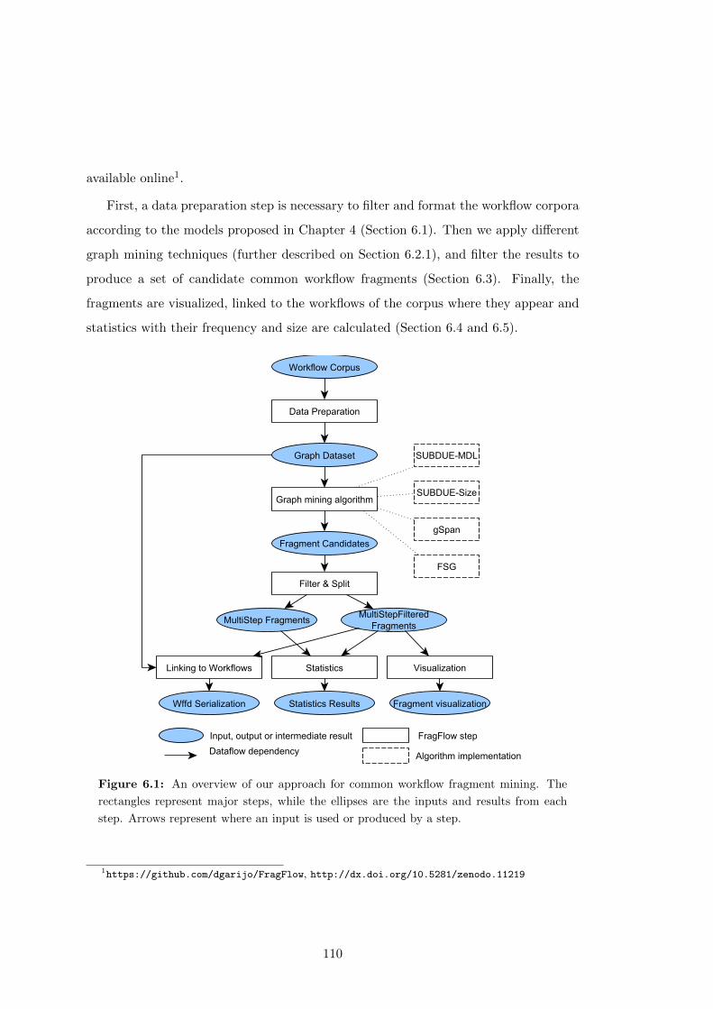
available online1.
First, a data preparation step is necessary to filter and format the workflow corpora
according to the models proposed in Chapter 4 (Section 6.1). Then we apply different
graph mining techniques (further described on Section 6.2.1), and filter the results to
produce a set of candidate common workflow fragments (Section 6.3). Finally, the
fragments are visualized, linked to the workflows of the corpus where they appear and
statistics with their frequency and size are calculated (Section 6.4 and 6.5).
Figure 6.1: An overview of our approach for common workflow fragment mining. The
rectangles represent major steps, while the ellipses are the inputs and results from each
step. Arrows represent where an input is used or produced by a step.
1https://github.com/dgarijo/FragFlow, http://dx.doi.org/10.5281/zenodo.11219
110
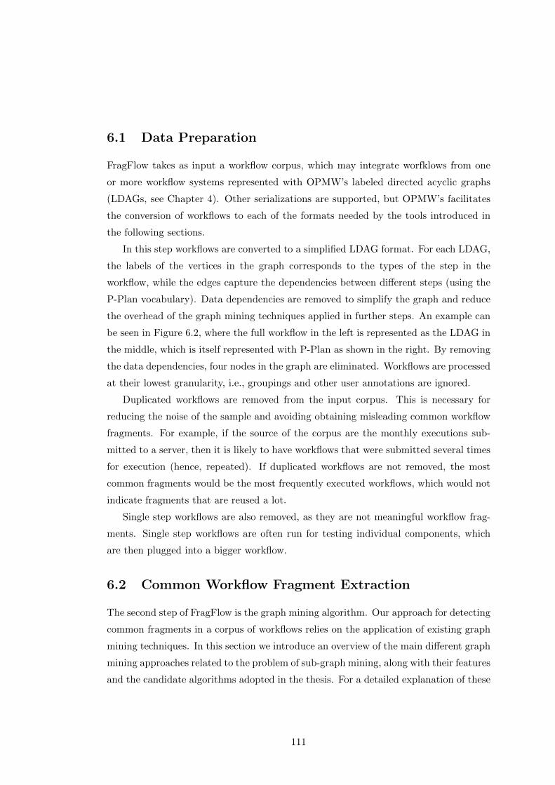
6.1 Data Preparation
FragFlow takes as input a workflow corpus, which may integrate worfklows from one
or more workflow systems represented with OPMW’s labeled directed acyclic graphs
(LDAGs, see Chapter 4). Other serializations are supported, but OPMW’s facilitates
the conversion of workflows to each of the formats needed by the tools introduced in
the following sections.
In this step workflows are converted to a simplified LDAG format. For each LDAG,
the labels of the vertices in the graph corresponds to the types of the step in the
workflow, while the edges capture the dependencies between different steps (using the
P-Plan vocabulary). Data dependencies are removed to simplify the graph and reduce
the overhead of the graph mining techniques applied in further steps. An example can
be seen in Figure 6.2, where the full workflow in the left is represented as the LDAG in
the middle, which is itself represented with P-Plan as shown in the right. By removing
the data dependencies, four nodes in the graph are eliminated. Workflows are processed
at their lowest granularity, i.e., groupings and other user annotations are ignored.
Duplicated workflows are removed from the input corpus. This is necessary for
reducing the noise of the sample and avoiding obtaining misleading common workflow
fragments. For example, if the source of the corpus are the monthly executions sub-
mitted to a server, then it is likely to have workflows that were submitted several times
for execution (hence, repeated). If duplicated workflows are not removed, the most
common fragments would be the most frequently executed workflows, which would not
indicate fragments that are reused a lot.
Single step workflows are also removed, as they are not meaningful workflow frag-
ments. Single step workflows are often run for testing individual components, which
are then plugged into a bigger workflow.
6.2 Common Workflow Fragment Extraction
The second step of FragFlow is the graph mining algorithm. Our approach for detecting
common fragments in a corpus of workflows relies on the application of existing graph
mining techniques. In this section we introduce an overview of the main different graph
mining approaches related to the problem of sub-graph mining, along with their features
and the candidate algorithms adopted in the thesis. For a detailed explanation of these
111
Figure 6.2: Simplifying workflows: by removing the data dependencies on the input graph
of the left, we reduce the overhead for graph mining algorithms (middle and right).
and other similar techniques for graph and tree mining we refer the reader to (Jiang
et al., 2012).
6.2.1 Frequent Sub-graph Mining
When representing workflows as graphs, finding the common workflow fragments of
an input corpus is an adaptation of the Frequent Sub-graph Mining (FSM) problem,
also referred to as Frequent Sub-graph Matching in the literature (Jiang et al., 2012).
The objective of FSM is “to extract all the frequent sub-graphs, in a given data set,
whose occurrence counts are above a specified threshold” (Jiang et al., 2012). The main
difference with our case is that we are not interested in obtaining all the workflow
fragments, just those that are useful for potential reuse. Hence, we first mine all the
common workflow fragments and then we filter them with the techniques explained in
section 6.3.
The core of FSM is (sub)graph isomorphism detection, a problem with NP-Complete
112
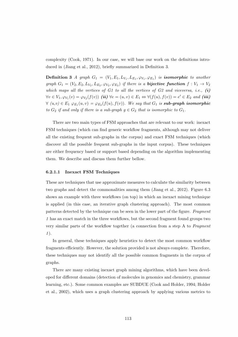
complexity (Cook, 1971). In our case, we will base our work on the definitions intro-
duced in (Jiang et al., 2012), briefly summarized in Definition 3.
Definition 3 A graph G1 = (V1, E1, LV1 , LE1 , ϕV1 , ϕE1) is isomorphic to another
graph G1 = (V2, E2, LV2 , LE2 , ϕV2 , ϕE2) if there is a bijective function f : V1 → V2
which maps all the vertices of G1 to all the vertices of G2 and viceversa, i.e., (i)
∀v ∈ V1, ϕV1(v) = ϕV2(f(v)) (ii) ∀e = (u, v) ∈ E1 ⇔ ∀(f(u), f(v)) = e′ ∈ E2 and (iii)
∀ (u,v) ∈ E1 ϕE1(u, v) = ϕE2(f(u), f(v)). We say that G1 is sub-graph isomorphic
to G2 if and only if there is a sub-graph g ∈ G2 that is isomorphic to G1.
There are two main types of FSM approaches that are relevant to our work: inexact
FSM techniques (which can find generic workflow fragments, although may not deliver
all the existing frequent sub-graphs in the corpus) and exact FSM techniques (which
discover all the possible frequent sub-graphs in the input corpus). These techniques
are either frequency based or support based depending on the algorithm implementing
them. We describe and discuss them further bellow.
6.2.1.1 Inexact FSM Techniques
These are techniques that use approximate measures to calculate the similarity between
two graphs and detect the commonalities among them (Jiang et al., 2012). Figure 6.3
shows an example with three workflows (on top) in which an inexact mining technique
is applied (in this case, an iterative graph clustering approach). The most common
patterns detected by the technique can be seen in the lower part of the figure. Fragment
1 has an exact match in the three workflows, but the second fragment found groups two
very similar parts of the workflow together (a connection from a step A to Fragment
1 ).
In general, these techniques apply heuristics to detect the most common workflow
fragments efficiently. However, the solution provided is not always complete. Therefore,
these techniques may not identify all the possible common fragments in the corpus of
graphs.
There are many existing inexact graph mining algorithms, which have been devel-
oped for different domains (detection of molecules in genomics and chemistry, grammar
learning, etc.). Some common examples are SUBDUE (Cook and Holder, 1994; Holder
et al., 2002), which uses a graph clustering approach by applying various metrics to
113
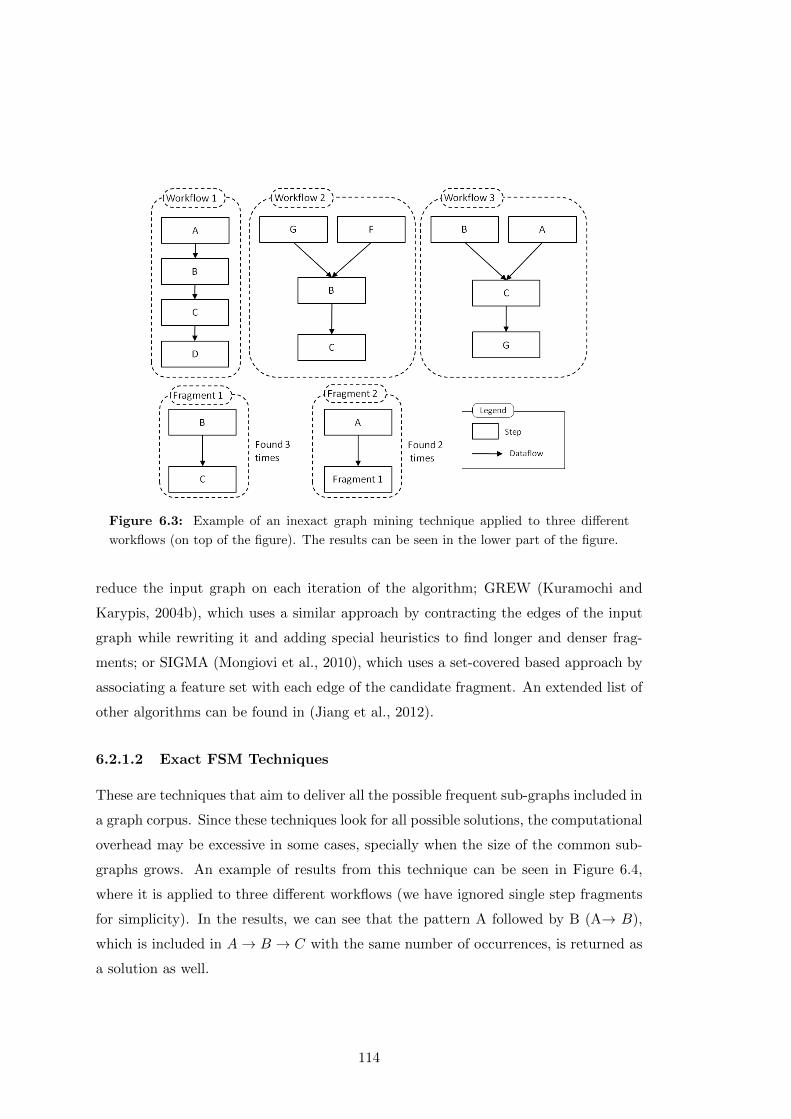
Figure 6.3: Example of an inexact graph mining technique applied to three different
workflows (on top of the figure). The results can be seen in the lower part of the figure.
reduce the input graph on each iteration of the algorithm; GREW (Kuramochi and
Karypis, 2004b), which uses a similar approach by contracting the edges of the input
graph while rewriting it and adding special heuristics to find longer and denser frag-
ments; or SIGMA (Mongiovi et al., 2010), which uses a set-covered based approach by
associating a feature set with each edge of the candidate fragment. An extended list of
other algorithms can be found in (Jiang et al., 2012).
6.2.1.2 Exact FSM Techniques
These are techniques that aim to deliver all the possible frequent sub-graphs included in
a graph corpus. Since these techniques look for all possible solutions, the computational
overhead may be excessive in some cases, specially when the size of the common sub-
graphs grows. An example of results from this technique can be seen in Figure 6.4,
where it is applied to three different workflows (we have ignored single step fragments
for simplicity). In the results, we can see that the pattern A followed by B (A→ B),
which is included in A→ B → C with the same number of occurrences, is returned as
a solution as well.
114
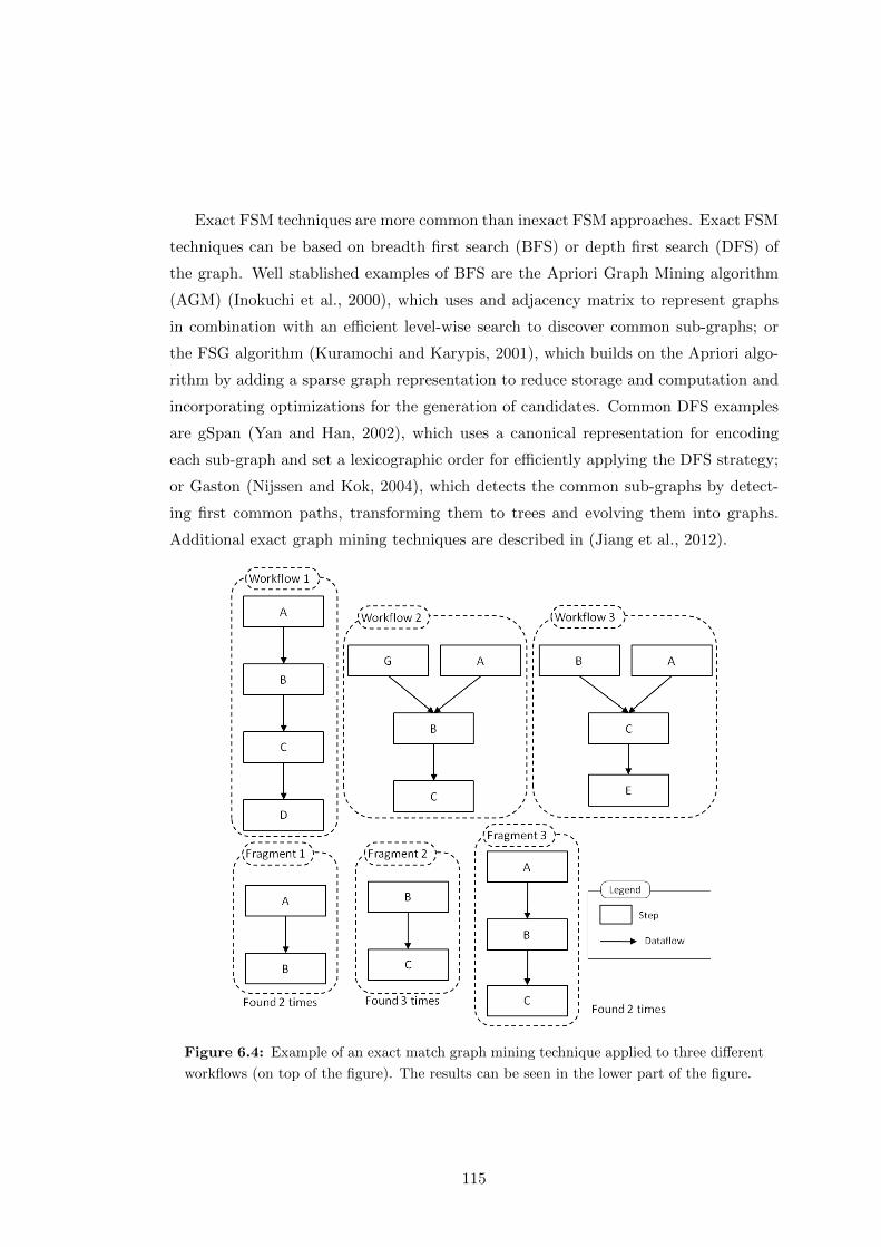
Exact FSM techniques are more common than inexact FSM approaches. Exact FSM
techniques can be based on breadth first search (BFS) or depth first search (DFS) of
the graph. Well stablished examples of BFS are the Apriori Graph Mining algorithm
(AGM) (Inokuchi et al., 2000), which uses and adjacency matrix to represent graphs
in combination with an efficient level-wise search to discover common sub-graphs; or
the FSG algorithm (Kuramochi and Karypis, 2001), which builds on the Apriori algo-
rithm by adding a sparse graph representation to reduce storage and computation and
incorporating optimizations for the generation of candidates. Common DFS examples
are gSpan (Yan and Han, 2002), which uses a canonical representation for encoding
each sub-graph and set a lexicographic order for efficiently applying the DFS strategy;
or Gaston (Nijssen and Kok, 2004), which detects the common sub-graphs by detect-
ing first common paths, transforming them to trees and evolving them into graphs.
Additional exact graph mining techniques are described in (Jiang et al., 2012).
Figure 6.4: Example of an exact match graph mining technique applied to three different
workflows (on top of the figure). The results can be seen in the lower part of the figure.
115
6.2.1.3 Exact FSM versus inexact FSM techniques
Both exact and inexact FSM techniques have advantages and disadvantages. On the
one hand, inexact FSM techniques tend to find smaller but highly frequent patterns,
including some interesting patterns not detected by exact graph mining techniques.
However, they might not identify all potential useful workflow fragments since the
results they provide are incomplete.
On the other hand, exact FSM techniques identify all possible fragments in the
input corpus. However, when the frequent sub-graph size in the input dataset is high,
exact FSM techniques might return too many fragment candidates, while consuming
significant computational resources. Adjusting the parameters of the search (e.g., fre-
quency of the desired workflow fragments) is important in order to obtain the best
results.
6.2.1.4 Frequency-based versus support-based techniques
Another important aspect is how each technique considers the graphs of the input
corpus. Some approaches are frequency-based (see Definition 2), i.e., they consider
each candidate structure based on the number of times it appears, while others are
support-based (see Definition 2), i.e., they only consider a candidate structure once
per input graph. An example is depicted in Figure 6.5: if we consider our threshold
for detecting fragments to be at least two occurrences, the two step fragment A → D
would not be recognized by a support based approach, since it only occurs on Workflow
3. However, since it appears two times, a frequency based approach would consider the
sequence of steps as a candidate fragment. Similarly, the fragment A → B would be
considered to have occurred three times on a frequency based approach (two times on
the first workflow and one on the second), while on a support based approach it would
occur only two times. Both techniques produce valuable workflow fragments, and are
worth considering for detecting common workflow fragments.
6.2.2 Frequent Sub-graph Mining in FragFlow
FragFlow integrates three different existing techniques for extracting common workflow
fragments, one inexact graph mining approach with two different heuristics and two
exact graph mining techniques. These techniques were selected due to several reasons:
116
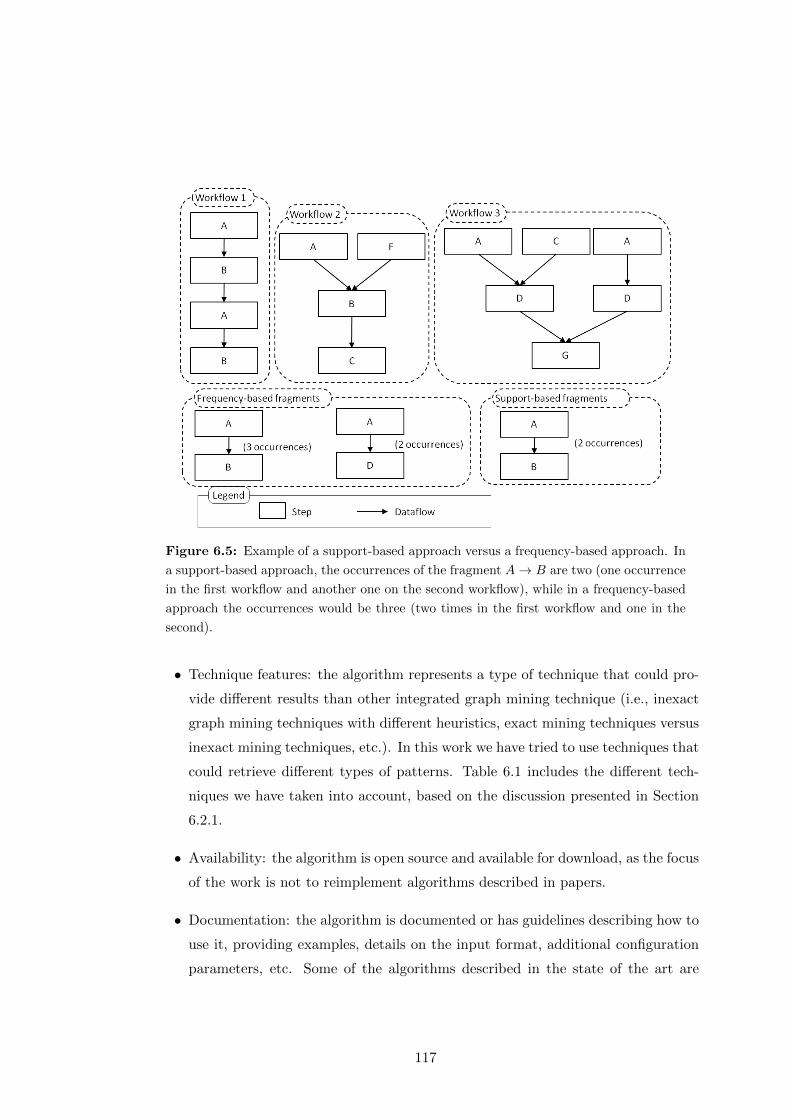
Figure 6.5: Example of a support-based approach versus a frequency-based approach. In
a support-based approach, the occurrences of the fragment A→ B are two (one occurrence
in the first workflow and another one on the second workflow), while in a frequency-based
approach the occurrences would be three (two times in the first workflow and one in the
second).
• Technique features: the algorithm represents a type of technique that could pro-
vide different results than other integrated graph mining technique (i.e., inexact
graph mining techniques with different heuristics, exact mining techniques versus
inexact mining techniques, etc.). In this work we have tried to use techniques that
could retrieve different types of patterns. Table 6.1 includes the different tech-
niques we have taken into account, based on the discussion presented in Section
6.2.1.
• Availability: the algorithm is open source and available for download, as the focus
of the work is not to reimplement algorithms described in papers.
• Documentation: the algorithm is documented or has guidelines describing how to
use it, providing examples, details on the input format, additional configuration
parameters, etc. Some of the algorithms described in the state of the art are
117

domain-specific and not trivial to reuse without a proper documentation.
• Input/output representation: the input of the algorithm follows a standard or
conforms to well used representation.
As shown in Table 6.1, FragFlow integrates two different heuristics of the SUB-
DUE algorithm (Cook and Holder, 1994) as inexact graph mining technique, the gSpan
algorithm (Yan and Han, 2002) as exact match depth first search technique and the
FSG algorithm (Kuramochi and Karypis, 2004a) as exact match breadth first search
technique. All the currently integrated inexact FSM techniques are frequency based,
while exact FSM techniques are support based. The rest of this section provides details
on each of the integrated approaches.
Table 6.1: Frequent sub-graph mining algorithms integrated in FragFlow.
Algorithm Mining type Occurrences Search Strategy
SUBDUE Inexact Frequency N/A
FSG Exact Support BFS
gSpan Exact Support DFS
6.2.2.1 SUBDUE
This algorithm was created to detect the most common and repetitive substructures
within structural data (Cook and Holder, 1994). SUBDUE uses a hierarchical graph
clustering approach by detecting on each iteration of the algorithm the most adequate
candidate structure and compressing the input graph with it. Each candidate structure
is selected by applying an heuristic, which determines the benefits of reducing the total
graph with that candidate structure. SUBDUE uses two main heuristics, which we
have used in our analyses:
1. Minimum description length (MDL): heuristic based on the minimum description
length introduced by Risannen (Rissanen, 1978). At each iteration, the best
candidate substructure is chosen by trying to minimize I(S) + I(G | S), where
S is the substructure, G is the input graph, I(S) is the bits necessary to encode
the substructure and I(G | S) is the number of bits necessary to encode G with
respect of S (Cook and Holder, 1994). After the candidate has been chosen, the
118
algorithm compresses the graph and continues iterating until no further reduction
can be applied.
2. Size: at each iteration, the best fragment is chosen according to how the over-
all size of graph collection is reduced. That is, this heuristic aims to minimize
size(S) + size(G | S), where S is the substructure, G is the input graph, size(S)
is the number of vertices plus the number of edges of the substructure and
size(G | S) is the number of vertices plus the number of edges of G with re-
spect of S. Thus, the most repetitive and the bigger the candidate substructure
is, the more possibilities it has to be selected.
SUBDUE has been updated through the years with different implementations to
make it able to operate with incremental data (Coble et al., 2005) (Coble et al., 2006)
or to allow it to recognize recursive structures (e.g., for concept learning) (Holder et al.,
2002). Even though more recent efforts have outperformed it, SUBDUE is recognized
in the literature as one of the most common algorithms for inexact sub-graph mining
(Jiang et al., 2012). In this work, we have used the implementation available on the
SUBDUE project website2, slightly tuned to produce additional metadata with the
results3.
6.2.2.2 FSG
Algorithm that uses a breadth first strategy based on the level-by-level expansion
adopted by the Apriori algorithm (Inokuchi et al., 2000).
FSG (Kuramochi and Karypis, 2004a) was designed to work efficiently on undirected
labeled graphs and scale reasonably well to very large graph datasets. FSG tackles the
problem of common sub-graph detection by applying the following approach: first, it
gathers all the single-edged and double-edged graphs. Then the algorithm iterates gen-
erating candidate sub-graphs (whose size is one edge greater than the previous frequent
ones) counting their frequencies and pruning any candidates that do not satisfy the
minimum support constraint (i.e., established minimum number of occurrences). The
algorithm stops when no further sub-graphs are generated in an iteration (Kuramochi
and Karypis, 2004a).
2http://ailab.wsu.edu/subdue/3https://github.com/dgarijo/FragFlow/tree/master/SUBDUE_TOOL
119
For efficiency, FSG uses a canonical representation of the graphs, i.e., a unique
code to represent the graph without depending on the order of its vertices and edges.
Unfortunately, this causes some of the fragments mined to be on an incorrect order
when applied to directed graphs (or LDAGs, as it is our case). In order to solve this
issue, we match the resulting fragments against those workflows were they were found
and fix the directionality of the fragment. We use the FSG implementation included
in the PAFI framework4.
6.2.2.3 gSpan
One of the most popular exact FSM techniques (Jiang et al., 2012), and the first one
designed using a DFS strategy. The gSpan algorithm (Yan and Han, 2002) uses a
canonical labeling system (a DFS lexicographic order) where each graph is assigned
a minimum DFS code. By doing this, gSpan turns the problem of finding common
sub-graphs to finding their respective minimum DFS codes. Based on the code, a
hierarchical graph is constructed and traversed, discovering all the most frequent sub-
graphs. Finally, gSpan applies pre-pruning, post-pruning and partial count pruning
to improve its performance (Yan and Han, 2002). In our work, we use the gSpan
implementation available on the ParSeMiS framework5.
6.3 Fragment Filtering and Splitting
The next step in FragFlow is filtering and splitting workflow fragments. The FSM
algorithms introduced in the previous section may return many results, including frag-
ments that overlap or that are included as part of other fragments. In order to present
to users only those fragments considered to be useful, we filter and refine the initial
results by introducing different classes of fragments, as described in Definition 4.
Definition 4 Given a workflow fragment wf, we denote it as a candidate workflow
fragment if it was produced by applying different FSM algorithms to a workflow corpus.
The order of a workflow fragment is a function o : wf → N which returns the number of
vertices in the workflow fragment (o(wf) = |V (wf)|). Fragments where o(wf) > 1 are
referred to as multi-step workflow fragment. Finally, if we have a set of workflow
4http://glaros.dtc.umn.edu/gkhome/pafi/overview/5https://github.com/timtadh/parsemis
120
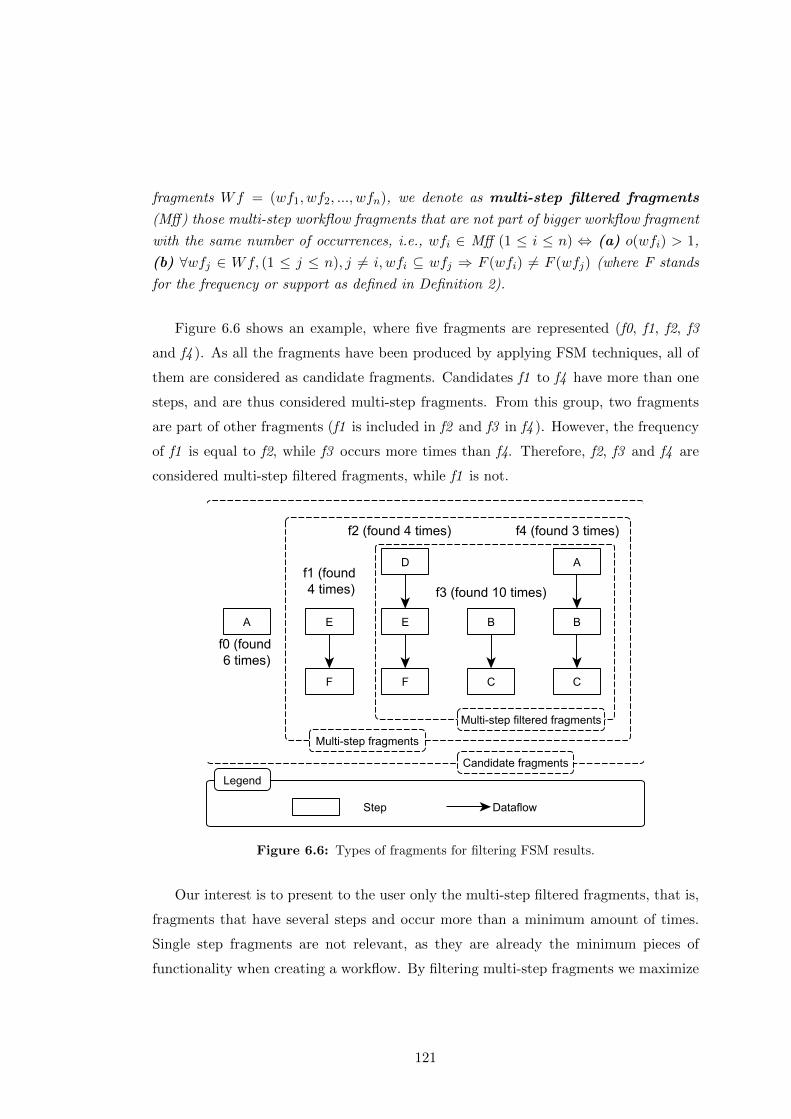
fragments Wf = (wf1, wf2, ..., wfn), we denote as multi-step filtered fragments
(Mff) those multi-step workflow fragments that are not part of bigger workflow fragment
with the same number of occurrences, i.e., wfi ∈ Mff (1 ≤ i ≤ n) ⇔ (a) o(wfi) > 1,
(b) ∀wfj ∈ Wf, (1 ≤ j ≤ n), j 6= i, wfi ⊆ wfj ⇒ F (wfi) 6= F (wfj) (where F stands
for the frequency or support as defined in Definition 2).
Figure 6.6 shows an example, where five fragments are represented (f0, f1, f2, f3
and f4 ). As all the fragments have been produced by applying FSM techniques, all of
them are considered as candidate fragments. Candidates f1 to f4 have more than one
steps, and are thus considered multi-step fragments. From this group, two fragments
are part of other fragments (f1 is included in f2 and f3 in f4 ). However, the frequency
of f1 is equal to f2, while f3 occurs more times than f4. Therefore, f2, f3 and f4 are
considered multi-step filtered fragments, while f1 is not.
Figure 6.6: Types of fragments for filtering FSM results.
Our interest is to present to the user only the multi-step filtered fragments, that is,
fragments that have several steps and occur more than a minimum amount of times.
Single step fragments are not relevant, as they are already the minimum pieces of
functionality when creating a workflow. By filtering multi-step fragments we maximize
121

the size of the fragments presented to the user without removing those common smaller
fragments that are included as part of bigger fragments.
After filtering, the candidate fragments are splitted according to their category
(multi-step or multi-step filtered). This helps selecting the group of fragments to visu-
alize, calculate statistics or link to the original corpus.
6.4 Fragment Linking
Once the workflow fragments have been filtered, the next step in fragFlow is to bind
each fragment to its occurrences in the original workflow corpus, so as to make explicit
the conexion between workflows and their common fragments. This section introduces
first the model used to represent and bind fragments to results by extending the P-Plan
ontology; and then it describes how the different fragments are bound to the workflows
of the original corpus.
6.4.1 Workflow Fragment Representation
We created the Workflow Fragment Description Ontology (Wf-fd6) to represent work-
flow fragments and link them to their occurrences in a workflow dataset. Wf-fd was built
by extending the P-Plan ontology, as workflow fragments are always part of a workflow
template (a plan in P-Plan). Figure 6.7 shows an overview of the model, highlighting
the extended terms and how the workflow fragment representation benefits from P-Plan.
In order to differentiate between the classes and properties of both models, we use the
p-plan and wffd prefixes respectively. In Wf-fd, a WorkflowFragment is a subclass of
P-Plan’s plan. A workflow fragment has steps (reusing the step concept in P-Plan)
which represent the individual data manipulation steps of a particular fragment. The
order among the steps is also captured with the P-Plan property isPrecededBy between
fragment steps.
In Wf-fd there are two types of workflow fragments. On the one hand, a detected
result workflow fragment is a workflow fragment found after applying FSM tech-
niques or manual analyses on a workflow dataset. It identifies a unique fragment
that can be found in a workflow dataset (e.g., a workflow fragment result provided
by any of the graph mining techniques presented in Section 6.2.1). On the other hand,
6http://purl.org/net/wf-fd
122

a tied workflow fragment represents how a detected result workflow fragment
was found in the workflow dataset, pointing to the particular steps of the workflows
that correspond to the fragment.
Figure 6.7: Wf-fd overview, extending the P-Plan ontology.
An example is represented in Figure 6.8, where two fragments (resultF1 and re-
sultF2 ) are found found two times (linked through their respective tied result workflow
fragments) in the workflows Workflow 1 and Workflow 2. As the figure shows, resultF2
is composed of two steps with types <B> and <C>, while resultF1 is composed by
the step <A> followed by the fragment resultF2. This relationship is represented with
the wffd:isPartOfWorkflowFragment relationship.
ResultF2 is represented with a P-Plan’s multiStep (step2F1 ) in resultF1. The ad-
ditional step (step2F1 ) is necessary as the fragment resultF2 could be part of many
other fragments, and including it directly as part of resultF1 would lead to inconsis-
tencies when representing the rest of the results. For example, if we want to represent
the three fragments depicted in Figure 6.9 and we don’t make use of a multiStep
step, the modeling would result as shown in Figure 6.10(a), which is inconsistent (the
precedence relationship in R2 would not be properly represented) and adds complexity
for retrieving fragments based on their isPrecededBy relationship. Instead, if we use
the modeling proposed in Figure 6.10(b) (i.e., using the mutliStep to model fragment
inclusion in other fragments), the fragments would be represented properly and their
123
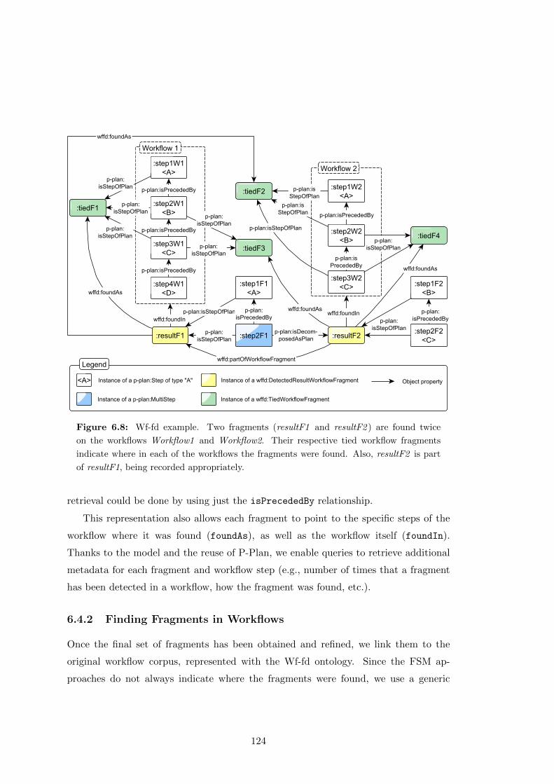
Figure 6.8: Wf-fd example. Two fragments (resultF1 and resultF2 ) are found twice
on the workflows Workflow1 and Workflow2. Their respective tied workflow fragments
indicate where in each of the workflows the fragments were found. Also, resultF2 is part
of resultF1, being recorded appropriately.
retrieval could be done by using just the isPrecededBy relationship.
This representation also allows each fragment to point to the specific steps of the
workflow where it was found (foundAs), as well as the workflow itself (foundIn).
Thanks to the model and the reuse of P-Plan, we enable queries to retrieve additional
metadata for each fragment and workflow step (e.g., number of times that a fragment
has been detected in a workflow, how the fragment was found, etc.).
6.4.2 Finding Fragments in Workflows
Once the final set of fragments has been obtained and refined, we link them to the
original workflow corpus, represented with the Wf-fd ontology. Since the FSM ap-
proaches do not always indicate where the fragments were found, we use a generic
124
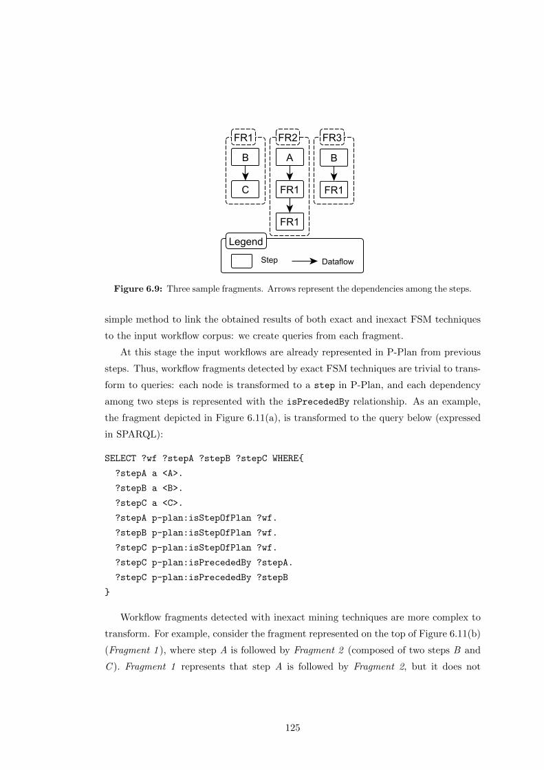
Figure 6.9: Three sample fragments. Arrows represent the dependencies among the steps.
simple method to link the obtained results of both exact and inexact FSM techniques
to the input workflow corpus: we create queries from each fragment.
At this stage the input workflows are already represented in P-Plan from previous
steps. Thus, workflow fragments detected by exact FSM techniques are trivial to trans-
form to queries: each node is transformed to a step in P-Plan, and each dependency
among two steps is represented with the isPrecededBy relationship. As an example,
the fragment depicted in Figure 6.11(a), is transformed to the query below (expressed
in SPARQL):
SELECT ?wf ?stepA ?stepB ?stepC WHERE{
?stepA a <A>.
?stepB a <B>.
?stepC a <C>.
?stepA p-plan:isStepOfPlan ?wf.
?stepB p-plan:isStepOfPlan ?wf.
?stepC p-plan:isStepOfPlan ?wf.
?stepC p-plan:isPrecededBy ?stepA.
?stepC p-plan:isPrecededBy ?stepB
}
Workflow fragments detected with inexact mining techniques are more complex to
transform. For example, consider the fragment represented on the top of Figure 6.11(b)
(Fragment 1 ), where step A is followed by Fragment 2 (composed of two steps B and
C ). Fragment 1 represents that step A is followed by Fragment 2, but it does not
125
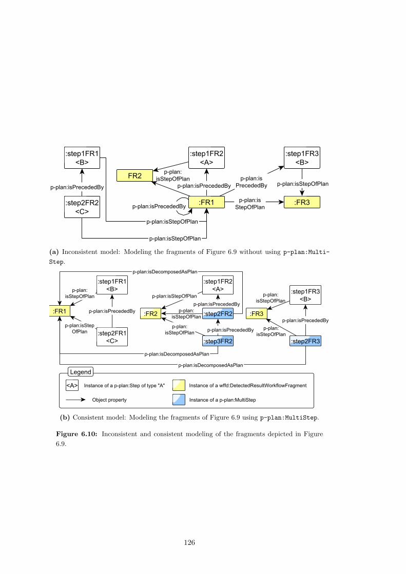
(a) Inconsistent model: Modeling the fragments of Figure 6.9 without using p-plan:Multi-
Step.
(b) Consistent model: Modeling the fragments of Figure 6.9 using p-plan:MultiStep.
Figure 6.10: Inconsistent and consistent modeling of the fragments depicted in Figure
6.9.
126
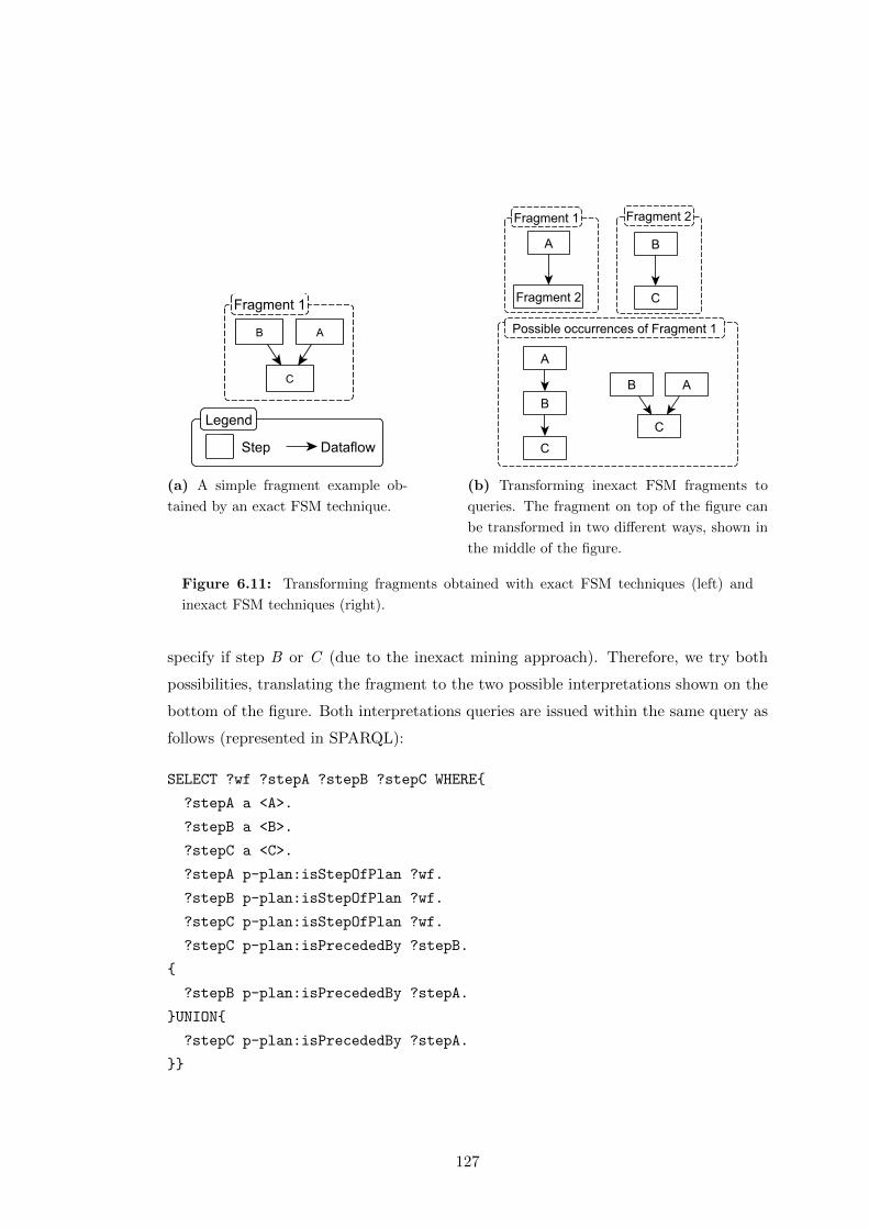
(a) A simple fragment example ob-
tained by an exact FSM technique.
(b) Transforming inexact FSM fragments to
queries. The fragment on top of the figure can
be transformed in two different ways, shown in
the middle of the figure.
Figure 6.11: Transforming fragments obtained with exact FSM techniques (left) and
inexact FSM techniques (right).
specify if step B or C (due to the inexact mining approach). Therefore, we try both
possibilities, translating the fragment to the two possible interpretations shown on the
bottom of the figure. Both interpretations queries are issued within the same query as
follows (represented in SPARQL):
SELECT ?wf ?stepA ?stepB ?stepC WHERE{
?stepA a <A>.
?stepB a <B>.
?stepC a <C>.
?stepA p-plan:isStepOfPlan ?wf.
?stepB p-plan:isStepOfPlan ?wf.
?stepC p-plan:isStepOfPlan ?wf.
?stepC p-plan:isPrecededBy ?stepB.
{
?stepB p-plan:isPrecededBy ?stepA.
}UNION{
?stepC p-plan:isPrecededBy ?stepA.
}}
127
The answers for each query (or union of queries in the case of inexact mining) are
all the possible bindings within all workflows, showing how and where each fragment
was found in each of the workflows of the original corpus.
6.5 Fragment Statistics and Visualization
Once the fragments have been filtered and bound to the workflow corpus, the next
step in FragFlow is to produce statistics and visualizations of the fragments. For this
purpose we created scripts for calculating the minimum frequency of the fragments and
number of times they were found on the corpus, which is particularly useful for the
evaluation of our approach (as we describe in Chapter 7). Additionally, we created a
graph-based visualization for a collection of fragments, helping users understand the
shape and dependencies of each fragment.
6.6 Summary
In this chapter we have introduced our approach for extracting workflow fragments by
reusing different graph mining techniques. In doing so, we have proposed a way to
clean the input workflow dataset to avoid incorrect results and we have characterized
and selected existing graph mining techniques that broaden the types of fragments
being found by our approach. This addresses the technical objective of this thesis TO1
(characterize the different types of existing graph mining algorithms, their features, their
limitations and available implementations).
We have also introduced a set of novel techniques to filter irrelevant fragments and
link the results to the parts of the input corpus where they occur, thus addressing
the technical objective TO2 (develop a framework for applying existing graph mining
approaches on workflow templates and executions, along with the means to refine and
filter the results provided by the different algorithms).
It is worth mentioning that our effort has been driven towards usefulness rather than
efficiency, as the second was not part of the scope of this thesis. For example, if the
number of workflows of the input corpus is high, doing a SELECT query retrieving how
a complex fragment was found on the corpus might be too time consuming. In those
cases, our approach could be divided into smaller sub-problems (e.g., issuing queries
128

against single workflows instead of workflow dataset) or simplifying our approach (e.g.,
issuing ASK queries instead of SELECT queries). Improving the performance and
efficiency of our approach is future work.
In the next section we will assess usefulness of our results by performing three
evaluations on two different workflow systems.
129

130
Chapter 7
Evaluation
In this chapter we evaluate our hypotheses by describing the results of our approach
for automatically detecting abstractions on scientific workflows. Given that H1.1 (i.e.,
it is possible to define a catalog of common domain independent patterns based on the
functionality of workflow steps) has already been addressed in Section 5.1 by defin-
ing a catalog of common workflow motifs, in this chapter we focus on evaluating H1.2
(it is possible to detect commonly occurring patterns and abstractions automatically)
and H1.3 (commonly occurring patterns are potentially useful for users designing work-
flows).
First, Section 7.1 defines the evaluation metrics associated to each hypothesis, and
then Sections 7.2 and 7.3 describe the results obtained on each of the evaluations.
Finally, section 7.4 summarizes our contributions with respect to each hypothesis.
7.1 Evaluation Metrics
There are different techniques to identify patterns in a workflow corpus, as we have
described on Chapter 6. In order to evaluate our hypotheses H1.2 and H1.3, we need
to assess the genericity and usefulness of our proposed frequent workflow fragments.
However, to our knowledge there are no standard metrics that define if a given workflow
pattern is generic or useful. Therefore we propose a metric for assessing frequent generic
fragments and two for evaluating fragment usefulness, as described in Definition 5.
These metrics will be adapted and used later for performing independent evaluations,
as they have different requirements on the input corpus.
131
Definition 5 A workflow fragment is generic if it appears in two or more workflows
with different levels of abstraction.We consider a workflow fragment to be useful if it
has been reused and annotated by one or several users designing workflows (either as a
workflow or as a sub-workflow).
7.1.1 Occurrence and Generalization Evaluation Metrics
Our proposed metric aims to confirm whether a workflow fragment is commonly oc-
curring and generic. In order to do so, we compare our proposed fragments to those
motifs from our catalog that are related to workflow reuse, i.e., internal macros and
composite workflows. Internal macros detect the reused parts of a workflow among
the workflow itself, and therefore a fragment matching an internal macro is commonly
occurring. Composite workflows indicate that a target workflow is composed by other
existing workflows. Hence, any fragment matching those sub-workflows is commonly
occurring. Additionally, these motifs may apply a step abstraction to relate workflows
with the same abstract functionality, and we can use them to assess the genericity of
our proposed fragments. For measuring our results, we use precision (Pmotifs) and
recall (Rmotifs), defined as:
Pmotifs =|F ∩M ||F |
Rmotifs =|F ∩M ||M |
Where F represents the resultant set of fragments and M stands for the set of motifs
we are looking for (in this case, M would represent either the set of internal macros
in the corpus or the sub-workflows included in any composite workflow in the corpus).
Precision and recall values range from 0 (low) to 1 (high). In order to be able to apply
this metric, a workflow corpus with annotated motifs is necessary.
7.1.2 Usefulness Evaluation Metrics
In this case, the first metric we propose aims at comparing whether the workflow frag-
ments found by our approach match those fragments or workflows designed and reused
by users (i.e., user groupings). We also measure our results in terms of precision and
recall for this task. On the one hand, the precision measures how many of the common
132

fragments correspond to the reused groupings and workflows identified by users. On
the other hand, the recall identifies the percentage of detected reused structures out of
the total reused groupings and workflows. Since our focus is to detect useful workflow
fragments, we prioritize precision over recall. The recall measure is relevant, but some
of the reused groupings or workflows may have a low frequency and may avoid detecting
higher frequent fragments, motivating our decision.
It is worth mentioning that workflows are considered in the metric as well. Some
workflows are reused as part of other bigger workflows in the workflow corpus and our
fragments may correspond to them. Precision (Pgroup) and recall (Rgroup) metrics are
defined as:
Pgroup(overlap) =|F ∩ (G ∪W )|
|F |
Rgroup =|F ∩ (G ∪W )||G ∪W |
Where F represents the set of proposed fragments, G stands for the set of user-
defined groupings and W corresponds to the set of reused workflows. The intersection
between fragments and the union of all groupings and workflows is calculated by mea-
suring which fragments overlap with a grouping or a workflow. The overlap term stands
for the percentage of steps that are equal between our proposed fragments and group-
ings or workflows when calculating |F ∩ (G ∪ W )|, with P(100%) meaning that the
fragments found are exactly the same as one of the the groupings or workflows defined
by users. Figure 7.1 shows an example by comparing the overlap of two fragments
against the same grouping. The fragment on the left (Fragment1) is equal to Group-
ing1 (overlap 100%), while in Fragment2 only two steps out of three are the same (with
an overlap of 66%). This additional measure determines how similar our fragments are
with respect to a user-defined grouping or workflow, and helps identifying whether our
fragments are close to what they defined or not. As in the last metric, precision and
recall values range from 0 (low) to 1 (high). A requirement for applying this technique
is to have a workflow corpus with user-defined groupings specified. Note that the over-
lap is not introduced for the recall (Rgroup), as it could lead to inconsistent results: if
the number of candidate fragments similar to the groupings and workflows designed by
133
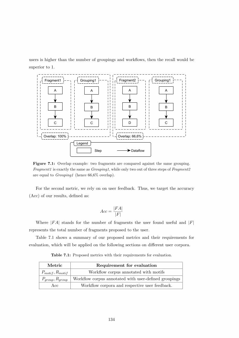
users is higher than the number of groupings and workflows, then the recall would be
superior to 1.
Figure 7.1: Overlap example: two fragments are compared against the same grouping.
Fragment1 is exactly the same as Grouping1, while only two out of three steps of Fragment2
are equal to Grouping1 (hence 66,6% overlap).
For the second metric, we rely on on user feedback. Thus, we target the accuracy
(Acc) of our results, defined as:
Acc =|FA||F |
Where |FA| stands for the number of fragments the user found useful and |F |represents the total number of fragments proposed to the user.
Table 7.1 shows a summary of our proposed metrics and their requirements for
evaluation, which will be applied on the following sections on different user corpora.
Table 7.1: Proposed metrics with their requirements for evaluation.
Metric Requirement for evaluation
Pmotif , Rmotif Workflow corpus annotated with motifs
Pgroup, Rgroup Workflow corpus annotated with user-defined groupings
Acc Workflow corpora and respective user feedback.
134
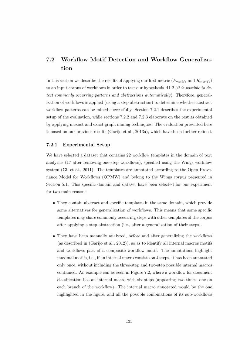
7.2 Workflow Motif Detection and Workflow Generaliza-
tion
In this section we describe the results of applying our first metric (Pmotifs and Rmotifs)
to an input corpus of workflows in order to test our hypothesis H1.2 (it is possible to de-
tect commonly occurring patterns and abstractions automatically). Therefore, general-
ization of workflows is applied (using a step abstraction) to determine whether abstract
workflow patterns can be mined successfully. Section 7.2.1 describes the experimental
setup of the evaluation, while sections 7.2.2 and 7.2.3 elaborate on the results obtained
by applying inexact and exact graph mining techniques. The evaluation presented here
is based on our previous results (Garijo et al., 2013a), which have been further refined.
7.2.1 Experimental Setup
We have selected a dataset that contains 22 workflow templates in the domain of text
analytics (17 after removing one-step workflows), specified using the Wings workflow
system (Gil et al., 2011). The templates are annotated according to the Open Prove-
nance Model for Workflows (OPMW) and belong to the Wings corpus presented in
Section 5.1. This specific domain and dataset have been selected for our experiment
for two main reasons:
• They contain abstract and specific templates in the same domain, which provide
some alternatives for generalization of workflows. This means that some specific
templates may share commonly occurring steps with other templates of the corpus
after applying a step abstraction (i.e., after a generalization of their steps).
• They have been manually analyzed, before and after generalizing the workflows
(as described in (Garijo et al., 2012)), so as to identify all internal macros motifs
and workflows part of a composite workflow motif. The annotations highlight
maximal motifs, i.e., if an internal macro consists on 4 steps, it has been annotated
only once, without including the three-step and two-step possible internal macros
contained. An example can be seen in Figure 7.2, where a workflow for document
classification has an internal macro with six steps (appearing two times, one on
each branch of the workflow). The internal macro annotated would be the one
highlighted in the figure, and all the possible combinations of its sub-workflows
135
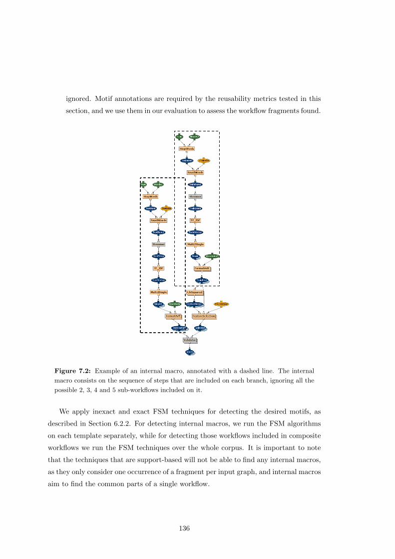
ignored. Motif annotations are required by the reusability metrics tested in this
section, and we use them in our evaluation to assess the workflow fragments found.
Figure 7.2: Example of an internal macro, annotated with a dashed line. The internal
macro consists on the sequence of steps that are included on each branch, ignoring all the
possible 2, 3, 4 and 5 sub-workflows included on it.
We apply inexact and exact FSM techniques for detecting the desired motifs, as
described in Section 6.2.2. For detecting internal macros, we run the FSM algorithms
on each template separately, while for detecting those workflows included in composite
workflows we run the FSM techniques over the whole corpus. It is important to note
that the techniques that are support-based will not be able to find any internal macros,
as they only consider one occurrence of a fragment per input graph, and internal macros
aim to find the common parts of a single workflow.
136
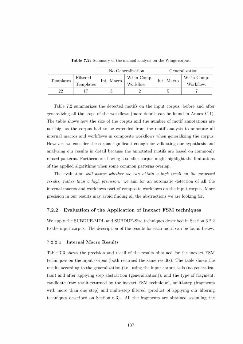
Table 7.2: Summary of the manual analysis on the Wings corpus.
No Generalization Generalization
TemplatesFiltered
TemplatesInt. Macro
Wf in Comp.
Workflow.Int. Macro
Wf in Comp.
Workflow.
22 17 3 2 5 7
Table 7.2 summarizes the detected motifs on the input corpus, before and after
generalizing all the steps of the workflows (more details can be found in Annex C.1).
The table shows how the size of the corpus and the number of motif annotations are
not big, as the corpus had to be extended from the motif analysis to annotate all
internal macros and workflows in composite workflows when generalizing the corpus.
However, we consider the corpus significant enough for validating our hypothesis and
analyzing our results in detail because the annotated motifs are based on commonly
reused patterns. Furthermore, having a smaller corpus might highlight the limitations
of the applied algorithms when some common patterns overlap.
The evaluation will assess whether we can obtain a high recall on the proposed
results, rather than a high precision: we aim for an automatic detection of all the
internal macros and workflows part of composite workflows on the input corpus. More
precision in our results may avoid finding all the abstractions we are looking for.
7.2.2 Evaluation of the Application of Inexact FSM techniques
We apply the SUBDUE-MDL and SUBDUE-Size techniques described in Section 6.2.2
to the input corpus. The description of the results for each motif can be found below.
7.2.2.1 Internal Macro Results
Table 7.3 shows the precision and recall of the results obtained for the inexact FSM
techniques on the input corpus (both returned the same results). The table shows the
results according to the generalization (i.e., using the input corpus as is (no generaliza-
tion) and after applying step abstraction (generalization)); and the type of fragment:
candidate (raw result returned by the inexact FSM technique), multi-step (fragments
with more than one step) and multi-step filtered (product of applying our filtering
techniques described on Section 6.3). All the fragments are obtained assuming the
137
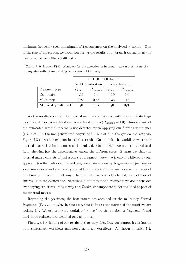
minimum frequency (i.e., a minimum of 2 occurrences on the analyzed structure). Due
to the size of the corpus, we avoid comparing the results at different frequencies, as the
results would not differ significantly.
Table 7.3: Inexact FSM techniques for the detection of internal macro motifs, using the
templates without and with generalization of their steps.
SUBDUE MDL/Size
No Generalization Generalization
Fragment type Pi.macro Ri.macro Pi.macro Ri.macro
Candidate 0,13 1,0 0,19 1,0
Multi-step 0,22 0,67 0,36 0,8
Multi-step filtered 1,0 0,67 1,0 0,8
As the results show, all the internal macros are detected with the candidate frag-
ments for the non generalized and generalized corpus (Ri.macro = 1,0). However, one of
the annotated internal macros is not detected when applying our filtering techniques
(1 out of 3 in the non-generalized corpus and 1 out of 5 in the generalized corpus).
Figure 7.3 shows the explanation of this result. On the left, the workflow where the
internal macro has been annotated is depicted. On the right we can see its reduced
form, showing just the dependencies among the different steps. It turns out that the
internal macro consists of just a one step fragment (Stemmer), which is filtered by our
approach (on the multi-step filtered fragments) since one-step fragments are just single-
step components and are already available for a workflow designer as atomics pieces of
functionality. Therefore, although the internal macro is not detected, the behavior of
our results is the desired one. Note that in our motifs and fragments we don’t consider
overlapping structures, that is why the Vocabular component is not included as part of
the internal macro.
Regarding the precision, the best results are obtained on the multi-step filtered
fragments (Pi.macro = 1,0). In this case, this is due to the nature of the motif we are
looking for. We explore every workflow by itself, so the number of fragments found
tend to be reduced and included on each other.
Finally, a key finding of our results is that they show how our approach can handle
both generalized workflows and non-generalized workflows. As shown in Table 7.2,
138

Figure 7.3: Workflow where the internal macro annotated could not be detected. When
transforming the workflow to its reduced form, the internal macro is just a one-step frag-
ment, which is ignored.
when applying generalization, two new internal macros are detected in the corpus.
Both of them are found by our approach.
7.2.2.2 Composite Workflow Results
Tables 7.4 and 7.5 show the results obtained after applying both SUBDUE-MDL and
SUBDUE-Size metrics on the corpus respectively.
Table 7.4: Inexact FSM techniques for the detection of workflows in composite workflow
motifs, using the templates as they are and with generalization and the SUBDUE MDL
evaluation. The asterisk represents the results when a target workflow is included as part
of a bigger detected fragment.
SUBDUE MDL
No Generalization Generalization
Fragment type Pc.wf Rc.wf Pc.wf Rc.wf
Candidate 0,14 0,50 0,67 (1,0 )* 0,57 (0,86)*
Multi-step 0,14 0,50 0,67 (1,0)* 0,57 (0,86)*
Multi-step filtered 0,14 0,50 0,67 (1.0)* 0,57 (0,86)*
139
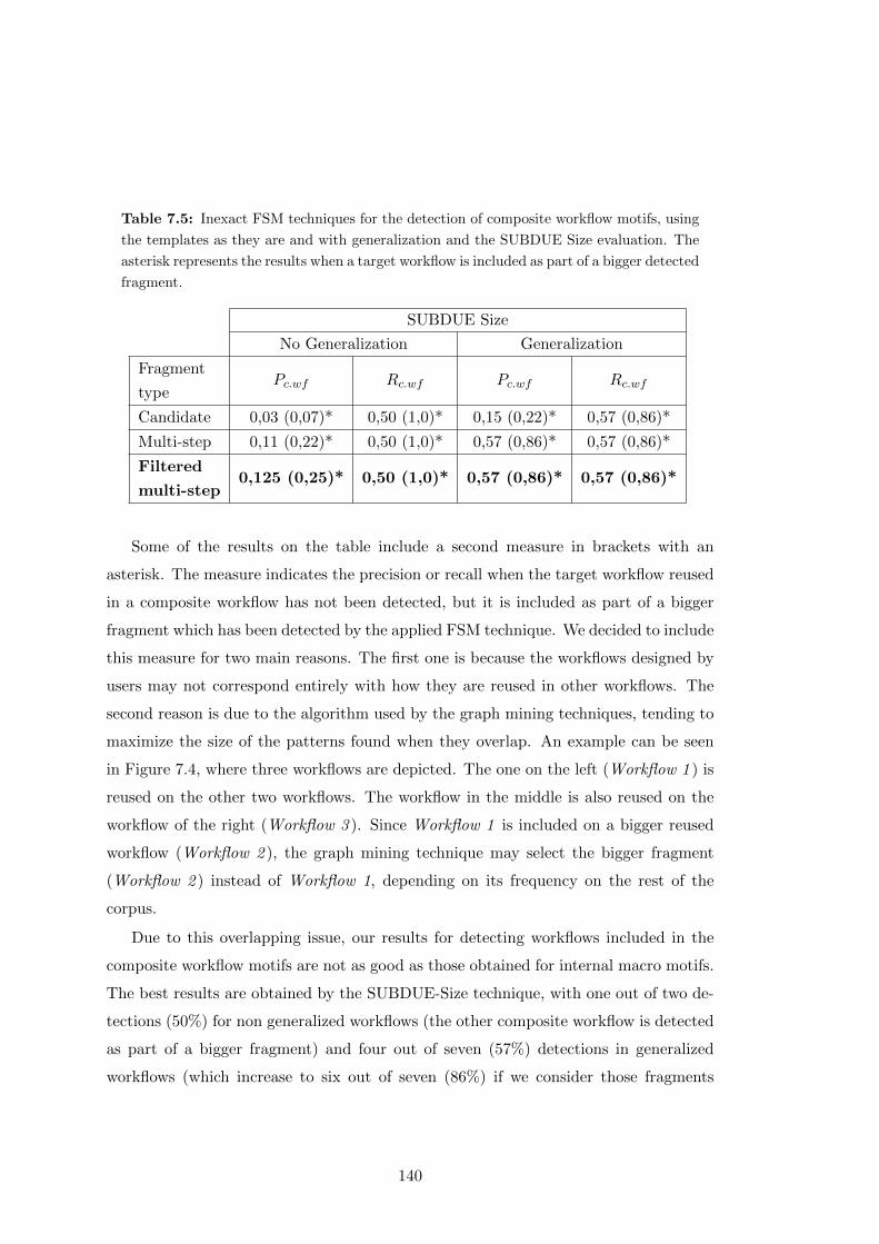
Table 7.5: Inexact FSM techniques for the detection of composite workflow motifs, using
the templates as they are and with generalization and the SUBDUE Size evaluation. The
asterisk represents the results when a target workflow is included as part of a bigger detected
fragment.
SUBDUE Size
No Generalization Generalization
Fragment
typePc.wf Rc.wf Pc.wf Rc.wf
Candidate 0,03 (0,07)* 0,50 (1,0)* 0,15 (0,22)* 0,57 (0,86)*
Multi-step 0,11 (0,22)* 0,50 (1,0)* 0,57 (0,86)* 0,57 (0,86)*
Filtered
multi-step0,125 (0,25)* 0,50 (1,0)* 0,57 (0,86)* 0,57 (0,86)*
Some of the results on the table include a second measure in brackets with an
asterisk. The measure indicates the precision or recall when the target workflow reused
in a composite workflow has not been detected, but it is included as part of a bigger
fragment which has been detected by the applied FSM technique. We decided to include
this measure for two main reasons. The first one is because the workflows designed by
users may not correspond entirely with how they are reused in other workflows. The
second reason is due to the algorithm used by the graph mining techniques, tending to
maximize the size of the patterns found when they overlap. An example can be seen
in Figure 7.4, where three workflows are depicted. The one on the left (Workflow 1 ) is
reused on the other two workflows. The workflow in the middle is also reused on the
workflow of the right (Workflow 3 ). Since Workflow 1 is included on a bigger reused
workflow (Workflow 2 ), the graph mining technique may select the bigger fragment
(Workflow 2 ) instead of Workflow 1, depending on its frequency on the rest of the
corpus.
Due to this overlapping issue, our results for detecting workflows included in the
composite workflow motifs are not as good as those obtained for internal macro motifs.
The best results are obtained by the SUBDUE-Size technique, with one out of two de-
tections (50%) for non generalized workflows (the other composite workflow is detected
as part of a bigger fragment) and four out of seven (57%) detections in generalized
workflows (which increase to six out of seven (86%) if we consider those fragments
140
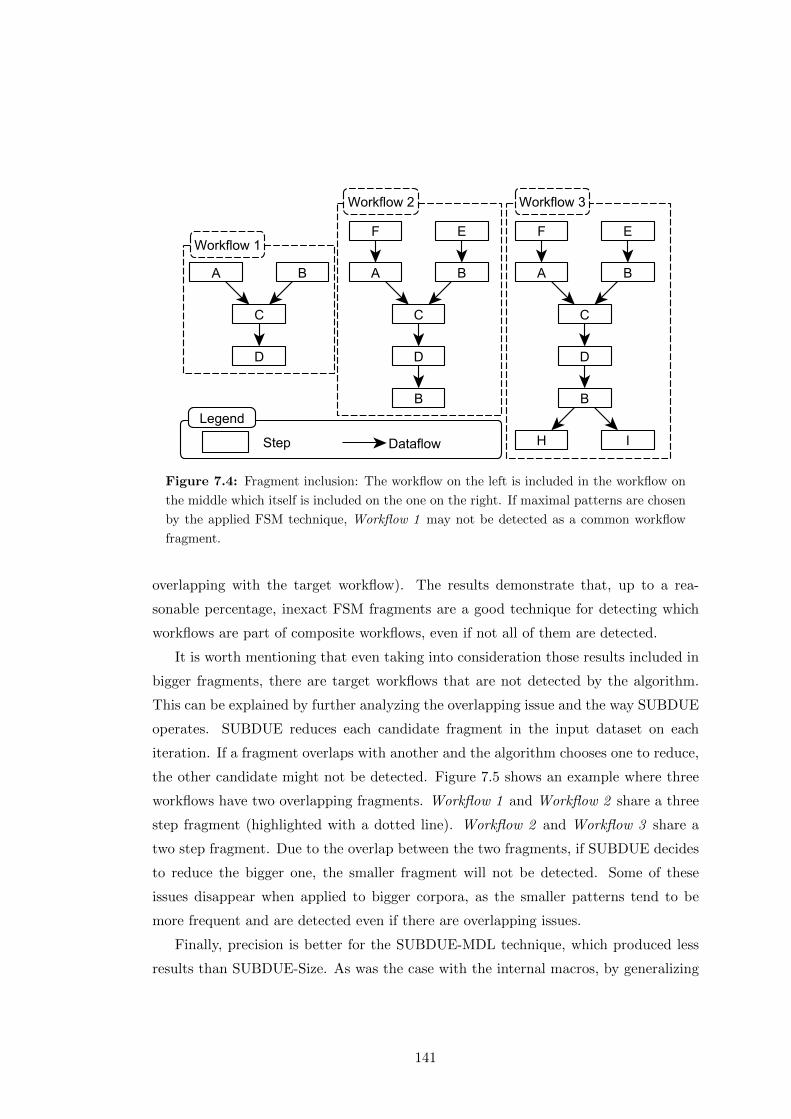
Figure 7.4: Fragment inclusion: The workflow on the left is included in the workflow on
the middle which itself is included on the one on the right. If maximal patterns are chosen
by the applied FSM technique, Workflow 1 may not be detected as a common workflow
fragment.
overlapping with the target workflow). The results demonstrate that, up to a rea-
sonable percentage, inexact FSM fragments are a good technique for detecting which
workflows are part of composite workflows, even if not all of them are detected.
It is worth mentioning that even taking into consideration those results included in
bigger fragments, there are target workflows that are not detected by the algorithm.
This can be explained by further analyzing the overlapping issue and the way SUBDUE
operates. SUBDUE reduces each candidate fragment in the input dataset on each
iteration. If a fragment overlaps with another and the algorithm chooses one to reduce,
the other candidate might not be detected. Figure 7.5 shows an example where three
workflows have two overlapping fragments. Workflow 1 and Workflow 2 share a three
step fragment (highlighted with a dotted line). Workflow 2 and Workflow 3 share a
two step fragment. Due to the overlap between the two fragments, if SUBDUE decides
to reduce the bigger one, the smaller fragment will not be detected. Some of these
issues disappear when applied to bigger corpora, as the smaller patterns tend to be
more frequent and are detected even if there are overlapping issues.
Finally, precision is better for the SUBDUE-MDL technique, which produced less
results than SUBDUE-Size. As was the case with the internal macros, by generalizing
141
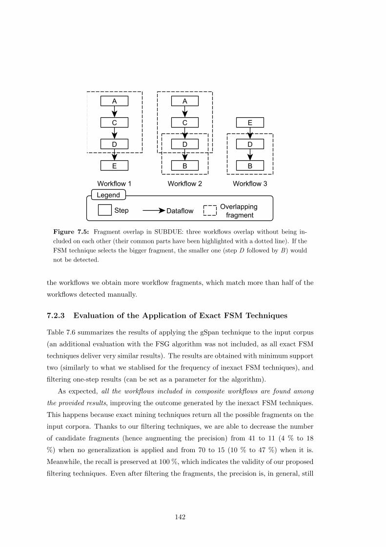
Figure 7.5: Fragment overlap in SUBDUE: three workflows overlap without being in-
cluded on each other (their common parts have been highlighted with a dotted line). If the
FSM technique selects the bigger fragment, the smaller one (step D followed by B) would
not be detected.
the workflows we obtain more workflow fragments, which match more than half of the
workflows detected manually.
7.2.3 Evaluation of the Application of Exact FSM Techniques
Table 7.6 summarizes the results of applying the gSpan technique to the input corpus
(an additional evaluation with the FSG algorithm was not included, as all exact FSM
techniques deliver very similar results). The results are obtained with minimum support
two (similarly to what we stablised for the frequency of inexact FSM techniques), and
filtering one-step results (can be set as a parameter for the algorithm).
As expected, all the workflows included in composite workflows are found among
the provided results, improving the outcome generated by the inexact FSM techniques.
This happens because exact mining techniques return all the possible fragments on the
input corpora. Thanks to our filtering techniques, we are able to decrease the number
of candidate fragments (hence augmenting the precision) from 41 to 11 (4 % to 18
%) when no generalization is applied and from 70 to 15 (10 % to 47 %) when it is.
Meanwhile, the recall is preserved at 100 %, which indicates the validity of our proposed
filtering techniques. Even after filtering the fragments, the precision is, in general, still
142

worse than inexact FSM methods due to the number of candidate fragments produced
by the technique.
Table 7.6: Exact FSM techniques for the detection of workflows included in composite
workflow motifs, using the templates with and without generalization.
GSpan
No Generalization Generalization
Fragment type Pc.wf Rc.wf Pc.wf Rc.wf
Candidate 0,04 1,0 0,10 1,0
Multi-step 0,04 1,0 0,10 1,0
Multi-step filtered 0,18 1,0 0,47 1,0
7.2.4 Summary
In this section we have described our first evaluation, which aims at addressing whether
it is possible to detect commonly occurring patterns and abstractions automatically
(H1.2) on a small hand-annotated corpus. In order to do so, we have compared our
proposed fragments to the commonly occurring motifs, i.e., internal macro motifs and
those workflows included as part of a composite workflow motif. One of the advantages
of using a small controlled corpus is that we are able to detect and analyze potential
issues of the applied fragment mining techniques. We have explained our experimental
setup and analyzed the results in detail. Overall, the results show that inexact FSM
techniques are a good approach to detect internal macros, while exact FSM techniques
obtain perfect recall for detecting those workflows that are part of the composite work-
flow motifs (since exact FSM techniques detect all commonly occurring fragments, this
is an expected result). Additionally, both approaches are able to deal successfully with
a scenario in which the workflows are declared at different levels of abstraction.
In the following section we describe our second evaluation, aimed at determining
whether our proposed fragments are useful for reuse based on what users have previously
defined (H1.3). A detailed discussion of the results with respect to the hypotheses can
be seen on Section 7.4
143

7.3 Workflow Fragment Assessment
As we have seen in our previous evaluation, our proposed workflow fragments are a
feasible means to find the workflows participating in composite workflow and internal
macro motifs annotated by users on a workflow corpus. However, the results in general
have low precision (under 50 %). This indicates that the fragments returned by our
approach suggest additional typical structures on the workflow corpus that could be po-
tentially useful for workflow reuse. Hence, in this section we aim to determine whether
our proposed fragments are actually useful or not, thus addressing our hypothesis H1.3
(common reusable patterns are potentially useful for users).
The Section is organized as follows. We first introduce the common experimental
setup in Section 7.3.1, common to both of the following evaluations. Section 7.3.2
checks whether our proposed fragments are similar to the reused structures manually
identified by users (user groupings and workflows) in a workflow system. Then, in
Section 7.3.3, we discuss the outcome of a survey that domain experts filled to determine
the usefulness of a set of proposed workflow fragments. The evaluation presented here
is based on our previous findings (Garijo et al., 2014c), which have been expanded and
refined.
7.3.1 Experimental Setup
Our evaluation has been performed using four workflow corpora from the LONI Pipeline
system. The corpora are WC1, WC2, WC3 and WC4, previously introduced in Section
5.3. We have chosen these corpora for two main reasons:
• High reusability : The workflows belong to the same domain, have been created
by single and multiple users, and are reused as a whole or included as part of
other workflows (as shown in Section 5.3).
• User groupings: Users have the means to annotate their sub-workflows as group-
ings. These can be taken as a reference to compare our candidate fragments
and are a requirement for applying the metrics proposed for this type of analysis
(Pgroup(overlap) and Rgroup(overlap)).
We first performed a comparison between our proposed fragments and the workflows
and groupings in the corpora defined by users. We used the Pgroup(overlap) and Rgroup
144

metrics. Different values of the frequency of the common fragments and the overlap with
our solution were considered in order to analyze the quality of the candidate fragments.
The evaluation prioritizes a high precision in the proposed candidate fragments rather
than a high recall : we aim at obtaining common workflow fragments that are useful for
the workflow designers, instead of aiming at finding all the possible fragments actually
reused by users. Table 7.7 provides a summary of the workflows and groupings that
have been reused by users. These numbers will be used to evaluate our approach.
Table 7.7: Unique workflows, groupings and their reuse. These numbers will be later
used to calculate the precision and recall of the proposed fragments.
Unique multi-step
workflows
Unique multi-step
groupings
Corpus Created Reused Created Reused
WC1 441 175 146 71
WC2 94 13 87 40
WC3 269 106 79 47
WC4 50 7 40 26
Candidate fragments that did not overlap with user-defined groupings or workflows
were collected and used as a part of a user survey. The survey aimed at testing whether
these fragments were still a useful suggestion to the users. Hence, we used the usefulness
metric (Acc) defined in Section 7.1.2. A high accuracy determines that our suggested
fragments were adequate for that user.
In this case generalization is not applied, as no domain-specific taxonomy modeling
the components of the workflows in the corpora was provided.
7.3.2 FragFlow Fragments versus User Defined Groupings
We applied inexact techniques (SUBDUE-MDL, SUBDUE-Size) and exact FSM tech-
niques (gSpan) to measure the precision and recall of our approach. The results of the
evaluation are described below.
7.3.2.1 Evaluation of the Application of Inexact FSM techniques
Figures 7.6, 7.7, 7.8 and 7.9 show the number of fragments found and their precision
(Pgroup(overlap)) for every corpus. Each figure shows two evaluations, corresponding
145
to the MDL and Size heuristics of the SUBDUE algorithm. Both of these techniques
are frequency-based approaches, that is, the frequency represents the number of times
(occurrences) a fragment is found in the corpus (counting several times if the frag-
ment appears several times in one workflow). The fragment frequencies are normalized
according to the size of the dataset, in order to show how different frequencies affect
the precision and the found FragFlow fragments. The “min” metric stands for the
minimum frequency for a fragment to be detected, i.e., it appears at least two times
in the corpus. Given that the number of multi-step fragment and multi-step filtered
fragments is similar in both evaluations, we only show the latter (Mff) in the precision
graphs.
Figure 7.6: Number of fragments found and precision results for WC1 with the MDL and
Size evaluations. For the precision, only multi-step filtered fragments are shown.
Finally, the precision metric shows different values for the overlap, indicating the
overlap percentage between the proposed fragments and the groupings and workflows
designed by the users. The rationale for having an overlap different to 100% is to
146
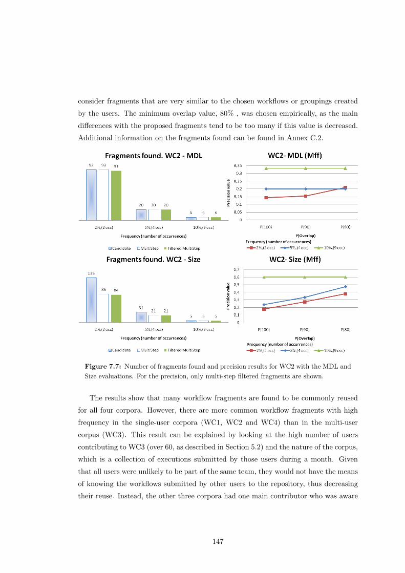
consider fragments that are very similar to the chosen workflows or groupings created
by the users. The minimum overlap value, 80% , was chosen empirically, as the main
differences with the proposed fragments tend to be too many if this value is decreased.
Additional information on the fragments found can be found in Annex C.2.
Figure 7.7: Number of fragments found and precision results for WC2 with the MDL and
Size evaluations. For the precision, only multi-step filtered fragments are shown.
The results show that many workflow fragments are found to be commonly reused
for all four corpora. However, there are more common workflow fragments with high
frequency in the single-user corpora (WC1, WC2 and WC4) than in the multi-user
corpus (WC3). This result can be explained by looking at the high number of users
contributing to WC3 (over 60, as described in Section 5.2) and the nature of the corpus,
which is a collection of executions submitted by those users during a month. Given
that all users were unlikely to be part of the same team, they would not have the means
of knowing the workflows submitted by other users to the repository, thus decreasing
their reuse. Instead, the other three corpora had one main contributor who was aware
147

Figure 7.8: Number of fragments found and precision results for WC3 with the MDL and
Size evaluations. For the precision, only multi-step filtered fragments are shown.
of the previous work in the respective corpus, facilitating their reuse.
In general, a good number of the workflow fragments found with inexact FSM tech-
niques match those workflows or groupings designed by users. The maximum precision
with 100% overlap ranges from 35% (WC2, WC4) to 60% (WC3), increasing to 60%
to 80% when considering an overlap of 80% of the workflow steps.
An individual analysis of each corpus can explain the differences in the corpora
results:
• In WC1 we see a high reuse and number of workflows, which leads to producing a
high number of precise fragments. This finding is confirmed when analyzing the
overlap, as a high number of fragments (up to 80 %) is similar to the groupings
or workflows designed by the user.
• WC2 consists on a set of curated workflows made public for the LONI Pipeline
community to reuse. Although they share some common parts, workflow reuse
148
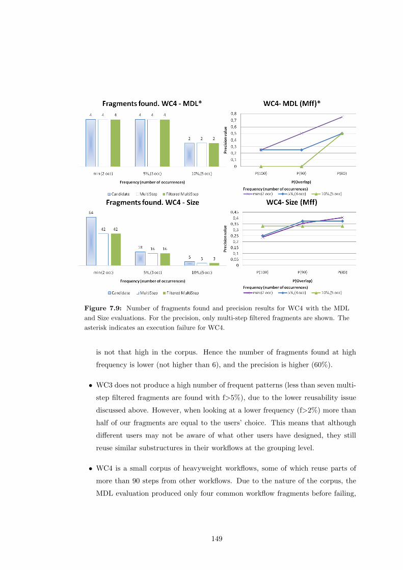
Figure 7.9: Number of fragments found and precision results for WC4 with the MDL
and Size evaluations. For the precision, only multi-step filtered fragments are shown. The
asterisk indicates an execution failure for WC4.
is not that high in the corpus. Hence the number of fragments found at high
frequency is lower (not higher than 6), and the precision is higher (60%).
• WC3 does not produce a high number of frequent patterns (less than seven multi-
step filtered fragments are found with f>5%), due to the lower reusability issue
discussed above. However, when looking at a lower frequency (f>2%) more than
half of our fragments are equal to the users’ choice. This means that although
different users may not be aware of what other users have designed, they still
reuse similar substructures in their workflows at the grouping level.
• WC4 is a small corpus of heavyweight workflows, some of which reuse parts of
more than 90 steps from other workflows. Due to the nature of the corpus, the
MDL evaluation produced only four common workflow fragments before failing,
149
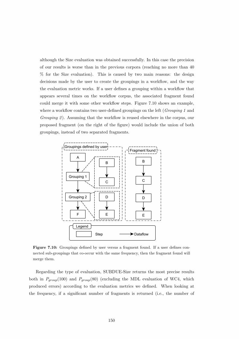
although the Size evaluation was obtained successfully. In this case the precision
of our results is worse than in the previous corpora (reaching no more than 40
% for the Size evaluation). This is caused by two main reasons: the design
decisions made by the user to create the groupings in a workflow, and the way
the evaluation metric works. If a user defines a grouping within a workflow that
appears several times on the workflow corpus, the associated fragment found
could merge it with some other workflow steps. Figure 7.10 shows an example,
where a workflow contains two user-defined groupings on the left (Grouping 1 and
Grouping 2 ). Assuming that the workflow is reused elsewhere in the corpus, our
proposed fragment (on the right of the figure) would include the union of both
groupings, instead of two separated fragments.
Figure 7.10: Groupings defined by user versus a fragment found. If a user defines con-
nected sub-groupings that co-occur with the same frequency, then the fragment found will
merge them.
Regarding the type of evaluation, SUBDUE-Size returns the most precise results
both in Pgroup(100) and Pgroup(80) (excluding the MDL evaluation of WC4, which
produced errors) according to the evaluation metrics we defined. When looking at
the frequency, if a significant number of fragments is returned (i.e., the number of
150
fragments is superior or equal to 5) then the more frequent those fragments are higher
the precision is for the technique. This indicates that in corpora with high reusability
such as WC1, users tend to annotate common steps of workflows for their reuse.
As shown in table 7.8, in all four corpora the recall is very low (21% for the best
case, and usually under 10%). This is an expected result, as for calculating the recall
metric all the user-designed workflows and groupings are taken into account, whether
reused or not. Additional noise is introduced by several user practices that we have
detected in the corpora. For example, different users tend to design similar workflows
and groupings differently (by adding or removing just a few steps), thus increasing their
total number. Other users tend to group certain steps of the workflow for simplifying
the view of their current experiment, some other group sets of steps, inputs or outputs
that are not relevant for their experiment, etc.
The results also show that by increasing the frequency of the found fragments the
recall decreases. This is natural, as the high frequent fragments are fewer than those
found at lower frequencies.
7.3.2.2 Evaluation of the Application of Exact FSM techniques
Table 7.9 shows the number of fragments found on the four corpora by the gSpan ex-
act FSM technique. Results are sorted by support, which represents the percentage of
workflows in the corpora where a FragFlow fragment was found at least once. The sup-
port is normalized to the corpora size, showing in parenthesis the number of templates
corresponding to that percentage.
As we described in Section 6.2.1.2, exact FSM techniques aim to find all the possible
workflow fragments in the corpora. Thus, table 7.9 only contains multi-step filtered
fragments (mff), due to the large amount of candidate and multi-step fragments re-
turned by the technique. In fact, those rows where an asterisk is shown (in WC1, WC2
and WC4) indicate that the results could only be obtained after fixing the maximum
size of a fragment for the gSpan technique. Otherwise the algorithm produces memory
errors due to the combinatory explosion produced by the amount of fragments that
have to be taken into account for mining results. This is highlighted on WC4, where
the size of the reused structures tends to be very large. On the contrary, in corpora
where the size of the reused of the patterns is lower, like WC3, all the multi-step filtered
151
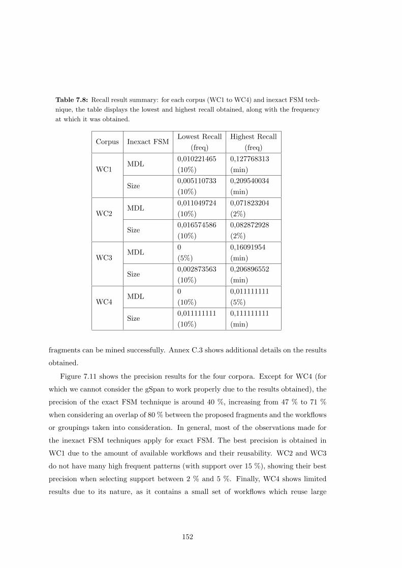
Table 7.8: Recall result summary: for each corpus (WC1 to WC4) and inexact FSM tech-
nique, the table displays the lowest and highest recall obtained, along with the frequency
at which it was obtained.
Corpus Inexact FSMLowest Recall
(freq)
Highest Recall
(freq)
WC1MDL
0,010221465
(10%)
0,127768313
(min)
Size0,005110733
(10%)
0,209540034
(min)
WC2MDL
0,011049724
(10%)
0,071823204
(2%)
Size0,016574586
(10%)
0,082872928
(2%)
WC3MDL
0
(5%)
0,16091954
(min)
Size0,002873563
(10%)
0,206896552
(min)
WC4MDL
0
(10%)
0,011111111
(5%)
Size0,011111111
(10%)
0,111111111
(min)
fragments can be mined successfully. Annex C.3 shows additional details on the results
obtained.
Figure 7.11 shows the precision results for the four corpora. Except for WC4 (for
which we cannot consider the gSpan to work properly due to the results obtained), the
precision of the exact FSM technique is around 40 %, increasing from 47 % to 71 %
when considering an overlap of 80 % between the proposed fragments and the workflows
or groupings taken into consideration. In general, most of the observations made for
the inexact FSM techniques apply for exact FSM. The best precision is obtained in
WC1 due to the amount of available workflows and their reusability. WC2 and WC3
do not have many high frequent patterns (with support over 15 %), showing their best
precision when selecting support between 2 % and 5 %. Finally, WC4 shows limited
results due to its nature, as it contains a small set of workflows which reuse large
152
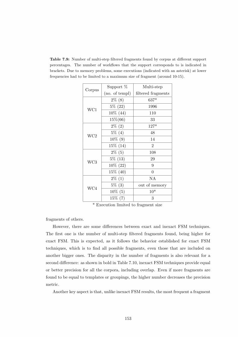
Table 7.9: Number of multi-step filtered fragments found by corpus at different support
percentages. The number of workflows that the support corresponds to is indicated in
brackets. Due to memory problems, some executions (indicated with an asterisk) at lower
frequencies had to be limited to a maximum size of fragment (around 10-15).
CorpusSupport %
(no. of templ)
Multi-step
filtered fragments
WC1
2% (8) 637*
5% (22) 1996
10% (44) 110
15%(66) 33
WC2
2% (2) 127*
5% (4) 48
10% (9) 14
15% (14) 2
WC3
2% (5) 108
5% (13) 29
10% (22) 9
15% (40) 0
WC4
2% (1) NA
5% (3) out of memory
10% (5) 10*
15% (7) 3
* Execution limited to fragment size
fragments of others.
However, there are some differences between exact and inexact FSM techniques.
The first one is the number of multi-step filtered fragments found, being higher for
exact FSM. This is expected, as it follows the behavior established for exact FSM
techniques, which is to find all possible fragments, even those that are included on
another bigger ones. The disparity in the number of fragments is also relevant for a
second difference: as shown in bold in Table 7.10, inexact FSM techniques provide equal
or better precision for all the corpora, including overlap. Even if more fragments are
found to be equal to templates or groupings, the higher number decreases the precision
metric.
Another key aspect is that, unlike inexact FSM results, the most frequent a fragment
153
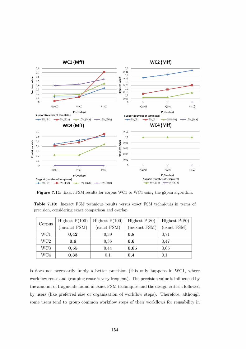
Figure 7.11: Exact FSM results for corpus WC1 to WC4 using the gSpan algorithm.
Table 7.10: Inexact FSM technique results versus exact FSM techniques in terms of
precision, considering exact comparison and overlap.
CorpusHighest P(100)
(inexact FSM)
Highest P(100)
(exact FSM)
Highest P(80)
(inexact FSM)
Highest P(80)
(exact FSM)
WC1 0,42 0,39 0,8 0,71
WC2 0,6 0,36 0,6 0,47
WC3 0,55 0,44 0,65 0,65
WC4 0,33 0,1 0,4 0,1
is does not necessarily imply a better precision (this only happens in WC1, where
workflow reuse and grouping reuse is very frequent). The precision value is influenced by
the amount of fragments found in exact FSM techniques and the design criteria followed
by users (like preferred size or organization of workflow steps). Therefore, although
some users tend to group common workflow steps of their workflows for reusability in
154
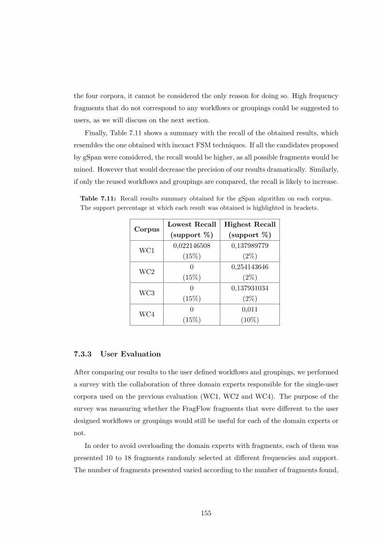
the four corpora, it cannot be considered the only reason for doing so. High frequency
fragments that do not correspond to any workflows or groupings could be suggested to
users, as we will discuss on the next section.
Finally, Table 7.11 shows a summary with the recall of the obtained results, which
resembles the one obtained with inexact FSM techniques. If all the candidates proposed
by gSpan were considered, the recall would be higher, as all possible fragments would be
mined. However that would decrease the precision of our results dramatically. Similarly,
if only the reused workflows and groupings are compared, the recall is likely to increase.
Table 7.11: Recall results summary obtained for the gSpan algorithm on each corpus.
The support percentage at which each result was obtained is highlighted in brackets.
CorpusLowest Recall
(support %)
Highest Recall
(support %)
WC10,022146508
(15%)
0,137989779
(2%)
WC20
(15%)
0,254143646
(2%)
WC30
(15%)
0,137931034
(2%)
WC40
(15%)
0,011
(10%)
7.3.3 User Evaluation
After comparing our results to the user defined workflows and groupings, we performed
a survey with the collaboration of three domain experts responsible for the single-user
corpora used on the previous evaluation (WC1, WC2 and WC4). The purpose of the
survey was measuring whether the FragFlow fragments that were different to the user
designed workflows or groupings would still be useful for each of the domain experts or
not.
In order to avoid overloading the domain experts with fragments, each of them was
presented 10 to 18 fragments randomly selected at different frequencies and support.
The number of fragments presented varied according to the number of fragments found,
155

and each domain expert answered on the usefulness of the fragments with regard to
their own corpus.
Similar to what we did in the fragment versus grouping evaluation (Section 7.3.2),
we relaxed the accuracy metric by asking domain experts if they would have modified
some parts of the proposed fragment before adopting it. Thus, candidate FragFlow
fragments could be used as proposed if the user would use the proposed fragment as
it was, used with minor changes if the user would change less than one third of the
fragment; used with major changes, if the user would change more than one third of the
fragment, or not used if the user did not think the proposed fragment would be useful.
In this section we describe and discuss the results of the survey. Additional details on
the survey can be seen in Annex C.4, while the responses and additional resources are
available online1.
7.3.3.1 User Evaluation Results
The responses to our survey are summarized in Table 7.12, with good results in average.
The first user would reuse more than half of the proposed fragments (66% accuracy),
using 11% of candidate fragments as proposed, changing slightly 16% of them and doing
major changes to 38% of them. When asked about the reasons to not use the other
third of the proposed FragFlow fragments, the user answered that they were too simple
(two or three steps).
User 2 would reuse all of the proposed fragments (100% accuracy), almost half of
them (43%) as FragFlow detected them, half of them by changing more than one third
of the components, and 6% with minor changes. When asked about the complexity
of the fragments, user 2 argued that sometimes additional sub-groupings would be
necessary, since they help clarifying and organizing the workflow.
Finally, user 3 would also reuse all of the proposed fragments, a 40% of them without
any change, a 30% with minor changes and a 30% with major changes. When asked
about the complexity of the proposed fragments, this user also said that some of the
fragments had too many steps (30%), but that some others were too simple (20%).
1http://dx.doi.org/10.6084/m9.figshare.1577564
156
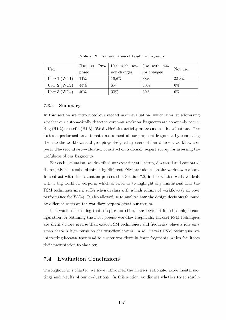
Table 7.12: User evaluation of FragFlow fragments.
UserUse as Pro-
posed
Use with mi-
nor changes
Use with ma-
jor changesNot use
User 1 (WC1) 11% 16,6% 38% 33,3%
User 2 (WC2) 44% 6% 50% 0%
User 3 (WC4) 40% 30% 30% 0%
7.3.4 Summary
In this section we introduced our second main evaluation, which aims at addressing
whether our automatically detected common workflow fragments are commonly occur-
ring (H1.2) or useful (H1.3). We divided this activity on two main sub-evaluations. The
first one performed an automatic assessment of our proposed fragments by comparing
them to the workflows and groupings designed by users of four different workflow cor-
pora. The second sub-evaluation consisted on a domain expert survey for assessing the
usefulness of our fragments.
For each evaluation, we described our experimental setup, discussed and compared
thoroughly the results obtained by different FSM techniques on the workflow corpora.
In contrast with the evaluation presented in Section 7.2, in this section we have dealt
with a big workflow corpora, which allowed us to highlight any limitations that the
FSM techniques might suffer when dealing with a high volume of workflows (e.g., poor
performance for WC4). It also allowed us to analyze how the design decisions followed
by different users on the workflow corpora affect our results.
It is worth mentioning that, despite our efforts, we have not found a unique con-
figuration for obtaining the most precise workflow fragments. Inexact FSM techniques
are slightly more precise than exact FSM techniques, and frequency plays a role only
when there is high reuse on the workflow corpus. Also, inexact FSM techniques are
interesting because they tend to cluster workflows in fewer fragments, which facilitates
their presentation to the user.
7.4 Evaluation Conclusions
Throughout this chapter, we have introduced the metrics, rationale, experimental set-
tings and results of our evaluations. In this section we discuss whether these results
157
validate the main hypothesis of the thesis (H1), described in Chapter 3: “Scientific
workflow repositories can be automatically analyzed to extract commonly occurring pat-
terns and abstractions that are useful for developers aiming to reuse existing workflows”.
The hypothesis has been divided into three different sub-parts, “it is possible to define a
catalog of common domain independent patterns based on the functionality of workflow
steps” (H1.1), “it is possible to detect commonly occurring patterns and abstractions au-
tomatically” (H1.2) and “commonly occurring patterns are potentially useful for users
designing workflows” (H1.3). Since H1.1 has already been addressed by the catalog
proposed in Section 5.1, in this section we discuss the relationship between our results,
H1.2 and H1.3.
7.4.1 Commonly Used Workflow Patterns and Abstractions
H1.2 states that it is possible to detect commonly occurring patterns and abstractions
automatically by making use of graph mining techniques (H1.2.1) and the exploita-
tion of domain specific metadata (H1.2.2). Our evaluations have shown that workflow
fragments can be mined successfully from a workflow corpus using inexact and exact
graph mining techniques. However, the key remaining question to answer is: are these
fragments commonly occurring and generic?
We have addressed this question in our first evaluation, by comparing our proposed
fragments to two groups of motifs related to workflow reuse: internal macros (which
identify the common sets of tasks within a single workflow) and composite workflows
(which detect whether a workflow is a composition of other existing workflows). These
motifs help identifying commonly occurring workflows and workflow fragments; and
our evaluation has shown that inexact mining techniques can find most of the internal
macros and workflows participating in composite workflows, while exact graph min-
ing techniques find all the target structures related to both motifs. Therefore, graph
mining techniques are adequate for finding commonly occurring patterns automatically
(addressing successfully H1.2.1).
Internal macros and composite workflows can be also used to assess the generality
of our fragments, as the corpus used in the evaluation had them annotated. Therefore,
in order to evaluate H1.2.2, we performed the same type of evaluation generalizing the
workflow corpus. Our results show that generic workflow fragments can also be mined
successfully (we obtained a high recall), even improving the results produced by the
158
inexact graph mining techniques. Therefore, we can confirm that our approach is able
to detect commonly occurring patterns and abstractions in a scientific workflow corpus,
thus confirming H1.2.2 and H1.2.
However, our evaluation also showed that, apart from the target motifs, other com-
monly occurring workflow fragments were included among the results found by our
approach (our precision in some cases was low). Therefore, the objective of our second
and third evaluations consisted on measuring whether these other common workflow
fragments are useful for workflow design or not.
7.4.2 Workflow Fragment Usefulness
Our hypothesis H1.3 states that commonly occurring patterns are potentially useful for
users designing workflows. In order to evaluate our hypothesis, we first introduced
a definition for usefulness (considering a fragment useful if it had been reused and
annotated as a workflow or a grouping by one or several users when designing workflows)
and designed two different evaluations.
The first evaluation compared our proposed fragments against several corpora of
user-annotated workflows and groupings. The results show that, in average, almost
half of the proposed fragments matched exactly those groupings (or workflows) reused
by users in their workflows. This number increases to more than half of our proposed
fragments (around 60 %) if we also take into account those fragments that are similar
to a user-defined grouping or workflow. Therefore, according to our results we have
enough evidence to confirm hypothesis H1.3, as up to 60 % of the commonly occur-
ring patterns that we detect automatically have demonstrated to be useful for users
designing workflows.
Our second evaluation aimed at determining if the other 40 % of our suggested
fragments were useful as well. Therefore, we performed a user survey with three domain
experts, asking them about the usefulness of the fragments found on their respective
corpora. In average, the accuracy of our results turned out to be very high. Most of the
proposed fragments were considered useful by users (nearly 90%), even if they would
change around half of the fragments according to their personal preferences (e.g., size,
complexity, frequency, etc.). These preferences can be set up as parameters to filter
fragments, thus increasing the performance of our approach.
159

There is clearly not enough evidence to state that the majority of our proposed
commonly occurring workflow fragments are useful, as half of our candidate fragments
were found to be useful and only three domain experts participated in the survey.
However, the analysis presented in this chapter supports this hypothesis. A more
complete analysis could not be completed due to the difficulty of finding volunteer
users with a significant corpus of workflows.
160
Chapter 8
Conclusions and Future Work
The main goal of this thesis was to facilitate scientific workflow understanding and reuse
by automatically mining commonly used workflow fragments of a workflow corpus. To
this end, we developed workflow provenance and template representation models that
extend on existing standards, we created a catalog of workflow abstractions based on
workflow step functionality, we developed and implemented workflow fragment mining
techniques and we defined metrics and used them to measure the usefulness of workflow
fragments.
Based on the evaluation of our results, we extract two main conclusions. The first
conclusion is that commonly occurring workflow fragments can be mined automatically
from a corpus of workflows using graph mining techniques. Furthermore, commonly
occurring workflow fragments are generally useful for users designing workflows. How-
ever, an important finding is that not all commonly used workflow fragments are useful,
as this depends partly on user preferences and context.
The second conclusion is that workflow abstraction plays an important role in un-
derstanding how different workflows relate to each other. Therefore, it is possible to
find additional occurring workflow fragments using step abstractions.
The rest of the section discusses our assumptions and restrictions, contributions,
impact, current limitations and future lines of work. All the inputs, outputs and
intermediate results of the thesis are available online as Research Objects (Belhajjame
et al., 2015) that define the datasets, structure and metadata of our experiments1.
1http://purl.org/net/mining-abstractions-in-scientific-wfs
161

8.1 Assumptions and Restrictions
Throughout the thesis, we have taken a series of assumptions and restrictions for our
work. Our first assumption for applying the methods described here is thatworkflow
repositories should be available for exploiting workflow definitions of their steps and
dependencies (A1) or their provenance traces (A2).
Also, in order to apply successfully our fragment mining techniques, we convert
the workflow corpus to directed labeled acyclic graphs (R1). We restrict to this type
of representation because it is the most common in data intensive scientific workflows.
Other types of workflows (e.g., business workflows) may benefit from this work, but
have been excluded from the scope of the thesis.
Furthermore, we assume that all the steps of a workflow can be assigned a label with
their type (A3). The type of the workflow step helps identify its functionality, and it is
normally chosen from a library of components by the workflow designer. If two steps
perform the same function in a workflow, they are assumed to have the same type (A4).
Thus, two workflows are assumed to have equivalent functionalities if their dependency
graphs are isomorphic and their nodes share the same types (A5).
Finally, our last assumption is that, when designing workflows, researchers aim to
reuse workflows and workflow fragments in their work, if they find them useful (A6).
Tables 8.1 and 8.2 summarize our assumptions and restrictions according to their
description.
8.2 Contributions
In this section we summarize our contributions regarding the research challenges defined
on Chapter 3.
8.2.1 Workflow Representation Heterogeneity
Our main contributions to this research challenge are the OPMW model (addressing
partly RCRepresent-1, there is no standard model for representing scientific workflows
and their metadata), and a methodology for publishing scientific workflows as Linked
Data (addressing RCRepresent-2, there are no methodologies for publishing a corpus of
scientific workflows and their associated resources as Linked Data).
162

Table 8.1: Assumptions considered in this thesis.
Assumption Description
A1Available workflow repositories exist for exploiting definitions
of workflow steps and dependencies
A2Available workflow repositories exist for exploiting
workflow provenance traces
A3All the steps of a workflow can be
assigned a label with their type
A4If two steps perform the same function in a workflow,
they are assumed to have the same type
A5Two workflows are assumed to have equivalent functionality if their
dependency graphs are isomorphic and their nodes share the same type
A6Researchers aim to reuse workflows and
workflow fragments in their work, if they find them useful
Table 8.2: Restrictions considered in this thesis.
Restriction Description
R1Workflows are represented as
directed acyclic graphs
8.2.1.1 The OPMW Model
In Chapter 4 we described our rationale and requirements for designing the OPMW
model, the first contribution of this thesis. OPMW is a lightweight vocabulary created
to represent workflow templates, workflow instances and workflow executions along with
their relationships and metadata. The requirements were gathered by looking at the
main workflow operations available in data intensive workflow management systems,
and selecting the minimum common group among all of them. In this regard, the
main scope of the model is to be able to exploit workflow data belonging to several
heterogeneous workflow systems.
Another key requirement of the model was to be aligned to existing vocabularies
and standards. By extending both OPM and PROV, OPMW ensures backwards com-
patibility with applications using OPM, as well as with those using the W3C PROV
standard. Additionally, by extending P-Plan, OPMW can be combined with other vo-
cabularies, as it happened in (Santana-Perez and Perez-Hernandez, 2015) for specifying
163
workflow execution infrastructure.
The OPMW vocabulary has evolved since its creation, and has been tested as
part of the WEST ecosystem (Garijo et al., 2014d), where a set of workflow tools for
design, analysis and execution use it as a simple intermediate representation during the
whole workflow life cycle. We have used this implementation to further evaluate the
effectiveness of the OPMW model.
8.2.1.2 A methodology for publishing scientific workflows as Linked Data
Our second contribution consists of a methodology to make the different resources
associated to workflow templates, workflow instances and workflow executions openly
accessible as web resources. Our proposal is to publish all the workflow related resources
following the Linked Data paradigm. This allows easy accessibility and reuse for both
humans and machines aiming to consume the workflow related information.
Our proposed methodology adapts a generic approach successfully applied for the
publication of data in other domains like energy consumption, meteorology or geog-
raphy. As described in Section 4.2.2, the methodology consists of five main steps
(specification, modelling, generation, publication and exploitation), which have been
adapted for the publication of scientific workflows. An example of each step is provided
on Section 4.2.3.
8.2.2 Addressing the Inadequate Level of Workflow Abstraction
Generalizing workflows by hand is a daunting task, and may require domain specific
knowledge from expert users. In this respect, we have made two main contributions in
this thesis: a catalog of common workflow motifs based on workflow step functionality,
addressing partly RCAbstract-1 (it is difficult to determine which steps perform the
main significant processing steps in a scientific workflow), and RCAbstract-2 (there are
no catalogs of the typical abstractions that can be found in scientific workflows based
on their basic step functionality); together with an approach to use domain specific
knowledge in order to find additional workflow fragments in a workflow corpus (based
on step abstraction).
164
8.2.2.1 A catalog of common workflow motifs
In Section 5.1 we described the result of a manual analysis over 260 scientific workflows
from four different workflow systems. As a result, we obtained a catalog of common
domain conceptual independent abstractions, which we refer to as common workflow
motifs.
The motif catalog consists on 6 major types of data-operation motifs (related to the
main functionality undertaken by the steps of the workflow) and 6 types of workflow-
oriented motifs (which indicate how the data-operation motifs are implemented in the
workflow). The most common motif is data preparation, highlighting that an impor-
tant effort in the creation of workflows is dedicated to data integration, filtering and
reformatting activities. Regarding workflow-oriented motifs, the amount of internal
macro motifs and composite workflows indicate that reuse is a common practice among
scientists publishing their workflows.
Workflow motifs categorize workflow steps by their functionality. Hence, they pro-
vide the means to create an adequate level for workflow abstractions.
8.2.2.2 Workflow generalization
Chapter 5 describes how a step abstraction may help connecting workflows that seemed
to be unrelated. In principle, this can be achieved by using domain experts to create
taxonomies of components with the same functionality. As we have demonstrated in
Chapter 7, this approach can be used to find additional generic motifs that help creating
relationships among different scientific workflows.
8.2.3 Difficulty of Workflow Reuse
We presented several contributions related to this open research challenge. First, we
analyzed how users reuse workflows in different corpora, addressing RCReuse-1 (it is
difficult to determine the relation between different workflows in a corpus).
Second, we have designed and evaluated an approach to find commonly occurring
workflow fragments automatically, along with the metrics to assess whether a workflow
fragment is useful or not in terms of reuse. This addresses RCReuse-2 (It is not easy to
detect which workflows or workflow fragments are potentially useful for reuse), as our
approach generates fragments that are potentially useful for reuse.
165
Finally, we defined a method for exploring how different workflow fragments can
be linked to their original workflows, enabling linking distinct workflows thet share
common functionality (and also addressing RCReuse-1).
8.2.3.1 Workflow reuse analysis
In order to dig into the level of workflow reuse exposed in Section 5.1, sections 5.2
and 5.3 describe two analyses from two different perspectives. One consists on an
automatic analysis of four workflow corpora, counting the number of unique workflows
and groupings (i.e., user hand made sub-workflows) and how many of them are finally
reused. An interesting conclusion of this analysis is that, despite the current difficulty
for workflow reuse, a high number of workflows appears in other workflows, specially
when the repository belongs to a single contributor. Groupings are also heavily used,
even more than workflows.
The second analysis describes a user survey on code, workflow and grouping reuse.
The rationale for the analysis was to understand the user perspective on reuse, in order
to confirm the findings from previous analyses. According to the results, workflows are
generally considered more useful than groupings (although groupings are considered
useful as well). Groupings are not created solely for reusing purposes, but also to
organize workflows and make them easier to modularize and simplify.
These analyses are a strong contribution, since they are unique on measuring sub-
workflow reuse in a workflow corpus.
8.2.3.2 Automatic workflow fragment detection
Another contribution to address the difficulty of workflow reuse is our approach for
the automated detection of workflow fragments using graph mining techniques. This
approach, described in Chapter 6, is able to detect successfully commonly occurring
workflow fragments using graph mining techniques and filtering the fragments to sim-
plify the results. As shown on the evaluation in Section 7.3, more than half of the
resulting fragments are equal or very similar to what users identified as useful in their
own designs. Furthermore, those fragments that were not similar to what users indi-
cated in their workflows were considered useful by three different domain experts on
their respective corpora. This indicates that our approach is able to find fragments
166
that are useful for workflow reuse, although further analysis is needed to confirm that
the majority of our proposed fragments is useful for that purpose.
8.2.3.3 Workflow fragment assessment metrics
Another contribution regarding the difficulty for workflow reuse are the metrics we have
defined for assessing whether a workflow fragment is useful or not. These metrics are
described in Section 7.1, and are based on precision and recall. The first metric relies
on the ability to find fragments as motifs that are either commonly occurring or generic
like internal macros and composite workflows. The second metric assesses whether our
fragments are similar to the structures defined by users when they design workflows.
8.2.3.4 Workflow fragment linking
In addition to obtaining the resulting set of commonly occurring workflow fragments,
we have described in Section 6.4 a generic method to link a fragment to the workflow or
workflows where the fragment appears. This is a contribution towards easing workflow
reuse and discoverability, as the workflows of a repository are related to each other by
their commonly occurring workflow fragments.
8.2.4 Lack of Support for Workflow Annotation
We have described in the thesis two contributions for facilitating annotation of work-
flows and workflow fragments in a semi-automated way (RCAnnot1), in the form of
two different vocabularies. The first one is a vocabulary for common workflow motifs
and the second one is a vocabulary for workflow fragment description and linking.
8.2.4.1 Workflow motif vocabulary (wf-motifs)
Wf-motifs2 is a vocabulary encoding the catalog of common workflow motifs presented
in Section 5.1. This vocabulary is a contribution towards workflow annotation for two
reasons. First, it provides a machine readable description of the catalog of motifs,
stating how different motifs are related or depend on each other. Second, it defines
explicit relationships to annotate workflows and workflow steps with any of the motifs
described on the catalog.
2http://purl.org/net/wf-motifs
167

8.2.4.2 Workflow fragment description vocabulary (wf-fd)
The Wf-fd vocabulary3 is the means we use to expose the links found between fragments
and the original workflows where they were found. In this regard, the vocabulary itself
is a contribution because we use it to automatically annotate workflows with their
associated workflow fragments.
8.3 Impact
The contributions of this thesis have already started to be used in recent work by other
researchers. The OPMW model has been used for exposing automatically annotated
bio-informatic workflows (Garcıa-Jimenez and Wilkinson, 2014b) and for documenting
the results of scientific research4. Our catalog of motifs has been adopted and ex-
tended by analyzing workflows of distributed environments (Olabarriaga et al., 2013)
and summarizing workflows (Alper et al., 2013).
Other contributions may impact different workflow research areas, as we describe
below:
• Workflow exploration: By knowing how each fragment is found on a workflow,
it is possible to derive a network where the nodes represent the different workflows
and the edges are the common fragments (dependencies) found among them.
Thus, the higher the number of common fragments the stronger the connection
would be between two workflows. This kind of network would help to see how
different workflows are connected to each other on a repository, facilitating the
exploration between workflows with same parts of functionality.
• Workflow abstraction: Approaches like (Cerezo, 2013) use fragment knowledge
bases to create abstractions. These approaches can benefit from our commonly
occurring workflow fragments.
• Workflow discovery: Commonly occurring workflow fragments, when sup-
ported in many workflows, may become valuable workflow candidates themselves.
Repository maintainers may offer these potentially reusable fragments to users to
include on their workflows.3http://purl.org/net/wf-fd4http://linked-research.270a.info/linked-research.html
168
• Workflow visualization: As stated in the user survey of Section 5.3, one of
the reasons why groupings are created is for summarization and organization
purposes. Hence, commonly occurring workflow fragments can be used to simplify
the complexity of a workflow by collapsing their nodes under a single one. If a
workflow has overlapping fragments it would be possible to create different views
according to user preferences, simplifying the overall complexity shown to the
final user.
• Workflow compression: Similarly, if several workflows share the same frag-
ment, it would be possible to store the common relevant workflow fragments
instead of every expanded workflow, for efficiency. This would be particularly
useful when dealing with similar or identical provenance traces.
• Suggestions for workflow design: Commonly occurring fragments may be
used to suggest how a user may complete a workflow under development. By
comparing the current workflow with the commonly occurring fragments, it would
be possible to recommend the next step or sets of steps of the workflow.
• Workflow ranking: Once the catalog of fragments is linked to a workflow cor-
pus, it would be possible to order the workflows by different criteria and create
rankings. Possibles examples of rankings are the degree of reusability of the work-
flow (i.e., how much of the workflow can be found in other workflows), workflows
with most reused fragments, etc.
8.4 Limitations
In this section we discuss the main limitations associated to the contributions and
methods described in the thesis.
8.4.1 Workflow Representation and Publication
OPMW aims to represent scientific workflow templates, instances and executions and
their relationships as labeled directed acyclic graphs (as stated on restriction R1). More
complex workflow structures, such as sub-workflows, loops and conditionals (the last
two being more typical of business workflows) have been deliberately left out of the
model for simplicity. In this regard, OPMW captures the minimum set of workflow
169

operations common to most workflow systems. In order to represent more complex
structures, additional extensions of the model would be necessary.
Regarding the publication of workflows, one possible issue is privacy. In some
domains privacy is a concern (e.g., if the workflow processes sensitive clinical data),
and in those cases the open publication of all the workflow resources as Linked Data
would not be appropriate. However, there are many areas of science where privacy is
not an issue and that would benefit tremendously from a more open architecture for
sharing both data and workflows. Besides, it is possible to publish workflows as Linked
Data for local consumption, by restricting the access to the Linked Data server.
8.4.2 Common Workflow Motifs
Our catalogue of common workflow motifs is the result of an extensive analysis on
workflows from different domains and different platforms. We believe that the sam-
ple collected is statistically significant for the life-sciences domain, as for most of the
systems we have chosen the majority of the workflows available.
However, there may be other motifs in other domains and types of workflows (e.g.,
business workflows) or in workflows prepared to be executed in other settings like
distributed systems (as happened in (Olabarriaga et al., 2013)). Since the catalog is
exposed as an online vocabulary, we have provided the means to extend it whenever
additional analyses are made.
In addition, one of the objectives of this work tackled the automatic detection of
abstractions from a repository of workflows. In this regard, we have only addressed the
detection of those motifs related to workflow reuse. The rest of the motif catalog has
been left out of scope, and it would present a challenging line of future work.
8.4.3 Workflow Fragment Mining
As discussed in Chapter 6, there are two possible limitations introduced by graph
mining techniques: the size of the result (i.e., number of mined workflow fragments)
and the time needed to compute the results.
Regarding the size of the result, we have developed filtering techniques that prune
the response and return only those fragments that are relevant to our purposes. How-
ever, our results have shown that there are cases where the size of the commonly occur-
ring fragments leads to produce memory errors on the exact graph mining techniques
170
(e.g., when many versions of a big workflow are included as part of the corpus). This
limitation can be handled by augmenting the amount of memory of the application,
increasing the minimum frequency or support for a fragment be found on the workflow
corpus, limiting the maximum size of the fragment to be found or by using an inexact
graph mining technique (which simplify greatly the number of responses, even if all the
possible fragments are not returned).
Regarding the time, sub-graph isomorphism is known to be a NP-Complete problem
(Cook, 1971). Different techniques optimize their algorithms in order to reduce the
execution time as much as possible, being able to handle a large amount of graphs in a
reasonable time. Although we state time as a limitation of graph mining techniques, we
do not consider it critical in our analyses. Workflow fragment mining can be performed
as an automated back-end task on a repository, executed once in a fixed period of time
(e.g., week or month). Time can also be reduced greatly by modifying the parameters
of the mining algorithms, such as maximum size of the fragment to look for in the
dataset or the minimum support or frequency of the fragments to find (the bigger the
support, the lesser the candidates and therefore the faster we obtain the results), etc.
However, adding these kinds of limitations may have an impact on the quality of the
results.
8.4.4 Workflow Generalization
In our work, we use taxonomies and domain knowledge to generalize workflows and find
abstract fragments in a workflow corpus, if they exist. These abstractions depend on
how domain experts model the domain, and thus different workflows may be simplified
differently according to how each user models their domains. The main limitation in
this regard is that the domain knowledge must come from an expert or a community
of experts in the form of a taxonomy or an ontology, in order for us to be able to
generalize workflows. The creation of a taxonomy from a repository of workflows is out
of the scope of this work.
8.5 Future Work
Our work may be expanded in several ways. In this section we discuss possible future
lines of work related to our research challenges.
171
8.5.1 Towards Workflow Ecosystem Interoperability
Workflow heterogeneity has been an issue in the workflow community for years, and
some interchange languages for workflow specification interoperability have been speci-
fied by part of the community (e.g., IWIR). However, the workflow life cycle (including
workflow instances and workflow executions) is still represented differently for each
workflow tool.
We believe that a way to consolidate an intermediate representation between dif-
ferent workflow design and execution tools is through a workflow ecosystem (Garijo
et al., 2014d). A workflow ecosystem brings together heterogeneous tools that consume
and produce workflow templates, instances and executions at different moments of the
workflow life cycle. Different tools may also consume workflows at different granularity
(e.g., a workflow depiction tool would aim to consume an abstract provenance trace,
while a workflow execution tool would require the full dependency graph among the
workflow steps and where to find the scripts to run each of them). This forces tools
to cooperate in order to communicate with a consistent representation. In this thesis
we have proposed and tested a model that tries to minimize the common workflow
operations in order to successfully communicate different applications in a workflow
ecosystem. However, this is only a first step, and a community of adopters and pro-
ducers is necessary to push forward a robust and consolidated standard model.
8.5.2 Automating Detection of Workflow Abstractions
In this thesis we have discussed two ways of creating abstractions from workflows: work-
flow generalization (which is generated automatically by using a taxonomy provided
by domain experts) and a catalog of workflow motifs (some of which we find automat-
ically by using graph mining techniques). Even though we have contributed towards
the automatic detection of workflow abstractions, our work may be expanded, as we
further describe below.
Workflow Generalization: One of the limitations we have devised for workflow
generalization is the need for a domain expert to create the taxonomy used to generalize
the workflow steps. The ability to derive a domain specific taxonomy automatically
would improve the process, in case no domain experts can be consulted. The extraction
172
of the taxonomy may be performed by exploring workflows and by mining domain
specific knowledge bases with description of the workflow steps.
Workflow Motifs: In Section 5.1 we described a catalog of common workflow motifs
in scientific workflows. As discussed in the limitations section, a future line of work
would be to expand this catalog with other types of workflows (e.g., business workflows)
or execution environments (e.g., high performance workflows or distributed workflows).
We have left the detection of any motif unrelated to workflow reuse out of the scope
of this thesis. A challenging line of work would be, given a workflow as an input, to be
able to recognize and annotate all its motifs automatically. This would help understand
the workflow better, as in many cases there is not enough documentation to determine
what a particular step of a workflow does unless we execute it.
After extracting and refining the motif catalog we have analyzed some of the features
of the motifs. Below we highlight some of the features which might help for their
automated classification, specially those under the “data preparation” category:
• Input and output number: by determining whether the number of inputs
is bigger than the number of outputs we can (usually) discard certain types of
motifs. For example, a merging component normally has several inputs of the
same type and produces a lesser amount of outputs of the same type.
• Input and output size: when combined with the number of inputs, their size
can be combined as a metric to speculate about the type of operation going on
the component. For example, if a dataset file is used as input of a step and the
result is a similar reduced dataset, the input may have been filtered.
• Input and output type: This feature can be combined with the previous two
to speculate about the type of motif being applied. For example, if the type of
the input is the same as the type of the output, we might be applying different
data transformations (filter, clean, merge, group) to the same file.
• Name similarity: It is common for the authors to name their components after
the function they perform. For example, if a component merges a dataset, it is
likely to be named “MergeDataset” (or similar). By measuring the distance of
the workflow step name to a controlled vocabulary (merge, filter, concatenate,
curate, add, etc.) we could speculate about its function.
173
These features may be combined into feature vectors and train classifiers with them.
Additionally, algorithms to differentiate between inputs and outputs could be run,
in order to determine the type of transformations happening on each workflow step.
Adding these kind of annotations on a workflow corpus automatically would also allow
categorizing workflow steps in order to derive their taxonomy.
8.5.3 Improving Workflow Reuse
There are several ways in which our candidate workflow fragments may be improved
to be more useful. First, it would be necessary to study the different features of a
workflow fragment in order to allow users customize their results. As we have seen in
our evaluations, different users prefer fragments of different sizes and frequencies. Other
metadata like the number of different workflows in which they appear (support) or the
technique used to obtain them (inexact or exact FSM) may be relevant for filtering a
set of useful fragments for a particular user.
Second, it should be possible to rank a set of fragments once they have been auto-
matically characterized and annotated. Rankings make a set of fragments to be easily
comparable in order to recommend similar workflows to a particular given one (based
on their fragment similarity). It would be an interesting line of work to determine if a
recommendation based on similar workflow fragments provides similar or better results
than other approaches existent in the state of the art.
Third, a set of workflow fragments may be used for suggestions in workflow de-
sign, in combination with process mining approaches. Process mining approaches have
demonstrated to obtain good results to predict the next step of the workflow. When
using process mining techniques with common workflow fragments (which have been
repeatedly used among the dataset), we suspect that better results may be obtained
with less processing, as the common workflow fragments filter those structures that are
unlikely to appear.
Finally, another area of improvement is the efficiency with which the workflow
fragments are obtained. The size of the commonly occurring fragments may cause the
fragment detection process to be slow (a consequence of being a NP-Complete problem).
We have deliberately left out the issue of efficiency of the thesis, as our main objective
was to assess whether graph mining techniques would be appropriate for obtaining a
set of useful workflow fragments for designing workflows or not. Therefore, we have
174

tested representative graph mining algorithms of inexact and exact FSM techniques.
In Annex D we discuss additional algorithms with potential to either discover other
types of workflow fragments (as inexact FSM), or return the results more efficiently.
175

176

ANNEX A
Competency questions for
OPMW
Here we introduce the competency questions created for the development of OPMW,
described in Section 4.1.3. The competency questions can be seen in table A.1, A.2,
A.3, A.4 and A.5 below.
Table A.1: Competency questions for OPMW (1).
Competency QuestionTerms created/reused to
address it
What are the input data variables of a workflow
step?
DataVariable,
uses,
WorkflowTemplateProcess
What are the output data variables generated by
a workflow step?
DataVariable,
isGeneratedBy,
WorkflowTemplateProcess
What are the parameters used for a workflow
step (name, type)?ParameterVariable, uses
What are the files associated to a workflow
execution?
WorkflowExecutionArtifact,
opmo:account,
WorkflowExecutionAccount
What are the intermediate results produced
in a workflow execution?
WorkflowExecutionArtifact,
opmo:account,
WorkflowExecutionAccount
177
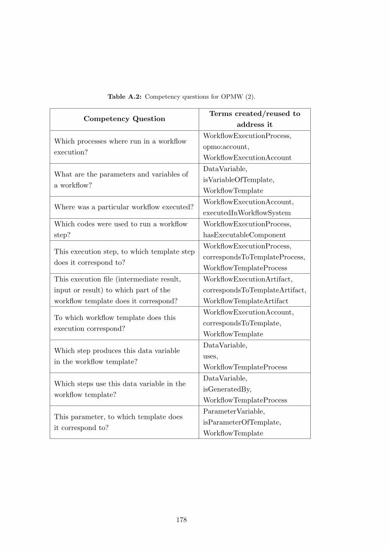
Table A.2: Competency questions for OPMW (2).
Competency QuestionTerms created/reused to
address it
Which processes where run in a workflow
execution?
WorkflowExecutionProcess,
opmo:account,
WorkflowExecutionAccount
What are the parameters and variables of
a workflow?
DataVariable,
isVariableOfTemplate,
WorkflowTemplate
Where was a particular workflow executed?WorkflowExecutionAccount,
executedInWorkflowSystem
Which codes were used to run a workflow
step?
WorkflowExecutionProcess,
hasExecutableComponent
This execution step, to which template step
does it correspond to?
WorkflowExecutionProcess,
correspondsToTemplateProcess,
WorkflowTemplateProcess
This execution file (intermediate result,
input or result) to which part of the
workflow template does it correspond?
WorkflowExecutionArtifact,
correspondsToTemplateArtifact,
WorkflowTemplateArtifact
To which workflow template does this
execution correspond?
WorkflowExecutionAccount,
correspondsToTemplate,
WorkflowTemplate
Which step produces this data variable
in the workflow template?
DataVariable,
uses,
WorkflowTemplateProcess
Which steps use this data variable in the
workflow template?
DataVariable,
isGeneratedBy,
WorkflowTemplateProcess
This parameter, to which template does
it correspond to?
ParameterVariable,
isParameterOfTemplate,
WorkflowTemplate
178

Table A.3: Competency questions for OPMW (3).
Competency QuestionTerms created/reused to
address it
This variable, to which template does
it correspond to?
DataVariable,
isVariableOfTemplate,
WorkflowTemplate
This intermediate result, to which
execution does it correspond to?
WorkflowExecutionArtifact,
opmo:account,
WorkflowExecutionAccount
This result, to which execution does it
correspond to?
WorkflowExecutionArtifact,
opmo:account,
WorkflowExecutionAccount
Who is the responsible for the execution
of the workflow (or steps of the
workflow)?
WorkflowExecutionProcess,
opmv:wasControlledBy,
prov:wasAssociatedWith,
opmv:Agent
Which steps use a particular dataset in
an execution?
WorkflowExecutionProcess,
opmv:used,
prov:used,
WorkflowExecutionArtifact
Which step has generated this output?
WorkflowExecutionArtifact,
opmv:wasGeneratedBy,
prov:wasGeneratedBy,
WorkflowExecutionProcess
Where was this workflow created?WorkflowTemplate,
createdInWorkflowSystem
Does this workflow have a documentation?WorkflotTemplate,
hasDocumentation
Are there any collections on the workflow?WorkflowTemplateArtifact,
hasDimensionality
179

Table A.4: Competency questions for OPMW (4).
Competency QuestionTerms created/reused to
address it
How long did an execution last?
WorkflowExecutionAccount,
hasOverallStartTime,
hasOverallEndTime
Was the execution finished successfully?WorkflowExecutionAccount,
hasStatus
What is the start time and end time of
this execution process?
WorkflowExecutionProcess,
prov:startedAtTime,
prov:endedAtTime
Can I see a diagram of the execution?WorkflowExecutionAccount,
hasExecutionDiagram
Can I see a diagram of the workflow?WorkflowTemplate,
hasTemplateDiagram
What is the original template designed
by the workflow system?
WorkflowTemplate,
hasNativeSystemTemplate
What is the execution log?WorkflowExecutionAccount,
hasOriginalLogFile
Is a template component abstract?
(i.e., it has multiple possible implementations)
WorkflowTemplateProcess,
isConcrete
What is the name of this file?WorkflowExecutionArtifact,
hasFileName
What is the size of this file?WorkflowExecutionArtifact,
hasSize
What is the URL with the location of this file?WorkflowExecutionArtifact,
hasLocation
What is the version number of this workflow?WorkflowTemplate,
versionNumber
What was the value of this parameter?WorkflowExecutionArtifact,
hasValue
180
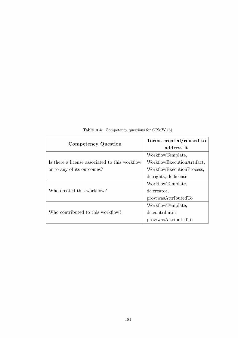
Table A.5: Competency questions for OPMW (5).
Competency QuestionTerms created/reused to
address it
Is there a license associated to this workflow
or to any of its outcomes?
WorkflowTemplate,
WorkflowExecutionArtifact,
WorkflowExecutionProcess,
dc:rights, dc:license
Who created this workflow?
WorkflowTemplate,
dc:creator,
prov:wasAttributedTo
Who contributed to this workflow?
WorkflowTemplate,
dc:contributor,
prov:wasAttributedTo
181

182
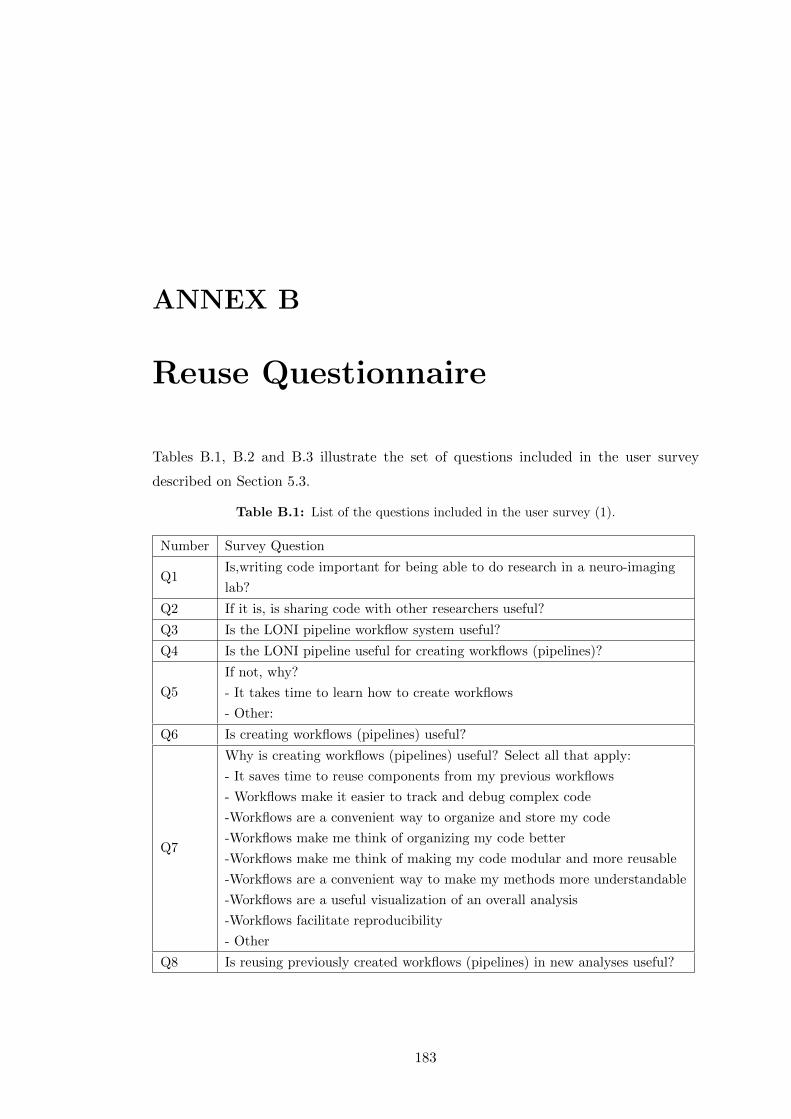
ANNEX B
Reuse Questionnaire
Tables B.1, B.2 and B.3 illustrate the set of questions included in the user survey
described on Section 5.3.
Table B.1: List of the questions included in the user survey (1).
Number Survey Question
Q1Is,writing code important for being able to do research in a neuro-imaging
lab?
Q2 If it is, is sharing code with other researchers useful?
Q3 Is the LONI pipeline workflow system useful?
Q4 Is the LONI pipeline useful for creating workflows (pipelines)?
Q5
If not, why?
- It takes time to learn how to create workflows
- Other:
Q6 Is creating workflows (pipelines) useful?
Q7
Why is creating workflows (pipelines) useful? Select all that apply:
- It saves time to reuse components from my previous workflows
- Workflows make it easier to track and debug complex code
-Workflows are a convenient way to organize and store my code
-Workflows make me think of organizing my code better
-Workflows make me think of making my code modular and more reusable
-Workflows are a convenient way to make my methods more understandable
-Workflows are a useful visualization of an overall analysis
-Workflows facilitate reproducibility
- Other
Q8 Is reusing previously created workflows (pipelines) in new analyses useful?
183

Table B.2: List of the questions included in the user survey (2).
Number Survey Question
Q9
Why is reusing previously created workflows (pipelines) useful? Select all that apply
- It saves time to reuse components from my previous workflows
- Workflows give a high-level diagram that helps remember what was done
- Other:
Q10 Is it useful to share workflows (pipelines) with other researchers?
Q11
Why is it useful to share workflows (pipelines) with other researchers?
Select all that apply
- Non-programmers can use the workflows to run code easily
- New students and new people in the lab can easily use workflows
- It saves them time because they do not have to re-implement the code
- It makes everyone think of standards by adopting the ways others do things
- Other:
Q12
If not, why are workflows (pipelines) not shared? Select all that apply
- Others would not want to use them
- Others ask too many questions to the creators of the workflows
- Workflows created by others are difficult to understand
- It is difficult to understand how to prepare the data for a workflow
- Other:
Q13
What is the most usual size of workflows (pipelines)? Select all that apply
- 1-5 components
- 5-10 components
- 10-20 components
- >20 components
Q14 Is it useful to reuse workflows (pipelines) from other researchers?
Q15
If not, why? Select all that apply
- Workflows created by others are difficult to understand
- It is difficult to understand how to prepare the data for a workflow
- Workflows created by others are often too specific
- It is hard to make them work
- Other:
Q16 Is the groupings functionality of the workflow system useful?
Q17 If not, why?
Q18
What are,the benefits of using groupings? Select all that apply.
- To have nice visualizations of an analysis
- To simplify workflows that are complex overall
- To make workflows more understandable to others
- Other:
Q19 Is it useful to reuse previous groupings in new work?
184
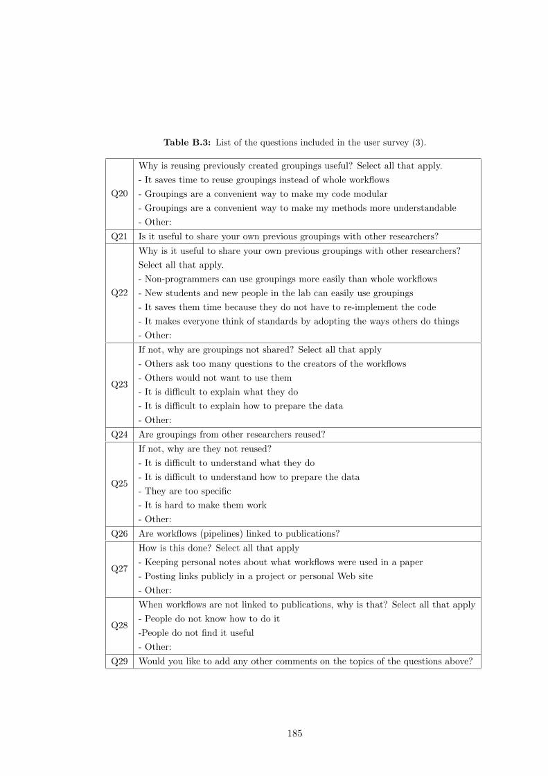
Table B.3: List of the questions included in the user survey (3).
Q20
Why is reusing previously created groupings useful? Select all that apply.
- It saves time to reuse groupings instead of whole workflows
- Groupings are a convenient way to make my code modular
- Groupings are a convenient way to make my methods more understandable
- Other:
Q21 Is it useful to share your own previous groupings with other researchers?
Q22
Why is it useful to share your own previous groupings with other researchers?
Select all that apply.
- Non-programmers can use groupings more easily than whole workflows
- New students and new people in the lab can easily use groupings
- It saves them time because they do not have to re-implement the code
- It makes everyone think of standards by adopting the ways others do things
- Other:
Q23
If not, why are groupings not shared? Select all that apply
- Others ask too many questions to the creators of the workflows
- Others would not want to use them
- It is difficult to explain what they do
- It is difficult to explain how to prepare the data
- Other:
Q24 Are groupings from other researchers reused?
Q25
If not, why are they not reused?
- It is difficult to understand what they do
- It is difficult to understand how to prepare the data
- They are too specific
- It is hard to make them work
- Other:
Q26 Are workflows (pipelines) linked to publications?
Q27
How is this done? Select all that apply
- Keeping personal notes about what workflows were used in a paper
- Posting links publicly in a project or personal Web site
- Other:
Q28
When workflows are not linked to publications, why is that? Select all that apply
- People do not know how to do it
-People do not find it useful
- Other:
Q29 Would you like to add any other comments on the topics of the questions above?
185

186
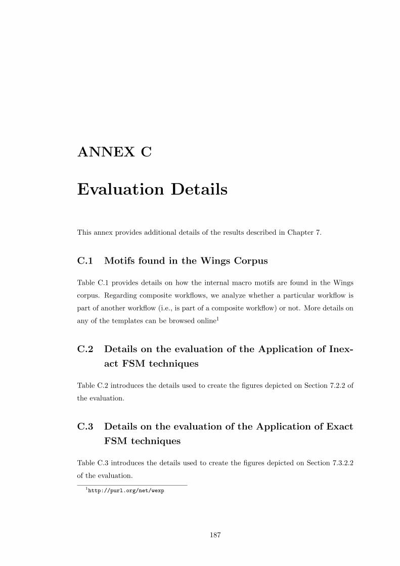
ANNEX C
Evaluation Details
This annex provides additional details of the results described in Chapter 7.
C.1 Motifs found in the Wings Corpus
Table C.1 provides details on how the internal macro motifs are found in the Wings
corpus. Regarding composite workflows, we analyze whether a particular workflow is
part of another workflow (i.e., is part of a composite workflow) or not. More details on
any of the templates can be browsed online1
C.2 Details on the evaluation of the Application of Inex-
act FSM techniques
Table C.2 introduces the details used to create the figures depicted on Section 7.2.2 of
the evaluation.
C.3 Details on the evaluation of the Application of Exact
FSM techniques
Table C.3 introduces the details used to create the figures depicted on Section 7.3.2.2
of the evaluation.
1http://purl.org/net/wexp
187

Table C.1: Motifs found in the Wings corpus. Templates with one step are omitted.
Template nameN of
Steps
Part of comp.
workflows?
Part of comp.
workflows?
(generalizing)
N of internal
macros
N of internal
macros
(generalizing)
1 Classify 1 - - - -
2 CorrelationScore 1 - - - -
3 DocumentClassificationMutli 15 no no 1 (5 steps)2 (2 steps
and 5 steps)
4 DocumentClassificationSingle 13 no no 1 (6 steps) 1 (6 steps)
5 DocumentClustering 6 no no 0 0
6 FeatureGeneration 4 no yes 0 0
7 FeatureSelection 7 no no 0 0
8 GenerateVocabular 3 no no 1 (1 step) 1 (1 step)
9 Model 3 no no 0 0
10 ModelThenClassify 2 no no 0 0
11 MultiLabel 3 no yes 0 0
12 PlotCorrelationScore 3 no no 0 0
13 PlotTopics 1 - - - -
14 PrepareDataset 2 no no 0 0
15 ReduceDataset 1 - - - -
16 Similar 2 no yes 0 0
17 SimilarWords 6 no yes 0 0
18 SimilarWordsTopics 6 no yes 0 0
19 Stemming 3 yes yes 0 0
20 TermWeighting 1 - - - -
21 Topic Modeling 6 no no 0 1 (2 step)
22 Validate 2 yes yes 0 0
C.4 Usefulness Questionnaire
The questionnaire issued to the three different users followed the template described in
table C.4:
188
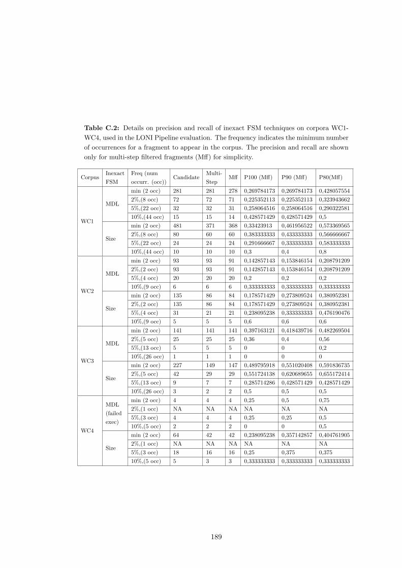
Table C.2: Details on precision and recall of inexact FSM techniques on corpora WC1-
WC4, used in the LONI Pipeline evaluation. The frequency indicates the minimum number
of occurrences for a fragment to appear in the corpus. The precision and recall are shown
only for multi-step filtered fragments (Mff) for simplicity.
CorpusInexact
FSM
Freq (num
occurr. (occ))Candidate
Multi-
StepMff P100 (Mff) P90 (Mff) P80(Mff)
WC1
MDL
min (2 occ) 281 281 278 0,269784173 0,269784173 0,428057554
2%,(8 occ) 72 72 71 0,225352113 0,225352113 0,323943662
5%,(22 occ) 32 32 31 0,258064516 0,258064516 0,290322581
10%,(44 occ) 15 15 14 0,428571429 0,428571429 0,5
Size
min (2 occ) 481 371 368 0,33423913 0,461956522 0,573369565
2%,(8 occ) 80 60 60 0,383333333 0,433333333 0,566666667
5%,(22 occ) 24 24 24 0,291666667 0,333333333 0,583333333
10%,(44 occ) 10 10 10 0,3 0,4 0,8
WC2
MDL
min (2 occ) 93 93 91 0,142857143 0,153846154 0,208791209
2%,(2 occ) 93 93 91 0,142857143 0,153846154 0,208791209
5%,(4 occ) 20 20 20 0,2 0,2 0,2
10%,(9 occ) 6 6 6 0,333333333 0,333333333 0,333333333
Size
min (2 occ) 135 86 84 0,178571429 0,273809524 0,380952381
2%,(2 occ) 135 86 84 0,178571429 0,273809524 0,380952381
5%,(4 occ) 31 21 21 0,238095238 0,333333333 0,476190476
10%,(9 occ) 5 5 5 0,6 0,6 0,6
WC3
MDL
min (2 occ) 141 141 141 0,397163121 0,418439716 0,482269504
2%,(5 occ) 25 25 25 0,36 0,4 0,56
5%,(13 occ) 5 5 5 0 0 0,2
10%,(26 occ) 1 1 1 0 0 0
Size
min (2 occ) 227 149 147 0,489795918 0,551020408 0,591836735
2%,(5 occ) 42 29 29 0,551724138 0,620689655 0,655172414
5%,(13 occ) 9 7 7 0,285714286 0,428571429 0,428571429
10%,(26 occ) 3 2 2 0,5 0,5 0,5
WC4
MDL
(failed
exec)
min (2 occ) 4 4 4 0,25 0,5 0,75
2%,(1 occ) NA NA NA NA NA NA
5%,(3 occ) 4 4 4 0,25 0,25 0,5
10%,(5 occ) 2 2 2 0 0 0,5
Size
min (2 occ) 64 42 42 0,238095238 0,357142857 0,404761905
2%,(1 occ) NA NA NA NA NA NA
5%,(3 occ) 18 16 16 0,25 0,375 0,375
10%,(5 occ) 5 3 3 0,333333333 0,333333333 0,333333333
189
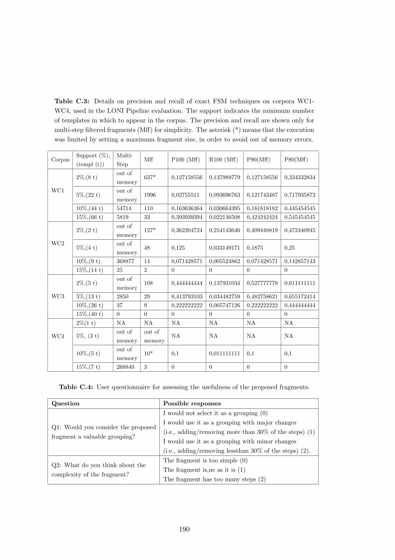
Table C.3: Details on precision and recall of exact FSM techniques on corpora WC1-
WC4, used in the LONI Pipeline evaluation. The support indicates the minimum number
of templates in which to appear in the corpus. The precision and recall are shown only for
multi-step filtered fragments (Mff) for simplicity. The asterisk (*) means that the execution
was limited by setting a maximum fragment size, in order to avoid out of memory errors.
CorpusSupport (%),
(templ (t))
Multi-
StepMff P100 (Mff) R100 (Mff) P90(Mff) P80(Mff)
WC1
2%,(8 t)out of
memory637* 0,127158556 0,137989779 0,127158556 0,334332834
5%,(22 t)out of
memory1996 0,02755511 0,093696763 0,121743487 0,717935872
10%,(44 t) 54714 110 0,163636364 0,030664395 0,181818182 0,445454545
15%,(66 t) 5819 33 0,393939394 0,022146508 0,424242424 0,545454545
WC2
2%,(2 t)out of
memory127* 0,362204724 0,254143646 0,409448819 0,472440945
5%,(4 t)out of
memory48 0,125 0,033149171 0,1875 0,25
10%,(9 t) 368877 14 0,071428571 0,005524862 0,071428571 0,142857143
15%,(14 t) 25 2 0 0 0 0
WC3
2%,(5 t)out of
memory108 0,444444444 0,137931034 0,527777778 0,611111111
5%,(13 t) 2850 29 0,413793103 0,034482759 0,482758621 0,655172414
10%,(26 t) 37 9 0,222222222 0,005747126 0,222222222 0,444444444
15%,(40 t) 0 0 0 0 0 0
WC4
2%(1 t) NA NA NA NA NA NA
5%, (3 t)out of
memory
out of
memoryNA NA NA NA
10%,(5 t)out of
memory10* 0,1 0,011111111 0,1 0,1
15%,(7 t) 268840 3 0 0 0 0
Table C.4: User questionnaire for assessing the usefulness of the proposed fragments.
Question Possible responses
Q1: Would you consider the proposed
fragment a valuable grouping?
I would not select it as a grouping (0)
I would use it as a grouping with major changes
(i.e., adding/removing more than 30% of the steps) (1)
I would use it as a grouping with minor changes
(i.e., adding/removing lessthan 30% of the steps) (2).
Q2: What do you think about the
complexity of the fragment?
The fragment is too simple (0)
The fragment is,ne as it is (1)
The fragment has too many steps (2)
190
ANNEX D
Additional FSM Algorithms for
Mining Useful Fragments
As described in Chapter 6, there are many existing algorithms for FSM (Jiang et al.,
2012). However, finding the associated implementations to each of the algorithms is not
always trivial. In this annex we discuss three algorithms with available implementations
that may improve some aspects of the current results obtained by our approach. Other
algorithms with available implementations exist1,2, but according to their descriptions
they may not return results significantly different to what we have already obtained with
the ones implemented in our approach (as most of them are exact FSM techniques).
• Sigma (Mongiovi et al., 2010) is an inexact FSM algorithm that performs over a
dataset of graphs. Being inexact, Sigma may return commonly occurring frag-
ments that are similar, discovering new levels of abstraction among the workflow
corpus. Additionally, according to the authors, it outperforms other state of
the art inexact FSM algorithms, which makes it a potential candidate for us to
consider when finding fragments in workflows.
• GRAMI (Saeedy and Kalnis, 2011) is another inexact FSM algorithms for effi-
ciently mining large single graphs. GRAMI uses an edit distance to group together
similar commonly occurring fragments, instead of using an exact mining approach.
1http://hms.liacs.nl/graphs.html2http://www.borgelt.net/fpm.html
191
However, GRAMI has been designed for single large graphs, and it would be re-
quired to explore whether it would be appropriate for finding patterns in multiple
graphs, as it is our case.
• MIRAGE (Bhuiyan and Hasan, 2013) implements an exact FSM algorithm using
a MapReduce approach. In this regard, the results would not differ from other
exact FSM algorithms already implemented in FragFlow, but by parallelizing
their approach with MapReduce, the total amount of time needed to process the
input corpus would be significantly reduced.
192

Glossary
AGM
The Apriori Graph Mining algorithm (AGM) is an exact FSM technique that
uses an adjacency matrix to represent graphs in combination with an efficient
levelwise search to discover common sub-graphs (Inokuchi et al., 2000). 115
AGWL
Askalon’s language for specifying scientific workflows (Fahringer et al., 2005). 20
ASKALON
Workflow management system developed by the University of Innsbruck (Austria)
(Fahringer et al., 2007). 14
BFS
Breadth first search (BFS) is a technique for exploring a graph by visiting first
all the neighbours of a node. 115
BPMN
The Business Process model and Notation (BPMN) provides a standard notation
for implementing, managing and monitoring business processes (Aggarwal et al.,
2011). 12
Business workflow
Templates designed to model, automate and execute a flow of business activities
in the corporate world3. 11
3http://www.wfmc.org/what-is-bpm
193
Candidate workflow fragment
A workflow fragment identified by any of the FSM approaches integrated in
FragFlow. 120
Case-based reasoning
Group of techniques that aim to solve a given problem based on past experience
with similar cases. 38
Clustering
Set of techniques that aim to group together individuals sharing a particular set
of common features. 37
Common workflow fragment
Given a workflow corpus, a workflow fragment is common if it appears at least
f times in the corpus, with f bigger than 2. The number “f” can be calculated
in two different ways. If each occurrence is counted once per workflow then “f”
represents the support for the workflow fragment. If all the occurrences of the
fragment are counted (even if it appears several times on the same workflow) “f”
represents the frequency of the workflow fragment. 109
Competency question
A requirement to be fulfilled by an ontology (i.e., the data modeled by an ontology
must be able to answer the question). 52
Conceptual workflows
Workflow model that aims to facilitate workflow abstraction and design by sepa-
rating workflows in conceptual and abstract levels (Cerezo, 2013). 23
CrowdLabs
Workflow repository for VisTrails’ workflows, created by the University of New
York (USA)(Mates et al., 2011). 26
D-PROV
Provenance model for representing workflow execution templates, instances and
executions (Missier et al., 2013). It extends the PROV standard. 23
194
DAX
Syntax used by the Pegasus workflow system for specifying scientific workflows4.
20
DFS
Depth first search (DFS) is a technique for exploring a graph by visiting each
branch associated to a node of the graph before backtracking to the next neighbor.
115
Directed acyclic graph
A non empty set of nodes and edges that connect those nodes. All the edges have
a direction, i.e., they go from a source node (tail) to a target node (head). This
type of graph has no cycles, i.e., from a node it is not possible to reach the same
node by following its edges. 14
Directed cyclic graph
A non empty set of nodes and edges that connect those nodes. All the edges have
a direction, i.e., they go from a source node (tail) to a target node (head). This
type of graph contains cycles, i.e., from a node it may be possible to reach the
same node by following its edges. 14
DISPEL
Data-Intensive Systems Process Engineering Language, defined to “describe ab-
stract workflows for distributed data-intensive applications” (Atkinson et al., 2013).
20
DOI
A Digital Object Identifier (DOI)5, is a standard way for accessing resources on
electronic networks. It has been commonly used to refer to electronic documents,
like journal articles.. 26
4http://pegasus.isi.edu/wms/docs/schemas/dax-3.4/dax-3.4.html5http://www.doi.org/
195
Dryad
Data repository for the international scientific and medical literature. Maintained
by the North Carolina State University (USA)6. 26
Dublin Core
Popular vocabulary for defining a set of common metadata terms (e.g., attribu-
tion, licensing, etc)7. 25
EXPO
Ontology designed to represent the methodological aspects of a scientific experi-
ment, including the scientific tasks required to carry it out (Soldatova and King,
2006). 24
FigShare
Popular data repository for archiving resources in digital sciences8. 26
FOAF
Popular vocabulary for describing agents on the Web and their interactions9. 25
FragFlow
The approach proposed in this thesis for mining frequent workflow fragments.
109
FSG
Exact FSM technique that builds on the Apriori algorithm by adding a sparse
graph representation to reduce storage and computation, while incorporating op-
timizations for the generation of candidate fragments (Inokuchi et al., 2000). 115
FSM
The Frequent Sub-graph Mining (FSM) problem aims to “to extract all the fre-
quent sub-graphs, in a given data set, whose occurrence counts are above a specified
6http://datadryad.org/7http://dublincore.org/documents/dcmi-terms/8http://figshare.com9http://xmlns.com/foaf/spec/
196
threshold”(Jiang et al., 2012). FSM techniques can be exact (if they retrieve all
the frequent sub-graphs of an input corpus) or inexact (if they group together
similar sub-graphs to create common abstractions. 112
Galaxy
Workflow management system developed by the Johns Hopkins University for
intensive biomedical research (Goecks et al., 2010). 14
GenePattern
Workflow management system specialized in the genomics domain and developed
by the Broad Institute of MIT and harvard (USA) (Reich et al., 2006). 14
Graph
A non empty set of nodes which are interconnected by a set of edges. 11
Graph mining
Term used to refer to the application of graph-based techniques to extract com-
monalities among the nodes and edges of a dataset expressed as a LDAG.. 39
GREW
Inexact FSM technique based on the contraction of the edges of the input graph
while rewriting it, adding special heuristics to find longer and denser fragments
(Kuramochi and Karypis, 2004b). 114
Grouping
User-defined sub-workflow, which can be copied and pasted in different workflows
and annotated as a unit of single functionality.. 94
GSpan
Exact FSM technique that uses a canonical labeling system (a DFS lexicographic
order) where each graph is assigned a minimum DFS code (Yan and Han, 2002).
120
197

ISA
The Investigation, Study, Assay Model (ISA) (Rocca et al., 2008) aims at de-
scribing the main steps and metadata involved in a scientific experiment. 24
IWIR
The Interoperable Workflow Intermediate Representation (IWIR) is a syntax for
defining workflows in a system-independent manner (Plankensteiner et al., 2011).
20
Kepler
Workflow management system designed as a collaborative effort between the Uni-
versity of Davis (USA), the University of Santa Barbara (USA) and the University
of San Diego (USA) (Ludascher et al., 2006). 14
Knime
Workflow management system developed by the University of Konstantz (Ger-
many) (Berthold et al., 2008). 14
Layered abstraction
Type of abstraction where conceptual levels of detail may have a very loose cor-
respondence with one another. 31
Linked Data principles
Set of guidelines that indicate how to publish a resource and its metadata on the
Web10 (Heath and Bizer, 2011). 65
Macro abstraction
Abstractions where several computation steps can be compressed together as one
step. 31
MOML
Kepler’s language for specifying scientific workflows (Lee and Neuendorffer, 2000).
20
10http://www.w3.org/DesignIssues/LinkedData.html
198

Moteur
Workflow management system designed at the I3S Laboratory (France) (Glatard
et al., 2007). 14
Multi-step filtered fragment
Multi-step workflow fragments which are not part of bigger workflow fragments
with the same number of occurrences as them. For more details, see Definition
4. 121
Multi-step workflow fragment
A workflow fragment with more than one step. 120
OBI
The Ontology for Biomedical Investigations (OBI) defines a common framework
for representing experimental descriptions and methods in biomedical research
(Brinkman et al., 2010). 24
Ontologies
An ontology is defined as a formal specification of a shared conceptualization. 22
OPM
The Open Provenance Model (OPM) is a generic model for describing the prove-
nance of a given resource (Moreau et al., 2011). 20
OPMO
The Open Provenance Model Ontology (OPMO)11 is an ontology that extends
on OPMV to represent the full functionality of OPM. 53
OPMV
The Open provenance Model Vocabulary (OPMV)12 is a lightweight implemen-
tation of the OPM model that only has a subset of the concepts in OPM but
facilitates modeling and query formulation. 53
11http://openprovenance.org/model/opmo12http://purl.org/net/opmv/ns
199
OPMW
The Open Provenance Model for Workflows (OPMW) is the model proposed in
this thesis to describe scientific workflows by capturing all their dataflow, depen-
dencies and provenance. 51
ORSD
The Ontology Requirement Specification Document (ORSD) (Suarez-Figueroa,
2010) describes the competency questions that an ontology must be able to answer
when modeling a particular domain. 52
OWL
The Web Ontology Language (OWL) is designed to “explicitly represent the mean-
ing of terms in vocabularies and the relationships between those terms”. OWL
“has more facilities for expressing meaning and semantics than XML, RDF, and
RDFS, and thus OWL goes beyond these languages in its ability to represent ma-
chine interpretable content on the Web” (McGuinness and van Harmelen, 2004).
22
P-Plan
PROV extension designed to “capture the plans that guided the execution of sci-
entific processes” (Garijo and Gil, 2012). 23
PASOA
Provenance Aware Management System (PASOA), integrated with some workflow
management systems to manage their execution traces (Miles et al., 2007). 21
Pegasus
Workflow management system developed at the Information Sciences Institute of
the University of Southern California (USA) (Deelman et al., 2005). 14
Petri Net
A model for representing states and local actions in the world of information
processing (Reisig and Rozenberg, 1998). When adapted to scientific workflows,
the actions correspond to workflow steps, which connect states of the workflow
through directed arcs. 11
200
POIROT
Architecture for integrating reasoning and learning components for workflows
(Burstein et al., 2009). 39
Predicate abstraction
Type of abstraction where entire predicates (e.g., constraints, inputs of steps,
etc.) are dropped at any given abstraction level (Graf and Saidi, 1997). 30
Problem Solving Methods
Resources that describe strategies to achieve the goal of a task in an implemen-
tation and domain-independent manner (Gomez-Perez and Benjamins, 1999). 34
PROV
W3C standard for specifying provenance on the Web (Groth and Moreau, 2013).
21
Provenance
“A record that describes the people, institutions, entities, and activities involved
in producing, influencing, or delivering a piece of data or a thing” (Moreau et al.,
2013). 20
Prov Manager
Provenance management system designed to store the executions of workflows
according to PROV (Marinho et al., 2012). 21
ProvONE
Provenance model extending the PROV standard to represent workflow execution
templates, instances and executions13. 23
Pubby
Tool used as a front-end for browsing Linked Data of SPARQL endpoints14. 69
13http://http://www.purl.org/provone14http://wifo5-03.informatik.uni-mannheim.de/pubby/
201
RapidMiner
Workflow management system aimed at creating workflows for predictive analy-
sis15. 26
RDF
The Resource Description Framework (RDF) is a W3C standard that specifies
the relationships between resources using a labeled graph with RDF statements.
Each RDF statement consists on a source node and an object node, connected
by the property that is linking them (Klyne et al., 2004). 22
RDFS
The RDF Schema (RDFS) is an extension of the RDF vocabulary to provide a
data-modeling vocabulary for RDF (McBride et al., 2014). 22
Research Object
Family of specifications for representing the aggregation of resources that are part
of a research work. In addition, the RO model contains vocabularies for specifying
workflow templates and executions (Belhajjame et al., 2012a). 21
SADI
The Semantic Automated Discovery and Integration (SADI) (Wilkinson et al.,
2009) is a framework for discovering and integrating distributed and analytical
resources16. 29
Scientific workflow
Template defining the “set of tasks needed to manage a computational science
process” (Deelman et al., 2009). 2
Scufl
Taverna’s language for specifying scientific workflows (Oinn et al., 2004). 20
15https://rapidminer.com/16http://sadiframework.org/content/about-sadi/
202
SIGMA
Inexact FSM technique which uses a set-covered based approach by associating a
feature set with each edge of the candidate fragment (Mongiovi et al., 2010). 114
Skeletal plan
“Sequence of abstract and only partially specified steps which, when specialized
to specific executable operations, will solve a given problem in a specific problem
context” (Bergmann, 1992). 28
Software Ontology
Ontology designed to represent the typical operations in software development17.
34
SPARQL
W3C standard for querying RDF data (Harris et al., 2013). 97
Sub-graph isomorphism
Problem aimed at determining whether a given graph is part of another graph or
not. 38
SUBDUE
Inexact FSM technique based on a iterative clustering approach, by applying two
heuristics to reduce the input graph on each iteration (Cook and Holder, 1994).
The two heuristics used by SUBDUE are the Minimum Description Length (MDL)
(Rissanen, 1978) and the current size of the graph. 113
SWAN-PAV
Vocabulary defined to describe detailed attribution, authoring, contributions and
versioning of web resources (Ciccarese et al., 2013). 25
Taverna
Workflow management system developed at the University of Manchester (UK)
(Wolstencroft et al., 2013). 14
17http://sourceforge.net/projects/theswo/
203
The LONI Pipeline
Workflow management system designed for neuro-image analysis by the Univer-
sity of California Los Angeles (USA) and the University of Southern California
(USA) (Dinov et al., 2009). 14
Topic modeling
Set of techniques that aim at generating the common topics of a set of documents.
A topic is not necessarily a single word, it may be a common subset of words
among the documents. 37
UML
The Unified Modelling Language (UML) is a common language for describing
system architectures and behavior in software engineering (Bock et al., 2015). In
the workflow domain, it can be used to represent the data dependencies among
the steps of a workflow. 12
URI
A Universal Resource Identifier (URI) is “is a compact sequence of characters that
identifies an abstract or physical resource” (Berners-Lee et al., 2005). 65
VisTrails
Workflow management system developed at the University of Utah (USA) and
the University of New York (USA) (Callahan et al., 2006). 14
WExp
The Workflow Explorer (WExp)18 is a simple browser for workflows and their
metadata. 69
Wf-fd
The Workflow Fragment Description Ontology (Wf-fd) is our proposed extension
of the P-Plan ontology to model the relationship between workflow fragments and
the workflows where they were found. 122
18http://purl.org/net/wexp
204
Wings
Workflow management system developed at the Information Sciences Institute of
the University of Southern California (USA) (Gil et al., 2011). 14
Workflow abstraction
The ability to generalize workflows (or workflow steps) by their common func-
tionality. Workflow abstraction is key for simplifying workflows and for finding
relations between them. 10
Workflow execution trace
Provenance trace that contains the details of the execution of a workflow: used
inputs, intermediate results, final outputs, etc. 17
Workflow fragment
Given a workflow W, a workflow fragment is a connected sub-workflow of W. 109
Workflow instance
A workflow that specifies the application algorithms to be executed and the con-
crete data to be used. Workflow instances do not specify execution resources.
17
Workflow management system
Systems made to design, monitor, execute and debug scientific workflows. 14
Workflow motif
Domain independent conceptual abstraction for workflow steps that can be found
in scientific workflows. 73
Workflow pattern
“The abstraction from a concrete form which keeps recurring in specific non-
arbitrary contexts” (Riehle and Zullighoven, 1996). 33
Workflow representation
The models created to serialize a workflow on the different phases of its life cycle.
10
205
Workflow reuse
The ability to adapt an existing workflow (or any of its sub-parts) for composing
a new workflow. 10
Workflow template
Generic reusable workflow specification that indicates the types of steps in the
workflow and their dataflow dependencies. 17
Workflow understanding
The ability of users to clearly determine the functionality of each of the steps (or
group of steps) of the workflow. 43
WS-BPEL
Web Services Business Process Execution Language (WS-BPEL), a standard lan-
guage for defining web service composition pipelines (Jordan et al., 2007). 20
ZOOM*Userviews
System designed to represent the different views of the same workflow according
to their relevance (Biton et al., 2007). 32
206
Bibliography
Aggarwal, A., Amend, M., Astier, S., Barros, A., Bartel, R., Benitez, M., Bock, C.,
Brown, G., Brunt, J., Bulles, J., Chapman, M., Cummins, F., Day, R., Elaasar, M.,
Frankel, D., Gagn, D., Hall, J., Hille-Doering, R., Ings, D., Irassar, P., Kieselbach,
O., Kloppmann, M., Koehler, J., Kraft, M., van Lessen, T., Leymann, F., Lonjon,
A., Malhotra, S., Menge, F., Mischkinsky, J., Moberg, D., Moffat, A., Mueller, R.,
Nijssen, S., Ploesser, K., Rivett, P., Rowley, M., Ruecker, B., Rutt, T., Samoojh,
S., Shapiro, R., Saxena, V., Schanel, S., Scheithauer, A., Silver, B., Srinivasan, M.,
Toulme, A., Trickovic, I., Voelzer, H., Weber, F., Andrea, W., and White, S. A.
(2011). Business Process Model and Notation (BPMN).
Alper, P., Belhajjame, K., Goble, C., and Karagoz, P. (2013). Small is beautiful:
Summarizing scientific workflows using semantic annotations. In Big Data (BigData
Congress), 2013 IEEE International Congress on, pages 318–325.
American, S. (2010). In science we trust: Poll results on how you feel about science.
Scientific American.
Atkinson, M., Baxter, R., Brezany, P., Corcho, O., Galea, M., Parsons, M., Snelling,
D., and van Hemert, J. (2013). Definition of the dispel language. In The Data
Bonanza: Improving Knowledge Discovery in Science, Engineering, and Business,
pages 203–236. Wiley-IEEE Press.
Barga, R. and Gannon, D. B. (2007). Scientific versus business workflows. In Workflows
for e-Science, pages 9–16.
Belhajjame, K., Corcho, O., Garijo, D., Zhao, J., Missier, P., Newman, D., Palma, R.,
Bechhofer, S., Garcia-Cuesta, E., Gomez-Perez, J.-M., Klyne, G., Page, K., Roos,
M., Ruiz, J. E., Soiland-Reyes, S., Verdes-Montenegro, L., Roure, D. D., and Goble,
207
C. (2012a). Workflow-centric Research Objects: First class citizens in scholarly
discourse. In Proceedings of Sepublica2012, pages 1–12.
Belhajjame, K., Roos, M., Garcia-Cuesta, E., Klyne, G., Zhao, J., De Roure, D., Goble,
C., Gomez-Perez, J. M., Hettne, K., and Garrido, A. (2012b). Why workflows break
— understanding and combating decay in Taverna workflows. In Proceedings of
the 2012 IEEE 8th International Conference on E-Science (e-Science), pages 1–9,
Washington, DC, USA. IEEE Computer Society.
Belhajjame, K., Zhao, J., Garijo, D., Gamble, M., Hettne, K., Palma, R., Mina, E.,
Corcho, O., Gomez-Perez, J. M., Bechhofer, S., Klyne, G., and Goble, C. (2015).
Using a suite of ontologies for preserving workflow-centric Research Objects. Web
Semantics: Science, Services and Agents on the World Wide Web.
Bergmann, R. (1992). Knowledge acquisition by generating skeletal plans from real
world cases. In Schmalhofer, F., Strube, G., and Wetter, T., editors, Contemporary
Knowledge Engineering and Cognition, volume 622 of Lecture Notes in Computer
Science, pages 125–133. Springer Berlin Heidelberg.
Bergmann, R. and Gil, Y. (2014). Similarity assessment and efficient retrieval of se-
mantic workflows. Information Systems, 40:115 – 127.
Berners-Lee, T., Fielding, R. T., and Masinter, L. (2005). Uniform resource identifier
(URI): Generic syntax.
Berthold, M. R., Cebron, N., Dill, F., Gabriel, T. R., Kotter, T., Meinl, T., Ohl,
P., Sieb, C., Thiel, K., and Wiswedel, B. (2008). Knime: The konstanz information
miner. In Data analysis, machine learning and applications, pages 319–326. Springer.
Bhuiyan, M. and Hasan, M. A. (2013). MIRAGE: an iterative MapReduce based
frequent subgraph mining algorithm. CoRR, abs/1307.5894.
Biton, O., Cohen-Boulakia, S., and Davidson, S. B. (2007). Zoom*userviews: Querying
relevant provenance in workflow systems. In Proceedings of the 33rd International
Conference on Very Large Data Bases, VLDB ’07, pages 1366–1369. VLDB Endow-
ment.
208
Bizer, C., Heath, T., and Berners-Lee, T. (2009). Linked Data - the story so far.
International Journal on Semantic Web and Information Systems, 5(3).
Blankenberg, D., Taylor, J., Schenck, I., He, J., Zhang, Y., Ghent, M., Veeraragha-
van, N., Albert, I., Miller, W., Makova, K. D., and et al. (2007). A framework for
collaborative analysis of encode data: making large-scale analyses biologist-friendly.
Genome Research, 17(6):960–964.
Bock, C., Cook, S., Rivett, P., Rutt, T., Seidewitz, E., Selic, B., and Tolbert, D. (2015).
OMG Unified Modeling Language (OMG UML).
Boldyreff, C. (1989). Reuse, software concepts, descriptive methods, and the practi-
tioner project. SIGSOFT Softw. Eng. Notes, 14(2):25–31.
Bondy, J. A. and Murty, U. S. R. (1976). Graph Theory with Applications. Elsevier,
New York.
Brinkman, R. R., Courtot, M., Derom, D., Fostel, J., He, Y., Lord, P. W., Malone,
J., Parkinson, H. E., Peters, B., Rocca-Serra, P., et al. (2010). Modeling biomedical
experimental processes with OBI. J. Biomedical Semantics, 1(S-1):S7.
Burstein, M. H., Yaman, F., Laddaga, R. M., and Bobrow, R. J. (2009). POIROT:
Acquiring workflows by combining models learned from interpreted traces. In Pro-
ceedings of the Fifth International Conference on Knowledge Capture, K-CAP ’09,
pages 129–136, New York, NY, USA. ACM.
Callahan, S. P., Freire, J., Santos, E., Scheidegger, C. E., Silva, C. T., and Vo, H. T.
(2006). Vistrails: Visualization meets data management. In In ACM SIGMOD,
pages 745–747. ACM Press.
Cerezo, N. (2013). Workflows conceptuels. PhD thesis, Universite Nice Sophia Antipolis.
Cerezo, N., Montagnat, J., and Blay-Fornarino, M. (2013). Computer-assisted scientific
workflow design. Journal of Grid Computing, 11(3):585–612.
Chirigati, F., Shasha, D., and Freire, J. (2013). Reprozip: Using provenance to support
computational reproducibility. In Proceedings of the 5th USENIX Workshop on the
Theory and Practice of Provenance, TaPP ’13, pages 1:1–1:4, Berkeley, CA, USA.
USENIX Association.
209
Ciccarese, P., Soiland-Reyes, S., Belhajjame, K., Gray, A. J., Goble, C. A., and Clark,
T. (2013). PAV ontology: provenance, authoring and versioning. Journal of Biomed-
ical Semantics, 4:37.
Coble, J. A., Cook, D. J., and Holder, L. B. (2006). Structure discovery in sequentially
connected data. International Journal of Artificial Intelligence Tools, 15(06).
Coble, J. A., Rathi, R., Cook, D. J., and Holder, L. B. (2005). Iterative structure
discovery in graph-based data. International Journal of Artificial Intelligence Tools,
14(01).
Cohen-Boulakia, S., Chen, J., Missier, P., Goble, C., Williams, A. R., and Froide-
vaux, C. (2014). Distilling structure in Taverna scientific workflows: A refactoring
approach. BMC Bioinformatics, 15(Suppl 1).
Cook, D. J. and Holder, L. B. (1994). Substructure discovery using minimum descrip-
tion length and background knowledge. Journal of Artifcial Intelligence Research,
1:231–255.
Cook, S. A. (1971). The complexity of theorem-proving procedures. In Proceedings of
the third annual ACM symposium on Theory of computing, STOC ’71, pages 151–158,
New York, NY, USA. ACM.
Corcho, O. (2013). Data-intensive components and usage patterns. In Atkinson, M.,
Baxter, R., Brezany, P., Corcho, O., Galea, M., Parsons, M., Snelling, D., and van
Hemert, J., editors, THE DATA BONANZA: Improving Knowledge Discovery for
Science, Engineering and Business, chapter 7, pages 165–179. John Wiley & Sons
Ltd.
Danovaro, E., Roverelli, L., Zereik, G., Galizia, A., DAgostino, D., Paschina, G.,
Quarati, A., Clematis, A., Delogu, F., Fiori, E., Parodi, A., Straube, C., Felde,
N., Harpham, Q., Jagers, B., Garrote, L., Dekic, L., Ivkovic, M., Caumont, O.,
and Richard, E. (2014). Setting up an hydro-meteo experiment in minutes: The
DRIHM e-infrastructure for HM research. In e-Science (e-Science), 2014 IEEE 10th
International Conference on, volume 1, pages 47–54.
210
Davies, K. (2011). Democratizing informatics for the long tail scientist. Bio-IT World
Magazine.
Deelman, E., Blythe, J., Gil, Y., Kesselman, C., Mehta, G., Patil, S., Su, M.-H., Vahi,
K., and Livny, M. (2004). Pegasus: Mapping scientific workflows onto the grid. In
Dikaiakos, M., editor, Grid Computing, volume 3165 of Lecture Notes in Computer
Science, pages 11–20. Springer Berlin / Heidelberg.
Deelman, E., Gannon, D., Shields, M., and Taylor, I. (2009). Workflows and e-science:
An overview of workflow system features and capabilities. Future Generation Com-
puter Systems, 25(5):528–540.
Deelman, E., Singh, G., Su, M., Blythe, J., Gil, Y., Kesselman, C., Kim, J., Mehta, G.,
Vahi, K., Berriman, G. B., Good, J., Laity, A., Jacob, J. C., and Katz, D. S. (2005).
Pegasus: A framework for mapping complex scientific workflows onto distributed
systems. Scientific Programming, 13(3).
Diamantini, C., Potena, D., and Storti, E. (2012). Mining usage patterns from a
repository of scientific workflows. In Proceedings of the 27th Annual ACM Symposium
on Applied Computing, SAC ’12, pages 152–157, New York, NY, USA. ACM.
Dinov, I. D., Horn, J. D. V., Lozev, K. M., Magsipoc, R., Petrosyan, P., Liu, Z.,
MacKenzie-Graham, A., Eggert, P., Parker, D. S., and Toga, A. W. (2009). Efficient,
distributed and interactive neuroimaging data analysis using the LONI Pipeline. In
Frontiers in Neuroinformatics, volume 3.
Dinov, I. D., Torri, F., Macciardi, F., Petrosyan, P., Liu, Z., Zamanyan, A., Eggert,
P., Pierce, J., Genco, A., Knowles, J. A., Clark, A. P., Horn, J. D. V., Ames, J.,
Kesselman, C., and Toga, A. W. (2011). Applications of the pipeline environment for
visual informatics and genomics computations. In BMC Bioinformatics, volume 12.
Editorial, N. (2006). Illuminating the black box. Nature, 442(1).
Fahringer, T., Prodan, R., Duan, R., Hofer, J., Nadeem, F., Nerieri, F., Stefan Podlip-
nig, J. Q., Siddiqui, M., Truong, H.-L., Villazon, A., and Wieczorek, M. (2007).
ASKALON: A development and Grid computing environment for scientific workflows.
In Taylor, I. J., Deelman, E., Gannon, D. B., and Shields, M., editors, Workflows for
e-Science, chapter 27, pages 450–471. Springer.
211
Fahringer, T., Qin, J., and Hainzer, S. (2005). Specification of grid workflow applica-
tions with AGWL: an Abstract Grid Workflow Language. volume 2, pages 676–685
Vol. 2.
Fanelli, D. (2010). Do pressures to publish increase scientists bias? an empirical support
from us states data. PLoS ONE, 5(4).
Filgueira, R., Atkinson, M., Bell, A., Main, I., Boon, S., Kilburn, C., and Meredith, P.
(2014). eScience gateway stimulating collaboration in rock physics and volcanology.
In e-Science (e-Science), 2014 IEEE 10th International Conference on, volume 1,
pages 187–195. IEEE.
Gadelha Jr., L. M., Clifford, B., Mattoso, M., Wilde, M., and Foster, I. (2011). Prove-
nance management in Swift. Future Generation Computer Systems, 27(6):775 – 780.
Garcıa-Jimenez, B. and Wilkinson, M. (2014a). Identifying bioinformatics sub-
workflows using automated biomedical ontology annotations. Technical report, Cen-
ter for Plant Biotechnology and Genomics (CBGP), Universidad Politecnica de
Madrid.
Garcıa-Jimenez, B. and Wilkinson, M. D. (2014b). Automatic annotation of bioinfor-
matics workflows with biomedical ontologies. In Margaria, T. and Steffen, B., editors,
Leveraging Applications of Formal Methods, Verification and Validation. Specialized
Techniques and Applications, volume 8803 of Lecture Notes in Computer Science,
pages 464–478. Springer Berlin Heidelberg.
Garijo, D., Alper, P., Belhajjame, K., Corcho, O., Gil, Y., and Goble, C. (2012). Com-
mon motifs in scientific workflows: An empirical analysis. In 8th IEEE International
Conference on eScience 2012, Chicago. IEEE Computer Society Press, USA.
Garijo, D., Alper, P., Belhajjame, K., Corcho, O., Gil, Y., and Goble, C. (2014a).
Common motifs in scientific workflows: An empirical analysis. Future Generation
Computer Systems, 36:338 – 351.
Garijo, D., Corcho, O., and Gil, Y. (2013a). Detecting common scientific workflow
fragments using templates and execution provenance. In Proceedings of the Seventh
International Conference on Knowledge Capture, K-CAP ’13, pages 33–40, New York,
NY, USA. ACM.
212
Garijo, D., Corcho, O., Gil, Y., Braskie, M. N., Hibar, D., Hua, X., Jahanshad, N.,
Thompson, P., and W.Toga, A. (2014b). Workflow reuse in practice: A study of
neuroimaging pipeline users. In 10th IEEE International Conference on eScience
2014.
Garijo, D., Corcho, O., Gil, Y., Gutman, B. A., Dinov, I. D., Thompson, P., and Toga,
A. W. (2014c). Fragflow: Automated fragment detection in scientific workflows. In
Proceedings of the 2014 IEEE 10th International Conference on e-Science - Volume
01, E-SCIENCE ’14, pages 281–289, Washington, DC, USA. IEEE Computer Society.
Garijo, D. and Gil, Y. (2011). A new approach for publishing workflows: Abstractions,
standards, and Linked Data. In Proceedings of the 6th workshop on Workflows in
support of large-scale science, pages 47–56, Seattle. ACM.
Garijo, D. and Gil, Y. (2012). Augmenting PROV with plans in P-Plan: Scientific
processes as Linked Data. In Second International Workshop on Linked Science:
Tackling Big Data (LISC), held in conjunction with the International Semantic Web
Conference (ISWC), Boston, MA.
Garijo, D., Gil, Y., and Corcho, O. (2014d). Towards workflow ecosystems through se-
mantic and standard representations. In Proceedings of the 9th Workshop on Work-
flows in Support of Large-Scale Science, WORKS ’14, pages 94–104, Piscataway, NJ,
USA. IEEE Press.
Garijo, D., Kinnings, S., Xie, L., Xie, L., Zhang, Y., Bourne, P. E., and Gil, Y. (2013b).
Quantifying reproducibility in computational biology: The case of the tuberculosis
drugome. PLoS ONE, 8(11):e80278.
Giardine, B., Riemer, C., Hardison, R. C., Burhans, R., Elnitski, L., Shah, P.,
Zhang, Y., Blankenberg, D., Albert, I., Taylor, J., Miller, W., amd, W. J. K., and
Nekrutenko, A. (2005). Galaxy: a platform for interactive large-scale genome anal-
ysis. Genome Research, 15(10):1451–1455.
Gil, Y., Cheney, J., Groth, P., Hartig, O., Miles, S., Moreau, L., da Silva, P. P., et al.
(2010). Provenance xg final report. Final Incubator Group Report.
213
Gil, Y., Deelman, E., Ellisman, M., Fahringer, T., Fox, G., Gannon, D., Goble, C.,
Livny, M., Moreau, L., and Myers, J. (2007). Examining the challenges of scientific
workflows. Computer, 40(12):24–32.
Gil, Y., Groth, P., Ratnakar, V., and Fritz, C. (2009). Expressive reusable workflow
templates. In Proceedings of the Fifth IEEE International Conference on e-Science
(e-Science), Oxford, UK.
Gil, Y., Ratnakar, V., Kim, J., Gonzalez-Calero, P. A., Groth, P. T., Moody, J., and
Deelman, E. (2011). Wings: Intelligent workflow-based design of computational
experiments. IEEE Intelligent Systems, 26(1):62–72.
Giraldo, O., Garcıa, A., and Corcho, O. (2014). SMART Protocols: Semantic represen-
tation for experimental protocols. Proceedings of the 4th Workshop on Linked Science
2014- Making Sense Out of Data (LISC2014), in conjunction with the International
Semantic Web Conference (ISWC2014), page 36.
Glatard, T., Sipos, G., Montagnat, J., Farkas, Z., and Kacsuk, P. (2007). Workflow-
level parametric study support by MOTEUR and the P-GRADE portal. In Taylor,
I., Deelman, E., Gannon, D., and Shields, M., editors, Workflows for e-Science, pages
279–299. Springer London.
Goderis, A. (2008). Workflow re-use and discovery in Bioinformatics. PhD thesis,
School of Computer Science, The University of Manchester.
Goderis, A., Fisher, P., Gibson, A., Tanoh, F., Wolstencroft, K., Roure, D. D., and
Goble, C. (2009). Benchmarking workflow discovery: A case study from bioinfor-
matics. Concurrency: Practice and Experience.
Goderis, A., Sattler, U., Lord, P., and Goble, C. (2005). Seven bottlenecks to workflow
reuse and repurposing. In The Semantic Web ISWC 2005, volume 3729 of Lecture
Notes in Computer Science, pages 323–337. Springer Berlin Heidelberg.
Goecks, J., Nekrutenko, A., and Taylor, J. (2010). Galaxy: a comprehensive approach
for supporting accessible, reproducible, and transparent computational research in
the life sciences. Genome Biology, 11(8):R86.
214
Gomez-Perez, A. and Benjamins, R. (1999). Applications of ontologies and problem-
solving methods. AI Magazine, 20(1).
Gomez-Perez, J. M. and Corcho, O. (2008). Problem-solving methods for understanding
process executions. Computing in Science & Engineering, 10(3):47–52.
Gomez-Perez, J. M., Erdmann, M., Greaves, M., Corcho, O., and Benjamins, R. (2010).
A framework and computer system for knowledge-level acquisition, representation,
and reasoning with process knowledge. International Journal of Human-Computer
Studies, 68(10).
Graf, S. and Saidi, H. (1997). Construction of abstract state graphs with PVS. In
Grumberg, O., editor, Computer Aided Verification, volume 1254 of Lecture Notes in
Computer Science, pages 72–83. Springer Berlin Heidelberg.
Groth, P., Gil, Y., Cheney, J., and Miles, S. (2012). Requirements for provenance on
the web. International Journal of Digital Curation, 7(1):39–56.
Groth, P. and Moreau, L. (2013). PROV-overview: an overview of the PROV family
of documents. Technical report, World Wide Web Consortium.
Gruninger, M. and Fox, M. S. (1994). The role of competency questions in enterprise
engineering. In Proceedings of the IFIP WG5. 7th workshop on benchmarking. Theory
and practice.
Harris, S., Seaborne, A., and Prud’hommeaux, E. (2013). SPARQL 1.1 query language.
Technical report, World Wide Web Consortium.
Heath, T. and Bizer, C. (2011). Linked Data: Evolving the Web into a Global Data
Space. Synthesis Lectures on the Semantic Web. Morgan & Claypool Publishers.
Herbst, J. and Karagiannis, D. (1998). Integrating machine learning and workflow man-
agement to support acquisition and adaptation of workflow models. In Proceedings
of the 9th International Workshop on Database and Expert Systems Applications,
DEXA ’98, pages 745–, Washington, DC, USA. IEEE Computer Society.
Holder, L., Cook, D., Gonzalez, J., and Jonyer, I. (2002). Structural pattern recognition
in graphs. Pattern Recognition and String Matching Combinatorial Optimization,
13:255–279.
215

Howison, J. and Herbsleb, J. D. (2011). Scientific software production: Incentives and
collaboration. In Proceedings of the ACM 2011 Conference on Computer Supported
Cooperative Work, CSCW ’11, pages 513–522, New York, NY, USA. ACM.
Hull, D., Stevens, R., Lord, P., Wroe, C., and Goble, C. (2004). Treating shimantic
web syndrome with ontologies. In AKT Workshop on Semantic Web Services.
Inokuchi, A., Washio, T., and Motoda, H. (2000). An apriori-based algorithm for
mining frequent substructures from graph data. Lecture Notes in Computer Science,
1910:13–23.
Jiang, C., Coenen, F., and Zito, M. (2012). A survey of frequent subgraph mining
algorithms. The Knowledge Engineering Review, 28(1):75105.
Jordan, D., Evdemon, J., Alves, A., Arkin, A., Askary, S., Barreto, C., Bloch, B.,
Curbera, F., Ford, M., Goland, Y., Guzar, A., Kartha, N., Kevin Liu, C., Khalaf,
R., Knig, D., Marin, M., Mehta, V., Thatte, S., van der Rijn, D., Yendluri, P., and
Yiu, A. (2007). Web services business process execution language version 2.0.
Kamgnia Wonkap, S. (2014). Extraction de motifs dans les graphes de workflows
scientifiques. Master’s thesis, Laboratoire de Recherche en Informatique, Universite
Paris-Sud, 91405 Orsay Cedex.
Klyne, G., Carroll, J. J., and McBride, B. (2004). Resource description framework
(RDF): Concepts and abstract syntax. World Wide Web Consortium, Recommen-
dation REC-rdf-concepts-20040210.
Koop, D. (2008). Viscomplete: Automating suggestions for visualization pipelines.
IEEE Transactions on Visualization and Computer Graphics, 14(6):1691–1698.
Krefting, D., Glatard, T., Korkhov, V., Montagnat, J., and Olabarriaga, S. (2011).
Enabling grid interoperability at workflow level. In Grid Workflow Workshop, Koln,
Germany.
Krueger, C. W. (1992). Software reuse. ACM Comput. Surv., 24(2):131–183.
Kuramochi, M. and Karypis, G. (2001). Frequent subgraph discovery. In Proceedings of
the 2001 IEEE International Conference on Data Mining, ICDM ’01, pages 313–320,
Washington, DC, USA. IEEE Computer Society.
216

Kuramochi, M. and Karypis, G. (2004a). An efficient algorithm for discovering frequent
subgraphs. IEEE Transactions on Knowledge and Data Engineering, 16(9):1038–
1051.
Kuramochi, M. and Karypis, G. (2004b). Grew: A scalable frequent subgraph discovery
algorithm. In Proceedings of the Fourth IEEE International Conference on Data
Mining, ICDM ’04, pages 439–442, Washington, DC, USA. IEEE Computer Society.
Lawrynowicz, A. and Potoniec, J. (2014). Pattern based feature construction in seman-
tic data mining. Int. J. Semant. Web Inf. Syst., 10(1):27–65.
Leake, D. and Kendall-Morwick, J. (2008). Towards case-based support for e-science
workflow generation by mining provenance. In Proceedings of the 9th European Con-
ference on Advances in Case-Based Reasoning, ECCBR ’08, pages 269–283, Berlin,
Heidelberg. Springer-Verlag.
Lebo, T., McGuiness, D., Belhajjame, K., Cheney, J., Corsar, D., Garijo, D., Soiland-
Reyes, S., Zednik, S., and Zhao, J. (30th April 2013.). The PROV ontology, w3c
recommendation. Technical report, WWW Consortium.
Lee, E. A. and Neuendorffer, S. (2000). MoML - a modeling markup language in XML.
Technical report, University of California Berkeley.
Likert, R. (1932). A technique for the measurement of attitudes. Archives of psychology,
22(140):5–55.
Littauer, R., Ram, K., Ludscher, B., Michener, W., and Koskela, R. (2012). Trends in
use of scientific workflows: Insights from a public repository and recommendations
for best practice. IJDC, 7(2):92–100.
Ludascher, B., Altintas, I., Berkley, C., Higgins, D., Jaeger, E., Jones, M., Lee, E. A.,
Tao, J., and Zhao, Y. (2006). Scientific workflow management and the Kepler system.
Concurrency and Computation: Practice and Experience, 18(10):1039–1065.
MacQueen, J. (1967). Some methods for classification and analysis of multivariate ob-
servations. In Proceedings of the Fifth Berkeley Symposium on Mathematical Statis-
tics and Probability, Volume 1: Statistics, pages 281–297, Berkeley, Calif. University
of California Press.
217
Marcus, A. and Oransky, I. (2014). Top retractions of 2014. The Scientist.
Marinho, A., Murta, L., Werner, C., Braganholo, V., Cruz, S. M. S. d., Ogasawara,
E., and Mattoso, M. (2012). Provmanager: A provenance management system for
scientific workflows. Concurr. Comput. : Pract. Exper., 24(13):1513–1530.
Markovic, M., Edwards, P., and Corsar, D. (2014). SC-PROV: A provenance vocab-
ulary for social computation. In Proceedings of the 5th International Provenance &
Annotation Workshop-IPAW 2014, pages 285–287. Springer.
Mates, P., Santos, E., Freire, J., and Silva, C. T. (2011). Crowdlabs: Social analysis
and visualization for the sciences. In 23rd International Conference on Scientific and
Statistical Database Management (SSDBM), pages 555–564. Springer.
Mattmann, C. A., Crichton, D. J., Medvidovic, N., and Hughes, S. (2006). A soft-
ware architecture-based framework for highly distributed and data intensive scien-
tific applications. In Proceedings of the 28th international conference on Software
engineering, ICSE ’06, pages 721–730, New York, NY, USA. ACM.
Mayer, R., Rauber, A., Neumann, M. A., Thomson, J., and Antunes, G. (2012). Pre-
serving scientific processes from design to publications. In Zaphiris, P., Buchanan, G.,
Rasmussen, E., and Loizides, F., editors, Theory and Practice of Digital Libraries,
volume 7489 of Lecture Notes in Computer Science, pages 113–124. Springer Berlin
Heidelberg.
McBride, B., Brickley, D., and Guha, R. (2014). RDF Schema 1.1. Technical report,
WWW Consortium.
McGuinness, D. L. and van Harmelen, F. (2004). OWL web ontology language overview.
Technical report, WWW Consortium.
Miles, S., Deelman, E., Groth, P., Vahi, K., Mehta, G., and Moreau, L. (2007). Con-
necting scientific data to scientific experiments with provenance. In Proceedings
of the Third IEEE International Conference on e-Science and Grid Computing, E-
SCIENCE ’07, pages 179–186, Washington, DC, USA. IEEE Computer Society.
218
Missier, P., Dey, S., Belhajjame, K., Cuevas-Vicenttın, V., and Ludascher, B. (2013).
D-PROV: Extending the PROV provenance model with workflow structure. In Pro-
ceedings of the 5th USENIX Workshop on the Theory and Practice of Provenance,
TaPP ’13, pages 9:1–9:7, Berkeley, CA, USA. USENIX Association.
Mongiovi, M., Di Natale, R., Giugno, R., Pulvirenti, A., Ferro, A., and Sharan, R.
(2010). SIGMA: A set-cover-based inexact graph matching algorithm. J Bioinform
Comput Biol, 8(2):199–218.
Montani, S. and Leonardi, G. (2012). Retrieval and clustering for business process mon-
itoring: Results and improvements. In Agudo, B. and Watson, I., editors, Case-Based
Reasoning Research and Development, volume 7466 of Lecture Notes in Computer
Science, pages 269–283. Springer Berlin Heidelberg.
Moreau, L. (2010). The foundations for provenance on the web. Foundations and
Trends in Web Science, 2(2–3):99–241.
Moreau, L., Clifford, B., Freire, J., Futrelle, J., Gil, Y., Groth, P., Kwasnikowska,
N., Miles, S., Missier, P., Myers, J., Plale, B., Simmhan, Y., Stephan, E., and den
Bussche., J. V. (2011). The open provenance model core specification (v1.1). Future
Generation Computer Systems, 27(6).
Moreau, L., Missier, P., Belhajjame, K., BFar, R., Cheney, J., Coppens, S., Cress-
well, S., Gil, Y., Groth, P., Klyne, G., Lebo, T., McCusker, J., Miles, S., Myers,
J., Sahoo, S., and Tilmes, C. (2013). PROV-DM: The PROV Data Model. W3C
Recommendation. Technical report, WWW Consortium.
Muller, G. and Bergmann, R. (2014). Workflow streams: A means for compositional
adaptation in process-oriented cbr. In Lamontagne, L. and Plaza, E., editors, Case-
Based Reasoning Research and Development, volume 8765 of Lecture Notes in Com-
puter Science, pages 315–329. Springer International Publishing.
Nijssen, S. and Kok, J. N. (2004). A quickstart in frequent structure mining can make
a difference. In Proceedings of the Tenth ACM SIGKDD International Conference
on Knowledge Discovery and Data Mining, KDD ’04, pages 647–652, New York, NY,
USA. ACM.
219
Noy, N., Rector, A., Hayes, P., and Welty, C. (2006). Defining n-ary relations on the
semantic web. Technical report, W3C.
Oinn, T., Addis, M., Ferris, J., Marvin, D., Greenwood, M., Goble, C., Wipat, A., Li,
P., and Carver, T. (2004). Delivering web service coordination capability to users.
In Proceedings of the 13th International World Wide Web Conference on Alternate
Track Papers &Amp; Posters, WWW Alt. ’04, pages 438–439, New York, NY, USA.
ACM.
Olabarriaga, S. D., Jaghoori, M. M., Korkhov, V., van Schaik, B., and van Kampen,
A. (2013). Understanding workflows for distributed computing: Nitty-gritty details.
In Proceedings of the 8th Workshop on Workflows in Support of Large-Scale Science,
WORKS ’13, pages 68–76, New York, NY, USA. ACM.
Oliveira, F. T., Murta, L., Werner, C., and Mattoso, M. (2008). Provenance and
annotation of data and processes. chapter Using Provenance to Improve Workflow
Design, pages 136–143. Springer-Verlag, Berlin, Heidelberg.
Ostermann, S., Prodan, R., Fahringer, T., Iosup, R., and Epema, D. (2008). On the
characteristics of grid workflows. In Proceedings of CoreGRID Integration Workshop
2008, pages 431–442, Hersonisson, Crete.
Plankensteiner, K., Montagnat, J., and Prodan, R. (2011). Iwir: A language enabling
portability across grid workflow systems. In Proceedings of the 6th Workshop on
Workflows in Support of Large-scale Science, WORKS ’11, pages 97–106, New York,
NY, USA. ACM.
Radulovic, F., Poveda-Villalon, M., Vila-Suero, D., Rodrıguez-Doncel, V., Garcıa-
Castro, R., and Gomez-Perez, A. (2015). Guidelines for Linked Data generation
and publication: An example in building energy consumption. Automation in Con-
struction, 57:178 – 187.
Ramakrishnan, L. and Plale, B. (2010). A multi-dimensional classification model for
scientific workflow characteristics. In Proceedings of the 1st International Workshop
on Workflow Approaches to New Data-centric Science, Wands ’10, pages 4:1–4:12,
New York, NY, USA. ACM.
220
Reich, M., Liefeld, T., Gould, J., Lerner, J., Tamayo, P., and Mesirov, J. P. (2006).
Genepattern 2.0. Nature genetics, 38(5):500–501.
Reisig, W. and Rozenberg, G. (1998). Informal introduction to Petri Nets. In Lectures
on Petri Nets I: Basic Models, Advances in Petri Nets, the Volumes Are Based on
the Advanced Course on Petri Nets, pages 1–11, London, UK. Springer-Verlag.
Riehle, D. and Zullighoven, H. (1996). Understanding and using patterns in software
development. Theor. Pract. Object Syst., 2(1):3–13.
Rissanen, J. (1978). Modeling by the shortest data description. Automatica, 14:465–
471.
Rivest, R. L. (1992). The MD5 message-digest algorithm. Technical report, Mas-
sachusetts Institute of Technology.
Rocca, P., Sansone, S.-A., and Brandizi, M. (2008). ISA - TAB 1.0. Technical report.
Rockoff, J. D. (2015). Amgen finds data falsified in obesity-diabetes study featuring
grizzly bears. The Wall Street Journal.
Roure, D. D., Goble, C. A., and Stevens, R. (2009). The design and realisation of the
myExperiment virtual research environment for social sharing of workflows. Future
Generation Comp. Syst., 25(5):561–567.
Rozinat, A. and van der Aalst, W. (2006). Decision mining in ProM. In Dustdar, S.,
Fiadeiro, J., and Sheth, A., editors, Business Process Management, volume 4102 of
Lecture Notes in Computer Science, pages 420–425. Springer Berlin Heidelberg.
Ruiz, J., Garrido, J., Santander-Vela, J., Sanchez-Exposito, S., and Verdes-Montenegro,
L. (2014). AstroTaverna: Building workflows with Virtual Observatory services.
Astronomy and Computing, 7–8:3 – 11. Special Issue on The Virtual Observatory: I.
Russell, N., ter Hofstede, A., Edmond, D., and van der Aalst, W. (2004a). Workflow
data patterns. Technical report, Queensland University of Technology.
Russell, N., ter Hofstede, A., Edmond, D., and van der Aalst, W. (2004b). Workflow
resource patterns. Technical report, Eindhoven University of Technology.
221
Saeedy, M. E. and Kalnis, P. (2011). GraMi: Generalized frequent pattern mining
in a single large graph. Technical report, King Abdullah University of Science and
Technology.
Santana-Perez, I. and Perez-Hernandez, M. (2015). Towards reproducibility in scientific
workflows: An infrastructure-based approach. Scientific Programming, 2015:11.
Santos, E., Lins, L., Ahrens, J. P., Freire, J., and Silva, C. (2008). A first study on
clustering collections of workflow graphs. In Freire, J., Koop, D., and Moreau, L.,
editors, Provenance and Annotation of Data and Processes, volume 5272 of Lecture
Notes in Computer Science, pages 160–173. Springer Berlin Heidelberg.
Scheidegger, C. E., Vo, H. T., Koop, D., Freire, J., and Silva, C. T. (2008). Querying
and re-using workflows with VisTrails. In Proceedings of the 2008 ACM SIGMOD
international conference on Management of data, SIGMOD ’08, pages 1251–1254,
New York, USA. ACM.
Sethi, R. J., Jo, H., and Gil, Y. (2012). Re-using workflow fragments across multiple
data domains. In 2012 SC Companion: High Performance Computing, Networking
Storage and Analysis, Salt Lake City, UT, USA, November 10-16, 2012, pages 90–99.
Silva, V., Chirigati, F., Maia, K., Ogasawara, E., Oliveira, D., Braganholo, V., Murta,
L., and Mattoso, M. (2011). Similarity-based workflow clustering. In JCIS, volume 2,
pages 23–35.
Simmhan, Y. L., Plale, B., and Gannon, D. (2005). A survey of data provenance in
e-science. SIGMOD Rec., 34(3):31–36.
Slominski, A. (2007). Adapting BPEL to Scientific Workflows. In Taylor, I. J., Deelman,
E., Gannon, D. B., and Shields, M., editors, Workflows for e-Science, pages 208–226.
Springer London.
Smirnov, S., Weildlich, M., and Mendling, J. (2012). Business process model abstraction
based on synthesis from well-structured behavioral profiles. International Journal of
Cooperative Information Systems, 21(01):55–83.
Soldatova, L. N. and King, R. D. (2006). An ontology of scientific experiments. Journal
of the Royal Society Interface, 3(11):795–803.
222
Starlinger, J., Brancotte, B., Cohen-Boulakia, S., and Leser, U. (2014a). Similarity
search for scientific workflows. Proceedings of the VLDB Endowment, 7(12):1143–
1154.
Starlinger, J., Cohen-Boulakia, S., Khanna, S., Davidson, S., and Leser, U. (2014b).
Layer decomposition: An effective structure-based approach for scientific workflow
similarity. In e-Science (e-Science), 2014 IEEE 10th International Conference on,
volume 1, pages 169–176.
Starlinger, J., Cohen-Boulakia, S., and Leser, U. (2012). (Re)use in public scientific
workflow repositories. In Ailamaki, A. and Bowers, S., editors, Scientific and Sta-
tistical Database Management, volume 7338 of Lecture Notes in Computer Science,
pages 361–378. Springer Berlin Heidelberg.
Stoyanovich, J., Taskar, B., and Davidson, S. (2010). Exploring repositories of scientific
workflows. In Proceedings of the 1st International Workshop on Workflow Approaches
to New Data-centric Science, Wands ’10, pages 7:1–7:10, New York, NY, USA. ACM.
Studer, R., Benjamins, V. R., and Fensel, D. (1998). Knowledge engineering: Principles
and methods. Data Knowl. Eng., 25(1-2):161–197.
Suarez-Figueroa, M. C. (2010). NeOn Methodology for building ontology networks:
specification, scheduling and reuse. PhD thesis, Facultad de Informatica, Universidad
Politcnica de Madrid.
Suarez-Figueroa, M. C., Brockmans, S., Gangemi, A., Gomez-Perez, A., Lehmann, J.,
Lewen, H., Presutti, V., and Sabou, M. (2007). D 5.1.1 NeOn modelling components.
Technical report, UPM.
Tan, W., Missier, P., Madduri, R., and Foster, I. (2009). Building scientific work-
flow with Taverna and BPEL: A comparative study in cagrid. In Feuerlicht, G.
and Lamersdorf, W., editors, Service-Oriented Computing ICSOC 2008 Workshops,
volume 5472 of Lecture Notes in Computer Science, pages 118–129. Springer Berlin
Heidelberg.
Tan, W., Zhang, J., and Foster, I. (2010). Network analysis of scientific workflows: A
gateway to reuse. Computer, 43(9):54–61.
223
Taylor, I. J., Deelman, E., Gannon, D. B., and Shields, M. (2006). Workflows for e-
Science: Scientific Workflows for Grids. Springer-Verlag New York, Inc., Secaucus,
NJ, USA.
van der Aalst, W. M. P., de Beer, H. T., and van Dongen, B. F. (2005). Process mining
and verification of properties : An approach based on temporal logic. In Proceedings
of the 2005 Confederated international conference on On the Move to Meaningful
Internet Systems, pages 130–147.
van der Aalst, W. M. P., ter Hofstede, A. H. M., Kiepuszewski, B., and Barros, A. P.
(2003a). Workflow patterns. Distributed and Parallel Databases, 14(1):5–51.
van der Aalst, W. M. P., van Dongen, B. F., Herbst, J., Maruster, L., Schimm, G., and
Weijters, A. J. M. M. (2003b). Workflow mining: A survey of issues and approaches.
Data Knowl. Eng., 47(2):237–267.
Velasco-Elizondo, P., Dwivedi, V., Garlan, D., Schmerl, B., and Fernandes, J. (2013).
Resolving data mismatches in end-user compositions. In Dittrich, Y., Burnett, M.,
Mrch, A., and Redmiles, D., editors, End-User Development, volume 7897 of Lecture
Notes in Computer Science, pages 120–136. Springer Berlin Heidelberg.
Villazon-Terrazas, B., Vila-Suero, D., Garijo, D., Vilches-Blazquez, L. M., Poveda-
Villalon, M., Mora, J., Corcho, O., and Gomez-Perez, A. (2012). Publishing Linked
Data:there is no one-size-fits-all formula. Proceedings of the European Data Forum.
Villazon-Terrazas, B., Vilches-Blazquez, L., Corcho, O., and Gomez-Perez, A. (2011).
Methodological guidelines for publishing government Linked Data. In Wood, D.,
editor, Linking Government Data, pages 27–49. Springer New York.
Ware, M. and Mabe, M. (2015). The STM report: An overview of scientific and
scholarly journal publishing. Technical report, STM: International Association of
Scientific, Technical and Medical Publishers.
Wassink, I., Vet, P. E. V. D., Wolstencroft, K., Neerincx, P. B. T., Roos, M., Rauwerda,
H., and Breit, T. M. (2009). Analysing scientific workflows: Why workflows not only
connect web services. 2009 Congress on Services I, 2009(5):314–321.
224
Wieczorek, M., Prodan, R., and Fahringer, T. (2005). Scheduling of scientific workflows
in the ASKALON grid environment. ACM SIGMOD Record Journal, 34:56–62.
Wilkinson, M., Vandervalk, B., and McCarthy, L. (2009). SADI semantic web services
- because you can’t always get what you want! In Services Computing Conference,
2009. APSCC 2009. IEEE Asia-Pacific, pages 13–18.
Wolstencroft, K., Haines, R., Fellows, D., Williams, A., Withers, D., Owen, S., Soiland-
Reyes, S., Dunlop, I., Nenadic, A., Fisher, P., Bhagat, J., Belhajjame, K., Bacall, F.,
Hardisty, A., de la Hidalga, A. N., Vargas, M. P. B., Sufi, S., and Goble, C. (2013).
The Taverna workflow suite: designing and executing workflows of web services on
the desktop, web or in the cloud. Nucleic Acids Research.
Wood, I., Vandervalk, B., McCarthy, L., and Wilkinson, M. (2012). OWL-DL domain-
models as abstract workflows. In Margaria, T. and Steffen, B., editors, Leveraging
Applications of Formal Methods, Verification and Validation. Applications and Case
Studies, volume 7610 of Lecture Notes in Computer Science, pages 56–66. Springer
Berlin Heidelberg.
Yaman, F., Oates, T., and Burstein, M. (2009). A context driven approach for workflow
mining. In Proceedings of the 21st International Jont Conference on Artifical Intel-
ligence, IJCAI’09, pages 1798–1803, San Francisco, CA, USA. Morgan Kaufmann
Publishers Inc.
Yan, X. and Han, J. (2002). gSpan: Graph-based substructure pattern mining. In In
Proceedings of International Conference on Data Mining, pages 721–724.
Yang, Q., Wu, K., and Jiang, Y. (2005). Learning actions models from plan examples
with incomplete knowledge. In Biundo, S., Myers, K. L., and Rajan, K., editors,
ICAPS, pages 241–250. AAAI.
Yildiz, U., Guabtni, A., and Ngu, A. (2009). Business versus scientific workflows: A
comparative study. In Services - I, 2009 World Conference on, pages 340–343.
Yu, J. and Buyya, R. (2005). A taxonomy of workflow management systems for grid
computing. Journal of Grid Computing, 3(3-4):171–200.
225
Related Documents