Minimum basic equipment Measuring hoses (Minimeß) L = 2000mm part no. 5 066 253 600 L = 2500mm part no. 5 066 314 010 L = 3200mm part no. 5 066 314 040 L = 5000mm part no. 5 066 314 055 L = 6000mm part no. 5 066 314 070 Typ/Model/Type Datum/Edition/Date General 01.2007 Blatt/Page/Feuille Benennung/Description/Dénomination 1.600.01 Test ports brake inching etc. control pressure regulation start housing pressure “travel hydraulics“ etc. brake pressure etc. pilot pressure “working hydraulics“ control pressure “travel hydraulics“ etc. 2 X 1 X 2 X 1 X screwed fitting ELSD 10 L part no. 1 919 060 352 test port 10 L part no. 5 066 234 230 nut 8 L part no. 1 911 060 154 plug part no. 1 928 000 944 screwed fitting G 8 L part no. 1 915 000 418 test port M 12x1,5 part no. 5 066 253 605 seal ring 18x12x1,5 part no. 1 636 815 453 screwed fitting ELSD 8 L part no. 1 919 060 351 test port 8 L part no. 5 066 234 200

Welcome message from author
This document is posted to help you gain knowledge. Please leave a comment to let me know what you think about it! Share it to your friends and learn new things together.
Transcript
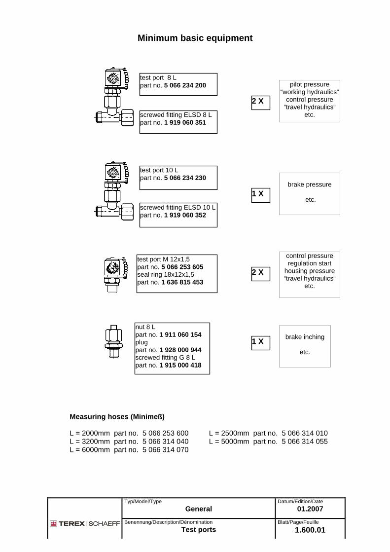
Minimum basic equipment
Measuring hoses (Minimeß) L = 2000mm part no. 5 066 253 600 L = 2500mm part no. 5 066 314 010 L = 3200mm part no. 5 066 314 040 L = 5000mm part no. 5 066 314 055 L = 6000mm part no. 5 066 314 070
Typ/Model/Type Datum/Edition/Date General 01.2007
Blatt/Page/Feuille Benennung/Description/Dénomination
1.600.01 Test ports
brake inching
etc.
control pressure regulation start
housing pressure “travel hydraulics“
etc.
brake pressure
etc.
pilot pressure “working hydraulics“
control pressure “travel hydraulics“
etc.
2 X
1 X
2 X
1 X
screwed fitting ELSD 10 Lpart no. 1 919 060 352
test port 10 L part no. 5 066 234 230
nut 8 L part no. 1 911 060 154 plug part no. 1 928 000 944 screwed fitting G 8 L part no. 1 915 000 418
test port M 12x1,5 part no. 5 066 253 605 seal ring 18x12x1,5 part no. 1 636 815 453
screwed fitting ELSD 8 L part no. 1 919 060 351
test port 8 L part no. 5 066 234 200
Typ/Model/Type Rohrbruchsicherung / Hose rupture valve
Datum/Edition/Date
01.2007
Benennung/Description/Dénomination
Spezialwerkzeug / Special tool Blatt/Page/Feuille
5.72.00
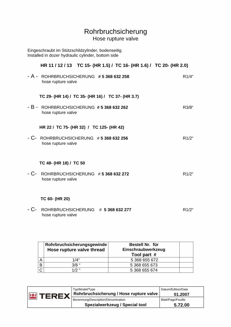
Rohrbruchsicherung Hose rupture valve
Eingeschraubt im Stützschildzylinder, bodenseitig. Installed in dozer hydraulic cylinder, bottom side HR 11 / 12 / 13 TC 15- (HR 1.5) / TC 16- (HR 1.6) / TC 20- (HR 2.0) - A - ROHRBRUCHSICHERUNG # 5 368 632 258 R1/4“ hose rupture valve TC 29- (HR 14) / TC 35- (HR 16) / TC 37- (HR 3.7) - B - ROHRBRUCHSICHERUNG # 5 368 632 262 R3/8“ hose rupture valve HR 22 / TC 75- (HR 32) / TC 125- (HR 42) - C- ROHRBRUCHSICHERUNG # 5 368 632 256 R1/2“ hose rupture valve TC 48- (HR 18) / TC 50 - C- ROHRBRUCHSICHERUNG # 5 368 632 272 R1/2“ hose rupture valve TC 60- (HR 20) - C- ROHRBRUCHSICHERUNG # 5 368 632 277 R1/2“ hose rupture valve
RohrbruchsicherungsgewindeHose rupture valve thread
Bestell Nr. für Einschraubwerkzeug
Tool part #
A 1/4“ 5 368 655 672 B 3/8 “ 5 368 655 673 C 1/2 “ 5 368 655 674
Typ/Model/Type TC 29 from s/n.: TC00290100 (HR 14)
Datum/Edition/Date
01.2008
Benennung / Description / Dénomination
Setting instruction Working pump A10VO45 DFLR
Blatt / Page / Feuille
5.76.05
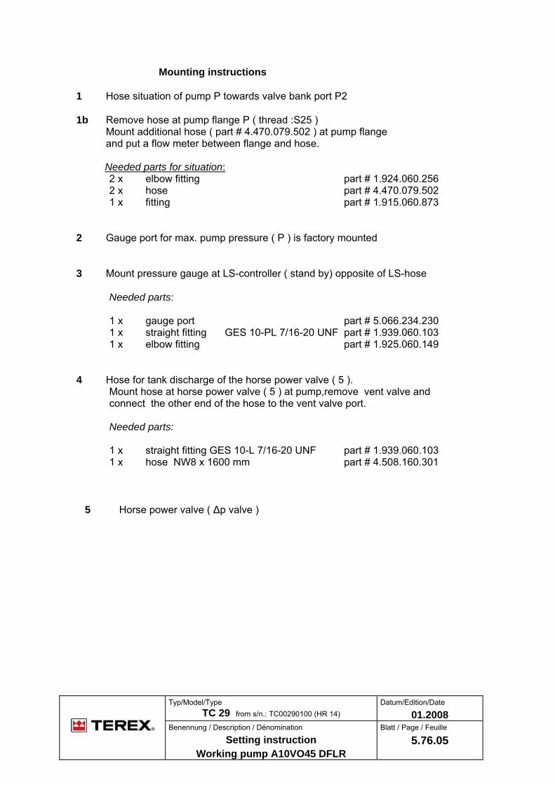
Mounting instructions
1 Hose situation of pump P towards valve bank port P2
1b Remove hose at pump flange P ( thread :S25 ) Mount additional hose ( part # 4.470.079.502 ) at pump flange and put a flow meter between flange and hose. Needed parts for situation:
2 x elbow fitting part # 1.924.060.256 2 x hose part # 4.470.079.502 1 x fitting part # 1.915.060.873
2 Gauge port for max. pump pressure ( P ) is factory mounted 3 Mount pressure gauge at LS-controller ( stand by) opposite of LS-hose
Needed parts: 1 x gauge port part # 5.066.234.230 1 x straight fitting GES 10-PL 7/16-20 UNF part # 1.939.060.103 1 x elbow fitting part # 1.925.060.149
4 Hose for tank discharge of the horse power valve ( 5 ). Mount hose at horse power valve ( 5 ) at pump,remove vent valve and connect the other end of the hose to the vent valve port. Needed parts: 1 x straight fitting GES 10-L 7/16-20 UNF part # 1.939.060.103 1 x hose NW8 x 1600 mm part # 4.508.160.301
5 Horse power valve ( Δp valve )
5.76.05/01.2008
6 LS – regulator ( stand-by ) 7 Connect additional circuit ( 7 ) right hand side of dipperstick with pressureless returnline ( 8 ) by means of a hose ( 9 )
Following parts are needed:
1 x quick coupler plug male part no. 5.000.253.100 1 x quick coupler plug female part no. 5.000.276.100 2 x fitting part no. 1.915.060.564 1 x hose part no. 4.262.110.363
10 Horsepower regulator (regulation start,regulation end ) Adjustment procedure - Machine must have service temperature (approx 50 – 60 ° C ) - Mount gauges - Check engine rpms, low and high idle and adjust if necessary Adjustment of the regulators: - Without tank discharge ( 4 ). Set LS-Controller( 6 ) to a differencial pressure ( Δp ) between P and LS to approx.25 – 28 bar while additional circuit is activated (dynamic ) - Mount tank discharge ( 4 ) Set horse power valve ( 5 ) to 20 bar ( no Δp ) while additional circuit is activated
- Without tank discharge ( 4 ) Set LS-Controller ( 6 ) now to a differencial pressure ( Δp ) between P and LS to 16,5 bar while additional circuit is activated ( dynamic )
Checking of adjustment: - Lift the machine, give full throttle and run the tracks in high speed (rabbit ) Flow: 85 liters Pressure: 90 bar
In case of too much divergences ,adjustment of regulation start and end is possible at horse power control valve ( 6 ) according characteristic curve and chart.

Tilt cabine Kit-No. 6.209.265.000
reworkdrilled hole 13mm
5 518 649 591clevis
attachment intravel direction right
5 518 660 001cable winch
view of “A”
A
B
view of “B”
6 2092 650 45safety rodincludingpin and clevis
use nut from cabin attachment+ washer A 361 343 707 063
Typ/Model/Type
TW 70 - 85 - 110 (HML) Datum/Edition/Date
01.2007
Benennung/Description/Dénomination
Tilt cabin Blatt/Page/Feuille
11.51.01
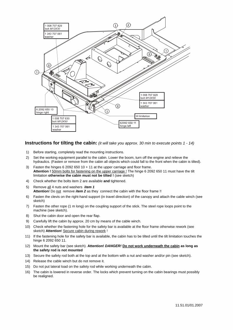
Instructions for tilting the cabin: (it will take you approx. 30 min to execute points 1 - 14) 1) Before starting, completely read the mounting instructions.
2) Set the working equipment parallel to the cabin. Lower the boom, turn off the engine and relieve the hydraulics. (Fasten or remove from the cabin all objects which could fall to the front when the cabin is tilted).
3) Fasten the hinges 6 2092 650 10 + 11 at the upper carriage and floor frame. Attention ! 50mm bolts for fastening on the upper carriage ! The hinge 6 2092 650 11 must have the tilt limitation otherwise the cabin must not be tilted ! (see sketch)
4) Check whether the bolts item 2 are available and tightened.
5) Remove all 4 nuts and washers item 1 Attention! Do not remove item 2 as they connect the cabin with the floor frame !!
6) Fasten the clevis on the right-hand support (in travel direction) of the canopy and attach the cable winch (see sketch)
7) Fasten the other rope (1 m long) on the coupling support of the stick. The steel rope loops point to the machine (see sketch).
8) Shut the cabin door and open the rear flap.
9) Carefully lift the cabin by approx. 20 cm by means of the cable winch.
10) Check whether the fastening hole for the safety bar is available at the floor frame otherwise rework (see sketch) Attention! Secure cabin during rework !
11) If the fastening hole for the safety bar is available, the cabin has to be tilted until the tilt limitation touches the hinge 6 2092 650 11.
12) Mount the safety bar (see sketch). Attention! DANGER! Do not work underneath the cabin as long as the safety rod is not mounted
13) Secure the safety rod both at the top and at the bottom with a nut and washer and/or pin (see sketch).
14) Release the cable winch but do not remove it.
15) Do not put lateral load on the safety rod while working underneath the cabin.
16) The cabin is lowered in reverse order. The locks which prevent turning on the cabin bearings must possibly be realigned.
11.51.01/01.2007
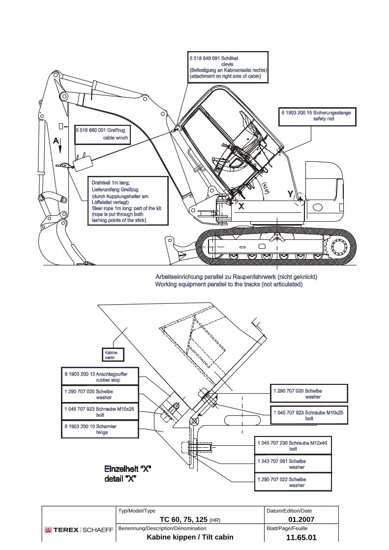
Typ/Model/Type
TC 60, 75, 125 (HR) Datum/Edition/Date
01.2007
Benennung/Description/Dénomination
Kabine kippen / Tilt cabin Blatt/Page/Feuille
11.65.01

11.65.01/01.2007
Related Documents