© 2006, Cisco Systems, Inc. All rights reserved. 14688_05_2008_c1.scr 1 © 2008 Cisco Systems, Inc. All rights reserved. Cisco Public BRKDCT-2840 14688_05_2008_c1 2 Minimizing the Risks with Enterprise Multi-Site Data Center L2 Connectivity BRKDCT-2840

Welcome message from author
This document is posted to help you gain knowledge. Please leave a comment to let me know what you think about it! Share it to your friends and learn new things together.
Transcript
© 2006, Cisco Systems, Inc. All rights reserved.14688_05_2008_c1.scr
1
© 2008 Cisco Systems, Inc. All rights reserved. Cisco PublicBRKDCT-284014688_05_2008_c1 2
Minimizing the Risks with Enterprise Multi-Site Data Center L2 Connectivity
BRKDCT-2840
© 2006, Cisco Systems, Inc. All rights reserved.14688_05_2008_c1.scr
2
© 2008 Cisco Systems, Inc. All rights reserved. Cisco Public 3BRKDCT-284014688_05_2008_c1
Goals of this Session…
Present alternatives for interconnecting multiple Data Center locations
Present tested methods in production for minimizing the risks associated with meeting these connectivity requirements.
© 2008 Cisco Systems, Inc. All rights reserved. Cisco Public 4BRKDCT-284014688_05_2008_c1
Session Agenda
Data Center Interconnection – Common Scenarios and Terms
Options for Layer 2 Interconnectivity
Recommended Designs for Optimizing Traffic Flows
EoMPLS and VPLS Stability Testing
Q & A
© 2006, Cisco Systems, Inc. All rights reserved.14688_05_2008_c1.scr
3
© 2008 Cisco Systems, Inc. All rights reserved. Cisco Public 5BRKDCT-284014688_05_2008_c1
Layer 2 / 3 ClustersUse Cases Risks Solution Types
© 2008 Cisco Systems, Inc. All rights reserved. Cisco Public 6BRKDCT-284014688_05_2008_c1
Layer 2 / 3 ClustersIntra-Cluster node communications
Flow TypesTraditionally Layer2 Communications on Private and/or Public interfacesIPv4 and/or IPv6 possible depending on clustering package usedAbility to prioritize interfaces
Client Access to ClusterDNS/Active Directory resolution by clientsShared Virtual IP for service discoveryCaching issues can inhibit Layer3 clusteringClient application can have logic to re-establish connections
Quorum considerations to avoid split-brainAdditional cluster nodes at alternate sites to achieve a majority node set (MNS)Possible extensions such as ping-groups (Linux-HA) to have a quorum mechanism without a member nodeShoot The Other Node In The Head topologies to resolve conflicts (STONITH)
Mechanisms to facilitate service restoration in another locationVMware Site Recovery Manager (SRM) is one exampleMicrosoft Server 2008 Layer 3 Clustering is anotherRemapping of service to new IP/DNS entry
© 2006, Cisco Systems, Inc. All rights reserved.14688_05_2008_c1.scr
4
© 2008 Cisco Systems, Inc. All rights reserved. Cisco Public 7BRKDCT-284014688_05_2008_c1
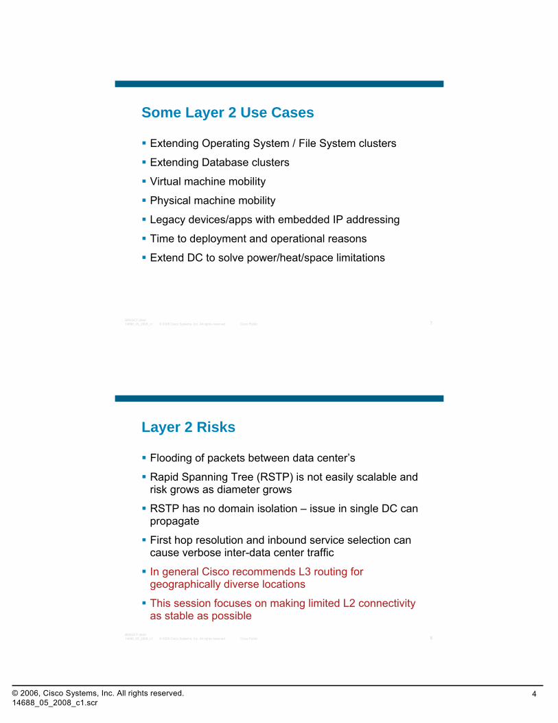
Some Layer 2 Use Cases
Extending Operating System / File System clusters
Extending Database clusters
Virtual machine mobility
Physical machine mobility
Legacy devices/apps with embedded IP addressing
Time to deployment and operational reasons
Extend DC to solve power/heat/space limitations
© 2008 Cisco Systems, Inc. All rights reserved. Cisco Public 8BRKDCT-284014688_05_2008_c1
Layer 2 Risks
Flooding of packets between data center’s
Rapid Spanning Tree (RSTP) is not easily scalable and risk grows as diameter grows
RSTP has no domain isolation – issue in single DC can propagate
First hop resolution and inbound service selection can cause verbose inter-data center traffic
In general Cisco recommends L3 routing for geographically diverse locations
This session focuses on making limited L2 connectivity as stable as possible
© 2006, Cisco Systems, Inc. All rights reserved.14688_05_2008_c1.scr
5
© 2008 Cisco Systems, Inc. All rights reserved. Cisco Public 9BRKDCT-284014688_05_2008_c1
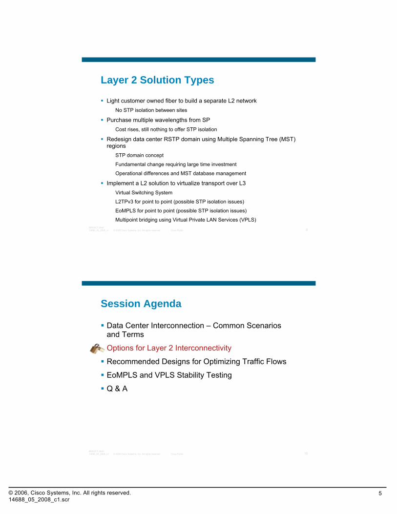
Layer 2 Solution Types
Light customer owned fiber to build a separate L2 networkNo STP isolation between sites
Purchase multiple wavelengths from SPCost rises, still nothing to offer STP isolation
Redesign data center RSTP domain using Multiple Spanning Tree (MST) regions
STP domain concept
Fundamental change requiring large time investment
Operational differences and MST database management
Implement a L2 solution to virtualize transport over L3Virtual Switching System
L2TPv3 for point to point (possible STP isolation issues)
EoMPLS for point to point (possible STP isolation issues)
Multipoint bridging using Virtual Private LAN Services (VPLS)
© 2008 Cisco Systems, Inc. All rights reserved. Cisco Public 10BRKDCT-284014688_05_2008_c1
Session Agenda
Data Center Interconnection – Common Scenarios and Terms
Options for Layer 2 Interconnectivity
Recommended Designs for Optimizing Traffic Flows
EoMPLS and VPLS Stability Testing
Q & A
© 2006, Cisco Systems, Inc. All rights reserved.14688_05_2008_c1.scr
6
© 2008 Cisco Systems, Inc. All rights reserved. Cisco Public 11BRKDCT-284014688_05_2008_c1
L2TPv3 Virtual Switching System EoMPLS VPLS
© 2008 Cisco Systems, Inc. All rights reserved. Cisco Public 12BRKDCT-284014688_05_2008_c1
Layer 2 Prerequisites For All Options
This session assumes a fairly detailed knowledge of Spanning Tree Protocol
Items we leverage in this solution:802.1w
802.1s
Port Fast
BPDU Filter
BPDU Guard
Root Guard
Loop Guard
© 2006, Cisco Systems, Inc. All rights reserved.14688_05_2008_c1.scr
7
© 2008 Cisco Systems, Inc. All rights reserved. Cisco Public 13BRKDCT-284014688_05_2008_c1
L2TP Version 3
Encapsulates Ethernet frames inside IP packets to pass layer 3 network
Layer 2 Tunneling Protocol (L2TPv3) provides routing separation from metro core devices providing connectivity – Customer Edge (CE) flapping routes wont propagate inside IP network
Point to point links between locations
Wide range of hardware support including ISR,72xx,73xx,ASR100x,76xx
IPSec securing of tunnel straightforward
Data plane rate limiting in L2 still needs protection
BPDU’s still pass between locations and STP root is same
© 2008 Cisco Systems, Inc. All rights reserved. Cisco Public 14BRKDCT-284014688_05_2008_c1
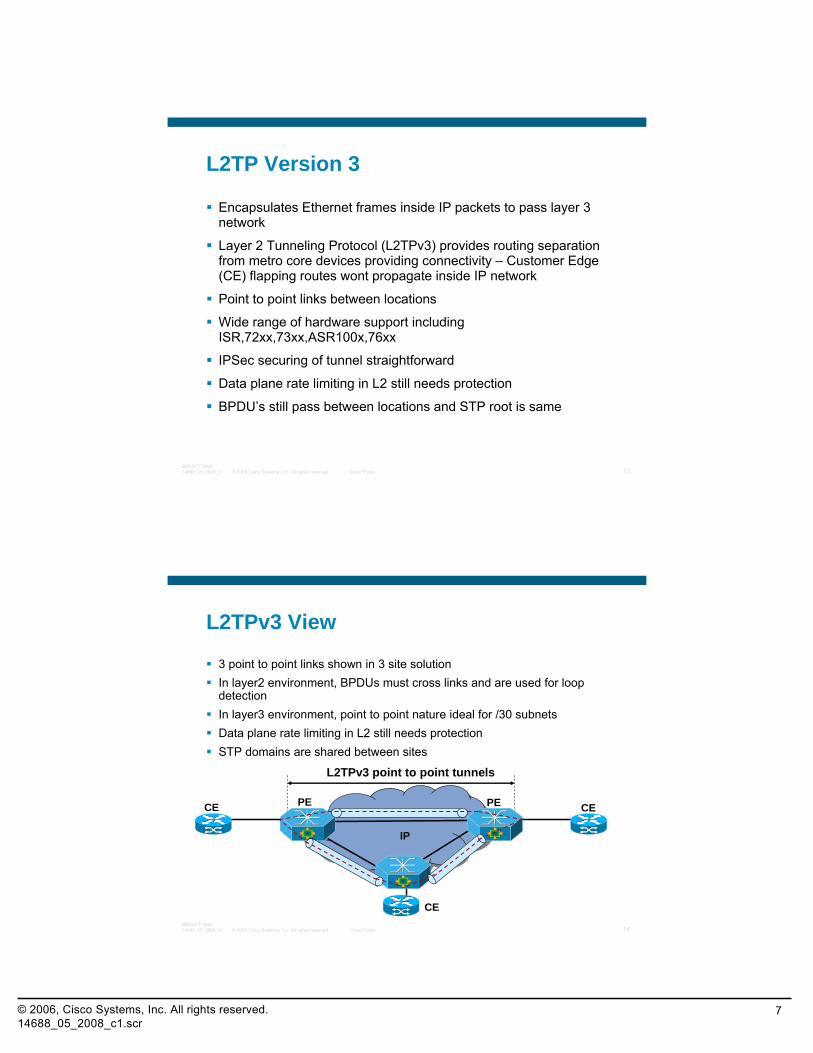
L2TPv3 View
3 point to point links shown in 3 site solution In layer2 environment, BPDUs must cross links and are used for loop detectionIn layer3 environment, point to point nature ideal for /30 subnetsData plane rate limiting in L2 still needs protectionSTP domains are shared between sites
PE PECE CE
L2TPv3 point to point tunnels
CE
IP
© 2006, Cisco Systems, Inc. All rights reserved.14688_05_2008_c1.scr
8
© 2008 Cisco Systems, Inc. All rights reserved. Cisco Public 15BRKDCT-284014688_05_2008_c1
IP CoreIP Core
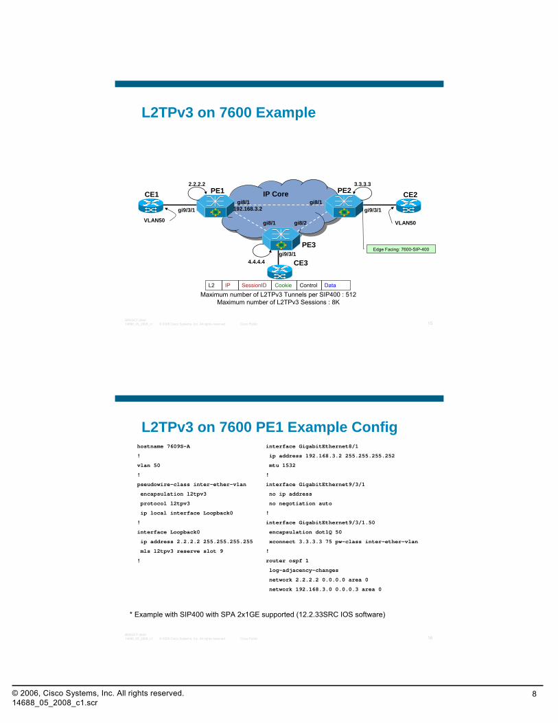
L2TPv3 on 7600 Example
PE1 PE2CE1 CE2
CE3
PE3
2.2.2.2 3.3.3.3
4.4.4.4
gi9/3/1 gi9/3/1
gi9/3/1
gi8/1 gi8/1
gi8/1 gi8/2VLAN50 VLAN50
Maximum number of L2TPv3 Tunnels per SIP400 : 512Maximum number of L2TPv3 Sessions : 8K
Edge Facing: 7600-SIP-400
DataControlCookieSessionIDL2 IP
192.168.3.2
© 2008 Cisco Systems, Inc. All rights reserved. Cisco Public 16BRKDCT-284014688_05_2008_c1
L2TPv3 on 7600 PE1 Example Confighostname 7609S-A
!
vlan 50
!
pseudowire-class inter-ether-vlan
encapsulation l2tpv3
protocol l2tpv3
ip local interface Loopback0
!
interface Loopback0
ip address 2.2.2.2 255.255.255.255
mls l2tpv3 reserve slot 9
!
interface GigabitEthernet8/1
ip address 192.168.3.2 255.255.255.252
mtu 1532
!
interface GigabitEthernet9/3/1
no ip address
no negotiation auto
!
interface GigabitEthernet9/3/1.50
encapsulation dot1Q 50
xconnect 3.3.3.3 75 pw-class inter-ether-vlan
!
router ospf 1
log-adjacency-changes
network 2.2.2.2 0.0.0.0 area 0
network 192.168.3.0 0.0.0.3 area 0
* Example with SIP400 with SPA 2x1GE supported (12.2.33SRC IOS software)
© 2006, Cisco Systems, Inc. All rights reserved.14688_05_2008_c1.scr
9
© 2008 Cisco Systems, Inc. All rights reserved. Cisco Public 17BRKDCT-284014688_05_2008_c1
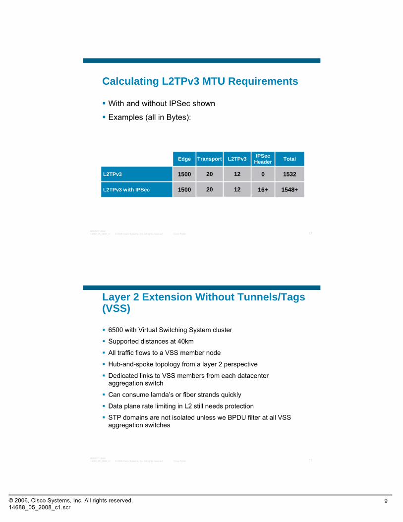
Calculating L2TPv3 MTU Requirements
With and without IPSec shown
Examples (all in Bytes):
1548+
1532
Total
16+1500L2TPv3 with IPSec
01500L2TPv3
IPSecHeaderEdge
20
20
Transport
12
12
L2TPv3
© 2008 Cisco Systems, Inc. All rights reserved. Cisco Public 18BRKDCT-284014688_05_2008_c1
Layer 2 Extension Without Tunnels/Tags (VSS)
6500 with Virtual Switching System cluster
Supported distances at 40km
All traffic flows to a VSS member node
Hub-and-spoke topology from a layer 2 perspective
Dedicated links to VSS members from each datacenter aggregation switch
Can consume lamda’s or fiber strands quickly
Data plane rate limiting in L2 still needs protection
STP domains are not isolated unless we BPDU filter at all VSS aggregation switches
© 2006, Cisco Systems, Inc. All rights reserved.14688_05_2008_c1.scr
10
© 2008 Cisco Systems, Inc. All rights reserved. Cisco Public 19BRKDCT-284014688_05_2008_c1
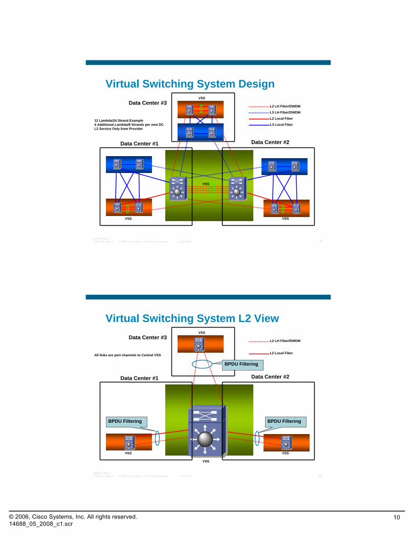
Virtual Switching System Design
VSS
VSS VSS
VSS
L2 LH Fiber/DWDM
L3 LH Fiber/DWDM
L2 Local Fiber
L3 Local Fiber12 Lambda/24 Strand Example4 Additional Lambda/8 Strands per new DCL2 Service Only from Provider
Data Center #1 Data Center #2
Data Center #3
© 2008 Cisco Systems, Inc. All rights reserved. Cisco Public 20BRKDCT-284014688_05_2008_c1
Virtual Switching System L2 View
VSS
VSS VSS
VSS
L2 LH Fiber/DWDM
L2 Local FiberAll links are port channels to Central VSS
Data Center #1 Data Center #2
Data Center #3
BPDU Filtering
BPDU FilteringBPDU Filtering
© 2006, Cisco Systems, Inc. All rights reserved.14688_05_2008_c1.scr
11
© 2008 Cisco Systems, Inc. All rights reserved. Cisco Public 21BRKDCT-284014688_05_2008_c1
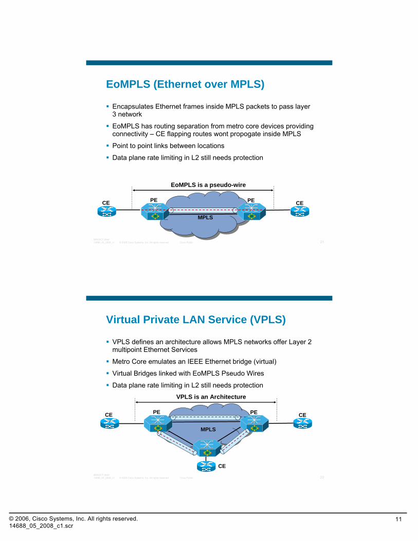
EoMPLS (Ethernet over MPLS)
Encapsulates Ethernet frames inside MPLS packets to pass layer 3 network
EoMPLS has routing separation from metro core devices providing connectivity – CE flapping routes wont propogate inside MPLS
Point to point links between locations
Data plane rate limiting in L2 still needs protection
PE PECE CE
EoMPLS is a pseudo-wire
MPLS
© 2008 Cisco Systems, Inc. All rights reserved. Cisco Public 22BRKDCT-284014688_05_2008_c1
Virtual Private LAN Service (VPLS)
VPLS defines an architecture allows MPLS networks offer Layer 2 multipoint Ethernet Services
Metro Core emulates an IEEE Ethernet bridge (virtual)
Virtual Bridges linked with EoMPLS Pseudo Wires
Data plane rate limiting in L2 still needs protection
PE PECE CE
VPLS is an Architecture
CE
MPLS
© 2006, Cisco Systems, Inc. All rights reserved.14688_05_2008_c1.scr
12
© 2008 Cisco Systems, Inc. All rights reserved. Cisco Public 23BRKDCT-284014688_05_2008_c1
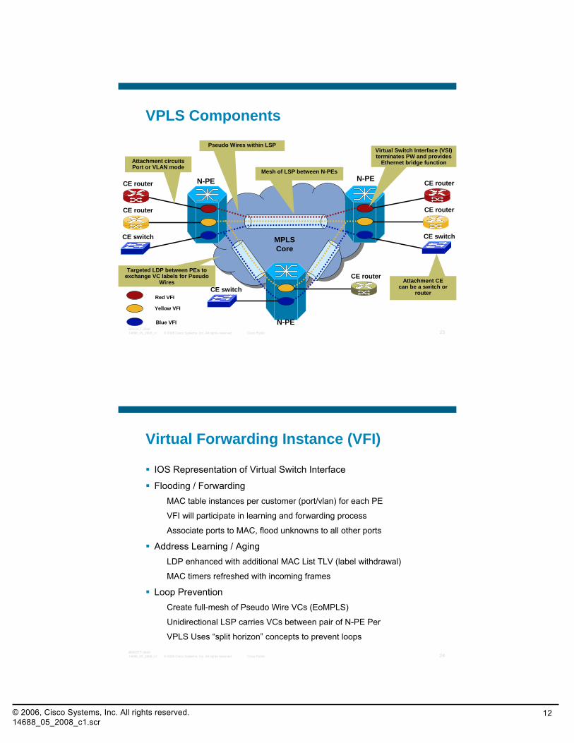
VPLS Components
N-PE
MPLS Core
CE router
CE router
CE switch
CE router
CE router
CE switch
CE switch
CE router
Attachment circuitsPort or VLAN mode
Mesh of LSP between N-PEsN-PE
N-PE
Pseudo Wires within LSPVirtual Switch Interface (VSI) terminates PW and provides
Ethernet bridge function
Targeted LDP between PEs to exchange VC labels for Pseudo
Wires Attachment CEcan be a switch or
routerRed VFI
Yellow VFI
Blue VFI
© 2008 Cisco Systems, Inc. All rights reserved. Cisco Public 24BRKDCT-284014688_05_2008_c1
Virtual Forwarding Instance (VFI)
IOS Representation of Virtual Switch Interface
Flooding / Forwarding MAC table instances per customer (port/vlan) for each PE
VFI will participate in learning and forwarding process
Associate ports to MAC, flood unknowns to all other ports
Address Learning / AgingLDP enhanced with additional MAC List TLV (label withdrawal)
MAC timers refreshed with incoming frames
Loop PreventionCreate full-mesh of Pseudo Wire VCs (EoMPLS)
Unidirectional LSP carries VCs between pair of N-PE Per
VPLS Uses “split horizon” concepts to prevent loops
© 2006, Cisco Systems, Inc. All rights reserved.14688_05_2008_c1.scr
13
© 2008 Cisco Systems, Inc. All rights reserved. Cisco Public 25BRKDCT-284014688_05_2008_c1
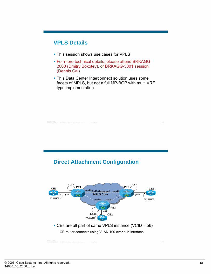
VPLS Details
This session shows use cases for VPLS
For more technical details, please attend BRKAGG-2000 (Dmitry Bokotey), or BRKAGG-3001 session (Dennis Cai)
This Data Center Interconnect solution uses some facets of MPLS, but not a full MP-BGP with multi VRF type implementation
© 2008 Cisco Systems, Inc. All rights reserved. Cisco Public 26BRKDCT-284014688_05_2008_c1
Self-ManagedMPLS Core
Self-ManagedMPLS Core
Direct Attachment Configuration
CEs are all part of same VPLS instance (VCID = 56)CE router connects using VLAN 100 over sub-interface
PE1 PE2CE1 CE2
CE2
PE3
1.1.1.1 2.2.2.2
3.3.3.3
gi3/0 gi4/4
gi4/2
pos4/1 pos4/3
pos3/0 pos3/1VLAN100
VLAN100
VLAN100
© 2006, Cisco Systems, Inc. All rights reserved.14688_05_2008_c1.scr
14
© 2008 Cisco Systems, Inc. All rights reserved. Cisco Public 27BRKDCT-284014688_05_2008_c1
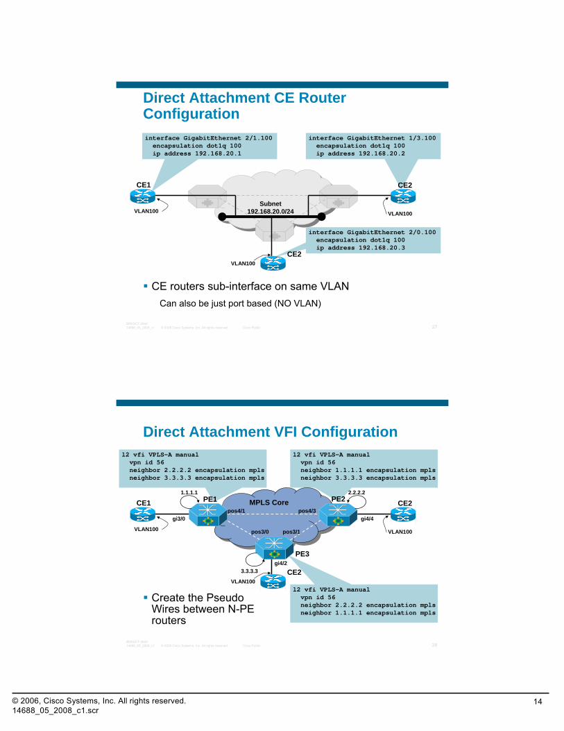
interface GigabitEthernet 1/3.100encapsulation dot1q 100ip address 192.168.20.2
interface GigabitEthernet 2/0.100encapsulation dot1q 100ip address 192.168.20.3
Direct Attachment CE Router Configuration
CE routers sub-interface on same VLANCan also be just port based (NO VLAN)
CE1 CE2
CE2
VLAN100
VLAN100
VLAN100
Subnet 192.168.20.0/24
interface GigabitEthernet 2/1.100encapsulation dot1q 100ip address 192.168.20.1
© 2008 Cisco Systems, Inc. All rights reserved. Cisco Public 28BRKDCT-284014688_05_2008_c1
l2 vfi VPLS-A manualvpn id 56neighbor 2.2.2.2 encapsulation mplsneighbor 1.1.1.1 encapsulation mpls
l2 vfi VPLS-A manualvpn id 56neighbor 1.1.1.1 encapsulation mplsneighbor 3.3.3.3 encapsulation mpls
l2 vfi VPLS-A manualvpn id 56neighbor 2.2.2.2 encapsulation mplsneighbor 3.3.3.3 encapsulation mpls
MPLS CoreMPLS Core
Direct Attachment VFI Configuration
Create the Pseudo Wires between N-PE routers
PE1 PE2CE1 CE2
CE2
PE3
1.1.1.1 2.2.2.2
3.3.3.3
gi3/0 gi4/4
gi4/2
pos4/1 pos4/3
pos3/0 pos3/1VLAN100
VLAN100
VLAN100
© 2006, Cisco Systems, Inc. All rights reserved.14688_05_2008_c1.scr
15
© 2008 Cisco Systems, Inc. All rights reserved. Cisco Public 29BRKDCT-284014688_05_2008_c1
MPLS CoreMPLS Core
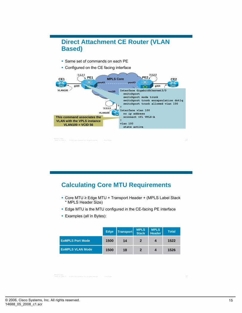
Direct Attachment CE Router (VLAN Based)
Same set of commands on each PEConfigured on the CE facing interface
PE1 PE2CE1 CE2
CE2
PE3
1.1.1.1 2.2.2.2
3.3.3.3
gi3/0 gi4/4
gi4/2
pos4/1 pos4/3
pos3/0 pos3/1VLAN100
VLAN100
VLAN100Interface GigabitEthernet3/0switchportswitchport mode trunkswitchport trunk encapsulation dot1qswitchport trunk allowed vlan 100
!Interface vlan 100no ip addressxconnect vfi VPLS-A
!vlan 100state active
This command associates the VLAN with the VPLS instance
VLAN100 = VCID 56
© 2008 Cisco Systems, Inc. All rights reserved. Cisco Public 30BRKDCT-284014688_05_2008_c1
Calculating Core MTU Requirements
Core MTU ≥ Edge MTU + Transport Header + (MPLS Label Stack * MPLS Header Size)
Edge MTU is the MTU configured in the CE-facing PE interface
Examples (all in Bytes):
1526
1522
Total
421500EoMPLS VLAN Mode
421500EoMPLS Port Mode
MPLSHeader
MPLSStackEdge
18
14
Transport
© 2006, Cisco Systems, Inc. All rights reserved.14688_05_2008_c1.scr
16
© 2008 Cisco Systems, Inc. All rights reserved. Cisco Public 31BRKDCT-284014688_05_2008_c1
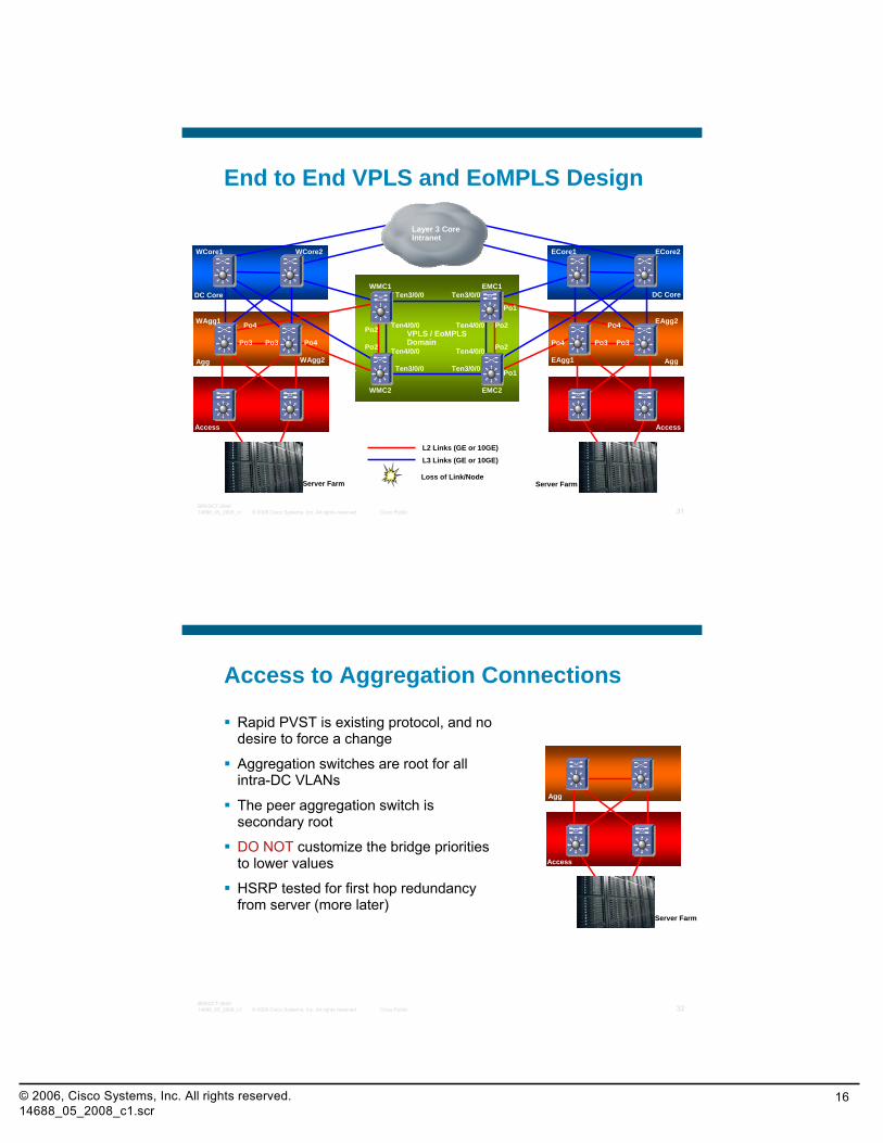
End to End VPLS and EoMPLS Design
Access Access
Agg Agg
DC Core DC Core
Layer 3 CoreIntranet
L2 Links (GE or 10GE)
L3 Links (GE or 10GE)
Server Farm Server Farm
VPLS / EoMPLSDomain
Loss of Link/Node
Ten3/0/0 Ten3/0/0
Ten3/0/0 Ten3/0/0
Ten4/0/0
Ten4/0/0
Ten4/0/0
Ten4/0/0Po2
Po2 Po2
Po2
Po1
Po1
Po1
Po1
Po3 Po3 Po3 Po3Po4
Po4
Po4
Po4WAgg1
WAgg2
WCore1 WCore2 ECore2ECore1
EAgg1
EAgg2
WMC1
WMC2
EMC1
EMC2
© 2008 Cisco Systems, Inc. All rights reserved. Cisco Public 32BRKDCT-284014688_05_2008_c1
Access to Aggregation Connections
Rapid PVST is existing protocol, and no desire to force a change
Aggregation switches are root for all intra-DC VLANs
The peer aggregation switch is secondary root
DO NOT customize the bridge priorities to lower values
HSRP tested for first hop redundancy from server (more later)
Server Farm
Agg
Access
© 2006, Cisco Systems, Inc. All rights reserved.14688_05_2008_c1.scr
17
© 2008 Cisco Systems, Inc. All rights reserved. Cisco Public 33BRKDCT-284014688_05_2008_c1
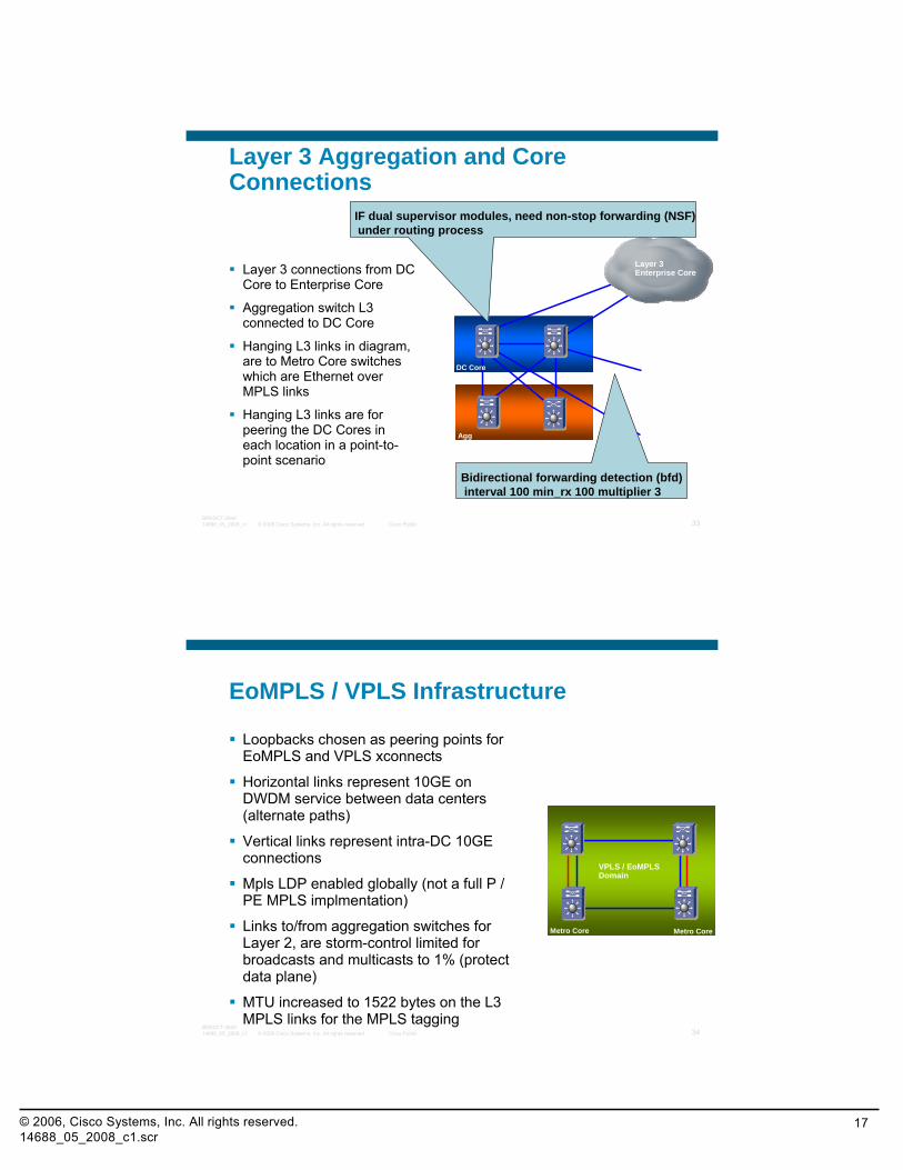
Layer 3 Aggregation and Core Connections
Layer 3 connections from DC Core to Enterprise Core
Aggregation switch L3 connected to DC Core
Hanging L3 links in diagram, are to Metro Core switches which are Ethernet over MPLS links
Hanging L3 links are for peering the DC Cores in each location in a point-to-point scenario
DC Core
Layer 3 Enterprise Core
Agg
Bidirectional forwarding detection (bfd)interval 100 min_rx 100 multiplier 3
IF dual supervisor modules, need non-stop forwarding (NSF)under routing process
© 2008 Cisco Systems, Inc. All rights reserved. Cisco Public 34BRKDCT-284014688_05_2008_c1
EoMPLS / VPLS Infrastructure
Loopbacks chosen as peering points for EoMPLS and VPLS xconnects
Horizontal links represent 10GE on DWDM service between data centers (alternate paths)
Vertical links represent intra-DC 10GE connections
Mpls LDP enabled globally (not a full P / PE MPLS implmentation)
Links to/from aggregation switches for Layer 2, are storm-control limited for broadcasts and multicasts to 1% (protect data plane)
MTU increased to 1522 bytes on the L3 MPLS links for the MPLS tagging
Metro Core Metro Core
VPLS / EoMPLSDomain
© 2006, Cisco Systems, Inc. All rights reserved.14688_05_2008_c1.scr
18
© 2008 Cisco Systems, Inc. All rights reserved. Cisco Public 35BRKDCT-284014688_05_2008_c1
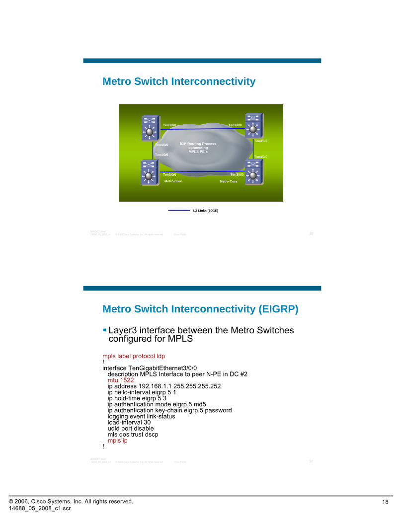
Metro Switch Interconnectivity
Metro Core Metro Core
L3 Links (10GE)
IGP Routing Process connectingMPLS PE’s
Ten3/0/0
Ten4/0/0
Ten3/0/0
Ten3/0/0Ten3/0/0
Ten4/0/0 Ten4/0/0
Ten4/0/0
© 2008 Cisco Systems, Inc. All rights reserved. Cisco Public 36BRKDCT-284014688_05_2008_c1
Metro Switch Interconnectivity (EIGRP)
Layer3 interface between the Metro Switches configured for MPLS
mpls label protocol ldp!interface TenGigabitEthernet3/0/0
description MPLS Interface to peer N-PE in DC #2mtu 1522ip address 192.168.1.1 255.255.255.252ip hello-interval eigrp 5 1ip hold-time eigrp 5 3ip authentication mode eigrp 5 md5ip authentication key-chain eigrp 5 passwordlogging event link-statusload-interval 30udld port disablemls qos trust dscpmpls ip
!
© 2006, Cisco Systems, Inc. All rights reserved.14688_05_2008_c1.scr
19
© 2008 Cisco Systems, Inc. All rights reserved. Cisco Public 37BRKDCT-284014688_05_2008_c1
Metro Switch Interconnectivity (EIGRP) (Cont.)
!interface TenGigabitEthernet4/0/0
description MPLS Interface to local peer N-PEmtu 1522ip address 192.168.1.9 255.255.255.252ip hello-interval eigrp 5 1ip hold-time eigrp 5 3ip authentication mode eigrp 5 md5ip authentication key-chain eigrp 5 passwordlogging event link-statusload-interval 30udld port disablemls qos trust dscpmpls ip
© 2008 Cisco Systems, Inc. All rights reserved. Cisco Public 38BRKDCT-284014688_05_2008_c1
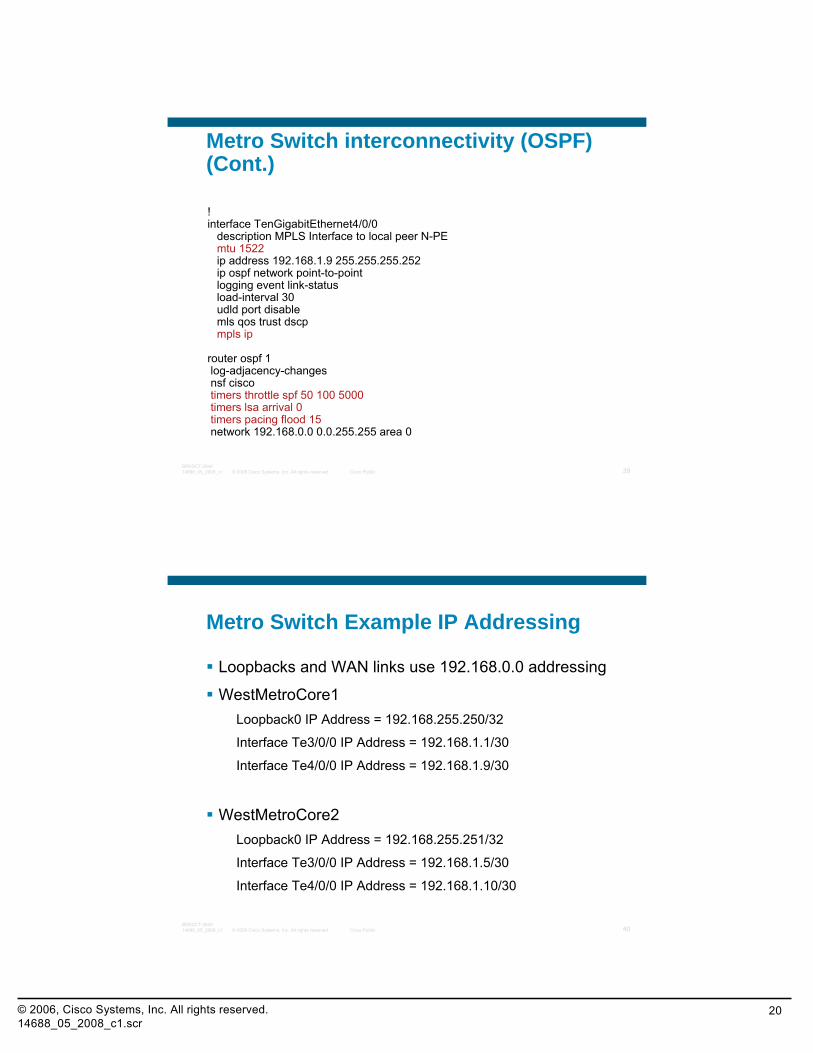
Metro Switch interconnectivity (OSPF)
!interface TenGigabitEthernet3/0/0description MPLS Interface to peer N-PE in DC #2
mtu 1522ip address 192.168.1.1 255.255.255.252ip ospf network point-to-point logging event link-statusload-interval 30udld port disablemls qos trust dscpmpls ip
router ospf 1log-adjacency-changesnsf ciscotimers throttle spf 50 100 5000timers lsa arrival 0timers pacing flood 15network 192.168.0.0 0.0.255.255 area 0
© 2006, Cisco Systems, Inc. All rights reserved.14688_05_2008_c1.scr
20
© 2008 Cisco Systems, Inc. All rights reserved. Cisco Public 39BRKDCT-284014688_05_2008_c1
Metro Switch interconnectivity (OSPF) (Cont.)
!interface TenGigabitEthernet4/0/0
description MPLS Interface to local peer N-PEmtu 1522ip address 192.168.1.9 255.255.255.252ip ospf network point-to-pointlogging event link-statusload-interval 30udld port disablemls qos trust dscpmpls ip
router ospf 1log-adjacency-changesnsf ciscotimers throttle spf 50 100 5000timers lsa arrival 0timers pacing flood 15network 192.168.0.0 0.0.255.255 area 0
© 2008 Cisco Systems, Inc. All rights reserved. Cisco Public 40BRKDCT-284014688_05_2008_c1
Metro Switch Example IP Addressing
Loopbacks and WAN links use 192.168.0.0 addressing
WestMetroCore1Loopback0 IP Address = 192.168.255.250/32
Interface Te3/0/0 IP Address = 192.168.1.1/30
Interface Te4/0/0 IP Address = 192.168.1.9/30
WestMetroCore2Loopback0 IP Address = 192.168.255.251/32
Interface Te3/0/0 IP Address = 192.168.1.5/30
Interface Te4/0/0 IP Address = 192.168.1.10/30
© 2006, Cisco Systems, Inc. All rights reserved.14688_05_2008_c1.scr
21
© 2008 Cisco Systems, Inc. All rights reserved. Cisco Public 41BRKDCT-284014688_05_2008_c1
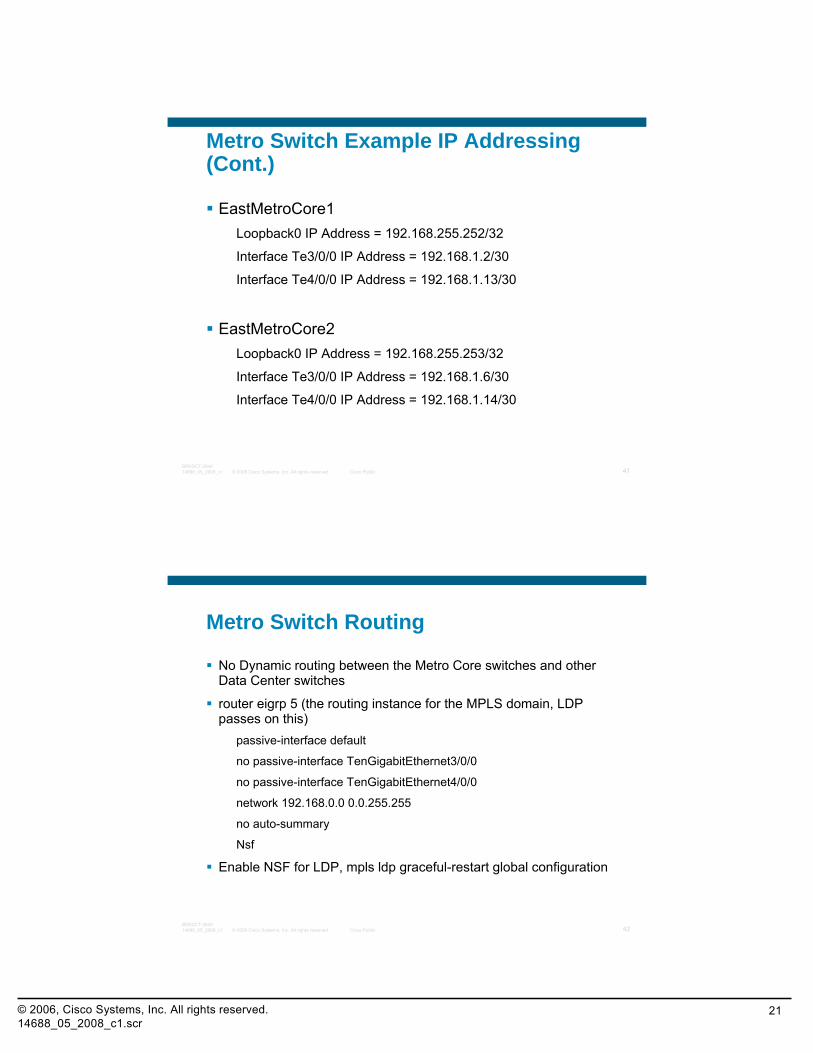
Metro Switch Example IP Addressing (Cont.)
EastMetroCore1Loopback0 IP Address = 192.168.255.252/32
Interface Te3/0/0 IP Address = 192.168.1.2/30
Interface Te4/0/0 IP Address = 192.168.1.13/30
EastMetroCore2Loopback0 IP Address = 192.168.255.253/32
Interface Te3/0/0 IP Address = 192.168.1.6/30
Interface Te4/0/0 IP Address = 192.168.1.14/30
© 2008 Cisco Systems, Inc. All rights reserved. Cisco Public 42BRKDCT-284014688_05_2008_c1
Metro Switch Routing
No Dynamic routing between the Metro Core switches and other Data Center switches
router eigrp 5 (the routing instance for the MPLS domain, LDP passes on this)
passive-interface default
no passive-interface TenGigabitEthernet3/0/0
no passive-interface TenGigabitEthernet4/0/0
network 192.168.0.0 0.0.255.255
no auto-summary
Nsf
Enable NSF for LDP, mpls ldp graceful-restart global configuration
© 2006, Cisco Systems, Inc. All rights reserved.14688_05_2008_c1.scr
22
© 2008 Cisco Systems, Inc. All rights reserved. Cisco Public 43BRKDCT-284014688_05_2008_c1
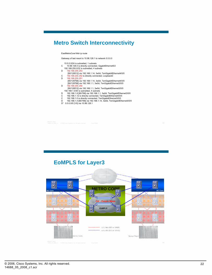
Metro Switch InterconnectivityEastMetroCore1#sh ip route
Gateway of last resort is 10.98.128.1 to network 0.0.0.0
10.0.0.0/24 is subnetted, 1 subnetsC 10.98.128.0 is directly connected, GigabitEthernet5/2
192.168.255.0/32 is subnetted, 4 subnetsD 192.168.255.253
[90/128512] via 192.168.1.14, 3w0d, TenGigabitEthernet4/0/0C 192.168.255.252 is directly connected, Loopback0D 192.168.255.251
[90/128768] via 192.168.1.14, 3w0d, TenGigabitEthernet4/0/0[90/128768] via 192.168.1.1, 3w0d, TenGigabitEthernet3/0/0
D 192.168.255.250[90/128512] via 192.168.1.1, 3w0d, TenGigabitEthernet3/0/0
192.168.1.0/30 is subnetted, 4 subnetsD 192.168.1.8 [90/768] via 192.168.1.1, 3w0d, TenGigabitEthernet3/0/0C 192.168.1.12 is directly connected, TenGigabitEthernet4/0/0C 192.168.1.0 is directly connected, TenGigabitEthernet3/0/0D 192.168.1.4 [90/768] via 192.168.1.14, 3w0d, TenGigabitEthernet4/0/0S* 0.0.0.0/0 [1/0] via 10.98.128.1
© 2008 Cisco Systems, Inc. All rights reserved. Cisco Public 44BRKDCT-284014688_05_2008_c1
EoMPLS for Layer3
Access Access
Agg Agg
Metro Core Metro Core
Layer 3 CoreIntranet
L2 Links (GE or 10GE)
L3 Links (GE or 10GE)
Server Farm Server Farm
DC Core DC Core
EoMPLS
METRO CORE
PW – Pseudo Wires

© 2006, Cisco Systems, Inc. All rights reserved.14688_05_2008_c1.scr
23
© 2008 Cisco Systems, Inc. All rights reserved. Cisco Public 45BRKDCT-284014688_05_2008_c1
EoMPLS for Layer3 Configuration
EastMetroCore1!interface Loopback0description Loopback interface for PW peeringip address 192.168.255.252 255.255.255.255!interface GigabitEthernet1/1description EASTCORE:9/1 - WESTCORE:1/1xconnect 192.168.255.250 250252 encapsulation mpls!interface GigabitEthernet2/1description EASTCORE:8/1 - WESTCORE:1/2xconnect 192.168.255.250 252250 encapsulation mpls
© 2008 Cisco Systems, Inc. All rights reserved. Cisco Public 46BRKDCT-284014688_05_2008_c1
EoMPLS for Layer3 Configuration (Cont.)
WestMetroCore1!interface Loopback0description Loopback interface for PW peeringip address 192.168.255.250 255.255.255.255!interface GigabitEthernet1/1description WESTCORE:1/1 - EASTCORE:9/1xconnect 192.168.255.252 250252 encapsulation mpls!interface GigabitEthernet2/1description WESTCORE:1/2 - EASTCORE:8/1xconnect 192.168.255.252 252250 encapsulation mpls
© 2006, Cisco Systems, Inc. All rights reserved.14688_05_2008_c1.scr
24
© 2008 Cisco Systems, Inc. All rights reserved. Cisco Public 47BRKDCT-284014688_05_2008_c1
DC Core DC Core
VPLS for Layer2
Access Access
Metro Core Metro Core
Layer 3 CoreIntranet
L2 Links (GE or 10GE)
L3 Links (GE or 10GE)
Server Farm Server Farm
Agg Agg
Metro Core
METRO CORE
PW – Pseudo Wires
VFI
© 2008 Cisco Systems, Inc. All rights reserved. Cisco Public 48BRKDCT-284014688_05_2008_c1
DC Core DC Core
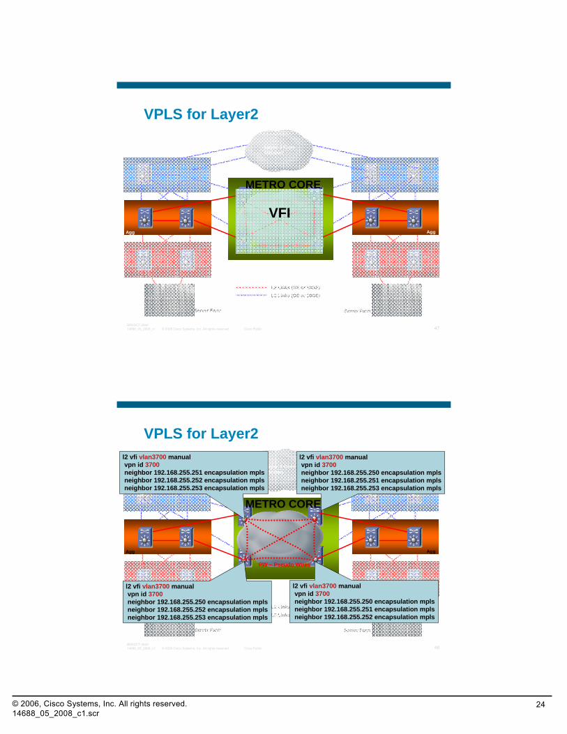
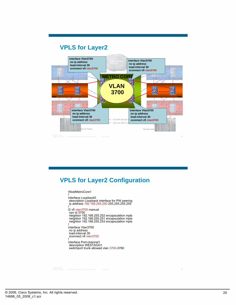
VPLS for Layer2
Access Access
Metro Core Metro Core
Layer 3 CoreIntranet
L2 Links (GE or 10GE)
L3 Links (GE or 10GE)
Server Farm Server Farm
Agg Agg
Metro Core
METRO CORE
PW – Pseudo Wires
l2 vfi vlan3700 manualvpn id 3700neighbor 192.168.255.251 encapsulation mplsneighbor 192.168.255.252 encapsulation mplsneighbor 192.168.255.253 encapsulation mpls
l2 vfi vlan3700 manualvpn id 3700neighbor 192.168.255.250 encapsulation mplsneighbor 192.168.255.251 encapsulation mplsneighbor 192.168.255.253 encapsulation mpls
l2 vfi vlan3700 manualvpn id 3700neighbor 192.168.255.250 encapsulation mplsneighbor 192.168.255.252 encapsulation mplsneighbor 192.168.255.253 encapsulation mpls
l2 vfi vlan3700 manualvpn id 3700neighbor 192.168.255.250 encapsulation mplsneighbor 192.168.255.251 encapsulation mplsneighbor 192.168.255.252 encapsulation mpls
© 2006, Cisco Systems, Inc. All rights reserved.14688_05_2008_c1.scr
25
© 2008 Cisco Systems, Inc. All rights reserved. Cisco Public 49BRKDCT-284014688_05_2008_c1
DC Core DC Core
VPLS for Layer2
Access Access
Metro Core Metro Core
Layer 3 CoreIntranet
L2 Links (GE or 10GE)
L3 Links (GE or 10GE)
Server Farm Server Farm
Agg Agg
Metro Core
METRO CORE
PW – Pseudo Wires
interface Vlan3700no ip addressload-interval 30xconnect vfi vlan3700
interface Vlan3700no ip addressload-interval 30xconnect vfi vlan3700
interface Vlan3700no ip addressload-interval 30xconnect vfi vlan3700
interface Vlan3700no ip addressload-interval 30xconnect vfi vlan3700
VLAN3700
© 2008 Cisco Systems, Inc. All rights reserved. Cisco Public 50BRKDCT-284014688_05_2008_c1
VPLS for Layer2 ConfigurationWestMetroCore1!interface Loopback0description Loopback interface for PW peeringip address 192.168.255.250 255.255.255.255
!l2 vfi vlan3700 manualvpn id 3700neighbor 192.168.255.252 encapsulation mplsneighbor 192.168.255.251 encapsulation mplsneighbor 192.168.255.253 encapsulation mpls
!interface Vlan3700no ip addressload-interval 30xconnect vfi vlan3700
!interface Port-channel1description WESTAGG1switchport trunk allowed vlan 3700-3760
© 2006, Cisco Systems, Inc. All rights reserved.14688_05_2008_c1.scr
26
© 2008 Cisco Systems, Inc. All rights reserved. Cisco Public 51BRKDCT-284014688_05_2008_c1
Spanning Tree
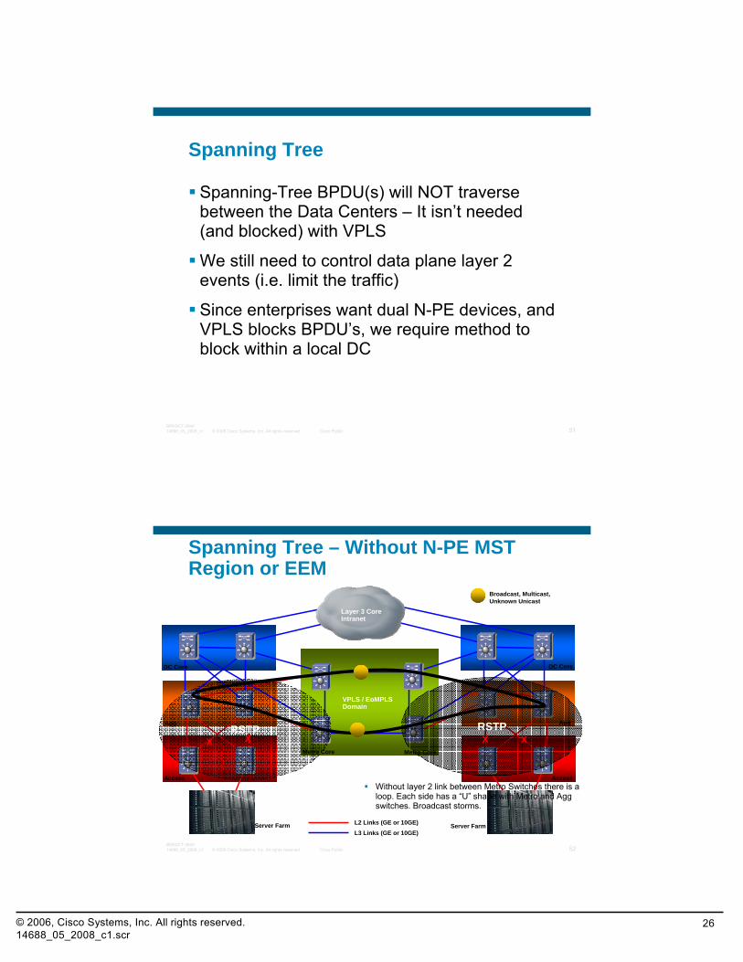
Spanning-Tree BPDU(s) will NOT traverse between the Data Centers – It isn’t needed (and blocked) with VPLS
We still need to control data plane layer 2 events (i.e. limit the traffic)
Since enterprises want dual N-PE devices, and VPLS blocks BPDU’s, we require method to block within a local DC
© 2008 Cisco Systems, Inc. All rights reserved. Cisco Public 52BRKDCT-284014688_05_2008_c1
Access
Agg
DC Core
Server Farm
Spanning Tree – Without N-PE MST Region or EEM
Access
Agg
DC Core
Metro Core Metro Core
L2 Links (GE or 10GE)L3 Links (GE or 10GE)
Server Farm
VPLS / EoMPLSDomain
RSTP RSTP
Without layer 2 link between Metro Switches there is a loop. Each side has a “U” shape with Metro and Aggswitches. Broadcast storms.
X X XX
Layer 3 CoreIntranet
Broadcast, Multicast,Unknown Unicast
© 2006, Cisco Systems, Inc. All rights reserved.14688_05_2008_c1.scr
27
© 2008 Cisco Systems, Inc. All rights reserved. Cisco Public 53BRKDCT-284014688_05_2008_c1
Access
Agg
DC Core
Server Farm
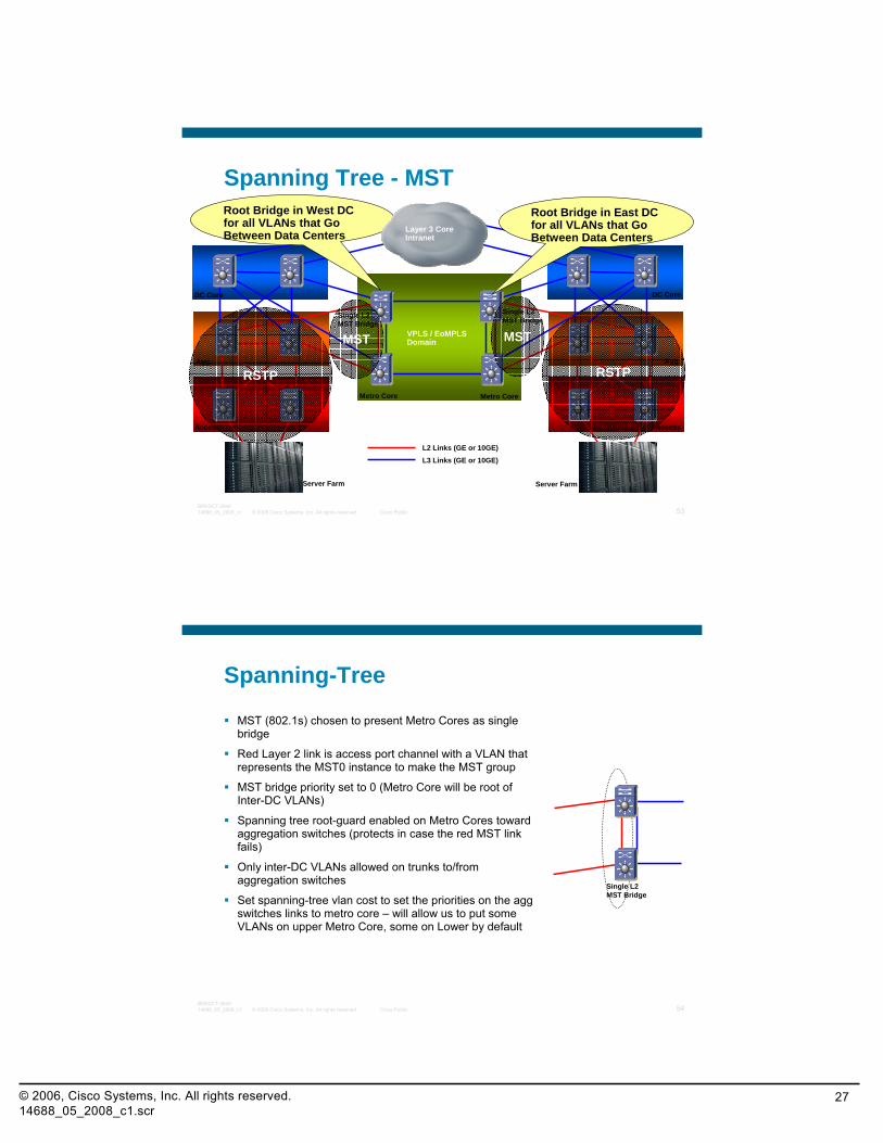
Spanning Tree - MST
Access
Agg
DC Core
Metro Core Metro Core
L2 Links (GE or 10GE)
L3 Links (GE or 10GE)
Server Farm
VPLS / EoMPLSDomain
RSTP RSTP
MST MST
Single L2MST Bridge
Single L2MST Bridge
Root Bridge in West DC for all VLANs that Go Between Data Centers
Root Bridge in East DC for all VLANs that Go Between Data Centers
Layer 3 CoreIntranet
© 2008 Cisco Systems, Inc. All rights reserved. Cisco Public 54BRKDCT-284014688_05_2008_c1
Spanning-Tree
MST (802.1s) chosen to present Metro Cores as single bridge
Red Layer 2 link is access port channel with a VLAN that represents the MST0 instance to make the MST group
MST bridge priority set to 0 (Metro Core will be root of Inter-DC VLANs)
Spanning tree root-guard enabled on Metro Cores toward aggregation switches (protects in case the red MST link fails)
Only inter-DC VLANs allowed on trunks to/from aggregation switches
Set spanning-tree vlan cost to set the priorities on the aggswitches links to metro core – will allow us to put some VLANs on upper Metro Core, some on Lower by default
Single L2MST Bridge
© 2006, Cisco Systems, Inc. All rights reserved.14688_05_2008_c1.scr
28
© 2008 Cisco Systems, Inc. All rights reserved. Cisco Public 55BRKDCT-284014688_05_2008_c1
Access
Agg
DC Core
Server Farm
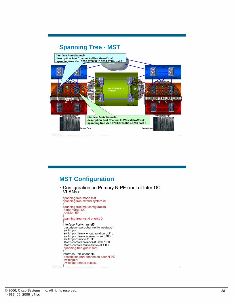
Spanning Tree - MST
Access
Agg
DC Core
Metro Core Metro Core
Layer 3 CoreIntranet
Server Farm
VPLS / EoMPLSDomain
RSTP RSTP
MST MST
Single L2MST Bridge
Single L2MST Bridge
X XX X
X X
X X
X
XX
X
interface Port-channel4description Port Channel to WestMetroCore2spanning-tree vlan 3700,3704,3712,3716 cost 8
interface Port-channel4description Port Channel to WestMetroCore1spanning-tree vlan 3702,3706,3710,3714,3718 cost 8
© 2008 Cisco Systems, Inc. All rights reserved. Cisco Public 56BRKDCT-284014688_05_2008_c1
MST ConfigurationConfiguration on Primary N-PE (root of Inter-DC VLANs):spanning-tree mode mstspanning-tree extend system-id!spanning-tree mst configurationname WESTDCrevision 50
!spanning-tree mst 0 priority 0!interface Port-channel5description port-channel to westagg1switchportswitchport trunk encapsulation dot1qswitchport trunk allowed vlan 3700switchport mode trunkstorm-control broadcast level 1.00storm-control multicast level 1.00spanning-tree guard root
!interface Port-channel6description port-channel to peer N-PEswitchportswitchport mode access
!
© 2006, Cisco Systems, Inc. All rights reserved.14688_05_2008_c1.scr
29
© 2008 Cisco Systems, Inc. All rights reserved. Cisco Public 57BRKDCT-284014688_05_2008_c1
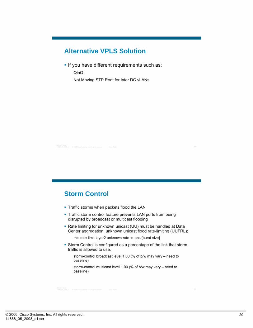
Alternative VPLS Solution
If you have different requirements such as:QinQ
Not Moving STP Root for Inter DC vLANs
© 2008 Cisco Systems, Inc. All rights reserved. Cisco Public 58BRKDCT-284014688_05_2008_c1
Storm Control
Traffic storms when packets flood the LAN
Traffic storm control feature prevents LAN ports from being disrupted by broadcast or multicast flooding
Rate limiting for unknown unicast (UU) must be handled at Data Center aggregation; unknown unicast flood rate-limiting (UUFRL):
mls rate-limit layer2 unknown rate-in-pps [burst-size]
Storm Control is configured as a percentage of the link that storm traffic is allowed to use.
storm-control broadcast level 1.00 (% of b/w may vary – need to baseline)
storm-control multicast level 1.00 (% of b/w may vary – need to baseline)
© 2006, Cisco Systems, Inc. All rights reserved.14688_05_2008_c1.scr
30
© 2008 Cisco Systems, Inc. All rights reserved. Cisco Public 59BRKDCT-284014688_05_2008_c1
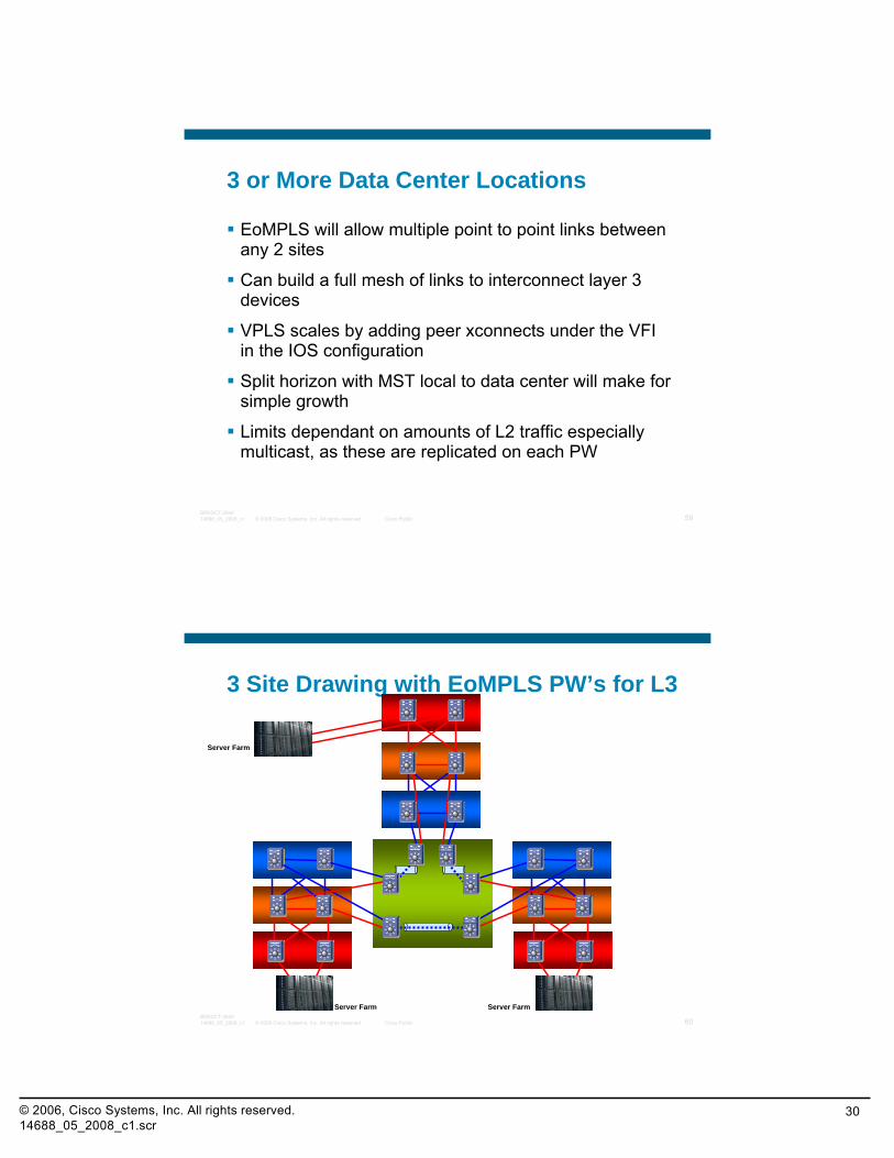
3 or More Data Center Locations
EoMPLS will allow multiple point to point links between any 2 sites
Can build a full mesh of links to interconnect layer 3 devices
VPLS scales by adding peer xconnects under the VFI in the IOS configuration
Split horizon with MST local to data center will make for simple growth
Limits dependant on amounts of L2 traffic especially multicast, as these are replicated on each PW
© 2008 Cisco Systems, Inc. All rights reserved. Cisco Public 60BRKDCT-284014688_05_2008_c1
3 Site Drawing with EoMPLS PW’s for L3
Server Farm Server Farm
Server Farm
© 2006, Cisco Systems, Inc. All rights reserved.14688_05_2008_c1.scr
31
© 2008 Cisco Systems, Inc. All rights reserved. Cisco Public 61BRKDCT-284014688_05_2008_c1
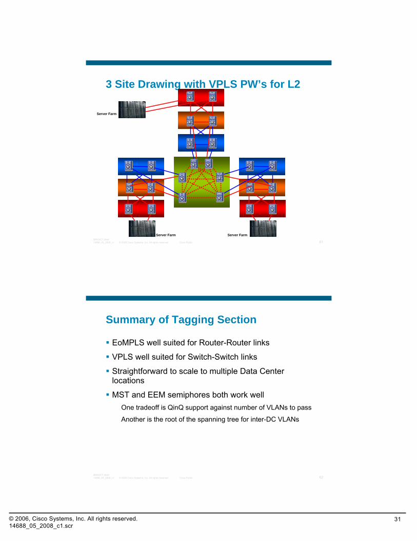
3 Site Drawing with VPLS PW’s for L2
Server Farm Server Farm
Server Farm
© 2008 Cisco Systems, Inc. All rights reserved. Cisco Public 62BRKDCT-284014688_05_2008_c1
Summary of Tagging Section
EoMPLS well suited for Router-Router links
VPLS well suited for Switch-Switch links
Straightforward to scale to multiple Data Center locations
MST and EEM semiphores both work wellOne tradeoff is QinQ support against number of VLANs to pass
Another is the root of the spanning tree for inter-DC VLANs
© 2006, Cisco Systems, Inc. All rights reserved.14688_05_2008_c1.scr
32
© 2008 Cisco Systems, Inc. All rights reserved. Cisco Public 63BRKDCT-284014688_05_2008_c1
Session Agenda
Data Center Interconnection – Common Scenarios and Terms
Options for Layer 2 Interconnectivity
Recommended Designs for Optimizing Traffic Flows
EoMPLS and VPLS Stability Testing
Q & A
© 2008 Cisco Systems, Inc. All rights reserved. Cisco Public 64BRKDCT-284014688_05_2008_c1
Flow Optimization and SymmetrySite Selection and Inbound FlowsFirst Hop Outbound Intra/Inter Site FailoverVMware DRS Case
© 2006, Cisco Systems, Inc. All rights reserved.14688_05_2008_c1.scr
33
© 2008 Cisco Systems, Inc. All rights reserved. Cisco Public 65BRKDCT-284014688_05_2008_c1
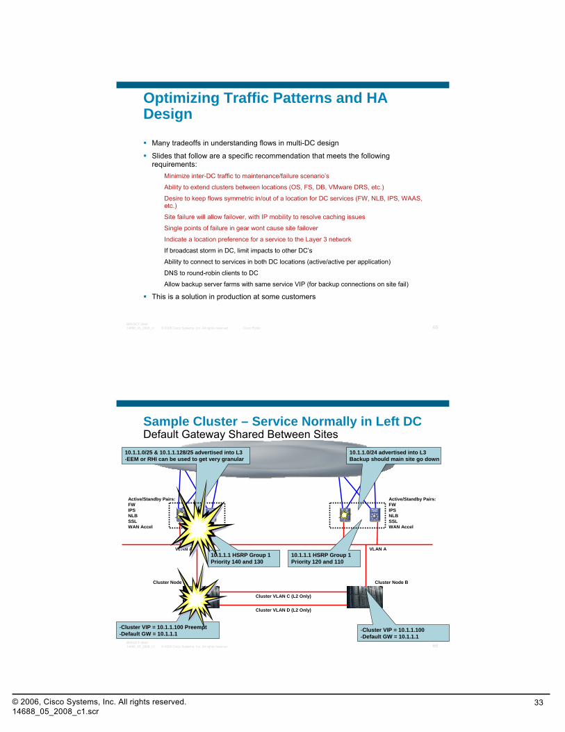
Optimizing Traffic Patterns and HA Design
Many tradeoffs in understanding flows in multi-DC design
Slides that follow are a specific recommendation that meets the following requirements:
Minimize inter-DC traffic to maintenance/failure scenario’s
Ability to extend clusters between locations (OS, FS, DB, VMware DRS, etc.)
Desire to keep flows symmetric in/out of a location for DC services (FW, NLB, IPS, WAAS, etc.)
Site failure will allow failover, with IP mobility to resolve caching issues
Single points of failure in gear wont cause site failover
Indicate a location preference for a service to the Layer 3 network
If broadcast storm in DC, limit impacts to other DC’s
Ability to connect to services in both DC locations (active/active per application)
DNS to round-robin clients to DC
Allow backup server farms with same service VIP (for backup connections on site fail)
This is a solution in production at some customers
© 2008 Cisco Systems, Inc. All rights reserved. Cisco Public 66BRKDCT-284014688_05_2008_c1
Cluster Node A
Layer3 Core
Cluster Node B
VLAN A VLAN A
Cluster VLAN D (L2 Only)
10.1.1.1 HSRP Group 1Priority 140 and 130
10.1.1.1 HSRP Group 1Priority 120 and 110
Sample Cluster – Service Normally in Left DCDefault Gateway Shared Between Sites
Cluster VLAN C (L2 Only)
-Cluster VIP = 10.1.1.100-Default GW = 10.1.1.1
-Cluster VIP = 10.1.1.100 Preempt-Default GW = 10.1.1.1
10.1.1.0/24 advertised into L3Backup should main site go down
10.1.1.0/25 & 10.1.1.128/25 advertised into L3-EEM or RHI can be used to get very granular
Active/Standby Pairs:FWIPSNLBSSLWAN Accel
Active/Standby Pairs:FWIPSNLBSSLWAN Accel
© 2006, Cisco Systems, Inc. All rights reserved.14688_05_2008_c1.scr
34
© 2008 Cisco Systems, Inc. All rights reserved. Cisco Public 67BRKDCT-284014688_05_2008_c1
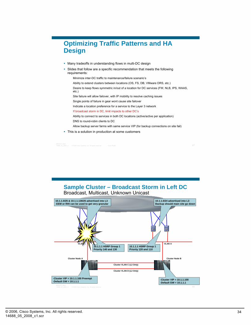
Optimizing Traffic Patterns and HA Design
Many tradeoffs in understanding flows in multi-DC design
Slides that follow are a specific recommendation that meets the following requirements:
Minimize inter-DC traffic to maintenance/failure scenario’s
Ability to extend clusters between locations (OS, FS, DB, VMware DRS, etc.)
Desire to keep flows symmetric in/out of a location for DC services (FW, NLB, IPS, WAAS, etc.)
Site failure will allow failover, with IP mobility to resolve caching issues
Single points of failure in gear wont cause site failover
Indicate a location preference for a service to the Layer 3 network
If broadcast storm in DC, limit impacts to other DC’s
Ability to connect to services in both DC locations (active/active per application)
DNS to round-robin clients to DC
Allow backup server farms with same service VIP (for backup connections on site fail)
This is a solution in production at some customers
© 2008 Cisco Systems, Inc. All rights reserved. Cisco Public 68BRKDCT-284014688_05_2008_c1
Cluster Node A
Layer3 Core
Cluster Node B
VLAN A VLAN A
Cluster VLAN D (L2 Only)
10.1.1.1 HSRP Group 1Priority 140 and 130
10.1.1.1 HSRP Group 1Priority 120 and 110
Sample Cluster – Broadcast Storm in Left DCBroadcast, Multicast, Unknown Unicast
Cluster VLAN C (L2 Only)
-Cluster VIP = 10.1.1.100-Default GW = 10.1.1.1
-Cluster VIP = 10.1.1.100 Preempt-Default GW = 10.1.1.1
10.1.1.0/25 & 10.1.1.128/25 advertised into L3-EEM or RHI can be used to get very granular
10.1.1.0/24 advertised into L3Backup should main site go down
© 2006, Cisco Systems, Inc. All rights reserved.14688_05_2008_c1.scr
35
© 2008 Cisco Systems, Inc. All rights reserved. Cisco Public 69BRKDCT-284014688_05_2008_c1
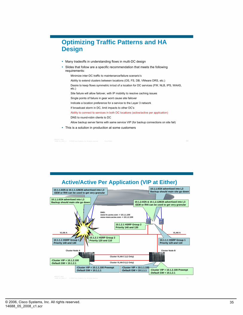
Optimizing Traffic Patterns and HA Design
Many tradeoffs in understanding flows in multi-DC design
Slides that follow are a specific recommendation that meets the following requirements:
Minimize inter-DC traffic to maintenance/failure scenario’s
Ability to extend clusters between locations (OS, FS, DB, VMware DRS, etc.)
Desire to keep flows symmetric in/out of a location for DC services (FW, NLB, IPS, WAAS, etc.)
Site failure will allow failover, with IP mobility to resolve caching issues
Single points of failure in gear wont cause site failover
Indicate a location preference for a service to the Layer 3 network
If broadcast storm in DC, limit impacts to other DC’s
Ability to connect to services in both DC locations (active/active per application)
DNS to round-robin clients to DC
Allow backup server farms with same service VIP (for backup connections on site fail)
This is a solution in production at some customers
© 2008 Cisco Systems, Inc. All rights reserved. Cisco Public 70BRKDCT-284014688_05_2008_c1
Cluster Node A
Layer3 Core
Cluster Node B
VLAN A VLAN A
Cluster VLAN D (L2 Only)
10.1.1.1 HSRP Group 1Priority 140 and 130
10.1.1.1 HSRP Group 1Priority 120 and 110
Active/Active Per Application (VIP at Either)
Cluster VLAN C (L2 Only)
-Cluster VIP = 10.1.1.100-Default GW = 10.1.1.1
-Cluster VIP = 10.1.1.100 Preempt-Default GW = 10.1.1.1
10.1.1.0/25 & 10.1.1.128/25 advertised into L3-EEM or RHI can be used to get very granular
10.1.1.0/24 advertised into L3Backup should main site go down
10.1.2.0/25 & 10.1.2.128/25 advertised into L3-EEM or RHI can be used to get very granular
10.1.1.0/24 advertised into L3Backup should main site go down
10.1.2.1 HSRP Group 2Priority 140 and 130
10.1.2.1 HSRP Group 2Priority 120 and 110
-Cluster VIP = 10.1.2.100 Preempt-Default GW = 10.1.2.1
-Cluster VIP = 10.1.2.100-Default GW = 10.1.2.1
DNS:www-hr.acme.com -> 10.1.1.100www-news.acme.com -> 10.1.2.100
© 2006, Cisco Systems, Inc. All rights reserved.14688_05_2008_c1.scr
36
© 2008 Cisco Systems, Inc. All rights reserved. Cisco Public 71BRKDCT-284014688_05_2008_c1
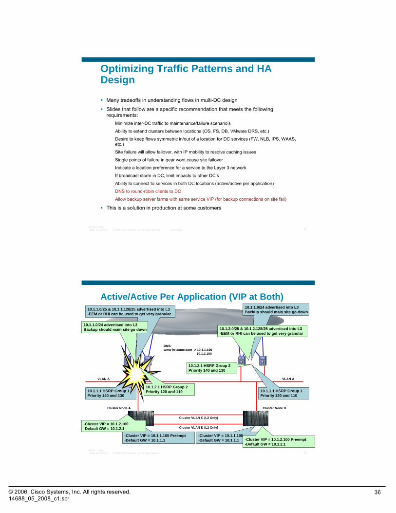
Optimizing Traffic Patterns and HA Design
Many tradeoffs in understanding flows in multi-DC design
Slides that follow are a specific recommendation that meets the following requirements:
Minimize inter-DC traffic to maintenance/failure scenario’s
Ability to extend clusters between locations (OS, FS, DB, VMware DRS, etc.)
Desire to keep flows symmetric in/out of a location for DC services (FW, NLB, IPS, WAAS, etc.)
Site failure will allow failover, with IP mobility to resolve caching issues
Single points of failure in gear wont cause site failover
Indicate a location preference for a service to the Layer 3 network
If broadcast storm in DC, limit impacts to other DC’s
Ability to connect to services in both DC locations (active/active per application)
DNS to round-robin clients to DC
Allow backup server farms with same service VIP (for backup connections on site fail)
This is a solution in production at some customers
© 2008 Cisco Systems, Inc. All rights reserved. Cisco Public 72BRKDCT-284014688_05_2008_c1
Cluster Node A
Layer3 Core
Cluster Node B
VLAN A VLAN A
Cluster VLAN D (L2 Only)
10.1.1.1 HSRP Group 1Priority 140 and 130
10.1.1.1 HSRP Group 1Priority 120 and 110
Active/Active Per Application (VIP at Both)
Cluster VLAN C (L2 Only)
-Cluster VIP = 10.1.1.100-Default GW = 10.1.1.1
-Cluster VIP = 10.1.1.100 Preempt-Default GW = 10.1.1.1
10.1.1.0/25 & 10.1.1.128/25 advertised into L3-EEM or RHI can be used to get very granular
10.1.1.0/24 advertised into L3Backup should main site go down
10.1.2.0/25 & 10.1.2.128/25 advertised into L3-EEM or RHI can be used to get very granular
10.1.1.0/24 advertised into L3Backup should main site go down
10.1.2.1 HSRP Group 2Priority 140 and 130
10.1.2.1 HSRP Group 2Priority 120 and 110
-Cluster VIP = 10.1.2.100 Preempt-Default GW = 10.1.2.1
-Cluster VIP = 10.1.2.100-Default GW = 10.1.2.1
DNS:www-hr.acme.com -> 10.1.1.100
10.1.2.100
© 2006, Cisco Systems, Inc. All rights reserved.14688_05_2008_c1.scr
37
© 2008 Cisco Systems, Inc. All rights reserved. Cisco Public 73BRKDCT-284014688_05_2008_c1
Session Agenda
Data Center Interconnection – Common Scenarios and Terms
Options for Layer 2 Interconnectivity
Recommended Designs for Optimizing Traffic Flows
EoMPLS and VPLS Stability Testing
Q & A
© 2008 Cisco Systems, Inc. All rights reserved. Cisco Public 74BRKDCT-284014688_05_2008_c1
CPOC Tested Failover Numbers
© 2006, Cisco Systems, Inc. All rights reserved.14688_05_2008_c1.scr
38
© 2008 Cisco Systems, Inc. All rights reserved. Cisco Public 75BRKDCT-284014688_05_2008_c1
EoMPLS and VPLS Stability Testing
Testing of link outage scenariosPulling fiber connections
Administratively shutting down interfaces
Pulling active cards and supervisors
Testing of failure and fail-back timing
Tests grouped by location in the networkMetro Core failures
Aggregation failures
Layer 3 Core failures
© 2008 Cisco Systems, Inc. All rights reserved. Cisco Public 76BRKDCT-284014688_05_2008_c1
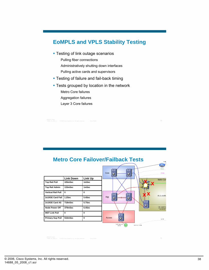
Metro Core Failover/Failback Tests
x1mSec105mSecTop Rail PullLink UpLink Down
1mSec133mSecTop Rail Admin
5.4Sec1.2Sec2x10GE Card Fail
5.7Sec718mSec2x10GE Card AS
6.4Sec379mSecNode Power Off
00MST Link Pull
xx00Vertical Rail Pull
0516mSecPrimary Sup Pull
x
© 2006, Cisco Systems, Inc. All rights reserved.14688_05_2008_c1.scr
39
© 2008 Cisco Systems, Inc. All rights reserved. Cisco Public 77BRKDCT-284014688_05_2008_c1
Embedded Event Manager
Scripting based on events
Script initiator is a tracking of node reachability
Bring up interfaces in a known order
Allow traffic flows based on a time delay
© 2008 Cisco Systems, Inc. All rights reserved. Cisco Public 78BRKDCT-284014688_05_2008_c1
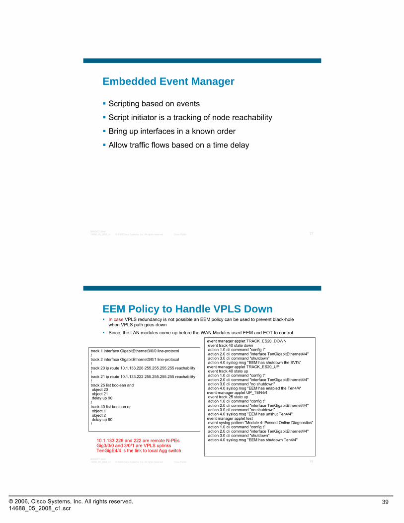
EEM Policy to Handle VPLS DownIn case VPLS redundancy is not possible an EEM policy can be used to prevent black-hole when VPLS path goes down
Since, the LAN modules come-up before the WAN Modules used EEM and EOT to control
track 1 interface GigabitEthernet3/0/0 line-protocol!track 2 interface GigabitEthernet3/0/1 line-protocol!track 20 ip route 10.1.133.226 255.255.255.255 reachability!track 21 ip route 10.1.133.222 255.255.255.255 reachability!track 25 list boolean andobject 20object 21delay up 90
!track 40 list boolean orobject 1object 2delay up 90
!
event manager applet TRACK_ES20_DOWN event track 40 state downaction 1.0 cli command "config t"action 2.0 cli command "interface TenGigabitEthernet4/4"action 3.0 cli command "shutdown"action 4.0 syslog msg "EEM has shutdown the SVI's"
event manager applet TRACK_ES20_UP event track 40 state upaction 1.0 cli command "config t"action 2.0 cli command "interface TenGigabitEthernet4/4"action 3.0 cli command "no shutdown"action 4.0 syslog msg "EEM has enabled the Ten4/4"
event manager applet UP_TEN4/4 event track 25 state upaction 1.0 cli command "config t"action 2.0 cli command "interface TenGigabitEthernet4/4"action 3.0 cli command "no shutdown"action 4.0 syslog msg "EEM has unshut Ten4/4"
event manager applet test event syslog pattern "Module 4: Passed Online Diagnostics"action 1.0 cli command "config t"action 2.0 cli command "interface TenGigabitEthernet4/4"action 3.0 cli command "shutdown"action 4.0 syslog msg "EEM has shutdown Ten4/4"10.1.133.226 and 222 are remote N-PEs
Gig3/0/0 and 3/0/1 are VPLS uplinksTenGigE4/4 is the link to local Agg switch
© 2006, Cisco Systems, Inc. All rights reserved.14688_05_2008_c1.scr
40
© 2008 Cisco Systems, Inc. All rights reserved. Cisco Public 79BRKDCT-284014688_05_2008_c1
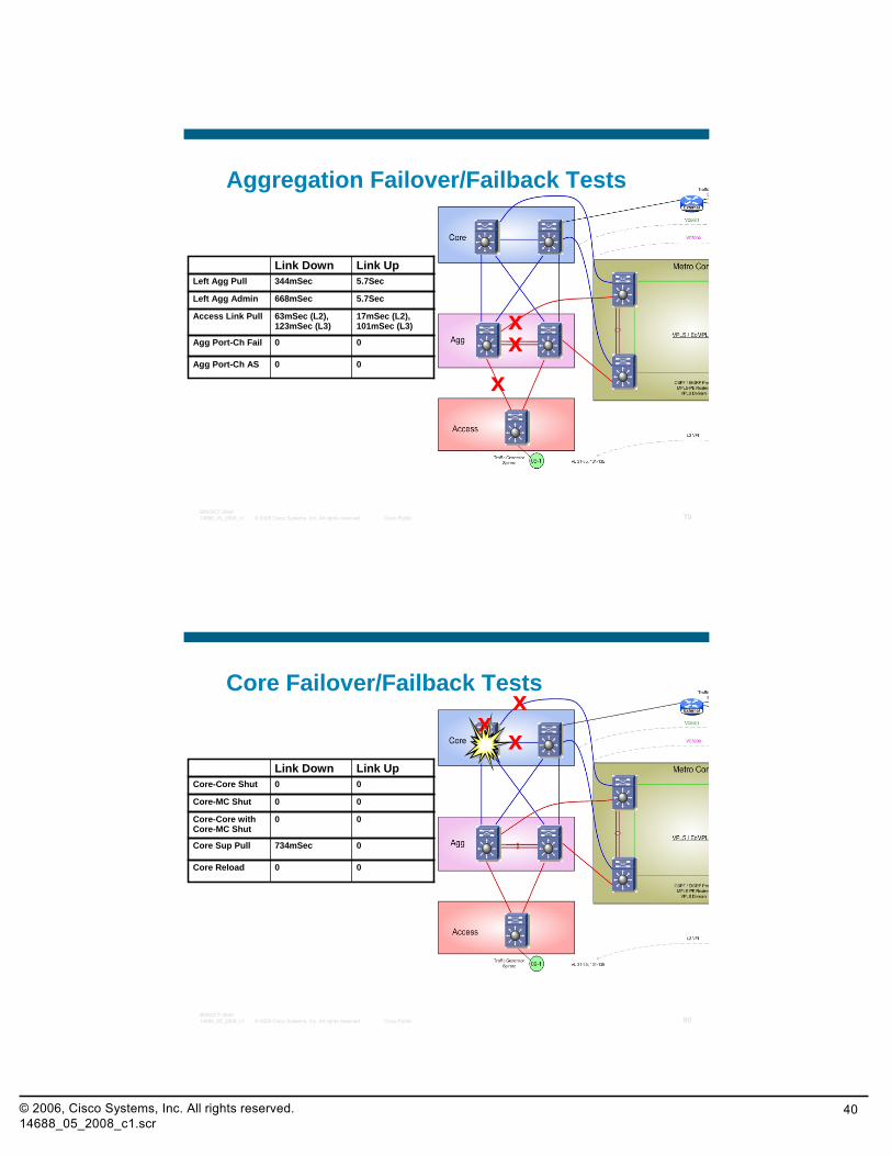
Aggregation Failover/Failback Tests
x
5.7Sec344mSecLeft Agg PullLink UpLink Down
5.7Sec668mSecLeft Agg Admin
00Agg Port-Ch Fail
00Agg Port-Ch AS
xx
17mSec (L2), 101mSec (L3)
63mSec (L2), 123mSec (L3)
Access Link Pull
© 2008 Cisco Systems, Inc. All rights reserved. Cisco Public 80BRKDCT-284014688_05_2008_c1
Core Failover/Failback Tests
x00Core-Core ShutLink UpLink Down
00Core-MC Shut
0734mSecCore Sup Pull
00Core Reload
xx
00Core-Core with Core-MC Shut
© 2006, Cisco Systems, Inc. All rights reserved.14688_05_2008_c1.scr
41
© 2008 Cisco Systems, Inc. All rights reserved. Cisco Public 81BRKDCT-284014688_05_2008_c1
Q and A
© 2008 Cisco Systems, Inc. All rights reserved. Cisco Public 82BRKDCT-284014688_05_2008_c1
Recommendations
Recommended Reading:MPLS and VPN Architectures, Volume II by Jim Guichard
Network Virtualization by Victor Moreno
Check the Recommended Reading flyer for suggested books
Related technology breakouts:BRKAGG-2000 Implementation and utilization of Layer 2 VPN technologies
TECAGG-2003 Layer 2 Virtual Private Networks – Converged IP/MPLS Network
NSITE is compiling test results for both the MST N-PE and EEM Solution
Available Onsite at the Cisco Company Store
© 2006, Cisco Systems, Inc. All rights reserved.14688_05_2008_c1.scr
42
© 2008 Cisco Systems, Inc. All rights reserved. Cisco Public 83BRKDCT-284014688_05_2008_c1
Complete Your Online Session Evaluation
Give us your feedback and you could win fabulous prizes. Winners announced daily.
Receive 20 Passport points for each session evaluation you complete.
Complete your session evaluation online now (open a browser through our wireless network to access our portal) or visit one of the Internet stations throughout the Convention Center.
Don’t forget to activate your Cisco Live virtual account for access to all session material on-demand and return for our live virtual event in October 2008.
Go to the Collaboration Zone in World of Solutions or visit www.cisco-live.com.
© 2008 Cisco Systems, Inc. All rights reserved. Cisco Public 84BRKDCT-284014688_05_2008_c1
Related Documents


![05 Deploy MPLS VPLS - start [APNIC TRAINING WIKI]Virtual Private LAN Service (VPLS) •VPLS defines an architecture allows MPLS networks offer Layer 2 multipoint Ethernet Services](https://static.cupdf.com/doc/110x72/5e593ce2fc6ae762cb390254/05-deploy-mpls-vpls-start-apnic-training-wiki-virtual-private-lan-service-vpls.jpg)