Minimal Placement of Bank Selection Instructions for Partitioned Memory Architectures BERNHARD SCHOLZ The University of Sydney and BERND BURGSTALLER Yonsei University and JINGLING XUE University of New South Wales We have devised an algorithm for minimal placement of bank selections in partitioned memory ar- chitectures. This algorithm is parameterizable for a chosen metric such as speed, space or energy. Bank switching is a technique that increases the code and data memory in microcontrollers with- out extending the address buses. Given a program in which variables have been assigned to data banks, we present a novel optimization technique that minimizes the overhead of bank switching through cost-effective placement of bank selection instructions. The placement is controlled by a number of different objectives, such as runtime, low power, small code size or a combination of these parameters. We have formulated the minimal placement of bank selection instructions as a discrete optimization problem that is mapped to a Partitioned Boolean Quadratic Programming (PBQP) problem. We implemented the optimization as part of a PIC Microchip backend and eval- uated the approach for several optimization objectives. Our benchmark suite comprises programs from MiBench and DSPStone plus a microcontroller real-time kernel and drivers for microcon- troller hardware devices. Our optimization achieved a reduction in program memory space of between 2.7% and 18.2%, and an overall improvement with respect to instruction cycles between 5.0% and 28.8%. Our optimization achieved the minimal solution for all benchmark programs. We investigated the scalability of our approach towards the requirements of future generations of microcontrollers. This study was conducted as a worst-case analysis on the entire MiBench suite. Our results show that our optimization (1) scales well to larger numbers of memory banks, (2) scales well to the larger problem sizes that will become feasible with future microcontrollers, and (3) achieves minimal placement for more than 72% of all functions from MiBench. Categories and Subject Descriptors: D.3.4 [Programming Languages]: Processors—Compilers ; Optimization This project has been supported by the ARC Discovery Project Grant “Compilation Techniques for Embedded Systems” (DP 0560190) and the University of Sydney R&D Grants Scheme “Spec- ulative Partial Redundancy Elimination” (L2849 U3229). Authors’ addresses: Bernhard Scholz, School of Information Technologies, The University of Syd- ney, Sydney, NSW 2006, Australia; email: [email protected]; Bernd Burgstaller, Department of Computer Science, Yonsei University, Seoul, Korea; Jingling Xue, School of Computer Sci- ence and Engineering, University of New South Wales, Sydney, NSW 2052, Australia; email: [email protected]. Permission to make digital/hard copy of all or part of this material without fee for personal or classroom use provided that the copies are not made or distributed for profit or commercial advantage, the ACM copyright/server notice, the title of the publication, and its date appear, and notice is given that copying is by permission of the ACM, Inc. To copy otherwise, to republish, to post on servers, or to redistribute to lists requires prior specific permission and/or a fee. c 20YY ACM 0000-0000/20YY/0000-0001 $5.00 ACM Journal Name, Vol. V, No. N, Month 20YY, Pages 1–32.

Welcome message from author
This document is posted to help you gain knowledge. Please leave a comment to let me know what you think about it! Share it to your friends and learn new things together.
Transcript

Minimal Placement of Bank Selection Instructions
for Partitioned Memory Architectures
BERNHARD SCHOLZ
The University of Sydney
and
BERND BURGSTALLER
Yonsei University
and
JINGLING XUE
University of New South Wales
We have devised an algorithm for minimal placement of bank selections in partitioned memory ar-chitectures. This algorithm is parameterizable for a chosen metric such as speed, space or energy.Bank switching is a technique that increases the code and data memory in microcontrollers with-out extending the address buses. Given a program in which variables have been assigned to databanks, we present a novel optimization technique that minimizes the overhead of bank switchingthrough cost-effective placement of bank selection instructions. The placement is controlled by anumber of different objectives, such as runtime, low power, small code size or a combination ofthese parameters. We have formulated the minimal placement of bank selection instructions as adiscrete optimization problem that is mapped to a Partitioned Boolean Quadratic Programming(PBQP) problem. We implemented the optimization as part of a PIC Microchip backend and eval-uated the approach for several optimization objectives. Our benchmark suite comprises programsfrom MiBench and DSPStone plus a microcontroller real-time kernel and drivers for microcon-troller hardware devices. Our optimization achieved a reduction in program memory space ofbetween 2.7% and 18.2%, and an overall improvement with respect to instruction cycles between5.0% and 28.8%. Our optimization achieved the minimal solution for all benchmark programs.We investigated the scalability of our approach towards the requirements of future generationsof microcontrollers. This study was conducted as a worst-case analysis on the entire MiBenchsuite. Our results show that our optimization (1) scales well to larger numbers of memory banks,(2) scales well to the larger problem sizes that will become feasible with future microcontrollers,and (3) achieves minimal placement for more than 72% of all functions from MiBench.
Categories and Subject Descriptors: D.3.4 [Programming Languages]: Processors—Compilers;Optimization
This project has been supported by the ARC Discovery Project Grant “Compilation Techniquesfor Embedded Systems” (DP 0560190) and the University of Sydney R&D Grants Scheme “Spec-ulative Partial Redundancy Elimination” (L2849 U3229).Authors’ addresses: Bernhard Scholz, School of Information Technologies, The University of Syd-
ney, Sydney, NSW 2006, Australia; email: [email protected]; Bernd Burgstaller, Departmentof Computer Science, Yonsei University, Seoul, Korea; Jingling Xue, School of Computer Sci-ence and Engineering, University of New South Wales, Sydney, NSW 2052, Australia; email:[email protected] to make digital/hard copy of all or part of this material without fee for personalor classroom use provided that the copies are not made or distributed for profit or commercialadvantage, the ACM copyright/server notice, the title of the publication, and its date appear, andnotice is given that copying is by permission of the ACM, Inc. To copy otherwise, to republish,to post on servers, or to redistribute to lists requires prior specific permission and/or a fee.c© 20YY ACM 0000-0000/20YY/0000-0001 $5.00
ACM Journal Name, Vol. V, No. N, Month 20YY, Pages 1–32.

2 · Bernhard Scholz et al.
General Terms: Algorithms, Languages, Performance
Additional Key Words and Phrases: Partitioned Boolean Quadratic Programming, Bank Selec-tion, Partitioned Memory Architectures
1. INTRODUCTION
Embedded systems have become an integral part of the infrastructure of today’stechnological society. They are prevalent in an ever-increasing range of applications,including consumer electronics, home appliances, instrumentation/measurement,automotive, communications and industrial control. Microcontrollers constitutethe core of all embedded systems designs. The Semiconductor Industry Associ-ation’s November 2005 forecast predicted the market for 4-, 8-, 16-, and 32-bitmicrocontrollers to grow to $12.8 billion in 2006. The reported share of 8-bit mi-crocontrollers is 42%. Gartner Dataquest reports that the 8-bit market reached$5.5 billion in 2004 [Gartner Dataquest 2005].
The widespread use of 8-bit microcontrollers can be attributed to the following:(1) many embedded systems designs do not need the more costly, energy-burningand complex 16- or 32bit CPUs, (2) many embedded systems designs distributesmall numbers of low-cost electronics instead of using one powerful and expensivecore CPU, (3) embedded systems designs often employ 8-bit microcontrollers aslow-cost subsystems of complex 32-bit hardware designs, and (4) there is a trendto add entry-level electronics intelligence to mechanics-based systems.
Bank switching is a common technique used for 8-bit microcontrollers whichincreases the size of code and data memory without extending the address buses ofthe CPU. The address space is partitioned into memory banks, and the CPU canonly access one bank at a time. This bank is called the active bank. To keep trackof the active bank the CPU’s bank register stores the address of the active bank. Abank selection instruction is issued to switch between banks. Smaller address busesresult in smaller chip die-sizes, higher clock frequencies and less power consumption.As an example, Motorola 68HC11 8-bit microcontrollers address a maximum of64KB memory using their 16-bit address registers. This scheme allows multiple64KB banks to be accessed although only one can be active at a time. As anotherexample, the memory of the PIC 16F877A microcontroller is partitioned into fourbanks of 128B each. Other processor families have similar features such as Zilog’sZ80 and Intel’s 8051 processor families. Architectures such as Ubicom’s 8-bit SXmicrocontroller organize their registers in register banks to shorten the cycle time,avoiding multi-porting [Nystrom and Eichenberger 1998; Ravindran et al. 2005;Kiyohara et al. 1993]. Bank-switched SRAMs are employed with ultra-low powersensors to achieve high code-density [Nazhandali et al. 2005] and allow the gatingof individual memory banks [Hempstead et al. 2005; Hempstead et al. 2006].
The disadvantage of bank-switched architectures is the code-size and runtimeoverhead caused by bank selection instructions. Currently compilers provide limitedsupport to generate bank-switched code. For example, GNU GCC for Motorola’s68HC11 and 68HC12 will compile a function declared with the far attribute byusing a calling convention that takes care of switching banks when entering and
ACM Journal Name, Vol. V, No. N, Month 20YY.

Minimal Placement of Bank Selection Instructions for Partitioned Memory Architectures · 3
leaving a function. However, the GCC compiler does not eliminate redundantbank selection instructions. The CC5X compiler for mid-range PICmicro devices(from B Knudsen Data) expects the programmer to allocate variables to banks butwill insert bank selection instructions automatically with no guarantee of optimalplacement of the bank selection instructions. The PICC-18 for the PIC18Fxxxfamily appears to have automated both tasks under certain language restrictions.As far as the authors are aware, the bank switching schemes of existing compilersare ad hoc, and it remains a challenging research problem to generate efficientmemory accesses for bank-switched architectures.
This work develops a compiler optimization for minimal placement of bank se-lection instructions in a bank-switched architecture. This problem is importantbecause poor placement of bank selection instructions increases runtime, code-size,and power consumption. Given a program in which all variables have been assignedto banks (by the programmer or compiler), we present an optimization that insertsthe minimum number of bank selection instructions in the program to guarantee thecorrect access to memory. The placement is controlled by a number of objectivessuch as runtime, low power, small code size or a combination of these parameters.We are only aware of an ad-hoc approach in this area [Kiyohara et al. 1993]. Aswe will explain in Section 3, the problem cannot be solved as a speculative partialredundancy elimination problem [Scholz et al. 2004; Knoop et al. 1994]. It can beseen as an extended code motion. However, bank selections impose dependencieswhich cannot be handled with classical code motion.
Most previous efforts on partitioned memory architectures focus on maximizingparallel data accesses to make memory banks simultaneously active [Cho et al.2004; Leupers and Kotte 2001; Panda et al. 2001; Panda et al. 2000; Saghir et al.1996; Sudarsanam and Malik 1995; Zhuang et al. 2002; Zhuge et al. 2002]. Byenabling parallel memory accesses in a single instruction, one can increase mem-ory bandwidth and thus improve program performance. Such partitioned memorybanks are found in Motorola’s DSP56000, Analog Devices’ ADSP2016x and NEC’sµPD77016. Some researchers re-organize the order of instructions and the layout ofdata, e.g., by loop transformations [Delaluz et al. 2000], to reduce energy consump-tion in partitioned memory architectures. In the case of heterogeneous memorybanks such as scratchpad SRAM, internal DRAM and external DRAM, we referto [Banakar et al. 2002; Li et al. 2005; Udayakumaran and Barua 2003; Verma et al.2004] and the references therein for a number of compiler techniques proposed toperform automatic scratchpad management.
The contributions of this paper are as follows:
—We present a novel algorithmic approach to minimize the number of bank selec-tion instructions in a partitioned memory architecture for a given cost metric.
—We formulate the problem as a form of Partitioned Boolean Quadratic Program-ming (PBQP). We present experimental evidence that PBQP is very efficient forreal-world applications.
—We introduce an intra- and inter-procedural approach for placing bank selectioninstructions.
—We present our worst-case feasibility study using MiBench to show that ourproblem formulation can be solved almost optimally in polynomial time.
ACM Journal Name, Vol. V, No. N, Month 20YY.

4 · Bernhard Scholz et al.
—We present our experimental results over a benchmark suite to show that our op-timization can accommodate a variety of optimization objectives such as speed,space or a combination of both. We have implemented the optimization as partof a backend for a Microchip microcontroller. Microchip is the No. 1 8-bit mi-crocontroller manufacturer with 45000 customers worldwide [Gartner Dataquest2004].
The paper is organized as follows. In Section 2, we describe the background.In Section 3, we define and motivate the problem of minimizing the costs of bankselection instructions across basic block boundaries. The optimization algorithmis presented in Section 4. In Section 5, we present and discuss our experimentalresults. We draw our conclusions in Section 6.
2. BACKGROUND
A basic block [Muchnick 1997] is a sequence of statements in which flow of controlcan only enter from its beginning and leave at its end. A control flow-graph(CFG)is a directed graph G = 〈V, E, s, e〉 where V is the set of vertices representingbasic blocks and E is the set of edges E ⊆ V × V . Vertex s is the entry node(aka. start node) of the CFG and e is the exit node (aka. end node). The set ofpredecessors preds(u) is defined as {w|(w, u) ∈ E} and the set of successors succs(u)as {v|(u, v) ∈ E}. For an edge (u, v) ∈ E, vertex u is the source and vertex v isthe tail of the edge. A critical edge is an edge (u, v) for which |succs(u)| > 1and |preds(v)| > 1, i.e. the source has several outgoing edges and the tail hasseveral incoming edges1. A path π is a sequence of vertices 〈v1, . . . , vk〉 such that(vi, vi+1) ∈ E for all 1 ≤ i < k. In a CFG, all vertices are reachable, i.e., there is apath from s to every other vertex in V .
The PBQP problem [Scholz and Eckstein 2002; Eckstein 2003] is a specializedquadratic assignment problem and is NP-complete. Consider a set of discrete vari-ables X = {x1, . . . , xn} and their finite domains {D1, . . . , Dn}. A solution of PBQPis a simple function h : X → D where D is D1 ∪ . . . ∪ Dn; for each variable xi wechoose an element di in Di. The quality of a solution is based on the contributionof two sets of terms:
(1) for assigning variable xi to the element di in Di. The quality of the assignmentis measured by a local cost function c(xi, di).
(2) for assigning two related variables xi and xj to the elements di in Di and dj
in Dj . We measure the quality of the assignment with a related cost function
C(xi, xj , di, dj).
Thus, the total cost of a solution h is given as
f =∑
1≤i≤n
c(xi, h(xi)) +∑
1≤i<j≤n
C (xi, xj , h(xi), h(xj)) . (1)
The PBQP problem seeks for an assignment at a minimum total cost.
1The term “critical edge” stems from compiler algorithms (e.g., partial redundancy elimination)that prohibit this kind of edge. Critical edges are split, i.e., nodes are inserted on critical edges,to convert them to non-critical edges.
ACM Journal Name, Vol. V, No. N, Month 20YY.

Minimal Placement of Bank Selection Instructions for Partitioned Memory Architectures · 5
RI=⇒
RN=⇒
RII=⇒
RI=⇒
R0=⇒
Fig. 1: Reduction sequence.
We solve the PBQP problem using matrix notation. A discrete variable xi be-comes a Boolean vector ~xi whose vector elements are zeros and ones, and whoselength is determined by the number of elements in its domain Di. Each 0-1 elementof ~xi corresponds to an element of Di. An assignment of xi to di is represented asa unit vector whose element for di is set to one. Hence, a possible assignment fora variable xi is modeled by the constraint ~xi
~1T = 1 that restricts vectors ~xi suchthat only one vector element is assigned one and all other elements are set to zero.
The cost function C(xi, xj , di, dj) is decomposed for each pair (xi, xj). The costsfor the pair are represented by matrix Cij . A matrix element corresponds to anassignment (di, dj). Similarly, the local cost function c(xi, di) is mapped to costvectors2 ~ci. Quadratic forms and scalar products are employed to formulate PBQPas a mathematical program:
minimize f =
∑
1≤i≤n
~ci~xTi
+
∑
1≤i<j≤n
~xiCij~xTj
subject to: ∀1 ≤ i ≤ n : ~xi ∈ {0, 1}|Di|
∀1 ≤ i ≤ n : ~xi~1T = 1.
In [Scholz and Eckstein 2002; Eckstein 2003] a solver was introduced, whichsolves a sub-class of PBQP problems optimally in O(nm3), where n is the numberof discrete variables and m is the maximal number of elements in their domains, i.e.,m = max (|D1|, . . . , |Dn|). The solver uses an undirected graph called PBQP graphas the underlying data structure. The nodes of the PBQP graph are the discretevariables xi, for all i (1 ≤ i ≤ n). In the graph there exists an edge (xi, xj) if thecost function C(xi, xj , h(xi), h(xj)) is not equal to zero for an arbitrary solution ofh, i.e., matrix Cij is not zero. An instance of the PBQP problem is regarded astrivial if the nodes in the PBQP graph are disconnected, i.e., there are no edges inthe PBQP graph.
The solver uses reductions to solve an instance of a PBQP problem. A reductionmaps an instance of the PBQP problem to a new instance that has one less discretevariable. If the solution for this new problem instance is known, the solution for theeliminated discrete variables can be computed. Hence, the solver has two phases:(1) a reduction phase that eliminates variables until a trivial instance (the emptygraph) of the PBQP problem remains, and (2) a back propagation phase thatdetermines the solutions for the eliminated variables.
The solver employs the reductions R0, RI, and RII to eliminate discrete variableswhose nodes in the PBQP graph have either a node degree of zero, one or two.Figure 1 depicts the reduction of a PBQP graph. If none of the above reductionscan be applied (as shown in Figure 1), the problem becomes irreducible and a
2Note that vectors are row vectors in our notation.
ACM Journal Name, Vol. V, No. N, Month 20YY.
6 · Bernhard Scholz et al.
heuristic is applied, which is called RN. The heuristic chooses a beneficial discretevariable ~xi and an assignment by searching for local minima. The solution obtainedis guaranteed to be optimal if the reduction RN is not applied [Eckstein 2003]. Evenif there are RN nodes in the PBQP graph, an optimal solution can be obtained bybranch-and-bound techniques [Hames and Scholz 2006].
3. MOTIVATION
The goal of our optimization is to insert the minimal number of bank selectioninstructions while ensuring that the banked memory is accessed correctly. Theunderlying optimization assumptions are that all variables in a program have beenassigned to memory banks and that our optimization does not re-order statementsto further minimize the number of bank selection instructions. For the sake ofsimplicity, we assume that a statement has at most one banked-memory access. Toextend the optimization to more than one banked-memory access per statement,the optimization is performed for each bank register separately.
A statement is said to be bank-sensitive if it accesses banked memory, otherwiseit is transparent. For example, all banked-memory accesses of load and store state-ments are bank-sensitive. A bank-sensitive statement requires that the appropriatebank is made active prior to its execution. Otherwise, the program semantics areviolated.
In the intra-procedural optimization, function calls are considered to be bank-sensitive but are handled differently from load and store statements. For a functioncall, we do not know which bank is active upon return. Therefore, a call statementdenotes a banked-memory access to an unknown bank. To optimize bank selectioninstructions across call sites, an extension of the intra-procedural optimization isdescribed in Section 4.4.
We define a local predicate bank(s) that indicates the bank property of state-ment s:
bank(s) =
b∗, if s is transparent,bx, if s requires bank bx,
b?, if s requires an unknown bank.
(2)
For a bank-sensitive statement, bank(s) is either b? denoting an unknown bank, orbx denoting a concrete bank.
A linear scan over a basic block is sufficient to find a minimal placement ofbank selection instructions in the basic block. However, with a linear scan it isnot possible to determine whether the bank of the first bank-sensitive statementis already active at the entry of the basic block. Therefore, placing bank selectioninstructions for the first bank-sensitive statements becomes an intra-proceduraloptimization problem.
If a basic block has only transparent statements then we call it a transparent
basic block, otherwise it is bank-sensitive. In our intraprocedural analysis, we needto distinguish between transparent basic blocks u ∈ T and bank-sensitive basicblocks u ∈ S, where T is the set of transparent basic blocks and S is the set ofbank-sensitive basic blocks.
The bank selection instruction for the first bank-sensitive statement is the onlybank selection instruction that can be beneficially moved across basic basic block
ACM Journal Name, Vol. V, No. N, Month 20YY.

Minimal Placement of Bank Selection Instructions for Partitioned Memory Architectures · 7
LD X
LD Y
ST Y
LD A
LD Z
ST B
ST X
ST A
ST B
1
2 3
4
5
6
7 8
9
10
73
7
12
90
1 2
28
2 2 6
4
LD X
LD Y
ST Y
LD A
LD Z
ST B
ST X
ST A
ST B
1
2 3
4
5
6
7 8
9
10
11
12
13
14
15
(a) CFG (b) Critical edge splitting
BSL 1
LD X
LD Y
ST Y
LD A
LD Z
BSL 0
ST B
BSL 1
BSL 0
BSL 1
ST X
BSL 0
ST A
ST B
BSL 0
BSL 1
LD X
LD Y
ST Y
BSL 0
LD A
LD Z
BSL 0
ST B
BSL 1
ST X
BSL 0
ST A
ST B
BSL 1
LD X
LD Y
ST Y
LD A
BSL 0
BSL 1
LD Z
BSL 0
ST B
BSL 1
ST X
BSL 0
ST A
ST B
(c) Speed (d) Space (e) Speed and space
Fig. 2: An example for a two-bank architecture (A and B reside in bank 0, X, Y andZ in bank 1).
ACM Journal Name, Vol. V, No. N, Month 20YY.
8 · Bernhard Scholz et al.
boundaries. Hence, the transformation of the intraprocedural optimization limitsthe placement of bank selection instructions to the following points inside a basicblock: (1) before the first bank-sensitive statement, (2) after the last bank-sensitivestatement, and (3) inside a transparent basic block.
Splitting a critical edge creates a transparent basic block (aka. critical basic block)in the CFG. Critical basic blocks are potential hosts for bank selection instructionsand therefore yield optimization opportunities. However, splitting a critical edge isnot free because an additional jump statement must be inserted. Overhead costsand optimization opportunities of critical basic blocks are considered during costanalysis of our optimization. A critical edge is only split if the cost analysis of theintra-procedural optimization decides to place a bank selection instruction in theresulting critical basic block. Otherwise the critical edge is kept (with zero overheadcost).
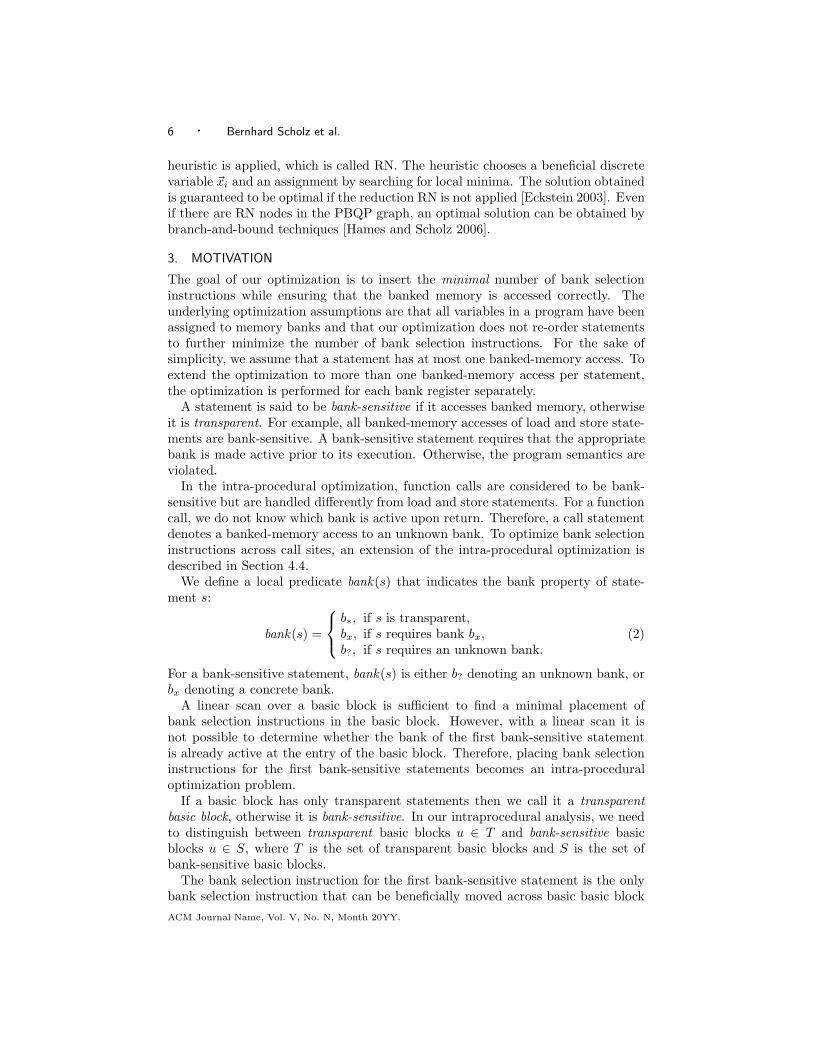
Consider our running example in Figure 2(a). Basic blocks are numbered in bold,execution frequencies are denoted by underlined numbers on edges. The executionfrequency of a basic block (except the start node) is the sum of frequencies of itsincoming edges. For the start node it is the sum of frequencies of its outgoing edges.Figure 2(b) shows the CFG where all five critical edges have been split tentatively.Let us assume that our example architecture has two banks, i.e., bank 0 and bank 1,and either bank 0 or bank 1 is active. All memory operations are done by load andstore statements of the form LD v and ST v, where v is a variable residing in eitherbank 0 or bank 1. Our example has five variables: A and B reside in bank 0, andX, Y and Z in bank 1. Before a load or store for variable v is executed, the bank ofthe variable must be active.
A naive approach to ensure correct code is to issue a bank selection instructionprior to all banked-memory accesses. However, this approach produces sub-optimalcode. For example, basic block 4 that contains LD A inside a loop would requirethe bank selection instruction BSL 0.
Figures 2(c)–(e) illustrate the minimal solutions that we find with respect to thethree optimization criteria: speed, space, and a combination of speed and space.In our cost model, we take into account the costs of additional jump statementsintroduced in critical basic blocks (critical basic blocks are shown as dashed boxesin Figure 2(b)). We assume that bank selection instructions and jump statementshave an instruction length of one byte and they take one cycle to execute. Ifwe want to minimize the number of bank selection instructions inserted, we canmeasure the cost of inserting a bank selection instruction in a basic block as thedynamic number of cycles spent on executing the bank selection instruction timesthe execution frequency of the basic block. If we place the bank selection instructionin a critical basic block, we need to add the extra cost for the jump statement. Theminimal solution for speed is shown in Figure 2(c) where we place a bank selectioninstruction before and after the loop and in basic block 14. In Figure 2(d) theoptimization for space is shown. BSL 0 stays inside the loop to avoid the additionaljump statement required if BSL 0 is placed in critical basic block 11. Optimizingfor space reduces the memory footprint but increases the execution time of theprogram. An optimization which combines speed and space objectives is shown inFigure 2(e). For this particular example the speed objective was weighted one third
ACM Journal Name, Vol. V, No. N, Month 20YY.
Minimal Placement of Bank Selection Instructions for Partitioned Memory Architectures · 9
LD A LD X
LD B
1
2
3 4
5
6
11009
1000
101000
10
1
BSL 0
LD A
BSL 1
LD X
BSL 0
LD B
(a) CFG (b) Minimal placement
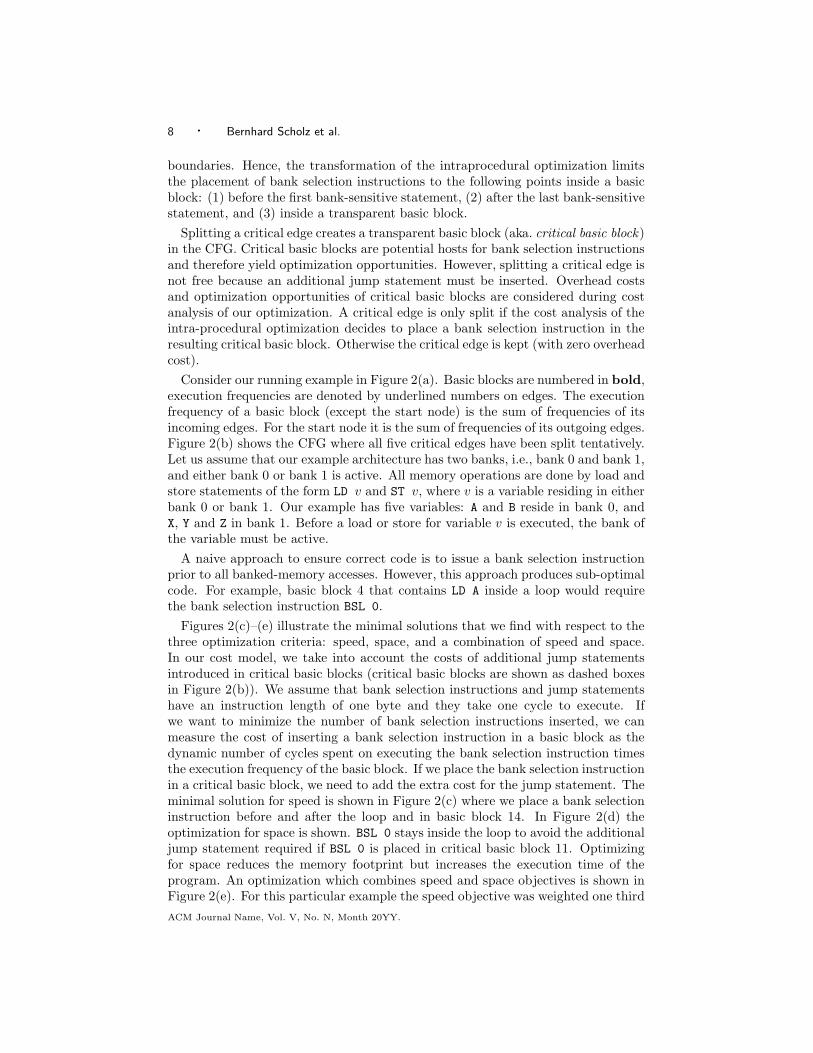
Fig. 3: Minimal placement by bank selection optimization but not by SPRE (variables A and B
are assigned to bank 0 and variable X to bank 1).
and the space objective was weighted two thirds.
3.1 Bank Selection Optimization vs. SPRE
The goal of Speculative Partial Redundancy Elimination (SPRE) is to minimize thedynamic number of computations for a given expression in a CFG with respect toan edge profile [Cai and Xue 2003; Scholz et al. 2004]. Computations of expressionsare moved from heavily executed paths to rarely executed paths and computationsare performed speculatively, i.e., without a guarantee that computations are usedlater. For SPRE, expressions are considered to be independent from each other,and the expression order of the SPRE transformation is arbitrary.
A bank selection instruction for a specific bank could be seen as a computation inSPRE. However, the placement of bank selection instructions for a specific bank isnot independent because bank selection instructions modify the same bank register.Hence, a necessary assumption of SPRE is violated and SPRE cannot solve theminimal placement of bank selection instructions. While SPRE may be used tofind the minimal placement for the set of all instructions that access a specificbank, the solutions obtained can lead to incorrect or sub-optimal code.
An example is illustrated in Figure 3. For the CFG given in Figure 3(a), theminimal placement found by our bank selection formulation is shown in Figure 3(b).If SPRE is used instead, one may proceed as follows. For the first bank-sensitiveinstruction in every basic block, the required bank selection instruction is insertedjust before the instruction. As a result, some of these instructions may be partiallyor fully redundant. In the current example, BSL 0 will be inserted at the entries ofbasic blocks 3 and 5, and BSL 1 at the entry of basic block 4. The three instructionsare all partially redundant (in the dynamic sense). To eliminate such redundancies,all distinct bank selection instructions are treated as distinct expressions. If thereare m banks, there will be m SPRE problems, one for each distinct bank. Thereare two approaches to solving these m SPRE problems. First, they are solvedindependently of each other. But this can lead to incorrect code. In the currentexample, BSL 0 and BSL 1 will both be inserted inside basic block 1 so that oneof the two instructions ends up being removed effectively but incorrectly. Second,
ACM Journal Name, Vol. V, No. N, Month 20YY.

10 · Bernhard Scholz et al.
OptimizeBasicBlock (u)1 first ← entry(u)2 last ← entry(u)3 rbank ← b∗
4 for all s ∈ u in seq. order do
5 if bank(s) 6= b∗ then
6 if rbank = b∗ then
7 first ← s
8 else
9 if bank(s) 6= b? ∧ bank(s) 6= rbank then
10 insert BSL 〈bank(s)〉 before s
11 endif
12 endif
13 rbank ← bank(s)14 last ← s
15 endif
16 endfor
17 return(first , last)
Fig. 4: Local optimization.
the m SPRE problems are solved one after another by considering the effects of thebank selection instructions introduced when the earlier SPRE problems are solved.However, this second approach also fails since there does not exist a linear orderto guarantee the minimal placement. In the current example, the minimal solutioncan be found if we process BSL 0 and then BSL 1. It is easy to see that the ordershould be swapped if edge (2,4) is far more frequently executed than edge (2,3).Since both scenarios can co-exist in the same CFG, SPRE cannot determine theminimal placement of bank selection instructions. Instead, the minimal placementmust be sought when all bank selections are considered together. This is the majorcontribution of this paper.
4. BANK SELECTION OPTIMIZATION
We develop the bank selection optimization in four steps. In the first step we discusshow to optimize bank selection instructions inside a basic block. In the second stepwe formulate the intraprocedural optimization as a discrete optimization problem.In the third step we show how the discrete optimization problem is mapped tothe PBQP problem, and the last step extends the intraprocedural optimization towhole programs.
4.1 Local Optimization
Given a basic block in which all variables have been assigned to banks, this sectiongives an algorithm that minimizes the number of bank selection instructions insertedin the basic block.
In Figure 4, the linear scan algorithm for inserting bank selection instructionsis listed. The algorithm initializes variable first, which points to the first bank-sensitive statement; variable last, which points to the last bank-sensitive statement;
ACM Journal Name, Vol. V, No. N, Month 20YY.

Minimal Placement of Bank Selection Instructions for Partitioned Memory Architectures · 11
Basic Block bank(s) first last
s0 NOP b∗ s0 s0
s1 LD X 1 s1 s1
BSL 0 inserteds2 ST A 0 s1 s2
s3 CALL foo b? s1 s3
BSL 0 inserteds4 LD B 0 s1 s4
BSL 1 inserteds5 ST Y 1 s1 s5
s6 ST Z 1 s1 s6
s7 NOP b∗ s1 s6
Fig. 5: Example: variables A and B reside in bank 0, and variables X, Y, and Z in bank 1.
and variable rbank , which represents the active bank of the bank register. Insidethe loop, we ignore transparent statements, i.e., those statements s that satisfybank(s) = b∗ (in line 5). When the first bank-sensitive statement is reached, thealgorithm sets variable first. For all subsequent bank-sensitive statements, thealgorithm checks whether a new bank selection instruction needs to be issued. Thisis the case if the required bank bank (s) for statement s is not b? and differs fromthe bank required by a preceding bank-sensitive statement. After having traversedthe basic block, the algorithm returns the first and last bank-sensitive statementsof the basic block. If the basic block is transparent, first and last will point to thefirst statement of the basic block (due to lines 1 and 2), and the following holds:bank(first) = b∗ and bank(last) = b∗.
Given a basic basic block u, we write first(u) and last(u) to denote the first andlast statement returned by the algorithm in Figure 4. We use fbu to denote thebank of statement first(u), and lbu to denote the bank of statement last(u).
Figure 5 illustrates the operation of our linear scan algorithm on a sample ba-sic block consisting of the instructions s0–s7. In this example we assume thatvariables A and B reside in bank 0, and variables X, Y and Z reside in bank 1. Thecolumn entitled “bank(s)” depicts the bank-sensitivity of the respective statements.We use NOP statements to introduce transparency to this example. The call tofunction foo in statement s3 potentially modifies the bank register. Therefore, thebank of this statement is unknown (b?). Columns “first” and “last” denote thefirst and last bank-sensitive statement as the algorithm progresses through the ba-sic block. Since statement s0 is transparent, first is eventually set to statement s1.For each bank-sensitive statement, last is updated. The linear scan algorithmintroduces three BSL instructions and sets first and last to the first and last bank-sensitive statement of the basic block.
Note that the optimization algorithm for basic blocks does not insert a bankselection instruction for the first bank-sensitive statement. If we do not take intoaccount the intra-procedural flow across basic blocks in our analysis, we could insertthe bank selection instruction prior to the first bank-sensitive statement. However,this would result in a sub-optimal solution for the entire program.
ACM Journal Name, Vol. V, No. N, Month 20YY.

12 · Bernhard Scholz et al.
Table I. Transformation for configuration (Pu, Qu).
For a bank-sensitive basic block:
Location Insertion Condition
entry BSL〈fbu〉 fb
u6= b? ∧ Pu 6= fb
u
exit BSL〈Qu〉 Qu 6= b? ∧ Qu 6= lbu
For a transparent basic block:
Insertion Condition
BSL〈Qu〉 Qu 6= b? ∧ Pu 6= Qu
4.2 Intra-Procedural Optimization
The intra-procedural optimization is effective because bank selection instructionscan be hoisted across basic blocks. For example, instead of performing the bankselection instruction for LD A of Figure 2 inside the loop, we move the bank se-lection instruction outside of the loop when optimizing for speed (as depicted inFigure 2(c)).
Our approach uses discrete optimization to place bank selection instructions. Themain idea is that we introduce two controlling variables Pu and Qu for every basicblock u. These two variables describe the state of the bank register before and afterexecution of the basic block. The domain of Pu and Qu is D = {b0, . . . , bm−1, b?},i.e., variables Pu and Qu are either set to a concrete bank, or the state of the bankregister is unknown. The semantics of the controlling variables are as follows: If Pu
is set to bx, we can assume that the bank register has been set to bx prior to theexecution of basic block u. If Pu is set to b?, then the state of the bank register isunknown upon entry of u. Conversely, variable Qu forces basic block u to guaranteethat the bank register is set to Qu upon exit.
Depending on the values of Pu and Qu we insert bank selection instructionsaccording to Table I. For a bank-sensitive basic block, there are at most twoinsertions, i.e., one before the first bank-sensitive statement and one after the lastbank-sensitive statement. The first insertion ensures that the bank register is setto bank fbu if variable Pu is not set to this bank. The second insertions is used toguarantee that the bank register is set to Qu after executing basic block u. For atransparent basic block at most one bank selection instruction is inserted to ensurethat the bank register is set to Qu upon exit (cf. again Table I).
A bank selection transformation T ∈ (D × D)|V | is defined by configurations(Pu, Qu) for all basic blocks u. All possible insertions of bank selection instructionsat entries and exits of basic blocks are covered by at least one configuration of abasic block.
A bank selection transformation T is correct if controlling variable Ps of the entrynode is unknown and for all CFG edges (u, v) it holds that
(Pv 6= b?) ⇒ (Qu = Pv) . (3)
The start node s cannot assume that a specific bank is active prior to its execution.Therefore, we set Ps to b?. For all other nodes, each predecessor needs to havebank Qu active upon exit if Pv is not equal to the unknown bank.
The controlling variables Pu and Qu determine the correctness of a transforma-tion and its costs. For each basic block u, we have a cost function costu(Pu, Qu)that returns the costs for a given configuration (Pu, Qu). These costs are chosenfrom arbitrary metrics such as speed, space, and mixed cost models.
A bank selection transformation T is minimal if it is correct and if the costs of a
ACM Journal Name, Vol. V, No. N, Month 20YY.

Minimal Placement of Bank Selection Instructions for Partitioned Memory Architectures · 13
transformation are minimal:
min f =∑
u∈V
costu(Pu, Qu). (4)
We split the cost function into the costs for bank-sensitive basic blocks (u ∈ S)and transparent basic blocks (u ∈ T ).
f =∑
u∈V
costu(Pu, Qu) =∑
u∈S
s-costu(Pu, Qu) +∑
u∈T
t-costu(Pu, Qu) (5)
Without loss of generality we divide the costs for a bank-sensitive basic block intothe costs occurring upon entry and exit of the basic block. Function n-costu(Pu)accounts for the cost of the bank selection instruction at the entry of the basic blockand function e-costu(Qu) upon exit:
s-costu(Pu, Qu) = n-costu(Pu) + e-costu(Qu). (6)
Both functions are zero if no insertion is performed. Otherwise they return thecost cu of a bank selection instruction.
n-costu(Pu) =
{
cu, if fbu 6= b? ∧ Pu 6= fbu
0, otherwise(7)
e-costu(Qu) =
{
cu, if Qu 6= b? ∧ Qu 6= lbu
0, otherwise(8)
For a transparent basic block the costs are defined by
t-costu(Pu, Qu) =
{
cu, if Qu 6= b? ∧ Pu 6= Qu
0, otherwise.(9)
In Eqns. (7) – (9), constant cu represents the insertion cost of a bank selectioninstruction in basic block u. Costs are computed based on a chosen metric. Theonly restriction we impose on such a metric is that the costs must have positivevalues3, i.e., cu ≥ 0. In our experiment, we have chosen the parameterizable costmetric
cu = α × SPEEDu + β × SPACEu, (10)
with its two parameters α and β controlling the weights of the speed and spaceobjectives. Depending on whether u is a critical basic block, SPEEDu is defined as
SPEEDu =
{
(bsl-cycles+ jump-cycles) × frequ, if u is critical
bsl-cycles× frequ, otherwise.(11)
Therein bsl-cycles denotes the number of cycles taken for executing one single bankselection instruction, jump-cycles is the number of cycles taken for executing oneadditional (unconditional) jump statement introduced in basic block u due to edgesplitting, and frequ is the execution frequency of u (obtained by profiling).
3Note that the PBQP solver would also cope with negative costs. However, in the context of bankselection negative costs are not sensible.
ACM Journal Name, Vol. V, No. N, Month 20YY.

14 · Bernhard Scholz et al.
Similarly, the constant SPACEu is defined as
SPACEu =
{
bsl-size+ jump-size, if u is critical
bsl-size, otherwise,(12)
where bsl-size (jump-size) is the size of a bank selection (jump) instruction (mea-sured in bytes).
Putting all constraints and costs together, we formulate the intra-proceduralbank selection problem as the following discrete optimization:
s.t. ∀u ∈ V : Pu, Qu ∈ D
Ps = b?
∀(u, v) ∈ E : (Pv 6= b?) ⇒ (Qu = Pv)
min f =∑
u∈S
n-costu(Pu) +∑
u∈S
e-costu(Qu) +∑
u∈T
t-costu(Pu, Qu). (13)
A related problem was introduced in [Kleinberg and Tardos 1999], which is a clas-sification problem and it was shown that this problem is hard to solve, i.e., a setof points should be labeled such that a cost function is to be minimized. Thecost function takes into account costs for local labeling and labeling of two relatedpoints. In [Kleinberg and Tardos 1999] an approximation algorithm was introduced.However, the approximation algorithm is not practical. Instead, we use the PBQPproblem to solve the underlying discrete optimization problem for bank selection,for which we have a very efficient and effective solver.
4.3 Mapping to PBQP
We employ PBQP [Scholz and Eckstein 2002; Eckstein 2003] to solve the discreteoptimization problem of Eqn. (13). The controlling variables Pu and Qu becomeBoolean vector variables ~pu and ~qu. The elements of the vectors represent anelement in D = {b0, . . . , bm−1, b?}. PBQP restricts ~pu and ~qu to Boolean vectorswhose elements are set to zero except one element is set to one, i.e. variables Pu
and Qu have a concrete bank assignment or they are set to b?.The costs of bank-sensitive basic blocks are modeled as scalar products and the
costs of transparent basic blocks become quadratic forms. The objective functionof Eqn. (13) is mapped to the PBQP objective function
f =∑
u∈S
~nu~pTu +
∑
u∈S
~eu~qTu +
∑
u∈T
~pu(cu · T )~qTu . (14)
Therein ~nu~pTu and ~eu~qT
u are the cost functions n-costu(Pu) and e-costu(Qu) in vectornotation, and ~pu(cu · T )~qT
u is t-costu(Pu, Qu) as a quadratic form. The vector ~nu inscalar product ~nu~pT
u is a zero vector if the bank of the first bank-sensitive statementis b?, otherwise it is the vector
b0 b1 . . . bi−1 bi bi+1 . . . bm−1 b?
~nu cu cu . . . cu 0 cu . . . cu cu, (15)
where bi is bank fbu of the first bank-sensitive statement and cu are the costsfor inserting a bank selection instruction (i.e., BSL bi). Cost function e-cost(Qu)
ACM Journal Name, Vol. V, No. N, Month 20YY.

Minimal Placement of Bank Selection Instructions for Partitioned Memory Architectures · 15
Table II. Cost matrices.
T b0 b1 . . . . . . bm−1 b?b0 0 1 . . . . . . 1 0b1 1 0 1 . . . 1 0...
.... . .
. . .. . .
......
bm−2 1 . . . 1 0 1 0bm−1 1 . . . . . . 1 0 0b? 1 . . . . . . . . . 1 0
(a) Transparent basic blocks
R b0 b1 . . . . . . bm−1 b?b0 0 ∞ . . . . . . ∞ 0b1 ∞ 0 ∞ . . . ∞ 0...
.... . .
. . .. . .
......
bm−2 ∞ . . . ∞ 0 ∞ 0bm−1 ∞ . . . . . . ∞ 0 0b? ∞ . . . . . . ∞ ∞ 0
(b) Correctness constraint for CFG edges
becomes the scalar product ~eu~qTu , for which the cost vector ~eu is
b0 b1 . . . bj−1 bj bj+1 . . . bm−1 b?
~eu cu cu . . . cu 0 cu . . . cu 0. (16)
Therein bank bj denotes bank lbu, and we do not issue a bank selection instructionif Qu is equal to bj or b?.
For example, consider basic block 4 in our motivating example (see Figure 2(a)).This basic block is executed 91 times. The first bank-sensitive statement is LD A,which accesses bank b0. If we assume that it takes one cycle to execute a bankselection instruction, then we have 91 cost units for the insertion before LD A. Thuscu = 91 and cost function n-cost(P4) becomes ~n4 =
(
0 91 91)
. The first elementof the vector imposes zero costs if P4 is set to b0. If P4 is set to b1 or b?, 91 costunits are imposed because a bank selection instruction needs to be inserted priorto LD A. Cost vector ~e4 is
(
0 91 0)
, because there are zero costs imposed for Q4
equal to b0 or b?.The transparent cost function t-costu(Pu, Qu) is expressed as quadratic form
~pu(cuT )~qTu . Matrix T is given in Table II(a) and it is generated based on Eqn. (9).
The rows of T correspond to variable Pu and the columns correspond to variable Qu.If Pu and Qu are not set to the same bank and Qu is not b?, one cost unit is imposed(zero costs otherwise). We multiply matrix T with scalar cu in Eqn. (14) to modelthe actual insertion costs for a bank selection instruction.
To enforce correct transformations, we use the standard technique of encodingthe correctness constraint as part of the objective function, which we extend tog = f + ∆, where ∆ is 0 if the transformation T is a correct transformation, and∞ otherwise. The correctness constraints defined over CFG edges are mapped toa sum of a scalar product and quadratic forms,
∆ =(
∞ . . . ∞ 0)
~qTs +
∑
(u,v)∈E
~quR~pTv , (17)
where the constraint expressed in Eqn. (3) is mapped to matrix R shown in Ta-ble II(b) and the constraint to set Ps to b? is mapped to a scalar product. Quadraticforms are used to express the correctness constraints. In matrix R the diagonal andthe last column contain zeroes, representing the cases where Qu is equal to Pv orwhere Pv is set to b?. All other assignments of Qu and Pv are penalized with ∞costs.
Our running example in Figure 2 assumes an architecture with two banks. Hence,
ACM Journal Name, Vol. V, No. N, Month 20YY.

16 · Bernhard Scholz et al.
we get the following correctness matrix R and transparent matrix T .
R b0 b1 b?
b0 0 ∞ 0b1 ∞ 0 0b? ∞ ∞ 0
T b0 b1 b?
b0 0 1 0b1 1 0 0b? 1 1 0
The objective function without correctness constraints is
f =~n1~pT1 + ~e1~q
T1 + ~n2~p
T2 + ~e2~q
T2 + ~n4~p
T4 + ~e4~q
T4 + ~n5~p
T5 + ~e5~q
T5 + ~n6~p
T6 + ~e6~q
T6 +
~n7~pT7 + ~e7~q
T7 + ~n9~p
T9 + ~e9~q
T9 + ~p3(c3 · T )~qT
3 + ~p8(c3 · T )~qT8 + ~p10(c10 · T )~qT
10+
~p11(c11 · T )~qT11 + ~p12(c12 · T )~qT
12 + ~p13(c13 · T )~qT13 + ~p14(c14 · T )~qT
14+
~p15(c15 · T )~qT15,
where cu for basic blocks 3, 8, 10, 11, 12, 13, 14 and 15 denotes the costs for insert-ing bank selection instructions. Constants cu are dependent on the optimizationcriteria.
The correctness constraints are
∆ =(
∞ ∞ 0)
~pTs + ~q1R~pT
2 + ~q1R~pT3 + ~q2R~pT
6 + ~q3R~pT5 + ~q3R~pT
11 + ~q4R~pT12+
~q4R~pT13 + ~q5R~pT
6 + ~q6R~pT7 + ~q6R~pT
8 + ~q7R~pT9 + ~q8R~pT
14 + ~q8R~pT15 + ~q9R~pT
10+
~q11R~pT4 + ~q12R~pT
4 + ~q13R~pT6 + ~q14R~pT
9 + ~q15R~pT10.
The objective function g = f +∆ is to be solved to find the minimal bank selectionplacement for the running example.
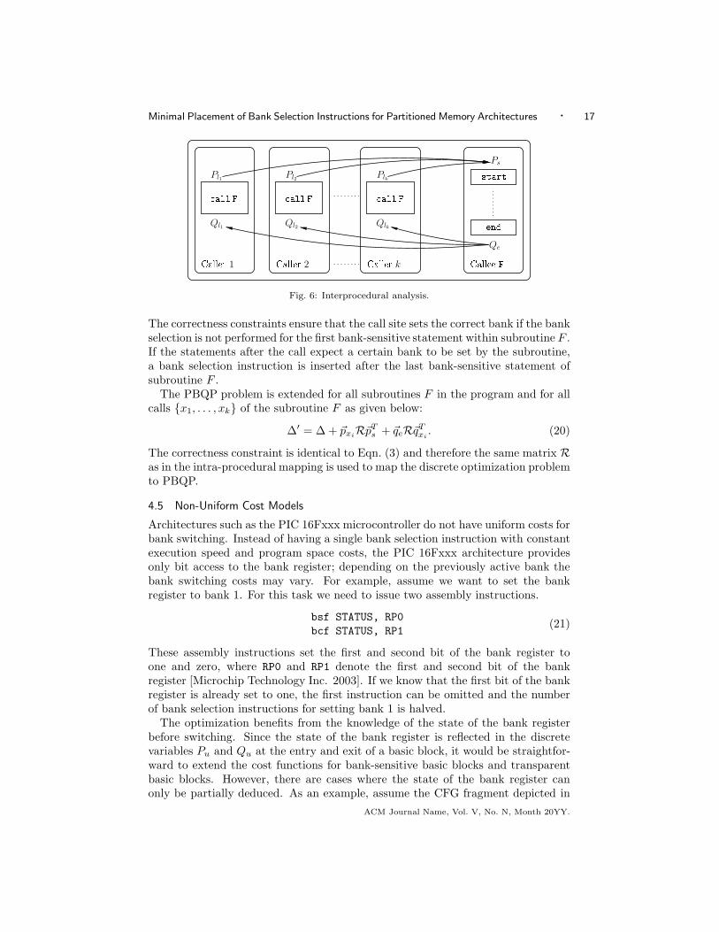
4.4 Inter-procedural Optimization
The bank selection optimization can be extended to hoist bank selection instructionsacross call sites. For frequently executed calls the inter-procedural optimization ishighly effective. The inter-procedural transformation extends the placement ofbank selection instructions to the following program points: (1) at the entry of asubroutine, (2) at the exit of a subroutine, (3) and before a call. In contrast tothe intra-procedural optimization, a single discrete optimization problem solves thebank selection of the whole program in one step.
The mathematical model of the inter-procedural optimization problem is an ex-tension of the intra-procedural approach. The discrete optimization problem foreach subroutine is constructed as outlined in the previous section. However, theboundary condition for the start node is removed except for the main subroutineof the program. Each call site li of subroutine F becomes a basic block of its own(with controlling variables Pli and Qli). Correctness constraints between the callsite and the callee ensure a consistent state of the bank register upon procedurecall and return. The correctness constraints between the callers and the callee aredepicted in Figure 6 (edges represent correctness constraints). For call site li weimpose a correctness constraint between discrete variable Pli and Ps such that
(Ps 6= b?) ⇒ (Ps = Pli) (18)
holds. For the end node of a subroutine we add correctness constraint
(Qli 6= b?) ⇒ (Qli = Qe) . (19)
ACM Journal Name, Vol. V, No. N, Month 20YY.
Minimal Placement of Bank Selection Instructions for Partitioned Memory Architectures · 17
all F all F all FPl2
Ql1Caller 1 Caller 2 Caller k
Plk
Callee FPs
Qlk
Qe
startendQl2
Pl1
Fig. 6: Interprocedural analysis.
The correctness constraints ensure that the call site sets the correct bank if the bankselection is not performed for the first bank-sensitive statement within subroutine F .If the statements after the call expect a certain bank to be set by the subroutine,a bank selection instruction is inserted after the last bank-sensitive statement ofsubroutine F .
The PBQP problem is extended for all subroutines F in the program and for allcalls {x1, . . . , xk} of the subroutine F as given below:
∆′ = ∆ + ~pxiR~pT
s + ~qeR~qTxi
. (20)
The correctness constraint is identical to Eqn. (3) and therefore the same matrix Ras in the intra-procedural mapping is used to map the discrete optimization problemto PBQP.
4.5 Non-Uniform Cost Models
Architectures such as the PIC 16Fxxx microcontroller do not have uniform costs forbank switching. Instead of having a single bank selection instruction with constantexecution speed and program space costs, the PIC 16Fxxx architecture providesonly bit access to the bank register; depending on the previously active bank thebank switching costs may vary. For example, assume we want to set the bankregister to bank 1. For this task we need to issue two assembly instructions.
bsf STATUS, RP0
bcf STATUS, RP1(21)
These assembly instructions set the first and second bit of the bank register toone and zero, where RP0 and RP1 denote the first and second bit of the bankregister [Microchip Technology Inc. 2003]. If we know that the first bit of the bankregister is already set to one, the first instruction can be omitted and the numberof bank selection instructions for setting bank 1 is halved.
The optimization benefits from the knowledge of the state of the bank registerbefore switching. Since the state of the bank register is reflected in the discretevariables Pu and Qu at the entry and exit of a basic block, it would be straightfor-ward to extend the cost functions for bank-sensitive basic blocks and transparentbasic blocks. However, there are cases where the state of the bank register canonly be partially deduced. As an example, assume the CFG fragment depicted in
ACM Journal Name, Vol. V, No. N, Month 20YY.
18 · Bernhard Scholz et al.
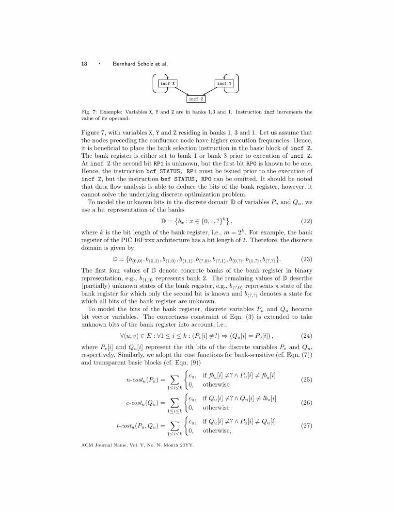
incf X incf Y
incf Z
Fig. 7: Example: Variables X, Y and Z are in banks 1,3 and 1. Instruction incf increments thevalue of its operand.
Figure 7, with variables X, Y and Z residing in banks 1, 3 and 1. Let us assume thatthe nodes preceding the confluence node have higher execution frequencies. Hence,it is beneficial to place the bank selection instruction in the basic block of incf Z.The bank register is either set to bank 1 or bank 3 prior to execution of incf Z.At incf Z the second bit RP1 is unknown, but the first bit RP0 is known to be one.Hence, the instruction bcf STATUS, RP1 must be issued prior to the execution ofincf Z, but the instruction bsf STATUS, RP0 can be omitted. It should be notedthat data flow analysis is able to deduce the bits of the bank register, however, itcannot solve the underlying discrete optimization problem.
To model the unknown bits in the discrete domain D of variables Pu and Qu, weuse a bit representation of the banks
D ={
bx : x ∈ {0, 1, ?}k}
, (22)
where k is the bit length of the bank register, i.e., m = 2k. For example, the bankregister of the PIC 16Fxxx architecture has a bit length of 2. Therefore, the discretedomain is given by
D = {b〈0,0〉, b〈0,1〉, b〈1,0〉, b〈1,1〉, b〈?,0〉, b〈?,1〉, b〈0,?〉, b〈1,?〉, b〈?,?〉}. (23)
The first four values of D denote concrete banks of the bank register in binaryrepresentation, e.g., b〈1,0〉 represents bank 2. The remaining values of D describe(partially) unknown states of the bank register, e.g., b〈?,0〉 represents a state of thebank register for which only the second bit is known and b〈?,?〉 denotes a state forwhich all bits of the bank register are unknown.
To model the bits of the bank register, discrete variables Pu and Qu becomebit vector variables. The correctness constraint of Eqn. (3) is extended to takeunknown bits of the bank register into account, i.e.,
∀(u, v) ∈ E : ∀1 ≤ i ≤ k : (Pv[i] 6=?) ⇒ (Qu[i] = Pv[i]) , (24)
where Pv[i] and Qu[i] represent the ith bits of the discrete variables Pv and Qu,respectively. Similarly, we adopt the cost functions for bank-sensitive (cf. Eqn. (7))and transparent basic blocks (cf. Eqn. (9))
n-costu(Pu) =∑
1≤i≤k
{
cu, if fbu[i] 6=? ∧ Pu[i] 6= fbu[i]
0, otherwise(25)
e-costu(Qu) =∑
1≤i≤k
{
cu, if Qu[i] 6=? ∧ Qu[i] 6= lbu[i]
0, otherwise(26)
t-costu(Pu, Qu) =∑
1≤i≤k
{
cu, if Qu[i] 6=? ∧ Pu[i] 6= Qu[i]
0, otherwise,(27)
ACM Journal Name, Vol. V, No. N, Month 20YY.
Minimal Placement of Bank Selection Instructions for Partitioned Memory Architectures · 19
C-
Program
Binary
Program
Info
Extended
Assembly
Banked
Assembly
C-Compiler
Simulator
Disassembler
PrunerExtended
AssemblyOptimizer Opt.
Binary
Fig. 8: Toolchain.
where for each bit that needs to be switched the costs cu are imposed. The mappingof the non-uniform cost model to PBQP follows along the lines of the mappingdevised in Section 4.3.
5. EXPERIMENTAL RESULTS
We evaluated our optimization using programs typically run on contemporary mi-crocontrollers. Our sample included programs from the MiBench Embedded Bench-mark Suite [Guthaus et al. 2001] and from DSPStone, and we surveyed a microcon-troller real-time kernel and common microcontroller driver routines. We conductedthis experiment on a PIC16F877A microcontroller [Microchip Technology Inc. 1997;2003]. We applied different optimization objectives to show the versatility of ourapproach.
Our second experiment addressed the scalability of our optimization. This isimportant due to the prevailing trend to equip next generation microcontrollers withmore program and data memory. (Microchip’s PIC18F97J60 8-bit microcontrollerfor example provides 128KB of program memory and 4KB of data memory spreadover 16 banks [Microchip Technology Inc. 2006].) In the second experiment weshowed that our optimization
—scales well to a larger number of memory banks (i.e., 8, 16, 32),
—scales well to the larger problem sizes that will become feasible with future mi-crocontrollers, and
—achieves the minimal result in almost all circumstances.
The second experiment involved the complete MiBench suite which has more than6000 procedures. In this experiment we assumed the worst-case scenario for ouroptimization problem, which occurs when all basic blocks are transparent.
5.1 Experiment 1: PIC16F877A Microcontroller Benchmarks
The PIC family of midrange microcontrollers constitutes a RISC-based Harvardarchitecture with instruction sizes of 12, 14 or 16 bits, and a data-bus that is 8 bitwide [Microchip Technology Inc. 1997]. The PIC16F877A microcontroller provides
ACM Journal Name, Vol. V, No. N, Month 20YY.

20 · Bernhard Scholz et al.
8KB of program memory and 368B of data memory spread over four banks [Mi-crochip Technology Inc. 2003]. The MiBench programs that we could fit onto thismicrocontroller included “basicmath”, “bitcount”, “qsort”, “sha”, “CRC32” and“FFT”. From the DSPStone benchmark suite we included “adpcm” and “matrix”.We also surveyed a microcontroller real-time kernel and common microcontrollerdriver routines [MicrochipC.com 2006].
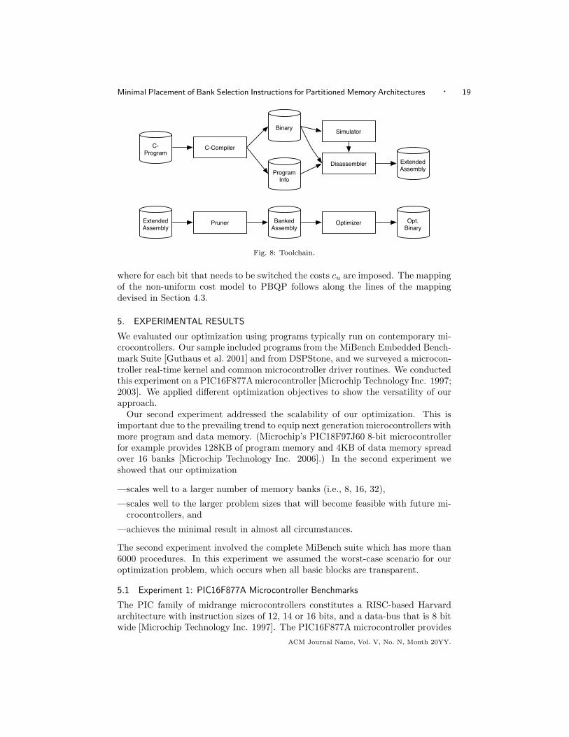
Our experimental setup is depicted in Figure 8. The compilation of a C bench-mark program for the PIC16F877A resulted in a binary image and supplementaryprogram information comprising the linker map file and a list of C-prototypes con-tained in the input program. We ran the binary image on the GPSIM simula-tor [Dattalo 2006] to obtain execution frequencies for the instructions of the binaryimage. The binary image together with the corresponding execution frequencieswere then fed into the disassembler to produce an extended assembly file. Thedisassembler used the linker map file and the list of C-prototypes to establish pro-cedural boundaries within the binary image. In this setup, an extended assemblyfile consisted of PIC assembly routines, where each instruction was augmented withits instruction frequency. The extended assembly file contained the bank selectioninstructions generated by the C-compiler. We used this information to compare itto the bank selection achieved by our optimization.
To carry out our optimization we pruned the extended assembly files from thebank selection instructions of the C-compiler. The pruner then performed data-flowanalysis to annotate each operand of the assembly file with the required bank. Inthe following we call these annotations bank assertions, and the annotated assemblycode is called banked assembly code.
The optimizer had to insert bank selection instructions into the banked assemblycode so that all bank assertions were satisfied (this is the correctness criteria of ouroptimization) at minimal cost. It should be noted that due to the pruner the bank
selection of our optimizer was completely independent of the bank selection of the
C-compiler.
We checked the correctness of the inserted bank selection instructions generatedby the optimizer. This was achieved by means of data-flow analysis. We deter-mined the costs induced by the bank selection instructions in the optimized binaryand compared them to the bank selection achieved by the C-compiler (from theextended assembly file). We used the HI-TECH PICC C-compiler as a referencepoint in this experiment. HI-TECH PICC is a high-performance C compiler adver-tised by Microchip itself for their whole family of PIC microcontrollers. It employsan optimizer that makes full use of PIC-specific features [HI-TECH Software 2006].However, this compiler does not automatically assign C variables to memory banks(apart from the default assignment to bank 0). For this reason we had to manu-ally assign program variables to memory banks with our benchmark programs. Wereplaced file I/O operations by I/O operations via the UART of the PIC16F877A.Some of the benchmark problem sizes had to be downsized to fit on an 8-bit mi-crocontroller.
As depicted in Table III, we determined the overall static instruction count (“To-tal”) together with the number of bank selection instructions (“BSL”) for eachbenchmark. We determined the cycle counts induced by these instruction-catego-
ACM Journal Name, Vol. V, No. N, Month 20YY.

Minimal Placement of Bank Selection Instructions for Partitioned Memory Architectures · 21
Table III: Experimental results for the PIC microcontroller benchmark programs; program sizereductions and speedups wrt. the optimizing commercial compiler.
Instruction count Cycle count Size reduction SpeedupBenchmark Objective Total BSL Total BSL Total% BSL% Total% BSL%
adpcm
HiT 6031 797 3.0e+09 3.9e+08 n/a n/a n/a n/aSpeed 5781 521 2.7e+09 1.6e+08 4.1 34.6 8.5 148.7Space 5640 406 2.8e+09 1.6e+08 6.5 49.1 8.3 140.2Mixed 5666 426 2.8e+09 1.6e+08 6.1 46.5 8.4 141.7
basicmath
HiT 1844 248 5856 1023 n/a n/a n/a n/aSpeed 1857 237 5545 712 -0.7 4.4 5.6 43.7Space 1794 198 5608 775 2.7 20.2 4.4 32.0Mixed 1799 199 5590 757 2.4 19.8 4.8 35.1
bitcnts
HiT 1888 197 81012 8091 n/a n/a n/a n/aSpeed 1871 163 75852 2931 0.9 17.3 6.8 176.0Space 1810 119 75992 3071 4.1 39.6 6.6 163.5Mixed 1811 120 75852 2931 4.1 39.1 6.8 176.0
crc32
HiT 450 36 2.2e+07 1.2e+06 n/a n/a n/a n/aSpeed 422 8 2.1e+07 64 6.2 77.8 5.9 1.9e+06Space 422 8 2.1e+07 64 6.2 77.8 5.9 1.9e+06Mixed 422 8 2.1e+07 64 6.2 77.8 5.9 1.9e+06
decimal
HiT 514 85 8547 1660 n/a n/a n/a n/aSpeed 460 31 7268 381 10.5 63.5 17.6 335.7Space 460 31 7284 397 10.5 63.5 17.3 318.1Mixed 460 31 7268 381 10.5 63.5 17.6 335.7
FFT
HiT 2693 348 53141 6485 n/a n/a n/a n/aSpeed 2576 216 50588 3932 4.3 37.9 5.0 64.9Space 2538 193 50688 4032 5.8 44.5 4.8 60.8Mixed 2540 195 50588 3932 5.7 44.0 5.0 64.9
lcd
HiT 307 65 72707 16285 n/a n/a n/a n/aSpeed 251 9 56431 9 18.2 86.2 28.8 1.8e+05Space 251 9 56431 9 18.2 86.2 28.8 1.8e+05Mixed 251 9 56431 9 18.2 86.2 28.8 1.8e+05
matrix
HiT 401 62 716 105 n/a n/a n/a n/aSpeed 368 27 660 49 8.2 56.5 8.5 114.3Space 360 21 667 56 10.2 66.1 7.3 87.5Mixed 360 21 666 55 10.2 66.1 7.5 90.9
nvmtsens
HiT 1238 134 121070 24229 n/a n/a n/a n/aSpeed 1138 34 97389 548 8.1 74.6 24.3 4.3e+03Space 1125 21 98075 1234 9.1 84.3 23.4 1.9e+03Mixed 1138 34 97389 548 8.1 74.6 24.3 4.3e+03
qsort
HiT 908 128 24549 3298 n/a n/a n/a n/aSpeed 802 20 21769 518 11.7 84.4 12.8 536.7Space 799 19 21771 520 12.0 85.2 12.8 534.2Mixed 799 19 21769 518 12.0 85.2 12.8 536.7
rtkernel
HiT 2097 422 2.6e+08 4.9e+07 n/a n/a n/a n/aSpeed 2063 343 2.3e+08 1.8e+07 1.6 18.7 13.4 169.9Space 1862 187 2.3e+08 1.8e+07 11.2 55.7 13.4 169.8Mixed 1864 189 2.3e+08 1.8e+07 11.1 55.2 13.4 169.9
serial
HiT 1178 189 8.4e+06 1.7e+06 n/a n/a n/a n/aSpeed 1035 44 6.7e+06 3128 12.1 76.7 25.3 5.4e+04Space 1022 33 6.7e+06 3385 13.2 82.5 25.3 5.0e+04Mixed 1022 33 6.7e+06 3385 13.2 82.5 25.3 5.0e+04
sha
HiT 3012 170 5.0e+06 9.3e+05 n/a n/a n/a n/aSpeed 2881 35 4.6e+06 5.2e+05 4.3 79.4 8.9 78.1Space 2868 26 4.7e+06 6.2e+05 4.8 84.7 6.8 51.8Mixed 2875 29 4.7e+06 5.8e+05 4.5 82.9 7.5 59.7
swi2c
HiT 740 123 4.1e+06 9.0e+05 n/a n/a n/a n/aSpeed 659 42 3.2e+06 673 10.9 65.9 28.1 1.3e+05Space 644 27 3.2e+06 1043 13.0 78.0 28.1 8.6e+04Mixed 653 36 3.2e+06 673 11.8 70.7 28.1 1.3e+05
ACM Journal Name, Vol. V, No. N, Month 20YY.

22 · Bernhard Scholz et al.
adpc
mba
sicm
athbi
tcnts
crc3
2de
cimal
FFT lcdm
atrix
nvm
tsens
qsor
trtk
erne
lse
rial
sha
swi2
ca.
mea
n
0
2
4
6
8
10
12
14
16
18
20
22
24
26
28
30
32
Spee
dup
(%)
SpeedSpaceMixed
Fig. 9: Speedup achieved over the optimizing commercial compiler.
ries for a given benchmark sample input. The given “Total” cycle counts take intoaccount extra jump instructions that might arise due to the insertion of bank selec-tion instructions. For each benchmark these performance figures were determinedfor the HI-TECH PICC C-compiler and for our optimization. We performed ouroptimization under the objectives (1) speed, (2) space, and (3) mixed (a combi-nation of speed and space). The corresponding values for α and β were α = 1,β = 0 (speed), α = 0, β = 1 (space), and α = 0.5, β = 0.5 (mixed). In terms ofEqns. (11) and (12), we set bsl-cycles = bsl-size = jump-cycles = jump-size = 1.The rightmost columns in Table III depict the memory footprint reduction and theresulting performance improvement achieved by our optimization. The figures re-flect the goals of the different optimization objectives: optimizing for space resultsin the lowest number of issued bank selection instructions, whereas optimizing forspeed minimizes instruction cycles. Optimizing for speed and space combines bothobjectives, resulting in performance figures between the two. Note however, thatfor some benchmarks the speed and space optimizations are identical, which thenapplies for the mixed optimization as well.
It follows from Table III that the reduction of the program memory footprint(corresponding to the overall instruction count) is between 2.7% and 18.2% whenwe optimize for space. In this case the reduction of bank selection instructionsis between 20.2% and 86.2%. If we optimize for speed , the achieved overall im-provement is between 5.0% and 28.8%, and the improvement with respect to theexecution of bank selection instructions alone is between 43.7% and 1900000%. Ouroptimization achieved the optimal solution for all benchmark programs. The over-all speedup is shown in the bar chart of Figure 9, and the program-size reductionof our bank selection optimization is shown in Figure 10 (“a. mean” denotes thearithmetic mean over all benchmark programs).
To investigate the sensitivity of our optimization to actual input data, we em-
ACM Journal Name, Vol. V, No. N, Month 20YY.

Minimal Placement of Bank Selection Instructions for Partitioned Memory Architectures · 23
adpc
mba
sicm
athbi
tcnts
crc3
2de
cimal
FFT lcdm
atrix
nvm
tsens
qsor
trtk
erne
lse
rial
sha
swi2
ca.
mea
n
0
2
4
6
8
10
12
14
16
18
20
Size
red
uctio
n (%
)
SpeedSpaceMixed
Fig. 10: Program size reduction achieved over the optimizing commercial compiler.
Table IV: Optimization results across different data sets.
Average speedup(%) Average size reduction(%)Benchm. Speed Space Mixed σSpd σSpc σMxd Speed Space Mixed σSpd σSpc σMxd
adpcm 8.38 8.17 8.21 0.18 0.19 0.17 3.88 6.5 6.05 0.33 0 0.05bitcnts 6.86 6.67 6.86 0.09 0.08 0.09 1.35 4.1 4.1 0.7 0 0crc32 5.9 0 6.2 0FFT 5.04 4.83 5.04 0.05 4.3 5.8 5.7 0qsort 12.54 12.53 12.54 0.26 11.45 12.0 11.98 0.36 0 0.08sha 8.9 6.8 7.5 0 4.3 4.8 4.5 0
ployed the MiDataSets of Fursin et al. [2007]. The MiDataSets provide 20 data setsper MiBench benchmark, with the intention to establish a baseline for the evalu-ation of compiler optimizations under varying input data conditions. We profiledseveral of our benchmarks with each of the corresponding 20 data sets to determinebasic block execution frequencies. The MiDataSets for qsort had to be shrunk tofit onto the PIC16F877A microcontroller. For benchmark FFT we used the datafrom bitcnts to seed the pseudo-random generator. Table IV shows the averagespeedup and program size reduction together with the standard deviation σ acrossall data sets. Note that a standard deviation of zero from the average footprint sizereduction is expected when optimizing for space, because execution frequencies arenot taken into account in this case. The extremely small values for σ in Table IVshow that our optimizations were effective with each data set.
We investigated the instruction distributions of the PIC microcontroller bench-mark programs to determine applicability and improvement potential of our opti-mization. The obtained data is depicted in Table V. Therein Column “traB” de-notes the percentage of transparent basic blocks. “traS”, “isenS” and “bsenS”denotethe percentages of transparent statements, bank sensitive statements inside basicblocks, and first and last bank sensitive statements of a basic block (note that theyadd up to 100% and hence do not account for BSL statements). “traC”, “isenC”
ACM Journal Name, Vol. V, No. N, Month 20YY.

24 · Bernhard Scholz et al.
Table V: Instruction distribution properties of the PIC microcontroller benchmark programs.
Benchmark Objective traB traS isenS bsenS traC isenC bsenC bBslS bBslC bsl
adpcmHiT 63.4 76.6 7.8 15.6 77.8 7.4 14.8 71.9 77.7 13.2
Speed 65.7 77.9 7.4 14.7 77.8 7.4 14.8 60.1 47.8 9.0Space 65.6 78.0 7.4 14.6 77.8 7.4 14.8 49.3 49.6 7.2
basicmathHiT 36.6 73.4 16.6 10.0 68.7 17.3 14.0 37.5 51.7 13.4
Speed 39.1 72.4 16.8 10.8 68.1 17.4 14.5 40.5 37.2 12.8Space 33.7 72.7 16.7 10.6 68.3 17.3 14.4 28.8 42.3 11.0
bitcntsHiT 50.9 70.2 14.3 15.5 68.9 14.0 17.1 61.9 77.8 10.4
Speed 53.5 71.3 13.8 14.9 68.9 14.0 17.1 54.6 44.3 8.7Space 51.9 71.0 14.0 15.0 68.9 14.0 17.1 37.8 46.8 6.6
crc32HiT 50.8 73.9 15.2 10.9 77.7 7.4 14.9 94.4 100.0 8.0
Speed 60.7 79.2 12.3 8.5 77.7 7.4 14.9 100.0 100.0 1.9Space 60.7 79.2 12.3 8.5 77.7 7.4 14.9 100.0 100.0 1.9
decimalHiT 56.3 68.8 13.3 17.9 77.2 8.0 14.8 85.9 86.4 16.5
Speed 56.3 68.8 13.3 17.9 77.2 8.0 14.8 61.3 40.7 6.7Space 56.3 68.8 13.3 17.9 77.2 8.0 14.8 61.3 43.1 6.7
FFTHiT 46.4 72.9 17.1 10.0 71.9 16.2 11.9 57.2 63.7 12.9
Speed 48.9 72.8 17.3 9.9 71.9 16.2 11.9 37.0 44.5 8.4Space 47.1 73.0 17.2 9.8 71.9 16.2 11.9 31.6 46.1 7.6
lcdHiT 56.0 67.7 8.7 23.6 84.5 0.4 15.1 92.3 100.0 21.2
Speed 56.0 67.7 8.7 23.6 84.5 0.4 15.1 44.4 44.4 3.6Space 56.0 67.7 8.7 23.6 84.5 0.4 15.1 44.4 44.4 3.6
matrixHiT 80.0 90.3 5.3 4.4 86.4 7.7 5.9 69.4 62.9 15.5
Speed 80.7 90.3 5.3 4.4 86.4 7.7 5.9 40.7 20.4 7.3Space 80.0 90.9 4.7 4.4 86.4 7.7 5.9 33.3 30.4 5.8
nvmtsensHiT 50.1 75.7 0.9 23.4 73.0 0.9 26.1 89.6 99.0 10.8
Speed 50.3 75.8 0.9 23.3 73.0 0.9 26.1 58.8 56.4 3.0Space 50.3 75.8 0.9 23.3 73.0 0.9 26.1 33.3 80.6 1.9
qsortHiT 55.8 69.5 10.0 20.5 68.8 9.0 22.2 85.9 97.4 14.1
Speed 56.1 69.5 10.0 20.5 68.8 9.0 22.2 45.0 89.6 2.5Space 55.8 69.5 10.0 20.5 68.8 9.0 22.2 42.1 89.6 2.4
rtkernelHiT 56.1 68.2 8.7 23.1 78.7 3.2 18.1 71.6 99.9 20.1
Speed 60.6 71.3 7.2 21.5 78.7 3.2 18.1 72.9 99.6 16.6Space 60.9 71.9 7.3 20.8 78.7 3.2 18.1 50.3 99.6 10.0
serialHiT 53.8 70.9 6.6 22.5 77.0 0.1 22.9 88.4 99.9 16.0
Speed 56.3 73.0 5.7 21.3 77.0 0.1 22.9 50.0 25.1 4.3Space 56.0 73.6 5.1 21.3 77.0 0.1 22.9 36.4 30.8 3.2
shaHiT 46.9 66.5 20.1 13.4 60.9 17.7 21.4 94.7 70.2 5.6
Speed 47.3 66.5 20.1 13.4 60.9 17.7 21.4 74.3 47.0 1.2Space 46.9 66.5 20.1 13.4 60.9 17.7 21.4 65.4 54.8 0.9
swi2cHiT 52.9 72.9 2.1 25.0 84.8 0.2 15.0 95.1 100.0 16.6
Speed 52.9 72.9 2.1 25.0 84.8 0.2 15.0 85.7 86.3 6.4Space 52.9 72.9 2.1 25.0 84.8 0.2 15.0 77.8 91.2 4.2
and “bsenC” denote the corresponding percentages of the cycle counts. Given thetotal number of BSL statements, “bBslS” denotes the percentage of BSL statementsbefore the first and after the last bank-sensitive statement of a basic block, and“bBslC” denotes the corresponding cycle count percentage. Given the total num-ber of statements of a benchmark, “bsl” denotes the percentage of BSL statements.For the following considerations we use again HI-TECH PICC as a baseline forcomparison. However, as already pointed out, our optimization is independent ofthis baseline. In Column 2 of Table V, “HiT” denotes data obtained from pro-grams compiled with the HI-TECH compiler, and “Speed” and “Space” denote thecorresponding objectives of our optimization.
The number of BSL statements in the code is an upper bound for the number of
ACM Journal Name, Vol. V, No. N, Month 20YY.
Minimal Placement of Bank Selection Instructions for Partitioned Memory Architectures · 25
statements that can be removed by our optimization. Column “bsl” shows that thepercentages of BSL statements for “HiT” range from 5.6% to 21.2%, which indicatespotential for improvement. However, due to the non-uniform cost model of thePIC16F877A (cf. Section 4.5), the number of optimization opportunities is lessthan the actual number of BSL statements. In our survey of benchmark programs,49% of all bank switches require two BSL statements (as depicted in Eqn. (21)). Thissuggests an improvement potential for the partitioning of variables. It is howeverthe case that most of the special function registers of the PIC 16Fxxx architectureare spread across different banks, which limits data partitioning optimizations forhardware-dependent code.
Transparent basic blocks benefit our optimization because they constitute poten-tial insertion points for BSL statements. Column “traB” shows that between 36.6%and 80% of all basic blocks in the “HiT” code are transparent. It should be notedthat due to the splitting of critical edges our optimization may generate additionaltransparent basic blocks and associated statements; for this reason the percentagesgiven for basic blocks and statements may vary across different optimizations of agiven benchmark.
Our optimization is effective for first and last bank-sensitive statements of abasic block. Column “bsenS” of Table V shows that between 4.4% and 25% ofall bank-sensitive statements are either a first or last bank sensitive statementin a basic block. For the majority of benchmark programs the number of bank-sensitive statements in the above category dominates the number of bank-sensitivestatements between the first and last bank-sensitive statement (“isenS”). Figure 10confirms that our space optimization is most effective for benchmarks in the high(17.9%–25%) “bsenS” category. “Matrix” from the DSPStone benchmark suite isthe only exception to this rule. Despite only 4.4% of bank-sensitive statements inthe “bsenS” category, our optimization achieves a program size reduction of 10.2%.This can be attributed to the exceptionally high rate of transparent basic blocks(80%) and to the high improvement potential (15.5% share of BSL statements)present in the “HiT” code that we use for comparison. In absolute terms “bsl”is down to 5.8% after our space optimization, which is is well within the range of0.9%–11% that we achieve when optimizing for space.
The principles outlined above apply to cycle counts and optimizations in thetime-domain as well. However, one has to take into account the non-uniformityof instruction frequencies among different statements to be able to precisely relatebenchmark programs to the achieved speedups. All surveyed benchmarks exhibit asurprisingly high percentage of transparent statements (between 66.5% and 90.3%).This suggests that there is a potential for instruction reordering within basic blocksto further improve the bank selection optimization.
We compared the efficiency and effectiveness of a heuristic PBQP solver with abranch-and-bound PBQP solver. For the experiment we used the inter-proceduralspace optimization only. Because of the small number of RN nodes, the heuristicsolver guessed the optimal solution and the branch-and-bound solver was able toterminate the search quickly. The results of the experiment are shown in Table VI.The first two columns (“nodes” and “edges”) show the number of discrete variablesand the number of dependencies between two discrete variables for each benchmark.
ACM Journal Name, Vol. V, No. N, Month 20YY.

26 · Bernhard Scholz et al.
Table VI: PBQP Problem, Interprocedural Optimization for Space.
PBQP Heuristic B&BBenchmark nodes edges R0 RI RII RN mem t f # mem t f
adpcm 2888 2862 297 1812 775 4 3.8 0.19 134 6 3.86 0.19 134basicmath 344 293 75 244 22 3 0.37 0.02 33 5 0.44 0.02 33
bitcnts 754 689 132 452 170 0 0.9 0.04 23 1 0.9 0.05 23crc32 106 81 30 66 10 0 0.1 0.01 4 1 0.1 0.01 4
decimal 238 219 25 195 18 0 0.27 0.02 12 1 0.27 0.02 12FFT 566 492 87 428 51 0 0.61 0.03 37 1 0.61 0.03 37lcd 200 196 11 169 20 0 0.24 0.01 2 1 0.24 0.01 2
matrix 110 100 18 80 12 0 0.12 0.01 3 1 0.12 0.01 3nvmtsens 946 1108 16 491 436 3 1.61 0.09 6 4 1.79 0.11 6
qsort 394 357 51 288 55 0 0.45 0.02 6 1 0.45 0.02 6rtkernel 1252 1041 241 937 72 2 1.29 0.04 45 3 1.32 0.05 45serial 714 677 76 573 63 2 0.82 0.04 8 4 0.87 0.04 8sha 1020 958 134 736 150 0 1.19 0.05 10 1 1.19 0.06 10
swi2c 510 506 24 401 83 2 0.65 0.03 20 3 0.69 0.03 20
The majority of the benchmarks result in small PBQP problems of approx. 1000variables or less for the bank selection optimization. There is only one benchmark(“adpcm”) that has approx. 3000 discrete variables.
The small number of dependencies (“edges”) is already a good indication thatthe number of RN nodes is small. The heuristic solver can reduce nearly all nodeswith reductions R0, RI, and RII. Six benchmarks have RN nodes, for which theheuristic solver cannot guarantee optimality4. The number of R0, RI, RII, and RNnodes are given in Table VI. The values of the objective functions are shown underColumns f . The heuristic solutions coincide with the branch-and-bound solutions.Note that Column “#” gives the total number of sub-problems that were computedfor the branch and bound solver. For benchmarks that do not contain RN nodes,this number is equal to one. Due to a very tight bound [Hames and Scholz 2006], thebranch-and-bound solver of PBQP finds the optimal solution with only a few sub-problems. Benchmark “adpcm” required 6 sub-problems to compute the optimalsolution whereas all the other benchmarks with RN nodes needed less than 6 sub-problems5. As shown in the table, the heuristic PBQP solver delivers an optimalsolution even for benchmarks with RN nodes, i.e. the Columns “f” of the solverscoincide for all benchmarks.
The memory consumption in MBytes is listed in Column “mem” and the timemeasurements in Column “t”. Time measurements have a time resolution of 10msand the solvetime is given in seconds. Both solvers were executed on a Pentium 4with 1.8Ghz and 1.2GB RAM under Linux. The memory consumption and the ex-ecution time of the branch-and-bound solver is marginally larger than the heuristicsolver because of storing and traversing the branch and bound tree. Runtime andmemory consumption are negligible for both solvers.
4A heuristic is only applied for RN nodes. If there are no RN nodes, the heuristic solver obtainsan optimal solution.5For benchmarks with no RN nodes, the solution is optimal and the total number of sub-problemsis one, i.e., the problem itself.
ACM Journal Name, Vol. V, No. N, Month 20YY.

Minimal Placement of Bank Selection Instructions for Partitioned Memory Architectures · 27
Table VII: Problem sizes and PBQP optimization results for MiBench.
CFG CFG (simpl.) PBQPBenchmark proc node edge node edge P ,Q optproc
auto
m. basicmath 6 97 143 174 220 348 6 100.0%
bitcount 15 88 102 124 138 248 13 86.7%qsort 4 40 55 59 74 118 3 75.0%susan 19 698 1102 1104 1509 2208 11 57.9%
consu
m. jpeg 375 6998 10255 10948 14211 21896 262 69.9%
lame 213 5720 8510 8735 11528 17470 148 69.5%mad 1 3 2 3 2 6 1 100.0%tiff 510 10735 15668 15678 20628 31356 320 62.7%typeset 399 20650 31675 31322 42348 62644 251 62.9%
nw dijkstra 12 138 184 198 246 396 10 83.3%
patricia 5 160 227 217 285 434 2 40.0%
offi
ce
ghostscript 3551 47967 65967 67117 85120 134234 2734 77.0%ispell 107 2368 3611 3757 5001 7514 51 47.7%rsynth 53 1326 2012 2074 2760 4148 32 60.4%sphinx 684 10597 14895 15732 20043 31464 522 76.3%stringsearch 13 176 240 262 326 524 7 53.8%
secu
r.
blowfish 14 237 344 373 483 746 13 92.9%pgp 320 7381 10959 11207 14788 22414 195 60.9%rijndael 7 157 223 220 286 440 2 28.6%sha 7 56 70 78 92 156 7 100.0%
tele
c.
adpcm 5 79 105 103 132 206 3 60.0%CRC32 4 32 41 47 56 94 3 75.0%FFT 6 83 114 124 156 248 6 100.0%gsm 65 1589 2244 2097 2754 4194 44 67.7%
all 6395 117375 168748 171753 223186 343506 4646 72.7%
5.2 Experiment 2: Scalability Study
In our second experiment we investigated the scalability of our optimization tofuture microcontrollers which will provide a larger number of memory banks andlarger program memories. Due to the memory constraints of current microcon-trollers it was not possible to investigate large MiBench programs within Experi-ment 1. Instead we used the CFGs and constructed PBQP problems based on thecontrol flow information. This approach is justified by the fact that the runtime ofthe PBQP problem solely depends on (1) the size and topology of the CFGs of theinput programs, and (2) the number of banks. The following evaluation of our op-timizations with MiBench was done on a Linux system based on kernel version 2.6and on GCC version 3.2.3.
During a build of the complete MiBench source distribution we used the infor-mation provided by the -dw option of GCC to generate CFGs for all MiBenchfunctions. With these CFGs we assumed that all basic blocks are transparent.As pointed out in Section 4.2, this assumption constitutes the worst-case for ourPBQP optimization problem because it requires optimizations across basic blocks(cf. Eqn. (14)). This experiment was conducted to gather empirical data on (1) thediscrete optimization problem and the PBQP solver (esp. on the optimality of thederived solution), and (2) the execution time spent for the analysis.
Table VII enumerates the programs of the MiBench suite together with the num-ber of functions and CFG nodes and edges. It lists the number of nodes and edgesof the so-called simplified CFG which is derived from the input-CFG by remov-
ACM Journal Name, Vol. V, No. N, Month 20YY.

28 · Bernhard Scholz et al.
m=2 m=4 m=8 m=16 m=32Number of banks
1
10
100
1000
10000
Prob
lem
sol
ve ti
me
in s
econ
ds
(a) Accumulated solve times wrt. the number of banks.
0 500 1000 1500 2000
Number of edges
0
50
100
150
200
250
300
Prob
lem
sol
ve ti
me
in m
illis
econ
ds
(b) Solve times of functions wrt. problem size.
Fig. 11: MiBench solve times.
ing unreachable nodes and splitting critical edges6. Our analysis is based solelyon simplified CFGs. It should be noted that these CFGs correspond to GCC’sintermediate representation (RTL), which is on a higher abstraction level than theCFGs created by the HI-TECH PICC compiler. Regarding the discrete optimiza-tion problem itself, we list the number of discrete variables occurring with ourapproach (“P ,Q”). Column “optproc” depicts the number of functions and theirpercentages in terms of the overall numbers of functions for which our PBQP solvercould derive an optimal solution7. Since the PBQP problem is NP complete in thegeneral case, this figure is an important indication of the practicality of our bank
6Section 4.2 shows that splitting a critical edge creates a critical block, which accounts for theactual increase in the number of nodes (cf. also Figure 2(a) and Figure 2(b)).7It follows from Section 2 that, if our solver derives an optimal solution, it does not need to applyan RN reduction.
ACM Journal Name, Vol. V, No. N, Month 20YY.

Minimal Placement of Bank Selection Instructions for Partitioned Memory Architectures · 29
selection optimization. It follows that despite the assumption that all basic blocksare transparent (which is a highly unrealistic worst-case scenario for practical pro-grams, as indicated in Table V), we can compute the minimal solution for morethan 72% of the 6395 MiBench functions.
Our PBQP optimization problem has complexity O(n ·m3), where n is the num-ber of discrete variables and m is the number of banks. Since m is fixed for anypractical implementation, we can expect our optimization to run in almost lineartime. We have conducted measurements using the k-best measurement scheme de-scribed by Bryant and O’Halloran [2003] and achieved an epsilon of ε = 25% byselecting the 5 best measurements out of 50 measurements. Figure 11(a) shows theproblem solve times measured for m=2,4,8,16, and 32 banks on a logarithmic scale.For m=32 banks the PBQP problem takes 7700 seconds on a 1.8GHz Pentium 4 PCto solve the optimizations for the entire MiBench suite. On average, that is 1.2 sec-onds per function, which suggests that the overhead induced by our optimizationis acceptable for practical implementations. Figure 11(b) details the problem solvetimes of functions for m=4 banks with respect to the number of CFG edges.
6. CONCLUSION
We believe this is the first algorithmic approach to address the problem of mini-mizing the number of bank selection instructions for a given instruction order anda given data partitioning. We formulated the bank selection placement problem asa discrete optimization problem. Optimization objectives such as speed, space orenergy are modeled as cost metrics and allow parameterizable trade-offs betweenthem. We provided empirical evidence that our method performs well for embed-ded systems architectures. We devised an efficient algorithm for bank selectionminimization based on Partitioned Boolean Quadratic Programming.
We conducted experiments with programs from the DSPStone and MiBenchbenchmark suites, and we surveyed a microcontroller real-time kernel and com-mon microcontroller driver routines. To show the practicality of our approach, weimplemented a toolchain for the Microchip PIC 16F877A microcontroller. Thistoolchain optimizes the bank selections of binaries. For the surveyed programswe achieved speedups to 28.8% and code size reductions up to 18.2%, where thebase-line is a state-of-the-art C-compiler for the PIC 16F877A.
In this work we showed that nearly optimal bank selection is solvable in polyno-mial time. We conducted experiments which show that the introduced optimizationtechnique has low overhead and performs very well on a real-world benchmark. Alsoa worst-case scenario (assuming that all basic blocks are transparent) computes in-sertions of bank selections in almost linear time.
ACKNOWLEDGMENTS
We would like to thank Merrilee Robb and Wei-Ying Ho for proofreading themanuscript. We would like to thank Sanjay Chawla for presenting the paper [Klein-berg and Tardos 1999] in our algorithmic reading group.
REFERENCES
Banakar, R., Steinke, S., Lee, B., Balakrishnan, M., and Marwedel, P. 2002. Scratchpadmemory: A design alternative for cache on-chip memory in embedded systems. In Proceedings of
ACM Journal Name, Vol. V, No. N, Month 20YY.

30 · Bernhard Scholz et al.
the 10th International Symposium on Hardware/Software Codesign (CODES’02). ACM Press,
New York, NY, USA, 73–78.
Bryant, R. E. and O’Halloran, D. R. 2003. Computer Systems: A Programmer’s Perspective.Prentice-Hall.
Cai, Q. and Xue, J. 2003. Optimal and efficient speculation-based partial redundancy elimina-tion. In Proceedings of the International Symposium on Code Generation and Optimization(CGO ’03). IEEE Computer Society, Washington, DC, USA, 91–102.
Cho, J., Paek, Y., and Whalley, D. 2004. Fast memory bank assignment for fixed-point digitalsignal processors. ACM Transactions on Design Automation of Electronic Systems 9, 1, 52–74.
Dattalo, T. S. 2006. The Gpsim SW simulator for PIC microcontrollers. http://www.dattalo.com/gnupic/gpsim.html.
Delaluz, V., Kandemir, M., Vijaykrishnan, N., and Irwin, M. J. 2000. Energy-oriented com-piler optimizations for partitioned memory architectures. In Proceedings of the 2000 Interna-tional Conference on Compilers, Architecture, and Synthesis for Embedded Systems (CASES’00). ACM Press, New York, NY, USA, 138–147.
Eckstein, E. 2003. Code optimizations for digital signal processors. Ph.D. thesis, Institute ofComputer Languages, Compilers and Languages Group, Vienna University of Technology.
Fursin, G., Cavazos, J., O’Boyle, M., and Temam, O. 2007. MiDataSets: Creating the condi-tions for a more realistic evaluation of iterative optimization. In Proceedings of the InternationalConference on High Performance Embedded Architectures & Compilers (HiPEAC 2007). Vol.4367. Springer LNCS, 245–260.
Gartner Dataquest. 2004. 2003 microcontroller market share and unit shipments.
Gartner Dataquest. 2005. Top companies revenue from shipments of 8-bit mcu — all applica-tions.
Guthaus, M. R., Ringenberg, J. S., Ernst, D., Austin, T. M., Mudge, T., and Brown, R. B.
2001. MiBench: A free, commercially representative embedded benchmark suite. In Proceedingsof the IEEE 4th Annual Workshop on Workload Characterization. IEEE Computer Society,3–14.
Hames, L. and Scholz, B. 2006. Nearly optimal register allocation with PBQP. In Proceedings ofthe 7th Joint Modular Languages Conference (JMLC’06). LNCS, vol. 4228. Springer, 346–361.
Hempstead, M., Tripathi, N., Mauro, P., Wei, G.-Y., and Brooks, D. 2005. An ultra lowpower system architecture for sensor network applications. In Proceedings of the 32nd An-nual International Symposium on Computer Architecture (ISCA’05). IEEE Computer Society,Washington, DC, USA, 208–219.
Hempstead, M., Wei, G., and Brooks, D. 2006. Architecture and circuit techniques for low-throughput, energy-constrained systems across technology generations. In Proceedings of the
2006 International Conference on Compilers, Architectures and Synthesis for Embedded Sys-tems (CASES’06). ACM Press, 368–378.
HI-TECH Software. 2006. PICC ANSI C Compiler. http://www.htsoft.com/.
Kiyohara, T., Mahlke, S., Chen, W., Bringmann, R., Hank, R., Anik, S., and Hwu, W.-M.
1993. Register connection: A new approach to adding registers into instruction set architectures.In Proceedings of the 20th Annual International Symposium on Computer Architecture. ACMPress, New York, NY, USA, 247–256.
Kleinberg, J. M. and Tardos, E. 1999. Approximation algorithms for classification problemswith pairwise relationships: Metric labeling and markov random fields. In Proceedings of the40th Annual Symposium on Foundations of Computer Science (FOCS’99). IEEE ComputerSociety, Washington, DC, USA, 14–23.
Knoop, J., Ruthing, O., and Steffen, B. 1994. Optimal code motion: Theory and practice.ACM Trans. Program. Lang. Syst. 16, 4, 1117–1155.
Leupers, R. and Kotte, D. 2001. Variable partitioning for dual memory bank DSPs. In Pro-ceedings of the IEEE International Conference on Acoustics, Speech, and Signal Processing.1121–1124.
ACM Journal Name, Vol. V, No. N, Month 20YY.

Minimal Placement of Bank Selection Instructions for Partitioned Memory Architectures · 31
Li, L., Gao, L., and Xue, J. 2005. Memory coloring: A compiler approach for scratchpad memory
management. In Proceedings of the 2005 International Conference on Parallel Architecturesand Compilation Techniques. 329–338.
Microchip Technology Inc. 1997. PICmicro mid-range MCU family reference manual.
Microchip Technology Inc. 2003. PIC16F87XA data sheet.
Microchip Technology Inc. 2006. PIC18F97J60 family data sheet, advance information.
MicrochipC.com. 2006. PIC micros and C. http://www.microchipc.com/.
Muchnick, S. S. 1997. Advanced Compiler Design and Implementation. Morgan KaufmannPublishers Inc., San Francisco, CA, USA.
Nazhandali, L., Minuth, M., Zhai, B., Olson, J., Austin, T., and Blaauw, D. 2005. Asecond-generation sensor network processor with application-driven memory optimizations andout-of-order execution. In Proceedings of the 2005 International Conference on Compilers,Architectures and Synthesis for Embedded Systems (CASES’05). ACM Press, New York, NY,USA, 249–256.
Nystrom, E. and Eichenberger, A. E. 1998. Effective cluster assignment for modulo scheduling.In Proceedings of the 31st Annual ACM/IEEE International Symposium on Microarchitecture.
103–114.
Panda, P. R., Catthoor, F., Dutt, N. D., Danckaert, K., Brockmeyer, E., Kulkarni, C.,Vandercappelle, A., and Kjeldsberg, P. G. 2001. Data and memory optimization techniquesfor embedded systems. ACM Transactions on Design Automation of Electronic Systems 6, 2,149–206.
Panda, P. R., Dutt, N. D., and Nicolau, A. 2000. On-chip vs. off-chip memory: The datapartitioning problem in embedded processor-based systems. ACM Transactions on DesignAutomation of Electronic Systems 5, 3, 682–704.
Ravindran, R. A., Senger, R. M., Marsman, E. D., Dasika, G. S., Guthaus, M. R., Mahlke,
S. A., and Brown, R. B. 2005. Partitioning variables across register windows to reduce spillcode in a low-power processor. IEEE Trans. Comput. 54, 8, 998–1012.
Saghir, M. A. R., Chow, P., and Lee, C. G. 1996. Exploiting dual data-memory banks in digitalsignal processors. In Proceedings of the 7th International Conference on Architectural Supportfor Programming Languages and Operating Systems (ASPLOS). ACM Press, New York, NY,USA, 234–243.
Scholz, B. and Eckstein, E. 2002. Register allocation for irregular architectures. In Pro-ceedings of the Joint Conference on Languages, Compilers and Tools for Embedded Systems(LCTES’02). ACM, 139–148.
Scholz, B., Horspool, N., and Knoop, J. 2004. Optimizing for space and time usage withspeculative partial redundancy elimination. SIGPLAN Notices 39, 7, 221–230.
Sudarsanam, A. and Malik, S. 1995. Memory bank and register allocation in software synthesisfor ASIPs. In Proceedings of the 1995 IEEE/ACM International Conference on Computer-Aided Design (ICCAD’95). 388–392.
Udayakumaran, S. and Barua, R. 2003. Compiler-decided dynamic memory allocation forscratch-pad based embedded systems. In Proceedings of the 2003 International Conferenceon Compilers, Architecture and Synthesis for Embedded Systems (CASES’03). ACM Press,276–286.
Verma, M., Wehmeyer, L., and Marwedel, P. 2004. Cache-aware scratchpad allocationalgorithm. In Proceedings of the Conference on Design, Automation and Test in Europe(DATE’04). IEEE Computer Society, Washington, DC, USA, 1264–1269.
Zhuang, X., Pande, S., and Jr., J. S. G. 2002. A framework for parallelizing load/storeson embedded processors. In Proceedings of the 2002 International Conference on ParallelArchitectures and Compilation Techniques (PACT’02). IEEE Computer Society, 68–79.
Zhuge, Q., Xiao, B., and Sha, E. H.-M. 2002. Variable partitioning and scheduling of multiplememory architectures for DSP. In Proceedings of the 16th International Parallel and DistributedProcessing Symposium (IPDPS’02). IEEE Computer Society, Washington, DC, USA, 332.
ACM Journal Name, Vol. V, No. N, Month 20YY.
32 · Bernhard Scholz et al.
Received Month Year; revised Month Year; accepted Month Year
ACM Journal Name, Vol. V, No. N, Month 20YY.
Related Documents