1 / 13 Document No.PRS-2225 Confidential C © DAI-ICHI SEIKO Co., Ltd. QKE-DFFDE06-08 REV.8 MINIFLEX ® 3-BFT HD TYPE Part No. 20783-0**E-0# Product Specification Qualification Test Report No. TR-16068 1 S19603 September 27, 2019 S.Shigekoshi M.Muro H.Ikari 0 S16411 June 22, 2016 T.Tanigawa T.Kurachi J.Tateishi Rev. ECN Date Prepared by Checked by Approved by

Welcome message from author
This document is posted to help you gain knowledge. Please leave a comment to let me know what you think about it! Share it to your friends and learn new things together.
Transcript

1 / 13
Document No.PRS-2225
Confidential C © DAI-ICHI SEIKO Co., Ltd. QKE-DFFDE06-08 REV.8
MINIFLEX® 3-BFT HD TYPE Part No. 20783-0**E-0#
Product Specification Qualification Test Report No. TR-16068
1 S19603 September 27, 2019 S.Shigekoshi M.Muro H.Ikari 0 S16411 June 22, 2016 T.Tanigawa T.Kurachi J.Tateishi
Rev. ECN Date Prepared by Checked by Approved by

MINIFLEX 3-BFT HD TYPE Product Specification Document No.
PRS-2225
2 / 13
Confidential C © DAI-ICHI SEIKO Co., Ltd.
1. 適応範囲 (Scope) 本規格は、コンタクトピッチ 0.3mm の基板対 FPC コネクタである MINIFLEX 3-BFT HD TYPE コネクタの性能と試験条件について 規定する。 This Product Specification defines the test conditions and the performances of the MINIFLEX 3-BFT HD TYPE Connector , a FPC-to-board connector of 0.3mm contact pitch.
2. 製品名称及び製品型番 (Product Name and Parts No.) 2.1 製品名称 (Product Name)
MINIFLEX 3-BFT HD TYPE
2.2 製品型番 (Parts No.) 20783-0**E-0#
3. 定格 (Ratings): 3.1 使用条件 (Operating Conditions)
電流 (Amperage) ・・・・・・・・・・・・・・・・・・・ 0.3A DC(per contact) 電圧 (Voltage) ・・・・・・・・・・・・・・・・・・・ 50V AC(per contact) 使用温度 (Operating Temperature) ・・・・ 233~358K (-40℃~+85℃)
(通電による温度上昇含む/Containing temperature rise by current) 使用湿度 (Operating Humidity) ・・・・・・・ 20~80%RH
3.2 保管条件 (Storage Conditions) 保管温度 (Storage Temperature) ・・・・・・ Connector : 233~358K (-40℃~+85℃)
Emboss Packing : 233~328K (-40℃~+55℃) 保管湿度 (Storage Humidity) ・・・・・・・・ Connector & Emboss Packing : 20~85%RH 保管期間 (Storage period) ・・・・・・・・・・ 納入後 1 年以内 (弊社梱包状態)/
Maximum storage period: Within one year from delivery date, under sealed condition. 3.3 適合導体厚/Applicable Lead Thickness
t=0.12±0.03 (FPC)
熱硬化性接着剤仕様/Thermosetting adhesive
4. 試験及び性能 (Test Methods and Performance): 4.1 試験条件 (Test Condition)
全ての測定と試験は、MIL-STD-202G に基づき以下の条件で行う。 Unless otherwise specified, all tests and measurements shall be performed under the following conditions
in accordance with MIL-STD-202G. 温度/Temperature… 288K~308K(15℃~35℃) 気圧/Pressure… 866hPa~1066hPa(650mmHg~800mmHg) 相対湿度/Relative humidity… 45~75%R.H.

MINIFLEX 3-BFT HD TYPE Product Specification Document No.
PRS-2225
3 / 13
Confidential C © DAI-ICHI SEIKO Co., Ltd.
4.2 試験及び性能 (Test and Performance) 4.2.1 電気的性能 (Electrical Performance)
(1) 接触抵抗 (Contact Resistance) A.試験法 ・・・・ コネクタをテスト基板に半田付け後、適合する導体を接続させ、開回路電圧 20mV DC
以下、短絡電流 1mA DC 以下で4端子法にて Fig.2 に示す区間の接触抵抗を測定する。 MIL-STD-202G 試験法 307 に準拠。 テスト基板、及び FPC の導体抵抗は除く。
(Test Method) Solder the connector to the test board and connect the applicable Lead. Apply the open circuit voltage of 20mV MAX. DC and the closed circuit current of 1mA MAX. DC in accordance with MIL-STD-202G Method 307 and measure the contact resistance as shown in Fig.2 by the four terminals method. The conductor resistance of test board and FPC is excluded.
B.必要条件 ・・ 接触抵抗の値は、表1の値を満足すること。 (Requirements) Contact resistance shall meet the values in Table 1.
表(Table)1 接触抵抗 (Contact Resistance)
初期値 (Initial) 60mΩ MAX.
試験後 (After Test)
ΔR= 40mΩ MAX.
(2) 耐電圧 (Dielectric Withstanding Voltage)
A.試験法 ・・・・ コネクタをテスト基板に半田付け後、適合する導体を接続させ、隣接する端子間に AC 250V(実効値)を一分間印加する。MIL-STD-202G 試験法 301 に準拠。
(Test Method) Solder the connector to the test board and connect the applicable Lead, then, apply AC 250V (rms) between the neighboring contacts for 1 minute in accordance with MIL-STD-202G, Method 301.
B.必要条件 ・・ 沿面放電、空中放電、絶縁破壊等の異常のないこと。 (Requirements) No creeping discharge, flashover, nor insulator breakdown shall occur.
(3) 絶縁抵抗 (Insulation Resistance)
A.試験法 ・・・・ コネクタをテスト基板に半田付け後、適合する導体を接続させ、隣接する端子間に DC 250V を印加し測定する。MIL-STD-202G 試験法 302 に準拠。
(Test Method) Solder the connector to the test board and connect the applicable Lead, then, apply DC250V between the neighboring contacts in accordance with MIL-STD-202G, Method 302.
B.必要条件 ・・・・ 100MΩ以上のこと。 (Requirements) Insulation resistance shall not be less than 100MΩ.

MINIFLEX 3-BFT HD TYPE Product Specification Document No.
PRS-2225
4 / 13
Confidential C © DAI-ICHI SEIKO Co., Ltd.
(4) 温度上昇(Temperature rise) A.試験法 ・・・ コネクタをテスト基板に半田付け後、適合する導体を接続させ、各コンタクトに定格電流 を通電させ、コネクタ周囲温度上昇を測定する。
(Test Method) Solder the connector to the test board and connect the applicable Lead, then, apply the rating current to each contact and measure temperature rise around the connector.
B.必要条件・・・ 温度上昇ΔT: 30K(30℃)MAX. (Requirement) Temperature rise ΔT : 30K (30℃) MAX.
4.2.2 機械的性能 (Mechanical Performance) (1) アクチュエータ操作力 (Actuator operating force)
A.試験法 ・・・・ テスト基板にコネクタを半田付け後、FPC をコネクタに挿入し、アクチュエータをロック 及び解除させる。
(Test Method) Solder the connector to the test board and insert FPC to the connector, then, lock & unlock the actuator.
B.必要条件 ・・ 試験前後のアクチュエータ操作力は、表 2 の値を満足すること。 (Requirements) Actuator operating force before and after test shall meet the values in Table 2.
表(Table)2 アクチュエータ操作力 (Operating Force)
n : 芯数 (Pos.) アクチュエータロック力 (Locking Force)
アクチュエータ解除力 (Unlocking Force)
初期値 (Initial) 0.3 N (31gf) ×(n+2) MAX. 0.02N (2gf) ×(n+2) MIN. 20 回目(20th cycles) 0.3 N (31gf) ×(n+2) MAX. 0.02N (2gf) ×(n+2) MIN.
※ n は極数 (“n” is the number of pin)
(2) FPC 保持力 (FPC Retention Force) A.試験法 ・・・・ 適合する導体を嵌合したコネクタを挿抜試験機に取り付け、適合する導体を嵌合軸に
平行に毎分 25±3mm の速度で、抜去を行う。 (Test Method) Insert the applicable Lead into the connector, place them on the push-on/pull-off machine,
then, un-mate applicable Lead at the speed of 25±3mm/min. along the mating axis.
B.必要条件 ・・ FPC 保持力は、表 3 の値を満足すること。 (Requirements) FPC Retention force before and after test shall meet the values in Table 3.
表(Table)3 FPC 保持力 (FPC Retention Force) n : 芯数 (Pos.) FPC 保持力 (FPC Retention Force)
初期 (Initial) 0.08 N (8gf) ×n +1.0 N (102gf) MIN. 試験後 (After Test) 0.06 N (6gf) ×n +1.0 N (102gf) MIN.
※ n は極数 (“n” is the number of pin)

MINIFLEX 3-BFT HD TYPE Product Specification Document No.
PRS-2225
5 / 13
Confidential C © DAI-ICHI SEIKO Co., Ltd.
(3) 耐久性 (Durability) A.試験法 ・・・・ テスト基板にコネクタを半田付け後、FPC を挿入しアクチュエータを
20 回繰り返し操作する。 (Test Method) Solder the connector to the test board, insert FPC to the connector,
then, and operate the actuator 20cycles repeatedly.
B.必要条件 ・・ 試験前後の接触抵抗は表 1 を、アクチュエータ操作力は表 2 を、FPC 保持力は 表 3 を満足すること。
(Requirements) Contact resistance before and after test shall meet the values in Table.1. Actuator operating force before and after test shall meet the values in Table.2. FPC retention force before and after test shall meet the values in Table.3.
(4) 端子保持力 (Contact Retention Force)
A.試験法 ・・・・ コネクタを挿抜試験機に取り付け、毎分 25±3mmの速度で端子に圧入と逆方向の 荷重を加え、端子がコネクタより抜ける時の荷重を測定する。
(Test Method) Set the connector on the push-on/pull-off machine and apply force to the contact in the direction opposite to the insertion at the speed of 25±3mm/min. Measure the force when the contact came off from the connector.
B.必要条件 ・・ 端子保持力は、0.1N (10.2gf) 以上のこと。 (Requirements) Contact retention force shall not be less than 0.1N (10.2gf).
(5) ロック保持力 (Lock Retention Force) A.試験法 ・・・・ コネクタを挿抜試験機に取り付け、毎分 25±3mmの速度でロックの軸に沿って
圧入と逆方向の荷重を加え、ロックがコネクタより抜ける時の荷重を測定する。 (Test Method) Set the connector on the push-on/pull-off machine and apply force to the lock
in the direction opposite to the insertion at the speed of 25±3mm/min. Measure the force when the lock came off from the connector.
B.必要条件 ・・ ロック保持力は、0.1N (10.2gf) 以上のこと。 (Requirements) Lock retention force shall not be less than 0.1N (10.2gf).
MINIFLEX 3-BFT HD TYPE Product Specification Document No.
PRS-2225
6 / 13
Confidential C © DAI-ICHI SEIKO Co., Ltd.
(6) 振動 (Vibration) A.試験法 ・・・・ コネクタをテスト基板に半田付け後、適合する導体を接続させ、振動試験機に取り付け、 以下の振動を加える。試験中 1mA DC の電流を流して電気的瞬断の有無を確認する。 MIL-STD-202G 試験法 201A に準拠。
(Test Method) Solder the connector to the test board and connect the applicable Lead, then, put them on the vibrator and apply the following vibration in accordance with MIL-STD-202G Method 201A. During the test, apply the current of 1mA DC to check electrical discontinuity.
周波数 (Frequency) ・・・・・・・・・・・ 10Hz→55Hz→10Hz/約 1 分 (approx 1 min.) 方向 (Directions) ・・・・・・・・・・・・・ 3 つの互いに直角な方向
(Three mutually perpendicular direction.) 全振幅 (Total Amplitude) ・・・・・ 1.52mm 掃引時間 (Sweep duration) ・・・・ 各方向に 2 時間、計 6 時間
(2 hours for each direction, a total of 6 hours.)
B.必要条件 ・・ 試験前後の接触抵抗は表 1 の値を満足し、試験中、1 マイクロ秒を超える 電気的瞬断の無いこと。 試験後、部品のゆるみ、欠け、割れ、その他外観上の異常の無いこと。 (Requirements) Contact resistance before and after test shall meet the values in Table 1.
During test, no electrical discontinuity greater than 1μsec. shall occur. After test, there shall be no looseness between parts, no chipping, no breakage or other abnormality.
(7) 衝撃 (Shock) A.試験法 ・・・・ コネクタをテスト基板に半田付け後、適合する導体を接続させ、衝撃試験機に取り付け、
以下の衝撃を加える。 試験中 1mA DC の電流を流して電気的瞬断の有無を確認する。 MIN-STD-202G 試験法 213B 試験条件 A に準拠。
(Test Method) Solder the connector to the test board, connect the applicable Lead, and place them on the shock machine. Then, apply the following shock in accordance with MIL-STD-202G, Method 213B, Condition A. During test, apply the current of 1mA DC to check electrical discontinuity.
最大加速度 (MAX. G) ・・・・・・・・ 50G 標準持続時間 (Duration) ・・・・ 11msec. 波形 (Wave Form) ・・・・・・・・・・ 半波正弦波 (Half Sinusoidal)
B.必要条件 ・・ 試験前後の接触抵抗は表 1 の値を満足し、試験中、1 マイクロ秒を超える電気的瞬断
の無いこと。 試験後、部品のゆるみ、欠け、割れ、その他外観上の異常の無いこと。 (Requirements) Contact resistance before and after test shall meet the values in Table 1.
During test, no electrical discontinuity greater than 1μsec. shall occur. After test, there shall be no looseness between parts, no chipping, no breakage or other abnormality.

MINIFLEX 3-BFT HD TYPE Product Specification Document No.
PRS-2225
7 / 13
Confidential C © DAI-ICHI SEIKO Co., Ltd.
(8) 微加振 (Fretting corrosion) A.試験法 ・・・ コネクタをテスト基板に半田付け後、適合する導体を接続させ、微加振試験機に
取り付け、以下の衝撃を与え、試験中 1mA DC の電流を流して電気的瞬断の有無を 確認する。
(Test Method) Solder the connector to the test board, connect the applicable Lead, place them on the fretting corrosion machine and apply the following shock. During test, apply the current of 1mA DC to check electrical discontinuity.
最大加速度 (MAX. G) ・・・・・・・・ 100G 加振回数 (Cycles) ・・・・ 20,000 cycles (50~60Cycles/min.)
B.必要条件・・・ 試験前後の接触抵抗は表 1 の値を満足し、試験中、1 マイクロ秒を超える電気的瞬断
の無いこと。 試験後、部品のゆるみ、欠け、割れ、その他外観上の異常の無いこと。 (Requirement) Contact resistance before and after test shall meet the values in Table 1.
During test, no electrical discontinuity greater than 1μsec. shall occur. After test, there shall be no looseness between parts, no chipping, no breakage or other abnormality.
4.2.3 耐環境性 (Environmental Performance) (1) 熱衝撃 (Thermal Shock)
A.試験法 ・・・・ コネクタをテスト基板に半田付け後、適合する導体を接続させ、以下の環境条件に 暴露する。
(Test Method) Solder the connector to the test board and connect the applicable Lead, then, expose them to the following environment.
温度 (Temperature) ・・・・・・・・・・ 233K(-40℃):30 min. → 358K (+85℃):30 min.
回数 (No. of cycles) ・・・・・・・・・・・ 200 サイクル (cycles)
B.必要条件 ・・ 試験前後の接触抵抗は、表 1 の値を満足すること。又、外観構造上に異常の無いこと。 (Requirements) Contact resistance before and after test shall meet the values in Table 1. No abnormality affecting the outside and structure shall occur.
(2) 高温放置 (High Temperature Life)
A.試験法 ・・・・ コネクタをテスト基板に半田付け後、適合する導体を接続させ、以下の環境条件に 暴露する。MIL-STD-202G 試験法 108A 試験条件 D に準拠。
(Test Method) Solder the connector to the test board and connect the applicable Lead, then, expose them to the following environment in accordance with MIL-STD-202G, Method 108A, Condition D.
温度 (Temperature) ・・・・ 358±2 K (85±2℃) 期間 (Duration) ・・・・・・・ 1000 時間 (hours)
B.必要条件 ・・ 試験前後の接触抵抗は、表 1 の値を満足すること。又、外観構造上に異常の無いこと。 (Requirements) Contact resistance before and after test shall meet the values in Table 1. No abnormality affecting the outside and structure shall occur.
MINIFLEX 3-BFT HD TYPE Product Specification Document No.
PRS-2225
8 / 13
Confidential C © DAI-ICHI SEIKO Co., Ltd.
(3) 高温高湿通電 (High Temperature & High humidity energizing) A.試験法 ・・・・ コネクタをテスト基板に半田付け後、適合する導体を接続させ、以下の環境条件に おいて定格電圧を連続印加する。
(Test Method) Solder the connector to the test board and connect the applicable Lead, then, apply the rated voltage in the following environment.
温度 (Temperature) ・・・・ 333 K (60℃) 湿度 (Humidity) ・・・・・・・ 90%RH 期間 (Duration) ・・・・・・・・ 1000 時間 (hours)
B.必要条件 ・・ 試験前後の接触抵抗は表 1 の値を満足し、耐電圧は 5.2.1.(2)を、絶縁抵抗は、
5.2.1.(3)を満足すること。又、外観構造上に異常の無いこと。 (Requirements) Contact resistance before and after test shall meet the values in Table 1,
Dielectric withstanding voltage shall meet 5.2.1. (2) and insulation resistance shall meet 5.2.1.(3). No abnormality affecting the outside and structure shall occur.
(4) 高温高湿放置 (High Temperature & High Humidity Life) A.試験法 ・・・・ コネクタをテスト基板に半田付け後、適合する導体を接続させ、以下の環境条件に
暴露する。 (Test Method) Solder the connector to the test board and connect the applicable Lead, then, expose them to
the following environment.
温度 (Temperature) ・・・・ 333 K (60℃) 湿度 (Humidity) ・・・・・・・ 90%RH 期間 (Duration) ・・・・・・・・ 1000 時間 (hours)
B.必要条件 ・・ 試験前後の接触抵抗は表 1 の値を満足し、耐電圧は 5.2.1.(2)を、絶縁抵抗は、
5.2.1.(3)を満足すること。又、外観構造上に異常の無いこと。 (Requirements) Contact resistance before and after test shall meet the values in Table 1,
Dielectric withstanding voltage shall meet 5.2.1. (2) and insulation resistance shall meet 5.2.1.(3). No abnormality affecting the outside and structure shall occur.
(5) 低温放置 (Cold Temperature Life) A.試験法 ・・・・ コネクタをテスト基板に半田付け後、適合する導体を接続させ、以下の環境条件に
暴露する。 (Test Method) Solder the connector to the test board and connect the applicable Lead, then, expose them to
the following environment.
温度 (Temperature) ・・・・ 233 K (-40℃) 期間 (Duration) ・・・・・・・ 1000 時間 (hours)
B.必要条件 ・・ 試験前後の接触抵抗は、表 1 の値を満足すること。又、外観構造上に異常の無いこと。 (Requirements) Contact resistance before and after test shall meet the values in Table 1. No abnormality affecting the outside and structure shall occur.
MINIFLEX 3-BFT HD TYPE Product Specification Document No.
PRS-2225
9 / 13
Confidential C © DAI-ICHI SEIKO Co., Ltd.
(6) ガス (Gas): H2S A.試験法 ・・・・ コネクタをテスト基板に半田付け後、適合する導体を接続させ、以下の環境条件に
暴露する。 (Test Method) Solder the connector to the test board and connect the applicable Lead, then, expose them to
the following environment.
試験槽温度 (Chamber temperature) ・・・・ 317 K (40℃) ガス (Gas) ・・・・・・・・・・・・・・・・・・・・・・・・・・・ H2S 3ppm 湿度 (Humidity) ・・・・・・・・・・・・・・・・・・・・・・ 80%RH 期間 (Duration) ・・・・・・・・・・・・・・・・・・・・・・ 96 時間 (hours)
B.必要条件 ・・ 試験前後の接触抵抗は、表 1 の値を満足すること。
また、性能上有害な異常の無いこと。 (Requirements) Contact resistance before and after test shall meet the values in Table 1.
No abnormality adversely affecting the performance shall occur.
(7) ガス (Gas): SO2 A.試験法 ・・・・ コネクタをテスト基板に半田付け後、適合する導体を接続させ、以下の環境条件に
暴露する。 (Test Method) Solder the connector to the test board and connect the applicable Lead, then, expose them to
the following environment.
試験槽温度 (Chamber temperature) ・・・・ 317 K (40℃) ガス (Gas) ・・・・・・・・・・・・・・・・・・・・・・・・・・・ SO2 25ppm 湿度 (Humidity) ・・・・・・・・・・・・・・・・・・・・・・ 80%RH 期間 (Duration) ・・・・・・・・・・・・・・・・・・・・・・ 96 時間 (hours)
B.必要条件 ・・ 試験前後の接触抵抗は、表 1 の値を満足すること。
また、性能上有害な異常の無いこと。 (Requirements) Contact resistance before and after test shall meet the values in Table 1.
No abnormality adversely affecting the performance shall occur.
(8) 塩水噴霧 (Salt Water Spray) A.試験法 ・・・・ コネクタをテスト基板に半田付け後、適合する導体を接続させ、以下の環境条件に
暴露する。MIL-STD-202G 試験法 101E 試験条件 B に準拠。 (Test Method) Solder the connector to the test board and connect the applicable Lead, then, expose them to
the following environment in accordance with MIL-STD-202G, Method 101E, Condition B. 温度 (Temperature) ・・・・・・・・・・・・・ 308±2 K (35±2℃) 塩水濃度 (Salt water density) ・・・・ 5±1%[重量比](by weight) 期間 (Duration) ・・・・・・・・・・・・・・・・ 48 時間 (hours)
B.必要条件 ・・ 試験前後の接触抵抗は、表 1 の値を満足すること。また著しい腐食無き事。 (Requirements) Contact resistance before and after test shall meet the values in Table 1. By visual inspection, there shall be no noticeable rust.
MINIFLEX 3-BFT HD TYPE Product Specification Document No.
PRS-2225
10 / 13
Confidential C © DAI-ICHI SEIKO Co., Ltd.
4.2.4 その他 (Others) (1) 半田濡れ性 (Solderability)
A.試験法 ・・・・ 以下の環境条件で前処理を行ったコネクタの、端子の半田付け部を 528±2 K (255±2℃)の半田漕内に浸す。EIAJ-ET7404(急加熱法)に準拠する。 半田ペーストは、M705-221MB(千住金属)を使用する。
(Test Method) Expose the connector to the following environment for preparation and dip the soldering area of the contact into the solder bath at 523±2 K (255±2℃) in accordance with EIAJ-ET7404 (Quick heating method). The solder paste of M31-221BM5 (SENJU METAL INDUSTRY Co., Ltd.) shall be used. 前処理条件(Condition of Preparation):PCT
温度(Temperature) ・・・・・・・・・・ 378K (105℃) 湿度(Humidity) ・・・・・・・・・・・・ 100%RH 期間(Duration) ・・・・・・・・・・・・・ 4 時間(hours)
B.必要条件 ・・ ゼロクロス時間 3 秒以内。又、浸した面積の 95%以上に半田がむらなく付着すること。 (Requirements) Zero cross time is 3 second MAX. More than 95% of the dipped surface shall be evenly wet.
(2) 半田耐熱性 (Soldering Heat Resistance)
A. 試験法 ・・・・ <リフロー (Reflow)>
① リフロー部 (Reflow part) 533K (260℃) ピーク (Peak) 503K (230℃)MIN. 30~40 秒 (sec.) ② 予熱部 (Pre-heat part) 423~453K (150~180℃) 60~120 秒 (sec.) リフロー回数は 2 回以内
The number of times of Reflow is within Twice.
前処理条件(Condition of Preparation):PCT 温度(Temperature) ・・・・・・・・・・ 358K (85℃) 湿度(Humidity) ・・・・・・・・・・・・ 85%RH 期間(Duration) ・・・・・・・・・・・・・ 24 時間(hours)
<手半田 Soldering iron> こて先温度 (Temperature of soldering iron) ・・・・ 663±10K (390±10℃) 加熱時間 (heating time) ・・・・ 3.0±0.5 秒 (sec.) 加熱回数 (heating times) ・・・・ 2 回 (times)
B.必要条件 ・・ 機能を損なう変形及び欠陥の無い事。 (Requirements) No abnormality adversely affecting the performance shall occur.
MINIFLEX 3-BFT HD TYPE Product Specification Document No.
PRS-2225
11 / 13
Confidential C © DAI-ICHI SEIKO Co., Ltd.
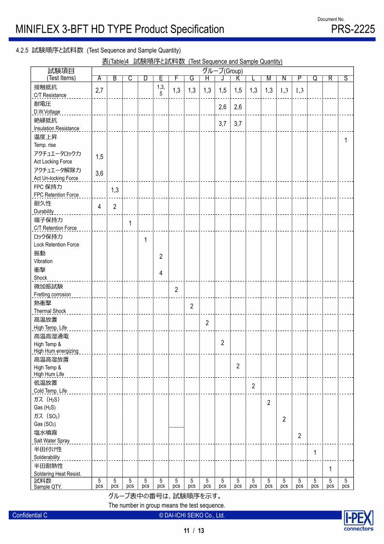
4.2.5 試験順序と試料数 (Test Sequence and Sample Quantity) 表(Table)4 試験順序と試料数 (Test Sequence and Sample Quantity)
試験項目 (Test Items)
グループ(Group) A B C D E F G H J K L M N P Q R S
接触抵抗 C/T Resistance
2,7 1,3, 5 1,3 1,3 1,3 1,5 1,5 1,3 1,3 1,3 1,3
耐電圧 D.W.Voltage
2,6 2,6
絶縁抵抗 Insulation Resistance
3,7 3,7
温度上昇 Temp. rise
1
アクチュエータロック力 Act Locking Force
1,5
アクチュエータ解除力 Act Un-locking Force
3,6
FPC 保持力 FPC Retention Force
1,3
耐久性 Durability
4 2
端子保持力 C/T Retention Force
1
ロック保持力 Lock Retention Force
1
振動 Vibration
2
衝撃 Shock
4
微加振試験 Fretting corrosion
2
熱衝撃 Thermal Shock
2
高温放置 High Temp. Life
2
高温高湿通電 High Temp & High Hum energizing
2
高温高湿放置 High Temp & High Hum Life
2
低温放置 Cold Temp. Life
2
ガス(H2S) Gas (H2S)
2
ガス(SO2) Gas (SO2)
2
塩水噴霧 Salt Water Spray
2
半田付け性 Solderability
1
半田耐熱性 Soldering Heat Resist.
1 試料数 Sample QTY.
5 pcs
5 pcs
5 pcs
5 pcs
5 pcs
5 pcs
5 pcs
5 pcs
5 pcs
5 pcs
5 pcs
5 pcs
5 pcs
5 pcs
5 pcs
5 pcs
5 pcs
グループ表中の番号は、試験順序を示す。 The number in group means the test sequence.

MINIFLEX 3-BFT HD TYPE Product Specification Document No.
PRS-2225
12 / 13
Confidential C © DAI-ICHI SEIKO Co., Ltd.
Fig. 1 リフロープロファイル (Reflow Temperature Profile)
接触抵抗 = RAB - FPC50mm 分 - Test Board 分の抵抗 Contact Resistance = RAB - Resistance of a 50mm length of FPC cable - Resistance of Test Board .
Fig. 2 接触抵抗 (Contact Resistance)
453K(180℃)
423K(150℃)
60~120 sec
533K(260 ℃ )
30~40 sec
503K(230℃)
MINIFLEX 3-BFT HD TYPE Product Specification Document No.
PRS-2225
13 / 13
Confidential C © DAI-ICHI SEIKO Co., Ltd.
5. 推奨メタルマスク/Recommended Metal Mask
推奨マスク厚と開口寸法に関しては、図面参照願います。 Refer to drawing for the recommended metal mask thickness and opening dimension.
6. コネクタ取り扱いの注意/Precautions for Handling Cable Connectors
本コネクタの取り扱いに関しては、取り扱い説明書:HIM-12018 を参照願います。 Refer to instruction manual HIM-12018 for the handling of MINIFLEX 3-BFT.
Related Documents


